KR20230016595A - Substrate processing method and substrate processing apparatus - Google Patents
Substrate processing method and substrate processing apparatus Download PDFInfo
- Publication number
- KR20230016595A KR20230016595A KR1020220088931A KR20220088931A KR20230016595A KR 20230016595 A KR20230016595 A KR 20230016595A KR 1020220088931 A KR1020220088931 A KR 1020220088931A KR 20220088931 A KR20220088931 A KR 20220088931A KR 20230016595 A KR20230016595 A KR 20230016595A
- Authority
- KR
- South Korea
- Prior art keywords
- discharge
- sub
- fluid
- substrate
- processing
- Prior art date
Links
- 238000012545 processing Methods 0.000 title claims abstract description 201
- 239000000758 substrate Substances 0.000 title claims abstract description 175
- 238000003672 processing method Methods 0.000 title claims abstract description 22
- 239000012530 fluid Substances 0.000 claims abstract description 156
- 238000009826 distribution Methods 0.000 claims abstract description 116
- 238000000034 method Methods 0.000 claims abstract description 57
- 230000008569 process Effects 0.000 claims abstract description 53
- 239000007788 liquid Substances 0.000 claims abstract description 17
- 238000007599 discharging Methods 0.000 claims abstract description 12
- 230000007246 mechanism Effects 0.000 claims description 11
- 238000001035 drying Methods 0.000 claims description 8
- 238000013459 approach Methods 0.000 claims description 2
- 239000002245 particle Substances 0.000 abstract description 11
- KFZMGEQAYNKOFK-UHFFFAOYSA-N Isopropanol Chemical compound CC(C)O KFZMGEQAYNKOFK-UHFFFAOYSA-N 0.000 description 72
- 238000000352 supercritical drying Methods 0.000 description 20
- 239000000126 substance Substances 0.000 description 16
- 239000013598 vector Substances 0.000 description 11
- 238000003860 storage Methods 0.000 description 9
- 238000012546 transfer Methods 0.000 description 9
- 238000010586 diagram Methods 0.000 description 8
- 238000012986 modification Methods 0.000 description 7
- 230000004048 modification Effects 0.000 description 7
- 239000004065 semiconductor Substances 0.000 description 7
- CURLTUGMZLYLDI-UHFFFAOYSA-N Carbon dioxide Chemical compound O=C=O CURLTUGMZLYLDI-UHFFFAOYSA-N 0.000 description 6
- 238000004519 manufacturing process Methods 0.000 description 4
- 229910002092 carbon dioxide Inorganic materials 0.000 description 3
- 239000001569 carbon dioxide Substances 0.000 description 3
- 238000004140 cleaning Methods 0.000 description 3
- 238000011144 upstream manufacturing Methods 0.000 description 3
- 239000000919 ceramic Substances 0.000 description 2
- 238000004891 communication Methods 0.000 description 2
- 238000005516 engineering process Methods 0.000 description 2
- 239000011521 glass Substances 0.000 description 2
- 238000001039 wet etching Methods 0.000 description 2
- 238000013019 agitation Methods 0.000 description 1
- 230000008859 change Effects 0.000 description 1
- 230000007423 decrease Effects 0.000 description 1
- 230000002950 deficient Effects 0.000 description 1
- 238000001514 detection method Methods 0.000 description 1
- 230000000694 effects Effects 0.000 description 1
- 238000001704 evaporation Methods 0.000 description 1
- 230000008020 evaporation Effects 0.000 description 1
- 230000006872 improvement Effects 0.000 description 1
- 239000000463 material Substances 0.000 description 1
- 230000003287 optical effect Effects 0.000 description 1
- 230000000149 penetrating effect Effects 0.000 description 1
- 238000010926 purge Methods 0.000 description 1
- 238000011084 recovery Methods 0.000 description 1
- 238000006467 substitution reaction Methods 0.000 description 1
- 230000007723 transport mechanism Effects 0.000 description 1
Images


Classifications
-
- H—ELECTRICITY
- H01—ELECTRIC ELEMENTS
- H01L—SEMICONDUCTOR DEVICES NOT COVERED BY CLASS H10
- H01L21/00—Processes or apparatus adapted for the manufacture or treatment of semiconductor or solid state devices or of parts thereof
- H01L21/02—Manufacture or treatment of semiconductor devices or of parts thereof
- H01L21/02041—Cleaning
- H01L21/02101—Cleaning only involving supercritical fluids
-
- H—ELECTRICITY
- H01—ELECTRIC ELEMENTS
- H01L—SEMICONDUCTOR DEVICES NOT COVERED BY CLASS H10
- H01L21/00—Processes or apparatus adapted for the manufacture or treatment of semiconductor or solid state devices or of parts thereof
- H01L21/02—Manufacture or treatment of semiconductor devices or of parts thereof
- H01L21/02041—Cleaning
- H01L21/02057—Cleaning during device manufacture
-
- H—ELECTRICITY
- H01—ELECTRIC ELEMENTS
- H01L—SEMICONDUCTOR DEVICES NOT COVERED BY CLASS H10
- H01L21/00—Processes or apparatus adapted for the manufacture or treatment of semiconductor or solid state devices or of parts thereof
- H01L21/67—Apparatus specially adapted for handling semiconductor or electric solid state devices during manufacture or treatment thereof; Apparatus specially adapted for handling wafers during manufacture or treatment of semiconductor or electric solid state devices or components ; Apparatus not specifically provided for elsewhere
- H01L21/67005—Apparatus not specifically provided for elsewhere
- H01L21/67011—Apparatus for manufacture or treatment
- H01L21/67017—Apparatus for fluid treatment
- H01L21/67028—Apparatus for fluid treatment for cleaning followed by drying, rinsing, stripping, blasting or the like
- H01L21/67034—Apparatus for fluid treatment for cleaning followed by drying, rinsing, stripping, blasting or the like for drying
-
- H—ELECTRICITY
- H01—ELECTRIC ELEMENTS
- H01L—SEMICONDUCTOR DEVICES NOT COVERED BY CLASS H10
- H01L21/00—Processes or apparatus adapted for the manufacture or treatment of semiconductor or solid state devices or of parts thereof
- H01L21/67—Apparatus specially adapted for handling semiconductor or electric solid state devices during manufacture or treatment thereof; Apparatus specially adapted for handling wafers during manufacture or treatment of semiconductor or electric solid state devices or components ; Apparatus not specifically provided for elsewhere
- H01L21/67005—Apparatus not specifically provided for elsewhere
- H01L21/67242—Apparatus for monitoring, sorting or marking
- H01L21/67253—Process monitoring, e.g. flow or thickness monitoring
-
- H—ELECTRICITY
- H01—ELECTRIC ELEMENTS
- H01L—SEMICONDUCTOR DEVICES NOT COVERED BY CLASS H10
- H01L21/00—Processes or apparatus adapted for the manufacture or treatment of semiconductor or solid state devices or of parts thereof
- H01L21/02—Manufacture or treatment of semiconductor devices or of parts thereof
- H01L21/02041—Cleaning
- H01L21/02043—Cleaning before device manufacture, i.e. Begin-Of-Line process
- H01L21/02052—Wet cleaning only
Abstract
Description
본 개시는 기판 처리 장치 및 기판 처리 장치에 관한 것이다.The present disclosure relates to a substrate processing apparatus and a substrate processing apparatus.
반도체 웨이퍼(이하, '웨이퍼'라 함) 등의 기판의 표면에 집적 회로의 적층 구조를 형성하는 반도체 장치의 제조 공정에 있어서는, 약액 세정 혹은 웨트 에칭 등의 액 처리가 행해진다. 이러한 액 처리로 웨이퍼의 표면에 부착한 액체 등을 제거할 시에, 근래에는, 초임계 상태의 처리 유체를 이용한 건조 방법이 이용되고 있다(예를 들면 특허 문헌 1을 참조).BACKGROUND OF THE INVENTION In a semiconductor device manufacturing process in which a laminated structure of integrated circuits is formed on a surface of a substrate such as a semiconductor wafer (hereinafter referred to as 'wafer'), liquid processing such as chemical liquid cleaning or wet etching is performed. When removing the liquid or the like adhering to the surface of the wafer by such a liquid process, in recent years, a drying method using a process fluid in a supercritical state has been used (see Patent Document 1, for example).
본 개시는, 기판 상에 대한 파티클의 부착을 억제할 수 있는, 기술을 제공한다.The present disclosure provides a technique capable of suppressing adhesion of particles on a substrate.
본 개시의 일실시 형태에 따르면, 표면에 액체가 부착된 기판을 초임계 유체 상태의 처리 유체를 이용하여 건조시키는 기판 처리 방법으로서, 상기 기판 처리 방법은, 처리 용기와, 상기 처리 용기 내에서, 상기 기판의 상기 표면을 상향으로 하여 상기 기판을 수평으로 유지하는 기판 유지부와, 상기 처리 용기 내에 처리 유체를 토출하는 유체 토출부와, 상기 처리 용기로부터 처리 유체를 배출하는 유체 배출부와, 상기 유체 토출부에 접속되어, 초임계 상태의 처리 유체를 공급하는 유체 공급원으로부터 상기 유체 토출부로 처리 유체를 공급하는 공급 라인과, 상기 유체 배출부에 접속된 배출 라인과, 상기 공급 라인 및 상기 배출 라인 중 적어도 일방에 마련되고, 상기 처리 용기 내를 상기 유체 토출부로부터 상기 유체 배출부를 향해 흐르는 처리 유체의 흐름을 제어하는 흐름 제어 기구를 구비한 기판 처리 장치를 이용하여 실행되고, 상기 기판 처리 방법은, 상기 기판 유지부에 의해 유지된 상기 기판의 표면을 따라 처리 유체가 흐르도록 상기 유체 토출부로부터 상기 유체 배출부로 처리 유체를 흘리는 유통 공정을 구비하고, 상기 유통 공정은, 상기 처리 용기 내에 제 1 유통 모드로 처리 유체를 흘리는 제 1 유통 단계와, 상기 처리 용기 내에 제 2 유통 모드로 처리 유체를 흘리는 제 2 유통 단계를 포함하고, 상기 제 1 유통 모드와 상기 제 2 유통 모드에서, 상기 기판의 표면의 법선 방향에서 봤을 때에, 상기 처리 용기 내에 있어서 상기 기판의 표면을 따라 흐르는 처리 유체의 흐름 방향 분포가 상이하며, 상기 제 1 유통 모드와 상기 제 2 유통 모드와의 전환은 상기 흐름 제어 기구에 의해 행해지는, 기판 처리 방법이 제공된다.According to one embodiment of the present disclosure, a substrate processing method of drying a substrate having a liquid adhered thereon using a processing fluid in a supercritical fluid state, the substrate processing method comprising: a processing container; and in the processing container, a substrate holding part for holding the substrate horizontally with the surface of the substrate facing upward; a fluid discharge part for discharging a processing fluid into the processing container; and a fluid discharge unit discharging the processing fluid from the processing container; A supply line connected to the fluid discharge unit and supplying a processing fluid from a fluid supply source supplying a processing fluid in a supercritical state to the fluid discharge unit, a discharge line connected to the fluid discharge unit, the supply line and the discharge line The substrate processing method is performed by using a substrate processing apparatus including a flow control mechanism provided in at least one of the processing containers and controlling a flow of processing fluid flowing from the fluid discharge unit toward the fluid discharge unit in the processing container. and a distribution process of flowing the processing fluid from the fluid discharge unit to the fluid discharge unit so that the processing fluid flows along the surface of the substrate held by the substrate holding unit, wherein the distribution process comprises a first substrate in the processing container. a first distribution step of flowing the processing fluid in a flow mode; and a second flow step of flowing the processing fluid in a second flow mode into the processing container, wherein in the first flow mode and the second flow mode, the substrate When viewed in the normal direction of the surface, the flow direction distribution of the processing fluid flowing along the surface of the substrate in the processing container is different, and switching between the first flow mode and the second flow mode is performed by the flow control mechanism. A substrate processing method is provided, which is performed by
본 개시에 따르면, 기판 상에 대한 파티클의 부착을 억제할 수 있다.According to the present disclosure, adhesion of particles to a substrate can be suppressed.
도 1은 기판 처리 장치의 일실시 형태에 따른 초임계 건조 장치의 처리 유닛의 구성의 일례를 나타내는 개략 종단면도이다.
도 2는 도 1에 나타낸 처리 유닛의 개략 횡단면도이다.
도 3은 도 1에 나타낸 처리 유닛을 포함하는 배관 계통의 일례를 나타내는 개략 배관 계통도이다.
도 4a는 도 1의 초임계 건조 장치의 동작을 설명하기 위한 도로서, 승압 공정을 나타내는 도이다.
도 4b는 도 1의 초임계 건조 장치의 동작을 설명하기 위한 도로서, 유통 공정의 유통 모드 1을 나타내는 도이다.
도 4c는 도 1의 초임계 건조 장치의 동작을 설명하기 위한 도로서, 유통 공정의 유통 모드 2를 나타내는 도이다.
도 4d는 도 1의 초임계 건조 장치의 동작을 설명하기 위한 도로서, 유통 공정의 유통 모드 3을 나타내는 도이다.
도 5는 처리 유닛의 제 1 변형 실시 형태를 나타내는 주요부 개략 평면도이다.
도 6은 처리 유닛의 제 2 변형 실시 형태를 나타내는 개략 종단면도이다.
도 7은 도 5의 처리 유닛에 있어서의 유통 공정에 있어서의 처리 유체의 흐름을 설명하는 대략 사시도이다.1 is a schematic longitudinal sectional view showing an example of a configuration of a processing unit of a supercritical drying apparatus according to an embodiment of a substrate processing apparatus.
FIG. 2 is a schematic cross-sectional view of the processing unit shown in FIG. 1 .
FIG. 3 is a schematic piping system diagram showing an example of a piping system including the processing unit shown in FIG. 1 .
FIG. 4A is a diagram for explaining the operation of the supercritical drying apparatus of FIG. 1 and showing a pressure raising process.
FIG. 4B is a diagram for explaining the operation of the supercritical drying apparatus of FIG. 1 and showing a distribution mode 1 of a distribution process.
FIG. 4C is a diagram for explaining the operation of the supercritical drying apparatus of FIG. 1 and showing a
FIG. 4D is a diagram for explaining the operation of the supercritical drying apparatus of FIG. 1 and showing distribution mode 3 of the distribution process.
5 is a schematic plan view of a main part showing a first modified embodiment of a processing unit.
6 is a schematic longitudinal sectional view showing a second modified embodiment of a processing unit.
FIG. 7 is a schematic perspective view illustrating a flow of a processing fluid in a distribution process in the processing unit of FIG. 5 .
기판 처리 장치의 일실시 형태로서의 초임계 건조 장치를, 첨부 도면을 참조하여 설명한다. 초임계 건조 장치는, 표면에 액체(예를 들면 IPA(이소프로필 알코올))의 액막이 형성된 기판(W)을, 초임계 상태의 처리 유체(예를 들면 이산화탄소)를 이용하여 건조시키는 초임계 건조 처리를 행하기 위하여 이용할 수 있다. 기판(W)은 예를 들면 반도체 웨이퍼이지만, 반도체 장치 제조의 기술 분야에서 이용되는 다른 종류의 기판(글라스 기판, 세라믹 기판) 등이어도 된다. 초임계 건조 기술은, 패턴 도괴를 발생시킬 수 있는 표면 장력이 패턴에 작용하지 않는 점에서, 미세하고 또한 고애스펙트비의 패턴이 형성된 기판의 건조에 유리하게 이용할 수 있다.A supercritical drying apparatus as one embodiment of a substrate processing apparatus will be described with reference to the accompanying drawings. The supercritical drying device is a supercritical drying process for drying a substrate W having a liquid film of liquid (eg, IPA (isopropyl alcohol)) on its surface using a processing fluid (eg, carbon dioxide) in a supercritical state. can be used to do The substrate W is, for example, a semiconductor wafer, but may be another type of substrate (glass substrate, ceramic substrate) used in the technical field of semiconductor device manufacturing. Supercritical drying technology can be advantageously used for drying a substrate on which a fine and high-aspect-ratio pattern is formed, since surface tension, which can cause pattern collapse, does not act on the pattern.
이하에 있어서는, 방향 및 위치의 설명을 용이하게 하기 위하여, XYZ 직교 좌표계를 설정하고, 필요에 따라 당해 좌표계를 참조하여 설명을 행하는 것으로 한다. 또한, X 방향을 전후 방향(X 정방향이 전방), Y 방향을 좌우 방향(Y 정방향이 좌방), Z 방향을 상하 방향(Z 정방향이 상방)이라고도 부르는 경우도 있는 것에 유의받고자 한다.In the following, in order to facilitate explanation of directions and positions, an XYZ orthogonal coordinate system is set, and the description is made with reference to the coordinate system as necessary. In addition, it should be noted that the X direction is also referred to as the front-back direction (positive X direction is forward), the Y direction is also referred to as the left-right direction (positive Y direction is left), and the Z direction is also referred to as the up-and-down direction (positive Z direction is upward).
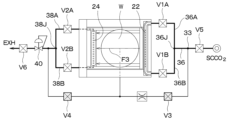
도 1 및 도 2에 나타내는 바와 같이, 초임계 건조 장치는, 처리 유닛(10)을 구비하고 있다. 처리 유닛(10)의 내부에서, 초임계 건조 처리가 행해진다. 처리 유닛(10)은 처리 용기(11)와, 처리 용기(11) 내에서 기판(W)을 유지하는 기판 유지 트레이(12)(이하, 단순히 '트레이(12)'라 부름)를 가지고 있다.As shown in FIGS. 1 and 2 , the supercritical drying apparatus includes a
일실시 형태에 있어서, 트레이(12)는, 처리 용기(11)의 측벽에 마련된 개구를 폐색하는 덮개부(13)와, 덮개부(13)에 연결된 수평 방향으로 연장되는 기판 유지부(14)를 가진다. 기판 유지부(14)는 플레이트(15)와, 플레이트(15)의 상면에 마련된 복수의 지지 핀(16)을 가지고 있다. 기판(W)은, 그 표면(디바이스 내지 패턴이 형성된 면)을 상향으로 한 상태에서, 지지 핀(16) 상에 수평 자세로 배치된다. 기판(W)이 지지 핀(16) 상에 배치되면, 플레이트(15)의 상면과 기판(W)의 하면(이면)과의 사이에 간극(17)이 형성된다.In one embodiment, the
플레이트(15)는, 전체로서 예를 들면 장방형(長方形) 또는 정방형(正方形)이다. 플레이트(15)의 면적은 기판(W)보다 크고, 기판 유지부(14)의 정해진 위치에 기판(W)이 배치되었을 때에 플레이트(15)를 바로 밑에서 보면, 기판(W)은 플레이트(15)로 완전히 덮인다.The
플레이트(15)에는, 당해 플레이트(15)를 상하로 관통하는 복수의 관통 홀(18)이 형성되어 있다. 복수의 관통 홀(18)은, 플레이트(15)의 하방의 공간에 공급된 처리 유체를 플레이트(15)의 상방의 공간으로 유입시키는 역할을 한다. 복수의 관통 홀(18) 중 몇 개는, 기판 유지부(14)와 처리 유닛(10)의 외부의 기판 반송 기구(도시하지 않음)와의 사이에서 기판(W)의 전달을 행하는 리프트 핀(도시하지 않음)을 통과시키는 역할도 하는데, 본 명세서에서는 이 점에 대한 설명은 생략한다.The
트레이(12)(덮개부(13) 및 기판 유지부(14)의 조립체)는, 도시하지 않는 트레이 이동 기구에 의해, 처리 위치(도 1 및 도 2에 나타내는 폐쇄 위치)와, 기판 전달 위치(도시하지 않는 개방 위치)와의 사이에서 수평 방향(X 방향)으로 이동할 수 있다.The tray 12 (the assembly of the
트레이(12)의 처리 위치에서는, 기판 유지부(14)가 처리 용기(11)의 내부 공간 내에 위치하고, 또한 덮개부(13)가 처리 용기(11)의 측벽의 개구를 폐쇄한다. 트레이(12)의 기판 전달 위치에서는, 기판 유지부(14)가 처리 용기(11)의 밖으로 나와 있고, 기판 유지부(14)와 도시하지 않는 기판 반송 암과의 사이에서, 전술한 도시하지 않는 리프트 핀을 개재하여 기판(W)의 전달을 행하는 것이 가능하다.In the processing position of the
트레이(12)가 처리 위치에 있을 때, 플레이트(15)에 의해, 처리 용기(11)의 내부 공간이, 처리 중에 기판(W)이 존재하는 플레이트(15)의 상방의 상방 공간(11A)과, 플레이트(15)의 하방의 하방 공간(11B)으로 분할된다. 단, 상방 공간(11A)과 하방 공간(11B)이 완전히 분리되어 있는 것은 아니다.When the
즉, 도시된 실시 형태에서는, 전술한 관통 홀(18)에 의해, 또한, 플레이트(15)와 덮개부(13)와의 접속부의 근방에 마련된 긴 홀(19)(이것도 관통 홀임)에 의해, 상방 공간(11A)과 하방 공간(11B)이 연통하고 있다. 플레이트(15)의 주연부와 처리 용기(11)의 내벽면과의 사이의 간극에 의해서도, 상방 공간(11A)과 하방 공간(11B)이 연통하고 있다. 상술한 간극, 관통 홀(18) 및 긴 홀(19) 등이 상방 공간(11A)과 하방 공간(11B)이 연통시키는 연통로라고도 할 수 있다.That is, in the illustrated embodiment, by the
상술한 바와 같이 처리 용기(11)의 내부 공간이 상방 공간(11A)과 하방 공간(11B)으로 분할되고, 또한, 상방 공간(11A)과 하방 공간(11B)을 연통시키는 연통로가 마련되어 있다면, 가동의 트레이(12) 대신에, 처리 용기(11) 내에 이동 불가능하게 고정된 기판 배치대(기판 유지부) 마련해도 된다. 이 경우, 처리 용기(11)에 마련된 도시하지 않는 덮개를 연 상태에서, 도시하지 않는 기판 반송 암이 용기 본체 내에 진입하여, 기판 배치대와 기판 반송 암과의 사이에서 기판(W)의 전달이 행해진다.As described above, if the inner space of the
처리 용기(11)에는, 제 1 토출부(21) 및 제 2 토출부(유체 토출부)(22)가 마련되어 있다. 제 1 토출부(21) 및 제 2 토출부(22)는, 초임계 유체(초임계 상태에 있는 처리 유체)의 공급원(30)으로부터 공급된 처리 유체(여기서는 이산화탄소(간편하게 하기 위하여 'CO2'라고도 적음))를 처리 용기(11)의 내부 공간에 토출한다.The
제 1 토출부(21)는, 처리 위치에 있는 트레이(12)의 플레이트(15)의 하방에 마련되어 있다. 제 1 토출부(21)는, 플레이트(15)의 하면을 향해(상향으로), 하방 공간(11B) 내에 CO2(처리 유체)를 토출한다. 제 1 토출부(21)는, 처리 용기(11)의 저벽에 형성된 관통 홀에 의해 구성할 수 있다. 제 1 토출부(21)는 처리 용기(11)의 저벽에 장착된 노즐체여도 된다.The
제 2 토출부(22)는, 처리 위치에 있는 트레이(12)의 기판 유지부(14) 상에 배치된 기판(W)의 전방(X 정방향)에 위치하도록 마련되어 있다. 제 2 토출부(22)는, 상방 공간(11A) 내에 CO2를 공급한다. 도시된 실시 형태에서는, 제 2 토출부(22)는, 덮개부(13)와 반대측의 처리 용기(11)의 측벽에 마련되어 있다.The
제 2 토출부(22)는, 봉 형상의 노즐체에 의해 구성되어 있다. 상세하게는, 제 2 토출부(22)는, 기판(W)의 폭 방향(Y 방향)으로 연장되는 관(22a)에, 복수의 토출구(22b)를 뚫음으로써 형성되어 있다. 복수의 토출구(22b)는, 예를 들면 Y 방향으로 등간격으로 배열되어 있다. 각 토출구(22b)는, 플레이트(15)의 선단(덮개부(13)로부터 가장 먼 전단부)에 형성된 경사면(15a)을 향해 CO2를 토출하도록, 비스듬히 하방을 향하고 있다. 또한 경사면(15a)은, 그 최선단부의 높이가 기판(W)의 표면보다 낮고, 또한, 기판(W)에 가까워짐에 따라 높아지도록 경사져 있다.The
처리 용기(11)에는, 또한, 처리 용기(11)의 내부 공간으로부터 처리 유체를 배출하는 유체 배출부(24)가 마련되어 있다. 유체 배출부(24)는, 제 2 토출부(22)와 대략 동일한 구성을 가지는 헤더로서 구성되어 있다. 상세하게는, 유체 배출부(24)는, 수평 방향으로 연장되는 관(24a)에, 복수의 배출구(24b)를 뚫음으로써 형성되어 있다. 복수의 배출구(24b)는, 예를 들면 Y 방향으로 등간격으로 배열되어 있다. 각 배출구(24b)는 상방을 향하고 있고, 또한, 플레이트(15)의 긴 홀(19)쪽을 향하고 있다.The
제 2 토출부(22) 및 유체 배출부(24)는, 제 2 토출부(22)로부터 처리 용기(11) 내로 공급된 CO2가 기판(W)의 표면의 대략 전체의 상방의 영역을 대략 수평 방향으로 통과한 후에 유체 배출부(24)로부터 배출된다면, 임의의 위치에 배치할 수 있다. 예를 들면, 제 2 토출부(22) 및 유체 배출부(24)를, 기판(W)을 사이에 두고, 기판(W)의 좌우 방향 양측(Y 방향 양측)에 배치해도 된다.The
이어서, 초임계 건조 장치에 있어서, 처리 용기(11)에 대하여 CO2의 공급 및 배출을 행하는 공급 / 배출계에 대하여, 도 3의 배관 계통도를 참조하여 설명한다. 또한, 초임계 건조 장치의 공급 / 배출계에는, 도 3에 나타난 것 이외의 분기 라인(처리 유체 회수용 라인, 퍼지용 라인 등), 밸브, 오리피스, 필터, 센서류 등이 마련되어 있는데, 본 개시의 요지에 직접 관계 없는 것에 대해서는 기재를 생략하고 있다.Next, in the supercritical drying device, a supply/discharge system for supplying and discharging CO 2 to and from the
초임계 건조 장치는, 초임계 처리 유체(초임계 CO2)의 공급원(30)으로서의 초임계 유체 공급 장치(30)를 가진다. 초임계 유체 공급 장치(30)는, 예를 들면 탄산 가스 봄베, 가압 펌프, 히터 등을 구비한 주지의 구성을 가지고 있다. 초임계 유체 공급 장치(30)는, 후술하는 초임계 상태 보증 압력(구체적으로 약 16 MPa)을 초과하는 압력으로 초임계 CO2를 보내는 능력을 가지고 있다.The supercritical drying device has a supercritical
초임계 유체 공급 장치(30)에는 주 공급 라인(32)이 접속되어 있다. 초임계 유체 공급 장치(30)로부터 초임계 상태로 CO2가 주 공급 라인(32)으로 유출되는데, 그 후의 팽창 혹은 온도 변화에 의해, 가스 상태로도 될 수 있다. 본 명세서에 있어서, '라인'이라 불리는 부재는 예를 들면 파이프(배관 부재)에 의해 구성할 수 있다.A
주 공급 라인(32)은 분기점(제 1 분기점)(33)에 있어서, 제 1 공급 라인(34)과 제 2 공급 라인(36)으로 분기하고 있다. 제 1 공급 라인(34)은, 처리 용기(11)의 제 1 토출부(21)에 접속되어 있다.The
제 2 공급 라인(36)은, 제 1 분기점(33)의 하류측에 있는 분기점(36J)에 있어서, 또한 제 1 서브 공급 라인(36A)과 제 2 서브 공급 라인(36B)으로 분기하고 있다. 제 1 서브 공급 라인(36A)은 제 2 토출부(22)를 구성하는 관(22a)의 제 1 단(접속부)(23A)에, 그리고 제 2 서브 공급 라인(36B)은 관(22a)의 제 2 단(접속부)(23B)에, 각각 접속되어 있다. 제 1 서브 공급 라인(36A) 및 제 2 서브 공급 라인(36B)에는 각각, 공급 흐름 제어 기기로서, 개폐 밸브(V1A) 및 개폐 밸브(V1B)가 개재 마련되어 있다.The
처리 용기(11)의 유체 배출부(24)에, 배출 라인(38)이 접속되어 있다. 상세하게는, 유체 배출부(24)를 구성하는 관(24a)의 제 1 단(접속부)(25A)에 제 1 서브 배출 라인(38A)이 접속되고, 관(24a)의 제 2 단(접속부)(25B)에 제 2 서브 배출 라인(38B)이 접속되어 있다. 참조 부호(25A, 25B)는 도 3에만 표시되어 있다. 제 1 서브 배출 라인(38A)과 제 2 서브 배출 라인(38B)에는 각각, 배출 흐름 제어 기기로서, 개폐 밸브(V2A) 및 개폐 밸브(V2B)가 개재 마련되어 있다. 제 1 서브 배출 라인(38A)과 제 2 서브 배출 라인(38B)은 합류점(38J)에 있어서 합류하여, 1 개의 배출 라인(38)이 된다.A
'공급 흐름 제어 기기' 및 '배출 흐름 제어 기기'의 조합은 '흐름 제어 기기'라고도 불린다.The combination of 'supply flow control device' and 'outlet flow control device' is also called 'flow control device'.
합류점(38J)의 근방에 있어서, 배출 라인(38)에는 압력 센서(39)가 마련되어 있다. 압력 센서(39)로 검출되는 압력은, 대략 처리 용기(11) 내의 압력과 일치하고 있는 것으로 간주해도 된다. 제 1 서브 배출 라인(38A) 및 제 2 서브 배출 라인(38B)에 각각 압력 센서(39)를 마련해도 된다.In the vicinity of the confluence point 38J, a
배출 라인(38)에는, 압력 제어 밸브(40)가 마련되어 있다. 압력 제어 밸브(40)의 개방도를 조절함으로써, 압력 제어 밸브(40)의 일차측 압력을 조절할 수 있고, 따라서, 처리 용기(11) 내의 압력을 조절할 수 있다. 또한, 압력 제어 밸브(40)의 개방도를 조절함으로써, 처리 용기(11)로부터의 처리 유체의 배출 속도도 조절할 수 있다.A
제 1 서브 공급 라인(36A), 제 2 서브 공급 라인(36B), 개폐 밸브(V1A) 및 개폐 밸브(V1B)는, 실질적으로 좌우 대칭으로(예를 들면 평면에서 봤을 때 기판(W)의 중심을 지나 X 방향으로 연장되는 대칭축에 관하여) 배치하는 것이 바람직하다. 그렇게 함으로써, 분기점(36J)으로부터 관(22a)의 제 1 단(23A)까지의 흐름 저항(예를 들면 관의 내경 및 길이에 의해 결정됨)과, 분기점(36J)으로부터 관(22a)의 제 2 단(23B)까지의 흐름 저항이 실질적으로 동일하게 된다. 또한, 제 2 토출부(22)의 형상 및 토출구(22b)의 배치도 좌우 대칭으로 하는 것이 바람직하다.The first
마찬가지로, 제 1 서브 배출 라인(38A), 제 2 서브 배출 라인(38B), 개폐 밸브(V2A), 개폐 밸브(V2B)도, 실질적으로 좌우 대칭으로 배치하는 것이 바람직하다. 그렇게 함으로써, 관(24a)의 제 1 단(25A)으로부터 합류점(38J)까지의 흐름 저항과, 관(24a)의 제 2 단(25B)으로부터 합류점(38J)까지의 흐름 저항이 실질적으로 동일하게 된다. 또한, 유체 배출부(24)의 형상 및 배출구(24b)의 배치도 좌우 대칭으로 하는 것이 바람직하다.Similarly, it is preferable that the first
도 3에 개략적으로 나타난 제어부(100)가, 처리 용기(11) 내의 압력의 측정값(PV)과 설정값(SV)과의 편차에 기초하여, 처리 용기(11) 내의 압력이 설정값으로 유지되도록, 압력 제어 밸브(40)의 개방도(구체적으로 밸브 본체의 위치)를 피드백 제어한다. 처리 용기(11) 내의 압력의 측정값으로서는, 배출 라인(38)에 마련된 압력 센서(39)의 검출값을 이용할 수 있다. 처리 용기(11) 내의 압력은, 처리 용기(11) 내에 마련한 압력 센서에 의해 직접적으로 측정해도 된다. 압력 제어 밸브(40)는, 제어부(100)로부터의 지령값에 기초하여(피드백 제어가 아닌) 고정 개방도로 설정할 수 있다.The
제어부(100)는 예를 들면 컴퓨터로 이루어지며, 연산부(101)와 기억부(102)를 구비하고 있다. 기억부(102)에는, 초임계 건조 장치(또는 초임계 건조 장치를 포함하는 기판 처리 시스템)에 있어서 실행되는 각종 처리를 제어하는 프로그램이 저장된다. 연산부(101)는, 기억부(102)에 기억된 프로그램을 읽어내 실행함으로써, 기억부(102)에 기억된 처리 레시피에 정의된 동작이 실현되도록, 초임계 건조 장치의 동작을 제어한다. 프로그램은, 컴퓨터에 의해 판독 가능한 기억 매체에 기록되어 있던 것으로서, 그 기억 매체로부터 제어부(100)의 기억부(102)에 인스톨된 것이어도 된다. 컴퓨터에 의해 판독 가능한 기억 매체로서는, 예를 들면 하드 디스크(HD), 플렉시블 디스크(FD), 콤팩트 디스크(CD), 마그넷 옵티컬 디스크(MO), 메모리 카드 등이 있다.The
제 1 공급 라인(34) 상에 설정된 분기점(42)에 있어서, 제 1 공급 라인(34)으로부터 바이패스 라인(44)이 분기하고 있다. 바이패스 라인(44)은, 배출 라인(38)에 설정된 접속점(합류점)(46)에 있어서, 배출 라인(38)에 접속되어 있다. 접속점(46)은, 압력 제어 밸브(40)의 상류측에 있다.At the
제 1 공급 라인(34)에는 개폐 밸브(V3) 및 오리피스(35)가 마련되고, 바이패스 라인(44)에는 개폐 밸브(V4)가 마련되어 있다.An on-off valve V3 and an
분기점(33)보다 상류측에 있어서, 주 공급 라인(32)에는 개폐 밸브(V5)가 마련되어 있다. 압력 제어 밸브(40)의 하류측에 있어서, 배출 라인(38)에는 개폐 밸브(V6)가 마련되어 있다.On the upstream side of the
이어서, 상술한 초임계 건조 장치를 이용한 초임계 건조 방법(기판 처리 방법)의 일례에 대하여 도 4a ~ 도 4d를 참조하여 설명한다. 이하에 설명하는 순서는, 기억부(102)에 기억된 처리 레시피 및 제어 프로그램에 기초하여, 제어부(100)의 제어 하에서, 자동적으로 실행된다. 도 4a ~ 도 4d에 있어서, 회색으로 칠해진 개폐 밸브는 폐쇄 상태로 되어 있고, 칠해져 있지 않은 개폐 밸브는 개방 상태로 되어 있는 것을 의미하고 있다.Next, an example of a supercritical drying method (substrate processing method) using the above-described supercritical drying apparatus will be described with reference to FIGS. 4A to 4D. The procedures described below are automatically executed under the control of the
<반입 공정><Incoming process>
반도체 웨이퍼 등의 기판(W)이, 그 표면의 패턴의 오목부 내가 IPA로 충전되고 또한 그 표면에 IPA의 퍼들(액막)이 형성된 상태에서, 도시하지 않는 기판 반송 암에 의해, 기판 전달 위치에서 대기하고 있는 트레이(12)의 기판 유지부(14) 상에 배치된다. 또한, 이 기판(W)은, 예를 들면, 도시하지 않는 매엽식 세정 장치에 있어서 (1) 웨트 에칭, 약액 세정 등의 약액 처리, (2) 약액을 린스액에 의해 씻어내는 린스 처리, (3) 린스액을 IPA로 치환하여 IPA의 퍼들(액막)을 형성하는 IPA 치환 처리가 순차 실시된 것이다. 기판(W)이 배치된 트레이(12)가 처리 위치로 이동하면, 처리 용기(11) 내에 밀폐된 처리 공간이 형성되고, 기판(W)은 처리 공간 내에 위치한다.A substrate W, such as a semiconductor wafer, is moved from a substrate transfer position by a substrate transfer arm (not shown) in a state where the concave portion of the pattern on the surface thereof is filled with IPA and an IPA puddle (liquid film) is formed on the surface. It is placed on the
<승압 공정><Pressure step>
이어서 승압 공정이 실시된다. 또한, 승압 공정의 개시 후부터 초임계 건조 처리의 종료까지의 사이, 개폐 밸브(V5)는 계속 열려 있다. 또한, 개폐 밸브(V6)는 계속 열려 있어도 되고, 승압 공정 시에만 닫혀 있어도 된다. 특히 필요가 없는 한, 이 이후는, 개폐 밸브(V5, V6)에 대한 언급은 행하지 않는 것으로 한다.Then, a pressure boosting process is performed. In addition, from the start of the pressure raising process to the end of the supercritical drying process, the on-off valve V5 remains open. In addition, the on-off valve V6 may remain open, or may be closed only during a pressure raising process. Unless particularly necessary, thereafter, no mention is made of the on-off valves V5 and V6.
먼저, 도 4a에 나타내는 바와 같이, 개폐 밸브(V3)를 열고, 개폐 밸브(V1A, V1B, V2A, V2B, V4)를 닫은 상태로 한다. 이에 의해, 초임계 유체 공급 장치(30)로부터 주 공급 라인(32)으로 초임계 상태로 보내진 CO2는, 분기점(33)을 지나 오리피스(35)가 마련된 제 1 공급 라인(34)으로 들어가고, 제 1 토출부(21)를 거쳐 처리 용기(11) 내로 유입된다. 이에 의해, 처리 용기(11) 내에 CO2가 충전되어 가, 처리 용기(11) 내의 압력이 비교적 완만하게 상승해 간다.First, as shown in FIG. 4A, the on-off valve V3 is opened and the on-off valves V1A, V1B, V2A, V2B and V4 are closed. As a result, CO 2 sent in a supercritical state from the supercritical
승압 공정의 초기에 있어서는, 처리 용기(11) 내의 압력이 낮기(대기압이기) 때문에, 제 1 토출부(21)로부터 토출되는 CO2는 가스 상태가 되고 또한 그 유속이 높아진다. 고유속의 CO2의 흐름이 기판(W)의 표면에 충돌하면, IPA의 퍼들의 붕괴(국소적 증발 또는 동요)가 생겨, 패턴 도괴가 생길 우려가 있다. 그러나, 제 1 토출부(21)로부터 처리 용기(11)의 하방 공간(11B)에 토출된 CO2는, 플레이트(15)의 하면에 충돌한 후에, 플레이트(15)의 관통 홀(18), 긴 홀(19), 플레이트(15)와 처리 용기(11)의 내벽면과의 사이의 간극 등을 지나, 상방 공간(11A)으로 유입된다. 이 때문에, 고유속의 CO2의 흐름이 기판(W)의 표면에 충돌하지는 않는다.In the initial stage of the pressure raising process, since the pressure in the
승압 공정의 초기에 있어서, 개폐 밸브(V4)를 열고 또한 압력 제어 밸브(40)를 소개방도(고정 개방도)로 열어, 제 1 공급 라인(34)을 흐르는 CO2의 일부를 바이패스 라인(44)을 거쳐 배출 라인(38)으로 보내 주어도 된다. 이렇게 함으로써, 승압 공정의 초기에 있어서의 처리 용기(11) 내로의 CO2의 유입 속도를 더 작게 할 수 있다. 이 경우, 개폐 밸브(V4)는 적당한 타이밍에 닫힌다.At the beginning of the pressure boosting process, the on-off valve V4 is opened and the
처리 용기(11) 내의 압력이 CO2의 임계 압력(약 8 MPa)을 초과하면, 처리 용기(11) 내에 존재하는 CO2(IPA와 혼합되어 있지 않은 CO2)는, 초임계 상태가 된다. 처리 용기(11) 내의 CO2가 초임계 상태가 되면, 기판(W) 상의 IPA가 초임계 상태의 CO2에 용해되기 시작한다.When the pressure in the
승압 공정은, 처리 용기(11) 내의 압력이 기판(W) 상의 혼합 유체(CO2 + IPA) 중의 IPA 농도 및 당해 혼합 유체의 온도에 관계 없이, 당해 혼합 유체가 초임계 상태로 유지되는 것이 보증되는 압력(초임계 상태 보증 압력)이 될 때까지 계속된다. 초임계 상태 보증 압력은 대략 16 MPa 정도이다.The pressure boosting process ensures that the mixed fluid is maintained in a supercritical state regardless of the pressure in the
<유통 공정><Distribution process>
승압 공정이 종료되면 유통 공정을 개시한다. 유통 공정에서는, 제 2 토출부(22)로부터 처리 용기(11) 내로 CO2를 토출하고, 또한 유체 배출부(24)로부터 CO2(이것에는 IPA가 포함됨)를 배출한다. 이에 의해, 처리 용기(11) 내에는, 제 2 토출부(22)로부터 유체 배출부(24)로 향하는 흐름이 생긴다(도 1 중의 화살표를 참조). 상세하게는, 기판(W)의 표면과 대략 평행으로(대략 수평 방향으로) 유동하는 초임계 CO2의 층류가 형성된다. 초임계 CO2의 층류에 노출된 기판(W)의 표면 상의 혼합 유체(IPA + CO2) 중의 IPA는 초임계 CO2로 치환되어 간다. 최종적으로는, 기판(W)의 표면 상에 존재하고 있던 IPA의 전부 혹은 거의 전부는, 초임계 CO2로 치환된다. 또한 유통 공정에서는, 개폐 밸브(V3, V4)는 항상 닫힌 상태가 되어, 제 1 토출부(21)로부터 처리 용기(11) 내로 CO2가 공급되지는 않는다.When the pressure boosting process ends, the distribution process starts. In the distribution process, CO 2 is discharged from the
유체 배출부(24)로부터 배출된 IPA 및 초임계 CO2로 이루어지는 혼합 유체는, 배출 라인(38)의 하류측에서 회수된다. 혼합 유체 중에 포함되는 IPA는 분리하여 재이용할 수 있다.The mixed fluid composed of IPA and supercritical CO 2 discharged from the
유통 공정의 동안에는, 배출 라인(38)에 마련된 압력 제어 밸브(40)는 피드백 제어 모드로 동작한다. 즉, 제어부(100)(또는 그 하위 컨트롤러)는, 처리 용기(11) 내의 압력이 설정값(설정값(SV) = 16 MPa)으로 유지되도록, 압력 센서(39)에 의해 검출된 처리 용기(11) 내의 압력(측정값(PV))과 설정값(SV)과의 편차에 기초하여 압력 제어 밸브(40)의 개방도(조작량(MV))를 조절하는 피드백 제어를 실행한다. 상기의 압력 제어에 관해서는, 하기의 어느 유통 모드에 있어서도 동일하게 행해진다.During the distribution process, the
유통 공정에 있어서는, 각 토출구(22b)로부터, 플레이트(15)의 선단(덮개부(13)로부터 가장 먼 단부)에 형성된 경사면(15a)을 향해, 비스듬히 하향으로 CO2가 토출되고, CO2는 경사면(15a)에 의해 전향된 후에, 기판(W)의 상방을 향해 흐른다. 이 때문에, 기판(W)의 표면 상의 혼합 유체 IPA의 액막에 초임계 CO2의 흐름이 직접적으로 충돌하지 않고, 또한, 보다 양호하게 액막의 근방을 따라 흐르게 된다. 상기한 바는 바람직한 것이나, 각 토출구(22b)는, 수평 방향(X부방향)으로 CO2를 토출하도록 되어 있어도 상관없다.In the distribution process, CO 2 is discharged from each
유통 공정은 복수의(예를 들면 이하 3 개의) 유통 모드를 적절히 조합하여 행할 수 있다. 유통 공정에서는, 항상 개폐 밸브(V3, V4)를 닫은 상태로 하고, 개폐 밸브(V1A, V1B, V2A, V2B)의 상태를 적절히 변경함으로써, 각 유통 모드를 실현한다. 유통 모드가 상이하면, 처리 용기(11) 내에 있어서 기판(W)의 상방을 대략 수평 방향으로 흐르는 CO2의 수평 방향의 유속 분포, 혹은, CO2의 수평 방향의 흐름 방향 분포가 상이하다.The distribution process can be performed by appropriately combining a plurality of (for example, the following three) distribution modes. In the distribution process, each distribution mode is realized by always closing the on-off valves V3 and V4 and changing the state of the on-off valves V1A, V1B, V2A and V2B appropriately. When the distribution modes are different, the horizontal flow velocity distribution of CO 2 flowing substantially horizontally above the substrate W within the
(유통 모드 1(제 1 유통 모드))(Distribution mode 1 (first distribution mode))
유통 모드 1에서는, 도 4b에 나타내는 바와 같이, 개폐 밸브(V1B, V2A)를 닫고, 개폐 밸브(V1A, V2B)를 연 상태로 한다. 이에 의해, 초임계 유체 공급 장치(30)로부터 주 공급 라인(32)을 흘러 온 CO2는, 분기점(33)을 지나 제 2 공급 라인(36)으로 들어가고, 또한 분기점(36J)을 지나 제 1 서브 공급 라인(36A)을 지나, 제 2 토출부(22)로 유입된다. 제 2 서브 공급 라인(36B)으로부터는 제 2 토출부(22)에 CO2는 유입되지 않는다.In circulation mode 1, as shown in FIG. 4B, the on-off valves V1B and V2A are closed and the on-off valves V1A and V2B are opened. As a result, the CO 2 flowing from the supercritical
이 때문에, 제 2 토출부(22)의 제 1 단(23A)에 가장 가까운 토출구(22b)로부터의 처리 용기(11) 내로의 CO2의 토출 유량이 가장 높고, 제 1 단(23A)으로부터 먼 토출구(22b)일수록 CO2의 토출 유량이 낮아진다고 하는 토출 유량 분포가 생긴다.For this reason, the discharge flow rate of CO 2 into the
또한, 처리 용기(11)로부터는 제 2 서브 배출 라인(38B)을 거쳐 CO2(이것은 IPA를 함유함)가 배출되고, 제 1 서브 배출 라인(38A)을 거쳐 CO2는 배출되지 않는다.Further, CO 2 (which contains IPA) is discharged from the
이 때문에, 유체 배출부(24)의 제 2 단(25B)에 가장 가까운 배출구(24b)로부터의 배출 유량이 가장 높고, 제 2 단(25B)으로부터 먼 배출구(24b)일수록 CO2의 배출 유량이 낮아진다고 하는 배출 유량 분포가 생긴다.For this reason, the discharge flow rate from the
상기의 토출 유량 분포 및 배출 유량 분포 때문에, 평면에서 봤을 때, 제 2 토출부(22)의 제 1 단(23A)측으로부터 유체 배출부(24)의 제 2 단(25B)측으로 향하는 흐름을 주류로 하는 CO2의 흐름 분포가 생긴다. 도 4b에 있어서, 주류를 모식적으로 화살표 F1로 나타냈다. 주류(F1)의 벡터는 Y 부방향 성분을 가진다. 또한, 본 명세서에 있어서, '평면에서 봤을 때'란, 기판(W)의 표면의 법선 방향으로부터(특히 상방으로부터) 기판(W)을 보는 것을 의미한다.Because of the above discharge flow rate distribution and discharge flow rate distribution, the flow from the
(유통 모드 2(제 2 유통 모드))(Distribution Mode 2 (Second Distribution Mode))
유통 모드 2에서는, 도 4c에 나타내는 바와 같이, 개폐 밸브(V1A, V2B)를 닫고, 개폐 밸브(V1B, V2A)를 연 상태로 한다. 이 경우, 평면에서 봤을 때, 제 2 토출부(22)의 제 2 단(23B)측으로부터 유체 배출부(24)의 제 1 단(25A)측으로 향하는 흐름을 주류로 하는 CO2의 흐름 분포가 생긴다. 즉, 평면에서 봤을 때, 유통 모드 1의 흐름 분포와 유통 모드 2의 흐름 분포는, 기판(W)의 중심을 통과하는 X축 방향으로 연장되는 직선을 대칭축으로 하여, 좌우 대칭(경면 대칭)이다. 도 4c에 있어서, 유통 모드 2에 있어서의 주류를 모식적으로 화살표 F2로 나타냈다. 주류(F2)의 벡터는 Y 정방향 성분을 가진다.In
(유통 모드 3(제 3 유통 모드))(Distribution Mode 3 (Third Distribution Mode))
유통 모드 3에서는, 개폐 밸브(V1A, V1B, V2A, V2B)를 연 상태로 한다. 이 경우, 제 1 단(23A) 및 제 2 단(23B)으로부터 대략 균등하게 제 2 토출부(22)로 CO2가 유입된다. 또한, 유체 배출부(24)의 제 1 단(25A) 및 제 2 단(25B)으로부터 배출되는 CO2의 유량도 대략 균등하게 된다. 이 때문에, 제 2 토출부(22)의 각 토출구(22b)로부터의 처리 용기(11) 내로의 CO2의 토출 유량은 대략 균등하게 되고, 유체 배출부(24)의 각 배출구(24b)를 통과하는 CO2의 토출 유량은 대략 균등하게 된다. 이 때문에, 평면에서 봤을 때, 대략 X 방향에 평행한 CO2의 흐름 분포가 생긴다. 도 4d에 있어서, 주류를 모식적으로 화살표 F3로 나타냈다. 주류(F3)의 벡터는 실질적으로 Y 방향 성분을 가지지 않는다.In circulation mode 3, the on-off valves V1A, V1B, V2A, and V2B are opened. In this case, CO 2 flows into the
유통 모드 1 및 유통 모드 2로 이루어지는 세트를 1 회, 또는 2 회 이상 교호로 실행함으로써 유통 공정을 행할 수 있다. 유통 모드 1 및 유통 모드 2로 이루어지는 세트를 1 회 또는 복수 회 반복한 후에 유통 모드 3을 실행해도 된다. 유통 공정에 있어서, 유통 모드 1의 1 회당 실행 시간과, 유통 모드 2의 1 회당 실행 시간은 서로 동일한 것이 바람직하며, 이 경우, 유통 모드 1의 실행 횟수와 유통 모드 2의 실행 횟수는 서로 동일한 것이 바람직하다.The distribution process can be performed by alternately executing the set consisting of the distribution mode 1 and the
그러나, 유통 모드 1의 실행 시간(실행 횟수)을 유통 모드 2의 실행 시간(실행 횟수)과 다소 상이하게 해도 상관없다. 그 이유로서, 예를 들면, 장치 차에 의해, 처리 용기(11) 및 그 주위의 배관이 완전히 대칭이라고는 할 수 없다 라고 하는 것을 들 수 있다.However, it does not matter if the execution time (number of executions) of circulation mode 1 is slightly different from the execution time (number of executions) of
이하와 같이 유통 모드 1을 변형해도 된다. 예를 들면, 유통 모드 1'(유통 모드 1의 제 1 변형예)에 있어서, 개폐 밸브(V1A, V1B, V2B)를 연 상태로 하고, 개폐 밸브(V2A)를 닫은 상태로 해도 된다. 이 경우, 주류의 벡터는, 유통 모드 1과 마찬가지로 Y 부방향 성분을 가지는데, Y 부방향 성분의 크기는 작아진다.Distribution mode 1 may be modified as follows. For example, in distribution mode 1' (first modified example of distribution mode 1), the on-off valves V1A, V1B and V2B may be opened and the on-off valve V2A may be closed. In this case, the mainstream vector has a Y negative direction component as in the distribution mode 1, but the magnitude of the Y negative direction component is reduced.
유통 모드 1“(유통 모드 1의 제 2 변형예)에 있어서, 개폐 밸브(V1A)를 연 상태로 하고, 개폐 밸브(V1B, V2A, V2B)를 닫은 상태로 해도 된다. 이 경우도, 주류의 벡터는, 유통 모드 1과 마찬가지로 Y 부방향 성분을 가지는데, Y 부방향 성분의 크기는 작아진다.In the circulation mode 1 "(the second modified example of the circulation mode 1), the on-off valve V1A may be opened, and the on-off valves V1B, V2A and V2B may be closed. Also in this case, the mainstream vector has a Y negative direction component as in the distribution mode 1, but the size of the Y negative direction component is small.
마찬가지로 유통 모드 2를 변형해도 된다. 예를 들면, 유통 모드 2'(유통 모드 2의 제 1 변형예)에 있어서, 개폐 밸브(V1A, V1B, V2A)를 연 상태로 하고, 개폐 밸브(V2B)를 닫은 상태로 해도 된다. 이 경우, 주류의 벡터는, 유통 모드 2와 마찬가지로 Y 정방향 성분을 가지는데, Y 정방향 성분의 크기는 작아진다.Similarly,
유통 모드 2“(유통 모드 2의 제 2 변형예)에 있어서, 개폐 밸브(V1B)를 연 상태로 하고, 개폐 밸브(V1A, V2A, V2B)를 닫은 상태로 해도 된다. 이 경우도, 주류의 벡터는, 유통 모드 2와 마찬가지로 Y 정방향 성분을 가지는데, Y 정방향 성분의 크기는 작아진다.In the
상기에 있어서, 동일한 변형예끼리를 조합하는 것이 바람직하다. 즉, 유통 모드 1'(제 1 변형예)와 유통 모드 2'(제 1 변형예)를 조합하여 세트를 형성하는 것이 바람직하며, 유통 모드 1“(제 2 변형예)와 유통 모드 2“(제 2 변형예)를 조합하여 세트를 형성하는 것이 바람직하다. 즉, 세트를 구성하는 유통 모드끼리의 주류의 벡터의 Y 방향 성분은, 방향이 서로 역방향이고, 또한 크기는 서로 대략 동일한 것이 바람직하다.In the above, it is preferable to combine the same modified examples. That is, it is preferable to form a set by combining distribution mode 1' (first modification) and distribution mode 2' (first modification), and distribution mode 1 "(second modification) and
[배출 공정][Discharge process]
기판(W) 상의 IPA의 초임계 CO2로의 치환이 완료되면, 개폐 밸브(V1A, V1B)를 닫아 처리 용기(11)로의 CO2의 공급을 정지하고, 개폐 밸브(V2A 및 V2B)의 양방을 연 상태로 하여, 처리 용기(11)의 설정 압력을 상압까지 내린다. 이에 의해 압력 제어 밸브(40)의 개방도가 큰 폭으로 커져(예를 들면 전개(全開)가 되어), 처리 용기(11) 내의 압력이 상압까지 저하되어 간다. 이에 수반하여, 기판(W)의 패턴 내에 있던 초임계 CO2가 기체가 되어 패턴 내로부터 이탈하고, 기체 상태의 CO2는 처리 용기(11)로부터 제 1 서브 배출 라인(38A), 제 2 서브 배출 라인(38B) 및 배출 라인(38)을 지나 배출되어 간다. 마지막으로, 바이패스 라인(44)의 개폐 밸브(V4)를 열어, 개폐 밸브(V3)와 개폐 밸브(V4)와의 사이에 잔류하고 있던 CO2를 빼낸다. 이상에 의해 기판(W)의 건조가 종료된다.When the replacement of the IPA on the substrate W with supercritical CO 2 is completed, the on-off valves V1A and V1B are closed to stop the supply of CO 2 to the
[반출 공정][Export process]
건조된 기판(W)을 배치하고 있는 트레이(12)의 기판 유지부(14)가 처리 용기(11)로부터 나와 기판 전달 위치로 이동한다. 기판(W)은, 도시하지 않는 기판 반송 암에 의해 기판 유지부(14)로부터 취출되고, 예를 들면 도시하지 않는 기판 처리 용기에 수용된다.The
<실시 형태의 효과><Effect of Embodiment>
상기 실시 형태에 따르면, 건조 처리의 종료 후에 기판(W)의 표면에 파티클이 잔류하는 것을 억제할 수 있다. 특히, 파티클이 예를 들면 기판(W)의 표면의 특정 영역에 집중하여 잔류하는(그 영역의 디바이스는 불량이 되는) 것을 방지할 수 있다. 이에 대하여 이하에 설명한다.According to the above embodiment, it is possible to suppress particles from remaining on the surface of the substrate W after completion of the drying process. Particularly, it is possible to prevent particles from concentrating and remaining in a specific region of the surface of the substrate W (devices in that region becoming defective), for example. This is explained below.
승압 공정 초기에 있어서, 처리 용기(11) 내에 고유속으로 CO2가 유입될 때에, 기판(W)의 이면, 처리 용기(11)의 내벽면, 기판 유지부(14)의 표면, 제 1 토출부(21) 및 제 1 공급 라인(34)의 내벽면 등에 부착하고 있던 파티클 원인 물질이 박리되어, CO2와 함께 기판(W)의 표면으로 돌아 들어가는 경우가 있다. 기판(W)의 표면으로 돌아 들어간 파티클 원인 물질은, 기판(W)의 표면의 IPA 액막에 혼입된다.At the beginning of the pressure boosting process, when CO 2 flows into the
파티클이 특정 영역에 잔류하는 원인으로서 이하 2 개의 모델이 상정된다.The following two models are assumed as causes for particles to remain in a specific area.
(모델 1)(Model 1)
승압 공정에 있어서 파티클 원인 물질이 기판(W)의 표면에 대략 균일하게 돌아 들어가고, 상기 유통 모드 3으로만 유통 공정이 행해진 경우를 상정한다.Assume a case where the particle-causing substance is substantially uniformly returned to the surface of the substrate W in the step-up process and the distribution process is performed only in the above-mentioned distribution mode 3.
처리 용기(11), 제 2 토출부(22), 유체 배출부(24) 및 그것에 접속되는 배관을 완전히 좌우 대칭으로 형성하는 것은 제조 기술상 반드시 용이하지 않으며, 다소의 비대칭성이 생기는 경우도 있다. 이 비대칭성을 원인으로서, 흐름 분포의 좌우 방향에 관한 균일성을 확보할 수 없는 경우가 있다. 예를 들면, 기판(W)의 상방의 공간을 지나 제 2 토출부(22)로부터 유체 배출부(24)를 향하는 CO2의 흐름의 유속이 예를 들면 처리 용기(11)의 우측의 영역에서 크고, 처리 용기(11)의 좌측의 영역에서 작은 경우가 있을 수 있다.Forming the
IPA의 액막(초임계 CO2를 포함함) 중에 파티클 원인 물질이 존재했을 때, 파티클 원인 물질은, 기판(W)의 상방을 흐르는 초임계 CO2와 함께 처리 용기(11)로부터 배출된다. 여기서, 상기와 같은 CO2의 유속의 불균일이 생겨 있으면, CO2의 유속이 작은 영역에서 파티클 원인 물질의 배출이 정체되고, 그 결과로서, CO2의 유속이 작은 영역에 파티클이 많이 잔류하게 된다.When a particle-causing substance exists in the IPA liquid film (including supercritical CO 2 ), the particle-causing substance is discharged from the
(모델 2)(model 2)
승압 공정에 있어서 파티클 원인 물질이 기판(W)의 표면에 불균일하게(예를 들면 처리 용기(11)의 우측의 영역에 많이) 돌아 들어가고, 상기 유통 모드 3으로만 유통 공정이 행해짐에 있어 CO2의 유속 분포가 좌우 방향에 관하여 균일할 경우를 상정한다. 이 경우, 파티클 원인 물질이 많이 돌아 들어간 영역에, 보다 많은 파티클이 잔류하게 된다.In the step-up process, when the particle-causing material is non-uniformly returned to the surface of the substrate W (for example, a lot of it in the right side of the processing container 11) and the distribution process is performed only in the distribution mode 3, CO 2 It is assumed that the flow velocity distribution of is uniform with respect to the left and right directions. In this case, more particles remain in the region into which a lot of the particle-causing substances have returned.
상기 실시 형태에 따르면, 유통 공정의 도중에 흘러 제 2 토출부(22)로부터 유체 배출부(24)로 향하는 CO2의 흐름의 방향을 변화시키고 있기 때문에, 유통 공정을 실시하고 있을 때에 파티클 원인 물질이 좌우 방향(Y 방향)으로 이동된다(도 4b 및 도 4c를 참조). 이 때문에, 예를 들면 유통 모드 1과 유통 모드 2를 교호로 실시함으로써, 좌우 방향에 관한 파티클 원인 물질의 분포가 보다 균일하게 된다. 이에 의해, 특정 영역에 국소적으로 파티클이 잔류하는 것을 방지할 수 있다. 또한, 유통 공정의 도중에 파티클 원인 물질의 분포가 균일화되면, 파티클 원인 물질의 배출 효율도 향상되기 때문에, 파티클의 총량도 감소시킬 수 있다. 즉, 모델 1 및 모델 2의 어느 메커니즘에 의해 파티클의 문제가 발생해 있었다 하더라도, 그 문제를 해결할 수 있다.According to the above embodiment, since the direction of the flow of CO 2 flowing from the
처리 유닛의 변형 실시 형태로서 이하의 구성을 채용할 수도 있다.As a modified embodiment of the processing unit, the following configuration may be employed.
도 5는, 제 1 변형 실시 형태에 따른 처리 유닛(110)에 있어서 유통 공정에 관여하는 부재만을 뽑아 나타낸 모식도이다. 여기서는, 제 2 토출부(22)가 복수, 예를 들면, 2 개의 서브 요소(22A, 22B)로 분할되어 있고, 서브 요소(22A, 22B)에 제 1 서브 공급 라인(36A) 및 제 2 서브 공급 라인(36B)이 각각 접속되어 있다. 또한, 유체 배출부(24)가 복수 예를 들면 2 개의 서브 요소(24A, 24B)로 분할되어 있고, 서브 요소(24A, 24B)에 제 1 서브 배출 라인(38A) 및 제 2 서브 배출 라인(38B)이 각각 접속되어 있다. 도 5에 도시된 구성예 대신에, 제 2 토출부(22) 및 유체 배출부(24) 중 일방이, 전술한 실시 형태와 마찬가지로 단일 요소로 구성되어 있어도 된다.Fig. 5 is a schematic diagram showing only the members involved in the distribution process in the
상기 제 1 변형 실시 형태에 있어서도, 유통 공정에 있어서, 먼저 설명한 유통 모드 혹은 그 변형예와 마찬가지로 개폐 밸브(V1A, V1B, V2A, V2B)를 조작함으로써, 주류의 벡터의 Y 방향 성분을 변화시켜도 된다.Also in the first modified embodiment, in the distribution process, the Y-direction component of the mainstream vector may be changed by operating the on-off valves V1A, V1B, V2A, and V2B in the same manner as in the distribution mode described above or a modification thereof. .
도 6은 제 2 변형 실시 형태에 따른 처리 유닛(210)의 구성을 나타내는 모식도이다. 도 6에 나타내는 처리 유닛(210)은, 처리 용기(211)를 구비하고 있다. 처리 용기(211)의 천장벽에는, 당해 천장벽의 약간 하방에서 기판(W)을 지지하는 복수 예를 들면 3 개의 기판 지지체(214)(기판 유지부)가 마련되어 있다. 각 기판 지지체(214)는 기판(W)의 하면의 주연부를 하방으로부터 지지한다. 처리 용기(211)의 저벽의 약간 상방에는 예를 들면 원판 형상의 방해판(202)이 마련되어 있다.6 is a schematic diagram showing the configuration of a
처리 용기(211)의 저벽에는, 제 1 토출부(221) 및 유체 배출부(224)가 마련되어 있다. 제 1 토출부(221) 및 유체 배출부(224)는 방해판(202)의 직하(直下)에 있다. 처리 용기(211)의 천장벽에는, 2 개의 제 2 토출부(222A, 222B)가 마련되어 있다. 제 1 토출부(221), 제 2 토출부(222A, 222B) 및 유체 배출부(224)는, 처리 용기(211)의 벽(저벽 또는 천장벽)에 형성된 홀이어도 되고, 이러한 홀에 통과된 파이프 또는 노즐과 같은 것이어도 된다.A
도 6에 나타내는 처리 유닛(210)을 도 3에 나타낸 배관 계통에 탑재할 수 있다. 이 경우, 제 1 공급 라인(34)의 하류단을 제 1 토출부(221)에 접속할 수 있고, 2 개의 제 2 토출부(222A, 222B)를 각각 제 1 서브 공급 라인(36A) 및 제 2 서브 공급 라인(36B)의 하류단에 접속할 수 있다. 또한, 유체 배출부(224)를 배출 라인(38)의 상류단에 접속할 수 있으며, 이 경우, 배출 라인(38)을 제 1 서브 배출 라인(38A)과 제 2 서브 배출 라인(38B)으로 분기시킬 필요는 없다.The
도 6에 나타내는 처리 유닛(210)에 있어서도, 전술한 실시 형태와 동일한 순서로 승압 공정, 유통 공정 및 배출 공정을 실시하는 것이 가능하다. 특히 유통 공정에 있어서도, 먼저 설명한 유통 모드 혹은 그 변형예와 마찬가지로 개폐 밸브(V1A, V1B, V2A, V2B)를 조작함으로써, 주류의 벡터의 Y 방향 성분을 변화시킬 수 있다.Also in the
승압 공정에 있어서는, 제 1 토출부(221)로부터 처리 유닛(210) 내로 CO2를 토출한다. 토출된 CO2는 방해판(202)에 충돌한 후에, 방해판(202)의 하면을 따라 방해판(202)의 주연부를 향해 흐른 후에 상방을 향해 흐른다. 따라서, 승압 공정에 있어서, 기판(W)의 주위를 고유속으로 CO2가 흐르지는 않는다.In the pressure boosting process, CO 2 is discharged from the
유통 공정에 있어서는, 제 2 토출부(222A 및 222B)로부터 예를 들면 교호로 CO2를 토출한다. 즉, 도 5의 실시 형태와 마찬가지로 2 개의 토출부로부터 교호로 CO2를 토출한다. 이와 동시에, 유체 배출부(124)로부터 CO2(이것은 IPA를 함유함)를 배출한다.In the distribution process, CO 2 is alternately discharged from the
제 2 토출부(222A 및 222B) 중 어느 하나로부터 CO2를 토출한 경우에 있어서도, 토출된 CO2는 그 바로 밑의 기판(W)의 상면에 충돌한 후에, 기판(W)의 표면을 따라 기판(W)의 주연을 향해 흐른다. 이 때, 도 7에 개략적으로 나타나는 바와 같이, 제 2 토출부(222A, 222B)로부터 토출된 CO2는, 기판(W)의 표면에 대한 충돌점(P)을 중심으로서, 기판(W)의 표면을 따라 기판 주연을 향해 확산되도록 흐른다. CO2가 제 2 토출부(222A)로부터 토출된 경우(모드 1)와 제 2 토출부(222B)로부터 토출된 경우(모드 2)에서는, 기판(W)의 표면 상에 있어서의 충돌점(P)의 위치 및 표면을 따른 흐름의 분포가 상이하다. 또한, 모드 1과 모드 2의 흐름의 분포는, 평면에서 봤을 때, 기판의 중심을 지나는 직선을 대칭축으로 한 경면 대칭이다. 이 때문에, 유통 공정에 있어서, 상이한 제 2 토출부(222A), 제 2 토출부(222B)로부터 예를 들면 교호로 CO2를 토출함으로써, 전술한 실시 형태와 마찬가지로 파티클 원인 물질의 분포가 균일화 및 파티클 원인 물질의 배출 효율 향상이 얻어진다.Even when CO 2 is discharged from either of the
공급 / 배출계에 마련한 공급 제어 기기 / 배출 제어 기기의 변형 실시 형태로서, 개폐 밸브(V1A, V1B, V2A, V2B)에 개방도 조절 기능을 마련해도 된다. 제 1 서브 공급 라인(36A)에 개폐 밸브(V1A)와 유량 제어 기능을 가지는 밸브(예를 들면 정압 밸브)를 직렬로 마련하고, 제 2 서브 공급 라인(36B)에 개폐 밸브(V1B)와 유량 제어 기능을 가지는 밸브를 직렬로 마련해도 된다. 제 1 서브 배출 라인(38A)에 개폐 밸브(V2A)와 유량 제어 기능을 가지는 밸브를 직렬로 마련하고, 제 2 서브 배출 라인(38B)에 개폐 밸브(V2B)와 유량 제어 기능을 가지는 밸브를 직렬로 마련해도 된다.As a modified embodiment of the supply control device/discharge control device provided in the supply/discharge system, an opening adjustment function may be provided in the opening/closing valves V1A, V1B, V2A, and V2B. An on-off valve V1A and a valve having a flow control function (for example, a constant pressure valve) are provided in series in the first
전술한 유통 모드 1 및 유통 모드 2에 있어서, 개폐 밸브를 닫지 않고 유량 제어 기능을 가지는 밸브의 개방도를 적절히 조정함으로써, 전술한 바와 같이 주류의 벡터가 Y 방향 부성분 및 Y 방향 정성분을 가지는 흐름 분포를 형성할 수 있다. 구체적으로 예를 들면, 유통 모드 1에 있어서, 제 1 단(23A)으로부터 제 2 토출부(22)로 유입되는 CO2의 유량이 상대적으로 크고, 제 2 단(23B)으로부터 제 2 토출부(22)로 유입되는 CO2의 유량이 상대적으로 작아지도록, 제 1 서브 공급 라인(36A) 및 제 2 서브 공급 라인(36B)에 마련한 유량 제어 기능(개방도 조절 기능)을 가지는 밸브의 개방도를 조절해도 된다. 유체 배출부(24)측에 있어서도 유량 제어 기능을 가지는 밸브를 이용하여 동일한 조절을 행하는 것이 가능하다. 유통 모드 2에 있어서도 유량 제어 기능을 가지는 밸브를 이용하여 동일한 조절을 행하는 것이 가능하다.In the flow mode 1 and flow
금회 개시된 실시 형태는 모든 점에서 예시로 제한적인 것은 아니라고 생각되어야 한다. 상기의 실시 형태는, 첨부의 청구의 범위 및 그 주지를 일탈하지 않고, 다양한 형태로 생략, 치환, 변경되어도 된다.It should be thought that the embodiment disclosed this time is not limited to an example at all points. The embodiments described above may be omitted, substituted, or changed in various forms without departing from the scope of the appended claims and the gist thereof.
기판은 반도체 웨이퍼에 한정되는 것은 아니며, 글라스 기판, 세라믹 기판 등의 반도체 장치의 제조에 있어서 이용되는 다른 종류의 기판이어도 된다.The substrate is not limited to a semiconductor wafer, and other types of substrates used in the manufacture of semiconductor devices such as glass substrates and ceramic substrates may be used.
Claims (17)
상기 기판 처리 방법은,
처리 용기와,
상기 처리 용기 내에서, 상기 기판의 상기 표면을 상향으로 하여 상기 기판을 수평으로 유지하는 기판 유지부와,
상기 처리 용기 내에 처리 유체를 토출하는 유체 토출부와,
상기 처리 용기로부터 처리 유체를 배출하는 유체 배출부와,
상기 유체 토출부에 접속되고, 초임계 상태의 처리 유체를 공급하는 유체 공급원으로부터 상기 유체 토출부로 처리 유체를 공급하는 공급 라인과,
상기 유체 배출부에 접속된 배출 라인과,
상기 공급 라인 및 상기 배출 라인 중 적어도 일방에 마련되고, 상기 처리 용기 내를 상기 유체 토출부로부터 상기 유체 배출부를 향해 흐르는 처리 유체의 흐름을 제어하는 흐름 제어 기구
를 구비한 기판 처리 장치를 이용하여 실행되고,
상기 기판 처리 방법은, 상기 기판 유지부에 의해 유지된 상기 기판의 표면을 따라 처리 유체가 흐르도록 상기 유체 토출부로부터 상기 유체 배출부로 처리 유체를 흘리는 유통 공정을 구비하고,
상기 유통 공정은, 상기 처리 용기 내에 제 1 유통 모드로 처리 유체를 흘리는 제 1 유통 단계와, 상기 처리 용기 내에 제 2 유통 모드로 처리 유체를 흘리는 제 2 유통 단계를 포함하고, 상기 제 1 유통 모드와 상기 제 2 유통 모드에서, 상기 기판의 표면의 법선 방향에서 봤을 때에, 상기 처리 용기 내에 있어서 상기 기판의 표면을 따라 흐르는 처리 유체의 흐름 방향 분포가 상이하며, 상기 제 1 유통 모드와 상기 제 2 유통 모드와의 전환은 상기 흐름 제어 기구에 의해 행해지는, 기판 처리 방법.A substrate processing method for drying a substrate having a liquid attached thereto using a processing fluid in a supercritical fluid state, comprising:
The substrate processing method,
a processing container;
a substrate holding part for holding the substrate horizontally in the processing container with the surface of the substrate facing upward;
a fluid discharge unit configured to discharge a processing fluid into the processing container;
a fluid discharge unit discharging a processing fluid from the processing container;
a supply line connected to the fluid discharge unit and supplying a processing fluid from a fluid supply source supplying a processing fluid in a supercritical state to the fluid discharge unit;
a discharge line connected to the fluid discharge portion;
A flow control mechanism provided on at least one of the supply line and the discharge line to control the flow of the processing fluid flowing from the fluid discharge unit toward the fluid discharge unit in the processing container.
It is carried out using a substrate processing apparatus having a,
The substrate processing method includes a circulation step of flowing a processing fluid from the fluid discharge portion to the fluid discharge portion so that the processing fluid flows along a surface of the substrate held by the substrate holding portion;
The distribution process includes a first distribution step of flowing a treatment fluid in a first distribution mode into the processing container and a second distribution step of flowing a treatment fluid in a second distribution mode into the processing container, and in the second flow mode, flow direction distributions of the processing fluid flowing along the surface of the substrate in the processing container are different when viewed in a direction normal to the surface of the substrate, and the first flow mode and the second flow mode are different. The substrate processing method according to claim 1 , wherein switching to and from the circulation mode is performed by the flow control mechanism.
상기 제 1 유통 단계와 상기 제 2 유통 단계가 교호로 반복되는, 기판 처리 방법.According to claim 1,
The substrate processing method, wherein the first distribution step and the second distribution step are alternately repeated.
상기 기판의 표면의 법선 방향에서 봤을 때에, 상기 제 1 유통 모드에 있어서의 처리 유체의 흐름과 상기 제 2 유통 모드에 있어서의 처리 유체의 흐름이 교차하는, 기판 처리 방법.According to claim 1 or 2,
The substrate processing method of claim 1 , wherein a flow of the processing fluid in the first flow mode and a flow of the processing fluid in the second flow mode intersect when viewed in a direction normal to the surface of the substrate.
상기 기판의 표면의 법선 방향에서 봤을 때에, 상기 기판의 중심을 지나는 직선을 대칭축으로 하여, 상기 제 1 유통 모드에 있어서의 흐름 방향 분포와 상기 제 2 유통 모드에 있어서의 흐름 방향 분포가 경면 대칭으로 되어 있는, 기판 처리 방법.According to claim 3,
When viewed from the normal direction of the surface of the substrate, with a straight line passing through the center of the substrate as an axis of symmetry, the flow direction distribution in the first flow mode and the flow direction distribution in the second flow mode are specularly symmetric , a substrate processing method.
상기 유체 토출부는, 그 제 1 단과 제 2 단과의 사이에 수평 방향으로 간격을 두고 배치된 복수의 토출구를 가지는 노즐체를 구비하고 있고, 상기 공급 라인은, 상기 노즐체의 상기 제 1 단 및 상기 제 2 단에 접속된 제 1 서브 공급 라인과 제 2 서브 공급 라인을 구비하고, 상기 제 1 서브 공급 라인 및 상기 제 2 서브 공급 라인에 각각 공급 흐름 제어 기기가 마련되고, 상기 공급 흐름 제어 기기는 상기 흐름 제어 기구의 적어도 일부를 구성하고,
상기 공급 흐름 제어 기기를 이용하여,
상기 제 1 유통 모드에 있어서의 상기 제 1 서브 공급 라인으로부터 상기 노즐체로의 처리 유체의 공급 유량을 상기 제 2 서브 공급 라인으로부터 상기 노즐체로의 처리 유체의 공급 유량보다 크게 하고,
상기 제 2 유통 모드에 있어서의 상기 제 1 서브 공급 라인으로부터 상기 노즐체로의 처리 유체의 공급 유량을 상기 제 2 서브 공급 라인으로부터 상기 노즐체로의 처리 유체의 공급 유량보다 작게 하는, 기판 처리 방법.According to claim 1 or 2,
The fluid discharge unit includes a nozzle body having a plurality of discharge ports arranged at intervals in a horizontal direction between a first end and a second end thereof, and the supply line comprises the first end and the second end of the nozzle body. a first sub-supply line and a second sub-supply line connected to a second end, wherein each of the first sub-supply line and the second sub-supply line is provided with a supply flow control device, the supply flow control device constituting at least a portion of the flow control mechanism;
Using the supply flow control device,
The supply flow rate of the processing fluid from the first sub supply line to the nozzle body in the first flow mode is greater than the supply flow rate of the processing fluid from the second sub supply line to the nozzle body;
and setting a supply flow rate of the processing fluid from the first sub supply line to the nozzle body in the second flow mode to be smaller than a supply flow rate of the processing fluid from the second sub supply line to the nozzle body.
상기 제 1 서브 공급 라인 및 상기 제 2 서브 공급 라인에 각각 마련된 상기 공급 흐름 제어 기기는 개폐 밸브이며, 상기 제 1 유통 모드에서는 상기 제 1 서브 공급 라인의 개폐 밸브가 열리고 또한 상기 제 2 서브 공급 라인의 개폐 밸브가 닫히고, 상기 제 2 유통 모드에서는 상기 제 1 서브 공급 라인의 개폐 밸브가 닫히고 또한 상기 제 2 서브 공급 라인의 개폐 밸브가 열리는, 기판 처리 방법.According to claim 5,
The supply flow control devices provided in the first sub supply line and the second sub supply line are open/close valves, and in the first distribution mode, the open/close valves of the first sub supply line are opened and the second sub supply line is opened. The on-off valve of the is closed, and in the second distribution mode, the on-off valve of the first sub supply line is closed and the on-off valve of the second sub supply line is open.
상기 제 1 서브 공급 라인 및 상기 제 2 서브 공급 라인에 각각 마련된 상기 공급 흐름 제어 기기는 가변 개방도의 밸브이며, 상기 제 1 유통 모드에서는 상기 제 1 서브 공급 라인의 가변 개방도의 밸브의 개방도를 상기 제 2 서브 공급 라인의 가변 개방도의 밸브의 개방도보다 크게 하고, 상기 제 2 유통 모드에서는 상기 제 1 서브 공급 라인의 가변 개방도의 밸브의 개방도를 상기 제 2 서브 공급 라인의 가변 개방도의 밸브의 개방도보다 작게 하는, 기판 처리 방법.According to claim 5,
The supply flow control devices respectively provided in the first sub supply line and the second sub supply line are variable opening valves, and in the first distribution mode, the opening of the variable opening valve of the first sub supply line is greater than the opening of the valve of the variable opening of the second sub supply line, and in the second distribution mode, the opening of the variable opening of the valve of the first sub supply line is set to the variable opening of the second sub supply line. A substrate processing method in which the opening is made smaller than the opening of the valve.
상기 유체 배출부는, 그 제 1 단과 제 2 단과의 사이에 수평 방향으로 간격을 두고 배치된 복수의 배출구를 가지는 매니폴드를 구비하고 있고, 상기 배출 라인은, 상기 매니폴드의 상기 제 1 단 및 상기 제 2 단에 접속된 제 1 서브 배출 라인과 제 2 서브 배출 라인을 구비하고, 상기 제 1 서브 배출 라인 및 상기 제 2 서브 배출 라인에 각각 배출 흐름 제어 기기가 마련되고, 상기 배출 흐름 제어 기기는 상기 흐름 제어 기구의 적어도 일부를 구성하고,
상기 배출 흐름 제어 기기를 이용하여,
상기 제 1 유통 모드에 있어서의 상기 매니폴드를 개재한 상기 제 1 서브 배출 라인으로의 처리 유체의 배출 유량을, 상기 매니폴드를 개재한 상기 제 2 서브 배출 라인으로의 처리 유체의 배출 유량보다 작게 하고,
상기 제 2 유통 모드에 있어서의 상기 매니폴드를 개재한 상기 제 1 서브 배출 라인으로의 처리 유체의 배출 유량을, 상기 매니폴드를 개재한 상기 제 2 서브 배출 라인으로의 처리 유체의 배출 유량보다 크게 하는, 기판 처리 방법.According to claim 1 or 2,
The fluid discharge unit includes a manifold having a plurality of outlets disposed at intervals in a horizontal direction between a first end and a second end thereof, and the discharge line comprises the first end and the second end of the manifold. a first sub-discharge line and a second sub-discharge line connected to a second end, wherein discharge flow control devices are respectively provided on the first sub-discharge line and the second sub-discharge line, wherein the discharge flow control device comprises: constituting at least a portion of the flow control mechanism;
Using the discharge flow control device,
A discharge flow rate of the processing fluid to the first sub-discharge line via the manifold in the first circulation mode is smaller than a discharge flow rate of the processing fluid to the second sub-discharge line via the manifold. do,
A discharge flow rate of the processing fluid to the first sub-discharge line via the manifold in the second circulation mode is greater than a discharge flow rate of the processing fluid to the second sub-discharge line via the manifold. To, the substrate processing method.
상기 제 1 서브 배출 라인 및 상기 제 2 서브 배출 라인에 각각 마련된 상기 배출 흐름 제어 기기는 개폐 밸브이며, 상기 제 1 유통 모드에서는 상기 제 1 서브 배출 라인의 개폐 밸브가 닫히고 또한 상기 제 2 서브 배출 라인의 개폐 밸브가 열리고, 상기 제 2 유통 모드에서는 상기 제 1 서브 배출 라인의 개폐 밸브가 열리고 또한 상기 제 2 서브 배출 라인의 개폐 밸브가 닫히는, 기판 처리 방법.According to claim 8,
The discharge flow control devices provided in the first sub discharge line and the second sub discharge line are open/close valves, and in the first distribution mode, the open/close valves of the first sub discharge line are closed and the second sub discharge line is closed. an on-off valve of the second distribution mode is opened, and an on-off valve of the first sub discharge line is opened and an on-off valve of the second sub discharge line is closed in the second distribution mode.
상기 제 1 서브 배출 라인 및 상기 제 2 서브 배출 라인에 각각 마련된 상기 배출 흐름 제어 기기는 가변 개방도의 밸브이며, 상기 제 1 유통 모드에서는 상기 제 1 서브 배출 라인의 가변 개방도의 밸브의 개방도를 상기 제 2 서브 배출 라인의 가변 개방도의 밸브의 개방도보다 작게 하고, 상기 제 2 유통 모드에서는 상기 제 1 서브 배출 라인의 가변 개방도의 밸브의 개방도를 상기 제 2 서브 배출 라인의 가변 개방도의 밸브의 개방도보다 크게 하는, 기판 처리 방법.According to claim 8,
The discharge flow control devices respectively provided in the first sub-discharge line and the second sub-discharge line are variable-opening valves, and in the first distribution mode, the opening of the variable-opening valve of the first sub-discharge line is smaller than the opening of the valve of the variable opening of the second sub discharge line, and in the second distribution mode, the opening of the variable opening of the valve of the first sub discharge line is set to the variable opening of the second sub discharge line. A substrate processing method in which the opening is made larger than the opening of the valve.
상기 유체 배출부는, 그 제 1 단과 제 2 단과의 사이에 수평 방향으로 간격을 두고 배치된 복수의 배출구를 가지는 매니폴드를 구비하고 있고, 상기 배출 라인은, 상기 매니폴드의 상기 제 1 단 및 상기 제 2 단에 접속된 제 1 서브 배출 라인과 제 2 서브 배출 라인을 구비하고, 상기 제 1 서브 배출 라인 및 상기 제 2 서브 배출 라인에 각각 배출 흐름 제어 기기가 마련되고, 상기 배출 흐름 제어 기기는 상기 흐름 제어 기구의 적어도 일부를 구성하고,
상기 배출 흐름 제어 기기를 이용하여,
상기 제 1 유통 모드에 있어서의 상기 매니폴드를 개재한 상기 제 1 서브 배출 라인으로의 처리 유체의 배출 유량을, 상기 매니폴드를 개재한 상기 제 2 서브 배출 라인으로의 처리 유체의 배출 유량보다 작게 하고,
상기 제 2 유통 모드에 있어서의 상기 매니폴드를 개재한 상기 제 1 서브 배출 라인으로의 처리 유체의 배출 유량을, 상기 매니폴드를 개재한 상기 제 2 서브 배출 라인으로의 처리 유체의 배출 유량보다 크게 하는, 기판 처리 방법.According to claim 5,
The fluid discharge unit includes a manifold having a plurality of outlets disposed at intervals in a horizontal direction between a first end and a second end thereof, and the discharge line comprises the first end and the second end of the manifold. a first sub-discharge line and a second sub-discharge line connected to a second end, wherein discharge flow control devices are respectively provided on the first sub-discharge line and the second sub-discharge line, wherein the discharge flow control device comprises: constituting at least a portion of the flow control mechanism;
Using the discharge flow control device,
A discharge flow rate of the processing fluid to the first sub-discharge line via the manifold in the first circulation mode is smaller than a discharge flow rate of the processing fluid to the second sub-discharge line via the manifold. do,
A discharge flow rate of the processing fluid to the first sub-discharge line via the manifold in the second circulation mode is greater than a discharge flow rate of the processing fluid to the second sub-discharge line via the manifold. To, the substrate processing method.
상기 기판의 표면의 법선 방향에서 봤을 때에, 상기 노즐체와 상기 매니폴드는, 상기 기판을 사이에 두고 서로 반대측에, 또한, 서로 평행하게 마련되어 있는, 기판 처리 방법.According to claim 11,
The substrate processing method according to claim 1 , wherein the nozzle body and the manifold are provided on opposite sides and parallel to each other with the substrate interposed therebetween when viewed in a direction normal to the surface of the substrate.
상기 유체 토출부는, 따로 따로 마련된 제 1 토출 요소 및 제 2 토출 요소를 가지고,
상기 공급 라인은, 상기 제 1 토출 요소 및 상기 제 2 토출 요소에 각각 접속된 제 1 서브 공급 라인과 제 2 서브 공급 라인을 구비하고, 상기 제 1 서브 공급 라인 및 상기 제 2 서브 공급 라인에 각각 공급 흐름 제어 기기가 마련되고, 상기 공급 흐름 제어 기기는 상기 흐름 제어 기구의 적어도 일부를 구성하고,
상기 공급 흐름 제어 기기를 이용하여,
상기 제 1 유통 모드에 있어서의 상기 제 1 서브 공급 라인으로부터 상기 제 1 토출 요소로의 처리 유체의 공급 유량을 상기 제 2 서브 공급 라인으로부터 상기 제 2 토출 요소로의 처리 유체의 공급 유량보다 크게 하고,
상기 제 2 유통 모드에 있어서의 상기 제 1 서브 공급 라인으로부터 상기 제 1 토출 요소로의 처리 유체의 공급 유량을 상기 제 2 서브 공급 라인으로부터 상기 제 2 토출 요소로의 처리 유체의 공급 유량보다 작게 하는, 기판 처리 방법.According to claim 1 or 2,
The fluid discharge unit has a first discharge element and a second discharge element provided separately,
The supply line includes a first sub-supply line and a second sub-supply line connected to the first discharge element and the second discharge element, respectively, to the first sub-supply line and the second sub-supply line, respectively. a supply flow control device is provided, the supply flow control device constituting at least a part of the flow control device;
Using the supply flow control device,
The supply flow rate of the processing fluid from the first sub-supply line to the first discharge element in the first flow mode is greater than the supply flow rate of the processing fluid from the second sub-supply line to the second discharge element; ,
The supply flow rate of the processing fluid from the first sub-supply line to the first discharge element in the second flow mode is smaller than the supply flow rate of the processing fluid from the second sub-supply line to the second discharge element. , substrate processing method.
상기 유체 배출부는, 따로 따로 마련된 제 1 배출 요소 및 제 2 배출 요소를 가지고,
상기 배출 라인은, 상기 제 1 배출 요소 및 상기 제 2 배출 요소에 각각 접속된 제 1 서브 배출 라인과 제 2 서브 배출 라인을 구비하고, 상기 제 1 서브 배출 라인 및 상기 제 2 서브 배출 라인에 각각 배출 흐름 제어 기기가 마련되고, 상기 배출 흐름 제어 기기는 상기 흐름 제어 기구의 적어도 일부를 구성하고,
상기 배출 흐름 제어 기기를 이용하여,
상기 제 1 유통 모드에 있어서의 상기 제 1 배출 요소로부터 상기 제 1 서브 배출 라인으로의 처리 유체의 배출 유량을 상기 제 2 배출 요소로부터 상기 제 2 서브 배출 라인으로의 처리 유체의 배출 유량보다 작게 하고,
상기 제 2 유통 모드에 있어서의 상기 제 1 배출 요소로부터 상기 제 1 서브 배출 라인으로의 처리 유체의 배출 유량을 상기 제 2 배출 요소로부터 상기 제 2 서브 배출 라인으로의 처리 유체의 배출 유량보다 크게 하는, 기판 처리 방법.According to claim 1 or 2,
The fluid discharge unit has a first discharge element and a second discharge element provided separately,
The discharge line includes a first sub-discharge line and a second sub-discharge line connected to the first discharge element and the second discharge element, respectively, to the first sub-discharge line and the second sub-discharge line, respectively. an outlet flow control device is provided, the outlet flow control device constituting at least a part of the flow control device;
Using the discharge flow control device,
a discharge flow rate of the processing fluid from the first discharge element to the first sub discharge line in the first circulation mode is smaller than a discharge flow rate of the processing fluid from the second discharge element to the second sub discharge line; ,
A discharge flow rate of the processing fluid from the first discharge element to the first sub-discharge line in the second flow mode is greater than a discharge flow rate of the processing fluid from the second discharge element to the second sub-discharge line. , Substrate processing method.
상기 기판 처리 장치는, 상기 배출 라인에 마련되고, 상기 처리 용기의 압력을 제어하는 기능을 가지는 개방도 조절 가능한 밸브를 더 구비하고 있고,
상기 제 1 유통 단계 및 상기 제 2 유통 단계는, 상기 밸브에 의해 처리 용기 내를 미리 설정된 압력으로 유지한 상태로 행해지는, 기판 처리 방법.According to claim 1 or 2,
The substrate processing apparatus further includes an opening adjustable valve provided in the discharge line and having a function of controlling a pressure of the processing vessel,
The first circulation step and the second circulation step are performed in a state where the inside of the processing container is maintained at a preset pressure by the valve.
상기 기판 유지부의 선단부에, 기판에 가까워짐에 따라 높아지도록 경사진 경사면이 마련되고, 상기 유체 토출부는, 상기 경사면을 향해 처리 유체를 토출하는 복수의 토출구를 가지고 있고, 상기 유통 공정에 있어서, 상기 복수의 토출구로부터 토출된 처리 유체가 상기 경사면에 의해 전향된 후에 상기 기판 유지부에 의해 유지된 상기 기판의 표면을 따라 흐르는, 기판 처리 방법.According to claim 1 or 2,
An inclined surface is provided at the front end of the substrate holding unit so as to increase as it approaches the substrate, the fluid discharge unit has a plurality of discharge ports through which processing fluid is discharged toward the inclined surface, and in the circulation process, the plurality of discharge ports are provided. wherein the processing fluid discharged from the discharge port of the substrate flows along the surface of the substrate held by the substrate holding portion after being diverted by the inclined surface.
처리 용기와,
상기 처리 용기 내에서, 상기 기판의 상기 표면을 상향으로 하여 상기 기판을 수평으로 유지하는 기판 유지부와,
상기 처리 용기 내에 처리 유체를 토출하는 유체 토출부와,
상기 처리 용기로부터 처리 유체를 배출하는 유체 배출부와,
상기 유체 토출부에 접속되고, 초임계 상태의 처리 유체를 공급하는 유체 공급원으로부터 상기 유체 토출부로 처리 유체를 공급하는 공급 라인과,
상기 유체 배출부에 접속된 배출 라인과,
상기 공급 라인 및 상기 배출 라인 중 적어도 일방에 마련되고, 상기 처리 용기 내를 상기 유체 토출부로부터 상기 유체 배출부를 향해 흐르는 처리 유체의 흐름을 제어하는 흐름 제어 기구와,
상기 흐름 제어 기구의 동작을 제어하는 제어부
를 구비하고,
상기 제어부는, 상기 흐름 제어 기구의 동작을 제어함으로써 제 1 항 또는 제 2 항에 기재된 기판 처리 방법을 실행하도록 구성되어 있는, 기판 처리 장치.A substrate processing apparatus for drying a substrate having a liquid adhered to its surface using a processing fluid in a supercritical fluid state, comprising:
a processing container;
a substrate holding part for holding the substrate horizontally in the processing container with the surface of the substrate facing upward;
a fluid discharge unit configured to discharge a processing fluid into the processing container;
a fluid discharge unit discharging a processing fluid from the processing container;
a supply line connected to the fluid discharge unit and supplying a processing fluid from a fluid supply source supplying a processing fluid in a supercritical state to the fluid discharge unit;
a discharge line connected to the fluid discharge portion;
a flow control mechanism provided on at least one of the supply line and the discharge line and controlling a flow of the processing fluid flowing from the fluid discharge unit toward the fluid discharge unit in the processing container;
A control unit for controlling the operation of the flow control mechanism
to provide,
The substrate processing apparatus, wherein the controller is configured to execute the substrate processing method according to claim 1 or 2 by controlling the operation of the flow control mechanism.
Applications Claiming Priority (2)
| Application Number | Priority Date | Filing Date | Title |
|---|---|---|---|
| JPJP-P-2021-121925 | 2021-07-26 | ||
| JP2021121925A JP2023017577A (en) | 2021-07-26 | 2021-07-26 | Substrate processing method and substrate processing apparatus |
Publications (1)
| Publication Number | Publication Date |
|---|---|
| KR20230016595A true KR20230016595A (en) | 2023-02-02 |
Family
ID=84976455
Family Applications (1)
| Application Number | Title | Priority Date | Filing Date |
|---|---|---|---|
| KR1020220088931A KR20230016595A (en) | 2021-07-26 | 2022-07-19 | Substrate processing method and substrate processing apparatus |
Country Status (5)
| Country | Link |
|---|---|
| US (1) | US20230022814A1 (en) |
| JP (1) | JP2023017577A (en) |
| KR (1) | KR20230016595A (en) |
| CN (1) | CN115692172A (en) |
| TW (1) | TW202320200A (en) |
Citations (1)
| Publication number | Priority date | Publication date | Assignee | Title |
|---|---|---|---|---|
| JP2014101241A (en) | 2012-11-19 | 2014-06-05 | Japan Organo Co Ltd | System and method for feeding purified carbon dioxide |
-
2021
- 2021-07-26 JP JP2021121925A patent/JP2023017577A/en active Pending
-
2022
- 2022-07-18 TW TW111126769A patent/TW202320200A/en unknown
- 2022-07-19 KR KR1020220088931A patent/KR20230016595A/en unknown
- 2022-07-21 CN CN202210873730.7A patent/CN115692172A/en active Pending
- 2022-07-22 US US17/814,267 patent/US20230022814A1/en active Pending
Patent Citations (1)
| Publication number | Priority date | Publication date | Assignee | Title |
|---|---|---|---|---|
| JP2014101241A (en) | 2012-11-19 | 2014-06-05 | Japan Organo Co Ltd | System and method for feeding purified carbon dioxide |
Also Published As
| Publication number | Publication date |
|---|---|
| TW202320200A (en) | 2023-05-16 |
| CN115692172A (en) | 2023-02-03 |
| US20230022814A1 (en) | 2023-01-26 |
| JP2023017577A (en) | 2023-02-07 |
Similar Documents
| Publication | Publication Date | Title |
|---|---|---|
| US8083456B2 (en) | Contained object transfer system | |
| US10128132B2 (en) | Substrate liquid processing apparatus | |
| JP5923300B2 (en) | Substrate processing apparatus and substrate processing method | |
| US20160126112A1 (en) | Substrate liquid processing apparatus | |
| TW202131386A (en) | Substrate processing apparatus substrate processing method and recording medium | |
| KR20190053092A (en) | Substrate processing apparatus, substrate processing method and recording medium | |
| KR102557222B1 (en) | Substrate solution-treatment apparatus, treatment solution supplying method and storage medium | |
| TWI463549B (en) | Substrate liquid treatment method, treatment liquid producing method, and computer readable storage medium recorded with program for producing treatment liquid | |
| KR101023750B1 (en) | Unit for opening and closing fluid flow, and apparatus for treating substrate using the same | |
| KR20230016595A (en) | Substrate processing method and substrate processing apparatus | |
| US20220208566A1 (en) | Substrate drying method and substrate drying apparatus | |
| KR102500483B1 (en) | Substrate processing apparatus | |
| US11955350B2 (en) | Substrate processing apparatus | |
| JP2023017577A5 (en) | ||
| TWI754309B (en) | Substrate processing apparatus | |
| US20230066729A1 (en) | Substrate processing method and substrate processing apparatus | |
| CN108987309B (en) | Substrate liquid processing apparatus, processing liquid supply method, and storage medium | |
| JP2023038790A (en) | Substrate processing apparatus and substrate processing method | |
| TWI834176B (en) | Substrate processing method and substrate processing apparatus | |
| KR102355357B1 (en) | Substrate drying apparatus | |
| KR20220054201A (en) | Substrate processing apparatus and substrate processing method | |
| JP2022104093A (en) | Substrate processing device | |
| KR20230037892A (en) | Substrate treating apparatus including liquid circulation structure | |
| TW202331968A (en) | Substrate processing apparatus and substrate processing method | |
| CN115938979A (en) | Substrate processing apparatus and substrate processing method |