KR20230010815A - Cannula with Proximally Mounted Camera - Google Patents
Cannula with Proximally Mounted Camera Download PDFInfo
- Publication number
- KR20230010815A KR20230010815A KR1020237000161A KR20237000161A KR20230010815A KR 20230010815 A KR20230010815 A KR 20230010815A KR 1020237000161 A KR1020237000161 A KR 1020237000161A KR 20237000161 A KR20237000161 A KR 20237000161A KR 20230010815 A KR20230010815 A KR 20230010815A
- Authority
- KR
- South Korea
- Prior art keywords
- cannula
- lumen
- camera
- distal end
- obturator
- Prior art date
Links
- 230000003287 optical effect Effects 0.000 claims abstract description 53
- 238000000034 method Methods 0.000 claims abstract description 18
- 210000004556 brain Anatomy 0.000 claims description 24
- 206010018852 Haematoma Diseases 0.000 abstract description 42
- 210000005013 brain tissue Anatomy 0.000 abstract description 17
- 206010053942 Cerebral haematoma Diseases 0.000 abstract 1
- 230000000007 visual effect Effects 0.000 description 22
- 210000001519 tissue Anatomy 0.000 description 20
- 239000003550 marker Substances 0.000 description 13
- 238000003384 imaging method Methods 0.000 description 12
- 208000020658 intracerebral hemorrhage Diseases 0.000 description 9
- 206010008111 Cerebral haemorrhage Diseases 0.000 description 8
- 230000008878 coupling Effects 0.000 description 8
- 238000010168 coupling process Methods 0.000 description 8
- 238000005859 coupling reaction Methods 0.000 description 8
- 210000004369 blood Anatomy 0.000 description 6
- 239000008280 blood Substances 0.000 description 6
- 238000001356 surgical procedure Methods 0.000 description 6
- 238000012800 visualization Methods 0.000 description 5
- 210000001175 cerebrospinal fluid Anatomy 0.000 description 4
- 239000000523 sample Substances 0.000 description 4
- 230000005611 electricity Effects 0.000 description 3
- 238000003780 insertion Methods 0.000 description 3
- 230000037431 insertion Effects 0.000 description 3
- 239000000463 material Substances 0.000 description 3
- VYPSYNLAJGMNEJ-UHFFFAOYSA-N Silicium dioxide Chemical compound O=[Si]=O VYPSYNLAJGMNEJ-UHFFFAOYSA-N 0.000 description 2
- 208000006011 Stroke Diseases 0.000 description 2
- 238000013459 approach Methods 0.000 description 2
- 238000002591 computed tomography Methods 0.000 description 2
- 230000006378 damage Effects 0.000 description 2
- 238000002224 dissection Methods 0.000 description 2
- 230000000694 effects Effects 0.000 description 2
- 239000013307 optical fiber Substances 0.000 description 2
- BASFCYQUMIYNBI-UHFFFAOYSA-N platinum Chemical compound [Pt] BASFCYQUMIYNBI-UHFFFAOYSA-N 0.000 description 2
- 238000012545 processing Methods 0.000 description 2
- 230000000644 propagated effect Effects 0.000 description 2
- 239000007787 solid Substances 0.000 description 2
- 239000012780 transparent material Substances 0.000 description 2
- 235000014698 Brassica juncea var multisecta Nutrition 0.000 description 1
- 235000006008 Brassica napus var napus Nutrition 0.000 description 1
- 240000000385 Brassica napus var. napus Species 0.000 description 1
- 235000006618 Brassica rapa subsp oleifera Nutrition 0.000 description 1
- 235000004977 Brassica sinapistrum Nutrition 0.000 description 1
- 241000284156 Clerodendrum quadriloculare Species 0.000 description 1
- 239000004593 Epoxy Substances 0.000 description 1
- WQZGKKKJIJFFOK-GASJEMHNSA-N Glucose Natural products OC[C@H]1OC(O)[C@H](O)[C@@H](O)[C@@H]1O WQZGKKKJIJFFOK-GASJEMHNSA-N 0.000 description 1
- 208000032843 Hemorrhage Diseases 0.000 description 1
- 208000016988 Hemorrhagic Stroke Diseases 0.000 description 1
- 238000004971 IR microspectroscopy Methods 0.000 description 1
- 208000012902 Nervous system disease Diseases 0.000 description 1
- 208000025966 Neurological disease Diseases 0.000 description 1
- 239000004677 Nylon Substances 0.000 description 1
- 239000004952 Polyamide Substances 0.000 description 1
- 208000007536 Thrombosis Diseases 0.000 description 1
- NIXOWILDQLNWCW-UHFFFAOYSA-N acrylic acid group Chemical group C(C=C)(=O)O NIXOWILDQLNWCW-UHFFFAOYSA-N 0.000 description 1
- 239000012080 ambient air Substances 0.000 description 1
- 239000006117 anti-reflective coating Substances 0.000 description 1
- 230000004323 axial length Effects 0.000 description 1
- 210000000988 bone and bone Anatomy 0.000 description 1
- 230000006931 brain damage Effects 0.000 description 1
- 231100000874 brain damage Toxicity 0.000 description 1
- 208000029028 brain injury Diseases 0.000 description 1
- 239000003086 colorant Substances 0.000 description 1
- 239000004020 conductor Substances 0.000 description 1
- 238000012790 confirmation Methods 0.000 description 1
- 229920001577 copolymer Polymers 0.000 description 1
- 238000002297 emergency surgery Methods 0.000 description 1
- 238000002594 fluoroscopy Methods 0.000 description 1
- 239000012634 fragment Substances 0.000 description 1
- 239000011521 glass Substances 0.000 description 1
- 239000008103 glucose Substances 0.000 description 1
- 238000005286 illumination Methods 0.000 description 1
- 230000003100 immobilizing effect Effects 0.000 description 1
- 230000007774 longterm Effects 0.000 description 1
- 238000002595 magnetic resonance imaging Methods 0.000 description 1
- 238000002324 minimally invasive surgery Methods 0.000 description 1
- 238000012978 minimally invasive surgical procedure Methods 0.000 description 1
- 239000000203 mixture Substances 0.000 description 1
- 229920001778 nylon Polymers 0.000 description 1
- 239000002245 particle Substances 0.000 description 1
- 230000037361 pathway Effects 0.000 description 1
- 230000000149 penetrating effect Effects 0.000 description 1
- 229910052697 platinum Inorganic materials 0.000 description 1
- 230000010287 polarization Effects 0.000 description 1
- 229920002647 polyamide Polymers 0.000 description 1
- 239000004417 polycarbonate Substances 0.000 description 1
- 229920000515 polycarbonate Polymers 0.000 description 1
- 229920001296 polysiloxane Polymers 0.000 description 1
- 239000000377 silicon dioxide Substances 0.000 description 1
- 210000003625 skull Anatomy 0.000 description 1
- 210000004872 soft tissue Anatomy 0.000 description 1
- 238000001228 spectrum Methods 0.000 description 1
Images


Classifications
-
- A—HUMAN NECESSITIES
- A61—MEDICAL OR VETERINARY SCIENCE; HYGIENE
- A61B—DIAGNOSIS; SURGERY; IDENTIFICATION
- A61B1/00—Instruments for performing medical examinations of the interior of cavities or tubes of the body by visual or photographical inspection, e.g. endoscopes; Illuminating arrangements therefor
- A61B1/04—Instruments for performing medical examinations of the interior of cavities or tubes of the body by visual or photographical inspection, e.g. endoscopes; Illuminating arrangements therefor combined with photographic or television appliances
-
- A—HUMAN NECESSITIES
- A61—MEDICAL OR VETERINARY SCIENCE; HYGIENE
- A61B—DIAGNOSIS; SURGERY; IDENTIFICATION
- A61B1/00—Instruments for performing medical examinations of the interior of cavities or tubes of the body by visual or photographical inspection, e.g. endoscopes; Illuminating arrangements therefor
- A61B1/00002—Operational features of endoscopes
- A61B1/00004—Operational features of endoscopes characterised by electronic signal processing
- A61B1/00006—Operational features of endoscopes characterised by electronic signal processing of control signals
-
- A—HUMAN NECESSITIES
- A61—MEDICAL OR VETERINARY SCIENCE; HYGIENE
- A61B—DIAGNOSIS; SURGERY; IDENTIFICATION
- A61B1/00—Instruments for performing medical examinations of the interior of cavities or tubes of the body by visual or photographical inspection, e.g. endoscopes; Illuminating arrangements therefor
- A61B1/00002—Operational features of endoscopes
- A61B1/00004—Operational features of endoscopes characterised by electronic signal processing
- A61B1/00009—Operational features of endoscopes characterised by electronic signal processing of image signals during a use of endoscope
- A61B1/000094—Operational features of endoscopes characterised by electronic signal processing of image signals during a use of endoscope extracting biological structures
-
- A—HUMAN NECESSITIES
- A61—MEDICAL OR VETERINARY SCIENCE; HYGIENE
- A61B—DIAGNOSIS; SURGERY; IDENTIFICATION
- A61B1/00—Instruments for performing medical examinations of the interior of cavities or tubes of the body by visual or photographical inspection, e.g. endoscopes; Illuminating arrangements therefor
- A61B1/00002—Operational features of endoscopes
- A61B1/00043—Operational features of endoscopes provided with output arrangements
- A61B1/00045—Display arrangement
-
- A—HUMAN NECESSITIES
- A61—MEDICAL OR VETERINARY SCIENCE; HYGIENE
- A61B—DIAGNOSIS; SURGERY; IDENTIFICATION
- A61B1/00—Instruments for performing medical examinations of the interior of cavities or tubes of the body by visual or photographical inspection, e.g. endoscopes; Illuminating arrangements therefor
- A61B1/00064—Constructional details of the endoscope body
- A61B1/00066—Proximal part of endoscope body, e.g. handles
-
- A—HUMAN NECESSITIES
- A61—MEDICAL OR VETERINARY SCIENCE; HYGIENE
- A61B—DIAGNOSIS; SURGERY; IDENTIFICATION
- A61B1/00—Instruments for performing medical examinations of the interior of cavities or tubes of the body by visual or photographical inspection, e.g. endoscopes; Illuminating arrangements therefor
- A61B1/00064—Constructional details of the endoscope body
- A61B1/00071—Insertion part of the endoscope body
- A61B1/0008—Insertion part of the endoscope body characterised by distal tip features
- A61B1/00087—Tools
-
- A—HUMAN NECESSITIES
- A61—MEDICAL OR VETERINARY SCIENCE; HYGIENE
- A61B—DIAGNOSIS; SURGERY; IDENTIFICATION
- A61B1/00—Instruments for performing medical examinations of the interior of cavities or tubes of the body by visual or photographical inspection, e.g. endoscopes; Illuminating arrangements therefor
- A61B1/00064—Constructional details of the endoscope body
- A61B1/00071—Insertion part of the endoscope body
- A61B1/0008—Insertion part of the endoscope body characterised by distal tip features
- A61B1/00096—Optical elements
-
- A—HUMAN NECESSITIES
- A61—MEDICAL OR VETERINARY SCIENCE; HYGIENE
- A61B—DIAGNOSIS; SURGERY; IDENTIFICATION
- A61B1/00—Instruments for performing medical examinations of the interior of cavities or tubes of the body by visual or photographical inspection, e.g. endoscopes; Illuminating arrangements therefor
- A61B1/00131—Accessories for endoscopes
- A61B1/00135—Oversleeves mounted on the endoscope prior to insertion
-
- A—HUMAN NECESSITIES
- A61—MEDICAL OR VETERINARY SCIENCE; HYGIENE
- A61B—DIAGNOSIS; SURGERY; IDENTIFICATION
- A61B1/00—Instruments for performing medical examinations of the interior of cavities or tubes of the body by visual or photographical inspection, e.g. endoscopes; Illuminating arrangements therefor
- A61B1/00147—Holding or positioning arrangements
-
- A—HUMAN NECESSITIES
- A61—MEDICAL OR VETERINARY SCIENCE; HYGIENE
- A61B—DIAGNOSIS; SURGERY; IDENTIFICATION
- A61B1/00—Instruments for performing medical examinations of the interior of cavities or tubes of the body by visual or photographical inspection, e.g. endoscopes; Illuminating arrangements therefor
- A61B1/00163—Optical arrangements
- A61B1/00188—Optical arrangements with focusing or zooming features
-
- A—HUMAN NECESSITIES
- A61—MEDICAL OR VETERINARY SCIENCE; HYGIENE
- A61B—DIAGNOSIS; SURGERY; IDENTIFICATION
- A61B1/00—Instruments for performing medical examinations of the interior of cavities or tubes of the body by visual or photographical inspection, e.g. endoscopes; Illuminating arrangements therefor
- A61B1/00163—Optical arrangements
- A61B1/00195—Optical arrangements with eyepieces
-
- A—HUMAN NECESSITIES
- A61—MEDICAL OR VETERINARY SCIENCE; HYGIENE
- A61B—DIAGNOSIS; SURGERY; IDENTIFICATION
- A61B1/00—Instruments for performing medical examinations of the interior of cavities or tubes of the body by visual or photographical inspection, e.g. endoscopes; Illuminating arrangements therefor
- A61B1/012—Instruments for performing medical examinations of the interior of cavities or tubes of the body by visual or photographical inspection, e.g. endoscopes; Illuminating arrangements therefor characterised by internal passages or accessories therefor
- A61B1/018—Instruments for performing medical examinations of the interior of cavities or tubes of the body by visual or photographical inspection, e.g. endoscopes; Illuminating arrangements therefor characterised by internal passages or accessories therefor for receiving instruments
-
- A—HUMAN NECESSITIES
- A61—MEDICAL OR VETERINARY SCIENCE; HYGIENE
- A61B—DIAGNOSIS; SURGERY; IDENTIFICATION
- A61B1/00—Instruments for performing medical examinations of the interior of cavities or tubes of the body by visual or photographical inspection, e.g. endoscopes; Illuminating arrangements therefor
- A61B1/04—Instruments for performing medical examinations of the interior of cavities or tubes of the body by visual or photographical inspection, e.g. endoscopes; Illuminating arrangements therefor combined with photographic or television appliances
- A61B1/042—Instruments for performing medical examinations of the interior of cavities or tubes of the body by visual or photographical inspection, e.g. endoscopes; Illuminating arrangements therefor combined with photographic or television appliances characterised by a proximal camera, e.g. a CCD camera
-
- A—HUMAN NECESSITIES
- A61—MEDICAL OR VETERINARY SCIENCE; HYGIENE
- A61B—DIAGNOSIS; SURGERY; IDENTIFICATION
- A61B1/00—Instruments for performing medical examinations of the interior of cavities or tubes of the body by visual or photographical inspection, e.g. endoscopes; Illuminating arrangements therefor
- A61B1/04—Instruments for performing medical examinations of the interior of cavities or tubes of the body by visual or photographical inspection, e.g. endoscopes; Illuminating arrangements therefor combined with photographic or television appliances
- A61B1/05—Instruments for performing medical examinations of the interior of cavities or tubes of the body by visual or photographical inspection, e.g. endoscopes; Illuminating arrangements therefor combined with photographic or television appliances characterised by the image sensor, e.g. camera, being in the distal end portion
- A61B1/053—Instruments for performing medical examinations of the interior of cavities or tubes of the body by visual or photographical inspection, e.g. endoscopes; Illuminating arrangements therefor combined with photographic or television appliances characterised by the image sensor, e.g. camera, being in the distal end portion being detachable
-
- A—HUMAN NECESSITIES
- A61—MEDICAL OR VETERINARY SCIENCE; HYGIENE
- A61B—DIAGNOSIS; SURGERY; IDENTIFICATION
- A61B1/00—Instruments for performing medical examinations of the interior of cavities or tubes of the body by visual or photographical inspection, e.g. endoscopes; Illuminating arrangements therefor
- A61B1/06—Instruments for performing medical examinations of the interior of cavities or tubes of the body by visual or photographical inspection, e.g. endoscopes; Illuminating arrangements therefor with illuminating arrangements
- A61B1/0661—Endoscope light sources
- A61B1/0669—Endoscope light sources at proximal end of an endoscope
-
- A—HUMAN NECESSITIES
- A61—MEDICAL OR VETERINARY SCIENCE; HYGIENE
- A61B—DIAGNOSIS; SURGERY; IDENTIFICATION
- A61B1/00—Instruments for performing medical examinations of the interior of cavities or tubes of the body by visual or photographical inspection, e.g. endoscopes; Illuminating arrangements therefor
- A61B1/06—Instruments for performing medical examinations of the interior of cavities or tubes of the body by visual or photographical inspection, e.g. endoscopes; Illuminating arrangements therefor with illuminating arrangements
- A61B1/0661—Endoscope light sources
- A61B1/0684—Endoscope light sources using light emitting diodes [LED]
-
- A—HUMAN NECESSITIES
- A61—MEDICAL OR VETERINARY SCIENCE; HYGIENE
- A61B—DIAGNOSIS; SURGERY; IDENTIFICATION
- A61B1/00—Instruments for performing medical examinations of the interior of cavities or tubes of the body by visual or photographical inspection, e.g. endoscopes; Illuminating arrangements therefor
- A61B1/06—Instruments for performing medical examinations of the interior of cavities or tubes of the body by visual or photographical inspection, e.g. endoscopes; Illuminating arrangements therefor with illuminating arrangements
- A61B1/07—Instruments for performing medical examinations of the interior of cavities or tubes of the body by visual or photographical inspection, e.g. endoscopes; Illuminating arrangements therefor with illuminating arrangements using light-conductive means, e.g. optical fibres
-
- A—HUMAN NECESSITIES
- A61—MEDICAL OR VETERINARY SCIENCE; HYGIENE
- A61B—DIAGNOSIS; SURGERY; IDENTIFICATION
- A61B1/00—Instruments for performing medical examinations of the interior of cavities or tubes of the body by visual or photographical inspection, e.g. endoscopes; Illuminating arrangements therefor
- A61B1/313—Instruments for performing medical examinations of the interior of cavities or tubes of the body by visual or photographical inspection, e.g. endoscopes; Illuminating arrangements therefor for introducing through surgical openings, e.g. laparoscopes
- A61B1/3132—Instruments for performing medical examinations of the interior of cavities or tubes of the body by visual or photographical inspection, e.g. endoscopes; Illuminating arrangements therefor for introducing through surgical openings, e.g. laparoscopes for laparoscopy
-
- A—HUMAN NECESSITIES
- A61—MEDICAL OR VETERINARY SCIENCE; HYGIENE
- A61B—DIAGNOSIS; SURGERY; IDENTIFICATION
- A61B17/00—Surgical instruments, devices or methods, e.g. tourniquets
- A61B17/02—Surgical instruments, devices or methods, e.g. tourniquets for holding wounds open; Tractors
-
- A—HUMAN NECESSITIES
- A61—MEDICAL OR VETERINARY SCIENCE; HYGIENE
- A61B—DIAGNOSIS; SURGERY; IDENTIFICATION
- A61B17/00—Surgical instruments, devices or methods, e.g. tourniquets
- A61B17/02—Surgical instruments, devices or methods, e.g. tourniquets for holding wounds open; Tractors
- A61B17/0218—Surgical instruments, devices or methods, e.g. tourniquets for holding wounds open; Tractors for minimally invasive surgery
-
- A—HUMAN NECESSITIES
- A61—MEDICAL OR VETERINARY SCIENCE; HYGIENE
- A61B—DIAGNOSIS; SURGERY; IDENTIFICATION
- A61B17/00—Surgical instruments, devices or methods, e.g. tourniquets
- A61B17/34—Trocars; Puncturing needles
-
- A—HUMAN NECESSITIES
- A61—MEDICAL OR VETERINARY SCIENCE; HYGIENE
- A61B—DIAGNOSIS; SURGERY; IDENTIFICATION
- A61B17/00—Surgical instruments, devices or methods, e.g. tourniquets
- A61B17/34—Trocars; Puncturing needles
- A61B17/3415—Trocars; Puncturing needles for introducing tubes or catheters, e.g. gastrostomy tubes, drain catheters
-
- A—HUMAN NECESSITIES
- A61—MEDICAL OR VETERINARY SCIENCE; HYGIENE
- A61B—DIAGNOSIS; SURGERY; IDENTIFICATION
- A61B17/00—Surgical instruments, devices or methods, e.g. tourniquets
- A61B17/34—Trocars; Puncturing needles
- A61B17/3417—Details of tips or shafts, e.g. grooves, expandable, bendable; Multiple coaxial sliding cannulas, e.g. for dilating
- A61B17/3421—Cannulas
- A61B17/3423—Access ports, e.g. toroid shape introducers for instruments or hands
-
- A—HUMAN NECESSITIES
- A61—MEDICAL OR VETERINARY SCIENCE; HYGIENE
- A61B—DIAGNOSIS; SURGERY; IDENTIFICATION
- A61B34/00—Computer-aided surgery; Manipulators or robots specially adapted for use in surgery
- A61B34/20—Surgical navigation systems; Devices for tracking or guiding surgical instruments, e.g. for frameless stereotaxis
-
- A—HUMAN NECESSITIES
- A61—MEDICAL OR VETERINARY SCIENCE; HYGIENE
- A61B—DIAGNOSIS; SURGERY; IDENTIFICATION
- A61B5/00—Measuring for diagnostic purposes; Identification of persons
- A61B5/02—Detecting, measuring or recording pulse, heart rate, blood pressure or blood flow; Combined pulse/heart-rate/blood pressure determination; Evaluating a cardiovascular condition not otherwise provided for, e.g. using combinations of techniques provided for in this group with electrocardiography or electroauscultation; Heart catheters for measuring blood pressure
- A61B5/02007—Evaluating blood vessel condition, e.g. elasticity, compliance
-
- A—HUMAN NECESSITIES
- A61—MEDICAL OR VETERINARY SCIENCE; HYGIENE
- A61B—DIAGNOSIS; SURGERY; IDENTIFICATION
- A61B5/00—Measuring for diagnostic purposes; Identification of persons
- A61B5/145—Measuring characteristics of blood in vivo, e.g. gas concentration, pH value; Measuring characteristics of body fluids or tissues, e.g. interstitial fluid, cerebral tissue
- A61B5/14532—Measuring characteristics of blood in vivo, e.g. gas concentration, pH value; Measuring characteristics of body fluids or tissues, e.g. interstitial fluid, cerebral tissue for measuring glucose, e.g. by tissue impedance measurement
-
- A—HUMAN NECESSITIES
- A61—MEDICAL OR VETERINARY SCIENCE; HYGIENE
- A61B—DIAGNOSIS; SURGERY; IDENTIFICATION
- A61B5/00—Measuring for diagnostic purposes; Identification of persons
- A61B5/145—Measuring characteristics of blood in vivo, e.g. gas concentration, pH value; Measuring characteristics of body fluids or tissues, e.g. interstitial fluid, cerebral tissue
- A61B5/1468—Measuring characteristics of blood in vivo, e.g. gas concentration, pH value; Measuring characteristics of body fluids or tissues, e.g. interstitial fluid, cerebral tissue using chemical or electrochemical methods, e.g. by polarographic means
- A61B5/1473—Measuring characteristics of blood in vivo, e.g. gas concentration, pH value; Measuring characteristics of body fluids or tissues, e.g. interstitial fluid, cerebral tissue using chemical or electrochemical methods, e.g. by polarographic means invasive, e.g. introduced into the body by a catheter
-
- A—HUMAN NECESSITIES
- A61—MEDICAL OR VETERINARY SCIENCE; HYGIENE
- A61B—DIAGNOSIS; SURGERY; IDENTIFICATION
- A61B5/00—Measuring for diagnostic purposes; Identification of persons
- A61B5/68—Arrangements of detecting, measuring or recording means, e.g. sensors, in relation to patient
- A61B5/6846—Arrangements of detecting, measuring or recording means, e.g. sensors, in relation to patient specially adapted to be brought in contact with an internal body part, i.e. invasive
- A61B5/6847—Arrangements of detecting, measuring or recording means, e.g. sensors, in relation to patient specially adapted to be brought in contact with an internal body part, i.e. invasive mounted on an invasive device
- A61B5/6848—Needles
-
- A—HUMAN NECESSITIES
- A61—MEDICAL OR VETERINARY SCIENCE; HYGIENE
- A61B—DIAGNOSIS; SURGERY; IDENTIFICATION
- A61B5/00—Measuring for diagnostic purposes; Identification of persons
- A61B5/68—Arrangements of detecting, measuring or recording means, e.g. sensors, in relation to patient
- A61B5/6846—Arrangements of detecting, measuring or recording means, e.g. sensors, in relation to patient specially adapted to be brought in contact with an internal body part, i.e. invasive
- A61B5/6867—Arrangements of detecting, measuring or recording means, e.g. sensors, in relation to patient specially adapted to be brought in contact with an internal body part, i.e. invasive specially adapted to be attached or implanted in a specific body part
- A61B5/6868—Brain
-
- A—HUMAN NECESSITIES
- A61—MEDICAL OR VETERINARY SCIENCE; HYGIENE
- A61B—DIAGNOSIS; SURGERY; IDENTIFICATION
- A61B5/00—Measuring for diagnostic purposes; Identification of persons
- A61B5/68—Arrangements of detecting, measuring or recording means, e.g. sensors, in relation to patient
- A61B5/6846—Arrangements of detecting, measuring or recording means, e.g. sensors, in relation to patient specially adapted to be brought in contact with an internal body part, i.e. invasive
- A61B5/6886—Monitoring or controlling distance between sensor and tissue
-
- A—HUMAN NECESSITIES
- A61—MEDICAL OR VETERINARY SCIENCE; HYGIENE
- A61B—DIAGNOSIS; SURGERY; IDENTIFICATION
- A61B5/00—Measuring for diagnostic purposes; Identification of persons
- A61B5/74—Details of notification to user or communication with user or patient ; user input means
- A61B5/742—Details of notification to user or communication with user or patient ; user input means using visual displays
-
- A—HUMAN NECESSITIES
- A61—MEDICAL OR VETERINARY SCIENCE; HYGIENE
- A61B—DIAGNOSIS; SURGERY; IDENTIFICATION
- A61B90/00—Instruments, implements or accessories specially adapted for surgery or diagnosis and not covered by any of the groups A61B1/00 - A61B50/00, e.g. for luxation treatment or for protecting wound edges
- A61B90/10—Instruments, implements or accessories specially adapted for surgery or diagnosis and not covered by any of the groups A61B1/00 - A61B50/00, e.g. for luxation treatment or for protecting wound edges for stereotaxic surgery, e.g. frame-based stereotaxis
-
- A—HUMAN NECESSITIES
- A61—MEDICAL OR VETERINARY SCIENCE; HYGIENE
- A61B—DIAGNOSIS; SURGERY; IDENTIFICATION
- A61B90/00—Instruments, implements or accessories specially adapted for surgery or diagnosis and not covered by any of the groups A61B1/00 - A61B50/00, e.g. for luxation treatment or for protecting wound edges
- A61B90/30—Devices for illuminating a surgical field, the devices having an interrelation with other surgical devices or with a surgical procedure
- A61B90/35—Supports therefor
-
- A—HUMAN NECESSITIES
- A61—MEDICAL OR VETERINARY SCIENCE; HYGIENE
- A61B—DIAGNOSIS; SURGERY; IDENTIFICATION
- A61B90/00—Instruments, implements or accessories specially adapted for surgery or diagnosis and not covered by any of the groups A61B1/00 - A61B50/00, e.g. for luxation treatment or for protecting wound edges
- A61B90/36—Image-producing devices or illumination devices not otherwise provided for
- A61B90/361—Image-producing devices, e.g. surgical cameras
-
- A—HUMAN NECESSITIES
- A61—MEDICAL OR VETERINARY SCIENCE; HYGIENE
- A61B—DIAGNOSIS; SURGERY; IDENTIFICATION
- A61B90/00—Instruments, implements or accessories specially adapted for surgery or diagnosis and not covered by any of the groups A61B1/00 - A61B50/00, e.g. for luxation treatment or for protecting wound edges
- A61B90/36—Image-producing devices or illumination devices not otherwise provided for
- A61B90/37—Surgical systems with images on a monitor during operation
-
- A—HUMAN NECESSITIES
- A61—MEDICAL OR VETERINARY SCIENCE; HYGIENE
- A61B—DIAGNOSIS; SURGERY; IDENTIFICATION
- A61B1/00—Instruments for performing medical examinations of the interior of cavities or tubes of the body by visual or photographical inspection, e.g. endoscopes; Illuminating arrangements therefor
- A61B1/06—Instruments for performing medical examinations of the interior of cavities or tubes of the body by visual or photographical inspection, e.g. endoscopes; Illuminating arrangements therefor with illuminating arrangements
- A61B1/0661—Endoscope light sources
- A61B1/0676—Endoscope light sources at distal tip of an endoscope
-
- A—HUMAN NECESSITIES
- A61—MEDICAL OR VETERINARY SCIENCE; HYGIENE
- A61B—DIAGNOSIS; SURGERY; IDENTIFICATION
- A61B17/00—Surgical instruments, devices or methods, e.g. tourniquets
- A61B17/34—Trocars; Puncturing needles
- A61B17/3417—Details of tips or shafts, e.g. grooves, expandable, bendable; Multiple coaxial sliding cannulas, e.g. for dilating
-
- A—HUMAN NECESSITIES
- A61—MEDICAL OR VETERINARY SCIENCE; HYGIENE
- A61B—DIAGNOSIS; SURGERY; IDENTIFICATION
- A61B17/00—Surgical instruments, devices or methods, e.g. tourniquets
- A61B17/34—Trocars; Puncturing needles
- A61B17/3494—Trocars; Puncturing needles with safety means for protection against accidental cutting or pricking, e.g. limiting insertion depth, pressure sensors
-
- A—HUMAN NECESSITIES
- A61—MEDICAL OR VETERINARY SCIENCE; HYGIENE
- A61B—DIAGNOSIS; SURGERY; IDENTIFICATION
- A61B17/00—Surgical instruments, devices or methods, e.g. tourniquets
- A61B2017/00017—Electrical control of surgical instruments
- A61B2017/00022—Sensing or detecting at the treatment site
- A61B2017/00026—Conductivity or impedance, e.g. of tissue
- A61B2017/00035—Conductivity or impedance, e.g. of tissue pH
-
- A—HUMAN NECESSITIES
- A61—MEDICAL OR VETERINARY SCIENCE; HYGIENE
- A61B—DIAGNOSIS; SURGERY; IDENTIFICATION
- A61B17/00—Surgical instruments, devices or methods, e.g. tourniquets
- A61B2017/00017—Electrical control of surgical instruments
- A61B2017/00221—Electrical control of surgical instruments with wireless transmission of data, e.g. by infrared radiation or radiowaves
-
- A—HUMAN NECESSITIES
- A61—MEDICAL OR VETERINARY SCIENCE; HYGIENE
- A61B—DIAGNOSIS; SURGERY; IDENTIFICATION
- A61B17/00—Surgical instruments, devices or methods, e.g. tourniquets
- A61B2017/0042—Surgical instruments, devices or methods, e.g. tourniquets with special provisions for gripping
- A61B2017/00455—Orientation indicators, e.g. recess on the handle
-
- A—HUMAN NECESSITIES
- A61—MEDICAL OR VETERINARY SCIENCE; HYGIENE
- A61B—DIAGNOSIS; SURGERY; IDENTIFICATION
- A61B17/00—Surgical instruments, devices or methods, e.g. tourniquets
- A61B2017/00743—Type of operation; Specification of treatment sites
-
- A—HUMAN NECESSITIES
- A61—MEDICAL OR VETERINARY SCIENCE; HYGIENE
- A61B—DIAGNOSIS; SURGERY; IDENTIFICATION
- A61B17/00—Surgical instruments, devices or methods, e.g. tourniquets
- A61B2017/00831—Material properties
- A61B2017/00902—Material properties transparent or translucent
- A61B2017/00907—Material properties transparent or translucent for light
-
- A—HUMAN NECESSITIES
- A61—MEDICAL OR VETERINARY SCIENCE; HYGIENE
- A61B—DIAGNOSIS; SURGERY; IDENTIFICATION
- A61B17/00—Surgical instruments, devices or methods, e.g. tourniquets
- A61B2017/00982—General structural features
- A61B2017/00991—Telescopic means
-
- A—HUMAN NECESSITIES
- A61—MEDICAL OR VETERINARY SCIENCE; HYGIENE
- A61B—DIAGNOSIS; SURGERY; IDENTIFICATION
- A61B17/00—Surgical instruments, devices or methods, e.g. tourniquets
- A61B17/34—Trocars; Puncturing needles
- A61B17/3417—Details of tips or shafts, e.g. grooves, expandable, bendable; Multiple coaxial sliding cannulas, e.g. for dilating
- A61B17/3421—Cannulas
- A61B17/3423—Access ports, e.g. toroid shape introducers for instruments or hands
- A61B2017/3425—Access ports, e.g. toroid shape introducers for instruments or hands for internal organs, e.g. heart ports
-
- A—HUMAN NECESSITIES
- A61—MEDICAL OR VETERINARY SCIENCE; HYGIENE
- A61B—DIAGNOSIS; SURGERY; IDENTIFICATION
- A61B17/00—Surgical instruments, devices or methods, e.g. tourniquets
- A61B17/34—Trocars; Puncturing needles
- A61B17/3417—Details of tips or shafts, e.g. grooves, expandable, bendable; Multiple coaxial sliding cannulas, e.g. for dilating
- A61B17/3421—Cannulas
- A61B2017/3433—Cannulas with different outer diameters of the cannula
-
- A—HUMAN NECESSITIES
- A61—MEDICAL OR VETERINARY SCIENCE; HYGIENE
- A61B—DIAGNOSIS; SURGERY; IDENTIFICATION
- A61B17/00—Surgical instruments, devices or methods, e.g. tourniquets
- A61B17/34—Trocars; Puncturing needles
- A61B17/3417—Details of tips or shafts, e.g. grooves, expandable, bendable; Multiple coaxial sliding cannulas, e.g. for dilating
- A61B2017/3454—Details of tips
-
- A—HUMAN NECESSITIES
- A61—MEDICAL OR VETERINARY SCIENCE; HYGIENE
- A61B—DIAGNOSIS; SURGERY; IDENTIFICATION
- A61B18/00—Surgical instruments, devices or methods for transferring non-mechanical forms of energy to or from the body
- A61B2018/00315—Surgical instruments, devices or methods for transferring non-mechanical forms of energy to or from the body for treatment of particular body parts
- A61B2018/00434—Neural system
- A61B2018/00446—Brain
-
- A—HUMAN NECESSITIES
- A61—MEDICAL OR VETERINARY SCIENCE; HYGIENE
- A61B—DIAGNOSIS; SURGERY; IDENTIFICATION
- A61B34/00—Computer-aided surgery; Manipulators or robots specially adapted for use in surgery
- A61B34/10—Computer-aided planning, simulation or modelling of surgical operations
- A61B2034/107—Visualisation of planned trajectories or target regions
-
- A—HUMAN NECESSITIES
- A61—MEDICAL OR VETERINARY SCIENCE; HYGIENE
- A61B—DIAGNOSIS; SURGERY; IDENTIFICATION
- A61B34/00—Computer-aided surgery; Manipulators or robots specially adapted for use in surgery
- A61B34/20—Surgical navigation systems; Devices for tracking or guiding surgical instruments, e.g. for frameless stereotaxis
- A61B2034/2046—Tracking techniques
- A61B2034/2055—Optical tracking systems
-
- A—HUMAN NECESSITIES
- A61—MEDICAL OR VETERINARY SCIENCE; HYGIENE
- A61B—DIAGNOSIS; SURGERY; IDENTIFICATION
- A61B34/00—Computer-aided surgery; Manipulators or robots specially adapted for use in surgery
- A61B34/20—Surgical navigation systems; Devices for tracking or guiding surgical instruments, e.g. for frameless stereotaxis
- A61B2034/2068—Surgical navigation systems; Devices for tracking or guiding surgical instruments, e.g. for frameless stereotaxis using pointers, e.g. pointers having reference marks for determining coordinates of body points
-
- A—HUMAN NECESSITIES
- A61—MEDICAL OR VETERINARY SCIENCE; HYGIENE
- A61B—DIAGNOSIS; SURGERY; IDENTIFICATION
- A61B90/00—Instruments, implements or accessories specially adapted for surgery or diagnosis and not covered by any of the groups A61B1/00 - A61B50/00, e.g. for luxation treatment or for protecting wound edges
- A61B90/06—Measuring instruments not otherwise provided for
- A61B2090/064—Measuring instruments not otherwise provided for for measuring force, pressure or mechanical tension
-
- A—HUMAN NECESSITIES
- A61—MEDICAL OR VETERINARY SCIENCE; HYGIENE
- A61B—DIAGNOSIS; SURGERY; IDENTIFICATION
- A61B90/00—Instruments, implements or accessories specially adapted for surgery or diagnosis and not covered by any of the groups A61B1/00 - A61B50/00, e.g. for luxation treatment or for protecting wound edges
- A61B90/08—Accessories or related features not otherwise provided for
- A61B2090/0807—Indication means
- A61B2090/0811—Indication means for the position of a particular part of an instrument with respect to the rest of the instrument, e.g. position of the anvil of a stapling instrument
-
- A—HUMAN NECESSITIES
- A61—MEDICAL OR VETERINARY SCIENCE; HYGIENE
- A61B—DIAGNOSIS; SURGERY; IDENTIFICATION
- A61B90/00—Instruments, implements or accessories specially adapted for surgery or diagnosis and not covered by any of the groups A61B1/00 - A61B50/00, e.g. for luxation treatment or for protecting wound edges
- A61B90/10—Instruments, implements or accessories specially adapted for surgery or diagnosis and not covered by any of the groups A61B1/00 - A61B50/00, e.g. for luxation treatment or for protecting wound edges for stereotaxic surgery, e.g. frame-based stereotaxis
- A61B2090/103—Cranial plugs for access to brain
-
- A—HUMAN NECESSITIES
- A61—MEDICAL OR VETERINARY SCIENCE; HYGIENE
- A61B—DIAGNOSIS; SURGERY; IDENTIFICATION
- A61B90/00—Instruments, implements or accessories specially adapted for surgery or diagnosis and not covered by any of the groups A61B1/00 - A61B50/00, e.g. for luxation treatment or for protecting wound edges
- A61B90/30—Devices for illuminating a surgical field, the devices having an interrelation with other surgical devices or with a surgical procedure
- A61B2090/306—Devices for illuminating a surgical field, the devices having an interrelation with other surgical devices or with a surgical procedure using optical fibres
-
- A—HUMAN NECESSITIES
- A61—MEDICAL OR VETERINARY SCIENCE; HYGIENE
- A61B—DIAGNOSIS; SURGERY; IDENTIFICATION
- A61B90/00—Instruments, implements or accessories specially adapted for surgery or diagnosis and not covered by any of the groups A61B1/00 - A61B50/00, e.g. for luxation treatment or for protecting wound edges
- A61B90/30—Devices for illuminating a surgical field, the devices having an interrelation with other surgical devices or with a surgical procedure
- A61B2090/309—Devices for illuminating a surgical field, the devices having an interrelation with other surgical devices or with a surgical procedure using white LEDs
-
- A—HUMAN NECESSITIES
- A61—MEDICAL OR VETERINARY SCIENCE; HYGIENE
- A61B—DIAGNOSIS; SURGERY; IDENTIFICATION
- A61B90/00—Instruments, implements or accessories specially adapted for surgery or diagnosis and not covered by any of the groups A61B1/00 - A61B50/00, e.g. for luxation treatment or for protecting wound edges
- A61B90/36—Image-producing devices or illumination devices not otherwise provided for
- A61B90/361—Image-producing devices, e.g. surgical cameras
- A61B2090/3614—Image-producing devices, e.g. surgical cameras using optical fibre
-
- A—HUMAN NECESSITIES
- A61—MEDICAL OR VETERINARY SCIENCE; HYGIENE
- A61B—DIAGNOSIS; SURGERY; IDENTIFICATION
- A61B90/00—Instruments, implements or accessories specially adapted for surgery or diagnosis and not covered by any of the groups A61B1/00 - A61B50/00, e.g. for luxation treatment or for protecting wound edges
- A61B90/36—Image-producing devices or illumination devices not otherwise provided for
- A61B90/361—Image-producing devices, e.g. surgical cameras
- A61B2090/3618—Image-producing devices, e.g. surgical cameras with a mirror
-
- A—HUMAN NECESSITIES
- A61—MEDICAL OR VETERINARY SCIENCE; HYGIENE
- A61B—DIAGNOSIS; SURGERY; IDENTIFICATION
- A61B90/00—Instruments, implements or accessories specially adapted for surgery or diagnosis and not covered by any of the groups A61B1/00 - A61B50/00, e.g. for luxation treatment or for protecting wound edges
- A61B90/36—Image-producing devices or illumination devices not otherwise provided for
- A61B2090/363—Use of fiducial points
-
- A—HUMAN NECESSITIES
- A61—MEDICAL OR VETERINARY SCIENCE; HYGIENE
- A61B—DIAGNOSIS; SURGERY; IDENTIFICATION
- A61B90/00—Instruments, implements or accessories specially adapted for surgery or diagnosis and not covered by any of the groups A61B1/00 - A61B50/00, e.g. for luxation treatment or for protecting wound edges
- A61B90/36—Image-producing devices or illumination devices not otherwise provided for
- A61B90/37—Surgical systems with images on a monitor during operation
- A61B2090/373—Surgical systems with images on a monitor during operation using light, e.g. by using optical scanners
-
- A—HUMAN NECESSITIES
- A61—MEDICAL OR VETERINARY SCIENCE; HYGIENE
- A61B—DIAGNOSIS; SURGERY; IDENTIFICATION
- A61B90/00—Instruments, implements or accessories specially adapted for surgery or diagnosis and not covered by any of the groups A61B1/00 - A61B50/00, e.g. for luxation treatment or for protecting wound edges
- A61B90/39—Markers, e.g. radio-opaque or breast lesions markers
- A61B2090/3937—Visible markers
-
- A—HUMAN NECESSITIES
- A61—MEDICAL OR VETERINARY SCIENCE; HYGIENE
- A61B—DIAGNOSIS; SURGERY; IDENTIFICATION
- A61B90/00—Instruments, implements or accessories specially adapted for surgery or diagnosis and not covered by any of the groups A61B1/00 - A61B50/00, e.g. for luxation treatment or for protecting wound edges
- A61B90/39—Markers, e.g. radio-opaque or breast lesions markers
- A61B2090/3966—Radiopaque markers visible in an X-ray image
-
- A—HUMAN NECESSITIES
- A61—MEDICAL OR VETERINARY SCIENCE; HYGIENE
- A61B—DIAGNOSIS; SURGERY; IDENTIFICATION
- A61B90/00—Instruments, implements or accessories specially adapted for surgery or diagnosis and not covered by any of the groups A61B1/00 - A61B50/00, e.g. for luxation treatment or for protecting wound edges
- A61B90/39—Markers, e.g. radio-opaque or breast lesions markers
- A61B2090/3983—Reference marker arrangements for use with image guided surgery
Abstract
본 발명은 뇌내 혈종에 접근하기 위한 캐뉼러 시스템과 방법에 관한 것이다. 이 시스템은 기단부에 카메라를 설치한 캐뉼러를 포함하여, 캐뉼러 루멘 안을 통해 루멘 내부와 밑의 조직을 볼 수 있다. 카메라와 캐뉼러 루멘 사이에는 프리즘이나 반사경이나 기타 적당한 광학요소를 배치하여, 루멘의 방해를 최소화하면서 카메라가 캐뉼러 내부를 촬영할 수 있도록 한다. 이 시스템은 소직경 샤프트와 대직경 팁을 갖춘 폐쇄관을 포함할 수 있고, 팁은 투명할 수 있어, 어셈블리를 삽입하거나 조작하는 의사가 폐쇄관 팁이 뇌조직이나 혈종 가까이 있는 것을 쉽게 알 수 있다.The present invention relates to a cannula system and method for accessing an intracerebral hematoma. The system includes a cannula with a camera mounted on its proximal end, which allows viewing of tissue within and beneath the lumen through the cannula lumen. A prism, reflector, or other suitable optical element is placed between the camera and the lumen of the cannula so that the camera can image the inside of the cannula while minimizing obstruction of the lumen. The system may include an obturator with a small diameter shaft and a large diameter tip, and the tip may be transparent so that the surgeon inserting or manipulating the assembly can easily see that the obturator tip is close to brain tissue or a hematoma. .
Description
본 발명은 최소침습 뇌수술 분야에 관한 것이다.The present invention relates to the field of minimally invasive brain surgery.
뇌졸중은 사망과 신경장애의 공통 원인이다. 70만명 정도의 환자들이 미국에서 매년 뇌졸중으로 고통받고 있다. 출혈성 뇌졸중이 20% 정도를 차지하고, 뇌혈관 손상 때문에 뇌조직으로의 출혈을 일으켜 뇌 안에 혈종(핏덩어리)을 발생시킨다. 장기간의 뇌손상을 제한하거나 방지하려면 혈종을 바로 제거해야 한다.Stroke is a common cause of death and neurological disorders. About 700,000 patients suffer from a stroke each year in the United States. Hemorrhagic stroke accounts for about 20%, and causes hemorrhage into brain tissue due to cerebrovascular damage, resulting in hematoma (blood clot) in the brain. The hematoma must be removed immediately to limit or prevent long-term brain damage.
혈종과 주변 수술부위를 선명하게 시각화하고 촬영할 수 있으면 혈종의 제거를 촉진할 수 있다. 이런 제거와 시각화는 캐뉼러와 폐쇄관 어셈블리를 통해 이루어지고, 이 어셈블리는 혈종 부위에 가까운 두개골에 뚫은 구멍을 통해 배치된다. 혈종 부위는 CT 스캔으로 정확하게 확인할 수 있다.Clear visualization and imaging of the hematoma and the surrounding surgical site can facilitate the removal of the hematoma. This removal and visualization is accomplished through a cannula and obturator assembly, which is placed through a hole drilled in the skull close to the site of the hematoma. The location of the hematoma can be accurately identified with a CT scan.
캐뉼러-폐쇄관 어셈블리를 혈종 부위에 정확하게 위치시키고 건강한 뇌조직을 손상시킬 가능성이 있는 경로를 통해 캐뉼러를 삽입하는데 도움을 받기위해, 신경외과의는 복잡하고 고가의 입체외과 시스템이나 뉴로내비게이션 시스템을 사용한다. 이런 시스템들은 미리 촬영한 MRI/CT 스캔을 이용하는데, 이런 스캔은 수시간 전에 촬영한 것이어서 수술할 때의 혈종의 형상과 위치를 완벽하게 반영하지 못한다. 이런 시스템에서, 캐뉼러 말단부가 제대로 위치했다는 육안 확인은 폐쇄관을 캐뉼러에서 제거한 뒤에야 이루어진다. 말단부가 정확히 위치하지 못했으면, 폐쇄관을 재삽입해야만 하고, 폐쇄관 제거 후 혈종이 보일 때까지 캐뉼러-폐쇄관 어셈블리를 아마도 반복적으로 조작해야만 한다.To assist in accurately positioning the cannula-obturator assembly at the site of the hematoma and inserting the cannula through pathways likely to damage healthy brain tissue, neurosurgeons use complex and expensive stereosurgery systems or neuronavigation systems. use. These systems use pre-taken MRI/CT scans, which were taken several hours in advance and do not perfectly reflect the shape and location of the hematoma at the time of surgery. In this system, visual confirmation that the cannula distal end is properly positioned is made only after the obturator is removed from the cannula. If the distal end is not positioned correctly, the obturator must be reinserted and, after the obturator is removed, the cannula-obturator assembly must be manipulated perhaps repeatedly until the hematoma is visible.
이런 고가의 뉴로내비게이션 시스템과 입체 시스템 표준화되고 이런 시스템들을 이용하지 못하는 곳에서는 아직 사용되기 전에 이용된 좀더 덜 복잡한 방법에서는 해형 절개술을 행하고, 혈종을 직접 눈으로 검사하며, 넓은 조직을 절개하고 침습적 장비를 사용했는데, 이들 모두 높은 사망률을 초래한다.These expensive neuronavigation systems and stereotaxic systems have been standardized and used before they are available where these systems are not yet available. Less complex methods include performing a dissection, direct visual examination of hematomas, large tissue dissection and invasive equipment. , all of which lead to high mortality rates.
본 발명의 장치와 방법들은 최소침습 수술과정 동안 뇌의 시각화를 개선하는 것을 목적으로 한다.Devices and methods of the present invention aim to improve visualization of the brain during minimally invasive surgical procedures.
본 발명의 장치는 기단부에 카메라를 설치한 캐뉼러를 포함하여, 캐뉼러 루멘 안을 통해 루멘 내부와 밑의 조직을 볼 수 있다. 카메라와 캐뉼러 루멘 사이에는 프리즘이나 반사경이나 기타 적당한 광학요소를 배치하여, 루멘의 방해를 최소화하면서 카메라가 캐뉼러 내부를 촬영할 수 있도록 한다.The device of the present invention includes a cannula with a camera mounted at the proximal end, so that the tissue inside and beneath the lumen can be viewed through the lumen of the cannula. A prism, reflector, or other suitable optical element is placed between the camera and the lumen of the cannula so that the camera can image the inside of the cannula while minimizing obstruction of the lumen.
기단부에 카메라가 설치되어 캐뉼러 루멘 안으로 루멘 내부와 밑의 조직을 촬영할 수 있는 캐뉼러와, 카메라로 찍은 영상을 보여주는 디스플레이를 포함한 이 장치는 폐쇄관과 함께 사용될 수 있고, 폐쇄관은 기다란 소직경 샤프트를 가지며, 샤프트의 짧은 대직경 팁은 투명하거나 빛을 투과한다. 카메라와 캐뉼러 루멘 사이에는 프리즘이나 반사경이나 기타 적당한 광학요소를 배치하여, 루멘의 방해를 최소화하면서 카메라가 캐뉼러 내부를 촬영할 수 있도록 한다. 조립된 캐뉼러와 카메라와 폐쇄관을 환자의 뇌 안으로 삽입할 수 있고, 폐쇄관 팁은 뇌조직을 부드럽게 절개해 어셈블리의 길을 만들고, 캐뉼러 말단 구멍을 막는 역할도 한다. 소직경 폐쇄관 샤프트는 캐뉼러의 내경보다 훨씬 작아, 샤프트와 캐뉼러 벽면 사이에 환형이나 원형의 공간을 만들어, 폐쇄관 팁의 기단면이 (카메라에게) 잘 보이도록 한다. 필요하다면 캐뉼러 내부에 빛을 비춰 폐쇄관 팁의 말단부와 캐뉼러 말단부 부근의 조직을 비추도록 할 수도 있다. 어셈블리 외부의 광원으로부터 빛을 비추거나 캐뉼러의 기단부에 광원을 설치할 수도 있다. 폐쇄관 팁의 말단면 부근 조직에서 반사된 빛은 폐쇄관을 통해 폐쇄관의 기단면 밖으로 나가므로, 어셈블리를 삽입하거나 조작하는 의사는 폐쇄관 팁이 (백색 내지 회색인) 뇌조직이나 (적색 내지 흑색인) 혈종 부근에 있음을 쉽게 알 수 있다.The device, which includes a cannula with a camera installed at the proximal end to allow imaging of tissue inside and below the lumen into the cannula lumen, and a display showing images taken by the camera, can be used with an obturator tube, which is an elongated, small-diameter tube. It has a shaft, the short large-diameter tip of the shaft being transparent or transmissive. A prism, reflector, or other suitable optical element is placed between the camera and the lumen of the cannula so that the camera can image the inside of the cannula while minimizing obstruction of the lumen. The assembled cannula, camera, and obturator can be inserted into the patient's brain, and the obturator tip gently incises the brain tissue to create a path for the assembly and also serves to close the hole at the end of the cannula. The small-diameter obturator shaft is much smaller than the inner diameter of the cannula, creating an annular or circular space between the shaft and the cannula wall, so that the proximal end of the obturator tip is clearly visible (to the camera). If necessary, a light may be shined inside the cannula to illuminate the distal end of the obturator tip and tissue near the distal end of the cannula. A light source may be shined from a light source external to the assembly or a light source may be installed at the proximal end of the cannula. Light reflected from tissue near the distal face of the obturator tip passes through the obturator and out of the proximal face of the obturator, so the surgeon inserting or manipulating the assembly can tell the surgeon that the obturator tip is either brain tissue (white to gray) or brain tissue (red to gray). black) is easily seen in the vicinity of the hematoma.
본 발명의 시스템과 접근 방법은 수술 목적이 캐뉼러를 통해 혈종을 제거할 경우 혈종까지의 성공적인 내비게이션을 확인하는데 도움을 준다. 혈종의 대략적인 위치를 촬영으로 알 수 있는 경우나, 혈종의 대략적인 위치를 소형 탐침으로나 응급수술 중에 확인할 수 있는 경우, 혈종을 찾는데 뉴로-내비게이션 시스템이 아닌 본 발명을 이용할 수 있다.The system and approach of the present invention helps to ensure successful navigation to the hematoma when the surgical goal is to remove the hematoma via a cannula. In the case where the approximate location of the hematoma can be known through a photograph or in the case where the approximate location of the hematoma can be confirmed with a small probe or during emergency surgery, the present invention, rather than the neuro-navigation system, can be used to find the hematoma.
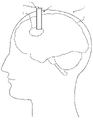
도 1은 수술할 부위를 갖는 환자의 두부 단면도;
도 2는 기단부에 카메라가 설치된 캐뉼러의 사시도;
도 3은 도 2의 캐뉼러의 전개 측면도;
도 4는 도 2의 캐뉼러의 평면도;
도 5는 카메라가 트랙에서 움직이는 캐뉼러 광실드의 측면도;
도 6은 기단부에 카메라가 설치된 캐뉼러의 카메라의 측면도;
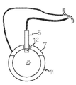
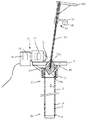
도 7은 기단부에 카메라가 설치된캐뉼러와 폐쇄관을 도 1의 환자의 혈종 안으로 삽입한 상태도;
도 8은 도 1의 환자에게 최소침습 수술을 하기 위해 카메라가 설치된 캐뉼러의 사용을 보여주는 도면;
도 9는 카메라를 캐뉼러 튜브에 쉽게 착탈하기 위한 다른 구조를 보여주는 도면;
도 10~11은 카메라가 캐뉼러 튜브에 고정되고 폐쇄관은 캐뉼러 튜브의 루멘 위의 공간에 접근할 경우에도 카메라를 통과하도록 개조된 카메라-캐뉼러 시스템의 사시도들;
도 12는 캐뉼러가 뇌조직에 삽입되어 있고, 캐뉼러 말단부가 혈종 가까이 있으며 폐쇄관 팁이 혈종 안으로 들어간 상태를 보여주는 도면;
도 13은 캐뉼러, 카메라, 폐쇄관 시스템의 상세도;
도 14는 카메라 어셈블리가 캐뉼러의 기단부에 고정된 상태로 폐쇄관을 제거하는 것을 보여주는 도면;
도 15~17은 뇌를 통해 시스템을 전진시키는 동안 카메라가 촬영한 영상들;
도 18~19는 도 12의 캐뉼러, 카메라, 폐쇄관 시스템에 사용될 폐쇄관 팁의 사시도와 단면도.1 is a cross-sectional view of the head of a patient having an area to be operated on;
2 is a perspective view of a cannula with a camera installed at its proximal end;
Figure 3 is an exploded side view of the cannula of Figure 2;
Fig. 4 is a plan view of the cannula of Fig. 2;
5 is a side view of the cannula optical shield with the camera moving on a track;
6 is a side view of a camera of a cannula with a camera installed at its proximal end;
7 is a view showing a state in which a cannula with a camera installed at the proximal end and an obturator tube are inserted into the hematoma of the patient of FIG. 1;
8 is a view showing the use of a cannula equipped with a camera to perform minimally invasive surgery on the patient of FIG. 1;
Fig. 9 shows another structure for easily attaching and detaching the camera to the cannula tube;
10-11 are perspective views of a camera-cannula system adapted to pass through a camera even when the camera is secured to the cannula tube and the obturator accesses the space above the lumen of the cannula tube;
12 shows a state in which a cannula is inserted into the brain tissue, the cannula distal end is close to the hematoma, and the obturator tip is retracted into the hematoma;
13 is a detailed view of the cannula, camera, and obturator system;
14 shows the obturator tube being removed with the camera assembly secured to the proximal end of the cannula;
15-17 are images taken by the camera while advancing the system through the brain;
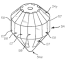
18 to 19 are perspective and cross-sectional views of a cannula, a camera, and a closure tip to be used in the closure system of FIG. 12;
도 1의 환자(1)의 뇌(3)에 수술이 필요한 혈종(2)이 있고, 캐뉼러(4)의 말단부가 혈종에 근접하게 캐뉼러를 뇌 안에 삽입했다. 캐뉼러의 근위부 림에 카메라(5)가 설치되어 캐뉼러 말단부로부터 혈종이나 다른 조직의 비디오나 정지영상을 구하고, 이때 카메라의 일부는 림에서 돌출한다.
도 2의 캐뉼러(4)의 캐뉼러 튜브(6)의 말단부(6d)는 환자의 신체 안으로 삽입되고, 기단부(6p)는 사용중에 신체 외부에 머무른다. 캐뉼러 튜브의 기단부(6p)d에 카메라(5)가 설치되고, 이 기단부에 장착부(7)가 고정된다. 다른 도면들에 자세히 도시된 카메라는 프리즘과 반사경이나 다른 미러구조나 광학요소를 갖고, 캐뉼러 튜브의 루멘(8)에서 돌출한다. 카메라가 루멘에 비해 작으면, 프리즘이나 반사경 없이 사용할 수 있고, 그 시선축을 캐뉼러의 종축선에 일치시킬 수 있다. 혈종이 잘 보이게 하고 혈종의 영상을 구하는데 필요한 빛은 캐뉼러 튜브의 말단부(6d)에 배치되거나 말단 개구부 가까이 배치된 LED와 같은 광원(9)에서 공급된다. 이런 광원이 기단부에 배치되고 빛이 루멘이나 광섬유(10)통해 전달될 수도 있고, 또는 캐뉼러가 투명재료로 구성될 경우 빛이 캐뉼러 튜브의 벽을 따라 말단부에서 나가 혈종을 비출 수도 있다. 장착부(7)의 링(11)은 근위 뷰포인트의 뷰로부터 빛을 차단하는 역할을 하는데, 빛이 근위부에서 직접 나오건 말단부로부터 캐뉼러 튜브를 통해 나오든 상관 없이 차단한다. 투과 캐뉼러 튜브의 근위단부에 광원들이 배치된 경우, 캐뉼러 튜브의 말단부(6d)는 캐뉼러 튜브(6)에서 빛이 나와 수술부위를 비추도록 성형되거나 가공되거나 처리될 수 있다. 예컨대, 말단부의 내측면 및/또는 외측면에서 빛이 나오도록 방출되도록 내측면이나 외측면을 연마하거나 코팅할 수 있다. 캐뉼러의 말단부를 향해 광원들이 배치될 경우, 광원을 고정하는 부위와 광원들에서 먼 부위는 수술부위를 더 잘 비추도록 투명하지만, 광원에서 가까운 캐뉼러 부위는 불투명하게 할 수 있다. 카메라와 광원에 전력을 공급하면서 카메라의 영상데이터를 디스플레이에 공급하는 케이블들을 배치하거나, 내장된 배터리를 이용해 장치에 전력을 공급하고 영상데이터를 디스플레이에 무선으로 전송할 수도 있다. The
도 3은 캐뉼러(4)의 측면도로서, 카메라(5)는 캐뉼러 튜브의 근위부 림에 배치되고, 프리즘이나 반사경(12)은 캐뉼러의 루멘(8)에서 돌출해있다. 도 4는 카메라(5)가 근위부에 설치되어 있는 캐뉼러(4)의 평면도이다. 도 3에서, LED(9)는 캐뉼러 튜브의 말단부(6d)나 그 부근에 배치되어 혈종(2)과 같은 수술부위를 비춘다. 3 is a side view of the
카메라를 반경 방향으로 슬라이딩하거나 피봇점을 중심으로 접히거나 장착부에서 완전히 분리되어 반사경(12)을 돌출위치에서 없앨 수 있도록 카메라를 장착부 안에 설치할 수도 있다. 도 5는 장착부(7)에 대해 카메라(5)가 슬라이딩 가능하게 설치되어 대기위치(13S)에서 사용위치(13A)로 움직이는 것을 보여준다. 카메라(5)가 사용위치(13A)에 있으면, 프리즘/반사경(12)은 일부나 전체가 루멘(8)에 의한 원통형 공간(14) 안으로 뻗어 캐뉼러 튜브의 말단 개구부의 수술부위의 시야를 방해하기는 해도, 루멘(8)을 이용한 소구경 수술도구(예; 흡입기나 분쇄기)의 방해를 최소화한다. 장착부(7)에 카메라(5)를 움직일 수 있게 연결하기만 하면 어떤 기술도 이용할 수 있다. 예컨대, 트랙(15)에 슬라이딩 가능하게 카메라를 설치할 경우, 트랙(15)이 카메라(5)를 장착부에 고정하고, 이 트랙을 통해 대기위치(13S)와 사용위치(13A) 사이를 카메라/프리즘 어셈블리가 움직이도록 하여, 프리즘이 루멘(8)이나 루멘으로 이루어진 공간(14) 안으로 뻗는 제1 위치에서 루멘이나 루멘 공간 밖에 머무는 제2 위치로 움직이도록 할 수 있다. 카메라를 16 지점에 피봇되게 연결해, 카메라 축선이 캐뉼러 튜브의 종축선에 수직인 제1 위치로부터 종축선에 비스듬한 제2 위치로 회전이 가능하게 함으로써, 프리즘이 루멘에 의한 원통형 공간(14) 밖에 머물도록 할 수도 있다. 또는 카메라를 수술중에 도구 없이 손으로 쉽게 착탈 가능하게 장착부에 연결할 수도 있는데, 예를 들면 카메라와 장착부의 채널 사이를 마찰결합하거나 걸쇠결합하거나 다른 방식으로 결합할 수 있다.The camera may be installed in the mounting portion so that the camera can be slid radially, folded around a pivot point, or completely separated from the mounting portion to remove the
도 6은 카메라(5)의 측면도이다. 카메라(5)는 프리즘이나 반사경(12), (이중렌즈 등을 포함한) 렌즈(17), 촬상소자(18) 및 제어시스템(19)을 포함한다. 렌즈(17)는 다른 광학요소들을 포함하는 광학어셈블리의 일부일 수 있다. 촬상소자(18)는 CCD 센서나 CMOS 센서와 같은 영상센서일 수 있다. 제어시스템(19)은 컨트롤러, 데이터처리 소자, 트랜스미터, 카메라를 제어하거나 카메라의 데이터를 전송하는 소자를 포함할 수 있고, 데이터 출력시스템이 장치에서 떨어져 위치할 수도 있다. 적당한 유선케이블이나 무선 트랜스미터를 이용해 카메라를 디스플레이나 전원에 연결할 수도 있다. 영상센서는 영상면을 갖고, 프리즘은 영상면에 나란한 빛을 영상면을 향하도록 영상면에 일치한다. 도시된 것처럼, 영상면은 캐뉼러 튜브의 종축선에 평행하고, 프리즘/반사경은 영상면에 수직인 선을 따라 배치되어 캐뉼러 튜브 말단부의 수술부위에서 영상면으로 빛을 비추도록 위치한다. 6 is a side view of the
도시된 실시예에서, 중심 종축선(20L)은 관체의 중심을 통과한다. 영상센서의 축선(20S)은 1차 시야축선으로서 센서 표면에 직각으로 뻗어 프리즘의 반경방향 표면을 교차한다. 도시된 것처럼, 중심 종축선과 영상센서 축선은 거의 직각으로 교차한다. 한편, 이 각도가 70°내지 110°또는 85°내지 95°범위에 있을 수도 있다. 물론 원하는 구성에 따라서는 이 각도가 90°보다 크거나 작을 수도 있다.In the illustrated embodiment, the central longitudinal axis 20L passes through the center of the body. The axis 20S of the image sensor is the primary viewing axis and extends perpendicular to the sensor surface and intersects the radial surface of the prism. As shown, the central longitudinal axis and the image sensor axis intersect at a substantially right angle. On the other hand, this angle may be in the range of 70° to 110° or 85° to 95°. Of course, depending on the desired configuration, this angle may be larger or smaller than 90°.
어떤 경우에도, 프리즘 시야축선(20F)은 프리즘으로부터 캐뉼러를 통해 말단부까지의 시야선인 2차 시야축선으로서 프리즘의 말단면과 교차하고 관체를 통해 축방향으로 표적조직을 향해 뻗는다. 경우에 따라서는, 프리즘 시야축선이 캐뉼러의 말단부 부근에서 캐뉼러의 중심종축선과 교차하거나, 캐뉼러의 말단부에서 4cm나 2cm 이내에 있을 수 있다. 프리즘은 캐뉼러 루멘의 내경의 약 25% 이내로 루멘에서 돌출하지만, 루멘의 내경의 15%나 10% 이내로 돌출할 수도 있다. 이런 이유로, 2차 시야축선은 일반적으로 중심종축선에 기울어져 있다. 사용되는 프리즘의 종류에 따라, 프리즘 시야축선이 프리즘의 말단 광학표면에 직각일 수 있는데, 반사를 위해 도면에는 직각 프리즘이 도시되어 있고, 이때 긴 표면은 예컨대 지붕으로 사용되며, 이 프리즘을 캐뉼러 루멘 위로 배치하여 말단 광학표면이 캐뉼러의 가로면에 대해 약간 기울어져 원하는 지점, 예컨대 캐뉼러의 말단부에서 캐뉼러의 중심종축선과의 교차점에서 프리즘 시야축선을 향하도록 할 수 있다. 시야각이 말단면에 직각이 아닌 다른 반사굴절 프리즘의 경우, 말단 광학면이 원하는 지점에서 프리즘 시야축선을 향하도록 기울일 수 있다. 펜타프리즘, 하프 펜타프리즘(프리즘 시야축선으로부터 빛을 45°로 구부려 영상센서 시야축선이 프리즘 시야축선이나 캐뉼러 종축선에 대해 약 45°로 배치되도록 하는 비반전 프리즘), 슈미트 프리즘(프리즘 시야축선으로부터 빛을 45°로 구부려 영상센서 시야축선이 프리즘 시야축선이나 캐뉼러 종축선에 대해 약 45°로 배치되도록 하는 반전 프리즘), 포로 프리즘(프리즘에 들어가는 빛을 프리즘에서 떨어져 평행한 경로로 움직여, 영상센서 시야축선을 프리즘 시야축선이나 캐뉼러 종축선에 평행하면서 반경방향으로 움직이는 반전 프리즘)이나 기타 프리즘 또는 이런 프리즘들의 조합을 포함해 다양한 프리즘들을 사용할 수 있는데, 예를 들면 Amici/Penta 프리즘 조합이나 말단부를 보는 긴 표면에 배치된 직각 프리즘을 이용해 직각 표면들이 반사면 역할을 하여 영상이 역병렬 경로를 따라 프리즘 시야축선을 향하도록 하되, 옵션 사항으로 제2 직각 프리즘과 쌍을 이뤄 영상을 평행하면서 이격된 경로로 또는 Bauerfeind 프리즘을 향하도록 할 수도 있고, 이런 프리즘들은 캐뉼러의 말단부에서 영상센서를 향해 빛을 반사하거나 움직인다.In any case, the prism visual axis 20F is a secondary visual axis, which is a visual line from the prism to the distal end through the cannula, intersects the distal face of the prism and extends axially through the body toward the target tissue. In some cases, the visual axis of the prism may intersect the central longitudinal axis of the cannula near the distal end of the cannula, or may be within 4 cm or 2 cm of the distal end of the cannula. The prism protrudes from the lumen to within about 25% of the inside diameter of the cannula lumen, but may project to within 15% or 10% of the inside diameter of the lumen. For this reason, the secondary visual axis is generally inclined to the central longitudinal axis. Depending on the type of prism used, the visual axis of the prism may be orthogonal to the distal optical surface of the prism, for reflection purposes a right angled prism is shown in the drawings, the elongated surface being used e. Positioned over the lumen, the distal optical surface may be tilted slightly relative to the transverse plane of the cannula to face the prism visual axis at a desired point, eg, the intersection with the central longitudinal axis of the cannula at the distal end of the cannula. For other catadioptric prisms where the viewing angle is not orthogonal to the distal plane, the distal optical surface can be tilted toward the prism viewing axis at a desired point. Pentaprism, half pentaprism (a non-inverting prism that bends light at 45° from the prism visual axis so that the image sensor visual axis is positioned at approximately 45° to the prism visual axis or cannula longitudinal axis), Schmidt prism (prism visual axis An inverting prism that bends the light from the prism at 45° so that the image sensor viewing axis is positioned at approximately 45° to the prism viewing axis or the cannula longitudinal axis A variety of prisms may be used, including inverting prisms that move the image sensor visual axis parallel to the prism visual axis or longitudinal cannula axis and move radially, or other prisms, or combinations of these prisms, for example the Amici/Penta prism combination or Using a right-angle prism placed on the long surface viewing the distal end, the right-angle surfaces act as reflecting surfaces to direct the image along the anti-parallel path to the prism viewing axis, optionally paired with a second right-angle prism to parallelize the image It may be directed in a spaced path or towards a Bauerfeind prism, which reflects or moves light from the distal end of the cannula towards the image sensor.
캐뉼러 튜브의 말단부에 배치된 광원에서 조명할 경우, 캐뉼러 튜브의 내벽에 배플들을 설치하면 내벽으로부터의 채광과 반사를 최소화할 수 있다. 이런 배플로는 루멘 안으로 약간 돌출해 튜브의 길이를 따라 배치된 돌기들이 있을 수 있는데, 이런 돌기들은 튜브의 기단부로 갈수록 간격이 좁아지고 말단부로 갈수록 간격이 넓어지는 것이 좋다. 도 3에 이런 돌기들(21)이 다수 도시되어 있지만, 이런 돌기들은 캐뉼러 튜브(6)와 일체이거나 튜브의 내벽에 접착이나 용접될 수도 있고, 튜브의 내벽 안에 삽입되거나 결합되는 코일이나 와이어일 수도 있으며, 코일이나 와이어는 말단부에 위치한 광원이나 카메라나 센서에 연결된 전선이나 데이터선을 포함할 수 있다.When illuminating from a light source disposed at the distal end of the cannula tube, baffles are installed on the inner wall of the cannula tube to minimize light and reflection from the inner wall. Such a baffle may have protuberances that protrude slightly into the lumen and are disposed along the length of the tube, preferably with protrusions that are narrower towards the proximal end of the tube and wider towards the distal end. Although a number of
도 7~8에서 보듯이, 폐쇄관(22)이 달린 캐뉼러(4)를 의사가 말단부(6d)가 수술할 조직(2)에 충분히 가까울 때까지 환자의 뇌 안으로 삽입한다. 이어서 캐뉼러(4)에 접근하여 수술부위가 보이도록 조명할 수 있도록 폐쇄관(22)을 제거한다. 이어서, 카메라(5)를 대기위치로부터 움직이거나 움직이면서 돌려, 프리즘을 루멘 위에 위치하도록 한다. 필요하다면, 촬상시스템을 움직여 수술부위가 보이도록 한다. 카메라를 제자리에 둔채, 의사가 카메라를 조작해 수술부위의 영상을 얻는다. 카메라의 영상데이터를 디스플레이(23)에 전송해 루멘(8)을 통해 구한 수술부위의 영상(24)을 제공한다. 이 영상은 정지영상(사진)과 비디오를 포함한다. 카메라를 배치한 뒤, 의사는 수술도구나 수술도구의 말단부를 루멘에 통과시키고, 그동안 카메라의 일부는 루멘(8) 위로 루멘이나 공간(14) 내부에 배치된다. 7-8, the surgeon inserts the
도 9는 캐뉼러(4)의 다른 구조로서, 캐뉼러 튜브(6)에 카메라(5)를 쉽게 연결/분리하기 위한 것이다. 카메라는 장착부(25)에 고정되고, 장착부는 캐뉼러 튜브에 착탈 가능하게 연결된다. 이 장착부는 이전 실시예의 장착부와 마찬가지로 링과 링 결합부를 갖고, 링 내부에 있는 제1 잠금요소인 홈(26)을 가지며, 캐뉼러 튜브의 기단부에 이에 대응하는 제2 잠금요소로서 플랜지(27)가 있고, 플랜지는 장착부의 홈에 끼워진다. 장착부는 필요하다면 캐뉼러 튜브 기단부에 카메라를 위치시키도록 캐뉼러에 스냅결합될 수도 있는데, 이때 프리즘은 캐뉼러 튜브의 벽에서 돌출해 루멘(8) 위로 배치된다. 이 장착부는 수술중에 도구 없이도 손으로 쉽게 연결분리할 수 있는 구조를 갖는다. 장착부와 캐뉼러 튜브의 외벽이나 내벽 사이에 마찰결합을 포함한 다른 착탈결합 수단, 또는 (캐뉼러 튜브 기단부와 장착부의 자석쌍에 의한) 자기결합, 스냅결합, 또는 장착부와 캐뉼러 기단부 사이의 걸쇠연결, 장착부와 캐뉼러 기단부 사이의 암수 나사결합과 같은) 나사결합, 베이넛 마운트, 장착부와 기단부 사이의 슬롯-핀 결합 등을 이용할 수도 있다.9 is another structure of the
또, 도 9는 도 3에 도시된 배플의 다른 예로서, 코일(28)을 보여주지만, 와이어를 사용할 수도 있다. 코일이나 와이어는 말단부의 전원이나 센서에 전기를 공급하는 전선을 포함하고, 이런 센서로부터 제어/디스플레이 시스템에 데이터를 전송하기 위한 데이터 케이블도 포함한다. Further, FIG. 9 shows a
도 10~11은 카메라(5)가 캐뉼러 튜브(6)에 착탈되지 않게 고정되고 폐쇄관(22)이 루멘 위로 공간에 도달할 때에도 카메라를 통과시키도록 개조된 카메라-캐뉼러 시스템을 보여준다. 도 10의 폐쇄관(22)은 기본적으로 전장에 걸쳐 직경이 동일하고 길이방향으로 뻗는 홈(29)을 갖는다. 이 홈의 크기는 루멘에서 돌출하는 프리즘을 수용할 정도이다. 이런 구조에서, 폐쇄관을 캐뉼러 튜브 안으로 삽입하고, 조립된 캐뉼러와 폐쇄관을 환자의 뇌 안으로 밀어내면서 캐뉼러를 정위치시킨다. 도 11의 폐쇄관(22)은 대직경 말단부(22d)와 소직경 로드(30)를 갖고, 대직경 말단부는 외경이 캐뉼러 튜브의 내경과 거의 같으며, 소직경 로드는 루멘 안에 쉽게 끼워진다. 카메라는 포스트(31)에 지지되고, 포스트는 캐뉼러 튜브의 기단부 개구부에서 카메라를 띄워놓되, 폐쇄관의 대직경 말단부(22d)의 길이에 비해 충분한 간격으로 떨어져 있어, 카메라를 움직이지 않고도 폐쇄관의 대직경 말단부(22d)를 루멘 안으로 삽입할 수 있도록 폐쇄관을 기울일 수 있다.10-11 show a camera-cannula system adapted such that the
도 12~19는 도 11과 비슷하게 캐뉼러와 카메라를 이용한 캐뉼러, 카메라, 폐쇄관 시스템을 보여주는데, 투명한 폐쇄관 팁을 통해 의사가 그 밑의 조직을 보면서 캐뉼러-폐쇄관을 뇌 안으로 삽입할 수 있다.12 to 19 show a cannula, camera, and obturator system using a cannula and a camera, similar to FIG. 11, through which the doctor can insert the cannula-obturator into the brain while viewing the underlying tissue through the transparent obturator tip. can
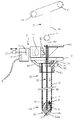
도 12의 환저(1)의 뇌(3) 안의 혈종(2)은 수술해야되는 부위로서, 캐뉼러(4)를 뇌 안에 삽입해 그 말단부를 혈종에 근접시킨다. 카메라(5)는 캐뉼러의 림에 설치되고, 림에서 돌출한 카메라 부위는 루멘 위에 위치하면서 말단부의 비디오나 정지영상을 획득하고, 이런 영상은 캐뉼러내 폐쇄관 팁의 영상이나 캐뉼러 말단부의 혈종이나 뇌조직이나 CSF(뇌척수액; cerebrospinal fluid)나 다른 조직의 영상을 포함한다. 도 12~13에서 보듯이, 캐뉼러는 카메라(5)와 광원이 달린 캐뉼러 튜브(6)와, 캐뉼러의 기단부에 고정된 장착부(7)를 포함한다. 카메라는 캐뉼러 튜브의 루멘(8)에서 돌출하는 프리즘, 반사경, 기타 미러 구조나 광학요소를 포함한다. 카메라가 캐뉼러의 기단부에 영구 고정되거나(도구나 분해 없이는 쉽게 제거 못함), 착탈 고정될 수 있다(즉, 특수 공구나 분해 없이도 쉽게 착탈됨). 프리즘, 반사경, 거울과 같은 카메라 어셈블리의 일부분은 루멘으로 이루어진 원통형 공간(14) 안으로 캐뉼러의 기단부 너머로 뻗으면서, 이 기단부에서는 떨어져 있으며, 공간(14) 안으로 약간만 돌출하여(예; 루멘의 내경의 25% 정도만, 바람직하게는 15%나 10% 정도만), 원통형 공간(14) 안으로 카메라 어셈블리 요소의 들어가고 카메라어셈블리의 기단부 간격에 비해 상대적인 크기를 갖는 폐쇄관 팁이 기울어져 카메라 어셈블리 요소의 침입을 방지하며 캐뉼러의 가단부 안으로 밀리지 않도록 한다. 캐뉼러는 손가락나사나 미끄럼 포스트(32)처럼 손으로 움직여 영상센서를 반경방향 안쪽으로나 바깥쪽으로 움직이면서 캐뉼러 내부나 캐뉼러의 말단부 너머에서 여러 깊이로 카메라의 초점을 조절하는 간단한 초점수단을 포함할 수 있다.The
혈종을 잘 보이게 하고 영상을 구하는데 필요한 빛은 캐뉼러 튜브의 말단부(6d)나 말단 개구부 부근에 배치된 LED와 같은 광원(9)에 의해 공급된다(도 13 참조). 캐뉼러 자체는 불투명하고 비반사성이거나 반사방지 코팅된 것이 바람직하다. LED를 기단부에 배치하고 광섬유를 통해 빛을 전달하거나, 캐뉼러가 투명한 재죠로 구성되었을 경우 캐뉼러 튜브의 벽을 통해 빛을 아래로 전파해 말단부로부터 혈종을 비출 수도 있다. 장착부(7)의 링(11)은 근위 뷰포인트의 뷰로부터 빛을 차단하는 역할을 하는데, 빛이 근위부에서 직접 나오건 (투명할 경우) 말단부로부터 캐뉼러 튜브를 통해 나오든 상관 없이 차단한다. 루멘(8) 위에 있는 프리즘, 반사경(2)에 의해 카메라는 캐뉼러의 종축선을 따라 내려볼 수 있고, 카메라가 크면 시야축선이 캐뉼러의 종축선에 수직이 되도록 설치해야 한다. 캐뉼러 튜브의 기단부에 광원이 있을 경우, 캐뉼러 튜브의 기단부(6d)는 캐뉼러 튜브(6)를 통해 빛이 수술부위를 비추도록 성형하거나 가공하거나 처리할 수 있다. 예를 들어, 단부 내면이나 외면을 통해 빛이 나오도록 이들 표면을 연마하거나 가공할 수 있다. 카메라와 광원에 전기를 공급하면서 카메라에서 디스플레이로 영상데이터를 전송하는 케이블을 사용하거나, 장치에 내장된 배터리를 이용해 전기를 공급하고 무선으로 디스플레이에 데이터를 전송할 수도 있다.The light needed to visualize the hematoma and obtain images is supplied by a
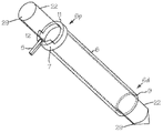
도 13의 폐쇄관(33)은 폐쇄관 팁(34), 샤프트(35), 핸들(36) 및 장착부(37)를 포함한다. 폐쇄관 팁은 원추형 볼록 말단면(34d), 원추형 볼록 기단면(34p) 및 축방향으로 짧은 원주면(34c)을 갖는 속이 찬 구조로서, 원주면 구역의 (캐뉼러의 횡단면 직경에 일치하고 종축선에 수직인 평면을 따른) 외경은 캐뉼러의 내경과 거의 일치하면서도 루멘을 통해 길이방향으로 팁을 쉽게 움직일 수 있을 정도의 크기를 갖는다. 팁은 렌즈 역할을 하여, 화살표(38)로 표시된 빛이 팁에서 굴절되어 팁을 통과하는 모든 "영상"이 반전된다. 팁의 단면이 직사각형일 수도 있고, 이때 중앙 원통부와 말단과 기단의 원추부를 갖는다. 도면들에 도시된 형상은 양쪽 원추형이지만, 구형, 회전타원체, 장축타원체(미식축구나 럭비 볼), 편원타원체, 달갈형 등의 형상을 가질 수도 있다. 말단부가 테이퍼진 뾰족한 팁은 뇌에 사용하기에 좋지만, 그 끝은 무디거나 라운드형일 수 있다. 말단면과 기단면이 종축선이나 횡축선을 중심으로 대칭일 필요도 없다. 예컨대, 말단면은 뾰족하면서 단면이 직사각형이고, 기단면은 뾰족하면서 단면이 원형이거나 평탄할 수 있다.The
폐쇄관 팁이 불투명하지 않고 투명하고, 광학적으로 빛을 투과할 수도 있다. 팁의 투명도는 가시광 스펙트럼 범위내에서 말단면에 접촉한 조직의 컬러를 보내서, 광원에 의한 조명의 휘도에서 팁 주변의 조직의 컬러를 팁의 기단면에서 보내진 빛과 구분할 수 있을 정도의 투과광을 카메라나 의사의 눈에 제공할 정도이면 된다. 팁의 재료는 유리, 실리카, 아크릴릭, 폴리카보네이트, 실리콘, 나일론, 폴리아미드, 코폴리머, 기타 의료기기에 사용할 수 있는 다른 재료이다. 팁의 표면은 연마나 코팅처리될 수 있다. 폐쇄관 팁이 때로는 수술하는 동안 형광투시경으로 구분할 수 있도록 방사선 불투과 물질(예; 백금 입자 등)을 함유하거나, 혈종이나 CSF를 탐지하고 주변 뇌조직과 구분하기 위해 pH센서나 저항센서나 힘센서, 글루코스 센서와 같은 센서를 포함할 수도 있다. The obturator tip may be transparent rather than opaque, and may optically transmit light. The transparency of the tip sends the color of the tissue in contact with the distal surface within the range of the visible light spectrum, and transmits light enough to distinguish the color of the tissue around the tip from the light sent from the proximal surface of the tip under the luminance of illumination by the light source. It's enough to give it to the doctor's eye. The material of the tip is glass, silica, acrylic, polycarbonate, silicone, nylon, polyamide, copolymer, and other materials that can be used in medical devices. The surface of the tip may be polished or coated. Obturator tips sometimes contain radiopaque material (e.g., platinum particles, etc.) to be distinguishable under fluoroscopy during surgery, or pH, resistance, or force sensors to detect hematomas or CSFs and differentiate them from surrounding brain tissue. , may include a sensor such as a glucose sensor.
기단부 방향으로 갈수록 직경이 작아져 테이퍼지는 팁의 기단면은 다른 장치를 위해 팁을 빼내는데 도움이 되는 형상을 갖기도 한다. 도 14에서 보듯이, 볼록면은 카메라 간격을 허용하는데, 폐쇄관 샤프트를 캐뉼러의 종축선 반대쪽으로 약간 기울이면 카메라 어셈블리의 돌출 프리즘의 방해를 받지 않고 폐쇄관을 빼낼 수 있다.The proximal face of the tip, which tapers in diameter towards the proximal end, may have a shape conducive to extracting the tip for other devices. As shown in FIG. 14, the convex surface allows for camera spacing, and a slight tilt of the obturator shaft away from the longitudinal axis of the cannula allows the obturator to be withdrawn without obstruction by the protruding prism of the camera assembly.
샤프트(35)는 속이 찬 로드나 튜브이고, 캐뉼러 루멘에 비해 직경이나 횡단면적이 작아 캐뉼러 근단부에서 팁의 근단면을 볼 수 있다. 튜브일 경우, 수술항법장치로 감지할 수 있는 수동 마커가 달린 수술항법 탐침(39)을 샤프트의 루멘에 끼우면, 어셈블리를 안내하는데 유용하다. 수술항법 탐침의 로드(40)를 샤프트의 루멘에 끼우면, 조립상태의 캐뉼러와 폐쇄관과 탐침을 수술항법장치로 추적할 수 있는데, 이때 말단 팁의 정확한 위치의 도움으로 프레임(42)의 마커(41)를 추적한다. 샤프트(35)에 뉴로 스타버스트 연결을 끼울 수도 잇다. 샤프트의 단면은 원형이지만, 정사각형이나 타원형일 수도 있고, 그 단면적이 캐뉼러의 내경에 비해 작아 캐뉼러의 기단부에서 팁의 기단면을 볼 수 있을 정도이기만 하면 된다. 샤프트가 하프파이프 형상일 수도 있는데, 그 외경은 캐뉼러의 내경과 거의 일치하고, 하프파이프를 캐뉼러 어셈블리 반대쪽에 배열하며, 캐뉼러 루멘의 대부분을 비워두어 캐뉼러의 기단부에서 팁이 보이도록 한다. The
폐쇄관 장착부(37)의 림에 있는 키홈(44)은 스트럿(45)이나 카메라 마운트의 다른 구조나 캐뉼러 림이나 다른 요소에 마찰결합하는 크기를 갖는다(도 14 참조). 캐뉼러의 노치와 장착부의 결합 레일이나 캐뉼러의 채널이나 구멍에 끼워지는 장착부의 핀이나 림과 같은 다른 적당한 결합수단을 이용할 수도 있다. 이런 결합수단은 캐뉼러에 대한 폐쇄관의 길이방향 이동을 제한하여, 결합수단이 캐뉼러에 고정되면 폐쇄관 말단면이 캐뉼러 말단부에서 돌출하도록 하는 것이 좋다. 키홈이나 노치와 같은 결합수단이 팁의 회전위치를 등록하는 수단 역할을 할 수도 있는데, 이 경우 팁에 표시를 하여 의사가 어셈블리의 기단부의 구조에 대해 팁을 통해 구분할 수 있는 위치를 확인하도록 한다. The
카메라(5)는 프리즘912), 렌즈(17), 촬상소자(18) 및 제어시스템(19)을 포함한다. 렌즈(17)는 다른 광학요소들을 포함하는 광학 어셈블리의 일부일 수 잇다. 예컨대, 프리즘과 센서 사이, 바람직하게는 프리즘과 렌즈 사이의 광경로에 소형조리개를 배치할 수 있는데, 이는 1.0~2.0mm 범위나 1.5mm 정도의 직경을 갖는 조리개를 포함해 프리즘의 기단면에 시트나 마스크를 붙여 이루어진다. 촬상소자(18)로는 CCD 센서나 CMOS 센서와 같은 이미지센서가 좋다. 제어시스템(19)은 컨트롤러, 데이터처리 소자, 트랜스미터, 카메라를 제어하거나 카메라의 데이터를 전송하는 소자를 포함할 수 있고, 데이터 출력시스템이 장치에서 떨어져 위치할 수도 있다. 적당한 유선케이블이나 무선 트랜스미터를 이용해 카메라를 디스플레이나 전원에 연결할 수도 있다. 영상센서는 영상면을 갖고, 프리즘은 영상면에 나란한 빛을 영상면을 향하도록 영상면에 일치한다. 도시된 것처럼, 영상면은 캐뉼러 튜브의 종축선에 평행하고, 프리즘은 영상면에 수직인 선을 따라 배치되어 캐뉼러 튜브 말단부의 수술부위에서 영상면으로 빛을 비추도록 위치한다. The
도 14는 카메라 어셈블리가 캐뉼러의 기단부에 고정되어 있는 동안 폐쇄관을 제거하는 것을 보여준다. 팁의 테이퍼형 기단면 때문에 폐쇄관을 꺼낼 수 있는데, 그동안 카메라/프리즘 어셈블리는 캐뉼러의 루멘 위로 돌출하면서 제자리에 있다. 폐쇄관을 캐뉼러의 종축선 반대쪽으로 간단히 기울여 카메라와 프리즘을 꺼내도록 한다. 팁의 기단면이 테이퍼형이 아니면, 폐쇄관을 제거할 수 있도록 루멘 위의 원통형 공간을 비우도록 카메라 어셈블리를 잠깐 제거할 수 있다.Figure 14 shows the obturator tube removed while the camera assembly is secured to the proximal end of the cannula. The tapered proximal surface of the tip allows the obturator to be withdrawn while the camera/prism assembly protrudes over the lumen of the cannula and stays in place. Simply tip the obturator away from the longitudinal axis of the cannula to eject the camera and prism. If the proximal surface of the tip is not tapered, the camera assembly can be removed briefly to clear the cylindrical space above the lumen to allow removal of the obturator.
도 13에서 보듯이, 캐뉼러의 말단부(6d)가 수술할 조직(2)에 충분히 가까울 때까지 폐쇄관(33)이 달린 캐뉼러(4)를 환자의 뇌 안으로 삽입한다. 캐뉼러와 폐쇄관을 삽입하는 동안, 의사는 카메라와 제어시스템을 조작해 캐뉼러 말단부의 구조와 캐뉼러 루멘의 영상을 디스플레이에 나타나도록 한다. 카메라(5)로부터의 영상데이터는 디스플레이(50)로 전송되어 루멘(8)과 폐쇄관 팁의 기단면을 통해 캐뉼러 말단부의 구조의 영상(51)을 제공한다. 카메라로부터 영상데이터를 받아 디스플레이로 전송하면서 마커, 커서, 환자 데이터의 표지와 같은 추가 영상들을 디스플레이에 추가하기도 하는 제어시스템에 의해 디스플레이가 조작될 수 있다. 캐뉼러 루멘이 대형이면, 의사가 폐쇄관 팁의 기단면을 직접 보면서 팁의 말단면에 가까운 뇌나 혈종을 볼 수 있다. As shown in FIG. 13, the
도 15~16는 뇌에 시스템을 전진시키면서 카메라로 찍은 영상들을 보여준다. 이 영상들은 폐쇄관의 말단 팁을 밀어내는 동안 뇌를 통해 혈종을 향해 캐뉼러의 말단부로부터 뻗는 폐쇄관의 말단면으로 캐뉼러 안에 배치된 것을 의사가 본 것을 보여준다. 이들 영상은 건강한 뇌조직 층 밑으로 약간은 깊이 있는 혈종을 향해 삽입하면서 찍은 것이다. 뇌 안으로 처음 삽입할 때, 팁이 건강한 뇌조직을 통과하면서 의사는 백색이나 다른 색(아이보리, 뼈, 린넨 등의 각종 음영)으로 보이는 "영상"을 본다. 각각의 영상은 폐쇄관 샤프트(35)와 폐쇄관 팁 기단면(34p)과 캐뉼러 벽면(53)의 일부의 영상을 포함한다. 이 영상은 팁 기단면의 외주부를 enffjTK는 링(54)으로 보인다. 캐뉼러나 폐쇄관상의 인덱스나 (인덱스가 있거나 없는) 카메라에 대한 소정의 위치에 해당하는 마커(55)를 운용소프트웨어를 이용해 디스플레이에 표시해, 캐뉼러와 폐쇄관의 위치에 대한 디스플레이 영상의 관계를 의사에게 알려줄 수 있다. 이 인덱스는 예컨대 캐뉼러의 원주 위치이고, 마커는 카메라 반대쪽 위치로 디스플레이에 표시될 수 있지만, 마커는 인덱스에 대한 모든 소정의 관계로 디스플레이에 표시될 수 있다. 인덱스는 캐뉼러나 폐쇄관의 임의의 특징일 수도 있다. 이런 특징들이 도 15~17에 도시되어 있다. 이런 영상들에서 볼 수 있는 다른 특징으로는 영상 링(54) 내부의 밝은 링(56)과, 폐쇄관 샤프트를 폐쇄관 팁에 고정하기 위한 에폭시 링(57)이 있다.15-16 show images taken by the camera while advancing the system to the brain. These images show what the surgeon sees placed inside the cannula while pushing the distal tip of the obturator into the distal face of the obturator extending from the distal end of the cannula through the brain toward the hematoma. These images were taken while inserting into a hematoma slightly deeper under a layer of healthy brain tissue. When first inserted into the brain, as the tip passes through healthy brain tissue, the doctor sees "images" that appear white or other colors (various shades of ivory, bone, linen, etc.). Each image includes an image of the
첫 삽입시, 팁이 혈종 위에 있는 건강한 뇌조직에 들어가면서 링(54)이 백색으로 나타나고, 의사는 백색으로 보이는 뇌조직 "영상"을 본다. 팁이 혈종에 들어가면서 링(54)이 적색으로 바뀌고 의사에게 보이는 혈종 영상은 적색이나 흑색으로 보인다. 이것이 도 16에 도시되어 있다. 팁이 혈종의 가장자리에 있으면, 이 "영상"은 뇌의 색상인 백색의 원주부와, 혈액색인 적색/흑색의 원주부, 및 팁과 뇌조직 사이의 혈액 두께에 따라 둘다의 여러 음영들을 품고있으며, 예를 들어 혈종 가장자리 가까운 팁의 말단면의 원주 구역에 대해서는 팁의 기단면을 통해 전송된 해당 영상이 핑크색이거나 혈액 음영과 뇌 음영이 섞인 것이 된다. 의사는 (도 15와 비슷한 영상으로 표시된 것처럼) 팁의 가단면으로부터 뇌조직 영상이 다시 보일 때까지 혈종 안으로 들어간 팁을 안으로 더 밀어넣어 혈종의 (캐뉼러와 두골의 인입점에 대한) 말단 가장자리를 결정할 수 있다. 의사는 뇌조직 영상이 링(54)의 한쪽에 보일 때까지 조립된 캐놀라와 폐쇄관을 기울이면서 팁을 옆으로 움직여 혈종의 가로 크기(즉, 캐뉼러의 종축선에 직각 방향의 폭)를 판단할 수 있다. 이 영상이 도 17의 영상이다. 이 영상은 도 12~13에 도시된 구성처럼 팁에 의해 반전될 것이지만, 디스플레이 시스템이나 프리즘/반사경(12)과 같은 반전 프리즘에 의해 반전될 수도 있다. 도 17과 같이, 폐쇄관 팁의 기단면이나 말단면에 기준 마커(58)나 다른 표시자가 제공될 수 잇다. 이런 기준 마커를 이용해 의사는 카메라 시야축선에 대한 폐쇄관의 방향을 결정하거나, 영상이 반전 없이 디스플레이되거나(이런 영상은 폐쇄관 팁의 렌즈효과로 실제로는 그 밑의 조직의 반전영상이다) 반전되어 디스플레이되어(이런 영상은 렌즈효과로 반전된 뒤 제어시스템에 의해 영상이 반전된 다음 구해진 제대로 된 영상이다) 그 밑의 조직 구조에 해당함을 확인할 수 있다. 제어시스템은 폐쇄관 팁의 기단면의 감지된 영상에 기준 마커가 있거나 없는 것을 결정하고, 기준 마커를 감지하면 감지된 영상에 관해 반전된 현재의 영상을 생성해 디스플레이에 제공하거나, 기준 마커가 없으면 반전되지 않은 영상을 생성하도록 프로그램된다. 가단면 영상이 제어시스템에 의해 반전되었을 때, 기잔면의 반전 영상과 함께 반전 영상내 기준 마커가 디스플레이되어, 이 영상이 반전된 것으로 상하좌우 방향이 캐뉼러에 대해 반대임을 의사에게 표시해준다. 도시된 예에서, 기준 마커가 비대칭 형상의 문자 B이기 때문에 그 반전이 명확하다. 기준 마커는 제어시스템이 인식할 수만 있으면, 바코드나 도트 배열과 같이 어떤 형태도 취할 수 있지만, 비대칭인 것이 바람직하다. 기준 마커는 제어시스템에 의해 사용될 수도 있는데, 폐쇄관 마운트와 관련되어 기준 마커가 카메라와 소정의 관계로 위치할 경우, 캡처된 영상의 방향을 결정하고, 디스플레이된 영상이 캐뉼러 시스템의 구조적 특징들에 대응하도록 영상을 회전시켜, 의사가 영상을 제대로 번역하는데 도움을 줄 수 있다. Upon initial insertion,
투명한 폐쇄관 팁 내부에 길이방향으로 뻗는 여러개의 불투명한 구조들을 배치하거나 불투명한 팁 내부에 길이방향으로 뻗는 여러개의 투명한 구조들을 배치해 말단면의 빛이 투명한 구조들을 통해 전파되도록 하는 전체적인 투명한 팁을 갖도록 하여(이 경우 도 1~3의 단일 구조의 반전을 피할 수 있음), 영상 반전을 피하도록 폐쇄관 팁을 구성할 수도 있다. 이것을 도 18이 보여주는데, 여기서는 폐쇄관 팁(34)의 말단면(34d)에서부터 원주면(34c)을 따라 기단면(34p)까지 다수의 투명 요소들(59)이 뻗어있다. 이런 요소들은 말단면부터 기단면까지 길이방향으로 뻗어있는 불투명 요소들(60)에 의해 분리되어 있거나 이산된 불투명 요소들에 직접 맞닿게 배치된 이산 요소들이어서, 각각의 투명 요소를 통해 전체적인 영상의 반전 없이 말단면부터 기단면까지 빛이 투과된다. 이런 빛투과 투명 요소들은 도시된 것처럼 원주면의 외측면까지 뻗거나, 원주면 밑에 매립될 수 있다. 도 19는 폐쇄관 팁(34)의 다른 비반전 구성을 보여준다. 이 폐쇄관 팁은 원추형 볼록 말단면(34d), 도 13에 도시된 원추형 볼록 기단면(34p)이 없이 축방향으로 짧은 원주면(34c), 기단면에 있으면서 팁의 기단부로부터 말단면까지 원주벽 부위(34w) 사이로 QJe으면서 원주면의 길이부에 있는 환형 홈(61), 및 팁의 기단부로부터 뻗는 소켓(62)과, 폐쇄관 샤프트(도 13의 35)가 삽입되는 보어(63)를 포함한다.By arranging several opaque structures extending longitudinally inside the tip of a transparent closure tube, or by placing several transparent structures extending longitudinally inside the opaque tip, the overall transparent tip allows the light of the end face to propagate through the transparent structures. (In this case, inversion of the single structure of FIGS. 1 to 3 can be avoided), the obturator tip may be configured to avoid image inversion. This is shown in FIG. 18, where a plurality of transparent elements 59 extend from the
이상 설명한 실시예에서, 적어도 4개의 광원을 관체에 배치할 수 있지만, 경우에 따라서는 적어도 10개, 15개, 20개, 30개 또는 그 이상의 LED와 같은 광원들을 배치할 수도 있다. 일례로 적어도 35개나 40개의 LED들을 관체에 설치해 중심 루멘에 노출시킬 수 있다. 이들 LED의 전부나 일부는 직각 LED일 수 있다.In the embodiment described above, at least four light sources may be disposed in the body, but in some cases, at least 10, 15, 20, 30 or more light sources such as LEDs may be disposed. As an example, at least 35 or 40 LEDs can be installed in the body and exposed in the central lumen. All or some of these LEDs may be right angle LEDs.
관체의 말단부로부터 길이의 50%, 30%, 20%, 10% 또는 그 미만의 길이내에 광원들을 배치할 수 있고, 경우에 따라서는 말단부로부터 5cm, 3cm, 2cm 또는 1cm 이내에 배치할 수도 있다. 다수의 광원들이 공통의 횡단면에 놓이거나, 링형 광원들이 공통의 횡단면에 놓일 수 있는데, 이는 링의 광원들이 횡단면의 약 ±1cm나 0.5cm 또는 그 미만 내에서 축방향향으로 작은 위치변동이 가능함을 의미한다. The light sources may be placed within 50%, 30%, 20%, 10% or less of the length from the distal end of the tube, and in some cases may be placed within 5 cm, 3 cm, 2 cm or 1 cm from the distal end. Multiple light sources can be placed on a common cross-section, or ring-shaped light sources can be placed on a common cross-section, which means that light sources in a ring are capable of small positional variations axially within about ±1 cm or 0.5 cm or less of the cross-section. it means.
관체에 제1 말단 광원 링과 제2 기단 광원 링을 배치할 수도 있고, 그 사이에 제3의 중간 광원 링을 배치할 수도 있다. 이들 링은 적어도 2cm 간격으로 또는 3cm, 4cm 또는 그 이상의 간격으로 분리될 수 있다.The first end light source ring and the second proximal light source ring may be disposed on the tube body, and a third intermediate light source ring may be disposed between them. These rings may be separated by at least 2 cm, or by 3 cm, 4 cm or more.
관체의 말단부에 하나의 광원이나 광원 링만 있으면, 관체의 말단부에서 루멘 안으로 혈액이 들어가면 이 광원을 방해할 수 있다. 루멘의 길이를 EK라 기단부에서 떨어져 하나 이상, 바람직하게는 2개 이상의 2차 광원들이 있으면 말단부 광원들이 방해를 받아도 빛을 연속 비출 수 있다.If there is only one light source or light ring at the distal end of the tube, blood entering the lumen at the distal end of the tube can obstruct this light source. If the length of the lumen is EK and one or more, preferably two or more secondary light sources are separated from the proximal end, light can be continuously emitted even if the distal light sources are obstructed.
이 시스템은 뇌내출혈(ICH)을 촬영하기 위해 열적으로 안정된 시스템으로 구성된다. 이 경우, 말단부와 기단부와 루멘을 갖는 기다란 관체; 관체의 길이의 30%나 20%나 10% 이내의 말단부에 설치된 다수의 LED 광원들; 및 관체의 기단부에 설치된 센서/카메라가 장치에 포함된다. 루멘은 ICH(뇌내출혈)에 대한 처치를 하면서 ICH 부위를 보도록 할 수 있다. 적어도 3000 루멘 정도의 강도로 60분 이상 STP로 주변 공기중에서 LED 광원들이 작동하면 관체의 말단부의 온도가 22℃, 17℃ 또는 10℃ 이하로 상승한다. 3500 내지 4500 루멘 범위내에서 LED가 동작해 관체의 말단부의 온도가 22℃, 17℃ 또는 10℃ 이하로 상승하면 좋다고 본다. (보통 30분 내지 60분의) ICH를 치료하는데 필요한 시간대의 체내 장치의 동작으로 말단부에 접하고 있는 조직의 온도는 45℃ 이하로, 바람직하게는 43℃나 40℃ 이하로 상승하는 것이 좋다.This system consists of a thermally stable system for imaging intracerebral hemorrhage (ICH). In this case, an elongated tubular body having a distal end, a proximal end and a lumen; A plurality of LED light sources installed at the distal end within 30%, 20% or 10% of the length of the tube; and a sensor/camera installed at the proximal end of the tubular body. The lumen can be used to view the ICH site while administering treatment for ICH (intracerebral hemorrhage). When the LED light sources are operated in the ambient air at an intensity of at least 3000 lumens at STP for more than 60 minutes, the temperature at the distal end of the tube rises below 22°C, 17°C or 10°C. It is good if the LED operates within the range of 3500 to 4500 lumens and the temperature of the end of the tube rises below 22 ° C, 17 ° C or 10 ° C. It is recommended that the operation of the internal device for the time period necessary to treat ICH (usually 30 to 60 minutes) raises the temperature of the tissue in contact with the distal end to less than 45°C, preferably less than 43°C or 40°C.
촬영 장치가 말단부부터 관체의 길이의 30% 이내에 3개 이상의 LED나, 10개, 20개, 30개 또는 그 이상의 LED들을 갖출 수 있다. LED는 동일 횡단면에 위치하거나, 적어도 하나나 다수의 LED들이 관체의 길이를 따라 축방향으로 떨어져 있는 첫번째 내지 두번째, 경우에 따라서는 세번째나 네번째의 횡단면들 각각에 배치될 수도 있다. 하나 이상, 바람직하게는 다수의 LED들은 직각 LED이다. 적어도 하나의 LED는 300nm 내지 1mm 정도의 파장으로, 바람직하게는 390nm 내지 700nm 범위의 파장으로 동작한다. 첫번째 LED 세트는 가시광 범위의 첫번째 파장에서 동작하고, 두번째 LED 세트는 적외선과 같은 다른 두번째 파장에서 동작할 수도 있다. 한편, 하나 이상이나 다수의 LED들이 첫번째와 두번째 파장들 사이를 가변할 수도 있다. The imaging device may have 3 or more LEDs, 10, 20, 30 or more LEDs within 30% of the length of the tube from the distal end. The LEDs may be located on the same cross-section, or at least one or a plurality of LEDs may be disposed on each of the first to second, third or fourth cross-sections spaced apart in the axial direction along the length of the body. At least one, preferably multiple LEDs are rectangular LEDs. At least one LED operates with wavelengths on the order of 300 nm to 1 mm, preferably in the range of 390 nm to 700 nm. The first set of LEDs may operate at a first wavelength in the visible light range, and the second set of LEDs may operate at a second other wavelength, such as infrared. On the other hand, one or more or multiple LEDs may be tunable between the first and second wavelengths.
광학요소를 센서와 말단부 사이의 광경로 내에서 기단부에 지지되도록 할 수도 있다. 이 광학요소는 프리즘과, 말단부를 향한 표면을 갖는 거울이나 다른 반사경을 포함할 수 있다. 중심 루멘은 종축선을 갖고; 촬상 센서는 1차 시야축선을 가지며; 이런 종축선과 1차 시야축선은 광학요소에서 소정의 각도로 교차한다. 이 각도는 0도보다는 크고, 경우에 따라 70도 내지 110도 사이나, 85도 내지 95도 사이에 있을 수 있다. 프리즘은 관체를 통과하는 빛을 휘어 센서를 향하게 한다.An optical element may be supported on the proximal end in the optical path between the sensor and the distal end. This optical element may include a prism and a mirror or other reflector having a distal end facing surface. the central lumen has a longitudinal axis; The imaging sensor has a primary viewing axis; This longitudinal axis and the primary viewing axis intersect at an angle at the optical element. This angle is greater than 0 degrees, and in some cases may be between 70 and 110 degrees, or between 85 and 95 degrees. The prism bends the light passing through the tube and directs it to the sensor.
프리즘의 말단면은 중심 루멘의 내경의 25% 이내, 바람직하게는 15%나 10% 이내로 루멘 위로 돌출한다. 프리즘은 관체에 고정되거나 조정 가능하게 설치된다. 프리즘 시야축선(2차 시야축선)은 프리즘의 말단 광학면에 직각으로 뻗고, 관체의 중심 종축선에 평행하지 않으며, 관체의 길이의 80~120% 범위내의 간격으로 기단부에서 떨어진 지점에서, 바람직하게는 관체의 길이의 95~105% 범위내의 간격으로 기단부에서 떨어진 지점에서 중심 종축선과 교차할 수 있다. The distal face of the prism protrudes above the lumen within 25% of the inner diameter of the central lumen, preferably within 15% or 10%. The prism is fixed or adjustable to the tube body. The prism visual axis (secondary visual axis) extends at right angles to the distal optical surface of the prism, is not parallel to the central longitudinal axis of the body, and is separated from the proximal end at intervals within the range of 80 to 120% of the length of the body, preferably may intersect the central longitudinal axis at points away from the proximal end at intervals within the range of 95 to 105% of the length of the body.
센서는 가시광 파장이나 적외선과 같은 비가시광 파장의 어느 하나나 둘다로 영상을 캡처할 수 있다. 한편, 가시광에 민감한 제1 센서와 적외선에 민감한 제2 센서를 이용할 수도 있다. 반사광을 2개의 센서 각각에 향하게 하는 빔스플리터를 사용할 수도 있다. 디지털 줌, 콘트라스트, 휘도, 포화도, 샤프니스, 화이트 밸런스, 수평수직 정렬, 회전을 제어하기 위해 센서가 제어회로를 구비할 수도 있다.The sensor may capture images in either or both visible light wavelengths and non-visible light wavelengths, such as infrared. Meanwhile, a first sensor sensitive to visible light and a second sensor sensitive to infrared light may be used. A beam splitter may be used to direct the reflected light to each of the two sensors. The sensor may include control circuitry to control digital zoom, contrast, luminance, saturation, sharpness, white balance, horizontal and vertical alignment, and rotation.
시스템 자체가 의료 시각화-접근 장치일 수도 있다. 이 경우, 이 장치는 기단부와 말단부를 갖고 작동 채널이 관통되어 있는 기다란 관체; 및 기단부에 설치되고, 작동 채널을 통해 빈 공간으로 전파된 영상을 캡처하는 센서를 포함하며, 센서와 작동 채널의 관계는 고정되며, 작동 채널을 통해 수술기구의 조작과 시각화가 동시에 이루어질 수 있다. 즉, 의사가 흡입기나 분쇄기와 같은 기구를 카메라를 제거하지 않고도 삽입하면서 카메라로 찍은 영상을 계속 볼 수 있고, 그동안 캐뉼러의 말단부 부근의 수술부위에 대한 기구 팁을 조작할 수 있다. 이 장치는 작동 채널로부터의 영상 데이터를 센서로 향하게 하는 프리즘이나 거울이나 반사경과 같은 광학요소를 더 포함할 수 있다. 프리즘에서부터 작동채널의 자유공간을 통해 말단부쪽으로 뻗는 (프리즘 말단면부터 캐뉼러 말단부까지의) 2차 시야축선은 기단부로부터 관체의 길이의 75% 이상인 지점에서 작동채널의 중심 종축선과 교차한다. 자립 의료 시각화-접근 장치가 전술한 것처럼 작동채널 내에 다수의 LED를 보유할 수도 있다.The system itself may be a medical visualization-access device. In this case, the device comprises an elongated tubular body having a proximal end and a distal end and through which an actuating channel passes; and a sensor installed at the proximal end and capturing an image propagated into an empty space through the working channel. That is, while inserting an instrument such as an inhaler or a grinder without removing the camera, the doctor can continue to view images taken by the camera, and in the meantime, manipulate the instrument tip for the surgical site near the distal end of the cannula. The device may further include optical elements such as prisms or mirrors or reflectors to direct image data from the working channel to the sensor. A secondary visual axis extending from the prism through the free space of the working channel toward the distal end (from the distal face of the prism to the distal end of the cannula) intersects the central longitudinal axis of the working channel at a point greater than 75% of the length of the body from the proximal end. A self-contained medical visualization-access device may have multiple LEDs in the working channel as described above.
이상의 어떤 장치도 눈부심 방지수단을 더 구비할 수 있다. 예를 들어, 광원의 반사광이 기단부 방향으로 눈부시지 않도록 말단부 광원과 기단부 사이에 다수의 광학 배플들을 설치할 수 있다. 말단부부터 관체의 길이의 50% 이내, 바람직하게는 20% 이내의 위치로, 관체의 내벽에 3개 이상의 광원들을 설치한다. 광학 배플로 사용될 편광격자를 광원에 및/또는 센서 부근에 설치할 수 있다. 한편, 이런 광학 배플들이 축방향으로 이격된 다수의 돌기/홈이나 반사광을 분산시키는 표면구조와 같은 내벽면상의 기계식 표면구조를 포함할 수 있다. 기계적 표면구조로는 나선형 돌기/채널, 중앙 루멘을 둘러싸고 축방향으로 서로 떨어진 이산 원형 링들이 있고 표면질감을 가질 수도 있다. 나선형 돌기는 관체에 일체로 형성되거나, 중심 루멘 안에 스프링과 같은 나선체를 삽입해 형성될 수 있다.Any of the above devices may further include an anti-glare means. For example, a plurality of optical baffles may be installed between the distal light source and the proximal end so that the reflected light of the light source is not dazzled toward the proximal end. Three or more light sources are installed on the inner wall of the tube body at positions within 50%, preferably within 20% of the length of the tube body from the distal end. A polarization grating to be used as an optical baffle may be installed at the light source and/or near the sensor. On the other hand, these optical baffles may include a plurality of protrusions/grooves spaced apart in the axial direction or a mechanical surface structure on the inner wall surface, such as a surface structure for dispersing reflected light. Mechanical surface structures include helical protuberances/channels, discrete circular rings surrounding a central lumen and axially spaced from each other, and may have a textured surface. The spiral protrusion may be formed integrally with the tube body, or may be formed by inserting a spring-like spiral body into the central lumen.
또, 중심 종축선 이외의 다른 축선을 따라 광학요소들을 움직여 초점 및/또는 심도를 조정하여, 폐쇄관이나 수술기구의 사용을 위해 중심 루멘에 대한 접근성을 최적화하고 중심 루멘을 통한 직접적인 시야선을 보존할 수도 있다. In addition, focus and/or depth of field can be adjusted by moving optical elements along axes other than the central longitudinal axis, optimizing access to the central lumen for use with obturators or surgical instruments, and preserving a direct line of sight through the central lumen. You may.
예컨대, 뇌내출혈 시각화-접근 장치가 기단부와 말단부와 중심 루멘을 갖는 기다란 관체를 포함할 수 있다. 관체의 말단부 너머의 초점잡힌 조직 영상을 심도 내에서 캡처하도록 기단부에 센서를 설치한다. 관체의 종축선에 대해 반경방향 안밖으로 광학요소를 움직이면 센서에 의해 캡처된 초점길이를 조절할 수 있다. 광학요소는 센서나 렌즈일 수 있다.For example, an intracerebral hemorrhage visualization-access device may include an elongated tube having a proximal end, a distal end, and a central lumen. A sensor is installed at the proximal end to capture focused tissue images beyond the distal end of the body in depth. Moving the optical element radially in or out relative to the longitudinal axis of the body allows adjustment of the focal length captured by the sensor. The optical element may be a sensor or a lens.
영상을 자유공간과 중심 루멘을 통해 센서로 향하도록 하는 프리즘을 기단부에 설치할 수 있다. 프리즘과 센서 사이의 광경로에 조리개를 배치할 수 있다. 조리개의 직경은 1.3mm 내지 1.7mm 정도이다. 프리즘을 관체에 움직이지 않게 고정할 수도 있다. 이 광학시스템이 광경로상의 렌즈와, 표적 조직의 확대를 위한 조절제어기구를 더 포함할 수 있다.A prism may be installed at the proximal end to direct the image through the free space and central lumen to the sensor. An aperture can be placed in the optical path between the prism and the sensor. The diameter of the aperture is about 1.3 mm to 1.7 mm. The prism can also be fixed immovably to the tube body. The optical system may further include a lens on the light path and an adjustment and control mechanism for magnifying the target tissue.
중심 루멘을 통과하는 자유공간 광경로의 가단부에 있는 광학요소(예; 프리즘)이 평평한 말단 광학면과, 말단 광학면에 직각으로 중심 루멘을 통해 뻗는 2차 시야축선을 가질 수 있다. 관체에 중심 종축선이 있고, 2차 시야축선은 관체의 말단부 부근에서 중심 종축선에 교차하는데, 그 교차점은 관체의 길이의 80% 내지 120% 범위의 간격으로 기단부에서 떨어져 있다. 경우에 따라서는 이 간격이 관체의 길이의 95% 내지 105% 범위내에 있을 수 있다.An optical element (eg, a prism) at the malleable end of the free-space optical path through the central lumen may have a flat distal optical surface and a secondary viewing axis extending through the central lumen at right angles to the distal optical surface. The body has a central longitudinal axis, and secondary visual axes intersect the central longitudinal axis near the distal end of the body, the intersections being spaced apart from the proximal end by intervals ranging from 80% to 120% of the body's length. In some cases, this spacing may be in the range of 95% to 105% of the tube body's length.
프리즘은 2차 시야축선에서 70도 내지 110도의 범위의 각도로 1차 시야축선을 향해 빛을 휘어주는데, 경우에 따라서는 그 각도범위가 85도 내지 95도일 수도 있다. 프리즘은 중심 루멘의 내경의 약 25% 이내로, 바람직하게는 15% 이내로 중심 루멘을 돌출시킬 수 있다. The prism bends light toward the primary visual axis at an angle ranging from 70 degrees to 110 degrees from the secondary visual axis, and in some cases, the angular range may be 85 degrees to 95 degrees. The prism may protrude the central lumen within about 25% of the inner diameter of the central lumen, preferably within 15%.
도 1~9에서 설명한 장치의 특징은 방해저항 광경로이다. 시스템 말단부에 (외피의 말단부나 그 부근에 있는윈도우나 렌즈와 같은) 광학요소가 있으면, 말단 광학면에 혈액이나 다른 조직이 접촉하면서 촬영을 방해할 수 있다. 이때문에 광학면을 깨끗하게 하도록 장치를 제거해야 한다. 외피의 기단부에서 말단부쪽으로 광학면을 배치하면, 이 광학면이 수술부위와 상당히 떨어져 혈액이나 조직이 광학면에 닿을 위험이 최소화된다. 따라서, 접근장치를 위해 보강된 광학성능 시각화 시스템이 기다란 관체를 갖고, 이 관체는 기단부와 말단부를 가지며 축방향으로 중심 루멘이 뻗어있고, 기다란 관체의 말단부에 광학요소를 움직이지 않게 고정하지 않아도 되어, 도 12~19에 도시된 착탈형 폐쇄관을 사용할 수 있다. 센서, 렌즈, 및 외피의 말단부 너머의 영상을 캡처하도록 말단부 방향을 향하는 말단 광학면을 갖는 광학시스템을 이용할 수도 있다. 이 광학면은 관체의 길이의 적어도 80%나 90% 정도 말단부에서 떨어져 있어, 중심 루멘을 통해 이루어지는 수술에 의해 분쇄된 조각이나 찌꺼기들의 범위 밖에 있다. 한편, 광학면이 외피의 말단부로부터 기단부쪽으로 50mm 이상의 길이에, 경우에 EK라서는 75mm, 100mm, 120mm 이상에 위치할 수도 있다. A feature of the device described in FIGS. 1 to 9 is a jamming-resistant optical path. If there are optical elements (such as windows or lenses at or near the distal end of the sheath) at the distal end of the system, blood or other tissue may come into contact with the distal optical surface and interfere with imaging. Because of this, the device must be removed to clear the optical surface. By disposing the optical surface from the proximal end of the sheath toward the distal end, the optical surface is significantly separated from the surgical site and the risk of blood or tissue contacting the optical surface is minimized. Therefore, the reinforced optical performance visualization system for the access device has an elongated body, which has a proximal end and a distal end, and has a central lumen extending in the axial direction, and does not require immobilizing optical elements at the distal end of the long body. , the detachable closed tube shown in FIGS. 12 to 19 can be used. An optical system having a sensor, lens, and distal optical surface facing the distal end to capture images beyond the distal end of the shell may be used. This optical surface is distal to the body for at least 80% or 90% of its length, out of the range of surgically crushed fragments or debris made through the central lumen. On the other hand, the optical surface may be located at a length of 50 mm or more from the distal end of the shell toward the proximal end, in case of EK, at 75 mm, 100 mm, or 120 mm or more.
도 12~19에서 설명한 장치의 특징은 폐쇄관으로서, 이 폐쇄관은 외피의 말단부 안으로 엇축으로 들어가고 광학적으로 투명한 말단 팁을 갖는다. 이 폐쇄관은 기다란 지지부를 갖고, 이 지지부의 말단부에 팁이 있다. 폐쇄관 팁의 가단면은 기단부 방향으로 가면서 안쪽으로 테이퍼진 테이퍼면을 갖는다. 이 기단면은 원추처럼 회전대칭일 수 있다. 원통 구간은 기단면의 말단부로부터 말단부쪽으로 뻗고, 외피 안에 슬라이딩 끼워맞춤될 정도의 크기를 갖는다. 말단면은 말단부 방향으로 갈수록 안쪽으로 테이퍼진 원추형 말단구간을 갖는다. 그 몸체는 가시광 범위의 빛을 투과시키고, 폐쇄관의 엇축 삽입의 장점은 불투명 폐쇄관 팁으로 구해진다(도 11 참조). 지지부는 관체이고 전기적이나 광학적인 도체이어서, 폐쇄관 몸체에, 바람직하게는 말단부에 지지된 적외선 매핑 센서를 작동시킬 수 있다. 말단 원추면은 연조직을 통해 전진시키는데 도움이 되지만, 기단 원추면은 외피의 기단부에서 중심 루멘 위로 돌출한 프리즘이나 다른 광학요소를 움직이지 않고도 폐쇄관을 쉽게 제거할 수 있도록 한다. A feature of the device illustrated in FIGS. 12-19 is a closure tube that is staggered into the distal end of the sheath and has an optically transparent distal tip. The obturator has an elongated support and a tip at the distal end of the support. The malleable surface of the obturator tip has a tapered surface that tapers inwardly toward the proximal end. This proximal plane may be rotationally symmetrical, like a cone. The cylindrical section extends from the distal end to the distal end of the proximal end face and has a size sufficient to slide fit into the shell. The distal face has a conical distal segment tapering inward towards the distal end. The body transmits light in the visible range, and the advantage of off-axis insertion of the obturator is obtained with an opaque obturator tip (see Fig. 11). The support is a tubular body and an electrical or optical conductor to actuate an infrared mapping sensor supported on the tubular body, preferably at the distal end. The distal conical surface assists in advancement through the soft tissue, while the proximal conical surface facilitates removal of the obturator without moving a prism or other optical element projecting above the central lumen at the proximal end of the sheath.
따라서, 뇌내출혈 시각화-접근 시스템은 기다란 관체를 포함하고, 이 관체는 기단부와 말단부와 중심 루멘과 종축선을 갖는다. 기단부에 설치된 센서는 중심 루멘을 통해 영상데이터를 캡처하고 1차 시야축선을 갖는다. 기단부에 지지된 광학요소는 중심 루멘의 기단부 연장 경로 안으로 뻗는다. 폐쇄관이 중심루멘을 통해 축방향으로 움직일 수 있다. 위에서 돌출한 광학요소는 외피의 중심 종축선을 따라 외피의 기단부 안으로 폐쇄관을 삽입하는 것을 방해하지만, 이 폐쇄관은 중심 종축선에 대해 기울어져 있는 진입축선을 따라 외피의 기단부에 들어갈 수 있고, 이어서 외피의 중심 종축선에 나란하거나 동축으로 지지부를 회전시킨 다음, 루멘을 통해 관체와 동출으로 말단부까지 축방향으로 지지부를 전진시킬 수 잇다. 원통 구간의 축방향 길이는 중심 루멘의 기단부부터 광학요소 까지의 간격보다 짧다. 따라서, 루멘 위로 돌출한 카메라 부분이 캐뉼러의 기단부에서 떨어져 있고, 그 틈새로 폐쇄관 팁을 넣을 수 있으며, 폐쇄관 팁은 캐뉼러 루멘 안으로 삽입될 수 있고, 이때 루멘 위에서 돌출한 카메라 부분은 제자리에 있다.Thus, the intracerebral hemorrhage visualization-approach system includes an elongated body, which body has a proximal end, a distal end, a central lumen, and a longitudinal axis. A sensor installed at the proximal end captures image data through the central lumen and has a primary viewing axis. An optical element supported at the proximal end extends into the proximal extension path of the central lumen. An obturator can be moved axially through the central lumen. The optical element protruding from above prevents insertion of the obturator into the proximal end of the sheath along the central longitudinal axis of the sheath, but allows the obturator to enter the proximal end of the sheath along an entry axis inclined with respect to the central longitudinal axis; It is then possible to rotate the support parallel to or coaxial with the central longitudinal axis of the sheath and then advance the support axially through the lumen and out of the body to the distal end. The axial length of the cylindrical section is shorter than the distance from the proximal end of the central lumen to the optical element. Therefore, the camera part protruding above the lumen is separated from the proximal end of the cannula, and the obturator tip can be inserted through the gap, and the obturator tip can be inserted into the cannula lumen, while the camera part protruding above the lumen is in place. is in
폐쇄관 팁은 말단면 너머의 색변화를 기단면의 직접적인 시각화로 확인할 수 있도록 충분히 투명한 것이 좋다. 이 경우, 간호사는 말단면이 뇌조직이나 뇌척수액 등에 닿을 때를 알 수 있다. 또, 폐쇄관에 IR 센서와 같은 센서를 더 배치할 수 있다. The obturator tip should preferably be sufficiently transparent to permit direct visualization of the proximal plane for color changes beyond the distal plane. In this case, the nurse can know when the distal surface is in contact with brain tissue or cerebrospinal fluid. In addition, a sensor such as an IR sensor may be further disposed in the closed tube.
Claims (12)
캐뉼러와 카메라 어셈블리를 포함하고, 캐뉼러는 기단부와 말단부를 갖는 캐뉼러 튜브와 기단부부터 말단부까지 뻗는 루멘을 구비하며, 카메라 어셈블리는 이미지 센서와 렌즈와 프리즘을 구비하는 캐뉼러 시스템을 캐뉼러 시스템을 제공하는 단계;
캐뉼러의 말단부가 수술부위에 가까워질 때까지 팁 달린 폐쇄관으로 캐뉼러를 환자의 뇌 안으로 삽입하는 단계;
수술부위에 접근해 조명하고 보는데 캐뉼러를 사용할 수 있도록 폐쇄관을 제거하는 단계;
카메라 어셈블리가 캐뉼러의 기단부에 고정되고 카메라 어셈블리가 캐뉼러 튜브의 루멘 위로 해서 루멘이 형성하는 원통형 공간 안으로 돌출되도록 카메라 어셈블리를 위치시키는 단계; 및
카메라 어셈블리를 조작해 루멘을 통해 구한 수술 부위의 영상들을 구하는 단계;를 포함하는 것을 특징으로 하는 방법.In the method for viewing the surgical site in the brain:
A cannula system comprising a cannula and a camera assembly, the cannula comprising a cannula tube having a proximal end and a distal end and a lumen extending from the proximal end to the distal end, the camera assembly comprising an image sensor, a lens and a prism. providing;
inserting the cannula into the patient's brain with a tipped obturator until the distal end of the cannula is close to the surgical site;
removing the obturator so that the cannula can be used to access, illuminate and view the surgical site;
positioning the camera assembly such that the camera assembly is secured to the proximal end of the cannula and the camera assembly protrudes over the lumen of the cannula tube and into a cylindrical space defined by the lumen; and
Manipulating a camera assembly to obtain images of the surgical site obtained through the lumen; a method characterized by comprising a.
캐뉼러와 카메라 어셈블리를 포함하고, 캐뉼러는 기단부와 말단부를 갖는 캐뉼러 튜브와 기단부부터 말단부까지 뻗는 루멘을 구비하며, 카메라 어셈블리의 말단 광학면은 캐뉼러 튜브의 기단부 가까이 배치되는 캐뉼러 시스템을 제공하는 단계;
캐뉼러의 말단부가 수술부위에 가까워질 때까지 팁 달린 폐쇄관으로 캐뉼러를 환자의 뇌 안으로 삽입하는 단계;
수술부위에 접근해 조명하고 보는데 캐뉼러를 사용할 수 있도록 폐쇄관을 제거하는 단계;
카메라 어셈블리가 캐뉼러의 기단부에 고정되고 카메라 어셈블리가 캐뉼러 튜브의 루멘 위로 해서 루멘이 형성하는 원통형 공간 안으로 돌출되도록 카메라 어셈블리를 위치시키는 단계; 및
카메라 어셈블리를 조작해 루멘을 통해 구한 수술 부위의 영상들을 구하는 단계;를 포함하는 것을 특징으로 하는 방법.In the method for viewing the surgical site in the brain:
A cannula system comprising a cannula and a camera assembly, the cannula having a cannula tube having a proximal end and a distal end and a lumen extending from the proximal end to the distal end, wherein the distal optical surface of the camera assembly is disposed proximate the proximal end of the cannula tube. providing;
inserting the cannula into the patient's brain with a tipped obturator until the distal end of the cannula is close to the surgical site;
removing the obturator so that the cannula can be used to access, illuminate and view the surgical site;
positioning the camera assembly such that the camera assembly is secured to the proximal end of the cannula and the camera assembly protrudes over the lumen of the cannula tube and into a cylindrical space defined by the lumen; and
Manipulating a camera assembly to obtain images of the surgical site obtained through the lumen; a method characterized by comprising a.
Applications Claiming Priority (6)
| Application Number | Priority Date | Filing Date | Title |
|---|---|---|---|
| US15/239,632 US10172525B2 (en) | 2015-08-17 | 2016-08-17 | Cannula with proximally mounted camera |
| US15/239,632 | 2016-08-17 | ||
| US201762483885P | 2017-04-10 | 2017-04-10 | |
| US62/483,885 | 2017-04-10 | ||
| PCT/US2017/047424 WO2018035366A1 (en) | 2016-08-17 | 2017-08-17 | Cannula with proximally mounted camera |
| KR1020217006479A KR102486092B1 (en) | 2016-08-17 | 2017-08-17 | Cannula with Proximally Mounted Camera |
Related Parent Applications (1)
| Application Number | Title | Priority Date | Filing Date |
|---|---|---|---|
| KR1020217006479A Division KR102486092B1 (en) | 2016-08-17 | 2017-08-17 | Cannula with Proximally Mounted Camera |
Publications (1)
| Publication Number | Publication Date |
|---|---|
| KR20230010815A true KR20230010815A (en) | 2023-01-19 |
Family
ID=68279142
Family Applications (2)
| Application Number | Title | Priority Date | Filing Date |
|---|---|---|---|
| KR1020217006479A KR102486092B1 (en) | 2016-08-17 | 2017-08-17 | Cannula with Proximally Mounted Camera |
| KR1020237000161A KR20230010815A (en) | 2016-08-17 | 2017-08-17 | Cannula with Proximally Mounted Camera |
Family Applications Before (1)
| Application Number | Title | Priority Date | Filing Date |
|---|---|---|---|
| KR1020217006479A KR102486092B1 (en) | 2016-08-17 | 2017-08-17 | Cannula with Proximally Mounted Camera |
Country Status (5)
| Country | Link |
|---|---|
| US (2) | US11779201B2 (en) |
| JP (3) | JP7110174B2 (en) |
| KR (2) | KR102486092B1 (en) |
| CN (1) | CN111329440B (en) |
| AU (1) | AU2022204629B2 (en) |
Families Citing this family (4)
| Publication number | Priority date | Publication date | Assignee | Title |
|---|---|---|---|---|
| CN111329440B (en) * | 2016-08-17 | 2023-03-21 | 瑞邦治疗股份有限公司 | Sleeve with proximally mounted camera |
| US10874428B2 (en) * | 2017-08-30 | 2020-12-29 | Intuitive Surgical Operations, Inc. | Imaging cannula with a hinged tip |
| KR20210089261A (en) * | 2018-12-06 | 2021-07-15 | 리바운드 세라퓨틱스 코포레이션 | Cannula and proximity camera with imaging control system for rotating images |
| US20240050164A1 (en) * | 2022-08-11 | 2024-02-15 | Wright Medical Technology, Inc. | Devices, systems and methods for user guidance in surgical navigation |
Family Cites Families (49)
| Publication number | Priority date | Publication date | Assignee | Title |
|---|---|---|---|---|
| US4877016A (en) * | 1988-07-29 | 1989-10-31 | Kantor Edward A | Video endoscopic microscope |
| US5004332A (en) | 1989-04-25 | 1991-04-02 | Edwards Optical Corporation | Telemicroscope with at least one light absorbing annular baffle fitting |
| US5957832A (en) * | 1993-10-08 | 1999-09-28 | Heartport, Inc. | Stereoscopic percutaneous visualization system |
| US5609562A (en) * | 1993-11-16 | 1997-03-11 | Worldwide Optical Trocar Licensing Corporation | Visually directed trocar and method |
| JP3618413B2 (en) * | 1995-05-15 | 2005-02-09 | オリンパス株式会社 | Endoscope device |
| US5836869A (en) * | 1994-12-13 | 1998-11-17 | Olympus Optical Co., Ltd. | Image tracking endoscope system |
| JP3506809B2 (en) * | 1995-06-08 | 2004-03-15 | オリンパス株式会社 | Body cavity observation device |
| US6679833B2 (en) | 1996-03-22 | 2004-01-20 | Sdgi Holdings, Inc. | Devices and methods for percutaneous surgery |
| TW375522B (en) * | 1996-10-24 | 1999-12-01 | Danek Medical Inc | Devices for percutaneous surgery under direct visualization and through an elongated cannula |
| US20040102804A1 (en) | 1999-08-10 | 2004-05-27 | Chin Albert K. | Apparatus and methods for endoscopic surgical procedures |
| US6361488B1 (en) | 2000-01-28 | 2002-03-26 | Endius Incorporated | Support apparatus for endoscopic surgery |
| DE102004009384B4 (en) | 2004-02-26 | 2005-12-22 | Olympus Winter & Ibe Gmbh | Video endoscopic system |
| US9033870B2 (en) | 2004-09-24 | 2015-05-19 | Vivid Medical, Inc. | Pluggable vision module and portable display for endoscopy |
| US8480566B2 (en) | 2004-09-24 | 2013-07-09 | Vivid Medical, Inc. | Solid state illumination for endoscopy |
| US9216015B2 (en) | 2004-10-28 | 2015-12-22 | Vycor Medical, Inc. | Apparatus and methods for performing brain surgery |
| US20080109026A1 (en) | 2004-10-28 | 2008-05-08 | Strategic Technology Assessment Group | Apparatus and Methods for Performing Brain Surgery |
| US7927272B2 (en) | 2006-08-04 | 2011-04-19 | Avantis Medical Systems, Inc. | Surgical port with embedded imaging device |
| JP4891006B2 (en) | 2006-09-06 | 2012-03-07 | オリンパス株式会社 | Endoscope device |
| AU2007303069B2 (en) * | 2006-10-06 | 2013-03-21 | Applied Medical Resources Corporation | Visual insufflation port |
| WO2008045316A2 (en) * | 2006-10-06 | 2008-04-17 | Surgiquest, Incorporated | Visualization trocar |
| JP5246959B2 (en) * | 2006-12-20 | 2013-07-24 | タイコ ヘルスケア グループ リミテッド パートナーシップ | Surgical visual occlusion device |
| AU2008205334B2 (en) * | 2007-01-03 | 2013-10-24 | Covidien Lp | Access sheath with removable optical penetrating member |
| EP2231233B1 (en) | 2008-01-25 | 2016-03-30 | Applied Medical Resources Corporation | Insufflating access system |
| US20100013910A1 (en) | 2008-07-21 | 2010-01-21 | Vivid Medical | Stereo viewer |
| EP3335651B1 (en) | 2008-09-29 | 2019-07-17 | Applied Medical Resources Corporation | First-entry trocar system |
| US20110071541A1 (en) | 2009-09-23 | 2011-03-24 | Intuitive Surgical, Inc. | Curved cannula |
| WO2011041724A2 (en) | 2009-10-01 | 2011-04-07 | Jacobsen Stephen C | Method and apparatus for viewing a body cavity |
| US20110087159A1 (en) | 2009-10-08 | 2011-04-14 | Parihar Shailendra K | Trocar Assembly |
| US8961552B2 (en) | 2010-09-21 | 2015-02-24 | Covidien Lp | Bladeless obturators and bladeless obturator members |
| US20120224263A1 (en) | 2011-03-02 | 2012-09-06 | Omnivision Technologies, Inc. | Optical Systems Utilizing Diffraction Gratings To Remove Undesirable Light From A Field Of View |
| JP6073906B2 (en) * | 2011-10-18 | 2017-02-01 | コヴィディエン リミテッド パートナーシップ | Optical trocar system |
| DE102011056705A1 (en) | 2011-12-20 | 2013-06-20 | Aesculap Ag | Medical obturator and trocar |
| US20140275779A1 (en) | 2013-03-12 | 2014-09-18 | Covidien Lp | Flexible Shaft with Multiple Flexible Portions |
| AU2014233486B2 (en) | 2013-03-15 | 2018-11-15 | DePuy Synthes Products, Inc. | Viewing trocar with integrated prism for use with angled endoscope |
| US20140324080A1 (en) * | 2013-04-25 | 2014-10-30 | Michael P. Wallace | Intracerebral hemorrhage treatment |
| US10881286B2 (en) * | 2013-09-20 | 2021-01-05 | Camplex, Inc. | Medical apparatus for use with a surgical tubular retractor |
| US9788856B2 (en) | 2014-03-11 | 2017-10-17 | Stryker European Holdings I, Llc | Endoscopic surgical systems and methods |
| KR20170035831A (en) | 2014-03-14 | 2017-03-31 | 시냅티브 메디컬 (바베이도스) 아이엔씨. | Intelligent positioning system and methods therefore |
| US9839344B2 (en) * | 2014-03-17 | 2017-12-12 | Arthroptics, L.L.C. | Cannula assembly |
| US10799146B2 (en) | 2014-03-24 | 2020-10-13 | University Of Houston System | Interactive systems and methods for real-time laparoscopic navigation |
| US9675333B2 (en) | 2014-06-19 | 2017-06-13 | Kyphon SÀRL | Cannula with flexible holder and methods of use |
| JP6393535B2 (en) | 2014-07-07 | 2018-09-19 | 京セラオプテック株式会社 | Trocar assembly |
| US10105161B2 (en) | 2014-08-15 | 2018-10-23 | Covidien Lp | Obturator having an insufflation pathway and an instrument guide |
| US9968249B2 (en) | 2014-09-29 | 2018-05-15 | Clearmind Biomedical, Inc. | Endocranial endoscope |
| EP3200705A4 (en) | 2014-09-29 | 2018-07-11 | Clearmind Biomedical, Inc. | Surgical tool |
| US10085649B1 (en) * | 2015-08-17 | 2018-10-02 | Rebound Therapeutics Corporation | Methods and devices for localizing the blood mass of an intracerebral hematoma |
| CN111329440B (en) * | 2016-08-17 | 2023-03-21 | 瑞邦治疗股份有限公司 | Sleeve with proximally mounted camera |
| US10105042B2 (en) * | 2016-08-17 | 2018-10-23 | Rebound Therapeutics Corporation | Cannula with proximally mounted camera |
| EP3500194A4 (en) * | 2016-08-17 | 2020-03-18 | Rebound Therapeutics Corporation | Cannula with proximally mounted camera |
-
2017
- 2017-08-17 CN CN202010235280.XA patent/CN111329440B/en active Active
- 2017-08-17 JP JP2019508834A patent/JP7110174B2/en active Active
- 2017-08-17 KR KR1020217006479A patent/KR102486092B1/en active IP Right Grant
- 2017-08-17 KR KR1020237000161A patent/KR20230010815A/en not_active Application Discontinuation
-
2021
- 2021-10-28 JP JP2021176414A patent/JP7110465B2/en active Active
- 2021-11-30 US US17/538,244 patent/US11779201B2/en active Active
-
2022
- 2022-06-29 AU AU2022204629A patent/AU2022204629B2/en active Active
- 2022-07-20 JP JP2022115268A patent/JP2022141834A/en active Pending
-
2023
- 2023-09-07 US US18/463,125 patent/US20230414090A1/en active Pending
Also Published As
| Publication number | Publication date |
|---|---|
| US20220225868A1 (en) | 2022-07-21 |
| KR102486092B1 (en) | 2023-01-06 |
| JP7110465B2 (en) | 2022-08-01 |
| KR20210042337A (en) | 2021-04-19 |
| US20230414090A1 (en) | 2023-12-28 |
| JP7110174B2 (en) | 2022-08-01 |
| AU2022204629A1 (en) | 2022-07-21 |
| CN111329440A (en) | 2020-06-26 |
| AU2022204629B2 (en) | 2024-01-25 |
| US11779201B2 (en) | 2023-10-10 |
| JP2022141834A (en) | 2022-09-29 |
| JP2022017420A (en) | 2022-01-25 |
| JP2019528822A (en) | 2019-10-17 |
| CN111329440B (en) | 2023-03-21 |
Similar Documents
| Publication | Publication Date | Title |
|---|---|---|
| KR102225021B1 (en) | Cannula with camera installed close | |
| US11185218B2 (en) | Cannula with proximally mounted camera and transparent obturator | |
| JP7110465B2 (en) | Cannula with proximally mounted camera | |
| US20170332887A1 (en) | Cannula with proximally mounted camera | |
| US20240074640A1 (en) | Cannula and Obturator with a Transparent Tip with an Opaque Component | |
| EP3927259A1 (en) | Cannula and obturator with a transparent tip with an opaque component |
Legal Events
| Date | Code | Title | Description |
|---|---|---|---|
| A107 | Divisional application of patent | ||
| E902 | Notification of reason for refusal |