KR20230009272A - Inflatable enclosure for introducing an intravascular delivery device into the body - Google Patents
Inflatable enclosure for introducing an intravascular delivery device into the body Download PDFInfo
- Publication number
- KR20230009272A KR20230009272A KR1020217042781A KR20217042781A KR20230009272A KR 20230009272 A KR20230009272 A KR 20230009272A KR 1020217042781 A KR1020217042781 A KR 1020217042781A KR 20217042781 A KR20217042781 A KR 20217042781A KR 20230009272 A KR20230009272 A KR 20230009272A
- Authority
- KR
- South Korea
- Prior art keywords
- inner liner
- sheath
- layer
- enclosure
- folded
- Prior art date
Links
Images


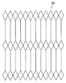


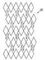
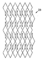


Classifications
-
- A—HUMAN NECESSITIES
- A61—MEDICAL OR VETERINARY SCIENCE; HYGIENE
- A61F—FILTERS IMPLANTABLE INTO BLOOD VESSELS; PROSTHESES; DEVICES PROVIDING PATENCY TO, OR PREVENTING COLLAPSING OF, TUBULAR STRUCTURES OF THE BODY, e.g. STENTS; ORTHOPAEDIC, NURSING OR CONTRACEPTIVE DEVICES; FOMENTATION; TREATMENT OR PROTECTION OF EYES OR EARS; BANDAGES, DRESSINGS OR ABSORBENT PADS; FIRST-AID KITS
- A61F2/00—Filters implantable into blood vessels; Prostheses, i.e. artificial substitutes or replacements for parts of the body; Appliances for connecting them with the body; Devices providing patency to, or preventing collapsing of, tubular structures of the body, e.g. stents
- A61F2/02—Prostheses implantable into the body
- A61F2/24—Heart valves ; Vascular valves, e.g. venous valves; Heart implants, e.g. passive devices for improving the function of the native valve or the heart muscle; Transmyocardial revascularisation [TMR] devices; Valves implantable in the body
- A61F2/2427—Devices for manipulating or deploying heart valves during implantation
- A61F2/2436—Deployment by retracting a sheath
-
- A—HUMAN NECESSITIES
- A61—MEDICAL OR VETERINARY SCIENCE; HYGIENE
- A61M—DEVICES FOR INTRODUCING MEDIA INTO, OR ONTO, THE BODY; DEVICES FOR TRANSDUCING BODY MEDIA OR FOR TAKING MEDIA FROM THE BODY; DEVICES FOR PRODUCING OR ENDING SLEEP OR STUPOR
- A61M25/00—Catheters; Hollow probes
- A61M25/0021—Catheters; Hollow probes characterised by the form of the tubing
- A61M25/0023—Catheters; Hollow probes characterised by the form of the tubing by the form of the lumen, e.g. cross-section, variable diameter
-
- A—HUMAN NECESSITIES
- A61—MEDICAL OR VETERINARY SCIENCE; HYGIENE
- A61F—FILTERS IMPLANTABLE INTO BLOOD VESSELS; PROSTHESES; DEVICES PROVIDING PATENCY TO, OR PREVENTING COLLAPSING OF, TUBULAR STRUCTURES OF THE BODY, e.g. STENTS; ORTHOPAEDIC, NURSING OR CONTRACEPTIVE DEVICES; FOMENTATION; TREATMENT OR PROTECTION OF EYES OR EARS; BANDAGES, DRESSINGS OR ABSORBENT PADS; FIRST-AID KITS
- A61F2/00—Filters implantable into blood vessels; Prostheses, i.e. artificial substitutes or replacements for parts of the body; Appliances for connecting them with the body; Devices providing patency to, or preventing collapsing of, tubular structures of the body, e.g. stents
- A61F2/02—Prostheses implantable into the body
- A61F2/24—Heart valves ; Vascular valves, e.g. venous valves; Heart implants, e.g. passive devices for improving the function of the native valve or the heart muscle; Transmyocardial revascularisation [TMR] devices; Valves implantable in the body
- A61F2/2427—Devices for manipulating or deploying heart valves during implantation
-
- A—HUMAN NECESSITIES
- A61—MEDICAL OR VETERINARY SCIENCE; HYGIENE
- A61F—FILTERS IMPLANTABLE INTO BLOOD VESSELS; PROSTHESES; DEVICES PROVIDING PATENCY TO, OR PREVENTING COLLAPSING OF, TUBULAR STRUCTURES OF THE BODY, e.g. STENTS; ORTHOPAEDIC, NURSING OR CONTRACEPTIVE DEVICES; FOMENTATION; TREATMENT OR PROTECTION OF EYES OR EARS; BANDAGES, DRESSINGS OR ABSORBENT PADS; FIRST-AID KITS
- A61F2/00—Filters implantable into blood vessels; Prostheses, i.e. artificial substitutes or replacements for parts of the body; Appliances for connecting them with the body; Devices providing patency to, or preventing collapsing of, tubular structures of the body, e.g. stents
- A61F2/02—Prostheses implantable into the body
- A61F2/24—Heart valves ; Vascular valves, e.g. venous valves; Heart implants, e.g. passive devices for improving the function of the native valve or the heart muscle; Transmyocardial revascularisation [TMR] devices; Valves implantable in the body
- A61F2/2442—Annuloplasty rings or inserts for correcting the valve shape; Implants for improving the function of a native heart valve
- A61F2/2466—Delivery devices therefor
-
- A—HUMAN NECESSITIES
- A61—MEDICAL OR VETERINARY SCIENCE; HYGIENE
- A61M—DEVICES FOR INTRODUCING MEDIA INTO, OR ONTO, THE BODY; DEVICES FOR TRANSDUCING BODY MEDIA OR FOR TAKING MEDIA FROM THE BODY; DEVICES FOR PRODUCING OR ENDING SLEEP OR STUPOR
- A61M25/00—Catheters; Hollow probes
- A61M25/0009—Making of catheters or other medical or surgical tubes
-
- A—HUMAN NECESSITIES
- A61—MEDICAL OR VETERINARY SCIENCE; HYGIENE
- A61M—DEVICES FOR INTRODUCING MEDIA INTO, OR ONTO, THE BODY; DEVICES FOR TRANSDUCING BODY MEDIA OR FOR TAKING MEDIA FROM THE BODY; DEVICES FOR PRODUCING OR ENDING SLEEP OR STUPOR
- A61M25/00—Catheters; Hollow probes
- A61M25/0043—Catheters; Hollow probes characterised by structural features
- A61M25/0045—Catheters; Hollow probes characterised by structural features multi-layered, e.g. coated
-
- A—HUMAN NECESSITIES
- A61—MEDICAL OR VETERINARY SCIENCE; HYGIENE
- A61M—DEVICES FOR INTRODUCING MEDIA INTO, OR ONTO, THE BODY; DEVICES FOR TRANSDUCING BODY MEDIA OR FOR TAKING MEDIA FROM THE BODY; DEVICES FOR PRODUCING OR ENDING SLEEP OR STUPOR
- A61M25/00—Catheters; Hollow probes
- A61M25/01—Introducing, guiding, advancing, emplacing or holding catheters
- A61M25/06—Body-piercing guide needles or the like
- A61M25/0662—Guide tubes
-
- A—HUMAN NECESSITIES
- A61—MEDICAL OR VETERINARY SCIENCE; HYGIENE
- A61M—DEVICES FOR INTRODUCING MEDIA INTO, OR ONTO, THE BODY; DEVICES FOR TRANSDUCING BODY MEDIA OR FOR TAKING MEDIA FROM THE BODY; DEVICES FOR PRODUCING OR ENDING SLEEP OR STUPOR
- A61M25/00—Catheters; Hollow probes
- A61M25/0021—Catheters; Hollow probes characterised by the form of the tubing
- A61M25/0023—Catheters; Hollow probes characterised by the form of the tubing by the form of the lumen, e.g. cross-section, variable diameter
- A61M2025/0024—Expandable catheters or sheaths
Abstract
팽창 가능한 외장의 양태는 카테터 조립체와 함께 사용되어 심장 판막과 같은 인공 디바이스를 환자 내로 도입할 수 있다. 이러한 양태는 전달 장치를 수용하기 위해 도입기 외장의 일부를 일시적으로 팽창시키고, 이후에 인공 디바이스가 통과하면 원래 직경으로 복귀시킴으로써 혈관에 대한 외상을 최소화할 수 있다. 일부 양태는 내부 라이너의 적어도 하나의 절첩된 부분을 갖는 내부 및 외부층을 갖는 외장을 포함할 수 있다. 일부 양태는 에칭된 부분, 에칭되지 않은 부분, 및 달리 표면 수정된 부분을 갖는 내부 라이너를 포함한다. 본 발명의 팽창 가능한 외장의 양태는 혈관 확장을 위한 다중 삽입의 필요성을 피할 수 있고, 따라서 종래 기술의 도입기 외장에 비교하여 이점을 제공할 수 있다.Aspects of the inflatable sheath can be used with a catheter assembly to introduce a prosthetic device, such as a heart valve, into a patient. This aspect may minimize trauma to the vessel by temporarily inflating a portion of the introducer sheath to accommodate the delivery device and then returning to its original diameter when the prosthetic device passes through. Some aspects may include an enclosure having an inner and an outer layer having at least one folded portion of the inner liner. Some embodiments include an inner liner having an etched portion, an unetched portion, and an otherwise surface-modified portion. Aspects of the inflatable sheath of the present invention may avoid the need for multiple insertions for vasodilation, thus providing advantages over prior art introducer sheaths.
Description
관련 출원에 대한 상호 참조CROSS REFERENCES TO RELATED APPLICATIONS
본 출원은 2020년 7월 31일자로 출원된 미국 가출원 제63/059,764호 및 2020년 5월 8일자로 출원된 미국 가출원 제63/021,945호의 이익을 주장하며, 이들 출원의 내용은 그 전체가 참조로 본 명세서에 포함된다.This application claims the benefit of U.S. Provisional Application No. 63/059,764, filed on July 31, 2020, and U.S. Provisional Application No. 63/021,945, filed on May 8, 2020, the contents of which are incorporated herein by reference in their entirety. is included in this specification.
기술분야technology field
본 출원은 심장 판막을 복구 및/또는 치환하고 인공 판막과 같은 인공 디바이스를 환자의 혈관 구조를 통해 심장에 전달하기 위해 카테터 기반 기술과 함께 사용하기 위한 외장의 양태에 관한 것이다.This application relates to aspects of sheaths for use with catheter-based technology to repair and/or replace heart valves and deliver prosthetic devices, such as prosthetic valves, to the heart through the vasculature of a patient.
혈관내 전달 카테터 조립체는 수술에 의해 쉽게 접근 가능하지 않거나 침습성 수술 없는 접근이 바람직한 신체 내부의 위치에서, 인공 판막과 같은 인공 디바이스를 이식하는 데 사용된다. 예를 들어, 대동맥, 승모판, 삼첨판 및/또는 폐 인공 판막은 최소 침습성 수술 기술을 사용하여 치료 부위로 전달될 수 있다.Intravascular delivery catheter assemblies are used to implant prosthetic devices, such as prosthetic valves, at locations within the body that are not easily accessible by surgery or where access without invasive surgery is desirable. For example, aortic, mitral, tricuspid and/or pulmonary prosthetic valves can be delivered to the treatment site using minimally invasive surgical techniques.
도입기 외장은 전달 장치를 환자의 혈관 구조(예를 들어, 대퇴 동맥) 내로 안전하게 도입하기 위해 사용될 수 있다. 도입기 외장은 일반적으로 혈관 구조 내에 삽입되는 세장형 슬리브 및 최소 혈액 손실로 전달 장치가 혈관 구조와 유체 연통하여 배치되게 하는 하나 이상의 밀봉 밸브를 수납하는 하우징을 갖는다. 종래의 도입기 외장은 통상적으로 벌룬 카테터에 장착된 밸브에 대해 하우징을 통한 방해받지 않는 경로를 제공하기 위해 하우징의 밀봉부를 통해 삽입되는 관형 로더를 필요로 한다. 종래의 로더는 도입기 외장의 근위 단부로부터 연장되고, 따라서 외장을 통해 신체 내로 삽입될 수 있는 전달 장치의 이용 가능한 작업 길이를 감소시킨다.The introducer sheath can be used to safely introduce the delivery device into a patient's vasculature (eg, femoral artery). The introducer sheath generally has an elongated sleeve that is inserted into the vasculature and a housing housing one or more sealing valves that allow the delivery device to be placed in fluid communication with the vasculature with minimal blood loss. Conventional introducer sheaths typically require a tubular loader to be inserted through a seal in the housing to provide an unobstructed passage through the housing for a valve mounted on a balloon catheter. Conventional loaders extend from the proximal end of the introducer sheath, thus reducing the usable working length of a delivery device that can be inserted through the sheath and into the body.
전달 시스템을 도입하기 전에 대퇴 동맥과 같은 혈관에 접근하는 종래의 방법은 직경이 점진적으로 증가하는 다수의 확장기 또는 외장을 사용하여 혈관을 확장시키는 단계를 포함한다. 이러한 반복적인 삽입 및 혈관 확장은 시술이 소요되는 시간, 뿐만 아니라 혈관 손상의 위험을 증가시킬 수 있다.A conventional method of accessing a blood vessel, such as the femoral artery, prior to introduction of a delivery system involves dilating the vessel using a plurality of dilators or sheaths of progressively increasing diameter. Such repetitive insertion and dilation of blood vessels may increase the time required for the procedure and the risk of blood vessel damage.
반경방향으로 팽창되는 혈관내 외장이 개시되어 있다. 그러한 외장은, 일단 외장의 원래 직경보다 더 큰 직경을 갖는 디바이스가 도입되면 샤프트 또는 외장을 팽창 구성으로 유지하는 래칫팅(ratcheting) 메커니즘과 같은 복잡한 메커니즘을 갖는 경향이 있다.A radially expanding endovascular sheath is disclosed. Such sheaths tend to have complex mechanisms such as ratcheting mechanisms that hold the shaft or sheath in an expanded configuration once a device having a larger diameter than the original diameter of the sheath is introduced.
그러나, 환자에게 또는 환자로부터 인공 디바이스 및 다른 재료를 전달 및/또는 제거하는 것은 여전히 환자에게 상당한 위험을 제기한다. 게다가, 혈관에 접근하는 것은 삽입 동안 혈관의 길이방향 및 반경방향 인열을 유발할 수 있는 전달 시스템의 비교적 큰 프로파일로 인해 여전히 도전 과제로 남아 있다. 전달 시스템은 추가로 혈관 내의 석회화된 플라크를 제거하여, 제거된 플라크에 의해 유발되는 혈전의 추가 위험을 제기할 수 있다.However, the delivery and/or removal of prosthetic devices and other materials to or from a patient still poses significant risks to the patient. Moreover, accessing the blood vessel remains a challenge due to the relatively large profile of the delivery system, which can cause longitudinal and radial tearing of the blood vessel during insertion. The delivery system may further remove calcified plaque within blood vessels, posing an additional risk of blood clots caused by the removed plaque.
이에 따라, 판막 및 다른 인공 디바이스를 이식하기 위해 사용되는 혈관내 시스템을 위한 개선된 도입기 외장에 대한 요구가 관련 기술분야에 남아 있다.Accordingly, a need remains in the art for improved introducer sheaths for endovascular systems used to implant valves and other prosthetic devices.
본 명세서에 개시된 바와 같이, 일부 양태에서, 본 팽창 가능한 외장은 전달 시스템을 수용하기 위해 도입기 외장의 일부의 일시적 팽창을 허용하고, 이어서 전달 시스템이 통과하면 원래 직경으로 복귀함으로써 혈관에 대한 외상을 최소화할 수 있다. 일부 양태에서, 종래 기술의 도입기 외장의 프로파일보다 작은 프로파일을 갖는 외장이 개시된다. 더욱이, 본 명세서에 개시된 양태는 시술에 소요되는 시간을 단축할 수 있을 뿐만 아니라 여러 상이한 크기의 외장이 아닌 하나의 외장만 필요하기 때문에 길이방향 또는 반경방향 혈관 인열 또는 플라크 이탈의 위험을 감소시킬 수 있다. 본 팽창 가능한 외장의 개시된 양태는 혈관 확장을 위해 여러 번 삽입해야 하는 대신에 단일 혈관 삽입만 필요로 할 수 있다.As disclosed herein, in some aspects, the present inflatable sheath allows for temporary inflation of a portion of the introducer sheath to accommodate the delivery system, which then returns to its original diameter once the delivery system has passed, thereby minimizing trauma to the vessel. can do. In some aspects, a sheath having a profile smaller than that of prior art introducer sheaths is disclosed. Moreover, embodiments disclosed herein may reduce the time required for the procedure as well as reduce the risk of longitudinal or radial vessel tear or plaque dislocation since only one sheath is required rather than several different sized sheaths. there is. The disclosed embodiments of the present inflatable sheath may require only a single vascular insertion instead of multiple insertions for vasodilation.
일 양태에서, 내부 라이너(층) 및 외부층을 포함하는 인공 디바이스를 도입하기 위한 외장이 본 명세서에 개시된다. 외장의 적어도 일부는 인공 디바이스가 외장의 루멘을 통해 푸시됨에 따라 제1 직경으로부터 제2 직경으로 국소로 팽창되며, 이어서 인공 디바이스가 일단 통과되면 제1 직경으로 적어도 부분적으로 복귀하도록 설계되거나 구성될 수 있다. 일부 양태에서, 탄성 외부 커버가 또한 외부층 둘레에 배치될 수 있다.In one aspect, disclosed herein is an enclosure for incorporating a prosthetic device comprising an inner liner (layer) and an outer layer. At least a portion of the sheath may be designed or configured to locally expand from a first diameter to a second diameter as the prosthetic device is pushed through a lumen of the sheath, and then at least partially return to the first diameter once the prosthetic device is passed through. there is. In some aspects, an elastic outer cover may also be disposed around the outer layer.
일부 양태에서, 서로 대향하는 근위 단부 및 원위 단부를 포함하는 외장이 개시된다. 본 명세서에 개시된 일부 양태는 외장의 근위 단부 또는 그 근방에 지혈 밸브를 포함할 수 있다. 일부 양태에서, 외장의 외경은 외장의 근위 단부로부터 원위 단부로의 구배를 따라 감소할 수 있다. 또 다른 양태에서, 외장의 외경은 외장의 길이의 적어도 대부분을 따라 실질적으로 일정할 수 있다.In some aspects, a sheath comprising a proximal end and a distal end that oppose each other is disclosed. Some aspects disclosed herein may include a hemostatic valve at or near the proximal end of the sheath. In some aspects, the outer diameter of the sheath can decrease along a gradient from the proximal end to the distal end of the sheath. In another aspect, the outer diameter of the sheath can be substantially constant along at least a majority of the length of the sheath.
본 명세서에 설명된 일 양태는 의료 디바이스를 전달하기 위한 외장에 관한 것이고, 외장은 근위 단부 및 원위 단부를 갖고, 내부 표면 및 외부 표면을 갖는 팽창 가능한 내부 라이너로서, 팽창 가능한 내부 라이너의 내부 표면은 루멘을 형성하고, 내부 라이너는 내부 부분 및 외부 부분을 갖는 적어도 하나의 절첩된 부분을 포함하는, 팽창 가능한 내부 라이너; 내부 표면 및 외부 표면을 갖고 외부층의 외부 표면의 제1 부분이 내부 라이너의 적어도 하나의 절첩된 부분의 내부 부분에 인접하게 위치 설정되고, 외부층의 내부 표면의 제1 부분이 내부 라이너의 적어도 하나의 절첩된 부분의 외부 부분에 인접하게 위치 설정되도록 내부 라이너 둘레에서 적어도 부분적으로 연장되는 외부층을 포함하고; 내부 라이너는 적어도 하나의 제1 부분과 적어도 하나의 제2 부분을 포함하며, 적어도 하나의 제1 부분의 외부 표면은 적어도 하나의 제2 부분의 외부 표면과 실질적으로 상이한 조성 및/또는 형태를 포함하고; 내부 루멘을 통해 이동하는 인공 디바이스로부터의 외향 지향 반경방향 힘이 적어도 하나의 절첩된 부분을 펼쳐서 외장의 팽창을 허용한다. 외장의 적어도 일부는 인공 디바이스를 수용하기 위해 팽창되도록 구성된다.One aspect described herein relates to an enclosure for delivering a medical device, the enclosure having a proximal end and a distal end, an inflatable inner liner having an inner surface and an outer surface, wherein the inner surface of the inflatable inner liner comprises: an inflatable inner liner defining a lumen, wherein the inner liner includes at least one folded portion having an inner portion and an outer portion; having an inner surface and an outer surface, wherein a first portion of the outer surface of the outer layer is positioned adjacent an inner portion of the at least one folded portion of the inner liner, and wherein the first portion of the inner surface of the outer layer is positioned adjacent to an inner portion of the at least one folded portion of the inner liner; an outer layer extending at least partially around the inner liner to be positioned adjacent an outer portion of the one folded portion; The inner liner includes at least one first portion and at least one second portion, wherein an outer surface of the at least one first portion includes a composition and/or shape that is substantially different from an outer surface of the at least one second portion. do; Outwardly directed radial forces from the prosthetic device moving through the interior lumen unfold the at least one folded portion to allow expansion of the sheath. At least a portion of the enclosure is configured to inflate to accommodate the prosthetic device.
일부 양태에서, 내부 라이너의 적어도 하나의 제1 부분이 에칭된다. 다른 양태에서, 내부 라이너의 적어도 하나의 제2 부분은 에칭되지 않는다.In some aspects, at least one first portion of the inner liner is etched. In another aspect, the at least one second portion of the inner liner is not etched.
특정 양태에서, 적어도 하나의 제2 부분은 에칭되고 이후에 적어도 하나의 제2 부분의 외부 표면의 조성이 적어도 하나의 제1 부분의 외부 표면의 조성과 실질적으로 상이하도록 표면 수정될 수 있다.In certain embodiments, the at least one second portion may be etched and then surface modified such that the composition of the outer surface of the at least one second portion is substantially different from the composition of the outer surface of the at least one first portion.
본 명세서에 개시된 양태 중 임의의 것에서, 외부층은 중첩 부분이 하위 부분과 중첩하도록 구성될 수 있고, 내부 관형 층의 절첩된 부분의 적어도 일부는 중첩 부분과 하위 부분 사이에 위치 설정된다는 것이 이해된다. 일부 양태에서, 외장의 적어도 일부는 외장의 복수의 세그먼트 각각이 내부 라이너의 루멘을 통한 인공 디바이스의 통과를 용이하게 하기 위해 제1 직경을 갖는 휴지 구성으로부터 제1 직경보다 더 큰 제2 직경을 갖는 팽창 구성으로 한 번에 하나씩 국소로 팽창되도록 구성된다. 각각의 세그먼트는 외장의 길이방향 축을 따라 형성된 길이를 가질 수 있고, 외장의 각각의 세그먼트는 일단 인공 디바이스가 통과되면 제1 직경으로 적어도 부분적으로 복귀하도록 구성될 수 있다. 일부 양태에서, 외장의 각각의 세그먼트가 팽창 구성에 있을 때, 세그먼트의 길이에 대응하는 절첩된 부분의 길이가 (예를 들어, 분리 및/또는 직선화에 의해) 적어도 부분적으로 펼쳐진다. 세그먼트의 길이에 대응하는 중첩 부분의 길이는 외장의 각각의 세그먼트가 휴지 구성으로부터 팽창 구성으로 팽창될 때 하위 부분에 대해 이동하도록 구성될 수 있다.In any of the aspects disclosed herein, it is understood that the outer layer may be configured such that the overlapping portion overlaps the lower portion, and at least a portion of the folded portion of the inner tubular layer is positioned between the overlapping portion and the lower portion. . In some aspects, at least a portion of the sheath has a second diameter greater than the first diameter from a rest configuration where each of the plurality of segments of the sheath has a first diameter to facilitate passage of the prosthetic device through a lumen of the inner liner. It is configured to be locally inflated one at a time in an inflatable configuration. Each segment may have a length defined along a longitudinal axis of the sheath, and each segment of the sheath may be configured to at least partially return to the first diameter once the prosthetic device is passed through. In some aspects, when each segment of the sheath is in the expanded configuration, a length of the folded portion corresponding to the length of the segment is at least partially unfolded (eg, by separation and/or straightening). The length of the overlapping portion corresponding to the length of the segment may be configured to move relative to the lower portion when each segment of the sheath is inflated from a rest configuration to an inflated configuration.
특정 양태에서, 외장의 제조 방법이 또한 개시된다. 하나의 방법은, 예를 들어 제한 없이, 제1 직경을 갖는 맨드릴을 제공하는 단계, 제2 직경을 갖는 제1 튜브를 제공하는 단계로서, 제2 직경은 제1 직경보다 큰, 제1 튜브 제공 단계, 맨드릴에 제1 튜브를 장착하는 단계, 제1 튜브의 초과 재료를 수집하는 단계 및 초과 재료를 일측으로 절첩하여 내부 라이너의 절첩된 부분을 형성하는 단계를 포함한다. 그 후, 제2 튜브가 제공될 수 있고, 제2 튜브는 절단되어 코일형 층을 형성할 수 있다. 코일형 층의 적어도 일부에 접착제가 도포될 수 있고, 코일형 층은 접착제가 제1 튜브와 코일형 층 사이에 위치 설정되도록 제1 튜브 상에 장착될 수 있다. 절첩된 부분이 들어올려져 절첩된 부분 아래에 코일형 층의 일부를 위치 설정할 수 있다.In certain aspects, a method of making an enclosure is also disclosed. One method includes, for example and without limitation, providing a mandrel having a first diameter, providing a first tube having a second diameter, the second diameter being greater than the first diameter. mounting the first tube on the mandrel, collecting excess material from the first tube and folding the excess material to one side to form a folded portion of the inner liner. A second tube may then be provided, and the second tube may be cut to form a coiled layer. Adhesive may be applied to at least a portion of the coiled layer, and the coiled layer may be mounted on the first tube such that the adhesive is positioned between the first tube and the coiled layer. The folded portion may be lifted to position a portion of the coiled layer below the folded portion.
일부 양태에서, 일부 방법은 또한 제1 튜브, 코일형 층, 및 맨드릴에 열을 인가하여 제1 튜브와 코일형 층을 함께 열적으로 융합하는 단계를 포함할 수 있다. 일부 다른 양태에서, 탄성 외부 커버는 또한 코일형 층의 외부 표면에 고정될 수 있다. 또 다른 예시적이고 비제한적인 양태에서, 연성 팁 부분은 환자의 혈관 구조를 통해 팽창 가능한 외장을 통과시키는 것을 용이하게 하기 위해 팽창 가능한 외장의 원위 단부에 결합될 수 있다.In some aspects, some methods may also include applying heat to the first tube, the coiled layer, and the mandrel to thermally fuse the first tube and the coiled layer together. In some other aspects, the elastic outer cover may also be secured to the outer surface of the coiled layer. In another exemplary, non-limiting aspect, the flexible tip portion can be coupled to the distal end of the inflatable sheath to facilitate passage of the inflatable sheath through the patient's vasculature.
다른 양태에서, 의료 디바이스를 전달하기 위한 외장을 제조하는 방법은, 내부 표면 및 외부 표면을 갖는 내부 라이너를 제공하는 단계로서, 내부 표면은 관통하는 루멘을 형성하고, 내부 라이너는 적어도 하나의 제1 부분과 적어도 하나의 제2 부분을 포함하며, 적어도 하나의 제1 부분의 외부 표면은 적어도 하나의 제2 부분의 외부 표면과 실질적으로 상이한 조성 및/또는 형태를 포함하고; 내부 라이너는 내부 부분 및 외부 부분을 갖는 적어도 하나의 절첩된 부분을 포함하는, 내부 라이너 제공 단계; 내부 표면 및 외부 표면을 갖는 외부층을 제공하여, 외부층의 외부 표면의 적어도 제1 부분이 내부 라이너의 적어도 하나의 절첩된 부분의 내부 부분에 인접하게 위치 설정되고, 외부층의 내부 표면의 제1 부분이 내부 라이너의 적어도 하나의 절첩된 부분의 외부 부분에 인접하게 위치 설정되도록 외부층이 내부 라이너 둘레에서 적어도 부분적으로 연장되게 하는 단계; 및 내부 루멘을 통해 이동하는 인공 디바이스로부터의 외향 지향 반경방향 힘이 적어도 하나의 절첩된 부분을 펼칠 때 팽창하도록 구성된 팽창 가능한 외장을 형성하는 단계를 포함한다.In another aspect, a method of manufacturing an enclosure for delivering a medical device includes providing an inner liner having an inner surface and an outer surface, the inner surface defining a lumen therethrough, the inner liner comprising at least one first surface. a portion and at least one second portion, wherein an outer surface of the at least one first portion comprises a composition and/or shape that is substantially different from an outer surface of the at least one second portion; providing an inner liner, wherein the inner liner includes at least one folded portion having an inner portion and an outer portion; An outer layer having an inner surface and an outer surface, wherein at least a first portion of the outer surface of the outer layer is positioned adjacent to an inner portion of at least one folded portion of the inner liner, wherein a first portion of the inner surface of the outer layer is positioned adjacent to an inner portion of the at least one folded portion of the inner liner. causing the outer layer to extend at least partially around the inner liner such that a portion is positioned adjacent an outer portion of the at least one folded portion of the inner liner; and forming an inflatable enclosure configured to expand when an outwardly directed radial force from the prosthetic device moving through the interior lumen unfolds the at least one folded portion.
또 다른 양태에서, 내부 라이너의 적어도 하나의 제1 부분 및 적어도 하나의 제2 부분은 선택적 에칭에 의해 형성될 수 있다. 이러한 예시적인 양태에서, 선택적 에칭은 원주 둘레에서, 외장의 길이를 따라 선형으로, 또는 이들의 조합으로 수행된다.In another aspect, at least one first portion and at least one second portion of the inner liner may be formed by selective etching. In this exemplary aspect, the selective etching is performed around the circumference, linearly along the length of the sheath, or a combination thereof.
내부 라이너의 일부를 마스킹하여 마스킹된 부분을 형성한 다음 내부 라이너의 나머지 마스킹되지 않은 부분을 에칭제로 에칭함으로써 적어도 하나의 제1 부분이 형성될 수 있는 양태가 본 명세서에 개시된다. 또 다른 양태에서, 본 명세서에 개시된 바와 같은 방법은 에칭 후에 마스킹된 부분을 마스킹 해제함으로써 적어도 하나의 제2 부분을 형성하는 단계를 더 포함할 수 있다.Disclosed herein are embodiments in which at least one first portion may be formed by masking a portion of the inner liner to form a masked portion and then etching the remaining unmasked portion of the inner liner with an etchant. In another aspect, a method as disclosed herein may further include forming at least one second portion by unmasking the masked portion after etching.
양태에서, 본 명세서에 개시된 바와 같이, 방법은 선택적 에칭을 포함한다. 이러한 예시적인 양태에서, 선택적 에칭은 에칭제로 수행될 수 있다. 이러한 양태에서, 에칭제는 액체, 유체, 기체, 플라즈마, 또는 이들의 조합을 포함할 수 있다.In an aspect, as disclosed herein, a method includes selective etching. In this exemplary aspect, selective etching may be performed with an etchant. In this aspect, the etchant may include a liquid, fluid, gas, plasma, or a combination thereof.
본 개시내용의 상기 및 다른 특징 및 이점은 첨부 도면을 참조하여 계속되는 이하의 상세한 설명으로부터 더 명백해질 것이다.The above and other features and advantages of the present disclosure will become more apparent from the following detailed description continued with reference to the accompanying drawings.
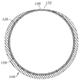
도 1은 인공 판막을 이식하기 위한 혈관내 전달 장치와 함께 본 개시내용에 따른 외장의 입면도이다.
도 2a, 도 2b 및 도 2d는 인공 디바이스를 환자에게 도입하기 위한 다양한 양태의 외장의 단면도이고, 도 2c는 이러한 외장의 한 구성요소의 사시도이다.
도 3은 도 2에 도시되어 있는 외장의 입면도이다.
도 4a 및 도 4b는 다양한 외경을 갖는 본 개시내용에 따른 외장의 2가지 양태의 입면도이다.
도 5는 전달 시스템을 수용하기 위해 제1 위치에서 팽창된 외장의 일 양태의 입면도를 예시한다.
도 6은 외장 아래로 더 멀리 제2 위치에서 팽창된, 일 양태의 외장의 입면도를 도시한다.
도 7은 외부 커버링 또는 쉘을 더 포함하는 외장의 다른 양태의 단면도를 도시한다.
도 8은 외부 커버링 또는 쉘을 갖는 외장의 일 양태의 입면도를 예시한다.
도 9는 본 개시내용에 따른 외장을 구성하는 데 사용될 수 있는 중간 관형 층의 일 양태의 부분 입면도를 예시한다.
도 10은 가변 다이아몬드 설계를 갖는 중간 관형 층의 다른 양태의 부분 입면도를 예시한다.
도 11은 스프링 스트러트를 갖는 다이아몬드 설계를 갖는 중간 관형 층의 다른 양태의 부분 입면도를 예시한다.
도 12는 직선 스트러트를 갖는 다이아몬드 설계를 갖는 중간 관형 층의 다른 양태의 부분 입면도를 예시한다.
도 13은 스프링 스트러트를 갖는 톱니 설계를 갖는 중간 관형 층의 다른 양태의 부분 입면도를 예시한다.
도 14는 직선 스트러트를 갖는 톱니 설계를 갖는 중간 관형 층의 다른 양태의 부분 입면도를 예시한다.
도 15는 직선 스트러트를 갖는 다이아몬드 설계를 갖는 중간 관형 층의 다른 양태의 부분 입면도를 예시한다.
도 16은 나선형 또는 소용돌이형 설계를 갖는 중간 관형 층의 다른 양태의 부분 입면도를 예시한다.
도 17은 직선이 아닌 스트러트를 갖는 다이아몬드 설계를 갖는 중간 관형 층의 다른 양태의 부분 입면도를 예시한다.
도 18은 직선이 아닌 스트러트를 갖는 대안적인 다이아몬드 설계를 갖는 중간 관형 층의 다른 양태의 부분 입면도를 예시한다.
도 19는 직선이 아닌 스트러트를 갖는 또 다른 다이아몬드 설계를 갖는 중간 관형 층의 다른 양태의 부분 입면도를 예시한다.
도 20은 스트러트를 갖는 다이아몬드 설계를 갖는 중간 관형 층의 다른 양태의 부분 입면도를 예시한다.
도 21은 도 20에 예시된 것과 유사한 설계를 갖지만 추가 스트러트가 있는 중간 관형 층의 다른 양태의 부분 입면도를 예시한다.
도 22는 나선형 스트러트를 갖는 다이아몬드 설계를 갖는 중간 관형 층의 다른 양태의 부분 입면도를 예시한다.
도 23은 인접한 스트러트가 있는 다이아몬드 설계를 갖는 중간 관형 층의 다른 양태의 부분 입면도를 예시한다.
도 24는 길이방향 노치를 갖는 외장의 일 양태의 단면도를 예시한다.
도 25는 내부 라이너에 길이방향 절단부를 갖는 외장의 일 양태의 단면도를 도시한다.
도 26은 외부 관형 층에 복수의 노치 또는 절단부를 갖는 외장의 일 양태의 사시도를 도시한다.
도 27a는 외장의 일 양태의 단면도를 예시하고, 외부 관형 층은 길이방향 절단부를 포함하고, 내부 라이너는 팽창되지 않은 구성에서 외부 관형 층의 절단부에 의해 생성된 간극 내로 연장되며; 도 27b 내지 도 27e는 팽창되지 않은 구성의 외장의 다양한 양태의 단면도를 도시한다.
도 28은 팽창 구성에서 도 27a의 외장의 단면도를 도시한다.
도 29a 내지 도 29d는 중첩 섹션을 갖는 외장의 다양한 양태의 단면도를 도시한다.
도 30은 본 개시내용에 따른 외장을 제조하는 방법의 일 양태의 블록도를 예시한다.
도 31은 본 개시내용에 따른 외장을 제조하는 방법의 다른 양태의 블록도를 예시한다.
도 32a 내지 도 32h는 도 30 내지 도 31에 도시된 방법의 다양한 방법 단계의 단면도 또는 입면도를 예시한다.
도 33은 부분 슬릿 또는 새김선을 갖는 외장의 일 양태의 평면도를 예시한다.
도 34는 부분 슬릿 또는 새김선을 갖는 외장의 다른 양태의 평면도를 예시한다.
도 35는 본 개시내용에 따른 팽창 가능한 외장 및 대표적인 하우징의 입면도이다.
도 36은 도 35의 외장의 원위 단부의 확대 절취도이다.
도 37은 도 36의 선 37-37을 따라 취한, 도 35의 외장의 원위 단부의 단면도이다.
도 38은 도 35의 선 38-38을 따라 취한, 도 35의 외장의 근위 섹션의 단면도이다.
도 39는 도 35의 선 39-39를 따라 취한, 휴지(팽창되지 않은) 구성의 도 35의 외장의 단면도이다.
도 40은 팽창 구성에서 도 39의 외장의 단면도이다.
도 41은 다른 양태에 따른, 탄성 외부 커버를 갖는 팽창 가능한 외장의 입면도를 도시한다.
도 42는 도 41의 선 42-42를 따라 취한, 도 41의 외장의 단면도를 예시한다.
도 43은 팽창 구성에서 도 42에 도시된 외장의 단면도를 예시한다.
도 44는 팽창가능한 외장의 다른 양태의 단면도를 예시한다.
도 45는 도 44의 외장의 팽창 구성을 도시한다.
도 46은 팽창가능한 외장의 다른 양태의 단면도를 예시한다.
도 47은 도 46의 외장의 팽창 구성을 도시한다.
도 48은 본 개시내용에 따른 팽창 가능한 외장의 다른 양태의 단면도를 예시한다.
도 49는 팽창가능한 외장의 다른 양태의 단면도를 예시한다.
도 50은 팽창되지 않은 구성의 예시적인 외장의 단면도이다.
도 51은 팽창 구성에서 도 50의 외장의 단면도이다.
도 52는 외부 재킷을 포함하는 도 50의 외장의 단면도이다.
도 53은 도 35의 선 39-39를 따라 취한, 외부 재킷을 포함하는 휴지(팽창되지 않은) 구성의 도 35의 외장의 단면도이다.
도 54는 도 35의 선 39-39를 따라 취한, 휴지(팽창되지 않은) 구성의 도 53의 외장의 단면도이다.
도 55는 팽창 구성에서 도 54의 외장의 단면도이다.
도 56은 외부층과 외부 재킷 사이에 윤활제를 포함하는 휴지(팽창되지 않은) 구성의 도 54의 외장의 단면도이다.
도 57은 윤활제 및 접합 스트립을 포함하는 휴지(팽창되지 않은) 구성의 도 54의 외장의 단면도이다.
도 58은 도 57의 외장의 저면 사시도이다.
도 59는 도 57의 외장의 저면 사시도이다.
도 60은 도 54의 외장의 상부 사시도이다.
도 61a 및 도 61b는 일 양태에 개시된 바와 같은 제1 및 제2 부분을 갖는 내부 라이너의 개략도이다.
도 62a 및 도 62b는 일 양태에 개시된 바와 같은 제1 및 제2 부분을 갖는 내부 라이너의 개략도이다.
도 63a 및 도 63b는 일 양태에 개시된 바와 같은 제1 및 제2 부분을 갖는 내부 라이너의 개략도이다.1 is an elevational view of an enclosure according to the present disclosure with an intravascular delivery device for implanting a prosthetic valve.
2A, 2B and 2D are cross-sectional views of various embodiments of an enclosure for introducing a prosthetic device into a patient, and FIG. 2C is a perspective view of one component of such an enclosure.
Figure 3 is an elevational view of the enclosure shown in Figure 2;
4A and 4B are elevational views of two aspects of sheaths according to the present disclosure having various outer diameters.
5 illustrates an elevational view of one aspect of an inflated sheath in a first position to accommodate a delivery system.
6 shows an elevational view of one aspect of the sheath, inflated in a second position further down the sheath.
7 shows a cross-sectional view of another embodiment of an enclosure further comprising an outer covering or shell.
8 illustrates an elevational view of one aspect of an enclosure having an outer covering or shell.
9 illustrates a partial elevation view of one aspect of an intermediate tubular layer that may be used to construct a sheath in accordance with the present disclosure.
10 illustrates a partial elevation view of another aspect of an intermediate tubular layer having a variable diamond design.
11 illustrates a partial elevation view of another aspect of a middle tubular layer having a diamond design with spring struts.
12 illustrates a partial elevation view of another aspect of a middle tubular layer having a diamond design with straight struts.
13 illustrates a partial elevation view of another aspect of a middle tubular layer having a toothed design with spring struts.
14 illustrates a partial elevation view of another aspect of a middle tubular layer having a toothed design with straight struts.
15 illustrates a partial elevation view of another aspect of a middle tubular layer having a diamond design with straight struts.
16 illustrates a partial elevation view of another embodiment of an intermediate tubular layer having a spiral or spiral design.
17 illustrates a partial elevation view of another aspect of a middle tubular layer having a diamond design with non-straight struts.
18 illustrates a partial elevation view of another aspect of a middle tubular layer having an alternative diamond design with non-straight struts.
19 illustrates a partial elevation view of another aspect of a middle tubular layer having another diamond design with non-straight struts.
20 illustrates a partial elevation view of another aspect of a middle tubular layer having a diamond design with struts.
FIG. 21 illustrates a partial elevation view of another aspect of a middle tubular layer having a design similar to that illustrated in FIG. 20 but with additional struts.
22 illustrates a partial elevation view of another aspect of a middle tubular layer having a diamond design with helical struts.
23 illustrates a partial elevation view of another aspect of a middle tubular layer having a diamond design with adjacent struts.
24 illustrates a cross-sectional view of one aspect of a sheath having a longitudinal notch.
25 shows a cross-sectional view of one aspect of a sheath having a longitudinal cut in the inner liner.
26 shows a perspective view of one aspect of a sheath having a plurality of notches or cuts in the outer tubular layer.
27A illustrates a cross-sectional view of one aspect of the sheath, wherein the outer tubular layer includes a longitudinal cut and the inner liner extends into the gap created by the cut in the outer tubular layer in an uninflated configuration; 27B-27E show cross-sectional views of various aspects of an enclosure in an uninflated configuration.
28 shows a cross-sectional view of the enclosure of FIG. 27A in an expanded configuration.
29A-29D show cross-sectional views of various aspects of an enclosure having overlapping sections.
30 illustrates a block diagram of one aspect of a method of manufacturing an enclosure in accordance with the present disclosure.
31 illustrates a block diagram of another aspect of a method of manufacturing an enclosure in accordance with the present disclosure.
32A-32H illustrate cross-sectional or elevational views of various method steps of the method shown in FIGS. 30-31.
33 illustrates a plan view of one aspect of a sheath having a partial slit or score.
34 illustrates a plan view of another aspect of a sheath having partial slits or scores.
35 is an elevational view of an inflatable enclosure and representative housing according to the present disclosure.
36 is an enlarged cutaway view of the distal end of the sheath of FIG. 35;
37 is a cross-sectional view of the distal end of the sheath of FIG. 35 taken along line 37-37 in FIG. 36;
38 is a cross-sectional view of a proximal section of the sheath of FIG. 35 taken along line 38-38 in FIG. 35;
39 is a cross-sectional view of the enclosure of FIG. 35 in a rest (unexpanded) configuration, taken along line 39-39 in FIG. 35;
40 is a cross-sectional view of the enclosure of FIG. 39 in an expanded configuration.
41 shows an elevational view of an inflatable enclosure having a resilient outer cover, according to another aspect.
42 illustrates a cross-sectional view of the enclosure of FIG. 41 taken along line 42-42 in FIG. 41 .
43 illustrates a cross-sectional view of the enclosure shown in FIG. 42 in an expanded configuration.
44 illustrates a cross-sectional view of another embodiment of an inflatable enclosure.
FIG. 45 shows an expanded configuration of the enclosure of FIG. 44;
46 illustrates a cross-sectional view of another embodiment of an inflatable enclosure.
FIG. 47 shows an expanded configuration of the enclosure of FIG. 46;
48 illustrates a cross-sectional view of another embodiment of an inflatable enclosure according to the present disclosure.
49 illustrates a cross-sectional view of another embodiment of an inflatable enclosure.
50 is a cross-sectional view of an exemplary enclosure in an uninflated configuration.
51 is a cross-sectional view of the enclosure of FIG. 50 in an expanded configuration.
Fig. 52 is a cross-sectional view of the enclosure of Fig. 50 including an outer jacket;
53 is a cross-sectional view of the enclosure of FIG. 35 in a rest (uninflated) configuration including an outer jacket, taken along line 39-39 in FIG. 35;
54 is a cross-sectional view of the enclosure of FIG. 53 in a rest (unexpanded) configuration, taken along line 39-39 in FIG. 35;
55 is a cross-sectional view of the enclosure of FIG. 54 in an expanded configuration.
56 is a cross-sectional view of the enclosure of FIG. 54 in a rest (unexpanded) configuration including a lubricant between the outer layer and the outer jacket.
57 is a cross-sectional view of the enclosure of FIG. 54 in a rest (unexpanded) configuration including lubricant and bonding strips.
58 is a bottom perspective view of the enclosure of FIG. 57;
59 is a bottom perspective view of the enclosure of FIG. 57;
60 is a top perspective view of the enclosure of FIG. 54;
61A and 61B are schematic diagrams of an inner liner having first and second portions as disclosed in one aspect.
62A and 62B are schematic diagrams of an inner liner having first and second portions as disclosed in one aspect.
63A and 63B are schematic diagrams of an inner liner having first and second portions as disclosed in one aspect.
본 개시내용은 하기 상세한 설명, 예, 도면 및 청구범위, 그리고 이들의 이전 및 아래의 설명을 참조함으로써 보다 용이하게 이해될 수 있다. 그러나, 본 발명의 물품, 시스템 및/또는 방법이 개시 및 설명되기 전에, 본 개시내용은 달리 명시되지 않는 한, 개시된 물품, 시스템 및/또는 방법의 특정 또는 예시적인 양태로 제한되지 않고, 이 때문에 물론 달라질 수 있다는 것을 이해하여야 한다. 또한, 본 명세서에 사용된 용어는 단지 특정한 양태를 설명하기 위한 것이며 제한하도록 의도되지 않음을 이해하여야 한다.The present disclosure may be more readily understood by reference to the following detailed description, examples, drawings and claims, and the preceding and following descriptions thereof. However, before an article, system, and/or method of the present invention is disclosed and described, the present disclosure is not limited to the specific or exemplary aspects of the disclosed article, system, and/or method unless otherwise specified, and to this end, It should be understood, of course, that this may change. Also, it should be understood that the terminology used herein is for the purpose of describing particular aspects only and is not intended to be limiting.
본 개시내용의 다음의 설명은 현재 알려진 최상의 양태에서 본 개시내용을 가능하게 하는 교시로서 제공된다. 이를 위해, 관련 기술 분야의 숙련자는 본 개시내용의 유익한 결과를 여전히 획득하면서 본 명세서에 설명된 개시내용의 다양한 양태에 대해 많은 변경이 이루어질 수 있음을 인식하고 이해할 것이다. 또한, 본 개시내용의 원하는 이점 중 일부는 다른 특징을 이용하지 않고 본 개시내용의 특징 중 일부를 선택함으로써 획득될 수 있음이 명백할 것이다. 따라서, 관련 기술 분야의 숙련자는 본 개시내용에 대한 많은 수정 및 개조가 가능하고 특정 상황에서 바람직할 수도 있고 본 개시내용의 일부임을 인식할 것이다. 따라서, 아래의 설명은 본 개시내용의 원리의 예시로서 다시 제공되며 이에 제한되지 않는다.The following description of the present disclosure is provided as teaching enabling the present disclosure in its best mode currently known. To this end, those skilled in the art will recognize and understand that many changes can be made to the various aspects of the disclosure described herein while still obtaining the beneficial results of the disclosure. It will also be apparent that some of the desired advantages of the present disclosure may be obtained by selecting some of the features of the present disclosure without using other features. Accordingly, those skilled in the relevant art will recognize that many modifications and adaptations of this disclosure are possible and may be desirable in certain circumstances and are part of this disclosure. Accordingly, the description below is again provided as an illustration of the principles of the present disclosure and not as a limitation.
정의Justice
본 명세서 및 청구범위에 사용될 때, 단수 형태는 문맥상 명백히 달리 지시되지 않으면, 복수 형태를 포함한다. 따라서, 예를 들어, "폴리머"에 대한 언급은 문맥상 명백하게 달리 나타내지 않는 한 2개 이상의 그러한 폴리머를 갖는 양태를 포함한다.As used in this specification and claims, the singular forms include the plural forms unless the context clearly dictates otherwise. Thus, for example, reference to “a polymer” includes embodiments having two or more such polymers unless the context clearly dictates otherwise.
명료함을 위해 개별 양태의 맥락에서 설명된 본 개시내용의 특정 특징은 또한 조합으로 또는 단일 양태로서 제공될 수 있음이 이해된다. 역으로, 간결함을 위해 단일 양태의 맥락에서 설명된 본 개시내용의 다양한 특징은 또한 개별적으로 또는 임의의 적절한 조합으로 제공될 수 있다.It is understood that certain features of the disclosure that are, for clarity, described in the context of separate aspects, may also be provided in combination or as a single aspect. Conversely, various features of the disclosure that, for brevity, are described in the context of a single aspect can also be provided individually or in any suitable combination.
본 명세서에서 사용되는 바와 같이, 용어 "임의적" 또는 "임의로"는, 이후에 설명되는 이벤트 또는 상황이 발생할 수도 있고 또는 발생하지 않을 수도 있으며, 설명이 상기 이벤트 또는 상황이 발생하는 경우 및 이러한 것이 발생하지 않는 경우를 포함한다는 것을 의미한다.As used herein, the terms "optional" or "optionally" mean that the subsequently described event or circumstance may or may not occur, and that the description indicates when the event or circumstance occurs and when it occurs. This means that it includes cases where it does not.
또한, 본 명세서에 사용된 용어는 단지 특정한 양태를 설명하기 위한 것이며 제한하도록 의도되지 않음을 이해하여야 한다. 명세서 및 청구범위에 사용되는 바와 같이, 용어 "구비하는"은 "구성되는" 및 "본질적으로 구성되는" 양태를 포함할 수 있다. 또한 "구비한다"라는 용어는 "포함한다"를 의미한다. Also, it should be understood that the terminology used herein is for the purpose of describing particular aspects only and is not intended to be limiting. As used in the specification and claims, the term “comprising” can include the aspects “consisting of” and “consisting essentially of”. Also, the term "comprising" means "comprising".
"예를 들어" 및 "예컨대"라는 용어 및 이들의 문법적 등가물의 경우, 달리 명시적으로 언급되지 않는 한 "그리고 제한 없이"라는 문구가 뒤따르는 것으로 이해된다.For the terms "for example" and "such as" and their grammatical equivalents, it is understood that the phrase "and without limitation" follows, unless expressly stated otherwise.
조성물 또는 물품의 특정 요소 또는 구성요소의 중량부에 대한 명세서와 최종 청구범위에서의 참조는 중량부가 표현되는 조성물 또는 물품의 요소 또는 구성요소와 임의의 다른 요소 또는 구성요소 사이의 중량 관계를 나타낸다. 따라서, 2중량부의 구성요소 X 및 5중량부의 구성요소 Y를 함유하는 조성물 또는 조성물의 선택된 부분에서, X 및 Y는 2:5의 중량비로 존재하고 추가 구성요소가 조성물에 함유되어 있는지의 여부에 관계없이 그러한 비율로 존재한다.References in the specification and final claims to parts by weight of a particular element or component of a composition or article indicate a weight relationship between the element or component and any other element or component of the composition or article for which the weight part is being expressed. Thus, in a composition or selected portion of a composition containing 2 parts by weight component X and 5 parts component Y, X and Y are present in a weight ratio of 2:5 and whether or not additional components are contained in the composition. Regardless, they exist in such proportions.
본 개시내용의 넓은 범위를 나타내는 수치 범위 및 파라미터가 근사치임에도 불구하고, 특정 예에 기재된 수치 값은 가능한 한 정확하게 보고된다. 그러나, 임의의 수치 값은 본질적으로 각각의 테스트 측정에서 발견된 표준 편차로부터 필연적으로 발생하는 특정 오류를 포함한다. 더욱이, 다양한 범위의 수치 범위가 본 명세서에 기재된 경우, 인용된 값을 포함하는 이들 값의 임의의 조합이 사용될 수 있음이 고려된다. 또한, 범위는 본 명세서에서 "약" 하나의 특정값으로부터 및/또는 "약" 다른 특정값까지로서 표현될 수 있다. 이러한 범위가 표현될 때, 다른 양태는 하나의 특정값으로부터 및/또는 다른 특정값까지를 포함한다.Although numerical ranges and parameters representing the broad scope of this disclosure are approximations, the numerical values set forth in specific examples are reported as accurately as possible. Any numerical value, however, inherently contains certain errors necessarily resulting from the standard deviation found in their respective testing measurements. Moreover, when various ranges of numerical ranges are set forth herein, it is contemplated that any combination of these values, inclusive of the recited values, may be used. Ranges may also be expressed herein as from “about” one particular value and/or to “about” another particular value. When such ranges are expressed, other aspects include from one particular value and/or to another particular value.
유사하게, 선행사 "약"의 사용에 의해 값이 근사치로서 표현될 때, 특정값이 다른 양태를 형성하는 것이 이해될 수 있을 것이다. 각각의 범위의 종단점들은 다른 종단점과 관련하여 그리고 다른 종단점과 독립적으로의 모두에 있어 유효하다는 것이 또한 이해될 수 있을 것이다. 달리 명시되지 않는 한, 용어 "약"은 용어 "약"에 의해 수정된 특정값의 5% 이내(예를 들어, 2% 또는 1% 이내)를 의미한다.Similarly, when values are expressed as approximations by use of the antecedent “about,” it will be appreciated that the particular value forms another aspect. It will also be appreciated that the endpoints of each range are valid both in relation to the other endpoints and independently of the other endpoints. Unless otherwise specified, the term “about” means within 5% (eg, within 2% or 1%) of the specified value corrected by the term “about”.
본 개시내용의 전체에 걸쳐, 개시내용의 다양한 양태는 범위 형식으로 제시될 수 있다. 범위 형식의 설명은 단지 편의와 간결함을 위한 것이며 본 개시내용의 범위에 대한 불변의 제한으로 해석되어서는 안 된다는 것을 이해하여야 한다. 따라서, 범위에 대한 설명은 가능한 모든 하위 범위 뿐만 아니라 해당 범위 내의 개별 수치 값을 구체적으로 개시한 것으로 고려되어야 한다. 예를 들어, 1 내지 6과 같은 범위의 설명은 1 내지 3, 1 내지 4, 1 내지 5, 2 내지 4, 2 내지 6, 3 내지 6 등과 같은 하위 범위 뿐만 아니라 해당 범위 내의 개별 숫자, 예를 들어 1, 2, 2.7, 3, 4, 5, 5.3, 6 및 그 사이의 임의의 전체 및 부분 증분을 구체적으로 개시한 것으로 고려되어야 한다. 이는 범위의 폭에 무관하게 적용된다.Throughout this disclosure, various aspects of the disclosure may be presented in a range format. It should be understood that the descriptions of range formats are for convenience and brevity only and should not be construed as invariable limitations on the scope of the present disclosure. Accordingly, the description of a range should be considered to have specifically disclosed all possible subranges as well as individual numerical values within that range. For example, a description of a range such as 1 to 6 includes subranges such as 1 to 3, 1 to 4, 1 to 5, 2 to 4, 2 to 6, 3 to 6, etc., as well as individual numbers within the range, e.g. For example, 1, 2, 2.7, 3, 4, 5, 5.3, 6 and any whole and partial increments therebetween should be considered as specifically disclosed. This applies regardless of the width of the range.
본 명세서에 사용되는 바와 같이, 용어 "조성물"은 명시된 양의 명시된 성분을 포함하는 제품 뿐만 아니라 명시된 양의 명시된 성분의 조합으로부터 직접 또는 간접적으로 생성되는 임의의 제품을 포함하는 것으로 의도된다.As used herein, the term "composition" is intended to include any product that results directly or indirectly from a combination of the specified ingredients in specified amounts, as well as a product comprising the specified ingredients in specified amounts.
달리 구체적으로 언급되지 않는 한, 구성요소의 wt%는 구성요소가 포함된 제제 또는 조성물의 총 중량을 기준으로 한다.Unless specifically stated otherwise, wt % of a component is based on the total weight of the formulation or composition in which the component is incorporated.
본 명세서에 사용되는 바와 같이, 용어 "실질적으로"는 후속적으로 설명되는 이벤트 또는 상황이 완전히 발생하거나 후속적으로 설명되는 이벤트 또는 상황이 일반적으로, 통상적으로, 또는 대략적으로 발생함을 의미한다.As used herein, the term "substantially" means that the subsequently described event or circumstance fully occurs or that the subsequently described event or circumstance generally, usually, or approximately occurs.
본 명세서에 사용되는 바와 같이, 용어 "실질적으로"는, 조성물과 관련하여 사용될 때, 조성물의, 명시된 특징 또는 구성요소의 총 중량을 기준으로 적어도 약 80%, 적어도 약 85%, 적어도 약 90%, 적어도 약 91%, 적어도 약 92%, 적어도 약 93%, 적어도 약 94%, 적어도 약 95%, 적어도 약 96%, 적어도 약 97%, 적어도 약 98%, 적어도 약 99%, 또는 약 100%를 지칭한다.As used herein, the term "substantially," when used in reference to a composition, comprises at least about 80%, at least about 85%, at least about 90%, based on the total weight of the specified features or components, of the composition. , at least about 91%, at least about 92%, at least about 93%, at least about 94%, at least about 95%, at least about 96%, at least about 97%, at least about 98%, at least about 99%, or about 100% refers to
본 명세서에 사용되는 바와 같이, 예를 들어 "실질적으로 없는"이라는 문맥에서 용어 "실질적으로"는 조성물의 총 중량을 기준으로 언급된 물질의 약 1 wt% 미만, 약 0.5 wt% 미만, 약 0.1 wt% 미만, 약 0.05 wt% 미만, 또는 약 0.01 wt% 미만을 갖는 조성물을 지칭한다.As used herein, the term "substantially" in the context of, for example, "substantially free" means less than about 1 wt %, less than about 0.5 wt %, less than about 0.1 wt % of the recited material, based on the total weight of the composition. less than about 0.05 wt%, or less than about 0.01 wt%.
본 명세서에 사용되는 바와 같이, 용어 "실질적으로 동일한 참조 조성물" 또는 "실질적으로 동일한 참조 물품"은 본 발명의 구성요소가 없이 실질적으로 동일한 구성요소를 포함하는 참조 조성물 또는 물품을 지칭한다. 또 다른 예시적인 양태에서, 예를 들어 "실질적으로 동일한 기준 조성물"의 문맥에서 용어 "실질적으로"는 실질적으로 동일한 구성요소를 포함하는 참조 조성물을 지칭하고 여기서, 본 발명의 구성요소는 당해 기술 분야에서 통상적인 구성요소로 치환된다.As used herein, the term “substantially identical reference composition” or “substantially identical reference article” refers to a reference composition or article that contains substantially the same elements without the elements of the present invention. In another exemplary embodiment, the term "substantially" in the context of, for example, "a substantially identical reference composition" refers to a reference composition comprising substantially identical components, wherein the inventive components are those skilled in the art. are replaced by common components in
또한, 용어 "결합된" 및 "연계된"은 일반적으로 전기적으로, 전자기적으로, 그리고/또는 물리적으로(예를 들어, 기계적으로 또는 화학적으로) 결합되거나 연결된 것을 의미하고, 결합된 또는 연계된 물품 사이의 중간 요소의 존재를 배제하는 것은 아니다.Also, the terms “coupled” and “associated” generally mean electrically, electromagnetically, and/or physically (eg, mechanically or chemically) coupled or connected, coupled or associated It does not preclude the presence of intermediate elements between articles.
"제1", "제2" 등의 용어가 본 명세서에서 다양한 요소, 구성요소, 영역, 층 및/또는 섹션을 설명하기 위해 사용될 수 있음이 이해될 것이다. 이들 요소, 구성요소, 영역, 층 및/또는 섹션은 이들 용어에 의해 제한되어서는 안 된다. 이들 용어는 하나의 요소, 구성요소, 영역, 층 또는 섹션을 다른 요소, 구성요소, 영역, 층 또는 섹션으로부터 구별하는 데만 사용된다. 따라서, 아래에 설명되는 제1 요소, 구성요소, 영역, 층 또는 섹션은 예시적인 양태의 교시를 벗어나지 않고 제2 요소, 구성요소, 영역, 층 또는 섹션으로 명명될 수 있다.It will be appreciated that the terms "first", "second" and the like may be used herein to describe various elements, components, regions, layers and/or sections. These elements, components, regions, layers and/or sections should not be limited by these terms. These terms are only used to distinguish one element, component, region, layer or section from another element, component, region, layer or section. Thus, a first element, component, region, layer or section described below could be termed a second element, component, region, layer or section without departing from the teachings of the exemplary aspects.
"층"과 "라이너"라는 용어는 상호 교환 가능하게 사용될 수 있는 것으로 이해된다. 예를 들어, "내부 라이너"를 설명하는 양태는 또한 "내부층"을 설명하는 양태를 포함한다. 유사하게, "외부층"을 설명하는 양태는 또한 "외부 라이너"를 설명하는 양태를 포함한다.It is understood that the terms "layer" and "liner" may be used interchangeably. For example, an aspect that describes an "inner liner" also includes an aspect that describes an "inner layer." Similarly, aspects describing the "outer layer" also include aspects describing the "outer liner."
"밑", "아래", "하부", "위", "상부" 등과 같은 공간적으로 상대적인 용어는 도면에 예시되는 바와 같이 다른 요소(들) 또는 피처(들)에 대한 하나의 요소 또는 피처의 관계를 설명하기 위한 설명의 용이함을 위해 본 명세서에서 사용될 수 있다. 공간적으로 상대적인 용어는 도면에 도시되어 있는 배향에 추가하여 사용 또는 동작 중인 디바이스의 상이한 배향을 포함하도록 의도된다는 것이 이해될 것이다. 예를 들어, 도면에서 디바이스가 뒤집힌 경우, 다른 요소 또는 피처 "아래" 또는 "밑"으로 설명된 요소는 다른 요소 또는 피처 "위"로 배향된다. 따라서 "아래"라는 용어는 위와 아래의 배향을 모두 포함할 수 있다. 디바이스는 달리 배향될 수 있으며(90도 또는 다른 배향으로 회전될 수 있으며), 본 명세서에 사용된 공간적으로 상대적인 기술어는 그에 따라 해석된다.Spatially relative terms such as "below", "below", "lower", "above", "upper", etc. refer to the relationship of one element or feature to another element(s) or feature(s) as illustrated in the figures. may be used herein for ease of explanation to describe relationships. It will be appreciated that spatially relative terms are intended to include different orientations of the device in use or operation in addition to the orientations shown in the figures. For example, when a device is turned over in the figures, elements described as “below” or “beneath” other elements or features are oriented “above” the other elements or features. Thus, the term “below” can include both an orientation of above and below. The device may be otherwise oriented (rotated 90 degrees or at other orientations) and the spatially relative descriptors used herein interpreted accordingly.
본 명세서에 사용되는 바와 같이, 용어 "비외상성"은 본 기술 분야에 통상적으로 알려져 있으며 조직 손상을 최소화하는 디바이스 또는 시술을 지칭한다.As used herein, the term “atraumatic” refers to a device or procedure that is commonly known in the art and that minimizes tissue damage.
개시된 방법의 예시적인 양태의 작동이 편리한 제시를 위해 특정 순차적인 순서로 설명될 수 있지만, 개시된 양태는 개시된 특정 순차적인 순서 이외의 작동의 순서를 포함할 수 있음을 이해하여야 한다. 예를 들어, 순차적으로 설명된 동작은 몇몇 경우에 재배열되거나 또는 동시에 수행될 수 있다. 또한, 하나의 특정 양태와 관련하여 제공된 설명 및 개시는 그 양태에 제한되지 않으며, 개시된 임의의 양태에 적용될 수 있다.Although the operations of exemplary aspects of the disclosed methods may be described in a specific sequential order for convenient presentation, it should be understood that the disclosed aspects may include sequences of operations other than the specific sequential order disclosed. For example, operations described sequentially may in some cases be rearranged or performed concurrently. Further, descriptions and disclosures provided in relation to one particular aspect are not limited to that aspect and may apply to any aspect disclosed.
본 개시내용의 양태는 시스템 법정 분류와 같은 특정 법정 분류에서 설명 및 청구될 수 있지만, 이는 단지 편의를 위한 것이며, 본 기술 분야의 숙련자는 본 개시내용의 각각의 양태가 임의의 법정 분류에서 설명 및 청구될 수 있음을 이해할 것이다. 달리 명시적으로 언급되지 않는 한, 본 명세서에 기재된 임의의 방법 또는 양태는 그 단계가 특정 순서로 수행되어야 하는 것으로 해석되지 않는다. 따라서, 방법 청구항이 청구범위 또는 설명에서 단계가 특정 순서로 제한되어야 한다고 구체적으로 명시되지 않은 경우, 순서는 임의의 면에서 추론되도록 의도된 것은 아니다. 이는 단계 또는 작동 유동의 배열과 관련된 로직 문제, 문법적 구성이나 구두점에서 파생된 단순한 의미, 또는 명세서에 설명된 양태의 수 또는 유형을 포함하여 해석을 위한 임의의 가능한 비명시적 근거에 적용된다.While aspects of the present disclosure may be described and claimed in a particular statutory classification, such as the Systems statutory classification, this is for convenience only, and one skilled in the art will understand that each aspect of the present disclosure may be described and claimed in any statutory classification. you will understand that you can Unless expressly stated otherwise, any method or aspect described herein is not to be construed as requiring that the steps be performed in any particular order. Thus, unless a method claim specifically states in the claims or description that steps are to be limited to a particular order, order is not intended to be inferred in any way. This applies to any possible non-explicit basis for interpretation, including matters of logic relating to the arrangement of steps or operational flow, mere meaning derived from grammatical construction or punctuation, or the number or type of aspects described in the specification.
더욱이, 간결성을 위해, 첨부 도면은 개시된 시스템, 방법, 및 장치가 다른 시스템, 방법, 및 장치와 조합되어 사용될 수 있는 다양한 방식(본 개시내용에 기초하여, 본 기술 분야의 숙련자가 쉽게 식별할 수 있음)을 나타내지 않을 수 있다. 더욱이, 설명은 때때로 개시된 방법을 설명하기 위해 "생성" 및 "제공"과 같은 용어를 사용한다. 이들 용어는 수행될 수 있는 실제 동작의 고레벨 추상 개념이다. 이들 용어에 대응하는 실제 동작은 특정 구현예에 따라 다양할 수 있고, 본 개시내용에 기초하여 본 기술분야의 숙련자에 의해 즉시 인식 가능하다.Moreover, for brevity, the accompanying drawings illustrate the various ways in which the disclosed systems, methods, and apparatuses may be used in combination with other systems, methods, and apparatuses (which, based on this disclosure, may be readily discernible to those skilled in the art). present) may not be indicated. Moreover, the description sometimes uses terms such as “generating” and “providing” to describe the disclosed method. These terms are high-level abstractions of the actual actions that can be performed. Actual operations corresponding to these terms may vary depending on the particular implementation, and are immediately recognizable to those skilled in the art based on this disclosure.
본 개시내용은 개시내용의 다양한 양태에 대한 하기의 상세한 설명 및 그 안에 포함된 예, 및 도면과 이들의 이전 및 아래의 설명을 참조함으로써 보다 용이하게 이해될 수 있다.The present disclosure may be more readily understood by reference to the following detailed description of various aspects of the disclosure and the examples contained therein, and the drawings and the preceding and following descriptions thereof.
본 개시내용은 개시내용의 다양한 양태에 대한 하기의 상세한 설명 및 그 안에 포함된 예, 및 도면과 이들의 이전 및 아래의 설명을 참조함으로써 보다 용이하게 이해될 수 있다.The present disclosure may be more readily understood by reference to the following detailed description of various aspects of the disclosure and the examples contained therein, and the drawings and the preceding and following descriptions thereof.
팽창 가능한 외장의 개시된 양태는 전달 시스템을 수용하기 위해 도입기 외장의 일부의 일시적 팽창을 허용하고, 이어서 디바이스가 통과하면 원래 직경으로 복귀함으로써 혈관에 대한 외상을 최소화할 수 있다. 일부 양태에서, 종래 기술의 도입기 외장의 프로파일보다 작은 프로파일(예를 들어, 휴지 구성에서 더 작은 직경)을 갖는 외장이 본 명세서에 개시된다. 더욱이, 본 명세서에 개시된 양태는 시술에 소요되는 시간을 단축할 수 있을 뿐만 아니라 여러 상이한 크기의 외장이 아닌 하나의 외장만 필요하기 때문에 길이방향 또는 반경방향 혈관 인열 또는 플라크 이탈의 위험을 감소시킬 수 있다. 본 팽창 가능한 외장의 양태는 혈관 확장을 위한 다중 삽입의 필요성을 피할 수 있다. 이러한 팽창 가능한 외장은 피검자의 혈관 내로 장치의 도입을 필요로 하는 임의의 수술과 같은 많은 유형의 최소 침습성 수술에 유용할 수 있다. 예를 들어, 외장은 다양한 유형의 루멘내 디바이스(예를 들어, 스텐트, 인공 심장 판막, 스텐트 그래프트 등)를 많은 유형의 혈관 및 비혈관 체강(예를 들어, 정맥, 동맥, 식도, 담관 가지의 관, 창자, 요도, 난관, 다른 내분비 또는 외분비관 등) 내에 배치하기 위한 다른 유형의 전달 장치를 도입하는 데 사용될 수 있다.The disclosed aspect of the inflatable sheath can minimize trauma to the blood vessel by allowing a portion of the introducer sheath to temporarily expand to accommodate the delivery system and then return to its original diameter as the device passes through. In some aspects, disclosed herein are sheaths having a smaller profile (eg, smaller diameter in a rest configuration) than the profile of prior art introducer sheaths. Moreover, embodiments disclosed herein may reduce the time required for the procedure as well as reduce the risk of longitudinal or radial vessel tear or plaque dislocation since only one sheath is required rather than several different sized sheaths. there is. This aspect of the inflatable sheath avoids the need for multiple insertions for vasodilation. Such an inflatable sheath can be useful in many types of minimally invasive surgery, such as any surgery requiring the introduction of a device into a subject's blood vessel. For example, sheaths can be used to encapsulate various types of intraluminal devices (eg, stents, prosthetic heart valves, stent grafts, etc.) into many types of vascular and non-vascular body cavities (eg, veins, arteries, esophagus, bile duct branches). tube, intestine, urethra, fallopian tube, other endocrine or exocrine ducts, etc.).
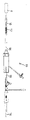
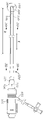
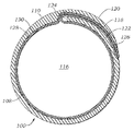
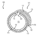
도 1은 환자에게 조직 심장 판막과 같은 인공 디바이스(12)를 전달하기 위한 대표적인 전달 장치(10)와 함께 사용되는 본 개시내용에 따른 외장(8)을 예시한다. 장치(10)는 조종가능한 가이드 카테터(14)(플렉스 카테터로도 지칭됨), 가이드 카테터(14)를 통해 연장되는 벌룬 카테터(16), 및 벌룬 카테터(16)를 통해 연장되는 노우즈 카테터(18)를 포함할 수 있다. 예시된 양태에서 가이드 카테터(14), 벌룬 카테터(16) 및 노우즈 카테터(18)는 아래에서 상세히 설명되는 바와 같이 환자의 신체의 이식 부위에서 판막(12)의 전달 및 위치 설정을 용이하게 하기 위해 서로에 대해 길이방향으로 활주하도록 구성된다. 일반적으로, 외장(8)은 환자의 피부를 통과하여 경대퇴 혈관과 같은 혈관 내로 삽입되어, 외장(8)의 원위 단부가 혈관 내로 삽입된다. 외장(8)은 외장의 반대쪽 근위 단부에 지혈 밸브를 포함할 수 있다. 전달 장치(10)는 외장(8) 내로 삽입될 수 있고, 이어서 인공 디바이스(12)가 전달되어 환자 내에 이식될 수 있다.1 illustrates an enclosure 8 according to the present disclosure used with a
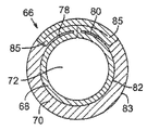
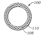
도 2a, 도 2b 및 도 2d는 도 1에 도시되어 있는 것과 같은 전달 장치와 함께 사용하기 위한 외장(22)의 예시적인 양태의 단면도를 도시한다. 예시적인 팽창 가능한 외장은 또한 2008년 10월 10일자로 출원된 미국 특허 출원 제12/249,867호(현재 미국 특허 제8,690,936호), 2011년 12월 6일자로 출원된 미국 특허 출원 제13/312,739호(현재 미국 특허 제8,790,387호), 2014년 4월 8일자로 출원된 미국 특허 출원 제14/248,120호(현재 미국 특허 제9,301,840호), 2014년 7월 7일자로 출원된 미국 특허 출원 제14/324,894호(현재 미국 특허 번호 9,301,841호), 2016년 3월 1일자로 출원된 특허 출원 제15/057,953호(현재 미국 특허 제9,987,134호), 2018년 6월 4일자로 출원된 미국 특허 출원 제15/997,587호, 2018년 10월 2일자로 출원된 미국 특허 출원 제16/149,953호(현재 미국 특허 제10,524,905호), 2018년 10월 2일자로 출원된 미국 특허 출원 제16/149,956호(현재 미국 특허 제10,517,720호), 2018년 10월 2일자로 출원된 미국 특허 출원 제16/149,960호(현재 미국 특허 제10,524,906호), 및 2018년 10월 2일자로 출원된 미국 특허 출원 제16/149,969호(현재 미국 특허 제10,524,907호)에 개시되어 있고, 이들 문헌의 개시내용은 참조로 본 명세서에 포함된다.2A, 2B and 2D show cross-sectional views of an exemplary embodiment of a
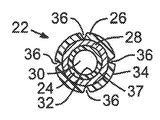
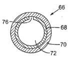
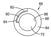
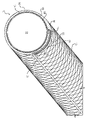
도 2c는 외장(22)과 함께 사용하기 위한 내부 라이너(24)의 일 양태의 사시도를 도시한다. 외장(22)은 내부 폴리머 관형 층(24)과 같은 내부 라이너, 외부 폴리머 관형 층(26)과 같은 외부층, 및 내부 및 외부 폴리머 관형 층(24, 26) 사이에 배치된 중간 관형 층(28)을 포함한다. 외장(22)은 인공 디바이스를 전달, 제거, 수리 및/또는 교체하기 위해 전달 장치가 환자의 혈관 내로 이동할 수 있게 하는 루멘(30)을 형성한다. 이러한 도입기 외장(22)은 또한 피검자의 혈관 내로 장치의 도입을 필요로 하는 임의의 수술과 같은 다른 유형의 최소 침습성 수술에 유용할 수 있다. 예를 들어, 외장(22)은 또한 다양한 유형의 루멘내 디바이스(예를 들어, 스텐트, 스텐트 그래프트 등)를 많은 유형의 혈관 및 비혈관 체강(예를 들어, 정맥, 동맥, 식도, 담관 가지의 관, 창자, 요도, 난관, 다른 내분비 또는 외분비관 등) 내에 배치하기 위한 다른 유형의 전달 장치를 도입하는 데 사용될 수 있다.2C shows a perspective view of one aspect of an
외부 폴리머 관형 층(26) 및 내부 폴리머 관형 층(24)은, 예를 들어 PTFE(예를 들어, Teflon®), 폴리이미드, PEEK, 폴리우레탄, 나일론, 폴리에틸렌, 폴리아미드, 폴리에테르 블록 아미드(예를 들어, PEBAX®), 폴리에테르 블록 에스테르 공중합체, 폴리에스테르, 플루오로폴리머, 폴리염화비닐, 열경화성 실리콘, 라텍스, 폴리이소프렌 고무, 폴리올레핀, 기타 의료 등급 폴리머, 또는 이들의 조합을 포함할 수 있다. 중간 관형 층(28)은 니티놀과 같은 형상 기억 합금, 및/또는 스테인리스강, 코발트 크롬, 스펙트럼 섬유, 폴리에틸렌 섬유, 아라미드 섬유, 또는 이들의 조합을 포함할 수 있다.The outer
내부 폴리머 관형 층(24)은 유리하게는 그 내부 표면에 낮은 마찰 계수가 제공될 수 있다. 예를 들어, 내부 폴리머 관형 층(24)은 약 0.1 미만의 마찰 계수를 가질 수 있다. 외장(22)의 일부 양태는 내부 폴리머 관형 층(24)의 내부 표면(32) 상의 윤활성 라이너를 포함할 수 있다. 이러한 라이너는 외장(22)의 루멘(30)을 통한 전달 장치의 통과를 용이하게 할 수 있다. 적절한 윤활성 라이너의 예는 PTFE, 폴리에틸렌, 폴리비닐리덴 플루오라이드, 및 이들의 조합과 같이 내부 폴리머 관형 층(24)의 마찰 계수를 감소시킬 수 있는 재료를 포함한다. 윤활성 라이너에 적합한 재료는 또한 바람직하게는 약 0.1 이하의 마찰 계수를 갖는 다른 재료를 포함한다.The inner
중간 관형 층(28)의 내경은 전달 장치 및 인공 디바이스의 용례 및 크기에 따라 달라진다. 일부 양태에서, 내경은 약 0.005 인치 내지 약 0.400 인치 범위이다. 중간 관형 층(28)의 두께는 원하는 반경방향 팽창량 뿐만 아니라 요구되는 강도에 따라 달라질 수 있다. 예를 들어, 중간 관형 층(28)의 두께는 약 0.002 인치 내지 약 0.025 인치일 수 있다. 내부 폴리머 관형 층(24) 및 외부 폴리머 관형 층(26)의 두께는 또한 외장(22)의 특정 용례에 따라 달라질 수 있다. 일부 양태에서, 내부 폴리머 관형 층(24)의 두께는 약 0.0005 인치 내지 약 0.010 인치의 범위이고, 하나의 특정 양태에서, 두께는 약 0.002 인치이다. 외부 폴리머 관형 층(26)은 약 0.002 인치 내지 약 0.015 인치의 두께를 가질 수 있고, 하나의 특정 양태에서 외부 폴리머 관형 층(26)은 약 0.010 인치의 두께를 갖는다.The inner diameter of the
외장(22)의 각각의 층의 경도는 또한 외장(22)의 특정 용례 및 원하는 특성에 따라 달라질 수 있다. 일부 양태에서, 외부 폴리머 관형 층(26)은 약 25 듀로미터 내지 약 75 듀로미터의 쇼어 경도를 갖는다.The hardness of each layer of
추가로, 외장(22)의 일부 양태는 외부 폴리머 관형 층(26)의 외부 표면(34) 상의 외부 친수성 코팅을 포함할 수 있다. 이러한 친수성 코팅은 환자의 혈관 내로 외장(22)의 삽입을 용이하게 할 수 있다. 적합한 친수성 코팅의 예는 미네소타주 이든 프레이리 소재의 SurModics, Inc.로부터 입수 가능한 HarmonyTM Advanced Lubricity Coatings 및 다른 진보형 친수성 코팅을 포함한다. DSM 의료용 코팅(네덜란드 헤를렌 소재의 Koninklijke DSM N.V로부터 입수 가능함) 뿐만 아니라 기타 친수성 코팅이 또한 외장(22)과 함께 사용하기에 적합하다.Additionally, some aspects of
일부 양태에서, 외부 폴리머 관형 층(26)의 외부 표면(34)은 수정될 수 있다. 예를 들어, 플라즈마 에칭과 같은 표면 수정이 외부 표면(34)에서 수행될 수 있다. 유사하게, 다른 표면, 즉 외부 및 내부 모두가 특정 양태 및 원하는 용례에 따라 표면 수정될 수 있다. 일부 양태에서, 표면 수정은 수정 영역에서 층들 사이의 접착력을 개선시킬 수 있다.In some aspects, the
외장(22)은 또한 적어도 하나의 방사선 불투과성 충전제 또는 마커를 가질 수 있다. 방사선 불투과성 충전제 또는 마커는 외부 폴리머 관형 층(26)의 외부 표면(34)과 관련될 수 있다. 대안적으로, 방사선 불투과성 충전제 또는 마커는 외부 폴리머 관형 층(24) 내에 임베딩되거나 혼합될 수 있다. 유사하게, 방사선 불투과성 충전제 또는 마커는 내부 폴리머 관형 층(24) 또는 중간 관형 층(28)의 표면과 관련되거나 이들 층 중 하나 또는 양자 모두 내에 임베딩될 수 있다.
방사선 불투과성 충전제 또는 마커로서 사용하기에 적합한 재료는, 예를 들어, 바륨 설파이트, 비스무트 트리옥사이드, 이산화티타늄, 비스무트 서브카보네이트, 또는 이들의 조합을 포함한다. 방사선 불투과성 충전제는 외부 폴리머 관형 층(26)을 형성하는 데 사용되는 재료와 혼합되거나 그 재료에 임베딩될 수 있고, 외부 폴리머 관형 층의 약 5 wt% 내지 약 45 wt%를 구성할 수 있다. 특정 용례에 따라 일부 양태에서 더 많거나 적은 방사선 불투과성 재료가 사용될 수 있다.Materials suitable for use as radiopaque fillers or markers include, for example, barium sulfite, bismuth trioxide, titanium dioxide, bismuth subcarbonate, or combinations thereof. The radiopaque filler may be mixed with or embedded in the material used to form the outer
일부 양태에서, 내부 폴리머 관형 층(24)은 실질적으로 균일한 원통형 튜브를 포함할 수 있다. 대안적인 양태에서, 내부 폴리머 관형 층(24)은 내부 폴리머 관형 층(24)의 반경방향 팽창을 용이하게 하기 위해 길이방향 축을 따라 불연속의 적어도 하나의 섹션을 가질 수 있다. 예를 들어, 내부 폴리머 관형 층(24)에는 외장(22)의 길이의 적어도 일부를 따라 연장되는 하나 이상의 길이방향 노치 및/또는 절단부(36)가 제공될 수 있다. 이러한 노치 또는 절단부(36)는 내부 폴리머 관형 층(24)의 반경방향 팽창을 용이하게 하여, 전달 장치 또는 다른 디바이스의 통과를 수용할 수 있다. 이러한 노치 및/또는 절단부(36)는 내부 표면(32) 근방, 외부 표면(37) 근방, 및/또는 실질적으로 내부 폴리머 층(24)의 전체 두께를 통해 제공될 수 있다. 복수의 노치 및/또는 절단부(36)를 갖는 양태에서, 이러한 노치 및/또는 절단부(36)는 내부 폴리머 층(24) 둘레에서 원주방향으로 서로 실질적으로 균등하게 이격되도록 위치 설정될 수 있다. 대안적으로, 노치 및 절단부(36)은 서로에 대해 또는 임의의 다른 원하는 패턴으로 무작위로 이격될 수 있다. 임의의 제공된 노치 및/또는 절단부(36)의 일부 또는 전부는 외장(22)의 실질적으로 전체 길이를 따라 길이방향으로 연장될 수 있다. 대안적으로, 임의의 제공된 노치 및/또는 절단부(36)의 일부 또는 전부는 외장(22)의 길이의 일부를 따라서만 길이방향으로 연장될 수 있다.In some aspects, inner
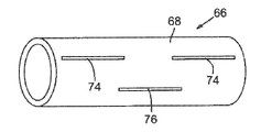
도 2b 및 도 2c(내부 폴리머 관형 층(24)만을 예시함)에 도시된 바와 같이, 일부 양태에서, 내부 폴리머 관형 층(24)은 길이방향으로 그리고 루멘(30)에 의해 형성된 축에 평행하게 연장되어 외장(22)의 실질적으로 전체 길이로 연장되는 적어도 하나의 노치 또는 절단부(36)를 포함한다. 따라서, 전달 장치의 도입 시에, 내부 폴리머 관형 층(24)은 노치 및/또는 절단부(36)를 따라 분할 개방되어 팽창하고, 이에 따라 전달 장치를 수용할 수 있다.2B and 2C (which illustrates only the inner polymeric tubular layer 24 ), in some aspects, the inner
추가적으로 또는 대안적으로, 도 2d에 도시된 바와 같이, 외부 폴리머 관형 층(26)은 하나 이상의 노치 및/또는 절단부(36)를 포함할 수 있다. 일부 양태에서, 노치 및/또는 절단부(36)는 외부 관형 층(26)의 전체 두께를 통해 연장되지 않는다. 노치 및/또는 절단부(36)는 외장(22)의 반경방향 팽창 시에 분리 가능할 수 있다. 외부 폴리머 관형 층(26)은 길이방향으로 후퇴 가능할 수 있거나, 중간 관형 층(28) 및 내부 폴리머 관형 층(24)으로부터 멀어지게 당겨질 수 있다. 후퇴 가능한 외부 폴리머 관형 층(26)을 갖는 양태에서, 외부 폴리머 관형 층(26)은 루멘(30)을 통한 전달 장치의 통과를 수용하거나 용이하게 하기 위해 후퇴될 수 있고, 그 다음 외장(22) 상의 원래 위치로 교체될 수 있다.Additionally or alternatively, as shown in FIG. 2D , outer
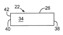
도 3은 도 2a에 도시된 외장(22)의 입면도를 예시한다. 이 도면에서는, 외부 폴리머 관형 층(26)만이 보인다. 외장(22)은 근위 단부(38) 및 근위 단부(38) 반대쪽의 원위 단부(40)를 포함한다. 외장(22)은 외장(22)의 근위 단부(38) 또는 그 근방에서 외장(22)의 루멘 내부에 지혈 밸브를 포함할 수 있다.FIG. 3 illustrates an elevational view of the
추가적으로, 외장(22)은 외장(22)의 원위 단부(40)에 연성 팁(42)을 포함할 수 있다. 이러한 연성 팁(42)은 외장(22)의 다른 부분보다 더 낮은 경도로 제공될 수 있다. 일부 양태에서, 연성 팁(42)은 약 25 D 내지 약 40 D의 쇼어 경도를 가질 수 있다.Additionally,
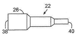
도 3에 도시된 바와 같이, 외장(22)의 팽창되지 않은 원래 외경은 외장(22)의 길이에 걸쳐, 실질적으로 근위 단부(38)로부터 원위 단부(40)까지 실질적으로 일정할 수 있다. 도 4a 및 도 4b에 예시된 것과 같은 대안적인 양태에서, 외장(22)의 원래의 팽창되지 않은 외경은 근위 단부(38)로부터 원위 단부(40)로 감소할 수 있다. 도 4a의 양태에 도시된 바와 같이, 원래의 팽창되지 않은 외경은 근위 단부(38)로부터 원위 단부(40)로 구배를 따라 감소할 수 있다. 도 4b에 도시된 것과 같은 대안적인 양태에서, 외장(22)의 원래의 팽창되지 않은 외경은 외장(22)의 길이를 따라 점증적으로 단계식 감소할 수 있고, 여기서 가장 큰 원래의 팽창되지 않은 외경은 근위 단부(38) 근방에 있고 가장 작은 원래의 팽창되지 않은 외경은 외장(22)의 원위 단부(40) 근방에 있다.As shown in FIG. 3 , the original uninflated outer diameter of
도 5 및 도 6에 도시된 바와 같이, 외장(22)은 인공 디바이스가 외장(22)의 루멘을 통과할 때 국소로 팽창하고, 이어서 인공 디바이스가 외장(22)의 해당 부분을 통과하면 원래의 형상으로 실질적으로 복귀하도록 설계될 수 있다. 예를 들어, 도 5는 외장(22)의 내부 루멘을 통과하는 디바이스를 나타내는 국소 돌출부(44)를 갖는 외장(22)을 예시한다. 도 5는 외장(22)의 근위 단부(38)에 가까이 있는, 즉 디바이스가 외장(22) 내로 도입되는 영역에 가까이 있는 디바이스를 도시한다. 도 6은 도 5의 외장(22)을 도시하는데, 디바이스는 외장(22)을 따라 더 진행되었다. 국소 돌출부(44)는 이제 외장(22)의 원위 단부(40)에 더 가깝고, 따라서 환자의 혈관에 도입될 예정이다. 도 5 및 도 6으로부터 명백한 바와 같이, 디바이스와 관련된 국소 돌출부가 외장(22)의 루멘의 일부를 통과하면, 외장(22)의 해당 부분은 적어도 부분적으로 외장(22)의 재료 및 구조로 인해 그 원래의 형상 및 크기로 자동적으로 복귀할 수 있다.5 and 6,
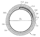
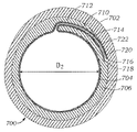
외장(22)은 내부 폴리머 관형 층(도 5 및 도 6에서는 보이지 않음)의 내경과 동일한 팽창되지 않은 내경, 및 외부 폴리머 관형 층(26)의 외경과 동일한 팽창되지 않은 외경(46)을 갖는다. 외장(22)은 팽창되지 않은 내경 및 팽창되지 않은 외경(46)보다 각각 더 큰 팽창된 내경 및 팽창된 외경(48)으로 팽창되도록 설계된다. 하나의 대표적인 양태에서, 팽창되지 않은 내경은 약 16 Fr이고 팽창되지 않은 외경(46)은 약 19 Fr인 반면, 팽창된 내경은 약 26 Fr이고 팽창된 외경(48)은 약 29 Fr이다. 다양한 용례를 위한 전달 장치의 크기 요건에 따라 상이한 팽창 및 팽창되지 않은 내경 및 외경을 갖는 상이한 외장(22)이 제공될 수 있다. 또한, 일부 양태는 사용된 특정 설계 파라미터, 재료, 및/또는 구성에 따라 더 많거나 적은 팽창을 제공할 수 있다.
본 개시내용에 따른 외장의 일부 양태에서, 그리고 도 7의 단면도 및 도 8의 입면도에 도시된 바와 같이, 외장(22)은 외부 폴리머 관형 층(26)의 외부 표면(52) 상에 배치된 외부 폴리머 커버링(50)과 같은 외부 커버링을 더 포함할 수 있다. 외부 폴리머 커버링(50)은 하위 외장(22)을 위한 보호 커버링을 제공할 수 있다. 일부 양태에서, 외부 폴리머 커버링(50)은 크림핑되거나 구속된 상태의 자체 팽창 가능한 외장을 수납할 수 있고, 이어서 외부 폴리머 커버링(50)의 제거 시에 자체 팽창 가능한 외장을 해제할 수 있다. 예를 들어, 자체 팽창 가능한 외장의 일부 양태에서, 중간층(28)은 니티놀 및/또는 다른 형상 기억 합금을 포함할 수 있고, 중간층(28)은 외부 폴리머 관형 층(26) 및 외부 폴리머 커버링(50) 내에서 감소된 직경으로 크림핑되거나 반경방향으로 압축될 수 있다. 자체 팽창 가능한 외장이 환자의 혈관 내로 적어도 부분적으로 삽입되면, 외부 폴리머 커버링(50)은 뒤로 활주되거나, 벗겨지거나, 달리 외장으로부터 적어도 부분적으로 제거될 수 있다. 외부 폴리머 커버링(50)의 제거를 용이하게 하기 위해, 외부 폴리머 커버링(50)의 일부는 환자의 혈관 외부에 남아 있을 수 있고, 그 부분은 외장이 팽창되게 하도록 뒤로 당겨지거나 외장으로부터 제거될 수 있다. 일부 양태에서, 실질적으로 전체 외부 폴리머 커버링(50)은 외장과 함께 환자의 혈관 내로 삽입될 수 있다. 이들 양태에서, 외부 폴리머 커버링(50)에 부착된 외부 메커니즘이 제공될 수 있어, 외부 폴리머 커버링은 외장이 환자의 혈관 내로 삽입되면 외장으로부터 적어도 부분적으로 제거될 수 있다.In some aspects of sheathing according to the present disclosure, and as shown in the cross-sectional view of FIG. 7 and the elevational view of FIG. It may further include an outer covering such as a polymer covering 50 . The outer polymeric covering 50 may provide a protective covering for the
외부 폴리머 커버링(50)에 의해 더 이상 구속되지 않으면, 반경방향으로 압축된 중간층(28)은 자체 팽창하여, 중간층(28)의 길이를 따라 외장의 팽창을 유발할 수 있다. 일부 양태에서, 외장의 일부는, 수술 절차가 완료된 후 외장이 혈관으로부터 인출됨에 따라, 반경방향으로 접혀, 적어도 부분적으로 원래의 크림핑된 상태로 복귀될 수 있다. 일부 양태에서, 이러한 접힘은, 일부 양태에서 외장이 혈관 내로 삽입되기 전에 외장의 일부 상에 장착될 수 있는 추가 디바이스 또는 층에 의해 용이하게 되고 및/또는 촉진될 수 있다.When no longer constrained by the outer polymer covering 50, the radially compressed
일부 양태에서, 외부 폴리머 커버링(50)은 외장(22)의 다른 층에 접착되지 않는다. 예를 들어, 외부 폴리머 커버링(50)은 하위 외장에 대해 활주 가능할 수 있어, 외장(22) 상의 초기 위치로부터 쉽게 제거되거나 후퇴될 수 있다.In some aspects, outer polymeric covering 50 is not adhered to other layers of
도 8에 도시된 바와 같이, 외부 폴리머 커버링(50)은 외부 폴리머 커버링(50)의 수동 제거를 용이하게 하기 위해 하나 이상의 박리 탭(54)을 포함할 수 있다. 외부 폴리머 커버링(50)은 외장(22)의 반경방향 팽창을 용이하게 하기 위해 자동으로 또는 수동으로 후퇴 가능 및/또는 분할 가능할 수 있다. 박리 탭(54)은 외부 폴리머 커버링(50)에 존재하는 임의의 절단부 또는 노치로부터 약 90도에 위치되고, 서로 약 180도 오프셋될 수 있다. 대안적인 양태에서, 박리 탭(54)은 외부 폴리머 커버링(50)의 원주 둘레에서 실질적으로 연장될 수 있고, 따라서 단일의 원형 박리 탭(54)을 초래할 수 있다.As shown in FIG. 8 , outer polymer covering 50 may include one or
외부 폴리머 커버링(50)에 적합한 재료는 내부 폴리머 관형 층 및 외부 폴리머 관형 층에 적합한 재료와 유사하고, PTFE 및/또는 고밀도 폴리에틸렌을 포함할 수 있다.Suitable materials for the outer polymeric covering 50 are similar to materials suitable for the inner polymeric tubular layer and the outer polymeric tubular layer, and may include PTFE and/or high density polyethylene.
이제, 중간 관형 층(28)을 참조하면, 몇 가지 상이한 구성이 가능하다. 중간 관형 층(28)은 일반적으로 와이어 또는 스트러트의 배열, 패턴, 구조 또는 구성을 포함하는 얇고 중공이며 실질적으로 원통형인 튜브이지만, 다른 기하형상도 사용될 수 있다. 중간 관형 층(28)은 외장(22)의 실질적으로 전체 길이를 따라 연장될 수 있거나, 대안적으로는 외장(22)의 길이의 일부를 따라서만 연장될 수 있다. 적합한 와이어는 약 0.0005 인치 내지 약 0.10 인치 두께 범위의 원형이거나 약 0.0005 인치 x 0.003 인치 내지 약 0.003 인치 x 0.007 인치 범위의 평탄형일 수 있다. 그러나, 특정 양태에 대해 다른 기하형상 및 크기가 또한 적합하다. 편조된 와이어가 사용되면, 편조 밀도가 변경될 수 있다. 일부 양태는 인치당 약 30 픽 내지 인치당 약 80 픽의 편조 밀도를 가지며 다양한 편조 패턴에서 최대 32개의 와이어를 포함할 수 있다.Referring now to the
중간 관형 층의 하나의 대표적인 양태는 중간 관형 층의 내부 및 외부 표면에 각각 배치된 내부 폴리머 관형 부재 및 외부 폴리머 관형 부재에 의해 적어도 부분적으로 캡슐화된 편조 니티놀 복합재를 포함한다. 폴리머 층에 의한 이러한 캡슐화는, 예를 들어 폴리머 층을 중간 관형 층에 융합시키거나 중간 관형 층을 침지 코팅함으로써 달성될 수 있다. 일부 양태에서, 내부 폴리머 관형 부재, 중간 관형 층, 및 외부 폴리머 관형 층은 맨드릴에 배열될 수 있고, 그 다음 층은 조립체를 오븐에 배치하거나 달리 조립체를 가열함으로써 서로 열적으로 융합되거나 용융될 수 있다. 그 후, 맨드릴을 결과적인 외장으로부터 제거할 수 있다. 다른 양태에서, 침지 코팅은 맨드릴의 표면에 내부 폴리머 관형 부재를 적용하기 위해 사용될 수 있다. 그 후, 중간 관형 층이 적용될 수 있고, 내부 폴리머 관형 부재가 경화하게 될 수 있다. 이어서, 조립체는, 예컨대 외장의 외부 폴리머 관형 부재가 될, 예를 들어 폴리우레탄의 얇은 코팅을 적용하도록 다시 침지 코팅될 수 있다. 그 후, 맨드릴로부터 외장이 제거될 수 있다.One representative embodiment of the middle tubular layer includes a braided nitinol composite at least partially encapsulated by an inner polymer tubular member and an outer polymer tubular member disposed on the inner and outer surfaces of the middle tubular layer, respectively. Such encapsulation by the polymer layer can be achieved, for example, by fusing the polymer layer to the intermediate tubular layer or by dip coating the intermediate tubular layer. In some aspects, the inner polymer tubular member, middle tubular layer, and outer polymer tubular layer can be arranged on a mandrel, and then the layers can be thermally fused or melted together by placing the assembly in an oven or otherwise heating the assembly. . The mandrel can then be removed from the resulting sheath. In another aspect, dip coating may be used to apply an inner polymeric tubular member to the surface of the mandrel. An intermediate tubular layer may then be applied and the inner polymeric tubular member may be allowed to cure. The assembly can then be dip-coated again to apply a thin coating of, for example, polyurethane, which will be, for example, the outer polymeric tubular member of the sheath. The sheath may then be removed from the mandrel.
추가로, 중간 관형 층(28)은, 예를 들어, 중간 관형 층(28)이 반경방향 팽창을 할 수 있도록, 패턴 또는 구조를 형성하기 위해 편조되거나 레이저 절단될 수 있다. 도 9 내지 도 23은 중간 관형 층에 대한 다양한 구조의 부분 입면도를 예시한다. 도 11 내지 도 14 및 도 23에 도시된 것과 같은 일부 예시된 구조는 적어도 하나의 불연속성을 포함한다. 예를 들어, 도 11, 도 12, 도 13, 도 14, 및 도 23에 도시된 스트러트(56, 58, 60, 62, 64)는 각각 스트러트(56, 58, 60, 62, 64)가 중간 관형 층(28)의 인접한 섹션을 서로 분리시킨다는 점에서 불연속적인 중간 관형 층(28)을 초래하며, 여기서 섹션은 외장의 루멘에 평행한 길이방향 축을 따라 서로 이격되어 있다. 따라서, 중간 관형 층(28)의 구조는 외장의 길이를 따라 변화하면서 섹션마다 달라질 수 있다.Additionally, the
도 9 내지 도 23에 도시되어 있는 구조는 반드시 실척으로 작성된 것은 아니다. 구조의 구성요소 및 요소는 단독으로 또는 단일 중간 관형 층(28) 내에서 조합하여 사용될 수 있다. 중간 관형 층(28)의 범위는 이들 특정 구조로 제한되도록 의도되지 않으며; 이들은 단지 예시적인 양태일 뿐이다.The structures shown in FIGS. 9 to 23 are not necessarily drawn to scale. The components and elements of the structure may be used singly or in combination within a single
인공 디바이스를 도입하기 위한 외장의 대안적인 양태가 또한 설명된다. 예를 들어, 도 24 내지 도 26은 신체 내로 인공 디바이스를 도입하기 위한 외장(66)의 단면도 및 사시도를 각각 예시한다. 외장(66)은 내부 폴리머 층(68)과 같은 내부 라이너, 폴리머 관형 층(70)과 같은 외부층, 및 지혈 밸브(도시되지 않음)를 포함한다. 내부 폴리머 층(68) 및 외부 폴리머 관형 층(70)은, 전달 장치 및 인공 디바이스가 환자의 신체 외부로부터 환자의 혈관 내로 통과할 수 있게 하는 루멘(72)을 적어도 부분적으로 둘러싼다. 내부 폴리머 층(68) 및 외부 폴리머 층(70) 중 어느 하나 또는 양자 모두에는 외장의 반경방향 팽창을 용이하게 하기 위해 적어도 하나의 길이방향 노치 및/또는 절단부가 제공될 수 있다.An alternative aspect of an enclosure for introducing a prosthetic device is also described. For example, FIGS. 24-26 illustrate cross-sectional and perspective views, respectively, of an
예를 들어, 도 24는 외장(66)의 반경방향 팽창을 용이하게 할 수 있는 내부 폴리머 층(68)의 길이방향 노치(74)를 예시한다. 길이방향 노치(74)는 전달 장치 또는 인공 디바이스의 삽입으로 인한 반경방향 힘의 인가 시에 완전히 분리되거나 분할 개방될 수 있다. 유사하게, 도 25는 외장(66)의 반경방향 팽창을 또한 용이하게 할 수 있는 내부 폴리머 층(68)의 길이방향 절단부(76)를 예시한다. 외부 폴리머 층(70)은 추가적으로 또는 대안적으로 하나 이상의 길이방향 절단부(76) 또는 노치(74)를 포함할 수 있다. 내부 폴리머 층(68)에서든 외부 폴리머 층(70)에서든 이러한 절단부 및/또는 노치는 실질적으로 층의 전체 두께를 통해 연장될 수 있거나, 층의 두께를 통해 단지 부분적으로 연장될 수 있다. 절단부 및/또는 노치는 내부 및/또는 외부 폴리머 층(68, 70)의 내부 또는 외부 표면, 또는 양쪽 표면에 또는 그 근방에 위치 설정될 수 있다.For example, FIG. 24 illustrates a
도 26은 길이방향 노치(74) 및 길이방향 절단부(76)를 갖는 내부 폴리머 층(68)의 일 양태의 사시도를 예시한다. 더 많거나 적은 노치(74) 및/또는 절단부(76)가 제공될 수 있다. 명확성을 위해, 외부 폴리머 층(70)은 도 26에 도시되지 않는다. 도 26에 도시된 바와 같이, 길이방향 노치(74) 및/또는 절단부(76)는 외장(66)의 길이의 일부를 따라서만 연장될 수 있다. 대안적인 양태에서, 하나 이상의 노치(74) 및/또는 절단부(76)는 외장(66)의 전체 길이를 따라 실질적으로 연장될 수 있다. 추가적으로, 노치(74) 및/또는 절단부(76)는 무작위로 위치 설정되거나 패턴화될 수 있다.26 illustrates a perspective view of one embodiment of an
외장(66)의 하나의 특정 양태는 외장(66)의 길이의 약 75%를 따라 길이방향으로 연장되는 외부 폴리머 층(70) 또는 내부 폴리머 층(68)에 노치 또는 절단부를 갖는 외장을 포함한다. 이러한 노치 또는 절단부가 관련 층을 통해 단지 부분적으로 연장되면, 약 0.5 lbs.의 인열력과 같은 비교적 낮은 인열력을 가질 수 있어, 사용 동안 노치가 비교적 쉽게 분할 개방될 수 있다.One particular aspect of the
내부 폴리머 층(68) 및 외부 폴리머 층(70)은 임의로 함께 접착되거나 달리 서로 물리적으로 연계될 수 있다. 내부 폴리머 층(68)과 외부 폴리머 층(70) 사이의 접착량은 층의 표면에 걸쳐 달라질 수 있다. 예를 들어, 외장(66)의 반경방향 팽창을 방해하지 않도록 층에 존재하는 임의의 노치 및/또는 절단부 주변 또는 근방 영역에 접착이 거의 또는 전혀 없을 수 있다. 층들 사이의 접착은, 예를 들어 열 접합 및/또는 코팅에 의해 생성될 수 있다. 일부 양태에서, 외장(66)은 내부 폴리머 층(68)의 역할을 할 수 있는 압출된 튜브로부터 형성될 수 있다. 내부 폴리머 층(68)은, 예컨대 플라즈마 에칭, 화학적 에칭 또는 다른 적절한 표면 처리 방법에 의해 표면 처리될 수 있다. 내부 폴리머 층(68)의 표면을 처리함으로써, 내부 폴리머 층(68)의 외부 표면은 내부 폴리머 층(68)과 외부 폴리머 층(70) 사이에 더 나은 접착을 제공할 수 있는 변경된 표면 각도를 갖는 영역을 가질 수 있다. 처리된 내부 폴리머 층은, 예를 들어 폴리우레탄 용액에 침지 코팅되어 외부 폴리머 층(70)을 형성할 수 있다. 일부 구성에서, 폴리우레탄은 내부 폴리머 층(68)의 처리되지 않은 표면 영역에 잘 접착되지 않을 수 있다. 따라서, 팽창 영역(예를 들어, 노치(74) 및/또는 절단부(76) 근방의 내부 폴리머 층(68)의 부분)으로부터 이격된 내부 폴리머 층(68)의 표면 영역만을 표면 처리함으로써, 외부 폴리머 층(70)은 내부 폴리머 층(68)의 일부 영역에 접착되는 반면, 내부 폴리머 층(68)의 다른 영역은 외부 폴리머 층(70)에 대해 활주하도록 자유롭게 남겨져, 외장(66)의 직경 팽창을 허용한다. 따라서, 임의의 노치(74) 및/또는 절단부(76) 주변 또는 근방의 영역은 층들 사이의 접착을 거의 또는 전혀 경험할 수 없는 반면, 내부 및 외부 폴리머 층(68, 70)의 다른 영역은 접착식으로 고정되거나 달리 서로 물리적으로 연계될 수 있다.
이전에 개시된 양태에서와 같이, 도 24 내지 도 26에 예시된 양태는 다양한 내경과 외경을 갖는 외장에 적용될 수 있다. 용례는 약 3 Fr 내지 약 26 Fr의 팽창된 직경으로 팽창 가능한 내부 폴리머 층(68)의 내경을 갖는 본 개시내용의 외장을 이용할 수 있다. 팽창된 직경은 외장(66)의 길이를 따라 약간 달라질 수 있다. 예를 들어, 외장(66)의 근위 단부에서의 팽창된 외경은 약 3 Fr 내지 약 28 Fr의 범위일 수 있는 반면, 외장(66)의 원위 단부에서의 팽창된 외경은 약 3 Fr 내지 약 25 Fr의 범위일 수 있다. 일부 양태에서, 외장(66)은 원래의 팽창되지 않은 외경보다 약 10% 더 큰 팽창된 외경에서 원래의 팽창되지 않은 외경보다 약 100% 더 큰 팽창된 외경으로 팽창될 수 있다.As with the previously disclosed aspects, the aspects illustrated in FIGS. 24-26 can be applied to sheaths having a variety of inner and outer diameters. Applications may utilize sheaths of the present disclosure having an inner diameter of the expandable
일부 양태에서, 외장(66)의 외경은 외장(66)의 근위 단부로부터 외장(66)의 원위 단부로 점진적으로 감소한다. 예를 들어, 일 양태에서, 외경은 근위 단부에서의 약 26 Fr로부터 원위 단부에서의 약 18 Fr로 점진적으로 감소할 수 있다. 외장(66)의 직경은 외장(66)의 실질적으로 전체 길이에 걸쳐 점진적으로 천이될 수 있다. 다른 양태에서, 외장(66)의 직경의 천이 또는 감소는 외장(66)의 길이의 일부를 따라서만 발생할 수 있다. 예를 들어, 천이는 근위 단부로부터 원위 단부까지의 길이를 따라 발생할 수 있으며, 여기서 길이는 약 0.5인치 내지 외장(66)의 대략 전체 길이의 범위일 수 있다.In some aspects, the outer diameter of
내부 폴리머 층(68)에 적합한 재료는 높은 탄성 강도를 가질 수 있고 다른 양태와 관련하여 설명된 재료, 특히 테플론(PTFE), 폴리에틸렌(예를 들어, 고밀도 폴리에틸렌), 플루오로폴리머, 또는 이들의 조합을 포함할 수 있다. 일부 양태에서, 내부 폴리머 층(68)은 바람직하게는 약 0.01 내지 약 0.5의 마찰 계수와 같은 낮은 마찰 계수를 갖는다. 외장(66)의 일부 예시적인 양태는 약 0.1 이하의 마찰 계수를 갖는 내부 폴리머 층(68)을 포함한다.Suitable materials for the
마찬가지로, 외부 폴리머 층(70)에 적합한 재료는 다른 양태와 관련하여 설명된 재료, 및 다른 열가소성 엘라스토머 및/또는 고탄성 재료를 포함한다.Likewise, suitable materials for the
외부 폴리머 층(70)의 쇼어 경도는 상이한 용례 및 양태를 위해 달라질 수 있다. 일부 양태는 쇼어 경도가 약 25A 내지 약 80A, 또는 약 20D 내지 약 40D인 외부 폴리머 층을 포함한다. 하나의 특정 양태는 72A의 쇼어 경도를 갖는 쉽게 입수 가능한 폴리우레탄을 포함한다. 다른 특정 양태는 외부 폴리머 층을 생성하기 위해 폴리우레탄 또는 실리콘에 침지된 폴리에틸렌 내부 폴리머 층을 포함한다.The Shore hardness of the
외장(66)은 또한 앞서 설명한 바와 같이 방사선 불투과성 충전제 또는 마커를 포함할 수 있다. 일부 양태에서, 별개의 방사선 불투과성 마커 또는 밴드가 외장(66)의 일부에 적용될 수 있다. 예를 들어, 방사선 불투과성 마커는 내부 폴리머 층(68), 외부 폴리머 층(70)에 결합될 수 있고 및/또는 내부 및 외부 폴리머 층(68, 70) 사이에 위치 설정될 수 있다.
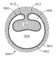
도 27a 내지 도 27e 및 도 28은 본 개시내용에 따른 팽창되지 않은(도 27a 내지 도 27e) 및 팽창된(도 28) 외장(66)의 다양한 양태의 단면도를 예시한다. 외장(66)은 외부 폴리머 관형 층(70)이 절단부(76)를 따라 서로 분리 가능한 제1 부분(78) 및 제2 부분(80)을 포함하도록 외부 폴리머 관형 층(70)의 두께를 통해 길이방향 절단부(76)를 갖는 분할된 외부 폴리머 관형 층(70)을 포함한다. 팽창 가능한 내부 폴리머 층(68)은 외부 폴리머 관형 층(70)의 내부 표면(82)과 연계되며, 도 27a에 도시되어 있는 팽창되지 않은 구성에서, 내부 폴리머 층(68)의 일부는 절단부(76)에 의해 생성된 간극을 통해 연장되고 외부 폴리머 관형 층(70)의 제1 및 제2 부분(78, 80) 사이에서 압축될 수 있다. 외장(66)의 팽창 시에, 도 28에 도시된 바와 같이, 외부 폴리머 관형 층(70)의 제1 및 제2 부분(78, 80)은 서로 분리되어 있고, 내부 폴리머 층(68)은 실질적으로 원통형 튜브로 팽창된다. 일부 양태에서, 2개 이상의 길이방향 절단부(76)가 외부 폴리머 관형 층(70)의 두께를 통해 제공될 수 있다. 이러한 양태에서, 내부 폴리머 층(68)의 일부는 외부 폴리머 관형 층(70)에 제공된 길이방향 절단부(76) 각각을 통해 연장될 수 있다.27A-27E and 28 illustrate cross-sectional views of various aspects of an unexpanded (FIG. 27A-27E) and expanded (FIG. 28)
바람직하게는, 내부 폴리머 층(68)은 탄성이 있고 절첩 및/또는 주름 형성을 할 수 있는 하나 이상의 재료를 포함한다. 예를 들어, 도 27a는 절첩된 영역(85)을 갖는 내부 폴리머 층(68)을 예시한다. 도 27a 내지 도 27e에 도시된 바와 같이, 외장(66)에는 하나 이상의 절첩된 영역(85)이 제공될 수 있다. 이러한 절첩된 영역(85)은 반경방향을 따라 제공되어 외부 폴리머 관형 층(70)의 원주와 실질적으로 합치할 수 있다. 절첩된 영역(85)의 적어도 일부는 외부 폴리머 관형 층(70)의 외부 표면(83)에 인접하게 위치 설정될 수 있다.Preferably, the
또한, 도 27b 및 도 27e에 도시된 바와 같이, 절첩된 영역 또는 영역들(85)의 적어도 일부는 외부 폴리머 커버링(81)과 같은 외부 커버링에 의해 중첩될 수 있다. 외부 폴리머 커버링(81)은 외부 폴리머 관형 층(70)의 외부 표면(83)의 적어도 일부에 인접할 수 있다. 외부 폴리머 커버링(81)은 내부 폴리머 층(68)의 절첩된 영역(85)을 적어도 부분적으로 수납하는 역할을 하고, 또한 예를 들어 외장(66)이 굽힘을 받을 때 절첩된 영역(85)이 외부 폴리머 관형 층(70)으로부터 분리되는 것을 방지할 수 있다. 일부 양태에서, 외부 폴리머 커버링(81)은 외부 폴리머 관형 층(70)의 외부 표면(83)에 적어도 부분적으로 접착될 수 있다. 외부 폴리머 커버링(81)은 또한 외장(66)의 강성 및/또는 내구성을 증가시킬 수 있다.Also, as shown in FIGS. 27B and 27E , at least a portion of the folded region or
또한, 도 27b 및 도 27e에 도시된 바와 같이, 외부 폴리머 커버링(81)은 외장(66)의 원주와 완전히 중첩되지 않을 수 있다. 예를 들어, 외부 폴리머 커버링(81)에는 제1 및 제2 단부가 제공될 수 있으며, 여기서 단부는 서로 접촉하지 않는다. 이들 양태에서, 내부 폴리머 층(68)의 절첩된 영역(85)의 일부만이 외부 폴리머 커버링(81)에 의해 중첩된다.Also, as shown in FIGS. 27B and 27E , the outer polymeric covering 81 may not completely overlap the circumference of the
복수의 절첩된 영역(85)이 존재하는 양태에서, 영역은 외부 폴리머 관형 층(70)의 원주 둘레에서 서로 동일하게 변위될 수 있다. 대안적으로, 절첩된 영역은 중심에서 벗어나고, 크기가 상이하고, 및/또는 서로 무작위로 이격될 수 있다. 내부 폴리머 층(68) 및 외부 관형 층(70)의 부분이 접착되거나 달리 서로 결합될 수 있지만, 절첩된 영역(85)은 바람직하게는 외부 관형 층(70)에 접착되거나 결합되지 않는다. 예를 들어, 내부 폴리머 층(68)과 외부 관형 층(70) 사이의 접착은 최소 팽창 영역에서 가장 높을 수 있다. In embodiments where there are a plurality of folded
도 27a 내지 도 28에 예시된 외장의 하나의 특정 양태는 폴리에틸렌(예를 들어, 고밀도 폴리에틸렌) 외부 폴리머 관형 층(70) 및 PTFE 내부 폴리머 층(68)을 포함한다. 그러나, 앞서 설명한 바와 같이, 다른 재료가 각각의 층에 적합하다. 일반적으로, 외부 폴리머 관형 층(70)과 함께 사용하기에 적합한 재료는 내부 폴리머 층(68)의 팽창 및 수축을 지원할 수 있는 높은 강성 또는 강도 모듈러스를 갖는 재료를 포함한다.One particular embodiment of the sheath illustrated in FIGS. 27A-28 includes a polyethylene (eg, high density polyethylene) outer
일부 양태에서, 외부 폴리머 관형 층(70)은 외부 폴리머 관형 층(70)의 전체 길이를 따라 동일한 재료 또는 재료들의 조합을 포함한다. 대안적인 양태에서, 재료 조성은 외부 폴리머 관형 층(70)의 길이를 따라 변할 수 있다. 예를 들어, 외부 폴리머 관형 층에는 하나 이상의 세그먼트가 제공될 수 있으며, 여기서 조성은 세그먼트마다 변경된다. 하나의 특정 양태에서, 조성물의 듀로미터 등급은, 근위 단부 근방의 세그먼트가 더 강성의 재료 또는 재료들의 조합을 포함하는 반면, 원위 단부 근방의 세그먼트가 더 연성의 재료 또는 재료들의 조합을 포함하도록 외부 폴리머 관형 층(70)의 길이를 따라 변경된다. 이는 전달 장치를 도입하는 지점에서 비교적 강성의 근위 단부를 갖는 외장(66)을 허용할 수 있지만, 환자의 혈관으로의 진입 지점에서 여전히 비교적 연성의 원위 팁을 가질 수 있다.In some embodiments, outer
다른 개시된 양태에서와 같이, 도 27a 내지 도 28에 도시되어 있는 외장(66)의 양태는 다양한 크기와 치수로 제공될 수 있다. 예를 들어, 외장(66)은 약 3 Fr 내지 약 26 Fr의 팽창되지 않은 내경이 제공될 수 있다. 일부 양태에서, 외장(66)은 약 15 Fr 내지 약 16 Fr의 팽창되지 않은 내경을 갖는다. 일부 양태에서, 외장(66)의 팽창되지 않은 내경은 외장(66)의 원위 단부 또는 그 근방에서 약 3 Fr 내지 약 26 Fr의 범위일 수 있는 반면, 외장(66)의 팽창되지 않은 내경은 외장(66)의 근위 단부 또는 그 근방에서 약 3 Fr 내지 약 28 Fr의 범위일 수 있다. 예를 들어, 일 양태에서, 팽창되지 않은 외장(66)은 외장(66)의 원위 단부 또는 그 근방에서 약 16 Fr의 팽창되지 않은 내경으로부터 외장(66)의 근위 단부 또는 그 근방에서 약 26 Fr의 팽창되지 않은 내경으로 천이될 수 있다.As with the other disclosed aspects, the aspects of
외장(66)은 약 3 Fr 내지 약 30 Fr의 팽창되지 않은 외경이 제공될 수 있고, 일부 양태에서 약 18 Fr 내지 약 19 Fr의 팽창되지 않은 외경을 갖는다. 일부 양태에서, 외장(66)의 팽창되지 않은 외경은 외장(66)의 원위 단부 또는 그 근방에서 약 3 Fr 내지 약 28 Fr의 범위일 수 있는 반면, 외장(66)의 팽창되지 않은 외경은 외장(66)의 근위 단부 또는 그 근방에서 약 3 Fr 내지 약 30 Fr의 범위일 수 있다. 예를 들어, 하나의 팽창되지 않은 양태에서, 외장(66)은 외장(66)의 원위 단부 또는 그 근방에서 약 18 Fr의 팽창되지 않은 외경으로부터 외장(66)의 근위 단부 또는 그 근방에서 약 28 Fr의 팽창되지 않은 외경으로 천이될 수 있다.
내부 폴리머 층(68)의 두께는 달라질 수 있지만, 일부 바람직한 양태에서는 약 0.002 인치 내지 약 0.015 인치이다. 일부 양태에서, 외장(66)의 팽창은 약 10% 이하 내지 약 430% 이상의 팽창되지 않은 외경의 팽창을 초래할 수 있다.The thickness of the
다른 예시 및 설명된 양태에서와 같이, 도 27a 내지 도 28에 도시된 양태에는 앞서 설명한 바와 같이 방사선 불투과성 충전제 및/또는 방사선 불투과성 팁 마커가 제공될 수 있다. 외장(66)에는 외장(66)의 원위 팁 또는 그 근방에 제공된 방사선 불투과성 팁 마커가 제공될 수 있다. 이러한 방사선 불투과성 팁 마커는 방사선 불투과성 충전제, 백금, 이리듐, 백금/이리듐 합금, 스테인리스강, 기타 생체 적합성 금속, 또는 이들의 조합에 적합한 재료와 같은 재료를 포함할 수 있다.As with other illustrated and described embodiments, the embodiments shown in FIGS. 27A-28 may be provided with radiopaque fillers and/or radiopaque tip markers as previously described.
도 50 및 도 51은 길이방향 슬릿(169)이 있는 내부 관형 층(168)을 갖는 팽창 가능한 외장(166)의 단면도를 도시한다. 일부 양태에서, 길이방향 슬릿(169)은 내부 관형 층(168)의 전체 길이로 연장된다. 외부 관형 층(170)은 내부 관형 층(168)을 둘러싸고 길이방향으로 연장되는 절첩된 플랩(171)을 포함한다. 일부 양태에서, 절첩된 플랩(171)은 외부 관형 층(170)의 전체 길이로 연장된다. 절첩된 플랩(171)은 외장이 팽창되지 않은 상태에 있을 때 외부 관형 층(170)의 외부 표면(183)의 일부 위에 놓이게 된다(도 50). 인공 디바이스가 외장(166)의 내부 루멘(172)을 통해 이동될 때, 인공 디바이스는 길이방향 슬릿(169)을 확장시키고 절첩된 플랩(171)을 펼치는 외향 지향 반경방향 힘을 내부 관형 층(168)에 인가한다. 도 51은 길이방향 슬릿(169)이 확장되고 외부 관형 층(170)이 펼쳐진 팽창되지 않은 상태의 외장(166)을 도시한다.50 and 51 show cross-sectional views of an
외부 관형 층(170)의 절첩된 플랩(171)은 베이스(173)를 갖는다. 베이스(173)는 길이방향 슬릿(169)으로부터 반경방향 외향으로 위치 설정될 수 있다. 일부 양태에서, 베이스(173)는 길이방향 슬릿(169) 위에 센터링된다. 절첩된 플랩(171)은 베이스(173)로부터 플랩(171)의 에지에서 길이방향으로 연장되는 주름(179)까지 연장되는 길이방향으로 연장되는 상위 부분(175)을 더 포함한다. 길이방향으로 연장되는 상위 부분(175)은 길이방향으로 연장되는 하위 부분(177) 위에 놓이고, 주름(179)에 의해 하위 부분(177)으로부터 분리된다. 하위 부분(177)은 도 50에 도시된 바와 같이 외장이 팽창되지 않은 상태에 있을 때 외부 관형 층(170)의 외부 표면(183)과 접촉한다.The folded flaps 171 of the outer
외장(166)의 일부 양태는 외장(166)의 원주 둘레의 다양한 위치에 위치 설정된 외부 관형 층(170)의 외부 표면(183)의 부분 위에 놓이는 다수의 길이방향으로 연장되는 절첩된 플랩을 포함할 수 있다. 예를 들어, 2, 3, 4, 5, 6, 7, 8, 9 또는 10개의 길이방향으로 연장되는 절첩된 플랩이 원주 둘레에 위치 설정될 수 있다. 일부 양태에서, 이들 다수의 절첩된 플랩은 외장(166)의 원주 둘레에 균등하게 이격되어 있다.Some aspects of the
절첩된 플랩(171)은 외장(166)의 일부 둘레에서 원주방향으로 연장된다. 일부 양태에서, 길이방향으로 연장되는 플랩(171)은 외장(166)이 팽창되지 않을 때 외부 관형 층(170)의 외주의 약 20% 내지 약 40%(외부 관형 층(170)의 외주의 약 20%, 약 21%, 약 22%, 약 23%, 약 24%, 약 25%, 약 26%, 약 27%, 약 28%, 약 29%, 약 30%, 약 31%, 약 32%, 약 33%, 약 34%, 약 35%, 약 36%, 약 37%, 약 38%, 약 39%, 및 약 40%를 포함)로 연장된다. 하나의 예에서, 14F(4.7 mm)의 팽창되지 않은 외경을 갖는 외장의 경우, 절첩된 플랩은 외주의 약 85 내지 120도 또는 약 23%-35%로 연장된다(약 7.6 mm 내지 약 8.4 mm의 팽창된 직경을 갖는 내부 루멘을 초래하고, 이는 6.4 mm의 크림핑된 외경 및 26 mm의 팽창된 외경을 갖는 밸브와 함께 사용될 수 있음).A folded
도 51에서, 플랩(171)의 벽 두께는 t로 표시되고 외부 관형 층(170)의 다른 부분의 벽 두께는 T로 표시된다. 일부 양태에서, 플랩(171)의 일부(예를 들어, 하위 부분(177) 또는 상위 부분(175) 등)는 외부 관형 층의 다른 부분의 벽 두께(T)보다 얇은 벽 두께(t)를 가질 수 있다. 이러한 벽 두께의 변화는 외장(166)의 원주 둘레에서 균일한 기둥 강도를 촉진하여, 외장의 꼬임을 감소시키고 전체 외경을 최소화한다. 벽 두께 변화는 또한 절첩 프로세스를 용이하게 할 수 있다. 일부 양태에서, 전체 플랩(171)은 외부 관형 층의 나머지의 벽 두께(T)보다 얇은 벽 두께(t)를 갖는다. 하나의 예에서, t의 벽 두께는 약 0.003 인치 내지 약 0.007 인치일 수 있는 반면, T의 벽 두께는 약 0.008 인치 내지 약 0.012 인치일 수 있다. 도 51에 도시된 것과 같은 다른 양태에서, 플랩(171)의 벽 두께(t)는 외부 관형 층(170)의 나머지의 벽 두께(T)와 대략 동일하다.In FIG. 51 , the wall thickness of the
외부 관형 층(170)은 꼬임을 감소시키면서 외장(166)의 길이를 통한 미는 힘 전달을 개선시키기 위해 낮은 마찰 계수, 높은 인장 모듈러스, 및 높은 극한 인장 강도를 갖는 재료로 형성된다. 양호한 미는 힘 전달이란 의사가 외장을 전진시키기 위해 인가하는 힘이 예측 가능하고 반응이 빠르며 외장의 길이를 따라 일정하다는 것을 의미한다. 그러나, 과도하게 높은 인장 모듈러스는 길이방향으로 연장되는 플랩(171)의 개방 능력을 제한할 수 있으며, 이는 미는 힘 전달을 방해할 수 있다. 외부 관형 층(170)의 인장 모듈러스에 대한 바람직한 범위는 약 300 MPa 내지 약 2,000 MPa(약 300 MPa, 약 400 MPa, 약 500 MPa, 약 600 MPa, 약 700 MPa, 약 800 MPa, 약 900 MPa, 약 1000 MPa, 약 1100 MPa, 약 1200 MPa, 약 1300 MPa, 약 1400 MPa, 약 1500 MPa, 약 1600 MPa, 약 1700 MPa, 약 1800 MPa, 약 1900 MPa, 및 약 2000 MPa을 포함)이다. 일부 양태에서, 인장 모듈러스는 바람직하게는 적어도 700 MPa일 수 있다. 높은 축방향 및 반경방향 강성은 외장을 쉽게 삽입하고 본체 내에서의 접힘에 저항할 수 있게 한다.Outer
외부 관형 층(170)의 극한 인장 강도는 적어도 50 MPa일 수 있다. 높은 극한 인장 강도는 인공 디바이스가 외장을 통해 전진하는 동안 재료가 인열되는 것을 방지하는 데 도움이 된다.The ultimate tensile strength of the outer
도 50 및 도 51에 도시된 양태의 외부 관형 층(170)을 형성하기 위한 예시적인 재료는 고밀도 폴리에틸렌(HDPE), 폴리아미드, 코폴리아미드, 폴리에테르 블록 아미드(PEBAX®) 또는 폴리아미드 혼합물을 포함한다. 형상 기억 특성을 갖는 재료는 외부 관형 층(170)이 (예를 들어, 열 경화에 의해) 절첩된 상태를 향해 편향될 수 있기 때문에유리하다. 이는 인공 디바이스의 통과 후에 외부 관형 층(170)의 재절첩을 용이하게 한다. PEBAX®는 절첩된 상태를 향해 열 경화될 수 있는 예시적인 형상 기억 재료이다.Exemplary materials for forming the outer
일부 양태에서, 외부 관형 층(170)의 외부 표면(183)은 친수성 코팅을 포함할 수 있다. 일부 양태에서, 절첩된 플랩(171)의 하위 부분(177)과 외부 관형 층(170)의 외부 표면(183) 사이에 접합부가 생성될 수 있다. 접합부는 열 접합부(접촉 층의 일부가 함께 용융됨)일 수 있거나 별개의 접착제 층일 수 있다.In some aspects,
앞서 설명된 바와 같이, 도 50 및 도 51에 도시된 양태의 내부 관형 층(168)은 길이방향 슬릿(169)을 포함한다. 내부 관형 층(168)은 길이방향으로 연장되는 제1 단부(178) 및 길이방향으로 연장되는 제2 단부(180)를 포함하며, 제1 및 제2 길이방향으로 연장되는 단부(178, 180)는 길이방향 슬릿(171)을 형성한다.As previously described, the inner
내부 관형 층(168)은 통과하는 인공 디바이스와 더 높은 마찰의 외부 관형 층(170) 사이에 저마찰 장벽을 형성한다. 내부 관형 층(168)은 외장(166)이 팽창되지 않은 상태에 있을 때 내부 루멘(172)의 원주의 약 적어도 80%(또는 적어도 85%, 또는 적어도 90%, 또는 적어도 95%)로 연장된다. 이러한 고도의 적용 범위는 통과하는 인공 디바이스와 더 높은 마찰의 외부 관형 층(170) 사이의 접촉을 제한한다. 일부 양태에서, 내부 관형 층(168)의 ASTM D1894(정적 또는 동적)에 따른 마찰 계수는 0.30 이하이다. 다른 양태에서, 마찰 계수는 0.25 이하이다.The inner
일부 양태에서, 저마찰 내부 관형 층(168)은 꼬임 저항을 제공하면서 양호한 미는 힘 전달을 제공하기 위해 적어도 약 300 MPa(및 최대 약 1400 MPa)의 인장 모듈러스를 갖는 재료를 포함하거나 이 재료로 형성된다. 이 재료는, 예를 들어 고밀도 폴리에틸렌 또는 플루오로폴리머일 수 있다. 예시적인 플루오로폴리머는 폴리테트라플루오로에틸렌, 에틸렌 플루오르화 에틸렌 프로필렌, 또는 퍼플루오로알콕시를 포함한다.In some aspects, the low friction inner
타이 층(174)은 2개의 층 사이에 위치 설정됨으로써, 내부 관형 층(168)을 외부 관형 층(170)에 접착시킬 수 있다. 일부 양태에서, 타이 층(174)은 폴리우레탄 또는 관능화 폴리올레핀으로 형성될 수 있다. 일부 양태에서, 내부 관형 층(168)의 접촉 표면은 타이 층에 대한 접합을 개선하기 위해 에칭될 수 있다. 예를 들어, 플루오로폴리머를 포함하거나 이로 형성된 내부 관형 층(168)은 타이 층(174)에 대한 열 접합을 개선하기 위해 외부 표면에서 에칭될 수 있다.A
도 50 및 도 51에 도시된 외장(166)의 일부 양태는 또한 도 52에 도시된 바와 같이 외부 재킷(181)을 포함할 수 있다. 외부 재킷(181)은 (내부 및 외부 관형 층(168, 170)에 비교하여 상대적으로 낮은 인장 모듈러스를 갖는) 엘라스토머이다. 앞서 설명한 바와 같이, 일부 양태에서, 외부 관형 층(170)은 팽창 후에 외부 관형 층(170)의 재절첩을 용이하게 하는 형상 기억 재료(예를 들어, PEBAX®와 같은 열 경화 폴리머)를 포함할 수 있거나 이 재료로 형성될 수 있다. 일부 양태에서, 외장(166)은 외부 관형 층(170) 위에서 연장되어 이 외부 관형 층을 둘러싸는 엘라스토머 외부 재킷(181)을 포함할 수 있다. 외부 재킷(181) 및 형상 기억 피처는 재절첩을 용이하게 하기 위해 단독으로 또는 서로 연계하여 사용될 수 있다(즉, 엘라스토머 외부 재킷(181)은 형상 기억 재료를 포함하는 외부 관형 층(170) 위에서 연장될 수 있음). 외부 관형 층(170)의 재절첩은 바람직하게는 외장(166)을 원래의 외경으로 또는 원래의 외경에 가까운 값(예를 들어, 원래의 외경의 약 10%, 약 20%, 약 30%, 약 40% 또는 약 50% 내)으로 복귀시킬 수 있다. 엘라스토머 외부 재킷(181)은 낮은 듀로미터의 폴리우레탄(예를 들어, 쇼어 85A 미만), 스티렌 엘라스토머(예를 들어, 쇼어 85A 미만), 라텍스 또는 낮은 듀로미터의 PEBAX®(예를 들어, 쇼어 35D 미만)와 같은 재료를 포함할 수 있거나 이 재료로 완전히 형성될 수 있다.Some aspects of the
도 50 내지 도 52의 외장을 사용하는 방법은 먼저 팽창 가능한 외장(166)을 피검자의 혈관 구조 내에 삽입하고 인공 디바이스를 팽창 가능한 외장(166)의 내부 루멘(172)을 통해 전진시키는 단계를 포함한다. 인공 디바이스는 팽창 가능한 외장(166)의 내부 관형 층(168)에 외향 지향 반경방향 힘을 인가한다. 일부 양태에서, 외향 지향 반경방향 힘은 내부 관형 층(168), 타이 층(174), 및 외부 관형 층(170)을 통해 전달된다. 외향 지향 반경방향 힘은 내부 관형 층(168)에서 길이방향 슬릿(169)을 확장시킨다. 특정 양태에서, 길이방향 슬릿(169)의 확장은 팽창 가능한 외장의 전체 길이로 이동된다.The method of using the sheath of FIGS. 50-52 includes first inserting the
외향 지향 반경방향 힘은 팽창 가능한 외장을 팽창시키기 위해 외부 관형 층(170)의 길이방향으로 연장되는 플랩(171)을 추가로 펼친다. 플랩(171)의 펼침은 플랩(171)의 길이방향으로 연장되는 하위 부분(177)에 대해 길이방향으로 연장되는 상위 부분(175)을 원주방향으로 활주시키는 단계를 포함할 수 있다. 하위 부분(177)은 외부 관형 층(170)의 외부 표면(183)에 대해 원주방향으로 활주할 수 있다. 일부 양태에서, 길이방향으로 연장되는 플랩(171)의 펼침은 내부 관형층(168)의 길이방향 슬릿(169)으로부터 반경방향 외향 위치에서 발생한다. 또 다른 양태에서, 플랩(171)의 펼침은 팽창 가능한 외장(166)의 전체 길이로 연장될 수 있다.The outward directed radial force further spreads the
내부 관형 층(168)의 길이방향 슬릿(169)은 외향 지향 반경방향 힘이 중단되면(즉, 인공 디바이스가 통과하면) 협소화된다. 슬릿(169)은 원래의 폭으로, 또는 원래의 폭에 가까운 값(예를 들어, 원래의 폭의 약 10% 이내의 값)으로 다시 협소화될 수 있다. 협소화는 외장(166)의 전체 길이를 따라 발생할 수 있다. 그 후, 인공 디바이스가 시술 부위로 전달된다.The
길이방향으로 연장되는 플랩(171)은 인공 디바이스가 외향 지향 반경방향 힘을 인가하는 것을 중단하면(즉, 인공 디바이스가 통과하면) 적어도 부분적으로 재절첩된다. 일부 양태에서, 길이방향으로 연장되는 플랩(171)은 절첩된 상태를 향한 형상 기억 편향으로 인해 자체적으로 재절첩된다. 일부 양태에서, (예를 들어, 엘라스토머 외부 재킷(181)에 의해) 길이방향으로 연장되는 플랩(171)을 재절첩하기 위해 내향 지향 반경방향 힘이 외부 관형 층(170)의 외부 표면(183)에 인가된다.The
외장을 제조하는 방법의 예는 다음과 같다. 이들 단계는 제한적인 것으로 의도되지 않는다. 주어진 단계는 필요에 따라 재정렬될 수 있다. 다른 단계가 추가될 수 있으며, 다른 예에서는 일부 단계가 필요하지 않을 수 있다. 크기는 대략적인 것이다. 1) 내경(ID)이 약 0.200 인치이고 벽 두께가 약 0.004 인치인 PTFE 내부 라이너로 시작하고, 2) PTFE 내부 라이너를 테이퍼링 맨드릴 상에 약 0.200 인치에서 약 0.187 인치까지 로딩하며, 3) 열 하에서 0.187 인치 외경(OD)의 맨드릴 섹션 상에서 신장시키고, 4) 열 하에서 0.200 인치 ID PTFE의 근위 단부를 0.340 인치 ID까지 확개하며, 5) 공기 압력으로 팽창시킴으로써, 약 0.200 인치 ID 및 0.004 인치 벽 두께를 갖는 Tecoflex 80A와 같은 타이 층을 본체 섹션을 따라 PTFE 내부 라이너 위에 로딩하고(임의로, 타이 층은 공기 압력으로 내부층을 팽창시킨 후 적용될 수 있음), 6) 예를 들어, FEP(fluorinated ethylene propylene) 열 수축 배관으로 덮고 열을 인가함으로써 타이 층을 내부 라이너에 접착시키며, 7) FEP 열 수축 배관이 사용된 경우 이 배관을 제거하고, 8) 조립체의 본체 섹션을 따라 길이방향 슬릿을 생성하며, 9) 슬릿이 있는 서브조립체를 0.187 인치 OD 맨드릴 상에 로딩하고, 10) 외부층을 본체 위에 로딩하며, 11) 외부층을 절첩하고, 12) 예를 들어, 절첩부가 있는 서브 조립체를 열 수축 배관 내부에 삽입하고 오븐에 조립체를 배치함으로써 절첩부를 열 경화시키며, 13) 수축 배관이 사용된 경우 수축 배관을 제거하고, 14) 맨드릴로부터 외장을 제거한다. 일부 양태에서, 외부 엘라스토머 재킷은 맨드릴로부터 제거되기 전에 열 경화 외부층 위에 추가된다.An example of a method for manufacturing the enclosure is as follows. These steps are not intended to be limiting. The steps given can be rearranged as needed. Other steps may be added, and in other examples some steps may not be necessary. Sizes are approximate. 1) start with a PTFE inner liner with an inside diameter (ID) of about 0.200 inches and a wall thickness of about 0.004 inches, 2) load the PTFE inner liner onto the tapering mandrel from about 0.200 inches to about 0.187 inches, 3) under heat By stretching on a mandrel section of 0.187 inch outside diameter (OD), 4) widening the proximal end of 0.200 inch ID PTFE under heat to 0.340 inch ID, and 5) expanding with air pressure, about 0.200 inch ID and 0.004 inch wall thickness. loading a tie layer, such as Tecoflex 80A, over the PTFE inner liner along the body section (optionally, the tie layer can be applied after inflating the inner layer with air pressure); 6) For example, fluorinated ethylene propylene (FEP) cover with heat shrink tubing and apply heat to bond the tie layer to the inner liner; 7) remove FEP heat shrink tubing if used; 8) create longitudinal slits along the body section of the assembly; 9 ) load the subassembly with the slit onto the 0.187 inch OD mandrel, 10) load the outer layer onto the body, 11) fold the outer layer, and 12) place the subassembly with the fold in heat shrink tubing, for example Heat cure the folds by inserting them inside and placing the assembly in an oven, 13) remove the shrink tubing if used, and 14) remove the sheath from the mandrel. In some aspects, an outer elastomeric jacket is added over the thermally cured outer layer prior to removal from the mandrel.
도 29a 내지 도 29d는 인공 디바이스를 환자의 혈관 구조 내에 도입하기 위한 외장(66)의 다른 가능한 구성의 단면도를 도시한다. 외장(66)은 내부 표면(86) 및 외부 표면(88)을 갖는 폴리머 관형 층(84)을 포함한다. 폴리머 관형 층(84)의 두께는 내부 표면(86)으로부터 외부 표면(88)까지 연장된다. 도 29b 내지 도 29d에 도시된 바와 같이, 폴리머 관형 층(84)은 적어도 내부 표면(86)에 인접한 감소된 두께의 제1 각도 부분(90) 및 외부 표면(88)에 인접한 감소된 두께의 제2 각도 부분(92)으로 형성될 수 있으며, 제2 부분(92)은 제1 부분(90)과 적어도 부분적으로 중첩된다. 도 29a는 제2 부분(92)이 부분 코일 구성에서 제1 부분(90)과 적어도 부분적으로 중첩되는 유사한 구성을 예시한다. 도 29a의 양태에서, 제2 부분(92) 및 제1 부분(90)은 동일한 두께를 가질 수 있다.29A-29D show cross-sectional views of another possible configuration of
바람직한 양태에서, 제1 및 제2 부분(90, 92)은 서로 접착되지 않는다. 일부 양태에서, 그리고 도 29a에 가장 잘 도시된 바와 같이, 외장(66)에 2개의 내부 루멘(72, 94)을 갖는 외관을 제공할 수 있는 작은 간극(94)이 제1 부분(90)과 제2 부분(92) 사이에 있을 수 있다. 도 29a 내지 도 29d는 팽창되지 않은 구성의 외장(66)을 예시한다. 바람직하게는, 외장(66)의 팽창 시에, 제1 및 제2 부분(90, 92)의 단부는 그 사이의 임의의 간극을 감소 또는 제거하기 위해 서로 맞닿거나 매우 근접해 있다.In a preferred embodiment, the first and
일부 양태에서, 외장(66)은 그 길이의 적어도 일부를 따라 부분 슬릿 또는 새김선을 포함할 수 있다. 예를 들어, 도 33에 도시된 바와 같이, 외장(66)은 내부 폴리머 층(68) 위에 외부 폴리머 관형 층(70)을 포함할 수 있다. 내부 폴리머 층은 외부 폴리머 관형 층(70)의 절단부를 통해 연장되어, 도 27c에 또한 도시된 바와 같이 외부 폴리머 관형 층(70)의 외부 표면 상에 절첩된 영역(85)을 형성할 수 있다. 내부 라이너의 절첩된 영역(85)은, 일부 양태에서, 외부 폴리머 관형 층(70) 이전에 종료된다(즉, 외부 폴리머 관형 층(70)은 내부 라이너보다 길다). 도 33에 도시된 바와 같이, 이들 양태에서, 외장(66)은 절첩된 영역(85)의 말단(원위 단부)(75)으로부터 외장(66)의 원위 단부(40)까지 연장될 수 있는 부분 슬릿 또는 새김선(77)을 포함할 수 있다. 일부 양태에서, 새김선(77)은 외장(66)의 팽창을 용이하게 할 수 있다.In some aspects,
새김선(77)은 절첩된 영역(85)에 대해 실질적으로 중앙에 위치될 수 있다. 대안적인 양태에서, 새김선(77)은 절첩된 영역(85)에 대해 다른 위치에 위치될 수 있다. 또한, 외장(66)은 하나 이상의 새김선(77)을 포함할 수 있다. 예를 들어, 도 34에 도시된 바와 같이, 하나 이상의 새김선(77)은 절첩된 영역(85)에 대해 주변에 위치될 수 있다. 하나 이상의 새김선(77)은 외부 폴리머 관형 층(70)의 원주 둘레의 임의의 위치에 위치 설정될 수 있다. 도 33에 도시된 바와 같은 방사선 불투과성 마커(69)를 포함하는 양태에서, 새김선(77)은, 예를 들어 방사선 불투과성 마커(69)의 원위 단부로부터 실질적으로 외장(66)의 원위 단부(40)까지 연장될 수 있다.
도 35 및 도 36은 조직 심장 판막과 같은 인공 디바이스를 환자에게 전달하기 위한 전달 장치와 함께 사용될 수 있는 본 개시내용에 따른 팽창 가능한 외장(100)을 예시한다. 일반적으로, 전달 장치는 조종 가능한 가이드 카테터(플렉스 카테터로도 지칭됨), 가이드 카테터를 통해 연장되는 벌룬 카테터, 및 벌룬 카테터를 통해 연장되는 노우즈 카테터(예를 들어, 도 1에 도시되어 있는 바와 같음)를 포함할 수 있다. 가이드 카테터, 벌룬 카테터, 및 노우즈 카테터는 환자 신체의 이식 부위에서 판막의 전달 및 위치 설정을 용이하게 하기 위해 서로에 대해 길이방향으로 활주하도록 구성될 수 있다. 그러나, 외장(100)은 벌룬 팽창 가능한 인공 판막, 자체 팽창 인공 판막, 및 기타 인공 디바이스를 이식하기 위해 사용되는 임의의 유형의 세장형 전달 장치와 함께 사용될 수 있다는 점에 유의해야 한다. 일반적으로, 외장(100)은 환자의 피부를 통과함으로써 혈관(예를 들어, 대퇴 동맥 또는 장골 동맥) 내로 삽입될 수 있어, 외장(100)의 원위 단부(104)에 있는 연성 팁 부분(102)이 혈관 내로 삽입된다. 외장(100)은 또한 도입기 하우징(101) 및 앞서 설명한 카테터와의 정합을 용이하게 하기 위해 근위 확개형 단부 부분(114)을 포함할 수 있다(예를 들어, 근위 확개형 단부 부분(114)은 하우징 팁 위에 압축 끼워맞춤을 제공할 수 있고 및/또는 근위 확개형 단부 부분(114)은 너트 또는 다른 고정 디바이스를 통해 또는 외장의 근위 단부를 하우징에 접합함으로써 하우징(101)에 고정될 수 있다). 도입기 하우징(101)은 본 기술 분야에 공지된 바와 같이 하우징을 통해 일단 삽입되면 전달 장치의 외부 표면 둘레에 밀봉부를 형성하는 하나 이상의 밸브를 수용할 수 있다. 전달 장치는 외장(100) 내로 그리고 외장을 통해 삽입될 수 있어, 인공 디바이스가 환자의 혈관 구조를 통해 전진되고 환자 내에 이식될 수 있게 한다.35 and 36 illustrate an
외장(100)은 복수의 층을 포함할 수 있다. 예를 들어, 외장(100)은 내부 라이너(108) 및 내부 라이너(108) 둘레에 배치된 외부층(110)을 포함할 수 있다. 내부 라이너(108)는 인공 디바이스를 전달, 제거, 수리 및/또는 교체하기 위해 전달 장치가 환자의 혈관 내로 이동하여, 길이방향 축(X)을 따른 방향으로 이동할 수 있게 하는 루멘을 형성할 수 있다. 인공 디바이스가 외장(100)을 통과함에 따라, 외장은 인공 디바이스를 수용하기 위해 제1 휴지 직경으로부터 제2 팽창된 직경으로 국소로 팽창된다. 인공 디바이스가 외장(100)의 특정 위치를 통과한 후, 외장(100)의 각각의 연속적인 팽창된 부분 또는 세그먼트는 더 작은 휴지 직경으로 적어도 부분적으로 복귀된다. 이러한 방식으로, 외장(100)은 팽창하기 위해 벌룬, 확장기, 및/또는 폐색구의 사용을 필요로 하지 않는다는 점에서 자체 팽창하는 것으로 고려될 수 있다.
내부 및 외부층(108, 110)은 임의의 적절한 재료를 포함할 수 있다. 내부 라이너(108)에 적합한 재료는 폴리테트라플루오로에틸렌(PTFE), 에틸렌 테트라플루오로에틸렌(ETFE), 나일론, 폴리에틸렌, 폴리에테르 블록 아미드(예를 들어, PEBAX®), 및/또는 이들의 조합을 포함한다. 일부 예시적인 양태에서, 내부 라이너(108)는 PTFE와 같은 윤활성, 저마찰 또는 친수성 재료를 포함할 수 있다. 이러한 낮은 마찰 계수 재료는 내부 라이너(108)에 의해 형성된 루멘을 통한 인공 디바이스의 통과를 용이하게 할 수 있다. 다른 양태에서, 내부 라이너(108)는 약 0.1 미만의 마찰 계수를 가질 수 있다. 외장(100)의 일부 양태는 내부 라이너(108)의 내부 표면 상의 윤활성 라이너를 포함할 수 있다. 적합한 윤활성 라이너의 예는 PTFE, 폴리에틸렌, 폴리비닐리덴 플루오라이드, 및 이들의 조합과 같은 내부 라이너(108)의 마찰 계수를 추가로 감소시킬 수 있는 재료를 포함한다. 윤활성 라이너에 적합한 재료는 또한 바람직하게는 약 0.1 이하의 마찰 계수를 갖는 다른 재료를 포함한다.The inner and
외부층(110)에 적합한 재료는 나일론, 폴리에틸렌, PEBAX®, HDPE, 폴리우레탄(예를 들어, TecoflexTM), 및 기타 의료 등급 재료를 포함한다. 일 양태에서, 외부층(110)은 고밀도 폴리에틸렌(HDPE) 및 복합재로서 압출된 TecoflexTM(또는 다른 폴리우레탄 재료)를 포함할 수 있다. 일부 양태에서, TecoflexTM는 내부 라이너(108)과 외부층(110) 사이의 접착제로서 작용할 수 있고 외부층(110)의 내부 표면의 일부를 따라서만 존재할 수 있다. 내부 및 외부층을 위한 다른 적합한 재료는 또한 본 명세서에 참조로 포함되는 미국 특허 출원 공개 제2010/0094392호에 개시되어 있다.Suitable materials for
추가로, 외장(100)의 일부 양태는 외부층(110)의 외부 표면 상의 외부 친수성 코팅을 포함할 수 있다. 이러한 친수성 코팅은 환자의 혈관 내로 외장(100)의 삽입을 용이하게 할 수 있다. 적합한 친수성 코팅의 예는 미네소타주 이든 프레이리 소재의 SurModics, Inc.로부터 입수 가능한 HarmonyTM Advanced Lubricity Coatings 및 다른 진보형 친수성 코팅을 포함한다. DSM 의료용 코팅(네덜란드 헤를렌 소재의 Koninklijke DSM N.V로부터 입수 가능함), 뿐만 아니라 다른 친수성 코팅(예를 들어, PTFE, 폴리에틸렌, 폴리비닐리덴 플루오라이드)이 또한 외장(100)과 함께 사용하기에 적합하다.Additionally, some aspects of
도 36에 가장 잘 도시된 바와 같이, 연성 팁 부분(102)은, 일부 양태에서, 저밀도 폴리에틸렌(LDPE)을 포함할 수 있고 외장이 혈관 구조를 통해 조종될 때 환자의 혈관에 대한 외상 또는 손상을 최소화하도록 구성될 수 있다. 예를 들어, 일부 양태에서, 연성 팁 부분(102)은 혈관을 통한 통과를 용이하게 하기 위해 약간 테이퍼질 수 있다. 연성 팁 부분(102)은, 예컨대 연성 팁 부분(102)을 외장(100)의 내부 및 외부층에 열적으로 접합함으로써 외장(100)의 원위 단부(104)에 고정될 수 있다. 이러한 연성 팁 부분(102)은 외장(100)의 다른 부분보다 낮은 경도가 제공될 수 있다. 일부 양태에서, 연성 팁(102)은 약 25 D 내지 약 40 D의 쇼어 경도를 가질 수 있다. 팁 부분(102)은 인공 디바이스가 외장(100)의 원위 개구를 통과하게 하기 위해 반경방향으로 팽창 가능하도록 구성된다. 예를 들어, 팁 부분(102)은, 인공 디바이스가 팁 부분(예컨대, 도 33 및 도 34의 양태에 도시됨)을 통과할 때, 분할되어 팁 부분이 반경방향으로 팽창되게 하도록 구성된 축방향으로 연장되는 새김선 또는 천공선과 같은 약화된 부분으로 형성될 수 있다.As best shown in FIG. 36 ,
도 37은 외장(100)의 원위 단부(104) 근방에서 취한 외장(100)의 단면도를 도시한다. 도 36 및 도 37에 도시된 바와 같이, 외장(100)은 외장(100)의 원위 단부(104) 근방에 위치 설정된 불연속 또는 C자형 밴드(112)와 같은 적어도 하나의 방사선 불투과성 충전제 또는 마커를 포함할 수 있다. 마커(112)는 외장(100)의 내부 및/또는 외부층(108, 110)과 연계될 수 있다. 예를 들어, 도 37에 도시된 바와 같이, 마커(112)는 내부 라이너(108)와 외부층(110) 사이에 위치 설정될 수 있다. 대안적인 양태에서, 마커(112)는 외부층(110)의 외부 표면과 연계될 수 있다. 일부 양태에서, 마커(112)는 내부 또는 외부층(108, 110) 내에 임베딩되거나 혼합될 수 있다.37 shows a cross-sectional view of the
C자형 밴드(112)는 방사선 불투과성 마커 또는 충전제의 역할을 하여, 환자 내에서 사용하는 동안 형광투시법 하에 외장(100)의 가시성을 가능하게 할 수 있다. C자형 밴드(112)는 바륨 설파이트, 비스무트 트리옥사이드, 이산화티타늄, 비스무트 서브카보네이트, 백금, 이리듐, 및 이들의 조합과 같은 임의의 적합한 방사선 불투과성 재료를 포함할 수 있다. 하나의 특정 양태에서, C자형 밴드는 약 90% 백금 및 약 10% 이리듐을 포함할 수 있다. 다른 양태에서, 마커(112)는 C자형 밴드일 필요는 없다. 다른 형상, 설계 및 구성이 가능하다. 예를 들어, 일부 양태에서, 마커(112)는 외장(100)의 전체 원주 둘레에서 연장될 수 있다. 다른 양태에서, 마커(112)는 외장(100) 둘레에서 이격된 복수의 작은 마커를 포함할 수 있다.C-shaped
도 38 및 도 39는 외장(100)을 따라 상이한 지점에서 취한 추가 단면을 도시한다. 도 38은, 도 35의 선 38-38에 의해 나타낸 바와 같이, 외장(100)의 근위 단부(106) 근방에 있는 외장의 세그먼트의 단면을 도시한다. 이 위치에서 외장(100)은 내부 라이너(108) 및 외부층(110)을 포함할 수 있다. 이 위치에서, 외장의 근위 단부 근방에서, 층(108, 110)은 층에 임의의 슬릿 또는 절첩된 부분 없이 실질적으로 관형일 수 있다. 이와 달리, 외장(100)을 따른 상이한 위치(예를 들어, 도 35에서 선 39-39에 의해 나타낸 지점)에 있는 층(108, 110)은 상이한 구성을 가질 수 있다.38 and 39 show additional cross-sections taken at different points along
도 39에 도시된 바와 같이, 내부 라이너(108)는 관통하는 실질적으로 원통형 루멘(116)을 형성하도록 배열될 수 있다. 내부 라이너(108)는 하나 이상의 절첩된 부분(118)을 포함할 수 있다. 도 39에 도시된 양태에서, 내부 라이너(108)는 내부 라이너(108)의 양쪽에 위치 설정될 수 있는 하나의 절첩된 부분(118)을 갖도록 배열된다. 절첩된 부분(118)은 제1 절첩부(예를 들어, 길이방향으로 연장되는 절첩선)와 제2 절첩부 및 이들 사이에서 원주방향으로 연장되는 중첩 부분(외장이 팽창되지 않은 구성일 때)을 포함한다. 도 39에 예시된 바와 같이, 절첩된 부분(118)은 내부 라이너(108)의 적어도 2개의 두께의 반경방향으로 중첩부를 포함한다. 내부 라이너(108)는 내부 라이너(108)에 파단부, 슬릿, 또는 천공이 없다는 점에서 연속적일 수 있다. 외부층(110)은 중첩 부분(120)이 내부 라이너(108)의 절첩된 부분(118)의 적어도 일부와 중첩되도록 중첩 방식으로 배열될 수 있다. 도 39에 도시된 바와 같이, 중첩 부분(120)은 또한 외부층(110)의 하위 부분(122)과 중첩된다. 하위 부분(122)은 외부층(110)의 중첩 부분(120) 뿐만 아니라 내부 라이너(108)의 절첩된 부분(118) 양자 모두의 아래에 놓이도록 위치 설정될 수 있다. 따라서, 외부층(110)은 중첩 부분(120) 및 하위 부분(122)을 형성하기 위해 슬릿 또는 절단부를 포함한다는 점에서 불연속적일 수 있다. 즉, 외부층(110)의 제1 에지(124)는 외부층(110)의 제2 에지(126)로부터 이격되어 연속적인 층을 형성하지 않는다.As shown in FIG. 39 , the
도 39에 도시된 바와 같이, 외장(100)은 또한 내부 및 외부층(108, 110) 사이에 위치 설정된, 타이 층으로도 지칭되는 접합 또는 접착제 재료(128)의 얇은 층을 포함할 수 있다. 일 양태에서, 접착제 재료(128)는 TecoflexTM 또는 에칭된 PTFE 배관과 같은 폴리우레탄 재료를 포함할 수 있다. 접착제 재료(128)는 내부 및 외부층(108, 110)의 선택된 부분 사이에 접착을 제공하기 위해 외부층(110)의 적어도 일부의 내부 표면(130) 상에 위치 설정될 수 있다. 예를 들어, 외부층(110)은 내부 라이너(108)의 루멘-형성 부분을 향하는 내부 표면(130)의 부분 둘레에 접착제 층(128)만을 포함할 수 있다. 다시 말해서, 접착제 층(128)은 일부 양태에서 내부 라이너(108)의 절첩된 부분(118)과 접촉하지 않도록 위치 설정될 수 있다. 다른 양태에서, 접착제 층(128)은 특정 용례를 위해 요구되는 바와 같이 상이한 구성으로 위치 설정될 수 있다. 예를 들어, 도 39에 도시된 바와 같이, 접착제 층(128)은 외부층(110)의 전체 내부 표면(130)을 따라 위치 설정될 수 있다. 대안적인 양태에서, 접착제 층은 외부층의 내부 표면 대신에 내부 라이너(108)의 외부 표면에 적용될 수 있다. 접착제 층(128)은 내부 라이너(108)의 전체 또는 선택된 부분에 적용될 수 있으며; 예를 들어, 접착제 층(128)은 절첩된 부분이 아니라 외부층의 루멘-형성 부분을 향하는 내부 라이너의 부분에만 형성될 수 있다. 도 39의 구성은 (예를 들어, 인공 심장 판막과 같은 의료 디바이스를 루멘(116)을 통해 통과시킴으로써) 외향 지향 반경방향 힘이 내부로부터 인가됨에 따라 외장(100)의 반경방향 팽창을 허용한다. 반경방향 힘이 인가됨에 따라, 절첩된 부분(118)은 적어도 부분적으로 분리, 직선화, 및/또는 펼칠 수 있고, 및/또는 중첩 부분(120)과 외부층(110)의 하위 부분(122)은 서로에 대해 원주방향으로 활주할 수 있음으로써, 루멘(116)의 직경이 확대될 수 있게 한다.As shown in FIG. 39 ,
이러한 방식으로, 외장(100)은 휴지 구성(도 39)으로부터 도 40에 도시되어 있는 팽창 구성으로 팽창되도록 구성된다. 팽창 구성에서, 도 40에 도시된 바와 같이, 환형 간극(132)이 중첩 부분(120)의 길이방향 에지와 외부층(110)의 하위 부분(122) 사이에 형성될 수 있다. 외장(100)이 특정 위치에서 팽창됨에 따라(즉, 통과하는 인공 디바이스의 위치에서 국소로 팽창됨에 따라), 외부층(110)의 중첩 부분(120)은 내부 라이너(108)의 절첩된 부분(118)이 펼쳐질 때 하위 부분(122)에 대해 원주방향으로 이동할 수 있다. 이러한 이동은 PTFE와 같은 내부 라이너(108)를 위한 저마찰 재료의 사용에 의해 용이하게 될 수 있다. 또한, 절첩된 부분(118)은 휴지 구성에서 루멘(116)의 직경보다 큰 직경을 갖는 의료 디바이스를 수용하기 위해 적어도 부분적으로 분리되고 및/또는 펼쳐질 수 있다. 도 40에 도시된 바와 같이, 일부 양태에서, 내부 라이너(108)의 절첩된 부분은 완전히 펼쳐질 수 있어, 내부 라이너(108)는 팽창 구성의 위치에서 원통형 튜브를 형성한다.In this manner,
외장(100)은 루멘(116)의 길이를 따라 의료 디바이스의 위치에 대응하는 특정 위치에서 국소로 팽창하고, 이어서 의료 디바이스가 그 특정 위치를 통과하면 국소로 수축하도록 구성될 수 있다. 따라서, 의료 디바이스가 외장을 통해 도입될 때 외장의 길이를 따라 길이방향으로 이동하는 돌출부가 보일 수 있어, 디바이스가 외장(100)의 길이를 이동함에 따라 지속적인 국소 팽창 및 수축을 나타낼 수 있다. 일부 양태에서, 외장(100)의 각각의 세그먼트는 루멘(116)의 원래 휴지 직경을 회복하도록 임의의 반경방향 외향력의 제거 후에 국소로 수축할 수 있다. 일부 양태에서, 외장(100)의 각각의 세그먼트는 루멘(116)의 원래 휴지 직경으로 적어도 부분적으로 복귀하도록 임의의 반경방향 외향력의 제거 후에 국소로 수축할 수 있다.
외장(100)의 층(108, 110)은 외장(100)의 길이의 적어도 일부를 따라 도 39에 도시된 바와 같이 구성될 수 있다. 일부 양태에서, 층(108, 110)은 연성 팁 부분(102)에 인접한 위치로부터 외장(100)의 근위 단부(106)에 더 가까운 위치로 연장되는 길이(A)(도 35)를 따라 도 39에 도시된 바와 같이 구성될 수 있다. 이 문제에서, 외장은 길이(A)(통상적으로 환자의 혈관 구조의 가장 협소한 섹션에 삽입된 외장의 섹션에 대응함)에 대응하는 외장의 길이 부분을 따라서만 팽창 가능하고 수축 가능하다.
도 35의 외장(100)은 외부층(110) 위에서 연장되는 외부 재킷(140)을 포함할 수 있다. 도 53 및 도 54는 외장(100)을 따라 상이한 지점에서 취한 추가 단면을 도시한다. 도 38과 유사하게, 도 53은 도 35의 선 38-38에 의해 나타낸 바와 같이, 외장(100)의 근위 단부(106) 근방에 있는 외장의 세그먼트의 단면을 도시한다. 이 위치에서 외장(100)은 내부 라이너(108), 외부층(110), 접착제 층(128), 및 외부 재킷(140)을 포함할 수 있다. 이 위치에서, 외장의 근위 단부 근방에서, 층(108, 110) 및 외부 재킷(140)은 층에서 임의의 슬릿 또는 절첩된 부분 없이 실질적으로 관형일 수 있다. 이와 달리, 외장(100)을 따른 상이한 위치(예를 들어, 도 35에서 선 39-39에 의해 나타낸 지점)에 있는 층(108, 110)은 상이한 구성을 가질 수 있는 반면, 외부 재킷(140)은 슬릿 또는 절첩부 없이 실질적으로 관형 형상을 유지한다.The
도 54에 도시되고, 도 39와 관련하여 앞서 설명된 바와 같이, 내부 라이너(108)는 관통 연장되는 실질적으로 원통형인 루멘(116)을 형성하도록 배열될 수 있다. 내부 라이너(108)는 하나 이상의 절첩된 부분(118)을 포함할 수 있다. 외부층(110)은, 외장이 팽창되지 않은 경우에, 중첩 부분(120)이 내부 라이너(108)의 절첩된 부분(118)의 적어도 일부 뿐만 아니라 하위 부분(122)(내부 라이너(108)의 절첩된 부분(118) 아래에 놓이도록 위치 설정됨)과 중첩되도록 중첩 방식으로 배열될 수 있다. 외장(100)은 루멘(116)이 제1 직경을 갖는 팽창되지 않은 구성으로부터 루멘(116)이 제1 직경보다 큰 제2 직경을 갖는 팽창 구성으로 국소로 팽창하도록 구성된다. 외장(100)은 의료 디바이스가 루멘(116)을 통과할 때 내부 라이너(108)에 대해 의료 디바이스에 의해 가해지는 외향 지향 반경방향 힘에 응답하여 팽창한다. 팽창 동안, 제1 절첩부/절첩된 에지는 절첩된 부분(118)을 단축시키기 위해 제2 절첩부/절첩된 에지에 더 근접하게 이동한다. 도 55에 도시된 바와 같이, 일부 양태에서, 내부 라이너(108)의 절첩된 부분(118)은 완전히 펼쳐질 수 있어, 내부 라이너(108)는 팽창 구성의 위치에서 원통형 튜브를 형성한다. 외장이 팽창될 때, 내부 라이너(108)의 일부는 외부층(110)에 제공된 개구/간극을 통해 연장되며, 여기서 개구는 중첩 부분(120)의 길이방향으로 연장되는 에지와 하위 부분(122)의 길이방향으로 연장되는 에지에 의해 형성된다. 인공 디바이스가 통과함에 따라, 외장(100)은 그 후 팽창되지 않은 구성으로 다시 적어도 부분적으로 국소로 수축한다.As shown in FIG. 54 and previously described with respect to FIG. 39 , the
앞서 설명한 바와 같이, 외장(100)은 내부 라이너(108)를 포함한다. 내부 라이너(108)의 다양한 예시적인 양태(절첩부가 생성되기 전)가 도 61 내지 도 63에 도시되어 있다. 라이너(108)는 적어도 하나의 제1 부분(6102), 및 적어도 하나의 제2 부분(6104)을 포함할 수 있다. 이러한 양태에서, 적어도 하나의 제1 부분의 외부 표면은 적어도 하나의 제2 부분의 외부 표면과 실질적으로 상이한 조성을 가질 수 있다. 또 다른 양태에서, 적어도 하나의 제1 부분의 외부 표면은 적어도 하나의 제2 부분의 외부 표면과 실질적으로 상이한 형태를 가질 수 있다. 이러한 예시적인 양태에서, 적어도 하나의 제1 부분(6102)은 에칭될 수 있는 반면, 내부 라이너의 적어도 하나의 제2 부분(6104)은 에칭되지 않는다.As previously described,
에칭은 본 기술 분야에 알려진 임의의 방법에 의해 수행될 수 있음이 이해된다. 예를 들어, 그리고 제한 없이, 에칭은 내부 라이너의 적어도 일부를 에칭제에 노출시킴으로써 수행될 수 있다. 특정 에칭제의 선택은 내부 라이너 자체의 조성에 따라 달라질 수 있다. 특정 양태에서 그리고 본 명세서에 개시된 바와 같이, 에칭제는 액체, 유체, 기체, 또는 플라즈마일 수 있다. 또 다른 예시적인 양태에서, 에칭제는 나트륨 나프탈렌을 포함할 수 있거나 플라즈마를 포함할 수 있다.It is understood that etching may be performed by any method known in the art. For example, and without limitation, etching may be performed by exposing at least a portion of the inner liner to an etchant. The selection of a particular etchant may depend on the composition of the inner liner itself. In certain embodiments and as disclosed herein, the etchant may be a liquid, fluid, gas, or plasma. In another exemplary aspect, the etchant may include sodium naphthalene or may include plasma.
앞서 설명한 바와 같이, 내부 라이너(108)는 폴리테트라플루오로에틸렌(PTFE), 플루오르화 에틸렌 프로필렌(FEP), 폴리이미드, 폴리에테르에테르케톤(PEEK), 폴리우레탄, 나일론, 폴리에틸렌, 폴리아미드, 또는 이들의 조합을 포함할 수 있다. 또 다른 양태에서, 내부 라이너는 플루오로카본계 폴리머, 예를 들어 PTFE 및/또는 FEP를 포함한다. 내부 라이너가 플루오로카본인 양태에서, 에칭제는 용액, 유체 또는 기체로서 존재할 수 있다. 또한 상승된 온도, 전기 또는 전압 또는 이들의 조합을 적용하여 가속될 수 있다. 그러나, 다른 양태에서, 에칭제는 플라즈마일 수 있다. 이러한 예시적인 양태에서, 플라즈마 에칭제는 산소 플라즈마, 수소 플라즈마, 질소 플라즈마, 아르곤 플라즈마, 또는 이들의 임의의 조합일 수 있다. 에칭의 정도는 원하는 마스킹, 용액의 온도, 또는 플라즈마의 파워 등에 의해 쉽게 제어될 수 있음을 이해하여야 한다.As previously described, the
특정 양태에서, 내부 라이너의 에칭되지 않은 부분을 형성(또는 보존)하기 위해, 이들 부분이 먼저 마스킹될 수 있다. 임의의 마스킹 방법이 이용될 수 있음이 이해된다. 특정 양태에서, 마스킹은 마스킹된 내부 라이너를 손상시키지 않으면서 에칭 조건을 견딜 수 있는 재료로, 에칭되지 않아야 하는 부분을 덮음으로써 수행될 수 있다. 또 다른 양태에서, 에칭은 에칭되기를 원하는 부분만이 에칭제에 노출되도록 수행될 수 있다.In certain aspects, to form (or preserve) unetched portions of the inner liner, these portions may first be masked. It is understood that any masking method may be used. In certain embodiments, masking can be performed by covering the areas that are not to be etched with a material that can withstand the etching conditions without damaging the masked inner liner. In another aspect, etching may be performed such that only the portion desired to be etched is exposed to the etchant.
내부 라이너(108)가 PTFE를 포함하는 또 다른 예시적인 양태에서, 이 내부 라이너의 적어도 일부는 나트륨 나프탈렌 용액과 같은 예시적인 에칭제에 노출될 수 있다. 나트륨 나프탈렌 용액에 노출되면 나프탈렌 나트륨과 내부 라이너의 외부 표면에 존재하는 불소 원자 사이의 반응이 초래될 수 있다. 이러한 예시적이고 비제한적인 양태에서, 적어도 하나의 제1 부분의 외부 표면은 에칭되지 않은 부분의 불소-대-탄소 비율보다 낮은 불소-대-탄소 비율을 포함할 수 있다.In another exemplary embodiment where the
또 다른 양태에서, 에칭은 또한 다양한 부분에서 내부 라이너의 외부 표면의 거칠기에 영향을 미칠 수 있다. 예를 들어, 내부 라이너의 적어도 하나의 제1 부분의 외부 표면은 내부 라이너의 적어도 하나의 제2 부분의 외부 표면의 RMS 값보다 낮은 RMS 값을 나타낼 수 있다.In another aspect, etching can also affect the roughness of the outer surface of the inner liner in various parts. For example, the outer surface of the at least one first portion of the inner liner can exhibit a lower RMS value than the RMS value of the outer surface of the at least one second portion of the inner liner.
또 다른 양태에서, 에칭은 또한 다양한 부분에서 내부 라이너의 외부 표면의 표면 에너지에 영향을 미칠 수 있다.In another aspect, etching can also affect the surface energy of the outer surface of the inner liner in various parts.
또 다른 양태에서, 에칭은 또한 다양한 부분에서 내부 라이너의 외부 표면의 극성에 영향을 미칠 수 있다.In another aspect, etching can also affect the polarity of the outer surface of the inner liner in various parts.
또 다른 양태에서, 에칭은 또한 내부 라이너의 외부 표면 상의 물과 같은 극성 용매와의 접촉각에 영향을 미칠 수 있다.In another aspect, etching can also affect the contact angle with a polar solvent such as water on the outer surface of the inner liner.
또 다른 양태에서, 내부 라이너(108)는 완전히 에칭될 수 있고, 그 다음 에칭된 부분의 일부는 다른 에칭된 (제1) 부분(6102)과 상이한 적어도 하나의 제2 부분(6104)을 형성하도록 추가로 표면 수정될 수 있다. 이러한 양태에서, 적어도 하나의 제2 부분은 에칭된 (제1) 부분의 조성과 실질적으로 상이한 조성을 갖는 외부 표면을 가질 수 있다. 유사하게, 적어도 하나의 제2 부분이 에칭된 (제1) 부분의 형태와 실질적으로 상이한 형태를 갖는 외부 표면을 가질 수 있는 양태가 또한 개시되어 있다.In another aspect, the
다양한 표면 수정 방법을 이용할 수 있다. 특정 양태에서, 표면 수정은 에칭된 부분을 원하는 용액에 노출시키고 에칭된 부분을 마스킹하면서 특정 부분을 화학적으로 수정함으로써 수행될 수 있다. 화학적 표면 수정은 또한, 예를 들어 에칭된 표면의 원하는 부분을 플라즈마 처리에 노출시킴으로써 달성될 수 있다. 그러나, 다른 양태에서, 표면 수정은 물리적 표면 수정일 수 있다. 본 기술 분야에 알려진 임의의 물리적 표면 수정이 이용될 수 있음이 이해된다. 일부 양태에서, 표면은 레이저의 사용, 예를 들어 레이저 절제에 의해 수정될 수 있다. 다른 양태에서, 이는 또한 내부 라이너의 외부 표면의 최외측 층을 제거하는 임의의 방법에 의해 달성될 수 있다.A variety of surface modification methods are available. In certain embodiments, surface modification may be performed by exposing the etched part to a desired solution and chemically modifying the specific part while masking the etched part. Chemical surface modification can also be accomplished, for example, by exposing the desired portion of the etched surface to a plasma treatment. However, in another aspect, the surface modification may be a physical surface modification. It is understood that any physical surface modification known in the art may be used. In some embodiments, the surface can be modified by the use of a laser, for example laser ablation. In another aspect, this may also be achieved by any method of removing the outermost layer of the outer surface of the inner liner.
또 다른 양태에서, 예를 들어, 그리고 제한 없이, 제2 부분을 형성하기 위해 에칭된 제1 부분을 표면 수정하기 위해 레이저 절제가 이용될 때, 이러한 제2 부분은 구배 형태를 포함할 수 있다. 그러나, 제2 부분의 구배 형태가 제한되지 않으며, 절제 구조의 임의의 형상이 구현될 수 있다는 것도 이해된다. 예를 들어, 레이저의 커프가 실제 형상을 제어할 수 있음이 이해된다. 또 다른 양태에서, 절제의 형상은 내부 라이너의 제1 부분(에칭된 부분)의 안정성에 의해 결정될 수 있다. 구배 형태(6106)의 일부 예시적인 개략도가 도 63a 및 도 63b에 도시되어 있다. 구배 형태는 임의의 미리 결정된 패턴을 가질 수 있음이 이해된다. 일부 예시적이고 비제한적인 양태에서, 구배는 체크 무늬, 줄무늬, 점선, 파형, 십자형 패턴, 또는 원하는 활용도에 따라 패턴의 임의의 조합을 가질 수 있다. 구배 패턴은 원하는 위치에서만 레이저 절제에 노출되도록 하는 마스킹 프로세스를 통해 제어될 수 있음이 이해된다.In another aspect, for example and without limitation, when laser ablation is used to surface modify an etched first portion to form a second portion, the second portion may include a gradient shape. However, it is also understood that the gradient shape of the second portion is not limited, and any shape of the ablation structure may be implemented. For example, it is understood that the kerf of the laser can control the actual shape. In another aspect, the shape of the ablation may be determined by the stability of the first portion (etched portion) of the inner liner. Some exemplary schematics of
또 다른 양태에서, 구배 형태는 라인의 원하는 형상, 폭, 라이너 사이의 간격(특정 패턴), 각도, 방향 및/또는 깊이를 갖는 패턴에 도달하기 위해 레이저 출력, 주파수 및/또는 속도에 의해 제어될 수 있다. 특정 양태에서, 길이방향 라인은 레이저 절제로 형성될 수 있다. 또 다른 양태에서, 그리고 도 63b에 도시된 바와 같이, 레이저 절제에 의해 형성된 라인은 상이한 폭 또는 상이한 각도를 가질 수 있다.In another aspect, the gradient shape can be controlled by the laser power, frequency and/or speed to arrive at a pattern with the desired shape, width, spacing between liners (a particular pattern), angle, direction and/or depth of the lines. can In certain embodiments, the longitudinal lines may be formed by laser ablation. In another aspect, and as shown in FIG. 63B , the lines formed by laser ablation may have different widths or different angles.
특정 양태에서, 그리고 위에 개시된 바와 같이, 적어도 하나의 제2 부분은, 완전히 에칭되지 않은 부분이든 또는 먼저 에칭된 다음 본 기술 분야에 알려진 임의의 수단에 의해 표면 수정된 부분이든, 내부 라이너의 길이를 따라 길이방향으로 연장될 수 있다. 또 다른 양태에서, 그리고 예를 들어 도 61a 및 도 61b에 도시된 바와 같이, 적어도 하나의 제2 부분은, 완전히 에칭되지 않은 부분이든 또는 먼저 에칭된 다음 본 기술 분야에 알려진 임의의 수단에 의해 표면 수정된 부분이든, 내부 라이너의 원주 둘레에서 원주방향으로 연장될 수 있다.In certain embodiments, and as disclosed above, the at least one second portion, whether completely unetched or first etched and then surface modified by any means known in the art, extends the length of the inner liner. It can be extended in the longitudinal direction along the In another aspect, and as shown for example in FIGS. 61A and 61B , the at least one second portion, whether completely unetched or first etched, is then surfaced by any means known in the art. Either a modified portion or it may extend circumferentially around the circumference of the inner liner.
일부 예시적인 양태에서, 내부 라이너의 제1 및/또는 제2 부분은 임의의 형상을 가질 수 있다. 일부 예시적이고 비제한적인 양태에서, 에칭된, 에칭되지 않은, 또는 에칭된 다음 표면 수정된 부분의 형상은 정사각형, 직사각형, 마름모 형상, 다각형, 사다리꼴, 피라미드, 원형, 타원형, 삼각형, 별 모양 등일 수 있다는 것이 이해된다. 특정 양태에서, 제2 부분은 내부 라이너의 에칭되지 않은 표면과 내부 라이너의 에칭된 다음 표면 수정된 표면의 조합을 가질 수 있는 것으로 이해된다. 예를 들어, 제2 부분은 구배 형태를 갖는 임의의 형상을 갖는 에지를 가질 수 있는 반면, 제2 섹션의 나머지는 에칭되지 않는다.In some exemplary aspects, the first and/or second portions of the inner liner can have any shape. In some exemplary, non-limiting aspects, the shape of the etched, unetched, or etched and then surface-modified portion can be square, rectangular, rhombic, polygonal, trapezoidal, pyramidal, circular, elliptical, triangular, star, etc. It is understood that there is It is understood that in certain aspects, the second portion may have a combination of an unetched surface of the inner liner and an etched and then surface modified surface of the inner liner. For example, the second portion may have an edge with an arbitrary shape having a gradient shape, while the rest of the second section is not etched.
또 다른 양태에서, 내부 라이너의 적어도 하나의 제2 부분은 내부 라이너의 적어도 하나의 절첩된 부분의 내부 부분 및/또는 외부 부분을 따라 연장될 수 있다. 이러한 양태에서, 최종 외장 구성에서 절첩부를 형성하도록 준비된 내부 라이너의 부분은, 예를 들어 절첩부를 형성하는 내부 라이너의 길이를 따라 제2 부분을 형성하기 위해 에칭되지 않은 상태로 유지될 수 있다. 향후의 절첩부를 형성할 수 있는 이러한 에칭되지 않은 부분을 형성하는 예는 도 61a 및 도 61b에 도시되어 있다. 이러한 예시적인 양태에서, 절첩부 및 주름(179)을 형성하는 내부 라이너의 부분은 에칭되지 않은 상태로 유지되도록 마스킹될 수 있다.In another aspect, the at least one second portion of the inner liner may extend along an inner portion and/or an outer portion of the at least one folded portion of the inner liner. In this aspect, the portion of the inner liner prepared to form the fold in the final enclosure construction may remain unetched to form the second portion, for example along the length of the inner liner that forms the fold. . An example of forming such an etched portion that may form a future fold is shown in FIGS. 61A and 61B . In this exemplary aspect, the portion of the inner liner that forms the folds and
또 다른 양태에서 그리고 본 명세서에 설명된 바와 같이, 내부 라이너의 외부 표면은 완전히 에칭될 수 있고 그 다음 외부 표면의 부분의 일부가, 예를 들어 내부 라이너의 에칭된 (제1) 부분과 실질적으로 상이한 제2 부분을 형성하기 위해 레이저 절제에 의해 표면 수정된다.In another aspect and as described herein, the outer surface of the inner liner may be fully etched and then a portion of a portion of the outer surface may substantially overlap, for example, the etched (first) portion of the inner liner. The surface is modified by laser ablation to form a different second part.
또 다른 양태에서 그리고 본 명세서에 개시된 바와 같이, 내부 라이너는 벽 두께를 가질 수 있다. 이러한 예시적인 양태에서, 내부 라이너의 벽 두께는 약 0.0025 인치, 약 0.003 인치, 약 0.0035 인치, 약 0.004 인치, 약 0.0045 인치, 약 0.005 인치, 및 약 0.0055 인치의 예시적인 값을 포함하여 약 0.002 인치 내지 약 0.006 인치일 수 있다.In another aspect and as disclosed herein, the inner liner may have a wall thickness. In this exemplary aspect, the wall thickness of the inner liner is about 0.002 inch, including exemplary values of about 0.0025 inch, about 0.003 inch, about 0.0035 inch, about 0.004 inch, about 0.0045 inch, about 0.005 inch, and about 0.0055 inch. to about 0.006 inches.
또 다른 양태에서, 적어도 하나의 제1 부분은 적어도 하나의 제2 부분의 벽 두께와 상이한 벽 두께를 갖는다. 예를 들어, 적어도 하나의 제2 부분이 내부 라이너의 에칭되지 않은 부분인 이러한 예시적인 양태에서, 이 부분의 벽 두께는 적어도 하나의 제1 부분의 벽 두께보다 최대 약 0.1%, 약 0.2%, 약 0.3%, 약 0.4%, 약 0.5%, 약 0.6%, 약 0.7%, 약 0.8%, 약 0.9%, 약 1%, 약 1.1%, 약 1.2%, 약 1.3%, 약 1.4%, 약 1.5%, 약 1.6%, 약 1.7%, 약 1.8%, 약 1.9%, 또는 최대 약 2% 더 크다.In another aspect, the at least one first portion has a wall thickness different from the wall thickness of the at least one second portion. For example, in this exemplary aspect where the at least one second portion is an unetched portion of the inner liner, the wall thickness of the portion is at most about 0.1%, about 0.2%, About 0.3%, about 0.4%, about 0.5%, about 0.6%, about 0.7%, about 0.8%, about 0.9%, about 1%, about 1.1%, about 1.2%, about 1.3%, about 1.4%, about 1.5 %, about 1.6%, about 1.7%, about 1.8%, about 1.9%, or up to about 2% greater.
예를 들어 내부 라이너가 완전히 에칭되고 적어도 하나의 제2 부분이 이후에 내부 라이너의 원하는 에칭된 부분의 표면 수정에 의해 형성되는 또 다른 예시적인 양태에서, 이 부분의 벽 두께는 적어도 하나의 제1 부분의 벽 두께보다 최대 약 0.1%, 약 0.2%, 약 0.3%, 약 0.4%, 약 0.5%, 약 0.6%, 약 0.7%, 약 0.8%, 약 0.9%, 약 1%, 약 1.1%, 약 1.2%, 약 1.3%, 약 1.4%, 약 1.5%, 약 1.6%, 약 1.7%, 약 1.8%, 약 1.9%, 또는 최대 약 2% 더 작다.In another exemplary embodiment, for example where the inner liner is fully etched and the at least one second portion is then formed by surface modification of a desired etched portion of the inner liner, the wall thickness of the portion may be at least one first up to about 0.1%, about 0.2%, about 0.3%, about 0.4%, about 0.5%, about 0.6%, about 0.7%, about 0.8%, about 0.9%, about 1%, about 1.1%, about 1.2%, about 1.3%, about 1.4%, about 1.5%, about 1.6%, about 1.7%, about 1.8%, about 1.9%, or up to about 2% smaller.
본 명세서에서 상세히 설명된 바와 같이, 내부 라이너는 제1 부분 및/또는 제2 부분 중 2개 이상을 포함할 수 있다. 제1 부분 및/또는 제2 부분 중 2개 이상이 존재하는 양태에서, 각각의 제1 부분은 동일하거나 상이한 벽 두께를 가질 수 있고, 각각의 제2 부분은 동일하거나 상이한 벽 두께를 가질 수 있다는 것이 이해된다.As detailed herein, the inner liner may include two or more of a first portion and/or a second portion. In embodiments where two or more of the first portion and/or second portion are present, each first portion may have the same or different wall thickness, and each second portion may have the same or different wall thickness. it is understood
예를 들어, 2개 이상의 제2 부분이 존재하면, 이들 부분 각각은 에칭되지 않은 재료 또는 에칭된 다음 표면 수정된 재료를 포함할 수 있다는 것이 더욱 더 이해된다.For example, if there are two or more second portions, it is further understood that each of these portions may include an unetched material or an etched and then surface modified material.
특정 양태에서 그리고 도 61a 및 도 61b에 도시된 바와 같이, 예를 들어, 제1 부분 다음에 제2 부분이 뒤따를 수 있고, 제2 부분 다음에는 이어서 추가적인 제1 부분이 뒤따를 수 있다. 예를 들어, 2개 이상의 제1 부분 각각은 동일하거나 상이한 길이를 가질 수 있다는 것이 이해된다. 유사하게, 2개 이상의 제2 부분 각각은 동일하거나 상이한 길이를 가질 수 있다. 예를 들어, 제한 없이, 그리고 도 61b에 도시된 바와 같이, 제1 부분(6102)은 외장의 근위 단부에서 시작하여 약 1.5 인치의 길이를 가질 수 있다. 이 제1 부분(6102)은 약 2.5 인치의 예시적이고 비제한적인 길이를 갖는 제2 부분(6104)이 뒤따를 수 있고, 다시 훨씬 더 큰 길이를 갖는 추가적인 제1 부분이 뒤따를 수 있다. 다시 말하면, 이 도시는 단지 예시일 뿐이며, 임의의 원하는 길이를 갖는 제1 및 제2 부분의 임의의 다른 조합이 존재할 수 있다는 것이 이해된다. 예를 들어, 제한 없이, 제2 부분은 외장의 근위 단부에 위치될 수 있고, 이후에 제1 부분 등이 뒤따를 수 있다. In certain embodiments and as shown in FIGS. 61A and 61B , for example, a first portion may be followed by a second portion, and the second portion may be followed by an additional first portion. For example, it is understood that each of the two or more first portions may have the same or different lengths. Similarly, each of the two or more second portions may have the same or different lengths. For example, without limitation, and as shown in FIG. 61B ,
또 다른 양태에서, 내부 라이너의 적어도 하나의 제2 부분은 외부층의 외부 표면과 접촉하는 외장의 부분을 따라 연장된다. 내부 라이너의 적어도 하나의 제2 부분은 외장의 절첩부 둘레에서 외부층과 접촉한다는 것이 이해된다. 또한, 이들 제2 부분을 갖는 것은 외부층에 대한 점착성을 감소시켜, 예를 들어 의료 디바이스가 통과하는 동안 펼침 프로세스를 더 쉽게 만듦으로써 외장 성능을 개선시킨다는 것이 이해된다. 위에서 상세히 개시된 바와 같이, 외부층은 본 기술 분야에 알려진 임의의 폴리머를 포함할 수 있다. 특정 양태에서, 외부층은 고밀도 폴리에틸렌(HDPE), 나일론, 및/또는 폴리프로필렌 폴리머를 포함할 수 있다.In another aspect, at least one second portion of the inner liner extends along a portion of the sheath in contact with an outer surface of the outer layer. It is understood that at least one second portion of the inner liner contacts the outer layer around the fold of the sheath. It is also understood that having these second portions improves sheath performance by reducing stickiness to the outer layer, for example making the unfolding process easier during passage of the medical device. As detailed above, the outer layer may include any polymer known in the art. In certain embodiments, the outer layer may include high density polyethylene (HDPE), nylon, and/or polypropylene polymers.
또 다른 양태에서, 내부 라이너의 적어도 하나의 제2 부분은 외부층에 대한 내부 라이너의 적어도 하나의 제1 부분의 점착성과 비교하여 외부층에 대해 실질적으로 더 적은 점착성을 나타낼 수 있다.In another aspect, the at least one second portion of the inner liner can exhibit substantially less tackiness to the outer layer compared to the tackiness of the at least one first portion of the inner liner to the outer layer.
또 다른 양태에서, 적어도 하나의 제2 부분의 외부 표면은 약 70°, 약 75°, 약 80°, 약 85°, 약 90°, 약 95°, 약 100°, 약 105°, 약 110°, 약 115°, 약 120°, 약 125°, 약 130° 및 약 135°의 예시적인 값을 포함하여 약 65° 초과 내지 약 140°의 접촉각을 나타낸다. 또 다른 양태에서, 적어도 하나의 제1 부분의 외부 표면은 약 35°, 약 40°, 약 45°, 약 50°, 약 55°, 약 60°, 약 65°, 약 70°, 약 75°, 약 80° 및 약 85°의 예시적인 값을 포함하여 약 30° 내지 약 90°의 접촉각을 나타낸다.In another aspect, the outer surface of the at least one second portion is about 70°, about 75°, about 80°, about 85°, about 90°, about 95°, about 100°, about 105°, about 110° , a contact angle greater than about 65° to about 140°, including exemplary values of about 115°, about 120°, about 125°, about 130° and about 135°. In another aspect, the outer surface of the at least one first portion is about 35°, about 40°, about 45°, about 50°, about 55°, about 60°, about 65°, about 70°, about 75° , a contact angle between about 30° and about 90°, including exemplary values of about 80° and about 85°.
또 다른 양태에서, 그리고 도 57에 도시된 바와 같이, 외장은 또한 외부 재킷(140)을 포함할 수 있다. 이러한 양태에서, 외부 재킷(140)은 내부 표면 및 외부 표면과 근위 단부 및 원위 단부를 포함할 수 있고 외부 재킷의 내부 표면이 외부층의 외부 표면 위에 놓이도록 외부층 둘레에서 적어도 부분적으로 연장될 수 있다. 일부 양태에서, 외부 재킷은 근위 단부 및 원위 단부를 가질 수 있다. 특정 양태에서, 외부 재킷의 근위 단부는 외장의 근위 단부에 맞접한다. 그러나, 다른 양태에서, 외부 재킷의 원위 단부는 외장의 길이를 따라 어디든지 있을 수 있다. 일부 예시적인 양태에서, 외부 재킷의 원위 단부는 외장의 원위 단부와 맞접할 수 있다.In another aspect, and as shown in FIG. 57 , the sheath may also include an
특정 양태에서, 외부 재킷이 존재하는 경우, 내부 라이너의 적어도 하나의 제2 부분은 적어도 외부 재킷의 원위 단부 둘레에 위치 설정된다. 이러한 예시적인 양태에서, 도 63a에 도시된 바와 같이, 예를 들어, 제2 부분은 에칭되지 않은 표면(6104) 및 구배 표면(6106) 모두를 가질 수 있다. 이 특정의 비제한적인 예에서, 제2 부분의 구배 부분은 돌출 영역, 즉, 외부 재킷이 외장의 외부층과 중첩되는 영역에 있다.In certain aspects, when an outer jacket is present, the at least one second portion of the inner liner is positioned at least around the distal end of the outer jacket. In this exemplary aspect, the second portion may have both an
또한, 내부 라이너가 2개 이상의 절첩된 부분을 포함하는 외장이 본 명세서에 개시되어 있다. 이러한 양태에서, 내부 라이너의 적어도 하나의 제2 부분은 또한 2개 이상의 절첩된 부분 각각의 내부 부분 및/또는 외부 부분을 따라 연장될 수 있다는 것이 이해된다.Also disclosed herein are enclosures in which the inner liner includes two or more folded portions. In this aspect, it is understood that the at least one second portion of the inner liner may also extend along the inner portion and/or outer portion of each of the two or more folded portions.
또한, 임의의 다른 이용 가능한 상업적 외장과 비교하여 감소된 삽입력을 갖는 외장을 언급하는 양태가 본 명세서에 개시된다. 본 기술 분야의 숙련자가 쉽게 이해할 수 있는 바와 같이, 외장 및 통과하는 임의의 의료 디바이스의 삽입력의 감소는 의료 시술 동안 환자에 대한 위험을 감소시키거나 실질적으로 제거하는 결과를 초래한다. 본 발명의 외장, 참조 외장, 및 임의의 다른 상업적으로 이용 가능한 외장의 삽입력은 적절한 비교를 위해 동일한 표준화된 기술을 사용하여 측정된다는 것이 이해된다. 이러한 양태에서, 인장 시험기 Instron 3366을 사용하여 인공 판막이 설명된 외장에 진입하는 데 필요한 시뮬레이션된 삽입력을 측정할 수 있다. 추가 수축 튜브를 사용하여 미는 힘에 기여하는 혈관 탄성을 시뮬레이션할 수 있다. 특정 예시적인 양태에서, 시험은 실온 내지 정상 체온(예를 들어, 제한 없이 약 20℃ 내지 약 40℃ 미만)의 온도 범위의 수조에서 수행될 수 있다. 시편은 직선 구성으로 유지될 수 있다. 시험은 외장에 진입하는 판막을 시뮬레이션하기 위해 테이퍼진 맨드릴로 수행될 수 있다.Also disclosed herein is an aspect that refers to a sheath having a reduced insertion force compared to any other available commercial sheath. As will be readily appreciated by those skilled in the art, a reduction in the insertion force of any medical device passing through and through the sheath results in a reduced or substantially eliminated risk to the patient during a medical procedure. It is understood that the insertion force of the sheath of the present invention, the reference sheath, and any other commercially available sheath are measured using the same standardized techniques for proper comparison. In this aspect, a tensile tester Instron 3366 can be used to measure the simulated insertion force required for the prosthetic valve to enter the described sheath. An additional constriction tube can be used to simulate vessel elasticity contributing to the pushing force. In certain exemplary embodiments, testing may be performed in a water bath at a temperature ranging from room temperature to normal body temperature (eg, without limitation, from about 20° C. to less than about 40° C.). The specimen may be kept in a straight configuration. Testing can be done with a tapered mandrel to simulate a valve entering an enclosure.
하나 이상의 제1 및 제2 부분을 포함하는 본 명세서에 설명된 바와 같은 외장은 인공 디바이스가 통과할 때 제2 부분을 포함하지 않는 실질적으로 동일한 참조 외장보다 적어도 약 10%, 적어도 약 20%, 적어도 약 30%, 적어도 약 50% 낮은 미는 힘을 나타낸다. 여전히, 추가 양태에서, 본 명세서에 설명되고 하나 이상의 제1 및 제2 부분을 포함하는 외장은 인공 디바이스가 통과할 때 약 50N 미만, 약 45N 미만, 약 40N 미만, 또는 약 35N 미만의 미는 힘을 나타낸다.An enclosure as described herein that includes one or more first and second portions is at least about 10%, at least about 20%, at least about 20% larger than a substantially identical reference enclosure that does not include the second portion when the prosthetic device passes through it. About 30%, at least about 50% lower pushing force. Still, in a further aspect, an enclosure described herein and comprising one or more first and second portions can exert a pushing force of less than about 50 N, less than about 45 N, less than about 40 N, or less than about 35 N as the prosthetic device passes through it. indicate
또 다른 예에서, 그리고 앞서 설명된 바와 같이, 외장(100), 에칭되지 않은 부분 또는 에칭된 다음 표면 수정된 부분(제2 부분)은 외부층(110)의 외부 표면과 접촉하게 되는 내부 라이너(108)의 표면을 따라 제공될 수 있다. 128과 같이 타이 층이 또한 존재하는 예시적인 양태에서, 타이 층(128)을 제외한 내부 라이너(108)의 부분은 에칭을 포함하지 않을 것이다. 예를 들어, 에칭은 내부 라이너(108)의 절첩된 부분(118)의 내부 표면과 외부층(110)의 하위 부분(122) 사이에 포함되지 않는 것으로 고려된다. 내부 라이너(108)와 외부층(110)의 외부 표면이 직접 접촉하는 부분에 대한 에칭을 배제함으로써, 외장(100)의 팽창 동안 절첩된 부분(118)의 내부 표면과 외부층(110)의 해제를 용이하게 하는 데 도움이 된다. 또 다른 예시적인 양태에서, 앞서 설명한 바와 같이 제2 부분을 형성하도록 에칭된 다음 표면 수정된 부분은 내부 라이너(108)의 절첩된 부분(118)의 내부 표면과 외부층(110)의 하위 부분(122) 사이에 포함되는 것으로 고려된다. 내부 라이너(108)와 외부층(110)의 외부 표면이 직접 접촉하는 이들 개시된 제2 부분을 포함함으로써, 외장(100)의 팽창 동안 절첩된 부분(118)의 내부 표면과 외부층(110)의 해제를 용이하게 하는 데 도움이 된다.In another example, and as described above, the
다시 위에서 개시된 바와 같이, 내부 라이너의 벽 두께는 달라질 수 있지만, 일부 예에서 내부 라이너(108)의 벽 두께는 약 0.002 인치 내지 약 0.006 인치의 범위(약 0.002 인치, 약 0.003 인치, 약 0.004 인치, 약 0.005 인치, 약 0.006 인치를 포함)이다. 다른 예에서 내부 라이너의 벽 두께는 약 0.003 인치 내지 약 0.005 인치 범위이다. 추가의 예에서, 내부 라이너(108)의 벽 두께는 약 0.0035 인치 내지 약 0.0045 인치의 범위(약 0.0035 인치, 약 0.0040 인치, 약 0.0045 인치를 포함)이다. As again disclosed above, the wall thickness of the inner liner can vary, but in some instances the wall thickness of the
앞서 설명한 바와 같이, 외장(100)은 내부 라이너(108)에 반경방향 내향력을 가하는 외부층(110)을 포함한다. 일반적으로, 외부층(110)은 폴리머 재료를 포함할 수 있다. 앞서 설명한 바와 같이, 외부층(110)은 PTFE, 폴리이미드, PEEK, 폴리우레탄, 나일론, 폴리에틸렌, 폴리프로필렌, 폴리아미드, 폴리에테르 블록 아미드, 폴리에테르 블록 에스테르 공중합체, 열경화성 실리콘, 라텍스, 폴리이소프렌 고무, 고밀도 폴리에틸렌(HDPE), TecoflexTM, 또는 이들의 조합으로 구성될 수 있다. 예시적인 양태에서, 내부 라이너(108)는 PTFE를 포함할 수 있고 외부층(110)은 HDPE 및 TecoflexTM의 조합을 포함할 수 있다. 외부층(110)은 약 0.007 인치 내지 약 0.013 인치 범위(0.007 인치, 약 0.008 인치, 약 0.009 인치, 약 0.010 인치, 약 0.011 인치, 약 0.012 인치, 약 0.013 인치를 포함)의 벽 두께를 가질 수 있다. 다른 예에서, 외부층(110)은 약 0.008 인치 내지 약 0.012 인치 범위의 벽 두께를 가질 수 있다. 다른 예에서, 외부층(110)은 약 0.009 인치 내지 약 0.011 인치 범위의 벽 두께를 가질 수 있다.As previously discussed, the
앞서 설명한 바와 같이, 외장(100)은 외부층(110) 위에서 연장되어 외부층을 둘러싸는 외부 재킷(140)을 포함한다. 외부층(110)은 불연속적일 수 있지만, 앞서 설명된 바와 같이 중첩 부분(120) 및 하위 부분(122)을 형성하기 위해 슬릿 또는 절단부를 포함한다는 점에서, 외부 재킷(140)은 내부 및 외부층(108, 110)을 덮는 연속적인 외부층을 포함할 수 있다.As previously described, the
외부 재킷(140)은 내마모성 및 인열 내성이 있으면서도 양호한 탄성을 갖는 연성 폴리머 재료와 같은 엘라스토머 재료로 구성될 수 있다. 일반적으로, 외부 재킷(140)은 내부 및 외부층(108, 110)에 비교하여 비교적 낮은 인장 모듈을 갖는다. 외부 재킷(140)을 위한 예시적인 재료는, 예를 들어 PEBAX®와 같은 폴리에테르 블록 아미드, 또는 Neusoft® 및 TecoflexTM 80A B20과 같은 열가소성 폴리우레탄을 포함한다. 일부 예에서, 외부 재킷(140)은 약 10 내지 약 95 쇼어 A 범위의 쇼어 경도(듀로미터)를 갖는 엘라스토머(예를 들어, 탄성 폴리머)를 포함한다. 외부 재킷(140)은 파단 연신율이 약 40% 내지 약 800% 범위(약 40%, 약 50%, 약 60%, 약 70%, 약 80%, 약 90%, 약 100%, 약 150%, 약 200%, 약 250%, 약 300%, 약 350%, 약 400%, 약 450%, 약 500%, 약 550%, 약 600%, 약 650%, 약 700%, 약 800%를 포함)인 엘라스토머를 포함할 수 있다. 외부 재킷(140)은 약 0.003 인치 내지 약 0.015 인치 범위(약 0.003 인치, 약 0.004 인치, 약 0.005 인치, 약 0.006 인치, 약 0.007 인치, 약 0.008 인치, 약 0.009 인치, 약 0.010 인치, 약 0.011 인치, 약 0.012 인치, 약 0.013 인치, 약 0.014 인치, 약 0.015 인치를 포함)의 벽 두께를 갖는 엘라스토머를 포함할 수 있다. 벽 두께는 외부 재킷(140)의 내부 표면과 외부 재킷(140)의 외부 표면 사이에서 반경방향으로 측정된다.The
일부 예에서, 외부 재킷(140)은 단일 재료 또는 외부 재킷(140)의 전체 길이를 따라 일정한 두께를 갖는 재료들의 조합을 포함한다. 대안적인 예에서, 재료 조성 및/또는 벽 두께는 외부 재킷(140)의 길이를 따라 변할 수 있다. 예를 들어, 외부 재킷(140)에는 하나 이상의 세그먼트가 제공될 수 있으며, 여기서 조성 및/또는 두께는 세그먼트마다 변경된다. 예시적인 양태에서, 조성물의 듀로미터 등급은, 근위 단부 근방의 세그먼트가 더 강성의 재료 또는 재료들의 조합을 포함하는 반면, 원위 단부 근방의 세그먼트가 더 연성의 재료 또는 재료들의 조합을 포함하도록 외부 재킷(140)의 길이를 따라 변경된다. 유사하게, 근위 단부 근방의 세그먼트에서 외부 재킷(140)의 벽 두께는 원위 단부 근방의 외부 재킷(140)의 벽 두께보다 더 두껍거나 클 수 있다.In some examples,
도 35에 예시된 바와 같이, 외장(100)은 외장(100)의 근위 단부에서 확개형 단부 부분(114)에 인접한 테이퍼진 세그먼트를 포함할 수 있다. 변형 경감 섹션이라고 지칭되는 테이퍼진 세그먼트와 확개형 단부 부분(114)은 외장(100)의 더 작은 직경 부분과 하우징(101) 사이의 천이를 용이하게 하는 데 도움이 된다. 외부 재킷(140)의 두께 및/또는 조성은 변형 경감 섹션을 따라 듀로미터 및/또는 강성을 증가시키도록 조절될 수 있다. 외장(100)의 이 부분은 일반적으로 시술 동안 환자의 신체 외부에 있기 때문에, 변형 경감 섹션을 따라 증가된 듀로미터 및/또는 강성을 외부 재킷(140)에 제공하는 것은 달리 외부 재킷(140)이 체액/혈액으로 "부풀어지게" 하는 혈압을 견디는 데 도움이 된다. 그 결과, 전달 장치를 도입하는 지점에서 비교적 강성의 근위 단부를 갖는 한편, 환자의 혈관으로의 진입 지점에서 여전히 비교적 연성 원위 팁을 갖는 외장(100)이 가능하게 된다.As illustrated in FIG. 35 ,
외부 재킷(140)은 외부층(110)에 접합되어, 외부 재킷(140)이 외부층(110) 위에서 활주되고 외장(100)을 환자의 혈관 구조 내에 삽입하는 동안 주변 조직에 의해 인가되는 마찰력에 응답하여 "뭉치게" 되는 것을 방지할 수 있다. 예를 들어, 외부 재킷(140)은 외부층(110)의 근위 단부 및/또는 원위 단부에서 접합될 수 있다. 근위 단부 및 원위 단부에서, 외부 재킷(140)은 외부층의 전체 원주 둘레에서 외부층(110)에 접합될 수 있다. 외장(100)의 원위 단부에서, 외부 재킷(140)은 대안적으로 내부 라이너(108)에 접합될 수 있다. 예를 들어, 외부 재킷(140)은 내부 라이너(108)의 원위 단부 표면에 접합될 수 있다.The
도 57에 예시된 바와 같이, 외부 재킷(140)은 내부 라이너(108)의 절첩된 부분에 대향하는 원주방향 위치에서 외부층(110)에 접합(144)될 수 있다. 도 58 내지 도 59에 제공된 바와 같이, 접합(144)은 외부층(110)의 전부 또는 일부를 따라 연장되는 스폿 접합 또는 선형 접합 라인일 수 있다. 도 57에 제공된 바와 같이, 접합(144) 라인/스폿은 또한 외부층(110) 둘레에서 원주방향으로 연장되는 폭을 가질 것이다. 예를 들어, 접합 라인은 외부층(110)의 원주의 약 5° 내지 약 90°(약 5°, 약 10°, 약 15°, 약 20°, 약 25°, 약 30°, 약 35°, 약 40°, 약 45°, 약 50°, 약 55°, 약 60°, 약 65°, 약 70°, 약 75°, 약 80°, 약 85°, 약 90°를 포함)를 덮을 수 있다.As illustrated in FIG. 57 , the
외부 재킷(140)은 본 기술 분야에 알려진 임의의 기계적 및/또는 화학적(예를 들어, 접착제) 체결구를 사용하여 외부층(110) 및/또는 내부 라이너(108)에 접합될 수 있다. 일 예에서, 외장(100), 외부 재킷(140) 및 외부층(110) 및/또는 내부 라이너(108)는 유사한 용융 온도를 가질 수 있다. 따라서, 예시적인 접합 방법은 외부 재킷(140)과 외부층(110) 및/또는 내부 라이너(108) 사이의 열적으로 접합된 결합을 포함한다. 예를 들어, 외부 재킷(140)과 외부층(110) 사이의 접합은 레이저 용접 및/또는 열 압축(예를 들어, 열 압축 조오를 사용)에 의해 달성될 수 있어, 접합 라인의 위치가 밀접하게 제어되게 할 수 있다.
도 54에 도시되고 도 39와 관련하여 앞서 설명된 바와 같이, 접착제 층(128)(예를 들어, 타이 층)은 내부 라이너(108)를 외부층(110)에 적어도 부분적으로 접착하기 위해 내부 라이너(108)와 외부층(110) 사이에 제공된다. 일부 양태에서, 접착제 층(128)은 내부 라이너(108)와 외부층(110) 사이에 선택적으로 제공/위치되어 접착제 층(128)의 선택된 위치에서 내부 및 외부층(108, 110)을 접합시킬 수 있다.As shown in FIG. 54 and previously described with respect to FIG. 39 , adhesive layer 128 (eg, a tie layer) is provided to at least partially adhere
도 54(및 도 39)에 예시된 바와 같이, 접착제 층(128)은 내부 라이너(108)의 외부 표면 및/또는 외부층(110)의 내부 표면(130)에 제공된다. 예를 들어, 접착제 층(128)은 내부 라이너(108)의 외부 표면 둘레에 부분적으로 또는 전체적으로 제공될 수 있다. 추가적으로 또는 대안적으로, 접착제 층(128)은 외부층(110)의 내부 표면(130) 둘레에 부분적으로 및/또는 전체적으로 제공될 수 있다. 도 54에 예시된 바와 같이, 접착제 층(128)은 외부층(110)과 내부 라이너(108)의 중첩 절첩된 부분(118) 사이에서 연장된다. 다른 양태에서, 접착제 층(128)은 내부 라이너(108)의 절첩된 부분(118)의 외부 표면과 외부층(110)의 중첩 부분(120)의 대응하는 내부 표면 사이에서 연장될 수 있다. 도 54에 예시된 바와 같이, 접착제 층(128)은 내부 라이너(108)의 중첩 절첩된 부분(118)의 내부 표면과 외부층(110)의 외부 표면의 하위 부분(122)의 대응 표면 사이에서 연장되지 않는다. 절첩된 부분(118)의 내부 표면과 하위 부분(122) 사이의 외장 부분 상의 접착제 층(128)을 배제하면, 외장의 팽창이 용이하게 되고 이 위치에서 내부 및 외부층(108, 110) 사이의 바람직하지 않은 접합/고착이 방지된다.As illustrated in FIG. 54 (and FIG. 39 ), an
접착제 재료(128)는 약 90 A 미만의 쇼어 A 경도(듀로미터)를 갖는 재료를 포함할 수 있다. 예를 들어, 접착제 재료(128)는 지방족 폴리에테르계 열가소성 폴리우레탄(thermoplastic polyurethane)(TPU)과 같은 열가소성 폴리우레탄을 포함할 수 있다. TPU의 예는 TecoflexTM 80A를 포함한다. 접착제 층(128)은 또한, 예를 들어 PellethaneTM 80A와 같은 방향족 폴리에테르 또는 폴리에스테르계 열가소성 폴리우레탄으로 구성될 수 있다. 접착제 층은 또한, 예를 들어 OrevacTM 수지와 같은 말레산 무수물로 수정된 폴리올레핀(PE, PP, 또는 EVA)을 포함하는 폴리올레핀 또는 폴리아미드로 구성될 수 있다.
접착제 층(128)의 두께(벽 두께)는 달라질 수 있지만, 일부 예에서 접착제 층의 벽 두께는 약 0.002 인치 내지 약 0.005 인치 범위(약 0.002 인치, 약 0.003 인치, 약 0.004 인치, 약 0.005 인치를 포함)이다. 다른 예에서, 접착제 층(128)의 벽 두께는 약 0.0025 내지 약 0.0040 인치 범위(약 0.0025 인치, 약 0.0030 인치, 약 0.0035 인치, 약 0.0040 인치를 포함)이다. 추가의 예에서, 접착제 층(128)의 벽 두께는 약 0.0025 인치 내지 약 0.0035 인치 범위(약 0.0025 인치, 약 0.0030 인치, 약 0.0035 인치를 포함)이다.The thickness (wall thickness) of the
일부 예에서, 외장(100)은 마찰을 감소시키고 외부층(110)과 외부 재킷(140) 사이의 팽창/수축을 용이하게 하기 위해 윤활제를 포함할 수 있다. 윤활제(142)는 외부층(110) 및 내부 라이너(108)가 외부 재킷(140) 아래에서 쉽게 펼쳐지게 하여, 외부 재킷(140)의 추가에 의해 달성되는 지혈 및 비외상성 이점이 외장(100)의 미는 힘 성능을 포함하지 않는 것을 보장한다. 일부 양태에서, 윤활제(142)는 인공 디바이스의 전달 및 외장(100)의 대응하는 국소 팽창 동안 내부 라이너(108)의 중앙 루멘(116)을 통해 인공 디바이스를 이동시키는 데 필요한 미는 힘을 감소시킬 수 있다.In some examples,
도 56에 예시된 바와 같이, 윤활제(142)는 중첩 부분(120)의 길이방향으로 연장되는 에지(126)에 근접한 외부층(110)의 외부 표면을 따라 선택적으로 적용될 수 있다. 일부 예에서, 내부 라이너(108)의 절첩된 부분(118)의 일부는 중첩 부분(120)의 길이방향으로 연장되는 에지(126)를 넘어 외부층(110)의 외부 표면을 따라 연장된다. 이 예에서, 윤활제(142)는 또한 외부층(110)의 외부 표면을 따라 연장하는 내부 라이너(108)의 절첩된 부분(118)의 돌출 부분을 따라 (에지(126)를 넘어) 제공된다. 이 위치에서, 윤활제(142)는 또한 외장(100)의 팽창 동안 외부 재킷(140)과 내부 라이너(108) 사이의 마찰을 감소시킨다. 도 56에 예시된 바와 같이, 윤활제(142)는 절첩된 부분(118)의 돌출 부분을 넘어 외부층(110)의 원주 둘레에서 연장된다.As illustrated in FIG. 56 ,
윤활제는 외부층(110)(및 내부 라이너(108)의 돌출 부분)을 따라 원주방향 및 길이방향 모두로 연장되는 밴드(또는 스폿)로서 적용된다. 예시적인 외장(100)에서, 윤활제(142)는 외부층(110) 둘레에서 원주방향으로 그리고 외부층(110)의 길이를 따라 길이방향으로 연장하는 밴드로서 적용된다. 이동을 방지하기 위해, 윤활제(142)는 열 경화성 재료, 예를 들어 실온에서 경화 가능한 재료로 구성될 수 있다. 그 결과, 재료는 외부층(110)을 따라 원하는 위치에 적용될 수 있고 외장(100)의 조립 및/또는 사용 동안 이동하지 않는다. 윤활제(142)는 실리콘과 같은 의료 등급 윤활제로 구성될 수 있다. 예시적인 윤활제는 NuSilTM MED10-6670(열 경화성)과 같은 백금 촉매 열경화성 실리콘 윤활제, DuraglideTM와 같은 PTFE 윤활제(실온에서 경화성) 및/또는 CHRISTO-LUBETM을 비롯한 의료 등급 경화성 실리콘 윤활제를 포함한다.The lubricant is applied as a band (or spot) extending both circumferentially and longitudinally along the outer layer 110 (and the protruding portion of the inner liner 108). In
도 60은 도 35의 외장(100)의 추가적인 양태를 예시한다. 이 예에서, 외장(100)은 외장(100)의 길이를 따라 코일형 와이어(160) 또는 코일형 와이어 메시를 포함할 수 있다. 코일형 와이어(160)는 외장의 균일한 굽힘을 제공하고 꼬임을 방지한다. 코일형 와이어(160)는 외부층(b)에 임베딩될 수 있다. 예를 들어, 코일형 와이어(160)는 외부층(110)과 공압출될 수 있다. 대안적으로, 코일형 와이어(160)는 외부층과 접착제 층(128) 사이에 제공될 수 있다. 다른 예에서, 코일형 와이어(160)는 외부층(110) 및 접착제 층(128) 양자 모두 내에 적어도 부분적으로 임베딩된다. 예를 들어, 코일형 와이어(160)는 접착제 층(128)의 외부 표면에 제공될 수 있고 외부층(110)은 리플로우된다.FIG. 60 illustrates a further aspect of the
도 60에 예시된 바와 같이, 코일형 와이어(160)는 외장(100)의 길이방향 축 둘레에 나선형 경로를 형성한다. 코일형 와이어(160)의 예는 외장(100)의 길이방향 축 둘레에 중첩되는 나선형 경로를 포함하여, 외장의 길이를 따라 연속적인 다이아몬드형 패턴을 초래한다.As illustrated in FIG. 60 , coiled
코일형 와이어(160)는 금속 또는 폴리머 와이어로 구성될 수 있다. 예를 들어, 코일형 와이어(160)는 PET, PEEK, 스테인리스강, 및/또는 니티놀로 구성될 수 있다. 코일형 와이어(160)는 플랫 와이어, 원형 와이어, 또는 이들의 조합으로 구성될 수 있다. 코일형 와이어(160)의 개별 와이어는 약 0.002 인치 내지 약 0.008 인치 범위(약 0.002 인치, 약 0.003 인치, 약 0.004 인치, 약 0.005 인치, 약 0.006 인치, 약 0.007 인치, 약 0.008 인치를 포함)의 직경/두께를 가질 수 있다. 다른 예에서, 코일형 와이어(160)의 개별 와이어는 약 0.004 인치 내지 약 0.007 인치 범위의 직경/두께를 가질 수 있다. 추가의 예에서, 코일형 와이어(160)의 개별 와이어는 약 0.006 인치의 직경/두께를 가질 수 있다. 코일형 와이어(160)의 인접한 코일 사이의 피치/거리는 코일형 와이어의 직경/두께에 대응할 수 있다. 예를 들어, 코일형 와이어의 단일 코일의 직경/두께가 약 0.006 인치인 경우, 와이어와 다음의 인접한 코일형 와이어 사이의 간격/피치는 약 0.006 인치이다.
도 53 내지 도 60의 외장을 사용하는 방법은 먼저 팽창 가능한 외장(100)을 피검자의 혈관 구조 내에 삽입하고 인공 디바이스를 내부 라이너(108)/외장(100)의 내부 루멘(116)을 통해 전진시키는 단계를 포함한다. 인공 디바이스는 팽창 가능한 외장(100)의 내부 라이너(108)에 외향 지향 반경방향 힘을 인가한다. 일부 양태에서, 외향 지향 반경방향 힘은 내부 라이너(108), 접착제 층(128) 및 외부층(110)을 통해 전달된다. 외장(100)의 루멘(116)은 전진 동안 루멘의 내부 표면에 대해 인공 디바이스에 의해 가해지는 외향 지향 반경방향 힘으로 인해 인공 디바이스의 축방향 위치에서 팽창된다. 루멘(116)의 팽창 동안, 절첩된 부분(118)의 제1 절첩부(절첩된 에지)는 제2 절첩부(절첩된 에지)에 원주방향으로 더 근접하게 이동되어, 제1 절첩부와 제2 절첩부 사이에서 원주방향으로 연장되는 절첩된 부분(118)의 중첩 부분을 단축시키고, 이에 의해 루멘(116)의 원주를 증가시킨다.The method of using the sheath of FIGS. 53-60 first inserts the
외장(100)이 특정 위치에서 팽창됨에 따라(즉, 통과하는 인공 디바이스의 위치에서 국소로 팽창됨에 따라), 외부층(110)의 중첩 부분(120)은, 내부 라이너(108)의 절첩된 부분(118)이 적어도 부분적으로 분리되고 및/또는 펼쳐질 때 하위 부분(122)에 대해 원주방향으로 이동되어, 외부층(110)에 제공된 세장형 간극(들)(132)이 확장/팽창되게 할 수 있다. 이에 의해 외장은 휴지(팽창되지 않은) 구성에서 루멘(116)의 직경보다 큰 직경을 갖는 의료 디바이스를 수용하도록 팽창된다. 도 55에 도시된 바와 같이, 일부 양태에서, 내부 라이너(108)의 절첩된 부분은 완전히 펼쳐질 수 있어, 내부 라이너(108)는 팽창 구성의 위치에서 원통형 튜브를 형성한다. 도 54 및 도 55에 예시된 바와 같이, 세장형 간극(132)은 대체로 루멘(116)의 길이방향 축과 정렬되어 팽창 동안 내부 라이너(108)의 펼쳐진 부분이 간극(132)으로 팽창된다.As the
팽창되지 않은 구성에서, 외장(100)은 약 0.030 인치 미만(약 0.029 인치 미만, 약 0.028 인치 미만, 약 0.027 인치 미만, 약 0.026 인치 미만, 약 0.025 인치 미만, 약 0.024 인치 미만을 포함)의 외경을 가질 수 있다. 바람직하게는, 팽창되지 않은 외장은 약 0.024 인치 내지 약 0.026 인치 범위의 외경을 갖는다. 완전히 팽창된 구성에서, 외장(100)은 0.040 인치보다 큰 내경을 가질 수 있다. 바람직하게는, 팽창된 외장(100)은 0.046 인치 내지 0.054 인치 범위(약 0.046 인치, 약 0.047 인치, 약 0.048 인치, 약 0.049 인치, 약 0.050 인치, 약 0.051 인치, 약 0.052 인치, 약 0.053 인치, 약 0.054인치를 포함)의 내경을 갖는다.In the uninflated configuration,
앞서 설명한 바와 같이, 내부 및 외부층(108, 110)은 접착제 층(128)을 사용하여 함께 접합될 수 있다. 접착제 층(128)은 내부 및 외부층(108, 110) 사이의 길이방향 및 반경방향 이동을 방지한다. 그 결과, 외장(100)의 팽창은 접착제 층(128)을 제외한 영역으로만 제한될 수 있다. 예를 들어, 도 54에 예시된 바와 같이, 절첩된 부분(118)의 내부 표면과 외부층의 하위 부분(122) 사이에 접착제 층(128)이 제공되지 않기 때문에, 외장의 팽창으로 인해 절첩된 부분의 내부 표면이 팽창된 외부층(110)의 제1 및 제2 에지(124, 126) 사이에 생성된 간극(132)으로 연장된다.As previously discussed, the inner and
인공 디바이스가 루멘(116)(또는 루멘을 따른 특정 위치)을 통과하면, 외장의 루멘(116)은 팽창되지 않은 구성으로 다시 적어도 부분적으로 수축될 수 있다. 외부층(110)은 내부 라이너(108)에 내향 지향 반경방향 힘을 가하여 내부층을 다시 원래의 절첩된 구성으로 압박할 수 있다. 유사하게, 코일형 와이어(160)가 포함되면, 코일형 와이어는 외부층(110) 및 내부 라이너(108)에 내향 지향 반경방향 힘을 가하여 다시 팽창되지 않은 구성을 향해 압박할 수 있다. 유사하게, 외부 재킷(140)이 포함되면, 외부 재킷(140)은 외부층(110) 및 내부 라이너(108)에 내향 지향 반경방향 힘을 가하여 다시 팽창되지 않은 구성으로 압박할 수 있다.Once the prosthetic device passes through the lumen 116 (or at a particular location along the lumen), the
인공 디바이스는 외장(100)의 원위 단부를 통해 환자 내의 전달 부위로 전달될 수 있다. 인공 디바이스는 자체 팽창형 심장 판막 또는 스텐트 장착형 심장 판막을 포함할 수 있다. 심장 판막은 전달 부위에서 세장형 루멘(116)의 원위 단부를 통해 연장될 수 있다. 루멘(116) 외측에 있으면, 심장 판막은 팽창될 수 있고 외장(100)은 치료 부위로부터 제거될 수 있다.The prosthetic device may be delivered through the distal end of
외장을 제조하는 방법의 예는 다음과 같다. 이들 단계는 제한적인 것으로 의도되지 않는다. 주어진 단계는 필요에 따라 재정렬될 수 있다. 다른 단계가 추가될 수 있으며, 다른 예에서는 일부 단계가 필요하지 않을 수 있다. 관통하는 루멘을 형성하는 연속적인 내부 라이너(108)가 제공된다. 내부 라이너(108)는 제1 절첩부와 제2 절첩부, 및 제1 절첩부와 제2 절첩부 사이에서 원주방향으로 연장되는 중첩 절첩된 부분(118)을 포함하도록 형성된다. 중첩 절첩된 부분(118)은 내부 라이너(108)의 적어도 2개의 두께의 반경방향으로 중첩을 포함하도록 형성된다. 내부 라이너(108)는 절첩된 부분(118)을 포함하여 압출될 수 있다. 대안적으로, 절첩된 부분(118)은 내부 라이너(108)가 압출된 후에 형성될 수 있다(예를 들어, 원통형 관형 구조 상에 형성됨).An example of a method for manufacturing the enclosure is as follows. These steps are not intended to be limiting. The steps given can be rearranged as needed. Other steps may be added, and in other examples some steps may not be necessary. A continuous
불연속적인 외부층(110)이 내부 라이너(108) 둘레에 (적어도 부분적으로) 제공된다. 외부층(110)은 내부 라이너(108)의 절첩된 부분(118)의 적어도 일부가 중첩 부분(120)과 하위 부분(122) 사이에 위치 설정되도록 중첩 부분(120) 및 하위 부분(122)을 포함하도록 형성된다. 일부 양태에서, 내부 라이너(108) 및 외부층(110)은 공압출된다. 대안적인 양태에서, 내부 라이너(108) 및 외부층(110)은 별도로 형성되고 함께 결합된다.A discontinuous
내부 라이너(108)을 외부층(110)에 (적어도 부분적으로) 접합하기 위해 내부 라이너(108)와 외부층(110) 사이에 접착제 층(128)이 제공된다. 접착제 층(128)은 외장의 길이를 따라, 예를 들어 외장의 전체 길이의 일부를 따라 또는 외장의 전체 길이를 따라 축방향으로 내부 및 외부층(108, 110)에 적용되고 이들을 접합시킬 수 있다. 예에서, 접착제 층(128)은 외부층(110)과 공압출된다. 추가의 예에서, 접착제 층(128)은 내부 라이너(108)와 공압출된다. 대안적인 예시적인 방법에서, 접착제 층(142)은 내부 라이너(108)의 외부 표면 및/또는 외부층(110)의 내부 표면에 적용될 수 있다.An
접착제 층(128)이 내부 및/또는 외부층(110)을 따라 원하는 위치에 적용된 후, 외부층(110)은 내부 라이너(108) 위에 적용된다. 그 다음, 외부층(110)은 접착제 층(128)을 열 경화함으로써 내부 라이너(108)에 접합될 수 있다. 접착제 층(128)은 실온 초과의 온도에서 경화 가능한 재료를 포함할 수 있고, 이 경우 열처리가 조립된 내부 라이너(108)/외부층(110)에 적용될 수 있다. 접착제 층(128)은 또한 실온에서 경화되는 재료로 구성될 수 있다. 따라서, 접착제 층(128)의 적용 및 (실온보다 낮은 온도에서) 내부 라이너(108) 위에 외부층(110)의 조립 후, 조합된 층의 온도는 실온으로 증가될 수 있다.After the
도 56에 예시된 바와 같이, 윤활제(142)는 외부층(110) 및/또는 외부 재킷(140)의 길이를 따라 원하는 위치에 선택적으로 도포될 수 있다. 앞서 설명한 바와 같이, 윤활제(142)는 중첩 부분(120)의 길이방향으로 연장되는 에지(126)에 근접한 외부층(110)의 외부 표면 상에, 에지(126)를 넘어 연장/돌출하는 절첩된 부분(118)의 임의의 부분 상에, 및/또는 절첩된 부분(118)의 돌출 부분에 인접한 외부층(110)의 외부 표면의 임의의 부분 상에 제공될 수 있다. 윤활제(142)는 외부층의 원주의 일부 둘레에서 연장되는 밴드로서 도포될 수 있고, 윤활제(142)의 밴드는 또한 외부층(110)의 길이를 따라 길이방향으로 연장된다. 윤활제(142)가 외부층(110)의 외부 표면에 선택적으로 도포된 후, 외부 재킷(140)은 외부층(110) 위에 적용될 수 있다. 위에서 개략적으로 설명한 바와 같이, 윤활제(142)는 열 경화성 재료를 포함할 수 있으며, 이 경우 열처리가 외부층(110)/외부 재킷(140)에 적용될 수 있다. 윤활제(142)는 또한 실온에서 경화되는 재료로 구성될 수 있다. 따라서, 윤활제(142)를 (실온 이하의 온도에서) 도포한 후, 외부층(110)의 온도는 (외부 재킷(140)과 별도로 또는 조합하여) 실온으로 증가될 수 있다.As illustrated in FIG. 56 ,
그 다음, 외부 재킷(140)은 외부층(110) 위에/둘레에 적용되어 외부층(110)의 근위 단부 및 원위 단부 중 적어도 하나에서 외부층(110)에 접합될 수 있다. 외부 재킷(140)은 또한 외부층(110)의 길이를 따라 외부층(110)에 접합될 수 있다. 외부 재킷(140)은 열처리 프로세스, 예를 들어 외부층(110) 및 외부 재킷이, 외부층(110) 및 외부 재킷(140)이 적어도 부분적으로 용융된 다음 열이 제거되고 조립체가 냉각될 때 함께 융합되도록 충분히 높은 온도로 향하도록 한 리플로우 프로세스를 통해 외부층(110)에 접합될 수 있다. 전체 외장(100) 조립체는 전체 외경을 감소시키고 단면에서 원형 형상을 회복/보장하기 위해 리플로우될 수 있다.An
앞서 설명한 바와 같이, 내부 라이너(108)의 외부 표면의 선택 부분은 표면 에칭과 같은 표면 처리를 포함할 수 있다. 예시적인 방법에서, 내부 라이너(108)의 표면 처리는 외부층(110)의 적용 전에 일어날 것이다. 외부층(110)의 외부 표면과 접촉하게 되는 내부 라이너(108)의 표면으로부터 에칭을 배제하는 것이 바람직할 수 있음이 고려된다. 예를 들어, 에칭은 내부 라이너(108)의 절첩된 부분(118)의 내부 표면과 외부층(110)의 하위 부분(122) 사이에 포함되지 않을 수 있다. 내부 라이너(108)와 외부층(110)의 외부 표면이 직접 접촉하는 부분에 대한 에칭을 배제함으로써, 외장(100)의 팽창 동안 절첩된 부분(118)의 내부 표면과 외부층(110)의 해제를 용이하게 하는 데 도움이 된다.As previously discussed, select portions of the outer surface of the
일부 경우에, 외부층(110)과 내부 라이너(108) 사이에서 발생하는 임의의 바람직하지 않은 접합을 해제("파단")하는 것이 필요할 수 있다. 이러한 접합은 내부 라이너(108)의 외부 표면 상의 에칭으로 인해 발생할 수 있어 내부 라이너가 외부층(110)에 (접착제 층(128)이 있거나 없이) 직접 고착되게 한다. 외부층(110)이 절첩된 내부 라이너(108) 상단에서 유동하고 리플로우 프로세스 동안 이를 "붙잡고" 있으면 바람직하지 않은 접합이 발생할 수도 있다.In some cases, it may be necessary to break ("break") any undesirable bonds that occur between the
그러나, 내부 라이너(108)가 접착제 층(128)을 제외한 위치, 예를 들어 외부층(110)의 하위 부분에 인접한 부분을 따라 에칭되지 않을 때, 이 위치에서 외부층(110)과 내부 라이너(108) 사이의 바람직하지 않은 접합은 제한된다. 따라서, 접합이 일어나지 않았기 때문에(또는 일어날 가능성이 적기 때문에), 내부 라이너(108)와 외부층(110) 사이의 바람직하지 않은 접합을 해제하기 위해 외장을 사전 컨디셔닝할 필요가 없을 수 있다.However, when the
그럼에도 불구하고, 내부 라이너(108)와 외부층(110)의 하위 부분(122) 사이의 바람직하지 않은 접합은, 외장(100)의 근위 단부 및 원위 단부에서 바람직한 접합을 유지하면서, 해제될 수 있다. 예를 들어, 맨드릴이 내부 라이너(108)의 루멘(116)을 통해 적어도 부분적으로 통과하여, 내부 라이너(108)와 외부층(110)을 팽창시켜, 내부 라이너(108)와 외부층(110)의 하위 부분(122) 사이의 임의의 바람직하지 않은 접합을 파단/해제시킬 수 있다.Nevertheless, an undesirable bond between the
도 41 내지 도 49는 앞서 설명한 일반 외장(100)에 대한 추가적인 양태 및 변형을 예시한다. 도 35 내지 도 40를 참조하여 앞서 설명된 변형(예를 들어, 재료 및 대안적인 구성)은 도 41 내지 도 49에 도시된 양태에도 적용될 수 있음을 이해하여야 한다. 더욱이, 도 41 내지 도 49를 참조하여 아래에 설명되는 변형은 도 35 내지 도 40에 설명된 외장에도 적용될 수 있다.41-49 illustrate additional aspects and variations to the
도 41 내지 도 43은 탄성 외부 커버로도 지칭되는 변형 경감 커버, 또는 내부 라이너(704) 및 외부층(706)의 적어도 일부 둘레에 위치 설정된 탄성 커버(702)를 더 포함하는 외장(700)을 예시한다. 도 41에 도시된 바와 같이, 탄성 커버(702)는 외장(700)의 본체의 적어도 일부를 따라 길이(L)만큼 연장될 수 있다. 일부 양태에서, 탄성 커버(702)는 외장(700)의 근위 단부(708)로부터 외장의 원위 단부(709)를 향해 연장될 수 있다. 일부 양태에서, 탄성 커버(702)는 외장(700)의 길이 아래로 단지 부분적으로 연장된다. 대안적인 양태에서, 탄성 커버(702)는 원위 단부(709)에 인접한 지점까지 연장될 수 있거나, 외장(700)의 원위 단부(709)까지 연장될 수 있다. 더욱이, 탄성 외부 커버(702)는 외장(700)의 근위 단부(708)까지 연장될 필요가 없다. 일부 양태에서, 탄성 외부 커버(702)는 근위 단부(708)를 향해 단지 부분적으로만 연장될 수 있다. 일부 양태에서, 탄성 커버(702)의 길이방향 길이(L)는 약 10 cm 내지 외장(700)의 전체 길이의 범위일 수 있다.41-43 illustrate a
도 42 및 도 43에 도시된 바와 같이, 탄성 커버(702)는 슬릿 또는 다른 불연속부가 없는 연속적인 관형 층일 수 있다. 탄성 커버(702)는 외부층(706)의 전체 원주를 둘러싸도록 위치 설정될 수 있고, 외장(700)의 길이의 임의의 부분을 따라 길이방향으로 연장될 수 있다. 탄성 외부 커버(702)는 바람직하게는 높은 팽창비로 팽창 및 수축하는 임의의 유연한 탄성 재료(들)를 포함할 수 있다. 바람직하게는, 사용된 재료는 PEBAX®, 폴리우레탄, 실리콘, 및/또는 폴리이소프렌과 같은 고탄성을 갖는 낮은 듀로미터 폴리머를 포함할 수 있다. 탄성 외부 커버(702)를 위한 재료는 외장(700)의 팽창을 방해하지 않도록 선택될 수 있다. 사실, 탄성 외부 커버(702)는, 예컨대 자체에 대한 절첩된 또는 새김 내부 라이너의 움직임에 의해 외장(700)이 팽창됨에 따라 신장 및 팽창될 수 있다.As shown in Figures 42 and 43, the
탄성 외부 커버(702)는 일부 양태에서 지혈을 제공할 수 있다(예를 들어, 인공 디바이스의 이식 동안 혈액 손실을 방지할 수 있다). 예를 들어, 탄성 외부 커버(702)는 삽입될 때 환자의 동맥과 밀봉부를 형성하도록 크기 설정 또는 구성될 수 있어, 혈액이 탄성 외부 커버(702)와 혈관 벽 사이에서 유동하는 것이 실질적으로 방지된다. 탄성 외부 커버(702)는 동맥 절개를 통과하도록 삽입될 수 있다. 예를 들어, 탄성 외부 커버(702)가 외장(700)의 원위 단부(709)까지 연장되지 않는 양태에서, 탄성 커버(702)는, 외장(700)이 환자 내로 완전히 삽입될 때, 탄성 외부 커버의 적어도 일부가 동맥 절개 부위를 통해 연장되도록 충분히 멀리 원위 방향으로 연장될 수 있다.The elastic
탄성 외부 커버는, 예를 들어 약 0.001" 내지 약 0.010" 범위의 두께를 가질 수 있다. 일부 양태에서, 외부 커버는 약 0.003" 내지 약 0.006"의 두께를 가질 수 있다. 탄성 외부 커버는 도 43의 팽창 구성에 도시된 바와 같이 외장이 팽창됨에 따라 팽창되도록 구성될 수 있다.The elastic outer cover can have a thickness ranging from about 0.001" to about 0.010", for example. In some aspects, the outer cover may have a thickness of about 0.003" to about 0.006". The resilient outer cover may be configured to expand as the enclosure inflates, as shown in the inflation configuration of FIG. 43 .
도 42는 내경(D1)을 갖는 휴지 구성에서의 외장(700)의 단면을 도시한다. 도 43은 내경(D2)을 갖는 팽창 구성에서의 외장(700)의 단면을 도시하며, 여기서 D2는 D1보다 크다. 도 35 내지 도 40의 양태와 유사하게, 외장(700)은 절첩된 부분(710)을 갖는 내부 라이너(704), 및 중첩 부분(712) 및 하위 부분(714)을 갖는 외부층(706)을 포함할 수 있다. 중첩 부분(712)은 내부 라이너의 절첩된 부분(710)의 적어도 일부와 중첩되고, 하위 부분(714)은 절첩된 부분(710)의 적어도 일부 아래에 놓여 있다. 도 42 및 도 43에 도시된 바와 같이, 일부 양태에서, 중첩 부분(712)은 내부 라이너(704)의 절첩된 부분(710) 전체와 중첩되지 않으며, 따라서 절첩된 부분(710)의 일부는 탄성 커버(702)가 존재하는 위치에서 탄성 외부 커버(702)에 바로 인접할 수 있다. 탄성 커버(702)가 존재하지 않는 위치에서, 절첩된 부분(710)의 일부는 도 41에 도시된 바와 같이 외장(700)의 외측으로부터 보일 수 있다. 이들 양태에서, 외장(700)은 중첩 부분(712)이 절첩된 부분(710)에서 종료되는 길이방향 시임(722)을 포함할 수 있다. 사용시, 외장은, 시임(722)이 시임(722)으로부터 180도인(예를 들어, 도 41의 도면에서 하향을 향하는) 외장의 지점보다 후방에 있도록 위치 설정될 수 있다. 시임(722)은 또한 시임(722)이 외장의 전체 길이를 연장할 필요가 없음을 도시하는 도 41에서 확인될 수 있다. 일부 양태에서, 외장의 근위 단부 부분은 절첩된 부분이 없는 2개의 층을 포함하고(예를 들어, 도 38과 유사함), 외장의 원위 단부 부분은 절첩된 부분이 있는 2개의 층을 포함한다(예를 들어, 도 39와 유사함). 일부 양태에서, 시임(722)은 절첩된 내부 라이너를 갖는 외장의 부분과 절첩된 내부 라이너를 갖지 않는 외장의 부분 사이의 천이점에서 종료될 수 있다.42 shows a cross section of
일부 양태에서, 절첩된 부분(710)은 내부 라이너(704)의 길이의 적어도 일부를 따라 길이방향 천공부, 새김선, 및/또는 슬릿(716)과 같은 약화된 부분을 포함할 수 있다. 슬릿(716)은 외장(700)이 도 43에 도시되어 있는 팽창 구성으로 팽창됨에 따라 절첩된 부분(710)의 2개의 인접한 단부(718, 720)가 서로에 대해 이동하게 할 수 있다. 외장(700)의 초기 휴지 내경보다 큰 외경 디바이스를 갖는 디바이스가 외장(700)을 통해 삽입됨에 따라, 디바이스는 외장(700)의 국소 팽창을 유발하고 외장(700)이 부분 새김선 또는 분할선 위치(716)에서 팽창하게 할 수 있다. 약화된 부분(716)은 팽창 가능한 외장(700)의 임의의 부분을 따라 길이방향으로 연장될 수 있다.In some aspects, folded
도 44 및 도 45는 휴지 구성(도 44)의 초기 직경 및 팽창 구성(도 45)의 더 큰 팽창된 직경을 갖는 팽창 가능한 외장(800)의 다른 양태를 도시한다. 외장(800)은 탄성 외부 커버(802), 내부 라이너(804), 및 외부층(806)을 포함할 수 있다. 내부 라이너(804)는 제1 및 제2 절첩된 부분(808, 810)을 포함할 수 있다. 절첩된 부분(808, 810)은 외장(800)의 원주 둘레에서 서로 반대 방향으로 멀어지게 절첩되도록 배열될 수 있다. 예를 들어, 절첩된 부분(808)은 도 44의 도면에서 우측으로 절첩될 수 있고 절첩된 부분(810)은 좌측으로 절첩될 수 있어 서로 중첩되지 않지만, 양쪽 절첩된 부분(808, 810)의 일부인 공통 세그먼트(812)를 공유한다. 이전의 양태와 달리, 외부층(806)은 이 양태에서 중첩 부분을 포함하지 않고, 오히려 제1 및 제2 절첩된 부분(808, 810) 아래에 각각 놓인 제1 및 제2 하위 부분(814, 816)을 갖는다. 내부 라이너(804)는 인접한 하위 부분(814, 816)의 단부 사이(예를 들어, 불연속적인 외부층(806)의 제1 단부와 제2 단부 사이)의 간극을 통해 연장될 수 있다.44 and 45 show another embodiment of an
각각의 절첩된 부분(808, 810)은 슬릿, 새김선, 및/또는 천공부와 같은 약화된 부분(818)을 포함할 수 있다. 약화된 부분(818)은 팽창 가능한 외장(800)이 높은 반경방향 힘 없이 쉽게 팽창되게 할 수 있다. 외장(800)이 팽창됨에 따라, 내부 라이너(804)의 절첩된 부분(808, 810)의 상단을 따른 세그먼트(812)는 절첩된 부분(808, 810)의 나머지로부터 분리되도록 구성될 수 있고 제1 및 제2 하위 부분(814, 816)은 서로 멀어지게 이동되어 내부 라이너(804) 내에 확대된 루멘을 생성할 수 있다. 약화된 부분(818)은 외장(800)이 팽창됨에 따라 세그먼트(812)가 내부 라이너(804)로부터 쉽게 분리되게 할 수 있다.Each folded
도 46 및 도 47은 팽창 가능한 외장(900)의 다른 양태를 도시한다. 외장(900)에는 내부 라이너(902) 및 내부 라이너(902)를 둘러싸는 탄성 커버(904)가 제공될 수 있다. 도시되지는 않았지만, 외장(900)은 내부 라이너(902)와 탄성 커버(904) 사이에 위치 설정된 중간층을 더 포함할 수 있다. 존재한다면, 중간층은 내부 라이너(902)의 윤곽을 밀접하게 따를 수 있다.46 and 47 show another aspect of an
내부 라이너(902)는 내부 라이너(902)의 내부 표면을 따라 외장(900)을 통해 길이방향으로 연장되는 대체로 말굽형 루멘(908)을 형성하도록 배열된 하나 이상의 절첩된 부분(906)을 포함하도록 형상화될 수 있다. 절첩된 부분(906)은 루멘(908) 내에 그리고 탄성 커버(904)로부터 반경방향 내향으로 위치 설정된 영역(910)을 형성하도록 배열될 수 있다. 일부 양태에서, 영역(910)은 하나 이상의 공극(예를 들어, 부분(910)을 통해 연장되는 더 작은 루멘 또는 개구)을 포함할 수 있다. 일부 양태에서, 영역(910)은 외장이 제조되는 동안 중간층으로부터 리플로우된 재료(예를 들어, HDPE)로 채워질 수 있다. 일부 양태에서, 영역(910)은 외장 제조 프로세스 동안 탄성 커버(904)로부터 리플로우된 재료로 채워질 수 있다.The
내부 라이너(902)는 새김선, 천공부, 또는 슬릿과 같은 하나 이상의 약화된 부분(912)을 포함할 수 있다. 약화된 부분(912)은 외장이 반경방향 힘의 존재 하에 초기 휴지 구성(도 46)으로부터 팽창 구성(도 47)으로 팽창됨에 따라 분할되거나, 분리되거나, 확장되도록 구성될 수 있다. 외장(900)이 팽창됨에 따라, 영역(910)으로부터의 재료는 약화된 부분(912)에 형성된 임의의 간극(914)을 덮을 수 있고, 이에 의해 루멘(908)을 실질적으로 밀봉된 상태로 유지할 수 있다. The
도 48은 내부 라이너(1002) 및 불연속적인 외부층(1004)을 갖는 팽창 가능한 외장(1000)의 다른 양태를 도시한다. 외장(1000)은, 외장(1000)이 탄성 외부 커버 없이 도시되고 추가로 내부 라이너(1002)가 절첩부(1006)에 약화된 부분이 없이 연속적이라는 것을 제외하고는, 도 44의 외장(800)과 유사하다. 도 48에 도시된 바와 같이, 내부 라이너(1002)는 하나 이상의 절첩부(1006)(예를 들어, 외부층(1004)의 외부 표면 상에 위치 설정된 2개의 절첩부)를 갖도록 구성될 수 있으며, 외부층(1004)의 부분(1008)은 절첩부(1006)와 절첩부(1006) 아래에 놓인 내부 라이너(1002)의 외부 표면(1010) 사이에서 연장된다.48 shows another embodiment of an
도 49는 내부 라이너(1102) 및 외부층(1104)을 갖는 팽창가능한 외장(1100)의 다른 양태를 도시한다. 외장(1100)은, 내부 라이너(1102)가 절첩된 부분(1106)과 연속적일 수 있고, 외부층(1104)은 절첩된 부분(1106)의 적어도 일부 및 절첩된 부분(1106)의 적어도 일부 아래에 놓인 하위 부분(1110)과 중첩하는 중첩 부분(1108)과 불연속적일 수 있다는 점에서, 도 39에 도시된 외장(100)과 유사하다. 따라서, 하위 부분(1110)은 내부 라이너(1102)의 루멘-형성 부분의 외부 표면(1112)과 절첩된 부분(1106) 사이에 위치 설정될 수 있다.49 shows another embodiment of an
도 48 및 도 49의 외장(1000, 1100)의 내부 라이너(1002, 1102)는 각각 앞서 설명한 외장의 내부 라이너와 약간 상이하게 수행하도록 최적화될 수 있다. 예를 들어, 시임의 내구성과 유연성을 증가시키기 위해 내부 라이너에 상이한 재료가 사용될 수 있다(단, 이러한 재료는 앞서 설명한 팽창 가능한 외장의 다른 양태에도 사용될 수 있음). 예를 들어, 직조 직물 또는 편조 필라멘트와 같은 재료가 사용될 수 있다. 이러한 직물, 필라멘트 또는 얀은, 예를 들어 PTFE, PET, PEEK, 및/또는 나일론 얀 또는 필라멘트를 포함할 수 있다. 이들 재료는 원하는 형상 또는 절첩된 부분으로 쉽게 형성될 수 있는 부드럽고 유연한 층을 유리하게 제공할 수 있다. 또한, 이러한 재료는 고온을 견딜 수 있을 뿐만 아니라 높은 인장 강도 및 인열 저항을 가질 수 있다. 그럼에도 불구하고, 이들 재료는 또한 탄성이고, 최소 꼬임을 경험하며, 환자의 혈관으로 외상이 덜한 삽입을 위해 연성 원위 에지를 제공할 수 있다.The
다양한 방법을 사용하여 본 개시내용 전체에 걸쳐 상기 및 하기에 설명된 외장을 제조할 수 있다. 예를 들어, 도 2a 내지 도 2d에 도시된 외장을 제조하는 방법은 맨드릴을 제공하는 단계 및, 예컨대 맨드릴을 분무 코팅 또는 침지 코팅함으로써 맨드릴에 내부 라이너를 적용하는 단계를 포함할 수 있다. 이어서, 메시 구조와 같은 중간층이 내부 라이너 상에 장착될 수 있다. 외부층은, 예컨대 제2 분무 코팅 또는 침지 코팅 단계에 의해 중간층 위에 적용될 수 있다. 방법은 내부 라이너의 적어도 일부를 에칭하거나 표면 처리하는 단계를 포함할 수 있다. 또한, 방법은 내부 라이너 및/또는 외부층에 하나 이상의 노치 및/또는 절단부를 제공하는 단계를 포함할 수 있다. 절단부 및/또는 노치는, 예를 들어 하나 이상의 층을 레이저 절단하거나 에칭함으로써 제공될 수 있다.A variety of methods can be used to manufacture the sheath described above and below throughout this disclosure. For example, a method of manufacturing the sheath shown in FIGS. 2A-2D may include providing a mandrel and applying an inner liner to the mandrel, such as by spray coating or dip coating the mandrel. An intermediate layer, such as a mesh structure, may then be mounted on the inner liner. An outer layer may be applied over the middle layer, for example by a second spray coating or dip coating step. The method may include etching or surface treating at least a portion of the inner liner. Additionally, the method may include providing one or more notches and/or cuts in the inner liner and/or outer layer. Cuts and/or notches may be provided, for example, by laser cutting or etching one or more layers.
도 2a 내지 도 2d에 예시된 외장과 같은 외장을 제조하는 방법의 일부 양태에서, 층이 사전 형성되고 맨드릴 상에 장착된 다음, 함께 융합되거나 열적으로 접합될 수 있다. 예를 들어, 한 방법에서, 내부 라이너가 맨드릴에 적용된다. 내부 라이너의 외부 표면에 중간층이 적용될 수 있다. 외부층은 중간층의 외부 표면에 적용될 수 있다. 열 수축 배관이 적용될 수 있고, 조립체가 가열되어, 내부 라이너, 중간층, 및/또는 외부층은 열적으로 접합되고 열 수축 배관 아래에서 함께 압축된다.In some aspects of the method of making a sheath, such as the sheath illustrated in FIGS. 2A-2D , the layers may be pre-formed and mounted on a mandrel, then fused or thermally bonded together. For example, in one method, an inner liner is applied to the mandrel. An intermediate layer may be applied to the outer surface of the inner liner. An outer layer may be applied to the outer surface of the middle layer. Heat shrink tubing may be applied and the assembly heated so that the inner liner, middle layer, and/or outer layer are thermally bonded and compressed together under the heat shrink tubing.
도 30은 최소 침습성 수술에서 전달 장치와 함께 사용하기 위한 외장을 제조하는 한 방법의 블록도를 예시한다. 하나 이상의 맨드릴이 제공될 수 있다(단계 300). 맨드릴에는 Teflon®코팅과 같은 외부 코팅이 제공될 수 있으며, 맨드릴의 직경은 결과적인 외장의 원하는 크기에 기초하여 미리 결정될 수 있다. PTFE 또는 고밀도 폴리에틸렌 라이너와 같은 외장의 내부 폴리머 층이 되는 라이너가 맨드릴에 장착될 수 있다(단계 302). 라이너는 통상적인 에칭 및 표면 처리 방법에 따라 맨드릴 상에 장착되기 전에 에칭 및/또는 표면 처리될 수 있다. 도 32a는 도 30의 단계 300 및 302에서 외장의 단면도를 예시한다. 코팅된 맨드릴(96)은 내부 폴리머 층(68)의 루멘(72) 내에 삽입된다. 내부 폴리머 층(68)의 원주는 맨드릴(96)의 원주보다 커서, 내부 폴리머 층(68)의 초과 부분이 맨드릴(96) 위에 수집될 수 있다.30 illustrates a block diagram of one method of manufacturing a sheath for use with a delivery device in minimally invasive surgery. One or more mandrels may be provided (step 300). The mandrel may be provided with an outer coating such as a Teflon ® coating, and the diameter of the mandrel may be predetermined based on the desired size of the resulting sheath. A liner that will be the inner polymer layer of the sheath, such as a PTFE or high-density polyethylene liner, can be mounted to the mandrel (step 302). The liner may be etched and/or surface treated prior to mounting on the mandrel according to conventional etching and surface treatment methods. FIG. 32A illustrates a cross-sectional view of the enclosure at
폴리우레탄 또는 폴리올레핀을 포함하는 층과 같은 외부 폴리머 관형 층이 되는 재료의 층은 층 두께의 전부, 실질적으로 전부 또는 일부를 통해 절단되거나 노치될 수 있다(단계 304). 이러한 절단부 또는 노치는 층의 길이를 따라 길이방향으로 연장될 수 있고 외부 폴리머 관형 층의 실질적으로 전체 길이를 따라 연장될 수 있다. 대안적인 양태에서, 절단부 또는 노치는 외부 폴리머 관형 층의 일부만을 따라 제공될 수 있다. 예를 들어, 외부 폴리머 관형 층은 외부 폴리머 관형 층의 원위 단부에서 시작하여 절단될 수 있고, 절단은 외부 폴리머 관형 층의 근위 단부 이전에 종료된다. 일 양태에서, 절단은 외부 폴리머 관형 층의 외경이 증가하거나 감소하는 천이부에서 종료될 수 있다. 하나의 특정 양태에서, 절단부 또는 노치는 외장 길이의 약 75%를 따라 길이방향으로 연장될 수 있다.A layer of material to be an outer polymeric tubular layer, such as a layer comprising polyurethane or polyolefin, may be cut or notched through all, substantially all, or part of the layer thickness (step 304). Such cuts or notches may extend longitudinally along the length of the layer and may extend along substantially the entire length of the outer polymeric tubular layer. In an alternative aspect, the cuts or notches may be provided along only a portion of the outer polymeric tubular layer. For example, the outer polymer tubular layer can be cut starting at the distal end of the outer polymer tubular layer and the cut ending before the proximal end of the outer polymer tubular layer. In one aspect, the cut may end at a transition where the outer diameter of the outer polymeric tubular layer increases or decreases. In one particular embodiment, the cut or notch may extend longitudinally along about 75% of the sheath length.
절단되거나 노치된 외부 폴리머 관형 층은 에칭된 내부 라이너에 적용, 위치 설정, 접착, 장착, 열적으로 융합 또는 접합, 침지 코팅 및/또는 달리 결합될 수 있다(단계 306). 도 32b는 도 30의 단계 306에서 외장의 단면도를 도시하는데, 외부 폴리머 관형 층(70)이 내부 폴리머 층(68)에 적용되어 내부 폴리머 층(68)의 일부는 외부 폴리머 관형 층(70)의 제1 및 제2 부분(78, 80) 사이에 형성된 절단부 사이에서 연장된다.The cut or notched outer polymeric tubular layer may be applied, positioned, adhered, mounted, thermally fused or bonded, dip coated, and/or otherwise bonded to the etched inner liner (step 306). FIG. 32B shows a cross-sectional view of the sheath at
대안적인 양태에서, 외부 폴리머 관형 층은 내부 라이너/맨드릴 조립체 상에 장착된 후에 노치되거나 절단될 수 있다. 외부 폴리머 관형 층에는 임의로 친수성 코팅이 제공될 수 있고 및/또는 폴리우레탄으로 침지 코팅되는 것과 같은 추가 층이 제공될 수 있다. 내부 라이너의 일부는 외부 폴리머 관형 층이 내부 라이너/맨드릴 배열 상에 장착된 후에 외부 폴리머 관형 층의 절단부를 통해 돌출될 수 있다. 예를 들어, 분할 도구를 사용하여, 내부 라이너의 돌출 부분은 외부 폴리머 관형 층의 외부 표면 위로 하향 절첩될 수 있다(단계 308). 일부 양태에서, 내부 라이너의 돌출 부분은 결과적인 외장의 전체 길이를 따라 하향 절첩되고, 다른 양태에서 내부 라이너의 돌출 부분은 외장의 길이의 일부를 따라서만 존재하거나 또는 결과적인 외장의 길이의 일부를 따라서만 하향 절첩된다. 도 32c는 도 30의 단계 308에서 외장의 단면도를 도시한다. 분할 도구(98)는 외부 폴리머 관형 층(70)의 외부 표면(83)의 일부 위에 내부 폴리머 층(68)의 초과 부분을 절첩하는 데 사용된다. 도 32d는 도 30의 단계 308의 완료 후 외장의 단면도를 도시한다. 분할 도구(98)가 제거되었고, 내부 폴리머 층(68)의 초과 부분의 절첩이 완료되었다. 도 32e는 내부 폴리머 층(68)의 절첩된 부분의 일부와 중첩되도록 적용될 수 있는 외부 폴리머 커버링(99)과 같은 외부 커버링의 단면도를 도시한다. 외부 폴리머 커버링(99)은 외부 폴리머 관형 층(70)의 외부 표면(83)의 적어도 일부와 접촉한다.In an alternative aspect, the outer polymeric tubular layer may be notched or cut after being mounted onto the inner liner/mandrel assembly. The outer polymeric tubular layer may optionally be provided with a hydrophilic coating and/or may be provided with additional layers such as dip coated with polyurethane. A portion of the inner liner may protrude through the cut-out portion of the outer polymer tubular layer after the outer polymer tubular layer is mounted on the inner liner/mandrel arrangement. For example, using a split tool, the protruding portion of the inner liner may be folded down over the outer surface of the outer polymeric tubular layer (step 308). In some aspects, the protruding portion of the inner liner is folded down along the entire length of the resulting sheath, in other aspects the protruding portion of the inner liner is present only along part of the length of the resulting sheath or only along part of the length of the resulting sheath. Therefore, it is only folded downwards. FIG. 32C shows a cross-sectional view of the enclosure at
연성의 비외상성 팁이 결과적인 외장의 원위 단부에 제공될 수 있다(단계 310). 원하는 경우, 추가 외부층이 적용될 수도 있다. 그 다음, 플루오르화 에틸렌 프로필렌(FEP) 열 수축 배관과 같은 열 수축 배관의 층이 전체 조립체 위에 위치 설정될 수 있다(단계 312). 적절한 양의 열이 인가되어, 열 수축 배관을 수축시키고 외장의 층을 함께 압축하여, 외장의 구성요소가 원하는 경우 함께 열적으로 접합되거나 융합될 수 있다. 외장의 구성요소가 함께 접합되면, 열 수축 배관이 제거될 수 있다(단계 314). 마지막으로, 외장의 근위 단부는 카테터 조립체의 하우징에 접착되거나 달리 부착될 수 있고, 외장은 맨드릴로부터 제거될 수 있다(단계 316).A soft, atraumatic tip may be applied to the distal end of the resulting sheath (step 310). If desired, additional outer layers may be applied. A layer of heat shrink tubing, such as fluorinated ethylene propylene (FEP) heat shrink tubing, may then be placed over the entire assembly (step 312). Appropriate amounts of heat are applied to shrink the heat shrink tubing and compress the layers of the sheathing together so that the components of the sheathing can be thermally bonded or fused together if desired. Once the components of the sheath are bonded together, the heat shrink tubing can be removed (step 314). Finally, the proximal end of the sheath can be glued or otherwise attached to the housing of the catheter assembly, and the sheath can be removed from the mandrel (step 316).
도 31은 외장을 제조하는 방법의 대안적인 양태의 블록도를 예시한다. 에칭된 PTFE 배관과 같은 내부 라이너는 16 Fr 테이퍼진 맨드릴과 같은 테이퍼진 맨드릴에 적용되고, 적절한 길이로 트리밍될 수 있다(단계 200). 0.070 인치 직경의 맨드릴과 같은 제2 맨드릴은 맨드릴이 내부 라이너에서 나란히 배열되도록 내부 라이너의 루멘에 삽입될 수 있다(단계 202). 도 32f는 도 31의 단계 200 및 202에서 외장의 단면도를 도시한다. 내부 라이너 또는 내부 폴리머 층(68)은 테이퍼진 제1 맨드릴(96) 상에 적용된다. 설명한 바와 같이, 내부 폴리머 층(68)의 초과 부분에 의해 생성된 내부 폴리머 층(68)의 루멘(72) 내로 제2 맨드릴(97)이 삽입된다.31 illustrates a block diagram of an alternative aspect of a method of manufacturing an enclosure. An inner liner, such as etched PTFE tubing, may be applied to a tapered mandrel, such as a 16 Fr tapered mandrel, and trimmed to an appropriate length (step 200). A second mandrel, such as a 0.070 inch diameter mandrel, may be inserted into the lumen of the inner liner such that the mandrels are aligned in the inner liner (step 202). FIG. 32F shows a cross-sectional view of the enclosure at
길이방향으로 노치되거나 절단된 고밀도 폴리에틸렌 배관과 같은 노치되거나 절단된 외부 폴리머 관형 층은 테이퍼진 맨드릴의 원위 단부에서 시작하여 테이퍼진 맨드릴 및 내부 라이너의 일부 위로 활주될 수 있다(단계 204). 이어서, 제2 맨드릴이 제거될 수 있다(단계 206). 도 32g는 도 31의 단계 204 및 206에서 외장의 사시도를 예시한다. 길이방향 절단부를 갖는 폴리머 외부 관형 층(70)은 테이퍼진 맨드릴(96) 및 내부 폴리머 층(68) 위에 적용된다. 외부 관형 층은 테이퍼진 맨드릴(96) 둘레의 내부 폴리머 층의 부분에 합치하고, 제2 맨드릴(97) 둘레의 내부 폴리머 층(68)의 부분은 외부 폴리머 관형 층(70)의 길이방향 절단부를 통해 연장된다.A notched or cut outer polymer tubular layer, such as a lengthwise notched or cut high density polyethylene tubing, may be slid over the tapered mandrel and a portion of the inner liner starting at the distal end of the tapered mandrel (step 204). The second mandrel may then be removed (step 206). 32G illustrates a perspective view of the enclosure at
분할 도구는 이전에 제2 맨드릴에 의해 점유되었던 내부 라이너의 루멘 부분에 삽입될 수 있다(단계 208). 그 후, 분할 도구를 사용하여 내부 라이너의 초과 부분에 절첩부 및/또는 주름을 형성할 수 있으며, 이는 이제 외부 폴리머 관형 층의 길이방향 절단부를 통해 연장된다(단계 210). 방사선 불투과성 마커 밴드는 외장의 원위 단부에 임의로 적용될 수 있다(단계 212). FEP 열 수축 배관과 같은 열 수축 배관은 외장 전체에 걸쳐 적용될 수 있으며, 열이 인가되어 외장의 구성요소를 압축하고 이들을 함께 접합하거나 융합할 수 있다(단계 214). 분할 도구, 열 수축 배관, 및 제2 맨드릴은 그 다음 제거될 수 있다(단계 216). 이어서, 외장은, 예컨대 전달 장치 또는 카테터 조립체의 폴리카보네이트 하우징에 외장의 근위 단부를 접합함으로써 전달 장치와 함께 이용될 수 있다(단계 218).A splitting tool may be inserted into the lumen portion of the inner liner previously occupied by the second mandrel (step 208). A split tool may then be used to form folds and/or pleats in the excess portion of the inner liner, which now extends through the longitudinal cut of the outer polymeric tubular layer (step 210). A radiopaque marker band may optionally be applied to the distal end of the sheath (step 212). Heat shrink tubing, such as FEP heat shrink tubing, may be applied over the entire sheath and heat may be applied to compress the components of the sheath and bond or fuse them together (step 214). The split tool, heat shrink tubing, and second mandrel may then be removed (step 216). The sheath can then be used with the delivery device (step 218), such as by bonding the proximal end of the sheath to the polycarbonate housing of the delivery device or catheter assembly.
도 32h는 도 31의 단계 218에서 외장의 입면도를 예시한다. 설명된 방법 및 프로세스에 따라 제조된 외장(66)은, 예컨대 외장(66)의 근위 단부를 폴리카보네이트 하우징(101)에 접합함으로써 하우징(101)에 부착되거나 접합될 수 있다.32H illustrates an elevational view of the enclosure at
다른 예에서, 리플로우된 맨드릴 프로세스를 사용하여 개시된 팽창 가능한 외장이 제조될 수 있다. 맨드릴이 제공될 수 있으며, 맨드릴의 크기는 휴지 구성에서 외장 루멘의 내경을 형성한다. 외장의 내부 라이너가 되는 PTFE 튜브와 같은 재료 튜브는 맨드릴보다 큰 내경이 제공될 수 있다(예를 들어, 9 mm PTFE 튜브는 6 mm 맨드릴 상에 장착될 수 있음). PTFE 튜브는 맨드릴 상에 장착될 수 있으며 PTFE 튜브의 초과 재료를 한쪽 또는 양쪽으로 절첩함으로써 최종 절첩된 구성으로 준비될 수 있다. 그 후, 외부층의 역할을 하는 HDPE 튜브가 PTFE 라이너 위에 위치될 수 있다. 이어서, 2층 조립체가 열적으로 함께 융합될 수 있다. 예를 들어, 내부 및/또는 외부층이 적어도 부분적으로 용융된 다음, 열이 제거되고 조립체가 냉각될 때 함께 융합되도록 조립체가 충분히 높은 온도로 가열되는 리플로우 프로세스가 수행될 수 있다.In another example, the disclosed inflatable enclosure may be manufactured using a reflowed mandrel process. A mandrel may be provided, the size of which defines the inside diameter of the sheath lumen in a rest configuration. A tube of material such as a PTFE tube that is the inner liner of the sheath may be provided with an inner diameter larger than the mandrel (eg a 9 mm PTFE tube may be mounted on a 6 mm mandrel). The PTFE tube may be mounted on a mandrel and prepared into a final folded configuration by folding the excess material of the PTFE tube onto one or both sides. An HDPE tube serving as the outer layer can then be placed over the PTFE liner. The two-layer assembly can then be thermally fused together. For example, a reflow process can be performed in which the inner and/or outer layers are at least partially melted and then the assembly is heated to a sufficiently high temperature so that the heat is removed and the assembly fuses together as it cools.
탄성 커버는 융합된 층의 적어도 일부 위에 (예를 들어, 외장의 근위 섹션 위에) 배치될 수 있고 열 프로세스를 사용하여 제자리에 유지될 수 있다. 일부 양태에서, 동일한 열 프로세스가 외장과 탄성 커버의 층을 접합할 수 있다. 다른 양태에서, 제1 열 프로세스는 외장의 층을 융합하기 위해 사용될 수 있고, 제2 열 프로세스는 외장에 탄성 커버를 고정하는 데 사용될 수 있다. 일부 양태에서, 탄성 커버는 팽창 가능한 외장 위에 적용되고 배관이 외장 둘레에서 수축하도록 하기에 충분히 높은 온도로 가열되는 열 수축 배관일 수 있다. 일부 양태에서, 원위 연성 팁은 팽창 가능한 외장의 샤프트에 부착될 수 있다.An elastic cover can be placed over at least a portion of the fused layer (eg, over a proximal section of the sheath) and held in place using a thermal process. In some aspects, the same thermal process may bond the sheath and the layers of the resilient cover. In another aspect, a first thermal process can be used to fuse the layers of the sheath and a second thermal process can be used to secure the resilient cover to the sheath. In some aspects, the resilient cover may be heat shrink tubing that is applied over the inflatable sheath and heated to a temperature high enough to cause the tubing to contract around the sheath. In some aspects, the distal flexible tip may be attached to the shaft of the inflatable sheath.
일부 양태에서, 외부층은 TecoflexTM로 형성된 층과 같은 접착제 층과 함께 공압출되어, TecoflexTM가 외부층의 내부 표면 상에 위치 설정된다 - 이러한 방식으로 TecoflexTM는 완성된 외장에서 내부층과 외부층 사이에 위치 설정되게 된다. 이들 양태에서, HDPE 튜브에는 내부 표면에 TecoflexTM의 코팅이 제공될 수 있다. HDPE 튜브는 튜브의 길이를 따라 절개되어 튜브를 개방하고 평탄하게 만든 다음, 일부 양태에서 템플릿을 사용하여 절단될 수 있다. 예를 들어, 특정 용례의 경우, 템플릿을 사용하여 외부층의 일부가 절단되고 제거될 수 있다. 그 후, 절단된 HDPE는 맨드릴의 내부 라이너 상에 위치될 수 있다. 일부 양태에서, 외부층의 일부에만 접착제 TecoflexTM가 있게 된다. 이들 양태에서, TecoflexTM가 없는 섹션은 내부 라이너에 단지 부분적으로 융합된다. 일부 양태에서, 외부층의 전체 내부 표면은 TecoflexTM를 가지며, 외부층의 내부 표면은 맨드릴 상의 내부 라이너와 접촉하도록 위치 설정될 수 있다. 도 39의 외장에 도시된 바와 같이 내부 및 외부층을 위치 설정하기 위해, 내부 라이너의 절첩된 부분은 위로 들어올려질 수 있고, 외부층의 에지를 절첩된 부분 아래에 집어넣을 수 있다.In some embodiments, the outer layer is coextruded with an adhesive layer, such as a layer formed of Tecoflex ™ , such that the Tecoflex ™ is positioned on the inner surface of the outer layer - in this way the Tecoflex ™ is bonded to the outer and inner layers in the finished exterior. It will be positioned between layers. In these embodiments, HDPE tubes may be provided with a coating of Tecoflex ™ on the inner surface. The HDPE tubing may be cut along the length of the tubing to open and flatten the tubing, and then cut using a template in some embodiments. For example, for certain applications, a portion of the outer layer may be cut and removed using a template. The cut HDPE can then be placed on the inner liner of the mandrel. In some embodiments, only a portion of the outer layer will have the adhesive Tecoflex ™ . In these embodiments, sections without Tecoflex ™ are only partially fused to the inner liner. In some aspects, the entire inner surface of the outer layer has Tecoflex ™ , and the inner surface of the outer layer can be positioned to contact the inner liner on the mandrel. To position the inner and outer layers as shown in the sheath of FIG. 39 , the folded portion of the inner liner can be lifted up and the edge of the outer layer tucked under the folded portion.
본 개시내용의 외장은 인공 디바이스를 환자의 혈관 구조에 도입하는 다양한 방법과 함께 사용될 수 있다. 이러한 방법 중 하나는 환자의 혈관에 팽창 가능한 외장을 위치 설정하는 단계, 디바이스를 둘러싸는 외장의 일부가 팽창하게 하고 디바이스의 프로파일을 수용하도록 하는 도입기 외장을 통해 디바이스를 통과시키는 단계, 및 디바이스가 팽창된 부분을 통과한 후에 외장의 팽창된 부분을 원래의 크기로 자동으로 수축시키는 단계를 포함한다. 일부 방법에서, 팽창 가능한 외장은 삽입 부위에서 환자의 피부에 봉합되어, 외장이 환자의 혈관 구조 내에서 적절한 거리에 삽입되면, 이식 가능한 디바이스가 외장을 통과하기 시작할 때 움직이지 않는다.The sheath of the present disclosure may be used with a variety of methods of introducing a prosthetic device into a patient's vasculature. One such method involves positioning an inflatable sheath in a patient's blood vessel, passing the device through an introducer sheath that causes a portion of the sheath surrounding the device to expand and accommodate the profile of the device, and allowing the device to expand. and automatically contracting the inflated portion of the sheath to its original size after passing through the inflated portion. In some methods, the inflatable sheath is sutured to the patient's skin at the insertion site so that once the sheath is inserted an appropriate distance within the patient's vasculature, it does not move when the implantable device begins to pass through the sheath.
팽창 가능한 외장의 개시된 양태는 도입기 및 로더와 같은 다른 전달 및 최소 침습성 수술 구성요소와 함께 사용될 수 있다. 일 양태에서, 팽창 가능한 외장은, 예를 들어 플러시 포트(103)(도 35)를 사용하여 외장 내의 임의의 공기를 퍼지하도록 플러싱될 수 있다. 도입기는 팽창 가능한 외장에 삽입될 수 있고 도입기/외장 조합은 0.35" 가이드와이어와 같은 안내 디바이스를 통해 혈관 구조에 완전히 삽입될 수 있다. 바람직하게는, 내부 라이너의 절첩된 부분과 외부층의 중첩 부분의 교차에 의해 형성된 시임은 하향(후방)으로 배향되도록 위치 설정될 수 있다. 외장과 도입기가 환자의 혈관 구조에 완전히 삽입되면, 일부 양태에서, 팽창 가능한 외장이 삽입 부위에서 제자리에 봉합될 수 있다. 이러한 방식으로, 팽창 가능한 외장은 일단 환자 내에 위치 설정되면 이동하는 것이 실질적으로 방지될 수 있다.The disclosed aspects of the inflatable sheath may be used with other delivery and minimally invasive surgical components such as introducers and loaders. In one aspect, the inflatable enclosure may be flushed to purge any air within the enclosure using, for example, flush port 103 (FIG. 35). The introducer may be inserted into the inflatable sheath and the introducer/sheath combination may be fully inserted into the vascular structure via a guiding device such as a 0.35" guidewire. Preferably, the folded portion of the inner liner and the overlapping portion of the outer layer The seam formed by the intersection of the can be positioned to be oriented downward (posterior) Once the sheath and introducer are fully inserted into the patient's vasculature, in some embodiments the inflatable sheath can be sutured into place at the insertion site. In this way, the inflatable sheath can be substantially prevented from moving once positioned within the patient.
그 후, 도입기가 제거될 수 있고, 일부 경우에는 로더를 사용하여 카테터경유 심장 판막과 같은 의료 디바이스를 외장에 삽입할 수 있다. 이러한 방법은 세장형 전달 장치의 원위 단부 부분에 크림핑된 상태의 조직 심장 판막을 배치하는 단계, 및 팽창 가능한 외장 내로 그리고 외장을 통해 크림핑된 판막이 있는 세장형 전달 디바이스를 삽입하는 단계를 더 포함할 수 있다. 다음으로, 전달 장치는 환자의 혈관 구조를 통해 판막이 이식될 수 있는 치료 부위로 전진될 수 있다.The introducer may then be removed and, in some cases, a loader may be used to insert a medical device, such as a heart valve, into the sheath via a catheter. The method further includes placing a tissue heart valve in a crimped condition on a distal end portion of the elongated delivery device, and inserting the elongated delivery device with the crimped valve into and through the inflatable sheath. can include Next, the delivery device can be advanced through the patient's vasculature to a treatment site where the valve can be implanted.
통상적으로, 의료 디바이스는 원래 구성의 외장 직경보다 큰 외경을 갖는다. 의료 디바이스는 팽창 가능한 외장을 통해 이식 부위를 향해 전진될 수 있고, 팽창 가능한 외장은 디바이스가 통과할 때 의료 디바이스를 수용하도록 국소로 팽창될 수 있다. 의료 디바이스에 의해 가해진 반경방향 힘은 의료 디바이스가 현재 위치되는 바로 그 영역에서 팽창된 직경(예를 들어, 팽창 구성)으로 외장을 국소로 팽창하기에 충분할 수 있다. 의료 디바이스가 외장의 특정 위치를 통과하면, 외장은 원래 구성의 더 작은 직경으로 적어도 부분적으로 수축할 수 있다. 따라서, 팽창 가능한 외장은 팽창 가능한 벌룬 또는 다른 확장기의 사용 없이 팽창될 수 있다. 의료 디바이스가 이식되면, 외장과 제자리에 유지되어 있는 봉합사를 제거할 수 있다. 일부 양태에서, 외장을 회전시키지 않고 제거하는 것이 바람직하다.Typically, a medical device has an outer diameter that is larger than the outer diameter of the original construction. The medical device can be advanced toward the implantation site through the inflatable sheath, and the inflatable sheath can be locally inflated to receive the medical device as the device passes through. The radial force applied by the medical device may be sufficient to locally expand the sheath to an expanded diameter (eg, an expansion configuration) in the very region where the medical device is currently positioned. When the medical device passes through a particular location on the sheath, the sheath may at least partially shrink to a smaller diameter of its original configuration. Thus, the inflatable enclosure can be inflated without the use of inflatable balloons or other dilators. Once the medical device is implanted, the sheath and sutures held in place may be removed. In some aspects, it is desirable to remove the sheath without rotating it.
예시적인 양태Exemplary Embodiments
예 1: 의료 디바이스를 전달하기 위한 외장이며, 외장은 근위 단부 및 원위 단부를 갖고 외장은: 내부 표면 및 외부 표면을 갖는 팽창 가능한 내부 라이너로서, 팽창 가능한 내부 라이너의 내부 표면은 루멘을 형성하고, 내부 라이너는 내부 부분 및 외부 부분을 갖는 적어도 하나의 절첩된 부분을 포함하는, 팽창 가능한 내부 라이너; 내부 표면 및 외부 표면을 갖고 외부층의 외부 표면의 제1 부분이 내부 라이너의 적어도 하나의 절첩된 부분의 내부 부분에 인접하게 위치 설정되고, 외부층의 내부 표면의 제1 부분이 내부 라이너의 적어도 하나의 절첩된 부분의 외부 부분에 인접하게 위치 설정되도록 내부 라이너 둘레에서 적어도 부분적으로 연장되는 외부층을 포함하고; 내부 라이너는 적어도 하나의 제1 부분과 적어도 하나의 제2 부분을 포함하며, 적어도 하나의 제1 부분의 외부 표면은 적어도 하나의 제2 부분의 외부 표면과 실질적으로 상이한 조성 및/또는 형태를 포함하고; 내부 루멘을 통해 이동하는 인공 디바이스로부터의 외향 지향 반경방향 힘이 적어도 하나의 절첩된 부분을 펼쳐서 외장의 팽창을 허용하는, 외장.Example 1: An inflatable inner liner for delivering a medical device, the enclosure having a proximal end and a distal end, the enclosure having: an inner surface and an outer surface, wherein the inner surface of the inflatable inner liner forms a lumen; The inner liner includes an inflatable inner liner comprising at least one folded portion having an inner portion and an outer portion; having an inner surface and an outer surface, wherein a first portion of the outer surface of the outer layer is positioned adjacent an inner portion of the at least one folded portion of the inner liner, and wherein the first portion of the inner surface of the outer layer is positioned adjacent to an inner portion of the at least one folded portion of the inner liner; an outer layer extending at least partially around the inner liner to be positioned adjacent an outer portion of the one folded portion; The inner liner includes at least one first portion and at least one second portion, wherein an outer surface of the at least one first portion includes a composition and/or shape that is substantially different from an outer surface of the at least one second portion. do; An outwardly directed radial force from an artificial device moving through an interior lumen unfolds at least one folded portion to allow expansion of the enclosure.
예 2: 본 명세서의 임의의 예, 특히 예 1에 있어서, 내부 라이너의 적어도 하나의 제1 부분은 에칭되는, 외장. Example 2: The enclosure of any example herein, particularly Example 1, wherein at least one first portion of the inner liner is etched.
예 3: 본 명세서의 임의의 예, 특히 예 1 또는 2에 있어서, 내부 라이너의 적어도 하나의 제2 부분은 에칭되지 않는, 외장.Example 3: The enclosure of any example herein, particularly examples 1 or 2, wherein at least one second portion of the inner liner is not etched.
예 4: 본 명세서의 임의의 예, 특히 예 1 또는 2에 있어서, 적어도 하나의 제2 부분은 에칭되고 이후에 적어도 하나의 제2 부분의 외부 표면의 조성이 적어도 하나의 제1 부분의 외부 표면의 조성과 실질적으로 상이하도록 표면 수정되는, 외장.Example 4: In any example herein, particularly examples 1 or 2, the at least one second portion is etched and then the composition of the outer surface of the at least one second portion changes to the outer surface of the at least one first portion. The surface is modified to be substantially different from the composition of the enclosure.
예 5: 본 명세서의 임의의 예, 특히 예 1 내지 4에 있어서, 적어도 하나의 제2 부분의 외부 표면은 적어도 하나의 제1 부분의 외부 표면의 형태와 실질적으로 상이한 형태를 포함하는, 외장.Example 5: The enclosure of any of the examples herein, particularly Examples 1-4, wherein the outer surface of the at least one second portion comprises a shape that is substantially different from the shape of the outer surface of the at least one first portion.
예 6: 본 명세서의 임의의 예, 특히 예 1 내지 5에 있어서, 내부 라이너는 플루오로카본계 폴리머를 포함하는, 외장.Example 6: The exterior of any example herein, particularly Examples 1-5, wherein the inner liner comprises a fluorocarbon-based polymer.
예 7: 본 명세서의 임의의 예, 특히 예 1 내지 6에 있어서, 내부 라이너는 폴리테트라플루오로에틸렌(PTFE)을 포함하는, 외장.Example 7: The exterior of any example herein, particularly examples 1-6, wherein the inner liner comprises polytetrafluoroethylene (PTFE).
예 8: 본 명세서의 임의의 예, 특히 예 6 내지 7에 있어서, 적어도 하나의 제1 부분의 외부 표면은 내부 라이너의 적어도 하나의 제2 부분의 외부 표면 상에 존재하는 불소-대-탄소 비율보다 낮은 불소-대-탄소 비율을 포함하는, 외장.Example 8: The fluorine-to-carbon ratio of any example herein, particularly Examples 6-7, wherein the outer surface of the at least one first portion is present on the outer surface of the at least one second portion of the inner liner. Enclosures, including lower fluorine-to-carbon ratios.
예 9: 본 명세서의 임의의 예, 특히 예 1 내지 8에 있어서, 내부 라이너의 적어도 하나의 제1 부분의 외부 표면은 내부 라이너의 적어도 하나의 제2 부분의 외부 표면의 RMS 값보다 낮은 RMS 값을 나타내는, 외장.Example 9: The RMS value of any example herein, particularly Examples 1-8, wherein the outer surface of the at least one first portion of the inner liner has a lower RMS value than the RMS value of the outer surface of the at least one second portion of the inner liner. Indicating, Exterior.
예 10: 본 명세서의 임의의 예, 특히 예 4 내지 9에 있어서, 내부 라이너의 적어도 하나의 제2 부분은 레이저 절제에 의해 표면 수정되는, 외장.Example 10: The enclosure of any of the examples herein, particularly examples 4-9, wherein at least one second portion of the inner liner is surface modified by laser ablation.
예 11: 본 명세서의 임의의 예, 특히 예 4 내지 10에 있어서, 적어도 하나의 제2 부분은 표면 수정되고 구배 형태를 포함하는, 외장.Example 11: The enclosure of any Example herein, particularly Examples 4-10, wherein the at least one second portion is surface modified and comprises a gradient shape.
예 12: 본 명세서의 임의의 예, 특히 예 11에 있어서, 구배 형태는 미리 결정된 패턴을 갖는, 외장.Example 12: The sheath of any example herein, particularly Example 11, wherein the gradient shape has a predetermined pattern.
예 13: 본 명세서의 임의의 예, 특히 예 1 내지 12에 있어서, 적어도 하나의 제2 부분은 내부 라이너의 길이를 따라 길이방향으로 연장되는, 외장.Example 13: The sheath of any of the examples herein, particularly examples 1-12, wherein the at least one second portion extends longitudinally along the length of the inner liner.
예 14: 본 명세서의 임의의 예, 특히 예 1 내지 13에 있어서, 적어도 하나의 제2 부분은 내부 라이너의 원주 둘레에서 원주방향으로 연장되는, 외장. Example 14: The sheath of any of the examples herein, particularly examples 1-13, wherein the at least one second portion extends circumferentially around the circumference of the inner liner.
예 15: 본 명세서의 임의의 예, 특히 예 1 내지 14에 있어서, 내부 라이너는 2개 이상의 제1 부분을 포함하는, 외장.Example 15: The enclosure of any of the examples herein, particularly examples 1-14, wherein the inner liner comprises at least two first portions.
예 16: 본 명세서의 임의의 예, 특히 예 1 내지 15에 있어서, 내부 라이너는 2개 이상의 제2 부분을 포함하는, 외장.Example 16: The enclosure of any of the examples herein, particularly examples 1-15, wherein the inner liner includes at least two second portions.
예 17: 본 명세서의 임의의 예, 특히 예 16에 있어서, 2개 이상의 제2 부분 각각은 동일한 또는 상이한 조성 및/또는 형태를 포함하는, 외장.Example 17: The enclosure of any example herein, particularly example 16, wherein each of the two or more second portions comprises the same or different composition and/or form.
예 18: 본 명세서의 임의의 예, 특히 예 16 또는 17에 있어서, 2개 이상의 제2 부분 각각은 동일하거나 상이한 길이를 갖는, 외장.Example 18: The sheath of any example herein, particularly examples 16 or 17, wherein each of the two or more second portions has the same or different lengths.
예 19: 본 명세서의 임의의 예, 특히 예 1 내지 18에 있어서, 내부 라이너의 제1 부분 다음에 내부 라이너의 제2 부분이 뒤따르는, 외장.Example 19: The enclosure of any example herein, particularly examples 1-18, wherein the first portion of the inner liner is followed by a second portion of the inner liner.
예 20: 본 명세서의 임의의 예, 특히 예 1 내지 19에 있어서, 내부 라이너의 제2 부분 다음에 내부 라이너의 제1 부분이 뒤따르는, 외장.Example 20: The enclosure of any of the examples herein, particularly examples 1-19, wherein the second portion of the inner liner is followed by the first portion of the inner liner.
예 21: 본 명세서의 임의의 예, 특히 예 1 내지 20에 있어서, 적어도 하나의 제1 부분은 적어도 하나의 제2 부분의 길이와 상이한 길이를 갖는, 외장.Example 21: The sheath of any example herein, particularly examples 1-20, wherein the at least one first portion has a length different from a length of the at least one second portion.
예 22: 본 명세서의 임의의 예, 특히 예 21에 있어서, 적어도 하나의 제1 부분의 길이는 적어도 하나의 제2 부분의 길이보다 긴, 외장.Example 22: The enclosure of any example herein, particularly example 21, wherein the length of the at least one first portion is greater than the length of the at least one second portion.
예 23: 본 명세서의 임의의 예, 특히 예 1 내지 22에 있어서, 내부 라이너는 약 0.002 인치 내지 약 0.006 인치 범위의 벽 두께를 갖는, 외장.Example 23: The enclosure of any of the examples herein, particularly examples 1-22, wherein the inner liner has a wall thickness in the range of about 0.002 inches to about 0.006 inches.
예 24: 본 명세서의 임의의 예, 특히 예 23에 있어서, 적어도 하나의 제1 부분은 적어도 하나의 제2 부분의 벽 두께와 상이한 벽 두께를 갖는, 외장.Example 24: The enclosure of any example herein, particularly example 23, wherein the at least one first portion has a wall thickness different from a wall thickness of the at least one second portion.
예 25: 본 명세서의 임의의 예, 특히 예 24에 있어서, 적어도 하나의 제2 부분의 벽 두께는 적어도 하나의 제1 부분의 벽 두께보다 최대 약 2% 더 큰, 외장.Example 25: The enclosure of any example herein, particularly example 24, wherein the wall thickness of the at least one second portion is up to about 2% greater than the wall thickness of the at least one first portion.
예 26: 본 명세서의 임의의 예, 특히 예 24에 있어서, 적어도 하나의 제2 부분의 벽 두께는 적어도 하나의 제1 부분의 벽보다 최대 약 2% 더 작은, 외장.Example 26: The enclosure of any example herein, particularly Example 24, wherein the wall thickness of the at least one second portion is at most about 2% less than the wall thickness of the at least one first portion.
예 27: 본 명세서의 임의의 예, 특히 예 25 내지 26에 있어서, 2개 이상의 제2 부분이 존재할 때, 2개 이상의 제2 부분 각각은 동일하거나 상이한 벽 두께를 포함하는, 외장.Example 27: The sheath of any Example herein, particularly Examples 25-26, wherein when two or more second portions are present, each of the two or more second portions comprises the same or different wall thickness.
예 28: 본 명세서의 임의의 예, 특히 예 1 내지 27에 있어서, 내부 라이너의 적어도 하나의 제2 부분은 내부 라이너의 적어도 하나의 절첩된 부분의 내부 부분 및/또는 외부 부분을 따라 연장되는, 외장.Example 28: The method of any example herein, particularly examples 1 to 27, wherein the at least one second portion of the inner liner extends along an inner portion and/or an outer portion of the at least one folded portion of the inner liner. sheath.
예 29: 본 명세서의 임의의 예, 특히 예 1 내지 28에 있어서, 내부 라이너의 적어도 하나의 제2 부분은 외부층의 외부 표면과 접촉하는 부분을 따라 연장되는, 외장.Example 29: The enclosure of any of the examples herein, particularly examples 1-28, wherein the at least one second portion of the inner liner extends along a portion in contact with the outer surface of the outer layer.
예 30: 본 명세서의 임의의 예, 특히 예 1 내지 29에 있어서, 외부층은 고밀도 폴리에틸렌 폴리머(HDPE), 나일론 또는 폴리프로필렌을 포함하는, 외장.Example 30: The sheath of any Example herein, particularly Examples 1-29, wherein the outer layer comprises a high density polyethylene polymer (HDPE), nylon or polypropylene.
예 31: 본 명세서의 임의의 예, 특히 예 1 내지 30에 있어서, 내부 라이너의 적어도 하나의 제2 부분은 외부층에 대한 내부 라이너의 적어도 하나의 제1 부분의 점착성과 비교하여 외부층에 대해 실질적으로 더 적은 점착성을 나타내는, 외장. Example 31: The method of any example herein, particularly Examples 1-30, wherein the at least one second portion of the inner liner has an adherence to the outer layer compared to the adhesion of the at least one first portion of the inner liner to the outer layer. Sheath, exhibiting substantially less tackiness.
예 32: 본 명세서의 임의의 예, 특히 예 1 내지 31에 있어서, 적어도 하나의 제2 부분의 외부 표면은 약 65° 초과 내지 약 140°의 접촉각을 나타내는, 외장.Example 32: The sheath of any of the examples herein, particularly examples 1-31, wherein the outer surface of the at least one second portion exhibits a contact angle of greater than about 65° to about 140°.
예 33: 본 명세서의 임의의 예, 특히 예 1 내지 32에 있어서, 적어도 하나의 제1 부분의 외부 표면은 약 30° 내지 약 90°의 접촉각을 나타내는, 외장.Example 33: The sheath of any Example herein, particularly Examples 1-32, wherein the outer surface of the at least one first portion exhibits a contact angle of from about 30° to about 90°.
예 34: 본 명세서의 임의의 예, 특히 예 1 내지 33에 있어서, 내부 라이너는 외장의 근위 단부에서 적어도 하나의 제2 부분을 포함하는, 외장.Example 34: The sheath of any of the examples herein, particularly examples 1-33, wherein the inner liner includes at least one second portion at a proximal end of the sheath.
예 35: 본 명세서의 임의의 예, 특히 예 1 내지 33에 있어서, 내부 라이너의 제2 부분은 내부 라이너의 제1 부분에 의해 외장의 근위 단부로부터 분리되는, 외장.Example 35: The sheath of any of the examples herein, particularly examples 1-33, wherein the second portion of the inner liner is separated from the proximal end of the sheath by the first portion of the inner liner.
예 36: 본 명세서의 임의의 예, 특히 예 35에 있어서, 제1 부분의 길이는 제2 부분의 길이와 실질적으로 유사하거나 더 짧은, 외장.Example 36: The sheath of any Example herein, particularly Example 35, wherein the length of the first portion is substantially similar to or shorter than the length of the second portion.
예 37: 본 명세서의 임의의 예, 특히 예 35 또는 36에 있어서, 내부 라이너의 제2 부분 다음에 내부 라이너의 추가적인 제1 부분이 뒤따르는, 외장.Example 37: The enclosure of any example herein, particularly examples 35 or 36, wherein the second portion of the inner liner is followed by an additional first portion of the inner liner.
예 38: 본 명세서의 임의의 예, 특히 예 37에 있어서, 내부 라이너의 제2 부분의 길이는 내부 라이너의 추가적인 제1 부분의 길이보다 짧은, 외장.Example 38: The enclosure of any example herein, particularly Example 37, wherein the length of the second portion of the inner liner is less than the length of the additional first portion of the inner liner.
예 39: 본 명세서의 임의의 예, 특히 예 1 내지 38에 있어서, 외장은 내부 표면 및 외부 표면과 근위 단부 및 원위 단부를 포함하고 외부 재킷의 내부 표면이 외부층의 외부 표면 위에 놓이도록 외부층 둘레에서 적어도 부분적으로 연장되는 외부 재킷을 더 포함하는, 외장.Example 39: The outer layer of any of the examples herein, particularly examples 1 to 38, wherein the sheath includes an inner surface and an outer surface and a proximal end and a distal end such that the inner surface of the outer jacket overlies the outer surface of the outer layer. The outer jacket further comprising an outer jacket extending at least partially around the circumference.
예 40: 본 명세서의 임의의 예, 특히 예 39에 있어서, 외부 재킷은 외장의 길이의 적어도 일부를 따라 외장의 근위 단부로부터 연장되는, 외장. Example 40: The sheath of any example herein, particularly example 39, wherein the outer jacket extends from the proximal end of the sheath along at least a portion of the length of the sheath.
예 41: 본 명세서의 임의의 예, 특히 예 39 또는 40에 있어서, 외부 재킷은 미리 결정된 제1 길이를 갖는, 외장.Example 41: The sheath of any example herein, particularly examples 39 or 40, wherein the outer jacket has a first predetermined length.
예 42: 본 명세서의 임의의 예, 특히 예 41에 있어서, 제2 부분은 외장의 근위 단부로부터 연장되고, 적어도 하나의 제2 부분의 길이는 외부 재킷의 미리 결정된 제1 길이와 실질적으로 유사한, 외장.Example 42: of any example herein, particularly example 41, wherein the second portion extends from the proximal end of the sheath, wherein a length of the at least one second portion is substantially similar to the predetermined first length of the outer jacket, sheath.
예 43: 본 명세서의 임의의 예, 특히 예 42에 있어서, 제2 부분은 외장의 근위 단부로부터 연장되고, 적어도 하나의 제2 부분의 길이는 외부 재킷의 미리 결정된 제1 길이보다 더 긴, 외장.Example 43: The sheath of any example herein, particularly example 42, wherein the second portion extends from the proximal end of the sheath, and wherein a length of the at least one second portion is greater than the predetermined first length of the outer jacket. .
예 44: 본 명세서의 임의의 예, 특히 예 41에 있어서, 내부 라이너의 제2 부분은 제1 부분에 의해 외장의 근위 단부로부터 분리되고, 내부 라이너의 제1 부분과 내부 라이너의 제2 부분의 총 길이는 외부 재킷의 미리 결정된 제1 길이와 실질적으로 유사한, 외장.Example 44: The method of any example herein, particularly example 41, wherein the second portion of the inner liner is separated from the proximal end of the sheath by the first portion, wherein the first portion of the inner liner and the second portion of the inner liner are separated. wherein the total length is substantially similar to the predetermined first length of the outer jacket.
예 45: 본 명세서의 임의의 예, 특히 예 41에 있어서, 내부 라이너의 제2 부분은 내부 라이너의 제1 부분에 의해 외장의 근위 단부로부터 분리되고, 내부 라이너의 제1 부분과 내부 라이너의 제2 부분의 총 길이는 외부 재킷의 미리 결정된 제1 길이보다 더 긴, 외장.Example 45: The method of any example herein, particularly Example 41, wherein the second portion of the inner liner is separated from the proximal end of the sheath by the first portion of the inner liner, and wherein the first portion of the inner liner and the first portion of the inner liner are separated from the proximal end of the sheath. wherein the total length of the two parts is greater than the first predetermined length of the outer jacket.
예 46: 본 명세서의 임의의 예, 특히 예 39 내지 45에 있어서, 외부 재킷의 원위 단부는 외장의 외부층으로 실질적으로 밀봉되는, 외장.Example 46: The sheath of any of the examples herein, particularly examples 39-45, wherein the distal end of the outer jacket is substantially sealed with an outer layer of the sheath.
예 47: 본 명세서의 임의의 예, 특히 예 39 내지 46에 있어서, 외부 재킷은 외장의 근위 단부로부터 외장의 원위 단부까지 연장되는, 외장.Example 47: The sheath of any of the examples herein, particularly examples 39-46, wherein the outer jacket extends from the proximal end of the sheath to the distal end of the sheath.
예 48: 본 명세서의 임의의 예, 특히 예 47에 있어서, 내부 라이너의 적어도 하나의 제2 부분은 내부 라이너의 적어도 하나의 절첩된 부분의 내부 부분 및/또는 외부 부분을 따라 연장되는, 외장.Example 48: The enclosure of any example herein, particularly example 47, wherein the at least one second portion of the inner liner extends along an inner portion and/or an outer portion of the at least one folded portion of the inner liner.
예 49: 본 명세서의 임의의 예, 특히 예 47 또는 48에 있어서, 내부 라이너의 적어도 하나의 제2 부분은 외부층의 외부 표면과 접촉하는 내부 라이너의 부분을 따라 연장되는, 외장.Example 49: The enclosure of any example herein, particularly examples 47 or 48, wherein the at least one second portion of the inner liner extends along a portion of the inner liner that contacts the outer surface of the outer layer.
예 50: 본 명세서의 임의의 예, 특히 예 1 내지 49에 있어서, 내부 라이너는 2개 이상의 절첩된 부분을 포함하는, 외장.Example 50: The sheath of any example herein, particularly examples 1-49, wherein the inner liner comprises two or more folded portions.
예 51: 본 명세서의 임의의 예, 특히 예 50에 있어서, 내부 라이너의 적어도 하나의 제2 부분은 2개 이상의 절첩된 부분 각각의 내부 부분 및/또는 외부 부분을 따라 연장되는, 외장.Example 51: The enclosure of any example herein, particularly example 50, wherein the at least one second portion of the inner liner extends along an inner portion and/or an outer portion of each of the two or more folded portions.
예 52: 본 명세서의 임의의 예, 특히 예 1 내지 51에 있어서, 외장은 인공 디바이스가 통과할 때 제2 부분을 포함하지 않는 실질적으로 동일한 참조 외장보다 적어도 약 10% 더 낮은 미는 힘을 나타내는, 외장.Example 52: The sheath of any example herein, particularly examples 1 to 51, wherein the sheath exhibits a pushing force that is at least about 10% lower than a substantially identical reference sheath not including the second portion when the prosthetic device passes through it. sheath.
예 53: 본 명세서의 임의의 예, 특히 예 1 내지 52에 있어서, 외장은 인공 디바이스가 통과할 때 약 50N 미만의 미는 힘을 나타내는, 외장.Example 53: The sheath of any example herein, particularly examples 1-52, wherein the sheath exhibits a pushing force of less than about 50 N when the prosthetic device passes through it.
예 54: 의료 디바이스를 전달하기 위한 외장의 제조 방법이며, 방법은: 내부 표면 및 외부 표면을 갖는 내부 라이너를 제공하는 단계로서, 내부 표면은 관통하는 루멘을 형성하고, 내부 라이너는 적어도 하나의 제1 부분과 적어도 하나의 제2 부분을 포함하며, 적어도 하나의 제1 부분의 외부 표면은 적어도 하나의 제2 부분의 외부 표면과 실질적으로 상이한 조성 및/또는 형태를 포함하고; 내부 라이너는 내부 부분 및 외부 부분을 갖는 적어도 하나의 절첩된 부분을 포함하는, 내부 라이너 제공 단계; 내부 표면 및 외부 표면을 갖는 외부층을 제공하여, 외부층의 외부 표면의 적어도 제1 부분이 내부 라이너의 적어도 하나의 절첩된 부분의 내부 부분에 인접하게 위치 설정되고, 외부층의 내부 표면의 제1 부분이 내부 라이너의 적어도 하나의 절첩된 부분의 외부 부분에 인접하게 위치 설정되도록 외부층이 내부 라이너 둘레에서 적어도 부분적으로 연장되게 하는 단계; 및 내부 루멘을 통해 이동하는 인공 디바이스로부터의 외향 지향 반경방향 힘이 적어도 하나의 절첩된 부분을 펼칠 때 팽창하도록 구성된 팽창 가능한 외장을 형성하는 단계를 포함하는, 방법.Example 54: A method of manufacturing an enclosure for delivering a medical device, the method comprising: providing an inner liner having an inner surface and an outer surface, the inner surface defining a lumen therethrough, the inner liner having at least one article comprising a first portion and at least one second portion, wherein an outer surface of the at least one first portion comprises a composition and/or shape that is substantially different from an outer surface of the at least one second portion; providing an inner liner, wherein the inner liner includes at least one folded portion having an inner portion and an outer portion; An outer layer having an inner surface and an outer surface, wherein at least a first portion of the outer surface of the outer layer is positioned adjacent to an inner portion of at least one folded portion of the inner liner, wherein a first portion of the inner surface of the outer layer is positioned adjacent to an inner portion of the at least one folded portion of the inner liner. causing the outer layer to extend at least partially around the inner liner such that a portion is positioned adjacent an outer portion of the at least one folded portion of the inner liner; and forming an inflatable enclosure configured to expand when an outwardly directed radial force from the prosthetic device moving through the interior lumen unfolds the at least one folded portion.
예 55: 본 명세서의 임의의 예, 특히 예 54에 있어서, 적어도 하나의 제1 부분 및 적어도 하나의 제2 부분은 선택적 에칭에 의해 형성되는, 방법.Example 55: The method of any example herein, particularly Example 54, wherein the at least one first portion and the at least one second portion are formed by selective etching.
예 56: 본 명세서의 임의의 예, 특히 예 55에 있어서, 선택적 에칭은 원주 둘레에서, 외장의 길이를 따라 선형으로, 또는 이들의 조합으로 수행되는, 방법.Example 56: The method of any example herein, particularly Example 55, wherein the selective etching is performed around the circumference, linearly along the length of the sheath, or a combination thereof.
예 57: 본 명세서의 임의의 예, 특히 예 55 또는 56에 있어서, 적어도 하나의 제1 부분은 내부 라이너의 일부를 마스킹하여 마스킹된 부분을 형성한 다음 내부 라이너의 나머지 마스킹되지 않은 부분을 에칭제로 에칭함으로써 형성되는, 방법.Example 57: The at least one first portion of any example herein, particularly examples 55 or 56, to form a masked portion by masking a portion of the inner liner and then subjecting the remaining unmasked portion of the inner liner to an etchant. formed by etching.
예 58: 본 명세서의 임의의 예, 특히 예 57에 있어서, 에칭 후에 마스킹된 부분을 마스킹 해제함으로써 적어도 하나의 제2 부분을 형성하는 단계를 더 포함하는, 방법.Example 58: The method of any example herein, particularly Example 57, further comprising forming the at least one second portion by unmasking the masked portion after etching.
예 59: 본 명세서의 임의의 예, 특히 예 54 내지 58에 있어서, 내부 라이너는 플루오로카본계 폴리머를 포함하는, 방법.Example 59: The method of any example herein, particularly Examples 54-58, wherein the inner liner comprises a fluorocarbon-based polymer.
예 60: 본 명세서의 임의의 예, 특히 예 54 내지 59에 있어서, 내부 라이너는 폴리테트라플루오로에틸렌(PTFE)을 포함하는, 방법.Example 60: The method of any example herein, particularly examples 54-59, wherein the inner liner comprises polytetrafluoroethylene (PTFE).
예 61: 본 명세서의 임의의 예, 특히 예 57 내지 60 중 어느 하나에 있어서, 에칭제는 액체, 유체, 기체, 플라즈마, 또는 이들의 조합을 포함하는, 방법.Example 61: The method of any example herein, particularly any of Examples 57-60, wherein the etchant comprises a liquid, fluid, gas, plasma, or a combination thereof.
예 62: 본 명세서의 임의의 예, 특히 예 57 내지 61에 있어서, 에칭제는 나트륨 나프탈렌 용액을 포함하는, 방법.Example 62: The method of any example herein, particularly Examples 57-61, wherein the etchant comprises a sodium naphthalene solution.
예 63: 본 명세서의 임의의 예, 특히 예 57 내지 62에 있어서, 에칭제는 산소 플라즈마, 수소 플라즈마, 질소 플라즈마, 아르곤 플라즈마, 또는 이들의 임의의 조합을 포함하는, 방법.Example 63: The method of any example herein, particularly examples 57-62, wherein the etchant comprises an oxygen plasma, a hydrogen plasma, a nitrogen plasma, an argon plasma, or any combination thereof.
예 64: 본 명세서의 임의의 예, 특히 예 55 또는 56에 있어서, 적어도 하나의 제1 부분은 내부 라이너의 적어도 일부를 에칭하여 에칭된 내부 라이너를 형성함으로써 형성되는, 방법.Example 64: The method of any example herein, particularly examples 55 or 56, wherein the at least one first portion is formed by etching at least a portion of the inner liner to form an etched inner liner.
예 65: 본 명세서의 임의의 예, 특히 예 64에 있어서, 에칭된 내부 라이너의 적어도 일부를 절제하여 내부 라이너의 적어도 하나의 제2 부분을 형성하는 단계를 더 포함하는, 방법.Example 65: The method of any example herein, particularly Example 64, further comprising ablating at least a portion of the etched inner liner to form at least one second portion of the inner liner.
예 66: 본 명세서의 임의의 예, 특히 예 65에 있어서, 절제 단계는 미리 결정된 패턴을 갖는 구배를 형성하는 단계를 포함하는, 방법.Example 66: The method of any Example herein, particularly Example 65, wherein the ablation step comprises forming a gradient having a predetermined pattern.
예 67: 본 명세서의 임의의 예, 특히 예 54 내지 66에 있어서, 내부 라이너의 적어도 하나의 제2 부분의 외부 표면은 내부 라이너의 적어도 하나의 제1 부분의 외부 표면의 조성과 실질적으로 상이한 조성을 포함하는, 방법.Example 67: The method of any of the examples herein, particularly Examples 54-66, wherein the outer surface of the at least one second portion of the inner liner has a composition that is substantially different from the composition of the outer surface of the at least one first portion of the inner liner. Including, how.
예 68: 본 명세서의 임의의 예, 특히 예 54 내지 67에 있어서, 적어도 하나의 제2 부분의 외부 표면은 적어도 하나의 제2 부분의 외부 표면의 형태와 실질적으로 상이한 형태를 포함하는, 방법.Example 68: The method of any Example herein, particularly Examples 54-67, wherein the outer surface of the at least one second portion comprises a shape that is substantially different from a shape of the outer surface of the at least one second portion.
예 69: 본 명세서의 임의의 예, 특히 예 54 내지 63에 있어서, 적어도 하나의 제1 부분의 외부 표면은 내부 라이너의 적어도 하나의 제2 부분의 외부 표면 상에 존재하는 불소-대-탄소 비율보다 낮은 불소-대-탄소 비율을 포함하는, 방법.Example 69: The fluorine-to-carbon ratio of any example herein, particularly Examples 54-63, wherein the outer surface of the at least one first portion is present on the outer surface of the at least one second portion of the inner liner. A method comprising a lower fluorine-to-carbon ratio.
예 70: 본 명세서의 임의의 예, 특히 예 65 내지 69에 있어서, 내부 라이너의 적어도 하나의 제1 부분의 외부 표면은 내부 라이너의 적어도 하나의 제2 부분의 외부 표면의 RMS 값보다 낮은 RMS 값을 나타내는, 방법.Example 70: The RMS value of any example herein, particularly Examples 65-69, wherein the outer surface of the at least one first portion of the inner liner has a lower RMS value than the RMS value of the outer surface of the at least one second portion of the inner liner Indicating, how.
예 71: 본 명세서의 임의의 예, 특히 예 54 내지 70에 있어서, 적어도 하나의 제2 부분은 내부 라이너의 길이를 따라 길이방향으로 연장되는, 방법.Example 71: The method of any example herein, particularly examples 54-70, wherein the at least one second portion extends longitudinally along a length of the inner liner.
예 72: 본 명세서의 임의의 예, 특히 예 54 내지 71에 있어서, 적어도 하나의 제2 부분은 내부 라이너의 원주 둘레에서 원주방향으로 연장되는, 방법. Example 72: The method of any example herein, particularly examples 54-71, wherein the at least one second portion extends circumferentially around the circumference of the inner liner.
예 73: 본 명세서의 임의의 예, 특히 예 54 내지 72에 있어서, 내부 라이너는 2개 이상의 제1 부분을 포함하는, 방법.Example 73: The method of any example herein, particularly examples 54-72, wherein the inner liner comprises two or more first portions.
예 74: 본 명세서의 임의의 예, 특히 예 54 내지 73에 있어서, 내부 라이너는 2개 이상의 제2 부분을 포함하는, 방법.Example 74: The method of any example herein, particularly examples 54-73, wherein the inner liner comprises two or more second portions.
예 75: 본 명세서의 임의의 예, 특히 예 74에 있어서, 2개 이상의 제2 부분 각각은 동일한 또는 상이한 조성 또는 형태를 포함하는, 방법.Example 75: The method of any example herein, particularly example 74, wherein each of the two or more second portions comprises the same or different composition or form.
예 76: 본 명세서의 임의의 예, 특히 예 74 또는 75에 있어서, 2개 이상의 제2 부분 각각은 동일하거나 상이한 길이를 갖는, 방법.Example 76: The method of any example herein, particularly example 74 or 75, wherein each of the two or more second portions has the same or different lengths.
예 77: 본 명세서의 임의의 예, 특히 예 74 내지 76에 있어서, 내부 라이너의 제1 부분 다음에 내부 라이너의 제2 부분이 뒤따르는, 방법.Example 77: The method of any example herein, particularly Examples 74-76, wherein the first portion of the inner liner is followed by a second portion of the inner liner.
예 78: 본 명세서의 임의의 예, 특히 예 74 내지 77에 있어서, 내부 라이너의 제2 부분 다음에 내부 라이너의 제1 부분이 뒤따르는, 방법.Example 78: The method of any example herein, particularly Examples 74-77, wherein the second portion of the inner liner is followed by the first portion of the inner liner.
예 79: 본 명세서의 임의의 예, 특히 예 74 내지 78에 있어서, 적어도 하나의 제1 부분은 적어도 하나의 제2 부분의 길이와 상이한 길이를 갖는, 방법.Example 79: The method of any example herein, particularly examples 74-78, wherein the at least one first portion has a length different from a length of the at least one second portion.
예 80: 본 명세서의 임의의 예, 특히 예 79에 있어서, 적어도 하나의 제1 부분의 길이는 적어도 하나의 제2 부분의 길이보다 긴, 방법.Example 80: The method of any example herein, particularly Example 79, wherein the length of the at least one first portion is greater than the length of the at least one second portion.
예 81: 본 명세서의 임의의 예, 특히 예 54 내지 80에 있어서, 내부 라이너는 약 0.002 인치 내지 약 0.006 인치 범위의 벽 두께를 갖는, 방법.Example 81: The method of any example herein, particularly examples 54-80, wherein the inner liner has a wall thickness in the range of about 0.002 inch to about 0.006 inch.
예 82: 본 명세서의 임의의 예, 특히 예 81에 있어서, 적어도 하나의 제1 부분은 적어도 하나의 제2 부분의 벽 두께와 상이한 벽 두께를 갖는, 방법.Example 82: The method of any example herein, particularly Example 81, wherein the at least one first portion has a wall thickness different from a wall thickness of the at least one second portion.
예 83: 본 명세서의 임의의 예, 특히 예 82에 있어서, 적어도 하나의 제2 부분의 벽 두께는 적어도 하나의 제1 부분의 벽 두께보다 최대 약 2% 더 큰, 방법.Example 83: The method of any example herein, particularly Example 82, wherein the wall thickness of the at least one second portion is at most about 2% greater than the wall thickness of the at least one first portion.
예 84: 본 명세서의 임의의 예, 특히 예 82에 있어서, 적어도 하나의 제2 부분의 벽 두께는 적어도 하나의 제1 부분의 벽보다 최대 약 2% 더 작은, 방법.Example 84: The method of any example herein, particularly example 82, wherein a wall thickness of the at least one second portion is at most about 2% less than a wall of the at least one first portion.
예 85: 본 명세서의 임의의 예, 특히 예 83 또는 84에 있어서, 2개 이상의 제2 부분이 존재할 때, 2개 이상의 제2 부분 각각은 동일하거나 상이한 벽 두께를 포함하는, 방법.Example 85: The method of any Example herein, particularly Example 83 or 84, wherein when two or more second portions are present, each of the two or more second portions comprises the same or different wall thicknesses.
예 86: 본 명세서의 임의의 예, 특히 예 54 내지 85에 있어서, 내부 라이너의 적어도 하나의 제2 부분은 내부 라이너의 적어도 하나의 절첩된 부분의 내부 부분 및/또는 외부 부분을 따라 연장되는, 방법.Example 86: The method of any example herein, particularly examples 54 to 85, wherein the at least one second portion of the inner liner extends along an inner portion and/or an outer portion of the at least one folded portion of the inner liner. Way.
예 87: 본 명세서의 임의의 예, 특히 예 54 내지 86에 있어서, 내부 라이너의 적어도 하나의 제2 부분은 외부층의 외부 표면과 접촉하는 내부 라이너의 부분을 따라 연장되는, 방법.Example 87: The method of any example herein, particularly examples 54-86, wherein the at least one second portion of the inner liner extends along a portion of the inner liner that contacts the outer surface of the outer layer.
예 88: 본 명세서의 임의의 예, 특히 예 54 내지 87에 있어서, 외부층은 고밀도 폴리에틸렌 폴리머(HDPE), 나일론 또는 폴리프로필렌을 포함하는, 방법.Example 88: The method of any example herein, particularly examples 54-87, wherein the outer layer comprises a high density polyethylene polymer (HDPE), nylon or polypropylene.
예 89: 본 명세서의 임의의 예, 특히 예 54 내지 88에 있어서, 내부 라이너의 적어도 하나의 제2 부분은 외부층에 대한 내부 라이너의 적어도 하나의 제1 부분의 점착성과 비교하여 외부층에 대해 실질적으로 더 적은 점착성을 나타내는, 방법. Example 89: The method of any example herein, particularly examples 54-88, wherein the at least one second portion of the inner liner has a tackiness to the outer layer compared to the adhesion of the at least one first portion of the inner liner to the outer layer. exhibiting substantially less tackiness.
예 90: 본 명세서의 임의의 예, 특히 예 54 내지 89에 있어서, 적어도 하나의 제2 부분의 외부 표면은 약 65°초과 내지 약 140°의 접촉각을 나타내는, 방법.Example 90: The method of any Example herein, particularly Examples 54-89, wherein the outer surface of the at least one second portion exhibits a contact angle greater than about 65° to about 140°.
예 91: 본 명세서의 임의의 예, 특히 예 54 내지 90에 있어서, 적어도 하나의 제1 부분의 외부 표면은 약 30° 내지 약 90°의 접촉각을 나타내는, 방법.Example 91: The method of any Example herein, particularly Examples 54-90, wherein the outer surface of the at least one first portion exhibits a contact angle of from about 30° to about 90°.
예 92: 본 명세서의 임의의 예, 특히 예 54 내지 91에 있어서, 내부 라이너는 외장의 근위 단부에서 내부 라이너의 적어도 하나의 제2 부분을 포함하는, 방법.Example 92: The method of any example herein, particularly examples 54-91, wherein the inner liner comprises at least one second portion of the inner liner at the proximal end of the sheath.
예 93: 본 명세서의 임의의 예, 특히 예 54 내지 92에 있어서, 내부 라이너의 제2 부분은 내부 라이너의 제1 부분에 의해 외장의 근위 단부로부터 분리되는, 방법.Example 93: The method of any example herein, particularly examples 54-92, wherein the second portion of the inner liner is separated from the proximal end of the sheath by the first portion of the inner liner.
예 94: 본 명세서의 임의의 예, 특히 예 93에 있어서, 제1 부분의 길이는 제2 부분의 길이와 실질적으로 유사하거나 더 짧은, 방법.Example 94: The method of any example herein, particularly Example 93, wherein the length of the first portion is substantially similar to or shorter than the length of the second portion.
예 95: 본 명세서의 임의의 예, 특히 예 93 또는 94에 있어서, 내부 라이너의 제2 부분 다음에 내부 라이너의 추가적인 제1 부분이 뒤따르는, 방법.Example 95: The method of any example herein, particularly examples 93 or 94, wherein the second portion of the inner liner is followed by an additional first portion of the inner liner.
예 96: 본 명세서의 임의의 예, 특히 예 95에 있어서, 내부 라이너의 제2 부분의 길이는 내부 라이너의 추가적인 제1 부분의 길이보다 짧은, 방법.Example 96: The method of any example herein, particularly Example 95, wherein a length of the second portion of the inner liner is shorter than a length of the additional first portion of the inner liner.
예 97: 본 명세서의 임의의 예, 특히 예 54 내지 96에 있어서, 외부 재킷이 외부층 둘레에서 적어도 부분적으로 연장되어 외부 재킷의 내부 표면이 외부층의 외부 표면 위에 놓이도록 내부 표면 및 외부 표면과 근위 단부 및 원위 단부를 포함하는 외부 재킷을 제공하는 단계를 더 포함하는, 방법.Example 97: The method of any of the examples herein, particularly examples 54 through 96, wherein the outer jacket extends at least partially around the outer layer so that the inner surface of the outer jacket overlies the outer surface of the outer layer such that the inner and outer surfaces intersect with each other. The method further comprising providing an outer jacket comprising a proximal end and a distal end.
예 98: 본 명세서의 임의의 예, 특히 예 97에 있어서, 외부 재킷은 외장의 길이의 적어도 일부를 따라 외장의 근위 단부로부터 연장되는, 방법. Example 98: The method of any example herein, particularly Example 97, wherein the outer jacket extends from the proximal end of the sheath along at least a portion of the length of the sheath.
예 99: 본 명세서의 임의의 예, 특히 예 97 내지 98에 있어서, 외부 재킷은 미리 결정된 제1 길이를 갖는, 방법.Example 99: The method of any example herein, particularly examples 97-98, wherein the outer jacket has a first predetermined length.
예 100: 본 명세서의 임의의 예, 특히 예 98 또는 99에 있어서, 제2 부분은 외장의 근위 단부로부터 연장되고, 적어도 하나의 제2 부분의 길이는 외부 재킷의 미리 결정된 제1 길이와 실질적으로 유사한, 방법.Example 100: any example herein, particularly examples 98 or 99, wherein the second portion extends from the proximal end of the sheath, and wherein a length of the at least one second portion is substantially the same as the predetermined first length of the outer jacket. similar, way.
예 101: 본 명세서의 임의의 예, 특히 예 98 또는 99에 있어서, 제2 부분은 외장의 근위 단부로부터 연장되고, 적어도 하나의 제2 부분의 길이는 외부 재킷의 미리 결정된 제1 길이보다 더 긴, 방법.Example 101: any example herein, particularly examples 98 or 99, wherein the second portion extends from the proximal end of the sheath, and wherein a length of the at least one second portion is greater than the predetermined first length of the outer jacket. , Way.
예 102: 본 명세서의 임의의 예, 특히 예 98 또는 99에 있어서, 내부 라이너의 제2 부분은 내부 라이너의 제1 부분에 의해 외장의 근위 단부로부터 분리되고, 내부 라이너의 제1 부분과 내부 라이너의 제2 부분의 총 길이는 외부 재킷의 미리 결정된 제1 길이와 실질적으로 유사한, 방법.Example 102: The method of any example herein, particularly examples 98 or 99, wherein the second portion of the inner liner is separated from the proximal end of the sheath by the first portion of the inner liner, wherein the first portion of the inner liner and the inner liner wherein the total length of the second portion of the outer jacket is substantially similar to the predetermined first length of the outer jacket.
예 103: 본 명세서의 임의의 예, 특히 예 98 또는 99에 있어서, 내부 라이너의 제2 부분은 내부 라이너의 제1 부분에 의해 외장의 근위 단부로부터 분리되고, 내부 라이너의 제1 부분과 내부 라이너의 제2 부분의 총 길이는 외부 재킷의 미리 결정된 제1 길이보다 더 긴, 방법.Example 103: any example herein, particularly examples 98 or 99, wherein the second portion of the inner liner is separated from the proximal end of the sheath by the first portion of the inner liner, wherein the first portion of the inner liner and the inner liner wherein the total length of the second portion of the outer jacket is greater than the predetermined first length of the outer jacket.
예 104: 본 명세서의 임의의 예, 특히 예 96 내지 103에 있어서, 외부 재킷의 원위 단부는 외장의 외부층으로 실질적으로 밀봉되는, 방법.Example 104: The method of any Example herein, particularly Examples 96-103, wherein the distal end of the outer jacket is substantially sealed with an outer layer of the sheath.
예 105: 본 명세서의 임의의 예, 특히 예 96 내지 104에 있어서, 외부 재킷은 외장의 근위 단부로부터 외장의 원위 단부까지 연장되는, 방법.Example 105: The method of any example herein, particularly examples 96-104, wherein the outer jacket extends from the proximal end of the sheath to the distal end of the sheath.
예 106: 본 명세서의 임의의 예, 특히 예 105에 있어서, 내부 라이너의 적어도 하나의 제2 부분은 내부 라이너의 적어도 하나의 절첩된 부분의 내부 부분 및/또는 외부 부분을 따라 연장되는, 방법.Example 106: The method of any example herein, particularly example 105, wherein the at least one second portion of the inner liner extends along an inner portion and/or an outer portion of the at least one folded portion of the inner liner.
예 107: 본 명세서의 임의의 예, 특히 예 105 또는 106에 있어서, 내부 라이너의 적어도 하나의 제2 부분은 외부층의 외부 표면과 접촉하는 내부 라이너의 부분을 따라 연장되는, 방법.Example 107: The method of any example herein, particularly examples 105 or 106, wherein the at least one second portion of the inner liner extends along a portion of the inner liner that contacts the outer surface of the outer layer.
예 108: 본 명세서의 임의의 예, 특히 예 54 내지 107에 있어서, 내부 라이너는 2개 이상의 절첩된 부분을 포함하는, 방법.Example 108: The method of any example herein, particularly examples 54-107, wherein the inner liner comprises two or more folded portions.
예 109: 본 명세서의 임의의 예, 특히 예 107에 있어서, 내부 라이너의 적어도 하나의 제2 부분은 2개 이상의 절첩된 부분 각각의 내부 부분 및/또는 외부 부분을 따라 연장되는, 방법.Example 109: The method of any example herein, particularly example 107, wherein the at least one second portion of the inner liner extends along an inner portion and/or an outer portion of each of the two or more folded portions.
예 110: 본 명세서의 임의의 예, 특히 예 54 내지 109에 있어서, 외장은 인공 디바이스가 통과할 때 제2 부분을 포함하지 않는 실질적으로 동일한 참조 외장보다 적어도 약 10% 더 낮은 미는 힘을 나타내는, 방법.Example 110: The sheath of any example herein, particularly examples 54 to 109, wherein the sheath exhibits a pushing force that is at least about 10% lower than a substantially identical reference sheath not including the second portion when the prosthetic device passes through it. Way.
예 111: 본 명세서의 임의의 예, 특히 예 54 내지 110에 있어서, 외장은 인공 디바이스가 통과할 때 약 50N 미만의 미는 힘을 나타내는, 방법.Example 111: The method of any example herein, particularly examples 54-110, wherein the sheath exhibits a pushing force of less than about 50N when the prosthetic device passes through.
개시된 개시내용의 원리가 적용될 수 있는 다수의 가능한 양태의 견지에서, 예시된 양태는 본 개시내용의 단지 바람직한 예일 뿐이고, 본 개시내용의 범주를 한정하는 것으로서 취해져서는 안된다는 것이 인식되어야 한다. 오히려, 본 개시내용의 범주는 이하의 청구범위에 의해 한정된다. 본 출원인은 따라서 이들 청구범위의 범주 및 사상 내에 있는 모든 것을 본 개시내용으로서 청구한다.In view of the many possible aspects to which the principles of the disclosed disclosure may be applied, it should be recognized that the illustrated aspects are merely preferred examples of the disclosure and should not be taken as limiting the scope of the disclosure. Rather, the scope of the present disclosure is defined by the following claims. Applicant therefore claims as this disclosure all that comes within the scope and spirit of these claims.
Claims (47)
내부 표면 및 외부 표면을 갖는 팽창 가능한 내부 라이너로서, 팽창 가능한 내부 라이너의 내부 표면은 루멘을 형성하고, 내부 라이너는 내부 부분 및 외부 부분을 갖는 적어도 하나의 절첩된 부분을 포함하는, 팽창 가능한 내부 라이너;
내부 표면 및 외부 표면을 갖고 외부층의 외부 표면의 제1 부분이 내부 라이너의 적어도 하나의 절첩된 부분의 내부 부분에 인접하게 위치 설정되고, 외부층의 내부 표면의 제1 부분이 내부 라이너의 적어도 하나의 절첩된 부분의 외부 부분에 인접하게 위치 설정되도록 내부 라이너 둘레에서 적어도 부분적으로 연장되는 외부층을 포함하고;
내부 라이너는 적어도 하나의 제1 부분과 적어도 하나의 제2 부분을 포함하며, 적어도 하나의 제1 부분의 외부 표면은 적어도 하나의 제2 부분의 외부 표면과 실질적으로 상이한 조성 및/또는 형태를 포함하고;
내부 루멘을 통해 이동하는 인공 디바이스로부터의 외향 지향 반경방향 힘이 적어도 하나의 절첩된 부분을 펼쳐서 외장의 팽창을 허용하는, 외장.An enclosure for delivering a medical device, the enclosure having a proximal end and a distal end, the enclosure comprising:
An inflatable inner liner having an inner surface and an outer surface, the inner surface of the inflatable inner liner defining a lumen, the inner liner comprising at least one folded portion having an inner portion and an outer portion. ;
having an inner surface and an outer surface, wherein a first portion of the outer surface of the outer layer is positioned adjacent an inner portion of the at least one folded portion of the inner liner, and wherein the first portion of the inner surface of the outer layer is positioned adjacent to an inner portion of the at least one folded portion of the inner liner; an outer layer extending at least partially around the inner liner to be positioned adjacent an outer portion of the one folded portion;
The inner liner includes at least one first portion and at least one second portion, wherein an outer surface of the at least one first portion includes a composition and/or shape that is substantially different from an outer surface of the at least one second portion. do;
An outwardly directed radial force from an artificial device moving through an interior lumen unfolds at least one folded portion to allow expansion of the enclosure.
내부 표면 및 외부 표면을 갖는 내부 라이너를 제공하는 단계로서, 내부 표면은 관통하는 루멘을 형성하고, 내부 라이너는 적어도 하나의 제1 부분과 적어도 하나의 제2 부분을 포함하며, 적어도 하나의 제1 부분의 외부 표면은 적어도 하나의 제2 부분의 외부 표면과 실질적으로 상이한 조성 및/또는 형태를 포함하고; 내부 라이너는 내부 부분 및 외부 부분을 갖는 적어도 하나의 절첩된 부분을 포함하는, 내부 라이너 제공 단계;
내부 표면 및 외부 표면을 갖는 외부층을 제공하여, 외부층의 외부 표면의 적어도 제1 부분이 내부 라이너의 적어도 하나의 절첩된 부분의 내부 부분에 인접하게 위치 설정되고, 외부층의 내부 표면의 제1 부분이 내부 라이너의 적어도 하나의 절첩된 부분의 외부 부분에 인접하게 위치 설정되도록 외부층이 내부 라이너 둘레에서 적어도 부분적으로 연장되게 하는 단계; 및
내부 루멘을 통해 이동하는 인공 디바이스로부터의 외향 지향 반경방향 힘이 적어도 하나의 절첩된 부분을 펼칠 때 팽창하도록 구성된 팽창 가능한 외장을 형성하는 단계를 포함하는, 방법.A method of manufacturing an enclosure for delivering a medical device, the method comprising:
providing an inner liner having an inner surface and an outer surface, the inner surface defining a lumen therethrough, the inner liner comprising at least one first portion and at least one second portion, wherein the at least one first portion the outer surface of the portion comprises a composition and/or shape that is substantially different from the outer surface of the at least one second portion; providing an inner liner, wherein the inner liner includes at least one folded portion having an inner portion and an outer portion;
An outer layer having an inner surface and an outer surface, wherein at least a first portion of the outer surface of the outer layer is positioned adjacent to an inner portion of at least one folded portion of the inner liner, wherein a first portion of the inner surface of the outer layer is positioned adjacent to an inner portion of the at least one folded portion of the inner liner. causing the outer layer to extend at least partially around the inner liner such that a portion is positioned adjacent an outer portion of the at least one folded portion of the inner liner; and
forming an inflatable enclosure configured to expand when an outwardly directed radial force from an artificial device moving through an interior lumen unfolds the at least one folded portion.
Applications Claiming Priority (5)
| Application Number | Priority Date | Filing Date | Title |
|---|---|---|---|
| US202063021945P | 2020-05-08 | 2020-05-08 | |
| US63/021,945 | 2020-05-08 | ||
| US202063059764P | 2020-07-31 | 2020-07-31 | |
| US63/059,764 | 2020-07-31 | ||
| PCT/US2021/031225 WO2021226420A1 (en) | 2020-05-08 | 2021-05-07 | Expandable sheath for introducing an endovascular delivery device into a body |
Publications (1)
| Publication Number | Publication Date |
|---|---|
| KR20230009272A true KR20230009272A (en) | 2023-01-17 |
Family
ID=76181273
Family Applications (1)
| Application Number | Title | Priority Date | Filing Date |
|---|---|---|---|
| KR1020217042781A KR20230009272A (en) | 2020-05-08 | 2021-05-07 | Inflatable enclosure for introducing an intravascular delivery device into the body |
Country Status (9)
| Country | Link |
|---|---|
| US (1) | US20230054952A1 (en) |
| EP (1) | EP4146320A1 (en) |
| JP (1) | JP2023525176A (en) |
| KR (1) | KR20230009272A (en) |
| CN (1) | CN114126542A (en) |
| AU (1) | AU2021269038A1 (en) |
| CA (1) | CA3141889A1 (en) |
| CR (1) | CR20210646A (en) |
| WO (1) | WO2021226420A1 (en) |
Families Citing this family (1)
| Publication number | Priority date | Publication date | Assignee | Title |
|---|---|---|---|---|
| CN220608464U (en) * | 2022-06-20 | 2024-03-19 | 爱德华兹生命科学公司 | Catheter shaft for implant delivery device |
Family Cites Families (5)
| Publication number | Priority date | Publication date | Assignee | Title |
|---|---|---|---|---|
| US7497844B2 (en) * | 2000-03-31 | 2009-03-03 | Medtronic, Inc. | System and method for positioning implantable medical devices within coronary veins |
| US8101091B2 (en) * | 2006-10-02 | 2012-01-24 | Greatbatch Ltd. | Introducer assembly and method for forming an introducer assembly |
| US8790387B2 (en) | 2008-10-10 | 2014-07-29 | Edwards Lifesciences Corporation | Expandable sheath for introducing an endovascular delivery device into a body |
| US8690936B2 (en) | 2008-10-10 | 2014-04-08 | Edwards Lifesciences Corporation | Expandable sheath for introducing an endovascular delivery device into a body |
| US10799685B2 (en) * | 2017-03-09 | 2020-10-13 | Edwards Lifesciences Corporation | Expandable sheath with longitudinally extending reinforcing members |
-
2021
- 2021-05-07 EP EP21728749.9A patent/EP4146320A1/en active Pending
- 2021-05-07 AU AU2021269038A patent/AU2021269038A1/en active Pending
- 2021-05-07 WO PCT/US2021/031225 patent/WO2021226420A1/en unknown
- 2021-05-07 CA CA3141889A patent/CA3141889A1/en active Pending
- 2021-05-07 CN CN202180004627.2A patent/CN114126542A/en active Pending
- 2021-05-07 CR CR20210646A patent/CR20210646A/en unknown
- 2021-05-07 KR KR1020217042781A patent/KR20230009272A/en unknown
- 2021-05-07 JP JP2021574833A patent/JP2023525176A/en active Pending
-
2022
- 2022-11-07 US US17/981,699 patent/US20230054952A1/en active Pending
Also Published As
| Publication number | Publication date |
|---|---|
| CR20210646A (en) | 2022-05-30 |
| WO2021226420A1 (en) | 2021-11-11 |
| CN114126542A (en) | 2022-03-01 |
| AU2021269038A1 (en) | 2021-12-23 |
| JP2023525176A (en) | 2023-06-15 |
| EP4146320A1 (en) | 2023-03-15 |
| US20230054952A1 (en) | 2023-02-23 |
| CA3141889A1 (en) | 2021-11-11 |
Similar Documents
| Publication | Publication Date | Title |
|---|---|---|
| US11045317B2 (en) | Expandable sheath for introducing an endovascular delivery device into a body | |
| US9301840B2 (en) | Expandable introducer sheath | |
| US20230056245A1 (en) | Expandable sheath for introducing an endovascular delivery device into a body | |
| WO2021071960A2 (en) | Expandable sheath | |
| US20230054952A1 (en) | Expandable sheath for introducing an endovascular delivery device into a body | |
| US20230172715A1 (en) | Expandable sheath for introducing an endovascular delivery device into a body | |
| US20230017645A1 (en) | Low temperature hydrophilic adhesive for use in expandable sheath for introducing an endovascular delivery device into a body | |
| AU2022323062A1 (en) | Expandable sheath |