KR20230006031A - A low complexity puncturing method for low-rate polar codes - Google Patents
A low complexity puncturing method for low-rate polar codes Download PDFInfo
- Publication number
- KR20230006031A KR20230006031A KR1020227045177A KR20227045177A KR20230006031A KR 20230006031 A KR20230006031 A KR 20230006031A KR 1020227045177 A KR1020227045177 A KR 1020227045177A KR 20227045177 A KR20227045177 A KR 20227045177A KR 20230006031 A KR20230006031 A KR 20230006031A
- Authority
- KR
- South Korea
- Prior art keywords
- bits
- puncturing
- channel
- bit
- code
- Prior art date
Links
- 238000000034 method Methods 0.000 title claims abstract description 55
- 241000169170 Boreogadus saida Species 0.000 title abstract description 30
- 238000013461 design Methods 0.000 abstract description 3
- 238000004891 communication Methods 0.000 description 64
- 230000005540 biological transmission Effects 0.000 description 26
- 230000010287 polarization Effects 0.000 description 26
- 238000005516 engineering process Methods 0.000 description 17
- 230000006870 function Effects 0.000 description 16
- 238000010586 diagram Methods 0.000 description 11
- 238000003860 storage Methods 0.000 description 6
- 239000000969 carrier Substances 0.000 description 5
- 230000008569 process Effects 0.000 description 5
- 238000012545 processing Methods 0.000 description 5
- 230000008901 benefit Effects 0.000 description 4
- 230000003287 optical effect Effects 0.000 description 4
- 238000005457 optimization Methods 0.000 description 4
- 230000002776 aggregation Effects 0.000 description 3
- 238000004220 aggregation Methods 0.000 description 3
- 230000006872 improvement Effects 0.000 description 3
- 230000008520 organization Effects 0.000 description 3
- 230000001413 cellular effect Effects 0.000 description 2
- 230000008859 change Effects 0.000 description 2
- 238000012937 correction Methods 0.000 description 2
- 230000008030 elimination Effects 0.000 description 2
- 238000003379 elimination reaction Methods 0.000 description 2
- 239000000835 fiber Substances 0.000 description 2
- 230000007774 longterm Effects 0.000 description 2
- 239000002245 particle Substances 0.000 description 2
- 230000003595 spectral effect Effects 0.000 description 2
- 238000012546 transfer Methods 0.000 description 2
- 230000009471 action Effects 0.000 description 1
- 238000013475 authorization Methods 0.000 description 1
- 239000003795 chemical substances by application Substances 0.000 description 1
- 238000004590 computer program Methods 0.000 description 1
- 238000010276 construction Methods 0.000 description 1
- 230000001934 delay Effects 0.000 description 1
- 238000009826 distribution Methods 0.000 description 1
- 230000008014 freezing Effects 0.000 description 1
- 238000007710 freezing Methods 0.000 description 1
- 238000012423 maintenance Methods 0.000 description 1
- 239000011159 matrix material Substances 0.000 description 1
- 238000005259 measurement Methods 0.000 description 1
- 238000010295 mobile communication Methods 0.000 description 1
- 238000012986 modification Methods 0.000 description 1
- 230000004048 modification Effects 0.000 description 1
- 230000011218 segmentation Effects 0.000 description 1
- 238000001228 spectrum Methods 0.000 description 1
Images


Classifications
-
- H—ELECTRICITY
- H03—ELECTRONIC CIRCUITRY
- H03M—CODING; DECODING; CODE CONVERSION IN GENERAL
- H03M13/00—Coding, decoding or code conversion, for error detection or error correction; Coding theory basic assumptions; Coding bounds; Error probability evaluation methods; Channel models; Simulation or testing of codes
- H03M13/03—Error detection or forward error correction by redundancy in data representation, i.e. code words containing more digits than the source words
- H03M13/05—Error detection or forward error correction by redundancy in data representation, i.e. code words containing more digits than the source words using block codes, i.e. a predetermined number of check bits joined to a predetermined number of information bits
- H03M13/13—Linear codes
-
- H—ELECTRICITY
- H03—ELECTRONIC CIRCUITRY
- H03M—CODING; DECODING; CODE CONVERSION IN GENERAL
- H03M13/00—Coding, decoding or code conversion, for error detection or error correction; Coding theory basic assumptions; Coding bounds; Error probability evaluation methods; Channel models; Simulation or testing of codes
- H03M13/63—Joint error correction and other techniques
- H03M13/635—Error control coding in combination with rate matching
- H03M13/6356—Error control coding in combination with rate matching by repetition or insertion of dummy data, i.e. rate reduction
-
- H—ELECTRICITY
- H03—ELECTRONIC CIRCUITRY
- H03M—CODING; DECODING; CODE CONVERSION IN GENERAL
- H03M13/00—Coding, decoding or code conversion, for error detection or error correction; Coding theory basic assumptions; Coding bounds; Error probability evaluation methods; Channel models; Simulation or testing of codes
- H03M13/63—Joint error correction and other techniques
- H03M13/635—Error control coding in combination with rate matching
- H03M13/6362—Error control coding in combination with rate matching by puncturing
-
- H—ELECTRICITY
- H04—ELECTRIC COMMUNICATION TECHNIQUE
- H04L—TRANSMISSION OF DIGITAL INFORMATION, e.g. TELEGRAPHIC COMMUNICATION
- H04L1/00—Arrangements for detecting or preventing errors in the information received
- H04L1/004—Arrangements for detecting or preventing errors in the information received by using forward error control
- H04L1/0056—Systems characterized by the type of code used
- H04L1/0057—Block codes
-
- H—ELECTRICITY
- H04—ELECTRIC COMMUNICATION TECHNIQUE
- H04L—TRANSMISSION OF DIGITAL INFORMATION, e.g. TELEGRAPHIC COMMUNICATION
- H04L1/00—Arrangements for detecting or preventing errors in the information received
- H04L1/004—Arrangements for detecting or preventing errors in the information received by using forward error control
- H04L1/0056—Systems characterized by the type of code used
- H04L1/0067—Rate matching
- H04L1/0068—Rate matching by puncturing
-
- H—ELECTRICITY
- H04—ELECTRIC COMMUNICATION TECHNIQUE
- H04L—TRANSMISSION OF DIGITAL INFORMATION, e.g. TELEGRAPHIC COMMUNICATION
- H04L1/00—Arrangements for detecting or preventing errors in the information received
- H04L1/12—Arrangements for detecting or preventing errors in the information received by using return channel
Landscapes
- Engineering & Computer Science (AREA)
- Physics & Mathematics (AREA)
- Probability & Statistics with Applications (AREA)
- Theoretical Computer Science (AREA)
- Computer Networks & Wireless Communication (AREA)
- Signal Processing (AREA)
- Mobile Radio Communication Systems (AREA)
- Error Detection And Correction (AREA)
Abstract
본 개시의 특징들은, 일부 경우들에서 펑쳐링 후에 양호한 비트 재추정 없이, 전체 레이트 매칭 입도를 지원하는 폴라 코드들에 대해 저 복잡도 레이트 매칭 설계를 구현한다. 특히, 본 개시의 특징들은 블록 펑쳐링 폴라 코드들에 대한 펑쳐링 된 비트들의 수 (P) 에 기초하여 정보 비트 할당을 조정하기 위한 기법들을 제공한다. 구체적으로, 본 개시의 특징들은 펑쳐링 후의 용량 공식에 기초하여 각 섹터에 대한 정보 비트들의 수를 결정한다. Features of the present disclosure implement a low complexity rate matching design for polar codes that support full rate matching granularity, in some cases without good bit reestimation after puncturing. In particular, features of this disclosure provide techniques for adjusting information bit allocation based on the number of punctured bits ( P ) for block puncturing polar codes. Specifically, features of this disclosure determine the number of information bits for each sector based on a capacity formula after puncturing.

Description
본 출원은 "A LOW COMPLEXITY PUNCTURING METHOD FOR LOW-RATE POLAR CODES" 라는 명칭으로 2017 년 2 월 7 일에 출원된 국제 출원 제 PCT/CN2017/073034 호의 이익을 주장하며, 상기 출원은 그 전체가 본원에 참조에 의해 명백히 통합된다. This application claims the benefit of International Application No. PCT/CN2017/073034, entitled "A LOW COMPLEXITY PUNCTURING METHOD FOR LOW-RATE POLAR CODES", filed February 7, 2017, which application is hereby incorporated in its entirety. expressly incorporated by reference.
본 개시의 양태들은 일반적으로 무선 통신 네트워크들에 관한 것으로, 특히, 분극 코드 레이트 매칭에 관한 것이다.Aspects of this disclosure relate generally to wireless communication networks, and in particular to polarization code rate matching.
무선 통신 네트워크들은 음성, 비디오, 패킷 데이터, 메시징, 브로드캐스트 등과 같은 다양한 타입들의 통신 컨텐츠를 제공하기 위해 널리 배치된다. 이들 시스템들은 이용가능 시스템 리소스들 (예를 들어, 시간, 주파수, 및 전력) 을 공유함으로써 다중의 사용자들과의 통신을 지원 가능한 다중-액세스 시스템들일 수도 있다. 그러한 다중-액세스 시스템들의 예들은 코드 분할 다중 액세스 (CDMA) 시스템들, 시분할 다중 액세스 (TDMA) 시스템들, 주파수 분할 다중 액세스 (FDMA) 시스템들, 직교 주파수 분할 다중 액세스 (SC-FDMA) 시스템들, 및 단일 캐리어 주파수 분할 다중 액세스 (OFDMA) 시스템들을 포함한다.Wireless communication networks are widely deployed to provide various types of communication content such as voice, video, packet data, messaging, broadcast, and the like. These systems may be multiple-access systems capable of supporting communication with multiple users by sharing available system resources (eg, time, frequency, and power). Examples of such multiple-access systems are code division multiple access (CDMA) systems, time division multiple access (TDMA) systems, frequency division multiple access (FDMA) systems, orthogonal frequency division multiple access (SC-FDMA) systems, and single carrier frequency division multiple access (OFDMA) systems.
이들 다중 액세스 기술들은 상이한 무선 디바이스들로 하여금 지방, 국가, 지역 그리고 심지어 국제적 수준으로 통신할 수 있게 하는 공통 프로토콜을 제공하기 위해 다양한 전기통신 표준들에서 채택되었다. 예를 들어, 5 세대 (5G) 무선 통신 기술 (뉴 라디오 (new radio, NR) 이라고도 함) 은 현재의 모바일 네트워크 세대와 관련하여 다양한 사용 시나리오들 및 애플리케이션들을 확장 및 지원할 것으로 예상된다. 일 양태에서, 5G 통신 기술은 멀티미디어 컨텐츠, 서비스 및 데이터에 대한 액세스를 위한 인간 중심의 사용 케이스들을 다루는 향상된 모바일 브로드밴드; 레이턴시 및 신뢰성에 대한 특정 사양을 갖는 초신뢰성 저레이턴시 통신 (URLLC); 및 매우 많은 수의 접속된 디바이스들 및 상대적으로 낮은 볼륨의 비지연 민감성 정보의 송신을 허용하는 대형 머신 타입 통신들을 포함할 수 있다. 그러나, 모바일 브로드밴드 액세스에 대한 수요가 계속 증가함에 따라, NR 통신 기술 및 그 이상에서의 추가 개선이 요구될 수 있다.These multiple access technologies have been adopted in various telecommunication standards to provide a common protocol that allows different wireless devices to communicate on a local, national, regional and even international level. For example, fifth generation (5G) wireless communication technology (also referred to as new radio (NR)) is expected to expand and support a variety of usage scenarios and applications in relation to the current mobile network generation. In one aspect, 5G communications technology includes enhanced mobile broadband addressing human-centric use cases for access to multimedia content, services and data; ultra-reliable low-latency communication (URLLC) with specific specifications for latency and reliability; and large machine type communications that allow transmission of very large numbers of connected devices and relatively low volumes of non-latency sensitive information. However, as the demand for mobile broadband access continues to increase, further improvements in NR communications technology and beyond may be required.
하나의 그러한 개선의 필요성은 높은 통신 품질을 보장하는 데이터 송신들의 신뢰성과 관련 될 수도 있다. 일반적으로, 그 목적을 위해, 송신 디바이스 (예를 들어, 기지국 또는 사용자 장비 (UE)) 의 소스 인코더는 통상적으로 통신 채널을 통해 송신 될 데이터를 압축할 수도 있는 반면, 채널 인코더는 송신 채널 내의 잡음에 대해 데이터를 보호하기 위해 압축 된 데이터에 추가의 리던던시를 추가할 수도 있다. 차례로, 수신기 (예를 들어, 기지국 또는 UE) 는 인코딩된 데이터를 수신하고 채널 디코더를 사용하여 채널 인코딩의 역을 수행할 수도 있다. One such need for improvement may be related to the reliability of data transmissions ensuring high communication quality. In general, for that purpose, a source encoder of a transmitting device (e.g., a base station or user equipment (UE)) may typically compress data to be transmitted over a communication channel, whereas a channel encoder is responsible for noise within the transmission channel. Additional redundancy may be added to the compressed data to protect the data against In turn, a receiver (eg, base station or UE) may receive the encoded data and perform the reverse of channel encoding using a channel decoder.
채널 인코딩은 일반적으로 전송 블록 (예를 들어, 송신을 위해 요청된 데이터) 을 코드 워드로 변환하는 것을 포함한다. 코드 워드는 무선 채널을 통한 송신에 적합하게 하기 위해 에러 방지 비트들을 포함한다. 종래 기술은 매트릭스를 사용하여 전송 블록을 곱하는 선형 블록 인코더를 사용함으로써 상기 목적을 달성한다. 선형 블록 인코더의 일례는 폴라 코드들을 이용하는 기법이다. 폴라 코드는 선형 블록 에러 정정 코드이다. 코드 구성은 물리적 채널을 다수의 가상 채널들로 변환하는 짧은 커널 코드들의 다중 재귀 연쇄에 기초한다. 그러나, 재귀들의 수가 많아지면, 가상 채널은 높은 신뢰성 또는 낮은 신뢰성 중 어느 하나를 가지는 경향이 있으며 (즉, 그것들은 분극화된다), 따라서 데이터 비트들은 가장 신뢰할 수 있는 채널들에 할당된다.Channel encoding generally involves converting a transport block (e.g., data requested for transmission) into code words. A code word contains error protection bits to make it suitable for transmission over a wireless channel. The prior art achieves this goal by using a linear block encoder that multiplies transport blocks using a matrix. One example of a linear block encoder is a technique using polar codes. Polar codes are linear block error correction codes. The code organization is based on multiple recursive chains of short kernel codes that transform a physical channel into multiple virtual channels. However, as the number of recursion increases, the virtual channels tend to have either high or low reliability (i.e., they become polarized), so data bits are assigned to the most reliable channels.
통상적으로, 종래의 폴라 코드의 코드 워드 길이는 2 의 거듭 제곱이어야 한다. 펑처링은 임의의 코드 길이를 지원하기 위해 요구되기 때문에, 코드 비트 펑처링은 분극 구조를 변화시키고 펑처링 후에 양호한 비트 재추정을 요구할 수도 있다. 코딩 이론에서, "펑처링 (puncturing)” 은 에러 정정 코드로 인코딩한 후 일부 패리티 비트를 제거하는 프로세스이다. 양호한 비트 재추정을 위한 복잡도 O (N log2(N)) 의 가우시안 근사화 스킴은 송신기 및 수신기 모두에 의해 알려진 상이한 코드 레이트들에 대한 신호 대 잡음비 (SNR) 가정들과 함께 사용된다. 그러나, 이러한 채널 재추정 절차는 일반적으로 자원 집약적이며 코드 워드의 송신에 지연을 추가한다. 따라서, 무선 통신 동작의 추가의 개선이 요망될 수도 있다.Typically, the code word length of a conventional polar code must be a power of two. Since puncturing is required to support arbitrary code lengths, code bit puncturing changes the polarization structure and may require good bit re-estimation after puncturing. In coding theory, “puncturing” is the process of removing some parity bits after encoding with an error correction code. A Gaussian approximation scheme of complexity O(N log2(N)) for good bit re-estimation is the transmitter and Used with signal-to-noise ratio (SNR) assumptions for different code rates known by both receivers However, this channel re-estimation procedure is usually resource intensive and adds delay to the transmission of code words Thus, radio Further improvements in communication operation may be desired.
다음은 이러한 양태들의 기본적인 이해를 제공하기 위하여, 하나 이상의 양태들의 간략화된 개요를 제시한다. 이 개요는 모든 고려되는 양태들의 광범위한 개관은 아니고, 모든 양태들의 핵심적인 또는 임계적인 엘리먼트들을 특정하지도 임의의 또는 모든 양태들의 범위를 기술하지도 않도록 의도된다. 그의 유일한 목적은 이후에 제시되는 보다 상세한 설명에 대한 도입부로서 간략화된 형태로 하나 이상의 양태들의 몇몇 개념들을 제시하는 것이다.The following presents a simplified summary of one or more aspects in order to provide a basic understanding of these aspects. This summary is not an extensive overview of all contemplated aspects, and is intended to neither specify key or critical elements of all aspects nor delineate the scope of any or all aspects. Its sole purpose is to present some concepts of one or more aspects in a simplified form as a prelude to the more detailed description that is presented later.
본 개시의 양태들은, 일부 경우에 펑쳐링 후에 양호한 비트 재추정 없이, 전체 레이트 매칭 입도를 지원하는 폴라 코드에 대해 저 복잡도 레이트 매칭 설계를 구현함으로써 전술한 문제점을 해결하는 기법을 개시한다. 특히, 본 개시의 특징들은 블록 펑쳐링 폴라 코드들에 대한 펑쳐링 된 비트들의 수 (P) 에 기초하여 정보 비트 할당을 조정하기 위한 기법들을 제공한다. 예를 들어, 본 개시의 특징들은 펑쳐링 후의 용량에 기초하여 각 섹터 (예를 들어, K0, K1, K3 및 K4) 에 대한 정보 비트들의 수를 결정한다. 따라서, 본 개시의 특징들은 종래 기법들에 비해 더 짧은 지연의 이점을 제공한다. 특히, 제안 된 펑쳐링 폴라 코드의 디코딩 복잡도 및 지연은 처음 N-M1 비트 채널들이 프로즌 (frozen) 비트들로 설정되기 때문에 종래의 시스템들의 N=2n 대신에 크기 M1 의 함수일 수도 있다. Aspects of this disclosure disclose techniques to address the foregoing problems by implementing a low complexity rate matching design for polar codes that support full rate matching granularity, in some cases without good bit reestimation after puncturing. In particular, features of this disclosure provide techniques for adjusting information bit allocation based on the number of punctured bits ( P ) for block puncturing polar codes. For example, features of this disclosure determine the number of information bits for each sector (e.g., K0, K1, K3, and K4) based on the capacity after puncturing. Thus, features of the present disclosure provide the advantage of shorter delays over prior techniques. In particular, the decoding complexity and delay of the proposed puncturing polar code may be a function of size M 1 instead of N=2 n in conventional systems because the first NM 1 -bit channels are set to frozen bits.
일 예에서, 무선 통신의 레이트 매칭 코드 분극화를 위한 방법이 개시된다. 상기 방법은 블록 펑쳐링 폴라 코드들에 대한 펑쳐링 된 비트들의 수를 결정하는 단계, 펑쳐링 된 비트들의 수에 기초하여 정보 비트들의 할당을 조정하는 단계, 및 정보 비트들의 할당에 기초하여 무선 채널을 통한 송신을 위한 코드 워드를 생성하는 단계를 포함할 수도 있다.In one example, a method for rate matching code polarization of wireless communication is disclosed. The method includes determining the number of punctured bits for block puncturing polar codes, adjusting an assignment of information bits based on the number of punctured bits, and determining a radio channel based on the assignment of information bits. It may also include generating a code word for transmission through.
다른 예에서, 무선 통신의 레이트 매칭 코드 분극화를 위한 장치가 개시된다. 그 장치는 명령들을 저장하도록 구성된 메모리 및 메모리에 통신가능하게 커플링된 프로세서를 포함할 수도 있다. 프로세서는 블록 펑쳐링 폴러 코드들에 대한 천공 된 비트들의 수를 결정하기 위해 명령들을 실행하도록 구성 될 수도 있다. 그 명령들은 또한 펑쳐링 된 비트들의 수에 기초하여 정보 비트들의 할당을 조정하고, 및 정보 비트들의 할당에 기초하여 무선 채널을 통한 송신을 위한 코드 워드를 생성하도록 구성될 수도 있다.In another example, an apparatus for rate matching code polarization of wireless communication is disclosed. The apparatus may include a memory configured to store instructions and a processor communicatively coupled to the memory. A processor may be configured to execute instructions to determine the number of punctured bits for block puncturing poller codes. The instructions may also be configured to adjust the allocation of information bits based on the number of bits punctured, and to generate a code word for transmission over the wireless channel based on the allocation of information bits.
다른 예에서, 무선 통신의 레이트 매칭 코드 분극화를 위한 컴퓨터 판독가능 매체가 개시된다. 그 컴퓨터 판독가능 매체는 블록 펑쳐링 폴라 코드들에 대한 펑쳐링 된 비트들의 수를 결정하는 것, 펑쳐링 된 비트들의 수에 기초하여 정보 비트들의 할당을 조정하는 것, 및 정보 비트들의 할당에 기초하여 무선 채널을 통한 송신을 위한 코드 워드를 생성하는 것을 위한 코드를 포함할 수도 있다.In another example, a computer readable medium for rate matching code polarization of wireless communications is disclosed. The computer readable medium includes determining a number of punctured bits for block puncturing polar codes, adjusting an assignment of information bits based on the number of punctured bits, and based on the assignment of information bits. and code for generating a code word for transmission through a radio channel.
다른 예에서, 무선 통신의 레이트 매칭 코드 분극화를 위한 다른 장치가 개시된다. 상기 장치는 블록 펑쳐링 폴라 코드들에 대한 펑쳐링 된 비트들의 수를 결정하는 것, 펑쳐링 된 비트들의 수에 기초하여 정보 비트들의 할당을 조정하는 것, 및 정보 비트들의 할당에 기초하여 무선 채널을 통한 송신을 위한 코드 워드를 생성하는 것을 위한 수단을 포함할 수도 있다.In another example, another apparatus for rate matching code polarization of wireless communication is disclosed. The apparatus determines the number of punctured bits for block puncturing polar codes, adjusts the allocation of information bits based on the number of punctured bits, and determines the radio channel based on the allocation of information bits. It may also include means for generating a code word for transmission via.
전술한 목적 및 관련 목적의 달성을 위해, 하나 이상의 양태들은, 이하에 완전히 설명되고 특히 청구범위에서 지적된 특징들을 포함한다. 다음의 설명 및 첨부 도면들은 하나 이상의 양태들의 특정한 예시적인 특징들을 상세히 설명한다. 그러나, 이들 피처들은, 다양한 양태들의 원리들이 채용될 수도 있는 다양한 방식들 중 단지 몇몇만을 나타내고, 이 설명은 모든 이러한 양태들 및 그들의 등가물들을 포함하도록 의도된다.To the accomplishment of the foregoing and related objects, one or more aspects include the features fully described below and particularly pointed out in the claims. The following description and accompanying drawings detail certain illustrative features of one or more aspects. However, these features represent only a few of the various ways in which the principles of the various aspects may be employed, and this description is intended to include all such aspects and their equivalents.
개시된 양태들은 이하에, 개시된 양태들을 한정하지 않고 예시하도록 제공되는 첨부 도면들과 함께 설명될 것이며, 첨부 도면들에서, 동일한 지정들은 동일한 엘리먼트들을 나타낸다.
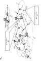
도 1 은 본 개시의 양태들에 따라 블록 펑쳐링 폴라 코드들에 대한 펑쳐링 된 비트들의 수에 기초하여 하나 이상의 정보 비트들의 할당을 조정하기 위한 채널 편파 컴포넌트를 갖는 예시적인 무선 통신 시스템의 개략도이다.
도 2 는 본 개시의 양태들에 따른 채널 편파 프로세싱 아키텍쳐의 일 예의 블록 다이어그램이다.
도 3 은 본 개시의 양태들에 따른 비트 반전 (reversal) 펑쳐링에 기초한 인코더로의 입력으로서의 비트 구조의 일 예의 블록 다이어그램이다.
도 4 는 본 개시의 양태들에 따라 블록 펑쳐링 폴라 코드들에 대한 펑쳐링 된 비트들의 수에 기초하여 정보 비트 할당을 조정하는 예와 관련된 비트 인덱스 구조의 일 예의 개략도이다.
도 5 는 본 개시의 양태들에 따른 용량 공식을 사용하여 정보 비트를 할당하는 예시적인 프로세스의 예시적인 프로세싱 아키텍처 다이어그램이다.
도 6 은 본 개시의 양태들에 따른 미리 결정된 비트 순서를 사용하여 정보 비트들을 할당하는 방법의 실행 후에 인코더로 입력될 결과의 비트 구조의 일 예의 블록 다이어그램이다.
도 7 은 본 개시의 양태들에 따른 하이브리드 반복 및 펑 처링 방법의 일 양태의 실행으로부터 초래되는 예시적인 서브 프레임 구조의 블록도이다.
도 8 은 본 개시의 다양한 양태들에 따라, 송신하는 디바이스 (예를 들어, 기지국 또는 UE) 의 여러 컴포넌트들의 구현의 일 양태의 개략도이다.
도 9 는 본 개시의 양태들에 따라 무선 통신들의 레이트 매칭 코드 분극화를 위해 UE 에 의해 구현되는 예시적인 방법의 플로우챠트이다.The disclosed aspects will be described below in conjunction with the accompanying drawings, which serve to illustrate rather than limit the disclosed aspects, in which like designations indicate like elements.
1 is a schematic diagram of an exemplary wireless communication system having a channel polarization component for adjusting an assignment of one or more information bits based on a number of punctured bits for block puncturing polar codes in accordance with aspects of the present disclosure; .
2 is a block diagram of an example of a channel polarization processing architecture in accordance with aspects of the present disclosure.
3 is a block diagram of an example of a bit structure as input to an encoder based on bit reversal puncturing in accordance with aspects of the present disclosure.
4 is a schematic diagram of an example of a bit index structure relating to an example of adjusting information bit allocation based on number of punctured bits for block puncturing polar codes in accordance with aspects of the present disclosure.
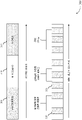
5 is an exemplary processing architecture diagram of an exemplary process of allocating information bits using a capacity formula in accordance with aspects of the present disclosure.
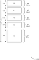
6 is a block diagram of an example of a bit structure of a result to be input to an encoder after execution of a method of allocating information bits using a predetermined bit order according to aspects of the present disclosure.
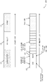
7 is a block diagram of an exemplary sub-frame structure resulting from implementation of an aspect of a hybrid iteration and puncturing method according to aspects of the present disclosure.
8 is a schematic diagram of an aspect of an implementation of various components of a transmitting device (eg, base station or UE), in accordance with various aspects of the present disclosure.
9 is a flowchart of an example method implemented by a UE for rate matching code polarization of wireless communications in accordance with aspects of the present disclosure.
상술한 바와 같이, 코드 비트 펑쳐링은 분극 구조를 변화시키고 펑쳐링을 수행한 후에 채널 재추정을 요구할 수도 있다. 그러나, 채널 재추정 절차는 자원 집약적이며 코드 워드의 송신에 지연을 추가할 수도 있다. 폴라 코드의 베이스라인 레이트 매칭의 일부 방법들은 QUP (quasi-uniform puncturing) 방법을 적용하는 것을 포함한다. QUP 방법은 가우시안 근사화 (Gaussian approximation) 에 기반한 밀도 진화 (Density Evolution) (DE/GA) 를 사용하여 각각의 합성 서브 채널의 신뢰성을 신뢰할 수 있는 메트릭으로서 계산함으로써 폴라 코드를 구성한다. 높은 신뢰성을 갖는 서브 채널들은 정보 비트들을 송신하도록 선택되는 반면, 신뢰할 수 없는 서브 채널들에 대한 비트들은 제로로 설정되거나, 프로즌 비트들로 지칭되거나 불린다. 이러한 신뢰할 수 없는 위치들의 세트는 프로즌-세트 (F) 라고 불린다. 코드 레이트 (R) 와 코드 길이 (M) 의 조합이 주어지면, 인코더와 디코더 양자 모두는 인코딩 또는 디코딩 전에 이러한 프로즌-세트 (F) 를 컴퓨팅해야 한다. 인코더와 디코더 간의 프로즌 세트 (F) 의 고유성이 확보되어야 한다. As discussed above, code bit puncturing may require channel re-estimation after changing the polarization structure and performing the puncturing. However, the channel re-estimation procedure is resource intensive and may add delay to the transmission of code words. Some methods of baseline rate matching of polar codes include applying a quasi-uniform puncturing (QUP) method. The QUP method constructs a polar code by using Density Evolution (DE/GA) based on Gaussian approximation to calculate the reliability of each synthetic sub-channel as a reliable metric. Subchannels with high reliability are selected to transmit information bits, while the bits for unreliable subchannels are set to zero, or referred to as frozen bits, or called frozen bits. This set of unreliable locations is called a frozen-set (F). Given a combination of code rate (R) and code length (M), both the encoder and decoder must compute this frozen-set (F) before encoding or decoding. The uniqueness of the frozen set (F) between the encoder and the decoder must be ensured.
2 의 거듭 제곱인 마더 코드 길이 N 을 갖는 폴라 코드는 길이 N/2 의 2 개의 폴라 코드의 네스팅된 (nested) 조합으로 간주 될 수 있기 때문에, 그러한 방법은 길이 N/2 의 폴라 코드들에 대한 순서화된 시퀀스가 길이 N 의 폴라 코드들에 대한 순서화 된 시퀀스의 서브 세트이도록 비트 위치들의 순서화 된 시퀀스 (인덱스 시퀀스) 를 구성한다. "비트 반전 펑쳐링 (bit reversal puncturing)” 이라 불리는 이 방법은 미리 결정된 양호한 비트 순서에 따라 처음 K 개의 양호한 비트들을 선택하고 K 개의 데이터 비트들을 할당하기 전에 프로즌 비트들을 스킵하는 것에 의존한다. 양호한-비트-순서 리스트는 그 순서가 양호한 비트로서 선택될 가능성을 나타내는 입력 비트 인덱스들의 시퀀스이다. 네스팅된 특성 때문에, 관심있는 가장 큰 N 의 단일의 양호한-비트-순서 리스트가 저장될 필요가 있다. 그러나, 비트 반전 펑처링 채널에 대한 하나의 관심은 다수의 블라인드 디코딩을 갖는 제어 채널에 대한 디코딩 레이턴시이다. 이것은, 펑쳐링 된 폴라 코드의 디코딩 복잡도 및 지연이 코드워드 크기 M 이 아니라, 크기 N = 2n 의 함수이기 때문이다.Since a polar code with a mother code length N that is a power of 2 can be regarded as a nested combination of two polar codes of length N/2, such a method can be applied to polar codes of length N/2. Construct an ordered sequence of bit positions (index sequence) such that the ordered sequence for polar codes of length N is a subset of the ordered sequence for polar codes of length N. This method, called "bit reversal puncturing", relies on selecting the first K good bits according to a predetermined good bit order and skipping the frozen bits before allocating the K data bits. A bit-ordered list is a sequence of input bit indices whose order indicates the probabilities of being selected as good bits Because of the nested nature, the largest N single good-bit-ordered list of interest needs to be stored. However, one concern for bit-reversal puncturing channels is the decoding latency for control channels with multiple blind decoding, which means that the decoding complexity and delay of the punctured polar code is not codeword size M, but size N = 2 because it is a function of n .
블록 펑처링 (block puncturing) 이라고 하는 또 다른 기법이 폴라 코드들에 대해 또한 제안되었다. 이 기법에서, 임의의 목표 코드워드 길이 M 을 달성하기 위해, 그 스킴은 단순히 처음 연속적으로 코딩 된 비트들을 제거하고 (즉, 송신하지 않고) 펑처링에 의해 제로 용량으로 인해 처음 P 개의 비트-채널들을 프로즌 비트들로 설정한다. 그러나, 이러한 블록 펑쳐링 스킴은 펑쳐링이 헤비 (heavy) 일 때 (예를 들어, 펑쳐링 된 비트들의 수 (P) 가 N/2 에 가까울 때, 여기서 N= ![]()
![]()
본 개시의 양태들은 블록 펑쳐링 폴라 코드들에 대한 펑쳐링 된 비트들의 수 (P) 에 기초하여 정보 비트 할당을 조정함으로써 상술된 문제를 다룬다. 특히, 본 개시의 특징들은 펑쳐링 후의 용량 공식에 기초하여 각 섹터 (예를 들어, K0, K1, K3 및 K4) (도 4 참조) 에 대한 정보 비트들의 수를 결정한다. 저 레이트 폴라 코드들 (예를 들어, R = K/M < 1/3) 의 경우, 블록 펑쳐링은 코딩 된 비트들의 상위 부분 (예를 들어, XOR 이후의 채널) 에 적용될 수도 있으며, 그 상위 부분은 그 후 4 개의 섹터들 (또는 더 미세한 입도의 경우 더 많은 섹터들) 로 분할된다. 섹터에 임의의 펑쳐링 된 비트가 존재하는 경우, 정보 비트는 해당 섹터에 할당되지 않는다. 또한, 프로즌 비트 위치들 (또는 다른 Ki 개의 값들) 은 (예를 들어, M = m * 2n, m = 1, 3, 5 및 7 에 대해) 가우시안 근사화를 사용하는 것에 의해 또는 미리 결정된 양호한 비트 순서 그리고 K 개의 정보 비트들을 할당하기 전에 프로즌 비트들을 스킵하는 것에 따라 선택될 수도 있다. 본 개시의 해결책은, 처음 N-M1 개의 비트 채널들이 프로즌 비트들로 설정되기 때문에 제안된 펑쳐링 폴라 코드의 디코딩 복잡도 및 지연이 N=2n 대신에 크기 M1 의 함수이기 때문에 감소된 디코딩 레이턴시를 포함하는 하나 이상의 이점들을 가질 수도 있다. Aspects of this disclosure address the aforementioned problem by adjusting the information bit allocation based on the number of punctured bits ( P ) for block puncturing polar codes. In particular, features of this disclosure determine the number of information bits for each sector (e.g., K0, K1, K3, and K4) (see FIG. 4) based on the capacity formula after puncturing. For low-rate polar codes (eg, R = K/M < 1/3), block puncturing may be applied to the upper portion of the coded bits (eg, channel after XOR), The portion is then divided into four sectors (or more sectors in the case of finer granularity). If there are any punctured bits in a sector, no information bits are assigned to that sector. Also, the frozen bit positions (or other K i values) can be determined by using a Gaussian approximation (eg, for M = m * 2 n , m = 1, 3, 5 and 7) or by a predetermined good It may be selected according to bit order and skipping frozen bits before allocating the K information bits. The solution of the present disclosure reduces decoding latency because the decoding complexity and delay of the proposed puncturing polar code is a function of size M 1 instead of N=2 n because the first NM 1 -bit channels are set to frozen bits. may have one or more advantages including
다양한 양태들이 이제 도면들을 참조하여 설명된다. 다음의 설명에서, 설명의 목적들을 위해, 다수의 특정 상세들이 하나 이상의 양태들의 철저한 이해를 제공하기 위하여 제시된다. 그러나, 이러한 양태(들)는 이들 특정 상세들 없이도 실시될 수도 있음이 분명할 수도 있다. 추가적으로, 본 명세서에서 사용된 바와 같은 용어 "컴포넌트" 는, 시스템을 구성하는 부분들 중 하나일 수도 있고, 하드웨어, 펌웨어, 및/또는 컴퓨터 판독가능 매체 상에 저장된 소프트웨어일 수도 있으며, 다른 컴포넌트들로 분할될 수도 있다. Various aspects are now described with reference to the drawings. In the following description, for purposes of explanation, numerous specific details are set forth in order to provide a thorough understanding of one or more aspects. It may be evident, however, that such aspect(s) may be practiced without these specific details. Additionally, the term "component" as used herein may be one of the parts constituting a system, and may be hardware, firmware, and/or software stored on a computer readable medium, and other components may be divided.
다음의 설명은 예들을 제공하며, 청구항들에 기재된 범위, 적용가능성, 또는 예들을 한정하는 것은 아니다. 본 개시의 범위로부터의 일탈함없이 논의된 엘리먼트들의 기능 및 배열에 있어서 변경들이 행해질 수도 있다. 다양한 예들은 다양한 절차들 또는 컴포넌트들을 적절하게 생략, 치환, 또는 부가할 수도 있다. 예를 들어, 설명된 방법들은 설명된 것과 상이한 순서로 수행될 수도 있으며, 다양한 단계들이 부가, 생략, 또는 결합될 수도 있다. 또한, 일부 예들에 관하여 설명된 특징들은 다른 예들에서 결합될 수도 있다.The following description provides examples and is not intended to limit the scope, applicability, or examples recited in the claims. Changes may be made in the function and arrangement of elements discussed without departing from the scope of the present disclosure. Various examples may omit, substitute, or add various procedures or components as appropriate. For example, the methods described may be performed in an order different from that described, and various steps may be added, omitted, or combined. Also, features described with respect to some examples may be combined in other examples.
도 1 을 참조하면, 본 개시의 여러 양태들에 따라, 예시의 무선 통신 네트워크 (100) 는 하나 이상의 기지국들 (105), 하나 이상의 UE 들 (115), 및 코어 네트워크 (130) 를 포함할 수도 있다. 코어 네트워크 (130) 는 사용자 인증, 액세스 인가, 추적, 인터넷 프로토콜 (IP) 접속, 및 다른 액세스, 라우팅, 또는 이동성 기능들을 제공할 수도 있다. 기지국들 (105) 은 백홀 링크들 (134) (예컨대, S1 등) 을 통해 코어 네트워크 (130) 와 인터페이싱할 수도 있다. 기지국들 (105) 은 UE들 (115) 과의 통신을 위해 라디오 구성 및 스케줄링을 수행할 수도 있거나, 또는 기지국 제어기 (도시 안됨) 의 제어 하에서 동작할 수도 있다. 다양한 예들에 있어서, 기지국들 (105) 은, 유선 또는 무선 통신 링크들일 수도 있는 백홀 링크들 (134) (예를 들어, X1 등) 상에서 서로와 (예를 들어, 코어 네트워크 (130) 를 통해) 직접 또는 간접적으로 통신할 수도 있다. 몇몇 예에서, 송신 디바이스로서 동작하는 기지국 (105) 및 UE (115) 는, 이하 더 상세히 설명되는 바와 같이, 블록 펑쳐링 폴라 코드들에 대한 펑쳐링 된 비트들의 수에 기초하여 하나 이상의 정보 비트들의 할당을 조정함으로써 채널 분극을 수행하도록 구성된 채널 분극 컴포넌트 (850) (도 8 참조) 를 포함할 수도 있다. Referring to Figure 1, In accordance with various aspects of the present disclosure, an example
기지국들 (105) 은 하나 이상의 기지국 안테나들을 통해 UE들 (115) 과 무선으로 통신할 수도 있다. 기지국들 (105) 의 각각은 개별 지리적 커버리지 영역 (110) 에 대한 통신 커버리지를 제공할 수도 있다. 일부 예들에서, 기지국들 (105) 은 기지국 송수신기, 무선 기지국, 액세스 포인트, 무선 송수신기, NodeB, eNodeB (eNB), Home NodeB, Home eNodeB, gNodeB, gNB, 중계기, 또는 일부 다른 적합한 전문 용어로 지칭될 수도 있다. 기지국 (105) 에 대한 지리적 커버리지 영역 (110) 은, 커버리지 영역의 오직 일부분 (도시 안됨) 만을 구성하는 섹터들 또는 셀들로 분할될 수도 있다. 무선 통신 시스템 (100) 은 상이한 타입들의 기지국들 (105) (예를 들어, 이하에 기술된 매크로 기지국들 또는 스몰 셀 기지국들) 을 포함할 수도 있다. 또한, 복수의 기지국들 (105) 은 복수의 통신 기술들 (예를 들어, 5G, 4G/LTE, 3G, Wi-Fi, 블루투스 등) 중 상이한 것들에 따라 동작할 수도 있고, 따라서 상이한 통신 기술에 대해 중첩하는 지리적 커버리지 영역들 (110) 이 존재할 수도 있다.
일부 예들에 있어서, 무선 통신 네트워크 (100) 은 롱텀 에볼루션 (LTE)/LTE-어드밴스드 (LTE-A) 기술 네트워크이거나 이들을 포함할 수도 있다. 또한, 무선 통신 네트워크 (100) 은 5G 무선 통신 네트워크와 같은 차세대 기술 네트워크일 수도 있다. LTE/LTE-A 네트워크들에 있어서, 용어 진화된 노드B (eNB) 또는 gNB 는 일반적으로 기지국들 (105) 을 설명하는데 사용될 수도 있는 한편, 용어 'UE' 는 일반적으로 UE들 (115) 을 설명하는데 사용될 수도 있다. 무선 통신 네트워크 (100) 은, 상이한 타입들의 eNB들이 다양한 지리적 영역들에 대해 커버리지를 제공하는 이종의 LTE/LTE-A 네트워크일 수도 있다. 예를 들어, 각각의 eNB 또는 기지국 (105) 은 매크로 셀, 소형 셀, 또는 다른 타입들의 셀에 대한 통신 커버리지를 제공할 수도 있다. 용어 "셀" 은, 맥락에 의존하여, 기지국, 기지국과 연관된 캐리어 또는 컴포넌트 캐리어, 또는 캐리어 또는 기지국의 커버리지 영역 (예를 들어, 섹터 등) 을 설명하는데 사용될 수 있는 3GPP 용어이다.In some examples,
매크로 셀은 일반적으로 상대적으로 큰 지리적 영역 (예를 들어, 반경 수 킬로미터) 을 커버할 수도 있고, 네트워크 제공자로의 서비스 가입들을 갖는 UE 들 (115) 에 의한 제한없는 액세스를 허용할 수도 있다.A macro cell may generally cover a relatively large geographic area (eg, several kilometers in radius) and may allow unrestricted access by
소형 셀은, 매크로 셀과 비교했을 때, 매크로 셀들과 동일한 또는 상이한 주파수 대역들 (예를 들어, 허가형, 비허가형 등) 에서 동작할 수도 있는 상대적으로 낮은 송신 송력 기지국을 포함할 수도 있다. 소형 셀들은 다양한 예들에 따라 피코 셀들, 펨토 셀들, 및 마이크로 셀들을 포함할 수도 있다. 피코 셀은, 예를 들어, 작은 지리적 영역을 커버할 수도 있고, 네트워크 제공자로의 서비스 가입들을 갖는 UE 들 (115) 에 의한 제한없는 액세스를 허용할 수도 있다. 펨토 셀은 또한, 작은 지리적 영역 (예를 들어, 홈) 을 커버할 수도 있고, 펨토 셀과의 연관을 갖는 UE 들 (115) (예를 들어, 제한된 액세스 경우에서, 홈 내의 사용자들에 대한 UE들 (115) 을 포함할 수도 있는, 기지국 (105) 의 CSG (Closed Subscriber Group) 내의 UE 들 (115) 등) 에 의한 제한된 액세스 및/또는 비제한 액세스를 제공할 수도 있다. 매크로 셀에 대한 eNB 는 매크로 eNB 로서 지칭될 수도 있다. 소형 셀에 대한 eNB 는 소형 셀 eNB, 피코 eNB, 펨토 eNB, 또는 홈 eNB 로서 지칭될 수도 있다. eNB 는 하나 또는 다중의 (예컨대, 2개, 3개, 4개 등) 셀들 (예컨대, 컴포넌트 캐리어들) 을 지원할 수도 있다.A small cell may include a relatively low transmit power base station that, when compared to a macro cell, may operate in the same or different frequency bands (eg, licensed, unlicensed, etc.) as the macro cells. Small cells may include pico cells, femto cells, and micro cells according to various examples. A pico cell, for example, may cover a small geographic area and may allow unrestricted access by
다양한 개시된 예들의 일부를 수용할 수도 있는 통신 네트워크들은 계층화된 프로토콜 스택에 따라 동작하는 패킷 기반 네트워크들일 수도 있고, 사용자 평면에서의 데이터는 IP 에 기초할 수도 있다. 무선 링크 제어 (RLC) 계층은 논리 채널들을 통해 통신하기 위해 패킷 세분화 및 재조립을 수행할 수도 있다. MAC 계층은 우선순위 핸들링 및 논리 채널들의 전송 채널들로의 멀티플렉싱을 수행할 수도 있다. MAC 계층은 또한, 링크 효율을 개선시키기 위해 MAC 계층에 재송신을 제공하는데 HARQ 를 사용할 수도 있다. 제어 평면에 있어서, 무선 리소스 제어 (RRC) 프로토콜 계층은 기지국들 (105) 과 UE (115) 간의 RRC 접속의 확립, 구성, 및 유지보수를 제공할 수도 있다. RRC 프로토콜 계층은 또한, 사용자 평면 데이터에 대한 무선 베어러들의 코어 네트워크 (130) 지원을 위해 사용될 수도 있다. 물리 (PHY) 계층에서, 전송 채널들은 물리 채널들에 매핑될 수도 있다.Communication networks that may accommodate some of the various disclosed examples may be packet-based networks that operate according to a layered protocol stack, and data in the user plane may be based on IP. A radio link control (RLC) layer may perform packet segmentation and reassembly to communicate over logical channels. The MAC layer may perform priority handling and multiplexing of logical channels into transport channels. The MAC layer may also use HARQ to provide retransmission to the MAC layer to improve link efficiency. In the control plane, a radio resource control (RRC) protocol layer may provide establishment, configuration, and maintenance of RRC connections between
UE 들 (115) 은 무선 통신 네트워크 (100) 전반에 걸쳐 산재될 수도 있으며, 각각의 UE (115) 는 정지식 또는 이동식일 수도 있다. UE (115) 는 또한, 이동국, 가입자국, 모바일 유닛, 가입자 유닛, 무선 유닛, 원격 유닛, 모바일 디바이스, 무선 디바이스, 무선 통신 디바이스, 원격 디바이스, 모바일 가입자국, 액세스 단말기, 모바일 단말기, 무선 단말기, 원격 단말기, 핸드셋, 사용자 에이전트, 모바일 클라이언트, 클라이언트, 또는 기타 다른 적합한 용어를 포함하거나 또는 이들로서 당업자에 의해 지칭될 수도 있다. UE (115) 는 셀룰러 폰, 개인용 디지털 보조기 (PDA), 무선 모뎀, 무선 통신 디바이스, 핸드헬드 디바이스, 태블릿 컴퓨터, 랩탑 컴퓨터, 코드리스 폰, 무선 로컬 루프 (WLL) 스테이션, 엔터테인먼트 디바이스, 챠량 컴포넌트, 또는 무선 통신 네트워크 (100) 에서 통신가능한 임의의 디바이스일 수도 있다. 또한, UE (115) 는 일부 양태들에서 무선 통신 네트워크 (100) 또는 다른 UE 들과 드물게 통신할 수도 있는 사물 인터텟 (IOT) 및/또는 M2M (machine-to-machine) 타입의 디바이스, 예를 들어 (예를 들어, 무선 전화에 비해) 저전력, 저 데이터 레이트 타입의 디바이스일 수도 있다. UE (115) 는 매크로 eNB들, 소형 셀 eNB들, 중계기 기지국들 등을 포함하여 다양한 타입들의 기지국들 (105) 및 네트워크 장비와 통신할 수도 있다.
UE (115) 는 하나 이상의 기지국들 (105) 과 하나 이상의 무선 통신 링크들 (125) 을 확립하도록 구성될 수도 있다. 무선 통신 네트워크 (100) 에 도시된 무선 통신 링크들 (125) 은 UE (115) 로부터 기지국 (105) 으로의 UL 송신들, 또는 기지국 (105) 으로부터 UE (115) 로의 다운링크 (DL) 송신들을 반송할 수도 있다. 다운링크 송신들은 또한 순방향 링크 송신들로 지칭될 수도 있는 한편, 업링크 송신들은 또한 역방향 링크 송신들로 지칭될 수도 있다. 각각의 무선 통신 링크 (125) 는 하나 이상의 캐리어들을 포함할 수도 있고, 여기서, 각각의 캐리어는 상기 설명된 다양한 무선 기술들에 따라 변조된 다중의 서브-캐리어들 (예를 들어, 상이한 주파수들의 파형 신호들) 로 구성된 신호일 수도 있다. 각각의 변조된 신호는 상이한 서브-캐리어 상에서 전송될 수 있고, 제어 정보 (예를 들어, 참조 신호들, 제어 채널들 등), 오버헤드 정보, 사용자 데이터 등을 반송할 수도 있다. 일 양태에서, 통신 링크들 (125) 은 (예를 들어, 페어링된 스펙트럼 자원들을 사용하는) 주파수 분할 듀플렉스 (FDD) 또는 (예를 들어, 페어링되지 않은 스펙트럼 자원들을 사용하는) 시분할 듀플렉스 (TDD) 동작을 사용하는 양방향 통신들을 송신할 수도 있다. 프레임 구조들은 FDD 에 대해 (예를 들어, 프레임 구조 타입 1) 및 TDD 에 대해 (예를 들어, 프레임 구조 타입 2) 정의될 수도 있다. 또한, 일부 양태들에서, 통신 링크들 (125) 은 하나 이상의 브로드캐스트 채널들을 나타낼 수있다.A
무선 통신 네트워크 (100) 에서, 하나 이상의 UE 들 (115) 은 무선 자원 제어 (RRC) 접속 모드 또는 RRC 유휴 모드 중 하나일 수도 있다. RRC 접속 모드 동안, UE들 (115) 은 기지국 (105) 과의 확립 된 통신을 유지할 수도 있다. RRC 유휴 모드 동안, UE 들 (115) 은 기지국 (105) 과의 임의의 통신 없이 슬립 모드에 있을 수도 있다. 예를 들어, 슬립 모드는 UE 들 (115) 에게 배터리 전력을 보존 할 기회를 제공 할 수도 있다.In the
무선 통신 네트워크 (100) 의 일부 양태들에 있어서, 기지국들 (105) 또는 UE 들 (115) 은 기지국들 (105) 과 UE들 (115) 간의 통신 품질 및 신뢰성을 개선시키도록 안테나 다이버시티 스킴들을 채용하기 위해 다중의 안테나들을 포함할 수도 있다. 부가적으로 또는 대안적으로, 기지국들 (105) 또는 UE들 (115) 은, 동일하거나 상이한 코딩된 데이터를 반송하는 다중의 공간 계층들을 송신하도록 다중-경로 환경들을 이용할 수도 있는 다중입력 다중출력 (MIMO) 기법들을 채용할 수도 있다. In some aspects of
UE 들 (115) 이 RRC 유휴 모드에 있는 상황들에서, 기지국 (105) 은 페이징 프로세스를 사용하여 UE (115) 에 대한 액세스를 개시할 수도 있다. "페이징 프로세스” 또는 "페이징 메시지” 라는 용어는 UE (115) 에게 페이지의 존재를 경고하기 위해 기지국 (105) 에 의해 송신 된 임의의 제어 메시지를 지칭할 수도 있다. 따라서, RRC 유휴 모드의 하나 이상의 UE (115) 들은 페이징 메시지를 청취하기 위해 주기적으로 만 깨어날 수도 있다. RRC 아이들 모드의 UE 들 (115) 은 주기적으로 만 깨어날 수도 있기 때문에, 기지국 (105) 이 페이지를 특정 UE (115) 로 향하게 하기 위해 빔포밍을 효과적으로 이용하는 것이 어려울 수도 있다. 구체적으로, 기지국은 페이징 메시지를 청취하기 위해 UE (115) 가 깨어날 수도 있는 정확한 위치 또는 셀을 인지하지 못할 수도 있기 때문에, 기지국 (105) 은 일반적으로 다수의 방향들 (송신 스위프 (sweep) 로서 지칭됨) 을 통해 송신하여 유휴 모드 UE 가 페이징 메시지를 수신하는 것을 보장한다. 그러나, 전술한 바와 같이, 그러한 송신 스위프는 자원 집약적이다. In situations where
무선 통신 네트워크 (100) 는 다중의 셀들 또는 캐리어들상에서의 동작, 즉 캐리어 집성 (CA) 또는 멀티-캐리어 동작으로서 지칭될 수도 있는 특징을 지원할 수도 있다. 또한, 캐리어는 컴포넌트 캐리어 (CC), 계층, 채널 등으로 지칭될 수도 있다. 용어 "캐리어", "컴포넌트 캐리어", "셀"및 "채널"은 본 명세서에서 상호 교환 적으로 사용될 수도 있다. UE (115) 는 캐리어 집성을 위해 다중 다운링크 CC들 및 하나 이상의 업링크 CC들로 구성될 수도 있다. 캐리어 집성은 FDD 및 TDD 컴포넌트 캐리어들 양자 모두로 사용될 수도 있다.The
이제 도 2 를 참조하면, 2-입력을 위한 예시적인 채널 분극화 프로세싱 아키텍처 (200) 가 설명된다. 전술한 바와 같이, 폴라 코드 구성은 물리 채널 (205) 을 다수의 가상 외부 채널들 (210) (예를 들어, W- 불량 채널 (210-a) 및 W+ 양호 채널 (210-b)) 로 변환하는 짧은 커널 코드의 다중 재귀 연쇄에 기초한다. 용어 "불량 채널” 및 "양호 채널” 은 신호 대 잡음 (SNR) 비 및/또는 각 채널에 대한 신뢰성에 기초한 채널 품질을 지칭 할 수도 있다. 예를 들어, 채널이 낮은 SNR 비를 가지면, "불량 채널"로 간주 될 수도 있지만, 높은 SNR 비는 "양호 채널"과 연관될 수도 있다. 재귀들의 수가 많아지면, 가상 채널은 높은 신뢰성 또는 낮은 신뢰성을 가지는 경향이 있으며 (즉, 그것들은 분극화된다), 데이터 비트들은 가장 신뢰할 수 있는 채널들에 할당된다. 도시된 예에서, 한 쌍의 동일한 2 진-입력 채널들 (205) 은 서로 다른 품질들의 2 개의 별개 채널들 (210), 예를 들어 원래의 2 진-입력 채널 (205) 보다 하나의 더 양호한 채널 및 하나의 더 불량한 채널로 변환된다. 그러한 예에서, 채널 W- (210-a) (예를 들어, "불량 채널")는 입력 (u0) 및 출력들 (y0 및 y1) 을 포함할 수도 있다. 유사하게, 채널 W+ (210-b) (예를 들어, "양호 채널")는 입력 (u1) 및 출력들 (y0 및 y1) 을 포함할 수도 있다. 2 개의 채널들 (210) 에 대한 채널 분극은 다음과 같이 달성 될 수 있는데, 여기서 채널 W- (210-a) 는 입력 (U0) 및 출력 (y0) 을 갖고, 채널 W+ 는 입력 (U1) 및 출력 (y1) 을 갖는다:Referring now to Figure 2, An exemplary channel
U0=X0X1=Y0Y1 패리티 체크 U 0 =X 0 X 1 =Y 0 Y 1 parity check
소거 확률, ε- = 1- (1-ε)2= 2ε-ε2.Elimination probability, ε - = 1- (1-ε) 2 = 2ε-ε 2 .
U1=X1=X0U0 반복,U 1 =X 1 =X 0 U 0 repeat ,
소거 확률, ε+ = ε2.Elimination probability, ε + = ε 2 .
일부 예들에서, 상기 동작은 재귀적으로 수행 될 수 있는데, 여기서 다양한 품질의 N= 2n 개의 "비트 채널들” 의 세트가 획득될 수 있다. 예를 들어, 그 동작은 "양호한” 채널을 통한 정보 비트의 송신 및 "불량한” 채널을 통한 알려진 "프로즌” 비트의 송신을 포함할 수 있다. 선택 사항으로, 리스트 SC 디코딩을 돕기 위해 정보 블록에 CRC 가 추가될 수 있다. In some examples, the above operation may be performed recursively, where a set of N= 2n "bit channels" of various qualities may be obtained. For example, the operation may be performed through a "good" channel. It may include transmission of information bits and transmission of known "frozen" bits over "bad" channels. Optionally, a CRC can be added to the information block to aid list SC decoding.
도 3 을 참조하면, 비트 반전 펑쳐링 기법 (300) 으로부터 야기되는 비트 구조를 포함하는 하나의 솔루션이 개시된다. 비트 반전 펑쳐링 기법 (300) 은 미리 결정된 양호한 비트 순서에 따라 처음 K 개의 양호 비트들 (305) 을 선택하고 K 개의 데이터 비트들 (315) 을 할당하기 전에 프로즌 비트들 (310) 을 스킵하는 것에 의존한다. 특히, 본 방법은 준 균일 펑쳐링 패턴을 적용하고 상응하는 입력 비트를 프로즌 비트 (325) 로서 설정한다. 다시 말하면, 펑쳐링 된 비트들 (320) 의 위치들 및 제로 용량을 갖는 비트 채널들의 위치들은 내림차순 이진 인덱스들 [0,1, ..., N-2, N-1]을 비트-반전 (bit-reversing) 시키고 가장 높은 비트-반전된 값을 갖는 N-M 개의 인덱스들을 펑쳐링된 위치들, 예를 들어 P = [BitRev (M), ..., BitRev (N-2), BitRev (N-1)] 로서 마킹함으로써 결정되며, 여기서, M 은 펑쳐링 후의 코드 길이이다.Referring to Figure 3, One solution is disclosed that involves a bit structure resulting from the bit inversion puncturing technique (300). The bit inversion puncturing technique (300) consists of selecting the first K good bits (305) according to a predetermined good bit order and skipping the frozen bits (310) before allocating the K data bits (315). depend on In particular, the method applies a quasi-uniform puncturing pattern and sets the corresponding input bits as
그러나, 비트 반전 펑쳐링 기법 (300) 에 대한 관심은 디코딩 레이턴시이다. 이것은 다수의 블라인드 디코딩을 갖는 제어 채널들의 경우 특히 그렇다. 이것은 이러한 펑쳐링 된 폴라 코드의 디코딩 복잡도 및 지연이 코드워드 크기 M 이 아니라, 크기 N = 2n 의 함수이기 때문이다. However, a concern with bit
또 다른 솔루션 (미도시) 은 정보 세트 최적화 없는 블록 펑쳐링에 관한 것이다. 이 대안의 솔루션에서, 폴라 코드에 대해 간단한 펑쳐링 스킴이 제안되었다. 임의의 목표 코드 워드 길이 (M) 를 달성하기 위해, 그 스킴은 단순히 처음 ![]()
![]()
![]()
![]()
도 4 를 참조하면, 다이어그램 (400) 은 블록 펑쳐링 폴라 코드들에 대한 펑쳐링 된 비트들의 수에 기초하여 정보 비트들의 할당을 조정하는 본 발명에 따른 솔루션을 도시한다. 예를 들어, 정보 비트의 할당은 (n K 정보 비트들, 또는 Kn, 예를 들어 K0 (405-a), K1 (405-b), K2 (405-c), K3 (405-d), 및 K4 (405-e) 의) 각각의 섹터 (405) 에서의 정보 비트들의 수를 결정함으로써 식별될 수도 있으며, 여기서 펑쳐링 후의 용량에 기초하여 K = K0 + K1 + K2 + K3 + K4 이다. 저 레이트 폴라 코드들, 예를 들어, R= (K/M) ≤1/3 의 경우, 블록 펑쳐링은 코딩된 비트의 상위 부분에 적용될 수도 있으며, 그 상위 부분은 그 후 4 개의 섹터들 (405) (또는 보다 미세한 입도) 로 분할된다. 섹터 (405) 에 임의의 펑처링 된 비트가 존재한다면, 그 섹터에 정보 비트가 할당되지 않으며, 예를 들어, Ki= 0 이어서, 프로즌 비트들로서 설정한다. 그 후, 다른 프로즌 위치들 (또는 다른 Ki 값들) 은 (M = m * 2n, m = 1, 3, 5 및 7 에 대해) 가우시안 근사화를 사용하는 것에 의해 또는 미리 결정된 양호한 비트 순서 그리고 K 개의 정보 비트들을 할당하기 전에 프로즌 비트들을 스킵하는 것에 따라 선택된다. Referring to Figure 4, Diagram 400 illustrates a solution in accordance with the present invention that adjusts the allocation of information bits based on the number of punctured bits for block puncturing polar codes. For example, the allocation of information bits is ( n K information bits, or K n , for example K0 (405-a), K1 (405-b), K2 (405-c), K3 (405-d) , and K4 405-e), where K = K0 + K1 + K2 + K3 + K4 based on the capacity after puncturing. . For low-rate polar codes, e.g., R= (K/M) ≤ 1/3, block puncturing may be applied to the upper part of the coded bit, which then divides the 4 sectors ( 405) (or finer grain size). If there are any punctured bits in
예를 들어, for example,
0<N-M≤(N/8) : K0= 0, M1= (7N/8) <M; 0<NM≤(N/8): K 0 = 0, M 1 = (7N/8) <M;
0<N-M≤(N/4): K0= K1=0, M1= (3N/4) <M; 0<NM≤(N/4): K 0 = K 1 =0, M 1 = (3N/4) <M;
0<N-M≤(3N/8): K0=K1=K2= 0, M1= (5N/8) <M; 및0<NM≤(3N/8): K 0 =K 1 =K 2 = 0, M 1 = (5N/8) <M; and
0<N-M<(N/2): K0= K1=K2=K3=0, M1= (N/2) <M. 0<NM<(N/2): K 0 = K 1 =K 2 =K 3 =0, M 1 = (N/2) <M.
도 5 를 참조하면, 도 5 는 본 개시의 양태들에 따른 용량 공식을 사용하여 정보 비트를 할당하는 예시적인 프로세싱 아키텍처 (500) 을 포함한다. 아키텍처 (500) 는 복수의 가상 채널들에 의해 표현되는 물리적 채널 (505) 을 포함한다. 채널들은 상이한 섹터들 (510) 로 서브 분할될 수도 있다. Referring to FIG. 5 , FIG. 5 includes an
본 개시의 양태들에 따르면, 블록 펑쳐링 폴라 코드들에 대한 펑쳐링 된 비트들의 수 (P) 에 기초하여 정보 비트들의 할당이 조정된다. 특히, 본 개시의 특징들은 펑쳐링 후의 채널 용량에 기초하여 각 섹터 (510) 에 대한 정보 비트들의 수를 결정한다. 각 섹터의 용량, 예를 들어, R1, R2 및 R3 는 정보 레이트 R = K/M 을 입력으로 사용하는 상호 정보 전송 차트로부터 도출될 수 있다 (참고 : R1 + R2 + R3 = 3 * R). 또한, 일부 예들에서, 정보 비트 분포는 다음과 같이 도출 될 수 있다 : K1 = R1 * (N / 3), K2 = R1 * (N / 3), K3 = R3 * (N / 3).According to aspects of this disclosure, the allocation of information bits is adjusted based on the number of punctured bits ( P ) for block puncturing polar codes. In particular, features of this disclosure determine the number of information bits for each
저 레이트 폴라 코드들 (예를 들어, R = K/M < 1/3) 의 경우, 블록 펑쳐링은 채널 (예를 들어, XOR 이후의 채널) 의 상위 부분에 적용될 수도 있으며, 그 채널은 그 후 다수의 섹터들 (또는 더 미세한 입도의 경우 더 많은 섹터들) 로 추가로 서브 분할된다. 섹터에 임의의 펑쳐링 된 비트가 존재하는 경우, 정보 비트는 해당 섹터에 할당되지 않는다. 또한, 프로즌 비트 위치들 (또는 다른 Ki 개의 값들) 은 (예를 들어, M = m * 2n, m = 1, 3, 5 및 7 에 대해) 가우시안 근사화를 사용하는 것에 의해 또는 미리 결정된 양호한 비트 순서 그리고 K 개의 정보 비트들을 할당하기 전에 프로즌 비트들을 스킵하는 것에 따라 선택될 수도 있다. For low-rate polar codes (eg, R = K/M < 1/3), block puncturing may be applied to the upper part of the channel (eg, the channel after the XOR), which channel and then further subdivided into multiple sectors (or more sectors in the case of finer granularity). If there are any punctured bits in a sector, no information bits are assigned to that sector. Also, the frozen bit positions (or other K i values) can be determined by using a Gaussian approximation (eg, for M = m * 2 n , m = 1, 3, 5 and 7) or by a predetermined good It may be selected according to bit order and skipping frozen bits before allocating the K information bits.
도 6 을 참조하면, 다이어그램 (600) 은 미리 결정된 양호한 비트 순서를 사용하여 정보 비트 할당을 결정하는 방법에 따라 인코더에 입력되는 비트 순서 구조를 도시한다. 일부 예에서, 처음 N-M1 개의 서브 채널들 (605) 은 프로즌 비트들로 설정 될 수도 있고 나머지 M1 개의 서브 채널들 (610) 은 상승하는 신뢰성에 기초하여 정렬될 수도 있다. 그 후, K 개의 정보 서브 채널들 (615) 은 프로즌 서브 채널들 (610) 을 스킵하면서 가장 오른쪽으로부터 가장 왼쪽의 신뢰성까지 선택 될 수도 있다. 또한, 정보 세트 최적화가 없는 블록 펑쳐링에 비해, 추가의 M1-M 개의 서브 채널들은 신뢰성 순서에 관계없이 프로즌으로 설정될 수도 있다. Referring to Figure 6, Diagram 600 shows the bit order structure input to the encoder according to a method for determining information bit allocation using a predetermined preferred bit order. In some examples, the first NM 1 sub-channels 605 may be set to frozen bits and the remaining M 1 sub-channels 610 may be ordered based on increasing reliability. The K information subchannels 615 may then be selected from the rightmost to the leftmost reliability skipping the
따라서, 일부 예들에서, 송신되지 않은 비트들의 수는 P = N-M 이고, 여기서 N 은 2 의 거듭 제곱의 마더 코드 블록 길이이고, M은 코드 길이이다. 몇몇 예들에서, 도 3 에 도시 된 바와 같은 인덱스 0 <= u <= (N-M) 을 갖는 모든 입력 비트들을 프리징 (freezing) 시키는 대신에, 본 개시의 특징들은 인덱스 0 <= u <(N-M1) (여기서, M1> M) 을 갖는 입력 비트들을 프리징시키는 기법들을 포함한다. 정보 비트들에 대한 위치는 그 후 나머지 N-M1 비트 위치로부터 결정된다. 이와 같이, 본 개시의 특징들은 송신되지 않은 코딩 된 비트들에 대응하는 입력 비트들을 프리징시키고, 또한 펑쳐링을 위해 부가적인 비트들 (예를 들어, M1-M) 을 프리징시킬 수도 있다. Thus, in some examples, the number of bits not transmitted is P=N−M, where N is the mother code block length in powers of 2 and M is the code length. In some examples, instead of freezing all input bits with index 0 <= u <= (N-M) as shown in FIG. M1) (where M1 > M). Positions for the information bits are then determined from the remaining N-M1 bit positions. As such, features of this disclosure may freeze input bits corresponding to coded bits that are not transmitted, and may also freeze additional bits (e.g., M1-M) for puncturing.
도 7 을 참조하면, 대안으로, 하이브리드 반복 및 펑처링 프레임 구조 (700) 의 예시적인 양태가 도시되어 있다. 이 경우, M 개의 코딩된 비트들은 하이브리드 반복 및 펑 처링을 사용함으로써 획득 될 수 있는데, 예를 들어 반복은 크기 M1 의 폴라 코드의 상부에서 사용되며, 여기서 M1 은 이 7N/8, 3N/4, 5N/8 및 N/2 에서 선택되고 N 은 M 보다 큰 2 의 거듭제곱이며, 예를 들어, ![]()
![]()
본 발명의 솔루션은 하나 이상의 장점을 가질 수도 있다. 제안된 펑쳐링 폴라 코드의 디코딩 복잡도 및 지연은 처음 N-M1 비트 채널들이 프로즌 (frozen) 비트들로 설정되기 때문에 N=2n 대신에 크기 M1 의 함수이다.The solution of the present invention may have one or more advantages. The decoding complexity and delay of the proposed puncturing polar code is a function of size M 1 instead of N=2 n because the first NM 1 -bit channels are set to frozen bits.
도 8 은 본 개시의 다양한 양태에 따라 여기에 기술 된 하나 이상의 방법 (예를 들어, 방법 (900)) 을 구현하기 위한 UE (115) 또는 기지국 (105) 일 수도 있는 송신 디바이스의 하드웨어 컴포넌트들 및 서브 컴포넌트들의 예이다. 예를 들어, 송신 디바이스의 구현의 하나의 예는, 그 일부의 컴포넌트들이 이미 상술되었지만, 채널 분극 컴포넌트 (850) 와 함께 동작할 수도 있는 하나 이상의 버스들 (844) 을 통해 통신하는 하나 이상의 프로세서들 (812) 및 메모리 (816) 및 송수신기 (802) 와 같은 컴포넌트들을 포함하는 다양한 컴포넌트들을 포함할 수도 있다.8 illustrates hardware components of a transmitting device, which may be a
채널 분극 컴포넌트 (850) 는 무선 통신의 레이트 매칭 코드 분극화를 위해 본 명세서에서 기술 된 기법들을 구현할 수도 있다. 일부 예들에서, 채널 분극 컴포넌트 (850) 는 블록 펑쳐링 폴라 코드들에 대한 펑쳐링 된 비트들의 수를 결정할 수도 있다. 채널 분극 컴포넌트 (850) 는 또한 펑 처링 된 비트의 수에 기초하여 정보 비트의 할당을 조정하기 위한 정보 비트 할당 컴포넌트 (855) 를 포함할 수도 있다. 채널 분극 컴포넌트 (850) 는 정보 비트들의 할당에 기초하여 무선 채널을 통한 송신을 위한 코드 워드를 생성하기 위한 코드 워드 생성 컴포넌트 (860) 를 더 포함할 수도 있다.
하나 이상의 프로세서들 (812), 모뎀 (814), 메모리 (816), 송수신기 (802), RF 프론트 엔드 (888) 및 하나 이상의 안테나들 (865) 은 하나 이상의 무선 액세스 기술들에서 (동시적으로 또는 비동시적으로) 음성 및/또는 데이터 호들을 지원하도록 구성될 수도 있다. 일 양태에서, 하나 이상의 프로세서들 (812) 은 하나 이상의 모뎀 프로세서들을 사용하는 모뎀 (814) 을 포함할 수 있다. 통신 관리 컴포넌트 (850) 에 관련된 다양한 기능들은 모뎀 (814) 및/또는 프로세서들 (812) 에 포함될 수도 있으며, 일 양태에서, 단일 프로세서에 의해 실행될 수 있는 반면, 다른 양태들에서는, 기능들 중 상이한 기능들은 둘 이상의 상이한 프로세서들의 결합에 의해 실행될 수도 있다. 예를 들어, 일 양태에서, 하나 이상의 프로세서들 (812) 은 모뎀 프로세서, 또는 기저 대역 프로세서, 또는 디지털 신호 프로세서, 또는 송신 프로세서, 또는 수신기 프로세서, 또는 송수신기 (802) 와 연관된 송수신기 프로세서 중 임의의 하나 또는 임의의 조합을 포함할 수도 있다. 다른 양태들에서, 통신 관리 컴포넌트 (850) 와 연관된 하나 이상의 프로세서들 (812) 및/또는 모뎀 (814) 의 특징들 중 일부 특징들은 송수신기 (802) 에 의해 수행될 수도 있다. One or more processors 812, modem 814, memory 816, transceiver 802, RF front end 888, and one or more antennas 865 may be used in one or more radio access technologies (either concurrently or may be configured to support voice and/or data calls (asynchronously). In one aspect, the one or more processors 812 can include a modem 814 using one or more modem processors. The various functions related to
또한, 메모리 (816) 는 본 명세서에서 사용된 데이터 및/또는 애플리케이션들 또는 통신 관리 컴포넌트 (850) 및/또는 적어도 하나의 프로세서 (812) 에 의해 실행되는 그 서브 컴포넌트들의 하나 이상의 로컬 버전들을 저장하도록 구성될 수도 있다. 메모리 (816) 는 랜덤 액세스 메모리 (RAM), 판독 전용 메모리 (ROM), 테이프들, 자기 디스크들, 광학 디스크들, 휘발성 메모리, 비휘발성 메모리, 및 이들의 임의의 조합과 같이 컴퓨터 또는 적어도 하나의 프로세서 (812) 에 의해 사용가능한 임의의 타입의 컴퓨터 판독가능 매체를 포함할 수 있다. 일 양태에 있어서, 예를 들어, 메모리 (816) 는, UE (115) 가 통신 관리 컴포넌트(850) 및/또는 그것의 서브 컴포넌트들 중 하나 이상을 실행하도록 적어도 하나의 프로세서 (812) 를 동작시키고 있을 경우, 통신 관리 컴포넌트 (850) 및/또는 그것의 서브 컴포넌트들 중 하나 이상을 정의하는 하나 이상의 컴퓨터 실행가능 코드들, 및/또는 그와 연관된 데이터를 저장하는 비일시적 컴퓨터 판독가능 저장 매체일 수도 있다. Memory 816 is also configured to store one or more local versions of data and/or applications used herein or one or more of its subcomponents executed by
송수신기 (802) 는 적어도 하나의 수신기 (806) 및 적어도 하나의 송신기 (808) 를 포함할 수 있다. 수신기 (806) 는 데이터를 수신하기 위한 프로세서에 의해 실행가능한 하드웨어, 펌웨어 및/또는 소프트웨어 코드를 포함할 수 있으며, 그 코드는 명령어를 포함하고 메모리 (예를 들어, 컴퓨터 판독가능 매체) 에 저장된다. 수신기 (806) 는 예를 들어 무선 주파수 (RF) 수신기일 수 있다. 일 양태에서, 수신기 (806) 는 적어도 하나의 UE (115) 에 의해 송신된 신호들을 수신할 수 있다. 또한, 수신기 (806) 는 그러한 수신 신호를 프로세싱할 수도 있고, Ec/Io, SNR, RSRP, RSSI 등과 같은 신호들의 측정을 획득할 수도 있지만 이에 제한되지 않는다. 송신기 (808) 는 데이터를 송신하기 위해 프로세서에 의해 실행가능한 소프트웨어 코드, 하드웨어 및/또는 펌웨어를 포함할 수도 있으며, 코드는 명령들을 포함하고 메모리 (예를 들어, 컴퓨터 판독가능 매체) 에 저장된다. 송신기 (808) 의 적합한 예는 RF 송신기를 포함할 수도 있지만, 그것에 한정되지는 않는다. The transceiver 802 can include at least one receiver 806 and at least one transmitter 808 . Receiver 806 can include hardware, firmware and/or software code executable by a processor for receiving data, the code including instructions and stored in memory (eg, a computer readable medium). . Receiver 806 can be, for example, a radio frequency (RF) receiver. In an aspect, receiver 806 can receive signals transmitted by at least one
게다가, 일 양태에서, 송신 디바이스는 무선 송신들, 예를 들어, 적어도 하나의 기지국 (105) 에 의해 송신되는 무선 통신들, 또는 UE (115) 에 의해 송신되는 무선 송신들을 수신 및 송신하기 위해 하나 이상의 안테나들 (865) 및 송수신기 (802) 와 통신하여 동작할 수도 있는 RF 프론트 엔드 (888) 를 포함할 수도 있다. RF 프론트 엔드 (888) 는 하나 이상의 안테나들 (865) 에 연결될 수도 있고, RF 신호들을 송신 및 수신하기 위해 하나 이상의 저잡음 증폭기들 (LNA들) (890), 하나 이상의 스위치들 (892), 하나 이상의 전력 증폭기들 (PA들) (898), 및 하나 이상의 필터들 (896) 을 포함할 수 있다. Moreover, in one aspect, a transmitting device may transmit one or more wireless transmissions, e.g., wireless communications transmitted by at least one
일 양태에서, LNA (890) 는 원하는 출력 레벨에서 수신된 신호를 증폭할 수 있다. 일 양태에서, 각각의 LNA (890) 는 지정된 최소 및 최대 이득 값들을 가질 수 있다. 일 양태에서, RF 프론트 엔드 (888) 는 특정 애플리케이션에 대한 원하는 이득 값에 기초하여 특정 LNA (390) 및 그 지정된 이득 값을 선택하기 위해 하나 이상의 스위치들 (892) 을 사용할 수 있다. In one aspect,
또한, 예를 들어, 하나 이상의 PA(들)(898) 은 원하는 출력 전력 레벨에서 RF 출력에 대한 신호를 증폭하기 위해 RF 프론트 엔드 (588) 에 의해 사용될 수도 있다. 일 양태에서, 각각의 PA (898) 는 지정된 최소 및 최대 이득 값들을 가질 수도 있다. 일 양태에서, RF 프론트 엔드 (888) 는 특정한 애플리케이션에 대한 원하는 이득 값에 기초하여 특정한 PA (898) 및 그 특정된 이득 값을 선택하기 위해 하나 이상의 스위치들 (892) 을 사용할 수도 있다. Also, for example, one or more PA(s) 898 may be used by the RF front end 588 to amplify the signal to the RF output at a desired output power level. In an aspect, each
또한, 예를 들어, 하나 이상의 필터들 (896) 이 RF 프론트 엔드 (888) 에 의해 사용되어 수신된 신호를 필터링하여 입력 RF 신호를 획득할 수 있다. 유사하게, 일 양태에서, 예를 들어, 개개의 필터 (896) 는 송신을 위한 출력 신호를 생성하기 위해 개개의 PA (898) 로부터의 출력을 필터링하는데 사용될 수 있다. 일 양태에서, 각각의 필터 (896) 는 특정 LNA (890) 및/또는 PA (898) 에 접속될 수 있다. 일 양태에서, RF 프론트 엔드 (888) 는 송수신기 (802) 및/또는 프로세서 (812) 에 의해 특정된 바와 같은 구성에 기초하여, 특정된 필터 (896), LNA (890) 및/또는 PA (898) 를 사용하여 송신 또는 수신 경로를 선택하기 위해 하나 이상의 스위치들 (892) 을 사용할 수 있다.Also, for example, one or
이로써, 송수신기 (802) 는 RF 프론트 엔드 (888) 를 통해 하나 이상의 안테나들 (865) 을 통하여 무선 신호들을 송신 및 수신하도록 구성될 수도 있다. 일 양태에서, 송수신기는 송신 디바이스가 예를 들어, 하나 이상의 기지국들 (105) 또는 하나 이상의 기지국들 (105) 과 연관된 하나 이상의 셀들과 통신할 수 있도록 특정된 주파수로 동작하도록 튜닝될 수도 있다. 일 양태에서, 예를 들어 모뎀 (814) 은 모뎀 (814) 에 의해 사용된 통신 프로토콜 및 송신 디바이스의 구성에 기초하여 특정된 주파수 및 전력 레벨에서 동작하도록 트랜시버 (802) 를 구성할 수 있다.As such, the transceiver 802 may be configured to transmit and receive wireless signals via one or more antennas 865 via the RF front end 888 . In an aspect, a transceiver may be tuned to operate at a specified frequency so that the transmitting device can communicate, for example, with one or
일 양태에서, 모뎀 (814) 은 디지털 데이터가 송수신기 (802) 를 사용하여 전송 및 수신되도록 디지털 데이터를 프로세싱하고 송수신기 (802) 와 통신할 수 있는 멀티대역-멀티모드 모뎀일 수 있다. 일 양태에서, 모뎀 (814) 은 멀티대역일 수 있고 특정 통신 프로토콜에 대한 다중 주파수 대역들을 지원하도록 구성될 수 있다. 일 양태에서, 모뎀 (814) 은 멀티모드일 수 있고 다중 동작 네트워크들 및 통신 프로토콜들을 지원하도록 구성될 수 있다. 일 양태에서, 모뎀 (814) 은 특정 모뎀 구성에 기초하여 네트워크로부터의 신호들의 송신 및/또는 수신을 가능하게 하기 위해 송신 디바이스의 하나 이상의 컴포넌트들 (예를 들어, RF 프론트 엔드 (888), 트랜시버 (802)) 를 제어할 수 있다. 일 양태에서, 모뎀 구성은 모뎀의 모드 및 사용 중인 주파수 대역에 기초할 수 있다. 또 다른 양태에서, 모뎀 구성은 셀 선택 및/또는 셀 재선택 동안 네트워크에 의해 제공되는 바와 같이 송신 디바이스와 연관된 UE 구성 정보에 기초할 수 있다.In one aspect, the modem 814 can be a multiband-multimode modem capable of communicating with the transceiver 802 and processing digital data such that the digital data is transmitted and received using the transceiver 802. In one aspect, modem 814 can be multiband and configured to support multiple frequency bands for a particular communication protocol. In one aspect, modem 814 can be multimode and configured to support multiple operating networks and communication protocols. In one aspect, modem 814 includes one or more components of a transmitting device (e.g., RF front end 888, a transceiver) to enable transmission and/or reception of signals from a network based on a particular modem configuration. (802)) can be controlled. In one aspect, the modem configuration may be based on the modem's mode and the frequency band in use. In another aspect, the modem configuration may be based on UE configuration information associated with the transmitting device as provided by the network during cell selection and/or cell reselection.
도 9 는 본 개시의 양태들에 따라, 기지국 또는 UE 중 어느 하나에 의해 구현된 무선 통신의 방법 (900) 의 일 예의 플로우차트이다. 따라서, 방법 (900) 은 송신 디바이스로서 동작하는 디바이스 (예를 들어, 기지국 (105) 또는 UE (115)) 를 사용하여 수행 될 수도 있다. 방법 (900) 이 기지국 (105) 또는 UE (115) 의 엘리먼트들에 관하여 아래에 설명되었지만, 다른 컴포넌트들이 본 명세서에 기재된 하나 이상의 동작들을 구현하기 위해 사용될 수도 있다. 9 is an example flowchart of a
블록 (905) 에서, 방법 (900) 은 블록 펑쳐링 폴라 코드들에 대한 펑쳐링 된 비트들의 수를 결정하는 단계를 포함할 수도 있다. 905 의 양태들은 도 8 을 참조하여 기술 된 채널 분극 컴포넌트들 (850) 에 의해 수행 될 수도 있다. At
블록 (910) 에서, 방법 (900) 은 펑쳐링 된 비트들의 수에 기초하여 정보 비트들의 할당을 조정하는 단계를 포함할 수도 있다. 일부 예들에서, 방법은 임의의 펑쳐링된 비트들이 채널의 복수의 섹터들의 섹터 내에 있는지 여부를 결정할 수도 있다. 펑쳐링 된 비트들이 섹터로부터 부재하는 (absent) (예를 들어, 섹터 내에 없는) 경우, 이 방법은 그 섹터에 정보 비트들을 할당할 수도 있다. 그러나, 하나 이상의 펑쳐링 된 비트들이 섹터 내에 존재한다면, 상기 방법은 대신에 그 섹터에 하나 이상의 프로즌 비트들을 할당할 수도 있다. 하나 이상의 프로즌 비트들에 대한 위치를 선택하는 것은 가우시안 근사화를 사용하는 것을 포함할 수도 있다. 하나 이상의 프로즌 비트들에 대한 위치는, 제 1 서브 채널 부분이 상기 하나 이상의 프로즌 비트들에 대해 설정되고 제 2 서브 채널 부분이 상승하는 신뢰성에 기초하여 정렬되도록 선택된다. 일부 예들에서, M 개의 코딩 된 비트들은 하이브리드 반복 및 펑처링을 사용함으로써 획득 될 수도 있다. 부가적으로 또는 대안적으로, 본 개시의 특징들은 송신되지 않은 코딩 된 비트들에 대응하는 입력 비트들을 프리징시킬 수도 있다. 또한, 추가의 비트들 (도 6 의 M1-M, 여기서 M1 은 M 보다 큼) 은 인덱스 0 <= u <(N-M1) 을 갖는 입력 비트들에 대해 펑처링을 위해 프리징될 수도 있다. 1010 의 양태들은 도 8 을 참조하여 기술 된 정보 비트 할당 컴포넌트 (855) 에 의해 수행 될 수도 있다. At
블록 (915) 에서, 방법 (900) 은 저 레이트 폴라 코드들에 대한 코딩된 비트들의 상위 부분에 블록 펑쳐링을 적용하는 단계를 선택적으로 포함할 수도 있다. 일부 예들에서, 방법 (900) 은 또한 상기 코드 워드에 대한 다수의 코딩된 비트들을 획득하기 위해 정보 세트 최적화 없이 블록 펑쳐링을 이용하는 단계를 포함할 수도 있다. 905 의 양태들은 도 8 을 참조하여 기술 된 채널 분극 컴포넌트들 (850) 에 의해 수행 될 수도 있다. At
블록 (920) 에서, 상기 방법 (900) 은 상기 정보 비트들의 할당에 기초하여 무선 채널을 통한 송신을 위한 코드 워드를 생성하는 단계를 포함할 수도 있다. 920 의 양태들은 도 8 을 참조하여 기술 된 코드워드 생성 컴포넌트 (860) 에 의해 수행 될 수도 있다. At
첨부 도면들과 관련하여 상기 기재된 상세한 설명은 예들을 기술하고, 오직 구현될 수도 있거나 또는 청구항들의 범위 내에 있는 예들만을 나타내지는 않는다. 본 설명에서 사용될 때, 용어 "예시의" 는 "예, 예시, 또는 설명으로서 작용하는" 을 의미하며, 다른 예들에 비해 “바람직하다” 거나 “유리하다” 는 것을 의미하지 않는다. 상세한 설명은 기술된 기법들의 이해를 제공할 목적으로 특정 상세들을 포함한다. 하지만, 이들 기법들은 이들 특정 상세들없이 실시될 수도 있다. 일부 경우들에 있어서, 널리 공지된 구조들 및 장치들은 설명된 예들의 개념들을 불명료하게 하는 것을 회피하기 위해 블록 다이어그램 형태로 도시된다.The detailed description set forth above in conjunction with the accompanying drawings describes examples and does not represent only examples that may be implemented or that are within the scope of the claims. As used in this description, the term "exemplary" means "serving as an example, illustration, or illustration" and does not mean "preferred" or "advantageous" over other examples. The detailed description includes specific details for the purpose of providing an understanding of the described techniques. However, these techniques may be practiced without these specific details. In some instances, well-known structures and devices are shown in block diagram form in order to avoid obscuring the concepts of the described examples.
정보 및 신호들은 임의의 다양한 서로 다른 기술들 및 기법들을 이용하여 표현될 수도 있다. 예를 들어, 위의 설명 전체에 걸쳐 언급될 수도 있는 데이터, 명령, 커맨드, 정보, 신호, 비트, 심볼, 및 칩은 전압, 전류, 전자기파, 자기장 또는 자기입자, 광학장 (optical field) 또는 광학 입자, 컴퓨터 판독가능 매체상에 저장된 컴퓨터 실행가능 코드 또는 명령들, 또는 이들의 임의의 조합에 의해 표현될 수도 있다.Information and signals may be represented using any of a variety of different technologies and techniques. For example, data, instructions, commands, information, signals, bits, symbols, and chips that may be referred to throughout the above description may include voltages, currents, electromagnetic waves, magnetic fields or particles, optical fields or optics. A particle, computer executable code or instructions stored on a computer readable medium, or any combination thereof.
본 명세서에서의 개시와 관련하여 설명된 다양한 예시적인 블록들 및 컴포넌트들은 프로세서, 디지털 신호 프로세서 (DSP), ASIC, FPGA 또는 다른 프로그래밍가능 로직 디바이스, 이산 게이트 또는 트랜지스터 로직, 이산 하드웨어 컴포넌트, 또는 본 명세서에서 설명된 기능들을 수행하도록 설계된 이들의 임의의 조합과 같지만, 그것들에 제한되지 않는 특수하게 프로그래밍된 디바이스로 구현 또는 수행될 수도 있다. 특수하게 프로그래밍된 프로세서는 마이크로프로세서일 수도 있지만, 다르게는, 프로세서는 임의의 종래의 프로세서, 제어기, 마이크로제어기, 또는 상태 머신일 수도 있다. 특수하게 프로그래밍된 프로세서는 또한, 컴퓨팅 디바이스들의 조합, 예를 들어, DSP 와 마이크로프로세서의 조합, 다중의 마이크로프로세서들, DSP 코어와 결합된 하나 이상의 마이크로프로세서들, 또는 임의의 기타 다른 구성물로서 구현될 수도 있다.Various illustrative blocks and components described in connection with the disclosure herein may include a processor, digital signal processor (DSP), ASIC, FPGA or other programmable logic device, discrete gate or transistor logic, discrete hardware component, or may be implemented or performed as a specially programmed device such as, but not limited to, any combination of these designed to perform the functions described in A specially programmed processor may be a microprocessor, but in the alternative, the processor may be any conventional processor, controller, microcontroller, or state machine. A specially programmed processor may also be implemented as a combination of computing devices, eg, a combination of a DSP and a microprocessor, multiple microprocessors, one or more microprocessors in conjunction with a DSP core, or any other configuration. may be
본 명세서에서 설명된 기능들은 하드웨어, 프로세서에 의해 실행된 소프트웨어, 펌웨어, 또는 이들의 임의의 조합에서 구현될 수도 있다. 프로세서에 의해 실행된 소프트웨어에서 구현된다면, 그 기능들은 하나 이상의 명령들 또는 코드로서 비일시적 컴퓨터 판독가능 매체 상으로 저장 또는 전송될 수도 있다. 다른 예들 및 구현들은 본 개시 및 첨부된 청구항들의 범위 및 사상 내에 있다. 예를 들어, 소프트웨어의 본성에 기인하여, 상기 설명된 기능들은 특수하게 프로그래밍된 프로세서에 의해 실행된 소프트웨어, 하드웨어, 펌웨어, 하드와이어링, 또는 이들의 임의의 조합들을 이용하여 구현될 수 있다. 기능들을 구현하는 특징부들은 또한, 기능들의 부분들이 상이한 물리적 위치들에서 구현되도록 분산되는 것을 포함하여 다양한 포지션들에서 물리적으로 위치될 수도 있다. 또한, 청구항들에서를 포함하여 본 명세서에서 사용된 바와 같이, "~ 중 적어도 하나" 에 의해 시작된 아이템들의 리스트에서 사용되는 바와 같은 "또는" 은, 예를 들어, "A, B, 또는 C 중 적어도 하나" 의 리스트는 A 또는 B 또는 C 또는 AB 또는 AC 또는 BC 또는 ABC (즉, A 와 B 와 C) 를 의미하도록 하는 이접적인 리스트를 표시한다.The functions described herein may be implemented in hardware, software executed by a processor, firmware, or any combination thereof. If implemented in software executed by a processor, the functions may be stored on or transmitted over as one or more instructions or code on a non-transitory computer-readable medium. Other examples and implementations are within the scope and spirit of this disclosure and appended claims. For example, due to the nature of software, the functions described above may be implemented using software executed by a specially programmed processor, hardware, firmware, hardwiring, or any combinations thereof. Features implementing functions may also be physically located at various positions, including being distributed such that portions of functions are implemented at different physical locations. Also, as used herein, including in the claims, “or” as used in a list of items prefaced by “at least one of” means, for example, “any of A, B, or C A list of "at least one" denotes a disjunctive list meant to mean A or B or C or AB or AC or BC or ABC (ie A and B and C).
컴퓨터 판독가능 매체는 일 장소로부터 다른 장소로의 컴퓨터 프로그램의 전송을 용이하게 하는 임의의 매체를 포함하는 통신 매체 및 컴퓨터 저장 매체 양자 모두를 포함한다. 저장 매체는, 범용 또는 특수목적 컴퓨터에 의해 액세스될 수 있는 임의의 가용 매체일 수도 있다. 비한정적인 예로서, 컴퓨터 판독가능 매체는 RAM, ROM, EEPROM, CD-ROM 또는 다른 광학 디스크 스토리지, 자기 디스크 스토리지 또는 다른 자기 저장 디바이스들, 또는 명령 또는 데이터 구조의 형태로 원하는 프로그램 코드 수단을 반송 또는 저장하는데 사용될 수 있고 범용 또는 전용 컴퓨터, 또는 범용 또는 전용 프로세서에 의해 액세스될 수 있는 임의의 다른 매체를 포함할 수 있다. 또한, 임의의 커넥션이 컴퓨터 판독가능 매체로 적절히 명명된다. 예를 들어, 동축 케이블, 광섬유 케이블, 꼬임쌍선, 디지털 가입자 라인 (DSL), 또는 적외선, 무선, 및 마이크로파와 같은 무선 기술들을 이용하여 웹사이트, 서버, 또는 다른 원격 소스로부터 소프트웨어가 송신된다면, 동축 케이블, 광섬유 케이블, 꼬임쌍선, DSL, 또는 적외선, 무선, 및 마이크로파와 같은 무선 기술들은 매체의 정의에 포함된다. 본 명세서에서 사용된 바와 같이, 디스크 (disk) 및 디스크 (disc) 는 컴팩트 디스크 (CD), 레이저 디스크, 광학 디스크, 디지털 다기능 디스크 (DVD), 플로피 디스크 및 블루레이 디스크를 포함하며, 여기서, 디스크(disk)들은 통상적으로 데이터를 자기적으로 재생하지만 디스크(disc)들은 레이저들을 이용하여 데이터를 광학적으로 재생한다. 상기의 조합들이 또한, 컴퓨터 판독가능 매체들의 범위 내에 포함된다.Computer-readable media includes both computer storage media and communication media including any medium that facilitates transfer of a computer program from one place to another. A storage media may be any available media that can be accessed by a general purpose or special purpose computer. By way of non-limiting example, a computer readable medium may carry desired program code means in the form of RAM, ROM, EEPROM, CD-ROM or other optical disk storage, magnetic disk storage or other magnetic storage devices, or instructions or data structures. or any other medium that can be used to store and be accessed by a general purpose or special purpose computer or general purpose or special purpose processor. Also, any connection is properly termed a computer-readable medium. For example, coax if the software is transmitted from a website, server, or other remote source using coaxial cable, fiber optic cable, twisted pair, digital subscriber line (DSL), or wireless technologies such as infrared, radio, and microwave. Cable, fiber optic cable, twisted pair, DSL, or wireless technologies such as infrared, radio, and microwave are included in the definition of medium. As used herein, disk and disc include compact discs (CDs), laser discs, optical discs, digital versatile discs (DVDs), floppy discs, and Blu-ray discs, where the disc Disks typically reproduce data magnetically, but discs reproduce data optically using lasers. Combinations of the above are also included within the scope of computer-readable media.
본 명세서에서 설명되는 기법들은 CDMA, TDMA, FDMA, OFDMA, SC-FDMA 및 다른 시스템들과 같은 다양한 무선 통신 네트워크들을 위해 사용될 수도 있다. 용어들 "시스템" 및 "네트워크" 는 종종 상호대체가능하게 사용된다. CDMA 시스템은 CDMA2000, 유니버셜 지상 무선 액세스 (UTRA) 등과 같은 무선 기술을 구현할 수도 있다. CDMA2000 은 IS-2000, IS-95 및 IS-856 표준들을 커버한다. IS-2000 릴리스 0 및 A 는 통상 CDMA2000 1X, 1X 등으로서 지칭될 수도 있다. IS-856 (TIA-856) 은 일반적으로 CDMA2000 1xEV-DO, HRPD (High Rate Packet Data) 등으로 지칭된다. UTRA는 광대역 CDMA (WCDMA) 및 CDMA 의 다른 변형을 포함한다. TDMA 시스템은 모바일 통신용 글로벌 시스템 (GSM) 과 같은 무선 기술을 구현할 수도 있다. OFDMA 시스템은 UMB (Ultra Mobile Broadband), E-UTRA (Evolved UTRA), IEEE 802.11 (Wi-Fi), IEEE 802.16 (WiMAX), IEEE 802.20, 플래시-OFDMTM 등과 같은 무선 기술을 구현할 수도 있다. UTRA 및 E-UTRA 는 범용 이동 통신 시스템 (UMTS) 의 일부이다. 3GPP 롱 텀 에볼루션 (LTE) 및 LTE-어드밴스드 (LTE-A) 는 E-UTRA 를 사용한 UMTS의 새로운 릴리스들이다. UTRA, E-UTRA, UMTS, LTE, LTE-A 및 GSM 은 "3rd Generation Partnership Project (3GPP)" 라는 이름의 조직으로부터의 문서들에서 설명된다. CDMA2000 및 UMB 는 "3rd Generation Partnership Project 2(3GPP2)"라는 이름의 조직으로부터의 문서들에서 설명된다. 본원에서 설명된 기법들은 상기 언급된 시스템들 및 무선 기술들뿐 아니라, 공유되는 무선 주파수 스펙트럼 대역을 통한 셀룰러 (예를 들어, LTE) 통신을 포함한 다른 시스템들 및 무선 기술들을 위해 사용될 수도 있다. 하지만, 이하의 설명은 예시의 목적들로 LTE/LTE-A 시스템을 설명하고, LTE 용어가 이하의 설명의 대부분에서 사용되지만, 그 기법들은 LTE/LTE-A 애플리케이션들 너머 (예컨대, 5G 네트워크들 또는 다른 차세대 통신 시스템들) 에도 적용가능하다.The techniques described herein may be used for a variety of wireless communication networks such as CDMA, TDMA, FDMA, OFDMA, SC-FDMA and other systems. The terms “system” and “network” are often used interchangeably. A CDMA system may implement a radio technology such as CDMA2000, Universal Terrestrial Radio Access (UTRA), or the like. CDMA2000 covers IS-2000, IS-95 and IS-856 standards. IS-2000 Releases 0 and A may be commonly referred to as CDMA2000 IX, IX, etc. IS-856 (TIA-856) is commonly referred to as CDMA2000 1xEV-DO, High Rate Packet Data (HRPD), etc. UTRA includes Wideband CDMA (WCDMA) and other variants of CDMA. A TDMA system may implement a radio technology such as Global System for Mobile Communications (GSM). An OFDMA system may implement a radio technology such as Ultra Mobile Broadband (UMB), Evolved UTRA (E-UTRA), IEEE 802.11 (Wi-Fi), IEEE 802.16 (WiMAX), IEEE 802.20, Flash-OFDM TM , and the like. UTRA and E-UTRA are part of Universal Mobile Telecommunications System (UMTS). 3GPP Long Term Evolution (LTE) and LTE-Advanced (LTE-A) are new releases of UMTS that use E-UTRA. UTRA, E-UTRA, UMTS, LTE, LTE-A and GSM are described in documents from an organization named “3rd Generation Partnership Project (3GPP)”. CDMA2000 and UMB are described in documents from an organization named “3rd
본 개시의 상기 설명은 당업자로 하여금 본 개시를 제조 또는 이용할 수 있도록 제공된다. 본 개시에 대한 다양한 변경은 당업자에게는 용이하게 명백할 것이며, 여기에 정의된 일반적인 원리는 본 개시의 사상 또는 범위를 벗어남이 없이 다른 변형들에 적용될 수도 있다. 더욱이, 비록 설명된 양태들 및/또는 실시형태들의 엘리먼트들이 단수로 설명되거나 또는 청구될 수도 있지만, 그 단수로의 제한이 명시적으로 언급되지 않는다면, 복수가 고려된다. 부가적으로, 임의의 양태 및/또는 실시형태의 일부 또는 그 모두는, 달리 언급되지 않으면, 임의의 다른 양태 및/또는 실시형태의 일부 또는 그 모두로 활용될 수도 있다. 따라서, 본 개시는 본 명세서에서 설명된 예들 및 설계들로 한정되지 않으며, 본 명세서에 개시된 원리들 및 신규한 특징들과 부합하는 최광의 범위를 부여받아야 한다.The above description of the present disclosure is provided to enable any person skilled in the art to make or use the present disclosure. Various modifications to the present disclosure will be readily apparent to those skilled in the art, and the generic principles defined herein may be applied to other variations without departing from the spirit or scope of the present disclosure. Moreover, although elements of the described aspects and/or embodiments may be described or claimed in the singular, the plural is contemplated unless limitation to the singular is expressly recited. Additionally, all or a portion of any aspect and/or embodiment may be utilized with all or a portion of any other aspect and/or embodiment, unless stated otherwise. Thus, the present disclosure is not limited to the examples and designs described herein but is to be accorded the widest scope consistent with the principles and novel features disclosed herein.
Claims (1)
Applications Claiming Priority (4)
| Application Number | Priority Date | Filing Date | Title |
|---|---|---|---|
| PCT/CN2017/073034 WO2018145242A1 (en) | 2017-02-07 | 2017-02-07 | A low complexity puncturing method for low-rate polar codes |
| CNPCT/CN2017/073034 | 2017-02-07 | ||
| PCT/CN2018/075546 WO2018145634A1 (en) | 2017-02-07 | 2018-02-07 | A low complexity puncturing method for low-rate polar codes |
| KR1020197023041A KR102593670B1 (en) | 2017-02-07 | 2018-02-07 | Low-complexity puncturing method for low-rate polar codes |
Related Parent Applications (1)
| Application Number | Title | Priority Date | Filing Date |
|---|---|---|---|
| KR1020197023041A Division KR102593670B1 (en) | 2017-02-07 | 2018-02-07 | Low-complexity puncturing method for low-rate polar codes |
Publications (1)
| Publication Number | Publication Date |
|---|---|
| KR20230006031A true KR20230006031A (en) | 2023-01-10 |
Family
ID=63106867
Family Applications (2)
| Application Number | Title | Priority Date | Filing Date |
|---|---|---|---|
| KR1020197023041A KR102593670B1 (en) | 2017-02-07 | 2018-02-07 | Low-complexity puncturing method for low-rate polar codes |
| KR1020227045177A KR20230006031A (en) | 2017-02-07 | 2018-02-07 | A low complexity puncturing method for low-rate polar codes |
Family Applications Before (1)
| Application Number | Title | Priority Date | Filing Date |
|---|---|---|---|
| KR1020197023041A KR102593670B1 (en) | 2017-02-07 | 2018-02-07 | Low-complexity puncturing method for low-rate polar codes |
Country Status (9)
| Country | Link |
|---|---|
| US (1) | US11108416B2 (en) |
| EP (1) | EP3580868A4 (en) |
| JP (1) | JP7179003B2 (en) |
| KR (2) | KR102593670B1 (en) |
| CN (2) | CN117278170A (en) |
| BR (1) | BR112019015661A2 (en) |
| CA (1) | CA3050814C (en) |
| TW (1) | TWI762575B (en) |
| WO (2) | WO2018145242A1 (en) |
Families Citing this family (8)
| Publication number | Priority date | Publication date | Assignee | Title |
|---|---|---|---|---|
| US10735154B2 (en) * | 2017-03-23 | 2020-08-04 | Huawei Technologies Co., Ltd. | Methods and apparatus for coding sub-channel selection |
| CN110637417B (en) * | 2017-03-24 | 2024-02-09 | 瑞典爱立信有限公司 | Method and device for puncturing polarization code |
| US11411779B2 (en) | 2020-03-31 | 2022-08-09 | XCOM Labs, Inc. | Reference signal channel estimation |
| KR20230091910A (en) | 2020-10-19 | 2023-06-23 | 엑스콤 랩스 인코퍼레이티드 | Reference signals in wireless communication systems |
| WO2022093988A1 (en) | 2020-10-30 | 2022-05-05 | XCOM Labs, Inc. | Clustering and/or rate selection in multiple-input multiple-output communication systems |
| JP2022127032A (en) * | 2021-02-19 | 2022-08-31 | セイコーエプソン株式会社 | Post-processing device and printer |
| US11728843B2 (en) * | 2021-10-19 | 2023-08-15 | L3Harris Technologies, Inc. | Frequency hopping interference detection using decoder codeword metrics |
| CN115118417B (en) * | 2022-06-24 | 2023-07-04 | 中国人民解放军国防科技大学 | Erasing and decoding configuration method and device of polarization code in information coordination |
Family Cites Families (17)
| Publication number | Priority date | Publication date | Assignee | Title |
|---|---|---|---|---|
| KR102015121B1 (en) * | 2012-10-17 | 2019-08-28 | 삼성전자주식회사 | Controller configured to control nonvolatile memory device and operating method of controller |
| CN103023618B (en) * | 2013-01-11 | 2015-04-22 | 北京邮电大学 | Random code length polar encoding method |
| CN103281166B (en) * | 2013-05-15 | 2016-05-25 | 北京邮电大学 | A kind of mixed automatic retransfer request transmission method based on polarization code |
| US9007241B2 (en) * | 2013-09-16 | 2015-04-14 | Seagate Technology Llc | Reduced polar codes |
| RU2571587C2 (en) * | 2014-04-10 | 2015-12-20 | Самсунг Электроникс Ко., Лтд. | Method and device for encoding and decoding data in convoluted polar code |
| KR102157667B1 (en) * | 2014-05-15 | 2020-09-18 | 삼성전자주식회사 | Puncturing apparatus and puncturing method thereof |
| RU2665233C1 (en) * | 2014-05-30 | 2018-08-28 | Хуавей Текнолоджиз Ко., Лтд. | Method and device for constructing the thinned polar code |
| KR101909549B1 (en) * | 2014-11-27 | 2018-10-18 | 후아웨이 테크놀러지 컴퍼니 리미티드 | Polar code rate matching method and apparatus, and wireless communications device |
| US9742440B2 (en) * | 2015-03-25 | 2017-08-22 | Samsung Electronics Co., Ltd | HARQ rate-compatible polar codes for wireless channels |
| US9628114B2 (en) * | 2015-03-31 | 2017-04-18 | Macronix International Co., Ltd. | Length-compatible extended polar codes |
| CN105743621B (en) * | 2016-02-02 | 2019-03-26 | 北京邮电大学 | HARQ signal sending, receiving method and device based on polarization code |
| US10630410B2 (en) * | 2016-05-13 | 2020-04-21 | Telefonaktiebolaget Lm Ericsson (Publ) | Network architecture, methods, and devices for a wireless communications network |
| US10313057B2 (en) * | 2016-06-01 | 2019-06-04 | Qualcomm Incorporated | Error detection in wireless communications using sectional redundancy check information |
| CN106100794B (en) * | 2016-06-17 | 2020-04-21 | 哈尔滨工业大学深圳研究生院 | Coding cooperation method based on punched polarization code |
| CN106230489B (en) * | 2016-07-15 | 2019-07-16 | 西安电子科技大学 | Polarization code encoding modulation method suitable for any high order modulation |
| US10554223B2 (en) * | 2016-12-23 | 2020-02-04 | Huawei Technologies Co., Ltd. | Apparatus and methods for polar code construction |
| US10523369B2 (en) * | 2017-01-09 | 2019-12-31 | Qualcomm Incorporated | Mutual-information based recursive polar code construction |
-
2017
- 2017-02-07 WO PCT/CN2017/073034 patent/WO2018145242A1/en active Application Filing
-
2018
- 2018-02-07 CA CA3050814A patent/CA3050814C/en active Active
- 2018-02-07 BR BR112019015661-5A patent/BR112019015661A2/en unknown
- 2018-02-07 JP JP2019540047A patent/JP7179003B2/en active Active
- 2018-02-07 TW TW107104290A patent/TWI762575B/en active
- 2018-02-07 EP EP18751498.9A patent/EP3580868A4/en active Pending
- 2018-02-07 CN CN202311329446.4A patent/CN117278170A/en active Pending
- 2018-02-07 CN CN201880009751.6A patent/CN110249562A/en active Pending
- 2018-02-07 US US16/474,474 patent/US11108416B2/en active Active
- 2018-02-07 WO PCT/CN2018/075546 patent/WO2018145634A1/en unknown
- 2018-02-07 KR KR1020197023041A patent/KR102593670B1/en active IP Right Grant
- 2018-02-07 KR KR1020227045177A patent/KR20230006031A/en not_active Application Discontinuation
Also Published As
| Publication number | Publication date |
|---|---|
| EP3580868A1 (en) | 2019-12-18 |
| TW201840140A (en) | 2018-11-01 |
| JP7179003B2 (en) | 2022-11-28 |
| US11108416B2 (en) | 2021-08-31 |
| CN117278170A (en) | 2023-12-22 |
| CN110249562A (en) | 2019-09-17 |
| KR20190111980A (en) | 2019-10-02 |
| WO2018145242A1 (en) | 2018-08-16 |
| JP2020507270A (en) | 2020-03-05 |
| TWI762575B (en) | 2022-05-01 |
| WO2018145634A1 (en) | 2018-08-16 |
| EP3580868A4 (en) | 2020-11-11 |
| BR112019015661A2 (en) | 2020-03-31 |
| CA3050814A1 (en) | 2018-08-16 |
| KR102593670B1 (en) | 2023-10-24 |
| CA3050814C (en) | 2023-09-19 |
| US20190372608A1 (en) | 2019-12-05 |
Similar Documents
| Publication | Publication Date | Title |
|---|---|---|
| KR102593670B1 (en) | Low-complexity puncturing method for low-rate polar codes | |
| US10305633B2 (en) | Per-symbol K-bit interleaver | |
| US10659207B2 (en) | Uplink power control in new radio (NR) | |
| CN110291736B (en) | Repetition-based uplink for low-latency communication in wireless communication systems for new wireless networks | |
| US10992441B2 (en) | Uplink multi-bits acknowledgement for self contained transmissions | |
| KR20190113789A (en) | Variable length transmission schemes | |
| WO2019153233A1 (en) | Configuration of non-orthogonal dmrs for noma | |
| KR102152558B1 (en) | Reduced control overhead for low latency communication systems | |
| WO2019153232A1 (en) | Polar coded harq-ir scheme | |
| US20210105087A1 (en) | Techniques for redundancy generation of polar codes during wireless communications | |
| TWI836697B (en) | Repetition-based uplink for low latency communications in a new radio wireless communication system | |
| US11283540B2 (en) | Cell-specific interleaving, rate-matching, and/or resource element mapping |
Legal Events
| Date | Code | Title | Description |
|---|---|---|---|
| A107 | Divisional application of patent | ||
| E902 | Notification of reason for refusal |