KR20230003484A - Radiation image processing method, learned model, radiation image processing module, radiation image processing program, radiation image processing system, and machine learning method - Google Patents
Radiation image processing method, learned model, radiation image processing module, radiation image processing program, radiation image processing system, and machine learning method Download PDFInfo
- Publication number
- KR20230003484A KR20230003484A KR1020227037164A KR20227037164A KR20230003484A KR 20230003484 A KR20230003484 A KR 20230003484A KR 1020227037164 A KR1020227037164 A KR 1020227037164A KR 20227037164 A KR20227037164 A KR 20227037164A KR 20230003484 A KR20230003484 A KR 20230003484A
- Authority
- KR
- South Korea
- Prior art keywords
- image
- radiation
- image processing
- average energy
- radiation image
- Prior art date
Links
- 230000005855 radiation Effects 0.000 title claims abstract description 103
- 238000012545 processing Methods 0.000 title claims abstract description 63
- 238000010801 machine learning Methods 0.000 title claims abstract description 23
- 238000003672 processing method Methods 0.000 title claims abstract description 12
- 238000004364 calculation method Methods 0.000 claims abstract description 27
- 238000003384 imaging method Methods 0.000 claims description 41
- 238000001514 detection method Methods 0.000 claims description 38
- 238000000034 method Methods 0.000 claims description 25
- 230000006870 function Effects 0.000 claims description 22
- 230000001678 irradiating effect Effects 0.000 claims description 13
- 238000012549 training Methods 0.000 claims description 7
- 238000010276 construction Methods 0.000 claims description 6
- 238000013135 deep learning Methods 0.000 claims description 6
- 230000005540 biological transmission Effects 0.000 description 73
- 239000000463 material Substances 0.000 description 19
- 238000010586 diagram Methods 0.000 description 18
- 230000006866 deterioration Effects 0.000 description 13
- 238000005259 measurement Methods 0.000 description 13
- 238000006243 chemical reaction Methods 0.000 description 11
- 238000007689 inspection Methods 0.000 description 8
- 230000008859 change Effects 0.000 description 7
- 238000012937 correction Methods 0.000 description 7
- 238000004088 simulation Methods 0.000 description 6
- 238000001228 spectrum Methods 0.000 description 6
- 239000013077 target material Substances 0.000 description 6
- 230000003321 amplification Effects 0.000 description 5
- 238000011156 evaluation Methods 0.000 description 5
- 238000003199 nucleic acid amplification method Methods 0.000 description 5
- 238000002834 transmittance Methods 0.000 description 5
- 238000002083 X-ray spectrum Methods 0.000 description 4
- 230000008569 process Effects 0.000 description 4
- 238000004590 computer program Methods 0.000 description 3
- 230000015654 memory Effects 0.000 description 3
- 241000287828 Gallus gallus Species 0.000 description 2
- 235000013330 chicken meat Nutrition 0.000 description 2
- 238000004891 communication Methods 0.000 description 2
- 238000002591 computed tomography Methods 0.000 description 2
- 230000008878 coupling Effects 0.000 description 2
- 238000010168 coupling process Methods 0.000 description 2
- 238000005859 coupling reaction Methods 0.000 description 2
- 230000006872 improvement Effects 0.000 description 2
- 229910052751 metal Inorganic materials 0.000 description 2
- 239000002184 metal Substances 0.000 description 2
- 239000004065 semiconductor Substances 0.000 description 2
- 238000012546 transfer Methods 0.000 description 2
- 241000251468 Actinopterygii Species 0.000 description 1
- 238000012935 Averaging Methods 0.000 description 1
- 229910004613 CdTe Inorganic materials 0.000 description 1
- 229910004611 CdZnTe Inorganic materials 0.000 description 1
- 238000004458 analytical method Methods 0.000 description 1
- 238000013528 artificial neural network Methods 0.000 description 1
- 210000000988 bone and bone Anatomy 0.000 description 1
- 238000004422 calculation algorithm Methods 0.000 description 1
- 230000015556 catabolic process Effects 0.000 description 1
- 235000013351 cheese Nutrition 0.000 description 1
- 230000000295 complement effect Effects 0.000 description 1
- 235000009508 confectionery Nutrition 0.000 description 1
- 238000007796 conventional method Methods 0.000 description 1
- 238000013527 convolutional neural network Methods 0.000 description 1
- 238000006731 degradation reaction Methods 0.000 description 1
- 230000009977 dual effect Effects 0.000 description 1
- 230000000694 effects Effects 0.000 description 1
- 229920001971 elastomer Polymers 0.000 description 1
- 230000005670 electromagnetic radiation Effects 0.000 description 1
- 230000008030 elimination Effects 0.000 description 1
- 238000003379 elimination reaction Methods 0.000 description 1
- 235000019688 fish Nutrition 0.000 description 1
- 235000013305 food Nutrition 0.000 description 1
- 239000011521 glass Substances 0.000 description 1
- 229910052500 inorganic mineral Inorganic materials 0.000 description 1
- 230000010354 integration Effects 0.000 description 1
- RQQRAHKHDFPBMC-UHFFFAOYSA-L lead(ii) iodide Chemical compound I[Pb]I RQQRAHKHDFPBMC-UHFFFAOYSA-L 0.000 description 1
- 235000013372 meat Nutrition 0.000 description 1
- 229910044991 metal oxide Inorganic materials 0.000 description 1
- 150000004706 metal oxides Chemical class 0.000 description 1
- 239000011707 mineral Substances 0.000 description 1
- 230000003287 optical effect Effects 0.000 description 1
- 230000000149 penetrating effect Effects 0.000 description 1
- 230000009467 reduction Effects 0.000 description 1
- 230000002787 reinforcement Effects 0.000 description 1
- 239000011347 resin Substances 0.000 description 1
- 229920005989 resin Polymers 0.000 description 1
- 229920006395 saturated elastomer Polymers 0.000 description 1
- 235000015170 shellfish Nutrition 0.000 description 1
- 230000003595 spectral effect Effects 0.000 description 1
- 239000000126 substance Substances 0.000 description 1
- 239000000758 substrate Substances 0.000 description 1
- WFKWXMTUELFFGS-UHFFFAOYSA-N tungsten Chemical group [W] WFKWXMTUELFFGS-UHFFFAOYSA-N 0.000 description 1
- 229910052721 tungsten Inorganic materials 0.000 description 1
- 239000010937 tungsten Substances 0.000 description 1
- 239000002699 waste material Substances 0.000 description 1
Images


Classifications
-
- A—HUMAN NECESSITIES
- A61—MEDICAL OR VETERINARY SCIENCE; HYGIENE
- A61B—DIAGNOSIS; SURGERY; IDENTIFICATION
- A61B6/00—Apparatus for radiation diagnosis, e.g. combined with radiation therapy equipment
- A61B6/42—Apparatus for radiation diagnosis, e.g. combined with radiation therapy equipment with arrangements for detecting radiation specially adapted for radiation diagnosis
-
- G—PHYSICS
- G01—MEASURING; TESTING
- G01N—INVESTIGATING OR ANALYSING MATERIALS BY DETERMINING THEIR CHEMICAL OR PHYSICAL PROPERTIES
- G01N23/00—Investigating or analysing materials by the use of wave or particle radiation, e.g. X-rays or neutrons, not covered by groups G01N3/00 – G01N17/00, G01N21/00 or G01N22/00
- G01N23/02—Investigating or analysing materials by the use of wave or particle radiation, e.g. X-rays or neutrons, not covered by groups G01N3/00 – G01N17/00, G01N21/00 or G01N22/00 by transmitting the radiation through the material
- G01N23/04—Investigating or analysing materials by the use of wave or particle radiation, e.g. X-rays or neutrons, not covered by groups G01N3/00 – G01N17/00, G01N21/00 or G01N22/00 by transmitting the radiation through the material and forming images of the material
-
- A—HUMAN NECESSITIES
- A61—MEDICAL OR VETERINARY SCIENCE; HYGIENE
- A61B—DIAGNOSIS; SURGERY; IDENTIFICATION
- A61B6/00—Apparatus for radiation diagnosis, e.g. combined with radiation therapy equipment
- A61B6/48—Diagnostic techniques
- A61B6/482—Diagnostic techniques involving multiple energy imaging
-
- G—PHYSICS
- G01—MEASURING; TESTING
- G01N—INVESTIGATING OR ANALYSING MATERIALS BY DETERMINING THEIR CHEMICAL OR PHYSICAL PROPERTIES
- G01N23/00—Investigating or analysing materials by the use of wave or particle radiation, e.g. X-rays or neutrons, not covered by groups G01N3/00 – G01N17/00, G01N21/00 or G01N22/00
- G01N23/02—Investigating or analysing materials by the use of wave or particle radiation, e.g. X-rays or neutrons, not covered by groups G01N3/00 – G01N17/00, G01N21/00 or G01N22/00 by transmitting the radiation through the material
- G01N23/06—Investigating or analysing materials by the use of wave or particle radiation, e.g. X-rays or neutrons, not covered by groups G01N3/00 – G01N17/00, G01N21/00 or G01N22/00 by transmitting the radiation through the material and measuring the absorption
- G01N23/083—Investigating or analysing materials by the use of wave or particle radiation, e.g. X-rays or neutrons, not covered by groups G01N3/00 – G01N17/00, G01N21/00 or G01N22/00 by transmitting the radiation through the material and measuring the absorption the radiation being X-rays
-
- G—PHYSICS
- G06—COMPUTING; CALCULATING OR COUNTING
- G06N—COMPUTING ARRANGEMENTS BASED ON SPECIFIC COMPUTATIONAL MODELS
- G06N20/00—Machine learning
-
- G—PHYSICS
- G06—COMPUTING; CALCULATING OR COUNTING
- G06N—COMPUTING ARRANGEMENTS BASED ON SPECIFIC COMPUTATIONAL MODELS
- G06N3/00—Computing arrangements based on biological models
- G06N3/02—Neural networks
- G06N3/08—Learning methods
-
- G06T5/60—
-
- G06T5/70—
-
- G—PHYSICS
- G06—COMPUTING; CALCULATING OR COUNTING
- G06T—IMAGE DATA PROCESSING OR GENERATION, IN GENERAL
- G06T7/00—Image analysis
- G06T7/0002—Inspection of images, e.g. flaw detection
- G06T7/0004—Industrial image inspection
-
- G—PHYSICS
- G01—MEASURING; TESTING
- G01N—INVESTIGATING OR ANALYSING MATERIALS BY DETERMINING THEIR CHEMICAL OR PHYSICAL PROPERTIES
- G01N2223/00—Investigating materials by wave or particle radiation
- G01N2223/10—Different kinds of radiation or particles
- G01N2223/101—Different kinds of radiation or particles electromagnetic radiation
- G01N2223/1016—X-ray
-
- G—PHYSICS
- G01—MEASURING; TESTING
- G01N—INVESTIGATING OR ANALYSING MATERIALS BY DETERMINING THEIR CHEMICAL OR PHYSICAL PROPERTIES
- G01N2223/00—Investigating materials by wave or particle radiation
- G01N2223/40—Imaging
- G01N2223/401—Imaging image processing
-
- G—PHYSICS
- G06—COMPUTING; CALCULATING OR COUNTING
- G06T—IMAGE DATA PROCESSING OR GENERATION, IN GENERAL
- G06T2207/00—Indexing scheme for image analysis or image enhancement
- G06T2207/10—Image acquisition modality
- G06T2207/10004—Still image; Photographic image
-
- G—PHYSICS
- G06—COMPUTING; CALCULATING OR COUNTING
- G06T—IMAGE DATA PROCESSING OR GENERATION, IN GENERAL
- G06T2207/00—Indexing scheme for image analysis or image enhancement
- G06T2207/10—Image acquisition modality
- G06T2207/10116—X-ray image
-
- G—PHYSICS
- G06—COMPUTING; CALCULATING OR COUNTING
- G06T—IMAGE DATA PROCESSING OR GENERATION, IN GENERAL
- G06T2207/00—Indexing scheme for image analysis or image enhancement
- G06T2207/20—Special algorithmic details
- G06T2207/20081—Training; Learning
-
- G—PHYSICS
- G06—COMPUTING; CALCULATING OR COUNTING
- G06T—IMAGE DATA PROCESSING OR GENERATION, IN GENERAL
- G06T2207/00—Indexing scheme for image analysis or image enhancement
- G06T2207/20—Special algorithmic details
- G06T2207/20084—Artificial neural networks [ANN]
-
- G—PHYSICS
- G06—COMPUTING; CALCULATING OR COUNTING
- G06T—IMAGE DATA PROCESSING OR GENERATION, IN GENERAL
- G06T2207/00—Indexing scheme for image analysis or image enhancement
- G06T2207/20—Special algorithmic details
- G06T2207/20172—Image enhancement details
- G06T2207/20182—Noise reduction or smoothing in the temporal domain; Spatio-temporal filtering
-
- G—PHYSICS
- G06—COMPUTING; CALCULATING OR COUNTING
- G06T—IMAGE DATA PROCESSING OR GENERATION, IN GENERAL
- G06T2207/00—Indexing scheme for image analysis or image enhancement
- G06T2207/30—Subject of image; Context of image processing
- G06T2207/30108—Industrial image inspection
- G06T2207/30128—Food products
Abstract
방사선 화상에 있어서의 노이즈를 효과적으로 제거할 수 있는 방사선 화상 처리 방법, 학습 완료 모델, 방사선 화상 처리 모듈, 방사선 화상 처리 프로그램, 및 방사선 화상 처리 시스템을 제공한다. 제어 장치(20)는 X선을 조사하여 대상물(F)을 촬상할 때의 X선의 발생원의 동작 조건 혹은 대상물(F)의 촬상시의 촬상 조건 중 어느 것을 나타내는 조건 정보의 입력을 접수하는 입력부(201)와, 조건 정보를 기초로, 대상물(F)을 투과한 X선의 평균 에너지를 산출하는 산출부(202)와, 평균 에너지를 기초로, 미리 화상 데이터를 이용하여 기계 학습에 의해서 각각 구축된 복수의 학습 완료 모델(206) 중에서, 학습 완료 모델(206)의 후보를 좁히는 좁힘부(203)를 구비한다. A radiation image processing method capable of effectively removing noise in a radiation image, a learned model, a radiation image processing module, a radiation image processing program, and a radiation image processing system are provided. The control device 20 includes an input unit ( 201), a calculation unit 202 that calculates the average energy of X-rays transmitted through the object F based on the condition information, and a calculation unit 202 that calculates the average energy based on the image data in advance and constructed by machine learning. A narrowing unit 203 for narrowing down the candidates of the learned model 206 among the plurality of learned models 206 is provided.

Description
실시 형태의 일 측면은, 방사선 화상 처리 방법, 학습 완료 모델, 방사선 화상 처리 모듈, 방사선 화상 처리 프로그램, 방사선 화상 처리 시스템, 및 기계 학습 방법에 관한 것이다. An aspect of an embodiment relates to a radiation image processing method, a learned model, a radiation image processing module, a radiation image processing program, a radiation image processing system, and a machine learning method.
종래부터, 화상 데이터를 대상으로 딥 러닝 등의 기계 학습에 의한 학습 완료 모델을 이용한 노이즈 제거를 행하는 수법이 알려져 있다(예를 들면, 하기 특허 문헌 1 참조). 이 수법에 의하면, 화상 데이터로부터의 노이즈가 자동적으로 제거되므로 대상물을 정밀도 좋게 관찰할 수 있다. BACKGROUND ART [0002] Conventionally, a method of denoising image data using a trained model by machine learning such as deep learning has been known (for example, see
상술한 것 같은 종래의 수법에 있어서는, X선 등의 방사선을 대상물에 투과시킴으로써 생성된 방사선 화상을 대상으로 했을 경우에 노이즈의 제거가 충분하지 않은 경우가 있었다. 예를 들면, X선원 등의 방사선 발생원의 조건, 이용하는 필터의 종류 등의 조건에 따라서, 화상에 있어서의 휘도와 노이즈의 관계가 변동하기 쉬워, 노이즈를 효과적으로 제거할 수 없는 경향이 있었다. [0003] In the conventional techniques described above, noise removal may not be sufficient when a radiographic image generated by passing radiation such as X-rays through the object is used as the object. For example, the relationship between luminance and noise in an image tends to fluctuate depending on conditions such as the conditions of a radiation generating source such as an X-ray source and the type of filter to be used, and the noise tends to be unable to be effectively removed.
이에, 실시 형태의 일 측면은, 이러한 과제를 감안하여 이루어진 것으로, 방사선 화상에 있어서의 노이즈를 효과적으로 제거할 수 있는 방사선 화상 처리 방법, 학습 완료 모델, 방사선 화상 처리 모듈, 방사선 화상 처리 프로그램, 방사선 화상 처리 시스템, 및 기계 학습 방법을 제공하는 것을 과제로 한다. Accordingly, one aspect of the embodiment has been made in view of these problems, and is a radiation image processing method capable of effectively removing noise in a radiation image, a learned model, a radiation image processing module, a radiation image processing program, and a radiation image. It is an object to provide a processing system and a machine learning method.
실시 형태의 일 측면에 따른 방사선 화상 처리 방법은, 방사선을 조사하여 대상물을 촬상할 때의 방사선의 발생원의 조건 혹은 촬상 조건 중 어느 것을 나타내는 조건 정보를 입력하는 스텝과, 조건 정보를 기초로, 대상물을 투과한 방사선에 관한 평균 에너지를 산출하는 스텝과, 평균 에너지를 기초로, 미리 화상 데이터를 이용하여 기계 학습에 의해서 각각 구축된 복수의 학습 완료 모델 중에서, 학습 완료 모델의 후보를 좁히는 스텝을 구비한다. A radiation image processing method according to an aspect of an embodiment includes a step of inputting condition information indicating either a radiation source condition or an imaging condition when an object is imaged by irradiating radiation; a step of calculating an average energy related to radiation transmitted through the radiation, and a step of narrowing down the candidates for the learned model from among a plurality of learned models each constructed by machine learning using image data in advance based on the average energy. do.
혹은, 실시 형태의 다른 측면에 따른 학습 완료 모델은, 상기의 방사선 화상 처리 방법에 이용하는 학습 완료 모델로서, 화상 데이터를 이용하여 기계 학습에 의해서 구축되어, 프로세서에, 대상물의 방사선 화상으로부터 노이즈를 제거하는 화상 처리를 실행시킨다. Alternatively, a learned model according to another aspect of the embodiment is a learned model used in the above-mentioned radiation image processing method, and is constructed by machine learning using image data, and the processor removes noise from the radiation image of the object. image processing to be performed.
혹은, 실시 형태의 다른 측면에 따른 방사선 화상 처리 모듈은, 방사선을 조사하여 대상물을 촬상할 때의 방사선의 발생원의 조건 혹은 촬상 조건 중 어느 것을 나타내는 조건 정보의 입력을 접수하는 입력부와, 조건 정보를 기초로, 대상물을 투과한 방사선에 관한 평균 에너지를 산출하는 산출부와, 평균 에너지를 기초로, 미리 화상 데이터를 이용하여 기계 학습에 의해서 각각 구축된 복수의 학습 완료 모델 중에서, 학습 완료 모델의 후보를 좁히는 좁힘부를 구비한다. Alternatively, the radiation image processing module according to another aspect of the embodiment includes an input unit that accepts input of condition information indicating either a condition of a radiation source or an imaging condition when an object is imaged by irradiating radiation, and the condition information. A candidate for a learned model among a plurality of learned models each constructed by machine learning using image data in advance, based on a calculation unit that calculates the average energy for radiation that has passed through the object as a basis, and the average energy as a basis It is provided with a narrowing part that narrows the .
혹은, 실시 형태의 다른 측면에 따른 방사선 화상 처리 프로그램은, 프로세서를, 방사선을 조사하여 대상물을 촬상할 때의 방사선의 발생원의 조건 혹은 촬상 조건 중 어느 것을 나타내는 조건 정보의 입력을 접수하는 입력부, 조건 정보를 기초로, 대상물을 투과한 방사선에 관한 평균 에너지를 산출하는 산출부, 및 평균 에너지를 기초로, 미리 화상 데이터를 이용하여 기계 학습에 의해서 각각 구축된 복수의 학습 완료 모델 중에서, 학습 완료 모델의 후보를 좁히는 좁힘부로서 기능시킨다. Alternatively, the radiation image processing program according to another aspect of the embodiment includes a processor, an input unit for accepting input of condition information indicating either a condition of a radiation source or an imaging condition when an object is imaged by irradiating radiation, and a condition A learned model among a plurality of learned models each constructed by machine learning using image data in advance, based on a calculator that calculates average energy for radiation that has passed through an object based on the information, and the average energy. It functions as a narrowing unit that narrows down the candidates of .
혹은, 실시 형태의 다른 측면에 따른 방사선 화상 처리 시스템은, 상기의 방사선 화상 처리 모듈과, 대상물에 방사선을 조사하는 발생원과, 대상물을 투과한 방사선을 촬상하여 방사선 화상을 취득하는 촬상 장치를 구비한다. Alternatively, a radiation image processing system according to another aspect of the embodiment includes the above-described radiation image processing module, a source for irradiating radiation to an object, and an imaging device for acquiring a radiation image by imaging radiation transmitted through the object. .
혹은, 실시 형태의 다른 측면에 따른 기계 학습 방법은, 방사선을 조사하여 대상물을 촬상할 때의 방사선의 발생원의 조건 혹은 촬상 조건 중 어느 것을 나타내는 조건 정보를 기초로 산출된 평균 에너지로서, 대상물을 투과한 방사선에 관한 평균 에너지에 대응하는 대상물의 방사선 화상인 훈련 화상을 훈련 데이터로서 이용하여, 훈련 화상을 기초로 노이즈가 제거된 화상 데이터를 출력하는 학습 완료 모델을, 기계 학습에 의해서 구축하는 구축 스텝을 구비한다. Alternatively, the machine learning method according to another aspect of the embodiment is based on average energy calculated based on condition information indicating either a condition of a radiation source or an imaging condition when imaging an object by irradiating radiation, and penetrates the object. A construction step of constructing, by machine learning, a trained model that outputs image data from which noise has been removed based on the training image, using a training image that is a radiation image of an object corresponding to average energy for one radiation as training data. to provide
상기 일 측면 혹은 다른 측면 중 어느 것에 따르면, 대상물의 방사선 화상을 취득할 때의 방사선의 발생원의 조건 혹은 촬상 조건을 기초로, 대상물을 투과한 방사선의 평균 에너지가 산출된다. 그리고, 그 평균 에너지를 기초로, 미리 구축된 학습 완료 모델 중에서 노이즈 제거에 이용하는 학습 완료 모델의 후보가 좁혀진다. 이것에 의해, 촬상 대상의 방사선의 평균 에너지에 대응한 학습 완료 모델이 노이즈 제거에 이용되므로, 방사선 화상에 있어서의 휘도와 노이즈의 관계에 대응한 노이즈 제거를 실현할 수 있다. 그 결과, 방사선 화상에 있어서의 노이즈를 효과적으로 제거할 수 있다. According to any one of the above aspects or other aspects, the average energy of the radiation transmitted through the object is calculated based on the condition of the radiation source or imaging conditions when acquiring a radiation image of the object. Then, based on the average energy, the candidates for the learned model used for noise removal are narrowed down from among the learned models built in advance. In this way, since the learned model corresponding to the average energy of the radiation to be imaged is used for noise removal, noise removal corresponding to the relationship between luminance and noise in the radiographic image can be realized. As a result, noise in a radiographic image can be effectively removed.
실시 형태에 의하면, 대상물의 방사선 화상에 있어서의 노이즈를 효과적으로 제거할 수 있다. According to the embodiment, noise in a radiographic image of an object can be effectively removed.
도 1은 실시 형태에 따른 화상 취득 장치(1)의 개략 구성도이다.
도 2는 도 1의 제어 장치(20)의 하드웨어 구성의 일례를 나타내는 블록도이다.
도 3은 도 1의 제어 장치(20)의 기능 구성을 나타내는 블록도이다.
도 4는 도 3의 학습 완료 모델(206)의 구축에 이용되는 교사 데이터인 화상 데이터의 일례를 나타내는 도면이다.
도 5는 도 3의 학습 완료 모델(206)의 구축에 이용되는 교사 데이터인 화상 데이터의 작성 절차를 나타내는 순서도이다.
도 6은 도 3의 선택부(204)의 해석 대상의 X선 투과 화상의 일례를 나타내는 도면이다.
도 7은 도 3의 선택부(204)가 취득한 두께-휘도의 특성 그래프의 일례를 나타내는 도면이다.
도 8은 도 3의 선택부(204)가 취득한 휘도-SNR의 특성 그래프의 일례를 나타내는 도면이다.
도 9는 도 3의 선택부(204)에 의한 화상 특성에 기초한 학습 완료 모델의 선택 기능을 설명하기 위한 도면이다.
도 10은 도 3의 선택부(204)에 의한 해상도의 평가에 이용되는 X선 투과 화상의 일례를 나타내는 도면이다.
도 11은 도 3의 선택부(204)에 의한 휘도-노이즈비의 평가에 이용되는 지그의 구조의 일례를 나타내는 사시도이다.
도 12는 도 11의 지그를 대상으로 얻어진 노이즈 제거 처리 후의 X선 투과 화상을 나타내는 도면이다.
도 13은 화상 취득 장치(1)를 이용한 관찰 처리의 절차를 나타내는 순서도이다.
도 14는 화상 취득 장치(1)에 의해서 취득된 노이즈 제거 처리의 전후의 X선 투과 화상의 예를 나타내는 도면이다.
도 15는 화상 취득 장치(1)에 의해서 취득된 노이즈 제거 처리의 전후의 X선 투과 화상의 예를 나타내는 도면이다.
도 16은 본 개시의 변형예에 따른 제어 장치(20A)의 기능 구성을 나타내는 블록도이다.
도 17은 변형예에 따른 화상 취득 장치(1)를 이용한 관찰 처리의 절차를 나타내는 순서도이다. 1 is a schematic configuration diagram of an
FIG. 2 is a block diagram showing an example of the hardware configuration of the
FIG. 3 is a block diagram showing the functional configuration of the
FIG. 4 is a diagram showing an example of image data that is teacher data used to build the learned
FIG. 5 is a flow chart showing a procedure for creating image data as teacher data used to build the learned
FIG. 6 is a diagram showing an example of an X-ray transmission image to be analyzed by the
FIG. 7 is a diagram showing an example of a characteristic graph of thickness-luminance obtained by the
FIG. 8 is a diagram showing an example of a luminance-SNR characteristic graph obtained by the
FIG. 9 is a diagram for explaining a function of selecting a learned model based on image characteristics by the
FIG. 10 is a diagram showing an example of an X-ray transmission image used for resolution evaluation by the
FIG. 11 is a perspective view showing an example of the structure of a jig used for evaluation of the luminance-noise ratio by the
FIG. 12 is a diagram showing an X-ray transmission image after noise removal processing obtained for the jig in FIG. 11 as an object.
13 is a flowchart showing the procedure of observation processing using the
FIG. 14 is a diagram showing an example of X-ray transmission images before and after noise removal processing acquired by the
FIG. 15 is a diagram showing an example of X-ray transmission images before and after noise removal processing acquired by the
16 is a block diagram showing the functional configuration of a
Fig. 17 is a flowchart showing a procedure of observation processing using the
이하, 첨부 도면을 참조하여, 본 발명의 실시 형태에 대해 상세하게 설명한다. 또한, 설명에 있어서, 동일 요소 또는 동일 기능을 가지는 요소에는, 동일 부호를 이용하는 것으로 하고, 중복하는 설명은 생략한다. EMBODIMENT OF THE INVENTION Hereinafter, with reference to an accompanying drawing, embodiment of this invention is described in detail. In addition, in description, the same code|symbol shall be used for the same element or the element which has the same function, and overlapping description is abbreviate|omitted.
도 1은 본 실시 형태에 따른 방사선 화상 처리 시스템인 화상 취득 장치(1)의 구성도이다. 도 1에 나타내지는 것처럼, 화상 취득 장치(1)는 반송 방향(TD)으로 반송되는 대상물(F)에 대해서 X선(방사선)을 조사하고, 대상물(F)을 투과한 X선에 기초하여 대상물(F)을 촬상한 X선 투과 화상(방사선 화상)을 취득하는 장치이다. 화상 취득 장치(1)는 X선 투과 화상을 이용하여, 대상물(F)을 대상으로 한 이물(異物) 검사, 중량 검사, 검품 검사 등을 행하고, 용도로서는, 식품 검사, 수화물 검사, 기판 검사, 전지 검사, 재료 검사 등을 들 수 있다. 화상 취득 장치(1)는 벨트 컨베이어(반송 수단)(60)와, X선 조사기(방사선 발생원)(50)와, X선 검출 카메라(촬상 장치)(10)와, 제어 장치(방사선 화상 처리 모듈)(20)와, 표시 장치(30)와, 각종 입력을 행하기 위한 입력 장치(40)를 구비하여 구성되어 있다. 또한, 본 발명의 실시 형태에 있어서의 방사선 화상이란, X선 화상으로 한정하지 않고, γ선 등의 X선 이외의 전자 방사선에 의한 화상도 포함한다. 1 is a configuration diagram of an
벨트 컨베이어(60)는 대상물(F)이 재치되는 벨트부를 가지고 있고, 그 벨트부를 반송 방향(TD)으로 이동시킴으로써, 대상물(F)을 소정의 반송 속도로 반송 방향(TD)으로 반송한다. 대상물(F)의 반송 속도는, 예를 들면 48m/분이다. 벨트 컨베이어(60)는, 필요에 따라서, 반송 속도를, 예를 들면 24m/분이나, 96m/분 등의 반송 속도로 변경할 수 있다. 또, 벨트 컨베이어(60)는 벨트부의 높이 위치를 적절히 변경하여, X선 조사기(50)와 대상물(F)의 거리를 변경할 수 있다. 또한, 벨트 컨베이어(60)로 반송되는 대상물(F)로서는, 예를 들면, 식용육, 어패류, 농작물, 과자 등의 식품, 타이어 등의 고무 제품, 수지 제품, 금속 제품, 광물 등의 자원 재료, 폐기물, 및 전자 부품이나 전자 기판 등, 다양한 물품을 들 수 있다. X선 조사기(50)는 X선원으로서 X선을 대상물(F)에 조사(출력)하는 장치이다. X선 조사기(50)는 점광원이며, 일정한 조사 방향으로 소정의 각도 범위로 X선을 확산시켜 조사한다. X선 조사기(50)는 X선의 조사 방향이 벨트 컨베이어(60)로 향해짐과 아울러, 확산하는 X선이 대상물(F)의 폭방향(반송 방향(TD)과 교차하는 방향) 전체에 이르도록, 벨트 컨베이어(60)로부터 소정의 거리를 떨어져 벨트 컨베이어(60)의 상방에 배치되어 있다. 또, X선 조사기(50)는 대상물(F)의 길이 방향(반송 방향(TD)과 평행한 방향)에 있어서는, 길이 방향에 있어서의 소정의 분할 범위가 조사 범위로 되고, 대상물(F)이 벨트 컨베이어(60)에서 반송 방향(TD)으로 반송됨으로써, 대상물(F)의 길이 방향 전체에 대해서 X선이 조사되도록 되어 있다. X선 조사기(50)는 제어 장치(20)에 의해 관전압 및 관전류가 설정되고, 설정된 관전압 및 관전류에 따른 소정의 에너지, 방사선량의 X선을, 벨트 컨베이어(60)를 향해서 조사한다. 또, X선 조사기(50)의 벨트 컨베이어(60)측의 근방에는, X선의 소정 파장역을 투과시키는 필터(51)가 마련되어 있다. The
X선 검출 카메라(10)는 X선 조사기(50)에 의해 대상물(F)에 조사된 X선 중, 대상물(F)을 투과한 X선을 검출하고, 그 X선에 기초하는 신호를 출력한다. X선 검출 카메라(10)는 X선을 검출하는 구성이 2세트 배치된 듀얼 라인 X선 카메라이다. 본 실시 형태에 따른 화상 취득 장치(1)에서는, 듀얼 라인 X선 카메라의 각각의 라인(제1 라인 및 제2 라인)에서 검출된 X선에 기초하여, 각각 X선 투과 화상이 생성된다. 그리고, 생성된 2개의 X선 투과 화상에 대해서, 평균 처리 또는 가산 처리 등을 행함으로써, 1개의 라인에서 검출된 X선에 기초하여 X선 투과 화상을 생성하는 경우와 비교해서, 적은 X선량으로 선명한(휘도가 큰) 화상을 취득할 수 있다. The
X선 검출 카메라(10)는 필터(19), 신틸레이터(11a, 11b)와, 라인 스캔 카메라(12a, 12b)와, 센서 제어부(13)와, 앰프(14a, 14b)와, AD 변환기(15a, 15b)와, 보정 회로(16a, 16b)와, 출력 인터페이스(17a, 17b)와, 앰프 제어부(18)를 가지고 있다. 신틸레이터(11a), 라인 스캔 카메라(12a), 앰프(14a), AD 변환기(15a), 보정 회로(16a), 및 출력 인터페이스(17a)는 각각 전기적으로 접속되어 있고, 제1 라인과 관련된 구성이다. 또, 신틸레이터(11b), 라인 스캔 카메라(12b), 앰프(14b), AD 변환기(15b), 보정 회로(16b), 및 출력 인터페이스(17b)는 각각 전기적으로 접속되어 있고, 제2 라인과 관련된 구성이다. 제1 라인의 라인 스캔 카메라(12a)와, 제2 라인의 라인 스캔 카메라(12b)는, 반송 방향(TD)을 따라서 늘어서서 배치되어 있다. 또한, 이하에서는, 제1 라인과 제2 라인에서 공통되는 구성에 대해서는, 제1 라인의 구성을 대표하여 설명한다. The
신틸레이터(11a)는 라인 스캔 카메라(12a) 상에 접착 등에 의해 고정되어 있고, 대상물(F)을 투과한 X선을 신틸레이션광으로 변환한다. 신틸레이터(11a)는 신틸레이션광을 라인 스캔 카메라(12a)에 출력한다. 필터(19)는 X선의 소정 파장역을 신틸레이터(11a)를 향해서 투과시킨다. The
라인 스캔 카메라(12a)는 신틸레이터(11a)로부터의 신틸레이션광을 검출하여, 전하로 변환하고, 검출 신호(전기 신호)로서 앰프(14a)에 출력한다. 라인 스캔 카메라(12a)는 반송 방향(TD)과 교차하는 방향으로 병렬된 복수의 라인 센서를 가지고 있다. 라인 센서는, 예를 들면 CCD(Charge Coupled Device) 이미지 센서나 CMOS(Complementary Metal-Oxide Semiconductor) 이미지 센서 등이며, 복수의 포토 다이오드를 포함하고 있다. The
센서 제어부(13)는 라인 스캔 카메라(12a, 12b)가, 대상물(F)의 같은 영역을 투과한 X선을 촬상할 수 있도록, 라인 스캔 카메라(12a, 12b)를 소정의 검출 주기로 반복하여 촬상하도록 제어한다. 소정의 검출 주기는, 예를 들면, 라인 스캔 카메라(12a, 12b) 간의 거리, 벨트 컨베이어(60)의 속도, X선 조사기(50)와 벨트 컨베이어(60) 상의 대상물(F)과의 거리(FOD(Focus Object Distance:선원 물체간 거리)), 및 X선 조사기(50)와 라인 스캔 카메라(12a, 12b)의 거리(FDD(Focus Detector Distance:선원 센서간 거리))에 기초하여, 라인 스캔 카메라(12a, 12b) 공통의 주기가 설정되어도 된다. 또, 소정의 주기는, 라인 스캔 카메라(12a, 12b) 각각의 라인 센서의 화소 배열 방향과 직교하는 방향의 포토 다이오드의 화소폭에 기초하여, 각각 개별로 설정되어도 된다. 이 경우에는, 라인 스캔 카메라(12a, 12b) 간의 거리, 벨트 컨베이어(60)의 속도, X선 조사기(50)와 벨트 컨베이어(60) 상의 대상물(F)과의 거리(FOD), 및 X선 조사기(50)와 라인 스캔 카메라(12a, 12b)의 거리(FDD)에 따라서, 라인 스캔 카메라(12a, 12b) 간의 검출 주기의 엇갈림(지연 시간)을 특정하여, 각각 개별의 주기가 설정되어도 된다. 앰프(14a)는 소정의 설정 증폭률로 검출 신호를 증폭하여 증폭 신호를 생성하고, 그 증폭 신호를 AD 변환기(15a)에 출력한다. 설정 증폭률은 앰프 제어부(18)에 의해서 설정되는 증폭률이다. 앰프 제어부(18)는 소정의 촬상 조건에 기초하여, 앰프(14a, 14b)의 설정 증폭률을 설정한다. The
AD 변환기(15a)는 앰프(14a)에 의해 출력된 증폭 신호(전압 신호)를 디지털 신호로 변환하여, 보정 회로(16a)에 출력한다. 보정 회로(16a)는 디지털 신호에 대해서, 신호 증폭 등의 소정의 보정을 행하고, 보정 후의 디지털 신호를 출력 인터페이스(17a)에 출력한다. 출력 인터페이스(17a)는 디지털 신호를 X선 검출 카메라(10) 외부로 출력한다. 도 1에서는, AD 변환기나 보정 회로, 출력 인터페이스는 각각 개별로 존재하고 있지만, 하나로 합쳐져 있어도 된다. The
제어 장치(20)는, 예를 들면 PC(Personal Computer) 등의 컴퓨터이다. 제어 장치(20)는 X선 검출 카메라(10)(보다 상세하게는, 출력 인터페이스(17a, 17b))로부터 출력된 디지털 신호(증폭 신호)에 기초하여 X선 투과 화상을 생성한다. 제어 장치(20)는 출력 인터페이스(17a, 17b)로부터 출력된 2개의 디지털 신호를 평균 처리 또는 가산 처리함으로써, 1개의 X선 투과 화상을 생성한다. 생성된 X선 투과 화상은, 후술하는 노이즈 제거 처리가 실시된 후에 표시 장치(30)로 출력되어, 표시 장치(30)에 의해서 표시된다. 또, 제어 장치(20)는 X선 조사기(50), 앰프 제어부(18), 및 센서 제어부(13)를 제어한다. 또한, 본 실시 형태의 제어 장치(20)는, X선 검출 카메라(10)의 외부에 독립적으로 마련된 장치이지만, X선 검출 카메라(10)의 내부에 일체화되어 있어도 된다. The
도 2는 제어 장치(20)의 하드웨어 구성을 나타내고 있다. 도 2에 나타내는 것처럼, 제어 장치(20)는 물리적으로는, 프로세서인 CPU(Central Processing Unit)(101), 기록 매체인 RAM(Random Access Memory)(102) 또는 ROM(Read Only Memory)(103), 통신 모듈(104), 및 입출력 모듈(106) 등을 포함한 컴퓨터 등이며, 각각은 전기적으로 접속되어 있다. 또한, 제어 장치(20)는 입력 장치(40) 및 표시 장치(30)로서, 디스플레이, 키보드, 마우스, 터치 패널 디스플레이 등을 포함하고 있어도 되고, 하드 디스크 드라이브, 반도체 메모리 등의 데이터 기록 장치를 포함하고 있어도 된다. 또, 제어 장치(20)는 복수의 컴퓨터에 의해서 구성되어 있어도 된다. 2 shows the hardware configuration of the
도 3은 제어 장치(20)의 기능 구성을 나타내는 블록도이다. 제어 장치(20)는 입력부(201), 산출부(202), 좁힘부(203), 선택부(204), 및 처리부(205)를 구비한다. 도 3에 나타내는 제어 장치(20)의 각 기능부는, CPU(101) 및 RAM(102) 등의 하드웨어 상에 프로그램(본 실시 형태의 방사선 화상 처리 프로그램)을 읽어들이게 함으로써, CPU(101)의 제어 하에서, 통신 모듈(104), 및 입출력 모듈(106) 등을 동작시킴과 아울러, RAM(102)에 있어서의 데이터의 판독 및 기입을 행함으로써 실현된다. 제어 장치(20)의 CPU(101)는, 이 컴퓨터 프로그램을 실행함으로써 제어 장치(20)를 도 3의 각 기능부로서 기능시켜, 후술하는 방사선 화상 처리 방법에 대응하는 처리를 차례로 실행한다. 또한, CPU는 단체(單體)의 하드웨어여도 되고, 소프트웨어 프로세서와 같이 FPGA와 같은 프로그래머블 로직 중에 실장된 것이어도 된다. RAM이나 ROM에 대해서도 단체의 하드웨어여도 되고, FPGA와 같은 프로그래머블 로직 중에 내장된 것이어도 된다. 이 컴퓨터 프로그램의 실행에 필요한 각종 데이터, 및 이 컴퓨터 프로그램의 실행에 의해서 생성된 각종 데이터는, 모두, ROM(103), RAM(102) 등의 내장 메모리, 또는 하드 디스크 드라이브 등의 기억 매체에 격납된다. 3 is a block diagram showing the functional configuration of the
또, 제어 장치(20)에는, CPU(101)에 의해서 읽어들여짐으로써, CPU(101)에 X선 투과 화상을 대상으로 노이즈 제거 처리를 실행시키는 학습 완료 모델(206)이 미리 복수 격납되어 있다. 복수의 학습 완료 모델(206)은 각각, 화상 데이터를 교사 데이터로서 미리 구축된 기계 학습에 의한 학습 모델이다. 기계 학습에는, 지도 학습(supervised learning), 심층 학습(딥 러닝), 혹은 강화 학습, 뉴럴 네트워크 학습 등이 있다. 본 실시 형태에서는, 딥 러닝의 알고리즘의 일례로서, Kai Zhang 등의 논문 "Beyonda Gaussian Denoiser: Residual Learning of Deep CNN for Image Denoising"에 기재된 2차원의 콘볼루션 뉴럴 네트워크(convolutional neural network)가 채용된다. 복수의 학습 완료 모델(206)은 외부의 컴퓨터 등에 의해 생성되어 제어 장치(20)에 다운로드되어도 되고, 제어 장치(20) 내에서 생성되어도 된다. Also, in the
도 4에는 학습 완료 모델(206)의 구축에 이용되는 교사 데이터인 화상 데이터의 일례를 나타낸다. 교사 데이터로서는, 다양한 두께, 다양한 재질, 및 다양한 해상도의 패턴을 촬상 대상으로 한 X선 투과 화상이 이용될 수 있다. 도 4에 나타내는 예는, 닭고기를 대상으로 생성된 X선 투과 화상의 예이다. 이 화상 데이터는, 실제로 화상 취득 장치(1)를 이용하여 복수 종류의 대상물을 대상으로 생성된 X선 투과 화상을 이용해도 되고, 시뮬레이션 계산에 의해서 생성된 화상 데이터를 이용해도 된다. X선 투과 화상에 대해서는, 화상 취득 장치(1)와는 상이한 장치를 이용하여 취득한 것이라도 상관없다. 또, X선 투과 화상과 시뮬레이션 계산에 의해서 생성된 화상 데이터를 조합하여 이용해도 된다. 복수의 학습 완료 모델(206)은 각각, 평균 에너지가 상이한 투과 X선을 대상으로 얻어진 화상 데이터로서, 노이즈 분포가 이미 알려진 화상 데이터를 이용하여 미리 구축되어 있다. 화상 데이터에 있어서의 X선의 평균 에너지는, 각각, 화상 취득 장치(1)의 X선 조사기(방사선 발생원)(50)의 동작 조건 혹은 화상 취득 장치(1)의 촬상 조건 등을 설정함으로써, 혹은 시뮬레이션 계산시의 X선 조사기(50)의 동작 조건 혹은 촬상 조건을 설정함으로써, 미리 상이한 값으로 설정되어 있다(동작 조건 혹은 촬상 조건에 의한 평균 에너지의 설정 방법에 대해서는 후술함.). 즉, 복수의 학습 완료 모델(206)은 대상물(F)의 X선 투과 화상을 촬상할 때의 X선 조사기(방사선 발생원)(50)의 동작 조건, 혹은 X선 검출 카메라(10)에 의한 촬상 조건 등을 나타내는 조건 정보를 기초로 산출된 대상물(F)을 투과한 X선에 관한 평균 에너지에 대응하는 X선 화상인 훈련 화상을 훈련 데이터로서 이용하여, 기계 학습에 의해서 구축된다(구축 스텝). 예를 들면, 본 실시 형태에서는, 복수의 학습 완료 모델(206)은 각각, 평균 에너지가 10keV, 20keV, 30keV,…로 10keV 단위의 값이 설정된 복수 종류의 화상 데이터를 복수 프레임(예를 들면, 20,000 프레임) 이용하여 구축되어 있다. Fig. 4 shows an example of image data that is teacher data used to construct the learned
도 5는 학습 완료 모델(206)의 구축에 이용되는 교사 데이터인 화상 데이터의 작성 절차를 나타내는 순서도이다. Fig. 5 is a flowchart showing a procedure for creating image data as teacher data used for constructing the learned
교사 데이터인 화상 데이터(교사 화상 데이터라고도 함.)는 컴퓨터에 의해서 다음의 절차로 작성된다. 우선, 소정의 구조를 가지는 구조체의 화상(구조체 화상)을 작성한다(스텝 S101). 예를 들면, 시뮬레이션 계산에 의해, 소정의 구조를 가지는 구조체의 화상을 작성해도 된다. 또, 소정의 구조를 가지는 차트 등의 구조체의 X선 화상을 취득하여 구조체 화상을 작성해도 된다. 다음에, 이 구조체 화상을 구성하는 복수의 화소 중에서 선택한 하나의 화소에 대해서, 화소 값의 표준 편차인 시그마값을 산출한다(스텝 S102). 그리고, 스텝 S102에서 구한 시그마값에 기초하여 노이즈 분포를 나타내는 정규 분포(푸아송 분포)를 설정한다(스텝 S103). 이와 같이, 시그마값에 기초하여 정규 분포를 설정함으로써 다양한 노이즈 조건의 교사 데이터를 생성할 수 있다. 이어서, 스텝 S103에서 시그마값에 기초하여 설정된 정규 분포에 따라서, 랜덤으로 설정된 노이즈값을 산출한다(스텝 S104). 또한, 하나의 화소의 화소 값에 스텝 S104에서 구한 노이즈값을 부가함으로써, 교사 데이터인 화상 데이터를 구성하는 화소 값을 생성한다(스텝 S105). 스텝 S102~스텝 S105까지의 처리를, 구조체 화상을 구성하는 복수의 화소 각각에 대해 행하여(스텝 S106), 교사 데이터가 되는 교사 화상 데이터를 생성한다(스텝 S107). 또, 교사 화상 데이터가 더 필요한 경우는, 스텝 S101~스텝 S107까지의 처리를, 다른 구조체 화상에 대해서 행하는 것을 판단하여(스텝 S108), 교사 데이터가 되는 다른 교사 화상 데이터를 생성한다. 또한, 다른 구조체 화상은 같은 구조를 가지는 구조체의 화상이어도 되고, 다른 구조를 가지는 구조체의 화상이어도 좋다. Image data as teacher data (also referred to as teacher image data) is created by a computer in the following procedure. First, an image of a structure having a predetermined structure (structure image) is created (step S101). For example, an image of a structure having a predetermined structure may be created by simulation calculation. Alternatively, an X-ray image of a structure such as a chart having a predetermined structure may be acquired to create a structure image. Next, for one pixel selected from among a plurality of pixels constituting this structure image, a sigma value, which is a standard deviation of pixel values, is calculated (step S102). Then, a normal distribution (Poisson distribution) representing a noise distribution is set based on the sigma value obtained in step S102 (step S103). In this way, by setting a normal distribution based on the sigma value, it is possible to generate teacher data under various noise conditions. Next, in step S103, a randomly set noise value is calculated according to the normal distribution set based on the sigma value (step S104). Further, by adding the noise value obtained in step S104 to the pixel value of one pixel, pixel values constituting image data as teacher data are generated (step S105). The processing from step S102 to step S105 is performed for each of a plurality of pixels constituting the structure image (step S106) to generate teacher image data serving as teacher data (step S107). In addition, when more teacher image data is needed, it is determined that the processing from step S101 to step S107 is performed for another structure image (step S108), and other teacher image data serving as teacher data is generated. Further, the different structure images may be images of structures having the same structure or images of structures having different structures.
또한, 학습 완료 모델(206)의 구축에 이용되는 교사 데이터인 화상 데이터는 다수 준비할 필요가 있다. 또, 구조체 화상은 노이즈가 적은 화상이 좋고, 이상적이게는, 노이즈가 없는 화상이 좋다. 그 때문에, 시뮬레이션 계산에 의해서 구조체 화상을 생성하면, 노이즈가 없는 화상을 많이 생성할 수 있으므로, 시뮬레이션 계산에 의해서, 구조체 화상을 생성하는 것은 효과적이다. In addition, it is necessary to prepare a large number of image data serving as teacher data used for constructing the learned
이하, 도 3으로 돌아가, 제어 장치(20)의 각 기능부의 기능의 상세에 대하여 설명한다. Hereinafter, returning to FIG. 3, the function of each functional part of the
입력부(201)는 대상물(F)의 X선 투과 화상을 촬상할 때의 X선 조사기(방사선 발생원)(50)의 동작 조건, 혹은 X선 검출 카메라(10)에 의한 촬상 조건 등을 나타내는 조건 정보의 입력을, 화상 취득 장치(1)의 유저로부터 접수한다. 동작 조건으로서는, 관전압, 타겟 각도, 타겟의 재료 등 중 전부 또는 일부를 들 수 있다. 촬상 조건을 나타내는 조건 정보로서는, X선 조사기(50)와 X선 검출 카메라(10)의 사이에 배치되는 필터(51, 19)(대상물의 촬상에 이용하는 카메라가 구비하는 필터 혹은 발생원이 구비하는 필터)의 재질 및 두께, X선 조사기(50)와 X선 검출 카메라(10)의 거리(FDD), X선 검출 카메라(10)의 창재(窓材)의 종류, 및 X선 검출 카메라(10)의 신틸레이터(11a, 11b)의 재료 및 두께에 관한 정보, X선 검출 카메라 정보(예를 들면, 게인 설정값, 회로 노이즈값, 포화 전하량, 변환 계수값(전자수/count), 카메라의 라인 레이트(Hz) 혹은 라인 스피드(m/min)), 대상물의 정보 등 중 전부 또는 일부를 들 수 있다. 입력부(201)는 조건 정보의 입력을, 수치 등의 정보의 직접 입력으로서 접수해도 되고, 미리 내부 메모리에 설정된 수치 등의 정보에 대한 선택 입력으로서 접수해도 된다. 입력부(201)는 상기의 조건 정보의 입력을 유저로부터 접수하지만, 일부의 조건 정보(관전압 등)를, 제어 장치(20)에 의한 제어 상태의 검출 결과에 따라 취득해도 된다. The
산출부(202)는 입력부(201)에 의해서 접수된 조건 정보를 기초로, 화상 취득 장치(1)를 이용하여 대상물(F)을 투과시켜 X선 검출 카메라(10)에 의해서 검출시키는 X선(방사선)의 평균 에너지의 값을 산출한다. 예를 들면, 산출부(202)는 조건 정보에 포함되는, 관전압, 타겟 각도, 타겟의 재료, 필터의 재질 및 두께 및 그 유무, 창재의 종류 및 그 유무, X선 검출 카메라(10)의 신틸레이터(11a, 11b)의 재료 및 두께, 등의 정보에 기초하여, X선 검출 카메라(10)로 검출되는 X선의 스펙트럼을, 예를 들면 공지의 Tucker 등의 근사식을 이용하여 산출한다. 그리고, 산출부(202)는 X선의 스펙트럼으로부터, 스펙트럼 강도 적분값과 광자수 적분값을 추가로 산출하여, 스펙트럼 강도 적분값을 광자수 적분값으로 나눔으로써 X선의 평균 에너지의 값을 산출한다. Based on the condition information received by the
공지의 Tucker의 근사식을 이용한 산출 방법에 대해 기재한다. 예를 들면, 산출부(202)는 타겟을 텅스텐, 타겟 각도를 25°로 특정하면, Em:전자 타겟 충돌시의 운동 에너지, T:타겟 중의 전자 운동 에너지, A:타겟 물질의 원자 번호로 정해지는 비례 상수, ρ:타겟의 밀도, μ(E):타겟 물질의 선감약(線減弱) 계수, B:완만하게 변화하는 Z와 T의 함수, C:Thomson-Whiddington 상수, θ:타겟 각도, c:진공 중의 광속도를 결정할 수 있다. 또한, 산출부(202)는 그것들을 기초로 하기 식(1)을 계산함으로써, 조사 X선 스펙트럼을 산출할 수 있다. The calculation method using the known Tucker's approximation formula is described. For example, if the
[수 1][number 1]

또한, Em은 관전압의 정보로부터 결정할 수 있고, A, ρ, μ(E)는 타겟의 재료의 정보로부터 결정할 수 있고, θ는 타겟 각도의 정보로부터 결정할 수 있다. In addition, Em can be determined from tube voltage information, A, ρ, and μ(E) can be determined from target material information, and θ can be determined from target angle information.
다음에, 산출부(202)는 필터 및 대상물(F)을 투과하여 신틸레이터에 흡수되는 X선 에너지 스펙트럼을 하기 식(2)의 X선의 감약식을 이용하여 산출할 수 있다. Next, the
[수 2][number 2]

여기서, μ는 대상물질, 필터, 신틸레이터 등의 감약 계수, x는 대상물질, 필터, 신틸레이터 등의 두께이다. μ는 대상물, 필터, 및 신틸레이터의 재질의 정보로부터 결정할 수 있고, x는 대상물, 필터, 및 신틸레이터의 두께의 정보로부터 결정할 수 있다. X선 광자수 스펙트럼은 이 X선 에너지 스펙트럼을 각 X선의 에너지로 나눔으로써 구해진다. 산출부(202)는 X선의 평균 에너지를, 에너지 강도의 적분값을 광자수의 적분값으로 나눔으로써, 하기 식(3)을 이용하여 산출한다. Here, μ is the attenuation coefficient of the target material, filter, scintillator, etc., and x is the thickness of the target material, filter, scintillator, etc. μ can be determined from information on the material of the object, filter, and scintillator, and x can be determined from information on the thickness of the object, filter, and scintillator. The X-ray photon number spectrum is obtained by dividing this X-ray energy spectrum by the energy of each X-ray. The
평균 에너지(E)=스펙트럼 강도 적분값/광자수 적분값 … (3)Average energy (E) = integral of spectral intensity / integral of photon count … (3)
상기의 계산 과정에 의해, 산출부(202)는 X선의 평균 에너지를 산출한다. 또한, X선 스펙트럼의 산출에 관해서는, 공지의 Kramers나, Birch 등에 의한 근사식을 사용해도 된다. Through the above calculation process, the
좁힘부(203)는 산출부(202)에 의해서 산출된 평균 에너지의 값을 기초로, 미리 구축된 복수의 학습 완료 모델(206) 중에서, 학습 완료 모델의 후보를 좁힌다. 즉, 좁힘부(203)는 산출된 평균 에너지의 값과, 복수의 학습 완료 모델(206)의 구축에 이용된 화상 데이터에 있어서의 X선의 평균 에너지의 값을 비교하여, 평균 에너지의 값이 가까운 화상 데이터에 의해서 구축된 복수의 학습 완료 모델(206)을 후보로서 좁힌다. 보다 구체적으로는, 산출부(202)에 의해서 산출된 평균 에너지의 값이 53keV인 경우에는, 좁힘부(203)는 그 값과의 차가 소정의 임계값(예를 들면 15keV) 미만인 평균 에너지값 40keV, 50keV, 60keV의 화상 데이터에 의해서 구축된 학습 완료 모델(206)을, 학습 완료 모델의 후보로 한다. The narrowing
선택부(204)는 좁힘부(203)에 의해서 좁혀진 후보 중에서, 최종적으로 대상물(F)의 X선 투과 화상의 노이즈 제거 처리에 이용하는 학습 완료 모델(206)을 선택한다. 상세하게는, 선택부(204)는 화상 취득 장치(1)에 있어서 지그를 대상으로 X선을 조사하여 촬상한 X선 투과 화상을 취득하고, 그 X선 투과 화상의 화상 특성에 기초하여, 최종적으로 이용할 학습 완료 모델(206)을 선택한다. 이 때, 선택부(204)는 X선 투과 화상의 화상 특성으로서, 에너지 특성, 노이즈 특성, 혹은 해상도 특성 등을 해석하여, 그 해석 결과를 기초로 학습 완료 모델(206)을 선택한다. The
보다 구체적으로는, 선택부(204)는 지그로서, 두께 및 재질이 이미 알려져 있고, X선의 평균 에너지와 X선 투과율의 관계가 이미 알려져 있는 평판 모양 부재를 대상으로 X선 투과 화상을 취득하고, 지그를 투과한 X선 이미지의 휘도와 공기를 투과한 X선 이미지의 휘도를 비교하여, 지그에 있어서의 1점(혹은 복수 점의 평균)의 X선의 투과율을 산출한다. 예를 들면, 지그를 투과한 X선 이미지의 휘도가 5,550이고, 공기를 투과한 X선 이미지의 휘도가 15,000인 경우에는, 투과율 37%라고 산출한다. 그리고, 선택부(204)는 투과율 37%로부터 추정되는 투과 X선의 평균 에너지(예를 들면, 50keV)를, 지그의 X선 투과 화상의 에너지 특성으로서 특정한다. 선택부(204)는 특정한 평균 에너지의 값에 가장 가까운 평균 에너지의 화상 데이터에 의해서 구축된 학습 완료 모델(206)을 하나 선택한다. More specifically, the
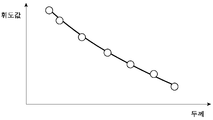
또, 선택부(204)는 지그의 X선 투과 화상의 에너지 특성으로서, 두께 혹은 재질이 변화하는 지그의 복수 점에 있어서의 특성을 해석해도 된다. 도 6은 선택부(204)의 해석 대상의 X선 투과 화상의 일례를 나타내는 도면이다. 도 6은 두께가 스텝 모양으로 변화한 형상의 지그를 대상으로 한 X선 투과 화상이다. 선택부(204)는 이러한 X선 투과 화상으로부터 두께가 상이한 복수의 측정 영역(ROI:Region Of Interest)을 선택하고, 복수의 측정 영역마다의 휘도 평균값을 해석하여, 두께-휘도의 특성 그래프를 에너지 특성으로서 취득한다. 도 7에는, 선택부(204)가 취득한 두께-휘도의 특성 그래프의 일례를 나타내고 있다. In addition, the
또한, 선택부(204)는, 마찬가지로 하여, 좁힘부(203)에 의해서 좁혀진 학습 완료 모델(206)의 구축에 이용한 화상 데이터를 대상으로, 두께-휘도의 특성 그래프를 취득하고, 지그를 대상으로 취득한 특성 그래프와 가장 가까운 특성을 가지는 화상 데이터에 의해서 구축된 학습 완료 모델(206)을, 최종적인 학습 완료 모델(206)로서 선택한다. 다만, 이 학습 완료 모델(206)의 구축에 이용된 화상 데이터의 화상 특성은 미리 제어 장치(20)의 외부에서 산출된 것을 참조해도 된다. 이와 같이, 복수의 측정 영역을 설정함으로써, 대상물(F)의 X선 투과 화상의 노이즈 제거에 최적인 학습 완료 모델을 선택할 수 있다. 특히, X선 투과 화상의 측정시의 X선 스펙트럼의 차이 혹은 필터의 효과의 차이를 정밀도 좋게 추정하는 것이 가능해진다. Further, similarly, the
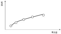
또, 선택부(204)는 지그의 X선 투과 화상의 노이즈 특성으로서, 복수의 측정 영역마다의 휘도값과 노이즈를 해석하여, 휘도-노이즈비의 특성 그래프를 노이즈 특성으로서 취득할 수도 있다. 즉, 선택부(204)는 X선 투과 화상으로부터 두께 혹은 재질이 상이한 복수의 측정 영역(ROI)을 선택하고, 복수의 측정 영역(ROI)의 휘도값의 표준 편차 및 휘도값의 평균값을 해석하여, 휘도-SNR(SN비)의 특성 그래프를 노이즈 특성으로서 취득한다. 이 때, 선택부(204)는 측정 영역(ROI)마다의 SNR을, SNR=(휘도값의 평균값)÷(휘도값의 표준 편차)에 의해서 산출한다. 도 8에는, 선택부(204)가 취득한 휘도-SNR의 특성 그래프의 일례를 나타내고 있다. 그리고, 선택부(204)는 취득한 특성 그래프와 가장 가까운 노이즈 특성을 가지는 화상 데이터에 의해서 구축된 학습 완료 모델(206)을, 최종적인 학습 완료 모델(206)로서 선택한다. Further, the
여기서, 선택부(204)는 노이즈 특성으로서, 상기의 휘도-SNR의 특성 그래프를 대신하여, 세로축을 휘도값의 표준 편차로부터 계산되는 노이즈로 한 특성 그래프를 취득해도 된다. 이러한 휘도-노이즈의 특성 그래프를 이용함으로써, X선 검출 카메라(10)에 의해서 검출되는 각 신호량에 대해, 각 신호량의 영역의 그래프의 기울기로부터 지배적인 노이즈 요인(쇼트 노이즈, 판독 노이즈 등)을 특정하고, 그 특정의 결과를 기초로 학습 완료 모델(206)을 선택할 수 있다. Here, the
도 9는 선택부(204)에 의한 화상 특성에 기초한 학습 완료 모델의 선택 기능을 설명하기 위한 도면이다. 도 9에 있어서, (a)부는 복수의 학습 완료 모델(206)의 구축에 이용된 각각의 화상 데이터의 휘도-SNR의 특성 그래프(G1, G2, G3)를 나타내고, (b)부에는 이들 특성 그래프(G1, G2, G3)에 더하여, 지그를 촬상한 X선 투과 화상의 휘도-SNR의 특성 그래프(GT)를 나타내고 있다. 이러한 특성 그래프(G1, G2, G3, GT)를 대상으로 했을 경우에는, 선택부(204)는 특성 그래프(GT)의 특성에 가장 가까운 특성 그래프(G2)의 화상 데이터에 의해서 구축된 학습 완료 모델(206)을 선택하도록 기능한다. 선택 시에는, 선택부(204)는 각 특성 그래프(G1, G2, G3)와 특성 그래프(GT) 사이에서, 일정 간격의 휘도값마다의 SNR의 오차를 계산하고, 그러한 오차의 평균 제곱 오차(RMSE:Root Mean Squared Error)를 계산하여, 평균 제곱 오차가 가장 작은 특성 그래프(G1, G2, G3)에 대응한 학습 완료 모델(206)을 선택한다. 또, 선택부(204)는 에너지 특성을 이용하여 선택하는 경우에도, 마찬가지로 하여 학습 완료 모델(206)을 선택할 수 있다. 9 is a diagram for explaining a function of selecting a learned model based on image characteristics by the
선택부(204)는 지그의 X선 투과 화상을 대상으로, 복수의 학습 완료 모델을 적용하여 노이즈 제거 처리를 실행한 후의 화상의 특성을 기초로, 학습 완료 모델(206)을 선택할 수도 있다. The
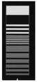
예를 들면, 선택부(204)는 다양한 해상도의 차트를 가지는 지그를 촬상한 X선 투과 화상을 이용하여, 그 화상에 복수의 학습 완료 모델(206)을 적용하여, 그 결과 생성된 노이즈 제거 후의 화상을 평가한다. 그리고, 선택부(204)는 노이즈 제거 처리 전후에 있어서의 해상도의 변화가 가장 작은 화상에 이용된 학습 완료 모델(206)을 선택한다. 도 10에는 해상도의 평가에 이용되는 X선 투과 화상의 일례를 나타내고 있다. 이 X선 투과 화상에 있어서는, 일 방향을 따라서 스텝 모양으로 해상도가 변화하는 차트가 촬상 대상으로 되어 있다. X선 투과 화상의 해상도는 MTF(Modulation Transfer Function) 또는 CTF(Contrast Transfer Function)를 이용하여 측정할 수 있다. For example, the
상기의 해상도의 변화의 평가 이외에도, 선택부(204)는 노이즈 제거 후의 화상의 휘도-노이즈비의 특성을 평가하여, 그 특성이 가장 높은 화상의 생성에 이용된 학습 완료 모델(206)을 선택해도 된다. 도 11에는, 휘도-노이즈비의 평가에 이용되는 지그의 구조의 일례를 나타내고 있다. 예를 들면, 지그로서, 두께가 일 방향으로 스텝 모양으로 변화하는 부재(P1) 중에 다양한 재질 및 다양한 크기를 가지는 이물(P2)이 점재한 것이 이용될 수 있다. 도 12는 도 11의 지그를 대상으로 얻어진 노이즈 제거 처리 후의 X선 투과 화상을 나타내고 있다. 선택부(204)는 X선 투과 화상 중에 있어서 이물(P2)의 이미지를 포함하는 화상 영역(R1)과, 그 영역(R1)의 근방의 이물(P2)의 이미지를 포함하지 않는 화상 영역(R2)을 선택하여, 화상 영역(R1)에 있어서의 휘도의 최소값 LMIN과, 화상 영역(R2)에 있어서의 휘도의 평균값 LAVE과, 화상 영역(R2)에 있어서의 휘도의 표준 편차 LSD을 계산한다. 그리고, 선택부(204)는 하기 식;In addition to the evaluation of the change in resolution described above, the
CNR=(LAVE-LMIN)/LSD CNR=(L AVE -L MIN )/L SD
를 이용하여, 휘도-노이즈비 CNR을 산출한다. 또한, 선택부(204)는 복수의 학습 완료 모델(206)의 적용 후의 X선 투과 화상의 각각을 대상으로 휘도-노이즈비 CNR을 산출하여, 휘도-노이즈비 CNR이 가장 높은 X선 투과 화상의 생성에 이용된 학습 완료 모델(206)을 선택한다. Calculate the luminance-noise ratio CNR using In addition, the
또는, 선택부(204)는 화상 영역(R1)에 있어서의 휘도의 평균값 LAVE_R1과, 화상 영역(R2)에 있어서의 휘도의 평균값 LAVE_R2과, 화상 영역(R2)에 있어서의 휘도의 표준 편차 LSD을 기초로, 하기 식에 의해 계산해도 된다. Alternatively, the
CNR=(LAVE_R1-LMIN _R2)/LSD CNR=(L AVE_R1 -L MIN_R2 ) /L SD
처리부(205)는 대상물(F)을 대상으로 취득된 X선 투과 화상에, 선택부(204)에 의해서 선택된 학습 완료 모델(206)을 적용하여, 노이즈를 제거하는 화상 처리를 실행함으로써 출력 화상을 생성한다. 그리고, 처리부(205)는 생성한 출력 화상을 표시 장치(30) 등에 출력한다. The
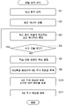
다음에, 본 실시 형태에 따른 화상 취득 장치(1)를 이용한 대상물(F)의 X선 투과 이미지의 관찰 처리의 절차, 즉, 본 실시 형태에 따른 방사선 화상 취득 방법의 흐름에 대해 설명한다. 도 13는 화상 취득 장치(1)에 의한 관찰 처리의 절차를 나타내는 순서도이다. Next, the procedure of observation processing of the X-ray transmission image of the object F using the
우선, 제어 장치(20)에 의해서, 화상 취득 장치(1)의 오퍼레이터(유저)로부터, X선 조사기(50)의 동작 조건, 혹은 X선 검출 카메라(10)에 의한 촬상 조건 등을 나타내는 조건 정보의 입력이 접수된다(스텝 S1). 다음에, 제어 장치(20)에 의해서, 조건 정보를 기초로, X선 검출 카메라(10)에 의해서 검출되는 X선의 평균 에너지의 값이 산출된다(스텝 S2). First, condition information indicating operating conditions of the
또한, 제어 장치(20)에 의해서, 제어 장치(20)에 격납되어 있는 학습 완료 모델(206)의 구축에 이용된 화상 데이터에 있어서의 X선의 평균 에너지의 값이 특정된다(스텝 S3). 그 후, 제어 장치(20)에 격납되어 있는 모든 학습 완료 모델(206)에 관해서, X선의 평균 에너지의 값의 특정이 반복된다(스텝 S4). Further, the value of the average energy of X-rays in the image data used for construction of the learned
다음에, 제어 장치(20)에 의해서, 산출한 X선의 평균 에너지의 값이 비교됨으로써, 복수의 학습 완료 모델(206)의 후보가 좁혀진다(스텝 S5). 또한, 화상 취득 장치(1)에 있어서 지그가 세트되어 그 지그가 촬상됨으로써, 지그의 X선 투과 화상이 취득된다(스텝 S6). Next, by comparing the values of the calculated average energy of X-rays by the
그 후, 제어 장치(20)에 의해, 지그의 X선 투과 화상의 화상 특성(X선의 평균 에너지의 값, 두께-휘도의 특성, 휘도-노이즈비의 특성, 휘도-노이즈의 특성, 해상도 변화의 특성 등)이 취득된다(스텝 S7). 그리고, 제어 장치(20)에 의해, 취득한 화상 특성을 기초로, 최종적인 학습 완료 모델(206)이 선택된다(스텝 S8). Thereafter, by the
또한, 화상 취득 장치(1)에 있어서 대상물(F)이 세트되어 대상물(F)이 촬상됨으로써, 대상물(F)의 X선 투과 화상이 취득된다(스텝 S9). 다음에, 제어 장치(20)에 의해, 최종적으로 선택한 학습 완료 모델(206)을 대상물(F)의 X선 투과 화상에 적용함으르써, X선 투과 화상을 대상으로 노이즈 제거 처리가 실행된다(스텝 S10). 마지막으로, 제어 장치(20)에 의해, 노이즈 제거 처리가 실시된 X선 투과 화상인 출력 화상이, 표시 장치(30)에 출력된다(스텝 S11).In addition, by setting the object F in the
이상 설명한 화상 취득 장치(1)에 의하면, 대상물(F)의 X선 투과 화상을 취득할 때의 X선의 발생원의 동작 조건 혹은 X선 투과 화상의 촬상 조건을 기초로, 대상물(F)을 투과한 X선의 평균 에너지가 산출된다. 그리고, 그 평균 에너지를 기초로, 미리 구축된 학습 완료 모델(206) 중에서 노이즈 제거에 이용하는 학습 완료 모델(206)의 후보가 좁혀진다. 이것에 의해, 촬상 대상의 X선의 평균 에너지에 대응한 학습 완료 모델(206)이 노이즈 제거에 이용되므로, X선 투과 화상에 있어서의 휘도와 노이즈의 관계에 대응한 노이즈 제거를 실현할 수 있다. 그 결과, X선 투과 화상에 있어서의 노이즈를 효과적으로 제거할 수 있어, 예를 들면, 이물 검출 성능을 향상시킬 수 있다. 특히, X선 투과 화상은 관전압, 필터, 신틸레이터, X선 검출 카메라의 조건(게인 설정값, 회로 노이즈값, 포화 전하량, 변환 계수값(e-/count), 카메라의 라인 레이트), 대상물 등의 차이에 따라 노이즈의 양태가 변화한다. 그 때문에, 기계 학습에 의해서 노이즈 제거를 실현하려고 하는 경우, 다양한 조건으로 학습시킨 복수의 학습 모델을 준비해 둘 필요가 있다. 종래는 X선 투과 화상의 측정시의 조건에 맞춰 복수의 학습 모델 중에서 노이즈의 양태에 맞는 학습 모델을 선택하는 것은 실현되어 있지 않았다. 본 실시 형태에 의하면, 촬상 대상의 X선의 평균 에너지에 대응한 학습 완료 모델(206)이 선택됨으로써, 항상 노이즈의 양태에 맞는 학습 모델의 선택이 실현된다. According to the
일반적으로, X선 투과 화상에 있어서는, X선 발생 유래의 노이즈가 포함되어 있다. X선 투과 화상의 SN비를 향상시키기 위해서 X선량을 증가시키는 것도 생각할 수 있지만, 그 경우는, X선량을 증가시키면 센서의 피폭량이 증가하여 센서의 수명이 짧아지는, X선 발생원의 수명이 짧아진다고 하는 문제가 있어, SN비의 향상과 장기 수명화의 양립이 곤란하다. 본 실시 형태에서는, X선량을 증가시킬 필요는 없으므로, SN비의 향상과 장기 수명화의 양립이 가능하다. In general, X-ray transmission images contain noise derived from X-ray generation. It is also conceivable to increase the amount of X-rays in order to improve the SN ratio of the X-ray transmission image, but in that case, increasing the amount of X-rays increases the amount of exposure to the sensor and shortens the life of the sensor, which shortens the life of the X-ray source. There is a problem of losing, and it is difficult to coexist with the improvement of the SN ratio and the long life. In this embodiment, since it is not necessary to increase the amount of X-rays, both improvement of the SN ratio and long life are possible.
또, 본 실시 형태의 제어 장치(20)는, 선택한 학습 완료 모델(206)을 이용하여 대상물(F)의 X선 투과 화상으로부터 노이즈를 제거하는 화상 처리를 실행하는 기능을 가진다. 이러한 기능에 의해, X선 투과 화상에 있어서의 휘도와 노이즈의 관계에 대응한 노이즈 제거를 실현할 수 있어, X선 투과 화상에 있어서의 노이즈를 효과적으로 제거할 수 있다. In addition, the
또, 본 실시 형태의 제어 장치(20)는, 선택 정보로부터 산출된 X선의 평균 에너지의 값과, 학습 완료 모델(206)의 구축에 이용된 화상 데이터로부터 특정되는 평균 에너지의 값을 비교함으로써, 학습 완료 모델의 후보를 좁히는 기능을 가지고 있다. 이러한 기능에 의해, X선 투과 화상에 있어서의 휘도와 노이즈의 관계에 대응한 노이즈 제거를 확실히 실현할 수 있다. In addition, the
또한, 본 실시 형태의 제어 장치(20)는, 지그의 X선 투과 화상의 화상 특성에 기초하여 후보로부터 학습 완료 모델(206)을 선택하는 기능을 가지고 있다. 이러한 기능에 의해, 대상물(F)의 X선 투과 화상의 노이즈 제거에 최적인 학습 완료 모델(206)을 선택할 수 있다. 그 결과, X선 투과 화상에 있어서의 휘도와 노이즈의 관계에 대응한 노이즈 제거를 보다 확실히 실현할 수 있다. In addition, the
도 14 및 도 15에는, 화상 취득 장치(1)에 의해서 취득된 노이즈 제거 처리의 전후의 X선 투과 화상의 예를 나타내고 있다. 도 14 및 도 15에는, 각각, 금속, 유리 등의 이물이 부여된 치즈를 대상으로 한 화상, 다양한 크기의 뼈가 잔존해 있는 닭고기를 대상으로 한 화상을 나타내고 있고, 좌측에 노이즈 처리 전의 화상, 우측에 노이즈 처리 후의 화상을 각각 나타내고 있다. 이와 같이, 본 실시 형태에 의하면, 다양한 대상물에 대해서 노이즈 제거가 효과적으로 행해져 있는 것을 안다. 14 and 15 show examples of X-ray transmission images obtained by the
이상, 본 발명의 다양한 실시 형태에 대해 설명했지만, 본 발명은 상기 실시 형태로 한정되는 것이 아니고, 각 청구항에 기재한 요지를 변경하지 않는 범위에서 변형하고, 또는 다른 것에 적용한 것이어도 된다. As mentioned above, although various embodiments of the present invention have been described, the present invention is not limited to the above embodiments, and may be modified or applied to others within a range that does not change the gist described in each claim.
예를 들면, X선 검출 카메라(10)는 듀얼 라인 X선 카메라인 것으로 설명했지만 이것으로 한정되지 않고, 싱글 라인 X선 카메라나, 듀얼 에너지 X선 카메라, TDI(Time Delay Integration) 스캔 X선 카메라, 2라인 이상의 복수의 라인을 가지는 멀티 라인 X선 카메라, 2차원 X선 카메라, X선 플랫 패널 센서, X선 I.I, 신틸레이터를 이용하지 않는 직접 변환 형태 X선 카메라(a-Se, Si, CdTe, CdZnTe, TlBr, PbI2 등), 신틸레이터를 렌즈 커플링에 의한 광학 렌즈를 이용한 관찰 방식의 카메라여도 된다. 또, X선 검출 카메라(10)는 방사선에 감도가 있는 촬상관 혹은 방사선에 감도가 있는 포인트 센서여도 된다. For example, the
또, 상기 실시 형태의 제어 장치(20)는, 조건 정보로부터 산출한 X선의 평균 에너지의 값을 기초로 학습 완료 모델(206)의 후보를 선택하고 있었지만, 이하에 나타내는 변형예에 따른 제어 장치(20A)와 같이 X선 검출 카메라(10)의 성능 열화, X선 조사기(50)의 출력 변동 혹은 성능 열화에 대응한 기능을 가지고 있어도 된다. In addition, the
또, 화상 취득 장치(1)에 대해서도, 상기 실시 형태로 한정되는 것이 아니고, CT(Computed Tomography) 장치 등, 대상물(F)을 정지시킨 상태에서 촬상하는 방사선 화상 처리 시스템이어도 된다. 또한, 대상물(F)을 회전시키면서 촬상하는 방사선 화상 처리 시스템이어도 된다. Also, the
도 16은 변형예에 따른 제어 장치(20A)의 기능 구성을 나타내는 블록도이다. 제어 장치(20A)는 상기 실시 형태에 따른 제어 장치(20)와 비교하여, 측정부(207)를 가지는 점과, 산출부(202A) 및 좁힘부(203A)의 기능이 다르다. Fig. 16 is a block diagram showing the functional configuration of a
제어 장치(20)에 있어서는, X선 검출 카메라(10)의 성능 열화 및 X선 조사기(50)의 출력 변동 혹은 성능 열화는 없는 것으로 하고, X선의 평균 에너지로부터 X선 투과 화상에 있어서의 휘도와 노이즈의 관계를 추정할 수 있다고 하는 전제로, 학습 완료 모델(206)을 좁히고 있다. 이것에 대해서, 본 변형예에 따른 제어 장치(20A)에 있어서는, X선 검출 카메라(10)의 성능 열화, X선 조사기(50)의 출력 변동, 혹은 그 성능 열화를 고려하여, X선 변환 계수를 산출하여, X선 변환 계수를 기초로 학습 완료 모델(206)을 좁히는 기능을 가진다. X선 변환 계수는 X선이 신틸레이터에 의해 가시광으로 변환된 후에 카메라의 센서로 전자(전기 신호)로 변환될 때까지의 효율을 나타내는 파라미터이다. In the
일반적으로, X선 변환 계수 FT는 X선의 평균 에너지를 E[keV]라고 하고, 신틸레이터 발광량을 EM[photon/keV], 센서에 있어서의 커플링 효율을 C, 센서의 광자 효율을 QE라고 하면, 하기 식;In general, the X-ray conversion coefficient F T denotes the average energy of X-rays as E [keV], the scintillator emission amount as EM [photon/keV], the coupling efficiency in the sensor as C, and the photon efficiency of the sensor as QE. If so, the following formula;
FT=E×EM×C×QEF T =E×EM×C×QE
에 의해 계산할 수 있다. 또, X선 투과 화상에 있어서의 SN비(SNR)는, X선 변환 계수 FT와, X선 포톤수 NP와, 카메라의 판독 노이즈 Nr을 이용하여, 하기 식;can be calculated by In addition, the SN ratio (SNR) in the X-ray transmission image is the following formula using the X-ray conversion coefficient F T , the number of X-ray photons N P , and the camera reading noise Nr;
SNR=FTNP/{(FTNP+Nr2)1/2}SNR=F T N P /{(F T N P +Nr 2 ) 1/2 }
로부터 구해지는 것으로부터, X선 변환 계수 FT를 기초로, 카메라의 성능 열화를 고려한 결과의 X선 투과 화상에 있어서의 휘도와 노이즈의 관계를 추정할 수 있다. Based on the X-ray conversion coefficient F T , it is possible to estimate the relationship between luminance and noise in the resulting X-ray transmission image in consideration of performance deterioration of the camera.
제어 장치(20A)의 측정부(207)는, 신틸레이터(11a, 11b)의 성능 열화로서의 발광량 EM의 저하량, 라인 스캔 카메라(12a, 12b)의 성능 열화로서의 센서의 광자 효율 QE의 저하량, X선 조사기(50)의 출력 변동 및 성능 열화로서의 평균 에너지 E의 변화량을 측정하는 기능을 가진다. 예를 들면, 측정부(207)는 신틸레이터(11a, 11b)의 성능 열화가 없는 상태(신품시에서의 상태)와, 현재의 신틸레이터(11a, 11b) 사이의 발광량의 저하량을 측정하여 그 저하량으로부터 현재의 발광량 EM을 추정한다. 또, 측정부(207)는 라인 스캔 카메라(12a, 12b)의 성능 열화가 없는 상태(신품시에서의 상태)와, 현재의 라인 스캔 카메라(12a, 12b) 사이의 휘도 저하량을 측정하여 그 저하량으로부터 현재의 광자 효율 QE를 추정한다. 또, 측정부(207)는 X선 조사기(50)의 성능 열화가 없는 상태(신품시에서의 상태)와, 현재의 X선 조사기(50) 사이의 평균 에너지의 변화량으로부터 현재의 평균 에너지 E를 추정한다. 평균 에너지 E는 두께 및 재질이 이미 알려져 있어, X선의 평균 에너지와 X선 투과율의 관계가 이미 알려져 있는 평판 모양 부재의 촬상 데이터로부터 구해지거나, 두께 혹은 재질이 변화하는 지그의 복수점에 있어서의 촬상 데이터로부터 구하는 등으로 해도 된다. The
제어 장치(20A)의 산출부(202A)는, 산출한 X선의 평균 에너지 E와, 측정부(207)에 의해 추정된 발광량 EM 및 광자 효율 QE를 이용하여 X선 변환 계수 FT를 산출한다. 제어 장치(20A)의 좁힘부(203)는, 산출한 X선 변환 계수 FT와, 학습 완료 모델(206)의 구축에 이용된 화상 데이터에 있어서의 X선 변환 계수 FT를 비교함으로써, 학습 완료 모델(206)의 후보를 좁히는 기능을 가진다. The
또, 상기 실시 형태의 제어 장치(20)는, 학습 완료 모델의 후보를 좁힌 후에, 지그를 촬상하여 얻어진 화상 특성을 기초로 학습 완료 모델을 선택하고 있었지만, 지그의 촬상을 행하는 일 없이, 대상물의 X선 투과 화상에 대한 노이즈 제거 처리를 실행해도 된다. 도 17은 변형예에 따른 화상 취득 장치(1)에 의한 관찰 처리의 절차를 나타내는 순서도이다. 이와 같이, 도 13에 있어서의 스텝 S6~S8의 처리를 생략하고, 평균 에너지를 기초로 좁힌 학습 완료 모델을 이용하여 노이즈 제거 처리를 실행할 수도 있다. In addition, although the
상술한 실시 형태에서는, 후보를 이용하여 대상물의 방사선 화상으로부터 노이즈를 제거하는 화상 처리를 실행하는 스텝을 더 구비하는 것이 바람직하다. 상기 실시 형태에 있어서는, 후보를 이용하여 대상물의 방사선 화상으로부터 노이즈를 제거하는 화상 처리를 실행하는 처리부를 더 구비하는 것이 바람직하다. 이것에 의해, 방사선 화상에 있어서의 휘도와 노이즈의 관계에 대응한 노이즈 제거를 실현할 수 있어, 방사선 화상에 있어서의 노이즈를 효과적으로 제거할 수 있다. In the above-described embodiment, it is preferable to further include a step of executing image processing for removing noise from the radiographic image of the object using the candidate. In the above embodiment, it is preferable to further include a processing unit that performs image processing for removing noise from a radiographic image of an object using candidates. Thereby, noise removal corresponding to the relationship between luminance and noise in a radiographic image can be realized, and noise in a radiographic image can be effectively removed.
또, 좁히는 스텝에서는, 평균 에너지와, 화상 데이터로부터 특정되는 평균 에너지를 비교함으로써, 후보를 좁히는 것도 바람직하다. 또, 좁힘부는 평균 에너지와, 화상 데이터로부터 특정되는 평균 에너지를 비교함으로써, 후보를 좁히는 것도 바람직하다. 이 경우, 학습 완료 모델의 구축에 이용된 화상 데이터로부터 특정되는 평균 에너지와의 비교에 의해, 학습 완료 모델이 좁혀지므로, 방사선 화상에 있어서의 휘도와 노이즈의 관계에 대응한 노이즈 제거를 확실히 실현할 수 있다. In the narrowing step, it is also preferable to narrow down the candidates by comparing the average energy with the average energy specified from the image data. In addition, it is also preferable to narrow down the candidates by comparing the average energy of the narrowing unit with the average energy specified from the image data. In this case, since the learned model is narrowed down by comparison with the average energy specified from the image data used for constructing the learned model, noise removal corresponding to the relationship between luminance and noise in the radiographic image can be reliably realized. there is.
또한, 조건 정보에는, 발생원의 관전압, 대상물의 촬상에 이용하는 카메라가 구비하는 필터의 정보, 발생원이 구비하는 필터의 정보, 카메라가 구비하는 신틸레이터의 정보, 발생원과 촬상 장치 사이의 거리, 대상물의 촬상에 이용하는 X선 검출 카메라에 관한 정보, 및 대상물에 관한 정보 중 어느 1개가 적어도 포함되는 것이 바람직하다. 이 경우, 대상물을 투과하는 방사선의 평균 에너지를 정밀도 좋게 계산할 수 있으므로, 방사선 화상에 있어서의 휘도와 노이즈의 관계에 대응한 노이즈 제거가 가능해진다.In addition, the condition information includes the tube voltage of the generating source, filter information of the camera used to capture the image of the object, filter information of the generating source, scintillator information of the camera, distance between the generating source and the imaging device, and target object. It is preferable that at least any one of the information about the X-ray detection camera used for imaging and the information about the object is included. In this case, since the average energy of the radiation penetrating the object can be calculated with high precision, noise removal corresponding to the relationship between luminance and noise in the radiographic image can be performed.
또한 추가로, 방사선을 조사하여 지그를 촬상하여 방사선 화상을 취득하고, 해당 방사선 화상의 화상 특성에 기초하여 후보로부터 학습 완료 모델을 선택하는 스텝을 더 구비하는 것도 바람직하다. 또한 추가로, 방사선을 조사하여 지그를 촬상하여 방사선 화상을 취득하고, 해당 방사선 화상의 화상 특성에 기초하여 후보로부터 학습 완료 모델을 선택하는 선택부를 더 구비하는 것도 바람직하다. 이러한 구성에 의하면, 실제의 지그를 촬상하여 얻어지는 방사선 화상의 화상 특성을 기초로 학습 완료 모델이 선택되므로, 대상물의 방사선 화상의 노이즈 제거에 최적인 학습 완료 모델을 선택할 수 있다. 그 결과, 방사선 화상에 있어서의 휘도와 노이즈의 관계에 대응한 노이즈 제거를 보다 확실히 실현할 수 있다. It is also preferable to further include a step of irradiating radiation to image the jig to obtain a radiation image, and selecting a trained model from candidates based on image characteristics of the radiation image. It is also preferable to further include a selection unit that acquires a radiation image by imaging the jig by irradiating radiation and selects a learned model from candidates based on the image characteristics of the radiation image. According to this configuration, since a learned model is selected based on the image characteristics of a radiographic image obtained by imaging an actual jig, it is possible to select a learned model optimal for noise reduction in a radiographic image of an object. As a result, noise removal corresponding to the relationship between luminance and noise in a radiographic image can be realized more reliably.
[산업상의 이용 가능성][Industrial Applicability]
실시 형태는 방사선 화상 처리 방법, 학습 완료 모델, 방사선 화상 처리 모듈, 방사선 화상 처리 프로그램, 및 방사선 화상 처리 시스템을 사용 용도로 하여, 방사선 화상에 있어서의 노이즈를 효과적으로 제거할 수 있는 것이다. 계에 대응한 노이즈 제거가 가능해진다.The embodiment is capable of effectively removing noise in a radiation image by using a radiation image processing method, a learned model, a radiation image processing module, a radiation image processing program, and a radiation image processing system as intended uses. Noise removal corresponding to the system becomes possible.
10…X선 검출 카메라(촬상 장치)
20…제어 장치(방사선 화상 처리 모듈)
201…입력부
202, 202A…산출부
203, 203A…좁힘부
204…선택부
205…처리부
206…학습 완료 모델
F…대상물10... X-ray detection camera (imaging device)
20... Control device (radiation image processing module) 201 . . . input part
202, 202A...
204...
206... Trained model F… quid pro quo
Claims (16)
상기 조건 정보를 기초로, 상기 대상물을 투과한 상기 방사선에 관한 평균 에너지를 산출하는 스텝과,
상기 평균 에너지를 기초로, 미리 화상 데이터를 이용하여 기계 학습에 의해서 각각 구축된 복수의 학습 완료 모델 중에서, 학습 완료 모델의 후보를 좁히는 스텝을 구비하는 방사선 화상 처리 방법.a step of inputting condition information indicating either a condition of a source of radiation or an imaging condition when capturing an image of an object by irradiating with radiation;
calculating an average energy of the radiation transmitted through the object based on the condition information;
and a step of narrowing down the candidates for the learned models from among a plurality of learned models each constructed by machine learning using image data in advance based on the average energy.
상기 후보를 이용하여 상기 대상물의 방사선 화상으로부터 노이즈를 제거하는 화상 처리를 실행하는 스텝을 더 구비하는 방사선 화상 처리 방법.The method of claim 1,
and a step of executing image processing for removing noise from the radiographic image of the object by using the candidate.
상기 좁히는 스텝에서는, 상기 평균 에너지와, 상기 화상 데이터로부터 특정되는 평균 에너지를 비교함으로써, 상기 후보를 좁히는, 방사선 화상 처리 방법.According to claim 1 or claim 2,
In the narrowing step, the candidates are narrowed down by comparing the average energy with the average energy specified from the image data.
상기 조건 정보에는, 상기 발생원의 관전압, 상기 대상물의 촬상에 이용하는 카메라가 구비하는 필터의 정보, 상기 발생원이 구비하는 필터의 정보, 상기 카메라가 구비하는 신틸레이터의 정보, 상기 발생원과 촬상 장치 사이의 거리, 상기 대상물의 촬상에 이용하는 X선 검출 카메라에 관한 정보, 및 상기 대상물에 관한 정보 중 어느 1개가 적어도 포함되는, 방사선 화상 처리 방법.The method according to any one of claims 1 to 3,
The condition information includes the tube voltage of the generating source, filter information provided by the camera used for capturing the image of the object, filter information provided by the generating source, scintillator information provided by the camera, information on the voltage between the generating source and the imaging device. A radiographic image processing method, wherein at least any one of distance, information on an X-ray detection camera used to capture an image of the target object, and information on the target object is included.
방사선을 조사하여 지그를 촬상하여 방사선 화상을 취득하고, 해당 방사선 화상의 화상 특성에 기초하여 상기 후보로부터 학습 완료 모델을 선택하는 스텝을 더 구비하는 방사선 화상 처리 방법.The method according to any one of claims 1 to 4,
A radiographic image processing method, further comprising a step of irradiating radiation to image a jig to obtain a radiographic image, and selecting a learned model from the candidates based on image characteristics of the radiographic image.
상기 기계 학습은 딥 러닝인, 방사선 화상 처리 방법.The method according to any one of claims 1 to 5,
The machine learning is deep learning, the radiographic image processing method.
화상 데이터를 이용하여 기계 학습에 의해서 구축되어, 프로세서에, 상기 대상물의 방사선 화상으로부터 노이즈를 제거하는 화상 처리를 실행시키는 학습 완료 모델.A learned model used in the radiographic image processing method according to any one of claims 1 to 6,
A learned model constructed by machine learning using image data and causing a processor to execute image processing for removing noise from a radiographic image of the object.
상기 조건 정보를 기초로, 상기 대상물을 투과한 상기 방사선에 관한 평균 에너지를 산출하는 산출부와,
상기 평균 에너지를 기초로, 미리 화상 데이터를 이용하여 기계 학습에 의해서 각각 구축된 복수의 학습 완료 모델 중에서, 학습 완료 모델의 후보를 좁히는 좁힘부를 구비하는 방사선 화상 처리 모듈.an input unit that accepts input of condition information indicating either a condition of a source of radiation or an imaging condition when an object is imaged by irradiation with radiation;
a calculation unit that calculates an average energy of the radiation transmitted through the object based on the condition information;
A radiation image processing module comprising a narrowing unit for narrowing down the candidates of the learned models from among a plurality of learned models each built by machine learning using image data in advance on the basis of the average energy.
상기 후보를 이용하여 상기 대상물의 방사선 화상으로부터 노이즈를 제거하는 화상 처리를 실행하는 처리부를 더 구비하는 방사선 화상 처리 모듈.The method of claim 8,
and a processing unit which executes image processing for removing noise from the radiographic image of the object using the candidate.
상기 좁힘부는 상기 평균 에너지와, 상기 화상 데이터로부터 특정되는 평균 에너지를 비교함으로써, 상기 후보를 좁히는, 방사선 화상 처리 모듈.In claim 8 or claim 9
wherein the narrowing unit narrows down the candidates by comparing the average energy with the average energy specified from the image data.
상기 조건 정보에는, 상기 발생원의 관전압, 필터, 상기 발생원과 촬상 장치 사이의 거리, X선 검출 카메라, 및 상기 대상물에 관한 정보를 포함하는, 사선 화상 처리 모듈.The method according to any one of claims 8 to 10,
The oblique image processing module, wherein the condition information includes information about a tube voltage of the generating source, a filter, a distance between the generating source and an imaging device, an X-ray detection camera, and the object.
방사선을 조사하여 지그를 촬상하여 방사선 화상을 취득하고, 해당 방사선 화상의 화상 특성에 기초하여 상기 후보로부터 학습 완료 모델을 선택하는 선택부를 더 구비하는 방사선 화상 처리 모듈.The method according to any one of claims 8 to 11,
A radiation image processing module further comprising: a selection unit that acquires a radiation image by capturing a jig by irradiating radiation and selecting a learned model from the candidates based on image characteristics of the radiation image.
상기 기계 학습은 딥 러닝인, 방사선 화상 처리 모듈.The method according to any one of claims 8 to 12,
The radiation image processing module, wherein the machine learning is deep learning.
방사선을 조사하여 대상물을 촬상할 때의 상기 방사선의 발생원의 조건 혹은 촬상 조건 중 어느 것을 나타내는 조건 정보의 입력을 접수하는 입력부,
상기 조건 정보를 기초로, 상기 대상물을 투과한 상기 방사선에 관한 평균 에너지를 산출하는 산출부, 및
상기 평균 에너지를 기초로, 미리 화상 데이터를 이용하여 기계 학습에 의해서 각각 구축된 복수의 학습 완료 모델 중에서, 학습 완료 모델의 후보를 좁히는 좁힘부로서 기능시키는 방사선 화상 처리 프로그램.processor,
an input unit that accepts input of condition information indicating either a condition of a source of radiation or an imaging condition when an object is imaged by irradiation with radiation;
a calculation unit for calculating an average energy of the radiation transmitted through the object based on the condition information; and
A radiation image processing program that functions as a narrowing unit that narrows down candidates for learned models from among a plurality of learned models each constructed by machine learning using image data in advance based on the average energy.
상기 대상물에 방사선을 조사하는 상기 발생원과,
상기 대상물을 투과한 방사선을 촬상하여 상기 방사선 화상을 취득하는 촬상 장치를 구비하는 방사선 화상 처리 시스템.The radiation image processing module according to any one of claims 8 to 13;
The generating source for irradiating radiation to the object;
A radiation image processing system comprising an imaging device that acquires the radiation image by capturing radiation transmitted through the object.
Applications Claiming Priority (3)
| Application Number | Priority Date | Filing Date | Title |
|---|---|---|---|
| JP2020073576 | 2020-04-16 | ||
| JPJP-P-2020-073576 | 2020-04-16 | ||
| PCT/JP2021/015488 WO2021210617A1 (en) | 2020-04-16 | 2021-04-14 | Radiography method, trained model, radiography module, radiography program, radiography system, and machine learning method |
Publications (1)
| Publication Number | Publication Date |
|---|---|
| KR20230003484A true KR20230003484A (en) | 2023-01-06 |
Family
ID=78083999
Family Applications (1)
| Application Number | Title | Priority Date | Filing Date |
|---|---|---|---|
| KR1020227037164A KR20230003484A (en) | 2020-04-16 | 2021-04-14 | Radiation image processing method, learned model, radiation image processing module, radiation image processing program, radiation image processing system, and machine learning method |
Country Status (6)
| Country | Link |
|---|---|
| US (1) | US20230125182A1 (en) |
| EP (1) | EP4123296A4 (en) |
| JP (1) | JPWO2021210617A1 (en) |
| KR (1) | KR20230003484A (en) |
| CN (1) | CN115427794A (en) |
| WO (1) | WO2021210617A1 (en) |
Citations (1)
| Publication number | Priority date | Publication date | Assignee | Title |
|---|---|---|---|---|
| JP2019091393A (en) | 2017-11-10 | 2019-06-13 | アジア航測株式会社 | Point group kind estimating apparatus using red three-dimensional map image, and point group kind estimating program using red three-dimensional map image |
Family Cites Families (8)
| Publication number | Priority date | Publication date | Assignee | Title |
|---|---|---|---|---|
| JP2006318103A (en) * | 2005-05-11 | 2006-11-24 | Fuji Photo Film Co Ltd | Image processor, image processing method, and program |
| JP4895204B2 (en) * | 2007-03-22 | 2012-03-14 | 富士フイルム株式会社 | Image component separation device, method, and program, and normal image generation device, method, and program |
| WO2011064683A2 (en) * | 2009-11-25 | 2011-06-03 | Koninklijke Philips Electronics N.V. | Enhanced image data/dose reduction |
| JP7169094B2 (en) * | 2017-06-01 | 2022-11-10 | 株式会社東芝 | Image processing system and medical information processing system |
| EP3702745A4 (en) * | 2017-10-24 | 2021-09-01 | System Square Inc. | Electromagnetic wave detection module, electromagnetic wave detection module row, and nondestructive inspection device |
| JP7246903B2 (en) * | 2017-12-20 | 2023-03-28 | キヤノンメディカルシステムズ株式会社 | medical signal processor |
| JPWO2020031984A1 (en) * | 2018-08-08 | 2021-08-10 | Blue Tag株式会社 | Parts inspection method and inspection system |
| CN109697476B (en) * | 2019-02-01 | 2023-06-23 | 重庆大学 | X-ray photon counting detector consistency calibration method based on deep learning |
-
2021
- 2021-04-14 US US17/918,178 patent/US20230125182A1/en active Pending
- 2021-04-14 KR KR1020227037164A patent/KR20230003484A/en active Search and Examination
- 2021-04-14 EP EP21788114.3A patent/EP4123296A4/en active Pending
- 2021-04-14 CN CN202180028353.0A patent/CN115427794A/en active Pending
- 2021-04-14 WO PCT/JP2021/015488 patent/WO2021210617A1/en unknown
- 2021-04-14 JP JP2022515418A patent/JPWO2021210617A1/ja active Pending
Patent Citations (1)
| Publication number | Priority date | Publication date | Assignee | Title |
|---|---|---|---|---|
| JP2019091393A (en) | 2017-11-10 | 2019-06-13 | アジア航測株式会社 | Point group kind estimating apparatus using red three-dimensional map image, and point group kind estimating program using red three-dimensional map image |
Also Published As
| Publication number | Publication date |
|---|---|
| US20230125182A1 (en) | 2023-04-27 |
| EP4123296A4 (en) | 2024-04-10 |
| JPWO2021210617A1 (en) | 2021-10-21 |
| WO2021210617A1 (en) | 2021-10-21 |
| CN115427794A (en) | 2022-12-02 |
| EP4123296A1 (en) | 2023-01-25 |
Similar Documents
| Publication | Publication Date | Title |
|---|---|---|
| CN110869811B (en) | Managing geometric misalignment in an X-ray imaging system | |
| EP2951615B1 (en) | Method and device for generating an energy-resolved x-ray image with adapted energy threshold | |
| CN110072459B (en) | Self-calibrating CT detector, system and method for self-calibration | |
| CN108135560B (en) | X-ray CT data processing device and X-ray CT device equipped with same | |
| JP2016519308A (en) | Direct conversion radiation detector digital signal processor | |
| KR20220149677A (en) | Spectral pile-up correction for photon-counting x-ray detectors | |
| WO2021210618A1 (en) | Radiographic image processing method, trained model, radiographic image processing module, radiographic image processing program, and radiographic image processing system | |
| EP4357818A1 (en) | Radiographic image acquiring device, radiographic image acquiring system, and radiographic image acquisition method | |
| KR20230003484A (en) | Radiation image processing method, learned model, radiation image processing module, radiation image processing program, radiation image processing system, and machine learning method | |
| JP7060446B2 (en) | X-ray line sensor and X-ray foreign matter detection device using it | |
| TW202307465A (en) | Radiographic image processing method, learning completion model, radiographic image processing module, radiographic image processing program, radiographic image processing system, and machine learning method capable of effectively removing noise of radiographic images of object | |
| WO2021210612A1 (en) | Radiographic image acquiring device, radiographic image acquiring system, and radiographic image acquisition method | |
| US20240054617A1 (en) | Radiographic image processing method, machine-learning method, trained model, machine-learning preprocessing method, radiographic image processing module, radiographic image processing program, and radiographic image processing system | |
| TW202307785A (en) | Radiographic image processing method, learned model, radiographic image processing module, radiographic image processing program, and radiographic image processing system capable of effectively removing noises from radiographic images | |
| JP7079966B2 (en) | X-ray detector | |
| US11166683B2 (en) | Spectral pileup correction for photon-counting x-ray detectors | |
| US20230293135A1 (en) | Metric-based data management for x-ray imaging systems | |
| US11185303B2 (en) | Image processing apparatus, radiography system, image processing method, and image processing program |
Legal Events
| Date | Code | Title | Description |
|---|---|---|---|
| A201 | Request for examination |