KR20230000006A - System for Component Fastening System Using Cooperative Robot and Fastening Method Thereof - Google Patents
System for Component Fastening System Using Cooperative Robot and Fastening Method Thereof Download PDFInfo
- Publication number
- KR20230000006A KR20230000006A KR1020210081290A KR20210081290A KR20230000006A KR 20230000006 A KR20230000006 A KR 20230000006A KR 1020210081290 A KR1020210081290 A KR 1020210081290A KR 20210081290 A KR20210081290 A KR 20210081290A KR 20230000006 A KR20230000006 A KR 20230000006A
- Authority
- KR
- South Korea
- Prior art keywords
- fastening
- robot
- component
- loading
- module component
- Prior art date
Links
- 238000000034 method Methods 0.000 title claims abstract description 57
- 238000001514 detection method Methods 0.000 claims description 6
- 238000004904 shortening Methods 0.000 abstract 1
- 238000003825 pressing Methods 0.000 description 18
- 238000004519 manufacturing process Methods 0.000 description 4
- 238000010586 diagram Methods 0.000 description 2
- 230000000694 effects Effects 0.000 description 2
- 230000005484 gravity Effects 0.000 description 1
- 238000012423 maintenance Methods 0.000 description 1
- 238000012986 modification Methods 0.000 description 1
- 230000004048 modification Effects 0.000 description 1
Images


Classifications
-
- B—PERFORMING OPERATIONS; TRANSPORTING
- B25—HAND TOOLS; PORTABLE POWER-DRIVEN TOOLS; MANIPULATORS
- B25J—MANIPULATORS; CHAMBERS PROVIDED WITH MANIPULATION DEVICES
- B25J9/00—Programme-controlled manipulators
- B25J9/16—Programme controls
- B25J9/1679—Programme controls characterised by the tasks executed
- B25J9/1687—Assembly, peg and hole, palletising, straight line, weaving pattern movement
-
- B—PERFORMING OPERATIONS; TRANSPORTING
- B25—HAND TOOLS; PORTABLE POWER-DRIVEN TOOLS; MANIPULATORS
- B25J—MANIPULATORS; CHAMBERS PROVIDED WITH MANIPULATION DEVICES
- B25J9/00—Programme-controlled manipulators
- B25J9/0084—Programme-controlled manipulators comprising a plurality of manipulators
-
- B—PERFORMING OPERATIONS; TRANSPORTING
- B25—HAND TOOLS; PORTABLE POWER-DRIVEN TOOLS; MANIPULATORS
- B25J—MANIPULATORS; CHAMBERS PROVIDED WITH MANIPULATION DEVICES
- B25J13/00—Controls for manipulators
- B25J13/08—Controls for manipulators by means of sensing devices, e.g. viewing or touching devices
- B25J13/086—Proximity sensors
-
- B—PERFORMING OPERATIONS; TRANSPORTING
- B25—HAND TOOLS; PORTABLE POWER-DRIVEN TOOLS; MANIPULATORS
- B25J—MANIPULATORS; CHAMBERS PROVIDED WITH MANIPULATION DEVICES
- B25J15/00—Gripping heads and other end effectors
- B25J15/0033—Gripping heads and other end effectors with gripping surfaces having special shapes
- B25J15/0038—Cylindrical gripping surfaces
-
- B—PERFORMING OPERATIONS; TRANSPORTING
- B25—HAND TOOLS; PORTABLE POWER-DRIVEN TOOLS; MANIPULATORS
- B25J—MANIPULATORS; CHAMBERS PROVIDED WITH MANIPULATION DEVICES
- B25J15/00—Gripping heads and other end effectors
- B25J15/0052—Gripping heads and other end effectors multiple gripper units or multiple end effectors
-
- B—PERFORMING OPERATIONS; TRANSPORTING
- B25—HAND TOOLS; PORTABLE POWER-DRIVEN TOOLS; MANIPULATORS
- B25J—MANIPULATORS; CHAMBERS PROVIDED WITH MANIPULATION DEVICES
- B25J19/00—Accessories fitted to manipulators, e.g. for monitoring, for viewing; Safety devices combined with or specially adapted for use in connection with manipulators
- B25J19/02—Sensing devices
- B25J19/021—Optical sensing devices
- B25J19/023—Optical sensing devices including video camera means
-
- B—PERFORMING OPERATIONS; TRANSPORTING
- B25—HAND TOOLS; PORTABLE POWER-DRIVEN TOOLS; MANIPULATORS
- B25J—MANIPULATORS; CHAMBERS PROVIDED WITH MANIPULATION DEVICES
- B25J9/00—Programme-controlled manipulators
- B25J9/16—Programme controls
- B25J9/1656—Programme controls characterised by programming, planning systems for manipulators
- B25J9/1664—Programme controls characterised by programming, planning systems for manipulators characterised by motion, path, trajectory planning
-
- B—PERFORMING OPERATIONS; TRANSPORTING
- B25—HAND TOOLS; PORTABLE POWER-DRIVEN TOOLS; MANIPULATORS
- B25J—MANIPULATORS; CHAMBERS PROVIDED WITH MANIPULATION DEVICES
- B25J9/00—Programme-controlled manipulators
- B25J9/16—Programme controls
- B25J9/1656—Programme controls characterised by programming, planning systems for manipulators
- B25J9/1669—Programme controls characterised by programming, planning systems for manipulators characterised by special application, e.g. multi-arm co-operation, assembly, grasping
-
- B—PERFORMING OPERATIONS; TRANSPORTING
- B25—HAND TOOLS; PORTABLE POWER-DRIVEN TOOLS; MANIPULATORS
- B25J—MANIPULATORS; CHAMBERS PROVIDED WITH MANIPULATION DEVICES
- B25J9/00—Programme-controlled manipulators
- B25J9/16—Programme controls
- B25J9/1674—Programme controls characterised by safety, monitoring, diagnostic
- B25J9/1676—Avoiding collision or forbidden zones
-
- B—PERFORMING OPERATIONS; TRANSPORTING
- B25—HAND TOOLS; PORTABLE POWER-DRIVEN TOOLS; MANIPULATORS
- B25J—MANIPULATORS; CHAMBERS PROVIDED WITH MANIPULATION DEVICES
- B25J9/00—Programme-controlled manipulators
- B25J9/16—Programme controls
- B25J9/1679—Programme controls characterised by the tasks executed
- B25J9/1682—Dual arm manipulator; Coordination of several manipulators
-
- B—PERFORMING OPERATIONS; TRANSPORTING
- B25—HAND TOOLS; PORTABLE POWER-DRIVEN TOOLS; MANIPULATORS
- B25J—MANIPULATORS; CHAMBERS PROVIDED WITH MANIPULATION DEVICES
- B25J9/00—Programme-controlled manipulators
- B25J9/16—Programme controls
- B25J9/1694—Programme controls characterised by use of sensors other than normal servo-feedback from position, speed or acceleration sensors, perception control, multi-sensor controlled systems, sensor fusion
- B25J9/1697—Vision controlled systems
-
- G—PHYSICS
- G05—CONTROLLING; REGULATING
- G05B—CONTROL OR REGULATING SYSTEMS IN GENERAL; FUNCTIONAL ELEMENTS OF SUCH SYSTEMS; MONITORING OR TESTING ARRANGEMENTS FOR SUCH SYSTEMS OR ELEMENTS
- G05B2219/00—Program-control systems
- G05B2219/30—Nc systems
- G05B2219/40—Robotics, robotics mapping to robotics vision
- G05B2219/40584—Camera, non-contact sensor mounted on wrist, indep from gripper
Landscapes
- Engineering & Computer Science (AREA)
- Robotics (AREA)
- Mechanical Engineering (AREA)
- Human Computer Interaction (AREA)
- Multimedia (AREA)
- Automatic Assembly (AREA)
- Manipulator (AREA)
Abstract
Description
본 개시는 협동로봇을 이용하는 부품 체결시스템 및 이의 체결방법에 관한 것이다.The present disclosure relates to a component fastening system using a collaborative robot and a fastening method thereof.
이 부분에 기술된 내용은 단순히 본 개시에 대한 배경정보를 제공할 뿐 종래기술을 구성하는 것은 아니다.The content described in this section simply provides background information for the present disclosure and does not constitute prior art.
스마트팩토리(smart factory)분야가 산업에 전반적으로 적용되고 있는데 제품의 각 부품을 조립할 때에도 로봇에 의해 자동화되어 조립된다. 제품을 조립하는 로봇은 일반적으로 로딩로봇, 체결로봇 및 부품공급로봇으로 구성되어 있다. 여기서 로딩로봇은 모듈부품을 파지하여 체결대상의 체결되는 위치에 이동 및 정렬시키는 역할을 수행하고, 체결로봇은 로딩로봇이 정렬시킨 모듈부품을 체결대상에 체결시키는 역할을 수행한다. 부품공급로봇은 로딩로봇이 파지할 부품을 외부로부터 공급하는 역할을 수행한다.The field of smart factory (smart factory) is applied to the industry as a whole, and even when assembling each part of a product, it is automated and assembled by robots. Robots that assemble products generally consist of loading robots, fastening robots, and parts supplying robots. Here, the loading robot plays a role of gripping the module parts and moving and aligning them to the fastening position of the fastening target, and the fastening robot plays a role of fastening the module parts aligned by the loading robot to the fastening target. The parts supply robot plays a role of supplying parts to be gripped by the loading robot from the outside.
여기서 로딩로봇, 체결로봇 및 부품공급로봇에는 정밀제어를 위해 각 로봇에 비전을 제공하는 카메라가 설치되어 있다. 비전을 이용해 위치를 파악하여 제어하는 것은 정밀성이 보장되지만 작업시간이 지연된다는 단점이 있다. 또한, 각각의 로봇에 카메라가 배치됨으로써 각 로봇의 구동범위가 제한되고 카메라의 무게에 의해 각 로봇에 부하가 가해진다는 단점이 있다.Here, a camera that provides vision to each robot is installed in the loading robot, fastening robot, and parts supply robot for precise control. Positioning and controlling using vision guarantees precision, but has the disadvantage of delaying working time. In addition, there is a disadvantage in that the driving range of each robot is limited by arranging a camera in each robot, and a load is applied to each robot by the weight of the camera.
이에, 본 개시는 부품 체결을 위한 작업시간을 단축시킬 수 있다.Thus, the present disclosure can shorten the working time for fastening parts.
또한, 본 개시는 각 로봇의 구동범위를 확대하고, 로딩로봇의 부하를 감소시킬 수 있다.In addition, the present disclosure can expand the driving range of each robot and reduce the load of the loading robot.
또한, 본 개시는 협동로봇을 이용하는 부품 체결시스템의 생산단가를 절감할 수 있다.In addition, the present disclosure can reduce the production cost of a parts fastening system using a collaborative robot.
본 발명이 해결하고자 하는 과제들은 이상에서 언급한 과제들로 제한되지 않으며, 언급되지 않은 또 다른 과제들은 아래의 기재로부터 통상의 기술자에게 명확하게 이해될 수 있을 것이다.The problems to be solved by the present invention are not limited to the problems mentioned above, and other problems not mentioned will be clearly understood by those skilled in the art from the description below.
본 개시의 일 실시예에 의하면, 체결대상에 모듈부품을 체결시키는 협동로봇을 이용하는 부품 체결시스템에 있어서, 모듈부품이 정해진 위치에 적재되도록 구비된 지그; 지그 상에 고정적재된 모듈부품을 파지하여, 모듈부품을 체결대상과 체결되는 체결영역으로 이동 및 정렬시키는 로딩로봇; 제1 카메라를 포함하고, 체결대상과 모듈부품을 체결시키는 체결로봇; 및 로딩로봇과 체결로봇의 움직임을 제어하는 제어장치를 포함하는 협동로봇을 이용하는 부품 체결시스템을 제공한다.According to one embodiment of the present disclosure, in a component fastening system using a collaborative robot that fastens module components to a fastening target, the module component is provided to be loaded at a predetermined position jig; a loading robot that grips the module components fixedly loaded on the jig, moves and aligns the module components to a fastening area where the module components are fastened with a fastening target; A fastening robot including a first camera and fastening a fastening object and a module component; And it provides a parts fastening system using a cooperative robot including a control device for controlling the movement of the loading robot and the fastening robot.
또한, 로딩로봇 및 체결로봇을 포함하는 협동로봇을 이용하는 부품 체결방법에 있어서, 모듈부품이 지그 상에 정해진 위치에 적재되었는지 여부를 판단하는 판단과정; 로딩로봇을 모듈부품을 파지하는 파지과정; 모듈부품이 체결영역에서 체결대상에 정렬되도록 로딩로봇을 제어하는 정렬과정; 및 모듈부품이 체결대상에 체결되도록 체결로봇을 제어하는 체결과정을 포함하는 협동로봇을 이용하는 부품 체결방법을 제공한다.In addition, in the component fastening method using a cooperative robot including a loading robot and a fastening robot, the process of determining whether a module component is loaded on a jig at a predetermined position; A gripping process of gripping the module parts by the loading robot; an alignment process of controlling the loading robot so that the module components are aligned with the fastening target in the fastening area; and a fastening process of controlling the fastening robot so that the module parts are fastened to the fastening target.
일 실시예에 의하면, 협동로봇을 이용하는 부품 체결시스템은 로딩로봇에 배치된 카메라를 제거하고, 로딩로봇이 지그 상의 모듈부품을 파지할 때 위치제어를 함으로써 작업시간을 단축시키고 생산단가를 절감할 수 있는 효과가 있다.According to an embodiment, a parts fastening system using a collaborative robot can shorten work time and reduce production cost by removing a camera disposed on a loading robot and controlling the location when the loading robot grips a module component on a jig. There is an effect.
일 실시예에 의하면, 로딩로봇에 배치된 카메라를 제거함으로써 로딩로봇에 가해지는 부하를 감소시키고 로딩로봇의 구동범위가 확대될 수 있는 효과가 있다.According to one embodiment, there is an effect that the load applied to the loading robot is reduced by removing the camera disposed on the loading robot and the driving range of the loading robot can be expanded.
도 1은 본 개시의 일 실시예에 따른 협동로봇을 이용하는 부품 체결시스템의 사시도이다.
도 2는 본 개시의 일 실시예에 따른 협동로봇을 이용하는 부품 체결시스템의 블록도이다.
도 3는 본 개시의 일 실시예에 따른 도 1의 지그의 사시도이다.
도 4은 본 개시의 일 실시예에 따른 도 1의 로딩로봇 단부에 연결되는 그리퍼의 사시도이다.
도 5는 도 4의 A-A를 기준으로 자른 단면도이다.
도 6는 도 4의 B-B를 기준으로 자른 단면도이다.
도 7은 그리퍼가 원형의 모듈부품을 파지한 상태를 도시한 측면도이다.
도 8 및 도 9은 본 개시의 일 실시예에 따른 협동로봇을 이용하는 부품 체결방법의 흐름도이다.1 is a perspective view of a parts fastening system using a collaborative robot according to an embodiment of the present disclosure.
2 is a block diagram of a component fastening system using a collaborative robot according to an embodiment of the present disclosure.
3 is a perspective view of the jig of FIG. 1 according to an embodiment of the present disclosure.
4 is a perspective view of a gripper connected to an end of the loading robot of FIG. 1 according to an embodiment of the present disclosure.
5 is a cross-sectional view taken along line AA of FIG. 4 .
6 is a cross-sectional view taken along line BB of FIG. 4;
7 is a side view illustrating a state in which a gripper grips a circular module component.
8 and 9 are flowcharts of a method for assembling parts using a collaborative robot according to an embodiment of the present disclosure.
이하, 본 개시의 일부 실시예들을 예시적인 도면을 통해 상세하게 설명한다. 각 도면의 구성 요소들에 참조 부호를 부가함에 있어서, 동일한 구성 요소들에 대해서는 비록 다른 도면상에 표시되더라도 가능한 한 동일한 부호를 가지도록 하고 있음에 유의해야 한다. 또한, 본 개시를 설명함에 있어, 관련된 공지 구성 또는 기능에 대한 구체적인 설명이 본 개시의 요지를 흐릴 수 있다고 판단되는 경우에는 그 상세한 설명은 생략한다.Hereinafter, some embodiments of the present disclosure will be described in detail through exemplary drawings. In adding reference numerals to components of each drawing, it should be noted that the same components have the same numerals as much as possible, even if they are displayed on different drawings. In addition, in describing the present disclosure, if it is determined that a detailed description of a related known configuration or function may obscure the gist of the present disclosure, the detailed description will be omitted.
본 개시에 따른 실시예의 구성요소를 설명하는 데 있어서, 제1, 제2, i), ii), a), b) 등의 부호를 사용할 수 있다. 이러한 부호는 그 구성요소를 다른 구성 요소와 구별하기 위한 것일 뿐, 그 부호에 의해 해당 구성요소의 본질 또는 차례나 순서 등이 한정되지 않는다. 명세서에서 어떤 부분이 어떤 구성요소를 '포함' 또는 '구비'한다고 할 때, 이는 명시적으로 반대되는 기재가 없는 한 다른 구성요소를 제외하는 것이 아니라 다른 구성요소를 더 포함할 수 있는 것을 의미한다.In describing the components of the embodiment according to the present disclosure, symbols such as first, second, i), ii), a), and b) may be used. These codes are only for distinguishing the component from other components, and the nature or sequence or order of the corresponding component is not limited by the codes. In the specification, when a part is said to 'include' or 'include' a certain component, it means that it may further include other components, not excluding other components unless explicitly stated otherwise. .
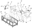
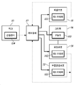
도 1은 본 개시의 일 실시예에 따른 협동로봇을 이용하는 부품 체결시스템의 사시도이다. 도 2는 본 개시의 일 실시예에 따른 협동로봇을 이용하는 부품 체결시스템의 블록도이다. 여기서, 협동로봇은 로딩로봇(14) 및 체결로봇(15)을 포함한다.1 is a perspective view of a parts fastening system using a collaborative robot according to an embodiment of the present disclosure. 2 is a block diagram of a component fastening system using a collaborative robot according to an embodiment of the present disclosure. Here, the cooperative robot includes a
협동로봇을 이용하는 부품 체결시스템(10)은 베이스(11), 부품공급로봇(12), 지그(13), 로딩로봇(14), 체결로봇(15) 및 제어장치(17)의 전부 또는 일부를 포함한다.A
제어장치(17)는 로딩로봇(14), 체결로봇(15) 및 부품공급로봇(12)의 움직임을 제어하도록 구성된다. 제어장치(17)는 로딩로봇(14)의 움직임을 제어하는 로딩로봇제어부, 체결로봇(15)의 움직임을 제어하는 체결로봇제어부, 및 부품공급로봇(12)의 움직임을 제어하는 부품공급로봇제어부를 포함할 수 있다. 각각의 제어부는 서로 인접하여 배치될 수 있고, 각 로봇과 인접하도록 서로 이격되어 배치될 수 있다. 또는 각 제어부의 제어는 하나의 제어장치(17) 내에서 이루어질 수도 있다.The
로딩로봇(14)은 지그(13) 상에 고정적재된 모듈부품(132)을 파지하여 모듈부품(132)을 체결대상(21)과 체결되는 체결영역으로 이동 및 정렬시킨다. 체결대상(21)은 컨베이어벨트(20)와 같은 장치에 의해 이동되어 체결영역 내에 배치된다. 여기서 체결영역은 로딩로봇(14) 및 체결로봇(15)의 이동반경 내에 있는 컨베이어벨트(20) 상의 영역으로서, 로딩로봇(14) 및 체결로봇(15)에 의해 모듈부품(132)을 체결할 수 있는 위치를 의미한다.The
로딩로봇(14)은 제2 머니퓰레이터(141), 제2 카메라(142) 및 그리퍼(16)를 포함할 수 있다. 제2 머니퓰레이터(141)의 일단은 베이스(11)에 고정되고 타단은 그리퍼(16)와 연결된다. The
제2 머니퓰레이터(141)와 그리퍼(16)는 분리가능하도록 구성되며, 로딩로봇(14)은 모듈부품(132)의 형상에 따라 다른 종류의 그리퍼(16)를 교체하여 사용할 수 있다. The
제2 카메라(142)는 그리퍼(16) 측 방향의 영상을 촬영하도록 배치된다. 제2 카메라(142)는 비전을 제공하여 로딩로봇(14)이 지그(13) 상에 적재된 모듈부품(132)을 파지할 때 정밀하게 파지할 수 있도록 한다. 예를 들어, 로딩로봇(14)은, 제2 카메라(142)에서 획득된 비전 정보에 기초하여, 모듈부품(132)을 체결대상(21)에 정렬시킬 수도 있다. 다시 말하면, 서로 다른 2개의 과정, 예를 들면, 파지과정(S320, 도 9 참조) 및 정렬과정(S340, 도 9 참조)에서, 로딩로봇(14)의 제어는, 로딩로봇(14)에 배치된 동일한 제2 카메라(142)를 이용하여 획득한 비전 정보에 기초하여 수행될 수 있다.The
한편, 로딩로봇(14)에는 제2 카메라(142)가 생략될 수 있다. 이 경우, 로딩로봇(14)은 비전기반이 아닌 위치기반제어를 이용하여 지그(13) 상의 모듈부품(132)을 파지할 수 있다. 제2 카메라(142)를 생략한 경우 제어방법에 대해서는 후술한다.Meanwhile, the
체결로봇(15)은 체결대상(21)과 모듈부품(132)을 체결시킨다. 체결로봇(15)은 제1 머니퓰레이터(151), 제1 카메라(153) 및 체결툴(152)을 포함할 수 있다. 제1 머니퓰레이터(151)의 일단은 베이스(11)에 고정되고 타단은 체결툴(152)과 연결된다.The
체결로봇(15)은 제1 카메라(153)가 촬영한 비전을 이용하여 체결영역 내에서 체결툴(152)을 정렬시킬 수 있다. 제1 카메라(153)는 체결툴(152)이 향하는 방향을 촬영하도록 배치될 수 있다. 체결로봇(15)은 제1 머니퓰레이터(151)를 구동하여 체결툴(152)을 체결영역으로 이동시켜 체결대상(21)과 모듈부품(132)을 체결시킬 수 있다.The
로딩로봇(14)은 로딩로봇제어부에 의해 제어된다. 로딩로봇제어부는 체결대상(21)에 모듈부품(132)을 체결시키기 위해, 위치기반 제어를 이용해 지그(13) 상에 적재된 모듈부품(132)을 파지하여 모듈부품(132)을 체결영역으로 이동시키는 제어를 수행한다. 로딩로봇(14)은 카메라를 이용하지 않고 위치기반 제어를 수행함으로써 보다 신속하게 지그(13) 상의 모듈부품(132)을 체결영역으로 이동시킬 수 있다.The
로딩로봇(14)이 모듈부품(132)을 체결영역으로 이동시킬 때, 로딩로봇제어부는 체결로봇(15)에 배치된 제1 카메라(153)를 이용하여 제어를 수행할 수 있다. 체결대상(21)에 모듈부품(132)을 체결시키기 위해서는 모듈부품(132)을 정확한 위치에 정확한 방향으로 정렬시켜야 하는데, 정밀성을 위해 체결로봇(15)의 제1 카메라(153)를 이용하여 모듈부품(132)을 정렬시킨다. 이 때 체결로봇(15)은 제1 카메라(153)가 체결대상측 비전을 제공할 수 있도록 구동된다.When the
체결로봇제어부는 로딩로봇(14)이 모듈부품(132)을 체결영역으로 이동시킨 후, 체결로봇(15)에 배치된 제1 카메라(153)를 이용하여 모듈부품(132)을 체결대상(21)에 체결시키는 제어를 수행한다.After the
로딩로봇(14)은 로딩로봇제어부에 의해 구동되기 이전에는 부품공급로봇(12)의 움직임을 물리적으로 간섭하지 않도록 부품공급로봇(12)의 구동반경에서 떨어진 제1 중간영역에 위치한다. 여기서 제1 중간영역은 로딩로봇(14)의 구동범위 중 로딩로봇(14)이 모듈부품(132)을 파지하는 영역과 체결영역 사이에 존재하는 영역을 의미한다.The
로딩로봇(14)이 모듈부품(132)을 체결영역으로 이동시킨 후에는 체결로봇제어부가 체결로봇(15)에 배치된 제1 카메라(153)를 이용하여 모듈부품(132)을 체결대상(21)에 체결시키는 제어를 수행한다.After the
부품공급로봇(12)은 외부로부터 모듈부품(132)을 전달받아 지그(13) 상의 정해진 위치로 모듈부품(132)을 적재시킨다. 부품공급로봇(12)은 제3 머니퓰레이터(121), 제3 카메라(122) 및 공급파지부(123)를 포함할 수 있다. 제3 머니퓰레이터(121)의 일단에는 공급파지부(123)가 배치되어 있다. 부품공급로봇(12)은 공급파지부(123)를 이용하여 모듈부품(132)을 공급부(E)에서 파지하여 지그(13) 상 정해진 위치에 적재시킨다. 부품공급로봇(12)이 공급부(E)에 있는 모듈부품(132)을 파지할 때 제3 카메라(122)의 비전을 이용한다.The
도 3는 본 개시의 일 실시예에 따른 도 1의 지그의 사시도이다.3 is a perspective view of the jig of FIG. 1 according to an embodiment of the present disclosure.
지그(13)는 모듈부품(132)이 정해진 위치에 적재되도록 구비된다. 도 3에 도시된 바와 같이 체결대상(21)에 체결되는 모듈부품(132)의 종류 및 형상은 다양할 수 있다. 도 3에 도시된 모듈부품(132)의 형상은 예시적인 것으로서 이에 한정되지 않는다.The
지그(13)는 제1 내지 제5 모듈부품(132a 내지 132e)이 고정된 위치에 정해질 수 있도록 각 모듈부품(132)의 형상에 맞게 형성되어 있다. 즉, 지그(13)는 모듈부품(132)의 형상에 따라 서로 다른 정해진 위치에 배치되도록 형성된다. 제1 모듈부품(132a)은 제1 위치(133a)에 배치되고, 제2 모듈부품(132b)은 제2 위치(133b)에 배치되고, 제3 모듈부품(132c)은 제3 위치(133c)에 배치되고, 제4 모듈부품(132d)은 제4 위치(133d)에 배치되며, 그리고 제5 모듈부품(132e)은 제5 위치(133e)에 배치된다. 로딩로봇(14)에 제2 카메라(142)가 생략되고 위치기반 제어를 할 경우 이러한 지그(13)의 특징은 정해진 위치에서 원하는 모듈부품(132)을 원하는 각도로 파지할 수 있게 한다. The
로딩로봇(14)은 위치기반 제어를 이용하여 모듈부품(132)을 파지하기 위해, 제1 내지 제5 모듈부품(132a 내지 132e)을 파지해야하는 위치는 제어장치(17)에 미리 저장될 수 있다.In order for the
지그(13)는 지그(13) 상에 모듈부품(132)이 적재되었는지 여부를 감지하는 근접센서(134)를 포함할 수 있다. 복수의 근접센서(134)가 제1 위치(133a) 내지 제5 위치(133e)에 각각 배치될 수 있다. 제어장치(17)는 근접센서(134)로부터 감지신호를 수신해 지그(13) 상에 정해진 위치에 모듈부품(132)이 적재되었는지 여부를 판단할 수 있다.The
도 4은 본 개시의 일 실시예에 따른 도 1의 로딩로봇 단부에 연결되는 그리퍼의 사시도이다. 도 5는 도 4의 A-A를 기준으로 자른 단면도이다. 도 6는 도 4의 B-B를 기준으로 자른 단면도이다. 도 4 내지 도 6에 도시된 그리퍼는 본 개시에서 다양한 형상(예: 원형)의 모듈부품(132b 또는 132c)을 파지하기 위해서 사용되는 그리퍼로서, 이외에 다른 형상을 가진 그리퍼도 제2 머니퓰레이터(141)의 단부에 연결되어 사용할 수 있다. 이하, 모듈부품(132b 또는 132c) 중 그리퍼에 접촉하는 면에 해당하는 단면이 원형인 경우를 예시적으로 설명하기로 한다.4 is a perspective view of a gripper connected to an end of the loading robot of FIG. 1 according to an embodiment of the present disclosure. 5 is a cross-sectional view taken along line A-A of FIG. 4; FIG. 6 is a cross-sectional view taken along line BB of FIG. 4 . The gripper shown in FIGS. 4 to 6 is a gripper used to grip the
여기서 원형의 모듈부품(132b 또는 132c)은 원기둥 형상 또는 구 형상을 가질 수 있으나 이에 제한되지 않고 그리퍼(16)가 부품을 파지할 때 그립핑거(162)에 대응되는 부분이 일정 곡률 반경을 가지면 족하다. 도 1에 도시된 원형의 모듈부품(132b 또는 132c)은 예시적인 것으로서 이에 한정되지 않는다.Here, the
도 4 내지 도 6를 참조하면, 그리퍼(16)는 로봇연결부(161), 그립핑거(162), 탄성가압부(163) 및 구동부(165)를 포함할 수 있다.4 to 6 , the
그립핑거(162)는 파지부(1622)를 포함할 수 있다. 그리퍼(16)는 두 개의 그립핑거(162)를 포함하며, 두 개의 그립핑거(162)는 그리퍼(16)의 가운데에 위치하는 X-Z평면을 기준으로 대칭되도록 배치될 수 있다.The
구체적으로, 그립핑거(162)는 몸체(164)와 접하고 구동부(165)로부터 동력을 전달받는 지지부(1621), 지지부(1621)의 일단으로부터 몸체(164)의 길이방향으로 연장되는 제1 파지홈(1621a)이 형성된 제1 파지부(1622a), 및 지지부(1621)의 타단으로부터 몸체(164)의 길이방향으로 연장되는 제2 파지홈(1621b)이 형성된 제2 파지부(1622b)를 포함할 수 있다. 여기서 몸체(164)의 길이방향은 도 4의 X축 방향을 의미한다. 제1 파지홈(1621a)과 제2 파지홈(1621b)은 같은 반경의 곡률을 가질 수 있다.Specifically, the
파지부(1622)에는 파지홈(1621)이 형성될 수 있다. 예를 들어, 파지홈(1621)의 형상은 원형의 모듈부품(132b 또는 132c)이 그립핑거(162)에 접하는 부분의 형상에 대응될 수 있다. 예를 들어, 제1 파지홈(1621a) 및/또는 제2 파지홈(1622a)은 각각 일정 반경의 곡률을 가질 수 있다.A
탄성가압부(163)는 두 개의 그립핑거(162) 사이에 몸체의 일단과 인접하게 배치된다. 탄성가압부(163)는 복수의 탄성체(1632) 및 가압판을 포함할 수 있다. 여기서 탄성체(1632)는 스프링일 수 있다. The elastic
복수의 탄성체(1632)는 일단이 그리퍼(16)의 몸체(164)와 접하고 타단이 가압판의 일면과 접하도록 배치될 수 있다. 탄성가압부(163)가 그리퍼(16)의 몸체(164)측으로 가압되는 경우 복수의 탄성체(1632)에 의해 몸체(164)의 반대방향으로 탄성력을 제공한다.The plurality of
가압판은 탄성체(1632)의 일단에 결합되어 원형의 모듈부품(132b 또는 132c)을 가압하도록 배치될 수 있다. 예를 들면, 가압판은, 특정 형상(예: 아크 형상, 삼각형, 사각형 등)의 가압홈(1631)을 가질 수 있다. 가압홈(1631)의 형상은 원형의 모듈부품(132b 또는 132c)이 탄성가압부(163)에 접하는 부분의 형상에 대응되는 아크 형상을 가질 수 있다. 구체적으로, 탄성가압부(163)의 가압판에 접하는 부분의 형상에 대응될 수 있다. 예를 들어, 도 3에 도시되는 것처럼, 원형의 모듈부품(132b 및 132c)의 중앙부의 직경이 더 크고, 단부의 직경이 더 작은 경우, 가압홈(1631)의 곡률 반경은 파지홈(1621a 및 1621b)의 곡률반경보다 크게 형성될 수 있다.The pressing plate may be coupled to one end of the
가압홈(1631)은 그립핑거(162)의 높이방향으로 소정의 간격을 두고 이격 형성되며, 그립핑거(162)의 높이방향에 수직한 방향으로 연장되어 홈을 형성하는 복수의 라인홈(1631a)을 포함할 수 있다. 여기서, 그립핑거(162)의 높이방향은 도 4의 Y축 방향을 의미하고, 그립핑거(162)의 높이방향에 수직한 방향은 도 4에서 Z축 방향을 의미한다. 상술한 라인홈(1631a)에 의하면, 그립핑거(162)의 파지력을 보다 향상시킴으로써, 이송 및/또는 체결 과정에서 모듈 부품이 미끄러짐으로써, 정렬 상태가 어긋나는 문제를 보다 효율적으로 방지할 수 있다.The
탄성가압부(163)는 그리퍼(16)가 원형의 모듈부품(132b 또는 132c)을 파지할 때, 원형의 모듈부품(132b 또는 132c)의 일부와 접하여 몸체(164)측 방향으로 가압된다. 이 때 탄성가압부(163)의 탄성력에 의해 가압판이 원형의 모듈부품(132b 또는 132c)을 가압한다. 가압에 의해 원형의 모듈부품(132b 또는 132c)은 그리퍼(16) 내에서 회전되지 않고 고정될 수 있다.When the
로봇연결부(161)는 몸체(164)의 타단과 인접하고, 로딩로봇(14)과 연결되도록 일단에 배치된다. 로딩로봇(14)의 제2 머니퓰레이터(141)의 일단도 로봇연결부(161)와 연결가능하도록 구성되어 있다.The
구동부(165)는 두 개의 그립핑거(162)를 이동시키도록 몸체 내에 배치된다. 구동부(165)는 두 개의 그립핑거(162)를 몸체(164)의 외측 방향으로 서로 멀어지거나 가까워지도록 할 수 있다. 예컨대, 도 5와 같이 두 개의 그립핑거는 Z축 방향으로 서로 멀어지거나 가까워지도록 움직일 수 있다.The driving
그리퍼(16)가 원형의 모듈부품(132b 또는 132c)을 파지하기 전 로딩로봇제어부는 구동부(165)를 제어하여 두 개의 그립핑거(162) 사이의 거리가 멀어지도록 제어한다. 그리퍼(16)가 원형의 모듈부품(132b 또는 132c)을 파지할 때에는 로딩로봇제어부가 구동부(165)를 제어하여 두 개의 그립핑거(162) 사이의 거리가 가까워지도록 제어한다. 원형의 모듈부품(132b 또는 132c)이 두 개의 그리퍼(16)의 파지홈(1621)에 안착되어 고정되면, 원형의 모듈부품(132b 또는 132c)이 탄성가압부(163)를 가압하면서 원형의 회전 또한 고정된다.Before the
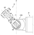
도 7은 그리퍼가 원형의 모듈부품을 파지한 상태를 도시한 측면도이다.7 is a side view illustrating a state in which a gripper grips a circular module component.
구동부(165)에 의해 그리퍼(16)가 원형의 모듈부품(132b 또는 132c)를 파지할 때, 원형의 모듈부품(132b 또는 132c)의 중력방향(G)과 일정 각도(A)를 이루는 대각선 방향으로 파지할 수 있다. 이와 같은 구조에 의하면, 도 7에 도시된 것처럼, 로딩로봇(14)에 간섭을 받지 않고, 체결로봇(15)이 체결 작업을 수행할 수 있는 공간을 충분히 확보함으로써, 체결 작업을 원활하게 수행할 수 있다. 따라서, 주변 구조물에 간섭을 회피하기 위하여, 체결로봇(15)의 체결 툴을 특정한 형상으로 제작하지 않고도, 다양한 형상의 체결 툴을 사용하여 체결 작업을 수행할 수 있다.When the
협동로봇 중 로딩로봇(14)은 전술한 도 4 내지 도 6에 따른 그리퍼를 장착하여 원형의 모듈부품(132b 및 132c)를 파지한 후 체결영역으로 이동하여 고정시킬 수 있다. 협동로봇 중 체결로봇(15)은 로딩로봇(14)이 고정시킨 원형의 모듈부품(132b 및 132c)을 체결시킬 수 있다.Among the cooperative robots, the
도 8 및 도 9은 본 개시의 일 실시예에 따른 협동로봇을 이용하는 부품 체결방법의 흐름도이다.8 and 9 are flowcharts of a method for assembling parts using a collaborative robot according to an embodiment of the present disclosure.
도 8에 도시된 흐름도는 모듈부품(132)을 외부로부터 파지하여 체결대상(21)에 체결하기까지의 여러 제어과정 중 하나를 나타낸 흐름도이다. The flowchart shown in FIG. 8 is a flowchart showing one of several control processes from holding the module component 132 from the outside to fastening it to the
제어장치(17)는 부품공급로봇(12)을 제어하여 모듈부품(132)을 지그(13) 상의 정해진 위치에 적재한다(S61). 예컨대 도 3에 도시된 바와 같이 부품공급로봇(12)은 제1 모듈부품(132a)을 제1 위치(133a)에 적재한다.The
제어장치(17)는 모듈부품(132)이 지그(13) 상에 정해진 위치에 적재되었는지 여부를 판단한다(S62). 지그(13) 상에는 모듈부품(132)이 정해진 위치에 적재되었는지 여부를 감지할 수 있는 근접센서(134)를 포함할 수 있다. 제어장치(17)는 근접센서(134)로부터 감지신호를 수신해 모듈부품(132)이 지그(13) 상에 정해진 위치에 적재되었는지 여부를 판단할 수 있다.The
모듈부품(132)이 지그(13) 상에 정해진 위치에 적재되었다고 판단한 경우, 제어장치(17)는 로딩로봇(14)을 위치기반 제어하여 모듈부품(132)을 파지하도록 제어를 수행한다(S63). 여기서 위치기반 제어는 카메라의 비전을 이용하지 않고, 각 모듈부품(132)마다 파지해야하는 위치를 미리 저장하여, 저장된 위치정보를 기초로 모듈부품(132)을 파지하는 제어를 의미한다. 한편, 이는 하나의 예시에 불과하며, 로딩로봇(14)은 제2 카메라(142)의 비전에 기초하여 모듈부품(132)을 파지 및 이송시킬 수도 있음을 밝혀 둔다.When it is determined that the module component 132 is loaded in a predetermined position on the
로딩로봇(14)이 모듈부품(132)을 파지한 후, 제어장치(17)는 체결로봇(15)에 배치된 제1 카메라(153)를 이용하여 모듈부품(132)이 체결영역에서 정렬되도록 로딩로봇(14)을 제어한다(S64). 제어장치(17)는 체결로봇(15)의 움직임을 제어하여 제1 카메라(153)가 체결영역측 비전을 제공하도록 제어한다. 예를 들어, 제1 카메라(153)는, (i) 입체 영상 촬영이 가능한 3D 비전 카메라이거나, (ii) 2D 영상에 추가적으로 깊이 인식 기능을 갖춘 2.5D 비전 카메라일 수 있다. 이와 같은 구성에 의하면, 제1 카메라(153)의 시선(line of sight)을 조정하기 위하여, 체결로봇(15)을 움직일 필요 없이, 로딩 작업 및/또는 체결 작업에 요구되는 충분한 정보를 획득하는 것이 가능하다.After the
모듈부품(132)이 체결영역에서 정렬된 후에는, 제어장치(17)는 제1 카메라(153)의 비전을 이용하여 모듈부품(132)이 체결대상(21)에 체결되도록 체결로봇을 제어한다(S65). 이와 같은 동작에 의하면, 전체 카메라 수를 줄임으로써 제조 비용 및 유지보수에 필요한 노력을 낮출 수 있다.After the module parts 132 are aligned in the fastening area, the
도 9은 협동로봇을 이용하는 부품 체결시스템이 작동하는 과정에 있어서 각 구성의 제어과정을 나누어 도시한 흐름도이다.FIG. 9 is a flow chart showing the control process of each component separately in the process of operating the parts fastening system using the collaborative robot.
도 9을 참조하면, 제어장치(17)는 부품공급로봇(12)에 대해 S110 내지 S120, 지그(13)에 대해 S210 내지 S240, 로딩로봇(14)에 대해 S310 내지 S340, 그리고 체결로봇(15)에 대해 S410 내지 S430의 제어과정을 반복하여 수행할 수 있다. 이하, 제어장치(17)를 부품공급로봇제어부, 로딩로봇제어부 및 체결로봇제어부로 나누어 설명한다.Referring to FIG. 9, the
부품공급로봇제어부는 부품공급로봇(12)이 외부에서 모듈부품(132)을 파지하도록 제어한다(S110). 부품공급로봇(12)이 외부에서 모듈부품(132)을 파지한 후에는 부품공급로봇제어부가 그 모듈부품(132)을 지그(13)로 이송하도록 제어한다(S120). The component supply robot controller controls the
지그(13)로 이송된 모듈부품(132)을 부품공급로봇제어부가 지그(13) 상에 정해진 위치에 안착시키도록 부품공급로봇(12)을 제어한다(S210). 그 후 근접센서(134)는 이용하여 모듈부품(132)이 감지되었는지 여부를 판단한다(S220). 근접센서(134)가 모듈부품(132)을 감지하지 못한 경우 모듈부품(132) 안착 불량 에러를 알람한다(S240). 근접센서(134)가 모듈부품(132)을 감지한 경우, 근접센서(134)의 감지신호를 로딩로봇제어부로 전송한다(S230).The component supply robot controller controls the
모듈부품(132) 감지신호가 수신되기 전, 로딩로봇제어부는 로딩로봇(14)을 제1 중간영역에서 대기시킨다(S310). 여기서 제1 중간영역은 로딩로봇(14)의 구동범위 중 로딩로봇(14)이 모듈부품(132)을 파지하는 영역과 체결영역 사이에 존재하는 영역을 의미한다.Before the module component 132 detection signal is received, the loading robot controller makes the
로딩로봇제어부가 모듈부품(132) 감지신호를 수신한 후에는 위치기반 제어를 이용하여 로딩로봇(14)이 지그(13) 상에 적재된 모듈부품(132)을 파지시키도록 제어한다(S320). 로딩로봇(14)이 모듈부품(132)을 파지한 후, 로딩로봇제어부는 로딩로봇(14)을 제어하여 모듈부품(132)을 체결대상(21)이 있는 체결영역으로 이송시킨다(S330). After the loading robot controller receives the module component 132 detection signal, it controls the
모듈부품(132)을 체결영역으로 이동시킬 때, 로딩로봇제어부는 체결로봇제어부에게 체결신호를 송신한다.When moving the module component 132 to the fastening area, the loading robot controller transmits a fastening signal to the fastening robot controller.
체결로봇제어부는 체결신호를 수신하기 전 체결로봇(15)을 대기영역에서 대기시킨다(S410). 여기서 대기영역은 체결로봇(15)이 작동하지 않을 때 로딩로봇(14)의 구동반경을 방해하지 않는 영역을 의미한다. The fastening robot control unit waits the
체결로봇제어부는 체결신호를 수신한 경우 체결로봇(15)을 제2 중간영역으로 이동시켜, 체결로봇(15)에 배치된 제1 카메라(153)의 비전이 체결대상(21)을 지향하도록 체결로봇(15)의 자세를 제어한다(S420). 여기서 체결로봇(15)의 구동범위 내에서 제2 중간영역은 대기영역과 체결영역 사이의 영역을 의미한다.When the fastening robot control unit receives the fastening signal, it moves the
로딩로봇제어부는 S420 과정 이후 체결로봇(15)의 제1 카메라의 비전에 기초하여, 로딩로봇(14)을 정밀 제어함으로써 체결대상(21)에 모듈부품(132)을 위치시킨다(S440).The loading robot controller places the module component 132 on the
체결로봇제어부는 모듈부품(132)이 체결대상(21)에 위치되어 로딩로봇(14)의 위치 정렬이 마무리된 상태에서, 체결로봇(15)이 체결작업을 수행하도록 제어한다(S430).The fastening robot control unit controls the
예를 들어, S340 과정 및 S430 과정을 수행함에 있어서, 로딩로봇(14)이, 모듈부품(132)을 체결대상(21)에 정렬시킨 상태에서, 체결로봇(15)은, 모듈부품(132) 및 체결대상(21)을 연결하는 복수의 체결부위 중 적어도 하나 이상의 체결부위를 체결시킬 수 있다. 예를 들어, 체결로봇(15)이 복수의 체결부위 중 일부만 체결시킨 상태에서(부분 체결 과정), 로딩 로봇(14)은 체결영역으로부터 후퇴하고(후퇴 과정), 체결로봇(15)이 나머지 체결부위를 체결시킬 수 있다(나머지 체결 과정). 이와 같은 과정에 의하면, 체결로봇(15)의 체결 작업을 위한 공간을 효율적으로 확보할 수 있다.For example, in performing steps S340 and S430, in a state in which the
예를 들어, 정렬과정(S340) 및/또는 체결과정(S430)이 수행되는 동안, 적재과정(S210)이 수행되게 하고, 정렬과정(S340) 이후에 대기과정(S310)을 생략하고 바로 파지과정(S320)이 수행되도록 함으로써, 대기과정(S310)에서 소요되는 시간을 줄일 수 있다.For example, while the alignment process (S340) and/or the fastening process (S430) is performed, the loading process (S210) is performed, and the waiting process (S310) is omitted after the alignment process (S340), and the gripping process is performed immediately. By allowing (S320) to be performed, the time required for the standby process (S310) can be reduced.
이상의 설명은 본 실시예의 기술 사상을 예시적으로 설명한 것에 불과한 것으로서, 본 실시예가 속하는 기술 분야에서 통상의 지식을 가진 자라면 본 실시예의 본질적인 특성에서 벗어나지 않는 범위에서 다양한 수정 및 변형이 가능할 것이다. 따라서, 본 실시예들은 본 실시예의 기술 사상을 한정하기 위한 것이 아니라 설명하기 위한 것이고, 이러한 실시예에 의하여 본 실시예의 기술 사상의 범위가 한정되는 것은 아니다. 본 실시예의 보호 범위는 아래의 청구범위에 의하여 해석되어야 하며, 그와 동등한 범위 내에 있는 모든 기술 사상은 본 실시예의 권리범위에 포함되는 것으로 해석되어야 할 것이다.The above description is merely an example of the technical idea of the present embodiment, and various modifications and variations can be made to those skilled in the art without departing from the essential characteristics of the present embodiment. Therefore, the present embodiments are not intended to limit the technical idea of the present embodiment, but to explain, and the scope of the technical idea of the present embodiment is not limited by these embodiments. The scope of protection of this embodiment should be construed according to the claims below, and all technical ideas within the scope equivalent thereto should be construed as being included in the scope of rights of this embodiment.
11: 베이스
12: 부품공급로봇
13: 지그
14: 로딩로봇
15: 체결로봇
16: 그리퍼
20: 컨베이어벨트
21: 체결대상11: base 12: parts supply robot
13: jig 14: loading robot
15: fastening robot 16: gripper
20: conveyor belt 21: fastening target
Claims (15)
상기 모듈부품이 정해진 위치에 적재되도록 구비된 지그;
상기 지그 상에 고정적재된 상기 모듈부품을 파지하여, 상기 모듈부품을 상기 체결대상과 체결되는 체결영역으로 이동 및 정렬시키는 로딩로봇;
제1 카메라를 포함하고, 상기 체결대상과 상기 모듈부품을 체결시키는 체결로봇; 및
상기 로딩로봇과 상기 체결로봇의 움직임을 제어하는 제어장치를 포함하는 협동로봇을 이용하는 부품 체결시스템.In a parts fastening system using a collaborative robot for fastening module parts to a fastening target,
a jig provided to load the module component at a predetermined location;
a loading robot that grips the module component fixedly loaded on the jig, moves and aligns the module component to a fastening area where the module component is fastened to the fastening target;
a fastening robot including a first camera and fastening the fastening target and the module component; and
A parts fastening system using a collaborative robot including a control device for controlling movements of the loading robot and the fastening robot.
상기 지그 상의 정해진 위치로 상기 모듈부품을 적재시키는 부품공급로봇을 더 포함하는 협동로봇을 이용하는 부품 체결시스템.According to claim 1,
A component fastening system using a collaborative robot further comprising a component supply robot for loading the module component to a predetermined position on the jig.
상기 제어장치는,
상기 로딩로봇이 상기 모듈부품을 상기 체결대상에 정렬시킬 때 상기 체결로봇에 배치된 상기 제1 카메라를 이용하여 제어를 수행하는 협동로봇을 이용하는 부품 체결시스템.According to claim 2,
The control device,
A component fastening system using a collaborative robot that performs control using the first camera disposed in the fastening robot when the loading robot aligns the module component to the fastening target.
상기 지그는,
상기 지그 상에 모듈부품이 적재되었는지 여부를 감지하는 근접센서를 더 포함하는 협동로봇을 이용하는 부품 체결시스템.According to claim 1,
The jig,
A component fastening system using a collaborative robot further comprising a proximity sensor for detecting whether module components are loaded on the jig.
상기 제어장치는,
상기 근접센서로부터 감지신호를 수신해 상기 지그 상에 상기 모듈부품이 적재되었는지 여부를 판단하는 협동로봇을 이용하는 부품 체결시스템.According to claim 4,
The control device,
A component fastening system using a collaborative robot that receives a detection signal from the proximity sensor and determines whether the module component is loaded on the jig.
상기 로딩로봇은,
상기 부품공급로봇이 상기 모듈부품을 상기 지그 상에 적재시키는 과정에서, 상기 부품공급로봇의 움직임을 물리적으로 간섭하지 않도록 상기 부품공급로봇의 구동반경에서 떨어진 제1 중간영역에 위치하는 협동로봇을 이용하는 부품 체결시스템.According to claim 2,
The loading robot,
In the process of the component supply robot loading the module components on the jig, a collaborative robot located in the first intermediate region away from the driving radius of the component supply robot is used to prevent physical interference with the movement of the component supply robot. parts fastening system.
상기 지그는,
상기 모듈부품의 형상에 따라 서로 다른 정해진 위치에 배치되도록 형성된 협동로봇을 이용하는 부품 체결시스템.According to claim 1,
The jig,
A component fastening system using a collaborative robot formed to be disposed at different predetermined positions according to the shape of the module component.
모듈부품이 지그 상에 정해진 위치에 적재되었는지 여부를 판단하는 판단과정;
상기 로딩로봇을 제어하여, 상기 모듈부품을 파지하는 파지과정;
상기 모듈부품이 체결영역에서 체결대상에 정렬되도록 상기 로딩로봇을 제어하는 정렬과정; 및
상기 모듈부품이 상기 체결대상에 체결되도록 상기 체결로봇을 제어하는 체결과정
을 포함하는 협동로봇을 이용하는 부품 체결방법.In the part fastening method using a cooperative robot including a loading robot and a fastening robot,
A determination process of determining whether the module component is loaded at a predetermined position on the jig;
a gripping process of controlling the loading robot to grip the module component;
an alignment process of controlling the loading robot to align the module component to a fastening target in a fastening area; and
A fastening process of controlling the fastening robot so that the module component is fastened to the fastening target
Part fastening method using a collaborative robot comprising a.
상기 파지과정은,
상기 로딩로봇을 위치기반 제어하여 수행되는 협동로봇을 이용하는 부품 체결방법.According to claim 8,
The gripping process,
A method of fastening parts using a collaborative robot performed by position-based control of the loading robot.
상기 정렬과정은,
상기 체결로봇에 배치된 제1 카메라를 이용하여 수집된 비전 정보에 기초하여, 상기 로딩로봇을 제어함으로써 수행되는 협동로봇을 이용하는 부품 체결방법.According to claim 8,
The sorting process is
A component fastening method using a collaborative robot performed by controlling the loading robot based on vision information collected using a first camera disposed in the fastening robot.
상기 체결과정은,
상기 체결로봇이, 상기 모듈부품 및 상기 체결대상을 연결하는 복수의 체결부위 중 일부만 체결시키는 부분 체결 과정;
상기 부분 체결 과정 이후 수행되고, 상기 로딩로봇이 상기 체결영역으로부터 후퇴하는 후퇴 과정; 및
상기 후퇴 과정 이후에 수행되고, 상기 체결로봇이 상기 복수의 체결부위 중 나머지를 체결시키는 나머지 체결 과정
을 포함하는 협동로봇을 이용하는 부품 체결방법.According to claim 8,
The fastening process is
a partial fastening process in which the fastening robot fastens only some of a plurality of fastening parts connecting the module component and the fastening target;
a retreat process performed after the partial fastening process, wherein the loading robot retreats from the fastening area; and
The rest of the fastening process, which is performed after the retracting process, and the fastening robot fastens the rest of the plurality of fastening parts.
Part fastening method using a collaborative robot comprising a.
상기 판단과정 이전에 부품공급로봇을 제어하여 상기 모듈부품을 지그 상의 정해진 위치에 적재하는 적재과정을 더 포함하는 협동로봇을 이용하는 부품 체결방법.According to claim 8,
The component fastening method using a collaborative robot further comprising a loading step of loading the module component to a predetermined position on a jig by controlling a component supply robot prior to the determining step.
상기 정렬과정 및/또는 상기 체결과정이 수행되는 동안, 상기 적재과정이 수행되는 협동로봇을 이용하는 부품 체결방법.According to claim 12,
A component fastening method using a collaborative robot in which the loading process is performed while the alignment process and/or the fastening process are performed.
상기 판단과정은,
상기 지그 상에 배치된 근접센서를 이용하여 상기 모듈부품이 상기 정해진 위치에 적재되었는지 여부를 판단하는 협동로봇을 이용하는 부품 체결방법.According to claim 8,
The judgment process is
A component fastening method using a collaborative robot that determines whether the module component is loaded at the predetermined position using a proximity sensor disposed on the jig.
상기 파지과정 및 상기 정렬과정에서, 상기 로딩로봇의 제어는, 상기 로딩로봇에 배치된 카메라에서 획득된 비전 정보에 기초하여 수행되는 협동로봇을 이용하는 부품 체결방법.
According to claim 8,
In the gripping process and the alignment process, control of the loading robot is performed based on vision information obtained from a camera disposed in the loading robot.
Priority Applications (2)
| Application Number | Priority Date | Filing Date | Title |
|---|---|---|---|
| KR1020210081290A KR20230000006A (en) | 2021-06-23 | 2021-06-23 | System for Component Fastening System Using Cooperative Robot and Fastening Method Thereof |
| US17/749,469 US20220410396A1 (en) | 2021-06-23 | 2022-05-20 | System for component fastening system using cooperative robot and fastening method thereof |
Applications Claiming Priority (1)
| Application Number | Priority Date | Filing Date | Title |
|---|---|---|---|
| KR1020210081290A KR20230000006A (en) | 2021-06-23 | 2021-06-23 | System for Component Fastening System Using Cooperative Robot and Fastening Method Thereof |
Publications (1)
| Publication Number | Publication Date |
|---|---|
| KR20230000006A true KR20230000006A (en) | 2023-01-02 |
Family
ID=84542069
Family Applications (1)
| Application Number | Title | Priority Date | Filing Date |
|---|---|---|---|
| KR1020210081290A KR20230000006A (en) | 2021-06-23 | 2021-06-23 | System for Component Fastening System Using Cooperative Robot and Fastening Method Thereof |
Country Status (2)
| Country | Link |
|---|---|
| US (1) | US20220410396A1 (en) |
| KR (1) | KR20230000006A (en) |
-
2021
- 2021-06-23 KR KR1020210081290A patent/KR20230000006A/en active Search and Examination
-
2022
- 2022-05-20 US US17/749,469 patent/US20220410396A1/en active Pending
Also Published As
| Publication number | Publication date |
|---|---|
| US20220410396A1 (en) | 2022-12-29 |
Similar Documents
| Publication | Publication Date | Title |
|---|---|---|
| US10031515B2 (en) | Production system including robot with position correction function that supplies or ejects workpieces to or from a machine tool | |
| KR20230000476A (en) | Gripper and Cooperative Robot Including the Same | |
| US10265821B2 (en) | Automatic component loading system | |
| US8855824B2 (en) | Dual arm robot | |
| EP2363250A2 (en) | Production system comprising a workpiece stocker, a dual-arm robot and a second robot | |
| US9713870B2 (en) | System and method for locating vehicle components relative to each other | |
| JP2013006231A (en) | Automated assembly apparatus and method of assembling component by using automated assembly apparatus | |
| US10589420B2 (en) | Hand device | |
| WO2017182937A1 (en) | Robot automatic assembling system and method | |
| JP6219901B2 (en) | Temporary placement device with adjustable workpiece orientation | |
| CN110919686A (en) | Machining system | |
| JP2020533189A5 (en) | ||
| US20210008991A1 (en) | Automated Connection of a Charging Plug to a Charging Interface of a Vehicle | |
| JP2020066067A (en) | Robot hand and robot system | |
| CN110024509B (en) | Component mounting apparatus and control method thereof | |
| JP2008221438A (en) | Robot hand and robot | |
| KR20230000006A (en) | System for Component Fastening System Using Cooperative Robot and Fastening Method Thereof | |
| CN208262857U (en) | Fixture for robot system | |
| US20230054602A1 (en) | Robot system for automated assembly of modular component | |
| KR20190000430A (en) | Dual Arm Robot System | |
| JP5737584B2 (en) | Robot and its work gripping method | |
| KR20160150359A (en) | System controlling robot for installing work and method the same | |
| CN113275476B (en) | Automatic material taking robot system for sheet metal machining | |
| KR20230027431A (en) | Assembly Tool | |
| JP6445922B2 (en) | End effector |
Legal Events
| Date | Code | Title | Description |
|---|---|---|---|
| A201 | Request for examination |