KR20220168562A - Image forming apparatus - Google Patents
Image forming apparatus Download PDFInfo
- Publication number
- KR20220168562A KR20220168562A KR1020220070717A KR20220070717A KR20220168562A KR 20220168562 A KR20220168562 A KR 20220168562A KR 1020220070717 A KR1020220070717 A KR 1020220070717A KR 20220070717 A KR20220070717 A KR 20220070717A KR 20220168562 A KR20220168562 A KR 20220168562A
- Authority
- KR
- South Korea
- Prior art keywords
- image forming
- fan
- unit
- forming unit
- intake
- Prior art date
Links
- 239000000463 material Substances 0.000 claims description 60
- 238000012546 transfer Methods 0.000 claims description 39
- 108091008695 photoreceptors Proteins 0.000 claims description 18
- 238000010438 heat treatment Methods 0.000 claims description 3
- 239000003086 colorant Substances 0.000 claims description 2
- 238000011161 development Methods 0.000 description 20
- 238000007639 printing Methods 0.000 description 15
- 238000010586 diagram Methods 0.000 description 9
- 230000000052 comparative effect Effects 0.000 description 8
- CBENFWSGALASAD-UHFFFAOYSA-N Ozone Chemical compound [O-][O+]=O CBENFWSGALASAD-UHFFFAOYSA-N 0.000 description 7
- 238000001816 cooling Methods 0.000 description 7
- 238000000034 method Methods 0.000 description 7
- 230000008569 process Effects 0.000 description 6
- 229910052745 lead Inorganic materials 0.000 description 5
- 238000011144 upstream manufacturing Methods 0.000 description 5
- 238000004891 communication Methods 0.000 description 4
- 238000007664 blowing Methods 0.000 description 3
- 238000004140 cleaning Methods 0.000 description 3
- 239000002245 particle Substances 0.000 description 3
- 238000012805 post-processing Methods 0.000 description 3
- 239000000428 dust Substances 0.000 description 2
- 150000002500 ions Chemical class 0.000 description 2
- 238000004080 punching Methods 0.000 description 2
- 238000011084 recovery Methods 0.000 description 2
- 239000004952 Polyamide Substances 0.000 description 1
- 230000008859 change Effects 0.000 description 1
- 230000006835 compression Effects 0.000 description 1
- 238000007906 compression Methods 0.000 description 1
- 230000007547 defect Effects 0.000 description 1
- 230000000694 effects Effects 0.000 description 1
- 239000004744 fabric Substances 0.000 description 1
- 230000001678 irradiating effect Effects 0.000 description 1
- 238000012423 maintenance Methods 0.000 description 1
- 230000007246 mechanism Effects 0.000 description 1
- 239000002184 metal Substances 0.000 description 1
- 229910052751 metal Inorganic materials 0.000 description 1
- 238000012986 modification Methods 0.000 description 1
- 230000004048 modification Effects 0.000 description 1
- 239000000123 paper Substances 0.000 description 1
- 239000002985 plastic film Substances 0.000 description 1
- 229920006255 plastic film Polymers 0.000 description 1
- 229920002647 polyamide Polymers 0.000 description 1
- 238000012545 processing Methods 0.000 description 1
- 238000011027 product recovery Methods 0.000 description 1
- 239000011347 resin Substances 0.000 description 1
- 229920005989 resin Polymers 0.000 description 1
- 229910001220 stainless steel Inorganic materials 0.000 description 1
- 239000010935 stainless steel Substances 0.000 description 1
- 230000001629 suppression Effects 0.000 description 1
Images


Classifications
-
- G—PHYSICS
- G03—PHOTOGRAPHY; CINEMATOGRAPHY; ANALOGOUS TECHNIQUES USING WAVES OTHER THAN OPTICAL WAVES; ELECTROGRAPHY; HOLOGRAPHY
- G03G—ELECTROGRAPHY; ELECTROPHOTOGRAPHY; MAGNETOGRAPHY
- G03G15/00—Apparatus for electrographic processes using a charge pattern
- G03G15/02—Apparatus for electrographic processes using a charge pattern for laying down a uniform charge, e.g. for sensitising; Corona discharge devices
- G03G15/0258—Apparatus for electrographic processes using a charge pattern for laying down a uniform charge, e.g. for sensitising; Corona discharge devices provided with means for the maintenance of the charging apparatus, e.g. cleaning devices, ozone removing devices G03G15/0225, G03G15/0291 takes precedence
-
- G—PHYSICS
- G03—PHOTOGRAPHY; CINEMATOGRAPHY; ANALOGOUS TECHNIQUES USING WAVES OTHER THAN OPTICAL WAVES; ELECTROGRAPHY; HOLOGRAPHY
- G03G—ELECTROGRAPHY; ELECTROPHOTOGRAPHY; MAGNETOGRAPHY
- G03G21/00—Arrangements not provided for by groups G03G13/00 - G03G19/00, e.g. cleaning, elimination of residual charge
- G03G21/20—Humidity or temperature control also ozone evacuation; Internal apparatus environment control
- G03G21/206—Conducting air through the machine, e.g. for cooling, filtering, removing gases like ozone
-
- G—PHYSICS
- G03—PHOTOGRAPHY; CINEMATOGRAPHY; ANALOGOUS TECHNIQUES USING WAVES OTHER THAN OPTICAL WAVES; ELECTROGRAPHY; HOLOGRAPHY
- G03G—ELECTROGRAPHY; ELECTROPHOTOGRAPHY; MAGNETOGRAPHY
- G03G15/00—Apparatus for electrographic processes using a charge pattern
- G03G15/01—Apparatus for electrographic processes using a charge pattern for producing multicoloured copies
-
- G—PHYSICS
- G03—PHOTOGRAPHY; CINEMATOGRAPHY; ANALOGOUS TECHNIQUES USING WAVES OTHER THAN OPTICAL WAVES; ELECTROGRAPHY; HOLOGRAPHY
- G03G—ELECTROGRAPHY; ELECTROPHOTOGRAPHY; MAGNETOGRAPHY
- G03G21/00—Arrangements not provided for by groups G03G13/00 - G03G19/00, e.g. cleaning, elimination of residual charge
- G03G21/16—Mechanical means for facilitating the maintenance of the apparatus, e.g. modular arrangements
- G03G21/1604—Arrangement or disposition of the entire apparatus
- G03G21/1623—Means to access the interior of the apparatus
- G03G21/1633—Means to access the interior of the apparatus using doors or covers
-
- G—PHYSICS
- G03—PHOTOGRAPHY; CINEMATOGRAPHY; ANALOGOUS TECHNIQUES USING WAVES OTHER THAN OPTICAL WAVES; ELECTROGRAPHY; HOLOGRAPHY
- G03G—ELECTROGRAPHY; ELECTROPHOTOGRAPHY; MAGNETOGRAPHY
- G03G21/00—Arrangements not provided for by groups G03G13/00 - G03G19/00, e.g. cleaning, elimination of residual charge
- G03G21/20—Humidity or temperature control also ozone evacuation; Internal apparatus environment control
-
- G—PHYSICS
- G03—PHOTOGRAPHY; CINEMATOGRAPHY; ANALOGOUS TECHNIQUES USING WAVES OTHER THAN OPTICAL WAVES; ELECTROGRAPHY; HOLOGRAPHY
- G03G—ELECTROGRAPHY; ELECTROPHOTOGRAPHY; MAGNETOGRAPHY
- G03G2221/00—Processes not provided for by group G03G2215/00, e.g. cleaning or residual charge elimination
- G03G2221/16—Mechanical means for facilitating the maintenance of the apparatus, e.g. modular arrangements and complete machine concepts
- G03G2221/1645—Mechanical means for facilitating the maintenance of the apparatus, e.g. modular arrangements and complete machine concepts for conducting air through the machine, e.g. cooling
Abstract
Description
본 발명은, 프린터, 복사기, 팩시밀리 또는 복합기 등의 화상 형성 장치에 관한 것이다.The present invention relates to an image forming apparatus such as a printer, copying machine, facsimile machine or multifunction machine.
화상 형성 장치는, 감광 드럼에 토너상을 형성하는 복수의 화상 형성부(화상 형성 스테이션이라고도 불린다)를 구비하고 있다. 각 화상 형성부에서는, 예를 들면 현상 유닛 내에서 반송 스크류에 의해 토너를 교반하면서 순환 반송하고 있고, 이 토너의 교반 동작에 따라 열이 발생한다. 다만, 현상 유닛이 고온으로 되면, 토너의 온도가 상승하고, 화상 불량을 생기게 하는 원인이 되므로, 종래로부터 흡기 팬에 의해 화상 형성 장치의 외부에서부터 흡기한 외기에 의해 형성되는 에어플로우(airflow)에 의해 현상 유닛을 식히도록 하고 있다(일본특허공개 특개2007-41562호). An image forming apparatus includes a plurality of image forming units (also called image forming stations) that form toner images on a photosensitive drum. In each image forming unit, for example, toner is circulated and conveyed while being agitated by a conveying screw within the developing unit, and heat is generated according to the agitating operation of the toner. However, when the developing unit is at a high temperature, the temperature of the toner rises, causing image defects. Conventionally, the airflow formed by outside air sucked in from the outside of the image forming apparatus by an intake fan (Japanese Unexamined Patent Publication No. 2007-41562).
일본특허공개 특개2007-41562호에 기재된 장치에서는, 1대의 흡기 팬과 복수의 현상 유닛이 튜브 형상의 덕트에 의해 접속된다. 1대의 흡기 팬은 장치의 일 측면에 설치된 흡기구로부터 흡기되는 외기를 복수의 현상 유닛을 향해 안내한다. In the apparatus described in Japanese Unexamined Patent Publication No. 2007-41562, one intake fan and a plurality of developing units are connected by a tubular duct. One intake fan guides outside air intake from an intake port provided on one side of the apparatus toward the plurality of developing units.
또한, 화상 형성부 중 감광 드럼의 표면을 대전하는 대전 유닛에서는, 코로나 방전에 의해 방출된 오존 등의 방전 생성물을 회수하기 위한 에어플로우를 형성하는 경우가 있다. 일본특허공개 특개2016-218420호에 기재된 장치에서는, 흡기 팬에 의해 흡기되는 외기를 각 화상 형성부의 대전 유닛으로 가이드하는 분기 덕트를 설치하여, 대전에 따라 생기는 오존을 회수할 수 있도록 하고 있다.Also, in the charging unit of the image forming unit that charges the surface of the photosensitive drum, an airflow for recovering discharge products such as ozone emitted by corona discharge may be formed in some cases. In the apparatus described in Japanese Patent Laid-Open No. 2016-218420, a branch duct is provided to guide outside air taken in by an intake fan to the charging unit of each image forming unit, so that ozone generated by charging can be recovered.
그런데, 최근, 보다 단시간에 보다 많은 기록재에 대해 토너상을 형성 가능한 상업 인쇄용의 화상 형성 장치가 사용되고 있다. 상업 인쇄용의 장치는 오피스 인쇄용의 장치나 가정 인쇄용의 장치와 비교하면, 케이스에 병렬로 탑재되는 복수의 화상 형성부의 각각이 크기 때문에, 대형화되기 쉽다. 또한, 상업 인쇄용의 화상 형성 장치는, 일반적으로 오피스 인쇄용의 장치에 비해 인쇄 속도가 빨라, 상술한 현상 유닛에서의 승온이나 대전 유닛에서의 방전 생성물의 발생량이 증가하는 경향이 있다. 이러한 인쇄 속도가 빠른 화상 형성 장치에서는, 현상 유닛의 냉각 에어플로우나 대전 유닛에서의 방전 생성물의 회수 에어플로우의 풍량을 많게 할 필요가 있다. 이에, 일본특허공개 특개2007-41562호나 일본특허공개 특개2016-218420호에 기재된 화상 형성 장치와 같이, 흡기 팬에 의해 화상 형성 장치의 일 측면으로부터 흡기한 외기를 복수의 현상 유닛이나 대전 유닛에 접속하는 덕트를 설치하는 것이 고려된다. 그러나, 상기한 바와 같이 인쇄 속도가 빠른 상업 인쇄용의 화상 형성 장치의 경우, 장치 자체가 크고, 또한 각 화상 형성부로의 송풍량이 많이 필요하기 때문에, 화상 형성 장치의 일 측면에 설치된 흡기구로부터 먼 타단측의 화상 형성부에 대해서는 충분한 송풍량을 확보하는 것이 어려웠다. Incidentally, in recent years, an image forming apparatus for commercial printing capable of forming toner images on a larger number of recording materials in a shorter time has been used. Commercial printing apparatuses tend to be larger in size than office printing apparatuses and home printing apparatuses because each of a plurality of image forming units mounted in parallel on a case is large. In addition, image forming apparatuses for commercial printing generally have a higher printing speed than apparatuses for office printing, and the above-mentioned temperature rise in the developing unit and the generation of discharge products in the charging unit tend to increase. In such an image forming apparatus having a high printing speed, it is necessary to increase the air volume of the cooling air flow of the developing unit and the air flow of the discharge product recovery air flow of the charging unit. Accordingly, as in the image forming apparatus described in Japanese Patent Laid-Open No. 2007-41562 or Japanese Unexamined Patent Publication No. 2016-218420, outside air drawn from one side of the image forming apparatus by an intake fan is connected to a plurality of developing units or charging units. It is considered to install a duct that However, in the case of an image forming apparatus for commercial printing with a high printing speed as described above, since the apparatus itself is large and requires a large amount of air flow to each image forming unit, the other end far from the intake vent provided on one side of the image forming apparatus. It was difficult to secure a sufficient amount of air flow for the image forming portion of .
본 발명은 상기 문제점을 감안하여, 덕트를 통해 흡기 팬에 의해 흡기되는 공기를 복수의 화상 형성부를 향해서 안내하는 구성에 있어서, 각 화상 형성부로의 송풍량이 부족해지는 것을 억제하는 것이 가능한 화상 형성 장치를 제공하는 것을 목적으로 한다.In view of the above problems, the present invention provides an image forming apparatus capable of suppressing an insufficient amount of air flow to each image forming unit in a configuration for guiding air taken in by an intake fan toward a plurality of image forming units through a duct. intended to provide
본 발명의 일 태양에 따르면, 기록재에 화상을 형성하는 화상 형성 장치로서,According to one aspect of the present invention, an image forming apparatus for forming an image on a recording material, comprising:
복수의 화상 형성 유닛 중 하나로서, 상기 복수의 화상 형성 유닛의 배열 방향에 있어서 가장 일단측에 위치하는 제1 화상 형성 유닛 - 상기 제1 화상 형성 유닛은, 제1 감광체와, 상기 제1 감광체를 코로나 방전에 의해 대전시키도록 구성된 제1 대전 유닛과, 상기 제1 감광체에 형성되는 정전 잠상을 토너를 사용하여 현상하도록 구성된 제1 현상 유닛을 가짐 -;A first image forming unit, one of a plurality of image forming units, located at the far end side in the arrangement direction of the plurality of image forming units, wherein the first image forming unit includes a first photosensitive member and the first photosensitive member. having a first charging unit configured to charge by corona discharge, and a first developing unit configured to develop an electrostatic latent image formed on the first photoreceptor using a toner;
상기 복수의 화상 형성 유닛 중 하나로서, 상기 배열 방향에 있어서 상기 일단측과 반대측인 가장 타단측에 위치하는 제2 화상 형성 유닛 - 상기 제2 화상 형성 유닛은, 제2 감광체와, 상기 제2 감광체를 코로나 방전에 의해 대전시키도록 구성된 제2 대전 유닛과, 상기 제2 감광체에 형성되는 정전 잠상을 토너를 사용하여 현상하도록 구성된 제2 현상 유닛을 가짐 -; A second image forming unit, as one of the plurality of image forming units, positioned at the most other end side opposite to the one end side in the arrangement direction, the second image forming unit comprising: a second photosensitive member; has a second charging unit configured to charge a by corona discharge, and a second developing unit configured to develop an electrostatic latent image formed on the second photoreceptor using a toner;
상기 배열 방향에 있어서 상기 제1 화상 형성 유닛보다 상기 일단측에 더 가까이 설치된 제1 팬으로서, 상기 배열 방향에 있어서 상기 제2 화상 형성 유닛보다 상기 제1 화상 형성 유닛에 가까운 위치에 설치된 제1 흡기구로부터 상기 제1 화상 형성 유닛에 공급하기 위한 외기를 흡기하는 제1 팬; 및, A first fan installed closer to the one end than the first image forming unit in the arrangement direction, and installed closer to the first image forming unit than the second image forming unit in the arrangement direction. a first fan that draws in outside air to supply the first image forming unit from the first fan; and,
상기 배열 방향에 있어서 상기 제2 화상 형성 유닛보다 상기 타단측에 더 가까이 설치된 제2 팬으로서, 상기 배열 방향에 있어서 상기 제1 화상 형성 유닛보다 상기 제2 화상 형성 유닛에 가까운 위치에 설치된 제2 흡기구로부터 상기 제2 화상 형성 유닛에 공급하기 위한 외기를 흡기하는 제2 팬을 포함하고, A second fan installed closer to the other end than the second image forming unit in the arrangement direction, and a second intake vent installed closer to the second image forming unit than to the first image forming unit in the arrangement direction. a second fan that draws in outside air to supply the second image forming unit from
상기 제1 팬은, 상기 배열 방향에 있어서 상기 제2 화상 형성 유닛보다 상기 제1 화상 형성 유닛에 가까운 위치에 설치되고, the first fan is installed closer to the first image forming unit than to the second image forming unit in the arrangement direction;
상기 제2 팬은, 상기 배열 방향에 있어서 상기 제1 화상 형성 유닛보다 상기 제2 화상 형성 유닛에 가까운 위치에 설치되는, 화상 형성 장치가 제공된다. The second fan is installed at a position closer to the second image forming unit than to the first image forming unit in the arrangement direction.
본 발명의 다른 특징들은, 첨부 도면을 참조하여 이하 설명하는 실시형태에 관한 기술로부터 명백해질 것이다.Other features of the present invention will become apparent from the description of the embodiments described below with reference to the accompanying drawings.
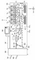
도 1은 본 실시형태의 화상 형성 장치를 구비한 화상 형성 시스템을 나타내는 개략도이다.
도 2는 화상 형성 장치의 프론트도어가 열린 상태를 나타내는 좌측 사시도이다.
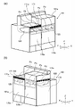
도 3의 (a)는 화상 형성 장치의 프론트도어가 닫힌 상태를 나타내는 좌측 사시도이고, 도 3의 (b)는 화상 형성 장치의 프론트도어가 닫힌 상태를 나타내는 우측 사시도이다.
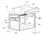
도 4는 제1 케이스에 있어서의 좌측 흡기 유닛과 우측 흡기 유닛의 배치를 나타내는 모식도이다.
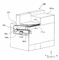
도 5는 현상 장치로의 흡기를 위한 좌측 흡기 유닛을 나타내는 사시도이다.
도 6은 현상 장치로의 흡기를 위한 우측 흡기 유닛을 나타내는 사시도이다.
도 7은 현상 장치로의 흡기를 위한 내부 커버 유닛의 내면측을 나타내는 개략도이다.
도 8의 (a)는 본 실시형태의 현상 장치에 대한 에어플로우를 설명하는 모식도이고, (b)는 비교예의 현상 장치에 대한 에어플로우를 설명하는 모식도이다.
도 9는 대전 장치에 대한 에어플로우를 설명하는 개략도이다.
도 10은 대전 장치로의 흡기를 위한 내부 커버 유닛의 내면측을 나타내는 개략도이다.
도 11은 흡기구를 나타내는 좌측 사시도이다.
도 12는 도 11의 경우에 있어서의 흡기 유닛을 나타내는 모식도이다.1 is a schematic diagram showing an image forming system equipped with an image forming apparatus of this embodiment.
2 is a left perspective view showing a state in which the front door of the image forming apparatus is opened.
FIG. 3(a) is a left perspective view showing a closed state of the front door of the image forming apparatus, and FIG. 3(b) is a right perspective view showing a closed state of the front door of the image forming apparatus.
4 is a schematic view showing the arrangement of the left intake unit and the right intake unit in the first case.
5 is a perspective view showing a left intake unit for intake of air to the developing device.
6 is a perspective view showing a right intake unit for intake of air to the developing device.
Fig. 7 is a schematic diagram showing the inner side of the inner cover unit for air intake to the developing device.
Fig. 8(a) is a schematic diagram illustrating the air flow of the developing device of the present embodiment, and (b) is a schematic diagram explaining the air flow of the developing device of the comparative example.
Fig. 9 is a schematic diagram illustrating air flow for a charging device.
Fig. 10 is a schematic view showing the inner surface side of the inner cover unit for air intake into the charging device.
11 is a left perspective view illustrating an intake port.
Fig. 12 is a schematic diagram showing an intake unit in the case of Fig. 11;
[제1 실시형태] [First Embodiment]
<화상 형성 시스템> <Image forming system>
본 실시형태의 화상 형성 장치를 구비한 화상 형성 시스템의 개략 구성에 대해, 도 1을 사용하여 설명한다. 도 1에 나타내는 화상 형성 시스템(1X)은, 화상 형성 장치(100)와, 피니셔 장치(300)를 가지고 있다. 화상 형성 장치(100)와 피니셔 장치(300)는, 기록재(S)를 전달 가능하도록 연결되어 있다. 본 실시형태에 있어서, 피니셔 장치(300)는, 기능 확장을 위해 화상 형성 장치(100)에 나중에 장착 가능한 후공정 유닛이며, 화상 형성 장치(100)에 의해 토너상이 정착된 기록재(S)에 대하여 후술하는 후공정을 행할 수 있다. 화상 형성 장치(100)와 피니셔 장치(300)는, 시리얼 통신이나 패러렐 통신이 가능한 통신 인터페이스를 통해 그들 사이에서 데이터 송수신이 가능하도록 접속되어 있다.A schematic configuration of an image forming system including the image forming apparatus of the present embodiment will be described with reference to FIG. 1 . An
<화상 형성 장치> <Image forming device>
화상 형성 장치(100)는 전자사진 방식의 탠덤형(tandem-type) 풀 컬러 프린터이며, 제1 케이스(101a)와 제2 케이스(10lb)를 가진다. 제1 케이스(101a)에는, 기록재(S)를 반송하여 토너상을 전사할 때까지의 공정을 실현하는 화상 형성 유닛(700)을 포함하는 각종 기기나 각종 부재 등이 배치되어 있다. 한편, 제2 케이스(10lb)에는, 기록재(S)를 가열하면서 반송하여 토너상을 정착하는 공정을 실현하는 정착 유닛(800) 등의 각종 기기나 각종 부재 등이 배치되어 있다. 또한, 제2 케이스(10lb)에는, 정면 측에 각종 정보를 표시 가능한 표시부나 사용자 조작에 따라 각종 정보를 입력 가능한 키 등을 가지는 조작부(200)가 배치되어 있다. 제2 케이스(10lb)는, 화상 형성 장치(100)의 폭방향에 있어서 제1 케이스(101a)의 일단측(하류측)에 배치되고, 제1 케이스(101a)와 제2 케이스(10lb)는 서로의 사이에서 기록재(S)를 전달 가능하도록 접속되어 있다.The
한편, 이들 제1 케이스(101a) 및 제2 케이스(10lb)의 배면 측에는, 전원 기판을 가지는 전장 유닛(미도시)이 배치되어 있어도 된다. 본 명세서에 있어서, 사용자가 화상 형성 장치(100)를 동작시키기 위해 조작부(200)를 조작할 때 서는 측을 "정면"이라고 부르고, 그 반대측을 "배면"이라고 부른다. 또한, 정면에서 화상 형성 장치(100)를 보아 좌측의 측면을 "좌측면"이라고 칭하고, 정면에서 보아 우측의 측면을 "우측면"이라고 칭한다. On the other hand, on the rear side of the
화상 형성 장치(100)는, 각각 옐로우, 마젠타, 시안, 블랙의 화상을 형성하는 4대의 화상 형성부(Pa, Pb, Pc, Pd)를 구비하고 있다. 본 실시예에 있어서, 화상 형성부(Pa)는, 복수의 화상 형성 유닛의 배열 방향에 있어서 가장 일단측에 위치하는 제1 화상 형성 유닛의 일 예이며, 복수의 화상 형성 유닛의 배열 방향에 있어서 가장 타단측에 위치하는 화상 형성부(Pd)는 제2 화상 형성 유닛의 일 예이다. 또한, 화상 형성부(Pb)는 제3 화상 형성 유닛의 일 예이며, 화상 형성부(Pc)는 제4 화상 형성 유닛의 일 예이다. 화상 형성 장치(100)는, 원고로부터 화상 신호를 판독하는 원고 판독 장치(190) 또는 퍼스널 컴퓨터 등의 외부기기(미도시)로부터 수신한 화상 신호에 따라 토너상을 기록재(S)에 형성한다. 본 실시형태의 화상 형성 장치(100)는, 제1 케이스(101a)에 병렬로 탑재되는 복수의 화상 형성부의 각각이 큰, 오피스용 장치나 가정용 장치에 비해 대형인 상업 인쇄용의 장치이다.The
한편, 본 실시형태의 경우, 화상 형성부(Pa~Pd), 1차 전사 롤러(24a~24d), 중간 전사 벨트(130), 복수의 롤러(13~15), 2차 전사 외측 롤러(11)에 의해, 기록재(S)에 토너상을 형성하는 화상 형성 유닛(700)이 구성되어 있다. 또한, 기록재(S)로서는, 보통지, 두꺼운 종이, 러프지, 요철지, 코팅지 등의 용지, 플라스틱 필름이나 천 등을 들 수 있다.Meanwhile, in the case of the present embodiment, the image forming units Pa to Pd, the
도 1에 나타낸 바와 같이, 화상 형성부(Pa~Pd)는, 중간 전사 벨트(130)의 이동 방향을 따라 나란히 배치되어 있다. 중간 전사 벨트(130)는 복수의 롤러(13, 14, 15)에 걸쳐 스트레치되고, 화살표 R2방향으로 이동된다. 그리고, 중간 전사 벨트(130)는 후술하는 바와 같이 1차 전사되는 토너상을 담지하여 반송한다. 중간 전사 벨트(130)를 스트레칭하는 2차 전사 내측 롤러(14)와 중간 전사 벨트(130)를 사이에 두고 대향하는 위치에는, 2차 전사 외측 롤러(11)가 배치되어, 중간 전사 벨트(130) 상의 토너상을 기록재(S)에 전사하는 2차 전사부(T2)를 형성하고 있다. 2차 전사부(T2)의 기록재 반송 방향의 하류에는, 정착 유닛(800)이 배치되어 있다. As shown in FIG. 1 , the image forming sections Pa to Pd are arranged side by side along the moving direction of the
화상 형성 장치(100)의 하방 측에는, 기록재(S)가 수용된 복수(여기서는 2대)의 카세트(10)가 배치되어 있다. 이들 카세트(10)에는 사이즈나 두께의 다른 기록재(S)가 수용되어 있고, 카세트(10) 중 어느 하나로부터 선택적으로 기록재(S)가 반송된다. 기록재(S)는, 반송 롤러(16)에 의해 카세트(10)로부터 반송 경로를 통해 레지스트레이션 롤러(12)를 향해서 반송된다. 그 후, 레지스트레이션 롤러(12)가 중간 전사 벨트(130) 상에 형성된 토너상과 동기하여 회전함으로써, 기록재(S)는 2차 전사부(T2)를 향해 반송된다. 한편, 카세트(10)에 수용된 기록재(S)에 한하지 않고, 수동 급지부(미도시)에 재치된 기록재(S)가 반송되도록 해도 좋다.On the lower side of the
화상 형성부(Pa, Pb, Pc, Pd)는, 토너상의 현상 색이 다른 것을 제외하고 실질적으로 동일한 구성이다. 따라서, 여기서는 대표로 옐로우의 화상 형성부(Pa)에 대해 설명하고, 그 밖의 화상 형성부(Pb, Pc, Pd)에 대해서는 설명을 생략한다. The image forming units (Pa, Pb, Pc, Pd) have substantially the same configuration except that the developed color of the toner image is different. Therefore, here, the yellow image forming portion Pa is explained as a representative, and the description of the other image forming portions Pb, Pc, and Pd is omitted.
화상 형성부(Pa)에는, 원통형의 감광 드럼(3a)이 배치되어 있다. 감광 드럼(3a)은, 도시하지 않은 모터에 의해 회전 구동된다. 감광 드럼(3a)의 주위에는, 대전 유닛으로서의 대전 장치(2a), 노광 장치(La), 현상 장치(1a), 1차 전사 롤러(24a), 드럼 클리닝 장치(4a)가 배치되어 있다.In the image forming section Pa, a cylindrical
화상 형성 장치(100)를 사용하여, 예를 들면 풀 컬러의 화상을 형성하는 프로세스에 대해 설명한다. 먼저, 화상 형성 동작이 개시되면, 회전하는 감광 드럼(3a)의 표면이 대전 장치(2a)에 의해 균일하게 대전된다. 대전 장치(2a)는, 예를 들면 코로나 방전에 수반되는 하전 입자를 조사하여 감광 드럼(3a)의 표면을 균일한 전위로 대전시키는 코로나 대전기이다. 이어서, 감광 드럼(3a)은, 노광 장치(La)로부터 발생된 화상 신호에 대응한 레이저광에 의해 주사 노광된다. 그 결과, 감광 드럼(3a)의 표면에 화상 신호에 따른 정전 잠상이 형성된다. 감광 드럼(3a)에 형성된 정전 잠상은, 현상 장치(1a) 내에 수용되어 있는 토너와 캐리어를 포함하는 현상제에 의해 가시상인 토너상으로 현상된다. 바꿔 말하면, 감광 드럼(3a)은 현상 장치(1a)에 의해 토너가 공급됨으로써 토너상으로 현상된다. 한편, 현상 장치(1a~1d) 내에서는, 현상제가 반송 스크류(미도시)에 의해 교반되면서 순환 반송되고 있다.A process of forming, for example, a full-color image using the
감광 드럼(3a)에 형성된 토너상은, 중간 전사 벨트(130)를 사이에 두고 배치되는 1차 전사 롤러(24a)와의 사이에서 구성되는 1차 전사부(T1)에서, 중간 전사 벨트(130)로 1차 전사된다. 이 때, 1차 전사 롤러(24a)에는 1차 전사 전압이 인가된다. 1차 전사 후에 감광 드럼(3a)의 표면에 남은 토너는, 드럼 클리닝 장치(4a)에 의해 제거된다.The toner image formed on the
이러한 동작을 옐로우, 마젠타, 시안, 블랙의 각 화상 형성부(Pa~Pd)에서 순차로 행하여, 중간 전사 벨트(130) 상에서 4색의 토너상을 겹친다. 그 후, 토너상의 형성 타이밍에 맞추어 카세트(10)에 수용된 기록재(S)가 2차 전사부(T2)로 반송된다. 그리고, 2차 전사 외측 롤러(11)에 2차 전사 전압을 인가함으로써, 중간 전사 벨트(130) 상에 형성된 풀 컬러의 토너상이 기록재(S)로 일괄하여 2차 전사된다. 한편, 2차 전사 후에 중간 전사 벨트(130) 상에 남은 토너는, 도시하지 않은 벨트 클리닝 장치에 의해 제거된다.These operations are sequentially performed in each of the yellow, magenta, cyan, and black image forming units Pa to Pd to superimpose toner images of four colors on the
본 실시형태에서는, 감광 드럼(3a, 3b)이 제1 감광체에 상당하고, 감광 드럼(3c, 3d)이 제2 감광체에 상당한다. 또한, 현상 장치(1a, 1b)가 제1 현상 유닛에 상당하고, 현상 장치(1c, 1d)가 제2 현상 유닛에 상당한다. 나아가, 대전 장치(2a, 2b)가 제1 대전 유닛에 상당하고, 대전 장치(2c, 2d)가 제2 대전 유닛에 상당한다.In this embodiment, the
토너상이 전사된 기록재(S)는, 정착 유닛(800)에 반송된다. 정착 유닛(800)은, 토너상이 전사된 기록재(S)에 열과 압력을 가함으로써 기록재(S)에 토너상을 정착시킨다. 본 실시형태의 경우, 기록재(S)에 대하여 제1 정착기(81)에 의해 열과 압력을 가한 뒤, 제2 정착기(91)에 의해 열과 압력을 더 가하는 것을 선택적으로 실시할 수 있도록 하고 있다. 정착 유닛(800)은 기록재(S)를, 제1 정착기(81) 통과 후 제2 정착기(91)를 향해 반송시킬 것인지, 제1 정착기(81) 통과 후 제2 정착기(91)를 회피하여 반송시킬 것인지를, 정착 스위치 플랩퍼(95)에 의해 스위칭할 수 있다.The recording material S onto which the toner image is transferred is conveyed to the fixing
제2 정착기(91)는, 제1 정착기(81)보다 기록재(S)의 반송 방향 하류측에 배치되어 있다. 제2 정착기(91)는, 제1 정착기(81)에 의해 정착된 기록재(S) 상의 토너상에 광택을 더 부여하는 등의 목적을 위하여 선택적으로 사용된다. 예를 들면, 기록재(S)가 광택지나 합성지 등의 코팅지일 경우, 제1 정착기(81) 및 제2 정착기(91)의 양쪽에서 정착이 행하여지도록, 제1 정착기(81)를 통과한 기록재(S)는 정착 루트(30a)를 따라 반송된다. 반면, 기록재(S)가 보통지 등의 비코팅지일 경우, 제1 정착기(81)에서 정착이 행해지고 제2 정착기(91)에서는 정착이 행하여지지 않도록, 제1 정착기(81)를 통과한 기록재(S)는 제2 정착기(91)를 회피하는 정착 바이패스 루트(30b)를 따라 반송된다.The
상기 제1 정착기(81)와 제2 정착기(91)는 같은 구성이어도 되므로, 여기서는 제1 정착기(81)를 예로 들어 설명한다. 제1 정착기(81)는, 기록재(S)의 토너상이 정착된 면에 접촉하여 회전 가능한 정착 롤러(82)(또는 정착 벨트)와, 정착 롤러(82)에 압접하여 정착 닙부를 형성하는 가압 벨트(83)(또는 가압 롤러)를 가진다. 정착 롤러(82) 및 가압 벨트(83)의 적어도 일방은, 도시하지 않은 히터에 의해 가열된다. 제1 정착기(81)는, 정착 롤러(82)와 가압 벨트(83)에 의해 형성되는 정착 닙부에서, 토너상이 형성된 기록재(S)를 협지 반송할 때 기록재(S)에 열 및 압력을 가하여, 토너상을 기록재(S)에 정착시킨다.Since the
본 실시형태의 경우, 화상 형성 장치(100)는 양면 인쇄 가능하다. 단면 인쇄의 경우, 토너상이 정착된 기록재(S)는, 배출 반송로(150)로 반송되어 화상 형성 장치(100)의 외부로 배출된다. 양면 인쇄의 경우, 토너상이 정착된 기록재(S)는, 양면 반전 반송로(600)로 반송된다. 양면 반전 반송로(600)는, 제1 케이스(101a)와 제2 케이스(10lb)에 걸쳐 형성되어 있다. 양면 반전 반송로(600)에서는, 스위치백 동작에 의해 기록재(S)가 반전되어, 기록재(S)의 표면과 이면이 바뀐다. 반전된 기록재(S)는, 레지스트레이션 롤러(12)를 향해 반송되고, 레지스트레이션 롤러(12)에 의해 인쇄되지 않은 이면측을 중간 전사 벨트(130)측을 향하게 한 상태로 2차 전사부(T2)에 반송된다. 2차 전사부(T2)에서는, 중간 전사 벨트(130) 상에 형성된 풀 컬러의 토너상이 기록재(S)(이면측)에 일괄하여 2차 전사된다. 그 후, 기록재(S)는 정착 유닛(800)에 의한 토너상의 정착이 행하여지고 화상 형성 장치(100)의 외부로, 직전에 화상 형성된 면(화상 형성면)을 상측으로 향하게 한 상태로 배출된다. 한편, 상기 배출 반송로(150)와 양면 반전 반송로(600)의 스위칭은, 반송 스위치 플랩퍼(160)에 의해 행하여진다. 한편, 본 실시형태에서는, 정착 유닛(800)으로서 정착기를 2개 구비하는 구성으로 하였지만, 정착기를 1개만 구비하는 구성이어도 된다. 또한, 정착 유닛(800)에 의해 토너상이 정착된 기록재(S)를 냉각하는 냉각 장치를 제2 케이스(10lb)에 구비하는 구성이어도 된다.In the case of this embodiment, the
화상 형성 장치(100)에는 피니셔 장치(300)가 기록재(S)를 전달 가능하도록 연결되고, 화상 형성 장치(100)로부터 배출된 기록재(S)는 피니셔 장치(300)로 반송된다. 피니셔 장치(300)로 반송된 기록재(S)는, 피니셔 장치(300)에 의해 기록재(S)에 구멍을 뚫는 펀치 처리, 또는 복수 매의 기록재(S)를 묶는 스테이플 처리 등의 후공정 처리가 행하여진다. 피니셔 장치(300)에 있어서, 펀칭된 기록재(S)는 상측 배출 트레이(301)에, 스테이플된 기록재(S)의 묶음은 하측 배출 트레이(302)에 각각 나누어 배출된다.A
이하, 화상 형성 장치(100)에 있어서의 에어플로우 구성에 대해서, 도 1을 참조하면서 도 2 내지 도 8을 사용하여 설명한다. 도 2는, 프론트도어가 열린 상태의 화상 형성 장치(100)를 나타내는 좌측 사시도이다. 도 3 (a)은 화상 형성 장치(100)의 프론트도어가 닫힌 상태를 나타내는 좌측 사시도, 도 3(b)은 화상 형성 장치(100)의 프론트도어가 닫힌 상태를 나타내는 우측 사시도이다. 도 4는, 제1 케이스에 있어서의 좌측 흡기 유닛과 우측 흡기 유닛의 배치를 나타내는 모식도이다.Hereinafter, an airflow configuration in the
도 2에 나타낸 바와 같이, 제1 케이스(101a)의 정면에는, 개폐 커버로서의 좌측 프론트도어(170a) 및 우측 프론트도어(170b)가 도시된 바와 같이 대략 중앙을 경계로 좌우 여닫이 식으로 개폐 가능하게 설치되어 있다. 제1 케이스(101a)의 정면에는, 좌측 프론트도어(170a) 및 우측 프론트도어(170b)의 내측에, 내부 커버(173)가 설치되어 있다. 내부 커버(173)는, 사용자가 프론트도어(170a, 170b)를 열었을 경우에, 제1 케이스(101a) 내의 가동부나 전기 배선 등에 잘못하여 접촉하지 않도록 하기 위한 것이다. 단, 서비스기사가 유지보수 작업을 행할 수 있도록, 내부 커버(173)는 나사 또는 다른 수단에 의해 제1 케이스(101a)에 착탈 가능하게 설치되어 있다. 이 내부 커버(173)에는, 화상 형성부(Pa~Pd)(점선으로 도시)를 제1 케이스(101a)에 대해 개별적으로 삽입하고 탈착하는 것이 가능한 개구부가 형성되어 있고, 내부 커버 유닛(125)이 화상 형성부(Pa~Pd)를 덮도록 내부 커버(173)에 착탈 가능하게 설치되어 있다.As shown in FIG. 2, on the front side of the
한편, 본 실시형태의 경우, 화상 형성부(Pa, Pb)는 닫힌 상태의 좌측 프론트도어(170a)에 대향하는 위치에서 제1 케이스(101a)에 지지되고, 화상 형성부(Pc, Pd)는 닫힌 상태의 우측 프론트도어(170b)에 대향하는 위치에서 제1 케이스(101a)에 지지되어 있다. 바꿔 말하면, 화상 형성부(Pa, Pb)는 정면에서 보아 중앙보다 좌측에 배치되고, 화상 형성부(Pc, Pd)는 정면에서 보아 중앙보다 우측에 배치되어 있다.Meanwhile, in the present embodiment, the image forming units Pa and Pb are supported by the
도 2 및 3(a)에 나타낸 바와 같이, 좌측 프론트도어(170a)의 상방에는 흡기 커버(171)가 설치되고, 흡기 커버(171)에는, 복수의 화상 형성부(Pa~Pd)의 배열 방향에 있어서 화상 형성부(Pd)보다 화상 형성부(Pa)에 가까운 위치에 설치된 제1 흡기구로서의 흡기구(171a)가 형성되어 있다. 바꿔 말하면, 흡기구(171a)가 화상 형성 장치(100)의 정면을 향하여, 외장 커버로서의 흡기 커버(171)에 형성되어 있다. 그리고, 제1 케이스(101a)의 좌측면 측에는, 흡기구(171a)로부터 외기를 흡기하는 팬을 갖는 좌측 흡기 유닛(124)이 배치되어 있다. 흡기구(171a)로부터 흡기된 외기는, 좌측 흡기 유닛(124)과 내부 커버 유닛(125)을 경유하여, 현상 장치(1a, 1b)를 향해 안내된다. 본 실시형태의 경우, 기록재(S)의 반송 방향의 하류측인 제1 케이스(101a)의 좌측면 측에 다른 케이스인 제2 케이스(10lb)가 접속되고 있다(도 1 참조). 따라서, 흡기구(171a)는 제2 케이스(10lb)에 면하는 제1 케이스(101a)의 좌측면(제1 측면)에 형성되지 않고, 제1 케이스(101a)의 좌측면(제1 측면)에 교차하는 정면(제2 측면)에 형성되어 있다.2 and 3(a), an
또한, 도 3(b)에 나타낸 바와 같이, 제1 케이스(101a)의 우측면에는 우측 커버(172)가 설치되어 있다. 우측 커버(172)에는, 복수의 화상 형성부(Pa~Pd)의 배열 방향에 있어서 화상 형성부(Pa)보다 화상 형성부(Pd)에 가까운 위치에 설치된 제2 흡기구로서의 흡기구(172a)가 형성되어 있다. 바꿔 말하면, 흡기구(172a)가 화상 형성 장치(100)의 우측방을 향하여, 우측 커버(172)에 형성되어 있다. 그리고, 제1 케이스(101a)의 우측면 측에는, 흡기구(172a)로부터 외기를 흡기하는 팬을 갖는 우측 흡기 유닛(126)이 배치되어 있다. 흡기구(172a)로부터 흡기된 외기는, 우측 흡기 유닛(126)과 내부 커버 유닛(125)을 경유하여 현상 장치(1c, 1d)로 안내된다. 본 실시형태의 경우, 화상 형성 장치(100)의 타단측(여기서는, 기록재(S)의 반송 방향의 상류측)인 제1 케이스(101a)의 우측면 측에 다른 케이스가 접속되지 않는다. 따라서, 흡기구(172a)는 기록재(S)의 반송 방향에 있어서 제1 케이스(101a)의 좌측면(제1 면)에 대향하는 상류측의 우측면(제3 측면)에 형성되어 있다. 한편, 본 실시형태에 있어서 좌측 흡기 유닛(124)은 제1 본체 덕트 유닛의 일 예이며, 우측 흡기 유닛(126)은 제2 본체 덕트 유닛의 일 예이다.As shown in Fig. 3(b), a
한편, 본 실시형태의 경우, 제2 케이스(10lb)에 지지된 제1 정착기(81)과 제2 정착기(91)는 열을 발생시키기 때문에, 도시를 생략한 냉각 기구에 의해 공냉에 의해 냉각된다. 이에 의해, 제2 케이스(10lb)에서는 배면측에 설치된 도시하지 않은 배기구로부터 배기가 행하여진다. 흡기구(171a) 및 흡기구(172a)로부터 흡기하는 외기는, 온도가 낮은 것이 바람직하다. 따라서, 흡기구(171a) 및 흡기구(172a)는, 온도가 높아지기 쉬운 제2 케이스(10lb)의 배면측이 아니라, 이로부터 될 수 있는 한 떨어진 제1 케이스(101a)의 정면과 측면의 정면 가까이에 형성된다.On the other hand, in the case of this embodiment, since the
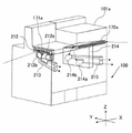
도 4에 나타낸 바와 같이, 제1 케이스(101a)에 있어서 각 유닛 등을 지지하는 지지 프레임은 네 코너에서 정면측에 전방 지주(185a, 185b), 배면측에 후방 지주(185c, 185d)의 4개의 지주를 가지고 있다. 또한, 지지 프레임은 도시하지 않은 측판 등을 가지고 있고, 전술한 화상 형성 장치(100)의 내부의 유닛을 지지하고 있다. 이들 전방 지주(185a, 185b) 및 후방 지주(185c, 185d)는, 저판(185)에 연결됨으로써 저판(185)으로부터 상방을 향해 세워 설치되어 있다. 좌측 흡기 유닛(124)은 전방 지주(185a)와 후방 지주(185c)에 걸쳐 지지되고, 우측 흡기 유닛(126)은 전방 지주(185b)와 후방 지주(185d)에 걸쳐 지지되어 있다. 본 실시형태에 있어서 지주(185a)는 제1 지주의 일 예이며, 지주(185c)는 제2 지주의 일 예이다. 본 실시형태에 있어서 지주(185b)는 제3 지주의 일 예이며, 지주(185d)는 제4 지주의 일 예이다. 좌측 흡기 유닛(124)과 우측 흡기 유닛(126)은, 각각 현상용 흡기 팬(180a, 180b, 180c, 180d)에 의해 흡기되는 외기의 배출구(174a, 174b, 179b, 179a)가 정면을 향하도록 지지되어 있다.As shown in Fig. 4, the support frame supporting each unit and the like in the
좌측 흡기 유닛(124)은, 제1 팬으로서의 현상용 흡기 팬(180a, 180b)이 기록재(S)의 반송 방향에 있어서 제1 케이스(101a)의 하류단 측에 배치되도록, 전방 지주(185a)와 후방 지주(185c)에 의해 지지되어 있다. 한편, 우측 흡기 유닛(126)은, 제2 팬으로서의 현상용 흡기 팬(180c, 180d)이 기록재(S)의 반송 방향에 있어서 제1 케이스(101a)의 상류단 측에 배치되도록, 전방 지주(185b)와 후방 지주(185d)에 의해 지지되어 있다. 현상용 흡기 팬(180b)은, 복수의 화상 형성부(Pa~Pd)의 배열 방향에 있어서 화상 형성부(Pa)보다 일단측에 설치되는 제1 팬으로, 화상 형성부(Pd)보다 화상 형성부(Pa)에 가까운 위치에 설치된 제1 팬의 일 예이다. 현상용 흡기 팬(180c)은, 복수의 화상 형성부(Pa~Pd)의 배열 방향에 있어서 화상 형성부(Pd)보다 타단측에 설치된 제2 팬으로서, 화상 형성부(Pa)보다 화상 형성부(Pd)에 가까운 위치에 설치된 제2 팬의 일 예이다. 현상용 흡기 팬(180a)은, 복수의 화상 형성부(Pa~Pd)의 배열 방향에 있어서 화상 형성부(Pa)보다 일단측에 설치된 제3 팬으로서, 화상 형성부(Pd)보다 화상 형성부(Pa)에 가까운 위치에 설치된 제3 팬의 일 예이다. 현상용 흡기 팬(180d)는, 복수의 화상 형성부(Pa~Pd)의 배열 방향에 있어서 화상 형성부(Pd)보다 타단측에 설치된 제4 팬으로서, 화상 형성부(Pa)보다 화상 형성부(Pd)에 가까운 위치에 설치된 제4 팬의 일 예이다.The left
나아가, 좌측 흡기 유닛(124)의 현상용 흡기 팬(180a, 180b), 우측 흡기 유닛(126)의 현상용 흡기 팬(180c, 180d)이, 각각 정면측의 2개의 전방 지주(185a, 185b)보다 배면측에 위치하도록, 좌측 흡기 유닛(124)과 우측 흡기 유닛(126)은 지지되어 있다. 이와 같이 하면, 현상용 흡기 팬(180a~180d)의 동작 소음이 프론트도어(170a, 170b, 도 3(a) 참조)에 의해 차단되므로, 사용자는 팬의 동작 소음에 신경쓸 일 없이 화상 형성 장치(100)를 조작할 수 있다. 즉, 팬의 동작 소음에 의한 소음을 억제할 수 있다.Furthermore, the developing
<흡기 유닛> <Intake unit>
제1 흡기 유닛으로서의 좌측 흡기 유닛(124)과, 제2 흡기 유닛으로서의 우측 흡기 유닛(126)에 대해서, 도 1을 참조하면서 도 5 내지 도 8(b)를 사용하여 설명한다. 도 5에 나타낸 바와 같이, 좌측 흡기 유닛(124)은, 좌측 본체 덕트(174)와, 현상용 흡기 팬(180a, 180b)과, 측면 덕트(1741)를 가진다. 현상용 흡기 팬(180a, 180b)은, 제1 케이스(101a)에 지지된 현상 장치(1a, 1b)를 냉각하기 위한 시로코팬이다. 좌측 본체 덕트(174)는, 화상 형성 장치(100)의 정면에 형성된 흡기구(171a)와 연통하는 공간이 내부에 형성된 덕트이다.The
현상용 흡기 팬(180a, 180b)과 측면 덕트(1741)는, 좌측 본체 덕트(174)의 좌측면에 배치되어 있다. 즉, 좌측 본체 덕트(174)의 좌측면에는, 현상용 흡기 팬(180a, 180b)과 연통하는 연통구가 형성되고, 현상용 흡기 팬(180a, 180b)의 동작에 따라 흡기구(171a)로부터 흡기되는 외기가 좌측 본체 덕트(174)의 내부를 통과한다. 측면 덕트(1741)에는, 내부에 현상용 덕트(181a, 18lb)가 형성되어 있다. 현상용 흡기 팬(180a, 180b)를 통과한 외기가 각각 현상용 덕트(181a, 18lb)를 지나도록, 측면 덕트(1741)는 현상용 흡기 팬(180a, 180b)에 접속되어 있다.The
도 8(a)에 나타낸 바와 같이, 흡기구(171a)로부터 흡기된 외기는, 좌측 본체 덕트(174), 현상용 흡기 팬(180a, 180b), 현상용 덕트(181a, 18lb), 내부 커버 유닛(125)을 경유하여, 현상 장치(1a, 1b)로 보내진다. 흡기구(171a)로부터 흡기된 외기로부터 먼지 및 그 밖의 파티클을 제거하기 위해, 흡기구(171a)에서부터 좌측 본체 덕트(174)에 이르는 유로에 필터(미도시)를 배치하는 것이 바람직하다.As shown in Fig. 8(a), the outside air taken in from the
다음으로, 우측 흡기 유닛(126)에 대해서, 도 6을 사용하여 설명한다. 도 6에 나타낸 바와 같이, 우측 흡기 유닛(126)은, 우측 본체 덕트(176)와, 현상용 흡기 팬(180c, 180d)과, 통과 덕트(179)를 가진다. 현상용 흡기 팬(180c, 180d)은, 제1 케이스(101a)에 지지된 현상 장치(1c, 1d)에 외기를 송풍하기 위한 시로코팬이다. 우측 본체 덕트(176)는, 화상 형성 장치(100)의 우측면에 형성된 흡기구(172a)와 연통하는 공간이 내부에 형성된 덕트이다.Next, the
현상용 흡기 팬(180c, 180d)은, 우측 본체 덕트(176)의 우측면에 설치되어 있다. 즉, 우측 본체 덕트(176)에는, 현상용 흡기 팬(180c, 180d)과 연통하는 연통구가 형성되어 있고, 현상용 흡기 팬(180c, 180d)의 동작에 따라 흡기구(172a)로부터 흡기되는 외기가 우측 본체 덕트(176)의 내부를 통과한다. 그리고, 통과 덕트(179)에는, 내부에 현상용 덕트(181c, 181d)가 형성되어 있다. 현상용 흡기 팬(180c, 180d)을 통과한 외기가 각각 현상용 덕트(181c, 181d)를 지나도록, 통과 덕트(179)는 현상용 흡기 팬(180c, 180d)에 접속되어 있다.The
도 8(a)에 나타낸 바와 같이, 흡기구(172a)로부터 흡기된 외기는, 우측 본체 덕트(176), 현상용 흡기 팬(180c, 180d), 현상용 덕트(181c, 181d), 내부 커버 유닛(125)을 경유하여, 현상 장치(1c, 1d)에 보내진다. 흡기구(172a)로부터 흡기된 외기로부터 먼지 및 그 밖의 파티클을 제거하기 위해, 흡기구(172a)에서부터 우측 본체 덕트(176)에 이르는 유로에 필터(미도시)를 배치하는 것이 바람직하다.As shown in Fig. 8(a), the outside air taken in from the
이와 같이, 본 실시형태에서는, 현상 장치(1a~1d)에 외기를 송풍하기 위해서, 좌측 흡기 유닛(124)과 우측 흡기 유닛(126)이 사용된다. 정면에서 보아 중앙보다 좌측에 배치된 현상 장치(1a, 1b)에 외기를 송풍하기 위해, 현상용 흡기 팬(180a, 180b)을 가지는 좌측 흡기 유닛(124)이 현상 장치(1a, 1b)에 가까운 화상 형성 장치(100)의 제1 케이스(101a)의 좌측면 측에 배치되어 있다. 또한, 현상용 흡기 팬(180a, 180b)에 의한 외기의 흡기를 위해, 흡기구(171a)가 화상 형성 장치(100)의 중앙보다 좌측 흡기 유닛(124)에 더 가까운 화상 형성 장치(100)의 정면에 형성되어 있다. 즉, 흡기구(171a)는, 기록재(S)의 반송 방향에 있어서 현상용 흡기 팬(180c, 180d)보다 현상용 흡기 팬(180a, 180b)에 더 가까운 제1 케이스(101a)의 중앙보다 하류측에 형성되어 있다. 제1 케이스(101a)의 좌측면측에는, 제2 케이스(10lb)가 연결되고 있다. 본 실시형태와 같이, 흡기구(171a)를 제1 케이스(101a)의 전방측면에 설치함으로써, 제2 케이스(10lb)에 의해 흡기구(171a)로부터의 흡기가 저해되는 것을 억제할 수 있다.Thus, in this embodiment, the
한편, 정면에서 보아 중앙보다 우측에 배치된 현상 장치(1c, 1d)에 외기를 송풍하기 위해, 현상용 흡기 팬(180c, 180d)을 가지는 우측 흡기 유닛(126)이 현상 장치(1c, 1d)에 가까운 화상 형성 장치(100)의 제1 케이스(101a)의 우측면 측에 배치되어 있다. 그리고, 현상용 흡기 팬(180c, 180d)에 의한 외기의 흡기를 위해, 흡기구(172a)가 우측 흡기 유닛(126)에 가까운 화상 형성 장치(100)의 우측면에 형성되어 있다. 즉, 흡기구(172a)는, 화상 형성 장치(100)의 폭방향에 있어서 제1 케이스(101a)의 중앙보다 일단측에 형성되어 있다. 여기에서는, 흡기구(172a)가 기록재(S)의 반송 방향에 있어서 현상용 흡기 팬(180a, 180b)보다 현상용 흡기 팬(180c, 180d)에 더 가까운 제1 케이스(101a)의 중앙보다 상류측에 형성되어 있다.On the other hand, in order to blow outside air to the developing
<내부 커버 유닛> <Inner cover unit>
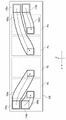
도 7에, 본 실시형태에서 사용하는 내부 커버 유닛(125)을 나타낸다. 도 7은, 내부 커버 유닛(125)의 내면측을 나타내는 개략도이다. 본 실시형태에서는, 도 7에 나타낸 바와 같이, 현상 장치(1a~1d)를 냉각하기 위한 외기를 통과시키는 중계 덕트로서, 제1 중계 덕트로서의 플렉서블 튜브(183a, 183b), 제2 중계 덕트로서의 플렉서블 튜브(183c, 183d)가, 내부 커버 유닛(125)의 내면에 배치되어 있다. 이들 플렉서블 튜브(183a~183d)는, 예를 들면 와이어 새들을 사용하여 내부 커버 유닛(125)의 내면에 장착되어 있다.7 shows the
플렉서블 튜브(183a~183d)는 예를 들면 PA6(폴리아미드) 등의 수지나 금속을 사용하여 내부가 공동의 원통 형상으로 형성되고, 외주면에는 다수의 볼록부가 소정의 간격을 두고 연속하여 형성된 주름상자 형상의 통 형상 부재이며, 만곡 가능하다. 이들 플렉서블 튜브(183a~183d)는, 만곡되었을 경우, 만곡의 내측(압축측)에서 볼록부에 의해 만곡이 제한되어 접어 구부리기 어렵다. 그 때문에, 플렉서블 튜브(183a~183d)는 만곡되더라도, 만곡 전과 비교하여 단면적의 크기가 유지되어, 단위시간당 풍량이 변함이 없이 외기를 안내할 수 있다.The
이와 같이 하여, 현상용 흡기 팬(180a, 180b)의 동작에 따라 흡기구(171a)로부터 흡기된 외기는, 좌측 본체 덕트(174), 현상용 덕트(181a, 18lb), 플렉서블 튜브(183a, 183b)를 통과하여 현상 장치(1a, 1b)를 향해 흐른다. 한편, 현상용 흡기 팬(180c, 180d)의 동작에 따라 흡기구(172a)로부터 흡기된 외기는, 우측 본체 덕트(176), 현상용 덕트(181c, 181d), 플렉서블 튜브(183c, 183d)를 통과하여 현상 장치(1c, 1d)를 향해 흐른다. 본 실시형태에 있어서, 현상용 덕트(18lb)와 플렉서블 튜브(183b)는 제1 덕트의 일 예이며, 현상용 덕트(181c)와 플렉서블 튜브(183d)는 제2 덕트의 일 예이다. 현상용 덕트(181a)와 플렉서블 튜브(183a)는 제3 덕트의 일 예이며, 현상용 덕트(181d)와 플렉서블 튜브(183c)는 제4 덕트의 일 예이다.In this way, the outside air taken in from the
본 실시형태에서는, 내부 커버 유닛(125)의 내면측에 있어서, 플렉서블 튜브(183a~183d)를 적절히 만곡시켜 둘러치도록 할 수 있다. 즉, 플렉서블 튜브(183a~183d)를 사용함으로써, 한정된 공간 내에서의 덕트 배치의 자유도가 높아진다. 한편, 여기에서 나타내는 플렉서블 튜브(183a~183d)의 배치는 일 예이며, 이에 한정되지 않는다.In this embodiment, on the inner surface side of the
상기 플렉서블 튜브(183a~183d)는, 예를 들면 단면적이 "25mm×20mm"이고, 최대 길이가 "550mm"인 사각 형상으로 형성된다. 현상용 흡기 팬(180a~180d)의 송풍량이 "0.5m3/min"일 경우, 플렉서블 튜브(183a~183d)의 압력 손실은 "약 99Pa"이다. 가령, 좌측 흡기 유닛(124)에 현상용 흡기 팬(180d)을 설치하고 현상 장치(1d)로 플렉서블 튜브를 사용하여 외기를 보내도록 하면, 플렉서블 튜브의 길이는 "1100mm"이 되고, 플렉서블 튜브의 압력 손실은 "약 200Pa"이다. 즉, 좌측 흡기 유닛(124)에 현상용 흡기 팬(180d)을 설치하여 현상 장치(1d)로 외기를 보내도록 하면, 본 실시형태에 비해, 압력 손실이 2배가 되고, 현상용 흡기 팬(180d)은 보다 출력이 큰 팬이 필요하게 된다. 그러나, 그러한 팬은 대형이고 비용이 높아지므로 채용하기 어렵다.The
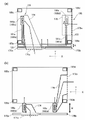
도 8(b)는, 화상 형성 장치(100)의 정면측에서 전방 지주(185a, 185b)보다 전방에, 현상용 흡기 팬(180a, 180b) 및 현상용 흡기 팬(180c, 180d)을 배치한 비교예를 나타낸다.8( b ) shows that the developing
도 8(b)에 나타내는 비교예에서는, 전방 지주(185a, 185b)의 전방에 현상용 흡기 팬(180a~180d)이 배치되어 있다. 흡기구(171a, 172a)로부터 흡기된 외기는, 좌측 본체 덕트(174), 우측 본체 덕트(176)를 경유하여, 현상용 흡기 팬(180a~180d)에 도달한다. 비교예에서는, 상술한 본 실시형태에 있어서의 측면 덕트(1741)나 통과 덕트(179)(도 5, 도 6 참조) 및 내부 커버 유닛(125)(도 2 참조)을 거치지 않고, 현상 장치(1a~1d)에 외기를 보낼 수 있다. 즉, 비교예에서는, 측면 덕트(1741), 통과 덕트(179), 내부 커버 유닛(125)을 설치하지 않아도 된다.In the comparative example shown in Fig. 8(b), the
그러나, 전방 지주(185a, 185b)와, 좌측 프론트도어(170a)와 우측 프론트도어(170b)와의 간격이, 화살표 A와 화살표 B로 나타내는 바와 같이, 본 실시형태(도 8 (a))에서 보다 커지고 있다. 즉, 비교예에서는 팬을 배치하는 스페이스를 확보하는 것에 수반하여 지지 프레임보다 전방측의 전유 면적이 증가하므로, 장치가 전후 방향(화살표 Y방향)으로 대형화되어 버린다. 보다 구체적으로는, 화상 형성 장치(100)의 지지 프레임의 내부에 설치되는 반송로보다 앞쪽에 전유 면적이 증대한다. 이에 의해, 제2 케이스(10lb)나 반송 방향 하류측에 연결하는 후처리 장치(예를 들면, 피니셔 장치(300))에 반송로를 정렬하여 연결한 경우, 이들 제2 케이스(10lb)나 후처리 장치의 전면 커버보다 제1 케이스(101a)의 전면 커버가 돌출하여, 외관 품위가 저하되어 버린다. 도 8(b)에 나타낸 비교예에서는 내부 커버(173)(도 2 참조)를 설치하고 있지 않다. 단, 사용자가 케이스 내의 가동부나 전기 배선 등에 잘못하여 접촉하지 않도록 하기 위해서, 내부 커버(173)를 설치하는 것이 일반적이다. 비교예의 경우에 내부 커버(173)를 설치하면, 그에 따라 전유 면적이 보다 증가한다. 이에 대해, 도 8(a)에 기재한 바와 같이, 본 실시형태에서는 팬 배치에 의한 전유 면적의 증가를 방지할 수 있게 되어 있다. 즉, 화상 형성 장치(100)가 전후 방향에서 대형화되는 것을 억제하고 있다.However, the distance between the
이상과 같이, 본 실시형태에서는, 정면에서 보아 중앙보다 좌측에 배치된 현상 장치(1a, 1b)에 외기를 송풍하기 위해, 좌측 흡기 유닛(124)이 현상 장치(1a, 1b)에 가까운 화상 형성 장치(100)의 좌측면 측에 배치된다. 그리고, 좌측 흡기 유닛(124)에 의한 외기의 흡기를 위해, 흡기구(171a)가 화상 형성 장치(100)의 중앙보다 좌측 흡기 유닛(124)에 가까운, 화상 형성 장치(100)의 좌측에 있어서 정면에 형성되어 있다. 한편, 정면에서 보아 중앙보다 우측에 배치된 현상 장치(1c, 1d)에 외기를 송풍하기 위해서, 우측 흡기 유닛(126)이 현상 장치(1c, 1d)에 가까운 화상 형성 장치(100)의 우측면 측에 배치된다. 우측 흡기 유닛(126)에 의한 외기의 흡기를 위해, 흡기구(172a)가 우측 흡기 유닛(126)에 가까운 화상 형성 장치(100)의 우측면에 형성되어 있다. 이와 같이, 복수의 현상 장치(1a~1d)에 송풍하는 외기를 흡기하기 위한 흡기구가, 좌측 흡기 유닛(124)에 가까운 측에 형성되는 흡기구(171a)와, 우측 흡기 유닛(126)에 가까운 측에 형성되는 흡기구(172a)로 나누어 형성된다. 이와 같이 하면, 좌측 흡기 유닛(124)과 우측 흡기 유닛(126)에 의해 흡기되는 외기가, 덕트를 통해 복수의 현상 장치(1a~1d)를 향해 충분한 송풍량을 확보하여 안내된다.As described above, in the present embodiment, in order to blow outside air to the developing
[제2 실시 형태] [Second Embodiment]
다음으로, 제2 실시 형태로서, 대전 장치(2a~2d)에 있어서의 에어플로우 구성에 대해서 설명한다. 도 9에서는, 대표예로서 대전 장치(2a)를 예로 들고 있다. 도 9에 나타낸 바와 같이, 대전 장치(2a)에서는, 코로나 방전에 의해 대전 와이어(203a)의 주위의 에어를 전리시켜 이온을 발생시킴으로써, 감광 드럼(3a)의 표면을 대전한다. 대전 장치(2a)는 코로나 방전 시에 이온뿐만 아니라 오존도 발생시킨다. 그러나, 오존은, 대전 장치(2a)의 예를 들면 스테인리스제의 그리드(미도시) 등을 부식시키기 쉽기 때문에 회수할 필요가 있다. 이에, 오존을 외기에 의해 오존 회수 필터(219a)로 보내어 회수시키기 위해, 대전 장치(2a)의 근방에는 대전 장치(2a)에 외기를 송풍하는 1차 흡기 덕트(202a)와, 오존 회수 필터(219a)를 거쳐 화상 형성 장치(100)의 외부로 공기를 배기하는 1차 배기 덕트(204a)가 배치되어 있다.Next, as a second embodiment, an airflow configuration in the
대전 장치(2a~2d)에 외기를 보내기 위한 에어플로우 구성은, 상술한 현상 장치(1a~1d)에 외기를 보내는 에어플로우 구성과 마찬가지일 수 있다. 따라서, 상술한 현상 장치(1a~1d)에 외기를 보내는 에어플로우 구성의 설명에 있어서 "현상"을 "대전"으로 바꾸어 읽으면 된다. 즉, 대전용 흡기 팬(180a, 180b)의 동작에 따라 흡기구(171a)로부터 흡기된 외기는, 좌측 본체 덕트(174), 대전용 덕트(181a, 18lb), 플렉서블 튜브(183a, 183b)를 통과하여 대전 장치(2a, 2b)를 향해 흐른다. 한편, 대전용 흡기 팬(180c, 180d)의 동작에 따라 흡기구(172a)로부터 흡기된 외기는, 우측 본체 덕트(176), 대전용 덕트(181c, 181d), 플렉서블 튜브(183c, 183d)를 통과하여 대전 장치(2c, 2d)를 향해 흐른다. 본 실시형태에 있어서, 대전용 덕트(18lb)와 플렉서블 튜브(183b)는 제1 덕트의 일 예이며, 대전용 덕트(181c)와 플렉서블 튜브(183d)는 제2 덕트의 일 예이다. 대전용 덕트(181a)와 플렉서블 튜브(183a)는 제3 덕트의 일 예이며, 대전용 덕트(181d)와 플렉서블 튜브(183c)는 제4 덕트의 일 예이다. 대전용 흡기 팬(180b)은, 복수의 화상 형성부(Pa~Pd)의 배열 방향에 있어서 화상 형성부(Pa)보다 일단측에 설치된 제1 팬으로, 화상 형성부(Pd)보다 화상 형성부(Pa)에 가까운 위치에 설치된 제1 팬의 일 예이다. 대전용 흡기 팬(180c)는, 복수의 화상 형성부(Pa~Pd)의 배열 방향에 있어서 화상 형성부(Pd)보다 타단측에 설치된 제2 팬으로서, 화상 형성부(Pa)보다 화상 형성부(Pd)에 가까운 위치에 설치된 제2 팬의 일 예이다. 대전용 흡기 팬(180a)은, 복수의 화상 형성부(Pa~Pd)의 배열 방향에 있어서 화상 형성부(Pa)보다 일단측에 설치된 제3 팬으로, 화상 형성부(Pd)보다 화상 형성부(Pa)에 가까운 위치에 설치된 제3 팬의 일 예이다. 대전용 흡기 팬(180d)은, 복수의 화상 형성부(Pa~Pd)의 배열 방향에 있어서 화상 형성부(Pd)보다 타단측에 설치된 제4 팬으로서, 화상 형성부(Pa)보다 화상 형성부(Pd)에 가까운 위치에 설치된 제4 팬의 일 예이다.The air flow configuration for sending outside air to the
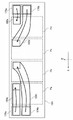
그러나, 도 1 및 도 9에 나타낸 바와 같이, 대전 장치(2a~2d)는 현상 장치(1a~1d)보다 상방에 배치되어 있다는 점에서, 내부 커버 유닛(125)에 있어서의 플렉서블 튜브(183a~183d)의 배치가 다르다. 도 10은, 대전 장치(2a~2d)로의 흡기를 위한 내부 커버 유닛(125)의 내면측을 나타내는 개략도이다.However, as shown in FIGS. 1 and 9 , since the
도 10에 나타낸 바와 같이, 대전 장치(2a~2d)로 송풍하는 외기를 통과시키는 중계 덕트로서, 플렉서블 튜브(183a~183d)가, 내부 커버 유닛(125)의 내면측에 배치되어 있다. 플렉서블 튜브(183a~183d)는, 예를 들면 와이어 새들을 사용하여 내부 커버 유닛(125)의 내면에 장착된다. 여기서 나타내는 플렉서블 튜브(183a~183d)의 배치는 일 예이며, 이에 한정되지 않는다.As shown in FIG. 10 ,
대전 장치(2a~2d)로 송풍하는 외기를 통과시키는 플렉서블 튜브(183a~183d)는, 예를 들면 단면적이 "25mm×20mm"이고, 최대 길이가 "500mm"인 사각 형상으로 형성된다. 그리고, 대전용 흡기 팬(180a~180d)의 송풍량이 "1.0m3/min"일 경우, 플렉서블 튜브(183a~183d)의 압력 손실은 "약 309Pa"이다. 가령, 좌측 흡기 유닛(124)에 대전용 흡기 팬(180d)를 설치하고 대전 장치(2d)로 플렉서블 튜브를 사용하여 외기를 보내도록 하면, 플렉서블 튜브의 길이는 "1000mm"이 되고, 플렉서블 튜브의 압력 손실은 "약 618Pa"이다. 즉, 좌측 흡기 유닛(124)에 대전용 흡기 팬(180d)을 설치하여 대전 장치(2d)로 외기를 보내도록 하면, 본 실시형태에 비교하여, 압력 손실이 2배가 되고, 대전용 흡기 팬(180d)은 보다 출력이 큰 팬이 필요하게 된다. 그러나, 그러한 팬은 대형이고 비용이 높아지므로 채용하기 어렵다.The
이와 같이, 대전 장치(2a~2d)로 흡기 팬에 의해 흡기되는 외기를 보내는 에어플로우 구성에도, 상술한 제1 실시형태의 에어플로우 구성을 채용할 수 있다. 따라서, 케이스에 병렬로 탑재되는 복수의 유닛이 대형이고, 인쇄 속도가 빨라 복수의 유닛으로의 송풍량이 많이 필요한 화상 형성 장치에 관하여, 흡기 팬에 의해 흡기되는 외기를 덕트를 거쳐 복수의 유닛을 향해 충분한 송풍량을 확보하여 안내하는 것이 간이한 구성으로 실현될 수 있다고 하는 제1 실시형태와 마찬가지의 효과가 얻어진다.In this way, the air flow configuration of the first embodiment described above can also be employed for the air flow configuration for sending outside air taken in by the intake fan to the
한편, 제1 실시형태에서는 현상 장치(1a~1d)로 흡기하는 에어플로우 구성을 나타내고, 제2 실시 형태에서는 대전 장치(2a~2d)로 흡기하는 에어플로우 구성을 나타냈지만, 이들 양쪽 모두를 구비하는 것이여도 좋다. 또한, 각 장치로의 에어플로우를 형성하는 구성은, 플렉서블 튜브 대신에 모두 덕트에 의해 형성되는 것이여도 된다.On the other hand, although the first embodiment shows an air flow configuration for intake of air to the developing
[다른 실시 형태] [Other embodiments]
한편, 상술한 실시 형태에서는, 기록재(S)의 반송 방향의 하류측인 제1 케이스(101a)의 좌측면 측에 다른 케이스인 제2 케이스(10lb)가 접속되는 예를 제시했지만(도 1 참조), 이에 한정되지 않는다. 예를 들면, 기록재(S)의 반송 방향의 상류측인 제1 케이스(101a)의 우측면 측에 다른 케이스인 제2 케이스(10lb)가 접속되는 경우도 있다. 그러한 경우의 흡기구(107a)와 흡기구(17lb)는, 도 11에 도시한 위치에 형성된다. 즉, 도 11에 나타낸 바와 같이, 흡기구(171a)는 화상 형성 장치(100)의 좌측면에 형성된다. 한편, 흡기구(172a)는 화상 형성 장치(100)의 중앙보다 우측에 있어서 화상 형성 장치(100)의 정면에 형성된다. On the other hand, in the above-described embodiment, an example is presented in which a second case 10lb, which is another case, is connected to the left side of the
도 12에, 상술한 도 11에 도시한 위치에 흡기구(171a)와 흡기구(172a)가 형성된 경우의 흡기 유닛을 나타낸다. 도 12에 나타낸 바와 같이, 이 경우의 흡기 유닛은, 상술한 흡기구(171a)가 화상 형성 장치(100)의 정면에 형성되고 흡기구(172a)가 화상 형성 장치(100)의 우측면에 형성된 경우(도 4 참조)와 비교하여, 좌측 흡기 유닛(124)과 우측 흡기 유닛(126)이 좌우로 뒤바뀌는 형태로 되어 있다. 단, 도 12에 나타낸 바와 같이, 화상 형성 장치(100)의 중앙보다 좌측에 배치된 흡기 유닛(212)에서는, 현상용 흡기 팬(212a, 212b), 통과 덕트(213)가 본체 덕트(210)의 좌측면에 설치된다. 한편, 화상 형성 장치(100)의 중앙보다 우측에 배치된 흡기 유닛(211)에서는, 현상용 흡기 팬(215a, 215b), 통과 덕트(215)가 본체 덕트(214)의 우측면에 설치된다.12 shows an intake unit in the case where the
흡기 유닛(212)의 에어플로우는 상술한 우측 흡기 유닛(126)과 마찬가지이고, 흡기 유닛(211)의 에어플로우는 상술한 좌측 흡기 유닛(124)과 마찬가지이므로, 여기에서는 설명을 생략한다. 또한, 이들 흡기 유닛(211, 212)으로부터 현상 장치(1a~1d)에 이르는 에어플로우도, 상술한 좌측 흡기 유닛(124)과 우측 흡기 유닛(126)과 마찬가지이므로, 설명을 생략한다.Since the air flow of the
상술한 실시 형태에서는, 2개의 흡기구가, 화상 형성 장치(100)의 정면과 우측면에 형성되는 경우(도 3(a), 도 3(b) 참조)와, 화상 형성 장치(100)의 정면과 좌측면에 형성되는 경우(도 11 참조)를 나타냈지만, 이에 한정되지 않는다. 예를 들면, 2개의 흡기구가 모두 화상 형성 장치(100)의 정면에 형성되어도 된다. 단, 이 경우에는, 일방의 흡기구가 화상 형성 장치(100)의 정면에 있어서 중앙보다 좌측에 형성되고, 타방의 흡기구가 화상 형성 장치(100)의 정면에 있어서 중앙보다 우측에 형성된다. 또는, 2개의 흡기구가 모두 화상 형성 장치(100)의 좌측면과 우측면에 형성되어도 된다.In the above-described embodiment, the case where the two intake ports are formed on the front and right side of the image forming apparatus 100 (see Figs. 3(a) and 3(b)) and the front and Although the case of being formed on the left side (see FIG. 11) has been shown, it is not limited thereto. For example, both intake ports may be formed on the front side of the
한편, 상술한 실시 형태에서는, 4대의 화상 형성부(Pa, Pb, Pc, Pd)가 중간 전사 벨트(130)의 이동 방향을 따라 나란히 배치된 예를 제시했지만, 화상 형성부의 수는 이에 한하지 않고, 예를 들면 5대 이상이어도 된다. 그 경우, 이들 화상 형성부는, 상술한 바와 같이 화상 형성 장치(100)의 중앙을 기준으로 해서, 좌측 흡기 유닛(124)(흡기 유닛(211))에 의해 흡기된 외기를 송풍하는 장치와, 우측 흡기 유닛(126)(흡기 유닛(212))에 의해 흡기된 외기를 송부하는 장치로 나눌 수 있다. 그리고, 2개의 흡기구가 상기 설명한 위치에 각각 형성된다.Meanwhile, in the above-described embodiment, an example in which four image forming units Pa, Pb, Pc, and Pd are arranged side by side along the moving direction of the
한편, 상술한 실시 형태에서는, 흡기 팬으로서 시로코팬을 사용한 경우를 예로 설명했지만, 이에 한정되지 않는다. 흡기 팬으로서 축류팬을 사용해도 된다.On the other hand, in the above-described embodiment, the case where a sirocco fan is used as an intake fan has been described as an example, but it is not limited to this. An axial flow fan may be used as the intake fan.
본 발명에 의하면, 각 화상 형성부로의 불충분한 에어플로우를 억제하는 것을 간이한 구성으로 실현될 수 있다.According to the present invention, suppression of insufficient air flow to each image forming section can be realized with a simple configuration.
이상 본 발명을 실시형태를 참조하여 설명하였으나, 본 발명이 이들 개시된 실시형태로 제한되는 것은 아니다. 첨부된 특허청구범위의 범위는, 그러한 모든 변형, 균등한 구조 및 기능을 포괄하는 최광의로 해석되어야 한다.Although the present invention has been described above with reference to embodiments, the present invention is not limited to these disclosed embodiments. The scope of the appended claims is to be interpreted broadly, encompassing all such modifications and equivalent structures and functions.
Claims (15)
복수의 화상 형성 유닛 중 하나로서, 상기 복수의 화상 형성 유닛의 배열 방향에 있어서 가장 일단측에 위치하는 제1 화상 형성 유닛 - 상기 제1 화상 형성 유닛은, 제1 감광체와, 상기 제1 감광체를 코로나 방전에 의해 대전시키도록 구성된 제1 대전 유닛과, 상기 제1 감광체에 형성되는 정전 잠상을 토너를 사용하여 현상하도록 구성된 제1 현상 유닛을 가짐 -;
상기 복수의 화상 형성 유닛 중 하나로서, 상기 배열 방향에 있어서 상기 일단측과 반대측인 가장 타단측에 위치하는 제2 화상 형성 유닛 - 상기 제2 화상 형성 유닛은, 제2 감광체와, 상기 제2 감광체를 코로나 방전에 의해 대전시키도록 구성된 제2 대전 유닛과, 상기 제2 감광체에 형성되는 정전 잠상을 토너를 사용하여 현상하도록 구성된 제2 현상 유닛을 가짐 -;
상기 배열 방향에 있어서 상기 제1 화상 형성 유닛보다 상기 일단측에 더 가까이 설치된 제1 팬으로서, 상기 배열 방향에 있어서 상기 제2 화상 형성 유닛보다 상기 제1 화상 형성 유닛에 가까운 위치에 설치된 제1 흡기구로부터 상기 제1 화상 형성 유닛에 공급하기 위한 외기를 흡기하는 제1 팬; 및,
상기 배열 방향에 있어서 상기 제2 화상 형성 유닛보다 상기 타단측에 더 가까이 설치된 제2 팬으로서, 상기 배열 방향에 있어서 상기 제1 화상 형성 유닛보다 상기 제2 화상 형성 유닛에 가까운 위치에 설치된 제2 흡기구로부터 상기 제2 화상 형성 유닛에 공급하기 위한 외기를 흡기하는 제2 팬을 포함하고,
상기 제1 팬은, 상기 배열 방향에 있어서 상기 제2 화상 형성 유닛보다 상기 제1 화상 형성 유닛에 가까운 위치에 설치되고,
상기 제2 팬은, 상기 배열 방향에 있어서 상기 제1 화상 형성 유닛보다 상기 제2 화상 형성 유닛에 가까운 위치에 설치되는, 화상 형성 장치.An image forming apparatus for forming an image on a recording material, comprising:
A first image forming unit, one of a plurality of image forming units, located at the far end side in the arrangement direction of the plurality of image forming units, wherein the first image forming unit includes a first photosensitive member and the first photosensitive member. having a first charging unit configured to charge by corona discharge, and a first developing unit configured to develop an electrostatic latent image formed on the first photoreceptor using a toner;
A second image forming unit, as one of the plurality of image forming units, positioned at the most other end side opposite to the one end side in the arrangement direction, the second image forming unit comprising: a second photosensitive member; has a second charging unit configured to charge a by corona discharge, and a second developing unit configured to develop an electrostatic latent image formed on the second photoreceptor using a toner;
A first fan installed closer to the one end than the first image forming unit in the arrangement direction, and installed closer to the first image forming unit than the second image forming unit in the arrangement direction. a first fan that draws in outside air to supply the first image forming unit from the first fan; and,
A second fan installed closer to the other end than the second image forming unit in the arrangement direction, and a second intake vent installed closer to the second image forming unit than to the first image forming unit in the arrangement direction. a second fan that draws in outside air to supply the second image forming unit from
the first fan is installed closer to the first image forming unit than to the second image forming unit in the arrangement direction;
wherein the second fan is installed at a position closer to the second image forming unit than to the first image forming unit in the arrangement direction.
상기 제1 팬에 의해 흡기된 공기를 상기 제1 화상 형성 유닛으로 안내하도록 구성된 제1 덕트; 및,
상기 제2 팬에 의해 흡기된 공기를 상기 제2 화상 형성 유닛으로 안내하도록 구성된 제2 덕트를 더 포함하는 화상 형성 장치.According to claim 1,
a first duct configured to guide air taken in by the first fan to the first image forming unit; and,
and a second duct configured to guide air taken in by the second fan to the second image forming unit.
상기 제1 덕트는, 상기 제1 팬에 의해 흡기된 공기를 상기 제1 대전 유닛으로 안내하고,
상기 제2 덕트는, 상기 제2 팬에 의해 흡기된 공기를 상기 제2 대전 유닛으로 안내하는 화상 형성 장치.According to claim 2,
The first duct guides the air taken in by the first fan to the first charging unit;
The second duct guides the air taken in by the second fan to the second charging unit.
상기 제1 덕트는, 상기 제1 팬에 의해 흡기된 공기를 상기 제1 현상 유닛으로 안내하고,
상기 제2 덕트는, 상기 제2 팬에 의해 흡기된 공기를 상기 제2 현상 유닛으로 안내하는 화상 형성 장치.According to claim 2,
The first duct guides the air taken in by the first fan to the first developing unit;
The second duct guides the air taken in by the second fan to the second developing unit.
상기 복수의 화상 형성 유닛과, 상기 제1 팬과, 상기 제2 팬과, 상기 제1 덕트와, 상기 제2 덕트를 가지는 제1 케이스; 및,
기록재의 반송 방향에서 상기 제1 케이스의 하류측에 인접하는 제2 케이스를 더 포함하고,
상기 제1 케이스의 제1 측면이 상기 제2 케이스와 대향하고,
상기 제1 흡기구는, 상기 제1 측면에 교차하는 제2 측면에 형성되고,
상기 제2 흡기구는, 상기 배열 방향에 있어서 상기 제1 측면과 반대측인 제3 측면에 형성되어 있는 화상 형성 장치.According to claim 2,
a first case having the plurality of image forming units, the first fan, the second fan, the first duct, and the second duct; and,
a second case adjacent to the downstream side of the first case in the conveying direction of the recording material;
A first side surface of the first case faces the second case,
The first intake port is formed on a second side surface intersecting the first side surface,
The second intake port is formed on a third side surface opposite to the first side surface in the arrangement direction.
상기 복수의 화상 형성 유닛과, 상기 제1 팬과, 상기 제2 팬과, 상기 제1 덕트와, 상기 제2 덕트를 가지는 제1 케이스; 및,
기록재의 반송 방향에서 상기 제1 케이스의 하류측에 인접하는 제2 케이스를 더 포함하고,
상기 제1 케이스의 제1 측면이 상기 제2 케이스와 대향하고,
상기 제2 흡기구는, 상기 제1 측면에 교차하는 제2 측면에 형성되고,
상기 제1 흡기구는, 상기 배열 방향에 있어서 상기 제1 측면과 반대측인 제3 측면에 형성되어 있는 화상 형성 장치.According to claim 2,
a first case having the plurality of image forming units, the first fan, the second fan, the first duct, and the second duct; and,
a second case adjacent to the downstream side of the first case in the conveying direction of the recording material;
A first side surface of the first case faces the second case,
The second intake port is formed on a second side surface crossing the first side surface,
wherein the first intake port is formed on a third side surface opposite to the first side surface in the arrangement direction.
상기 제2 측면은, 상기 화상 형성 장치의 정면측의 측면인 화상 형성 장치.According to claim 5,
The second side surface is a side surface on the front side of the image forming apparatus.
상기 제1 케이스는, 상기 제1 감광체 및 상기 제2 감광체에 형성된 토너상을 기록재에 전사하도록 구성된 전사 유닛을 더 구비하고,
상기 제2 케이스는, 상기 토너상이 전사된 기록재를 가열하여, 상기 토너상을 정착시키도록 구성된 정착 유닛을 가지는 화상 형성 장치.According to claim 5,
the first case further includes a transfer unit configured to transfer toner images formed on the first photoreceptor and the second photoreceptor to a recording material;
wherein the second case has a fixing unit configured to fix the toner image by heating the recording medium onto which the toner image is transferred.
상기 제1 케이스는, 상기 제1 감광체 및 상기 제2 감광체에 형성된 토너상을 기록재에 전사하는 전사 유닛을 더 구비하고,
상기 제2 케이스는, 상기 토너상이 전사된 기록재를 가열하여, 상기 토너상을 정착시키도록 구성된 정착 유닛을 가지는 화상 형성 장치.According to claim 6,
the first case further includes a transfer unit for transferring toner images formed on the first photoreceptor and the second photoreceptor to a recording material;
wherein the second case has a fixing unit configured to fix the toner image by heating the recording medium onto which the toner image is transferred.
저판과, 상기 저판 상에 세워 설치된 복수의 지주를 가지는 지지 프레임;
상기 제1 팬이 고정되고, 상기 제1 흡기구로부터 흡기한 공기를 상기 제1 팬으로 안내하도록 구성된 제1 본체 덕트 유닛; 및,
상기 제2 팬이 고정되고, 상기 제2 흡기구로부터 흡기한 공기를 상기 제2 팬으로 안내하도록 구성된 제2 본체 덕트 유닛을 더 포함하고,
상기 복수의 지주는, 상기 화상 형성 장치의 정면측에 설치되는 제1 지주와, 상기 화상 형성 장치의 배면측에 설치되어 상기 제1 지주와 함께 상기 제1 본체 덕트 유닛을 지지하도록 구성되는 제2 지주와, 상기 정면측에 설치되고 상기 제1 지주와 다른 제3 지주와, 상기 배면측에 설치되고 상기 제3 지주와 함께 상기 제2 본체 덕트 유닛을 지지하도록 구성되는 제4 지주를 갖고,
상기 제1 팬은, 상기 제1 지주보다 상기 배면측에 더 가까이 위치하고,
상기 제2 팬은, 상기 제3 지주보다 상기 배면측에 더 가까이 위치하는 화상 형성 장치.According to claim 1,
a support frame having a bottom plate and a plurality of posts erected on the bottom plate;
a first main body duct unit to which the first fan is fixed and configured to guide the air taken in from the first intake port to the first fan; and,
The second fan is fixed and further includes a second body duct unit configured to guide the air intake from the second intake port to the second fan,
The plurality of supports include a first support installed on a front side of the image forming apparatus, and a second support installed on a rear side of the image forming apparatus and configured to support the first body duct unit together with the first support. A post, a third post provided on the front side and different from the first post, and a fourth post provided on the rear side and configured to support the second body duct unit together with the third post,
The first fan is located closer to the rear side than the first support,
The second fan is positioned closer to the rear side than the third support.
상기 화상 형성 장치의 정면측에 개폐 가능하게 설치된 개폐 커버; 및,
상기 개폐 커버가 닫힌 상태에서 상기 개폐 커버의 내면에 대향하여 배치된 내부 커버 유닛을 더 포함하고,
상기 내부 커버 유닛은, 상기 제1 덕트와 상기 제2 덕트를 가지는 화상 형성 장치.According to claim 1,
an opening/closing cover installed to be able to open/close on the front side of the image forming apparatus; and,
Further comprising an inner cover unit disposed to face the inner surface of the opening and closing cover in a closed state,
wherein the inner cover unit has the first duct and the second duct.
상기 제1 화상 형성 유닛과 상기 제2 화상 형성 유닛의 사이에 위치하는 제3 화상 형성 유닛 - 상기 제3 화상 형성 유닛은, 제3 감광체와, 상기 제3 감광체를 코로나 방전에 의해 대전시키도록 구성된 제3 대전 유닛과, 상기 제3 감광체에 형성되는 정전 잠상을 토너를 사용하여 현상하도록 구성된 제3 현상 유닛을 가짐 -;
상기 제2 화상 형성 유닛과 상기 제3 화상 형성 유닛의 사이에 위치하는 제4 화상 형성 유닛 - 상기 제4 화상 형성 유닛은, 제4 감광체와, 상기 제4 감광체를 코로나 방전에 의해 대전시키도록 구성된 제4 대전 유닛과, 상기 제4 감광체에 형성되는 정전 잠상을 토너를 사용하여 현상하도록 구성된 제4 현상 유닛을 가짐 -;
상기 배열 방향에 있어서 상기 제1 화상 형성 유닛보다 상기 일단측에 더 가까이 설치된 제3 팬으로서, 상기 제1 흡기구로부터 외기를 흡기하는 제3 팬; 및,
상기 배열 방향에 있어서 상기 제2 화상 형성 유닛보다 상기 타단측에 더 가까이 설치된 제4 팬으로서, 상기 제2 흡기구로부터 외기를 흡기하는 제4 팬을 더 포함하고,
상기 제3 팬은, 상기 제2 화상 형성 유닛보다 상기 제1 화상 형성 유닛에 가까운 위치에 설치되고,
상기 제4 팬은, 상기 제1 화상 형성 유닛보다 상기 제2 화상 형성 유닛에 가까운 위치에 설치되는 화상 형성 장치.According to claim 1,
a third image forming unit positioned between the first image forming unit and the second image forming unit, the third image forming unit configured to charge a third photoreceptor and the third photoreceptor by corona discharge; having a third charging unit and a third developing unit configured to develop an electrostatic latent image formed on the third photoreceptor by using a toner;
a fourth image forming unit positioned between the second image forming unit and the third image forming unit, the fourth image forming unit configured to charge a fourth photoreceptor and the fourth photoreceptor by corona discharge; having a fourth charging unit and a fourth developing unit configured to develop an electrostatic latent image formed on the fourth photoreceptor by using a toner;
a third fan installed closer to the one end than the first image forming unit in the arrangement direction, and intakes outside air from the first intake port; and,
a fourth fan installed closer to the other end than the second image forming unit in the arrangement direction, and sucking in outside air from the second intake port;
the third fan is installed closer to the first image forming unit than to the second image forming unit;
The fourth fan is installed closer to the second image forming unit than to the first image forming unit.
상기 제3 팬에 의해 흡기된 공기를 상기 제3 화상 형성 유닛으로 안내하도록 구성된 제3 덕트; 및,
상기 제4 팬에 의해 흡기된 공기를 상기 제4 화상 형성 유닛으로 안내하도록 구성된 제4 덕트를 더 포함하는 화상 형성 장치.According to claim 12,
a third duct configured to guide air taken in by the third fan to the third image forming unit; and,
and a fourth duct configured to guide air taken in by the fourth fan to the fourth image forming unit.
저판과, 상기 저판 상에 세워 설치된 복수의 지주를 가지는 지지 프레임;
상기 제1 팬 및 상기 제3 팬이 고정되고, 상기 제1 흡기구로부터 흡기한 공기를 상기 제1 팬 및 상기 제3 팬으로 안내하도록 구성된 제1 본체 덕트 유닛; 및,
상기 제2 팬 및 상기 제4 팬이 고정되고, 상기 제2 흡기구로부터 흡기한 공기를 상기 제2 팬 및 상기 제4 팬으로 안내하도록 구성된 제2 본체 덕트 유닛을 더 포함하고,
상기 복수의 지주는, 상기 화상 형성 장치의 정면측에 설치되는 제1 지주와, 상기 화상 형성 장치의 배면측에 설치되어 상기 제1 지주와 함께 상기 제1 본체 덕트 유닛을 지지하도록 구성되는 제2 지주와, 상기 정면측에 설치되고 상기 제1 지주와 다른 제3 지주와, 상기 배면측에 설치되고 상기 제3 지주와 함께 상기 제2 본체 덕트 유닛을 지지하도록 구성되는 제4 지주를 가지고,
상기 제1 팬 및 상기 제3 팬은, 상기 제1 지주보다 상기 배면측에 더 가까이 위치하고,
상기 제2 팬 및 상기 제4 팬은, 상기 제3 지주보다 상기 배면측에 더 가까이 위치하는 화상 형성 장치.According to claim 12,
a support frame having a bottom plate and a plurality of posts erected on the bottom plate;
a first main body duct unit to which the first fan and the third fan are fixed and configured to guide the air taken in from the first intake port to the first fan and the third fan; and,
The second fan and the fourth fan are fixed, and a second body duct unit configured to guide the air intake from the second intake port to the second fan and the fourth fan,
The plurality of supports include a first support installed on a front side of the image forming apparatus, and a second support installed on a rear side of the image forming apparatus and configured to support the first body duct unit together with the first support. A post, a third post installed on the front side and different from the first post, and a fourth post installed on the rear side and configured to support the second body duct unit together with the third post,
The first fan and the third fan are located closer to the rear side than the first support,
The second fan and the fourth fan are positioned closer to the rear side than the third support.
상기 제1 현상 유닛, 상기 제2 현상 유닛, 상기 제3 현상 유닛 및 상기 제4 현상 유닛은, 각각 다른 색의 토너를 사용하여, 상기 제1 감광체, 상기 제2 감광체, 상기 제3 감광체 및 상기 제4 감광체에 형성되는 정전 잠상을 현상하는 화상 형성 장치.According to claim 12,
The first developing unit, the second developing unit, the third developing unit, and the fourth developing unit use toners of different colors, and the first photoreceptor, the second photoreceptor, the third photoreceptor and the An image forming apparatus that develops an electrostatic latent image formed on a fourth photoreceptor.
Applications Claiming Priority (2)
| Application Number | Priority Date | Filing Date | Title |
|---|---|---|---|
| JPJP-P-2021-100082 | 2021-06-16 | ||
| JP2021100082A JP2022191699A (en) | 2021-06-16 | 2021-06-16 | Image forming apparatus |
Publications (1)
| Publication Number | Publication Date |
|---|---|
| KR20220168562A true KR20220168562A (en) | 2022-12-23 |
Family
ID=81653602
Family Applications (1)
| Application Number | Title | Priority Date | Filing Date |
|---|---|---|---|
| KR1020220070717A KR20220168562A (en) | 2021-06-16 | 2022-06-10 | Image forming apparatus |
Country Status (5)
| Country | Link |
|---|---|
| US (1) | US11822285B2 (en) |
| EP (1) | EP4105729A1 (en) |
| JP (1) | JP2022191699A (en) |
| KR (1) | KR20220168562A (en) |
| CN (1) | CN115480464A (en) |
Families Citing this family (1)
| Publication number | Priority date | Publication date | Assignee | Title |
|---|---|---|---|---|
| CN116493287B (en) * | 2023-06-21 | 2023-08-18 | 南方医科大学南方医院 | Automatic medical record arrangement filing equipment |
Family Cites Families (18)
| Publication number | Priority date | Publication date | Assignee | Title |
|---|---|---|---|---|
| JP4647323B2 (en) * | 2005-01-31 | 2011-03-09 | 京セラミタ株式会社 | Cooling structure and image forming apparatus having the cooling structure |
| US7734222B2 (en) | 2005-06-30 | 2010-06-08 | Kyocera Mita Corporation | Image forming apparatus with flexible tube for cooling air and guide channel for flexible tube |
| JP2007041562A (en) | 2005-06-30 | 2007-02-15 | Kyocera Mita Corp | Image forming apparatus |
| JP2008033052A (en) * | 2006-07-28 | 2008-02-14 | Fuji Xerox Co Ltd | Image forming apparatus |
| JP2009025759A (en) * | 2007-07-24 | 2009-02-05 | Kyocera Mita Corp | Image forming apparatus |
| JP5170652B2 (en) * | 2008-03-13 | 2013-03-27 | 富士ゼロックス株式会社 | Image forming apparatus |
| JP5001891B2 (en) * | 2008-03-27 | 2012-08-15 | 京セラドキュメントソリューションズ株式会社 | Image forming apparatus |
| JP5182622B2 (en) * | 2008-05-19 | 2013-04-17 | 株式会社リコー | Image forming apparatus and image forming apparatus control method |
| JP5141836B2 (en) | 2012-01-10 | 2013-02-13 | 富士ゼロックス株式会社 | Image forming apparatus |
| US9170561B2 (en) * | 2013-01-25 | 2015-10-27 | Ricoh Company, Ltd. | Cooling device and image forming apparatus incorporating same |
| JP6331703B2 (en) * | 2014-05-29 | 2018-05-30 | 株式会社リコー | Image forming apparatus and image forming method |
| JP2016218420A (en) | 2015-05-19 | 2016-12-22 | 株式会社リコー | Image forming apparatus |
| US9791828B2 (en) | 2015-05-19 | 2017-10-17 | Ricoh Company, Ltd. | Image forming apparatus including a blower to perform an operation based on a detection result of the a detector |
| JP6702705B2 (en) * | 2015-12-08 | 2020-06-03 | キヤノン株式会社 | Image forming device |
| JP6794183B2 (en) | 2016-08-30 | 2020-12-02 | キヤノン株式会社 | Photo interrupter unit, sheet transfer device and image forming device |
| JP7225724B2 (en) * | 2018-11-16 | 2023-02-21 | 京セラドキュメントソリューションズ株式会社 | Developing device and image forming apparatus provided with the developing device |
| JP2020173316A (en) * | 2019-04-09 | 2020-10-22 | 京セラドキュメントソリューションズ株式会社 | Toner dust collector and image forming apparatus |
| CN112299067A (en) * | 2019-07-26 | 2021-02-02 | 柯尼卡美能达办公系统研发(无锡)有限公司 | Paper feeding mechanism and image forming apparatus |
-
2021
- 2021-06-16 JP JP2021100082A patent/JP2022191699A/en active Pending
-
2022
- 2022-05-13 EP EP22173181.3A patent/EP4105729A1/en active Pending
- 2022-06-10 KR KR1020220070717A patent/KR20220168562A/en active Search and Examination
- 2022-06-10 US US17/837,714 patent/US11822285B2/en active Active
- 2022-06-14 CN CN202210668303.5A patent/CN115480464A/en active Pending
Also Published As
| Publication number | Publication date |
|---|---|
| CN115480464A (en) | 2022-12-16 |
| US20220404764A1 (en) | 2022-12-22 |
| JP2022191699A (en) | 2022-12-28 |
| EP4105729A1 (en) | 2022-12-21 |
| US11822285B2 (en) | 2023-11-21 |
Similar Documents
| Publication | Publication Date | Title |
|---|---|---|
| US7630663B2 (en) | Structure for cooling the interior of an image-forming apparatus | |
| JP5472810B2 (en) | Image forming apparatus | |
| JP5768418B2 (en) | Image forming apparatus | |
| KR101360156B1 (en) | Image forming apparatus | |
| JP6237613B2 (en) | Image forming apparatus | |
| JP2018005198A (en) | Image forming apparatus, image forming system, and housing structure | |
| KR20220168562A (en) | Image forming apparatus | |
| US20080240769A1 (en) | Image forming apparatus | |
| JP2015028563A (en) | Image forming apparatus | |
| JP5857631B2 (en) | Image forming apparatus | |
| JP5674177B2 (en) | Fixing device | |
| JP5877414B2 (en) | Exhaust system and image forming apparatus | |
| JP6319650B2 (en) | Exhaust flow path unit and image forming apparatus | |
| JP6693143B2 (en) | Image forming device | |
| US11822284B2 (en) | Image forming apparatus with branched ducts for cooling of image forming units | |
| JP2017161622A (en) | Cooling device and image forming apparatus | |
| JP2016080785A (en) | Cooling device and image forming apparatus | |
| JP2022191698A (en) | image forming device | |
| US20230305484A1 (en) | Image forming apparatus | |
| JP2023144983A (en) | Image forming apparatus | |
| JP2019078898A (en) | Image forming device | |
| JP7417189B2 (en) | Equipment and image forming device | |
| US7539436B2 (en) | Image forming apparatus provided with a cooling mechanism for cooling portions | |
| JP2023144984A (en) | Image forming apparatus | |
| JP2022180109A (en) | Image forming apparatus |
Legal Events
| Date | Code | Title | Description |
|---|---|---|---|
| A201 | Request for examination |