KR20220161780A - Heater assembly for aerosol generating device and aerosol generating device including the same - Google Patents
Heater assembly for aerosol generating device and aerosol generating device including the same Download PDFInfo
- Publication number
- KR20220161780A KR20220161780A KR1020210069941A KR20210069941A KR20220161780A KR 20220161780 A KR20220161780 A KR 20220161780A KR 1020210069941 A KR1020210069941 A KR 1020210069941A KR 20210069941 A KR20210069941 A KR 20210069941A KR 20220161780 A KR20220161780 A KR 20220161780A
- Authority
- KR
- South Korea
- Prior art keywords
- aerosol generating
- cover
- heater
- generating device
- heater assembly
- Prior art date
Links
- 239000000443 aerosol Substances 0.000 title claims abstract description 217
- 238000007789 sealing Methods 0.000 claims description 72
- 238000003780 insertion Methods 0.000 claims description 38
- 230000037431 insertion Effects 0.000 claims description 38
- 238000009413 insulation Methods 0.000 claims description 35
- 239000000463 material Substances 0.000 claims description 30
- 230000004308 accommodation Effects 0.000 claims description 14
- 230000008878 coupling Effects 0.000 claims description 13
- 238000010168 coupling process Methods 0.000 claims description 13
- 238000005859 coupling reaction Methods 0.000 claims description 13
- 238000001514 detection method Methods 0.000 claims description 7
- 238000010438 heat treatment Methods 0.000 abstract description 33
- 241000208125 Nicotiana Species 0.000 description 28
- 235000002637 Nicotiana tabacum Nutrition 0.000 description 28
- 239000007788 liquid Substances 0.000 description 27
- 239000006200 vaporizer Substances 0.000 description 17
- 238000005452 bending Methods 0.000 description 16
- 230000006870 function Effects 0.000 description 16
- 238000000034 method Methods 0.000 description 15
- 239000000203 mixture Substances 0.000 description 12
- 230000000052 comparative effect Effects 0.000 description 10
- 239000002775 capsule Substances 0.000 description 9
- 239000000796 flavoring agent Substances 0.000 description 9
- 230000008569 process Effects 0.000 description 9
- 235000019634 flavors Nutrition 0.000 description 7
- 239000007769 metal material Substances 0.000 description 7
- 239000004696 Poly ether ether ketone Substances 0.000 description 6
- 229920000491 Polyphenylsulfone Polymers 0.000 description 6
- DNIAPMSPPWPWGF-UHFFFAOYSA-N Propylene glycol Chemical compound CC(O)CO DNIAPMSPPWPWGF-UHFFFAOYSA-N 0.000 description 6
- 238000001816 cooling Methods 0.000 description 6
- 229920002530 polyetherether ketone Polymers 0.000 description 6
- 230000004888 barrier function Effects 0.000 description 5
- 230000006698 induction Effects 0.000 description 5
- PEDCQBHIVMGVHV-UHFFFAOYSA-N Glycerine Chemical compound OCC(O)CO PEDCQBHIVMGVHV-UHFFFAOYSA-N 0.000 description 4
- 229910052782 aluminium Inorganic materials 0.000 description 4
- XAGFODPZIPBFFR-UHFFFAOYSA-N aluminium Chemical compound [Al] XAGFODPZIPBFFR-UHFFFAOYSA-N 0.000 description 4
- 239000003205 fragrance Substances 0.000 description 4
- 239000002861 polymer material Substances 0.000 description 4
- LYCAIKOWRPUZTN-UHFFFAOYSA-N Ethylene glycol Chemical compound OCCO LYCAIKOWRPUZTN-UHFFFAOYSA-N 0.000 description 3
- 238000000429 assembly Methods 0.000 description 3
- 230000000712 assembly Effects 0.000 description 3
- 239000000919 ceramic Substances 0.000 description 3
- 239000004020 conductor Substances 0.000 description 3
- MTHSVFCYNBDYFN-UHFFFAOYSA-N diethylene glycol Chemical compound OCCOCCO MTHSVFCYNBDYFN-UHFFFAOYSA-N 0.000 description 3
- 230000000694 effects Effects 0.000 description 3
- 229910052751 metal Inorganic materials 0.000 description 3
- 239000002184 metal Substances 0.000 description 3
- 239000004417 polycarbonate Substances 0.000 description 3
- 229920000515 polycarbonate Polymers 0.000 description 3
- NOOLISFMXDJSKH-UTLUCORTSA-N (+)-Neomenthol Chemical compound CC(C)[C@@H]1CC[C@@H](C)C[C@@H]1O NOOLISFMXDJSKH-UTLUCORTSA-N 0.000 description 2
- GVJHHUAWPYXKBD-UHFFFAOYSA-N (±)-α-Tocopherol Chemical compound OC1=C(C)C(C)=C2OC(CCCC(C)CCCC(C)CCCC(C)C)(C)CCC2=C1C GVJHHUAWPYXKBD-UHFFFAOYSA-N 0.000 description 2
- CIWBSHSKHKDKBQ-JLAZNSOCSA-N Ascorbic acid Chemical compound OC[C@H](O)[C@H]1OC(=O)C(O)=C1O CIWBSHSKHKDKBQ-JLAZNSOCSA-N 0.000 description 2
- NOOLISFMXDJSKH-UHFFFAOYSA-N DL-menthol Natural products CC(C)C1CCC(C)CC1O NOOLISFMXDJSKH-UHFFFAOYSA-N 0.000 description 2
- LFQSCWFLJHTTHZ-UHFFFAOYSA-N Ethanol Chemical compound CCO LFQSCWFLJHTTHZ-UHFFFAOYSA-N 0.000 description 2
- BQCADISMDOOEFD-UHFFFAOYSA-N Silver Chemical compound [Ag] BQCADISMDOOEFD-UHFFFAOYSA-N 0.000 description 2
- 229910000831 Steel Inorganic materials 0.000 description 2
- FFBHFFJDDLITSX-UHFFFAOYSA-N benzyl N-[2-hydroxy-4-(3-oxomorpholin-4-yl)phenyl]carbamate Chemical compound OC1=C(NC(=O)OCC2=CC=CC=C2)C=CC(=C1)N1CCOCC1=O FFBHFFJDDLITSX-UHFFFAOYSA-N 0.000 description 2
- 229920002301 cellulose acetate Polymers 0.000 description 2
- 235000019504 cigarettes Nutrition 0.000 description 2
- 238000004891 communication Methods 0.000 description 2
- 238000005516 engineering process Methods 0.000 description 2
- 238000002474 experimental method Methods 0.000 description 2
- 239000000835 fiber Substances 0.000 description 2
- 239000011888 foil Substances 0.000 description 2
- 235000013355 food flavoring agent Nutrition 0.000 description 2
- 235000011187 glycerol Nutrition 0.000 description 2
- 229940041616 menthol Drugs 0.000 description 2
- 238000012545 processing Methods 0.000 description 2
- 229910052709 silver Inorganic materials 0.000 description 2
- 239000004332 silver Substances 0.000 description 2
- 230000000391 smoking effect Effects 0.000 description 2
- 229910001220 stainless steel Inorganic materials 0.000 description 2
- 239000010935 stainless steel Substances 0.000 description 2
- 239000010959 steel Substances 0.000 description 2
- 238000012546 transfer Methods 0.000 description 2
- 229930003231 vitamin Natural products 0.000 description 2
- 239000011782 vitamin Substances 0.000 description 2
- 235000013343 vitamin Nutrition 0.000 description 2
- 229940088594 vitamin Drugs 0.000 description 2
- 150000003722 vitamin derivatives Chemical class 0.000 description 2
- ALSTYHKOOCGGFT-KTKRTIGZSA-N (9Z)-octadecen-1-ol Chemical compound CCCCCCCC\C=C/CCCCCCCCO ALSTYHKOOCGGFT-KTKRTIGZSA-N 0.000 description 1
- FPIPGXGPPPQFEQ-UHFFFAOYSA-N 13-cis retinol Natural products OCC=C(C)C=CC=C(C)C=CC1=C(C)CCCC1(C)C FPIPGXGPPPQFEQ-UHFFFAOYSA-N 0.000 description 1
- 229920000742 Cotton Polymers 0.000 description 1
- ZZZCUOFIHGPKAK-UHFFFAOYSA-N D-erythro-ascorbic acid Natural products OCC1OC(=O)C(O)=C1O ZZZCUOFIHGPKAK-UHFFFAOYSA-N 0.000 description 1
- 244000246386 Mentha pulegium Species 0.000 description 1
- 235000016257 Mentha pulegium Nutrition 0.000 description 1
- 235000004357 Mentha x piperita Nutrition 0.000 description 1
- 239000004909 Moisturizer Substances 0.000 description 1
- UWHCKJMYHZGTIT-UHFFFAOYSA-N Tetraethylene glycol, Natural products OCCOCCOCCOCCO UWHCKJMYHZGTIT-UHFFFAOYSA-N 0.000 description 1
- FPIPGXGPPPQFEQ-BOOMUCAASA-N Vitamin A Natural products OC/C=C(/C)\C=C\C=C(\C)/C=C/C1=C(C)CCCC1(C)C FPIPGXGPPPQFEQ-BOOMUCAASA-N 0.000 description 1
- 229930003270 Vitamin B Natural products 0.000 description 1
- 229930003268 Vitamin C Natural products 0.000 description 1
- 229930003427 Vitamin E Natural products 0.000 description 1
- 239000000654 additive Substances 0.000 description 1
- 230000000996 additive effect Effects 0.000 description 1
- FPIPGXGPPPQFEQ-OVSJKPMPSA-N all-trans-retinol Chemical compound OC\C=C(/C)\C=C\C=C(/C)\C=C\C1=C(C)CCCC1(C)C FPIPGXGPPPQFEQ-OVSJKPMPSA-N 0.000 description 1
- 239000004621 biodegradable polymer Substances 0.000 description 1
- 229920002988 biodegradable polymer Polymers 0.000 description 1
- 230000000903 blocking effect Effects 0.000 description 1
- 238000009841 combustion method Methods 0.000 description 1
- 238000002485 combustion reaction Methods 0.000 description 1
- 230000008021 deposition Effects 0.000 description 1
- 238000013461 design Methods 0.000 description 1
- SZXQTJUDPRGNJN-UHFFFAOYSA-N dipropylene glycol Chemical compound OCCCOCCCO SZXQTJUDPRGNJN-UHFFFAOYSA-N 0.000 description 1
- 239000000945 filler Substances 0.000 description 1
- 239000008369 fruit flavor Substances 0.000 description 1
- WIGCFUFOHFEKBI-UHFFFAOYSA-N gamma-tocopherol Natural products CC(C)CCCC(C)CCCC(C)CCCC1CCC2C(C)C(O)C(C)C(C)C2O1 WIGCFUFOHFEKBI-UHFFFAOYSA-N 0.000 description 1
- 239000003365 glass fiber Substances 0.000 description 1
- 239000008187 granular material Substances 0.000 description 1
- 235000001050 hortel pimenta Nutrition 0.000 description 1
- 239000003906 humectant Substances 0.000 description 1
- 239000004615 ingredient Substances 0.000 description 1
- 239000001683 mentha spicata herb oil Substances 0.000 description 1
- 238000012986 modification Methods 0.000 description 1
- 230000004048 modification Effects 0.000 description 1
- 230000001333 moisturizer Effects 0.000 description 1
- 229910001120 nichrome Inorganic materials 0.000 description 1
- 229940055577 oleyl alcohol Drugs 0.000 description 1
- XMLQWXUVTXCDDL-UHFFFAOYSA-N oleyl alcohol Natural products CCCCCCC=CCCCCCCCCCCO XMLQWXUVTXCDDL-UHFFFAOYSA-N 0.000 description 1
- 150000007524 organic acids Chemical class 0.000 description 1
- 235000005985 organic acids Nutrition 0.000 description 1
- 239000000419 plant extract Substances 0.000 description 1
- 229920000747 poly(lactic acid) Polymers 0.000 description 1
- 239000004626 polylactic acid Substances 0.000 description 1
- 239000000779 smoke Substances 0.000 description 1
- 239000002904 solvent Substances 0.000 description 1
- 235000019721 spearmint oil Nutrition 0.000 description 1
- 238000005507 spraying Methods 0.000 description 1
- 230000007723 transport mechanism Effects 0.000 description 1
- ZIBGPFATKBEMQZ-UHFFFAOYSA-N triethylene glycol Chemical compound OCCOCCOCCO ZIBGPFATKBEMQZ-UHFFFAOYSA-N 0.000 description 1
- 230000000007 visual effect Effects 0.000 description 1
- 235000019155 vitamin A Nutrition 0.000 description 1
- 239000011719 vitamin A Substances 0.000 description 1
- 235000019156 vitamin B Nutrition 0.000 description 1
- 239000011720 vitamin B Substances 0.000 description 1
- 235000019154 vitamin C Nutrition 0.000 description 1
- 239000011718 vitamin C Substances 0.000 description 1
- 235000019165 vitamin E Nutrition 0.000 description 1
- 229940046009 vitamin E Drugs 0.000 description 1
- 239000011709 vitamin E Substances 0.000 description 1
- 229940045997 vitamin a Drugs 0.000 description 1
- XLYOFNOQVPJJNP-UHFFFAOYSA-N water Substances O XLYOFNOQVPJJNP-UHFFFAOYSA-N 0.000 description 1
Images


Classifications
-
- A—HUMAN NECESSITIES
- A24—TOBACCO; CIGARS; CIGARETTES; SIMULATED SMOKING DEVICES; SMOKERS' REQUISITES
- A24F—SMOKERS' REQUISITES; MATCH BOXES; SIMULATED SMOKING DEVICES
- A24F40/00—Electrically operated smoking devices; Component parts thereof; Manufacture thereof; Maintenance or testing thereof; Charging means specially adapted therefor
- A24F40/40—Constructional details, e.g. connection of cartridges and battery parts
- A24F40/46—Shape or structure of electric heating means
-
- A—HUMAN NECESSITIES
- A24—TOBACCO; CIGARS; CIGARETTES; SIMULATED SMOKING DEVICES; SMOKERS' REQUISITES
- A24F—SMOKERS' REQUISITES; MATCH BOXES; SIMULATED SMOKING DEVICES
- A24F40/00—Electrically operated smoking devices; Component parts thereof; Manufacture thereof; Maintenance or testing thereof; Charging means specially adapted therefor
- A24F40/50—Control or monitoring
- A24F40/51—Arrangement of sensors
-
- H—ELECTRICITY
- H02—GENERATION; CONVERSION OR DISTRIBUTION OF ELECTRIC POWER
- H02J—CIRCUIT ARRANGEMENTS OR SYSTEMS FOR SUPPLYING OR DISTRIBUTING ELECTRIC POWER; SYSTEMS FOR STORING ELECTRIC ENERGY
- H02J7/00—Circuit arrangements for charging or depolarising batteries or for supplying loads from batteries
- H02J7/007—Regulation of charging or discharging current or voltage
-
- H—ELECTRICITY
- H05—ELECTRIC TECHNIQUES NOT OTHERWISE PROVIDED FOR
- H05B—ELECTRIC HEATING; ELECTRIC LIGHT SOURCES NOT OTHERWISE PROVIDED FOR; CIRCUIT ARRANGEMENTS FOR ELECTRIC LIGHT SOURCES, IN GENERAL
- H05B6/00—Heating by electric, magnetic or electromagnetic fields
- H05B6/02—Induction heating
- H05B6/10—Induction heating apparatus, other than furnaces, for specific applications
- H05B6/105—Induction heating apparatus, other than furnaces, for specific applications using a susceptor
-
- H—ELECTRICITY
- H05—ELECTRIC TECHNIQUES NOT OTHERWISE PROVIDED FOR
- H05B—ELECTRIC HEATING; ELECTRIC LIGHT SOURCES NOT OTHERWISE PROVIDED FOR; CIRCUIT ARRANGEMENTS FOR ELECTRIC LIGHT SOURCES, IN GENERAL
- H05B6/00—Heating by electric, magnetic or electromagnetic fields
- H05B6/02—Induction heating
- H05B6/36—Coil arrangements
-
- A—HUMAN NECESSITIES
- A24—TOBACCO; CIGARS; CIGARETTES; SIMULATED SMOKING DEVICES; SMOKERS' REQUISITES
- A24F—SMOKERS' REQUISITES; MATCH BOXES; SIMULATED SMOKING DEVICES
- A24F40/00—Electrically operated smoking devices; Component parts thereof; Manufacture thereof; Maintenance or testing thereof; Charging means specially adapted therefor
- A24F40/20—Devices using solid inhalable precursors
-
- H—ELECTRICITY
- H01—ELECTRIC ELEMENTS
- H01M—PROCESSES OR MEANS, e.g. BATTERIES, FOR THE DIRECT CONVERSION OF CHEMICAL ENERGY INTO ELECTRICAL ENERGY
- H01M2220/00—Batteries for particular applications
- H01M2220/30—Batteries in portable systems, e.g. mobile phone, laptop
Landscapes
- Physics & Mathematics (AREA)
- Electromagnetism (AREA)
- Engineering & Computer Science (AREA)
- Power Engineering (AREA)
- Resistance Heating (AREA)
- Devices For Medical Bathing And Washing (AREA)
- Devices For Use In Laboratory Experiments (AREA)
Abstract
Description
실시예들은 에어로졸 생성 장치용 히터 조립체 및 이를 포함하는 에어로졸 생성 장치에 관한 것으로, 보다 상세하게는 단열 성능이 향상된 에어로졸 생성 장치용 히터 조립체 및 이를 포함하는 에어로졸 생성 장치에 관한 것이다.Embodiments relate to a heater assembly for an aerosol generating device and an aerosol generating device including the same, and more particularly, to a heater assembly for an aerosol generating device having improved insulation performance and an aerosol generating device including the same.
궐련을 연소시켜 에어로졸을 생성하는 방식을 대체하여 비연소 방식으로 에어로졸을 생성하는 에어로졸 생성 장치에 관한 수요가 증가하고 있다. 에어로졸 생성 장치는 예를 들어, 에어로졸 생성 물질로부터 비연소 방식으로 에어로졸을 생성하여 사용자에게 공급하거나, 에어로졸 생성 물질로부터 생성한 증기를 향 매체를 통과시킴으로써 향미를 갖는 에어로졸을 생성하는 기능을 수행하는 장치이다.There is an increasing demand for an aerosol generating device that generates aerosol in a non-combustion method, replacing the method of generating an aerosol by burning a cigarette. An aerosol-generating device is, for example, a device that generates an aerosol from an aerosol-generating material in a non-combustible manner and supplies it to a user, or generates a flavored aerosol by passing vapor generated from an aerosol-generating material through a flavoring medium. to be.
에어로졸 생성 장치의 일 예시에는 에어로졸 생성 물품을 가열하여 에어로졸을 생성하는 히터를 포함하는 가열식 에어로졸 생성 장치가 포함될 수 있다.One example of an aerosol-generating device may include a heated aerosol-generating device that includes a heater that heats an aerosol-generating article to generate an aerosol.
히터가 에어로졸 생성 물품을 가열함에 따라 발생된 열은 에어로졸 생성 장치의 외부로 전달된다. 단열 성능이 낮은 에어로졸 생성 장치의 경우, 히터에서 발생된 열이 외부로 쉽게 방출된다. 이 경우, 에어로졸 생성 물품을 기설정된 온도로 계속 가열하기 위해서는 히터에 공급되는 전력량을 증가시킬 수 밖에 없으므로, 히터에 대한 운용 비용이 증가될 수 있다. 또한, 사용자가 에어로졸 생성 장치를 파지 시 느낄 수 있는 온도가 증대되므로 에어로졸 생성 장치에 대한 안정적인 사용 환경을 구현하기 어려운 문제가 있다.Heat generated as the heater heats the aerosol-generating article is transferred to the exterior of the aerosol-generating device. In the case of an aerosol generating device with low insulation performance, the heat generated by the heater is easily released to the outside. In this case, since the amount of electric power supplied to the heater must be increased in order to continuously heat the aerosol-generating article to a predetermined temperature, operating costs for the heater may increase. In addition, since the temperature that the user can feel when holding the aerosol generating device increases, it is difficult to implement a stable use environment for the aerosol generating device.
따라서 히터의 운용 비용을 감소시키고 안정적인 에어로졸 생성 장치의 사용을 구현하기 위해, 히터에서 발생된 열이 외부로 쉽게 방출되지 않도록 향상된 단열 성능을 가진 에어로졸 생성 장치가 요구될 수 있다.Therefore, in order to reduce the operating cost of the heater and realize the use of a stable aerosol generating device, an aerosol generating device having improved insulation performance may be required so that the heat generated by the heater is not easily released to the outside.
실시예들은 향상된 단열 성능을 가진 에어로졸 생성 장치용 히터 조립체 및 이를 포함하는 에어로졸 생성 장치을 제공한다.Embodiments provide a heater assembly for an aerosol generating device having improved thermal insulation performance and an aerosol generating device including the same.
실시예들을 통해 해결하고자 하는 과제가 상술한 과제로 제한되는 것은 아니며, 언급되지 아니한 과제들은 본 명세서 및 첨부된 도면으로부터 실시예들이 속하는 기술분야에서 통상의 지식을 가진 자에게 명확하게 이해될 수 있을 것이다.The problems to be solved through the embodiments are not limited to the above-mentioned problems, and problems not mentioned can be clearly understood by those skilled in the art from this specification and the accompanying drawings to which the embodiments belong. will be.
실시예들은 에어로졸 생성 장치용 히터 조립체 및 에어로졸 생성 장치을 구현할 수 있다.Embodiments may implement a heater assembly for an aerosol generating device and an aerosol generating device.
일 실시예에 관한 에어로졸 생성 장치용 히터 조립체는 에어로졸 생성 물품을 가열하는 히터, 에어로졸 생성 물품을 둘러싸는 바디, 바디의 일 측에 배치되고, 에어로졸 생성 물품이 삽입되는 제1 홀을 포함하는 제1 커버, 및 바디의 타 측에 배치되고, 히터에 전력을 공급하기 위한 선이 히터 조립체의 외부로 통과하는 제2 홀을 포함하는 제2 커버를 포함한다. 제1 커버와 바디의 일 측, 및 제2 커버와 바디의 타 측은 서로 결합함으로써 에어로졸 생성 물품을 수용하는 수용 공간을 형성한다. 바디, 제1 커버, 및 제2 커버 중 적어도 하나의 내측면 중의 적어도 일부에는 히터에서 발생하는 열을 수용 공간으로 반사하는 물질이 증착된다.A heater assembly for an aerosol generating device according to an embodiment includes a first heater for heating an aerosol generating article, a body surrounding the aerosol generating article, and a first hole disposed on one side of the body and into which the aerosol generating article is inserted. and a second cover disposed on the other side of the body and including a second hole through which a line for supplying electric power to the heater passes to the outside of the heater assembly. One side of the first cover and the body and the other side of the second cover and the body are coupled to each other to form an accommodation space for accommodating the aerosol-generating article. A material that reflects heat generated by the heater to the receiving space is deposited on at least a portion of inner surfaces of at least one of the body, the first cover, and the second cover.
일 실시예에 관한 에어로졸 생성 장치는 일 실시예에 관한 에어로졸 생성 장치용 히터 조립체, 에어로졸 생성 장치용 히터 조립체에 전력을 제공하는 배터리, 및 에어로졸 생성 장치용 히터 조립체의 동작을 제어하는 제어부를 포함한다.An aerosol generating device according to an embodiment includes a heater assembly for an aerosol generating device according to an embodiment, a battery providing power to the heater assembly for the aerosol generating device, and a controller for controlling operation of the heater assembly for the aerosol generating device. .
상술한 바와 같은 실시예들에 관한 에어로졸 생성 장치용 히터 조립체 및 에어로졸 생성 장치는 단열 성능을 향상시켜 히터를 운용하는 데 소비되는 전력량을 감소시킴으로써, 히터의 운용 비용을 감소시킬 수 있다.The heater assembly for an aerosol generating device and the aerosol generating device according to the embodiments as described above can reduce the operating cost of the heater by improving the insulation performance and reducing the amount of power consumed to operate the heater.
또한, 상술한 바와 같은 실시예들에 관한 에어로졸 생성 장치용 히터 조립체 및 에어로졸 생성 장치는 사용자가 에어로졸 생성 장치를 파지 시 느낄 수 있는 온도를 낮출 수 있으므로, 안정적인 사용이 가능한 에어로졸 생성 장치를 구현할 수 있다.In addition, since the heater assembly for the aerosol generating device and the aerosol generating device according to the above-described embodiments can lower the temperature that the user can feel when holding the aerosol generating device, it is possible to implement an aerosol generating device that can be used stably. .
도 1은 에어로졸 생성 장치에 에어로졸 생성 물품이 삽입된 예를 도시한 도면이다.
도 2는 일 실시예에 관한 에어로졸 생성 장치용 히터 조립체의 전방 사시도이다.
도 3은 일 실시예에 관한 에어로졸 생성 장치용 히터 조립체의 후방 사시도이다.
도 4는 일 실시예에 관한 에어로졸 생성 장치용 히터 조립체의 분해 사시도이다.
도 5는 도 2의 V-V 선을 기준으로 나타낸 일 실시예에 관한 에어로졸 생성 장치용 히터 조립체의 단면도이다.
도 6은 도 2의 VI-VI 선을 기준으로 나타낸 일 실시예에 관한 에어로졸 생성 장치용 히터 조립체의 단면도이다.
도 7은 일 실시예에 관한 에어로졸 생성 장치용 히터 조립체에 있어서 제1 커버, 히터, 및 홀더의 결합 사시도이다.
도 8은 일 실시예에 관한 에어로졸 생성 장치용 히터 조립체에 있어서 히터, 안테나, 및 감지부의 결합 사시도이다.
도 9는 일 실시예에 관한 에어로졸 생성 장치용 히터 조립체에 있어서 제1 커버, 및 안테나의 결합 사시도이다.
도 10은 일 실시예에 관한 에어로졸 생성 장치용 히터 조립체에 있어서 안테나, 감지부, 및 차폐부의 결합 사시도이다.
도 11은 하부실링이 제2 커버에 결합된 모습을 설명하기 위한 일 실시예에 관한 에어로졸 생성 장치용 히터 조립체의 후방 사시도이다.
도 12는 일 실시예에 관한 에어로졸 생성 장치용 히터 조립체에 있어서 제2 커버, 및 하부실링의 분해 사시도이다.
도 13은 일 실시예에 관한 에어로졸 생성 장치용 히터 조립체에 있어서 제2 커버를 도시한 도면이다.
도 14는 일 실시예에 관한 에어로졸 생성 장치용 히터 조립체에 있어서 제1 실링을 도시한 도면이다.
도 15는 일 실시예에 관한 에어로졸 생성 장치용 히터 조립체에 있어서 제2 실링을 도시한 도면이다.
도 16은 도 11의 XVI-XVI 선을 기준으로 나타낸 일 실시예에 관한 에어로졸 생성 장치용 히터 조립체의 단면도이다.
도 17은 일 실시예에 관한 에어로졸 생성 장치용 히터 조립체에 있어서 지지부, 히터, 및 감지부의 결합 사시도이다.
도 18 및 도 19는 에어로졸 생성 물품의 예들을 도시한 도면이다.1 shows an example of an aerosol-generating article inserted into an aerosol-generating device;
2 is a front perspective view of a heater assembly for an aerosol generating device according to an embodiment.
3 is a rear perspective view of a heater assembly for an aerosol generating device according to an embodiment.
4 is an exploded perspective view of a heater assembly for an aerosol generating device according to an embodiment.
5 is a cross-sectional view of a heater assembly for an aerosol generating device according to an embodiment taken along line VV of FIG. 2 .
FIG. 6 is a cross-sectional view of a heater assembly for an aerosol generating device according to an embodiment taken along line VI-VI of FIG. 2 .
7 is a perspective view of a combination of a first cover, a heater, and a holder in a heater assembly for an aerosol generating device according to an embodiment.
8 is a combined perspective view of a heater, an antenna, and a sensing unit in a heater assembly for an aerosol generating device according to an embodiment.
9 is a combined perspective view of a first cover and an antenna in a heater assembly for an aerosol generating device according to an embodiment.
10 is a combined perspective view of an antenna, a sensing unit, and a shielding unit in a heater assembly for an aerosol generating device according to an embodiment.
11 is a rear perspective view of a heater assembly for an aerosol generating device according to an embodiment for explaining a state in which a lower seal is coupled to a second cover.
12 is an exploded perspective view of a second cover and a lower seal in the heater assembly for an aerosol generating device according to an embodiment.
13 is a view showing a second cover in a heater assembly for an aerosol generating device according to an embodiment.
14 is a view showing a first seal in a heater assembly for an aerosol generating device according to an embodiment.
15 is a view showing a second seal in a heater assembly for an aerosol generating device according to an embodiment.
FIG. 16 is a cross-sectional view of a heater assembly for an aerosol generating device according to an embodiment taken along line XVI-XVI of FIG. 11 .
17 is a perspective view of a combination of a support part, a heater, and a sensing part in a heater assembly for an aerosol generating device according to an embodiment.
18 and 19 show examples of aerosol-generating articles.
실시예들에서 사용되는 용어는 본 발명에서의 기능을 고려하면서 가능한 현재 널리 사용되는 일반적인 용어들을 선택하였으나, 이는 당 분야에 종사하는 기술자의 의도 또는 판례, 새로운 기술의 출현 등에 따라 달라질 수 있다. 또한, 특정한 경우는 출원인이 임의로 선정한 용어도 있으며, 이 경우 해당되는 발명의 설명 부분에서 상세히 그 의미를 기재할 것이다. 따라서 본 발명에서 사용되는 용어는 단순한 용어의 명칭이 아닌, 그 용어가 가지는 의미와 본 발명의 전반에 걸친 내용을 토대로 정의되어야 한다.The terms used in the embodiments have been selected from general terms that are currently widely used as much as possible while considering the functions in the present invention, but they may vary depending on the intention of a person skilled in the art, precedent, or the emergence of new technologies. In addition, in a specific case, there is also a term arbitrarily selected by the applicant, and in this case, the meaning will be described in detail in the description of the invention. Therefore, the term used in the present invention should be defined based on the meaning of the term and the overall content of the present invention, not simply the name of the term.
명세서 전체에서 어떤 부분이 어떤 구성요소를 "포함"한다고 할 때, 이는 특별히 반대되는 기재가 없는 한 다른 구성요소를 제외하는 것이 아니라 다른 구성요소를 더 포함할 수 있음을 의미한다. 또한, 명세서에 기재된 "…부", "…모듈" 등의 용어는 적어도 하나의 기능이나 동작을 처리하는 단위를 의미하며, 이는 하드웨어 또는 소프트웨어로 구현되거나 하드웨어와 소프트웨어의 결합으로 구현될 수 있다.When it is said that a certain part "includes" a certain component throughout the specification, it means that it may further include other components without excluding other components unless otherwise stated. In addition, terms such as “…unit” and “…module” described in the specification mean a unit that processes at least one function or operation, which may be implemented as hardware or software or a combination of hardware and software.
실시예들은 히터의 단열 구조에 관한 것이다. 다만, 실시예들은 후술할 구체적인 예에 한정되지 않으며, 히터에서 발생되는 열을 단열시킬 수 있는 구조를 구현할 수 있는 한 다른 변형이 포함될 수 있음은 실시예들이 속하는 기술 분야의 통상의 지식을 가진 자에게 있어 명백할 것이다.Embodiments relate to a heat insulation structure of a heater. However, the embodiments are not limited to the specific examples to be described later, and other modifications may be included as long as a structure capable of insulating heat generated from the heater can be implemented. Those skilled in the art to which the embodiments belong will be clear to
아래에서는 첨부한 도면을 참고하여 본 발명의 실시예에 대하여 본 발명이 속하는 기술 분야에서 통상의 지식을 가진 자가 용이하게 실시할 수 있도록 상세히 설명한다. 그러나 본 발명은 여러 가지 상이한 형태로 구현될 수 있으며 여기에서 설명하는 실시예에 제한되지 않는다.Hereinafter, with reference to the accompanying drawings, embodiments of the present invention will be described in detail so that those skilled in the art can easily carry out the present invention. However, the present invention may be embodied in many different forms and is not limited to the embodiments described herein.
도 1은 에어로졸 생성 장치에 에어로졸 생성 물품이 삽입된 예를 도시한 도면이다.1 shows an example of an aerosol-generating article inserted into an aerosol-generating device;
도 1을 참조하면, 에어로졸 생성 장치(100)는 배터리(110), 제어부(120), 및 히터 조립체(1)를 포함한다.Referring to FIG. 1 , an
에어로졸 생성 장치(100)는 증기화기(130)를 더 포함한다. 또한, 에어로졸 생성 장치(100)의 내부 공간에는 에어로졸 생성 물품(200)이 삽입될 수 있다.The
도 1에 도시된 에어로졸 생성 장치(100)에는 본 실시예와 관련된 구성요소들이 도시되어 있다. 따라서 도 1에 도시된 구성요소들 외에 다른 범용적인 구성요소들이 에어로졸 생성 장치(100)에 더 포함될 수 있음을 본 실시예와 관련된 기술분야에서 통상의 지식을 가진 자라면 이해할 수 있다.Components related to the present embodiment are shown in the
도 1에는 배터리(110), 제어부(120), 증기화기(130), 및 히터 조립체(1)가 일렬로 배치된 것으로 도시되어 있다. 그러나, 에어로졸 생성 장치(100)의 내부 구조는 도 1에 도시된 것에 한정되지 않는다. 다시 말해, 에어로졸 생성 장치(100)의 설계에 따라, 배터리(110), 제어부(120), 히터 조립체(1), 및 증기화기(130)의 배치는 변경될 수 있다.1 shows a
에어로졸 생성 물품(200)이 에어로졸 생성 장치(100)에 삽입되면, 에어로졸 생성 장치(100)는 히터 조립체(1) 및/또는 증기화기(130)를 작동시켜, 에어로졸 생성 물품(200) 및/또는 증기화기(130)로부터 에어로졸을 발생시킬 수 있다. 히터 조립체(1) 및/또는 증기화기(130)에 의하여 발생된 에어로졸은 에어로졸 생성 물품(200)을 통과하여 사용자에게 전달된다.When the aerosol-generating
필요에 따라, 에어로졸 생성 물품(200)이 에어로졸 생성 장치(100)에 삽입되지 않은 경우에도 에어로졸 생성 장치(100)는 히터 조립체(1)를 가열할 수 있다.If desired, the
배터리(110)는 에어로졸 생성 장치(100)가 동작하는데 이용되는 전력을 공급한다. 예를 들어, 배터리(110)는 히터 조립체(1) 또는 증기화기(130)가 가열될 수 있도록 전력을 공급할 수 있고, 제어부(120)가 동작하는데 필요한 전력을 공급할 수 있다. 또한, 배터리(110)는 에어로졸 생성 장치(100)에 설치된 디스플레이, 센서, 모터 등이 동작하는데 필요한 전력을 공급할 수 있다.The
제어부(120)는 에어로졸 생성 장치(100)의 동작을 전반적으로 제어한다. 구체적으로, 제어부(120)는 배터리(110), 히터 조립체(1), 및 증기화기(130)뿐만 아니라 에어로졸 생성 장치(100)에 포함된 다른 구성들의 동작을 제어한다. 또한, 제어부(120)는 에어로졸 생성 장치(100)의 구성들 각각의 상태를 확인하여, 에어로졸 생성 장치(100)가 동작 가능한 상태인지 여부를 판단할 수도 있다.The
제어부(120)는 적어도 하나의 프로세서를 포함한다. 프로세서는 다수의 논리 게이트들의 어레이로 구현될 수도 있고, 범용적인 마이크로 프로세서와 이 마이크로 프로세서에서 실행될 수 있는 프로그램이 저장된 메모리의 조합으로 구현될 수도 있다. 또한, 다른 형태의 하드웨어로 구현될 수도 있음을 본 실시예가 속하는 기술분야에서 통상의 지식을 가진 자라면 이해할 수 있다.The
히터 조립체(1)는 배터리(110)로부터 공급된 전력에 의하여 가열될 수 있다. 예를 들어, 에어로졸 생성 물품(200)이 에어로졸 생성 장치(100)에 삽입되면, 히터 조립체(1)는 에어로졸 생성 물품(200)의 외부에 위치할 수 있다. 따라서 가열된 히터 조립체(1)는 에어로졸 생성 물품(200) 내의 에어로졸 생성 물질의 온도를 상승시킬 수 있다.The
히터 조립체(1)는 전기 저항성 히터일 수 있다. 예를 들어, 히터 조립체(1)에는 전기 전도성 트랙(track)을 포함하고, 전기 전도성 트랙에 전류가 흐름에 따라 히터 조립체(1)가 가열될 수 있다. 그러나, 히터 조립체(1)는 상술한 예에 한정되지 않으며, 희망 온도까지 가열될 수 있는 것이라면 제한 없이 해당될 수 있다. 여기에서, 희망 온도는 에어로졸 생성 장치(100)에 기 설정되어 있을 수도 있고, 사용자에 의하여 원하는 온도로 설정될 수도 있다.The
한편, 다른 예로, 히터 조립체(1)는 유도 가열식 히터일 수 있다. 구체적으로, 히터 조립체(1)는 에어로졸 생성 물품(200)을 유도 가열 방식으로 가열하기 위한 히터 (10, 도 4 내지 도 6에 도시됨)를 포함할 수 있으며, 히터(10)에 의해 가열될 수 있는 서셉터(11, 도 4 내지 도 6에 도시됨)를 포함할 수 있다. 히터(10)는 전기 전도성 코일일 수 있다.Meanwhile, as another example, the
이하의 실시예에서는 히터 조립체(1)가 유도 가열식 히터로 구현된 실시예를 기준으로 하여 설명하나, 실시예들은 히터 조립체(1)의 구현 방식에 의해 제한되지 않으며 예를 들어 히터 조립체(1)가 전기 저항성 히터로 구현될 수도 있다.In the following embodiments, the
예를 들어, 히터 조립체(1)는 관 형 가열 요소, 판 형 가열 요소, 침 형 가열 요소 또는 봉 형의 가열 요소를 포함할 수 있으며, 가열 요소의 모양에 따라 에어로졸 생성 물품(200)의 내부 또는 외부를 가열할 수 있다.For example, the
또한, 에어로졸 생성 장치(100)에는 히터 조립체(1)가 복수 개 배치될 수도 있다. 이때, 복수 개의 히터 조립체(1)들은 에어로졸 생성 물품(200)의 내부에 삽입되도록 배치될 수도 있고, 에어로졸 생성 물품(200)의 외부에 배치될 수도 있다. 또한, 복수 개의 히터 조립체(1)들 중 일부는 에어로졸 생성 물품(200)의 내부에 삽입되도록 배치되고, 나머지는 에어로졸 생성 물품(200)의 외부에 배치될 수 있다.In addition, a plurality of
또한, 히터 조립체(1)의 형상은 본 명세서에서 도시된 형상에 한정되지 않고, 다양한 형상으로 제작될 수 있다.In addition, the shape of the
증기화기(130)는 액상 조성물을 가열하여 에어로졸을 생성할 수 있으며, 생성된 에어로졸은 에어로졸 생성 물품(200)을 통과하여 사용자에게 전달될 수 있다. 다시 말해, 증기화기(130)에 의하여 생성된 에어로졸은 에어로졸 생성 장치(100)의 기류 통로를 따라 이동할 수 있고, 기류 통로는 증기화기(130)에 의하여 생성된 에어로졸이 에어로졸 생성 물품(200)을 통과하여 사용자에게 전달될 수 있도록 구성될 수 있다.The
예를 들어, 증기화기(130)는 액체 저장부, 액체 전달 수단, 및 가열 요소를 포함할 수 있으나, 이에 한정되지 않는다. 예를 들어, 액체 저장부, 액체 전달 수단, 및 가열 요소는 독립적인 모듈로서 에어로졸 생성 장치(100)에 포함될 수도 있다.For example, the
액체 저장부는 액상 조성물을 저장할 수 있다. 예를 들어, 액상 조성물은 휘발성 담배 향 성분을 포함하는 담배 함유 물질을 포함하는 액체일 수 있고, 비 담배 물질을 포함하는 액체일 수도 있다. 액체 저장부는 증기화기(130)로부터 탈/부착될 수 있도록 제작될 수도 있고, 증기화기(130)와 일체로서 제작될 수도 있다.The liquid reservoir may store a liquid composition. For example, the liquid composition may be a liquid containing a tobacco-containing material including a volatile tobacco flavor component, or may be a liquid containing a non-tobacco material. The liquid storage unit may be manufactured to be detachable from/attached to/from the
예를 들어, 액상 조성물은 물, 솔벤트, 에탄올, 식물 추출물, 향료, 향미제, 또는 비타민 혼합물을 포함할 수 있다. 향료는 멘솔, 페퍼민트, 스피아민트 오일, 각종 과일향 성분 등을 포함할 수 있으나, 이에 제한되지 않는다. 향미제는 사용자에게 다양한 향미 또는 풍미를 제공할 수 있는 성분을 포함할 수 있다. 비타민 혼합물은 비타민 A, 비타민 B, 비타민 C, 및 비타민 E 중 적어도 하나가 혼합된 것일 수 있으나, 이에 제한되지 않는다. 또한, 액상 조성물은 글리세린 및 프로필렌 글리콜과 같은 에어로졸 형성제를 포함할 수 있다.For example, liquid compositions may include water, solvents, ethanol, plant extracts, fragrances, flavors, or vitamin mixtures. Fragrance may include menthol, peppermint, spearmint oil, various fruit flavor components, etc., but is not limited thereto. Flavoring agents can include ingredients that can provide a variety of flavors or flavors to the user. The vitamin mixture may be a mixture of at least one of vitamin A, vitamin B, vitamin C, and vitamin E, but is not limited thereto. Liquid compositions may also contain aerosol formers such as glycerin and propylene glycol.
액체 전달 수단은 액체 저장부의 액상 조성물을 가열 요소로 전달할 수 있다. 예를 들어, 액체 전달 수단은 면 섬유, 세라믹 섬유, 유리 섬유, 다공성 세라믹과 같은 심지(wick)가 될 수 있으나, 이에 한정되지 않는다.The liquid delivery means may deliver the liquid composition of the liquid reservoir to the heating element. For example, the liquid delivery means may be a wick such as cotton fiber, ceramic fiber, glass fiber, or porous ceramic, but is not limited thereto.
가열 요소는 액체 전달 수단에 의해 전달되는 액상 조성물을 가열하기 위한 요소이다. 예를 들어, 가열 요소는 금속 열선, 금속 열판, 세라믹 히터 등이 될 수 있으나, 이에 한정되지 않는다. 또한, 가열 요소는 니크롬선과 같은 전도성 필라멘트로 구성될 수 있고, 액체 전달 수단에 감기는 구조로 배치될 수 있다. 가열 요소는, 전류 공급에 의해 가열될 수 있으며, 가열 요소와 접촉된 액체 조성물에 열을 전달하여, 액체 조성물을 가열할 수 있다. 그 결과, 에어로졸이 생성될 수 있다.The heating element is an element for heating the liquid composition delivered by the liquid delivery means. For example, the heating element may be a metal heating wire, a metal heating plate, or a ceramic heater, but is not limited thereto. In addition, the heating element may be composed of a conductive filament such as nichrome wire, and may be disposed in a structure wound around the liquid delivery means. The heating element may be heated by supplying current, and may transfer heat to the liquid composition in contact with the heating element to heat the liquid composition. As a result, an aerosol may be generated.
예를 들어, 증기화기(130)는 카토마이저(cartomizer) 또는 무화기(atomizer)로 지칭될 수 있으나, 이에 한정되지 않는다.For example, the
한편, 에어로졸 생성 장치(100)는 배터리(110), 제어부(120), 히터 조립체(1), 및 증기화기(130) 외에 범용적인 구성들을 더 포함할 수 있다. 예를 들어, 에어로졸 생성 장치(100)는 시각 정보의 출력이 가능한 디스플레이 및/또는 촉각 정보의 출력을 위한 모터를 포함할 수 있다. 또한, 에어로졸 생성 장치(100)는 적어도 하나의 센서(퍼프 센서, 온도 센서, 에어로졸 생성 물품 삽입 감지 센서 등)를 포함할 수 있다. 또한, 에어로졸 생성 장치(100)는 에어로졸 생성 물품(200)이 삽입된 상태에서도 외부 공기가 유입되거나, 내부 기체가 유출될 수 있는 구조로 제작될 수 있다.Meanwhile, the
도 1에는 도시되지 않았으나, 에어로졸 생성 장치(100)는 별도의 크래들과 함께 시스템을 구성할 수도 있다. 예를 들어, 크래들은 에어로졸 생성 장치(100)의 배터리(110)의 충전에 이용될 수 있다. 또는, 크래들과 에어로졸 생성 장치(100)가 결합된 상태에서 히터 조립체(1)가 가열될 수도 있다.Although not shown in FIG. 1, the
에어로졸 생성 물품(200)은 일반적인 연소형 궐련과 유사할 수 있다. 예를 들어, 에어로졸 생성 물품(200)은 에어로졸 생성 물질을 포함하는 제1 부분과 필터 등을 포함하는 제2 부분으로 구분될 수 있다. 또는, 에어로졸 생성 물품(200)의 제2 부분에도 에어로졸 생성 물질이 포함될 수도 있다. 예를 들어, 과립 또는 캡슐의 형태로 만들어진 에어로졸 생성 물질이 제2 부분에 삽입될 수도 있다.The aerosol-generating
에어로졸 생성 장치(100)의 내부에는 제1 부분의 전체가 삽입되고, 제2 부분은 외부에 노출될 수 있다. 또는, 에어로졸 생성 장치(100)의 내부에 제1 부분의 일부만 삽입될 수도 있고, 제1 부분의 전체 및 제2 부분의 일부가 삽입될 수도 있다. 사용자는 제2 부분을 입으로 문 상태에서 에어로졸을 흡입할 수 있다. 이때, 에어로졸은 외부 공기가 제1 부분을 통과함으로써 생성되고, 생성된 에어로졸은 제2 부분을 통과하여 사용자의 입으로 전달된다.The entirety of the first part may be inserted into the
일 예로서, 외부 공기는 에어로졸 생성 장치(100)에 형성된 적어도 하나의 공기 통로를 통하여 유입될 수 있다. 예를 들어, 에어로졸 생성 장치(100)에 형성된 공기 통로의 개폐 및/또는 공기 통로의 크기는 사용자에 의하여 조절될 수 있다. 이에 따라, 무화량, 끽연감 등이 사용자에 의하여 조절될 수 있다. 다른 예로서, 외부 공기는 에어로졸 생성 물품(200)의 표면에 형성된 적어도 하나의 구멍(hole)을 통하여 에어로졸 생성 물품(200)의 내부로 유입될 수도 있다.As an example, external air may be introduced through at least one air passage formed in the
도 2는 일 실시예에 관한 에어로졸 생성 장치용 히터 조립체의 전방 사시도이고, 도 3은 일 실시예에 관한 에어로졸 생성 장치용 히터 조립체의 후방 사시도이다.2 is a front perspective view of a heater assembly for an aerosol generating device according to an embodiment, and FIG. 3 is a rear perspective view of a heater assembly for an aerosol generating device according to an embodiment.
도 2 및 도 3을 참고하면, 일 실시예에 관한 에어로졸 생성 장치용 히터 조립체(1)는 바디(2), 제1 커버(3), 제2 커버(4)를 포함할 수 있다. 다만 일 실시예에 관한 에어로졸 생성 장치용 히터 조립체(1)의 구성 요소들이 이에 한정되는 것은 아니며, 실시예에 따른 다른 구성 요소가 추가되거나, 적어도 하나의 구성 요소가 생략될 수도 있다.Referring to FIGS. 2 and 3 , a
제1 커버(3)는 바디(2)의 일 측에 결합될 수 있다. 제1 커버(3)에는 에어로졸 생성 물품(200)을 지지하는 홀더(20)가 결합될 수 있다.The
제2 커버(4)는 바디(2)의 타 측에 결합될 수 있다. 즉, 제1 커버(3) 및 제2 커버(4)는 바디(2)의 서로 다른 부분에 결합될 수 있다.The
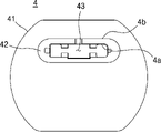
제2 커버(4)는 제2 커버본체(41), 제2 돌출부재(42), 제2 홀(43), 및 실링 삽입홈(44)을 포함할 수 있다.The
제2 커버본체(41)는 제2 커버(4)의 본체로 기능할 수 있다. 제2 커버본체(41)는 바디(2)의 타 측에 배치되도록 바디(2)에 결합될 수 있다. 제2 커버본체(41)는 전체적으로 원판 형상일 수 있으나, 이는 예시적인 것이며 바디(2)의 타 측에 배치될 수 있는 한 다른 형상으로 형성될 수도 있다.The
제2 돌출부재(42)는 제2 커버본체(41)로부터 돌출될 수 있다. 제2 돌출부재(42)는 제2 커버본체(41)와 일체로 형성될 수도 있다. 제2 돌출부재(42)는 전체적으로 원형 고리의 형상으로 형성될 수 있다.The second protruding
제2 홀(43)은 히터(10)의 후술할 가열 접속부(10a), 안테나(5)의 안테나 접속부(53), 및 감지부(6)의 감지 접속부(63) 중에서 적어도 어느 하나가 통과하기 위해 제2 돌출부재(42)에 형성될 수 있다. 접속부들(10a, 53, 63) 중에서 적어도 어느 하나는 제2 홀(43)을 통과하여 배터리(110) 또는 제어부(120)에 전기적으로 연결될 수 있다. 제2 홀(43)은 제2 커버본체(41) 및 제2 돌출부재(42)를 관통하도록 형성될 수 있다. 제2 홀(43)은 접속부들(10a, 53, 63)의 각각에 비해 더 큰 크기로 형성될 수 있다.In the
실링 삽입홈(44)에는 하부실링(8)의 일부가 삽입된다. 실링 삽입홈(44)은 제2 돌출부재(42)의 외면에 형성될 수 있다. 실링 삽입홈(44)은 제2 돌출부재(42)의 일 측 및 타 측의 각각에 하나씩 형성될 수 있다.A part of the
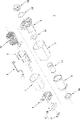
도 4는 일 실시예에 관한 에어로졸 생성 장치용 히터 조립체의 분해 사시도이다.4 is an exploded perspective view of a heater assembly for an aerosol generating device according to an embodiment.
도 4를 참고하면, 일 실시예에 관한 에어로졸 생성 장치용 히터 조립체(1)는 안테나(5), 감지부(6), 차폐부(7), 하부실링(8), 지지부(9), 히터(10), 서셉터(11), 및 홀더(20)를 더 포함할 수 있다. 다만 일 실시예에 관한 에어로졸 생성 장치용 히터 조립체(1)의 구성 요소들이 이에 한정되는 것은 아니며, 실시예에 따른 다른 구성 요소가 추가되거나, 적어도 하나의 구성 요소가 생략될 수도 있다.Referring to FIG. 4, the
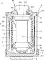
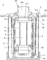
도 5는 도 2의 V-V 선을 기준으로 나타낸 일 실시예에 관한 에어로졸 생성 장치용 히터 조립체의 단면도이고, 도 6은 도 2의 VI-VI 선을 기준으로 나타낸 일 실시예에 관한 에어로졸 생성 장치용 히터 조립체의 단면도이다.5 is a cross-sectional view of a heater assembly for an aerosol generating device according to an embodiment taken along line V-V of FIG. 2, and FIG. 6 is a cross-sectional view of a heater assembly for an aerosol generating device according to an embodiment taken along line VI-VI of FIG. 2 A cross-sectional view of the heater assembly.
도 5 및 도 6을 참고하면, 일 실시예에 관한 에어로졸 생성 장치용 히터 조립체(1)는 에어로졸 생성 물품(200)을 가열하는 히터(10, 전기 전도성 코일), 에어로졸 생성 물품(200)을 둘러싸는 바디(2), 바디(2)의 일 측에 배치되고 에어로졸 생성 물품(200)이 삽입되는 제1 홀(311)을 포함하는 제1 커버(3), 및 바디(2)의 타 측에 배치되고, 히터(10)에 전력을 공급하기 위한 선이 히터 조립체(1)의 외부로 통과하는 제2 홀(43)을 포함하는 제2 커버(4)를 포함한다.5 and 6, a
제1 커버(3)와 바디(2)의 일 측, 및 제2 커버(4)와 바디(2)의 타 측은 서로 결합함으로써 에어로졸 생성 물품을 수용하는 수용 공간(21)을 형성한다.One side of the
바디(2), 제1 커버(3), 및 제2 커버(4) 중 적어도 하나의 내측면 중의 적어도 일부에는 히터(10)에서 발생하는 열을 수용 공간(21)으로 반사하는 물질이 증착된다. 이에 따라, 일 실시예에 관한 에어로졸 생성 장치용 히터 조립체(1)는 다음과 같은 효과를 도모할 수 있다.A material that reflects heat generated from the
첫째, 일 실시예에 관한 에어로졸 생성 장치용 히터 조립체(1)에 따르면, 제2 커버(4), 제1 커버(3), 및 바디(2)는 히터(10)의 외측 모두를 둘러싸도록 배치됨으로써 히터(10)에서 발생된 열이 외부로 방출되는 것을 방지하는 물리적인 장벽으로 기능할 수 있다. 따라서 일 실시예에 관한 에어로졸 생성 장치용 히터 조립체(1)는 물리적인 장벽을 통해 단열 성능을 향상시킬 수 있으므로, 히터(10)를 운용하는 데 소비되는 전력량을 감소시킬 수 있다.First, according to the
둘째, 일 실시예에 관한 에어로졸 생성 장치용 히터 조립체(1)는 에어로졸 생성 장치(100)로 전달되는 열의 양을 감소시킬 수 있으므로, 사용자가 에어로졸 생성 장치(100)를 파지 시 느낄 수 있는 온도를 감소시킬 수 있다. 따라서 일 실시예에 관한 에어로졸 생성 장치용 히터 조립체(1)는 에어로졸 생성 장치(100)를 사용하는 데 있어 안정적인 사용 환경을 구현할 수 있다.Second, since the
셋째, 증착 물질은 히터(10)에서 발생하는 열을 수용 공간(21)으로 반사할 수 있으므로, 히터(10)에서 발생된 열이 외부로 전달되는 양을 감소시킬 수 있다. 따라서 일 실시예에 관한 에어로졸 생성 장치용 히터 조립체(1)는 단열 성능을 더욱 향상시킬 수 있다.Third, since the deposition material can reflect heat generated from the
상기의 3가지 효과는 다음과 같은 실험에 의해 증명될 수 있다.The above three effects can be demonstrated by the following experiments.
[실험][Experiment]
우선, 일 실시예에 관한 에어로졸 생성 장치용 히터 조립체(1)의 온도 프로파일을 270℃로 설정하여 서셉터(11)의 온도를 270℃로 증가시킨다(과정 1).First, the temperature profile of the
다음, 서셉터(11)를 270초 동안 가열한다(과정 2).Next, the
다음, 과정 1, 과정 2를 3회 연속 반복한다(과정 3).Next,
다음, 5분의 시간이 흐른 뒤, 에어로졸 생성 장치(100)의 온도를 측정한다(과정 4).Next, after 5 minutes have elapsed, the temperature of the
다음, 종래 기술에 따른 히터 조립체(비교예 1) 및 진공관의 단열 구조를 포함하는 히터 조립체(비교예 2)를 이용하여 상기의 과정 1 내지 과정 4를 반복한다(과정 5).Next, steps 1 to 4 are repeated using a heater assembly (Comparative Example 1) according to the prior art and a heater assembly (Comparative Example 2) including a heat insulation structure of a vacuum tube (Process 5).
하기의 표 1은 상기의 실험 결과이다.Table 1 below shows the above experimental results.
상기의 표 1에서 알 수 있듯이, 일 실시예에 관한 에어로졸 생성 장치용 히터 조립체(1)는 비교예 1보다 에어로졸 생성 장치(100)의 온도가 대략 27℃정도 낮음을 알 수 있다. 이로부터, 일 실시예에 관한 에어로졸 생성 장치용 히터 조립체(1)에 따를 때, 종래 기술과 대비하여 에어로졸 생성 장치(100)의 전체적인 단열 성능이 향상됨을 알 수 있다. 또한, 일 실시예에 관한 에어로졸 생성 장치용 히터 조립체(1)는 진공관의 단열 구조를 포함하는 비교예 2와 유사한 단열 성능을 가짐을 알 수 있다.이하에서는 바디(2), 제1 커버(3), 및 제2 커버(4)에 대해 첨부된 도면을 참고하여 상세히 설명한다.As can be seen from Table 1 above, it can be seen that the
한편, 본 명세서에서 기재되어 있는 '상부', 또는 '하부'의 용어는 일 실시예에 관한 에어로졸 생성 장치용 히터 조립체(1)의 하부 구성들의 위치를 구분하기 위한 것이지, 특정 방향을 지칭하는 것이 아니다.On the other hand, the term 'upper' or 'lower' described in this specification is for distinguishing the positions of the lower components of the
도 5 및 도 6을 참고하면, 바디(2)는 히터(10)를 둘러싸도록 히터(10)의 외측에 배치된다. 바디(2)는 히터(10)에서 발생된 열이 외측으로 방출되는 것을 방지하는 기능을 수행할 수 있다. Referring to FIGS. 5 and 6 , the
바디(2)의 내측에는 에어로졸 생성 물품(200)을 수용하는 수용 공간(21, 도 5 및 도 6에 도시됨)이 형성된다. 에어로졸 생성 물품(200)이 수용 공간(21)에 수용되면, 에어로졸 생성 물품(200)은 서셉터(11)의 내측에 배치될 수 있다. 히터(10)의 가열 접속부(10a)가 배터리(110)에 전기적으로 연결되고, 히터(10)가 배터리(110)로부터 공급된 전력을 이용하여 서셉터(11)를 가열하면, 에어로졸 생성 물품(200)은 유도 가열 방식으로 가열되어 에어로졸을 발생시킬 수 있다. 가열 접속부(10a)는 앞에서 서술한 히터(10)에 전력을 공급하기 위한 선일 수 있다. 서셉터(11)는 속이 빈 원통의 형상으로 형성될 수 있으나, 이는 예시적인 것이며 에어로졸 생성 물품(200)을 수용할 수 있는 한 다른 형상으로 형성될 수도 있다. 서셉터(11)는 히터(10)의 내측에 배치될 수 있다. 서셉터(11)는 금속 소재를 포함할 수 있다.An accommodation space 21 (shown in FIGS. 5 and 6 ) accommodating the aerosol-generating
바디(2)의 내면에는 히터(10)에서 발생하는 열을 수용 공간(21)으로 반사하는 물질이 증착될 수 있다. 바디(2)의 내면은, 히터(10)를 향하는 바디(2)의 일 면일 수 있다. 물질은, 은(Ag)과 같은 금속 소재를 포함할 수 있다.A material that reflects heat generated from the
바디(2)는 전체적으로 속이 빈 원통의 형상으로 형성될 수 있으나, 이는 예시적인 것이며 히터(10)를 수용할 수 있는 한 다른 형상으로 형성될 수도 있다. 바디(2)는 금속 소재를 포함할 수 있다. 예컨대, 바디(2)는 스테인리스(SUS: Steel Use Stainless), 알루미늄(Aluminum) 등의 소재를 포함할 수 있다.The
도 5 및 도 6을 참고하면, 제1 커버(3)는 바디(2)의 일 측에 배치되어서 히터(10)의 일 측을 덮도록 배치된다. 제1 커버(3)는 히터(10)에서 발생한 열이 바디(2)의 일 측으로 방출되는 것을 방지하는 기능을 수행할 수 있다. 바디(2)의 일 측은, 바디(2)의 상부일 수 있다.Referring to FIGS. 5 and 6 , the
제1 커버(3)와 바디(2)의 일 측은 서로 결합함으로써, 에어로졸 생성 물품(200)을 수용하는 수용 공간(21)을 형성할 수 있다.One side of the
제1 커버(3)의 내면에는 히터(10)에서 발생하는 열을 수용 공간(21)으로 반사하는 물질이 증착될 수 있다. 제1 커버(3)의 내면은, 히터(10)를 향하는 제1 커버(3)의 일 면일 수 있다.A material that reflects heat generated from the
제1 커버(3)는 고내열성의 폴리머(Polymer) 소재를 포함할 수 있다. 예컨대, 제1 커버(3)는 폴리에테르에테르케톤(PEEK: Polyether Ether Ketone), 폴리페닐설폰(PPSU: Polyphenylsulfone), 폴리카보네이트(PC: Polycarbonate) 등의 소재를 포함할 수 있다.The
도 5 및 도 6을 참고하면, 제1 커버(3)는 제1 커버본체(31)를 포함할 수 있다.Referring to FIGS. 5 and 6 , the
제1 커버본체(31)는 제1 커버(3)의 본체로 기능할 수 있다. 제1 커버본체(31)는 바디(2)의 일 측에 배치되도록 바디(2)에 결합될 수 있다. 제1 커버본체(31)가 바디(2)에 결합되면, 제1 커버본체(31)는 히터(10)의 일 측을 덮을 수 있다. 제1 커버본체(31)는 전체적으로 원형 고리의 형상일 수 있으나, 이는 예시적인 것이며 바디(2)의 일 측에 배치되어서 히터(10)를 덮을 수 있는 한 다른 형상으로 형성될 수도 있다.The
제1 커버(3)는 제1 홀(311)을 더 포함할 수 있다. 제1 홀(311)에는 에어로졸 생성 물품(200)이 삽입될 수 있다. 제1 홀(311)은 제1 커버본체(31)의 상부와 하부를 관통하도록, 제1 커버본체(31)에 형성될 수 있다.The
도 5를 참고하면, 제1 커버(3)는 홀더 삽입홈(312)을 더 포함할 수 있다. 홀더 삽입홈(312)에는 홀더(20)가 삽입될 수 있다. 홀더(20)가 홀더 삽입홈(312)에 삽입되면, 홀더(20)는 제1 커버(3)에 결합될 수 있다. 홀더 삽입홈(312)은 제1 커버본체(31)의 상면에 형성될 수 있다.Referring to FIG. 5 , the
도 6을 참고하면, 제1 커버(3)는 제1 바디 삽입홈(313)을 더 포함할 수 있다. 제1 바디 삽입홈(313)에는 바디(2)의 일 측이 삽입될 수 있다. 바디(2)의 일 측이 제1 바디 삽입홈(313)에 삽입되면, 바디(2)는 제1 커버(3)에 결합될 수 있다. 이에 따라, 제1 커버(3)는 바디(2)의 일 측을 지지할 수 있다. 제1 바디 삽입홈(313)은 제1 커버본체(31)의 하면에 형성될 수 있다.Referring to FIG. 6 , the
도 5 및 도 6을 참고하면, 제1 커버(3)는 커버단열부재(32)를 더 포함할 수 있다.Referring to FIGS. 5 and 6 , the
커버단열부재(32)는 히터(10)가 연장된 길이 방향을 따라 연장된다. 커버단열부재(32)는 히터(10)와 바디(2)의 사이에 배치될 수 있다. 이에 따라, 일 실시예에 관한 에어로졸 생성 장치용 히터 조립체(1)는 커버단열부재(32) 및 바디(2)를 통해 히터(10)에서 발생된 열이 외부로 방출되는 것을 방지하는 물리적인 2중 장벽을 구현할 수 있다. 히터(10)가 연장된 길이 방향은, 일 실시예에 관한 에어로졸 생성 장치용 히터 조립체(1)의 상대적으로 길이가 긴 방향을 의미할 수 있다.The
커버단열부재(32)는 길이 방향을 따라 히터(10)보다 더 길게 연장될 수 있다. 이에 따라, 커버단열부재(32)는 히터(10)를 가릴 수 있는 영역을 증대시킬 수 있다.The
커버단열부재(32)는 제1 커버본체(31)에 결합될 수 있다. 커버단열부재(32)는 길이 방향을 따라 연장되도록 제1 커버본체(31)에 결합될 수 있다. 커버단열부재(32)는 제1 커버본체(31)와 일체로 형성될 수도 있다.The
제1 커버(3)가 바디(2)의 일 측에 결합되면, 커버단열부재(32)는 바디(2)의 내측에 삽입되어서 히터(10)의 외측의 일부를 둘러싸도록 배치될 수 있다. 즉, 커버단열부재(32)는 히터(10)의 외측의 일부를 둘러싸도록 일 단과 타 단이 서로 이격될 수 있다.When the
이에 따라, 커버단열부재(32)가 히터(10)의 외측의 전부를 둘러싸는 비교예와 대비하여 볼 때, 일 실시예에 관한 에어로졸 생성 장치용 히터 조립체(1)는 커버단열부재(32)를 바디(2)에 용이하게 삽입할 수 있다. 실시예는 커버단열부재(32)를 바디(2)의 내측에 삽입하는 과정에서, 비교예와 대비하여 볼 때, 커버단열부재(32)가 바디(2)와의 간섭이 이루어지는 부분이 감소하기 때문이다. 따라서 일 실시예에 관한 에어로졸 생성 장치용 히터 조립체(1)는 제1 커버(3) 및 바디(2) 간의 조립의 용이성을 향상시킬 수 있다.Accordingly, as compared to the comparative example in which the
도 6을 참고하면, 제1 커버(3)는 제1 돌출부재(33)를 더 포함할 수 있다.Referring to FIG. 6 , the
제1 돌출부재(33)는 제1 커버본체(31)로부터 외측으로 돌출될 수 있다. 제1 돌출부재(33)는 제1 커버본체(31)의 양 단에 하나씩 배치될 수 있다. 제1 돌출부재(33), 커버단열부재(32), 및 제1 커버본체(31)는 일체로 형성될 수도 있다.The first protruding
제1 돌출부재(33)는 결합공(331)을 포함할 수 있다. 결합공(331)에는 제1 커버(3)를 에어로졸 생성 장치(100)에 결합시키기 위한 결합부재(3a, 도 7에 도시됨)가 삽입될 수 있다. 결합부재(3a)가 결합공(331)에 삽입되어서 에어로졸 생성 장치(100)에 결합됨에 따라, 제1 커버(3)는 에어로졸 생성 장치(100)에 고정될 수 있다. 결합부재(3a)는 볼트(bolt)로 구현될 수 있다. 이 경우, 결합공(331)을 향하는 제1 돌출부재(33)의 내측에는, 나사산이 형성될 수 있다.The first protruding
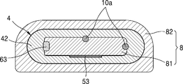
도 5 및 도 6을 참고하면, 제2 커버(4)는 바디(2)의 타 측에 배치되어서 히터(10)의 타 측을 덮도록 배치된다. 제2 커버(4)는 히터(10)에서 발생한 열이 바디(2)의 타 측으로 방출되는 것을 방지하는 기능을 수행할 수 있다. 바디(2)의 타 측은, 바디(2)의 하부일 수 있다.Referring to FIGS. 5 and 6 , the
제2 커버(4)와 바디(2)의 타 측은 서로 결합함으로써, 수용 공간(21)을 형성할 수 있다. 즉, 바디(2), 제1 커버(3), 및 제2 커버(4)는 서로 결합함으로써, 수용 공간(21)의 외측 전부를 둘러싸도록 배치될 수 있다.The
제2 커버(4)의 내면에는 히터(10)에서 발생하는 열을 수용 공간(21)으로 반사하는 물질이 증착될 수 있다. 제2 커버(4)의 내면은, 히터(10)를 향하는 제2 커버(4)의 일 면일 수 있다.A material that reflects heat generated from the
제2 커버(4)는 고내열성의 폴리머(Polymer) 소재를 포함할 수 있다. 예컨대, 제2 커버(4)는 폴리에테르에테르케톤(PEEK: Polyether Ether Ketone), 폴리페닐설폰(PPSU: Polyphenylsulfone), 폴리카보네이트(PC: Polycarbonate) 등의 소재를 포함할 수 있다.The
도 5 및 도 6을 참고하면, 제2 커버(4)는 제2 바디 삽입홈(411)을 더 포함할 수 있다.Referring to FIGS. 5 and 6 , the
제2 바디 삽입홈(411)에는 바디(2)의 타 측이 삽입될 수 있다. 바디(2)의 타 측이 제2 바디 삽입홈(411)에 삽입되면, 바디(2)는 제2 커버(4)에 결합될 수 있다. 이에 따라, 제2 커버(4)는 바디(2)의 타 측을 지지할 수 있다. 제2 바디 삽입홈(411)은 제2 커버본체(41)의 내측에 형성될 수 있다.The other side of the
도 5 및 도 6을 참고하면, 제2 커버(4)는 걸림부재(412)를 더 포함할 수 있다.Referring to FIGS. 5 and 6 , the
걸림부재(412)는 바디(2)에 형성된 커버 삽입홈(22)에 삽입될 수 있다. 걸림부재(412)가 커버 삽입홈(22)에 삽입되면, 바디(2)의 타 측은 제2 커버(4)에 결합될 수 있다. 이에 따라, 제2 커버(4) 및 바디(2) 사이의 결합 상태가 견고해질 수 있다. 걸림부재(412)는 제2 바디 삽입홈(411)을 향해 제2 커버본체(41)로부터 돌출될 수 있다. 걸림부재(412)는 제2 커버본체(41)와 일체로 형성될 수 있다.The engaging
도 5 및 도 6을 참고하면, 안테나(5)는 에어로졸 생성 물품(200)이 수용 공간(21)에 수용되었는지 여부를 인식한다. 안테나(5)는 배터리(110) 및 제어부(120)에 연결될 수 있다. 안테나(5)는 금속 소재를 포함할 수 있다.Referring to FIGS. 5 and 6 , the
일 예로서, 에어로졸 생성 물품(200)이 수용 공간(21)에 수용되면, 안테나(5)는 에어로졸 생성 물품(200)이 수용 공간(21)에 수용된 것을 인식하여, 에어로졸 생성 물품(200)의 수용된 상태에 관한 정보를 제어부(120)에 제공할 수 있다. 이에 따라, 제어부(120)는 히터(10)에 전력이 공급되도록 배터리(110)를 제어할 수 있다.As an example, when the aerosol-generating
다른 예로서, 에어로졸 생성 물품(200)이 수용 공간(21)으로부터 분리되면, 안테나(5)는 에어로졸 생성 물품(200)이 분리된 것을 인식하여, 에어로졸 생성 물품(200)이 분리된 상태에 관한 정보를 제어부(120)에 제공할 수 있다. 이에 따라, 제어부(120)는 히터(10)에 공급되는 전력을 차단하도록 배터리(110)를 제어할 수 있다.As another example, if the aerosol-generating
안테나(5)는 바디(2)의 내측에 배치된다. 안테나(5)는 커버단열부재(32)와 차폐부(7)의 사이에 배치되어 히터(10)의 외측의 적어도 일부를 둘러싸도록 배치될 수 있다. 이에 따라, 일 실시예에 관한 에어로졸 생성 장치용 히터 조립체(1)는 커버단열부재(32), 안테나(5), 및 바디(2)를 통해 히터(10)에서 발생된 열이 외부로 방출되는 것을 방지하는 물리적인 3중 장벽을 구현할 수 있다.The
도 5 및 도 6을 참고하면, 감지부(6)는 히터(10), 또는 서셉터(11) 중에서 적어도 어느 하나의 온도를 감지한다. 감지부(6)는 도 5에 도시된 바와 같이 서셉터(11)에 맞닿을 수 있다. 감지부(6)는 배터리(110) 또는 제어부(120)에 연결될 수 있다.Referring to FIGS. 5 and 6 , the
감지부(6)는 바디(2)의 내측에 배치되어 히터(10)가 연장된 길이 방향을 따라 적어도 일부가 연장될 수 있다. 감지부(6)는 금속 소재를 포함할 수 있다.The
도 5를 참고하면, 감지부(6)는 감지본체(61), 및 절곡부재(62)를 포함할 수 있다.Referring to FIG. 5 , the
감지본체(61)는 히터(10)가 연장된 길이 방향을 따라 적어도 일부가 연장된다. 감지본체(61)는 바디(2)와 차폐부(7)의 사이에 배치될 수 있다.At least a portion of the
절곡부재(62)는 감지부(6)가 서셉터(11)에 맞닿도록 서셉터(11)를 향해 절곡된다. 절곡부재(62)는 제1 커버(3)와 지지부(9)의 사이를 통과하여 서셉터(11)를 향해 연장될 수 있다. 절곡부재(62)는 감지본체(61)의 상측에 연결될 수 있다.The bending
도 5 및 도 6을 참고하면, 차폐부(7)는 바디(2)의 내측에 배치된다. 차폐부(7)는 바디(2)와 안테나(5)의 사이에 배치되어 히터(10)의 외측의 적어도 일부를 둘러싸도록 배치된다. 이에 따라, 일 실시예에 관한 에어로졸 생성 장치용 히터 조립체(1)는 다음과 같은 효과를 도모할 수 있다.Referring to FIGS. 5 and 6 , the
첫째, 일 실시예에 관한 에어로졸 생성 장치용 히터 조립체(1)는 차폐부(7)가 안테나(5)의 외측에 배치되므로, 안테나(5)가 차폐부(7)의 외부에 존재하는 전자 기기들을 인식할 가능성을 감소시킬 수 있다. 따라서 일 실시예에 관한 에어로졸 생성 장치용 히터 조립체(1)는 안테나(5)가 에어로졸 생성 물품(200)의 수용 여부만을 인식할 수 있으므로, 안테나(5)의 전체적인 성능을 향상시킬 수 있다.First, in the
둘째, 일 실시예에 관한 에어로졸 생성 장치용 히터 조립체(1)는 커버단열부재(32), 안테나(5), 차폐부(7), 및 바디(2)를 통해 히터(10)에서 발생된 열이 외부로 방출되는 것을 방지하는 물리적인 4중 장벽을 구현할 수 있다. 따라서 일 실시예에 관한 에어로졸 생성 장치용 히터 조립체(1)는 단열 성능을 더욱 향상시킬 수 있다.Second, the
차폐부(7)는 금속 소재를 포함할 수 있다. 예컨대, 차폐부(7)는 알루미늄(Al), 은(Ag) 등과 같은 소재를 포함할 수 있다.The
도 5 및 도 6을 참고하면, 하부실링(8)은 접속부들(10a, 53, 63) 중에서 적어도 어느 하나와 제2 커버(4)의 사이를 밀폐하는 기능을 수행한다. 하부실링(8)은 제2 커버(4)에 결합될 수 있다. 하부실링(8)은 제2 돌출부재(42)의 외측 및 제2 돌출부재(42)의 내측 각각에 결합될 수 있다. 하부실링(8)은 고무 소재를 포함할 수 있다. 하부실링(8)은 제1 실링(81) 및 제2 실링(82)을 포함할 수 있으며 이에 관한 구체적인 설명은 후술한다.Referring to FIGS. 5 and 6 , the
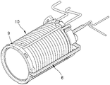
도 5 및 도 6을 참고하면, 지지부(9)는 히터(10)의 내측에 배치되어서 히터(10)를 지지한다. 히터(10)는 지지부(9)에 결합될 수 있다. 지지부(9)는 전체적으로 속이 빈 원통의 형상으로 형성될 수 있으나, 이는 예시적인 것이며 히터(10)를 지지할 수 있는 한 다른 형상으로 형성될 수도 있다.Referring to FIGS. 5 and 6 , the
지지부(9)의 내측에는 서셉터(11)가 배치될 수 있다. 따라서, 지지부(9)는 서셉터(11)에서 발생된 열이 외부로 방출되는 것을 차단하는 기능을 수행할 수도 있다.A
도 4 내지 도 6을 참고하면, 일 실시예에 관한 에어로졸 생성 장치용 히터 조립체(1)는 제1 밀봉링(30), 제2 밀봉링(40), 및 제3 밀봉링(50)을 더 포함할 수 있다.4 to 6, the
제1 밀봉링(30)은 홀더(20)와 제1 커버(3)의 사이에 배치될 수 있다. 제1 밀봉링(30)은 홀더(20)와 제1 커버(3)의 사이를 밀폐하는 기능을 수행할 수 있다.The
제2 밀봉링(40)은 제1 커버(3)에 배치될 수 있다. 제2 밀봉링(40)은 제1 커버본체(31)의 내측에서 제1 홀(311)을 둘러싸도록 배치될 수 있다. 제2 밀봉링(40)에는 에어로졸 생성 물품(200)의 적어도 일부가 삽입될 수 있다. 에어로졸 생성 물품(200)이 수용 공간(21)에 수용되면, 제2 밀봉링(40)은 에어로졸 생성 물품(200)과 제1 커버본체(31)의 사이를 밀폐할 수 있다.The
제3 밀봉링(50)은 지지부(9)의 내측에서 서셉터(11)의 하단에 배치될 수 있다. 제3 밀봉링(50)에는 에어로졸 생성 물품(200)의 적어도 일부가 삽입될 수 있다. 에어로졸 생성 물품(200)이 수용 공간(21)에 수용되면, 제3 밀봉링(50)은 에어로졸 생성 물품(200)과 지지부(9)의 사이를 밀폐할 수 있다.The
제1 밀봉링(30), 제2 밀봉링(40), 제3 밀봉링(50) 각각은 고무 소재를 포함할 수 있다. 제1 밀봉링(30), 제2 밀봉링(40), 제3 밀봉링(50) 각각은 원형 고리의 형상으로 형성될 수 있으나, 형상에는 제한이 없다.Each of the
도 7은 일 실시예에 관한 에어로졸 생성 장치용 히터 조립체에 있어서 제1 커버, 히터, 및 홀더의 결합 사시도이다.7 is a perspective view of a combination of a first cover, a heater, and a holder in a heater assembly for an aerosol generating device according to an embodiment.
홀더(20)는 에어로졸 생성 물품(200)을 지지하는 기능을 수행한다. 홀더(20)는 에어로졸 생성 물품(200)이 삽입되는 삽입구멍(20a), 삽입구멍(20a)을 향해 돌출되어서 에어로졸 생성 물품(200)을 지지하는 릿지(20b), 및 홀더 삽입홈(312)에 삽입되도록 제1 커버본체(31)를 향해 돌출된 홀더 돌출부(20c)를 포함할 수 있다. 홀더 돌출부(20c)가 홀더 삽입홈(312)에 삽입되면, 홀더(20)는 제1 커버본체(31)에 결합될 수 있다.The
홀더(20)가 제1 커버본체(31)에 결합되면, 홀더(20)의 삽입구멍(20a)은 제1 커버본체(31)의 제1 홀(311)에 연통될 수 있다.When the
홀더(20)는 복수 개의 릿지(20b)를 포함할 수 있다. 복수 개의 릿지(20b)는 홀더(20)의 둘레 방향을 따라 서로 이격되게 배치될 수 있다.The
도 8은 일 실시예에 관한 에어로졸 생성 장치용 히터 조립체에 있어서 히터, 안테나, 및 감지부의 결합 사시도이고, 도 9는 일 실시예에 관한 에어로졸 생성 장치용 히터 조립체에 있어서 제1 커버, 및 안테나의 결합 사시도이다.8 is a combined perspective view of a heater, an antenna, and a detection unit in a heater assembly for an aerosol generating device according to an embodiment, and FIG. 9 is a perspective view of a first cover and an antenna in a heater assembly for an aerosol generating device according to an embodiment. It is a combined perspective view.
도 8 및 도 9를 참고하면, 안테나(5)는 안테나 본체(51), 안테나 연장부(52), 및 안테나 접속부(53)를 포함할 수 있다.Referring to FIGS. 8 and 9 , the
도 8에 도시된 바와 같이, 안테나 본체(51)는 히터(10)가 연장된 길이 방향을 따라 연장되고, 히터(10)의 외측의 일부를 둘러싸도록 배치된다. 즉, 안테나 본체(51)는 히터(10)의 외측의 일부만을 둘러싸도록 일 단과 타 단이 서로 이격될 수 있다.As shown in FIG. 8 , the
이에 따라, 안테나 본체(51)가 히터(10)의 외측의 전부를 둘러싸는 비교예와 대비하여 볼 때, 일 실시예에 관한 에어로졸 생성 장치용 히터 조립체(1)는 안테나 본체(51)를 바디(2)의 내측에 용이하게 삽입할 수 있다. 실시예는 안테나 본체(51)가 바디(2)의 내측에 삽입되는 과정에서, 비교예와 대비하여 볼 때, 안테나 본체(51)가 바디(2)와의 간섭이 이루어지는 부분이 감소하기 때문이다. 따라서 일 실시예에 관한 에어로졸 생성 장치용 히터 조립체(1)는 안테나(5) 및 바디(2) 간의 조립의 용이성을 향상시킬 수 있다.Accordingly, as compared to the comparative example in which the
안테나 본체(51)가 히터(10)가 연장된 길이 방향을 따라 연장되고, 히터(10)의 외측의 일부를 둘러싸도록 배치될 경우, 커버단열부재(32)는 도 9에 도시된 바와 같이 안테나 본체(51)와 대응되는 위치에 배치될 수 있다. 이에 따라, 안테나 본체(51)는 커버단열부재(32)의 외측에서 커버단열부재(32)를 지지할 수 있다.When the
안테나 연장부(52)는 안테나 본체(51)에 연결된다. 안테나 연장부(52)는 안테나 본체(51)의 일 측으로부터 히터(10)의 둘레 방향을 따라 연장된 제1 연장부, 및 안테나 본체(51)의 타 측으로부터 히터(10)의 둘레 방향을 따라 연장된 제2 연장부를 포함할 수 있다.The
도 8을 참고하면, 안테나(5)는 절곡부재(62)가 통과하는 통과부(5a)를 포함할 수 있다. 이에 따라, 일 실시예에 관한 에어로졸 생성 장치용 히터 조립체(1)는 감지부(6)가 서셉터(11)에 맞닿는 과정에서 안테나(5)와 감지부(6)가 서로 전기적으로 연결되지 않는 구조로 구현될 수 있다. 따라서 일 실시예에 관한 에어로졸 생성 장치용 히터 조립체(1)는 안테나(5) 및 감지부(6)의 사이에 전기적인 단락의 발생 가능성을 감소시킬 수 있다. 통과부(5a)는 제1 연장부 및 제2 연장부의 사이에 위치하는 공간일 수 있다.Referring to FIG. 8 , the
도 8 및 도 9를 참고하면, 안테나 접속부(53)는 안테나 연장부(52)로부터 이격된 위치에서, 안테나 본체(51)에 연결된다. 안테나 접속부(53)는 배터리(110), 또는 제어부(120) 중에서 적어도 어느 하나에 연결될 수 있다. 안테나 접속부(53)는 히터(10)가 연장된 길이 방향을 가로지르는 방향을 따라 연장된 제1 접속부재, 및 히터(10)가 연장된 길이 방향을 따라 연장된 제2 접속부재를 포함할 수 있다. 안테나 접속부(53), 안테나 연장부(52), 및 안테나 본체(51)는 일체로 형성될 수도 있다.Referring to FIGS. 8 and 9 , the
도 10은 일 실시예에 관한 에어로졸 생성 장치용 히터 조립체에 있어서 안테나, 감지부, 및 차폐부의 결합 사시도이다.10 is a combined perspective view of an antenna, a sensing unit, and a shielding unit in a heater assembly for an aerosol generating device according to an embodiment.
도 10을 참고하면, 감지부(6)는 감지본체(61), 절곡부재(62), 및 감지 접속부(63)를 포함할 수 있다. 이하에서는 앞서 도 5에서 설명한 감지본체(61) 및 절곡부재(62)에 대한 중복적인 설명은 제외한다.Referring to FIG. 10 , the
감지본체(61)는 길이 방향을 따라 연장된 제1 본체, 제1 본체에 연결되고 길이 방향을 가로지르는 방향을 따라 절곡된 제2 본체, 제2 본체에 연결되고 감지 접속부(63)에 연결된 제3 본체를 포함할 수 있다.The
절곡부재(62)는 길이 방향을 가로지르는 방향을 따라 연장된 제1 절곡부재, 및 제1 절곡부재에 연결되고 서셉터(11)를 향해 하측으로 절곡된 제2 절곡부재를 포함할 수 있다.The bending
감지 접속부(63)는 감지본체(61)의 하측에 연결될 수 있다. 감지 접속부(63)는 배터리(110), 또는 제어부(120) 중에서 적어도 어느 하나에 연결될 수 있다. 감지 접속부(63)는 서로 다른 방향으로 연장된 2개의 접속부재를 포함할 수 있다. 감지 접속부(63), 절곡부재(62), 및 감지본체(61)는 일체로 형성될 수도 있다.The
도 10을 참고하면, 차폐부(7)는 차폐본체(71) 및 감지부 통과홈(72)을 포함할 수 있다.Referring to FIG. 10 , the
차폐본체(71)는 차폐부(7)의 전체적인 외형을 이룰 수 있다. 차폐본체(71)는 안테나(5)의 외측을 둘러싸도록 바디(2)의 내측에 배치될 수 있다. 차폐본체(71)는 전체적으로 속이 빈 원통의 형상으로 형성될 수 있으나, 이는 예시적인 것이며 안테나(5)의 외측에 배치될 수 있는 한 다른 형상으로 형성될 수도 있다.The shielding
감지부 통과홈(72)은 절곡부재(62)가 통과하는 공간일 수 있다. 이에 따라, 일 실시예에 관한 에어로졸 생성 장치용 히터 조립체(1)는 감지부(6)가 서셉터(11)에 맞닿는 과정에서 차폐부(7)와 감지부(6)가 서로 전기적으로 연결되지 않는 구조로 구현될 수 있다. 따라서 일 실시예에 관한 에어로졸 생성 장치용 히터 조립체(1)는 차폐부(7) 및 감지부(6)의 사이에 전기적인 단락의 발생 가능성을 감소시킬 수 있다. 감지부 통과홈(72)은 차폐본체(71)에 형설될 수 있다.The sensing
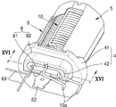
도 11은 하부실링이 제2 커버에 결합된 모습을 설명하기 위한 일 실시예에 관한 에어로졸 생성 장치용 히터 조립체의 후방 사시도이다.11 is a rear perspective view of a heater assembly for an aerosol generating device according to an embodiment for explaining a state in which a lower seal is coupled to a second cover.
도 11을 참고하면, 접속부들(10a, 53, 63)은 제2 홀(43)을 통과하게 되는데, 하부실링(8)은 접속부들(10a, 53, 63) 중에서 적어도 어느 하나와 제2 커버(4)의 사이를 밀폐하는 기능을 수행할 수 있다. 하부실링(8)은 제2 돌출부재(42)에 결합될 수 있다.Referring to FIG. 11, the
도 12는 일 실시예에 관한 에어로졸 생성 장치용 히터 조립체에 있어서 제2 커버, 및 하부실링의 분해 사시도이고, 도 13은 일 실시예에 관한 에어로졸 생성 장치용 히터 조립체에 있어서 제2 커버를 도시한 도면이다.12 is an exploded perspective view of a second cover and a lower sealing in a heater assembly for an aerosol generating device according to an embodiment, and FIG. 13 is an exploded perspective view of a second cover in a heater assembly for an aerosol generating device according to an embodiment. it is a drawing
도 12를 참고하면, 하부실링(8)은 제2 홀(43)에 삽입되는 제1 실링(81), 및 제1 실링(81)으로부터 이격된 위치에 배치되는 제2 실링(82)을 포함할 수 있다.Referring to FIG. 12 , the
제1 실링(81)은 제2 홀(43)에 삽입되어 제2 돌출부재(42)의 내면(4a, 도 13에 도시됨)에 접할 수 있다. 이에 따라, 제1 실링(81)은 제2 홀(43)을 밀폐할 수 있다. 따라서 제1 실링(81)은 히터(10)에서 발생된 열이 제2 홀(43)을 통해 하측으로 방출되는 것을 방지할 수 있다. 내면(4a)은 제2 홀(43)을 향하는 제2 돌출부재(42)의 일면일 수 있다.The
제1 실링(81)은 억지 끼워 맞춤(interference fit) 방식으로 제2 홀(43)에 삽입될 수 있다. 이에 따라, 일 실시예에 관한 에어로졸 생성 장치용 제1 실링(81)이 제2 홀(43)을 밀폐하는 밀폐력을 향상시킬 수 있다.The
제2 실링(82)은 제1 실링(81)으로부터 이격된 위치에 배치된다. 제2 실링(82)은 내면(4a)의 반대면인 제2 돌출부재(42)의 외면(4b, 도 13에 도시됨)에 결합될 수 있다. 제2 돌출부재(42)의 외면(4b)은 제2 커버(4)의 외면과 동일한 면을 의미할 수 있다. 제2 실링(82)은 제2 돌출부재(42)의 외측을 둘러싸도록 배치될 수 있다.The
도 14는 일 실시예에 관한 에어로졸 생성 장치용 히터 조립체에 있어서 제1 실링을 도시한 도면이다.14 is a view showing a first seal in a heater assembly for an aerosol generating device according to an embodiment.
도 14를 참고하면, 제1 실링(81)은 제1 실링본체(811), 제1 통과홈(812), 및 제2 통과홈(813)을 포함한다.Referring to FIG. 14 , the
제1 실링본체(811)는 제2 홀(43)에 삽입된다. 제1 실링본체(811)에는 제1 통과홈(812) 및 제2 통과홈(813)이 형성될 수 있다. 제1 실링본체(811)는 전체적으로 직육면체의 형상으로 형성될 수 있으나, 제2 홀(43)에 삽입될 수 있는 한 다른 형상으로 형성될 수 있다.The
제1 통과홈(812)은 가열 접속부(10a)가 통과하기 위해 제1 실링본체(811)에 형성될 수 있다. 제1 통과홈(812)은 제1 실링본체(811)의 외면으로부터 소정 깊이 홈을 가공함으로써 형성될 수 있다. 도 14에는 2개의 제1 통과홈(812)을 도시하였으나 이는 예식적인 것이며, 형성되는 제1 통과홈(812)의 개수에는 제한이 없다.The
제2 통과홈(813)은 감지 접속부(63)가 통과하기 위해 제1 통과홈(812)과 이격된 위치에서 제1 실링본체(811)에 형성될 수 있다. 제2 통과홈(813)은 제1 실링본체(811)의 외면으로부터 소정 깊이 홈을 가공함으로써 형성될 수 있다. 도 14에는 1개의 제2 통과홈(813)을 도시하였으나 이는 예시적인 것이며, 형성되는 제2 통과홈(813)의 개수에는 제한이 없다.The
도 15는 일 실시예에 관한 에어로졸 생성 장치용 히터 조립체에 있어서 제2 실링을 도시한 도면이다.15 is a view showing a second seal in a heater assembly for an aerosol generating device according to an embodiment.
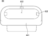
도 15를 참고하면, 제2 실링(82)은 제2 실링본체(821), 제2 커버 삽입홈(822), 및 실링 돌출부(823)를 포함할 수 있다.Referring to FIG. 15 , the
제2 실링본체(821)는 제2 돌출부재(42)에 결합된다. 제2 실링본체(821)에는 제2 커버 삽입홈(822), 및 실링 돌출부(823)가 형성될 수 있다. 제2 실링본체(821)는 제2 실링(82)의 본체로 기능할 수 있다.The
제2 커버 삽입홈(822)에는 제2 돌출부재(42)가 삽입될 수 있다. 제2 돌출부재(42)는 억지 끼워 맞춤 방식으로 제2 커버 삽입홈(822)에 삽입될 수 있다. 이 경우, 제2 돌출부재(42) 및 제2 실링본체(821)의 사이에는 틈이 발생하지 않을 수 있다.The second protruding
실링 돌출부(823)는 제2 커버 삽입홈(822)을 향해 돌출된다. 제2 커버 삽입홈(822)에 제2 돌출부재(42)가 삽입되면, 실링 돌출부(823)는 제2 돌출부재(42)의 외면(4b)에 형성된 실링 삽입홈(44)에 삽입된다. 이에 따라, 제2 커버(4) 및 제2 실링(82)의 사이에 결합상태가 견고해질 수 있다. 실링 돌출부(823)는 제2 실링본체(821)의 일 측 및 타 측 각각에 하나씩 형성될 수 있다. 실링 돌출부(823)는 제2 실링본체(821)와 일체로 형성될 수도 있다. The sealing
도 16은 도 11의 XVI-XVI 선을 기준으로 나타낸 일 실시예에 관한 에어로졸 생성 장치용 히터 조립체의 단면도이다.FIG. 16 is a cross-sectional view of a heater assembly for an aerosol generating device according to an embodiment taken along line XVI-XVI of FIG. 11 .
제1 실링(81)이 제2 홀(43)에 삽입되면, 도 16에 도시된 바와 같이 접속부들(10a, 53, 63)은 제1 실링(81)과 제2 커버(4)의 사이에 배치될 수 있다. 따라서 일 실시예에 관한 에어로졸 생성 장치용 히터 조립체(1)에 진동, 흔들림이 작용하더라도 접속부들(10a, 53, 63)은 이동이 제한될 수 있다.When the first sealing 81 is inserted into the
제1 실링(81)이 억지 끼워 맞춤 방식으로 제2 홀(43)에 삽입되는 경우, 제1 실링(81)은 접속부들(10a, 53, 63)를 제2 돌출부재(42)의 내면(4a)을 향해 가압할 수 있다.When the
이하에서는 제1 실링(81), 제2 커버(4), 접속부들(10a, 53, 63)의 사이의 조립 과정을 설명한다.Hereinafter, an assembly process between the
우선, 접속부들(10a, 53, 63)를 제2 홀(43)에 통과시킨다. 가열 접속부(10a), 안테나 접속부(53), 및 감지 접속부(63)를 함께 제2 홀(43)에 통과시킬 수 있고, 가열 접속부(10a), 안테나 접속부(53), 및 감지 접속부(63)를 순차적으로 제2 홀(43)에 통과시킬 수도 있다.First, the
제2 홀(43)의 크기는 접속부들(10a, 53, 63) 각각의 크기 보다 크므로, 접속부들(10a, 53, 63)은 제2 홀(43)에 쉽게 통과될 수 있다.Since the size of the
다음, 제1 실링(81)을 제2 홀(43)에 삽입시킨다. 이 경우, 가열 접속부(10a)는 제1 통과홈(812)에 삽입되고, 안테나 접속부(53)는 제2 돌출부재(42)의 내면(4a)에 위치하며, 감지 접속부(63)는 제2 통과홈(813)에 삽입될 수 있다.Next, the
제1 실링(81)을 제2 홀(43)에 먼저 삽입시킨 이후 접속부들(10a, 53, 63)을 제2 홀(43)에 통과시키면, 제2 홀(43)의 크기가 작아진 상태에서 접속부들(10a, 53, 63)을 제2 홀(43)에 통과시키기 어렵다. 따라서, 이 경우에는, 제1 실링(81), 제2 커버(4), 접속부들(10a, 53, 63)의 사이의 조립 공정이 용이하지 않다.When the
그러나, 일 실시예에 관한 에어로졸 생성 장치용 히터 조립체(1)는 접속부들(10a, 53, 63)을 우선적으로 제2 홀(43)에 삽입하고, 순차적으로 제1 실링(81)을 제2 홀(43)에 삽입시킴으로써, 제1 실링(81), 제2 커버(4), 접속부들(10a, 53, 63)의 사이의 조립이 용이하게 이루어질 수 있다.However, in the
도 17은 일 실시예에 관한 에어로졸 생성 장치용 히터 조립체에 있어서 지지부, 히터, 및 감지부의 결합 사시도이다.17 is a perspective view of a combination of a support part, a heater, and a sensing part in a heater assembly for an aerosol generating device according to an embodiment.
도 17을 참고하면, 지지부(9)에는 히터(10)가 감길 수 있다. 이에 따라, 지지부(9)는 히터(10)를 지지할 수 있다.Referring to FIG. 17 , a
일 실시예에 관한 에어로졸 생성 장치용 히터 조립체(1)에 있어서, 지지부(9)는 감지부(6)를 지지할 수도 있다. 이를 위해, 지지부(9)는 감지부(6)의 절곡부재(62)가 삽입되는 홈을 포함할 수 있다. 절곡부재(62)가 홈에 삽입됨에 따라, 지지부(9)는 감지부(6)를 지지할 수 있다. 이에 따라, 일 실시예에 관한 에어로졸 생성 장치용 히터 조립체(1)에 진동, 흔들림이 작용하더라도 감지부(6)의 위치가 고정될 수 있으므로, 감지부(6)는 안정적으로 히터(10) 또는 서셉터(11)의 온도를 감지할 수 있다.In the
일 예로서, 지지부(9)는 금속 소재를 포함할 수 있다. 예컨대, 지지부(9)는 스테인리스(SUS: Steel use stainless), 알루미늄(Aluminum) 등의 소재를 포함할 수 있다. 다른 예로서, 지지부(9)는 고내열성의 폴리머(Polymer) 소재를 포함할 수 있다. 예컨대, 지지부(9)는 폴리에테르에테르케톤(PEEK: Polyether ether ketone), 폴리페닐설폰(PPSU: polyphenylsulfone), 폴리카보네이트(PC: Polycarbonate) 등의 소재를 포함할 수 있다.As an example, the
이하, 도 18 및 도 19를 참조하여, 에어로졸 생성 물품(200)의 예들을 설명한다.Examples of aerosol-generating
도 18 및 도 19는 에어로졸 생성 물품의 예들을 도시한 도면이다.18 and 19 show examples of aerosol-generating articles.
도 18를 참조하면, 에어로졸 생성 물품(200)은 담배 로드(210) 및 필터 로드(220)를 포함한다. 도 1을 참조하여 상술한 제1 부분은 담배 로드(210)를 포함하고, 제2 부분은 필터 로드(220)를 포함한다.Referring to FIG. 18 , an aerosol-generating
도 18에는 필터 로드(220)가 단일 세그먼트로 도시되어 있으나, 이에 한정되지 않는다. 다시 말해, 필터 로드(220)는 복수의 세그먼트들로 구성될 수도 있다. 예를 들어, 필터 로드(220)는 에어로졸을 냉각하는 제1 세그먼트 및 에어로졸 내에 포함된 소정의 성분을 필터링하는 제2 세그먼트를 포함할 수 있다. 또한, 필요에 따라, 필터 로드(220)에는 다른 기능을 수행하는 적어도 하나의 세그먼트를 더 포함할 수 있다.Although
에어로졸 생성 물품(200)은 적어도 하나의 래퍼(240)에 의하여 포장될 수 있다. 래퍼(240)에는 외부 공기가 유입되거나 내부 기체가 유출되는 적어도 하나의 구멍(hole)이 형성될 수 있다. 일 예로서, 에어로졸 생성 물품(200)은 하나의 래퍼(240)에 의하여 포장될 수 있다. 다른 예로서, 에어로졸 생성 물품(200)은 2 이상의 래퍼(240)들에 의하여 중첩적으로 포장될 수도 있다. 예를 들어, 제1 래퍼(241)에 의하여 담배 로드(210)가 포장되고, 래퍼들(242, 243, 244)에 의하여 필터 로드(220)가 포장될 수 있다. 그리고, 단일 래퍼(245)에 의하여 에어로졸 생성 물품(200) 전체가 재포장될 수 있다. 만약, 필터 로드(220)가 복수의 세그먼트들로 구성되어 있다면, 각각의 세그먼트가 래퍼들(242, 243, 244)에 의하여 포장될 수 있다.The aerosol-generating
담배 로드(210)는 에어로졸 생성 물질을 포함한다. 예를 들어, 에어로졸 생성 물질은 글리세린, 프로필렌 글리콜, 에틸렌 글리콜, 디프로필렌 글리콜, 디에틸렌 글리콜, 트리에틸렌 글리콜, 테트라에틸렌 글리콜, 및 올레일 알코올 중 적어도 하나를 포함할 수 있으나, 이에 한정되지 않는다. 또한, 담배 로드(210)는 풍미제, 습윤제, 및/또는 유기산(organic acid)과 같은 다른 첨가 물질을 함유할 수 있다. 또한, 담배 로드(210)에는, 멘솔 또는 보습제 등의 가향액이, 담배 로드(210)에 분사됨으로써 첨가할 수 있다.
담배 로드(210)는 다양하게 제작될 수 있다. 예를 들어, 담배 로드(210)는 시트(sheet)로 제작될 수도 있고, 가닥(strand)으로 제작될 수도 있다. 또한, 담배 로드(210)는 담배 시트가 잘게 잘린 각초로 제작될 수도 있다. 또한, 담배 로드(210)는 열 전도 물질에 의하여 둘러싸일 수 있다. 예를 들어, 열 전도 물질은 알루미늄 호일과 같은 금속 호일일 수 있으나, 이에 한정되지 않는다. 일 예로, 담배 로드(210)를 둘러싸는 열 전도 물질은 담배 로드(210)에 전달되는 열을 고르게 분산시켜 담배 로드에 가해지는 열 전도율을 향상시킬 수 있으며, 이로 인해 담배 맛을 향상시킬 수 있다. 또한, 담배 로드(210)를 둘러싸는 열 전도 물질은 유도 가열식 히터에 의해 가열되는 서셉터로서의 기능을 할 수 있다. 이때, 도면에 도시되지는 않았으나, 담배 로드(210)는 외부를 둘러싸는 열 전도 물질 이외에도 추가의 서셉터를 더 포함할 수 있다.
필터 로드(220)는 셀룰로오스 아세테이트 필터일 수 있다. 한편, 필터 로드(220)의 형상에는 제한이 없다. 예를 들어, 필터 로드(220)는 원기둥 형(type) 로드일 수도 있고, 내부에 중공을 포함하는 튜브 형(type) 로드일 수도 있다. 또한, 필터 로드(220)는 리세스 형(type) 로드일 수도 있다. 만약, 필터 로드(220)가 복수의 세그먼트들로 구성된 경우, 복수의 세그먼트들 중 적어도 하나가 다른 형상으로 제작될 수도 있다.The
필터 로드(220)는 향미가 발생되도록 제작될 수도 있다. 일 예로서, 필터 로드(220)에 가향액이 분사될 수도 있고, 가향액이 도포된 별도의 섬유가 필터 로드(220)의 내부에 삽입될 수도 있다.The
또한, 필터 로드(220)에는 적어도 하나의 캡슐(230)이 포함될 수 있다. 여기에서, 캡슐(230)은 향미 또는 에어로졸을 발생시킬 수 있다. 예를 들어, 캡슐(230)은 향료를 포함하는 액체를 피막으로 감싼 구조일 수 있다. 캡슐(230)은 구형 또는 원통형의 형상을 가질 수 있으나, 이에 제한되지 않는다.In addition, at least one
만약, 필터 로드(220)에 에어로졸을 냉각하는 세그먼트가 포함될 경우, 냉각 세그먼트는 고분자 물질 또는 생분해성 고분자 물질로 제조될 수 있다. 예를 들어, 냉각 세그먼트는 순수한 폴리락트산만으로 제작될 수 있으나, 이에 한정되지 않는다. 또는, 냉각 세그먼트는 복수의 구멍들이 뚫린 셀룰로오스 아세테이트 필터로 제작될 수 있다. 그러나, 냉각 세그먼트는 상술한 예에 한정되지 않고, 에어로졸이 냉각되는 기능을 수행할 수 있다면, 제한 없이 해당될 수 있다.If the
도 19를 참조하면, 에어로졸 생성 물품(300)은 전단 플러그(330)를 더 포함할 수 있다. 전단 플러그(330)는 담배 로드(310)에 있어서, 필터 로드(320)에 반대되는 일 측에 위치할 수 있다. 전단 플러그(330)는 담배 로드(310)가 외부로 이탈하는 것을 방지할 수 있으며, 흡연 중에 담배 로드(310)로부터 액상화된 에어로졸이 에어로졸 생성 장치(도 1의 100)로 흘러 들어가는 것을 방지할 수 있다.Referring to FIG. 19 , the aerosol-generating
필터 로드(320)는 제1 세그먼트(321) 및 제2 세그먼트(322)를 포함할 수 있다. 여기에서, 제1 세그먼트(321)는 도 18의 필터 로드(220)의 제1 세그먼트에 대응될 수 있고, 제2 세그먼트(322)는 도 18의 필터 로드(220)의 제2 세그먼트에 대응될 수 있다.The
에어로졸 생성 물품(300)의 직경 및 전체 길이는 도 18의 에어로졸 생성 물품(200)의 직경 및 전체 길이에 대응될 수 있다. 예를 들어, 전단 플러그(330)의 길이는 약 7mm, 담배 로드(310)의 길이는 약 15mm, 제1 세그먼트(321)의 길이는 약 12mm, 제2 세그먼트(322)의 길이는 약 14mm일 수 있으나, 이에 한정되지 않는다.The diameter and overall length of the aerosol-generating
에어로졸 생성 물품(300)은 적어도 하나의 래퍼(350)에 의하여 포장될 수 있다. 래퍼(350)에는 외부 공기가 유입되거나 내부 기체가 유출되는 적어도 하나의 구멍(hole)이 형성될 수 있다. 예를 들어, 제1 래퍼(351)에 의하여 전단 플러그(330)가 포장되고, 제2 래퍼(352)에 의하여 담배 로드(310)가 포장되고, 제3 래퍼(353)에 의하여 제1 세그먼트(321)가 포장되고, 제4 래퍼(354)에 의하여 제2 세그먼트(322)가 포장될 수 있다. 그리고, 제5 래퍼(355)에 의하여 에어로졸 생성 물품(300) 전체가 재포장될 수 있다.The aerosol-generating
또한, 제5 래퍼(355)에는 적어도 하나의 천공(360)이 형성될 수 있다. 예를 들어, 천공(360)은 담배 로드(310)를 둘러싸는 영역에 형성될 수 있으나, 이에 제한되지 않는다. 천공(360)은 도 1에 도시된 히터 조립체(1)에 의하여 형성된 열을 담배 로드(310)의 내부로 전달하는 역할을 수행할 수 있다.In addition, at least one
또한, 제2 세그먼트(322)에는 적어도 하나의 캡슐(340)이 포함될 수 있다. 여기에서, 캡슐(340)은 향미 또는 에어로졸을 발생시킬 수 있다. 예를 들어, 캡슐(340)은 향료를 포함하는 액체를 피막으로 감싼 구조일 수 있다. 캡슐(340)은 구형 또는 원통형의 형상을 가질 수 있으나, 이에 제한되지 않는다.In addition, at least one
일 실시예는 컴퓨터에 의해 실행되는 프로그램 모듈과 같은 컴퓨터에 의해 실행가능한 명령어를 포함하는 기록 매체의 형태로도 구현될 수 있다. 컴퓨터 판독 가능 매체는 컴퓨터에 의해 액세스될 수 있는 임의의 가용 매체일 수 있고, 휘발성 및 비휘발성 매체, 분리형 및 비분리형 매체를 모두 포함한다. 또한, 컴퓨터 판독가능 매체는 컴퓨터 저장 매체 및 통신 매체를 모두 포함할 수 있다. 컴퓨터 저장 매체는 컴퓨터 판독가능 명령어, 데이터 구조, 프로그램 모듈, 또는 기타 데이터와 같은 정보의 저장을 위한 임의의 방법 또는 기술로 구현된 휘발성 및 비휘발성, 분리형 및 비분리형 매체를 모두 포함한다. 통신 매체는 전형적으로 컴퓨터 판독가능 명령어, 데이터 구조, 프로그램 모듈과 같은 변조된 데이터 신호의 기타 데이터, 또는 기타 전송 메커니즘을 포함하며, 임의의 정보 전달 매체를 포함한다.An embodiment may be implemented in the form of a recording medium including instructions executable by a computer, such as program modules executed by a computer. Computer readable media can be any available media that can be accessed by a computer and includes both volatile and nonvolatile media, removable and non-removable media. Also, computer readable media may include both computer storage media and communication media. Computer storage media includes both volatile and nonvolatile, removable and non-removable media implemented in any method or technology for storage of information such as computer readable instructions, data structures, program modules, or other data. Communication media typically includes computer readable instructions, data structures, other data in a modulated data signal such as program modules, or other transport mechanism, and includes any information delivery media.
본 실시예와 관련된 기술 분야에서 통상의 지식을 가진 자는 상기된 기재의 본질적인 특성에서 벗어나지 않는 범위에서 변형된 형태로 구현될 수 있음을 이해할 수 있을 것이다. 그러므로 개시된 방법들은 한정적인 관점이 아니라 설명적인 관점에서 고려되어야 한다. 본 발명의 범위는 전술한 설명이 아니라 청구범위에 나타나 있으며, 그와 동등한 범위 내에 있는 모든 차이점은 본 발명에 포함된 것으로 해석되어야 할 것이다.Those skilled in the art related to the present embodiment will be able to understand that it may be implemented in a modified form within a range that does not deviate from the essential characteristics of the above description. Therefore, the disclosed methods are to be considered in an illustrative rather than a limiting sense. The scope of the present invention is shown in the claims rather than the foregoing description, and all differences within the equivalent range should be construed as being included in the present invention.
1 : 에어로졸 생성 장치용 히터 조립체
2 : 바디
3 : 제1 커버
4 : 제2 커버
5 : 안테나
6 : 감지부
7 : 차폐부
8 : 하부실링
9 : 지지부
10 : 히터
10a : 가열 접속부
11 : 서셉터
20 : 홀더
2a : 삽입구멍
2b : 릿지
2c : 홀더돌출부
21 : 수용 공간
31 : 제1 커버본체
32 : 커버단열부재
33 : 제1 돌출부재
41: 제2 커버본체
42 : 제2 돌출부재
43 : 제2 홀
44 : 실링 삽입홈
4a : 내면
4b : 외면
51 : 안테나 본체
52 : 안테나 연장부
53 : 안테나 접속부
61 : 감지본체
62 : 절곡부재
63 : 감지 접속부
71 : 차폐본체
72 : 감지부 통과홈
81 : 제1 실링
82 : 제2 실링
311 : 제1 홀
312 : 홀더 삽입홈
313 : 바디 삽입홈
331 : 결합공
811 : 제1 실링본체
812 : 제1 통과홈
813 : 제2 통과홈
821 : 제2 실링본체
822 : 제2 커버 삽입홈
823 : 실링 돌출부
100 : 에어로졸 생성 장치
110 : 배터리
120 : 제어부
130 : 증기화기
200 : 에어로졸 생성 물품
30 : 제1 밀봉링
40 : 제2 밀봉링
50 : 제3 밀봉링1: heater assembly for aerosol generating device 2: body
3: first cover 4: second cover
5: antenna 6: detection unit
7: shield 8: lower sealing
9: support 10: heater
10a: heating connection 11: susceptor
20: holder 2a: insertion hole
2b: ridge 2c: holder protrusion
21: accommodation space 31: first cover body
32: cover insulation member 33: first protruding member
41: second cover body 42: second protruding member
43: second hole 44: sealing insertion groove
4a:
51: antenna body 52: antenna extension
53: antenna connection part 61: sensing body
62: bending member 63: sensing connection
71: shielding body 72: sensing part passage groove
81: first seal 82: second seal
311: first hole 312: holder insertion groove
313: body insertion groove 331: coupling hole
811: first sealing body 812: first passage groove
813: second passage groove 821: second sealing body
822: second cover insertion groove 823: sealing protrusion
100: aerosol generating device 110: battery
120: control unit 130: vaporizer
200: aerosol generating article 30: first sealing ring
40: second sealing ring 50: third sealing ring
Claims (15)
에어로졸 생성 물품을 가열하는 히터;
상기 에어로졸 생성 물품을 둘러싸는 바디;
상기 바디의 일 측에 배치되고, 상기 에어로졸 생성 물품이 삽입되는 제1 홀을 포함하는 제1 커버; 및
상기 바디의 타 측에 배치되고, 상기 히터에 전력을 공급하기 위한 선이 상기 히터 조립체의 외부로 통과하는 제2 홀을 포함하는 제2 커버;를 포함하고,
상기 제1 커버와 상기 바디의 일 측, 및 상기 제2 커버와 상기 바디의 타 측은 서로 결합함으로써 상기 에어로졸 생성 물품을 수용하는 수용 공간을 형성하며,
상기 바디, 상기 제1 커버, 및 상기 제2 커버 중 적어도 하나의 내면 중의 적어도 일부에는 상기 히터에서 발생하는 열을 상기 수용 공간으로 반사하는 물질이 증착되는, 에어로졸 생성 장치용 히터 조립체.In the heater assembly for an aerosol generating device,
a heater that heats the aerosol-generating article;
a body enclosing the aerosol-generating article;
a first cover disposed on one side of the body and including a first hole into which the aerosol generating article is inserted; and
A second cover disposed on the other side of the body and including a second hole through which a line for supplying power to the heater passes to the outside of the heater assembly,
The first cover and one side of the body and the second cover and the other side of the body are coupled to each other to form an accommodation space for accommodating the aerosol generating article,
A heater assembly for an aerosol generating device, wherein a material for reflecting heat generated by the heater to the accommodation space is deposited on at least a portion of an inner surface of at least one of the body, the first cover, and the second cover.
상기 제1 커버는 상기 히터가 연장된 길이 방향을 따라 연장되고 상기 히터와 상기 바디의 사이에 배치된 커버단열부재를 포함하는, 에어로졸 생성 장치용 히터 조립체.According to claim 1,
The first cover extends along a longitudinal direction in which the heater extends and includes a cover insulation member disposed between the heater and the body.
상기 제1 커버가 상기 바디의 일 측에 결합되면, 상기 커버단열부재는 상기 바디의 내측에 삽입되어서 상기 히터의 외측의 일부를 둘러싸는, 에어로졸 생성 장치용 히터 조립체.According to claim 2,
When the first cover is coupled to one side of the body, the cover insulation member is inserted inside the body to surround a part of the outside of the heater, the heater assembly for the aerosol generating device.
상기 제1 커버는,
상기 에어로졸 생성 물품이 삽입되는 삽입공을 포함하는 제1 커버본체;
상기 제1 커버본체로부터 돌출되는 제1 돌출부재; 및
상기 제1 돌출부재에 형성되고, 상기 제1 커버를 에어로졸 생성 장치에 결합시키는 결합부재가 삽입되는 결합공;을 포함하는, 에어로졸 생성 장치용 히터 조립체.According to claim 1,
The first cover,
a first cover body including an insertion hole into which the aerosol generating article is inserted;
a first protruding member protruding from the first cover body; and
A heater assembly for an aerosol generating device comprising a; coupling hole formed in the first protruding member and into which a coupling member coupling the first cover to the aerosol generating device is inserted.
상기 히터의 외측의 적어도 일부를 둘러싸도록 상기 바디의 내측에 배치되어 상기 에어로졸 생성 물품이 상기 수용 공간에 수용된 여부를 인식하는 안테나;를 더 포함하는, 에어로졸 생성 장치용 히터 조립체.According to claim 1,
The heater assembly for an aerosol generating device further comprising an antenna disposed inside the body so as to surround at least a portion of the outside of the heater and recognizing whether the aerosol generating article is accommodated in the accommodation space.
상기 안테나는 상기 히터가 연장된 길이 방향을 따라 연장되고 상기 히터의 외측의 적어도 일부를 둘러싸는 안테나 본체를 포함하고,
상기 제1 커버는 상기 길이 방향을 따라 연장되고 상기 안테나 본체와 대응되는 위치에 배치된 커버단열부재를 포함하는, 에어로졸 생성 장치용 히터 조립체.According to claim 5,
The antenna includes an antenna body extending along a longitudinal direction in which the heater extends and surrounding at least a part of an outer side of the heater,
The first cover extends along the longitudinal direction and includes a cover insulation member disposed at a position corresponding to the antenna body, the heater assembly for an aerosol generating device.
상기 바디의 내측에 배치되어 상기 히터의 온도를 감지하는 감지부;를 더 포함하고,
상기 안테나는 상기 감지부의 일부가 통과하는 통과부를 포함하는, 에어로졸 생성 장치용 히터 조립체.According to claim 5,
A sensor disposed inside the body to sense the temperature of the heater; further comprising,
The antenna includes a passage portion through which a portion of the detection portion passes.
상기 안테나의 외측의 적어도 일부를 둘러싸도록 상기 안테나와 상기 바디의 사이에 배치된 차폐부;를 더 포함하는, 에어로졸 생성 장치용 히터 조립체.According to claim 5,
A heater assembly for an aerosol generating device further comprising a; shield disposed between the antenna and the body to surround at least a portion of an outer side of the antenna.
상기 바디의 내측에 배치되어 상기 히터의 온도를 감지하는 감지부;를 더 포함하고,
상기 차폐부는 상기 감지부의 일부가 통과하는 감지부 통과홈을 포함하는, 에어로졸 생성 장치용 히터 조립체.According to claim 8,
A sensor disposed inside the body to sense the temperature of the heater; further comprising,
The heater assembly for the aerosol generating device, wherein the shield portion includes a sensing portion passing groove through which a portion of the sensing portion passes.
상기 제2 커버에 결합된 하부실링;을 더 포함하고,
상기 제2 커버는 상기 제2 홀을 향하는 내면을 포함하며,
상기 하부실링은 상기 제2 홀에 삽입되면 상기 제2 커버의 내면에 접하는 제1 실링을 포함하는, 에어로졸 생성 장치용 히터 조립체.According to claim 1,
Further comprising a; lower sealing coupled to the second cover,
The second cover includes an inner surface facing the second hole,
The heater assembly for an aerosol generating device comprising a first sealing contacting the inner surface of the second cover when the lower sealing is inserted into the second hole.
상기 제1 실링은 억지 끼워 맞춤(interference fit) 방식으로 상기 제2 홀에 삽입되는, 에어로졸 생성 장치용 히터 조립체.According to claim 10,
The heater assembly for an aerosol generating device, wherein the first seal is inserted into the second hole in an interference fit manner.
상기 제1 실링은,
상기 제2 홀에 삽입되는 제1 실링본체;
상기 제1 실링본체에 형성되고 상기 히터의 일부가 통과하는 제1 통과홈; 및
상기 제1 통과홈으로부터 이격된 위치에서 제1 실링본체에 형성되는 제2 통과홈;을 포함하는, 에어로졸 생성 장치용 히터 조립체.According to claim 10,
The first sealing,
a first sealing body inserted into the second hole;
a first passage groove formed in the first sealing body and through which a part of the heater passes; and
A heater assembly for an aerosol generating device comprising a; second passage groove formed in the first sealing body at a position spaced apart from the first passage groove.
상기 제2 커버는 상기 내면의 반대면인 외면을 더 포함하고,
상기 하부실링은 상기 제2 커버의 외면에 배치된 제2 실링을 더 포함하는, 에어로졸 생성 장치용 히터 조립체.According to claim 10,
The second cover further includes an outer surface opposite to the inner surface,
The lower seal further comprises a second seal disposed on an outer surface of the second cover, the heater assembly for the aerosol generating device.
상기 히터의 내측에 배치되어서 상기 히터를 지지하는 지지부;를 더 포함하는, 에어로졸 생성 장치용 히터 조립체.According to claim 1,
A heater assembly for an aerosol generating device further comprising a; support disposed inside the heater to support the heater.
상기 에어로졸 생성 장치용 히터 조립체에 전력을 제공하는 배터리; 및
상기 에어로졸 생성 장치용 히터 조립체의 동작을 제어하는 제어부;를 포함하는 에어로졸 생성 장치.a heater assembly for an aerosol generating device according to any one of claims 1 to 14;
a battery providing power to the heater assembly for the aerosol generating device; and
Aerosol generating device comprising a; control unit for controlling the operation of the heater assembly for the aerosol generating device.
Priority Applications (8)
| Application Number | Priority Date | Filing Date | Title |
|---|---|---|---|
| KR1020210069941A KR102552670B1 (en) | 2021-05-31 | 2021-05-31 | Heater assembly for aerosol generating device and aerosol generating device including the same |
| EP22816425.7A EP4301172A1 (en) | 2021-05-31 | 2022-05-31 | Heater assembly for aerosol-generating device and aerosol-generating device including the same |
| JP2023560942A JP2024513068A (en) | 2021-05-31 | 2022-05-31 | Heater assembly for an aerosol generation device and an aerosol generation device including the same |
| CA3215050A CA3215050A1 (en) | 2021-05-31 | 2022-05-31 | Heater assembly for aerosol-generating device and aerosol-generating device including the same |
| PCT/KR2022/007714 WO2022255766A1 (en) | 2021-05-31 | 2022-05-31 | Heater assembly for aerosol-generating device and aerosol-generating device including the same |
| CN202280021539.8A CN117015321A (en) | 2021-05-31 | 2022-05-31 | Heater assembly for an aerosol-generating device and aerosol-generating device comprising a heater assembly |
| KR1020230085971A KR102670544B1 (en) | 2023-07-03 | Heater assembly for aerosol generating device and aerosol generating device including the same | |
| KR1020240046944A KR20240051904A (en) | 2021-05-31 | 2024-04-05 | Heater assembly for aerosol generating device and aerosol generating device including the same |
Applications Claiming Priority (1)
| Application Number | Priority Date | Filing Date | Title |
|---|---|---|---|
| KR1020210069941A KR102552670B1 (en) | 2021-05-31 | 2021-05-31 | Heater assembly for aerosol generating device and aerosol generating device including the same |
Related Child Applications (1)
| Application Number | Title | Priority Date | Filing Date |
|---|---|---|---|
| KR1020230085971A Division KR102670544B1 (en) | 2021-05-31 | 2023-07-03 | Heater assembly for aerosol generating device and aerosol generating device including the same |
Publications (2)
| Publication Number | Publication Date |
|---|---|
| KR20220161780A true KR20220161780A (en) | 2022-12-07 |
| KR102552670B1 KR102552670B1 (en) | 2023-07-06 |
Family
ID=84324409
Family Applications (2)
| Application Number | Title | Priority Date | Filing Date |
|---|---|---|---|
| KR1020210069941A KR102552670B1 (en) | 2021-05-31 | 2021-05-31 | Heater assembly for aerosol generating device and aerosol generating device including the same |
| KR1020240046944A KR20240051904A (en) | 2021-05-31 | 2024-04-05 | Heater assembly for aerosol generating device and aerosol generating device including the same |
Family Applications After (1)
| Application Number | Title | Priority Date | Filing Date |
|---|---|---|---|
| KR1020240046944A KR20240051904A (en) | 2021-05-31 | 2024-04-05 | Heater assembly for aerosol generating device and aerosol generating device including the same |
Country Status (6)
| Country | Link |
|---|---|
| EP (1) | EP4301172A1 (en) |
| JP (1) | JP2024513068A (en) |
| KR (2) | KR102552670B1 (en) |
| CN (1) | CN117015321A (en) |
| CA (1) | CA3215050A1 (en) |
| WO (1) | WO2022255766A1 (en) |
Citations (3)
| Publication number | Priority date | Publication date | Assignee | Title |
|---|---|---|---|---|
| US20180325179A1 (en) * | 2017-05-10 | 2018-11-15 | Shenzhen First Union Technology Co., Ltd. | Electronic cigarette of electromagnetic induction heating capable of calibrating temperature |
| WO2020249661A1 (en) * | 2019-06-14 | 2020-12-17 | Philip Morris Products S.A. | Aerosol-generating device with optical means for state detection |
| KR20210006920A (en) * | 2018-06-15 | 2021-01-19 | 필립모리스 프로덕츠 에스.에이. | Dust-repellent, heat-reflective coating for aerosol-generating devices |
Family Cites Families (2)
| Publication number | Priority date | Publication date | Assignee | Title |
|---|---|---|---|---|
| EA202190995A1 (en) * | 2018-10-12 | 2021-07-22 | ДжейТи ИНТЕРНЭШНЛ С.А. | AEROSOL GENERATING DEVICE AND HEATING CHAMBER FOR IT |
| KR102381044B1 (en) * | 2018-12-21 | 2022-03-31 | 주식회사 이노아이티 | Microparticle generating device with induction heater |
-
2021
- 2021-05-31 KR KR1020210069941A patent/KR102552670B1/en active IP Right Grant
-
2022
- 2022-05-31 CN CN202280021539.8A patent/CN117015321A/en active Pending
- 2022-05-31 JP JP2023560942A patent/JP2024513068A/en active Pending
- 2022-05-31 WO PCT/KR2022/007714 patent/WO2022255766A1/en active Application Filing
- 2022-05-31 CA CA3215050A patent/CA3215050A1/en active Pending
- 2022-05-31 EP EP22816425.7A patent/EP4301172A1/en active Pending
-
2024
- 2024-04-05 KR KR1020240046944A patent/KR20240051904A/en active Application Filing
Patent Citations (3)
| Publication number | Priority date | Publication date | Assignee | Title |
|---|---|---|---|---|
| US20180325179A1 (en) * | 2017-05-10 | 2018-11-15 | Shenzhen First Union Technology Co., Ltd. | Electronic cigarette of electromagnetic induction heating capable of calibrating temperature |
| KR20210006920A (en) * | 2018-06-15 | 2021-01-19 | 필립모리스 프로덕츠 에스.에이. | Dust-repellent, heat-reflective coating for aerosol-generating devices |
| WO2020249661A1 (en) * | 2019-06-14 | 2020-12-17 | Philip Morris Products S.A. | Aerosol-generating device with optical means for state detection |
Also Published As
| Publication number | Publication date |
|---|---|
| KR20230104847A (en) | 2023-07-11 |
| EP4301172A1 (en) | 2024-01-10 |
| KR102552670B1 (en) | 2023-07-06 |
| WO2022255766A1 (en) | 2022-12-08 |
| CN117015321A (en) | 2023-11-07 |
| CA3215050A1 (en) | 2022-12-08 |
| JP2024513068A (en) | 2024-03-21 |
| KR20240051904A (en) | 2024-04-22 |
Similar Documents
| Publication | Publication Date | Title |
|---|---|---|
| KR102530610B1 (en) | Cigarette and aerosol generating apparatus therefor | |
| EP3704968B1 (en) | Device for generating aerosol | |
| KR20190049405A (en) | An apparatus for generating aerosols and A heater therein | |
| KR20200057490A (en) | Apparatus and system for generating aerosols | |
| KR102262491B1 (en) | An apparatus for generating aerosols and A heater therein | |
| KR102253048B1 (en) | Recharging system for aerosol generating apparatus | |
| KR102343350B1 (en) | Aerosol generating article comprising multiple susceptors | |
| EP3804548B1 (en) | Aerosol generating device | |
| KR102503276B1 (en) | Cartridge and Aerosol generating device comprising thereof | |
| KR102538129B1 (en) | Heater assembly, and Aerosol generating system | |
| KR102480482B1 (en) | Aerosol generating device | |
| KR20220008169A (en) | Aerosol generating system | |
| KR102552670B1 (en) | Heater assembly for aerosol generating device and aerosol generating device including the same | |
| KR102670544B1 (en) | Heater assembly for aerosol generating device and aerosol generating device including the same | |
| KR20200061131A (en) | Article and system for generating aerosol | |
| CN113365515B (en) | Aerosol generating device and aerosol generating system | |
| KR102477682B1 (en) | Aerosol generating article | |
| KR102262492B1 (en) | Aerosol generating device and method for controlling the same | |
| KR20220042938A (en) | Aerosol generating device | |
| KR20210155688A (en) | Aerosol generating apparatus and method for operating the same | |
| KR20210078323A (en) | Aerosol generating article comprising a first wrapper and a second wrapper, and aerosol generating system using the same | |
| KR20210084014A (en) | Aerosol generating article and aerosol generating system using the same | |
| KR20210000205A (en) | Method and system for producing aerosol for enhancing transition of nicotine from medium | |
| KR102405812B1 (en) | Heater and aerosol generating device comprising thereof | |
| KR102556047B1 (en) | Heater assembly and Aerosol generating system including the same |
Legal Events
| Date | Code | Title | Description |
|---|---|---|---|
| E902 | Notification of reason for refusal | ||
| E701 | Decision to grant or registration of patent right | ||
| A107 | Divisional application of patent | ||
| GRNT | Written decision to grant |