KR20220157458A - Electrode assembly including plated emitter - Google Patents
Electrode assembly including plated emitter Download PDFInfo
- Publication number
- KR20220157458A KR20220157458A KR1020227036528A KR20227036528A KR20220157458A KR 20220157458 A KR20220157458 A KR 20220157458A KR 1020227036528 A KR1020227036528 A KR 1020227036528A KR 20227036528 A KR20227036528 A KR 20227036528A KR 20220157458 A KR20220157458 A KR 20220157458A
- Authority
- KR
- South Korea
- Prior art keywords
- emitter
- distal
- proximal
- lumen
- electrode assembly
- Prior art date
Links
Images


Classifications
-
- A—HUMAN NECESSITIES
- A61—MEDICAL OR VETERINARY SCIENCE; HYGIENE
- A61B—DIAGNOSIS; SURGERY; IDENTIFICATION
- A61B18/00—Surgical instruments, devices or methods for transferring non-mechanical forms of energy to or from the body
- A61B18/04—Surgical instruments, devices or methods for transferring non-mechanical forms of energy to or from the body by heating
- A61B18/12—Surgical instruments, devices or methods for transferring non-mechanical forms of energy to or from the body by heating by passing a current through the tissue to be heated, e.g. high-frequency current
- A61B18/14—Probes or electrodes therefor
-
- A—HUMAN NECESSITIES
- A61—MEDICAL OR VETERINARY SCIENCE; HYGIENE
- A61B—DIAGNOSIS; SURGERY; IDENTIFICATION
- A61B90/00—Instruments, implements or accessories specially adapted for surgery or diagnosis and not covered by any of the groups A61B1/00 - A61B50/00, e.g. for luxation treatment or for protecting wound edges
- A61B90/39—Markers, e.g. radio-opaque or breast lesions markers
-
- A—HUMAN NECESSITIES
- A61—MEDICAL OR VETERINARY SCIENCE; HYGIENE
- A61B—DIAGNOSIS; SURGERY; IDENTIFICATION
- A61B18/00—Surgical instruments, devices or methods for transferring non-mechanical forms of energy to or from the body
- A61B2018/00053—Mechanical features of the instrument of device
- A61B2018/00059—Material properties
- A61B2018/00071—Electrical conductivity
- A61B2018/00077—Electrical conductivity high, i.e. electrically conducting
-
- A—HUMAN NECESSITIES
- A61—MEDICAL OR VETERINARY SCIENCE; HYGIENE
- A61B—DIAGNOSIS; SURGERY; IDENTIFICATION
- A61B18/00—Surgical instruments, devices or methods for transferring non-mechanical forms of energy to or from the body
- A61B2018/00053—Mechanical features of the instrument of device
- A61B2018/00059—Material properties
- A61B2018/00071—Electrical conductivity
- A61B2018/00083—Electrical conductivity low, i.e. electrically insulating
-
- A—HUMAN NECESSITIES
- A61—MEDICAL OR VETERINARY SCIENCE; HYGIENE
- A61B—DIAGNOSIS; SURGERY; IDENTIFICATION
- A61B18/00—Surgical instruments, devices or methods for transferring non-mechanical forms of energy to or from the body
- A61B2018/00571—Surgical instruments, devices or methods for transferring non-mechanical forms of energy to or from the body for achieving a particular surgical effect
- A61B2018/00577—Ablation
-
- A—HUMAN NECESSITIES
- A61—MEDICAL OR VETERINARY SCIENCE; HYGIENE
- A61B—DIAGNOSIS; SURGERY; IDENTIFICATION
- A61B18/00—Surgical instruments, devices or methods for transferring non-mechanical forms of energy to or from the body
- A61B2018/00636—Sensing and controlling the application of energy
- A61B2018/00773—Sensed parameters
- A61B2018/00791—Temperature
- A61B2018/00821—Temperature measured by a thermocouple
-
- A—HUMAN NECESSITIES
- A61—MEDICAL OR VETERINARY SCIENCE; HYGIENE
- A61B—DIAGNOSIS; SURGERY; IDENTIFICATION
- A61B18/00—Surgical instruments, devices or methods for transferring non-mechanical forms of energy to or from the body
- A61B18/04—Surgical instruments, devices or methods for transferring non-mechanical forms of energy to or from the body by heating
- A61B18/12—Surgical instruments, devices or methods for transferring non-mechanical forms of energy to or from the body by heating by passing a current through the tissue to be heated, e.g. high-frequency current
- A61B18/14—Probes or electrodes therefor
- A61B2018/1465—Deformable electrodes
-
- A—HUMAN NECESSITIES
- A61—MEDICAL OR VETERINARY SCIENCE; HYGIENE
- A61B—DIAGNOSIS; SURGERY; IDENTIFICATION
- A61B18/00—Surgical instruments, devices or methods for transferring non-mechanical forms of energy to or from the body
- A61B18/04—Surgical instruments, devices or methods for transferring non-mechanical forms of energy to or from the body by heating
- A61B18/12—Surgical instruments, devices or methods for transferring non-mechanical forms of energy to or from the body by heating by passing a current through the tissue to be heated, e.g. high-frequency current
- A61B18/14—Probes or electrodes therefor
- A61B2018/1467—Probes or electrodes therefor using more than two electrodes on a single probe
-
- A—HUMAN NECESSITIES
- A61—MEDICAL OR VETERINARY SCIENCE; HYGIENE
- A61B—DIAGNOSIS; SURGERY; IDENTIFICATION
- A61B90/00—Instruments, implements or accessories specially adapted for surgery or diagnosis and not covered by any of the groups A61B1/00 - A61B50/00, e.g. for luxation treatment or for protecting wound edges
- A61B90/39—Markers, e.g. radio-opaque or breast lesions markers
- A61B2090/3966—Radiopaque markers visible in an X-ray image
-
- A—HUMAN NECESSITIES
- A61—MEDICAL OR VETERINARY SCIENCE; HYGIENE
- A61B—DIAGNOSIS; SURGERY; IDENTIFICATION
- A61B2217/00—General characteristics of surgical instruments
- A61B2217/002—Auxiliary appliance
- A61B2217/007—Auxiliary appliance with irrigation system
-
- A—HUMAN NECESSITIES
- A61—MEDICAL OR VETERINARY SCIENCE; HYGIENE
- A61B—DIAGNOSIS; SURGERY; IDENTIFICATION
- A61B2218/00—Details of surgical instruments, devices or methods for transferring non-mechanical forms of energy to or from the body
- A61B2218/001—Details of surgical instruments, devices or methods for transferring non-mechanical forms of energy to or from the body having means for irrigation and/or aspiration of substances to and/or from the surgical site
- A61B2218/002—Irrigation
Landscapes
- Health & Medical Sciences (AREA)
- Surgery (AREA)
- Life Sciences & Earth Sciences (AREA)
- Engineering & Computer Science (AREA)
- Molecular Biology (AREA)
- Animal Behavior & Ethology (AREA)
- Veterinary Medicine (AREA)
- Biomedical Technology (AREA)
- Heart & Thoracic Surgery (AREA)
- Medical Informatics (AREA)
- Nuclear Medicine, Radiotherapy & Molecular Imaging (AREA)
- Public Health (AREA)
- General Health & Medical Sciences (AREA)
- Physics & Mathematics (AREA)
- Plasma & Fusion (AREA)
- Otolaryngology (AREA)
- Pathology (AREA)
- Oral & Maxillofacial Surgery (AREA)
- Surgical Instruments (AREA)
- Electrodes Of Semiconductors (AREA)
Abstract
전극 조립체는 세장형 몸체, 근위 이미터, 및 원위 이미터를 포함한다. 배출 포트는 세장형 몸체의 루멘과 유체 연통할 수 있다. 근위 및 원위 이미터는 폴리머인 세장형 몸체의 외부 표면을 금속 도금함으로써 형성된다. 세장형 몸체의 일부분은 근위 이미터와 원위 이미터 사이에 절연 스페이서를 형성한다. 원위 캡은 세장형 몸체에 결합되고, 비전도성 재료로 형성되고, 원위 이미터와 유체 연통하여 배열될 수 있다. 원위 리드, 열전대, 및/또는 하이포튜브는 루멘 내에 배치되어 원위 캡 내에 전기 경로를 형성할 수 있다. 시스는 근위 이미터의 일부분에 걸쳐 배치될 수 있고, 방사선 불투과성 마커는 근위 이미터에 결합될 수 있다. 전극 조립체의 제조 방법도 개시되어 있다.The electrode assembly includes an elongate body, a proximal emitter, and a distal emitter. The evacuation port can be in fluid communication with the lumen of the elongated body. The proximal and distal emitters are formed by metal plating the outer surface of the polymeric elongated body. A portion of the elongated body forms an insulating spacer between the proximal emitter and the distal emitter. The distal cap may be coupled to the elongated body, formed of a non-conductive material, and arranged in fluid communication with the distal emitter. A distal lead, thermocouple, and/or hypotube may be placed within the lumen to form an electrical pathway within the distal cap. A sheath can be placed over a portion of the proximal emitter, and a radiopaque marker can be coupled to the proximal emitter. A method of manufacturing an electrode assembly is also disclosed.

Description
우선권preference
본 출원은 2020년 3월 23일자로 출원된 미국가특허출원 제62/993,317호의 우선권 및 모든 이점을 주장하며, 그 전체 내용은 본원에 참조로 포함된다.This application claims priority to and all advantages of US Provisional Patent Application No. 62/993,317, filed March 23, 2020, the entire contents of which are incorporated herein by reference.
절제 시스템(ablation system)은 더 이상 통증 신호를 뇌로 전달하지 않도록 신경 조직을 선택적으로 파괴하는 데 사용되는 경우가 있다. 예를 들면, 절제 시스템의 전극 조립체는 에너지를 조직으로 보내 조직의 세포를 가열하고 파괴한다. 다른 예는 간, 신장, 폐, 및 골의 종양을 절제하는 것을 포함한다. 일부 절제 시스템은 전극 조립체와 조직 사이의 계면을 가로지르는 에너지의 전달을 개선하기 위해 유체를 사용한다.Ablation systems are sometimes used to selectively destroy nerve tissue so that it no longer transmits pain signals to the brain. For example, an electrode assembly in an ablation system directs energy to tissue to heat and destroy cells in the tissue. Other examples include resection of liver, kidney, lung, and bone tumors. Some ablation systems use fluids to improve the transfer of energy across the interface between the electrode assembly and tissue.
병리가 골 내, 예를 들면 골 종양인 경우, 삽입기 조립체는 골 내의 타겟 위치에 전극 조립체를 위치시키는 것을 용이하게 할 수 있다. 특정 경우에 있어서, 삽입기 조립체가 어려운 해부학적 위치의 골 종양에 접근하기 위한 만곡부를 제공하는 것이 바람직할 수 있다. 일례는 척추의 척추체 내 후방에 위치한 종양을 포함한다. 많은 공지의 전극 조립체, 특히 그 안에 하나 이상의 루멘을 필요로 하는 관주(irrigation) 능력을 갖는 전극 조립체는 그 기능을 손상시키는 일 없이 삽입기 조립체의 만곡부를 따라 충분히 구부릴 수 없다. 또한, 많은 공지의 전극 조립체의 구성은 복잡하고, 따라서 제조 및 조립 비용의 증가 및 부품 고장의 잠재적인 위험 증가와 관련이 있다. 따라서, 상술한 단점 중 하나 이상을 극복하는 절제 시스템을 위한 전극 조립체가 당업계에 필요하다If the pathology is in bone, for example a bone tumor, the introducer assembly may facilitate positioning the electrode assembly at a target location in bone. In certain instances, it may be desirable for an introducer assembly to provide a bend for accessing bone tumors in difficult anatomical locations. One example includes a tumor located posteriorly within the vertebral body of the spine. Many known electrode assemblies, particularly electrode assemblies with irrigation capabilities that require one or more lumens therein, cannot be sufficiently bent along the curvature of the introducer assembly without compromising its function. In addition, the construction of many known electrode assemblies is complex and is therefore associated with increased manufacturing and assembly costs and a potential risk of component failure. Accordingly, there is a need in the art for an electrode assembly for an ablation system that overcomes one or more of the aforementioned disadvantages.
본 개시의 전극 조립체는 종래의 장치로는 쉽게 접근할 수 없는 해부학적 위치에서의 조직의 치료를 용이하게 한다. 보다 구체적으로, 전극 조립체의 세장형 몸체의 유연성은 더 큰 곡률 및/또는 더 날카로운 곡률 반경을 필요로 하는 해부학적 위치에 대한 접근을 제공할 수 있고, 추가로 해부학적 위치에 주입 유체를 제공할 수 있다. 전극 조립체는 세장형 몸체, 원위 이미터, 및 전극 조립체의 구성이 바이폴라가 되도록 원위 이미터로부터 전기적으로 절연된 근위 이미터를 포함한다. 세장형 몸체는 구성이 단일형일 수 있고 유연성 재료로 형성될 수 있다. 세장형 몸체는 근위 이미터의 근위, 원위 이미터와 근위 이미터 사이, 및 원위 이미터의 원위인 연속 부분을 포함할 수 있다. 세장형 몸체는 외부 표면을 포함하고, 적어도 하나의 루멘을 규정하는 적어도 하나의 내부 표면을 더 포함할 수 있다. 특정 구현에 있어서, 세장형 몸체는 폴리머이고, 즉 폴리머로 적어도 부분적으로 형성된다. 세장형 몸체는 폴리에테르에테르케톤(PEEK)으로부터 압출된 튜브일 수 있다. 제 1 루멘은 주입 유체를 유체원으로부터 배출 포트로 보내도록 구성될 수 있다. 배출 포트는 근위 이미터에 의해 규정되거나 근위 이미터 상에 배치될 수 있고, 또는 절연 스페이서를 형성하는 세장형 몸체의 일부분에 의해 규정될 수 있다. 루멘(들)은 선택적일 수 있고, 세장형 몸체는 단면이 중실(solid)일 수 있다. 제 1 루멘은 배출 포트와 유체 연통할 수 있다. 제 1 루멘은 배출 포트를 통과하여 세장형 몸체의 원위 단부 부근으로 길이방향으로 연장될 수 있다. 세장형 몸체의 원위 단부는 폐쇄형 단부로서 형성되거나 원위 캡으로 폐색될 수 있다.Electrode assemblies of the present disclosure facilitate treatment of tissue in anatomical locations that are not readily accessible with conventional devices. More specifically, the flexibility of the elongated body of the electrode assembly can provide access to an anatomical location that requires a greater curvature and/or sharper radius of curvature, and can further provide infusion fluid to the anatomical location. can The electrode assembly includes an elongated body, a distal emitter, and a proximal emitter electrically insulated from the distal emitter such that the configuration of the electrode assembly is bipolar. The elongate body may be unitary in construction and may be formed of a flexible material. The elongate body may include a continuous portion proximal of the proximal emitter, between the distal emitter and the proximal emitter, and distal of the distal emitter. The elongate body includes an outer surface and may further include at least one inner surface defining at least one lumen. In certain implementations, the elongated body is a polymer, ie is at least partially formed of a polymer. The elongated body may be an extruded tube from polyetheretherketone (PEEK). The first lumen may be configured to direct infusion fluid from the fluid source to the discharge port. The evacuation port may be defined by or disposed on the proximal emitter, or may be defined by a portion of an elongated body forming an insulating spacer. The lumen(s) may be optional, and the elongate body may be solid in cross section. The first lumen can be in fluid communication with the evacuation port. The first lumen may extend longitudinally through the discharge port and proximate the distal end of the elongate body. The distal end of the elongate body may be formed as a closed end or closed with a distal cap.
원위 및 근위 이미터는 세장형 몸체에 결합되거나 세장형 몸체 상에 배치된다. 원위 및 근위 이미터는 폴리머인 세장형 몸체의 외부 표면에 전기 전도성 재료를 도금함으로써 형성될 수 있다. 원위 이미터는 외부 표면의 제 1 부분 상에 금속을 도금함으로써 형성될 수 있고, 근위 이미터는 외부 표면의 제 2 부분 상에 금속 또는 다른 금속을 도금함으로써 형성될 수 있다. 제 1 및 제 2 부분은 세장형 몸체의 일부분이 근위 이미터와 원위 이미터 사이에 절연 스페이서를 형성하도록 서로 축방향으로 이격될 수 있다. 원위 및 근위 이미터는 에너지원과 분리가능하게 결합되도록 도체와 전기적으로 연통한다. 전극 조립체는 원위 이미터와 전기적으로 연통하는 제 1 전기 경로를 포함한다. 열전대는 전극 조립체의 원위 단부 부근의 온도를 측정하도록 배열될 수 있다. 세장형 몸체는 제 1 루멘으로부터 유체적으로 분리된 제 2 루멘을 규정할 수 있고, 제 1 전기 경로 및/또는 열전대가 제 2 루멘 내에 배치되어 있다. 제 1 전기 경로는 원위 리드(distal lead)일 수 있거나, 제 2 루멘을 규정하는 내부 표면 상에 도금된 금속일 수 있다. 열전대는 원위 단부 또는 그 부근의 세장형 몸체에 고정될 수 있다.Distal and proximal emitters are coupled to or disposed on the elongate body. The far and proximal emitters may be formed by plating an electrically conductive material on the outer surface of the polymeric elongated body. A far emitter may be formed by plating a metal on a first portion of the exterior surface, and a proximal emitter may be formed by plating a metal or other metal on a second portion of the exterior surface. The first and second portions may be axially spaced from each other such that a portion of the elongate body forms an insulating spacer between the proximal emitter and the distal emitter. The distal and proximal emitters are in electrical communication with the conductor so as to be separably coupled to the energy source. The electrode assembly includes a first electrical pathway in electrical communication with the distal emitter. A thermocouple may be arranged to measure the temperature near the distal end of the electrode assembly. The elongate body may define a second lumen fluidly separated from the first lumen, with a first electrical path and/or thermocouple disposed within the second lumen. The first electrical path may be a distal lead or may be metal plated on an interior surface defining the second lumen. The thermocouple may be secured to the elongate body at or near the distal end.
원위 캡은 세장형 몸체에 결합될 수 있고, 또한 루멘(들)을 밀봉하는 방식으로 세장형 몸체에 고정될 수 있다. 원위 캡은 전도성 재료로 형성될 수 있고, 원위 이미터와 전기적으로 연통하여 배열될 수 있다. 원위 캡은 무선 주파수(RF) 에너지를 원위 이미터에 전달하기 위해 제 1 전기 경로의 일부분을 형성할 수 있다. 원위 캡은 납땜된 금속으로 형성되어 전도성이 있을 수 있거나, 또는 금속으로 형성된 원위 캡을 구비한 세장형 몸체와 원위 캡 사이의 계면에 전기 전도성 접착제가 도포될 수 있다.The distal cap may be coupled to the elongate body and may also be secured to the elongate body in a manner that seals the lumen(s). The distal cap may be formed of a conductive material and may be arranged in electrical communication with the distal emitter. The distal cap may form part of a first electrical pathway to deliver radio frequency (RF) energy to the distal emitter. The distal cap may be formed of soldered metal and be conductive, or an electrically conductive adhesive may be applied to the interface between the distal cap and the elongate body with the distal cap formed of metal.
원위 이미터는 세장형 몸체의 원위 단부 상에 배치될 수 있다. 원위 이미터의 제 1 부분은 세장형 몸체의 외부 표면 상에 도금될 수 있고, 원위 이미터의 제 2 부분은 세장형 몸체의 원위 단부를 형성하는 표면 상에 도금될 수 있다. 제 2 부분은 제 1 부분과 전기적으로 연통한다. 원위 캡의 근위 표면은 원위 이미터의 제 2 부분과 전기적으로 연통하는 방식으로 고정된다. 원위 캡의 고정은 제 1 루멘과 제 2 루멘을 폐색할 뿐만 아니라, 적절한 위치에 열전대의 리드를 고정하기 위해서도 수행될 수 있다. 원위 캡은 전기 전도성 재료로 형성되고, 또한 열전대의 리드에 의해 감지되는 열을 효과적으로 전달하기에 충분한 열전도성을 가진 재료로 형성될 수 있다. 열전대는 RF 에너지를 원위 캡을 통해 원위 이미터에 전달하도록 추가로 구성될 수 있다. 원위 이미터의 제 3 부분은 세장형 몸체의 원위 단부 부근의 내부 표면의 일부분 상에 도금될 수 있다. 제 3 부분은 제 2 부분 및 제 1 부분과 전기적으로 연통한다. 원위 캡은 제 3 부분과 전기적으로 연통하도록 제 1 루멘 내에 적어도 부분적으로 배치되거나 리세스될 수 있다. 원위 캡 전체는 원위 캡의 원위 표면이 세장형 몸체의 원위 단부와 거의 접하도록 제 1 루멘 내에 배치될 수 있다. 원위 캡의 외측 표면은 원위 이미터의 제 3 부분에 고정된다. 원위 캡은 루멘 내에 배치된 근위 캡 부분을 포함할 수 있다. 근위 캡 부분은 하이포튜브 및 원위 이미터와 전기적으로 연통하여 제 1 전기 경로의 일부분을 형성할 수 있다. 원위 캡의 일부분이 루멘 내에 배치되는 배열은 원위 이미터의 제 3 부분(98)에 고정된 외측 표면을 포함한다.A distal emitter may be disposed on the distal end of the elongated body. A first portion of the distal emitter may be plated on an outer surface of the elongate body and a second portion of the distal emitter may be plated on a surface forming a distal end of the elongate body. The second portion is in electrical communication with the first portion. A proximal surface of the distal cap is secured in electrical communication with a second portion of the distal emitter. The fixation of the distal cap may be performed not only to occlude the first lumen and the second lumen, but also to secure the lead of the thermocouple in an appropriate position. The distal cap is formed of an electrically conductive material and may also be formed of a material that is sufficiently thermally conductive to effectively transfer the heat sensed by the leads of the thermocouple. The thermocouple may be further configured to deliver RF energy through the distal cap to the distal emitter. A third portion of the distal emitter may be plated on a portion of the inner surface near the distal end of the elongate body. The third portion is in electrical communication with the second portion and the first portion. The distal cap may be disposed or recessed at least partially within the first lumen in electrical communication with the third portion. The entire distal cap may be disposed within the first lumen such that a distal surface of the distal cap substantially abuts the distal end of the elongate body. The outer surface of the distal cap is secured to the third portion of the distal emitter. The distal cap can include a proximal cap portion disposed within the lumen. The proximal cap portion can form part of the first electrical pathway in electrical communication with the hypotube and the distal emitter. An arrangement in which a portion of the distal cap is disposed within the lumen includes an outer surface secured to the
열전대의 리드는 하이포튜브 내에 배치될 수 있다. 하이포튜브는 제 1 루멘 내에 동축으로 배치될 수 있다. 하이포튜브와 세장형 몸체의 내부 표면 사이의 환형 갭은 배출 포트와 유체 연통할 수 있다. 열전대의 리드는 주입 유체로부터 유체적으로 분리될 수 있다. 하이포튜브는 원위 캡에 고정된 원위 단부를 포함할 수 있다. 하이포튜브의 원위 단부는 폐쇄형 단부일 수 있고, 원위 캡의 근위 표면의 일부분에 대해 상보적으로 사이즈화되고 형상화될 수 있다. 하이포튜브는 전기 전도성 재료로 형성될 수 있다. 하이포튜브는 도체와 전기적으로 연통할 수 있고, 또한 RF 에너지를 원위 캡을 통해 원위 이미터에 전달하도록 구성될 수 있다. 재킷은 비전도성 재료로 형성될 수 있고, 하이포튜브의 원위 단부와 원위 캡 사이에 배치될 수 있다. 재킷은 열전도성을 제한하지 않으면서 원위 캡으로부터 하이포튜브를 전기적으로 절연하도록 구성될 수 있다.The leads of the thermocouple may be placed within the hypotube. A hypotube may be disposed coaxially within the first lumen. An annular gap between the hypotube and the inner surface of the elongated body can be in fluid communication with the evacuation port. The leads of the thermocouple may be fluidically isolated from the injection fluid. The hypotube may include a distal end secured to a distal cap. The distal end of the hypotube may be a closed end and may be complementary sized and shaped to a portion of the proximal surface of the distal cap. The hypotube may be formed of an electrically conductive material. The hypotube may be in electrical communication with the conductor and may be configured to transmit RF energy through the distal cap to the distal emitter. The jacket may be formed of a non-conductive material and may be disposed between the distal end of the hypotube and the distal cap. The jacket can be configured to electrically insulate the hypotube from the distal cap without limiting thermal conductivity.
전극 조립체는 근위 이미터와 전기적으로 연통하는 제 2 전기 경로를 더 포함한다. 제 2 전기 경로는 RF 에너지를 근위 이미터에 전달하도록 구성된다. 제 2 전기 경로는 제 1 루멘, 리드 등을 규정하는 내부 표면 상에 금속을 도금함으로써 형성될 수 있다. 전극 조립체는 비전도성 재료로 형성된 시스(sheath)를 포함할 수 있다. 제 2 전기 경로는 세장형 몸체와 시스 사이에서 연장될 수 있다. 시스는 근위 이미터로부터 연장되는 근위 리드 또는 도금된 도체에 의해 규정된 제 2 전기 경로를 구비한 열수축 튜빙일 수 있다. 제 2 전기 경로 및 시스는 세장형 몸체의 전체 길이 또는 그 일부분에 대해 근위방향으로 연장될 수 있다.The electrode assembly further includes a second electrical pathway in electrical communication with the proximal emitter. The second electrical path is configured to deliver RF energy to the proximal emitter. The second electrical path may be formed by plating a metal on the inner surface defining the first lumen, lead, or the like. The electrode assembly may include a sheath formed of a non-conductive material. A second electrical path may extend between the elongate body and the sheath. The sheath may be heat shrink tubing with a second electrical path defined by a proximal lead or plated conductor extending from the proximal emitter. The second electrical pathway and sheath can extend proximally over the entire length of the elongated body or a portion thereof.
전극 조립체는 x-선 화상 상에서 시각화되기에 충분한 방사선 밀도를 갖는 적어도 하나의 방사선 불투과성 마커를 포함할 수 있다. 방사선 불투과성 마커는 세장형 몸체를 따라 임의의 적절한 위치에 결합될 수 있다. 방사선 불투과성 마커는 근위 이미터에 결합된 밴드일 수 있다. 방사선 불투과성 마커는 x-선 화상 상에서 근위 이미터를 시각적으로 북엔드(bookend)하도록 시스의 원위에 위치될 수 있다. 방사선 불투과성 마커는 제 2 전기 경로의 일부분을 형성할 수 있다. 방사선 불투과성 마커는 근위 이미터, 또는 근위 이미터에 근위 리드를 고정하는 밴드에 결합된다. 원위 캡은 전기 전도성 재료로 형성되고, x-선 화상 상에서 원위 이미터를 시각적으로 북엔드하도록 x-선 화상 상에서 쉽게 시각화될 수 있다.The electrode assembly may include at least one radiopaque marker having a radiation density sufficient to be visualized on an x-ray image. A radiopaque marker may be incorporated at any suitable location along the elongate body. The radiopaque marker may be a band coupled to a proximal emitter. A radiopaque marker can be placed distal to the sheath to visually bookend the proximal emitter on the x-ray image. A radiopaque marker may form part of the second electrical pathway. A radiopaque marker is coupled to the proximal emitter or a band securing the proximal lead to the proximal emitter. The distal cap is formed of an electrically conductive material and can be easily visualized on the x-ray image to visually bookend the distal emitter on the x-ray image.
본 개시의 특정 양태에 따르면, 전극 조립체를 제조하는 개선된 방법이 제공된다. 세장형 몸체는 적어도 하나의 루멘을 규정하도록 형성될 수 있다. 세장형 몸체는 PEEK와 같은 폴리머 튜브의 세그먼트를 형성하도록 압출될 수 있다. 배출 포트는 루멘과 유체 연통하는 배출 포트를 구비한 세장형 몸체로부터 제거될 수 있다. 근위 이미터 및 원위 이미터는 폴리머 튜브 상에 도금될 수 있다. 구리 또는 니켈의 제 1 층은 폴리머 튜브에 부착될 수 있고, 금 또는 백금의 제 2 층은 제 1 층 상에 도금될 수 있다. 근위 이미터 및 원위 이미터는 절연 스페이서를 형성하는 폴리머 튜브의 일부분에 의해 이격되어 있다. 원위 이미터는 세장형 몸체의 원위 단부에 추가로 도금되고, 원위 캡은 원위 이미터와 전기적으로 연통하도록 세장형 몸체의 원위 단부에 고정된다. 원위 이미터는 루멘(들)을 규정하는 세장형 몸체의 내부 표면에 추가로 도금될 수 있고, 원위 캡은 루멘 내에 배치되고 내부 표면에 고정된 근위 부분을 포함한다. 원위 캡은 전도성이고, 납땜될 수 있다.According to certain aspects of the present disclosure, an improved method of manufacturing an electrode assembly is provided. The elongate body may be formed to define at least one lumen. The elongated body may be extruded to form segments of a polymer tube such as PEEK. The evacuation port may be removable from the elongate body with the evacuation port in fluid communication with the lumen. A proximal emitter and a distal emitter may be plated on the polymer tube. A first layer of copper or nickel may be attached to the polymer tube, and a second layer of gold or platinum may be plated over the first layer. The proximal emitter and the far emitter are spaced apart by a portion of a polymer tube forming an insulating spacer. A distal emitter is further plated on the distal end of the elongate body, and a distal cap is secured to the distal end of the elongate body in electrical communication with the distal emitter. The distal emitter may further be plated on an inner surface of the elongate body defining the lumen(s), and the distal cap includes a proximal portion disposed within the lumen and secured to the inner surface. The distal cap is conductive and can be soldered.
상기 방법은 열전대를 원위 캡에 결합하는 단계를 포함할 수 있다. 열전대는 하이포튜브에 삽입될 수 있고, 하이포튜브의 원위 단부는 열전대의 리드에 크림핑되어 열전대 조립체를 형성할 수 있다. 열전대 조립체는 루멘을 통해 보내어지고 원위 캡에 고정될 수 있다. 재킷 또는 접착제는 열전대와 하이포튜브 사이에 배열될 수 있으며 재킷 또는 접착제는 전기 절연성이지만 열 전도성이다. 하이포튜브는 도체와 전기적으로 연통하여 배열될 수 있다. 대안적으로, 원위 리드는 원위 캡에 고정될 수 있다. 원위 캡은 원위 리드를 위한 상대적으로 작은 면적의 땜납으로 형성될 수 있으며, 그 후에 원위 캡 자체가 비전도성 접착제로 캡핑된다.The method may include coupling a thermocouple to the distal cap. A thermocouple can be inserted into the hypotube and the distal end of the hypotube can be crimped to the leads of the thermocouple to form a thermocouple assembly. A thermocouple assembly may be routed through the lumen and secured to the distal cap. A jacket or adhesive may be arranged between the thermocouple and the hypotube and the jacket or adhesive is electrically insulative but thermally conductive. The hypotube may be arranged in electrical communication with the conductor. Alternatively, the distal lead may be secured to the distal cap. The distal cap can be formed with a relatively small area of solder for the distal lead, after which the distal cap itself is capped with a non-conductive adhesive.
상기 방법은 근위 이미터와 전기적으로 연통하여 근위 리드를 배열하는 단계를 더 포함할 수 있다. 근위 리드는 세장형 몸체, 또는 와이어와 같은 개별 근위 도체 상에 금속을 도금함으로써 형성될 수 있다. 시스는 전기 경로에 걸쳐, 그리고 선택적으로는 근위 이미터의 일부분에 걸쳐 배치될 수 있다. 시스는 근위 이미터의 일부분에 걸쳐 열수축되는 튜빙일 수 있다. 방사선 불투과성 마커는 근위 이미터에 결합될 수 있다. 방사선 불투과성 마커는 시스에 인접하여 위치될 수 있다. 방사선 불투과성 마커는 근위 리드에 크림핑되거나 스웨이징된 밴드일 수 있다. 원위 캡은 전도성 재료로 형성되고, 방사선 불투과성 마커는 원위 및 근위 이미터를 각각 북엔드하는 x-선 화상에 대한 시각적 표시를 제공한다. 전극 조립체는 접근 캐뉼라 및 삽입기 장치를 구비한 키트에 배열될 수 있다. 그 결과, 더 큰 곡률 및/또는 더 날카로운 곡률 반경으로 해부학적 위치에 접근하기 위한 향상된 유연성으로 주입을 제공하는, 저비용이고 잠재적으로는 일회성인 전극 조립체이다.The method may further include arranging the proximal lead in electrical communication with the proximal emitter. The proximal lead may be formed by plating a metal on the elongate body, or on an individual proximal conductor such as a wire. The sheath may be disposed over the electrical pathway and optionally over a portion of the proximal emitter. The sheath may be tubing that heat shrinks over a portion of the proximal emitter. A radiopaque marker may be coupled to the proximal emitter. A radiopaque marker may be placed adjacent to the sheath. The radiopaque marker may be a band crimped or swaged to the proximal lead. The distal cap is formed of a conductive material, and a radiopaque marker provides a visual indication to the x-ray image bookending the distal and proximal emitters, respectively. The electrode assembly may be arranged in a kit with an access cannula and introducer device. The result is a low-cost, potentially disposable electrode assembly that provides implantation with improved flexibility for accessing anatomical sites with greater curvature and/or sharper radii of curvature.
본 발명의 이점은 첨부된 도면과 관련하여 고려될 때 하기 상세한 설명을 참조함으로써 더 잘 이해됨에 따라 쉽게 이해될 것이다. 도면은 사실상 예시적이며 반드시 축척대로 그려진 것은 아님을 이해해야 한다.
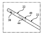
도 1은 전극 조립체를 포함하는 절제 시스템의 사시도이다.
도 2는 상세도 2 내의 도 1의 전극 조립체의 상세도이다.
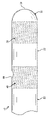
도 3은 도 1의 전극 조립체의 일부분의 정면도이다.
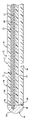
도 4는 도 3의 전극 조립체의 일부분의 단면도이다.
도 5는 선 5-5를 따라 취해진 도 3의 전극 조립체의 일부분의 축방향 도면이다.
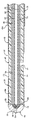
도 6은 전극 조립체의 다른 구현의 일부분의 단면도이다.
도 7은 전극 조립체의 다른 구현의 일부분의 단면도이다.
도 8은 전극 조립체의 다른 구현의 일부분의 단면도이다.
도 9는 전극 조립체의 다른 구현의 일부분의 단면도이다.
도 10은 전극 조립체의 다른 구현의 일부분의 단면도이다.
도 11은 골 내 종양 또는 기저추신경을 절제하기 위해 전극 조립체가 삽입기 조립체와 함께 전개되는 척추의 개략도이다.The advantages of the present invention will be readily understood as it is better understood by reference to the following detailed description when considered in conjunction with the accompanying drawings. It should be understood that the drawings are illustrative in nature and are not necessarily drawn to scale.
1 is a perspective view of an ablation system including an electrode assembly.
FIG. 2 is a detailed view of the electrode assembly of FIG. 1 in
3 is a front view of a portion of the electrode assembly of FIG. 1;
4 is a cross-sectional view of a portion of the electrode assembly of FIG. 3;
5 is an axial view of a portion of the electrode assembly of FIG. 3 taken along line 5-5.
6 is a cross-sectional view of a portion of another implementation of an electrode assembly.
7 is a cross-sectional view of a portion of another implementation of an electrode assembly.
8 is a cross-sectional view of a portion of another implementation of an electrode assembly.
9 is a cross-sectional view of a portion of another implementation of an electrode assembly.
10 is a cross-sectional view of a portion of another implementation of an electrode assembly.
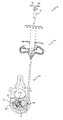
11 is a schematic diagram of a spine in which an electrode assembly is deployed together with an introducer assembly to resect an intraosseous tumor or basal spinal nerve.
도 1을 참조하면, 절제 시스템은 조직을 치료하도록 구성된 전극 조립체(12)를 포함한다. 전극 조립체(12)는 원위 단부(20)에 대향하는 근위 단부(16) 사이에 규정된 길이를 갖는 세장형 몸체(22)를 포함한다. 세장형 몸체(22)의 원위 단부(20) 부근에서, 전극 조립체(12)는 원위 이미터(38), 및 원위 이미터(38)의 근위에 위치된 근위 이미터(40)를 포함한다. 원위 이미터(38) 및 근위 이미터(40)는 전극 조립체(12)의 구성이 바이폴라가 되도록 서로 전기적으로 절연될 수 있다. 본 개시의 양태들은 접지원, 예를 들면 접지 패드를 필요로 하는 모노폴라 전극 조립체 상에 제공될 수 있다.Referring to FIG. 1 , an ablation system includes an
전극 조립체(12)는 원위 및 근위 이미터(38, 40)와 전기적으로 연통하는 적어도 하나의 도체(50), 및 도체(50)와 전기적으로 연통하는 커넥터(52)를 포함한다. 커넥터(52)는 에너지원(54), 예를 들면 전기수술 발생기와 분리가능하게 결합되도록 구성된다. 하나의 적합한 에너지원(54)은 Stryker Corporation(Kalamazoo, Mich.)에 의해 상품명 MultiGen(MG1) 및 MultiGen 2(MG2)로 판매되는 무선 주파수 발생기 및 제어 콘솔이며, 이들은 2018년 11월 1일자로 공개된 공동 소유의 국제공개번호 WO2018/0200254에 설명되어 있고, 그 전체 내용은 본원에 참조로 포함된다. 에너지원(54)은 전극 조립체(12)에 가변 전류를 소싱할 수 있다. 제어 콘솔은 다양한 기간 동안 소싱된 전류의 주파수, 전류 및/또는 전압 레벨의 조정을 허용할 수 있다. 에너지원(54)으로부터의 에너지는 원위 및 근위 이미터(38, 40)가 반대 극성을 갖도록 하는 방식으로 원위 및 근위 이미터(38, 40)에 전달된다. 조직 내 또는 인접한 조직에 위치될 때, 원위 및 근위 이미터(38, 40) 사이를 통과하는 에너지는 조직을 가열 및 절제하거나, 또는 대안적으로 전기수술 절단 또는 응고를 용이하게 한다.The
언급한 바와 같이, 종래의 전극 조립체, 특히 유체 주입, 관주, 또는 내부 냉각을 구비한 전극 조립체는 일반적으로 최소 곡률을 초과하여 달성할 수 없다. 이들 전극 조립체는 축 외(off-axis) 위치 결정이 필요한 다른 절차 중, 편측 척추경(unipedicular) 접근을 통한 척추체 내의 충분한 후방 접근을 달성할 수 없다. 유리하게는, 본 개시의 전극 조립체(12)는 매우 유연성인 세장형 몸체(22)를 제공한다. 또한, 세장형 몸체(22)는 세장형 몸체(22)의 거의 전체 길이가 유연성을 갖도록 전극 조립체(12)의 원위 단부(20) 부근 또는 원위 단부(20)로 연장될 수 있다. 즉, 세장형 몸체(22)는 유연성 재료로부터의 구성에 있어서 단일형일 수 있고, 적어도 근위 이미터(40)의 원위로, 일부 경우에는 원위 이미터(38)의 원위로 연장될 수 있다. 예를 들면, 도 3은 근위 이미터(40)의 근위, 원위 및 근위 이미터(38, 40) 사이, 및 원위 이미터(38)의 원위인 연속 부분을 갖는 세장형 몸체(22)를 나타낸다. 대안적인 구현에 있어서, 세장형 몸체(22)는 하나보다 많은 하위 구성요소로 형성되는 것이 고려된다. 그 유연성에 기초하여, 세장형 몸체(22)는 추가로 설명되는 방식으로 삽입기 조립체(13)(도 11 참조)를 통해 전개될 때 구부러지거나 만곡되도록 구성된다.As mentioned, conventional electrode assemblies, particularly electrode assemblies with fluid injection, irrigation, or internal cooling, generally cannot achieve more than a minimum curvature. These electrode assemblies cannot achieve sufficient posterior access within the vertebral body via a unipedicular approach, among other procedures requiring off-axis positioning. Advantageously, the
세장형 몸체(22)는 전극 조립체(12)의 원위 단부(20)를 규정할 수 있고, 세장형 몸체(22)는 근위 단부(16)를 규정할 수 있다. 특정 구현에 있어서, 전극 조립체(12)는 허브(23)(도 11 참조)를 포함하고, 세장형 몸체(22)가 허브(23)로부터 원위방향으로 연장되어 있다. 이제 도 3 및 도 4를 참조하면, 세장형 몸체(22)는 외부 표면(72)을 포함하고, 설명될 적어도 하나의 루멘(34, 35)을 규정하는 적어도 하나의 내부 표면(70)을 더 포함할 수 있다. 특정 구현에 있어서, 세장형 몸체(22)는 폴리머이며, 즉 폴리머로 적어도 부분적으로 형성된다. 세장형 몸체(22)는 다른 적절한 제조 기술을 통해 압출, 성형, 또는 형상화될 수 있고, 필름, 섬유, 직물, 및 분말로 형성될 수 있다. 일례에 있어서, 세장형 몸체(22)는 폴리에테르에테르케톤(PEEK)으로부터 압출된 튜브이며, 이는 매우 유연하고, 의료 장치에 매우 적합한 재료 특성을 포함한다. 또한, 하나보다 많은 루멘(34, 35)을 구비한 구현에 있어서, PEEK 튜브를 압출하는 것은 공지의 장치에 비해 제조 복잡성 및 비용을 저감할 수 있다. 다른 적합한 재료, 예를 들면 특히 폴리테트라플루오로에틸렌(Teflon™), 페놀류, 폴리카보네이트, 폴리술판, 및 폴리옥시메틸렌이 고려된다. 적합한 재료는 3.6 기가파스칼(GPa) 미만의 영률을 포함할 수 있다.The
원위 및 근위 이미터(38, 40)는 세장형 몸체(22)에 결합되거나 세장형 몸체(22) 상에 배치된다. 보다 구체적으로, 원위 및 근위 이미터(38, 40)는 폴리머인 세장형 몸체(22)의 외부 표면(72)에 전기 전도성 재료를 도금함으로써 형성될 수 있다. 예시적인 도금 공정은 폴리머인 세장형 몸체(22) 상에 금속을 전기 도금하는 것을 포함하고, 이는 도 1 내지 도 3에서 점묘에 의해 개략적으로 나타내어진다. 폴리머 상에 금속을 도금하기 위한 하나의 적절한 제조 공정은 SAT Plating(Troy, Mich.)에 의해 개발되었다. 일례에 있어서, 금속은 금이지만, 다른 적합한 금속에는 특히 구리, 니켈, 스테인리스강, 티타늄, 및 크롬이 포함된다. 예를 들면, 구리 또는 니켈의 제 1 층이 폴리머 튜브에 부착될 수 있고, 금 또는 백금의 제 2 층이 제 1 층 상에 도금될 수 있다. 폴리머 재료 상의 금속 도금은 원위 및 근위 이미터(38, 40)를 전기 전도성으로 만들어 세장형 몸체(22)의 유연성에 악영향을 미치는 일 없이 RF 에너지를 전달한다. 근위 및 원위 이미터가 도금될 수 있는 다른 적절한 방식은 무전해 도금, 전착, 침지, 물리적 기상 퇴적(PVD), 화학적 기상 퇴적(CVD), 플라즈마 스프레이 등이 있다. Distal and
언급된 바와 같이, 원위 이미터(38)는 전극 조립체(12)가 바이폴라 전극으로서 작동하기 위해 필요한 만큼 근위 이미터(40)로부터 이격되고 전기적으로 절연된다. 원위 이미터(38)는 외부 표면(72)의 제 1 부분(56) 상에 금속을 도금함으로써 형성될 수 있고, 근위 이미터(40)는 외부 표면(72)의 제 2 부분(58) 상에 금속 또는 다른 금속을 도금함으로써 형성될 수 있다. 제 1 및 제 2 부분(56, 58)은 세장형 몸체(22)의 일부분이 근위 및 원위 이미터(38, 40) 사이에 절연 스페이서(42)를 형성하도록 서로 축방향으로 이격될 수 있다. 예를 들면, 세장형 몸체(22)가 PEEK 튜브인 구현에 있어서, PEEK 튜브 자체는 비전도성이고, 따라서 근위 및 원위 이미터(38, 40) 사이에 절연 스페이서(42)를 형성한다. 따라서, 근위 및 원위 이미터(38, 40)는 접착제, 나사산, 랩 조인트(lap joint) 등과 함께 기계적 결합을 요구할 수 있는 개별 절연 스페이서의 필요 없이 전기적으로 절연된다. 앞서 설명된 바와 같이 유연성을 증가시키고 제조 복잡성 및 비용을 절감하는 것에 추가하여, 상기 배열은 특히 더 큰 굽힘 각도 및 더 날카로운 곡률 반경으로 전극 조립체(12)를 구부렸을 경우, 개별 구성요소 간의 계면 및 그 계면을 통한 상응하는 주입 유체의 유출 가능성을 제거한다. 그렇지 않으면 계면에서의 유체 유출로 인해 작동 중 가상 전극이 장치 "내부"에 있게 되어 그 기능을 손상시킬 수 있다. 본 개시의 전극 조립체(12)는 이러한 단점을 극복한다.As noted, the
제 1 루멘(34)은 유체원(도시되지 않음)으로부터 배출 포트(44)로 주입 유체를 보내도록 구성될 수 있다. 배출 포트(44)는 세장형 몸체(22)의 길이를 따라 임의의 적절한 위치에 위치될 수 있고, 하나보다 많은 배출 포트(44)가 제공될 수 있다. 도 2 내지 도 4는 근위 이미터(40)에 의해 규정되거나 근위 이미터(40) 상에 배치된 배출 포트(44)를 나타내고, 도 5 내지 도 10은 절연 스페이서(42)를 형성하는 세장형 몸체(22)의 일부분, 즉 근위 및 원위 이미터(38, 40) 사이에 의해 규정된 배출 부분을 나타낸다. 배출 포트(44)를 원위 이미터(38)의 근위에 위치시킴으로써, 전극 조립체(12)가 접근 각도로 해부학적 구조 내에서 전개될 때 중력의 영향 하에 원위 이미터(38)의 표면을 따라 내려오는 주입 유체를 유리하게 제공할 수 있다. 예를 들면, 미세주입 모듈(도지되지 않음)을 이용한 유체(예를 들면, 식염수 또는 다른 전도성 유체)의 미세주입은 조직-이미터 계면을 가로지르는 에너지 전달을 용이하게 하고, 이는 온도, 임피던스, 수화, 및 이온 농도를 제어하여 생물학적 조직의 탄화를 방지하는 데 도움이 된다. 2020년 11월 5일자로 공개된 공동 소유의 국제공개번호 WO2020/0198150에 하나의 적합한 미세주입 모듈이 개시되었고, 그 전체 내용은 본원에 참조로 포함된다. 미세주입 모듈은, 예를 들면 유체 결합부(36)에 결합된 루어 락 고정구(Luer lock fitting)로 전극 조립체(12)에 해제가능하게 결합될 수 있다(도 1 참조). 미세주입 모듈은 그것의 상대적으로 작은 폼 팩터로 인해 "미세"로 간주될 수 있고, 및/또는 유체의 양은 상대적으로 낮은 속도로 주입될 수 있다. 그러나, 루멘(들)(34, 35)은 선택적이며, 세장형 몸체(22)는 단면이 중실일 수 있음이 이해되어야 한다. 생성된 전극 조립체는 주입을 제공하지 않을 수 있고, 전자적 하위 구성요소는 세장형 몸체(22)의 외부 표면(72)을 따라 배열될 수 있다. 필요에 따라 특정 구성요소를 전기적으로 절연하기 위해 하나 이상의 시스가 제공될 수 있다.
제 1 루멘(34)은 배출 포트(44)와 유체 연통하고, 그렇지 않으면 세장형 몸체(22) 내에 임의의 적절한 방식으로 배열될 수 있다. 예를 들면, 도 4는 세장형 몸체(22)의 일부분 내에서 길이방향으로 연장되고 배출 포트(44)에 대해 반경방향 바깥쪽으로 더 구부러지는 제 1 루멘(34)을 나타낸다. 도 6 내지 도 10은 배출 포트를 통과하여 세장형 몸체(22)의 원위 단부(20) 부근으로 길이방향으로 연장되는 제 1 루멘(34)을 나타낸다. 제 1 루멘(34)이 배출 포트(44)의 원위로 연장되는 구현에 있어서, 세장형 몸체(22)의 원위 단부(20)는 폐쇄형 단부로서 형성되거나(도 4) 또는 상세히 설명될 원위 캡(46)으로 폐색될 수 있다(도 6 내지 도 10). 예를 들면, 도 4에 나타내어진 세장형 몸체(22)의 원위 단부(20)는 세장형 몸체(22)의 원위 단부(20)를 적어도 부분적으로 둥글게 하거나, 끝이 가늘어지게 하거나, 폐쇄하기 위해 열이 가해지는 카테터 팁핑(tipping) 공정에 의해 형성될 수 있다. 대안적으로, 원위 단부(20)는 배출 포트(44) 또는 다른 배출 포트를 규정할 수 있다. 도 6 내지 도 10은 세장형 몸체(22)의 원위 단부(84)로 연장되는 루멘(34, 35)을 나타내고, 세장형 몸체(22)의 원위 단부(84)에 원위 캡(46)이 결합되어 있다. 특정 구현의 경우에서와 같이, 상기 배열은 루멘(34, 35)이 세장형 몸체(22)의 전체 길이를 연장시키는 결과를 초래할 수 있으며, 세장형 몸체(22)는 축방향 단면이 일정하고, 폼 팩터는 압출되는 세장형 몸체(22)에 특히 매우 적합하며 그 자체는 22 게이지, 14 게이지 등의 레벨의 소형 장치를 제조하기 위한 덜 복잡하고 보다 비용 효율적인 제조 공정이다. 마찬가지로, 다중-루멘 튜빙의 제조도 효율적인 방식으로 압출을 통해 달성될 수 있다. 다른 적절한 제조 기술은 진공 성형, 사출 성형, 블로우 성형, 적층 제조, 브레이딩 등을 포함할 수 있다.The
원위 및 근위 이미터(38, 40)는 에너지원(54)과 분리가능하게 결합되도록 도체(50)와 전기적으로 연통한다. 전기적 접속을 용이하게 하기 위해, 전극 조립체(12)는 원위 이미터(38)와 전기적으로 연통하는 제 1 전기 경로(76)를 포함한다. 또한, 전극 조립체(12)는 전극 조립체(12)의 원위 단부(20) 부근의 온도를 측정하도록 배열된 열전대(62)를 포함할 수 있고, 이는 도 4에 개략적으로 나타내어지고 도 6 내지 도 10에 한 쌍의 리드(80, 82)로서 도시된다. 제어 콘솔은 다른 측정된 파라미터와 함께, 열전대(62)에 의해 측정된 온도에 기초하여 전달되는 RF 에너지를 조절하도록 구성될 수 있다. 세장형 몸체(22)는 제 1 루멘(34)으로부터 유체적으로 분리된 제 2 루멘(35)을 규정할 수 있고 제 1 전기 경로(76) 및/또는 열전대(62)가 제 2 루멘(35) 내에 배치되어 있다. 도 4를 계속 참조하면, 제 1 전기 경로(76)는 제 2 루멘(35)을 통해 연장되어 원위 이미터(38)와 전기적으로 연통할 수 있다. 예를 들면, 제 1 전기 경로(76)는 원위 리드(92)일 수 있거나, 또는 제 2 루멘(35)을 규정하는 내부 표면(70) 상에 도금된 금속일 수 있다. 작은 구멍(도시되지 않음)은 내부 표면(70)으로부터 외부 표면(72)으로 연장되어 제 2 루멘(35) 내의 제 1 전기 경로(76)와 외부 표면(72) 상의 원위 이미터(38) 사이의 전기적 연통을 제공할 수 있다. 열전대(62)는 임의의 적절한 결합 수단으로 원위 단부(20)에서 또는 그 부근에서 세장형 몸체(22)에 고정될 수 있다. 특정 구현에 있어서, 하나 이상의 추가 열전대(도시되지 않음)는 근위 이미터(40)의 근위에 위치될 수 있다. 추가 열전대(들)은 전극 조립체(12)의 원위 단부(20)보다 더 근위 위치에서 절제된 병변의 진행을 모니터링하도록 구성될 수 있다. 제어 콘솔은 추가 열전대(들)에 의해 측정된 온도에 기초하여 전달되는 RF 에너지를 조절하도록 구성될 수 있다.Distal and
다중-루멘 배열은 주입 유체에 의한 전기적 구성요소의 잠재적인 손상을 방지한다. 또한, 세장형 몸체(22) 자체가 제 1 루멘(34)을 제 2 루멘(35)으로부터 분리하는 장벽을 제공하기 때문에, 세장형 몸체(22)의 유연성의 희생이 거의 없고, 내부 하위 구성요소 또는 이들 사이의 계면의 손상에 대한 우려가 덜하다.The multi-lumen arrangement prevents potential damage to electrical components by injection fluid. Also, since the
이제 도 6 내지 도 10을 참조하면, 원위 캡(46)은 세장형 몸체(22)에 결합될 수 있다. 원위 캡(46)은 전극 조립체(12)의 원위 단부(20)를 규정할 수 있다. 원위 캡(46)은 루멘(34, 35)을 밀봉하는 방식으로 세장형 몸체(22)에 고정될 수 있다. 또한, 원위 캡(46)은 전도성 재료로 형성될 수 있고, 원위 이미터(38)와 전기적으로 연통하여 배열될 수 있다. 추가로 설명되는 바와 같이, 원위 캡(46)은 원위 이미터(38)에 RF 에너지를 전달하기 위해 1 전기 경로(76)의 일부분을 형성할 수 있다. 원위 캡(46)은 세장형 몸체(22)의 외부 표면(72) 상에 위치된 원위 이미터(38)와 전기적으로 연통하여 배열될 수 있고, 원위 리드(92)(및/또는 열전대(62))가 루멘(34, 35) 내에 배치되어 있다. 이러한 배열에 있어서, 전극 조립체(12)의 전기적 하위 구성요소는 필요한 RF 에너지를 세장형 몸체(22)의 외부에 있는 원위 이미터(38)에 여전히 전달하면서 세장형 몸체(22)의 내부에 있을 수 있다. 일례에 있어서, 원위 캡(46) 자체는 납땜된 금속으로 형성되고, 따라서 전도성이 있으며, 다른 예에 있어서 전기 전도성 접착제는 금속으로 형성된 원위 캡(46)을 구비한 세장형 몸체(22)와 원위 캡(46) 사이의 계면에 도포될 수 있다. 특정 구현에 있어서, 원위 캡(46)은 비열성(non-thermal) 및 비전기 전도성 재료로 형성될 수 있다. 예를 들면, 원위 캡(46)은 원위 리드(92)를 위한 상대적으로 작은 면적의 땜납으로 형성될 수 있고, 그 후에 원위 캡(46) 자체가 비전도성 접착제로 캡핑된다.Referring now to FIGS. 6-10 ,
도 6은 원위 이미터(38)의 일부분이 세장형 몸체(22)의 원위 단부(84) 상에 배치된 전극 조립체(12)의 구현을 도시한다. 보다 구체적으로, 원위 이미터(38)의 제1 부분(86)은 세장형 몸체(22)의 외부 표면(72) 상에 도금되고, 원위 이미터(38)의 제 2 부분(88)은 세장형 몸체(22)의 원위 단부(84)를 형성하는 표면 상에 도금된다. 제 2 부분(88)은 제 1 부분(86)과 전기적으로 연통하고, 세장형 몸체(22)의 원위 단부(84) 주위에서 반경방향 안쪽으로 연장되는 립으로 간주될 수 있다. 원위 캡(46)의 근위 표면(48)은 원위 이미터(38)의 제 2 부분(88)과 전기적으로 연통하는 방식으로 고정된다. 납땜된 금속 자체는 응고 시 근위 표면(48)을 포함할 수 있고, 또는 대안적으로 원위 캡(46)은 근위 표면(48)을 포함하는 개별 금속 구성요소일 수 있다. 6 shows an implementation of
도 6의 구현은 제 1 루멘(34), 및 제 1 루멘(34)으로부터 유체적으로 분리된 제 2 루멘(35)을 규정하는 세장형 몸체(22)를 추가로 나타낸다. 열전대(62)의 리드(80, 82)는 제 2 루멘(35)을 통해 연장되고 원위 캡(46)에 고정된다. 원위 캡(46)의 납땜은 제 1 루멘(34) 및 제 2 루멘(35)을 폐색할 뿐만 아니라, 적절한 위치에 열전대(62)의 리드(80, 82)를 고정하기 위해서도 수행될 수 있다. 대안적으로, 리드(80, 82)는 접착제, 크림핑, 마찰 결합 등으로 원위 캡(46)에 고정될 수 있다. 원위 캡(46)은 전기 전도성 재료로 형성되고, 추가로 충분한 열전도성을 가진 재료로 형성될 수 있다. 원위 캡(46)은 절제되는 인접한 조직으로부터 열을 효과적으로 전달하고, 예를 들면 그 자체가 전기 전도성인 열전대(62)의 리드(80, 82)에 의해 열이 감지된다. 온도를 나타내는 전기 신호는 열전대(62)로부터 제어 콘솔로 전달된다. 또한, 열전대(62)의 리드(80, 82)가 전기 전도성인 경우, 특정 구현에 있어서 열전대(62)는 RF 에너지를 원위 캡(46)을 통해 원위 이미터(38)에 전달하도록 추가로 구성될 수 있음이 고려된다. 이러한 배열에 있어서, 제 1 전기 경로(76)는 RF 에너지를 도체(50)로부터 원위 이미터(38)에 전달하기 위한 원위 리드(92)를 필요로 하지 않을 수 있다(도 3 및 도 8 참조).The implementation of FIG. 6 further shows an
이제 도 7을 참조하면, 하이포튜브(90)가 제공되는 전극 조립체(12)의 다른 구현이 나타내어지고, 여기서 리드(80, 82)는 하이포튜브(90) 내에 배치된다. 도 6이 제 1 및 제 2 루멘(34, 35)을 규정하는 세장형 몸체(22)를 나타내는 반면, 도 7은 제 1 루멘(34) 내에 동축으로 배치된 하이포튜브(90)를 구비한 단일 루멘(제 1 루멘(34))을 나타낸다. 이러한 배열에 있어서, 제 1 루멘(34), 특히 하이포튜브(90)와 세장형 몸체(22)의 내부 표면(70) 사이의 환형 갭은 배출 포트(44)와 유체 연통한다. 열전대(62)의 리드(80, 82)는 주입 유체로부터 유체적으로 분리된다.Referring now to FIG. 7 , another implementation of an
하이포튜브(90)는, 예를 들면 땜납, 접착제 등으로 원위 캡(46)에 고정된 원위 단부(94)를 포함할 수 있다. 또한, 원위 이미터(38)의 제 1 부분(86)은 세장형 몸체(22)의 외부 표면(72) 상에 도금되고, 원위 이미터(38)의 제 2 부분(88)은 세장형 몸체(22)의 원위 단부(84)를 형성하는 표면 상에 도금되며, 제 1 및 제 2 부분(86, 88)은 원위 캡(46)과 유체 연통한다. 하이포튜브(90)의 원위 단부(94)는 나타내어진 바와 같이 폐쇄형 단부일 수 있고, 일례에 있어서 원위 캡(46)의 근위 표면(48)의 일부분은 반구형이고, 하이포튜브(90)의 원위 단부(94)가 반구형이며 사이즈 및 형상이 상보적이다. 하이포튜브(90)는 전기 전도성 재료, 예를 들면 스테인리스강으로 형성될 수 있다. 특정 구현에 있어서, 하이포튜브(90)는 도체(50)와 전기적으로 연통할 수 있고, RF 에너지를 원위 캡(46)을 통해 원위 이미터(38)에 전달하도록 추가로 구성될 수 있음이 고려된다. 이러한 배열에 있어서, 제 1 전기 경로(76)는 RF 에너지를 원위 이미터(38)에 전달하기 위한 원위 리드(92)를 필요로 하지 않을 수 있다(도 3 및 도 8 참조). 세장형 몸체(22)의 유연성을 제한하지 않도록 충분한 유연성을 가진 하이포튜브(90)가 형성될 수 있음이 또한 이해되어야 한다. 전기 전도성 재료로 형성된 하이포튜브(90)의 경우, 비전도성 재료로 형성된 재킷(96)이 하이포튜브(90)의 원위 단부(94)와 열전대(62) 사이에 배치될 수 있다. 재킷(96)은 그 사이의 열전도성을 제한하지 않으면서 열전대(62)로부터 하이포튜브(90)를 전기적으로 절연하도록 구성될 수 있다. 재킷(96)에 적합한 재료의 예는 열접착제 또는 열수축을 포함할 수 있다.
도 8은 원위 이미터(38)의 제 1 부분(86)이 세장형 몸체(22)의 외부 표면(72) 상에 도금되고, 원위 이미터(38)의 제 2 부분(88)이 세정형 몸체(22)의 원위 단부(84)를 형성하는 표면 상에 도금되고, 제 3 부분(98)이 세장형 몸체(22)의 원위 단부(84) 부근의 내부 표면(70)의 일부분 상에 도금되는 전극 조립체(12)의 구현을 도시한다. 제 3 부분(98)은 제 2 부분(88) 및 제 1 부분(86)과 전기적으로 연통하고, 원위 이미터(38)는 형태가 대략 원통형으로 간주될 수 있다. 도시된 구현은 세장형 몸체(22)의 원위 단부(84)로부터 제 3 부분(98)보다 먼 거리까지 근위방향으로 연장되는 제 1 부분(86)을 나타내지만, 대안적인 상대 치수가 고려된다.8 shows that a
제 3 부분(98)이 제 1 루멘(34) 내에 배치되는 경우, 원위 캡(46)은 제 3 부분(98)과 전기적으로 연통하도록 제 1 루멘(34) 내에 적어도 부분적으로 배치되거나 리세스될 수 있다(도 9 및 도 10 참조). 도 8은 원위 캡(46)의 원위 표면이 세장형 몸체(22)의 원위 단부(84)와 거의 접하도록 제 1 루멘(34) 내에 배치된 원위 캡(46)의 전체를 나타낸다. 원위 캡(46)의 외측 표면(100)은 원위 이미터(38)의 제 3 부분(98)에 고정된다. 납땜된 금속 자체는 응고 시 외측 표면(100)을 포함할 수 있고, 또는 대안적으로 원위 캡(46)은 외측 표면(100)을 포함하는 개별 금속 구성요소일 수 있다.When the
도 8의 구현은 열전대(62)의 리드(80, 82) 및 전기 경로(74)의 원위 리드(92)가 제 1 루멘(34) 내에 배치된 제 1 루멘(34)을 규정하는 세장형 몸체(22)를 추가로 도시한다. 리드(80, 82, 92)는 재킷 또는 시스(도시되지 않음) 내에 배치되어 주입 유체로부터 전기적 구성요소를 전기적으로 절연할 수 있다. 본 구현의 원위 캡(46)은 하이포튜브(90), 제 1 및 제 2 루멘(34, 35)을 구비한 세장형 몸체(22), 및/또는 본 개시의 임의의 다른 호환가능한 구현과 조합하여 사용될 수 있음이 추가로 이해되어야 한다.The implementation of FIG. 8 is an elongated body defining a
도 8은 루멘(34) 내에 배치된 원위 캡(46)을 나타내고, 도 9 및 도 10은 돔 형상이고 루멘(34) 내에 배치된 근위 캡 부분(102)을 더 포함하는 원위 캡(46)을 나타낸다. 일구현에 있어서, 원위 캡(46)은 돔 형상의 단부를 재현가능하게 납땜하는 것이 아니라 루멘(34) 내에서 보다 쉽게 납땜될 수 있다. 근위 캡 부분(102)은 하이포튜브(90) 및 원위 이미터(38)와 전기적으로 연통하여 제 1 전기 경로(76)의 일부분을 형성할 수 있다. 원위 캡(46)의 일부분이 루멘(34) 내에 배치되는 배열은 원위 이미터(38)의 제 3 부분(98)에 고정된 외측 표면(100)을 포함한다. 다른 이점들 중, 외측 표면(100)과 제 3 부분(98) 사이의 계면은 인장력이 아니라 전단력을 받고, 압력 하에서 유체를 받기 위한 보다 강건한 설계를 제공한다. 주입 유체는 대략 1bar의 압력일 수 있지만, 원위 캡(46)은 더 큰 압력을 수용하도록 구성될 수 있다.8 shows the
제 1 전기 경로(76)는 원위 이미터(38)에 RF 에너지를 전달하도록 구성된다. 전극 조립체(12)는 근위 이미터(40)와 전기적으로 연통하고 그것에 RF 에너지를 전달하도록 구성된 제 2 전기 경로(78)를 더 포함한다. 다시 도 4를 참조하면, 제 2 전기 경로(78)는 제 1 루멘(34)에 의해 규정된 만곡부를 가로질러 근위 이미터(40)에 결합된다. 제 2 전기 경로(78)는 제 1 루멘(34), 리드 등을 규정하는 내부 표면(70) 상에 금속을 도금함으로써 형성될 수 있다. 제 1 전기 경로(76)는 제 2 전기 경로(78)로부터 절연되지만 근위 이미터(40)를 지나 축방향으로 연장되어야 하므로, 제 1 전기 경로(76)를 세장형 몸체(22)의 내부에 위치시키는 것이 바람직할 수 있다. 즉, 예를 들면 근위 이미터(40)에 걸쳐 세장형 몸체(22)의 외부 표면(72)을 따라 연장되는 원위 리드(92)가 아니라, 루멘(34, 35) 내에 제 1 전기 경로(76)를 가짐으로써 아크 발생 또는 전기적 손상에 대한 우려를 덜 수 있다. 근위 이미터(40)로부터 근위방향으로 연장되는 리드가 어떤 방식으로든 원위 이미터(38)를 전기적으로 연루시키지 않기 때문에, 이러한 우려는 근위 이미터(40)에서 덜 두드러진다. 그러나, 근위 이미터(40)는 근위 이미터(40)로부터 전기적으로 절연되는 방식으로 갭을 통해 연장되는 원위 리드(92)를 구비한 갭(도시하지 않음)을 규정하도록 C-형상일 수 있음이 고려된다.The first
이제 도 7 내지 도 10을 참조하면, 전극 조립체(12)는 비전도성 재료로 형성된 시스(104)를 포함할 수 있다. 제 2 전기 경로(78)는 세장형 몸체(22)와 시스(104) 사이에서 연장될 수 있다. 특정 구현에 있어서, 시스(104)는 근위 이미터(40)로부터 연장되는 근위 리드(108) 또는 도금된 도체에 의해 규정되는 제 2 전기 경로(78)를 구비한 열수축 튜빙이다. 도 7 내지 도 9는 시스(104) 아래에 배치된 근위 이미터(40)의 일부분으로 간주될 수 있는 도금된 도체를 나타낸다. 시스(104) 아래의 도금된 도체는 근위 이미터(40)와 마찬가지로 세장형 몸체(22)의 외부 직경 주위에서 연장되거나, 또는 도금된 리드와 유사하게 좁게 형상화될 수 있다. 도 10은 근위 이미터(40)의 외부 표면에 결합되고 시스(104)와 세장형 몸체(22) 사이에 배치된 근위 리드(108)를 나타낸다. 제 2 전기 경로(78) 및 시스(104)는 세장형 몸체(22)의 전체 길이 또는 그 일부분에 대해 근위방향으로 연장될 수 있다. 일례에 있어서, 제 2 전기 경로(78) 및 시스(104)는 세장형 몸체(22)의 근위 부분에 걸쳐 결합된 허브(23) 아래에 배치될 때까지 근위방향으로 연장될 수 있다(도 11 참조).Referring now to FIGS. 7-10 , the
세장형 몸체(22)가 폴리머이기 때문에, 세장형 몸체(22)는 형광 투시 및 다른 x-선 화상 상에서 상대적으로 방사선 투과성일 수 있다. 본 개시의 전극 조립체(12)는 x-선 화상 상에서 시각화되기에 충분한 방사선 밀도를 갖는 적어도 하나의 방사선 불투과성 마커(106)를 포함한다. 방사선 불투과성 마커(106)는 세장형 몸체(22)를 따라 임의의 적절한 위치에 결합될 수 있다. 예시적인 구현에 있어서 그리고 도 9 및 도 10을 참조하면, 방사선 불투과성 마커(106)는 근위 이미터(40)에 결합된 밴드이다. 또한, 방사선 불투과성 마커(106)는 x-선 화상 상에서 근위 이미터(40)를 시각적으로 북엔드하도록 시스(104)의 바로 원위에 위치될 수 있다. 방사선 불투과성 마커(106)는 x-선 화상 상에서 쉽게 시각화되도록 백금, 또는 백금 이리듐과 같은 금속으로 형성될 수 있다. 방사선 불투과성 마커(106)는 제 2 전기 경로(78)의 일부분을 형성할 수 있다. 예를 들면, 도 9는 근위 이미터(40)에 결합된 방사선 불투과성 마커(106)를 나타내고, 도 10은 근위 리드(108)를 근위 이미터(40)에 고정하는 밴드인 방사선 불투과성 마커(106)를 나타낸다. 방사선 불투과성 마커(106)는 크림핑되거나, 스웨이징되거나, 그렇지 않으면 근위 이미터(40) 또는 세장형 몸체(22)에 고정될 수 있다.Because the
상술한 바와 같이, 원위 캡(46)은 전기 전도성 재료로 형성된다. 이와 같이, 원위 캡(46)은 x-선 화상 상에서 원위 이미터(38)를 시각적으로 북엔드하도록 x-선 화상 상에서 쉽게 시각화될 수 있다. 세장형 몸체(22)가 상대적으로 방사선 투과성일 수 있기 때문에, 원위 캡(46) 및 방사선 불투과성 마커(106)는 x-선 화상 상에서 특히 두드러져 관심의 해부학적 위치 내에서의 정확한 위치 결정을 용이하게 할 수 있다. 따라서, 원위 캡(46)은 전극 조립체(12)와 관련된 여러 기능을 제공한다는 것이 쉽게 이해된다. 특정 구현에 있어서, 다른 방사선 불투과성 마커(도시되지 않음)는 전극 조립체(12)의 원위 단부(20) 부근에서 스웨이징되는 밴드일 수 있다. 이러한 배열은 원위 캡(46)이 접착제이거나, 충분히 방사선 불투과성이 아닌 다른 재료로 형성되는 경우에 특히 매우 적합할 수 있다. 추가적으로 또는 대안적으로, 금속을 도금함으로써 형성된 근위 및 원위 이미터(38, 40)는 그 자체가 방사선 불투과성일 수 있다. 예를 들면, 백금의 금과 같은 높은 원자량을 갖는 금속의 충분히 두꺼운 층으로 도금하면, x-선 화상 상에서 시각화되기에 충분한 방사선 밀도를 제공할 수 있다. 방사선 불투과성 마커(들)(106)이 세장형 몸체(22)의 외부 표면(72) 상에 배치되거나 그에 결합될 필요가 없음이 더욱 더 고려된다. 특정 구현에 있어서, 방사선 불투과성 마커(들)(106)은 루멘(34, 35) 내에 배치될 수 있다. 예를 들면, 텅스텐 와이어와 같은 와이어의 세그먼트는 루멘(34, 35) 내의 하나 이상의 소망의 위치에 고정될 수 있다.As noted above, the
본 개시의 전극 조립체(12)는 종래의 장치로 이전에 접근할 수 없었던 해부학적 위치에서의 조직의 치료를 용이하게 한다. 보다 구체적으로, 세장형 몸체(22)의 유연성은 더 큰 곡률 및/또는 더 날카로운 곡률 반경을 필요로 하는 해부학적 위치에 대한 접근을 제공한다. 이제 도 11을 참조하면, 세장형 몸체(22)는 삽입기 조립체(13)를 통해 전개될 때 구부러지거나 만곡되도록 구성된다. 하나의 적합한 삽입기 조립체가 2017년 12월 12일자로 발행된 공동 소유의 미국특허번호 9,839,443에 개시되어 있으며, 그 전체 내용은 본원에 참조로 포함된다. 특정 구현에 있어서, 세장형 몸체(22)는 적어도 60도, 보다 특히 적어도 90도, 더욱 보다 특히 적어도 120도의 만곡부를 통해 전개되기에 충분한 유연성을 갖는다. 또한, 세장형 몸체(22)는 약 0.75 내지 2.50인치의 범위, 보다 특히 약 1.25 내지 2.25인치의 범위 내의 곡률 반경을 갖는 만곡부를 통해 전개되기에 충분한 유연성을 갖는다.The
절제 시스템(11)은 전극 조립체(12), 삽입기 조립체(13), 및 접근 캐뉼라(14)를 포함할 수 있다. 절제 시스템(11)은 키트로서 패키징될 수 있다. 절제 시스템(11)이 전개될 수 있는 예시적인 방식은 척추체 내의 골 종양(BT)의 절제이다. 골 종양은 접근 캐뉼라(14)가 전개되는 추궁근(vertebral pedicle)으로부터 현저히 후방 및 현저히 반대측인 것으로 도시된다. 전극 조립체(12)는 골 종양에 접근하기 위해서 약 180도의 만곡부를 통해 전개되는 것으로 나타내어진다. 절제 시스템(11)이 전개될 수 있는 다른 예시적인 방식은 척추체 내의 기저추신경(BVN)의 절제이다. 광학적 결과를 얻기 위해서는 기저추신경의 주요 후방측이 절제되어야 하는 것이 공지되어 있다. 기저추신경의 주요 후방측으로 접근하기 위해서, 전극 조립체(12)는 약 270도의 만곡부를 통해 전개되는 것으로 나타내어진다. 대안적으로, 전극 조립체(12)는 기저추신경의 주요 후방측으로 접근하기 위해서 더 날카로운 만곡부를 통해 전개될 수 있다.Ablation system 11 may include
접근 캐뉼라(14)는 추궁근을 통해 전개되고, 삽입기 조립체(13)는 접근 캐뉼라(14)를 통해 전개될 수 있다. 삽입기 조립체(13)는 접근 캐뉼라를 지나 만곡된 구성으로 척추체 내에 위치되도록 구성된 시스(15)를 포함할 수 있다. 전극 조립체리(12)는 삽입기 조립체(13)에 의해 생성된 골 내의 만곡된 경로 또는 시스(15)의 만곡된 구성을 추적하도록 구성된다. 전극 조립체(12)의 원위 단부(20)는 시스(15)의 원위 단부와 정합되어 대략적으로 위치될 수 있다. 전극 조립체(12)와의 위치 맞춤은 원위 캡(46) 및 방사선 불투과성 마커(106)를 시각화함으로써 x-선 화상 상에서 확인될 수 있다. 시스(15)는, 예를 들면 골 종양 내에서 또는 기저추신경을 가로질러 전극 조립체(12, 12')의 근위 및 원위 이미터(38, 40)를 노출시키도록 후퇴될 수 있다. 전극 조립체(12, 12')는 골 종양 또는 기저추신경을 절제하기 위해 작동된다. 본 개시의 절제 시스템(11)은 골성(osseous) 및 비골성(non-osseous) 적용을 포함한, 임의의 적절한 해부학적 위치에서 사용될 수 있음이 이해된다. 예시적인 비골성 적용은 후관절 신경근 절개(facet rhizotomy), 천장관절 신경 차단, 슬관절 신경 차단 등을 포함한다.The
상술한 개시는 본 발명을 임의의 특정 형태로 망라하거나 제한하도록 의도되지 않는다. 사용된 용어는 제한이 아닌 설명의 단어의 특성이도록 의도된다. 상기 교시에 비추어 많은 수정 및 변형이 가능하고, 본 발명은 구체적으로 설명된 것과 다르게 실행될 수 있다. 예를 들면, 제 1 루멘(34)(및/또는 제 2 루멘(35))의 내부 직경은 도 4 내지 도 10에서 축척대로 나타내어지지 않을 수 있고, 오히려 전극 조립체(12)의 구성요소의 유의미한 도시를 위해 과장될 수 있음이 이해되어야 한다. 즉, 열전대(62), 하이포튜브(90), 및/또는 원위 리드(92)는 제 1 루멘(34) 내에서 상대적인 형태-맞춤식 배열일 수 있다. 제 1 루멘(34) 내의 임의의 자유 공간을 폐색하기 위해 추가 매체, 예를 들면 유전체 재료가 제공될 수 있다.The foregoing disclosure is not intended to be exhaustive or limit the invention in any particular form. The terms used are intended to be of the nature of the word of description and not of limitation. Many modifications and variations are possible in light of the above teachings, and the invention may be practiced otherwise than specifically described. For example, the inner diameter of the first lumen 34 (and/or the second lumen 35) may not be drawn to scale in FIGS. It should be understood that this may be exaggerated for the city. That is,
Claims (26)
루멘을 규정하는 내부 표면 반대쪽의 외부 표면을 포함하는 세장형 몸체 - 상기 세장형 몸체는 비전도성 재료로 형성됨 -;
상기 외부 표면의 제 1 부분 상에 금속을 도금함으로써 형성된 근위 이미터; 및
상기 외부 표면의 제 2 부분 상에 상기 금속 또는 다른 금속을 도금함으로써 형성된 원위 이미터를 포함하고,
상기 제 1 부분 및 상기 제 2 부분은 상기 세장형 몸체가 상기 근위 이미터와 상기 원위 이미터 사이에 절연 스페이서를 형성하도록 서로 이격되는, 전극 조립체.As an electrode assembly,
an elongate body including an outer surface opposite an inner surface defining a lumen, the elongated body being formed of a non-conductive material;
a proximal emitter formed by plating a metal on a first portion of the outer surface; and
a far emitter formed by plating the metal or another metal on a second portion of the outer surface;
wherein the first portion and the second portion are spaced from each other such that the elongate body forms an insulating spacer between the proximal emitter and the distal emitter.
상기 세장형 몸체에 결합되어 상기 전극 조립체의 원위 단부를 규정하는 원위 캡을 더 포함하고, 상기 원위 캡은 전도성 재료로 형성되고, 상기 원위 이미터와 전기적으로 연통하여 배열되는, 전극 조립체.The method of claim 1,
and a distal cap coupled to the elongated body and defining a distal end of the electrode assembly, the distal cap being formed of a conductive material and arranged in electrical communication with the distal emitter.
루멘을 규정하는 내부 표면 반대쪽의 외부 표면을 포함하는 세장형 몸체 - 상기 세장형 몸체는 비전도성 재료로 형성됨 -;
상기 외부 표면의 제 1 부분 상에 배열된 근위 이미터;
상기 외부 표면의 제 2 부분 상에 배열된 원위 이미터 - 상기 제 1 부분 및 상기 제 2 부분은 상기 세장형 몸체가 상기 근위 이미터와 상기 원위 이미터 사이에 절연 스페이서를 형성하도록 서로 이격됨 -; 및
상기 세장형 몸체에 결합되어 상기 전극 조립체의 원위 단부를 규정하는 원위 캡 - 상기 원위 캡은 전도성 재료로 형성되고, 상기 원위 이미터와 전기적으로 연통하여 배열됨 - 을 포함하는, 전극 조립체.As an electrode assembly,
an elongate body including an outer surface opposite an inner surface defining a lumen, the elongated body being formed of a non-conductive material;
a proximal emitter arranged on a first portion of the outer surface;
a distal emitter arranged on a second portion of the outer surface, the first portion and the second portion spaced apart from each other such that the elongate body forms an insulating spacer between the proximal emitter and the distal emitter; ; and
and a distal cap coupled to the elongate body to define a distal end of the electrode assembly, the distal cap being formed of a conductive material and arranged in electrical communication with the distal emitter.
상기 원위 캡은 상기 세장형 몸체의 원위 표면에 고정되고, 상기 원위 이미터는 상기 원위 표면 상에 상기 금속을 전착함으로써 더 형성되는, 전극 조립체.According to claim 2 or claim 3,
wherein the distal cap is secured to the distal surface of the elongated body, and the distal emitter is further formed by electrodepositing the metal on the distal surface.
상기 원위 캡은 상기 루멘 내에 적어도 부분적으로 고정되고, 상기 원위 이미터는 상기 내부 표면 상에 상기 금속을 전착함으로써 더 형성되는, 전극 조립체.The method according to any one of claims 2 to 4,
wherein the distal cap is secured at least partially within the lumen, and wherein the distal emitter is further formed by electrodepositing the metal on the inner surface.
상기 루멘을 통해 연장되고, 상기 원위 캡과 전기적으로 연통하는 원위 리드를 더 포함하는, 전극 조립체.The method according to any one of claims 2 to 5,
and a distal lead extending through the lumen and in electrical communication with the distal cap.
상기 루멘을 통해 연장되고, 상기 원위 캡과 열적으로 연통하는 열전대를 더 포함하는, 전극 조립체.The method according to any one of claims 2 to 6,
and a thermocouple extending through the lumen and in thermal communication with the distal cap.
상기 루멘을 통해 연장되고, 상기 원위 캡에 결합된 폐쇄형 원위 단부를 포함하는 하이포튜브를 더 포함하고, 상기 열전대는 상기 하이포튜브 내에 배치되는, 전극 조립체.The method of claim 7,
and a hypotube extending through the lumen and including a closed distal end coupled to the distal cap, wherein the thermocouple is disposed within the hypotube.
상기 열전대를 상기 하이포튜브로부터 전기적으로 절연하기 위해 상기 열전대에 배치된 재킷을 더 포함하는, 전극 조립체.The method of claim 8,
and a jacket disposed on the thermocouple to electrically insulate the thermocouple from the hypotube.
상기 세장형 몸체는 상기 루멘과 유체 연통하는 주입 포트를 더 규정하는, 전극 조립체.According to claim 8 or claim 9,
wherein the elongate body further defines an injection port in fluid communication with the lumen.
상기 근위 이미터의 일부분에 걸쳐 동축으로 배치된 시스(sheath)를 더 포함하고, 상기 시스는 비전도성 재료로 형성되는, 전극 조립체.The method according to any one of claims 1 to 10,
The electrode assembly further comprises a sheath disposed coaxially over a portion of the proximal emitter, wherein the sheath is formed of a non-conductive material.
상기 근위 이미터와 전기적으로 연통하여 배열되고, 상기 시스와 상기 세장형 몸체의 상기 외부 표면 사이에서 근위방향으로 연장되는 근위 리드를 더 포함하는, 전극 조립체.The method of claim 11,
and a proximal lead arranged in electrical communication with the proximal emitter and extending proximally between the sheath and the outer surface of the elongate body.
상기 근위 리드를 상기 근위 이미터에 고정하는 방사선 불투과성 마커 밴드를 더 포함하는, 전극 조립체.The method of claim 12,
and a radiopaque marker band securing the proximal lead to the proximal emitter.
루멘을 규정하는 내부 표면 반대쪽의 외부 표면을 포함하는 세장형 몸체 - 상기 세장형 몸체는 비전도성 재료로 형성됨 -;
상기 외부 표면의 제 1 부분 상에 배열된 근위 이미터;
상기 외부 표면의 제 2 부분 상에 배열된 원위 이미터 - 상기 제 1 부분 및 상기 제 2 부분은 상기 세장형 몸체가 상기 근위 이미터와 상기 원위 이미터 사이에 절연 스페이서를 형성하도록 서로 이격됨 -; 및
상기 근위 이미터의 일부분에 걸쳐 동축으로 배치된 시스 - 상기 시스는 비전도성 재료로 형성됨 - 를 포함하는, 전극 조립체.As an electrode assembly,
an elongate body including an outer surface opposite an inner surface defining a lumen, the elongated body being formed of a non-conductive material;
a proximal emitter arranged on a first portion of the outer surface;
a distal emitter arranged on a second portion of the outer surface, the first portion and the second portion spaced apart from each other such that the elongate body forms an insulating spacer between the proximal emitter and the distal emitter; ; and
and a sheath disposed coaxially over a portion of the proximal emitter, wherein the sheath is formed of a non-conductive material.
상기 근위 이미터에 결합된 방사선 불투과성 마커를 더 포함하는, 전극 조립체.According to any one of claims 1 to 14,
The electrode assembly of claim 1, further comprising a radiopaque marker coupled to the proximal emitter.
루멘을 규정하는 내부 표면 반대쪽의 외부 표면을 포함하는 세장형 몸체 - 상기 세장형 몸체는 비전도성 재료로 형성됨 -;
상기 외부 표면의 제 1 부분 상에 배열된 근위 이미터;
상기 외부 표면의 제 2 부분 상에 배열된 원위 이미터 - 상기 제 1 부분 및 상기 제 2 부분은 상기 세장형 몸체가 상기 근위 이미터와 상기 원위 이미터 사이에 절연 스페이서를 형성하도록 서로 이격됨 -;
상기 근위 이미터의 일부분에 걸쳐 배치된 시스 - 상기 시스는 비전도성 재료로 형성됨 -;
상기 근위 이미터와 전기적으로 연통하여 배열되고, 상기 시스와 상기 세장형 몸체의 상기 외부 표면 사이에서 근위방향으로 연장되는 근위 리드; 및
상기 근위 리드를 상기 근위 이미터에 고정하는 방사선 불투과성 마커 밴드를 포함하는, 전극 조립체.As an electrode assembly,
an elongate body including an outer surface opposite an inner surface defining a lumen, the elongated body being formed of a non-conductive material;
a proximal emitter arranged on a first portion of the outer surface;
a distal emitter arranged on a second portion of the outer surface, the first portion and the second portion spaced apart from each other such that the elongate body forms an insulating spacer between the proximal emitter and the distal emitter; ;
a sheath disposed over a portion of the proximal emitter, the sheath being formed of a non-conductive material;
a proximal lead arranged in electrical communication with the proximal emitter and extending proximally between the sheath and the outer surface of the elongate body; and
and a radiopaque marker band securing the proximal lead to the proximal emitter.
상기 루멘은 제 1 루멘이고, 상기 세장형 몸체의 상기 내부 표면은 상기 제 1 루멘으로부터 유체적으로 분리된 제 2 루멘, 및 상기 제 2 루멘과 유체 연통하는 주입 포트를 규정하고, 상기 제 1 루멘은 전기적 구성요소를 위한 전기 경로를 규정하고, 상기 제 2 루멘은 유체원(fluid source)으로부터 받는 유체가 상기 주입 포트를 통해 배출되기 위한 유체 경로를 규정하는, 전극 조립체.The method according to any one of claims 1 to 16,
wherein the lumen is a first lumen and the interior surface of the elongate body defines a second lumen fluidly separated from the first lumen and an injection port in fluid communication with the second lumen; defines an electrical pathway for an electrical component, and wherein the second lumen defines a fluid pathway for fluid received from a fluid source to be expelled through the injection port.
상기 주입 포트는 상기 근위 이미터 또는 상기 절연 스페이서 내에 축방향으로 위치되는, 전극 조립체.The method of claim 17
wherein the injection port is located axially within the proximal emitter or the insulating spacer.
상기 원위 캡은 땜납인, 전극 조립체.According to any one of claims 2 to 18,
The electrode assembly of claim 1, wherein the distal cap is solder.
제 1 루멘, 상기 제 1 루멘으로부터 유체적으로 분리된 제 2 루멘, 및 상기 제 2 루멘과 유체 연통하는 주입 포트를 규정하는 내부 표면 반대쪽의 외부 표면을 포함하는 세장형 몸체 - 상기 세장형 몸체는 비전도성 재료로 형성됨 -;
상기 외부 표면의 제 1 부분 상에 배열된 근위 이미터; 및
상기 외부 표면의 제 2 부분 상에 배열된 원위 이미터 - 상기 제 1 부분 및 상기 제 2 부분은 상기 세장형 몸체가 상기 근위 이미터와 상기 원위 이미터 사이에 절연 스페이서를 형성하도록 서로 이격됨 - 를 포함하고,
상기 제 1 루멘은 상기 전극 조립체의 전기적 구성요소를 위한 전기 경로를 규정하고, 상기 제 2 루멘은 유체원으로부터 받는 유체가 상기 주입 포트를 통해 배출되기 위한 유체 경로를 규정하는, 전극 조립체.As an electrode assembly,
an elongated body comprising a first lumen, a second lumen fluidly separated from the first lumen, and an outer surface opposite an inner surface defining an infusion port in fluid communication with the second lumen, the elongate body comprising: formed of non-conductive material;
a proximal emitter arranged on a first portion of the outer surface; and
a distal emitter arranged on a second portion of the outer surface, the first portion and the second portion spaced apart from each other such that the elongate body forms an insulating spacer between the proximal emitter and the distal emitter; including,
The electrode assembly, wherein the first lumen defines an electrical path for an electrical component of the electrode assembly, and the second lumen defines a fluid path for fluid received from a fluid source to be discharged through the injection port.
상기 제 1 이미터 및 상기 제 2 이미터는 상기 세장형 몸체의 상기 외부 표면 상에 금속을 도금함으로써 형성되는, 전극 조립체.The method according to any one of claims 3, 14, 16 and 20,
wherein the first emitter and the second emitter are formed by plating a metal on the outer surface of the elongate body.
상기 금속은 금, 백금, 구리, 니켈, 스테인리스강, 티타늄, 및 크롬으로 이루어지는 군으로부터 선택되는, 전극 조립체.The method of claim 21,
The electrode assembly, wherein the metal is selected from the group consisting of gold, platinum, copper, nickel, stainless steel, titanium, and chromium.
상기 제 1 이미터 및 상기 제 2 이미터는 무전해 도금, 전착, 침지, 물리적 기상 퇴적(PVD), 화학적 기상 퇴적(CVD), 및 플라즈마 스프레이로 이루어지는 군으로부터 형성되는, 전극 조립체.The method according to any one of claims 3, 14, 16 and 20,
wherein the first emitter and the second emitter are formed from the group consisting of electroless plating, electrodeposition, immersion, physical vapor deposition (PVD), chemical vapor deposition (CVD), and plasma spray.
상기 세장형 몸체는 구성이 단일형인, 전극 조립체.The method according to any one of claims 1 to 23,
The electrode assembly, wherein the elongated body is unitary in configuration.
상기 세장형 몸체는 폴리에테르에테르케톤(PEEK)의 압출된 세그먼트인, 전극 조립체.The method of claim 24
wherein the elongated body is an extruded segment of polyetheretherketone (PEEK).
미세주입 모듈을 포함하는, 절제 시스템(ablation system).The electrode assembly according to any one of claims 1 to 25; and
An ablation system comprising a microinjection module.
Applications Claiming Priority (3)
| Application Number | Priority Date | Filing Date | Title |
|---|---|---|---|
| US202062993317P | 2020-03-23 | 2020-03-23 | |
| US62/993,317 | 2020-03-23 | ||
| PCT/US2021/023697 WO2021195091A1 (en) | 2020-03-23 | 2021-03-23 | Electrode assembly including plated emitters |
Publications (1)
| Publication Number | Publication Date |
|---|---|
| KR20220157458A true KR20220157458A (en) | 2022-11-29 |
Family
ID=75478321
Family Applications (1)
| Application Number | Title | Priority Date | Filing Date |
|---|---|---|---|
| KR1020227036528A KR20220157458A (en) | 2020-03-23 | 2021-03-23 | Electrode assembly including plated emitter |
Country Status (8)
| Country | Link |
|---|---|
| US (1) | US20230117847A1 (en) |
| EP (1) | EP4125662A1 (en) |
| JP (1) | JP2023520666A (en) |
| KR (1) | KR20220157458A (en) |
| CN (1) | CN115334988A (en) |
| AU (1) | AU2021244391A1 (en) |
| CA (1) | CA3172067A1 (en) |
| WO (1) | WO2021195091A1 (en) |
Family Cites Families (8)
| Publication number | Priority date | Publication date | Assignee | Title |
|---|---|---|---|---|
| US6042580A (en) * | 1998-05-05 | 2000-03-28 | Cardiac Pacemakers, Inc. | Electrode having composition-matched, common-lead thermocouple wire for providing multiple temperature-sensitive junctions |
| US9486275B2 (en) * | 2010-12-30 | 2016-11-08 | Avent, Inc. | Electrosurgical apparatus having a sensor |
| US9393070B2 (en) * | 2012-04-24 | 2016-07-19 | Cibiem, Inc. | Endovascular catheters and methods for carotid body ablation |
| CA3201083A1 (en) | 2012-06-20 | 2013-12-27 | Stryker Corporation | Systems and methods for off-axis tissue manipulation |
| US10285752B2 (en) * | 2015-12-07 | 2019-05-14 | Biosense Webster (Israel) Ltd. | Multilayer split ablation electrode |
| US10524859B2 (en) * | 2016-06-07 | 2020-01-07 | Metavention, Inc. | Therapeutic tissue modulation devices and methods |
| US11497543B2 (en) | 2017-04-28 | 2022-11-15 | Stryker Corporation | Control console and accessories for RF nerve ablation and methods of operating the same |
| EP3941376A2 (en) | 2019-03-22 | 2022-01-26 | Stryker Corporation | Systems for ablating tissue |
-
2021
- 2021-03-23 WO PCT/US2021/023697 patent/WO2021195091A1/en unknown
- 2021-03-23 US US17/914,097 patent/US20230117847A1/en active Pending
- 2021-03-23 KR KR1020227036528A patent/KR20220157458A/en unknown
- 2021-03-23 CN CN202180023065.6A patent/CN115334988A/en active Pending
- 2021-03-23 CA CA3172067A patent/CA3172067A1/en active Pending
- 2021-03-23 AU AU2021244391A patent/AU2021244391A1/en active Pending
- 2021-03-23 JP JP2022557953A patent/JP2023520666A/en active Pending
- 2021-03-23 EP EP21718435.7A patent/EP4125662A1/en active Pending
Also Published As
| Publication number | Publication date |
|---|---|
| CA3172067A1 (en) | 2021-09-30 |
| WO2021195091A1 (en) | 2021-09-30 |
| CN115334988A (en) | 2022-11-11 |
| EP4125662A1 (en) | 2023-02-08 |
| US20230117847A1 (en) | 2023-04-20 |
| JP2023520666A (en) | 2023-05-18 |
| AU2021244391A1 (en) | 2022-11-03 |
Similar Documents
| Publication | Publication Date | Title |
|---|---|---|
| EP2760358B1 (en) | Electrosurgical device with offset conductive element | |
| US7879031B2 (en) | Cooled RF ablation needle | |
| US9848932B2 (en) | Cool-tip thermocouple including two-piece hub | |
| US12082874B2 (en) | Irrigated ablation electrode assembly having off-center irrigation passageway | |
| US9956032B1 (en) | Electrosurgical generator | |
| US7815635B2 (en) | Catheter and method, in particular for ablation and like technique | |
| US20200188684A1 (en) | Polymer Introducer for Use with an RF Ablation Probe and Associated RF Ablation Probe Assembly | |
| US20120046610A1 (en) | Methods and devices for reducing bubble formations in fluid delivery devices | |
| US20230117847A1 (en) | Electrode Assembly Including Plated Emitters | |
| CA2521267C (en) | Cooled rf ablation needle | |
| EP1767165B1 (en) | Cooled ablation needle | |
| EP3897435B1 (en) | Cooled radiofrequency ablation probe | |
| US20210169558A1 (en) | Fiber Optic Temperature Sensor for Cooled Radiofrequency Probe | |
| WO2024158829A1 (en) | Integrated radiofrequency device for intraosseous nerve ablation | |
| WO2020131770A1 (en) | Steerable tip cooled radiofrequency ablation probe |