KR20220155984A - motion detection system - Google Patents
motion detection system Download PDFInfo
- Publication number
- KR20220155984A KR20220155984A KR1020227027274A KR20227027274A KR20220155984A KR 20220155984 A KR20220155984 A KR 20220155984A KR 1020227027274 A KR1020227027274 A KR 1020227027274A KR 20227027274 A KR20227027274 A KR 20227027274A KR 20220155984 A KR20220155984 A KR 20220155984A
- Authority
- KR
- South Korea
- Prior art keywords
- motion
- wiring
- electrode
- unit
- detection
- Prior art date
Links
- 238000001514 detection method Methods 0.000 title claims abstract description 345
- 230000033001 locomotion Effects 0.000 title claims abstract description 283
- 238000004891 communication Methods 0.000 claims abstract description 47
- 239000000463 material Substances 0.000 claims description 58
- OKTJSMMVPCPJKN-UHFFFAOYSA-N Carbon Chemical compound [C] OKTJSMMVPCPJKN-UHFFFAOYSA-N 0.000 claims description 50
- 239000004744 fabric Substances 0.000 claims description 50
- 239000002041 carbon nanotube Substances 0.000 claims description 45
- 229910021393 carbon nanotube Inorganic materials 0.000 claims description 45
- 230000008602 contraction Effects 0.000 claims description 44
- 230000008859 change Effects 0.000 claims description 31
- 238000003860 storage Methods 0.000 claims description 23
- 238000000034 method Methods 0.000 claims description 22
- 210000001503 joint Anatomy 0.000 claims description 17
- 230000007423 decrease Effects 0.000 claims description 15
- 230000001133 acceleration Effects 0.000 claims description 10
- 210000000811 metacarpophalangeal joint Anatomy 0.000 claims description 5
- 238000010801 machine learning Methods 0.000 claims description 2
- 210000003811 finger Anatomy 0.000 description 84
- 239000010410 layer Substances 0.000 description 64
- 229910052751 metal Inorganic materials 0.000 description 29
- 239000002184 metal Substances 0.000 description 29
- 238000012545 processing Methods 0.000 description 25
- 239000002131 composite material Substances 0.000 description 16
- 230000004048 modification Effects 0.000 description 14
- 238000012986 modification Methods 0.000 description 14
- 210000003813 thumb Anatomy 0.000 description 13
- 238000010586 diagram Methods 0.000 description 11
- PXHVJJICTQNCMI-UHFFFAOYSA-N Nickel Chemical compound [Ni] PXHVJJICTQNCMI-UHFFFAOYSA-N 0.000 description 10
- 239000000835 fiber Substances 0.000 description 10
- 230000008569 process Effects 0.000 description 10
- 210000000707 wrist Anatomy 0.000 description 10
- 238000005452 bending Methods 0.000 description 9
- BQCADISMDOOEFD-UHFFFAOYSA-N Silver Chemical compound [Ag] BQCADISMDOOEFD-UHFFFAOYSA-N 0.000 description 8
- 238000005259 measurement Methods 0.000 description 8
- 229910052709 silver Inorganic materials 0.000 description 8
- 239000004332 silver Substances 0.000 description 8
- 230000009471 action Effects 0.000 description 6
- 238000009940 knitting Methods 0.000 description 6
- 229910001092 metal group alloy Inorganic materials 0.000 description 5
- 229910052759 nickel Inorganic materials 0.000 description 5
- 238000009958 sewing Methods 0.000 description 5
- XMWRBQBLMFGWIX-UHFFFAOYSA-N C60 fullerene Chemical compound C12=C3C(C4=C56)=C7C8=C5C5=C9C%10=C6C6=C4C1=C1C4=C6C6=C%10C%10=C9C9=C%11C5=C8C5=C8C7=C3C3=C7C2=C1C1=C2C4=C6C4=C%10C6=C9C9=C%11C5=C5C8=C3C3=C7C1=C1C2=C4C6=C2C9=C5C3=C12 XMWRBQBLMFGWIX-UHFFFAOYSA-N 0.000 description 4
- RYGMFSIKBFXOCR-UHFFFAOYSA-N Copper Chemical compound [Cu] RYGMFSIKBFXOCR-UHFFFAOYSA-N 0.000 description 4
- XEEYBQQBJWHFJM-UHFFFAOYSA-N Iron Chemical compound [Fe] XEEYBQQBJWHFJM-UHFFFAOYSA-N 0.000 description 4
- 239000003575 carbonaceous material Substances 0.000 description 4
- 229910052802 copper Inorganic materials 0.000 description 4
- 239000010949 copper Substances 0.000 description 4
- 230000006870 function Effects 0.000 description 4
- 210000001624 hip Anatomy 0.000 description 4
- 210000003127 knee Anatomy 0.000 description 4
- 239000002759 woven fabric Substances 0.000 description 4
- 239000000853 adhesive Substances 0.000 description 3
- 239000004020 conductor Substances 0.000 description 3
- 210000004177 elastic tissue Anatomy 0.000 description 3
- 210000001513 elbow Anatomy 0.000 description 3
- 238000004519 manufacturing process Methods 0.000 description 3
- 229910044991 metal oxide Inorganic materials 0.000 description 3
- 150000004706 metal oxides Chemical class 0.000 description 3
- 150000002739 metals Chemical class 0.000 description 3
- VNWKTOKETHGBQD-UHFFFAOYSA-N methane Chemical compound C VNWKTOKETHGBQD-UHFFFAOYSA-N 0.000 description 3
- 239000000123 paper Substances 0.000 description 3
- 238000007747 plating Methods 0.000 description 3
- 239000011347 resin Substances 0.000 description 3
- 229920005989 resin Polymers 0.000 description 3
- 229920000049 Carbon (fiber) Polymers 0.000 description 2
- VYZAMTAEIAYCRO-UHFFFAOYSA-N Chromium Chemical compound [Cr] VYZAMTAEIAYCRO-UHFFFAOYSA-N 0.000 description 2
- 239000004952 Polyamide Substances 0.000 description 2
- ATJFFYVFTNAWJD-UHFFFAOYSA-N Tin Chemical compound [Sn] ATJFFYVFTNAWJD-UHFFFAOYSA-N 0.000 description 2
- HCHKCACWOHOZIP-UHFFFAOYSA-N Zinc Chemical compound [Zn] HCHKCACWOHOZIP-UHFFFAOYSA-N 0.000 description 2
- 230000001070 adhesive effect Effects 0.000 description 2
- 229910045601 alloy Inorganic materials 0.000 description 2
- 239000000956 alloy Substances 0.000 description 2
- 229910052782 aluminium Inorganic materials 0.000 description 2
- XAGFODPZIPBFFR-UHFFFAOYSA-N aluminium Chemical compound [Al] XAGFODPZIPBFFR-UHFFFAOYSA-N 0.000 description 2
- 210000003423 ankle Anatomy 0.000 description 2
- 230000008901 benefit Effects 0.000 description 2
- 239000004917 carbon fiber Substances 0.000 description 2
- 229910052804 chromium Inorganic materials 0.000 description 2
- 239000011651 chromium Substances 0.000 description 2
- 229920001940 conductive polymer Polymers 0.000 description 2
- 230000007797 corrosion Effects 0.000 description 2
- 238000005260 corrosion Methods 0.000 description 2
- 210000001145 finger joint Anatomy 0.000 description 2
- 210000002683 foot Anatomy 0.000 description 2
- PCHJSUWPFVWCPO-UHFFFAOYSA-N gold Chemical compound [Au] PCHJSUWPFVWCPO-UHFFFAOYSA-N 0.000 description 2
- 229910052737 gold Inorganic materials 0.000 description 2
- 239000010931 gold Substances 0.000 description 2
- 229910021389 graphene Inorganic materials 0.000 description 2
- 210000004247 hand Anatomy 0.000 description 2
- 238000009413 insulation Methods 0.000 description 2
- 229910052742 iron Inorganic materials 0.000 description 2
- 239000010985 leather Substances 0.000 description 2
- 210000003739 neck Anatomy 0.000 description 2
- 229920002647 polyamide Polymers 0.000 description 2
- 229920000728 polyester Polymers 0.000 description 2
- -1 polypropylene Polymers 0.000 description 2
- 230000000452 restraining effect Effects 0.000 description 2
- 210000002832 shoulder Anatomy 0.000 description 2
- 239000002356 single layer Substances 0.000 description 2
- 238000009987 spinning Methods 0.000 description 2
- 239000000758 substrate Substances 0.000 description 2
- 229910052718 tin Inorganic materials 0.000 description 2
- 239000011135 tin Substances 0.000 description 2
- 229910052725 zinc Inorganic materials 0.000 description 2
- 239000011701 zinc Substances 0.000 description 2
- 229920002972 Acrylic fiber Polymers 0.000 description 1
- 229910001369 Brass Inorganic materials 0.000 description 1
- 229910000906 Bronze Inorganic materials 0.000 description 1
- 244000025254 Cannabis sativa Species 0.000 description 1
- 235000012766 Cannabis sativa ssp. sativa var. sativa Nutrition 0.000 description 1
- 235000012765 Cannabis sativa ssp. sativa var. spontanea Nutrition 0.000 description 1
- 229910000975 Carbon steel Inorganic materials 0.000 description 1
- 229920000742 Cotton Polymers 0.000 description 1
- 229910000881 Cu alloy Inorganic materials 0.000 description 1
- 241001465754 Metazoa Species 0.000 description 1
- ZOKXTWBITQBERF-UHFFFAOYSA-N Molybdenum Chemical compound [Mo] ZOKXTWBITQBERF-UHFFFAOYSA-N 0.000 description 1
- 229910001096 P alloy Inorganic materials 0.000 description 1
- OAICVXFJPJFONN-UHFFFAOYSA-N Phosphorus Chemical compound [P] OAICVXFJPJFONN-UHFFFAOYSA-N 0.000 description 1
- 239000004743 Polypropylene Substances 0.000 description 1
- 229920000297 Rayon Polymers 0.000 description 1
- 229910000831 Steel Inorganic materials 0.000 description 1
- RTAQQCXQSZGOHL-UHFFFAOYSA-N Titanium Chemical compound [Ti] RTAQQCXQSZGOHL-UHFFFAOYSA-N 0.000 description 1
- 229910001297 Zn alloy Inorganic materials 0.000 description 1
- SNDJECPQBZAXEZ-UHFFFAOYSA-N [P].[Fe].[Zn].[Cu] Chemical compound [P].[Fe].[Zn].[Cu] SNDJECPQBZAXEZ-UHFFFAOYSA-N 0.000 description 1
- JUWOETZNAMLKMG-UHFFFAOYSA-N [P].[Ni].[Cu] Chemical compound [P].[Ni].[Cu] JUWOETZNAMLKMG-UHFFFAOYSA-N 0.000 description 1
- HZEWFHLRYVTOIW-UHFFFAOYSA-N [Ti].[Ni] Chemical compound [Ti].[Ni] HZEWFHLRYVTOIW-UHFFFAOYSA-N 0.000 description 1
- 229910003481 amorphous carbon Inorganic materials 0.000 description 1
- 238000013528 artificial neural network Methods 0.000 description 1
- DMFGNRRURHSENX-UHFFFAOYSA-N beryllium copper Chemical compound [Be].[Cu] DMFGNRRURHSENX-UHFFFAOYSA-N 0.000 description 1
- 239000010951 brass Substances 0.000 description 1
- 239000010974 bronze Substances 0.000 description 1
- 235000009120 camo Nutrition 0.000 description 1
- 239000006229 carbon black Substances 0.000 description 1
- 239000011852 carbon nanoparticle Substances 0.000 description 1
- 239000010962 carbon steel Substances 0.000 description 1
- 235000005607 chanvre indien Nutrition 0.000 description 1
- 238000006243 chemical reaction Methods 0.000 description 1
- KUNSUQLRTQLHQQ-UHFFFAOYSA-N copper tin Chemical compound [Cu].[Sn] KUNSUQLRTQLHQQ-UHFFFAOYSA-N 0.000 description 1
- XTYUEDCPRIMJNG-UHFFFAOYSA-N copper zirconium Chemical compound [Cu].[Zr] XTYUEDCPRIMJNG-UHFFFAOYSA-N 0.000 description 1
- 238000005336 cracking Methods 0.000 description 1
- 239000006185 dispersion Substances 0.000 description 1
- 239000013013 elastic material Substances 0.000 description 1
- 238000005516 engineering process Methods 0.000 description 1
- 239000010419 fine particle Substances 0.000 description 1
- 229910003472 fullerene Inorganic materials 0.000 description 1
- 229910002804 graphite Inorganic materials 0.000 description 1
- 239000010439 graphite Substances 0.000 description 1
- 229910021385 hard carbon Inorganic materials 0.000 description 1
- 229910000856 hastalloy Inorganic materials 0.000 description 1
- 239000011487 hemp Substances 0.000 description 1
- 230000006872 improvement Effects 0.000 description 1
- 230000010365 information processing Effects 0.000 description 1
- UGKDIUIOSMUOAW-UHFFFAOYSA-N iron nickel Chemical compound [Fe].[Ni] UGKDIUIOSMUOAW-UHFFFAOYSA-N 0.000 description 1
- 229910000953 kanthal Inorganic materials 0.000 description 1
- 239000004973 liquid crystal related substance Substances 0.000 description 1
- 230000007257 malfunction Effects 0.000 description 1
- 229910052750 molybdenum Inorganic materials 0.000 description 1
- 239000011733 molybdenum Substances 0.000 description 1
- 239000002071 nanotube Substances 0.000 description 1
- 229910001120 nichrome Inorganic materials 0.000 description 1
- 229910001000 nickel titanium Inorganic materials 0.000 description 1
- 229910000623 nickel–chromium alloy Inorganic materials 0.000 description 1
- 239000004745 nonwoven fabric Substances 0.000 description 1
- 229920000642 polymer Polymers 0.000 description 1
- 229920001155 polypropylene Polymers 0.000 description 1
- 229920002635 polyurethane Polymers 0.000 description 1
- 239000004814 polyurethane Substances 0.000 description 1
- 239000002964 rayon Substances 0.000 description 1
- 230000004044 response Effects 0.000 description 1
- DECCZIUVGMLHKQ-UHFFFAOYSA-N rhenium tungsten Chemical compound [W].[Re] DECCZIUVGMLHKQ-UHFFFAOYSA-N 0.000 description 1
- 238000000926 separation method Methods 0.000 description 1
- 238000009751 slip forming Methods 0.000 description 1
- 229910021384 soft carbon Inorganic materials 0.000 description 1
- 229910000679 solder Inorganic materials 0.000 description 1
- 239000007787 solid Substances 0.000 description 1
- 238000004544 sputter deposition Methods 0.000 description 1
- 239000010935 stainless steel Substances 0.000 description 1
- 229910001220 stainless steel Inorganic materials 0.000 description 1
- 239000010959 steel Substances 0.000 description 1
- 239000000126 substance Substances 0.000 description 1
- 229920002994 synthetic fiber Polymers 0.000 description 1
- 239000012209 synthetic fiber Substances 0.000 description 1
- 229910052719 titanium Inorganic materials 0.000 description 1
- 239000010936 titanium Substances 0.000 description 1
- 238000012549 training Methods 0.000 description 1
- 230000007704 transition Effects 0.000 description 1
- WFKWXMTUELFFGS-UHFFFAOYSA-N tungsten Chemical compound [W] WFKWXMTUELFFGS-UHFFFAOYSA-N 0.000 description 1
- 229910052721 tungsten Inorganic materials 0.000 description 1
- 239000010937 tungsten Substances 0.000 description 1
- 239000013598 vector Substances 0.000 description 1
- 238000009941 weaving Methods 0.000 description 1
- 238000004804 winding Methods 0.000 description 1
- 210000002268 wool Anatomy 0.000 description 1
Images


Classifications
-
- G—PHYSICS
- G06—COMPUTING; CALCULATING OR COUNTING
- G06F—ELECTRIC DIGITAL DATA PROCESSING
- G06F3/00—Input arrangements for transferring data to be processed into a form capable of being handled by the computer; Output arrangements for transferring data from processing unit to output unit, e.g. interface arrangements
- G06F3/01—Input arrangements or combined input and output arrangements for interaction between user and computer
- G06F3/011—Arrangements for interaction with the human body, e.g. for user immersion in virtual reality
- G06F3/014—Hand-worn input/output arrangements, e.g. data gloves
-
- A—HUMAN NECESSITIES
- A41—WEARING APPAREL
- A41D—OUTERWEAR; PROTECTIVE GARMENTS; ACCESSORIES
- A41D19/00—Gloves
- A41D19/0024—Gloves with accessories
- A41D19/0027—Measuring instruments, e.g. watch, thermometer
-
- A—HUMAN NECESSITIES
- A41—WEARING APPAREL
- A41D—OUTERWEAR; PROTECTIVE GARMENTS; ACCESSORIES
- A41D19/00—Gloves
- A41D19/015—Protective gloves
-
- G—PHYSICS
- G06—COMPUTING; CALCULATING OR COUNTING
- G06F—ELECTRIC DIGITAL DATA PROCESSING
- G06F3/00—Input arrangements for transferring data to be processed into a form capable of being handled by the computer; Output arrangements for transferring data from processing unit to output unit, e.g. interface arrangements
- G06F3/01—Input arrangements or combined input and output arrangements for interaction between user and computer
- G06F3/017—Gesture based interaction, e.g. based on a set of recognized hand gestures
Abstract
통신부는, 피장착체에 장착되는 동작 검지용 부재에 의해 피장착체의 동작 정보를 검지하는 동작 검지부에 의해 검지된 동작 정보를 서버에 송신하고, 동작 판정부는, 동작 정보가, 어떠한 동작인지를 판정한다.The communication unit transmits the motion information detected by the motion detection unit that detects the motion information of the attached object by the motion detecting member attached to the attached object to the server, and the motion determination unit determines what kind of motion the motion information is. judge
Description
본 개시는, 동작 검지 시스템에 관한 것이다.The present disclosure relates to a motion detection system.
종래, 예를 들면, 인체의 부위(팔꿈치부, 무릎부, 허리부, 손의 손가락 등) 등의 동작을 검지하기 위한 동작 검지용 부재를 이용한 동작 검지 시스템이 알려져 있다.BACKGROUND OF THE INVENTION [0002] Conventionally, motion detection systems using motion detection members for detecting motions of human body parts (elbows, knees, waists, fingers, etc.) have been known.
동작 검지용 부재로서는, 예를 들면, 특허문헌 1에는, 「사용자의 손의 움직임이나 형태를 검출하기 위해 손에 장착되는 장갑형 입력 장치로서, 신축 가능한 소재에 의해 구성된 장갑의 외측 및/또는 내측에, 신축성을 갖는 도전성 잉크를 이용하여, 손가락 관절의 동작을 검지하기 위한 센싱 디바이스가 형성되어 있는 장갑형 입력 장치.」가 개시되어 있다.As a member for motion detection, for example, Patent Document 1 describes "a glove-type input device worn on a user's hand in order to detect the movement and shape of a user's hand, on the outside and/or inside of a glove made of an elastic material. A glove-type input device in which a sensing device for detecting motion of a finger joint is formed using conductive ink having elasticity.” is disclosed.
또한, 특허문헌 2에는, 「착용자의 손에 장착 가능한 장갑 본체와, 상기 장갑 본체의 손바닥 측(掌側)의 면 이외의 부위이며 또한 관절 상당 부위에 부설(付設)되고, 상기 장갑 본체의 변형에 추종하여 신축하는 시트상의 하나 또는 복수의 스트레인 센서와, 상기 장갑 본체에 일체적으로 마련되고, 상기 장갑 본체의 변형에 추종하여 변형하도록 마련되는 신축성의 배선부를 구비하는 스트레인 센서 부착 장갑.」이 개시되어 있다.Further, in
그러나, 특허문헌 1 및 특허문헌 2의 방법에서는, 손가락 관절이 움직인 것을 검지할 수는 있지만, 피장착체가 어떠한 동작을 했는지를 정확하게 검지할 수 없다는 문제가 있었다.However, in the methods of Patent Literature 1 and
그래서, 본 개시의 과제는, 피장착체가 어떠한 동작을 했는지를 정확하게 검지할 수 있는 동작 검지 시스템을 제공하는 것이다.Then, the subject of this indication is to provide the motion detection system which can accurately detect what kind of motion the attached object performed.
본 개시의 동작 검지 시스템은, 피장착체에 장착되는 동작 검지용 부재에 의해 피장착체의 동작 정보를 검지하는 동작 검지부와, 상기 동작 검지부에 의해 검지된 상기 동작 정보를 서버에 송신하는 통신부와, 상기 동작 정보가, 어떠한 동작인지를 판정하는 동작 판정부를 포함한다.A motion detecting system of the present disclosure includes: a motion detecting unit that detects motion information of an attached object by a motion detecting member attached to the attached object; a communication unit that transmits the motion information detected by the motion detecting unit to a server; , and an operation determination unit that determines what kind of operation the operation information is.
본 개시에 의하면, 피장착체가 어떠한 동작을 했는지를 정확하게 검지할 수 있는 동작 검지 시스템을 제공할 수 있다.According to the present disclosure, it is possible to provide a motion detection system capable of accurately detecting what kind of motion an attached object has performed.
도 1은 본 실시형태에 따른 동작 검지 시스템의 구성을 나타내는 도면이다.
도 2는 본 실시형태에 따른 동작 검지용 부재를 나타내는 모식적인 평면도이다.
도 3은 본 실시형태에 따른 동작 검지용 부재를 나타내는 모식적인 단면도이다.
도 4a는 본 실시형태에 따른 동작 검지용 부재에 있어서의 신축 부위(배선부가 마련된 장착부의 신장부의 일례)를 나타내는 모식적인 평면도이다.
도 4b는 본 실시형태에 따른 동작 검지용 부재에 있어서의 손가락부의 신축 부위(배선부가 마련된 장착부의 신장부의 일례)의 신장 상태를 나타내는 모식적인 평면도이다.
도 5는 본 실시형태에 따른 동작 검지용 부재를 나타내는 블록도이다.
도 6은 본 실시형태에 따른 동작 검지용 부재에 있어서, 도전성 선상체를 짜 넣은 일례를 나타내는 개략 평면도이다.
도 7은 본 실시형태에 따른 동작 검지용 부재에 있어서, 도전성 선상체를 엮어 넣은 일례를 나타내는 개략 평면도이다.
도 8은 본 실시형태에 따른 동작 검지용 부재에 있어서, 도전성 선상체를 자수(刺繡)한 일례를 나타내는 개략 평면도이다.
도 9는 최대 신장률까지의 신축 부위(배선부가 마련된 장착부의 신장부의 일례)의 신장 및 수축을 5회 반복하여 실시했을 때의 「제1 전극부 및 제2 전극부 사이의 저항치와 측정 시간과의 관계, 그리고, 신장률과 측정 시간과의 관계」의 일례를 나타내는 도면이다.
도 10은 도 9의 결과에 의거하는, 1회째의 신축에 있어서의 「제1 전극부 및 제2 전극부 사이의 저항치와 신장률과의 관계」의 일례를 나타내는 도면이다.
도 11은 본 실시형태에 따른 서버의 하드웨어 구성의 예를 나타내는 블록도이다.
도 12는 본 실시형태에 따른 서버의 기능 구성의 예를 나타내는 블록도이다.
도 13은 본 실시형태에 따른 서버에 의한 동작 검지 처리 루틴의 흐름을 나타내는 플로우 차트이다.
도 14a는 제1 변형예의 배선 전극부를 나타내는 모식적인 평면도이다.
도 14b는 제1 변형예의 배선 전극부의 신장 상태를 나타내는 모식적인 평면도이다.
도 15a는 제2 변형예의 배선 전극부를 나타내는 모식적인 평면도이다.
도 15b는 제2 변형예의 배선 전극부의 제1 신장 상태를 나타내는 모식적인 평면도이다.
도 15c는 제2 변형예의 배선 전극부의 제2 신장 상태를 나타내는 모식적인 평면도이다.
도 16a는 제3 변형예의 배선 전극부를 나타내는 모식적인 평면도이다.
도 16b는 제3 변형예의 배선 전극부의 제1 신장 상태를 나타내는 모식적인 평면도이다.
도 16c는 제3 변형예의 배선 전극부의 제2 신장 상태를 나타내는 모식적인 평면도이다.
도 17a는 제4 변형예의 배선 전극부를 나타내는 모식적인 평면도이다.
도 17b는 제4 변형예의 배선 전극부의 제1 신장 상태를 나타내는 모식적인 평면도이다.
도 17c는 제4 변형예의 배선 전극부의 제2 신장 상태를 나타내는 모식적인 평면도이다.
도 18a는 제5 변형예의 배선 전극부를 나타내는 모식적인 평면도이다.
도 18b는 제5 변형예의 배선 전극부의 신장 상태를 나타내는 모식적인 평면도이다.
도 19는 제6 변형예의 동작 검지용 부재를 나타내는 모식적인 단면도이다.
도 20은 제7 변형예의 동작 검지용 부재를 나타내는 모식적인 단면도이다.
도 21은 변형예 1에 따른 서버의 기능 구성의 예를 나타내는 블록도이다.
도 22는 변형예 1에 따른 서버에 의한 동작 검지 처리 루틴의 흐름을 나타내는 플로우 차트이다.
도 23은 변형예 2에 따른 서버의 기능 구성의 예를 나타내는 블록도이다.1 is a diagram showing the configuration of a motion detection system according to the present embodiment.
Fig. 2 is a schematic plan view showing the member for motion detection according to the present embodiment.
Fig. 3 is a schematic cross-sectional view showing the member for motion detection according to the present embodiment.
Fig. 4A is a schematic plan view showing an expansion and contraction portion (an example of an extension portion of a mounting portion provided with a wiring portion) in the motion detection member according to the present embodiment.
Fig. 4B is a schematic plan view showing an extension state of an extension and contraction portion of a finger portion (an example of an extension portion of an attachment portion provided with a wiring portion) in the motion detection member according to the present embodiment.
Fig. 5 is a block diagram showing the member for motion detection according to the present embodiment.
Fig. 6 is a schematic plan view showing an example in which a conductive linear body is incorporated in the member for motion detection according to the present embodiment.
Fig. 7 is a schematic plan view showing an example in which conductive linear bodies are interwoven in the member for motion detection according to the present embodiment.
Fig. 8 is a schematic plan view showing an example in which a conductive linear body is embroidered in the member for motion detection according to the present embodiment.
Fig. 9 shows "resistance value between the first electrode part and the second electrode part and the measurement time" when the stretching and contraction of the stretched part (an example of the stretched part of the attaching part provided with the wiring part) up to the maximum elongation rate is repeated five times. It is a diagram showing an example of the relationship and the relationship between the elongation rate and the measurement time.
FIG. 10 is a diagram showing an example of "relationship between resistance value and elongation rate between the first electrode portion and the second electrode portion" in the first stretch and contraction based on the results of FIG. 9 .
11 is a block diagram showing an example of a hardware configuration of a server according to the present embodiment.
12 is a block diagram showing an example of a functional configuration of a server according to the present embodiment.
Fig. 13 is a flow chart showing the flow of the operation detection processing routine by the server according to the present embodiment.
Fig. 14A is a schematic plan view showing the wiring electrode portion of the first modified example.
Fig. 14B is a schematic plan view showing an elongated state of the wiring electrode portion of the first modified example.
15A is a schematic plan view showing a wiring electrode portion of a second modified example.
15B is a schematic plan view showing a first stretched state of the wiring electrode portion of the second modified example.
Fig. 15C is a schematic plan view showing a second stretched state of the wiring electrode part of the second modified example.
16A is a schematic plan view showing a wiring electrode portion of a third modified example.
Fig. 16B is a schematic plan view showing a first stretched state of the wiring electrode portion of the third modified example.
Fig. 16C is a schematic plan view showing a second stretched state of the wiring electrode part of the third modified example.
Fig. 17A is a schematic plan view showing a wiring electrode portion of a fourth modified example.
Fig. 17B is a schematic plan view showing a first stretched state of the wiring electrode portion of the fourth modified example.
Fig. 17C is a schematic plan view showing a second stretched state of the wiring electrode part of the fourth modified example.
18A is a schematic plan view showing a wiring electrode portion of a fifth modified example.
Fig. 18B is a schematic plan view showing an elongated state of the wiring electrode part in the fifth modified example.
Fig. 19 is a schematic cross-sectional view showing a member for motion detection in a sixth modified example.
Fig. 20 is a schematic cross-sectional view showing a member for motion detection in a seventh modified example.
21 is a block diagram showing an example of a functional configuration of a server according to Modification Example 1;
Fig. 22 is a flow chart showing the flow of the operation detection processing routine by the server according to Modification 1;
23 is a block diagram showing an example of a functional configuration of a server according to Modification Example 2;
<본 개시의 실시형태에 따른 동작 검지 시스템의 구성><Configuration of motion detection system according to an embodiment of the present disclosure>
이하, 개시된 기술의 실시형태의 예를, 도면을 참조하면서 설명한다. 또, 각 도면에서 동일 또는 등가(等價)인 구성 요소 및 부분에는 동일한 참조 부호를 부여하고 있다. 또한, 도면의 치수 비율은, 설명의 편의상 과장되어 있어, 실제의 비율과는 다를 경우가 있다.Hereinafter, examples of embodiments of the disclosed technology will be described with reference to the drawings. In each drawing, the same reference numerals are given to components and parts that are the same or equivalent. In addition, the dimension ratios in the drawings are exaggerated for convenience of description, and may differ from actual ratios.
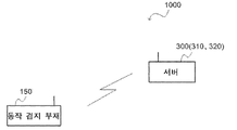
도 1은, 본 실시형태에 따른 동작 검지 시스템(1000)의 구성을 나타내는 도면이다. 도 1에 나타내는 바와 같이, 동작 검지 시스템(1000)은, 동작 검지용 부재(150)와 서버(300)를 포함한다. 동작 검지용 부재(150)와 서버(300)는, 무선 통신을 실행한다.1 is a diagram showing the configuration of a
<동작 검지용 부재><Member for motion detection>
이하, 동작 검지용 부재의 개요에 대해서 설명한다. 또, 본 개시에 있어서, 「∼」를 이용한 수치 범위는, 「∼」의 전후에서 나타난 수치가 각각 최소치 및 최대치로서 포함되는 수치 범위를 의미한다.Hereinafter, the outline of the member for motion detection is demonstrated. In addition, in the present disclosure, a numerical range using “to” means a numerical range in which the numerical values appearing before and after “to” are included as the minimum and maximum values, respectively.
동작 검지용 부재는, 피장착체의 동작을 검지하기 위한 부재이다. 동작 검지용 부재로서는, 손의 신축에 의해 동작을 검지하는 신축 센서나, 가속도 센서, 각속도 센서, 자기 센서 등의 손의 기울기나 위치에 따라 동작을 검지하는 시간축 검지형의 센서를 채용할 수 있다. 본 실시형태에서는, 동작 검지용 부재가 신축 센서인 경우를 예로 설명한다.The member for motion detection is a member for detecting the motion of the attached object. As the motion detection member, a telescopic sensor that detects motion by stretching and contracting the hand, and a time axis detection type sensor that detects motion according to the inclination and position of the hand, such as an acceleration sensor, an angular velocity sensor, and a magnetic sensor, can be employed. . In this embodiment, the case where the member for motion detection is a stretch sensor is demonstrated as an example.
본 실시형태에 따른 동작 검지용 부재는, 피장착체에 장착되는 장착부로서, 상기 피장착체의 동작에 의해 신축하는 신축 부위를 갖는 장착부와, 상기 장착부의 신축 부위의 적어도 일부에 마련된 배선부로서, 도전성 선상체를 포함하는 제1 배선부 및 도전성 선상체를 포함하는 제2 배선부를 갖는 배선부와, 상기 제1 배선부에 전기적으로 접속된 제1 전극부 및 상기 제2 배선부에 전기적으로 접속된 제2 전극부를 갖는 전극부를 구비하고, 상기 피장착체의 동작에 의해, 상기 배선부가 마련된 상기 장착부의 신축 부위가 신축했을 때, 상기 제1 배선부 및 상기 제2 배선부의 접촉 상태가 변화함으로써, 상기 제1 전극부와 상기 제2 전극부 사이의 저항치가 변화하는 배선 전극부를 구비한다.An operation detecting member according to the present embodiment is a mounting portion attached to an attached body, the mounting portion having an elastic portion that expands and contracts in response to the motion of the attached object, and a wiring portion provided in at least a part of the elastic portion of the mounting portion. , A wiring part having a first wiring part including a conductive linear body and a second wiring part including a conductive linear body, a first electrode part electrically connected to the first wiring part and the second wiring part electrically An electrode portion having a connected second electrode portion is provided, and the contact state of the first wiring portion and the second wiring portion changes when an extension and contraction portion of the attachment portion provided with the wiring portion is stretched and contracted by an operation of the attached body. By doing so, a wiring electrode portion in which the resistance value between the first electrode portion and the second electrode portion changes is provided.
본 실시형태에 따른 동작 검지용 부재는, 피장착체의 동작에 의해 신축 부위가 신축(즉, 신장 및 수축)했을 때, 제1 배선부 및 제2 배선부의 접촉 상태가 변화함으로써, 제1 전극부와 제2 전극부 사이의 저항치가 변화한다. 이 저항치의 변화를 검지함으로써, 피장착체의 동작을 검지할 수 있다.In the motion detecting member according to the present embodiment, when the expansion/contraction portion expands or contracts (i.e., expands or contracts) due to the motion of the attached body, the contact state of the first wiring part and the second wiring part changes, and the first electrode The resistance value between the portion and the second electrode portion changes. By detecting the change in the resistance value, the motion of the attached object can be detected.
그리고, 본 실시형태에 따른 동작 검지용 부재는, 동작을 검지하기 위한 배선 전극부가, 도전성 선상체로 구성되어 있다. 그 때문에, 내구성도 높다.And, in the member for motion detection according to the present embodiment, the wiring electrode portion for detecting motion is constituted by a conductive linear body. Therefore, durability is also high.
거기에 더해, 신축성 포재(布材)로 구성된 장착부의 신축 부위에, 도전성 선상체로 구성된 배선부가 마련되어 있다. 그 때문에, 피장착체에 장착했을 때 위화감을 품기 어렵고, 장착감도 우수하다.In addition to that, a wiring portion made of a conductive linear body is provided at an elastic part of the attachment portion made of an elastic cloth material. Therefore, it is difficult to have a sense of incongruity when attached to the adhered body, and the wearing feeling is also excellent.
또한, 특허문헌 1의 장갑형 입력 장치, 스트레인 센서 부착 장갑 등은, 손을 편 상태와 쥔 상태에서 캘리브레이션을 필요로 하지만, 장갑을 계속 사용하고 있으면 센서 위치가 어긋나, 검출 정밀도가 저하할 가능성이 있다. 한편, 본 실시형태에 따른 동작 검지용 부재는, 캘리브레이션이 불필요하고, 장착 후 곧바로 사용 가능하며, 위치 어긋남의 허용 범위가 넓다.In addition, the glove-type input device of Patent Document 1, gloves with strain sensors, etc. require calibration in the open and gripped hands, but if the gloves are continuously used, the sensor position may shift and detection accuracy may decrease. . On the other hand, the member for motion detection according to the present embodiment does not require calibration, can be used immediately after being attached, and has a wide allowable range of misalignment.
여기에서, 본 개시에 있어서, 「제1 전극부와 제2 전극부 사이의 저항치가 변화한다」란, 1) 제1 전극부와 제2 전극부 사이가 도통된 상태에서, 저항치가 증감하는 것, 또는 2) 제1 전극부와 제2 전극부 사이가 도통으로부터 비도통 상태 혹은 비도통으로부터 도통 상태로 변화하는 것을 나타낸다. 또, 이 저항치의 변화는, 전극부, 배선부, 및 전극부와 배선부와의 접합부의 파손에 의한 저항치의 변화는 포함하지 않는다.Here, in the present disclosure, "the resistance value between the first electrode portion and the second electrode portion changes" means that 1) the resistance value increases or decreases in a state where the first electrode portion and the second electrode portion are in conduction. , or 2) indicates that the transition between the first electrode part and the second electrode part changes from a conduction state to a non-conduction state or from a non-conduction state to a conduction state. Note that this change in resistance value does not include a change in resistance value due to damage to the electrode portion, the wiring portion, and the junction between the electrode portion and the wiring portion.
「제1 배선부와 제2 배선부의 적어도 일부가 접촉해 있다」란, 제1 배선부 및 제2 배선부 이외의 다른 배선부(예를 들면, 제3 배선부)를 가질 경우, 다른 배선부를 개재하여 제1 배선부와 제2 배선부의 적어도 일부가 접촉해 있는 태양도 포함한다."At least a part of the first wiring part and the second wiring part are in contact" means that when there is a wiring part other than the first wiring part and the second wiring part (for example, the third wiring part), the other wiring part A mode in which at least a part of the first wiring portion and the second wiring portion are in contact with each other is also included.
「배선부가, 신축 부위에 마련되어 있다」란, 「배선부가 신축성 부재의 표면에 마련되어 있다」 또는 「배선부가 신축성 포재의 내부에 마련되어 있다」는 것을 나타낸다.“The wiring portion is provided in the stretchable portion” indicates that “the wiring portion is provided on the surface of the elastic member” or “the wiring portion is provided inside the elastic cloth material”.
그리고, 「배선부가 신축성 포재의 표면에 마련되어 있다」란, 신축성 포재의 표리면을 구성하는 포재층(부분적으로 표리면을 구성하는 포재층도 포함함)에, 배선부(즉, 도전성 선상체)가 마련되어 있는 것을 나타낸다. 환언하면, 「배선부가 신축성 포재의 표면에 마련되어 있다」란, 신축성 포재로부터 배선부를 구성하는 도전성 선상체의 적어도 일부가 노출된 상태에서, 전극부 또는 배선부(즉, 도전성 선상체)가 마련되어 있는 것을 나타낸다.Further, "a wiring portion is provided on the surface of the stretchable fabric material" means that a wiring portion (ie, a conductive linear body) is provided in the fabric layer constituting the front and back surfaces of the stretchable fabric material (including the wrapping material layer partially constituting the front and back surfaces) indicates that is provided. In other words, "the wiring portion is provided on the surface of the flexible fabric material" means that the electrode portion or the wiring portion (ie, the conductive linear body) is provided in a state where at least a part of the conductive linear members constituting the wiring portion is exposed from the elastic fabric material. indicates that
한편, 「배선부가 신축성 포재의 내부에 마련되어 있다」란, 신축성 포재의 내층에, 예를 들면, 신축성 포재의 내층이 되는 포재층 중 또는 포재층간에, 배선부(즉, 도전성 선상체)가 마련되어 있는 것을 나타낸다.On the other hand, “a wiring portion is provided inside the elastic fabric material” means that a wiring portion (ie, a conductive linear body) is provided in the inner layer of the elastic fabric material, for example, among the fabric layers serving as the inner layer of the elastic fabric material or between the fabric layers. indicates that there is
「장착부가, 신축성 포재로 구성된 신축 부위를 갖는다」란, 장착부의 신축 부위에 상당하는 위치가 신축성 포재로 구성되고, 상기 신축성 포재에 배선부가 마련된 태양, 장착부의 신축 부위에 상당하는 위치의 표면에, 별도, 배선부를 갖는 신축성 포재가 첩합되어 있는 태양 모두 포함한다. 또, 신축 부위를 마련하는 방법은, 접착제에 의한 첩합, 봉제에 의한 부착 등이 예시된다."The wearing part has an elastic part made of an elastic cloth material" means that the position corresponding to the stretch part of the wearing part is made of an elastic cloth material, and the wiring part is provided on the elastic cloth material, and the surface at the position corresponding to the stretch part of the wearing part. , separately, all aspects in which a flexible wrapping material having a wiring portion are bonded together are included. Moreover, as a method of providing an expansion/contraction site|part, bonding with an adhesive agent, attachment by sewing, etc. are illustrated.
(동작 검지용 부재의 구성)(Configuration of member for motion detection)
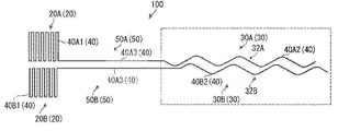
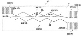
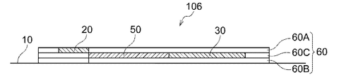
이하, 본 실시형태에 따른 동작 검지용 부재의 일례에 대해서, 도면을 참조하면서 설명한다. 본 실시형태에 따른 동작 검지용 부재(150)는, 전극 배선이 부착된 포재이다. 본 실시형태에서는, 동작 검지용 부재(150)는, 도 2에 나타내는 장갑상의 부재인 경우를 예로 설명한다. 구체적으로는, 동작 검지용 부재(150)는, 예를 들면, 장갑상 장착부(10)(장착부의 일례)와, 배선 전극부(100)와, 통신 모듈(202)을 갖고 있다.Hereinafter, an example of the member for motion detection according to the present embodiment will be described with reference to the drawings. The
(장갑상 장착부)(Attached part on the glove)
장갑상 장착부(10)는, 피장착체로서의 인체의 손에 장착되는 장갑상의 장착부이다.The glove-
장갑상 장착부(10)는, 인체의 손목에 장착되는 손목부(1)와, 인체의 손가락에 장착되는 손가락부(2)와, 손목부(1) 및 손가락부(2)를 연결하는 몸통부(3)를 갖고 있다.The glove-like mounting
또, 손목부(1), 손가락부(2) 및 몸통부(3)의 연결부(중수지절간 관절에 대응하는 부위), 손가락부(2)(원위지절간 관절 및 근위지절간 관절에 대응하는 부위)가 「피장착체의 동작에 의해 신축하는 신축 부위」의 일례에 상당한다.In addition, the connection part of the wrist part 1, the
또한, 근위지절간 관절의 손등 측(甲側)에 대향하는 손가락부(2)의 부위가, 「배선부가 마련된 장착부의 신축 부위」의 일례에 상당한다.In addition, the part of the
여기에서, 장갑상 장착부(10)는 손가락부(2)를, 예를 들면, 각 손가락에 대응하여 5개 갖고 있다. 구체적으로는, 장갑상 장착부(10)는, 손가락부(2)로서, 예를 들면, 엄지에 장착되는 엄지부(2A), 검지에 장착되는 검지부(2B), 중지에 장착되는 중지부(2C), 약지에 장착되는 약지부(2D), 및 소지에 장착되는 소지부(2E)를 갖고 있다.Here, the glove-like wearing
단, 손가락부(2)의 구성은, 상기 구성에 한정되는 것은 아니다. 장갑상 장착부(10)는, 손가락부(2)로서, 예를 들면, 엄지에 장착되는 엄지부와, 검지, 중지, 약지 및 소지에 장착되는 손가락부의 2개의 부위를 갖고 있어도 된다.However, the configuration of the
장갑상 장착부(10)는, 예를 들면, 표면을 구성하는 표면 포재층(10A)과, 이면을 구성하는 이면 포재층(10B)과, 표면 포재층(10A) 및 이면 포재층(10B) 사이에 갖는 중간 포재층(10C)의 3중(3층)의 포재층으로 구성되어 있다.The armored wearing
장갑상 장착부(10)는, 3중의 포재층 이외에, 예를 들면, 1중(단층), 2중(2층), 또는 4중(4층) 이상의 포재층으로 구성되어 있어도 된다.The glove-on
또, 2층 이상의 포재층으로 구성된 다중의 장착부는, 예를 들면, 각 포재층을 제작한 후, 봉합하는 방법으로 제작해도 좋고, 직편기에 의해 일괄하여 다중의 장갑상 장착부(10)를 제작해도 좋다.In addition, multiple wearing parts composed of two or more wrapping material layers may be produced by, for example, a method of fabricating each covering material layer and then stitching it, or by using a knitting machine to produce multiple armored wearing
장갑상 장착부(10)는, 예를 들면, 신축성 포재로 구성되어 있다. 단, 장갑상 장착부(10)는, 유연성 포재로 구성되며, 또한 적어도 근위지절간 관절의 손등 측에 대향하는 손가락부(2)의 부위(배선부가 마련된 장착부의 신축 부위의 일례)가 신축성 포재로 구성되어 있으면 된다.The glove-like wearing
신축성 포재로서는, 예를 들면, 직편물을 대표적으로 들 수 있다. 장갑상 장착부(10)는 부직포여도 된다.As a stretchable cloth material, a woven fabric is typically mentioned, for example. The glove-
직편물로서는, 평직(平織), 능직(綾織), 주자직(朱子織), 주지(周知)의 응용직 등의 직물; 위편(緯編), 경편(經編), 레이스편(lace stitch), 주지의 응용편 등의 편물을 들 수 있다.As woven fabrics, fabrics such as plain weave, twill weave, satin weave, and well-known applied weave; Knitted fabrics such as weft knit, warp knit, lace stitch, and well-known applied stitch are exemplified.
신축성 포재를 구성하는 실(선상체)은, 절연성의 실로 한다. 절연성의 실이란, 선저항이 1.0 × 10⁶Ω/㎝ 이상의 실을 나타낸다. 절연성의 실의 선저항은, 후술하는 도전성 선상체의 선저항과 같은 방법으로 측정되는 선저항이다.The yarn (linear body) constituting the stretchable fabric is an insulating yarn. The insulating yarn refers to a yarn having a wire resistance of 1.0 × 10 6 Ω/cm or more. The line resistance of an insulating yarn is a line resistance measured in the same way as the line resistance of a conductive linear body described later.
신축성 포재는, 탄성사를 이용한 직편물을 적용하는 것이 좋다.It is good to apply a woven fabric using an elastic yarn as the elastic fabric.
탄성사로서는, 예를 들면, 탄성사의 외주(外周)에 비탄성사를 코일상으로 권부(卷付)한 커버드 얀(싱글 커버드 얀 또는 더블 커버드 얀), 탄성사와 비탄성사를 정방교연한 코어 스팬 얀, 압공(壓空) 노즐을 이용하여 탄성사의 외주에 비탄성사를 권부한 에어 교락 커버드 얀, 탄성사와 비탄성사를 연사하여 이루어지는 트이스티드 얀 등을 들 수 있다.As the elastic yarn, for example, a covered yarn (single covered yarn or double covered yarn) in which an inelastic yarn is wound around the outer periphery of the elastic yarn in a coil shape, and a core in which the elastic yarn and the inelastic yarn are squarely intertwined. Examples include span yarns, air-tangled covered yarns in which non-elastic yarns are wound around the outer periphery of elastic yarns using a pressure hole nozzle, and twisted yarns formed by twisting elastic yarns and inelastic yarns.
탄성사로서는, 폴리우레탄 탄성 섬유, 폴리에스테르 탄성 섬유, 폴리아미드 탄성 섬유 등, 소위 고무상 탄성을 나타내는 섬유의 실을 들 수 있다.Examples of the elastic yarn include fibers of so-called rubber-like elasticity, such as polyurethane elastic fibers, polyester elastic fibers, and polyamide elastic fibers.
비탄성사로서는, 합성 섬유(폴리에스테르 섬유, 폴리아미드 섬유, 아크릴 섬유, 폴리프로필렌 섬유, 레이온 섬유), 천연 섬유(면, 견, 마, 양모 등의 섬유)의 실을 들 수 있다.Examples of inelastic yarns include yarns of synthetic fibers (polyester fibers, polyamide fibers, acrylic fibers, polypropylene fibers, rayon fibers) and natural fibers (fibers such as cotton, silk, hemp, and wool).
(배선 전극부)(Wiring electrode part)
배선 전극부(100)는, 전극부(20)와, 배선부(30)와, 배선부(50)를 갖고 있다.The
전극부(20)는, 제1 전극부(20A)와 제2 전극부(20B)를 갖고, 통신 모듈(202)과 전기적으로 접속되는 전극부이다.The
배선부(30)는, 제1 배선부(30A)와 제2 배선부(30B)를 갖고, 손가락의 근위지절간 관절의 굽힘(피장착체의 동작의 일례)에 의해, 손가락의 근위지절간 관절의 손등 측에 대향하는 손가락부(2)의 부위가 신축했을 때(이하, 「손가락부(2)의 신축 부위가 신축했을 때」라고도 함), 제1 배선부(30A) 및 제2 배선부(30B)의 접촉 상태가 변화하는 배선부(30)(이하, 「검지용 배선부(30)」라고 함)이다.The
배선부(50)는, 제1 배선부(50A)와 제2 배선부(50B)를 갖고, 전극부(20)와 배선부(30)를 전기적으로 접속하기 위한 접속용의 배선부(이하 「접속용 배선부(50)」라고 함)이다.The
또, 접속용 배선부(50)는, 필요에 따라 마련되는 배선부이며, 전극부(20)와 검지용 배선부(30)가 직접 접속한 태양이어도 된다.Moreover, the
-전극부--Electrode part-
전극부(20)에 있어서, 제1 전극부(20A)와 제2 전극부(20B)는, 예를 들면, 장갑상 장착부(10)의 손목부(1)의 손등 측에, 각각 마련되어 있다. 단, 전극의 배치 위치는, 특별히 제한은 없고, 예를 들면, 장갑상 장착부(10)의 손목부(1)의 손바닥 측, 장갑상 장착부(10)의 몸통부(3)의 손바닥 측이어도 된다.In the
또, 전극부(20)는, 목적에 따라, 3개 이상 마련해도 된다. 예를 들면, 하나의 전극부를 공통 전극으로 하고, 하나의 전극부에 2개 이상의 배선부(50)를 접속해도 된다. 본 태양으로서는, 예를 들면, 약지부(2D)에 배치되는 검지용 배선부(30)에 접속되는 2개의 배선부(50) 중, 하나와, 소지부(2E)에 배치되는 검지용 배선부(30)에 접속되는 2개의 배선부(50) 중, 하나를 공통 전극으로서의 하나의 전극부에 접속하는 태양을 들 수 있다.In addition, three or
전극부(20)는, 예를 들면, 도 3에 나타내는 바와 같이, 장갑상 장착부(10)의 표면 포재층(10A)에 마련되어 있다. 즉, 전극부(20)는, 장갑상 장착부(10)의 표면에 마련되어 있다.The
또, 전극부(20)는, 장갑상 장착부(10)의 중간 포재층(10C)에 마련되어 있어도 된다. 즉, 전극부(20)는, 장갑상 장착부(10)의 내부에 마련되어 있어도 된다. 장갑상 장착부(10)의 내부에 전극부(20)가 마련되어 있어도, 핀상의 전극 등에 의해 접속이 가능하기 때문이다.In addition, the
-검지용 배선부--Wiring part for detection-
검지용 배선부(30)는, 손가락의 근위지절간 관절의 손등 측에 대향하는 손가락부(2)의 부위(엄지부(2A), 검지부(2B), 중지부(2C), 약지부(2D), 및 소지부(2E)의 전체 부위)에 마련되어 있다.The
단, 검지용 배선부(30)의 배치 위치는, 상기 태양으로 한정되지 않고, 목적에 따라, 하기 태양이어도 된다.However, the arrangement position of the
·검지용 배선부(30)가, 손가락의, 근위지절간 관절의 손등 측 및 중수지절간 관절의 손등 측의 적어도 한쪽에 대향하는 손가락부(2)의 부위에 마련되어 있는 태양.・The aspect in which the
·검지용 배선부(30)가, 손가락의, 근위지절간 관절의 손바닥 측 및 중수지절간 관절의 손바닥 측의 적어도 한쪽에 대향하는 손가락부(2)의 부위에 마련되어 있는 태양.・The aspect in which the
·복수의 검지용 배선부(30) 중, 일부가, 손가락의 손등 측에 대향하는 손가락부(2)의 부위에 대향하는 위치에 마련되고, 그 이외의 일부가 손가락의 손바닥 측에 대향하는 손가락부(2)의 부위에 대향하는 위치에 마련되는 태양. 예를 들면, 엄지의 손바닥 측에 대향하는 엄지부(2A)의 부위에 대향하는 위치에 검지용 배선부(30)를 마련하고, 검지부, 중지부, 약지부 및 소지부의 손등 측에 대향하는 검지부(2B), 중지부(2C), 약지부(2D), 및 소지부(2E)의 부위에 대향하는 위치에 검지용 배선부(30)가 마련되는 태양이다.・Among the plurality of detecting
·검지용 배선부(30)가, 엄지부(2A), 검지부(2B), 중지부(2C), 약지부(2D), 및 소지부(2E)의 적어도 하나에 마련되어 있는 태양.• The aspect in which the
검지용 배선부(30)에 있어서, 제1 검지용 배선부(30A)는, 제1 전극부(20A)에 전기적으로 접속되어 있다. 또한, 제2 검지용 배선부(30B)는, 제2 전극부(20B)에 전기적으로 접속되어 있다.In the
제1 검지용 배선부(30A)와 제2 검지용 배선부(30B)는, 별개이며, 또한 손가락부(2)의 신축 부위의 신장 전 상태에서 적어도 일부가 접촉해서 마련되어 있다.The first detecting
단, 검지용 배선부(30)의 일부를 손가락의 손바닥 측에 대향하는 엄지부(2A)의 부위에 대향하는 위치를 마련할 경우(예를 들면, 엄지의 손바닥 측에 대향하는 엄지부(2A)의 부위에 대향하는 위치에 검지용 배선부(30)를 마련하고, 검지부, 중지부, 약지부 및 소지부의 손등 측에 대향하는 검지부(2B), 중지부(2C), 약지부(2D), 및 소지부(2E)의 부위에 대향하는 위치에 검지용 배선부(30)를 마련할 경우), 엄지의 손바닥 측에 대향하는 엄지부(2A)의 부위에 대향하는 위치에 검지용 배선부(30)에 있어서, 제1 검지용 배선부(30A)와 제2 검지용 배선부(30B)는, 별개이며, 또한 손가락부(2)의 신축 부위의 신장 전 상태에서 이간(離間)하여 마련된다.However, when a part of the
또, 제1 검지용 배선부(30A)와 제2 검지용 배선부(30B)는, 별개이며, 또한 손가락부(2)의 신축 부위의 신장 전 상태에서 이간하여 마련하는 태양은, 제1 변형예에서 설명한다.In addition, the first detecting
제1 검지용 배선부(30A)는, 예를 들면, 손가락부(2)의 길이 방향을 따라 연장되고 있다. 제1 검지용 배선부(30A)는, 도전성 선상체(40A2)를 파상(波狀)으로 마련한 파상부(32A)를 갖고 있다.The first
제2 검지용 배선부(30B)는, 예를 들면, 손가락부(2)의 길이 방향을 따라 연장되고 있다. 제2 검지용 배선부(30B)도, 도전성 선상체(40B2)를 파상으로 마련한 파상부(32B)를 갖고 있다.The second
그리고, 손가락부(2)의 신축 부위의 신장 전 상태에서, 제1 검지용 배선부(30A)의 파상부(32A)와 제2 검지용 배선부(30B)의 파상부(32B)가 점 접촉 또는 선 접촉해 있다.Then, in the state before the expansion and contraction of the
또, 제1 검지용 배선부(30A) 및 제2 검지용 배선부(30B)는, 모두, 도전성 선상체(40A2) 및 도전성 선상체(40B2)를 파상으로 마련한 파상부를 갖지 않고, 직선에 마련한 직선부만 갖는 구성이어도 된다. 또한, 제1 검지용 배선부(30A) 및 제2 검지용 배선부(30B)는, 모두, 도전성 선상체(40A2) 및 도전성 선상체(40B2)가 굴곡한 굴곡부를 가져도 된다.In addition, both the first
검지용 배선부(30)는, 장갑상 장착부(10)의 내부에 마련되어 있다. 구체적으로는, 예를 들면, 도 3에 나타내는 바와 같이, 3층의 포재층으로 구성된 장갑상 장착부(10)의 내층의 포재층(부분적으로 내층이 되는 포재층도 포함함)인 중간 포재층(10C)에, 검지용 배선부(30)가 마련되어 있음으로써, 검지용 배선부(30)를 장갑상 장착부(10)의 내부에 마련할 수 있다. 또한, 예를 들면, 2층의 포재층으로 구성된 장갑상 장착부(10)의 포재층 사이에, 검지용 배선부(30)를 마련해도 된다.The
또, 검지용 배선부(30)는, 장갑상 장착부(10)의 표면에 마련되어 있어도 된다. 예를 들면, 검지용 배선부(30)는, 3층의 포재층으로 구성된 장갑상 장착부(10)의 표면 포재층(10A) 또는 이면 포재층(10B)에 마련되어 있어도 된다. 단, 검지용 배선부(30)는, 장갑상 장착부(10)에 의한 외부와의 절연화를 도모하는 관점에서, 장갑상 장착부(10)의 내부에 마련하는 것이 좋다.In addition, the
-접속용 배선부(50)--Wiring part for connection (50)-
접속용 배선부(50)에 있어서, 제1 접속용 배선부(50A)는, 제1 전극부(20A)와 제1 배선부(30A)를 전기적으로 접속하고 있다. 제2 접속용 배선부(50B)는, 제2 전극부(20B)와 제2 배선부(30B)를 전기적으로 접속하고 있다.In the
접속용 배선부(50)는, 손의 손등 측에 대향하는, 장갑상 장착부(10)의 몸통부(3)에 마련되어 있다.The
단, 접속용 배선부(50)의 배치 위치는, 상기 태양으로 한정되지 않고, 전극부(20) 및 검지용 배선부(30)의 배치 위치에 따라 설정된다.However, the arrangement|positioning of the
접속용 배선부(50)는, 장갑상 장착부(10)의 내부에 마련되어 있다. 구체적으로는, 예를 들면, 3층의 포재층으로 구성된 장갑상 장착부(10)의 내층의 포재층(부분적으로 내층이 되는 포재층도 포함함)인 중간 포재층(10C)에, 접속용 배선부(50)가 마련되어 있음으로써, 접속용 배선부(50)를 장갑상 장착부(10)의 내부에 마련할 수 있다. 또한, 예를 들면, 2층의 포재층으로 구성된 장갑상 장착부(10)의 포재층 사이에, 접속용 배선부(50)를 마련해도 된다.The
또, 접속용 배선부(50)는, 장갑상 장착부(10)의 표면에 마련되어 있어도 된다. 예를 들면, 접속용 배선부(50)는, 3층의 포재층으로 구성된 장갑상 장착부(10)의 표면 포재층(10A) 또는 이면 포재층(10B)에 마련되어 있어도 된다. 단, 접속용 배선부(50)는, 장갑상 장착부(10)에 의한 외부와의 절연화를 도모하는 관점에서, 장갑상 장착부(10)의 내부에 마련하는 것이 좋다.Moreover, the
-도전성 선상체--Conductive ship body-
전극부(20), 검지용 배선부(30) 및 접속용 배선부(50)는, 각각, 도전성 선상체(40)를 포함한다. 즉, 도전성 선상체(40)가 배치된 영역을, 전극부(20), 검지용 배선부(30) 및 접속용 배선부(50)로 한다.The
구체적으로는, 예를 들면, 제1 전극부(20A)는 도전성 선상체(40A1)를 포함한다.Specifically, for example, the
제1 접속용 배선부(50A)는, 제1 전극부(20A)의 도전성 선상체(40A1)가 연장된 도전성 선상체(40A3)를 포함한다.The first
제1 검지용 배선부(30A)는, 제1 접속용 배선부(50A)의 도전성 선상체(40A3)가 연장된 도전성 선상체(40A2)를 포함한다.The first
즉, 제1 전극부(20A)와 제1 검지용 배선부(30A)는, 적어도 같은 1개의 도전성 선상체(40)로 구성되어 있다.That is, the
또한, 예를 들면, 제2 전극부(20B)는 도전성 선상체(40B1)를 포함한다.Also, for example, the
제2 접속용 배선부(50B)는, 제2 전극부(20B)의 도전성 선상체(40B1)가 연장된 도전성 선상체(40B3)를 포함한다.The second
제2 검지용 배선부(30B)는, 제2 접속용 배선부(50B)의 도전성 선상체(40B3)가 연장된 도전성 선상체(40B2)를 포함한다.The second
즉, 제2 전극부(20B)와 제2 검지용 배선부(30B)는, 적어도 같은 1개의 도전성 선상체(40)로 구성되어 있다.That is, the
제1 전극부(20A) 및 제1 검지용 배선부(30A)와, 제2 전극부(20B) 및 제2 검지용 배선부(30B)는, 각각, 같은 1개의 도전성 선상체(40)로 구성됨으로써, 전극부(20)와 검지용 배선부(30)와의 접속 불량이 억제된다.The
또, 같은 1개의 도전성 선상체(40)란, 도전성 선상체(40)의 단부(端部)끼리를, 선상체 이외의 다른 접속 재료(핸더, 도전성 페이스트 등) 또는 접속 부재(코킹, 커넥터 등)를 이용하는 일 없이, 매듭 또는 꼬임 등에 의해 결합한 선상체도 포함한다.In addition, the same conductive
단, 전극부(20), 검지용 배선부(30) 및 접속용 배선부(50)는, 각각, 복수 개의 도전성 선상체(40)를 포함해도 된다. 또한, 제1 전극부(20A), 제1 검지용 배선부(30A) 및 제1 접속용 배선부(50A)와, 제2 전극부(20B), 제2 검지용 배선부(30B) 및 제2 접속용 배선부(50B)는 각각, 같은 1개의 도전성 선상체(40)로 구성되어 있지 않아도 된다.However, the
예를 들면, 제1 전극부(20A), 제1 검지용 배선부(30A) 및 제1 접속용 배선부(50A)와, 제2 전극부(20B), 제2 검지용 배선부(30B) 및 제2 접속용 배선부(50B)는 각각, 서로의 도전성 선상체(40)의 단부끼리, 선상체 이외의 다른 접속 재료(핸더, 도전성 페이스트 등) 또는 접속 부재(코킹, 커넥터 등)로 연결되어 있어도 된다.For example, the
전극부(20), 검지용 배선부(30) 및 접속용 배선부(50)의 적어도 하나에 있어서, 예를 들면, 도전성 선상체(40)의 적어도 일부는, 장갑상 장착부(10)의 실에 의해 구속(拘束)되어 있다.In at least one of the
이러한 형태는, 도전 재료로서 기능하는 도전성 선상체(40)를, 전극부(20), 검지용 배선부(30) 및 접속용 배선부(50)로서 장갑상 장착부(10)에 고정하는 수단으로서도 이용할 수 있다는 관점에서 바람직하다.This form is also used as a means for fixing the conductive
장갑상 장착부(10)에 구속되어 있는 도전성 선상체(40)는, 전극부(20), 검지용 배선부(30) 및 접속용 배선부(50)에 포함되는 같은 1개의 도전성 선상체(40)여도 좋고, 전극부(20), 검지용 배선부(30) 및 접속용 배선부(50) 중 어느 하나만에 포함되는 다른 도전성 선상체(40)여도 좋다.The conductive
또, 전극부(20), 검지용 배선부(30) 및 접속용 배선부(50)의 적어도 하나에 있어서, 도전성 선상체(40)는 장갑상 장착부(10)의 실에 의해 구속되어 있지 않아도 된다.In addition, in at least one of the
예를 들면, 전극부(20), 검지용 배선부(30) 및 접속용 배선부(50)의 적어도 하나가 접착제에 의해 장갑상 장착부(10)에 고정되어 있을 경우, 전극부(20), 검지용 배선부(30) 및 접속용 배선부(50)의 적어도 하나가 절연성의 실에 의해 장갑상 장착부(10)에 봉제되어 있을 때에는, 도전성 선상체(40)가 장갑상 장착부(10)의 실에 의해 구속되어 있지 않아도, 전극부(20), 검지용 배선부(30) 및 접속용 배선부(50)의 적어도 하나를 장갑상 장착부(10)에 고정 가능하다.For example, when at least one of the
예를 들면, 도전성 선상체(40)를 180°로 반복하여 굴곡 또는 만곡해서 배치한 직사각형의 영역을 형성한다. 이 직사각형의 영역은, 장갑상 장착부(10)의 표면 포재층(10A)의 실에 도전성 선상체(40)의 일부를 구속시켜 형성한다. 그리고, 이 직사각형의 영역을 면상(面狀)의 전극부(20)로 한다.For example, a rectangular area formed by bending or curving the conductive
또, 도전성 선상체(40)를 소용돌이상으로 배치한 영역을, 전극부(20)로 해도 된다. 또한, 도전성 선상체(40)를 굴곡 또는 만곡해서 배치한 임의의 면 형상(다각형, 원형 등)을, 전극부(20)로 해도 된다.Moreover, it is good also considering the
한편, 전극부(20)로부터 도전성 선상체(40)를 직선상, 파상, 굴곡 또는 그들의 조합으로 연장시킨 영역을 형성한다. 이 영역은, 장갑상 장착부(10)의 중간 포재층(10C)의 실에 도전성 선상체(40)의 일부를 구속시켜 형성한다. 그리고, 이 영역을 검지용 배선부(30) 및 접속용 배선부(50)로 한다.On the other hand, a region in which the conductive
구체적으로는, 장갑상 장착부(10)가 직물인 경우, 도 7에 나타내는 바와 같이, 날실 및 씨실로 짜인 직물의 직조직에, 도전성 선상체(40)를 짜 넣어, 전극부(20), 검지용 배선부(30) 및 접속용 배선부(50)를 구성하는 것이, 장갑상 장착부(10)를 짬으로써 형성할 때에, 장갑상 장착부(10), 전극부(20), 검지용 배선부(30) 및 접속용 배선부(50)를 동시에 형성 가능하다는 관점, 장갑상 장착부(10), 전극부(20), 검지용 배선부(30) 및 접속용 배선부(50)의 일체성의 향상이라는 관점에서 바람직하다.Specifically, when the glove-like wearing
장갑상 장착부(10)가 편물인 경우, 도 7에 나타내는 바와 같이, 루프상의 실이 엮어 넣어진 편물의 편조직에, 상기 형상으로 도전성 선상체(40)를 엮어 넣어, 전극부(20), 검지용 배선부(30) 및 접속용 배선부(50)를 구성하는 것이, 장갑상 장착부(10)를 엮음으로써 형성할 때에, 장갑상 장착부(10), 전극부(20), 검지용 배선부(30) 및 접속용 배선부(50)를 동시에 형성 가능하다는 관점, 장갑상 장착부(10), 전극부(20), 검지용 배선부(30) 및 접속용 배선부(50)의 일체성의 향상이라는 관점에서 바람직하다.When the armored wearing
편물의 망조직에 도전성 선상체(40)를 엮어 넣을 경우, 예를 들면, 혼합 편직, 플레이팅 편직, 인레이 편직 등을 채용할 수 있다. 도 7은, 인레이 편직을 채용하여 도전성 선상체(40)를 엮어 넣은 예를 나타내고 있다.When the conductive
또한, 도 8에 나타내는 바와 같이, 장갑상 장착부(10)에 대하여, 상기 형상으로 도전성 선상체(40)를 자수하여, 전극부(20), 검지용 배선부(30) 및 접속용 배선부(50)를 구성하는 것이, 전극부(20), 검지용 배선부(30) 및 접속용 배선부(50)를 형성할 때에, 동시에, 전극부(20), 검지용 배선부(30) 및 접속용 배선부(50)의, 장갑상 장착부(10)에의 고정도 행하는 것이 가능하다는 관점에서 바람직하다.Further, as shown in FIG. 8 , the conductive
자수의 방법은, 예를 들면, 러닝 스티치, 카우칭 스티치, 백 스티치, 체인 스티치, 아웃라인 스티치 등의 주지의 스티치를 채용할 수 있다. 도 8은, 체인 스티치를 채용하여 도전성 선상체(40)를 자수한 예를 나타내고 있다.As an embroidery method, known stitches such as running stitch, couching stitch, back stitch, chain stitch, and outline stitch can be employed, for example. 8 shows an example in which the conductive
또한, 장갑상 장착부(10)에 대하여, 전극부(20), 검지용 배선부(30) 및 접속용 배선부(50)를 도전성 선상체(40)로 봉제하여 고정하는 것이, 전극부(20)를 구성하는 도전성 선상체(40)와, 검지용 배선부(30)를 고정하는 도전성 선상체(40)와, 접속용 배선부(50)를 고정하는 도전성 선상체(40)를 공통되는 것으로 할 수 있다는 관점에서 바람직하다.In addition, with respect to the glove-on wearing
예를 들면, 전극부(20), 검지용 배선부(30) 및 접속용 배선부(50)를 도전성 선상체(40)로 봉제하여 고정되어 있는 태양으로서는, 도전성 선상체(40)를 짜 넣은 직물 또는 도전성 선상체(40)를 엮어 넣은 편물로부터, 전극부(20), 검지용 배선부(30) 및 접속용 배선부(50)를 연속적으로 형성하고, 그, 전극부(20), 검지용 배선부(30) 및 접속용 배선부(50)를 도전성 선상체(40)로 장갑상 장착부(10)에 봉제한 태양을 들 수 있다.For example, as a mode in which the
도 6 중, 12는 장갑상 장착부(10)(직물)를 구성하는 날실, 14는 장갑상 장착부(10)(직물)를 구성하는 씨실을 나타낸다. 도 7 중, 16은, 장갑상 장착부(10)(직물)를 구성하는 실을 나타낸다.In Fig. 6, 12 denotes warp yarns constituting the armored portion 10 (fabric), and 14 denotes weft yarns constituting the armored portion 10 (fabric). In Fig. 7, 16 denotes a yarn constituting the glove-top wearing portion 10 (fabric).
또, 장갑상 장착부(10)를 구성하는 실로서 탄성사를 채용할 경우, 탄성사를 신장한 상태에서, 직편물을 형성하면서, 도전성 선상체(40)를 장갑상 장착부(10)에, 짜 넣거나 또는 엮어 넣는 것이 좋다.In addition, when elastic yarn is used as a yarn constituting the glove-on
(도전성 선상체)(conductive ship body)
전극부(20), 검지용 배선부(30) 및 접속용 배선부(50)를 구성하는 도전성 선상체는, 도전성을 갖는 것이면, 특별히 제한은 없지만, 금속 와이어를 포함하는 선상체, 도전성 실을 포함하는 선상체 등을 들 수 있다. 도전성 선상체(40)는, 금속 와이어 및 도전성 실을 포함하는 선상체(금속 와이어와 도전성 실을 꼬은 선상체 등)여도 된다.The conductive linear bodies constituting the
금속 와이어를 포함하는 선상체, 및 도전성 실을 포함하는 선상체는, 모두, 높은 전기 전도성을 갖기 때문에, 도전성 선상체(40)로서 적용하면, 전극부(20), 검지용 배선부(30) 및 접속용 배선부(50)의 저항을 저감하는 것이 용이해진다.Since both the linear body containing metal wire and the linear body containing conductive thread have high electrical conductivity, when applied as the conductive
금속 와이어로서는, 구리, 알루미늄, 텅스텐, 철, 몰리브덴, 니켈, 티타늄, 은, 금 등의 금속, 또는, 금속을 2종 이상 포함하는 합금(예를 들면, 스테인리스강, 탄소강 등의 강철, 황동, 인청동, 지르코늄 구리 합금, 베릴륨구리, 철니켈, 니크롬, 니켈 티타늄, 칸탈, 하스테로이, 레늄텅스텐 등)을 포함하는 와이어를 들 수 있다. 또한, 금속 와이어는 주석, 아연, 은, 니켈, 크롬, 니켈 크롬 합금, 땜납 등으로 도금된 것이어도 좋고, 후술하는 탄소 재료나 폴리머에 의해 표면이 피복된 것이어도 좋다.As the metal wire, metals such as copper, aluminum, tungsten, iron, molybdenum, nickel, titanium, silver, gold, or alloys containing two or more types of metals (for example, steel such as stainless steel and carbon steel, brass, phosphor bronze, zirconium copper alloy, beryllium copper, iron nickel, nichrome, nickel titanium, kanthal, hastelloy, rhenium tungsten, etc.). Further, the metal wire may be plated with tin, zinc, silver, nickel, chromium, a nickel chromium alloy, solder, or the like, or may have a surface coated with a carbon material or polymer described later.
금속 와이어로서는, 탄소 재료로 피복된 금속 와이어도 들 수 있다. 금속 와이어는, 탄소 재료로 피복되어 있으면, 금속 부식이 억제된다.As the metal wire, a metal wire coated with a carbon material is also exemplified. When the metal wire is coated with a carbon material, metal corrosion is suppressed.
금속 와이어를 피복하는 탄소 재료로서는, 카본 블랙, 활성탄, 하드 카본, 소프트 카본, 메조포러스 카본, 카본 파이버 등의 비정질 탄소; 그라파이트; 풀러 렌; 그라펜; 카본 나노 튜브 등을 들 수 있다.Examples of the carbon material covering the metal wire include amorphous carbon such as carbon black, activated carbon, hard carbon, soft carbon, mesoporous carbon, and carbon fiber; graphite; fullerene; graphene; A carbon nanotube etc. are mentioned.
한편, 도전성 실을 포함하는 선상체는, 1개의 도전성 실로 이루어지는 선상체여도 좋고, 복수 개의 도전성 실을 꼬은 선상체여도 좋다. 또한, 도전성 실과 절연성 실을 꼬은 것이어도 좋다. 도전성 실을 포함하는 선상체는, 금속 와이어를 포함하는 선상체에 비해, 유연성이 높고, 장갑상 장착부(10)에의 짜 넣음, 엮어 넣음 혹은 자수 또는 장갑상 장착부(10)에의 봉제에 의한 단선(斷線)이 생기기 어렵다는 이점이 있다.On the other hand, the linear body containing conductive yarn may be a linear body composed of one conductive yarn or a linear body formed by twisting a plurality of conductive yarns. Alternatively, a twisted conductive yarn and an insulating yarn may be used. The wire body containing the conductive thread has higher flexibility than the wire body containing the metal wire, and is woven into the
도전성 실로서는, 도전성 섬유(금속 섬유, 탄소 섬유, 이온 도전성 폴리머의 섬유 등)를 포함하는 실, 도전성 미립자(카본 나노 입자 등)를 포함하는 실(이하, 카본 나노 튜브 실), 표면에 금속(구리, 은, 니켈 등)을 도금 또는 증착한 실, 금속 산화물을 함침시킨 실 등을 들 수 있다.As the conductive thread, a thread containing conductive fiber (metal fiber, carbon fiber, fiber of ion conductive polymer, etc.), a thread containing conductive fine particles (carbon nanoparticles, etc.) (hereinafter referred to as carbon nanotube thread), a metal on the surface ( copper, silver, nickel, etc.) plated or vapor-deposited, yarn impregnated with metal oxide, and the like.
도전성 실을 포함하는 선상체로서는, 특히, 카본 나노 튜브 실을 포함하는 선상체(이하 「카본 나노 튜브 선상체」라고도 함)를 바람직하게 들 수 있다.As the linear body containing the conductive yarn, particularly preferably, the linear body containing the carbon nanotube yarn (hereinafter also referred to as "carbon nanotube linear body") is exemplified.
카본 나노 튜브 선상체는, 예를 들면, 카본 나노 튜브 포레스트(카본 나노 튜브를, 기판에 대하여 수직 방향으로 배향하도록, 기판 상에 복수 성장시킨 성장체를 말하며, 「어레이」라고 하는 경우도 있음)의 단부로부터, 카본 나노 튜브를 시트상으로 꺼내고, 꺼낸 카본 나노 튜브 시트를 묶은 후, 카본 나노 튜브의 다발을 꼬음으로써 얻어진다. 이러한 제조 방법에 있어서, 꼬을 때에 비틀기를 가하지 않을 경우에는, 리본상의 카본 나노 튜브 선상체가 얻어지고, 비틀기를 가했을 경우에는, 사상(絲狀)의 선상체가 얻어진다. 리본상의 카본 나노 튜브 선상체는, 복수의 카본 나노 튜브의 집합이 비틀어진 구조를 갖지 않는 선상체이다. 이 외, 카본 나노 튜브의 분산액으로부터, 방사(紡絲)를 하는 것 등에 의해, 카본 나노 튜브 선상체를 얻을 수 있다. 방사에 의한 카본 나노 튜브 선상체의 제조는, 예를 들면, 미국 공개공보 US 2013/0251619(일본국 특허공개 2011-253140호 공보)에 개시되어 있는 방법에 의해 행할 수 있다. 카본 나노 튜브 선상체의 직경의 균일함이 얻어지는 관점에서는, 사상의 카본 나노 튜브 선상체를 이용하는 것이 바람직하고, 순도가 높은 카본 나노 튜브 선상체가 얻어지는 관점에서는, 카본 나노 튜브 시트를 꼬음으로써 사상의 카본 나노 튜브 선상체를 얻는 것이 바람직하다. 카본 나노 튜브 선상체는, 2개 이상의 카본 나노 튜브 선상체끼리 꼬인 선상체여도 된다.The carbon nanotube linear body, for example, is a carbon nanotube forest (refers to a growth body in which a plurality of carbon nanotubes are grown on a substrate so as to be oriented in a direction perpendicular to the substrate, sometimes referred to as an "array") It is obtained by taking out the carbon nanotubes in a sheet form from the end of the , and after bundling the taken out carbon nanotube sheets, twisting the bundle of carbon nanotubes. In this manufacturing method, when twisting is not applied, a ribbon-shaped carbon nanotube linear body is obtained, and when twisting is applied, a filamentous linear body is obtained. A ribbon-like carbon nanotube linear body is a linear body in which a set of a plurality of carbon nanotubes does not have a twisted structure. In addition, carbon nanotube linear bodies can be obtained from the dispersion of carbon nanotubes by, for example, spinning. Production of carbon nanotube linear bodies by spinning can be performed by, for example, a method disclosed in US 2013/0251619 (Japanese Unexamined Patent Publication No. 2011-253140). From the viewpoint of obtaining the uniformity of the diameter of the carbon nanotube linear body, it is preferable to use a filamentous carbon nanotube linear body, and from the viewpoint of obtaining a carbon nanotube linear body with high purity, by twisting the carbon nanotube sheet, the filamentous carbon nanotube It is desirable to obtain nanotube linear bodies. The carbon nanotube linear body may be a linear body in which two or more carbon nanotube linear bodies are twisted.
카본 나노 튜브 선상체는, 카본 나노 튜브와 금속이나 도전성 고분자, 그라펜 등의 카본 나노 튜브 이외의 도전성 재료를 포함하는 선상체(이하 「복합 선상체」라고도 함)여도 된다. 복합 선상체는, 카본 나노 튜브 선상체의 상술한 특징을 유지하면서, 선상체의 도전성이 향상되기 쉬워진다.The carbon nanotube linear body may be a linear body (hereinafter also referred to as "composite linear body") composed of carbon nanotubes and conductive materials other than carbon nanotubes such as metal, conductive polymer, and graphene. In the composite linear body, the conductivity of the linear body is easily improved while maintaining the above-described characteristics of the carbon nanotube linear body.
복합 선상체로서는, 예를 들면, 카본 나노 튜브와 금속을 포함하는 선상체를 예로 하면, (1) 카본 나노 튜브 포레스트의 단부로부터, 카본 나노 튜브를 시트상으로 꺼내고, 꺼낸 카본 나노 튜브 시트를 묶은 후, 카본 나노 튜브의 다발을 꼬는 카본 나노 튜브 선상체를 얻는 과정에서, 카본 나노 튜브의 포레스트, 시트 혹은 다발, 또는 꼬은 선상체의 표면에, 금속 단체(單體) 또는 금속 합금을 증착, 이온 플레이팅, 스퍼터링, 습식 도금 등에 의해 담지(擔持)시킨 복합 선상체, (2) 금속 단체의 선상체 혹은 금속 합금의 선상체 또는 복합 선상체와 함께, 카본 나노 튜브의 다발을 꼬은 복합 선상체, (3) 금속 단체의 선상체 혹은 금속 합금의 선상체 또는 복합 선상체와, 카본 나노 튜브 선상체 또는 복합 선상체를 꼬은 복합 선상체 등을 들 수 있다. 또, (2)의 복합 선상체에 있어서는, 카본 나노 튜브의 다발을 꼬을 때에, (1)의 복합 선상체와 마찬가지로 카본 나노 튜브에 대하여 금속을 담지시켜도 된다. 또한, (3)의 복합 선상체는, 2개의 선상체를 엮었을 경우의 복합 선상체이지만, 적어도 1개의 금속 단체의 선상체 혹은 금속 합금의 선상체 또는 복합 선상체가 포함되어 있으면, 카본 나노 튜브 선상체 또는 금속 단체의 선상체 혹은 금속 합금의 선상체 혹은 복합 선상체의 3개 이상을 서로 엮어도 된다.As the composite linear body, for example, if a linear body containing carbon nanotubes and metal is taken as an example, (1) carbon nanotubes are taken out in a sheet form from the end of the carbon nanotube forest, and the carbon nanotube sheets taken out are bundled. Then, in the process of twisting the bundles of carbon nanotubes to obtain a carbon nanotube linear body, a metal substance or metal alloy is deposited on the forest, sheet or bundle of carbon nanotubes, or the surface of the twisted linear body, ion Composite linear bodies supported by plating, sputtering, wet plating, etc., (2) composite linear bodies in which bundles of carbon nanotubes are twisted together with linear bodies of metal or metal alloy or composite linear bodies , (3) a linear body of simple metal or a linear body of a metal alloy or a composite linear body, and a composite linear body obtained by twisting a carbon nanotube linear body or a composite linear body. Further, in the composite linear body of (2), when the bundle of carbon nanotubes is twisted, a metal may be supported on the carbon nanotubes similarly to the composite linear body of (1). In addition, the composite linear body of (3) is a composite linear body in the case of intertwining two linear bodies, but if the linear body of at least one metal alone or a linear body of metal alloy or a composite linear body is included, the carbon nanotube You may weave together three or more of the linear body or the linear body of a single metal, the linear body of a metal alloy, or a composite linear body.
복합 선상체의 금속으로서는, 예를 들면, 금, 은, 구리, 철, 알루미늄, 니켈, 크롬, 주석, 아연 등의 금속 단체, 이들 금속 단체의 적어도 1종을 포함하는 합금(구리-니켈-인 합금, 구리-철-인-아연 합금 등)을 들 수 있다.As the metal of the composite linear body, for example, a simple metal such as gold, silver, copper, iron, aluminum, nickel, chromium, tin, zinc, or an alloy containing at least one of these simple metals (copper-nickel-phosphorus alloys, copper-iron-phosphorus-zinc alloys, etc.).
이들, 도전성 선상체(40) 중에서도, 카본 나노 튜브 실을 포함하는 도전성 선상체(특히, 카본 나노 튜브 실만을 포함하는 도전성 선상체나, 카본 나노 튜브 실과 비금속계 도전성 재료를 포함하는 도전성 선상체)가 바람직하다.Among these conductive
예를 들면, 표면에 금속(구리, 은, 니켈 등)을 도금 또는 증착한 실, 금속 산화물을 함침시킨 실은, 신축이 반복되면 금속 또는 금속 산화물에 균열이 생기기 쉽고, 내구성이 낮다. 이 점에서, 카본 나노 튜브 선상체는, 굴곡에의 내성이 강하며, 손가락부(2)의 신축 부위가 신축을 반복해도, 배선부의 저항치가 변화하기 어렵다. 또한, 카본 나노 튜브 선상체는, 내식성도 높다는 이점도 있다.For example, a yarn in which a metal (copper, silver, nickel, etc.) is plated or deposited on the surface or a yarn impregnated with a metal oxide is prone to cracking in the metal or metal oxide when stretched and contracted repeatedly, and has low durability. In this regard, the carbon nanotube linear body is highly resistant to bending, and even if the extension and contraction portions of the
여기에서, 도전성 선상체(40)의 선저항은, 5.0 × 10⁻³Ω/㎝ ∼ 1.0 × 10³Ω/㎝가 바람직하고, 1.0 × 10⁻²Ω/㎝ ∼ 5.0 × 10²Ω/㎝가 보다 바람직하다.Here, the line resistance of the conductive
도전성 선상체(40)의 선저항의 측정은, 다음과 같다. 우선, 도전성 선상체(40)의 양단(兩端)에 은 페이스트를 도포하여, 은 페이스트간의 부분의 저항을 측정하고, 도전성 선상체(40)의 저항치(단위: Ω)를 구한다. 그리고, 얻어진 저항치를, 은 페이스트간의 거리(㎝)로 나누어, 도전성 선상체(40)의 선저항을 산출한다.The measurement of the line resistance of the conductive
(통신 모듈)(communication module)
통신 모듈(202)은, 예를 들면, 장갑상 장착부(10)의 손목부(1)의 손등 측에 마련되어 있다. 단, 통신 모듈(202)의 배치 위치는, 특별히 제한은 없고, 예를 들면, 장갑상 장착부(10)의 손목부(1)의 손바닥 측, 장갑상 장착부(10)의 몸통부의 손바닥 측이어도 된다.The
그리고, 통신 모듈(202)은, 도시하지 않은 접속 단자를 통해, 전극부(20)와 전기적으로 접속되어 있다.And the
통신 모듈(202)은, 예를 들면, 면 파스너(fastener) 등의 수단에 의해, 장갑상 장착부(10)에 탈착 가능하게 마련되어 있다. 통신 모듈(202)을 장갑상 장착부(10)로부터 취출함으로써, 통신 모듈에 방수 처리를 실시하는 일 없이, 동작 검지용 부재(150)가 선택 가능해진다.The
통신 모듈(202)은, 저항 검지부(204)와 통신부(206)를 갖고 있다(도 5). 또, 통신 모듈(202)은, 도시하지 않은 전원부도 갖고 있다.The
저항 검지부(204)는, 저항치를 검지하기 위한 센서이다. 저항 검지부(204)는, 기능적으로는, 제1 전극부(20A)와 제2 전극부(20B)와의 저항치를 검지한다. 그리고, 저항 검지부(204)는, 검지한 저항치를, 통신부(206)에 건네준다. 이와 같이, 저항 검지부(204)는, 피장착체에 장착되는 동작 검지용 부재(150)에 의해 피장착체의 동작 정보를 검지하는 것이다.The
통신부(206)는, 서버(300)와 무선 통신을 행하기 위한 통신 디바이스이다. 통신부(206)는, 서버(300)와 직접 통신을 행할 경우에는 IEEE802.15.1이나 IEEE802.15.4 등의 규격에 준거한다. 또, 통신부(206)는, 서버(300)와 무선 기지국이나 무선 라우터 경유의 통신을 행할 경우, 예를 들면, Wi-Fi(등록상표), LTE 등의 규격에 준거하여, 상기 무선 기지국이나 무선 라우터와 직접 통신을 행한다. 또한, 통신부(206)는, 검지한 저항치의 데이터를 유선으로 서버(300)에 송신하는 구성으로 해도 된다. 통신부(206)는, 기능적으로는, 저항 검지부(204)에 의해 검지된 저항치의 데이터를 서버(300)에 송신한다.The
(동작 검지용 부재의 작용)(Action of member for motion detection)
본 실시형태에 따른 동작 검지용 부재(150)는, 장갑상 장착부(10)에 있어서의 손가락부(2)의 신축 부위가 신장 전 상태에서, 제1 검지용 배선부(30A)와 제2 검지용 배선부(30B)의 적어도 일부(본 실시형태에서는, 파상부(32A, 32B))가 접촉해 있다(도 4a 참조). 구체적으로는, 제1 검지용 배선부(30A)를 구성하는 도전성 선상체(40A2)와, 제2 검지용 배선부(30B)를 구성하는 도전성 선상체(40B2)의 적어도 일부가 접촉해 있다.In the
한편, 손의 손가락의 굽힘(근위지절간 관절의 굽힘)에 의해, 장갑상 장착부(10)에 있어서의 손가락부(2)의 신축 부위가 신장하면, 어느 신장률에 달한 시점에서, 접촉해 있던 제1 검지용 배선부(30A)와 제2 검지용 배선부(30B)가 이간한다(도 4b 참조). 구체적으로는, 제1 검지용 배선부(30A)를 구성하는 도전성 선상체(40A2)와, 제2 검지용 배선부(30B)를 구성하는 도전성 선상체(40B2)가 이간한다.On the other hand, when the elastic portion of the
보다 구체적으로는, 손가락부(2)의 신축 부위가 신장하면, 제1 검지용 배선부(30A)의 파상부(32A)와 제2 검지용 배선부(30B)의 파상부(32B)의 주기(周期)가 길며, 또한 진폭이 작아진다. 그에 따라, 제1 검지용 배선부(30A)와 제2 검지용 배선부(30B)가 이간한다.More specifically, when the stretchable portion of the
이 동작에 의해, 손가락부(2)의 신축 부위가 신장했을 때, 제1 전극부(20A)와 제2 전극부(20B) 사이의 저항치가 변화한다. 즉, 저항치가 증가한다. 구체적으로는, 제1 전극부(20A)와 제2 전극부(20B) 사이가 도통으로부터 비도통이 된다.By this operation, the resistance value between the
그리고, 신장에 수반하는 제1 전극부(20A)와 제2 전극부(20B) 사이의 저항치 변화를 검지함으로써, 손의 손가락의 동작(손가락의 근위지절간 관절의 굽힘)을 검지할 수 있다.And, by detecting a change in the resistance value between the
한편, 손의 손가락의 굽힘(근위지절간 관절의 굽힘)이 해제되어, 손가락부(2)의 신축 부위의 신장이 해제되면(즉 수축하면), 어느 신장률에 달한 시점에서, 이간해 있던 제1 검지용 배선부(30A)와 제2 검지용 배선부(30B)의 적어도 일부가 접촉한다(도 4a 참조). 즉, 저항치가 저하한다. 구체적으로는, 제1 전극부(20A)와 제2 전극부(20B) 사이가 비도통으로부터 도통이 된다.On the other hand, when the bending of the fingers of the hand (bending of the proximal interphalangeal joint) is released and the extension of the stretched portion of the
이와 같이, 신축에 수반하는 제1 전극부(20A)와 제2 전극부(20B) 사이의 저항치 변화를 검지함으로써, 손의 손가락의 동작(손가락의 근위지절간 관절의 굽힘의 해제)을 검지할 수 있다.In this way, by detecting a change in the resistance value between the
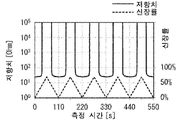
여기에서, 최대 신장률(=약 80%)을 갖는 손가락부(2)의 신축 부위(즉, 검지용 배선부가 마련된 장착부의 신축 부위)에 대해서, 손가락부(2)의 신축 부위를 신장률 70%까지 신장한 후, 수축하는 동작을, 신축 속도 1㎜/s로 5회 반복해서 실시했을 때의 「제1 전극부(20A) 및 제2 전극부(20B) 사이의 저항치와 측정 시간과의 관계, 신장률과 측정 시간과의 관계」의 일례를 도 9에 나타낸다. 또한, 도 9의 측정 결과에 의거하는, 1회째의 신축에 있어서의 「제1 전극부(20A) 및 제2 전극부(20B) 사이의 저항치와 신장률과의 관계」의 일례를 도 10에 나타낸다.Here, with respect to the stretchable portion of the
도 9 ∼ 도 10에 나타내는 바와 같이, 손가락부(2)의 신축 부위(즉, 검지용 배선부가 마련된 장착부의 신축 부위)는, 신축했을 때, 제1 전극부(20A)와 제2 전극부(20B) 사이의 저항치가, 어느 신장률을 경계로 변화하고 있다. 구체적으로는, 제1 전극부(20A)와 제2 전극부(20B) 사이가 도통으로부터 비도통, 그리고 비도통으로부터 도통으로 변화하고 있다.As shown in FIGS. 9 to 10 , the expansion and contraction portion of the finger portion 2 (that is, the expansion and contraction portion of the wearing portion provided with the detecting wiring portion), when expanded and contracted, the
도 9 ∼ 도 10에 나타내는 바와 같이, 동작 검지용 부재(150)는, 손가락부(2)의 신축 부위(즉, 검지용 배선부가 마련된 장착부의 신축 부위)의 신축에 의한 제1 전극부(20A)와 제2 전극부(20B) 사이의 저항치 변화를 검지함으로써, 손의 손가락의 동작(손가락의 근위지절간 관절의 굽힘 및 그 해제)을 검지할 수 있다.As shown in FIGS. 9 to 10 , the
또, 도 9 ∼ 도 10에 나타내는 저항치 변화의 측정 결과에서는, 신장률이 평균 43.7% ± 5% 정도의 범위에서, 신장 시에 저항치의 상승, 수축 시에 저항치의 강하가 보이는 것을 알 수 있다.In addition, from the measurement results of resistance change shown in FIGS. 9 to 10 , it can be seen that the increase in resistance value during elongation and the decrease in resistance value during contraction can be seen in an average elongation range of about 43.7% ± 5%.
<서버><server>
다음으로, 서버(300)에 대해서 설명한다. 서버(300)는, 동작 검지용 부재(150)가 검지한 저항치에 의거하여, 손의 상태(예를 들면, 가위바위보의, 주먹, 가위, 보 등)를 표시한다. 즉, 동작 검지용 부재(150)에 의해 손가락의 동작을 검지할 수 있으므로, 본 실시형태의 동작 검지 시스템(1000)에서는, 동작 검지용 부재(150)가 손의 상태를 표시하기 위한 입력 장치로서 기능하는 것이 된다. 또, 서버(300)는, 손의 상태를 표시할 뿐만 아니라, 손의 상태를 설명하는 음성을 출력하는 것도 가능하다.Next, the
(서버의 구성)(Server configuration)
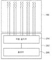
도 11은, 본 실시형태에 따른 서버(300)의 하드웨어 구성을 나타내는 블록도이다. 도 11에 나타내는 바와 같이, 서버(300)는, CPU(Central Processing Unit)(301), ROM(Read Only Memory)(302), RAM(Random Access Memory)(303), 스토리지(304), 입력부(305), 표시부(306) 및 안테나(307)를 갖는다. 각 구성은, 버스(309)를 통해 상호 통신 가능하게 접속되어 있다. 서버(300)로서는, 범용 컴퓨터뿐만이 아니라, 예를 들면 스마트폰이나 태블릿형 디바이스 등 각종 정보 처리 장치를 채용할 수 있다.Fig. 11 is a block diagram showing the hardware configuration of the
CPU(301)는, 중앙 연산 처리 유닛이며, 각종 프로그램을 실행하거나, 각부(各部)를 제어한다. 즉, CPU(301)는, ROM(302) 또는 스토리지(304)로부터 프로그램을 판독하고, RAM(303)을 작업 영역으로서 프로그램을 실행한다. CPU(301)는, ROM(302) 또는 스토리지(304)에 기억되어 있는 프로그램에 따라서, 상기 각 구성의 제어 및 각종 연산 처리를 행한다. 본 실시형태에서는, ROM(302) 또는 스토리지(304)에는, 동작 검지 프로그램이 기억되어 있다.The
ROM(302)은, 각종 프로그램 및 각종 데이터를 저장한다. RAM(303)은, 작업 영역으로서 일시적으로 프로그램 또는 데이터를 기억한다. 스토리지(304)는, HDD(Hard Disk Drive) 또는 SSD(Solid State Drive) 등의 기억 장치에 의해 구성되고, 오퍼레이팅 시스템을 포함하는 각종 프로그램, 및 각종 데이터를 저장한다.The ROM 302 stores various programs and various data.
입력부(305)는, 마우스 등의 포인팅 디바이스, 및 키보드를 포함하고, 각종 입력을 행하기 위해 사용된다.The
표시부(306)는, 예를 들면, 액정 디스플레이이며, 각종 정보를 표시한다. 표시부(306)는, 터치 패널 방식을 채용하여, 입력부(305)로서 기능해도 된다.The display unit 306 is, for example, a liquid crystal display and displays various types of information. The display unit 306 may function as the
안테나(307)는, 동작 검지용 부재(150)를 포함하는 다른 기기와 무선 통신을 행하기 위한 안테나이며, 다른 기기와 직접 통신을 행할 경우에는 IEEE802.15.1이나 IEEE802.15.4 등의 규격에 준거한다. 또, 안테나(307)는, 다른 기기와 무선 기지국이나 무선 라우터 경유의 통신을 행할 경우, 예를 들면, Wi-Fi(등록상표), LTE 등의 규격을 이용할 수 있다.The
다음으로, 서버(300)의 기능 구성에 대해서 설명한다. 도 12는, 서버(300)의 기능 구성의 예를 나타내는 블록도이다. 도 12에 나타내는 바와 같이, 서버(300)는, 기능 구성으로서, 통신부(311)와, 동작 판정부(312)와, 화상 생성부(313)와, 표시부(314)를 갖는다. 각 기능 구성은, CPU(301)가 ROM(302) 또는 스토리지(304)에 기억된 동작 검지 프로그램을 판독하고, RAM(303)으로 전개(展開)하여 실행함으로써 실현된다.Next, the functional configuration of the
통신부(311)는, 동작 검지용 부재(150)로부터 저항치를 수신한다. 그리고, 통신부(311)는, 수신한 저항치를, 동작 판정부(312)에 건네준다.The
동작 판정부(312)는, 통신부(206)로부터 수신한 저항치에 의거하여, 피장착체의 동작의 유무를 판정한다.Based on the resistance value received from the
구체적으로는, 동작 판정부(312)는, 소정의 저항치와, 저항 검지부(204)에 의해 검지된 저항치와의 차가, 소정의 임계치 이상인 경우, 손의 손가락에 동작이 있다고 판정한다.Specifically, the
여기에서, 동작 판정부(312)는, 손가락마다의 동작의 유무를 판정하지만, 어느 손가락에 대해서인지는, 미리 저항치의 데이터와 어느 손가락인지를 나타내는 정보를 아울러 동작 검지용 부재(150)로부터 수신하는 구성으로 하면 된다. 동작 판정부(312)는, 손가락마다 복수 마련되고 저항 검지부(204)에 의해 검지된 저항치에 의거하여, 각 손가락의 동작의 유무를 판정하고, 판정 결과의 조합에 의거하여, 사람의 손의 동작을 판정한다. 예를 들면, 동작 판정부(312)는, 근위지절간 관절에 대해서 동작이 있었는지의 여부, 중수지절간 관절에 동작이 있었는지의 여부를 각각 판정한다. 그리고, 동작 판정부(312)는, 판정 결과를 화상 생성부(313)에 건네준다.Here, the
화상 생성부(313)는, 동작 판정부(312)에 의한 판정 결과에 의거하여, 판정 결과의 동작에 따른 화상을 생성한다. 구체적으로는, 화상 생성부(313)는, 근위지절간 관절에 대해서 동작이 있었다고 판정했을 경우, 근위지절간 관절을 굽힌 화상을 생성한다. 또, 미리 정한 손의 동작을 나타내는 복수의 화상으로부터, 대응하는 화상을 선택하는 구성으로 해도 된다. 그리고, 화상 생성부(313)는, 생성한 화상을, 표시부(314)에 건네준다.The
표시부(314)는, 화상 생성부(313)가 생성한 동작에 따른 문자열, 화상, 혹은 동영상을 표시하고, 음성을 재생하며, 또한 동작에 따라 조작되는 기기를 제어하기 위한 제어 신호를 출력한다. 구체적으로는, 표시부(314)는, 동작에 따른 문자열, 화상, 동영상, 혹은 음성, 또는 동작에 따라 조작되는 기기를 제어하기 위한 제어 신호를 표시부(306)에 표시한다. 표시부(314)는, 문자열 또는 음성을 출력할 때에는, 상기 동작에 대응하는 문자열 또는 상기 문자열을 음성 변환한 것을 출력한다. 또한, 제어 신호로서는, 예를 들면, IoT에 의한 제어를 하기 위한 IFTTT 등에 있어서의 입력 정보나, 차량의 핸들이나 로봇에 대한 제어 신호 등이 포함된다. 이 경우, 서버(300)는, 다른 기기와 통신에 의해, 또는 직접 접속된다.The
(서버의 작용)(action of the server)
서버(300)의 작용에 대해서 설명한다. 도 13은, 서버(300)에 의한 동작 검지 처리 루틴의 흐름을 나타내는 플로우 차트이다. CPU(301)가 ROM(302) 또는 스토리지(304)로부터 동작 검지 프로그램을 판독하여, RAM(303)으로 전개하여 실행함으로써, 서버(300)에 의한 처리가 행해진다.The operation of the
스텝 S101에서, CPU(301)는, 통신부(311)로서, 동작 검지용 부재(150)로부터 저항치를 수신한다.In step S101, the
스텝 S102에서, CPU(301)는, 동작 판정부(312)로서, 통신부(206)로부터 수신한 저항치에 의거하여, 피장착체의 동작의 유무를 판정한다.In step S102, the
스텝 S103에서, CPU(301)는, 화상 생성부(313)로서, 동작 판정부(312)에 의한 판정 결과에 의거하여, 판정 결과의 동작에 따른 화상을 생성한다.In step S103, the
스텝 S104에서, CPU(301)는, 표시부(314)로서, 화상 생성부(313)가 생성한 동작에 따른 화상을 표시하고, 처리를 종료한다. 그리고, 저항치를 수신할 때마다 상기 루틴을 반복한다. 또, 소정 주기에 의해, 저항치의 수신이 있었는지의 여부를 판정하고, 수신이 있었을 경우에 상기 처리를 행하는 구성으로 해도 된다.In step S104, the
이상 설명한 바와 같이, 본 개시의 동작 검지 시스템은, 피장착체에 장착되는 동작 검지용 부재에 의해 피장착체의 동작 정보를 검지하는 동작 검지부와, 동작 검지부에 의해 검지된 동작 정보를 서버에 송신하는 통신부와, 동작 정보가, 어떠한 동작인지를 판정하는 동작 판정부를 포함함으로써, 피장착체가 어떠한 동작을 했는지를 정확하게 검지할 수 있는 동작 검지 시스템을 제공할 수 있다.As described above, the motion detection system of the present disclosure includes a motion detecting unit that detects motion information of an attached object by a motion detecting member attached to the attached object, and transmits the motion information detected by the motion detecting unit to the server. It is possible to provide a motion detection system capable of accurately detecting what kind of motion the attached object has performed by including a communication unit that performs a communication unit and an operation determining unit that determines what kind of motion the motion information is.
또한, 동작 검지용 부재는, 피장착체에 장착되는 장착부로서, 피장착체의 동작에 의해 신축하는 신축 부위를 갖는 장착부와, 장착부의 신축 부위가 신축했을 때, 신축한 것을 나타내는 신축 정보를 검지하는 배선 전극부를 포함함으로써, 장착감이 우수하므로, 동작이 있을 경우에 피장착자가 위화감을 느끼는 일이 없기 때문에, 동작에 동작 검지용 부재의 영향이 적다. 이 때문에, 보다 동작을 정확하게 검지할 수 있다.Further, the motion detecting member is a wearing part attached to the attached object, and detects a wearing part having an elastic part that expands and contracts by the motion of the attached object, and stretch information indicating that the elastic part of the attached part is stretched and contracted. By including the wire electrode part to do so, the wearing comfort is excellent, so that the wearer does not feel uncomfortable when there is an operation, so the motion detection member has little influence on the operation. For this reason, the motion can be more accurately detected.
또한, 서버가, 통신부로부터 수신한 저항치에 의거하여, 피장착체의 동작의 유무를 판정함으로써, 임의의 동작 범위를 검출할 수 있다. 임계치를 복수 준비함으로써, 다단계의 동작을 검지하는 것도 가능하다.Further, the server can detect an arbitrary operating range by determining whether or not the attached object is operating based on the resistance value received from the communication unit. By preparing a plurality of thresholds, it is also possible to detect multi-step operations.
또한, 동작에 따른 화상 또는 동영상을 표시함으로써, 리얼타임에 피장착체의 상태를 파악할 수 있다. 즉, 리하빌리테이션이나, 로봇 암(arm)의 동작 확인 등에 응용할 수 있다.In addition, by displaying an image or moving picture according to the operation, the state of the attached object can be grasped in real time. That is, it can be applied to rehabilitation or operation check of a robot arm.
또한, 동작에 따른 문자열, 화상, 혹은 동영상을 표시하고, 음성을 재생하거나, 또는 동작에 따라 조작되는 기기를 제어하기 위한 제어 신호를 출력할 수 있기 때문에, 예를 들면 수화 등을, 문자나 음성으로 변환하여 인식할 수도 있다. 수화 등의 훈련에도 응용할 수 있다.In addition, since it is possible to display a character string, image, or video according to an operation, reproduce a voice, or output a control signal for controlling a device operated according to an operation, for example, sign language, etc., text or voice It can also be recognized by converting it to . It can also be applied to training such as sign language.
또한, 상기 신축 센서를 이용함으로써, 내구성이 높고, 장착감이 우수한 동작 검지용 부재를 이용한 동작 검지를 할 수 있다. 즉, 장착감이 우수하며, 또한, 손의 동작 자체를 정확하게 검지할 수 있는 동작 검지 시스템을 제공할 수 있다.In addition, by using the stretchable sensor, motion detection can be performed using a motion detection member that is highly durable and has an excellent fit. That is, it is possible to provide a motion detection system that is excellent in wearing comfort and can accurately detect the motion itself of the hand.
(배선 전극부의 변형예)(Modified example of wiring electrode part)
본 실시형태에 따른 동작 검지용 부재(150)에 있어서, 배선 전극부는, 도 4에 나타내는 배선 전극부(100)의 구성으로 한정되지 않고, 변형, 또는 개량해도 된다.In the
이하, 본 실시형태에 따른 동작 검지용 부재에 있어서의 배선 전극부의 변형예에 대해서 설명한다.Hereinafter, a modified example of the wiring electrode portion in the motion detection member according to the present embodiment will be described.
또, 이하의 설명에서는, 배선 전극부는, 상기 형태에 대해서 설명한 부재와 동일하면, 도면 중에, 동일 부호를 붙여 그 설명을 생략 또는 간략한다.In the following description, if the wiring electrode portion is the same as the member described in the above embodiment, the same reference numerals are used in the drawings to omit or simplify the description.
또한, 이하의 설명에서는, 접속용 배선부는, 생략하고 설명한다.In addition, in the following description, the wiring part for connection is abbreviate|omitted and demonstrated.
-제1 변형예--First modified example-
배선 전극부는, 예를 들면, 도 14a에 나타내는 배선 전극부(101)여도 된다.The wiring electrode portion may be, for example, the
구체적으로는, 도 14a에 나타내는 바와 같이, 배선 전극부(101)는, 검지용 배선부(30)가 마련된 장착부의 신축 부위(이하, 단순히 「장착부의 신축 부위」라고 함)의 신장 전 상태에서, 제1 검지용 배선부(30A)와 제2 검지용 배선부(30B)가 이간하여 마련되어 있다. 그리고, 제1 검지용 배선부(30A)의 파상부(32A)와 제2 검지용 배선부(30B)의 파상부(32B)는, 대략 평행하게 대향하며, 또한 이간하여 마련되어 있다.Specifically, as shown in FIG. 14A , the
피장착체의 동작에 의해, 장착부의 신축 부위가 신장하면, 어느 신장률에 달한 시점에서, 이간해 있던 제1 검지용 배선부(30A)와 제2 검지용 배선부(30B)의 적어도 일부가 접촉한다(도 14b 참조). 구체적으로는, 제1 검지용 배선부(30A)를 구성하는 도전성 선상체(40A2)와, 제2 검지용 배선부(30B)를 구성하는 도전성 선상체(40B2)의 적어도 일부가 접촉한다.When the expansion and contraction portion of the wearing portion is stretched due to the operation of the adhered object, at a point in time when a certain elongation rate is reached, at least a part of the separated first
보다 구체적으로는, 장착부의 신축 부위가 신장하면, 제1 검지용 배선부(30A)의 파상부(32A)와, 제2 검지용 배선부(30B)의 파상부(32B)가, 그 주기가 길며, 또한 진폭이 작아지면서, 가까이 접촉한다.More specifically, when the stretchable portion of the attaching portion is extended, the
이 동작에 의해, 장착부의 신축 부위가 신장했을 때, 제1 전극부(20A)와 제2 전극부(20B) 사이의 저항치가 변화한다. 즉, 저항치가 저하한다. 구체적으로는, 제1 전극부(20A)와 제2 전극부(20B) 사이가 비도통으로부터 도통이 된다.Due to this operation, the resistance value between the
그리고, 신장에 수반하는 제1 전극부(20A)와 제2 전극부(20B) 사이의 저항치 변화를 검지함으로써, 피장착체의 동작을 검지할 수 있다.Then, by detecting a change in resistance value between the
한편, 피장착체의 동작에 의해, 장착부의 신축 부위의 신장이 해제되면(즉 수축하면), 어느 신장률에 달한 시점에서, 접촉해 있던 제1 검지용 배선부(30A)와 제2 검지용 배선부(30B)가 이간한다(도 14a 참조). 즉, 저항치가 증가한다. 구체적으로는, 제1 전극부(20A)와 제2 전극부(20B) 사이가 도통으로부터 비도통이 된다.On the other hand, when the extension of the stretchable part of the wearing part is released (ie contracted) by the operation of the attached object, the first
이와 같이, 수축에 수반하는 제1 전극부(20A)와 제2 전극부(20B) 사이의 저항치 변화를 검지함으로써, 피장착체의 동작을 검지할 수 있다.In this way, by detecting a change in the resistance value between the
-제2 변형예--Second modification-
배선 전극부는, 예를 들면, 도 15a에 나타내는 배선 전극부(102)여도 된다.The wiring electrode portion may be, for example, the
구체적으로는, 도 15a에 나타내는 바와 같이, 배선 전극부(102)는, 제1 검지용 배선부(30A)의 파상부(32A)로서, 제1 파상부(32A1)와, 제1 파상부(32A1)보다 제2 검지용 배선부(30B)의 파상부(32B)와의 접촉 길이가 다른 제2 파상부(32A2)를 갖고 있다.Specifically, as shown in FIG. 15A , the
그리고, 배선 전극부(102)는, 제1 검지용 배선부(30A)의 파상부(32A)로서, 제1 파상부(32A1)와, 제1 파상부(32A1)의 주기 및/또는 진폭이 다른 제2 파상부(32A2)를 갖고 있다.Further, the
또, 본 예에서는, 제2 파상부(32A2)가, 제1 파상부(32A1)보다 제2 검지용 배선부(30B)의 파상부(32B)와의 접촉 길이가 짧은 예를 나타내고 있다. 그리고, 제2 파상부(32A2)가, 제1 파상부(32A1)보다 주기가 짧으며, 또한 진폭이 작은 예를 나타내고 있다.In addition, in this example, an example in which the contact length of the second corrugated portion 32A2 with the
피장착체의 동작에 의해, 검지용 배선부(30)가 마련된 장착부의 신축 부위(이하, 단순히 「장착부의 신축 부위」라고 함)가 신장하면, 어느 신장률에 달한 시점에서, 접촉해 있던 제1 검지용 배선부(30A)와 제2 검지용 배선부(30B)의 일부가 이간한다(도 15b 참조). 구체적으로는, 제1 검지용 배선부(30A)의 제2 파상부(32A2)와, 제2 검지용 배선부(30B)의 파상부(32B)가 이간한다.When the elastic part of the wearing part provided with the detection wiring part 30 (hereinafter, simply referred to as the "extending part of the wearing part") is extended by the operation of the attached object, at the time of reaching a certain elongation rate, the contacted first Part of the
또한 신장하면, 어느 신장률에 달한 시점에서, 제1 검지용 배선부(30A)의 제2 파상부(32A2)와, 제2 검지용 배선부(30B)의 파상부(32B)가 이간한다(도 15c 참조).Further, when elongated, when a certain elongation rate is reached, the second corrugated portion 32A2 of the first
즉, 제1 검지용 배선부(30A)의 제2 파상부(32A2)와 제2 검지용 배선부(30B)의 파상부(32B)가 먼저 이간하고, 제1 검지용 배선부(30A)의 제1 파상부(32A1)와 제2 검지용 배선부(30B)의 파상부(32B)가 나중에 이간한다.That is, the second corrugated portion 32A2 of the first detecting
이 동작에 의해, 장착부의 신축 부위가 신장했을 때, 제1 전극부(20A)와 제2 전극부(20B) 사이의 저항치가 단계적으로 변화한다. 즉, 제1 검지용 배선부(30A)와 제2 검지용 배선부(30B)가 일부 이간한 것에 의한 접촉 저항의 증가만큼, 저항치가 단계적으로 증가한다. 구체적으로는, 제1 전극부(20A)와 제2 전극부(20B) 사이가 도통 상태에서, 저항치가 일정치 증가한 후, 도통으로부터 비도통이 된다.By this operation, the resistance value between the
그리고, 신장에 수반하는 제1 전극부(20A)와 제2 전극부(20B) 사이의 저항치의 단계적인 변화를 검지함으로써, 단계적인 피장착체의 동작을 검지할 수 있다.Then, by detecting a gradual change in the resistance value between the
한편, 피장착체의 동작에 의해, 장착부의 신축 부위의 신장이 해제되면(즉 수축하면), 어느 신장률에 달한 시점에서, 이간해 있던 제1 검지용 배선부(30A)의 제1 파상부(32A1)와 제2 검지용 배선부(30B)의 파상부(32B)가 접촉한다(도 15b 참조).On the other hand, when the extension of the stretchable portion of the wearing portion is released (ie, contracted) by the operation of the attached object, the first wavy portion of the first
또한, 수축하면, 어느 신장률에 달한 시점에서, 이간해 있던 제1 검지용 배선부(30A)의 제2 파상부(32A2)와 제2 검지용 배선부(30B)의 파상부(32B)가 접촉한다(도 15a 참조). 즉, 저항치가 단계적으로 저하한다.Further, upon contraction, when a certain elongation rate is reached, the separated second corrugated portion 32A2 of the first
구체적으로는, 제1 전극부(20A)와 제2 전극부(20B) 사이가 비도통으로부터 도통이 된 후, 도통한 상태에서, 저항치가 저하한다.Specifically, after the
이와 같이, 수축에 수반하는 제1 전극부(20A)와 제2 전극부(20B) 사이의 저항치의 단계적인 변화를 검지함으로써, 단계적인 피장착체의 동작을 검지할 수 있다.In this way, by detecting a gradual change in the resistance value between the
여기에서, 제2 변형예는, 목적으로 하는, 제1 전극부(20A)와 제2 전극부(20B) 사이의 저항치의 단계적인 변화에 따라, 제1 검지용 배선부(30A)의 파상부(32A)와 제2 검지용 배선부(30B)의 파상부(32B)와의 접촉부에 있어서, 서로의 접촉 길이가 다른 영역을 복수 갖고 있어도 된다. 그리고, 제1 검지용 배선부(30A) 및 제2 검지용 배선부(30B)의 적어도 한쪽에, 주기 및/또는 진폭이 다른 복수의 파상부를 갖고 있어도 된다.Here, in the second modification, the wavy portion of the first
또, 저항치의 단계적인 변화(즉 단계적인 증가 또는 저하)란, 장착부의 신축 부위가 신장하는 과정에서, 저항치가 변화하고, 그 저항치 변화가 일단 종료한 후, 다시, 저항치가 변화하는 것을 나타낸다.Further, a gradual change in resistance value (i.e., a gradual increase or decrease) indicates that the resistance value changes in the course of elongation of the stretchable portion of the wearing portion, and then changes again after the resistance change is once completed.
-제3 변형예--The third modified example-
배선 전극부는, 예를 들면, 도 16a에 나타내는 배선 전극부(103)여도 된다. 구체적으로는, 도 16a에 나타내는 바와 같이, 배선 전극부(103)는, 전극부(20)로서, 제3 전극부(20C)와, 검지용 배선부(30)로서 제3 검지용 배선부(30C)를 더 갖고 있다.The wiring electrode portion may be, for example, the
제3 전극부(20C)는 도전성 선상체(40C1)를 포함한다. 제3 검지용 배선부(30C)는, 제3 전극부(20C)의 도전성 선상체(40C1)가 연장된 도전성 선상체(40C2)를 포함한다. 즉, 제3 전극부(20C)와 제3 검지용 배선부(30C)는, 적어도 같은 1개의 도전성 선상체(40)로 구성되어 있다.The third electrode portion 20C includes a conductive linear body 40C1. The third
제3 검지용 배선부(30C)는, 제3 전극부(20C)에 전기적으로 접속되어 있다.The third
제3 검지용 배선부(30C)는, 제1 검지용 배선부(30A) 및 제2 검지용 배선부(30B)와 별개이며, 또한 검지용 배선부(30)가 마련된 장착부의 신축 부위(이하, 단순히 「장착부의 신축 부위」라고 함)의 신장 전 상태에서, 제1 검지용 배선부(30A)와 제2 검지용 배선부(30B) 사이에 개재하며, 또한 제1 검지용 배선부(30A)와 제2 검지용 배선부(30B)의 적어도 일부와 접촉해서 마련되어 있다.The third
제3 검지용 배선부(30C)는, 예를 들면, 도전성 선상체(40C2)를 파상으로 마련한 파상부(32C)를 갖고 있다.The 3rd
그리고, 장착부의 신축 부위의 신장 전 상태에서, 제3 검지용 배선부(30C)의 파상부(32C)는, 제1 검지용 배선부(30A)의 파상부(32A) 및 제2 검지용 배선부(30B)의 파상부(32B)와 점 접촉 또는 선 접촉해 있다.Then, in the pre-extended state of the stretchable portion of the attaching portion, the wavy portion 32C of the third
단, 제3 검지용 배선부(30C)의 파상부(32C)와 제1 검지용 배선부(30A)의 파상부(32A)와의 접촉 길이는, 제3 검지용 배선부(30C)의 파상부(32C)와 제2 검지용 배선부(30B)의 파상부(32B)와의 접촉 길이와 다르다. 그리고, 제3 검지용 배선부(30C)의 파상부(32C), 제1 검지용 배선부(30A)의 파상부(32A) 및 제2 검지용 배선부(30B)의 파상부(32B)의 주기 및/또는 진폭이 다르다.However, the contact length between the wavy portion 32C of the third
또, 본 예에서는, 제3 검지용 배선부(30C)의 파상부(32C)와 제1 검지용 배선부(30A)의 파상부(32A)와의 접촉 길이가, 제3 검지용 배선부(30C)의 파상부(32C)와 제2 검지용 배선부(30B)의 파상부(32B)와의 접촉 길이보다 짧은 예를 나타내고 있다. 그리고, 제3 검지용 배선부(30C)의 파상부(32C)는, 제1 검지용 배선부(30A)의 파상부(32A) 및 제2 검지용 배선부(30B)의 파상부(32B)보다 진폭이 작은 예를 나타내고 있다.In addition, in this example, the contact length between the wavy portion 32C of the third
장착부의 신축 부위가 신장하면, 어느 신장률에 달한 시점에서, 접촉해 있던 제1 검지용 배선부(30A)와 제3 검지용 배선부(30C)가 이간한다(도 16b 참조). 구체적으로는, 제1 검지용 배선부(30A)의 파상부(32A)와, 제3 검지용 배선부(30C)의 파상부(32C)가 이간한다.When the elastic portion of the wearing portion is stretched, when a certain elongation rate is reached, the first
또한 신장하면, 어느 신장률에 달한 시점에서, 접촉해 있던 제2 검지용 배선부(30B)와 제3 검지용 배선부(30C)가 이간한다(도 16c 참조). 구체적으로는, 제2 검지용 배선부(30B)의 파상부(32B)와, 제3 검지용 배선부(30C)의 파상부(32C)가 이간한다.Further, when elongation occurs, when a certain elongation rate is reached, the second
즉, 제1 검지용 배선부(30A)와 제3 검지용 배선부(30C)가 먼저 이간하고, 제2 검지용 배선부(30B)와 제3 검지용 배선부(30C)가 나중에 이간한다.That is, the first
이 동작에 의해, 장착부의 신축 부위가 신장했을 때, 제1 전극부(20A)와 제3 전극부(20C) 사이의 저항치가 변화한다. 즉, 저항치가 증가한다. 구체적으로는, 제1 전극부(20A)와 제3 전극부(20C) 사이가 도통으로부터 비도통이 된다.Due to this operation, the resistance value between the
또한 신장하면, 제2 전극부(20B)와 제3 전극부(20C) 사이의 저항치가 변화한다. 즉, 저항치가 증가한다. 구체적으로는, 제2 전극부(20B)와 제3 전극부(20C) 사이가 도통으로부터 비도통이 된다.Further, when elongated, the resistance value between the
그리고, 신장에 수반하는, 제1 전극부(20A)와 제3 전극부(20C) 사이의 저항치의 변화, 및 제2 전극부(20B)와 제3 전극부(20C) 사이의 저항치의 변화를 검지함으로써, 피장착체의 동작을 검지할 수 있다.Then, the change in the resistance value between the
한편, 피장착체의 동작에 의해, 장착부의 신축 부위의 신장이 해제되면(즉 수축하면), 어느 신장률에 달한 시점에서, 이간해 있던 제2 검지용 배선부(30B)와 제3 검지용 배선부(30C)가 접촉한다(도 16b 참조). 구체적으로는, 제2 검지용 배선부(30B)의 파상부(32B)와, 제3 검지용 배선부(30C)의 파상부(32C)가 접촉한다.On the other hand, when the extension of the stretchable part of the wearing part is released (ie contracted) by the operation of the attached object, at the time of reaching a certain elongation rate, the second
또한 수축하면, 어느 신장률에 달한 시점에서, 이간해 있던 제1 검지용 배선부(30A)와 제3 검지용 배선부(30C)가 접촉한다(도 16a 참조). 구체적으로는, 제1 검지용 배선부(30A)의 파상부(32A)와, 제3 검지용 배선부(30C)의 파상부(32C)가 접촉한다.Further, upon contraction, when a certain elongation rate is reached, the separated first
즉, 제2 검지용 배선부(30B)와 제3 검지용 배선부(30C)가 먼저 접촉하고, 제1 검지용 배선부(30A)와 제3 검지용 배선부(30C)가 나중에 접촉한다.That is, the second
이와 같이, 수축에 수반하는, 제1 전극부(20A)와 제3 전극부(20C) 사이의 저항치의 변화, 및 제2 전극부(20B)와 제3 전극부(20C) 사이의 저항치의 변화를 검지함으로써, 단계적인 피장착체의 동작을 검지할 수 있다.In this way, a change in the resistance value between the
또, 제3 변형예는, 제2 검지용 배선부(30B)와 제3 검지용 배선부(30C)가 먼저 이간하고, 제1 검지용 배선부(30A)와 제3 검지용 배선부(30C)가 나중에 이간하는 태양이어도 된다.Further, in the third modification, the second
-제4 변형예--Fourth modification-
배선 전극부는, 예를 들면, 도 17a에 나타내는 배선 전극부(104)여도 된다.The wiring electrode portion may be, for example, the
구체적으로는, 도 17a에 나타내는 바와 같이, 배선 전극부(104)는, 검지용 배선부(30)가 마련된 장착부의 신축 부위(이하, 단순히 「장착부의 신축 부위」라고 함)의 신장 전 상태에서, 제1 검지용 배선부(30A)와 제2 검지용 배선부(30B)가 이간하여 마련되어 있다. 그리고, 제1 검지용 배선부(30A)의 파상부(32A)와 제2 검지용 배선부(30B)의 파상부(32B)는, 각도(예를 들면, 각 파상부의 연장 방향이 이루는 각도가 3° ∼ 30°)를 이루어 대향하며, 또한 이간하여 마련되어 있다.Specifically, as shown in FIG. 17A , the
피장착체의 동작에 의해, 장착부의 신축 부위가 신장하면, 어느 신장률에 달한 시점에서, 이간해 있던 제1 검지용 배선부(30A)와 제2 검지용 배선부(30B)의 적어도 일부가 접촉한다(도 17b 참조). 구체적으로는, 제1 검지용 배선부(30A)를 구성하는 도전성 선상체(40A2)와, 제2 검지용 배선부(30B)를 구성하는 도전성 선상체(40B2)의 적어도 일부가 접촉한다.When the expansion and contraction portion of the wearing portion is stretched due to the operation of the adhered object, at a point in time when a certain elongation rate is reached, at least a part of the separated first
보다 구체적으로는, 장착부의 신축 부위가 신장하면, 제1 검지용 배선부(30A)의 파상부(32A)와, 제2 검지용 배선부(30B)의 파상부(32B)가 그 주기가 길며, 또한 진폭이 작아지면서, 제1 검지용 배선부(30A)의 파상부(32A)에, 제2 검지용 배선부(30B)의 파상부(32B)의 선단 측(제2 전극부(20B)와 접속되어 있지 않은 쪽의 선단 측)으로부터 가까이 접촉해 간다.More specifically, when the stretchable portion of the attaching part is extended, the
또한 신장하면, 제1 검지용 배선부(30A)와 제2 검지용 배선부(30B)와의 접촉 영역이 증가한다(도 17c 참조). 구체적으로는, 제1 검지용 배선부(30A)를 구성하는 도전성 선상체(40A2)와, 제2 검지용 배선부(30B)를 구성하는 도전성 선상체(40B2)와의 접촉 영역이 증가한다.Further, when extended, the contact area between the first
보다 구체적으로는, 장착부의 신축 부위가 신장하면, 제1 검지용 배선부(30A)의 파상부(32A)와, 제2 검지용 배선부(30B)의 파상부(32B)가 그 주기가 길며, 또한 진폭이 작아지면서, 가까워져 접촉 영역이 증가한다.More specifically, when the stretchable portion of the attaching part is extended, the
이 동작에 의해, 장착부의 신축 부위가 신장했을 때, 제1 전극부(20A)와 제2 전극부(20B) 사이의 저항치가 단계적으로 변화한다. 즉, 제1 검지용 배선부(30A)와 제2 검지용 배선부(30B)가 최초로 접촉했을 때에, 제1 전극부(20A)와 제2 전극부(20B) 사이가 비도통 상태로부터 도통 상태가 된다. 다음으로, 제1 검지용 배선부(30A)와 제2 검지용 배선부(30B)와의 접촉 영역이 증가하면, 접촉 저항이 저하하며, 제1 전극부(20A)와 제2 전극부(20B) 사이의 저항치가 단계적으로 저하한다.By this operation, the resistance value between the
그리고, 신장에 수반하는 제1 전극부(20A)와 제2 전극부(20B) 사이의 저항치의 단계적인 변화를 검지함으로써, 단계적인 피장착체의 동작을 검지할 수 있다.Then, by detecting a gradual change in the resistance value between the
한편, 피장착체의 동작에 의해, 장착부의 신축 부위의 신장이 해제되면(즉 수축하면), 제1 검지용 배선부(30A)와 제2 검지용 배선부(30B)와의 접촉 영역이 적어진다(도 17b). 또한, 수축하면, 어느 신장률에 달한 시점에서, 배직(背職)하고 있던 제1 검지용 배선부(30A)의 제1 파상부(32A1)와 제2 검지용 배선부(30B)의 파상부(32B)가 이간한다(도 17a 참조). 즉, 저항치가 단계적으로 증가한다.On the other hand, when the expansion and contraction portion of the attachment part is released (i.e. contracted) by the operation of the attached object, the contact area between the first
구체적으로는, 제1 전극부(20A)와 제2 전극부(20B) 사이가 도통 상태에서, 저항치가 저하하고, 그 후, 비도통 상태가 된다.Specifically, when the
이와 같이, 수축에 수반하는 제1 전극부(20A)와 제2 전극부(20B) 사이의 저항치의 단계적인 변화를 검지하는 것으로도, 단계적인 피장착체의 동작을 검지할 수 있다.In this way, also by detecting a gradual change in the resistance value between the
-제5 변형예--Fifth modified example-
배선 전극부는, 예를 들면, 도 18a에 나타내는 배선 전극부(105)여도 된다. 구체적으로는, 도 18a에 나타내는 바와 같이, 배선 전극부(105)는, 검지용 배선부(30)로서, 제1 검지용 배선부(30A)와 제2 검지용 배선부(30B)가 일체적으로 마련되어 있다. 구체적으로는, 예를 들면, 검지용 배선부(30)로서의, 제1 검지용 배선부(30A)와 제2 검지용 배선부(30B)는, 제1 전극부(20A) 및 제2 전극부(20B)를 구성하는 도전성 선상체(40)가 연장된 1개의 도전성 선상체(40)로 구성되어 있다.The wiring electrode portion may be, for example, the
즉, 배선 전극부(105)는, 제1 전극부(20A)와 제2 전극부(20B)가, 하나의 검지용 배선부(30)에서 전기적으로 연결되어 있다.That is, in the
또, 검지용 배선부(30)는, 복수 개의 도전성 선상체(40)로 구성되어 있어도 된다.In addition, the
검지용 배선부(30)의 도중에는, 검지용 배선부(30)가 마련된 장착부의 신축 부위(이하, 단순히 「장착부의 신축 부위」라고 함)의 신장 전 상태에서, 검지용 배선부(30)가 180°로 반복하여 굴곡 또는 만곡하며, 또한 굴곡부 또는 만곡부 사이의 검지용 배선부(30)끼리의 적어도 일부가 접촉한 접촉부(34)를 갖고 있다.In the middle of the detecting
즉, 검지용 배선부(30)의 도중에는, 장착부의 신축 부위의 신장 전 상태에서, 도전성 선상체(40)가 180°로 반복하여 굴곡 또는 만곡하며, 또한 굴곡부 또는 만곡부 사이의 도전성 선상체(40)끼리의 적어도 일부가 접촉한 접촉부(34)를 갖고 있다.That is, in the middle of the
장착부의 신축 부위가, 검지용 배선부(30)의 연장 방향을 따라 신장하면, 검지용 배선부(30)의 접촉부(34)에 있어서, 굴곡부 또는 만곡부 사이에서 접촉한 검지용 배선부(30)끼리 이간한다(도 18b 참조). 그에 따라, 제1 전극부(20A)와 제2 전극부(20B)와의 도통 경로가 길어진다.When the extension and contraction portion of the attaching portion extends along the extension direction of the
이 동작에 의해, 장착부의 신축 부위가 신장했을 때, 제1 전극부(20A)와 제2 전극부(20B) 사이의 저항치가 변화한다. 즉, 도통 경로가 증가한 만큼, 저항치가 증가한다.Due to this operation, the resistance value between the
그리고, 신장에 수반하는 제1 전극부(20A)와 제2 전극부(20B) 사이의 저항치 변화를 검지함으로써, 피장착체의 동작을 검지할 수 있다.Then, by detecting a change in resistance value between the
한편, 피장착체의 동작에 의해, 장착부의 신축 부위의 신장이 해제되면(즉 수축하면), 검지용 배선부(30)의 도중에서, 검지용 배선부(30)가 180°로 반복하여 굴곡 또는 만곡하며, 또한 굴곡부 또는 만곡부 사이의 검지용 배선부(30)끼리의 적어도 일부가 접촉한 접촉부(34)를 형성한다(도 18a 참조).On the other hand, when the extension of the stretchable part of the attachment part is released (ie contracted) by the operation of the attached object, the
이 동작에 의해, 장착부의 신축 부위가 수축했을 때, 제1 전극부(20A)와 제2 전극부(20B) 사이의 저항치가 변화한다. 즉, 도통 경로가 감소한 만큼, 저항치가 저하한다.Due to this operation, the resistance value between the
그리고, 수축에 수반하는 제1 전극부(20A)와 제2 전극부(20B) 사이의 저항치 변화를 검지하는 것으로도, 피장착체의 동작을 검지할 수 있다.And also by detecting a change in the resistance value between the
또, 제5 변형예는, 검지용 배선부(30)의 접촉부에 있어서의, 검지용 배선부(30)끼리의 접촉 면적의 증감에 따라, 제1 전극부(20A)와 제2 전극부(20B) 사이의 저항치의 변화량을 제어할 수 있다.Further, in the fifth modification, in accordance with the increase or decrease in the contact area between the
-제6 변형예--Sixth modification-
전극 배선부는, 예를 들면, 도 19에 나타내는 배선 전극부(106)여도 된다. 즉, 검지용 배선부가 마련된 장갑상 장착부의 신축 부위가, 장갑상 장착부의 해당 위치의 표면에 배치된 태양이어도 된다.The electrode wiring portion may be, for example, the
구체적으로는, 도 19에서 나타내는 바와 같이, 배선 전극부(106)(전극부(20), 검지용 배선부(30) 및 접속용 배선부(50))는, 신축성 포재(60)에 마련되어 있다.Specifically, as shown in FIG. 19 , the wiring electrode portion 106 (
신축성 포재(60)는, 표면을 구성하는 표면 포재층(60A)과, 이면을 구성하는 이면 포재층(60B)과, 표면 포재층(60A) 및 이면 포재층(60B) 사이에 갖는 중간 포재층(60C)의 3중(3층)의 포재층으로 구성되어 있다. 또, 신축성 포재(60)의 구성은, 장갑상 장착부(10)를 구성하는 포재와 마찬가지이다.The
전극부(20)는, 예를 들면, 신축성 포재(60)의 표면 포재층(60A)에 마련되어 있다.The
검지용 배선부(30)는, 예를 들면, 신축성 포재(60)의 중간 포재층(60C)에 마련되어 있다.The
배선용 배선부(50)는, 예를 들면, 신축성 포재(60)의 중간 포재층(60C)에 마련되어 있다.The
그리고, 배선 전극부(106)가 마련된 신축성 포재(60)는, 봉제, 접착 등의 주지의 고정 수단에 의해, 장갑상 장착부(10)의 해당 위치의 표면에 배치되어 있다.Then, the
제6 변형예에서는, 배선 전극부(106)가 마련된 신축성 포재(60)를 장갑상 장착부(10)의 해당 위치의 표면에 배치하기 때문에, 장갑상 장착부(10)는, 포재 이외에, 수지, 종이, 가죽 등의 주지의 재질로 구성할 수 있다.In the sixth modified example, since the
-제7 변형예--Seventh modification-
전극 배선부는, 예를 들면, 도 20에 나타내는 배선 전극부(107)여도 된다. 즉, 검지용 배선부가 마련된 장갑상 장착부의 신축 부위가, 장갑상 장착부의 해당 위치의 표면에 배치된 태양이어도 된다.The electrode wiring portion may be, for example, the
구체적으로는, 도 20에 나타내는 바와 같이, 전극부(20)로서 버튼 전극(스냅 버튼 등)이, 봉제, 접착 등의 주지의 고정 수단에 의해, 장갑상 장착부(10)의 해당 위치의 표면에 배치되어 있다.Specifically, as shown in FIG. 20 , a button electrode (snap button, etc.) as the
검지용 배선부(30)는 신축성 포재(70)에 마련되어 있다.The detecting
신축성 포재(70)는, 표면을 구성하는 표면 포재층(70A)과, 이면을 구성하는 이면 포재층(70B)과, 표면 포재층(70A) 및 이면 포재층(70B) 사이에 갖는 중간 포재층(70C)의 3중(3층)의 포재층으로 구성되어 있다. 또, 신축성 포재(70)의 구성은, 장갑상 장착부(10)를 구성하는 포재와 마찬가지이다.The
그리고, 검지용 배선부(30)가 마련된 신축성 포재(70)는, 장갑상 장착부(10)의 표면에 마련되어 있다.And, the
접속용 배선부(50)는, 장갑상 장착부(10)의 표면에, 전극부(20)와 검지용 배선부(30)를 접속해서 마련되어 있다. 또한, 접속용 배선부(50)는, 포재, 수지재 등의 주지의 절연 시트(72)에 의해 피복되어 있다.The
제7 변형예에서도, 배선 전극부(107)를 장갑상 장착부(10)의 해당 위치의 표면에 배치하기 때문에, 장갑상 장착부(10)는, 포재 이외에, 수지, 종이, 가죽 등의 주지의 재질로 구성할 수 있다.Also in the seventh modified example, since the
(특성)(characteristic)
또, 피장착체의 동작을 검지하기 위해, 검지용 배선부(30)가 마련된 장착부의 신축 부위(이하, 단순히 「장착부의 신축 부위」라고 함)는, 신장률의 변화가 ± 5%의 범위 내에서 제1 전극부(20A)와 제2 전극부(20B) 사이의 저항치가 2배 이상 또는 1/2 이하(바람직하게는 10배 이상 또는 1/10 이하, 보다 바람직하게는 100배 이상 또는 1/100 이하)로 변화하는, 신장률의 범위를 갖는 것이 좋다(도 7 ∼ 도 8 참조). 즉, 장착부의 신축 부위는, 신장하는 과정에서, 신장률이 10% 변화하는 동안에 제1 전극부(20A)와 제2 전극부(20B) 사이의 저항치가 2배 이상 또는 1/2 이하로 변화하는 것이 좋다.Further, in order to detect the operation of the attached object, the change in elongation rate is within the range of ± 5% in the expansion and contraction part of the wearing part provided with the detecting wiring part 30 (hereinafter simply referred to as “extension and contraction part of the wearing part”). , the resistance value between the
구체적으로는, 장착부의 신축 부위의 최대 신장률을 X(단 10 ≤ X), 장착부의 신축 부위를 신장시켰을 때의, 어느 지점의 신장률을 Y(단, 5 ≤ Y ≤ (X - 5)로 했을 때, Y - 5% ∼ Y + 5%의 범위 내에서, 최대 저항치가 최소 저항치의 2배 이상 또는 1/2 이하(바람직하게는 10배 이상 또는 1/10 이하, 보다 바람직하게는 100배 이상 또는 1/100 이하)가 되는 영역을 갖는 것이 좋다.Specifically, the maximum elongation of the elastic part of the wearing part is X (provided that 10 ≤ X), and the elongation at any point when the elastic part of the wearing part is stretched is Y (provided that 5 ≤ Y ≤ (X - 5) When, within the range of Y - 5% to Y + 5%, the maximum resistance value is 2 times or more or 1/2 or less (preferably 10 times or more or 1/10 or less, more preferably 100 times or more of the minimum resistance value) or 1/100 or less).
이 저항치 변화는, 신장률이 목적으로 하는 시점과, 이 시점으로부터 신장률이 10% 변화한 시점과의 저항치의 비(比)에 의해 산출한다.This change in resistance value is calculated by the ratio of the resistance value between the point at which the elongation rate is the target and the point at which the elongation rate has changed by 10% from this point in time.
또, 신장률의 변화가 ± 5%의 범위 내에서 제1 전극부(20A)와 제2 전극부(20B) 사이의 저항치가 2배 이상 또는 1/2 이하로 변화하는, 신장률의 범위는, 2점 이상 존재해도 된다.In addition, the range of the elongation rate in which the resistance value between the
또한, 신장률의 변화가 ± 5%의 범위 내에서 제1 전극부(20A)와 제2 전극부(20B) 사이의 저항치가 2배 이상 또는 1/2 이하로 변화하는, 신장률과 최대 신장률과의 비(신장률/최대 신장률)의 범위는, 0.1 ∼ 0.9(바람직하게는 0.2 ∼ 0.8)의 범위인 것이 좋다. 이 비가 상기 범위이면, 오동작을 방지하면서, 효율적으로, 피장착체의 동작을 검지할 수 있다.In addition, the difference between the elongation rate and the maximum elongation rate in which the resistance value between the
장착부의 신축 부위의 신축에 수반하는, 제1 전극부(20A)와 제2 전극부(20B) 사이의 저항치의 변화는, 다음과 같이 측정된다.A change in the resistance value between the
제1 전극부(20A)와 제2 전극부(20B) 사이의 저항치를 측정하면서, 속도 1㎜/s로, 장착부의 신축 부위를 최대 신장까지 신장시킨 후, 같은 속도로 원래대로 돌아갈 때까지 수축시킨다. 이때, 저항치를 1초마다 플롯으로 하여, 저항치의 변화를 측정한다. 또, 장착부의 신축 부위의 신장 방향은, 신장 신축에 의한 저항치의 변화를 검지하고자 하는 방향으로 한다.While measuring the resistance value between the
여기에서, 장착부의 신축 부위의 신장률은, 식: ((신장 시의 신장 방향의 길이) - (신장 전의 신장 방향의 길이))/(신장 전의 신장 방향의 길이) × 100으로 산출한다.Here, the elongation rate of the elastic portion of the wearing portion is calculated by the formula: ((length in the stretching direction at the time of stretching) - (length in the stretching direction before stretching))/(length in the stretching direction before stretching) x 100.
한편, 장착부의 신축 부위의 최대 신장률이란, 식: ((최대 신장 시의 신장 방향의 길이) - (신장 전의 신장 방향의 길이))/(신장 전의 신장 방향의 길이) × 100으로 산출한다.On the other hand, the maximum elongation of the stretchable portion of the wearing part is calculated by the formula: ((length in the extension direction at maximum extension) - (length in the extension direction before extension)) / (length in the extension direction before extension) × 100.
또, 장착부의 신축 부위의 최대 신장은, 장착부의 신축 부위를 적절한 장력으로 신장했을 때에, 그 이상 늘어나지 않게 될 때의 길이이다. 즉, 장착부의 신축 부위를 신장이 정지하는 장력으로 신장시켰을 때의 길이를, 장착부의 신축 부위의 최대 신장으로 한다.Further, the maximum elongation of the stretchable portion of the wearing portion is the length at which the stretchable portion of the wearing portion does not stretch any further when the stretchable portion of the wearing portion is stretched with an appropriate tension. That is, the maximum extension of the stretchable portion of the wearing portion is the length when the stretchable portion of the wearing portion is stretched to a tension at which elongation stops.
(동작 검지용 부재(그 장착부)의 형상 등)(shape of motion detection member (wearing part thereof), etc.)
상기 실시형태에서는 동작 검지용 부재(150)의 장착부의 형상이 장갑상인 경우를 예로 설명했지만, 이에 한정되는 것은 아니다. 동작 검지의 목적에 따라, 장착부의 형상을, 통상(筒狀), 시트상, 띠상(帶狀) 등의 각종 형상으로 해도 된다.In the above embodiment, the case where the shape of the attaching portion of the
통상의 장착부로서는, 서포터, 리스트밴드 등의 형상을 채용할 수 있다. 시트상의 장착부로서는, 양단에 파스너를 마련하여, 피착체에 권부하는 형식의, 서포터, 리스트밴드 등의 형상을 채용할 수 있다. 또, 시트상의 장착부의 경우, 시트상의 장착부를 점착제에 의해, 피장착체에 첩부(貼付)하는 태양이어도 된다. 띠상의 장착부로서는, 서스펜더 등의 형상을 채용할 수 있다. 또, 장착부의 형상은, 피장착체에 장착하는 개소에 따라 선택된다.As a normal attachment part, the shape of a supporter, a wristband, etc. can be employ|adopted. As the sheet-shaped attaching portion, fasteners are provided at both ends, and shapes such as a supporter, a wristband, or the like in the form of winding on an adherend can be employed. Moreover, in the case of a sheet-shaped attachment part, an aspect in which the sheet-shaped attachment part is attached to the adhered body with an adhesive may be used. As the belt-shaped attachment portion, shapes such as a suspender can be employed. In addition, the shape of the attaching portion is selected according to the location to be attached to the attached object.
여기에서, 피장착체에 장착하는 개소로서는, 예를 들면, 피장착체로서의 인체의, 가동부(목부, 손목부, 팔꿈치부, 어깨부, 무릎부, 허리부, 발목부, 발부 등)를 들 수 있다. 단, 이에 한정되는 것은 아니다. 인체 이외라면, 공업용 로봇의 암이나 인형의 로봇 등이어도 좋다.Here, examples of places to be attached to the attached object include movable parts (neck, wrist, elbow, shoulder, knee, waist, ankle, foot, etc.) of the human body as the attached object. can However, it is not limited thereto. Other than the human body, it may be an industrial robot arm or a doll robot.
이와 같이, 본 실시형태에 따른 동작 검지용 부재는, 장착부의 형상에 따라, 피장착체에 있어서의 각종 개소에 장착 가능해진다.In this way, the member for motion detection according to the present embodiment can be attached to various locations of the attached body depending on the shape of the attaching portion.
그에 따라, 예를 들면, 피장착체의 가동부의 동작(팔꿈치부, 무릎부 등의 가동부가 소정의 각도로 가동한 동작 등) 및, 그 가동 횟수 등이 검지 가능해진다. 또한, 팔이나 허리 둘레의 사이즈 측정도 가능해진다. 또한, 복수 계측에 따른 움직임 검지도 가능해진다(예를 들면, 목부, 손목부, 팔꿈치부, 어깨부, 무릎부, 허리부, 발목부, 발부 등을 복합하여 계측함으로써 사람의 움직임을 예측 검지 가능해진다).This makes it possible to detect, for example, the operation of the movable part of the attached object (movement in which the movable part, such as an elbow part or a knee part, moves at a predetermined angle, etc.) and the number of times of its operation. In addition, it becomes possible to measure the size of an arm or a waist circumference. In addition, motion detection by multiple measurements is also possible (for example, human motion can be predicted and detected by measuring the neck, wrist, elbow, shoulder, knee, waist, ankle, foot, etc. in combination). becomes).
(검지용 배선부의 변형예)(Modified example of wiring part for detection)
본 실시형태에 따른 동작 검지용 부재는, 검지용 배선부(30) 이외의 주지의 센서(예를 들면, 압력 센서, 가속도 센서, 각속도 센서, 자기 센서 등)를 마련해도 된다. 다른 센서를 마련함으로써, 동작의 보다 높은 검지가 가능해진다.The member for motion detection according to this embodiment may be provided with a known sensor (for example, a pressure sensor, an acceleration sensor, an angular velocity sensor, a magnetic sensor, etc.) other than the
예를 들면, 압력 센서에 의해, 신축 부재에 대한 압력을 측정하고, 계측된 압력이 소정의 임계치를 초과하는지의 여부를 판정할 수 있다. 또한, 예를 들면, 압력 센서에 의해, 물건에 닿았을 때의 압력이나, 손가락끼리 접촉한 것의 검지 등의 무언가에 닿거나, 또는 무언가에 닿아진 것의 검지가 가능해진다.For example, it is possible to measure the pressure on the elastic member by means of a pressure sensor, and determine whether or not the measured pressure exceeds a predetermined threshold. Further, for example, a pressure sensor can detect contact with something, such as pressure when touching an object or detection of contact between fingers, or detection of contact with something.
또한, 가속도 센서, 각속도 센서, 자기 센서 등의 시간축 검지형의 센서를 채용함으로써, 피장착체의 현재의 형상을 계측할 수 있다. 시간축 검지형의 센서를, 상기의 신축 센서와 조합하는 것도 가능하다.In addition, by adopting a time axis detection type sensor such as an acceleration sensor, an angular velocity sensor, or a magnetic sensor, the current shape of the attached object can be measured. It is also possible to combine a sensor of the time axis detection type with the above-mentioned telescopic sensor.
(서버의 변형예 1)(Server Modification 1)
본 실시형태에 따른 동작 검지용 부재(150)는, 예를 들면, 손가락의 동작을 검지할 수 있으므로, 게임 등의 조작용의 입력 장치 등에 이용할 수 있다. 이하, 변형예로서, 표시된 화면과 같은 손의 상태가 되고 있는지의 여부를 판정하는 게임에, 동작 검지 시스템을 이용할 경우를 설명한다. 또, 상기 실시형태에 있어서의 서버(300)와 마찬가지의 처리에 대해서는, 동일한 부호를 붙여 설명을 생략한다.Since the
도 21에 나타내는 바와 같이, 변형예에 따른 서버(310)는, 통신부(311)와, 동작 판정부(312)와, 화상 생성부(313)와, 표시부(314)와, 처리부(315)와, 정오(正誤) 판정부(316)를 포함하여 구성된다.As shown in Fig. 21, the
표시부(314)는, 처리부(315)로부터 건네받은 인체의 손의 동작의 견본 화상을, 표시부(306)에 표시한다. 또한, 표시부(314)는, 처리부(315)로부터 건네받은 정오 판정부(316)에 의한 판정 결과에 대응하는 화상을 표시한다.The
처리부(315)는, 표시된 화면과 같은 손의 상태가 되고 있는지의 여부를 판정하는 게임의 처리를 실행한다. 구체적으로는, 우선, 처리부(315)는, 미리 준비된, 인체의 손의 동작의 견본 화상과, 정답 동작으로 이루어지는 복수의 페어로부터, 랜덤으로 1개의 페어를 선택한다. 다음으로, 처리부(315)는, 선택한 페어의 견본 화상을, 표시부(314)에 건네준다. 처리부(315)는, 선택한 페어의 정답 동작을, 정오 판정부(316)에 건네준다.The
또한, 처리부(315)는, 정오 판정부(316)로부터 판정 결과를 수취하면, 표시부(314)에, 미리 준비된 판정 결과에 대응하는 화상을 건네준다.Further, when the
정오 판정부(316)는, 동작 판정부(312)에 의해 판정된 동작이, 표시부(314)가 표시한 견본 화상의 동작인 정답 동작과 일치하는지의 여부를 판정한다. 구체적으로는, 정오 판정부(316)는, 동작 판정부(312)에 의한 판정 결과가, 처리부(315)로부터 건네받은 정답 동작과 일치하는지의 여부를 판정한다. 즉, 정오 판정부(316)는, 사람의 손가락이 구부러져 있는지의 여부가, 각 손가락에 대해서 모두 일치할 경우에는, 동작이 정답 동작과 일치한다고 하여 정답으로 판정한다. 그렇지 않을 경우, 정오 판정부(316)는, 부정답으로서 판정한다. 그리고, 정오 판정부(316)는, 판정 결과를 처리부(315)에 건네준다.The
(변형예 1에 있어서의 서버의 작용)(Action of server in modified example 1)
다음으로, 변형예 1에 있어서의 서버(310)의 작용에 대해서 설명한다. 도 22는, 서버(310)에 의한 동작 검지 처리 루틴의 흐름을 나타내는 플로우 차트이다. CPU(301)가 ROM(302) 또는 스토리지(304)로부터 동작 검지 프로그램을 판독하여, RAM(303)으로 전개하여 실행함으로써, 동작 검지 처리 루틴이 행해진다. 또, 서버(300)와 마찬가지의 처리에 대해서는, 동일한 부호를 붙여 설명을 생략한다.Next, the operation of the
스텝 S201에서, CPU(301)는, 처리부(315)로서, 미리 준비된, 인체의 손의 동작의 견본 화상과, 정답 동작으로 이루어지는 복수의 페어로부터, 랜덤으로 1개의 페어를 선택한다.In step S201, the
스텝 S200에서, CPU(301)는, 표시부(314)로서, 상기 스텝 S201에 의해 선택된 인체의 손의 동작의 견본 화상을, 표시부(306)에 표시한다.In step S200, the
스텝 S203에서, CPU(301)는, 정오 판정부(316)로서, 상기 스텝 S102에 의해 판정된 동작이, 상기 스텝 S200에서 표시한 견본 화상의 동작인 정답 동작과 일치하는지의 여부를 판정한다.In step S203, the
스텝 S204에서, CPU(301)는, 표시부(314)로서, 상기 스텝 S203에 의한 판정 결과에 대응하는 화상을 표시하고, 처리를 종료한다. 그리고, 저항치를 수신할 때마다 상기 루틴을 반복한다. 또, 소정 주기에 의해, 저항치의 수신이 있었는지의 여부를 판정하고, 수신이 있었을 경우에 상기 처리를 행하는 구성으로 해도 된다. 또, 서버(310)는, 견본 화상 등을, 다른 외부 단말에 표시하는 구성으로 해도 된다.In step S204, the
또, 본 변형예에서는 화상의 경우를 예로 설명했지만, 화상이 아니고, 동영상을 이용해도 된다.Incidentally, in this modified example, the case of an image has been described as an example, but a motion picture may be used instead of an image.
이와 같이, 본 변형예에 따른 동작 검지 시스템은, 인체의 손의 동작의 견본 화상 또는 견본 동영상을 표시하고, 동작 판정부에 의해 판정된 동작이, 표시한 견본 화상 또는 견본 동영상의 동작과 일치하는지의 여부를 판정하고, 상기 판정 결과를 표시함으로써, 게임에 응용할 수도 있다. 또한, 복수의 동작 검지 시스템을 준비하고, 이들을 연휴(連携)시킴으로써, 가위바위보 게임 등, 복수인의 동작의 검출 결과에 따른 게임에 응용할 수 있다.In this way, the motion detection system according to the present modified example displays a sample image or sample motion picture of the human hand motion, and determines whether the motion determined by the motion judgment unit matches the motion of the displayed sample image or motion sample motion picture. It can also be applied to a game by determining whether or not and displaying the result of the determination. Furthermore, by preparing a plurality of motion detection systems and linking them together, it can be applied to a game based on detection results of motions of a plurality of people, such as a rock-paper-scissors game.
(서버의 변형예 2)(Modified example 2 of server)
변형예 2에서는, 동작 정보와 동작이 미리 대응지어 저장되고, 그것에 의거하여 동작 판정을 행할 경우에 대해서 설명한다. 도 23에 나타내는 바와 같이, 변형예 2에 따른 서버(320)는, 통신부(311)와, 동작 판정부(312)와, 화상 생성부(313)와, 표시부(314)와, 처리부(315)와, 정오 판정부(316)와, 등록부(317)와, 저장부(318)를 포함하여 구성된다. 또, 상기 실시형태에 있어서의 서버(300) 및 변형예 1과 마찬가지의 처리에 대해서는, 동일한 부호를 붙여 설명을 생략한다.
등록부(317)는, 동작마다 대응하는 동작 정보를 저장부(318)에 등록한다. 예를 들면, 등록부(317)는, 「가위바위보의 가위 형태의 동작」에 대응하여, 5개의 손가락의 각각에 대해서 동작 검지용 부재(150)에 의해 검지된 동작 정보 중, 「검지와 중지의 동작 정보가 소정 임계치 초과하고 있으며, 또한, 다른 손가락의 동작 정보가 소정의 임계치 이하이다」와 같이 동작과 동작 정보가 대응지어, 저장부(318)에 등록한다.The
저장부(318)에는, 동작마다 대응하는 동작 정보가 미리 저장되어 있다. 구체적으로는, 저장부(318)에는, 동작 정보에 대응한, 동작이 등록되어 있다.In the
동작 판정부(312)는, 동작 정보에 의거하여, 어떠한 인체의 손의 동작인지 판정한다. 구체적으로는, 동작 판정부(312)는, 동작 검지용 부재(150)에 의해 검지된 동작 정보가, 저장부(318)에 저장된 동작 정보와 일치할 경우에, 동작 정보에 대응하는 동작이라고 판정한다.The
정오 판정부(316)는, 동작 판정부(312)에 의해 판정된 동작이, 표시부(314)가 표시한 견본 화상의 동작인 정답 동작과 일치하는지의 여부를 판정한다. 구체적으로는, 정오 판정부(316)는, 동작 판정부(312)에 의한 판정 결과가, 처리부(315)로부터 건네받은 정답 동작과 일치하는지의 여부를 판정한다. 즉, 정오 판정부(316)는, 동작 판정부(312)에 의한 판정 결과가 나타내는 동작이, 정답 동작과 일치한다고 하여 정답으로 판정한다. 그렇지 않은 경우, 정오 판정부(316)는, 부정답으로서 판정한다. 그리고, 정오 판정부(316)는, 판정 결과를, 처리부(315)에 건네준다.The
이상 설명한 바와 같이, 본 변형예에 따른 동작 검지 시스템은, 동작마다 대응하는 동작 정보를, 미리 등록해 두고, 검지된 동작 정보가, 등록된 동작 정보와 일치할 경우에, 동작 정보에 대응하는 동작이라고 판정함으로써, 동작을 보다 정확하게 검지할 수 있다.As described above, in the motion detection system according to the present modification, motion information corresponding to each motion is registered in advance, and when the detected motion information coincides with the registered motion information, the motion corresponding to the motion information is performed. By determining that it is, the motion can be more accurately detected.
(서버의 변형예 3)(Server variant 3)
변형예 3에서는, 가속도 센서, 각속도 센서, 자기 센서 등의 시간축 검지형의 센서를 채용했을 경우에 대해서 설명한다. 또, 상기 실시형태에 있어서의 서버(300) 및 변형예 1 그리고 변형예 2와 마찬가지의 처리에 대해서는, 동일한 부호를 붙여 설명을 생략한다.Modification Example 3 describes a case in which a time axis detection type sensor such as an acceleration sensor, an angular velocity sensor, or a magnetic sensor is employed. Note that the same reference numerals are assigned to the same processes as those of the
본 변형예에서는, 동작 정보는, 가속도 센서에 의해 얻어지는 가속도 정보인 경우를 예로 들어 설명한다.In this modified example, a case where motion information is acceleration information obtained by an acceleration sensor will be described as an example.
등록부(317)는, 동작 정보를 입력으로 하고, 동작 정보에 대응하는 동작을 출력하는 동작 판정 모델을, 저장부(318)에 저장한다.The
구체적으로는, 동작 판정 모델은, 임의의 모델이며, 동작 정보와, 동작 정보에 대응하는 동작을 교사 데이터로서 미리 학습된 기계 학습 모델을 채용할 수 있다.Specifically, the motion determination model is an arbitrary model, and a machine learning model learned in advance with motion information and motion corresponding to the motion information as teacher data can be employed.
예를 들면, 동작 판정 모델이 뉴럴 네트워크인 경우, 등록부(317)는, 미리 동작 정보와, 동작 정보에 대응하는 동작을 교사 데이터로서, 예를 들면 역오차 전파법 등에 의해 학습해 둔다. 이 경우, 동작 정보로서는, 예를 들면, 초기 위치부터 동작에 의해 움직인 위치까지의 시간마다의 가속도 정보를, 일련의 벡터로서 표현하여, 입력에 이용하면 좋다. 그리고, 등록부(317)는, 학습한 동작 판정 모델을 저장부(318)에 저장한다.For example, when the motion determination model is a neural network, the
저장부(318)에는, 동작 판정 모델이 저장되어 있다.In the
동작 판정부(312)는, 동작 검지용 부재(150)에 의해 검지된 동작 정보와, 동작 판정 모델에 의거하여 얻어지는 동작을, 판정 결과로 한다.The
이상 설명한 바와 같이, 본 변형예에 따른 동작 검지 시스템은, 동작 검지용 부재(150)에 의해 검지된 동작 정보와, 동작 정보를 입력으로 하고, 동작 정보에 대응하는 동작을 출력하는 동작 판정 모델을 이용하여, 동작의 판정을 행함으로써, 보다 정확하게 동작을 검지할 수 있다.As described above, the motion detection system according to the present modified example includes the motion information detected by the
또, 상기 실시형태에서는, 동작 판정부(312)를 서버(300)에 구성할 경우를 예로 설명했지만, 이에 한정되는 것은 아니다. 동작 판정부(312)를 동작 검지용 부재(150)에 구성해도 된다. 이 경우, 통신부(206)는, 동작 판정부(312)에 의한 판정 결과를 서버(300)에 송신하는 구성으로 하면 된다. 그리고, 통신부(311)는, 수신한 판정 결과를, 화상 생성부(313)에 건네주는 구성으로 하면 된다.In the above embodiment, the case where the
또한, 상기 실시형태에서는, 저항 검지부(204)가, 피장착체에 장착되는 동작 검지용 부재(150)에 의해 피장착체의 동작 정보를 검지하는 동작 검지부로서 기능했지만, 이에 한정되는 것은 아니다. 저항 검지부(204)를 대신하여 동작 검지부로서, 전기 신호를 그대로 동작 정보로서 이용하여, 통신부(206)에 건네주는 구성으로 해도 된다. 이 경우, 동작 검지부는, 동작 검지용 부재에 의해 피장착체의 동작의 유무, 즉 전기 신호의 유무를 동작 정보로서 검지한다. 동작 검지부는, 상기의 각 센서로서 구성해도 된다.In the above embodiment, the
또한, 실시형태 및 각 변형예에서 나타낸 기능 구성을, 조합하여 구성할 수도 있다.In addition, it is also possible to configure by combining the functional configurations shown in the embodiments and each modified example.
또한, 상기 실시형태의 예뿐만 아니라, 동작과 출력되는 대상을 자유롭게 설정할 수도 있다. 예를 들면, 검지만 펴는 동작인 경우, 숫자 1로서 설정하여 문자열 등에 의해 출력하거나, 텔레비전을 켜는 동작으로서 설정하여 제어 신호로서 출력하는 것도 가능하다.In addition, not only the examples of the above embodiments, but also the operation and the object to be output can be set freely. For example, in the case of an action of extending the index finger, it is possible to set it as the number 1 and output it as a character string or the like, or set it as an action of turning on the television and output it as a control signal.
또한, 피장착체가 손인 경우를 예로 설명했지만, 이에 한정되는 것은 아니다. 장갑, 손에 한정하지 않고, 동작을 검지할 수 있는 개소이면 장착시킬 수 있다. 예를 들면, 구부러지는 개소나 접히는 개소, 팽창 수축이 행해지는 개소 등이면 장착 가능하다.In addition, although the case where the adhered object was a hand was demonstrated as an example, it is not limited to this. It is not limited to gloves and hands, and can be attached as long as it is a location where operation can be detected. For example, it can be attached as long as it is bent, folded, or expands and contracts.
또한, 피장착체가 사람의 손인 경우를 예로 설명했지만, 이에 한정되는 것은 아니다. 예를 들면, 동물이나, 로봇의 암 등의 공작기 등의 다른 물건에 대해서도, 동작의 검지 대상으로 할 수 있다.In addition, although the case where the adhered object is a person's hand has been described as an example, it is not limited thereto. For example, another object, such as an animal or a machine tool such as a robot arm, can also be set as a motion detection target.
또, 일본국 특허출원 제2020-053263호의 개시는, 그 전체가 참조에 의해 본 명세서에 도입된다. 또한, 본 명세서에 기재된 모든 문헌, 특허출원, 및 기술 규격은, 개개의 문헌, 특허출원, 및 기술 규격이 참조에 의해 도입되는 것이 구체적이며 또한 개개에 기재되었을 경우와 동(同)정도로, 본 명세서 중에 참조에 의해 도입된다.In addition, as for the indication of Japanese Patent Application No. 2020-053263, the whole is taken in into this specification by reference. In addition, all documents, patent applications, and technical specifications described in this specification are specifically incorporated by reference, and to the same extent as when each document, patent application, and technical specification is described individually. It is incorporated by reference in the specification.
10A: 표면 포재층
10B: 이면 포재층
10C: 중간 포재층
20: 전극부
20A: 제1 전극부
20B: 제2 전극부
20C: 제3 전극부
30: 배선부(검지용 배선부)
30A: 제1 배선부(제1 검지용 배선부)
30B: 제2 배선부(제1 검지용 배선부)
30C: 제3 배선부
32A: 파상부(제1 검지용 배선부)
32A1: 제1 파상부
32A2: 제2 파상부
32B: 파상부
32C: 파상부
34: 접촉부
40, 40A1 ∼ 3, 40B1 ∼ 3, 40C1, 40C2: 도전성 선상체
50: 배선부(접속용 배선부)
50A: 제1 배선부(제1 접속용 배선부)
50B: 제2 배선부(제2 접속용 배선부)
100 ∼ 107: 배선 전극부
150: 동작 검지용 부재
202: 통신 모듈
204: 저항 검지부
300, 310, 320: 서버
301: CPU
302: ROM
303: RAM
304: 스토리지
305: 입력부
306: 표시부
307: 안테나
309: 버스
311: 통신부
312: 동작 판정부
313: 화상 생성부
314: 표시부
315: 처리부
316: 정오 판정부
317: 등록부
318: 저장부
1000: 동작 검지 시스템10A: surface covering layer
10B: back cover layer
10C: middle covering layer
20: electrode part
20A: first electrode part
20B: second electrode part
20C: third electrode part
30: wiring part (wiring part for detection)
30A: first wiring part (first detection wiring part)
30B: second wiring part (first detecting wiring part)
30C: third wiring part
32A: wavy part (first detection wiring part)
32A1: first undulation
32A2: second undulation
32B: wavy part
32C: wavy part
34: contact
40, 40A1 to 3, 40B1 to 3, 40C1, 40C2: Conductive linear body
50: wiring part (wiring part for connection)
50A: first wiring part (first connection wiring part)
50B: second wiring part (second wiring part for connection)
100 to 107: wiring electrode part
150: member for motion detection
202: communication module
204: resistance detection unit
300, 310, 320: server
301: CPU
302: ROM
303 RAM
304: storage
305: input unit
306: display unit
307: antenna
309: bus
311: communication department
312: operation determination unit
313: image generating unit
314: display unit
315: processing unit
316 noon judge
317: register
318: storage unit
1000: motion detection system
Claims (22)
상기 동작 검지부에 의해 검지된 상기 동작 정보를 서버에 송신하는 통신부와,
상기 동작 정보가, 어떠한 동작인지를 판정하는 동작 판정부를 포함하는, 동작 검지 시스템.a motion detecting unit that detects motion information of an attached object by means of a motion detecting member attached to the attached object;
a communication unit which transmits the motion information detected by the motion detection unit to a server;
A motion detection system comprising: a motion determining unit that determines what kind of motion the motion information is.
상기 동작 검지부는, 상기 동작 검지용 부재에 의해 피장착체의 동작의 유무를 상기 동작 정보로서 검지하는, 동작 검지 시스템.According to claim 1,
The motion detecting unit detects, as the motion information, the presence or absence of motion of an attached object by the motion detecting member.
상기 동작 검지용 부재는, 가속도 센서, 각속도 센서, 자기 센서, 및 압력 센서의 적어도 1개를 포함하고,
상기 동작 검지부는, 상기 가속도 센서에 의해 얻어진 가속도, 상기 각속도 센서에 의해 얻어진 각속도, 상기 자기 센서에 의해 얻어진 자기 정보, 및 상기 압력 센서에 의해 얻어진 압력 정보의 적어도 1개를 상기 동작 정보로서 검지하는, 동작 검지 시스템.According to claim 1,
The member for motion detection includes at least one of an acceleration sensor, an angular velocity sensor, a magnetic sensor, and a pressure sensor;
The motion detection unit detects, as the motion information, at least one of acceleration obtained by the acceleration sensor, angular velocity obtained by the angular velocity sensor, magnetic information obtained by the magnetic sensor, and pressure information obtained by the pressure sensor. , motion detection system.
상기 동작 판정부는, 상기 동작 검지부에 의해 검지된 상기 동작 정보가 소정의 임계치를 초과했을 경우에, 상기 동작 정보의 종류에 따라 미리 정해지는 동작이라고 판정하는, 동작 검지 시스템.According to claim 2 or 3,
The motion detection system according to claim 1 , wherein the motion determination unit determines that the operation is determined in advance according to the type of the motion information, when the motion information detected by the motion detection unit exceeds a predetermined threshold value.
상기 동작 검지용 부재는,
피장착체에 장착되는 장착부로서, 상기 피장착체의 동작에 의해 신축하는 신축 부위를 갖는 장착부와,
상기 장착부의 신축 부위가 신축했을 때, 신축한 것을 나타내는 신축 정보를 검지하는 배선 전극부를 포함하는, 동작 검지 시스템.According to any one of claims 1 to 4,
The member for motion detection,
a mounting portion attached to an object to be attached, the attachment portion having an extension and contraction portion that expands and contracts by the operation of the object to be attached;
A motion detection system comprising: a wiring electrode portion that detects stretch information indicating that the wearer has stretched when an elastic portion of the wearing portion has been stretched or contracted.
상기 배선 전극부는, 상기 장착부의 신축 부위의 적어도 일부에 마련된 배선부로서, 도전성 선상체를 포함하는 제1 배선부 및 도전성 선상체를 포함하는 제2 배선부를 갖는 배선부와, 상기 제1 배선부에 전기적으로 접속된 제1 전극부 및 상기 제2 배선부에 전기적으로 접속된 제2 전극부를 갖는 전극부를 구비하고, 상기 피장착체의 동작에 의해, 상기 배선부가 마련된 상기 장착부의 신축 부위가 신축했을 때, 상기 제1 전극부 및 상기 제2 전극부의 접촉 상태가 변화함으로써, 상기 제1 전극부와 상기 제2 전극부 사이의 저항치가 변화하는, 동작 검지 시스템.According to claim 5,
The wiring electrode part is a wiring part provided on at least a part of the stretchable part of the mounting part, and includes a wiring part having a first wiring part including a conductive linear body and a second wiring part including a conductive linear body; and an electrode portion having a first electrode portion electrically connected to the second wiring portion and a second electrode portion electrically connected to the second wiring portion, and an expansion and contraction portion of the mounting portion provided with the wiring portion is stretched and contracted by the operation of the attached object. When the first electrode portion and the second electrode portion change in contact state, the resistance value between the first electrode portion and the second electrode portion changes.
상기 신축 부위는, 상기 피장착체의 동작에 의해 신축하는 신축성 포재로 구성되는, 동작 검지 시스템.According to claim 6,
The motion detection system according to claim 1 , wherein the stretchable portion is composed of a stretchable cloth material that expands and contracts when the attached object moves.
상기 제1 전극부와 상기 제2 전극부 사이의 저항치를 검지하는 저항 검지부를 더 포함하고,
상기 통신부는, 상기 저항 검지부에 의해 검지된 상기 저항치를 서버에 송신하는, 동작 검지 시스템.According to claim 6 or 7,
Further comprising a resistance detection unit for detecting a resistance value between the first electrode unit and the second electrode unit,
wherein the communication unit transmits the resistance value detected by the resistance detection unit to a server.
동작마다 대응하는 동작 정보를 미리 저장하는 저장부를 더 포함하고,
상기 동작 판정부는, 상기 동작 검지부에 의해 검지된 상기 동작 정보가, 상기 저장부에 저장된 동작 정보와 일치할 경우에, 상기 동작 정보에 대응하는 동작이라고 판정하는, 동작 검지 시스템.According to claim 2 or 3,
Further comprising a storage unit for previously storing motion information corresponding to each motion;
wherein the motion determining unit determines that the motion corresponding to the motion information is the motion when the motion information detected by the motion detecting unit coincides with the motion information stored in the storage unit.
상기 동작 정보를 입력으로 하고, 상기 동작 정보에 대응하는 동작을 출력하는 동작 판정 모델을 저장하는 모델 저장부를 더 포함하고,
상기 동작 판정부는, 상기 동작 검지부에 의해 검지된 상기 동작 정보와, 상기 동작 판정 모델에 의거하여 얻어지는 동작을, 판정 결과로 하는, 동작 검지 시스템.According to claim 2 or 3,
A model storage unit configured to store a motion determination model that receives the motion information as an input and outputs an motion corresponding to the motion information;
The motion detection system according to claim 1 , wherein the motion determination unit uses the motion information detected by the motion detection unit and an operation obtained based on the motion determination model as a determination result.
상기 동작 판정 모델은, 상기 동작 정보와, 상기 동작 정보에 대응하는 동작을 교사 데이터로서 미리 학습된 기계 학습 모델인, 동작 검지 시스템.According to claim 10,
The motion detection system according to claim 1 , wherein the motion determination model is a machine learning model in which the motion information and motions corresponding to the motion information are previously learned as teacher data.
상기 동작 판정부에 의해 판정된 상기 동작에 따른 문자열, 화상, 동영상, 혹은 음성, 또는 상기 동작에 따라 조작되는 기기를 제어하기 위한 제어 신호를 출력하는 출력부를 더 포함하는, 동작 검지 시스템.According to any one of claims 1 to 11,
The motion detection system further includes an output unit that outputs a character string, image, video, or audio according to the motion determined by the motion determination unit, or a control signal for controlling a device operated according to the motion.
상기 동작 검지용 부재는, 피장착체로서의 인체의 손에 장착되는 장착부를 포함하고,
상기 동작 판정부는, 상기 동작 정보에 의거하여, 어떠한 상기 인체의 손의 동작인지 판정하고,
상기 출력부는, 상기 동작 판정부에 의해 판정된 상기 인체의 손의 동작에 따른 문자열, 화상, 동영상, 혹은 음성, 또는 상기 제어 신호를 출력하는, 동작 검지 시스템.According to claim 12,
The member for detecting motion includes a wearing portion worn on a hand of a human body as an attached object,
The motion determining unit determines which motion of the human hand is based on the motion information;
The motion detection system according to claim 1 , wherein the output unit outputs a character string, an image, a motion picture, or a sound or the control signal according to the motion of the hand of the human body determined by the motion determination unit.
상기 서버는, 상기 통신부로부터 수신한 상기 저항치에 의거하여, 상기 피장착체의 동작의 유무를 판정하는 동작 판정부를 포함하는, 동작 검지 시스템.According to claim 8,
The motion detection system according to claim 1, wherein the server includes an motion determination unit that determines whether or not an operation of the attached object is performed based on the resistance value received from the communication unit.
상기 저항치에 의거하여, 상기 피장착체의 동작의 유무를 판정하는 동작 판정부를 더 포함하고,
상기 통신부는, 상기 동작 판정부에 의한 판정 결과를 상기 서버에 송신하는, 동작 검지 시스템.According to claim 8,
Based on the resistance value, further comprising an operation determining unit for determining whether the attached object is operating or not,
The motion detection system according to claim 1 , wherein the communication unit transmits a result of determination by the operation determination unit to the server.
상기 장착부는, 상기 피장착체로서의 인체의 손에 장착되는 장갑상의 장착부이며,
상기 장갑상의 장착부의 신축 부위 중, 상기 배선부가 마련되는 신축 부위는, 상기 손의 손가락의, 근위지절간 관절의 손등 또는 중수지절간 관절의 손등에 대향하는 부위이며,
상기 동작 판정부는, 소정의 저항치와, 상기 저항 검지부에 의해 검지된 상기 저항치와의 차가, 소정의 임계치 이상인 경우, 상기 손의 손가락에 동작이 있다고 판정하는, 동작 검지 시스템.The method of claim 14 or 15,
The attaching part is a glove-shaped attaching part attached to the hand of the human body as the attached object,
Among the elastic parts of the wearing part on the glove, the elastic part where the wiring part is provided is a part of the finger of the hand that faces the back of the hand of the proximal interphalangeal joint or the back of the hand of the metacarpophalangeal joint,
The motion detection system of claim 1 , wherein the motion determination unit judges that a finger of the hand is in motion when a difference between a predetermined resistance value and the resistance value detected by the resistance detection unit is equal to or greater than a predetermined threshold value.
상기 동작 검지용 부재는, 복수 마련되어, 각각이 상기 저항 검지부에 접속되어 있고,
상기 동작 판정부는, 복수의 상기 동작 검지용 부재의 각각으로부터 상기 저항 검지부에 의해 검지되는 상기 저항치에 의거하여, 복수의 상기 동작 검지용 부재의 각각이 장착된 상기 피장착체의 부위의 동작의 유무를 판정하고, 상기 복수의 동작 검지용 부재의 각각의 동작의 유무의 판정 결과의 조합에 의거하여, 상기 피장착체의 동작을 판정하는, 동작 검지 시스템.According to claim 8,
A plurality of the motion detection members are provided, and each is connected to the resistance detection unit;
The operation determination unit determines whether or not there is an operation of a portion of the attached body on which each of the plurality of motion detection members is mounted, based on the resistance value detected by the resistance detection unit from each of the plurality of operation detection members. and determines the motion of the attached object based on a combination of a result of determination of the presence/absence of motion of each of the plurality of motion detection members.
상기 제1 배선부와 상기 제2 배선부는 별개로 마련되고,
상기 배선부를 마련한 상기 장착부의 신축 부위의 신장 전에 상기 제1 배선부와 상기 제2 배선부의 적어도 일부가 접촉해서 마련되어 있을 경우, 상기 피장착체의 동작에 의해, 상기 배선부를 마련한 상기 장착부의 신축 부위가 신장했을 때, 상기 제1 배선부와 상기 제2 배선부가 이간하고,
상기 배선부를 마련한 상기 장착부의 신축 부위의 신장 전에 상기 제1 배선부와 상기 제2 배선부가 이간하여 마련되어 있을 경우, 상기 피장착체의 동작에 의해, 상기 배선부를 마련한 상기 장착부의 신축 부위가 신장했을 때, 상기 제1 배선부와 상기 제2 배선부의 적어도 일부가 접촉하는, 동작 검지 시스템.The method of any one of claims 6 to 8 or 17,
The first wiring part and the second wiring part are provided separately,
When at least a part of the first wiring part and the second wiring part are provided in contact with each other before the extension of the elastic part of the attaching part provided with the wiring part, the elastic part of the attaching part provided with the wiring part is caused by the operation of the attached object. When elongated, the first wiring part and the second wiring part are separated from each other,
If the first wiring part and the second wiring part are provided apart from each other before the stretching of the elastic part of the wearing part provided with the wiring part, the elastic part of the wearing part provided with the wiring part is stretched due to the operation of the attached object. At this time, the first wiring part and at least a part of the second wiring part contact.
상기 제1 배선부와 상기 제2 배선부는 별개로 마련되고,
상기 배선부를 마련한 상기 장착부의 신축 부위의 신장 전에 상기 제1 배선부와 상기 제2 배선부의 적어도 일부가 접촉해서 마련되어 있을 경우, 상기 피장착체의 동작에 의해, 상기 배선부를 마련한 상기 장착부의 신축 부위가 신장했을 때, 상기 제1 배선부와 상기 제2 배선부와의 접촉 영역이 단계적으로 감소하고,
상기 배선부를 마련한 상기 장착부의 신축 부위의 신장 전에 상기 제1 배선부와 상기 제2 배선부가 이간하여 마련되어 있을 경우, 상기 피장착체의 동작에 의해, 상기 배선부를 마련한 상기 장착부의 신축 부위가 신장했을 때, 상기 제1 배선부와 상기 제2 배선부와의 접촉 영역이 단계적으로 증가하는, 동작 검지 시스템.The method of any one of claims 6 to 8 or 17 to 18,
The first wiring part and the second wiring part are provided separately,
When at least a part of the first wiring part and the second wiring part are provided in contact with each other before the extension of the elastic part of the attaching part provided with the wiring part, the elastic part of the attaching part provided with the wiring part is caused by the operation of the attached object. When is elongated, the contact area between the first wiring part and the second wiring part decreases step by step,
If the first wiring part and the second wiring part are provided apart from each other before the stretching of the elastic part of the wearing part provided with the wiring part, the elastic part of the wearing part provided with the wiring part is stretched due to the operation of the attached object. at this time, the contact area between the first wiring portion and the second wiring portion increases step by step.
상기 제1 배선부와 상기 제2 배선부는 일체적으로 마련되고,
상기 피장착체의 동작에 의해, 상기 배선부를 마련한 상기 장착부의 신축 부위가 신장했을 때, 상기 제1 배선부와 상기 제2 배선부와의 도통 경로가 길어지는, 동작 검지 시스템.The method of any one of claims 6 to 8 or 17 to 19,
The first wiring part and the second wiring part are integrally provided,
The motion detection system of claim 1 , wherein a conduction path between the first wiring portion and the second wiring portion is lengthened when an extension and contraction portion of the attachment portion provided with the wiring portion is extended by an operation of the attached object.
상기 배선부가 마련된 상기 장착부의 신축 부위를 최대 신장률까지 신장시켰을 때, 신장률의 변화가 ± 5%의 범위 내에서 상기 제1 전극부와 상기 제2 전극부 사이의 저항치가 2배 이상 또는 1/2 이하로 변화하는, 신장률의 범위를 갖는, 동작 검지 시스템.The method of any one of claims 6 to 8 or 17 to 19,
When the stretchable part of the mounting part provided with the wiring part is stretched to the maximum elongation rate, the resistance value between the first electrode part and the second electrode part is 2 times or more or 1/2 within the range of ± 5% of the change in elongation rate. A motion detection system having a range of elongation that changes below.
상기 제1 전극부, 상기 제2 전극부, 상기 제1 배선부 및 상기 제2 배선부의 적어도 하나에 포함되는 도전성 선상체는, 카본 나노 튜브 실을 포함하는 도전성 선상체인, 동작 검지 시스템.
The method of any one of claims 6 to 8 or 17 to 20,
The motion detection system according to claim 1 , wherein the conductive linear body included in at least one of the first electrode portion, the second electrode portion, the first wiring portion, and the second wiring portion is a conductive linear body including a carbon nanotube yarn.
Applications Claiming Priority (3)
| Application Number | Priority Date | Filing Date | Title |
|---|---|---|---|
| JPJP-P-2020-053263 | 2020-03-24 | ||
| JP2020053263 | 2020-03-24 | ||
| PCT/JP2021/005759 WO2021192737A1 (en) | 2020-03-24 | 2021-02-16 | Motion detection system |
Publications (1)
| Publication Number | Publication Date |
|---|---|
| KR20220155984A true KR20220155984A (en) | 2022-11-24 |
Family
ID=77892491
Family Applications (1)
| Application Number | Title | Priority Date | Filing Date |
|---|---|---|---|
| KR1020227027274A KR20220155984A (en) | 2020-03-24 | 2021-02-16 | motion detection system |
Country Status (7)
| Country | Link |
|---|---|
| US (1) | US20230085521A1 (en) |
| EP (1) | EP4129102A1 (en) |
| JP (1) | JPWO2021192737A1 (en) |
| KR (1) | KR20220155984A (en) |
| CN (1) | CN115176219A (en) |
| TW (1) | TW202136971A (en) |
| WO (1) | WO2021192737A1 (en) |
Families Citing this family (2)
| Publication number | Priority date | Publication date | Assignee | Title |
|---|---|---|---|---|
| FR3097565B1 (en) * | 2019-06-19 | 2022-08-12 | Staubli Sa Ets | Textile machine, weaving loom comprising such a textile machine and associated methods |
| US11874964B1 (en) | 2022-12-02 | 2024-01-16 | Htc Corporation | Glove |
Citations (2)
| Publication number | Priority date | Publication date | Assignee | Title |
|---|---|---|---|---|
| JP2016130940A (en) | 2015-01-14 | 2016-07-21 | 東洋紡株式会社 | Glove type input device |
| JP2017061770A (en) | 2012-07-27 | 2017-03-30 | ヤマハ株式会社 | Glove with strain sensor |
Family Cites Families (8)
| Publication number | Priority date | Publication date | Assignee | Title |
|---|---|---|---|---|
| JP2011253140A (en) | 2010-06-04 | 2011-12-15 | Konica Minolta Business Technologies Inc | Fixing device and image forming device |
| WO2012070537A1 (en) | 2010-11-22 | 2012-05-31 | 古河電気工業株式会社 | Coagulation spinning structure and production method therefor, and electric wire using same |
| JP6044306B2 (en) * | 2012-12-03 | 2016-12-14 | 株式会社リコー | Information processing apparatus, information processing system, and program |
| JP6524663B2 (en) * | 2014-10-17 | 2019-06-05 | ヤマハ株式会社 | Data glove |
| KR102339355B1 (en) * | 2014-12-08 | 2021-12-13 | 로힛 세스 | Wearable wireless hmi device |
| WO2018037855A1 (en) * | 2016-08-25 | 2018-03-01 | グンゼ株式会社 | Wearable device for detection of human body motion and human body motion monitoring device |
| JP6969877B2 (en) * | 2017-02-28 | 2021-11-24 | 株式会社Zozo | Size measuring device and size measuring system |
| JP7354532B2 (en) | 2018-09-27 | 2023-10-03 | 東芝ライテック株式会社 | Decision device, control system and control method |
-
2021
- 2021-02-16 US US17/801,117 patent/US20230085521A1/en active Pending
- 2021-02-16 KR KR1020227027274A patent/KR20220155984A/en active Search and Examination
- 2021-02-16 WO PCT/JP2021/005759 patent/WO2021192737A1/en unknown
- 2021-02-16 CN CN202180016385.9A patent/CN115176219A/en active Pending
- 2021-02-16 EP EP21775744.2A patent/EP4129102A1/en active Pending
- 2021-02-16 JP JP2022509405A patent/JPWO2021192737A1/ja active Pending
- 2021-03-05 TW TW110107803A patent/TW202136971A/en unknown
Patent Citations (2)
| Publication number | Priority date | Publication date | Assignee | Title |
|---|---|---|---|---|
| JP2017061770A (en) | 2012-07-27 | 2017-03-30 | ヤマハ株式会社 | Glove with strain sensor |
| JP2016130940A (en) | 2015-01-14 | 2016-07-21 | 東洋紡株式会社 | Glove type input device |
Also Published As
| Publication number | Publication date |
|---|---|
| JPWO2021192737A1 (en) | 2021-09-30 |
| US20230085521A1 (en) | 2023-03-16 |
| WO2021192737A1 (en) | 2021-09-30 |
| CN115176219A (en) | 2022-10-11 |
| TW202136971A (en) | 2021-10-01 |
| EP4129102A1 (en) | 2023-02-08 |
Similar Documents
| Publication | Publication Date | Title |
|---|---|---|
| US10602965B2 (en) | Wearable deformable conductive sensors for human motion capture including trans-joint pitch, yaw, and roll | |
| CN107077207B (en) | Data glove | |
| JP6524663B2 (en) | Data glove | |
| JP5536943B2 (en) | Motion detection system | |
| KR20220155984A (en) | motion detection system | |
| JP2009511135A5 (en) | ||
| US20190352808A1 (en) | Electronically functional yarn and textile | |
| TWI822887B (en) | Cloth material with wiring and electrode | |
| CN107692376A (en) | A kind of Sign Language Recognition Intelligent glove of integrated weaving base ess-strain sensing network | |
| US11892286B2 (en) | Motion recognition clothing [TM] with an electroconductive mesh | |
| JP2016125931A (en) | Data glove | |
| WO2021192748A1 (en) | Motion-detecting member | |
| CN111665937B (en) | Integrated self-driven full-textile gesture recognition data glove | |
| JP6706747B2 (en) | Strain measuring sensor | |
| KR102060678B1 (en) | Wearable strain sensor | |
| JP6896967B2 (en) | Human body motion detection wear | |
| JP2022172341A (en) | linear sensor | |
| JP2024053454A (en) | Communication System | |
| WO2020073947A1 (en) | Wearable sensor, forming method therefor, and sensor module | |
| WO2018012142A1 (en) | Biosignal detector | |
| WO2018131354A1 (en) | Tactile sensor | |
| KR20180103482A (en) | Intergrated sensor | |
| US20230346310A1 (en) | Wearable electromyography device | |
| KR20160114482A (en) | Intergrated sensor | |
| JP2017164296A (en) | Action detection device |
Legal Events
| Date | Code | Title | Description |
|---|---|---|---|
| A201 | Request for examination |