KR20220150737A - Cooling and heating system of vehicle - Google Patents
Cooling and heating system of vehicle Download PDFInfo
- Publication number
- KR20220150737A KR20220150737A KR1020210058087A KR20210058087A KR20220150737A KR 20220150737 A KR20220150737 A KR 20220150737A KR 1020210058087 A KR1020210058087 A KR 1020210058087A KR 20210058087 A KR20210058087 A KR 20210058087A KR 20220150737 A KR20220150737 A KR 20220150737A
- Authority
- KR
- South Korea
- Prior art keywords
- cooling
- line
- refrigerant
- evaporator
- chiller
- Prior art date
- Legal status (The legal status is an assumption and is not a legal conclusion. Google has not performed a legal analysis and makes no representation as to the accuracy of the status listed.)
- Granted
Links
Images


Classifications
-
- B—PERFORMING OPERATIONS; TRANSPORTING
- B60—VEHICLES IN GENERAL
- B60H—ARRANGEMENTS OF HEATING, COOLING, VENTILATING OR OTHER AIR-TREATING DEVICES SPECIALLY ADAPTED FOR PASSENGER OR GOODS SPACES OF VEHICLES
- B60H1/00—Heating, cooling or ventilating devices
- B60H1/32—Cooling devices
- B60H1/3233—Cooling devices characterised by condensed liquid drainage means
-
- B—PERFORMING OPERATIONS; TRANSPORTING
- B60—VEHICLES IN GENERAL
- B60H—ARRANGEMENTS OF HEATING, COOLING, VENTILATING OR OTHER AIR-TREATING DEVICES SPECIALLY ADAPTED FOR PASSENGER OR GOODS SPACES OF VEHICLES
- B60H1/00—Heating, cooling or ventilating devices
- B60H1/00007—Combined heating, ventilating, or cooling devices
-
- B—PERFORMING OPERATIONS; TRANSPORTING
- B60—VEHICLES IN GENERAL
- B60H—ARRANGEMENTS OF HEATING, COOLING, VENTILATING OR OTHER AIR-TREATING DEVICES SPECIALLY ADAPTED FOR PASSENGER OR GOODS SPACES OF VEHICLES
- B60H1/00—Heating, cooling or ventilating devices
- B60H1/02—Heating, cooling or ventilating devices the heat being derived from the propulsion plant
- B60H1/14—Heating, cooling or ventilating devices the heat being derived from the propulsion plant other than from cooling liquid of the plant
- B60H1/143—Heating, cooling or ventilating devices the heat being derived from the propulsion plant other than from cooling liquid of the plant the heat being derived from cooling an electric component, e.g. electric motors, electric circuits, fuel cells or batteries
-
- B—PERFORMING OPERATIONS; TRANSPORTING
- B60—VEHICLES IN GENERAL
- B60H—ARRANGEMENTS OF HEATING, COOLING, VENTILATING OR OTHER AIR-TREATING DEVICES SPECIALLY ADAPTED FOR PASSENGER OR GOODS SPACES OF VEHICLES
- B60H1/00—Heating, cooling or ventilating devices
- B60H1/00271—HVAC devices specially adapted for particular vehicle parts or components and being connected to the vehicle HVAC unit
- B60H1/00278—HVAC devices specially adapted for particular vehicle parts or components and being connected to the vehicle HVAC unit for the battery
-
- B—PERFORMING OPERATIONS; TRANSPORTING
- B60—VEHICLES IN GENERAL
- B60H—ARRANGEMENTS OF HEATING, COOLING, VENTILATING OR OTHER AIR-TREATING DEVICES SPECIALLY ADAPTED FOR PASSENGER OR GOODS SPACES OF VEHICLES
- B60H1/00—Heating, cooling or ventilating devices
- B60H1/00507—Details, e.g. mounting arrangements, desaeration devices
- B60H1/00557—Details of ducts or cables
- B60H1/00571—Details of ducts or cables of liquid ducts, e.g. for coolant liquids or refrigerants
-
- B—PERFORMING OPERATIONS; TRANSPORTING
- B60—VEHICLES IN GENERAL
- B60H—ARRANGEMENTS OF HEATING, COOLING, VENTILATING OR OTHER AIR-TREATING DEVICES SPECIALLY ADAPTED FOR PASSENGER OR GOODS SPACES OF VEHICLES
- B60H1/00—Heating, cooling or ventilating devices
- B60H1/00642—Control systems or circuits; Control members or indication devices for heating, cooling or ventilating devices
- B60H1/00814—Control systems or circuits characterised by their output, for controlling particular components of the heating, cooling or ventilating installation
- B60H1/00878—Control systems or circuits characterised by their output, for controlling particular components of the heating, cooling or ventilating installation the components being temperature regulating devices
- B60H1/00899—Controlling the flow of liquid in a heat pump system
- B60H1/00907—Controlling the flow of liquid in a heat pump system where the flow direction of the refrigerant changes and an evaporator becomes condenser
-
- B—PERFORMING OPERATIONS; TRANSPORTING
- B60—VEHICLES IN GENERAL
- B60H—ARRANGEMENTS OF HEATING, COOLING, VENTILATING OR OTHER AIR-TREATING DEVICES SPECIALLY ADAPTED FOR PASSENGER OR GOODS SPACES OF VEHICLES
- B60H1/00—Heating, cooling or ventilating devices
- B60H1/00642—Control systems or circuits; Control members or indication devices for heating, cooling or ventilating devices
- B60H1/00814—Control systems or circuits characterised by their output, for controlling particular components of the heating, cooling or ventilating installation
- B60H1/00878—Control systems or circuits characterised by their output, for controlling particular components of the heating, cooling or ventilating installation the components being temperature regulating devices
- B60H1/00899—Controlling the flow of liquid in a heat pump system
- B60H1/00921—Controlling the flow of liquid in a heat pump system where the flow direction of the refrigerant does not change and there is an extra subcondenser, e.g. in an air duct
-
- B—PERFORMING OPERATIONS; TRANSPORTING
- B60—VEHICLES IN GENERAL
- B60H—ARRANGEMENTS OF HEATING, COOLING, VENTILATING OR OTHER AIR-TREATING DEVICES SPECIALLY ADAPTED FOR PASSENGER OR GOODS SPACES OF VEHICLES
- B60H1/00—Heating, cooling or ventilating devices
- B60H1/22—Heating, cooling or ventilating devices the heat source being other than the propulsion plant
- B60H1/2215—Heating, cooling or ventilating devices the heat source being other than the propulsion plant the heat being derived from electric heaters
- B60H1/2221—Heating, cooling or ventilating devices the heat source being other than the propulsion plant the heat being derived from electric heaters arrangements of electric heaters for heating an intermediate liquid
-
- B—PERFORMING OPERATIONS; TRANSPORTING
- B60—VEHICLES IN GENERAL
- B60H—ARRANGEMENTS OF HEATING, COOLING, VENTILATING OR OTHER AIR-TREATING DEVICES SPECIALLY ADAPTED FOR PASSENGER OR GOODS SPACES OF VEHICLES
- B60H1/00—Heating, cooling or ventilating devices
- B60H1/32—Cooling devices
- B60H1/3204—Cooling devices using compression
- B60H1/3205—Control means therefor
- B60H1/3207—Control means therefor for minimizing the humidity of the air
-
- B—PERFORMING OPERATIONS; TRANSPORTING
- B60—VEHICLES IN GENERAL
- B60H—ARRANGEMENTS OF HEATING, COOLING, VENTILATING OR OTHER AIR-TREATING DEVICES SPECIALLY ADAPTED FOR PASSENGER OR GOODS SPACES OF VEHICLES
- B60H1/00—Heating, cooling or ventilating devices
- B60H1/32—Cooling devices
- B60H1/3204—Cooling devices using compression
- B60H1/3228—Cooling devices using compression characterised by refrigerant circuit configurations
-
- B—PERFORMING OPERATIONS; TRANSPORTING
- B60—VEHICLES IN GENERAL
- B60H—ARRANGEMENTS OF HEATING, COOLING, VENTILATING OR OTHER AIR-TREATING DEVICES SPECIALLY ADAPTED FOR PASSENGER OR GOODS SPACES OF VEHICLES
- B60H3/00—Other air-treating devices
- B60H3/0085—Smell or pollution preventing arrangements
-
- B—PERFORMING OPERATIONS; TRANSPORTING
- B60—VEHICLES IN GENERAL
- B60H—ARRANGEMENTS OF HEATING, COOLING, VENTILATING OR OTHER AIR-TREATING DEVICES SPECIALLY ADAPTED FOR PASSENGER OR GOODS SPACES OF VEHICLES
- B60H1/00—Heating, cooling or ventilating devices
- B60H1/00271—HVAC devices specially adapted for particular vehicle parts or components and being connected to the vehicle HVAC unit
- B60H2001/00307—Component temperature regulation using a liquid flow
-
- B—PERFORMING OPERATIONS; TRANSPORTING
- B60—VEHICLES IN GENERAL
- B60H—ARRANGEMENTS OF HEATING, COOLING, VENTILATING OR OTHER AIR-TREATING DEVICES SPECIALLY ADAPTED FOR PASSENGER OR GOODS SPACES OF VEHICLES
- B60H1/00—Heating, cooling or ventilating devices
- B60H1/00642—Control systems or circuits; Control members or indication devices for heating, cooling or ventilating devices
- B60H1/00814—Control systems or circuits characterised by their output, for controlling particular components of the heating, cooling or ventilating installation
- B60H1/00878—Control systems or circuits characterised by their output, for controlling particular components of the heating, cooling or ventilating installation the components being temperature regulating devices
- B60H2001/00928—Control systems or circuits characterised by their output, for controlling particular components of the heating, cooling or ventilating installation the components being temperature regulating devices comprising a secondary circuit
-
- B—PERFORMING OPERATIONS; TRANSPORTING
- B60—VEHICLES IN GENERAL
- B60H—ARRANGEMENTS OF HEATING, COOLING, VENTILATING OR OTHER AIR-TREATING DEVICES SPECIALLY ADAPTED FOR PASSENGER OR GOODS SPACES OF VEHICLES
- B60H1/00—Heating, cooling or ventilating devices
- B60H1/32—Cooling devices
- B60H2001/3269—Cooling devices output of a control signal
- B60H2001/328—Cooling devices output of a control signal related to an evaporating unit
- B60H2001/3283—Cooling devices output of a control signal related to an evaporating unit to control the refrigerant flow
Landscapes
- Engineering & Computer Science (AREA)
- Mechanical Engineering (AREA)
- Physics & Mathematics (AREA)
- Thermal Sciences (AREA)
- Chemical & Material Sciences (AREA)
- Combustion & Propulsion (AREA)
- Life Sciences & Earth Sciences (AREA)
- Atmospheric Sciences (AREA)
- Environmental & Geological Engineering (AREA)
- Air-Conditioning For Vehicles (AREA)
Abstract
Description
본 발명은 차량의 에어컨 증발기의 위생관리를 위해, 증발기의 건조가 필요한 건조모드시에 차량의 열원부품의 폐열을 통해 증발기를 건조시키는 차량의 냉난방 시스템에 관한 것이다.The present invention relates to a cooling/heating system for a vehicle that dries an evaporator through waste heat from a heat source component of the vehicle in a drying mode in which drying of the evaporator is required for sanitary management of the evaporator of the air conditioner of the vehicle.
차량의 공조 시스템에서, 냉방은 압축, 응축, 팽창, 증발을 거친 냉매싸이클을 통해 차량의 실내로 차가워진 공기를 송출함으로서 이루어진다. 이때 냉매를 증발시키는 증발기의 에바코어 내부 핀에는 습기가 응축되어 응축수가 발생할 수 있으며, 응축수가 발생함에 따라 증발기의 에바코어 내부 핀에 곰팡이, 세균 등이 번식할 수 있다. 증발기의 에바코어 내부 핀에 곰팡이, 세균 등이 번식하는 경우에는 차량의 에어컨을 작동시켰을 때 악취가 발생하게 되는 문제가 있다.In an air conditioning system of a vehicle, cooling is performed by sending cooled air to the interior of the vehicle through a refrigerant cycle that has undergone compression, condensation, expansion, and evaporation. At this time, moisture is condensed on the inner fins of the evaporator core that evaporates the refrigerant, and condensation water may be generated. As the condensate is generated, mold, bacteria, and the like may propagate on the inner fins of the evaporator core of the evaporator. In the case where mold, bacteria, etc. propagate on the inner fins of the evaporator core, there is a problem in that odor is generated when the air conditioner of the vehicle is operated.
이와 같이 차량의 냉방을 작동시켰을 때 악취가 나는 것을 방지하기 위해, 종래에는 '에프터 블로우' 즉, 차량의 운행이 종료된 이후 일정 시간동안 블로워를 작동하여 증발기를 건조시키거나, 자외선 등을 이용한 살균장치를 통해 곰팡이, 세균 등을 직접 제거하는 기술이 활용되었으나, 이는 증발기 에바코어 내부 핀의 응축수를 효과적으로 제거하지 못하거나, 살균장치의 경우 인체유해성 등 양산적용시 시간적, 법규적으로 비용 발생이 크다는 문제가 있었다.In order to prevent bad odors from occurring when the vehicle air conditioner is operated in this way, conventionally, 'after blow', that is, to dry the evaporator by operating a blower for a certain period of time after the vehicle operation is finished, or to sterilize using ultraviolet rays, etc. The technology to directly remove mold and bacteria through the device was used, but this does not effectively remove condensate from the inner fin of the evaporator core. There was a problem.
따라서, 종래와 달리 차량 내부에서 발생하는 폐열을 활용하여 증발기 내부를 더욱 빠르고 효과적으로 건조시키는 차량의 냉난방 시스템의 개발이 요구된다.Therefore, unlike the prior art, there is a demand for the development of a cooling and heating system for a vehicle that more quickly and effectively dries the inside of the evaporator by utilizing waste heat generated inside the vehicle.
상기의 배경기술로서 설명된 사항들은 본 발명의 배경에 대한 이해 증진을 위한 것일 뿐, 이 기술분야에서 통상의 지식을 가진자에게 이미 알려진 종래기술에 해당함을 인정하는 것으로 받아들여져서는 안 될 것이다.The matters described as the background art above are only for improving understanding of the background of the present invention, and should not be taken as an admission that they correspond to prior art already known to those skilled in the art.
본 발명은 이러한 문제점을 해결하기 위하여 제안된 것으로, 냉각수라인 및 냉매라인이 구비되며, 증발기의 건조가 필요한 건조모드시 제어부에서 냉각수라인 및 냉매라인을 제어함으로써 차량의 열원부품의 폐열을 통해 증발기를 건조시키는 차량의 냉난방 시스템을 제공하고자 함이다.The present invention has been proposed to solve this problem, and a cooling water line and a refrigerant line are provided, and the control unit controls the cooling water line and the refrigerant line in a dry mode in which drying of the evaporator is required, thereby evaporating the evaporator through the waste heat of the vehicle's heat source parts. It is intended to provide a cooling and heating system for a vehicle to be dried.
상기의 목적을 달성하기 위한 본 발명에 따른 차량의 냉난방 시스템은 폐열을 제공하는 차량의 열원부품과 칠러의 사이에서 냉각수가 순환되는 냉각수라인; 냉매가 압축기, 컨덴서, 팽창밸브 및 증발기를 순환하며, 증발기를 통해 실내냉방을 수행하는 냉매라인; 및 증발기의 건조가 필요한 건조모드시, 냉각수라인의 냉각수가 열원부품과 칠러를 순환 또는 미순환하도록 제어하며, 냉매라인의 냉매가 압축기, 증발기, 칠러의 순서로 흐르도록 냉매라인을 제어하는 제어부;를 포함한다.A cooling and heating system for a vehicle according to the present invention for achieving the above object includes a coolant line through which coolant is circulated between a heat source component of the vehicle and a chiller that provides waste heat; A refrigerant line through which refrigerant circulates through a compressor, a condenser, an expansion valve, and an evaporator, and performs indoor cooling through the evaporator; and a control unit controlling the cooling water in the cooling water line to circulate or non-circulate between the heat source component and the chiller in a dry mode in which the evaporator needs to be dried, and controlling the refrigerant line so that the refrigerant in the refrigerant line flows in the order of the compressor, the evaporator, and the chiller; includes
차량의 열원부품은 전자구동부 또는 고전압배터리를 포함하며, 냉각수라인은 전자구동부와 라디에이터 또는 칠러의 사이를 냉각수가 순환하도록 하는 제1냉각라인 또는 고전압배터리와 라디에이터 또는 칠러의 사이를 냉각수가 순환하도록 하는 제2냉각라인을 포함할 수 있다.The heat source component of the vehicle includes an electronic drive unit or a high voltage battery, and the coolant line is a first cooling line that allows coolant to circulate between the electronic drive unit and the radiator or chiller, or a first cooling line that allows coolant to circulate between the high voltage battery and the radiator or chiller. A second cooling line may be included.
제2냉각라인에는 고전압배터리의 하류 지점에 수가열히터가 마련될 수 있다.A water heating heater may be provided in the second cooling line at a downstream point of the high voltage battery.
제1냉각라인과 제2냉각라인은 통합리저버에 함께 연결되어 일부 냉각수의 혼합이 이루어질 수 있다.The first cooling line and the second cooling line are connected together to the integrated reservoir so that some cooling water may be mixed.
칠러의 냉매입구에는 제1팽창밸브가 마련되고, 증발기의 냉매입구에는 제2팽창밸브가 마련될 수 있다.A first expansion valve may be provided at the refrigerant inlet of the chiller, and a second expansion valve may be provided at the refrigerant inlet of the evaporator.
제어부는 제1냉각라인을 통한 건조모드시, 제1냉각라인의 냉각수가 전자구동부와 칠러를 순환하도록 하며, 냉매라인의 냉매가 압축기, 증발기, 제1팽창밸브, 칠러의 순서로 흐르도록 냉매라인을 제어할 수 있다.In the dry mode through the first cooling line, the control unit allows the cooling water of the first cooling line to circulate between the electronic drive unit and the chiller, and the refrigerant line so that the refrigerant in the refrigerant line flows in the order of the compressor, evaporator, first expansion valve, and chiller. can control.
제어부는 제1냉각라인을 통한 건조모드시, 냉매라인의 냉매가 압축기에서 압축되고, 증발기에서 응축되며, 제1팽창밸브에서 팽창되고, 칠러에서 증발되도록 냉매라인을 제어할 수 있다.The controller may control the refrigerant line so that, in the drying mode through the first cooling line, the refrigerant in the refrigerant line is compressed in the compressor, condensed in the evaporator, expanded in the first expansion valve, and evaporated in the chiller.
제어부는 제2냉각라인을 통한 건조모드시, 제2냉각라인의 냉각수가 고전압배터리와 칠러를 순환하도록 하며, 냉매라인의 냉매가 압축기, 증발기, 제1팽창밸브, 칠러의 순서로 흐르도록 냉매라인을 제어할 수 있다.In the drying mode through the second cooling line, the control unit allows the cooling water of the second cooling line to circulate between the high voltage battery and the chiller, and the refrigerant line to flow in the order of the compressor, evaporator, first expansion valve, and chiller. can control.
제어부는 제2냉각라인을 통한 건조모드시, 냉매라인의 냉매가 압축기에서 압축되고, 증발기에서 응축되며, 제1팽창밸브에서 팽창되고, 칠러에서 증발되도록 냉매라인을 제어할 수 있다.The controller may control the refrigerant line so that, in the drying mode through the second cooling line, the refrigerant in the refrigerant line is compressed in the compressor, condensed in the evaporator, expanded in the first expansion valve, and evaporated in the chiller.
컨덴서는 내부컨덴서 및 외부컨덴서를 포함하며, 실내냉방시 제어부는 냉매가 압축기, 내부컨덴서, 외부컨덴서, 제2팽창밸브, 증발기의 순서로 흐르도록 냉매라인을 제어할 수 있다.The condenser includes an internal condenser and an external condenser, and during room cooling, the control unit may control the refrigerant line so that the refrigerant flows in the order of the compressor, internal condenser, external condenser, second expansion valve, and evaporator.
냉매라인에는 증발기를 흐른 냉매가 압축기의 상류에서 분기되어 압축기를 바이패스하고 외부컨덴서에 유입되도록 하는 건조라인이 마련될 수 있다.A drying line may be provided in the refrigerant line so that the refrigerant flowing through the evaporator is branched upstream of the compressor, bypasses the compressor, and flows into the external condenser.
제어부는 건조모드시 냉매가 압축기, 증발기, 외부컨덴서, 칠러의 순서로 흐르도록 냉매라인을 제어할 수 있다.The control unit may control the refrigerant line so that the refrigerant flows in the order of the compressor, evaporator, external condenser, and chiller in the drying mode.
냉매라인에는 증발기의 하류에서 분기되어 외부컨덴서의 상류에 마련된 제3팽창밸브에 연결되는 건조라인이 마련되고, 제어부는 건조모드시 증발기에서 토출된 냉매를 건조라인을 통해 제3팽창밸브, 외부컨덴서, 칠러, 압축기의 순서로 흐르도록 제어할 수 있다.The refrigerant line is branched downstream of the evaporator and has a drying line connected to a third expansion valve provided upstream of the external condenser. , chiller, and compressor can be controlled to flow in the order.
제어부는 건조라인을 통한 건조모드시, 냉매라인의 냉매가 압축기에서 압축되고, 증발기에서 응축되며, 제3팽창밸브에서 팽창되고, 외부컨덴서 및 칠러에서 증발되도록 냉매라인을 제어할 수 있다.The control unit may control the refrigerant line so that the refrigerant in the refrigerant line is compressed in the compressor, condensed in the evaporator, expanded in the third expansion valve, and evaporated in the external condenser and chiller in the drying mode through the drying line.
본 발명의 차량의 냉난방 시스템에 따르면, 냉각수라인 및 냉매라인이 구비되며, 증발기의 건조가 필요한 건조모드시 제어부에서 냉각수라인 및 냉매라인을 제어함으로써 차량의 열원부품의 폐열을 통해 증발기를 건조실 수 있고, 이에 따라 차량 에어컨 증발기의 위생을 확보할 수 있다.According to the cooling and heating system of the vehicle of the present invention, a cooling water line and a refrigerant line are provided, and in a drying mode in which drying of the evaporator is required, the control unit controls the cooling water line and the refrigerant line so that the evaporator can be dried through waste heat of the heat source parts of the vehicle. , Accordingly, it is possible to secure the hygiene of the vehicle air conditioner evaporator.
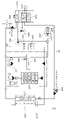
도 1은 본 발명의 일 실시예에 따른 차량용 냉난방 시스템을 나타낸 회로도이다.
도 2는 본 발명의 일 실시예에 따른 차량용 냉난방 시스템에서 전자구동부의 폐열을 이용한 증발기 건조모드를 나타낸 회로도이다.
도 3은 본 발명의 일 실시예에 따른 차량용 냉난방 시스템에서 고전압배터리의 폐열을 이용한 증발기 건조모드를 나타낸 회로도이다.
도 4는 본 발명의 일 실시예에 따른 차량용 냉난방 시스템에서 외기를 이용한 증발기 건조모드를 나타낸 회로도이다.1 is a circuit diagram showing a cooling and heating system for a vehicle according to an embodiment of the present invention.
2 is a circuit diagram showing an evaporator drying mode using waste heat of an electronic drive unit in a cooling and heating system for a vehicle according to an embodiment of the present invention.
3 is a circuit diagram showing an evaporator drying mode using waste heat from a high-voltage battery in a cooling and heating system for a vehicle according to an embodiment of the present invention.
4 is a circuit diagram showing an evaporator drying mode using outside air in a cooling and heating system for a vehicle according to an embodiment of the present invention.
도 1은 본 발명의 일 실시예에 따른 차량용 냉난방 시스템을 나타낸 회로도이다. 도 2는 본 발명의 일 실시예에 따른 차량용 냉난방 시스템에서 전자구동부의 폐열을 이용한 증발기 건조모드를 나타낸 회로도이다. 도 3은 본 발명의 일 실시예에 따른 차량용 냉난방 시스템에서 고전압배터리의 폐열을 이용한 증발기 건조모드를 나타낸 회로도이다. 도 4는 본 발명의 일 실시예에 따른 차량용 냉난방 시스템에서 외기를 이용한 증발기 건조모드를 나타낸 회로도이다.1 is a circuit diagram showing a cooling and heating system for a vehicle according to an embodiment of the present invention. 2 is a circuit diagram showing an evaporator drying mode using waste heat of an electronic drive unit in a cooling and heating system for a vehicle according to an embodiment of the present invention. 3 is a circuit diagram showing an evaporator drying mode using waste heat from a high-voltage battery in a cooling and heating system for a vehicle according to an embodiment of the present invention. 4 is a circuit diagram showing an evaporator drying mode using outside air in a cooling and heating system for a vehicle according to an embodiment of the present invention.
도 1은 본 발명의 일 실시예에 따른 차량용 냉난방 시스템을 나타낸 회로도이다. 본 발명의 일 실시예에 따른 차량용 냉난방 시스템은 폐열을 제공하는 차량의 열원부품(100, 200)과 칠러(300)의 사이에서 냉각수가 순환되는 냉각수라인(10, 20); 냉매가 압축기(510), 컨덴서(520, 540), 팽창밸브(550, 560) 및 증발기(570)를 순환하며, 증발기(570)를 통해 실내냉방을 수행하는 냉매라인(50); 및 증발기(570)의 건조가 필요한 건조모드시, 냉각수라인(10, 20)의 냉각수가 열원부품(100, 200)과 칠러(300)를 순환 또는 미순환하도록 제어하며, 냉매라인의 냉매가 압축기(510), 증발기(570), 칠러(300)의 순서로 흐르도록 냉매라인을 제어하는 제어부(미도시);를 포함한다.1 is a circuit diagram showing a cooling and heating system for a vehicle according to an embodiment of the present invention. A cooling and heating system for a vehicle according to an embodiment of the present invention includes a coolant line (10, 20) through which coolant is circulated between a heat source component (100, 200) of the vehicle that provides waste heat and a chiller (300); A
또한, 본 발명의 일 실시예에 따른 차량용 냉난방 시스템에서 차량의 열원부품은 전자구동부(100) 또는 고전압배터리(200)를 포함하며, 냉각수라인은 전자구동부(100)와 라디에이터(150) 또는 칠러(300)의 사이를 냉각수가 순환하도록 하는 제1냉각라인(10) 또는 고전압배터리(200)와 라디에이터(150) 또는 칠러(300)의 사이를 냉각수가 순환하도록 하는 제2냉각라인(20)을 포함할 수 있다.In addition, in the cooling and heating system for a vehicle according to an embodiment of the present invention, the heat source component of the vehicle includes the
한편, 본 발명의 일 실시예에 따른 차량용 냉난방 시스템에서 제2냉각라인(20)에는 고전압배터리(200)의 하류 지점에 수가열히터(410)가 마련될 수 있다.Meanwhile, in the cooling and heating system for a vehicle according to an embodiment of the present invention, a
또한, 본 발명의 일 실시예에 따른 차량용 냉난방 시스템에서 제1냉각라인(10)과 제2냉각라인(20)은 통합리저버에 함께 연결되어 일부 냉각수의 혼합이 이루어질 수 있다.In addition, in the cooling and heating system for a vehicle according to an embodiment of the present invention, the
도 2는 본 발명의 일 실시예에 따른 차량용 냉난방 시스템에서 전자구동부의 폐열을 이용한 증발기 건조모드를 나타낸 회로도이다. 도 3은 본 발명의 일 실시예에 따른 차량용 냉난방 시스템에서 고전압배터리의 폐열을 이용한 증발기 건조모드를 나타낸 회로도이다. 본 발명의 일 실시예에 따른 차량용 냉난방 시스템에서 칠러(300)의 냉매입구에는 제1팽창밸브(560)가 마련되고, 증발기(570)의 냉매입구에는 제2팽창밸브(550)가 마련될 수 있다.2 is a circuit diagram showing an evaporator drying mode using waste heat of an electronic drive unit in a cooling and heating system for a vehicle according to an embodiment of the present invention. 3 is a circuit diagram showing an evaporator drying mode using waste heat from a high-voltage battery in a cooling and heating system for a vehicle according to an embodiment of the present invention. In the vehicle cooling and heating system according to an embodiment of the present invention, the
또한, 본 발명의 일 실시예에 따른 차량용 냉난방 시스템에서 제어부는 제1냉각라인(10)을 통한 건조모드시, 제1냉각라인(10)의 냉각수가 전자구동부(100)와 칠러(300)를 순환하도록 하며, 냉매라인의 냉매가 압축기(510), 증발기(570), 제1팽창밸브(560), 칠러(300)의 순서로 흐르도록 냉매라인을 제어할 수 있다.In addition, in the cooling and heating system for a vehicle according to an embodiment of the present invention, in the drying mode through the
한편, 제어부는 제1냉각라인(10)을 통한 건조모드시, 냉매라인의 냉매가 압축기(510)에서 압축되고, 증발기(570)에서 응축되며, 제1팽창밸브(560)에서 팽창되고, 칠러(300)에서 증발되도록 냉매라인을 제어할 수 있다.On the other hand, in the drying mode through the
이에 따라, 전자구동부(100)에서 발생하는 폐열은 칠러(300)를 통해 냉매라인(50)과 열교환하게되고, 냉매라인에서는 최종적으로 전자구동부(100)에서 발생한 폐열을 이용하여 증발기(570)를 건조시킴으로써, 증발기(570)에 곰팡이, 세균 등이 발생하는 것을 방지할 수 있다.Accordingly, the waste heat generated in the
또한, 본 발명의 일 실시예에 따른 차량용 냉난방 시스템에서 제어부는 제2냉각라인(20)을 통한 건조모드시, 제2냉각라인(20)의 냉각수가 고전압배터리(200)와 칠러(300)를 순환하도록 하며, 냉매라인의 냉매가 압축기(510), 증발기(570), 제1팽창밸브(560), 칠러(300)의 순서로 흐르도록 냉매라인을 제어할 수 있다.In addition, in the cooling and heating system for a vehicle according to an embodiment of the present invention, in the drying mode through the
한편, 제어부는 제2냉각라인을 통한 건조모드시, 냉매라인의 냉매가 압축기(510)에서 압축되고, 증발기(570)에서 응축되며, 제1팽창밸브(560)에서 팽창되고, 칠러(300)에서 증발되도록 냉매라인을 제어할 수 있다.Meanwhile, in the drying mode through the second cooling line, the control unit compresses the refrigerant in the refrigerant line in the
마찬가지로, 고전압배터리(200)에서 발생하는 폐열은 칠러(300)를 통해 냉매라인(50)과 열교환하게되고, 냉매라인에서는 최종적으로 고전압배터리(200)에서 발생한 폐열을 이용하여 증발기(570)를 건조시킴으로써, 증발기(570)에 곰팡이, 세균 등이 발생하는 것을 방지할 수 있다.Likewise, the waste heat generated from the
도 4는 본 발명의 일 실시예에 따른 차량용 냉난방 시스템에서 외기를 이용한 증발기 건조모드를 나타낸 회로도이다. 본 발명의 일 실시예에 따른 차량용 냉난방 시스템에서 컨덴서는 내부컨덴서(520) 및 외부컨덴서(540)를 포함하며, 실내냉방시 제어부는 냉매가 압축기(510), 내부컨덴서(520), 외부컨덴서(540), 제2팽창밸브(550), 증발기(570)의 순서로 흐르도록 냉매라인을 제어할 수 있다.4 is a circuit diagram showing an evaporator drying mode using outside air in a cooling and heating system for a vehicle according to an embodiment of the present invention. In the cooling and heating system for a vehicle according to an embodiment of the present invention, the condenser includes an
한편, 본 발명의 일 실시예에 따른 차량용 냉난방 시스템에서 냉매라인에는 증발기(570)를 흐른 냉매가 압축기(510)의 상류에서 분기되어 압축기(510)를 바이패스하고 외부컨덴서(540)에 유입되도록 하는 건조라인(630)이 마련될 수 있다.Meanwhile, in the cooling and heating system for vehicles according to an embodiment of the present invention, in the refrigerant line, the refrigerant flowing through the
또한, 본 발명의 일 실시예에 따른 차량용 냉난방 시스템에서 제어부는 건조모드시 냉매가 압축기(510), 증발기(570), 외부컨덴서(540), 칠러(300)의 순서로 흐르도록 냉매라인을 제어할 수 있다.In addition, in the cooling and heating system for a vehicle according to an embodiment of the present invention, the control unit controls the refrigerant line so that the refrigerant flows in the order of the
한편, 본 발명의 일 실시예에 따른 차량용 냉난방 시스템에서 냉매라인에는 증발기(570)의 하류에서 분기되어 외부컨덴서(540)의 상류에 마련된 제3팽창밸브(530)에 연결되는 건조라인(630)이 마련되고, 제어부는 건조모드시 증발기(570)에서 토출된 냉매를 건조라인(630)을 통해 제3팽창밸브(530), 외부컨덴서(540), 칠러(300), 압축기(510)의 순서로 흐르도록 제어할 수 있다.On the other hand, in the cooling and heating system for a vehicle according to an embodiment of the present invention, the refrigerant line is branched downstream of the
또한, 제어부는 건조라인(630)을 통한 건조모드시, 냉매라인의 냉매가 압축기(510)에서 압축되고, 증발기(570)에서 응축되며, 제3팽창밸브(530)에서 팽창되고, 외부컨덴서(540) 및 칠러(300)에서 증발되도록 냉매라인을 제어할 수 있다.In addition, the control unit is in the drying mode through the
이에 따라, 차량의 전자구동부(100) 및 고전압배터리(200)의 폐열이 발생하지 않는 경우에는 차량 외기열을 활용하여 증발기를 응축시켜 건조시킴으로써, 증발기(570)에 곰팡이, 세균 등이 발생하는 것을 방지할 수 있다.Accordingly, when waste heat from the
본 발명의 일 실시예에 따른 차량용 냉난방 시스템은 전자구동부(100) 또는 고전압배터리(200)에서 발생한 폐열을 활용하여 증발기를 응축시킴으로써 증발기를 건조한 상태로 유지하여 곰팡이, 세균 등의 번식을 방지할 수 있고, 필요한 경우 블로워를 함께 가동함으로써 보다 효과적으로 증발기 및 HVAC내 잔류 습기를 건조시킬 수 있을 것이다.In the vehicle cooling and heating system according to an embodiment of the present invention, the evaporator is condensed using the waste heat generated from the
본 발명의 특정한 실시예에 관련하여 도시하고 설명하였지만, 이하의 특허청구범위에 의해 제공되는 본 발명의 기술적 사상을 벗어나지 않는 한도 내에서, 본 발명이 다양하게 개량 및 변화될 수 있다는 것은 당 업계에서 통상의 지식을 가진 자에게 있어서 자명할 것이다.Although shown and described in relation to specific embodiments of the present invention, it is known in the art that the present invention can be variously improved and changed without departing from the technical spirit of the present invention provided by the claims below. It will be self-evident to those skilled in the art.
10 : 제1냉각라인
20 : 제2냉각라인
50 : 냉매라인
100 : 전자구동부
200 : 고전압배터리
300 : 칠러
410 : 수가열히터
420 : PTC히터10: first cooling line 20: second cooling line
50: refrigerant line 100: electronic drive unit
200: high voltage battery 300: chiller
410: water heating heater 420: PTC heater
Claims (14)
냉매가 압축기, 컨덴서, 증발기, 칠러를 순환하며, 증발기를 통해 실내냉방을 수행하는 냉매라인; 및
증발기의 건조가 필요한 건조모드시, 냉각수라인의 냉각수가 열원부품과 칠러를 순환 또는 미순환하도록 제어하며, 냉매라인의 냉매가 압축기, 증발기, 칠러의 순서로 흐르도록 냉매라인을 제어하는 제어부;를 포함하는 차량의 냉난방 시스템.a coolant line through which coolant is circulated between a heat source component of a vehicle that provides waste heat and a chiller;
A refrigerant line through which the refrigerant circulates through the compressor, condenser, evaporator, and chiller, and performs indoor cooling through the evaporator; and
In a drying mode in which the evaporator needs to be dried, a control unit controls the cooling water in the cooling water line to circulate or non-circulate between the heat source component and the chiller, and controls the refrigerant line so that the refrigerant in the refrigerant line flows in the order of the compressor, evaporator, and chiller; Including the vehicle's air conditioning and heating system.
차량의 열원부품은 전자구동부 또는 고전압배터리를 포함하며, 냉각수라인은 전자구동부와 라디에이터 또는 칠러의 사이를 냉각수가 순환하도록 하는 제1냉각라인 또는 고전압배터리와 라디에이터 또는 칠러의 사이를 냉각수가 순환하도록 하는 제2냉각라인을 포함하는 것을 특징으로 하는 차량의 냉난방 시스템.The method of claim 1,
The heat source component of the vehicle includes an electronic drive unit or a high voltage battery, and the coolant line is a first cooling line that allows coolant to circulate between the electronic drive unit and the radiator or chiller, or a first cooling line that allows coolant to circulate between the high voltage battery and the radiator or chiller. A cooling and heating system for a vehicle comprising a second cooling line.
제2냉각라인에는 고전압배터리의 하류 지점에 수가열히터가 마련된 것을 특징으로 하는 차량의 냉난방 시스템.The method of claim 2,
A cooling and heating system for a vehicle, characterized in that a water heating heater is provided in the second cooling line at a point downstream of the high voltage battery.
제1냉각라인과 제2냉각라인은 통합리저버에 함께 연결되어 일부 냉각수의 혼합이 이루어지는 것을 특징으로 하는 차량의 냉난방 시스템.The method of claim 2,
The cooling and heating system of a vehicle, characterized in that the first cooling line and the second cooling line are connected together to the integrated reservoir so that some of the cooling water is mixed.
칠러의 냉매입구에는 제1팽창밸브가 마련되고, 증발기의 냉매입구에는 제2팽창밸브가 마련된 것을 특징으로 하는 차량의 냉난방 시스템.The method of claim 2,
A cooling and heating system for a vehicle, characterized in that a first expansion valve is provided at the refrigerant inlet of the chiller and a second expansion valve is provided at the refrigerant inlet of the evaporator.
제어부는 제1냉각라인을 통한 건조모드시, 제1냉각라인의 냉각수가 전자구동부와 칠러를 순환하도록 하며, 냉매라인의 냉매가 압축기, 증발기, 제1팽창밸브, 칠러의 순서로 흐르도록 냉매라인을 제어하는 것을 특징으로 하는 차량의 냉난방 시스템.The method of claim 5,
In the dry mode through the first cooling line, the control unit allows the cooling water of the first cooling line to circulate between the electronic drive unit and the chiller, and the refrigerant line so that the refrigerant in the refrigerant line flows in the order of the compressor, evaporator, first expansion valve, and chiller. A cooling and heating system of a vehicle, characterized in that for controlling.
제어부는 제1냉각라인을 통한 건조모드시, 냉매라인의 냉매가 압축기에서 압축되고, 증발기에서 응축되며, 제1팽창밸브에서 팽창되고, 칠러에서 증발되도록 냉매라인을 제어하는 것을 특징으로 하는 차량의 냉난방 시스템.The method of claim 6,
In the drying mode through the first cooling line, the control unit controls the refrigerant line so that the refrigerant in the refrigerant line is compressed in the compressor, condensed in the evaporator, expanded in the first expansion valve, and evaporated in the chiller. heating and cooling system.
제어부는 제2냉각라인을 통한 건조모드시, 제2냉각라인의 냉각수가 고전압배터리와 칠러를 순환하도록 하며, 냉매라인의 냉매가 압축기, 증발기, 제1팽창밸브, 칠러의 순서로 흐르도록 냉매라인을 제어하는 것을 특징으로 하는 차량의 냉난방 시스템.The method of claim 5,
In the drying mode through the second cooling line, the control unit allows the cooling water of the second cooling line to circulate between the high voltage battery and the chiller, and the refrigerant line to flow in the order of the compressor, evaporator, first expansion valve, and chiller. A cooling and heating system of a vehicle, characterized in that for controlling.
제어부는 제2냉각라인을 통한 건조모드시, 냉매라인의 냉매가 압축기에서 압축되고, 증발기에서 응축되며, 제1팽창밸브에서 팽창되고, 칠러에서 증발되도록 냉매라인을 제어하는 것을 특징으로 하는 차량의 냉난방 시스템.The method of claim 8,
In the drying mode through the second cooling line, the control unit controls the refrigerant line so that the refrigerant in the refrigerant line is compressed in the compressor, condensed in the evaporator, expanded in the first expansion valve, and evaporated in the chiller. heating and cooling system.
컨덴서는 내부컨덴서 및 외부컨덴서를 포함하며, 실내냉방시 제어부는 냉매가 압축기, 내부컨덴서, 외부컨덴서, 제2팽창밸브, 증발기의 순서로 흐르도록 냉매라인을 제어하는 것을 특징으로 하는 차량의 냉난방 시스템.The method of claim 5,
The condenser includes an internal condenser and an external condenser, and the control unit controls the refrigerant line so that the refrigerant flows in the order of the compressor, internal condenser, external condenser, second expansion valve, and evaporator during indoor cooling. .
냉매라인에는 증발기를 흐른 냉매가 압축기의 상류에서 분기되어 압축기를 바이패스하고 외부컨덴서에 유입되도록 하는 건조라인이 마련되는 것을 특징으로 하는 차량의 냉난방 시스템.The method of claim 10,
A cooling and heating system for a vehicle, characterized in that the refrigerant line is provided with a drying line that allows the refrigerant flowing through the evaporator to branch upstream from the compressor, bypass the compressor, and flow into the external condenser.
제어부는 건조모드시 냉매가 압축기, 증발기, 외부컨덴서, 칠러의 순서로 흐르도록 냉매라인을 제어하는 것을 특징으로 하는 차량의 냉난방 시스템.The method of claim 10,
The control unit controls the refrigerant line so that the refrigerant flows in the order of a compressor, an evaporator, an external condenser, and a chiller in a drying mode.
냉매라인에는 증발기의 하류에서 분기되어 외부컨덴서의 상류에 마련된 제3팽창밸브에 연결되는 건조라인이 마련되고, 제어부는 건조모드시 증발기에서 토출된 냉매를 건조라인을 통해 제3팽창밸브, 외부컨덴서, 칠러, 압축기의 순서로 흐르도록 제어하는 것을 특징으로 하는 차량의 냉난방 시스템.The method of claim 12,
The refrigerant line is branched downstream of the evaporator and has a drying line connected to a third expansion valve provided upstream of the external condenser. A cooling and heating system for a vehicle, characterized in that the flow is controlled in the order of a chiller and a compressor.
제어부는 건조라인을 통한 건조모드시, 냉매라인의 냉매가 압축기에서 압축되고, 증발기에서 응축되며, 제3팽창밸브에서 팽창되고, 외부컨덴서 및 칠러에서 증발되도록 냉매라인을 제어하는 것을 특징으로 하는 차량의 냉난방 시스템.The method of claim 13,
In the drying mode through the drying line, the control unit controls the refrigerant line so that the refrigerant in the refrigerant line is compressed in the compressor, condensed in the evaporator, expanded in the third expansion valve, and evaporated in the external condenser and chiller. heating and cooling system.
Priority Applications (2)
| Application Number | Priority Date | Filing Date | Title |
|---|---|---|---|
| KR1020210058087A KR102916849B1 (en) | 2021-05-04 | 2021-05-04 | Cooling and heating system of vehicle |
| US17/494,150 US11958332B2 (en) | 2021-05-04 | 2021-10-05 | Vehicle cooling/heating system |
Applications Claiming Priority (1)
| Application Number | Priority Date | Filing Date | Title |
|---|---|---|---|
| KR1020210058087A KR102916849B1 (en) | 2021-05-04 | 2021-05-04 | Cooling and heating system of vehicle |
Publications (2)
| Publication Number | Publication Date |
|---|---|
| KR20220150737A true KR20220150737A (en) | 2022-11-11 |
| KR102916849B1 KR102916849B1 (en) | 2026-01-22 |
Family
ID=83901873
Family Applications (1)
| Application Number | Title | Priority Date | Filing Date |
|---|---|---|---|
| KR1020210058087A Active KR102916849B1 (en) | 2021-05-04 | 2021-05-04 | Cooling and heating system of vehicle |
Country Status (2)
| Country | Link |
|---|---|
| US (1) | US11958332B2 (en) |
| KR (1) | KR102916849B1 (en) |
Families Citing this family (5)
| Publication number | Priority date | Publication date | Assignee | Title |
|---|---|---|---|---|
| KR102916849B1 (en) * | 2021-05-04 | 2026-01-22 | 현대자동차주식회사 | Cooling and heating system of vehicle |
| KR20240073348A (en) * | 2022-11-18 | 2024-05-27 | 현대자동차주식회사 | Heat pump system for vehicle |
| KR20260036432A (en) * | 2023-04-18 | 2026-03-17 | 솔스티스 어드밴스드 머티리얼즈 유에스 인코포레이티드 | Vehicle air conditioning system using a flexible heat pump |
| US12485729B2 (en) * | 2023-05-22 | 2025-12-02 | Garrett Transportation I Inc. | Method of operating a vehicle air-conditioning system having a centrifugal-type electric refrigerant compressor |
| KR20250026657A (en) * | 2023-08-17 | 2025-02-25 | 현대자동차주식회사 | Heat pump system for vehicle |
Citations (1)
| Publication number | Priority date | Publication date | Assignee | Title |
|---|---|---|---|---|
| KR101558611B1 (en) | 2010-06-08 | 2015-10-07 | 현대자동차주식회사 | Integrated heat management system of clean car |
Family Cites Families (52)
| Publication number | Priority date | Publication date | Assignee | Title |
|---|---|---|---|---|
| US5390505A (en) * | 1993-07-23 | 1995-02-21 | Baltimore Aircoil Company, Inc. | Indirect contact chiller air-precooler method and apparatus |
| DE10006513B4 (en) * | 2000-02-15 | 2014-12-24 | Behr Gmbh & Co. Kg | Air conditioning system for a motor vehicle with heat pump and / or reheat mode |
| DE102006024796B4 (en) * | 2006-03-17 | 2009-11-26 | Konvekta Ag | air conditioning |
| US7789176B2 (en) * | 2007-04-11 | 2010-09-07 | Tesla Motors, Inc. | Electric vehicle thermal management system |
| US8215432B2 (en) * | 2008-05-09 | 2012-07-10 | GM Global Technology Operations LLC | Battery thermal system for vehicle |
| US8448460B2 (en) * | 2008-06-23 | 2013-05-28 | GM Global Technology Operations LLC | Vehicular combination chiller bypass system and method |
| US7971447B2 (en) * | 2008-06-27 | 2011-07-05 | Bayerische Motoren Werke Aktiengesellschaft | Control parameters for a high voltage battery cooling strategy |
| US20100009246A1 (en) * | 2008-07-09 | 2010-01-14 | Bayerische Motoren Werke Aktiengesellschaft | Bypass Function for a High Voltage Battery Cooling Strategy |
| JP5663849B2 (en) * | 2009-07-09 | 2015-02-04 | 株式会社デンソー | Air conditioner for vehicles |
| US8336319B2 (en) * | 2010-06-04 | 2012-12-25 | Tesla Motors, Inc. | Thermal management system with dual mode coolant loops |
| US20120297809A1 (en) * | 2011-05-26 | 2012-11-29 | Neil Carpenter | Refrigerant loop for battery electric vehicle with internal heat exchanger for heat exchange with coolant |
| US10427491B2 (en) * | 2011-09-28 | 2019-10-01 | Tesla, Inc. | Thermal management system with heat exchanger blending valve |
| US10522845B2 (en) * | 2011-09-28 | 2019-12-31 | Tesla, Inc. | Battery centric thermal management system utilizing a heat exchanger blending valve |
| US20140326430A1 (en) * | 2011-12-14 | 2014-11-06 | Magna E-Car Systems Of America, Inc. | Vehicle with traction motor with preemptive cooling of motor fluid circuit prior to cooling of battery fluid circuit |
| JP6060797B2 (en) * | 2012-05-24 | 2017-01-18 | 株式会社デンソー | Thermal management system for vehicles |
| KR101927153B1 (en) | 2012-06-05 | 2018-12-10 | 현대자동차 주식회사 | Heat pump system for vehicle |
| JP5860361B2 (en) * | 2012-08-13 | 2016-02-16 | カルソニックカンセイ株式会社 | Thermal management system for electric vehicles |
| US20140060102A1 (en) | 2012-09-04 | 2014-03-06 | GM Global Technology Operations LLC | Mild ambient vehicular heat pump system |
| DE102013110224B4 (en) * | 2012-09-17 | 2022-03-17 | Audi Ag | Method for operating an air conditioning system for a motor vehicle |
| US10046617B2 (en) * | 2013-02-01 | 2018-08-14 | Ford Global Technologies, Llc | Electric vehicle multi-loop thermal management system |
| JP6197671B2 (en) * | 2014-01-29 | 2017-09-20 | 株式会社デンソー | Air conditioner |
| US9758012B2 (en) * | 2014-10-21 | 2017-09-12 | Atieva, Inc. | EV multi-mode thermal management system |
| US9758011B2 (en) * | 2014-10-21 | 2017-09-12 | Atieva, Inc. | EV multi-mode thermal management system |
| KR101637772B1 (en) * | 2014-12-11 | 2016-07-07 | 현대자동차주식회사 | Apparatus for accelerating reproduction of odor from air-conditioner and method for the same |
| FR3034712B1 (en) * | 2015-04-08 | 2018-12-07 | Valeo Systemes Thermiques | AIR CONDITIONING LOOP AND CORRESPONDING AIR CONDITIONING SYSTEM FOR MOTOR VEHICLE |
| US20160318409A1 (en) * | 2015-04-28 | 2016-11-03 | Atieva, Inc. | EV Muti-Mode Thermal Control System |
| US20160318410A1 (en) * | 2015-04-28 | 2016-11-03 | Atieva, Inc. | EV Muti-Mode Thermal Control System |
| US20160344075A1 (en) * | 2015-05-20 | 2016-11-24 | Ford Global Technologies, Llc | Thermal Management System for a Vehicle |
| US9950638B2 (en) * | 2015-07-10 | 2018-04-24 | Ford Global Technologies, Llc | Preconditioning an electric vehicle |
| CN107031347B (en) * | 2016-01-13 | 2019-08-09 | 翰昂汽车零部件有限公司 | Vehicle Air Conditioning Unit |
| US10226980B2 (en) * | 2016-04-15 | 2019-03-12 | Denso Corporation | Cooling system for vehicle battery pack |
| US10340563B2 (en) * | 2016-04-29 | 2019-07-02 | Ford Global Technologies, Llc | Traction battery cooling system with coolant proportional valve |
| US9947975B2 (en) * | 2016-07-01 | 2018-04-17 | Ford Global Technologies, Llc | Battery coolant circuit control |
| US10293706B2 (en) * | 2016-07-01 | 2019-05-21 | Ford Global Technologies, Llc | Battery coolant circuit control |
| US10384511B2 (en) * | 2017-01-27 | 2019-08-20 | Ford Global Technologies, Llc | Method to control battery cooling using the battery coolant pump in electrified vehicles |
| DE102017109309A1 (en) * | 2017-05-02 | 2018-11-08 | Hanon Systems | Air conditioning system of a motor vehicle and method for operating the air conditioning system |
| DE102017216778B4 (en) * | 2017-09-22 | 2020-07-16 | Audi Ag | Refrigeration system for a vehicle with a refrigerant circuit |
| CN108099544B (en) | 2018-01-12 | 2023-04-25 | 浙江大学 | Whole-vehicle thermal management system and management method for pure electric vehicle |
| US11342603B2 (en) * | 2018-01-15 | 2022-05-24 | Ford Global Technologies, Llc | Thermal management of traction battery based on electric current of traction battery |
| DE102018104410A1 (en) * | 2018-02-27 | 2019-08-29 | Hanon Systems | Air conditioning system of a motor vehicle and method for operating the air conditioning system |
| DE102019109796B4 (en) * | 2018-05-31 | 2025-07-10 | Hanon Systems | Heat flow management device and method for operating a heat flow management device |
| KR20200045727A (en) * | 2018-10-23 | 2020-05-06 | 현대자동차주식회사 | Heat pump system for vehicle |
| DE102019126850A1 (en) * | 2019-10-07 | 2021-04-08 | Audi Ag | Refrigeration system with heat pump and reheat function |
| US11732967B2 (en) * | 2019-12-11 | 2023-08-22 | Baltimore Aircoil Company, Inc. | Heat exchanger system with machine-learning based optimization |
| DE102019135056A1 (en) * | 2019-12-19 | 2021-06-24 | Audi Ag | Refrigerant management for a post-heating process for operating a refrigeration system for a motor vehicle, refrigeration system and motor vehicle with such a refrigeration system |
| JP7396116B2 (en) * | 2020-02-27 | 2023-12-12 | 株式会社デンソー | Vehicle air conditioner |
| DE102021101127A1 (en) * | 2020-03-19 | 2021-09-23 | Hanon Systems | System for air conditioning the air in a passenger compartment and for heat transfer with drive components of a motor vehicle and a method for operating the system |
| DE102020117471B4 (en) * | 2020-07-02 | 2024-01-04 | Hanon Systems | Heat pump arrangement with indirect battery heating for battery-operated motor vehicles and method for operating a heat pump arrangement |
| KR102855185B1 (en) * | 2020-07-09 | 2025-09-04 | 현대자동차주식회사 | Thermal management system of vehicle electric power system |
| KR102916849B1 (en) * | 2021-05-04 | 2026-01-22 | 현대자동차주식회사 | Cooling and heating system of vehicle |
| KR20220162241A (en) * | 2021-05-31 | 2022-12-08 | 현대자동차주식회사 | Heat pump system for vehicle |
| US11890914B2 (en) * | 2021-09-07 | 2024-02-06 | Ford Global Technologies, Llc | Balancing battery heating and cabin heating with shared thermal-management system |
-
2021
- 2021-05-04 KR KR1020210058087A patent/KR102916849B1/en active Active
- 2021-10-05 US US17/494,150 patent/US11958332B2/en active Active
Patent Citations (1)
| Publication number | Priority date | Publication date | Assignee | Title |
|---|---|---|---|---|
| KR101558611B1 (en) | 2010-06-08 | 2015-10-07 | 현대자동차주식회사 | Integrated heat management system of clean car |
Also Published As
| Publication number | Publication date |
|---|---|
| US20220355639A1 (en) | 2022-11-10 |
| US11958332B2 (en) | 2024-04-16 |
| KR102916849B1 (en) | 2026-01-22 |
Similar Documents
| Publication | Publication Date | Title |
|---|---|---|
| KR20220150737A (en) | Cooling and heating system of vehicle | |
| CN111688432B (en) | Vehicle temperature control device | |
| KR101015640B1 (en) | Vehicle air conditioning system | |
| KR101715723B1 (en) | Heat pump system for vehicle | |
| US20090095005A1 (en) | Air-Conditioning System | |
| CN112654514A (en) | Air conditioning system for vehicle | |
| JP5640485B2 (en) | Air conditioner for vehicles | |
| CN113474190A (en) | Thermal management system | |
| KR20180076397A (en) | Automotive air conditioning system | |
| JP2022053320A (en) | Vehicular air conditioner | |
| KR20170084729A (en) | Apparatus humidity of airconditioner evaporator for vihicle and the method thereof | |
| KR20230143259A (en) | Automotive heat pump system | |
| CN214728055U (en) | An air conditioner deodorizing system for electric vehicles and automobiles | |
| JP2023107644A (en) | vehicle air conditioner | |
| JPS60219114A (en) | Automotive air conditioner | |
| KR20220156240A (en) | Automotive air conditioning system | |
| CN219856734U (en) | Vehicle thermal management systems and vehicles | |
| WO2020246306A1 (en) | Vehicle air conditioning device | |
| KR100534897B1 (en) | Airconditioning unit and its control method for elimination water in automobile | |
| CN117615923A (en) | Vehicle air conditioning unit | |
| KR101146477B1 (en) | Heat Pump System for Car | |
| KR20220049059A (en) | Automotive air conditioning system | |
| KR100572613B1 (en) | Electric Heat Pump System | |
| WO2020246305A1 (en) | Vehicle air conditioning device | |
| CN223672214U (en) | Vehicle thermal management system |
Legal Events
| Date | Code | Title | Description |
|---|---|---|---|
| PA0109 | Patent application |
St.27 status event code: A-0-1-A10-A12-nap-PA0109 |
|
| PG1501 | Laying open of application |
St.27 status event code: A-1-1-Q10-Q12-nap-PG1501 |
|
| A201 | Request for examination | ||
| PA0201 | Request for examination |
St.27 status event code: A-1-2-D10-D11-exm-PA0201 |
|
| D22 | Grant of ip right intended |
Free format text: ST27 STATUS EVENT CODE: A-1-2-D10-D22-EXM-PE0701 (AS PROVIDED BY THE NATIONAL OFFICE) |
|
| PE0701 | Decision of registration |
St.27 status event code: A-1-2-D10-D22-exm-PE0701 |
|
| F11 | Ip right granted following substantive examination |
Free format text: ST27 STATUS EVENT CODE: A-2-4-F10-F11-EXM-PR0701 (AS PROVIDED BY THE NATIONAL OFFICE) |
|
| PR0701 | Registration of establishment |
St.27 status event code: A-2-4-F10-F11-exm-PR0701 |
|
| PR1002 | Payment of registration fee |
St.27 status event code: A-2-2-U10-U11-oth-PR1002 Fee payment year number: 1 |
|
| U11 | Full renewal or maintenance fee paid |
Free format text: ST27 STATUS EVENT CODE: A-2-2-U10-U11-OTH-PR1002 (AS PROVIDED BY THE NATIONAL OFFICE) Year of fee payment: 1 |
|
| PG1601 | Publication of registration |
St.27 status event code: A-4-4-Q10-Q13-nap-PG1601 |
|
| Q13 | Ip right document published |
Free format text: ST27 STATUS EVENT CODE: A-4-4-Q10-Q13-NAP-PG1601 (AS PROVIDED BY THE NATIONAL OFFICE) |