KR20220146677A - Resin container - Google Patents
Resin container Download PDFInfo
- Publication number
- KR20220146677A KR20220146677A KR1020227035976A KR20227035976A KR20220146677A KR 20220146677 A KR20220146677 A KR 20220146677A KR 1020227035976 A KR1020227035976 A KR 1020227035976A KR 20227035976 A KR20227035976 A KR 20227035976A KR 20220146677 A KR20220146677 A KR 20220146677A
- Authority
- KR
- South Korea
- Prior art keywords
- container
- mold
- neck
- preform
- blow molding
- Prior art date
Links
- 239000011347 resin Substances 0.000 title claims description 22
- 229920005989 resin Polymers 0.000 title claims description 22
- 238000000071 blow moulding Methods 0.000 claims abstract description 75
- 238000000034 method Methods 0.000 claims description 16
- 230000007246 mechanism Effects 0.000 abstract description 63
- 210000003739 neck Anatomy 0.000 description 80
- 238000004519 manufacturing process Methods 0.000 description 15
- 230000008569 process Effects 0.000 description 9
- 238000005452 bending Methods 0.000 description 7
- 238000002347 injection Methods 0.000 description 6
- 239000007924 injection Substances 0.000 description 6
- 238000001746 injection moulding Methods 0.000 description 6
- 238000010586 diagram Methods 0.000 description 4
- 239000000463 material Substances 0.000 description 4
- -1 polyethylene terephthalate Polymers 0.000 description 4
- 238000005520 cutting process Methods 0.000 description 3
- 229920000089 Cyclic olefin copolymer Polymers 0.000 description 2
- 239000004695 Polyether sulfone Substances 0.000 description 2
- 239000004698 Polyethylene Substances 0.000 description 2
- 239000004743 Polypropylene Substances 0.000 description 2
- 239000004793 Polystyrene Substances 0.000 description 2
- 238000007664 blowing Methods 0.000 description 2
- 239000002184 metal Substances 0.000 description 2
- 238000000465 moulding Methods 0.000 description 2
- 229920003207 poly(ethylene-2,6-naphthalate) Polymers 0.000 description 2
- 229920000747 poly(lactic acid) Polymers 0.000 description 2
- 229920003229 poly(methyl methacrylate) Polymers 0.000 description 2
- 239000004417 polycarbonate Substances 0.000 description 2
- 229920006393 polyether sulfone Polymers 0.000 description 2
- 239000011112 polyethylene naphthalate Substances 0.000 description 2
- 229920000139 polyethylene terephthalate Polymers 0.000 description 2
- 239000005020 polyethylene terephthalate Substances 0.000 description 2
- 239000004626 polylactic acid Substances 0.000 description 2
- 239000004926 polymethyl methacrylate Substances 0.000 description 2
- 239000002994 raw material Substances 0.000 description 2
- 229920003002 synthetic resin Polymers 0.000 description 2
- 239000000057 synthetic resin Substances 0.000 description 2
- FDSYTWVNUJTPMA-UHFFFAOYSA-N 2-[3,9-bis(carboxymethyl)-3,6,9,15-tetrazabicyclo[9.3.1]pentadeca-1(15),11,13-trien-6-yl]acetic acid Chemical compound C1N(CC(O)=O)CCN(CC(=O)O)CCN(CC(O)=O)CC2=CC=CC1=N2 FDSYTWVNUJTPMA-UHFFFAOYSA-N 0.000 description 1
- 229920001634 Copolyester Polymers 0.000 description 1
- 229920000491 Polyphenylsulfone Polymers 0.000 description 1
- NIXOWILDQLNWCW-UHFFFAOYSA-N acrylic acid group Chemical group C(C=C)(=O)O NIXOWILDQLNWCW-UHFFFAOYSA-N 0.000 description 1
- 230000008901 benefit Effects 0.000 description 1
- 229920000704 biodegradable plastic Polymers 0.000 description 1
- 238000004891 communication Methods 0.000 description 1
- 230000006872 improvement Effects 0.000 description 1
- 239000007788 liquid Substances 0.000 description 1
- 229920000515 polycarbonate Polymers 0.000 description 1
- 229920000573 polyethylene Polymers 0.000 description 1
- 229920001155 polypropylene Polymers 0.000 description 1
- 229920002223 polystyrene Polymers 0.000 description 1
- KKEYFWRCBNTPAC-UHFFFAOYSA-L terephthalate(2-) Chemical compound [O-]C(=O)C1=CC=C(C([O-])=O)C=C1 KKEYFWRCBNTPAC-UHFFFAOYSA-L 0.000 description 1
- 229920005992 thermoplastic resin Polymers 0.000 description 1
- 230000009466 transformation Effects 0.000 description 1
- 238000009966 trimming Methods 0.000 description 1
- XLYOFNOQVPJJNP-UHFFFAOYSA-N water Substances O XLYOFNOQVPJJNP-UHFFFAOYSA-N 0.000 description 1
- 238000003466 welding Methods 0.000 description 1
Images


Classifications
-
- B—PERFORMING OPERATIONS; TRANSPORTING
- B29—WORKING OF PLASTICS; WORKING OF SUBSTANCES IN A PLASTIC STATE IN GENERAL
- B29B—PREPARATION OR PRETREATMENT OF THE MATERIAL TO BE SHAPED; MAKING GRANULES OR PREFORMS; RECOVERY OF PLASTICS OR OTHER CONSTITUENTS OF WASTE MATERIAL CONTAINING PLASTICS
- B29B11/00—Making preforms
- B29B11/14—Making preforms characterised by structure or composition
-
- B—PERFORMING OPERATIONS; TRANSPORTING
- B29—WORKING OF PLASTICS; WORKING OF SUBSTANCES IN A PLASTIC STATE IN GENERAL
- B29C—SHAPING OR JOINING OF PLASTICS; SHAPING OF MATERIAL IN A PLASTIC STATE, NOT OTHERWISE PROVIDED FOR; AFTER-TREATMENT OF THE SHAPED PRODUCTS, e.g. REPAIRING
- B29C49/00—Blow-moulding, i.e. blowing a preform or parison to a desired shape within a mould; Apparatus therefor
- B29C49/42—Component parts, details or accessories; Auxiliary operations
- B29C49/48—Moulds
-
- B—PERFORMING OPERATIONS; TRANSPORTING
- B29—WORKING OF PLASTICS; WORKING OF SUBSTANCES IN A PLASTIC STATE IN GENERAL
- B29C—SHAPING OR JOINING OF PLASTICS; SHAPING OF MATERIAL IN A PLASTIC STATE, NOT OTHERWISE PROVIDED FOR; AFTER-TREATMENT OF THE SHAPED PRODUCTS, e.g. REPAIRING
- B29C49/00—Blow-moulding, i.e. blowing a preform or parison to a desired shape within a mould; Apparatus therefor
- B29C49/08—Biaxial stretching during blow-moulding
-
- B—PERFORMING OPERATIONS; TRANSPORTING
- B29—WORKING OF PLASTICS; WORKING OF SUBSTANCES IN A PLASTIC STATE IN GENERAL
- B29C—SHAPING OR JOINING OF PLASTICS; SHAPING OF MATERIAL IN A PLASTIC STATE, NOT OTHERWISE PROVIDED FOR; AFTER-TREATMENT OF THE SHAPED PRODUCTS, e.g. REPAIRING
- B29C33/00—Moulds or cores; Details thereof or accessories therefor
- B29C33/42—Moulds or cores; Details thereof or accessories therefor characterised by the shape of the moulding surface, e.g. ribs or grooves
-
- B—PERFORMING OPERATIONS; TRANSPORTING
- B29—WORKING OF PLASTICS; WORKING OF SUBSTANCES IN A PLASTIC STATE IN GENERAL
- B29C—SHAPING OR JOINING OF PLASTICS; SHAPING OF MATERIAL IN A PLASTIC STATE, NOT OTHERWISE PROVIDED FOR; AFTER-TREATMENT OF THE SHAPED PRODUCTS, e.g. REPAIRING
- B29C49/00—Blow-moulding, i.e. blowing a preform or parison to a desired shape within a mould; Apparatus therefor
- B29C49/02—Combined blow-moulding and manufacture of the preform or the parison
- B29C49/06—Injection blow-moulding
-
- B—PERFORMING OPERATIONS; TRANSPORTING
- B29—WORKING OF PLASTICS; WORKING OF SUBSTANCES IN A PLASTIC STATE IN GENERAL
- B29C—SHAPING OR JOINING OF PLASTICS; SHAPING OF MATERIAL IN A PLASTIC STATE, NOT OTHERWISE PROVIDED FOR; AFTER-TREATMENT OF THE SHAPED PRODUCTS, e.g. REPAIRING
- B29C49/00—Blow-moulding, i.e. blowing a preform or parison to a desired shape within a mould; Apparatus therefor
- B29C49/071—Preforms or parisons characterised by their configuration, e.g. geometry, dimensions or physical properties
-
- B—PERFORMING OPERATIONS; TRANSPORTING
- B29—WORKING OF PLASTICS; WORKING OF SUBSTANCES IN A PLASTIC STATE IN GENERAL
- B29C—SHAPING OR JOINING OF PLASTICS; SHAPING OF MATERIAL IN A PLASTIC STATE, NOT OTHERWISE PROVIDED FOR; AFTER-TREATMENT OF THE SHAPED PRODUCTS, e.g. REPAIRING
- B29C49/00—Blow-moulding, i.e. blowing a preform or parison to a desired shape within a mould; Apparatus therefor
- B29C49/08—Biaxial stretching during blow-moulding
- B29C49/10—Biaxial stretching during blow-moulding using mechanical means for prestretching
- B29C49/12—Stretching rods
-
- B—PERFORMING OPERATIONS; TRANSPORTING
- B29—WORKING OF PLASTICS; WORKING OF SUBSTANCES IN A PLASTIC STATE IN GENERAL
- B29C—SHAPING OR JOINING OF PLASTICS; SHAPING OF MATERIAL IN A PLASTIC STATE, NOT OTHERWISE PROVIDED FOR; AFTER-TREATMENT OF THE SHAPED PRODUCTS, e.g. REPAIRING
- B29C49/00—Blow-moulding, i.e. blowing a preform or parison to a desired shape within a mould; Apparatus therefor
- B29C49/08—Biaxial stretching during blow-moulding
- B29C49/10—Biaxial stretching during blow-moulding using mechanical means for prestretching
- B29C49/14—Clamps
-
- B—PERFORMING OPERATIONS; TRANSPORTING
- B65—CONVEYING; PACKING; STORING; HANDLING THIN OR FILAMENTARY MATERIAL
- B65D—CONTAINERS FOR STORAGE OR TRANSPORT OF ARTICLES OR MATERIALS, e.g. BAGS, BARRELS, BOTTLES, BOXES, CANS, CARTONS, CRATES, DRUMS, JARS, TANKS, HOPPERS, FORWARDING CONTAINERS; ACCESSORIES, CLOSURES, OR FITTINGS THEREFOR; PACKAGING ELEMENTS; PACKAGES
- B65D1/00—Containers having bodies formed in one piece, e.g. by casting metallic material, by moulding plastics, by blowing vitreous material, by throwing ceramic material, by moulding pulped fibrous material, by deep-drawing operations performed on sheet material
- B65D1/02—Bottles or similar containers with necks or like restricted apertures, designed for pouring contents
- B65D1/0223—Bottles or similar containers with necks or like restricted apertures, designed for pouring contents characterised by shape
- B65D1/023—Neck construction
-
- B—PERFORMING OPERATIONS; TRANSPORTING
- B65—CONVEYING; PACKING; STORING; HANDLING THIN OR FILAMENTARY MATERIAL
- B65D—CONTAINERS FOR STORAGE OR TRANSPORT OF ARTICLES OR MATERIALS, e.g. BAGS, BARRELS, BOTTLES, BOXES, CANS, CARTONS, CRATES, DRUMS, JARS, TANKS, HOPPERS, FORWARDING CONTAINERS; ACCESSORIES, CLOSURES, OR FITTINGS THEREFOR; PACKAGING ELEMENTS; PACKAGES
- B65D1/00—Containers having bodies formed in one piece, e.g. by casting metallic material, by moulding plastics, by blowing vitreous material, by throwing ceramic material, by moulding pulped fibrous material, by deep-drawing operations performed on sheet material
- B65D1/02—Bottles or similar containers with necks or like restricted apertures, designed for pouring contents
- B65D1/0223—Bottles or similar containers with necks or like restricted apertures, designed for pouring contents characterised by shape
- B65D1/0261—Bottom construction
-
- B—PERFORMING OPERATIONS; TRANSPORTING
- B29—WORKING OF PLASTICS; WORKING OF SUBSTANCES IN A PLASTIC STATE IN GENERAL
- B29C—SHAPING OR JOINING OF PLASTICS; SHAPING OF MATERIAL IN A PLASTIC STATE, NOT OTHERWISE PROVIDED FOR; AFTER-TREATMENT OF THE SHAPED PRODUCTS, e.g. REPAIRING
- B29C49/00—Blow-moulding, i.e. blowing a preform or parison to a desired shape within a mould; Apparatus therefor
- B29C49/02—Combined blow-moulding and manufacture of the preform or the parison
- B29C2049/023—Combined blow-moulding and manufacture of the preform or the parison using inherent heat of the preform, i.e. 1 step blow moulding
-
- B—PERFORMING OPERATIONS; TRANSPORTING
- B29—WORKING OF PLASTICS; WORKING OF SUBSTANCES IN A PLASTIC STATE IN GENERAL
- B29C—SHAPING OR JOINING OF PLASTICS; SHAPING OF MATERIAL IN A PLASTIC STATE, NOT OTHERWISE PROVIDED FOR; AFTER-TREATMENT OF THE SHAPED PRODUCTS, e.g. REPAIRING
- B29C49/00—Blow-moulding, i.e. blowing a preform or parison to a desired shape within a mould; Apparatus therefor
- B29C49/42—Component parts, details or accessories; Auxiliary operations
- B29C49/48—Moulds
- B29C2049/4856—Mounting, exchanging or centering moulds or parts thereof
- B29C2049/4858—Exchanging mould parts, e.g. for changing the mould size or geometry for making different products in the same mould
- B29C2049/4861—Neck portions of bottle producing moulds
-
- B—PERFORMING OPERATIONS; TRANSPORTING
- B29—WORKING OF PLASTICS; WORKING OF SUBSTANCES IN A PLASTIC STATE IN GENERAL
- B29C—SHAPING OR JOINING OF PLASTICS; SHAPING OF MATERIAL IN A PLASTIC STATE, NOT OTHERWISE PROVIDED FOR; AFTER-TREATMENT OF THE SHAPED PRODUCTS, e.g. REPAIRING
- B29C49/00—Blow-moulding, i.e. blowing a preform or parison to a desired shape within a mould; Apparatus therefor
- B29C49/42—Component parts, details or accessories; Auxiliary operations
- B29C49/48—Moulds
- B29C2049/4879—Moulds characterised by mould configurations
- B29C2049/4882—Mould cavity geometry
- B29C2049/48825—Asymmetric moulds, i.e. the parison is not in the center of the mould
-
- B—PERFORMING OPERATIONS; TRANSPORTING
- B29—WORKING OF PLASTICS; WORKING OF SUBSTANCES IN A PLASTIC STATE IN GENERAL
- B29C—SHAPING OR JOINING OF PLASTICS; SHAPING OF MATERIAL IN A PLASTIC STATE, NOT OTHERWISE PROVIDED FOR; AFTER-TREATMENT OF THE SHAPED PRODUCTS, e.g. REPAIRING
- B29C49/00—Blow-moulding, i.e. blowing a preform or parison to a desired shape within a mould; Apparatus therefor
- B29C49/42—Component parts, details or accessories; Auxiliary operations
- B29C49/48—Moulds
- B29C2049/4879—Moulds characterised by mould configurations
- B29C2049/4889—Mould halves consisting of an independent neck, main and bottom part
-
- B—PERFORMING OPERATIONS; TRANSPORTING
- B29—WORKING OF PLASTICS; WORKING OF SUBSTANCES IN A PLASTIC STATE IN GENERAL
- B29C—SHAPING OR JOINING OF PLASTICS; SHAPING OF MATERIAL IN A PLASTIC STATE, NOT OTHERWISE PROVIDED FOR; AFTER-TREATMENT OF THE SHAPED PRODUCTS, e.g. REPAIRING
- B29C2949/00—Indexing scheme relating to blow-moulding
- B29C2949/07—Preforms or parisons characterised by their configuration
- B29C2949/0715—Preforms or parisons characterised by their configuration the preform having one end closed
-
- B—PERFORMING OPERATIONS; TRANSPORTING
- B29—WORKING OF PLASTICS; WORKING OF SUBSTANCES IN A PLASTIC STATE IN GENERAL
- B29C—SHAPING OR JOINING OF PLASTICS; SHAPING OF MATERIAL IN A PLASTIC STATE, NOT OTHERWISE PROVIDED FOR; AFTER-TREATMENT OF THE SHAPED PRODUCTS, e.g. REPAIRING
- B29C2949/00—Indexing scheme relating to blow-moulding
- B29C2949/07—Preforms or parisons characterised by their configuration
- B29C2949/076—Preforms or parisons characterised by their configuration characterised by the shape
- B29C2949/0761—Preforms or parisons characterised by their configuration characterised by the shape characterised by overall the shape
- B29C2949/0763—Axially asymmetrical
-
- B—PERFORMING OPERATIONS; TRANSPORTING
- B29—WORKING OF PLASTICS; WORKING OF SUBSTANCES IN A PLASTIC STATE IN GENERAL
- B29C—SHAPING OR JOINING OF PLASTICS; SHAPING OF MATERIAL IN A PLASTIC STATE, NOT OTHERWISE PROVIDED FOR; AFTER-TREATMENT OF THE SHAPED PRODUCTS, e.g. REPAIRING
- B29C2949/00—Indexing scheme relating to blow-moulding
- B29C2949/07—Preforms or parisons characterised by their configuration
- B29C2949/076—Preforms or parisons characterised by their configuration characterised by the shape
- B29C2949/0768—Preforms or parisons characterised by their configuration characterised by the shape characterised by the shape of specific parts of preform
- B29C2949/077—Preforms or parisons characterised by their configuration characterised by the shape characterised by the shape of specific parts of preform characterised by the neck
-
- B—PERFORMING OPERATIONS; TRANSPORTING
- B29—WORKING OF PLASTICS; WORKING OF SUBSTANCES IN A PLASTIC STATE IN GENERAL
- B29C—SHAPING OR JOINING OF PLASTICS; SHAPING OF MATERIAL IN A PLASTIC STATE, NOT OTHERWISE PROVIDED FOR; AFTER-TREATMENT OF THE SHAPED PRODUCTS, e.g. REPAIRING
- B29C2949/00—Indexing scheme relating to blow-moulding
- B29C2949/07—Preforms or parisons characterised by their configuration
- B29C2949/076—Preforms or parisons characterised by their configuration characterised by the shape
- B29C2949/0768—Preforms or parisons characterised by their configuration characterised by the shape characterised by the shape of specific parts of preform
- B29C2949/078—Preforms or parisons characterised by their configuration characterised by the shape characterised by the shape of specific parts of preform characterised by the bottom
- B29C2949/0781—Preforms or parisons characterised by their configuration characterised by the shape characterised by the shape of specific parts of preform characterised by the bottom characterised by the sprue, i.e. injection mark
-
- B—PERFORMING OPERATIONS; TRANSPORTING
- B29—WORKING OF PLASTICS; WORKING OF SUBSTANCES IN A PLASTIC STATE IN GENERAL
- B29C—SHAPING OR JOINING OF PLASTICS; SHAPING OF MATERIAL IN A PLASTIC STATE, NOT OTHERWISE PROVIDED FOR; AFTER-TREATMENT OF THE SHAPED PRODUCTS, e.g. REPAIRING
- B29C49/00—Blow-moulding, i.e. blowing a preform or parison to a desired shape within a mould; Apparatus therefor
- B29C49/02—Combined blow-moulding and manufacture of the preform or the parison
- B29C49/06—Injection blow-moulding
- B29C49/061—Injection blow-moulding with parison holding means displaceable between injection and blow stations
- B29C49/062—Injection blow-moulding with parison holding means displaceable between injection and blow stations following an arcuate path, e.g. rotary or oscillating-type
-
- B—PERFORMING OPERATIONS; TRANSPORTING
- B29—WORKING OF PLASTICS; WORKING OF SUBSTANCES IN A PLASTIC STATE IN GENERAL
- B29C—SHAPING OR JOINING OF PLASTICS; SHAPING OF MATERIAL IN A PLASTIC STATE, NOT OTHERWISE PROVIDED FOR; AFTER-TREATMENT OF THE SHAPED PRODUCTS, e.g. REPAIRING
- B29C49/00—Blow-moulding, i.e. blowing a preform or parison to a desired shape within a mould; Apparatus therefor
- B29C49/42—Component parts, details or accessories; Auxiliary operations
- B29C49/56—Opening, closing or clamping means
- B29C49/5611—Tilting movement, e.g. changing angle of the mould parts towards the vertical direction
-
- B—PERFORMING OPERATIONS; TRANSPORTING
- B29—WORKING OF PLASTICS; WORKING OF SUBSTANCES IN A PLASTIC STATE IN GENERAL
- B29L—INDEXING SCHEME ASSOCIATED WITH SUBCLASS B29C, RELATING TO PARTICULAR ARTICLES
- B29L2031/00—Other particular articles
- B29L2031/712—Containers; Packaging elements or accessories, Packages
- B29L2031/7158—Bottles
Abstract
협지기구(230)는, 보텀금형(220)에 독립하여 설치되어, 프리폼(20)의 바닥부(24)에 게이트부(26)와 독립하여 형성된 돌기부(27)를 잡는 것이 가능하도록 구성되어 있고, 회전기구(240)는, 협지기구(230)에 의하여 돌기부(27)를 잡은 상태의 보텀금형(220)을, 넥금형(152)에 의하여 지지된 정지상태의 프리폼(20)의 목부(22)에 대하여 회전시키는 것이 가능하도록 구성되어 있는 블로우 성형용 금형(200).The clamping mechanism 230 is installed independently of the bottom mold 220, and is configured to hold the protrusion 27 formed independently of the gate part 26 on the bottom part 24 of the preform 20, , the rotating mechanism 240 is the neck portion 22 of the preform 20 in a stationary state supported by the neck mold 152 and the bottom mold 220 in a state where the protrusion 27 is held by the clamping mechanism 230 . ) A mold for blow molding 200 configured to be able to rotate with respect to.
Description
본 발명은, 블로우 성형용 금형(blow 成形用 金型), 이것을 사용한 수지제 용기(樹脂製 容器)의 제조방법 및 수지제의 용기에 관한 것이다.The present invention relates to a mold for blow molding, a method for manufacturing a resin container using the same, and a resin container.
특허문헌1, 특허문헌2 및 특허문헌3에는, 스트레치 블로우 성형방법(stretch blow 成形方法)이 개시되어 있다. 특허문헌4에는, 다이렉트 블로우 성형방법(direct blow 成形方法)이 개시되어 있다.
블로우 성형에 의하여 제조되는 용기로서, 목부(neck部)의 중심축이 몸통부의 중심축에 대하여 경사지는 목이 구부러진 용기라는 것이 존재한다. 목부의 경사각이 작은 것은, 특허문헌1, 특허문헌2 및 특허문헌3의 경사연신기구(傾斜延伸機構)를 사용함으로써 스트레치 블로우 성형에 의해서도 제조할 수 있다. 그러나 이들 경사연신기구에 의하여 목부의 경사각이 큰 용기(예를 들면 60°이상)를 성형하는 것은 실질적으로 불가능하기 때문에, 이와 같은 용기는 특허문헌4의 다이렉트 블로우 성형에 의하여 제조된다.As a container manufactured by blow molding, there exists a container with a bent neck in which the central axis of a neck part is inclined with respect to the central axis of a body part. The thing with a small inclination angle of a neck part can be manufactured also by stretch blow molding by using the diagonal stretch mechanism of
한편, 다이렉트 블로우 성형에 의하여 제조할 수 있는 용기는, 대체로 스트레치 블로우 성형에 의하여 제조된 것보다 외관의 미적인 면에서 떨어진다. 큰 경사각으로 목이 구부러진 용기도 스트레치 블로우 성형에 의하여 제조하고자 하는 요망이 높아지고 있다.On the other hand, containers that can be manufactured by direct blow molding are generally inferior to those manufactured by stretch blow molding in terms of aesthetic appearance. There is a growing demand to manufacture containers with a bent neck at a large inclination angle by stretch blow molding.
본 발명은, 큰 경사각으로 목이 구부러진 용기를 스트레치 블로우 성형에 의하여 제조할 수 있는 블로우 성형용 금형, 이것을 사용한 수지제 용기의 제조방법 및 수지제의 용기를 제공하는 것을 목적으로 한다.An object of the present invention is to provide a mold for blow molding capable of producing a container with a bent neck at a large inclination angle by stretch blow molding, a method for manufacturing a resin container using the same, and a resin container.
상기 과제를 해결할 수 있는 본 발명의 블로우 성형용 금형은,The mold for blow molding of the present invention that can solve the above problems,
보텀금형과, 넥금형과, 협지기구와, 회전기구를 구비하는 블로우 성형용 금형으로서,A mold for blow molding having a bottom mold, a neck mold, a clamping mechanism, and a rotating mechanism, comprising:
상기 협지기구는, 상기 보텀금형에 독립하여 설치되어, 프리폼의 바닥부에 게이트부와 독립하여 형성된 돌기부를 잡는 것이 가능하도록 구성되어 있고,The clamping mechanism is installed independently of the bottom mold, and is configured to hold the protrusion formed independently of the gate part at the bottom of the preform,
상기 회전기구는, 상기 협지기구에 의하여 상기 돌기부를 잡은 상태의 상기 보텀금형을, 상기 넥금형에 의하여 지지된 정지상태의 상기 프리폼의 목부에 대하여 회전시키는 것이 가능하도록 구성되어 있다.The rotating mechanism is configured to be capable of rotating the bottom mold in a state in which the protrusion is held by the clamping mechanism with respect to the neck of the preform in a stationary state supported by the neck mold.
상기의 구성을 구비하는 블로우 성형용 금형에 의하면, 큰 경사각으로 목이 구부러진 용기를 스트레치 블로우 성형에 의하여 제조할 수 있다.According to the mold for blow molding provided with said structure, the container which the neck was bent at a large inclination angle can be manufactured by stretch blow molding.
또 본 발명의 수지제 용기의 제조방법은,In addition, the manufacturing method of the resin container of this invention,
블로우 성형용 금형의 분할금형이 열려 있는 상태에서, 상기 블로우 성형용 금형에 수용된 프리폼의 바닥부에 게이트부와 독립하여 형성된 돌기부를, 상기 블로우 성형용 금형의 보텀금형에 독립하여 설치된 협지기구에 의하여 잡는 협지공정,In a state in which the split mold of the blow molding mold is opened, the protrusion formed independently of the gate part on the bottom of the preform accommodated in the blow molding mold is formed independently of the bottom mold of the blow molding mold by a clamping mechanism installed independently gripping process,
상기 돌기부를 잡고 있는 상기 보텀금형을, 넥금형에 의하여 지지된 정지상태의 상기 프리폼의 목부에 대하여 회전시켜서, 상기 프리폼을 구부리는 벤딩공정, 및a bending process of bending the preform by rotating the bottom mold holding the protrusion with respect to the neck of the preform in a stationary state supported by a neck mold; and
상기 분할금형을 닫고 가압매체에 의하여 상기 프리폼을 연신시키는 블로우 공정을A blow process of closing the division mold and stretching the preform by a pressurized medium
갖는다.have
상기의 구성을 구비하는 수지제 용기의 블로우 성형방법에 의하면, 큰 경사각으로 목이 구부러진 용기를 다이렉트 블로우 성형 이외의 방법에 의해서도 제조할 수 있다.According to the blow molding method of the resin container provided with the said structure, the container which the neck was bent at a large inclination angle can be manufactured also by methods other than direct blow molding.
또 본 발명의 수지제의 용기의 제조방법은,Moreover, the manufacturing method of the resin container of this invention is,
상기 협지공정의 전에, 연신로드에 의하여 상기 프리폼의 상기 바닥부를 상기 보텀금형을 향하여 연신시키는 예비연신공정을 가지는 것이 바람직하다.It is preferable to have a preliminary stretching step of stretching the bottom portion of the preform toward the bottom mold by a stretching rod before the clamping step.
상기의 구성을 구비하는 수지제 용기의 블로우 성형방법에 의하면, 큰 경사각으로 목이 구부러진 용기를 스트레치 블로우 성형에 의하여 제조할 수 있다.According to the blow molding method of the resin container provided with said structure, the container which the neck was bent at a large inclination angle can be manufactured by stretch blow molding.
또한 본 발명의 수지제의 용기는,In addition, the resin container of the present invention,
개구를 구비하는 목부와, 목부와 연속하도록 형성되어 측벽부분을 규정하는 몸통부와, 몸통부와 연속하도록 형성된 바닥부로 구성되는 수지제의 용기로서,A resin container comprising: a neck having an opening; a body formed to be continuous with the neck to define a side wall; and a bottom formed to be continuous with the body, comprising:
상기 개구의 중심을 통과하고 상기 개구가 이루는 개구면과 직교하는 축과, 상기 용기의 연직방향으로 연장되는 축이 이루는 경사각이 50° 이상 80° 이하이고,An inclination angle between an axis passing through the center of the opening and perpendicular to the opening surface formed by the opening and an axis extending in the vertical direction of the container is 50° or more and 80° or less,
상기 개구에 있어서의 수평인 직경방향으로 연장되는 방향을 용기의 폭방향으로 하고, 상기 개구가 이루는 개구면과 직교하는 축이 신장되는 방향을 용기의 깊이방향으로 하였을 때에,When the direction extending in the horizontal radial direction in the opening is the width direction of the container, and the direction in which the axis orthogonal to the opening surface formed by the opening is extended is the depth direction of the container,
상기 몸통부에 있어서의 수평단면의 폭방향의 길이와 깊이방향의 길이가 다른The length in the width direction and the length in the depth direction of the horizontal section of the body are different
스트레치 블로우 성형법에 의하여 제조되는 용기이다.It is a container manufactured by the stretch blow molding method.
또 상기의 용기에 있어서,In addition, in the above container,
상기 바닥부가, 상기 바닥부의 외표면으로부터 외측으로 돌출되는 돌출부를 구비하는 것이 바람직하다.It is preferable that the bottom portion has a protrusion protruding outward from the outer surface of the bottom portion.
또 상기의 용기에 있어서,In addition, in the above container,
상기 몸통부는, 상기 개구가 이루는 개구면과 직교하는 축과 직교하는 방향을 따라 경사지는 경사면부를 구비하는 상방 몸통부와, 상기 상방 몸통부와 연속하고 연직방향을 따라 신장되는 하방 몸통부를 구비하고,The body includes an upper body having an inclined surface inclined in a direction perpendicular to an axis orthogonal to an axis orthogonal to the opening formed by the opening, and a lower body extending in a vertical direction and continuous with the upper body;
상기 상방 몸통부 및 상기 하방 몸통부의 수평단면의 형상이 다각 형상이고,The shape of the horizontal cross section of the upper body part and the lower body part is a polygonal shape,
상기 상방 몸통부의 다각 형상에 있어서의 수평단면의 모서리의 수가, 상기 하방 몸통부의 다각 형상에 있어서의 수평단면의 모서리의 수보다 적은 것이 바람직하다.It is preferable that the number of corners of the horizontal section in the polygonal shape of the upper body is smaller than the number of edges of the horizontal section in the polygonal shape of the lower body.
본 발명에 의하면, 큰 경사각으로 목이 구부러진 용기를 스트레치 블로우 성형에 의하여 제조할 수 있는 블로우 성형용 금형, 이것을 사용한 수지제 용기의 제조방법 및 수지제의 용기를 제공할 수 있다.ADVANTAGE OF THE INVENTION According to this invention, the metal mold|die for blow molding which can manufacture the container with the neck bent at a large inclination angle by stretch blow molding, the manufacturing method of the resin container using this, and the resin container can be provided.
[도1] 큰 경사각으로 목이 구부러진 용기를 나타내는 도면이다. (a)는 용기의 좌측면의 모습을 나타내고, (b)는 용기의 정면의 모습을 나타낸다.
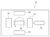
[도2] 블로우 성형장치의 기능 블록도이다.
[도3] 프리폼의 외관을 나타내는 도면이다. (a)는 프리폼의 정면도, (b)는 프리폼의 좌측면도, (c)는 프리폼의 정면도의 부분 확대도, (d)는 프리폼의 좌측면도의 부분 확대도를 나타낸다.
[도4] 블로우 성형용 금형을 나타내는 도면이다. (a)는 금형의 정면도, (b)는 금형의 좌측면도를 나타낸다.
[도5] 협지기구를 나타내는 도면이다.
[도6] 블로우 성형의 모습을 나타내는 도면이다. (a)는 분할금형(도시를 생략함)이 열려 있는 상태에서, 금형에 프리폼이 수용된 모습을 나타내는 도면이고, (b)는 프리폼의 돌출부를 협지기구에 의하여 잡은 상태를 나타내는 도면이고, (c)는 프리폼을 구부린 상태를 나타내는 도면이다.
[도7] 큰 경사각으로 목이 구부러진 용기의 1태양을 나타내는 도면이다. (a)는 용기를 개구측으로부터 보았을 때의 모습을 나타내고, (b)는 용기의 정면의 모습을 나타내고, (c)는 용기의 우측면의 모습을 나타내고, (d)는 용기의 E―E 단면의 모습을 나타내고, (e)는 용기의 F―F 단면의 모습을 나타낸다.[Fig. 1] It is a view showing a container with a bent neck at a large inclination angle. (a) shows the appearance of the left side of the container, (b) shows the appearance of the front of the container.
[Fig. 2] It is a functional block diagram of a blow molding apparatus.
Fig. 3 is a view showing the appearance of the preform. (a) is a front view of the preform, (b) is a left side view of the preform, (c) is a partial enlarged view of the front view of the preform, (d) is a partially enlarged view of the left side view of the preform.
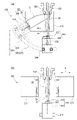
Fig. 4 is a view showing a mold for blow molding. (a) is a front view of the mold, (b) is a left side view of the mold.
[Fig. 5] It is a diagram showing a pinching mechanism.
Fig. 6 is a view showing the state of blow molding. (a) is a view showing the state that the preform is accommodated in the mold with the split mold (not shown) open, (b) is a view showing the state in which the protrusion of the preform is held by a clamping mechanism, (c) ) is a diagram showing the bent state of the preform.
Fig. 7 is a view showing one embodiment of a container whose neck is bent at a large inclination angle. (a) shows the state when the container is seen from the opening side, (b) shows the state of the front side of the container, (c) shows the state of the right side of the container, (d) is the E-E section of the container shows the shape of , and (e) shows the shape of the F-F cross-section of the container.
이하, 본 발명의 실시형태에 대하여 도면을 참조하여 설명한다. 또한 본 도면에 나타낸 각 부재의 치수는, 설명의 편의상 실제 각 부재의 치수와는 다른 경우가 있다.EMBODIMENT OF THE INVENTION Hereinafter, embodiment of this invention is described with reference to drawings. In addition, the dimension of each member shown in this figure may differ from the dimension of each actual member for convenience of description.
우선, 도1을 참조하여, 본 실시형태에 관한 목(neck)이 구부러진 용기(容器)(10)를 설명한다. 도1의 (a)는 용기(10)의 좌측면도, 도1의 (b)는 용기(10)의 정면도를 나타낸다. 용기(10)는, 개구(開口)(11)를 구비하는 목부(neck部)(12)와, 목부(12)와 연속하도록 형성되어 용기(10)의 측벽부분을 규정하는 몸통부(13)와, 몸통부(13)와 연속하도록 형성된 바닥부(14)로 구성되는 수지제(樹脂製)의 용기이다. 바닥부(14)는, 수평면 모양으로 형성되어 접지면(接地面)이 되는 외측 가장자리부와, 몸통부(13)측을 향하여 우묵하게 들어가서 오목부를 형성하는 상측 바닥부로 이루어진다. 바닥부(14)(상측 바닥부)의 외표면(外表面)에는, 바닥부(14)에 있어서 오목한 곳의 깊이(상측 바닥부의 깊이)의 범위 내에 수납되는 도시하지 않은 돌출부(돌출 흔적부)(215)가 형성되어 있다. 본 실시형태에 있어서, 목부(12)에 있어서의 개구(11)의 중심을 통과하고 개구면(開口面)과 직교하는 축(A)과, 용기(10)의 연직방향으로 연장되는 축(B)이 이루는 각을 경사각(X)이라고 말한다. 본 예에 있어서의 용기(10)의 경사각(X)은 크며, 대략 60°이다. 몸통부(13)를 연직방향으로 2등분하였을 때의 상측의 부분은, 정면에서 볼 때에 대략 3각형 모양이다(도1의 (b)). 연직방향에 있어서의 상측의 위치에서 목부(12)와 접속되어 있는 몸통부(13)의 일부는 만곡(彎曲)되어 있고, 연직방향에 있어서의 하측의 위치에서 목부(12)와 접속되어 있는 몸통부(13)의 일부는 개구면과 평행하게 연장되어 있다(도1의 (b)). 또 몸통부(13)에 있어서의 수평방향의 횡단면 형상은, 편평 형상, 대략 타원 형상, 대략 진원(眞圓) 형상 또는 대략 다각 형상 중 어느 것이어도 좋다(도1의 용기(10)에서는, 편평 형상으로 되어 있다). 본 예에 있어서의 용기(10)의 높이는 대략 13cm, 폭은 대략 3cm, 깊이는 대략 4cm이다. 또 용기(10) 및 후술하는 용기(10A)에 있어서, 폭은 몸통부(13) 또는 바닥부(14)의 수평 횡단면의 단축방향(단경방향(短徑方向))의 길이를, 깊이는 몸통부(13) 또는 바닥부(14)의 수평 횡단면의 장축방향(장경방향)의 길이를 나타내고 있다.First, with reference to Fig. 1, a
계속하여, 도2를 참조하여 용기를 제조하기 위한 블로우 성형장치(blow 成形裝置)(100)에 대하여 설명한다. 도2는 블로우 성형장치(100)의 블록도이다.Next, with reference to FIG. 2, the blow molding apparatus 100 for manufacturing a container is demonstrated. 2 is a block diagram of the blow molding apparatus 100 .
도2에 나타내는 바와 같이 블로우 성형장치(100)는, 프리폼(preform)(20)을 제조하기 위한 사출성형부(射出成形部)(110)와, 제조된 프리폼(20)의 온도를 조정하기 위한 온도조절부(120)를 구비하고 있다. 사출성형부(110)에는, 원재료인 수지재료를 공급하는 사출장치(射出裝置)(112)가 접속되어 있다. 원재료가 되는 합성수지는 열가소성 수지(熱可塑性 樹脂)이고, 용도에 따라 적절하게 선정할 수 있다. 합성수지로서는, 예를 들면 PET(폴리에틸렌테레프탈레이트), PEN(폴리에틸렌나프탈레이트), PCTA(폴리시클로헥산디메틸렌테레프탈레이트), Tritan(트라이탄 : 코폴리에스테르), PP(폴리프로필렌), PE(폴리에틸렌), PC(폴리카보네이트), PES(폴리에테르술폰), PPUS(폴리페닐술폰), PS(폴리스티렌), COP/COC(환상 올레핀계 폴리머), PMMA(폴리메타크릴산메틸 : 아크릴), PLA(폴리젖산) 등을 들 수 있다. 또한 생분해성 플라스틱도 들 수 있다. 또한 블로우 성형장치(100)는, 프리폼(20)을 블로우하여 용기(10)를 제조하기 위한 블로우 성형부(blow 成形部)(130)와, 제조된 용기(10)를 꺼내기 위한 인출부(140)를 구비하고 있다.As shown in FIG. 2 , the blow molding apparatus 100 includes an
사출성형부(110)와 온도조절부(120)와 블로우 성형부(130)와 인출부(140)는, 반송수단(150)을 중심으로 하여 소정 각도(본 실시형태에서는 90°)씩 회전한 위치에 설치되어 있다. 반송수단(150)은 회전판(回轉板) 등으로 구성되어 있고, 후술하는 도4 및 도6에 나타내는 바와 같이, 회전판에 부착되어 있는 넥금형(neck金型)(152)에 의하여 목부(12, 22)가 지지된 상태의 프리폼(20) 또는 용기(10)가, 회전판의 회전에 따라 각 부로 반송되도록 구성되어 있다.The
도2에 나타내는 사출성형부(110)는, 도시를 생략하는 사출캐비티금형(射出cavity金型), 사출코어금형(射出core金型), 넥금형 등을 구비하고 있다. 이들 금형이 체결됨으로써 형성되는 프리폼 형상의 공간 내에 사출장치(112)로부터 수지재료를 유입시킴으로써, 바닥을 갖는 프리폼(20)이 제조된다.The
여기에서 도3을 참조하여 본 실시형태에 관한 프리폼(20)에 대하여 설명한다. 도3의 (a)는 프리폼(20)의 정면도, 도3의 (b)는 프리폼(20)의 우측면도, 도3의 (c)는 프리폼(20)의 정면도의 부분 확대도, 도3의 (d)는 프리폼(20)의 우측면도의 부분 확대도를 나타낸다. 프리폼(20)은, 개구(21)를 구비하는 목부(22)와, 목부(22)와 연속하도록 형성되어 프리폼(20)의 측벽부분을 규정하는 몸통부(23)와, 몸통부(23)와 연속하도록 형성된 바닥부(24)로 구성되어 있다. 바닥부(24)의 중심부분에는 돌출부(25)가 형성되어 있다. 돌출부(25)는, 프리폼 성형 시에 있어서의 수지의 사출 게이트(射出 gate)에 가까운 게이트부(gate部)(26)와, 게이트부(26)보다 연직방향에 있어서 상측에 형성되고 프리폼(20)의 하단(下端)과 연속하는 돌기부(突起部)(27)로 구성되어 있다. 돌기부(27)는, 편평 모양으로 형성되어 있고, 정면에서 볼 때에 있어서 게이트부(26)보다 확경(擴徑)되어(광폭(廣幅)으로) 형성되어 있고(도3의 (a) 및 도3의 (c)), 측면에서 볼 때에 있어서 게이트부(26)와 동등한 폭으로 형성되어 있다(도3의 (b) 및 도3의 (d)). 즉, 돌기부(27)의 좌우방향(도3의 (a) 및 도3의 (c)의 지면(紙面) 상에서의 좌우방향. 프리폼(20)이 넥금형(152)에 의하여 지지된 상태에 있어서, 돌기부(27)가 게이트부(26)보다 광폭으로 보이는 광폭방향)에 있어서의 길이는, 게이트부(26)의 도3의 (a) 및 도3의 (c)의 지면 상에서의 좌우방향에 있어서의 길이보다 길다. 돌기부(27)의 전후방향(도3의 (b) 및 도3의 (d)의 지면 상에서의 좌우방향. 프리폼(20)이 넥금형(152)에 의하여 지지된 상태에 있어서, 돌기부(27)의 폭과 게이트부(26)의 폭이 동등하게 보이는 방향)에 있어서의 길이는, 게이트부(26)의 전후방향에 있어서의 길이와 동등하다.Here, with reference to FIG. 3, the
도2로 되돌아가서 블로우 성형장치(100)를 설명한다. 온도조절부(120)는, 사출성형부(110)에서 제조된 프리폼(20)의 온도를 최종 블로우에 적합한 온도로 조정하도록 구성되어 있다. 블로우 성형부(130)는, 온도조절부(120)에서 온도조정된 프리폼(20)에 대하여 블로우 성형을 하여, 수지제의 용기(10)를 제조하도록 구성되어 있다. 블로우 성형부(130)는, 블로우 성형용 금형(200)과 연신로드(延伸rod)(132)를 구비하고 있다.Returning to Fig. 2, the blow molding apparatus 100 will be described. The
여기에서 도4를 참조하여, 블로우 성형부(130)가 구비하는 블로우 성형용 금형(200)에 대하여 상세하게 설명한다. 도4의 (a)는 금형(200)의 정면도, 도4의 (b)는 금형(200)의 좌측면도를 나타낸다. 금형(200)은, 1쌍의 분할금형(블로우 캐비티 분할금형(blow cavity split 金型))(210)과, 보텀금형(bottom金型)(220)과, 1쌍의 넥금형(152)과, 협지기구(挾持機構)(230)와, 회전기구(240)를 구비하고 있다.Here, with reference to FIG. 4 , the
분할금형(210)은, 측면에서 볼 때에 있어서 파팅면(parting面)(C)을 기준으로 하여 좌우방향(개폐방향(D))으로 개폐할 수 있도록 구성되어 있다(도4의 (b)). 좌우 1쌍의 분할금형(210)은, 닫힌 상태에서 용기(10)의 몸통부(13)를 규정하는 공간(S)을 구성한다.The
보텀금형(220)은, 용기(10)의 바닥부(14)를 규정하는 제1보텀금형부재(221)와, 그 하방에 배치되는 제2보텀금형부재(수용블록(收容block))(260)로 이루어진다. 또 보텀금형(220)에는, 그 내부에 수용되도록 협지기구(230)가 설치되어 있다(도4의 (a) 및 도4의 (b)). 제1보텀금형부재(221)에는 적어도 협지기구(230)의 협지부(挾持部)(232)(후술)의 일부가 수용되고, 제2보텀금형부재(260)에는 적어도 협지기구(230)의 개폐기구(234)(후술)의 일부가 수용된다. 제2보텀금형부재(260)는, 후술하는 피가이드부(被guide部)(244)의 상면에 설치되어 있다. 보텀금형(220) 및 피가이드부(244)(후술)는, 일체(一體)가 되어 가이드부(242)(후술)를 따라 이동할 수 있도록 구성되어 있다.The
여기에서 도5를 참조하여 협지기구(230)를 설명한다. 협지기구(230)는, 프리폼(20)의 바닥부(24)에 형성된 돌출부(25)의 돌기부(27)를 잡는 것이 가능하도록 구성된 협지부(232)를 구비하고 있다. 협지부(232)는 보텀금형(220)으로부터 독립하여(보텀금형(220)에 직접 설치되지 않고 분리하여) 설치되어 있다. 협지부(232)는, 보텀금형(220)의 하방에서 링크기구(link機構)를 통하여 연접(連接)한 구동부재(개폐기구(234))에 의하여 개폐할 수 있도록 구성되고, 열린 상태로부터 닫힌 상태가 됨으로써 돌기부(27)를 협지한다. 협지부(232)의 선단부분(先端部分)에는, 협지부(232)의 내측으로 돌출된 폴부(pawl部)(233)가 형성되고, 협지부(232)가 닫힌 상태에서 폴부(233)가 돌기부(27)를 물도록 구성되어 있다.Here, the
제1보텀금형부재(221)는 제1수용부(第1收容部)(236A)를 포함한다. 제2보텀금형부재(260)는 제2수용부(236B)를 포함한다. 여기에서, 제1수용부(236A)와 제2수용부(236B)로 이루어지는 부분을 본 명세서에서는 수용부(236)라고 정의한다. 또한 제1수용부(236A)와 제2수용부(236B)는 연통(連通)되어 있다. 수용부(236) 및 보텀금형(220)에는, 프리폼(20)의 돌출부(25)를 협지부(232)로 인도하기 위한 개구부가 각각 형성되어 있다. 협지부(232)와 개폐기구(234)는 수용부(236)로 덮여 있다. 수용부(236)에는, 협지기구(230)가 배치되어 있다.The first
도4로 되돌아가서, 금형(200)을 설명한다. 넥금형(152)은, 전술한 바와 같이 회전판에 부착되어, 목부(12, 22)를 지지한 상태에서 프리폼(20) 또는 용기(10)를 회전판의 회전에 따라 각 부로 반송하도록 구성되어 있다. 회전기구(240)는, 보텀금형(220)의 측방 및 분할금형(210)의 하방에 배치되고 평판 모양이며 캠홈(cam groove)(243)을 구비하는 가이드부(242)와, 수용부(236)의 바로 아래에 고정된 이동블록(도시하지 않음)에 연결된 피가이드부(캠 팔로워(cam follower))(244)를 구비한다(도4의 (a)). 가이드부(242)의 캠홈(243)은, 적어도 곡선부를 구비하고 있고, 필요에 따라 직선부가 형성된다. 이 곡선부는, 회전판에 의하여 온도조절부(120)로부터 반송된 프리폼(20)의 하방의 연직방향에 있어서, 일방(一方)의 끝부를 갖는다. 이 곡선부를 따라 피가이드부(244)가 이동함으로써, 프리폼(20)의 몸통부(23) 및 바닥부(24)는 목부(22)에 대하여, 용기(10)의 경사각(X)에 대응하는 소정 각도(예를 들면 60°) 회전된다. 또 이 동작 시에, 목부(22)는 위치가 움직이지 않도록 넥금형 등에 의하여 지지되어 있다.Returning to Fig. 4, the
회전기구(240)는, 피가이드부(244)를 가이드부(242)의 캠홈(243)을 따라 이동시킴으로써, 이동블록을 통하여 보텀금형(220)을 블로우 성형 시에 넥금형(152)이 배치되는 위치에 대하여 회전시키는 것이 가능하도록 구성되어 있다. 즉 회전기구(240)는, 협지기구(230)에 의하여 돌기부(27)를 잡은 상태의 보텀금형(220)을, 넥금형(152)에 의하여 지지된 정지상태의 프리폼(20)의 목부(22)에 대하여 회전시키는 것이 가능하도록 구성되어 있다. 또한 회전기구(240)는, 보텀금형(220)을 금형(200)에 있어서의 분할금형(210)의 개폐방향(D)과 직교하는 면 위에서 회전시키는 것이 가능하도록 구성되어 있다. 바꾸어 말하면, 회전기구(240)는 보텀금형(220)을 분할금형(210)의 파팅면(C)을 따라 회전시키는 것이 가능하도록 구성되어 있다. 즉 보텀금형(220)은, 구부러져 있지 않은(직선 모양의) 프리폼(20)의 몸통부(23)의 중심축방향에 대응하는 제1위치로부터, 구부러진(굴곡 모양의) 프리폼(20)의 몸통부(23)의 중심축방향에 대응하는 제2위치로 회전기구에 의하여 이동된다. 또 회전기구(240)는 스윙기구(swing機構) 또는 요동기구(搖動機構)라고 불러도 좋다.The
다시 도2로 되돌아가서, 블로우 성형장치(100)의 인출부(140)에 대하여 설명한다. 인출부(140)는, 블로우 성형부(130)에서 제조된 용기(10)의 목부(12)를 넥금형(152)으로부터 개방하여 용기(10)를 꺼내도록 구성되어 있다.Returning to FIG. 2 again, the lead-out
계속하여 도6을 참조하여, 블로우 성형장치(100)의 블로우 성형부(130)에 있어서의 용기(10)의 블로우 성형방법에 대하여 설명한다. 도6의 (a)는, 분할금형(210)(도시를 생략함)이 열려 있는 상태에서 금형(200)에 프리폼(20)이 수용된 모습을 나타내는 도면이고, 도6의 (b)는, 프리폼(20)의 돌기부(27)를 협지기구(230)에 의하여 잡은 상태를 나타내는 도면이고, 도6의 (c)는, 프리폼(20)을 구부린 상태를 나타내는 도면이다. 본 실시형태의 블로우 성형공정은, 금형(200)의 분할금형(210)이 열려 있는 상태에서, 금형(200)에 수용된 프리폼(20)의 돌기부(27)를 금형(200)의 협지기구(230)에 의하여 잡는 협지공정(挾持工程)과, 돌기부(27)를 잡고 있는 보텀금형(220)을 넥금형(152)에 의하여 지지된 정지상태의 프리폼(20)의 목부(22)에 대하여 회전시켜서, 프리폼(20)을 구부리는 벤딩공정(bending工程)과, 분할금형(210)을 닫고 가압매체에 의하여 프리폼(20)을 연신시키는 블로우 공정(blow 工程)을 갖는다.Then, with reference to FIG. 6, the blow molding method of the
우선, 넥금형(152)으로 지지되고 온도조절부(120)에서 블로우 성형에 적합한 온도로 조정된 프리폼(20)을 반송수단(150)에 의하여 블로우 성형부(130)로 반송하여, 분할금형(210)이 열려 있는 상태의 금형(200)에 수용한다(도6의 (a)). 다음에, 블로우 성형부(130)에 설치되어 있는 대기위치의 연신로드(132)를 하강시켜서 프리폼(20)의 바닥부(24)를 내부로부터 가압하여, 보텀금형(220)을 향하여 프리폼(20)을 연신시킨다(예비연신공정(豫備延伸工程). 프리폼(20)을 보텀금형(220)까지 늘려서, 바닥부(24)의 돌출부(25)를 보텀금형(220) 및 수용부(236)의 개구부에 수용한다(도6의 (b)). 수용된 돌출부(25)의 돌기부(27)를 협지기구(230)에 의하여 잡고, 금형(200)의 보텀금형(220)과 프리폼(20)의 바닥부(24)를 연결한다(협지공정). 그 후에 연신로드(132)를 대기위치로 상승시킨다.First, the
계속하여, 회전기구(240)에 의하여, 보텀금형(220)에 부착된 피가이드부(244)를 가이드부(242)의 캠홈(243)을 따라 도6의 (b)에 있어서의 좌측상방으로 경사진 방향으로 이동시킨다. 이에 따라, 돌기부(27)를 잡고 있는 보텀금형(220)을 넥금형(152)에 의하여 지지된 정지상태의 프리폼(20)의 목부(22)에 대하여 회전시킨다(도6의 (c)). 이에 따라 프리폼(20)의 목부(22)에 가까운 몸통부(23)의 일부를 구부린다(벤딩공정). 그리고 분할금형(210)을 닫고, 넥금형(152)과 분할금형(210)과 보텀금형(220)으로 구성되는 용기(10)의 외형을 규정하는 공간(SS)에, 구부러진 프리폼(20)을 수용한다. 이 상태에서 공기 등의 가압매체를 프리폼(20)에 유입시키고, 프리폼(20)을 블로우·연신시켜서 용기(10)를 성형한다(블로우 공정). 성형이 끝난 후에 분할금형(210)을 열고 용기(10)를 개방하여, 반송수단(150)에 의하여 인출부(140)로 용기(10)를 반송한다. 상기 방법에 의하여, 프리폼(20)으로부터 목이 구부러진 용기(10)를 블로우 성형할 수 있다.Then, the
그런데 목부의 경사각이 작은 용기는, 특허문헌1, 특허문헌2 및 특허문헌3에 개시된 경사연신기구(傾斜延伸機構)를 사용함으로써 스트레치 블로우 성형(stretch blow 成形)에 의해서도 제조할 수 있다. 그러나 이들 경사연신기구는, 블로우 에어(blow air)의 유입 전에 연신로드의 선단(先端)을 프리폼의 바닥부 내벽면에 접촉시키는 것이 필수조건이다. 따라서 목부의 경사각이 큰 용기(예를 들면 60°이상)는 이 조건을 충족시키는 것이 실질적으로 불가능하기 때문에, 이와 같은 용기는 다이렉트 블로우 성형(direct blow 成形)에 의하여 제조되고 있었다.By the way, the container with a small inclination angle of the neck part can be manufactured also by stretch blow molding by using the diagonal stretch mechanism disclosed in
한편, 다이렉트 블로우 성형에 의하여 제조할 수 있는 용기는, 대체로 스트레치 블로우 성형에 의하여 제조된 것보다 외관의 미적인 면에서 떨어진다. 또한 용기 바닥부의 핀치오프부(pinch-off部)에 있어서의 용착불량(핀홀(pin hole))에 대한 염려가 있고, 용기의 목부도 에어 블로우에 의하여 부형(賦形)되기 때문에 목부의 치수정밀도가 높지 않고(기밀성(氣密性)이 좋지 않음), 버(burr)의 절삭이 필수여서 허비되는 수지량(로스재(loss材))이 많고, 블로우 성형 후에도 절삭면의 트리밍(trimming)이라는 후공정이 필수적이고, 표면광택성이 높은 용기의 제조가 곤란하다는 과제가 존재하였다.On the other hand, containers that can be manufactured by direct blow molding are generally inferior to those manufactured by stretch blow molding in terms of aesthetic appearance. In addition, there is a concern about poor welding (pin hole) in the pinch-off portion of the bottom of the container, and since the neck of the container is also shaped by air blow, the dimensional accuracy of the neck is not high (airtightness is not good), burr cutting is essential, so the amount of resin wasted (loss material) is high, and even after blow molding, trimming of the cutting surface is There was a problem that a post-process was essential and it was difficult to manufacture a container with high surface glossiness.
상기의 실시형태에 관한 블로우 성형용 금형(200)은, 보텀금형(220)에 독립하여 설치되어, 프리폼(20)의 바닥부(24)에 게이트부(26)와 독립하여 형성된 돌기부(27)를 잡는 것이 가능하도록 구성된 협지기구(230)와, 협지기구(230)에 의하여 돌기부(27)를 잡은 상태의 보텀금형(220)을 넥금형(152)에 의하여 지지된 정지상태의 프리폼(20)의 목부(22)에 대하여 회전시키는 것이 가능하도록 구성되어 있는 회전기구(240)를 구비하고 있다. 당해 구성을 구비하는 블로우 성형용 금형(200)에 의하면, 큰 경사각으로 목이 구부러진 용기(10)를 스트레치 블로우 성형에 의하여 제조할 수 있다. 이에 따라 상기의 다이렉트 블로우 성형에 있어서의 과제를 고려할 필요 없이, 미적으로 외관이 우수하고 목부(12)의 경사각이 큰 목이 구부러진 용기(10)를 제조할 수 있다.The blow molding die 200 according to the above embodiment is provided independently of the bottom die 220 , and a
또 상기의 실시형태에 관한 블로우 성형용 금형(200)은, 보텀금형(220)이 회전기구(240)에 의하여 금형(200)의 분할금형(210)의 개폐방향(D)과 직교하는 면 위를 회전할 수 있도록 구성되어 있다. 바꾸어 말하면, 보텀금형(220)은 분할금형(210)의 파팅면(C)을 따라 회전할 수 있도록 구성되어 있다. 보텀금형(220)을 분할금형(210)의 개폐방향(D)과 직교하는 면 위에서 회전시킴으로써, 분할금형(210)의 개폐방향(D)으로 보텀금형(220)이 움직이는 태양과 비교하여 분할금형(210)이 이동하는 데에 필요한 가동폭(可動幅)을 축소시킬 수 있어, 공간절약을 할 수 있다. 또한 금형(200)의 두께를 얇게 할 수 있어 열효율의 면에서도 유리하다.Further, in the
또 상기의 실시형태에 관한 블로우 성형방법은, 프리폼(20)의 바닥부(24)에 게이트부(26)와 독립하여 형성된 돌기부(27)를, 블로우 성형용 금형(200)의 보텀금형(220)에 독립하여 설치된 협지기구(230)에 의하여 잡는 협지공정과, 돌기부(27)를 잡고 있는 보텀금형(220)을 넥금형(152)에 의하여 지지된 정지상태의 프리폼(20)의 목부(22)에 대하여 회전시켜서, 프리폼(20)을 구부리는 벤딩공정을 갖고 있다. 당해 구성을 구비하는 블로우 성형방법에 의하면, 큰 경사각으로 목이 구부러진 용기(10)를 다이렉트 블로우 성형 이외의 방법에 의해서도 제조할 수 있다. 이에 따라 상기의 다이렉트 블로우 성형에 있어서의 과제를 고려할 필요 없이, 미적으로 외관이 우수하고 목부(12)의 경사각이 큰 목이 구부러진 용기(10)를 제조할 수 있다.Further, in the blow molding method according to the above embodiment, the
또 상기의 실시형태에 관한 블로우 성형방법은, 연신로드(132)에 의하여 프리폼(20)의 바닥부(24)를 보텀금형(220)을 향하여 연신시키는 예비연신공정을 갖고 있다. 당해 구성을 구비하는 용기(10)의 블로우 성형방법에 의하면, 큰 경사각으로 목이 구부러진 용기(10)를 스트레치 블로우 성형에 의하여 제조할 수 있다.Further, the blow molding method according to the above embodiment has a preliminary stretching step in which the
또 상기의 실시형태에 있어서, 협지기구(230)에 의하여 협지되는 돌기부(27)를 게이트부(26)보다 상측에 형성하고, 또한 확경(擴徑)시켜서 폭방향으로 두께를 갖게 하고 있다. 이에 따라 협지기구(230)에 의한 돌기부(27)의 협지가 안정하게 되어, 회전기구(240)에 의하여 보텀금형(220)을 회전시킬 때에 프리폼(20)이 협지기구(230)로부터 빠지는 것을 적절하게 막을 수 있다. 또한 돌기부(27)의 사이즈를 적절하게 변경함으로써, 프리폼 형상의 변경이 용이하게 된다.Moreover, in the said embodiment, the
또 상기의 실시형태에 있어서, 협지부(232)가 보텀금형(220)과 독립하여 설치되어 있어, 보텀금형(220)의 하방에서 링크기구를 통하여 연접한 구동부재(개폐기구(234))에 의하여 개폐할 수 있도록 구성되어 있다. 이에 따라 협지부(232)에 의한 돌기부(27)의 협지를 강고(强固)한 것으로 할 수 있어, 회전기구(240)에 의하여 보텀금형(220)을 회전시킬 때에 프리폼(20)이 협지기구(230)로부터 빠지는 것을 적절하게 막을 수 있다.Further, in the above embodiment, the clamping
또 상기의 실시형태에 있어서, 협지기구(230)의 협지부(232)에 폴부(233)가 형성되어 있다. 폴부(233)를 형성함으로써 돌기부(27)를 강고하게 협지할 수 있어, 회전기구(240)에 의하여 보텀금형(220)을 회전시킬 때에 프리폼(20)이 협지기구(230)로부터 빠지는 것을 적절하게 막을 수 있다.Moreover, in the said embodiment, the
계속하여, 실시형태에 관한 수지제 용기의 1태양을 도7을 참조하여 설명한다. 도7은, 큰 경사각으로 목이 구부러진 용기의 1태양인 용기(10A)를 나타내는 도면이다. 도7의 (a)는 용기(10A)를 개구측으로부터 보았을 때의 모습을 나타내고, 도7의 (b)는 용기(10A)의 정면의 모습을 나타내고, 도7의 (c)는 용기(10A)의 우측면의 모습을 나타내고, 도7의 (d)는 용기(10A)의 E―E 단면의 모습을 나타내고, 도7의 (e)는 용기(10A)의 F―F 단면의 상태를 나타낸다.Next, one aspect of the resin container according to the embodiment will be described with reference to FIG. 7 . Fig. 7 is a view showing a
용기(10A)의 기본적인 태양은 용기(10)와 동일하지만, 경사각(X)이나 용기의 치수 등 취할 수 있는 베리에이션(variation)을 포함하여 상세하게 설명한다. 용기(10A)는, 개구(11A)를 구비하는 목부(12A)와, 목부(12A)와 연속하도록 형성되어 용기(10A)의 측벽부분을 규정하는 몸통부(13A)와, 몸통부(13A)와 연속하도록 형성된 바닥부(14A)로 구성되는 수지제의 용기이다(도1의 용기(10)의 태양을 참조). 바닥부(14A)는, 수평면 모양으로 형성되어 접지면이 되는 외측 가장자리부와, 몸통부(13A)측을 향하여 우묵하게 들어가서 오목부를 형성하는 상측 바닥부로 이루어진다. 목부의 개구(11A)의 중심을 통과하고 개구면과 직교하는 축(A)과, 용기의 연직방향으로 연장되는 축(B)이 이루는 경사각(X)은, 50∼80°의 범위이다. 경사각(X)은, 60°±5° 또는 60°∼70°의 범위인 것이 바람직하다.Although the basic aspect of the
도7의 (d) 및 도7의 (e)에 나타내는 바와 같이, 용기(10A)에 있어서의 몸통부(13A)의 수평방향의 횡단면의 형상은, 파지(把持)하여 이용할 때에 목이 구부러진 방향을 파악할 수 있는 대략 편평 형상이다. 바꾸어 말하면, 용기(10A)에 있어서의 몸통부(13A)의 횡단면의 형상은, 몸통부(13A)의 폭(도7의 (d) 및 도7의 (e)에 있어서의 지면 상의 몸통부의 상하방향의 길이)과 깊이(도7의 (d) 및 도7의 (e)에 있어서의 지면 상의 몸통부의 좌우방향의 길이)가 상이한 형상이다. 폭과 깊이가 상이한 것으로부터 목이 구부러진 방향을 파악할 수 있다. 도7의 용기(10A)는, 폭이 깊이보다 작은 형상이다. 또한 개구(11A)에 있어서의 수평인 직경방향으로 연장되는 방향을 용기의 폭방향으로 하고, 개구(11A)가 이루는 개구면과 직교하는 축이 신장되는 방향을 용기의 깊이방향으로 하여도 좋다.As shown in Fig. 7(d) and Fig. 7(e), the shape of the horizontal cross section of the
용기(10A)의 몸통부(13A)는, 하방을 향하여 서서히 깊이(도7의 (b)에 있어서의 지면 상의 좌우방향의 폭)가 넓어지는 상방 몸통부(13a)와, 대략 동일한 지름이 계속되는 하방 몸통부(13b)를 구비하고 있다. 상방 몸통부(13a)는, 축(A)과 대략 직교하는 방향을 따라 경사지는 경사면부(13c)와, 목부(12A)에서부터 멀어짐에 따라 연직방향으로 연장되도록 구부러지는 곡면부(13d)(어깨부)를 구비하고 있다. 또한 용기(10A)의 몸통부(13A)는, 연직방향을 따라 신장되는 면 모양의 부분인 제1연직면부(13e), 제2연직면부(13f) 및 제3연직면부(13g)를 구비한다. 제1연직면부(13e)는, 용기(10A)를 우측면에서 보았을 때에(도7의 (c)), 몸통부(13A)의 중심에 위치하고 용기(10A)의 바닥부(14A)에서부터 목부(12A)에 걸쳐서 연장되는 대략 평면의 부분이다. 제2연직면부(13f)는, 용기(10A)를 우측면에서 보았을 때에(도7의 (c)), 제1연직면부(13e)를 사이에 두도록 하여 2개 존재하고, 바닥부(14A)에서부터 곡면부(13d)에 걸쳐서 연장되는 대략 평면의 부분이다. 제3연직면부(13g)는, 각각의 제2연직면부(13f)에 있어서의 제1연직면부(13e)와 반대측의 위치에서 제2연직면부(13f)와 서로 이웃하고(도7의 (b)), 바닥부(14A)에서부터 목부(12A)에 걸쳐서 연장되는 대략 평면의 부분이다. 경사면부(13c), 제1연직면부(13e), 제2연직면부(13f) 및 제3연직면부(13g)를 구비함으로써, 몸통부(13A)의 단면 형상은, 바닥부(14A)의 근방측(F―F 단면)에서는 대략 6각형 모양이 되고(도7의 (e)), 목부(12A)의 근방측(E―E 단면)에서는 대략 5각형 모양이 된다(도7의 (d)). 또 상기에서 설명한 제1, 제2 및 제3연직면부(13e, 13f, 13g)는 각각, 연직방향으로 연장되는 제1, 제2 및 제3평면부의 의미이다.The
용기(10A)에 있어서의 바닥부(14A)의 외표면(상측 바닥부의 외표면)에는, 바닥부(14A)로부터 외측으로 돌출된(연직방향의 하방으로 돌출된) 돌출부(215A)(돌출 흔적부)가 존재하고 있다. 이 돌출부(215A)(돌출 흔적부)는, 바닥부(14A)에 있어서의 오목한 곳의 깊이(상측 바닥부의 깊이)의 범위 내에 수납되도록 형성되어 있다. 용기(10A)는, 상기의 실시형태에서 설명한 금형(200)과 프리폼(20)을 사용하여 성형할 수 있다. 당해 돌출부(215A)는, 프리폼(20)의 돌출부(25)가 용기(10A)의 성형 후에 남은 것이다. 즉, 용기(10A)의 돌출부(215A)에는, 프리폼(20)의 돌출부(25)와 마찬가지로 적어도 돌기부(27)가 남아 있다(도시를 생략함). 용기(10A)를 성형하기 위한 프리폼(20)에 형성된 돌출부(25)는, 프리폼(20)의 중심축 상에 형성된다. 이에 따라, 상기에서 설명한 금형(200)에 있어서 연신로드(132)에 의하여 프리폼을 연신시켜서 돌출부(25)를 협지기구(230)에 의하여 적절하게 잡을 수 있다. 따라서 돌출부(215A)에는, 협지기구(230)에 의하여 잡힌 흔적이 되는 오목부가 형성되어 있다. 또한 프리폼(20)을 구부려서 성형되는 용기(10A)의 돌출부(215A)는, 용기(10A)의 중심에 형성되어 있지 않아도 좋다. 예를 들면, 용기(10A)의 바닥부 중심에 대하여 오프 센터적으로(off-center, 중심에서 벗어난 위치에) 형성되어 있어도 좋다. 또 용기(10A)의 돌출부(215A)는 외관을 고려하여, 예를 들면 절삭 등에 의하여 제거하여도 좋다(이 경우에도, 돌출부(215A)가 약간이지만 남는다). 용기(10A)는, 높이가 10∼20cm(바람직하게는 13cm±3cm), 폭이 2∼6cm(바람직하게는 3±1cm), 깊이가 3∼10cm(바람직하게는 4±1cm)이다.On the outer surface (outer surface of the upper bottom portion) of the
상기와 같이 용기(10A)의 몸통부(13A)를 다각 형상으로 형성함으로써, 용기(10A)의 강성도(剛性度)나 그립성(grip性)의 향상이 도모된다. 또한 돌출부(215A)를 바닥부(14A)에 있어서의 오목한 곳의 깊이 범위 내에 수납되도록 형성함으로써, 용기(10A)의 접지안정성(接地安定性)도 담보할 수 있다.By forming the
또 본 발명은, 상기에서 설명한 실시형태에 한정되지 않으며, 적절하게 변형, 개량 등이 가능하다. 그 이외에, 상기에서 설명한 실시형태에 있어서의 각 구성요소의 재질, 형상, 치수, 수치, 형태, 수(數), 배치장소 등은, 본 발명을 달성할 수 있는 것이라면 임의이며, 한정되지 않는다.In addition, this invention is not limited to embodiment demonstrated above, A deformation|transformation, improvement, etc. are possible suitably. In addition, the material, shape, dimension, numerical value, form, number, arrangement location, etc. of each component in the embodiment described above are arbitrary and not limited as long as the present invention can be achieved.
상기의 실시형태에 있어서 경사각이 대략 60°인 목이 구부러진 용기(10)의 태양을 설명하였지만, 본 실시형태의 금형(200) 및 블로우 성형방법에 의하면, 경사각이 60° 이상 또는 60° 이하인 용기이더라도 스트레치 블로우 성형에 의하여 제조하는 것이 가능하다. 또한 회전기구(240)의 동작은 회전뿐만 아니라, 수평이동이나 직선적·다단계적으로 상방으로 경사진 방향으로의 이동에 의하여 구성되는 동작이어도 좋다.In the above embodiment, the aspect of the
상기의 실시형태에 있어서, 프리폼(20)을 블로우하는 가압매체로서, 공기를 예로 들었지만, 공기 이외의 기체매체를 사용하여도 좋고, 또 물 등의 액체매체를 사용하여 가압하여도 좋다.In the above embodiment, as the pressurizing medium for blowing the
또 본원은, 2018년 7월 17일자로 출원된 일본국 특허출원(특원2018―134579)에 의거하고 있으며, 그 전체가 인용에 의하여 원용된다. 또한 여기에 인용되는 모든 참조는 전체로서 포함된다.In addition, this application is based on the Japanese patent application (Japanese Patent Application No. 2018-134579) for which it applied on July 17, 2018, The whole is used by reference. Also, all references cited herein are incorporated in their entirety.
10 : 목이 구부러진 용기
11 : 개구
12 : 목부
13 : 몸통부
14 : 바닥부
20 : 프리폼
21 : 개구
22 : 목부
23 : 몸통부
24 : 바닥부
25 : 돌출부
26 : 게이트부
27 : 돌기부
100 : 블로우 성형장치
110 : 사출성형부
112 : 사출장치
120 : 온도조절부
130 : 블로우 성형부
132 : 연신로드
140 : 인출부
150 : 반송수단
152 : 넥금형
200 : 블로우 성형용 금형
210 : 분할금형
220 : 보텀금형
230 : 협지기구
232 : 협지부
233 : 폴부
234 : 개폐기구
236 : 수용부
240 : 회전기구
242 : 가이드부
244 : 피가이드부10: crooked-necked container
11: opening
12 : neck
13: body
14: bottom
20: preform
21: opening
22 : neck
23: body
24: bottom
25: protrusion
26: gate part
27: protrusion
100: blow molding device
110: injection molding part
112: injection device
120: temperature control unit
130: blow molding part
132: stretching rod
140: withdrawal unit
150: conveyance means
152: neck mold
200: mold for blow molding
210: split mold
220: bottom mold
230: pinch mechanism
232: pinch part
233: pole part
234: opening and closing mechanism
236: receptacle
240: rotating mechanism
242: guide unit
244: guide part
Claims (3)
상기 개구의 중심을 통과하고 상기 개구가 이루는 개구면(開口面)과 직교하는 축과, 상기 용기의 연직방향으로 연장되는 축이 이루는 경사각이 50° 이상 80° 이하이고,
상기 개구에 있어서의 수평인 직경방향으로 연장되는 방향을 용기의 폭방향으로 하고, 상기 폭방향과 직교하는 수평인 방향을 용기의 깊이방향으로 하였을 때에,
상기 몸통부에 있어서의 수평단면(水平斷面)의 상기 폭방향의 길이와 상기 깊이방향의 길이가 다른
스트레치 블로우 성형법(stretch blow 成形法)에 의하여 제조되는 용기.
A resin container comprising: a neck having an opening; a body formed to be continuous with the neck to define a side wall; and a bottom formed to be continuous with the body, comprising:
An inclination angle between an axis passing through the center of the opening and perpendicular to an opening surface formed by the opening and an axis extending in the vertical direction of the container is 50° or more and 80° or less,
When the direction extending in the horizontal radial direction in the said opening is made into the width direction of a container, and the horizontal direction orthogonal to the said width direction is made into the depth direction of a container,
The length in the width direction and the length in the depth direction of a horizontal cross section of the body are different from each other.
A container manufactured by a stretch blow molding method.
상기 바닥부가, 상기 바닥부의 외표면(外表面)으로부터 외측으로 돌출되는 돌출부를 구비하는 용기.
According to claim 1,
A container in which the bottom portion has a protrusion protruding outward from an outer surface of the bottom portion.
상기 몸통부는, 상기 개구가 이루는 개구면과 직교하는 축과 직교하는 방향을 따라 경사지는 경사면부를 구비하는 상방 몸통부와, 상기 상방 몸통부와 연속하고 연직방향을 따라 신장되는 하방 몸통부를 구비하고,
상기 상방 몸통부 및 상기 하방 몸통부의 수평단면의 형상이 다각 형상이고,
상기 상방 몸통부의 다각 형상에 있어서의 수평단면의 모서리(corner)의 수가, 상기 하방 몸통부의 다각 형상에 있어서의 수평단면의 모서리의 수보다 적은 용기.3. The method of claim 1 or 2,
The body includes an upper body having an inclined surface inclined in a direction perpendicular to an axis orthogonal to an axis orthogonal to the opening formed by the opening, and a lower body extending in a vertical direction and continuous with the upper body;
The shape of the horizontal cross section of the upper body part and the lower body part is a polygonal shape,
A container in which the number of horizontal cross-section corners in the polygonal shape of the upper body is smaller than the number of horizontal cross-section corners in the polygonal shape of the lower body.
Applications Claiming Priority (4)
| Application Number | Priority Date | Filing Date | Title |
|---|---|---|---|
| JPJP-P-2018-134579 | 2018-07-17 | ||
| JP2018134579 | 2018-07-17 | ||
| PCT/JP2019/027947 WO2020017505A1 (en) | 2018-07-17 | 2019-07-16 | Mold for blow molding, method for manufacturing resin container using same, and resin container |
| KR1020217004532A KR102456985B1 (en) | 2018-07-17 | 2019-07-16 | Mold for blow molding, method for manufacturing a resin container using the same, and a resin container |
Related Parent Applications (1)
| Application Number | Title | Priority Date | Filing Date |
|---|---|---|---|
| KR1020217004532A Division KR102456985B1 (en) | 2018-07-17 | 2019-07-16 | Mold for blow molding, method for manufacturing a resin container using the same, and a resin container |
Publications (1)
| Publication Number | Publication Date |
|---|---|
| KR20220146677A true KR20220146677A (en) | 2022-11-01 |
Family
ID=69164142
Family Applications (2)
| Application Number | Title | Priority Date | Filing Date |
|---|---|---|---|
| KR1020227035976A KR20220146677A (en) | 2018-07-17 | 2019-07-16 | Resin container |
| KR1020217004532A KR102456985B1 (en) | 2018-07-17 | 2019-07-16 | Mold for blow molding, method for manufacturing a resin container using the same, and a resin container |
Family Applications After (1)
| Application Number | Title | Priority Date | Filing Date |
|---|---|---|---|
| KR1020217004532A KR102456985B1 (en) | 2018-07-17 | 2019-07-16 | Mold for blow molding, method for manufacturing a resin container using the same, and a resin container |
Country Status (6)
| Country | Link |
|---|---|
| US (1) | US11951670B2 (en) |
| JP (1) | JP7390291B2 (en) |
| KR (2) | KR20220146677A (en) |
| CN (1) | CN112689557A (en) |
| TW (1) | TWI714171B (en) |
| WO (1) | WO2020017505A1 (en) |
Citations (4)
| Publication number | Priority date | Publication date | Assignee | Title |
|---|---|---|---|---|
| JPS513247B1 (en) | 1970-07-22 | 1976-02-02 | ||
| JP2006062110A (en) | 2004-08-25 | 2006-03-09 | Aoki Technical Laboratory Inc | Method and apparatus for molding neck bending container using resin |
| JP3893054B2 (en) | 2001-12-14 | 2007-03-14 | 日精エー・エス・ビー機械株式会社 | Biaxial stretch blow molding method and apparatus |
| JP4093562B2 (en) | 2003-03-11 | 2008-06-04 | 株式会社日本製鋼所 | Paris machine bending machine for hollow molding machine |
Family Cites Families (11)
| Publication number | Priority date | Publication date | Assignee | Title |
|---|---|---|---|---|
| JP2627920B2 (en) * | 1988-04-18 | 1997-07-09 | 大日本印刷株式会社 | Preformed body for synthetic resin bottle, method for producing the same, two-wheel stretch blow bottle using the same, and composite container thereof |
| US5178817A (en) | 1988-09-06 | 1993-01-12 | Dai Nippon Insatsu K. K. | Stretch blow molding method for manufacturing an expanded bottle |
| JP2627937B2 (en) * | 1988-09-06 | 1997-07-09 | 大日本印刷株式会社 | Biaxially stretch blow-molded bottle, method for producing the same, and composite container using the same |
| JPH0681699B2 (en) * | 1988-09-22 | 1994-10-19 | 日精エー・エス・ビー機械株式会社 | Molding method for deformed hollow container |
| JP2567950B2 (en) * | 1989-08-14 | 1996-12-25 | 大日本印刷株式会社 | Method of manufacturing deformed parison for blow molding, manufacturing apparatus, and method of manufacturing stretch blow molded bottle |
| US5662842A (en) | 1994-07-18 | 1997-09-02 | Salflex Polymers Ltd. | Process for blow molding hollow objects with independent movement of mold halves |
| JP3727834B2 (en) * | 2000-08-31 | 2005-12-21 | 株式会社吉野工業所 | Manufacturing method of heat-resistant neck bend container |
| JP4209267B2 (en) | 2003-06-20 | 2009-01-14 | 株式会社フロンティア | Neck bending container forming method |
| JP5103247B2 (en) | 2008-03-31 | 2012-12-19 | 株式会社青木固研究所 | Molding device for stretch blow of container having mouth at upper corner |
| JP6570845B2 (en) | 2015-02-27 | 2019-09-04 | 株式会社吉野工業所 | Container manufacturing equipment |
| JP6809044B2 (en) * | 2016-08-26 | 2021-01-06 | 大日本印刷株式会社 | Plastic bottles and fillers |
-
2019
- 2019-07-16 CN CN201980059898.0A patent/CN112689557A/en active Pending
- 2019-07-16 US US17/260,720 patent/US11951670B2/en active Active
- 2019-07-16 WO PCT/JP2019/027947 patent/WO2020017505A1/en active Application Filing
- 2019-07-16 JP JP2020531318A patent/JP7390291B2/en active Active
- 2019-07-16 KR KR1020227035976A patent/KR20220146677A/en active IP Right Grant
- 2019-07-16 KR KR1020217004532A patent/KR102456985B1/en active IP Right Grant
- 2019-07-17 TW TW108125251A patent/TWI714171B/en active
Patent Citations (4)
| Publication number | Priority date | Publication date | Assignee | Title |
|---|---|---|---|---|
| JPS513247B1 (en) | 1970-07-22 | 1976-02-02 | ||
| JP3893054B2 (en) | 2001-12-14 | 2007-03-14 | 日精エー・エス・ビー機械株式会社 | Biaxial stretch blow molding method and apparatus |
| JP4093562B2 (en) | 2003-03-11 | 2008-06-04 | 株式会社日本製鋼所 | Paris machine bending machine for hollow molding machine |
| JP2006062110A (en) | 2004-08-25 | 2006-03-09 | Aoki Technical Laboratory Inc | Method and apparatus for molding neck bending container using resin |
Also Published As
| Publication number | Publication date |
|---|---|
| KR102456985B1 (en) | 2022-10-19 |
| CN112689557A (en) | 2021-04-20 |
| WO2020017505A1 (en) | 2020-01-23 |
| US11951670B2 (en) | 2024-04-09 |
| TWI714171B (en) | 2020-12-21 |
| US20210299936A1 (en) | 2021-09-30 |
| JPWO2020017505A1 (en) | 2021-08-02 |
| KR20210030456A (en) | 2021-03-17 |
| TW202017728A (en) | 2020-05-16 |
| JP7390291B2 (en) | 2023-12-01 |
Similar Documents
| Publication | Publication Date | Title |
|---|---|---|
| WO2017073699A1 (en) | Metal mould, blow moulding apparatus, and blow moulding method | |
| US20190308362A1 (en) | Forming mold and injection mold | |
| JP7457077B2 (en) | Manufacturing method of bent-neck container, temperature adjustment mold, blow molding device, and blow molding method | |
| CN112055641B (en) | Method for manufacturing resin container member, mold unit, and blow molding machine including the mold unit | |
| US6386380B1 (en) | Neck finish for a container and mold for forming the container | |
| KR102456985B1 (en) | Mold for blow molding, method for manufacturing a resin container using the same, and a resin container | |
| JP4748475B2 (en) | Injection molding preform | |
| WO2012096905A2 (en) | Process for the manufacture of an article comprising a recess | |
| US11964793B2 (en) | Resin-made container, resin-made container manufacturing method, resin-made container manufacturing apparatus, and mold | |
| JP7112395B2 (en) | Mold | |
| JPWO2018070499A1 (en) | Blow mold | |
| US20190047179A1 (en) | Moulding of plastic containers with handles | |
| JP5883724B2 (en) | Bottle-type container and manufacturing method thereof | |
| EP2663509A2 (en) | Process for the manufacture of an article comprising a recess,and article |
Legal Events
| Date | Code | Title | Description |
|---|---|---|---|
| A107 | Divisional application of patent | ||
| E902 | Notification of reason for refusal | ||
| AMND | Amendment | ||
| E601 | Decision to refuse application | ||
| AMND | Amendment | ||
| X701 | Decision to grant (after re-examination) |