KR20220131336A - diffractive eye lens - Google Patents
diffractive eye lens Download PDFInfo
- Publication number
- KR20220131336A KR20220131336A KR1020227030493A KR20227030493A KR20220131336A KR 20220131336 A KR20220131336 A KR 20220131336A KR 1020227030493 A KR1020227030493 A KR 1020227030493A KR 20227030493 A KR20227030493 A KR 20227030493A KR 20220131336 A KR20220131336 A KR 20220131336A
- Authority
- KR
- South Korea
- Prior art keywords
- diffractive
- lens
- region
- ophthalmic lens
- diffraction
- Prior art date
Links
Images


Classifications
-
- A—HUMAN NECESSITIES
- A61—MEDICAL OR VETERINARY SCIENCE; HYGIENE
- A61F—FILTERS IMPLANTABLE INTO BLOOD VESSELS; PROSTHESES; DEVICES PROVIDING PATENCY TO, OR PREVENTING COLLAPSING OF, TUBULAR STRUCTURES OF THE BODY, e.g. STENTS; ORTHOPAEDIC, NURSING OR CONTRACEPTIVE DEVICES; FOMENTATION; TREATMENT OR PROTECTION OF EYES OR EARS; BANDAGES, DRESSINGS OR ABSORBENT PADS; FIRST-AID KITS
- A61F2/00—Filters implantable into blood vessels; Prostheses, i.e. artificial substitutes or replacements for parts of the body; Appliances for connecting them with the body; Devices providing patency to, or preventing collapsing of, tubular structures of the body, e.g. stents
- A61F2/02—Prostheses implantable into the body
- A61F2/14—Eye parts, e.g. lenses, corneal implants; Implanting instruments specially adapted therefor; Artificial eyes
- A61F2/16—Intraocular lenses
- A61F2/1613—Intraocular lenses having special lens configurations, e.g. multipart lenses; having particular optical properties, e.g. pseudo-accommodative lenses, lenses having aberration corrections, diffractive lenses, lenses for variably absorbing electromagnetic radiation, lenses having variable focus
- A61F2/1654—Diffractive lenses
- A61F2/1656—Fresnel lenses, prisms or plates
-
- G—PHYSICS
- G02—OPTICS
- G02B—OPTICAL ELEMENTS, SYSTEMS OR APPARATUS
- G02B5/00—Optical elements other than lenses
- G02B5/18—Diffraction gratings
- G02B5/1876—Diffractive Fresnel lenses; Zone plates; Kinoforms
-
- B—PERFORMING OPERATIONS; TRANSPORTING
- B29—WORKING OF PLASTICS; WORKING OF SUBSTANCES IN A PLASTIC STATE IN GENERAL
- B29D—PRODUCING PARTICULAR ARTICLES FROM PLASTICS OR FROM SUBSTANCES IN A PLASTIC STATE
- B29D11/00—Producing optical elements, e.g. lenses or prisms
- B29D11/00009—Production of simple or compound lenses
- B29D11/00038—Production of contact lenses
-
- G—PHYSICS
- G02—OPTICS
- G02B—OPTICAL ELEMENTS, SYSTEMS OR APPARATUS
- G02B5/00—Optical elements other than lenses
- G02B5/18—Diffraction gratings
- G02B5/1876—Diffractive Fresnel lenses; Zone plates; Kinoforms
- G02B5/189—Structurally combined with optical elements not having diffractive power
- G02B5/1895—Structurally combined with optical elements not having diffractive power such optical elements having dioptric power
-
- G—PHYSICS
- G02—OPTICS
- G02C—SPECTACLES; SUNGLASSES OR GOGGLES INSOFAR AS THEY HAVE THE SAME FEATURES AS SPECTACLES; CONTACT LENSES
- G02C7/00—Optical parts
- G02C7/02—Lenses; Lens systems ; Methods of designing lenses
- G02C7/04—Contact lenses for the eyes
- G02C7/041—Contact lenses for the eyes bifocal; multifocal
- G02C7/042—Simultaneous type
-
- G—PHYSICS
- G02—OPTICS
- G02C—SPECTACLES; SUNGLASSES OR GOGGLES INSOFAR AS THEY HAVE THE SAME FEATURES AS SPECTACLES; CONTACT LENSES
- G02C7/00—Optical parts
- G02C7/02—Lenses; Lens systems ; Methods of designing lenses
- G02C7/04—Contact lenses for the eyes
- G02C7/041—Contact lenses for the eyes bifocal; multifocal
- G02C7/044—Annular configuration, e.g. pupil tuned
-
- G—PHYSICS
- G02—OPTICS
- G02C—SPECTACLES; SUNGLASSES OR GOGGLES INSOFAR AS THEY HAVE THE SAME FEATURES AS SPECTACLES; CONTACT LENSES
- G02C7/00—Optical parts
- G02C7/02—Lenses; Lens systems ; Methods of designing lenses
- G02C7/04—Contact lenses for the eyes
- G02C7/041—Contact lenses for the eyes bifocal; multifocal
- G02C7/045—Sectorial configuration
-
- A—HUMAN NECESSITIES
- A61—MEDICAL OR VETERINARY SCIENCE; HYGIENE
- A61F—FILTERS IMPLANTABLE INTO BLOOD VESSELS; PROSTHESES; DEVICES PROVIDING PATENCY TO, OR PREVENTING COLLAPSING OF, TUBULAR STRUCTURES OF THE BODY, e.g. STENTS; ORTHOPAEDIC, NURSING OR CONTRACEPTIVE DEVICES; FOMENTATION; TREATMENT OR PROTECTION OF EYES OR EARS; BANDAGES, DRESSINGS OR ABSORBENT PADS; FIRST-AID KITS
- A61F2240/00—Manufacturing or designing of prostheses classified in groups A61F2/00 - A61F2/26 or A61F2/82 or A61F9/00 or A61F11/00 or subgroups thereof
- A61F2240/001—Designing or manufacturing processes
-
- A—HUMAN NECESSITIES
- A61—MEDICAL OR VETERINARY SCIENCE; HYGIENE
- A61F—FILTERS IMPLANTABLE INTO BLOOD VESSELS; PROSTHESES; DEVICES PROVIDING PATENCY TO, OR PREVENTING COLLAPSING OF, TUBULAR STRUCTURES OF THE BODY, e.g. STENTS; ORTHOPAEDIC, NURSING OR CONTRACEPTIVE DEVICES; FOMENTATION; TREATMENT OR PROTECTION OF EYES OR EARS; BANDAGES, DRESSINGS OR ABSORBENT PADS; FIRST-AID KITS
- A61F2250/00—Special features of prostheses classified in groups A61F2/00 - A61F2/26 or A61F2/82 or A61F9/00 or A61F11/00 or subgroups thereof
- A61F2250/0014—Special features of prostheses classified in groups A61F2/00 - A61F2/26 or A61F2/82 or A61F9/00 or A61F11/00 or subgroups thereof having different values of a given property or geometrical feature, e.g. mechanical property or material property, at different locations within the same prosthesis
- A61F2250/0053—Special features of prostheses classified in groups A61F2/00 - A61F2/26 or A61F2/82 or A61F9/00 or A61F11/00 or subgroups thereof having different values of a given property or geometrical feature, e.g. mechanical property or material property, at different locations within the same prosthesis differing in optical properties
-
- G—PHYSICS
- G02—OPTICS
- G02C—SPECTACLES; SUNGLASSES OR GOGGLES INSOFAR AS THEY HAVE THE SAME FEATURES AS SPECTACLES; CONTACT LENSES
- G02C2202/00—Generic optical aspects applicable to one or more of the subgroups of G02C7/00
- G02C2202/20—Diffractive and Fresnel lenses or lens portions
Landscapes
- Physics & Mathematics (AREA)
- Health & Medical Sciences (AREA)
- Ophthalmology & Optometry (AREA)
- General Physics & Mathematics (AREA)
- Optics & Photonics (AREA)
- General Health & Medical Sciences (AREA)
- Engineering & Computer Science (AREA)
- Oral & Maxillofacial Surgery (AREA)
- Vascular Medicine (AREA)
- Cardiology (AREA)
- Manufacturing & Machinery (AREA)
- Transplantation (AREA)
- Biomedical Technology (AREA)
- Heart & Thoracic Surgery (AREA)
- Mechanical Engineering (AREA)
- Life Sciences & Earth Sciences (AREA)
- Animal Behavior & Ethology (AREA)
- Public Health (AREA)
- Veterinary Medicine (AREA)
- Prostheses (AREA)
- Diffracting Gratings Or Hologram Optical Elements (AREA)
- Eyeglasses (AREA)
Abstract
본 발명은 전면(10), 후면(15) 및 주 광축(A)을 갖는 회절 안렌즈(1)에 관한 것으로, 상기 전면(10) 및/또는 후면(15)은 구면형, 비구면형, 구면-원환형 또는 비구면-원환형 기본 형상을 가지고, 상기 전면(10) 및/또는 후면(15)은 회절 광학 구조를 가지며, 여기서 회절 광학 구조는 안렌즈(1)의 주 광축(A)을 둘러싸는 복수의 제1 환형 회절 구역(32)을 갖는 제1 렌즈 영역(30)을 포함하고, 상기 회절 구역은 각각 메인 하위 구역(34) 및 위상 하위 구역(36)을 가진다.
본 발명의 과제는 색 보정을 가능하게 하는 동시에 광륜을 감소시켜 안렌즈의 시각적 특성을 개선시키는 회절 안렌즈를 제공하는 것이다.
상기 과제는, 설계 파장에서, 하나 이상의 파장의 제1 메인 하위 구역(34) 사이의 위상 편차에 대하여 유의적인 회절 효율이 발생하고, 제1 렌즈 영역(30)에 대하여, 모든 회절 구역(32)에 걸쳐 평균적으로 회절 구역(32)에 대한 메인 하위 구역(34)의 비율이 94% 이상, 특히 95% 이상이 되도록, 제1 렌즈 영역(30)에서의 회절 광학 구조가 설계되는 것을 특징으로 하는 회절 안렌즈에 의해 해결된다.The present invention relates to a diffractive ophthalmic lens (1) having a front surface (10), a rear surface (15) and a main optical axis (A), said front surface (10) and/or rear surface (15) being spherical, aspherical, spherical - has a toroidal or aspherical-toroidal basic shape, said front surface 10 and/or rear surface 15 having a diffractive optical structure, wherein the diffractive optical structure surrounds the main optical axis A of the ophthalmic lens 1 comprises a first lens region 30 having a plurality of first annular diffractive regions 32 , each having a main subregion 34 and a phase subregion 36 .
SUMMARY OF THE INVENTION It is an object of the present invention to provide a diffractive ophthalmic lens that improves the visual properties of the ocular lens by reducing the halo while at the same time enabling color correction.
The task is that, at the design wavelength, significant diffraction efficiencies occur for phase deviations between the first main sub-regions 34 of one or more wavelengths, and, for the first lens region 30, all diffraction regions 32 characterized in that the diffractive optical structure in the first lens region 30 is designed such that, on average, the ratio of the main sub-region 34 to the diffractive zone 32 over resolved by diffractive ophthalmic lenses.
Description
본 발명은 전면, 후면 및 주 광축을 갖는 회절 안렌즈에 관한 것으로, 전면 및/또는 후면은 구면형, 비구면형, 구면-원환형, 비구면-원환형 또는 자유형 기본 형상을 가지고, 전면 및/또는 후면은 회절 광학 구조를 가지며, 이 회절 광학 구조는 안렌즈의 주 광축을 둘러싸는 복수의 제1 환형 회절 구역을 갖는 제1 렌즈 영역을 포함하고, 회절 구역은 각각 메인 하위 구역 및 위상 하위 구역을 가진다.The present invention relates to a diffractive ophthalmic lens having an anterior, a posterior and a principal optical axis, the anterior and/or posterior having a spherical, aspherical, spherical-toroidal, aspherical-toroidal or freeform basic shape, the anterior and/or The rear face has a diffractive optical structure, the diffractive optical structure comprising a first lens region having a plurality of first annular diffractive regions surrounding a main optical axis of the ophthalmic lens, the diffractive regions comprising a main subregion and a phase subregion, respectively have
안렌즈에서 광학 효과를 생성하기 위한 회절 구조의 이용은 오래전부터 확립되어 상용 제품으로 구현되었다. 이것은 특히 소위 EDoF 렌즈라고 일컬어지는 확장된 초점 심도를 제공하는 안렌즈 또는 다초점 안렌즈에 적용된다. 이중 초점 안렌즈는 일반적으로 두 가지의 주 굴절력(또는 주 굴절값이라고도 일컬어짐)을 가지고 있으며 원거리에서의 선명한 시력(원거리 시력을 위한 원거리 초점) 및 판독 거리에서의 선명한 시력(근거리 시력을 위한 근거리 초점)을 가능하게 한다. 예를 들어, 두 가지 이상의 주 굴절력을 갖는 다초점 안렌즈는 예컨대 추가적으로 중간 거리에서의 선명한 시력(중간 시력)을 가능하게 한다. 이중 초점 또는 삼중 초점 안렌즈는 예를 들어 서로 다른 회절 차수의 조합으로 작동하는 회절 구조에 의하여 구현된다.The use of diffractive structures to create optical effects in ophthalmic lenses has long been established and has been implemented in commercial products. This applies in particular to ophthalmic lenses or multifocal ophthalmic lenses that provide extended depth of focus, so-called EDoF lenses. Bifocal ophthalmic lenses generally have two main refractive powers (also called primary values), and sharp vision at a distance (far focus for distance vision) and clear vision at reading distance (near vision for near vision). focus) is possible. For example, multifocal ophthalmic lenses with two or more main refractive powers enable, for example, additional sharp vision at intermediate distances (intermediate vision). A bifocal or trifocal ophthalmic lens is realized by means of a diffractive structure that works, for example, in a combination of different diffraction orders.
굴절력 및 회절력을 갖는 다초점 렌즈는 EP 1 194 797 B1호로부터 공지되어 있다. 거기에 개시된 렌즈는 고리형 또는 환형 구역을 가지며, 이러한 고리형 구역들은 각각 메인 하위 구역과 위상 하위 구역으로 나뉘어진다. 메인 하위 구역의 시스템은 언급된 선행 기술에서 두 가지 주 굴절률 또는 주 도수를 갖는 회절 렌즈이다. 위상 하위 구역의 굴절력은 전체 구역 또는 전체 렌즈의 평균 굴절력이 두 가지 주 회절력 중 하나와 일치하도록 선택된다. 개시된 회절 렌즈는 이중 초점 렌즈이다.Multifocal lenses with refractive power and diffractive power are known from
EP 1 194 797 B1호에는 평균 굴절력이 세 가지 주 굴절력의 평균(중심 거리)과 동일한 삼중 초점 렌즈가 또한 개시되어 있으며, 여기서 가장 큰 주 굴절력은 +1차의 회절력(판독 거리, 근거리 시력)에 의해 주어지고, 가장 작은 주 굴절력은 -1차의 회절력(원거리, 원거리 초점)에 의해 주어진다. 이러한 삼중 초점 렌즈는 세 가지 주 굴절력 또는 주 도수 중 가장 작은 것과 가장 큰 것 모두에서 길이 방향 색수차(소위 종방향 색수차)를 가질 수 있다. 이러한 렌즈가 안과용 렌즈(예컨대, 콘택트 렌즈, 안내 렌즈)로서 사용되어야 하는 경우, 이러한 종방향 색수차는 가장 작은 주 굴절력에 대해 특히 불리하다. 이 굴절력은 원거리 물체의 이미징에 이용된다. -1차 회절 차수와 관련된 종방향 색수차는 눈의 자연적인 종방향 색수차를 더 증폭하기 때문에 이러한 사용에 있어 특히 문제가 된다.
종방향 색수차의 증폭을 피하기 위해, 0차, 1차 및 경우에 따라 2차 회절 차수의 조합으로 작동하는 다초점 렌즈가 사용된다. 이러한 렌즈에서 0차 회절은 원거리 초점에 사용되고, 이에 대해 양의 회절 차수(n>0)는 근시력 및/또는 중간 시력을 위한 부가 굴절력을 생성한다. 0차 회절 차수는 눈의 광학 시스템에 회절 색상 오류를 발생시키지 않는 특성을 가진다. 이것은 원거리 시력이 눈의 광학 매체와 (인공) 안렌즈의 물질 분산으로 인한 순수한 굴절 색수차의 영향을 받음을 의미한다. 이러한 색수차는 환자가 다색 조명에서 인지할 수 있는 콘트라스트를 감소시킬 수 있다. 이러한 콘트라스트 손실을 피하기 위해, 원거리 초점에서도 세로 색수차를 보정할 수 있는 다초점 회절 렌즈가 개발되었다. 예를 들어, WO 2014/033543호에는, 더 높은 회절 차수(n>0)에서 작동하는, 예컨대 원거리 시력을 위해 +1차 회절 차수에서, 중간 거리 시력을 위해 +2차 회절 차수에서 그리고 근거리 시력을 위해 +3차 회절 차수에서 작동하는 회절 렌즈를 개시하고 있다. 이것은 소위 다차 위상판 또는 MOD(다차 회절) 옵틱이다. 더 높은 회절 차수의 사용은 MOD 옵틱의 고리형 회절 구역간 (경계면 전후의 각각의 굴절률을 고려하여) 하나 이상의 파장의 위상 편차(이하, 경로 차이, 광로 길이 차이 또는 광학 경로 길이 차이라고도 함)에 의해 달성된다.In order to avoid amplification of longitudinal chromatic aberration, multifocal lenses are used that operate with a combination of the 0th, 1st and optionally 2nd diffraction orders. In such lenses, zero-order diffraction is used for far focus, where a positive diffraction order (n>0) produces additional power for near and/or intermediate vision. The 0th diffraction order has a characteristic that does not cause a diffraction color error in the optical system of the eye. This means that distance vision is affected by pure refractive chromatic aberration due to material dispersion in the eye's optical medium and (artificial) ophthalmic lens. Such chromatic aberrations can reduce the contrast that the patient perceives in multi-colored lighting. In order to avoid such a contrast loss, a multifocal diffractive lens capable of correcting vertical chromatic aberration even at a far focus has been developed. For example, WO 2014/033543 describes operating at higher diffraction orders (n>0), such as at +1 diffraction order for distance vision, at +2 diffraction order for intermediate distance vision and near vision. For this purpose, a diffractive lens operating at the +3rd diffraction order is disclosed. This is a so-called multi-order phase plate or MOD (multi-order diffraction) optic. The use of higher diffraction orders allows for the phase deviation of one or more wavelengths (hereinafter also referred to as path difference, optical path length difference, or optical path length difference) between the annular diffraction zones of MOD optics (taking into account the respective refractive indices before and after the boundary plane). achieved by
그러나 하나 이상의 파장의 위상 편차를 갖는 MOD 옵틱으로서 설계되는 다초점 회절 렌즈는 0차 회절 차수에서 원거리 초점을 실현하는 다초점 렌즈보다 훨씬 더 많은 양의 "후광과 같은" 가광을 생성하는 것으로 나타났다. 여기서 후광은 (점형) 광원 주위에 과다 노출된 배경을 야기하는 광륜(halo)을 의미하는 것으로 이해되어야 한다. 반경 방향으로 유효한 회절 차수의 혼동 원의 중첩으로 인해 발생하는 불가피한 1차 광륜에 이어서 ("딥 헤일로" 또는 "글로우"라고도 일컬어지는) 2차 광륜이 뒤따른다. 이것은 개시된 회절 렌즈의 사용자에게 시각 장애를 초래하고 예컨대 콘트라스트 감도를 감소시킨다.However, multifocal diffractive lenses designed as MOD optics with phase deviation of one or more wavelengths have been shown to produce a much greater amount of "halo-like" false light than multifocal lenses that realize far focus at the 0th diffraction order. A halo here should be understood to mean a halo that causes an overexposed background around a (point-shaped) light source. The unavoidable primary annulus resulting from the superposition of confounding circles of effective diffraction orders in the radial direction is followed by a secondary annulus (also referred to as a “deep halo” or “glow”). This results in visual impairment for users of the disclosed diffractive lenses and eg reduced contrast sensitivity.
따라서, 본 발명의 과제는, 색 보정을 가능하게 하는 동시에 광륜을 감소시켜 안렌즈의 시각적 특성을 개선시키는 회절 안렌즈를 제공하는 것이다.Accordingly, it is an object of the present invention to provide a diffractive ophthalmic lens that improves the visual properties of the ocular lens by reducing the halo while at the same time enabling color correction.
본 발명에 따르면, 상기 과제는 독립항의 특징에 의해 해결된다. 바람직한 개발 및 개선은 종속항의 대상이다.According to the invention, the above object is solved by the features of the independent claims. Preferred developments and improvements are the subject of the dependent claims.
본 발명의 제1 측면은 전면, 후면 및 주 광축을 갖는 회절 안렌즈에 관한 것이다. 여기서 전면 및/또는 후면은 구면형, 비구면형, 구면-원환형, 비구면-원환형 또는 자유형 기본 형상을 가진다. 여기서 자유형 표면은 예를 들어 다항식을 통해 또는 단편적으로 다항식을 통해 설명되는 자유형 표면에 해당한다. 또한, 전면 및/또는 후면은 회절 광학 구조를 가지며, 이 회절 광학 구조는 안렌즈의 주 광축을 둘러싸는 복수의 제1 환형 회절 구역을 갖는 제1 렌즈 영역을 포함하고, 회절 구역은 각각 메인 하위 구역 및 위상 하위 구역을 가진다. 본 발명에 따른 회절 안렌즈는, 제1 렌즈 영역의 회절 광학 구조가, 설계 파장에서 하나 이상의 파장의 제1 메인 하위 구역 사이의 광로 길이 차이에 대해 유의적인 회절 효율이 발생하도록 설계되는 것을 특징으로 한다. 제1 렌즈 영역에서의 회절 광학 구조는 또한 제1 렌즈 영역에 대하여 모든 회절 구역에 걸쳐 평균적으로 회절 구역에 대한 메인 하위 구역의 비율이 94% 이상, 특히 95% 이상이 되도록 설계된다.A first aspect of the invention relates to a diffractive ophthalmic lens having anterior, posterior and principal optical axes. Here, the front and/or rear surfaces have a spherical, aspherical, spherical-toroidal, aspherical-toroidal or free-form basic shape. A freeform surface here corresponds to a freeform surface that is described, for example, through polynomials or fractionally through polynomials. Further, the front and/or rear surfaces have a diffractive optical structure, the diffractive optical structure comprising a first lens region having a plurality of first annular diffractive zones surrounding a main optical axis of the ophthalmic lens, each diffractive zone being a main sub-section It has a zone and a phase subzone. The diffractive ophthalmic lens according to the present invention is characterized in that the diffractive optical structure of the first lens region is designed such that a significant diffractive efficiency occurs for optical path length differences between the first main sub-region of one or more wavelengths at the design wavelength. do. The diffractive optical structure in the first lens region is also designed such that the ratio of the main sub-zone to the diffractive zone on average over all the diffractive zones for the first lens zone is at least 94%, in particular at least 95%.
본 발명에 따른 회절 안렌즈의 전면 및 후면은 광학 이미징 특성을 담당한다. 빛은 안렌즈의 전면으로 들어와서 후면에서 다시 나갈 수 있다. 주 광축은 안렌즈의 전면과 후면 사이에 위치한 가상의 평면에 수직으로 연장된다.The front and rear surfaces of the diffractive ophthalmic lens according to the present invention are responsible for optical imaging properties. Light enters the front of the ophthalmic lens and can exit again from the back. The main optical axis extends perpendicular to an imaginary plane located between the front and rear surfaces of the ophthalmic lens.
회절 광학 구조는 굴절률이 다른 두 매질(예컨대 렌즈 재료 및 수분) 사이의 경계면으로서 이해되어야 하며, 빛이 경계면을 통과할 때 회절되어 구조적으로 간섭하는 방식으로 설계된다. 전형적으로 표면에는 모서리가 있으므로 이러한 모서리들에서 (제조 허용오차 및 사용된 도구의 범위 내에서) 경계면의 기울기에 불연속성이 존재한다.A diffractive optical structure should be understood as an interface between two media with different refractive indices (eg, lens material and moisture), and is designed in such a way that light diffracts and structurally interferes as it passes through the interface. Surfaces typically have edges, so there are discontinuities in the slope of the interface at these edges (within manufacturing tolerances and tools used).
0차 회절 차수로 안내되는 빛에 대한 회절 광학 구조를 갖는 경계면의 광학 효과를 고려하면, 회절 광학 구조를 갖지 않는 경계면에 의해서도 동일한 광학 효과가 생성될 수 있다. 이러한 회절 광학 구조를 갖지 않는 (가상의) 경계면을 기본 형상이라고 한다. 기본 형상은 회절 광학 구조의 국소 최대값(높이 프로파일에서)의 가상의 연결에 해당할 수 있다.Considering the optical effect of the interface having the diffractive optical structure for light guided to the 0th diffraction order, the same optical effect can be produced even by the interface having no diffractive optical structure. A (virtual) interface that does not have such a diffractive optical structure is called a basic shape. The basic shape may correspond to an imaginary connection of local maxima (in the height profile) of the diffractive optical structure.
기본 형상이 회절 광학 구조를 갖지 않는 경계면을 가진다면 기본 형상은 표면 자체의 형상이다.If the basic shape has an interface that does not have a diffractive optical structure, then the basic shape is the shape of the surface itself.
따라서, 전면과 후면의 기본 형상이, 회절 광학 구조의 0차 회절 차수로 편향되는 빛에 대해 회절 안렌즈가 갖는 굴절력을 결정한다.Accordingly, the basic shapes of the front and rear surfaces determine the refractive power of the diffractive ophthalmic lens for light deflected to the 0th diffraction order of the diffractive optical structure.
회절 광학 구조를 갖는 안렌즈의 한 면(전면, 후면)은 위에서 언급한 기본 형상 중 하나를 가질 수 있으므로 회절 광학 구조가 이에 중첩된다. 0이 아닌 회절 차수(n≠0)로 편향된 빛은 이하에서 설명되는 바와 같이 기본 형상의 굴절력에서 벗어나는 굴절력을 받는다. (회절 광학 구조로 인해 발생하는) 이 굴절력은 일반적으로 "가산력(add power)"이라고도 언급되는 부가 굴절력으로서 일컬어진다.One side (front, back) of an ophthalmic lens having a diffractive optical structure may have one of the above-mentioned basic shapes, so that the diffractive optical structure is superimposed thereon. Light deflected to a non-zero diffraction order (n≠0) receives a refractive power that deviates from the refractive power of the basic shape, as described below. This refractive power (caused by the diffractive optical structure) is commonly referred to as the additional refractive power, also referred to as "add power."
회절 광학 구조는 안렌즈의 주 광축 주위에 환형으로 배열되는 복수의 제1 회절 구역을 포함하는 제1 렌즈 영역을 가진다. 이러한 맥락에서, 렌즈 영역은 렌즈의 원형 또는 원환형(고리형) 구역을 의미하는 것으로 이해되어야 한다. 렌즈 영역은 또한 렌즈의 연관되어 있지 않은 복수의 원형 또는 원환형 구역 또는 회절 구역을 가질 수 있다.The diffractive optical structure has a first lens region comprising a plurality of first diffractive zones that are annularly arranged around a major optical axis of the ophthalmic lens. In this context, a lens region is to be understood as meaning a circular or annular (annular) region of a lens. The lens region may also have a plurality of non-associated circular or toroidal regions or diffractive regions of the lens.
제1 렌즈 영역의 환형 제1 회절 구역은 모두 전면에 형성되거나 또는 모두 후면에 형성될 수 있다. 그러나 전면에 뿐만 아니라 후면에도 제1 회절 구역이 존재할 수도 있다.The annular first diffractive zone of the first lens region may be all formed on the front surface or all formed on the rear surface. However, there may be a first diffractive zone not only at the front side but also at the back side.
제1 렌즈 영역은 복수의 제1 회절 구역을 가진다. 이것은 적어도 2개의 제1 회절 구역이 존재함을 의미한다. 파장 λ의 빛이 적어도 2개의 회절 구역에 떨어지면 빛이 이들 회절 구역 사이에서 간섭할 수 있다. 회절 구역 사이에 파장 λ의 배수의 위상 편차가 발생하는 경우 구조적 간섭이 발생할 수 있는데, 이것이 회절 차수이다. 더 바깥쪽에 배열된 회절 구역과 더 안쪽에 배열된 회절 구역 사이의 광로 길이의 차이가 플러스인 경우 양의 회절 차수가 존재한다. 주 광축 주위의 회절 구역의 환형 배열로 인해 각각 다른 회절 차수로 굴절력이 할당될 수 있다. 회절 구역의 면적 또는 크기가 회절 차수 사이의 거리를 결정하고 이에 따라 렌즈의 굴절력 사이의 거리를 결정한다. 이러한 거리는 회절 구역의 면적이 작아질수록 커진다. 회절 구역은 회절 렌즈의 기본 형상의 굴절력과 비교하여 부가 굴절력을 생성한다.The first lens region has a plurality of first diffractive zones. This means that there are at least two first diffraction zones. When light of wavelength λ falls on at least two diffraction regions, the light can interfere between these diffraction regions. Structural interference can occur when a phase deviation of multiples of the wavelength λ occurs between diffraction zones, which is the diffraction order. A positive diffraction order exists when the difference in the optical path length between the diffraction zone arranged more outward and the diffraction zone arranged more inner is positive. Due to the annular arrangement of the diffractive zones around the main optical axis, the refractive powers can be assigned to different diffraction orders. The area or size of the diffractive zones determines the distance between the diffraction orders and thus the distance between the refractive powers of the lens. This distance increases as the area of the diffraction zone becomes smaller. The diffractive zone produces additional power compared to the power of the basic shape of the diffractive lens.
각각의 제1 회절 구역의 메인 하위 구역(또는 에셜렛 구역)은 일반적으로 곡률, 즉 0이 아닌 경계면의 제2 공간 도함수를 가진다. 바람직하게는 곡률이 일정하여 메인 하위 구역은 예를 들어 구면으로 형성된다. 곡률은 또한 공간적으로 다를 수 있어서, 메인 하위 구역은 예를 들어 비구면으로 형성된다. 메인 하위 구역은 항상 연속적인(부단한) 곡률을 가진다. 위상 하위 구역이라는 용어는 메인 하위 구역의 연속적인(부단한) 곡률 코스에서 벗어나는 회절 구역의 영역을 포함하며; 여기에는 지형에 대한 도구의 영향도 포함된다. 높이 프로파일에서 메인 하위 구역과 위상 하위 구역은 서로 끊임없이 병합된다. 그러나, 곡률은 정의에 따라 메인 하위 구역과 위상 하위 구역 사이의 전이부에서 불연속적이다. 높이 프로파일이 에지를 갖는 경우 기울기가 전이부에서 역시 불연속적일 수 있다. 특히, 이것은 하나의 회절 구역의 위상 하위 구역에서 다른 회절 구역의 메인 하위 구역으로의 전이부에서 발생할 수 있다.The main subregion (or eschelett region) of each first diffractive region generally has a curvature, ie a second spatial derivative of the non-zero boundary surface. Preferably, the curvature is constant so that the main sub-region is formed, for example, as a sphere. The curvature can also vary spatially, so that the main sub-region is formed, for example, as an aspherical surface. The main sub-region always has a continuous (uninterrupted) curvature. The term phase subregion includes the region of the diffractive region that deviates from the continuous (uninterrupted) course of curvature of the main subregion; This includes the influence of tools on the terrain. In the height profile, the main sub-region and the phase sub-region are constantly merging with each other. However, the curvature is, by definition, discontinuous at the transition between the main sub-region and the phase sub-region. If the height profile has an edge, the slope may also be discontinuous at the transition. In particular, this may occur at the transition from a phase sub-region of one diffraction zone to a main sub-region of another diffraction zone.
위상 하위 구역의 역할은 2개의 메인 하위 구역 사이에 광로 길이 차이를 만드는 것이다. 이것은 2개의 인접한 회절 구역의 메인 하위 구역 사이에 광로 길이 차이(t)가 생성되도록 위상 하위 구역과 메인 하위 구역이 설계된다는 것을 의미한다. 따라서 광로 길이 차이는 위상 하위 구역의 프로파일 깊이(주 광축 방향으로의 확장) 및 경계면 앞과 뒤의 굴절률과 연관된다. 광로 길이 차이(t)는 개별 회절 차수(또는 관련 부가 굴절력)에서의 상대적인 최대 강도를 결정한다. 예를 들어 위상 편차가 파장의 절반(t = λ/2)이면, 0차 및 +1차 회절 차수에 대한 일반 키노폼 프로파일에 대하여 (2/π)² = 40.5%의 최대 강도가 얻어진다. 여기서 100%는 회절이 제한된 "일반" 굴절 렌즈(동일한 굴절력 및 동일한 직경)의 최대 강도에 해당한다. 절대값이 파장 λ의 절반 미만인 위상 편차의 경우, 예를 들어 규칙적인 키노폼 프로파일에 대하여 0차 회절 차수의 굴절력이 지배적이다. 광로 길이 차이가 반파장보다 크고 3 반파장보다 작은 경우(λ/2 < t < λㆍ3/2), +1차 회절 차수의 굴절력은 최대 상대 강도를 가진다. 따라서, 메인 하위 구역 및 위상 하위 구역의 설계 및 이에 따른 인접 메인 하위 구역 사이의 관련 광학 경로 길이 차이가, 어떤 회절 차수에서 얼마나 많은 빛이 편향되는지, 이에 따라 어떤 부가 굴절력이 얼마나 큰 강도를 갖는지를 결정한다.The role of the phase sub-zone is to create a difference in optical path length between the two main sub-zones. This means that the phase sub-region and the main sub-region are designed such that an optical path length difference t is created between the main sub-regions of two adjacent diffraction zones. Therefore, the optical path length difference is related to the profile depth (extension in the direction of the main optical axis) of the phase sub-region and the refractive indices before and after the interface. The optical path length difference (t) determines the relative maximum intensity at the individual diffraction orders (or related additive powers). For example, if the phase deviation is half the wavelength (t = λ/2), a maximum intensity of (2/π)² = 40.5% is obtained for the normal kinoform profile for the 0 and +1 diffraction orders. Here 100% corresponds to the maximum intensity of a diffraction limited "normal" refractive lens (same power and same diameter). For phase deviations whose absolute value is less than half of the wavelength λ, the refractive power of the 0th diffraction order dominates, for example for a regular kinoform profile. When the optical path length difference is greater than half-wavelength and less than 3 half-wavelengths (λ/2 < t < λ·3/2), the refractive power of the +1 diffraction order has the maximum relative intensity. Thus, the design of the main sub-regions and phase sub-regions, and thus the relevant optical path length differences between adjacent main sub-regions, determines how much light is deflected at which diffraction orders and thus which additional refractive powers have how much intensity. decide
본 발명에 따르면, 제1 렌즈 영역의 회절 광학 구조는, 설계 파장에 있어서 하나 이상의 파장(λ)의 제1 메인 하위 구역 사이의 광 경로 길이 차이에 대해 유의적인 회절 효율이 발생하도록 설계된다. 설계 파장은 회절 안렌즈가 최적화되어야 하는 광파장으로서 이해되어야 하며; 그래서 설계 파장에 대해서 한쪽 눈과의 상호 작용으로 망막에 선명한 이미지가 생성될 수 있다. 회절이 제한되는 "일반" 굴절 렌즈의 최대 강도의 적어도 8%, 바람직하게는 최대 강도의 적어도 10%, 특히 바람직하게는 적어도 15%가 해당 회절 차수에 대해 달성되는 경우 유의적인 회절 효율이 존재하는 것이다. 따라서, 본 발명에 따르면, 회절 안렌즈는 제1 회절 차수 이상의 회절 차수에 상응하는 굴절력에 대해 유의적인 강도를 가진다. 이것은 유리하게도 종방향 색수차가 보상되도록 허용한다.According to the present invention, the diffractive optical structure of the first lens region is designed such that, in the design wavelength, a significant diffractive efficiency occurs for optical path length differences between the first main sub-regions of one or more wavelengths λ. The design wavelength should be understood as the light wavelength for which the diffractive ophthalmic lens should be optimized; So for the design wavelength, the interaction with one eye can produce a clear image on the retina. A significant diffraction efficiency exists when at least 8%, preferably at least 10%, particularly preferably at least 15% of the maximum intensity of a diffraction-limited "normal" refractive lens is achieved for that diffraction order. will be. Therefore, according to the present invention, the diffractive ophthalmic lens has a significant intensity with respect to a refractive power corresponding to a diffraction order greater than or equal to the first diffraction order. This advantageously allows the longitudinal chromatic aberration to be compensated.
회절 구역의 크기 또는 면적은 예를 들어 광축에 수직인 평면에 회절 구역을 투영함으로써 측정될 수 있다. 이 투영 평면에서의 회절 구역의 면적이 회절 구역의 면적 또는 크기에 해당한다. 메인 하위 구역과 위상 하위 구역의 면적도 유사하게 정의될 수 있다. 구역 크기는 회절 구역, 메인 하위 구역 및 위상 하위 구역의 크기의 상위 개념인 것으로 이해되어야 한다. 원형 구역(즉, 회절 구역, 메인 하위 구역 또는 위상 하위 구역)에 대하여 ![]()
![]()
![]()
![]()
따라서, i 번째 회절 구역(BZ), 메인 하위 구역(HUZ), 또는 위상 하위 구역(PUZ)에 대하여 ![]()
![]()
![]()
![]()
![]()
![]()
원형 구역의 경우, 최소 반경은 위의 공식에서 0 값에 해당한다.For a circular area, the minimum radius corresponds to a value of zero in the above formula.
제1 회절 구역에 대한 메인 하위 구역의 면적 비율은 제1 렌즈 영역의 모든 제1 회절 구역에 대해 평균화될 수 있다. 평균은 예를 들어 구역 크기의 비율의 평균값에 의해 구할 수 있다:The area ratio of the main sub-region to the first diffractive region may be averaged over all the first diffractive regions of the first lens region. The average can be found, for example, by the average of the proportions of the zone sizes:
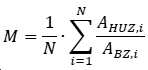
광학 시뮬레이션은 2차 광륜("딥 헤일로")의 강도가 회절 구역에서의 메인 하위 구역의 면적 비율과 인과적으로 연관되어 있음을 보여주었다. 어떠한 비율의 빛이 어떤 굴절값에 할당될 수 있는지 계산되었다. 이를 위해 푸라운호퍼(Fraunhofer) 회절 적분에 따라 임의의 디포커스 위치에 대한 회절 효율을 계산하는 알고리즘이 사용되었다. 회절 안렌즈의 높은 수의 음의 회절 차수는 음의 블레이즈 각도 및 위상 하위 구역의 푸리에 변환에 할당될 수 있는 것으로 나타났다. 한편, 굴절력은 음의 회절 차수에 할당될 수 있다. 놀랍게도, 이러한 (음의) 굴절력은 이식된 회절 안렌즈를 갖는 눈("이식된 눈"이라고도 함)의 (양의) 굴절 기여도와 같은 크기이다. 따라서, 미광의 음의 부가 굴절률은 각막의 굴절률 및 회절 안렌즈의 원거리 초점에 대한 굴절률과 대체로 균형을 이룬다. 그 결과 초점이 맞지 않고 상대적으로 큰 저강도의 교란 원이 망막에 생긴다. 이것은 대수 망막 밝기 감도로 인해 2차 광륜으로서 인식된다. 따라서, 놀랍게도, 높은 음의 회절 차수에서의 낮은 강도가 이러한 교란 효과의 원인인 것이다. 회절 구역에서 위상 하위 구역의 면적 비율을 감소시킴으로써 높은 음의 회절 차수에서의 효율이 감소된다. 따라서, 본 발명에 따르면, 모든 회절 구역에 걸쳐 평균적으로 회절 구역에서의 메인 하위 구역의 비율이 94% 이상의 값, 특히 95% 이상의 값이 달성되도록 제1 렌즈 영역이 설계된다.Optical simulations have shown that the intensity of the secondary annulus (“deep halo”) is causally related to the area ratio of the main subregion in the diffraction region. It was calculated what proportion of light could be assigned to which refraction value. For this, an algorithm for calculating the diffraction efficiency for an arbitrary defocus position according to the Fraunhofer diffraction integral was used. It has been shown that a high number of negative diffraction orders of diffractive ocular lenses can be assigned to the Fourier transform of negative blaze angles and phase subregions. On the other hand, refractive power may be assigned to a negative diffraction order. Surprisingly, this (negative) refractive power is equal to the (positive) refractive contribution of an eye with an implanted diffractive ophthalmic lens (also referred to as an “implanted eye”). Thus, the negative additive index of refraction of stray light is roughly balanced with the index of refraction of the cornea and the index of refraction for the distant focus of the diffractive ophthalmic lens. The result is an out-of-focus and relatively large, low-intensity disturbance circle in the retina. It is perceived as a secondary halo due to logarithmic retinal brightness sensitivity. Thus, surprisingly, the low intensity at high negative diffraction orders is responsible for this perturbing effect. By reducing the area ratio of the phase subregions in the diffraction zone, the efficiency at high negative diffraction orders is reduced. Thus, according to the invention, the first lens region is designed such that, on average over all diffractive zones, a value of at least 94%, in particular a value of at least 95%, is achieved for the proportion of the main subzones in the diffractive zone.
회절 구역에 대한 메인 하위 구역(또는 위상 하위 구역)의 이러한 면적 비율 값을 달성하기 위해서는, 이에 회절 안렌즈의 제조 방법을 맞추어야 한다. 특히, 이에 따라 사용되는 도구를 선택하여야 한다. 일반적으로 회절 안렌즈의 회절 광학 구조는 선회 공정으로 제조된다. 다이아몬드 도구를 회전하는 회절 안렌즈 블랭크에 대해 이동시키고 안렌즈 블랭크로부터 재료를 제거하여 안렌즈를 생성한다. 다이아몬드 도구의 반경이 클수록 더 많은 재료를 동시에 (또는 안렌즈 블랭크의 회전당) 안렌즈로부터 제거할 수 있다. 다이아몬드 도구의 반경이 작을수록 더 적은 재료가 동시에 (또는 안렌즈 블랭크의 회전당) 안렌즈로부터 제거될 수 있다. 따라서 큰 반경을 갖는 도구를 사용하는 것에 비해 작은 반경을 갖는 도구를 사용하는 경우 회절 안렌즈의 제조에 필요한 회전수가 더 많아지게 된다. 그러나 큰 도구 반경을 갖는 다이아몬드 도구를 사용하면 메인 하위 구역의 표면적에 제한이 생기는데, 이러한 제한은 회절 구역(또는 메인 하위 구역 및 위상 하위 구역)의 형상 또는 지형 또는 높이 프로파일로 인해 발생하는 것이다. 위상 하위 구역은 메인 하위 구역의 연속적인(부단한) 곡률 코스에서 벗어난 회절 구역의 영역을 포함하므로, 지형에 대한 도구의 영향도 거기에 포함된다. 따라서 도구 반경의 선택은 위상 하위 구역의 크기와 연관된다.In order to achieve this area ratio value of the main sub-region (or phase sub-region) to the diffractive zone, the manufacturing method of the diffractive ophthalmic lens must be adapted to it. In particular, the tool to be used should be selected accordingly. In general, the diffractive optical structure of a diffractive ophthalmic lens is manufactured by a turning process. An ophthalmic lens is created by moving the diamond tool relative to the rotating diffractive ophthalmic lens blank and removing material from the ophthalmic lens blank. The larger the radius of the diamond tool, the more material can be removed from the eye lens simultaneously (or per revolution of the eye lens blank). The smaller the radius of the diamond tool, the less material can be removed from the ophthalmic lens simultaneously (or per revolution of the ocular lens blank). Therefore, when a tool having a small radius is used compared to using a tool having a large radius, the number of rotations required for manufacturing the diffractive ophthalmic lens is increased. However, the use of diamond tools with large tool radii imposes limitations on the surface area of the main sub-regions, which arise due to the shape or topography or height profile of the diffraction regions (or main sub-regions and phase sub-regions). Since the phase sub-region contains the region of the diffraction field that deviates from the continuous (uninterrupted) course of curvature of the main sub-region, it also includes the influence of the tool on the terrain. The choice of tool radius is thus related to the size of the topology sub-region.
광학 시뮬레이션은 회절 구역에 대한 메인 하위 구역의 비율을 89%에서 94%로 증가시키면 음의 회절 차수의 적분 회절 효율이 50% 이상 감소됨을 나타내었다. 이러한 방식으로 2차 광륜이 감소한다.Optical simulations showed that increasing the ratio of the main subregion to the diffraction region from 89% to 94% reduces the integral diffraction efficiency of the negative diffraction order by more than 50%. In this way, the secondary halo is reduced.
따라서, 본 발명에 따른 회절 안렌즈는 광륜을 감소시킴으로써 안렌즈의 시각적 특성을 개선하는 것을 가능하게 한다.Therefore, the diffractive ophthalmic lens according to the present invention makes it possible to improve the visual properties of the ophthalmic lens by reducing the halo.
회절 안렌즈의 특히 유리한 한 실시양태에 따르면, 회절 구조는 안렌즈의 주 광축을 둘러싸는 제2 환형 회절 구역을 갖는 적어도 하나의 제2 렌즈 영역을 포함한다. 이것은 단일 회절 구역일 수도 있고 복수의 제2 회절 구역일 수도 있다. 각각의 제2 회절 구역은 추가의 메인 하위 구역 및 추가의 위상 하위 구역을 가진다. 또한, 제2 렌즈 영역에 대해, 모든 제2 회절 구역에 걸쳐 평균적으로, 제2 회절 구역에 대한 추가의 메인 하위 구역의 비율은 적어도 94%, 특히 적어도 95%이다. 끝으로, 제1 렌즈 영역과 제2 렌즈 영역은 이하의 광학 파라미터, 즉, 광로 길이 차이, 구역 크기 중 적어도 하나에서 상이하다.According to one particularly advantageous embodiment of the diffractive ophthalmic lens, the diffractive structure comprises at least one second lens region with a second annular diffractive zone surrounding the main optical axis of the ophthalmic lens. It may be a single diffractive zone or it may be a plurality of second diffractive zones. Each second diffractive zone has a further main sub-region and an additional phase sub-region. Furthermore, for the second lens region, on average over all the second diffractive regions, the proportion of the further main subregion to the second diffractive region is at least 94%, in particular at least 95%. Finally, the first lens region and the second lens region differ in at least one of the following optical parameters: optical path length difference, and zone size.
제2 렌즈 영역(또는 추가의 렌즈 영역)은 제1 렌즈 영역과 회절 안렌즈의 동일한 쪽 또는 반대쪽에 위치할 수 있다. 또한 두 (또는 추가의) 렌즈 영역은 각각 안렌즈의 양쪽에 배열될 수 있다.The second lens region (or additional lens region) may be located on the same side or on the opposite side of the diffractive ophthalmic lens as the first lens region. Also two (or additional) lens areas may each be arranged on either side of the ophthalmic lens.
제2 회절 구역에 대한 추가의 메인 하위 구역의 비율을 모든 제2 회절 구역에 대해 평균하여 94% 이상으로 함으로써, 광륜의 감소에 의해 적어도 하나의 제2 렌즈 영역에 대해 안렌즈의 시각적 특성의 개선이 또한 보장된다.improvement of the visual properties of the ophthalmic lens for at least one second lens region by reduction of the halo by the ratio of the additional main sub-region to the second diffractive region being 94% or more averaged over all the second diffractive regions This is also guaranteed.
렌즈 영역의 언급된 광학 매개변수는 회절 효율 및 부가 굴절력에 영향을 줄 수 있다. 하나 이상의 렌즈 영역을 사용함으로써, 유리하게도 회절 안렌즈에 의해 추가의 초점이 생성될 수 있다.The mentioned optical parameters of the lens area can affect the diffraction efficiency and the added refractive power. By using more than one lens area, an additional focal point can advantageously be created by the diffractive ophthalmic lens.
적어도 2개의 렌즈 영역을 갖는 회절 안렌즈의 유리한 실시양태에서, 제1 렌즈 영역은 적어도 2개의 제1 회절 구역을 가지며, 그 사이에, 반경 방향으로 볼 때 주축을 중심으로 제2 렌즈 영역의 적어도 하나의 제2 회절 구역이 배열된다. 특히, 반경 방향으로 볼 때 제1 회절 구역과 제2 회절 구역은 교번하는 순서로 배열된다.In an advantageous embodiment of a diffractive ophthalmic lens having at least two lens regions, the first lens region has at least two first diffractive regions, between which at least of the second lens region about the principal axis when viewed in the radial direction. One second diffraction zone is arranged. In particular, when viewed in the radial direction, the first diffractive zone and the second diffractive zone are arranged in an alternating order.
회절 안렌즈가 2개보다 많은 렌즈 영역을 가진다면, 각각의 추가의 렌즈 영역의 적어도 하나의 회절 구역은 반경 방향으로 적어도 2개의 제1 회절 구역 사이에 위치할 수 있다.If the diffractive ophthalmic lens has more than two lens areas, at least one diffractive zone of each additional lens area may be located between the at least two first diffractive zones in the radial direction.
개시된 배열로 인하여 유리하게도, 눈의 가변 동공 직경에 대해 2개(또는 그 이상)의 렌즈 영역의 광학 효과가 달성될 수 있다는 것이 보장된다. 예를 들어 동공이 밝은 주변광에서 수축하여 작은 직경을 갖는 경우, 모든 렌즈 영역의 회절 구역이 여전히 이 직경 안에 위치할 수 있다. 동공이 커지는 어두운 주변광에 대해서도 동일하게 적용된다. 이러한 방식으로, 회절 안렌즈의 광학 효과가 유리하게도 눈의 적응과 무관하게 유지된다.Advantageously with the disclosed arrangement it is ensured that the optical effect of two (or more) lens areas can be achieved for variable pupil diameters of the eye. If, for example, the pupil has a small diameter due to contraction in bright ambient light, the diffractive zone of all lens areas can still be located within this diameter. The same applies to dark ambient light, where the pupil is enlarged. In this way, the optical effect of the diffractive ophthalmic lens advantageously remains independent of the adaptation of the eye.
회절 안렌즈의 한 유리한 실시양태에서, 각각의 회절 구역에서 메인 하위 구역의 각각의 비율은 모든 제1 회절 구역에 대해 94% 이상이다. 회절 안렌즈가 제2 렌즈 영역을 가진다면, 추가적으로 또는 대안적으로 각각의 회절 구역에서 메인 하위 구역의 각각의 비율은 모든 제2 회절 구역에 대해 94% 이상이다. 이것은 다시 말해서 제1 및/또는 제2 렌즈 영역의 N개의 제1 및/또는 제2 회절 구역의 비율이 ![]()
![]()
이러한 방식으로 설계된 회절 안렌즈는 음의 회절 차수에서의 빛의 회절이 추가적으로 감소되기 때문에 2차 광륜이 더욱 감소한다.The diffractive ophthalmic lens designed in this way further reduces the secondary halo because the diffraction of light in the negative diffraction order is further reduced.
회절 안렌즈의 특히 유리한 한 실시양태에 따르면, 제1 및/또는 제2 렌즈 영역의 회절 광학 구조는, 설계 파장에 있어서 음의 회절 차수에서 유의적인 회절 효율이 발생하지 않도록 설계된다. 특히, 0 이하의 회절 차수에서 유의적인 회절 효율이 발생하지 않는다. 이것은 +1차 회절 차수보다 작은 모든 회절 차수에 대해 유의적인 회절 효율이 발생하지 않음을 의미한다.According to one particularly advantageous embodiment of the diffractive ophthalmic lens, the diffractive optical structure of the first and/or the second lens region is designed such that no significant diffraction efficiencies occur at negative diffraction orders at the design wavelength. In particular, no significant diffraction efficiency occurs at diffraction orders below zero. This means that no significant diffraction efficiency occurs for all diffraction orders smaller than the +1 diffraction order.
그러므로 0차 회절 차수가 낮은 강도만을 갖는다는 이유에서 회절 안렌즈는 순수한 회절 렌즈인 것이 유리하다. 여기서 "유의적이지 않은 회절 효율" 또는 "비유의적인 회절 효율"이라는 용어는 회절이 제한되는 "일반" 굴절 렌즈의 최대 강도의 최대 8%, 바람직하게는 최대 강도의 최대 5%, 특히 바람직하게는 최대 강도의 최대 1%가 해당 회절 차수에 대해 달성됨을 의미하는 것으로 이해되어야 한다. 위에서 정의된 바와 같은 유의적인 회절 효율과 본 명세서에 정의된 바와 같은 비유의적인 회절 효율 사이에는 회절 효율이 유의적이지도 않고 비유의적이지도 않은 중간 영역이 있을 수 있다.Therefore, it is advantageous that the diffractive ophthalmic lens is a purely diffractive lens because the 0th diffraction order has only a low intensity. The term "insignificant diffraction efficiency" or "nonsignificant diffraction efficiency" herein means at most 8% of the maximum intensity of a diffraction limited "normal" refractive lens, preferably at most 5% of the maximum intensity, particularly preferably is to be understood as meaning that at most 1% of the maximum intensity is achieved for that diffraction order. There may be an intermediate region between significant diffraction efficiency as defined above and non-significant diffraction efficiency as defined herein, where the diffraction efficiency is neither significant nor nonsignificant.
회절 안렌즈는 음의 회절 차수 또는 0의 회절 차수에 대해 유의적인 회절 효율을 갖지 않는다는 특성으로 인해, 보정에 의해, 안렌즈, 각막 및 굴절 매체 조합의 전체 종방향 색수차를 감소시키는 것이 가능하다. 주 굴절력은 0 초과의 또는 0 이상의 회절 차수에서 유의적이지 않은 회절 효율을 넘는 회절 효율을 가지고 발생한다. 따라서, 음의 회절 차수로 인해 야기되는 종방향 색수차가 눈의 자연적인 종방향 색수차를 증폭하지 않아 다색 조명에서 인지가능한 콘트라스트 저하를 야기하지 않는다는 것이 보장된다. 오히려, (추가의 더 높은 회절 차수에 더하여) 예를 들어 +1차 회절 차수만이 유의적인 회절 효율을 가질 수 있다. 이러한 방식으로, 회절 안렌즈는 양의 회절 차수의 종방향 색수차가 눈의 자연적인 종방향 색수차를 감소시키거나 완전히 보상할 수 있기 때문에 눈의 색수차를 보정할 수 있다. 이러한 방식으로, 다색 조명에서 환자가 인지할 수 있는 콘트라스트의 저하가 감소될 수 있다.Due to the property that diffractive ophthalmic lenses do not have significant diffraction efficiencies for negative or zero diffraction orders, by correction, it is possible to reduce the overall longitudinal chromatic aberration of the ophthalmic lens, cornea and refractive medium combination. The principal power occurs with diffraction efficiencies above zero or above insignificant diffraction efficiencies at diffraction orders greater than zero. Thus, it is ensured that the longitudinal chromatic aberration caused by the negative diffraction order does not amplify the natural longitudinal chromatic aberration of the eye, resulting in a perceptible contrast degradation in polychromatic lighting. Rather, only eg +1 diffraction orders (in addition to additional higher diffraction orders) may have significant diffraction efficiencies. In this way, the diffractive ophthalmic lens can correct the chromatic aberration of the eye because the longitudinal chromatic aberration of the positive diffractive order can reduce or completely compensate for the natural longitudinal chromatic aberration of the eye. In this way, a decrease in patient perceptible contrast in multicolor illumination can be reduced.
한 유리한 실시양태에서, 회절 안렌즈는 설계 파장에서 적어도 2개의 회절 차수에 대해, 특히 적어도 3개의 회절 차수에 대해 유의적인 회절 효율이 발생하도록 설계된다.In one advantageous embodiment, the diffractive ophthalmic lens is designed such that a significant diffractive efficiency occurs for at least two diffraction orders, in particular for at least three diffraction orders, at the design wavelength.
이러한 방식으로 이중 초점, 삼중 초점(또는 다초점) 안렌즈를 구현할 수 있다. 또한, 음의 회절 차수 또는 0 이하의 회절 차수에 대해 추가의 유의적인 회절 효율이 발생하지 않는 경우가 특히 유리하다. 이 경우 이것은 동시에 종방향 색수차를 감소시킬 수 있는 이중 초점(삼중 초점, 다초점) 안렌즈이다. 여기서, 원거리 초점은 유의적인 회절 효율을 갖는 가장 낮은 회절 차수, 예를 들어 +1차 회절 차수에 할당될 수 있다.In this way, it is possible to implement a bifocal, trifocal (or multifocal) ophthalmic lens. It is also particularly advantageous if no further significant diffraction efficiencies occur for negative or sub-zero diffraction orders. In this case, it is a bifocal (trifocal, multifocal) ophthalmic lens that can simultaneously reduce longitudinal chromatic aberration. Here, the far focus may be assigned to the lowest diffraction order with significant diffraction efficiency, for example, the +1 diffraction order.
따라서, 본 발명에 따른 회절 안렌즈는 이중 초점, 삼중 초점 또는 다초점 렌즈로서 복수의 초점 위치를 제공하면서 동시에 광륜을 감소시키는 것을 가능하게 한다.Thus, the diffractive ophthalmic lens according to the present invention makes it possible to provide a plurality of focal positions as a bifocal, trifocal or multifocal lens while simultaneously reducing the halo.
추가의 특히 유리한 한 실시양태에 따르면, 회절 안렌즈는 디포커스 영역에서 최대 회절 효율이 0.3% 미만, 특히 0.15% 미만인 것을 특징으로 한다. 디포커스 영역은 원거리 초점의 굴절력과 비교하여 적어도 -45D에서 -15D까지, 특히 적어도 -60D에서 -10D까지의 범위에 이르른다.According to one further particularly advantageous embodiment, the diffractive ophthalmic lens is characterized in that the maximum diffractive efficiency in the defocus region is less than 0.3%, in particular less than 0.15%. The defocus region ranges from at least -45D to -15D, in particular from at least -60D to -10D compared to the refractive power of the far focus.
유의적인 회절 효율을 갖는 가장 낮은 굴절력을 원거리 초점에 할당할 수 있다. 더 낮은 부가 굴절력으로 안내되는 빛은 망막에 선명하게 이미지 형성될 수 없고, 초점이 맞지 않게 이미지 형성된다. 이 굴절력 범위를 디포커스 영역이라고 일컫는다. 예를 들어, 원거리 초점이 (회절 안렌즈의 기본 형상의 굴절력과 비교하여) +2D의 부가 굴절력을 가진다면, 디포커스 영역은 적어도 -43D의 부가 굴절력에서 -13D의 부가 굴절력까지, 특히 적어도 -58D의 부가 굴절력에서 -8D의 부가 굴절력까지의 범위에 이르른다.The lowest refractive power with significant diffraction efficiency can be assigned to the far focus. Light guided with a lower additional refractive power cannot be imaged clearly on the retina, and is imaged out of focus. This refractive power range is referred to as a defocus region. For example, if the far focus has an additive power of +2D (compared to the power of the basic shape of the diffractive ophthalmic lens), then the defocus region ranges from an additive power of at least -43D to an additive power of -13D, in particular at least - It ranges from an additive power of 58D to an additive power of -8D.
2차 광륜은 특히 렌즈 이식된 눈의 굴절력을 보상하는 그러한 (낮은) 굴절력으로 망막 방향으로 편향되는 빛에 의해 야기되며, 렌즈 이식된 눈(특히 각막)의 양의 기여는 음의 굴절력(회절 안렌즈를 통한 음의 기여)에 의해 음의 기여와 같은 크기이다.The secondary annulus is caused by light that is deflected towards the retina, particularly with such (low) refractive power that compensates for the refractive power of the lens implanted eye, and the positive contribution of the lens implanted eye (especially the cornea) is the negative refractive power (diffractive eye). equal to the negative contribution by the negative contribution through the lens).
2차 광륜을 감소시키거나 피하기 위해서는 디포커스 영역의 회절 효율이 한계값을 초과해서는 안된다. 임계값은 위에서 설명한 디포커스 영역에서 발생하는 최대 회절 효율일 수 있다.In order to reduce or avoid the secondary halo, the diffraction efficiency of the defocus region should not exceed the limit value. The threshold value may be the maximum diffraction efficiency that occurs in the defocus region described above.
추가의 특히 유리한 한 실시예에 따르면, 회절 안렌즈는 디포커스 영역에서 적분 회절 효율이 6% 미만, 특히 2% 미만인 것을 특징으로 한다. 여기서 디포커스 영역은 원거리 초점의 굴절력과 비교하여 적어도 -45D에서 -15D까지, 특히 적어도 -60D에서 -10D까지의 범위에 이르른다. 따라서 언급된 한계값은 발생하는 모든 부가 굴절력에 대해 적분된 회절 효율과 디포커스 영역에 걸쳐 적분된 회절 효율을 연관시킨다.According to a further particularly advantageous embodiment, the diffractive ophthalmic lens is characterized in that the integrated diffraction efficiency in the defocus region is less than 6%, in particular less than 2%. Here, the defocus region ranges from at least -45D to -15D, in particular from at least -60D to -10D compared to the refractive power of the far focus. The stated limit thus relates the integrated diffraction efficiency over the defocus region to the integrated diffraction efficiency for every additional refractive power that occurs.
본 발명에 따르면, 디포커스 영역에 대해 도입된 최대 및 적분 한계값을 이용하여, 대수 망막 밝기 감도를 고려하더라도 회절 안렌즈에 의한 2차 광륜이 감소되도록 보장한다. 이를 위해 디포커스 영역의 적분된 회절 효율과 최대값에 대한 한계값을 준수하는 것이 특히 유리하다.According to the present invention, by using the maximum and integration limits introduced for the defocus region, it is ensured that the secondary halo caused by the diffractive ophthalmic lens is reduced even when the logarithmic retinal brightness sensitivity is taken into account. For this purpose, it is particularly advantageous to observe the limits for the integrated diffraction efficiency and the maximum of the defocus region.
회절 안렌즈의 또 다른 유리한 실시양태에서, 설계 파장은 밝기 감도 곡선의 중심 스펙트럼 범위에 있다. 특히, 설계 파장은 530 nm와 570 nm 사이, 바람직하게는 550 nm 또는 546 nm에 있다.In another advantageous embodiment of the diffractive ophthalmic lens, the design wavelength lies in the central spectral range of the brightness sensitivity curve. In particular, the design wavelength is between 530 nm and 570 nm, preferably at 550 nm or 546 nm.
밝기 감도 곡선은 빛의 파장에 따른 인간의 눈의 감도를 나타낸다. 바람직하게는 일광(명소시)에 대한 밝기 감도 곡선이 사용된다. 대안적으로 황혼(중간시) 또는 야간(암소시)에 대한 밝기 감도 곡선이 사용될 수 있다. 밝기 감도 곡선의 중심 스펙트럼 범위는 밝기 감도가 최대 밝기 감도의 적어도 30%, 바람직하게는 적어도 50%, 특히 바람직하게는 적어도 70%인 파장을 의미하는 것으로 이해되어야 한다.The brightness sensitivity curve represents the sensitivity of the human eye according to the wavelength of light. Preferably a brightness sensitivity curve for daylight (in bright light) is used. Alternatively, a brightness sensitivity curve for twilight (middle vision) or nighttime (cocous vision) may be used. The central spectral range of the brightness sensitivity curve is to be understood as meaning wavelengths at which the brightness sensitivity is at least 30%, preferably at least 50%, particularly preferably at least 70% of the maximum brightness sensitivity.
여기서 530 nm와 570nm 사이의 설계 파장은 일광에서의 밝기 감도가 80%를 초과하므로 특히 유리하다. 550 nm 또는 546 nm의 설계 파장에 대해서는 99% 또는 98% 이상이 달성된다. 따라서 이렇게 선택된 설계 파장의 사용은 특히 일광에 대해 적합하다.Design wavelengths between 530 nm and 570 nm here are particularly advantageous as the brightness sensitivity in daylight exceeds 80%. More than 99% or 98% is achieved for design wavelengths of 550 nm or 546 nm. The use of this chosen design wavelength is therefore particularly suitable for daylight.
언급된 사양에 해당하는 설계 파장에 대해 회절 안렌즈를 최적화 하는 것은 유리하게도 굴절력(또는 이중 초점 또는 다초점 안렌즈의 경우의 굴절력)이 눈의 고스펙트럼 밝기 감도에 상응하여 최적화되도록 유도한다. 또한 인간의 눈이 민감한 파장에 대하여 2차 광륜이 특히 효과적으로 감소된다. 이것은 일상적인 환경 조건에서 안렌즈의 시각적 특성을 더욱 개선시킨다.Optimizing the diffractive ophthalmic lens for the design wavelength corresponding to the stated specifications advantageously leads to the power (or power in the case of bifocal or multifocal ophthalmic lenses) being optimized commensurate with the high spectral brightness sensitivity of the eye. In addition, the secondary halo is particularly effectively reduced for wavelengths to which the human eye is sensitive. This further improves the visual properties of the ophthalmic lenses under normal environmental conditions.
회절 안렌즈의 또 다른 유리한 실시양태에 따르면, 렌즈 영역의 모든 회절 구역은 동일한 구역 크기를 가진다. 추가적으로 또는 대안적으로, 렌즈 영역의 모든 회절 구역은 동일한 광로 길이 차이를 가진다.According to another advantageous embodiment of the diffractive ophthalmic lens, all diffractive zones of the lens area have the same zone size. Additionally or alternatively, all diffractive zones of the lens area have the same optical path length difference.
안렌즈가 하나 이상의 렌즈 영역을 포함한다면, 각 렌즈 영역의 회절 구역도 동일한 구역 크기 또는 광로 길이 차이를 가진다. 그러나, 제1 렌즈 영역의 구역 크기 또는 광로 길이 차이가 추가의 렌즈 영역의 구역 크기 또는 광로 길이 차이와 다를 수 있다.If the ophthalmic lens includes more than one lens region, the diffraction regions of each lens region also have the same region size or optical path length difference. However, the zone size or optical path length difference of the first lens region may be different from the zone size or optical path length difference of the additional lens regions.
특히 유리한 한 실시양태에서, 회절 안렌즈는 생체적합성 재료로 제조되고 눈에 이식하기에 적합하다.In one particularly advantageous embodiment, the diffractive ophthalmic lens is made of a biocompatible material and is suitable for implantation into the eye.
생체 적합성 물질을 사용함으로써, 회절 렌즈를 눈에 이식할 때 눈에서 거부 반응이 일어나지 않도록 할 수 있다.By using a biocompatible material, it is possible to avoid rejection in the eye when the diffractive lens is implanted in the eye.
추가의 실시양태에 따르면, 회절 안렌즈는 콘택트 렌즈, 안내 렌즈 또는 각막내 렌즈이다.According to a further embodiment, the diffractive ophthalmic lens is a contact lens, an intraocular lens or an intracorneal lens.
본 발명의 제2 측면은 상기 개시한 실시양태들 중 하나에 따른 회절 안렌즈의 제조 방법에 관한 것이다. 이미 위에서 논한 바와 같이, 회절 안렌즈의 제조에 사용되는 도구의 크기는 메인 하위 구역이 회절 구역에 대해 가질 수 있는 면적 비율에 영향을 준다. 공구 반경이 지나치게 크면 94% 또는 95%의 필요한 비율(p)을 얻을 수 없다. 주 광축을 중심으로 반경 방향으로 볼 때 i번째 회절 구역(BZ)의 메인 하위 구역(HUZ)에 인접한 동일 회절 구역의 위상 하위 구역(PUZ)에 대하여, 위상 하위 구역의 폭은 ![]()
![]()
![]()
![]()
![]()
![]()

따라서 회절 구역에 대한 위상 하위 구역의 면적 비율은 다음과 같다:Thus, the ratio of the area of the phase subregion to the diffraction domain is:

이 표현은 다음으로 변환된다:This expression is converted to:

여기서 제1 펙터는 회절 구역의 폭(![]()
![]()
![]()
![]()
![]()
![]()
![]()
![]()
위상 하위 구역의 폭(![]()
![]()
본 발명에 따른 회절 안렌즈 제조 방법은 안렌즈 블랭크를 제공하는 방법 단계를 포함한다. 또한, 본 방법은 도구의 사용에 의해 안렌즈 블랭크로부터 재료를 제거하여 회절 구역을 생성하는 단계를 가진다. 가공은 일반적으로 선삭 공정으로 이루어진다. 도구가 안렌즈 블랭크에 대해 이동하여 안렌즈 블랭크에서 재료를 제거하며, 일반적으로 안렌즈 블랭크는 회전한다. 본 발명에 따르면, 사용되는 도구는 회절 구역의 폭의 최대 6%, 바람직하게는 최대 5%에 상응하는 반경을 가진다.A method for manufacturing a diffractive ophthalmic lens according to the present invention comprises a method step of providing an ophthalmic lens blank. The method also has the step of removing material from the ophthalmic lens blank by use of a tool to create a diffractive zone. Machining is usually done in a turning process. A tool is moved relative to the ophthalmic lens blank to remove material from the ophthalmic lens blank, which typically rotates. According to the invention, the tool used has a radius corresponding to at most 6%, preferably at most 5% of the width of the diffractive zone.
이러한 방식으로 (일시적으로 회절 구역의 생성을 위해) 사용되는 도구가 94%(또는 95%)의 회절 구역에 대한 메인 하위 구역의 필요한 면적 비율을 생성하는 데 적합하도록 보장된다. 다른 반경을 갖는 도구를 사용하여 회절 안렌즈의 다른 부분을 제조할 수 있다. 따라서 회절 안렌즈를 제조하는 동안 도구가 교체될 수도 있다.In this way it is ensured that the tool used (for the creation of a temporary diffraction zone) is suitable for generating the required area ratio of the main sub-region to the diffractive zone of 94% (or 95%). Tools with different radii can be used to fabricate different parts of the diffractive ophthalmic lens. Therefore, the tools may be changed during the manufacture of the diffractive ophthalmic lenses.
바람직하게는 상응하는 회절 구역에 대한 최대 반경에 따라 요건을 충족하는 도구를 사용해 재료를 제거하여 각각의 회절 구역을 생성한다.Each diffractive zone is created by removing material, preferably using a tool that meets the requirements according to the maximum radius for the corresponding diffractive zone.
위상 하위 구역의 절대 폭은 주 광축으로부터의 회절 구역의 반경 방향 거리가 증가함에 따라 감소한다. 단 하나의 도구로 회절 안렌즈의 회절 구조를 제조할 수 있기 위해서는, 바람직하게는 반경 방향으로 주 광축(A) 주위의 가장 바깥쪽 회절 구역의 폭의 최대 6%(또는 5%)에 상응하는 반경을 갖는 도구를 사용해 재료를 제거하여 모든 회절 구역을 생성한다.The absolute width of the phase subregion decreases as the radial distance of the diffractive region from the main optical axis increases. In order to be able to manufacture the diffractive structure of a diffractive ophthalmic lens with only one tool, it is preferably equivalent to at most 6% (or 5%) of the width of the outermost diffractive zone around the main optical axis A in the radial direction. Remove the material using a tool with a radius to create all diffraction zones.
위에서 언급한 특징 및 이하에서 더 설명될 특징은 본 발명의 범위를 벗어나지 않으면서 개시된 조합으로 뿐만 아니라 다른 조합으로도 또는 단독으로도 이용될 수 있음은 물론이다.It goes without saying that the features mentioned above and features to be further described below may be used alone or in other combinations as well as in the disclosed combinations without departing from the scope of the present invention.
이하, 본 발명의 본질적인 특징들을 보여주는 첨부 도면을 참조하여 본 발명을 예시적으로 더 상세히 설명한다. 도면은 다음과 같다:
도 1a는 본 발명에 따른 회절 안렌즈의 제1 실시예의 사시도를 도시한 것이다;
도 1b는 본 발명에 따른 회절 안렌즈의 또 다른 실시예의 사시도를 도시한 것이다;
도 2는 회절 안렌즈에 대한 광륜을 개략적으로 도시한 것이다;
도 3은 추가의 실시예에 따른 회절 안렌즈의 렌즈 단면의 일부 섹션을 개략적으로 도시한 것이다;
도 4는 2개의 렌즈 영역을 갖는 추가의 실시예에 따른 회절 안렌즈의 렌즈 단면의 일부 섹션을 개략적으로 도시한 것이다;
도 5a 내지 도 5c는 제조에 사용되는 도구의 다양한 크기를 고려한 회절 안렌즈의 렌즈 단면의 일부 섹션을 개략적으로 도시한 것이다;
도 6은 삼중 초점 회절 안렌즈의 위상 프로파일의 시뮬레이션된 방사상 진행 경과를 다이어그램으로 도시한 것이다;
도 7은 삼중 초점 회절 안렌즈에 대한 사용가능 영역에서 부가 굴절력의 함수로서 시뮬레이션된 회절 효율의 다이어그램을 도시한 것이다;
도 8a는 종래 기술에 따른 삼중 초점 회절 안렌즈에 대한 사용가능 영역 및 디포커스 영역에 대해 부가 굴절력의 함수로서 시뮬레이션된 회절 효율의 다이어그램을 도시한 것이다;
도 8b는 본 발명에 따른 삼중 초점 회절 안렌즈에 대한 사용가능 영역 및 디포커스 영역에 대해 부가 굴절력의 함수로서 시뮬레이션된 회절 효율의 다이어그램을 도시한 것이다.
도 8c는 본 발명에 따른 다른 삼중 초점 회절 안렌즈에 대한 사용가능 영역 및 디포커스 영역에 대해 부가 굴절력의 함수로서 시뮬레이션된 회절 효율의 다이어그램을 도시한 것이다.DETAILED DESCRIPTION OF THE PREFERRED EMBODIMENTS Hereinafter, the present invention will be described in more detail by way of example with reference to the accompanying drawings showing essential features thereof. The drawings are as follows:
1a shows a perspective view of a first embodiment of a diffractive ophthalmic lens according to the invention;
1B shows a perspective view of another embodiment of a diffractive ophthalmic lens according to the present invention;
Figure 2 schematically shows the halo for a diffractive ophthalmic lens;
3 schematically shows a partial section of a lens section of a diffractive ophthalmic lens according to a further embodiment;
4 schematically shows a partial section of a lens section of a diffractive ophthalmic lens according to a further embodiment having two lens areas;
Figures 5a-5c schematically show some sections of the lens cross-section of a diffractive ophthalmic lens taking into account the various sizes of the tools used for manufacturing;
6 is a diagrammatic representation of the simulated radial progression course of the phase profile of a trifocal diffractive ophthalmic lens;
7 shows a diagram of the simulated diffraction efficiency as a function of additional power in the usable region for a trifocal diffractive ophthalmic lens;
Fig. 8a shows a diagram of the simulated diffraction efficiency as a function of added power for the usable area and the defocus area for a trifocal diffractive ophthalmic lens according to the prior art;
Figure 8b shows a diagram of the simulated diffraction efficiency as a function of added power for the usable area and the defocus area for a trifocal diffractive ophthalmic lens according to the present invention.
Fig. 8c shows a diagram of the simulated diffraction efficiency as a function of the added power for the usable area and the defocus area for another trifocal diffractive ophthalmic lens according to the present invention.
도 1a에는, 안내 렌즈(IOL)로서 설계된 본 발명에 따른 회절 안렌즈(1)의 제1 실시예의 사시도가 도시되어 있다. 안렌즈는 전면(10)과 후면(15) 및 햅틱(20)을 포함한다. 안렌즈(1)는 햅틱(20)에 의해 눈 안에 유지된다. 안렌즈(1)는 접힐 수 있고 작은 절개를 통해 눈에 이식될 수 있다. 전면(10) 및 후면(15)은 안렌즈(1)의 광학 이미징 특성을 담당한다. 주 광축(A)은 안렌즈(1)의 전면(10)과 후면(15) 사이에 위치하는 가상의 평면에 수직으로 연장된다. 눈에 안렌즈(1)가 이식된 상태에서, 이 도면에 예시된 전면(10)은 각막을 향하고, 반면에 후면(15)은 이 각막에서 반대쪽을 향한다.1a shows a perspective view of a first embodiment of a diffractive
도 1b에는, 안내 렌즈로서 설계된 회절 안렌즈(1)의 다른 실시예의 사시도가 도시되어 있다. 이것은 상이한 햅틱(20)을 가진다는 점에서 도 1a의 실시예와 상이하다.1b a perspective view of another embodiment of a diffractive
기본적으로, 상이한 형상 및 디자인의 햅틱(20)이 또한 제공될 수 있다.Basically, haptics 20 of different shapes and designs may also be provided.
도 2에는, 회절 다초점 안렌즈(1)의 광륜의 개략도가 도시되어 있다. 회절 안렌즈(1)가 이식된 눈의 망막에 점광원에 의해 발생된 광분포가 나타나 있다. 여기서 점광원은 멀리 있고 안렌즈(1)는 이식된 눈이 거리에 대해 보정되는 방식으로 설계된다. 망막 상의 점광원의 이미지는 수평 및 수직 좌표(0°, 0°)에 맵핑된다. 망막 상의 이 이미지 포인트는 이 개략도에서 약 1°(물체 각도)의 직경을 갖는 1차 광륜(60)으로 둘러싸여 있다. 불가피한 1차 광륜의 원인은 사용된 회절 차수의 동시 초점 중첩 때문이다. 2차 광륜(70)으로 지칭되는 추가의 미광 구역은 (수평 및 수직 방향으로 더 큰 물체 각도로) 반경 방향으로 1차 광륜(60)에 인접한다. 2차 광륜(70)의 원인은 회절 안렌즈(1)의 사용되지 않아 바람직하지 않은 회절 차수이다. 도시된 예에서, 2차 광륜(70)은 2°보다 약간 더 큰 물체 각도로 반경 방향으로 연장된다. 2차 광륜(70)에 기여하는 광은 1차 광륜(60)이 존재하는 망막의 위치에서도 회절될 수 있다. 그러나 1차 광륜(60)이 이 빛을 능가한다.In Fig. 2, a schematic view of the halo of the diffractive multifocal
도 3에는, 또 다른 실시예에 따른 회절 안렌즈(1)의 렌즈 단면의 일부 섹션의 개략도가 도시되어 있다. 도시된 단면 평면은 주 광축(A)을 포함하고 회절 안렌즈(1)의 전면(10) 프로파일의 단면을 도시한다. 여기서 안렌즈(1)는 제1 렌즈 영역(30)을 가진다. 도시된 예에서, 이것은 4개의 회절 구역(32)을 포함한다. 이 회절 구역(32)은 주 광축(A)을 중심으로 회전 대칭적으로 배열된다. 각각의 회절 구역(32)은 메인 하위 구역(34) 및 위상 하위 구역(36)을 포함한다. 도시된 예에서, 모든 메인 하위 구역(34)은 동일한 곡률을 가진다. 대안적으로, 메인 하위 구역들이 다른 곡률을 가질 수도 있다. 위상 하위 구역(36)은 메인 하위 구역(34) 사이에 배열된다. 이들의 곡률은 각각의 메인 하위 구역(34)의 곡률과 상이하다. 회절 구역(32)의 메인 하위 구역(34)과 위상 하위 구역(36) 사이의 전이부는 불연속 곡률을 가진다. 위상 하위 구역의 역할은 설계 파장에 대해 각각의 메인 하위 구역(34) 사이에 광로 길이 차이를 만드는 것이다.3 shows a schematic view of a partial section of a lens section of a diffractive
개개의 회절 구역(32), 메인 하위 구역(34) 및 위상 하위 구역(36)의 크기 또는 면적은 주 광축(A)에 수직인 평면에서의 투영의 결과이다. 이것은 도 3에 참조 번호 55를 갖는 라인으로서 도시되어 있다. 구역의 반경 방향 범위(최소 반경 및 최대 반경)는 투영 평면(55)에서 판독되고 면적으로 환산될 수 있다. 본 발명에 따르면, 회절 구역(32)에서 메인 하위 구역(34)의 비율은 94% 이상이다. 다양한 구역의 정의를 더 명확하게 하기 위해 회절 구역(32)에 대한 메인 하위 구역(34)의 더 작은 면적 비율이 도시되어 있다는 점을 언급해 둔다.The size or area of the
회절 안렌즈(1)의 전면(10)의 기본 형상(50)은 점선으로 도시되어 있다. 도시된 예에서 이것은 회절 광학 구조의 높이 프로파일에서 국소 최대값의 가상 연결에 해당한다.The
도 4에는, 2개의 렌즈 영역(30, 40)을 갖는 또 다른 실시예에 따른 회절 안렌즈의 렌즈 단면의 일부 섹션의 개략도가 도시되어 있다. 여기서, 제1 렌즈 영역(30)은 2개의 제1 회절 구역(32)을 가진다. 이들은 각각 메인 하위 구역(34) 및 위상 하위 구역(36)을 포함한다. 제2 렌즈 영역(40)은 2개의 제2 회절 구역(42)을 가진다. 이들도 각각 메인 하위 구역(44) 및 위상 하위 구역(46)을 포함한다. 렌즈 영역(30, 40)은 회절 안렌즈(1)의 전면(10)에 배열된다. 제1 회절 구역(32) 및 제2 회절 구역(42)은 주 광축(A)에 대해 반경 방향으로 교번한다. 도시된 예에서, 렌즈 영역(30, 40)은 광로 길이 차이를 가진다. 대안적으로 또는 추가적으로, 2개의 렌즈 영역(30, 40)은 또한 상이한 구역 크기를 가질 수 있다. 이러한 방식으로, 다초점 회절 안렌즈(1)에 대한 추가의 초점 위치가 가능하게 된다.4 shows a schematic view of a partial section of a lens section of a diffractive ophthalmic lens according to another embodiment having two
도 5a에는, 제조에 사용되는 다이아몬드 공구(90)를 고려하여 회절 안렌즈(1)의 렌즈 단면의 전면(10)의 부분 컷아웃이 개략적으로 도시되어 있다. 회절 구역(32)에 대한 컷아웃은 도 3에서와 같이 방사상 섹션에 대해 도시되어 있다. 여기서도 회절 구역(32)은 메인 하위 구역(34) 및 위상 하위 구역(36)을 가진다. 메인 하위 구역(34)은 곡률을 가진다. 위상 하위 구역(36)은 메인 하위 구역(34)의 연속적인(부단한) 곡률 과정에서 벗어나는 회절 구역(32)의 모든 영역을 포함한다. 전면(10)이 극히 작은 공구 반경을 갖는 이상적인 공구로 가공된다면, 도 5a에 점선으로 도시된 바와 같이 이상적인 형상(80)을 갖는 위상 하위 구역(36)이 생성될 수 있다. 이상적인 형상(80)은 도시된 바와 같이 곡선을 가지지 않을 수 있다. 매우 작은 도구를 이용하는 안렌즈(1)의 제조는 렌즈 블랭크의 매우 많은 회전을 필요로 하기 때문에 유한 반경을 갖는 도구(90)가 사용된다. 도구(90)의 프로파일은 점쇄선으로 도시되어 있다. 실선으로 도시되어 있는 위상 하위 구역(36)의 실제 형상(85)은 도구 반경을 통해 생성된다.In Fig. 5a, a partial cutout of the
또한 다이아몬드 공구(90)의 반경을 더 작게 하면 더 작은 위상 하위 구역(36)이 제조될 수 있다는 점에 유의해야 한다. 예를 들어, 완성될 위상 하위 구역의 프로파일 깊이가 위상 하위 구역의 폭보다 크다면, 일반적으로 도구의 반경이 위상 하위 구역의 폭이 얼마나 작을 수 있는지를 제한한다. 이것은 도 5b에 도시되어 있다. 여기서 사용되는 다이아몬드 공구(90)는 도 5a에 사용된 다이아몬드 공구(90)의 절반인 공구 반경을 가진다. 위상 하위 구역은 여기서 도 5a에 따른 예에서보다 유의적으로 더 작을 수 있다. 더 작은 도구 반경을 갖는 다이아몬드 도구(90)가 사용되는 경우, 경우에 따라 회절 구역을 생성하기 위해 더 많은 수의 렌즈 블랭크 회전이 필요할 수 있다.It should also be noted that a smaller radius of the
도 5c에는 다른 회절 안렌즈(1)의 렌즈 단면의 전면(10)의 부분 컷아웃이 개략적으로 도시되어 있다. 이 예에서, 위상 하위 구역(36)은 도 5a의 위상 하위 구역(36)과 동일한 크기이다. 그러나, 여기에 사용된 다이아몬드 공구(90)의 반경이 더 작기 때문에, 실제 위상 하위 구역(85)이 도 5a로부터의 이상적인 위상 하위 구역(80)에 (거의) 대응하는 것이 가능하다. 위상 하위 구역(36)에 의해 생성되는 위상 편차(t) 뿐만 아니라 위상 하위 구역(36)의 형상도 회절 효율에 영향을 미치므로, 회절 안렌즈(1)의 제조에 있어서 다이아몬드 공구(90)의 반경의 영향을 고려하는 것이 특히 중요하다.5c schematically shows a partial cutout of the
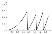
도 6에는, IOL로서 설계되고 회절 광학 구조에 의해 생성되는 삼중 초점 회절 안렌즈(1)의 위상 프로파일의 시뮬레이션된 방사상 진행 경과가 다이어그램으로 도시되어 있다. 다이어그램은 주 광축(A)을 중심으로 회전 대칭으로 배열되는 4개의 회절 구역(32, 42)과 2개의 렌즈 영역(30, 40)을 갖는 실시예의 효과를 나타내고 있다. 수평축에는 주 광축(A)에 대한 거리가 mm 단위로 표시되어 있다. 제1 렌즈 영역(30)의 첫번째 제1 회절 구역(32)은 약 0.75 mm의 반경까지 연장되고, 제2 렌즈 영역(40)의 첫번째 제2 회절 구역(42)은 약 0.75 mm에서 약 1.08 mm까지 연장되며, 제1 렌즈 영역(30)의 두번째 제1 회절 구역(32)은 약 1.08 mm에서 약 1.32 mm까지 연장된다. 제2 렌즈 영역(40)의 두번째 제2 회절 구역(42)은 두번째 제1 회절 구역(32)에 인접해 있다. 시뮬레이션은 1.5 mm의 동공 반경에 대해 수행되었다. 두번째 제2 회절 구역(42)은 이 반경을 넘어 연장된다. 위상 편차는 설계 파장의 배수로 수직축에 표시된다. 처음 3개의 회절 구역(32, 42)은 각각의 외부 에지에서 약 1.4Ω 또는 약 1.2Ω의 위상 편차를 생성한다. 회절 구역(32, 42)의 메인 하위 구역(34, 44)의 곡률로 인해, 위상 편차의 방사상 진행 경과도 또한 섹션별 곡률을 나타낸다. 곡선 부분 사이의 섹션은 위상 하위 구역(36, 46)에 할당된다. 도시된 실시예에서, 모든 4개의 회절 구역(32, 42)에 있어서 회절 구역(32, 42)에 대한 메인 하위 구역(34, 44)의 비율은 각 경우 94%이다. 위상 하위 구역(36, 46)의 크기 및 위상 편차의 시뮬레이션에 있어서, 회절 안렌즈(1)의 프로파일이 두번째 제1 위상 하위 구역(36)의 폭보다 작은 도구 반경을 갖는 다이아몬드 도구(90)로 생성되었다는 것이 고려되었다.6, the simulated radial progression course of the phase profile of a trifocal diffractive
도 7에는, 도 6에서 다룬 실시예에 따른 삼중 초점 회절 안렌즈(1)의 사용가능 범위에서 (회절 안렌즈의 기본 형상의 굴절력과 비교한) 부가 굴절력의 함수로서 시뮬레이션된 회절 효율의 다이어그램이 도시되어 있다. 사용가능 범위는 유의적인 회절 효율이 발생하는 부가 굴절력의 범위를 포함한다. 다이어그램에서 부가 굴절력은 디옵터(D) 단위로 가로축에 표시된다. 회절 효율은 세로축에 표시된다. 값 1은 (동일한 굴절력 및 동일한 직경을 갖는) 회절이 제한된 "일반" 굴절 렌즈의 최대 강도에 해당한다. 이 실시예에서 회절 효율의 제1 최대값은 약 0.5의 효율을 갖고 약 1.85D의 부가 굴절력으로 발생한다. 이것은 원거리 초점에 기인한 것이며; 이에 약 50%의 회절 효율이 할당된다. 또 다른 최대값은 대략 3D의 부가 굴절력에서 발생하고 약 0.16의 회절 효율을 가지며(약 16% 회절 효율); 이 회절 최대값은 중간 거리(중간 시야)에서의 시력을 지원한다. 제3 피크는 약 3.7D의 부가 굴절력에서 발생하고 약 0.33의 회절 효율을 가지며(약 33% 회절 효율); 이 회절 피크는 더 짧은 시야 거리에서의 시력을 지원한다. 따라서 도시된 실시예는 삼중 초점 회절 안렌즈(1)이다. 0D의 부가 굴절력에서 0차 회절에서는 어떠한 유의적인 회절 효율도 나타내지 않는다. 회절 안렌즈(1)는 소위 다차 위상판(MOD 옵틱)이다. 도시된 실시예는 원거리 초점에서도 이식된 눈의 종방향 색수차의 보정을 허용한다.7 is a diagram of the simulated diffraction efficiency as a function of additional power (compared to the power of the basic shape of the diffractive ophthalmic lens) in the usable range of the trifocal diffractive
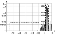
도 8a에는 종래 기술에 따른 삼중 초점 회절 안렌즈의 사용가능 영역 및 디포커스 영역에 대한 부가 굴절력의 함수로서 시뮬레이션된 회절 효율의 다이어그램이 도시되어 있다. 도 7에서와 같이 가로축은 디옵터 단위로 굴절력을 나타낸다. 그러나 여기에는 -60D에서 +10D까지의 구간이 표시되어 있다. 회절 효율은 세로축에 표시된다. 세로축은 여기에서 대수적으로 스케일 조정된다. 이러한 방식으로 낮은 회절 효율도 나타낼 수 있다. 부가 굴절력의 함수로서 여기에 도시된 회절 효율은 회절 구역(32)에 대한 메인 하위 구역(34)의 비율이 단지 88%인 회절 안렌즈의 특성에 해당한다. 1.5D와 4.5D 사이의 사용가능 영역에서의 회절 효율은 실시예에 대해 도 7에 도시된 것에 (대략) 상응하고; 부가 굴절력의 상응하는 범위는 도 8a에 점선 상자로 표시되어 있다. 이용되는 회절 차수와 관련하여 여기에 도시된 종래 기술에 따른 회절 안렌즈도 (거의) 본 발명에 따른 안렌즈(1)처럼 거동한다. 그러나, 여기서 점선 상자로 표시되고 -55D에서 -10D까지(즉, 약 2D에 있는 원거리 초점의 굴절력에 대하여 약 -57D에서 약 -12D까지) 연장되는 디포커스 영역에 대하여, 이 종래 기술에 따른 예는 0.6%까지의 회절 효율을 가진다. 증가된 회절 효율은 특히 -30D와 -15D 사이에서 발생한다. 간섭광의 이러한 음의 부가 굴절값은 각막의 굴절값과 회절 안렌즈의 원거리 초점에 대한 굴절값을 대체로 동일하게 한다. 따라서 이는 대수 망막 밝기 감도로 인해 이차 광륜으로 느껴질 수 있다.Fig. 8a shows a diagram of the simulated diffraction efficiency as a function of added refractive power for the usable area and the defocus area of a trifocal diffractive ophthalmic lens according to the prior art. As shown in FIG. 7 , the horizontal axis represents refractive power in units of diopters. However, the interval from -60D to +10D is indicated here. The diffraction efficiency is plotted on the vertical axis. The vertical axis is scaled logarithmically here. In this way, low diffraction efficiencies can also be exhibited. The diffractive efficiencies shown here as a function of additional power correspond to the characteristic of a diffractive ophthalmic lens in which the ratio of the
2차 광륜은 디포커스 영역에서 회절 효율의 적분을 통해 평가되므로, 종래 기술에 따른 도시된 예에서는 모든 발생하는 부가 굴절력에 대해 적분된 회절 효율과 비교하여 대략 8%의 값이 얻어진다.Since the secondary halo is evaluated through integration of the diffraction efficiency in the defocus region, in the illustrated example according to the prior art, a value of approximately 8% is obtained compared with the integrated diffraction efficiency for all generated additional refractive powers.
도 8b에는 본 발명에 따른 삼중 초점 회절 안렌즈(1)의 실시예에 대한 사용가능 영역 및 디포커스 영역에 대한 부가 굴절력의 함수로서 시뮬레이션된 회절 효율의 다이어그램이 도시되어 있다. 가로축 및 세로축의 표시는 도 8a의 표시에 대응한다. 여기서 부가 굴절력의 함수로서 나타어지는 회절 효율은 회절 구역(32, 42)에 대한 메인 하위 구역(34, 44)의 비율이 각각 94%인 회절 안렌즈(1)의 특성에 해당한다. 이용 범위에서의 회절 효율은 실시예에 대해 도 7에 도시된 것에 대응한다. 여기서 점선 상자로 표시되고 -55D에서 -10D까지 연장되는 디포커스 영역에 대해, 이 실시예는 최대로 단지 0.25%인 회절 효율을 가진다. 2차 광륜은 디포커스 영역에서 회절 효율의 적분을 통해 평가되므로, 도시된 실시예에서 모든 발생하는 부가 굴절력에 대해 적분된 회절 효율과 비교하여 대략 5%만의 값이 얻어진다. 따라서, 2차 광륜은 본 발명에 따른 안렌즈에 의해 유의적으로 감소된다.Fig. 8b shows a diagram of the simulated diffraction efficiency as a function of the added power for the usable area and the defocus area for an embodiment of a trifocal diffractive
도 8c에는 본 발명에 따른 삼중 초점 회절 안렌즈(1)의 다른 실시예에 대한 사용가능 영역 및 디포커스 영역에 대한 부가 굴절력의 함수로서 시뮬레이션된 회절 효율의 다이어그램이 도시되어 있다. 여기서 부가 굴절력의 함수로서 나타내어지는 회절 효율은 회절 구역(32, 42)에 대한 메인 하위 구역(34, 44)의 비율이 각각 98%인 회절 안렌즈(1)의 특성에 해당한다. 이용 범위의 회절 효율은 실시예에 대해 도 7에 도시된 것에 대응한다. -55D 내지 -10D의 디포커스 영역에서, 이 실시예는 0.13% 미만인 회절 효율을 가진다. 2차 광륜은 디포커스 영역에서 회절 효율의 적분을 통해 평가되므로, 도시된 실시예에서 모든 발생하는 부가 굴절력에 대해 적분된 회절 효율과 비교하여 1.4%만의 값이 얻어진다. 따라서 2차 광륜은 본 발명에 따른 안렌즈에 의해 더 유의적으로 감소된다.Fig. 8c shows a diagram of the simulated diffraction efficiency as a function of additional power for the usable area and the defocus area for another embodiment of a trifocal diffractive
도 8c에 따라 설명된 실시예에 대하여 망막의 측단면에서의 2차 광륜의 강도를 고려하면, 광륜의 망막 강도는 도 8a에 따른 종래 기술과 비교하여 한 자릿수 정도 감소된 것이다. Considering the intensity of the secondary annulus in the lateral section of the retina with respect to the embodiment described according to Fig. 8c, the retinal intensity of the halo is reduced by an order of magnitude compared to the prior art according to Fig. 8a.
이상에서 언급되고 여러 실시예에서 개시된 본 발명의 특징은 본 발명의 범위를 벗어나지 않으면서 개시된 예시적인 조합으로 뿐만 아니라 다른 조합으로도 또는 단독으로도 이용될 수 있다.The features of the present invention mentioned above and disclosed in the various embodiments may be used alone or in other combinations as well as the disclosed exemplary combinations without departing from the scope of the present invention.
방법 특징과 관련된 장치의 설명은, 이러한 특징과 관련하여, 대응하는 방법에 유사하게 적용되며, 방법 특징은 개시된 장치의 기능적 특징에 대응하도록 제시된다.Descriptions of apparatus with respect to method features apply analogously to corresponding methods with respect to those features, and method features are presented to correspond to functional features of the disclosed apparatus.
Claims (13)
- 상기 전면(10) 및/또는 후면(15)은 구면형, 비구면형, 구면-원환형, 비구면-원환형 또는 자유형 기본 형상을 갖고,
- 상기 전면(10) 및/또는 후면(15)은 회절 광학 구조를 가지며,
여기서 회절 광학 구조는 안렌즈(1)의 주 광축(A)을 둘러싸는 복수의 제1 환형 회절 구역(32)을 갖는 제1 렌즈 영역(30)을 포함하고, 상기 회절 구역은 각각 메인 하위 구역(34) 및 위상 하위 구역(36)을 갖는 상기 회절 안렌즈(1)에 있어서,
상기 제1 렌즈 영역(30)에서의 회절 광학 구조가
- 설계 파장에서, 하나 이상의 파장의 제1 메인 하위 구역(34)간 광로 길이 차이에 대해 유의적인 회절 효율이 발생하고,
- 제1 렌즈 영역(30)에 대해, 모든 회절 구역(32)에 걸쳐 평균적으로 회절 구역(32)에 대한 메인 하위 구역(34)의 비율이 94% 이상, 특히 95% 이상이 되도록,
설계되는 것을 특징으로 하는 회절 안렌즈(1).A diffractive ophthalmic lens (1) having a front surface (10), a rear surface (15) and a main optical axis (A), comprising:
- said front surface (10) and/or rear surface (15) has a spherical, aspherical, spherical-toroidal, aspherical-toroidal or free-form basic shape,
- said front (10) and/or rear (15) has a diffractive optical structure,
wherein the diffractive optical structure comprises a first lens region 30 having a plurality of first annular diffractive regions 32 surrounding a main optical axis A of the ophthalmic lens 1 , said diffractive regions each being a main subregion In the diffractive ophthalmic lens (1) having (34) and a phase subregion (36),
The diffractive optical structure in the first lens area 30 is
- at the design wavelength, significant diffraction efficiencies occur for optical path length differences between the first main subregions 34 of one or more wavelengths,
- for the first lens region 30, on average over all diffractive zones 32, the ratio of the main sub-zone 34 to the diffractive zone 32 is at least 94%, in particular at least 95%,
A diffractive ophthalmic lens (1), characterized in that it is designed.
- 제2 렌즈 영역(40)에 대해, 모든 제2 회절 구역(42)에 걸쳐 평균적으로, 제2 회절 구역(42)에 대한 추가의 메인 하위 구역(44)의 비율이 94% 이상이고,
- 제1 렌즈 영역(30) 및 제2 렌즈 영역(40)은 이하의 광학적 매개변수, 즉, 광로 길이 차이, 구역 크기 중 적어도 하나에서 상이한 것을 특징으로 하는 회절 안렌즈(1).2 . The diffractive optical structure according to claim 1 , wherein the diffractive optical structure comprises at least one second lens region ( 40 ) having a second annular diffractive zone ( 42 ) surrounding the main optical axis (A) of the ophthalmic lens ( 1 ), The diffraction zone comprises a further main sub-zone 44 and a further phase sub-zone 46, wherein
- for the second lens region 40 , on average over all the second diffractive regions 42 , the proportion of the additional main sub-regions 44 to the second diffractive regions 42 is at least 94%,
- a diffractive ophthalmic lens (1), characterized in that the first lens region (30) and the second lens region (40) differ in at least one of the following optical parameters: optical path length difference, zone size.
- 안렌즈 블랭크를 제공하는 단계,
- 회절 구역(32, 42) 폭의 최대 6%, 바람직하게는 최대 5%에 상응하는 반경을 갖는 도구(90)를 사용하여 안렌즈 블랭크로부터 재료를 제거하여 회절 구조의 회절 구역(32, 42)을 생성하는 단계
를 포함하는 제조 방법.A method for manufacturing the diffractive ophthalmic lens (1) according to any one of claims 1 to 12, comprising the following method steps:
- providing an ophthalmic lens blank;
- material is removed from the ophthalmic lens blank using a tool 90 having a radius corresponding to at most 6%, preferably at most 5% of the width of the diffractive zones 32, 42 of the diffractive zone 32, 42 of the diffractive structure ) to create
A manufacturing method comprising a.
Applications Claiming Priority (3)
| Application Number | Priority Date | Filing Date | Title |
|---|---|---|---|
| DE102020201817.0 | 2020-02-13 | ||
| DE102020201817.0A DE102020201817A1 (en) | 2020-02-13 | 2020-02-13 | Diffractive lens of the eye |
| PCT/EP2021/052923 WO2021160548A1 (en) | 2020-02-13 | 2021-02-08 | Diffractive eye lens |
Publications (1)
| Publication Number | Publication Date |
|---|---|
| KR20220131336A true KR20220131336A (en) | 2022-09-27 |
Family
ID=74572770
Family Applications (1)
| Application Number | Title | Priority Date | Filing Date |
|---|---|---|---|
| KR1020227030493A KR20220131336A (en) | 2020-02-13 | 2021-02-08 | diffractive eye lens |
Country Status (7)
| Country | Link |
|---|---|
| US (1) | US20230190453A1 (en) |
| EP (1) | EP4103980A1 (en) |
| JP (1) | JP2023513232A (en) |
| KR (1) | KR20220131336A (en) |
| CN (1) | CN115087892A (en) |
| DE (1) | DE102020201817A1 (en) |
| WO (1) | WO2021160548A1 (en) |
Family Cites Families (8)
| Publication number | Priority date | Publication date | Assignee | Title |
|---|---|---|---|---|
| US5699142A (en) * | 1994-09-01 | 1997-12-16 | Alcon Laboratories, Inc. | Diffractive multifocal ophthalmic lens |
| US6536899B1 (en) | 1999-07-14 | 2003-03-25 | Bifocon Optics Gmbh | Multifocal lens exhibiting diffractive and refractive powers |
| DE102007059470B3 (en) | 2007-12-11 | 2009-05-20 | *Acri.Tec Gmbh | Ophthalmic composition and its use |
| US9335563B2 (en) | 2012-08-31 | 2016-05-10 | Amo Groningen B.V. | Multi-ring lens, systems and methods for extended depth of focus |
| NZ594697A (en) | 2009-02-12 | 2014-02-28 | Univ Arizona State | Diffractive trifocal lens |
| US8709079B2 (en) | 2009-06-09 | 2014-04-29 | Novartis Ag | IOL with varying correction of chromatic aberration |
| BE1019161A5 (en) * | 2010-01-26 | 2012-04-03 | Physiol | INTRAOCULAR LENS. |
| EP3582719A1 (en) * | 2017-02-14 | 2019-12-25 | Dave, Jagrat Natavar | Diffractive multifocal implantable lens device |
-
2020
- 2020-02-13 DE DE102020201817.0A patent/DE102020201817A1/en active Pending
-
2021
- 2021-02-08 JP JP2022548209A patent/JP2023513232A/en active Pending
- 2021-02-08 KR KR1020227030493A patent/KR20220131336A/en unknown
- 2021-02-08 WO PCT/EP2021/052923 patent/WO2021160548A1/en unknown
- 2021-02-08 US US17/904,103 patent/US20230190453A1/en active Pending
- 2021-02-08 CN CN202180014536.7A patent/CN115087892A/en active Pending
- 2021-02-08 EP EP21704239.9A patent/EP4103980A1/en active Pending
Also Published As
| Publication number | Publication date |
|---|---|
| WO2021160548A1 (en) | 2021-08-19 |
| JP2023513232A (en) | 2023-03-30 |
| CN115087892A (en) | 2022-09-20 |
| US20230190453A1 (en) | 2023-06-22 |
| DE102020201817A1 (en) | 2021-08-19 |
| EP4103980A1 (en) | 2022-12-21 |
Similar Documents
| Publication | Publication Date | Title |
|---|---|---|
| US11944535B2 (en) | Intraocular lenses having zone-by-zone step height control | |
| US20240077751A1 (en) | Diffractive trifocal lens | |
| CN113281913B (en) | Multifocal lenses with reduced chromatic aberration | |
| CN107920889B (en) | Trifocal intraocular lens with extended visual range and correction of longitudinal chromatic aberration | |
| US11813160B2 (en) | Multifocal lens having reduced visual disturbances | |
| JP4926068B2 (en) | Ophthalmic lens having a plurality of phase plates | |
| US5100226A (en) | Diffractive ophthalmic lens for correcting astigmatism | |
| JP5792716B2 (en) | IOL to change the correction of chromatic aberration | |
| CN110753528B (en) | Diffractive multifocal implantable lens device | |
| CN112004499A (en) | Diffractive artificial ophthalmic lens with optimized apodization and method for producing such an artificial ophthalmic lens | |
| WO2007141788A2 (en) | Optical system and method for multi-range and dual-range imaging | |
| CN111417364A (en) | Triple focus artificial spectacle lens and method for producing same | |
| KR20220131336A (en) | diffractive eye lens | |
| US20240061271A1 (en) | Multifocal ophthalmic lens with extended depth-of-focus | |
| CA3226046A1 (en) | Multifocal ophthalmic lens with extended depth-of-focus | |
| WO2022075423A1 (en) | Multifocal diffraction lens | |
| CN115551444A (en) | Lens providing positive and negative diffraction | |
| WO2023192448A1 (en) | Diffractive multifocal small aperture ophthalmic lens |