KR20220127183A - Transparent display device and method for driving the same - Google Patents
Transparent display device and method for driving the same Download PDFInfo
- Publication number
- KR20220127183A KR20220127183A KR1020220109222A KR20220109222A KR20220127183A KR 20220127183 A KR20220127183 A KR 20220127183A KR 1020220109222 A KR1020220109222 A KR 1020220109222A KR 20220109222 A KR20220109222 A KR 20220109222A KR 20220127183 A KR20220127183 A KR 20220127183A
- Authority
- KR
- South Korea
- Prior art keywords
- image
- block
- sharpness
- sharpness improvement
- intensity
- Prior art date
Links
Images


Classifications
-
- G—PHYSICS
- G09—EDUCATION; CRYPTOGRAPHY; DISPLAY; ADVERTISING; SEALS
- G09G—ARRANGEMENTS OR CIRCUITS FOR CONTROL OF INDICATING DEVICES USING STATIC MEANS TO PRESENT VARIABLE INFORMATION
- G09G5/00—Control arrangements or circuits for visual indicators common to cathode-ray tube indicators and other visual indicators
- G09G5/10—Intensity circuits
-
- G—PHYSICS
- G09—EDUCATION; CRYPTOGRAPHY; DISPLAY; ADVERTISING; SEALS
- G09G—ARRANGEMENTS OR CIRCUITS FOR CONTROL OF INDICATING DEVICES USING STATIC MEANS TO PRESENT VARIABLE INFORMATION
- G09G3/00—Control arrangements or circuits, of interest only in connection with visual indicators other than cathode-ray tubes
- G09G3/20—Control arrangements or circuits, of interest only in connection with visual indicators other than cathode-ray tubes for presentation of an assembly of a number of characters, e.g. a page, by composing the assembly by combination of individual elements arranged in a matrix no fixed position being assigned to or needed to be assigned to the individual characters or partial characters
- G09G3/22—Control arrangements or circuits, of interest only in connection with visual indicators other than cathode-ray tubes for presentation of an assembly of a number of characters, e.g. a page, by composing the assembly by combination of individual elements arranged in a matrix no fixed position being assigned to or needed to be assigned to the individual characters or partial characters using controlled light sources
- G09G3/30—Control arrangements or circuits, of interest only in connection with visual indicators other than cathode-ray tubes for presentation of an assembly of a number of characters, e.g. a page, by composing the assembly by combination of individual elements arranged in a matrix no fixed position being assigned to or needed to be assigned to the individual characters or partial characters using controlled light sources using electroluminescent panels
- G09G3/32—Control arrangements or circuits, of interest only in connection with visual indicators other than cathode-ray tubes for presentation of an assembly of a number of characters, e.g. a page, by composing the assembly by combination of individual elements arranged in a matrix no fixed position being assigned to or needed to be assigned to the individual characters or partial characters using controlled light sources using electroluminescent panels semiconductive, e.g. using light-emitting diodes [LED]
- G09G3/3208—Control arrangements or circuits, of interest only in connection with visual indicators other than cathode-ray tubes for presentation of an assembly of a number of characters, e.g. a page, by composing the assembly by combination of individual elements arranged in a matrix no fixed position being assigned to or needed to be assigned to the individual characters or partial characters using controlled light sources using electroluminescent panels semiconductive, e.g. using light-emitting diodes [LED] organic, e.g. using organic light-emitting diodes [OLED]
-
- G—PHYSICS
- G09—EDUCATION; CRYPTOGRAPHY; DISPLAY; ADVERTISING; SEALS
- G09G—ARRANGEMENTS OR CIRCUITS FOR CONTROL OF INDICATING DEVICES USING STATIC MEANS TO PRESENT VARIABLE INFORMATION
- G09G2320/00—Control of display operating conditions
- G09G2320/02—Improving the quality of display appearance
- G09G2320/0271—Adjustment of the gradation levels within the range of the gradation scale, e.g. by redistribution or clipping
- G09G2320/0276—Adjustment of the gradation levels within the range of the gradation scale, e.g. by redistribution or clipping for the purpose of adaptation to the characteristics of a display device, i.e. gamma correction
-
- G—PHYSICS
- G09—EDUCATION; CRYPTOGRAPHY; DISPLAY; ADVERTISING; SEALS
- G09G—ARRANGEMENTS OR CIRCUITS FOR CONTROL OF INDICATING DEVICES USING STATIC MEANS TO PRESENT VARIABLE INFORMATION
- G09G2320/00—Control of display operating conditions
- G09G2320/06—Adjustment of display parameters
- G09G2320/0673—Adjustment of display parameters for control of gamma adjustment, e.g. selecting another gamma curve
-
- G—PHYSICS
- G09—EDUCATION; CRYPTOGRAPHY; DISPLAY; ADVERTISING; SEALS
- G09G—ARRANGEMENTS OR CIRCUITS FOR CONTROL OF INDICATING DEVICES USING STATIC MEANS TO PRESENT VARIABLE INFORMATION
- G09G2360/00—Aspects of the architecture of display systems
- G09G2360/16—Calculation or use of calculated indices related to luminance levels in display data
Abstract
Description
본 발명은 투명 표시 장치의 구동 특성 및 후면 배경의 특성에 따라 적응적으로 영상을 보정하여 화질을 향상시킬 수 있는 투명 표시 장치 및 그 구동 방법에 관한 것이다.The present invention relates to a transparent display device capable of improving image quality by adaptively correcting an image according to driving characteristics of the transparent display device and characteristics of a rear background, and a driving method thereof.
최근 표시 장치의 발전으로 액정 표시 장치(Liquid Crystal Display; LCD), 유기 발광 다이오드(Organic Light Emitting Diode; OLED) 표시 장치를 이용한 투명 표시 장치가 개발되었다. With the recent development of display devices, transparent display devices using liquid crystal displays (LCDs) and organic light emitting diodes (OLEDs) have been developed.
투명 표시 장치는 전후 양방향으로 광을 투과하므로 표시 장치의 양방향으로 정보를 표시할 수 있음과 아울러 표시 장치를 사이에 두고 마주하는 사용자 각각이 투명 표시 장치 너머를 볼 수 있게 한다. Since the transparent display device transmits light in both front and rear directions, information can be displayed in both directions of the display device, and each user facing the display device with the display device therebetween can see beyond the transparent display device.
투명 표시 장치는 자동차 유리, 건물 유리, 광고용 전광판, 쿨러 도어(Cooler Door), 스크린 도어(Screen Door) 등과 같은 다양한 응용 제품에 적용될 수 있으므로 사용자 환경이 다양하다. Since the transparent display device can be applied to various application products such as automobile glass, building glass, advertisement signboard, cooler door, screen door, and the like, the user environment is diversified.
투명 표시 장치는 투과율이 높은 상태에서는 블랙을 구현할 수 없으므로 차광판을 이용하여 투과율을 조절하는 기술이 개발되었다.Since a transparent display device cannot realize black in a state of high transmittance, a technology for controlling transmittance using a light blocking plate has been developed.
그러나, 차광판 재료 기술의 한계에 의해 차광판이 동작한 이후 차광판이 닫히는 데까지 상당한 시간이 소요되는 문제점이 있다.However, there is a problem in that a considerable amount of time is required for the light blocking plate to close after the light blocking plate operates due to the limitation of the material technology of the light blocking plate.
이로 인하여, 차광판이 닫히기 이전까지 차광판의 투과율 특성, 투명 표시 장치의 후면 배경 특성, 입력 영상의 특성에 따라 인지되는 화질이 큰 영향을 받아 투명 표시 장치의 화질이 저하되는 문제점이 있다. Accordingly, there is a problem in that the image quality of the transparent display device is deteriorated because the perceived image quality is greatly affected by the transmittance characteristics of the light blocking plate, the back background characteristic of the transparent display device, and the characteristics of the input image before the light blocking plate is closed.
예를 들면, 투명 표시 장치의 차광판이 닫히기 이전에 투과율이 높은 경우 블랙 구현이 불가능하므로 저계조 영역의 뭉침과 같은 화질 저하가 발생한다. 투명 표시 장치의 후면 배경이 밝은 경우 더 많은 빛이 투과되어 영상의 시인성이 저하되므로 화질 저하가 발생한다. 입력 영상이 어두운 경우 투명 표시 장치에서 블랙 구현이 어려워 화질 저하가 발생한다.For example, if the transmittance is high before the light blocking plate of the transparent display device is closed, black cannot be realized, and thus image quality deterioration such as aggregation of the low grayscale region occurs. When the rear background of the transparent display device is bright, more light is transmitted and the visibility of an image is deteriorated, and thus image quality is deteriorated. When the input image is dark, it is difficult to implement black in a transparent display device, and thus image quality is deteriorated.
또한, 투명 표시 장치는 사용 환경에 따라 영상 정보와 함께 후면 배경의 인지가 필요한 경우 차광판을 구비하지 않거나, 차광판을 투과 모드로 유지하면서 영상을 표시할 수 있다.In addition, when it is necessary to recognize the rear background along with image information according to the usage environment, the transparent display device may not include a light blocking plate or display an image while maintaining the light blocking panel in a transmission mode.
이 경우, 후면 배경과 함께 영상이 인지되므로, 투명 표시 장치는 영상의 밝기와 후면 배경의 밝기에 따라 영상의 선명도 저하가 발생되어 화질이 저하되는 문제점이 있다.In this case, since the image is recognized together with the rear background, the transparent display device has a problem in that the image quality is deteriorated because the sharpness of the image is lowered according to the brightness of the image and the brightness of the rear background.
본 발명은 투명 표시 장치의 구동 특성 및 후면 배경 특성에 따라 적응적으로 영상을 보정하여 화질을 향상시킬 수 있는 투명 표시 장치 및 그 구동 방법을 제공한다.The present invention provides a transparent display device capable of improving image quality by adaptively correcting an image according to driving characteristics and rear background characteristics of the transparent display device, and a driving method thereof.
본 발명의 일 실시예에 따른 투명 표시 장치는 투명 표시부, 차광판, 표시 구동부, 차광판 구동부와, 상기 투명 표시 장치의 후면에 배치되어 후면 배경을 센싱하는 배경 센서와, 영상 처리부를 구비한다.A transparent display device according to an embodiment of the present invention includes a transparent display unit, a light blocking plate, a display driving unit, a light blocking plate driving unit, a background sensor disposed on a rear surface of the transparent display device to sense a rear background, and an image processing unit.
영상 처리부는 입력 영상을 분석하여 그 입력 영상이 어두운 영상인지 밝은 영상인지를 나타내는 영상 특성을 판단하고, 배경 센서로부터 센싱된 후면 배경 신호를 분석하여 후면 배경이 밝은 배경인지 어두운 배경인지를 나타내는 배경 특성을 판단하고, 차광판의 투과율 특성을 판단한다. The image processing unit analyzes the input image to determine image characteristics indicating whether the input image is a dark image or a bright image, and analyzes the rear background signal sensed from the background sensor to determine whether the rear background is a light background or a dark background to determine the transmittance characteristics of the light shielding plate.
영상 처리부는 영상 특성과 배경 특성이 밝은 영상과 어두운 배경인 정상 조건을 제외한 나머지의 화질 저하 조건들 어느 하나에 해당하고, 투과율이 제1 기준값을 초과할 때, 입력 영상에 대한 감마 보정을 실시하여, 감마 보정된 영상 데이터를 표시 구동부로 출력한다.The image processing unit performs gamma correction on the input image when the image characteristics and background characteristics correspond to any one of the other image quality degradation conditions except for the normal condition of a bright image and a dark background, and the transmittance exceeds the first reference value. , and output the gamma-corrected image data to the display driver.
영상 처리부는 영상 특성과 배경 특성이 정상 조건일 때, 투과율과 관계없이 입력 영상을 감마 보정없이 표시 구동부로 출력하고, 투과율이 제1 기준값 이하일 때, 영상 특성과 배경 특성과 관계없이 입력 영상을 감마 보정없이 표시 구동부로 출력한다.The image processing unit outputs the input image to the display driver without gamma correction regardless of transmittance when the image characteristics and the background characteristics are normal conditions, and when the transmittance is less than the first reference value, gamma the input image regardless of the image characteristics and the background characteristics. Output to the display driver without correction.
본 발명의 일 실시예에 따른 투명 표시 장치의 구동 방법은 입력 영상을 분석하여 그 입력 영상이 어두운 영상인지 밝은 영상인지를 나타내는 영상 특성을 판단하는 단계와, 투명 표시 장치의 후면 배경을 센싱하고, 센싱된 후면 배경 신호를 분석하여 상기 후면 배경이 밝은 배경인지 어두운 배경인지를 나타내는 배경 특성을 판단하는 단계와, 차광판의 투과율 특성을 판단하는 단계를 포함한다.A method of driving a transparent display device according to an embodiment of the present invention comprises the steps of analyzing an input image and determining image characteristics indicating whether the input image is a dark image or a bright image; sensing a rear background of the transparent display; and analyzing the sensed rear background signal to determine a background characteristic indicating whether the rear background is a light background or a dark background, and determining a transmittance characteristic of a light shielding plate.
또한, 본 발명의 구동 방법은 영상 특성과 상기 배경 특성이 밝은 영상과 어두운 배경인 정상 조건을 제외한 나머지의 화질 저하 조건들 어느 하나에 해당하고, 투과율이 제1 기준값을 초과할 때, 입력 영상에 대한 감마 보정을 실시하는 단계와; 감마 보정된 영상을 출력하는 단계를 더 포함한다.In addition, the driving method of the present invention corresponds to any one of the image quality degradation conditions other than the normal condition in which the image characteristics and the background characteristics are a bright image and a dark background, and when the transmittance exceeds the first reference value, performing gamma correction for The method further includes outputting a gamma-corrected image.
또한, 본 발명의 구동 방법은 영상 특성과 배경 특성이 정상 조건일 때, 투과율과 관계없이 입력 영상에 대한 감마 보정없이 출력하는 단계와, 투과율이 제1 기준값 이하일 때, 영상 특성과 배경 특성과 관계없이 입력 영상에 대한 감마 보정없이 출력하는 단계를 추가로 포함한다.In addition, the driving method of the present invention includes outputting an input image without gamma correction regardless of transmittance when image characteristics and background characteristics are normal conditions, and when the transmittance is less than or equal to a first reference value, the relationship between image characteristics and background characteristics The method further includes outputting the input image without gamma correction.
본 발명의 일 실시예에 따른 투명 표시 장치는 투명 표시부와, 배경 센서와, 표시 구동부와, 입력 영상을 복수의 픽셀 블록으로 분할하여 그 픽셀 블록 단위로 계산된 블록별 밝기 특성과, 배경 센서로부터 센싱된 후면 배경의 밝기 특성에 따라 픽셀 블록 단위로 블록별 선명도 개선 강도를 결정하고, 입력 영상에 블록별 선명도 개선 강도를 적용하여 픽셀 블록 단위로 입력 영상의 선명도를 보정하고, 선명도가 보정된 영상을 표시 구동부로 출력하는 영상 처리부를 구비한다.A transparent display device according to an embodiment of the present invention includes a transparent display unit, a background sensor, a display driver, a brightness characteristic for each block calculated by dividing an input image into a plurality of pixel blocks, and a background sensor. The sharpness improvement intensity for each block is determined in units of pixel blocks according to the brightness characteristics of the sensed back background, and the sharpness improvement intensity for each block is applied to the input image to correct the sharpness of the input image in units of pixel blocks, and the sharpness is corrected image and an image processing unit for outputting to the display driving unit.
영상 처리부는 로우 패스 필터, 마스크 생성부, 선명도 개선 강도 조절부, 선명도 개선 마스크 결정부, 영상 보정부를 구비한다. 로우 패스 필터는 입력 영상을 로우 패스 필터링하여 블러 영상을 생성하여 출력한다. 마스크 생성부는 로우 패스 필터로부터 공급된 블러 영상을, 입력 영상으로부터 차감하여 에지 마스크 영상을 생성하여 출력한다. 선명도 개선 강도 조절부는 입력 영상의 블록별 밝기 특성과, 센싱된 후면 배경의 밝기 특성에 따라 블록별 선명도 개선 강도를 조절한다. 선명도 개선 마스크 결정부는 마스크 생성부로부터 공급된 에지 마스크 영상에, 선명도 개선 강도 조절부로부터 공급된 블록별 선명도 개선 강도를 적용하여, 선명도 개선 마스크 영상을 생성하여 출력한다. 영상 보정부는 선명도 개선 마스크 결정부로부터 공급된 선명도 개선 마스크 영상과 입력 영상을 합성하여 선명도가 보정된 영상을 패널 구동부로 출력한다.The image processing unit includes a low-pass filter, a mask generator, a sharpness improvement intensity control unit, a sharpness improvement mask determiner, and an image correction unit. The low-pass filter generates and outputs a blur image by low-pass filtering the input image. The mask generator generates and outputs an edge mask image by subtracting the blur image supplied from the low pass filter from the input image. The sharpness improvement intensity adjusting unit adjusts the sharpness improvement intensity for each block according to the brightness characteristic of each block of the input image and the brightness characteristic of the sensed back background. The sharpness improvement mask determiner applies the sharpness improvement intensity for each block supplied from the sharpness improvement intensity adjuster to the edge mask image supplied from the mask generator to generate and output the sharpness improvement mask image. The image compensator outputs the sharpness-corrected image to the panel driver by synthesizing the input image with the sharpness-enhancing mask image supplied from the sharpness-improving mask determiner.
본 발명의 일 실시예에 따른 투명 표시 장치의 구동 방법은 입력 영상을 로우 패스 필터링하여 블러 영상을 생성하는 단계와, 입력 영상으로부터 블러 영상을 차감하여 에지 마스크 영상을 생성하는 단계와, 입력 영상을 복수의 픽셀 블록으로 분할하여 픽셀 블록 단위로 계산된 블록별 밝기 특성과, 센싱된 후면 배경의 밝기 특성에 따라 픽셀 블록 단위로 블록별 선명도 개선 강도를 결정하는 단계와, 에지 마스크 영상에 상기 블록별 선명도 개선 강도를 적용하여, 선명도 개선 마스크 영상을 생성하는 단계와, 선명도 개선 마스크 영상과 입력 영상을 합성하여 선명도가 보정된 영상을 투명 표시부에 표시하는 단계를 포함한다. A method of driving a transparent display device according to an embodiment of the present invention includes generating a blur image by low-pass filtering an input image, generating an edge mask image by subtracting the blur image from the input image, and Determining the intensity of sharpness improvement for each block in units of pixel blocks according to the brightness characteristics of each block calculated in units of pixel blocks by dividing it into a plurality of pixel blocks and the brightness characteristics of the sensed back background; The method includes generating a sharpness improvement mask image by applying a sharpness improvement intensity, and displaying the sharpness-corrected image on a transparent display by synthesizing the sharpness improvement mask image and an input image.
블록별 선명도 개선 강도를 결정하는 단계는 입력 영상에 대하여 블록별 평균 계조를 계산하는 단계와, 센싱된 후면 배경의 밝기에 따라 선명도 개선 강도의 최대값 및 최소값을 결정하는 단계와, 블록별 평균 계조(L)와, 선명도 개선 강도의 최대값 및 최소값(Kmax, Kmin)과, 블록별 평균 계조(L)가 미리 설정된 임계값(Lth) 미만일 때, 아래 수학식의 함수를 이용하여 블록별 선명도 개선 강도(K)를 결정하는 단계와, 블록별 평균 계조가 임계값 이상일 때 미리 설정된 최소값을 해당 블록의 선명도 개선 강도로 결정하는 단계를 포함한다.Determining the sharpness improvement intensity for each block includes calculating the average grayscale for each block for the input image, determining the maximum and minimum values of the sharpness enhancement intensity according to the sensed brightness of the back background, and the average grayscale for each block When (L), the maximum and minimum values (Kmax, Kmin) of the sharpness improvement intensity, and the average grayscale (L) for each block are less than the preset threshold value (Lth), the sharpness improvement for each block is improved using the function of the following equation Determining the intensity K; and determining a preset minimum value as the sharpness improvement intensity of the corresponding block when the average gray scale for each block is equal to or greater than a threshold value.

본 발명의 일 실시예에 따른 투명 표시 장치 및 그 구동 방법은 차광판의 투과율 특성과, 입력 영상의 휘도 특성 및 배경 영상의 휘도 특성을 모두 분석하여 분석 결과에 따라 투과율이 기준값 보다 크고 입력 영상과 후면 배경이 화질 저하 조건에 해당하는 경우 감마를 조절하여 영상 데이터를 보정함으로써 화질을 향상시킬 수 있다. A transparent display device and a driving method thereof according to an exemplary embodiment of the present invention analyze all of the transmittance characteristics of the light shielding plate, the luminance characteristics of the input image and the luminance characteristics of the background image. When the background corresponds to the image quality degradation condition, the image quality may be improved by correcting the image data by adjusting the gamma.
본 발명의 일 실시예에 따른 투명 표시 장치 및 그 구동 방법은 영상의 밝기와 후면 배경의 밝기에 따라 선명도 개선 강도를 조절함으로써 영상 및 시청 환경에 따라 적절한 선명도 개선 강도를 적용하여 선명도 및 화질을 향상시킬 수 있다.A transparent display device and a driving method thereof according to an embodiment of the present invention improve sharpness and image quality by applying an appropriate sharpness improvement intensity according to an image and viewing environment by adjusting the sharpness improvement intensity according to the brightness of an image and the brightness of a rear background. can do it
본 발명의 일 실시예에 따른 투명 표시 장치 및 그 구동 방법은 영상의 밝기와 후면 배경의 밝기에 따라 선명도 개선 강도를 조절함으로써 영상과 후면 배경 모두 의미있는 정보를 전달하는 경우 배경과 영상 사이의 경계를 강조하여 영상 및 후면 배경 양측의 시인성을 개선할 수 있다. A transparent display device and a driving method thereof according to an embodiment of the present invention control the sharpness improvement intensity according to the brightness of the image and the brightness of the rear background, so that when meaningful information is transmitted on both the image and the rear background, the boundary between the background and the image It is possible to improve the visibility of both the image and the rear background by emphasizing it.
도 1은 본 발명의 선행 기술에 따른 투명 표시 장치에서 차광판의 구동 시간 경과에 따른 투과율 특성을 나타낸 그래프이다.
도 2는 본 발명의 선행 기술에 따른 투명 표시 장치에서 차광판의 투과율에 따른 영상 표시 결과를 비교하여 보여주는 사진이다.
도 3은 본 발명의 선행 기술에 따른 투명 표시 장치에서 영상 특성과 배경 특성에 따른 영상 표시 결과를 비교하여 보여주는 사진이다.
도 4는 본 발명의 일 실시예에 따른 투명 표시 장치의 구성을 개략적으로 나타낸 블록도이다.
도 5는 본 발명의 일 실시예에 따른 서브픽셀의 구성을 예시한 등가회로도이다.
도 6은 본 발명의 일 실시예에 따른 투명 표시 장치의 영상 처리부 구성을 나타낸 블록도이다.
도 7은 본 발명의 일 실시예에 따른 투명 표시 장치의 영상 처리 방법을 단계적으로 나타낸 순서도이다.
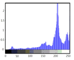
도 8은 본 발명의 일 실시예에 따른 입력 영상의 계조별 분포율을 나타낸 그래프이다.
도 9는 본 발명의 일 실시예에 따른 배경 영상의 계조별 분포율을 나타낸 그래프이다.
도 10은 본 발명의 일 실시예에 따른 다양한 감마 커브들을 나타낸 그래프이다.
도 11은 본 발명의 일 실시예에 따른 감마 보정 전후의 영상과 감마 보정이 불필요한 영상을 보여주는 사진이다.
도 12는 본 발명의 일 실시예에 따른 투명 표시 장치의 구성을 개략적으로 나타낸 블록도이다.
도 13은 본 발명의 일 실시예에 따른 영상 처리부의 구성을 나타낸 블록도이다.
도 14는 본 발명의 일 실시예에 따른 영상 처리 방법을 단계적으로 나타낸 순서도이다.
도 15는 본 발명의 일 실시예에 따른 블록 평균 계조에 따른 선명도 개선 강도 함수를 나타낸 그래프이다.
도 16은 본 발명의 일 실시예에 따른 투명 표시 장치에서 영상의 밝기 및 후면 배경의 밝기에 따라 선명도 개선 강도를 조절하여 적용한 경우의 영상을 선행 기술의 영상과 대비하여 나타낸 것이다.1 is a graph illustrating transmittance characteristics according to the lapse of driving time of a light blocking plate in a transparent display device according to a prior art of the present invention.
2 is a photograph showing a comparison of image display results according to transmittance of a light blocking plate in a transparent display device according to the prior art of the present invention.
3 is a photograph showing a comparison of image display results according to image characteristics and background characteristics in the transparent display device according to the prior art of the present invention.
4 is a block diagram schematically illustrating a configuration of a transparent display device according to an embodiment of the present invention.
5 is an equivalent circuit diagram illustrating a configuration of a sub-pixel according to an embodiment of the present invention.
6 is a block diagram illustrating the configuration of an image processing unit of a transparent display device according to an embodiment of the present invention.
7 is a flowchart illustrating an image processing method of a transparent display device in stages according to an embodiment of the present invention.
8 is a graph illustrating a distribution rate for each gray level of an input image according to an embodiment of the present invention.
9 is a graph illustrating a distribution rate for each gray level of a background image according to an embodiment of the present invention.
10 is a graph showing various gamma curves according to an embodiment of the present invention.
11 is a photograph showing an image before and after gamma correction and an image without gamma correction according to an embodiment of the present invention.
12 is a block diagram schematically illustrating a configuration of a transparent display device according to an exemplary embodiment.
13 is a block diagram illustrating the configuration of an image processing unit according to an embodiment of the present invention.
14 is a flowchart illustrating an image processing method step-by-step according to an embodiment of the present invention.
15 is a graph illustrating a sharpness improvement intensity function according to a block average grayscale according to an embodiment of the present invention.
16 is a diagram illustrating an image in the case where the intensity of sharpness improvement is adjusted and applied according to the brightness of the image and the brightness of the rear background in the transparent display device according to an embodiment of the present invention in comparison with an image of the prior art.
본 발명의 실시예에 대한 설명에 앞서서 본 발명의 선행 기술에 따른 투명 표시 장치의 화질 저하 현상을 예를 들어 먼저 살펴보기로 한다.Prior to the description of the embodiment of the present invention, the image quality deterioration phenomenon of the transparent display device according to the prior art of the present invention will be first described as an example.
도 1은 본 발명의 선행 기술에 따른 투명 표시 장치에서 구동 시간 경과에 따른 차광판의 투과율 특성을 나타낸 그래프이고, 도 2는 본 발명의 선행 기술에 따른 투명 표시 장치에서 차광판의 투과율에 따라 영상 표시 결과를 비교하여 보여주는 사진이고, 도 3은 본 발명의 선행 기술에 따른 투명 표시 장치에서 차광판 투과율이 70%일 때 영상 특성과 배경 특성에 따라 영상 표시 결과를 비교하여 보여주는 사진이다.1 is a graph showing the transmittance characteristics of the light blocking plate according to the lapse of driving time in a transparent display device according to the prior art of the present invention, and FIG. 2 is an image display result according to the transmittance of the light blocking plate in the transparent display device according to the prior art of the present invention. 3 is a photograph showing comparison of image display results according to image characteristics and background characteristics when the light-shielding plate transmittance is 70% in the transparent display device according to the prior art of the present invention.
도 1을 참조하면, 선행 기술에 따른 투명 표시 장치의 차광판은 구동을 시작한 이후 투과율 10% 이하로 닫히는 데까지 약 3분 정도의 상당한 시간이 소요됨을 알 수 있다.Referring to FIG. 1 , it can be seen that it takes about 3 minutes for the light blocking plate of the transparent display device according to the prior art to close with a transmittance of 10% or less after starting to be driven.
이로 인하여, 도 2(a)에서 보여주는 바와 같이 차광판의 투과율 80%이면 차광판의 블랙 구현이 불가능하므로 투명 특성에 의해 후면 배경이 보임과 아울러 후면으로부터 보다 많은 빛이 투과됨으로써 표시 영상의 시인성이 저하됨을 알 수 있다. 도 2(b)에서 보여주는 바와 같이 차광판이 투과율 10% 이하로 닫혀야만 차광판의 블랙 구현으로 표시 영상의 시인성이 나아지게 되므로, 차광판 투과율이 10% 보다 큰 경우에는 화질 저하 문제가 있다.For this reason, as shown in Fig. 2(a), if the transmittance of the light-shielding plate is 80%, it is impossible to implement black of the light-shielding plate, so that the rear background is visible due to the transparent property and more light is transmitted from the rear side, thereby reducing the visibility of the display image Able to know. As shown in FIG. 2(b) , the visibility of the displayed image is improved by implementing the black of the light blocking plate only when the light blocking plate is closed with a transmittance of 10% or less.
또한, 차광판 투과율이 70%일 때, 도 3(a), (b)에서 보여주는 바와 같이 동일한 어두운 영상에 대하여, 어두운 배경(a) 보다 밝은 배경(b)에서 화질이 저하되고, 도 3(c), (d)에서 보여주는 바와 같이 동일한 밝은 배경일 때, 어두운 영상(a) 및 밝은 영상(b) 모두 후면 배경이 보임과 아울러 표시 영상의 시인성이 저하됨을 알 수 있다.In addition, when the light-shielding plate transmittance is 70%, for the same dark image, as shown in FIGS. 3(a) and (b), the image quality is lowered on a bright background (b) than on a dark background (a), and in FIG. 3(c) ) and (d), when the same bright background is used, both the dark image (a) and the bright image (b) show the back background and it can be seen that the visibility of the display image is deteriorated.
또한, 차광판을 구비하지 않거나, 후면 배경의 인지가 필요하여 차광판이 투과 모드를 유지할 때, 선행 기술에 따른 투명 표시 장치는 영상의 밝기 특성과 후면 배경의 밝기 특성에 따라 후면 배경의 인지 정도가 결정되어 후면 배경의 인지 정도에 따라 영상의 선명도 저하가 발생할 수 있다.Also, when the light blocking plate is not provided or the light blocking plate maintains the transmission mode due to the need to recognize the rear background, the transparent display device according to the prior art determines the degree of recognition of the rear background according to the brightness characteristics of the image and the brightness characteristics of the rear background Therefore, the sharpness of the image may deteriorate depending on the degree of recognition of the background background.
이러한 선행 기술의 문제점들을 해결하기 위하여, 본 발명은 차광판의 투과율 특성을 선택적으로 고려하고, 입력 영상의 밝기 특성 및 후면 배경의 밝기 특성(즉, 시청 환경)을 고려하여 영상을 보정함으로써 영상 및 시청 환경에 따른 적절한 시인성 향상에 의해 화질을 향상시킬 수 있는 투명 표시 장치 및 그 구동 방법을 제안한다.In order to solve the problems of the prior art, the present invention selectively considers the transmittance characteristic of the light shielding plate, and corrects the image in consideration of the brightness characteristic of the input image and the brightness characteristic of the rear background (that is, the viewing environment) to view and view the image. A transparent display device capable of improving image quality by appropriately improving visibility according to an environment and a driving method thereof are proposed.
이하, 본 발명의 바람직한 실시예들에 대하여 설명한다.Hereinafter, preferred embodiments of the present invention will be described.
본 발명의 실시예에 따른 투명 표시 장치는 영상 및 시청 환경에 따라 시인성을 향상시키기 위한 영상 처리 방법으로 감마 보정 방법과 선명도 개선 방법 중 적어도 하나를 이용한다. A transparent display device according to an embodiment of the present invention uses at least one of a gamma correction method and a sharpness improvement method as an image processing method for improving visibility according to an image and a viewing environment.
도 4는 본 발명의 일 실시예에 따른 투명 표시 장치의 구성을 개략적으로 나타낸 블록도이고, 도 5는 본 발명의 일 실시예에 따른 서브픽셀의 구성을 나타낸 등가회로도이다.4 is a block diagram schematically illustrating a configuration of a transparent display device according to an embodiment of the present invention, and FIG. 5 is an equivalent circuit diagram illustrating a configuration of a sub-pixel according to an embodiment of the present invention.
도 4를 참조하면, 본 발명의 일 실시예에 따른 투명 표시 장치는 영상 처리부(100), 타이밍 컨트롤러(150), 데이터 구동부(200) 및 게이트 구동부(300), 투명 표시부(400), 감마 전압 생성부(500), 배경 센서(600), 차광판(700) 및 차광판 구동부(800) 등을 포함한다. 여기서, 타이밍 컨트롤러(150), 데이터 구동부(200) 및 게이트 구동부(300)는 투명 표시부(400)를 구동하는 표시 구동부로 표현될 수 있다.Referring to FIG. 4 , a transparent display device according to an embodiment of the present invention includes an
투명 표시부(400)는 픽셀들이 매트릭스 형태로 배열된 픽셀 어레이를 통해 영상을 표시한다. 픽셀 어레이의 기본 픽셀은 화이트(W), 레드(R), 그린(G), 블루(B) 서브픽셀들(SP) 중 컬러 혼합으로 화이트 표현이 가능한 적어도 3개 이상의 서브픽셀들(W/R/G, B/W/R, G/B/W, R/G/B, 또는 W/R/G/B)로 구성될 수 있다.The
투명 표시부(400)로는 액정 패널, 유기 발광 다이오드(OLED) 패널 등이 이용될 수 있으나, 이하에서는 OLED 패널을 예로 들어 설명하기로 한다. A liquid crystal panel, an organic light emitting diode (OLED) panel, or the like may be used as the
투명 표시부(400)가 OLED 패널인 경우 도 5에 도시된 바와 같이, 각 서브픽셀(SP)은 OLED 소자가 위치하는 발광 영역(EA)과, 전/후면으로부터의 빛을 투과시키는 투과 영역(TA)을 포함한다. OLED 소자의 발광 영역(EA)은 픽셀 회로와 오버랩하거나 오버랩하지 않을 수 있다. When the
도 5를 참조하면, 픽셀 회로는 고전위 전원(EVDD) 라인 및 저전위 전원(EVSS) 라인 사이에 접속된 OLED 소자와, OLED 소자를 독립적으로 구동하기 위하여 제1 및 제2 스위칭 TFT(ST1, ST2) 및 구동 TFT(DT)와 스토리지 커패시터(Cst)를 포함하는 픽셀 회로를 구비하며, 픽셀 회로 구성은 다양하므로 도 5의 구조로 한정되지 않는다.Referring to FIG. 5 , the pixel circuit includes an OLED device connected between a high potential power supply (EVDD) line and a low potential power supply (EVSS) line, and first and second switching TFTs ST1 and ST1 to independently drive the OLED device. ST2) and a pixel circuit including a driving TFT (DT) and a storage capacitor (Cst), and the configuration of the pixel circuit is not limited to the structure of FIG. 5 .
OLED 소자는 구동 TFT(DT)와 접속된 애노드와, 저전위 전압(EVSS)과 접속된 캐소드와, 애노드 및 캐소드 사이의 발광층을 구비하여, 구동 TFT(DT)로부터 공급된 전류량에 비례하는 광을 발생한다. The OLED device includes an anode connected to the driving TFT (DT), a cathode connected to a low potential voltage (EVSS), and a light emitting layer between the anode and the cathode, and emits light proportional to the amount of current supplied from the driving TFT (DT). Occurs.
제1 스위칭 TFT(ST1)는 한 게이트 라인(GL1)의 게이트 신호에 의해 구동되어 해당 데이터 라인(DL)으로부터의 데이터 전압을 구동 TFT(DT)의 게이트 노드에 공급하고, 제2 스위칭 TFT(ST2)는 다른 게이트 라인(GL2)의 게이트 신호에 의해 구동되어 레퍼런스 라인(REF)으로부터의 레퍼런스 전압을 구동 TFT(DT)의 소스 노드에 공급한다. 제2 스위칭 TFT(ST2)는 센싱 모드에서 구동 TFT(DT)로부터의 전류를 레퍼런스 라인(REF)으로 출력하는 경로로 더 이용된다. The first switching TFT ST1 is driven by the gate signal of one gate line GL1 to supply the data voltage from the corresponding data line DL to the gate node of the driving TFT DT, and the second switching TFT ST2 ) is driven by the gate signal of the other gate line GL2 to supply the reference voltage from the reference line REF to the source node of the driving TFT DT. The second switching TFT ST2 is further used as a path for outputting the current from the driving TFT DT to the reference line REF in the sensing mode.
구동 TFT(DT)의 게이트 노드 및 소스 노드 사이에 접속된 스토리지 커패시터(Cst)는 제1 스위칭 TFT(ST1)를 통해 게이트 노드로 공급된 데이터 전압과, 제2 스위칭 TFT(ST2)를 통해 소스 노드로 공급된 레퍼런스 전압의 차전압을 충전하여 구동 TFT(DT)의 구동 전압으로 공급한다.The storage capacitor Cst connected between the gate node and the source node of the driving TFT DT includes a data voltage supplied to the gate node through the first switching TFT ST1 and a source node through the second switching TFT ST2. It charges the difference voltage of the reference voltage supplied to , and supplies it as a driving voltage of the driving TFT (DT).
구동 TFT(DT)는 고전위 전원(EVDD)으로부터 공급되는 전류를 스토리지 커패시터(Cst)로부터 공급된 구동 전압에 따라 제어함으로써 구동 전압에 비례하는 전류를 OLED 소자로 공급하여 OLED 소자를 발광시킨다. The driving TFT DT controls the current supplied from the high potential power EVDD according to the driving voltage supplied from the storage capacitor Cst, thereby supplying a current proportional to the driving voltage to the OLED element to emit light.
도 4를 참조하면, 차광판(700)은 투명 표시부(400)의 후면에 배치되고, 투명 표시부(400)가 영상을 표시할 때 차광판 구동부(800)에 의해 차광 모드 또는 투과 모드로 구동될 수 있다. 차광판(700)은 차광판 구동부(800)에 의해 전계가 인가되면 블랙을 표시하여 차광 모드를 구현하고, 전계가 인가되지 않으면 투과 모드를 구현할 수 있다. 차광판 구동부(800)에 의해 차광판(700)이 차광 모드로 구동되면, 차광판(700)은 블랙을 구현하여 광투과를 차단함으로써 투명 표시부(400) 표시되는 영상의 시인성을 향상시킨다.4 , the
예를 들면, 차광판(700)으로는 전기 변색 필터로 알려진 일렉트로크로믹 디바이스(Electrochromic Device)나, 일렉트로웨팅 디바이스(ElctroWetting Device) 등이 이용될 수 있거나, 액정을 이용하여 광 투과를 스위칭할 수 있는 장치일 수 있다. For example, as the
한편, 차광판(700)은 투명 표시부(400)의 전면 및 후면 중 적어도 일측면에 배치될 수 있다.Meanwhile, the
배경 센서(600)는 투명 표시 장치의 후면에 장착되어 투명 표시 장치의 후면 배경을 센싱하고, 센싱된 후면 배경 정보(밝기 또는 영상)을 영상 처리부(100)로 공급한다. 배경 센서(600)로는 공지된 조도 센서나 CMOS 이미지 센서 등이 적용될 수 있다.The
영상 처리부(100)는 외부로부터 공급되는 입력 영상을 분석하여 영상 특성을 판단하고, 배경 센서(600)로부터 센싱된 후면 배경 정보(밝기 또는 영상)를 분석하여 후면 배경의 특성을 판단한다. 영상 처리부(100)는 차광판 구동부(800)에 의한 차광판(700)의 투과 모드와 차광 모드에 따라 차광판(700)의 투과율을 판단할 수 있다. 영상 처리부(100)에는 차광판(700)이 차광 모드로 구동될 때 그 구동 시간 경과에 따른 차광판(700)의 투과율이 미리 측정되어 룩-업 테이블(Look-Up Table; 이하 LUT) 형태로 저장될 수 있다. 영상 처리부(100)는 차광판 구동부(800)에 의해 차광판(700)이 차광 모드로 구동될 때 그 차광 모드의 구동 시간에 따른 차광판(700)의 투과율을 판단할 수 있다. The
영상 처리부(100)는 입력 영상을 분석하여 입력 영상이 어두운 영상인지 밝은 영상인지를 판단하고, 후면 배경 정보를 분석하여 후면 배경이 밝은 환경인지 어두운 환경인지를 판단한다. 이에 대한 구체적인 설명은 후술하기로 한다.The
영상 처리부(100)는 입력 영상의 특성 및 후면 배경 특성을 판단한 결과, 입력 영상이 어둡고 배경이 밝거나, 입력 영상이 어둡고 배경이 어둡거나, 입력 영상이 밝고 배경이 밝은 경우 화질 저하 조건으로 판단하고, 차광판(700)의 투과율이 제1 기준값(예를 들면 10%)을 초과할 때, 입력 영상에 대하여 투과율에 따른 감마 보정을 실시하여 감마 보정된 영상을 출력함으로써 화질을 보상한다.As a result of determining the characteristics of the input image and the back background characteristics, the
반면에, 영상 처리부(100)는 입력 영상이 밝고 배경이 어두운 정상 조건에 해당하고 투과율이 제1 기준값(예를 들면 10%)을 초과하거나, 상기 입력 영상 및 후면 배경의 특성에 상관없이 투과율이 제1 기준값 이하일 때, 입력 영상을 감마 보정없이 출력한다. On the other hand, the
영상 처리부(100)는 전술한 감마 보정 이전 또는 이후에 통상의 RGB-to-WRGB 변환 방법을 이용하여 3색 데이터(R, G, B)를 4색 데이터(W, R, G, B)로 변환할 수 있다. 영상 처리부(100)는 전술한 감마 보정 이전 또는 이후에 소비 전력 감소나 데이터 렌더링, 화질 보상, 열화 보상 등과 같은 필요한 영상 처리를 더 수행할 수 있다. 영상 처리부(100)는 영상 처리된 영상 데이터와, 타이밍 제어 신호들을 타이밍 컨트롤러(150)로 공급한다.The
영상 처리부(100)는 타이밍 컨트롤러(100) 내에 하드웨어도 구현되거나, 메모리에 저장된 소프트웨어의 영상 처리 모듈을 의미할 수 있다.The
타이밍 컨트롤러(150)는 영상 처리부(100)로부터 공급된 타이밍 제어 신호들을 이용하여 데이터 제어 신호(DCS) 및 게이트 제어 신호(GCS)를 생성하여 데이터 구동부(200) 및 게이트 구동부(300)로 각각 출력한다. 타이밍 제어 신호들은 도트 클럭, 데이터 인에이블 신호, 수직 동기 신호, 수평 동기 신호를 포함하며, 수직 동기 신호 및 수평 동기 신호는 데이터 인에이블 신호를 카운트하여 생성할 수 있으므로 생략 가능하다. 데이터 제어 신호들은 데이터 구동부(200) 구동을 제어하는 소스 스타트 펄스, 소스 샘플링 클럭, 소스 출력 인에이블 신호 등을 포함할 수 있다. 게이트 제어 신호들은 게이트 구동부(300) 구동을 제어하는 게이트 스타트 펄스, 게이트 쉬프트 클럭 등을 포함할 수 있다.The
타이밍 컨트롤러(150)는 영상 처리부(100)로부터 공급받은 영상 데이터에 대하여, 투명 표시부(400)의 서브픽셀별 구동 특성(구동 TFT의 문턱 전압, 이동도, OLED 문턱 전압 등) 편차를 데이터 구동부(200)를 통해 센싱하여 보상하는 외부 보상이나 열화 보상 등과 같은 필요한 영상 처리를 더 실시한 다음 데이터 구동부(200)로 출력할 수 있다.The
데이터 구동부(200)는 타이밍 컨트롤러(150)로부터의 데이터 제어 신호 및 영상 데이터를 공급받는다. 데이터 구동부(200)는 데이터 제어 신호에 따라 구동되어, 감마 전압 생성부(500)로부터 공급된 레퍼런스 감마 전압 세트를 데이터의 계조값에 각각 대응하는 계조 전압들로 세분화한 다음, 세분화된 계조 전압들을 이용하여 디지털 영상 데이터를 아날로그 데이터 신호로 변환하고, 아날로그 데이터 신호를 투명 표시부(400)의 데이터 라인들로 각각 공급한다. The
데이터 구동부(200)는 투명 표시부(400)의 데이터 라인들을 분할 구동하는 다수의 데이터 구동 IC로 구성되고, 각 데이터 구동 IC는 TCP(Tape Carrier Package), COF(Chip On Film), FPC(Flexible Print Circuit) 등과 같은 회로 필름에 실장되어 투명 표시부(400)에 TAB(Tape Automatic Bonding) 방식으로 부착되거나, COG(Chip On Glass) 방식으로 투명 표시부(400) 상에 실장될 수 있다.The
게이트 구동부(300)는 타이밍 컨트롤러(150)로부터 공급된 게이트 제어 신호(GCS)를 이용하여 투명 표시부(400)의 다수의 게이트 라인을 각각 구동한다. 게이트 구동부(300)는 게이트 제어 신호에 응답하여 각 게이트 라인에 해당 스캔 기간에서 게이트 온 전압의 스캔 펄스를 공급하고, 나머지 기간에서는 게이트 오프 전압을 공급한다. 게이트 구동부(300)는 타이밍 컨트롤러(150)로부터 게이트 제어 신호(GCS)를 공급받거나, 타이밍 컨트롤러(150)로부터 데이터 구동부(200)를 경유하여 게이트 제어 신호(GCS)를 공급받거나, 타이밍 컨트롤러(150)로부터 전원 회로(도시 생략)을 경유하여 공급받을 수 있다. The
게이트 구동부(300)는 적어도 하나의 게이트 IC로 구성되고 TCP, COF, FPC 등과 같은 회로 필름에 실장되어 투명 표시부(400)에 TAB 방식으로 부착되거나, COG 방식으로 투명 표시부(400) 상에 실장될 수 있다. 이와 달리, 게이트 구동부(300)는 투명 표시부(400)의 픽셀 어레이를 구성하는 박막 트랜지스터 어레이와 함께 박막 트랜지스터 기판에 형성됨으로써 투명 표시부(400)의 비표시 영역에 내장된 GIP(Gate In Panel) 타입으로 구비될 수 있다. The
도 6은 본 발명의 일 실시예에 따른 영상 처리부(100)의 내부 구성을 나타낸 블록도이고, 도 7은 본 발명의 일 실시예에 따른 영상 처리 방법을 단계적으로 나타낸 순서도이고, 도 6 및 도 7을 결부하여 설명한다.6 is a block diagram illustrating an internal configuration of the
도 6을 참조하면, 영상 처리부(100)는 투과율 LUT(102), 영상 특성 분석부(104), 배경 특성 분석부(106), 판단부(108), 감마 보정부(110)를 포함한다. 영상 처리부(100)는 이외에도 공지된 다른 영상 처리 블록들을 더 포함할 수 있다.Referring to FIG. 6 , the
영상 특성 분석부(104)는 외부로부터 입력 영상을 공급받아 입력 영상을 분석하여 어두운 영상의 포함 정도, 즉 어두운 정도를 산출하고, 어두운 정도에 따라 입력 영상이 어두운 영상인지 밝은 영상인지를 나타내는 제1 판단 신호를 판단부(108)로 출력한다. (S12)The image
예를 들면, 영상 특성 분석부(104)는 아래 수학식 1을 이용하여 각 프레임의 입력 영상에서 저계조값들이 차지하는 분포율, 즉 어두운 영상의 포함 정도를 나타내는 저계조 가중치 평균 영상 레벨(Weighted Average Picture Level; 이하 WAPL_Low)을 백분율(%)로 산출한다.For example, the image
<수학식 1><

n은 입력 영상의 단위 프레임에 포함되는 서브픽셀 수이고, Gray는 각 서브픽셀의 계조값을 의미한다. n is the number of sub-pixels included in a unit frame of the input image, and Gray means a gray level value of each sub-pixel.
그리고, 영상 특성 분석부(104)는 상기 수학식 1로부터 산출된 WAPL_Low가 제2 기준값 α% 보다 작은 경우 입력 영상을 어두운 영상으로 판단하고, 그 반대로 WAPL_Low가 제2 기준값 α% 이상인 경우 입력 영상을 밝은 영상으로 판단하며, 그 판단 결과에 따라 입력 영상이 어두운 영상인지 밝은 영상인지를 나타내는 제1 판단 신호를 판단부(108)로 출력한다. (S12) 여기서, 제2 기준값 α%는 설계자에 의해 미리 설정된 것으로 투명 표시 장치 및 차광판(700)의 특성에 따라 차이가 있으나 30≤α≤50 정도가 어두운 영상 여부를 판단하는 기준값으로 적당하다. Then, the image
상기 수학식 1로부터 산출된 WAPL_Low가 제2 기준값 α% (30≤α≤50) 보다 작은 경우는 도 8에 도시된 입력 영상의 계조별 분포율을 나타낸 그래프와 같이 저계조 영역의 분포율이 상대적으로 큰 경우를 의미한다.When WAPL_Low calculated from
배경 특성 분석부(106)는 배경 센서(600)에 의해 센싱된 배경 영상을 공급받아 배경 영상을 분석하여 밝은 정도를 산출하고, 그 밝은 정도에 따라 배경이 밝은지 어두운지를 나타내는 제2 판단 신호를 감마 보정부(108)로 출력한다. (S14)The background
예를 들면, 센싱된 후면 배경 정보가 영상 정보일 때, 배경 특성 분석부(106)는 아래 수학식 2를 이용하여 각 프레임의 배경 영상에서 고계조값의 픽셀수가 차지하는 정도, 즉 배경 영상의 밝은 정도를 나타내는 고계조 가중치 평균 영상 레벨(이하 WAPL_High)을 백분율(%)로 산출한다.For example, when the sensed rear background information is image information, the background
<수학식2><

n은 배경 영상의 단위 프레임에 포함되는 서브픽셀 수이고, Gray는 각 서브픽셀의 계조값을 의미한다. n is the number of subpixels included in a unit frame of the background image, and Gray denotes a grayscale value of each subpixel.
그리고, 배경 특성 분석부(106)는 상기 수학식 2로부터 산출된 WAPL_High 가 제3 기준값 β% 보다 큰 경우 배경 영상이 밝은 것으로 판단하고, 그 반대로 WAPL_High가 제2 기준값 β% 이하인 경우 배경 영상이 어두운 것으로 판단하며, 그 판단 결과에 따라 배경 영상이 밝은지 어두운지를 나타내는 제2 판단 신호를 판단부(108)로 출력한다. (S14) 여기서, 제2 기준값 β%는 설계자에 의해 미리 설정된 것으로 투명 표시 장치 및 차광판(700)의 특성에 따라 차이가 있으나 50≤β≤70 정도가 밝은 배경을 판단하는 기준값으로 적당하다.In addition, the background
상기 수학식 2로부터 산출된 WAPL_High가 제3 기준값 β% (50≤β≤70) 보다 큰 경우는 도 9에 도시된 배경 영상의 계조별 분포율을 나타낸 그래프와 같이 고계조 영역의 분포율이 상대적으로 큰 경우를 의미한다.When WAPL_High calculated from
투과율 LUT(102)에는 구동 시간 경과에 따른 차광판(700)의 투과율이 미리 측정되어 저장되어 있다. 투과율 LUT(102)는 외부 시스템(도시 생략)으로부터 차광판(700)의 구동 시간을 공급받아 차광판(700)의 구동 시간에 따른 투과율을 선택하여 판단부(108)로 공급한다(S16). 투과율 LUT(102)는 구동 시간에 따른 투과율 구간을 다수개로 분류하여 저장할 수 있다. 예를 들면, 투과율(t) 구간은 t>70, 60<t≤70, ..., 20<t≤30, 10<t≤20, t≤10와 같이 분류되어 저장될 수 있다. 투과율 LUT(102)는 구동 시간에 대응하는 투과율(t) 구간에 대한 정보를 판단부(108)로 출력할 수 있다. (S18)In the
판단부(108)는 영상 특성 분석부(104)로부터 공급된 입력 영상이 어두운지 밝은지를 나타내는 제1 판단 신호와, 배경 특성 분석부(106)로부터 공급된 배경이 밝은지 어두운지를 나타내는 제2 판단 신호를 논리 조합하여 감마 보정 여부를 결정한다. 판단부(108)는 감마 보정 여부가 결정된 신호와, 투과율 LUT(102)로부터 공급된 투과율 정보를 감마 보정부(110)로 출력한다. 판단부(108)는 차광판 구동부(800)에 의해 차광판(700)이 투과 모드일 때 최대 투과율 정보를 감마 보정부(110)로 출력할 수 있다.The
판단부(108)는 영상 특성 분석부(104)로부터의 제1 판단 신호와, 배경 특성 분석부(106)로부터의 제2 판단 신호가 아래 표 1에 나타낸 4가지 조건 중 화질 저하가 예측되는 제1 내지 제3 조건(어두운 영상 및 밝은 배경, 어두운 영상 및 어두운 배경, 밝은 영상 및 밝은 배경) 중 어느 하나인 화질 저하 조건에 해당하고(S18, YES), 투과율 LUT(102)로부터 공급된 투과율 정보가 제1 기준값(예를 들면 10%)를 초과하는 경우(S20, YES), 감마 보정부(110)에 감마 보정 필요 신호를 출력한다. 판단부(108)는 감마 보정 필요 신호와 함께 투과율 정보도 함께 감마 보정부(110)로 출력한다.The
<표 1><Table 1>

반면에, 판단부(108)는 영상 특성 분석부(104)로부터의 제1 판단 신호와, 배경 특성 분석부(106)로부터의 제2 판단 신호가 상기 표 1에 나타낸 제4 조건(밝은 영상 및 어두운 배경)인 정상 조건에 해당하면, 투과율 정보에 관계없이 감마 보정 불필요 신호를 감마 보정부(110)에 출력한다(S18, NO) On the other hand, the
한편, 판단부(108)는 투과율 LUT(102)로부터 공급된 투과율 정보가 제1 기준값(예를 들면 10%) 이하일 때, 전술한 영상 특성 및 배경 특성과 관계없이 감마 보정 불필요 신호를 감마 보정부(110)에 출력한다. (S20, NO)On the other hand, when the transmittance information supplied from the
감마 보정부(110)는 판단부(108)로부터 감마 보정 필요 신호가 공급되면, 그 판단부(108)를 경유하여 공급된 투과율 정보에 따라 영상 특성 분석부(104)를 경유하여 공급된 입력 영상에 대한 감마 보정을 실시하여(S22), 감마 보정된 영상을 출력한다(S24).When a gamma correction necessary signal is supplied from the
반면에, 감마 보정부(110)는 판단부(108)로부터 감마 보정 불필요 신호가 공급되면, 영상 특성 분석부(104)를 경유하여 공급된 입력 영상을 감마 보정없이 출력한다(S24).On the other hand, when the gamma correction unnecessary signal is supplied from the
감마 보정부(110)에는 투과율 정보에 따라 도 10에 도시된 바와 같이 감마값(입력 계조값에 대한 출력 계조값을 나타내는 감마 커브를 정의한 값)이 서로 다른 다수의 감마 보정 LUT가 미리 설정되어 저장되어 있다. In the
예를 들면, 감마 보정부(110)는 아래 표 2와 같이 투과율(t) 정보에 따라 서로 다른 감마값(GMA)을 선택하고, 선택된 감마값에 해당하는 LUT를 이용하여 입력 영상의 각 데이터(입력 계조값)에 대응하는 출력 데이터(출력 계조값)를 선택하여 출력함으로써, 입력 영상에 대하여 투과율에 따라 차등적인 감마 보정을 실시하고 감마 보정된 영상을 출력한다. For example, the
<표 2><Table 2>

상기 표 2에서 투과율(t) 정보가 10% 미만인 경우에 해당하는 2.2 감마값은 투명 표시 장치의 기본 설정값으로 입력 영상을 감마 보정없이 출력하는 것을 의미한다.In Table 2, a gamma value of 2.2 corresponding to the case where the transmittance (t) information is less than 10% is a basic setting value of the transparent display device and means that the input image is output without gamma correction.
상기 표 2와 같이 투과율이 클수록 감마값은 증가하며, 도 9에 도시된 바와 같이 감마값이 클수록 입력 계조값에 대한 출력 계조값이 감소함을 알 수 있다.As shown in Table 2, as the transmittance increases, the gamma value increases. As shown in FIG. 9 , as the gamma value increases, the output grayscale value with respect to the input grayscale value decreases.
도 11은 본 발명의 일 실시예에 따른 감마 보정 전후의 영상과 감마 보정이 불필요한 영상을 보여주는 사진이다.11 is a photograph showing an image before and after gamma correction and an image without gamma correction according to an embodiment of the present invention.
차광판 투과율이 70%이고 입력 영상이 어둡고 배경이 밝은 경우, 도 11(a)에 도시된 바와 같이 본 발명이 적용되기 이전의 2.2 감마를 이용하여 영상을 표시하면, 표시 영상의 시인성이 저하되는 반면, 도 11(b)에 도시된 바와 같이 본 발명이 적용되어 3.4 감마를 이용하여 영상을 표시하면 시인성이 향상되어 화질이 향상되었음을 알 수 있다. When the transmittance of the light shielding plate is 70% and the input image is dark and the background is bright, as shown in FIG. , it can be seen that when the present invention is applied and an image is displayed using 3.4 gamma as shown in FIG. 11( b ), visibility is improved and image quality is improved.
한편, 도 11(c)와 같이 배경이 어둡고 입력 영상이 밝은 경우에는 감마 보정이 필요하지 않음을 알 수 있다.On the other hand, it can be seen that gamma correction is not required when the background is dark and the input image is bright as shown in FIG. 11( c ).
전술한 바와 같이, 본 발명의 일 실시예에 따른 투명 표시 장치 및 그 구동 방법은 차광판의 투과율 특성과, 입력 영상의 휘도 특성 및 배경 영상의 휘도 특성을 모두 분석하여, 투과율이 기준값 보다 크고 입력 영상과 후면 배경이 화질 저하 조건에 해당하는 경우 감마를 조절하여 영상 데이터를 보정함으로써 화질을 향상시킬 수 있다. As described above, the transparent display device and the driving method thereof according to an embodiment of the present invention analyze all of the transmittance characteristics of the light blocking plate, the luminance characteristics of the input image, and the luminance characteristics of the background image, so that the transmittance is greater than the reference value and the input image When the background and the background fall under the condition for image quality degradation, the image quality can be improved by correcting the image data by adjusting the gamma.
도 12는 본 발명의 일 실시예에 따른 투명 표시 장치의 구성을 개략적으로 나타낸 블록도이다. 12 is a block diagram schematically illustrating a configuration of a transparent display device according to an exemplary embodiment.
도 12에 도시된 투명 표시 장치는 도 4에 도시된 실시예와 대비하여, 영상 처리부(1000)가 영상 밝기 및 후면 배경(시청 환경)의 밝기의 영향을 받는 영상의 선명도 저하 정도(후면 배경의 인지 정도)에 따라 적응적으로 영상의 선명도를 개선하여 화질을 향상시키는 영상 처리를 수행하는 점에서 차이가 있다. 도 12에서 영상 처리부(1000)를 제외한 나머지 구성요소들은 도 4와 동일하므로 도 4와 동일한 구성요소들에 대한 설명은 생략하기로 한다. In the transparent display device illustrated in FIG. 12 , in contrast to the embodiment illustrated in FIG. 4 , the
도 12에 도시된 투명 표시 장치는 영상 표시와 함께 후면 배경에 대한 인지가 필요한 경우로, 도 12에 도시된 투명 표시 장치는 도 4에 도시된 차광판(700) 및 차광판 구동부(800)를 생략할 수 있다. 한편, 도 4에 도시된 차광판(700) 및 차광판 구동부(800)를 구비하는 경우에는 차광판(700)은 차광판 구동부(800)에 의해 투과 모드를 유지할 수 있다.The transparent display device shown in FIG. 12 requires recognition of the rear background together with image display. The transparent display device shown in FIG. 12 omits the
영상 처리부(1000)는 영상의 선명도를 개선하기 위하여 언샤프 마스킹(unsharp masking)을 적용하여 영상의 에지 강도에 비례하여 선명도를 개선하는 선명도 개선 방법을 이용할 수 있다. 또한, 영상 처리부(1000)는 영상의 밝기 및 후면 배경의 밝기에 따라 후면 배경의 인지 정도가 달라짐으로써 영상의 선명도와 화질 중 적어도 하나가 저하되는 것을 방지하기 위하여, 영상의 밝기 및 후면 배경의 밝기에 따라 적응적으로 선명도 개선 강도를 조절한다. 이 결과, 영상 처리부(1000)는 영상의 에지 강도 특성과 영상의 밝기 특성과 후면 배경의 밝기 특성을 모두 고려하여 선명도 개선 강도를 조절함으로써 영상 및 시청 환경에 적절하게 선명도를 개선할 수 있으므로 화질을 향상시킬 수 있다.The
구체적으로, 투명 표시 장치에서 영상의 밝은 영역은 밝은 영상으로 인해 후면 배경이 잘 인지되지 않는 반면, 영상의 어두운 영역은 후면 배경이 영상과 함께 인지되어 영상의 에지 표현력이 저하되므로, 영상의 밝기가 감소할수록 영상의 선명도가 저감할 수 있다. 영상의 밝기에 따라 영상의 선명도가 저하되는 것을 방지하기 위하여, 영상 처리부(1000)는 영상의 어두운 영역은 후면 배경의 인지 정도가 높아 영상의 선명도 저하 정도가 높으므로 선명도 개선 강도를 증가시키고, 영상의 밝은 영역은 후면 배경의 인지 정도가 낮아 선명도 저하 정도도 낮으므로 선명도 개선 강도를 감소시킨다. 이를 위하여, 영상 처리부(100)는 영상 프레임을 복수의 픽셀 블록으로 분할하여 픽셀 블록별로 평균 계조를 계산하고, 블록별 평균 계조(블록별 평균 밝기)에 따라 블록별로 선명도 개선 강도를 조절한다.Specifically, in a transparent display device, in a bright area of an image, the back background is not well recognized due to a bright image, whereas in a dark area of the image, the back background is recognized together with the image and the edge expression power of the image is lowered, so that the brightness of the image is reduced. As it decreases, the sharpness of the image may decrease. In order to prevent the sharpness of the image from being deteriorated according to the brightness of the image, the
또한, 후면 배경의 밝기가 높을수록 배경 시인성이 증가하여 영상의 선명도가 저감되는 방지하기 위하여, 영상 처리부(100)는 후면 배경의 밝기에 따라 선명도 개선 강도를 조절한다. 영상 처리부(100)는 어두운 후면 배경의 경우 후면 배경의 인지 정도가 낮아 선명도 저하 정도도 낮으므로 선명도 개선 강도를 감소시키고 밝은 후면 배경의 경우 후면 배경의 인지 정도가 높아 선명도 저하 정도가 높으므로 선명도 개선 강도를 증가시킨다. 이를 위하여, 영상 처리부(100)는 후면 배경의 밝기를 센싱하고, 영상의 블록별 평균 계조에 따라 선명도 개선 강도를 결정하는 함수를, 후면 배경 밝기에 따른 배경 가중치를 적용하여 가변시킴으로써 후면 배경 밝기에 따라 선명도 개선 강도를 조절한다. 이에 대한 구체적인 설명은 후술한다.In addition, in order to prevent the sharpness of the image from being reduced by increasing the background visibility as the brightness of the rear background increases, the
도 13은 본 발명의 일 실시예에 따른 투명 표시 장치의 영상 처리부(1000)의 구성을 나타낸 블록도이고, 도 14는 본 발명의 일 실시예에 따른 투명 표시 장치의 영상 처리 방법을 단계적으로 나타낸 순서도이고, 도 15는 본 발명의 일 실시예에 따른 영상의 블록별 평균 계조에 따른 선명도 개선 강도를 결정하는 함수의 그래프를 나타낸 것이다. 이하, 도 13 내지 도 15을 참조하여 설명한다. 13 is a block diagram illustrating a configuration of an
도 13에 도시된 영상 처리부(1000)는 영상 밝기와 후면 배경의 밝기에 따라 선명도 개선 강도(K)를 조절하는 선명도 개선 강도 조절부(1200)와, 언샤프 마스킹 처리를 통해 입력 영상(FD)의 에지 강도와 선명도 개선 강도(K)에 비례하여 영상의 선명도를 개선하고 선명도가 개선된 영상(FD')을 출력하는 언샤프 마스크 필터(1100)를 구비한다. The
언샤프 마스크 필터(1100)는 로우 패스 필터(1110), 마스크 생성부(1120), 선명도 개선 마스크 결정부(1130), 영상 보정부(1140)를 구비한다.The
로우 패스 필터(1110)는 프레임 단위의 입력 영상(FD)을 로우 패스 필터링함으로써 픽셀간 휘도 차이가 감소된 블러 영상을 생성하고 블러 영상을 출력한다.The low-
마스크 생성부(1120)는 로우 패스 필터(1110)로부터 공급된 블러 영상을, 입력 영상(FD)으로부터 차감함으로써 입력 영상(FD)의 에지 성분을 나타내는 에지 마스크 영상(MD)을 생성하고 에지 마스크 영상(MD)을 출력한다. (S42)The
선명도 개선 마스크 결정부(1130)는 마스크 생성부(1120)로부터 공급된 에지 마스크 영상(MD)에, 선명도 개선 강도 조절부(1200)에서 영상 밝기 및 후면 배경 밝기에 따라 조절된 선명도 개선 강도(K)를 적용하여 선명도 개선 마스크 영상(MD')을 결정하고 선명도 개선 마스크 영상(MD')을 출력한다. (S54) 선명도 개선 마스크 결정부(1130)는 에지 마스크 영상(MD)과 선명도 개선 강도(K)를 곱함으로써 에지 마스크 영상(MD)에서 에지 성분의 강도가 선명도 개선 강도(K)에 의해 증가된 선명도 개선 마스크 영상(MD')을 생성한다. 선명도 개선 강도 조절부(1200)는 픽셀 블록별 평균 계조와 후면 배경 밝기에 따라 조절된 블록별 선명도 개선 강도(K)를 출력한다. 따라서, 선명도 개선 마스크 결정부(1130)는 에지 마스크 영상(MD)의 픽셀 블록 단위로 블록별 선명도 개선 강도(K)를 적용하여 선명도 개선 마스크 영상(MD')을 생성한다.The sharpness
영상 보정부(1140)는 입력 영상(FD)과, 선명도 개선 마스크 결정부(1300)로부터 공급된 선명도 개선 마스크 영상(MD')을 합성함으로써 선명도가 개선된 출력 영상(FD')을 생성하고, 출력 영상(FD')을 출력한다. (S56)The
선명도 개선 강도 조절부(1200)는 입력 영상(FD)을 분할한 복수의 픽셀 블록 각각의 블록별 평균 계조(L)와, 후면 배경의 밝기에 따라 조절된 가중치(Kmax, Kmin)을 이용하여, 블록별로 선명도 개선 강도(K)를 결정하고, 블록별 선명도 개선 강도(K)를 출력한다. (S44, S46, S48, S50, S52) 이를 위하여, 선명도 개선 강도 조절부(1200)는 평균 계조 계산부(1210), 배경 가중치 결정부(1220), 선명도 강도 결정부(1230)를 구비한다.The sharpness improvement
평균 계조 계산부(120)는 입력 영상(FD)을 복수의 픽셀 블록으로 분할하고, 블록별 평균 계조(L)를 계산하여, 블록별 평균 계조(L)를 출력한다. (S44) 평균 계조(L)를 계산하기 위한 각 픽셀 블록 각각의 크기(n*n, n은 픽셀수)는 다양하게 설정될 수 있으며, 예를 들면 영역별 평균 밝기 특성을 반영하기 위하여 3≤n≤10 정도가 적당하다.The average grayscale calculator 120 divides the input image FD into a plurality of pixel blocks, calculates the average grayscale L for each block, and outputs the average grayscale L for each block. (S44) The size (n*n, n is the number of pixels) of each pixel block for calculating the average grayscale L may be set variously, for example, 3≤ About n≤10 is suitable.
배경 가중치 결정부(1220)는 배경 센서(600; 도 12)로부터 센싱된 후면 배경의 밝기 정보(E)에 따른 가중치(Wmax, Wmin)를 결정하고, 이 가중치(Wmax, Wmin)를 아래 수학식 3과 같이 미리 설정된 암실 환경의 최대 및 최소 선명도 개선 강도(K0max, K0min)에 각각 적용함으로써 후면 배경의 밝기에 따른 최대 및 최소 선명도 개선 강도(Kmax, Kmin)를 결정하고, 최대 및 최소 선명도 개선 강도(Kmax, Kmin)를 배경 가중치로 출력한다. (S50)The
<수학식 3><
Kmax = K0max * WmaxKmax = K0max * Wmax
Kmin = K0min * WminKmin = K0min * Wmin
다시 말하여, 배경 가중치 결정부(1220)는 후면 배경의 밝기(E)에 따라 최대 및 최소 선명도 개선 강도(Kmax, Kmin)를 가변시킨다. 예를 들면, 사무실 조도 환경을 기준으로 선명도 개선 강도의 최대값(Kmax)은 1.5≤Kmax≤3.0 정도가 적당하고, 최소값(Kmin)은 0.01≤Kmin≤0.5 정도가 적당하다.In other words, the
선명도 강도 결정부(1230)는 평균 계조 계산부(120)로부터 공급된 블록별 평균 계조(L)와, 배경 가중치 결정부(1220)로부터 공급된 배경 가중치, 즉 후면 배경 밝기에 따라 가변된 최대 및 최소 선명도 개선 강도(Kmax, Kmin)를 이용하여 아래 수학식 4와 같이 블록별 선명도 개선 강도(K)를 결정하여 출력한다. (S52)The
<수학식 4><Equation 4>

상기 수학식 4에서 Lth는 블록별 평균 계조의 임계값을 의미한다. 상기 수학식 4를 이용한 선명도 개선 강도(K) 결정은 블록별 평균 계조(L)가 임계값(Lth) 보다 작은 경우에만 적용된다. (S52) 블록별 평균 계조(L)가 평균 계조가 일정 수준 이상인 경우 후면 배경이 잘 인지되지 않으므로 선명도 강도 결정부(1230)는 임계값(Lth)을 설정하고, 블록별 평균 계조(L)가 임계값(Lth) 이상일 때 그 블록의 선명도 개선 강도(K)는 설정치인 최소값으로 결정된다. (S48) 예를 들면, 평균 계조의 임계값(Lth)은 128≤ Lth ≤255 정도가 적당하다.In Equation 4, Lth denotes a threshold value of the average grayscale for each block. The determination of the sharpness improvement intensity (K) using Equation (4) is applied only when the average gray level (L) for each block is smaller than the threshold value (Lth). (S52) When the average gradation L for each block is above a certain level, the background background is not well recognized, so the
도 15를 참조하면, 선명도 강도 결정부(1230)는 블록별 평균 계조(L)가 임계값(Lth)보다 큰 경우, 상기 수학식 2의 2차 함수를 이용하여 블록별 평균 계조(L)가 증가할수록 선명도 개선 강도(K)가 감소됨을 알 수 있다. 최대 및 최소 선명도 개선 강도(Kmax, Kmin)는 후면 배경의 밝기에 따라 가변되면, 도 15에 도시된 2차 함수의 커브 그래프가 가변되어 블록별 평균 계조(L)에 대응하는 블록별 선명도 개선 강도(K)도 가변하게 된다. 도 15에서 블록별 평균 계조(L)가 임계값(Lth) 이상일 때 블록별 선명도 개선 강도(K)는 최소값(Kmin)으로 결정된다.Referring to FIG. 15 , when the average grayscale L for each block is greater than the threshold value Lth, the
이와 같이, 본 발명의 일 실시예에 따른 투명 표시 장치 및 그 구동 방법은 영상의 밝기와 후면 배경의 밝기에 따라 선명도 개선 강도를 조절함으로써 영상 및 시청 환경에 따라 적절한 선명도 개선 강도를 적용하여 선명도 및 화질을 향상시킬 수 있다. 따라서, 영상과 후면 배경 모두 의미있는 정보를 전달하는 경우 배경과 영상 사이의 경계를 강조하여 영상 및 후면 배경 양측의 시인성을 개선할 수 있다.As described above, the transparent display device and the method for driving the same according to an embodiment of the present invention adjust the sharpness improvement intensity according to the brightness of the image and the brightness of the rear background, thereby applying an appropriate sharpness improvement intensity according to the image and the viewing environment to improve sharpness and The picture quality can be improved. Accordingly, when both the image and the background background transmit meaningful information, the visibility of both the image and the background background may be improved by emphasizing the boundary between the background and the image.
도 16은 본 발명의 일 실시예에 따른 투명 표시 장치에서 영상의 밝기 및 후면 배경의 밝기에 따라 선명도 개선 강도를 조절하여 적용한 경우의 영상을 선행 기술의 영상과 대비하여 나타낸 것이다.16 is a diagram illustrating an image in the case where the intensity of sharpness improvement is adjusted and applied according to the brightness of the image and the brightness of the rear background in the transparent display device according to an embodiment of the present invention in comparison with an image of the prior art.
도 16(a)를 참조하면 선행 기술의 투명 표시 장치는 영상의 어두운 영역이 밝은 후면 배경의 영향을 받아 선명도가 저하되는 문제점이 있는 반면, 본 발명의 일 실시예는 어두운 영역의 영상 밝기와 밝은 후면 배경에 따라 선명도 개선 강도가 증가시킴으로써 에지 강도가 향상되어 선명도가 향상되었음을 알 수 있다.Referring to FIG. 16( a ) , the transparent display device of the prior art has a problem in that a dark area of an image is affected by a bright rear background and the sharpness is deteriorated, whereas an embodiment of the present invention provides image brightness and a bright image in a dark area. It can be seen that the sharpness is improved because the edge strength is improved by increasing the sharpness improvement intensity according to the back background.
도 16(b)를 참조하면, 선행 기술의 투명 표시 장치는 영상의 밝은 영역은 후면 배경의 영향이 작아 선명도 저하가 낮으므로, 본 발명의 일 실시예는 영상의 밝은 영역에서 선명도 개선 강도를 감소시키더라도 화질 저하가 낮음을 알 수 있으며, 밝은 영상에서 선명도 개선 강도 증가로 인한 오버 샤프닝과 같은 화질 저하를 방지할 수 있다.Referring to FIG. 16(b) , in the transparent display device of the prior art, since the effect of the rear background is small in the bright area of the image and thus the sharpness deterioration is low, an embodiment of the present invention reduces the intensity of sharpness improvement in the bright area of the image It can be seen that the image quality deterioration is low even if the image quality is reduced, and image quality deterioration such as over-sharpening due to the increase in sharpness improvement intensity in bright images can be prevented.
도 16(c)를 참조하면, 선행 기술의 투명 표시 장치는 후면 배경의 밝기가 어두운 경우 영상의 어두운 영역은 선명도 저하가 낮으므로 본 발명의 일 실시예는 어두운 영역의 영상 밝기와 어두운 후면 배경에 따라 선명도 개선 강도를 감소시키더라도 화질 저하가 낮음을 알 수 있다.Referring to FIG. 16(c) , in the transparent display device of the prior art, when the brightness of the back background is low, the sharpness degradation in the dark area of the image is low, so an embodiment of the present invention provides the image brightness in the dark area and the dark back background. Accordingly, it can be seen that even if the sharpness improvement intensity is reduced, the image quality deterioration is low.
전술한 바와 같이, 본 발명의 일 실시예에 따른 투명 표시 장치 및 그 구동 방법은 입력 영상의 밝기 특성 및 후면 배경의 밝기 특성을 고려하여 감마 보정 방법 및 선명도 개선 방법 중 하나의 영상 처리를 실시하여 영상을 보정함으로써 영상 및 시청 환경에 따라 적절하게 영상의 시인성 및 화질을 향상시킬 수 있다. As described above, in the transparent display device and the driving method according to an embodiment of the present invention, one of the gamma correction method and the sharpness improvement method is performed in consideration of the brightness characteristics of the input image and the brightness characteristics of the rear background. By correcting the image, visibility and image quality of the image may be appropriately improved according to the image and viewing environment.
이상 설명한 내용을 통해 당업자라면 본 발명의 기술사상을 일탈하지 아니하는 범위에서 다양한 변경 및 수정이 가능함을 알 수 있을 것이다. 따라서, 본 발명의 기술적 범위는 명세서의 상세한 설명에 기재된 내용으로 한정되는 것이 아니라 특허 청구 범위에 의해 정하여져야만 할 것이다.Those skilled in the art from the above description will be able to see that various changes and modifications can be made without departing from the technical spirit of the present invention. Accordingly, the technical scope of the present invention should not be limited to the content described in the detailed description of the specification, but should be defined by the claims.
100, 1000: 영상 처리부 102: 투과율 LUT
104: 영상 특성 분석부 106: 배경 특성 분석부
108: 판단부 110: 감마 보정부
150: 타이밍 컨트롤러 200: 데이터 구동부
300: 게이트 구동부 400: 투명 표시부
500: 감마 전압 생성부 600: 배경 센서
700: 차광판 800: 차광판 구동부
1100: 언샤프 마스크 필터 1110: 로우 패스 필터
1120: 마스크 생성부 1130: 선명도 개선 마스크 결정부
1140: 영상 보정부 1200: 선명도 개선 강도 조절부
1210: 평균 계조 계산부 1220: 배경 가중치 결정부
1230: 선명도 강도 결정부100, 1000: image processing unit 102: transmittance LUT
104: image characteristic analysis unit 106: background characteristic analysis unit
108: determination unit 110: gamma correction unit
150: timing controller 200: data driver
300: gate driving unit 400: transparent display unit
500: gamma voltage generator 600: background sensor
700: light-shielding plate 800: light-shielding plate driving unit
1100: unsharp mask filter 1110: low pass filter
1120: mask generating unit 1130: sharpness improvement mask determining unit
1140: image correction unit 1200: sharpness improvement intensity control unit
1210: average gray scale calculator 1220: background weight determiner
1230: sharpness intensity determining unit
Claims (7)
투과 영역과, 발광 영역을 포함하는 투명 표시부와,
상기 투명 표시 장치의 후면에 배치되어 후면 배경을 센싱하는 배경 센서와,
상기 투명 표시부에 출력 영상을 공급하는 표시 구동부와,
입력 영상을 복수의 픽셀 블록으로 분할하여 픽셀 블록 단위로 계산된 블록별 밝기 특성과, 상기 센싱된 후면 배경의 밝기 특성에 따라 상기 픽셀 블록 단위로 블록별 선명도 개선 강도를 결정하고, 상기 입력 영상에서 에지 성분을 추출하여 에지 마스크 영상을 생성하고, 상기 에지 마스크 영상에 상기 블록별 선명도 개선 강도를 적용하여 선명도 개선 마스크 영상을 생성한 후 상기 선명도 개선 마스크와 상기 입력 영상을 합성하여 상기 픽셀 블록 단위로 상기 입력 영상의 선명도를 보정하고, 선명도가 보정된 영상을 상기 표시 구동부로 출력하는 영상 처리부를 구비하는 투명 표시 장치.In the transparent display device,
A transparent display unit including a transmissive region and a light emitting region;
a background sensor disposed on a rear surface of the transparent display device to sense a rear background;
a display driving unit for supplying an output image to the transparent display unit;
The input image is divided into a plurality of pixel blocks and the intensity of sharpness improvement is determined for each block in units of the pixel blocks according to the brightness characteristics of each block calculated in units of pixel blocks and the brightness characteristics of the sensed back background, and in the input image An edge mask image is generated by extracting an edge component, a sharpness improvement intensity is applied to the edge mask image for each block to generate a sharpness improvement mask image, and the sharpness improvement mask and the input image are synthesized in the pixel block unit. and an image processing unit for correcting the sharpness of the input image and outputting the sharpness-corrected image to the display driver.
상기 영상 처리부는
상기 입력 영상을 로우 패스 필터링하여 블러 영상을 생성하여 출력하는 로우 패스 필터와,
상기 로우 패스 필터로부터 공급된 상기 블러 영상을, 상기 입력 영상으로부터 차감하여 에지 마스크 영상을 생성하여 출력하는 마스크 생성부와,
상기 입력 영상의 상기 블록별 밝기 특성과, 상기 센싱된 후면 배경의 밝기 특성에 따라 상기 블록별 선명도 개선 강도를 조절하는 선명도 개선 강도 조절부와,
상기 마스크 생성부로부터 공급된 상기 에지 마스크 영상에, 상기 선명도 개선 강도 조절부로부터 공급된 상기 블록별 선명도 개선 강도를 적용하여, 선명도 개선 마스크 영상을 생성하여 출력하는 선명도 개선 마스크 결정부와,
상기 선명도 개선 마스크 결정부로부터 공급된 상기 선명도 개선 마스크 영상과 상기 입력 영상을 합성하여 상기 선명도가 보정된 영상을 상기 표시 구동부로 출력하는 영상 보정부를 구비하는 투명 표시 장치.The method according to claim 1,
The image processing unit
a low-pass filter for generating and outputting a blur image by low-pass filtering the input image;
a mask generator for generating and outputting an edge mask image by subtracting the blur image supplied from the low-pass filter from the input image;
a sharpness improvement intensity adjusting unit for adjusting the sharpness improvement intensity for each block according to the brightness characteristic of each block of the input image and the brightness characteristic of the sensed back background;
a sharpness improvement mask determiner for generating and outputting a sharpness improvement mask image by applying the sharpness improvement intensity for each block supplied from the sharpness improvement intensity adjustment part to the edge mask image supplied from the mask generator;
and an image compensator for synthesizing the input image with the sharpness improvement mask image supplied from the sharpness improvement mask determiner to output the sharpness-corrected image to the display driver.
상기 선명도 개선 강도 조절부는
상기 입력 영상에 대하여 상기 복수의 픽셀 블록 각각의 블록별 평균 계조를 계산하여 출력하는 평균 계조 계산부와,
상기 센싱된 후면 배경의 밝기에 따라 선명도 개선 강도의 최대값 및 최소값을 결정하여 배경 가중치로 출력하는 배경 가중치 결정부와,
상기 평균 계조 계산부로부터 공급된 블록별 평균 계조(L)와, 상기 배경 가중치 결정부로부터 공급된 선명도 개선 강도의 최대값 및 최소값(Kmax, Kmin)과, 아래 수학식의 함수를 이용하여 상기 블록별 선명도 개선 강도(K)를 결정하는 선명도 개선 강도 결정부를 구비하고,

상기 선명도 개선 강도 결정부는
상기 블록별 평균 계조(L)가 미리 설정된 임계값(Lth) 미만일 때 상기 수학식으로 해당 블록의 선명도 개선 강도(K)를 결정하고,
상기 블록별 평균 계조가 상기 임계값 이상일 때 미리 설정된 최소값을 해당 블록의 선명도 개선 강도로 결정하는 투명 표시 장치.3. The method of claim 2
The sharpness improvement intensity control unit
an average grayscale calculation unit for calculating and outputting an average grayscale for each block of the plurality of pixel blocks with respect to the input image;
a background weight determining unit that determines the maximum and minimum values of sharpness improvement intensity according to the sensed brightness of the back background and outputs them as background weights;
The block using the average gray level (L) for each block supplied from the average gray level calculation unit, the maximum and minimum values (Kmax, Kmin) of the sharpness improvement intensity supplied from the background weight determination unit, and the function of the following equation and a sharpness improvement intensity determining unit for determining the sharpness improvement intensity (K) of each star;
The sharpness improvement intensity determining unit
When the average gray level (L) for each block is less than a preset threshold value (Lth), the intensity of sharpness improvement (K) of the corresponding block is determined by the above equation,
A transparent display device for determining a preset minimum value as a sharpness improvement intensity of a corresponding block when the average grayscale for each block is equal to or greater than the threshold value.
상기 영상 처리부는,
상기 블록별 밝기가 감소할수록 상기 선명도 개선 강도를 증가시키고 상기 블록별 밝기가 증가할수록 상기 선명도 개선 강도를 감소시키는 투명 표시 장치.The method according to claim 1,
The image processing unit,
A transparent display device for increasing the sharpness improvement intensity as the brightness of each block decreases, and decreasing the sharpness improvement intensity as the brightness for each block increases.
상기 영상 처리부는,
상기 후면 배경의 밝기가 감소할수록 상기 선명도 개선 강도를 감소시키고 상기 후면 배경의 밝기가 증가할수록 상기 선명도 개선 강도를 증가시키는 투명 표시 장치.The method according to claim 1,
The image processing unit,
A transparent display device for decreasing the sharpness improvement intensity as the brightness of the back background decreases, and increasing the sharpness improvement intensity as the brightness of the back background increases.
상기 입력 영상으로부터 상기 블러 영상을 차감하여 에지 마스크 영상을 생성하는 단계와,
상기 입력 영상을 복수의 픽셀 블록으로 분할하여 픽셀 블록 단위로 계산된 블록별 밝기 특성과, 센싱된 후면 배경의 밝기 특성에 따라 상기 픽셀 블록 단위로 블록별 선명도 개선 강도를 결정하는 단계와,
상기 에지 마스크 영상에 상기 블록별 선명도 개선 강도를 적용하여, 선명도 개선 마스크 영상을 생성하는 단계와,
상기 선명도 개선 마스크 영상과 상기 입력 영상을 합성하여 선명도가 보정된 영상을 투명 표시부에 표시하는 단계를 투명 표시 장치의 구동 방법.generating a blur image by low-pass filtering the input image;
generating an edge mask image by subtracting the blur image from the input image;
dividing the input image into a plurality of pixel blocks and determining the intensity of sharpness improvement for each block in units of the pixel blocks according to the brightness characteristics of each block calculated in units of pixel blocks and the brightness characteristics of the sensed back background;
generating a sharpness improvement mask image by applying the sharpness improvement intensity for each block to the edge mask image;
and displaying the image whose sharpness is corrected by synthesizing the sharpness improvement mask image and the input image on a transparent display unit.
상기 블록별 선명도 개선 강도를 결정하는 단계는
상기 입력 영상에 대하여 상기 복수의 픽셀 블록 각각의 블록별 평균 계조를 계산하는 단계와,
상기 센싱된 후면 배경의 밝기에 따라 선명도 개선 강도의 최대값 및 최소값을 결정하는 단계와,
상기 블록별 평균 계조(L)가 미리 설정된 임계값(Lth) 미만일 때, 상기 블록별 평균 계조(L)와, 상기 선명도 개선 강도의 최대값 및 최소값(Kmax, Kmin)과, 아래 수학식의 함수를 이용하여 상기 블록별 선명도 개선 강도(K)를 결정하는 단계와,

상기 블록별 평균 계조가 상기 임계값 이상일 때 미리 설정된 최소값을 해당 블록의 선명도 개선 강도로 결정하는 단계를 포함하는 투명 표시 장치의 구동 방법.7. The method of claim 6,
The step of determining the sharpness improvement intensity for each block is
calculating an average grayscale for each block of the plurality of pixel blocks with respect to the input image;
determining a maximum value and a minimum value of sharpness improvement intensity according to the brightness of the sensed back background;
When the average gradation L for each block is less than a preset threshold value Lth, the average gradation L for each block, the maximum and minimum values (Kmax, Kmin) of the sharpness improvement intensity, and a function of the following equation determining the sharpness improvement intensity (K) for each block using
and determining a preset minimum value as a sharpness improvement intensity of the corresponding block when the average grayscale for each block is equal to or greater than the threshold value.
Applications Claiming Priority (3)
| Application Number | Priority Date | Filing Date | Title |
|---|---|---|---|
| KR1020150179729 | 2015-12-16 | ||
| KR20150179729 | 2015-12-16 | ||
| KR1020160097355A KR102510568B1 (en) | 2015-12-16 | 2016-07-29 | Transparent display device and method for driving the same |
Related Parent Applications (1)
| Application Number | Title | Priority Date | Filing Date |
|---|---|---|---|
| KR1020160097355A Division KR102510568B1 (en) | 2015-12-16 | 2016-07-29 | Transparent display device and method for driving the same |
Publications (2)
| Publication Number | Publication Date |
|---|---|
| KR20220127183A true KR20220127183A (en) | 2022-09-19 |
| KR102510573B1 KR102510573B1 (en) | 2023-03-16 |
Family
ID=59282713
Family Applications (2)
| Application Number | Title | Priority Date | Filing Date |
|---|---|---|---|
| KR1020160097355A KR102510568B1 (en) | 2015-12-16 | 2016-07-29 | Transparent display device and method for driving the same |
| KR1020220109222A KR102510573B1 (en) | 2015-12-16 | 2022-08-30 | Transparent display device and method for driving the same |
Family Applications Before (1)
| Application Number | Title | Priority Date | Filing Date |
|---|---|---|---|
| KR1020160097355A KR102510568B1 (en) | 2015-12-16 | 2016-07-29 | Transparent display device and method for driving the same |
Country Status (1)
| Country | Link |
|---|---|
| KR (2) | KR102510568B1 (en) |
Families Citing this family (3)
| Publication number | Priority date | Publication date | Assignee | Title |
|---|---|---|---|---|
| KR102656687B1 (en) * | 2019-07-01 | 2024-04-11 | 엘지디스플레이 주식회사 | Transparent display device and image processing method thereof |
| KR102330949B1 (en) * | 2021-05-26 | 2021-12-01 | 주식회사 노아엘이디 | Smart LED display board and image output method using the same |
| WO2023238966A1 (en) * | 2022-06-08 | 2023-12-14 | 엘지전자 주식회사 | Transparent display device and operating method therefor |
Citations (3)
| Publication number | Priority date | Publication date | Assignee | Title |
|---|---|---|---|---|
| KR20060021665A (en) * | 2004-09-03 | 2006-03-08 | 엘지전자 주식회사 | Apparatus and method of controlling screen contrast for mobile station |
| KR20130094095A (en) * | 2012-02-15 | 2013-08-23 | 삼성디스플레이 주식회사 | Transparent display device and operating method thereof |
| KR20150025872A (en) * | 2013-08-30 | 2015-03-11 | 삼성디스플레이 주식회사 | Transparent display device and driving method thereof |
Family Cites Families (1)
| Publication number | Priority date | Publication date | Assignee | Title |
|---|---|---|---|---|
| US9594286B2 (en) * | 2012-12-31 | 2017-03-14 | Lg Display Co., Ltd. | Transparent display apparatus with adjustable transmissive area and a method for controlling the same |
-
2016
- 2016-07-29 KR KR1020160097355A patent/KR102510568B1/en active IP Right Grant
-
2022
- 2022-08-30 KR KR1020220109222A patent/KR102510573B1/en active IP Right Grant
Patent Citations (3)
| Publication number | Priority date | Publication date | Assignee | Title |
|---|---|---|---|---|
| KR20060021665A (en) * | 2004-09-03 | 2006-03-08 | 엘지전자 주식회사 | Apparatus and method of controlling screen contrast for mobile station |
| KR20130094095A (en) * | 2012-02-15 | 2013-08-23 | 삼성디스플레이 주식회사 | Transparent display device and operating method thereof |
| KR20150025872A (en) * | 2013-08-30 | 2015-03-11 | 삼성디스플레이 주식회사 | Transparent display device and driving method thereof |
Also Published As
| Publication number | Publication date |
|---|---|
| KR20170072119A (en) | 2017-06-26 |
| KR102510573B1 (en) | 2023-03-16 |
| KR102510568B1 (en) | 2023-03-16 |
Similar Documents
| Publication | Publication Date | Title |
|---|---|---|
| US10504217B2 (en) | Method and module for processing high dynamic range (HDR) image and display device using the same | |
| KR102231046B1 (en) | Display device and method for driving the same | |
| KR102322709B1 (en) | Image processing method, image processing circuit and display device using the same | |
| US9595229B2 (en) | Local dimming method and liquid crystal display | |
| CN106205485B (en) | Image processing method, image processing circuit and the organic LED display device using it | |
| EP1564714B1 (en) | Display device, liquid crytal monitor, liquid crystal television receiver, and display method | |
| KR102510573B1 (en) | Transparent display device and method for driving the same | |
| US8890900B2 (en) | Liquid crystal display and method of local dimming thereof | |
| JP6309777B2 (en) | Display device, display panel driver, and display panel driving method | |
| US9454937B2 (en) | Timing controller, liquid crystal display device having the same, and driving method thereof | |
| KR102390980B1 (en) | Image processing method, image processing circuit and display device using the same | |
| KR101990335B1 (en) | Data clipping method and device, and display device using the same | |
| KR20080044104A (en) | Display apparatus and method of driving the same | |
| US20080246784A1 (en) | Display device | |
| US20190057659A1 (en) | Brightness compensation method and circuit | |
| KR102438252B1 (en) | Display device with 4-colors for high dynamic range (hdr) | |
| KR102511039B1 (en) | Image processing method, image processing circuit and display device using the same | |
| KR20170080778A (en) | Display device and method for driving the same | |
| KR102642018B1 (en) | Transparent display device and method for driving the same | |
| KR20130037538A (en) | Apparatus and method for correcting color of display device | |
| KR102438250B1 (en) | Transparent display device and method for driving the same | |
| KR20170053204A (en) | Voltage Controller, Display Device and Method for driving thereof | |
| KR20070121336A (en) | Liquid crystal display and gamma compensative method for liquid crystal display | |
| JP2009093055A (en) | Liquid crystal display | |
| KR20100076605A (en) | Liquid crystal display device and method of driving the same |
Legal Events
| Date | Code | Title | Description |
|---|---|---|---|
| E701 | Decision to grant or registration of patent right |