KR20220125087A - Steamer and apparatus for supplying steam thereof - Google Patents
Steamer and apparatus for supplying steam thereof Download PDFInfo
- Publication number
- KR20220125087A KR20220125087A KR1020210029059A KR20210029059A KR20220125087A KR 20220125087 A KR20220125087 A KR 20220125087A KR 1020210029059 A KR1020210029059 A KR 1020210029059A KR 20210029059 A KR20210029059 A KR 20210029059A KR 20220125087 A KR20220125087 A KR 20220125087A
- Authority
- KR
- South Korea
- Prior art keywords
- water
- steamer
- water tank
- steam
- tube body
- Prior art date
Links
- XLYOFNOQVPJJNP-UHFFFAOYSA-N water Substances O XLYOFNOQVPJJNP-UHFFFAOYSA-N 0.000 claims abstract description 91
- 238000010438 heat treatment Methods 0.000 claims abstract description 43
- 239000008400 supply water Substances 0.000 claims abstract description 27
- 238000000034 method Methods 0.000 claims description 34
- 229910001220 stainless steel Inorganic materials 0.000 claims description 4
- 239000010935 stainless steel Substances 0.000 claims description 4
- 238000002347 injection Methods 0.000 claims 1
- 239000007924 injection Substances 0.000 claims 1
- 238000010586 diagram Methods 0.000 description 6
- 238000005406 washing Methods 0.000 description 5
- 239000000428 dust Substances 0.000 description 4
- 238000005192 partition Methods 0.000 description 4
- 230000000694 effects Effects 0.000 description 3
- 230000037303 wrinkles Effects 0.000 description 3
- 230000002159 abnormal effect Effects 0.000 description 2
- 239000004744 fabric Substances 0.000 description 2
- 239000000463 material Substances 0.000 description 2
- 239000007769 metal material Substances 0.000 description 2
- 235000019645 odor Nutrition 0.000 description 2
- 239000007921 spray Substances 0.000 description 2
- 238000004891 communication Methods 0.000 description 1
- 230000018044 dehydration Effects 0.000 description 1
- 238000006297 dehydration reaction Methods 0.000 description 1
- 230000001877 deodorizing effect Effects 0.000 description 1
- 230000000994 depressogenic effect Effects 0.000 description 1
- 238000007599 discharging Methods 0.000 description 1
- 238000001035 drying Methods 0.000 description 1
- 238000001704 evaporation Methods 0.000 description 1
- 230000008020 evaporation Effects 0.000 description 1
- 230000020169 heat generation Effects 0.000 description 1
- 239000011810 insulating material Substances 0.000 description 1
- 230000004048 modification Effects 0.000 description 1
- 238000012986 modification Methods 0.000 description 1
- 238000013021 overheating Methods 0.000 description 1
- 238000005507 spraying Methods 0.000 description 1
- 230000001954 sterilising effect Effects 0.000 description 1
Images


Classifications
-
- D—TEXTILES; PAPER
- D06—TREATMENT OF TEXTILES OR THE LIKE; LAUNDERING; FLEXIBLE MATERIALS NOT OTHERWISE PROVIDED FOR
- D06F—LAUNDERING, DRYING, IRONING, PRESSING OR FOLDING TEXTILE ARTICLES
- D06F73/00—Apparatus for smoothing or removing creases from garments or other textile articles by formers, cores, stretchers, or internal frames, with the application of heat or steam
- D06F73/02—Apparatus for smoothing or removing creases from garments or other textile articles by formers, cores, stretchers, or internal frames, with the application of heat or steam having one or more treatment chambers
-
- A—HUMAN NECESSITIES
- A61—MEDICAL OR VETERINARY SCIENCE; HYGIENE
- A61L—METHODS OR APPARATUS FOR STERILISING MATERIALS OR OBJECTS IN GENERAL; DISINFECTION, STERILISATION OR DEODORISATION OF AIR; CHEMICAL ASPECTS OF BANDAGES, DRESSINGS, ABSORBENT PADS OR SURGICAL ARTICLES; MATERIALS FOR BANDAGES, DRESSINGS, ABSORBENT PADS OR SURGICAL ARTICLES
- A61L2/00—Methods or apparatus for disinfecting or sterilising materials or objects other than foodstuffs or contact lenses; Accessories therefor
- A61L2/02—Methods or apparatus for disinfecting or sterilising materials or objects other than foodstuffs or contact lenses; Accessories therefor using physical phenomena
- A61L2/04—Heat
- A61L2/06—Hot gas
- A61L2/07—Steam
-
- D—TEXTILES; PAPER
- D06—TREATMENT OF TEXTILES OR THE LIKE; LAUNDERING; FLEXIBLE MATERIALS NOT OTHERWISE PROVIDED FOR
- D06F—LAUNDERING, DRYING, IRONING, PRESSING OR FOLDING TEXTILE ARTICLES
- D06F39/00—Details of washing machines not specific to a single type of machines covered by groups D06F9/00 - D06F27/00
- D06F39/008—Steam generating arrangements
-
- D06F39/40—
-
- F—MECHANICAL ENGINEERING; LIGHTING; HEATING; WEAPONS; BLASTING
- F22—STEAM GENERATION
- F22B—METHODS OF STEAM GENERATION; STEAM BOILERS
- F22B1/00—Methods of steam generation characterised by form of heating method
- F22B1/28—Methods of steam generation characterised by form of heating method in boilers heated electrically
- F22B1/284—Methods of steam generation characterised by form of heating method in boilers heated electrically with water in reservoirs
-
- F—MECHANICAL ENGINEERING; LIGHTING; HEATING; WEAPONS; BLASTING
- F22—STEAM GENERATION
- F22D—PREHEATING, OR ACCUMULATING PREHEATED, FEED-WATER FOR STEAM GENERATION; FEED-WATER SUPPLY FOR STEAM GENERATION; CONTROLLING WATER LEVEL FOR STEAM GENERATION; AUXILIARY DEVICES FOR PROMOTING WATER CIRCULATION WITHIN STEAM BOILERS
- F22D5/00—Controlling water feed or water level; Automatic water feeding or water-level regulators
- F22D5/26—Automatic feed-control systems
-
- A—HUMAN NECESSITIES
- A61—MEDICAL OR VETERINARY SCIENCE; HYGIENE
- A61L—METHODS OR APPARATUS FOR STERILISING MATERIALS OR OBJECTS IN GENERAL; DISINFECTION, STERILISATION OR DEODORISATION OF AIR; CHEMICAL ASPECTS OF BANDAGES, DRESSINGS, ABSORBENT PADS OR SURGICAL ARTICLES; MATERIALS FOR BANDAGES, DRESSINGS, ABSORBENT PADS OR SURGICAL ARTICLES
- A61L2202/00—Aspects relating to methods or apparatus for disinfecting or sterilising materials or objects
- A61L2202/20—Targets to be treated
- A61L2202/26—Textiles, e.g. towels, beds, cloths
-
- Y—GENERAL TAGGING OF NEW TECHNOLOGICAL DEVELOPMENTS; GENERAL TAGGING OF CROSS-SECTIONAL TECHNOLOGIES SPANNING OVER SEVERAL SECTIONS OF THE IPC; TECHNICAL SUBJECTS COVERED BY FORMER USPC CROSS-REFERENCE ART COLLECTIONS [XRACs] AND DIGESTS
- Y02—TECHNOLOGIES OR APPLICATIONS FOR MITIGATION OR ADAPTATION AGAINST CLIMATE CHANGE
- Y02B—CLIMATE CHANGE MITIGATION TECHNOLOGIES RELATED TO BUILDINGS, e.g. HOUSING, HOUSE APPLIANCES OR RELATED END-USER APPLICATIONS
- Y02B40/00—Technologies aiming at improving the efficiency of home appliances, e.g. induction cooking or efficient technologies for refrigerators, freezers or dish washers
Abstract
Description
본 발명은 스티머 및 이를 포함하는 스팀 공급장치에 관한 것이다.The present invention relates to a steamer and a steam supply device including the same.
일반적으로, 의류 또는 침구류와 같은 직물로 이루어진 물품을 세척하기 위한 장치로서 세탁기가 널리 사용되고 있으며, 세탁기는 수조에 수용된 세탁수와 세탁물과의 마찰을 통해 세탁물을 세척함에 따라 별도의 탈수, 건조 과정 등이 추가로 필요하다.In general, a washing machine is widely used as a device for washing articles made of fabrics such as clothes or bedding, and the washing machine washes laundry through friction between laundry water and laundry contained in a water tank, and thus separate dehydration and drying processes etc. are additionally needed.
최근에는 종래의 세탁기보다 의복을 간편하게 처리 또는 관리하기 위하여 별도의 세탁 과정없이 의복의 주름, 살균 및 탈취 등을 수행할 수 있는 장치들이 소개되어 있다.In recent years, apparatuses capable of wrinkling, sterilizing, and deodorizing clothes without a separate washing process have been introduced in order to process or manage clothes more conveniently than in a conventional washing machine.
이 중, 스팀을 인가하기 위한 스티머들은 주름을 제거하고, 걸려 있는 의복(hanging garment), 천(drapery), 덮개, 및 패브릭으로 만들어진 다른 물품들의 외형을 개선하는 데 특히 유용하다. 이러한 스티머들은 의류에 고온의 스팀을 분사함으로써 의류에 잔류하는 냄새, 구김 또는 습기 등을 제거할 수 있다. Among them, steamers for applying steam are particularly useful for removing wrinkles and improving the appearance of hanging garments, drapers, covers, and other articles made of fabric. These steamers can remove odors, wrinkles, or moisture remaining on the clothes by spraying high-temperature steam on the clothes.
그러나, 종래의 스티머들은 물 저장 탱크의 저탕 스팀 방식으로 물이 부족할 때마다 단속적으로 펌프에 의하여 공급되는 상기 물탱크에 저장된 물을 히터기로 직접 가열하여 스팀을 발생시키는 방식으로 이루어져 있으므로 장시간 스팀 발생을 위한 예열시간이 필요하고 상기 물탱크에 많은 물을 보관하기 위하여 전체 크기가 커지고 이에 따라 소비 전력량이 증가하는 문제점이 있다.However, conventional steamers use the steam storage method of the water storage tank to generate steam by directly heating the water stored in the water tank intermittently supplied by the pump whenever there is insufficient water with a heater to generate steam for a long time. There is a problem in that a preheating time is required for this purpose, and the overall size is increased in order to store a lot of water in the water tank, and thus power consumption is increased.
본 발명은 상기한 기술적 과제를 해결하기 위하여 안출된 것으로서, 본 발명은, 순간 발열 직 스팀 방식으로 저장탱크의 수위를 지속적으로 유지하도록 함으로써, 별도의 물 공급을 위한 펌프가 생략될 수 있는 스티머 및 이를 포함하는 스팀 공급장치를 제공하는 것을 그 목적으로 한다.The present invention has been devised to solve the above technical problem, and the present invention is a steamer that can be omitted by a separate pump for supplying water by continuously maintaining the water level of the storage tank in an instantaneous heating direct steam method, and An object of the present invention is to provide a steam supply device including the same.
또한, 본 발명은, 순간 발열 직 스팀 방식으로 저장탱크의 수위를 지속적으로 유지하도록 함으로써, 종래의 저탕 스팀 방식과 비교하여 저장탱크의 사이즈 및 중량을 크게 감소시킬 수 있는 스티머 및 이를 포함하는 스팀 공급장치를 제공하는 것을 그 목적으로 한다.In addition, the present invention provides a steamer capable of significantly reducing the size and weight of a storage tank compared to a conventional hot water storage steam method by continuously maintaining the water level of the storage tank in an instantaneous direct steam method, and steam supply including the same The purpose is to provide a device.
또한, 본 발명은, 전극이 구비된 히터관에 의한 직 스팀 가열 방식을 제공함으로써, 보다 신속한 가열에 의한 스팀이 발생될 수 있는 스티머 및 이를 포함하는 스팀 공급장치를 제공하는 것을 그 목적으로 한다.In addition, an object of the present invention is to provide a steamer capable of generating steam by faster heating by providing a direct steam heating method by a heater tube provided with an electrode, and a steam supply device including the same.
본 발명에 따른 스티머의 일 실시예는, 급수부와 배수부 중 적어도 하나가 형성되고 일정량의 공급수가 공급되는 물탱크; 및An embodiment of the steamer according to the present invention includes: a water tank in which at least one of a water supply part and a drain part is formed and a predetermined amount of supply water is supplied; and
상기 물탱크에 일측에 결합되는 가열부재;를 포함하고,Including; a heating member coupled to one side of the water tank;
상기 가열부재는,The heating element is
상기 공급수가 유동하는 중공형의 히터관 본체; 및a hollow heater tube body through which the supply water flows; and
상기 히터관 본체의 적어도 일부에 형성되는 히터부;를 포함할 수 있다.It may include; a heater unit formed in at least a portion of the heater tube body.
본 발명의 일 실시예에서, 상기 물탱크에는 상기 가열부재가 안착되는 장착홈이 형성될 수 있다.In an embodiment of the present invention, a mounting groove in which the heating member is seated may be formed in the water tank.
여기서, 본 발명의 일 실시예에서, 상기 물탱크의 장착홈은 중심부위에 형성되고, 상기 가열부재는 상기 중심부위에 안착되는 구조일 수 있다.Here, in one embodiment of the present invention, the mounting groove of the water tank may be formed on a central portion, and the heating member may be seated on the central portion.
본 발명의 일 실시예에서, 상기 물탱크와 상기 가열부재의 상단부의 높이는 동일하게 유지되도록 형성될 수 있다.In an embodiment of the present invention, the height of the upper end of the water tank and the heating member may be maintained to be the same.
본 발명의 일 실시예에서, 상기 가열부재는 상기 물탱크와 일체로 형성되거나 독립적으로 탈착 가능하게 형성될 수 있다.In an embodiment of the present invention, the heating member may be formed integrally with the water tank or may be formed independently and detachably.
본 발명의 일 실시예에서, 상기 히터관 본체는 금속소재를 포함할 수 있고, 바람직하게는 스테인레스 강을 포함할 수 있다.In an embodiment of the present invention, the heater tube body may include a metal material, preferably stainless steel.
본 발명의 일 실시예에서, 상기 히터부는 상기 히터관 본체에 소정의 패턴으로 형성될 수 있다.In an embodiment of the present invention, the heater unit may be formed in a predetermined pattern on the heater tube body.
여기서, 본 발명의 일 실시예에서, 상기 히터관 본체와 상기 물탱크에는 상기 공급수가 동일한 수위로 항상 유지될 수 있다.Here, in one embodiment of the present invention, the supply water may be always maintained at the same water level in the heater tube body and the water tank.
본 발명의 일 실시예에서, 상기 저장탱크의 공급수는 상기 급수 공급부로부터 연속적으로 공급될 수 있다.In one embodiment of the present invention, the supply water of the storage tank may be continuously supplied from the water supply unit.
본 발명의 일 실시예에서, 상기 공급수는 증발하여 상기 증기수 배출구로 배출되는 가습식 방식으로 공급될 수 있다.In one embodiment of the present invention, the supply water may be supplied in a humidified manner that is discharged to the steam water outlet by evaporation.
여기서, 본 발명의 일 실시예에서, 상기 가습식 방식은 가열식, 초음파 방식 또는 복합식 가습 방식을 포함할 수 있다.Here, in an embodiment of the present invention, the humidification method may include a heating method, an ultrasonic method, or a complex humidification method.
본 발명의 일 실시예에서, 상기 저장탱크에는 이상상태, 즉 과열 및 입수나 출수부의 막힘 등의 현상을 감지할 수 있는 안전장치가 더 형성될 수 있다.In one embodiment of the present invention, the storage tank may be further provided with a safety device capable of detecting abnormal conditions, such as overheating and clogging of the intake or water outlet.
본 발명의 일 실시예에서, 상기 히터관 본체에는 상기 공급수가 유입되는 유입구와 배출되는 배출부가 형성되고, 상기 배출부에는 분사노즐이 형성될 수 있다.In an embodiment of the present invention, an inlet through which the supply water is introduced and an outlet through which the feed water is discharged are formed in the heater tube body, and a spray nozzle may be formed at the outlet.
한편, 본 발명은 상기 스티머를 포함하는 스팀 공급 장치를 제공할 수 있다.Meanwhile, the present invention may provide a steam supply device including the steamer.
본 발명의 일 실시예에서, 상기 스티머는 상기 스팀 공급 장치로부터 착탈 가능하게 장착될 수 있다.In an embodiment of the present invention, the steamer may be detachably mounted from the steam supply device.
본 발명의 일 실시예에서, 상기 스팀 공급 장치는 케비넷(cabinet) 형상으로 형성되어 내부에 의류 등을 수납할 수 있다.In an embodiment of the present invention, the steam supply device may be formed in a cabinet shape to accommodate clothes and the like therein.
본 발명에 따른 스티머는, 순간 발열 직스팀 방식으로 저장탱크의 수위를 지속적으로 유지할 수 있는 가습 방식으로 구성함으로써, 별도의 초기 및 중간 물 공급을 위한 펌프를 생략할 수 있는 효과를 제공한다. The steamer according to the present invention provides an effect of omitting a separate pump for initial and intermediate water supply by configuring a humidification method capable of continuously maintaining the water level of the storage tank in an instantaneous heating direct steam method.
또, 본 발명에 따른 스티머는 순간 발열 직 스팀 방식으로 저장탱크의 수위를 지속적으로 유지하도록 함으로써, 종래의 저탕 스팀 방식과 비교하여 저장탱크의 사이즈 및 중량을 크게 감소시킬 수 있는 효과를 제공한다.In addition, the steamer according to the present invention provides the effect of significantly reducing the size and weight of the storage tank as compared to the conventional hot water storage steam method by continuously maintaining the water level of the storage tank in an instantaneous direct steam method.
또, 본 발명에 따른 스티머는 전극이 구비된 히터관에 의한 직 스팀 가열 방식을 제공함으로써, 보다 신속한 가열에 의한 스팀이 발생시킬 수 있는 효과를 제공한다.In addition, the steamer according to the present invention provides an effect of generating steam by faster heating by providing a direct steam heating method using a heater tube provided with an electrode.
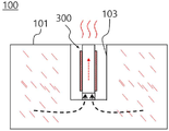
도 1은 본 발명의 일 실시예에 따른 스티머(steamer)의 구성도이고,
도 2는 본 발명의 일 실시예에 따른 히터부가 형성된 히터관 본체의 단면도이고,
도 3 및 도 4는 본 발명의 일 실시예에 따른 스티머를 포함하는 스팀 공급 장치의 사용 상태도들이고,
도 5는 본 발명의 일 실시예에 따른 스티머가 적용된 스팀 공급 장치의 작동원리를 나타내는 구성도이다.1 is a block diagram of a steamer according to an embodiment of the present invention;
2 is a cross-sectional view of a heater tube body in which a heater unit is formed according to an embodiment of the present invention;
3 and 4 are diagrams of a state of use of a steam supply device including a steamer according to an embodiment of the present invention,
5 is a configuration diagram illustrating an operating principle of a steam supply device to which a steamer is applied according to an embodiment of the present invention.
이하, 본 발명에 따른 스티머 및 이를 포함하는 스팀 공급장치의 일 실시예를 첨부된 도면을 참조하여 상세하게 설명하기로 한다.Hereinafter, an embodiment of a steamer according to the present invention and a steam supply device including the same will be described in detail with reference to the accompanying drawings.
각 도면의 구성요소들에 참조부호를 부가함에 있어서, 동일한 구성요소들에 대해서는 비록 다른 도면상에 표시되더라도 가능한 한 동일한 부호를 가지도록 하고 있음에 유의해야 한다. 또한, 본 발명의 실시예를 설명함에 있어, 관련된 공지 구성 또는 기능에 대한 구체적인 설명이 본 발명의 실시예에 대한 이해를 방해한다고 판단되는 경우에는 그 상세한 설명은 생략한다.In adding reference numerals to the components of each drawing, it should be noted that the same components are given the same reference numerals as much as possible even though they are indicated on different drawings. In addition, in describing the embodiment of the present invention, if it is determined that a detailed description of a related known configuration or function interferes with the understanding of the embodiment of the present invention, the detailed description thereof will be omitted.
본 발명의 실시예의 구성요소를 설명하는 데 있어서, 제1, 제2, A, B, (a), (b) 등의 용어를 사용할 수 있다. 이러한 용어는 그 구성요소를 다른 구성요소와 구별하기 위한 것일 뿐, 그 용어에 의해 해당 구성요소의 본질이나 차례 또는 순서 등이 한정되지 않는다. 또한, 다르게 정의되지 않는 한, 기술적이거나 과학적인 용어를 포함해서 여기서 사용되는 모든 용어들은 본 발명이 속하는 기술분야에서 통상의 지식을 가진 자에 의해 일반적으로 이해되는 것과 동일한 의미를 가진다. 일반적으로 사용되는 사전에 정의되어 있는 것과 같은 용어들은 관련 기술의 문맥상 가지는 의미와 일치하는 의미를 가진 것으로 해석되어야 하며, 본 출원에서 명백하게 정의하지 않는 한, 이상적이거나 과도하게 형식적인 의미로 해석되지 않는다.In describing the components of the embodiment of the present invention, terms such as first, second, A, B, (a), (b), etc. may be used. These terms are only for distinguishing the elements from other elements, and the essence, order, or order of the elements are not limited by the terms. In addition, unless otherwise defined, all terms used herein, including technical or scientific terms, have the same meaning as commonly understood by one of ordinary skill in the art to which this invention belongs. Terms such as those defined in a commonly used dictionary should be interpreted as having a meaning consistent with the meaning in the context of the related art, and should not be interpreted in an ideal or excessively formal meaning unless explicitly defined in the present application. does not
도 1은 본 발명의 일 실시예에 따른 스티머(steamer)의 구성도이고, 도 2는 본 발명의 일 실시예에 따른 투명 히터관의 단면도이다.1 is a block diagram of a steamer according to an embodiment of the present invention, and FIG. 2 is a cross-sectional view of a transparent heater tube according to an embodiment of the present invention.
이들 도면을 참조하면, 본 발명에 따른 스티머(100)는 외부로부터 물이 연속적으로 공급되는 메인 물탱크(101) 및 메인 물탱크(101)의 일측에 결합되는 가열부재(300)를 포함하여 구성될 수 있다.Referring to these drawings, the
메인 물탱크(101)는 소정의 내부 공간이 형성되되, 가열부재(300)가 안착될 수 있도록 중앙 부위가 함몰된 장착홈(103)이 형성된 'U'자 형태로 형성되고, 외부로부터 공급되는 물이 저장될 수 있다. 이러한 메인 물탱크(101)에는 상기 물이 외부로부터 연속적으로 공급되며 항상 일정량이 유지되도록 할 수 있다. 즉, 본 발명은, 메인 물탱크(101)의 수위가 항상 일정량 유지되도록 함으로써, 상기 물이 공급되어 가열되면서 증발되는 가습식 방식으로 구동될 수 있다. 메인 물탱크(101)에는 상기 물이 외부로부터 유입되는 유입구(미도시) 및 배출구(미도시)가 형성될 수 있다. 상기 배출구는 메인 물탱크(101)의 장착홈(103) 부위에 형성될 수 있다.The
메인 물탱크(101)의 중앙부위에 형성된 장착홈(103)은 가열부재(300)의 크기를 고려하여 적절히 조절 가능하며, 가열부재(300)의 상단부는 메인 물탱크(101)의 상단부의 높이와 동일하게 형성되는 것이 바람직할 수 있다.The
한편, 가열부재(300)는 메인 물탱크(101)의 장착홈(103)의 하측 단부로부터 상측 방향으로 수직 배치될 수 있다. 여기서, 가열부재(300)는 순간적으로 가열하여 공급하는 수단이면 특별히 제한되는 것은 아니며, 바람직하게는 금속소재, 예를 들어 스테인레스 강의 외면에 히터부(H)가 패턴으로 함께 프린트되어 가열되는 구조일 수 있다. 또, 가열부재(300)의 상단부 높이는 메인 물탱크(101)의 상단부의 높이와 적어도 동일하게 형성되는 것이 바람직할 수 있다.Meanwhile, the
본 발명은, 별도의 외부로부터 공급되는 물탱크 및 이로부터 물을 공급하기 위한 펌프(pump) 및 추가적인 히터 구성을 제거하고, 스티머에 직접 공급되는 상기 물이 메인 물탱크로부터 직접 가열되어 공급되도록 함으로써, 전체적인 스팀 공급장치의 크기를 획기적으로 감소시키고 순간 가열 방식에 따라 위생적이라는 점에 특징이 있다.The present invention removes a separate externally supplied water tank, a pump for supplying water therefrom, and an additional heater configuration, and allows the water directly supplied to the steamer to be directly heated and supplied from the main water tank. , it is characterized in that it dramatically reduces the size of the overall steam supply and is hygienic according to the instantaneous heating method.
본 발명에 따른 가열부재(300)는, 상기 공급수가 유동하는 중공형의 히터관 본체(310), 히터관 본체(310)의 표면에 절연재가 인쇄되고, 전도성 발열재와 같은 히팅이 가능한 히터부(H)가 소정의 패턴으로 프린팅될 수 있다.In the
히터관 본체(310)은 외부로부터 공급되는 물이 유동하도록 중공형의 스테인레스 강의 관으로 형성될 수 있다. 히터관 본체(310)의 외부표면에는 외부로부터 공급되는 상기 물이 가열되도록 히터부(H)가 형성될 수 있다. 이러한 히터부(H)는 외부 전류에 의하여 발열이 가능한 물질이면 특별히 제한되는 것은 아니다.The
히터관 본체(310)의 표면에는 히터부(H)가 소정의 패턴으로 형성될 수 있고, 히터부(H)는 외부 전원에 의하여 순간 발열이 가능할 수 있다. 본 발명에 따르면, 이러한 히터부(H)는, 히터관 본체(310) 내부에서 유동하는 공급수의 유입 부위와 배출 부위에서 보다 넓은 가열 구간이 확보하여 가열 가능하도록, 히터관 본체(310)의 외주면 전체에 형성되는 것이 바람직할 수 있다.A heater part (H) may be formed in a predetermined pattern on the surface of the
구체적으로, 본 발명에 따른 가열부재(300)에 의한 스팀 공급과정을 설명하면, 먼저 외부로부터 물이 메인 물탱크(101)로 항상 일정한 수위가 유지되도록 공급될 수 있다. 이어서, 메인 물탱크(101)의 상기 유입구를 통하여 유입되는 공급수는 장착홈(103) 부위에 형성된 상기 배출구를 통하여 가열부재(300)의 히터관 본체(310) 유동 챔버(315)로 공급될 수 있다.Specifically, when explaining the steam supply process by the
이 때, 메인 물탱크(101)에 공급되는 상기 공급수의 수위는 가열부재(300)의 히터관 본체(310)에 공급되는 상기 공급수의 수위가 항상 동일하게 유지될 수 있다. 이는 메인 물탱크(101)와 가열부재(300)가 연통되어 있으므로 상기 공급수가 동일한 수위로 유지될 수 있다.In this case, the level of the supply water supplied to the
여기서, 본 발명에 따르면, 메인 물탱크(101) 및 가열부재(300)의 히터관 본체(310)의 수위가 일정하게 유지하기 위하여 경우에 따라, 스티머(100)에는 메인 물탱크(101) 내에 채워진 공급수의 수위를 감지하는 수위 감지 센서(미도시) 및 메인 물탱크(101)로 유입되는 물을 감지하는 공급수 감지 센서(미도시)가 형성될 수 있다.Here, according to the present invention, in order to keep the water level of the
상기 수위 감지 센서는 메인 물탱크(101) 내에서 공급수의 수위를 감지할 수 있고, 상기 공급수가 형성하는 수면 최상단 부위 또는 상기 공급수와 공기층 계면 부위에 형성되되, 적어도 일부가 상기 공급수와 접촉될 수 있다. 따라서, 메인 물탱크(101) 내의 공급수의 수위를 지속적으로 감지하여 항상 일정량의 공급수가 유지될 수 있도록 센싱(sensing)할 수 있다. 경우에 따라서, 본 발명의 일 실시예에 따른 도면에는 도시되어 있지 않지만, 상기 메인 물탱크 내에서 공급수의 수량을 감지할 수 있는 수량 감지 센서가 추가로 형성될 수 있다.The water level sensor may detect the level of the supply water in the
또, 상기 메인 물탱크에는 T/F 안전장치가 형성될 수 있다. 따라서 스티머(100)의 이상 상태가 감지되면 전기적으로 연결된 컨트롤러(미도시)를 통하여 스티머(100)로 공급되는 전력 또는 신호를 즉시 차단하여 화재 발생 등을 방지할 수 있다.In addition, a T/F safety device may be formed in the main water tank. Accordingly, when an abnormal state of the
도 3 및 도 4는 본 발명의 일 실시예에 따른 스티머(steamer)를 포함하는 스팀 공급 장치의 사용 상태도들이다.3 and 4 are state diagrams of a steam supply device including a steamer according to an embodiment of the present invention.
이들 도면을 참조하면, 본 발명은 전술한 스티머(100)가 일측에 탈착 가능하게 형성되는 스팀 공급장치(500)를 포함할 수 있다.Referring to these drawings, the present invention may include a
스팀 공급장치(500)는 케비넷(cabinet) 형상으로 일면이 개방되는 본체(미도시) 및 상기 본체의 내부에 형성되되, 스티머(100)로부터 공급되는 스팀이 직접 배출되는 한 쌍의 스팀노즐(51)이 형성되어 있는 스팀판(50)와 바지 등의 대상체가 거치될 수 수 있는 옷걸이(11)가 형성되고 일측이 고정된 상태로 회동 가능하게 장착되는 거치대(10)를 포함하여 구성될 수 있다.The
이러한 스팀 공급장치(500)는, 도 3에 도시된 바와 같이, 바지 등의 대상체를 거치대(10)의 옷걸이(11)에 거치한 후에 스팀판(50)으로 회동시켜 일면을 밀착시킬 수 있다. 그 다음, 본 발명에 따른 스티머(100)를 작동시켜 스팀을 발생시키게 되면, 이러한 스팀은 일측에 형성되는 연결관(미도시)을 통하여 스팀판(50)의 스팀노즐(51)로 유동 및 배출되면서 상기 바지 등의 대상체에 공급되어 구김 또는 냄새 등의 제거가 수행될 수 있다.As shown in FIG. 3 , the
도 5는 본 발명의 일 실시예에 따른 스티머(steamer)가 적용된 스팀 공급 장치의 작동원리를 나타내는 구성도이다.5 is a configuration diagram illustrating an operating principle of a steam supply device to which a steamer is applied according to an embodiment of the present invention.
도 5를 참조하면, 본 발명에 따른 스팀 공급장치(500)는, 전술한 스티머(100)가 일측에 탈착 가능하게 형성되되, 스팀 공급장치(500) 내에 스팀의 순환을 유도하는 구성을 포함하는 스팀 공급장치(500)를 제공할 수 있다. 스팀 공급장치(500)는 내부 공기를 순환시키는 순환팬(550), 내부 공기를 가열하는 히터(530) 및 먼지필터(520)를 포함하여 구성될 수 있다.Referring to FIG. 5 , the
스팀 공급장치(500)의 내부는 복수의 구획판(510)에 의하여 스티머(100) 및 순환팬(550)과 공간적으로 분리되고 하부측의 구획판(510)의 일측에는 스티머(100)로부터 배출되는 스팀이 공급되는 스팀분사 노즐(511)이 돌출될 수 있다. 스팀 공급장치(500)의 상부에는 상기 바지 등의 대상체가 거치되는 옷걸이(11)가 형성되고, 옷걸이(11)는 순환팬(550)으로부터 공급되는 공기가 유입될 수 있도록 연통될 수 있다.The inside of the
스티머(100)로부터 분사되는 스팀은 하나의 구획판(510)에 의하여 분리되는 순환팬(550)이 배치되는 공간으로 유입될 수 있고, 이러한 스팀이 유입되는 경로 상에는 먼지필터(520)과 히터(530)가 형성될 수 있다.The steam sprayed from the
따라서, 스티머(100)로부터 분사되는 스팀은, 스팀 공급장치(500) 내부로 공급된 후, 순환팬(550)이 배치되는 공간으로 유입되면서 먼지필터(250)와 히터(530)를 지나며 정화 및 가열될 수 있다. 그 다음, 정화 및 가열된 스팀은 순환팬(550)으로 이동한 후에 옷걸이(11)의 상기 연통된 부위를 통하여 다시 스팀 공급장치(500)의 내부로 배출되면서 내부 순환이 원활하게 이루어질 수 있다.Accordingly, the steam injected from the
이상, 본 발명에 따른 스티머 및 이를 포함하는 스팀 공급장치의 일 실시예를 첨부된 도면을 참조하여 상세하게 설명하였다. 그러나, 본 발명의 실시예가 반드시 상술한 일 실시예에 의하여 한정되는 것은 아니고, 본 발명이 속하는 기술분야에서 통상의 지식을 가진 자에 의한 다양한 변형 및 균등한 범위에서의 실시가 가능함은 당연하다고 할 것이다. 그러므로, 본 발명의 진정한 권리범위는 후술하는 청구범위에 의하여 정해진다고 할 것이다.Above, an embodiment of a steamer according to the present invention and a steam supply device including the same has been described in detail with reference to the accompanying drawings. However, the embodiment of the present invention is not necessarily limited by the above-described embodiment, and it is natural that various modifications and implementations within an equivalent range are possible by those skilled in the art to which the present invention pertains. will be. Therefore, the true scope of the present invention will be determined by the claims to be described later.
10: 거치대
11: 옷걸이
50: 스팀판
100: 스티머
101: 물탱크
103: 장착홈
300: 가열부재
310: 히터관 본체
311: 유입부
312: 배출부
315: 유동 챔버
500: 스팀 공급장치
510: 구획판
511: 스팀 분사노즐
520: 먼지필터
530: 히터
550: 순환팬
H: 히터부10: Stand 11: Hanger
50: steam board 100: steamer
101: water tank 103: mounting groove
300: heating member 310: heater tube body
311: inlet 312: outlet
315: flow chamber 500: steam supply
510: partition plate 511: steam jet nozzle
520: dust filter 530: heater
550: circulation fan H: heater unit
Claims (14)
상기 물탱크에 일측에 결합되는 가열부재;를 포함하고,
상기 가열부재는,
상기 공급수가 유동하는 중공형의 히터관 본체; 및
상기 히터관 본체의 적어도 일부에 형성되는 히터부;를 포함하는 스티머.
a water tank in which at least one of a water supply part and a drain part is formed and a predetermined amount of supply water is supplied; and
Including; a heating member coupled to one side of the water tank;
The heating element is
a hollow heater tube body through which the supply water flows; and
A steamer including; a heater part formed on at least a portion of the heater tube body.
상기 물탱크에는 상기 가열부재가 안착되는 장착홈이 형성되는 스티머.
The method of claim 1,
A steamer in which a mounting groove in which the heating member is seated is formed in the water tank.
상기 물탱크의 장착홈은 중심부위에 형성되고, 상기 가열부재는 상기 중심부위에 안착되는 스티머.
3. The method of claim 2,
The water tank mounting groove is formed on a central portion, and the heating member is seated on the central portion.
상기 물탱크와 상기 가열부재의 상단부의 높이는 동일하게 형성되는 스티머.
The method of claim 1,
The steamer is formed to have the same height as the upper end of the water tank and the heating member.
상기 가열부재는 상기 물탱크와 일체로 형성되거나 독립적으로 탈착 가능하게 형성되는 스티머.
The method of claim 1,
The heating member is formed integrally with the water tank or is independently detachably formed.
상기 히터관 본체는 스테인레스 강을 포함하는 스티머.
The method of claim 1,
The heater tube body includes a stainless steel steamer.
상기 히터부는 상기 히터관 본체에 소정의 패턴으로 형성되는 스티머.
The method of claim 1,
The heater part is a steamer formed in a predetermined pattern on the heater tube body.
상기 히터관 본체와 상기 물탱크에는 상기 공급수가 동일한 수위로 항상 유지되는 스티머.
The method of claim 1,
A steamer in which the supply water is always maintained at the same water level in the heater tube body and the water tank.
상기 저장탱크의 공급수는 상기 급수 공급부로부터 연속적으로 공급되는 스티머.
The method of claim 1,
The water supplied to the storage tank is continuously supplied from the water supply unit.
상기 공급수는 증발하여 상기 증기수 배출구로 배출되는 가습식 방식으로 공급되는 스티머.
The method of claim 1,
The steamer is supplied in a humidified manner in which the supply water is evaporated and discharged to the steam water outlet.
상기 가습식 방식은 가열식, 초음파 방식 또는 복합식 가습 방식을 포함하는 스티머.
11. The method of claim 10,
The humidification method is a steamer including a heating method, an ultrasonic method or a complex humidification method.
상기 히터관 본체에는 상기 공급수가 유입되는 유입구와 배출되는 배출부가 형성되고, 상기 배출부에는 분사노즐이 형성되는 스티머.
The method of claim 1,
The heater tube body is formed with an inlet through which the supply water is introduced and an outlet through which the water is discharged, and an injection nozzle is formed at the outlet.
13. A steam supply device comprising the steamer according to any one of claims 1 to 12.
상기 스티머는 상기 스팀 공급 장치로부터 착탈 가능하게 장착되는 스팀 공급 장치.14. The method of claim 13,
The steamer is a steam supply device that is detachably mounted from the steam supply device.
Priority Applications (1)
| Application Number | Priority Date | Filing Date | Title |
|---|---|---|---|
| KR1020210029059A KR20220125087A (en) | 2021-03-04 | 2021-03-04 | Steamer and apparatus for supplying steam thereof |
Applications Claiming Priority (1)
| Application Number | Priority Date | Filing Date | Title |
|---|---|---|---|
| KR1020210029059A KR20220125087A (en) | 2021-03-04 | 2021-03-04 | Steamer and apparatus for supplying steam thereof |
Publications (1)
| Publication Number | Publication Date |
|---|---|
| KR20220125087A true KR20220125087A (en) | 2022-09-14 |
Family
ID=83278821
Family Applications (1)
| Application Number | Title | Priority Date | Filing Date |
|---|---|---|---|
| KR1020210029059A KR20220125087A (en) | 2021-03-04 | 2021-03-04 | Steamer and apparatus for supplying steam thereof |
Country Status (1)
| Country | Link |
|---|---|
| KR (1) | KR20220125087A (en) |
Citations (1)
| Publication number | Priority date | Publication date | Assignee | Title |
|---|---|---|---|---|
| KR101525568B1 (en) | 2008-12-09 | 2015-06-03 | 엘지전자 주식회사 | Fabric treating apparatus |
-
2021
- 2021-03-04 KR KR1020210029059A patent/KR20220125087A/en unknown
Patent Citations (1)
| Publication number | Priority date | Publication date | Assignee | Title |
|---|---|---|---|---|
| KR101525568B1 (en) | 2008-12-09 | 2015-06-03 | 엘지전자 주식회사 | Fabric treating apparatus |
Similar Documents
| Publication | Publication Date | Title |
|---|---|---|
| KR101351045B1 (en) | device for cloth treating | |
| CN111607945B (en) | Clothes dryer | |
| CN101970743A (en) | Apparatus for treating clothing | |
| KR102300033B1 (en) | Laundry treating machine | |
| CN102482827B (en) | Steam generator for use in a laundry appliance, and laundry appliance | |
| TR201908929T4 (en) | A steam generator for a steamer. | |
| KR101521917B1 (en) | Apparatus and method thereof for treating clothing | |
| KR20220125087A (en) | Steamer and apparatus for supplying steam thereof | |
| KR20220125088A (en) | Steamer and apparatus for supplying steam thereof | |
| KR102367321B1 (en) | Steamer and apparatus for supplying steam thereof | |
| KR102367315B1 (en) | Steamer and apparatus for supplying steam thereof | |
| KR20220079314A (en) | Steamer and apparatus for supplying steam thereof | |
| KR20220079317A (en) | Steamer and apparatus for supplying steam thereof | |
| KR20220079312A (en) | Steamer and apparatus for supplying steam thereof | |
| KR20220126926A (en) | Steamer and apparatus for supplying steam thereof | |
| KR20220169171A (en) | Steamer and apparatus for supplying steam thereof | |
| KR20220092122A (en) | Steamer and apparatus for supplying steam thereof | |
| KR20230144747A (en) | Steam module and apparatus for supplying steam thereof | |
| KR20220079320A (en) | Steamer and apparatus for supplying steam thereof | |
| EP3315648B1 (en) | Washing and drying machine | |
| KR20230075749A (en) | Steamer and apparatus for supplying steam thereof | |
| KR20220079321A (en) | Steamer and apparatus for supplying steam thereof | |
| KR101291275B1 (en) | Clothes treatment apparatus | |
| KR20230165591A (en) | Steamer and apparatus for supplying steam thereof | |
| KR20230144746A (en) | Steam module and apparatus for supplying steam thereof |