KR20220123580A - A contactor, an integrated circuit, a method of interrupting a current flow - Google Patents
A contactor, an integrated circuit, a method of interrupting a current flow Download PDFInfo
- Publication number
- KR20220123580A KR20220123580A KR1020220022081A KR20220022081A KR20220123580A KR 20220123580 A KR20220123580 A KR 20220123580A KR 1020220022081 A KR1020220022081 A KR 1020220022081A KR 20220022081 A KR20220022081 A KR 20220022081A KR 20220123580 A KR20220123580 A KR 20220123580A
- Authority
- KR
- South Korea
- Prior art keywords
- switch
- controller
- contactor
- open
- primary
- Prior art date
Links
- 238000000034 method Methods 0.000 title claims description 59
- 238000004891 communication Methods 0.000 claims abstract description 30
- 238000007664 blowing Methods 0.000 claims abstract description 12
- 238000005259 measurement Methods 0.000 claims description 12
- 239000004065 semiconductor Substances 0.000 claims description 9
- GNFTZDOKVXKIBK-UHFFFAOYSA-N 3-(2-methoxyethoxy)benzohydrazide Chemical compound COCCOC1=CC=CC(C(=O)NN)=C1 GNFTZDOKVXKIBK-UHFFFAOYSA-N 0.000 claims description 6
- 230000002159 abnormal effect Effects 0.000 claims description 4
- 230000003213 activating effect Effects 0.000 claims description 3
- 230000000694 effects Effects 0.000 claims 1
- 238000001514 detection method Methods 0.000 abstract description 24
- 239000004020 conductor Substances 0.000 abstract description 16
- 230000008901 benefit Effects 0.000 description 16
- 238000010586 diagram Methods 0.000 description 14
- 230000006870 function Effects 0.000 description 7
- 230000001419 dependent effect Effects 0.000 description 4
- 230000014509 gene expression Effects 0.000 description 4
- 230000007257 malfunction Effects 0.000 description 4
- WQGWDDDVZFFDIG-UHFFFAOYSA-N pyrogallol Chemical compound OC1=CC=CC(O)=C1O WQGWDDDVZFFDIG-UHFFFAOYSA-N 0.000 description 4
- 239000000758 substrate Substances 0.000 description 4
- 230000002441 reversible effect Effects 0.000 description 3
- XUIMIQQOPSSXEZ-UHFFFAOYSA-N Silicon Chemical compound [Si] XUIMIQQOPSSXEZ-UHFFFAOYSA-N 0.000 description 2
- 230000004913 activation Effects 0.000 description 2
- 239000013078 crystal Substances 0.000 description 2
- 230000004907 flux Effects 0.000 description 2
- 238000004904 shortening Methods 0.000 description 2
- 229910052710 silicon Inorganic materials 0.000 description 2
- 239000010703 silicon Substances 0.000 description 2
- 238000012360 testing method Methods 0.000 description 2
- 230000001960 triggered effect Effects 0.000 description 2
- FGUUSXIOTUKUDN-IBGZPJMESA-N C1(=CC=CC=C1)N1C2=C(NC([C@H](C1)NC=1OC(=NN=1)C1=CC=CC=C1)=O)C=CC=C2 Chemical compound C1(=CC=CC=C1)N1C2=C(NC([C@H](C1)NC=1OC(=NN=1)C1=CC=CC=C1)=O)C=CC=C2 FGUUSXIOTUKUDN-IBGZPJMESA-N 0.000 description 1
- 230000001133 acceleration Effects 0.000 description 1
- 230000002457 bidirectional effect Effects 0.000 description 1
- 230000000903 blocking effect Effects 0.000 description 1
- 238000004590 computer program Methods 0.000 description 1
- 238000012937 correction Methods 0.000 description 1
- 230000001934 delay Effects 0.000 description 1
- 238000013461 design Methods 0.000 description 1
- 239000002360 explosive Substances 0.000 description 1
- 239000012634 fragment Substances 0.000 description 1
- 230000002427 irreversible effect Effects 0.000 description 1
- 230000009467 reduction Effects 0.000 description 1
- 238000005070 sampling Methods 0.000 description 1
Images


Classifications
-
- H—ELECTRICITY
- H01—ELECTRIC ELEMENTS
- H01H—ELECTRIC SWITCHES; RELAYS; SELECTORS; EMERGENCY PROTECTIVE DEVICES
- H01H47/00—Circuit arrangements not adapted to a particular application of the relay and designed to obtain desired operating characteristics or to provide energising current
- H01H47/002—Monitoring or fail-safe circuits
-
- H—ELECTRICITY
- H02—GENERATION; CONVERSION OR DISTRIBUTION OF ELECTRIC POWER
- H02H—EMERGENCY PROTECTIVE CIRCUIT ARRANGEMENTS
- H02H3/00—Emergency protective circuit arrangements for automatic disconnection directly responsive to an undesired change from normal electric working condition with or without subsequent reconnection ; integrated protection
- H02H3/08—Emergency protective circuit arrangements for automatic disconnection directly responsive to an undesired change from normal electric working condition with or without subsequent reconnection ; integrated protection responsive to excess current
-
- H—ELECTRICITY
- H01—ELECTRIC ELEMENTS
- H01H—ELECTRIC SWITCHES; RELAYS; SELECTORS; EMERGENCY PROTECTIVE DEVICES
- H01H50/00—Details of electromagnetic relays
- H01H50/14—Terminal arrangements
-
- B—PERFORMING OPERATIONS; TRANSPORTING
- B60—VEHICLES IN GENERAL
- B60L—PROPULSION OF ELECTRICALLY-PROPELLED VEHICLES; SUPPLYING ELECTRIC POWER FOR AUXILIARY EQUIPMENT OF ELECTRICALLY-PROPELLED VEHICLES; ELECTRODYNAMIC BRAKE SYSTEMS FOR VEHICLES IN GENERAL; MAGNETIC SUSPENSION OR LEVITATION FOR VEHICLES; MONITORING OPERATING VARIABLES OF ELECTRICALLY-PROPELLED VEHICLES; ELECTRIC SAFETY DEVICES FOR ELECTRICALLY-PROPELLED VEHICLES
- B60L3/00—Electric devices on electrically-propelled vehicles for safety purposes; Monitoring operating variables, e.g. speed, deceleration or energy consumption
- B60L3/0023—Detecting, eliminating, remedying or compensating for drive train abnormalities, e.g. failures within the drive train
-
- B—PERFORMING OPERATIONS; TRANSPORTING
- B60—VEHICLES IN GENERAL
- B60L—PROPULSION OF ELECTRICALLY-PROPELLED VEHICLES; SUPPLYING ELECTRIC POWER FOR AUXILIARY EQUIPMENT OF ELECTRICALLY-PROPELLED VEHICLES; ELECTRODYNAMIC BRAKE SYSTEMS FOR VEHICLES IN GENERAL; MAGNETIC SUSPENSION OR LEVITATION FOR VEHICLES; MONITORING OPERATING VARIABLES OF ELECTRICALLY-PROPELLED VEHICLES; ELECTRIC SAFETY DEVICES FOR ELECTRICALLY-PROPELLED VEHICLES
- B60L3/00—Electric devices on electrically-propelled vehicles for safety purposes; Monitoring operating variables, e.g. speed, deceleration or energy consumption
- B60L3/04—Cutting off the power supply under fault conditions
-
- G—PHYSICS
- G01—MEASURING; TESTING
- G01R—MEASURING ELECTRIC VARIABLES; MEASURING MAGNETIC VARIABLES
- G01R1/00—Details of instruments or arrangements of the types included in groups G01R5/00 - G01R13/00 and G01R31/00
- G01R1/20—Modifications of basic electric elements for use in electric measuring instruments; Structural combinations of such elements with such instruments
- G01R1/203—Resistors used for electric measuring, e.g. decade resistors standards, resistors for comparators, series resistors, shunts
-
- G—PHYSICS
- G01—MEASURING; TESTING
- G01R—MEASURING ELECTRIC VARIABLES; MEASURING MAGNETIC VARIABLES
- G01R19/00—Arrangements for measuring currents or voltages or for indicating presence or sign thereof
- G01R19/0092—Arrangements for measuring currents or voltages or for indicating presence or sign thereof measuring current only
-
- H—ELECTRICITY
- H01—ELECTRIC ELEMENTS
- H01H—ELECTRIC SWITCHES; RELAYS; SELECTORS; EMERGENCY PROTECTIVE DEVICES
- H01H50/00—Details of electromagnetic relays
- H01H50/44—Magnetic coils or windings
- H01H50/443—Connections to coils
-
- H—ELECTRICITY
- H01—ELECTRIC ELEMENTS
- H01H—ELECTRIC SWITCHES; RELAYS; SELECTORS; EMERGENCY PROTECTIVE DEVICES
- H01H85/00—Protective devices in which the current flows through a part of fusible material and this current is interrupted by displacement of the fusible material when this current becomes excessive
- H01H85/02—Details
- H01H85/04—Fuses, i.e. expendable parts of the protective device, e.g. cartridges
- H01H85/041—Fuses, i.e. expendable parts of the protective device, e.g. cartridges characterised by the type
-
- H—ELECTRICITY
- H02—GENERATION; CONVERSION OR DISTRIBUTION OF ELECTRIC POWER
- H02H—EMERGENCY PROTECTIVE CIRCUIT ARRANGEMENTS
- H02H1/00—Details of emergency protective circuit arrangements
- H02H1/0007—Details of emergency protective circuit arrangements concerning the detecting means
-
- H—ELECTRICITY
- H02—GENERATION; CONVERSION OR DISTRIBUTION OF ELECTRIC POWER
- H02H—EMERGENCY PROTECTIVE CIRCUIT ARRANGEMENTS
- H02H3/00—Emergency protective circuit arrangements for automatic disconnection directly responsive to an undesired change from normal electric working condition with or without subsequent reconnection ; integrated protection
- H02H3/08—Emergency protective circuit arrangements for automatic disconnection directly responsive to an undesired change from normal electric working condition with or without subsequent reconnection ; integrated protection responsive to excess current
- H02H3/087—Emergency protective circuit arrangements for automatic disconnection directly responsive to an undesired change from normal electric working condition with or without subsequent reconnection ; integrated protection responsive to excess current for dc applications
-
- H—ELECTRICITY
- H02—GENERATION; CONVERSION OR DISTRIBUTION OF ELECTRIC POWER
- H02H—EMERGENCY PROTECTIVE CIRCUIT ARRANGEMENTS
- H02H3/00—Emergency protective circuit arrangements for automatic disconnection directly responsive to an undesired change from normal electric working condition with or without subsequent reconnection ; integrated protection
- H02H3/02—Details
- H02H3/05—Details with means for increasing reliability, e.g. redundancy arrangements
Landscapes
- Engineering & Computer Science (AREA)
- Physics & Mathematics (AREA)
- General Physics & Mathematics (AREA)
- Electromagnetism (AREA)
- Sustainable Energy (AREA)
- Transportation (AREA)
- Mechanical Engineering (AREA)
- Power Engineering (AREA)
- Life Sciences & Earth Sciences (AREA)
- Sustainable Development (AREA)
- Emergency Protection Circuit Devices (AREA)
- Relay Circuits (AREA)
- Breakers (AREA)
Abstract
Description
본 발명은 일반적으로 전력 회로들의 분야에 관한 것이며, 더 상세하게는, 선택적으로 전기 또는 하이브리드 차량의 배터리를 전기 로드(electric load)에 연결하고 전기 로드로부터 연결 해제하기 위한 접촉기, 및 전류 흐름을 차단하는 방법에 관한 것이다.FIELD OF THE INVENTION The present invention relates generally to the field of power circuits, and more particularly, optionally a contactor for connecting and disconnecting a battery of an electric or hybrid vehicle to and from an electric load, and blocking current flow. it's about how to
EV(electric vehicle) 또는 HV(hybrid vehicle)의 모터는 약 200V 내지 약 800V, 또는 그 초과 범위의 전압을 제공하는 배터리에 의해 전력 공급될 수 있다. 배터리는 최대 약 1500A의 크기를 갖는 전류를 제공할 수 있으며, 전류 피크는 최대 3000A 또는 그 초과이다. 말할 필요도 없이, 그러한 차량들의 전력 회로는 차량의 승객들에게 잠재적인 위협이 된다. 안전상의 이유들로, 전력 회로 및/또는 배터리 자체의 오작동이 신속하게 검출되어 해결되어야 하고, 예컨대, 일부 오작동들은 5ms 이내에 검출될 필요가 있다. The motor of an electric vehicle (EV) or hybrid vehicle (HV) may be powered by a battery that provides a voltage in the range of about 200V to about 800V, or more. The battery can provide a current having a magnitude of up to about 1500 A, with a current peak of up to 3000 A or more. Needless to say, the power circuitry of such vehicles is a potential threat to the vehicle's passengers. For safety reasons, malfunctions of the power circuit and/or the battery itself must be detected and resolved quickly, for example, some malfunctions need to be detected within 5 ms.
이러한 차량들에서, 접촉기는 전형적으로 정상적인 상황들에서 배터리를 전기 모터 및/또는 충전 회로에 선택적으로 연결하고 그리고 이들로부터 연결 해제하는 데 사용된다. 전력 회로는 비상 사태, 예컨대, 충돌의 경우에 회로를 개방하기 위한 퓨즈를 더 포함할 수 있다. In such vehicles, a contactor is typically used to selectively connect and disconnect a battery to and from an electric motor and/or charging circuit under normal circumstances. The power circuit may further include a fuse to open the circuit in case of an emergency, such as a crash.
US2014292109(A1)는 EV(electric vehicle) 또는 HV(hybrid vehicle)에서 사용하기 위한 전류 센서를 포함하는 접촉기 장치를 설명한다.US2014292109 (A1) describes a contactor device comprising a current sensor for use in an electric vehicle (EV) or hybrid vehicle (HV).
개선들 또는 대안들에 대한 여지가 항상 있다.There is always room for improvements or alternatives.
본 발명의 실시예들의 목적은 전기 또는 하이브리드 차량, 특히 전기 및/또는 하이브리드 자동차들에 사용하기 위한 접촉기를 제공하는 것이다. It is an object of embodiments of the present invention to provide a contactor for use in electric or hybrid vehicles, in particular electric and/or hybrid vehicles.
본 발명의 실시예들의 목적은 이러한 접촉기를 포함하는 전력 회로, 및 이러한 전력 회로를 포함하는 전기 차량을 제공하는 것이다.It is an object of embodiments of the present invention to provide a power circuit comprising such a contactor, and an electric vehicle comprising such a power circuit.
본 발명의 실시예들의 목적은 이러한 접촉기를 통해 흐르는 전류를 차단하는 방법을 제공하는 것이다. It is an object of embodiments of the present invention to provide a method of interrupting the current flowing through such a contactor.
본 발명의 실시예들의 목적은 그러한 방법을 수행하기 위한 집적 회로를 제공하는 것이다. It is an object of embodiments of the present invention to provide an integrated circuit for performing such a method.
본 발명의 실시예들의 목적은 스위치를 갖고, 또한 전류를 측정하고 그 전류를 차단할 수 있는 접촉기를 제공하는 것이다.SUMMARY OF THE INVENTION It is an object of embodiments of the present invention to provide a contactor having a switch and capable of measuring and breaking the current.
본 발명의 실시예들의 목적은, (전류가 흐르는 것을 정지시킬 수 있다는 점에서) 개선된 신뢰성을 갖고 그리고/또는 개선된 수명을 갖고, 그리고 바람직하게는 둘 모두를 갖는 접촉기를 제공하는 것이다.It is an object of embodiments of the present invention to provide a contactor with improved reliability (in that it can stop current flowing) and/or with an improved lifetime, and preferably both.
본 발명의 실시예들의 목적은 이러한 접촉기를 포함하는 전력 회로를 제공하는 것이며, 이 전력 회로는 개선된 안전성을 제공하고 그리고/또는 개선된 수명을 가지며, 바람직하게는 둘 모두를 갖는다.It is an object of embodiments of the present invention to provide a power circuit comprising such a contactor, which power circuit provides improved safety and/or has an improved lifetime, preferably both.
본 발명의 실시예들의 목적은 그러한 방법을 더 빠르고, 그리고/또는 더 효율적으로, 및/또는 더 신뢰성 있게 수행하기 위한 집적 회로를 제공하는 것이다.It is an object of embodiments of the present invention to provide an integrated circuit for performing such a method faster, and/or more efficiently, and/or more reliably.
이들 및 다른 목적들은 본 발명의 실시예들에 따른 접촉기, 전력 회로, 접촉기를 통해 흐르는 전류를 차단하는 방법, 및 집적 회로에 의해 달성된다.These and other objects are achieved by a contactor, a power circuit, a method of interrupting current flowing through the contactor, and an integrated circuit according to embodiments of the present invention.
제1 양상에 따라, 본 발명은 접촉기를 제공하고, 접촉기는: 제1 전력 단자; 제2 전력 단자; 제1 전력 단자와 제2 전력 단자 사이에 전기적으로 연결되고, 직렬로 연결된 적어도 3개의 엘리먼트들: 전기 전도체 부분, 1차 스위치(본원에 또한 "고전압 스위치" 또는 "HV 스위치"로 지칭됨), 및 퓨즈를 포함하는 서브 회로; 액추에이터에 의해 구동되는 가동 부분을 포함하는 1차 스위치; 전기 전도체 부분을 통해 흐르는 1차 전류(본원에서 또한 "고전압 전류" 또는 "HV 전류"로 지칭됨)를 측정하도록 구성된 자기 센서; 전기 전도체 부분을 통해 흐르는 상기 1차 전류를 측정하도록 상기 자기 센서에 통신 가능하게 연결되고, 그리고 상기 스위치를 선택적으로 개방 및 폐쇄하도록 상기 액추에이터에 동작 가능하게 연결된 제어기를 포함하고, 접촉기는, 1차 스위치가 실제로 개방인지 또는 폐쇄인지를 검출하기 위한 검출 수단을 더 포함하고; 그리고 상기 제어기는: (i) 1차 전류를 측정하고, 과전류 상태가 발생하는지를 검출하고; 그리고 과전류 상태가 검출되는 경우, 단계 ii)로 계속하고, 그렇지 않은 경우, 단계 i)를 반복하고; (ii) 1차 스위치를 개방하도록 액추에이터를 동작시키고; (iii) 1차 스위치가 실질적으로 개방인지를 검출하고, 그리고 (예컨대, 시간 간격(Δt) 후에) 1차 스위치가 여전히 폐쇄인 것이 검출된 경우, 퓨즈를 끊도록 구성된다. According to a first aspect, the present invention provides a contactor, the contactor comprising: a first power terminal; a second power terminal; at least three elements electrically connected between the first power terminal and the second power terminal and connected in series: an electrical conductor portion, a primary switch (also referred to herein as a “high voltage switch” or “HV switch”); and a sub-circuit including a fuse; a primary switch comprising a movable portion driven by an actuator; a magnetic sensor configured to measure a primary current (also referred to herein as "high voltage current" or "HV current") flowing through the electrically conductive portion; a controller communicatively coupled to the magnetic sensor to measure the primary current flowing through the electrical conductor portion, and a controller operatively coupled to the actuator to selectively open and close the switch, the contactor comprising: detecting means for detecting whether the switch is actually open or closed; and the controller: (i) measures the primary current and detects whether an overcurrent condition occurs; and if an overcurrent condition is detected, continue to step ii), otherwise repeat step i); (ii) actuating the actuator to open the primary switch; (iii) detect that the primary switch is substantially open, and blow the fuse (eg, after a time interval Δt) if it is detected that the primary switch is still closed.
시간 간격(Δt)은 미리 정의된 시간 간격일 수 있거나, 측정된 HV 전류의 함수로써 (예컨대, 룩업 테이블을 사용하여) 계산될 수 있다. 시간 기간은, HV 전류의 측정 이후에, 한 번만 결정될 수 있거나 (진행 중인 HV 전류 측정 값들에 기반하여) 동적으로 조정 또는 업데이트될 수 있다.The time interval Δt may be a predefined time interval, or may be calculated (eg, using a lookup table) as a function of the measured HV current. The time period may be determined only once, after measurement of the HV current, or may be dynamically adjusted or updated (based on ongoing HV current measurements).
"제1 전력 단자"는 배터리에 (직접 또는 간접적으로) 연결되거나 연결 가능할 수 있다. "제2 전력 단자"는 전기 모터에 (직접 또는 간접적으로) 연결되거나 연결 가능할 수 있다.The “first power terminal” may be connected (directly or indirectly) or connectable to the battery. The “second power terminal” may be connected (directly or indirectly) or connectable to the electric motor.
자기 센서가 비접촉 방식으로 1차 전류를 측정할 수 있다는 장점이 있다. 이것은, 자기 센서가 (상대적인) 낮은 전압(예컨대, 최대 48V)에서 동작하는 것을 허용한다.There is an advantage that the magnetic sensor can measure the primary current in a non-contact manner. This allows the magnetic sensor to operate at (relatively) low voltages (eg, up to 48V).
접촉기가, 외부 디바이스와 통신할 필요 없이 자체적으로 그리고 자기 센서의 측정에 의존하지 않는 방식으로, 상기 검출 수단을 사용하여 스위치가 실질적으로 개방 또는 폐쇄인지를 검출할 수 있다는 것이 주요 장점인데, 왜냐하면 이는 피드백 루프를 단축하기 때문이고, 이는 결국 퓨즈를 끊어야 하는 것보다는 액추에이터를 사용하여 스위치를 개방하기 위한 시도가 이루어질 수 있는 여분의 시간을 제공한다. 또는 다시 말해서, 이 접촉기의 장점은, (특정 상태들 하에서, 예컨대, HV 전류가 특정 값보다 낮은 경우) 먼저 스위치를 가역적인 방식으로 개방하려고 시도할 수 있다는 점이고, 이는, 다른 디바이스들(예컨대, 외부 프로세서)과의 통신으로 인해 귀중한 시간이 허비된 경우, 가능하지 않을 수 있다. 통신 루프 또는 판정 루프를 단축시킴으로써, 시간 부족으로 인해 퓨즈를 끊어야 할 확률이 감소될 수 있다.The main advantage is that the contactor can detect whether the switch is substantially open or closed using said detection means, on its own and in a way that does not depend on the measurement of a magnetic sensor, without the need to communicate with an external device, since it This is because it shortens the feedback loop, which gives extra time that an attempt can be made to open the switch using the actuator rather than having to blow the fuse in the end. Or, in other words, the advantage of this contactor is that it can first attempt to open the switch in a reversible manner (under certain conditions, eg, when the HV current is lower than a certain value), which may cause other devices (e.g., This may not be possible if valuable time was wasted communicating with an external processor). By shortening the communication loop or decision loop, the probability of having to blow a fuse due to a lack of time can be reduced.
"검출 수단"이 자기 센서에 의해 수행되는 전류 측정과 독립적인 방식으로 내부 진단을 수행하는 방법을 제공한다는 것이 장점이다. 또는 다시 말해서, 스위치가 폐쇄 루프 방식(즉, 포워드 동작 + 피드백)으로 동작될 수 있다는 장점이 있다. 이러한 방식으로, 접촉기의 신뢰성이 증가될 수 있고, 이 접촉기가 사용되는 전력 시스템의 안전성이 향상될 수 있다.The advantage is that the "detection means" provides a method for performing internal diagnostics in a manner independent of the current measurement performed by the magnetic sensor. Or in other words, there is an advantage that the switch can be operated in a closed loop manner (ie, forward operation + feedback). In this way, the reliability of the contactor can be increased, and the safety of the power system in which the contactor is used can be improved.
과전류 상태의 검출은: 측정된 HV 전류와 미리 정의된 값을 비교하는 것을 포함할 수 있거나, 또는 고전적인 I2T(암페어 제곱 시간 초) 기법을 포함할 수 있거나 이에 기반할 수 있다.Detection of an overcurrent condition may include: comparing the measured HV current with a predefined value, or may include or be based on the classical I2T (amps squared time second) technique.
"제1 전력 단자"는 배터리에 (직접 또는 간접적으로) 연결되거나 연결 가능할 수 있다. "제2 전력 단자"는 전기 모터 또는 2상 또는 3상 변환기에 (직접 또는 간접적으로) 연결되거나 연결 가능할 수 있다.The “first power terminal” may be connected (directly or indirectly) or connectable to the battery. The “second power terminal” may be connected (directly or indirectly) or connectable to an electric motor or a two- or three-phase converter.
퓨즈가 1차 스위치와 직렬로 연결되는 것이 장점인데, 왜냐하면 1차 스위치가 개방되지 않은 경우에도, 이것은 HV 전류가 차단될 수 있다는 것을 허용하기 때문이다.It is advantageous to have a fuse connected in series with the primary switch, since this allows the HV current to be interrupted even if the primary switch is not open.
"과전류 상태를 검출하는 단계"는 측정된 전류와 미리 정의된 임계값을 비교하는 것을 포함할 수 있다. “Detecting an overcurrent condition” may include comparing the measured current with a predefined threshold.
"과전류 상태를 검출하는 단계"는: 시간 경과에 따른 I2T 값(암페어 제곱 초)을 계산하는 것, 및 이 값과 미리 정의된 임계값을 비교하는 것을 포함할 수 있다."Detecting an overcurrent condition" may include: calculating an I2T value (ampere squared seconds) over time, and comparing this value to a predefined threshold.
실시예에서, 제어기는: a) 전기 전도체 부분을 통해 흐르는 1차 전류를 자기 센서를 사용하여 반복적으로(예컨대, 주기적으로) 측정하고; b) (예컨대, 주기적으로) 측정된 1차 전류에 기반하여 과전류 상태가 발생했는지를 검출하고, 그리고 과전류가 발생했다는 것이 검출된 경우, 단계 c)로 계속하고; 예컨대, 측정된 전류 값(들)의 함수로써, 1차 스위치를 개방하기 위해 이용 가능한 시간 기간(예컨대, Δtav)을 결정하고; d) 이용 가능한 시간 기간(Δtav)과, 1차 스위치를 개방하기 위해 요구된 시간 기간(Δtreq)을 비교하고, 그리고 이용 가능한 시간 기간이 요구된 시간 기간보다 짧은 경우, 단계 g)로 계속하고; 그렇지 않은 경우, 단계 e)로 계속하고; (e) 1차 스위치를 개방하도록 액추에이터를 동작시키고; f) 1차 스위치가 이용 가능한 시간 기간(Δtav) 내에서 실질적으로 개방인지 여부를 검출 수단을 사용하여 검출하고, 그리고 이용 가능한 시간 기간(Δtav) 후에 1차 스위치가 여전히 폐쇄인는 경우에, 퓨즈를 끊도록 구성된다.In an embodiment, the controller is configured to: a) repeatedly (eg, periodically) measure a primary current flowing through the electrically conductive portion using the magnetic sensor; b) detect whether an overcurrent condition has occurred based on the measured primary current (eg, periodically), and if it is detected that an overcurrent has occurred, continue to step c); determine a time period (eg, Δtav) available for opening the primary switch, eg, as a function of the measured current value(s); d) compare the available time period Δtav with the time period Δtreq required to open the primary switch, and if the available time period is shorter than the required time period, continue with step g); otherwise, continue with step e); (e) actuating the actuator to open the primary switch; f) detecting by means of detection whether the primary switch is substantially open within the available time period Δtav, and if the primary switch is still closed after the available time period Δtav, blow the fuse configured to break.
위에서 언급한 바와 같이, 스위치의 개방은 (적어도) 외부 프로세서(예컨대, ECU)로부터의 대응하는 명령의 수신에 의해 트리거될 수 있거나 트리거될 것이다.As mentioned above, the opening of the switch may or will be triggered by (at least) receiving a corresponding command from an external processor (eg, ECU).
일 실시예에서, 제어기는 외부 프로세서에 연결 가능한 적어도 하나의 통신 포트를 갖고; 제어기는, 스위치를 폐쇄하라는 커맨드, 스위치를 개방하라는 커맨드, 퓨즈를 끊으라는 커맨드로 구성된 그룹으로부터 선택된 적어도 하나의 커맨드를 수신하도록 추가로 구성되고; 그리고 제어기는: (x) 스위치를 폐쇄하라는 커맨드의 수신 시에, 1차 스위치를 폐쇄하도록 액추에이터를 동작시키는 것; (y) 스위치를 개방하라는 커맨드의 수신 시에, 단계 ii) 및 iii)를 수행하는 것; (z) 퓨즈를 끊으라는 커맨드의 수신 시에, 퓨즈를 끊는 것 중 적어도 하나를 수행하도록 추가로 구성된다.In one embodiment, the controller has at least one communication port connectable to an external processor; the controller is further configured to receive at least one command selected from the group consisting of a command to close the switch, a command to open the switch, and a command to blow the fuse; and the controller: (x) upon receipt of the command to close the switch, actuating the actuator to close the primary switch; (y) upon receipt of a command to open the switch, performing steps ii) and iii); (z) upon receiving the command to blow the fuse, perform at least one of blowing the fuse.
일부 실시예들에서, 단계 ii) 및 iii)을 수행하는 것은 단계 a) 및 단계 c) 내지 g)를 수행함으로써 구현될 수 있다.In some embodiments, performing steps ii) and iii) may be implemented by performing steps a) and c)-g).
일 실시예에서, 접촉기는 적어도 60A(또는 적어도 75A, 또는 적어도 100A, 또는 적어도 125A)의 전류를 전도할 수 있고; 그리고 접촉기는 최대 48V(또는 최대 36V, 또는 최대 24V, 또는 최대 12V)의 전압 공급을 수신하기 위한 제3 및 제4 전력 단자를 더 포함한다.In one embodiment, the contactor is capable of conducting a current of at least 60A (or at least 75A, or at least 100A, or at least 125A); and the contactor further includes third and fourth power terminals for receiving a voltage supply of up to 48V (or up to 36V, or up to 24V, or up to 12V).
이 전압은 본원에서 "저전압 공급기"로 지칭된다. 이 저전압은, 차량의 모터에 전력을 공급하도록 의도되는 것이 아니라 제어 회로에 전력을 공급하도록 의도된 제2 배터리에 의해 공급될 수 있다. 적어도 제어기, 액추에이터, 검출 수단 및 자기 센서는 저전압 공급기에 의해 전력이 공급된다.This voltage is referred to herein as a "low voltage supply". This low voltage may be supplied by a secondary battery which is not intended to power the motor of the vehicle but is intended to power the control circuit. At least the controller, actuator, detection means and magnetic sensor are powered by a low voltage supply.
고전압 도메인 및 저전압 도메인은 전기적으로(galvanically) 분리된다. 바람직하게는 물리적으로 전기 전도체 부분에 매우 가깝게 위치되지만 전기 전도체 부분으로부터 전기적으로 분리된 자기 센서를 사용하는 것의 이점은, 저전압 도메인의 회로가 고전압 도메인에서, 즉, 전기 전도체 부분을 통해 흐르는 전류를 측정하는 것을 허용한다는 것이다. The high voltage domain and the low voltage domain are galvanically separated. An advantage of using a magnetic sensor, preferably physically located very close to the electrically conductive portion but electrically isolated from the electrically conductive portion, is that the circuit in the low voltage domain measures the current flowing in the high voltage domain, i.e. through the electrically conductive portion. that it allows to do
일 실시예에서, 퓨즈는 파이로 퓨즈 또는 스퀴브이거나 이를 포함한다.In one embodiment, the fuse is or includes a pyro fuse or a squib.
일 실시예에서, 액추에이터는 코일, 및 상기 코일에 대해 가동 엘리먼트를 포함한다. 액추에이터는 스위치를 개방하기 위해 편향된(NO 유형) 또는 스위치를 폐쇄하기 위해 편향된(NC 유형) 스프링을 더 포함할 수 있다. In one embodiment, the actuator comprises a coil and a movable element with respect to the coil. The actuator may further include a spring biased to open the switch (type NO) or biased to close the switch (type NC).
일 실시예에서, 제어기는 코일을 통해 흐르는 2차 전류를 측정하도록 추가로 구성되고; 그리고 제어기는, 자기 센서로부터 획득된 신호에 기반하여 1차 전류를 결정하고, 그리고 2차 전류를 고려하도록 추가로 구성된다.In an embodiment, the controller is further configured to measure a secondary current flowing through the coil; and the controller is further configured to determine the primary current based on the signal obtained from the magnetic sensor, and to consider the secondary current.
자기 센서 자체로부터 획득된 신호는, 예컨대, 미리 정의된 상수를 곱한 2차 전류 값을 1차 전류 값으로부터 감산함으로써, 자기 센서의 위치에서 코일에 의해 생성된 자기장에 대해 보정될 수 있다. 이러한 방식으로, 전기 전도체 부분을 통해 흐르는 전류는 개선된 정확도로 측정될 수 있는 동시에, 컴팩트한 설계를 허용한다(자기 센서와 코일이 함께 비교적 근접할 수 있고, 자기 차폐가 절대적으로 필요하지는 않음).The signal obtained from the magnetic sensor itself can be corrected for the magnetic field generated by the coil at the position of the magnetic sensor, for example, by subtracting the secondary current value multiplied by a predefined constant from the primary current value. In this way, the current flowing through the electrical conductor part can be measured with improved accuracy, while at the same time allowing for a compact design (the magnetic sensor and coil can be relatively close together and magnetic shielding is not absolutely necessary) .
일 실시예에서, 검출 수단은 액추에이터를 통해 흐르는 전류를 측정하도록 구성된 션트 저항기를 포함하고, 제어기는, 션트 저항기를 통해 그리고 코일을 통해 흐르는 전류를 결정하기 위해, 이러한 션트 저항기에 걸친 전압을 측정하도록 추가로 구성되고; 그리고 제어기는 션트 저항기를 통해 흐르는 전류를 반복적으로(예컨대, 주기적으로) 샘플링하고 이로써 전류 파형을 획득하고, 그리고 가동 엘리먼트의 움직임을 나타내는 특징을 검출하기 위해 이러한 전류 파형을 분석하도록 추가로 구성된다. In one embodiment, the detecting means comprises a shunt resistor configured to measure a current flowing through the actuator, and the controller is configured to measure a voltage across the shunt resistor to determine a current flowing through the shunt resistor and through the coil. further comprising; and the controller is further configured to repeatedly (eg, periodically) sample the current flowing through the shunt resistor to thereby obtain a current waveform, and to analyze the current waveform to detect a characteristic indicative of movement of the movable element.
일 실시예에서, 검출 수단은, 가동 엘리먼트의 위치를 검출하기 위한 위치 센서(예컨대, 영구 자석에 의해 방출된 자기장에 기반하는, 예컨대, 자기 위치 센서)를 포함하고, 그리고 제어기는 가동 엘리먼트의 위치를 결정하고 이로써 스위치의 상태(즉, 개방 또는 폐쇄)를 결정하기 위해 상기 위치 센서에 연결된다. In one embodiment, the detecting means comprises a position sensor for detecting the position of the movable element (eg a magnetic position sensor based on a magnetic field emitted by the permanent magnet, eg a magnetic position sensor), and the controller is the position of the movable element. is coupled to the position sensor to determine the state of the switch (ie, open or closed).
일 실시예에서, 자기 센서는, 상기 전기 전도체 부분 부근에 배열되고 그리고 상기 전기 전도체 부분을 통해 흐르는 상기 전류에 의해 생성된 자기장 컴포넌트를 측정하도록 구성된 적어도 하나의 수평 홀 엘리먼트, 또는 적어도 하나의 수직 홀 엘리먼트, 또는 적어도 하나의 자기 저항 엘리먼트를 포함한다.In an embodiment, the magnetic sensor comprises at least one horizontal Hall element, or at least one vertical Hall, arranged near the electrically conductive portion and configured to measure a magnetic field component generated by the current flowing through the electrically conductive portion. element, or at least one magnetoresistive element.
이 실시예에서, 제어기는, 측정된 자기장 컴포넌트에 비례하는 것으로서 전기 전도체 부분을 통해 흐르는 전류를 결정할 수 있다.In this embodiment, the controller may determine the current flowing through the electrical conductor portion as proportional to the measured magnetic field component.
외부 자기장 교란(disturbance field)으로부터의 또는 액추에이터 코일로부터의 영향을 줄이기 위해, 자기 센서 근처에 자기 차폐를 제공될 수 있다. To reduce influence from external magnetic field disturbances or from actuator coils, magnetic shielding may be provided near the magnetic sensor.
일 실시예에서, 자기 센서는, 서로 이격되고 병렬로 배향되고 그리고 자기장 차이 또는 자기장 그래디언트를 측정하도록 구성된 적어도 2개의 수평 홀 엘리먼트들 또는 적어도 2개의 수직 홀 엘리먼트들을 포함한다. In one embodiment, the magnetic sensor includes at least two horizontal Hall elements or at least two vertical Hall elements spaced apart from each other and oriented in parallel and configured to measure a magnetic field difference or magnetic field gradient.
이 실시예에서, 제어기는 전기 전도체 부분을 통해 흐르는 전류를 자기장 차이 또는 자기장 그래디언트에 비례하는 것으로 결정할 수 있다. 자기장 그래디언트를 사용하는 것의 장점은, 자기장 교란을 감소시킨다는 것이다. In this embodiment, the controller may determine the current flowing through the electrically conductive portion to be proportional to the magnetic field difference or magnetic field gradient. The advantage of using magnetic field gradients is that they reduce magnetic field disturbances.
일 실시예에서, 접촉기는 자기 센서의 온도를 측정하기 위해 자기 센서 근처에 장착된(예컨대, 동일한 반도체 기판에 통합된) 온도 센서를 더 포함하고, 그리고 제어기는 자기장 값을 현재 값으로 변환할 때 (예컨대, 온도 보정을 수행하기 위해) 자기 센서의 온도를 고려하도록 추가로 구성된다. 이러한 방식으로, 신호의 정확도를 추가로 향상될 수 있다.In one embodiment, the contactor further comprises a temperature sensor mounted near the magnetic sensor (eg, integrated into the same semiconductor substrate) to measure the temperature of the magnetic sensor, and wherein the controller converts the magnetic field value to a current value. and to consider the temperature of the magnetic sensor (eg, to perform temperature correction). In this way, the accuracy of the signal can be further improved.
일 실시예에서, 접촉기는 제어기에 연결된 가속도계 및/또는 자이로스코프를 더 포함하고; 제어기는, 상기 가속도계 및/또는 상기 자이로스코프로부터 획득된 신호들에 기반하여, 비정상 상태(예컨대, 충돌이 발생하였거나 차량이 다리에서 떨어진 후 거꾸로 배향됨)을 결정하도록 추가로 구성되고; 그리고 제어기는, 예컨대, 특정 파라미터들(예컨대, 가속 파라미터들 또는 배향 파라미터들)을 분석함으로써, 1차 스위치를 자율적으로 개방하고 그리고/또는 비정상 상태가 검출되는 경우 퓨즈를 끊도록 추가로 구성된다. In one embodiment, the contactor further comprises an accelerometer and/or a gyroscope coupled to the controller; the controller is further configured to determine, based on the signals obtained from the accelerometer and/or the gyroscope, an abnormal condition (eg, a collision has occurred or the vehicle is oriented upside down after falling off a bridge); and the controller is further configured to autonomously open the primary switch and/or blow the fuse when an abnormal condition is detected, eg, by analyzing certain parameters (eg, acceleration parameters or orientation parameters).
일 실시예에서, 제어기는 반도체 디바이스로 구현되고; 자기 센서는 또한 상기 반도체 디바이스(예컨대, 동일한 리드 프레임 상의 개별 컴포넌트로서, 예컨대, 동일한 패키징된 디바이스)에 통합되거나, 또는 제어기와 동일한 실리콘 기판 상에 통합되고; 액추에이터는 제2 스위치와 직렬로 연결된 코일을 포함하고; 검출 수단은 상기 코일과 직렬로 연결된 션트 저항기를 포함하고; 제어기는 상기 션트 저항기에 걸친 제1 전압을 샘플링하고, 상기 코일에 걸친 또는 상기 코일 및 상기 션트 저항기의 직렬 연결에 걸친 제2 전압을 샘플링하고, 그리고 제1 전압 샘플 및 제2 전압 샘플에 기반하여 1차 스위치의 상태를 결정하도록 구성되고; 제어기는, 1차 스위치를 동작시키도록 액추에이터를 제어하기 위한 제1 출력을 갖고; 제어기는 퓨즈를 끊기 위한 제2 출력을 갖는다.In one embodiment, the controller is implemented as a semiconductor device; The magnetic sensor may also be integrated into the semiconductor device (eg, as a separate component on the same lead frame, eg, the same packaged device), or on the same silicon substrate as the controller; the actuator includes a coil connected in series with the second switch; the detecting means comprises a shunt resistor connected in series with the coil; The controller samples a first voltage across the shunt resistor, samples a second voltage across the coil or across a series connection of the coil and the shunt resistor, and based on the first voltage sample and the second voltage sample. configured to determine a state of the primary switch; The controller has a first output for controlling the actuator to operate the primary switch; The controller has a second output for blowing the fuse.
제어기는 ADC(analog-to-digital convertor), 타이머, 클록 회로, 비휘발성 메모리(예컨대, 플래시), PWM 모듈 등을 더 포함할 수 있다.The controller may further include an analog-to-digital converter (ADC), a timer, a clock circuit, a non-volatile memory (eg, flash), a PWM module, and the like.
다른 양상에 따라, 본 발명은 또한 전력 회로를 제공하고, 전력 회로는 전력을 제공하기 위한 전기 배터리; 전기 모터를 포함하는 전기 로드; 배터리의 제1 전력 단자에 의해 상기 배터리에 연결되고, 배터리의 제2 전력 단자에 의해 상기 전기 로드에 연결되거나, 그 역도 가능한, 이전 양상들 중 임의의 양상들에 따른 접촉기를 포함한다.According to another aspect, the present invention also provides a power circuit, the power circuit comprising: an electric battery for providing power; an electric rod comprising an electric motor; and a contactor according to any of the preceding aspects connected to the battery by a first power terminal of the battery, to the electrical load by a second power terminal of the battery, or vice versa.
전기 로드는 3상 변환기를 더 포함할 수 있다.The electrical load may further include a three-phase converter.
다른 양상에 따라, 본 발명은 또한, 제1 양상에 따른 접촉기, 또는 제2 양상에 따른 전력 회로를 포함하는 전기 또는 하이브리드 차량을 제공한다.According to another aspect, the present invention also provides an electric or hybrid vehicle comprising a contactor according to the first aspect, or a power circuit according to the second aspect.
전기 차량은 적어도 하나의 에어백을 더 포함할 수 있다.The electric vehicle may further include at least one airbag.
전기 차량은 상기 통신 포트를 통해 접촉기에 연결된 ECU(Engine Control Unit)을 더 포함할 수 있다. ECU는, 에어백으로부터 획득된 신호에 기반하여, 스위치를 개방하라는 신호를 접촉기에 제공하도록 구성될 수 있다.The electric vehicle may further include an engine control unit (ECU) connected to the contactor through the communication port. The ECU may be configured to provide a signal to the contactor to open the switch based on the signal obtained from the airbag.
다른 양상에 따라, 본 발명은 또한, 제1 양상에 따른 접촉기를 통해 흐르는 전류를 차단하는 방법을 제공하고, 방법은 i) 전기 전도체 부분을 통해 흐르는 1차 전류를 측정하고, 과전류 상태가 발생하는지를 검출하고; 그리고 과전류 상태가 검출되는 경우, 단계 ii)로 계속하고, 그렇지 않은 경우, 단계 i)를 반복하는 단계; ii) 1차 스위치를 개방하기 위해 또는 개방하기 위한 시도로 액추에이터를 동작시키는 단계; iii) 1차 스위치가 실질적으로 개방인지를 검출하고, 시간 간격(Δtav) 후에 1차 스위치가 여전히 폐쇄인 것이 검출된 경우, 퓨즈를 끊는 단계를 포함한다.According to another aspect, the present invention also provides a method of interrupting a current flowing through a contactor according to the first aspect, the method comprising: i) measuring a primary current flowing through an electrically conductive part, and determining whether an overcurrent condition occurs detect; and if an overcurrent condition is detected, continue to step ii), otherwise repeat step i); ii) operating the actuator to or in an attempt to open the primary switch; iii) detecting whether the primary switch is substantially open, and blowing the fuse if it is detected that the primary switch is still closed after a time interval Δtav.
단계 i)는, 측정된 전류에 기반하여, 이용 가능한 시간 기간(Δtav)을 결정하는 선택적 단계를 포함할 수 있다. ii) 단계가 일정 시간이 걸리기 때문에, 일부 실시예들에서, 전류를 계속 측정하고, 그리고 이용 가능한 시간 기간(Δtav)을 동적으로 업데이트하는 것이 가능하다.Step i) may comprise an optional step of determining, based on the measured current, an available time period Δtav. Since step ii) takes a certain amount of time, in some embodiments it is possible to continuously measure the current and dynamically update the available time period Δtav.
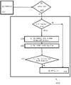
다른 양상에 따라, 본 발명은 또한 제1 양상에 따른 접촉기를 통해 흐르는 전류를 차단하는 방법을 제공하며, 방법은: a) 접촉기 전기 전도체 부분을 통해 흐르는 1차 전류를 자기 센서를 사용하여 반복적으로(예컨대, 주기적으로) 측정하는 단계; b) 선택적으로 측정된 전류의 함수로써 (예컨대, 미리 정의된 안전 기준에 따라) 1차 스위치를 개방하는 데 이용 가능한 양의 시간을 결정하는 단계; c) 이용 가능한 시간과 1차 스위치를 개방하는 데 전형적으로 필요한 시간을 비교하고, 그리고 이용 가능한 시간이 전형적으로 필요한 시간보다 짧은 경우, 단계 f)로 계속하는 단계, 그렇지 않은 경우 단계 d)로 계속하는 단계; d) 1차 스위치를 개방하도록 액추에이터를 동작시키는 단계; e) 검출 수단을 사용하여 이용 가능한 시간 기간 내에 1차 스위치가 실질적으로 개방인지 여부를 검출하고, 그리고 이용 가능한 시간 기간 후에도 1차 스위치가 여전히 폐쇄인 경우에 퓨즈를 끊는 단계를 포함한다.According to another aspect, the present invention also provides a method of interrupting a current flowing through a contactor according to the first aspect, the method comprising: a) repeatedly applying a primary current flowing through a contactor electrical conductor portion using a magnetic sensor measuring (eg, periodically); b) optionally determining an amount of time available to open the primary switch as a function of the measured current (eg, according to a predefined safety criterion); c) compare the time available and the time typically required to open the primary switch, and if the time available is less than the time typically required, continue with step f), otherwise continue with step d) to do; d) operating the actuator to open the primary switch; e) detecting whether the primary switch is substantially open within the available time period using the detecting means, and blowing the fuse if the primary switch is still closed after the available time period.
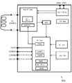
다른 양상에 따라, 본 발명은 또한 제1 양상에 따른 접촉기에서 사용하기 위한 집적 회로를 제공하고, 집적 회로는: 프로그래밍 가능 프로세서 형태의 상기 제어기; (예컨대, 수평 홀 엘리먼트 또는 수직 홀 엘리먼트, 또는 자기 저항 엘리먼트를 포함하는 회로 형태의) 상기 자기 센서; 집적 회로에 연결 가능한 션트 저항기에 걸친 전압을 감지하기 위한 션트 인터페이스 ― 전압으로부터 2차 전류가 결정될 수 있음 ― ; 코일에 걸친 전압을 감지하기 위한 전압 감지 인터페이스; 1차 스위치에 연결된 액추에이터를 구동시키기 위한 제1 출력; 퓨즈 드라이버(예컨대, 파이로 퓨즈 드라이버)를 활성화시키기 위한 제2 출력을 포함하고, 프로세서는: i) 상기 자기 센서를 사용하여 1차 전류를 측정하고, 과전류 상태가 발생하는지를 검출하고; 그리고 과전류 상태가 검출되는 경우, 단계 ii)로 계속하고, 그렇지 않은 경우, 단계 i)를 반복하고, ii) 1차 스위치를 개방하기 위해 또는 개방하기 위한 시도로 액추에이터를 동작시키기 위해 제1 출력을 어서팅(assert)하고; iii) 션트 인터페이스로부터 획득된 신호들 및 전압 감지 인터페이스로부터 획득된 신호들을 분석함으로써, 1차 스위치가 실질적으로 개방인지를 검출하고; 그리고 시간 간격 후에 1차 스위치가 여전히 폐쇄인 것이 검출된 경우, 퓨즈를 끊기 위해 제2 출력을 어서팅하도록 구성된다. According to another aspect, the present invention also provides an integrated circuit for use in a contactor according to the first aspect, the integrated circuit comprising: the controller in the form of a programmable processor; the magnetic sensor (eg, in the form of a circuit including a horizontal Hall element or a vertical Hall element, or a magnetoresistive element); a shunt interface for sensing a voltage across a shunt resistor connectable to the integrated circuit, from which a secondary current may be determined; a voltage sensing interface for sensing the voltage across the coil; a first output for driving an actuator coupled to the primary switch; a second output for activating a fuse driver (eg, a pyro fuse driver), the processor configured to: i) measure a primary current using the magnetic sensor, and detect whether an overcurrent condition occurs; and if an overcurrent condition is detected, continue with step ii); assert; iii) detecting whether the primary switch is substantially open by analyzing the signals obtained from the shunt interface and the signals obtained from the voltage sensing interface; and assert the second output to blow the fuse if it is detected that the primary switch is still closed after the time interval.
본 발명은 또한 집적 회로(도 6에 도시됨)의 변형을 제공하고, 여기서 션트 인터페이스 및 전압 인터페이스 및 제1 출력은 생략되지만, 집적 회로는 코일 인터페이스에 동작 가능하게 연결된 집적 션트 저항기 및 트랜지스터를 포함한다.The present invention also provides a variant of an integrated circuit (shown in FIG. 6 ) wherein the shunt interface and voltage interface and the first output are omitted, but the integrated circuit includes an integrated shunt resistor and transistor operatively coupled to the coil interface. do.
집적 회로는 바람직하게는 또한, 션트 인터페이스로부터 획득된 신호를 디지털화하도록 구성되고 전압 검출 인터페이스로부터 획득된 신호를 디지털화하도록 구성된 아날로그-디지털 변환기를 포함한다.The integrated circuit preferably also comprises an analog-to-digital converter configured to digitize the signal obtained from the shunt interface and configured to digitize the signal obtained from the voltage detection interface.
션트 인터페이스는 전압이 측정되는 하나 또는 2개의 전용 입력 핀들을 포함할 수 있다.The shunt interface may include one or two dedicated input pins through which voltage is measured.
전압 검출 인터페이스는 하나 또는 2개의 전용 입력 핀들을 포함할 수 있으며, 그 중 하나는 션트 인터페이스와 공유될 수 있다.The voltage detection interface may include one or two dedicated input pins, one of which may be shared with the shunt interface.
집적 회로는 바람직하게는 상기 프로세서에 임베딩되거나 상기 프로세서에 연결된 비휘발성 메모리를 더 포함한다. 비휘발성 메모리는 전류 대 시간 곡선에 대응하는 데이터를 포함할 수 있다. 비휘발성 메모리는 또한 바람직하게는, 프로그래밍 가능 프로세서에 의해 실행될 때, 위에서 설명된 방법들 중 하나, 또는 위에 언급된 방법 단계들의 일부 또는 전부를 수행하기 위한 실행 가능한 명령들을 포함하는 컴퓨터 프로그램 또는 코드 프래그먼트들을 포함한다.The integrated circuit preferably further comprises a non-volatile memory embedded in or coupled to the processor. The non-volatile memory may include data corresponding to a current versus time curve. The non-volatile memory is also preferably a computer program or code fragment comprising executable instructions for performing one of the methods described above, or some or all of the method steps described above, when executed by a programmable processor. include those
일 실시예에서, 집적 회로는 외부 프로세서(예컨대, 외부 ECU)로부터 명령들을 수신하기 위한 디지털 통신 인터페이스를 더 포함하고; 프로세서는, 외부 프로세서로부터의 스위치를 개방하라는 명령(또는 커맨드)의 수신 시에, 단계들 ii) 및 iii)을 수행하도록 추가로 구성된다.In one embodiment, the integrated circuit further comprises a digital communication interface for receiving instructions from an external processor (eg, external ECU); The processor is further configured to, upon receipt of a command (or command) to open the switch from the external processor, perform steps ii) and iii).
일 실시예에서, 집적 회로는 다음의 특징들: 저전압 공급 입력, 예컨대, 12V 공급 입력 또는 24V 공급 입력; PWM 발생기; 타이머 유닛; 외부 온도를 측정하기 위한 NTC(Negative Temperature Coefficient) 컴포넌트 인터페이스; 에어백 ECU와 통신하기 위한 제1 통신 인터페이스; BMS(battery management system)의 제어기와 통신하기 위한 제2 통신 인터페이스 중 하나 이상을 더 포함한다. In one embodiment, the integrated circuit has the following features: a low voltage supply input, eg, a 12V supply input or a 24V supply input; PWM generator; timer unit; Negative Temperature Coefficient (NTC) component interface for measuring external temperature; a first communication interface for communicating with the airbag ECU; and one or more of the second communication interfaces for communicating with a controller of a battery management system (BMS).
집적 회로는 반도체 기판에 임베딩될 수 있고, 그리고 패키징된 반도체 디바이스(또한 "칩"으로 지칭됨)에 통합될 수 있다.An integrated circuit may be embedded in a semiconductor substrate and integrated into a packaged semiconductor device (also referred to as a “chip”).
다른 양상에 따라, 본 발명은 또한 접촉기를 제공하고, 접촉기는: 제1 전력 단자; 제2 전력 단자; 제1 전력 단자와 제2 전력 단자 사이에 전기적으로 연결되고, 직렬로 연결된 적어도 3개의 엘리먼트들: 전기 전도체 부분, 액추에이터에 의해 구동된 가동 부분을 포함하는 1차 스위치, 및 퓨즈를 포함하는 서브 회로; 전기 전도체 부분을 통해 흐르는 1차 전류를 측정하도록 구성된 자기 센서; 전도체 부분을 통해 흐르는 상기 1차 전류를 측정하도록 상기 자기 센서에 통신 가능하게 연결되고, 그리고 상기 1차 스위치를 선택적으로 개방 및 폐쇄하도록 상기 액추에이터에 동작 가능하게 연결된 제어기를 포함하고, 제어기는, 스위치를 개방 또는 폐쇄하라는 커맨드를 수신하도록 외부 프로세서(BMS; ECU)에 연결 가능한 통신 포트를 갖는다.According to another aspect, the present invention also provides a contactor, the contactor comprising: a first power terminal; a second power terminal; At least three elements electrically connected between the first power terminal and the second power terminal and connected in series: a primary switch comprising an electrically conductive portion, a movable portion driven by an actuator, and a sub-circuit comprising a fuse ; a magnetic sensor configured to measure a primary current flowing through the electrically conductive portion; a controller communicatively coupled to the magnetic sensor to measure the primary current flowing through the conductive portion and operatively coupled to the actuator to selectively open and close the primary switch, the controller comprising: It has a communication port connectable to an external processor (BMS; ECU) to receive a command to open or close the .
본 발명의 특정 및 바람직한 양상들은 첨부된 독립 청구항들 및 종속 청구항들에 제시된다. 종속 청구항들로부터의 특징들은 독립 청구항들의 특징들 및 다른 종속 청구항들의 특징과 적절히 그리고 단지 청구항들에 명시적으로 제시되지는 않은 특징들과 결합될 수 있다.Certain and preferred aspects of the invention are set forth in the appended independent and dependent claims. Features from the dependent claims may be combined with features of the independent claims and other dependent claims as appropriate and only with features not expressly set forth in the claims.
본 발명의 이들 및 다른 양상들은 이후에 설명되는 실시예(들)로부터 자명하고 이들을 참조하여 설명될 것이다.These and other aspects of the invention will be apparent from and elucidated with reference to the hereinafter described embodiment(s).
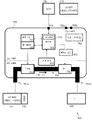
도 1은 본 발명에 의해 제안된 접촉기, 및 상기 접촉기를 포함하는 전력 회로의 고레벨 블록도를 도시한다.
도 2는 도 1에 도시된 접촉기 및 회로의 변형 또는 특정 구현으로 볼 수 있는, 본 발명에 의해 제안된 접촉기 및 상기 접촉기를 포함하는 전력 회로의 다른 블록도를 도시한다.
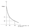
도 3은 측정된 전류의 함수로써 스위치를 개방하는데 얼마나 많은 시간이 이용 가능한지를 결정하기 위해, 본 발명의 실시예들에서 사용될 수 있는 전형적인 시간-전류 곡선을 도시한다.
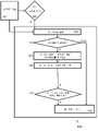
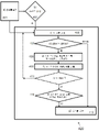
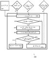
도 4a 내지 도 4d는 도 1 또는 도 2에 도시된 접촉기의 제어기에 의해 수행될 수 있는, 본 발명의 실시예들에 따른 방법들의 흐름도들을 도시한다.
도 5는, 본 발명의 실시예들에서 사용될 수 있는 프로세서를 포함하는 집적 회로의 블록도를 도시한다.
도 6은, 본 발명의 실시예들에서 사용될 수 있는 프로세서를 포함하는 다른 집적 회로의 블록도를 도시한다.
도면들은 단지 개략적이며 비-제한적이다. 도면들에서, 엘리먼트들 중 몇몇의 사이즈는 예시의 목적들을 위해 과장되고 축적에 맞게 도시되지 않는다. 청구항들 내의 임의의 참조 부호들은 범위를 제한하는 것으로 해석되어서는 안 된다. 상이한 도면들에서, 동일한 참조 부호들은 동일하거나 유사한 엘리먼트들을 나타낸다.1 shows a high level block diagram of a contactor proposed by the present invention and a power circuit comprising said contactor.
Figure 2 shows another block diagram of the contactor proposed by the present invention and a power circuit comprising said contactor, which can be viewed as a variant or specific implementation of the contactor and circuit shown in Figure 1;
3 shows a typical time-current curve that may be used in embodiments of the present invention to determine how much time is available to open a switch as a function of the measured current.
4A-4D show flowcharts of methods according to embodiments of the invention, which may be performed by the controller of the contactor shown in FIG. 1 or FIG. 2 ;
5 shows a block diagram of an integrated circuit including a processor that may be used in embodiments of the present invention.
6 shows a block diagram of another integrated circuit including a processor that may be used in embodiments of the present invention.
The drawings are only schematic and non-limiting. In the drawings, the size of some of the elements are exaggerated for purposes of illustration and are not drawn to scale. Any reference signs in the claims should not be construed as limiting the scope. In different drawings, like reference numbers indicate identical or similar elements.
본 발명은 특정한 실시예들에 관해 그리고 특정한 도면들을 참조하여 설명될 것이지만, 본 발명은 이에 제한되지 않고 청구범위에 의해서만 제한된다. 설명된 도면들은 단지 개략적이며 비-제한적이다. 도면들에서, 엘리먼트들 중 몇몇의 사이즈는 예시의 목적들을 위해 과장되고 축적에 맞게 도시되지 않는다. 치수들 및 상대적인 치수들은 본 발명의 실시에 대한 실제 환원들에 대응하지는 않는다.DETAILED DESCRIPTION OF THE PREFERRED EMBODIMENTS The present invention will be described with reference to specific embodiments and with reference to specific drawings, but the invention is not limited thereto and is limited only by the claims. The drawings described are only schematic and non-limiting. In the drawings, the size of some of the elements are exaggerated for purposes of illustration and are not drawn to scale. The dimensions and relative dimensions do not correspond to actual reductions to the practice of the present invention.
또한, 설명 및 청구범위에서 제1, 제2 등의 용어들은 유사한 엘리먼트들 사이를 구별하기 위해 사용되며, 반드시 시간적으로, 공간적으로, 순위로 또는 임의의 다른 방식으로 시퀀스를 설명하기 위해 사용되지는 않는다. 그렇게 사용되는 용어들은 적절한 환경들 하에서 상호교환가능하며, 본원에 설명된 본 발명의 실시예들은 본원에 설명 또는 예시된 것 이외의 다른 시퀀스들로 동작이 가능하다는 것이 이해될 것이다.Further, in the description and claims, the terms first, second, etc. are used to distinguish between like elements, and are not necessarily used to describe a sequence in time, space, rank, or in any other way. does not It will be understood that the terms so used are interchangeable under appropriate circumstances, and that the embodiments of the invention described herein are capable of operation in sequences other than those described or illustrated herein.
또한, 설명 및 특허청구범위에서 상단, 하단 등의 용어들은 설명 목적들로 사용되며 반드시 상대적인 위치들을 설명하는 것은 아니다. 그렇게 사용되는 용어들은 적절한 환경들 하에서 상호교환가능하며, 본원에 설명된 본 발명의 실시예들은 본원에 설명 또는 예시된 것 이외의 다른 배향들로 동작이 가능하다는 것이 이해될 것이다.In addition, in the description and claims, terms such as top, bottom, etc. are used for descriptive purposes and do not necessarily describe relative positions. It will be understood that the terms so used are interchangeable under appropriate circumstances, and that the embodiments of the invention described herein are capable of operation in other orientations than those described or illustrated herein.
청구범위에 사용된 "포함하는"이라는 용어는 이후에 나열된 수단으로 제한되는 것으로 해석되어서는 안 되고, 다른 엘리먼트들 또는 단계들을 제외하지 않는다는 것이 주목되어야 한다. 따라서, 이것은 언급된 특징들, 정수들, 단계들 또는 컴포넌트들의 존재를 명시하는 것으로 해석되어야 하지만, 하나 이상의 다른 특징들, 정수들, 단계들 또는 컴포넌트들, 또는 이들의 그룹의 존재 또는 추가를 배제하지 않는다. 따라서 "수단 A 및 B를 포함하는 디바이스"라는 표현의 범위는 컴포넌트들 A 및 B로만 구성된 디바이스들로 제한되어서는 안 된다. 이는, 본 발명과 관련하여, 디바이스의 유일한 관련 컴포넌트들이 A 및 B임을 의미한다.It should be noted that the term "comprising" as used in the claims should not be construed as limited to the means listed hereinafter, and does not exclude other elements or steps. Accordingly, this should be construed as specifying the presence of the recited features, integers, steps or components, but excluding the presence or addition of one or more other features, integers, steps or components, or a group thereof. I never do that. Accordingly, the scope of the expression "a device comprising means A and B" should not be limited to devices consisting only of components A and B. This means, in the context of the present invention, that the only relevant components of the device are A and B.
본 명세서 전체에 걸쳐, "일 실시예" 또는 "실시예"에 대한 참조는, 실시예와 관련하여 설명된 특정한 피처, 구조, 또는 특성이 본 발명의 적어도 하나의 실시예에 포함되는 것을 의미한다. 따라서, 본 명세서 전반에 걸친 다양한 위치들에서 "일 실시예에서" 또는 "실시예에서"라는 문구들의 출현들이 모두 반드시 동일한 실시예를 지칭하는 것은 아니지만 지칭할 수도 있다. 또한, 특정 특징들, 구조들 또는 특징들은, 하나 이상의 실시예들에서, 본 개시내용으로부터 당업자에게 명백할 바와 같이, 임의의 적합한 방식으로 조합될 수 있다. Throughout this specification, reference to “one embodiment” or “an embodiment” means that a particular feature, structure, or characteristic described in connection with the embodiment is included in at least one embodiment of the invention. . Thus, the appearances of the phrases "in one embodiment" or "in an embodiment" in various places throughout this specification may refer to, but not necessarily all of, the same embodiment. Moreover, the particular features, structures, or features, in one or more embodiments, may be combined in any suitable manner, as will be apparent to one of ordinary skill in the art from this disclosure.
유사하게, 본 발명의 예시적인 실시예들의 설명에서, 본 발명의 다양한 특징들이 때때로 본 개시내용을 간소화하고 하나 이상의 다양한 본 발명 양상들의 이해를 돕기 위해 단일 실시예, 도면 또는 그의 설명으로 함께 그룹화된다는 것을 인지되어야 한다. 그러나, 본 개시내용의 이러한 방법은, 청구된 발명이 각각의 청구항에서 명확하게 언급된 것보다 더 많은 특징들을 요구한다는 의도를 반영하는 것으로 해석되지 않아야 한다. 오히려, 다음의 청구항들이 반영하는 바와 같이, 본 발명의 양상들은 단일의 앞서 말한 개시된 실시예의 모든 특징들보다 적다. 따라서, 이로써 상세한 설명에 뒤따르는 청구범위는 이 상세한 설명에 명시적으로 통합되며, 각각의 청구항은 그 자체로 본 발명의 별개의 실시예로서 존재한다.Similarly, in the description of exemplary embodiments of the invention, it is noted that various features of the invention are sometimes grouped together in a single embodiment, figure, or description thereof to simplify the present disclosure and aid in understanding one or more various aspects of the invention. that should be recognized This method of disclosure, however, is not to be interpreted as reflecting an intention that the claimed invention requires more features than are expressly recited in each claim. Rather, as the following claims reflect, inventive aspects lie in less than all features of a single aforesaid disclosed embodiment. Accordingly, the claims that follow the Detailed Description are hereby expressly incorporated into this Detailed Description, with each claim standing on its own as a separate embodiment of the invention.
또한, 본원에 설명된 일부 실시예들이 다른 실시예들에 포함된 다른 특징들이 아닌 일부들을 포함하지만, 상이한 실시예들의 특징들의 조합은 본 발명의 범위 내에 있는 것으로 의미되고, 당업자들에 의해 이해될 바와 같이, 상이한 실시예들을 형성한다. 예컨대, 다음 청구범위에서, 청구된 실시예들 중 임의의 것이 임의의 조합으로 사용될 수 있다.Also, although some embodiments described herein include some that are not other features included in other embodiments, combinations of features of different embodiments are meant to be within the scope of the present invention and will be understood by those of ordinary skill in the art. As such, different embodiments are formed. For example, in the following claims, any of the claimed embodiments may be used in any combination.
본원에 제공된 설명에서, 많은 구체적으로 세부사항들이 기술되었다. 그러나, 본 발명의 실시예들이 이러한 특정 세부사항들 없이 실시될 수 있음이 이해된다. 다른 예시들에서, 잘-알려진 방법들은, 구조들 및 기법들은 이런 설명의 이해를 모호하게 하지 않기 위해 상세하게 도시되지 않는다.In the description provided herein, numerous specific details have been set forth. It is understood, however, that embodiments of the invention may be practiced without these specific details. In other instances, well-known methods, structures and techniques have not been shown in detail in order not to obscure an understanding of this description.
본 문서에서 "스퀴브(squib)"라는 용어는 소형 폭발 디바이스(miniature explosive device)를 나타낸다.In this document, the term "squib" refers to a miniature explosive device.
본 문서에서 "1차 전류" 및 "HV 전류"라는 표현은 동일한 것을 의미한다.In this document, the expressions "primary current" and "HV current" mean the same thing.
본 문서에서, "2차 전류" 및 "액추에이터 코일을 통해 흐르는 전류"라는 표현은 동일한 것을 의미한다.In this document, the expressions "secondary current" and "current flowing through the actuator coil" mean the same thing.
본 문서에서, "스위치" 또는 "HV 스위치" 또는 "1차 스위치"라는 용어들은 동일한 것을 의미하고, 문맥상으로 다른 스위치(예컨대, 코일에 전력을 공급하기 위한 스위치(265), 또는 퓨즈를 끊기 위한 스위치(263))를 의미한다는 것이 분명하지 않는다면, 그들은 제1 고전력 단자와 제2 고전력 단자 사이에 연결된 스위치(스위치(153, 253) 참조)를 나타낸다. In this document, the terms "switch" or "HV switch" or "primary switch" mean the same thing, and in the context of another switch (eg, switch 265 to power a coil, or blow a fuse) Unless it is clear that they mean a
본 문서에서, "시간 기간" 또는 "시간 간격" 또는 "시간 지속기간"이라는 용어들은 동일한 것을 의미한다. In this document, the terms "period of time" or "interval of time" or "duration of time" mean the same thing.
본 발명은 전기 또는 하이브리드 차량의 배터리를 전기 로드(예컨대, 인버터, 전기 모터 등)에/로부터 선택적으로 연결/연결 해제하기 위한 접촉기에 관한 것이다. 본 발명은 또한 접촉기를 포함하는 전력 회로, 접촉기를 통해 흐르는 전류를 차단하는 방법, 및 이러한 접촉기에 사용하기에 이상적으로 적합한 집적 회로에 관한 것이다.The present invention relates to a contactor for selectively connecting/disconnecting a battery of an electric or hybrid vehicle to/from an electrical load (eg inverter, electric motor, etc.). The present invention also relates to a power circuit comprising a contactor, a method of interrupting current flowing through the contactor, and an integrated circuit ideally suitable for use in such a contactor.
US2014292109A1은, 스위치가 폐쇄일 때, 접촉기를 통해 흐르는 전류를 측정하기 위한 전류 센서를 포함하는 전기-기계적 스위치를 포함하는 접촉기를 개시한다. 이 종래 기술의 접촉기의 스위치가 개방 또는 폐쇄인지는, 종종 ECU(Electronic Control Unit)로 지칭되는 외부 프로세서에 의해 제어된다. US2014292109A1 discloses a contactor comprising an electro-mechanical switch comprising a current sensor for measuring the current flowing through the contactor when the switch is closed. Whether the switch of this prior art contactor is open or closed is controlled by an external processor, often referred to as an ECU (Electronic Control Unit).
그러나, 안전한 전력 시스템을 만들기 위해서는, 배터리를 연결하거나 연결 해제할 수 있는 접촉기만으로는 부족하다. 전기 차량들의 전기 회로가, 예컨대, 충돌 시에 승객들에게 실질적인 위협이 될 수 있기 때문에, 안전상의 이유들로 전력 회로의 오동작이 신속하게 검출되어야 하고, 그리고 배터리는 문제의 심각도에 따라, 신속하게, 예컨대, 때때로 5ms 이내에 안정적으로 연결 해제되어야 한다.However, to create a safe power system, a contactor that can connect or disconnect a battery is not enough. Since the electrical circuit of electric vehicles can pose a real threat to passengers, for example in the event of a collision, malfunctions of the power circuit must be detected quickly for safety reasons, and the battery can be , e.g., should be reliably disconnected sometimes within 5 ms.
본 발명은 제1 전력 단자(예컨대, 배터리에 연결 가능함), 및 제2 전력 단자(예컨대, 전기 로드 또는 충전 회로에 연결 가능함); 및 제1 전력 단자와 제2 전력 단자 사이에 전기적으로 연결되고 직렬로 연결된 적어도 다음의 3개의 엘리먼트들: 전기 전도체 부분(예컨대, 버스 바 부분), 액추에이터에 의해 구동되는 가동 부분을 포함하는 1차 스위치, 및 퓨즈(예컨대, 파이로 퓨즈 또는 스퀴브 등)를 포함하는 서브 회로를 포함하고, 이들 모두는 접촉기의 하우징에 임베딩된다. 접촉기는, 전기 전도체 부분을 통해 흐르는 (1차) 전류(본원에서 또한 "HV 전류"로 지칭됨)를 측정하도록 구성된 자기 센서를 더 포함한다. 접촉기는, 전기 전도체 부분을 통해 흐르는 상기 1차 전류를 측정하기 위해 상기 자기 센서에 통신 가능하게 연결된 제어기(예컨대, 프로그래밍 가능 마이크로제어기)를 더 포함한다. 제어기는 또한 상기 스위치를 선택적으로 개방 및 폐쇄하기 위해 상기 액추에이터에 동작 가능하게 연결된다. 접촉기는 (직접적으로 또는 간접적으로, 예컨대, 액추에이터의 전기적 특성을 결정함으로써) 1차 스위치가 실질적으로 개방인지 또는 폐쇄인지를 검출하기 위한 검출 수단을 더 포함한다. The present invention provides a first power terminal (eg, connectable to a battery), and a second power terminal (eg, connectable to an electrical load or charging circuit); and at least the following three elements electrically connected between the first power terminal and the second power terminal and connected in series: an electrically conductive portion (eg, a bus bar portion), a primary comprising a movable portion driven by an actuator It includes a switch and a sub-circuit including a fuse (eg, a pyro fuse or a squib, etc.), all of which are embedded in the housing of the contactor. The contactor further includes a magnetic sensor configured to measure a (primary) current (also referred to herein as “HV current”) flowing through the electrically conductive portion. The contactor further includes a controller (eg, a programmable microcontroller) communicatively coupled to the magnetic sensor for measuring the primary current flowing through the electrically conductive portion. A controller is also operatively connected to the actuator for selectively opening and closing the switch. The contactor further comprises detecting means for detecting whether the primary switch is substantially open or closed (either directly or indirectly, for example by determining an electrical characteristic of the actuator).
본 발명의 중요한 양상에 따라, 제어기는 (i) 전기 전도체 부분을 통해 흐르는 1차 전류를 측정하고, 과전류 상태를 검출하고, 그리고 과전류 상태가 검출되는 경우, (ii) 1차 스위치를 개방하기 위해(또는 시도하기 위해) 액추에이터를 동작시키고, 그리고 (iii) 스위치가 실제로 개방인지를 검출하고, (예컨대, 액추에이터를 동작시키는 순간보다 늦은 시간 간격(Δt)으로) 스위치가 여전히 폐쇄 있음을 제어기가 검출한 경우, 퓨즈를 끊도록 추가로 구성된다.According to an important aspect of the present invention, the controller is configured to (i) measure a primary current flowing through the electrical conductor portion, detect an overcurrent condition, and, when an overcurrent condition is detected, (ii) open the primary switch. (or to attempt) actuate the actuator, and (iii) detect that the switch is actually open, and the controller detects that the switch is still closed (e.g., at a time interval Δt later than the moment of actuating the actuator) In one case, it is further configured to blow the fuse.
1차 스위치는 바람직하게는 적어도 100A의 전류를 전도할 수 있다.The primary switch is preferably capable of conducting a current of at least 100A.
시간 간격(Δt)은 미리 정의된 시간 간격일 수 있거나, 측정된 HV 전류의 함수로써 (예컨대, 룩업 테이블을 사용하여) 계산될 수 있다. 시간 기간은, HV 전류의 측정 이후에, 한 번만 결정될 수 있거나 (진행 중인 HV 전류 측정 값들에 기반하여) 동적으로 조정 또는 업데이트될 수 있다.The time interval Δt may be a predefined time interval, or may be calculated (eg, using a lookup table) as a function of the measured HV current. The time period may be determined only once, after measurement of the HV current, or may be dynamically adjusted or updated (based on ongoing HV current measurements).
접촉기 내부의 제어기가 1차 스위치가 실제로 개방인지 여부를 결정할 수 있고, 따라서 어떤 이유에서든 스위치가 개방이 아니라는 것을 검출할 수 있다는 장점이 있다. 이것은, 예컨대, 전류 서지(current surge)로 인해 스위치의 접점들이 버스 바에 붙어 있거나 용접된 경우에, 발생할 수 있다. 이러한 경우에, 제어기는 퓨즈를 끊어 전류를 중지하기로 판정할 것이다.The advantage is that the controller inside the contactor can determine whether the primary switch is actually open, and thus can detect that the switch is not open for any reason. This may occur, for example, if the contacts of the switch are glued or welded to the bus bar due to a current surge. In this case, the controller will decide to blow the fuse to stop the current.
자기 센서가 비접촉 방식으로 HV 전류를 측정할 수 있다는 장점이 있다. 이러한 방식으로, 접촉기는 2개의 전압 도메인들: 예컨대, 60V 이상, 예컨대, 120V 이상, 또는 200V 이상에서 동작하는 본원에서 "고전압 도메인", HV 도메인으로 또한 지칭되는 1차 전압 도메인; 및 예컨대, 48V 이하, 예컨대, 36V 이하, 예컨대, 24V 이하, 예컨대, 12V에서 동작하는 본원에서 "저전압 도메인", LV 도메인으로 또한 지칭되는 2차 전압 도메인을 가질 수 있다. 자기 센서는, HV 도메인의 일부인 전기 전도체 부분(예컨대, 버스 바 부분) 부근에 물리적으로 위치될 수 있지만, LV 도메인에서 동작하고, 그리고 바람직하게는 전기 전도체 부분으로부터 열적으로 격리된다.The advantage is that the magnetic sensor can measure the HV current in a non-contact manner. In this way, the contactor operates in two voltage domains: a primary voltage domain, also referred to herein as a “high voltage domain”, HV domain, that operates at, for example, 60V or higher, such as 120V or higher, or 200V or higher; and a secondary voltage domain, also referred to herein as a “low voltage domain”, LV domain, operating at, for example, 48V or less, such as 36V or less, such as 24V or less, such as 12V. The magnetic sensor may be physically located near an electrical conductor portion (eg, a bus bar portion) that is part of the HV domain, but operates in the LV domain, and is preferably thermally isolated from the electrical conductor portion.
접촉기가 상기 검출 수단을 사용하여 스위치가 실질적으로 개방인지 또는 폐쇄인지를 (자체적으로) 검출할 수 있다는 것이 주요 장점이다. It is a major advantage that the contactor can (by itself) detect whether the switch is substantially open or closed using said detection means.
접촉기가 자기 센서(변형되거나 손상될 수 있음)의 측정에 의존할 필요 없이(또는 전적으로 의존할 필요 없이), 그리고/또는 외부 디바이스와 통신할 필요 없이(통신 채널이 파손되거나 지연을 유발할 수 있음), 그리고/또는 접촉기 외부의 컴포넌트를 사용하거나 의존할 필요 없이, 스위치가 개방인지 또는 폐쇄인지를 자율적으로 검출할 수 있다는 장점이 있다. 이는 (시스템 레벨에서) 중복성을 제공하고, 따라서 이 접촉기가 사용되는 전력 시스템의 전반적인 안전성과 신뢰성을 향상시킨다. No need for the contactor to rely (or wholly depend on) the measurement of a magnetic sensor (which can be deformed or damaged), and/or no need to communicate with an external device (which may break the communication channel or cause delays). , and/or having the advantage of being able to autonomously detect whether a switch is open or closed, without the need to use or rely on components external to the contactor. This provides redundancy (at the system level) and thus improves the overall safety and reliability of the power system in which this contactor is used.
실제로 (접촉기 내부의) 스위치 상태 자체를 점검하고 그리고/또는 (접촉기 내부의) HV 전류 자체를 측정하고, 그리고/또는 (접촉기 내부의) 과전류 상태 자체를 결정함으로써, 특정 이벤트의 통신 루프 또는 피드백 루프는 (접촉기 외부에 위치된 외부 프로세서 및/또는 컴포넌트들과의 하나 이상의 통신(들)을 포함하는 통신 루프와 비교하여) 단축된다는 것이 주요 장점이다. 이 단축된 루프는 결국 추가 시간을 제공하고, 추가 시간 동안, 퓨즈를 끊지 않고도(퓨즈를 끊는 것은 비가역적인 방식으로 접촉기를 손상시킬 것임) 스위치를 개방하기 위한 시도가 이루어질 수 있다. 따라서, 접촉기 자체 내부의 진단 특징들 덕분에, 예컨대, 전류가 충분히 낮고 그리고/또는 안전하게 스위치를 개방할 충분한 시간이 있는 상황들에서, 퓨즈가 끊어지는 것을 방지함으로써, 접촉기의 수명이 증가될 수 있다. By actually checking the switch state itself (inside the contactor) and/or measuring the HV current itself (inside the contactor), and/or determining the overcurrent condition itself (inside the contactor), the communication loop or feedback loop of a specific event A major advantage is that n is shortened (compared to a communication loop comprising one or more communication(s) with an external processor and/or components located outside the contactor). This shortened loop eventually provides additional time, during which an attempt can be made to open the switch without blowing the fuse (blowing the fuse will damage the contactor in an irreversible manner). Thus, thanks to the diagnostic features inside the contactor itself, the lifetime of the contactor can be increased, for example by preventing the fuse from blowing in situations where the current is low enough and/or there is enough time to safely open the switch. .
또는 다시 말해서, 이 접촉기의 장점은, (특정 상태들 하에서) 먼저 스위치를 가역적인 방식으로 개방하려고 시도할 수 있다는 점이고, 이는, 외부 디바이스들과의 통신으로 인해 귀중한 시간이 허비된 경우, 가능하지 않을 수 있다. 통신 루프 또는 판정 루프를 단축시킴으로써, 안전 기준에 따라 퓨즈를 끊어야 할 확률이 감소될 수 있다.Or in other words, the advantage of this contactor is that it can first try to open the switch in a reversible way (under certain conditions), which is not possible if valuable time is wasted due to communication with external devices. may not be By shortening the communication loop or decision loop, the probability of having to blow a fuse according to safety criteria can be reduced.
"검출 수단"은, 자기 센서에 의해 수행되는 전류 측정과 독립적인 방식으로 스위치가 폐쇄인지를 분석하는 방법(내부 진단의 한 형태임)을 제공한다는 장점이 있다. 이러한 방식으로, 접촉기의 신뢰성이 증가될 수 있고, 이 접촉기가 사용되는 전력 시스템의 안전성이 향상될 수 있다. 놀랍게도, 검출 수단이 없는 경우, 유일한 안전한 옵션은 퓨즈를 끊는 것이기 때문에, 접촉기의 수명이 또한 증가될 수 있다. 대조적으로, 본 발명의 접촉기는, 전류가 충분히 낮은지 및/또는 스위치를 개방하려고 시도할 충분한 시간이 있는지 여부를 더 잘 판정할 수 있게 하고, 이것이 성공하면, 퓨즈가 끊어질 필요가 없다. The "detection means" has the advantage of providing a method (which is a form of internal diagnostics) for analyzing whether a switch is closed in a manner independent of the current measurement performed by the magnetic sensor. In this way, the reliability of the contactor can be increased, and the safety of the power system in which the contactor is used can be improved. Surprisingly, the life of the contactor can also be increased, since, in the absence of detection means, the only safe option is to blow the fuse. In contrast, the contactor of the present invention makes it possible to better determine whether the current is low enough and/or whether there is sufficient time to attempt to open the switch, and if this is successful, the fuse does not need to blow.
접촉기의 하우징이 퓨즈 및 제어기와 퓨즈 사이의 상호연결부를 보호하기 때문에, 퓨즈가 또한 접촉기에 통합된다는 장점이 있다. 따라서, 퓨즈가 끊어지지 않을 위험이 감소되고, 전체 시스템의 안전성이 추가로 증가된다.Since the housing of the contactor protects the fuse and the interconnection between the controller and the fuse, it is advantageous that the fuse is also integrated into the contactor. Accordingly, the risk that the fuse will not blow is reduced, and the safety of the overall system is further increased.
다른 또는 추가 실시예에서, 제어기는, 정보 또는 명령들을 전송 및 수신하고, 예컨대, 측정된 전류를 나타내는 신호를 제공하고 그리고/또는 다음의 커맨드들: 스위치를 개방하라는 커맨드(또는 배터리를 연결 해제하라는 커맨드), 스위치를 폐쇄하라는 커맨드(또는 배터리를 연결하라는 커맨드), 퓨즈를 끊으라는 커맨드 중 하나를 수신하기 위해, 외부 프로세서(예컨대, 외부 ECU, 예컨대, 에어백 ECU 및/또는 배터리 관리 시스템 제어기)에 연결 가능한 적어도 하나(예컨대, 하나 또는 2개)의 통신 인터페이스(예컨대, 단방향 또는 양방향 직렬 버스 인터페이스)를 더 포함할 수 있다.In further or additional embodiments, the controller transmits and receives information or commands, eg, provides a signal indicative of a measured current and/or commands the following: a command to open a switch (or to disconnect a battery). command), a command to close a switch (or a command to connect a battery), a command to blow a fuse, to an external processor (eg, an external ECU, eg, an airbag ECU and/or a battery management system controller) It may further include at least one (eg, one or two) connectable communication interfaces (eg, unidirectional or bidirectional serial bus interfaces).
이러한 실시예에서, 스위치의 개방은 다음의 이벤트들: (a), 예컨대, 측정 전류와 임계값을 비교하거나 고전적인 I2T(암페어 제곱 시간 초) 기법을 사용함으로써 접촉기 자체에 의한 과전류 상태의 검출; 또는 (b) 배터리를 연결 해제하거나 외부 프로세서, 예컨대, 에어백 제어기로부터 스위치를 개방하라는 커맨드의 수신 중 하나 이상에 의해 트리거될 수 있다.In this embodiment, the opening of the switch is caused by the following events: (a) detection of an overcurrent condition by the contactor itself, eg, by comparing the measured current with a threshold or using the classic I2T (amps squared time second) technique; or (b) disconnecting the battery or receiving a command to open a switch from an external processor, such as an airbag controller.
그러나, 다른 통신이 또한 가능하다. 예컨대, 접촉기가 무조건 퓨즈를 끊으라는 커맨드를 수신하거나, 접촉기가 비정상적인 HV 전류를 보고하는 것 등이 또한 가능하다.However, other communications are also possible. It is also possible, for example, for the contactor to receive a command to blow a fuse unconditionally, for the contactor to report an abnormal HV current, and the like.
본 발명은 또한 전술된 방법 단계들 (i) 내지 (iii)을 포함하는, 이러한 접촉기를 통해 흐르는 전류를 차단하는 방법을 제공한다. 이 방법은, 도 4를 참조할 때 더 상세히 설명될 것이다. The present invention also provides a method of interrupting the current flowing through such a contactor comprising the method steps (i) to (iii) described above. This method will be described in more detail with reference to FIG. 4 .
본 발명은 또한, 이러한 접촉기에 통합될 때, 이 방법을 수행하도록 특별히 구성된 집적 회로를 제공한다. 집적 회로는 바람직하게는, 이 방법을 수행하기 위한 실행 가능한 명령들을 포함하는 비휘발성 메모리(예컨대, 플래시)를 포함한다.The present invention also provides an integrated circuit specifically configured to perform this method when incorporated into such a contactor. The integrated circuit preferably includes a non-volatile memory (eg, flash) containing executable instructions for performing the method.
이제 도면들이 참조된다.Reference is now made to the drawings.
도 1은, 접촉기(150)를 통해 전기 로드(120)(예컨대, 전기 2상 모터 또는 전기 3상 모터 또는 충전 회로)에 연결된 배터리(111)(예컨대, 적어도 100V 또는 적어도 200V의 전압을 제공하는 고전압 배터리)를 포함하는 전력 회로(100)의 고레벨 블록도를 도시한다. 전력 회로(100)는 EV(electric vehicle) 또는 HV(hybrid vehicle), 예컨대, 자동차에 통합될 수 있다. 실제로, 물론, 전력 회로(100)는, 예컨대, 인버터(도시되지 않음)와 같은 추가 컴포넌트들을 포함할 수 있다.1 shows a battery 111 (eg, providing a voltage of at least 100V or at least 200V) connected to an electrical load 120 (eg, an electric two-phase motor or an electric three-phase motor or charging circuit) via a
도 1의 접촉기(150)는, 배터리(111)에 연결되거나 연결 가능한 제1 전력 단자(151a), 및 전기 로드(120)에 연결되거나 연결 가능한 제2 전력 단자(151b)를 포함하지만, 물론, 접촉기(150)가 또한 다른 전력 회로들에 사용될 수 있다.The
접촉기(150)는 제1 전력 단자(151a)와 제2 전력 단자(151b) 사이에 전기적으로 연결되고, 직렬로 연결된 적어도 다음의 3개의 엘리먼트들: 전기 전도체 부분(154)(예컨대, 버스 바), 스위치(153)(예컨대, 전자기 스위치), 및 퓨즈(158)(예컨대, 파이로-퓨즈) 또는 스퀴브를 포함하는 서브 회로를 포함한다. 전기 전도체 부분(154)은 제1 전력 단자(151a)와 일체로 형성될 수 있거나, 제2 전력 단자(151b)와 일체로 형성될 수 있지만, 반드시 필요한 것은 아니다. The
퓨즈(158)가 여전히 손상되지 않고 스위치(153)가 폐쇄되면, 제1 및 제2 단자(151a, 151b) 사이에 형성된 전기 경로는 전도성이고, 즉, 배터리가 전기 로드에 연결된다. 스위치(153)가 개방되고 그리고/또는 퓨즈(158)가 끊어지면, 제1 단자와 제2 단자(151a, 151b) 사이에 형성된 전기 경로가 개방되고, 또는 다시 말해서, 배터리가 전기 로드로부터 연결 해제된다.If the
접촉기(150)는 제어기(160), 예컨대, 프로그래밍 가능 마이크로제어기, 선택적으로 비휘발성 메모리(161), 타이머 유닛, PWM 발생기 블록, ADC(analog-to-digital convertor), 통신 인터페이스(예컨대, 직렬 통신 인터페이스, 예컨대, CAN 인터페이스), 클록 발생기(예컨대, 수정 기반 또는 RC 발진기에 기반) 등을 더 포함한다. 제어기(160)는, 접촉기 외부에 위치되지만 접촉기에 연결되고 그리고 예컨대, 48V 이하 또는 36V 이하, 또는 24V 이하, 예컨대, 약 12V의 저전압 공급기를 제공하도록 구성된 저전압 공급기, 예컨대, 제2 배터리에 의해 전력을 공급받는다. 저전압은 저전압 단자들(152a, 152b)을 통해 접촉기에 인가된다. 제어기는 이 저전압 공급기에 의해 직접적으로 또는, 예컨대, 존재하는 경우 하나 이상의 전압 조정기들(162)에 의해 제공되는 그로부터 유도된 전압에 의해 전력이 공급될 수 있다. 제어기(160) 및 전압 조정기(들)(162)는, 존재하는 경우, PCB(printed circuit board)(도시되지 않음) 상에 장착될 수 있다. 제어기(160)는 집적 회로의 일부일 수 있다. 그러한 집적 회로의 바람직한 실시예가 도 5에 도시될 것이다.
접촉기(150)는 하우징(명시적으로 도시되지는 않았지만 둥근 코너들을 갖는 직사각형(150)으로 개략적으로 표시됨)을 더 포함한다. 도시된 바와 같이, 스위치(153)와 퓨즈(158) 및 제어기(160)는 하우징 내부에 위치된다. 이것은, 비상 상황에서, 예컨대, 충돌 후에 퓨즈가 끊어지지 않을 위험성을 감소시킨다. 중요하게는, 스위치(153) 및 퓨즈(158)는 고전압 도메인에서 동작하는 반면에, 제어기(160)(및 추가로 설명될 다른 컴포넌트들)는 고전압 도메인 전기적으로 분리된 저전압 도메인에서 동작한다. The
접촉기는 전기 전도체 부분(154)을 통해 흐르는 전류를 (비접촉 방식으로) 측정하도록 구성된 자기 센서(155)를 더 포함한다. 자기 전류 센서들은 당업계에 공지되어 있고, 따라서 여기에서 자세히 설명할 필요는 없다. 자기 전류 센서들이 적어도 하나의 자기 센서 엘리먼트, 예컨대, 전기 전도체 부분(154)을 통해 흐를 때 전류에 의해 생성된 자기장을 측정하도록 배향된 수평 홀 엘리먼트 또는 수직 홀 엘리먼트를 포함할 수 있다고 말하는 것으로 충분하지만, 예컨대, 자기장 그래디언트를 결정할 수 있도록 이격되고 동일한 방향으로 배향된 MR(magneto-resistive) 엘리먼트 또는 적어도 2개의 홀 엘리먼트들을 포함하는 다른 자기 센서 구조들이 또한 사용될 수 있다. 차이 신호 또는 그래디언트 신호를 사용하는 것은, 외부 자기장 교란으로부터의 감소된 영향, 따라서 향상된 정확도로, 전기 전도체 부분(154)을 통해 흐르는 전류를 결정하는 것을 허용한다. 자기 센서는 자속 집중기(magnetic flux concentrator)를 포함할 수 있다.The contactor further comprises a
자기 센서 엘리먼트 또는 자기 센서 엘리먼트를 포함하는 자기 센서 구조, 예컨대, 휘트스톤 브리지(Wheatstone-bridge)로부터 획득된 값은 당업계에 공지된 방식으로 (예컨대, 차동 증폭기를 사용하여) 증폭되고 (예컨대, 제어기(160)에 임베딩된 ADC(analog-to-digital convertor)를 사용하여) 디지털화될 수 있다. 전류 값들 또는 전류 값들의 서브세트는 통신 버스, 예컨대, CAN 인터페이스를 통해 외부 프로세서, 예컨대, 외부 ECU로 전송될 수 있다.A value obtained from a magnetic sensor element or a magnetic sensor structure comprising a magnetic sensor element, such as a Wheatstone-bridge, is amplified (eg, using a differential amplifier) in a manner known in the art (eg, may be digitized (using an analog-to-digital converter (ADC) embedded in controller 160 ). The current values or a subset of the current values may be transmitted to an external processor, eg an external ECU, via a communication bus, eg a CAN interface.
자기 센서(155)는 제어기(160)와 동일한 실리콘 기판에 임베딩될 수 있거나, 제어기(160)의 외부에 위치되지만 그에 전기적으로 연결될 수 있다. 신호가 충분히 커지도록 자기 센서(155)와 전기 전도체 부분(154) 사이의 거리는 비교적 작은 것이 바람직하다(예컨대, 10mm 미만). 특정 실시예들에서, 접촉기(150)는 전기 전도체 부분(154)으로부터 여러 거리들에 위치된 복수의 자기 센서 엘리먼트들을 가질 수 있다. 이것은 더 높은 SNR(signal-to-noise ratio)로 전류를 측정하는 것을 허용한다.The
스위치(153)는 액추에이터(156)에 의해 구동되는 가동 부분(도시되지 않음)을 포함한다. 액추에이터(156)는 코일(도 2에 개략적으로 도시됨) 및 상기 코일 내부에 배열된 가동 엘리먼트(도시되지 않음)를 포함하는 전자기 액추에이터일 수 있다. 액추에이터(156)는 또한, 스위치(153)를 정상 개방(NO) 상태 또는 정상 폐쇄(NC) 상태로 편향시키기 위한 기계적 스프링(도시되지 않음)을 포함할 수 있다. 가동 엘리먼트는, 예컨대, 코일(예컨대, 도 2에 도시됨)을 통해 2차 전류(LV 전류)를 전송함으로써 제어될 수 있다. 이러한 스위치들(153) 및 액추에이터들(156)은 당업계에 잘 알려져 있으므로 여기에서 더 자세히 설명할 필요가 없다. The
본 발명의 중요한 양상에 따라, 본 발명의 접촉기(150)의 액추에이터(156)는, 스위치(153)가 실제로 개방인지 또는 폐쇄인지를 (직접적으로 또는 간접적으로) 검출할 수 있는 검출 수단(157)을 포함한다. 2개의 가능한 구현들이 다음에 설명되지만, 본 발명은 이에 제한되지 않고 다른 검출 수단이 또한 구상된다. 제1 구현에서, 액추에이터(156)는 코일 및 코일과 직렬로 연결된 션트 저항기를 포함하고, 션트 저항기에 걸친 전압이 측정되고, 코일에 걸친 전압이 측정되어 디지털화되며, 전압 신호들이 제어기(160)에서(예컨대, 소프트웨어에서) 분석된다. 제2 구현에서, 액추에이터(156)는 코일 및 자기 포지셔닝 수단, 예컨대, 선형 위치 검출기, 또는 "근접 스위치"로 또한 알려진 자기 존재 검출기를 포함한다. 근접 스위치는 (RF 신호를 송신하기 위한) 송신기 코일 및 (상기 RF 신호를 수신하기 위한) 수신기 코일을 포함할 수 있으며, 소위 "타겟"은 수신된 신호를 변조하기 위해 가동 엘리먼트에 연결될 수 있다. 제어기(160)는 수신기 신호를 분석하여, 타겟의 위치 및 따라서 스위치(153)의 상태를 결정할 수 있다.According to an important aspect of the present invention, the
접촉기(150) 내부에 검출 수단(157)을 추가하는 것의 주요 장점은, 제어기(160)가, 자기 센서(155)로부터 획득된 신호와 독립적으로 그리고 외부 프로세서로부터 획득된 신호에 의존할 필요 없이, 스위치(153)가 실제로 개방인지 또는 폐쇄인지("폐쇄 루프 제어")를 결정하기 위해 피드백 수단으로서 검출 수단(157)을 사용할 수 있다는 것이다. 검출 수단이 또한 하우징 내부에 통합되기 때문에, 예컨대, 신호 장애 또는 통신 링크 끊김으로 인한 오동작의 위험성이 크게 줄어든다. The main advantage of adding the detection means 157 inside the
본원에 설명된 검출 수단(157)이 또한, 예컨대, 1차 스위치가 개방 상태인지 또는 폐쇄 상태인지를 테스트함으로써, (시스템 레벨에서) 안전 검사를 위해 사용될 수 있다는 점이 유의된다. 이는, 본 발명에 따른 2개의 접촉기들이 배터리와 전기 로드 사이에 직렬로 연결되고 그의 1차 스위치들 중 하나가 개방된 경우에도 가능하다. 심지어 이 경우에도, 1차 전류(0임)를 측정하는 것이 아니라 검출 수단(157)을 사용함으로써 다른 접촉기의 1차 스위치가 개방인지 또는 폐쇄인지를 확인하는 것이 가능하다.It is noted that the detection means 157 described herein can also be used for safety checks (at the system level), for example by testing whether the primary switch is open or closed. This is also possible if the two contactors according to the invention are connected in series between the battery and the electrical load and one of their primary switches is open. Even in this case, it is possible to ascertain whether the primary switch of the other contactor is open or closed, not by measuring the primary current (which is zero) but by using the detection means 157 .
제어기(160)는 또한, 예컨대, 직접적으로 또는 선택적인 활성화 회로(163)를 통해 퓨즈(158)를 트리거할 수 있는 출력 포트(예컨대, 도 5의 OUT2)를 갖는다.
접촉기(150)의 다양한 컴포넌트들을 설명했지만, 다음 단락들은 본 발명에서 제안한 접촉기(150)가 어떻게 작동할 수 있는지를 설명할 것이다.Although the various components of the
도 1로부터 알 수 있듯이, 동작 동안, HV 배터리(111)는 적어도 100V의 전압을 제공하고, 저전압 배터리(140)는 최대 48V의 전압을 제공하며, 외부 제어기(130)(예컨대, ECU)는 접촉기(150)의 제어기(160)에 신호를 제공하여, HV 배터리를 연결하거나 스위치(153)(또는 이와 유사한 것)를 폐쇄할 수 있다. 그러한 명령을 수신할 때, 제어기(160)는, 스위치(153)를 폐쇄하도록 액추에이터(156)를 (예컨대, 코일에 전력을 공급함으로써) 동작시킬 것이고, 이로써 1차 전류가 전기 전도체 부분(154)을 통해 흐르는 것을 허용한다. 선택적으로, 제어기(160)는, 이러한 명령을 수신할 때, 먼저 내부 안전 검사를 수행하고(예컨대, 비휘발성 메모리의 일부의 체크섬을 계산하거나 또는 코일을 진단하고), 안전 검사들이 성공적인 경우 액추에이터(156)를 동작시킬 수 있다. 모터의 실제 제어는 접촉기(150) 외부에서 이루어지며, 본 발명의 범위에서 벗어난다.As can be seen from FIG. 1 , during operation, the
외부 프로세서(130)는 전기 전도체 부분(154)을 통해 흐르는 (1차) 전류를 측정하도록 접촉기(150)에 요청할 수 있다. 제어기(160)는 자기 센서(155)로부터 신호(예컨대, 전압 신호)를 획득할 것이고, 이를 당업계에 공지된 방식으로(예컨대, 증폭 및 디지털화하고, 상수 K를 곱함으로써) 전류 신호로 변환할 것이다. 상수 K는 하드코딩될 수 있거나, 교정 단계 동안 결정될 수 있고, 그리고 후속적으로 접촉기(150)의 비휘발성 메모리(161)에 저장될 수 있다. 바람직하게는 측정된 신호는 또한 공지된 방식들로 온도 보정된다. 이를 위해, 접촉기는, 자기 센서 부근에 배열될 수 있는 온도 센서를 더 포함할 수 있다. 도 5의 집적 회로에서, 자기 센서와 온도 센서 둘 모두는 집적 회로에 통합되지만, 본 발명이 이에 제한되는 것은 아니다. (선택적으로 온도 보정됨) 전류 값은 출력 포트를 통해 또는 직렬 버스 인터페이스, 예컨대, CAN 버스를 통해 외부 프로세서(130)로 전송될 수 있다. 비휘발성 메모리(161)는, 예를 들면, 플래시(flash) 형태로 제어기(160) 내부에 통합될 수 있거나, 제어기(160)에 연결되는 별개의 컴포넌트일 수 있다. The
본 발명의 중요한 양상에 따라, 접촉기(150)의 제어기(160)는 또한 HV 전류를 자율적으로(그렇게 하기 위해 심지어 외부 프로세서로부터 명령을 받지 않아도) 측정하고, 그리고 과전류 상태 자체를 검출하고 그리고/또는 내부 진단을 수행하도록 구성된다. 이것은, 측정된 전류와 미리 정의된 임계값(I1)(예컨대, 비휘발성 메모리(161)에 저장된 파라미터)의 간단한 비교에 기반할 수 있거나, 또는 고전적인 I2T(암페어 제곱 시간) 기법에 기반할 수 있거나 이 둘 모두의 조합에 기반할 수 있다. 이것은 도 3과 관련하여 추가로 논의될 것이다. 위에서 설명된 바와 같이, 제어기가 과전류 상태를 검출하면, 위의 단계들 (i) 내지 (iii)에서 설명된 바와 같이, 제어기는 먼저 스위치를 개방하려고 시도할 것이고, 스위치가 개방이 아니면, 퓨즈를 끊으려고 시도할 것이다. In accordance with an important aspect of the present invention, the
외부 프로세서(130)는 HV 배터리로부터 연결 해제(또는 스위치(153)를 개방)하도록 접촉기(150)에 요청할 수 있다. 고전적인 접촉기는 (개루프 방식으로) 스위치(153)를 개방하기 위해 액추에이터(156)를 단순히 동작시킬 것이지만, 스위치가 실제로 개방인지를 알지 못할 것이다. 외부 프로세서는 새로운 전류 측정을 요청할 수 있으며, 외부 프로세서가 전류가 떨어지지 않음을 알아차린 경우, 결국 외부 프로세서가 다른 컴포넌트에 퓨즈를 끊도록 지시할 때까지, 스위치(153)를 개방하라는 새로운 요청 ― 이는 다시 실패할 수 있음 ― 을 접촉기에 전송할 수 있다. 이것은 이상적이지 않고, 너무 많은 시간이 필요할 수 있고, 이는 결국 위험한 상황들로 이어질 수 있다.
다른 예로서, 외부 프로세서(130)가 에어백 ECU이고, 에어백이 활성화되게 하는 충돌이 발생한다고 가정된다. 이러한 경우에, 에어백 ECU는 안전 예방책으로 무조건 퓨즈를 끊으라는 커맨드를 전송할 수 있다. As another example, it is assumed that the
본 발명의 발명자들은, 이러한 종래 기술의 해결책들이 이상적이지 않으며, 스위치가 실질적으로 개방되는 것이 보장된다면, 퓨즈를 끊는 대신에, 스위치를 개방하는 것이 가능한 상황들이 있을 수 있다는 것을 깨달았다. 이것이 가능했다면, 안전이 보장될 수 있다면, 접촉기의 수명이 연장될 수 있다. 이것은 본 발명의 기초가 되는 중요한 통찰이다. The inventors of the present invention have realized that these prior art solutions are not ideal, and there may be situations in which it is possible to open the switch instead of blowing the fuse, provided that the switch is guaranteed to be substantially open. If this were possible, the lifetime of the contactor could be extended if safety could be ensured. This is an important insight on which the present invention is based.
본원에 제안된 접촉기(150)는, HV 전류가 차단되지만, 절대적으로 필요한 경우에만 퓨즈를 끊는 것을 보장할 것이다. 더 구체적으로, 제어기(160)가 외부 프로세서로부터 "전류 흐름을 차단"(또는 "배터리를 연결 해제" 또는 "스위치를 개방" 등)하라는 커맨드를 수신할 때, 먼저 스위치를 개방하려고 시도할 것이고, 시도가 실패하거나 시간이 충분하지 않으면, 퓨즈가 자율적으로 끊을 것이다. 이것은 도 4의 방법을 논의할 때 더 상세히 설명될 것이다.The
도 1에 명시적으로 도시되지는 않지만, 접촉기(150)는, 기 센서(155) 상의 액추에이터 코일(존재하는 경우)에 의해 발생되는 자기장 교란을 감소시키기 위한 자기 차폐물을 선택적으로 더 포함할 수 있다.Although not explicitly shown in FIG. 1 , the
제어기(160) 및/또는 제어기(160)가 장착될 수 있는 인쇄 회로 기판은 HV 도메인으로부터, 특히 전기 전도체 부분(154)(예컨대, 버스 바 부분)으로부터 전기적으로 격리(갈바닉 분리)되고, 바람직하게는 또한 HV 도메인으로부터 열적으로 격리된다.The
접촉기는 진단 목적들로 제1의 비교적 높은 샘플링 속도(예컨대, 1kHz 내지 10kHz의 속도)로 HV 전류를 측정할 수 있으며, 외부 ECU에, 예컨대, 배터리 관리 시스템 제어기에 (예컨대, 100Hz 내지 500Hz의 속도로) 그의 서브샘플링된 버전이 제공될 수 있다. The contactor may measure the HV current at a first relatively high sampling rate (eg, 1 kHz to 10 kHz) for diagnostic purposes, and to an external ECU, eg, to a battery management system controller (eg, 100 to 500 Hz rate). r) a subsampled version thereof may be provided.
도 2는, 도 1의 접촉기(150) 및 전력 회로(100)의 변형 또는 특정 구현으로 간주될 수 있는, 접촉기(250) 및 적어도 하나의 이러한 접촉기를 포함하는 전력 회로(200)의 블록도를 도시한다. 유사한 엘리먼트들은 유사한 참조 번호들로 표시된다. 도 2의 블록도와 도 1의 블록도 사이의 주요 차이들은 다음과 같다.FIG. 2 is a block diagram of a power circuit 200 including a
- 도 2에 도시된 접촉기(250)의 액추에이터(256)는 코일을 포함하는 전자석이고; - the
- 접촉기(250)의 검출 수단(257)은 션트 저항기(264)를 포함하고;- the detecting means 257 of the
- 스위치가 개방인지 또는 폐쇄인지의 검출은 알려진 파형, 예컨대, 계단 함수(즉, 논리 "0"에서 논리 "1"로 갑자기 변경되는 파형) 또는 펄스 폭 변조된 신호(PWM)를 코일에 인가하고, 그리고 션트 저항기(264)에 걸친 (제1) 전압을 측정 및 샘플링하고, 그리고 선택적으로 또한 코일에 걸친 (제2) 전압(또는 코일 및 션트 저항기의 직렬 연결에 걸친 전압, 또는 제2 스위치(265)(예컨대, 트랜지스터)에 걸친 전압, 이로부터 코일에 걸친 전압이 도출될 수 있음)을 측정 및 샘플링하고, 그리고 제1 및 제2 전압 파형을 분석함으로써(예컨대, 시간 상수 또는 파형의 형상과 같은 일부 파라미터들을 고려함으로써) 수행될 수 있다. 이 분석은 가동 엘리먼트가 갖는 RLC 회로 모델에 기반할 수 있다.- Detection of whether a switch is open or closed is achieved by applying a known waveform, e.g., a step function (i.e. a waveform that abruptly changes from a logic "0" to a logic "1") or a pulse width modulated signal (PWM) to the coil and , and measure and sample the (first) voltage across the
- 부가적으로, 스위치가 개방인지 또는 폐쇄인지의 검출은 또한, 이 전류가 0과 상이한 경우에, 자기 센서로부터 획득된 값(전기 전도체 부분을 통해 흐르는 HV 전류를 나타냄)을 고려할 수 있다. - Additionally, the detection of whether the switch is open or closed can also take into account the value obtained from the magnetic sensor (representing the HV current flowing through the electrical conductor part) when this current is different from zero.
- 도 2에 도시된 접촉기(250)의 제어기(260)는 적어도 하나, 예컨대, 2개의 통신 포트들, 예컨대, 2개의 직렬 통신 포트들을 갖는다. 도 2에 도시된 특정 예에서, 제1 통신 포트는 일반 ECU 또는 에어백 ECU(230)와 통신하는 데 사용되거나 사용될 수 있고, 제2 통신 포트는 BMS(Battery Management System)(212)의 제어기(213)와 통신하는 데 사용되거나 사용될 수 있다.- the
- 제어기(260)는 바람직하게는 집적 회로 또는 반도체 칩, 예컨대, 패키징된 반도체 디바이스에 통합된다. 이 칩은 5V 공급기에 의해 직접 또는 간접적으로 전력을 공급받거나 12V 공급기에 의해 직접 또는 간접적으로 전력을 공급받도록 구성될 수 있다. 자기 센서(255)는, 바람직하게는 집적 회로에 또는 동일한 패키징된 디바이스 내부에 통합되는 적어도 하나의 홀 엘리먼트 또는 적어도 하나의 MR(magneto-resistive) 엘리먼트일 수 있거나 이를 포함할 수 있고;- The
- 접촉기(250)는 여기서 스위치 기호에 의해 개략적으로 도시된 "퓨즈 활성화 회로(263)"를 더 포함할 수 있다. 실제로 이것은, 예컨대, 트랜지스터 또는 전용 퓨즈 드라이버 칩(예컨대, "스퀴브 드라이버"로 알려짐)일 수 있다.- the
제어기(260)는 인쇄 회로 기판(도시되지 않음)에 장착될 수 있으며, 이 PCB는 접촉기(250) 내부에 장착되며, HV 도메인으로부터 전기적으로 그리고 바람직하게는 열적으로 또한 격리된다. The
도 2의 변형에서, 전력 회로는 적어도 2개의 접촉기들, 예컨대, 직렬로 연결된 2개의 접촉기들 또는 병렬로 연결된 2개의 접촉기들, 또는 배터리에서 로드까지의 경로 내의 하나의 접촉기 및 로드에서 배터리까지 리턴-경로 내의 다른 접촉기를 갖는다.In the variant of FIG. 2 , the power circuit includes at least two contactors, for example two contactors connected in series or two contactors connected in parallel, or one contactor in the path from battery to load and return from load to battery. - have other contactors in the path.
도 3은, 예컨대, 전기 전도체 부분(154, 254)을 통해 흐르는 측정된 HV 전류의 함수로써, 스위치(153, 253)를 개방하려고 시도하는 데 얼마나 많은 시간(Δtav)이 이용 가능한지를 결정하기 위해, 본 발명의 실시예들에서 사용될 수 있는 예시적인 "시간-전류 곡선"을 도시한다. 이러한 그래프는 특정 차량 유형에 대해 특정적일 수 있고, 버스 바 네트워크 치수들, 파워트레인 모듈들의 열 제한에 의존할 수 있고, 이러한 식이다. 그래프는 특정 프로젝트에 대해 주어진 것으로 간주될 수 있다. 이 그래프의 값들은 임의의 적절한 방식으로(예컨대, 테이블로서, 또는 조각별 선형 곡선으로서, 또는 대수식의 파라미터들의 세트로서 또는 임의의 다른 적절한 방식으로) 제어기의 비휘발성 메모리에 저장될 수 있다.3 illustrates, for example, to determine how much time Δtav is available to attempt to open
전술한 바와 같이, 접촉기(150, 250)의 제어기(160, 260)는 요청 시 또는 자율적으로 전기 전도체 부분(154, 254)을 통해 흐르는 HV 전류를 측정할 수 있다. 스위치 및/또는 액추에이터 및/또는 저전압 공급기의 특정 구현에 의존하여, 정상적인 상황들(즉, 가동 부분이 고착되지 않은 것으로 가정함) 하에서, 스위치를 개방하는 데 전형적으로 한정된 양의 시간(Δtreq)(필요한 시간)이 걸리고, 예컨대, 특정 유형의 스위치에 대해 약 90ms가 걸리지만, 물론 본 발명은 이에 제한되지 않는다.As noted above, the
제어기가 HV 전류를 측정하고, 이 측정된 전류가 값(Imax)보다 크면(도면 3 참조), 제어기는 스위치를 개방하려고 시도할 시간이 없다는 것을 알고, 따라서 제어기는 즉시 퓨즈를 끊을 것이다. 측정된 전류가 Imax보다 작으면, 이 전류가 흐르도록 허용되는 최대 시간이 이 그래프에 도시된다. 예컨대, 측정된 전류가 i1과 같으면, 최대 시간은 t1이다. 최대 허용 시간이 전형적으로 스위치를 개방하는 데 또는 안전 점검들을 수행하고 스위치를 개방하는 데 필요한 시간(구현에 따라 다름)(예컨대, 위에서 언급한 90ms)보다 짧다면, 다시 스위치를 개방하려고 시도할 가치도 없으며, 제어기는 즉시 퓨즈를 끊을 것이다. 그러나, 측정된 HV 전류가 i2와 같으면, 최대 시간은 t2이고, 선택적으로 상기 안전 점검들이 선행되고, 이 시간이 전형적으로 스위치를 개방하는 데 필요한 시간보다 길면(예컨대, 위에서 언급한 90ms 초과), 먼저 액추에이터를 사용하여 가역적인 방식으로 스위치를 개방하려고 시도하는 것이 합리적이고, 그리고 스위치가 개방될 수 없거나 예상 시간 기간 내에 개방될 수 없는 것으로 판명된 경우에만, 제어기는 결국 퓨즈를 끊기로 결정할 것이다. 이러한 방식으로, 본 발명의 제어기는 안전을 보장함과 동시에 접촉기의 수명을 최대화할 수 있다.If the controller measures the HV current, and this measured current is greater than the value Imax (see Figure 3), then the controller knows that it has no time to attempt to open the switch, so the controller will blow the fuse immediately. If the measured current is less than Imax, the maximum time this current is allowed to flow is shown in this graph. For example, if the measured current is equal to i1, then the maximum time is t1. If the maximum allowable time is typically less than the time required to open the switch or perform safety checks and open the switch (implementation dependent) (eg 90 ms as mentioned above), then worth trying to open the switch again. no, the controller will blow the fuse immediately. However, if the measured HV current is equal to i2, then the maximum time is t2, optionally preceded by the safety checks, and if this time is typically longer than the time required to open the switch (e.g. greater than the 90 ms mentioned above), It is reasonable to first attempt to open the switch in a reversible manner using the actuator, and only if it is found that the switch cannot or cannot open within the expected time period, the controller will eventually decide to blow the fuse. In this way, the controller of the present invention can maximize the life of the contactor while ensuring safety.
물론, 90ms의 값은 예시일 뿐이며, 다른 스위치들 또는 액추에이터들이 또한 사용될 수 있지만 동일한 원리들이 적용된다.Of course, the value of 90 ms is just an example, other switches or actuators may also be used but the same principles apply.
도 4a는 도 1 또는 도 2에 도시된 것과 같은 접촉기(150, 250)를 통해 흐르는 전류를 차단하는 방법(400)의 흐름도를 도시한다. 방법(400)은 다음 단계들을 포함한다: FIG. 4A shows a flow diagram of a
a) 접촉기(150, 250)의 전기 전도체 부분(154, 254)을 통해 흐르는 전류를 적어도 한 번 또는 반복적으로 측정하는 단계(401); a) measuring (401) at least once or repeatedly the current flowing through the electrically conductive portion (154, 254) of the contactor (150, 250);
b) (측정된 전류 값 또는 값들에 기반하여) 과전류 상태를 검출하는 단계(403);b) detecting (403) an overcurrent condition (based on the measured current value or values);
c) 예컨대, 스위치를 개방하고 그리고/또는 안전 점검들을 수행하는 데 전형적으로 필요한 시간을 고려하여, 예컨대, 전류 대 시간 표 또는 곡선 또는 수학 공식을 고려하여, 1차 스위치(153, 253)를 개방하고 그리고 측정된 전류 값(들)에 기반하여 선택적으로 안전 검사들을 수행하기 위해 이용 가능한 양의 시간(Δtav)을 결정하는 단계(406);c) opening the
d) 이용 가능한 시간(Δtav)과 전형적으로 필요한 시간(Δtreq)을 비교하는 단계(407) 및 ;d) comparing 407 the time available (Δtav) with the time typically required (Δtreq);
그리고 이용 가능한 시간(Δtav) 필요한 시간(Δtreq)보다 짧다면, 단계 g)로 계속하고;and if the available time (Δtav) is less than the required time (Δtreq), continue with step g);
그렇지 않은 경우, 단계 e)로 계속하는 단계; otherwise, continuing to step e);
e) 스위치(153, 253)를 개방하기 위해(또는 시도로) 액추에이터(156, 256)를 동작시키는 단계(408); e) actuating (408) the actuators (156, 256) to open (or attempt) the switches (153, 253);
f) 검출 수단(157, 257)을 사용하여, 스위치(153, 253)가 이용 가능한 시간 기간(Δtav) 내에 실질적으로 개방인지 여부를 검출하는 단계(409);f) using the detecting means (157, 257), detecting (409) whether the switches (153, 253) are substantially open within the available time period (Δtav);
그리고 스위치(153, 253)가 이용 가능한 시간 기간(Δtav) 후에도 여전히 폐쇄인 경우, 단계 g)로 계속하는 단계;and if the
g) 퓨즈(412)를 끊는 단계.g) blowing
제어기가 단계(403)(과전류 상태를 결정)를 수행하는 것은 장점인데, 왜냐하면 이는 자동으로 스위치의 개방 및/또는 퓨즈의 단선을 더 빨리(예컨대, 무언가가 잘못된 것을 외부 프로세서가 검출하기 전에) 트리거할 수 있고, 이로써 차량을 손상시키고 그리고/또는 차량의 탑승자들의 생명을 위험에 빠뜨릴 위험을 피하거나 감소시키기 때문이다. 더 빠른 검출은 또한 퓨즈를 활성 상태로 유지할 확률을 증가시킨다.It is advantageous for the controller to perform step 403 (determining an overcurrent condition), since it automatically triggers the opening of the switch and/or the blow of the fuse faster (eg, before the external processor detects that something is wrong). can, thereby avoiding or reducing the risk of damaging the vehicle and/or endangering the lives of its occupants. Faster detection also increases the probability of keeping the fuse active.
방법(400)은 비교적 간단한 절차를 설명하고, 본 발명에 의해 제안된 가장 중요한 단계들을 보여준다. 그러나, 이 방법의 많은 변형들이 가능하다.
도시되지 않은 도 4a의 변형에서, 단계 c) 및 d)는 생략되고, 퓨즈를 끈기 위한 분기가 생략되고, 단계(410)의 타임아웃 값은 미리 정의된다(예컨대, 하드코딩됨). 그러한 실시예에서, 접촉기는 단계 a)에서 전류를 측정할 것이고, 단계 b)에서 과전류가 검출되는 경우, 접촉기는 먼저 단계들 e)와 f)에서 1차 스위치를 개방하려고 시도할 것이고, 그리고 1차 스위치가 상기 미리 정의된 타임아웃 기간 후에 실제로 개방인지를 평가할 것이다. 그리고 1차 스위치가 개방이 아닌 경우, 접촉기는 퓨즈를 끊을 것이다.In a non-illustrated variant of FIG. 4A , steps c) and d) are omitted, the branch to blow the fuse is omitted, and the timeout value of
도 4b는 위에 설명된 방법의 추가 변형인 방법(410)의 흐름도를 도시하고, 여기서 과전류 상태가 (또는 그 일부로서) 발생했음을 검출한 후에, 접촉기는 측정된 1차 전류가 미리 정의된(임계) 임계값보다 큰지를 (단계(414)에서) 테스트할 것이고, 그리고 그에 해당하는 경우, 접촉기는 (단계 g)에서) 퓨즈를 끊을 것이다. 그렇지 않은 경우, 접촉기는 먼저 단계들 e) 및 f)에서 1차 스위치를 개방하려고 시도할 것이고, 그리고 미리 정의된 타임 아웃 기간(Δt) 후에 1차 스위치가 실제로 개방인지를 (단계(410)에서) 평가할 것이다. 그리고 1차 스위치가 개방이 아닌 경우, 접촉기는 (단계 g)에서) 퓨즈를 끊을 것이다.4B shows a flow diagram of
도 4c는, 도 4a의 방법(400)의 다른 변형으로 볼 수 있는, 접촉기(150, 250)를 통해 흐르는 전류를 차단하는 방법(420)의 흐름도를 도시한다. 도 4c의 방법(420)과 도 4a의 방법(400) 사이의 가장 중요한 차이점은, 단계 b)에서 과전류 상황이 검출된 이후 경과된 시간이 이용 가능한 시간(Δtav)보다 긴지 여부가 테스트되고, 그리고 그렇지 않은 경우 단계 c)로 돌아가 이용 가능한 시간(Δtav)을 업데이트하는 단계(413)를 포함한다는 것이다.FIG. 4C shows a flow diagram of a
이 방법(410)의 장점은, (단계 a)에서) 1차 전류의 최근 측정들을 고려하고 따라서 스위치를 개방하려고 시도하는 동안 1차 전류의 변동들을 실질적으로 고려하여, 이용 가능한 시간(Δtav)이 적어도 한번 업데이트되고, 예컨대, 동적으로 업데이트된다는 것이다.The advantage of this
도 4d는, 도 4a의 방법(400)의 다른 변형으로 볼 수 있는, 접촉기(150, 250)를 통해 흐르는 전류를 차단하는 방법(430)의 흐름도를 도시한다. 도 4d의 방법(430)과 도 4a의 방법(400) 사이의 가장 중요한 차이점은 다음과 같다.FIG. 4D shows a flow diagram of a
스위치를 개방하려는 시도는 제어기 자체의 과전류 검출에 의해 트리거될 뿐만 아니라 제어기 또는 프로세서 또는 접촉기 외부에 위치된 ECU에서 오는, 스위치를 개방(또는 배터리를 연결 해제하는 것 등)하라는 커맨드에 의해 트리거될 수 있고; Attempts to open the switch can be triggered not only by the overcurrent detection of the controller itself, but also by a command to open the switch (or disconnect the battery, etc.), coming from the controller or ECU located outside the processor or contactor. there is;
그리고 접촉기의 제어기는 또한, 제어기 또는 프로세서 또는 접촉기 외부에 위치된 ECU로부터 오는, 무조건 퓨즈를 끊으라는 커맨드를 수신(405)한 후, 퓨즈를 끊을 수 있다는 것이다.And the controller of the contactor may also blow the fuse after receiving 405 a command to blow the fuse unconditionally, coming from the controller or the processor or ECU located outside the contactor.
단계들(401, 403, 405 및/또는 402)은 병렬로, 또는 반병렬로, 예컨대, 시간 다중화 방식으로 수행될 수 있다.
도 4a 내지 도 4d는, 본원에서 제안된 접촉기의 제어기에 의해 수행될 수 있는 방법들의 4개의 예들을 도시하지만, 물론 실제로는 다른 변형들이 또한 가능하다. Figures 4a to 4d show four examples of methods that can be performed by the controller of the contactor proposed herein, but of course other variations are also possible in practice.
위에서 언급한 바와 같이, 1차 스위치(153, 253)가 실제로 개방인지 여부를 테스트 또는 평가 또는 사정하는 것(409)은 액추에이터의 상태를 평가함으로써 간접적으로 수행될 수 있다. 액추에이터의 상태는, 예컨대, 가동 엘리먼트가 실제로 이동하였는지 여부를 검출하기 위해 (예컨대, 션트 저항기를 사용하여) 액추에이터의 전류 파형을 측정 및 분석함으로써 결정될 수 있다. 액추에이터의 상태는 또한 위치 센서(예컨대, 자기 위치 센서 또는 근접 센서)를 사용함으로써, 또는 임의의 다른 적절한 방식으로 결정될 수 있다. As noted above, testing or evaluating or assessing 409 whether the
"스위치가 개방인지 여부를 검출하는 단계(409)"는 션트 저항기에 걸친 전압 및/또는 코일(또는 스위치와 직렬로 연결된 코일, 또는 션트와 직렬로 연결된 코일)에 걸친 전압을 측정하는 것을 포함할 수 있고, 따라서 다수의 전압 측정들을 수반할 수 있다. 이 2개의 전압들은 시간 다중화 방식, 및 단일 또는 2개의 ADC(analog-to-digital convertor)를 사용하여 측정 및 샘플링될 수 있다. “Detecting whether the switch is open 409” may include measuring the voltage across the shunt resistor and/or the voltage across the coil (or coil in series with the switch, or coil in series with the shunt). and thus may involve multiple voltage measurements. These two voltages can be measured and sampled using a time multiplexed scheme, and a single or two analog-to-digital converters (ADCs).
물론, 접촉기(150, 250)의 제어기(160, 260)는 또한, 예컨대:Of course, the
- 측정된 전류 값들을 외부 프로세서, 예컨대, BDU(Battery Disconnect Unit)(때때로, BJB(Battery Junction Box) 또는 PRA(Power Relay Assembly)로 또한 지칭됨)에 주기적으로 전송하는 것과 같은 다른 작업들(도 4a 내지 도 4d에 도시되지 않음)을 수행할 수 있다. 상술한 바와 같이, 전류값들이 전송되는 속도는, 1차 전류가 측정되고 내부적으로는 과전류 상태를 평가하는 데 사용되는 속도보다 낮을 수 있다.- other tasks such as periodically sending the measured current values to an external processor, e.g., a Battery Disconnect Unit (BDU) (sometimes also referred to as a Battery Junction Box (BJB) or Power Relay Assembly (PRA)) (Fig. 4a to 4d) may be performed. As described above, the rate at which current values are transmitted may be lower than the rate at which the primary current is measured and internally used to evaluate an overcurrent condition.
도 5는 본 발명의 실시예들에서 사용될 수 있는 집적 회로(500)의 블록도를 도시한다.5 shows a block diagram of an
도 5의 집적 회로(500)는 다음을 포함한다:The
- 프로그래밍 가능 프로세서 형태의 제어기, 예컨대, 프로그래밍 가능 마이크로제어기 또는 DSP(digital signal processor);- a controller in the form of a programmable processor, for example a programmable microcontroller or a digital signal processor (DSP);
- 예컨대, 하나 이상의 수평 홀 엘리먼트들, 하나 이상의 수직 홀 엘리먼트들, MR(magneto-resistive) 엘리먼트를 포함하는 회로, 선택적으로 IMC(integrated magnetic flux concentrator)를 포함하는 자기 센서;- a magnetic sensor comprising, for example, one or more horizontal Hall elements, one or more vertical Hall elements, a circuit comprising a magneto-resistive (MR) element, optionally an integrated magnetic flux concentrator (IMC);
- 집적 회로에 연결 가능한 션트 저항기에 걸친 전압을 감지하기 위한 션트 인터페이스 ― 전압으로부터 2차 전류(또는 LV 전류)가 도출될 수 있음 ― ;- a shunt interface for sensing a voltage across a shunt resistor connectable to an integrated circuit, from which a secondary current (or LV current) can be derived;
- 집적 회로에 연결 가능한 코일에 걸친 전압을 감지하기 위한 전압 감지 인터페이스(예컨대, 도 2에 도시됨);- a voltage sensing interface (eg shown in FIG. 2 ) for sensing the voltage across the coil connectable to the integrated circuit;
- 선택적으로 PWM 신호를 사용하여 액추에이터(156, 256)를 구동시키기 위한 제1 출력(OUT1);- a first output OUT1 for driving
- 퓨즈 드라이버, 예컨대, 파이로 퓨즈 드라이버를 활성화 또는 트리거하기 위한 제2 출력(OUT2);- a second output OUT2 for activating or triggering a fuse driver, for example a pyro fuse driver;
- 제어기가 다음을 수행하기 위한 실행 가능한 명령들을 포함하는 비휘발성 메모리:- non-volatile memory containing executable instructions for the controller to:
i) 상기 자기 센서를 사용하여 1차 전류를 측정하고(401), 과전류 상태가 발생하는지를 검출하고(403); 그리고 과전류 상태가 검출되는 경우, 단계 ii)로 계속하고, 그렇지 않은 경우, 단계 i)를 반복하는 것;i) using the magnetic sensor to measure the primary current (401), and detect whether an overcurrent condition occurs (403); and if an overcurrent condition is detected, continue to step ii), otherwise repeat step i);
ii) 1차 스위치(153; 253)를 개방하도록 액추에이터를 동작시키기(408) 위해 제1 출력(OUT1)을 어서팅하는 것;ii) asserting the first output OUT1 to operate (408) the actuator to open the primary switch (153; 253);
iii) 션트 인터페이스로부터 획득된 신호들 및 전압 감지 인터페이스로부터 획득된 신호들을 분석함으로써, 1차 스위치(153; 253)가 실질적으로 개방인지를 검출하고(409); 그리고 시간 간격(예컨대, Δtav) 후에 1차 스위치가 여전히 폐쇄인 것이 검출된 경우, 퓨즈(158, 258)를 끊기(412) 위해 제2 출력(OUT2)을 어서팅하는 것. iii) by analyzing the signals obtained from the shunt interface and the signals obtained from the voltage sensing interface, detecting whether the
비휘발성 메모리는 또한 전류 대 시간 곡선에 대응하는 데이터를 포함할 수 있다. The non-volatile memory may also include data corresponding to a current versus time curve.
"션트 인터페이스" 및 "전압 감지 인터페이스" 및 "공급 전압 인터페이스"는 6개의 단자들(또는 핀들)로 표시되지만, 일부 신호들이 당업계에 공지된 방식들로 "접지 단자"와 공유될 수 있기 때문에, 반드시 필요한 것은 아니다."Shunt Interface" and "Voltage Sense Interface" and "Supply Voltage Interface" are denoted by six terminals (or pins), since some signals may be shared with the "ground terminal" in ways known in the art. , which is not necessarily required.
집적 회로(500)는 다음: 클록 발생기(예컨대, 수정 기반 또는 RC 발진기에 기반); 전압 조정기; 타이머 유닛; 아날로그 멀티플렉서; 예컨대, 제1 출력(OUT1)에 연결 가능한 PWM(pulse-width modulation) 발생기 블록; 외부 프로세서로부터 명령들을 수신하기 위한 디지털 통신 인터페이스; 션트 인터페이스로부터 획득된 신호를 디지털화하고 전압 검출 인터페이스로부터 획득된 신호를 디지털화하도록 구성된 아날로그-디지털 변환기(ADC); 12V 공급 입력; 타이머 유닛; 외부 온도를 측정하기 위한 NTC 인터페이스(Negative Temperature Coefficient component); 자기 센서의 온도를 측정하거나 추정하기 위한 온도 센서 중 하나 이상을 더 포함할 수 있다.The
도 6은 도 5의 집적 회로(500)의 변형으로 볼 수 있는, 집적 션트 저항기를 포함하는 코일 인터페이스 회로, 및 코일을 통한 전류 흐름을 제어하기 위한 집적 트랜지스터를 갖는 집적 회로(600)의 블록도를 도시한다. 6 is a block diagram of an
Claims (18)
제1 전력 단자(151a; 251a);
제2 전력 단자(151b; 251b);
상기 제1 전력 단자와 상기 제2 전력 단자 사이에 전기적으로 연결되고, 직렬로 연결된 적어도 3개의 엘리먼트들: 전기 전도체 부분(154; 254), 1차 스위치(153; 253) 및 퓨즈(158; 258)를 포함하는 서브 회로;
액추에이터(156; 256)에 의해 구동되는 가동 부분(movable part)을 포함하는 상기 1차 스위치;
상기 전기 전도체 부분(154; 254)을 통해 흐르는 1차 전류를 측정하도록 구성된 자기 센서(155; 255);
상기 전기 전도체 부분(154; 254)을 통해 흐르는 상기 1차 전류를 측정하도록 상기 자기 센서(155; 255)에 통신 가능하게 연결되고, 그리고 상기 스위치(153; 253)를 선택적으로 개방 및 폐쇄하도록 상기 액추에이터(156; 256)에 동작 가능하게 연결된 제어기(160; 260)를 포함하고,
상기 접촉기(150; 250)는, 상기 1차 스위치(153; 253)가 실제로 개방인지 또는 폐쇄인지를 검출하기 위한 검출 수단(157; 257)을 더 포함하고;
상기 제어기(160; 260)는:
i) 1차 전류를 측정하고(401), 그리고 과전류 상태(overcurrent condition)가 발생하는지를 검출하고(403); 그리고 과전류 상태가 검출된 경우, ii) 단계로 계속하고;
ii) 상기 1차 스위치(153; 253)를 개방하도록 상기 액추에이터(156; 256)를 동작시키고(408);
iii) 상기 1차 스위치(153; 253)가 실질적으로 개방인지를 검출하고(409); 그리고 상기 1차 스위치가 여전히 폐쇄인 것이 검출된 경우, 상기 퓨즈(158; 258)를 끊도록(412) 구성되는,
접촉기(150; 250).A contactor (150; 250) comprising:
a first power terminal (151a; 251a);
a second power terminal (151b; 251b);
At least three elements electrically connected between the first power terminal and the second power terminal and connected in series: an electrically conductive portion 154; 254, a primary switch 153; 253 and a fuse 158; 258. ) a sub-circuit comprising;
the primary switch comprising a movable part driven by an actuator (156; 256);
a magnetic sensor (155; 255) configured to measure a primary current flowing through the electrically conductive portion (154; 254);
communicatively coupled to the magnetic sensor (155; 255) to measure the primary current flowing through the electrically conductive portion (154; 254), and to selectively open and close the switch (153; 253) a controller (160; 260) operatively coupled to the actuator (156; 256);
said contactor (150; 250) further comprises detecting means (157; 257) for detecting whether said primary switch (153; 253) is actually open or closed;
The controller 160; 260 includes:
i) measure the primary current (401), and detect whether an overcurrent condition occurs (403); and if an overcurrent condition is detected, continue to step ii);
ii) actuating (408) the actuator (156; 256) to open the primary switch (153; 253);
iii) detecting (409) whether the primary switch (153; 253) is substantially open; and blow (412) the fuse (158; 258) when it is detected that the primary switch is still closed.
Contactors 150; 250.
상기 검출 수단(157; 257)은, 상기 자기 센서(155; 255)에 의해 수행된 상기 전류 측정과 독립적인 방식으로, 상기 1차 스위치가 실제로 개방인지 또는 폐쇄인지를 검출하도록 구성되는,
접촉기(150; 250).The method of claim 1,
the detecting means (157; 257) are configured to detect whether the primary switch is actually open or closed, in a manner independent of the current measurement performed by the magnetic sensor (155; 255);
Contactors 150; 250.
상기 제어기는:
a) 상기 자기 센서(155; 255)를 사용하여, 상기 전기 전도체 부분(154; 254)을 통해 흐르는 1차 전류를 반복적으로 측정하고(401);
b) 상기 측정된 1차 전류에 기반하여 과전류 상태가 발생했는지를 검출하고(403), 그리고 과전류가 발생했다는 것이 검출된 경우, 단계 c)로 계속하고;
c) 상기 1차 스위치(153; 253)를 개방하기 위해 이용 가능한 시간 기간(Δtav)을 결정하고(406);
d) 상기 이용 가능한 시간 기간(Δtav)과, 상기 1차 스위치(153; 253)를 개방하기 위해 요구된 시간 기간(Δtreq)을 비교하고(407), 그리고 상기 이용 가능한 시간 기간이 상기 요구된 시간 기간보다 짧은 경우, 단계 g)로 계속하고; 그렇지 않은 경우, 단계 e)로 계속하고;
e) 상기 1차 스위치(153; 253)를 개방하도록 상기 액추에이터(156; 256)를 동작시키고(408);
f) 상기 1차 스위치(153; 253)가 실질적으로 개방인지 여부를 검출하고(409), 그리고 상기 이용 가능한 시간 기간(Δtav) 후에 상기 1차 스위치(153; 253)가 여전히 폐쇄인 경우에, g) 퓨즈를 끊도록(412) 구성되는,
접촉기(150; 250).3. The method according to claim 1 or 2,
The controller is:
a) using the magnetic sensor (155; 255) repeatedly measuring (401) the primary current flowing through the electrically conductive portion (154; 254);
b) detecting ( 403 ) whether an overcurrent condition has occurred based on the measured primary current, and if it is detected that an overcurrent has occurred, proceed to step c);
c) determining (406) a time period Δtav available for opening the primary switch (153; 253);
d) comparing 407 the available time period Δtav with the time period Δtreq required to open the primary switch 153; 253, and the available time period Δtav is the required time if shorter than the period, continue with step g); otherwise, continue with step e);
e) actuating (408) the actuator (156; 256) to open the primary switch (153; 253);
f) detecting (409) whether the primary switch (153; 253) is substantially open, and if the primary switch (153; 253) is still closed after the available time period (Δtav), g) configured to blow (412) the fuse;
Contactors 150; 250.
상기 제어기(160; 260)는 외부 프로세서(130; 213, 230)에 연결 가능한 적어도 하나의 통신 포트를 갖고;
상기 제어기(160; 260)는, 상기 스위치를 폐쇄하라는 커맨드, 상기 스위치를 개방하라는 커맨드, 상기 퓨즈를 끊으라는 커맨드로 구성된 그룹으로부터 선택된 적어도 하나의 커맨드를 수신하도록 추가로 구성되고,
상기 제어기는:
x) 상기 스위치를 폐쇄하라는 커맨드의 수신 시에, 상기 1차 스위치(153; 253)를 폐쇄하도록 상기 액추에이터(156; 256)를 동작시키는 것;
y) 상기 스위치를 개방하라는 커맨드의 수신 시에, 단계 ii) 및 iii)를 수행하는 것;
z) 상기 퓨즈를 끊으라는 커맨드의 수신 시에, 상기 퓨즈를 끊는 것 중 적어도 하나를 수행하도록 추가로 구성되는,
접촉기(150; 250).4. The method according to any one of claims 1 to 3,
the controller (160; 260) has at least one communication port connectable to an external processor (130; 213, 230);
The controller (160; 260) is further configured to receive at least one command selected from the group consisting of a command to close the switch, a command to open the switch, and a command to blow the fuse,
The controller is:
x) upon receipt of a command to close the switch, operating the actuator (156; 256) to close the primary switch (153; 253);
y) upon receipt of a command to open the switch, performing steps ii) and iii);
z) upon receiving the command to blow the fuse, further configured to perform at least one of blowing the fuse;
Contactors 150; 250.
상기 접촉기는 적어도 60A의 전류를 전도할 수 있고;
상기 접촉기는 최대 48V의 전압 공급을 수신하기 위한 제3 전력 단자 및 제4 전력 단자(152a, 152b; 252a, 252b)를 더 포함하는,
접촉기(150; 250).5. The method according to any one of claims 1 to 4,
the contactor is capable of conducting a current of at least 60A;
The contactor further comprises a third power terminal and a fourth power terminal (152a, 152b; 252a, 252b) for receiving a voltage supply of up to 48V.
Contactors 150; 250.
상기 퓨즈는 파이로 퓨즈(pyro-fuse) 또는 스퀴브(squib)이거나 이를 포함하는,
접촉기(150; 250).6. The method according to any one of claims 1 to 5,
The fuse is or includes a pyro-fuse or a squib,
Contactors 150; 250.
상기 액추에이터(156; 256)는 코일, 및 상기 코일에 대해 가동 엘리먼트를 포함하는,
접촉기(150; 250).7. The method according to any one of claims 1 to 6,
wherein the actuator (156; 256) comprises a coil and a movable element with respect to the coil;
Contactors 150; 250.
상기 제어기는 상기 코일을 통해 흐르는 2차 전류를 측정하도록 추가로 구성되고;
상기 제어기는, 상기 자기 센서(155; 255)로부터 획득된 신호에 기반하여 상기 1차 전류를 결정하고, 그리고 상기 2차 전류에 의해 생성된 자기장의 영향을 감소시키기 위해 상기 2차 전류를 고려하도록 추가로 구성되는,
접촉기(150; 250).8. The method of claim 7,
the controller is further configured to measure a secondary current flowing through the coil;
The controller determines the primary current based on a signal obtained from the magnetic sensor 155; 255, and takes into account the secondary current to reduce the effect of a magnetic field generated by the secondary current. further comprising,
Contactors 150; 250.
상기 검출 수단(157; 257)은 상기 액추에이터(156; 256)를 통해 흐르는 전류를 측정하도록 구성된 션트 저항기(shunt resistor)(264)를 포함하고; 그리고
상기 제어기(160; 260)는, 상기 션트 저항기(264)를 통해 그리고 상기 코일(256)을 통해 흐르는 전류를 결정하기 위해, 상기 션트 저항기(264)에 걸친 전압을 측정하도록 추가로 구성되고;
상기 제어기(160; 260)는 상기 션트 저항기(256)를 통해 흐르는 상기 전류를 반복적으로 샘플링하고 이로써 전류 파형을 획득하고, 그리고 상기 가동 엘리먼트의 움직임을 나타내는 특징을 검출하기 위해 상기 전류 파형을 분석하도록 추가로 구성되는,
접촉기(150; 250).9. The method according to claim 7 or 8,
the detecting means (157; 257) comprises a shunt resistor (264) configured to measure the current flowing through the actuator (156; 256); and
the controller (160; 260) is further configured to measure a voltage across the shunt resistor (264) to determine a current flowing through the shunt resistor (264) and through the coil (256);
The controller 160; 260 repeatedly samples the current flowing through the shunt resistor 256 to thereby obtain a current waveform, and analyzes the current waveform to detect features indicative of movement of the movable element. further comprising,
Contactors 150; 250.
상기 검출 수단(157; 257)은 상기 가동 엘리먼트의 위치를 검출하기 위한 위치 센서를 포함하고;
상기 제어기(160; 260)는 상기 가동 엘리먼트의 위치를 결정하고 이로써 상기 스위치의 상태를 결정하기 위해 상기 위치 센서에 연결되는,
접촉기(150; 250).10. The method according to any one of claims 1 to 9,
the detecting means (157; 257) comprises a position sensor for detecting the position of the movable element;
the controller (160; 260) is coupled to the position sensor for determining the position of the movable element and thereby determining the state of the switch;
Contactors 150; 250.
상기 자기 센서(155; 255)는, 상기 전기 전도체 부분(154; 254) 부근에 배열되고 그리고 상기 전기 전도체 부분을 통해 흐르는 상기 전류에 의해 생성된 자기장 컴포넌트를 측정하도록 구성된 적어도 하나의 수평 홀 엘리먼트(horizontal Hall element), 또는 적어도 하나의 수직 홀 엘리먼트(vertical Hall element), 또는 적어도 하나의 자기 저항 엘리먼트(magneto-resistive element)를 포함하고;
또는, 상기 자기 센서(155; 255)는, 서로 이격되고 병렬로 배향되고 그리고 자기장 차이 또는 자기장 그래디언트(magnetic field gradient)를 측정하도록 구성된 적어도 2개의 수평 홀 엘리먼트들 또는 적어도 2개의 수직 홀 엘리먼트들을 포함하는,
접촉기(150; 250).11. The method according to any one of claims 1 to 10,
The magnetic sensor (155; 255) comprises at least one horizontal Hall element arranged near the electrically conductive portion (154; 254) and configured to measure a magnetic field component generated by the current flowing through the electrically conductive portion ( horizontal Hall element, or at least one vertical Hall element, or at least one magneto-resistive element;
Alternatively, the magnetic sensor 155; 255 includes at least two horizontal Hall elements or at least two vertical Hall elements spaced apart from each other and oriented in parallel and configured to measure a magnetic field difference or magnetic field gradient. doing,
Contactors 150; 250.
상기 제어기(160; 260)에 연결된 가속도계 및/또는 자이로스코프를 더 포함하고;
상기 제어기(160; 260)는, 상기 가속도계 및/또는 상기 자이로스코프로부터 획득된 신호들에 기반하여, 비정상 상태를 결정하도록 추가로 구성되고;
상기 제어기(160; 260)는 상기 1차 스위치(153; 253)를 자율적으로 개방하고 그리고/또는 상기 퓨즈(158; 258)를 끊도록 추가로 구성되는,
접촉기(150; 250).12. The method according to any one of claims 1 to 11,
further comprising an accelerometer and/or gyroscope coupled to the controller (160; 260);
the controller (160; 260) is further configured to determine, based on signals obtained from the accelerometer and/or the gyroscope, an abnormal state;
the controller (160; 260) is further configured to autonomously open the primary switch (153; 253) and/or blow the fuse (158; 258);
Contactors 150; 250.
상기 제어기(160; 260)는 집적 반도체 디바이스로 구현되고;
상기 자기 센서(155; 255)는 또한 상기 반도체 디바이스에 통합되고;
상기 액추에이터(156; 256)는 제2 스위치(265)와 직렬로 연결된 코일을 포함하고;
상기 검출 수단(157; 257)은 상기 코일과 직렬로 연결된 션트 저항기(264)를 포함하고;
상기 제어기(160; 260)는 상기 션트 저항기(264)에 걸친 제1 전압을 샘플링하고, 상기 코일에 걸친 또는 상기 코일 및 상기 션트 저항기의 직렬 연결에 걸친 제2 전압을 샘플링하고, 그리고 제1 전압 샘플 및 제2 전압 샘플에 기반하여 상기 1차 스위치(253)의 상태를 결정하도록 구성되고;
상기 제어기(160; 260)는, 상기 1차 스위치를 동작시키도록 상기 액추에이터를 제어하기 위한 제1 출력(OUT1)을 갖고;
상기 제어기는 상기 퓨즈(158; 258)를 끊기 위한 제2 출력(OUT2)을 갖는,
접촉기(150; 250).13. The method according to any one of claims 1 to 12,
the controller 160; 260 is implemented as an integrated semiconductor device;
the magnetic sensor 155; 255 is also integrated into the semiconductor device;
the actuator (156; 256) comprises a coil connected in series with the second switch (265);
the detecting means (157; 257) comprises a shunt resistor (264) connected in series with the coil;
The controller 160; 260 samples a first voltage across the shunt resistor 264, samples a second voltage across the coil or across the series connection of the coil and the shunt resistor, and determine a state of the primary switch (253) based on a sample and a second voltage sample;
the controller (160; 260) has a first output (OUT1) for controlling the actuator to operate the primary switch;
the controller has a second output (OUT2) for blowing the fuse (158; 258);
Contactors 150; 250.
- 프로그래밍 가능 프로세서 형태의 상기 제어기;
- 상기 자기 센서;
- 상기 집적 회로에 연결 가능한 션트 저항기에 걸친 전압을 감지하기 위한 션트 인터페이스 ― 상기 전압으로부터 2차 전류가 결정될 수 있음 ― ;
- 1차 스위치(153, 253)에 연결된 액추에이터를 구동시키기 위한 제1 출력(out1);
- 퓨즈 드라이버를 활성화하기 위한 제2 출력(out2)을 포함하고,
상기 프로세서는:
i) 상기 자기 센서를 사용하여 1차 전류를 측정하고(401), 과전류 상태가 발생하는지를 검출하고(403); 그리고 과전류 상태가 검출되는 경우, 단계 ii)로 계속하고, 그렇지 않은 경우, 단계 i)를 반복하고,
ii) 1차 스위치(153; 253)를 개방하도록 상기 액추에이터(156; 256)를 동작시키기(408) 위해 상기 제1 출력(out1)을 어서팅하고;
iii) 상기 션트 인터페이스로부터 획득된 신호들을 분석함으로써, 상기 1차 스위치(153; 253)가 실질적으로 개방인지를 검출하고(409); 그리고 시간 간격(Δtav) 후에 상기 1차 스위치가 여전히 폐쇄인 것이 검출된 경우, 상기 퓨즈(158, 258)를 끊기(412) 위해 상기 제2 출력(out2)을 어서팅하도록 구성되는,
집적 회로(500).14. An integrated circuit (500) for use in a contactor (150; 250) according to any one of the preceding claims, comprising:
- said controller in the form of a programmable processor;
- said magnetic sensor;
- a shunt interface for sensing a voltage across a shunt resistor connectable to said integrated circuit, from which a secondary current can be determined;
- a first output (out1) for driving an actuator connected to the primary switch (153, 253);
- a second output (out2) for activating the fuse driver,
The processor is:
i) using the magnetic sensor to measure the primary current (401), and detect whether an overcurrent condition occurs (403); and if an overcurrent condition is detected, continue to step ii), otherwise repeat step i),
ii) assert the first output (out1) to operate (408) the actuator (156; 256) to open the primary switch (153; 253);
iii) detecting (409) whether the primary switch (153; 253) is substantially open by analyzing signals obtained from the shunt interface; and assert the second output (out2) to blow (412) the fuse (158, 258) if it is detected that the primary switch is still closed after a time interval (Δtav).
integrated circuit 500 .
코일에 걸친 전압을 감지하기 위한 전압 감지 인터페이스를 더 포함하고,
상기 프로세서는, iii) 상기 션트 인터페이스로부터 획득된 신호들 및 상기 전압 감지 인터페이스로부터 획득된 신호들을 분석함으로써, 상기 1차 스위치가 실질적으로 개방인지를 검출하도록(409) 구성되는,
집적 회로(500).15. The method of claim 14,
a voltage sensing interface for sensing the voltage across the coil;
wherein the processor is configured to: iii) detect (409) whether the primary switch is substantially open by analyzing signals obtained from the shunt interface and signals obtained from the voltage sensing interface;
integrated circuit 500 .
외부 프로세서로부터 커맨드들을 수신하기 위한 디지털 통신 인터페이스를 더 포함하고;
상기 프로세서는, 상기 외부 프로세서로부터의 상기 스위치를 개방하라는 커맨드의 수신 시에, 단계들 ii) 및 iii)을 수행하도록 추가로 구성되는,
집적 회로(500).16. The method of claim 14 or 15,
a digital communication interface for receiving commands from an external processor;
the processor is further configured to, upon receipt of a command to open the switch from the external processor, perform steps ii) and iii);
integrated circuit 500 .
12V 공급 입력;
상기 제1 출력에 연결 가능한 PWM 발생기;
타이머 유닛;
외부 온도를 측정하기 위한 NTC(Negative Temperature Coefficient) 컴포넌트 인터페이스;
에어백 ECU와 통신하기 위한 제1 통신 인터페이스;
BMS(battery management system)의 제어기와 통신하기 위한 제2 통신 인터페이스 중 하나 이상을 더 포함하는,
집적 회로(500).17. The method according to any one of claims 14 to 16,
12V supply input;
a PWM generator connectable to the first output;
timer unit;
Negative Temperature Coefficient (NTC) component interface for measuring external temperature;
a first communication interface for communicating with the airbag ECU;
Further comprising one or more of a second communication interface for communicating with a controller of a battery management system (BMS),
integrated circuit 500 .
제1 전력 단자(151a; 251a);
제2 전력 단자(151b; 251b);
상기 제1 전력 단자와 상기 제2 전력 단자 사이에 전기적으로 연결되고, 직렬로 연결된 적어도 3개의 엘리먼트들: 전기 전도체 부분(154; 254), 액추에이터(156; 256)에 의해 구동된 가동 부분을 포함하는 1차 스위치(153; 253), 및 퓨즈(158; 258)를 포함하는 서브 회로;
상기 전기 전도체 부분(154; 254)을 통해 흐르는 1차 전류를 측정하도록 구성된 자기 센서(155; 255);
상기 전기 전도체 부분(154; 254)을 통해 흐르는 상기 1차 전류를 측정하도록 상기 자기 센서(155; 255)에 통신 가능하게 연결되고, 그리고 상기 스위치(153; 253)를 선택적으로 개방 및 폐쇄하도록 상기 액추에이터(156; 256)에 동작 가능하게 연결된 제어기(160; 260)를 포함하고,
상기 제어기(160; 260)는, 상기 1차 스위치(153; 253)를 개방 또는 폐쇄하라는 커맨드를 수신하도록 외부 프로세서(BMS; ECU)에 연결 가능한 통신 포트를 갖는,
접촉기(150; 250).A contactor (150; 250) comprising:
a first power terminal (151a; 251a);
a second power terminal (151b; 251b);
at least three elements electrically connected between the first power terminal and the second power terminal and connected in series: an electrically conductive portion (154; 254), a movable portion driven by an actuator (156; 256); a sub-circuit including a primary switch 153; 253, and a fuse 158; 258;
a magnetic sensor (155; 255) configured to measure a primary current flowing through the electrically conductive portion (154; 254);
communicatively coupled to the magnetic sensor (155; 255) to measure the primary current flowing through the electrically conductive portion (154; 254), and to selectively open and close the switch (153; 253) a controller (160; 260) operatively coupled to the actuator (156; 256);
the controller (160; 260) having a communication port connectable to an external processor (BMS; ECU) to receive a command to open or close the primary switch (153; 253);
Contactors 150; 250.
Applications Claiming Priority (2)
| Application Number | Priority Date | Filing Date | Title |
|---|---|---|---|
| EP21159992.3 | 2021-03-01 | ||
| EP21159992.3A EP4053874A1 (en) | 2021-03-01 | 2021-03-01 | A contactor, an integrated circuit, a method of interrupting a current flow |
Publications (1)
| Publication Number | Publication Date |
|---|---|
| KR20220123580A true KR20220123580A (en) | 2022-09-08 |
Family
ID=74853530
Family Applications (1)
| Application Number | Title | Priority Date | Filing Date |
|---|---|---|---|
| KR1020220022081A KR20220123580A (en) | 2021-03-01 | 2022-02-21 | A contactor, an integrated circuit, a method of interrupting a current flow |
Country Status (5)
| Country | Link |
|---|---|
| US (1) | US11936176B2 (en) |
| EP (1) | EP4053874A1 (en) |
| JP (1) | JP2022133241A (en) |
| KR (1) | KR20220123580A (en) |
| CN (1) | CN114987202A (en) |
Families Citing this family (4)
| Publication number | Priority date | Publication date | Assignee | Title |
|---|---|---|---|---|
| EP3975362A1 (en) * | 2020-09-24 | 2022-03-30 | Volvo Truck Corporation | Safety circuit for a power system of a vehicle and method for controlling the safety circuit |
| FR3123168A1 (en) * | 2021-05-21 | 2022-11-25 | Schneider Electric Industries Sas | METHOD AND DEVICE FOR MONITORING SWITCHING DEVICES |
| US11794585B1 (en) * | 2022-07-06 | 2023-10-24 | Rivian Ip Holdings, Llc | Electrical circuit based voltage control of electric vehicle batteries |
| DE202022106939U1 (en) | 2022-12-12 | 2024-03-19 | Hofer Powertrain Innovation Gmbh | Safety device with a disconnection unit for the battery of an electrically powered motor vehicle |
Family Cites Families (10)
| Publication number | Priority date | Publication date | Assignee | Title |
|---|---|---|---|---|
| AU724292C (en) * | 1995-06-21 | 2001-10-11 | Batteryguard Limited | Battery monitor |
| US20130043111A1 (en) * | 2011-08-15 | 2013-02-21 | Honeywell International Inc. | Circuit breaker position sensing and health monitoring system |
| US9064661B2 (en) * | 2012-06-26 | 2015-06-23 | Abl Ip Holding Llc | Systems and methods for determining actuation duration of a relay |
| JP6255691B2 (en) | 2013-03-29 | 2018-01-10 | 株式会社ケーヒン | Current sensor / contactor unit |
| KR101535011B1 (en) * | 2014-02-18 | 2015-07-07 | 현대자동차주식회사 | Device and method for interrupting battery current |
| CN107250823B (en) * | 2014-11-04 | 2020-10-30 | Cps科技控股有限公司 | Extensible modular design of 48V lithium ion battery management system |
| KR102238607B1 (en) * | 2016-09-08 | 2021-04-08 | 삼성에스디아이 주식회사 | Battery pack |
| DE102017205403A1 (en) * | 2017-03-30 | 2018-10-04 | Audi Ag | System with a high-voltage battery and a coupling device, motor vehicle and method for operating a coupling device |
| US10833499B2 (en) * | 2017-10-25 | 2020-11-10 | Texas Instruments Incorporated | Pyro-fuse circuit |
| EP3942662A1 (en) * | 2019-03-22 | 2022-01-26 | Eaton Intelligent Power Limited | Power distribution and circuit protection for a mobile application having a high efficiency inverter |
-
2021
- 2021-03-01 EP EP21159992.3A patent/EP4053874A1/en active Pending
-
2022
- 2022-02-07 JP JP2022016893A patent/JP2022133241A/en active Pending
- 2022-02-09 US US17/667,986 patent/US11936176B2/en active Active
- 2022-02-21 KR KR1020220022081A patent/KR20220123580A/en unknown
- 2022-02-23 CN CN202210170451.4A patent/CN114987202A/en active Pending
Also Published As
| Publication number | Publication date |
|---|---|
| US11936176B2 (en) | 2024-03-19 |
| CN114987202A (en) | 2022-09-02 |
| JP2022133241A (en) | 2022-09-13 |
| EP4053874A1 (en) | 2022-09-07 |
| US20220278520A1 (en) | 2022-09-01 |
Similar Documents
| Publication | Publication Date | Title |
|---|---|---|
| US11936176B2 (en) | Contactor, an integrated circuit, a method of interrupting a current flow | |
| US11420521B2 (en) | Arrangement with battery system for providing electric energy to a vehicle | |
| KR102058198B1 (en) | Apparatus for detecting relay fault of battery using parallel circuit for constant power suppy and method thereof | |
| US10330716B2 (en) | Earth fault detector with flying capacitor | |
| US10379150B2 (en) | Earth fault detector | |
| US11396235B2 (en) | Traction network and method for operating a traction network of an electrically-driven transportation vehicle in the event of a short circuit | |
| JP2006262642A (en) | Monitor for power system | |
| US7800872B2 (en) | Switch-state monitoring device | |
| TW201429096A (en) | Digital protection relay, digital protection relay test device, and method for testing digital protection relay | |
| US10153632B2 (en) | Device and method for protecting an electrical system component of a vehicle electrical system | |
| US11309697B2 (en) | Apparatus for tripping a circuit breaker for vehicles | |
| US11124138B2 (en) | Device for supplying power to a control unit and method for monitoring a power supply | |
| KR102291762B1 (en) | Circuit for diagnosing a relay | |
| US20230408560A1 (en) | Contactor, an integrated circuit, a method of interrupting a current flow | |
| US8934208B2 (en) | Trip circuit supervision relay for low and medium voltage applications | |
| US11368015B2 (en) | Process for testing the operability of a circuit breaker device | |
| US9196434B2 (en) | Method and device for performing diagnostics of an actuator, and actuator comprising one such device | |
| EP4123858B1 (en) | Battery management system and method for monitoring overcurrent in a battery management system | |
| KR20200111314A (en) | System and method for diagnosing high voltage relay of vehicle | |
| US11500002B2 (en) | Method for determining an electrical variable | |
| US20170207641A1 (en) | Systems and methods for separating batteries | |
| EP2222137B1 (en) | System and method for automatic and safe detection of earth faults and interwire short circuits for DC lamp circuits | |
| JP2019503035A (en) | Power contactor and method for functional test of power contactor | |
| CN117043013A (en) | Cut-off control device | |
| CN117426036A (en) | Vehicle-mounted circuit breaking device and circuit breaking method |