KR20220121997A - Fixation device for attaching the ultrasonic probe to the eyeball area - Google Patents
Fixation device for attaching the ultrasonic probe to the eyeball area Download PDFInfo
- Publication number
- KR20220121997A KR20220121997A KR1020210026069A KR20210026069A KR20220121997A KR 20220121997 A KR20220121997 A KR 20220121997A KR 1020210026069 A KR1020210026069 A KR 1020210026069A KR 20210026069 A KR20210026069 A KR 20210026069A KR 20220121997 A KR20220121997 A KR 20220121997A
- Authority
- KR
- South Korea
- Prior art keywords
- probe
- subject
- fixing member
- height
- bracket
- Prior art date
Links
- 239000000523 sample Substances 0.000 title claims abstract description 73
- 210000005252 bulbus oculi Anatomy 0.000 title claims abstract description 28
- 210000003128 head Anatomy 0.000 claims abstract description 30
- 210000001508 eye Anatomy 0.000 claims abstract description 27
- 238000002604 ultrasonography Methods 0.000 claims description 15
- 238000000034 method Methods 0.000 claims description 5
- 210000000867 larynx Anatomy 0.000 claims 1
- 230000004044 response Effects 0.000 abstract description 7
- 210000004556 brain Anatomy 0.000 description 11
- 238000007917 intracranial administration Methods 0.000 description 6
- 238000005259 measurement Methods 0.000 description 6
- 230000003727 cerebral blood flow Effects 0.000 description 3
- 210000003625 skull Anatomy 0.000 description 3
- 210000004204 blood vessel Anatomy 0.000 description 2
- 230000002490 cerebral effect Effects 0.000 description 2
- 238000010168 coupling process Methods 0.000 description 2
- 206010048962 Brain oedema Diseases 0.000 description 1
- 206010008132 Cerebral thrombosis Diseases 0.000 description 1
- 208000028399 Critical Illness Diseases 0.000 description 1
- 201000001429 Intracranial Thrombosis Diseases 0.000 description 1
- 230000002411 adverse Effects 0.000 description 1
- 210000000988 bone and bone Anatomy 0.000 description 1
- 230000008344 brain blood flow Effects 0.000 description 1
- 208000006752 brain edema Diseases 0.000 description 1
- 230000008878 coupling Effects 0.000 description 1
- 238000005859 coupling reaction Methods 0.000 description 1
- 230000007423 decrease Effects 0.000 description 1
- 230000000694 effects Effects 0.000 description 1
- 210000001061 forehead Anatomy 0.000 description 1
- 210000003657 middle cerebral artery Anatomy 0.000 description 1
- 238000012986 modification Methods 0.000 description 1
- 230000004048 modification Effects 0.000 description 1
- 230000000926 neurological effect Effects 0.000 description 1
- 210000000056 organ Anatomy 0.000 description 1
- 230000008569 process Effects 0.000 description 1
- 230000009257 reactivity Effects 0.000 description 1
- 239000007787 solid Substances 0.000 description 1
- 238000001356 surgical procedure Methods 0.000 description 1
- 230000001457 vasomotor Effects 0.000 description 1
Images


Classifications
-
- A—HUMAN NECESSITIES
- A61—MEDICAL OR VETERINARY SCIENCE; HYGIENE
- A61B—DIAGNOSIS; SURGERY; IDENTIFICATION
- A61B8/00—Diagnosis using ultrasonic, sonic or infrasonic waves
- A61B8/42—Details of probe positioning or probe attachment to the patient
- A61B8/4209—Details of probe positioning or probe attachment to the patient by using holders, e.g. positioning frames
-
- A—HUMAN NECESSITIES
- A61—MEDICAL OR VETERINARY SCIENCE; HYGIENE
- A61B—DIAGNOSIS; SURGERY; IDENTIFICATION
- A61B5/00—Measuring for diagnostic purposes; Identification of persons
- A61B5/03—Detecting, measuring or recording fluid pressure within the body other than blood pressure, e.g. cerebral pressure; Measuring pressure in body tissues or organs
- A61B5/031—Intracranial pressure
-
- A—HUMAN NECESSITIES
- A61—MEDICAL OR VETERINARY SCIENCE; HYGIENE
- A61B—DIAGNOSIS; SURGERY; IDENTIFICATION
- A61B8/00—Diagnosis using ultrasonic, sonic or infrasonic waves
-
- A—HUMAN NECESSITIES
- A61—MEDICAL OR VETERINARY SCIENCE; HYGIENE
- A61B—DIAGNOSIS; SURGERY; IDENTIFICATION
- A61B8/00—Diagnosis using ultrasonic, sonic or infrasonic waves
- A61B8/04—Measuring blood pressure
-
- A—HUMAN NECESSITIES
- A61—MEDICAL OR VETERINARY SCIENCE; HYGIENE
- A61B—DIAGNOSIS; SURGERY; IDENTIFICATION
- A61B8/00—Diagnosis using ultrasonic, sonic or infrasonic waves
- A61B8/08—Detecting organic movements or changes, e.g. tumours, cysts, swellings
-
- A—HUMAN NECESSITIES
- A61—MEDICAL OR VETERINARY SCIENCE; HYGIENE
- A61B—DIAGNOSIS; SURGERY; IDENTIFICATION
- A61B8/00—Diagnosis using ultrasonic, sonic or infrasonic waves
- A61B8/08—Detecting organic movements or changes, e.g. tumours, cysts, swellings
- A61B8/0808—Detecting organic movements or changes, e.g. tumours, cysts, swellings for diagnosis of the brain
-
- A—HUMAN NECESSITIES
- A61—MEDICAL OR VETERINARY SCIENCE; HYGIENE
- A61B—DIAGNOSIS; SURGERY; IDENTIFICATION
- A61B8/00—Diagnosis using ultrasonic, sonic or infrasonic waves
- A61B8/42—Details of probe positioning or probe attachment to the patient
- A61B8/4209—Details of probe positioning or probe attachment to the patient by using holders, e.g. positioning frames
- A61B8/4218—Details of probe positioning or probe attachment to the patient by using holders, e.g. positioning frames characterised by articulated arms
-
- A—HUMAN NECESSITIES
- A61—MEDICAL OR VETERINARY SCIENCE; HYGIENE
- A61B—DIAGNOSIS; SURGERY; IDENTIFICATION
- A61B8/00—Diagnosis using ultrasonic, sonic or infrasonic waves
- A61B8/42—Details of probe positioning or probe attachment to the patient
- A61B8/4209—Details of probe positioning or probe attachment to the patient by using holders, e.g. positioning frames
- A61B8/4227—Details of probe positioning or probe attachment to the patient by using holders, e.g. positioning frames characterised by straps, belts, cuffs or braces
Abstract
Description
본 발명은 안구 부위에 초음파 프로브를 밀착하기 위한 고정장치에 관한 것으로, 더욱 상세하게는 안구 부위에 위치되는 초음파 프로브를 고정하는 브라켓의 높이, 각도, 및 깊이를 선택적으로 가변할 수 있어, 피검자의 머리 모양이나, 안구 돌출상태에 따라 프로브의 위치를 대응하는 해당 위치에 위치할 수 있기에, 프로브와 안구 부위의 밀착정도를 일정하게 유지시킬 수 있는 안구 부위에 초음파 프로브를 밀착하기 위한 고정장치에 관한 것이다.The present invention relates to a fixing device for adhering an ultrasound probe to an eyeball region, and more particularly, the height, angle, and depth of a bracket for fixing an ultrasound probe positioned in the eyeball region can be selectively varied, so that the subject's Since the position of the probe can be located at the corresponding position depending on the shape of the head or the state of the eyeball protrusion will be.
일반적으로, 뇌압측정기란 사람의 뇌압을 측정하는 기기를 의미한다. 사람의 뇌는, 해부학적으로 두개골이라는 견고한 뼈 안에 존재하고 있어, 외부로부터 가해지는 충격으로부터 안전하게 보호되고 있다. In general, an intracranial pressure meter refers to a device that measures a person's brain pressure. The human brain, anatomically, exists within the solid bone called the skull, and is safely protected from external impact.
하지만, 뇌가 심하게 충격을 받거나 손상을 입게 되면 뇌가 부어오르는 뇌부종 현상이 발생하는데, 이러한 상태에서는 두개골이라는 보호장치에 의해 부어 오르는 뇌가 밀폐된 두개골 안에서 눌려 오히려 뇌압을 높이게 되어, 환자를 사망에 이르게 하는 결과를 초래한다. However, when the brain is severely impacted or damaged, cerebral edema occurs, in which the brain swells. lead to results
따라서 사람의 뇌압을 측정하여 뇌압이 갑작스럽게 높아지는 것을 억제하고 또 그에 맞는 적절한 의학적 조치를 취하는 것은, 중환자를 치료하고 관리하는 데 있어 신경학적으로 가장 기본적인 사항이라고 할 수 있다.Therefore, measuring a person's intracranial pressure and suppressing the sudden increase in intracranial pressure and taking appropriate medical measures are the most basic neurological issues in treating and managing critically ill patients.
한편, 뇌압측정기는, 뇌압을 측정하는 탐침을 사람의 두개골 내부로 삽입시키는 침습식과, 탐침을 두개 내부로 삽입시키지 않고 뇌압을 측정하는 비침습식이 존재한다. 사람의 뇌는 매우 민감한 기관이므로, 외부의 환경에 노출되는 경우 환자에게 악영향을 미칠 수 있다. On the other hand, the intracranial pressure meter, there is an invasive type that inserts a probe for measuring the brain pressure into the inside of a person's skull, and a non-invasive type that measures the intracranial pressure without inserting the probe into the skull. Since the human brain is a very sensitive organ, exposure to the external environment may adversely affect the patient.
따라서 사람의 뇌압 측정에 있어서는, 침습식 뇌압측정기보다는 비침습식 뇌압측정기가 보다 다빈도로 사용된다고 볼 수 있다.Therefore, it can be seen that in the measurement of human brain pressure, the non-invasive pressure gauge is used more frequently than the invasive pressure gauge.
이러한 비침습적 뇌압측정기와 관련된 것으로서, 대한민국 공개특허 제10-2005-0056100호에서는, 충전용 무선제어기를 사용한 초음파 뇌혈류 측정장치에 관해 개시하고 있다. As related to such a non-invasive brain pressure measuring device, Korean Patent Laid-Open No. 10-2005-0056100 discloses an ultrasonic brain blood flow measuring device using a wireless charging controller.
상기 종래의 뇌혈류 측정장치는, 주로 중대뇌동맥 뇌혈관에 초음파를 발산시켜 되돌아오는 파형을 분석하여 뇌압을 산출하는 것을 특징으로 한다.The conventional cerebral blood flow measuring apparatus is characterized in that it calculates the intracranial pressure by analyzing the returned waveform by radiating ultrasound mainly to the middle cerebral artery cerebral blood vessels.
이때, 상기 종래의 뇌혈류 측정장치는, 사람이 직접 측정장치를 파지한 상태에서 사람의 두부에 접촉시켜 환자의 뇌압을 측정해야 하며, 오로지 뇌혈관으로부터 얻은 정보만을 기초로 환자의 뇌압을 산출해야 하는데, 숙달되지 않은 조작자가 측정장치를 조작하는 경우 뇌압의 측정오차가 크게 나타나며, 숙달된 조작자가 측정장치를 조작한다 하더라도 뇌혈관으로부터 측정된 정보만을 기초로 뇌압을 산출해야 하므로 정확한 뇌압값을 산출할 수 없다는 문제가 있다.At this time, the conventional cerebral blood flow measuring device should measure the brain pressure of the patient by contacting the head of the person while the person directly grips the measuring device, and calculate the patient's brain pressure based only on information obtained from the cerebral blood vessels. However, when an unskilled operator operates the measuring device, the measurement error of the brain pressure is large. The problem is that it can't be done.
또한, 종래에는 안구 탐침(프로브)을 고정하는 장치가 존재하지 않아, 기존의 프로브 고정장치를 이용하였으나, 피검자의 이마나 안구 돌출 여부에 따라 안구 프로브가 해당위치에 제대로 밀착 고정되지 않아 정확한 데이터를 얻을 수 없는 문제점이 있었다.In addition, in the prior art, there is no device for fixing the eye probe (probe), so the existing probe fixing device was used. There was a problem that could not be obtained.
본 발명은 안구 부위에 위치되는 초음파 프로브를 고정하는 브라켓의 높이, 각도, 및 깊이를 선택적으로 가변할 수 있어, 피검자의 머리 모양이나, 안구 돌출상태에 따라 프로브의 위치를 대응하는 해당 위치에 위치할 수 있도록 하여, 프로브와 안구 부위의 밀착정도를 일정하게 유지시킬 수 있어, 정확한 측정 결과를 얻을 수 있는 안구 부위에 초음파 프로브를 밀착하기 위한 고정장치를 제공하는 것을 그 목적으로 한다.The present invention can selectively vary the height, angle, and depth of the bracket for fixing the ultrasound probe positioned on the eyeball, so that the probe is positioned at the corresponding position according to the shape of the subject's head or the state of the protrusion of the eyeball. It is an object of the present invention to provide a fixing device for adhering the ultrasonic probe to the eyeball region, which can maintain a constant degree of adhesion between the probe and the eyeball region, thereby obtaining accurate measurement results.
본 발명에 따른 안구 부위에 초음파 프로브를 밀착하기 위한 고정장치는 피검자의 머리에 착용되는 헤드셋과, 상기 헤드셋의 전방측에 고정되는 브라켓, 및 상기 브라켓의 하단에 구비되어, 초음파 프로브를 고정하는 프로브고정부재를 포함하고, 상기 브라켓은 피검자 눈의 높이에 대응하여 수직선상으로 이동하여 상기 프로브고정부재의 높이를 조절하는 높이조절바와, 상기 높이조절바의 하단에 일측이 회전 가능하게 구비되고, 피검자 눈의 깊이에 대응하여 회전하여 상기 프로브고정부재의 깊이를 조절하는 깊이조절바, 및 상기 깊이조절바의 타측에 회전 가능하게 구비되고, 피검자 눈 위치에 대응하여 회전하여 상기 프로브고정부재의 기울기를 조절하는 기울기조절바를 포함한다.A fixing device for attaching an ultrasonic probe to an eyeball according to the present invention includes a headset worn on a subject's head, a bracket fixed to the front side of the headset, and a probe provided at a lower end of the bracket to fix the ultrasonic probe A fixing member is included, wherein the bracket is provided with a height adjustment bar for adjusting the height of the probe fixing member by moving in a vertical line corresponding to the height of the subject's eyes, and one side is rotatably provided at the lower end of the height adjustment bar, the examinee A depth adjustment bar for adjusting the depth of the probe fixing member by rotating in response to the depth of the eye, and rotatably provided on the other side of the depth control bar, and rotating to correspond to the position of the subject's eye to adjust the inclination of the probe fixing member Includes a tilt adjustment bar to adjust.
이때 본 발명에 따른 상기 헤드셋은 전두부의 전방에 위치하는 전두지지대와, 후두부의 후방에 위치하는 후두지지대와, 상기 전두지지대 및 후두지지대들의 좌, 우측 양단이 연결되고 머리의 좌측 및 우측에 위치하는 한 쌍의 측면 고정부재와, 상기 전두 지지대의 전면에 구비되고, 상기 브라켓이 고정되는 전면 고정부재를 포함한다.In this case, the headset according to the present invention has a frontal support positioned in front of the frontal part, a laryngeal support positioned in the rear of the occipital part, and both left and right ends of the frontal support and the laryngeal support are connected and located on the left and right sides of the head. A pair of side fixing members and a front fixing member provided on the front surface of the frontal support and to which the bracket is fixed.
여기서 본 발명에 따른 상기 전두지지대 및 상기 후두지지대는 피검자의 머리 둘레에 대응하도록, 라운딩 처리된 원호 형태로 형성하는 것이 바람직하다.Here, it is preferable that the frontal support and the laryngeal support according to the present invention be formed in a rounded arc shape to correspond to the circumference of the subject's head.
그리고 본 발명에 따른 상기 브라켓은 상기 전두지지대의 좌, 우 양측 중 어느 한 곳에 위치하여, 상기 프로브고정부재를 피검자 눈에 근접시킨다.In addition, the bracket according to the present invention is located in any one of the left and right sides of the frontal support, to bring the probe fixing member close to the subject's eye.
또한, 본 발명에 따른 안구 부위에 초음파 프로브를 밀착하기 위한 고정장치는 상기 한 쌍의 측면 고정부재 각각의 상측과 좌, 우측단이 연결되고, 피검자의 머리 정수리에 위치하여, 상기 헤드셋을 피검자의 머리 일정 높이 위치상에 위치되도록 고정하는 헤드밴드를 포함한다.In addition, the fixing device for adhering the ultrasonic probe to the eyeball region according to the present invention is connected to the upper, left, and right ends of each of the pair of side fixing members, and is located on the crown of the subject's head, so that the headset is attached to the subject's head. It includes a headband that is fixed to be positioned on a predetermined height of the head.
본 발명에 따른 안구 부위에 초음파 프로브를 밀착하기 위한 고정장치에 의해 나타나는 효과는 다음과 같다.The effects exhibited by the fixing device for adhering the ultrasound probe to the eyeball region according to the present invention are as follows.
안구 부위에 위치되는 초음파 프로브를 고정하는 브라켓의 높이, 각도, 및 깊이를 선택적으로 가변할 수 있어, 피검자의 머리 모양이나, 안구 돌출상태에 따라 프로브의 위치를 대응하는 해당 위치에 위치할 수 있기에, 프로브와 안구 부위의 밀착정도를 일정하게 유지시킬 수 있어, 정확한 측정 결과를 얻을 수 있는 효과를 가진다.The height, angle, and depth of the bracket for fixing the ultrasonic probe positioned in the eye area can be selectively varied, so that the probe can be positioned at the corresponding position according to the subject's head shape or eyeball protrusion state. , it is possible to maintain a constant degree of adhesion between the probe and the eye area, so that accurate measurement results can be obtained.
도 1은 본 발명의 일 실시 예에 따른 안구 부위에 초음파 프로브를 밀착하기 위한 고정장치를 보인 예시도이다.
도 2는 본 발명의 일 실시 예에 따른 안구 부위에 초음파 프로브를 밀착하기 위한 고정장치의 사용 에시를 보인 예시도이다.
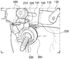
도 3은 본 발명의 일 실시 예에 따른 브라켓의 각도 및 깊이를 가변하는 상태를 보인 예시도이다.1 is an exemplary view illustrating a fixing device for attaching an ultrasound probe to an eyeball region according to an embodiment of the present invention.
2 is an exemplary view illustrating a use case of a fixing device for attaching an ultrasound probe to an eyeball region according to an embodiment of the present invention.
3 is an exemplary view showing a state of varying the angle and depth of the bracket according to an embodiment of the present invention.
이하, 첨부된 도면을 참조하여 본 발명에 따른 바람직한 실시 예를 상세히 설명하기로 한다. 이에 앞서, 본 명세서 및 청구범위에 사용된 용어나 단어는 통상적이거나 사전적인 의미로 한정해서 해석되어서는 아니 되며, 발명자는 그 자신의 발명을 가장 최선의 방법으로 설명하기 위해 용어의 개념을 적절하게 정의할 수 있다는 원칙에 입각하여, 본 발명의 기술적 사상에 부합하는 의미와 개념으로 해석되어야만 한다.Hereinafter, preferred embodiments according to the present invention will be described in detail with reference to the accompanying drawings. Prior to this, the terms or words used in the present specification and claims should not be construed as being limited to conventional or dictionary meanings, and the inventor should properly understand the concept of the term in order to best describe his invention. Based on the principle that it can be defined, it should be interpreted as meaning and concept consistent with the technical idea of the present invention.
따라서 본 명세서에 기재된 실시 예와 도면에 도시된 구성은 본 발명의 가장 바람직한 실시 예에 불과할 뿐이고, 본 발명의 기술적 사상을 모두 대변하는 것은 아니므로, 본 출원시점에 있어서 이들은 대체할 수 있는 균등한 변형 예들이 있을 수 있음을 이해하여야 한다.Therefore, the embodiments described in this specification and the configurations shown in the drawings are only the most preferred embodiments of the present invention, and do not represent all the technical ideas of the present invention, so at the time of the present application, they are equivalent It should be understood that there may be variations.
본 발명은 안구 부위에 위치되는 초음파 프로브를 고정하는 브라켓의 높이, 각도, 및 깊이를 선택적으로 가변할 수 있어, 피검자의 머리 모양이나, 안구 돌출상태에 따라 프로브의 위치를 대응하는 해당 위치에 위치할 수 있기에, 프로브와 안구 부위의 밀착정도를 일정하게 유지시킬 수 있어, 정확한 측정 결과를 얻을 수 있는 눈 부위에 초음파 프로브를 밀착하기 위한 고정장치에 관한 것으로, 도면을 참조하여 살펴보면 다음과 같다.The present invention can selectively vary the height, angle, and depth of the bracket for fixing the ultrasound probe positioned on the eyeball, so that the probe is positioned at the corresponding position according to the shape of the subject's head or the state of the protrusion of the eyeball. It relates to a fixing device for closely adhering an ultrasound probe to an eye area that can maintain a constant degree of adhesion between a probe and an eyeball region, thereby obtaining accurate measurement results.
도 1 내지 도 3을 참조한 본 발명의 일 실시 예에 따른 눈 부위에 초음파 프로브를 밀착하기 위한 고정장치는 헤드셋(100)과, 브라켓(200) 및 프로브고정부재(300)를 포함하는데, 먼저 상기 헤드셋(100)은 머리의 전방에 위치하는 전두지지대(110) 및 머리의 후방에 위치하는 후두지지대(120)를 포함한다.1 to 3, the fixing device for attaching the ultrasound probe to the eye region according to an embodiment of the present invention includes a
이때 상기 전두지지대(110)는 원호 형태를 가지며, 라운딩 처리되어 사용자의 전두부 전방과 밀착할 수 있도록 형성되고, 상기 후두지지대(120)는 상기 전두지지대(110)와 마찬가지로 원호 형태를 가지며, 라운딩 처리되어 사용자의 후두부 후방과 밀착할 수 있도록 형성된다.At this time, the
여기서 본 발명의 일 실시 예에서는 도시되지 않았으나, 상술한 전두지지대(110) 및 후두지지대(120)의 내측면, 즉 피검자의 머리와 맞닿는 면에는 패드(도시하지 않음)를 더 포함하고, 이러한 패드는 머리와 접촉하여 쿠션을 제공하며, 다수의 조절부재(도시하지 않음)에 의해 머리와 밀착정도가 조절된다.Here, although not shown in one embodiment of the present invention, a pad (not shown) is further included on the inner surface of the
그리고 본 발명의 일 실시 예에 따른 헤드셋(100)은 측면 고정부재(130)와 전면 고정부재(140)를 더 포함하는데, 상기 측면 고정부재(130)는 한 쌍으로, 상기 전두지지대(110) 및 후두지지대(120)의 좌, 우측에 위치하면서 상기 전두지지대(110) 및 후두지지대(120) 각각의 끝단에 상기 측면 고정부재(130)의 전, 후단이 연결되어, 머리의 좌측 및 우측에 위치하면서, 상기 전두지지대(110) 및 후두지지대(120)를 연결, 지지 및 고정하는 역할을 수행한다. And the
이때 상기 측면 고정부재(130)도 라운딩 처리된 원호 형태를 갖는 것이 바람직하고, 상기 한 쌍의 측면 고정부재(130)에는 헤드밴드(131)가 체결되는데, 상기 헤드밴드(131)는 그 좌, 우측단이 서로 대향진 상기 한 쌍의 측면 고정부재(130) 각각의 상측과 연결되어, 상기 헤드셋(100)을 피검자의 머리에 씌우면, 피검자의 머리 정수리에 위치한다.At this time, it is preferable that the
따라서 상기 헤드밴드(131)는 상기 헤드셋(100)을 피검자의 머리 일정 높이 위치상에 위치되도록 한다. Accordingly, the
또한, 상기 헤드밴드(131)는 벨크로부재(미부호)를 구비하여, 상기 벨크로부재의 체결 길이로 선택적으로 길이를 조절할 수 있어, 상기 헤드밴드(131)의 길이 조절로, 피검자의 머리에서 상기 헤드셋(100)의 높이를 가변할 수 있다.In addition, the
일례로, 상기 헤드밴드(131)의 체결 길이가 짧으면, 상기 헤드셋(100)의 높이가 올라가고, 상기 헤드밴드(131)의 체결 길이가 길면, 상기 헤드셋(100)의 높이가 내려가게 된다. For example, when the fastening length of the
더불어 상기 측면 고정부재(130)의 전, 후단에 연결되는 상기 전두지지대(110) 및 후두지지대(120) 중 어느 한 지지대(130)는 회전 가능하게 연결되어, 피검자의 두상에 대응하여 상기 전두지지대(110) 및 후두지지대(120)의 기울기를 조절할 수 있다.In addition, any one of the
그리고 상기 전두지지대(110)의 전면에는 전면 고정부재(140)를 구비하는데, 상기 전면 고정부재(140)에는 브라켓(200)이 고정된다.A
이때 상기 전면 고정부재(140)는 체결부재(400)가 상기 전두지지대(110)에 체결됨에 따라 상기 전두지지대(110)의 전면에 고정되고, 상기 전면 고정부재(140)의 중심에는 상기 체결부재(400)의 나사가 관통하는 관통홀(도시하지 않음)을 형성하며, 상기 체결부재(400)가 관통하는 관통홀을 기준으로 상기 전면 고정부재(140)의 좌, 우에는 가로(수평선상)로 길이를 갖는 좌, 우측 체결장공(141)을 형성하는 것이 바람직하다.At this time, the
따라서 상기 체결부재(400)가 상기 전면 고정부재(140)의 관통홀을 관통하여 상기 전두지지대(110)에 체결됨에 따라 상기 전면 고정부재(140)는 상기 전두지지대(110)의 전면에 고정되고, 상기 체결부재(400)와 상기 전두지지대(110)의 결합은 나사결합 방식으로 적용되는 것이 바람직하다. Therefore, as the
또한, 상기 전면 고정부재(140)의 좌, 우측 체결장공(141)은 피검자의 좌, 우측 안구에 대응하는 위치상에 위치하고, 상기 체결장공(141)에는 상기 프로브고정부재(300)가 고정된 브라켓(200)을 체결하여 고정한다.In addition, the left and
여기서 상기 체결장공(141)은 가로(수평선상)로 길이를 갖기에, 피검자의 안구 위치에 대응하여 상기 브라켓(200)을 좌, 우 방향으로 미세 조절하여 고정할 수 있다.Here, since the
그리고 상기 브라켓(200)은 상기 전면 고정부재(140)의 체결장공(141)에 일단이 체결부재(400)에 의해 고정되며, 상기한 브라켓(200)은 높이조절바(210), 깊이조절바(220), 및 기울기조절바(230)을 포함한다.And one end of the
먼저, 상기 높이조절바(210)는 피검자 눈의 높이에 대응하여 수직선상으로 이동하여 상기 프로브고정부재(300)의 높이를 조절한다. First, the
이때 상기 높이조절바(210)는 상, 하 수직으로 길이를 갖고, 중심에는 수직선상으로 높이조절장공(211)을 형성하여, 상기 높이조절장공(211)을 따라 상기 높이조절바(210)를 해당 지정 위치에 위치시킨 후, 체결부재(400)의 체결로 상기 프로브고정부재(300)의 높이를 결정한다. At this time, the
그리고 상기 깊이조절바(220)는 상기 높이조절바(210)의 하단에 일측이 회전 가능하게 구비되고, 피검자 눈의 깊이에 대응하여 회전하여 상기 프로브고정부재(300)의 깊이를 조절한다.And the
또한, 상기 기울기조절바(230)는 상기 깊이조절바(220)의 타측에 회전 가능하게 구비되고, 피검자 눈 위치에 대응하여 회전하여 상기 프로브고정부재(300)의 기울기를 조절한다.In addition, the
이때 상기 깊이조절바(220)는 상기 높이조절바(210)의 하단에 회전 가능하도록, 힌지로 결합되는 것이 바람직하고, 상기 기울기조절바(230)는 상기 깊이조절바(220)의 타측에 회전 가능하도록, 힌지로 결합되는 것이 바람직하다.At this time, the
따라서 상기 깊이조절바(220) 및 상기 기울기조절바(230)는 피검자의 눈(안구) 위치 및 깊이에 대응하여 각각 힌지를 축으로 해당 각도만큼 회전시켜, 상기 프로브고정부재(300)의 깊이 및 기울기를 조절할 수 있기에 피점자의 이마와 안구 돌출 여부에 상관없이 눈 부위에 초음파 프로브를 밀착할 수 있다.Therefore, the
그리고 상기 프로브고정부재(300)는 원통으로 형성되며, 그 중앙에는 초음파 프로브를 장착하는 장착공을 형성하며, 상기 기울기조절바(230)와 회전 가능하게 힌지로 연결된다.In addition, the
초음파 프로브(500)는 통상의 프로브와 같이 원주형을 이루고, 상기 프로브고정부재(300)에 형성되는 장착공에 고정되어 시술할 수 있게 한다.The
그러므로 상기한 구성의 초음파 프로브를 밀착하기 위한 고정장치는 뇌혈류 측정용 프로브를 안구에 간편하고 견고하게 고정하기 위한 프로브 고정장치에 관한 것으로서, 특히, 안구 탐침이 지속적이고 견고하게 고정되어야 하는 상황, 즉 혈관운동 반응성 검사, 미세색전신호(microembolic signal; MES) 검사, 수술 중 대뇌혈전발생의 연속측정검사 등에서 사용될 수 있도록, 안구 부위에 위치되는 초음파 프로브를 고정하는 브라켓의 높이, 각도, 및 깊이를 선택적으로 가변할 수 있어, 피검자의 머리 모양이나, 안구 돌출상태에 따라 프로브의 위치를 대응하는 해당 위치에 위치할 수 있기에, 프로브와 안구 부위의 밀착정도를 일정하게 유지시킬 수 있어, 정확한 측정 결과를 얻을 수 있도록 한다.Therefore, the fixing device for closely attaching the ultrasonic probe of the above configuration relates to a probe fixing device for simply and firmly fixing the probe for measuring cerebral blood flow to the eyeball, in particular, the situation in which the eye probe must be continuously and firmly fixed; That is, the height, angle, and depth of the bracket for fixing the ultrasound probe positioned in the eye area can be used for vasomotor reactivity test, microembolic signal (MES) test, and continuous measurement test for cerebral thrombosis during surgery. Since it can be selectively changed, the position of the probe can be positioned at the corresponding position according to the shape of the subject's head or the state of the eyeball protrusion. to be able to obtain
본 발명은 도면에 도시된 실시 예를 참고로 설명되었으나 이는 예시적인 것에 불과하며, 본 기술 분야의 통상의 지식을 가진 자라면 이로부터 다양한 변형 및 균등한 다른 실시 예가 가능하다는 점을 이해할 것이다. 따라서 본 발명의 진정한 기술적 보호 범위는 첨부된 특허청구범위의 기술적 사상에 의하여 정해져야 할 것이다.Although the present invention has been described with reference to the embodiment shown in the drawings, which is merely exemplary, those skilled in the art will understand that various modifications and equivalent other embodiments are possible therefrom. Therefore, the true technical protection scope of the present invention should be determined by the technical spirit of the appended claims.
100: 헤드셋
110: 전두지지대
120: 후두지지대
130: 측면 고정부재
131: 헤드밴드
140: 전면 고정부재
141: 체결장공
200: 브라켓
210: 높이조절바
211: 높이조절장공
220: 깊이조절바
230: 기울기조절바
300: 프로브고정부재
400: 체결부재
500: 초음파 프로브100: headset
110: frontal support
120: laryngeal support
130: side fixing member
131: headband
140: front fixing member
141: fastener
200: bracket
210: height adjustment bar
211: height adjustable long ball
220: depth adjustment bar
230: tilt adjustment bar
300: probe fixing member
400: fastening member
500: ultrasonic probe
Claims (5)
상기 헤드셋의 전방측에 고정되는 브라켓; 및
상기 브라켓의 하단에 구비되어, 초음파 프로브를 고정하는 프로브고정부재;를 포함하고,
상기 브라켓은
피검자 눈의 높이에 대응하여 수직선상으로 이동하여 상기 프로브고정부재의 높이를 조절하는 높이조절바;
상기 높이조절바의 하단에 일측이 회전 가능하게 구비되고, 피검자 눈의 깊이에 대응하여 회전하여 상기 프로브고정부재의 깊이를 조절하는 깊이조절바; 및
상기 깊이조절바의 타측에 회전 가능하게 구비되고, 피검자 눈 위치에 대응하여 회전하여 상기 프로브고정부재의 기울기를 조절하는 기울기조절바;를 포함하는 눈 부위에 초음파 프로브를 밀착하기 위한 고정장치.
a headset worn on the subject's head;
a bracket fixed to the front side of the headset; and
and a probe fixing member provided at the lower end of the bracket to fix the ultrasonic probe.
The bracket is
a height adjustment bar for adjusting the height of the probe fixing member by moving in a vertical line corresponding to the height of the subject's eyes;
a depth adjustment bar having one side rotatably provided at the lower end of the height adjustment bar and rotating to correspond to the depth of the subject's eye to adjust the depth of the probe fixing member; and
A fixing device for adhering an ultrasound probe to an eye area comprising a; a tilt adjustment bar which is rotatably provided on the other side of the depth adjustment bar and rotates to correspond to the position of the eye of the subject to adjust the inclination of the probe fixing member.
상기 헤드셋은
전두부의 전방에 위치하는 전두지지대와,
후두부의 후방에 위치하는 후두지지대와,
상기 전두지지대 및 후두지지대들의 좌, 우측 양단이 연결되고 머리의 좌측 및 우측에 위치하는 한 쌍의 측면 고정부재와,
상기 전두지지대의 전면에 구비되고, 상기 브라켓이 고정되는 전면 고정부재;를 포함하는 안구 부위에 초음파 프로브를 밀착하기 위한 고정장치.
The method according to claim 1,
the headset is
The frontal support located in front of the frontal part,
And the laryngeal support located at the back of the larynx,
A pair of side fixing members connected to the left and right ends of the frontal support and the laryngeal support and located on the left and right sides of the head;
A fixing device for adhering an ultrasound probe to an eyeball region including a; a front fixing member provided on the front surface of the frontal support and to which the bracket is fixed.
상기 전두지지대 및 상기 후두지지대는
피검자의 머리 둘레에 대응하도록, 라운딩 처리된 원호 형태인 것을 특징으로 하는 안구 부위에 초음파 프로브를 밀착하기 위한 고정장치.
3. The method according to claim 2,
The frontal support and the laryngeal support
A fixing device for adhering the ultrasound probe to the eye area, characterized in that it has a rounded arc shape to correspond to the circumference of the subject's head.
상기 브라켓은
상기 전두지지대의 좌, 우 양측 중 어느 한 곳에 위치하여, 상기 프로브고정부재를 피검자 눈에 근접시키는 안구 부위에 초음파 프로브를 밀착하기 위한 고정장치.
3. The method according to claim 2,
The bracket is
A fixing device for adhering the ultrasonic probe to an eye area that is located on either side of the left and right sides of the frontal support and brings the probe fixing member close to the subject's eye.
상기 한 쌍의 측면 고정부재 각각의 상측과 좌, 우측단이 연결되고, 피검자의 머리 정수리에 위치하여, 상기 헤드셋을 피검자의 머리 일정 높이 위치상에 위치되도록 고정하는 헤드밴드를 포함하는 안구 부위에 초음파 프로브를 밀착하기 위한 고정장치.3. The method according to claim 2,
The upper, left, and right ends of each of the pair of side fixing members are connected to each other, and located on the crown of the subject's head, the eye area comprising a headband for fixing the headset to be positioned at a certain height of the subject's head. A fixing device for attaching the ultrasonic probe in close contact.
Priority Applications (2)
| Application Number | Priority Date | Filing Date | Title |
|---|---|---|---|
| KR1020210026069A KR102651863B1 (en) | 2021-02-26 | 2021-02-26 | Fixation device for attaching the ultrasonic probe to the eyeball area |
| PCT/KR2022/002658 WO2022182129A1 (en) | 2021-02-26 | 2022-02-23 | Fixing device for bringing ultrasonic probe into close contact with eye region |
Applications Claiming Priority (1)
| Application Number | Priority Date | Filing Date | Title |
|---|---|---|---|
| KR1020210026069A KR102651863B1 (en) | 2021-02-26 | 2021-02-26 | Fixation device for attaching the ultrasonic probe to the eyeball area |
Publications (2)
| Publication Number | Publication Date |
|---|---|
| KR20220121997A true KR20220121997A (en) | 2022-09-02 |
| KR102651863B1 KR102651863B1 (en) | 2024-03-29 |
Family
ID=83049484
Family Applications (1)
| Application Number | Title | Priority Date | Filing Date |
|---|---|---|---|
| KR1020210026069A KR102651863B1 (en) | 2021-02-26 | 2021-02-26 | Fixation device for attaching the ultrasonic probe to the eyeball area |
Country Status (2)
| Country | Link |
|---|---|
| KR (1) | KR102651863B1 (en) |
| WO (1) | WO2022182129A1 (en) |
Citations (8)
| Publication number | Priority date | Publication date | Assignee | Title |
|---|---|---|---|---|
| KR100873267B1 (en) * | 2007-07-19 | 2008-12-11 | 사회복지법인 삼성생명공익재단 | Suboccipital probe fixing device |
| KR20130048360A (en) * | 2011-11-02 | 2013-05-10 | 아주대학교산학협력단 | Simply-designed probe fixation device for the tight contracts in the suboccipital area |
| WO2015075603A1 (en) * | 2013-11-21 | 2015-05-28 | Koninklijke Philips N.V. | Ultrasound headset |
| WO2017118964A1 (en) * | 2016-01-05 | 2017-07-13 | Neural Analytics, Inc. | Systems and methods for detecting neurological conditions |
| JP2018537147A (en) * | 2015-10-15 | 2018-12-20 | 国立陽明大学 | Ultrasonic stimulation helmet |
| KR20190078076A (en) * | 2017-12-26 | 2019-07-04 | 아주대학교산학협력단 | Non-invasive Apparatus for measuring intracranial pressure |
| KR102151712B1 (en) * | 2019-06-14 | 2020-09-04 | 주식회사 오토스윙 | Head band |
| CN111921101A (en) * | 2020-07-10 | 2020-11-13 | 深圳先进技术研究院 | Head-mounted ultrasonic nerve stimulation device and system |
Family Cites Families (1)
| Publication number | Priority date | Publication date | Assignee | Title |
|---|---|---|---|---|
| CN203494074U (en) * | 2013-09-26 | 2014-03-26 | 北京天行健医疗科技有限公司 | Ultrasonic scanning treatment head cap |
-
2021
- 2021-02-26 KR KR1020210026069A patent/KR102651863B1/en active IP Right Grant
-
2022
- 2022-02-23 WO PCT/KR2022/002658 patent/WO2022182129A1/en active Application Filing
Patent Citations (9)
| Publication number | Priority date | Publication date | Assignee | Title |
|---|---|---|---|---|
| KR100873267B1 (en) * | 2007-07-19 | 2008-12-11 | 사회복지법인 삼성생명공익재단 | Suboccipital probe fixing device |
| KR20130048360A (en) * | 2011-11-02 | 2013-05-10 | 아주대학교산학협력단 | Simply-designed probe fixation device for the tight contracts in the suboccipital area |
| KR101333911B1 (en) * | 2011-11-02 | 2013-12-02 | 아주대학교산학협력단 | Simply-designed probe fixation device for the tight contracts in the suboccipital area |
| WO2015075603A1 (en) * | 2013-11-21 | 2015-05-28 | Koninklijke Philips N.V. | Ultrasound headset |
| JP2018537147A (en) * | 2015-10-15 | 2018-12-20 | 国立陽明大学 | Ultrasonic stimulation helmet |
| WO2017118964A1 (en) * | 2016-01-05 | 2017-07-13 | Neural Analytics, Inc. | Systems and methods for detecting neurological conditions |
| KR20190078076A (en) * | 2017-12-26 | 2019-07-04 | 아주대학교산학협력단 | Non-invasive Apparatus for measuring intracranial pressure |
| KR102151712B1 (en) * | 2019-06-14 | 2020-09-04 | 주식회사 오토스윙 | Head band |
| CN111921101A (en) * | 2020-07-10 | 2020-11-13 | 深圳先进技术研究院 | Head-mounted ultrasonic nerve stimulation device and system |
Also Published As
| Publication number | Publication date |
|---|---|
| WO2022182129A1 (en) | 2022-09-01 |
| KR102651863B1 (en) | 2024-03-29 |
Similar Documents
| Publication | Publication Date | Title |
|---|---|---|
| JP6972093B2 (en) | Ultrasonic head frame for emergency medical services | |
| US5514146A (en) | Device for accomodating at least one sonographic probe | |
| US4528990A (en) | Apparatus for measuring head and spine movement | |
| AU2016246143A1 (en) | Device configured to be supported on a human body, to measure a biological parameter of the human body, and to control a characteristic of the human body | |
| KR20110094183A (en) | Method of determining blood pressure and an apparatus for determining blood pressure | |
| US20230157639A1 (en) | Device configured to position a sensor at an abreu brain thermal tunnel terminus | |
| FI117886B (en) | Position indicator frame and method for supporting a position indicator frame | |
| US20030131852A1 (en) | Registration and surgical face mask | |
| US20070232918A1 (en) | Doppler helmet | |
| KR20220121997A (en) | Fixation device for attaching the ultrasonic probe to the eyeball area | |
| JP2002172120A (en) | Stereotactic tool | |
| EP2977000B1 (en) | Head frame with integrated pressure chamber for non-invasive intracranial pressure measurements | |
| KR102114350B1 (en) | Non-invasive Apparatus for measuring intracranial pressure | |
| US20060122513A1 (en) | Doppler helmet | |
| JP2021168752A (en) | Degree of pain measuring device | |
| US9925449B2 (en) | Head mounted training aid | |
| CN201082164Y (en) | Headstock device of probe for detecting brain bloodstream | |
| TWI766607B (en) | Head-mounted apparatus for medical use and system thereof | |
| US20230166129A1 (en) | Head-wearable devices for positioning ultrasound transducers for brain stimulation | |
| US20240148582A1 (en) | Surgical universal headrest including skull pin holder assembly | |
| US20230218235A1 (en) | Stabilization assembly for head-mounted device | |
| WO2023159039A1 (en) | Ophthalmic instrument for self-tonometry | |
| WO2024102725A1 (en) | Surgical universal headrest including skull pin holder assembly |
Legal Events
| Date | Code | Title | Description |
|---|---|---|---|
| E902 | Notification of reason for refusal | ||
| E701 | Decision to grant or registration of patent right |