KR20220121851A - Stent delivery systems and stent placement methods - Google Patents
Stent delivery systems and stent placement methods Download PDFInfo
- Publication number
- KR20220121851A KR20220121851A KR1020227025629A KR20227025629A KR20220121851A KR 20220121851 A KR20220121851 A KR 20220121851A KR 1020227025629 A KR1020227025629 A KR 1020227025629A KR 20227025629 A KR20227025629 A KR 20227025629A KR 20220121851 A KR20220121851 A KR 20220121851A
- Authority
- KR
- South Korea
- Prior art keywords
- stent
- release
- delay
- constraining
- thread
- Prior art date
Links
- 238000000034 method Methods 0.000 title claims abstract description 18
- 230000000452 restraining effect Effects 0.000 claims abstract description 52
- 238000011068 loading method Methods 0.000 claims description 7
- 238000003780 insertion Methods 0.000 claims description 5
- 230000037431 insertion Effects 0.000 claims description 5
- 238000004804 winding Methods 0.000 claims description 5
- 238000002788 crimping Methods 0.000 claims description 2
- 239000008280 blood Substances 0.000 abstract description 5
- 210000004369 blood Anatomy 0.000 abstract description 5
- 230000009471 action Effects 0.000 abstract description 3
- 229910052751 metal Inorganic materials 0.000 description 30
- 239000002184 metal Substances 0.000 description 30
- 210000004204 blood vessel Anatomy 0.000 description 16
- 230000003902 lesion Effects 0.000 description 16
- 239000012528 membrane Substances 0.000 description 14
- 238000004873 anchoring Methods 0.000 description 9
- 230000003111 delayed effect Effects 0.000 description 8
- 229920001343 polytetrafluoroethylene Polymers 0.000 description 6
- 239000004810 polytetrafluoroethylene Substances 0.000 description 6
- 208000002251 Dissecting Aneurysm Diseases 0.000 description 5
- 208000027418 Wounds and injury Diseases 0.000 description 5
- 210000003484 anatomy Anatomy 0.000 description 3
- 210000000709 aorta Anatomy 0.000 description 3
- 206010002895 aortic dissection Diseases 0.000 description 3
- 238000002224 dissection Methods 0.000 description 3
- 229920000728 polyester Polymers 0.000 description 3
- 230000008569 process Effects 0.000 description 3
- 239000012781 shape memory material Substances 0.000 description 3
- 239000010935 stainless steel Substances 0.000 description 3
- 229910001220 stainless steel Inorganic materials 0.000 description 3
- 238000001356 surgical procedure Methods 0.000 description 3
- 201000008982 Thoracic Aortic Aneurysm Diseases 0.000 description 2
- 208000007536 Thrombosis Diseases 0.000 description 2
- 230000004888 barrier function Effects 0.000 description 2
- 230000017531 blood circulation Effects 0.000 description 2
- 239000000463 material Substances 0.000 description 2
- 239000007769 metal material Substances 0.000 description 2
- 238000012986 modification Methods 0.000 description 2
- 230000004048 modification Effects 0.000 description 2
- -1 polytetrafluoroethylene Polymers 0.000 description 2
- 201000006474 Brain Ischemia Diseases 0.000 description 1
- 206010008120 Cerebral ischaemia Diseases 0.000 description 1
- VEXZGXHMUGYJMC-UHFFFAOYSA-M Chloride anion Chemical compound [Cl-] VEXZGXHMUGYJMC-UHFFFAOYSA-M 0.000 description 1
- 208000001750 Endoleak Diseases 0.000 description 1
- VEQPNABPJHWNSG-UHFFFAOYSA-N Nickel(2+) Chemical compound [Ni+2] VEQPNABPJHWNSG-UHFFFAOYSA-N 0.000 description 1
- 239000004677 Nylon Substances 0.000 description 1
- 229910000566 Platinum-iridium alloy Inorganic materials 0.000 description 1
- 239000004743 Polypropylene Substances 0.000 description 1
- 206010064396 Stent-graft endoleak Diseases 0.000 description 1
- 229920004933 Terylene® Polymers 0.000 description 1
- HZEWFHLRYVTOIW-UHFFFAOYSA-N [Ti].[Ni] Chemical compound [Ti].[Ni] HZEWFHLRYVTOIW-UHFFFAOYSA-N 0.000 description 1
- 238000004026 adhesive bonding Methods 0.000 description 1
- 229910045601 alloy Inorganic materials 0.000 description 1
- 239000000956 alloy Substances 0.000 description 1
- 210000001367 artery Anatomy 0.000 description 1
- 230000004323 axial length Effects 0.000 description 1
- 230000015572 biosynthetic process Effects 0.000 description 1
- 230000036770 blood supply Effects 0.000 description 1
- 210000001124 body fluid Anatomy 0.000 description 1
- 239000010839 body fluid Substances 0.000 description 1
- 206010008118 cerebral infarction Diseases 0.000 description 1
- 230000007797 corrosion Effects 0.000 description 1
- 238000005260 corrosion Methods 0.000 description 1
- 239000006071 cream Substances 0.000 description 1
- 238000005520 cutting process Methods 0.000 description 1
- 230000001934 delay Effects 0.000 description 1
- 230000001627 detrimental effect Effects 0.000 description 1
- 230000010339 dilation Effects 0.000 description 1
- 201000010099 disease Diseases 0.000 description 1
- 208000037265 diseases, disorders, signs and symptoms Diseases 0.000 description 1
- 238000006073 displacement reaction Methods 0.000 description 1
- 238000004090 dissolution Methods 0.000 description 1
- 210000001105 femoral artery Anatomy 0.000 description 1
- 230000036541 health Effects 0.000 description 1
- 239000007943 implant Substances 0.000 description 1
- 208000014674 injury Diseases 0.000 description 1
- 150000002500 ions Chemical class 0.000 description 1
- 208000028867 ischemia Diseases 0.000 description 1
- 239000007788 liquid Substances 0.000 description 1
- 239000003550 marker Substances 0.000 description 1
- 229910021645 metal ion Inorganic materials 0.000 description 1
- 229910001453 nickel ion Inorganic materials 0.000 description 1
- 229910001000 nickel titanium Inorganic materials 0.000 description 1
- 229920001778 nylon Polymers 0.000 description 1
- 210000000056 organ Anatomy 0.000 description 1
- HWLDNSXPUQTBOD-UHFFFAOYSA-N platinum-iridium alloy Chemical class [Ir].[Pt] HWLDNSXPUQTBOD-UHFFFAOYSA-N 0.000 description 1
- 239000005020 polyethylene terephthalate Substances 0.000 description 1
- 239000002861 polymer material Substances 0.000 description 1
- 229920005597 polymer membrane Polymers 0.000 description 1
- 229920001155 polypropylene Polymers 0.000 description 1
- 230000008439 repair process Effects 0.000 description 1
- 231100000331 toxic Toxicity 0.000 description 1
- 230000002588 toxic effect Effects 0.000 description 1
- 230000008733 trauma Effects 0.000 description 1
- 230000002792 vascular Effects 0.000 description 1
- 238000003466 welding Methods 0.000 description 1
Images


Classifications
-
- A—HUMAN NECESSITIES
- A61—MEDICAL OR VETERINARY SCIENCE; HYGIENE
- A61F—FILTERS IMPLANTABLE INTO BLOOD VESSELS; PROSTHESES; DEVICES PROVIDING PATENCY TO, OR PREVENTING COLLAPSING OF, TUBULAR STRUCTURES OF THE BODY, e.g. STENTS; ORTHOPAEDIC, NURSING OR CONTRACEPTIVE DEVICES; FOMENTATION; TREATMENT OR PROTECTION OF EYES OR EARS; BANDAGES, DRESSINGS OR ABSORBENT PADS; FIRST-AID KITS
- A61F2/00—Filters implantable into blood vessels; Prostheses, i.e. artificial substitutes or replacements for parts of the body; Appliances for connecting them with the body; Devices providing patency to, or preventing collapsing of, tubular structures of the body, e.g. stents
- A61F2/95—Instruments specially adapted for placement or removal of stents or stent-grafts
- A61F2/962—Instruments specially adapted for placement or removal of stents or stent-grafts having an outer sleeve
- A61F2/966—Instruments specially adapted for placement or removal of stents or stent-grafts having an outer sleeve with relative longitudinal movement between outer sleeve and prosthesis, e.g. using a push rod
-
- A—HUMAN NECESSITIES
- A61—MEDICAL OR VETERINARY SCIENCE; HYGIENE
- A61F—FILTERS IMPLANTABLE INTO BLOOD VESSELS; PROSTHESES; DEVICES PROVIDING PATENCY TO, OR PREVENTING COLLAPSING OF, TUBULAR STRUCTURES OF THE BODY, e.g. STENTS; ORTHOPAEDIC, NURSING OR CONTRACEPTIVE DEVICES; FOMENTATION; TREATMENT OR PROTECTION OF EYES OR EARS; BANDAGES, DRESSINGS OR ABSORBENT PADS; FIRST-AID KITS
- A61F2/00—Filters implantable into blood vessels; Prostheses, i.e. artificial substitutes or replacements for parts of the body; Appliances for connecting them with the body; Devices providing patency to, or preventing collapsing of, tubular structures of the body, e.g. stents
- A61F2/95—Instruments specially adapted for placement or removal of stents or stent-grafts
- A61F2/962—Instruments specially adapted for placement or removal of stents or stent-grafts having an outer sleeve
-
- A—HUMAN NECESSITIES
- A61—MEDICAL OR VETERINARY SCIENCE; HYGIENE
- A61F—FILTERS IMPLANTABLE INTO BLOOD VESSELS; PROSTHESES; DEVICES PROVIDING PATENCY TO, OR PREVENTING COLLAPSING OF, TUBULAR STRUCTURES OF THE BODY, e.g. STENTS; ORTHOPAEDIC, NURSING OR CONTRACEPTIVE DEVICES; FOMENTATION; TREATMENT OR PROTECTION OF EYES OR EARS; BANDAGES, DRESSINGS OR ABSORBENT PADS; FIRST-AID KITS
- A61F2/00—Filters implantable into blood vessels; Prostheses, i.e. artificial substitutes or replacements for parts of the body; Appliances for connecting them with the body; Devices providing patency to, or preventing collapsing of, tubular structures of the body, e.g. stents
- A61F2/95—Instruments specially adapted for placement or removal of stents or stent-grafts
- A61F2/9517—Instruments specially adapted for placement or removal of stents or stent-grafts handle assemblies therefor
-
- A—HUMAN NECESSITIES
- A61—MEDICAL OR VETERINARY SCIENCE; HYGIENE
- A61F—FILTERS IMPLANTABLE INTO BLOOD VESSELS; PROSTHESES; DEVICES PROVIDING PATENCY TO, OR PREVENTING COLLAPSING OF, TUBULAR STRUCTURES OF THE BODY, e.g. STENTS; ORTHOPAEDIC, NURSING OR CONTRACEPTIVE DEVICES; FOMENTATION; TREATMENT OR PROTECTION OF EYES OR EARS; BANDAGES, DRESSINGS OR ABSORBENT PADS; FIRST-AID KITS
- A61F2/00—Filters implantable into blood vessels; Prostheses, i.e. artificial substitutes or replacements for parts of the body; Appliances for connecting them with the body; Devices providing patency to, or preventing collapsing of, tubular structures of the body, e.g. stents
- A61F2/95—Instruments specially adapted for placement or removal of stents or stent-grafts
- A61F2002/9505—Instruments specially adapted for placement or removal of stents or stent-grafts having retaining means other than an outer sleeve, e.g. male-female connector between stent and instrument
- A61F2002/9511—Instruments specially adapted for placement or removal of stents or stent-grafts having retaining means other than an outer sleeve, e.g. male-female connector between stent and instrument the retaining means being filaments or wires
-
- A—HUMAN NECESSITIES
- A61—MEDICAL OR VETERINARY SCIENCE; HYGIENE
- A61F—FILTERS IMPLANTABLE INTO BLOOD VESSELS; PROSTHESES; DEVICES PROVIDING PATENCY TO, OR PREVENTING COLLAPSING OF, TUBULAR STRUCTURES OF THE BODY, e.g. STENTS; ORTHOPAEDIC, NURSING OR CONTRACEPTIVE DEVICES; FOMENTATION; TREATMENT OR PROTECTION OF EYES OR EARS; BANDAGES, DRESSINGS OR ABSORBENT PADS; FIRST-AID KITS
- A61F2/00—Filters implantable into blood vessels; Prostheses, i.e. artificial substitutes or replacements for parts of the body; Appliances for connecting them with the body; Devices providing patency to, or preventing collapsing of, tubular structures of the body, e.g. stents
- A61F2/95—Instruments specially adapted for placement or removal of stents or stent-grafts
- A61F2/962—Instruments specially adapted for placement or removal of stents or stent-grafts having an outer sleeve
- A61F2/966—Instruments specially adapted for placement or removal of stents or stent-grafts having an outer sleeve with relative longitudinal movement between outer sleeve and prosthesis, e.g. using a push rod
- A61F2002/9665—Instruments specially adapted for placement or removal of stents or stent-grafts having an outer sleeve with relative longitudinal movement between outer sleeve and prosthesis, e.g. using a push rod with additional retaining means
Abstract
스텐트 전달 시스템 및 스텐트(1) 장착 방법이 개시된다. 스텐트 전달 시스템은 핸들, 외부 튜브(52), 구속 부재 및 지연-해제 부재(4)를 포함하며 구조적으로 간단하고 사용하기 쉽다. 구속 부재에서 스텐트(1)를 해제하는 동안 스텐트(1)의 근위 단부는 항상 지연-해제 부재(4)에 고정되어 힘의 작용으로 스텐트(1)가 뒤로 이동하는 것을 방지한다. 혈액으로부터의 힘의 작용 하에 스텐트(1)가 뒤로 이동하는 것을 피함으로써 스텐트(1)의 해제 위치 정확도를 향상시킨다. 추가적으로, 구속 부재로부터 스텐트(1)를 해제하는 동안, 스텐트(1)의 원위 단부는 고정 코일(32)에 의해 내부 튜브(51)에 고정될 수 있고, 스텐트(1)의 근위 단부는 지연-해제 부재(4)에 고정된 상태로 유지될 수 있다. 이렇게 하면 스텐트(1)의 중간 섹션을 해제하는 동안 스텐트(1)가 앞뒤로 움직이는 것을 방지할 수 있으므로 스텐트(1)가 정확한 위치 제어 하에 해제될 수 있게 된다.A stent delivery system and a stent (1) mounting method are disclosed. The stent delivery system includes a handle, an outer tube 52 , a constraining member and a delay-release member 4 , and is structurally simple and easy to use. During release of the stent 1 from the restraining member, the proximal end of the stent 1 is always secured to the delay-release member 4 to prevent backward movement of the stent 1 under the action of the force. The release position accuracy of the stent 1 is improved by avoiding the stent 1 moving backward under the action of a force from the blood. Additionally, during release of the stent 1 from the restraining member, the distal end of the stent 1 may be secured to the inner tube 51 by a fixation coil 32 and the proximal end of the stent 1 may be delayed- It can remain fixed to the release member 4 . This will prevent the stent 1 from moving back and forth during release of the middle section of the stent 1 so that the stent 1 can be released under precise positioning control.
Description
본 발명은 의료 기기 분야에 관한 것으로, 특히 스텐트 전달 시스템 및 스텐트 장착 방법에 관한 것이다.FIELD OF THE INVENTION The present invention relates to the field of medical devices, and more particularly to stent delivery systems and stent placement methods.
흉부 대동맥류(Thoracic aortic aneurysms) 또는 박리(dissections)는 널리 퍼진 치명적인 혈관 외과 질환이다. 1990년대 이전에는 흉부 대동맥류 또는 박리를 전통적인 수술 기법을 사용하여 치료했지만 높은 수술 난이도, 심각한 외상 및 많은 합병증을 비롯한 여러 단점들이 존재하였다. 1994년 Dake와 그의 동료들은 이식된 혈관 내 커버드 스텐트로 대동맥 박리를 치료하는 것을 최초로 보고한 이후 중재 수술(interventional surgery)이 크게 발전했다. 이러한 중재적 수술 절차는 일반적으로 대퇴 동맥의 천자 절개(puncture incision)를 통해 삽입된 시스를 통해 환자의 신체에 커버드 스텐트(covered stent)를 도입하고 주동맥을 통해 대동맥의 표적 병변 부위로 전진시키는 과정을 포함한다. 그 후, 커버드 스텐트를 해제하여 환부 혈관 섹션을 덮고 고치게 된다. 커버드 스텐트(covered stent)는 스텐트 본체의 내부 또는 외부 표면이 부분적으로 또는 전체적으로 멤브레인으로 덮여 있는 보철 임플란트이다.Thoracic aortic aneurysms or dissections are a widespread and fatal vascular surgical disease. Prior to the 1990s, thoracic aortic aneurysms or dissections were treated using traditional surgical techniques, but there were several drawbacks, including high surgical difficulty, severe trauma, and many complications. Since 1994, when Dake and colleagues first reported the treatment of aortic dissection with an implanted endovascular covered stent, interventional surgery has advanced significantly. This interventional surgical procedure typically involves introducing a covered stent into the patient's body through a sheath inserted through a puncture incision in the femoral artery and advancing it through the main artery to the target lesion site of the aorta. includes the process. Thereafter, the covered stent is released to cover and repair the affected vessel section. A covered stent is a prosthetic implant in which the inner or outer surface of a stent body is partially or wholly covered with a membrane.
커버드 스텐트로 대동맥 박리를 치료하는 것은 특수한 전달 시스템을 사용하여 커버드 스텐트를 대상 병변 부위에 전달한 다음 커버드 스텐트를 해제하고 확장하는 것으로 구성된다. 그 결과로, 커버드 스텐트의 멤브레인이 대동맥의 찢어진 부분을 막아 혈액이 박리 시 가성 내강(false lumen)으로 더 들어가는 것을 차단하고 찢어진 부분이 더 확장되거나 대동맥이 파열되는 것을 방지하게 된다. 동시에, 커버드 스텐트의 스텐트 본체가 혈관벽을 지지하여 혈액이 가성 내강으로 흐르는 것을 방지하고, 진성 내강(true lumen)을 압축하여 정상적인 혈류에 영향을 미치고 영향을 받는 조직 및 기관으로의 혈액 공급을 감소시킬 수 있다. 입구 파열(entry tear)을 막기위해서는, 일반적으로 스텐트 앵커 역할을 할 수 있는 커버드 스텐트의 근위 단부 주위에 일정 길이의 건강한 혈관이 존재하여야 한다. 그러나 입구 파열은 종종 중요한 분지 혈관들의 구멍에 가깝기 때문에 그러한 앵커는 매우 짧고 길이가 제한적이며 귀중한 경향이 있다. 또한 혈류의 힘이나 시스템 설계 문제로 인해, 일반적으로 커버드 스텐트를 대상 부위에 정확하게 해제하기 어렵고 전개된 커버드 스텐트가 종종 표적 위치에서 앞뒤로 다소 변위되어 스텐트 앵커와 주변 분지 혈관들이 완전히 닫힐 수 있게 되어, 기관 허혈(ischemia), 대뇌 허혈 또는 환자의 건강에 해로운 기타 바람직하지 않은 결과의 원인이 될 수 있거나 내강 누출 또는 환자의 건강에 해로운 기타 바람직하지 않은 결과의 원인이 될 수 있는 입구 파열의 불완전한 폐쇄의 원인이 될 수 있다.Treatment of aortic dissection with a covered stent consists of delivering the covered stent to the target lesion site using a specialized delivery system, followed by release and expansion of the covered stent. As a result, the membrane of the covered stent blocks the tear in the aorta, preventing further blood from entering the false lumen during dissection and preventing further dilation of the tear or rupture of the aorta. At the same time, the stent body of the covered stent supports the vessel wall to prevent blood from flowing into the pseudolumen, and compresses the true lumen to affect normal blood flow and reduce blood supply to the affected tissues and organs. can do it In order to prevent an entry tear, there must generally be a length of healthy blood vessel around the proximal end of the covered stent that can serve as a stent anchor. However, such anchors tend to be very short, limited in length, and valuable because entrance ruptures are often close to the orifices of important branch vessels. Also, due to blood flow forces or system design issues, it is generally difficult to release the covered stent accurately into the target site, and the deployed covered stent is often slightly displaced back and forth from the target location, allowing the stent anchor and surrounding branch vessels to close completely. , tracheal ischemia, cerebral ischemia, or incomplete closure of the inlet rupture that may cause lumen leakage or other undesirable outcomes that are detrimental to the patient's health can be the cause of
본 발명의 목적은 혈류로부터의 힘의 작용에 의해 스텐트가 후방으로 이동하는 것을 방지함으로써 해제된 스텐트의 위치 정확도를 향상시킬 수 있는 스텐트 전달 시스템 및 스텐트 로딩 방법을 제공하는 것이다.It is an object of the present invention to provide a stent delivery system and a stent loading method capable of improving the positioning accuracy of a released stent by preventing the stent from moving posteriorly by the action of a force from the bloodstream.
이를 위해 제공되는 스텐트 전달 시스템은 핸들, 외부 튜브, 구속 부재 및 지연-해제 부재를 포함한다.A stent delivery system provided for this purpose includes a handle, an outer tube, a constraining member, and a delay-release member.
외부 튜브는, 크림핑된 상태의 스텐트를 수용하기 위해 축 방향으로 연장되는 내부 루멘을 형성하고, 외부 튜브는 스텐트가 노출되도록 핸들의 제어에 따라 스텐트의 원위 단부를 향해 철수하게 된다.The outer tube defines an inner lumen extending axially to receive the stent in a crimped condition, and the outer tube is withdrawn towards the distal end of the stent under control of the handle such that the stent is exposed.
구속 부재는, 적어도 하나의 구속 스레드 및 제어 가이드 와이어를 포함하고, 구속 스레드는 스텐트 주위에 원주 방향으로 배열되고, 제어 가이드 와이어는 스텐트를 압축하거나 해제하기 위해 개방-루프 또는 폐쇄-루프 구조 사이에서 구속 스레드를 전환하게 된다.The restraining member includes at least one restraining thread and a control guide wire, the restraining thread arranged circumferentially around the stent, and the control guide wire being disposed between the open-loop or closed-loop structure to compress or release the stent. The constraint thread will be switched.
지연-해제 부재는, 외부 튜브 내에 배치되고, 스텐트의 근위 단부를 구속하거나 해제하기 위해 스텐트의 근위 단부에 제거 가능하게 연결된다.A delay-release member is disposed within the outer tube and is removably connected to the proximal end of the stent to constrain or release the proximal end of the stent.
선택적으로, 구속 부재는 2 개 이상의 구속 스레드들을 포함할 수 있고, 2 개 이상의 구속 스레드들은 축 방향을 따라 스텐트의 메인 부분을 가로질러 서로 이격되어 있다.Optionally, the restraining member may comprise two or more restraining threads, the two or more restraining threads being spaced apart from each other along the axial direction and across the main portion of the stent.
선택적으로, 구속 스레드들 각각은, 양 단부에서 닫히는 이중 가닥 구속 스레드일 수 있고, 제어 가이드 와이어가 이중 가닥 구속 스레드의 선단부를 통해 삽입되어 이중 가닥 구속 스레드가 폐쇄-루프 구조로 구성되는 동안, 스텐트 주위에 이중 가닥 구속 스레드를 적어도 1회 감은 이후, 이중 가닥 구속 스레드의 선단부가 후단부를 통해 삽입되게 되어 이중 가닥 구속 스레드가 폐쇄-루프 구조로 구성되거나 또는, 제어 가이드 와이어가 이중 가닥 구속 스레드의 선단부와 후단부 모두를 통해 삽입되는 동안, 스텐트 주위에 이중 가닥 구속 스레드를 적어도 1회 감도록 되어, 이중 가닥 구속 스레드가 폐쇄-루프 구조로 구성될 수 있다.Optionally, each of the constraining threads may be a double stranded constraining thread closed at both ends, wherein a control guide wire is inserted through a distal end of the double stranded constraining thread to configure the double stranded constraining thread in a closed-loop configuration, while the stent After at least one winding of the double-stranded constraining thread around it, the leading end of the double-stranded constraining thread is inserted through the trailing end so that the double-stranded constraining thread is configured in a closed-loop configuration, or the control guide wire is connected to the leading end of the double-stranded constraining thread. The double stranded constraining thread may be configured in a closed-loop configuration by winding the double stranded constraining thread at least once around the stent during insertion through both the stent and the posterior end.
선택적으로, 스텐트는 고정 코일을 구비할 수 있고, 구속 스레드는 고정 코일을 통해 삽입되도록 구성된다.Optionally, the stent may have a fixation coil, wherein the constraining thread is configured to be inserted through the fixation coil.
선택적으로, 스텐트는 복수의 고정 코일들을 구비할 수 있고, 복수의 고정 코일들 중 적어도 2 개는 스텐트 주위에 원주 방향으로 서로 이격되어 있고, 구속 스레드는 복수의 고정 코일들 중 적어도 2 개를 통해 삽입되도록 구성된다.Optionally, the stent may have a plurality of anchoring coils, at least two of the plurality of anchoring coils being circumferentially spaced from each other about the stent, and a restraining thread passing through at least two of the plurality of anchoring coils. configured to be inserted.
선택적으로, 외부 튜브 내에 배치되는 내부 튜브를 더 포함할 수 있고, 외부 튜브와 내부 튜브 사이에는 스텐트를 수용하기 위한 간극이 존재하고, 지연-해제 부재는 내부 튜브 삽입을 위한 채널을 형성한다.Optionally, it may further include an inner tube disposed within the outer tube, wherein a gap exists between the outer tube and the inner tube for receiving the stent, and the delay-release member defines a channel for insertion of the inner tube.
선택적으로, 지연-해제 부재는 원추형 팁, 지연-해제 고정구, 지연-해제 후방 베이스, 복수의 지연-해제 스크류 로드들 및 지연-해제 가이드 와이어를 포함할 수 있고, 원추형 팁의 원위 단부에 각각의 지연-해제 스크류 로드들과 상호 작용하기 위한 동일한 개수의 고정 구멍들이 구비되고, 지연-해제 고정구는, 각각의 지연-해제 스크류 로드들과 상호 작용하기 위해 동일한 개수의 가이드 구멍들을 구비하고, 각각의 지연-해제 스크류 로드들은, 지연-해제 후방 베이스와 고정 연결되는 원위 단부 및 지연-해제 고정구의 가이드 구멍들 중 하나를 통해 원추형 팁의 고정 구멍들 중 하나에 삽입되는 근위 단부를 구비하고, 지연-해제 가이드 와이어는, 지연-해제 후방 베이스와 고정 연결되는 근위 단부를 구비하고, 지연-해제 스크류 로드들은, 원추형 팁과 지연-해제 고정구 사이에, 스텐트의 근위 단부를 통해 삽입되고 구속하는 섹션들을 구비한다.Optionally, the delay-release member may include a conical tip, a delay-release fixture, a delay-release rear base, a plurality of delay-release screw rods and a delay-release guide wire, each at the distal end of the conical tip. an equal number of fastening holes for cooperating with the retard-release screw rods, the retard-release fastener having an equal number of guide holes for cooperating with respective retard-release screw rods, each The delay-release screw rods have a distal end fixedly connected with the delay-release rear base and a proximal end inserted into one of the anchoring holes of the conical tip through one of the guide holes of the delay-releasing fixture, The release guide wire has a proximal end fixedly connected to the delay-release posterior base, and the delay-release screw rods have sections that are inserted through the proximal end of the stent and constrained between the conical tip and the delay-release fixture. do.
선택적으로, 원추형 팁, 지연-해제 고정구 및 지연-해제 후방 베이스 각각은, 내부 튜브의 삽입을 위한 채널을 형성할 수 있다. 내부 튜브는 일 단부가 원추형 팁에 연결되고, 채널들을 순차적으로 통과할 수 있다.Optionally, each of the conical tip, the delay-release fixture and the delay-release rear base may define a channel for insertion of the inner tube. The inner tube is connected at one end to a conical tip and can pass through the channels sequentially.
선택적으로, 지연-해제 후방 베이스에 대해 원위에 위치된 내부 튜브의 섹션은 제한 블록을 포함할 수 있고, 제한 블록은 지연-해제 후방 베이스의 채널의 직경보다 큰 외부 직경을 갖는다.Optionally, the section of the inner tube positioned distally to the release-release rear base can include a restriction block, the restriction block having an outer diameter greater than a diameter of the channel of the delay-release rear base.
동일한 본 발명의 개념에 기초하여, 본 발명은 또한 다음을 포함하는 스텐트 로딩 방법을 제공한다:Based on the same inventive concept, the present invention also provides a stent loading method comprising:
전달 시스템의 지연-해제 부재에 스텐트의 근위 단부를 고정하는 단계; 제어 가이드 와이어의 제어 하에 폐쇄-루프 구조로 구성된 적어도 하나의 구속 스레드가 스텐트 주위에 원주 방향으로 감겨 있는 상태로 스텐트를 크림핑하는 단계; 및 전달 시스템의 내부 튜브 및 지연-해제 부재와 함께 크림핑된 스텐트를 전달 시스템의 외부 튜브의 내부 루멘으로 압축 및 로딩하는 단계 - 외부 튜브의 원위 단부는 핸들에 고정적으로 연결됨 -;를 포함한다.securing the proximal end of the stent to a delay-release member of the delivery system; crimping the stent with at least one constraining thread configured in a closed-loop configuration circumferentially wound around the stent under the control of a control guide wire; and compressing and loading the crimped stent together with the inner tube of the delivery system and the delay-releasing member into the inner lumen of the outer tube of the delivery system, the distal end of the outer tube being fixedly connected to the handle.
종래 기술과 비교하여, 본 발명은 다음과 같은 이점을 제공한다:Compared with the prior art, the present invention provides the following advantages:
핸들, 외부 튜브, 구속 부재 및 지연-해제 부재를 포함하는 본 발명의 스텐트 전달 시스템은 구조적으로 간단하고 사용하기 쉽다. 지연-해제 부재는 스텐트의 근위 단부(즉, 그 단부에서 표적 병변 부위에 더 가까운 부분)와 조립될 수 있고, 구속 부재는 스텐트를 크림핑된 상태로 묶는다. 이 어셈블리는 압축되어 외부 튜브에 로드될 수 있으며, 그 내부에서 표적 병변 부위로 전달되고 그곳에서 해제될 수 있다. 구속 부재로부터 스텐트를 해제하는 동안, 스텐트의 근위 단부 부분은 지연-해제 부재에 고정된 상태로 유지된다. 따라서 스텐트가 혈액에 의해 뒤로 밀려나는 것을 방지하여 스텐트 해제의 위치 정확도가 향상된다. 또한, 제어 가이드 와이어의 제어하에 구속 부재의 구속 스레드가 열리고 닫히기 때문에 제어 가이드 와이어를 천천히 후퇴시키면 스텐트의 여러 부분이 연속적으로 풀려나와 근위 단부로부터 원위 단부로의 방향을 따라서 같은 속도로 팽창하게 된다. 이러한 방식으로 스텐트를 안정적으로 해제할 수 있어 스텐트의 위치 정확도가 더욱 향상된다. 또한, 스텐트의 원위 단부는 지연-해제 부재에 스텐트의 근위 단부를 고정하는 것 외에도 스텐트의 고정 코일들을 통해 내부 튜브에 고정될 수 있다. 이는 스텐트의 중간 섹션이 해제되는 동안 스텐트가 앞뒤로 움직이는 것을 방지할 수 있어 스텐트가 실제의 정확한 위치 제어 하에 해제되도록 할 수 있다.The stent delivery system of the present invention comprising a handle, an outer tube, a constraining member and a delay-release member is structurally simple and easy to use. The delay-release member may be assembled with the proximal end of the stent (ie, the portion at that end closer to the target lesion site), and the constraining member binds the stent in a crimped state. This assembly can be compressed and loaded into an outer tube, within which it can be delivered to and released from the target lesion site. During release of the stent from the restraining member, the proximal end portion of the stent remains secured to the delay-release member. Therefore, the positioning accuracy of stent release is improved by preventing the stent from being pushed back by the blood. Also, since the restraining thread of the restraining member opens and closes under the control of the control guide wire, slowly retracting the control guide wire causes various portions of the stent to successively release and expand at the same rate along the direction from the proximal end to the distal end. In this way, the stent can be released reliably, which further improves the positioning accuracy of the stent. Additionally, the distal end of the stent may be secured to the inner tube via anchoring coils of the stent in addition to anchoring the proximal end of the stent to the delay-release member. This can prevent the stent from moving back and forth while the middle section of the stent is being released, allowing the stent to be released under actual precise positioning control.
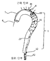
도 1은 본 발명의 특정 실시 예에 따른 구속 부재에 의해 결속된 스텐트를 개략적으로 도시한다.
도 2는 본 발명의 특정 실시 예에 따른 구속 부재에 의해 결속된 스텐트를 개략적으로 도시한다.
도 3은 본 발명의 특정 실시 예에 따른 지연-해제 부재가 스텐트의 근위 단부와 상호작용하는 방식을 개략적으로 도시한다.
도 4는 본 발명의 특정 실시 예에 따른 지연-해제 후방 베이스의 구조를 도시한다.
도 5 내지 도 8은 본 발명의 특정 실시 예에 따른 스텐트 전달 시스템을 이용한 스텐트 전달을 도시한다.1 schematically illustrates a stent bound by a constraining member according to a specific embodiment of the present invention.
Figure 2 schematically shows a stent bound by a constraining member according to a specific embodiment of the present invention.
3 schematically illustrates how a delay-release member interacts with a proximal end of a stent in accordance with certain embodiments of the present invention.
4 shows the structure of the delay-release rear base according to a specific embodiment of the present invention.
5-8 illustrate stent delivery using a stent delivery system in accordance with certain embodiments of the present invention.
본 발명의 목적 및 특징은 첨부된 도면과 함께 몇 가지 실시 예에 대한 다음의 상세한 설명을 읽으면서 보다 쉽게 명백해질 것이다. 그러나 본 발명은 개시된 실시 예들에 한정되지 않고 다양한 다른 형태로 구현될 수 있다는 점을 밝혀둔다. 본 명세서에 사용된 바와 같이, "근위 단부(proximal end)"라는 용어는 정상 작동 중에 의료 기구가 배치되는 위치(예: 심장, 혈관의 환부 등)에 더 가깝게 위치하는 의료 기구의 단부를 의미하며, 또한, 스텐트 전달 시스템의 전진 방향의 선단부로서, 의료 기기를 조작하는 사람으로부터 이격되어 있는 단부이다. 이에 반해, 원위 단부(distal end)는 의료 기기의 끝단이 배치된 곳에서 멀리 떨어져 있는 경우가 많으며, 이는 시술자에게 더 가깝고 의료 기기의 핸들 부분에 가까운 단부를 의미한다.The objects and features of the present invention will become more readily apparent upon reading the following detailed description of several embodiments in conjunction with the accompanying drawings. However, it should be noted that the present invention is not limited to the disclosed embodiments and may be implemented in various other forms. As used herein, the term “proximal end” refers to the end of a medical device that is located closer to the location (eg, heart, lesion of blood vessels, etc.) where the medical device is placed during normal operation and , is also the forward end of the stent delivery system, which is an end spaced apart from the person operating the medical device. In contrast, the distal end is often remote from where the end of the medical device is placed, meaning the end closer to the operator and closer to the handle portion of the medical device.
도 1 내지 도 8을 참조하면, 본 발명의 일 실시 예들에서, 핸들, 외부 튜브(52, outer tube), 구속 부재(restraining member) 및 지연-해제 부재(4, delayed-release member)를 포함하는 스텐트 전달 시스템(stent delivery system)이 제공된다.1 to 8 , in one embodiment of the present invention, including a handle, an outer tube (52, outer tube), a restraining member (restraining member) and a delayed-release member (4, delayed-release member) A stent delivery system is provided.
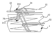
도 5 내지 도 7을 참조하면, 외부 튜브(52)는 크림핑된 스텐트(1)를 수용하기 위한 축 방향의 내부 루멘(axial inner lumen)을 형성하고 핸들이 조작될 때 스텐트(1)가 노출되도록 스텐트(1)의 원위 단부를 향해 후퇴하도록 구성된다. 본 실시 예에 따른 스텐트 전달 시스템은 또한 내부 튜브(51, inner tube)를 포함하는데, 이는 내부 튜브(51)와 외부 튜브(52) 사이에 간극이 형성되도록 외부 튜브(52) 내에 배치되어, 스텐트(1)가 상기 간극에 수용될 수 있게 된다. 지연-해제 부재(4, delayed-release member)는 내부 튜브(51)의 통과를 허용하는 채널을 형성하고, 내부 튜브(51)의 근위 단부는 지연-해제 부재(4)의 근위 단부에 고정적으로 연결된다. 스텐트(1)는 내부 튜브(51)에 배치될 수 있고, 그 근위 단부는 지연-해제 부재(4)와 조립되고 나머지 부분은 크림핑된 상태(crimped state)에서 구속 부재(restraining member )에 의해 결속된다. 이러한 스텐트(1), 구속 부재 및 지연-해제 부재(4)의 조립체의 원위 단부 및 중간 섹션은 함께 외부 튜브(52)와 내부 튜브(51) 사이의 간극에서 이동 가능하게 수용될 수 있다.5-7 , the
이 실시 예에 따르면, 스텐트 전달 시스템에 의해 전달될 수 있는 스텐트(1)는 커버드 스텐트(covered stent) 또는 언커버드 스텐트(uncovered stent) 또는 베어 스텐트(bare stent)일 수 있다. 베어 스텐트는 일반적으로 스테인리스 스틸 및/또는 금속 형상 기억 재료로 만들어진 중공 관형 구조(hollow tubular structure)로, 내부 튜브(51)에 배치될 수 있고 폴리머 멤브레인으로 덮여있지 않다. 베어 스텐트를 혈관에 전달하기 위해 베어 스텐트 전달을 용이하게 하는 확장되지 않은 구성으로 크림핑될 수 있다. 혈관 내 표적 병변 부위에 전달되면, 베어 스텐트는 탄력성으로 인해 혈관벽에 합병증을 유발할 수 있는 국부적인 힘을 가하지 않으면서, 혈관의 만곡된 해부학적 구조에 맞는 구성으로 확장될 수 있다. 베어 스텐트는, 예를 들어, 금속 메시 링들(metal mesh rings)과 교대로 연결된 지그재그 링들(zigzag rings)로 구성된 중공 관형 구조(hollow tubular structure) 또는 금속 메시로 이루어진 중공 관형 구조일 수 있다. 커버드 스텐트는 금속 스텐트 본체가 멤브레인으로 덮여 있다는 점에서 베어 스텐트와 상이하다. 멤브레인은 금속 스텐트 본체의 외부 또는 내부 표면을 완전히 덮을 수 있다. 또는 금속 스텐트 본체의 중간 섹션만 덮을 수 있다. 대안적으로, 이것은 금속 스텐트 본체의 중간 섹션과 원위 단부 모두를 덮을 수 있다. 또 다른 예로, 금속 스텐트 본체의 중간 섹션의 여러 부분을 불연속적 방식으로 덮을 수도 있다. 멤브레인은 또한 일반적으로 중공형 관형 구조일 수 있으며 내부 튜브(51)에 배치될 수 있다. 커버드 스텐트는 만곡된 확장 구성(curved, expanded configuration) 및 크림핑된 비확장 구성(crimped, unexpanded configuration) 사이에서 더 쉽게 전환할 수 있다. 비확장 구성(unexpanded configuration)은 커버드 스텐트를 혈관으로 전달하는 것을 용이하게 할 수 있다. 혈관의 표적 병변 부위에 도달하면, 커버드 스텐트가 해제되어 탄력성으로 인해 혈관벽에 합병증을 유발할 수 있는 국부적인 힘을 가하지 않고 혈관의 만곡된 해부학 구조에 따라 확장된 구성으로 전환될 수 있다. 커버드 스텐트는 일반적으로 금속 스텐트 본체와 금속 스텐트 본체의 내부 또는 외부 표면을 덮는 멤브레인을 포함한다. 금속 스텐트 본체는 스테인리스 스틸과 같은 금속 재료 또는 금속 형상 기억 재료로 만들어진 벽의 개구들을 갖는 탄성 구조일 수 있다. 이는 압축된 및 크림핑될 수 있으며, 해제될 때 확장되고, 축 방향의 텔레스코픽 구조를 갖고, 방사상으로 주름 잡힐 수 있다. 따라서, 직경 및/또는 길이가 수동적으로 조정될 수 있어 커버드 스텐트가 배치되는 혈관의 기하학적 구조에 더 잘 맞도록 하여 내강 누출(endoleak)의 위험을 줄일 수 있다. 금속 스텐트 본체는 금속 와이어(들)로 편조된 금속 메시거나, 여러 개의 스트럿(strut)에 의해 서로 고정 연결된 여러 개의 지그재그 링으로 구성된 구조, 또는 여러 개의 스트럿에 의해 함께 연결된 지그재그 링과 금속 메시 링으로 구성된 구조일 수 있다.According to this embodiment, the
도 1 내지 도 8에 도시된 실시 예에서, 스텐트(1)는 본질적으로 금속 스텐트 본체 및 금속 스텐트 본체의 표면을 덮는 멤브레인으로 구성된 커버드 스텐트이다. 스텐트(1)는 표적 병변 부위에 근접한 근위 단부 부분(10), 표적 병변 부위로부터 멀리 위치된 원위 단부 부분(12), 및 근위 단부 부분들(10, 12)과 원위 단부 부분(12) 사이의 중간 섹션(11, middle section)을 갖는다. 스텐트(1)의 근위 단부는 멤브레인으로 덮이지 않은 베어 스텐트 섹션(bare stent section)이고, 스텐트(1)의 금속 스텐트 본체의 외부 표면은 중간 섹션(11, middle section)과 원위 단부 부분(12) 모두에서 멤브레인으로 덮인다. 바람직하게는, 스텐트(1)의 금속 스텐트 본체는 니켈-티타늄(NiTi) 합금과 같은 금속 형상 기억 재료로 제조되며, 형상 기억을 갖고 다른 재료의 사용으로 인한 부정적인 변형(deformability) 문제를 피할 수 있다. 스텐트(1)의 멤브레인은 폴리에스터(PET), 폴리테트라플루오로에틸렌(PTFE), 나일론, 테릴렌, 폴리프로필렌 등과 같은 고분자 물질로 이루어진다. 멤브레인은 폴리에스터 봉합사(polyester sutures)로 꿰매거나 금속 스텐트 본체에 프레스 성형될 수 있다. 바람직하게는, 멤브레인에는 예를 들어 백금 이리듐 합금으로 만들어진 방사선 불투과성 마커가 제공되며, 이는 사용자가 방사선 불투과성 장비에 의해 스텐트(1)의 도입 또는 해제 동안 스텐트(1)의 위치를 동적으로 모니터링할 수 있게 한다. 이를 통해 스텐트(1)를 최적의 위치로 조정하여 높은 정확도로 스텐트를 해제할 수 있게 된다.1 to 8 , the
도 1 내지 도 8에 도시된 실시 예에서, 베어 스텐트 섹션(10), 즉, 스텐트의 근위 단부는 혈관 벽에 대한 스텐트(1)의 고정을 강화하도록 구성된다. 그것은 멤브레인으로 덮이지 않은 적어도 하나의 물결 형상의(wave-shaped) 링을 포함할 수 있다. 물결 모양의 링은 금속 와이어로 편조되나 금속 튜브를 절단하여 제작할 수 있다. 대안적으로, 그것은 개별적으로 배향되어 일반적으로 클로우(claw)와 유사하거나 금속 메시로 만들어진 다수의 금속 와이어를 포함할 수 있다. 바람직하게는, 본 발명에 따르면, 베어 스텐트 섹션(10, bare stent section)에는 바람직하게는 PTFE로 만들어진 생체적합성 배리어 층(barrier layer)이 제공된다. PTFE 층은 베어 스텐트 섹션(10)의 금속 와이어(들) 또는 튜브의 표면에 PTFE 필름 스트립을 감음으로써 형성될 수 있다. 대안적으로, 이것은 또한 베어 스텐트 섹션(10)의 표면 상에 액체 PTFE를 스프링으로 형성할 수 있다. 이 배리어 층은 베어 스텐트 섹션 표면의 혈전 발생을 방지하고, 2가 니켈 이온 등의 방출을 억제하고, 체액 내의 염화물 및 기타 부식성 이온으로부터 베어 스텐트 섹션(10)을 보호할 수 있다. 그것은 좋은 혈전 생성 성능, 내식성 및 독성 금속 이온의 용해 및 방출을 방지하는 능력을 가지고 있다. 베어 스텐트 섹션(10)은 직선의 원통 형상이거나, 원위 단부에서 근위 단부로 갈수록 테이퍼진 플레어(flare) 형태이거나, 원위 단부에서 근위 단부로 갈수록 테이퍼지는 원추 형일 수 있다. 또한, 베어 스텐트 섹션(10)은 스텐트(1)의 멤브레인에 여러 지점에서 고정되거나, 멤브레인으로 덮인 금속 스텐트 본체의 일부와 통합되거나, 용접되거나, 그렇지 않으면 결합될 수 있다.1-8 , the
도 1 내지 도 8을 참조하면, 구속 부재는 스텐트(1)의 중간 섹션(11) 및 원위 단부 부분(12, distal end portion)에 구비되며, 스텐트(1)의 중간 섹션(11) 및 원위 단부 부분(12)에 대해 개폐형으로 구성될 수 있다. 폐쇄된 구성(closed configuration)에서 스텐트(1)의 중간 섹션(11)과 원위 단부(12)를 크림핑된 상태로 결속하고, 개방된 구성(opened configuration)에서 스텐트(1)의 원위 단부(12) 및 중간 섹션(11)의 해제 및 확장을 허용하도록 구성된다. 구속 부재는 적어도 하나의 구속 스레드(21, restraining thread) 및 제어 가이드 와이어(22, control guidewire)를 포함한다. 구속 스레드(21)은 원주 방향으로 스텐트(1)를 둘러싸도록 배열되고, 제어 가이드 와이어(22)는 구속 스레드(21)를 스텐트(1)를 압축하거나 해제하기 위한 개방 또는 폐쇄-루프 구조로 구성하도록 구성된다.1 to 8 , the restraining member is provided in the
도 1 및 도 2에 도시된 실시 예에서, 구속 부재는 적어도 2개의 구속 스레드(21)를 포함하고, 모든 구속 스레드(21)는 스텐트(1)의 금속 스텐트 본체(즉, 메인 스텐트(1))의 축 방향을 따라 서로 이격되어 있고, 제어 가이드 와이어(22)의 제어 하에 스텐트(1)의 직경을 원하는 값으로 제한하도록 구성된다. 인접한 구속 스레드(21) 사이의 간격(즉, 구속 스레드에 의해 감겨지지 않은 스텐트(1)의 부분)은 구속 스레드(21) 사이 또는 제어 가이드 와이어(22)와 구속 스레드(21) 사이의 엉킴을 방지하기 위해 제공된다. 바람직하게는, 구속 스레드(21)는 인체 내에서 대사 및 흡수될 수 있고 또 그렇게 될 재료로 형성된다. 이 실시 예에서, 각각의 구속 스레드(21)는 이중 가닥(double-stranded)이고 양 단부가 폐쇄되고, 스텐트(1) 둘레에 적어도 1회 감기게 되고 제어 가이드 와이어(22)는 차례로 선단부(211)를 통해 삽입되도록 구성될 수 있다. 이런 방식 식으로 폐쇄-루프(closed-loop) 구조가 된다. 대안적으로, 각각의 이중 가닥 구속 스레드(double-stranded restraining thread)는 스텐트 주위에 적어도 한 바퀴 감도록 구성될 수 있으며, 제어 가이드 와이어(22)는 그 선단부 및 후단부(211, 212) 모두를 통해 삽입되어 또한 폐쇄-루프 구조가 될 수 있다. 또한, 구속 스레드들(21) 각각은 스텐트(1)에 감길 때 동일하거나 동일하지 않은 직경들을 형성할 수 있다. 이 실시 예에서, 제어 가이드 와이어(22)가 스텐트(1)의 원위 단부를 향해 후퇴할 때, 구속 스레드(21)는 스텐트의 근위 단부로부터 원위 단부 방향으로 연속적으로 개방-루프(open-loop) 구조가 될 것이다. 그 결과 스텐트(1)가 확장하여 해제될 수 있다.1 and 2 , the constraining member comprises at least two constraining
본 발명의 대안적인 실시 예에서, 구속 스레드들(21) 각각은 단일 가닥일 수 있으며, 스텐트(1)를 크림핑된 상태로 결속하기 위해 스텐트(1)의 원하는 부분에 적어도 1회 감기도록 구성될 수 있다. 또한, 각각의 구속 스레드(21)의 후단부 및 선단부는 제어 가이드 와이어(22)의 제어하에 스텐트(1)를 압축하거나 해제하기 위한 개방-루프 또는 폐쇄-루프 구조가 될 수 있도록 제어 가이드 와이어(22)에 묶일 수 있다.In an alternative embodiment of the present invention, each of the constraining
바람직하게는, 스텐트(1)에는 스텐트(1)의 금속 스텐트 본체로부터 돌출하는 엥커링 후크들(anchoring hooks) 또는 고정 구멍(securing eyelets)과 같은 패스너(31)가 제공될 수 있다. 구속 스레드들(21)의 후단부가 스텐트(1) 상의 패스너(31)를 통해 삽입될 때, 구속 스레드(21)에 의해 형성된 개방 또는 폐쇄-루프 구조는 풀리지 않을 것이다. 이것은 한편으로 구속 스레드들(21)의 선단부 및 후단부에 걸쳐 제어 가이드 와이어(22)의 제어를 용이하게 할 수 있고 다른 한편으로 구속 스레드들(21) 사이의 및 제어 가이드 와이어(22)와 구속 스레드들(21) 사이의 엉킴을 방지할 수 있다.Preferably, the
도 2를 참조하면, 본 실시 예에서 적어도 하나의 고정 코일(32)은 스텐트(1)의 원위 단부(12)에 제공될 수 있다. 각각의 구속 스레드(21)는 고정 코일(32, fixed coil) 중 대응하는 코일을 통해 삽입되도록 구성된다. 각각의 고정 코일은 원위 단부가 내부 튜브(51)의 원위 단부에 고정될 수 있다. 이러한 고정 코일들이 2개 이상 구비되는 경우, 고정 코일들(32)은 스텐트(1)의 원위 단부 부분(12) 둘레에 고르게 분포되는 것이 바람직하다. 이러한 방식으로, 스텐트(1)의 원위 단부(12)는 균일하게 스트레스를 받을 것이며, 불균형 스트레스로 인해 스텐트(1)가 회전하거나 달리 움직이는 것을 방지할 수 있다. 또한, 제어 가이드 와이어(22)는 고정 코일들(32) 중 일부의 근위 단부를 통해 삽입될 수 있으며, 구속 스레드들(21)는 나머지 고정 코일들(32) 중 대응하는 코일의 근위 단부를 통해 각각 삽입된다. 이 경우, 제어 가이드 와이어(22)를 빼내면, 제어 가이드 와이어(22)가 삽입되었던 근위 단부들을 갖는 고정 코일들(32)이 해제되고, 각각의 구속 스레드들(21)이 삽입된 근위 단부들을 갖는 고정 코일들(32)이 스텐트(1)의 탄성 확장으로 인해 옆으로 밀리게 된다. 그 결과, 스텐트(1)는 구속 스레드들(21)로부터 원위 단부부분(12)에서 해제된다. 동시에, 구속 스레드들(21)이 삽입된 근위 단부를 갖는 고정 코일들(32)의 근위 단부들은 여전히 내부 튜브(51)에 고정되어 있기 때문에, 스텐트(1)의 원위 단부 부분(12)이 스텐트(1)의 해제 및 탄성 확장 중에 후퇴 또는 이동 없이 해제 전과 동일한 위치에 유지된다.Referring to FIG. 2 , in this embodiment at least one fixed
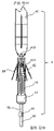
도 3 및 도 4에 도시된 실시 예에서, 지연-해제 부재(4)는 스텐트(1)의 근위 단부 부분(즉, 베어 스텐트 섹션)을 구속 및 해제하도록 구성되고, 지연-해제 부재(4)는 내부 튜브(51)에 각각 이동 가능하게 배치되고 내부 튜브(51)에 고정되는 구성 요소들을 포함한다. 특히, 지연-해제 부재(4)는 원추형 팁(41, conical tip), 지연-해제 고정구(42, delayed-release fixture), 지연-해제 후방 베이스(44, delayed-release rear base), 다수의 지연-해제 스크류 로드들(43, delayed-release screw rods) 및 지연-해제 가이드 와이어(46, delayed-release guidewire)를 포함할 수 있다. 원추형 팁(41)은 내부 튜브(51)의 근위 단부에 고정되게 배치되고, 전진을 안내하기 위한 전달 시스템의 선단부로서 작용하는 근위 단부(즉, 직경이 더 작은 단부)를 포함한다. 이러한 단부는 시스템이 진행하는 혈관의 저항을 감소시켜 전달 시스템에 로딩된 스텐트(1)의 전달을 용이하게 할 수 있다. 원추형 팁(41)의 원위 단부(즉, 작업자에게 더 가까운 지름이 큰 쪽)에는 지연-해제 스크류 로드들(43)과 동일한 개수의 고정 구멍들(410, fixation holes)이 제공되고, 지연-해제 고정구(42)에는 지연-해제 스크류 로드들(43)과 동일한 개수의 가이드 구멍들(421, guide holes)이 제공된다. 각각의 지연-해제 스크류 로드들(43)는 지연-해제 후방 베이스(44)에 고정된 원위 단부와, 지연-해제 고정구(42)의 각각의 가이드 구멍들(421)을 통해 삽입되고 원추형 팁(41)의 고정 구멍들(410) 중 하나에 각각 수용되는 근위 단부를 포함한다. 각각의 지연-해제 가이드 와이어(46)의 근위 단부는 지연-해제 후방 베이스(44)에 고정된다. 커버드 스텐트(1)의 근위 단부에 있는 베어 스텐트 섹션(10)은 원추형 팁(41)과 지연-해제 고정구(42) 사이의 지연-해제 스크류 로드들(43)의 섹션들 상에 배치되고 크림핑되도록 구성된다. 대안적인 실시 예들에서, 지연-해제 고정구(42)의 가이드 구멍들(421)은 릿지들(ridges) 또는 슬라이드 채널들(slide channels)과 같은 다른 구조로 대체될 수 있다.3 and 4 , the delay-
커버드 스텐트(1)를 장착하기 위해, 그 근위 단부의 베어 스텐트 섹션(10)은 지연-해제 로드들(43) 위에 배치되고 지연-해제 후방 베이스(44)는 제한점에 도달할 때까지 원추형 팁(41)을 향해 밀리게 된다. 다음으로, 지연-해제 스크류 로드들(43)은 지연-해제 고정구(42)의 각 가이드 구멍들(421)의 안내 하에 원추형 팁(41)의 각각 고정 구멍들(410)에 삽입된다. 이러한 방식으로, 베어 스텐트 섹션(10)은 원추형 팁(41)과 지연-해제 고정구(42) 사이의 지연-해제 스크류 로드들(43)에 고정된다. 커버드 스텐트(1)를 해제하기 위해 지연-해제 가이드 와이어(46)를 후퇴시키도록 핸들을 조작하여 지연-해제 스크류 로드(43)가 원추형 팁(41)의 고정 구멍들(410)에서 제거되어, 커버드 스텐트(1)의 근위 단부에서 베어 스텐트 섹션(10)의 해제를 허용한다. 그 결과, 베어 스텐트 섹션은 자체 탄성에 의해 확장되고 혈관벽에 단단히 부착되어 커버드 스텐트(1)를 제자리에 고정시킨다. 각각의 지연-해제 가이드 와이어(46)는 지연-해제 후방 베이스(44)의 원위 단부에 고정된다.To mount the covered
따라서, 본 실시 예에 따르면, 지연-해제 부재(4)는 지연-해제 스크류 로드들(43)의 도움으로 스텐트(1)의 근위 단부를 구속 및 해제할 수 있고, 지연-해제 고정구(42)의 도움으로 스텐트(1)의 근위 단부 부분을 효과적으로 구속하고, 지연-해제 스크류 로드들(43)의 축 방향 이동에서의 신뢰성을 증가시킬 수 있다. 또한, 지연-해제 스크류 로드들(43)과 고정 구멍들(410) 사이의 작은 접촉 영역으로 인해, 스텐트(1)의 해제 동안 감소된 저항을 마주하도록 함으로써, 해제 과정의 증가된 정확도를 가져올 수 있다.Thus, according to this embodiment, the delay-
이 실시 예에서, 원추형 팁(41), 지연-해제 고정구(42) 및 지연-해제 후방 베이스(44) 각각은 내부 튜브(51)가 이동 가능하게 삽입되는 채널을 형성한다. 내부 튜브(51)는 원추형 팁(41)의 원위 단부에 결합된 내부 튜브(51)의 근위 단부와 함께 채널을 통해 연속적으로 삽입된다. 내부 튜브(51)에는 지연-해제 후방 베이스(44)에 대해 원위에 위치된 섹션에 제한 블록(45, limit block)이 구비된다. 제한 블록(45)은 지연-해제 후방 베이스(44)에서 채널(441)의 직경보다 큰 외경을 갖는다. 이와 같이, 베어 스텐트 섹션(10)의 해제 동안 지연-해제 후방 베이스(44)의 변위를 주변 혈관에 손상을 주지 않는 범위 내에서 제한할 수 있다(즉, 지연-해제 후방 베이스(44)의 원위 단부의 이동에 대해 전술한 제한을 형성함으로써). 또한, 지연-해제 후방 베이스(44)가 스텐트(1)의 근위 단부를 향해 이동할 때(즉, 원추형 팁(41)으로부터 멀어질 때), 제한 블록(45)은 지연-해제 후방 베이스(44)가 정지해야 하는 제한점도 제공한다.. 이것은 지연-해제 고정구(42)로부터 지연-해제 스크류 로드들(43)의 이탈을 방지한다. 이 실시 예에서, 지연-해제 스크류 로드들(43)은 스테인리스 스틸 또는 니켈-티타늄 합금과 같은 금속 재료로 제조될 수 있다. 스텐트의 장착 및 해제에 대한 요구 사항을 충족하는 것 외에도 지연-해제 고정구(42)와 원추형 팁(41) 사이의 지연-해제 스크류 로드들(43)의 축 방향 길이는 스텐트에 증가된 강성을 부여하기 위해 충분히 짧을 수 있으며, 이는 커버드 스텐트(1)의 확장으로 인한 지연-해제 스크류 로드들(43)의 변형량을 감소시킬 수 있다.In this embodiment, the
또한, 도 4에 도시된 바와 같이 지연-해제 후방 베이스(44)의 중앙에는 채널(441)이 형성되고, 채널(441)의 둘레에는 지연-해제 로드들(43)을 고정하기 위한 다수의 제 1 보어들(442, first bores)이 균일하게 분포된다. 제 1 보어들(442)의 개수는, 예를 들어 6개일 수 있다. 제 1 보어들(442)은 채널(441)을 중심으로 원주 방향으로 등각으로 분포되며, 제 1 보어들(442)의 개수는 지연-해제 스크류 로드들(43)의 개수와 동일하다. 지연-해제 스크류 로드들(43)는 각각의 제 1 보어들(442)에 고정된다. 지연-해제 가이드 와이어(들)(46)를 고정하기 위한 적어도 하나의 제 2 보어(443, second bore)는 지연-해제 후방 베이스(44)의 채널(441) 둘레에 원주방향으로 또한 형성된다. 제 2 보어(들)(443)의 개수는 지연-해제 가이드 와이어(들)(46)의 수와 동일하며, 지연-해제 가이드 와이어(46) 각각은 지연-해제 후방 베이스(44)의 원위에서 근위까지 하나의 제 2 보어(443)에 삽입된 다음, 다음의 다른 제2 보어(433)내로 구부러진다. 지연-해제 가이드 와이어(들)(46)는 용접, 접착제로 본딩, 기계적 잠금되는 것을 포함하지만 이에 제한되지 않는 임의의 방법에 의해 제 2 보어(들)(443)에 고정될 수 있다.In addition, as shown in FIG. 4 , a
도 1 내지 도 8을 참조하면, 본 발명의 일 실시 예에서, 스텐트의 로딩, 전달 및 해제 방법이 제공된다. 스텐트(1)가 커버드 스텐트(이하, "커버드 스텐트(1)"라 함)로 구현되는 경우를 예로 들면, 본 방법은 하기에 상세히 설명되는 단계들을 포함할 수 있다.1 to 8 , in an embodiment of the present invention, a stent loading, delivery and release method is provided. Taking the case in which the
커버드 스텐트(1)를 로딩하는 단계는 다음 세 단계에 의해 달성될 수 있다. 단계 1), 커버드 스텐트(1)의 근위 단부는 지연-해제 부재 상에 유지된다. 구체적으로, 지연-해제 부재(4)는 미리 내부 튜브(51)에 조립되고, 지연-해제 고정구(42)의 각 가이드 구멍들(421)을 통해 지연-해제 스크류 로드들(43)이 삽입된 후, 그 위에 커버드 스텐트(1)가 배치되고 커버드 스텐트(1)의 근위 단부가 지연-해제 부재(4)의 근위 단부 근처의 위치에 도달할 때까지 내부 튜브(51) 상에서 이동된다. 커버드 스텐트(1)의 근위 단부(즉, 노출된 스텐트 섹션)(10)는 그 다음 지연-해제 스크류 로드들(43) 위로 슬리빙되고 지연-해제 부재(4)의 지연-해제 가이드 와이어(들)(46)는 그 다음 지연-해제 부재(4)의 지연-해제 후방 베이스(44)가 내부 튜브(51) 위로 원추형 팁(41)을 향해 이동하도록 작동시킨다. 지연-해제 후방 베이스(44)에 의해 구동되고 지연-해제 고정구(42)의 가이드 구멍(421)에 의해 안내되며, 지연-해제형 스크류 로드들(43)은 원추형 팁(41)의 각 고정 구멍들(410)에 삽입되어 커버드 스텐트(1)의 베어 스텐트 섹션(10)를 고정한다. 단계 2), 커버드 스텐트(1)는 구속 스레드들(21)로 결속된다. 구체적으로, 구속 스레드들(21)은 봉합 및 권취에 의해 스텐트에 원주방향으로 배열되고, 제어 가이드 와이어(22)의 제어하에 다중의 폐쇠된 루프 구조(즉, 스레드 링들)로 구성된다. 이러한 폐쇄-루프 구조는 크림핑된 상태에서 내부 튜브(51) 상의 스텐트(1)의 원위 단부 부분(12) 및 중간 섹션(11)을 제한할 수 있다. 예를 들어, 각 구속 스레드(21)은 이중 가닥이고, 양단이 폐쇄되고 구속 스레드(21)을 스텐트 주위에 적어도 한 바퀴 감아 폐쇄-루프 구조로 구성될 수 있으며, 선단부(211)는 후단부(212)를 통해 삽입되고, 제어 가이드 와이어(22)는 차례로 선단부(211)를 통해 삽입되게 된다. 이와 같이, 커버드 스텐트(1)의 근위 단부는 지연-해제 부재(4)에 고정되고, 커버드 스텐트(1)의 원위 단부 부분(12) 및 중간 섹션(11)은 구속 스레드들 및 제어 가이드 와이어(22)에 의해 고정된다. 단계 3), 커버드 스텐트(1)는 압축되고 외부 튜브(52)로 로딩된다. 구체적으로, 지연-해제 부재(4), 구속 부재, 커버드 스텐트(1) 및 내부 튜브(51)의 조립체는 외부 튜브(52)의 내부 루멘 내로 로딩될 수 있도록 하는, 가능한 최소 직경으로 압축된다. 로딩 이후, 외부 튜브(52)의 근위 단부가 원추형 팁(41)의 근위 단부와 접촉할 때까지 외부 튜브(52)는 내부 튜브(51) 상으로 이동되어, 커버드 스텐트(1)가 외부 튜브(52)에 완전히 수용되게 된다. 그 후, 외부 튜브(52)의 원위 단부는 핸들에 고정된다.The step of loading the covered
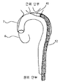
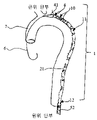
커버드 스텐트(1)의 전달 및 해제는 또한 전술한 각 단계에 대응하는 다음의 3 단계에 의해서 달성될 수 있다. 단계 1), 커버드 스텐트(1)는 외부 튜브(52)에서 혈관(7) 내의 표적 병변 부위(또는 지정된 위치) 근처의 위치로 전달된다. 이러한 방식으로 초기 위치 설정이 수행된 후 외부 튜브(52)가 제거된다. 구체적으로, 전달 전에 위치 결정 가이드 와이어(6)의 선단부가 천자 절개(puncture incision)를 통해 도입되고 혈관(7)의 표적 병변 부위 근처의 위치(또는 지정된 위치, 예를 들어, 대동맥 박리)로 진행된다. 전달하는 동안, 서로 배치되고 그 사이의 간극에 스텐트(1)를 로딩하는 내부 및 외부 튜브(51, 52)는 외부 튜브(52)의 근위 단부가 혈관(7)의 표적 병변 부위 근처의 위치에 도달할 때까지 위치 결정 가이드 와이어(6, positioning guidewire)를 따라 혈관(7) 내로 전달된다. 이 과정에서 커버드 스텐트(1)의 근위 단부 부분(10)(즉, 스텐트가 노출된 섹션)과 원위 단부 부분(12)는 모두 고정되기 때문에 커버드 스텐트(1)는 외부 튜브(52) 또는 내부 튜브(51)에 대해 상대적으로 움직이지 않는다. 도 5에 도시된 바와 같이, 커버드 스텐트(1)가 외부 튜브(52)에 의해 혈관(7)의 표적 병변 부위 근처의 위치로 전달되면 초기 위치 결정(Initial positioning)이 달성된다. 그 후, 외부 튜브(52)는 후퇴되고 내부 튜브(51)는 유지되어 근위 단부 부분(10)(즉, 베어 스텐트 섹션)에서 원위 단부 부분(12)까지 커버드 스텐트(1)의 적어도 모든 구성 요소들이 완전히 노출되게 된다. 선택적으로, 커버드 스텐트(1)의 원위 단부(12)에 근접한 내부 튜브(51)의 일부는 도 6에 도시된 바와 같이 노출될 수 있다. 이 때, 커버드 스텐트(1)는 지연-해제 부재(4), 구속 부재 및 제어 가이드 와이어(22)에 의해 내부 튜브(51) 상의 제 위치에 여전히 유지되고 있다. 단계 2), 일단 커버드 스텐트(1)가 정확하게 위치되면, 스텐트(1)의 근위로부터 원위로의 방향을 따라 구속 스레드들(21)이 연속적으로 느슨해져, 커버드 스텐트(1)가 그 방향으로 점진적으로 확장하게 된다. 구체적으로, 커버드 스텐트(1)의 정확한 위치는 내부 튜브(51)의 위치를 조정함으로써 달성된다. 그 후, 제어 가이드 와이어(22)가 후퇴되는 것과 동시에 내부 튜브(51)가 유지되어, 커버드 스텐트(1)의 개별 구속 스레드들(21)이 커버드 스텐트(1)의 근위 단부 부분(10)(즉, 베어 스텐트 섹션) 에서 커버드 스텐트(1)의 원위 단부 부분(12)으로의 방향으로 연속적으로 느슨해진다. 그 결과, 커버드 스텐트(1)의 중간 섹션(11)과 원위 단부 부분(12)이 연속적으로 해제되어 혈관의 해부학적 구조에 따라 적절한 크기로 확장된다. 즉, 확장된 구성의 스텐트는 혈관(7)의 크기에 맞는 크기를 갖게 된다. 커버드 스텐트(1)의 해제 속도는 제어 가이드 와이어(22)가 얼마나 빨리 후퇴되는지에 달려 있다. 제어 가이드 와이어(22)가 더 빨리 후퇴될수록 커버드 스텐트(1)의 해제가 더 빨라질 것이다. 단계 3), 커버드 스텐트(1)의 근위 단부 부분(10) (즉, 베어 스텐트 섹션)의 지연된 해제(delayed release)는 지연-해제 부재(4)에 의해 달성된다. 구체적으로, 지연-해제 부재(4)의 지연-해제 가이드 와이어(46)는 지연-해제 후방 베이스(44)를 원추형 팁(41)으로부터 멀어지도록 구동하도록 작동되어, 지연-해제 스크류 로드들(43)이 원추형 팁(41)의 고정 구멍들(410)과 지연-해제 고정구(42)의 가이드 구멍들(421)에 다시 도킹되도록 한다. 그 결과, 커버드 스텐트(1)의 근위 단부(즉, 베어 스텐트 섹션)(10)가 지연-해제 스크류 로드(43)로부터 완전히 해제된다. 이러한 방식으로, 커버드 스텐트(1)의 근위 단부 부분(10)(즉, 베어 스텐트 섹션)은 지연-해제 부재(4)로부터 완전히 제거된다. 덮개형 스텐트(1)의 해제된 근위 단부 부분(즉, 노출된 스텐트 섹션)(10)은 혈관(7)의 표적 병변 부위에서 조직에 고정되고 확장하여, 혈관(7)에 커버드 스텐트(1)를 고정시킨다. 그 후, 내부 튜브(51)와 지연-해제 부재(4)가 모두 환자의 신체에서 인출될 때까지 내부 튜브(51)는 후퇴되고, 구속 스레드들(21)이 환자의 신체에 남아 있는 상태에서 위치 결정 가이드 와이어(6)이 인출된다. 이러한 방식으로 커버드 스텐트(1)가 환자의 몸에 이식된다.Delivery and release of the covered
요약하면, 핸들, 외부 튜브, 구속 부재 및 지연-해제 부재를 포함하는 본 발명의 스텐트 전달 시스템은 구조적으로 간단하고 사용하기 쉽다. 지연-해제 부재는 스텐트의 근위 단부(즉, 그 단부에서 표적 병변 부위에 더 가까운 부분)와 조립될 수 있고, 구속 부재는 스텐트를 크림핑된 상태로 묶는다. 이 조립체는 압축되어 외부 튜브에 로드될 수 있으며, 그 내부에서 표적 병변 부위로 전달되고 그곳에서 해제될 수 있다. 구속 부재로부터 스텐트의 중간 섹션을 해제하는 동안 스텐트의 근위 단부 부분은 지연-해제 부재에 고정된 상태로 유지된다. 따라서 스텐트가 혈액에 의해 뒤로 밀려나는 것을 방지하여 스텐트 해제의 위치 정확도가 향상된다. 또한, 제어 가이드 와이어의 제어하에 구속 부재의 구속 스레드들이 개방 및 닫히게 되기 때문에, 제어 가이드 와이어를 천천히 후퇴시키면 스텐트의 여러 부분이 그것의 근위로부터 원위로의 방향을 따라서 연속적으로 풀려나와 같은 속도로 확장하게 된다. 이러한 방식으로 스텐트를 안정적으로 해제할 수 있어 스텐트의 위치 정확도가 더욱 향상된다. 또한, 스텐트의 선단부는 지연-해제 부재에 스텐트의 근위 단부를 고정하는 것 외에도 스텐트의 고정 코일들을 통해 내부 튜브에 고정될 수 있다. 이는 스텐트의 중간 섹션이 해제되는 동안 스텐트가 앞뒤로 움직이는 것을 방지할 수 있어 스텐트가 진정 정확한 위치 제어 하에 해제되도록 할 수 있다.In summary, the stent delivery system of the present invention comprising a handle, an outer tube, a constraining member and a delay-release member is structurally simple and easy to use. The delay-release member may be assembled with the proximal end of the stent (ie, the portion at that end closer to the target lesion site), and the constraining member binds the stent in a crimped state. This assembly can be compressed and loaded into an outer tube, within which it can be delivered to and released from the target lesion site. The proximal end portion of the stent remains secured to the delay-release member during release of the intermediate section of the stent from the restraining member. Therefore, the positioning accuracy of stent release is improved by preventing the stent from being pushed back by the blood. Also, because the restraining threads of the restraining member are opened and closed under the control of the control guide wire, slowly retracting the control guide wire causes various portions of the stent to continuously unwind along its proximal to distal direction and expand at the same rate. will do In this way, the stent can be released reliably, which further improves the positioning accuracy of the stent. Additionally, the tip of the stent may be secured to the inner tube via anchoring coils of the stent in addition to anchoring the proximal end of the stent to the delay-release member. This can prevent the stent from moving back and forth while the middle section of the stent is being released, allowing the stent to be released under truly precise positioning control.
명백하게, 통상의 기술자들은 본 발명의 사상 및 범위를 벗어나지 않고 본 발명에 다양한 수정 및 변형을 할 수 있다. 따라서, 본 발명은 첨부된 청구범위 및 그 균등물의 범위 내에 있는 경우 이러한 모든 수정 및 변형을 포함하도록 의도된다.Obviously, those skilled in the art can make various modifications and variations to the present invention without departing from the spirit and scope of the present invention. Accordingly, this invention is intended to cover all such modifications and variations as come within the scope of the appended claims and their equivalents.
1- 스텐트 또는 커버드 스텐트; 10- 스텐트의 베어 섹션 또는 근위 단부 부분; 11- 스텐트의 중간 섹션; 12- 스텐트의 원위 단부; 21- 구속 스레드; 211- 구속 스레드의 선단부; 212- 구속 스레드의 후단부; 22- 제어 가이드 와이어; 31- 스텐트의 패스너; 32- 고정 코일; 4- 지연-해제 부재; 41- 원추형 팁; 410- 원추형 팁의 고정 구멍; 42- 지연-해제 고정구; 421- 지연-해제 고정구의 가이드 구멍; 43- 지연-해제 스크류 로드; 44- 지연-해제 후방 베이스; 441- 지연-해제 후방 베이스의 채널; 442- 제 1 보어; 443- 제 2 보어; 45- 제한 블록; 46- 지연-해제 가이드 와이어; 51- 내부 튜브; 52- 외부 튜브; 6- 위치 결정 가이드 와이어; 7- 혈관1- stent or covered stent; 10- bare section or proximal end portion of the stent; 11- middle section of the stent; 12- distal end of the stent; 21- constraining thread; 211 - the leading end of the restraining thread; 212 - the rear end of the restraining thread; 22- control guide wire; 31- Fastener of the stent; 32- fixed coil; 4- no delay-release; 41-conical tip; 410-fixing hole of conical tip; 42-delay-release fixture; 421- guide hole in the delay-release fixture; 43- Retard-Release Screw Rod; 44-delay-release rear base; 441- Delay-release rear base's channel; 442- first bore; 443 - 2nd bore; 45- limit block; 46- delay-release guide wire; 51- inner tube; 52- outer tube; 6- positioning guide wire; 7- blood vessels
Claims (10)
상기 외부 튜브는, 크림핑된 상태의 스텐트를 수용하기 위해 축 방향으로 연장되는 내부 루멘을 형성하고, 상기 외부 튜브는 상기 스텐트가 노출되도록 상기 핸들의 제어에 따라 상기 스텐트의 원위 단부를 향해 철수하게 되고;
상기 구속 부재는, 적어도 하나의 구속 스레드 및 제어 가이드 와이어를 포함하고, 상기 구속 스레드는 상기 스텐트 주위에 원주 방향으로 배열되고, 상기 제어 가이드 와이어는 상기 스텐트를 압축하거나 해제하기 위해 개방-루프 또는 폐쇄-루프 구조 사이에서 상기 구속 스레드를 전환하게 되고;
상기 지연-해제 부재는, 상기 외부 튜브 내에 배치되고, 상기 스텐트의 근위 단부를 구속하거나 해제하기 위해 상기 스텐트의 근위 단부에 제거 가능하게 연결되게 되는, 스텐트 전달 시스템.
A stent delivery system comprising a handle, an outer tube, a constraining member and a delay-release member, the stent delivery system comprising:
The outer tube defines an axially extending inner lumen to receive the stent in a crimped condition, the outer tube being withdrawn toward the distal end of the stent under control of the handle such that the stent is exposed become;
The restraining member includes at least one restraining thread and a control guide wire, the restraining thread arranged circumferentially around the stent, the control guide wire being open-loop or closed to compress or release the stent. - to switch said constraining thread between loop structures;
wherein the delay-release member is disposed within the outer tube and is adapted to be removably connected to a proximal end of the stent to constrain or release the proximal end of the stent.
상기 구속 부재는 2 개 이상의 구속 스레드들을 포함하고, 상기 2 개 이상의 구속 스레드들은 상기 축 방향을 따라 상기 스텐트의 메인 부분을 가로질러 서로 이격되어 있는, 스텐트 전달 시스템.
The method of claim 1,
wherein the constraining member comprises two or more restraining threads, the two or more restraining threads being spaced apart from each other across the main portion of the stent along the axial direction.
상기 구속 스레드들 각각은, 양 단부에서 닫히는 이중 가닥 구속 스레드이고,
상기 이중 가닥 구속 스레드는,
상기 제어 가이드 와이어가 상기 이중 가닥 구속 스레드의 선단부를 통해 삽입되어 상기 이중 가닥 구속 스레드가 폐쇄-루프 구조로 구성되는 동안, 상기 스텐트 주위에 상기 이중 가닥 구속 스레드를 적어도 1회 감은 이후, 상기 이중 가닥 구속 스레드의 선단부가 후단부를 통해 삽입되게 되어 상기 이중 가닥 구속 스레드가 폐쇄-루프 구조로 구성되고,
또는,
상기 이중 가닥 구속 스레드는,
상기 제어 가이드 와이어가 상기 이중 가닥 구속 스레드의 선단부와 후단부 모두를 통해 삽입되는 동안, 상기 스텐트 주위에 상기 이중 가닥 구속 스레드를 적어도 1회 감도록 되어, 상기 이중 가닥 구속 스레드가 폐쇄-루프 구조로 구성되는, 스텐트 전달 시스템.
The method of claim 1,
each of the constraining threads is a double stranded constraining thread closed at both ends;
The double-stranded constraining thread comprises:
After winding the double stranded constraining thread at least once around the stent while the control guide wire is inserted through the distal end of the double stranded constraining thread to configure the double stranded constraining thread in a closed-loop configuration, The leading end of the restraining thread is inserted through the rear end so that the double-stranded restraining thread is configured in a closed-loop configuration;
or,
The double-stranded constraining thread comprises:
while the control guide wire is inserted through both the leading and trailing ends of the double stranded constraining thread, at least one wrap of the double stranded constraining thread around the stent so that the double stranded constraining thread enters into a closed-loop configuration. A stent delivery system comprising:
상기 스텐트는 고정 코일을 구비하고, 상기 구속 스레드는 상기 고정 코일을 통해 삽입되는, 스텐트 전달 시스템.
The method of claim 1,
wherein the stent has a fixation coil and the constraining thread is inserted through the fixation coil.
상기 스텐트는 복수의 고정 코일들을 구비하고, 상기 복수의 고정 코일들 중 적어도 2 개는 상기 스텐트 주위에 원주 방향으로 서로 이격되어 있고, 상기 구속 스레드는 상기 복수의 고정 코일들 중 적어도 2 개를 통해 삽입되는, 스텐트 전달 시스템.
5. The method of claim 4,
The stent has a plurality of fixation coils, at least two of the plurality of fixation coils are circumferentially spaced from each other about the stent, and the constraining thread passes through at least two of the plurality of fixation coils. An implanted, stent delivery system.
상기 외부 튜브 내에 배치되는 내부 튜브를 더 포함하고, 상기 외부 튜브와 상기 내부 튜브 사이에는 상기 스텐트를 수용하기 위한 간극이 존재하고, 상기 지연-해제 부재는 상기 내부 튜브 삽입을 위한 채널을 형성하는, 스텐트 전달 시스템.
The method of claim 1,
further comprising an inner tube disposed within the outer tube, wherein a gap exists between the outer tube and the inner tube for receiving the stent, the delay-release member defining a channel for insertion of the inner tube; Stent delivery system.
상기 지연-해제 부재는 원추형 팁, 지연-해제 고정구, 지연-해제 후방 베이스, 복수의 지연-해제 스크류 로드들 및 지연-해제 가이드 와이어를 포함하고,
상기 원추형 팁의 원위 단부에 각각의 지연-해제 스크류 로드들과 상호 작용하기 위한 동일한 개수의 고정 구멍들이 구비되고,
상기 지연-해제 고정구는, 각각의 지연-해제 스크류 로드들과 상호 작용하기 위해 동일한 개수의 가이드 구멍들을 구비하고,
각각의 상기 지연-해제 스크류 로드들은, 상기 지연-해제 후방 베이스와 고정 연결되는 원위 단부 및 상기 지연-해제 고정구의 상기 가이드 구멍들 중 하나를 통해 상기 원추형 팁의 상기 고정 구멍들 중 하나에 삽입되는 근위 단부를 구비하고,
상기 지연-해제 가이드 와이어는, 상기 지연-해제 후방 베이스와 고정 연결되는 근위 단부를 구비하고,
상기 지연-해제 스크류 로드들은, 상기 원추형 팁과 상기 지연-해제 고정구 사이에, 상기 스텐트의 근위 단부를 통해 삽입되고 구속하는 섹션들을 구비하는, 스텐트 전달 시스템.
7. The method of claim 6,
the delay-release member comprises a conical tip, a delay-release fixture, a delay-release rear base, a plurality of delay-release screw rods and a delay-release guide wire;
the distal end of the conical tip is provided with an equal number of locking holes for cooperating with respective delay-release screw rods;
the delay-release fastener having an equal number of guide holes for cooperating with respective delay-release screw rods;
Each of the delay-release screw rods is inserted into one of the fixing holes of the conical tip through one of the guide holes of the delay-release fixture and a distal end fixedly connected with the delay-release rear base having a proximal end;
the delay-release guide wire has a proximal end in fixed connection with the delay-release rear base;
wherein the delay-release screw rods have sections between the conical tip and the delay-release fixture that are inserted through and constraining the proximal end of the stent.
상기 원추형 팁, 상기 지연-해제 고정구 및 상기 지연-해제 후방 베이스 각각은, 상기 내부 튜브의 삽입을 위한 채널을 형성하고, 상기 내부 튜브는 일 단부가 상기 원추형 팁에 연결되고, 상기 채널들을 순차적으로 통과하는, 스텐트 전달 시스템.
8. The method of claim 7,
Each of the conical tip, the delay-release fixture and the delay-release rear base forms a channel for insertion of the inner tube, the inner tube having one end connected to the conical tip, and sequentially connecting the channels A transmissive, stent delivery system.
상기 지연-해제 후방 베이스에 대해 원위에 위치된 상기 내부 튜브의 섹션은 제한 블록을 구비하고, 상기 제한 블록은 상기 지연-해제 후방 베이스의 채널의 직경보다 큰 외부 직경을 갖는, 스텐트 전달 시스템.
9. The method of claim 8,
The section of the inner tube positioned distal to the delay-release posterior base has a restriction block, the restriction block having an outer diameter greater than a diameter of the channel of the delay-release posterior base.
전달 시스템의 지연-해제 부재에 스텐트의 근위 단부를 고정하는 단계;
제어 가이드 와이어의 제어 하에 폐쇄-루프 구조로 구성된 적어도 하나의 구속 스레드가 상기 스텐트 주위에 원주 방향으로 감겨 있는 상태로 상기 스텐트를 크림핑하는 단계; 및
상기 전달 시스템의 내부 튜브 및 지연-해제 부재와 함께 상기 크림핑된 스텐트를 상기 전달 시스템의 외부 튜브의 내부 루멘으로 압축 및 로딩하는 단계 - 상기 외부 튜브의 원위 단부는 핸들에 고정적으로 연결됨 -;를 포함하는 방법.In the method of mounting a stent,
securing the proximal end of the stent to a delay-release member of the delivery system;
crimping the stent with at least one constraining thread configured in a closed-loop configuration circumferentially wound around the stent under the control of a control guide wire; and
compressing and loading the crimped stent together with the inner tube of the delivery system and the delay-releasing member into the inner lumen of the outer tube of the delivery system, the distal end of the outer tube being fixedly connected to a handle; How to include.
Applications Claiming Priority (3)
| Application Number | Priority Date | Filing Date | Title |
|---|---|---|---|
| CN201911359117.8 | 2019-12-25 | ||
| CN201911359117.8A CN111035486B (en) | 2019-12-25 | 2019-12-25 | Stent delivery system and method of loading stents |
| PCT/CN2020/113612 WO2021128937A1 (en) | 2019-12-25 | 2020-09-04 | Stent delivery system and method for mounting stent |
Publications (1)
| Publication Number | Publication Date |
|---|---|
| KR20220121851A true KR20220121851A (en) | 2022-09-01 |
Family
ID=70239745
Family Applications (1)
| Application Number | Title | Priority Date | Filing Date |
|---|---|---|---|
| KR1020227025629A KR20220121851A (en) | 2019-12-25 | 2020-09-04 | Stent delivery systems and stent placement methods |
Country Status (8)
| Country | Link |
|---|---|
| US (1) | US20230018528A1 (en) |
| EP (1) | EP4082490A4 (en) |
| JP (1) | JP2023509865A (en) |
| KR (1) | KR20220121851A (en) |
| CN (1) | CN111035486B (en) |
| AR (1) | AR120911A1 (en) |
| BR (1) | BR112022012544A2 (en) |
| WO (1) | WO2021128937A1 (en) |
Families Citing this family (6)
| Publication number | Priority date | Publication date | Assignee | Title |
|---|---|---|---|---|
| CN111035486B (en) * | 2019-12-25 | 2024-01-23 | 上海微创心脉医疗科技(集团)股份有限公司 | Stent delivery system and method of loading stents |
| CN113940786A (en) * | 2020-06-30 | 2022-01-18 | 上海微创心脉医疗科技(集团)股份有限公司 | Stent system |
| CN113274166B (en) * | 2021-05-10 | 2023-12-08 | 杭州唯强医疗科技有限公司 | Tectorial membrane support and conveying system |
| CN116262078A (en) * | 2021-12-14 | 2023-06-16 | 上海拓脉医疗科技有限公司 | Support conveying device and support conveying system |
| CN114099100B (en) * | 2022-01-26 | 2022-06-03 | 上海微创心脉医疗科技(集团)股份有限公司 | Branch sheath and blood vessel support conveyer |
| CN117815522A (en) * | 2024-03-06 | 2024-04-05 | 北京泰杰伟业科技股份有限公司 | Mechanical balloon device |
Family Cites Families (19)
| Publication number | Priority date | Publication date | Assignee | Title |
|---|---|---|---|---|
| FR2762989B1 (en) * | 1997-05-12 | 1999-09-03 | Braun Celsa Sa | SYSTEM FOR REPAIRING AN ANATOMIC DUCT BY A PROGRESSIVE OPENING IMPLANT |
| US20040138734A1 (en) * | 2001-04-11 | 2004-07-15 | Trivascular, Inc. | Delivery system and method for bifurcated graft |
| US8500792B2 (en) * | 2003-09-03 | 2013-08-06 | Bolton Medical, Inc. | Dual capture device for stent graft delivery system and method for capturing a stent graft |
| WO2009042796A2 (en) * | 2007-09-26 | 2009-04-02 | Trivascular2, Inc. | Alignment stent apparatus and method |
| CN101283937B (en) * | 2008-05-21 | 2010-08-18 | 微创医疗器械(上海)有限公司 | Overlay film frame with an opening and bonding method of the overlay film frame |
| CN102946829B (en) * | 2010-06-18 | 2015-09-30 | 库克医学技术有限责任公司 | The support introducer system of two bifurcated |
| US9364359B2 (en) * | 2011-12-08 | 2016-06-14 | W. L. Gore & Associates, Inc. | Systems and methods for delivery of a medical device |
| US9622893B2 (en) * | 2012-12-20 | 2017-04-18 | Cook Medical Technologies Llc | Apparatus and method for improved deployment of endovascular grafts |
| CN104706449B (en) * | 2013-12-17 | 2017-11-07 | 微创心脉医疗科技(上海)有限公司 | A kind of stent delivery system and component is discharged thereafter |
| US10004620B2 (en) * | 2015-01-14 | 2018-06-26 | Cook Medical Technologies Llc | Suture and wire stent deployment system |
| GB2536439C (en) * | 2015-03-16 | 2019-10-16 | Cook Medical Technologies Llc | Medical device assembly with constriction mechanism |
| CN105943211A (en) * | 2015-12-23 | 2016-09-21 | 微创心脉医疗科技(上海)有限公司 | Stent delivering system and back releasing assembly thereof |
| US10188538B2 (en) * | 2015-12-30 | 2019-01-29 | Cook Medical Technologies Llc | Hybrid trigger wire for endografts |
| EP3534837A1 (en) * | 2017-02-24 | 2019-09-11 | Bolton Medical, Inc. | Constrainable stent graft, delivery system and methods of use |
| ES2910187T3 (en) * | 2017-10-31 | 2022-05-11 | Bolton Medical Inc | Distal torque component, delivery system and method of use thereof |
| JP2021525581A (en) * | 2018-05-31 | 2021-09-27 | エンドロジックス リミテッド ライアビリティ カンパニー | Stent graft system with constraints in the channel and methods thereof |
| CN109350317A (en) * | 2018-12-06 | 2019-02-19 | 大连科万维医疗科技有限公司 | It is a kind of facilitate conveying with branch stent |
| CN111035486B (en) * | 2019-12-25 | 2024-01-23 | 上海微创心脉医疗科技(集团)股份有限公司 | Stent delivery system and method of loading stents |
| CN212213955U (en) * | 2019-12-25 | 2020-12-25 | 上海微创心脉医疗科技股份有限公司 | Stent delivery system |
-
2019
- 2019-12-25 CN CN201911359117.8A patent/CN111035486B/en active Active
-
2020
- 2020-09-04 WO PCT/CN2020/113612 patent/WO2021128937A1/en unknown
- 2020-09-04 KR KR1020227025629A patent/KR20220121851A/en not_active Application Discontinuation
- 2020-09-04 JP JP2022538900A patent/JP2023509865A/en active Pending
- 2020-09-04 EP EP20907496.2A patent/EP4082490A4/en active Pending
- 2020-09-04 BR BR112022012544A patent/BR112022012544A2/en unknown
- 2020-09-04 US US17/787,120 patent/US20230018528A1/en active Pending
- 2020-12-23 AR ARP200103658A patent/AR120911A1/en unknown
Also Published As
| Publication number | Publication date |
|---|---|
| EP4082490A1 (en) | 2022-11-02 |
| CN111035486A (en) | 2020-04-21 |
| EP4082490A4 (en) | 2023-01-18 |
| AR120911A1 (en) | 2022-03-30 |
| BR112022012544A2 (en) | 2022-09-06 |
| WO2021128937A1 (en) | 2021-07-01 |
| CN111035486B (en) | 2024-01-23 |
| JP2023509865A (en) | 2023-03-10 |
| US20230018528A1 (en) | 2023-01-19 |
Similar Documents
| Publication | Publication Date | Title |
|---|---|---|
| US11491003B2 (en) | Constrainable stent graft, delivery system and methods of use | |
| EP3040054B1 (en) | Low profile prosthesis delivery device | |
| US20230338133A1 (en) | System and method to radially constrict a stent graft | |
| US11219540B2 (en) | Radially adjustable stent graft delivery system and method of use | |
| US10188538B2 (en) | Hybrid trigger wire for endografts | |
| KR20220121851A (en) | Stent delivery systems and stent placement methods | |
| US20180110610A1 (en) | Introducer for deploying a stent graft in a curved lumen and stent graft therefor | |
| US9757263B2 (en) | Stent graft and introducer assembly | |
| US6602280B2 (en) | Delivery system and method for expandable intracorporeal device | |
| JP3184735B2 (en) | Device for introducing a stent or stent-graft | |
| US20020091439A1 (en) | Graft assembly having support structure | |
| US9717611B2 (en) | Stent graft and introducer assembly | |
| CN212213955U (en) | Stent delivery system |
Legal Events
| Date | Code | Title | Description |
|---|---|---|---|
| E902 | Notification of reason for refusal |