KR20220121806A - Rotating Continuous Multiple Capture System and Apparatus for Advanced Carbon Dioxide Direct Air Capture (DAC+) - Google Patents
Rotating Continuous Multiple Capture System and Apparatus for Advanced Carbon Dioxide Direct Air Capture (DAC+) Download PDFInfo
- Publication number
- KR20220121806A KR20220121806A KR1020227020918A KR20227020918A KR20220121806A KR 20220121806 A KR20220121806 A KR 20220121806A KR 1020227020918 A KR1020227020918 A KR 1020227020918A KR 20227020918 A KR20227020918 A KR 20227020918A KR 20220121806 A KR20220121806 A KR 20220121806A
- Authority
- KR
- South Korea
- Prior art keywords
- adsorbent
- carbon dioxide
- box
- removal
- chamber
- Prior art date
Links
Images


Classifications
-
- B—PERFORMING OPERATIONS; TRANSPORTING
- B01—PHYSICAL OR CHEMICAL PROCESSES OR APPARATUS IN GENERAL
- B01D—SEPARATION
- B01D53/00—Separation of gases or vapours; Recovering vapours of volatile solvents from gases; Chemical or biological purification of waste gases, e.g. engine exhaust gases, smoke, fumes, flue gases, aerosols
- B01D53/02—Separation of gases or vapours; Recovering vapours of volatile solvents from gases; Chemical or biological purification of waste gases, e.g. engine exhaust gases, smoke, fumes, flue gases, aerosols by adsorption, e.g. preparative gas chromatography
- B01D53/04—Separation of gases or vapours; Recovering vapours of volatile solvents from gases; Chemical or biological purification of waste gases, e.g. engine exhaust gases, smoke, fumes, flue gases, aerosols by adsorption, e.g. preparative gas chromatography with stationary adsorbents
- B01D53/0462—Temperature swing adsorption
-
- B—PERFORMING OPERATIONS; TRANSPORTING
- B01—PHYSICAL OR CHEMICAL PROCESSES OR APPARATUS IN GENERAL
- B01D—SEPARATION
- B01D53/00—Separation of gases or vapours; Recovering vapours of volatile solvents from gases; Chemical or biological purification of waste gases, e.g. engine exhaust gases, smoke, fumes, flue gases, aerosols
- B01D53/02—Separation of gases or vapours; Recovering vapours of volatile solvents from gases; Chemical or biological purification of waste gases, e.g. engine exhaust gases, smoke, fumes, flue gases, aerosols by adsorption, e.g. preparative gas chromatography
- B01D53/06—Separation of gases or vapours; Recovering vapours of volatile solvents from gases; Chemical or biological purification of waste gases, e.g. engine exhaust gases, smoke, fumes, flue gases, aerosols by adsorption, e.g. preparative gas chromatography with moving adsorbents, e.g. rotating beds
-
- B—PERFORMING OPERATIONS; TRANSPORTING
- B01—PHYSICAL OR CHEMICAL PROCESSES OR APPARATUS IN GENERAL
- B01D—SEPARATION
- B01D53/00—Separation of gases or vapours; Recovering vapours of volatile solvents from gases; Chemical or biological purification of waste gases, e.g. engine exhaust gases, smoke, fumes, flue gases, aerosols
- B01D53/34—Chemical or biological purification of waste gases
- B01D53/46—Removing components of defined structure
- B01D53/62—Carbon oxides
-
- B—PERFORMING OPERATIONS; TRANSPORTING
- B01—PHYSICAL OR CHEMICAL PROCESSES OR APPARATUS IN GENERAL
- B01D—SEPARATION
- B01D2253/00—Adsorbents used in seperation treatment of gases and vapours
- B01D2253/20—Organic adsorbents
-
- B—PERFORMING OPERATIONS; TRANSPORTING
- B01—PHYSICAL OR CHEMICAL PROCESSES OR APPARATUS IN GENERAL
- B01D—SEPARATION
- B01D2253/00—Adsorbents used in seperation treatment of gases and vapours
- B01D2253/25—Coated, impregnated or composite adsorbents
-
- B—PERFORMING OPERATIONS; TRANSPORTING
- B01—PHYSICAL OR CHEMICAL PROCESSES OR APPARATUS IN GENERAL
- B01D—SEPARATION
- B01D2253/00—Adsorbents used in seperation treatment of gases and vapours
- B01D2253/30—Physical properties of adsorbents
- B01D2253/34—Specific shapes
- B01D2253/342—Monoliths
- B01D2253/3425—Honeycomb shape
-
- B—PERFORMING OPERATIONS; TRANSPORTING
- B01—PHYSICAL OR CHEMICAL PROCESSES OR APPARATUS IN GENERAL
- B01D—SEPARATION
- B01D2257/00—Components to be removed
- B01D2257/50—Carbon oxides
- B01D2257/504—Carbon dioxide
-
- B—PERFORMING OPERATIONS; TRANSPORTING
- B01—PHYSICAL OR CHEMICAL PROCESSES OR APPARATUS IN GENERAL
- B01D—SEPARATION
- B01D2258/00—Sources of waste gases
- B01D2258/06—Polluted air
-
- B—PERFORMING OPERATIONS; TRANSPORTING
- B01—PHYSICAL OR CHEMICAL PROCESSES OR APPARATUS IN GENERAL
- B01D—SEPARATION
- B01D2259/00—Type of treatment
- B01D2259/40—Further details for adsorption processes and devices
- B01D2259/40083—Regeneration of adsorbents in processes other than pressure or temperature swing adsorption
- B01D2259/40088—Regeneration of adsorbents in processes other than pressure or temperature swing adsorption by heating
- B01D2259/4009—Regeneration of adsorbents in processes other than pressure or temperature swing adsorption by heating using hot gas
-
- Y—GENERAL TAGGING OF NEW TECHNOLOGICAL DEVELOPMENTS; GENERAL TAGGING OF CROSS-SECTIONAL TECHNOLOGIES SPANNING OVER SEVERAL SECTIONS OF THE IPC; TECHNICAL SUBJECTS COVERED BY FORMER USPC CROSS-REFERENCE ART COLLECTIONS [XRACs] AND DIGESTS
- Y02—TECHNOLOGIES OR APPLICATIONS FOR MITIGATION OR ADAPTATION AGAINST CLIMATE CHANGE
- Y02A—TECHNOLOGIES FOR ADAPTATION TO CLIMATE CHANGE
- Y02A50/00—TECHNOLOGIES FOR ADAPTATION TO CLIMATE CHANGE in human health protection, e.g. against extreme weather
- Y02A50/20—Air quality improvement or preservation, e.g. vehicle emission control or emission reduction by using catalytic converters
-
- Y—GENERAL TAGGING OF NEW TECHNOLOGICAL DEVELOPMENTS; GENERAL TAGGING OF CROSS-SECTIONAL TECHNOLOGIES SPANNING OVER SEVERAL SECTIONS OF THE IPC; TECHNICAL SUBJECTS COVERED BY FORMER USPC CROSS-REFERENCE ART COLLECTIONS [XRACs] AND DIGESTS
- Y02—TECHNOLOGIES OR APPLICATIONS FOR MITIGATION OR ADAPTATION AGAINST CLIMATE CHANGE
- Y02C—CAPTURE, STORAGE, SEQUESTRATION OR DISPOSAL OF GREENHOUSE GASES [GHG]
- Y02C20/00—Capture or disposal of greenhouse gases
- Y02C20/40—Capture or disposal of greenhouse gases of CO2
Abstract
이산화탄소를 가득 실은(laden) 가스 혼합물로부터 이산화탄소를 제거하기 위한 시스템 및 방법에 있어서, 상기 시스템은 폐곡선 트랙을 따라 이동하는 이산화탄소 제거 구조체들의 그룹을 포함한다. 트랙을 따른 하나의 위치에는 재생을 위해 각각의 포집 구조체가 통과하는 탈착 또는 재생 상자가 위치한다. 대부분의 CO2 제거 구조체들에는 주변 공기 또는 적은 부분의 연도 가스 및 주변 공기의 혼합물이 공급되고 CO2가 희박한(CO2-lean) 공기를 배출한다. 포집 구조체로 진입하기 직전 위치에서 각각의 그룹 내에서 선택된 적어도 하나의 이러한 제거 구조체에는 부피 기준으로 적어도 4% CO2를 포함하는 연도 가스가 공급된다. 이전의 시스템과 동일한 방식으로 작동하는 시스템을 활용하여 대기로부터 이산화탄소를 제거하는 방법이 제공된다.A system and method for removing carbon dioxide from a gas mixture laden with carbon dioxide, the system comprising a group of carbon dioxide removal structures moving along a closed curve track. At one location along the track is a removable or recycle box through which each collection structure passes for replay. Most CO 2 removal structures are supplied with ambient air or a small fraction of a mixture of flue gas and ambient air and exhaust CO 2 -lean air. At least one such removal structure selected within each group at a location immediately prior to entry into the capture structure is supplied with a flue gas comprising at least 4% CO 2 by volume. A method is provided for removing carbon dioxide from the atmosphere utilizing a system that operates in the same manner as the previous system.
Description
본 발명은 일반적으로 대기로부터 온실 가스를 제거하기 위한 시스템 및 방법에 관한 것으로, 특히, 먼저 주변 공기를 포함하는 가스 스트림으로부터, 그 후에 연도 가스(flue gas)를 함유하는 가스의 적어도 하나의 스트림으로부터 순차적으로 이산화탄소를 포집하기 위한 신규하고 개선된 시스템 및 방법에 관한 것이다. 본 발명은 상기 시퀀스가 상이한 이산화탄소 제거 순서를 포함할 수 있는 시스템을 고려한다. 본 발명은 또한 연도 가스들을 포함하는 하나 이상의 가스 스트림을 포함하는 상기 제2 순차적 단계를 고려한다.BACKGROUND OF THE INVENTION 1. Field of the Invention The present invention relates generally to systems and methods for removing greenhouse gases from an atmosphere, and more particularly, from a gas stream comprising ambient air first and then from at least one stream of gas comprising flue gas. It relates to novel and improved systems and methods for sequentially capturing carbon dioxide. The present invention contemplates systems in which the sequence may include different carbon dioxide removal sequences. The present invention also contemplates said second sequential step comprising one or more gas streams comprising flue gases.
본 발명은 2011. 4. 29. 출원된 미국 특허출원 일련번호 13/098,370(현재 미국 8,500,855), 및 미국 9,925,488에 기재된 시스템에 대한 개선을 제공한다. 특히 추가로 수정되는 경우, 이전 출원들에 개시된 것보다 더 넓은 범위의 사용을 위해 활용될 수 있는 것으로 인식될 수 있는 시스템 및 공정이 제시된다. 상기 동시 계류 중인 출원의 개시는 본원에서 제시된 새로운 개시에 의해 수정된 바와 같이 전부 반복되는 것처럼 본원에 참조로 포함된다.The present invention provides improvements to the system described in U.S. Patent Application Serial No. 13/098,370, filed April 29, 2011 (now U.S. 8,500,855), and U.S. 9,925,488. Systems and processes are presented, particularly if modified further, which may be recognized as being amenable to a broader range of uses than those disclosed in the previous applications. The disclosure of this co-pending application is hereby incorporated by reference as if it were repeated in its entirety as modified by the new disclosure presented herein.
현재 일부 사람들에게는 다소 상충되는 세 가지 에너지 관련 목표를 달성하기 위해 노력하는 데 많은 관심이 집중되고 있다: 1) 경제 발전을 위한 저렴한 에너지 제공; 2) 에너지 보안 달성; 및 3) 지구 온난화로 인한 독특한 기후 변화 방지. 여기에서, 우리가 경제적 번영에 필요한 에너지를 확보하고 갈등으로 이어질 수 있는 에너지 부족을 피하려면, 금세기의 나머지 기간 동안 화석 연료의 사용을 완전히 피할 실현 가능한 방법이 없다고 가정해 보자.Much attention is now focused on working to achieve three somewhat conflicting energy-related goals for some: 1) providing affordable energy for economic development; 2) achieve energy security; and 3) preventing the unique climate change caused by global warming. Here, suppose that there is no feasible way to completely avoid the use of fossil fuels for the rest of this century, if we want to secure the energy needed for economic prosperity and avoid energy shortages that can lead to conflict.
이산화탄소(메탄과 수증기는 다른 주요 온실가스임)와 같은 소위 온실가스의 양의 증가가 지구의 평균 온도를 증가시킬 것이라는 것은 존경받는 과학자들에 의해 대부분 논란의 여지가 없다.It is largely uncontroversial by respected scientists that an increase in the amount of so-called greenhouse gases, such as carbon dioxide (methane and water vapor are the other major greenhouse gases), will increase the Earth's average temperature.
또한 기후 변화의 위험은 이산화탄소 배출에 대한 인간의 지속적인 원인 제공의 감소를 통해서만 제거될 것이라는 것도 분명하다. 직접 공기 포집(Direct Air Capture) 또는 직접 공기 추출(Direct Air Extraction)(DAC)로 알려진, 대기로부터의 추가적인 CO2 제거 또한 필요하다. 공기 추출 및 대기 중 이산화탄소의 양을 줄이는 능력을 통해, 기후 변화를 일으킬 수 있는 메탄(자연적으로 및 인간의 활동으로 모두 대기로 유입)과 같은 다른 온실 가스 배출을 원칙적으로 보상할 수 있다.It is also clear that the risks of climate change will only be eliminated through reductions in the continued human contribution to carbon dioxide emissions. Additional CO 2 removal from the atmosphere, known as Direct Air Capture or Direct Air Extraction (DAC) is also required. Through its ability to extract air and reduce the amount of carbon dioxide in the atmosphere, it is possible in principle to compensate for emissions of other greenhouse gases such as methane (which enters the atmosphere both naturally and through human activities) that can cause climate change.
특히 지난 10년 동안 대기 중의 소위 '온실' 가스의 증가를 적어도 늦추기 위해 그 화합물의 낮은 농도에도 불구하고 대기로부터 직접 이산화탄소를 포집하는 것이 경제적으로 실현될 수 있다는 것이 해당 분야의 전문가들 사이에서 일반적으로 받아들여지고 있는 믿음이 되었다. 이제 주변 조건 하에서 CO2는 적절한 재생 가능한 흡착제 시스템 및 약간 더 높지만 비교적 낮은 온도의 박리 또는 재생 공정을 사용하여 공기로부터 효율적으로 추출될 수 있고, 이러한 공정은 연도 가스로부터 CO2를 제거할 뿐만 아니라 대기로부터 추가적인 CO2를 제거하기 위하여 많은 양의 주변 공기와 혼합된 유출 가스의 혼합물로부터의 CO2 제거와 결합되고 확장될 수 있다는 것이 이해된다. 이는 더 낮은 비용과 더 높은 효율로 대기 중 CO2의 순 감소를 달성할 것이다.It is generally accepted by experts in the field that it can be economically feasible to capture carbon dioxide directly from the atmosphere, despite the low concentrations of its compounds, to at least slow the increase in so-called 'greenhouse' gases in the atmosphere, especially over the past decade. It has become an accepted belief. Now, under ambient conditions, CO 2 can be efficiently extracted from the air using a suitable regenerable adsorbent system and a slightly higher but relatively low temperature stripping or regeneration process, which removes CO 2 from the flue gas as well as atmospheric air. It is understood that this can be combined and extended with CO 2 removal from a mixture of effluent gas mixed with a large amount of ambient air to remove additional CO 2 from it. This will achieve a net reduction of CO 2 in the atmosphere at lower cost and higher efficiency.
본 발명은 더 낮은 자본적 지출("CAPEX") 및 더 낮은 운영 비용("OPEX")을 포함하는 더 낮은 전체 비용 및 더 높은 효율로 이산화탄소를 가득 실은(laden) 대량의 공기로부터 이산화탄소를 제거하기 위한 DAC 시스템 및 방법에 대한 더욱 새롭고 유용한 개선을 제공한다.The present invention provides a method for removing carbon dioxide from large volumes of air laden with carbon dioxide at lower overall cost and higher efficiency including lower capital expenditure (“CAPEX”) and lower operating cost (“OPEX”). It provides new and useful improvements to DAC systems and methods for
본 발명에 따르면, 신규한 공정 및 시스템이 복수의 별도의 CO2 포집 구조체의 어셈블리들을 활용하여 개발되었으며, 각각의 지지 기판 포집 구조체는, 포집된 CO2를 가득 실은(CO2-laden) 흡착제의 재생 속도와 비교한 CO2를 제거하기 위해 처리되고 있는 가스 혼합물 또는 주변 공기로부터의 흡착 속도의 비율에 따른 비율로, 단일 재생 상자와 결합되는 기판 입자의 베드를 포함할 수 있다. 바람직한 실시예에서, CO2 포집 구조체는 실질적으로 연속적인 폐루프 트랙 상에 지지되며, 바람직하게는 폐곡선을 형성하고; 그 위에서 CO2 포집 구조체는 트랙을 따라 종방향으로 계속하여 이동하는 한편, 주변 공기의 많은 비율을 차지하는 가스의 혼합물 또는 주변 공기의 이동 스트림에 노출된다. 대안적으로, 포집 구조체는 끝이-개방된(open-ended) 트랙을 따라 종방향으로 앞뒤로 이동할 수 있다.According to the present invention, a novel process and system has been developed utilizing assemblies of a plurality of separate CO 2 capture structures, each supporting substrate capture structure comprising: It may include a bed of substrate particles combined with a single regeneration box, at a rate proportional to the rate of adsorption from the ambient air or gas mixture being treated to remove CO 2 compared to the rate of regeneration. In a preferred embodiment, the CO 2 capture structure is supported on a substantially continuous closed loop track, preferably forming a closed curve; Above it the CO 2 capture structure continues to move longitudinally along the track, while being exposed to a moving stream of ambient air or a mixture of gases that make up a large proportion of the ambient air. Alternatively, the collection structure may move back and forth longitudinally along an open-ended track.
트랙을 따른 하나의 위치에서, 종방향 이동은 중단되고, CO2 포집 구조체 중 하나가 처리를 위해 밀봉된 상자 내로 이동되어, 흡착제에서 CO2를 박리하고 흡착제를 재생시킨다. 흡착제가 재생되면, 모든 CO2 포집 구조체의 회전이 다음에 중단될 때 다음 CO2 포집 구조체가 재생 상자에 들어가기 위한 위치에 있을 때까지 포집 구조체가 트랙 주위에서 회전한다. 본 발명의 개선은 주변 공기 대신에 연도 가스를 수용하기 위한 적어도 하나의 포집 구조체를 제공하며, 바람직하게는 적어도 다른 포집 구조체들의 대부분은 주변 공기를 공급받을 것이다. 가장 바람직하게는, 탄소 결합 연도 가스(carbureted flue gas)로 지칭되는, 주변 공기와 연도 가스의 혼합물, 또는 순수하지만 전처리된 연도 가스인, 연도 가스 입력을 수용하는 재생 상자 이전의 마지막 스테이션 또는 스테이지가 될 것이다.At one location along the track, the longitudinal movement is stopped and one of the CO 2 capture structures is moved into a sealed box for processing to strip the CO 2 from the adsorbent and regenerate the adsorbent. Once the adsorbent is regenerated, the capture structure rotates around the track until the next CO 2 capture structure is in position to enter the regeneration box when rotation of all CO 2 capture structures is next stopped. An improvement of the present invention provides at least one collection structure for receiving flue gas instead of ambient air, preferably at least most of the other collection structures will be supplied with ambient air. Most preferably, the last station or stage prior to the regeneration box receiving the flue gas input, which is a mixture of ambient air and flue gas, or pure but pretreated flue gas, referred to as carbureted flue gas, is will be
입력 연도 가스의 속도 및 농도는, 출력이 별도의 매니폴드를 사용할 가능성이 있는 팬에 의해 제거될지라도, 입력 측에서 독립적으로 제어될 것이다. 이상적으로 일부 상황들에서 이것는 순수한 DAC 유닛에 대한 개조(retrofit)일 수 있다. 그것은 재생 상자에 들어가기 전에, 여분의 CO2를 추가하고 포집 구조체 기판의 흡착제를 예열할 것이다. 재생이 시작되기 전에 어레이가 이미 예열되었기 때문에 제거된 열의 사용은 상이할지라도, 재생 상자에서의 탈착 후 흡착제 및 포집 구조체 기판의 냉각은 변경되지 않고 유지될 수 있다. 별도의 DAC 및 카뷰레터 유닛에 대한 이러한 통합된 접근 방식의 이점은 다음과 같다:The velocity and concentration of the input flue gas will be independently controlled on the input side, although the output will be removed by a fan possibly using a separate manifold. Ideally in some situations this could be a retrofit to a pure DAC unit. It will add extra CO 2 and preheat the adsorbent of the capture structure substrate before entering the recycle box. The cooling of the adsorbent and collection structure substrates after desorption in the regeneration box can remain unchanged, although the use of heat removed is different because the array has already been preheated before regeneration begins. The advantages of this integrated approach to separate DAC and carburetor units are:
1. DAC 설비당 CO2의 전체 생산량을 예상치인 30%에서 50%까지 증가시켜 톤당 자본적 지출(capex)을 줄인다. 1. Increase total CO2 production per DAC plant from 30% to 50% projected to reduce capex per ton.
2. DAC와 동일한 자본 설비를 사용하여 연도 가스 포집 구성요소의 자본 비용을 감소시킨다.2. Reduces the capital cost of the flue gas capture component by using the same capital equipment as the DAC.
3. 생산된 CO2의 톤당 사용되는 에너지가 감소한다:3. The energy used per ton of CO2 produced is reduced:
A. 고농도 CO2에 결합하는 아민 부위는 더 낮은 반응열을 갖기 때문에(단지 1차 아민을 갖는 흡착제보다는, 2차 아민을 포함하는 흡착제와 같은 흡착제의 혼합물, 또는 상이한 흡착제가 본 실시예에 가장 적합할 수 있음을 유의),A. A mixture of adsorbents, such as adsorbents comprising secondary amines, or different adsorbents, are best suited for this example than adsorbents with only primary amines, since the amine moieties that bind high concentrations of CO 2 have a lower heat of reaction. Note that you can),
B. 동일한 현열에 대해 더 많은 CO2가 생성되기 때문에, 및B. Because more CO 2 is produced for the same sensible heat, and
C. 연도(flue)에서 나오는 열이 어레이를 예열하는 데 사용되기 때문에. C. Because the heat from the flue is used to warm up the array.
고려해야 할 세 가지 경우가 있다:There are three cases to consider:
1. 열병합(Cogen) 유닛이 시스템 시설에 열과 전력을 제공하는 크기인 독립형(standalone)의 경우;One. For standalone units sized to provide heat and power to system facilities;
2. 이용 가능한 열 및 연도 가스 CO2가 DAC 유닛에 사용될 것보다 더 크고 초과 전기 및 열이 생성될, 더 큰 열병합(Cogen) 설비에의 연결;2. Connection to a larger cogen facility where the available heat and flue gas CO 2 will be greater than will be used in the DAC unit and excess electricity and heat will be generated;
3. 연도 가스 CO2 또한 제거할 필요에 기초하여, 제공된 DAC를 크기를 조정하고 전원으로부터 CO2를 포집할, 네거티브 탄소 발전소의 경우. (이 경우, 시설 전체가 탄소 네거티브이기 때문에(예를 들어, 발전소에 의해 배출되는 것보다 더 많은 CO2 제거), 비용에 기초하여 포집된 연도 가스 CO2의 양을 선택할 수 있을 것이다.)3. For a negative carbon power plant that will size the provided DAC and capture CO 2 from the power source, based on the need to also remove flue gas CO 2 . (In this case, since the entire facility is carbon negative (eg, removing more CO 2 than emitted by the power plant), you would be able to choose the amount of flue gas CO 2 captured based on cost.)
전술한 세 가지 경우 모두에 대해 동일한 설계가 유지이 관찰될 것이다; 변화하는 것은 열병합(Cogen) 설비의 크기뿐이다 - 상기 1에서 DAC 에너지 요구에 의해; 상기 2에서 특정 응용(압축 등)의 에너지 요구에 의해; 상기 3에서 탄소 네거티브 발전소의 크기에 의해; 결정된.It will be observed that the same design remains for all three cases described above; The only thing that changes is the size of the cogen plant - by the DAC energy demand in 1 above; by the energy demand of a specific application (compression, etc.) in 2 above; by the size of the carbon-negative power plant in 3 above; determined.
배출을 감소시키기로 결정된 세계는 굴뚝으로부터 나오는 10%에 대한 순수한 연도 시설에 페널티을 주고 생성된 네거티브 탄소에 대한 크레딧을 줄 것이며, 이 경우 본 실시예는 기후 변화 및 경제적으로 모두 바람직한 실시예가 될 수 있다고 주장할 수도 있다. 공정의 본 실시예에서, 순수한 연도 가스는 재생 직전에 적어도 CO2 포집의 마지막 스테이션에서 사용될 것이다.A world determined to reduce emissions will penalize the pure flue facility for 10% from its chimneys and give credit for the negative carbon generated, in which case it is argued that this embodiment could be a desirable embodiment both for climate change and economically. You may. In this embodiment of the process, the pure flue gas will be used at least in the last station of CO 2 capture immediately prior to regeneration.
또 다른 바람직한 실시예는, 사전에 전처리된 또는 부분적으로 포집된 연도 가스, 예를 들어 최종 또는 마지막 포집 구조체로부터의 배기가스, 또는 예를 들어 연료 연소 발전소, 시멘트 제조 설비, 제강 설비 등과 같이 배기가스를 함유하는 CO2가 많은 산업에서 오래 사용되는 유형의 종래의 CO2 제거 시스템으로부터의 배기가스를 포함하는, 공급물을 제공한다. 연도 가스의 전처리를 수반하는 이러한 시스템은, 미립자가 존재할 개연성이 있거나 흡착제에 독성이 있는 비-미립자 화합물인, 고체, 예를 들어 석탄, 또는 액체, 예를 들어 석유, 연소 공정으로부터의 배기가스를 처리할 때 특히 중요하다.Another preferred embodiment is a flue gas that has been previously pretreated or partially captured, for example the exhaust gas from the last or last capture structure, or the exhaust gas, for example from a fuel-fired power plant, a cement manufacturing plant, a steel plant, etc.
하나의 이러한 시스템에서, 재생 챔버를 가열하기 위한 증기를 생성하는 설비는 이 개선된 발명에 따라 처리되어야 하는 유출물을 제공한다. 이러한 시스템은 예를 들어, 흡착제를 재생하기 위한 증기를 주로 제공하도록 의도된 독립형 설비를 포함한다. 두 번째 대안은 전기 발전소, 시멘트 설비 또는 제강 설비, 뿐만 아니라 예를 들어 석유 정유소와 같은 다른 생성물을 주로 공동 생산하는 설비를 사용하는 것이다. 바람직한 예는, 열병합 발전 설비(cogenerating plant)가 본 발명의 설비로부터 생산된 CO2로부터 연료를 생산하기 위한 것인 경우이다. 또 다른 바람직한 예는 열병합 발전 설비가 다른 위치에서 판매하거나 사용하도록 의도된 CO2로부터 연료를 생산하는 경우이다.In one such system, a facility for generating steam for heating the regeneration chamber provides an effluent to be treated in accordance with this improved invention. Such systems include, for example, stand-alone installations intended primarily to provide steam for regenerating the adsorbent. A second alternative is to use plants that primarily co-produce other products, such as electric power plants, cement plants or steel mills, as well as, for example, petroleum refineries. A preferred example is when a cogenerating plant is for producing fuel from CO 2 produced from the plant of the present invention. Another preferred example is when a cogeneration plant produces fuel from CO 2 intended for sale or use at another location.
인접 설비가 발전소인 경우, 이러한 설비의 생성물은, 적어도 부분적으로 DAC 설비를 작동시키는데 필요한 증기 또는 전기를 포함하는, 열병합 발전된(cogenerated) 또는 잉여의 증기 및 전기를 포함한다. 이러한 발전소로부터의 연소 유출물 또는 연도 가스는, 유출물이 재생 챔버로 들어가기 직전, CO2 포집의 최종 스테이지로 공급되기 전에, 적어도 부분적으로 깨끗해진다. 또한, 상기 언급된 바와 같이 부분적으로 CO2가 감소된 유출물은 포집 구조체의 직전 또는 제 8 위치에서 주변 공기와 혼합되어 또는 단독으로 사용될 수 있고; 물론, 단일 재생 챔버와 함께 10개의 포집 구조체가 있는 경우, 재생 챔버는 10번째 스테이지이고, 포집 구조체가 재생 챔버에 들어가기 전인, 직전의 포집 구조체 스테이지는 9번째 스테이지이며, 그 전의 스테이지는 8번째 스테이지인 것으로 이해된다. 시스템에 적합한 구조체의 예는 아래의 도면 및 서술된 본문에서 보여진다.If the adjacent facility is a power plant, the product of such facility includes cogenerated or surplus steam and electricity, at least in part including the steam or electricity required to operate the DAC facility. Combustion effluents or flue gases from these power plants are at least partially cleaned before they are fed to the final stage of CO 2 capture, just before the effluent enters the regeneration chamber. Also, as mentioned above, the partially CO 2 reduced effluent can be used alone or mixed with ambient air at the immediately preceding or eighth position of the capture structure; Of course, if there are 10 collection structures with a single regeneration chamber, the regeneration chamber is the tenth stage, the immediately preceding collection structure stage before the collection structure enters the regeneration chamber is the ninth stage, and the stage before that is the eighth stage. is understood to be Examples of structures suitable for the system are shown in the drawings and the text described below.
다른 바람직한 실시예는, CO2를 가득 실은(CO2-laden) 공급물이 CO2를 포집하기 위해 사전에 부분적으로 처리된 연도 가스, 예를 들어 최종 또는 마지막 포집 구조체로부터의 배기가스, 또는 연료 연소 발전소, 시멘트 제조 설비, 제강 설비 등과 같이 배기가스를 함유하는 CO2가 많은 산업에서 통상적으로 사용되는 종래의 CO2 제거 시스템으로부터의 배기가스를 포함하도록 제공한다. 유출물의 전처리를 수반하는 이러한 시스템은, 미세 미립자 물질, 고체 또는 액체 입자, 및 흡착제에 독성이 있는 가스를 종종 포함하는 연소 공정, 액체, 예를 들어 석유, 고체, 예를 들어 석탄으로부터의 배기가스를 처리할 때 특히 중요하다.Another preferred embodiment is that the CO 2 -laden feed has been previously partially treated to capture CO 2 , such as flue gas, eg exhaust gas from the last or last capture structure, or fuel CO 2 containing exhaust gases, such as combustion power plants, cement manufacturing plants, steel mills, etc., provides to contain exhaust gases from conventional CO 2 removal systems commonly used in many industries. Such systems, which involve the pretreatment of effluents, are exhaust gases from combustion processes, liquids such as petroleum, solids such as coal, which often contain fine particulate matter, solid or liquid particles, and gases that are toxic to adsorbents. This is especially important when dealing with
또 다른 바람직한 실시예는, 설비가 본 발명의 DAC+ 설비로부터 생산된 CO2로부터 다른 위치에서 판매하거나 사용하도록 의도된 연료를 생산하는 상황이다.Another preferred embodiment is a situation in which the plant produces fuel intended for sale or use at another location from the CO 2 produced from the DAC+ plant of the present invention.
각각의 포집 구조체는 그 표면 상에 이산화탄소 흡착 부위, 바람직하게는 아민기, 및 가장 바람직하게는 1차 아민의 비율이 높은 아민기를 갖는 다공성 기판으로 형성된다. 포집 구조체가 트랙을 따라 이동할 때, 이들은 각 포집 구조체가 밀봉된 재생 상자에 도달할 때까지 이동 가스 스트림으로부터 CO2를 흡착한다. 본 개선에 따르면, CO2 포집 구조체가 재생 상자에 도달하기 몇 분 전에 루프 주위 이동의 일부 동안, 주변 공기 대신에 연도 가스를 각각의 CO2 포집 구조체 내로 통과시킴으로써 공정이 더욱 개선된다.Each collection structure is formed of a porous substrate having on its surface a carbon dioxide adsorption site, preferably an amine group, and most preferably an amine group having a high proportion of primary amine. As the capture structures move along the track, they adsorb CO 2 from the moving gas stream until each capture structure reaches a sealed recovery box. According to this improvement, the process is further improved by passing the flue gas into each CO 2 capture structure instead of ambient air during a portion of the loop around movement a few minutes before the CO 2 capture structure reaches the regeneration box.
그러나, 전술한 바와 같이, 본 공정 발명은 저온(바람직하게는 주변 100°C까지)이고 공정의 각 단계에서의 일방향 대량 수송을 이용한 반연속 공정이다. 이 공정의 추가적인 신규한 측면은 기체 혼합물로부터 CO2를 포집하는 반응이 바람직하게는 재생 가능한 물질(바람직한 일 실시예에서, 아미노중합체 상에)과 함께 발생하며, 재생 가능한 물질, 예를 들어, 아미노중합체 흡착제가 기판 내에 함침된다는 것이다.However, as mentioned above, the present process invention is a semi-continuous process at low temperature (preferably up to ambient 100°C) and using unidirectional mass transport at each stage of the process. A further novel aspect of this process is that the reaction to capture CO 2 from the gas mixture preferably takes place with a renewable material (in one preferred embodiment, on an aminopolymer), a renewable material such as amino The polymer adsorbent is impregnated into the substrate.
바람직한 실시예에서, 흡착제-지지 포집 구조체는 다음에 의해 차례로 지지되는 모놀리식(monolithic) 기판을 포함한다.In a preferred embodiment, the adsorbent-supported collection structure comprises a monolithic substrate supported in turn by
1. CO2 포집 공정 동안 이동하는 폐루프 또는 끝이-개방된 라인을 따라 기판을 지지하는 프레임워크. 하나의 바람직한 실시예에서, 기판은 모놀리스의 공극 내에 함침된 흡착제를 갖는 다공성 모놀리스를 포함한다;1. A framework that supports the substrate along a closed-loop or open-ended line moving during the CO 2 capture process. In one preferred embodiment, the substrate comprises a porous monolith having an adsorbent impregnated within the pores of the monolith;
2. 본 발명의 하나의 바람직한 실시예에서, 기판은 예를 들어 코디어라이트(cordierite), 멀라이트(mullite), 실리카(silica), 알루미나(alumina), 티타니아(titania), 실리카 메조셀룰라 폼(silica mesocellular foam, MCF)으로부터, 및 메조포러스-γ-알루미나(mesoporous-γ-alumina) 상에, 뿐만 아니라 MCF 또는 그런 다른 물질의 공극 전체에 걸쳐 코팅된 메조포러스-γ알루미나 상에)와 같은 세라믹 물질, 금속 산화물(예를 들어, 후술하는 바와 같이, 단일 또는 혼합된, CO2 포집 스테이지 동안 또는 흡착제의 재생 동안 충족되는 조건 하에서 모놀리식 형상을 유지할 수 있도록 충분한 구조적 강도 및 열에 대한 저항성을 갖는, 실리카, 알루미나, 티타니아 또는 다른 금속의 다공성 산화물)로 형성될 수 있다. 열적 조건이 엄격하지 않기 때문에, 압출(extrusion), 주름 가공(corrugation), 크림핑(crimping), 3-D 프린팅, 또는 몰딩(molding), 또는 다른 공지된 또는 개발될 절차에 의해 원하는 형상으로 형성될 수 있는 다공성 섬유 유리, 강성 폴리머 플라스틱, 또는 다른 구조적으로 강한 다공성 재료와 같은, 다른 다공성 재료가 사용될 수 있다.2. In one preferred embodiment of the present invention, the substrate is, for example, cordierite, mullite, silica, alumina, titania, silica mesocellular foam ( ceramics, such as from silica mesocellular foam (MCF), and on mesoporous-γ-alumina, as well as on mesoporous-γ alumina coated throughout the pores of MCF or other materials. Materials, metal oxides (eg, single or mixed, as described below, having sufficient structural strength and resistance to heat to maintain a monolithic shape under conditions met during the CO 2 capture stage or during regeneration of the adsorbent) , silica, alumina, titania or porous oxides of other metals). Because the thermal conditions are not stringent, it is formed into the desired shape by extrusion, corrugation, crimping, 3-D printing, or molding, or other known or to-be-developed procedures. Other porous materials may be used, such as porous fiber glass, rigid polymer plastics, or other structurally strong porous materials.
3. 함침된 흡착제3. Impregnated adsorbent
a. 가장 일반적으로 사용되는 흡착제는 아미노중합체이다: a. The most commonly used adsorbents are aminopolymers:
i. 폴리에틸렌이민(Polyethyleneimine, PEI)은 다음과 같은 이유로 이 분야에서 대부분의 근로자들에 의해 선택된 흡착제였다. i. Polyethyleneimine (PEI) was the adsorbent of choice by most workers in this field for the following reasons.
1. 낮은 CO2 농도에서의 높은 활성, 높은 아민 밀도, 충분한 상업적 가용성;1. High activity at low CO 2 concentration, high amine density, sufficient commercial availability;
2. 그러나 그것은 상승된 온도에서 알려진 산화 분해에 의해 제한된다. 2. However, it is limited by known oxidative decomposition at elevated temperatures.
ii. 다른 아미노폴리머는 다양한 정도의 1차, 2차 및 3차 아민뿐만 아니라 다양한 골격 화학구조(backbone chemistries), 분자량, 분기 정도 및 첨가제를 갖는 흡착제로서 사용될 수 있다. 다른 공지된 폴리아민 중 CO2 흡착제로서 유용한 것은 폴리프로필렌 아민(polypropylene amine), 폴리글리콜아민(polyglycolamine), 폴리프로필렌 아민 폴리(polypropylene amines poly)(바이닐아민(vinylamine)), 및 폴리(poly)(알릴아민(allylamine)) 및 이들의 유도체이다.ii. Other aminopolymers can be used as adsorbents with varying degrees of primary, secondary and tertiary amines as well as varying backbone chemistries, molecular weights, degrees of branching and additives. Among other known polyamines useful as CO 2 adsorbents are polypropylene amine, polyglycolamine, polypropylene amines poly(vinylamine), and poly(allyl). amines) and their derivatives.
iii. 비-아미노중합체 흡착제는 유용한 흡착제로 고려되어야 한다: iii. Non-aminopolymer adsorbents should be considered useful adsorbents:
1. 금속유기(metalorganic) 프레임워크, 공유유기(covalent organic) 프레임워크, POMs 및 기타 이러한 물질이 유용하다. One. Metalorganic frameworks, covalent organic frameworks, POMs and other such materials are useful.
2. 비-중합체성 아민 흡착제("Ph-XX-YY"), 올리고머(oligomers). 2. Non-polymeric amine adsorbents (“Ph-XX-YY”), oligomers.
3. 상기 시스템에 대한 개선은, 증가된 안정성(스캐빈저(scavengers)), 활성(공중합체), 접근성(PEG)을 위해 흡착제와 결합된 비-흡착제 첨가제, 및 본 기술분야에 공지되어 있거나 미래에 개발될 많은 다른 것들의 사용에 의해 달성될 수 있다. 3. Improvements to the system include non-adsorbent additives in combination with adsorbents for increased stability (scavengers), activity (copolymers), accessibility (PEG), and known or future developments in the art. This can be achieved by the use of many others to be developed.
(예를 들어, 3D 프린팅에 의해) 활성 흡착제로 구성된 접촉기가 또한 사용될 수 있음이 본 발명에 의해 고려된다.It is contemplated by the present invention that contactors composed of active adsorbents (eg, by 3D printing) may also be used.
분석analysis
일반적으로, DAC 제거 시스템("시스템")은 연도 가스(바람직하게는 전처리된)를 CO2 포집의 최종 스테이지로 공급함으로써 DAC 사이클당 여분 분율의 FGCO2를 연도 가스로부터 포집할 것이며; 이로 인해 개별 기판이 재생 챔버에 들어가기 전에, 추가적인 CO2("FG CO2")가 포집된다. 이는 그 마지막 스테이지에서 증가된 효율의 결과가 될 것이며, 따라서 "시스템"의 각 사이클 동안 포착된 CO2의 양을 증가시킨다. 첫 번째 순서로, 톤당 자본적 지출(CAPEX)는 순수한 DAC(연도 가스를 첨가하지 않음)에 비해 1/(1+FGCO2)만큼 감소할 것이다. 이는 주변 공기에 대비 연도 가스 내의 CO2 농도의 수십 배(order of magnitude) 증가로부터 기인한다. 증가된 농도의 효과는 상이한 흡착제들에 따라 상이하다. 각각의 스테이지에서 연도 가스의 적은 부분과 함께 공기의 혼합물을 처리할 때 추가 장비의 자본적 지출(capex) 비용 또한 피할 수 있다.In general, the DAC removal system (“system”) will capture an extra fraction of FGCO 2 from the flue gas per DAC cycle by feeding the flue gas (preferably pretreated) to the final stage of CO 2 capture; This results in additional CO 2 (“FG CO 2 ”) being captured before the individual substrates enter the regeneration chamber. This will result in increased efficiency in its final stage, thus increasing the amount of CO 2 captured during each cycle of the “system”. In the first order, capital expenditure per tonne (CAPEX) will be reduced by 1/(1+FGCO 2 ) compared to pure DAC (no flue gas added). This results from an order of magnitude increase in the concentration of CO 2 in the flue gas relative to ambient air. The effect of increased concentration is different for different adsorbents. Capex costs of additional equipment can also be avoided when treating a mixture of air with a small fraction of the flue gas in each stage.
열병합(Cogen) 설비가 연간 천연 가스의 M* (MMbtu)를 연소하는 경우, 열 및 전기에 대해 생산된 에너지의 양(M)은 M = COGENE x M*에 의해 주어지고, 첫번째 순서로 연도(flue)를 나가는 에너지의 양은 MF = (1-COGENE) x M*이며, 그 에너지는 포집된 경우의 CO2 및 응축된 경우의 물의 반응 에너지를 포함하지 않고, COGENE은 열병합(Cogen) 유닛의 에너지 효율이다. 배출된 연도 가스 CO2의 양, 연간 FT CO2는, 연간 FTCO2=0.056 M*톤이다.If a cogeneration plant burns M* (MMbtu) of natural gas per year, the amount of energy (M) produced for heat and electricity is given by M = COGENE x M*, in the first order year ( The amount of energy leaving flue) is MF = (1-COGENE) x M*, the energy does not include the reaction energy of CO 2 when it is captured and water when it is condensed, and COGENE is the energy of the cogeneration unit is efficiency. The amount of flue gas CO 2 emitted, FT CO 2 per year, is FTCO 2 =0.056 M*tons per year.
포집 효율(ECF)로 연도 가스로부터 CO2를 포집하는 경우, 연간 연도 가스로부터 포집되는 CO2의 양은 다음과 같다:When CO 2 is captured from flue gas with capture efficiency (ECF), the amount of CO 2 captured from flue gas per year is:
FGCO2 = ECF x FTCO2.FGCO 2 = ECF x FTCO 2 .
연간 포집되는 총 공기 CO2에 대한 FCCO2의 비율(DACCO2)은 사이클당 포집되는 비율과 동일하다. 이는 DAC 유닛의 경우 연간 DACCO2 톤을 포집하는 다음과 같은 경우를 의미한다:The ratio of FCCO 2 to the total air CO 2 captured per year (DACCO 2 ) is equal to the ratio captured per cycle. This means for a DAC unit to capture 2 tonnes of DACCO per year:
DACCO2 = (1/FGCO2) x ECF x FTCO2 DACCO 2 = (1/FGCO 2 ) x ECF x FTCO 2
포집한 총 CO2(TCCCO2)는 다음으로부터 결정될 것이다:The total CO 2 captured (TCCCO 2 ) will be determined from:
TCCO2 = (1/FGCO2 +- 1) x ECF x FTCO2. TCCO 2 = (1/FGCO 2 +- 1) x ECF x FTCO 2 .
배출된 CO2의 양은 (1-ECF) FTCO2이다. 전체 설비는 (1/FGCO2+1) x (ECF-1)FTCO2의 양만큼 탄소 네거티브이다.The amount of CO 2 emitted is (1-ECF) FTCO 2 . The entire plant is carbon negative by the amount of (1/FGCO 2 +1) x (ECF-1)FTCO 2 .
ECF=0.9의 경우(적은 비율이 연도 가스와 혼합된 공기("카뷰레터")의 경우), 1.7FTCO2(FGCO2= .S)에서 -0.8FTCO2(FGCO2=1)까지 다양하다. 이는 시스템으로 유입되는 FGCO2의 양이 적을수록 탄소 네거티브 설비가 더 많아지나, 설비가 더 탄소 네거티브일수록 자본적 지출(Capex)의 감소가 적음을 의미한다. 이는 포집된 연도 가스의 분율이 클수록 자본적 지출(capex)이 더 많이 감소하지만, 더 적은 탄소 네거티브가 전체 설비가 된다는 예상된 결과이다.For ECF=0.9 (with a small proportion of air mixed with flue gas (“carburetor”)), it varies from 1.7 FTCO 2 (FGCO 2 = .S) to -0.8 FTCO 2 (FGCO 2 =1). This means that the lower the amount of FGCO2 entering the system, the more carbon negative facilities, but the more carbon negative the facilities, the smaller the reduction in capital expenditure (Capex). This is the expected result of a larger fraction of captured flue gas resulting in a greater reduction in capital expenditure, but less carbon negatives overall.
열병합(Cogen) 유닛이 단지 DAC 유닛에 열 및 전기를 제공하기 위한 크기이고, CO2 제거 시스템을 통해 배출되는 CO2가 있고, 총 에너지(열 및 전기)가 예를 들어 톤당 6 MMbtu인 경우, 설비는 (1-0.9x 6x.056) 탄소 네거티브 또는 약 0.7이 될 것이다. 이는 FGCO2가 1과 동일한 경우와 잘 일치한다. 하지만 순수한 DAC 경우에는 여분의 전기가 생성되지 않아 자본적 지출(CAPEX) 비용이 더 높고 포집된 톤당 에너지를 더 많이 사용한다. 따라서, 이러한 통합된 실시예는, 예를 들어 더 적은 자본적 지출(CAPEX), 포집에 사용되는 더 적은 에너지 및 더 많은 탄소 네거티브인 것이 바람직하다.If the cogen unit is only sized to provide heat and electricity to the DAC unit, there is CO 2 exhausted through the CO 2 removal system, and the total energy (heat and electricity) is for example 6 MMbtu per ton, The plant will be (1-0.9x 6x.056) carbon negative or about 0.7. This is in good agreement with the case where FGCO 2 is equal to 1. However In the case of a pure DAC, no extra electricity is generated, which results in a higher CAPEX cost and uses more energy per tonne captured. Thus, it is desirable that such a consolidated embodiment be, for example, less capital expenditure (CAPEX), less energy used for capture and more carbon negative.
다음으로 평가할 것은 얼마나 적은 에너지가 필요하고 따라서 얼마나 많은 여분의 전기를 생산할 수 있는가이다. 생성된 DAC의 톤당 필요한 에너지가 MDAC이고, 톤당 연도 가스를 포집하는데 필요한 에너지가 MFG인 경우(MFG의 경우, 연도 가스 성분에 대한 여분의 현열 성분 및 CO2를 유리시키기 위한 감소된 반응열을 가정하지 않음), 톤당 CO2 포집에 필요한 총 에너지는 다음에 의해 결정된다:The next thing to evaluate is how little energy is needed and thus how much extra electricity can be produced. If the energy required per ton of DAC produced is MDAC and the energy required to capture the flue gas per ton is MFG (for MFG, we do not assume an extra sensible heat component for the flue gas component and a reduced heat of reaction to liberate CO2). not), the total energy required to capture CO 2 per tonne is determined by:
MT CO2 = ((1/FGCO2) x MDAC + MFG)/((1/FGCO2}+1} = (MDAC+ FGCO2 x MFG} / (1+FGCO2}.MT CO 2 = ((1/FGCO 2 ) x MDAC + MFG)/((1/FGCO 2 }+1} = (MDAC+ FGCO 2 x MFG} / (1+FGCO 2 }).
이는 이미 다음과 같은 DAC 경우에 비해 톤당 에너지를 절약한다.This already saves energy per ton compared to the DAC case:
MDAC - MTCO2 = (MDAC-J\;1FG} FGCO2 / (1+FGCO2} = (SHA+ ΔHR} x (FGCO2/(1+FGCO2}}MDAC - MTCO 2 = (MDAC-J\;1FG} FGCO 2 / (1+FGCO 2 } = (SHA+ ΔHR} x (FGCO 2 /(1+FGCO 2 }})
여기서, SHA는 전체 현열이고, ΔHR은 연도 가스 성분에 대한 반응열의 감소이다. 또한 톤당 전기 사용량도 감소할 것이다.where SHA is the total sensible heat and ΔHR is the reduction in the heat of reaction for the flue gas component. It will also reduce electricity consumption per tonne.
연소 가스 내의 열을 사용하여 SHA의 ½이 제공되도록 어레이를 추가로 예열할 수 있다면, 0.5 SHA의 추가 감소를 가질 것이다. 이 열은 연도 가스 스트림으로부터 발생하고, 따라서 생산되는 전기의 양을 감소시키지 않는데, 이는 이 열이 일반적으로 사용되지 않는 진정한 폐열이기 때문이다.If the heat in the combustion gases could be used to further preheat the array to provide ½ of the SHA, it would have an additional reduction of 0.5 SHA. This heat originates from the flue gas stream and thus does not reduce the amount of electricity produced, since this heat is true waste heat that is not normally used.
재생 후 SHA의 일부를 추가로 회수하면, 예를 들어, 미국 특허 9,925,488에 기재된 바와 같이, 2-재생 상자 시스템에서 행해진 바와 같이 열을 스와핑함으로써 원칙적으로 현열의 ¾를 잠재적으로 수집할 수 있다. 연도 가스 열로 직접 이를 할 수 있지만, 온도의 증가는 포집된 여분의 CO2를 감소시킬 수 있다(여기서 다시 용량(capacity)과 운동(kinetics) 사이에 약간의 상호 절충(trade off)이 있을 것이다). 일부 응용에서, 물을 열병합(Cogen) 유닛에 예열하는 것을 포함하여 저등급 열(low grade heat)에 사용될 수 있지만, 매우 바람직한 실시예에서, 예열이 흡착의 마지막 스테이지 동안 수행되기 때문에, 최상의 결과는 재생을 더 빠르게 만드는 것일 수 있다.Further recovery of some of the SHA after regeneration could in principle potentially collect ¾ of the sensible heat by swapping heat as is done in a two-recycle box system, for example as described in US Pat. No. 9,925,488. You can do this directly with flue gas heat, but an increase in temperature can reduce the extra CO 2 captured (again there will be some trade off between capacity and kinetics) . In some applications, it may be used for low grade heat, including preheating water in a cogen unit, but in a highly preferred embodiment, since preheating is performed during the last stage of adsorption, the best results are It could be to make playback faster.
이와 관련하여, 연도 가스 스테이지를 설계하는데 있어서 또 다른 자유도를 가진다는 것에 주목할 필요가 있다. 즉, 연도 가스 스트림의 속도 및 농도의 선택은, 배출되는 연도 가스 CO2의 속도와 일치하도록 생성물을 일정하게 유지한다. 일반적으로, 낮은 속도는 DAC 모놀리스(monolith)를 더 높은 CPSI처럼 보이게 할 것이기 때문에 높은 농도 및 낮은 속도를 원한다. 모놀리스가 100 CPSI를 갖고 5rn/초에서 0.7의 감쇠 지수를 갖는 경우, 1m/초에서 감쇠 지수는 3.5가 될 것이다. 보다 일반적으로 본 실시예의 또 다른 특징은 연도 가스 스트림으로부터의 포집 효율을 완화시킬 수 있지만, 전체 결과는 여전히 탄소 네거티브일 것이다. 각 시스템에 대한 최적 효율 매개변수를 결정하는 것은 처리되는 연도 가스 성분에 대한 속도 및 농도로부터 경험적으로 결정되어야 한다.In this regard, it is worth noting that we have another degree of freedom in designing the flue gas stage. That is, the selection of the velocity and concentration of the flue gas stream keeps the product constant to match the velocity of the exhausted flue gas CO 2 . In general, higher concentrations and lower rates are desired because lower rates will make the DAC monolith look like a higher CPSI. If the monolith had 100 CPSI and had a damping index of 0.7 at 5 rn/sec, the damping index at 1 m/sec would be 3.5. More generally, another feature of this embodiment may mitigate the capture efficiency from the flue gas stream, but the overall result will still be carbon negative. Determining the optimal efficiency parameters for each system must be determined empirically from the rates and concentrations for the flue gas components being treated.
따라서, 나머지 문제는 재생 전에 기판을 예열하는데 필요한 열을 제공하기 위해 접촉기를 통과하는 연도 가스 스트림 내에 사용 가능한 열이 충분히 존재한다는 것이다. 어레이를 예열하기 위해 필요한 열은 응축수에 의해 생성되는 열에 의해 제공될 수 있으며, 연도 가스 스트림으로부터 포집되는 CO2의 반응열 및 연도 가스 스트림의 현열은 다음과 같다.Thus, the remaining problem is that there is sufficient heat available in the flue gas stream passing through the contactor to provide the heat necessary to preheat the substrate prior to regeneration. The heat required to preheat the array can be provided by the heat generated by the condensate, and the heat of reaction of the CO 2 captured from the flue gas stream and the sensible heat of the flue gas stream are as follows.
a. THF = 연도 가스 내의 총 열 = SHF + 연도 가스 스트림 내의 수증기의 응축열(HFCW) + 재생 전 마지막 스테이션 동안 수집된 CO2의 톤당 CO2 반응열(HFRC).a. THF = total heat in flue gas = SHF + heat of condensation of water vapor in flue gas stream (HFCW) + heat of reaction of CO 2 per ton of CO 2 collected during the last station before regeneration (HFRC).
이용 가능한 충분한 열이 있는지 매우 대략적으로 추정하기 위해, SHA는 CO2의 톤당 2 MM BTU이고, 필요한 전체 열은 방출된 CO2의 톤당 연소시 방출되는 에너지의 약 30%인 6 MM BTU로 가정한다.To get a very rough estimate of whether there is sufficient heat available, it is assumed that the SHA is 2 MM BTU per ton of CO 2 , and the total heat required is 6 MM BTU per ton of CO 2 released, which is about 30% of the energy released in combustion. .
a. CO2의 포집은 수집된 총 CO2의 기껏해야 1/2이고 반응열이 더 낮기 때문에 많이 추가하지 않을 것이다.a. The capture of CO 2 will not add much since it is at most 1/2 of the total CO 2 collected and the heat of reaction is lower.
b. SHF = 수집된 CO2의 톤당 연도 가스 내의 현열 = (1-COGENE) M*. COGENE가 70% 범위에 있는 경우 30%가 연도(flue) 위로 올라가고; 그 열의 1/4이 이용 가능하다고(200°C에서 50°C로 냉각함으로써) 가정한다. 이는 필요한 것의 약 1/2일 수 있다.b. SHF = sensible heat in flue gas per ton of CO 2 collected = (1-COGENE) M*. 30% rises above the flue if COGENE is in the 70% range; Assume that 1/4 of that heat is available (by cooling from 200°C to 50°C). This may be about 1/2 of what is needed.
그러나, CO2 포집 스테이지의 마지막 스테이지로 들어가는 연도 가스 내의 이용 가능한 수증기로부터의 잠열은, 재생 상자로 들어가기 전에 CO2 포집 유닛을 예열하기에 충분할 것이다. 따라서, 또 다른 바람직한 실시예에서, 고온의 연도 가스는, 입사된 연도 가스 스트림이, 최종 온도, 예를 들어 60°C보다 높은 델타 T(예를 들어, 70°C)에 있지만, 높은 수증기 함량을 가지며, 기판("SA") 온도를 60°C로 상승시키는데 필요한 잠열의 양보다 더 많은 열을 함유하기에 충분한 수증기를 갖도록, 물을 증발시킴으로써 냉각될 수 있다. 이러한 경우에 예열이 발생되기까지 90초가 걸린다는 것에 주목할 필요가 있다. 속도는 1 m/초인 것으로 가정되고, 연도 가스는 일반적으로 적어도 약 10%의 물을 함유하고, 이는 300 cm/초에서 30초 동안 순수한 증기의 입력과 동등하며, 이는 명백히 필요한 것보다 훨씬 많다. 그러나, 이러한 방식으로 생성된 잉여 물은, 물이 비싼 사막 지역, 예를 들어, 미국 남서부 지역 또는 아프리카나 아시아의 사막 지역과 같은 곳에서 귀중한 부산물이 될 것이다. SA가 60 °C에서 재생 상자에 들어가면, 재생 상자를 상당히 냉각시키지 않고도 압력이 0.2 bar로 감소될 수 있을 것이며; 사실 압력을 더 줄임으로써 더 냉각시키는 것이 가능하지만, 갇힌 연도 가스를 제거하기 위해 수증기를 사용할 수 있다.However, the latent heat from the available water vapor in the flue gas entering the last stage of the CO 2 capture stage will be sufficient to preheat the CO 2 capture unit before entering the recovery box. Thus, in another preferred embodiment, the hot flue gas has a high water vapor content, although the incident flue gas stream is at a delta T (e.g. 70 °C) higher than the final temperature, e.g. 60 °C. can be cooled by evaporating water to have sufficient water vapor to contain more heat than the amount of latent heat required to raise the substrate (“SA”) temperature to 60 °C. It is worth noting that in this case it takes 90 seconds for the warm-up to occur. The velocity is assumed to be 1 m/sec, and the flue gas typically contains at least about 10% water, which is equivalent to an input of pure steam for 30 s at 300 cm/sec, which is obviously much more than is necessary. However, the surplus produced in this way will be a valuable by-product in desert areas where water is expensive, for example, in the Southwestern United States or in the desert areas of Africa or Asia. If SA enters the regeneration box at 60 °C, the pressure may be reduced to 0.2 bar without significantly cooling the regeneration box; In fact, further cooling is possible by further reducing the pressure, but water vapor can be used to remove the trapped flue gases.
일단 재생 상자 내에 밀봉되면, 흡착제는 예를 들어 증기로 가열함으로써 처리되어, CO2를 흡착제로부터 박리시키고, 흡착제를 재생시킨다. 박리된 CO2는 상자에서 제거되고 포집된다. 재생된 흡착제를 갖는 포집 구조체는 그 후 밀봉된 상자 밖으로 이동하고, 다음 포집 구조체가 재생 상자 내로 이동될 위치로 이동될 때까지 더 많은 CO2를 흡착하기 위해, 다른 포집 구조체들과 함께 트랙을 따라 이동한다. 박리/재생 위치에서, 포집 구조체는 트랙의 지면(grade) 위 또는 아래에 위치하는 상자 내로 이동될 수 있거나, 또는 상자는 포집 구조체가 트랙과 동일한 지면 높이에서 상자 내로 이동하여 포집 구조체와 밀봉을 형성하도록 위치할 수 있다. 이러한 몇 가지 대안이 아래에 추가로 정의되며 첨부된 도면들에 도시된다.Once sealed in the regeneration box, the adsorbent is treated, for example by heating with steam, to strip the CO 2 from the adsorbent and regenerate the adsorbent. The exfoliated CO 2 is removed from the box and collected. The capture structure with regenerated adsorbent is then moved out of the sealed box and along the track along with other capture structures to adsorb more CO 2 until the next capture structure is moved to a position to be moved into the recovery box. Move. In the peel/recycle position, the collection structure may be moved into a box positioned above or below the grade of the track, or the box may be moved into the box at the same ground level as the track to form a seal with the collection structure. can be positioned to Some of these alternatives are further defined below and are shown in the accompanying drawings.
재생 상자가 지면 아래 또는 위에 있는 경우 시스템은 포집 구조체를 높이거나 낮추는 하위 시스템을 포함해야 한다. 재생 상자가 트랙과 함께 지면 상에 있는 시스템에서, 상부 및/또는 하부 표면을 따라, 뿐만 아니라 측면을 따라 밀봉을 제공하기 위해, 만족스러운 밀봉 배열이 요구된다.If the reclaim box is below or above the ground, the system shall include a subsystem for raising or lowering the capture structure. In systems where the replay box is on the ground with the track, a satisfactory sealing arrangement is required to provide a seal along the top and/or bottom surfaces, as well as along the sides.
CO2 흡착 및 제거 공정CO2 adsorption and removal process
이 공정의 기본적인 전제는, CO2가 흡착제 베드를 통해, 바람직하게는 주변 조건에서 또는 주변 조건에 근접하여 공기 또는 공기 및 유출 가스의 혼합물을 통과시킴으로써, 대기로부터 흡착된다는 것이다. 일단 CO2가 흡착제에 의해 흡착되면, CO2는 수집되어야 하고 흡착제는 재생되어야 한다. 후자의 단계는 CO2를 방출하고 흡착제를 재생하기 위해 밀봉된 격납 상자 내에서 증기로 흡착제를 가열함으로써 수행될 수 있다. CO2는 상자로부터 수집되고, 이어서 흡착제는 재생 상자를 떠날 때 대기로부터 CO2를 다시 흡착하는데 이용 가능하다.The basic premise of this process is that CO 2 is adsorbed from the atmosphere by passing air or a mixture of air and effluent gas through an adsorbent bed, preferably at or close to ambient conditions. Once the CO 2 is adsorbed by the adsorbent, the CO 2 must be collected and the adsorbent regenerated. The latter step can be performed by heating the adsorbent with steam in a sealed containment box to release the CO 2 and regenerate the adsorbent. CO 2 is collected from the box, and the adsorbent is then available to adsorb CO 2 back from the atmosphere when it leaves the regeneration box.
대부분의 이용 가능한 흡착제는 특정 온도 이상에서 공기에 노출되면 분해되기 쉬우며 따라서 비활성화되기 쉽다는 것은 잘 알려져 있다. 따라서, 기판 상의 흡착제는 종종 포집 구조체가 재생 상자를 떠나고 공기 스트림으로 복귀되기 전에 냉각되어야 한다.It is well known that most of the available adsorbents are susceptible to decomposition and thus inactivation upon exposure to air above a certain temperature. Accordingly, the adsorbent on the substrate often has to be cooled before the collection structure leaves the recycle box and returns to the air stream.
본 발명의 공정의 다른 바람직한 실시예에서, 바람직하게는 임의의 미립자 고체 또는 액체 물질 및 흡착제에 독성이 있는 임의의 가스 물질을 제거한 후 정제된 형태로 연도 가스는, 포집 구조체가 재생 챔버에 들어가기 직전에 포집 구조체를 통해 유동된다. 이러한 연도 가스 처리 스테이지는, 전처리된 연도 가스가 포집 구조체 내의 다공성 기판의 주 표면 위를 통과하기 전에 주변 환경으로 빠져나가지 못하도록, 바람직하게는 폐쇄 챔버 내에서 수행된다.In another preferred embodiment of the process of the present invention, the flue gas, in purified form, preferably after removal of any particulate solid or liquid material and any gaseous material toxic to the adsorbent, is removed immediately before the capture structure enters the regeneration chamber. to flow through the collection structure. This flue gas treatment stage is preferably performed in a closed chamber so that the pretreated flue gas does not escape into the surrounding environment before passing over the major surface of the porous substrate in the capture structure.
일반적으로, 주변 공기로부터의 CO2의 흡착에 필요한 시간은 연도 가스로부터의 흡착 시간보다 더 크고, CO2의 농도는 훨씬 더 크다. 흡착제의 현재 발생에 따른 이러한 차이는, 주변 공기를 처리할 때, CO2 방출 및 흡착제 재생에 필요한 시간 대비 대략 10배가 더 긴 흡착 기간을 필요로 할 것이다. 따라서, 10개의 포집 구조체 및 단일 재생 유닛을 갖는 시스템이 폴리에틸렌이민 흡착제의 사용에 기초하여 개별 회전 시스템에 대한 현재 기초로서 채택되었다. 흡착제의 성능이 시간 경과에 따라 향상되면, 이 탈착 시간에 대한 흡착 시간의 비율과, 이에 따른 시스템에서 필요한 포집 구조체의 개수를 감소시킬 수 있다.In general, the time required for the adsorption of CO 2 from the ambient air is greater than the adsorption time from the flue gas, and the concentration of CO 2 is much greater. This difference with the current generation of adsorbents will require adsorption periods that are approximately ten times longer compared to the time required for CO 2 release and adsorbent regeneration when treating ambient air. Thus, a system with ten collection structures and a single regeneration unit has been adopted as the current basis for a separate rotating system based on the use of polyethyleneimine adsorbents. As the performance of the adsorbent improves over time, it is possible to reduce this ratio of adsorption time to desorption time, and thus the number of collection structures required in the system.
특히, 흡착제의 더 높은 부하(loading) 실시예가 사용되는 경우, 1시간 흡착 시간이 실행 가능할 수 있고, 따라서 5개의 포집 구조체만을 제공하는 하나의 재생 상자가 필요하다. 또한, 상대 처리 시간(relative treatment times)은 처리된 가스 혼합물 내의 CO2 농도에 따라 달라질 것이며, 예를 들어 연소 유출물("연도 가스")을 가스 혼합기 또는 "카뷰레터"를 통해 주변 공기와 혼합함으로써, CO2 함량이 높을수록 재생 시간에 비해 흡착 시간이 짧아지고, 혼합물은 공기보다 상당히 높은 CO2 농도를 갖지만 순수한 연도 가스보다는 상당히 낮은 농도를 갖는다.In particular, when higher loading embodiments of adsorbent are used, one hour adsorption times may be feasible, thus requiring one regeneration box providing only five collection structures. Also, the relative treatment times will depend on the CO 2 concentration in the treated gas mixture, for example by mixing the combustion effluent (“flue gas”) with ambient air through a gas mixer or “carburetor”. , the higher the CO 2 content, the shorter the adsorption time compared to the regeneration time, and the mixture has a significantly higher CO 2 concentration than air but a significantly lower concentration than pure flue gas.
연도 가스로부터 CO2의 보다 완전한 제거를 보장하기 위해, 제9 또는 재생 직전의 최종 스테이지로부터의 유출물은, 바람직하게는 직전 스테이지, 즉 포집 구조체의 흡착 사이클의 제8 스테이지의 제2 챔버 내로 다시 전달된다.To ensure a more complete removal of CO 2 from the flue gas, the effluent from the ninth or last stage immediately prior to regeneration is preferably returned back into the second chamber of the immediately preceding stage, ie the eighth stage of the adsorption cycle of the capture structure. is transmitted
본 발명의 공정은, 상기 모든 실시예에서, 공정의 각 단계에서의 일방향 대량 수송을 이용한 저온(즉, 주변 ·-- 100°C 또는 그 미만) 일괄(batch) 공정으로 유지된다.The process of the present invention, in all of the above examples, is maintained as a low temperature (ie ambient ... 100 °C or less) batch process with one-way mass transport at each stage of the process.
포집 구조체 내의 화학적 및 물리적 활성과, 포집 구조체 및 재생 챔버의 기계적인 부분(mechanics)은, 밀봉 상자 내의 흡착 사이클 및 재생 사이클의 적어도 첫번째 일곱 스테이지 동안, 실질적으로 미국 특허 10,413,866 및 10,512,880에 기재된 바와 동일하다. 이러한 특허의 개시는, 본원에 제시된 새로운 개시에 의해 수정된 바와 같이, 완전히 반복되는 것처럼 본원에 참조로 포함된다. 본 발명에 따른 시스템에서, 각각의 회전 시스템은 회전 포집 구조체 각각의 그룹에 대해 하나의 밀봉 가능한 재생 상자를 제공하며, 포집 구조체의 수는 원하는 흡착 및 원하는 재생을 달성하기 위해 상대 시간(relative time)에 의존한다. 또한, 바람직한 실시예들 중 특정 실시예에서, 2개의 회전 포집 구조체 시스템을 위한 재생 상자가 상호 작용할 수 있도록, 적절한 관계로 2개의 회전 시스템을 공간적으로 관련시키고 시간적으로 작동시킴으로써, 더 높은 효율 및 더 낮은 비용이 달성되어, 각각이 재생 상자에 들어가는 시간을 상쇄함으로써, 제1 상자에서의 재생 절차의 결과로 두 번째는 첫 번째에 남은 열에 의해 예열되어 재생 상자에 들어가는 것으로 밝혀졌으며; 이는 또한 회전 트랙 상의 흡착 사이클로 복귀되기 전에 재생된 포집 구조체를 효율적으로 냉각시킨다.The chemical and physical activity within the collection structure, and the mechanics of the collection structure and the regeneration chamber, during at least the first seven stages of the adsorption cycle and regeneration cycle in the sealed box, are substantially the same as described in US Pat. Nos. 10,413,866 and 10,512,880. . The disclosures of these patents are hereby incorporated by reference as if in their entirety, as if modified by the new disclosures presented herein. In a system according to the present invention, each rotating system provides one sealable regeneration box for each group of rotating collection structures, the number of collection structures being dependent on relative time to achieve the desired adsorption and desired regeneration. depend on Furthermore, in certain of the preferred embodiments, by spatially relating and temporally operating the two rotating systems in proper relationship, higher efficiency and more It has been found that a low cost has been achieved, offsetting the time each enters the recycle box, so that as a result of the recycle procedure in the first box the second enters the recycle box preheated by the heat remaining in the first; It also efficiently cools the regenerated capture structure before returning to the adsorption cycle on the rotating track.
재생 상자들 사이의 이러한 상호 작용은 본 발명에 따라 제1 상자 시스템의 압력을 낮춤으로써 달성되어, 제1 상자 내에 잔류하는 증기 및 물이 CO2의 방출 후에 증발하고, 시스템은 낮아진 부분 압력에서 증기의 포화 온도로 냉각된다. 뿐만 아니라, 후술하는 바와 같이, 이 공정에서 방출되는 열은 제2 흡착제 포집 구조체를 예열하기 위해 사용되고, 따라서 에너지 및 물 사용에 유익한 영향을 갖는 대략 50% 현열 회수를 제공한다. 이 개념은 산소 저항성 흡착제를 활용하는 경우에도 사용될 수 있다. 더 높은 온도에서 산소에 덜 민감한 흡착제의 사용은 시간이 지남에 따라 성능이 개선되는 결과를 가져올 것이다. 적어도 재생 상자 바로 전의 마지막 스테이지에서, 및 가능하게는 하나 이상의 스테이지 이전에, 직접적인 연도 가스 주입의 더 높은 농도로 인해, 흡착제 및 기판은 흡착제로 흡수되는 CO2의 더 높은 농도 및 수착 반응의 발열 특성으로 인해 더 높은 온도에 있을 것이라는 것이 이해되어야 한다. 이는 주변 공기의 단독 처리를 다룰 때 또는 적은 비율의 연도 가스와 혼합될 때, 재생 챔버 내의 압력을 요구되는 만큼 낮은 진공으로 감소시킬 필요성을 피할 수 있게 한다.This interaction between the regeneration boxes is achieved according to the invention by lowering the pressure in the first box system, so that the steam and water remaining in the first box evaporate after the release of the CO 2 , and the system is brought to the steam at the lowered partial pressure. cooled to a saturation temperature of In addition, as discussed below, the heat released in this process is used to preheat the second adsorbent collection structure, thus providing approximately 50% sensible heat recovery with beneficial impact on energy and water usage. This concept can also be used when utilizing oxygen resistant adsorbents. The use of adsorbents that are less sensitive to oxygen at higher temperatures will result in improved performance over time. At least in the last stage just before the regeneration box, and possibly before one or more stages, due to the higher concentration of the direct flue gas injection, the adsorbent and the substrate have a higher concentration of CO 2 absorbed into the adsorbent and the exothermic nature of the sorption reaction. It should be understood that there will be a higher temperature due to This avoids the need to reduce the pressure in the regeneration chamber to as low a vacuum as required, when dealing with the sole treatment of ambient air or when mixed with a small proportion of flue gases.
위에서 이전 특허들에서 논의된 바와 같이, 흡착제 포집 구조체는 바람직하게는 공기 중의 산소에 의한 불활성화를 피하기 위해 공기에 노출되기 전에 냉각된다. 폴리아민(polyamines) 중 예를 들어 폴리(알릴아민), 폴리(바이닐아민) 및 이들의 유도체와 같이 열 분해에 보다 큰 저항성을 갖는 흡착제를, 공동 출원한 미국 출원 14/063,850에 기재된 바와 같이 활용할 수 있다. 필요한 경우 냉각은 재생 상자 내의 시스템 압력을 낮추어 증기 포화 온도를 낮춤으로써 달성될 수 있다. 이는 시스템의 온도를 낮추어 흡착제 비활성화 문제를 제거하는데 효과적인 것으로 나타났다. 따라서, 감압 단계 동안 냉각되는 제1 포집 구조체로부터 상당한 양의 에너지가 제거된다. CO2 흡착 스테이지를 완료하고 제2 재생 상자에 들어간 CO2를 가득 실은(CO2-laden) 기판은, CO2를 방출하고 흡착제를 재생하기 위해 매번 가열되어야 한다. 이 열은 재생 상자에 공급되는 대기압 증기만으로도 제공될 수 있지만, 이는 추가적인 운영 비용이다. 이러한 운영 비용을 최소화하기 위하여 2-베드(two-bed) 설계 개념이 개발되었다. 이 개념에서, 미국 특허 제 10,512,880에 기재된 바와 같이, 제 1 재생 상자 내의 시스템 압력(및 이에 따른 증기 포화 온도)을 감소시킴으로써 냉각되고 있는 제 1 재생 상자로부터 제거되는 열은 제 2 재생 상자에서 재생될 CO2를 가득 실은(CO2-laden) 기판을 적어도 부분적으로 예열하는데 사용된다. 따라서, 제 1 상자의 냉각에 의한 열을 사용하여 제 2 상자의 온도를 증가시킴으로써 증기 사용이 감소한다. 제2 상자에 대한 나머지 열 부하(duty)는, 바람직하게는 대기압에서, 증기를 추가함으로써 달성된다. 이 공정은 두 개의 재생 상자에 들어가고 나갈 때 다른 회전하는 포집 구조체에 대해 반복되어, 시스템의 열 효율을 크게 향상시킨다.As discussed in the previous patents above, the adsorbent collection structure is preferably cooled prior to exposure to air to avoid inactivation by oxygen in the air. Adsorbents with greater resistance to thermal decomposition, such as poly(allylamine), poly(vinylamine) and derivatives thereof among polyamines, may be utilized, as described in co-filed US Application No. 14/063,850. have. If necessary, cooling can be achieved by lowering the system pressure in the regeneration box to lower the vapor saturation temperature. This has been shown to be effective in eliminating the adsorbent deactivation problem by lowering the temperature of the system. Accordingly, a significant amount of energy is removed from the cooling first collection structure during the depressurization step. The CO 2 -laden substrate that has completed the CO 2 adsorption stage and entered the second regeneration box must be heated each time to release the CO 2 and regenerate the adsorbent. This heat can only be provided by atmospheric steam supplied to the recovery box, but this is an additional operating cost. To minimize these operating costs, a two-bed design concept was developed. In this concept, as described in US Patent No. 10,512,880, the heat removed from the first regeneration box being cooled by reducing the system pressure (and thus the vapor saturation temperature) in the first regeneration box will be regenerated in the second regeneration box. Used to at least partially preheat a CO 2 -laden substrate. Thus, steam usage is reduced by using the heat from the cooling of the first box to increase the temperature of the second box. The remaining heat duty to the second box is achieved by adding steam, preferably at atmospheric pressure. This process is repeated for the other rotating collection structure as it enters and exits the two recycling boxes, greatly improving the thermal efficiency of the system.
위에서 사용된 여러 약어들은 다음과 같이 정의할 수 있다.Several abbreviations used above can be defined as follows.
FG-CO2 = 연도 가스인 사이클당 포집된 공기 CO2에 대한 CO2의 분율FG-CO 2 = fraction of CO 2 to air CO 2 captured per cycle, flue gas
DA. CO2 = 사이클당 포집된 공기 CO2의 양DA. CO 2 = Amount of air CO 2 captured per cycle
FGCAPEX = 순수한 카뷰레터 실시예에서의 연도 가스 자본적 지출(CAPEX), 즉, 주변 공기 및 연도 가스의 혼합물의 각각의 포집 구조체로의 공급, M*= MMBTu에서 연소된 총 천연 가스FGCAPEX = flue gas capital expenditure (CAPEX) in the pure carburetor example, ie the supply of a mixture of ambient air and flue gas to each capture structure, M*= total natural gas burned in MMBtu
M = 사용 가능한 열 및 생산된 전기M = heat available and electricity produced
COGENE = 열병합(cogen) 효율= M/M* COGENE = cogen efficiency = M/M*
FGCCO2 = 연간 포집되는 연도 가스 CO2 FGCCO 2 = flue gas CO 2 captured per year
DACCO2 = 연간 포집되는 공기 CO2 DACCO 2 = Air CO 2 captured per year
FTCO2== J\11* 천연 가스 연소시 생산된 총 연도 가스 CO2 FTCO 2 == J\11* Total flue gas CO 2 produced when burning natural gas
MTCO2 = 포집된 총 CO2 / 년 = 포집된 공기 및 연도 가스로부터의 총 CO2 / 년MTCO 2 = Total CO 2 captured / year = Total CO 2 / Year from air and flue gases captured
ECF = 연도 가스 포집 효율ECF = flue gas capture efficiency
MDAC = 포집된 공기 CO2의 톤당 에너지MDAC = energy per tonne of air CO 2 captured
MFG = 포집된 연도 가스 CO2의 톤당 에너지MFG = energy per tonne of flue gas CO 2 captured
SHA= 모놀리스 어레이의 현열SHA = sensible heat of monolith array
Delta HR = DAC CO2와 연도 가스 CO2 부위 간 반응열의 차이Delta HR = difference in heat of reaction between DAC CO 2 and flue gas CO 2 sites
THF = 연도 가스 증기 내의 총 열원 -현열 + CO2 반응열 + 물 응축 열- (천연 가스의 발열량이 일정하지 않음을 유의)THF = total heat source in flue gas vapor - sensible heat + heat of reaction of CO 2 + heat of condensation of water - (note that the calorific value of natural gas is not constant)
본 발명의 이들 및 다른 특징들은 이하의 상세한 설명 및 첨부 도면들에 설명되거나 그로부터 명백하다.These and other features of the present invention are set forth in, or are apparent from, the following detailed description and accompanying drawings.
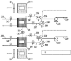
도 1은, 본 발명의 예시적인 실시예에 따른, 대기로부터 이산화탄소를 제거하기 위한 서로 상호 작용하는 한 쌍의 회전 다중 포집 구조체 시스템의 개략적인 상면도로서, 포집 구조체들의 그룹 및 각각의 루프에 대한 지면 높이 재생 챔버를 도시하고, 각각의 재생 챔버로부터 바로 상류에 있는 2개의 포집 구조체가, 깨끗해진 연도 가스를 포집 구조체에 공급하기 위한 밀봉 가능한 도관이 제공된, 밀봉 가능한 하우징 내에 도시된다;
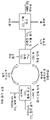
도 2는 도 1의 포집 구조체로부터 이산화탄소를 제거하기 위한 한 쌍의 재생 챔버의 개략도로서, 챔버 중 하나에 연결된 여러 개의 입구 및 출구 도관과, 두 개의 챔버를 연결하는 밀봉 가능한 연결 도관을 도시한다;
도 3은 각각의 챔버 및 챔버들 사이의 배관 시스템 배열을 나타내는 각각의 인접한 루프상의 연도 가스 포집 구조체 및 재생 챔버의 개략도이다;
도 4는 비교적 고정되어 있고 각각의 포집 구조체와 함께 각각 회전하는 팬을 도시하는 개략적인 입면도이다;
도 5는 도 4의 이중 흡출 축류 팬(Dual Induced Axial Fans) 및 플레넘(Plenums)에 대한 설계의 개략적인 측입면도이다;
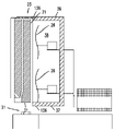
도 6은, 대기로부터 이산화탄소를 제거하기 위한 트랙 높이 재생 챔버와, CO2 포집을 위해 연도 가스 스트림을 처리하기 위한 직전의 두 개의 포집 구조체 하우징을 도시하는, 회전 다중 포집 구조체 시스템의 서로 상호 작용하는 쌍들 중 하나의 개략적인 입면도이다;
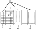
도 7은 마지막 흡착 스테이지와 CO2 탈착 및 재생 단계 사이에서의 이 시스템의 일반적인 작동을 도시하는 개념도로서, 흡착 스테이지가 모두 주변 공기를 처리하는 시스템을 도시한다;
도 8은 마지막 흡착 연도 가스 스테이지와 CO2 탈착 및 재생 단계 사이에서의 이 시스템의 본 발명의 바람직한 실시예들 중 하나의 일반적인 작동을 도시하는 개념도로서, 본 실시예에서, "탈착 유닛"으로부터 바로 상류인 마지막 흡착 스테이지, 예를 들어 제9 스테이지는, 순수하거나 또는 주변 공기와 혼합된 연도 가스를 수용하고, 다음의 이전 스테이지, 예를 들어 제8 스테이지는, 제9 스테이지 배기가스의 조성에 따라, 제9 스테이지로부터의 배기가스, 그 배기가스와 주변 공기의 혼합물, 또는 주변 공기만을 수용할 수 있다;
도 9는 마지막 흡착-혼합된 공기-연도 가스 스테이지와 CO2 탈착 및 재생 단계 사이에서의 이 시스템의 본 발명의 또 다른 바람직한 실시예의 일반적인 작동을 도시하는 개념도로서, 본 실시예에서, "탈착 유닛"으로부터 바로 상류인 마지막 흡착 스테이지, 예를 들어 제 9 스테이지는, 연도 가스와 주변 공기와 혼합된 연도 가스를 수용한다; 및
도 10은, 각각의 하우징이 지면(grade) 높이에 있고 각각의 포집 구조체가 트랙을 따라 이동하는 동안 포집 구조체가 각각의 하우징에 들어갈 때, 탈착 유닛에서 또는 연도 가스 흡착 유닛 하우징 중 하나에서 각각의 포집 유닛의 모든 측면들 주변으로 연장되는 밀봉의 한 예를 도시한다.1 is a schematic top view of a pair of rotating multiple capture structure systems interacting with each other for removing carbon dioxide from the atmosphere, in accordance with an exemplary embodiment of the present invention, for a group of collection structures and for each loop; It shows a ground level regeneration chamber, with two collection structures immediately upstream from each regeneration chamber shown in a sealable housing provided with a sealable conduit for supplying cleaned flue gas to the collection structure;
FIG. 2 is a schematic view of a pair of regeneration chambers for removing carbon dioxide from the capture structure of FIG. 1, showing several inlet and outlet conduits connected to one of the chambers, and a sealable connecting conduit connecting the two chambers;
3 is a schematic view of a flue gas collection structure and regeneration chamber on each adjacent loop showing each chamber and arrangement of a piping system between the chambers;
Fig. 4 is a schematic elevational view showing a fan relatively stationary and each rotating with a respective collection structure;
Figure 5 is a schematic side elevational view of the design for the Dual Induced Axial Fans and Plenums of Figure 4;
6 is mutually interacting pairs of a rotating multiple capture structure system, showing a track height regeneration chamber for removing carbon dioxide from the atmosphere and two capture structure housings just prior to treating a flue gas stream for CO2 capture; This is a schematic elevation of one of the;
Figure 7 is a conceptual diagram illustrating the general operation of this system between the last adsorption stage and the CO2 desorption and regeneration stages, showing the system in which the adsorption stages all treat ambient air;
8 is a conceptual diagram illustrating the general operation of one of the preferred embodiments of the present invention of this system between the last adsorption flue gas stage and the CO2 desorption and regeneration stage, in this embodiment immediately upstream from the "desorption unit"; The last adsorption stage, eg the ninth stage, receives the flue gas, either pure or mixed with ambient air, the next previous stage, eg the eighth stage, depending on the composition of the ninth stage exhaust gas: can receive exhaust gas from the ninth stage, a mixture of that exhaust gas and ambient air, or only ambient air;
9 is a conceptual diagram illustrating the general operation of another preferred embodiment of the present invention of this system between the last adsorption-mixed air-flue gas stage and the CO2 desorption and regeneration stage, in this embodiment a "desorption unit"; The last adsorption stage, eg the ninth stage, immediately upstream from , receives flue gas mixed with the flue gas and ambient air; and
Figure 10 shows each housing in one of the desorption unit or flue gas adsorption unit housings when each housing is at grade level and the collection structure enters the respective housing while each collection structure moves along the track. An example of a seal extending around all sides of the collection unit is shown.
전술한 이러한 작동을 수행하는 시스템에 대한 설계의 단순화된 묘사는 도 1 내지 6에 도시되어 있다. 필요한 보조 장비 및 작동에 대한 자세한 설명은 아래에 제시되어 있으며, 소유자가 동일한(in commonly owned) 미국 특허 10,413,866 및 10,512,880에 제시된 것과 유사하다.A simplified depiction of a design for a system that performs these operations described above is shown in Figures 1-6. A detailed description of the necessary auxiliary equipment and operation is provided below and is similar to that set forth in U.S. Patents 10,413,866 and 10,512,880 in commonly owned.
본 실시예에서, 10개의 "포집 구조체"는 바람직하게는 그러나 필수적인 것은 아닌 10각형 배열로 위치하고 실질적으로 원형 또는 아치형 트랙 상에 위치한다. 2개의 실질적으로 원형(또는 타원형)/10각형인 어셈블리들은 각각의 공정 유닛과 연관되고 도시된 바와 같이 서로 상호 작용한다. 이러한 바람직한 실시예에서, 공기는 포집 구조체의 내부 측면에 위치하는 흡출 송풍기(induced draft fan)에 의해 포집 구조체를 통과한다. 하나의 위치에서 포집 구조체는, 각 포집 구조체가 처리를 위해 트랙을 따라 이동할 때 각 포집 구조체가 삽입되는, 단일의 밀봉 가능한 챔버 상자에 인접한 위치에 있다. 밀봉 가능한 재생 챔버 상자에서 이들은 130°C 이하, 보다 바람직하게는 120°C 이하, 최적으로는 100°C 이하의 온도로 가열되고, 바람직하게는 공정 열 증기를 사용하여 흡착제로부터 CO2를 방출하고 흡착제를 재생시킨다. 대안적으로, 재생 챔버는 지면(grade)보다 높거나 낮을 수 있다. 본 실시예에서, 포집 구조체에 의해 CO2를 흡착하기 위한 흡착 시간은, 바람직하게는 흡착제 재생 시간의 10배이다.In this embodiment, the ten “collecting structures” are preferably but not necessarily in a decagonal arrangement and are located on a substantially circular or arcuate track. Two substantially circular (or elliptical)/ten-gonal assemblies are associated with each processing unit and interact with each other as shown. In this preferred embodiment, air is passed through the collection structure by means of an induced draft fan located on the inner side of the collection structure. In one location, the collection structures are adjacent to a single sealable chamber box, into which each collection structure is inserted as it moves along the track for processing. In a sealable regeneration chamber box they are heated to a temperature below 130°C, more preferably below 120°C, optimally below 100°C, preferably using process heat vapor to release CO2 from the adsorbent and Regenerate the adsorbent. Alternatively, the regeneration chamber may be above or below grade. In this embodiment, the adsorption time for adsorbing CO 2 by the collecting structure is preferably 10 times the adsorbent regeneration time.
포집 구조체에서 다공성 모놀리식(monolithic) 기판을 사용하는 것이 바람직하지만, 가능한 경우 포집 구조체 상의 프레임 내에 지지되는 다공성 미립자(porous particulate) 또는 알갱이 모양(granular), 물질의 고정 베드(stationary bed)를 사용할 수 있다는 것이 이해되어야 한다. 어느 경우에나 다공성 기판은, 입자 포집 구조체가 흡착제를 지지하기 위한 모놀리스(monolith) 포집 구조체와 동일한 공극 부피를 가질 때, 바람직하게는 CO2용 아민 흡착제를 지지한다.While it is desirable to use a porous monolithic substrate in the capture structure, it is possible to use a stationary bed of porous particulate or granular material supported in a frame on the capture structure, if possible. It should be understood that there can be In either case, the porous substrate preferably supports the amine adsorbent for CO 2 when the particle trapping structure has the same pore volume as the monolith trapping structure for supporting the adsorbent.
상기 개략도는 본 발명에 따른 시스템의 기본 작동 개념을 개략적으로 도시한다. 10개의 "포집 구조체"(21, 22)는 각각의 10각형 어셈블리 배열에 위치하고 원형 트랙(31, 33) 상에 이동 가능하게 지지된다. 2개의 원형/10각형 어셈블리들(A, B)은 각각의 공정 유닛과 연관되고 서로 상호 작용한다. 공기 또는 연도 가스(flue gas)는, 각각의 10각형 어셈블리들 내부에 방사상으로 위치하는 흡출 송풍기(23, 26)에 의해 각각의 포집 구조체(21, 22)를 통과하고, 각각의 포집 구조체의 내주면 밖으로 그리고 시스템으로부터 멀리 위로 배기가스의 흐름을 유도한다. 트랙(31, 33)을 따른 하나의 위치에서 포집 구조체(21, 22)는, 포집 구조체(22, 22)가 트랙 주변에서 하나의 회전을 완료한 후 재생 처리를 위해 삽입되는, 밀봉 가능한 재생 상자(25, 27)에 인접한다.Said schematic diagram schematically shows the basic operating concept of the system according to the invention. Ten “collecting structures” 21 , 22 are located in each decagonal assembly arrangement and are movably supported on
따라서, 도 1 및 도 2에 도시된 바와 같이, 제1 포집 구조체(21)는 처리를 위해 재생 상자(25) 내의 위치로 회전된다; 지면 상의 재생 상자(25)에 대해. 포집 구조체가 재생 상자(25) 내의 위치에 있을 때, 트랙을 따른 이동은 모든 포집 구조체에 대해 정지된다. 대안적으로, 포집 구조체, 및 트랙의 직경을 증가시킴으로써, 재생 상자 상에, 그리고 임의의 연도 가스 흡착 하우징(121, 221, 122, 222) 상에 적합한 밀봉 시스템을 가짐으로써 일정한 움직임이 가능하게 된다. 포집 구조체(21, 22)가 재생되면, 모든 포집 구조체가 이동함에 따라 재생된 포집 구조체가 재생 상자(25, 27) 밖으로 이동되어, 다음 포집 구조체(21, 22)는 도 1에 도시된 바와 같이 연도 가스를 처리한 후에 안으로 이동될 수 있다. 이 공정은 실질적으로 지속적으로 반복된다. 도면에 도시된 바람직한 실시예에서, 타이밍이 바람직하게는 연도 가스 탈착 타이밍과 일치하기 때문에, 각각의 트랙 상의 하나 이상의 포집 구조체는 연도 가스 흡착 하우징(121, 221, 122, 222) 밖으로 이동할 것이다. 대안적으로, 포집 구조체 움직임은 포집 구조체가 재생 상자 및 하나 이상의 연도 가스 흡착 하우징(121, 221, 122, 222)에 들어갈 때마다 정지될 수 있고, 그 후 탈착 및 연도 가스 흡착이 완료되면 움직임이 재시작된다.Accordingly, as shown in FIGS. 1 and 2 , the
그러나, 전술한 바와 같이, 본 공정 발명은 저온(바람직하게는 주변 100°C까지)이고 공정의 각 단계에서의 일방향 대량 수송을 이용한 반연속 공정이다. 이 공정의 추가적인 신규한 측면은 기체 혼합물로부터 CO2를 포집하는 반응이 바람직하게는 재생 가능한 물질(바람직한 일 실시예에서, 아미노중합체 상에)과 함께 발생하며, 재생 가능한 물질, 예를 들어, 아미노중합체 흡착제가 기판 내에 함침된다는 것이다.However, as mentioned above, the present process invention is a semi-continuous process at low temperature (preferably up to ambient 100°C) and using unidirectional mass transport at each stage of the process. A further novel aspect of this process is that the reaction to capture CO 2 from the gas mixture preferably takes place with a renewable material (in one preferred embodiment, on an aminopolymer), a renewable material such as amino The polymer adsorbent is impregnated into the substrate.
바람직한 실시예에서, 흡착제-지지 포집 구조체는 각각의 포집 구조체를 형성하기 위해 프레임워크에 의해 차례로 지지되는 모놀리식 기판을 포함한다.In a preferred embodiment, the adsorbent-supported collection structure comprises a monolithic substrate supported in turn by a framework to form each collection structure.
후술하는 바와 같이, 다른 상자, 예를 들어 재생 상자(27)의 예열을 제공하기 위해, 예를 들어, 상자(25)에서의 재생이 완료되면, 예를 들어 상자(25) 및 상자(27) 사이에서의, 열의 통과를 허용하기 위해, 각각의 10각형 고리에 대한 포집 구조체가 그들의 탈착./재생 상자 내외로 약간 상이한 시간에 이동됨에도 불구하고, 두 개의 10각형 고리 어셈블리는 함께 작동한다. 이는 재생 시작시 열을 절약하고, 재생 후 포집 구조체의 냉각 비용을 감소시킨다.As will be described below, to provide for preheating of other boxes, for example the
재생 상자(25, 27)를 위한 3개의 위치가, 즉, 연속적인 움직임을 허용하지 않는 회전 포집 구조체 위 또는 아래, 또는 지면 높이에서, 이용 가능하다. 미국 특허 10,413,866 및 10,512,880 참조.Three positions are available for the
재생 챔버(321, 327)는 회전하는 포집 구조체 어셈블리들과 함께 지면 상에 위치한다. 상자 또한 유지보수 및 배관 공정을 위한 적절한 접근이 가능하게 지면 상에 위치한다. 적절한 상호 밀봉 표면은 상자 상에 그리고 각각의 포집 구조체 상에 위치하여, 포집 구조체가 상자 내의 위치로 이동함에 따라, 상자(322, 327)는 움직임이 상향인지, 상승된 재생 상자 내로 향하는지, 지면-아래(sub-grade)의 재생 상자 내로 하향인지, 또는 지면 상의 재생 상자에 대해 직진인지에 관계없이 밀봉되며; 연도 가스 흡착 하우징(121, 221, 122, 222)이 지면 상에 또는 지면 위 또는 아래일 수 있는 실시예에 대해서도 마찬가지이다. 포집 구조체 내로 연도 가스 또는 부분적으로 깨끗해진 연도 가스를 공급하기 위한 트랙을 따른 직전 위치의 선택적인 폐쇄 챔버도 있다.
모든 경우에 보조 장비(펌프, 제어 시스템 등과 같은)는 바람직하게는 회전 포집 구조체 어셈블리(29)를 지지하는 트랙의 원주 내 또는 원주 외부의 지면에 위치한다.In all cases auxiliary equipment (such as pumps, control systems, etc.) is preferably located on the ground within or outside the circumference of the track supporting the rotation capture structure assembly 29 .
재생 상자 및 하우징은, 본 발명의 개념 또는 범위로부터 벗어나지 않고, 특정 상황에서 상이한 높이에 위치할 수 있다.The recycle box and housing may be located at different heights in certain circumstances without departing from the spirit or scope of the present invention.
본 발명의 범위 내에 있는 대안적인 설계는 한 쌍의 재생 상자, 챔버(25)가 트랙을 따라 이동할 수 있는 시스템을 제공한다. 이는 트랙 설계가 직선 트랙을 따른 포집 구조체에 의한 왕복 이동을 가능하게 하여, 재생 상자들(25)이 넓게 분리되지 않도록 하는 경우에 가장 잘 사용될 것이다. 종래 기술에 개시된 종래의 장치와 비교하면, 이는 다음과 같을 것이다:An alternative design that is within the scope of the present invention provides a system in which a pair of play boxes,
구조상의 강철 최소화;minimal structural steel;
모든 주요 장비는 격납 용기로만 작용하는 재생 상자들과 떨어지게 지면 높이에 배치됨;All major equipment is placed at ground level, away from recycling bins acting only as containment vessels;
상자가 트랙과 상이한 높이에 있는 포집 구조체로의 공기 흐름에 간섭이 없음을 보장함;ensuring that there is no interference with the airflow to the capture structure where the box is at a different height than the track;
재생 상자 내로 이동시키기 위해 모든 포집 구조체를 회전시키는 더 큰 다중 유닛 시스템의 이동을 피함;avoid movement of larger multi-unit systems that rotate all capture structures to move into the recycle box;
효율을 높이기 위한 바람직한 열교환을 허용하기 위해 두 개의 재생 상자가 최소한의 간격으로 서로 인접하도록 함.Two regeneration boxes are adjacent to each other with minimal spacing to allow for desirable heat exchange to increase efficiency.
필요한 기계 및 전력을 사용하는 기계적 작동에는 다음이 포함된다:Mechanical operations using the necessary machinery and electrical power include:
지지 구조체 상의 실질적으로 원형인 트랙 주변의 두 세트의 포집 구조체 어셈블리들의 회전은, 재생 상자 및 임의의 연도 가스 흡착 하우징들 내외로 포집 구조체들의 자유로운 이동을 보장하기 위해, 포집 구조체들이 정지될 위치에 요소들을 정확하게 위치시킨다.Rotation of the two sets of collection structure assemblies around the substantially circular track on the support structure is an element in the position where the collection structures will be stationary to ensure free movement of the collection structures in and out of the recycle box and any flue gas adsorption housings. position them accurately.
포집 구조체 또는 기판만의 제거, 재생 상자 내로 포집 구조체 삽입, 재생 상자로부터 포집 구조체 제거 및 트랙 어셈블리 상의 위치로 포집 구조체 재삽입. 이러한 모든 이동은 수직 방향으로, 또는 대안적으로 트랙 상의 수평 회전 이동의 일부로서 발생한다. 포집 구조체 및 재생 상자는, 수직으로 이동 가능한 포집 구조체의 경우, 상자의 지지 구조체와 각각의 포집 구조체의 상부 또는 하부 사이에 실질적으로 기밀 밀봉(air-tight seal)이 존재하도록 설계된다. 지면 상의 이러한 재생 상자 또는 연도 가스 흡착 하우징의 경우, 밀봉은 상부 및 하부 표면 뿐만 아니라 측면 상에 있을 수 있거나, 포집 구조체가 재생 상자 또는 연도 가스 흡착 하우징 내로 이동할 때 폐쇄되는 밀봉 도어가 있을 수 있다. 이러한 밀봉에 대한 일부 개념적 설계의 예는 이전에 등록된 미국 아이젠버그(Eisenberger) 특허에서, 그리고 본 출원의 도 10에 의해 보여진다.Removal of the collection structure or substrate only, insertion of the collection structure into the recycle box, removal of the collection structure from the recycle box and reinsertion of the collection structure into position on the track assembly. All such movements occur in the vertical direction, or alternatively as part of a horizontal rotational movement on the track. The collection structure and the recycling box are designed such that, in the case of a vertically movable collection structure, there is a substantially air-tight seal between the support structure of the box and the top or bottom of each collection structure. For such a recovery box or flue gas adsorption housing on the ground, the seals may be on the top and bottom surfaces as well as the sides, or there may be a sealing door that closes when the collection structure moves into the recovery box or flue gas adsorption housing. Examples of some conceptual designs for such seals are shown in the previously issued US Eisenberger patent, and by Figure 10 of the present application.
바람직한 일 실시예의 모든 경우에, 도 1 내지 도 9를 참조하면, 포집 구조체(21-1)(고리 A)는 위치로 회전되고, 이어서 처리를 위해 재생 또는 탈착 상자(25) 내로 이동된다. 탈착 상자(25)(포집 구조체(21-1), 고리 A 함유) 내의 압력은, 예를 들어 진공 펌프(230)를 사용하여, 0.2 Bar 미만으로 감소된다. 상자(25)는 라인(235)을 통해 대기압에서 증기에 의해 가열되고, CO2는 포집 구조체(21-1)로부터 발생되고 응축기(240)(도 SA) 상에서 분리되는 CO2 및 응축물을 위한 상자(25)로부터 출구 배관(237)을 통해 제거된다. 그 후 포집 구조체(22-1)(고리 B)는 위와 같이 상자(25)가 처리되는 동안 상자(27)(고리 B)에 배치된다(도 5B). 상자(25)로의 증기 공급은 정지되고, CO2 및 응축물을 위한 출구 배관이 격리된다. 상자(25) 및 상자(27)는 연결 배관(125)에서 밸브(126)를 개방함으로써 연결된다(도 SC).In all cases of one preferred embodiment, with reference to FIGS. 1-9 , the collection structure 21-1 (ring A) is rotated into position and then moved into a recycling or
상자(27) 내의 압력은 상자(27)와 연관된 진공 펌프(330)를 사용하여 낮아진다. 이는 두 상자 내의 시스템 압력을 낮추고, 상자(25) 내에 남아 있는 증기 및 불활성 요소를 상자(27)를 통해, 그리고 그 후 진공 펌프로 끌어들인다. 이는 상자(25)(및 그에 따른 포집 구조체(21-1), 고리 A)를 더 낮은 온도(즉, 상자 내의 증기의 부분 압력에서의 포화 온도)로 냉각시키고, 포집 구조체(21-1)가 공기 스트림 내로 다시 위치할 때 흡착제의 산소 비활성화를 위한 퍼텐셜(potential)를 감소시킨다. 이 공정은 또한 상자(250) 내의 증기의 부분 압력에서 주변 온도로부터 포화 온도까지 상자(27)(및 그에 따른 포집 구조체(22-1), 고리 B)를 예열시킨다. 따라서, 에너지가 회수되고, 제2 상자(27)(및 포집 구조체(22-1) 고리B)를 가열하는데 필요한 대기압 증기의 양이 감소된다(도 SD). 진공 펌프(330)가 상자들(25 및 27) 내의 압력을 낮춤에 따라, 제1 상자(25)는 온도(대략 100°C로부터 어느 중간 온도로)가 감소되고, 제2 상자(27)는 온도(주변 온도로부터 상기 동일한 중간 온도로)가 증가된다. CO2 및 불활성 가스는 진공 펌프(330)에 의해 시스템으로부터 제거된다.The pressure in the
제1 상자(25)와 제2 상자(27) 사이의 밸브는 폐쇄되고, 상자들은 서로 격리된다. 포집 구조체(21-1) 고리 A는 이제, 포집 구조체가 공기 흐름 내에 다시 위치할 때 흡착체의 산소 비활성화가 우려되는 온도 아래로 냉각된다. 제2 상자(27) 및 포집 구조체(22-1), 고리 B는 예열되었고, 따라서 상자 및 포집 구조체를 가열하는데 필요한 증기의 양이 감소된다(도 5E). 그 후, 포집 구조체(21-1) 고리 A는 포집 구조체 어셈블리 내로 이동된다. 고리 A 포집 구조체 어셈블리는 하나의 포집 구조체에 의해 회전되고 포집 구조체(21-2) 고리 A는 그 후 상자(25) 내로 삽입되며, 예열할 준비가 된다. 상자(27)는 대기 증기로 가열되고 박리된 CO2가 수집된다(도 5F).The valve between the
제2 상자(27)(포집 구조체(22-1) 고리 B 함유)가 완전히 재생되면, 상자 B로의 증기 공급은 격리되고, 응축물 및 CO2를 위한 배관은 밸브(241, 242)를 사용하여 격리된다. 제1 상자(25)와 제2 상자(27) 사이의 밸브(126)는 개방되고, 상자(25, 27) 내의 압력은 상자(25)를 위한 진공 펌프(230) 시스템을 사용하여 감소된다. 제2 상자(27)(및 그에 따른 포집 구조체(22-1), 고리 B)의 온도는 감소된다(상기 5 참조). 제1 상자(25)(포집 구조체(21-2), 고리 A 함유)의 온도는 증가된다(상기 5 참조)(도 5G). 진공 펌프(230)는 상자(25, 27) 내의 압력을 낮춘다. 상자(25)는 온도(대략 100°C로부터 어느 중간 온도로)가 감소된다. 상자(27)는 온도(주변 온도로부터 상기 동일한 중간 온도로)가 증가된다. CO2 및 불활성 가스는 진공 펌프(230)에 의해 시스템으로부터 제거된다. 포집 구조체(22-1), 고리 B는 고리 어셈블리 내로 되돌아가고 어셈블리는 하나의 베드로 회전된다. 그 후, 포집 구조체(22-2), 고리 B는 상자(27) 내로 삽입된다. 상자(25)(포집 구조체(21-2), 고리 A 함유)는 대기 증기로 가열되어 CO2를 방출하고 흡착제를 재생한다(도 5H). 그 후, 상자(27)의 예열은 전술한 바와 같이 발생한다. 이 과정은 10각형이 여러 번 회전함에 따라 모든 베드에 대해 반복된다.When the second box 27 (containing ring B of the capture structure 22-1) is completely regenerated, the steam supply to box B is isolated and the piping for condensate and CO 2 is connected using
도 8에 도시된 바와 같은 바람직한 실시예를 다룰 때, 두 고리들은 재생 상자 내로 진입 직전의 한 쌍의 연도 가스 흡착 하우징을 포함하고, 바람직하게는 전처리된 연도 가스의 공급물이 제공된다. 예를 들어, 재생 상자 직전의 제9 흡착 스테이지에는, 보통 약 10-15% CO2를 갖는 전처리된 연도 가스, 또는 전처리된 연도 가스와 주변 공기의 혼합물이 공급된다. 그 스테이지로부터의 배기가스는, 예를 들어 2 내지 8%의 CO2를 함유할 수 있다. 바람직하게는, CO2의 상부 범위가 배출될 때, 대기로 배출되기에 적합한 정도로 배기가스를 감소시키기 위해, 배기가스는 가장 바람직하게는 추가 흡착을 위해 직전의 탈착 스테이지 하우징 내로 전달된다.When dealing with the preferred embodiment as shown in Figure 8, both rings comprise a pair of flue gas adsorption housings just before entry into the recycle box, preferably provided with a feed of pretreated flue gas. For example, a ninth adsorption stage just before the regeneration box is fed with pretreated flue gas, usually having about 10-15% CO 2 , or a mixture of pretreated flue gas with ambient air. The exhaust gas from that stage may contain, for example, 2 to 8% CO 2 . Preferably, when the upper range of CO 2 is evacuated, the exhaust gas is most preferably passed into the immediately preceding desorption stage housing for further adsorption in order to reduce the exhaust gas to a level suitable for venting to the atmosphere.
기본 설정 설계 매개변수Preferred design parameters
시스템 설계를 위한 현재 선호되는 기준은 다음과 같다:Currently preferred criteria for system design are:
이동할 개별 포집 구조체의 무게:Weight of individual collection structures to be moved:
1,500 --- 10,000 파운드. (지지 구조체 포함)1,500 --- 10,000 pounds. (with support structure)
대략적인 베드 크기: 너비 - 5-6 미터Approximate bed size: Width - 5-6 meters
높이 -- 9-10 미터 Height -- 9-10 meters
깊이 - 0.15-1 미터 Depth - 0.15-1 meters
포집 구조체 치수들은, 시스템의 각 쌍의 지리적 위치에서의 특정 조건들과, 원하는 또는 달성가능한 처리 매개변수들에 따라 조정될 수 있다는 점을 유의해야 한다.It should be noted that the collection structure dimensions may be adjusted according to the specific conditions in the geographic location of each pair of systems and the desired or achievable processing parameters.
각각의 10각형 고리 내에 10개의 포집 구조체를 포함하는 시스템의 경우, 바람직한 원형/10각형 구조체의 외부 치수는 약 15-17 미터, 바람직하게는 약 16.5 미터일 것이다. 포집 구조체 지지 구조체는, 예를 들어 트랙을 따라 전기 모터 및 구동 휠에 의해 개별적으로 구동될 수 있거나, 지지 구조체는 트랙을 따른 특정 위치 및 폐루프 주변의 모든 구조체 및 트랙을 구동하는데 사용되는 단일 대형 모터에 고정될 수 있다. 어느 경우에나 재생 상자는 하나의 위치에 배치되고, 지지 구조체 중 하나가 재생 상자 내로 이동하도록 배치되면 모든 구조체는 이동을 정지할 수 있다. 단일 구동 모터 또는 엔진, 또는 다중 구동 모터 또는 엔진의 경제성은, 구동이 전기 모터에 의해 또는 일부 연료 구동 엔진에 의해 달성될 것인지 여부 및 위치와 같은, 많은 요인에 의존할 것이다. 구동 유닛의 성질은 그 자체가 본 발명의 주요 특징이 아니며, 많은 것이 통상의 기술자에게 잘 알려져 있다. 적합한 엔진의 예는, 예를 들어 스털링 엔진 사이클을 사용하여 작동하는, 가스 압력 구동 엔진 또는 내연 또는 외연 엔진, 또는 공정 증기 엔진 또는 유압 또는 공압 엔진을 포함한다.For a system comprising 10 collection structures in each decagonal ring, the preferred outer dimension of the circular/decagonal structures would be about 15-17 meters, preferably about 16.5 meters. The collection structure support structure may be driven individually by, for example, an electric motor and drive wheels along the track, or the support structure may be a single large structure used to drive all structures and tracks around a closed loop and at a specific location along the track. It can be fixed to the motor. In either case, the play box is placed in one position, and when one of the support structures is positioned to move into the play box, all of the structures can stop moving. The economics of a single drive motor or engine, or a multiple drive motor or engine, will depend on many factors, such as location and whether the drive will be achieved by an electric motor or some fuel driven engine. The nature of the drive unit is not itself a key feature of the invention, many of which are well known to the person skilled in the art. Examples of suitable engines include, for example, gas pressure driven engines or internal or external combustion engines, or process steam engines or hydraulic or pneumatic engines, operating using a Stirling engine cycle.
재생 상자가 트랙 높이 위에 위치하는 경우, 상단은 트랙의 지면보다 약 20 미터 위에 있을 것이고, 재생 상자가 트랙의 지면 아래에 위치하는 경우, 상자의 상단은 트랙 지면의 바로 아래에 있을 것이다. 재생 동안 상자 내에 완전히 포집 구조체를 수용하기 위해, 지면 상의 상자는 포집 구조체의 상단보다 최소한으로만 위에 있을 것이다.If the playbox is positioned above the track height, the top will be about 20 meters above the ground of the track, and if the playbox is positioned below the ground of the track, the top of the box will be just below the ground of the track. In order to fully accommodate the collection structure within the box during regeneration, the box on the ground will only be minimally above the top of the collection structure.
재생 상자가 지면 상에 있지 않은 경우, 포집 구조체를 재생 상자 내외로 이동시키기 위한 승강 시스템은, 30초 내지 i20초, 바람직하게는 30 및 45초 사이의 범위 내의 기간 동안 상자 내외로 이동을 달성할 수 있어야 한다. 기간이 짧을수록 공정에 이용 가능한 공정 매개변수의 유연성이 커진다. 대량의 포집 구조체를 이동시키는 데는 일부 내재하는 기계적 한계가 존재한다는 것이 인식된다. 재생 상자가 지면 상에 있는 것의 한 가지 장점은, 포집 구조체가 단순히 회전 이동의 일부로서 상자 내로 회전하고 밀봉하기 때문에 수직 이동이 필요하지 않으며; 따라서 수직 이동, 시간의 손실 및 승강의 추가적인 자본 비용을 피한다는 것이다. 각각의 경우, 포집 구조체의 두 가장자리는 단단하고(solid) 재생 상자의 가장자리와 함께 밀봉을 형성한다.When the recycle box is not on the ground, the lifting system for moving the collection structure in and out of the recycle box is capable of achieving movement in and out of the box for a period within the range of 30 seconds to i20 seconds, preferably between 30 and 45 seconds. should be able The shorter the duration, the greater the flexibility of the process parameters available to the process. It is recognized that there are some inherent mechanical limitations in moving large amounts of collection structures. One advantage of having the recycling box on the ground is that no vertical movement is required as the collection structure simply rotates and seals into the box as part of the rotational movement; This avoids vertical movement, loss of time and the additional capital cost of lifting and lowering. In each case, the two edges of the collection structure are solid and form a seal together with the edges of the recycling box.
Claims (20)
상기 제1 챔버는, 이산화탄소를 가득 실은(laden) 연도 가스의 공급원에 연결되도록 설계된 입구, 및 CO2의 적어도 일부가 상기 흡착제에 의해 흡착된 후의 CO2가 희박한(CO2-lean) 연도 가스를 위한 출구를 포함하는, 시스템.A system for removing carbon dioxide from a gas mixture laden with carbon dioxide, the system comprising: a group of carbon dioxide removal structures, each removal structure in each group supported on the structure; wherein each porous substrate has an adsorbent supported within its pores, the adsorbent capable of adsorbing or binding to carbon dioxide to remove carbon dioxide from the gas mixture; an endless loop support for the group of removal structures, the endless loop support arranged to allow movement of each group of removal structures along a closed curve while exposed to a stream of a gas mixture laden with carbon dioxide; and a recycle box sealable at one location along the endless loop support, such that when the removal structure is sealed in place therein, the carbon dioxide absorbed by the adsorbent is exfoliated from the adsorbent and captured and the adsorbent is regenerated. may be sealingly disposed therein; each of the removal structures supporting the porous substrates in a position such that the adsorbent is exposed to a flow of a gas mixture laden with carbon dioxide to allow removal of CO 2 from the gas mixture; The number of removal structures to the number of regeneration boxes is directly determined by the ratio of adsorption time (for removing CO 2 from the gas mixture) to regeneration time (for stripping CO 2 from the adsorbent on the porous substrate) wherein the adsorption time is the time to adsorb CO 2 from the gas mixture onto the adsorbent from a base level on the adsorbent to a desired height, and the regeneration time is the time to adsorb on the adsorbent from the desired height on the adsorbent to the base level time to exfoliate the CO 2 again; the system further comprising a first chamber, wherein in a position along the track, the first chamber is designed to sealingly receive a respective collection structure as it moves along the track;
The first chamber has an inlet designed to connect to a source of carbon dioxide-laden flue gas, and CO 2 -lean flue gas after at least a portion of the CO 2 has been adsorbed by the adsorbent . A system comprising an outlet for
상기 제2 챔버는 상기 제1 챔버에 들어가기 전에 상기 트랙을 따라 이동할 때 각각의 포집 구조체를 밀봉식으로 수용하도록 설계되는, 시스템.The method of claim 1 , further comprising: a second chamber at a location along the track upstream from the first chamber;
wherein the second chamber is designed to hermetically receive a respective collection structure as it travels along the track prior to entering the first chamber.
상기 두 그룹의 이산화탄소 제거 구조체들의 각각의 회전 운동은 다른 재생 상자에서의 이산화탄소 제거 구조체의 재생이 시작된 후에 이산화탄소 제거 구조체가 재생 상자들 중 하나로 들어가도록 오프-셋(off-set)되는, 시스템.9. The system of claim 8, further comprising: a sealable fluid connection between each of the recovery boxes and an exhaust pump for reducing the atmospheric pressure in the sealed recovery box after a removal structure is sealed within the recovery box; and a sealable fluid connection between each of the recovery boxes, and a source of process heat vapor to each recovery box; and a sealable fluid connection between each regeneration box and the CO 2 collection chamber;
wherein the rotational motion of each of the two groups of carbon dioxide removal structures is off-set such that the carbon dioxide removal structure enters one of the recovery boxes after regeneration of the carbon dioxide removal structure in the other recycling box begins.
상기 방법은, CO2를 가득 실은(CO2-laden) 연도 가스를 트랙을 따라 위치한 제1 챔버 내로 유동시키는 단계 - 상기 제1 챔버는 트랙을 따라 이동함에 따라 각각의 포집 구조체를 밀봉식으로 수용함 -를 더 포함하고; 상기 포집 구조체 상의 상기 다공성 기판 내의 상기 흡착제는 흡착 시간 동안 연도 가스로부터 이산화탄소를 흡착 및 제거하고, 상기 포집 구조체가 트랙을 따라 제1 챔버 밖으로 이동하기 전에 상기 제1 챔버로부터 CO2가 희박한(CO2-lean) 연도 가스를 통과시키는, 방법.A method for removing carbon dioxide from a gas mixture laden with carbon dioxide, the method comprising: removing a group of individual carbon dioxide removal structures around an endless closed loop while exposed to a stream of a gas mixture laden with carbon dioxide; moving; each removal structure in the group comprising a porous solid substrate supported on the structure, each porous substrate having an adsorbent supported in its pores, the adsorbent adsorbing or binding to carbon dioxide to form a gas mixture during the adsorption time Can remove carbon dioxide from -; Once the removal structure is sealed in place therein, the carbon dioxide absorbed on the adsorbent is stripped off and captured from the adsorbent so that the adsorbent is regenerated during the regeneration time. sealingly disposing the removal structure; Each removal structure supporting the porous substrate on an endless closed loop is such that the adsorbent is continuous in the flow of the carbon dioxide containing gas mixture to allow removal of CO 2 from the gas mixture except when the removal structure is located in a recovery box. wherein the adsorbent is exposed to process heat at a temperature of less than 130°C to strip CO 2 from the adsorbent when the removal structure is placed in the regeneration box; The number of removal structures to the number of regeneration boxes is directly determined by the ratio of the adsorption time, the adsorption time being, from a base level on the adsorbent bed to a desired height, with each structure being a stream of a carbon dioxide containing gas mixture. is the time to adsorb CO 2 from the gas mixture onto the adsorbent during exposure to, and the regeneration time is the desired height on the adsorbent in the regeneration box, during the time each structure is in the regeneration box is the time to exfoliate the CO 2 back to the reference height from;
The method includes flowing CO 2 -laden flue gas into a first chamber positioned along a track, the first chamber sealingly receiving each capture structure as it moves along the track. ham - further comprising; The adsorbent in the porous substrate on the capture structure adsorbs and removes carbon dioxide from the flue gas during the adsorption time, and from the first chamber before the capture structure moves out of the first chamber along the track ( CO 2 ) -lean) passing the flue gas, the method.
상기 제2 챔버는 상기 제1 챔버에 들어가기 전에 상기 트랙을 따라 이동할 때 각각의 포집 구조체를 밀봉식으로 수용하는, 방법.13. The method of claim 12, further providing a second chamber located along the track upstream from the first chamber;
and the second chamber sealingly receives a respective collection structure as it travels along the track prior to entering the first chamber.
각각의 개별 이산화탄소 제거 구조체를 가스 혼합물로부터 이산화탄소를 제거하기 위해 흡착 시간 동안 이산화탄소를 가득 실은(laden) 가스 혼합물의 스트림에 노출하는 단계 - 각각의 무한 폐루프 상에서 다공성 기판를 지지하는 제거 구조체 각각은 상기 가스 혼합물로부터 CO2의 제거를 허용하기 위해 이산화탄소를 가득 실은(laden) 가스 혼합물의 흐름에 노출되는 위치에 있음 -;
하나의 위치에서 각각의 루프에 인접한 재생 상자를 제공하는 단계;
상기 무한 루프 지지체들 각각을 따른 하나의 위치에서 상기 이산화탄소 제거 구조체들 중 하나를 재생 상자 내에 연속적으로 밀봉 가능하게 배치하는 단계;
제거 구조체가 그 내부에서 제 위치에 밀봉되면, 상기 흡착제 상에 흡수된 이산화탄소가 상기 흡착제로부터 박리되어 포집되고 흡착제가 재생되도록, 각각의 재생 상자 내에 밀봉 가능하게 배치된 각각의 제거 구조체 상의 상기 흡착제를, 상기 흡착제로부터 CO2를 박리시키기 위해 재생 시간 동안, 130°C 미만의 온도에서 공정 열에 노출하는 단계를 포함하고,
인접한 각각의 루프에 제공된 재생 상자들의 개수에 대한 각각의 루프 상에 제공된 제거 구조체들의 개수는, 재생 시간에 대한 흡착 시간의 비율에 직접적으로 비례하며 이에 의해 직접적으로 결정되고, 상기 흡착 시간은 상기 흡착제 상의 기준 높이(base level)로부터 원하는 높이로 상기 가스 혼합물로부터의 CO2를 상기 흡착제 상에 흡착하는 시간이고, 상기 재생 시간은 상기 흡착제 상의 상기 원하는 높이로부터 상기 기준 높이로 상기 CO2를 다시 박리하는 시간인, 방법.13. The porous solid substrate of claim 12, further comprising providing a second group of removal structures and a second moving endless loop for supporting the second group, each removal structure in each group supported on the structure. wherein each porous substrate has an adsorbent supported in its pores, the adsorbent capable of adsorbing or binding carbon dioxide;
exposing each individual carbon dioxide removal structure to a stream of a gas mixture laden with carbon dioxide for an adsorption time to remove carbon dioxide from the gas mixture, each removal structure supporting a porous substrate on a respective endless closed loop of said gas being in a position to be exposed to a flow of a gas mixture laden with carbon dioxide to allow removal of CO 2 from the mixture;
providing a play box adjacent to each loop at a location;
continuously sealingly placing one of the carbon dioxide removal structures in a recycling box at a location along each of the endless loop supports;
When the removal structures are sealed in place therein, the adsorbent on each removal structure sealingly disposed within each regeneration box is disposed such that the carbon dioxide absorbed on the adsorbent is stripped away from the adsorbent and captured and the adsorbent is regenerated. exposing to process heat at a temperature of less than 130 °C during regeneration time to strip CO 2 from the adsorbent;
The number of removal structures provided on each loop relative to the number of regeneration boxes provided on each adjacent loop is directly proportional to and directly determined by the ratio of adsorption time to regeneration time, wherein the adsorption time is is the time to adsorb CO 2 from the gas mixture onto the adsorbent from a base level of a bed to a desired height, and the regeneration time is the time to exfoliate the CO 2 back from the desired height to the base level of the adsorbent bed Time, the way.
상기 다른 재생 상자 내의 상기 대기압을 미리 설정된 압력으로 감소시키는 단계;
상기 제2 재생 상자를 예열하고 상기 제1 재생 상자 내의 제거 구조체를 냉각시키기 위해 상기 제1 재생 상자 내의 잔류 증기를 빼내도록, 상기 제1 재생 상자 내의 상기 제거 구조체의 지정된 재생이 완료된 후, 두 재생 상자들 사이의 밀봉된 연결을 개방하는 단계; 및 상기 냉각된 제거 구조체를 상기 제1 재생 상자로부터 상기 무한 루프 상으로 다시 제거하는 단계, 및 제거 구조체가 상기 무한 루프 주위로 이동하고 재생 상자로 순환적으로 재진입할 동안 이 사이클을 계속하는 단계를 포함하는, 방법.20. The method of claim 19, wherein one of the two groups of carbon dioxide removal structures has an adjacent first recovery box, and the other of the two groups of carbon dioxide removal structures has an adjacent second recovery box, the method comprising: 1 off-setting the rotational movement of each of the two groups of carbon dioxide removal structures so that the carbon dioxide removal structure enters the second of the recycling boxes after the regeneration of the carbon dioxide removal structure in the recycling box is started;
reducing the atmospheric pressure in the other recycling box to a preset pressure;
After the designated regeneration of the removal structure in the first recovery box is completed, two regenerations are performed to preheat the second recovery box and evacuate the residual vapor in the first recovery box to cool the removal structure in the first recovery box. opening a sealed connection between the boxes; and removing the cooled removal structure from the first recycling box back onto the endless loop, and continuing this cycle while the removal structure moves around the endless loop and cyclically re-enters the recovery box. Including method.
상기 제2 재생 상자를 예열하고 상기 제1 재생 상자 내의 제거 구조체를 냉각시키기 위해 상기 제1 재생 상자 내의 잔류 증기를 빼내도록, 상기 제1 재생 상자 내의 상기 제거 구조체의 지정된 재생이 완료된 후, 두 재생 상자들 사이의 밀봉된 연결을 개방하는 단계; 및 상기 제1 재생 상자에서 냉각된 상기 제거 구조체를 다시 상기 무한 루프 상으로 제거하는 단계, 및 제거 구조체가 상기 무한 루프 주위로 이동하고 재생 상자로 순환적으로 재진입할 동안 이 사이클을 계속하는 단계를 포함하는, 방법.18. The method of claim 17, wherein the process heat is added to the regeneration boxes in the form of process heat vapor, and upon completion of regeneration in each of the regeneration boxes, steam remains in the box and the atmospheric pressure in the other r box reducing to a preset pressure;
After the designated regeneration of the removal structure in the first recovery box is completed, two regenerations are performed to preheat the second recovery box and evacuate the residual vapor in the first recovery box to cool the removal structure in the first recovery box. opening a sealed connection between the boxes; and removing the removal structure cooled in the first recycle box back onto the endless loop, and continuing this cycle while the removal structure moves around the endless loop and re-enters the recycle box cyclically. Including method.
Applications Claiming Priority (5)
| Application Number | Priority Date | Filing Date | Title |
|---|---|---|---|
| US201962938773P | 2019-11-21 | 2019-11-21 | |
| US62/938,773 | 2019-11-21 | ||
| US202062969202P | 2020-02-03 | 2020-02-03 | |
| US62/969,202 | 2020-02-03 | ||
| PCT/US2020/061690 WO2021102385A1 (en) | 2019-11-21 | 2020-11-21 | Rotating continuous multi-capture systems and apparatus for improved direct air capture of carbon dioxide (dac+) |
Publications (1)
| Publication Number | Publication Date |
|---|---|
| KR20220121806A true KR20220121806A (en) | 2022-09-01 |
Family
ID=75980890
Family Applications (1)
| Application Number | Title | Priority Date | Filing Date |
|---|---|---|---|
| KR1020227020918A KR20220121806A (en) | 2019-11-21 | 2020-11-21 | Rotating Continuous Multiple Capture System and Apparatus for Advanced Carbon Dioxide Direct Air Capture (DAC+) |
Country Status (11)
| Country | Link |
|---|---|
| US (1) | US20230023050A1 (en) |
| EP (1) | EP4061507A4 (en) |
| JP (1) | JP2023502736A (en) |
| KR (1) | KR20220121806A (en) |
| CN (1) | CN115515700A (en) |
| AU (1) | AU2020386642A1 (en) |
| BR (1) | BR112022009939A2 (en) |
| CA (1) | CA3162284A1 (en) |
| IL (1) | IL293183A (en) |
| MX (1) | MX2022006108A (en) |
| WO (1) | WO2021102385A1 (en) |
Families Citing this family (2)
| Publication number | Priority date | Publication date | Assignee | Title |
|---|---|---|---|---|
| GB202113190D0 (en) * | 2021-09-15 | 2021-10-27 | Ahbstra Eng Ltd | Atmospheric water harvesting device and method |
| US11801470B2 (en) * | 2021-12-29 | 2023-10-31 | Microsoft Technology Licensing, Llc | Carbon capture system |
Family Cites Families (9)
| Publication number | Priority date | Publication date | Assignee | Title |
|---|---|---|---|---|
| US8163066B2 (en) * | 2007-05-21 | 2012-04-24 | Peter Eisenberger | Carbon dioxide capture/regeneration structures and techniques |
| US8500857B2 (en) * | 2007-05-21 | 2013-08-06 | Peter Eisenberger | Carbon dioxide capture/regeneration method using gas mixture |
| EP2266680A1 (en) * | 2009-06-05 | 2010-12-29 | ETH Zürich, ETH Transfer | Amine containing fibrous structure for adsorption of CO2 from atmospheric air |
| JP5932771B2 (en) | 2010-04-30 | 2016-06-08 | ピーター・アイゼンベルガー | System and method for capturing and sequestering carbon dioxide |
| US9028592B2 (en) * | 2010-04-30 | 2015-05-12 | Peter Eisenberger | System and method for carbon dioxide capture and sequestration from relatively high concentration CO2 mixtures |
| US8647412B2 (en) * | 2011-02-28 | 2014-02-11 | Corning Incorporated | Sorbent articles for CO2 capture |
| EA201691356A1 (en) | 2013-12-31 | 2016-11-30 | Питер Айзенбергер | ROTATING SYSTEM FOR LAYER MOVEMENT WITH A MULTIPLE OF MONOLITHIC LAYERS TO REMOVE COAT OF THE ATMOSPHERE |
| CN107684811B (en) * | 2017-08-23 | 2018-11-30 | 华中科技大学 | A kind of rotary cyclic carbon capturing device and method based on three reactions |
| WO2019161420A1 (en) * | 2018-01-26 | 2019-08-22 | Eisenberger, Peter And Chichilnisky, Graciela, Jointly | A methodology and system for optimising and improving the cost and performance of direct air carbon dioxide capture systems, thereby contributing to a lessening of the threat of catastrophic climate change |
-
2020
- 2020-11-21 IL IL293183A patent/IL293183A/en unknown
- 2020-11-21 AU AU2020386642A patent/AU2020386642A1/en active Pending
- 2020-11-21 JP JP2022529806A patent/JP2023502736A/en active Pending
- 2020-11-21 CA CA3162284A patent/CA3162284A1/en active Pending
- 2020-11-21 KR KR1020227020918A patent/KR20220121806A/en unknown
- 2020-11-21 MX MX2022006108A patent/MX2022006108A/en unknown
- 2020-11-21 BR BR112022009939A patent/BR112022009939A2/en unknown
- 2020-11-21 US US17/756,259 patent/US20230023050A1/en active Pending
- 2020-11-21 CN CN202080093240.4A patent/CN115515700A/en active Pending
- 2020-11-21 EP EP20889360.2A patent/EP4061507A4/en active Pending
- 2020-11-21 WO PCT/US2020/061690 patent/WO2021102385A1/en active Application Filing
Also Published As
| Publication number | Publication date |
|---|---|
| MX2022006108A (en) | 2022-08-22 |
| CA3162284A1 (en) | 2021-05-27 |
| AU2020386642A1 (en) | 2022-06-16 |
| US20230023050A1 (en) | 2023-01-26 |
| EP4061507A1 (en) | 2022-09-28 |
| AU2020386642A2 (en) | 2022-12-22 |
| IL293183A (en) | 2022-07-01 |
| BR112022009939A2 (en) | 2022-08-09 |
| WO2021102385A1 (en) | 2021-05-27 |
| JP2023502736A (en) | 2023-01-25 |
| CN115515700A (en) | 2022-12-23 |
| EP4061507A4 (en) | 2023-07-05 |
Similar Documents
| Publication | Publication Date | Title |
|---|---|---|
| US10512880B2 (en) | Rotating multi-monolith bed movement system for removing CO2 from the atmosphere | |
| US20210146303A1 (en) | System and Method for Carbon Dioxide Capture and Sequestration | |
| CA2755674C (en) | Carbon dioxide capture/regeneration structures and techniques | |
| US20150298049A1 (en) | Carbon dioxide capture/regeneration method using monolith | |
| KR20220121806A (en) | Rotating Continuous Multiple Capture System and Apparatus for Advanced Carbon Dioxide Direct Air Capture (DAC+) | |
| EA040334B1 (en) | ROTATING SYSTEM FOR MOVING A LAYER WITH MULTIPLE MONOLITHIC LAYERS TO REMOVE CO2 FROM THE ATMOSPHERE |