KR20220121752A - Finger grip for shears - Google Patents
Finger grip for shears Download PDFInfo
- Publication number
- KR20220121752A KR20220121752A KR1020220025539A KR20220025539A KR20220121752A KR 20220121752 A KR20220121752 A KR 20220121752A KR 1020220025539 A KR1020220025539 A KR 1020220025539A KR 20220025539 A KR20220025539 A KR 20220025539A KR 20220121752 A KR20220121752 A KR 20220121752A
- Authority
- KR
- South Korea
- Prior art keywords
- finger grip
- lever
- scissors
- thumb
- substantially flat
- Prior art date
Links
- 210000003811 finger Anatomy 0.000 claims abstract description 105
- 210000003813 thumb Anatomy 0.000 claims abstract description 56
- 238000003780 insertion Methods 0.000 claims abstract description 4
- 230000037431 insertion Effects 0.000 claims abstract description 4
- 210000005224 forefinger Anatomy 0.000 claims description 3
- 238000000034 method Methods 0.000 claims 4
- 238000005538 encapsulation Methods 0.000 claims 2
- 238000005520 cutting process Methods 0.000 abstract description 27
- 210000000236 metacarpal bone Anatomy 0.000 abstract description 2
- NJPPVKZQTLUDBO-UHFFFAOYSA-N novaluron Chemical compound C1=C(Cl)C(OC(F)(F)C(OC(F)(F)F)F)=CC=C1NC(=O)NC(=O)C1=C(F)C=CC=C1F NJPPVKZQTLUDBO-UHFFFAOYSA-N 0.000 description 6
- 239000000463 material Substances 0.000 description 5
- 239000013256 coordination polymer Substances 0.000 description 4
- 210000003205 muscle Anatomy 0.000 description 4
- 238000005452 bending Methods 0.000 description 3
- 241000606125 Bacteroides Species 0.000 description 2
- 230000008901 benefit Effects 0.000 description 2
- 239000002775 capsule Substances 0.000 description 2
- 238000010276 construction Methods 0.000 description 2
- 239000002184 metal Substances 0.000 description 2
- 238000012986 modification Methods 0.000 description 2
- 230000004048 modification Effects 0.000 description 2
- 230000002035 prolonged effect Effects 0.000 description 2
- 230000002500 effect on skin Effects 0.000 description 1
- 230000007774 longterm Effects 0.000 description 1
- 239000007779 soft material Substances 0.000 description 1
- 210000000707 wrist Anatomy 0.000 description 1
Images


Classifications
-
- B—PERFORMING OPERATIONS; TRANSPORTING
- B26—HAND CUTTING TOOLS; CUTTING; SEVERING
- B26B—HAND-HELD CUTTING TOOLS NOT OTHERWISE PROVIDED FOR
- B26B13/00—Hand shears; Scissors
- B26B13/28—Joints
-
- B—PERFORMING OPERATIONS; TRANSPORTING
- B26—HAND CUTTING TOOLS; CUTTING; SEVERING
- B26B—HAND-HELD CUTTING TOOLS NOT OTHERWISE PROVIDED FOR
- B26B13/00—Hand shears; Scissors
- B26B13/12—Hand shears; Scissors characterised by the shape of the handles
- B26B13/20—Hand shears; Scissors characterised by the shape of the handles with gripping bows in the handle
-
- B—PERFORMING OPERATIONS; TRANSPORTING
- B23—MACHINE TOOLS; METAL-WORKING NOT OTHERWISE PROVIDED FOR
- B23D—PLANING; SLOTTING; SHEARING; BROACHING; SAWING; FILING; SCRAPING; LIKE OPERATIONS FOR WORKING METAL BY REMOVING MATERIAL, NOT OTHERWISE PROVIDED FOR
- B23D29/00—Hand-held metal-shearing or metal-cutting devices
- B23D29/02—Hand-operated metal-shearing devices
-
- B—PERFORMING OPERATIONS; TRANSPORTING
- B25—HAND TOOLS; PORTABLE POWER-DRIVEN TOOLS; MANIPULATORS
- B25G—HANDLES FOR HAND IMPLEMENTS
- B25G1/00—Handle constructions
-
- B—PERFORMING OPERATIONS; TRANSPORTING
- B26—HAND CUTTING TOOLS; CUTTING; SEVERING
- B26B—HAND-HELD CUTTING TOOLS NOT OTHERWISE PROVIDED FOR
- B26B13/00—Hand shears; Scissors
- B26B13/12—Hand shears; Scissors characterised by the shape of the handles
Landscapes
- Engineering & Computer Science (AREA)
- Mechanical Engineering (AREA)
- Life Sciences & Earth Sciences (AREA)
- Forests & Forestry (AREA)
- Scissors And Nippers (AREA)
- Orthopedics, Nursing, And Contraception (AREA)
- Professional, Industrial, Or Sporting Protective Garments (AREA)
- Thermotherapy And Cooling Therapy Devices (AREA)
- Working Measures On Existing Buildindgs (AREA)
Abstract
Description
관련 출원(들)에 대한 상호-참조(들)Cross-reference(s) to related application(s)
본 출원은 미국 출원 제17/184,935호(출원일: 2021년 2월 25일, 발명의 명칭: "FINGER GRIP FOR SHEARS")의 출원일의 이득을 주장하고, 이의 분할이며, 이의 내용은 35 U.S.C. § 120하에서, 전문이 참조에 의해 본 명세서에 분명히 원용된다.This application claims the benefit of, and is a division of, the filing date of U.S. Application Serial No. 17/184,935, filed February 25, 2021, entitled "FINGER GRIP FOR SHEARS", the content of which is 35 U.S.C. Under § 120, this specification is expressly incorporated herein by reference in its entirety.
본 발명은 일반적으로 손 작동식 절단 도구, 더 구체적으로, 절단 도구, 예컨대, 가위, 손가위 및 시저스(scissors)를 위한 핑거 파지 구조체에 관한 것이다.FIELD OF THE INVENTION The present invention relates generally to hand operated cutting tools, and more particularly to finger gripping structures for cutting tools such as scissors, hand scissors and scissors.
많은 손 작동식 도구, 예컨대, 시저스, 가위 및 손가위는 경량이거나 또는 부드러운 물질부터 무거운 물질, 예컨대, 시트 금속까지의 다양한 물질의 절단을 용이하게 하기 위해 수많은 구성으로 수년 간 제안되어 왔다. 이 절단 도구의 대부분의 목적이 도구의 편안한 사용을 허용하기 위해 설계되었지만, 대부분의 설계는 사용자에게 스트레스, 압력 및 피로를 빈번하게 야기한다.Many hand operated tools, such as scissors, scissors, and scissors, have been proposed over the years in numerous configurations to facilitate cutting of a variety of materials, from light or soft materials to heavy materials, such as sheet metal. Although most purposes of this cutting tool are designed to allow comfortable use of the tool, most designs frequently cause stress, pressure and fatigue to the user.
손의 모든 손가락의 강도가 더 크거나 또는 더 작거나 또는 동일하다는 것이 일반적으로 이해되지만, 시저스, 가위 또는 손가위의 핸들을 파지하거나 또는 쥐는 것은 보통 하나의 손가락, 즉, 엄지가 하나의 상부 핑거 그립 상에서 작용하고 반면에 나머지 4개의 손가락이 다른 또는 대항하는 핑거 그립 상에서 작용하여 엄지에 의해 인가된 힘에 대항하는 것을 수반한다. 따라서, 엄지는 하나의 손가락에 의한 불균형한 힘을 인가하여 나머지 4개의 손가락에 의해 인가된 집단적 대항하는 힘에 대항해야 한다. 이것은 엄지의 굴근에 증가된 응력을 발생시킨다. 결과적으로, 이것은 특히 길어진 사용 및 두꺼운 물질, 예컨대, 판지, 시트 금속 등의 절단으로 사용자 피로를 발생시킨다.While it is generally understood that the strength of all fingers of the hand is greater, less or equal, the gripping or gripping of the handle of a scissor, scissors, or scissor usually involves one finger, i.e., the thumb with one upper finger. It involves acting on the grip while the remaining four fingers act on the other or opposing finger grips to counteract the force applied by the thumb. Thus, the thumb must apply an unbalanced force by one finger to counteract the collective opposing force applied by the remaining four fingers. This creates increased stress on the flexors of the thumb. As a result, this causes user fatigue, especially with prolonged use and cutting of thick materials, such as cardboard, sheet metal, and the like.
미국 특허 제454,735호(Heinisch)는 손의 손바닥의 외부로 연장되고 가위가 사용될 때 손의 부분이 놓이는 좌대 또는 받침대를 외향으로 그리고 후방으로 연장시키는 넓은 부분을 포함하는 가위를 개시한다. 좌대 또는 받침대로부터의 연장은 엄지 및 모지구(ball of the thumb)가 놓이게 하는 연장부이고, 손의 전체 손바닥은 가위를 작동시킬 때 본체의 중량을 견디기 위해 활용된다. 그러나, 연장된 좌대 또는 받침대는 절단 동안 힘의 인가를 위한 엄지에 계속해서 의존한다. 또한, 연장 및 시드 정지 장치의 형상이 볼록하여, 사용자에게 길어진 사용, 통증 및 피로를 유발하고, 과도한 응력 지점을 발생시키는 하나 이상의 압력 지점을 잠재적으로 적용하는 하나 이상의 피크를 형성한다. 유사한 구조체가 관련된 미국 특허 제760,204호에 개시된다.U.S. Patent No. 454,735 (Heinisch) discloses scissors that include a wide portion extending outwardly and rearwardly extending outwardly of the palm of the hand and extending outwardly and rearwardly a pedestal or pedestal upon which the portion of the hand rests when the scissors are used. The extension from the pedestal or pedestal is an extension that allows the thumb and ball of the thumb to rest, and the entire palm of the hand is utilized to bear the weight of the body when operating the scissors. However, the extended pedestal or pedestal continues to rely on the thumb for application of force during cutting. Additionally, the shape of the extension and seed stop devices is convex to form one or more peaks that potentially apply one or more pressure points that cause prolonged use, pain and fatigue to the user, and create points of excessive stress. A similar structure is disclosed in related US Patent No. 760,204.
미국 특허 제968,219호(Wheeler)는 조작자에게 덜 피로하고 더 긴 시간 동안 사용되도록 설계된 가위를 개시한다. 가위가 손가락 곡선부의 평면에 대해 45°의 각으로 평면에 있는 사선의 엄지 루프를 포함하여 곡선부를 통과한 후 손목과 정렬되는 곡선부에 엄지를 삽입하는 것이 엄지 곡선부를 오프셋함으로써 자루를 견딘다. 엄지 곡선부를 작동시키도록 인가된 힘은 엄지에 거의 횡방향으로 그리고 엄지의 제2 관절 위에 인가된다. 엄지 곡선부의 배향이 곡선부를 더 인체 공학적으로 만들지만, 나머지 4개의 손가락의 힘에 대항하거나 또는 반대하도록 인가된 힘은 여전히 주로 엄지에 의해 인가된다.U.S. Pat. No. 968,219 (Wheeler) discloses scissors designed to be used for longer periods of time and less fatigue to the operator. Inserting the thumb into the curved portion that aligns with the wrist after the scissors have passed through the curve including the oblique thumb loops in the plane at an angle of 45° to the plane of the finger curve offset the handle by offsetting the thumb curve. The force applied to actuate the thumb curve is applied substantially transversely to the thumb and over the second joint of the thumb. Although the orientation of the thumb curve makes the curve more ergonomic, the force applied against or against the force of the remaining four fingers is still primarily applied by the thumb.
미국 특허 제4,635,363호(Chapin)는 45° 미만의 각만큼 중심 평면 또는 축(B)으로부터 오프셋된 중심축(A)을 가진 링을 포함하는 손 작동식 절단 도구를 개시한다. 이전의 가위와 같이, 다른 설계보다 더 인체 공학적이지만, 다른 손가락에 인가된 힘에 대항하기 위해 엄지의 굽힘에 계속해서 의존한다.U.S. Pat. No. 4,635,363 (Chapin) discloses a hand operated cutting tool comprising a ring having a central axis (A) offset from the central plane or axis (B) by an angle of less than 45°. Like previous scissors, it is more ergonomic than other designs, but continues to rely on bending of the thumb to counteract forces applied to the other fingers.
미국 공개 특허 출원 제2011/0131813호(Lin)는 한 쌍의 시저스를 위한 그립 구조체를 개시한다. 이전의 설계의 경우와 같이, 엄지를 수용하기 위한 상부 그립 부분은 엄지의 기저부의 일부를 지지하도록 구성되고 블레이드에 대해 사각으로 엄지를 수용하도록 구성된다. 설계는 주로 2개의 블레이드를 절단 과정 동안 최상의 수직 상태로 유지하여 절단 품질 및 안정성을 효과적으로 개선시키고 시저스의 2개의 블레이드의 원하지 않은 편향을 방지함으로써 시저스의 개방 및 폐쇄 동안 개선된 안정성을 제공하도록 의도된다.US Published Patent Application No. 2011/0131813 (Lin) discloses a grip structure for a pair of scissors. As is the case with previous designs, the upper grip portion for receiving the thumb is configured to support a portion of the base of the thumb and is configured to receive the thumb at an angle to the blade. The design is primarily intended to provide improved stability during opening and closing of the scissor by keeping the two blades in the best vertical position during the cutting process, effectively improving the cut quality and stability, and preventing unwanted deflection of the two blades of the scissor .
따라서, 본 발명의 목적은 대부분의 기존의 절단 도구의 내재된 단점을 극복하는 절단 도구, 예컨대, 시저스, 손가위 또는 가위를 제공하는 것이다.Accordingly, it is an object of the present invention to provide a cutting tool such as a scissor, scissors or scissors that overcomes the inherent disadvantages of most existing cutting tools.
본 발명의 또 다른 목적은 사용하기 쉽고 편리한 절단 도구를 제공하는 것이다.Another object of the present invention is to provide an easy-to-use and convenient cutting tool.
본 발명의 추가의 또 다른 목적은 도구를 작동시키기 위한 지렛대 힘을 향상시키고 동시에 작동을 용이하게 하고 사용자에 대한 편안함을 증가시키는 절단 도구를 제공하는 것이다.Still another object of the present invention is to provide a cutting tool which improves the lever force for actuating the tool and at the same time facilitates the actuation and increases the comfort for the user.
본 발명의 추가의 또 다른 목적은 사용자가 손, 특히, 엄지 상의 더 적은 응력으로 더 두껍거나 또는 더 단단한 물질을 절단하게 하는 절단 도구를 제공하는 것이다.Still another object of the present invention is to provide a cutting tool that allows the user to cut thicker or harder materials with less stress on the hand, in particular the thumb.
본 발명의 추가의 목적은 조작하기 쉬운, 논의하에 있는 유형의 절단 도구를 제공하는 것이다.It is a further object of the present invention to provide a cutting tool of the type under discussion, which is easy to operate.
본 발명의 추가의 목적은 더 긴 시간 기간 동안 조작자에게 더 적은 피로로 사용될 수 있는 위에서 언급된 바와 같은 절단 도구를 제공하는 것이다.It is a further object of the present invention to provide a cutting tool as mentioned above which can be used with less fatigue to the operator for a longer period of time.
본 발명의 추가의 목적은 사용하기 편안할 뿐만 아니 절단 작동 동안 정확성 및 제어를 증가시키는, 인체 공학적으로 설계된 절단 도구를 제공하는 것이다.It is a further object of the present invention to provide an ergonomically designed cutting tool that is comfortable to use as well as increases accuracy and control during cutting operations.
위의 목적뿐만 아니라 이하에 분명해질 다른 목적을 달성하기 위해, 본 발명에 따른 한 쌍의 시저스 또는 가위를 위한 파지 구조체는 선회점에 선회 가능하게 연결된 2개의 지렛대를 포함하고 상기 지렛대의 원위 단부에서 실질적으로 평행한 블레이드를 형성한다. 블레이드는 중앙 절단면을 획정하고 상기 절단면 내 개방된 위치와 폐쇄된 위치 간의 상기 선회점을 중심으로 선회 가능하게 이동 가능하고, 폐쇄된 위치에서, 상기 선회점과 함께 라인 또는 길이방향 축을 획정한다. 각각의 지렛대는 핑거 그립과 함께 상기 선회점에 대한 근위 단부에 형성되고, 제1 핑거 그립은 상기 라인 또는 축 위에 형성된 상단 또는 상부 핑거 그립이고 상기 절단면에 실질적으로 법선인 횡평면에 배치되고 상기 블레이드의 상기 폐쇄된 위치에서 상기 라인 또는 축에 대체로 평행한 방향을 따라 길이방향으로 연장되고 그에 가장 가까운 실질적으로 평평한 내면으로 형성된 하부 부분을 갖는다. 상부 핑거 그립은 손의 손바닥과 인접하거나 또는 접촉하는 상기 루프의 적어도 외부 우측부를 손의 무지구 주름(thenar crease)을 넘어 손의 손바닥 주름(palmar crease) 중 적어도 하나의 구역으로 위치시키는 동안 모지구를 수용하기 위해 우측면으로부터 상기 상부 핑거 그립을 통한 엄지 중수골(thumb metacarpal bone)의 실질적으로 완전한 삽입을 허용하여 엄지가 상기 절단면과 실질적으로 평행한 배향으로 좌측면의 위치로 이동되게 하고 손의 무지구(thenar eminence)를 상기 제1 핑거 그립의 상기 일반적으로 평평한 내면과 인접하게 위치시키도록 치수가 결정되고 구성된다. 제2 핑거 그립, 즉, 하부 핑거 그립은 상기 제1 핑거 그립 아래에 위치되고 손의 다른 4개의 손가락 중 적어도 일부에 의해 파지되도록 구성되고 치수가 결정된다. 이 방식으로, 제1 핑거 그립은 무지구 및 손의 손바닥이 상기 제2 핑거 그립에 작용하는 손가락에 의해 인가되는 힘에 대항하게 하고, 무지구에 대해 인가되는 힘이 모지구근에 대해 균일하게 인가되고 손의 손바닥 표면으로 전달되어 엄지가 절단 방향을 가이드하게 하면서 상기 제2 핑거 그립 상의 다른 손가락에 의해 인가되는 힘에 대항하여 굽힘 또는 파지 힘을 최소로 인가하여 엄지의 유연근의 응력 또는 피로를 제거하거나 또는 최소화한다.In order to achieve the above object as well as other objects that will become apparent hereinafter, a gripping structure for a pair of scissors or scissors according to the present invention comprises two levers pivotably connected to a pivot point and at the distal end of the lever. to form substantially parallel blades. The blade defines a central cutting plane and is pivotably movable about the pivot point between an open position and a closed position in the cut plane, and in the closed position, defines a line or longitudinal axis with the pivot point. Each lever is formed at a proximal end to the pivot point with a finger grip, a first finger grip being a top or upper finger grip formed on the line or axis and disposed in a transverse plane substantially normal to the cutting plane and the blade has a lower portion formed with a substantially flat inner surface that extends longitudinally along a direction generally parallel to the line or axis in the closed position and is closest thereto. The upper finger grip provides for positioning at least the outer right side of the loop adjacent or in contact with the palm of the hand into the region of at least one of the palmar crease of the hand beyond the thenar crease of the hand. Allows substantially complete insertion of the thumb metacarpal bone through the upper finger grip from the right side to receive It is dimensioned and configured to position a thenar eminence adjacent the generally flat inner surface of the first finger grip. A second finger grip, ie, a lower finger grip, is positioned below the first finger grip and is configured and dimensioned to be gripped by at least some of the other four fingers of the hand. In this way, the first finger grip causes the thumb and palm of the hand to oppose the force applied by the finger acting on the second finger grip, and the force applied to the thumb is applied uniformly to the bulbus capsularis muscle. It is transmitted to the palm surface of the hand and allows the thumb to guide the cutting direction while minimizing the bending or gripping force against the force applied by the other finger on the second finger grip to eliminate stress or fatigue of the flexible muscle of the thumb. or minimize it.
본 발명의 위의 양상 및 다른 양상, 특징 및 이점은 첨부된 도면과 함께 고려될 때 다음의 설명으로부터 더 분명해질 것이다:
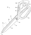
도 1은 완전히 폐쇄된 상태로 도시된, 본 발명에 따른 시저스 또는 가위의 좌측 사시도이다;
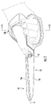
도 2는 정상적인 사용 동안 손의 손가락의 위치를 팬텀 윤곽으로 나타내는, 도 1에 도시된 시저스 또는 가위의 좌측면도이다;
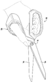
도 3은 시저스 또는 가위가 부분적으로 개방된 상태에 있을 때 도 2와 유사하다;
도 4는 도 1 내지 도 3에 도시된 시저스 또는 가위의 상단 평면도이다;
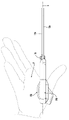
도 5는 엄지의 초기 삽입 동안 그리고 핸들의 파지 전에 손의 위치를 팬텀 윤곽으로 나타내는, 도 1 내지 도 4에 도시된 시저스 또는 가위의 하단 평면도이다;
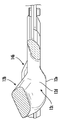
도 6은 상부 핑거 그립의 구성의 상세사항을 나타내는, 우측면에서 볼 때의, 확대된 부분도이다;
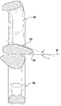
도 7은 라인(7-7)을 따라 취한, 도 6에 도시된 상부 핑거 그립의 단면도이다;
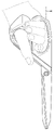
도 8은 무지구 및 손의 손바닥 표면에 관하여 배치되는 방식 및 상부 핑거 그립의 하부 구성을 예시하기 위해 분리된, 이전의 도면에 도시된 시저스 또는 가위의 하단 평면도이다;
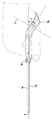
도 9는 도 2와 유사하고 핑거 그립 둘 다가 축 위에 그립 둘 다를 위치시키기 위해 축으로부터 각지게 오프셋되는 가위의 또 다른 실시형태를 도시한다;
도 10은 도 2 및 도 9와 유사하고 핑거 그립 둘 다가 축 위에 그립 둘 다를 위치시키기 위해 축으로부터 선형으로 오프셋되는 가위의 추가의 실시형태를 또한 도시한다; 그리고
도 11은 라인(11-11)을 따라 취한 도 2에 도시된 핑거 그립의 단면도이다.The above and other aspects, features and advantages of the present invention will become more apparent from the following description when considered in conjunction with the accompanying drawings:
1 is a left perspective view of a scissor or scissors according to the present invention, shown in a fully closed state;
Fig. 2 is a left side view of the scissor or scissors shown in Fig. 1, with a phantom outline showing the position of the fingers of the hand during normal use;
Fig. 3 is similar to Fig. 2 when the scissors or scissors are in a partially open state;
Fig. 4 is a top plan view of the scissors or scissors shown in Figs. 1-3;
Fig. 5 is a bottom plan view of the scissors or scissors shown in Figs.
Fig. 6 is an enlarged partial view, viewed from the right side, showing details of the construction of the upper finger grip;
FIG. 7 is a cross-sectional view of the upper finger grip shown in FIG. 6 taken along line 7-7;
8 is a bottom plan view of the scissors or scissors shown in the previous figures, separated to illustrate the lower configuration of the upper finger grip and the manner in which it is positioned relative to the palm surface of the thumb and hand;
Fig. 9 is similar to Fig. 2 and shows another embodiment of a scissors in which both finger grips are angularly offset from the axis to position both grips on the axis;
Fig. 10 is similar to Figs. 2 and 9 and also shows a further embodiment of the scissors in which both finger grips are linearly offset from the axis to position both grips on the axis; and
11 is a cross-sectional view of the finger grip shown in FIG. 2 taken along line 11-11.
동일하거나 또는 유사한 부분이 전반에 걸쳐 동일한 참조 부호로 표기되는 도면을 이제 구체적으로 참조하면 그리고 먼저 도 1을 참조하면, 시저스, 가위, 손가위 또는 다른 유사 절단 기구가 일반적으로 참조 부호(10)으로 표기된다. 모든 이러한 절단 도구는 본 명세서에서 "가위"로서 집합적으로 지칭될 것이다.Referring now specifically to the drawings in which like or similar parts are denoted by the same reference numerals throughout, and with reference first to FIG. marked All such cutting tools will be referred to collectively herein as “scissors”.
가위(10)는 선회점을 형성하는 선회부(16)에서 서로 연결된 2개의 지렛대(12, 14)를 포함한다. 지렛대는 실질적으로 평행한 블레이드(12a, 14a)를 형성한다. 블레이드(12, 14)는 중앙 절단면(CP)을 획정하고 절단면 내 개방된 위치와 폐쇄된 위치 간에 선회부(16)를 중심으로 선회 가능하게 이동 가능하다. 폐쇄된 위치에서, 블레이드(12, 14)는 선회부(16)와 함께 라인 또는 길이방향 축(A)을 획정한다.
각각의 지렛대는 핑거 그립과 함께 선회부(16)에 대한 근위 단부에서 형성된다. 제1 핑거 그립(12b)은 라인 또는 축(A) 위에 형성된 상단 또는 상부 핑거 그립이다. 제1 또는 상부 핑거 그립은 라인 또는 축(A) 위에 형성되고 블레이드가 폐쇄될 때 라인 또는 축(A)과 대체로 평행한 방향을 따라 길이방향으로 연장되고 이와 가장 가까운 실질적으로 평평한 내면(12d)으로 형성된 하부 부분(12c)을 갖는다.Each lever is formed at the proximal end to the
제1 또는 상부 핑거 그립(12b)은 핑거 그립의 적어도 외부 우측부(12e)를 손의 손바닥(P)과 인접하거나 또는 접촉하게, 도 8에 가장 잘 도시된 바와 같이, 손의 무지구 주름(TC)을 넘어 손의 손바닥 주름(PC1 및 PC2) 중 적어도 하나의 구역으로 위치시키는 동안 상부 핑거 그립(12b)의 일반적으로 평평한 내면(12d)에 대해 인접하게 손의 무지구(TE)를 위치시키게 하기 위해 그리고 엄지가 절단면(CP)과 실질적으로 평행한 배향으로 좌측면 상의 위치로 이동되게 하기 위해 모지구를 수용하기 위해 그리고 우측면으로부터 핑거 그립(12b)을 통해 도 5 및 도 8에 가장 잘 도시된 바와 같이, 모지구 또는 무지구(TE)를 수용하기 위해 우측면으로부터 상부 핑거 그립(12b)을 통한 엄지 중수골의 실질적으로 완전한 삽입을 허용하도록 치수가 결정되고 구성된다.The first or
도 1 내지 도 8에 도시된 실시형태에서, 제2 또는 하부 핑거 그립(14b)은 라인 또는 축(A) 아래에 배치되고 도 2 및 도 3에 도시된 바와 같이 다른 4개의 손가락 또는 손의 다른 4개의 손가락 중 적어도 일부에 의해 파지되도록 구성되고 치수가 결정된다. 그러나, 축(A)에 대한 핑거 그립의 위치는 중요하지 않고 축으로부터 각지게 또는 선형으로 오프셋될 수 있다. 예를 들어, 핑거 그립 둘 다가 축으로부터 각지게 오프셋되어 축 위에 핑거 그립 둘 다를 위치시키는 도 9, 및 핑거 그립 둘 다가 축으로부터 선형으로 오프셋되어 축 위에 핑거 그립 둘 다를 다시 위치시키는 도 10을 참조한다. 오프셋은 축 아래에 핑거 그립을 위치시킬 수 있고 도 9 및 도 10에 도시된 오프셋과 반대인 오프셋으로부터 발생될 수 있고, 또한 선형 오프셋과 각 오프셋의 조합을 포함할 수 있다.1-8 , the second or
제1 또는 상부 핑거 그립(12b)은 바람직하게는 엄지가 블레이드(12a, 14a)와 실질적으로 정렬될 때, 엄지와 집게 손가락 간의 무지구 피막 공간 또는 피부 피막을 수용하기 위해, 좌측면 상에서, 평평한 내면(12d)의 연속인 선두 또는 원위 단부에서 함몰된 곡면(12f)으로 형성된 각 루프로서 구성된다.The first or upper finger grips 12b are preferably flat, on the left side, to accommodate the dermal capsule space or skin capsule between the thumb and forefinger when the thumb is substantially aligned with the
도 4를 참조하면, 상부 핑거 그립(12b)은 절단면(CP)으로부터 분기되거나 또는 각지게 오프셋되는 중심축(A') 또는 50° 내지 60°의 범위 내에 있는 각(θ)에서의 축(A)을 획정한다. 바람직하게는, 각(θ)은 대략 55°와 같다.Referring to FIG. 4 , the
내면(12d)이 도 11에 도시된 바와 같이, 실질적으로 평평해서 무지구 또는 모지구 및 모지구근에 걸쳐 균일하게 힘을 분포한다. 이 표면(12d)에서 임의의 중요한 만곡부 또는 피크를 갖는 일 없이, 모지구근 상의 힘 집중이 방지되어, 사용자에게 잠재적으로 상당한 통증을 방지한다. 또한, 도구를 더 인체 공학적으로 그리고 사용하기 편안하게 만들기 위해, 평평한 표면(12d)이 우측면으로부터 좌측면을 향하여 상향으로 다소 경사져서 상부 핑거 그립(12b)과 파지식으로 맞물리는 동안 손의 형상과 맞춰질 수 있다. 평평한 표면의 경사가 도 11에 가장 잘 도시되고 표면은 절단면(CP)에 실질적으로 법선인 평면(NP)에 대해 좌측으로부터 우측으로 하향으로 경사지게 도시된다. 경사각(γ)은 10° 내지 20°의 범위 내, 바람직하게는 15° 내지 17°의 범위 내이다.As shown in FIG. 11 , the
가위의 사용을 위한 준비 시, 도 5를 참조하면, 엄지가 상부 핑거 그립(12b)에 완전히 삽입되어 무지구(TE)가 실질적으로 평평한 표면(12d) 위에 놓이고 엄지가 블레이드(12a, 14a)와 실질적으로 정렬되는 도 8에 도시된 위치로 엄지가 이동될 수 있다. 일단 손가락이 파지 위치에 대해 구부러진다면, 우측 외부 측면 부분 또는 에지(12e)는 무지구 주름(TC)을 넘어 손바닥 표면(PS)과 인접하게 배치되고 손바닥 주름(PC1 및/또는 PC2)과 접촉한다. 중요하게는, 도 3에 도시된 위치에 있다면 엄지는 대항하는 엄지에 의해 인가된 굽힘 힘을 제거하거나 또는 상당히 감소시키는 동안 절단 방향을 주로 안정화시키고 가이드하거나 또는 하부 핑거 그립(14b)에 작용하는 다른 4개의 손가락의 압착 힘에 대항하는 역할을 하고, 이 힘은 손의 손바닥에 의해 흡수되거나 또는 이에 대항한다. 따라서, 모지구근은 가위의 작동 동안 구부러질 필요가 없지만 실질적으로 고정될 수 있어서, 엄지 상의 응력 및 압력을 상당히 감소시킨다. 설계는 인체 공학적일 뿐만 아니라 가위를 더 편안하게 하고 특히 장기적인 사용에 의한 피로를 방지하면서 또는 두꺼운 물질을 절단하는 동안 사용하기 쉽게 한다.In preparation for use of the scissors, with reference to FIG. 5 , the thumb is fully inserted into the
도 1 내지 도 8에 도시된 가위(10)가 상부 그립(12b)이 축(A) 위에 일반적으로 위치되고 하부 그립(14b)이 축 아래에 위치되는 가위를 도시하지만, 본 발명은 다른 구성된 가위, 시저스 또는 손가위와 함께 사용될 수 있다. 따라서, 도 9 및 도 10을 참조하면, 상부 그립과 하부 그립 둘 다가 축(A) 위에 위치되는 다른 흔한 구성의 가위가 예시된다. 모든 경우에서, 상부 그립(12b)에 대해 위에서 언급된 구성은 실질적으로 동일하다.Although the
전술한 내용은 본 발명의 원리의 예시로서만 고려된다. 게다가, 수많은 변경 및 변화가 당업자에게 손쉽게 발생할 것이기 때문에, 본 발명을 도시되고 설명된 정확한 구성 및 작동으로 제한하는 것이 바람직하지 않고, 따라서, 모든 적합한 변경 및 등가물이 본 발명의 범위 내에 속하는 것으로 재분류될 수 있다.The foregoing is considered only as illustrative of the principles of the invention. Moreover, since numerous modifications and variations will readily occur to those skilled in the art, it is not desirable to limit the invention to the precise construction and operation shown and described, and therefore, it is reclassified that all suitable modifications and equivalents fall within the scope of the invention. can be
Claims (20)
제1 지렛대 및 선회부에서 상기 제1 지렛대에 선회 가능하게 연결된 제2 지렛대로서, 각각의 지렛대는 개방된 위치로부터 폐쇄된 위치로 선회 가능하고, 블레이드는 각각의 지렛대 상에 형성되고, 상기 폐쇄된 위치의 상기 블레이드는 길이방향 축을 획정하는, 제1 지렛대 및 제2 지렛대; 및
상기 제1 지렛대 상에 형성된 제1 핑거 그립, 및 상기 제2 지렛대 상에 형성된 제2 핑거 그립으로서, 상기 제1 핑거 그립은 상기 사용자의 상기 엄지의 무지구를 수용하도록 구성된 실질적으로 평평한 내면을 포함하고, 상기 제2 핑거 그립은 상기 사용자의 적어도 하나의 손가락을 수용하도록 구성된 제2 내면을 획정하여, 상기 실질적으로 평평한 내면에 대한 상기 무지구 및 상기 제2 내면에 대한 상기 적어도 하나의 손가락의 결합된 압력은 상기 제1 지렛대 및 상기 제2 지렛대를 이들의 대응하는 폐쇄된 위치로 이동되게 하는, 제1 핑거 그립 및 제2 핑거 그립
을 포함하되;
상기 실질적으로 평평한 내면은 상기 제1 지렛대가 폐쇄된 위치에 있을 때 상기 길이방향 축과 대체로 평행하고 그로부터 오프셋되게 연장되는, 가위.A scissors for reducing stress on a user's thumb during operation of the scissors, comprising:
a first lever and a second lever pivotally connected to the first lever at the pivot, each lever pivotable from an open position to a closed position, a blade formed on each lever, the closed position being The blade in position includes a first lever and a second lever defining a longitudinal axis; and
a first finger grip formed on the first lever, and a second finger grip formed on the second lever, the first finger grip comprising a substantially flat inner surface configured to receive the thumb of the user and the second finger grip defines a second inner surface configured to receive at least one finger of the user, such that engagement of the thumb to the substantially flat inner surface and the at least one finger to the second inner surface the applied pressure causes the first and second levers to move to their corresponding closed positions.
including;
wherein the substantially flat inner surface extends generally parallel to and offset from the longitudinal axis when the first lever is in the closed position.
제1 지렛대 및 선회부에서 상기 제1 지렛대에 선회 가능하게 연결된 제2 지렛대로서, 각각의 지렛대는 개방된 위치로부터 폐쇄된 위치로 선회 가능하고, 블레이드는 각각의 지렛대 상에 형성되고, 상기 폐쇄된 위치의 상기 블레이드는 길이방향 축을 획정하는, 제1 지렛대 및 제2 지렛대; 및
상기 제1 지렛대 상에 형성된 제1 핑거 그립, 및 상기 제2 지렛대 상에 형성된 제2 핑거 그립으로서, 상기 제1 핑거 그립은 상기 사용자의 상기 엄지의 무지구를 수용하도록 구성된 실질적으로 평평한 내면을 포함하고, 상기 제2 핑거 그립은 상기 사용자의 적어도 하나의 손가락을 수용하도록 구성된 제2 내면을 획정하여, 상기 실질적으로 평평한 내면에 대한 상기 무지구 및 상기 제2 내면에 대한 상기 적어도 하나의 손가락의 결합된 압력은 상기 제1 지렛대 및 상기 제2 지렛대를 이들의 대응하는 폐쇄된 위치로 이동되게 하는, 제1 핑거 그립 및 제2 핑거 그립
을 포함하되;
상기 실질적으로 평평한 내면은 상기 제1 지렛대가 폐쇄된 위치에 있을 때 상기 길이방향 축과 대체로 평행하고 그로부터 오프셋되게 연장되고;
상기 제1 핑거 그립은 하부 부분을 더 포함하고, 상기 실질적으로 평평한 내면은 상기 하부 부분으로부터 형성되고, 상기 제2 핑거 그립은 제2 내면을 포함하고, 상기 제1 지렛대와 상기 제2 지렛대가 이들의 각각의 폐쇄된 위치에 있을 때 상기 실질적으로 평평한 내면과 상기 제2 내면은 서로 대체로 평행한, 가위.A scissors for reducing stress on a user's thumb during operation of the scissors, comprising:
a first lever and a second lever pivotally connected to the first lever at the pivot, each lever pivotable from an open position to a closed position, a blade formed on each lever, the closed position being The blade in position includes a first lever and a second lever defining a longitudinal axis; and
a first finger grip formed on the first lever, and a second finger grip formed on the second lever, the first finger grip comprising a substantially flat inner surface configured to receive the thumb of the user and the second finger grip defines a second inner surface configured to receive at least one finger of the user, such that engagement of the thumb to the substantially flat inner surface and the at least one finger to the second inner surface the applied pressure causes the first and second levers to move to their corresponding closed positions.
including;
the substantially flat inner surface extends generally parallel to and offset from the longitudinal axis when the first lever is in the closed position;
The first finger grip further comprises a lower portion, the substantially flat inner surface formed from the lower portion, the second finger grip comprising a second inner surface, wherein the first lever and the second lever wherein the substantially flat inner surface and the second inner surface are generally parallel to each other when in their respective closed positions.
상기 제2 핑거 그립은 적어도 하나의 손가락이 제2 개구를 통해 연장되게 하고 상기 가위의 작동 동안 제2 내면 상에 위치되게 하도록 구성된 상기 제2 개구를 획정하는, 가위.16. The method of claim 15, wherein: said first finger grip defines said first opening configured to allow said thumb to extend through said first opening such that said thumb-free surface of said thumb is positioned on said substantially flat inner surface during actuation;
wherein the second finger grip defines a second opening configured to allow at least one finger to extend through the second opening and to be positioned on a second inner surface during operation of the scissors.
상기 제1 핑거 그립은 손의 무지구 주름을 넘어 상기 손의 손바닥 주름을 향하여 상기 사용자의 상기 손의 손바닥에 인접하도록 구성되는 외부 우측부를 더 포함하고;
상기 제1 핑거 그립은 하부 부분을 더 포함하고, 상기 실질적으로 평평한 내면은 상기 하부 부분으로부터 형성되고, 상기 제2 핑거 그립은 제2 내면을 포함하고, 상기 제1 지렛대와 상기 제2 지렛대가 이들의 폐쇄된 위치로 이동될 때 상기 실질적으로 평평한 내면과 상기 제2 내면은 서로 대체로 평행하고;
상기 제1 핑거 그립은 상기 가위의 작동 동안 상기 엄지와 집게 손가락 간의 상기 손의 피막을 수용하도록 구성된 함몰된 곡면을 갖는, 가위.17. The method of claim 16, wherein: the first opening is defined by each loop of the first finger grip, and the substantially flat inner surface is formed on each loop;
the first finger grip further comprises an outer right portion configured to abut the palm of the user's hand beyond the palmar folds of the hand toward the palmar folds of the hand;
The first finger grip further comprises a lower portion, the substantially flat inner surface formed from the lower portion, the second finger grip comprising a second inner surface, wherein the first lever and the second lever the substantially flat inner surface and the second inner surface are generally parallel to each other when moved to the closed position of
wherein the first finger grip has a recessed curved surface configured to receive the encapsulation of the hand between the thumb and forefinger during actuation of the scissors.
Applications Claiming Priority (4)
| Application Number | Priority Date | Filing Date | Title |
|---|---|---|---|
| US17/184,935 US20220266462A1 (en) | 2021-02-25 | 2021-02-25 | Finger grip for shears |
| US17/184,935 | 2021-02-25 | ||
| US17/674,718 US20220266463A1 (en) | 2021-02-25 | 2022-02-17 | Finger grip for shears |
| US17/674,718 | 2022-02-17 |
Publications (1)
| Publication Number | Publication Date |
|---|---|
| KR20220121752A true KR20220121752A (en) | 2022-09-01 |
Family
ID=80446691
Family Applications (1)
| Application Number | Title | Priority Date | Filing Date |
|---|---|---|---|
| KR1020220025539A KR20220121752A (en) | 2021-02-25 | 2022-02-25 | Finger grip for shears |
Country Status (11)
| Country | Link |
|---|---|
| US (1) | US20220266463A1 (en) |
| EP (1) | EP4049814A1 (en) |
| JP (1) | JP2022130349A (en) |
| KR (1) | KR20220121752A (en) |
| CN (1) | CN114951805A (en) |
| AU (1) | AU2022201313A1 (en) |
| BR (1) | BR102022003730A2 (en) |
| CA (1) | CA3150184A1 (en) |
| MX (1) | MX2022002440A (en) |
| TR (1) | TR2022002556A2 (en) |
| TW (1) | TW202241672A (en) |
Families Citing this family (1)
| Publication number | Priority date | Publication date | Assignee | Title |
|---|---|---|---|---|
| US20230256630A1 (en) * | 2022-02-17 | 2023-08-17 | Michael H Panosian | Finger grip for shears |
Family Cites Families (55)
| Publication number | Priority date | Publication date | Assignee | Title |
|---|---|---|---|---|
| US968A (en) | 1838-10-08 | Jedutha | ||
| US760A (en) | 1838-05-30 | Facing iron with steel for sleigh-runners and tires for wheels | ||
| US204A (en) | 1837-05-22 | Construction of and mode of | ||
| US2563461A (en) * | 1951-08-07 | Shears | ||
| US219A (en) | 1837-06-03 | Mode of dipping or charging locofoco matches | ||
| US454735A (en) | 1891-06-23 | Shears | ||
| US85500A (en) * | 1868-12-29 | Improvement in hand-shears | ||
| US3861038A (en) * | 1973-10-25 | 1975-01-21 | Wesley N Charles | Shears |
| US3869792A (en) * | 1974-01-28 | 1975-03-11 | Italo Marco Levi Laurenti | Finger grip-contoured molded scissors |
| US3971131A (en) * | 1975-05-27 | 1976-07-27 | The Stanley Works | Straight pattern snips |
| USD245569S (en) * | 1975-09-29 | 1977-08-30 | Cooper Industries | Shears |
| USD258560S (en) * | 1978-06-16 | 1981-03-17 | Stout Elizabeth E | Pattern cutting scissors with notched blades |
| USD258042S (en) * | 1978-08-17 | 1981-01-27 | Oy Fiskars Ab | Pinking shears |
| USD259853S (en) * | 1979-01-29 | 1981-07-14 | Kai Cutlery Center Co., Ltd. | Scissors |
| JPS55146058U (en) * | 1979-04-06 | 1980-10-20 | ||
| USD272227S (en) * | 1980-08-20 | 1984-01-17 | Oy Fiskars Ab | Scissors |
| USD282047S (en) * | 1983-03-11 | 1986-01-07 | Vicom Italiana Di Nave Libero | Scissor |
| US4635363A (en) | 1984-06-29 | 1987-01-13 | Cooper Industries, Inc. | Hand operated cutting tool |
| USD301678S (en) * | 1986-08-22 | 1989-06-20 | Fiskars Oy Ab | Scissors |
| USD307233S (en) * | 1987-02-02 | 1990-04-17 | Cooper Industries, Inc. | Scissors |
| US4742617A (en) * | 1987-05-28 | 1988-05-10 | Gauvry Glenn A | Scissors having an obliquely oriented thumb loop with limited dampened flexibility |
| USD319942S (en) * | 1989-02-21 | 1991-09-17 | Zoltan Schubert | Scissors |
| US5279034A (en) * | 1992-12-01 | 1994-01-18 | The Caper Company | Scissors |
| USD380657S (en) * | 1995-11-27 | 1997-07-08 | Fiskars Inc. | Scissors |
| USD398826S (en) * | 1996-09-26 | 1998-09-29 | Manufacture D'Articles De Precision Et De Dessin | Scissors |
| USD398210S (en) * | 1997-05-13 | 1998-09-15 | Clover Mfg. Co., Ltd. | Pair of scissors |
| USD404624S (en) * | 1998-05-04 | 1999-01-26 | Market USA Promotional Marketing, Inc. | Scissors handle |
| USD409064S (en) * | 1998-09-03 | 1999-05-04 | Heritage Cutlery, Inc. | Pair of scissors |
| USD432378S (en) * | 1999-03-09 | 2000-10-24 | Manufacture Articles de Precision | Scissors |
| USD421375S (en) * | 1999-05-25 | 2000-03-07 | Fiskars Inc. | Softgrip pinker |
| US6158128A (en) * | 1999-07-19 | 2000-12-12 | Huff; Bernard G. | Meat and poultry scissors |
| USD472121S1 (en) * | 2002-05-31 | 2003-03-25 | Wolff Industries | Scissors handle |
| US20060064879A1 (en) * | 2004-09-30 | 2006-03-30 | Lauritzen Pamela S | Adjustable ergonomic scissors |
| USD566501S1 (en) * | 2006-04-05 | 2008-04-15 | Allesandro De Stefano | Scissors |
| US7966733B2 (en) * | 2007-01-19 | 2011-06-28 | Dong Ho Jun | Scissors with a ringlet |
| USD565373S1 (en) * | 2007-02-08 | 2008-04-01 | Wki Holding Company, Inc. | Scissors |
| US20090247315A1 (en) * | 2008-03-26 | 2009-10-01 | Andrew Kossowsky | Golf putter construction and method for use thereof |
| TW201119814A (en) | 2009-12-08 | 2011-06-16 | Nusharp Inc | Grip structure for a pair of scissors |
| US8726522B2 (en) * | 2010-10-04 | 2014-05-20 | Nusharp Inc. | Pair of scissors with an open second handle |
| USD722852S1 (en) * | 2012-06-26 | 2015-02-24 | Fiskars Home Oy Ab | Scissors |
| USD677539S1 (en) * | 2012-08-07 | 2013-03-12 | Fiskars Brands, Inc. | Scissor handles |
| USD684027S1 (en) * | 2012-08-07 | 2013-06-11 | Fiskars Brands, Inc. | Scissor handles |
| JP6070276B2 (en) * | 2013-03-01 | 2017-02-01 | コクヨ株式会社 | Bags, handles, and tools |
| US20140360025A1 (en) * | 2013-06-06 | 2014-12-11 | Milwaukee Electric Tool Corporation | Scissors |
| WO2015068262A1 (en) * | 2013-11-08 | 2015-05-14 | 株式会社ヒカリ | Scissors |
| USD718592S1 (en) * | 2014-01-27 | 2014-12-02 | Fiskars Brands, Inc. | Set of handles for a cutting instrument |
| USD739197S1 (en) * | 2014-02-28 | 2015-09-22 | Acme United Corporation | Scissors |
| JP1522948S (en) * | 2014-10-15 | 2015-05-11 | ||
| US10682557B2 (en) * | 2015-09-29 | 2020-06-16 | Lateral Line, LLC. | Golf putter grip and golf putter incorporating same |
| WO2017099760A1 (en) * | 2015-12-09 | 2017-06-15 | Fiskars Brands, Inc. | Cutting tool with a flat force profile |
| USD787286S1 (en) * | 2015-12-14 | 2017-05-23 | Fiskars Brands, Inc. | Scissors |
| USD786041S1 (en) * | 2016-02-16 | 2017-05-09 | Fiskars Brands, Inc. | Cutting device |
| US11235399B2 (en) * | 2016-08-23 | 2022-02-01 | Stanley Black & Decker, Inc. | Metal snips |
| USD889226S1 (en) * | 2018-07-23 | 2020-07-07 | Yangchun Xinyi Scissors Factory Co., Ltd. | Scissors |
| USD892581S1 (en) * | 2020-04-21 | 2020-08-11 | Fiskars Finland Oy Ab | Scissor handle |
-
2022
- 2022-02-17 US US17/674,718 patent/US20220266463A1/en not_active Abandoned
- 2022-02-23 EP EP22158121.8A patent/EP4049814A1/en active Pending
- 2022-02-24 TR TR2022/002556A patent/TR2022002556A2/en unknown
- 2022-02-24 TW TW111106774A patent/TW202241672A/en unknown
- 2022-02-25 CA CA3150184A patent/CA3150184A1/en active Pending
- 2022-02-25 AU AU2022201313A patent/AU2022201313A1/en not_active Abandoned
- 2022-02-25 JP JP2022027425A patent/JP2022130349A/en active Pending
- 2022-02-25 KR KR1020220025539A patent/KR20220121752A/en not_active Application Discontinuation
- 2022-02-25 BR BR102022003730-2A patent/BR102022003730A2/en not_active Application Discontinuation
- 2022-02-25 CN CN202210176233.1A patent/CN114951805A/en active Pending
- 2022-02-25 MX MX2022002440A patent/MX2022002440A/en unknown
Also Published As
| Publication number | Publication date |
|---|---|
| JP2022130349A (en) | 2022-09-06 |
| MX2022002440A (en) | 2022-08-26 |
| BR102022003730A2 (en) | 2022-09-06 |
| CA3150184A1 (en) | 2022-08-25 |
| TR2022002556A2 (en) | 2022-09-21 |
| CN114951805A (en) | 2022-08-30 |
| TW202241672A (en) | 2022-11-01 |
| AU2022201313A1 (en) | 2022-09-08 |
| US20220266463A1 (en) | 2022-08-25 |
| EP4049814A1 (en) | 2022-08-31 |
Similar Documents
| Publication | Publication Date | Title |
|---|---|---|
| US8726522B2 (en) | Pair of scissors with an open second handle | |
| US7930804B2 (en) | Implement handle | |
| US5279034A (en) | Scissors | |
| US4635363A (en) | Hand operated cutting tool | |
| US20050267519A1 (en) | Handle for forceps/tweezers and method and apparatus for designing the like | |
| US20020023359A1 (en) | Ergonomic poultry knife | |
| KR20220121752A (en) | Finger grip for shears | |
| US20110131813A1 (en) | Grip structure for a pair of scissors | |
| KR20220121749A (en) | Finger grip for shears | |
| US20220266462A1 (en) | Finger grip for shears | |
| KR940005944B1 (en) | Ergonomic knife | |
| US20230256630A1 (en) | Finger grip for shears | |
| RU2813072C2 (en) | Universal scissors (variants) | |
| EP4049813A1 (en) | Finger grip for shears | |
| RU2813080C2 (en) | Universal scissors (variants) | |
| NZ785567A (en) | Finger Grip for Shears | |
| NZ785566A (en) | Finger Grip for Shears | |
| RU2813071C2 (en) | Pair of universal scissors (variants) and pair of household scissors | |
| NZ785563A (en) | Finger Grip for Shears | |
| JP3213308U (en) | Improved structure of food cooking knife |
Legal Events
| Date | Code | Title | Description |
|---|---|---|---|
| E902 | Notification of reason for refusal |