KR20220119441A - Aerosol-generating system with ventilation chamber - Google Patents
Aerosol-generating system with ventilation chamber Download PDFInfo
- Publication number
- KR20220119441A KR20220119441A KR1020227025065A KR20227025065A KR20220119441A KR 20220119441 A KR20220119441 A KR 20220119441A KR 1020227025065 A KR1020227025065 A KR 1020227025065A KR 20227025065 A KR20227025065 A KR 20227025065A KR 20220119441 A KR20220119441 A KR 20220119441A
- Authority
- KR
- South Korea
- Prior art keywords
- aerosol
- generating
- ventilation
- generating article
- ventilation chamber
- Prior art date
Links
Images

Classifications
-
- A—HUMAN NECESSITIES
- A24—TOBACCO; CIGARS; CIGARETTES; SIMULATED SMOKING DEVICES; SMOKERS' REQUISITES
- A24F—SMOKERS' REQUISITES; MATCH BOXES; SIMULATED SMOKING DEVICES
- A24F40/00—Electrically operated smoking devices; Component parts thereof; Manufacture thereof; Maintenance or testing thereof; Charging means specially adapted therefor
- A24F40/40—Constructional details, e.g. connection of cartridges and battery parts
- A24F40/48—Fluid transfer means, e.g. pumps
-
- A—HUMAN NECESSITIES
- A24—TOBACCO; CIGARS; CIGARETTES; SIMULATED SMOKING DEVICES; SMOKERS' REQUISITES
- A24F—SMOKERS' REQUISITES; MATCH BOXES; SIMULATED SMOKING DEVICES
- A24F40/00—Electrically operated smoking devices; Component parts thereof; Manufacture thereof; Maintenance or testing thereof; Charging means specially adapted therefor
- A24F40/40—Constructional details, e.g. connection of cartridges and battery parts
-
- A—HUMAN NECESSITIES
- A24—TOBACCO; CIGARS; CIGARETTES; SIMULATED SMOKING DEVICES; SMOKERS' REQUISITES
- A24D—CIGARS; CIGARETTES; TOBACCO SMOKE FILTERS; MOUTHPIECES FOR CIGARS OR CIGARETTES; MANUFACTURE OF TOBACCO SMOKE FILTERS OR MOUTHPIECES
- A24D1/00—Cigars; Cigarettes
- A24D1/02—Cigars; Cigarettes with special covers
- A24D1/027—Cigars; Cigarettes with special covers with ventilating means, e.g. perforations
-
- A—HUMAN NECESSITIES
- A24—TOBACCO; CIGARS; CIGARETTES; SIMULATED SMOKING DEVICES; SMOKERS' REQUISITES
- A24D—CIGARS; CIGARETTES; TOBACCO SMOKE FILTERS; MOUTHPIECES FOR CIGARS OR CIGARETTES; MANUFACTURE OF TOBACCO SMOKE FILTERS OR MOUTHPIECES
- A24D1/00—Cigars; Cigarettes
- A24D1/04—Cigars; Cigarettes with mouthpieces or filter-tips
- A24D1/045—Cigars; Cigarettes with mouthpieces or filter-tips with smoke filter means
-
- A—HUMAN NECESSITIES
- A24—TOBACCO; CIGARS; CIGARETTES; SIMULATED SMOKING DEVICES; SMOKERS' REQUISITES
- A24D—CIGARS; CIGARETTES; TOBACCO SMOKE FILTERS; MOUTHPIECES FOR CIGARS OR CIGARETTES; MANUFACTURE OF TOBACCO SMOKE FILTERS OR MOUTHPIECES
- A24D1/00—Cigars; Cigarettes
- A24D1/20—Cigarettes specially adapted for simulated smoking devices
-
- A—HUMAN NECESSITIES
- A24—TOBACCO; CIGARS; CIGARETTES; SIMULATED SMOKING DEVICES; SMOKERS' REQUISITES
- A24D—CIGARS; CIGARETTES; TOBACCO SMOKE FILTERS; MOUTHPIECES FOR CIGARS OR CIGARETTES; MANUFACTURE OF TOBACCO SMOKE FILTERS OR MOUTHPIECES
- A24D3/00—Tobacco smoke filters, e.g. filter-tips, filtering inserts; Filters specially adapted for simulated smoking devices; Mouthpieces for cigars or cigarettes
- A24D3/04—Tobacco smoke filters characterised by their shape or structure
- A24D3/043—Tobacco smoke filters characterised by their shape or structure with ventilation means, e.g. air dilution
-
- A—HUMAN NECESSITIES
- A24—TOBACCO; CIGARS; CIGARETTES; SIMULATED SMOKING DEVICES; SMOKERS' REQUISITES
- A24D—CIGARS; CIGARETTES; TOBACCO SMOKE FILTERS; MOUTHPIECES FOR CIGARS OR CIGARETTES; MANUFACTURE OF TOBACCO SMOKE FILTERS OR MOUTHPIECES
- A24D3/00—Tobacco smoke filters, e.g. filter-tips, filtering inserts; Filters specially adapted for simulated smoking devices; Mouthpieces for cigars or cigarettes
- A24D3/17—Filters specially adapted for simulated smoking devices
-
- A—HUMAN NECESSITIES
- A24—TOBACCO; CIGARS; CIGARETTES; SIMULATED SMOKING DEVICES; SMOKERS' REQUISITES
- A24F—SMOKERS' REQUISITES; MATCH BOXES; SIMULATED SMOKING DEVICES
- A24F40/00—Electrically operated smoking devices; Component parts thereof; Manufacture thereof; Maintenance or testing thereof; Charging means specially adapted therefor
- A24F40/20—Devices using solid inhalable precursors
-
- A—HUMAN NECESSITIES
- A24—TOBACCO; CIGARS; CIGARETTES; SIMULATED SMOKING DEVICES; SMOKERS' REQUISITES
- A24F—SMOKERS' REQUISITES; MATCH BOXES; SIMULATED SMOKING DEVICES
- A24F40/00—Electrically operated smoking devices; Component parts thereof; Manufacture thereof; Maintenance or testing thereof; Charging means specially adapted therefor
- A24F40/40—Constructional details, e.g. connection of cartridges and battery parts
- A24F40/46—Shape or structure of electric heating means
-
- A—HUMAN NECESSITIES
- A24—TOBACCO; CIGARS; CIGARETTES; SIMULATED SMOKING DEVICES; SMOKERS' REQUISITES
- A24F—SMOKERS' REQUISITES; MATCH BOXES; SIMULATED SMOKING DEVICES
- A24F40/00—Electrically operated smoking devices; Component parts thereof; Manufacture thereof; Maintenance or testing thereof; Charging means specially adapted therefor
- A24F40/40—Constructional details, e.g. connection of cartridges and battery parts
- A24F40/48—Fluid transfer means, e.g. pumps
- A24F40/485—Valves; Apertures
Abstract
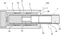
에어로졸 발생 물품(1) 및 에어로졸 발생 장치(20)를 포함하는 에어로졸 발생 시스템 (200)이 제공된다. 에어로졸 발생 물품은 에어로졸 형성 기재의 로드(12) 및 에어로졸 형성 기재의 로드의 하류에 위치된 필터(14-16-18)를 포함한다. 에어로졸 형성 기재의 로드 및 필터는 래퍼(22) 내에 조립된다. 에어로졸 발생 물품은 래퍼 상에 위치된 환기 구역(26)을 포함한다. 환기 구역은 래퍼를 통해 연장되는 복수의 애퍼처를 포함한다. 에어로졸 발생 장치는 원위 단부 및 마우스 단부(2)를 갖고, 하우징(4) 및 에어로졸 발생 물품이 장치 공동 내에 수용될 때 에어로졸 형성 기재를 가열하기 위한 히터를 포함한다. 하우징은 주변 벽을 포함한다. 주변 벽은 장치의 마우스 단부에서 에어로졸 발생 물품을 제거 가능하게 수용하기 위한 장치 공동을 정의한다. 에어로졸 발생 시스템은 에어로졸 발생 물품이 장치 공동 내에 수용될 때, 에어로졸 발생 물품의 환기 구역이 장치 공동 내에 위치되고, 환기 구역 위에 놓이는 주변 벽의 내부 표면의 일부가 에어로졸 발생 물품으로부터 이격되도록 구성된다.An aerosol-generating system (200) is provided comprising an aerosol-generating article (1) and an aerosol-generating device (20). The aerosol-generating article includes a rod 12 of the aerosol-forming substrate and a filter 14-16-18 positioned downstream of the rod of the aerosol-forming substrate. The rod and filter of the aerosol-forming substrate are assembled within the wrapper 22 . The aerosol-generating article includes a ventilation zone 26 located on the wrapper. The ventilation zone includes a plurality of apertures extending through the wrapper. The aerosol-generating device has a distal end and a mouth end 2 and includes a housing 4 and a heater for heating the aerosol-forming substrate when the aerosol-generating article is received within the device cavity. The housing includes a peripheral wall. The peripheral wall defines a device cavity for removably receiving an aerosol-generating article at a mouth end of the device. The aerosol-generating system is configured such that, when the aerosol-generating article is received within the device cavity, a ventilation zone of the aerosol-generating article is located within the device cavity, and a portion of the interior surface of a peripheral wall overlying the ventilation zone is spaced from the aerosol-generating article.
Description
본 발명은 에어로졸 발생 물품을 수용하도록 구성된 에어로졸 발생 장치를 포함하는 에어로졸 발생 시스템에 관한 것이다. 본 출원은 또한 환기 챔버를 갖는 에어로졸 발생 장치에 관한 것이다.The present invention relates to an aerosol-generating system comprising an aerosol-generating device configured to receive an aerosol-generating article. The present application also relates to an aerosol-generating device having a ventilation chamber.
담배 함유 기재 같은, 에어로졸 형성 기재가 연소되기보다는 가열되는 에어로졸 발생 물품이 당분야에 공지되어 있다. 통상적으로, 이러한 가열식 흡연 물품에서, 에어로졸은 열원으로부터 물리적으로 분리된 에어로졸 형성 기재 또는 재료로의 열 전달에 의해 발생되며, 이러한 기재 또는 재로는 열원과 접촉되게 위치하거나, 열원의 내부에 위치하거나, 열원의 주위에 위치하거나, 열원의 하류에 위치할 수 있다. 에어로졸 발생 물품의 사용 동안, 휘발성 화합물은 열원으로부터의 열 전달에 의해 에어로졸 형성 기재로부터 방출되고 에어로졸 발생 물품을 통해 흡인된 공기에 비말동반된다. 방출된 화합물이 냉각됨에 따라, 화합물은 응축되어 에어로졸을 형성한다.Aerosol-generating articles, such as tobacco-containing substrates, are known in the art in which an aerosol-forming substrate is heated rather than combusted. Typically, in such heated smoking articles, the aerosol is generated by heat transfer from a heat source to an aerosol-forming substrate or material that is physically separate, such substrate or ashes being placed in contact with the heat source, located inside the heat source, or It may be located around the heat source, or it may be located downstream of the heat source. During use of the aerosol-generating article, volatile compounds are released from the aerosol-forming substrate by heat transfer from a heat source and are entrained in the air drawn through the aerosol-generating article. As the released compound cools, the compound condenses to form an aerosol.
다수의 종래 기술 문헌에 에어로졸 발생 물품을 소모하기 위한 에어로졸 발생 장치가 개시되어 있다. 이러한 장치는, 예를 들어 에어로졸 발생 장치의 하나 이상의 전기 히터 요소로부터 가열식 에어로졸 발생 물품의 에어로졸 형성 기재로의 열 전달에 의해 에어로졸이 발생되는 전기 가열식 에어로졸 발생 장치를 포함한다.A number of prior art documents disclose aerosol-generating devices for consuming aerosol-generating articles. Such devices include, for example, electrically heated aerosol-generating devices in which an aerosol is generated by heat transfer from one or more electric heater elements of the aerosol-generating device to the aerosol-forming substrate of the heated aerosol-generating article.
그러나, 외부 래퍼 상에 환기 애퍼처('환기 구역'으로 지칭됨)를 갖는 에어로졸 발생 물품이 공지된 에어로졸 발생 장치 내에 수용될 때, 이러한 환기 애퍼처는 장치의 외부 환경에 노출될 수 있다. 장치 내의 물품의 사용 동안, 환기 애퍼처는 발생된 에어로졸의 온도를 감소시킬 수 있는 환기 기류뿐만 아니라, 소비자에게 전달될 물품을 통해 흐르는 에어로졸의 유익한 희석을 제공할 수 있다.However, when an aerosol-generating article having a ventilation aperture (referred to as a 'ventilation zone') on an outer wrapper is contained within a known aerosol-generating device, such ventilation aperture may be exposed to the environment outside of the device. During use of the article in the device, the ventilation aperture can provide a beneficial dilution of the aerosol flowing through the article to be delivered to the consumer, as well as a ventilation airflow that can reduce the temperature of the generated aerosol.
환기 애퍼처의 노출은 소비자가 에어로졸 발생 시스템의 정상적인 사용 동안 손가락 또는 입술로 물품의 환기 애퍼처를 부주의하게 차단하는 것을 초래할 수 있다. 결과적으로, 이러한 차단은 물품의 유효 흡인 저항을 증가시키고 최적의 에어로졸 형성 및 냉각을 방해함으로써 소비자의 감각적 경험에 영향을 미칠 수 있다. 따라서, 적어도 이러한 문제점을 처리하는 에어로졸 발생 시스템을 제공하는 것이 바람직할 것이다.Exposure of the ventilation aperture may result in a consumer inadvertently blocking the ventilation aperture of an article with a finger or lips during normal use of the aerosol-generating system. Consequently, such blocking can affect the sensory experience of the consumer by increasing the effective resistance to aspiration of the article and preventing optimal aerosol formation and cooling. Accordingly, it would be desirable to provide an aerosol-generating system that addresses at least this problem.
본 명세서에서, 에어로졸 발생 물품을 수용하도록 구성된 에어로졸 발생 장치가 제공된다. 에어로졸 발생 물품은 에어로졸 형성 기재의 로드를 포함할 수 있다. 에어로졸 발생 물품은 래퍼 내에 조립된 필터를 포함할 수 있다. 에어로졸 발생 물품은 래퍼 상에 위치된 환기 구역을 더 포함할 수 있다. 환기 구역은 래퍼를 통해 연장되는 복수의 애퍼처를 포함할 수 있다. 에어로졸 발생 장치는 원위 단부 및 마우스 단부를 가질 수 있다. 에어로졸 발생 장치는 하우징을 포함할 수 있다. 하우징은 장치의 마우스 단부에서 에어로졸 발생 물품을 제거 가능하게 수용하기 위한 장치 공동을 정의하는 주변 벽을 포함할 수 있다. 에어로졸 발생 장치는 에어로졸 발생 물품이 장치 공동 내에 수용될 때 에어로졸 형성 기재를 가열하기 위한 히터를 포함할 수 있다. 에어로졸 발생 장치는 에어로졸 발생 물품이 장치 공동 내에 수용될 때, 에어로졸 발생 물품의 환기 구역이 장치 공동 내에 위치되고, 환기 구역 위에 놓이는 주변 벽의 내부 표면의 일부가 에어로졸 발생 물품으로부터 이격되도록 구성될 수 있다.Provided herein is an aerosol-generating device configured to receive an aerosol-generating article. The aerosol-generating article may comprise a rod of an aerosol-forming substrate. The aerosol-generating article may include a filter assembled within a wrapper. The aerosol-generating article may further comprise a ventilation zone located on the wrapper. The ventilation zone may include a plurality of apertures extending through the wrapper. The aerosol-generating device may have a distal end and a mouth end. The aerosol-generating device may include a housing. The housing may include a peripheral wall defining a device cavity for removably receiving an aerosol-generating article at a mouth end of the device. The aerosol-generating device may include a heater for heating the aerosol-forming substrate when the aerosol-generating article is received within the device cavity. The aerosol-generating device may be configured such that, when the aerosol-generating article is received within the device cavity, a ventilation zone of the aerosol-generating article is located within the device cavity, and wherein a portion of an interior surface of a peripheral wall overlying the ventilation zone is spaced from the aerosol-generating article. .
본 발명에 따르면, 에어로졸 발생 물품 및 에어로졸 발생 장치를 포함할 수 있는 에어로졸 발생 시스템이 제공될 수 있다. 에어로졸 발생 물품은 에어로졸 형성 기재의 로드를 포함할 수 있다. 에어로졸 발생 물품은 에어로졸 형성 기재의 로드의 하류에 위치된 필터를 포함할 수 있다. 에어로졸 형성 기재의 로드 및 필터는 래퍼 내에 조립될 수 있다. 에어로졸 발생 물품은 래퍼 상에 위치된 환기 구역을 포함할 수 있다. 환기 구역은 래퍼를 통해 연장되는 복수의 애퍼처를 포함할 수 있다. 에어로졸 발생 장치는 원위 단부 및 마우스 단부를 가질 수 있다. 에어로졸 발생 장치는 하우징을 포함할 수 있다. 에어로졸 발생 장치는 에어로졸 발생 물품이 장치 공동 내에 수용될 때 에어로졸 형성 기재를 가열하기 위한 히터를 포함할 수 있다. 하우징은 주변 벽을 포함할 수 있다. 주변 벽은 장치의 마우스 단부에서 에어로졸 발생 물품을 제거 가능하게 수용하기 위한 장치 공동을 정의할 수 있다. 에어로졸 발생 시스템은 에어로졸 발생 물품이 장치 공동 내에 수용될 때, 에어로졸 발생 물품의 환기 구역이 장치 공동 내에 위치되고, 환기 구역 위에 놓이는 주변 벽의 내부 표면의 일부가 에어로졸 발생 물품으로부터 이격되도록 구성된다.According to the present invention, an aerosol-generating system may be provided which may comprise an aerosol-generating article and an aerosol-generating device. The aerosol-generating article may comprise a rod of an aerosol-forming substrate. The aerosol-generating article may include a filter positioned downstream of the rod of the aerosol-forming substrate. The rod and filter of the aerosol-forming substrate may be assembled into a wrapper. The aerosol-generating article may include a ventilation zone located on the wrapper. The ventilation zone may include a plurality of apertures extending through the wrapper. The aerosol-generating device may have a distal end and a mouth end. The aerosol-generating device may include a housing. The aerosol-generating device may include a heater for heating the aerosol-forming substrate when the aerosol-generating article is received within the device cavity. The housing may include a peripheral wall. The peripheral wall may define a device cavity for removably receiving an aerosol-generating article at a mouth end of the device. The aerosol-generating system is configured such that, when the aerosol-generating article is received within the device cavity, a ventilation zone of the aerosol-generating article is located within the device cavity, and a portion of the interior surface of a peripheral wall overlying the ventilation zone is spaced from the aerosol-generating article.
본 발명에 따르면, 에어로졸 발생 물품 및 에어로졸 발생 장치를 포함하는 에어로졸 발생 시스템이 제공된다. 에어로졸 발생 물품은 에어로졸 형성 기재의 로드 및 에어로졸 형성 기재의 로드에 하류에 위치된 필터를 포함한다. 에어로졸 형성 기재의 로드 및 필터는 래퍼 내에 조립된다. 에어로졸 발생 물품은 래퍼 상에 위치된 환기 구역을 포함한다. 환기 구역은 래퍼를 통해 연장되는 복수의 애퍼처를 포함한다. 에어로졸 발생 장치는 원위 단부 및 마우스 단부를 갖고, 하우징 및 에어로졸 발생 물품이 장치 공동 내에 수용될 때 에어로졸 형성 기재를 가열하기 위한 히터를 포함한다. 하우징은 주변 벽을 포함한다. 주변 벽은 장치의 마우스 단부에서 에어로졸 발생 물품을 제거 가능하게 수용하기 위한 장치 공동을 정의한다. 에어로졸 발생 시스템은 에어로졸 발생 물품이 장치 공동 내에 수용될 때, 에어로졸 발생 물품의 환기 구역이 장치 공동 내에 위치되고, 환기 구역 위에 놓이는 주변 벽의 내부 표면의 일부가 에어로졸 발생 물품으로부터 이격되도록 구성된다.According to the present invention, there is provided an aerosol-generating system comprising an aerosol-generating article and an aerosol-generating device. The aerosol-generating article comprises a rod of the aerosol-forming substrate and a filter positioned downstream of the rod of the aerosol-forming substrate. The rod and filter of the aerosol-forming substrate are assembled within a wrapper. The aerosol-generating article includes a ventilation zone located on the wrapper. The ventilation zone includes a plurality of apertures extending through the wrapper. The aerosol-generating device has a distal end and a mouth end and includes a housing and a heater for heating the aerosol-forming substrate when the aerosol-generating article is received within the device cavity. The housing includes a peripheral wall. The peripheral wall defines a device cavity for removably receiving an aerosol-generating article at a mouth end of the device. The aerosol-generating system is configured such that, when the aerosol-generating article is received within the device cavity, a ventilation zone of the aerosol-generating article is located within the device cavity, and a portion of the interior surface of a peripheral wall overlying the ventilation zone is spaced from the aerosol-generating article.
에어로졸 발생 시스템의 에어로졸 발생 장치는 에어로졸 발생 물품이 장치 공동 내에 수용될 때, 에어로졸 발생 물품의 환기 구역이 장치 공동 내에 위치되고, 환기 구역 위에 놓이는 주변 벽의 내부 표면의 일부가 에어로졸 발생 물품으로부터 이격되도록 구성될 수 있다.The aerosol-generating device of the aerosol-generating system is configured such that, when the aerosol-generating article is received within the device cavity, a ventilation zone of the aerosol-generating article is located within the device cavity, and a portion of the inner surface of a peripheral wall overlying the ventilation zone is spaced apart from the aerosol-generating article. can be configured.
에어로졸 발생 물품으로부터 환기 구역 위에 놓이는 주변 벽의 내부 표면의 일부를 제공함으로써, 에어로졸 발생 시스템의 사용 동안, 에어로졸 발생 물품의 환기 구역이 에어로졸 발생 장치의 하우징에 의해 덮이고 장치의 외부에 노출되지 않는 것이 보장된다.By providing a portion of the inner surface of the peripheral wall from the aerosol-generating article that overlies the ventilation zone, it is ensured that, during use of the aerosol-generating system, the ventilation zone of the aerosol-generating article is covered by the housing of the aerosol-generating device and is not exposed to the outside of the device. do.
추가적으로, 물품의 환기 구역으로부터 이격된 주변 벽의 내부 표면의 이러한 부분을 제공함으로써, 또한 공기 또는 에어로졸이 주변 벽의 내부 표면과 물품의 환기 구역 사이에서 흐를 수 있는 것이 보장한다. 이는 환기 구역이 소비자에 의해 가려지거나 차단되지 않고 물품에 환기를 제공하는 기능을 서빙할 수 있음을 의미한다.Additionally, by providing this portion of the inner surface of the peripheral wall spaced from the ventilation zone of the article, it is also ensured that air or aerosol can flow between the interior surface of the peripheral wall and the ventilation zone of the article. This means that the ventilation zone can serve the function of providing ventilation to the article without being obscured or blocked by the consumer.
에어로졸 발생 물품의 환기 구역으로부터 이격된 주변 벽의 내부 표면의 이러한 부분은 주변 벽의 내부 표면의 나머지 또는 다른 부분보다 에어로졸 발생 물품으로부터 더 이격된 주변 벽의 내부 표면의 부분을 지칭할 수 있다. 즉, 에어로졸 발생 물품의 환기 구역으로부터 이격된 주변 벽의 내부 표면의 이러한 부분은 주변 벽의 내부 표면의 나머지 또는 다른 부분보다 에어로졸 발생 물품으로부터 더 이격된 주변 벽의 내부 표면의 부분이다. 즉, 에어로졸 발생 물품의 환기 구역으로부터 이격된 주변 벽의 내부 표면의 이러한 부분은 주변 벽의 내부 표면의 나머지 또는 다른 부분보다 에어로졸 발생 물품으로부터 더 이격된 주변 벽의 내부 표면의 부분이다.This portion of the inner surface of the peripheral wall that is spaced from the ventilation zone of the aerosol-generating article may refer to the portion of the inner surface of the peripheral wall that is more spaced from the aerosol-generating article than the rest or other portions of the inner surface of the peripheral wall. That is, this portion of the inner surface of the peripheral wall that is spaced from the ventilation zone of the aerosol-generating article is the portion of the inner surface of the peripheral wall that is more spaced from the aerosol-generating article than the rest or other portions of the inner surface of the peripheral wall. That is, this portion of the inner surface of the peripheral wall that is spaced from the ventilation zone of the aerosol-generating article is the portion of the inner surface of the peripheral wall that is more spaced from the aerosol-generating article than the rest or other portions of the inner surface of the peripheral wall.
본원에서 사용되는 바와 같이, 용어 "에어로졸 발생 장치"는 에어로졸 발생 물품의 에어로졸 발생 기재와 상호작용하여 에어로졸을 발생시키는 히터 요소를 포함하는 장치를 지칭한다.As used herein, the term “aerosol-generating device” refers to a device comprising a heater element that interacts with the aerosol-generating substrate of an aerosol-generating article to generate an aerosol.
본원에서 사용되는 바와 같이, 용어 "길이방향"은 에어로졸 발생 물품 또는 에어로졸 발생 장치의 상류 단부와 하류 단부 사이에서 연장되는, 에어로졸 발생 물품 또는 장치의 주 길이방향 축에 대응하는 방향을 지칭한다.As used herein, the term “longitudinal” refers to a direction corresponding to the major longitudinal axis of the aerosol-generating article or device, extending between the upstream and downstream ends of the aerosol-generating article or device.
본원에서 사용되는 바와 같이, 용어 "상류" 및 "하류"는 에어로졸이 사용 동안 에어로졸 발생 물품을 통해 이송되는 방향에 대하여 에어로졸 발생 물품 또는 장치의 요소, 또는 요소의 부분의 상대적 위치를 설명한다.As used herein, the terms “upstream” and “downstream” describe the relative position of an element, or portion of an element, of an aerosol-generating article or device with respect to the direction in which the aerosol is transported through the aerosol-generating article during use.
사용 동안, 공기는 에어로졸 발생 물품을 통해 길이방향으로 흡인된다. 용어 "가로방향"은 길이방향 축에 수직인 방향을 지칭한다. 에어로졸 발생 물품 또는 에어로졸 발생 물품의 구성요소의 "단면"에 대한 임의의 언급은 달리 언급되지 않는 한 횡단면을 지칭한다.During use, air is drawn longitudinally through the aerosol-generating article. The term “transverse direction” refers to a direction perpendicular to the longitudinal axis. Any reference to “cross-section” of an aerosol-generating article or component of an aerosol-generating article refers to a cross-section unless otherwise stated.
용어 "길이"는 길이방향으로의 에어로졸 발생 물품 또는 장치의 구성요소의 치수를 나타낸다.The term “length” refers to the dimension of a component of an aerosol-generating article or device in the longitudinal direction.
본 명세서에서 사용되는 바와 같이, 용어 "균질화 담배 재료"는 담배 재료의 입자를 뭉쳐서 형성한 임의의 담배 재료를 포함한다. 균질화 담배 재료의 시트 또는 웹은 담배 잎몸(leaf lamina) 및 담배 잎자루(leaf stem) 중 하나 또는 둘 모두를 분쇄하거나 달리 분말화하여 얻어진 미립자 담배를 뭉침으로써 형성된다. 또한, 균질화 담배 재료는 담배의 처리, 취급 및 배송 동안에 형성된 담배 가루, 담배 미분 및 다른 미립자 담배 부산물 중 하나 이상을 미량으로 포함할 수 있다. 균질화 담배 재료의 시트는 캐스팅, 압출, 제지 공정 또는 당업계에 공지된 다른 임의의 적합한 공정에 의해 제조될 수 있다.As used herein, the term “homogenized tobacco material” includes any tobacco material formed by agglomerating particles of tobacco material. A sheet or web of homogenised tobacco material is formed by agglomerating particulate tobacco obtained by grinding or otherwise pulverizing one or both of tobacco leaf lamina and tobacco leaf stem. In addition, the homogenized tobacco material may include trace amounts of one or more of tobacco powder, tobacco fines, and other particulate tobacco by-products formed during the processing, handling and shipping of tobacco. Sheets of homogenised tobacco material may be made by casting, extrusion, papermaking processes, or any other suitable process known in the art.
용어 "다공성"은 재료를 통한 공기의 통과를 허용하는 복수의 기공 또는 개구를 제공하는 재료를 지칭하기 위해 본원에서 사용된다.The term “porous” is used herein to refer to a material that provides a plurality of pores or openings that allow passage of air through the material.
용어 "환기 수준(ventilation level)"은 환기 구역(환기 기류)을 통해 에어로졸 발생 물품 내로 진입된 기류와 에어로졸 기류 및 환기 기류의 합 사이의 체적비를 나타내도록 본 명세서 전반에 걸쳐 사용될 수 있다. 환기 수준이 높을수록, 소비자에게 전달되는 에어로졸 흐름이 더 많이 희석된다. 환기 수준은 그 자체로서, 즉, 에어로졸 형성 기재를 가열하도록 적응된 적합한 에어로졸 발생 장치 내에 에어로졸 발생 물품을 삽입하지 않고 에어로졸 발생 물품 상에서 측정된다.The term “ventilation level” may be used throughout this specification to refer to the volume ratio between the airflow entering an aerosol-generating article through a ventilation zone (ventilation airflow) and the sum of the aerosol airflow and the ventilation airflow. The higher the ventilation level, the more dilute the aerosol stream delivered to the consumer. The ventilation level is measured on an aerosol-generating article as such, ie without inserting the aerosol-generating article into a suitable aerosol-generating device adapted to heat the aerosol-forming substrate.
본 발명의 에어로졸 발생 물품은 에어로졸 형성 기재의 로드를 포함한다. 에어로졸 발생 물품은 에어로졸 형성 기재의 로드의 하류에 위치된 하류 섹션을 더 포함할 수 있다. 이러한 하류 섹션은 에어로졸 발생 물품의 필터로 간주될 수 있다. 필터(또는 물품의 하류 섹션), 또는 마우스피스 세그먼트는 여과 재료의 플러그, 및 에어로졸 형성 기재의 로드와 마우스피스 세그먼트 사이의 위치에 있는 중공 관형 세그먼트를 포함할 수 있다. 모든 3개의 요소는 바람직하게는 길이방향으로 정렬된다. 에어로졸 형성 기재의 로드는 바람직하게는 적어도 에어로졸 형성제를 포함한다. 일부 구현예에서, 본 발명에 따른 에어로졸 발생 물품은 에어로졸 형성 기재의 로드와 중공 관형 세그먼트 사이에 그리고 이와 길이방향 정렬로 배열된 추가 지지 요소(또는 지지 세그먼트)를 포함할 수 있다. 보다 상세하게, 지지 요소(또는 지지 세그먼트)는 바람직하게는 로드의 바로 하류에 그리고 중공 관형 요소(또는 세그먼트)의 바로 상류에 제공된다. 추가 지지 요소 또는 세그먼트는 관형일 수 있다.The aerosol-generating article of the present invention comprises a rod of an aerosol-forming substrate. The aerosol-generating article may further comprise a downstream section located downstream of the rod of the aerosol-forming substrate. This downstream section can be considered as a filter for the aerosol-generating article. The filter (or downstream section of the article), or mouthpiece segment, may include a plug of filtering material and a hollow tubular segment positioned between the rod of the aerosol-forming substrate and the mouthpiece segment. All three elements are preferably longitudinally aligned. The rod of the aerosol-forming substrate preferably comprises at least an aerosol former. In some embodiments, an aerosol-generating article according to the present invention may comprise an additional support element (or support segment) arranged between and in longitudinal alignment with the hollow tubular segment and the rod of the aerosol-forming substrate. More particularly, the support element (or support segment) is preferably provided immediately downstream of the rod and immediately upstream of the hollow tubular element (or segment). The additional support element or segment may be tubular.
에어로졸 발생 물품의 환기 구역은 물품을 따르는 임의의 위치에 위치될 수 있다. 환기 구역은 에어로졸 형성 기재의 로드의 하류의 위치에 위치될 수 있다. 환기 구역은 물품의 필터의 중공 관형 세그먼트 또는 물품의 마우스피스 세그먼트를 따르는 위치에 위치될 수 있다. 환기 구역은 물품의 필터의 여과 재료(또는 마우스피스 세그먼트)의 플러그를 따르는 위치에 위치될 수 있다.The ventilation zone of the aerosol-generating article may be located anywhere along the article. The ventilation zone may be located at a location downstream of the rod of the aerosol-forming substrate. The ventilation zone may be located at a location along the hollow tubular segment of the filter of the article or the mouthpiece segment of the article. The ventilation zone may be located at a location along the plug of filtration material (or mouthpiece segment) of the filter of the article.
표현 "~내에 수용된"은 구성요소 또는 요소가 다른 구성요소 또는 요소 내에 완전히 또는 부분적으로 수용된다는 사실을 지칭할 수 있다. 예를 들어, 표현 "에어로졸 발생 물품이 장치 공동 내에 수용된다"는 에어로졸 발생 물품이 에어로졸 발생 물품의 장치 공동 내에 완전히 또는 부분적으로 수용되는 것을 지칭한다. 에어로졸 발생 물품이 장치 공동 내에 수용될 때, 에어로졸 발생 물품은 장치 공동의 원위 단부와 접경할 수 있다. 에어로졸 발생 물품이 장치 공동 내에 수용될 때, 에어로졸 발생 물품은 장치 공동의 원위 단부에 실질적으로 근접할 수 있다. 장치 공동의 원위 단부는 단부 벽에 의해 정의될 수 있다.The expression “contained in” may refer to the fact that an element or element is fully or partially contained within another element or element. For example, the expression “an aerosol-generating article is contained within the device cavity” refers to the aerosol-generating article being completely or partially contained within the device cavity of the aerosol-generating article. When the aerosol-generating article is received within the device cavity, the aerosol-generating article may abut the distal end of the device cavity. When the aerosol-generating article is received within the device cavity, the aerosol-generating article may be substantially proximate to the distal end of the device cavity. The distal end of the device cavity may be defined by an end wall.
장치 공동의 길이는 약 10 mm 내지 약 50 mm일 수 있다. 장치 공동의 길이는 약 20 mm 내지 약 40 mm일 수 있다. 장치 공동의 길이는 약 25 mm 내지 약 30 mm일 수 있다.The length of the device cavity may be between about 10 mm and about 50 mm. The length of the device cavity may be from about 20 mm to about 40 mm. The length of the device cavity may be from about 25 mm to about 30 mm.
주변 벽의 내부 표면의 부분에 의해 정의된 공간은 주변 벽 내에 환기 챔버를 정의할 수 있다. 환기 챔버는 에어로졸 발생 장치의 외부 및 에어로졸 발생 물품의 환기 구역과 유체 연통하도록 구성될 수 있다. 바람직하게는, 환기 챔버는 주변 벽의 두께 내에 정의된다. 즉, 환기 챔버는 주변 벽의 내부 및 외부 길이방향 표면 사이의 위치에서, 주변 벽의 표면(예를 들어, 내부 또는 내부 표면) 상에 또는 주변 벽의 두께 내에 정의될 수 있다.A space defined by a portion of the inner surface of the peripheral wall may define a ventilation chamber within the peripheral wall. The ventilation chamber may be configured to be in fluid communication with the exterior of the aerosol-generating device and with a ventilation zone of the aerosol-generating article. Preferably, the ventilation chamber is defined within the thickness of the peripheral wall. That is, the ventilation chamber may be defined at a location between the inner and outer longitudinal surfaces of the perimeter wall, on a surface (eg, inner or inner surface) of the perimeter wall, or within the thickness of the perimeter wall.
에어로졸 발생 물품이 장치 공동 내에 수용될 때, 물품의 환기 구역은 장치 내에 정의된 환기 챔버와 정렬되고 이에 의해 둘러싸이도록 배열된다. 이는 에어로졸 발생 시스템의 정상적인 사용 동안, 환기 구역이 장치의 외부에 노출되지 않도록, 에어로졸 발생 물품의 환기 구역이 에어로졸 발생 장치의 하우징에 의해 덮이는 것을 보장한다. 또한, 공기 또는 에어로졸이 장치의 환기 챔버와 물품의 환기 구역 사이에서 흐를 수 있는 것이 보장된다. 이는 환기 구역이 정상적인 사용 동안 소비자의 입 또는 손가락에 의해 가려지거나 차단되지 않고 물품에 환기를 제공하는 기능을 서빙할 수 있는 것을 의미한다.When the aerosol-generating article is received within the device cavity, a ventilation zone of the article is arranged to align with and be surrounded by a ventilation chamber defined within the device. This ensures that, during normal use of the aerosol-generating system, the ventilation zone of the aerosol-generating article is covered by the housing of the aerosol-generating device so that the ventilation zone is not exposed to the outside of the device. It is also ensured that air or aerosol can flow between the ventilation chamber of the device and the ventilation zone of the article. This means that the ventilation zone can serve the function of providing ventilation to the article without being obscured or blocked by the consumer's mouth or fingers during normal use.
환기 챔버는 에어로졸 발생 장치의 마우스 단부에 인접할 수 있다. 환기 챔버는 에어로졸 발생 장치의 마우스 단부로부터 연장될 수 있다. 이러한 구현예에서, 환기 챔버는 에어로졸 발생 장치의 외부와 직접 유체 연통할 수 있다. 용어 "직접 유체 연통"은 유체(공기)가 환기 챔버와 연통하는 데 다른 요소 또는 기류 통로가 필요하지 않다는 사실을 지칭한다. 예를 들어, 환기 챔버가 에어로졸 발생 장치의 외부와 직접 유체 연통하는 것은 에어로졸 발생 장치의 외부로부터의 공기가 환기 챔버에 직접 진입하는 것을 의미한다. 즉, 공기가 환기 챔버를 빠져나오면, 이러한 공기는 에어로졸 발생 장치의 외부에 직접 도달할 것이다. 바람직하게는, 환기 챔버는 에어로졸 발생 장치의 마우스 단부를 통해 에어로졸 발생 장치의 외부와 유체 연통하도록 구성된다. 바람직하게는, 환기 챔버는 에어로졸 발생 장치의 마우스 단부 면을 통해 에어로졸 발생 장치의 외부와 유체 연통하도록 구성된다. 즉, 공기는, 바람직하게는 에어로졸 발생 장치의 마우스 단부 또는 마우스 단부 면을 통해 환기 챔버에 진입하도록 구성된다.The ventilation chamber may be adjacent the mouth end of the aerosol-generating device. The ventilation chamber may extend from the mouth end of the aerosol-generating device. In such embodiments, the ventilation chamber may be in direct fluid communication with the exterior of the aerosol-generating device. The term “direct fluid communication” refers to the fact that no other element or airflow passage is required for the fluid (air) to communicate with the ventilation chamber. For example, when the ventilation chamber is in direct fluid communication with the exterior of the aerosol-generating device, it means that air from the outside of the aerosol-generating device enters the ventilation chamber directly. That is, when air exits the ventilation chamber, this air will reach the outside of the aerosol-generating device directly. Preferably, the ventilation chamber is configured to be in fluid communication with the exterior of the aerosol-generating device through the mouth end of the aerosol-generating device. Preferably, the ventilation chamber is configured to be in fluid communication with the exterior of the aerosol-generating device through the mouth end face of the aerosol-generating device. That is, the air is preferably configured to enter the ventilation chamber through the mouth end or mouth end face of the aerosol-generating device.
환기 챔버를 마우스 단부에 인접하여 위치시키는 것은 물품이 환기 구역을 포함하면, 공기가 환기 챔버 내로 흐를 수 있어 에어로졸 발생 물품 및 그의 환기 구역과의 유체 연통을 제공하는 것을 보장한다. 환기 챔버는 2개의 단부, 즉 제1 단부 및 제2 단부를 포함할 수 있다. 환기 챔버의 제2 단부는 환기 챔버의 제1 단부보다 에어로졸 발생 장치의 마우스 단부에 더 가깝게 위치될 수 있다. 환기 챔버의 제2 단부 또는 근위 단부는 에어로졸 발생 장치의 마우스 단부에 위치될 수 있다. 이러한 구현예에서, 환기 챔버의 제2 단부는 개방될 수 있고, 환기의 제1 단부는 폐쇄될 수 있다. 개방되는 환기 챔버의 제2 단부는 공기가 환기 챔버에 쉽게 진입할 수 있게 하는 한편, 또한 정상적인 사용 동안 에어로졸 발생 물품의 환기 구역이 사용자로부터 은폐되는 것을 보장한다.Positioning the ventilation chamber adjacent the mouth end ensures that if the article includes a ventilation zone, air can flow into the ventilation chamber to provide fluid communication with the aerosol-generating article and its ventilation zone. The ventilation chamber may comprise two ends, a first end and a second end. The second end of the ventilation chamber may be located closer to the mouth end of the aerosol-generating device than the first end of the ventilation chamber. The second or proximal end of the ventilation chamber may be located at the mouth end of the aerosol-generating device. In this embodiment, the second end of the ventilation chamber may be open and the first end of the ventilation may be closed. The open second end of the ventilation chamber allows air to easily enter the ventilation chamber, while also ensuring that the ventilation zone of the aerosol-generating article is concealed from the user during normal use.
환기 챔버의 제2 단부가 에어로졸 발생 장치의 마우스 단부에 위치되지 않는 구현예에서, 환기 챔버의 제2 단부는 에어로졸 발생 장치의 마우스 단부(면)(또는 장치 공동의 개방 단부)로부터 적어도 약 1 mm에 위치될 수 있다. 환기 챔버의 제2 단부는 에어로졸 발생 장치의 마우스 단부 (면)로부터 적어도 약 2 mm에 위치될 수 있다. 환기 챔버의 제2 단부는 에어로졸 발생 장치의 마우스 단부 (면)로부터 적어도 약 3 mm에 위치될 수 있다.In embodiments where the second end of the ventilation chamber is not located at the mouth end of the aerosol-generating device, the second end of the ventilation chamber is at least about 1 mm from the mouth end (face) of the aerosol-generating device (or the open end of the device cavity). can be located in The second end of the ventilation chamber may be located at least about 2 mm from the mouth end (face) of the aerosol-generating device. The second end of the ventilation chamber may be located at least about 3 mm from the mouth end (face) of the aerosol-generating device.
환기 챔버의 제1 단부는 장치 공동의 원위 단부로부터 적어도 약 10 mm에 위치될 수 있다. 환기 챔버의 제1 단부는 장치 공동의 원위 단부로부터 적어도 약 20 mm에 위치될 수 있다. 환기 챔버의 제1 단부는 장치 공동의 원위 단부로부터 적어도 약 30 mm에 위치될 수 있다.The first end of the ventilation chamber may be located at least about 10 mm from the distal end of the device cavity. The first end of the ventilation chamber may be located at least about 20 mm from the distal end of the device cavity. The first end of the ventilation chamber may be located at least about 30 mm from the distal end of the device cavity.
용어 "마우스 단부"는 요소 또는 구성요소의 정상적인 사용 동안 사용자의 입 안에 또는 입 근처에 있도록 구성되는 요소 또는 구성요소의 부분을 지칭한다. 마우스 단부는 또한 하류 단부에 대응할 수 있다. 예를 들어, 에어로졸 발생 물품의 마우스 단부는 또한 물품의 하류 단부일 수 있다. 에어로졸 발생 물품 또는 장치의 마우스 단부는 정상적인 사용 동안 소비자의 입 안에 또는 입 근처에 배치되도록 구성된다. 에어로졸 발생 장치의 마우스 단부는 또한 에어로졸 발생 장치의 근위 단부로 지칭될 수 있다. 에어로졸 발생 장치의 마우스 단부는 에어로졸 발생 물품을 수용하도록 구성되는 에어로졸 발생 장치의 마우스 단부 면을 지칭할 수 있다. 따라서, 장치 공동의 개방 단부는 에어로졸 발생 장치의 마우스 단부 면에 정의될 수 있다.The term “mouse end” refers to a portion of an element or component that is configured to be in or near the mouth of a user during normal use of the element or component. The mouth end may also correspond to the downstream end. For example, the mouth end of an aerosol-generating article may also be a downstream end of the article. The mouth end of the aerosol-generating article or device is configured to be placed in or near the mouth of a consumer during normal use. The mouth end of the aerosol-generating device may also be referred to as the proximal end of the aerosol-generating device. The mouth end of the aerosol-generating device may refer to the mouth end face of the aerosol-generating device configured to receive an aerosol-generating article. Thus, the open end of the device cavity may be defined on the mouth end face of the aerosol-generating device.
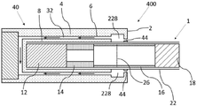
일부 구현예에서, 환기 챔버는 에어로졸 발생 장치의 마우스 단부로부터 떨어진 길이방향 위치에 위치될 수 있다.In some embodiments, the ventilation chamber may be located in a longitudinal position away from the mouth end of the aerosol-generating device.
표현 "에어로졸 발생 장치의 마우스 단부로부터 떨어진 길이방향 위치"는 본 맥락에서, 에어로졸 발생 장치의 마우스 단부에 위치되지 않는 길이방향 위치를 지칭한다. 따라서, 에어로졸 발생 장치의 마우스 단부로부터 떨어진 길이방향 위치는 에어로졸 발생 장치의 마우스 단부의 길이방향 위치와 상이한(또는 이로부터 간격을 둔) 길이방향 위치를 지칭한다.The expression “longitudinal position away from the mouth end of the aerosol-generating device” refers in this context to a longitudinal position which is not located at the mouth end of the aerosol-generating device. Thus, a longitudinal position away from the mouth end of the aerosol-generating device refers to a longitudinal position different from (or spaced from) the longitudinal position of the mouth end of the aerosol-generating device.
환기 챔버를 에어로졸 발생 장치의 마우스 단부로부터 떨어져서 제공함으로써, 환기 챔버는 장치의 공동 내에 수용되고 장치의 마우스 단부로부터 떨어진 에어로졸 발생 물품 주위에 공동 또는 공간을 형성할 수 있다. 에어로졸 발생 물품이 물품과 수용될 때, 이러한 환기 챔버는 에어로졸 발생 물품의 외부와 유체 연통한다. 에어로졸 발생 물품의 외부는 래퍼에 의해 정의될 수 있다. 래퍼는 다공성일 수 있다. 래퍼는 환기 챔버로부터의 공기가 에어로졸 발생 물품에 진입할 수 있도록 충분히 다공성일 수 있다. 공기가 진입하는 것을 허용함으로써, 환기 챔버는 물품의 냉각을 촉진할 수 있으며, 이는 물품 내의 에어로졸 입자의 핵 형성을 향상시킬 수 있다. 환기 챔버는 환기 챔버가, 에어로졸 발생이 발생하는 곳에 더 가깝게, 에어로졸 발생 물품의 더 상류 부분과 중첩될 가능성이 더 많기 때문에, 마우스 단부로부터 떨어진 길이방향 위치에 위치될 때, 핵 형성을 촉진할 가능성이 더 많을 수 있다. 따라서, 환기 챔버의 이러한 위치 설정은 소비자로의 에어로졸 전달을 개선할 수 있다.By providing the ventilation chamber away from the mouth end of the aerosol-generating device, the ventilation chamber may be received within the cavity of the device and define a cavity or space around the aerosol-generating article remote from the mouth end of the device. When the aerosol-generating article is received with the article, such ventilation chamber is in fluid communication with the exterior of the aerosol-generating article. The exterior of the aerosol-generating article may be defined by a wrapper. The wrapper may be porous. The wrapper may be sufficiently porous to allow air from the ventilation chamber to enter the aerosol-generating article. By allowing air to enter, the ventilation chamber can promote cooling of the article, which can enhance nucleation of aerosol particles within the article. The ventilation chamber is likely to promote nucleation when positioned in a longitudinal position away from the mouth end because the ventilation chamber is more likely to overlap with a more upstream portion of the aerosol-generating article, closer to where aerosol generation occurs. This could be more. Thus, such positioning of the ventilation chamber may improve aerosol delivery to the consumer.
이러한 구현예에서, 환기 챔버는 2개의 단부, 즉 제1 단부 및 제2 단부를 갖는다. 환기 챔버의 제2 단부는 환기 챔버의 제1 단부보다 장치의 마우스 단부에 더 가깝다. 이러한 구현예에서, 환기 챔버의 양 단부는 에어로졸 발생 장치의 마우스 단부로부터 떨어져 위치된다. 즉, 제2 단부는 장치의 마우스 단부에 위치되지 않는다.In this embodiment, the ventilation chamber has two ends, a first end and a second end. The second end of the ventilation chamber is closer to the mouth end of the device than the first end of the ventilation chamber. In this embodiment, both ends of the ventilation chamber are positioned away from the mouth end of the aerosol-generating device. That is, the second end is not located at the mouth end of the device.
이러한 구현예에서, 공기는 장치 공동 내에 수용되고, 장치의 환기 챔버와 마우스 단부 사이에서 연장될 때 주변 벽과 에어로졸 발생 물품 사이에 제공된 갭 또는 공간을 통해 장치의 외부로부터 환기 챔버로 흐를 수 있다.In such embodiments, air is received within the device cavity and can flow from the outside of the device to the ventilation chamber through a gap or space provided between the peripheral wall and the aerosol-generating article when extending between the ventilation chamber and the mouth end of the device.
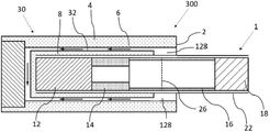
환기 챔버가 에어로졸 발생 장치의 마우스 단부로부터 떨어진 길이방향 위치에 위치되는 구현예에서, 환기 챔버는 하우징 내에 정의된 챔버 유입구를 통해 에어로졸 발생 장치의 외부와 유체 연통하도록 구성될 수 있다.In embodiments where the ventilation chamber is located in a longitudinal position away from the mouth end of the aerosol-generating device, the ventilation chamber may be configured to be in fluid communication with the exterior of the aerosol-generating device through a chamber inlet defined within the housing.
챔버 유입구는 장치 공동에 대한 별도의 요소일 수 있다. 즉, 챔버 유입구는 장치 공동에 의해 정의되지 않을 수 있고, 대신에 하우징 내에 정의될 수 있다. 챔버 유입구는 장치 공동을 정의하는 주변 벽 내에 정의될 수 있다. 바람직하게는, 챔버 유입구는 주변 벽의 두께 내에 또는 주변 벽 상에 정의된다. 즉, 챔버 유입구는 주변 벽의 내부 및 외부 길이방향 표면 사이의 위치에서, 주변 벽의 표면(예를 들어, 내부 또는 내부 표면) 상에 또는 주변 벽의 두께 내에 정의될 수 있다.The chamber inlet may be a separate element to the device cavity. That is, the chamber inlet may not be defined by the device cavity, but may instead be defined within the housing. The chamber inlet may be defined within a peripheral wall defining the device cavity. Preferably, the chamber inlet is defined in or on the peripheral wall thickness. That is, the chamber inlet may be defined at a location between the inner and outer longitudinal surfaces of the perimeter wall, on a surface (eg, inner or inner surface) of the perimeter wall, or within the thickness of the perimeter wall.
챔버 유입구는 에어로졸 발생 장치의 외부와 환기 챔버 사이의 유체 연통을 가능하게 한다. 이에 따라, 장치의 외부로부터의 공기는 장치 내에 수용될 때 에어로졸 발생 물품의 래퍼와 유체 연통할 수 있다. 이러한 유체 연통은 물품에서 발생된 에어로졸의 핵 형성 및 냉각을 촉진함으로써 에어로졸의 발생을 향상시킨다.The chamber inlet enables fluid communication between the exterior of the aerosol-generating device and the ventilation chamber. Accordingly, air from the outside of the device may be in fluid communication with the wrapper of the aerosol-generating article when received within the device. Such fluid communication enhances the generation of the aerosol by promoting nucleation and cooling of the aerosol generated in the article.
에어로졸 발생 물품이 래퍼 상에 환기 구역을 가질 때, 에어로졸 발생 장치의 외부로부터 챔버 유입구를 통해 환기 챔버로 유입되는 공기는 물품의 환기 구역을 통과할 수 있다. 이는 에어로졸 발생 물품을 위한 환기를 제공한다.When the aerosol-generating article has a ventilation zone on the wrapper, air entering the ventilation chamber from the outside of the aerosol-generating device through the chamber inlet may pass through the ventilation zone of the article. This provides ventilation for the aerosol-generating article.
또한, 환기 챔버가 에어로졸 발생 장치의 마우스 단부로부터 떨어진 길이방향 위치에 위치되는 구현예에서, 발생된 에어로졸은 환기 챔버 내에 축적될 수 있다. 에어로졸의 이러한 축적은 에어로졸의 보충 공급원을 제공함으로써 소비자의 경험을 향상시킬 수 있다. 소비자는 에어로졸의 이러한 보충 공급원을 흡인할 수 있다.Further, in embodiments where the ventilation chamber is located in a longitudinal position away from the mouth end of the aerosol-generating device, the generated aerosol may accumulate within the ventilation chamber. This accumulation of aerosol can enhance the consumer's experience by providing a supplemental source of aerosol. Consumers can inhale these supplemental sources of aerosols.
일부 구현예에서, 챔버 유입구는 에어로졸 발생 장치의 환기 챔버와 마우스 단부 사이에서 연장될 수 있다. 이는 공기가 챔버 유입구를 통해 장치의 외부로부터 환기 챔버로 흐를 수 있게 한다.In some embodiments, the chamber inlet may extend between the ventilation chamber and the mouth end of the aerosol-generating device. This allows air to flow from the outside of the device into the ventilation chamber through the chamber inlet.
챔버 유입구는 장치의 환기 챔버와 외부 사이의 유체 연결을 확립하기 위해 환기 챔버로부터 임의의 방향을 따라 연장될 수 있다. 챔버 유입구는 에어로졸 발생 장치의 길이방향 축에 평행한 방향을 따라 실질적으로 연장될 수 있다. 챔버 유입구는 에어로졸 발생 장치의 길이방향 축에 수직인 방향을 따라 실질적으로 연장될 수 있다.The chamber inlet may extend along any direction from the ventilation chamber to establish a fluid connection between the ventilation chamber and the exterior of the device. The chamber inlet may extend substantially along a direction parallel to the longitudinal axis of the aerosol-generating device. The chamber inlet may extend substantially along a direction perpendicular to the longitudinal axis of the aerosol-generating device.
챔버 유입구는 원형 단면을 가질 수 있다. 챔버 유입구는 환형 단면을 가질 수 있다. 챔버 유입구는 환형 섹터의 형상의 단면을 가질 수 있다. "환형 섹터"는 환형 형상 또는 고리의 부분 또는 섹션을 지칭한다.The chamber inlet may have a circular cross-section. The chamber inlet may have an annular cross-section. The chamber inlet may have a cross-section in the shape of an annular sector. “Annular sector” refers to a portion or section of an annular shape or ring.
챔버 유입구 및 환기 챔버는 동일한 단면 형상을 가질 수 있다. 예를 들어, 환기 챔버는 환형 형상일 수 있고, 챔버 유입구는 환형 형상일 수 있다. 예를 들어, 환기 챔버는 원형일 수 있고, 챔버 유입구는 또한 원형일 수 있다. 대안적으로, 챔버 유입구 및 환기 챔버는 상이한 단면 형상을 가질 수 있다. 예를 들어, 챔버 유입구는 원형일 수 있고, 환기 챔버는 환형일 수 있다.The chamber inlet and the ventilation chamber may have the same cross-sectional shape. For example, the ventilation chamber may be annular in shape and the chamber inlet may be annular in shape. For example, the ventilation chamber may be circular, and the chamber inlet may also be circular. Alternatively, the chamber inlet and ventilation chamber may have different cross-sectional shapes. For example, the chamber inlet may be circular and the ventilation chamber may be annular.
챔버 유입구는 환기 챔버의 단면적보다 더 작은 단면적을 가질 수 있다. 챔버 유입구의 단면적은 길이방향을 따라 변할 수 있다.The chamber inlet may have a cross-sectional area that is smaller than the cross-sectional area of the ventilation chamber. The cross-sectional area of the chamber inlet may vary along the longitudinal direction.
챔버 유입구는 원통 또는 원추 형상일 수 있다.The chamber inlet may be cylindrical or conical in shape.
챔버 유입구는 환기 챔버의 단면적의 약 75% 이하인 단면적을 가질 수 있다. 챔버 유입구는 환기 챔버의 단면적의 약 50% 이하인 단면적을 가질 수 있다. 챔버 유입구는 환기 챔버의 단면적의 약 25% 이하인 단면적을 가질 수 있다. 챔버 유입구는 환기 챔버의 단면적의 약 20% 이하인 단면적을 가질 수 있다. 챔버 유입구는 환기 챔버의 단면적의 약 10% 이하인 단면적을 가질 수 있다. 챔버 유입구는 환기 챔버의 단면적의 약 5% 이하인 단면적을 가질 수 있다.The chamber inlet may have a cross-sectional area that is less than or equal to about 75% of the cross-sectional area of the ventilation chamber. The chamber inlet may have a cross-sectional area that is less than or equal to about 50% of the cross-sectional area of the ventilation chamber. The chamber inlet may have a cross-sectional area that is less than or equal to about 25% of the cross-sectional area of the ventilation chamber. The chamber inlet may have a cross-sectional area that is less than or equal to about 20% of the cross-sectional area of the ventilation chamber. The chamber inlet may have a cross-sectional area that is less than or equal to about 10% of the cross-sectional area of the ventilation chamber. The chamber inlet may have a cross-sectional area that is less than or equal to about 5% of the cross-sectional area of the ventilation chamber.
챔버 유입구의 직경은 약 0.1 mm 이상일 수 있다. 챔버 유입구의 직경은 약 0.2 mm 이상일 수 있다. 챔버 유입구의 직경은 약 0.5 mm 이상일 수 있다.The diameter of the chamber inlet may be greater than or equal to about 0.1 mm. The diameter of the chamber inlet may be greater than or equal to about 0.2 mm. The diameter of the chamber inlet may be greater than or equal to about 0.5 mm.
챔버 유입구의 직경은 약 2 mm 이하일 수 있다. 챔버 유입구의 직경은 약 1.5 mm 이하일 수 있다. 챔버 유입구의 직경은 약 1 mm 이하일 수 있다.The diameter of the chamber inlet may be about 2 mm or less. The diameter of the chamber inlet may be about 1.5 mm or less. The diameter of the chamber inlet may be about 1 mm or less.
챔버 유입구의 직경은 약 0.1 mm 내지 약 2 mm일 수 있다. 챔버 유입구의 직경은 약 0.2 mm 내지 약 1.5 mm일 수 있다. 챔버 유입구의 직경은 약 0.5 mm 내지 약 1 mm일 수 있다.The diameter of the chamber inlet may be from about 0.1 mm to about 2 mm. The diameter of the chamber inlet may be from about 0.2 mm to about 1.5 mm. The diameter of the chamber inlet may be from about 0.5 mm to about 1 mm.
챔버 유입구의 직경 대 환기 챔버의 깊이의 비율은 약 30 이하일 수 있다. 챔버 유입구의 직경 대 환기 챔버의 깊이의 비율은 약 20 이하일 수 있다. 챔버 유입구의 직경 대 환기 챔버의 깊이의 비율은 약 15 이하일 수 있다.The ratio of the diameter of the chamber inlet to the depth of the ventilation chamber may be about 30 or less. The ratio of the diameter of the chamber inlet to the depth of the ventilation chamber may be about 20 or less. The ratio of the diameter of the chamber inlet to the depth of the ventilation chamber may be about 15 or less.
챔버 유입구의 직경 대 환기 챔버의 깊이의 비율은 약 2 이상일 수 있다. 챔버 유입구의 직경 대 환기 챔버의 깊이의 비율은 약 5 이상일 수 있다. 챔버 유입구의 직경 대 환기 챔버의 깊이의 비율은 약 10 이상일 수 있다.The ratio of the diameter of the chamber inlet to the depth of the ventilation chamber may be about two or more. The ratio of the diameter of the chamber inlet to the depth of the ventilation chamber may be about 5 or greater. The ratio of the diameter of the chamber inlet to the depth of the ventilation chamber may be about 10 or greater.
챔버 유입구의 직경 대 환기 챔버의 깊이의 비율의 범위는 약 2 내지 약 30일 수 있다. 챔버 유입구의 직경 대 환기 챔버의 깊이의 비율의 범위는 약 5 내지 약 20일 수 있다. 챔버 유입구의 직경 대 환기 챔버의 깊이의 비율의 범위는 약 10 내지 약 15일 수 있다.The ratio of the diameter of the chamber inlet to the depth of the ventilation chamber may range from about 2 to about 30. The ratio of the diameter of the chamber inlet to the depth of the ventilation chamber may range from about 5 to about 20. The ratio of the diameter of the chamber inlet to the depth of the ventilation chamber may range from about 10 to about 15.
환기 챔버의 깊이가 변하는 경우, 환기 챔버의 깊이는 환기 챔버의 평균 깊이를 지칭할 수 있다. 챔버 유입구의 직경이 변하는 경우, 챔버 유입구의 직경은 챔버 유입구의 평균 직경을 지칭할 수 있다.When the depth of the ventilation chamber varies, the depth of the ventilation chamber may refer to the average depth of the ventilation chamber. When the diameter of the chamber inlet varies, the diameter of the chamber inlet may refer to the average diameter of the chamber inlet.
챔버 유입구의 길이는 약 1 mm 이상일 수 있다. 챔버 유입구의 길이는 약 2 mm 이상일 수 있다. 챔버 유입구의 길이는 약 3 mm 이상일 수 있다.The length of the chamber inlet may be greater than or equal to about 1 mm. The length of the chamber inlet may be at least about 2 mm. The length of the chamber inlet may be at least about 3 mm.
챔버 유입구의 길이는 약 15 mm 이하일 수 있다. 챔버 유입구의 길이는 약 10 mm 이하일 수 있다. 챔버 유입구의 길이는 약 6 mm 이하일 수 있다. 챔버 유입구의 길이는 약 4 mm 이하일 수 있다.The length of the chamber inlet may be about 15 mm or less. The length of the chamber inlet may be about 10 mm or less. The length of the chamber inlet may be about 6 mm or less. The length of the chamber inlet may be about 4 mm or less.
챔버 유입구의 길이는 약 1 mm 내지 약 15 mm일 수 있다. 챔버 유입구의 길이는 약 1 mm 내지 약 6 mm일 수 있다. 챔버 유입구의 길이는 약 2 mm 내지 약 6 mm일 수 있다. 챔버 유입구의 길이는 약 3 mm 내지 약 4 mm일 수 있다.The length of the chamber inlet may be between about 1 mm and about 15 mm. The length of the chamber inlet may be from about 1 mm to about 6 mm. The length of the chamber inlet may be between about 2 mm and about 6 mm. The length of the chamber inlet may be from about 3 mm to about 4 mm.
챔버 유입구의 길이는 에어로졸 발생 장치의 마우스 단부로부터 환기 챔버의 거리를 정의할 수 있다.The length of the chamber inlet may define the distance of the ventilation chamber from the mouth end of the aerosol-generating device.
복수의 챔버 유입구가 있을 수 있다. 이러한 구현예에서, 챔버 유입구는 장치의 마우스 단부에서 균등하게 그리고 방경방향으로 분포될 수 있다.There may be a plurality of chamber inlets. In this embodiment, the chamber inlets may be evenly and radially distributed at the mouth end of the device.
일부 구현예에서, 환기 챔버를 정의하는 주변 벽의 부분의 두께는 주변 벽의 상이한 부분의 두께와 상이할 수 있다.In some embodiments, the thickness of the portion of the peripheral wall defining the ventilation chamber may be different from the thickness of a different portion of the peripheral wall.
일부 구현예에서, 환기 챔버를 정의하는 주변 벽의 부분의 두께는 주변 벽의 상이한 부분의 두께보다 더 작을 수 있다. 일부 구현예에서, 환기 챔버를 정의하는 주변 벽의 부분의 두께는 주변 벽의 나머지의 두께보다 더 작을 수 있다.In some embodiments, the thickness of the portion of the peripheral wall defining the ventilation chamber may be less than the thickness of a different portion of the peripheral wall. In some embodiments, the thickness of the portion of the peripheral wall defining the ventilation chamber may be less than the thickness of the remainder of the peripheral wall.
일부 구현예에서, 환기 챔버를 정의하는 주변 벽의 부분의 두께는 길이방향을 따라 변할 수 있다. 이러한 구현예에서, 환기 챔버를 정의하는 주변 벽의 부분은 에어로졸 발생 장치의 마우스 단부를 향해 감소될 수 있다. 이러한 구현예에서, 환기 챔버를 정의하는 주변 벽의 부분은 에어로졸 발생 장치의 마우스 단부를 향해 증가될 수 있다.In some embodiments, the thickness of the portion of the peripheral wall defining the ventilation chamber may vary along the longitudinal direction. In this embodiment, the portion of the peripheral wall defining the ventilation chamber may be reduced towards the mouth end of the aerosol-generating device. In this embodiment, the portion of the peripheral wall defining the ventilation chamber may be increased towards the mouth end of the aerosol-generating device.
주변 벽의 두께의 변화는 장치 공동의 주변 벽 내의 환기 챔버의 정의를 가능하게 한다. 이러한 두께 변화 또는 차이는 장치 내에 수용된 에어로졸 발생 물품과 장치 공동의 주변 벽 사이에 공간을 제공하며, 이는 결국 공기가 주변 벽과 수용된 물품 사이에서 흐를 수 있게 한다. 이는 환기 또는 냉각 효과를 에어로졸에 제공하기 위해 기류가 물품의 환기 구역 또는 래퍼에 도달할 수 있게 한다.Variation in the thickness of the peripheral wall enables the definition of a ventilation chamber within the peripheral wall of the device cavity. This thickness change or difference provides space between the aerosol-generating article contained within the device and the peripheral wall of the device cavity, which in turn allows air to flow between the peripheral wall and the contained article. This allows airflow to reach the ventilation zone or wrapper of the article to provide a ventilation or cooling effect to the aerosol.
환기 챔버는 환형일 수 있다. 환기 챔버는 장치 하우징의 주변 벽 내에 정의된 연속적인 환형 챔버일 수 있다. 이는 환기 챔버가 수용된 물품의 전체 래퍼 또는 환기 구역을 둘러싸도록 하며, 이에 따라 수용된 에어로졸 발생 물품의 환기 구역과 환기 챔버 사이의 중첩의 양을 최대화한다. 중첩의 양이 클수록, 장치 내에 수용된 에어로졸 발생 물품에 제공되는 환기가 더 크다. 추가적으로, 환형 환기 챔버는 간단하고 제조에 효율적일 수 있다.The ventilation chamber may be annular. The ventilation chamber may be a continuous annular chamber defined within the peripheral wall of the device housing. This allows the ventilation chamber to enclose the entire wrapper or ventilation area of the contained article, thus maximizing the amount of overlap between the ventilation area and the ventilation chamber of the contained aerosol-generating article. The greater the amount of overlap, the greater the ventilation provided to the aerosol-generating article contained within the device. Additionally, the annular ventilation chamber can be simple and efficient to manufacture.
환기 챔버는 정사각형 형상, 직사각형 형상 또는 삼각형 형상인 길이방향 단면을 가질 수 있다.The ventilation chamber may have a longitudinal cross-section that is square, rectangular or triangular in shape.
환기 챔버는 수용된 에어로졸 발생 물품의 래퍼 또는 환기 구역을 부분적으로 둘러싸는 환형 부분(또는 섹터)일 수 있다. 에어로졸 발생 장치는 복수의 환기 챔버를 포함할 수 있다. 이러한 복수의 환기 챔버는 상이한 길이방향 위치에 배열된 복수의 환기 챔버 또는 상이한 원주 위치에 배열된 복수의 환기 챔버를 포함할 수 있다.The ventilation chamber may be a wrapper of the contained aerosol-generating article or an annular portion (or sector) that partially surrounds the ventilation zone. The aerosol-generating device may comprise a plurality of ventilation chambers. Such a plurality of ventilation chambers may comprise a plurality of ventilation chambers arranged at different longitudinal positions or a plurality of ventilation chambers arranged at different circumferential positions.
환기 챔버의 길이는 약 8 mm 이하일 수 있다. 환기 챔버의 길이는 약 4 mm 이하일 수 있다. 환기 챔버의 길이는 약 3 mm 이하일 수 있다.The length of the ventilation chamber may be about 8 mm or less. The length of the ventilation chamber may be about 4 mm or less. The length of the ventilation chamber may be about 3 mm or less.
환기 챔버의 길이는 약 1 mm 이상일 수 있다. 환기 챔버의 길이는 약 2 mm 이상일 수 있다. 환기 챔버의 길이는 약 1 mm 이상일 수 있다.The length of the ventilation chamber may be at least about 1 mm. The length of the ventilation chamber may be at least about 2 mm. The length of the ventilation chamber may be at least about 1 mm.
환기 챔버의 길이는 약 1 mm 내지 약 8 mm일 수 있다. 환기 챔버의 길이는 약 2 mm 내지 약 4 mm일 수 있다. 환기 챔버의 길이는 약 3 mm 내지 약 4 mm일 수 있다.The length of the ventilation chamber may be from about 1 mm to about 8 mm. The length of the ventilation chamber may be from about 2 mm to about 4 mm. The length of the ventilation chamber may be from about 3 mm to about 4 mm.
환기 챔버의 길이는 장치 공동의 길이의 적어도 약 2.5%일 수 있다. 환기 챔버의 길이는 장치 공동의 길이의 적어도 약 5%일 수 있다. 환기 챔버의 길이는 장치 공동의 길이의 적어도 약 7.5%일 수 있다. 환기 챔버의 길이는 장치 공동의 길이의 적어도 약 10%일 수 있다.The length of the ventilation chamber may be at least about 2.5% of the length of the device cavity. The length of the ventilation chamber may be at least about 5% of the length of the device cavity. The length of the ventilation chamber may be at least about 7.5% of the length of the device cavity. The length of the ventilation chamber may be at least about 10% of the length of the device cavity.
환기 챔버의 길이는 장치 공동의 길이의 약 40% 미만일 수 있다. 환기 챔버의 길이는 장치 공동의 길이의 약 30% 미만일 수 있다. 환기 챔버의 길이는 장치 공동의 길이의 약 25% 미만일 수 있다. 환기 챔버의 길이는 장치 공동의 길이의 약 20% 미만일 수 있다. 환기 챔버의 길이는 장치 공동의 길이의 약 15% 미만일 수 있다.The length of the ventilation chamber may be less than about 40% of the length of the device cavity. The length of the ventilation chamber may be less than about 30% of the length of the device cavity. The length of the ventilation chamber may be less than about 25% of the length of the device cavity. The length of the ventilation chamber may be less than about 20% of the length of the device cavity. The length of the ventilation chamber may be less than about 15% of the length of the device cavity.
환기 챔버의 길이는 장치 공동의 길이의 약 2.5% 내지 약 40%일 수 있다. 환기 챔버의 길이는 장치 공동의 길이의 약 5% 내지 약 30%일 수 있다. 환기 챔버의 길이는 장치 공동의 길이의 약 7.5% 내지 약 25%일 수 있다.The length of the ventilation chamber may be from about 2.5% to about 40% of the length of the device cavity. The length of the ventilation chamber may be from about 5% to about 30% of the length of the device cavity. The length of the ventilation chamber may be from about 7.5% to about 25% of the length of the device cavity.
비교적 짧거나 작은 환기 챔버를 제공함으로써, 에어로졸 발생 물품과 에어로졸 발생 장치의 환기 챔버 사이에 비교적 짧거나 작은 중첩이 달성될 수 있다. 결과적으로, 에어로졸 발생 물품의 보다 표적화되고 국소화된 부분은 장치 내에 수용될 때 냉각되고, 따라서 환기 챔버에 진입하는 냉각 공기에서 기인하는 냉각 효과는 물품의 이러한 부분에 더 효과적일 수 있다.By providing a relatively short or small ventilation chamber, a relatively short or small overlap between the aerosol-generating article and the ventilation chamber of the aerosol-generating device can be achieved. Consequently, a more targeted and localized portion of the aerosol-generating article is cooled when received within the device, and thus the cooling effect resulting from the cooling air entering the ventilation chamber may be more effective on this portion of the article.
환기 챔버의 깊이는 환기 챔버가 장치 하우징의 주변 벽 내로 연장되는 반경방향 거리를 지칭한다. 환기 챔버의 깊이는 약 3 mm 이하일 수 있다. 환기 챔버의 깊이는 약 2 mm 이하일 수 있다. 환기 챔버의 깊이는 약 1.5 mm 이하일 수 있다.The depth of the ventilation chamber refers to the radial distance the ventilation chamber extends into the peripheral wall of the device housing. The depth of the ventilation chamber may be about 3 mm or less. The depth of the ventilation chamber may be about 2 mm or less. The depth of the ventilation chamber may be about 1.5 mm or less.
환기 챔버의 깊이는 약 0.5 mm 이상일 수 있다. 환기 챔버의 깊이는 약 1 mm 이상일 수 있다.The depth of the ventilation chamber may be at least about 0.5 mm. The depth of the ventilation chamber may be at least about 1 mm.
환기 챔버의 깊이는 약 0.5 mm 내지 약 3 mm일 수 있다. 환기 챔버의 깊이는 약 1 mm 내지 약 2 mm일 수 있다.The depth of the ventilation chamber may be from about 0.5 mm to about 3 mm. The depth of the ventilation chamber may be from about 1 mm to about 2 mm.
환기 챔버의 횡단면적은 약 5 평방 mm 이상일 수 있다. 환기 챔버의 횡단면적은 약 20 평방 mm 이상일 수 있다. 환기 챔버의 횡단면적은 약 50 평방 mm 이상일 수 있다. The cross-sectional area of the ventilation chamber may be at least about 5 square mm. The cross-sectional area of the ventilation chamber may be at least about 20 square mm. The cross-sectional area of the ventilation chamber may be at least about 50 square mm.
환기 챔버의 횡단면적은 약 275 평방 mm 이하일 수 있다. 환기 챔버의 횡단면적은 약 150 평방 mm 이하일 수 있다.The cross-sectional area of the ventilation chamber may be about 275 square mm or less. The cross-sectional area of the ventilation chamber may be less than or equal to about 150 square mm.
환기 챔버의 횡단면적은 약 5 평방 mm 내지 약 275 평방 mm일 수 있다. 환기 챔버의 횡단면적은 약 20 평방 mm 내지 약 150 평방 mm일 수 있다.The cross-sectional area of the ventilation chamber may be from about 5 square mm to about 275 square mm. The cross-sectional area of the ventilation chamber may be from about 20 square mm to about 150 square mm.
장치 하우징을 정의하는 에어로졸 발생 장치 하우징의 주변 벽의 두께는 약 1 mm 이상일 수 있다. 주변 벽의 두께는 약 2 mm 이상일 수 있다. 주변 벽의 두께는 약 3 mm 이상일 수 있다.The thickness of the peripheral wall of the aerosol-generating device housing defining the device housing may be at least about 1 mm. The thickness of the peripheral wall may be at least about 2 mm. The thickness of the peripheral wall may be at least about 3 mm.
장치 하우징을 정의하는 에어로졸 발생 장치 하우징의 주변 벽의 두께는 약 10 mm 이하일 수 있다. 주변 벽의 두께는 약 7.5 mm 이하일 수 있다. 주변 벽의 두께는 약 5 mm 이하일 수 있다.The thickness of the peripheral wall of the aerosol-generating device housing defining the device housing may be about 10 mm or less. The thickness of the peripheral wall may be about 7.5 mm or less. The thickness of the peripheral wall may be about 5 mm or less.
장치 하우징을 정의하는 에어로졸 발생 장치 하우징의 주변 벽의 두께는 약 1 mm 내지 약 10 mm일 수 있다. 주변 벽의 두께는 약 2 mm 내지 약 7.5 mm일 수 있다. 주변 벽의 두께는 약 3 mm 내지 약 5 mm일 수 있다.The thickness of the peripheral wall of the aerosol-generating device housing defining the device housing may be from about 1 mm to about 10 mm. The thickness of the peripheral wall may be from about 2 mm to about 7.5 mm. The thickness of the peripheral wall may be from about 3 mm to about 5 mm.
환기 챔버의 깊이는 주변 벽의 두께의 약 75% 이하일 수 있다. 환기 챔버의 깊이는 주변 벽의 두께의 약 50% 이하일 수 있다. 환기 챔버의 깊이는 주변 벽의 두께의 약 35% 이하일 수 있다.The depth of the ventilation chamber may be less than or equal to about 75% of the thickness of the peripheral wall. The depth of the ventilation chamber may be about 50% or less of the thickness of the peripheral wall. The depth of the ventilation chamber may be about 35% or less of the thickness of the peripheral wall.
환기 챔버의 깊이는 주변 벽의 두께의 약 10% 이상일 수 있다. 환기 챔버의 깊이는 주변 벽의 두께의 약 20% 이상일 수 있다. 환기 챔버의 깊이는 주변 벽의 두께의 약 25% 이상일 수 있다.The depth of the ventilation chamber may be at least about 10% of the thickness of the peripheral wall. The depth of the ventilation chamber may be at least about 20% of the thickness of the peripheral wall. The depth of the ventilation chamber may be at least about 25% of the thickness of the peripheral wall.
환기 챔버의 깊이는 주변 벽의 두께의 약 10% 내지 약 75%일 수 있다. 환기 챔버의 깊이는 주변 벽의 두께의 약 20% 내지 약 50%일 수 있다. 환기 챔버의 깊이는 주변 벽의 두께의 약 25% 내지 약 35%일 수 있다.The depth of the ventilation chamber may be from about 10% to about 75% of the thickness of the peripheral wall. The depth of the ventilation chamber may be from about 20% to about 50% of the thickness of the peripheral wall. The depth of the ventilation chamber may be from about 25% to about 35% of the thickness of the peripheral wall.
에어로졸 발생 장치는 에어로졸 발생 장치 내에 수용된 에어로졸 발생 물품을 추출하기 위한 추출기를 포함할 수 있으며, 추출기는 장치 공동 내에서 이동 가능하도록 구성된다.The aerosol-generating device may include an extractor for extracting an aerosol-generating article contained within the aerosol-generating device, wherein the extractor is configured to be movable within the device cavity.
추출기는 추출기가 작동 위치에 있을 때 환기 챔버를 노출시키도록 구성되며, 작동 위치는 에어로졸 발생 물품의 에어로졸 형성 기재와 접촉하는 히터에 의해 정의된다.The extractor is configured to expose the ventilation chamber when the extractor is in an actuation position, the actuation position being defined by a heater in contact with the aerosol-forming substrate of the aerosol-generating article.
추출기는 에어로졸 발생 물품을 수용하도록 구성된 리셉터클 몸체를 포함한다. 추출기의 리셉터클 몸체(추출기 몸체)는 단부 벽 및 주변 벽을 포함할 수 있다. 추출기의 리셉터클 몸체는 에어로졸 발생 물품이 수용될 수 있는 단부 벽에 대향하는 개방 단부를 포함한다. 에어로졸 발생 물품은 추출기 몸체 내에 수용되면 단부 벽과 접경하도록 구성된다. 리셉터클 몸체의 주변 벽은 추출기 내에 수용될 때 에어로졸 발생 물품을 둘러쌀 수 있다. 추출기가 존재하는 이러한 구현예에서, 추출기 몸체의 주변 벽은 환기 챔버를 정의할 수 있다. 대안적으로, 장치 하우징의 주변 벽은 환기 챔버를 정의할 수 있다.The extractor includes a receptacle body configured to receive an aerosol-generating article. The receptacle body (extractor body) of the extractor may include an end wall and a peripheral wall. The receptacle body of the extractor includes an open end opposite an end wall in which an aerosol-generating article can be received. The aerosol-generating article is configured to abut an end wall when received within the extractor body. A peripheral wall of the receptacle body may surround the aerosol-generating article when received within the extractor. In such embodiments where an extractor is present, the peripheral wall of the extractor body may define a ventilation chamber. Alternatively, the peripheral wall of the device housing may define a ventilation chamber.
추출기는 작동 위치에서, 리셉터클 몸체가 환기 챔버의 제1 단부와 장치 공동의 원위 단부 사이에서 연장되도록 크기를 가질 수 있다. 이는 환기 챔버와 에어로졸 발생 물품 사이의 유체 연통을 방해하는 추출기 몸체를 갖지 않고 에어로졸 발생 물품이 환기 챔버에 직접 노출될 수 있게 한다.The extractor may be sized such that, in the operative position, the receptacle body extends between the first end of the ventilation chamber and the distal end of the device cavity. This allows the aerosol-generating article to be exposed directly to the ventilation chamber without having an extractor body obstructing fluid communication between the ventilation chamber and the aerosol-generating article.
추출기는 작동 위치에서, 리셉터클 몸체가 장치 공동의 마우스 단부와 장치 공동의 원위 단부 사이에서 연장되도록 크기를 가질 수 있다. 이러한 구현예에서, 추출기 몸체는 삽입될 때 에어로졸 발생 물품에 환기 챔버의 노출을 허용하도록, 절개부 또는 복수의 절개부를 가질 수 있다. 추출기 몸체 및 장치 공동은 절개부, 또는 복수의 절개부의 사용 동안 환기 챔버, 또는 복수의 환기 챔버와의 정렬을 보장하도록 함께 구성될 수 있다. 예를 들어, 추출기 몸체는 에어로졸 발생 장치의 하우징 내에 위치된 슬롯 또는 홈과 협력하도록 배열된 돌기를 포함할 수 있다.The extractor may be sized such that, in the operative position, the receptacle body extends between a mouth end of the device cavity and a distal end of the device cavity. In such embodiments, the extractor body may have an incision or a plurality of incisions to allow exposure of the ventilation chamber to the aerosol-generating article when inserted. The extractor body and device cavity may be configured together to ensure alignment with the ventilation chamber, or plurality of ventilation chambers, during use of the incision, or plurality of incisions. For example, the extractor body may include a protrusion arranged to cooperate with a slot or groove located within the housing of the aerosol-generating device.
에어로졸 발생 장치는 에어로졸 발생 물품이 장치 공동 내에 수용될 때 에어로졸 발생 물품 내로 삽입되도록 배열된 세장형 히터를 포함할 수 있다. 세장형 히터는 장치 공동과 함께 배열될 수 있다. 세장형 히터는 공동 내로 연장될 수 있다. 대안적인 가열 배열이 이하에서 더 논의된다. 그러나, 히터가 장치 공동 내로 연장되는 이러한 구현예에서, 추출기 몸체는 히터가 에어로졸 발생 물품 내로 연장될 수 있도록 단부 벽에 애퍼처를 포함한다. 이러한 애퍼처는 공기가 추출기 공동의 내부에 진입하는 것을 허용할 수 있어, 공기는 사용 동안 에어로졸 발생 물품의 에어로졸 형성 기재의 로드를 통해 흐를 수 있다. 대안적으로, 공기가 추출기 공동의 내부에 진입할 수 있도록 추가 애퍼처가 제공될 수 있다.The aerosol-generating device may include an elongate heater arranged to be inserted into the aerosol-generating article when the aerosol-generating article is received within the device cavity. The elongate heater may be arranged with the device cavity. The elongate heater may extend into the cavity. Alternative heating arrangements are further discussed below. However, in such embodiments where the heater extends into the device cavity, the extractor body includes an aperture in the end wall to allow the heater to extend into the aerosol-generating article. Such apertures may allow air to enter the interior of the extractor cavity, such that air may flow through the rod of the aerosol-forming substrate of the aerosol-generating article during use. Alternatively, additional apertures may be provided to allow air to enter the interior of the extractor cavity.
일부 구현예에서, 추출기 몸체의 길이는 장치 공동의 길이 미만일 수 있다. 이러한 구현예에서, 추출기가 작동 위치에 있을 때(추출기가 장치 공동의 원위 단부와 접경할 때), 환기 챔버는 추출기를 둘러싸지 않는 장치 하우징의 주변 벽의 부분에 의해 정의될 수 있다. 주변 벽의 이러한 부분은 추출기가 작동 위치에 있을 때 환기 챔버를 정의한다. 효과적으로, 장치 하우징의 주변 벽의 상기 부분은 환기 챔버를 정의하기 위해 추출기를 지나 길이 방향으로 연장될 수 있다. 에어로졸 발생 물품과 장치 하우징의 주변 벽 사이의 간격 또는 갭은 환기 챔버를 정의한다.In some embodiments, the length of the extractor body may be less than the length of the device cavity. In this embodiment, when the extractor is in the operative position (when the extractor abuts the distal end of the device cavity), the ventilation chamber may be defined by the portion of the peripheral wall of the device housing that does not enclose the extractor. This portion of the peripheral wall defines a ventilation chamber when the extractor is in the operating position. Effectively, said portion of the peripheral wall of the device housing may extend longitudinally past the extractor to define a ventilation chamber. A gap or gap between the aerosol-generating article and the peripheral wall of the device housing defines a ventilation chamber.
기류 통로는 장치 공동 내에 수용된 에어로졸 발생 물품의 에어로졸 형성 기재와 에어로졸 발생 장치의 외부 사이의 유체 연통을 가능하게 하도록 정의될 수 있다. 이러한 기류 통로는 사용자가 에어로졸 발생 장치 내에서 가열되는 에어로졸 발생 물품을 퍼핑할 때 에어로졸 형성을 허용한다. 기류 통로로부터의 공기는 에어로졸 발생 물품의 상류 단부 내로 그리고 물품의 에어로졸 형성 기재를 통해 흐를 수 있다. 이러한 기류 통로는 에어로졸 발생 장치 내에 정의될 수 있다.The airflow passageway may be defined to enable fluid communication between the aerosol-forming substrate of an aerosol-generating article contained within the device cavity and the exterior of the aerosol-generating device. Such airflow passages allow for aerosol formation when a user puffs an aerosol-generating article that is heated within the aerosol-generating device. Air from the airflow passage may flow into the upstream end of the aerosol-generating article and through the aerosol-forming substrate of the article. Such airflow passages may be defined within the aerosol-generating device.
추출기가 제공되는 구현예에서, 기류 통로는 에어로졸 발생 장치 하우징의 주변 벽과 추출기의 외부 표면 사이에 정의될 수 있으며, 환기 챔버는 상기 기류 통로와 유체 연통한다.In embodiments in which an extractor is provided, an airflow passageway may be defined between a peripheral wall of the aerosol-generating device housing and an exterior surface of the extractor, with the ventilation chamber in fluid communication with the airflow passageway.
추출기가 제공되지 않는 구현예에서, 기류 통로는 에어로졸 발생 장치 하우징의 주변 벽의 두께 내에 정의될 수 있다. 기류 통로는 또한 환기 챔버와 유체 연통할 수 있다.In embodiments where no extractor is provided, the airflow passage may be defined within the thickness of the peripheral wall of the aerosol-generating device housing. The airflow passage may also be in fluid communication with the ventilation chamber.
에어로졸 발생 물품의 필터는 에어로졸 형성 기재의 로드의 하류에 배열된 여과 재료의 플러그를 포함하는 마우스피스 세그먼트; 및 마우스피스 세그먼트와 에어로졸 형성 기재의 로드 사이에 위치되는 중공 관형 세그먼트를 포함할 수 있으며, 환기 구역은 중공 관형 세그먼트의 상류 절반을 따르는 위치에 위치된다.The filter of the aerosol-generating article comprises a mouthpiece segment comprising a plug of filtration material arranged downstream of the rod of the aerosol-forming substrate; and a hollow tubular segment positioned between the mouthpiece segment and the rod of the aerosol-forming substrate, wherein the ventilation zone is positioned at a location along the upstream half of the hollow tubular segment.
용어 "상류 절반"은 요소의 상류 단부와 요소의 중간점 사이의 요소의 영역 또는 부분을 지칭한다.The term “upstream half” refers to the region or portion of an element between the upstream end of the element and the midpoint of the element.
에어로졸 발생 물품은 중공 관형 세그먼트의 상류 단부로부터 약 18 mm 미만의 중공 관형 세그먼트를 따르는 위치에 환기 구역을 포함할 수 있다. 환기 구역과 중공 관형 세그먼트의 상류 단부 사이의 거리는 약 15 mm 미만일 수 있다. 보다 더 바람직하게는, 환기 구역과 중공 관형 세그먼트의 상류 단부 사이의 거리는 약 10 mm 미만이다.The aerosol-generating article may include a ventilation zone at a location along the hollow tubular segment less than about 18 mm from the upstream end of the hollow tubular segment. The distance between the ventilation zone and the upstream end of the hollow tubular segment may be less than about 15 mm. Even more preferably, the distance between the ventilation zone and the upstream end of the hollow tubular segment is less than about 10 mm.
추가적으로 또는 대안적으로, 환기 구역과 중공 관형 세그먼트의 상류 단부 사이의 거리는 적어도 약 2 mm일 수 있다. 환기 구역과 중공 관형 세그먼트의 상류 단부 사이의 거리는 적어도 약 4 mm일 수 있다. 환기 구역과 중공 관형 세그먼트의 상류 단부 사이의 거리는 적어도 약 6 mm일 수 있다.Additionally or alternatively, the distance between the ventilation zone and the upstream end of the hollow tubular segment may be at least about 2 mm. The distance between the ventilation zone and the upstream end of the hollow tubular segment may be at least about 4 mm. The distance between the ventilation zone and the upstream end of the hollow tubular segment may be at least about 6 mm.
환기 구역은 마우스피스의 상류 단부로부터 적어도 약 2 mm의 중공 관형 세그먼트를 따르는 위치에 제공될 수 있다. 바람직하게는, 환기 구역은 마우스피스의 상류 단부로부터 적어도 약 4 mm의 중공 관형 세그먼트를 따르는 위치에 제공된다. 바람직하게는, 환기 구역은 마우스피스의 상류 단부로부터 적어도 약 5 mm의 중공 관형 세그먼트를 따르는 위치에 제공된다. 보다 더 바람직하게는, 환기 구역은 마우스피스의 상류 단부로부터 적어도 약 6 mm의 중공 관형 세그먼트를 따르는 위치에 제공된다.A ventilation zone may be provided at a location along a hollow tubular segment of at least about 2 mm from the upstream end of the mouthpiece. Preferably, the ventilation zone is provided at a location along a hollow tubular segment of at least about 4 mm from the upstream end of the mouthpiece. Preferably, the ventilation zone is provided at a location along a hollow tubular segment of at least about 5 mm from the upstream end of the mouthpiece. Even more preferably, the ventilation zone is provided at a location along a hollow tubular segment of at least about 6 mm from the upstream end of the mouthpiece.
에어로졸 발생 물품을 통해 흐르는 공기와 에어로졸 입자의 혼합물이 환기 구역에 도달할 때, 환기 구역을 통해 중공 관형 세그먼트 내로 흡인된 외부 공기가 에어로졸과 혼합된다. 이는 공기 및 에어로졸 입자의 혼합물을 부분적으로 희석시키면서 에어로졸 혼합물의 온도를 신속하게 감소시킨다. 전술한 범위 내에 있는 마우스피스 세그먼트의 상류 단부로부터 간격을 두고 환기 구역을 제공함으로써, 냉각 챔버는 마우스피스의 바로 상류에 효과적으로 제공되며, 에어로졸 입자의 핵 형성 및 성장이 유리하게 바람직하다. 이와 같이, 중공 관형 세그먼트 내로 유입되는 환기 공기의 희석 효과는 적어도 부분적으로 저지되며, 이는 유리하게는 소비자에게 만족스러운 수준의 에어로졸 전달의 제공을 가능하게 한다.When the mixture of aerosol particles and air flowing through the aerosol-generating article reaches the ventilation zone, outside air drawn through the ventilation zone into the hollow tubular segment mixes with the aerosol. This rapidly reduces the temperature of the aerosol mixture while partially diluting the mixture of air and aerosol particles. By providing a ventilation zone spaced from the upstream end of the mouthpiece segment within the aforementioned range, a cooling chamber is effectively provided immediately upstream of the mouthpiece, where nucleation and growth of aerosol particles is advantageously preferred. As such, the diluting effect of the ventilation air entering the hollow tubular segment is at least partially counteracted, which advantageously makes it possible to provide the consumer with a satisfactory level of aerosol delivery.
환기 구역은 마우스피스 세그먼트의 하류 단부로부터 적어도 약 10 mm의 중공 관형 세그먼트를 따르는 위치에 제공될 수 있다. 환기 구역은 마우스피스 세그먼트의 하류 단부로부터 적어도 약 12 mm의 중공 관형 세그먼트를 따르는 위치에 제공될 수 있다. 환기 구역은 마우스피스 세그먼트의 하류 단부로부터 적어도 약 15 mm의 중공 관형 세그먼트를 따르는 위치에 제공될 수 있다. 이는 사용 동안, 환기 구역이 소비자의 입술에 의해 가려지지 않는 것을 보장한다는 점에서 유리하다.The ventilation zone may be provided at a location along the hollow tubular segment of at least about 10 mm from the downstream end of the mouthpiece segment. The ventilation zone may be provided at a location along the hollow tubular segment of at least about 12 mm from the downstream end of the mouthpiece segment. The ventilation zone may be provided at a location along the hollow tubular segment of at least about 15 mm from the downstream end of the mouthpiece segment. This is advantageous in that it ensures that, during use, the ventilation zone is not obscured by the lips of the consumer.
일부 구현예에서, 환기 구역은 마우스피스 세그먼트의 하류 단부로부터 약 10 mm 내지 약 25 mm, 더 바람직하게는 마우스피스 세그먼트의 하류 단부로부터 약 12 mm 내지 약 20 mm의 중공 관형 세그먼트를 따르는 위치에 제공된다. 예시적인 구현예에서, 환기 구역은 마우스피스 세그먼트의 하류 단부로부터 약 18 mm의 중공 관형 세그먼트를 따르는 위치에 제공된다. 다른 예시적인 구현예에서, 환기 구역은 마우스피스 세그먼트의 하류 단부로부터 약 13 mm의 중공 관형 세그먼트를 따르는 위치에 제공된다.In some embodiments, the ventilation zone is provided at a location along the hollow tubular segment from about 10 mm to about 25 mm from the downstream end of the mouthpiece segment, more preferably from about 12 mm to about 20 mm from the downstream end of the mouthpiece segment do. In an exemplary embodiment, the ventilation zone is provided at a location along the hollow tubular segment about 18 mm from the downstream end of the mouthpiece segment. In another exemplary embodiment, the ventilation zone is provided at a location along the hollow tubular segment about 13 mm from the downstream end of the mouthpiece segment.
이론에 얽매이지 않는 범위에서, 환기 구역을 통해 중공 관형 세그먼트 내로 더 차가운 외부 공기의 유입에 의해 야기되는 온도 강하가 에어로졸 입자의 핵 형성 및 성장에 유리한 효과를 가질 수 있음을 발견하였다.Without wishing to be bound by theory, it has been found that the temperature drop caused by the introduction of cooler outside air into the hollow tubular segment through the ventilation zone can have a beneficial effect on the nucleation and growth of aerosol particles.
유착 현상에 의해 더 복잡해질 수 있는 이러한 시나리오에서, 냉각 온도 및 속도는 시스템이 어떻게 반응하는지를 결정하는 데 중요한 역할을 할 수 있다. 일반적으로, 핵 형성 공정이 통상적으로 비선형이기 때문에, 상이한 냉각 속도는 액상(액적)의 형성에 관한 것으로서 상당히 상이한 시간적 거동을 초래할 수 있다. 이론에 얽매이지 않는 범위에서, 냉각은 액적의 수 농도의 급격한 증가를 야기할 수 있고, 이는 이러한 성장(핵 형성 버스트(nucleation burst))의 강하고 단기적인(short-lived) 증가가 뒤따를 수 있다고 가정된다. 이러한 핵 형성 버스트는 저온에서 더 중요한 것으로 보일 것이다. 또한, 더 높은 냉각 속도가 핵 형성의 조기 개시에 유리할 수 있는 것으로 보일 것이다. 대조적으로, 냉각 속도의 감소는 에어로졸 액적이 궁극적으로 도달하는 최종 크기에 긍정적인 효과를 갖는 것으로 보일 것이다.In these scenarios, which can be further complicated by coalescence phenomena, cooling temperature and rate can play an important role in determining how the system responds. In general, since the nucleation process is typically non-linear, different cooling rates can lead to significantly different temporal behaviors with respect to the formation of liquid phases (droplets). Without wishing to be bound by theory, it is hypothesized that cooling may cause a sharp increase in the number concentration of the droplets, which may be followed by a strong and short-lived increase in this growth (nucleation burst). do. These nucleation bursts would appear to be more significant at lower temperatures. It would also appear that higher cooling rates may be advantageous for early initiation of nucleation. In contrast, a decrease in the cooling rate would appear to have a positive effect on the final size the aerosol droplet ultimately reaches.
따라서, 환기 구역을 통해 중공 관형 세그먼트 내로 외부 공기를 유입시킴으로써 유도된 급속 냉각은 에어로졸 액적의 핵 형성 및 성장에 선호되도록 유리하게 사용될 수 있다. 그러나, 동시에, 중공 관형 세그먼트 내로 외부 공기의 유입은 소비자에게 전달되는 에어로졸 스트림을 희석시키는 즉각적인 단점을 갖는다.Thus, rapid cooling induced by introducing external air into the hollow tubular segment through the ventilation zone can be advantageously used to favor the nucleation and growth of aerosol droplets. At the same time, however, the introduction of outside air into the hollow tubular segment has the immediate disadvantage of diluting the aerosol stream delivered to the consumer.
추가적으로, 본 발명에 따른 에어로졸 발생 물품에서, 전술한 중공 관형 세그먼트에 의해 정의된 도관을 따르는 위치에서 환기 공기의 유입에 의해 야기되는 냉각 및 희석 효과가 페놀 함유 종의 발생 및 전달에 놀라운 감소 효과를 갖는다는 것을 발견하였다.Additionally, in the aerosol-generating article according to the present invention, the cooling and diluting effect caused by the introduction of ventilation air at a location along the conduit defined by the aforementioned hollow tubular segment has a surprising reduction effect on the generation and transmission of phenol-containing species. found to have
환기 구역은 에어로졸 발생 물품의 래퍼를 통해 연장되는 하나 이상의 열의 애퍼처 또는 천공을 포함할 수 있다. 환기 구역의 애퍼처 또는 천공은 에어로졸 발생 물품의 필터를 통해 연장될 수 있다.The ventilation zone may include one or more rows of apertures or perforations extending through the wrapper of the aerosol-generating article. The aperture or perforation of the ventilation zone may extend through the filter of the aerosol-generating article.
환기 구역은 에어로졸 형성 기재의 로드를 따르는 위치에 위치될 수 있다. 환기 구역은 에어로졸 형성 기재의 로드의 하류의 위치에 위치될 수 있다. 환기 구역은 중공 관형 세그먼트를 따르는 위치에 위치될 수 있다. 환기 구역은 지지 세그먼트를 따르는 위치에 위치될 수 있다. 환기 구역은 마우스피스 세그먼트를 따르는 위치에 위치될 수 있다. 환기 구역의 애퍼처는 환기 구역이 위치되는 곳에 따라, 중공 관형 세그먼트, 지지 세그먼트 또는 마우스피스 세그먼트를 통해 연장될 수 있다.The ventilation zone may be located at a location along the rod of the aerosol-forming substrate. The ventilation zone may be located at a location downstream of the rod of the aerosol-forming substrate. The ventilation zone may be located at a location along the hollow tubular segment. The ventilation zone may be located at a location along the support segment. The ventilation zone may be located at a location along the mouthpiece segment. The aperture of the ventilation zone may extend through the hollow tubular segment, the support segment, or the mouthpiece segment, depending on where the ventilation zone is located.
환기 구역은 중공 관형 세그먼트를 따라 위치될 수 있고, 환기 구역의 애퍼처 또는 천공은 중공 관형 세그먼트의 주변 벽을 통해 연장될 수 있다. 이는 환기에 의해 야기된 냉각 효과를 중공 관형 세그먼트에 의해 정의된 공동의 짧은 부분에 대해 농축함으로써, 에어로졸 핵 형성을 더욱 향상시킬 수 있다는 점에서 유리하다고 이해된다. 이는 에어로졸 형성 기재로부터의 휘발된 종의 스트림의 더 빠르고 더 극적인 냉각이 에어로졸 입자의 새로운 핵의 형성에 특히 유리할 것으로 예상되기 때문이다.The ventilation zone may be located along the hollow tubular segment, and the aperture or perforation of the ventilation zone may extend through a peripheral wall of the hollow tubular segment. This is understood to be advantageous in that aerosol nucleation can be further enhanced by concentrating the cooling effect caused by ventilation over a short portion of the cavity defined by the hollow tubular segment. This is because faster and more dramatic cooling of the stream of volatilized species from the aerosol-forming substrate is expected to be particularly beneficial for the formation of new nuclei of aerosol particles.
환기 구역은 애퍼처 또는 천공의 하나의 열만을 포함할 수 있다. 애퍼처, 또는 천공의 열은 8 내지 30개의 애퍼처 또는 천공을 포함할 수 있다. 환기 구역은 에어로졸 발생 물품을 둘러쌀 수 있다. 환기 구역은 에어로졸 형성 기재의 로드를 둘러쌀 수 있다. 환기 구역은 중공 관형 세그먼트를 둘러쌀 수 있다. 환기 구역은 지지 세그먼트를 둘러쌀 수 있다. 환기 구역은 마우스피스 세그먼트를 둘러쌀 수 있다.A ventilation zone may include only one row of apertures or perforations. A row of apertures, or perforations, may include from 8 to 30 apertures or perforations. The ventilation zone may surround the aerosol-generating article. The ventilation zone may surround the rod of the aerosol-forming substrate. The ventilation zone may surround the hollow tubular segment. The ventilation zone may surround the support segment. The ventilation zone may surround the mouthpiece segment.
환기 천공은 균일한 크기를 가질 수 있다. 대안으로서, 환기 천공은 크기가 다양할 수 있다. 환기 천공의 수 및 크기를 변화시킴으로써, 소비자가 사용 동안 에어로졸 발생 물품의 마우스피스를 흡인할 때 중공 관형 세그먼트 내로 유입되는 외부 공기의 양을 조정하는 것이 가능하다. 이와 같이, 유리하게는 에어로졸 발생 물품의 환기 수준을 조정하는 것이 가능하다.The ventilation perforations may have a uniform size. Alternatively, the ventilation perforations may vary in size. By varying the number and size of the ventilation perforations, it is possible to adjust the amount of outside air that is drawn into the hollow tubular segment when the consumer inhales the mouthpiece of the aerosol-generating article during use. As such, it is advantageously possible to adjust the ventilation level of the aerosol-generating article.
환기 천공은 에어로졸 발생 물품을 형성하기 위해서, 임의의 적합한 기술, 예를 들어 레이저 기술에 의해, 에어로졸 발생 물품의 일부로서 중공 관형 세그먼트의 기계적 천공 또는 다른 요소와 조합되기 전에 중공 관형 세그먼트의 예비-천공을 사용하여 형성될 수 있다. 바람직하게는, 환기 천공은 온라인 레이저 천공에 의해 형성된다.Ventilation perforation may be performed by means of any suitable technique, such as laser technology, by means of any suitable technique, such as laser technique, by mechanical perforation of the hollow tubular segment as part of the aerosol-generating article or pre-perforation of the hollow tubular segment prior to being combined with other elements to form the aerosol-generating article. can be formed using Preferably, the ventilation perforation is formed by online laser perforation.
본 발명에 따른 에어로졸 발생 물품에서, 물품의 전체 흡인 저항(RTD)은 중공 관형 세그먼트가 실질적으로 비어 있고, 이와 같이, 전체 RTD애 실질적으로 단지 미미하게 기여하기 때문에, 에어로졸 형성 기재의 로드의 RTD 및 필터의 마우스피스 세그먼트의 RTD에 본질적으로 의존한다. 실제로, 중공 관형 세그먼트는 대략 0 mmH2O(약 0 Pa) 내지 대략 20 mmH2O(약 200 Pa) 범위의 RTD를 발생시키도록 적응될 수 있다. 중공 관형 세그먼트는 대략 0 mmH2O(약 0 Pa) 내지 대략 10 mmH2O(약 100 Pa)의 RTD를 발생시키도록 적응될 수 있다.In an aerosol-generating article according to the present invention, the overall resistance to draw resistance (RTD) of the article is the RTD of the rod of the aerosol-forming substrate and, since the hollow tubular segment is substantially empty and, as such, contributes substantially only insignificantly to the overall RTD and It essentially depends on the RTD of the mouthpiece segment of the filter. In practice, hollow tubular segments can be adapted to generate RTDs ranging from approximately 0 mmH2O (about 0 Pa) to approximately 20 mmH2O (about 200 Pa). The hollow tubular segment may be adapted to generate an RTD of approximately 0 mmH2O (about 0 Pa) to approximately 10 mmH2O (about 100 Pa).
에어로졸 발생 물품은 약 90 mmH2O(약 900 Pa) 미만의 전체 RTD를 가질 수 있다. 에어로졸 발생 물품은 약 80 mmH2O(약 800 Pa) 미만의 전체 RTD를 가질 수 있다. 에어로졸 발생 물품은 약 70 mmH2O(약 700 Pa) 미만의 전체 RTD를 가질 수 있다.The aerosol-generating article may have an overall RTD of less than about 90 mmH 2 O (about 900 Pa). The aerosol-generating article may have an overall RTD of less than about 80 mmH2O (about 800 Pa). The aerosol-generating article may have an overall RTD of less than about 70 mmH2O (about 700 Pa).
추가적으로 또는 대안적으로, 에어로졸 발생 물품은 적어도 약 30 mmH2O(약 300 Pa)의 전체 RTD를 가질 수 있다. 에어로졸 발생 물품은 적어도 약 40 mmH2O(약 400 Pa)의 전체 RTD를 가질 수 있다. 에어로졸 발생 물품은 적어도 약 50 mmH2O(약 500 Pa)의 전체 RTD를 가질 수 있다.Additionally or alternatively, the aerosol-generating article may have an overall RTD of at least about 30 mmH2O (about 300 Pa). The aerosol-generating article may have an overall RTD of at least about 40 mmH2O (about 400 Pa). The aerosol-generating article may have an overall RTD of at least about 50 mmH2O (about 500 Pa).
에어로졸 발생 물품의 RTD는 마우스피스를 통한 17.5 ml/s의 공기의 일정한 체적 유량을 유지하기 위해, ISO 3402에 정의된 바와 같은 시험 조건 하에서, 마우스피스의 하류 단부에 인가되어야 하는 부압으로서 평가될 수 있다. 위에 열거된 RTD의 값은 환기 구역의 천공을 차단하지 않고 그 자체로(즉, 에어로졸 발생 장치 내로 물품을 삽입하기 전에) 에어로졸 발생 물품 상에서 측정되도록 의도된다.The RTD of an aerosol-generating article can be evaluated as the negative pressure that must be applied to the downstream end of the mouthpiece, under test conditions as defined in ISO 3402, in order to maintain a constant volumetric flow rate of 17.5 ml/s of air through the mouthpiece. have. The values of the RTDs listed above are intended to be measured on an aerosol-generating article as such (ie prior to insertion of the article into the aerosol-generating device) without blocking the perforation of the ventilation zone.
환기 구역과 에어로졸 발생 물품의 상류 단부 사이의 거리는 약 50 mm 미만일 수 있다. 환기 구역과 에어로졸 발생 물품의 상류 단부 사이의 거리는 약 45 mm 미만일 수 있다. 환기 구역과 에어로졸 발생 물품의 상류 단부 사이의 거리는 약 40 mm 미만일 수 있다.The distance between the ventilation zone and the upstream end of the aerosol-generating article may be less than about 50 mm. The distance between the ventilation zone and the upstream end of the aerosol-generating article may be less than about 45 mm. The distance between the ventilation zone and the upstream end of the aerosol-generating article may be less than about 40 mm.
환기 구역과 에어로졸 발생 물품의 상류 단부 사이의 거리는 적어도 약 12 mm일 수 있다. 환기 구역과 에어로졸 발생 물품의 상류 단부 사이의 거리는 적어도 약 15 mm일 수 있다. 환기 구역과 에어로졸 발생 물품의 상류 단부 사이의 거리는 적어도 약 20 mm일 수 있다. 일부 구현예에서, 환기 구역과 에어로졸 발생 물품의 상류 단부 사이의 거리는 적어도 약 25 mm일 수 있다.The distance between the ventilation zone and the upstream end of the aerosol-generating article may be at least about 12 mm. The distance between the ventilation zone and the upstream end of the aerosol-generating article may be at least about 15 mm. The distance between the ventilation zone and the upstream end of the aerosol-generating article may be at least about 20 mm. In some embodiments, the distance between the ventilation zone and the upstream end of the aerosol-generating article may be at least about 25 mm.
환기 구역과 에어로졸 형성 기재의 로드의 하류 단부 사이의 거리는 적어도 약 2 mm일 수 있다. 환기 구역과 에어로졸 형성 기재의 로드의 하류 단부 사이의 거리는 적어도 약 5 mm일 수 있다. 환기 구역과 에어로졸 형성 기재의 로드의 하류 단부 사이의 거리는 적어도 약 10 mm일 수 있다. 일부 구현예에서, 환기 구역과 에어로졸 형성 기재의 로드의 하류 단부 사이의 거리는 적어도 약 15 mm일 수 있다.The distance between the ventilation zone and the downstream end of the rod of the aerosol-forming substrate may be at least about 2 mm. The distance between the ventilation zone and the downstream end of the rod of the aerosol-forming substrate may be at least about 5 mm. The distance between the ventilation zone and the downstream end of the rod of the aerosol-forming substrate may be at least about 10 mm. In some embodiments, the distance between the ventilation zone and the downstream end of the rod of the aerosol-forming substrate may be at least about 15 mm.
환기 구역과 에어로졸 형성 기재의 로드의 하류 단부 사이의 거리는 약 35 mm 미만일 수 있다. 환기 구역과 에어로졸 형성 기재의 로드의 하류 단부 사이의 거리는 약 30 mm 미만일 수 있다. 환기 구역과 에어로졸 형성 기재의 로드의 하류 단부 사이의 거리는 약 25 mm 미만일 수 있다.The distance between the ventilation zone and the downstream end of the rod of the aerosol-forming substrate may be less than about 35 mm. The distance between the ventilation zone and the downstream end of the rod of the aerosol-forming substrate may be less than about 30 mm. The distance between the ventilation zone and the downstream end of the rod of the aerosol-forming substrate may be less than about 25 mm.
에어로졸 발생 기재의 로드는, 바람직하게는 에어로졸 발생 물품의 외경과 거의 동등한 외경을 갖는다.The rod of the aerosol-generating substrate preferably has an outer diameter approximately equal to the outer diameter of the aerosol-generating article.
바람직하게는, 에어로졸 발생 기재의 로드는 적어도 약 5 mm의 외경을 갖는다. 에어로졸 발생 기재의 로드는 약 5 mm 내지 약 12 mm, 예를 들어 약 5 mm 내지 약 10 mm 또는 약 6 mm 내지 약 8 mm의 외경을 가질 수 있다. 바람직한 구현예에서, 에어로졸 발생 기재의 로드는 7.2 mm +/- 10%의 외경을 갖는다.Preferably, the rod of the aerosol-generating substrate has an outer diameter of at least about 5 mm. The rod of the aerosol-generating substrate may have an outer diameter of from about 5 mm to about 12 mm, such as from about 5 mm to about 10 mm or from about 6 mm to about 8 mm. In a preferred embodiment, the rod of the aerosol-generating substrate has an outer diameter of 7.2 mm +/- 10%.
에어로졸 발생 기재의 로드는 약 5 mm 내지 약 100 mm의 길이를 가질 수 있다. 바람직하게는, 에어로졸 발생 기재의 로드는 적어도 약 5 mm, 더 바람직하게는 적어도 약 7 mm의 길이를 갖는다. 추가적으로 또는 대안적으로, 에어로졸 발생 기재의 로드는, 바람직하게는 약 80 mm 미만, 더 바람직하게는 약 65 mm 미만, 보다 더 바람직하게는 약 50 mm 미만의 길이를 갖는다. 특히 바람직한 구현예에서, 에어로졸 발생 기재의 로드는 약 35 mm 미만, 더 바람직하게는 약 25 mm 미만, 보다 더 바람직하게는 약 20 mm 미만의 길이를 갖는다. 일 구현예에서, 에어로졸 발생 기재의 로드는 약 10 mm의 길이를 가질 수 있다. 바람직한 구현예에서, 에어로졸 발생 기재의 로드는 약 12 mm의 길이를 갖는다.The rod of the aerosol-generating substrate may have a length of from about 5 mm to about 100 mm. Preferably, the rod of the aerosol-generating substrate has a length of at least about 5 mm, more preferably at least about 7 mm. Additionally or alternatively, the rod of the aerosol-generating substrate preferably has a length of less than about 80 mm, more preferably less than about 65 mm, even more preferably less than about 50 mm. In a particularly preferred embodiment, the rod of the aerosol-generating substrate has a length of less than about 35 mm, more preferably less than about 25 mm, even more preferably less than about 20 mm. In one embodiment, the rod of the aerosol-generating substrate may have a length of about 10 mm. In a preferred embodiment, the rod of the aerosol-generating substrate has a length of about 12 mm.
바람직하게는, 에어로졸 발생 기재의 로드는 로드의 길이를 따라 실질적으로 균일한 단면을 갖는다. 특히 바람직하게는, 에어로졸 발생 기재의 로드는 실질적으로 원형 단면을 갖는다.Preferably, the rod of the aerosol-generating substrate has a substantially uniform cross-section along the length of the rod. Particularly preferably, the rod of the aerosol-generating substrate has a substantially circular cross-section.
바람직한 구현예에서, 에어로졸 형성 기재는 균질화 담배 재료의 하나 이상의 주름진 시트를 포함한다. 바람직하게는, 균질화 담배 재료의 하나 이상의 시트는 질감이 형성되어 있다. 본원에서 사용되는 바와 같이, 용어 '텍스쳐 가공 시트(textured sheet)'는 크림핑되었거나, 양각되었거나, 음각되었거나, 천공되었거나 달리 변형된 시트를 나타낸다. 본 발명에서 사용하기 위한 균질화 담배 재료의 텍스쳐 가공 시트는 복수의 이격된 압입부, 돌출부, 천공부 또는 이들의 조합을 포함할 수 있다. 본 발명의 특히 바람직한 구현예에 따르면, 에어로졸 형성 기재의 로드는 래퍼에 의해 둘러싸여 있는 균질화 담배 재료의 주름진 크림핑된 시트를 포함한다.In a preferred embodiment, the aerosol-forming substrate comprises one or more corrugated sheets of homogenised tobacco material. Preferably, at least one sheet of homogenised tobacco material is textured. As used herein, the term 'textured sheet' refers to a sheet that has been crimped, embossed, engraved, perforated or otherwise deformed. The texturized sheet of homogenised tobacco material for use in the present invention may include a plurality of spaced apart indentations, projections, perforations, or combinations thereof. According to a particularly preferred embodiment of the present invention, the rod of the aerosol-forming substrate comprises a crimped crimped sheet of homogenised tobacco material surrounded by a wrapper.
본원에서 사용되는 바와 같이, 용어 '크림핑된 시트(crimped sheet)'는 용어 '크레이프 가공 시트(creped sheet)'와 동의어인 것으로 의도되어 있고 복수의 실질적으로 평행한 리지(ridge) 또는 물결주름(corrugation)을 갖는 시트를 가리킨다. 바람직하게는, 균질화 담배 재료의 크림핑된 시트는 본 발명에 따른 로드의 원통형 축에 실질적으로 평행한 복수의 리지 또는 물결주름을 갖는다. 이는 유리하게는, 로드를 형성하기 위해 균질화 담배 재료의 크림핑된 시트의 주름 형성을 용이하게 한다. 그러나, 본 발명에서 사용하기 위한 균질화 담배 재료의 크림핑된 시트는 대안적으로 또는 추가적으로 로드의 원통형 축에 예각 또는 둔각으로 배치된 복수의 실질적으로 평행한 리지 및 물결주름을 가질 수 있다는 것을 이해해야 할 것이다. 특정 구현예에서, 본 발명의 물품의 로드에 사용하기 위한 균질화 담배 재료의 시트는 실질적으로 그들의 전체 표면에 걸쳐서 실질적으로 균등하게 질감을 가질 수 있다. 예를 들어, 본 발명에 따른 에어로졸 발생 물품에 사용하기 위한 로드의 제작에 사용하기 위한 균질화 담배 재료의 크림핑된 시트는 시트의 폭에 걸쳐서 실질적으로 균등하게 이격되는 복수의 실질적으로 평행한 리지 또는 물결주름을 포함할 수 있다.As used herein, the term 'crimped sheet' is intended to be synonymous with the term 'creped sheet' and has a plurality of substantially parallel ridges or corrugations ( It refers to a sheet with corrugation. Preferably, the crimped sheet of homogenised tobacco material has a plurality of ridges or corrugations substantially parallel to the cylindrical axis of the rod according to the invention. This advantageously facilitates the crimping of the crimped sheet of homogenised tobacco material to form a rod. It should be understood, however, that a crimped sheet of homogenised tobacco material for use in the present invention may alternatively or additionally have a plurality of substantially parallel ridges and corrugations disposed at acute or obtuse angles to the cylindrical axis of the rod. will be. In certain embodiments, sheets of homogenised tobacco material for use in rods of articles of the present invention may be textured substantially evenly over substantially their entire surface. For example, a crimped sheet of homogenised tobacco material for use in the manufacture of a rod for use in an aerosol-generating article according to the present invention may comprise a plurality of substantially parallel ridges spaced substantially equally over the width of the sheet or It may include wavy lines.
본 발명에서 사용하기 위한 균질화 담배 재료의 시트 또는 웹은 건조 중량 기준으로 적어도 약 40 중량%, 더 바람직하게는 건조 중량 기준으로 적어도 약 60 중량%, 더 바람직하게는 건조 기준으로 적어도 약 70 중량%, 가장 바람직하게는 건조 중량 기준으로 적어도 약 90 중량%의 담배 함량을 가질 수 있다.The sheet or web of homogenised tobacco material for use in the present invention contains at least about 40% by weight on a dry weight basis, more preferably at least about 60% by weight on a dry weight basis, more preferably at least about 70% by weight on a dry weight basis. , most preferably a tobacco content of at least about 90% by weight on a dry weight basis.
에어로졸 형성 기재에 사용하기 위한 균질화 담배 재료의 시트 또는 웹은 미립자 담배의 응집을 돕기 위한 하나 이상의 고유 결합제, 즉 담배 내인성 결합제, 하나 이상의 외부 결합제, 즉 담배 외인성 결합제, 또는 이들의 조합을 포함할 수 있다. 대안적으로, 또는 추가적으로, 에어로졸 형성 기재에 사용하기 위한 균질화 담배 재료의 시트는 이에 한정되는 것은 아니지만, 담배 및 비-담배 섬유, 에어로졸 형성제, 습윤제, 가소제, 향미제, 충전제, 수성 및 비수성 용매, 및 이들의 조합을 포함하는 다른 첨가제를 포함할 수 있다.A sheet or web of homogenised tobacco material for use in an aerosol-forming substrate may include one or more intrinsic binders, i.e., tobacco endogenous binders, one or more external binders, i.e. tobacco exogenous binders, or combinations thereof, to aid in the agglomeration of particulate tobacco. have. Alternatively, or in addition, sheets of homogenised tobacco material for use in an aerosol-forming substrate include, but are not limited to, tobacco and non-tobacco fibers, aerosol formers, wetting agents, plasticizers, flavoring agents, fillers, aqueous and non-aqueous solvents, and other additives including combinations thereof.
에어로졸 형성 기재에 사용하기 위한 균질화 담배 재료의 시트 또는 웹에 포함시키기 위한 적합한 외부 결합제는 당업계에 공지되어 있고, 예를 들어, 구아 검, 잔탄 검, 아라비아 검 및 로커스트 콩 검과 같은 검; 예를 들어 하이드록시프로필 셀룰로스, 카르복시메틸 셀룰로스, 하이드록시에틸 셀룰로스, 메틸 셀룰로스 및 에틸 셀룰로스와 같은 셀룰로스 결합제; 예를 들어, 전분, 알긴산과 같은 유기산, 알긴산 나트륨과 같은 유기산의 짝염기 염, 아가 및 펙틴과 같은 다당류; 및 이들의 조합을 포함하지만 이에 한정되지 않는다.Suitable external binders for incorporation into sheets or webs of homogenised tobacco material for use in aerosol-forming substrates are known in the art and include, for example, gums such as guar gum, xanthan gum, gum arabic and locust bean gum; cellulosic binders such as, for example, hydroxypropyl cellulose, carboxymethyl cellulose, hydroxyethyl cellulose, methyl cellulose and ethyl cellulose; For example, starch, organic acids such as alginic acid, conjugate base salts of organic acids such as sodium alginate, polysaccharides such as agar and pectin; and combinations thereof.
에어로졸 형성 기재에 사용하기 위한 균질화 담배 재료의 시트 또는 웹에 포함시키기 위한 적합한 비-담배 섬유는 당업계에 공지되어 있고, 셀룰로스 섬유; 연질 목재 섬유; 경질 목재 섬유; 황마(jute) 섬유; 및 이들의 조합을 포함하지만 이에 한정되지 않는다. 에어로졸 형성 기재에 사용하기 위한 균질화 담배 재료의 시트에 포함시키기 전에, 비-담배 섬유는 기계 펄핑(mechanical pulping); 정제(refining); 화학 펄핑(chemical pulping); 표백; 황산염 펄핑(sulfate pulping); 및 이들의 조합을 포함하지만 이에 한정되지 않는 당업계에 공지된 적합한 공정에 의해 처리될 수 있다.Suitable non-tobacco fibers for inclusion in sheets or webs of homogenised tobacco material for use in aerosol-forming substrates are known in the art and include cellulosic fibers; soft wood fibers; hard wood fibers; jute fibers; and combinations thereof. Prior to inclusion in a sheet of homogenised tobacco material for use in an aerosol-forming substrate, the non-tobacco fibers may be subjected to mechanical pulping; refining; chemical pulping; bleaching; sulfate pulping; and combinations thereof.
균질화 담배 재료의 시트 또는 웹은 에어로졸 형성제를 포함할 수 있다. 본원에서 사용되는 바와 같이, 용어 "에어로졸 형성제"는 사용 시, 에어로졸의 형성을 촉진시키고 에어로졸 발생 물품의 작동 온도에서 열적 열화에 실질적으로 내성이 있는 임의의 적합한 공지된 화합물 또는 화합물의 혼합물을 설명한다.The sheet or web of homogenised tobacco material may include an aerosol former. As used herein, the term "aerosol former" describes any suitable known compound or mixture of compounds that, in use, promotes the formation of an aerosol and is substantially resistant to thermal degradation at the operating temperature of the aerosol-generating article. do.
적합한 에어로졸 형성제는 당업계에 공지되어 있고, 프로필렌 글리콜, 트리에틸렌 글리콜, 1,3-부탄디올 및 글리세린과 같은 다가 알코올; 글리세롤 모노-, 디- 또는 트리아세테이트와 같은 다가 알코올의 에스테르; 및 디메틸 도데칸디오에이트(dimethyl dodecanedioate) 및 디메틸 테트라데칸디오에이트(dimethyl tetradecanedioate)와 같은, 모노-, 디- 또는 폴리카르복실산의 지방족 에스테르를 포함하지만, 이에 한정되지 않는다.Suitable aerosol formers are known in the art and include polyhydric alcohols such as propylene glycol, triethylene glycol, 1,3-butanediol and glycerin; esters of polyhydric alcohols such as glycerol mono-, di- or triacetate; and aliphatic esters of mono-, di- or polycarboxylic acids, such as dimethyl dodecanedioate and dimethyl tetradecanedioate.
바람직한 에어로졸 형성제는 프로필렌 글리콜, 트리에틸렌 글리콜, 1,3-부탄디올 같은 다가 알코올 또는 그들의 혼합물이며, 가장 바람직하게는 글리세린이다.Preferred aerosol formers are polyhydric alcohols such as propylene glycol, triethylene glycol, 1,3-butanediol or mixtures thereof, most preferably glycerin.
균질화 담배 재료의 시트 또는 웹은 단일 에어로졸 형성제를 포함할 수 있다. 대안적으로, 균질화 담배 재료의 시트 또는 웹은 2개 이상의 에어로졸 형성제의 조합을 포함할 수 있다.The sheet or web of homogenised tobacco material may comprise a single aerosol former. Alternatively, the sheet or web of homogenised tobacco material may comprise a combination of two or more aerosol formers.
균질화 담배 재료의 시트 또는 웹은 건조 중량 기준으로 약 10% 초과의 에어로졸 형성제 함량을 갖는다. 바람직하게는, 균질화 담배 재료의 시트 또는 웹은 건조 중량 기준으로 약 12% 초과의 에어로졸 형성제 함량을 갖는다. 더 바람직하게는, 균질화 담배 재료의 시트 또는 웹은 건조 중량 기준으로 약 14% 초과의 에어로졸 형성제 함량을 갖는다. 보다 더 바람직하게는, 균질화 담배 재료의 시트 또는 웹은 건조 중량 기준으로 약 16% 초과의 에어로졸 형성제 함량을 갖는다.The sheet or web of homogenised tobacco material has an aerosol former content of greater than about 10% on a dry weight basis. Preferably, the sheet or web of homogenised tobacco material has an aerosol former content of greater than about 12% on a dry weight basis. More preferably, the sheet or web of homogenised tobacco material has an aerosol former content of greater than about 14% on a dry weight basis. Even more preferably, the sheet or web of homogenised tobacco material has an aerosol former content of greater than about 16% on a dry weight basis.
균질화 담배 재료의 시트는 건조 중량 기준으로 대략 10% 내지 대략 30%의 에어로졸 형성제 함량을 가질 수 있다. 바람직하게는, 균질화 담배 재료의 시트 또는 웹은 건조 중량 기준으로 25% 미만의 에어로졸 형성제 함량을 갖는다.The sheet of homogenised tobacco material may have an aerosol former content of from about 10% to about 30% on a dry weight basis. Preferably, the sheet or web of homogenised tobacco material has an aerosol former content of less than 25% on a dry weight basis.
바람직한 구현예에서, 균질화 담배 재료의 시트는 건조 중량 기준으로 대략 20%의 에어로졸 형성제 함량을 갖는다.In a preferred embodiment, the sheet of homogenised tobacco material has an aerosol former content of approximately 20% on a dry weight basis.
본 발명의 에어로졸 발생 물품에 사용하기 위한 균질화 담배의 시트 또는 웹은 당업계에 공지된 방법, 예를 들어 국제 특허 출원 WO-A-2012/164009 A2호에 개시된 방법에 의해 만들어질 수 있다. 바람직한 구현예에서, 에어로졸 발생 물품에 사용하기 위한 균질화 담배 재료의 시트는 캐스팅 공정에 의해 미립자 담배, 구아 검, 셀룰로스 섬유 및 글리세린을 포함한 슬러리로 형성된다.Sheets or webs of homogenised tobacco for use in the aerosol-generating article of the present invention may be made by methods known in the art, for example those disclosed in International Patent Application WO-A-2012/164009 A2. In a preferred embodiment, a sheet of homogenised tobacco material for use in an aerosol-generating article is formed by a casting process into a slurry comprising particulate tobacco, guar gum, cellulose fibers and glycerin.
에어로졸 발생 물품에서 사용하기 위한 로드 내의 균질화 담배 재료의 대안적인 배열은 당업자에게 공지되어 있을 것이고, 균질화 담배 재료의 복수의 적층된 시트, 균질화 담배 재료의 스트립을 그들의 길이방향 축에 대해 감음으로써 형성된 복수의 세장형 관형 요소 등을 포함할 수 있다.Alternative arrangements of homogenised tobacco material in rods for use in aerosol-generating articles will be known to those skilled in the art, and include a plurality of laminated sheets of homogenised tobacco material, a plurality formed by winding strips of homogenised tobacco material about their longitudinal axes. may include an elongate tubular element of
다른 대안으로서, 에어로졸 형성 기재의 로드는 니코틴(예를 들어, 니코틴 염의 형태) 및 에어로졸 형성제가 로딩된 수착제 비-담배 재료의 시트와 같은 비-담배 기반, 니코틴-함유 재료를 포함할 수 있다. 이러한 로드의 예는 국제 출원 WO-A-2015/052652호에 설명되어 있다. 추가적으로 또는 대안적으로, 에어로졸 형성 기재의 로드는 방향족 비-담배 식물 재료와 같은 비-담배 식물 재료를 포함할 수 있다.As another alternative, the rod of the aerosol-forming substrate may comprise a non-tobacco-based, nicotine-containing material, such as a sheet of sorbent non-tobacco material loaded with nicotine (e.g., in the form of a nicotine salt) and an aerosol former. . Examples of such rods are described in international application WO-A-2015/052652. Additionally or alternatively, the rod of the aerosol-forming substrate may comprise a non-tobacco plant material, such as an aromatic non-tobacco plant material.
에어로졸 형성 기재는 래퍼에 의해 둘러싸여 있다. 래퍼는 다공성 또는 비다공성 시트 재료로 형성될 수 있다. 래퍼는 임의의 적합한 재료 또는 재료들의 조합으로 형성될 수 있다. 바람직하게는, 래퍼는 종이 래퍼이다.The aerosol-forming substrate is surrounded by a wrapper. The wrapper may be formed of a porous or non-porous sheet material. The wrapper may be formed of any suitable material or combination of materials. Preferably, the wrapper is a paper wrapper.
마우스피스 세그먼트는 입자 성분, 가스 성분 또는 조합을 제거할 수 있는 여과 재료의 플러그를 포함한다. 적합한 여과 재료는 당업계에 공지되어 있고, 예를 들어 셀룰로스 아세테이트 토우, 비스코스 섬유, 폴리하이드록시알카노에이트(PHA) 섬유, 폴리락트산(PLA) 섬유 및 종이와 같은 섬유질 여과 재료; 예를 들어, 활성화된 알루미나, 제올라이트, 분자 체 및 실리카 겔과 같은 흡수제; 및 이들의 조합을 포함하지만, 이에 한정되지 않는다. 또한, 여과 재료의 플러그는 하나 이상의 에어로졸 개질제를 더 포함할 수 있다. 적합한 에어로졸 개질제는 당분야에 공지되어 있고, 예를 들어 멘톨과 같은 향미제를 포함하지만 이에 한정되지 않는다. 일부 구현예에서, 마우스피스는 여과 재료의 플러그의 하류에 마우스 단부 오목부를 더 포함할 수 있다. 예로서, 마우스피스는 여과 재료의 플러그와 길이방향으로 정렬되게 그리고 그 바로 하류에 배열된 중공형 튜브를 포함할 수 있으며, 중공 튜브는 마우스피스 및 에어로졸 발생 물품의 하류 단부에서 외부 환경에 개방된 마우스 단부에서 공동을 형성한다.The mouthpiece segment includes a plug of filtration material capable of removing a particulate component, a gas component, or a combination. Suitable filtration materials are known in the art and include, for example, fibrous filtration materials such as cellulose acetate tow, viscose fibers, polyhydroxyalkanoate (PHA) fibers, polylactic acid (PLA) fibers and paper; absorbents such as, for example, activated alumina, zeolites, molecular sieves and silica gel; and combinations thereof. In addition, the plug of filtration material may further comprise one or more aerosol modifiers. Suitable aerosol modifiers are known in the art and include, but are not limited to, flavoring agents such as, for example, menthol. In some embodiments, the mouthpiece may further include a mouth end recess downstream of the plug of filtration material. As an example, the mouthpiece may include a hollow tube arranged in longitudinal alignment with and immediately downstream of the plug of filtration material, the hollow tube being open to the external environment at the downstream end of the mouthpiece and the aerosol-generating article. Form a cavity at the end of the mouth.
마우스피스의 길이는 바람직하게는 적어도 약 4 mm, 더 바람직하게는 적어도 약 6 mm, 보다 더 바람직하게는 적어도 약 8 mm이다. 추가적으로 또는 대안적으로, 마우스피스의 길이는 바람직하게는 25 mm 미만, 더 바람직하게는 20 mm 미만, 보다 더 바람직하게는 15 mm 미만이다. 특히 바람직한 구현예에서, 마우스피스의 길이는 약 4 mm 내지 약 25 mm, 더욱 바람직하게는 약 6 mm 내지 약 20 mm이다. 마우스피스의 길이는 약 7 mm일 수 있다. 마우스피스의 길이는 약 12 mm일 수 있다.The length of the mouthpiece is preferably at least about 4 mm, more preferably at least about 6 mm, even more preferably at least about 8 mm. Additionally or alternatively, the length of the mouthpiece is preferably less than 25 mm, more preferably less than 20 mm, even more preferably less than 15 mm. In a particularly preferred embodiment, the length of the mouthpiece is from about 4 mm to about 25 mm, more preferably from about 6 mm to about 20 mm. The length of the mouthpiece may be about 7 mm. The length of the mouthpiece may be about 12 mm.
중공 관형 세그먼트의 길이는, 바람직하게는 적어도 약 10 mm이다. 더욱 바람직하게는, 중공 관형 세그먼트의 길이는 적어도 약 15 mm이다. 추가로, 또는 대안으로서, 중공 관형 세그먼트의 길이는 바람직하게는 약 30 mm 미만이다. 더욱 바람직하게는, 중공 관형 세그먼트의 길이는 약 25 mm 미만이다. 보다 더 바람직하게는, 중공 관형 세그먼트의 길이는 약 20 mm 미만이다. 일부 바람직한 구현예에서, 중공 관형 세그먼트의 길이는 약 10 mm 내지 약 30 mm, 더욱 바람직하게는 약 12 mm 내지 약 25 mm, 보다 더 바람직하게는 약 15 mm 내지 약 20 mm이다. 예로서, 특히 바람직한 구현예에서, 중공 관형 세그먼트의 길이는 약 18 mm이다. 다른 특히 바람직한 구현예에서, 중공 관형 세그먼트의 길이는 약 13 mm이다.The length of the hollow tubular segment is preferably at least about 10 mm. More preferably, the length of the hollow tubular segment is at least about 15 mm. Additionally or alternatively, the length of the hollow tubular segment is preferably less than about 30 mm. More preferably, the length of the hollow tubular segment is less than about 25 mm. Even more preferably, the length of the hollow tubular segment is less than about 20 mm. In some preferred embodiments, the length of the hollow tubular segment is from about 10 mm to about 30 mm, more preferably from about 12 mm to about 25 mm, even more preferably from about 15 mm to about 20 mm. By way of example, in a particularly preferred embodiment, the length of the hollow tubular segment is about 18 mm. In another particularly preferred embodiment, the length of the hollow tubular segment is about 13 mm.
중공 관형 세그먼트의 주변 벽의 두께는 약 1.5 mm 미만이다. 바람직하게는, 중공 관형 세그먼트의 주변 벽의 두께는 1250 μm 미만, 더 바람직하게는 1000 μm 미만, 보다 더 바람직하게는 900 μm 미만이다. 특히 바람직한 구현예에서, 중공 관형 세그먼트의 주변 벽의 두께는 800 μm 미만이다.The thickness of the peripheral wall of the hollow tubular segment is less than about 1.5 mm. Preferably, the thickness of the peripheral wall of the hollow tubular segment is less than 1250 μm, more preferably less than 1000 μm, even more preferably less than 900 μm. In a particularly preferred embodiment, the thickness of the peripheral wall of the hollow tubular segment is less than 800 μm.
또한, 또는 대안적으로 중공 관형 세그먼트의 주변 벽의 두께는 적어도 약 100 μm이다. 바람직하게는, 중공 관형 세그먼트의 주변 벽의 두께는 적어도 약 200 μm이다.Also, or alternatively, the thickness of the peripheral wall of the hollow tubular segment is at least about 100 μm. Preferably, the thickness of the peripheral wall of the hollow tubular segment is at least about 200 μm.
본 발명에 따른 에어로졸 발생 물품의 전체 길이는 바람직하게는 적어도 약 40 mm이다. 추가적으로 또는 대안적으로, 본 발명에 따른 에어로졸 발생 물품의 전체 길이는 바람직하게는 약 70 mm 미만, 더 바람직하게는 60 mm 미만, 보다 더 바람직하게는 50 mm 미만이다. 바람직한 구현예에서, 에어로졸 발생 물품의 전체 길이는 약 40 mm 내지 약 70 mm이다. 일부 구현예에서, 에어로졸 발생 물품의 전체 길이는 약 45 mm이다.The overall length of the aerosol-generating article according to the invention is preferably at least about 40 mm. Additionally or alternatively, the overall length of the aerosol-generating article according to the present invention is preferably less than about 70 mm, more preferably less than 60 mm, even more preferably less than 50 mm. In a preferred embodiment, the overall length of the aerosol-generating article is from about 40 mm to about 70 mm. In some embodiments, the overall length of the aerosol-generating article is about 45 mm.
지지 요소(또는 지지 세그먼트)는 약 5 mm 내지 약 15 mm의 길이를 가질 수 있다. 바람직한 구현예에서, 지지 요소는 약 8 mm의 길이를 갖는다.The support element (or support segment) may have a length of from about 5 mm to about 15 mm. In a preferred embodiment, the support element has a length of about 8 mm.
히터는 에어로졸 발생 물품이 에어로졸 발생 장치 내에 수용될 때 에어로졸 형성 기재의 로드를 관통하도록 구성된 세장형 가열 요소를 포함할 수 있다.The heater may include an elongate heating element configured to penetrate the rod of the aerosol-forming substrate when the aerosol-generating article is received within the aerosol-generating device.
히터는 임의의 적합한 유형의 히터일 수 있다. 히터는 에어로졸 발생 물품을 내부적으로 가열할 수 있다. 대안적으로, 히터는 에어로졸 발생 물품을 외부적으로 가열할 수 있다. 이러한 외부 히터는 에어로졸 발생 장치 내에 삽입되거나 에어로졸 발생 장치 내에 수용될 때 에어로졸 발생 물품을 둘러쌀 수 있다.The heater may be any suitable type of heater. The heater may internally heat the aerosol-generating article. Alternatively, the heater may externally heat the aerosol-generating article. Such an external heater may surround the aerosol-generating article when inserted into the aerosol-generating device or received within the aerosol-generating device.
일부 구현예에서, 히터는 에어로졸 형성 기재의 외부 표면을 가열하도록 배열되어 있다. 일부 구현예에서, 히터는 에어로졸 형성 기재가 공동 내에 수용될 때 에어로졸 형성 기재 내로 삽입되도록 배열된다. 히터는 공동 내부에 위치될 수 있다. 히터는 공동 내로 연장될 수 있다. 히터는 세장형 히터일 수 있다. 세장형 히터는 블레이드 형상일 수 있다. 세장형 히터는 핀 형상일 수 있다. 세장형 히터는 원뿔 형상일 수 있다. 일부 구현예에서, 에어로졸 발생 장치는 에어로졸 발생 물품이 공동 내에 수용될 때 에어로졸 발생 물품 내로 삽입되도록 배열된 세장형 히터를 포함한다.In some embodiments, the heater is arranged to heat the outer surface of the aerosol-forming substrate. In some embodiments, the heater is arranged to be inserted into the aerosol-forming substrate when the aerosol-forming substrate is received within the cavity. The heater may be located inside the cavity. The heater may extend into the cavity. The heater may be an elongate heater. The elongated heater may have a blade shape. The elongate heater may have a fin shape. The elongate heater may have a conical shape. In some embodiments, the aerosol-generating device comprises an elongate heater arranged to be inserted into the aerosol-generating article when the aerosol-generating article is received within the cavity.
히터는 적어도 하나의 가열 요소를 포함할 수 있다. 적어도 하나의 가열 요소는 임의의 적합한 유형의 가열 요소일 수 있다. 일부 구현예에서, 장치는 하나의 가열 요소만을 포함한다. 일부 구현예에서, 장치는 복수의 가열 요소를 포함한다.The heater may include at least one heating element. The at least one heating element may be any suitable type of heating element. In some embodiments, the device includes only one heating element. In some embodiments, the device includes a plurality of heating elements.
히터는 적어도 하나의 저항성 가열 요소를 포함할 수 있다. 바람직하게는, 히터는 복수의 저항 가열 요소를 포함한다. 바람직하게는, 저항 가열 요소는 평행 배열로 전기적으로 연결된다. 유리하게는, 평행 배열로 전기적으로 연결된 복수의 저항 가열 요소를 제공하는 것은 원하는 전력을 제공하는 데 필요한 전압을 감소시키거나 최소화하면서 히터에 원하는 전력의 전달을 용이하게 할 수 있다. 유리하게는, 히터를 작동시키는 데 필요한 전압을 감소시키거나 최소화하는 것은 전력 공급부의 물리적 크기를 감소시키거나 최소화하는 것을 용이하게 할 수 있다.The heater may include at least one resistive heating element. Preferably, the heater comprises a plurality of resistive heating elements. Preferably, the resistive heating elements are electrically connected in a parallel arrangement. Advantageously, providing a plurality of resistive heating elements electrically connected in a parallel arrangement may facilitate delivery of desired power to the heater while reducing or minimizing the voltage required to provide the desired power. Advantageously, reducing or minimizing the voltage required to operate the heater may facilitate reducing or minimizing the physical size of the power supply.
적어도 하나의 저항 가열 요소를 형성하기 위한 적합한 재료는 도핑된 세라믹과 같은 반도체, 전기 '전도성' 세라믹(예를 들어, 몰리브덴 디실리사이드 등), 탄소, 그래파이트, 금속, 금속 합금 및 세라믹 재료와 금속 재료로 제조된 복합 재료를 포함하지만 이에 한정되지 않는다. 이러한 복합 재료는 도핑된 세라믹 또는 도핑되지 않은 세라믹을 포함할 수 있다. 적합한 도핑된 세라믹의 예는 도핑된 탄화규소를 포함한다. 적합한 금속의 예는 티타늄, 지르코늄, 탄탈륨 및 백금족의 금속을 포함한다. 적합한 금속 합금의 예는 스테인리스 스틸, 니켈-, 코발트-, 크롬-, 알루미늄-, 티타늄-, 지르코늄-, 하프늄-, 니오븀-, 몰리브덴-, 탄탈륨-, 텅스텐-, 주석-, 갈륨-, 망간-, 및 철-함유 합금, 및 니켈, 철, 코발트, 스테인리스 스틸, Timetal® 기반 초합금 및 철-망간-알루미늄계 합금을 포함한다.Suitable materials for forming the at least one resistive heating element include semiconductors such as doped ceramics, electrically 'conductive' ceramics (eg, molybdenum disilicide, etc.), carbon, graphite, metals, metal alloys and ceramic materials and metallic materials. including, but not limited to, composite materials made of Such composite materials may include doped or undoped ceramics. Examples of suitable doped ceramics include doped silicon carbide. Examples of suitable metals include titanium, zirconium, tantalum and metals of the platinum group. Examples of suitable metal alloys include stainless steel, nickel-, cobalt-, chromium-, aluminum-, titanium-, zirconium-, hafnium-, niobium-, molybdenum-, tantalum-, tungsten-, tin-, gallium-, manganese- , and iron-containing alloys, and nickel, iron, cobalt, stainless steel, Timetal® based superalloys and iron-manganese-aluminum based alloys.
일부 구현예에서, 적어도 하나의 저항 가열 요소는 스테인리스 스틸과 같은 전기 저항성 재료의 하나 이상의 스탬핑 부분을 포함한다. 대안적으로, 적어도 하나의 저항 가열 요소는 가열 와이어 또는 필라멘트, 예를 들어 Ni-Cr(니켈-크롬), 백금, 텅스텐 또는 합금 와이어를 포함할 수 있다.In some embodiments, the at least one resistive heating element comprises one or more stamped portions of an electrically resistive material, such as stainless steel. Alternatively, the at least one resistance heating element may comprise a heating wire or filament, for example a Ni-Cr (nickel-chromium), platinum, tungsten or alloy wire.
일부 구현예에서, 적어도 하나의 가열 요소는 전기 절연성 기재를 포함하고, 적어도 하나의 저항 가열 요소는 전기 절연성 기재 상에 제공되어 있다.In some embodiments, the at least one heating element comprises an electrically insulating substrate, and the at least one resistive heating element is provided on the electrically insulating substrate.
전기 절연성 기재는 임의의 적합한 재료를 포함할 수 있다. 예를 들어, 전기 절연성 기재는, 종이, 유리, 세라믹, 양극 처리된 금속, 코팅된 금속, 및 폴리이미드 중 하나 이상을 포함할 수 있다. 세라믹은 운모, 알루미나(Al2O3) 또는 지르코니아(ZrO2)를 포함할 수 있다. 바람직하게는, 전기 절연성 기재는 약 40 W/mK 이하, 바람직하게는 약 20 W/mK 이하, 및 이상적으로는 약 2 W/mK 이하의 열 전도율을 갖는다.The electrically insulating substrate may comprise any suitable material. For example, the electrically insulating substrate may include one or more of paper, glass, ceramic, anodized metal, coated metal, and polyimide. The ceramic may include mica, alumina (Al 2 O 3 ) or zirconia (ZrO 2 ). Preferably, the electrically insulating substrate has a thermal conductivity of about 40 W/mK or less, preferably about 20 W/mK or less, and ideally about 2 W/mK or less.
히터는 그 표면 상에 배치된 하나 이상의 전기 전도성 트랙 또는 와이어를 갖는 강성 전기 절연성 기재를 포함하는 가열 요소를 포함할 수 있다. 전기 절연성 기재의 크기 및 형상은 전기 절연성 기재가 에어로졸 형성 기재 내에 직접 삽입될 수 있게 한다. 전기 절연성 기재가 충분히 강성이 아닌 경우, 가열 요소는 추가 보강 수단을 포함할 수 있다. 전류는 하나 이상의 전기 전도성 트랙을 통과해서 가열 요소 및 에어로졸 형성 기재를 가열할 수 있다.The heater may include a heating element comprising a rigid electrically insulating substrate having one or more electrically conductive tracks or wires disposed on its surface. The size and shape of the electrically insulating substrate allows the electrically insulating substrate to be directly inserted into the aerosol-forming substrate. If the electrically insulating substrate is not sufficiently rigid, the heating element may comprise additional reinforcing means. Current may pass through one or more electrically conductive tracks to heat the heating element and the aerosol-forming substrate.
일부 구현예에서, 히터는 유도 가열 배열을 포함한다. 유도 가열 배열은 인덕터 코일 및 인덕터 코일에 고주파 발진 전류를 제공하도록 구성되어 있는 전력 공급부를 포함할 수 있다. 본원에서 사용되는 바와 같이, 고주파 발진 전류는 500 kHz 내지 30 MHz의 주파수를 갖는 발진 전류를 의미한다. 히터는 유리하게는, DC 전력 공급부에 의해 공급된 DC 전류를 교류로 변환하기 위한 DC/AC 인버터를 포함할 수 있다. 인덕터 코일은 전력 공급부로부터 고주파 발진 전류를 수신할 때 고주파 발진 전자기장을 발생시키도록 배열될 수 있다. 인덕터 코일은 장치 공동 내에 고주파 발진 전자기장을 발생시키도록 배열될 수 있다. 일부 구현예에서, 인덕터 코일은 장치 공동을 실질적으로 둘러쌀 수 있다. 인덕터 코일은 장치 공동의 길이를 따라 적어도 부분적으로 연장될 수 있다.In some embodiments, the heater comprises an induction heating arrangement. The induction heating arrangement may include an inductor coil and a power supply configured to provide a high frequency oscillating current to the inductor coil. As used herein, high frequency oscillation current means an oscillation current having a frequency of 500 kHz to 30 MHz. The heater may advantageously comprise a DC/AC inverter for converting the DC current supplied by the DC power supply into alternating current. The inductor coil may be arranged to generate a high frequency oscillating electromagnetic field upon receiving a high frequency oscillating current from the power supply. The inductor coil may be arranged to generate a high frequency oscillating electromagnetic field within the device cavity. In some implementations, the inductor coil may substantially surround the device cavity. The inductor coil may extend at least partially along the length of the device cavity.
히터는 유도 가열 요소를 포함할 수 있다. 유도 가열 요소는 서셉터 요소일 수 있다. 본원에서 사용되는 바와 같이, 용어 '서셉터 요소'는 전자기 에너지를 열로 변환할 수 있는 재료를 포함하는 요소를 지칭한다. 서셉터 요소가 교번 전자기장 내에 위치될 때, 서셉터는 가열된다. 서셉터 요소의 가열은 서셉터 재료의 전기 및 자기 특성에 따라, 서셉터에 유도된 히스테리시스 손실 또는 와전류 중 적어도 하나의 결과일 수 있다.The heater may include an induction heating element. The induction heating element may be a susceptor element. As used herein, the term 'susceptor element' refers to an element comprising a material capable of converting electromagnetic energy into heat. When the susceptor element is placed in the alternating electromagnetic field, the susceptor is heated. The heating of the susceptor element may be the result of at least one of hysteresis losses or eddy currents induced in the susceptor, depending on the electrical and magnetic properties of the susceptor material.
서셉터 요소는, 에어로졸 발생 물품이 에어로졸 발생 장치의 공동 내에 수용될 때, 인덕터 코일에 의해 발생된 발진 전자기장이 서셉터 요소 내에 전류를 유도하여 서셉터 요소가 가열되도록 배열될 수 있다. 이들 구현예에서, 에어로졸 발생 장치는, 바람직하게는 1 내지 5 kA/m(kilo ampere per metre), 바람직하게는 2 내지 3 kA/m, 예를 들어 약 2.5 kA/m의 자계 강도(H-자계 강도)를 갖는 변동 전자기장을 발생시킬 수 있다. 전기 작동식 에어로졸 발생 장치는 1과 30 MHz 사이, 예를 들어 1과 10 MHz 사이, 예를 들어 5와 7 MHz 사이의 주파수를 갖는 변동 전자기장을 발생시킬 수 있는 것이 바람직하다.The susceptor element may be arranged such that, when the aerosol-generating article is received within the cavity of the aerosol-generating device, an oscillating electromagnetic field generated by the inductor coil induces a current in the susceptor element to heat the susceptor element. In these embodiments, the aerosol-generating device preferably has a magnetic field strength (H- A fluctuating electromagnetic field with magnetic field strength) can be generated. The electrically operated aerosol-generating device is preferably capable of generating a fluctuating electromagnetic field having a frequency between 1 and 30 MHz, for example between 1 and 10 MHz, for example between 5 and 7 MHz.
일부 구현예에서, 서셉터 요소는 에어로졸 발생 물품에 위치되어 있다. 이들 구현예에서, 서셉터 요소는, 바람직하게는 에어로졸 형성 기재와 접촉하여 위치되어 있다. 서셉터 요소는 에어로졸 형성 기재에 위치될 수 있다.In some embodiments, the susceptor element is located in the aerosol-generating article. In these embodiments, the susceptor element is preferably positioned in contact with the aerosol-forming substrate. The susceptor element may be positioned on the aerosol-forming substrate.
일부 구현예에서, 서셉터 요소는 에어로졸 발생 장치에 위치되어 있다. 이들 구현예에서, 서셉터 요소는 공동 내에 위치될 수 있다. 에어로졸 발생 장치는 하나의 서셉터 요소만을 포함할 수 있다. 에어로졸 발생 장치는 복수의 서셉터 요소를 포함할 수 있다.In some embodiments, the susceptor element is located in the aerosol-generating device. In these embodiments, the susceptor element may be positioned within the cavity. The aerosol-generating device may comprise only one susceptor element. The aerosol-generating device may comprise a plurality of susceptor elements.
일부 구현예에서, 서셉터 요소는 에어로졸 형성 기재의 외부 표면을 가열하도록 배열되어 있다. 일부 구현예에서, 서셉터 요소는 에어로졸 형성 기재가 공동 내에 수용될 때 에어로졸 형성 기재 내에 삽입되도록 배열되어 있다.In some embodiments, the susceptor element is arranged to heat the outer surface of the aerosol-forming substrate. In some embodiments, the susceptor element is arranged to be inserted into the aerosol-forming substrate when the aerosol-forming substrate is received within the cavity.
서셉터 요소는 임의의 적합한 재료를 포함할 수 있다. 서셉터 요소는 에어로졸 형성 기재로부터 휘발성 화합물을 방출하기에 충분한 온도로 유도 가열될 수 있는 임의의 재료로 형성될 수 있다. 세장형 서셉터 요소에 적합한 물질은 그래파이트, 몰리브덴, 탄화규소, 스테인리스 스틸, 니오븀, 알루미늄, 니켈, 니켈 함유 화합물, 티타늄, 및 금속 물질의 복합물을 포함한다. 일부 서셉터 요소는 금속 또는 탄소를 포함한다. 유리하게는, 서셉터 요소는 강자성 재료, 예를 들어 페라이트 철, 강자성 합금, 예컨대 강자성 강 또는 스테인리스 스틸, 강자성 입자, 및 페라이트를 포함할 수 있거나 이로 구성될 수 있다. 적합한 서셉터 요소는 알루미늄이거나 이를 포함할 수 있다. 서셉터 요소는 바람직하게는 5% 초과, 바람직하게는 20% 초과, 더 바람직하게는 50% 초과 또는 90% 초과의 강자성 또는 상자성 재료를 포함한다. 일부 세장형 서셉터 요소는 약 250℃를 초과하는 온도로 가열될 수 있다.The susceptor element may comprise any suitable material. The susceptor element may be formed of any material capable of induction heating to a temperature sufficient to release the volatile compound from the aerosol-forming substrate. Suitable materials for the elongate susceptor element include graphite, molybdenum, silicon carbide, stainless steel, niobium, aluminum, nickel, nickel containing compounds, titanium, and composites of metallic materials. Some susceptor elements include metal or carbon. Advantageously, the susceptor element may comprise or consist of a ferromagnetic material such as ferritic iron, a ferromagnetic alloy such as ferromagnetic steel or stainless steel, ferromagnetic particles, and ferrite. A suitable susceptor element may be or include aluminum. The susceptor element preferably comprises more than 5%, preferably more than 20%, more preferably more than 50% or more than 90% ferromagnetic or paramagnetic material. Some elongate susceptor elements may be heated to temperatures in excess of about 250°C.
서셉터 요소는 금속층이 비금속 코어 상에 배치되어 있는 비금속 코어를 포함할 수 있다. 예를 들어, 서셉터 요소는 세라믹 코어 또는 기재의 외부 표면에 형성된 금속 트랙을 포함할 수 있다.The susceptor element may include a non-metallic core having a metal layer disposed on the non-metallic core. For example, the susceptor element may include a metal track formed in an outer surface of a ceramic core or substrate.
일부 구현예에서, 에어로졸 발생 시스템은 적어도 하나의 저항 가열 요소 및 적어도 하나의 유도 가열 요소를 포함한다. 일부 구현예에서, 에어로졸 발생 시스템은 저항 가열 요소 및 유도 가열 요소의 조합을 포함한다.In some embodiments, the aerosol-generating system comprises at least one resistive heating element and at least one induction heating element. In some embodiments, the aerosol-generating system comprises a combination of a resistive heating element and an induction heating element.
에어로졸 발생 장치는 전력 공급부를 포함할 수 있다. 전력 공급부는 DC 전력 공급부일 수 있다. 일부 구현예에서, 전력 공급부는 배터리이다. 전력 공급부는 니켈-수소 합금 배터리, 니켈 카드뮴 배터리, 또는 리튬계 배터리, 예를 들어 리튬-코발트, 리튬-철-인산염 또는 리튬-폴리머 배터리일 수 있다. 그러나, 일부 구현예에서, 전력 공급부는 커패시터와 같은 다른 형태의 전하 저장 장치일 수 있다. 전력 공급부는 재충전을 필요로 할 수 있고 하나 이상의 사용자 작동, 예를 들어 하나 이상의 에어로졸 발생 경험을 위해 충분한 에너지의 저장을 허용하는 용량을 가질 수 있다. 예를 들어, 전력 공급부는 종래의 궐련을 흡연하는 데 걸리는 통상적인 시간에 대응하는 약 6분의 기간 동안, 또는 6분의 배인 기간 동안 에어로졸 형성 기재의 연속적인 가열을 허용하기에 충분한 용량을 가질 수 있다. 다른 예에서, 전력 공급부는 미리 결정된 수의 퍼프 또는 이산된 히터의 활성화를 허용하기에 충분한 용량을 가질 수 있다.The aerosol-generating device may include a power supply. The power supply may be a DC power supply. In some implementations, the power supply is a battery. The power supply may be a nickel-hydrogen alloy battery, a nickel cadmium battery, or a lithium-based battery, such as a lithium-cobalt, lithium-iron-phosphate or lithium-polymer battery. However, in some implementations, the power supply may be another type of electrical charge storage device such as a capacitor. The power supply may require recharging and may have a capacity to allow storage of sufficient energy for one or more user operations, eg, one or more aerosol-generating experiences. For example, the power supply would have a capacity sufficient to permit continuous heating of the aerosol-forming substrate for a period of about six minutes, corresponding to the typical time it would take to smoke a conventional cigarette, or for a period that is double the six minutes. can In another example, the power supply may have sufficient capacity to allow activation of a predetermined number of puffs or discrete heaters.
이제 도면들을 참조하여 특정 구현예들이 설명될 것이다:
도 1은 비교 에어로졸 발생 장치 및 비교 에어로졸 발생 시스템의 개략적인 단면도이다.
도 2는 에어로졸 발생 시스템의 일 구현예의 개략적인 단면도이다.
도 3은 에어로졸 발생 시스템의 다른 구현예의 개략적인 단면도이며;
도 4는 에어로졸 발생 시스템의 추가 구현예의 개략적인 단면도이다.Specific implementations will now be described with reference to the drawings:
1 is a schematic cross-sectional view of a comparative aerosol-generating device and a comparative aerosol-generating system;
2 is a schematic cross-sectional view of one embodiment of an aerosol-generating system.
3 is a schematic cross-sectional view of another embodiment of an aerosol-generating system;
4 is a schematic cross-sectional view of a further embodiment of an aerosol-generating system;
도 1은 비교 에어로졸 발생 장치(10) 및 에어로졸 발생 물품(1)을 포함하는 에어로졸 발생 시스템(100)을 도시한다. 에어로졸 발생 장치(10)는 마우스 단부(2)와 원위 단부(도시되지 않음) 사이에서 연장되는 하우징(4)을 포함한다. 하우징(4)은 주변 벽(6)을 포함한다. 주변 벽(6)은 에어로졸 발생 물품(1)을 수용하기 위한 장치 공동을 정의한다. 추출기(8)는 주변 벽(6)에 의해 정의된 장치 공동 내에 위치되고, 장치 공동으로부터 에어로졸 발생 물품(1)을 수용하고 추출하도록 구성된다. 추출기(8)는 개방 마우스 단부 및 폐쇄 단부를 갖는 몸체를 포함한다. 추출기(8) 몸체의 폐쇄 단부는 단부 벽에 의해 정의된다. 장치 공동은 폐쇄 원위 단부 및 개방 마우스 단부에 의해 더 정의된다. 장치 공동의 마우스 단부는 에어로졸 발생 장치(10)의 마우스 단부에 위치된다. 에어로졸 발생 물품(1)은 장치 공동의 마우스 단부를 통해 수용되도록 구성되고, 장치 공동의 폐쇄 단부 또는 추출기(8)의 폐쇄 단부와 접경하도록 구성된다. 추출기(8)의 폐쇄 단부는 장치 공동의 폐쇄 단부와 실질적으로 접경하거나 근접하도록 구성된다.1 shows an aerosol-generating
기류 통로(32)는 추출기(8)의 외부 표면 주위에 그리고 에어로졸 발생 장치 하우징(4)의 주변 벽(6)과 추출기(8)의 외부 표면 사이에 정의된다. 공기가 추출기(8) 몸체의 폐쇄 단부에 존재하는 애퍼처(도시되지 않음)를 통해 추출기(8)에 진입하도록 허용된다. 이는 흡입이 물품(1)의 마우스 단부에서 사용자에 의해 생성될 때, 공기가 에어로졸 형성 기재의 로드(12)를 통해 그리고 에어로졸 발생 물품(1)의 나머지를 통해 더 하류로 흐르게 할 수 있다.An
에어로졸 발생 장치(10)는 히터(도시되지 않음) 및 히터에 전력을 공급하기 위한 전원(도시되지 않음)을 더 포함한다. 히터로 전력의 공급을 제어하기 위해 제어기(도시되지 않음)가 또한 제공된다. 히터는 에어로졸 발생 물품(1)이 장치(10) 내에 수용될 때, 사용 동안 에어로졸 발생 물품(1)을 가열하도록 구성된다.The aerosol-generating
에어로졸 발생 물품(1)은 에어로졸 형성 기재의 로드(12), 중공 지지 세그먼트(14), 중공 관형 세그먼트(16) 및 마우스피스 세그먼트(18)를 포함한다. 이들 4개의 요소는 단부-대-단부 길이방향 정렬로 배열되고 래퍼(22)에 의해 둘러싸여 에어로졸 발생 물품(1)을 형성한다. 도 1에 도시된 에어로졸 발생 물품(1)은 에어로졸 형성 기재의 로드(12)를 가열하기 위한 히터를 포함하는 전기 작동식 에어로졸 발생 장치(1)에 사용하기에 특히 적합하다.The aerosol-generating
에어로졸 형성 기재의 로드(12)는 약 12 mm의 길이 및 약 7 mm의 직경을 갖는다. 로드(12)는 원통형 형상이고 실질적으로 원형 단면을 갖는다. 로드(12)는 균질화 담배 재료의 주름진 시트를 포함한다. 중공 셀룰로스 아세테이트 관(중공 지지 세그먼트)(14)은 약 8 mm의 길이 및 1 mm의 두께를 갖는다.The
마우스피스 세그먼트(18)는 필라멘트당 8 데니어의 셀룰로스 아세테이트 토우로 이루어진 플러그를 포함하며, 약 7 mm의 길이를 갖는다.
중공 관형 세그먼트(16)는 약 18 mm의 길이를 갖는 원통형 튜브로서 제공되며, 튜브 벽의 두께는 약 100 μm이다.The
에어로졸 발생 물품(1)은 마우스피스 세그먼트(18)의 상류 단부로부터 적어도 약 5 mm에 제공된 환기 구역(26)을 포함한다. 환기 구역(26)은 에어로졸 발생 물품(1)의 하류 단부로부터 적어도 약 12 mm에 있다. 환기 구역(26)은 로드(12)의 하류 단부로부터 적어도 약 21 mm에 있다. 환기 구역(26)은 래퍼(22)를 통해 연장되는 일련의 또는 한 줄의 천공을 포함한다.The aerosol-generating
도 1에 도시된 바와 같이, 에어로졸 발생 물품(1)의 환기 구역(26)은 시스템(100)의 사용 동안에 노출된다.1 , the
도 2는 에어로졸 발생 장치(20) 및 에어로졸 발생 물품(1)을 포함하는 에어로졸 발생 시스템(200)의 일 구현예를 도시한다. 에어로졸 발생 장치(20)는 에어로졸 발생 장치(10)와 관련하여 설명된 것과 유사한 특징을 포함한다.2 shows an embodiment of an aerosol-generating
에어로졸 발생 장치(20)는 에어로졸 발생 장치(20) 내에 수용될 때 에어로졸 발생 물품(1)의 환기 구역(26)을 둘러싸도록 구성된 환기 챔버(28)를 더 포함한다. 장치 공동은 30 mm의 총 길이를 갖고, 환기 챔버(28)는 6 mm의 길이를 갖는다. 환기 챔버(28)는 삼각형인 길이방향 단면 형상을 갖는다. 환기 챔버(28)는 또한 환형이어서 환기 챔버(28)는 주변 벽(6)의 전체 내부 주변부 주위로 연장된다. 사용 동안, 환기 챔버(28)는 에어로졸 발생 물품(1)의 외부 주변을 둘러싼다.The aerosol-generating
환기 챔버(28)는 장치(10)의 마우스 단부를 통해 에어로졸 발생 물품(1)의 외부 표면 및 장치(10)의 외부와 유체 연통한다. 특히, 환기 챔버(28)는 물품(1)의 환기 구역(26)과 유체 연통하도록 구성된다. 환기 챔버(28)는 또한 기류 통로(32)와 유체 연통하도록 구성된다. 환기 챔버(28)는 장치(20)의 마우스 단부(2)로부터 장치 공동의 원위 단부를 향해 연장된다. 도 2에 도시된 바와 같이, 환기 챔버(28)는 주변 벽(6)의 두께 내에 정의된다.The
도 3은 에어로졸 발생 장치(30) 및 에어로졸 발생 물품(1)을 포함하는 에어로졸 발생 시스템(300)의 다른 구현예를 도시한다. 에어로졸 발생 장치(30)는 장치 공동의 길이보다 더 짧은 추출기(8)를 포함한다. 사용 동안, 에어로졸 발생 물품(10)이 장치(30) 내에 수용될 때, 공간은 추출기(8)의 근위 단부와 장치(30)의 마우스 단부(2) 사이에 정의된다. 이러한 공간은 에어로졸 발생 물품(1), 특히 환기 구역(26)을 둘러싸는 환기 챔버(128)를 정의한다. 환기 챔버(128)는 물품(1)의 환기 구역(26)과 유체 연통하도록 구성된다. 환기 챔버(28)는 또한 추출기(8) 주위에 정의된 기류 통로(32)와 유체 연통하도록 구성된다. 환기 챔버(128)는 6 mm의 길이를 갖는다.3 shows another embodiment of an aerosol-generating
환기 챔버(128)는 직사각형인 길이방향 단면 형상을 갖는다. 환기 챔버(128)는 또한 환형이어서 환기 챔버(28)는 주변 벽(6)의 전체 내부 주변으로 연장된다. 즉, 사용 동안, 환기 챔버(28)는 에어로졸 발생 물품(1)의 외부 주변을 둘러싼다. 환기 챔버(128)는 장치(30)의 마우스 단부(2)로부터 떨어져 연장된다.The
도 2 및 도 3의 구현예 둘 모두에서, 환기 챔버(28, 128)는 에어로졸 발생 장치(20, 30)의 외부와 직접 유체 연통한다.In both the embodiments of FIGS. 2 and 3 , the
도 4는 에어로졸 발생 장치(40) 및 에어로졸 발생 물품(1)을 포함하는 에어로졸 발생 시스템(400)의 다른 구현예를 도시한다. 에어로졸 발생 장치(40)는 추출기(8)를 포함한다.4 shows another embodiment of an aerosol-generating
에어로졸 발생 장치(40)는 에어로졸 발생 장치(40) 내에 수용될 때 에어로졸 발생 물품(1)의 환기 구역(26)을 둘러싸도록 구성된 환기 챔버(228)를 포함한다. 장치 공동은 30 mm의 총 길이를 갖고, 환기 챔버(228)는 6 mm의 길이를 갖는다. 환기 챔버(228)는 직사각형인 길이방향 단면 형상을 갖는다. 환기 챔버(228)는 또한 환형이어서 환기 챔버(228)는 주변 벽(6)의 전체 내부 주변 주위로 연장된다. 사용 동안, 환기 챔버(228)는 에어로졸 발생 물품(1)의 외부 주변을 둘러싼다.The aerosol-generating
환기 챔버(228)는 물품(1)의 환기 구역(26) 및 에어로졸 발생 장치(40)의 외부와 유체 연통하도록 구성된다. 환기 챔버(228)는 또한 추출기(8) 주위에 정의된 기류 통로(32)와 유체 연통하도록 구성된다.The
도 4에 도시된 바와 같이, 환기 챔버(228)는 에어로졸 발생 장치(40)의 마우스 단부(2)로부터 떨어져 위치된다. 환기 챔버(228)는 에어로졸 발생 장치(40)의 외부와 직접 유체 연통하지 않는다. 환기 챔버(228)는 복수의 챔버 유입구(44)를 통해 에어로졸 발생 장치(40)의 외부와 유체 연통한다. 각각의 챔버 유입구(44)는 에어로졸 발생 장치(40)의 마우스 단부(2)와 환기 챔버(228) 사이에서 연장되어, 에어로졸 발생 장치(40)의 마우스 단부(2)와 환기 챔버(228) 사이의 유체 연통을 보장한다.As shown in FIG. 4 , the
각각의 챔버 유입구(44)는 원형 단면을 갖는다. 각각의 챔버 유입구(44)의 직경은 환기 챔버(228)의 깊이(즉, 반경방향 깊이)보다 실질적으로 더 작다. 도 4에 도시된 바와 같이, 환기 챔버(228)의 깊이는 챔버 유입구(44)의 직경의 5배 초과이다.Each
전술한 에어로졸 발생 시스템(200, 300, 400)의 사용 동안, 에어로졸 발생 물품(1)이 에어로졸 발생 장치(20, 30, 40)의 공동 내에 수용될 때, 에어로졸 발생 물품(1)의 환기 구역(26)은 소비자에 의해 직접 차단될 수 없다. 이는 환기 구역(26)과 주변 벽(6)의 중첩의 결과이다.During use of the aerosol-generating
Claims (15)
에어로졸 발생 물품; 및
에어로졸 발생 장치를 포함하고,
상기 에어로졸 발생 물품은,
에어로졸 형성 기재의 로드; 및
상기 에어로졸 형성 기재의 로드의 하류에 위치되는 필터를 포함하며;
상기 에어로졸 형성 기재의 로드 및 상기 필터는 래퍼 내에 조립되고, 상기 에어로졸 발생 물품은 상기 래퍼 상에 위치된 환기 구역을 포함하고, 상기 환기 구역은 상기 래퍼를 통해 연장되는 복수의 애퍼처를 포함하고;
상기 에어로졸 발생 장치는 원위 단부 및 마우스 단부를 가지며, 상기 에어로졸 발생 장치는,
주변 벽을 포함하는 하우징으로서, 상기 주변 벽은 상기 장치의 마우스 단부에서 상기 에어로졸 발생 물품을 제거 가능하게 수용하기 위한 장치 공동을 정의하는, 하우징; 및
상기 에어로졸 발생 물품이 상기 장치 공동 내에 수용될 때 상기 에어로졸 형성 기재를 가열하기 위한 히터를 포함하고;
상기 에어로졸 발생 시스템은 상기 에어로졸 발생 물품이 상기 장치 공동 내에 수용될 때, 상기 에어로졸 발생 물품의 환기 구역이 상기 장치 공동 내에 위치되고 상기 환기 구역 위에 놓이는 주변 벽의 내부 표면의 일부가 상기 에어로졸 발생 물품으로부터 이격되도록 구성되는, 에어로졸 발생 시스템.An aerosol-generating system comprising:
aerosol-generating articles; and
an aerosol-generating device;
The aerosol-generating article comprises:
rods of aerosol-forming substrates; and
a filter positioned downstream of the rod of the aerosol-forming substrate;
wherein the rod of aerosol-forming substrate and the filter are assembled within a wrapper, the aerosol-generating article comprising a ventilation zone positioned on the wrapper, the ventilation zone comprising a plurality of apertures extending through the wrapper;
wherein the aerosol-generating device has a distal end and a mouth end, the aerosol-generating device comprising:
a housing comprising a peripheral wall, the peripheral wall defining a device cavity for removably receiving the aerosol-generating article at a mouth end of the device; and
a heater for heating the aerosol-forming substrate when the aerosol-generating article is received within the device cavity;
The aerosol-generating system is configured such that when the aerosol-generating article is received within the device cavity, a ventilation zone of the aerosol-generating article is located within the device cavity and a portion of an interior surface of a peripheral wall overlying the ventilation zone is removed from the aerosol-generating article. an aerosol-generating system configured to be spaced apart.
상기 에어로졸 형성 기재의 로드의 하류에 배열된 여과 재료의 플러그를 포함하는 마우스피스 세그먼트; 및
상기 마우스피스 세그먼트와 상기 에어로졸 형성 기재의 로드 사이에 위치된 중공 관형 세그먼트를 포함하고,
상기 환기 구역은 상기 중공 관형 세그먼트의 상류 절반을 따르는 위치에 위치되는, 에어로졸 발생 시스템.14. The filter of any one of claims 1 to 13, wherein the filter of the aerosol-generating article comprises:
a mouthpiece segment comprising a plug of filtration material arranged downstream of the rod of aerosol-forming substrate; and
a hollow tubular segment positioned between the mouthpiece segment and the rod of the aerosol-forming substrate;
wherein the ventilation zone is located at a location along the upstream half of the hollow tubular segment.
Applications Claiming Priority (3)
| Application Number | Priority Date | Filing Date | Title |
|---|---|---|---|
| EP19219534 | 2019-12-23 | ||
| EP19219534.5 | 2019-12-23 | ||
| PCT/EP2020/087532 WO2021130191A1 (en) | 2019-12-23 | 2020-12-21 | Aerosol-generating system having a ventilation chamber |
Publications (1)
| Publication Number | Publication Date |
|---|---|
| KR20220119441A true KR20220119441A (en) | 2022-08-29 |
Family
ID=69024138
Family Applications (1)
| Application Number | Title | Priority Date | Filing Date |
|---|---|---|---|
| KR1020227025065A KR20220119441A (en) | 2019-12-23 | 2020-12-21 | Aerosol-generating system with ventilation chamber |
Country Status (7)
| Country | Link |
|---|---|
| US (1) | US20230337747A1 (en) |
| EP (1) | EP4081056A1 (en) |
| JP (1) | JP2023508890A (en) |
| KR (1) | KR20220119441A (en) |
| CN (1) | CN114845577A (en) |
| BR (1) | BR112022012304A2 (en) |
| WO (1) | WO2021130191A1 (en) |
Families Citing this family (2)
| Publication number | Priority date | Publication date | Assignee | Title |
|---|---|---|---|---|
| WO2023099776A1 (en) * | 2021-12-02 | 2023-06-08 | Philip Morris Products S.A. | Aerosol-generating article having an air channelling element with inner and outer air passageways |
| GB202206202D0 (en) * | 2022-04-28 | 2022-06-15 | Nicoventures Trading Ltd | Article for use in a non-combustible aerosol provision system |
Family Cites Families (7)
| Publication number | Priority date | Publication date | Assignee | Title |
|---|---|---|---|---|
| US5934289A (en) * | 1996-10-22 | 1999-08-10 | Philip Morris Incorporated | Electronic smoking system |
| US6810883B2 (en) * | 2002-11-08 | 2004-11-02 | Philip Morris Usa Inc. | Electrically heated cigarette smoking system with internal manifolding for puff detection |
| KR101993887B1 (en) | 2011-05-31 | 2019-06-28 | 필립모리스 프로덕츠 에스.에이. | Rods for use in smoking articles |
| ITBS20130143A1 (en) | 2013-10-11 | 2015-04-12 | Turboden Srl | OIL SEPARATOR FROM A WORK FLUID FOR ORC PLANT |
| CN107205494B (en) * | 2015-02-06 | 2020-09-01 | 菲利普莫里斯生产公司 | Improved extractor for aerosol-generating device |
| PL3456149T3 (en) | 2016-05-13 | 2023-10-30 | Nicoventures Trading Limited | Apparatus arranged to heat smokable material and method of forming a heater |
| GB201718923D0 (en) * | 2017-11-16 | 2018-01-03 | British American Tobacco Investments Ltd | Consumable ventilation control |
-
2020
- 2020-12-21 EP EP20833895.4A patent/EP4081056A1/en active Pending
- 2020-12-21 JP JP2022537440A patent/JP2023508890A/en active Pending
- 2020-12-21 US US17/787,816 patent/US20230337747A1/en active Pending
- 2020-12-21 CN CN202080089321.7A patent/CN114845577A/en active Pending
- 2020-12-21 KR KR1020227025065A patent/KR20220119441A/en unknown
- 2020-12-21 WO PCT/EP2020/087532 patent/WO2021130191A1/en active Search and Examination
- 2020-12-21 BR BR112022012304A patent/BR112022012304A2/en unknown
Also Published As
| Publication number | Publication date |
|---|---|
| BR112022012304A2 (en) | 2022-09-06 |
| US20230337747A1 (en) | 2023-10-26 |
| EP4081056A1 (en) | 2022-11-02 |
| WO2021130191A1 (en) | 2021-07-01 |
| JP2023508890A (en) | 2023-03-06 |
| CN114845577A (en) | 2022-08-02 |
Similar Documents
| Publication | Publication Date | Title |
|---|---|---|
| US20230027569A1 (en) | Aerosol-generating device having a ventilation chamber | |
| KR20220154137A (en) | Aerosol-generating system with air inlet zone | |
| KR20220119441A (en) | Aerosol-generating system with ventilation chamber | |
| EP4117467B1 (en) | Aerosol-generating article having a plurality of air ingress zones | |
| EP3930501B1 (en) | Aerosol-generating system and aerosol-generating article comprising an aerosol-forming substrate | |
| RU2816150C1 (en) | Aerosol generating system with ventilation chamber | |
| KR20220153035A (en) | Aerosol-generating article having a plurality of air inlet zones | |
| EP4117464B1 (en) | Aerosol-generating article having a plurality of air ingress zones | |
| KR20230170700A (en) | Aerosol-generating article comprising a wrapper having overlapping areas | |
| KR20230170701A (en) | Aerosol-generating article comprising a double-layer wrapping structure | |
| KR20230082645A (en) | Aerosol-generating system with low resistance to draw and improved flavor delivery | |
| KR20230080455A (en) | Aerosol-generating article having a non-homogenized tobacco substrate |