KR20220115535A - Variable heating apparatus - Google Patents
Variable heating apparatus Download PDFInfo
- Publication number
- KR20220115535A KR20220115535A KR1020220017308A KR20220017308A KR20220115535A KR 20220115535 A KR20220115535 A KR 20220115535A KR 1020220017308 A KR1020220017308 A KR 1020220017308A KR 20220017308 A KR20220017308 A KR 20220017308A KR 20220115535 A KR20220115535 A KR 20220115535A
- Authority
- KR
- South Korea
- Prior art keywords
- transparent
- heating element
- transparent heating
- unit
- substrate
- Prior art date
Links
- 238000010438 heat treatment Methods 0.000 title claims abstract description 657
- 238000000034 method Methods 0.000 claims abstract description 53
- 239000000758 substrate Substances 0.000 claims description 304
- OKTJSMMVPCPJKN-UHFFFAOYSA-N Carbon Chemical group [C] OKTJSMMVPCPJKN-UHFFFAOYSA-N 0.000 claims description 147
- 229910021389 graphene Inorganic materials 0.000 claims description 140
- 239000010410 layer Substances 0.000 claims description 106
- 239000010409 thin film Substances 0.000 claims description 40
- 125000006850 spacer group Chemical group 0.000 claims description 36
- 239000011241 protective layer Substances 0.000 claims description 30
- 239000002019 doping agent Substances 0.000 claims description 7
- 230000020169 heat generation Effects 0.000 claims description 7
- 239000011261 inert gas Substances 0.000 claims description 6
- 238000007789 sealing Methods 0.000 claims description 6
- 235000013305 food Nutrition 0.000 abstract description 8
- 238000010411 cooking Methods 0.000 abstract description 4
- 238000010586 diagram Methods 0.000 description 35
- 239000011521 glass Substances 0.000 description 25
- 239000010408 film Substances 0.000 description 23
- 229910052751 metal Inorganic materials 0.000 description 21
- 239000002184 metal Substances 0.000 description 21
- 229920006254 polymer film Polymers 0.000 description 10
- BQCADISMDOOEFD-UHFFFAOYSA-N Silver Chemical compound [Ag] BQCADISMDOOEFD-UHFFFAOYSA-N 0.000 description 9
- 238000005229 chemical vapour deposition Methods 0.000 description 9
- 229910052709 silver Inorganic materials 0.000 description 9
- 239000004332 silver Substances 0.000 description 9
- 238000000465 moulding Methods 0.000 description 8
- 239000003054 catalyst Substances 0.000 description 7
- XKRFYHLGVUSROY-UHFFFAOYSA-N Argon Chemical compound [Ar] XKRFYHLGVUSROY-UHFFFAOYSA-N 0.000 description 6
- UHOVQNZJYSORNB-UHFFFAOYSA-N Benzene Chemical compound C1=CC=CC=C1 UHOVQNZJYSORNB-UHFFFAOYSA-N 0.000 description 6
- LFQSCWFLJHTTHZ-UHFFFAOYSA-N Ethanol Chemical compound CCO LFQSCWFLJHTTHZ-UHFFFAOYSA-N 0.000 description 6
- YXFVVABEGXRONW-UHFFFAOYSA-N Toluene Chemical compound CC1=CC=CC=C1 YXFVVABEGXRONW-UHFFFAOYSA-N 0.000 description 6
- 230000008901 benefit Effects 0.000 description 6
- 229910052799 carbon Inorganic materials 0.000 description 6
- 239000003795 chemical substances by application Substances 0.000 description 6
- 239000007789 gas Substances 0.000 description 6
- 230000017525 heat dissipation Effects 0.000 description 6
- 239000000463 material Substances 0.000 description 6
- VLKZOEOYAKHREP-UHFFFAOYSA-N n-Hexane Chemical compound CCCCCC VLKZOEOYAKHREP-UHFFFAOYSA-N 0.000 description 6
- OFBQJSOFQDEBGM-UHFFFAOYSA-N n-pentane Natural products CCCCC OFBQJSOFQDEBGM-UHFFFAOYSA-N 0.000 description 6
- 239000002033 PVDF binder Substances 0.000 description 5
- 239000010949 copper Substances 0.000 description 5
- 229920003229 poly(methyl methacrylate) Polymers 0.000 description 5
- 229920000767 polyaniline Polymers 0.000 description 5
- 239000004926 polymethyl methacrylate Substances 0.000 description 5
- 229920002981 polyvinylidene fluoride Polymers 0.000 description 5
- IJGRMHOSHXDMSA-UHFFFAOYSA-N Atomic nitrogen Chemical compound N#N IJGRMHOSHXDMSA-UHFFFAOYSA-N 0.000 description 4
- 229910000906 Bronze Inorganic materials 0.000 description 4
- KAKZBPTYRLMSJV-UHFFFAOYSA-N Butadiene Chemical compound C=CC=C KAKZBPTYRLMSJV-UHFFFAOYSA-N 0.000 description 4
- CURLTUGMZLYLDI-UHFFFAOYSA-N Carbon dioxide Chemical compound O=C=O CURLTUGMZLYLDI-UHFFFAOYSA-N 0.000 description 4
- RYGMFSIKBFXOCR-UHFFFAOYSA-N Copper Chemical compound [Cu] RYGMFSIKBFXOCR-UHFFFAOYSA-N 0.000 description 4
- ATUOYWHBWRKTHZ-UHFFFAOYSA-N Propane Chemical compound CCC ATUOYWHBWRKTHZ-UHFFFAOYSA-N 0.000 description 4
- 239000010974 bronze Substances 0.000 description 4
- 229910052802 copper Inorganic materials 0.000 description 4
- KUNSUQLRTQLHQQ-UHFFFAOYSA-N copper tin Chemical compound [Cu].[Sn] KUNSUQLRTQLHQQ-UHFFFAOYSA-N 0.000 description 4
- ZSWFCLXCOIISFI-UHFFFAOYSA-N cyclopentadiene Chemical compound C1C=CC=C1 ZSWFCLXCOIISFI-UHFFFAOYSA-N 0.000 description 4
- 238000004519 manufacturing process Methods 0.000 description 4
- VNWKTOKETHGBQD-UHFFFAOYSA-N methane Chemical compound C VNWKTOKETHGBQD-UHFFFAOYSA-N 0.000 description 4
- -1 oxone Chemical compound 0.000 description 4
- 229910052710 silicon Inorganic materials 0.000 description 4
- 238000002834 transmittance Methods 0.000 description 4
- 229920002799 BoPET Polymers 0.000 description 3
- 229910001369 Brass Inorganic materials 0.000 description 3
- 239000002313 adhesive film Substances 0.000 description 3
- 229910052786 argon Inorganic materials 0.000 description 3
- 239000010951 brass Substances 0.000 description 3
- 235000008429 bread Nutrition 0.000 description 3
- 125000004432 carbon atom Chemical group C* 0.000 description 3
- 238000003763 carbonization Methods 0.000 description 3
- 230000000694 effects Effects 0.000 description 3
- 239000001307 helium Substances 0.000 description 3
- 229910052734 helium Inorganic materials 0.000 description 3
- SWQJXJOGLNCZEY-UHFFFAOYSA-N helium atom Chemical compound [He] SWQJXJOGLNCZEY-UHFFFAOYSA-N 0.000 description 3
- 229920001721 polyimide Polymers 0.000 description 3
- 238000005096 rolling process Methods 0.000 description 3
- 239000002356 single layer Substances 0.000 description 3
- 239000010935 stainless steel Substances 0.000 description 3
- 229910001220 stainless steel Inorganic materials 0.000 description 3
- UGFAIRIUMAVXCW-UHFFFAOYSA-N Carbon monoxide Chemical compound [O+]#[C-] UGFAIRIUMAVXCW-UHFFFAOYSA-N 0.000 description 2
- 229910000570 Cupronickel Inorganic materials 0.000 description 2
- XDTMQSROBMDMFD-UHFFFAOYSA-N Cyclohexane Chemical compound C1CCCCC1 XDTMQSROBMDMFD-UHFFFAOYSA-N 0.000 description 2
- OTMSDBZUPAUEDD-UHFFFAOYSA-N Ethane Chemical compound CC OTMSDBZUPAUEDD-UHFFFAOYSA-N 0.000 description 2
- VGGSQFUCUMXWEO-UHFFFAOYSA-N Ethene Chemical compound C=C VGGSQFUCUMXWEO-UHFFFAOYSA-N 0.000 description 2
- 239000005977 Ethylene Substances 0.000 description 2
- 241000269821 Scombridae Species 0.000 description 2
- XUIMIQQOPSSXEZ-UHFFFAOYSA-N Silicon Chemical compound [Si] XUIMIQQOPSSXEZ-UHFFFAOYSA-N 0.000 description 2
- 229910052770 Uranium Inorganic materials 0.000 description 2
- 239000000853 adhesive Substances 0.000 description 2
- 230000001070 adhesive effect Effects 0.000 description 2
- 229910045601 alloy Inorganic materials 0.000 description 2
- 239000000956 alloy Substances 0.000 description 2
- HSFWRNGVRCDJHI-UHFFFAOYSA-N alpha-acetylene Natural products C#C HSFWRNGVRCDJHI-UHFFFAOYSA-N 0.000 description 2
- 229910052782 aluminium Inorganic materials 0.000 description 2
- 238000001505 atmospheric-pressure chemical vapour deposition Methods 0.000 description 2
- 239000001273 butane Substances 0.000 description 2
- 229910002092 carbon dioxide Inorganic materials 0.000 description 2
- 239000001569 carbon dioxide Substances 0.000 description 2
- 229910002091 carbon monoxide Inorganic materials 0.000 description 2
- 239000002041 carbon nanotube Substances 0.000 description 2
- 229910021393 carbon nanotube Inorganic materials 0.000 description 2
- 239000005345 chemically strengthened glass Substances 0.000 description 2
- 229910052804 chromium Inorganic materials 0.000 description 2
- 239000003086 colorant Substances 0.000 description 2
- 150000001875 compounds Chemical class 0.000 description 2
- 239000011889 copper foil Substances 0.000 description 2
- 230000005611 electricity Effects 0.000 description 2
- 239000007772 electrode material Substances 0.000 description 2
- 238000005530 etching Methods 0.000 description 2
- 125000002534 ethynyl group Chemical group [H]C#C* 0.000 description 2
- 229910052737 gold Inorganic materials 0.000 description 2
- 229910052742 iron Inorganic materials 0.000 description 2
- 238000004518 low pressure chemical vapour deposition Methods 0.000 description 2
- 235000020640 mackerel Nutrition 0.000 description 2
- 229910052749 magnesium Inorganic materials 0.000 description 2
- 229910052748 manganese Inorganic materials 0.000 description 2
- 235000013372 meat Nutrition 0.000 description 2
- 150000002739 metals Chemical class 0.000 description 2
- 229910052750 molybdenum Inorganic materials 0.000 description 2
- IJDNQMDRQITEOD-UHFFFAOYSA-N n-butane Chemical compound CCCC IJDNQMDRQITEOD-UHFFFAOYSA-N 0.000 description 2
- 229910052759 nickel Inorganic materials 0.000 description 2
- 229910052757 nitrogen Inorganic materials 0.000 description 2
- 238000012856 packing Methods 0.000 description 2
- YWAKXRMUMFPDSH-UHFFFAOYSA-N pentene Chemical compound CCCC=C YWAKXRMUMFPDSH-UHFFFAOYSA-N 0.000 description 2
- 238000000623 plasma-assisted chemical vapour deposition Methods 0.000 description 2
- 229910052697 platinum Inorganic materials 0.000 description 2
- 229920000139 polyethylene terephthalate Polymers 0.000 description 2
- 239000005020 polyethylene terephthalate Substances 0.000 description 2
- 239000001294 propane Substances 0.000 description 2
- 238000001289 rapid thermal chemical vapour deposition Methods 0.000 description 2
- 239000012495 reaction gas Substances 0.000 description 2
- 229910052703 rhodium Inorganic materials 0.000 description 2
- 239000010703 silicon Substances 0.000 description 2
- 230000002194 synthesizing effect Effects 0.000 description 2
- 229910052715 tantalum Inorganic materials 0.000 description 2
- 229910052719 titanium Inorganic materials 0.000 description 2
- 229910052721 tungsten Inorganic materials 0.000 description 2
- 229910052720 vanadium Inorganic materials 0.000 description 2
- 235000013311 vegetables Nutrition 0.000 description 2
- 229910052726 zirconium Inorganic materials 0.000 description 2
- ZXMGHDIOOHOAAE-UHFFFAOYSA-N 1,1,1-trifluoro-n-(trifluoromethylsulfonyl)methanesulfonamide Chemical compound FC(F)(F)S(=O)(=O)NS(=O)(=O)C(F)(F)F ZXMGHDIOOHOAAE-UHFFFAOYSA-N 0.000 description 1
- HZNVUJQVZSTENZ-UHFFFAOYSA-N 2,3-dichloro-5,6-dicyano-1,4-benzoquinone Chemical compound ClC1=C(Cl)C(=O)C(C#N)=C(C#N)C1=O HZNVUJQVZSTENZ-UHFFFAOYSA-N 0.000 description 1
- 241000251468 Actinopterygii Species 0.000 description 1
- 235000010149 Brassica rapa subsp chinensis Nutrition 0.000 description 1
- 235000000536 Brassica rapa subsp pekinensis Nutrition 0.000 description 1
- 241000499436 Brassica rapa subsp. pekinensis Species 0.000 description 1
- 229910003771 Gold(I) chloride Inorganic materials 0.000 description 1
- UFHFLCQGNIYNRP-UHFFFAOYSA-N Hydrogen Chemical compound [H][H] UFHFLCQGNIYNRP-UHFFFAOYSA-N 0.000 description 1
- 229920000557 Nafion® Polymers 0.000 description 1
- 229910018286 SbF 6 Inorganic materials 0.000 description 1
- FOIXSVOLVBLSDH-UHFFFAOYSA-N Silver ion Chemical compound [Ag+] FOIXSVOLVBLSDH-UHFFFAOYSA-N 0.000 description 1
- 241000219315 Spinacia Species 0.000 description 1
- 235000009337 Spinacia oleracea Nutrition 0.000 description 1
- LYBDVVBIMGTZMB-HVIJGSDCSA-N [3-[hydroxy-[(2s,3r,5s,6s)-2,3,4,5,6-pentahydroxycyclohexyl]oxyphosphoryl]oxy-2-tetradecanoyloxypropyl] tetradecanoate Chemical compound CCCCCCCCCCCCCC(=O)OCC(OC(=O)CCCCCCCCCCCCC)COP(O)(=O)OC1[C@@H](O)[C@@H](O)C(O)[C@@H](O)[C@@H]1O LYBDVVBIMGTZMB-HVIJGSDCSA-N 0.000 description 1
- 239000002253 acid Substances 0.000 description 1
- 235000015278 beef Nutrition 0.000 description 1
- 230000015572 biosynthetic process Effects 0.000 description 1
- 239000012159 carrier gas Substances 0.000 description 1
- 230000007547 defect Effects 0.000 description 1
- 238000001035 drying Methods 0.000 description 1
- 229920001971 elastomer Polymers 0.000 description 1
- 235000019688 fish Nutrition 0.000 description 1
- FDWREHZXQUYJFJ-UHFFFAOYSA-M gold monochloride Chemical compound [Cl-].[Au+] FDWREHZXQUYJFJ-UHFFFAOYSA-M 0.000 description 1
- 239000001257 hydrogen Substances 0.000 description 1
- 150000002431 hydrogen Chemical class 0.000 description 1
- 229910052739 hydrogen Inorganic materials 0.000 description 1
- AMGQUBHHOARCQH-UHFFFAOYSA-N indium;oxotin Chemical compound [In].[Sn]=O AMGQUBHHOARCQH-UHFFFAOYSA-N 0.000 description 1
- 239000002608 ionic liquid Substances 0.000 description 1
- 230000007774 longterm Effects 0.000 description 1
- WCZAXBXVDLKQGV-UHFFFAOYSA-N n,n-dimethyl-2-(7-oxobenzo[c]fluoren-5-yl)oxyethanamine oxide Chemical compound C12=CC=CC=C2C(OCC[N+](C)([O-])C)=CC2=C1C1=CC=CC=C1C2=O WCZAXBXVDLKQGV-UHFFFAOYSA-N 0.000 description 1
- 238000000059 patterning Methods 0.000 description 1
- 235000013550 pizza Nutrition 0.000 description 1
- 229920006267 polyester film Polymers 0.000 description 1
- 235000015277 pork Nutrition 0.000 description 1
- 235000021067 refined food Nutrition 0.000 description 1
- 229920002379 silicone rubber Polymers 0.000 description 1
- 239000004945 silicone rubber Substances 0.000 description 1
- 239000007921 spray Substances 0.000 description 1
- 239000000126 substance Substances 0.000 description 1
- 239000002341 toxic gas Substances 0.000 description 1
- 239000012780 transparent material Substances 0.000 description 1
Images


Classifications
-
- H—ELECTRICITY
- H05—ELECTRIC TECHNIQUES NOT OTHERWISE PROVIDED FOR
- H05B—ELECTRIC HEATING; ELECTRIC LIGHT SOURCES NOT OTHERWISE PROVIDED FOR; CIRCUIT ARRANGEMENTS FOR ELECTRIC LIGHT SOURCES, IN GENERAL
- H05B3/00—Ohmic-resistance heating
- H05B3/02—Details
-
- H—ELECTRICITY
- H05—ELECTRIC TECHNIQUES NOT OTHERWISE PROVIDED FOR
- H05B—ELECTRIC HEATING; ELECTRIC LIGHT SOURCES NOT OTHERWISE PROVIDED FOR; CIRCUIT ARRANGEMENTS FOR ELECTRIC LIGHT SOURCES, IN GENERAL
- H05B3/00—Ohmic-resistance heating
- H05B3/10—Heater elements characterised by the composition or nature of the materials or by the arrangement of the conductor
- H05B3/12—Heater elements characterised by the composition or nature of the materials or by the arrangement of the conductor characterised by the composition or nature of the conductive material
- H05B3/14—Heater elements characterised by the composition or nature of the materials or by the arrangement of the conductor characterised by the composition or nature of the conductive material the material being non-metallic
- H05B3/145—Carbon only, e.g. carbon black, graphite
-
- H—ELECTRICITY
- H05—ELECTRIC TECHNIQUES NOT OTHERWISE PROVIDED FOR
- H05B—ELECTRIC HEATING; ELECTRIC LIGHT SOURCES NOT OTHERWISE PROVIDED FOR; CIRCUIT ARRANGEMENTS FOR ELECTRIC LIGHT SOURCES, IN GENERAL
- H05B3/00—Ohmic-resistance heating
- H05B3/68—Heating arrangements specially adapted for cooking plates or analogous hot-plates
- H05B3/74—Non-metallic plates, e.g. vitroceramic, ceramic or glassceramic hobs, also including power or control circuits
-
- H—ELECTRICITY
- H05—ELECTRIC TECHNIQUES NOT OTHERWISE PROVIDED FOR
- H05B—ELECTRIC HEATING; ELECTRIC LIGHT SOURCES NOT OTHERWISE PROVIDED FOR; CIRCUIT ARRANGEMENTS FOR ELECTRIC LIGHT SOURCES, IN GENERAL
- H05B3/00—Ohmic-resistance heating
- H05B3/02—Details
- H05B3/03—Electrodes
-
- H—ELECTRICITY
- H05—ELECTRIC TECHNIQUES NOT OTHERWISE PROVIDED FOR
- H05B—ELECTRIC HEATING; ELECTRIC LIGHT SOURCES NOT OTHERWISE PROVIDED FOR; CIRCUIT ARRANGEMENTS FOR ELECTRIC LIGHT SOURCES, IN GENERAL
- H05B3/00—Ohmic-resistance heating
- H05B3/68—Heating arrangements specially adapted for cooking plates or analogous hot-plates
- H05B3/688—Fabrication of the plates
-
- H—ELECTRICITY
- H05—ELECTRIC TECHNIQUES NOT OTHERWISE PROVIDED FOR
- H05B—ELECTRIC HEATING; ELECTRIC LIGHT SOURCES NOT OTHERWISE PROVIDED FOR; CIRCUIT ARRANGEMENTS FOR ELECTRIC LIGHT SOURCES, IN GENERAL
- H05B3/00—Ohmic-resistance heating
- H05B3/84—Heating arrangements specially adapted for transparent or reflecting areas, e.g. for demisting or de-icing windows, mirrors or vehicle windshields
- H05B3/86—Heating arrangements specially adapted for transparent or reflecting areas, e.g. for demisting or de-icing windows, mirrors or vehicle windshields the heating conductors being embedded in the transparent or reflecting material
-
- H—ELECTRICITY
- H05—ELECTRIC TECHNIQUES NOT OTHERWISE PROVIDED FOR
- H05B—ELECTRIC HEATING; ELECTRIC LIGHT SOURCES NOT OTHERWISE PROVIDED FOR; CIRCUIT ARRANGEMENTS FOR ELECTRIC LIGHT SOURCES, IN GENERAL
- H05B2203/00—Aspects relating to Ohmic resistive heating covered by group H05B3/00
- H05B2203/013—Heaters using resistive films or coatings
-
- H—ELECTRICITY
- H05—ELECTRIC TECHNIQUES NOT OTHERWISE PROVIDED FOR
- H05B—ELECTRIC HEATING; ELECTRIC LIGHT SOURCES NOT OTHERWISE PROVIDED FOR; CIRCUIT ARRANGEMENTS FOR ELECTRIC LIGHT SOURCES, IN GENERAL
- H05B2203/00—Aspects relating to Ohmic resistive heating covered by group H05B3/00
- H05B2203/027—Heaters specially adapted for glow plug igniters
Abstract
Description
본 명세서는 2021년 2월 10일에 한국특허청에 제출된 한국 특허 출원 제10-2021-0019317호의 출원일의 이익을 주장하며, 그 내용 전부는 본 발명에 포함된다.This specification claims the benefit of the filing date of Korean Patent Application No. 10-2021-0019317 filed with the Korean Intellectual Property Office on February 10, 2021, the entire contents of which are included in the present invention.
본 발명은 가변형 가열 장치에 관한 것으로, 구체적으로 가열 부위가 투명하게 형성되고, 변형 가능한 가열 장치에 관한 것이다.The present invention relates to a variable heating device, and more particularly, to a heating device in which a heating portion is formed transparently and deformable.
최근 1인 가구가 늘어나면서 멀티 기능을 갖추거나 사이즈가 컴팩트한 주방 가전제품의 소요가 늘어나고 있다. 특히, 가열 조리 기구와 관련하여, 가스레인지를 사용하는 경우에 가스가 인화되며 발생되는 유해성 가스의 문제, 가스 누출 등의 문제로, 전기를 이용하여 음식을 조리할 수 있는 조리 기구에 대한 관심이 커지고 있다.Recently, as the number of single-person households increases, the demand for kitchen appliances with multi-function or compact size is increasing. In particular, with respect to heating cookware, there is a growing interest in cookware that can cook food using electricity due to the problem of toxic gas generated by igniting gas when using a gas range, gas leakage, etc. is growing
일반적으로 전기를 이용하여 음식을 가열하는 조리 기구는 불투명하여, 음식이 조리되는 과정을 확인하기 어렵고, 위생적으로 관리하기가 어려운 문제가 있었다.In general, cookware that heats food using electricity is opaque, so it is difficult to check the process of cooking the food, and there is a problem in that it is difficult to manage hygienically.
이에, 음식이 조리되는 과정을 용이하게 확인할 수 있고, 위생적인 관리가 가능하며, 멀티 기능을 갖추고 있는 가열 조리 기구에 대한 개발이 필요한 실정이다.Accordingly, there is a need to develop a heating cooking appliance that can easily check the process in which food is cooked, can manage hygienically, and has multi-functions.
본 발명이 해결하고자 하는 과제는 가열 부위가 투명하여 대상체가 가열되는 과정을 용이하게 확인할 수 있고, 변형이 가능하여 멀티 기능을 수행할 수 있는 가변형 가열 장치를 제공하는 것이다.SUMMARY OF THE INVENTION An object of the present invention is to provide a variable heating device capable of performing multi-functions because a heating part is transparent so that a process of heating an object can be easily checked, and can be deformed.
다만, 본 발명이 해결하고자 하는 과제는 상기 언급한 과제로 제한되지 않으며, 언급되지 않은 또 다른 과제들은 하기의 기재로부터 당업자에게 명확하게 이해될 수 있을 것이다.However, the problems to be solved by the present invention are not limited to the above-mentioned problems, and other problems not mentioned will be clearly understood by those skilled in the art from the following description.
본 발명의 일 실시상태는 제1 투명 발열체를 포함하는 제1 투명 가열부; 제2 투명 발열체를 포함하는 제2 투명 가열부; 및 상기 제1 투명 가열부와 상기 제2 투명 가열부 사이에 구비되는 폴딩부;를 포함하는 가변형 가열 장치를 제공한다.One embodiment of the present invention is a first transparent heating unit including a first transparent heating element; a second transparent heating unit including a second transparent heating element; and a folding unit provided between the first transparent heating unit and the second transparent heating unit.
본 발명의 일 실시상태에 따른 가변형 가열 장치는, 대상체를 가열하는 부위가 투명하여, 대상체가 가열되는 과정을 용이하게 확인할 수 있다.In the variable heating apparatus according to an exemplary embodiment of the present invention, a portion for heating an object is transparent, so that a process in which the object is heated can be easily checked.
본 발명의 일 실시상태에 따른 가변형 가열 장치는, 대상체을 가열하는 부위가 투명하여 위생적인 관리가 용이할 수 있다.In the variable heating apparatus according to an exemplary embodiment of the present invention, a portion for heating an object is transparent, so that hygienic management may be easy.
본 발명의 일 실시상태에 따른 가변형 가열 장치는, 폴딩부를 통하여 변형이 가능하여, 다양한 대상체를 용이하게 가열할 수 있는 이점이 있다.The variable heating device according to an exemplary embodiment of the present invention has an advantage in that it can be deformed through a folding part and can easily heat various objects.
본 발명의 효과는 상술한 효과로 한정되는 것은 아니며, 언급되지 아니한 효과들은 본원 명세서 및 첨부된 도면으로부터 당업자에게 명확히 이해될 수 있을 것이다.Effects of the present invention are not limited to the above-described effects, and effects not mentioned will be clearly understood by those skilled in the art from the present specification and accompanying drawings.
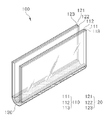
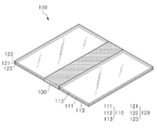
도 1a는 본 발명의 일 실시상태에 따른 가변형 가열 장치가 폴딩된 상태를 개략적으로 나타낸 도면이고, 도 1b는 가변형 가열 장치가 펼쳐진 상태를 개략적으로 나타낸 도면이다.
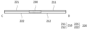
도 2a는 본 발명의 일 실시상태에 따른 가변형 가열 장치의 평면도를 개략적으로 나타낸 도면이고, 도 2b는 도 2a에서 A-B 선을 따른 가변형 가열 장치의 단면도를 개략적으로 나타낸 도면이고, 도 2c는 도 2a에서 C-D 선을 따른 가변형 가열 장치의 단면도를 개략적으로 나타낸 도면이다.
도 3a는 본 발명의 일 실시상태에 따른 가변형 가열 장치의 평면도를 개략적으로 나타낸 도면이고, 도 3b는 도 3a에서 A-B 선을 따른 가변형 가열 장치의 단면도를 개략적으로 나타낸 도면이다.
도 4a는 본 발명의 일 실시상태에 따른 가변형 가열 장치의 폴딩부가 탈착된 상태를 개략적으로 나타낸 도면이고, 도 4b는 본 발명의 일 실시상태에 따른 가변형 가열 장치의 폴딩부가 변형되어 제1 투명 가열부와 제2 투명 가열부 사이의 거리가 조절되는 것을 보여주는 도면이다.
도 5a는 본 발명의 일 실시상태에 따른 가변형 가열 장치의 평면도를 개략적으로 나타낸 도면이고, 도 5b는 도 5a에서 A-B 선을 따른 가변형 가열 장치의 단면도를 개략적으로 나타낸 도면이다.
도 6a는 본 발명의 일 실시상태에 따른 제어부, 온도 표시부, 구동 시간 제어부 및 발광 소자가 구비된 가변형 가열 장치의 평면도를 개략적으로 나타낸 도면이고, 도 6b는 본 발명의 일 실시상태에 따른 제어부, 온도 표시부, 구동 시간 제어부 및 영상 디스플레이부가 구비된 가변형 가열 장치의 평면도를 개략적으로 나타낸 도면이다.
도 7a 내지 도 7d는 본 발명의 일 실시상태에 따른 가변형 가열 장치에 포함된 전극을 나타낸 도면이다.
도 8a는 본 발명의 일 실시상태에 따른 가변형 가열 장치가 폴딩된 상태를 개략적으로 나타낸 도면이고, 도 8b는 가변형 가열 장치가 펼쳐진 상태를 개략적으로 나타낸 도면이다.
도 9a는 본 발명의 일 실시상태에 따른 가변형 가열 장치의 평면도를 개략적으로 나타낸 도면이고, 도 9b는 도 9a에서 A-B 선을 따른 가변형 가열 장치의 단면도를 개략적으로 나타낸 도면이다.
도 10a는 본 발명의 일 실시상태에 따른 가변형 가열 장치의 평면도를 개략적으로 나타낸 도면이고, 도 10b는 도 10a에서 A-B 선을 따른 가변형 가열 장치의 단면도를 개략적으로 나타낸 도면이고, 도 10c는 도 10a에서 C-D 선을 따른 가변형 가열 장치의 단면도를 개략적으로 나타낸 도면이다.
도 11은 본 발명의 일 실시상태에 따른 투명 보조층이 구비된 가변형 가열 장치의 단면도를 개략적으로 나타낸 도면이다.
도 12a 및 도 12b는 본 발명의 일 실시상태에 따른 가변형 가열 장치의 폴딩부가 부착된 상태 및 탈착된 상태를 개략적으로 나타낸 도면이다.
도 13a 및 도 13b는 본 발명의 일 실시상태에 따른 가변형 가열 장치의 폴딩부가 변형되어 제1 투명 가열부와 제2 투명 가열부 사이의 거리가 조절되는 것을 보여주는 도면이다.
도 14a는 본 발명의 일 실시상태에 따른 가변형 가열 장치의 평면도를 개략적으로 나타낸 도면이고, 도 14b는 도 14a에서 A-B 선을 따른 가변형 가열 장치의 단면도를 개략적으로 나타낸 도면이다.
도 15a 및 도 15b는 본 발명의 일 실시상태에 따른 투명 보호층이 구비된 가변형 가열 장치의 단면도를 개략적으로 나타낸 도면이다.
도 16은 본 발명의 일 실시상태에 따른 가변형 가열 장치의 단면도를 나타낸 것이다.
도 17은 본 발명의 일 실시상태에 따른 투명 기재인 유리 상에 보조 전극으로서 격자 무늬 형태의 은(Ag) 전극이 형성된 것을 촬영한 이미지이다.1A is a view schematically showing a folded state of the variable heating device according to an embodiment of the present invention, and FIG. 1B is a diagram schematically showing a state in which the variable heating device is unfolded.
2A is a diagram schematically showing a plan view of a variable heating device according to an embodiment of the present invention, FIG. 2B is a diagram schematically showing a cross-sectional view of a variable heating device taken along line AB in FIG. 2A, and FIG. 2C is FIG. 2A It is a diagram schematically showing a cross-sectional view of the variable heating device along the CD line.
3A is a diagram schematically showing a plan view of a variable heating device according to an embodiment of the present invention, and FIG. 3B is a diagram schematically showing a cross-sectional view of a variable heating device taken along line AB in FIG. 3A .
4A is a view schematically showing a state in which the folding part of the variable heating device according to an embodiment of the present invention is detached, and FIG. 4B is a first transparent heating by the folding part of the variable heating device according to an embodiment of the present invention is deformed. It is a view showing that the distance between the unit and the second transparent heating unit is adjusted.
5A is a diagram schematically showing a plan view of a variable heating device according to an embodiment of the present invention, and FIG. 5B is a diagram schematically showing a cross-sectional view of a variable heating device taken along line AB in FIG. 5A .
6A is a diagram schematically showing a plan view of a variable heating device having a control unit, a temperature display unit, a driving time control unit, and a light emitting element according to an embodiment of the present invention, FIG. 6B is a control unit according to an embodiment of the present invention; It is a diagram schematically showing a plan view of a variable heating device provided with a temperature display unit, a driving time control unit, and an image display unit.
7A to 7D are views illustrating electrodes included in a variable heating device according to an exemplary embodiment of the present invention.
8A is a view schematically showing a state in which the variable heating device according to an embodiment of the present invention is folded, and FIG. 8B is a view schematically showing a state in which the variable heating device is unfolded.
9A is a diagram schematically showing a plan view of a variable heating apparatus according to an embodiment of the present invention, and FIG. 9B is a schematic cross-sectional view of a variable heating apparatus taken along line AB in FIG. 9A.
10A is a diagram schematically showing a plan view of a variable heating device according to an embodiment of the present invention, FIG. 10B is a diagram schematically showing a cross-sectional view of a variable heating device taken along line AB in FIG. 10A, and FIG. 10C is FIG. 10A It is a diagram schematically showing a cross-sectional view of the variable heating device along the CD line.
11 is a diagram schematically showing a cross-sectional view of a variable heating device provided with a transparent auxiliary layer according to an embodiment of the present invention.
12A and 12B are diagrams schematically illustrating a state in which a folding part of a variable heating device according to an embodiment of the present invention is attached and detached.
13A and 13B are views illustrating that the folding part of the variable heating device according to an embodiment of the present invention is deformed so that the distance between the first transparent heating part and the second transparent heating part is adjusted.
14A is a diagram schematically showing a plan view of a variable heating device according to an embodiment of the present invention, and FIG. 14B is a diagram schematically showing a cross-sectional view of a variable heating device taken along line AB in FIG. 14A.
15A and 15B are schematic cross-sectional views of a variable heating device having a transparent protective layer according to an embodiment of the present invention.
16 is a cross-sectional view of a variable heating device according to an embodiment of the present invention.
17 is a photograph taken of a silver (Ag) electrode having a grid pattern as an auxiliary electrode formed on a glass, which is a transparent substrate, according to an exemplary embodiment of the present invention.
본 명세서에 있어서, 어떤 부분이 어떤 구성요소를 "포함" 한다고 할 때, 이는 특별히 반대되는 기재가 없는 한 다른 구성요소를 제외하는 것이 아니라 다른 구성 요소를 더 포함할 수 있는 것을 의미한다.In the present specification, when a part "includes" a certain component, this means that other components may be further included rather than excluding other components unless otherwise stated.
본 명세서에 있어서, 어떤 부재가 다른 부재 "상에" 위치하고 있다고 할 때, 이는 어떤 부재가 다른 부재에 접해 있는 경우뿐 아니라 두 부재 사이에 또 다른 부재가 존재하는 경우도 포함한다.In the present specification, when a member is said to be located "on" another member, this includes not only a case in which a member is in contact with another member but also a case in which another member exists between the two members.
본 명세서에 있어서, 용어 "~하는 단계" 및 "~의 단계"는 "~를 위한 단계"를 의미하지 않는다.In this specification, the terms "step to" and "step to" do not mean "step for".
본 명세서에 있어서, "그래핀층" 이라는 용어는 복수개의 탄소원자들이 서로 공유결합으로 연결되어 폴리시 클릭 방향족 분자를 형성하는 그래핀이 막 또는 시트 형태를 형성한 것으로서, 상기 공유결합으로 연결된 탄소원자들은 기본 반복단위로서 6원환을 형성하나, 5원환 및/또는 7원환을 더 포함하는 것도 가능하다. 따라서 상기 "그래핀층"은 서로 공유결합된 탄소원자들(통상 sp2 결합)의 단일층으로서 보이게 된다. 상기 "그래핀층"은 다양한 구조를 가질 수 있으며, 이와 같은 구조는 그래핀 내에 포함될 수 있는 5원환 및/또는 7원환의 함량에 따라 달라질 수 있다. 상기 "그래핀층"은 상술한 바와 같은 그래핀의 단일층으로 이루어질 수 있으나, 이들이 여러 개 서로 적층되어 복수층을 형성하는 것도 가능하며, 최대 100 nm까지의 두께를 형성할 수 있다.In the present specification, the term "graphene layer" refers to a graphene in which a plurality of carbon atoms are covalently connected to each other to form a polycyclic aromatic molecule to form a film or sheet, wherein the carbon atoms connected by covalent bonds are A 6-membered ring is formed as a basic repeating unit, but it is also possible to further include a 5-membered ring and/or a 7-membered ring. Accordingly, the "graphene layer" is viewed as a single layer of carbon atoms covalently bonded to each other (usually sp 2 bonds). The "graphene layer" may have various structures, and such a structure may vary depending on the content of a 5-membered ring and/or a 7-membered ring that may be included in graphene. The "graphene layer" may be made of a single layer of graphene as described above, but it is also possible to form a plurality of layers by stacking several of them, and a thickness of up to 100 nm may be formed.
본 명세서에 있어서, “투명 가열부”는 제1 투명 가열부 및 제2 투명 가열부를 일괄하여 지칭하는 것일 수 있고, “투명 발열체”는 제1 투명 발열체 및 제2 투명 발열체를 일괄하여 지칭하는 것일 수 있고, “투명 기재”는 제1 투명 기재 및 제2 투명 기재를 일괄하여 지칭하는 것일 수 있고, “투명 보조층”는 제1 투명 보조층 및 제2 투명 보조층를 일괄하여 지칭하는 것일 수 있고, “투명 보호층”는 제1 투명 보호층 및 제2 투명 보호층를 일괄하여 지칭하는 것일 수 있다.In this specification, the “transparent heating unit” may refer to the first transparent heating unit and the second transparent heating unit collectively, and the “transparent heating element” may refer to the first transparent heating element and the second transparent heating element collectively. The “transparent substrate” may collectively refer to the first transparent substrate and the second transparent substrate, and the “transparent auxiliary layer” may collectively refer to the first transparent auxiliary layer and the second transparent auxiliary layer, , “transparent protective layer” may refer to the first transparent protective layer and the second transparent protective layer collectively.
이하 첨부된 도면을 참조하여 본 발명의 실시를 위한 구체적인 내용을 상세히 설명한다.Hereinafter, specific details for carrying out the present invention will be described in detail with reference to the accompanying drawings.
도 1a는 본 발명의 일 실시상태에 따른 가변형 가열 장치가 폴딩된 상태를 개략적으로 나타낸 도면이고, 도 1b는 가변형 가열 장치가 펼쳐진 상태를 개략적으로 나타낸 도면이다. 도 1a 및 도 1b는 가변형 가열 장치의 구성을 개략적으로 나타낸 것으로, 설명의 편의를 위하여 후술하는 스페이서, 전극 등의 구성을 생략하여 도시하였다.1A is a view schematically showing a folded state of the variable heating device according to an embodiment of the present invention, and FIG. 1B is a diagram schematically showing a state in which the variable heating device is unfolded. 1A and 1B schematically show the configuration of a variable heating device, and for convenience of explanation, the configuration of spacers and electrodes, which will be described later, is omitted.
본 발명의 일 실시상태는 제1 투명 발열체를 포함하는 제1 투명 가열부; 제2 투명 발열체를 포함하는 제2 투명 가열부; 및 상기 제1 투명 가열부와 상기 제2 투명 가열부 사이에 구비되는 폴딩부;를 포함하는 가변형 가열 장치를 제공한다.One embodiment of the present invention is a first transparent heating unit including a first transparent heating element; a second transparent heating unit including a second transparent heating element; and a folding unit provided between the first transparent heating unit and the second transparent heating unit.
본 발명의 일 실시상태에 따른 가변형 가열 장치는, 대상체를 가열하는 부위가 투명하여, 대상체가 가열되는 과정을 용이하게 확인할 수 있고, 위생적인 관리가 용이할 수 있다. 또한, 상기 가변형 가열 장치는, 폴딩부를 통하여 변형이 가능하여, 다양한 대상체를 용이하게 가열할 수 있는 이점이 있다.In the variable heating device according to an exemplary embodiment of the present invention, a portion for heating an object is transparent, so that the heating process of the object can be easily checked and hygienic management can be facilitated. In addition, the variable heating apparatus has an advantage in that it can be deformed through a folding part, and thus various objects can be easily heated.
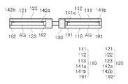
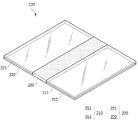
도 1a 및 도 1b를 참고하면, 상기 가변형 가열 장치(100)는 제1 투명 가열부(110), 제2 투명 가열부(120) 및 폴딩부(130)를 포함한다. 이때, 폴딩부(130)는 제1 투명 가열부(110)와 제2 투명 가열부(120) 사이에 구비될 수 있다. 도 1a에 도시된 바와 같이, 폴딩부(130)를 통하여, 제1 투명 가열부(110)와 제2 투명 가열부(120)가 서로 마주보도록 가변형 가열 장치(100)는 폴딩될 수 있다. 도 1b에 도시된 바와 같이, 폴딩부(130)를 통하여, 제1 투명 가열부(110)와 제2 투명 가열부(120)가 가변형 가열 장치(100)의 구비 장소(예를 들어 지면)와 수평이 되도록 가변형 가열 장치(100)는 펼쳐질 수 있다. 즉, 상기 가변형 가열 장치(100)는 폴딩형 가열 장치일 수 있다.1A and 1B , the
도 1a 및 도 1b를 참고하면, 폴딩부(130)를 통하여, 제1 투명 가열부(110)의 제1 투명 발열체(111)와 제2 투명 가열부(120)의 제2 투명 발열체(121)는 서로 0°이상 180°의 각도를 이룰 수 있다.Referring to FIGS. 1A and 1B , through the
본 발명의 일 실시상태에 따르면, 상기 가변형 가열 장치는 폴딩부를 통하여 변형 가능하여, 다양한 종류의 대상을 가열시킬 수 있다. 예를 들어, 상기 가변형 가열 장치는 음식의 조리를 위한 가열 장치일 수 있다. 구체적으로, 상기 가변형 가열 장치가 폴딩된 상태에서는 토스터기와 같은 역할을 수행하여 빵을 구울 수 있고, 고기 등을 구울 수도 있다. 즉, 상기 가변형 가열 장치는 가변형 투명 토스터기일 수 있다. 또한, 상기 가변형 가열 장치는 폴딩된 상태 또는 펼쳐진 상태에서, 돼지 고기, 소고기 등의 육류, 고등어, 삼치 등의 어류, 시금치, 배추, 정경채 등의 야채와 채소, 피자, 만두 등의 가공 식품 등을 조리할 수 있다. 다만, 상기 가변형 가열 장치를 이용하여 조리할 수 있는 대상의 종류를 상기 기재된 것으로 한정하는 것은 아니다.According to an exemplary embodiment of the present invention, the variable heating device is deformable through a folding unit, so that various types of objects can be heated. For example, the variable heating device may be a heating device for cooking food. Specifically, in a state in which the variable heating device is folded, it can serve as a toaster to bake bread, and can also bake meat. That is, the variable heating device may be a variable transparent toaster. In addition, the variable heating device is in a folded state or unfolded state, meat such as pork and beef, fish such as mackerel and mackerel, vegetables and vegetables such as spinach, Chinese cabbage, and jeonggyeongchae, pizza, processed foods such as dumplings, etc. can cook However, the types of objects that can be cooked using the variable heating device are not limited to those described above.
또한, 상기 가변형 가열 장치가 펼쳐진 상태에서는 핫 트레이(hot tray)와 같은 역할을 수행하여 음식을 조리하거나 또는 조리된 음식을 보온할 수 있다. 따라서, 상기 가변형 가열 장치는 폴딩을 통하여 멀티 기능을 구현할 수 있다. 또한, 상기 가변형 가열 장치는 폴딩된 상태에서 수납 또는 보관이 가능하여, 보관 및 운반 용이성이 있다.In addition, in a state in which the variable heating device is unfolded, it may serve as a hot tray to cook food or keep the cooked food warm. Therefore, the variable heating device can implement a multi-function through folding. In addition, the variable heating device can be stored or stored in a folded state, so that it is easy to store and transport.
본 발명의 일 실시상태에 따르면, 상기 가변형 가열 장치는, 대상체를 800 ℃의 이하의 온도로 가열할 수 있다. 구체적으로, 상기 가변형 가열 장치가 대상체를 가열하는 온도는 700 ℃ 이하, 600 ℃ 이하, 500 ℃ 이하, 400 ℃ 이하, 300 ℃ 이하, 200 ℃ 이하, 100 ℃ 이하, 또는 50 ℃ 이하일 수 있다. 또한, 상기 가변형 가열 장치가 대상체를 가열하는 온도는 35 ℃ 이상, 50 ℃ 이상, 75 ℃ 이상, 100 ℃ 이상, 200 ℃ 이상, 300 ℃ 이상, 400 ℃ 이상, 500 ℃ 이상, 600 ℃ 이상, 또는 700 ℃ 이상일 수 있다. 전술한 대상체를 가열하는 온도는, 상기 제1 및 제2 투명 가열부가 가열되는 온도일 수 있다. 후술하는 바와 같이, 상기 제1 투명 가열부(제1 투명 발열체)가 가열되는 온도는 제1 온도 제어부를 통해 제어가 가능하고, 상기 제2 투명 가열부(제2 투명 발열체)가 가열되는 온도는 제2 온도 제어부를 통해 제어가 가능할 수 있다.According to an exemplary embodiment of the present invention, the variable heating device may heat an object to a temperature of 800° C. or less. Specifically, the temperature at which the variable heating device heats the object may be 700 °C or less, 600 °C or less, 500 °C or less, 400 °C or less, 300 °C or less, 200 °C or less, 100 °C or less, or 50 °C or less. In addition, the temperature at which the variable heating device heats the object is 35 °C or higher, 50 °C or higher, 75 °C or higher, 100 °C or higher, 200 °C or higher, 300 °C or higher, 400 °C or higher, 500 °C or higher, 600 °C or higher, or It may be 700 °C or higher. The temperature at which the above-described object is heated may be a temperature at which the first and second transparent heating units are heated. As will be described later, the temperature at which the first transparent heating unit (first transparent heating element) is heated can be controlled through the first temperature control unit, and the temperature at which the second transparent heating unit (second transparent heating element) is heated is Control may be possible through the second temperature controller.
본 발명의 일 실시상태에 따르면, 상기 제1 투명 가열부 및 상기 제2 투명 가열부는 투명할 수 있다. 즉, 상기 제1 및 제2 투명 가열부에 맞닿아 가열되는 대상의 가열 정도, 상태 등을 실시간으로 확인할 수 있는 이점이 있다. 또한, 상기 제1 및 제2 투명 가열부는 투명하기 때문에, 제1 및 제2 투명 가열부에 묻은 이물질의 존재 확인이 용이하여, 위생적인 관리가 가능한 이점이 있다.According to an exemplary embodiment of the present invention, the first transparent heating unit and the second transparent heating unit may be transparent. That is, there is an advantage in that the heating degree, state, etc. of the object to be heated in contact with the first and second transparent heating units can be checked in real time. In addition, since the first and second transparent heating units are transparent, it is easy to check the presence of foreign substances adhered to the first and second transparent heating units, so that hygienic management is possible.
본 발명의 일 실시상태에 따르면, 상기 제1 투명 발열체 및 상기 제2 투명 발열체는 그래핀 박막일 수 있다. 상기 제1 및 제2 투명 발열체로서 그래핀 이외에 다른 소재를 사용할 수도 있으나, 그래핀의 우수한 투명성 및 발열 특성을 고려하여, 이하에서는 제1 및 제2 투명 발열체로서 그래핀을 사용하는 실시상태를 중점으로 설명하도록 한다.According to an exemplary embodiment of the present invention, the first transparent heating element and the second transparent heating element may be a graphene thin film. Although other materials other than graphene may be used as the first and second transparent heating elements, in consideration of the excellent transparency and heat generation characteristics of graphene, hereinafter, the embodiment using graphene as the first and second transparent heating elements is focused on to be explained as
본 발명의 일 실시상태에 따르면, 화학기상증착법을 이용하여 그래핀을 합성하여, 제1 투명 발열체 및 제2 투명 발열체를 제조할 수 있다. 상기 그래핀을 형성하는 방법은, 당업계에서 그래핀을 합성하는 방법을 제한 없이 채택하여 사용할 수 있다. 예를 들어, 후술하는 제1 투명 기재 및 제3 투명 기재를 가열하고, 수소 가스와 탄화 소스를 공급하여, 제1 투명 기재 및 제3 투명 기재 상에 그래핀을 합성시킬 수 있다. 상기 탄화 소스는 일산화탄소, 이산화탄소, 메탄, 에탄, 에틸렌, 에탄올, 아세틸렌, 프로판, 부탄, 부타디엔, 펜탄, 펜텐, 사이클로펜타디엔, 헥산, 사이클로헥산, 벤젠, 및 톨루엔 중 적어도 하나를 포함할 수 있으나, 상기 탄화 소스의 종류를 한정하는 것은 아니다.According to an exemplary embodiment of the present invention, by synthesizing graphene using a chemical vapor deposition method, the first transparent heating element and the second transparent heating element can be manufactured. The method for forming the graphene may be used by adopting without limitation a method for synthesizing graphene in the art. For example, graphene may be synthesized on the first transparent substrate and the third transparent substrate by heating the first transparent substrate and the third transparent substrate, which will be described later, and supplying hydrogen gas and a carbonization source. The carbonization source may include at least one of carbon monoxide, carbon dioxide, methane, ethane, ethylene, ethanol, acetylene, propane, butane, butadiene, pentane, pentene, cyclopentadiene, hexane, cyclohexane, benzene, and toluene, The type of the carbonization source is not limited.
본 발명의 일 실시상태에 따르면, 상기 화학기상증착법은 700 ℃ 이상의 온도에서 수행될 수 있다. 구체적으로, 상기 화학기상증착법은 750 ℃ 이상의 온도, 800 ℃ 이상의 온도, 850 ℃ 이상의 온도, 900 ℃ 이상의 온도, 또는 1,000 ℃ 이상의 온도에서 수행될 수 있다. 또한, 상기 화학기상증착법은 2,000 ℃ 이하의 온도, 1,900 ℃ 이하의 온도, 1,800 ℃ 이하의 온도, 1,700 ℃ 이하의 온도, 1,600 ℃ 이하의 온도, 또는 1,500 ℃ 이하의 온도에서 수행될 수 있다. 상기 화학기상증착법이 수행되는 온도가 전술한 범위 내인 경우, 상기 그래핀이 안정적으로 형성될 수 있으며, 합성되는 그래핀의 결정성이 우수할 수 있다.According to an exemplary embodiment of the present invention, the chemical vapor deposition method may be performed at a temperature of 700 °C or higher. Specifically, the chemical vapor deposition method may be performed at a temperature of 750 °C or higher, a temperature of 800 °C or higher, a temperature of 850 °C or higher, a temperature of 900 °C or higher, or a temperature of 1,000 °C or higher. In addition, the chemical vapor deposition method is a temperature of 2,000 ℃ or less, a temperature of 1,900 ℃ or less, a temperature of 1,800 ℃ or less, a temperature of 1,700 ℃ or less, a temperature of 1,600 ℃ or less, or 1,500 ℃ or less It can be performed at a temperature. When the temperature at which the chemical vapor deposition method is performed is within the aforementioned range, the graphene may be stably formed, and the synthesized graphene may have excellent crystallinity.
본 발명의 일 실시상태에 따르면, 상기 그래핀 박막은 단일 또는 복수의 그래핀층을 포함할 수 있다. 구체적으로, 상기 그래핀 박막은 1층 이상 5층 이하, 2층 이상 5층 이하, 3층 이상 5층 이하, 1층 이상 3층 이하, 또는 2층 이상 3층 이하의 그래핀층을 포함할 수 있다. 상기 그래핀 박막에 포함된 상기 그래핀층의 수가 전술한 범위 내인 경우, 상기 그래핀 박막의 표면 저항을 감소시켜, 그래핀 박막의 최대 온도, 발열 효율 및 방열 특성을 향상시킬 수 있다. 즉, 상기 제1 및 제2 투명 발열체는 대상을 효과적으로 가열시킬 수 있음과 동시에 제1 및 제2 투명 발열체의 두께를 효과적으로 감소시킬 수 있다. 이를 통해, 상기 가변형 가열 장치의 두께 및 무게를 감소시키며, 가열 효율을 향상시킬 수 있는 이점이 있다. 한편, 상기 가변형 가열 장치가 사용되는 용도에 따라, 상기 그래핀 박막에 포함된 그래핀층의 수는 5층 이상으로 조절될 수도 있다.According to an exemplary embodiment of the present invention, the graphene thin film may include a single or a plurality of graphene layers. Specifically, the graphene thin film may include one or more and five or less, two or more and five or less, three or more and five or less, one or more and three or less, or two or more and three or less graphene layers. have. When the number of the graphene layers included in the graphene thin film is within the above-described range, the surface resistance of the graphene thin film may be reduced, thereby improving the maximum temperature, heat generation efficiency, and heat dissipation characteristics of the graphene thin film. That is, the first and second transparent heating elements can effectively heat the object and at the same time effectively reduce the thickness of the first and second transparent heating elements. Through this, there is an advantage in that the thickness and weight of the variable heating device can be reduced, and the heating efficiency can be improved. On the other hand, depending on the purpose for which the variable heating device is used, the number of graphene layers included in the graphene thin film may be adjusted to 5 or more.
본 발명의 일 실시상태에 따르면, 상기 그래핀 박막은 도펀트로 도핑된 것일 수 있다. 도핑 처리된 그래핀을 사용함으로써, 제1 및 제2 투명 발열체의 발열 효율을 증가시킬 수 있다. 구체적으로, 상기 도펀트는 유기계 도펀트 또는 무기계 도펀트를 포함할 수 있다. 상기 도펀트는 이온성 액체, 이온성 기체, 산류 화합물, 유기 분자계 화합물, 및 이들의 조합으로 이루어지는 군으로부터 선택되는 것을 포함하는 것일 수 있으나, 이에 제한되는 것은 아니다. 예를 들어, 상기 도펀트는 NO2BF4, NOBF4, NO2SbF6, HCl, H2PO4, H3CCOOH, H2SO4, HNO3, PVDF, 나피온(Nafion), AuCl3, SOCl2, Br2, CH3NO2, 디클로로디시아노퀴논, 옥손, 디미리스토일포스파티딜이노시톨, 트리플루오로메탄술폰이미드 및 이들의 조합으로 이루어진 군으로부터 선택되는 것을 포함하는 것일 수 있으나, 이에 제한되는 것은 아니다.According to an exemplary embodiment of the present invention, the graphene thin film may be doped with a dopant. By using doped graphene, the heating efficiency of the first and second transparent heating elements may be increased. Specifically, the dopant may include an organic dopant or an inorganic dopant. The dopant may include one selected from the group consisting of an ionic liquid, an ionic gas, an acid compound, an organic molecular compound, and a combination thereof, but is not limited thereto. For example, the dopant is NO 2 BF 4 , NOBF 4 , NO 2 SbF 6 , HCl, H 2 PO 4 , H 3 CCOOH, H 2 SO 4 , HNO 3 , PVDF, Nafion, AuCl 3 , SOCl 2 , Br 2 , CH 3 NO 2 , dichlorodicyanoquinone, oxone, dimyristoylphosphatidylinositol, trifluoromethanesulfonimide, and combinations thereof. It is not limited.
본 발명의 일 실시상태에 따르면, 상기 그래핀 박막의 단위면적에 따른 저항값은 0.01 Ω/cm2 이상 5 Ω/cm2 이하, 0.02 Ω/cm2 이상 5 Ω/cm2 이하, 0.05 Ω/cm2 이상 5 Ω/cm2 이하, 0.1 Ω/cm2 이상 5 Ω/cm2 이하, 0.5 Ω/cm2 이상 5 Ω/cm2 이하, 1 Ω/cm2 이상 5 Ω/cm2 이하, 2 Ω/cm2 이상 5 Ω/cm2 이하, 3 Ω/cm2 이상 5 Ω/cm2 이하, 4 Ω/cm2 이상 5 Ω/cm2 이하, 0.01 Ω/cm2 이상 1 Ω/cm2 이하, 0.02 Ω/cm2 이상 1 Ω/cm2 이하, 0.05 Ω/cm2 이상 1 Ω/cm2 이하, 0.1 Ω/cm2 이상 1 Ω/cm2 이하, 또는 0.5 Ω/cm2 이상 1 Ω/cm2 이하일 수 있다. According to an exemplary embodiment of the present invention, the resistance value according to the unit area of the graphene thin film is 0.01 Ω/cm 2 or more and 5 Ω/cm 2 or less, 0.02 Ω/cm 2 or more and 5 Ω/cm 2 or less, 0.05 Ω/cm 2 or less cm 2 or more and 5 Ω/cm 2 or less, 0.1 Ω/cm 2 or more and 5 Ω/cm 2 or less, 0.5 Ω/cm 2 or more and 5 Ω/cm 2 or less, 1 Ω/cm 2 or more and 5 Ω/cm 2 or less, 2 Ω/cm 2 or more and 5 Ω/cm 2 or less, 3 Ω/cm 2 or more and 5 Ω/cm 2 or less, 4 Ω/cm 2 or more and 5 Ω/cm 2 or less, 0.01 Ω/cm 2 or more and 1 Ω/cm 2 or less , 0.02 Ω/cm 2 or more and 1 Ω/cm 2 or less, 0.05 Ω/cm 2 or more and 1 Ω/cm 2 or less, 0.1 Ω/cm 2 or more and 1 Ω/cm 2 or less, or 0.5 Ω/cm 2 or more 1 Ω/ cm 2 or less.
상기 그래핀 박막의 단위면적에 따른 저항값이 전술한 범위 내인 경우, 상기 그래핀 박막의 발열 효율을 효과적으로 향상시킬 수 있다. 이를 통해, 상기 가변형 가열 장치는 대상체를 효과적으로 가열할 수 있다. 또한, 상기 그래핀 박막의 단위면적에 따른 저항값을 전술한 범위로 조절함으써, 상기 그래핀 박막이 구비되는 투명 기재의 두께를 감소시켜, 상기 가변형 가열 장치의 두께를 보다 얇게 구현할 수도 있다.When the resistance value according to the unit area of the graphene thin film is within the above-described range, the heating efficiency of the graphene thin film can be effectively improved. Through this, the variable heating apparatus can effectively heat the object. In addition, by adjusting the resistance value according to the unit area of the graphene thin film to the above-described range, the thickness of the transparent substrate on which the graphene thin film is provided can be reduced, thereby making the thickness of the variable heating device thinner.
예를 들어, 상기 그래핀 박막의 크기는 100 cm2 이상 2,500 cm2 이하일 수 있다. 구체적으로, 상기 그래핀 박막의 크기는 10 cm X 10 cm 이상 40 cm X 60 cm일 수 있다. 또한, 상기 그래핀 박막이 1층의 그래핀층을 포함하는 경우, 상기 그래핀 박막은 전술한 크기에서의 면적이 200 Ω 이상 400 Ω 이하일 수 있다. 상기 그래핀 박막이 2층의 그래핀층을 포함하는 경우, 상기 그래핀 박막은 전술한 크기에서의 면적이 150 Ω 이상 300 Ω 이하일 수 있다. 상기 그래핀 박막이 3층의 그래핀층을 포함하는 경우, 상기 그래핀 박막은 전술한 크기에서의 면적이 100 Ω 이상 200 Ω 이하일 수 있다. 상기 그래핀 박막이 4층의 그래핀층을 포함하는 경우, 상기 그래핀 박막은 전술한 크기에서의 면적이 80 Ω 이상 150 Ω 이하일 수 있다. 상기 그래핀 박막이 5층의 그래핀층을 포함하는 경우, 상기 그래핀 박막은 전술한 크기에서의 면적이 60 Ω 이상 100 Ω 이하일 수 있다.For example, the size of the graphene thin film may be 100 cm 2 or more and 2,500 cm 2 or less. Specifically, the size of the graphene thin film may be 10 cm X 10 cm or more and 40 cm X 60 cm. In addition, when the graphene thin film includes one graphene layer, the graphene thin film may have an area of 200 Ω or more and 400 Ω or less in the above-described size. When the graphene thin film includes two graphene layers, the graphene thin film may have an area of 150 Ω or more and 300 Ω or less in the above-described size. When the graphene thin film includes three graphene layers, the graphene thin film may have an area of 100 Ω or more and 200 Ω or less in the size described above. When the graphene thin film includes four graphene layers, the graphene thin film may have an area of 80 Ω or more and 150 Ω or less in the aforementioned size. When the graphene thin film includes five graphene layers, the graphene thin film may have an area of 60 Ω or more and 100 Ω or less in the above-described size.
본 발명의 일 실시상태에 따르면, 상기 그래핀 박막의 두께는 0.35 nm 이상 2.0 nm 이하일 수 있다. 예를 들어, 상기 그래핀 박막이 단일(1층)의 그래핀층을 포함하는 경우, 상기 그래핀 박막의 두께는 0.35 nm일 수 있다. 또한, 상기 그래핀 박막이 5층의 그래핀층을 포함하는 경우, 상기 그래핀 박막의 두께는 1.75 nm일 수 있다. 상기 그래핀 박막의 두께가 전술한 범위 내인 경우, 상기 투명 발열체의 발열 효율이 증가되면서, 상기 가변형 가열 장치의 제조 비용을 저감시킬 수 있다.According to an exemplary embodiment of the present invention, the thickness of the graphene thin film may be 0.35 nm or more and 2.0 nm or less. For example, when the graphene thin film includes a single (one layer) graphene layer, the thickness of the graphene thin film may be 0.35 nm. In addition, when the graphene thin film includes five graphene layers, the graphene thin film may have a thickness of 1.75 nm. When the thickness of the graphene thin film is within the above-described range, the heating efficiency of the transparent heating element is increased, and the manufacturing cost of the variable heating device can be reduced.
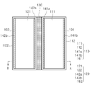
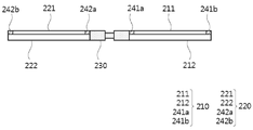
도 2a는 본 발명의 일 실시상태에 따른 가변형 가열 장치의 평면도를 개략적으로 나타낸 도면이고, 도 2b는 도 2a에서 A-B 선을 따른 가변형 가열 장치의 단면도를 개략적으로 나타낸 도면이고, 도 2c는 도 2a에서 C-D 선을 따른 가변형 가열 장치의 단면도를 개략적으로 나타낸 도면이다.2A is a diagram schematically showing a plan view of a variable heating device according to an embodiment of the present invention, FIG. 2B is a diagram schematically showing a cross-sectional view of a variable heating device taken along line A-B in FIG. 2A, and FIG. 2C is FIG. 2A It is a diagram schematically showing a cross-sectional view of the variable heating device along the line C-D.
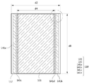
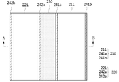
본 발명의 일 실시상태에 따르면, 상기 제1 투명 가열부는 상기 제1 투명 발열체가 구비되는 제1 투명 기재, 및 상기 제1 투명 발열체를 사이에 두고 상기 제1 투명 기재에 대향하는 제2 투명 기재를 포함하고, 상기 제2 투명 가열부는 상기 제2 투명 발열체가 구비되는 제3 투명 기재, 및 상기 제2 투명 발열체를 사이에 두고 상기 제3 투명 기재에 대향하는 제4 투명 기재를 포함하고, 상기 제1 투명 기재 및 제2 투명 기재는 밀봉되어, 상기 제1 투명 기재 및 제2 투명 기재 사이에 에어갭이 형성되고, 상기 제3 투명 기재 및 제4 투명 기재는 밀봉되어, 상기 제3 투명 기재 및 제4 투명 기재 사이에 에어갭이 형성될 수 있다.According to an exemplary embodiment of the present invention, the first transparent heating unit includes a first transparent substrate provided with the first transparent heating element, and a second transparent substrate facing the first transparent substrate with the first transparent heating element interposed therebetween. Including, wherein the second transparent heating unit comprises a third transparent substrate provided with the second transparent heating element, and a fourth transparent substrate facing the third transparent substrate with the second transparent heating element interposed therebetween, The first transparent substrate and the second transparent substrate are sealed, an air gap is formed between the first transparent substrate and the second transparent substrate, the third transparent substrate and the fourth transparent substrate are sealed, and the third transparent substrate and an air gap may be formed between the fourth transparent substrate.
도 2a 내지 도 2c를 참고하면, 제1 투명 기재(112)의 일면 상에 제1 투명 발열체(111)가 구비되고, 제2 투명 기재(113)는 제1 투명 발열체(111)를 사이에 두고, 제1 투명 기재(112)와 대향하며 이격된 상태로 구비될 수 있다. 즉, 제1 투명 기재(112)와 제2 투명 기재(113) 사이에는 에어갭(AG)이 형성될 수 있고, 에어갭(AG) 내에 제1 투명 발열체(111)가 위치할 수 있다. 또한, 제3 투명 기재(122)의 일면 상에 제2 투명 발열체(121)가 구비되고, 제4 투명 기재(123)는 제2 투명 발열체(121)를 사이에 두고, 제3 투명 기재(122)와 대향하며 이격된 상태로 구비될 수 있다. 즉, 제3 투명 기재(122)와 제4 투명 기재(123) 사이에는 에어갭(AG)이 형성될 수 있고, 에어갭(AG) 내에 제2 투명 발열체(121)가 위치할 수 있다.2A to 2C , the first
상기 제1 투명 발열체가 구비된 상기 제1 투명 기재와 상기 제2 투명 발열체가 구비된 상기 제3 투명 기재는 대상체를 가열하는 부분(가열 부분)에 해당하고, 제2 투명 기재와 제4 투명 기재는 대상체를 가열하지 않는 부분(비가열 부분)에 해당할 수 있다. 이때, 상기 제1 투명 기재 및 상기 제2 투명 기재 사이에 에어갭을 형성하고, 상기 제3 투명 기재 및 상기 제4 투명 기재 사이에 에어갭을 형성함으로써, 상기 제1 및 제2 투명 발열체에서 발산되는 열은 상기 제1 및 제3 투명 기재를 통해 대상체를 효과적으로 가열함과 동시에, 제2 및 제4 투명 기재로 열이 방출되는 것을 효과적으로 억제할 수 있다. 이를 통해, 상기 가변형 가열 장치의 사용 안정성을 보다 향상시킬 수 있다.The first transparent substrate provided with the first transparent heating element and the third transparent substrate provided with the second transparent heating element correspond to a portion (heating portion) for heating an object, and a second transparent substrate and a fourth transparent substrate may correspond to a portion in which the object is not heated (non-heating portion). At this time, by forming an air gap between the first transparent substrate and the second transparent substrate, and forming an air gap between the third transparent substrate and the fourth transparent substrate, the first and second transparent heating elements radiate The generated heat effectively heats the object through the first and third transparent substrates, and at the same time, it is possible to effectively suppress heat emission to the second and fourth transparent substrates. Through this, it is possible to further improve the use stability of the variable heating device.
본 발명의 일 실시상태에 따르면, 상기 제1 내지 제4 투명 기재로서, 당업계에서 사용되는 기재 중에서 소정의 강도를 가지며 투명한 것을 이용할 수 있다. 예를 들어, 상기 제1 투명 기재 내지 제4 투명 기재는 유리 또는 고분자 필름일 수 있다. 이때, 상기 유리는 물리적 및/또는 화학적으로 강화된 것을 사용할 수 있다. 상기 고분자 필름은 PET(Polyethylene Terephthalate), PMMA[poly(methyl methacrylate)], PVDF[Poly(viniylidine flouride)] 및 PANI(polyaniline) 중 적어도 하나를 포함할 수 있으나, 상기 고분자 필름의 종류를 한정하는 것은 아니다.According to an exemplary embodiment of the present invention, as the first to fourth transparent substrates, a transparent substrate having a predetermined strength among substrates used in the art may be used. For example, the first to fourth transparent substrates may be glass or polymer films. In this case, the glass may be physically and/or chemically strengthened. The polymer film may include at least one of PET (Polyethylene Terephthalate), PMMA [poly(methyl methacrylate)], PVDF [Poly(viniylidine flouride)], and PANI (polyaniline), but limiting the type of the polymer film is not.
본 발명의 일 실시상태에 따르면, 상기 제1 투명 기재와 상기 제2 투명 기재의 두께비는 1:0.1 내지 1:10일 수 있다. 구체적으로, 도 2a 및 도 2b를 참고하면, 상기 제1 투명 기재(112)의 두께(d41)와 상기 제2 투명 기재(113)의 두께(d42) 비는 1:0.1 내지 1:8, 1:0.1 내지 1:6, 1:1 내지 1:4, 1:0.1 내지 1:4, 1:0.1 내지 1:2, 1:1 내지 1:8, 1:1 내지 1:6, 또는 1:1 내지 1:3일 수 있다. 보다 구체적으로, 상기 제1 투명 기재와 상기 제2 투명 기재의 두께비는 1:2 내지 1:10, 1:2 내지 1:8, 1:2 내지 1:6, 또는 1:2 내지 1:4일 수 있다. 상기 제1 투명 기재와 상기 제2 투명 기재의 두께비가 전술한 범위 내인 경우, 상기 제1 투명 발열체로부터 생성된 열은 상기 제1 투명 기재를 통하여 대상체로 효과적으로 전달되어 효과적으로 가열할 수 있고, 상기 제2 투명 기재를 통해 외부로 열이 발산되는 것을 억제하여 가변형 가열 장치의 사용 안정성을 향상시킬 수 있다. 바람직하게는, 상기 제2 투명 기재의 두께가 상기 제1 투명 기재의 두께보다 두꺼울 수 있다.According to an exemplary embodiment of the present invention, the thickness ratio of the first transparent substrate and the second transparent substrate may be 1:0.1 to 1:10. Specifically, referring to FIGS. 2A and 2B , the ratio of the thickness d41 of the first
또한, 상기 제3 투명 기재와 상기 제4 투명 기재의 두께비는 1:0.1 내지 1:10일 수 있다. 구체적으로, 도 2a 및 도 2c를 참고하면, 상기 제3 투명 기재(122)의 두께(d41)와 상기 제4 투명 기재(123)의 두께(d42) 비는 1:0.1 내지 1:8, 1:0.1 내지 1:6, 1:1 내지 1:4, 1:0.1 내지 1:4, 1:0.1 내지 1:2, 1:1 내지 1:8, 1:1 내지 1:6, 또는 1:1 내지 1:3일 수 있다. 보다 구체적으로, 상기 제3 투명 기재와 상기 제4 투명 기재의 두께비는 1:2 내지 1:10, 1:2 내지 1:8, 1:2 내지 1:6, 또는 1:2 내지 1:4일 수 있다. 상기 제3 투명 기재와 상기 제4 투명 기재의 두께비가 전술한 범위 내인 경우, 상기 제2 투명 발열체로부터 생성된 열은 상기 제3 투명 기재를 통하여 대상체로 효과적으로 전달되어 효과적으로 가열할 수 있고, 상기 제4 투명 기재를 통해 외부로 열이 발산되는 것을 억제하여 가변형 가열 장치의 사용 안정성을 향상시킬 수 있다. 바람직하게는, 상기 제4 투명 기재의 두께가 상기 제3 투명 기재의 두께보다 두꺼울 수 있다.In addition, a thickness ratio of the third transparent substrate and the fourth transparent substrate may be 1:0.1 to 1:10. Specifically, referring to FIGS. 2A and 2C , the ratio of the thickness d41 of the third
본 발명의 일 실시상태에 따르면, 상기 제1 투명 기재 내지 상기 제4 투명 기재 각각의 두께는 0.5 mm 이상 5 mm 이하일 수 있다. 구체적으로, 상기 제1 투명 기재 내지 상기 제4 투명 기재 각각의 두께는 0.5 mm 이상 4.5 mm 이하, 0.5 mm 이상 4 mm 이하, 0.5 mm 이상 3.5 mm 이하, 또는 0.5 mm 이상 3 mm 이하일 수 있다. 상기 제1 투명 기재 내지 상기 제4 투명 기재 각각의 두께가 전술한 범위 내인 경우, 상기 가변형 가열 장치는 대상체를 효과적으로 가열할 수 있으며, 사용 안정성을 증대시킬 수 있고, 상기 가변형 가열 장치의 총 두께 및 무게를 효과적으로 저감하여 사용 용이성을 향상시킬 수 있다.According to an exemplary embodiment of the present invention, each of the first transparent substrate to the fourth transparent substrate may have a thickness of 0.5 mm or more and 5 mm or less. Specifically, each of the first transparent substrate to the fourth transparent substrate may have a thickness of 0.5 mm or more and 4.5 mm or less, 0.5 mm or more and 4 mm or less, 0.5 mm or more and 3.5 mm or less, or 0.5 mm or more and 3 mm or less. When the thickness of each of the first transparent substrate to the fourth transparent substrate is within the above-described range, the variable heating device can effectively heat an object, increase stability in use, and the total thickness of the variable heating device and Ease of use can be improved by effectively reducing the weight.
본 발명의 일 실시상태에 따르면, 상기 제1 투명 발열체의 두께와 상기 제1 투명 기재의 두께 비는 1:0.1 x 10⁶ 내지 1:10 x 106 일 수 있다. 구체적으로, 도 2a 및 도 2b를 참고하면, 상기 제1 투명 발열체(111)에 포함된 그래핀 박막과 상기 제1 투명 기재(112)의 두께(d41) 비는 1:0.1 x 10⁶ 내지 1:10 x 106, 1:0.2 x 10⁶ 내지 1:9 x 10⁶, 1:0.5 x 10⁶ 내지 1:8.5 x 10⁶, 1:1 x 10⁶ 내지 1:7 x 10⁶, 1:2.5 x 10⁶ 내지 1:5.5 x 10⁶, 1:0.2 x 10⁶ 내지 1:2.5 x 10⁶, 1:0.25 x 10⁶ 내지 1:2 x 10⁶, 1:5 x 10⁶ 내지 1:10 x 106, 또는 1:7.5 x 10⁶ 내지 1:10 x 106일 수 있다. 상기 제1 투명 발열체의 두께와 상기 제1 투명 기재의 두께 비가 전술한 범위 내인 경우, 상기 제1 투명 발열체에서 생성된 열은 상기 제1 투명 기재에 용이하게 전달되어, 대상체를 효과적으로 가열할 수 있다.According to an exemplary embodiment of the present invention, a ratio of the thickness of the first transparent heating element to the thickness of the first transparent substrate may be 1:0.1 x 10 6 to 1:10 x 10 6 . Specifically, referring to FIGS. 2A and 2B , a thickness (d41) ratio of the graphene thin film included in the first
또한, 상기 제2 투명 발열체의 두께와 상기 제3 투명 기재의 두께 비는 1:0.1 x 10⁶ 내지 1:10 x 106 일 수 있다. 구체적으로, 도 2a 및 도 2c를 참고하면, 상기 제2 투명 발열체(121)에 포함된 그래핀 박막과 상기 제3 투명 기재(122)의 두께(d41) 비는 1:0.1 x 10⁶ 내지 1:10 x 106, 1:0.2 x 10⁶ 내지 1:9 x 10⁶, 1:0.5 x 10⁶ 내지 1:8.5 x 10⁶, 1:1 x 10⁶ 내지 1:7 x 10⁶, 1:2.5 x 10⁶ 내지 1:5.5 x 10⁶, 1:0.2 x 10⁶ 내지 1:2.5 x 10⁶, 1:0.25 x 10⁶ 내지 1:2 x 10⁶, 1:5 x 10⁶ 내지 1:10 x 106, 또는 1:7.5 x 10⁶ 내지 1:10 x 106일 수 있다. 상기 제2 투명 발열체의 두께와 상기 제3 투명 기재의 두께 비가 전술한 범위 내인 경우, 상기 제2 투명 발열체에서 생성된 열은 상기 제3 투명 기재에 용이하게 전달되어, 대상체를 효과적으로 가열할 수 있다.In addition, a ratio of the thickness of the second transparent heating element to the thickness of the third transparent substrate may be 1:0.1 x 10 6 to 1:10 x 10 6 . Specifically, referring to FIGS. 2A and 2C , a thickness (d41) ratio of the graphene thin film included in the second
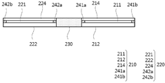
본 발명의 일 실시상태에 따르면, 상기 제1 투명 가열부는 상기 제1 투명 기재 및 제2 투명 기재 사이에 구비되어, 상기 제1 투명 기재 및 제2 투명 기재를 밀봉하는 제1 스페이서를 포함하고, 상기 제2 투명 가열부는 상기 제3 투명 기재 및 제4 투명 기재 사이에 구비되어, 상기 제3 투명 기재 및 제4 투명 기재를 밀봉하는 제2 스페이서를 포함할 수 있다.According to an exemplary embodiment of the present invention, the first transparent heating unit is provided between the first transparent substrate and the second transparent substrate, and includes a first spacer for sealing the first transparent substrate and the second transparent substrate, The second transparent heating unit may include a second spacer provided between the third transparent substrate and the fourth transparent substrate to seal the third transparent substrate and the fourth transparent substrate.
도 2a 내지 도 2c를 참고하면, 제1 스페이서(191)는 제1 투명 기재(112) 및 제2 투명 기재(113) 사이에 구비되어, 제1 투명 기재(112) 및 제2 투명 기재(113)를 밀봉시켜, 제1 투명 기재(112) 및 제2 투명 기재(113) 사이에 에어갭(AG)을 형성할 수 있다. 또한, 제2 스페이서(192)는 제3 투명 기재(122) 및 제4 투명 기재(123) 사이에 구비되어, 제3 투명 기재(122) 및 제4 투명 기재(123)를 밀봉시켜, 제3 투명 기재(122) 및 제4 투명 기재(123) 사이에 에어갭(AG)을 형성할 수 있다.2A to 2C , the
상기 제1 스페이서는 제1 투명 기재 및 제2 투명 기재의 외곽부에 구비되어, 제1 투명 발열체를 감싸는 형태로 구비될 수 있고, 상기 제2 스페이서는 제3 투명 기재 및 제4 투명 기재의 외곽부에 구비되어, 제2 투명 발열체를 감싸는 형태로 구비될 수 있다. 상기 제1 스페이서 및 제2 스페이서는 당업계에서 사용되는 스페이서를 사용할 수 있고, 예를 들어 실리콘 고무를 이용할 수 있다. 다만, 상기 제1 스페이서 및 제2 스페이서의 재질을 한정하는 것은 아니다.The first spacer may be provided in the outer portion of the first transparent substrate and the second transparent substrate to surround the first transparent heating element, and the second spacer may be provided in the outer portion of the third transparent substrate and the fourth transparent substrate. It is provided in the portion, and may be provided in the form of enclosing the second transparent heating element. The first spacer and the second spacer may use a spacer used in the art, for example, a silicone rubber may be used. However, the material of the first spacer and the second spacer is not limited.
본 발명의 일 실시상태에 따르면, 상기 제1 스페이서 및 제2 스페이서 각각은 두께가 1 mm 이상 10 mm 이하, 2.5 mm 이상 7.5 mm 이하, 4 mm 이상 6 mm 이하, 1 mm 이상 6 mm 이하, 2 mm 이상 4 mm 이하, 5 mm 이상 10 mm 이하, 또는 6.5 mm 이상 8.5 mm 이하일 수 있다. 도 2a 내지 도 2c를 참고하면, 상기 제1 스페이서(191) 및 제2 스페이서(192)의 두께가 전술한 범위 내인 경우, 상기 제1 투명 기재(112)와 제2 투명 기재(113) 사이, 제3 투명 기재(122)와 제4 투명 기재(123) 사이에 안정적으로 에어갭을 형성할 수 있다. 이를 통해, 상기 제1 및 제2 투명 발열체에서 발생된 열이 상기 제2 투명 기재 및 제4 투명 기재로 전달되는 것을 효과적으로 억제하여, 상기 가변형 가열 장치의 사용 안정성을 증대시킬 수 있다.According to an exemplary embodiment of the present invention, each of the first spacer and the second spacer has a thickness of 1 mm or more and 10 mm or less, 2.5 mm or more and 7.5 mm or less, 4 mm or more and 6 mm or less, 1 mm or more and 6 mm or less, 2 mm or more and 4 mm or less, 5 mm or more and 10 mm or less, or 6.5 mm or more and 8.5 mm or less. 2A to 2C, when the thickness of the
본 발명의 일 실시상태에 따르면, 상기 제2 투명 기재의 두께와 상기 제1 스페이서의 두께 비는 1:0.2 내지 1:25일 수 있다. 구체적으로, 도 2a 및 도 2b를 참고하면, 상기 제2 투명 기재(113)의 두께(d42)와 제1 스페이서(191)의 두께(d43) 비는 1:0.3 내지 1:20, 1:1 내지 1:15, 1:3 내지 1:10, 1:5 내지 1:7, 1:0.2 내지 1:10, 1:1 내지 1:7.5, 1:3 내지 1:5, 1:10 내지 1:25, 또는 1:15 내지 1:20일 수 있다. 상기 제2 투명 기재의 두께와 상기 제1 스페이서의 두께 비를 전술한 범위로 조절함으로써, 상기 제1 투명 발열체에서 발생된 열이 상기 제2 투명 기재로 전달되는 것을 효과적으로 억제하여, 상기 가변형 가열 장치의 사용 안정성을 증대시킬 수 있다. 또한, 상기 제1 스페이서의 두께를 조절함에 따라 상기 제2 투명 기재의 두께를 제어하여, 상기 가변형 가열 장치의 총 두께, 중량 등을 용이하게 조절할 수 있다.According to an exemplary embodiment of the present invention, a ratio of the thickness of the second transparent substrate to the thickness of the first spacer may be 1:0.2 to 1:25. Specifically, referring to FIGS. 2A and 2B , a ratio of the thickness d42 of the second
또한, 상기 제4 투명 기재의 두께와 상기 제2 스페이서의 두께 비는 1:0.2 내지 1:25일 수 있다. 구체적으로, 도 2a 및 도 2c를 참고하면, 상기 제4 투명 기재(123)의 두께(d42)와 제2 스페이서(192)의 두께(d43) 비는 1:0.3 내지 1:20, 1:1 내지 1:15, 1:3 내지 1:10, 1:5 내지 1:7, 1:0.2 내지 1:10, 1:1 내지 1:7.5, 1:3 내지 1:5, 1:10 내지 1:25, 또는 1:15 내지 1:20일 수 있다. 상기 제4 투명 기재의 두께와 상기 제2 스페이서의 두께 비를 전술한 범위로 조절함으로써, 상기 제2 투명 발열체에서 발생된 열이 상기 제4 투명 기재로 전달되는 것을 효과적으로 억제하여, 상기 가변형 가열 장치의 사용 안정성을 증대시킬 수 있다. 또한, 상기 제2 스페이서의 두께를 조절함에 따라 상기 제4 투명 기재의 두께를 제어하여, 상기 가변형 가열 장치의 총 두께, 중량 등을 용이하게 조절할 수 있다.In addition, a ratio of the thickness of the fourth transparent substrate to the thickness of the second spacer may be 1:0.2 to 1:25. Specifically, referring to FIGS. 2A and 2C , the ratio of the thickness d42 of the fourth
본 발명의 일 실시상태에 따르면, 상기 제1 투명 발열체의 두께와 상기 제1 스페이서의 두께 비는 1:0.5 x 10⁶ 내지 1:30 x 106 일 수 있다. 구체적으로, 도 2a 및 도 2b를 참고하면, 상기 제1 투명 발열체(111)에 포함된 그래핀 박막과 상기 제1 스페이서(191)의 두께(d43) 비는 1:0.5 x 10⁶ 내지 1:25 x 106, 1:0.2 x 10⁶ 내지 1:20 x 106, 1:0.5 x 10⁶ 내지 1:15 x 106, 1:1 x 10⁶ 내지 1:10 x 106, 1:2.5 x 10⁶ 내지 1:7.5 x 10⁶, 1:0.5 x 10⁶ 내지 1:10 x 106, 1:1 x 10⁶ 내지 1:7 x 10⁶, 또는 1:2 x 10⁶ 내지 1:6 x 10⁶일 수 있다. 상기 제1 투명 발열체의 두께와 상기 제1 스페이서의 두께 비가 전술한 범위 내인 경우, 상기 제1 투명 발열체와 상기 제2 투명 기재 간의 거리가 적절히 조절되어, 상기 제1 투명 발열체에서 생성된 열은 상기 제1 투명 기재에 용이하게 전달됨과 동시에, 상기 제2 투명 기재로 열이 전달되는 것을 효과적으로 억제할 수 있다.According to an exemplary embodiment of the present invention, a ratio of the thickness of the first transparent heating element to the thickness of the first spacer may be 1:0.5 x 10 6 to 1:30 x 10 6 . Specifically, referring to FIGS. 2A and 2B , a thickness (d43) ratio of the graphene thin film included in the first
또한, 상기 제2 투명 발열체의 두께와 상기 제2 스페이서의 두께 비는 1:0.5 x 10⁶ 내지 1:30 x 106 일 수 있다. 구체적으로, 도 2a 및 도 2c를 참고하면, 상기 제2 투명 발열체(121)에 포함된 그래핀 박막과 상기 제2 스페이서(192)의 두께(d43) 비는 1:0.5 x 10⁶ 내지 1:25 x 106, 1:0.2 x 10⁶ 내지 1:20 x 106, 1:0.5 x 10⁶ 내지 1:15 x 106, 1:1 x 10⁶ 내지 1:10 x 106, 1:2.5 x 10⁶ 내지 1:7.5 x 10⁶, 1:0.5 x 10⁶ 내지 1:10 x 106, 1:1 x 10⁶ 내지 1:7 x 10⁶, 또는 1:2 x 10⁶ 내지 1:6 x 10⁶일 수 있다. 상기 제2 투명 발열체의 두께와 상기 제2 스페이서의 두께 비가 전술한 범위 내인 경우, 상기 제2 투명 발열체와 상기 제4 투명 기재 간의 거리가 적절히 조절되어, 상기 제2 투명 발열체에서 생성된 열은 상기 제3 투명 기재에 용이하게 전달됨과 동시에, 상기 제4 투명 기재로 열이 전달되는 것을 효과적으로 억제할 수 있다.In addition, a ratio of the thickness of the second transparent heating element to the thickness of the second spacer may be 1:0.5 x 10 6 to 1:30 x 10 6 . Specifically, referring to FIGS. 2A and 2C , a thickness (d43) ratio of the graphene thin film included in the second
본 발명의 일 실시상태에 따르면, 상기 에어갭은 비활성 기체를 포함할 수 있다. 구체적으로, 상기 제1 투명 기재와 제2 투명 기재 사이에 형성된 에어갭, 상기 제3 투명 기재와 제4 투명 기재 사이에 형성된 에어갭은 질소, 아르곤 및 헬륨 중 적어도 하나의 비활성 기체를 포함할 수 있다. 보다 구체적으로, 상기 제1 투명 기재 및 제2 투명 기재 사이, 제3 투명 기재 및 제4 투명 기재 사이는 질소, 아르곤 및 헬륨 중 적어도 하나의 비활성 기체로 채워져 에어갭을 형성할 수 있다. 상기 에어갭에 비활성 기체가 포함됨으로써, 상기 제1 및 제2 투명 발열체에 포함된 그래핀 박막이 산화되는 것을 방지하여, 상기 가변형 가열 장치의 장기 신뢰성 및 내구성을 향상시킬 수 있다.According to an exemplary embodiment of the present invention, the air gap may include an inert gas. Specifically, the air gap formed between the first transparent substrate and the second transparent substrate and the air gap formed between the third transparent substrate and the fourth transparent substrate may include at least one inert gas selected from nitrogen, argon, and helium. have. More specifically, an air gap may be formed between the first transparent substrate and the second transparent substrate and between the third transparent substrate and the fourth transparent substrate by being filled with an inert gas of at least one of nitrogen, argon, and helium. By including the inert gas in the air gap, the graphene thin film included in the first and second transparent heating elements is prevented from being oxidized, thereby improving long-term reliability and durability of the variable heating device.
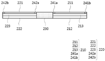
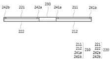
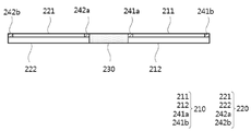
본 발명의 일 실시상태에 따르면, 상기 제1 투명 가열부는 상기 제1 투명 발열체에 연결되는 전극을 더 포함하고, 상기 제2 투명 가열부는 상기 제2 투명 발열체에 연결되는 전극을 더 포함할 수 있다. 구체적으로, 상기 제1 투명 가열부는 상기 제1 투명 발열체와 연결되는 한 쌍의 전극을 포함하고, 상기 제2 투명 가열부는 상기 제2 투명 발열체와 연결되는 한 쌍의 전극을 포함할 수 있다. 이때, 상기 전극들은 상기 투명 발열체의 말단, 투명 발열체의 상부, 또는 투명 발열체의 하부에 구비될 수 있다. 다만, 상기 투명 발열체에 구비되는 전극의 위치는 설계에 따라 다양하게 변경될 수 있다.According to an exemplary embodiment of the present invention, the first transparent heating unit may further include an electrode connected to the first transparent heating element, and the second transparent heating unit may further include an electrode connected to the second transparent heating element. . Specifically, the first transparent heating unit may include a pair of electrodes connected to the first transparent heating element, and the second transparent heating unit may include a pair of electrodes connected to the second transparent heating element. In this case, the electrodes may be provided at an end of the transparent heating element, an upper portion of the transparent heating element, or a lower portion of the transparent heating element. However, the position of the electrode provided in the transparent heating element may be variously changed according to design.
도 2a 내지 도 2c에는 제1 투명 가열부(110)에 포함된 한 쌍의 전극(141a, 141b)이 제1 투명 발열체(111)의 양 말단에 구비되고, 제2 투명 가열부(120)에 포함된 한 쌍의 전극(142a, 142b)이 제2 투명 발열체(121)의 양 말단에 구비된 본 발명의 일 실시상태에 따른 가변형 가열 장치를 나타낸 것이다. 한편, 도 2a 내지 도 2c에 도시된 바와 달리, 전극이 투명 발열체의 하부에 구비되는 경우, 투명 기재/전극/투명 발열체/투명 기재의 적층 순서를 가질 수 있다. 또한, 전극이 투명 발열체의 상부에 구비되는 경우, 투명 기재/투명 발열체/전극/투명 기재의 적층 순서를 가질 수 있다. 한편, 상기 전극들이 상기 투명 발열체의 상부 또는 하부 상에 구비되는 경우, 상기 투명 발열체는 투명 기재의 일면 전체 면적에서 스페이서가 구비된 영역을 제외한 면적 전체 상에 구비될 수도 있다.In FIGS. 2A to 2C , a pair of
상기 전극의 재료는 당업계에서 통상적으로 사용되는 것을 이용할 수 있다. 또한, 상기 전극은 미세 구조로 패터닝되어 형성될 수 있다.As the material of the electrode, one commonly used in the art may be used. In addition, the electrode may be formed by patterning into a microstructure.
도 2a 내지 도 2c를 참고하면, A-B 선 및 C-D 선이 제1 투명 발열체(111)와 제2 투명 발열체(121)의 장축 방향에 해당될 수 있고, A-B 선 및 C-D 선에 직교하는 방향이 제1 투명 발열체(111)와 제2 투명 발열체(121)의 단축 방향에 해당될 수 있다. 즉, 상기 전극들(141a, 141b, 142a, 142b)은 제1 및 제2 투명 발열체(111, 121)의 단축 방향을 따라, 제1 및 제2 투명 발열체(111, 121)의 양 말단에서 연속하여 구비될 수 있다.2A to 2C, the lines A-B and C-D may correspond to the long axis directions of the first
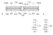
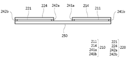
도 3a는 본 발명의 일 실시상태에 따른 가변형 가열 장치의 평면도를 개략적으로 나타낸 도면이고, 도 3b는 도 3a에서 A-B 선을 따른 가변형 가열 장치의 단면도를 개략적으로 나타낸 도면이다. 도 3a 및 도 3b를 참고하면, A-B 선의 방향이 제1 투명 발열체(111)와 제2 투명 발열체(121)의 단축 방향에 해당될 수 있고, A-B 선에 직교하는 방향이 제1 투명 발열체(111)와 제2 투명 발열체(121)의 장축 방향에 해당될 수 있다.3A is a diagram schematically showing a plan view of a variable heating apparatus according to an embodiment of the present invention, and FIG. 3B is a schematic cross-sectional view of a variable heating apparatus taken along line A-B in FIG. 3A. 3A and 3B, the direction of the line A-B may correspond to the minor axis direction of the first
본 발명의 일 실시상태에 따르면, 상기 전극들은 상기 투명 가열부의 장축 방향을 따라 구비될 수 있다. 도 3a 및 도 3b를 참고하면, 상기 전극들(141a, 141b, 142a, 142b)은 제1 및 제2 투명 발열체(111, 121)의 장축 방향을 따라, 제1 및 제2 투명 발열체(111, 121)의 양 말단에서 연속하여 구비될 수 있다. 전극들이 투명 발열체의 장축 방향을 따라 연속하여 구비됨으로써, 상기 투명 발열체의 발열 효율 및 방열 효율이 향상될 수 있다.According to an exemplary embodiment of the present invention, the electrodes may be provided along a long axis direction of the transparent heating unit. 3A and 3B, the
본 발명의 일 실시상태에 따르면, 상기 전극은 투명 전극일 수 있다. 투명 전극을 사용함으로써, 투명 가열부의 투명성을 보다 확보할 수 있다. According to an exemplary embodiment of the present invention, the electrode may be a transparent electrode. By using a transparent electrode, transparency of a transparent heating part can be ensured more.
예를 들어, 상기 전극은 ITO(Indium Tin Oxide), 그래핀, 또는 탄소나노튜브(carbon nanotube, CNT)를 포함하는 투명 전극일 수 있다. 이때, 상기 전극이 그래핀을 포함하는 것인 경우, 전극 형성을 위한 그래핀의 미세 패턴 구조를 형성하여 그래핀 전극을 형성한 후 그래핀층을 전사함으로써 상기 투명 발열체를 그래핀 일체형으로 제조할 수 있다.For example, the electrode may be a transparent electrode including indium tin oxide (ITO), graphene, or carbon nanotube (CNT). At this time, when the electrode includes graphene, the transparent heating element can be manufactured as a graphene integrated structure by forming a graphene electrode by forming a fine pattern structure of graphene for electrode formation and then transferring the graphene layer. have.
한편, 상기 전극으로 투명 전극이 아닌 미세한 크기의 패턴 구조를 가지는 전극을 사용함으로써, 사용자에게 시인되지 않도록 하여 투명 가열부의 투명성을 확보할 수도 있다.On the other hand, by using an electrode having a pattern structure of a fine size rather than a transparent electrode as the electrode, the transparency of the transparent heating unit may be secured by preventing the user from being visually recognized.
본 발명의 일 실시상태에 따르면, 투명 발열체(그래핀층) 상에 미세 패턴 구조의 전극을 형성함으로써, 상기 투명 발열체의 전면에 고효율의 균일한 열을 발생시킬 수 있다. 예를 들어, 상기 전극은 상기 그래핀층의 상부 및/또는 하부에 미세 패턴 구조로 형성되어 복수 개의 전극이 직렬 또는 병렬로 연결될 수 있으며, 이러한 경우 발열량이 증가될 수 있다.According to an exemplary embodiment of the present invention, by forming an electrode having a micro-pattern structure on the transparent heating element (graphene layer), it is possible to generate high-efficiency and uniform heat on the entire surface of the transparent heating element. For example, the electrode may be formed in a fine pattern structure on the upper and/or lower portion of the graphene layer so that a plurality of electrodes may be connected in series or in parallel, and in this case, the amount of heat generated may be increased.
상기 미세 패턴 구조의 전극을 포함하는 투명 발열체는, 마스크 공정을 통해서 전극을 미세 패턴으로 형성한 후, 상기 형성된 전극의 미세 패턴 상에 투명 발열체으로 작용하는 그래핀층을 형성할 수 있다. 또는, 투명 기재 일면에 투명 발열체로 작용하는 그래핀층을 먼저 형성하고, 상기 그래핀층 상에 전극으로 작용하는 미세 패턴의 그래핀 필름을 형성하는 것도 가능하다.The transparent heating element including the electrode having the micro-pattern structure may form a graphene layer acting as a transparent heating element on the micro-pattern of the formed electrode after forming the electrode in a micro-pattern through a mask process. Alternatively, it is possible to first form a graphene layer acting as a transparent heating element on one surface of a transparent substrate, and then to form a graphene film having a fine pattern acting as an electrode on the graphene layer.
본 발명의 일 실시상태에 따르면, 상기 투명 가열부는 상기 투명 기재 상에 구비되는 금속층을 더 포함할 수 있다. 즉, 상기 제1 투명 가열부는 제1 투명 기재와 제1 투명 발열체 사이에 구비되는 제1 금속층을 포함할 수 있고, 상기 제2 투명 가열부는 제2 투명 기재와 제2 투명 발열체 사이에 구비되는 제2 금속층을 포함할 수 있다.According to an exemplary embodiment of the present invention, the transparent heating unit may further include a metal layer provided on the transparent substrate. That is, the first transparent heating unit may include a first metal layer provided between the first transparent substrate and the first transparent heating element, and the second transparent heating unit may include a first metal layer provided between the second transparent substrate and the second transparent heating element. 2 may include a metal layer.
상기 금속층은 상기 투명 기재의 전면 또는 일부 영역 상에 구비될 수 있다. 상기 금속층은 적은 수의 그래핀층이 상기 투명 기재 상으로 전사되더라도 양 전극 사이에 전류를 보다 용이하게 흐를 수 있도록 하여 발열 효율 및 방열 효율을 향상시킬 수 있으며, 표면적을 증가시키고 표면 저항(또는 시트 저항)을 감소시켜 더 높은 열을 발생시키고 발생된 열이 보다 빠르게 방출될 수 있다.The metal layer may be provided on the entire surface or a partial region of the transparent substrate. The metal layer can improve heat generation efficiency and heat dissipation efficiency by allowing a current to flow more easily between both electrodes even if a small number of graphene layers are transferred onto the transparent substrate, and increase the surface area and surface resistance (or sheet resistance) ) to generate higher heat and the generated heat can be dissipated faster.
상기 금속층은, Ni, Co, Fe, Pt, Au, Al, Cr, Cu, Mg, Mn, Mo, Rh, Si, Ta, Ti, W, U, V, Zr, 황동(brass), 청동(bronze), 백동, 스테인레스 스틸(stainless steel) 및 Ge 로 이루어진 그룹으로부터 선택된 하나 이상의 금속 또는 합금을 포함하는 것일 수 있으나, 이에 제한되는 것은 아니다.The metal layer is, Ni, Co, Fe, Pt, Au, Al, Cr, Cu, Mg, Mn, Mo, Rh, Si, Ta, Ti, W, U, V, Zr, brass (brass), bronze (bronze) ), cupronickel, stainless steel and Ge may include one or more metals or alloys selected from the group consisting of, but is not limited thereto.
또한, 상기 투명 기재 상에 상기 금속층이 형성되어 있는 경우, 상기 금속층은 상기 그래핀층 형성을 위한 촉매 역할을 할 수 있으며, 상기 금속층이 형성된 투명 기재 상에 탄소 소스를 포함하는 반응 가스 및 열을 제공하여 반응시켜 그래핀층을 직접적으로 형성함으로써, 별도의 전사 과정 없이 투명 발열체를 제조할 수도 있다.In addition, when the metal layer is formed on the transparent substrate, the metal layer may serve as a catalyst for forming the graphene layer, and provides a reaction gas and heat including a carbon source on the transparent substrate on which the metal layer is formed. By reacting to form a graphene layer directly, it is also possible to manufacture a transparent heating element without a separate transfer process.
본 발명의 일 실시상태에 따르면, 상기 투명 기재 상에 상기 투명 발열체(그래핀)을 형성하는 방법은 하기와 같을 수 있다.According to an exemplary embodiment of the present invention, a method of forming the transparent heating element (graphene) on the transparent substrate may be as follows.
먼저, 투명 기재를 준비하고, 상기 투명 기재의 일면에 그래핀층을 형성한다. 상기 투명 기재 상에 상기 그래핀층을 형성하기 위하여, 다른 기판 상에서 형성된 그래핀층을 상기 투명 기재 상으로 전사하거나, 상기 언급한 바와 같이 상기 투명 기재 상에 금속층이 형성되어 있는 경우에는 상기 투명 기재 상의 금속층에 직접 그래핀층을 형성할 수 있다.First, a transparent substrate is prepared, and a graphene layer is formed on one surface of the transparent substrate. In order to form the graphene layer on the transparent substrate, the graphene layer formed on another substrate is transferred onto the transparent substrate, or when the metal layer is formed on the transparent substrate as described above, the metal layer on the transparent substrate A graphene layer can be formed directly on the
예를 들어, 금속 촉매 상에서 탄소 소스를 포함하는 반응 가스 및 열을 제공하여 반응시킴으로써 형성된 그래핀층을 상기 투명 기재의 일면에 전사함으로써, 상기 투명 기재 상에 그래핀층(투명 발열체)를 형성할 수 있다. 상기 탄소 소스는, 예를 들어, 일산화탄소, 이산화탄소, 메탄, 에탄, 에틸렌, 에탄올, 아세틸렌, 프로판, 부탄, 부타디엔, 펜탄, 펜텐, 사이클로펜타디엔, 헥산, 사이클로헥산, 벤젠, 톨루엔 등과 같은 탄소 소스를 기상으로 공급하면서, 예를 들어, 300 ℃ 내지 2000 ℃의 온도로 열처리하면 상기 탄소 소스에 존재하는 탄소 성분들이 결합하여 6각형의 판상 구조를 형성하면서 그래핀층이 성장된다. 상기 금속 촉매층은 기재 상에 그래핀 필름의 성장을 용이하게 하기 위하여 형성되며, 상기 금속 촉매층의 재료는 특별히 제한 없이 사용될 수 있다. 예를 들어, 상기 금속 촉매층은 Ni, Co, Fe, Pt, Au, Al, Cr, Cu, Mg, Mn, Mo, Rh, Si, Ta, Ti, W, U, V, Zr, 황동(brass), 청동(bronze), 백동, 스테인레스 스틸(stainless steel) 및 Ge 로 이루어진 그룹으로부터 선택된 하나 이상의 금속 또는 합금일 수 있다. 또한, 상기 금속 촉매층의 두께는 특별히 제한되지 않으며, 박막 또는 후막일 수 있다. 상기 그래핀층을 형성하는 방법은 당업계에서 그래핀 성장을 위해 통상적으로 사용하는 방법을 특별히 제한 없이 사용할 수 있으며, 예를 들어, 화학기상증착법을 이용할 수 있으나 이에 제한되는 것은 아니다. 상기 화학기상증착법은 고온 화학기상증착(Rapid Thermal Chemical Vapour Deposition; RTCVD), 유도결합플라즈마 화학기상증착(Inductively Coupled Plasma-Chemical Vapor Deposition; ICP-CVD), 저압 화학기상증착(Low Pressure Chemical Vapor Deposition; LPCVD), 상압 화학기상증착(Atmospheric Pressure Chemical Vapor Deposition; APCVD), 금속 유기화학기상증착(Metal Organic Chemical Vapor Deposition; MOCVD), 및 플라즈마 화학기상증착(Plasma-enhanced chemical vapor deposition; PECVD)을 포함할 수 있으나, 이제 제한되는 것은 아니다. For example, a graphene layer (transparent heating element) may be formed on the transparent substrate by transferring a graphene layer formed by reacting by providing a reaction gas including a carbon source and heat on a metal catalyst to one surface of the transparent substrate. . The carbon source may include, for example, a carbon source such as carbon monoxide, carbon dioxide, methane, ethane, ethylene, ethanol, acetylene, propane, butane, butadiene, pentane, pentene, cyclopentadiene, hexane, cyclohexane, benzene, toluene, and the like. While supplying in the gas phase, for example, when heat-treated at a temperature of 300 °C to 2000 °C, the carbon components present in the carbon source are combined to form a hexagonal plate-like structure while the graphene layer is grown. The metal catalyst layer is formed to facilitate the growth of the graphene film on the substrate, and the material of the metal catalyst layer may be used without particular limitation. For example, the metal catalyst layer includes Ni, Co, Fe, Pt, Au, Al, Cr, Cu, Mg, Mn, Mo, Rh, Si, Ta, Ti, W, U, V, Zr, brass , bronze (bronze), cupronickel, stainless steel (stainless steel) and may be one or more metals or alloys selected from the group consisting of Ge. In addition, the thickness of the metal catalyst layer is not particularly limited, and may be a thin film or a thick film. As a method of forming the graphene layer, a method commonly used for graphene growth in the art may be used without particular limitation, for example, a chemical vapor deposition method may be used, but is not limited thereto. The chemical vapor deposition method includes: Rapid Thermal Chemical Vapor Deposition (RTCVD), Inductively Coupled Plasma-Chemical Vapor Deposition (ICP-CVD), Low Pressure Chemical Vapor Deposition; LPCVD), atmospheric pressure chemical vapor deposition (APCVD), metal organic chemical vapor deposition (MOCVD), and plasma-enhanced chemical vapor deposition (PECVD). However, it is not limited now.
상기 그래핀층을 성장시키는 공정은 상압, 저압 또는 진공 하에서 수행 가능하다. 예를 들어, 상압 조건 하에서 상기 공정을 수행하는 경우 헬륨(He) 등을 캐리어 가스로 사용함으로써 고온에서 무거운 아르곤(Ar)과의 충돌에 의해 야기되는 그래핀의 손상(damage)을 최소화시킬 수 있다. 또한 상압 조건 하에서 상기 공정을 수행하는 경우, 저비용으로 간단한 공정에 의하여 대면적 그래핀 필름을 제조할 수 있는 이점이 있다. 또한, 상기 공정이 저압 또는 진공 조건에서 수행되는 경우, 수소(H2)를 분위기 가스로 사용하며, 온도를 올리면서 처리하여 주면 금속 촉매의 산화된 표면을 환원시킴으로써 고품질의 그래핀을 합성할 수 있다. 상기 언급한 방법에 의해 형성되는 그래핀층은 횡방향 및/또는 종방향 길이가 약 1 mm 이상 내지 약 1000 m 에 이르는 대면적일 수 있다. 또한, 상기 그래핀 필름은 결함이 거의 없는 균질한 구조를 가진다. 상기 언급한 방법에 의해 제조되는 그래핀층은 그래핀의 단일층 또는 복수층을 포함할 수 있다. 비제한적 예로서, 상기 그래핀 필름의 두께는 1 층 내지 100 층 범위에서 조절할 수 있다.The process of growing the graphene layer may be performed under normal pressure, low pressure, or vacuum. For example, when the process is performed under atmospheric pressure, damage to graphene caused by collision with heavy argon (Ar) at a high temperature can be minimized by using helium (He) or the like as a carrier gas. . In addition, when the process is performed under atmospheric pressure, there is an advantage in that a large-area graphene film can be manufactured at a low cost and by a simple process. In addition, when the process is performed under low pressure or vacuum conditions, high-quality graphene can be synthesized by using hydrogen (H 2 ) as an atmospheric gas and reducing the oxidized surface of the main metal catalyst by treating it while raising the temperature. have. The graphene layer formed by the above-mentioned method may have a large area ranging from about 1 mm or more to about 1000 m in transverse and/or longitudinal direction. In addition, the graphene film has a homogeneous structure with few defects. The graphene layer prepared by the above-mentioned method may include a single layer or multiple layers of graphene. As a non-limiting example, the thickness of the graphene film may be adjusted in the range of 1 to 100 layers.
이후, 상기 그래핀층은 다양한 공정에 의하여 투명 기재 상에 전사될 수 있다. 상기 전사 방법은 그래핀층을 기판 상에 전사하여 코팅시키기 위하여 당업계에서 통상적으로 사용되는 방법이라면 제한 없이 사용 가능하며, 예를 들어, 건식 공정, 습식 공정, 스프레이 공정, 롤투롤 공정을 사용할 수 있다. Thereafter, the graphene layer may be transferred onto the transparent substrate by various processes. The transfer method can be used without limitation as long as it is a method commonly used in the art to transfer and coat the graphene layer on a substrate, for example, a dry process, a wet process, a spray process, and a roll-to-roll process can be used. .
상기 롤투롤 공정에 의한 전사 방법은 대면적 그래핀층의 전사 방법으로서 유용하게 사용될 수 있으며, 예를 들어, 투명 발열체로서 그래핀층을 형성하기 위하여 상기 롤투롤 공정에 의하여 대면적 그래핀층을 상기 투명 기재(후술하는 투명 유연 기재) 등에 전사할 수 있다. 또한, 상기 전극이 그래핀을 포함하는 투명 전극인 경우, 상기 롤투롤 공정을 이용하여 그래핀층을 상기 투명 기재 상에 전사하여 그래핀 전극 미세 패턴을 자유롭게 형성할 수 있다.The transfer method by the roll-to-roll process may be usefully used as a transfer method of a large-area graphene layer, for example, a large-area graphene layer is transferred to the transparent substrate by the roll-to-roll process to form a graphene layer as a transparent heating element. (Transparent flexible base material mentioned later) etc. can be transcribe|transferred. In addition, when the electrode is a transparent electrode including graphene, the graphene layer may be transferred onto the transparent substrate by using the roll-to-roll process to freely form a fine pattern of the graphene electrode.
상기 롤투롤 공정에 의한 전사 방법은 그래핀이 형성되어 있는 유연성 기판 및 상기 그래핀 상에 접촉된 목적 기판을 전사 롤러(transfer roller)로 롤링하여 상기 그래핀 필름을 상기 목적 기판 상에 전사시키는 것을 포함하는데, 보다 상세하게는 3 단계를 포함할 수 있다. 상기 3 단계는, 그래핀 성장 지지체 상에 형성된 그래핀 과 상기 그래핀 상에 접촉된 유연성 기판을 접착 롤러(roller)인 제1 롤러로 롤링함으로써 그래핀 성장 지지체-그래핀 필름-유연성 기판의 적층체를 형성하고; 상기 적층체를 제 2 롤러를 이용하여 에칭 용액 내로 함침되어 통과하도록 함으로써 상기 그래핀 성장 지지체를 에칭하여 상기 그래핀 필름을 상기 유연성 기판 상에 전사하고; 상기 그래핀 필름이 전사된 유연성 기판 및 상기 그래핀 필름 상에 접촉된 목적 기판을 전사 롤러(transfer roller)인 제3 롤러로 롤링하여 상기 그래핀 필름을 상기 목적 기판 상에 전사시키는 것을 포함할 수 있다.The transfer method by the roll-to-roll process involves rolling the flexible substrate on which graphene is formed and the target substrate in contact with the graphene with a transfer roller to transfer the graphene film onto the target substrate. Including, in more detail, may include three steps. In the third step, the graphene growth support-graphene film-flexible substrate is laminated by rolling the graphene formed on the graphene growth support and the flexible substrate contacted on the graphene with a first roller that is an adhesive roller. form a sieve; transferring the graphene film onto the flexible substrate by etching the graphene growth support by impregnating the laminate into an etching solution using a second roller to pass therethrough; It may include transferring the graphene film onto the target substrate by rolling the flexible substrate to which the graphene film is transferred and the target substrate in contact with the graphene film with a third roller that is a transfer roller. have.
마지막으로, 상기 그래핀층을 상기 투명 기재 상에 전사하여 형성한 이후에는 상기 그래핀층의 양 말단 또는 상기 그래핀층의 상부 및/또는 하부에 전극을 형성할 수 있다.Finally, after the graphene layer is transferred and formed on the transparent substrate, electrodes may be formed at both ends of the graphene layer or on the upper and/or lower portions of the graphene layer.
본 발명의 일 실시상태에 따르면, 상기 폴딩부는 상기 제1 투명 가열부와 상기 제2 투명 가열부를 연결하고, 제1 투명 가열부에 대하여 상기 제2 투명 가열부를 이동시킬 수 있는 구성으로서, 당업계에서 사용되는 것을 제한 없이 이용할 수 있다. 예를 들어, 상기 폴딩부는 상기 제1 및 제2 투명 가열부와 힌지 결합되어, 제1 투명 가열부에 대하여 상기 제2 투명 가열부를 힌지 이동시킬 수 있다. 또한, 상기 폴딩부는 신축성이 있는 고무 등의 소재로 형성되어, 상기 폴딩부의 신축성을 통해 상기 가변형 가열 장치가 폴딩될 수 있다.According to an exemplary embodiment of the present invention, the folding part connects the first transparent heating part and the second transparent heating part, and is a configuration that can move the second transparent heating part with respect to the first transparent heating part, It can be used without limitation. For example, the folding unit may be hingedly coupled to the first and second transparent heating units to move the second transparent heating unit by a hinge with respect to the first transparent heating unit. In addition, the folding part may be formed of a material such as elastic rubber, and the variable heating device may be folded through the elasticity of the folding part.
도 4a는 본 발명의 일 실시상태에 따른 가변형 가열 장치의 폴딩부가 탈착된 상태를 개략적으로 나타낸 도면이다.4A is a view schematically showing a state in which the folding part of the variable heating device according to an embodiment of the present invention is detached.
본 발명의 일 실시상태에 따르면, 상기 폴딩부는 상기 제1 투명 가열부와 상기 제2 투명 가열부에 대하여 탈부착 가능할 수 있다. 도 3b를 참고하면, 폴딩부(130)가 제1 투명 가열부(110) 및 제2 투명 가열부(120)에 부착되어, 가변형 가열 장치가 제공될 수 있다. 반면, 도 3b 및 도 4a를 참고하면, 폴딩부(130)가 제1 투명 가열부(110) 및 제2 투명 가열부(120)에서 탈착됨으로써, 제1 투명 가열부와 제2 투명 가열부가 분리될 수 있다. 이를 통해, 제1 투명 가열부와 제2 투명 가열부를 별도로 사용할 수 있다. 즉, 사용자는 대상체의 크기, 대상체의 종류를 고려하여 폴딩부를 탈부착함으로써, 가변형 가열 장치로 사용하거나 또는 2 개의 가열 장치로 사용할 수 있다.According to an exemplary embodiment of the present invention, the folding part may be detachable with respect to the first transparent heating part and the second transparent heating part. Referring to FIG. 3B , the
도 4b는 본 발명의 일 실시상태에 따른 가변형 가열 장치의 폴딩부가 변형되어 제1 투명 가열부와 제2 투명 가열부 사이의 거리가 조절되는 것을 보여주는 도면이다.4B is a view showing that the folding part of the variable heating device according to an embodiment of the present invention is deformed to adjust the distance between the first transparent heating part and the second transparent heating part.
본 발명의 일 실시상태에 따르면, 상기 폴딩부는 상기 제1투명 가열부와 상기 제2 투명 가열부 사이를 조절할 수 있다. 도 1a와 같이 상기 가변형 가열 장치(100)를 폴딩 상태로 사용하는 경우, 대상체의 두께에 따라 폴딩부(130)를 조절함으로써, 상기 제1 투명 가열부(110)와 제2 투명 가열부(120) 사이에 가열 대상체를 용이하게 구비시킬 수 있다. 예를 들어, 폴딩된 상태의 상기 가변형 가열 장치를 토스터기로 사용하는 경우, 굽고자 하는 빵의 두께에 따라 상기 폴딩부를 변형시켜, 상기 제1 투명 가열부와 상기 제2 투명 가열부 사이에 빵을 용이하게 위치시켜 구울 수 있다.According to an exemplary embodiment of the present invention, the folding unit may adjust between the first transparent heating unit and the second transparent heating unit. When the
또한, 도 1b에서와 같이 상기 가변형 가열 장치(100)를 펼친 상태로 사용하는 경우, 제1 투명 가열부(110)와 제2 투명 가열부(120) 사이의 거리를 조절하여, 사용자의 작업 편의성을 향상시킬 수 있다.In addition, when the
상기 폴딩부는 상기 제1 가열부와 제2 가열부 사이의 거리를 조절할 수 있는 것으로, 당업계에서 2 물체를 연결함과 동시에 그 거리를 조절할 수 있는 구성을 제한 없이 사용할 수 있다. 예를 들어, 도 3b 및 도 4b에 도시된 바와 같이, 상기 폴딩부(130)는 2단 접이식으로 구성되어 상기 제1 투명 가열부(110)와 제2 투명 가열부(120) 사이의 거리를 조절할 수 있다.The folding part can adjust the distance between the first heating part and the second heating part, and in the art, a configuration that can connect two objects and adjust the distance can be used without limitation. For example, as shown in FIGS. 3B and 4B , the
도 5a는 본 발명의 일 실시상태에 따른 가변형 가열 장치의 평면도를 개략적으로 나타낸 도면이고, 도 5b는 도 5a에서 A-B 선을 따른 가변형 가열 장치의 단면도를 개략적으로 나타낸 도면이다.5A is a diagram schematically showing a plan view of a variable heating device according to an embodiment of the present invention, and FIG. 5B is a diagram schematically showing a cross-sectional view of the variable heating device taken along line A-B in FIG. 5A.
본 발명의 일 실시상태에 따르면, 상기 가변형 가열 장치는 투명 유연 기재를 더 포함하며, 상기 투명 유연 기재는 상기 제1 투명 가열부가 구비되는 제1 투명 가열 영역; 상기 제2 투명 가열부가 구비되는 제2 투명 가열 영역; 및 상기 제1 투명 가열부와 상기 제2 투명 가열부 사이에 위치하는 폴딩 영역을 포함하고, 상기 폴딩부는 상기 폴딩 영역에 대응되는 상기 투명 유연 기재의 부분일 수 있다.According to an exemplary embodiment of the present invention, the variable heating device further comprises a transparent flexible substrate, the transparent flexible substrate is a first transparent heating region provided with the first transparent heating unit; a second transparent heating region provided with the second transparent heating unit; and a folding region positioned between the first transparent heating part and the second transparent heating part, wherein the folding part may be a portion of the transparent flexible substrate corresponding to the folding region.
본 발명의 일 실시상태에 따르면, 상기 가변형 가열 장치는 투명 유연 기재를 포함할 수 있다. 도 5a 및 도 5b를 참고하면, 상기 가변형 가열 장치(100)는 하나의 투명 유연 기재(150)와 이의 일면 상에 구비된 제1 투명 가열부(110)와 제2 투명 가열부(120)를 포함한다.According to an exemplary embodiment of the present invention, the variable heating device may include a transparent flexible substrate. Referring to FIGS. 5A and 5B , the
도 5a 및 도 5b를 참고하면, 상기 투명 유연 기재(150)는 상기 제1 투명 가열부(110)가 구비되는 제1 투명 가열 영역(HZ1); 상기 제2 투명 가열부(120)가 구비되는 제2 투명 가열 영역(HZ2); 및 상기 제1 투명 가열부(110)와 상기 제2 투명 가열부(120) 사이에 위치하는 폴딩 영역(FZ)을 포함하고, 상기 폴딩부는 상기 폴딩 영역(FZ)에 대응되는 상기 투명 유연 기재(150)의 부분일 수 있다. 투명 유연 기재(50)의 폴딩 영역(FZ) 상에 전극(41a, 42a)이 구비될 수 있다. Referring to FIGS. 5A and 5B , the transparent
본 발명의 일 실시상태에 따르면, 상기 제1 및 제2 투명 가열부가 구비되는 기재로서 유연성을 가지는 투명 기재를 사용하여, 상기 가변형 가열 장치를 폴딩하기 위한 별도의 구성을 생략할 수 있다. 즉, 상기 제1 및 제2 투명 가열부가 미구비된 상기 투명 유연 기재의 부분을 폴딩부로 활용할 수 있다.According to an exemplary embodiment of the present invention, a separate configuration for folding the variable heating device may be omitted by using a flexible transparent substrate as the substrate provided with the first and second transparent heating units. That is, a portion of the transparent flexible substrate that is not provided with the first and second transparent heating units may be utilized as a folding unit.
상기 투명 유연 기재로 투명하면서도 플렉시블한 기재를 사용할 수 있다. 예를 들어, 상기 투명 유연 기재는 폴리이미드 필름, 폴리에스테르 필름 등을 사용할 수 있으나, 상기 투명 유연 기재의 종류를 한정하는 것은 아니다.A transparent and flexible substrate may be used as the transparent flexible substrate. For example, the transparent flexible substrate may be a polyimide film, a polyester film, etc., but the type of the transparent flexible substrate is not limited thereto.
도 6a는 본 발명의 일 실시상태에 따른 제어부, 온도 표시부, 구동 시간 제어부 및 발광 소자가 구비된 가변형 가열 장치의 평면도를 개략적으로 나타낸 도면이고, 도 6b는 본 발명의 일 실시상태에 따른 제어부, 온도 표시부, 구동 시간 제어부 및 영상 디스플레이부가 구비된 가변형 가열 장치의 평면도를 개략적으로 나타낸 도면이다. 도 6a 및 도 6b에는 설명의 편의를 위하여, 제1 투명 가열부에 포함되는 제1 투명 발열체, 전극 들의 구성을 생략하여 도시하였고, 제2 투명 가열부에 포함되는 제2 투명 발열체, 전극 들의 구성을 생략하여 도시하였다.6A is a diagram schematically showing a plan view of a variable heating device having a control unit, a temperature display unit, a driving time control unit, and a light emitting element according to an embodiment of the present invention, FIG. 6B is a control unit according to an embodiment of the present invention; It is a diagram schematically showing a plan view of a variable heating device provided with a temperature display unit, a driving time control unit, and an image display unit. For convenience of explanation, the configuration of the first transparent heating element and electrodes included in the first transparent heating unit is omitted in FIGS. 6A and 6B, and the configuration of the second transparent heating element and electrodes included in the second transparent heating unit is omitted. is omitted.
본 발명의 일 실시상태에 따르면, 상기 제1 투명 발열체와 연결되어 상기 제1 투명 발열체의 발열 정도를 제어하는 제1 온도 제어부; 및 상기 제2 투명 발열체와 연결되어 상기 제2 투명 발열체의 발열 정도를 제어하는 제2 온도 제어부;를 더 포함할 수 있다.According to an exemplary embodiment of the present invention, a first temperature control unit connected to the first transparent heating element to control the degree of heat generation of the first transparent heating element; and a second temperature controller connected to the second transparent heating element to control the degree of heat generation of the second transparent heating element.
도 6a 및 도 6b를 참고하면, 제1 투명 가열부(110)의 표면 상에 제1 온도 제어부(161)가 구비되고, 제2 투명 가열부(120)의 표면 상에 제2 온도 제어부(162)가 구비될 수 있다. 상기 제1 및 제2 온도 제어부(161, 162)는 당업계에서 가열 장치의 구동 온도를 조절하는 구성을 제한 없이 채택하여 사용할 수 있다. 6A and 6B , the first
상기 제1 온도 제어부는 상기 제1 투명 발열체와 연결되어 이의 구동 온도를 제어하고, 상기 제2 온도 제어부는 상기 제2 투명 발열체와 연결되어 이의 구동 온도를 제어할 수 있다. 즉, 상기 제1 및 제2 투명 발열체의 구동 온도는 독립적으로 제어가 가능할 수 있다.The first temperature controller may be connected to the first transparent heating element to control the driving temperature thereof, and the second temperature controller may be connected to the second transparent heating element to control the driving temperature thereof. That is, the driving temperatures of the first and second transparent heating elements may be independently controllable.
본 발명의 일 실시상태에 따르면, 상기 제1 투명 발열체와 연결되어 상기 제1 투명 발열체의 온도 및 구동 시간을 포함하는 구동 정보를 표시하는 제1 디스플레이부; 및 상기 제2 투명 발열체와 연결되어 상기 제2 투명 발열체의 온도 및 구동 시간을 포함하는 구동 정보를 표시하는 제2 디스플레이부;를 더 포함할 수 있다. 도 6a 및 도 6b를 참고하면, 제1 투명 가열부(110)에 제1 디스플레이부(171)가 구비되고, 제2 투명 가열부(120)에 제2 디스플레이부(172)가 구비될 수 있다.According to an exemplary embodiment of the present invention, a first display unit connected to the first transparent heating element to display driving information including the temperature and driving time of the first transparent heating element; and a second display unit connected to the second transparent heating element to display driving information including a temperature and a driving time of the second transparent heating element. 6A and 6B , the
상기 디스플레이부는 상기 투명 발열체와 연결되어 상기 투명 발열체의 구동 정보를 사용자에게 표시할 수 있으며, 당업계에서 사용되는 디스플레이 소자를 사용할 수 있다. 특히, 상기 디스플레이부로서 투명 디스플레이 소자를 사용함으로써, 상기 투명 가열부의 투명성을 확보할 수 있다.The display unit may be connected to the transparent heating element to display driving information of the transparent heating element to the user, and a display device used in the art may be used. In particular, by using a transparent display element as the display unit, transparency of the transparent heating unit can be ensured.
상기 가변형 가열 장치는 상기 투명 발열체와 연결되어 상기 투명 발열체의 온도를 측정하는 온도 센서부를 더 포함할 수 있으며, 상기 디스플레이부는 상기 온도 센서부와 연동되어 투명 발열체의 온도를 표시할 수 있다. 상기 디스플레이부에서 표시되는 투명 발열체의 온도는, 숫자, 게이지, 색상 등으로 사용자에게 온도 정보를 표시할 수 있는 다양한 형태로 나타날 수 있다.The variable heating device may further include a temperature sensor unit connected to the transparent heating element to measure the temperature of the transparent heating element, and the display unit may be linked with the temperature sensor unit to display the temperature of the transparent heating element. The temperature of the transparent heating element displayed on the display unit may be displayed in various forms capable of displaying temperature information to the user with numbers, gauges, colors, and the like.
본 발명의 일 실시상태에 따르면, 상기 제1 디스플레이부 및 제2 디스플레이부 각각은, 투명 발열체의 온도에 따라 색을 변화시키는 발광 소자를 포함할 수 있다. 도 6a를 참고하면, 상기 제1 및 제2 투명 가열부(110, 120)의 양 말단에 발광 소자(LED)가 구비될 수 있다. 상기 발광 소자는 당업계에서 사용되는 발광 소자를 사용할 수 있으며, 예를 들어, OLED 소자를 사용할 수 있다.According to an exemplary embodiment of the present invention, each of the first display unit and the second display unit may include a light emitting device that changes color according to the temperature of the transparent heating element. Referring to FIG. 6A , light emitting devices (LEDs) may be provided at both ends of the first and second
상기 발광 소자는 상기 온도 센서부와 연동되어, 상기 투명 발열체의 온도에 따라 다른 색을 발현시킬 수 있다. 예를 들어, 투명 발열체의 온도가 낮은 경우에는 상기 발광 소자는 청색의 광의 발광하고, 투명 발열체의 온도가 어느 정도 상승한 경우에는 상기 발광 소자는 녹색의 광의 발광하고, 상기 투명 발열체의 온도가 높아진 경우에는 상기 발광 소자는 적색의 광의 발광하도록 설정될 수 있다.The light emitting element may be linked with the temperature sensor unit to express different colors according to the temperature of the transparent heating element. For example, when the temperature of the transparent heating element is low, the light emitting element emits blue light, and when the temperature of the transparent heating element rises to some extent, the light emitting element emits green light, and when the temperature of the transparent heating element increases In this case, the light emitting device may be set to emit red light.
본 발명의 일 실시상태에 따르면, 상기 제1 투명 발열체와 연결되어 상기 제1 투명 발열체의 구동 시간을 제어하는 제1 구동 시간 제어부; 및 상기 제2 투명 발열체와 연결되어 상기 제2 투명 발열체의 구동 시간을 제어하는 제2 구동 시간 제어부를 더 포함할 수 있다. 도 6a 및 도 6b를 참고하면, 제1 투명 가열부(110)에 제1 구동 시간 제어부(181)가 구비되고, 제2 투명 가열부(120)에 제2 구동 시간 제어부(182)가 구비될 수 있다. 상기 구동 시간 제어부를 통해 상기 투명 발열체의 구동 시간을 미리 설정할 수 있으며, 설정되는 시간은 상기 디스플레이부를 통하여 표시될 수 있다.According to an exemplary embodiment of the present invention, a first driving time control unit connected to the first transparent heating element to control the driving time of the first transparent heating element; and a second driving time controller connected to the second transparent heating element to control a driving time of the second transparent heating element. 6A and 6B , the first driving
본 발명의 일 실시상태에 따르면, 상기 제1 투명 가열부 및 상기 제2 투명 가열부 중 적어도 하나는 영상을 출력하는 영상 디스플레이부를 더 포함할 수 있다. 도 6b를 참고하면, 제1 투명 가열부(110)는 제1 영상 디스플레이부(173a)를 포함하고, 제2 투명 가열부(120)는 제2 영상 디스플레이부(173b)를 포함할 수 있다. According to an exemplary embodiment of the present invention, at least one of the first transparent heating unit and the second transparent heating unit may further include an image display unit for outputting an image. Referring to FIG. 6B , the first
상기 영상 디스플레이부는 사용자가 미리 설정한 영상을 출력할 수 있다. 예를 들어, 상기 영상 디스플레이부는 자연 경관, 특정 건물, 모닥불, 화로 등의 다양한 영상을 출력할 수 있다. 특히, 상기 영상 디스플레이부로서 투명 디스플레이 소자를 사용함으로써, 상기 투명 가열부의 투명성을 확보할 수 있다. 상기 제1 투명 가열부에 상기 영상 디스플레이부가 구비되는 경우, 상기 제1 투명 기재와 제2 투명 기재 사이에 형성된 에어갭 공간에 상기 영상 디스플레이부 구비될 수 있다. 예를 들어, 상기 영상 디스플레이부는 상기 제2 투명 기재 상에 구비되어, 상기 제1 투명 발열체에 대향하게 위치할 수 있다.The image display unit may output an image preset by a user. For example, the image display unit may output various images such as a natural landscape, a specific building, a bonfire, and a brazier. In particular, by using a transparent display element as the image display unit, transparency of the transparent heating unit can be secured. When the image display unit is provided in the first transparent heating unit, the image display unit may be provided in an air gap space formed between the first transparent substrate and the second transparent substrate. For example, the image display unit may be provided on the second transparent substrate and positioned to face the first transparent heating element.
본 발명의 일 실시상태에 따르면, 상기 제1 투명 가열부는 상기 제1 투명 발열체 상에 구비되는 제1 투명 성형부를 포함할 수 있고, 상기 제2 투명 가열부는 상기 제2 투명 발열체 상에 구비되는 제2 투명 성형부를 포함할 수 있다. 상기 투명 성형부는 가열 대상체를 소정의 형상으로 성형할 수 있는 부재일 수 있다. 예를 들어, 상기 제1 및 제2 투명 성형부는 와플 형태의 필름, 붕어빵 형태의 필름 등일 수 있다. 상기 제1 및 제2 투명 성형부를 이용하여, 상기 제1 및 제2 투명 가열부를 통해 가열되는 대상체의 형태를 성형할 수 있다. 상기 제1 및 제2 투명 성형부는 상기 제1 및 제2 투명 가열부에 대하여 탈부착이 가능할 수 있다. 상기 제1 및 제2 투명 성형부는, 투명하며 열 전도성이 우수한 소재로 구현될 수 있다.According to an exemplary embodiment of the present invention, the first transparent heating unit may include a first transparent molding unit provided on the first transparent heating element, and the second transparent heating unit is provided on the second transparent heating element. 2 It may include a transparent molding part. The transparent molding part may be a member capable of molding a heating object into a predetermined shape. For example, the first and second transparent molding parts may be a waffle-shaped film, a bungeoppang-shaped film, or the like. The shape of the object heated through the first and second transparent heating units may be formed by using the first and second transparent molding units. The first and second transparent molding parts may be detachable with respect to the first and second transparent heating parts. The first and second transparent molding parts may be made of a transparent material having excellent thermal conductivity.
본 발명의 일 실시상태에 따르면, 상기 제1 투명 가열부 및 상기 제2 투명 가열부의 광투과도는 50% 이상 99% 이하일 수 있다. 구체적으로, 상기 제1 및 제2 투명 가열부의 광투과도는 60% 이상 99% 이하, 70% 이상 99% 이하, 80% 이상 95% 이하, 또는 85% 이상 90% 이하일 수 있다. 이때, 상기 제1 및 제2 투명 가열부의 광투과도는 550 nm 파장에서 측정한 것일 수 있다. 따라서, 상기 제1 및 제2 투명 가열부는 우수한 광투과도를 가지고 있어, 상기 제1 및 제2 투명 가열부에 의하여 가열되는 대상의 상태를 용이하게 확인할 수 있다.According to an exemplary embodiment of the present invention, light transmittance of the first transparent heating unit and the second transparent heating unit may be 50% or more and 99% or less. Specifically, the light transmittance of the first and second transparent heating units may be 60% or more and 99% or less, 70% or more and 99% or less, 80% or more and 95% or less, or 85% or more and 90% or less. In this case, the light transmittance of the first and second transparent heating units may be measured at a wavelength of 550 nm. Accordingly, since the first and second transparent heating units have excellent light transmittance, it is possible to easily check the state of the object heated by the first and second transparent heating units.
도 7a 내지 도 7d는 본 발명의 일 실시상태에 따른 가변형 가열 장치에 포함된 전극을 나타낸 도면이다. 구체적으로, 도 7a 내지 도 7d는 제1 투명 가열부를 중점으로 나타낸 것이고, 제2 투명 가열부 또한 도 7a 내지 도 7d에 나타낸 전극 구조와 동일한 구조를 포함할 수 있다. 한편, 본 발명의 일 실시상태에 따른 전극의 형태가 도 7a 내지 도 7d로 한정되는 것은 아니다.7A to 7D are views illustrating electrodes included in a variable heating device according to an exemplary embodiment of the present invention. Specifically, FIGS. 7A to 7D show the first transparent heating part mainly, and the second transparent heating part may also include the same structure as the electrode structure shown in FIGS. 7A to 7D . Meanwhile, the shape of the electrode according to an exemplary embodiment of the present invention is not limited to FIGS. 7A to 7D .
도 7a는 제1 전극(141a), 제2 전극(141b), 제1 보조 전극(141c) 및 제2 보조 전극(141d)과 제1 투명 발열체(111)를 포함한 제1 투명 가열부(110)의 평면도를 나타낸 것이고, 도 7b는 도 7a에서 원으로 표시된 영역의 확대도이고, 도 7c는 제2 보조 전극(141d)을 확대한 도면이고, 도 7d는 제1 투명 기재(112) 상에 구비된 제1 및 제2 보조 전극(141c, 141d)의 형태를 나타낸 도면이다.7A is a first
도 7a를 참고하면, 제1 투명 가열부(110)의 장변(d3)의 길이는 200 mm 이상 400 mm 이하일 수 있고, 제1 투명 가열부(110)의 단변(d2)의 길이는 150 mm 이상 350 mm 이하일 수 있다. 상기 제1 투명 가열부(110)의 장변(d3)과 단변(d2)의 길이가 전술한 범위 내인 경우, 상기 가변형 가열 장치의 휴대성 및 보관성이 우수할 수 있다. 다만, 상기 제1 투명 가열부의 장변과 단변의 길이는 사용하고자 하는 용도에 따라 상기 범위와 달리 설정될 수도 있다.Referring to FIG. 7A , the length of the long side d3 of the first
도 7a를 참고하면, 제1 투명 기재(112)의 단변(d2)와 제1 투명 발열체(11)의 폭(d4)의 길이비는 1:0.5 내지 1:0.9일 수 있다. 제1 투명 기재(112)의 단변(d2)와 제1 투명 발열체(111)의 폭(d4)의 길이비가 전술한 범위 내인 경우, 상기 제1 투명 가열부(110)는 대상체를 효과적으로 가열할 수 있다. 상기 제1 투명 발열체(111)의 폭(d4)은 130 mm 이상 180 mm 이하일 수 있다.Referring to FIG. 7A , a length ratio between the short side d2 of the first
도 7a 내지 도 7d를 참고하면, 제1 투명 기재(112) 상에 제1 및 제2 보조 전극(141c, 141d)이 구비되고, 제1 및 제2 보조 전극(141c, 141d) 상에 제1 투명 발열체(111), 제1 및 제2 전극(141a, 141b)가 구비될 수 있다. 반면, 제1 투명 기재(112) 상에 제1 투명 발열체(111), 제1 및 제2 전극(141a, 141b)가 구비되고, 제1 투명 발열체(111), 제1 및 제2 전극(141a, 141b) 상에 제1 및 제2 보조 전극(141c, 141d)이 구비될 수도 있다. 7A to 7D , first and second
도 17은 본 발명의 일 실시상태에 따른 투명 기재인 유리 상에 보조 전극으로서 격자 무늬 형태의 은(Ag) 전극이 형성된 것을 촬영한 이미지이다.FIG. 17 is a photograph taken of a silver (Ag) electrode having a grid pattern as an auxiliary electrode formed on glass, which is a transparent substrate, according to an exemplary embodiment of the present invention.
본 발명의 일 실시상태에 따르면, 상기 제1 및 제2 보조 전극은 사다리 형태, 또는 격자 형태로 구비될 수 있다.According to an exemplary embodiment of the present invention, the first and second auxiliary electrodes may be provided in a ladder shape or a grid shape.
본 발명의 일 실시상태에 따르면, 상기 제1 보조 전극 및 상기 제2 보조 전극 각각의 길이당 저항값은 0.001 Ω/cm 이상 4 Ω/cm 이하, 0.003 Ω/cm 이상 3.5 Ω/cm 이하, 0.01 Ω/cm 이상 3 Ω/cm 이하, 0.05 Ω/cm 이상 2.5 Ω/cm 이하, 0.1 Ω/cm 이상 2 Ω/cm 이하, 0.1 Ω/cm 이상 2 Ω/cm 이하, 0.1 Ω/cm 이상 1.5 Ω/cm 이하, 또는 0.1 Ω/cm 이상 1 Ω/cm 이하일 수 있다. 예를 들어, 상기 제1 보조 전극(제2 보조 전극) 30 cm 기준으로, 저항값은 0.1 Ω 이상 100 Ω 이하, 1 Ω 이상 80 Ω 이하, 2 Ω 이상 50 Ω 이하, 또는 3 Ω 이상 30 Ω 이하일 수 있다.According to an exemplary embodiment of the present invention, the resistance value per length of each of the first auxiliary electrode and the second auxiliary electrode is 0.001 Ω/cm or more and 4 Ω/cm or more, 0.003 Ω/cm or more and 3.5 Ω/cm or less, 0.01 Ω/cm or more and 3 Ω/cm or less, 0.05 Ω/cm or more and 2.5 Ω/cm or less, 0.1 Ω/cm or more and 2 Ω/cm or less, 0.1 Ω/cm or more and 2 Ω/cm or less, 0.1 Ω/cm or more and 1.5 Ω /cm or less, or 0.1 Ω/cm or more and 1 Ω/cm or less. For example, based on 30 cm of the first auxiliary electrode (second auxiliary electrode), the resistance value is 0.1 Ω or more and 100 Ω or less, 1 Ω or more and 80 Ω or less, 2 Ω or more and 50 Ω or less, or 3 Ω or more 30 Ω may be below.
상기 제1 보조 전극 및 상기 제2 보조 전극 각각의 저항값이 전술한 범위 내인 경우, 제1 투명 발열체가 제1 보조 전극을 통해 제1 전극과 연결되고, 제1 투명 발열체가 제2 보조 전극을 통해 제2 전극과 연결됨에 따라, 상기 제1 투명 발열체에 전류를 효율적으로 인가할 수 있어, 상기 제1 투명 발열체의 발열 효율이 향상될 수 있다.When the resistance value of each of the first auxiliary electrode and the second auxiliary electrode is within the above-described range, the first transparent heating element is connected to the first electrode through the first auxiliary electrode, and the first transparent heating element is connected to the second auxiliary electrode As it is connected to the second electrode through the electrode, a current may be efficiently applied to the first transparent heating element, so that the heating efficiency of the first transparent heating element may be improved.
상기 제1 보조 전극 및 상기 제2 보조 전극 각각의 높이(또는 두께)는 10 nm 이상 3 ㎛ 이하, 또는 100 nm 이상 3 ㎛ 이하일 수 있다. 상기 제1 보조 전극 및 상기 제2 보조 전극 각각의 높이가 전술한 범위 내인 경우, 상기 제1 투명 발열체에 전류를 효율적으로 인가할 수 있어, 상기 제1 투명 발열체의 발열 효율이 향상될 수 있다.Each of the first auxiliary electrode and the second auxiliary electrode may have a height (or thickness) of 10 nm or more and 3 μm or less, or 100 nm or more and 3 μm or less. When the height of each of the first auxiliary electrode and the second auxiliary electrode is within the above-described range, a current may be efficiently applied to the first transparent heating element, so that the heating efficiency of the first transparent heating element may be improved.
상기 제1 보조 전극 및 상기 제2 보조 전극은 당업계에서 사용되는 전극 물질을 이용하여 제조될 수 있고, 예를 들어 은(Ag)을 이용하여, 상기 제1 보조 전극 및 상기 제2 보조 전극을 제조할 수 있다. 또한, 상기 제1 전극 및 상기 제2 전극은 당업계에서 사용되는 전극 물질을 이용하여 제조될 수 있고, 예를 들어 구리(Cu)을 이용하여, 상기 제1 전극 및 상기 제2 전극을 제조할 수 있다.The first auxiliary electrode and the second auxiliary electrode may be manufactured using an electrode material used in the art. For example, silver (Ag) may be used to form the first auxiliary electrode and the second auxiliary electrode. can be manufactured. In addition, the first electrode and the second electrode may be manufactured using an electrode material used in the art, for example, using copper (Cu), to manufacture the first electrode and the second electrode. can
본 발명의 일 실시상태에 따르면, 상기 제1 전극 및 상기 제2 전극 각각의 길이당 저항값은 0.01 Ω/cm 이상 2 Ω/cm 이하, 0.05 Ω/cm 이상 1.5 Ω/cm 이하, 또는 0.1 Ω/cm 이상 1 Ω/cm 이하일 수 있다. 예를 들어, 상기 제1 전극(제2 전극) 30 cm 기준으로, 저항값은 0.1 Ω 이상 10 Ω 이하일 수 있다. 상기 제1 전극 및 상기 제2 전극 각각의 저항값이 전술한 범위 내인 경우, 상기 제1 투명 발열체에 전류를 효율적으로 인가할 수 있어, 상기 제1 투명 발열체의 발열 효율이 향상될 수 있다. 또한, 상기 제1 전극 및 상기 제2 전극 각각의 높이(또는 두께)는 0.5 ㎛ 이상 3 ㎛ 이하일 수 있다. 상기 제1 전극 및 상기 제2 전극 각각의 높이가 전술한 범위 내인 경우, 상기 제1 투명 발열체에 전류를 효율적으로 인가할 수 있어, 상기 제1 투명 발열체의 발열 효율이 향상될 수 있다.According to an exemplary embodiment of the present invention, the resistance value per length of each of the first electrode and the second electrode is 0.01 Ω/cm or more and 2 Ω/cm or less, 0.05 Ω/cm or more and 1.5 Ω/cm or less, or 0.1 Ω It may be not less than /cm and not more than 1 Ω/cm. For example, the resistance value may be 0.1 Ω or more and 10 Ω or less based on 30 cm of the first electrode (second electrode). When the resistance value of each of the first electrode and the second electrode is within the above-described range, a current may be efficiently applied to the first transparent heating element, so that the heating efficiency of the first transparent heating element may be improved. In addition, the height (or thickness) of each of the first electrode and the second electrode may be 0.5 μm or more and 3 μm or less. When the height of each of the first electrode and the second electrode is within the above-described range, a current may be efficiently applied to the first transparent heating element, so that the heating efficiency of the first transparent heating element may be improved.
도 7a 내지 도 7d를 참고하면, 제1 투명 발열체(111)는 제1 및 제2 보조 전극(141c, 141d) 사이에 구비되며, 제1 투명 발열체(111)는 제1 및 제2 보조 전극(141c, 141d)과 중첩되어 구비될 수 있다. 한편, 제1 투명 발열체(111)는 제1 및 제2 전극(141a, 141b)과 이격되어 구비될 수 있다. 즉, 제1 전극(141a)은 제1 보조 전극(141c)을 통해 제1 투명 발열체(111)와 연결되고, 제2 전극(141b)은 제2 보조 전극(141d)을 통해 제1 투명 발열체(111)와 연결될 수 있다.7A to 7D , the first
상기와 같이 제1 투명 발열체가 제1 보조 전극을 통해 제1 전극과 연결되고, 제1 투명 발열체가 제2 보조 전극을 통해 제2 전극과 연결됨에 따라, 상기 제1 투명 발열체에 전류를 효율적으로 인가할 수 있어, 상기 제1 투명 발열체의 발열 효율이 향상될 수 있다.As described above, as the first transparent heating element is connected to the first electrode through the first auxiliary electrode, and the first transparent heating element is connected to the second electrode through the second auxiliary electrode, current is efficiently supplied to the first transparent heating element can be applied, the heating efficiency of the first transparent heating element can be improved.
도 7a 내지 도 7d를 참고하면, 제1 투명 기재(112)의 말단과 제2 전극(141b)이 이격된 거리(d11)은 3 mm 이상 10 mm 이하일 수 있다. 해당 거리 d11은 상기 제1 스페이서의 폭과 동일할 수 있다. 또한, 제1 투명 기재(112)의 단변(d2)과 상기 거리 d11의 길이비는 1:0.01 내지 1:0.05일 수 있다. 제1 투명 기재(112)의 말단과 제2 보조 전극(141d)이 이격된 거리(d12)은 3 mm 이상 10 mm 이하일 수 있다. 또한, 제1 투명 기재(112)의 단변(d2)과 상기 거리 d12의 길이비는 1:0.01 내지 1:0.05일 수 있다. 제1 투명 기재(112)의 말단에 멀리 위치한 제2 전극(141b)의 말단과 제1 투명 기재(112)의 말단에 인접하여 위치한 제2 보조 전극(141d)의 말단 사이의 거리(d13)는 3 mm 이상 10 mm 이하일 수 있다. 또한, 제1 투명 기재(112)의 단변(d2)과 상기 거리 d13의 길이비는 1:0.01 내지 1:0.05일 수 있다. 제1 투명 발열체(111)과 제2 전극(141b)이 이격된 거리(d14)는 3 mm 이상 10 mm 이하일 수 있다. 또한, 제1 투명 기재(112)의 단변(d2)과 상기 거리 d14의 길이비는 1:0.01 내지 1:0.05일 수 있다. 제1 투명 기재(112)의 말단에 멀리 위치한 제2 보조 전극(141d)의 말단과 제1 투명 발열체(111) 사이의 거리(d15)는 3 mm 이상 10 mm 이하일 수 있다. 또한, 제1 투명 기재(112)의 단변(d2)과 상기 거리 d15의 길이비는 1:0.01 내지 1:0.05일 수 있다.7A to 7D , a distance d11 between the distal end of the first
상기 거리 d11 내지 d15의 길이가 전술한 범위 내인 경우, 상기 제1 투명 발열체에 전류를 효과적으로 인가할 수 있다. 또한, 상기 거리 d11 내지 d15 각각과 제1 투명 기재의 단변 간의 길이비가 전술한 범위 내인 경우, 상기 제1 투명 발열체에 전류를 효과적으로 인가할 수 있다. 상기 거리 d11 내지 d15의 길이는 서로 동일하거나 상이할 수 있다. 한편, 상기 거리 d11 내지 d15의 길이는 가변형 가열 장치의 용도에 따라, 전술한 범위 이외의 길이로 조절될 수도 있다.When the length of the distance d11 to d15 is within the above-described range, a current may be effectively applied to the first transparent heating element. In addition, when the length ratio between each of the distances d11 to d15 and the short side of the first transparent substrate is within the aforementioned range, a current may be effectively applied to the first transparent heating element. The lengths of the distances d11 to d15 may be the same as or different from each other. Meanwhile, the lengths of the distances d11 to d15 may be adjusted to a length other than the above-described range according to the use of the variable heating device.
도 7c를 참고하면, 제2 보조 전극(141d)은 사다리 형태를 가질 수 있다. 다만, 제2 보조 전극(141d)의 형태를 한정하는 것은 아니다. 도 7a 내지 도 7c를 참고하면, 제2 보조 전극(141d)에서 거리 d21은 2 mm 이상 5 mm 이하일 수 있다. 또한, 제1 투명 기재(112)의 장변(d3)과 상기 거리 d21의 길이비는 1:0.01 내지 1:0.03일 수 있다. 제2 보조 전극(141d)에서 거리 d22는 1 mm 이상 5 mm 이하일 수 있다. 또한, 제1 투명 기재(112)의 장변(d3)과 상기 거리 d22의 길이비는 1:0.005 내지 1:0.02일 수 있다. 제2 보조 전극(141d)에서 거리 d23은 7 mm 이상 20 mm 이하일 수 있다. 또한, 제1 투명 기재(112)의 단변(d2)과 상기 거리 d23의 길이비는 1:0.005 내지 1:0.02일 수 있다. 제2 보조 전극(141d)에서 거리 d24은 2 mm 이상 5 mm 이하일 수 있다. 또한, 제1 투명 기재(112)의 단변(d2)과 상기 거리 d24의 길이비는 1:0.01 내지 1:0.03일 수 있다.Referring to FIG. 7C , the second
도 7a 내지 도 7d를 참고하면, 제1 및 제2 보조 전극(141c, 141d)은 제1 투명 기재(112)의 장변(d3) 방향을 따라 연속되어 구비될 수 있다. 상기 제1 및 제2 보조 전극(141c, 141d)을 형성하기 위하여, 제1 투명 기재(112) 상에 전극 형성용 잉크를 프린팅할 수 있다. 예를 들어, 제1 투명 기재(112) 상에 은(Ag)을 함유하는 잉크를 프린팅할 수 있다. 구체적으로, 은 나노 입자를 함유하는 잉크를 사용할 수 있다. 또한, 제1 및 제2 전극(141a, 141b)으로 구리 전극을 사용할 수 있다. 도 7d에서 제1 투명 기재(112)의 말단과 제1 보조 전극(141c)의 말단이 이격된 거리(d32)는 제1 투명 기재(112)의 말단과 제2 보조 전극(141d)의 말단이 이격된 거리(d31)과 동일할 수 있다. 이때, 제1 투명 기재(112)의 말단과 제2 보조 전극(141d)의 말단이 이격된 거리(d31)는 상기 도 7b에서 거리 d11과 d12를 합한 값과 동일하다.7A to 7D , the first and second
본 발명의 일 실시상태에 따르면, 상기 가변형 가열 장치는 추가의 투명 가열부 및 추가의 폴딩부를 더 포함할 수 있다. 예를 들어, 상기 가변형 가열 장치는 제1 투명 가열부, 제2 투명 가열부 및 제3 투명 가열부를 포함하고, 상기 제1 투명 가열부와 제2 투명 가열부 사이에 구비되는 제1 폴딩부, 제2 투명 가열부와 제3 투명 가열부 사이에 구비되는 제2 폴딩부를 포함할 수 있다. 이 경우, 상기 가변형 가열 장치는 “Z” 형태로 변형이 가능하며, 제1 투명 가열부, 제2 투명 가열부 및 제3 투명 가열부가 중첩되도록 폴딩될 수 있다. 또한, 상기 가변형 가열 장치는 제1 투명 가열부, 제2 투명 가열부, 제3 투명 가열부 및 제4 투명 가열부를 포함하고, 상기 제1 투명 가열부와 제2 투명 가열부 사이에 구비되는 제1 폴딩부, 제2 투명 가열부와 제3 투명 가열부 사이에 구비되는 제2 폴딩부, 제3 투명 가열부와 제4 투명 가열부 사이에 구비되는 제3 폴딩부를 포함할 수 있다. 이 경우, 상기 가변형 가열 장치는 “W” 형태로 변형이 가능하며, 제1 투명 가열부, 제2 투명 가열부, 제3 투명 가열부 및 제4 투명 가열부가 중첩되도록 폴딩될 수 있다.According to an exemplary embodiment of the present invention, the variable heating device may further include an additional transparent heating unit and an additional folding unit. For example, the variable heating device includes a first transparent heating unit, a second transparent heating unit, and a third transparent heating unit, a first folding unit provided between the first transparent heating unit and the second transparent heating unit; It may include a second folding unit provided between the second transparent heating unit and the third transparent heating unit. In this case, the variable heating device may be deformable in a “Z” shape, and the first transparent heating unit, the second transparent heating unit, and the third transparent heating unit may be folded to overlap. In addition, the variable heating device includes a first transparent heating unit, a second transparent heating unit, a third transparent heating unit, and a fourth transparent heating unit, the first transparent heating unit provided between the first transparent heating unit and the second transparent heating unit It may include a first folding unit, a second folding unit provided between the second transparent heating unit and the third transparent heating unit, and a third folding unit provided between the third transparent heating unit and the fourth transparent heating unit. In this case, the variable heating device may be deformed in a “W” shape, and the first transparent heating unit, the second transparent heating unit, the third transparent heating unit, and the fourth transparent heating unit may be folded to overlap each other.
본 발명의 일 실시상태에 따르면, 제1 가열부는 하기와 같은 방법으로 제조될 수 있으며, 제2 가열부 또한 동일한 방법으로 제조될 수 있다. 다만, 상기 제1 가열부를 제조하는 방법이 이에 한정되는 것은 아니다.According to an exemplary embodiment of the present invention, the first heating unit may be manufactured by the following method, and the second heating unit may also be manufactured by the same method. However, the method of manufacturing the first heating unit is not limited thereto.
먼저, 전술한 방법으로 TRT(Thermal Release Tape) 상에 1층의 그래핀층을 합성하고, TRT 상에 합성된 그래핀층이 투명 기재인 유리와 접하도록 라미네이션하여 전사하고, 150 ℃의 온도에서 1 분 동안 유리/그래핀층/TRT 적층체를 열처리한 후, TRT를 박리할 수 있다. 이를 통해, 유리에 그래핀층을 구비시킬 수 있다. 한편, 유리 상에 복수의 그래핀층을 형성하고자 하는 경우, 상기의 방법을 반복하여 유리 상에 복층의 그래핀층을 구비시킬 수 있다.First, one graphene layer is synthesized on TRT (thermal release tape) by the above-described method, and the graphene layer synthesized on TRT is laminated and transferred so that the graphene layer synthesized on the TRT is in contact with glass, which is a transparent substrate, and the temperature is 150 ° C. for 1 minute. After heat treatment of the glass / graphene layer / TRT laminate during the time, the TRT can be peeled off. Through this, the graphene layer may be provided on the glass. On the other hand, when a plurality of graphene layers are to be formed on the glass, the above method may be repeated to provide a multilayer graphene layer on the glass.
이후, 그래핀층이 구비된 유리를 엔젯 실버 전극 인쇄 장비에 위치시키고, 은(Ag)을 함유하는 잉크를 출력하여, 설정된 두께 및 길이를 가지는 헝태를 출력할 수 있다. 이후, 200 ℃에서 30 분 내지 1 시간 동안 잉크를 경화시켜, 제1 및 제2 보조 전극을 형성시킬 수 있다. 이후, 구리 포일을 부착하여, 제1 및 제2 전극을 제조할 수 있다. 이를 통해, 투명 기재인 유리, 투명 발열체인 그래핀층, 전극과 보조 전극이 구비된 가열부를 제조할 수 있다.Thereafter, the glass provided with the graphene layer may be placed in the angel silver electrode printing equipment, and ink containing silver (Ag) may be output to output a shape having a set thickness and length. Thereafter, the ink may be cured at 200° C. for 30 minutes to 1 hour to form first and second auxiliary electrodes. Thereafter, by attaching a copper foil, the first and second electrodes may be manufactured. Through this, glass as a transparent substrate, a graphene layer as a transparent heating element, and a heating unit provided with an electrode and an auxiliary electrode can be manufactured.
이후, 가열부의 유리 테두리 부분에 실리콘 패킹을 정렬하고, 새로운 유리를 실리콘 패킹 상에 위치시켜 샌드위치 구조를 만들고, 비활성 기체를 충전시킨 후에 실링 처리하여, 최종적으로 가열부를 제조할 수 있다. 실링 처리는 접착제 또는 접착 필름(절연 접착 필름, 또는 PI 접착 필름 등)을 이용할 수 있다.Thereafter, the silicon packing is aligned with the glass edge of the heating unit, a new glass is placed on the silicon packing to form a sandwich structure, and the sealing treatment is performed after filling inert gas, and finally the heating unit can be manufactured. For the sealing treatment, an adhesive or an adhesive film (such as an insulating adhesive film or a PI adhesive film) may be used.
한편, 전술한 방법을 통해 유리 상에 은 전극(제1 및 제2 보조 전극)을 형성하고, 전술한 방법을 이용하여 은 전극이 형성된 유리 상에 그래핀층을 전사시킬 수 있다. 이후, 은 전극의 가장자리를 따라 구리 호일을 부착할 수 있다. 이후, 상기와 동일한 방법으로, 실링 처리하여 가열부를 제조할 수도 있다.Meanwhile, silver electrodes (first and second auxiliary electrodes) may be formed on the glass through the above-described method, and the graphene layer may be transferred onto the glass on which the silver electrode is formed using the above-described method. Then, a copper foil can be attached along the edge of the silver electrode. Thereafter, in the same manner as described above, the heating unit may be manufactured by performing a sealing treatment.
도 8a는 본 발명의 일 실시상태에 따른 가변형 가열 장치가 폴딩된 상태를 개략적으로 나타낸 도면이고, 도 8b는 가변형 가열 장치가 펼쳐진 상태를 개략적으로 나타낸 도면이다.8A is a view schematically showing a state in which the variable heating device according to an embodiment of the present invention is folded, and FIG. 8B is a view schematically showing a state in which the variable heating device is unfolded.
이하에서는 본 실시상태가 앞선 실시상태 대비 달라지는 점 위주로 설명하도록 하며, 설명을 생략한 부분은 앞선 내용으로 갈음한다. 이는 이하 후술하는 실시상태에 대해서도 마찬가지임을 알려 둔다.Hereinafter, the present embodiment will be mainly described on the points that are different from the previous embodiment, and the parts omitted from the description will be replaced with the previous content. Note that this also applies to the embodiment described below.
도 8a 및 도 8b를 참고하면, 상기 가변형 가열 장치(200)는 제1 투명 가열부(210), 제2 투명 가열부(220) 및 폴딩부(230)를 포함한다. 제1 투명 가열부(210)는 제1 투명 발열체(211)와 제1 투명 기재(212)를 포함하고, 제2 투명 가열부(220)는 제2 투명 발열체(221)와 제2 투명 기재(222)를 포함한다.8A and 8B , the
본 실시상태는, 전술한 실시상태 대비하여, 제1 및 제2 투명 가열부가 에어갭을 포함하지는 않는 실시상태에 해당한다.This embodiment corresponds to an embodiment in which the first and second transparent heating units do not include an air gap, compared to the above-described embodiment.
본 발명의 일 실시상태에 따르면, 상기 제1 투명 가열부는 상기 제1 투명 발열체가 구비되는 제1 투명 기재, 및 상기 제1 투명 발열체와 연결되는 전극을 더 포함하고, 상기 제2 투명 가열부는 상기 제2 투명 발열체가 구비되는 제2 투명 기재, 및 상기 제2 투명 발열체와 연결되는 전극을 더 포함할 수 있다.According to an exemplary embodiment of the present invention, the first transparent heating unit further includes a first transparent substrate provided with the first transparent heating element, and an electrode connected to the first transparent heating element, and the second transparent heating unit is the It may further include a second transparent substrate provided with a second transparent heating element, and an electrode connected to the second transparent heating element.
도 9a는 본 발명의 일 실시상태에 따른 가변형 가열 장치의 평면도를 개략적으로 나타낸 도면이고, 도 9b는 도 9a에서 A-B 선을 따른 가변형 가열 장치의 단면도를 개략적으로 나타낸 도면이다.9A is a diagram schematically showing a plan view of a variable heating device according to an embodiment of the present invention, and FIG. 9B is a diagram schematically showing a cross-sectional view of a variable heating device taken along line A-B in FIG. 9A.
도 9a 및 도 9b를 참고하면, 제1 투명 기재(212)의 상면 상에 제1 투명 발열체(211)가 구비되고, 제2 투명 기재(222)의 상면 상에 제2 투명 발열체(221)가 구비될 수 있다. 이때, 제1 투명 발열체(211)는 제1 투명 기재(212) 일면의 전부에 구비될 수 있고, 제1 투명 기재(212) 일면의 일부에 구비될 수도 있다. 또한, 제2 투명 발열체(221)는 제2 투명 기재(222) 일면의 전부에 구비될 수 있고, 제2 투명 기재(222) 일면의 일부에 구비될 수도 있다.9A and 9B , the first
본 발명의 일 실시상태에 따르면, 상기 전극들은 상기 투명 가열부의 장축 방향을 따라 구비될 수 있다. 도 9a 및 도 9b를 참고하면, A-B 선이 제1 투명 발열체(211)와 제2 투명 발열체(221)의 단축 방향에 해당될 수 있다. 즉, 상기 전극들(241a, 241b, 242a, 242b)은 제1 및 제2 투명 발열체(211, 221)의 장축 방향을 따라, 제1 및 제2 투명 발열체(211, 221)의 양 말단에서 연속하여 구비될 수 있다. 전극들이 투명 발열체의 장축 방향을 따라 연속하여 구비됨으로써, 상기 투명 발열체의 발열 효율 및 방열 효율이 향상될 수 있다.According to an exemplary embodiment of the present invention, the electrodes may be provided along a long axis direction of the transparent heating unit. Referring to FIGS. 9A and 9B , a line A-B may correspond to a minor axis direction of the first
도 10a는 본 발명의 일 실시상태에 따른 가변형 가열 장치의 평면도를 개략적으로 나타낸 도면이고, 도 10b는 도 10a에서 A-B 선을 따른 가변형 가열 장치의 단면도를 개략적으로 나타낸 도면이고, 도 10c는 도 10a에서 C-D 선을 따른 가변형 가열 장치의 단면도를 개략적으로 나타낸 도면이다.10A is a diagram schematically showing a plan view of a variable heating device according to an embodiment of the present invention, FIG. 10B is a diagram schematically showing a cross-sectional view of a variable heating device taken along line A-B in FIG. 10A, and FIG. 10C is FIG. 10A It is a diagram schematically showing a cross-sectional view of the variable heating device along the line C-D.
도 10a 내지 도 10c를 참고하면, A-B 선 및 C-D 선이 제1 투명 발열체(211)와 제2 투명 발열체(221)의 단축 방향에 해당될 수 있다. 즉, 상기 전극들(241a, 241b, 242a, 242b)은 제1 및 제2 투명 발열체(211, 221)의 단축 방향을 따라, 제1 및 제2 투명 발열체(211, 221)의 양 말단에서 연속하여 구비될 수 있다.10A to 10C , a line A-B and a line C-D may correspond to a minor axis direction of the first
도 11은 본 발명의 일 실시상태에 따른 투명 보조층이 구비된 가변형 가열 장치의 단면도를 개략적으로 나타낸 도면이다.11 is a diagram schematically showing a cross-sectional view of a variable heating device provided with a transparent auxiliary layer according to an embodiment of the present invention.
본 발명의 일 실시상태에 따르면, 상기 제1 투명 가열부는 상기 제1 투명 발열체와 상기 제1 투명 기재 상에 구비되는 제1 투명 보조층을 더 포함하고, 상기 제2 투명 가열부는 상기 제2 투명 발열체와 상기 제2 투명 기재 상에 구비되는 제2 투명 보조층을 더 포함할 수 있다. 도 11을 참고하면, 제1 투명 가열부(210)는 제1 투명 기재(212)/제1 투명 보조층(213)/제1 투명 발열체(211)의 적층 구조를 가질 수 있고, 제1 투명 가열부(220)는 제2 투명 기재(222)/제2 투명 보조층(223)/제2 투명 발열체(221)의 적층 구조를 가질 수 있다.According to an exemplary embodiment of the present invention, the first transparent heating unit further comprises a first transparent auxiliary layer provided on the first transparent heating element and the first transparent substrate, and the second transparent heating unit is the second transparent It may further include a second transparent auxiliary layer provided on the heating element and the second transparent substrate. Referring to FIG. 11 , the first
상기 투명 보조층은 상기 투명 기재 상에 상기 투명 발열체를 효과적으로 도입하기 위하여 구비되는 구성일 수 있다. 예를 들어, 상기 투명 기재가 유리인 경우, 유리의 표면은 매끄러워 전술한 방법과 같이 그래핀층을 상기 유리 상에 전사하는 공정이 용이하지 않을 수 있다. 이에, 상기 유리 상에 투명 보조층을 도입하여, 상기 그래핀층을 상기 투명 기재 상에 보다 용이하게 도입시킬 수 있다. 또한, 상기 투명 보조층은 상기 투명 기재와 상기 투명 발열체 사이에 구비되어, 상기 투명 발열체에서 발생된 열이 상기 투명 기재를 통하여 외부로 방출되는 것을 방지하여, 가열 효율 및 사용자의 작업 편의성을 향상시킬 수 있다.The transparent auxiliary layer may be configured to effectively introduce the transparent heating element on the transparent substrate. For example, when the transparent substrate is glass, the surface of the glass is smooth, so it may not be easy to transfer the graphene layer onto the glass as in the above-described method. Accordingly, by introducing a transparent auxiliary layer on the glass, the graphene layer can be more easily introduced on the transparent substrate. In addition, the transparent auxiliary layer is provided between the transparent substrate and the transparent heating element to prevent heat generated from the transparent heating element from being emitted to the outside through the transparent substrate, thereby improving heating efficiency and user's work convenience. can
상기 제1 및 제2 투명 보조층으로 투명한 고분자 필름을 이용할 수 있다. 예를 들어, 상기 투명 보조층은 PET 필름, PMMA 필름, PVDF 필름, 및 PANI 필름 중 적어도 하나를 포함할 수 있으나, 상기 고분자 필름의 종류를 한정하는 것은 아니다.A transparent polymer film may be used as the first and second transparent auxiliary layers. For example, the transparent auxiliary layer may include at least one of a PET film, a PMMA film, a PVDF film, and a PANI film, but the type of the polymer film is not limited.
도 12a 및 도 12b는 본 발명의 일 실시상태에 따른 가변형 가열 장치의 폴딩부가 부착된 상태 및 탈착된 상태를 개략적으로 나타낸 도면이다.12A and 12B are diagrams schematically illustrating a state in which a folding part of a variable heating device according to an embodiment of the present invention is attached and detached.
전술한 실시상태에서 설명한 바와 같이, 상기 폴딩부는 상기 제1 투명 가열부와 상기 제2 투명 가열부에 대하여 탈부착 가능할 수 있다.As described in the above-described embodiment, the folding part may be detachable with respect to the first transparent heating part and the second transparent heating part.
도 13a 및 도 13b는 본 발명의 일 실시상태에 따른 가변형 가열 장치의 폴딩부가 변형되어 제1 투명 가열부와 제2 투명 가열부 사이의 거리가 조절되는 것을 보여주는 도면이다.13A and 13B are views illustrating that the folding part of the variable heating device according to an embodiment of the present invention is deformed so that the distance between the first transparent heating part and the second transparent heating part is adjusted.
전술한 실시상태에서 설명한 바와 같이, 상기 폴딩부는 상기 제1투명 가열부와 상기 제2 투명 가열부 사이를 조절할 수 있다.As described in the above-described embodiment, the folding unit may adjust between the first transparent heating unit and the second transparent heating unit.
도 14a는 본 발명의 일 실시상태에 따른 가변형 가열 장치의 평면도를 개략적으로 나타낸 도면이고, 도 14b는 도 14a에서 A-B 선을 따른 가변형 가열 장치의 단면도를 개략적으로 나타낸 도면이다.14A is a diagram schematically illustrating a plan view of a variable heating apparatus according to an embodiment of the present invention, and FIG. 14B is a schematic cross-sectional view of a variable heating apparatus taken along line A-B in FIG. 14A.
본 발명의 일 실시상태에 따르면, 상기 가변형 가열 장치는 투명 유연 기재를 포함할 수 있다. 도 14a 및 도 14b를 참고하면, 상기 가변형 가열 장치(200)는 하나의 투명 유연 기재(250)와 이의 일면 상에 구비된 제1 투명 가열부(210)와 제2 투명 가열부(220)를 포함한다.According to an exemplary embodiment of the present invention, the variable heating device may include a transparent flexible substrate. 14A and 14B , the
도 14a 및 도 14b를 참고하면, 상기 투명 유연 기재(250)는 상기 제1 투명 가열부(210)가 구비되는 제1 투명 가열 영역(HZ1); 상기 제2 투명 가열부(220)가 구비되는 제2 투명 가열 영역(HZ2); 및 상기 제1 투명 가열부(210)와 상기 제2 투명 가열부(220) 사이에 위치하는 폴딩 영역(FZ)을 포함하고, 상기 폴딩부는 상기 폴딩 영역(FZ)에 대응되는 상기 투명 유연 기재(250)의 부분일 수 있다. 투명 유연 기재(250)의 폴딩 영역(FZ) 상에 전극(241a, 242a)이 구비될 수 있다. 14A and 14B , the transparent
본 발명의 일 실시상태에 따르면, 상기 제1 및 제2 투명 가열부가 구비되는 기재로서 유연성을 가지는 투명 기재를 사용하여, 상기 가변형 가열 장치를 폴딩하기 위한 별도의 구성을 생략할 수 있다. 즉, 상기 제1 및 제2 투명 가열부가 미구비된 상기 투명 유연 기재의 부분을 폴딩부로 활용할 수 있다.According to an exemplary embodiment of the present invention, a separate configuration for folding the variable heating device may be omitted by using a flexible transparent substrate as the substrate provided with the first and second transparent heating units. That is, a portion of the transparent flexible substrate that is not provided with the first and second transparent heating units may be utilized as a folding unit.
도 15a 및 도 15b는 본 발명의 일 실시상태에 따른 투명 보호층이 구비된 가변형 가열 장치의 단면도를 개략적으로 나타낸 도면이다.15A and 15B are schematic cross-sectional views of a variable heating device having a transparent protective layer according to an embodiment of the present invention.
본 발명의 일 실시상태에 따르면, 상기 제1 투명 가열부는 상기 제1 투명 발열체 상에 구비되는 제1 투명 보호층을 더 포함하고, 상기 제2 투명 가열부는 상기 제2 투명 발열체 상에 구비되는 제2 투명 보호층을 더 포함할 수 있다.According to an exemplary embodiment of the present invention, the first transparent heating unit further includes a first transparent protective layer provided on the first transparent heating element, and the second transparent heating unit is provided on the second transparent heating element 2 It may further include a transparent protective layer.
도 15a를 참고하면, 제1 투명 기재(212) 상에 제1 투명 발열체(211)가 구비되고, 제2 투명 기재(222) 상에 제2 투명 발열체(221)가 구비되고, 제1 투명 기재(212) 및 전극(241a, 241b)을 커버하도록 제1 투명 보호층(214)이 구비되고, 제2 투명 기재(222) 및 전극(242a, 242b)을 커버하도록 제2 투명 보호층(224)이 구비될 수 있다.Referring to FIG. 15A , the first
도 15b를 참고하면, 투명 유연 기재(250) 상에 제1 투명 발열체(211)와 제2 투명 발열체(221)가 구비되고, 제1 투명 기재(212) 및 전극(241a, 241b)을 커버하도록 제1 투명 보호층(214)이 구비되고, 제2 투명 기재(222) 및 전극(242a, 242b)을 커버하도록 제2 투명 보호층(224)이 구비될 수 있다.Referring to FIG. 15B , the first
상기 제1 및 제2 투명 보호층은 상기 제1 및 제2 투명 발열체 및 전극이 가열 대상체와 직접 맞닿은 것을 방지하여, 상기 제1 및 제2 투명 발열체 및 전극을 보호할 수 있다. 또한, 상기 제1 및 제2 투명 보호층은 상기 제1 및 제2 투명 발열체의 표면에서 발생한 열이 바로 방출되지 않고 주변으로 균일하게 방출될 수 있도록 한다. 상기 제1 및 제2 투명 보호층으로 유리 또는 투명한 고분자 필름을 이용할 수 있다. 예를 들어, 제1 및 제2 투명 보호층으로 사용되는 유리는 기계적 및/또는 화학적으로 강화된 유리일 수 있다. 또한, 상기 제1 및 제2 투명 보호층은 PET 필름, PMMA 필름, PVDF 필름, 및 PANI 필름 중 적어도 하나를 포함할 수 있으나, 상기 고분자 필름의 종류를 한정하는 것은 아니다.The first and second transparent protective layers may prevent the first and second transparent heating elements and electrodes from coming into direct contact with a heating object, thereby protecting the first and second transparent heating elements and electrodes. In addition, the first and second transparent protective layers allow heat generated on the surfaces of the first and second transparent heating elements to be uniformly radiated to the surroundings without being immediately radiated. Glass or a transparent polymer film may be used as the first and second transparent protective layers. For example, the glass used as the first and second transparent protective layers may be mechanically and/or chemically strengthened glass. In addition, the first and second transparent protective layers may include at least one of a PET film, a PMMA film, a PVDF film, and a PANI film, but the type of the polymer film is not limited thereto.
한편, 도 15a에는 도시되어 있지 않으나, 상기 제1 투명 가열부는 상기 제1 투명 기재의 하부에 구비되는 제3 투명 보호층을 포함하고, 상기 제2 투명 가열부는 상기 제2 투명 기재의 하부에 제4 투명 보호층을 포함할 수 있다. 또한, 도 15b에는 도시되어 있지 않으나, 상기 투명 유연 기재의 하부에는 제5 투명 보호층이 구비될 수 있다. 상기 제3 내지 제5 투명 보호층은, 상기 제1 및 제2 투명 기재, 상기 투명 유연 기재의 하부에 구비되어, 제1 및 제2 투명 발열체에서 발생한 열이 외부로 방출되는 것을 방지하여, 상기 가변형 가열 장치의 가열 효율을 향상시킬 수 있고, 사용자가 열에 의하여 다치는 것을 방지할 수 있다. 상기 제3 내지 제5 투명 보호층은 유리 또는 투명한 고분자 필름을 이용할 수 있다. 예를 들어, 제3 내지 제5 투명 보호층으로 사용되는 유리는 기계적 및/또는 화학적으로 강화된 유리일 수 있다. 또한, 상기 고분자 필름은 PET 필름, PMMA 필름, PVDF 필름, 및 PANI 필름 중 적어도 하나를 포함할 수 있으나, 상기 고분자 필름의 종류를 한정하는 것은 아니다.On the other hand, although not shown in FIG. 15A, the first transparent heating unit includes a third transparent protective layer provided under the first transparent substrate, and the second transparent heating unit is disposed on the lower portion of the second transparent substrate. 4 may include a transparent protective layer. In addition, although not shown in FIG. 15B , a fifth transparent protective layer may be provided under the transparent flexible substrate. The third to fifth transparent protective layers are provided under the first and second transparent substrates and the transparent flexible substrate to prevent heat generated from the first and second transparent heating elements from being emitted to the outside, It is possible to improve the heating efficiency of the variable heating device, and it is possible to prevent the user from being injured by heat. The third to fifth transparent protective layers may be made of glass or a transparent polymer film. For example, the glass used as the third to fifth transparent protective layers may be mechanically and/or chemically strengthened glass. In addition, the polymer film may include at least one of a PET film, a PMMA film, a PVDF film, and a PANI film, but the type of the polymer film is not limited thereto.
도 16은 본 발명의 일 실시상태에 따른 가변형 가열 장치의 단면도를 나타낸 것이다.16 is a cross-sectional view of a variable heating device according to an embodiment of the present invention.
도 16을 참고하면, 제1 투명 가열부(210)는 제1 투명 기재(212), 제1 투명 보조층(213), 제1 투명 발열체(211), 제3 투명 보조층(215) 및 제1 투명 보호층(214)이 순차적으로 적층된 구조를 가질 수 있다. 또한, 제2 투명 가열부(220)는 제2 투명 기재(222), 제2 투명 보조층(223), 제2 투명 발열체(221), 제4 투명 보조층(225) 및 제2 투명 보호층(224)이 순차적으로 적층된 구조를 가질 수 있다. 상기 제3 및 제4 투명 보조층은 전술한 상기 제1 및 제2 투명 보조층과 동일한 구성일 수 있다. Referring to FIG. 16 , the first
예를 들어, 제1 투명 가열부(210)에서 제1 투명 기재(212)로서 유리, 제1 투명 보조층(213)으로 폴리이미드 필름, 제1 투명 발열체(211)로서 그래핀, 제3 투명 보조층(215)로서 폴리이미드 필름 및 제1 투명 보호층(214)으로 유리를 사용할 수 있다. 다만, 상기 제1 투명 기재(212), 제1 투명 보조층(213), 제1 투명 발열체(211), 제3 투명 보조층(215) 및 제1 투명 보호층(214)의 종류를 한정하는 것은 아니다.For example, in the first
도 16을 참고하면, 제1 투명 가열부(210) 및 제2 투명 가열부(220) 각각의 두께(d1)은 4 mm 이상 10 mm 이하일 수 있다. 상기 제1 및 제2 투명 가열부의 두께가 전술한 범위 내인 경우, 상기 가변형 가열 장치는 두께가 저감되면서도 내구성을 확보할 수 있다.Referring to FIG. 16 , the thickness d1 of each of the first
100: 가변형 가열 장치
110: 제1 투명 가열부
120: 제2 투명 가열부
111: 제1 투명 발열체
121: 제2 투명 발열체
112: 제1 투명 기재
113: 제2 투명 기재
122: 제3 투명 기재
123: 제4 투명 기재
130: 폴딩부
141a, 141b, 142a, 142b: 전극
141c: 제1 보조 전극
141d: 제2 보조 전극
150: 투명 유연 기재
161: 제1 온도 제어부
162: 제2 온도 제어부
171: 제1 디스플레이부
172: 제2 디스플레이부
173a, 173b: 영상 디스플레이부
181: 제1 구동 시간 제어부
182: 제2 구동 시간 제어부
191: 제1 스페이서
192: 제2 스페이서
200: 가변형 가열 장치
210: 제1 투명 가열부
220: 제2 투명 가열부
211: 제1 투명 발열체
221: 제2 투명 발열체
212: 제1 투명 기재
222: 제2 투명 기재
213: 제1 투명 보조층
223: 제2 투명 보조층
214: 제1 투명 보호층
224: 제2 투명 보호층
215: 제3 투명 보조층
225: 제4 투명 보조층
230: 폴딩부100: variable heating device
110: first transparent heating unit 120: second transparent heating unit
111: first transparent heating element 121: second transparent heating element
112: first transparent substrate 113: second transparent substrate
122: third transparent substrate 123: fourth transparent substrate
130: folding unit
141a, 141b, 142a, 142b: electrode
141c: first
150: transparent flexible substrate
161: first temperature control unit 162: second temperature control unit
171: first display unit 172: second display unit
173a, 173b: video display unit
181: first driving time control unit 182: second driving time control unit
191: first spacer 192: second spacer
200: variable heating device
210: first transparent heating unit 220: second transparent heating unit
211: first transparent heating element 221: second transparent heating element
212: first transparent substrate 222: second transparent substrate
213: first transparent auxiliary layer 223: second transparent auxiliary layer
214: first transparent protective layer 224: second transparent protective layer
215: third transparent auxiliary layer 225: fourth transparent auxiliary layer
230: folding unit
Claims (18)
제2 투명 발열체를 포함하는 제2 투명 가열부; 및
상기 제1 투명 가열부와 상기 제2 투명 가열부 사이에 구비되는 폴딩부;를 포함하는 가변형 가열 장치.
a first transparent heating unit including a first transparent heating element;
a second transparent heating unit including a second transparent heating element; and
A variable heating device including a; a folding unit provided between the first transparent heating unit and the second transparent heating unit.
상기 제1 투명 발열체 및 상기 제2 투명 발열체는 그래핀 박막인 것인 가변형 가열 장치.
According to claim 1,
The first transparent heating element and the second transparent heating element is a variable heating device that is a graphene thin film.
상기 그래핀 박막은 단일 또는 복수의 그래핀층을 포함하는 것인 가변형 가열 장치.
3. The method of claim 2,
The graphene thin film is a variable heating device comprising a single or a plurality of graphene layers.
상기 그래핀 박막은 도펀트로 도핑된 것인 가변형 가열 장치.
3. The method of claim 2,
The graphene thin film is a variable heating device doped with a dopant.
상기 제1 투명 가열부는 상기 제1 투명 발열체가 구비되는 제1 투명 기재, 및 상기 제1 투명 발열체를 사이에 두고 상기 제1 투명 기재에 대향하는 제2 투명 기재를 포함하고,
상기 제2 투명 가열부는 상기 제2 투명 발열체가 구비되는 제3 투명 기재, 및 상기 제2 투명 발열체를 사이에 두고 상기 제3 투명 기재에 대향하는 제4 투명 기재를 포함하고,
상기 제1 투명 기재 및 제2 투명 기재는 밀봉되어, 상기 제1 투명 기재 및 제2 투명 기재 사이에 에어갭이 형성되고,
상기 제3 투명 기재 및 제4 투명 기재는 밀봉되어, 상기 제3 투명 기재 및 제4 투명 기재 사이에 에어갭이 형성되는 것인 가변형 가열 장치.
According to claim 1,
The first transparent heating unit includes a first transparent substrate provided with the first transparent heating element, and a second transparent substrate facing the first transparent substrate with the first transparent heating element interposed therebetween,
The second transparent heating unit includes a third transparent substrate provided with the second transparent heating element, and a fourth transparent substrate facing the third transparent substrate with the second transparent heating element interposed therebetween,
The first transparent substrate and the second transparent substrate are sealed, an air gap is formed between the first transparent substrate and the second transparent substrate,
The third transparent substrate and the fourth transparent substrate are sealed, and an air gap is formed between the third transparent substrate and the fourth transparent substrate.
상기 제1 투명 가열부는 상기 제1 투명 기재 및 제2 투명 기재 사이에 구비되어, 상기 제1 투명 기재 및 제2 투명 기재를 밀봉하는 제1 스페이서를 포함하고,
상기 제2 투명 가열부는 상기 제3 투명 기재 및 제4 투명 기재 사이에 구비되어, 상기 제3 투명 기재 및 제4 투명 기재를 밀봉하는 제2 스페이서를 포함하는 것인 가변형 가열 장치.
6. The method of claim 5,
The first transparent heating unit is provided between the first transparent substrate and the second transparent substrate, and includes a first spacer for sealing the first transparent substrate and the second transparent substrate,
The second transparent heating unit is provided between the third transparent substrate and the fourth transparent substrate to include a second spacer for sealing the third transparent substrate and the fourth transparent substrate.
상기 에어갭은 비활성 기체를 포함하는 것인 가변형 가열 장치.
6. The method of claim 5,
wherein the air gap contains an inert gas.
상기 제1 투명 가열부는 상기 제1 투명 발열체에 연결되는 전극을 더 포함하고,
상기 제2 투명 가열부는 상기 제2 투명 발열체에 연결되는 전극을 더 포함하는 것인 가변형 가열 장치.
6. The method of claim 5,
The first transparent heating unit further comprises an electrode connected to the first transparent heating element,
The second transparent heating unit variable heating device further comprising an electrode connected to the second transparent heating element.
상기 폴딩부는 상기 제1 투명 가열부와 상기 제2 투명 가열부에 대하여 탈부착 가능한 것인 가변형 가열 장치.
According to claim 1,
The folding part is a variable heating device that is detachable with respect to the first transparent heating part and the second transparent heating part.
투명 유연 기재를 더 포함하며,
상기 투명 유연 기재는 상기 제1 투명 가열부가 구비되는 제1 투명 가열 영역; 상기 제2 투명 가열부가 구비되는 제2 투명 가열 영역; 및 상기 제1 투명 가열부와 상기 제2 투명 가열부 사이에 위치하는 폴딩 영역을 포함하고,
상기 폴딩부는 상기 폴딩 영역에 대응되는 상기 투명 유연 기재의 부분인 것인 가변형 가열 장치.
According to claim 1,
Further comprising a transparent flexible substrate,
The transparent flexible substrate may include a first transparent heating region provided with the first transparent heating unit; a second transparent heating region provided with the second transparent heating unit; and a folding region positioned between the first transparent heating unit and the second transparent heating unit,
The folding part is a variable heating device that is a portion of the transparent flexible substrate corresponding to the folding area.
상기 제1 투명 발열체와 연결되어 상기 제1 투명 발열체의 발열 정도를 제어하는 제1 온도 제어부; 및
상기 제2 투명 발열체와 연결되어 상기 제2 투명 발열체의 발열 정도를 제어하는 제2 온도 제어부;를 더 포함하는 것인 가변형 가열 장치.
According to claim 1,
a first temperature controller connected to the first transparent heating element to control the degree of heat generation of the first transparent heating element; and
The variable heating device further comprising a; a second temperature control unit connected to the second transparent heating element to control the degree of heat generation of the second transparent heating element.
상기 제1 투명 발열체와 연결되어 상기 제1 투명 발열체의 구동 시간을 제어하는 제1 구동 시간 제어부; 및
상기 제2 투명 발열체와 연결되어 상기 제2 투명 발열체의 구동 시간을 제어하는 제2 구동 시간 제어부를 더 포함하는 것인 가변형 가열 장치.
According to claim 1,
a first driving time control unit connected to the first transparent heating element to control a driving time of the first transparent heating element; and
The variable heating device further comprising a second driving time control unit connected to the second transparent heating element to control the driving time of the second transparent heating element.
상기 제1 투명 발열체와 연결되어 상기 제1 투명 발열체의 온도 및 구동 시간을 포함하는 구동 정보를 표시하는 제1 디스플레이부; 및
상기 제2 투명 발열체와 연결되어 상기 제2 투명 발열체의 온도 및 구동 시간을 포함하는 구동 정보를 표시하는 제2 디스플레이부;를 더 포함하는 것인 가변형 가열 장치.
According to claim 1,
a first display unit connected to the first transparent heating element to display driving information including a temperature and a driving time of the first transparent heating element; and
The variable heating device further comprising a; a second display unit connected to the second transparent heating element to display driving information including the temperature and driving time of the second transparent heating element.
상기 제1 디스플레이부 및 제2 디스플레이부 각각은, 투명 발열체의 온도에 따라 색을 변화시키는 발광 소자를 포함하는 것인 가변형 가열 장치.
14. The method of claim 13,
Each of the first display unit and the second display unit is a variable heating device that includes a light emitting element that changes color according to the temperature of the transparent heating element.
상기 제1 투명 가열부 및 상기 제2 투명 가열부 중 적어도 하나는 영상을 출력하는 영상 디스플레이부를 더 포함하는 것인 가변형 가열 장치.
According to claim 1,
At least one of the first transparent heating unit and the second transparent heating unit may further include an image display unit for outputting an image.
상기 제1 투명 가열부는 상기 제1 투명 발열체가 구비되는 제1 투명 기재, 및 상기 제1 투명 발열체와 연결되는 전극을 더 포함하고,
상기 제2 투명 가열부는 상기 제2 투명 발열체가 구비되는 제2 투명 기재, 및 상기 제2 투명 발열체와 연결되는 전극을 더 포함하는 것인 가변형 가열 장치.
According to claim 1,
The first transparent heating unit further includes a first transparent substrate provided with the first transparent heating element, and an electrode connected to the first transparent heating element,
The second transparent heating unit may further include a second transparent substrate provided with the second transparent heating element, and an electrode connected to the second transparent heating element.
상기 제1 투명 가열부는 상기 제1 투명 발열체와 상기 제1 투명 기재 사이에 구비되는 제1 투명 보조층을 더 포함하고,
상기 제2 투명 가열부는 상기 제2 투명 발열체와 상기 제2 투명 기재 사이에 구비되는 제2 투명 보조층을 더 포함하는 것인 가변형 가열 장치.
17. The method of claim 16,
The first transparent heating unit further comprises a first transparent auxiliary layer provided between the first transparent heating element and the first transparent substrate,
The second transparent heating unit may further include a second transparent auxiliary layer provided between the second transparent heating element and the second transparent substrate.
상기 제1 투명 가열부는 상기 제1 투명 발열체 상에 구비되는 제1 투명 보호층을 더 포함하고,
상기 제2 투명 가열부는 상기 제2 투명 발열체 상에 구비되는 제2 투명 보호층을 더 포함하는 것인 가변형 가열 장치.According to claim 1,
The first transparent heating unit further comprises a first transparent protective layer provided on the first transparent heating element,
The second transparent heating unit variable heating device further comprising a second transparent protective layer provided on the second transparent heating element.
Applications Claiming Priority (2)
| Application Number | Priority Date | Filing Date | Title |
|---|---|---|---|
| KR20210019317 | 2021-02-10 | ||
| KR1020210019317 | 2021-02-10 |
Publications (1)
| Publication Number | Publication Date |
|---|---|
| KR20220115535A true KR20220115535A (en) | 2022-08-17 |
Family
ID=82838026
Family Applications (1)
| Application Number | Title | Priority Date | Filing Date |
|---|---|---|---|
| KR1020220017308A KR20220115535A (en) | 2021-02-10 | 2022-02-10 | Variable heating apparatus |
Country Status (6)
| Country | Link |
|---|---|
| US (1) | US20240107632A1 (en) |
| EP (1) | EP4294123A1 (en) |
| JP (1) | JP2024506643A (en) |
| KR (1) | KR20220115535A (en) |
| CN (1) | CN116982402A (en) |
| WO (1) | WO2022173234A1 (en) |
Family Cites Families (5)
| Publication number | Priority date | Publication date | Assignee | Title |
|---|---|---|---|---|
| KR101222639B1 (en) * | 2010-02-12 | 2013-01-16 | 성균관대학교산학협력단 | Flexible and transparent heating device using graphene and preparing method of the same |
| KR20160023346A (en) * | 2014-08-22 | 2016-03-03 | 박혜연 | Induction With Toaster |
| KR20160026172A (en) * | 2014-08-29 | 2016-03-09 | (주)쿠첸 | Induction range with improved visibility for confirmation of operation |
| CN104501233B (en) * | 2015-01-18 | 2016-12-07 | 李博文 | A kind of folding electromagnetic oven |
| DE102018212675B4 (en) * | 2018-07-30 | 2020-02-06 | E.G.O. Elektro-Gerätebau GmbH | Method for controlling induction heating coils in an induction hob |
-
2022
- 2022-02-10 CN CN202280019766.7A patent/CN116982402A/en active Pending
- 2022-02-10 US US18/276,523 patent/US20240107632A1/en active Pending
- 2022-02-10 WO PCT/KR2022/002014 patent/WO2022173234A1/en active Application Filing
- 2022-02-10 EP EP22752994.8A patent/EP4294123A1/en active Pending
- 2022-02-10 KR KR1020220017308A patent/KR20220115535A/en unknown
- 2022-02-10 JP JP2023548340A patent/JP2024506643A/en active Pending
Also Published As
| Publication number | Publication date |
|---|---|
| WO2022173234A1 (en) | 2022-08-18 |
| CN116982402A (en) | 2023-10-31 |
| US20240107632A1 (en) | 2024-03-28 |
| JP2024506643A (en) | 2024-02-14 |
| EP4294123A1 (en) | 2023-12-20 |
Similar Documents
| Publication | Publication Date | Title |
|---|---|---|
| US8816257B2 (en) | Flexible transparent heating element using graphene and method for manufacturing the same | |
| CN107934909B (en) | A kind of preparation method of the actuator based on carbon nanotube | |
| Lee et al. | Low resistive transparent and flexible ZnO/Ag/ZnO/Ag/WO3 electrode for organic light-emitting diodes | |
| JP5914036B2 (en) | Method for producing conductive laminated film | |
| CN107946451B (en) | A kind of temperature sensing system | |
| JP5454476B2 (en) | Transparent electrode and method for producing transparent electrode | |
| Han et al. | ITO-free flexible organic light-emitting diode using ZnS/Ag/MoO3 anode incorporating a quasi-perfect Ag thin film | |
| US20170318625A1 (en) | Transparent heating device with graphene film | |
| CN107932475A (en) | A kind of bionic arm and the robot using the bionic arm | |
| JP2009506298A (en) | Microwave oven susceptor assembly and electric field director assembly | |
| CN107275378A (en) | Flexible display panels | |
| JP2010198934A (en) | Manufacturing method of transparent conductive laminate, the transparent conductive laminate, and touch panel | |
| KR20220115535A (en) | Variable heating apparatus | |
| Sahu et al. | Effect of substrate temperature and annealing treatment on the electrical and optical properties of silver-based multilayer coating electrodes | |
| US9962914B2 (en) | Method for transferring a large-area graphene sheet | |
| KR20230094754A (en) | Variable heating apparatus | |
| Zhao et al. | Characteristics of indium zinc oxide/silver/indium zinc oxide multilayer thin films prepared by magnetron sputtering as flexible transparent film heaters | |
| KR20230094755A (en) | Transparent electric range | |
| KR20230094756A (en) | Transparent display heater | |
| EP2110009A1 (en) | Microwave energy interactive insulating sheet and system | |
| KR20230094757A (en) | Warm baby carriage | |
| CN104091821A (en) | Flexible display device and folding-resistant metal wire | |
| Zhang et al. | Super color purity green organic light-emitting diodes with ZrO2/zircone nanolaminates as a distributed Bragg reflector deposited by atomic layer deposition | |
| KR20130108744A (en) | Method for controlling phase transition temperature of vo2 laminate with graphene | |
| CN107933911B (en) | A kind of bionic insect |