KR20220105638A - Lithium/Sodium Ion Battery Anode Material - Google Patents
Lithium/Sodium Ion Battery Anode Material Download PDFInfo
- Publication number
- KR20220105638A KR20220105638A KR1020227016654A KR20227016654A KR20220105638A KR 20220105638 A KR20220105638 A KR 20220105638A KR 1020227016654 A KR1020227016654 A KR 1020227016654A KR 20227016654 A KR20227016654 A KR 20227016654A KR 20220105638 A KR20220105638 A KR 20220105638A
- Authority
- KR
- South Korea
- Prior art keywords
- active electrode
- electrode material
- active
- satisfies
- samples
- Prior art date
Links
Images


Classifications
-
- H—ELECTRICITY
- H01—ELECTRIC ELEMENTS
- H01M—PROCESSES OR MEANS, e.g. BATTERIES, FOR THE DIRECT CONVERSION OF CHEMICAL ENERGY INTO ELECTRICAL ENERGY
- H01M4/00—Electrodes
- H01M4/02—Electrodes composed of, or comprising, active material
- H01M4/36—Selection of substances as active materials, active masses, active liquids
- H01M4/48—Selection of substances as active materials, active masses, active liquids of inorganic oxides or hydroxides
- H01M4/485—Selection of substances as active materials, active masses, active liquids of inorganic oxides or hydroxides of mixed oxides or hydroxides for inserting or intercalating light metals, e.g. LiTi2O4 or LiTi2OxFy
-
- C—CHEMISTRY; METALLURGY
- C01—INORGANIC CHEMISTRY
- C01G—COMPOUNDS CONTAINING METALS NOT COVERED BY SUBCLASSES C01D OR C01F
- C01G33/00—Compounds of niobium
-
- C—CHEMISTRY; METALLURGY
- C01—INORGANIC CHEMISTRY
- C01G—COMPOUNDS CONTAINING METALS NOT COVERED BY SUBCLASSES C01D OR C01F
- C01G33/00—Compounds of niobium
- C01G33/006—Compounds containing, besides niobium, two or more other elements, with the exception of oxygen or hydrogen
-
- C—CHEMISTRY; METALLURGY
- C01—INORGANIC CHEMISTRY
- C01G—COMPOUNDS CONTAINING METALS NOT COVERED BY SUBCLASSES C01D OR C01F
- C01G37/00—Compounds of chromium
-
- C—CHEMISTRY; METALLURGY
- C01—INORGANIC CHEMISTRY
- C01G—COMPOUNDS CONTAINING METALS NOT COVERED BY SUBCLASSES C01D OR C01F
- C01G39/00—Compounds of molybdenum
-
- C—CHEMISTRY; METALLURGY
- C01—INORGANIC CHEMISTRY
- C01G—COMPOUNDS CONTAINING METALS NOT COVERED BY SUBCLASSES C01D OR C01F
- C01G41/00—Compounds of tungsten
-
- C—CHEMISTRY; METALLURGY
- C01—INORGANIC CHEMISTRY
- C01G—COMPOUNDS CONTAINING METALS NOT COVERED BY SUBCLASSES C01D OR C01F
- C01G45/00—Compounds of manganese
-
- C—CHEMISTRY; METALLURGY
- C01—INORGANIC CHEMISTRY
- C01G—COMPOUNDS CONTAINING METALS NOT COVERED BY SUBCLASSES C01D OR C01F
- C01G49/00—Compounds of iron
- C01G49/0018—Mixed oxides or hydroxides
-
- H—ELECTRICITY
- H01—ELECTRIC ELEMENTS
- H01M—PROCESSES OR MEANS, e.g. BATTERIES, FOR THE DIRECT CONVERSION OF CHEMICAL ENERGY INTO ELECTRICAL ENERGY
- H01M10/00—Secondary cells; Manufacture thereof
- H01M10/05—Accumulators with non-aqueous electrolyte
- H01M10/052—Li-accumulators
- H01M10/0525—Rocking-chair batteries, i.e. batteries with lithium insertion or intercalation in both electrodes; Lithium-ion batteries
-
- H—ELECTRICITY
- H01—ELECTRIC ELEMENTS
- H01M—PROCESSES OR MEANS, e.g. BATTERIES, FOR THE DIRECT CONVERSION OF CHEMICAL ENERGY INTO ELECTRICAL ENERGY
- H01M10/00—Secondary cells; Manufacture thereof
- H01M10/05—Accumulators with non-aqueous electrolyte
- H01M10/054—Accumulators with insertion or intercalation of metals other than lithium, e.g. with magnesium or aluminium
-
- H—ELECTRICITY
- H01—ELECTRIC ELEMENTS
- H01M—PROCESSES OR MEANS, e.g. BATTERIES, FOR THE DIRECT CONVERSION OF CHEMICAL ENERGY INTO ELECTRICAL ENERGY
- H01M10/00—Secondary cells; Manufacture thereof
- H01M10/42—Methods or arrangements for servicing or maintenance of secondary cells or secondary half-cells
- H01M10/44—Methods for charging or discharging
-
- H—ELECTRICITY
- H01—ELECTRIC ELEMENTS
- H01M—PROCESSES OR MEANS, e.g. BATTERIES, FOR THE DIRECT CONVERSION OF CHEMICAL ENERGY INTO ELECTRICAL ENERGY
- H01M4/00—Electrodes
- H01M4/02—Electrodes composed of, or comprising, active material
- H01M4/04—Processes of manufacture in general
- H01M4/0438—Processes of manufacture in general by electrochemical processing
- H01M4/0459—Electrochemical doping, intercalation, occlusion or alloying
-
- H—ELECTRICITY
- H01—ELECTRIC ELEMENTS
- H01M—PROCESSES OR MEANS, e.g. BATTERIES, FOR THE DIRECT CONVERSION OF CHEMICAL ENERGY INTO ELECTRICAL ENERGY
- H01M4/00—Electrodes
- H01M4/02—Electrodes composed of, or comprising, active material
- H01M4/04—Processes of manufacture in general
- H01M4/0471—Processes of manufacture in general involving thermal treatment, e.g. firing, sintering, backing particulate active material, thermal decomposition, pyrolysis
-
- H—ELECTRICITY
- H01—ELECTRIC ELEMENTS
- H01M—PROCESSES OR MEANS, e.g. BATTERIES, FOR THE DIRECT CONVERSION OF CHEMICAL ENERGY INTO ELECTRICAL ENERGY
- H01M4/00—Electrodes
- H01M4/02—Electrodes composed of, or comprising, active material
- H01M4/13—Electrodes for accumulators with non-aqueous electrolyte, e.g. for lithium-accumulators; Processes of manufacture thereof
- H01M4/131—Electrodes based on mixed oxides or hydroxides, or on mixtures of oxides or hydroxides, e.g. LiCoOx
-
- H—ELECTRICITY
- H01—ELECTRIC ELEMENTS
- H01M—PROCESSES OR MEANS, e.g. BATTERIES, FOR THE DIRECT CONVERSION OF CHEMICAL ENERGY INTO ELECTRICAL ENERGY
- H01M4/00—Electrodes
- H01M4/02—Electrodes composed of, or comprising, active material
- H01M4/13—Electrodes for accumulators with non-aqueous electrolyte, e.g. for lithium-accumulators; Processes of manufacture thereof
- H01M4/139—Processes of manufacture
- H01M4/1391—Processes of manufacture of electrodes based on mixed oxides or hydroxides, or on mixtures of oxides or hydroxides, e.g. LiCoOx
-
- H—ELECTRICITY
- H01—ELECTRIC ELEMENTS
- H01M—PROCESSES OR MEANS, e.g. BATTERIES, FOR THE DIRECT CONVERSION OF CHEMICAL ENERGY INTO ELECTRICAL ENERGY
- H01M4/00—Electrodes
- H01M4/02—Electrodes composed of, or comprising, active material
- H01M4/36—Selection of substances as active materials, active masses, active liquids
- H01M4/362—Composites
- H01M4/366—Composites as layered products
-
- H—ELECTRICITY
- H01—ELECTRIC ELEMENTS
- H01M—PROCESSES OR MEANS, e.g. BATTERIES, FOR THE DIRECT CONVERSION OF CHEMICAL ENERGY INTO ELECTRICAL ENERGY
- H01M4/00—Electrodes
- H01M4/02—Electrodes composed of, or comprising, active material
- H01M4/62—Selection of inactive substances as ingredients for active masses, e.g. binders, fillers
- H01M4/624—Electric conductive fillers
- H01M4/625—Carbon or graphite
-
- C—CHEMISTRY; METALLURGY
- C01—INORGANIC CHEMISTRY
- C01P—INDEXING SCHEME RELATING TO STRUCTURAL AND PHYSICAL ASPECTS OF SOLID INORGANIC COMPOUNDS
- C01P2002/00—Crystal-structural characteristics
- C01P2002/70—Crystal-structural characteristics defined by measured X-ray, neutron or electron diffraction data
- C01P2002/72—Crystal-structural characteristics defined by measured X-ray, neutron or electron diffraction data by d-values or two theta-values, e.g. as X-ray diagram
-
- C—CHEMISTRY; METALLURGY
- C01—INORGANIC CHEMISTRY
- C01P—INDEXING SCHEME RELATING TO STRUCTURAL AND PHYSICAL ASPECTS OF SOLID INORGANIC COMPOUNDS
- C01P2002/00—Crystal-structural characteristics
- C01P2002/80—Crystal-structural characteristics defined by measured data other than those specified in group C01P2002/70
- C01P2002/82—Crystal-structural characteristics defined by measured data other than those specified in group C01P2002/70 by IR- or Raman-data
-
- C—CHEMISTRY; METALLURGY
- C01—INORGANIC CHEMISTRY
- C01P—INDEXING SCHEME RELATING TO STRUCTURAL AND PHYSICAL ASPECTS OF SOLID INORGANIC COMPOUNDS
- C01P2002/00—Crystal-structural characteristics
- C01P2002/80—Crystal-structural characteristics defined by measured data other than those specified in group C01P2002/70
- C01P2002/88—Crystal-structural characteristics defined by measured data other than those specified in group C01P2002/70 by thermal analysis data, e.g. TGA, DTA, DSC
-
- C—CHEMISTRY; METALLURGY
- C01—INORGANIC CHEMISTRY
- C01P—INDEXING SCHEME RELATING TO STRUCTURAL AND PHYSICAL ASPECTS OF SOLID INORGANIC COMPOUNDS
- C01P2004/00—Particle morphology
- C01P2004/51—Particles with a specific particle size distribution
-
- C—CHEMISTRY; METALLURGY
- C01—INORGANIC CHEMISTRY
- C01P—INDEXING SCHEME RELATING TO STRUCTURAL AND PHYSICAL ASPECTS OF SOLID INORGANIC COMPOUNDS
- C01P2004/00—Particle morphology
- C01P2004/60—Particles characterised by their size
- C01P2004/61—Micrometer sized, i.e. from 1-100 micrometer
-
- C—CHEMISTRY; METALLURGY
- C01—INORGANIC CHEMISTRY
- C01P—INDEXING SCHEME RELATING TO STRUCTURAL AND PHYSICAL ASPECTS OF SOLID INORGANIC COMPOUNDS
- C01P2004/00—Particle morphology
- C01P2004/60—Particles characterised by their size
- C01P2004/62—Submicrometer sized, i.e. from 0.1-1 micrometer
-
- C—CHEMISTRY; METALLURGY
- C01—INORGANIC CHEMISTRY
- C01P—INDEXING SCHEME RELATING TO STRUCTURAL AND PHYSICAL ASPECTS OF SOLID INORGANIC COMPOUNDS
- C01P2004/00—Particle morphology
- C01P2004/60—Particles characterised by their size
- C01P2004/64—Nanometer sized, i.e. from 1-100 nanometer
-
- C—CHEMISTRY; METALLURGY
- C01—INORGANIC CHEMISTRY
- C01P—INDEXING SCHEME RELATING TO STRUCTURAL AND PHYSICAL ASPECTS OF SOLID INORGANIC COMPOUNDS
- C01P2004/00—Particle morphology
- C01P2004/80—Particles consisting of a mixture of two or more inorganic phases
- C01P2004/82—Particles consisting of a mixture of two or more inorganic phases two phases having the same anion, e.g. both oxidic phases
- C01P2004/84—Particles consisting of a mixture of two or more inorganic phases two phases having the same anion, e.g. both oxidic phases one phase coated with the other
-
- C—CHEMISTRY; METALLURGY
- C01—INORGANIC CHEMISTRY
- C01P—INDEXING SCHEME RELATING TO STRUCTURAL AND PHYSICAL ASPECTS OF SOLID INORGANIC COMPOUNDS
- C01P2006/00—Physical properties of inorganic compounds
- C01P2006/10—Solid density
-
- C—CHEMISTRY; METALLURGY
- C01—INORGANIC CHEMISTRY
- C01P—INDEXING SCHEME RELATING TO STRUCTURAL AND PHYSICAL ASPECTS OF SOLID INORGANIC COMPOUNDS
- C01P2006/00—Physical properties of inorganic compounds
- C01P2006/12—Surface area
-
- C—CHEMISTRY; METALLURGY
- C01—INORGANIC CHEMISTRY
- C01P—INDEXING SCHEME RELATING TO STRUCTURAL AND PHYSICAL ASPECTS OF SOLID INORGANIC COMPOUNDS
- C01P2006/00—Physical properties of inorganic compounds
- C01P2006/40—Electric properties
-
- H—ELECTRICITY
- H01—ELECTRIC ELEMENTS
- H01M—PROCESSES OR MEANS, e.g. BATTERIES, FOR THE DIRECT CONVERSION OF CHEMICAL ENERGY INTO ELECTRICAL ENERGY
- H01M4/00—Electrodes
- H01M4/02—Electrodes composed of, or comprising, active material
- H01M2004/021—Physical characteristics, e.g. porosity, surface area
-
- H—ELECTRICITY
- H01—ELECTRIC ELEMENTS
- H01M—PROCESSES OR MEANS, e.g. BATTERIES, FOR THE DIRECT CONVERSION OF CHEMICAL ENERGY INTO ELECTRICAL ENERGY
- H01M4/00—Electrodes
- H01M4/02—Electrodes composed of, or comprising, active material
- H01M2004/026—Electrodes composed of, or comprising, active material characterised by the polarity
- H01M2004/027—Negative electrodes
-
- Y—GENERAL TAGGING OF NEW TECHNOLOGICAL DEVELOPMENTS; GENERAL TAGGING OF CROSS-SECTIONAL TECHNOLOGIES SPANNING OVER SEVERAL SECTIONS OF THE IPC; TECHNICAL SUBJECTS COVERED BY FORMER USPC CROSS-REFERENCE ART COLLECTIONS [XRACs] AND DIGESTS
- Y02—TECHNOLOGIES OR APPLICATIONS FOR MITIGATION OR ADAPTATION AGAINST CLIMATE CHANGE
- Y02E—REDUCTION OF GREENHOUSE GAS [GHG] EMISSIONS, RELATED TO ENERGY GENERATION, TRANSMISSION OR DISTRIBUTION
- Y02E60/00—Enabling technologies; Technologies with a potential or indirect contribution to GHG emissions mitigation
- Y02E60/10—Energy storage using batteries
Abstract
본 발명은 활성 전극 물질 및 활성 전극 물질의 제조 방법에 관한 것이다. 이러한 물질은 리튬 이온 또는 나트륨 이온 전지의 활성 전극 재료로 주목되고 있다. 본 발명은 일반식 [M][Nb]y[O]z으로 표시되는 활성 전극 물질을 제공하며; 상기 활성 전극 물질은 산소 결핍된 것이고; 여기서 M은 Mg, Cr, W, Mo, Cu, Ga, Ge, Ca, K, Ni, Co, Al, Sn, Mn, Ce, Sb, Y, La, Hf, Ta, Zn, In, 또는 Cd 중 하나로 구성되고; y는 0.5 ≤ y ≤ 49를 충족하고; z는 4 ≤ z ≤ 124를 충족한다.FIELD OF THE INVENTION The present invention relates to active electrode materials and methods of making active electrode materials. These materials are attracting attention as active electrode materials for lithium ion or sodium ion batteries. The present invention provides an active electrode material represented by the general formula [M][Nb] y [O] z ; the active electrode material is oxygen deficient; where M is Mg, Cr, W, Mo, Cu, Ga, Ge, Ca, K, Ni, Co, Al, Sn, Mn, Ce, Sb, Y, La, Hf, Ta, Zn, In, or Cd consist of one; y satisfies 0.5 ≤ y ≤ 49; z satisfies 4 ≤ z ≤ 124.
Description
본 발명은 전극 활성 물질 및 전극 활성 물질의 제조 방법에 관한 것이다. 이러한 물질은, 예를 들어, 리튬 이온 또는 나트륨 이온 전지의 전극 활성 물질로 주목되고 있다.The present invention relates to an electrode active material and a method for producing an electrode active material. Such materials are attracting attention as, for example, electrode active materials for lithium ion or sodium ion batteries.
리튬 이온(Li-ion) 전지는 일반적으로 사용되는 충전식 전지 유형으로, 세계 시장은 2018년에 400억 달러로 추산되며 2030년에는 2,000억 달러로 성장할 것으로 예상된다. 이 거대 시장은, 운송 및 유틸리티-규모 에너지 저장에서 소비자 전자제품 및 전동 공구에 이르는, 다양한 애플리케이션으로 나뉜다. 따라서, 재충전가능한 (2차) 리튬 이온 전지는 현재 기술의 산업적 요구에 부응하기 위해 성능을 향상시키기 위한 집중적인 연구와 개발이 진행되고 있다[Goodenough and Park(2013)]. 특히, 리튬 이온 전지는 기술 성능에서 환경 영향에 이르기까지 다양한 요구 사항이 있는 전기 자동차에 선택되는 기술로, 친환경 자동차 산업을 위한 실행가능한 경로를 제공한다.Lithium-ion (Li-ion) batteries are a commonly used type of rechargeable battery, with the global market estimated at $40 billion in 2018 and expected to grow to $200 billion by 2030. This huge market is segmented into applications ranging from transportation and utility-scale energy storage to consumer electronics and power tools. Therefore, intensive research and development of rechargeable (secondary) lithium ion batteries are being conducted to improve their performance in order to meet the industrial demands of the current technology [Goodenough and Park (2013)]. In particular, lithium-ion batteries are the technology of choice for electric vehicles with diverse requirements ranging from technological performance to environmental impact, providing a viable path for the eco-friendly automobile industry.
일반적인 리튬 이온 전지는 직렬 또는 병렬로 연결된 여러 개의 전지로 구성된다. 각 개별 전지는 일반적으로 애노드(음의 극성 전극)과 캐소드(양의 극성 전극)으로 구성되며, 다공성의 전기 절연막(분리막이라고 함)으로 분리되어, 리튬 이온 수송을 가능하게 하는 액체(전해질이라고 함)에 잠겨 있다.A typical lithium-ion battery consists of several batteries connected in series or parallel. Each individual cell typically consists of an anode (negative polarity electrode) and cathode (positive polarity electrode), separated by a porous electrically insulating membrane (called a separator), a liquid (called an electrolyte) that enables lithium ion transport ) is locked in
대부분의 시스템에서, 전극은 전기화학적 활성 물질 - 이것은 리튬 이온과 화학적으로 반응하여 이들을 제어된 방식으로 가역적으로 저장 및 방출할 수 있음을 의미함 - 으로 구성되며, 필요한 경우 전기 전도성 첨가제(예컨대, 탄소)와 폴리머 바인더와 혼합된다. 이러한 성분의 슬러리는 집전체(일반적으로 구리 또는 알루미늄의 얇은 호일)에 박막으로 코팅되어, 건조 시 전극을 형성한다.In most systems, the electrode consists of an electrochemically active material, which means that it can react chemically with lithium ions to store and release them reversibly in a controlled manner, and if necessary an electrically conductive additive (e.g. carbon ) and a polymer binder. A slurry of these components is coated as a thin film on a current collector (usually a thin foil of copper or aluminum) to form an electrode when dried.
알려진 리튬 이온 전지 기술에서, 전지 충전 시 흑연 애노드의 불량한 속도 성능은 고전력 전자제품, 자동차 및 산업 분야에서의 애플리케이션에 심각한 장애물이다. 최근에 제안된 다양한 잠재적 대안 중에서, Si, Si 합금, 리튬 티타네이트(LTO), 산화니오븀 기반 물질은 고전력 애플리케이션에서 선택되는 활성 물질로 흑연을 대체할 주요 경쟁재이다.In known lithium ion cell technology, the poor rate performance of the graphite anode when charging the cell is a serious obstacle for applications in high power electronics, automotive and industrial fields. Among the various potential alternatives proposed recently, Si, Si alloys, lithium titanate (LTO), and niobium oxide based materials are the main competitor to replace graphite as the active material of choice in high power applications.
전지 충전율은 일반적으로 "C-속도(rate)"로 표시된다. 1C 충전율은 전지가 1시간 안에 완전히 충전될 수 있는 충전 전류를 의미하고, 10C 충전은 전지가 1/10시간(6분)에 완전히 충전되는 것을 의미한다.The cell charge rate is commonly expressed as "C-rate". 1C charge rate means the charging current at which the battery can be fully charged in 1 hour, and 10C charge means that the battery is fully charged in 1/10 hour (6 minutes).
흑연 애노드에 의존하는 전지는 충전 속도 측면에서 근본적으로 한계가 있다. 공칭 조건에서 리튬 이온은 충전 시 애노드 활성 물질에 삽입된다. 충전 속도가 증가할 때, 전형적인 흑연 전압 프로파일은 과전위가 애노드의 전위를 Li/Li+에 대해 < 0V가 되도록 하는 높은 위험이 있으며, 이는 리튬 수지상 전기도금(lithium dendrite electroplating)이라고 하는 현상을 초래하여, 리튬 이온 대신 리튬 금속이 흑연 전극의 표면에 증착된다. 이것은 활성 리튬의 비가역적 손실로 이어지며 이에 따라 전지의 급속한 용량 퇴화를 초래한다. 일부 경우에는 이러한 수지상 침전물이 전지 분리막을 관통하여 전지의 단락을 유발할 정도로 큰 크기로 성장할 수 있다. 이것은 화재나 폭발로 이어지는 전지의 치명적인 고장을 촉발할 수 있다. 따라서, 흑연 애노드를 갖는 가장 빠르게 충전되는 전지는 충전 속도가 5-7C로 제한되지만, 종종 더 적다. 그럼에도 불구하고, 흑연 애노드는 2018년 리튬 이온 전지 시장의 90% 이상을 차지했다.Cells that rely on graphite anodes are fundamentally limited in terms of charging rates. At nominal conditions, lithium ions are intercalated into the anode active material during charging. When the charging rate is increased, the typical graphite voltage profile shows a high risk of overpotential causing the potential of the anode to be < 0 V versus Li/Li+, resulting in a phenomenon called lithium dendrite electroplating. , instead of lithium ions, lithium metal is deposited on the surface of the graphite electrode. This leads to an irreversible loss of the active lithium and thus a rapid capacity degradation of the cell. In some cases, these dendritic deposits may penetrate the cell separator and grow to a size large enough to cause a short circuit in the cell. This can trigger catastrophic failure of the battery leading to a fire or explosion. Thus, the fastest-charging cells with graphite anodes are limited to charging rates of 5-7C, but often less. Nevertheless, graphite anodes accounted for more than 90% of the lithium-ion battery market in 2018.
Si 및 Si 합금은 비용량이 크지만 높은 속도로 충전 및 방전할 때 수명이 짧고, 낮은 속도(예를 들어, 0.5C)에서 더 높은 속도(예를 들어, 5C)로 속도를 높일 때 용량 유지가 불량하다. 이는 입자 내 리튬 이온의 제한된 확산 속도로 인해 충전 시 활성 물질 입자의 불균일한 리튬화 때문이다. 활성 물질 입자의 코어(일반적으로 1-20 μm 구체)는 리튬 이온이 입자 표면으로부터 확산되어야 하므로 급속 충전 시 리튬화될 시간이 없을 수 있으며, 따라서 충전 속도를 증가시킬 때 용량 유지가 불량하다. 더욱이, Si 및 Si 합금 활성 물질은 리튬화 시 부피 기준으로 최대 400%까지 물리적으로 팽창한다. 따라서 불균일한 입자 리튬화는 입자 내에서 내부 기계적 응력을 유발하여 입자의 분해 및 전극 분쇄로 이어질 수 있으므로, 급속 충전 시 전극의 불량한 사이클 수명을 야기한다.Si and Si alloys have high specific capacity but short life when charging and discharging at high rates, and retaining capacity when speeding up from low rates (e.g. 0.5C) to higher rates (e.g. 5C). bad This is due to the non-uniform lithiation of the active material particles during charging due to the limited diffusion rate of lithium ions within the particles. The core of the active material particles (typically 1-20 μm spheres) may not have time to lithiate during rapid charging as lithium ions must diffuse from the particle surface, and thus capacity retention is poor when increasing the charging rate. Moreover, Si and Si alloy active materials physically expand by up to 400% by volume upon lithiation. Thus, non-uniform particle lithiation can induce internal mechanical stress within the particles, which can lead to particle disintegration and electrode crushing, resulting in poor cycle life of the electrode during rapid charging.
리튬 티타네이트(LTO) 애노드는 높은 전위(1.6V 대 Li/Li+)로 인해 높은 충전 속도에서 수지상 전기도금을 겪지 않으며, 리튬화 시 부피 팽창을 겪지 않아 우수한 사이클 수명을 갖는다. LTO 전지는 일반적으로 이러한 두 가지 이유로 고 안전성 전지로 간주된다. 그러나, LTO는 상대적으로 불량한 전자 및 이온 전도체이며, 비표면적을 증가시키기 위해 물질을 나노사이즈화하고, 전자 전도도를 증가시키기 위해 탄소-코팅하지 않는 한, 높은 속도에서 용량 유지가 제한된다. 이 입자-수준 물질 공학은 물질 입자 비용을 증가시키고, 활성 물질 LTO 분말의 탭-밀도(tapped-density)를 감소시킨다. 이는 저 밀도 전극과 더 높은 분율의 전기화학적으로 비활성인 물질(예를 들어, 바인더, 탄소 첨가제)를 야기하기 때문에 중요하다.Lithium titanate (LTO) anodes do not undergo dendrite electroplating at high charge rates due to their high potential (1.6V vs. Li/Li+), and do not undergo volume expansion upon lithiation, resulting in excellent cycle life. LTO cells are generally considered high safety cells for these two reasons. However, LTO is a relatively poor electronic and ionic conductor and has limited capacity retention at high rates unless the material is nanosized to increase specific surface area and carbon-coated to increase electronic conductivity. This particle-level materials engineering increases the material particle cost and reduces the tapped-density of the active material LTO powder. This is important because it results in a lower density electrode and a higher fraction of electrochemically inert materials (eg binders, carbon additives).
애노드 성능의 주요 척도는 체적 용량(mAh/㎤), 즉 애노드의 단위 체적당 저장할 수 있는 전하(즉, 리튬 이온)의 양이다. 이것은 체적 기준(Wh/L)으로 전체 전지 에너지 밀도를 결정하는 중요한 요소이다. 체적 용량은 전극 밀도, 활성 물질 비용량, 및 전극의 활성 물질 비율의 곱으로 추산할 수 있다. LTO 애노드는 일반적으로 상대적으로 낮은 비용량(흑연의 경우 c. 330 mAh/g와 비교하여, c. 170 mAh/g)을 가지며, 이는 위에서 설명한 낮은 전극 밀도(일반적으로 1.9 g/㎤) 및 낮은 활성 물질 분율(<87%)과 조합되어, 매우 낮은 체적 용량(<300 mAh/㎤)과 그에 따라 낮은 전지 에너지 밀도와 높은 $/kWh 비용을 야기한다. 결과적으로, LTO 전지/전지는, 이들의 긴 사이클 수명, 고속-충전 용량, 및 높은 안전성에도 불구하고, 일반적으로 특정 틈새 애플리케이션으로 제한된다.A key measure of anode performance is its volumetric capacity (mAh/cm 3 ), i.e., the amount of charge (ie, lithium ions) that can be stored per unit volume of the anode. This is an important factor in determining the overall cell energy density on a volume basis (Wh/L). The volumetric capacity can be estimated as the product of the electrode density, the specific active material specific capacity, and the active material ratio of the electrode. LTO anodes generally have a relatively low specific capacity (c. 170 mAh/g compared to c. 330 mAh/g for graphite), which is due to the low electrode density described above (typically 1.9 g/cm 3 ) and low Combined with the active material fraction (<87%), it results in a very low volumetric capacity (<300 mAh/cm 3 ) and thus low cell energy density and high $/kWh cost. Consequently, LTO cells/cells, despite their long cycle life, fast-charge capacity, and high safety, are generally limited to certain niche applications.
혼합 니오븀 산화물(MNO)은 1980년대 학술 문헌[Cava et al. (1983); Cava et al. (1984)]에서 잠재적인 전지 물질로 처음 확인되었으나, 이들의 속도 성능과 부합하는 상업적으로 이용가능한 캐소드가 없기 때문에 당시에는 제한된 관심을 유발하였다.Mixed niobium oxide (MNO) was described in the 1980s academic literature [Cava et al. (1983); Cava et al. (1984)], but caused limited interest at the time due to the lack of commercially available cathodes matching their rate performance.
MNO 애노드에 대한 관심은, TiNb2O7 애노드와 상업적으로 이용가능한 LNMO 캐소드를 조합한 실용적인 전지가 속도 성능, 사이클 수명, 및 에너지 밀도 측면에서 유망한 성능을 나타냄을 입증함으로써 2010년대 초에 되살아났다[Goodenough and Park(2013))]. TiNb2O7과 같은 선택된 MNO 애노드는 Li/Li+에 비해 높은 작동 전위(1.6V) 및 낮은 부피 팽창(<5%)의 측면에서 LTO와 유사한 특성을 제공하여, 안전한 고속 충전 및 긴 사이클 수명(>10,000 사이클)을 야기한다. MNO 애노드의 주요 이점은 LTO보다 유의하게 더 높은 비용량을 달성할 수 있다는 것이며(예를 들어, TiNb2O7의 경우 c. 300mAh/g), 이는 전지 에너지 밀도를 향상시킨다. 그러나, 전자 전도도는 TiNb2O7과 같은 MNO 물질에서 일반적으로 너무 낮아 입자 공학 및 탄소 코팅 없이는 고속 충전 속도를 유지하지 못하기 때문에, LTO와 유사한 한계가 있다.Interest in MNO anodes was revived in the early 2010s when practical cells combining TiNb 2 O 7 anodes with commercially available LNMO cathodes demonstrated promising performance in terms of rate performance, cycle life, and energy density [ Goodenough and Park (2013)]. Selected MNO anodes such as TiNb 2 O 7 provide LTO-like properties in terms of high operating potential (1.6 V) and low volumetric expansion (<5%) compared to Li/Li+, resulting in safe fast charging and long cycle life. >10,000 cycles). The main advantage of the MNO anode is that it can achieve a significantly higher specific capacity than LTO (eg c. 300 mAh/g for TiNb 2 O 7 ), which improves the cell energy density. However, since the electronic conductivity is generally too low for MNO materials such as TiNb 2 O 7 to maintain fast charging rates without particle engineering and carbon coating, there are similar limitations as for LTO.
다른 한편으로는, 일반적으로 소위 "Wadsley-Roth" 또는 "브론즈(bronze)" 결정 구조를 갖는, 1980년대에 연구된 전지인, Nb2O5와 같은 다른 MNO는 극도로 빠른 리튬 이온 확산 속도 10-14-10-10 cm2 s-1(LTO는 일반적으로 10-17 cm2 s-1임)를 제공할 수 있음이 최근 밝혀졌다[Griffith et al. (2016)]. 이는 잠재적으로 전극 밀도(즉, >2.5g/㎤)를 개선시킬 수 있고, 따라서 체적 용량(>600 mAh/㎤) 및 전지 에너지 밀도를 개선할 수 있다. 그러나, 낮은 전자 전도도, "미세물질(micromaterial)"(크기가 1-10μm 정도인 결정)에 따른 수명 문제, 및 "경사(sloping)" 리튬화 전압 프로파일과 같은, 몇 가지 문제가 이러한 물질의 상업적 배치를 제한한다. 리튬화 전압 프로파일은 애노드 전위의 모양 대 애노드에 삽입된 리튬의 양을 지칭한다. LTO 및 TiNb2O7은 "평평한(flat)" 전압 프로파일을 갖는 반면 Nb2O5와 같은 물질은 일반적으로 "경사" 전압 프로파일을 갖는다. 너무 경사진 전압 프로파일은 전압 창을 크게 만들어 상용 전지에서 전체 전지 밸런싱을 어렵게 만든다.On the other hand, other MNOs, such as Nb 2 O 5 , cells studied in the 1980s, generally having a so-called “Wadsley-Roth” or “bronze” crystal structure, have extremely fast lithium
특히 TiNb2O7은 고전력 전지 기술에서의 애플리케이션에 대한 추가 제한이 있다. 다른 MNO(예를 들어, Nb12MoO33 = 4.0x10⁻¹⁴ cm2 s-1)[Zhu 2019]에 비해 리튬 이온 확산 속도(8.0x10⁻¹⁶ cm2 s-1)가 제한되어 있어, 고전력에서 성능이 제한된다. 특히 이것은 고전력용 MNO 사용의 주요 이점인 유사용량(pseudocapacitive) 전하 저장 메커니즘의 활용을 제한한다[Yang 2017].In particular, TiNb 2 O 7 has further limitations for applications in high-power cell technology. Compared to other MNOs (e.g., Nb 12 MoO 33 = 4.0x10 -14 cm 2 s -1 ) [Zhu 2019], the lithium ion diffusion rate (8.0x10 -16 cm 2 s -1 ) is limited, so that at high power Performance is limited. In particular, this limits the utilization of the pseudocapacitive charge storage mechanism, which is the main advantage of using MNO for high power [Yang 2017].
US9515319B2는 TiNb2O7에 대해 논의하고 이 물질의 변형을 고려하지만 예시하지는 못하고 있다. 그러나 이 개시에 사용된 공급원료 및 방법은 고가이며(1500 ℃에서 최대 50시간까지 퍼니스 처리), 생산된 물질은 낮은 초기 쿨롱 효율(84.7%, 86.5%)을 나타낸다. US2015/0270543A1 및 KR20150131800A는 TiNb2O7의 변형을 개시하고 있다.US9515319B2 discusses TiNb 2 O 7 and considers but does not exemplify the modification of this material. However, the feedstocks and methods used in this disclosure are expensive (furnace treatment at 1500° C. for up to 50 hours) and the material produced exhibits low initial coulombic efficiencies (84.7%, 86.5%). US2015/0270543A1 and KR20150131800A disclose the transformation of TiNb 2 O 7 .
US2019/0288283A1은 리튬 니오븀 복합산화물을 개시하고 있으며, 여기서 필수적 특징으로서 니오븀의 일부는 Fe, Mg, Al, Cu, Mn, Co, Ni, Zn, Sn, Ti, Ta, V, 및 Mo으로부터 선택된 적어도 하나의 원소로 치환되어야 한다.US2019/0288283A1 discloses a lithium niobium composite oxide, wherein, as an essential feature, a portion of the niobium is at least selected from Fe, Mg, Al, Cu, Mn, Co, Ni, Zn, Sn, Ti, Ta, V, and Mo. It must be replaced by one element.
본 발명은 상기 고려사항에 비추어 고안된 것이다.The present invention has been devised in light of the above considerations.
본 발명자들은 선행 기술에 의해 제시된 명백한 과제들에도 불구하고, 위에서 논의된 종래 물질에 의해 제시된 문제의 일부 또는 전부를 극복하는 활성 전극 물질을 제공하는 것이 가능하다는 것을 깨달았다.The inventors have realized that, notwithstanding the obvious challenges presented by the prior art, it is possible to provide an active electrode material that overcomes some or all of the problems presented by the prior materials discussed above.
따라서, 제1 양태에서, 본 발명은 일반식 [M1]x[M2](1-x)[Nb]y[O]z로 표시되는 활성 전극 물질을 제공하며, 여기서:Accordingly, in a first aspect, the present invention provides an active electrode material represented by the general formula [M1] x [M2] (1-x) [Nb] y [O] z , wherein:
M1과 M2는 다르고;M1 and M2 are different;
M1은 Ti, Mg, V, Cr, W, Zr, Mo, Cu, Fe, Ga, Ge, Ca, K, Ni, Co, Al, Sn, Mn, Ce, Te, Se, Si, Sb, Y, La, Hf, Ta, Re, Zn, In, 또는 Cd 중 하나 이상을 나타내고;M1 is Ti, Mg, V, Cr, W, Zr, Mo, Cu, Fe, Ga, Ge, Ca, K, Ni, Co, Al, Sn, Mn, Ce, Te, Se, Si, Sb, Y, at least one of La, Hf, Ta, Re, Zn, In, or Cd;
M2는 Mg, V, Cr, W, Zr, Mo, Cu, Ga, Ge, Ca, K, Ni, Co, Al, Sn, Mn, Ce, Sb, Y, La, Hf, Ta, Zn, In, 또는 Cd 중 하나 이상을 나타내고; 여기서M2 is Mg, V, Cr, W, Zr, Mo, Cu, Ga, Ge, Ca, K, Ni, Co, Al, Sn, Mn, Ce, Sb, Y, La, Hf, Ta, Zn, In, or at least one of Cd; here
x는 0 < x < 0.5를 충족하고;x satisfies 0 < x < 0.5;
y는 0.5 ≤ y ≤ 49를 충족하고;y satisfies 0.5 ≤ y ≤ 49;
z는 4 ≤ z ≤ 124를 충족한다.z satisfies 4 ≤ z ≤ 124.
M1과 M2가 다른 물질은 혼합된 양이온 활성 물질, 또는 복합 산화물 활성 물질이라고도 지칭될 수 있다. 이들 용어는 본 개시에서 상기 기재된 바와 같은 일반식의 물질을 지칭하기 위해 상호교환가능하게 사용된다. 이러한 물질은 비-혼합된 양이온 활성 물질(예를 들어, 일반식 [M]x[Nb]y[O]z를 갖는 물질, 여기서 M은 단일 이온을 나타냄)과 비교하여 개선된 전기화학적 특성을 제공할 수 있다.Materials having different M1 and M2 may also be referred to as mixed cationic active materials, or complex oxide active materials. These terms are used interchangeably in this disclosure to refer to materials of the general formula as described above. Such materials exhibit improved electrochemical properties compared to non-mixed cationically active materials (eg, materials having the general formula [M] x [Nb] y [O] z , where M represents a single ion). can provide
특히, 실시예에 의해 나타난 바와 같이, 본 발명자들은 혼합된 양이온 구조를 형성하기 위해 비-Nb 양이온을 대체함으로써 결정 구조에서 엔트로피가 증가할 수 있고, 경미한(minor) 결함 도입을 통해 Li 이온 확산에 대한 전위 에너지 장벽을 감소시킬 수 있음을 발견하였다. 비변형된 결정 구조와 동일한 전체 산화 상태를 유지하는 혼합된 양이온 구조를 생성함에 의한 변형은 이온 반경을 변경하여 잠재적인 개선을 보여주며, 이는 전기화학적 특성을 향상시킬 수 있는 결정 파라미터 및 리튬 이온 공동에 경미한 변화를 일으킬 수 있다. 예를 들어, 더 큰 이온 반경의 양이온으로 대체함으로써, 단위 전지는 비변형된 구조에 비해 확장될 수 있으며, 이는 더 높은 Li 이온 확산 속도를 초래할 수 있다. 증가된 산화 상태를 초래하는 혼합된 양이온 구조를 생성함에 의한 변형은, 전기 전도성을 돕기 위해 구조에 추가 전자 정공의 도입과 컴파운딩되며, 변경된 이온 반경에 따른 유사한 잠재적 이점이 나타난다. 감소된 산화 상태를 초래하는 혼합된 양이온 구조를 생성함에 의한 변형은, 전기 전도성을 돕기 위해 구조에 산소 결손 및 추가 전자의 도입과 컴파운딩되며, 변경된 이온 반경에 따른 유사한 잠재적 이점이 나타난다. 불활성 또는 환원 조건에서 고온 처리에서 산소 결핍을 유도함에 의한 변형은 훨씬 개선된 전기 전도도의 감소된 구조를 제공한다. 혼합된 양이온 구조와 유도된 산소 결핍의 조합은 여러 유익한 효과를 허용한다.In particular, as shown by the examples, the present inventors show that entropy can be increased in the crystal structure by replacing non-Nb cations to form a mixed cation structure, and that Li ion diffusion through the introduction of minor defects can be It has been found that the potential energy barrier can be reduced. The modification by creating a mixed cation structure that maintains the same overall oxidation state as the unstrained crystal structure shows potential improvements by changing the ionic radius, which can improve the crystal parameters and lithium ion cavities that can improve the electrochemical properties. may cause minor changes in For example, by replacing cations with larger ionic radii, the unit cell can be expanded compared to the unstrained structure, which can result in higher Li ion diffusion rates. Transformation by creating a mixed cation structure resulting in an increased oxidation state is compounded with the introduction of additional electron holes into the structure to aid in electrical conductivity, with similar potential benefits with altered ionic radii. Transformation by creating a mixed cation structure resulting in a reduced oxidation state is compounded with the introduction of oxygen vacancies and additional electrons into the structure to aid in electrical conductivity, with similar potential benefits with altered ionic radii. Deformation by inducing oxygen starvation in high temperature treatment in inert or reducing conditions provides a reduced structure with much improved electrical conductivity. The combination of mixed cation structures and induced oxygen starvation allows for several beneficial effects.
위에서 설명한 바와 같이, M1은 Ti, Mg, V, Cr, W, Zr, Mo, Cu, Fe, Ga, Ge, Ca, K, Ni, Co, Al, Sn, Mn, Ce, Te, Se, Si, Sb, Y, La, Hf, Ta, Re, Zn, In, 또는 Cd 중 하나 이상을 나타낸다. M2는 Mg, V, Cr, W, Zr, Mo, Cu, Ga, Ge, Ca, K, Ni, Co, Al, Sn, Mn, Ce, Sb, Y, La, Hf, Ta, Zn, In, 또는 Cd 중 하나 이상을 나타낸다. '하나 이상을 나타냄(represents one or more of)'은 M1 또는 M2가 각각의 목록에서 둘 이상의 요소를 각각 나타낼 수 있음을 의도한 것이다. 이러한 물질의 예는 Ti0.05W0.25Mo0.70Nb12O33이다. 여기서, M1은 Tix'Wx''(여기서, x' + x'' = x)이고, M2는 Mo, x=0.3, y=12, z=33을 나타낸다. 이러한 물질의 다른 예는 Ti0.05Zr0.05W0.25Mo0.65Nb12O33이다. 여기서, M1은 Tix'Zrx''Wx''' (여기서 x' + x'' + x''' = x)이고, M2는 Mo, x=0.35, y=12, z=33을 나타낸다.As described above, M1 is Ti, Mg, V, Cr, W, Zr, Mo, Cu, Fe, Ga, Ge, Ca, K, Ni, Co, Al, Sn, Mn, Ce, Te, Se, Si , Sb, Y, La, Hf, Ta, Re, Zn, In, or Cd. M2 is Mg, V, Cr, W, Zr, Mo, Cu, Ga, Ge, Ca, K, Ni, Co, Al, Sn, Mn, Ce, Sb, Y, La, Hf, Ta, Zn, In, or Cd. By 'represents one or more of', it is intended that either M1 or M2 may each represent more than one element in each list. An example of such a material is Ti 0.05 W 0.25 Mo 0.70 Nb 12 O 33 . Here, M1 is Ti x' W x'' (here, x' + x'' = x), and M2 represents Mo, x=0.3, y=12, z=33. Another example of such a material is Ti 0.05 Zr 0.05 W 0.25 Mo 0.65 Nb 12 O 33 . where M1 is Ti x' Zr x'' W x''' (where x' + x'' + x''' = x), M2 is Mo, x=0.35, y=12, z=33 indicates.
선택적으로 M1은 K, Mg, Ca, Y, Ti, Zr, Hf, V, Ta, Cr, Mo, W, Mn, Fe, Co, Ni, Cu, Zn, Al, Ga, Si, Ge, Sn, Sb 중 하나 이상을 나타낸다. M1은 Ti, Mg, V, Cr, W, Zr, Mo, Cu, Ga, Ge, K, Ni, Al, Hf, Ta, 또는 Zn 중 하나 이상을 나타낸다. 바람직하게는, M1은 Ti, Mg, V, Cr, W, Zr, Mo, Ga, Ge, Al, 또는 Zn 중 하나 이상을 나타낸다.Optionally, M1 is K, Mg, Ca, Y, Ti, Zr, Hf, V, Ta, Cr, Mo, W, Mn, Fe, Co, Ni, Cu, Zn, Al, Ga, Si, Ge, Sn, represents at least one of Sb. M1 represents at least one of Ti, Mg, V, Cr, W, Zr, Mo, Cu, Ga, Ge, K, Ni, Al, Hf, Ta, or Zn. Preferably, M1 represents one or more of Ti, Mg, V, Cr, W, Zr, Mo, Ga, Ge, Al, or Zn.
M2는 Ti를 나타내지 않는다. 다시 말해서, 바람직하게는, Ti는 활성 전극 물질에서 주요 비-Nb 양이온이 아니다. M1이 Ti 단독을 나타내는 경우, 바람직하게는 x는 0.05 이하이다. M1이 Ti를 포함하는 하나 이상의 양이온을 나타내는 경우, 바람직하게는 비-Nb 양이온의 총량에 대한 Ti의 양은 0.05:1 이하이다.M2 does not represent Ti. In other words, preferably, Ti is not the major non-Nb cation in the active electrode material. When M1 represents Ti alone, preferably x is 0.05 or less. When M1 represents one or more cations comprising Ti, preferably the amount of Ti with respect to the total amount of non-Nb cations is 0.05:1 or less.
선택적으로 M2는 Mo, W, V, Zr, Al, Zn, Ga, Ge, Ta, Cr, Cu, K, Mg, Ni, 또는 Hf 중 하나 이상에서 선택되고, M2는 Mo, W, V, Zr, Al, Zn, Ga, 또는 Ge 중 하나 이상에서 선택될 수 있다. 바람직하게는, M2는 Mo, W, V, 또는 Zr 중 하나 이상에서 선택된다. 본 발명자들은 M2가 이들 원소 중 하나로부터 선택될 때, 활성 전극 물질이 개선된 전기화학적 특성을 가질 수 있음을 발견하였다. M2는 단일 요소로 구성될 수 있다.Optionally, M2 is selected from one or more of Mo, W, V, Zr, Al, Zn, Ga, Ge, Ta, Cr, Cu, K, Mg, Ni, or Hf, and M2 is Mo, W, V, Zr , Al, Zn, Ga, and may be selected from one or more of Ge. Preferably, M2 is selected from one or more of Mo, W, V, or Zr. The present inventors have discovered that when M2 is selected from one of these elements, the active electrode material can have improved electrochemical properties. M2 may consist of a single element.
x가 0 < x < 0.5를 충족함에 따라, M2는 활성 전극 물질의 주요 비-Nb 양이온이다. 바람직하게는 x는 0.01 ≤ x ≤ 0.4를 충족하고, 보다 바람직하게는 x는 0.05 ≤ x ≤ 0.25를 충족하며, 예를 들어, x는 약 0.05일 수 있다.As x satisfies 0 < x < 0.5, M2 is the major non-Nb cation of the active electrode material. Preferably x satisfies 0.01 ≤ x ≤ 0.4, more preferably x satisfies 0.05 ≤ x ≤ 0.25, for example, x may be about 0.05.
정의된 범위 내의 y 및 z의 정확한 값은 전하 균형, 또는 실질적으로 전하 균형 결정 구조를 제공하도록 선택될 수 있다. 추가적으로 또는 대안적으로, 정의된 범위 내의 y 및 z의 정밀한 값은 열역학적으로 안정하거나, 또는 열역학적으로 준안정한 결정 구조를 제공하도록 선택될 수 있다.The exact values of y and z within the defined ranges can be selected to provide a charge balanced, or substantially charge balanced, crystal structure. Additionally or alternatively, precise values for y and z within the defined ranges may be selected to provide a thermodynamically stable, or thermodynamically metastable crystal structure.
일부 경우에, z는 z=(z'-z'α) 형식으로 정의될 수 있고, 여기서α는 1보다 작은 정수가 아닌 값이고, 예를 들어, α는 0 ≤ α ≤ 0.05를 충족하는 경우, α는 0보다 클 수 있으며, 즉, α는 0 < α ≤ 0.05를 충족할 수 있다. α가 0보다 크면, 활성 전극 물질은 산소 결핍 물질, 즉 물질은 산소 결손(vacancies)을 갖는다. 이러한 물질은 정밀한 전하 균형을 갖지 않지만, 위에 표시된 대로 "실질적으로 전하 균형을 이룬" 것으로 간주된다. 대안적으로, α는 0과 같을 수 있으며, 이 경우 물질은 산소 결핍 물질이 아니다.In some cases, z can be defined in the form z=(z'-z'α), where α is a non-integer value less than 1, e.g., α satisfies 0 ≤ α ≤ 0.05. , α may be greater than 0, that is, α may satisfy 0 < α ≤ 0.05. If α is greater than 0, the active electrode material is an oxygen deficient material, ie the material has oxygen vacancies. Such materials do not have precise charge balance, but are considered "substantially charge balanced" as indicated above. Alternatively, α may be equal to 0, in which case the material is not an oxygen deficient material.
α가 0.05일 때, 산소 결손의 수는 결정 구조의 전체 산소의 5%에 해당한다. 일부 실시형태에서, α는 0.001 초과(0.1% 산소 결손), 0.002 초과(0.2% 산소 결손), 0.005 초과(0.5% 산소 결손), 또는 0.01 초과(1% 산소 결손)일 수 있다. 일부 실시형태에서, α는 0.04 미만(4% 산소 결손), 0.03 미만(3% 산소 결손), 0.02 미만(2% 산소 결손), 또는 0.1 미만(1% 산소 결손)일 수 있다. 예를 들어, α는 0.001 ≤ α ≤ 0.05를 충족할 수 있다. 물질이 산소 결핍일 때, 물질의 전기화학적 특성이 개선될 수 있다. 예를 들어. 저항 측정은 동등한 비-산소 결핍 물질과 비교하여 개선된 전도도를 나타낼 수 있다. 이해되는 바와 같이, 여기에 표현된 백분율 값은 원자 백분율로 표시된다.When α is 0.05, the number of oxygen vacancies corresponds to 5% of the total oxygen in the crystal structure. In some embodiments, α can be greater than 0.001 (0.1% oxygen vacancies), greater than 0.002 (0.2% oxygen vacancies), greater than 0.005 (0.5% oxygen vacancies), or greater than 0.01 (1% oxygen vacancies). In some embodiments, α can be less than 0.04 (4% oxygen vacancies), less than 0.03 (3% oxygen vacancies), less than 0.02 (2% oxygen vacancies), or less than 0.1 (1% oxygen vacancies). For example, α may satisfy 0.001 ≤ α ≤ 0.05. When the material is oxygen deficient, the electrochemical properties of the material can be improved. for example. Resistance measurements may indicate improved conductivity compared to equivalent non-oxygen deficient materials. As will be understood, percentage values expressed herein are expressed as atomic percentages.
물질의 산소 결핍(예를 들어, 산소 결핍의 백분율로 표시)은, 예를 들어, 산소가 풍부한 대기에서 열중량 분석(TGA)에 의해, 산소 결손에 산소의 재-도입(re-inclusion)으로 인해 시간이 지남에 따라 샘플 질량이 어떻게 변하는지 측정함으로써 측정될 수 있다. 대안적으로 또는 추가로, 산소 결핍은 동일한 물질의 비-산소 결핍 샘플에 대한 물질의 색상을 평가함으로써 정성적으로 측정될 수 있다. 예를 들어, 비-산소 결핍 MoNb12O33은 흰색, 회백색 또는 노란색을 띤다. 산소-결핍 MoNb12O<33은 보라색을 띤다. MoNb12O<33의 산소 결핍 결정 생성 시 백색/회백색/황색에서 자주색으로의 색상 변화가 관찰될 수 있다.Oxygen deprivation (e.g., expressed as a percentage of oxygen deprivation) of a material can be determined, e.g., by thermogravimetric analysis (TGA) in an oxygen-enriched atmosphere, by re-inclusion of oxygen in oxygen vacancies. Due to this, it can be measured by measuring how the sample mass changes over time. Alternatively or additionally, oxygen starvation can be measured qualitatively by evaluating the color of a material against a non-oxygenated sample of the same material. For example, non-oxygen deficient MoNb 12 O 33 has a white, off-white or yellow color. Oxygen-deficient MoNb 12 O <33 is purple. A color change from white/grey white/yellow to purple can be observed in the formation of oxygen-deficient crystals of MoNb 12 O <33 .
M1은 M2와 같거나 낮은 산화 상태를 가질 수 있다. 바람직하게는, M1은 M2보다 낮은 산화 상태를 갖는다. 하나 이상의 원소가 M1 및/또는 M2로 존재할 때 산화 상태는 전체로서 M1 및/또는 M2를 지칭하는 것으로 이해될 것이다. 예를 들어, M1의 25 원자%가 Ti이고 M1의 75 원자%가 W인 경우 M1의 산화 상태는 0.25×4(Ti의 기여) + 0.75×6(W의 기여)이다.M1 may have an oxidation state equal to or lower than M2. Preferably, M1 has a lower oxidation state than M2. It will be understood that the oxidation state refers to M1 and/or M2 as a whole when one or more elements are present as M1 and/or M2. For example, if 25 atomic% of M1 is Ti and 75 atomic% of M1 is W, the oxidation state of M1 is 0.25x4 (contribution of Ti) + 0.75x6 (contribution of W).
유리하게는, M1이 M2보다 낮은 산화 상태를 가질 때, 이것은 산소 결손의 형성, 즉 산소 결핍 활성 전극 물질을 형성함으로써 보상된다. 산소 결손의 존재는 실시예에 의해 입증된 바와 같이 활성 전극 물질의 전도도를 개선하고 추가 이점을 제공하는 것으로 믿어진다. 선택적으로, M1은 4+ 산화 상태를 갖는 적어도 하나의 양이온을 포함하고 M2는 6+ 산화 상태를 갖는 적어도 하나의 양이온을 포함한다. 선택적으로, M1은 4+의 산화 상태를 갖고 M2는 6+의 산화 상태를 갖는다. M1은 바람직하게는 M2와 상이한 이온 반경, 가장 바람직하게는 더 큰 이온 반경을 갖는다. 이로 인해 단위 전지 크기가 변경되고 결정 구조에서 국부적인 왜곡이 발생한다. 이것은 공동(cavity) 크기를 변경하고 가역적 리튬화에 대한 에너지 장벽을 감소시켜 Li 이온 사이트 가용성을 변경함으로써 비용량 및 쿨롱 효율과 같은 전기화학적 특성을 개선하는 것으로 믿어진다. 이온 반경은 이온이 활성 전극 물질의 결정 구조에서 채택할 것으로 예상되는 배위 및 원자가에서의 Shannon 이온 반경(R. D. Shannon, Acta Cryst., A32, 1976, 751-76에서 입수가능함)일 수 있다.Advantageously, when M1 has a lower oxidation state than M2, this is compensated for by the formation of oxygen vacancies, i.e. the formation of oxygen-deficient active electrode material. It is believed that the presence of oxygen vacancies improves the conductivity of the active electrode material and provides additional benefits as demonstrated by the examples. Optionally, M1 comprises at least one cation having a 4+ oxidation state and M2 comprises at least one cation having a 6+ oxidation state. Optionally, M1 has an oxidation state of 4+ and M2 has an oxidation state of 6+. M1 preferably has a different ionic radius than M2, most preferably a larger ionic radius. This changes the unit cell size and causes local distortion in the crystal structure. It is believed to improve electrochemical properties such as specific capacity and coulombic efficiency by altering the cavity size and reducing the energy barrier to reversible lithiation, thereby altering the Li ion site availability. The ionic radius can be the Shannon ionic radius at the coordination and valence that the ion is expected to adopt in the crystal structure of the active electrode material (available from RD Shannon, Acta Cryst. , A32 , 1976, 751-76).
활성 전극 물질은 하기로 이루어진 그룹으로부터 선택된 물질일 수 있다:The active electrode material may be a material selected from the group consisting of:
(i) M1xMo(1-x)Nb12O(33-33α) (i) M1 x Mo (1-x) Nb 12 O (33-33α)
M1xW(1-x)Nb12O(33-33α) M1 x W (1-x) Nb 12 O (33-33α)
M1xV(1-x)Nb9O(25-25α) M1 x V (1-x) Nb 9 O (25-25α)
M1xZr(1-x)Nb24O(62-62α) M1 x Zr (1-x) Nb 24 O (62-62α)
M1xW(1-x)Nb0.57O(4.43-4.43α) M1 x W (1-x) Nb 0.57 O (4.43-4.43α)
M1xW(1-x)Nb0.89O(5.22-5.22α) M1 x W (1-x) Nb 0.89 O (5.22-5.22α)
M1xZn(1-x)Nb17O(43.5-43.5α) M1 x Zn (1-x) Nb 17 O (43.5-43.5α)
M1xCu(1-x)Nb17O(43.5-43.5α) M1 x Cu (1-x) Nb 17 O (43.5-43.5α)
M1xAl(1-x)Nb11O(29-29α) M1 x Al (1-x) Nb 11 O (29-29α)
M1xGa(1-x)Nb11O(29-29α) M1 x Ga (1-x) Nb 11 O (29-29α)
M1xGe(1-x)Nb18O(47-47α) M1 x Ge (1-x) Nb 18 O (47-47α)
M1xW(1-x)Nb-1.125O(5.81-5.81α) M1 x W (1-x) Nb -1.125 O (5.81-5.81α)
M1xW(1-x)Nb-3.2O(11-11α) M1 x W (1-x) Nb -3.2 O (11-11α)
M1xAl(1-x)Nb49O(124-124α) M1 x Al (1-x) Nb 49 O (124-124α)
M1xGa(1-x)Nb49O(124-124α); 또는M1 x Ga (1-x) Nb 49 O (124-124α) ; or
(ii) M1xMo(1-x)Nb12O(33-33α) (ii) M1 x Mo (1-x) Nb 12 O (33-33α)
M1xW(1-x)Nb12O(33-33α) M1 x W (1-x) Nb 12 O (33-33α)
M1xV(1-x)Nb9O(25-25α) M1 x V (1-x) Nb 9 O (25-25α)
M1xZr(1-x)Nb24O(62-62α) M1 x Zr (1-x) Nb 24 O (62-62α)
M1xW(1-x)Nb0.57O(4.43-4.43α) M1 x W (1-x) Nb 0.57 O (4.43-4.43α)
M1xW(1-x)Nb0.89O(5.22-5.22α) M1 x W (1-x) Nb 0.89 O (5.22-5.22α)
M1xZn(1-x)Nb17O(43.5-43.5α) M1 x Zn (1-x) Nb 17 O (43.5-43.5α)
M1xAl(1-x)Nb11O(29-29α) M1 x Al (1-x) Nb 11 O (29-29α)
M1xGe(1-x)Nb18O(47-47α); 또는 바람직하게는M1 x Ge (1-x) Nb 18 O (47-47α) ; or preferably
(iii) M1xMo(1-x)Nb12O(33-33α) (iii) M1 x Mo (1-x) Nb 12 O (33-33α)
M1xW(1-x)Nb12O(33-33α) M1 x W (1-x) Nb 12 O (33-33α)
M1xV(1-x)Nb9O(25-25α) M1 x V (1-x) Nb 9 O (25-25α)
M1xZr(1-x)Nb24O(62-62α) M1 x Zr (1-x) Nb 24 O (62-62α)
M1xW(1-x)Nb0.57O(4.43-4.43α) M1 x W (1-x) Nb 0.57 O (4.43-4.43α)
M1xW(1-x)Nb0.89O(5.22-5.22α),M1 x W (1-x) Nb 0.89 O (5.22-5.22α) ,
여기서 M1은 Ti, Mg, V, Cr, W, Zr, Mo, Cu, Fe, Ga, Ge, Ca, K, Ni, Co, Al, Sn, Mn, Ce, Te, Se, Si, Sb, Y, La, Hf, Ta, Re, Zn, In, 또는 Cd 중 하나 이상을 나타내고; x는 0 < x < 0.5를 충족하고; α는 0 ≤ α ≤ 0.05를 충족한다.where M1 is Ti, Mg, V, Cr, W, Zr, Mo, Cu, Fe, Ga, Ge, Ca, K, Ni, Co, Al, Sn, Mn, Ce, Te, Se, Si, Sb, Y , La, Hf, Ta, Re, Zn, In, or at least one of Cd; x satisfies 0 < x < 0.5; α satisfies 0 ≤ α ≤ 0.05.
특히 바람직한 양태에서, 활성 전극 물질은 M1xMo(1-x)Nb12O(33-33α)이다. 또 다른 특히 바람직한 양태에서, 활성 전극 물질은 M1xW(1-x)Nb0.57O(4.43-4.43α)이다. 또 다른 특히 바람직한 양태에서, 활성 전극 물질은 M1xZn(1-x)Nb17O(43.5-43.5α)이다. 또 다른 특히 바람직한 양태에서, 활성 전극 물질은 M1xAl(1-x)Nb11O(29-29α)다. 실시예는 이들 물질이 활성 전극 물질로서 사용하기에 특히 유리한 특성을 갖는다는 것을 보여준다.In a particularly preferred embodiment, the active electrode material is M1 x Mo (1-x) Nb 12 O (33-33α) . In another particularly preferred embodiment, the active electrode material is M1 x W (1-x) Nb 0.57 O (4.43-4.43α) . In another particularly preferred embodiment, the active electrode material is M1 x Zn (1-x) Nb 17 O (43.5-43.5α) . In another particularly preferred embodiment, the active electrode material is M1 x Al (1-x) Nb 11 O (29-29α) . The examples show that these materials have particularly advantageous properties for use as active electrode materials.
그룹 (i), (ii), 및 (iii) 및 특히 바람직한 양태에서 상기 물질은 M2의 절반 미만을 다른 원소 M1로 치환함으로써 혼합된 양이온 활성 물질로 변형된 특정 비혼합된 양이온 활성 물질(즉, x = 0임)을 나타낸다. 선택적으로, 이러한 물질에서, M2는 또한 결정 구조의 비-Nb 사이트에서 Nb로 치환될 수 있다. 즉, M1은 Ti, Mg, V, Cr, W, Zr, Mo, Cu, Fe, Ga, Ge, Ca, K, Ni, Co, Al, Sn, Mn, Ce, Te, Se, Si, Sb, Y, La, Hf, Ta, Re, Zn, In, Cd, 또는 Nb 중 하나 이상을 나타낼 수 있다. M1은 또한 상기 및 청구범위에 언급된 추가 요소 목록을 나타낼 수 있다.In groups (i), (ii), and (iii) and particularly preferred embodiments, the material is a specific unmixed cationic active material (i.e., a mixed cationic active material) transformed into a mixed cationic active material by substituting another element M1 for less than half of M2. x = 0). Optionally, in these materials, M2 may also be substituted with Nb at the non-Nb site of the crystal structure. That is, M1 is Ti, Mg, V, Cr, W, Zr, Mo, Cu, Fe, Ga, Ge, Ca, K, Ni, Co, Al, Sn, Mn, Ce, Te, Se, Si, Sb, It may represent one or more of Y, La, Hf, Ta, Re, Zn, In, Cd, or Nb. M1 may also represent a list of additional elements mentioned above and in the claims.
제2 양태에서, 본 발명은 일반식 [M][Nb]y[O]z로 표시되는 활성 전극 물질을 제공하고; 활성 전극 물질은 산소 결핍이고; 여기서 M은 Mg, Cr, W, Mo, Cu, Ga, Ge, Ca, K, Ni, Co, Al, Sn, Mn, Ce, Sb, Y, La, Hf, Ta, Zn, In, 또는 Cd 중 하나로 구성되고; y는 0.5 ≤ y ≤ 49를 충족하고; z는 4 ≤ z ≤ 124를 충족한다.In a second aspect, the present invention provides an active electrode material represented by the general formula [M][Nb] y [O] z ; The active electrode material is oxygen deficient; where M is Mg, Cr, W, Mo, Cu, Ga, Ge, Ca, K, Ni, Co, Al, Sn, Mn, Ce, Sb, Y, La, Hf, Ta, Zn, In, or Cd consist of one; y satisfies 0.5 ≤ y ≤ 49; z satisfies 4 ≤ z ≤ 124.
본 발명의 제2 양태에 따른 물질은 MoNb12O33, WNb12O33, W7Nb4O31, 및 W9Nb8O47과 같은 공지된 '베이스' 물질의 산소 결핍 유사체이다. z는 z=(z'-z'α)로 정의될 수 있으며, 여기서α는 0 < α ≤ 0.05를 충족한다. z=(z'-z'α)로 정의될 때α에 대한 가능한 범위를 지정하는 제1 양태에 따른 물질과 관련하여 위에서 제시된 설명은 또한 본 발명의 제2 양태의 물질에도 적용된다. 예를 들어, α는 0.001 ≤ α ≤ 0.05를 충족할 수 있다. 제2 양태에 따른 산소 결핍 물질은 화학량론적 '베이스' 물질에 비해 활성 전극 물질로 사용하기 위한 개선된 특성을 갖는 것으로 밝혀졌다. 예를 들어, 제2 양태에 따른 물질은 개선된 전기 전도도른 나타낸다.A material according to a second aspect of the invention is an oxygen deficient analog of known 'base' materials such as MoNb 12 O 33 , WNb 12 O 33 , W 7 Nb 4 O 31 , and W 9 Nb 8 O 47 . z can be defined as z=(z'-z'α), where α satisfies 0 < α ≤ 0.05. The descriptions given above with respect to the material according to the first aspect specifying possible ranges for a when defined as z=(z'-z'a) also apply to the material of the second aspect of the invention. For example, α may satisfy 0.001 ≤ α ≤ 0.05. It has been found that the oxygen deficient material according to the second aspect has improved properties for use as an active electrode material compared to a stoichiometric 'base' material. For example, a material according to the second aspect exhibits improved electrical conductivity.
M은 Mo, W, Al, Zn, Ga, Ge, Ta, Cr, Cu, K, Mg, Ni, 또는 Hf 중 하나로 구성될 수 있거나; 또는 M은 Mo, W, Al, Zn, Ga, 또는 Ge 중 하나로 구성될 수 있거나; 또는 바람직하게는 M은 Mo, W, Al, 또는 Zn 중 하나로 구성될 수 있다.M may consist of one of Mo, W, Al, Zn, Ga, Ge, Ta, Cr, Cu, K, Mg, Ni, or Hf; or M may consist of one of Mo, W, Al, Zn, Ga, or Ge; Or preferably M may consist of one of Mo, W, Al, or Zn.
제2 양태의 활성 전극 물질은 일반식 [M]x[Nb]y[O](z'-z'α)로 표시되고, 하기로 이루어진 그룹으로부터 선택될 수 있다:The active electrode material of the second aspect is represented by the general formula [M] x [Nb] y [O] (z'-z'α) and may be selected from the group consisting of:
MoNb12O(33-33α) MoNb 12 O (33-33α)
WNb12O(33-33α) WNb 12 O (33-33α)
W7Nb4O(31-31α) W 7 Nb 4 O (31-31α)
W9Nb8O(47-47α) W 9 Nb 8 O (47-47α)
Zn2Nb34O(87-87α) Zn 2 Nb 34 O (87-87α)
Cu2Nb34O(87-87α) Cu 2 Nb 34 O (87-87α)
AlNb11O(29-29α) AlNb 11 O (29-29α)
GaNb11O(29-29α) GaNb 11 O (29-29α)
GeNb18O(47-47α) GeNb 18 O (47-47α)
W16Nb-18O(93-93α) W 16 Nb -18 O (93-93α)
W5Nb16O(55-55α) W 5 Nb 16 O (55-55α)
AlNb49O(124-124α) AlNb 49 O (124-124α)
GaNb49O(124-124α), GaNb 49 O (124-124α),
여기서α는 0 < α ≤ 0.05를 충족한다.where α satisfies 0 < α ≤ 0.05.
이들은 산소 결핍 혼합 니오븀 산화물로 변형된 특정 화학량론적 혼합 니오븀 산화물을 나타낸다.They represent specific stoichiometric mixed niobium oxides transformed into oxygen deficient mixed niobium oxides.
제2 양태의 활성 전극 물질은 일반식 [M]x[Nb]y[O](z'-z'α)로 표시되고, 하기로 이루어진 그룹으로부터 선택될 수 있다:The active electrode material of the second aspect is represented by the general formula [M] x [Nb] y [O] (z'-z'α) and may be selected from the group consisting of:
MoNb12O(33-33α) MoNb 12 O (33-33α)
WNb12O(33-33α) WNb 12 O (33-33α)
W7Nb4O(31-31α) W 7 Nb 4 O (31-31α)
W9Nb8O(47-47α) W 9 Nb 8 O (47-47α)
Zn2Nb34O(87-87α) Zn 2 Nb 34 O (87-87α)
AlNb11O(29-29α) AlNb 11 O (29-29α)
GeNb18O(47-47α), GeNb 18 O (47-47α),
여기서α는 0 < α ≤ 0.05를 충족한다.where α satisfies 0 < α ≤ 0.05.
제2 양태의 활성 전극 물질은 일반식 [M]x[Nb]y[O](z'-z'α)로 표시되고, 하기로 이루어진 그룹으로부터 선택될 수 있다:The active electrode material of the second aspect is represented by the general formula [M] x [Nb] y [O] (z'-z'α) and may be selected from the group consisting of:
MoNb12O(33-33α) MoNb 12 O (33-33α)
WNb12O(33-33α) WNb 12 O (33-33α)
W7Nb4O(31-31α) W 7 Nb 4 O (31-31α)
W9Nb8O(47-47α) W 9 Nb 8 O (47-47α)
여기서α는 0 < α ≤ 0.05를 충족한다.where α satisfies 0 < α ≤ 0.05.
선택적으로, M은 W이다. 즉, 활성 전극 물질은 일반식 [W][Nb]y[O]z로 표시될 수 있다. 예를 들어, 활성 전극 물질은 WNb12O(33-33α), W7Nb4O(31-31α), W9Nb8O(47-47α), W16Nb-18O(93-93α), 및 W5Nb16O(55-55α)로부터 선택될 수 있다. 실시예는 여러 다른 텅스텐 니오븀 산화물에서 산소 결핍을 유도하면 개선된 특성, 예를 들어, 화학양론적 기재 산화물과 비교하여 향상된 전기 전도도를 야기함을 입증한다.Optionally, M is W. That is, the active electrode material may be represented by the general formula [W][Nb] y [O] z . For example, the active electrode material is WNb 12 O (33-33α) , W 7 Nb 4 O (31-31α) , W 9 Nb 8 O (47-47α) , W 16 Nb -18 O (93-93α) , and W 5 Nb 16 O (55-55α) . The examples demonstrate that inducing oxygen starvation in several other tungsten niobium oxides results in improved properties, such as improved electrical conductivity compared to stoichiometric base oxides.
특히 바람직한 양태에서, 활성 전극 물질은 MoNb12O(33-33α)이다. 또 다른 특히 바람직한 양태에서, 활성 전극 물질은 WNb12O(33-33α)이다. 또 다른 특히 바람직한 양태에서, 활성 전극 물질은 W5Nb16O(55-55α)이다. 또 다른 특히 바람직한 양태에서, 활성 전극 물질은 W7Nb4O(31-31α)이다. 또 다른 특히 바람직한 양태에서, 활성 전극 물질은 Zn2Nb34O(87-87α)이다. 또 다른 특히 바람직한 양태에서, 활성 전극 물질은 AlNb11O(29-29α)이다. 실시예는 이들 물질이 활성 전극 물질로서 사용하기에 특히 유리한 특성을 갖는다는 것을 보여준다.In a particularly preferred embodiment, the active electrode material is MoNb 12 O (33-33α) . In another particularly preferred embodiment, the active electrode material is WNb 12 O (33-33α) . In another particularly preferred embodiment, the active electrode material is W 5 Nb 16 O (55-55α) . In another particularly preferred embodiment, the active electrode material is W 7 Nb 4 O (31-31α) . In another particularly preferred embodiment, the active electrode material is Zn 2 Nb 34 O (87-87α) . In another particularly preferred embodiment, the active electrode material is AlNb 11 O (29-29α) . The examples show that these materials have particularly advantageous properties for use as active electrode materials.
본 발명자들은, 다수의 비-Nb 양이온을 혼입하여 혼합된 양이온 활성 물질/복합 산화물 활성 물질을 형성하고/하거나(본 발명의 제1 양태에 따라), 산소 결핍을 생성하여(본 발명의 제2 양태에 따라) MoNb12O33, WNb12O33, ZrNb24O62, VNb9O25, W7Nb4O31, 및 W9Nb8O47과 같은 물질을 변형함으로써, 개선된 전기화학적 특성, 특히 애노드 물질로서 사용될 때 개선된 전기화학적 특성을 갖는 활성 전극 물질을 생성하는 것이 가능하다는 것을 밝혀냈다.The inventors have found that incorporating a plurality of non-Nb cations to form a mixed cationically active material/composite oxide active material (according to the first aspect of the invention) and/or to create an oxygen starvation (according to the second aspect of the invention) improved electrochemical properties by modifying materials such as MoNb 12 O 33 , WNb 12 O 33 , ZrNb 24 O 62 , VNb 9 O 25 , W 7 Nb 4 O 31 , and W 9 Nb 8 O 47 according to embodiments) found that it is possible to produce active electrode materials with improved electrochemical properties, especially when used as anode materials.
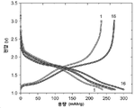
본 발명에 따른 활성 전극 물질의 비용량/가역적 탈리튬화 용량은 200 mAh/g 이상, 225 mAh/g 이상, 250 mAh/g 이상, 최대 약 300 mAh/g 이상일 수 있다. 여기서, 비용량은 Li/Li+에 대해 1.1-3.0V의 전압 창으로 0.05C의 속도로 반쪽 전지 정전류 사이클링 테스트의 2번째 사이클에서 측정된 것으로 정의된다. 높은 비용량을 갖는 물질을 제공하는 것이 유리할 수 있는데, 이는 이것이 활성 전극 물질을 포함하는 전기화학 장치에서 개선된 성능을 제공할 수 있기 때문이다.The specific capacity/reversible delithiation capacity of the active electrode material according to the present invention may be at least 200 mAh/g, at least 225 mAh/g, at least 250 mAh/g, up to about 300 mAh/g or more. Here, the specific capacity is defined as measured in the second cycle of the half-cell constant current cycling test at a rate of 0.05C with a voltage window of 1.1-3.0V for Li/Li+. It may be advantageous to provide a material with a high specific capacity, as this may provide improved performance in an electrochemical device comprising an active electrode material.
또한, 본 발명에 따른 활성 전극 물질은 Li/Li+에 대해 1.1-3.0V의 전압 창으로 0.05C의 속도에서 반쪽 전지 정전류식 사이클링 테스트의 2번째 사이클에서 측정된 적절한 전압 프로파일을 가질 수 있다. 즉, 물질의 용량은 리튬화 >180mAh/g에서 2.0V와 1.1V 사이일 수 있고, 물질의 용량은 리튬화 >180mAh/g에서 1.1V와 2.0V 사이일 수 있다.In addition, the active electrode material according to the present invention may have an appropriate voltage profile measured in the second cycle of the half-cell galvanostatic cycling test at a rate of 0.05C with a voltage window of 1.1-3.0V for Li/Li+. That is, the capacity of the material may be between 2.0V and 1.1V at lithiation >180 mAh/g, and the capacity of the material may be between 1.1V and 2.0V at lithiation >180 mAh/g.
전극(선택적으로 전도성 탄소 첨가제 및 결합제 물질과 함께)으로서 제형화되거나 코팅되는 경우, 본 발명에 따른 활성 전극 물질의 벌크 저항률(resistivity)은 5kΩ.cm 이하, 보다 바람직하게는 2kΩ.cm 이하일 수 있다. 벌크 저항률은 그러한 물질의 전자 전도도에 대한 유용한 프록시 측정이 될 수 있다. 적절하게 낮은 벌크 저항률을 갖는 물질을 제공하는 것이 유리할 수 있는데, 이는 이것이 활성 전극 물질을 포함하는 전기화학 장치에서 개선된 성능을 제공할 수 있기 때문이다.When formulated or coated as an electrode (optionally with a conductive carbon additive and binder material), the bulk resistivity of the active electrode material according to the invention may be 5 kΩ.cm or less, more preferably 2 kΩ.cm or less. . Bulk resistivity can be a useful proxy measure for the electronic conductivity of such materials. It may be advantageous to provide a material having a suitably low bulk resistivity, as this may provide improved performance in an electrochemical device comprising an active electrode material.
설명된 전극을 사용하여 리튬-이온 하프 코인 전지에서 측정할 때 활성 전극 물질의 직류 내부 저항(DCIR) 및 생성된 면적 비임피던스(ASI; area specific impedance)는 90Ω 이하(DCIR의 경우) 및 170Ω.㎠ 이하(ASI의 경우)일 수 있다. 적절하게 낮은 DCIR 및/또는 ASI를 갖는 물질을 제공하는 것이 유리할 수 있는데, 이는 이것이 활성 전극 물질을 포함하는 전기화학 디바이스에서 개선된 성능을 제공할 수 있기 때문이다. 그러나, DCIR/ASI 값의 추가 개선이 나타날 수 있는데, 예를 들어, 탄소 코팅된 활성 전극 물질인 경우, 또는 활성 전극 물질이 캐소드가 있는 상용 전원 전지에 도입된 경우, 캘린더링되고 일반적인 공지 방식으로 제조된 전극에서 그럴 수 있다. 코인 전지에서 이러한 배열로 측정할 때, 본 발명자들은 ASI가, 예를 들어, 26Ω.㎠ 이하 만큼 낮을 수 있다는 이론을 세웠다.The direct current internal resistance (DCIR) of the active electrode material and the resulting area specific impedance (ASI) when measured in a lithium-ion half-coin cell using the described electrodes were less than 90 Ω (for DCIR) and 170 Ω. cm2 or less (in the case of ASI). It may be advantageous to provide materials with suitably low DCIR and/or ASI as they may provide improved performance in electrochemical devices comprising active electrode materials. However, further improvements in DCIR/ASI values may be seen, for example in the case of carbon coated active electrode materials, or when the active electrode material is introduced into a commercial power cell with a cathode, calendered and in a generally known manner. This may be the case with fabricated electrodes. When measured with this arrangement in a coin cell, the inventors theorize that the ASI can be as low as, for example, 26 Ω.
본 발명에 따른 활성 전극 물질은 10-14 ㎠ S-1 초과의 리튬 확산 속도를 가질 수 있다. 적절하게 높은 리튬 확산 속도를 갖는 물질을 제공하는 것이 유리할 수 있으며, 이는 활성 전극 물질을 포함하는 전기화학 디바이스에서 개선된 성능을 제공할 수 있기 때문이다.The active electrode material according to the present invention may have a lithium diffusion rate greater than 10 -14 cm 2 S −1 . It may be advantageous to provide a material with a suitably high lithium diffusion rate, as it may provide improved performance in an electrochemical device comprising an active electrode material.
본 발명에 따른 활성 전극 물질은 캘린더링 후에 2.5 g/㎤ 이상의 전극 밀도를 가질 수 있다. 예를 들어, 캘린더링 후 최대 3.0 g/㎤ 이상의 전극 밀도가 달성되었다. 활성 전극 물질을 포함하는 전기화학 장치에서 개선된 성능을 제공할 수 있기 때문에 이러한 전극 밀도를 갖는 물질을 제공하는 것이 유리할 수 있다. 구체적으로, 전극 밀도가 높을 때, 중량 용량 x 전극 밀도 x 활성 물질 분율 = 체적 용량과 같이 높은 체적 용량을 달성할 수 있다.The active electrode material according to the present invention may have an electrode density of 2.5 g/
본 발명에 따른 활성 전극 물질의 초기 쿨롱 효율은 88% 초과, 보다 바람직하게는 90% 초과일 수 있다. 일부 경우에, 활성 전극 물질의 초기 쿨롱 효율은 92% 이상, 93% 이상 또는 94% 이상만큼 높을 수 있다. 이것은 활성 전극 물질을 포함하는 전기화학 장치에서 개선된 성능을 제공할 수 있기 때문에, 적절하게 높은 초기 쿨롱 효율을 갖는 물질을 제공하는 것이 유리할 수 있다. 초기 쿨롱 효율은 반쪽 전지의 C/10에서 첫 번째 충전/방전 주기의 리튬화 및 탈리튬화 용량의 차이로 측정할 수 있다.The initial coulombic efficiency of the active electrode material according to the invention may be greater than 88%, more preferably greater than 90%. In some cases, the initial coulombic efficiency of the active electrode material can be as high as 92% or greater, 93% or greater, or 94% or greater. Since this may provide improved performance in electrochemical devices comprising active electrode materials, it may be advantageous to provide materials with suitably high initial coulombic efficiencies. The initial coulombic efficiency can be measured as the difference in the lithiation and delithiation capacities of the first charge/discharge cycle at C/10 of the half cell.
본 발명의 제1 및 제2 양태의 추가의 선택적인 특징이 아래에 설명되어 있다.Further optional features of the first and second aspects of the invention are set forth below.
X-선 회절에 의해 측정된, 제1 양태의 활성 전극 물질의 결정 구조는 활성 전극 물질의 비변형(unmodified) 형태의 결정 구조에 상응할 수 있으며, 여기서 비변형된 형태는 식 [M2][Nb]y[O]z로 표시되고, 여기서 M2는 단일 원소로 구성되고, 비변형된 형태는 산소 결핍이 아니며, 비변형된 형태는 다음 중 하나 이상에서 선택된다: M2INb5O13, M2I 6Nb10.8O30, M2IINb2O6, M2II 2Nb34O87, M2IIINb11O29, M2IIINb49O124 (M2III 0.5Nb24.5O62), M2IVNb24O62, M2IVNb2O7, M2IV 2Nb10O29, M2IV 2Nb14O39, M2IVNb14O37, M2IVNb6O17, M2IVNb18O47, M2VNb9O25, M2V 4Nb18O55, M2V 3Nb17O50, M2VINb12O33, M2VI 4Nb26O77, M2VI 3Nb14O44, M2VI 5Nb16O55, M2VI 8Nb18O69, M2VINb2O8, M2VI 16Nb18O93, M2VI 20Nb22O115, M2VI 9Nb8O47, M2VI 82Nb54O381, M2VI 31Nb20O143, M2VI 7Nb4O31, M2VI 15Nb2O50, M2VI 3Nb2O14, 및 M2VI 11Nb12O63, 여기서 숫자 I, II, III, IV, V 및 VI는 M2의 산화 상태를 나타낸다. 이로써, 결정 구조에 유의하게 영향을 미치지 않으면서 비변형된 형태가 변형되었음을 확인할 수 있다.The crystal structure of the active electrode material of the first aspect, as determined by X-ray diffraction, may correspond to the crystal structure of an unmodified form of the active electrode material, wherein the unmodified form has the formula [M2][ Nb] y [O] z , wherein M2 consists of a single element, the unmodified form is not oxygen deficient, and the unmodified form is selected from one or more of: M2 I Nb 5 O 13 , M2 I 6 Nb 10.8 O 30 , M2 II Nb 2 O 6 , M2 II 2 Nb 34 O 87 , M2 III Nb 11 O 29 , M2 III Nb 49 O 124 (M2 III 0.5 Nb 24.5 O 62 ), M2 IV Nb 24 O 62 , M2 IV Nb 2 O 7 , M2 IV 2 Nb 10 O 29 , M2 IV 2 Nb 14 O 39 , M2 IV Nb 14 O 37 , M2 IV Nb 6 O 17 , M2 IV Nb 18 O 47 , M2 V Nb 9 O 25 , M2 V 4 Nb 18 O 55 , M2 V 3 Nb 17 O 50 , M2 VI Nb 12 O 33 , M2 VI 4 Nb 26 O 77 , M2 VI 3 Nb 14 O 44 , M2 VI 5 Nb 16 O 55 , M2 VI 8 Nb 18 O 69 , M2 VI Nb 2 O 8 , M2 VI 16 Nb 18 O 93 , M2 VI 20 Nb 22 O 115 , M2 VI 9 Nb 8 O 47 , M2 VI 82 Nb 54 O 381 , M2 VI 31 Nb 20 O 143 , M2 VI 7 Nb 4 O 31 , M2 VI 15 Nb 2 O 50 , M2 VI 3 Nb 2 O 14 , and M2 VI 11 Nb 12 O 63 , wherein the numbers I, II, III, IV, V and VI represents the oxidation state of M2. Accordingly, it can be confirmed that the unstrained form is modified without significantly affecting the crystal structure.
X-선 회절에 의해 측정된 제2 양태의 활성 전극 물질의 결정 구조는 활성 전극 물질의 비변형된 형태의 결정 구조에 해당할 수 있으며, 여기서 비변형된 형태는 일반식 [M][Nb]y[O]z로 표시되고, 여기서 비변형된 형태는 산소 결핍이 아니며, 여기서 비변형된 형태는 M2INb5O13, M2I 6Nb10.8O30, M2IINb2O6, M2II 2Nb34O87, M2IIINb11O29, M2IIINb49O124, M2IVNb24O62, M2IVNb2O7, M2IV 2Nb10O29, M2IV 2Nb14O39, M2IVNb14O37, M2IVNb6O17, M2IVNb18O47, M2VNb9O25, M2V 4Nb18O55, M2V 3Nb17O50, M2VINb12O33, M2VI 4Nb26O77, M2VI 3Nb14O44, M2VI 5Nb16O55, M2VI 8Nb18O69, M2VINb2O8, M2VI 16Nb18O93, M2VI 20Nb22O115, M2VI 9Nb8O47, M2VI 82Nb54O381, M2VI 31Nb20O143, M2VI 7Nb4O31, M2VI 15Nb2O50, M2VI 3Nb2O14, 및 M2VI 11Nb12O63로부터 선택되고, 여기서 숫자 I, II, III, IV, V 및 VI는 M의 산화 상태를 나타낸다. 이로써, 결정 구조에 유의하게 영향을 미치지 않으면서 비변형된 형태가 변형되었음을 확인할 수 있다.The crystalline structure of the active electrode material of the second aspect determined by X-ray diffraction may correspond to the crystalline structure of an unstrained form of the active electrode material, wherein the unstrained form has the general formula [M][Nb] denoted by y [O] z , wherein the unmodified form is not oxygen deficient, wherein the unmodified form is M2 I Nb 5 O 13 , M2 I 6 Nb 10.8 O 30 , M2 II Nb 2 O 6 , M2 II 2 Nb 34 O 87 , M2 III Nb 11 O 29 , M2 III Nb 49 O 124 , M2 IV Nb 24 O 62 , M2 IV Nb 2 O 7 , M2 IV 2 Nb 10 O 29 , M2 IV 2 Nb 14 O 39 , M2 IV Nb 14 O 37 , M2 IV Nb 6 O 17 , M2 IV Nb 18 O 47 , M2 V Nb 9 O 25 , M2 V 4 Nb 18 O 55 , M2 V 3 Nb 17 O 50 , M2 VI Nb 12 O 33 , M2 VI 4 Nb 26 O 77 , M2 VI 3 Nb 14 O 44 , M2 VI 5 Nb 16 O 55 , M2 VI 8 Nb 18 O 69 , M2 VI Nb 2 O 8 , M2 VI 16 Nb 18 O 93 , M2 VI 20 Nb 22 O 115 , M2 VI 9 Nb 8 O 47 , M2 VI 82 Nb 54 O 381 , M2 VI 31 Nb 20 O 143 , M2 VI 7 Nb 4 O 31 , M2 VI 15 Nb 2 O 50 , M2 VI 3 Nb 2 O 14 , and M2 VI 11 Nb 12 O 63 , wherein the numbers I, II, III, IV, V and VI represent the oxidation state of M. Accordingly, it can be confirmed that the unstrained form is modified without significantly affecting the crystal structure.
X-선 회절 분석에 의해 결정된, 활성 전극 물질의 결정 구조는 다음 중 하나 이상의 결정 구조에 상응할 수 있다:The crystal structure of the active electrode material, as determined by X-ray diffraction analysis, may correspond to a crystal structure of one or more of the following:
(i) MoNb12O33 (i) MoNb 12 O 33
WNb12O33 WNb 12 O 33
VNb9O25 VNb 9 O 25
ZrNb24O62 ZrNb 24 O 62
W7Nb4O31 W 7 Nb 4 O 31
W9Nb8O47 W 9 Nb 8 O 47
Zn2Nb34O87 Zn 2 Nb 34 O 87
Cu2Nb34O87 Cu 2 Nb 34 O 87
AlNb11O29 AlNb 11 O 29
GaNb11O29 GaNb 11 O 29
GeNb18O47 GeNb 18 O 47
W16Nb18O93 W 16 Nb 18 O 93
W5Nb-16O55 W 5 Nb -16 O 55
AlNb49O124 AlNb 49 O 124
GaNb49O124; 또는GaNb 49 O 124 ; or
(ii) MoNb12O33 (ii) MoNb 12 O 33
WNb12O33 WNb 12 O 33
VNb9O25 VNb 9 O 25
ZrNb24O62 ZrNb 24 O 62
W4Nb7O31 W 4 Nb 7 O 31
W9Nb8O47 W 9 Nb 8 O 47
Zn2Nb34O87 Zn 2 Nb 34 O 87
AlNb11O29 AlNb 11 O 29
GeNb18O47; 또는 바람직하게는GeNb 18 O 47 ; or preferably
(iii) MoNb12O33 (iii) MoNb 12 O 33
WNb12O33 WNb 12 O 33
ZrNb24O62 ZrNb 24 O 62
VNb9O25 VNb 9 O 25
W7Nb4O31 W 7 Nb 4 O 31
W9Nb8O47.W 9 Nb 8 O 47 .
여기에서 '상응하다(corresponds)'라는 용어는 활성 전극 물질의 X선 회절 분석에 의해 식별된 피크가 하나 이상의 참조 결정 구조(예를 들어, MoNb12O33, WNb12O33, ZrNb24O62, VNb9O25, W7Nb4O31, 및/또는 W9Nb8O47)의 X선 회절 분석에서 상응하는 피크로부터 0.5도 이하로 편이(바람직하게는 0.2도 이하로, 보다 바람직하게는 0.1도 이하로 편이)될 수 있음을 반영하기 위해 의도된 것이다. 바람직하게는 활성 전극 물질의 결정 구조는 TiNb2O7의 결정 구조와 상응하지 않으며, 예를 들어, 바람직하게는 활성 전극 물질의 측정된 XRD 회절 패턴은 TiNb2O7의 경우 JCPDS 결정학 데이터베이스 항목 데이터베이스 00-039-1407에 상응하지 않는다. 선택적으로, 활성 전극 물질의 결정 구조는 Ti2Nb10O29의 결정 구조와 상응하지 않는다. 선택적으로, 활성 전극 물질의 결정 구조는, MIIINb11O29, 예를 들어, FeNb11O29, GaNb11O29, CrNb11O29, 및 AlNb11O29의 결정 구조와 상응하지 않는다.The term 'corresponds' herein means that the peak identified by X-ray diffraction analysis of the active electrode material has one or more reference crystal structures (eg, MoNb 12 O 33, WNb 12 O 33, ZrNb 24 O 62 ). , VNb 9 O 25 , W 7 Nb 4 O 31 , and/or W 9 Nb 8 O 47 ) shifted by 0.5 degrees or less (preferably by 0.2 degrees or less, more preferably from the corresponding peaks in X-ray diffraction analysis) is intended to reflect that it can be deflected by 0.1 degrees or less). Preferably the crystal structure of the active electrode material does not correspond to the crystal structure of TiNb 2 O 7 , for example, preferably the measured XRD diffraction pattern of the active electrode material is in the case of TiNb 2 O 7 JCPDS crystallography database entry database Does not correspond to 00-039-1407. Optionally, the crystal structure of the active electrode material does not correspond to the crystal structure of Ti 2 Nb 10 O 29 . Optionally, the crystal structure of the active electrode material does not correspond to the crystal structure of M III Nb 11 O 29 , eg, FeNb 11 O 29 , GaNb 11 O 29 , CrNb 11 O 29 , and AlNb 11 O 29 .
활성 전극 물질의 적어도 일부는 Wadsley-Roth 결정 구조 및/또는 TTB(tetragonal Tungsten Bronze) 결정 구조를 가질 수 있다. 바람직하게는, 활성 전극 물질의 대부분은 Wadsley-Roth 결정 구조 및/또는 정방정계 텅스텐 브론즈(TTB) 결정 구조를 가지며, 예를 들어, 부피를 기준으로 적어도 50%, 적어도 60%, 적어도 70%, 적어도 80%, 또는 적어도 90%의 Wadsley-Roth 결정 구조 및/또는 정방정계 텅스텐 브론즈(TTB) 결정 구조를 가질 수 있다. 바람직한 실시형태에서, 실질적으로 모든 활성 전극 물질은 Wadsley-Roth 결정 구조 및/또는 정방정계 텅스텐 브론즈(TTB) 결정 구조를 가질 수 있다. 물질이 이러한 결정 구조를 가질 때, 개선된 전기화학적 특성을 가질 수 있다.At least a portion of the active electrode material may have a Wadsley-Roth crystal structure and/or a tetragonal Tungsten Bronze (TTB) crystal structure. Preferably, a majority of the active electrode material has a Wadsley-Roth crystal structure and/or a tetragonal tungsten bronze (TTB) crystal structure, for example at least 50%, at least 60%, at least 70% by volume, at least 80%, or at least 90% Wadsley-Roth crystal structure and/or tetragonal tungsten bronze (TTB) crystal structure. In a preferred embodiment, substantially all of the active electrode material may have a Wadsley-Roth crystal structure and/or a tetragonal tungsten bronze (TTB) crystal structure. When the material has such a crystal structure, it can have improved electrochemical properties.
전하 균형을 이루고 열역학적으로 안정한 Wadsley-Roth 결정 구조의 결정 식은 다음 식을 따른다:The crystal formula for a charge-balanced and thermodynamically stable Wadsley-Roth crystal structure is:
(1)
![]()
![]()
이 식에서, O는 산소(음이온)이고 M(양이온)은 Ti, Mg, V, Cr, W, Zr, Nb, Mo, Cu, Fe, Ga, Ge, Ca, K, Ni, Co, Al, Sn, Mn, Ce, Te, Se, Si, Sb, Y, La, Hf, Ta, Re, Zn, In, 또는 Cd로부터 선택되는 원소의 임의의 조합이다. 본 발명에 따른 물질에서, (M1, M2, M3…) 중 적어도 하나는 Nb를 포함한다.where O is oxygen (anion) and M (cation) is Ti, Mg, V, Cr, W, Zr, Nb, Mo, Cu, Fe, Ga, Ge, Ca, K, Ni, Co, Al, Sn , Mn, Ce, Te, Se, Si, Sb, Y, La, Hf, Ta, Re, Zn, In, or Cd. In the material according to the invention, at least one of (M 1 , M 2 , M 3 ...) comprises Nb.
식 (1)은 결정 토폴로지(topography)을 기반으로 한다: m 및 n은 3 내지 5(정수) 범위의, 형성된 모서리 공유 초구조(superstructure) 블록의 치수이다. 코너에서, 블록은 모서리-공유에 의해서만 무한 리본(p=∞)으로 연결되고, 부분적으로 모서리-공유와 부분적으로 사면체에 의해 쌍으로(p=2) 또는 사면체에 의해서만 고립된 블록(p=1)으로 연결된다. p가 무한대일 때 식은 다음과 같다:Equation (1) is based on the crystal topography: m and n are the dimensions of the formed edge-sharing superstructure block, ranging from 3 to 5 (integer). At corners, blocks are connected by infinite ribbons (p=∞) only by edge-sharing, partially by edge-sharing and partly tetrahedron in pairs (p=2) or blocks isolated only by tetrahedron (p=1) ) is connected to When p is infinity, the expression is:
(2)
![]()
![]()
함께, 식 (1)과 (2)는 Wadsley-Roth 결정 구조에 대한 전체 조성 샘플을 정의한다. 바람직하게는 전체 결정 조성은 또한 전하 중성이어야 하고 열역학적으로 유리해야 한다.Together, equations (1) and (2) define an overall compositional sample for the Wadsley-Roth crystal structure. Preferably the overall crystal composition should also be charge neutral and thermodynamically favorable.
더 많은 정보는 문헌[Griffith et al. (2017)]의 연구에서 찾을 수 있다.For more information, see Griffith et al. (2017)].
본 개시에서 정방정계 텅스텐 브론즈(TTB) 결정 구조(또는 단순히 '브론즈' 구조)에 대한 언급은 부분적으로 채워진 터널을 갖는 정방정 텅스텐 브론즈(TTB) 구조를 의미한다. 문헌[Montemayor 1998]에 설명된 대로, 이러한 단계는 3면, 4면 및 5면 터널이 형성되는 방식으로 연결된 NbO6 팔면체 공유 모서리의 프레임워크로 구성된다. 다수의 5면 터널이 W, Nb, O, 또는 적절한 금속 양이온으로 채워져 구조를 형성한다.Reference in this disclosure to a tetragonal tungsten bronze (TTB) crystal structure (or simply a 'bronze' structure) refers to a tetragonal tungsten bronze (TTB) structure having a partially filled tunnel. As described in Montemayor 1998, these steps consist of a framework of NbO 6 octahedral shared edges connected in such a way that three-, four- and five-sided tunnels are formed. A number of five-sided tunnels are filled with W, Nb, O, or appropriate metal cations to form the structure.
활성 전극 물질은 Li 및/또는 Na를 추가로 포함할 수 있다. 다시 말해서, 활성 전극 물질은 리튬화 및/또는 나트륨화 활성 전극 물질일 수 있다. 제1 양태의 활성 전극 물질은 일반식 [Li]λ[M1]x[M2](1-x)[Nb]y[O]z 또는 [Na]λ[M1]x[M2](1-x)[Nb]y[O]z으로 표시될 수 있다. 제2 양태의 활성 물질은 일반식 [Li]λ[M][Nb]y[O]z 또는 [Na]λ[M][Nb]y[O]z로 표시될 수 있다. x, y, 및 z는 위에서 논의된 범위를 충족하고, λ는 전하 균형을 이루거나, 또는 실질적으로 전하 균형을 이룬 결정 구조, 및/또는 열역학적으로 안정하거나, 또는 열역학적으로 준안정한 결정 구조를 제공하도록 선택된다.The active electrode material may further comprise Li and/or Na. In other words, the active electrode material may be a lithiated and/or natriated active electrode material. The active electrode material of the first aspect has the general formula [Li] λ [M1] x [M2] (1-x) [Nb] y [O] z or [Na] λ [M1] x [M2] (1-x ) [Nb] y [O] z . The active material of the second aspect may be represented by the general formula [Li] λ [M][Nb] y [O] z or [Na] λ [M][Nb] y [O] z . x, y, and z meet the ranges discussed above, and λ provides a charge balanced, or substantially charge balanced, crystal structure, and/or a thermodynamically stable, or thermodynamically metastable crystal structure chosen to do
활성 전극 물질은 0.1-100 ㎡/g, 또는 0.5-50 ㎡/g, 또는 1-20 ㎡/g 범위의 BET 표면적을 가질 수 있다. 일반적으로, 활성 전극 물질과 전해질, 예를 들어 BET의 반응을 최소화하기 위해 낮은 BET 표면적이 바람직하다. 물질을 포함하는 전극의 제1 충전-방전 사이클 동안 고체 전해질 계면(SEI) 층의 형성을 최소화하는 단계를 포함한다. 그러나, 너무 낮은 BET 표면적은 주변 전해질의 금속 이온에 대한 대부분의 활성 전극 물질의 접근 불가능성으로 인해 허용할 수 없을 정도로 낮은 충전 속도 및 용량을 초래한다. "BET 표면적"이라는 용어는 Brunauer-Emmett-Teller 이론을 이용하여, 고체 표면에 대한 기체 분자의 물리적 흡착 측정에서 계산된 단위 질량당 표면적을 나타낸다. 예를 들어, BET 표면적은 ISO 9277:2010에 따라 결정할 수 있다.The active electrode material may have a BET surface area in the range of 0.1-100 m/g, or 0.5-50 m/g, or 1-20 m/g. In general, a low BET surface area is desirable to minimize the reaction of the active electrode material with the electrolyte, such as BET. and minimizing the formation of a solid electrolyte interface (SEI) layer during a first charge-discharge cycle of an electrode comprising the material. However, too low BET surface area results in unacceptably low charging rates and capacities due to the inaccessibility of most active electrode materials to the metal ions of the surrounding electrolyte. The term "BET surface area" refers to the surface area per unit mass calculated from measurements of the physisorption of gas molecules on a solid surface using the Brunauer-Emmett-Teller theory. For example, the BET surface area can be determined according to ISO 9277:2010.
활성 전극 물질은 복수의 1차 결정립(crystallite)(때때로 미세결정(microcrystals) 또는 미세결정립(microcrystallites)으로 지칭됨)를 포함할 수 있다. 1차 결정립의 평균 직경은 10 nm 내지 10 ㎛, 바람직하게는 100 nm 내지 5 ㎛일 수 있지만, 1차 결정립의 가장 바람직한 직경은 의도된 용도에 따라 달라질 수 있다. 예를 들어, 활성 전극 물질이 초고출력 제품에 사용하도록 의도된 경우, 1차 결정립 크기가 작은 것, 예를 들어, 50 nm 이하, 또는 30 nm 이하가 유리할 수 있다. 활성 전극 물질이 "고에너지 전력 전지"를 개발하는 데 사용하도록 의도된 경우, 결정립 크기가 더 큰 것, 예를 들어, 5 μm 이상, 또는 7 μm 이상이 유리할 수 있다.The active electrode material may include a plurality of primary crystallites (sometimes referred to as microcrystals or microcrystallites). The average diameter of the primary grains may be 10 nm to 10 µm, preferably 100 nm to 5 µm, although the most preferred diameter of the primary grains may vary depending on the intended use. For example, if the active electrode material is intended for use in ultra-high power applications, a smaller primary grain size, for example 50 nm or less, or 30 nm or less may be advantageous. If the active electrode material is intended for use in developing “high energy power cells”, it may be advantageous to have a larger grain size, for example at least 5 μm, or at least 7 μm.
이들 1차 결정립의 일부 또는 전부는 2차 입자로 응집될 수 있다. 대안적으로, 1차 결정립은 실질적으로 응집되지 않을 수 있다. 이들 1차 결정립의 일부 또는 전부가 2차 입자로 응집되는 경우, 2차 입자의 평균 직경(예를 들어, 고체 상태 분말 레이저 회절을 사용하여 측정할 때 D50 직경)은 1㎛ 내지 30㎛, 바람직하게는 2 ㎛ 내지 15 ㎛이지만, 2차 입자의 가장 바람직한 직경은 의도된 용도에 따라 다를 수 있다. 예를 들어, 활성 전극 물질이 초고출력 제품에 사용하도록 의도된 경우, 2차 입자 크기가 작은 것, 예를 들어, 4μm 이하, 2μm 이하, 1.5μm 이하인 것이 유리할 수 있다. 활성 전극 물질이 "고에너지 전력 전지"를 개발하는 데 사용하도록 의도된 경우, 2차 입자 크기가 더 큰 것, 예를 들어, 8μm 이상, 12μm 이상, 또는 15μm 이상인 것이 유리할 수 있다. 2차 입자는 다공성일 수 있다.Some or all of these primary grains may agglomerate into secondary grains. Alternatively, the primary grains may be substantially non-agglomerated. When some or all of these primary grains are agglomerated into secondary particles, the average diameter of the secondary particles (e.g., D 50 diameter as measured using solid state powder laser diffraction) is 1 μm to 30 μm; Although preferably 2 μm to 15 μm, the most preferred diameter of the secondary particles may vary depending on the intended use. For example, if the active electrode material is intended for use in ultra-high power applications, it may be advantageous to have a small secondary particle size, eg, 4 μm or less, 2 μm or less, 1.5 μm or less. If the active electrode material is intended for use in developing "high energy power cells", it may be advantageous to have a larger secondary particle size, for example at least 8 μm, at least 12 μm, or at least 15 μm. The secondary particles may be porous.
1차 결정립 및/또는 2차 입자의 평균 직경은 임의의 통상적인 공지된 기술, 예를 들어, SEM 이미징을 사용하여 물질 샘플을 조사하는 단계, 1차 결정립 및/또는 2차 입자의 수(n)를 선택하는 단계, 측정된 n개의 1차 결정립/2차 입자의 평균 직경으로서 평균 직경을 계산하는 단계를 이용하여 측정될 수 있으며, 예를 들어 여기서 n은 30이다.The average diameter of the primary grains and/or secondary particles is determined by the number of primary grains and/or secondary particles (n ), calculating the average diameter as the average diameter of the measured n primary grains/secondary particles, for example, where n is 30.
2차 입자 크기를 측정하기 위한 다른 방법은 고체 상태 분말 레이저 회절을 사용하는 것이며, 예를 들어, 0.3 MPa로 유지되는 공기압으로 건조 분말에 대해 Horiba 레이저 회절 입자 분석기를 사용한다.Another method for determining secondary particle size is to use solid state powder laser diffraction, for example, a Horiba laser diffraction particle analyzer for dry powder with air pressure maintained at 0.3 MPa.
활성 전극 물질은 고체 상태 분말 레이저 회절을 사용하여 측정할 때 D10 이차 입자 직경이 적어도 0.05 ㎛, 또는 적어도 0.1 ㎛, 또는 적어도 0.5 ㎛, 또는 적어도 1 ㎛일 수 있다. D10 입자 직경을 이러한 범위 내로 유지함으로써, Li 이온 전지에서 기생 반응의 가능성이 감소된 표면적을 갖는 것으로부터 감소되고, 전극 슬러리에서 더 적은 바인더로 처리가 더 쉬워진다. "Dn"이라는 용어는 입자 집단의 부피를 기준으로 n% 이하로 확인되는 직경을 나타낸다.The active electrode material may have a D 10 secondary particle diameter of at least 0.05 μm, or at least 0.1 μm, or at least 0.5 μm, or at least 1 μm, as measured using solid state powder laser diffraction. By keeping the D 10 particle diameter within this range, the likelihood of parasitic reactions in the Li-ion battery is reduced from having a reduced surface area, and processing becomes easier with less binder in the electrode slurry. The term “D n ” denotes a diameter identified as n% or less, based on the volume of the population of particles.
활성 전극 물질은 고체 상태 분말 레이저 회절을 사용하여 측정할 때 D90 이차 입자 직경이 < 50 ㎛, < 20 ㎛, < 10 ㎛, 또는 < 5 ㎛일 수 있다. D90 입자 직경을 이러한 범위 내로 유지함으로써, 입자 크기가 큰 입자 크기 분포의 비율을 최소화하여, 물질을 균질한 전극으로 쉽게 제조할 수 있다.The active electrode material can have a D 90 secondary particle diameter of <50 μm, <20 μm, <10 μm, or <5 μm as measured using solid state powder laser diffraction. By keeping the D 90 particle diameter within this range, the ratio of the large particle size distribution can be minimized, and the material can be easily manufactured into a homogeneous electrode.
활성 전극 물질은 1차 결정립 및/또는 2차 입자의 표면에 형성된 탄소 코팅을 포함할 수 있다. 1차 결정립 및/또는 2차 입자의 표면에 탄소 코팅을 형성하기 위한 몇 가지 적절한 방법은 문헌, 예를 들어, Zhou (2012)에 제시되어 있다. 다른 적절한 방법은 아래에 설명되어 있다. 탄소 코팅은 활성 전극 물질의 총 중량을 기준으로 5 w/w% 이하의 양으로 존재할 수 있다. 탄소 코팅은 흑연 탄소를 포함할 수 있다.The active electrode material may include a carbon coating formed on the surface of the primary grains and/or secondary grains. Some suitable methods for forming carbon coatings on the surfaces of primary grains and/or secondary particles are presented in the literature, for example, Zhou (2012). Other suitable methods are described below. The carbon coating may be present in an amount of up to 5 w/w% based on the total weight of the active electrode material. The carbon coating may include graphitic carbon.
활성 전극이 복수의 1차 결정립의 형태를 갖고 이들 1차 결정립의 일부 또는 전부가 다공성 2차 입자로 응집되는 경우, 2차 입자는 적어도 2차 입자의 기공 표면에 형성된 탄소 코팅을 포함할 수 있다.When the active electrode has the form of a plurality of primary grains and some or all of these primary grains are aggregated into porous secondary particles, the secondary particles may include at least a carbon coating formed on the pore surface of the secondary particles. .
제3 양태에서, 본 발명은 애노드, 캐소드, 및 애노드와 캐소드 사이에 배치된 전해질을 포함하는 전기화학 디바이스를 제공하며, 여기서 애노드는 본 발명의 제1 또는 제2 양태에 따른 전극 활성 물질을 포함한다.In a third aspect, the invention provides an electrochemical device comprising an anode, a cathode, and an electrolyte disposed between the anode and the cathode, wherein the anode comprises an electrode active material according to the first or second aspect of the invention do.
전해질은 액체 전해질일 수 있다. 대안적으로 또는 추가적으로 전해질은 고체 상태 전해질일 수 있다.The electrolyte may be a liquid electrolyte. Alternatively or additionally, the electrolyte may be a solid state electrolyte.
애노드는 전도성 첨가제 및/또는 바인더를 추가로 포함할 수 있다. 예를 들어, 애노드는 활성 물질 약 80wt%, 전도성 첨가제 약 10wt% 및 바인더 약 10wt%의 조성을 가질 수 있다. 대안적으로, 애노드는 약 91wt% 활성 물질, 약 5wt% 전도성 첨가제, 및 약 4wt% 바인더의 조성을 가질 수 있다. 애노드에서 활성 전극 물질의 양은 70wt% 내지 99wt% 범위, 보다 바람직하게는 75wt% 내지 98wt% 범위, 더욱 더 바람직하게는 85wt% 내지 96wt% 범위일 수 있다.The anode may further comprise conductive additives and/or binders. For example, the anode may have a composition of about 80 wt % active material, about 10 wt % conductive additive, and about 10 wt % binder. Alternatively, the anode may have a composition of about 91 wt % active material, about 5 wt % conductive additive, and about 4 wt % binder. The amount of active electrode material in the anode may range from 70 wt % to 99 wt %, more preferably from 75 wt % to 98 wt %, even more preferably from 85 wt % to 96 wt %.
제4 양태에서, 본 발명은 (i) 리튬 이온 전지의 충전 및 방전을 위한 리튬 이온 전지; 또는 (ii) 나트륨 이온 전지의 충전 및 방전을 위한 나트륨 이온 전지에서 캐소드 및 전해질과 함께 애노드에서 애노드 활성 물질, 또는 애노드 활성 물질의 성분으로서의 본 발명의 제1 또는 제2 양태에 따른 전극 활성 물질의 용도를 제공한다.In a fourth aspect, the present invention provides: (i) a lithium ion battery for charging and discharging a lithium ion battery; or (ii) an anode active material in an anode together with a cathode and an electrolyte in a sodium ion cell for charging and discharging of a sodium ion cell, or an electrode active material according to the first or second aspect of the invention as a component of the anode active material provide use.
제5 양태에서, 본 발명은 하기의 것을 위한 애노드 활성 물질로서 또는 애노드 활성 물질 중에서 본 발명의 제1 또는 제2 양태에 따른 전극 활성 물질을 처리하는 방법을 제공한다: (i) 리튬 이온 전지, 여기서 상기 방법은 리튬 이온을 상기 애노드 활성 물질 내로 확산시키는 단계를 포함함; 또는 (ii) 나트륨 이온 전지, 여기서 상기 방법은 나트륨 이온을 상기 애노드 활성 물질 내로 확산시키는 단계를 포함함.In a fifth aspect, the present invention provides a method of treating an electrode active material according to the first or second aspect of the invention as or in an anode active material for: (i) a lithium ion battery; wherein the method comprises diffusing lithium ions into the anode active material; or (ii) a sodium ion cell, wherein the method comprises diffusing sodium ions into the anode active material.
제6 양태에서, 본 발명은 본 발명의 제1 또는 제2 양태에 따른 활성 전극 물질의 제조 방법을 제공하며, 상기 방법은,In a sixth aspect, the present invention provides a method for producing an active electrode material according to the first or second aspect of the present invention, said method comprising:
하나 이상의 전구체 물질을 제공하는 단계;providing one or more precursor materials;
상기 전구체 물질을 혼합하여 전구체 물질 혼합물을 형성하는 단계; 및mixing the precursor materials to form a precursor material mixture; and
400℃ 내지 1350℃의 온도 범위에서 상기 전구체 물질 혼합물을 열처리하여 활성 전극 물질을 형성하는 단계를 포함한다.heat-treating the precursor material mixture at a temperature ranging from 400° C. to 1350° C. to form an active electrode material.
본 발명의 제1 양태에 따른 물질을 제조하는 것이 바람직한 경우, 바람직하게는 하나 이상의 전구체 물질은 M1 이온 공급원, M2 이온 공급원, 및 Nb의 공급원을 포함한다.When it is desired to prepare a material according to the first aspect of the present invention, preferably the at least one precursor material comprises a source of M1 ions, a source of M2 ions, and a source of Nb.
본 발명의 제2 양태에 따른 물질을 제조하는 것이 바람직한 경우, 바람직하게는 하나 이상의 전구체 물질은 M 공급원 및 Nb 공급원을 포함한다.When it is desired to prepare a material according to the second aspect of the invention, preferably the at least one precursor material comprises a source of M and a source of Nb.
'M1 이온 공급원'이라는 문구는 M1 이온/원자를 포함하는 물질을 설명하기 위해 본 명세서에서 사용된다. 'M2 이온 공급원'이라는 문구는 M2 이온/원자를 포함하는 물질을 설명하기 위해 본 명세서에서 사용된다. 예를 들어, 'Mo/W/Zr/V/Nb의 공급원'이라는 문구는, 적절한 경우, Mo/W/Zr/V/Nb 이온/원자를 포함하는 물질을 설명하기 위해 본 명세서에서 사용된다.The phrase 'source of M1 ions' is used herein to describe a material comprising M1 ions/atoms. The phrase 'source of M2 ions' is used herein to describe a material comprising M2 ions/atoms. For example, the phrase 'source of Mo/W/Zr/V/Nb' is used herein to describe a material comprising Mo/W/Zr/V/Nb ions/atoms, where appropriate.
전구체 물질은 하나 이상의 금속 산화물, 금속 수산화물, 금속 염 또는 옥살레이트를 포함할 수 있다. 예를 들어, 전구체 물질은 상이한 산화 상태 및/또는 상이한 결정 구조의 하나 이상의 금속 산화물을 포함할 수 있다. 적합한 금속 산화물 전구체 물질의 예는 Nb2O5, NbO2, WO3, TiO2, MoO3, V2O5, ZrO2, 및 MgO를 포함하지만 이에 제한되는 것은 아니다. 그러나, 전구체 물질은 금속 산화물을 포함하지 않을 수 있거나 산화물 이외의 이온 공급원을 포함할 수 있다. 예를 들어, 전구체 물질은 금속 염(예를 들어, NO3 -, SO3 -) 또는 기타 화합물(예를 들어, 옥살레이트)을 포함할 수 있다. 바람직하게는 하나 이상의 전구체 물질은 Nb 공급원, Mo 공급원, W 공급원, Zr 공급원, 및/또는 V 공급원 중 하나 이상을 포함한다.The precursor material may include one or more metal oxides, metal hydroxides, metal salts or oxalates. For example, the precursor material may include one or more metal oxides in different oxidation states and/or different crystal structures. Examples of suitable metal oxide precursor materials include, but are not limited to, Nb 2 O 5 , NbO 2 , WO 3 , TiO 2 , MoO 3 , V 2 O 5 , ZrO 2 , and MgO. However, the precursor material may not include a metal oxide or may include an ion source other than an oxide. For example, the precursor material may include a metal salt (eg, NO 3 − , SO 3 − ) or other compound (eg, oxalate). Preferably, the one or more precursor materials comprise one or more of an Nb source, a Mo source, a W source, a Zr source, and/or a V source.
전구체 물질의 일부 또는 전부는 미립자(particulate) 물질일 수 있다. 미립자 물질인 경우, 이들은 바람직하게는 직경(예를 들어, 고체 상태 분말 레이저 회절을 사용하여 측정할 때 D50 직경)이 < 20 ㎛인 평균 입자 크기를 갖는다. 평균 입자 크기는, 예를 들어, 10 nm 내지 20 μm일 수 있다. 이러한 평균 입자 크기를 갖는 미립자 물질을 제공하는 것은 전구체 물질의 보다 친밀한 혼합을 촉진하는 데 도움이 될 수 있으며, 그에 따라 열처리 단계 동안 보다 효율적인 고체 상태 반응을 야기할 수 있다. 그러나, 하나 이상의 전구체 물질의 입자 크기가 전구체 물질 혼합물을 형성하기 위해 상기 전구체 물질을 혼합하는 단계 동안 기계적으로 감소될 수 있기 때문에, 전구체 물질이 직경이 < 20 ㎛인 초기 입자 크기를 가질 필요는 없다.Some or all of the precursor material may be a particulate material. In the case of particulate matter, they preferably have an average particle size of <20 μm in diameter (eg D 50 diameter as measured using solid state powder laser diffraction). The average particle size may be, for example, between 10 nm and 20 μm. Providing a particulate material with such an average particle size may help to promote more intimate mixing of the precursor materials, thus resulting in a more efficient solid state reaction during the heat treatment step. However, it is not necessary for the precursor material to have an initial particle size of <20 μm in diameter, as the particle size of one or more precursor materials may be mechanically reduced during the step of mixing the precursor materials to form the precursor material mixture. .
전구체 물질을 혼합/밀링하여 전구체 물질 혼합물을 형성하는 단계는 (이로만 제한되는 것은 아니지만) 건식 또는 습식 유성 볼 밀링, 롤링 볼 밀링, 고전단 밀링, 에어 제트 밀링, 및/또는 충돌(impact) 밀링으로부터 선택된 방법에 의해 수행될 수 있다. 혼합/밀링에 사용되는 힘은 전구체 물질의 형태에 따라 달라질 수 있다. 예를 들어, 전구체 물질의 일부 또는 전부가 더 큰 입자 크기(예를 들어, 직경이 20 ㎛ 초과인 평균 입자 크기)를 갖는 경우, 밀링력은 전구체 물질의 평균 입자 크기를 감소시키도록 선택될 수 있으며, 전구체 물질 혼합물의 평균 입자 크기는 직경이 20㎛ 이하로 감소된다. 전구체 물질 혼합물 중의 입자의 평균 입자 크기가 20㎛ 이하인 경우, 열처리 단계에서 전구체 물질 혼합물 중의 전구체 물질의 고상 반응을 보다 효율적으로 촉진할 수 있다.Mixing/milling the precursor materials to form the precursor material mixture includes (but is not limited to) dry or wet planetary ball milling, rolling ball milling, high shear milling, air jet milling, and/or impact milling. It can be carried out by a method selected from The force used for mixing/milling may vary depending on the shape of the precursor material. For example, if some or all of the precursor material has a larger particle size (eg, an average particle size greater than 20 μm in diameter), the milling force may be selected to reduce the average particle size of the precursor material. and the average particle size of the precursor material mixture is reduced to 20 μm or less in diameter. When the average particle size of the particles in the precursor material mixture is 20 μm or less, the solid-state reaction of the precursor material in the precursor material mixture can be promoted more efficiently in the heat treatment step.
전구체 물질 혼합물을 열처리하는 단계는 1시간 내지 24시간, 보다 바람직하게는 3시간 내지 14시간 동안 수행될 수 있다. 예를 들어, 열처리 단계는 1시간 이상, 2시간 이상, 3시간 이상, 6시간 이상 또는 12시간 이상 동안 수행될 수 있다. 열처리 단계는 24시간 이하, 18시간 이하, 14시간 이하, 또는 12시간 이하로 수행될 수 있다.The heat treatment of the precursor material mixture may be performed for 1 hour to 24 hours, more preferably 3 hours to 14 hours. For example, the heat treatment step may be performed for 1 hour or more, 2 hours or more, 3 hours or more, 6 hours or more, or 12 hours or more. The heat treatment step may be performed for 24 hours or less, 18 hours or less, 14 hours or less, or 12 hours or less.
일부 방법에서는 2단계 열처리를 수행하는 것이 유리할 수 있다. 예를 들어, 전구체 물질 혼합물은 제1 시간 동안 제1 온도에서 가열되고, 이어서 제2 시간 동안 제2 온도에서 가열될 수 있다. 바람직하게는 제2 온도는 제1 온도보다 높다. 이러한 2단계 열처리를 수행하면 고체 상태 반응이 원하는 결정 구조를 형성하는 데 도움이 될 수 있다.In some methods it may be advantageous to perform a two-step heat treatment. For example, the precursor material mixture may be heated at a first temperature for a first time and then at a second temperature for a second time. Preferably the second temperature is higher than the first temperature. Performing such a two-step heat treatment may help the solid-state reaction to form the desired crystal structure.
전구체 물질 혼합물을 열처리하는 단계는 기체 분위기에서 수행될 수 있다. 기체 분위기는 불활성 분위기일 수 있거나 환원 분위기일 수 있다. 산소 결핍 물질을 제조하는 것이 바람직한 경우, 바람직하게는 전구체 물질 혼합물을 열처리하는 단계는 불활성 또는 환원 분위기에서 수행된다. 적절한 기체 분위기는 공기, N2, Ar, He, CO2, CO, O2, H2 및 이들의 혼합물을 포함한다.The step of heat-treating the precursor material mixture may be performed in a gaseous atmosphere. The gaseous atmosphere may be an inert atmosphere or a reducing atmosphere. When it is desired to produce an oxygen-deficient material, the step of heat-treating the precursor material mixture is preferably carried out in an inert or reducing atmosphere. Suitable gas atmospheres include air, N 2 , Ar, He, CO 2 , CO, O 2 , H 2 and mixtures thereof.
본 방법은 활성 전극 물질의 형성 후에 하나 이상의 후처리 단계를 포함할 수 있다.The method may include one or more post-treatment steps after formation of the active electrode material.
일부 경우에, 본 방법은 활성 전극 물질을 열처리하는 후처리 단계를 포함할 수 있으며, 때때로 '어닐링(annealing)'이라고 지칭한다. 이러한 후처리 열처리 단계는 전구체 물질 혼합물을 열처리하여 활성 전극 물질을 형성하는 단계와 다른 기체 분위기에서 수행될 수 있다. 후처리 열처리 단계는 불활성 또는 환원성 기체 분위기에서 수행될 수 있다. 이러한 후처리 열처리 단계는 500℃ 이상의 온도, 예를 들어, 약 900℃에서 수행될 수 있다. 후처리 열처리 단계를 포함하면, 예를 들어, 활성 전극 물질에 결핍 또는 결함을 형성하여, 예를 들어, 산소 결핍을 형성한다. 유리하게는, 불활성 또는 환원 기체 분위기에서 수행되는 후처리 열처리 단계는 활성 전극 물질의 전기 전도도를 향상시킬 수 있다. 이와 같이 하여, 제2 양태에 따른 활성 전극 물질을 합성할 수 있다.In some cases, the method may include a post-treatment step of thermally treating the active electrode material, sometimes referred to as 'annealing'. This post-treatment heat treatment step may be performed in a gas atmosphere different from the step of heat-treating the precursor material mixture to form the active electrode material. The post-treatment heat treatment step may be performed in an inert or reducing gas atmosphere. This post-treatment heat treatment step may be performed at a temperature of 500 °C or higher, for example, about 900 °C. Including a post-treatment heat treatment step, for example, creates a deficiency or defect in the active electrode material, for example, an oxygen deficiency. Advantageously, the post-treatment heat treatment step carried out in an inert or reducing gas atmosphere can improve the electrical conductivity of the active electrode material. In this way, the active electrode material according to the second aspect can be synthesized.
일부 경우에, 상기 방법은 활성 전극 물질과 탄소 공급원을 혼합하여, 활성 전극 물질 상에 탄소 코팅을 형성하는 후처리 단계를 포함할 수 있다. 선택적으로, 활성 전극 물질과 탄소원의 혼합물을 가열하여 활성 전극 물질 상에 탄소 코팅을 형성할 수 있다. 적합한 탄소원은 이로만 제한되는 것은 아니지만 탄수화물 물질(예를 들어, 당, 중합체); 전도성 탄소(예를 들어, 카본 블랙); 및/또는 방향족 탄소 물질(예를 들어, 피치 탄소)를 포함한다.In some cases, the method may include a post-treatment step of mixing the active electrode material and a carbon source to form a carbon coating on the active electrode material. Optionally, the mixture of the active electrode material and the carbon source may be heated to form a carbon coating on the active electrode material. Suitable carbon sources include, but are not limited to, carbohydrate materials (eg, sugars, polymers); conductive carbon (eg, carbon black); and/or an aromatic carbon material (eg, pitch carbon).
탄소 코팅을 형성하는 한 가지 바람직한 방법은 활성 전극 물질을 탄소 공급원과 함께 밀링한 후, (예를 들어, 퍼니스에서) 불활성 또는 환원 분위기 하에 활성 전극 물질 및 탄소 공급원을 열분해하는 단계를 포함한다.One preferred method of forming a carbon coating includes milling the active electrode material with a carbon source, followed by pyrolysis of the active electrode material and carbon source under an inert or reducing atmosphere (eg, in a furnace).
탄소 코팅을 형성하는 또 다른 바람직한 방법은 활성 전극 물질과 탄소 공급원의 혼합, 활성 전극 물질 및 탄소 공급원을 수성 슬러리에 분산시킨 후, 분무 건조를 포함한다. 생성된 분말은 선택적으로 열분해될 수 있다. 탄소원이, 예를 들어, 전도성 카본 블랙인 경우, 분무 건조 후 물질을 열분해할 필요가 없다.Another preferred method of forming a carbon coating includes mixing the active electrode material and carbon source, dispersing the active electrode material and carbon source in an aqueous slurry, followed by spray drying. The resulting powder can optionally be pyrolyzed. If the carbon source is, for example, conductive carbon black, it is not necessary to pyrolyze the material after spray drying.
일부 경우에, 방법은 활성 전극 물질 입자 크기를 변경하기 위해 활성 전극 물질을 밀링하는 후처리 단계를 포함할 수 있다. 예를 들어, 활성 전극 물질은 에어 제트 밀링, 충돌(impact) 밀링, 고전단 밀링, 체질, 또는 볼 밀링을 포함하는 하나 이상의 공정에 의해 처리될 수 있다. 이것은 활성 전극 물질의 원하는 용도에 사용하기 위한 보다 적합한 입자 크기를 제공할 수 있다.In some cases, the method may include a post-processing step of milling the active electrode material to alter the active electrode material particle size. For example, the active electrode material may be processed by one or more processes including air jet milling, impact milling, high shear milling, sieving, or ball milling. This may provide a more suitable particle size for use in the desired application of the active electrode material.
추가 양태에서, 본 발명은 금속-이온 전지 애노드용 활성 물질로서 사용하기 위한 베이스 물질의 특성을 개선하기 위한 도펀트 M1의 용도를 제공하며, 여기서 베이스 물질은 구조 M2NbyOz를 가지며, 도펀트가 변형 물질 [M1]x[M2](1-x)[Nb]y[O]z를 제공하기 위해 사용되고, 여기서 변형된 물질은 베이스 물질에 비해 개선된 특성을 갖는다. 개선된 특성은 개선된 초기 쿨롱 효율(반쪽 전지의 C/10에서 1차 충전/방전 사이클에서 리튬화 및 탈리튬화 용량의 차이로 예시됨)을 개선할 수 있다. 개선된 특성은 고율 충전/방전과 더 낮은 비율(5C 또는 10C 대 0.5C로 예시됨)을 비교할 때 개선된 용량 유지일 수 있다. 개선된 특성은 낮은 충방전 속도(본 명세서에서 0.1C로 예시됨)에서 개선된 비용량일 수 있다. M1, M2, x, y 및 z는 본 명세서에 정의된 바와 같다.In a further aspect, the present invention provides the use of a dopant M1 for improving the properties of a base material for use as an active material for an anode of a metal-ion cell, wherein the base material has the structure M2Nb y O z , wherein the dopant is modified used to provide material [M1] x [M2] (1-x) [Nb] y [O] z , wherein the modified material has improved properties compared to the base material. The improved properties may improve improved initial coulombic efficiency (illustrated by the difference in lithiation and delithiation capacity in the first charge/discharge cycle at C/10 of the half cell). An improved characteristic may be improved capacity retention when comparing a higher rate charge/discharge to a lower ratio (eg 5C or 10C versus 0.5C). The improved characteristic may be an improved specific capacity at a low charge/discharge rate (exemplified herein as 0.1C). M1, M2, x, y and z are as defined herein.
본 발명은 조합이 명백히 허용될 수 없거나 명시적으로 회피되는 경우를 제외하고는 위에서 설명된 양태 및 특징 및 바람직한 특징의 조합을 포함한다.The invention includes the above-described aspects and features and combinations of preferred features, except where such combinations are expressly impermissible or expressly avoided.
본 발명의 원리를 예시하는 실시형태 및 실험이 이제 첨부 도면을 참조하여 논의될 것이다:
도 1은 샘플 1, 4, 14, 2, 5, 15, 16, 18 및 22의 XRD 회절 패턴을 나타낸다.
도 2는 샘플 8 및 9의 XRD 회절 패턴을 나타낸다.
도 3은 샘플 6, 7, 17, 19 및 20의 XRD 회절 패턴을 나타낸다.
도 4는 샘플 10, 11 및 21의 XRD 회절 패턴을 나타낸다.
도 5는 샘플 12 및 13의 XRD 회절 패턴을 나타낸다.
도 6은 샘플 3의 공기 중 TGA 특성화를 나타낸다.
도 7은 샘플 1, 2, 15 및 16의 입자 크기 분포를 나타낸다.
도 8은 샘플 3의 입자 크기 분포를 나타낸다.
도 9는 열분해 전의 샘플 3의 SEM 이미지이고 이미징을 위해 전도성 Au로 코팅되어 있다.
도 10은 열분해 후 샘플 3의 SEM 이미지이다(전도성 코팅 없음).
도 11은 샘플 1 및 2의 SEM 이미지이고;
도 12는 샘플 1 및 16에 대해 0.05C 속도로 반쪽 전지 구성, 1.1-3.0 V 전압 창, 처음 2 사이클에서 정전류 사이클링에 의해 얻은 대표적인 리튬화 및 탈리튬화 전압 프로파일을 나타낸다.
도 13은 샘플 6 및 7에 대해 0.05C 속도로 반쪽 전지 구성, 1.1-3.0 V 전압 창, 처음 2 사이클에서 정전류 사이클링에 의해 얻은 대표적인 리튬화 및 탈리튬화 전압 프로파일을 나타낸다;
도 14는 샘플 1, 4, 16에 대한 전류 밀도 0.5C, 1C, 2C, 5C(데이터의 단계적 변화로 표시)에서 반쪽 전지 구성, 1.1-3.0V 전압 창에서 정전류 순환으로 얻은 리튬화 및 탈리튬화 용량을 나타낸다;
도 15는 샘플 6, 7, 17에 대한 전류 밀도 0.5C, 1C, 2C, 5C, 0.5C(데이터의 단계적 변화로 표시)에서 반쪽 전지 구성, 1.1-3.0V 전압 창에서 정전류 사이클링으로 얻은 리튬화 용량을 나타낸다;
도 16(a)와 (b)는 서로 다른 축 스케일에서 샘플 1, 7, 16의 EIS 측정값을 나타낸다;
도 17은 후처리 전과 후의 샘플 16의 입자 크기 분포를 나타낸다;
도 18은 활성 물질 입자의 표면에 초점을 맞춘 샘플 22의 전극 표면의 SEM 이미지이다;
도 19는 샘플 12 및 13에 대해 0.05C 속도로 반쪽 전지 구성, 1.1-3.0 V 전압 창, 처음 2 사이클에서 정전류 사이클링에 의해 얻은 대표적인 리튬화 및 탈리튬화 전압 프로파일을 나타낸다;
도 E1은 샘플 E1, E2의 XRD 회절 패턴을 나타낸다.
도 E2는 샘플 E3, E4, E5의 XRD 회절 패턴을 나타낸다.
도 E3은 샘플 E6, E7, E8의 XRD 회절 패턴을 나타낸다.
도 E4는 샘플 E9, E10의 XRD 회절 패턴을 나타낸다.
도 E5는 샘플 E2, E4, E7, E10의 입자 크기 분포를 나타낸다.
도 E6은 샘플 E1 및 E2에 대해 0.1C 속도로 반쪽 전지 구성, 1.1-3.0V 전압 창, 처음 2주기에서 정전류 사이클링으로 얻은 대표적인 리튬화 및 탈리튬화 전압 프로파일을 나타낸다.
도 E7은 샘플 E3 및 E5에 대해 0.1C 속도로 반쪽 전지 구성, 1.1-3.0V 전압 창, 처음 2주기에서 정전류 사이클링으로 얻은 대표적인 리튬화 및 탈리튬화 전압 프로파일을 나타낸다.
도 E8은 샘플 E6 및 E7에 대해 0.1C 속도로 반쪽 전지 구성, 1.1-3.0V 전압 창, 처음 2주기에서 정전류 사이클링으로 얻은 대표적인 리튬화 및 탈리튬화 전압 프로파일을 나타낸다.
도 E9는 샘플 E9 및 E10에 대해 0.1C 속도로 반쪽 전지 구성, 1.1-3.0V 전압 창, 처음 2주기에서 정전류 사이클링으로 얻은 대표적인 리튬화 및 탈리튬화 전압 프로파일을 나타낸다. x 축은 SOC(충전 상태)를 기준으로 하여, 곡선을 최대 용량으로 정규화하고 곡선 모양을 평가할 수 있다.
도 E10은 E11-E14의 XRD 회절 패턴을 나타낸다.BRIEF DESCRIPTION OF THE DRAWINGS Embodiments and experiments illustrating the principles of the invention will now be discussed with reference to the accompanying drawings:
1 shows the XRD diffraction patterns of
2 shows the XRD diffraction patterns of
3 shows the XRD diffraction patterns of
4 shows the XRD diffraction patterns of
5 shows the XRD diffraction patterns of
6 shows TGA characterization in air of
7 shows the particle size distribution of
8 shows the particle size distribution of
9 is an SEM image of
10 is an SEM image of
11 is an SEM image of
12 shows representative lithiation and delithiation voltage profiles obtained by constant current cycling in a half cell configuration, 1.1-3.0 V voltage window, first 2 cycles at 0.05 C rate for
13 shows representative lithiation and delithiation voltage profiles obtained by constant current cycling in a half cell configuration, 1.1-3.0 V voltage window, first 2 cycles at 0.05 C rate for
Figure 14 shows half-cell configurations at current densities of 0.5C, 1C, 2C, and 5C (represented by stepwise changes in data) for
Figure 15 shows half-cell configurations at current densities of 0.5C, 1C, 2C, 5C, and 0.5C (represented by stepwise changes in data) for
16 (a) and (b) show the EIS measurements of
17 shows the particle size distribution of
18 is a SEM image of the electrode surface of
19 shows representative lithiation and delithiation voltage profiles obtained by constant current cycling in a half cell configuration, 1.1-3.0 V voltage window, first 2 cycles at 0.05 C rate for
Figure E1 shows the XRD diffraction patterns of samples E1 and E2.
Figure E2 shows the XRD diffraction patterns of samples E3, E4, E5.
Figure E3 shows the XRD diffraction patterns of samples E6, E7, E8.
Figure E4 shows the XRD diffraction patterns of samples E9, E10.
Figure E5 shows the particle size distribution of samples E2, E4, E7, E10.
Figure E6 shows representative lithiation and delithiation voltage profiles obtained with constant current cycling in a half cell configuration, 1.1-3.0 V voltage window, first 2 cycles at 0.1 C rate for samples E1 and E2.
Figure E7 shows representative lithiation and delithiation voltage profiles obtained with constant current cycling in a half cell configuration, 1.1-3.0 V voltage window, first 2 cycles at 0.1 C rate for samples E3 and E5.
Figure E8 shows representative lithiation and delithiation voltage profiles obtained with constant current cycling in a half cell configuration, 1.1-3.0 V voltage window, first 2 cycles at 0.1 C rate for samples E6 and E7.
Figure E9 shows representative lithiation and delithiation voltage profiles obtained with constant current cycling in a half cell configuration, 1.1-3.0 V voltage window, first 2 cycles at 0.1 C rate for samples E9 and E10. The x-axis is based on the state of charge (SOC), so the curve can be normalized to the maximum capacity and the curve shape can be evaluated.
Figure E10 shows the XRD diffraction patterns of E11-E14.
이제 본 발명의 양태 및 실시형태가 첨부 도면을 참조하여 논의될 것이다. 추가 양태 및 실시형태는 당업자에게 명백할 것이다. 이 텍스트에 언급된 모든 문서는 참조로 본 명세서에 통합된다.Aspects and embodiments of the present invention will now be discussed with reference to the accompanying drawings. Additional aspects and embodiments will be apparent to those skilled in the art. All documents mentioned in this text are incorporated herein by reference.
아래 표 1에 요약된 바와 같이 다수의 상이한 물질이 제조되고 특성화되었다. 일반적으로 이러한 샘플은 여러 그룹으로 나눌 수 있다.A number of different materials were prepared and characterized as summarized in Table 1 below. In general, these samples can be divided into several groups.
샘플 1, 2, 3, 4, 5, 14, 15, 16, 18 및 22는 MoNb12O33(M6+Nb12O33, 각 블록 코너에 사면체가 있는 3x4 팔면체 블록)을 기반으로 하는 Wadsley-Roth 상의 동일한 패밀리에 속한다. 블록은 NbO6 팔면체 사이의 모서리 공유를 비롯하여, M6+O4 사면체와 NbO6 팔면체 사이의 모서리 공유에 의해 서로 연결된다. 샘플 1은 샘플 2 내지 4 및/또는 샘플 14, 15, 16, 18 및 22에서 혼합 결정 구성(등구조 WNb12O33과 혼합)에서 하나 이상의 양이온을 교환하여 혼합 금속 양이온 구조로 변형된 기본 결정 구조이다. 산소 결핍은 샘플 5의 기본 결정과 혼합 금속 양이온 구조 18에서 생성된다. 샘플 3은 샘플 2에서 형성된 결정의 분무 건조 및 탄소 코팅된 버전이고, 샘플 22는 샘플 16에서 형성된 결정의 분무 건조 및 탄소 코팅 버전이다.
샘플 6, 7, 17, 19, 20은 ZrNb24O62(M4+Nb24O62, 각 블록 모서리에 사면체의 절반이 있는 3x4 블록의 8면체)를 기반으로 하는 Wadsley-Roth 상의 동일한 패밀리에 속한다.
샘플 8, 9 및 E11은 WNb12O33(M6+Nb12O33, 각 블록 모서리에 사면체가 있는 3x4 NbO6 팔면체 블록)을 기반으로 하는 Wadsley-Roth 상의 동일한 패밀리에 속한다.
샘플 10, 11 및 21은 VNb9O25(M5+Nb9O25, 각 블록 모서리에 4면체가 있는 3x3 NbO6 8면체 블록)를 기반으로 하는 Wadsley-Roth 상의 동일한 패밀리에 속한다.
샘플 12, 13 및 E14는 W7Nb4O31(M6+ 7Nb4O31)을 기반으로 하는 동일한 TTB(tungsten tetragonal 브론즈) 제품군에 속한다. 이것은 MO6(M = 0.4 Nb + 0.6 W) 팔면체가 3, 4 및 5면 터널과 함께 독점적으로 모서리를 공유하는 정방형 텅스텐 브론즈 구조이다. 이 터널 중 일부는 -O-M-O- 사슬로 채워져 있는 반면 다른 터널은 리튬 이온 수송 및 저장을 위해 열려 있다.
샘플 E1, E2, E13은 Zn2Nb34O87(M2+ 2Nb34O87)을 기반으로 하는 Wadsley-Roth 상의 동일한 패밀리에 속한다. 이 사방정계 상은 MO6 팔면체(M=Zn+2/Nb+5)의 3x4 블록으로 구성되며, 블록은 모서리 공유에 의해 전적으로 연결되고 사면체는 없다.Samples E1, E2, E13 belong to the same family on Wadsley-Roth based on Zn 2 Nb 34 O 87 (M 2+ 2 Nb 34 O 87 ). This orthorhombic phase consists of 3x4 blocks of MO 6 octahedron (M=Zn +2 /Nb +5 ), the blocks being entirely connected by edge sharing and no tetrahedra.
샘플 E3, E4, E5, E12는 AlNb11O29(M3+Nb11O29)를 기반으로 하는 Wadsley-Roth 상의 동일한 패밀리에 속한다. 구조는 3x4 8면체 블록이 전적으로 모서리-공유를 통해 연결된 단사정 전단 구조에 속하며 사면체는 없다.Samples E3, E4, E5, E12 belong to the same family on Wadsley-Roth based on AlNb 11 O 29 (M 3+ Nb 11 O 29 ). The structure belongs to a monoclinic shear structure in which 3x4 octahedral blocks are entirely connected through edge-sharing, and there is no tetrahedron.
샘플 E6, E7, E8은 GeNb18O47(M4+Nb18O47)을 기반으로 하는 Wadsley-Roth 상의 동일한 패밀리에 속한다. 구조는 3x3 NbO6 팔면체 블록과 모서리에 블록을 연결하는 하나의 사면체 블록이 있는 샘플 10과 유사하다. 그러나, 구조는 V5+ 대신 Ge+4로 인한 고유 결함을 포함한다.Samples E6, E7, E8 belong to the same family on Wadsley-Roth based on GeNb 18 O 47 (M 4+ Nb 18 O 47 ). The structure is similar to sample 10 with a 3x3 NbO 6 octahedral block and one tetrahedral block connecting the blocks at the corners. However, the structure contains intrinsic defects due to Ge +4 instead of V 5+ .
샘플 E9, E10은 W5Nb16O55(M6+ 5Nb16O55)를 기반으로 하는 Wadsley-Roth 상의 동일한 패밀리에 속한다. 구조는 모서리 공유 (W,Nb)O6에 의해 측면(sides)에서 연결되고 WO4 사면체에 의해 모서리에서 연결되는 4x5 블록으로 구성된다. 이 구조는 샘플 8 및 9와 유사하지만 블록 크기가 더 크다.Samples E9, E10 belong to the same family on Wadsley-Roth based on W 5 Nb 16 O 55 (M 6+ 5 Nb 16 O 55 ). The structure consists of 4x5 blocks connected at the sides by shared edge (W,Nb)O 6 and at the edges by WO 4 tetrahedra. This structure is similar to


표 1 - 합성된 다양한 조성의 요약. *로 표시된 샘플은 비교 샘플이다.Table 1 - Summary of the various compositions synthesized. Samples marked with * are comparative samples.
물질 합성material synthesis
표 1에 나열된 샘플은 고체 상태 경로를 이용하여 합성하였다. 첫 번째 단계에서, 금속 산화물 전구체 상용 분말(Nb2O5, NbO2, MoO3, ZrO2, TiO2, WO3, V2O5, ZrO2, K2O, CoO, Fe2O3, GeO2, Ga2O3, Al2O3, ZnO 및/또는 MgO)을 화학양론적 비율로 혼합하고 지르코니아 병 및 볼 대 분말 비율이 10:1인 밀링 매체에서 550rpm으로 3시간 동안 유성(planetary) 볼 밀링했다. 그런 다음 생성된 분말을 공기 중에서 정적 머플 퍼니스에서 가열하여 원하는 결정상을 형성하였다. 샘플 1 내지 5 및 12 내지 16, 18 및 22는 900℃에서 12시간 동안 열처리하였고; 샘플 6 내지 9, 17, 19 및 20은 1200℃에서 12시간 동안 열처리하였고, 샘플 6, 7, 17, 19 및 20은 추가 4시간 동안 1350℃에서 추가 열처리 단계를 거쳤고; 샘플 10, 11 및 21은 1000℃에서 12시간 동안 열처리하였다. 샘플 3 및 22를 탄수화물 전구체(예컨대, 수크로스, 말토덱스트린 또는 기타 수용성 탄수화물)와 추가로 혼합하고, 이온성 계면활성제와 함께 5, 10, 15, 또는 20w/w%의 농도로 수성 슬러리에 분산시키고, 실험실 규모의 분무 건조기에서 분무 건조시켰다(입구 온도 220℃, 출구 온도 95℃, 500mL/h 샘플 도입 속도). 생성된 분말을 질소 중에서 5시간 동안 600℃에서 열분해하였다. 샘플 5 및 18은 4시간 동안 900℃에서 질소에서 추가로 어닐링시켰다.The samples listed in Table 1 were synthesized using the solid state route. In the first step, metal oxide precursor commercial powder (Nb 2 O 5 , NbO 2 , MoO 3 , ZrO 2 , TiO 2 , WO 3 , V 2 O 5 , ZrO 2 , K 2 O, CoO, Fe 2 O 3 , GeO 2 , Ga 2 O 3 , Al 2 O 3 , ZnO and/or MgO) were mixed in a stoichiometric ratio and planetary for 3 hours at 550 rpm in a milling medium with a 10:1 zirconia bottle and ball-to-powder ratio. ) was ball milled. The resulting powder was then heated in a static muffle furnace in air to form the desired crystalline phase. Samples 1-5 and 12-16, 18 and 22 were heat treated at 900° C. for 12 hours; Samples 6-9, 17, 19 and 20 were heat treated at 1200° C. for 12 hours, and
샘플 E1, E2, E6, E7, E8, E9, E10은 위와 같이 볼밀링을 하고, 필요에 따라 20,000rpm으로 충돌 밀링하여 D90 < 20μm의 입도 분포를 갖도록 한 후, 머플 퍼니스에서 1200℃로 공기 중에서 12시간 동안 열처리하였고; 샘플 E8, E10, E11, E12, E13은 1000℃로 4시간 동안 질소에서 추가로 어닐링시켰고; E14는 900℃로 5시간 동안 질소에서 어닐링되었고; 샘플 E3, E4, E5는 1300℃로 12시간 동안 열처리하였다. 샘플 E1 내지 E10은 합성 후 충돌 밀링 또는 제트 밀링로 원하는 입자 크기 범위로 탈응집시켰다.Samples E1, E2, E6, E7, E8, E9, E10 were ball milled as above, and if necessary, impact milled at 20,000 rpm to have a particle size distribution of D90 < 20 μm, and then in the air at 1200 ° C in a muffle furnace. heat-treated for 12 hours; Samples E8, E10, E11, E12, E13 were further annealed in nitrogen at 1000° C. for 4 hours; E14 was annealed in nitrogen at 900° C. for 5 hours; Samples E3, E4, and E5 were heat treated at 1300° C. for 12 hours. Samples E1 to E10 were deagglomerated to the desired particle size range by impact milling or jet milling after synthesis.
샘플의 원소 분석elemental analysis of samples
원소 분석을 ICP-MS/OES(Inductively-Coupled Plasma-Optical Emission Spectroscopy)로 수행하였다. 측정을 Thermo Scientific ICP-OES Duo iCAP 7000 시리즈에서 수행하였다. 샘플을 질산 5ml와 HF산 1ml를 사용하여 분해시키고 내부 표준을 사용하여 임의의 기기 변화를 해소하였다. 이 과정에서 플라즈마는 물질을 원소의 원자/이온 상태로 증발시키는 데 사용된다. 원자는 고온으로 인해 여기 상태에 있고 에너지 전이를 통해 정상 상태로 붕괴된다. 각 여기 이온에서 방출되는 특징적 방사선을 측정 분석한다. 결과는 하기 표 2에 제시되어 있다.Elemental analysis was performed by ICP-MS/OES (Inductively-Coupled Plasma-Optical Emission Spectroscopy). Measurements were performed on a Thermo Scientific ICP-OES Duo iCAP 7000 series. Samples were digested with 5 ml nitric acid and 1 ml HF acid and internal standards were used to account for any instrument changes. In this process, plasma is used to vaporize the material into the atomic/ionic state of the element. Atoms are in an excited state due to the high temperature and decay to a steady state through an energy transition. The characteristic radiation emitted by each excitation ion is measured and analyzed. The results are presented in Table 2 below.

표 2: 샘플 1, 2, 4, 14, 3, 16, 9, 11 및 17에 대한 ICP-OES 원소 분석 결과의 요약. Table 2: Summary of ICP-OES elemental analysis results for
이 원소 분석 표는 테스트된 각 조성에 대해 실질적으로 예상되는 양이온 비율이 달성되었음을 입증한다.This elemental analysis table demonstrates that the substantially expected cation ratios were achieved for each composition tested.
샘플의 XRD 특성화XRD characterization of samples
일부 샘플의 위상 순도는 1°/min 스캔 속도로 2θ 범위(10-70°)에서 Rigaku Miniflex 분말 X선 회절계를 이용하여 분석하였다.The phase purity of some samples was analyzed using a Rigaku Miniflex powder X-ray diffractometer in the 2θ range (10-70°) with a scan rate of 1°/min.
도 1은 비교 연구 A와 관련된 샘플 1, 4, 14, 2, 5, 15, 16, 18, 22에 대해 측정된 XRD 회절 패턴을 나타낸다. 모든 회절 패턴은 동일한 위치(기기 오차 이내, 즉 0.1°)이고 MoNb12O33에 상응하는 JCPDS 결정학 데이터베이스 항목 JCPDS 73-1322와 일치한다. 무정형 배경 노이즈가 없으며 피크는 날카롭고 강렬하다. 이는 모든 샘플이 순수한 상이고 결정질이며, 결정립 크기가 Scherrer 방정식에 따라 ~200nm이고 결정 구조는 MoNb12O33과 일치함을 의미한다.1 shows the XRD diffraction patterns measured for
도 2는 샘플 8과 9에 대해 측정된 XRD 회절 패턴을 나타낸다. 도 E10은 샘플 E11에 대한 XRD 패턴을 나타낸다. 모든 회절 패턴은 동일한 위치(기기 오차 이내, 즉 0.1°)에서 피크를 가지며 WNb12O33에 상응하는 JCPDS 결정학 데이터베이스 항목 JCPDS 73-1322와 일치한다. 무정형 배경 노이즈가 없으며 피크는 날카롭고 강렬하다. 이는 모든 샘플이 순수한 상이고 결정질이며, 결정립 크기가 Scherrer 방정식에 따라 ~200nm이고 결정 구조는 WNb12O33과 일치함을 의미한다.2 shows the XRD diffraction patterns measured for
도 3은 비교 연구 B와 관련된 샘플 6, 7, 17, 19, 20에 대해 측정된 XRD 회절 패턴을 나타낸다. 모든 회절 패턴은 동일한 위치(기기 오차 이내, 즉 0.1°)에서 피크를 가지며, ZrNb24O62에 상응하는 JCPDS 결정학 데이터베이스 항목 JCPDS 01-072-1655와 일치한다. 무정형 배경 노이즈가 없으며 피크는 날카롭고 강렬하다. 이는 모든 샘플이 순수한 상이고 결정질이며, 결정립 크기가 Scherrer 방정식에 따라 ~200nm이고 결정 구조는 ZrNb24O62과 일치함을 의미한다.3 shows the XRD diffraction patterns measured for
도 4는 샘플 10, 11, 21에 대해 측정된 XRD 회절 패턴을 나타낸다. 모든 회절 패턴은 동일한 위치(기기 오차 이내, 즉 0.1°)에서 피크를 가지며, VNb9O25에 상응하는 JCPDS 결정학 데이터베이스 항목 JCPDS 00-049-0289와 일치한다. 무정형 배경 노이즈가 없으며 피크는 날카롭고 강렬하다. 이는 모든 샘플이 순수한 상이고 결정질이며, 결정립 크기가 Scherrer 방정식에 따라 ~200nm이고 결정 구조는 VNb9O25과 일치함을 의미한다.Figure 4 shows the XRD diffraction patterns measured for
도 5는 샘플 12 및 13에 대한 측정된 XRD 회절 패턴을 나타낸다. 도 E10은 샘플 E14에 대한 XRD 패턴을 나타낸다. 모든 회절 패턴은 동일한 위치(기기 오차 내, 즉 0.1°)에서 피크를 가지며, W7Nb4O31에 상응하는 JCPDS 결정학 데이터베이스 항목 JCPDS 00-020-1320과 일치한다. 무정형 배경 노이즈가 없으며 피크는 날카롭고 강렬하다. 이는 모든 샘플이 순수한 상이고 결정질이며, 결정립 크기가 Scherrer 방정식에 따라 ~200nm이고 결정 구조는 W7Nb4O31과 일치함을 의미한다.5 shows the measured XRD diffraction patterns for
도 E1은 샘플 E1, E2에 대해 측정된 XRD 회절 패턴을 나타낸다. 도 E10은 샘플 E13에 대한 XRD 패턴을 나타낸다. 모든 회절 패턴은 동일한 위치(0.1-0.2° 이내)에서 피크를 가지며 JCPDS 결정학 데이터베이스 항목 JCPDS 22-353과 일치한다. 무정형 배경 노이즈가 없으며 피크는 날카롭고 강렬하다. 이는 모든 샘플이 순수한 상이고 결정질이며, 결정립 크기가 Scherrer 방정식에 따라 52 ± 12 nm이고 결정 구조는 Zn2Nb34O87과 일치함을 의미한다.Figure E1 shows the XRD diffraction patterns measured for samples E1 and E2. Figure E10 shows the XRD pattern for sample E13. All diffraction patterns have peaks at the same position (within 0.1-0.2°), consistent with JCPDS crystallography database entry JCPDS 22-353. There is no amorphous background noise and the peaks are sharp and intense. This means that all samples are pure phase and crystalline, the grain size is 52 ± 12 nm according to the Scherrer equation, and the crystal structure is consistent with Zn 2 Nb 34 O 87 .
도 E2는 샘플 E3, E4, E5에 대해 측정된 XRD 회절 패턴을 나타낸다. 도 E10은 샘플 E12에 대한 XRD 패턴을 나타낸다. 모든 회절 패턴은 동일한 위치(0.1-0.2° 이내)에서 피크를 가지며 JCPDS 결정학 데이터베이스 항목 JCPDS 72-159(등구조 Ti2Nb10O29)와 일치한다. 무정형 배경 노이즈가 없으며 피크는 날카롭고 강렬하다. 이는 모든 샘플이 순수한 상이고 결정질이며, 결정립 크기가 Scherrer 방정식에 따라 53 ± 16 nm이고 결정 구조가 AlNb11O29와 일치함을 의미한다.Figure E2 shows the measured XRD diffraction patterns for samples E3, E4, E5. Figure E10 shows the XRD pattern for sample E12. All diffraction patterns have peaks at the same position (within 0.1-0.2°) and are consistent with JCPDS crystallography database entry JCPDS 72-159 (isostructural Ti 2 Nb 10 O 29 ). There is no amorphous background noise and the peaks are sharp and intense. This means that all samples are pure phase and crystalline, the grain size is 53 ± 16 nm according to Scherrer equation, and the crystal structure is consistent with AlNb 11 O 29 .
도 E3은 샘플 E6, E7, E8에 대해 측정된 XRD 회절 패턴을 나타낸다. 모든 회절 패턴은 동일한 위치(0.1-0.2° 이내)에서 피크를 가지며 ICSD 결정학 데이터베이스 항목 72683(등구조 PNb9O25)과 일치한다. 무정형 배경 노이즈가 없으며 피크는 날카롭고 강렬하다. 이는 모든 샘플이 순수한 상이고 결정질이며, 결정립 크기가 Scherrer 방정식에 따라 53 ± 3 nm이고 결정 구조가 GeNb18O47와 일치함을 의미한다.Figure E3 shows the measured XRD diffraction patterns for samples E6, E7, E8. All diffraction patterns have peaks at the same position (within 0.1-0.2°) and are consistent with ICSD crystallography database entry 72683 (isostructural PNb 9 O 25 ). There is no amorphous background noise and the peaks are sharp and intense. This means that all samples are pure phase and crystalline, the grain size is 53 ± 3 nm according to the Scherrer equation, and the crystal structure is consistent with GeNb 18 O 47 .
도 E4는 샘플 E9, E10에 대해 측정된 XRD 회절 패턴을 나타낸다. 모든 회절 패턴은 동일한 위치(0.1-0.2° 이내)에서 피크를 가지며 JCPDS 결정학 데이터베이스 항목 JCPDS 44-0467과 일치한다. 무정형 배경 노이즈가 없으며 피크는 날카롭고 강렬하다. 이는 모든 샘플이 순수한 상이고 결정질이며, 결정립 크기가 Scherrer 방정식에 따라 37 ± 11 nm이고 결정 구조가 W5Nb16O55와 일치함을 의미한다.Figure E4 shows the measured XRD diffraction patterns for samples E9, E10. All diffraction patterns have peaks at the same position (within 0.1-0.2°), consistent with JCPDS crystallography database entry JCPDS 44-0467. There is no amorphous background noise and the peaks are sharp and intense. This means that all samples are pure phase and crystalline, the grain size is 37 ± 11 nm according to the Scherrer equation, and the crystal structure is consistent with W 5 Nb 16 O 55 .
샘플의 TGA 특성화TGA characterization of samples
합성 공기 분위기에서 Perkin Elmer Pyris 1 시스템을 사용하여 일부 샘플에 대해 열중량 분석(TGA)을 수행했다. 샘플을 먼저 30℃에서 15분 동안 유지한 다음 5℃/min의 속도로 30℃에서 950℃로 가열하고 마지막으로 950℃에서 30분 동안 유지했다. 탄소 함량을 정량화하기 위해 샘플 3에 대해 TGA를 수행하고 산소 결손이 채워짐에 따라 질량 증가를 나타내기 위해 샘플 5에 대해 TGA를 수행했다.Thermogravimetric analysis (TGA) was performed on some samples using a
도 6은 샘플 3의 공기 중의 TGA 특성을 나타낸다. ~400℃와 500℃ 사이의 급격한 질량 강하는 탄소 코팅의 분해에 기인한다. 분해 온도는 비정질 탄소와 흑연 탄소의 혼합물에 해당한다. 질량 손실의 양은 샘플 3이 1.1w.%의 탄소 코팅을 포함한다는 것을 나타내며, 이는 전구체의 화학량론에서 예상되는 양과 일치한다.6 shows the TGA properties of
산소 결핍의 정성적 평가Qualitative Assessment of Oxygen Deficiency
상기 논의된 바와 같이, 샘플 5 및 18은 900℃에서 12시간 동안 열처리되어 활성 전극 물질을 형성한 다음, 후처리 열처리 단계에서 900℃에서 질소(환원 분위기)에서 추가로 어닐링시켰다. 질소에서 열처리 후 백색에서 짙은 보라색으로 색상 변화가 관찰되었으며, 이는, 샘플의 산소 결핍의 결과로서, 물질의 산화 상태 및 밴드 구조의 변화를 나타낸다.As discussed above,
샘플 E8, E10, E11, E12, E13은 1000℃에서 4시간 동안 질소에서 추가로 어닐링되었고, 샘플 E14는 900℃에서 5시간 동안 질소에서 어닐링되었다. 샘플 E7은 샘플 E8에 유도된 산소 결핍이 도입되면 흰색에서 진한 노란색으로 전환되고; 샘플 E9는 샘플 E10에 유도된 산소 결핍이 도입되면 회백색에서 청회색으로 전환되고; 샘플 8은 E11에서 회백색에서 밝은 파란색으로 전환되고; 샘플 E3은 E12에서 흰색에서 회색/검정색으로 전환되고; 샘플 E1은 E3에서 흰색에서 회색/검정색으로 전환되고; 샘플 12는 E14에서 밝은 노란색에서 진한 파란색으로 전환된다.Samples E8, E10, E11, E12, E13 were further annealed in nitrogen at 1000°C for 4 hours, and sample E14 was annealed in nitrogen at 900°C for 5 hours. Sample E7 changes from white to dark yellow when induced oxygen starvation is introduced into sample E8; Sample E9 changes from grayish white to bluish gray when sample E10 induced oxygen starvation is introduced;
샘플의 입자 크기 분포 분석Particle Size Distribution Analysis of Samples
입자 크기 분포를 건조 분말에 대한 Horiba 레이저 회절 입자 분석기로 얻었다. 공기 압력은 0.3 MPa로 유지되었다. 결과는 아래 표 3에 제시되어 있다.The particle size distribution was obtained with a Horiba laser diffraction particle analyzer for dry powder. The air pressure was maintained at 0.3 MPa. The results are presented in Table 3 below.

표 3: 1, 2, 15, 16, 18, 열분해 전 3, 열분해 후 3, 후처리 후 샘플 16 및 18, 샘플 E1-E14에 대한 입자 크기 분포 통계의 요약Table 3: Summary of particle size distribution statistics for
도 7은, 이 연구에서 추가 처리 또는 크기 최적화 없이 고체 상태 경로에 의해 얻은 입자 크기 분포의 대표적인 예로서, 샘플 1, 2, 15 및 16에 대한 입자 크기 분포(측정된 입자 크기는 결정 또는 결정립 크기가 아닌 2차 입자 크기임)를 나타낸다. 입자 크기 분포는 일반적으로 첫 번째 모드가 ~10 μm이고, 두 번째 모드가 ~90 μm인 이중 모드이다. 샘플 3은 분무 건조 및 열분해 후처리 단계로 인해 도 8에 도시된 바와 같이 입자 크기 분포 양태에서 상당한 차이를 나타낸다.7 is a representative example of the particle size distribution obtained by the solid state route without further processing or size optimization in this study, showing the particle size distributions for
모든 입자 크기 분포는 도 17 및 표 3에 나타낸 바와 같이 원하는 범위(예를 들어, d90 < 20 μm, < 10 μm 또는 < 5 μm)로 입자 크기 분포를 줄이기 위해 분무 건조, 볼 밀링, 고전단 밀링, 제트 밀링 또는 충격 밀링과 같은 추가 처리 단계를 통해 정제할 수도 있다. 일반적으로 입자 크기 분포는 표적 애플리케이션에 대한 상 형성 프로세스(즉, 고체 상태 합성 경로) 및 후처리 단계를 최적화하여 조정된다. 예를 들어, 고출력의 Li 이온 전극의 경우 일반적으로 다른 고려 사항 중에서 더 낮은 평균 입자 크기를 타깃으로 한다.All particle size distributions were spray dried, ball milled, high shear milled to reduce the particle size distribution to a desired range (e.g., d90 < 20 μm, <10 μm or < 5 μm) as shown in FIG. 17 and Table 3 , may also be purified through additional processing steps such as jet milling or impact milling. In general, the particle size distribution is tuned by optimizing the phase formation process (ie the solid state synthesis route) and post-treatment steps for the target application. For high-power Li-ion electrodes, for example, you typically target a lower average particle size, among other considerations.
도 E5는 최종 형태의 샘플 E2, E4, E7, E10에 대한 입자 크기 분포를 보여주며, 이는 전극 슬러리 및 잉크로 처리된다.Figure E5 shows the particle size distributions for samples E2, E4, E7, E10 in their final form, which were treated with electrode slurries and inks.
샘플의 SEM 특성화SEM characterization of samples
일부 샘플의 형태는 주사 전자 현미경(SEM)으로 분석되었다.The morphology of some samples was analyzed by scanning electron microscopy (SEM).
도 9 및 10은 열분해 전후의 샘플 3의 SEM 이미지를 나타낸다. 탄소 코팅된 다공성 미소구 형태가 관찰되며, 1차 결정립은 2차 입자로 조직화된다. 물질은 고밀도 전극을 형성하기 위해 효율적으로 패킹할 수 있는 균질한 다공성 입자를 가지고 있음을 알 수 있다. SEM 이미징을 수행하기 위해 전도성 코팅을 적용할 필요가 없으므로 전도성이 질적으로 크게 향상되어 물질 표면 전도성이 크게 개선됨을 의미한다. 도 18은 샘플 22의 전극에서 입자 표면의 SEM 이미지이며, 전극에 포함된 전도성 카본 블랙 입자는 이미지의 오른쪽에서도 확인할 수 있다. 이것은 MNO 물질 주위에 등각 탄소 코팅의 증거를 가시적으로 보여준다.9 and 10 show SEM images of
도 11은 샘플 1과 2의 SEM 이미지를 보여주고, XRD 및 PSD 데이터를 제공하며, ~200 nm 1차 결정립으로 구성된 조밀한 2차 입자 마이크론 크기 입자를 보여준다.11 shows SEM images of
샘플의 전기화학적 테스트Electrochemical testing of samples
전기화학적 테스트는 초기 분석을 위해 하프 코인 전지(CR2032 크기)에서 수행하였다. 하프 코인 테스트에서, 물질은 기본 성능을 평가하기 위해 전극 대 Li 금속 전극에서 테스트된다. 하기 실시예에서, (NMP 대신 물을 사용하여 수성 슬러리를 형성하는 것도 가능하지만) 테스트하고자 하는 활성 물질 조성물을 N-메틸 피롤리돈(NMP), 전도성 첨가물로 작용하는 카본블랙, 폴리(비닐디플루오라이드(PVDF) 바인더와 혼합하고 실험실 규모의 원심 유성 혼합기를 사용하여 혼합하여 슬러리를 형성하였다. 슬러리의 비-NMP 조성은 80w.% 활성 물질, 10w.% 전도성 첨가제, 10w.% 바인더였다. 그런 다음, 슬러리를 닥터 블레이드 코팅에 의해 1mg/㎠의 원하는 로딩량으로 Al 호일 집전체 상에 코팅하고 12시간 동안 진공 오븐에서 건조시켰다. 전극을 원하는 크기로 펀칭하고 강철 코인 전지 케이싱 내부에서 분리기(Celgard 다공성 PP/PE), Li 금속 및 전해질(EC/DEC의 1M LiPF6)과 결합하고 압력 하에 밀봉했다. 그런 다음, 형성 사이클링을 2회의 완전 충전 및 방전 사이클 동안 낮은 전류속도(C/20)에서 수행하였다. 형성 후, 필요에 따라 고정 또는 가변 전류 밀도에서 추가 순환을 수행할 수 있다. 이 테스트는 향후 참조를 위해 "반쪽 전지 정전류 사이클링(half-cell galvanostatic cycling)"으로 지칭된다. 샘플 E1-E10의 경우, 전해질을 3:7 EC/DEC에서 1.3M LiPF6로 변경하였고, 형성 사이클링을 C/10에서 1.1 내지 3.0V 한도 내에서 2회 충전/방전 사이클 동안 수행되었다. 이 샘플에 대해 표시된 값은 3회 측정의 평균이며 오차는 표준 편차이다.Electrochemical tests were performed on half coin cells (CR2032 size) for initial analysis. In the half-coin test, materials are tested on an electrode versus a Li metal electrode to evaluate basic performance. In the examples below, the active substance composition to be tested (although it is also possible to use water instead of NMP to form an aqueous slurry) was tested with N-methyl pyrrolidone (NMP), carbon black acting as a conductive additive, poly(vinyldidiol) The fluoride (PVDF) binder was mixed and mixed using a laboratory scale centrifugal planetary mixer to form a slurry, The non-NMP composition of the slurry was 80w.% active material, 10w.% conductive additive, 10w.% binder. Then, the slurry was coated on the Al foil current collector at the desired loading of 1 mg/cm by doctor blade coating and dried in a vacuum oven for 12 hours.The electrodes were punched to the desired size and separated inside the steel coin cell casing ( Celgard porous PP/PE), Li metal and electrolyte (1M LiPF 6 in EC/DEC) and sealed under pressure.Then, formation cycling was performed at low current rates (C/20) for two full charge and discharge cycles. After formation, additional cycling can be performed at fixed or variable current density as needed.This test is referred to as "half-cell galvanostatic cycling" for future reference. Sample E1 For -E10, the electrolyte was changed to 1.3M LiPF 6 at 3:7 EC/DEC, and formation cycling was performed for two charge/discharge cycles at C/10 within the 1.1 to 3.0V limit. Values shown are the average of three measurements and the error is the standard deviation.
집전체 호일 상의 균일하고 매끄러운 코팅, 가시적 결함이 없는 코팅은 또한 원심 유성 혼합기를 사용하여 94w.% 활성 물질, 4w.% 전도성 첨가제, 2w.% 바인더의 조성으로 상기와 같이 제조하였다. C/20에서 0.7 내지 3.0V의 전압 범위에서 가능한 체적 용량 > 700mAh/㎤, 및 C/5에서 전압 범위 1.1 내지 3.0 V에서 > 640 mAh/㎤ 를 입증하기 위해 코팅을 80℃에서 1.3 - 1.7mAh/㎠의 부하에서 최대 3.0g/㎤의 밀도로 캘린더링했다. 이것은 높은 전극 밀도로 캘린더링한 후 성능을 유지하면 높은 체적 용량을 허용하는 상업적으로 집중된 전극 전원 전지 포뮬레이션에서 이러한 물질이 실행가능하다는 중요한 실증이다. 최대 1.0, 1.5, 2.0, 2.5 또는 3.0mAh/㎠의 부하는 전력 성능에 집중된 둔 리튬 이온 전지에 유용할 수 있으며; 3.0, 4.0 또는 5.0 mAh/㎠보다 큰 부하는 리튬 이온 전지의 에너지-집중된 성능에 유용하다. 이들 물질의 캘린더링은 35%, 일반적으로 35-40% 범위의 전극 다공성 값까지 입증되었으며; w/w%로 조정된 각 전극 구성요소의 실제 밀도의 평균으로 나눈 측정된 전극 밀도로 정의된다.A uniform, smooth coating on the current collector foil, a coating without visible defects, was also prepared as above with a composition of 94w.% active material, 4w.% conductive additive, 2w.% binder using a centrifugal planetary mixer. The coating was applied to 1.3 - 1.7 mAh at 80°C to demonstrate a possible volumetric capacity > 700 mAh/
표 1에 기재된 샘플로 만든 전극의 전기 전도도는 4점 탐침 박막저항 측정기를 이용하여 측정하였다. 위에서 설명한 절차에 따라 슬러리를 제형화하고 1 mg/㎠의 부하로 유전체 마일라 필름 상에 코팅했다. 그런 다음 펀칭된 전극 크기의 디스크와 코팅된 필름의 저항을 4점 프로브를 사용하여 측정했다. 벌크 저항률은 다음 방정식을 사용하여 측정된 저항으로부터 계산할 수 있다.The electrical conductivity of the electrodes made with the samples listed in Table 1 was measured using a four-point probe thin film resistance meter. The slurry was formulated according to the procedure described above and coated onto the dielectric mylar film at a load of 1 mg/
(3) 벌크 저항률(ρ)=2πs(V/I); R=V/I; s=0.1cm(3) bulk resistivity (ρ)=2πs(V/I); R=V/I; s=0.1cm
= 2πx0.1xR (Ω) = 2πx0.1xR (Ω)
이 테스트의 결과는 아래 표 4에 나와 있다.The results of this test are shown in Table 4 below.

표 4 - 샘플 1, 2, 4, 5, 6, 7, 13 내지 20, 22에 대한 4-점 프로브 저항률 측정 결과의 요약Table 4 - Summary of 4-point probe resistivity measurement results for
샘플 E1-E14도 전기 저항을 정량화하기 위해 4점 프로브 저항을 측정했다. 이것은 1.0 mg/㎠의 부하에서 마일라 필름 상의 코팅을 위해 23℃에서 다른 Ossila 기기(T2001A3-UK)로 수행되었다. 면저항(Ω/스퀘어)에 대한 결과는 표 4a에 요약되어 있으며, 오차는 3회 측정의 표준 편차에 기초한다.Samples E1-E14 also measured four-point probe resistance to quantify electrical resistance. This was done with another Ossila instrument (T2001A3-UK) at 23° C. for coating on mylar films at a load of 1.0 mg/


표 4a - 샘플 E1 내지 E14에 대한 4-점 프로브 저항률 측정 결과의 요약.Table 4a - Summary of 4-point probe resistivity measurement results for samples E1-E14.
DCIR(직류 내부 저항)과 생성된 ASI(면적 특정 임피던스)는 리튬 이온 전지의 전극에서 내부 저항을 측정하는 핵심 요소이다. 일반적인 측정에서, 이미 성형을 거친 전지는 C/2에서 3 사이클 동안 사이클링될 수 있다. 전극이 탈리튬화된 상태에서 C/2 방전 전류가 1시간 동안 적용되어 ~50% 리튬화가 달성된다. 전지는 OCV(개방 회로 전압)에서 평형을 이루기 위해 30분 동안 휴지된 다음, 5C 전류 펄스를 10초 동안 적용한 후, 이어서 30분 휴지하여 OCV에 도달된다. 10초 펄스 동안 전압 응답은 평균 내부 저항을 정확하게 결정하기 위해 더 높은 주파수에서 샘플링된다. 그런 다음 저항은 OCV(펄스 이전의 초기 OCV와 이후의 OCV 사이의 선형 평균)와 측정된 전압 사이의 차이를 이용하여 V = IR로부터 계산된다. 그런 다음 저항에 전극 면적을 곱하여 ASI를 생성한다.DCIR (Direct Current Internal Resistance) and the resulting ASI (Area Specific Impedance) are key factors in measuring the internal resistance in the electrodes of lithium-ion batteries. In a typical measurement, an already molded cell can be cycled at C/2 for 3 cycles. With the electrode delithiated, a C/2 discharge current is applied for 1 h to achieve ~50% lithiation. The cell is rested for 30 minutes to equilibrate at OCV (open circuit voltage), then a 5C current pulse is applied for 10 seconds, followed by a 30 minute rest to reach OCV. During the 10-second pulse, the voltage response is sampled at a higher frequency to accurately determine the average internal resistance. The resistance is then calculated from V = IR using the difference between the OCV (linear average between the initial OCV before the pulse and the OCV after) and the measured voltage. The resistor is then multiplied by the electrode area to produce the ASI.
이 테스트의 결과는 아래 표 5에 제시되어 있다.The results of this test are presented in Table 5 below.

![]()
![]()
표 5 -샘플 1, 2, 4, 7, 14, 16, 및 17에 대한 DCIR/ASI 측정 결과의 요약.Table 5—Summary of DCIR/ASI measurement results for
다수의 샘플에 대해서 가역적 비용량 C/20, 초기 쿨롱 효율, 공칭 리튬화 전압 대 C/20에서 Li/Li+, 5C/0.5C 용량 유지, 및 10C/0.5C 용량 유지를 또한 테스트하였고, 결과는 아래 표 6에 나타나 있다. 공칭 리튬화 전압 대 Li/Li+는 V/Q 곡선의 적분을 2차 사이클 C/20 리튬화의 총 용량으로 나눈 값으로 계산하였다. 10C 및 5C에서의 용량 유지는 10C 또는 5C에서의 비용량을 0.5C에서의 비용량으로 나누어 계산하였다. 용량 유지는 리튬화 및 탈리튬화에 대해 동등한 C-속도를 이용하여 대칭 사이클링 테스트로 테스트되었다는 점에 유의해야 한다. 비대칭 사이클링 프로그램으로 테스트할 때, 89%보다 큰 10C/0.5C 용량 유지가 일상적으로 관찰된다.Reversible specific capacity C/20, initial coulombic efficiency, Li/Li+, 5C/0.5C capacity retention, and 10C/0.5C capacity retention at nominal lithiation voltage versus C/20 were also tested for a number of samples, and the results were It is shown in Table 6 below. The nominal lithiation voltage versus Li/Li+ was calculated as the integral of the V/Q curve divided by the total capacity of the second cycle C/20 lithiation. Capacity retention at 10C and 5C was calculated by dividing the specific capacity at 10C or 5C by the specific capacity at 0.5C. It should be noted that capacity retention was tested in a symmetric cycling test using equivalent C-rates for lithiation and delithiation. When tested with an asymmetric cycling program, a 10C/0.5C capacity retention greater than 89% is routinely observed.
샘플 E1-E10은 표 6a에서 약간의 차이가 있는 것으로 테스트되었고, 나타난 가역적 비용량은 C/10에서 2차 사이클 탈리튬화 용량이고, 공칭 리튬화 전압 대 Li/Li+은 2차 사이클에서 C/10이며, 속도 테스트는, C/5에서 리튬화 및 증가하는 C-속도에서 탈리튬화와 함께, 정전압 단계(즉, 정전류)가 없는 비대칭 사이클링 프로그램으로 수행되었다.Samples E1-E10 were tested with some differences in Table 6a, and the reversible specific capacity shown was the 2nd cycle delithiation capacity at C/10, and the nominal lithiation voltage versus Li/Li+ was C/Li+ at the 2nd cycle. 10, and rate tests were performed with an asymmetric cycling program without a constant voltage step (ie, constant current), with lithiation at C/5 and delithiation at increasing C-rate.


표 6 - 다수의 샘플을 사용한 Li-이온 하프 코인 전지의 전기화학적 테스트 결과의 요약. 일반적으로(전적이지는 않지만), 더 높은 용량, 더 높은 ICE, 더 낮은 공칭 전압, 및 더 높은 용량 유지를 갖는 것이 유리하다.Table 6 - Summary of electrochemical test results of Li-ion half coin cells using multiple samples. In general (but not exclusively), it is advantageous to have higher capacity, higher ICE, lower nominal voltage, and higher capacity retention.

표 6a - 다수의 샘플을 사용한 Li-이온 하프 코인 전지의 전기화학적 테스트 결과의 요약.Table 6a - Summary of electrochemical test results of Li-ion half coin cells using multiple samples.
청구범위에 제시된 것과 같은 혼합된 니오븀 산화물 기반 Wadsley-Roth 및 Bronze 구조의 변형은 Li-이온 전지에서 활성 물질 성능을 개선하기 위한 본 발명의 적용가능성을 입증한다. 설명된 대로 혼합된 양이온 구조를 형성하기 위해 비-Nb 양이온을 대체함으로써, 엔트로피(참조(cf) 무질서)는 결정 구조에서 증가할 수 있으며, 경미한 결함 도입을 통해 Li 이온 확산에 대한 잠재적 에너지 장벽을 감소시킬 수 있다(예를 들어, 샘플 E7, 16). 동일한 전체 산화 상태를 유지하는 혼합된 양이온 구조를 생성함에 의한 변형은 이온 반경을 변경하여 잠재적 개선을 나타내며, 예를 들어, 샘플 14에서 Mo6+ 양이온을 W6+로 대체하거나 샘플 E4 및 E5에서 Al3+에 대해 Fe3+ 또는 Ga3+로 대체하여, 비용량, Li-이온 확산을 개선하고, Li 이온 트래핑을 감소시켜 사이클링의 쿨롱 효율을 증가시킬 수 있는 결정 파라미터 및 리튬 이온 공동에서의 경미한 변화(예를 들어, Wadsley-Roth 구조에서 Type VI 공동의 가역성 조정)를 유발할 수 있다. 증가된 산화 상태를 초래하는 혼합된 양이온 구조를 생성함에 의한 변형(예를 들어, 샘플 E2에서 Zn2+를 대체하기 위한 Ge4+ 또는 샘플 19에서 Zr4+에 대해 Mo6+)은, 전기 전도도에 도움이 되도록 구조 내에 추가 전자 정공을 도입함으로써 컴파운딩되며, 용량 및 효율과 관련된 변경된 이온 반경에 따른 유사한 잠재적 이점을 나타낸다. 산화 상태를 감소시키는 혼합된 양이온 구조를 생성함에 의한 변형(예를 들어, 샘플 E7에서 Ge4+를 대체하기 위해 K+ 및 Co3+, 샘플 2에서 Mo6+를 대체하기 위해 Ti4+)은, 전기 전도도에 도움이 되도록 구조 내에 산소 결손과 추가 전자를 도입함으로써 컴파운딩되며, 용량 및 효율과 관련된 변경된 이온 반경에 따른 유사한 잠재적 이점을 나타낸다. 불활성 또는 환원 조건에서 고온 처리에서 산소 결핍을 유도함에 의한 변형은 구조에서 적은 비율의 산소 손실을 입증하며, 이는 훨씬 개선된 전기 전도도(예를 들어, 샘플 5, E10 및 E12-14) 및 높은 C-속도에서의 용량 유지와 같은 개선된 전기 화학적 특성(예를 들어 샘플 5, E13)의 환원된(reduced) 구조를 제공한다. 혼합된 양이온 구조와 유도된 산소 결핍의 조합은 여러 유익한 효과(예를 들어, 비용량 증가, 전기 저항 감소)가 컴파운딩되도록 한다(예를 들어, 샘플 18, E8).Modifications of the mixed niobium oxide based Wadsley-Roth and Bronze structures as set forth in the claims demonstrate the applicability of the present invention to improve active material performance in Li-ion cells. By displacing non-Nb cations to form a mixed cation structure as described, entropy (cf. disordered) can be increased in the crystalline structure, creating a potential energy barrier to Li ion diffusion through the introduction of minor defects. can be reduced (eg samples E7, 16). Modifications by creating mixed cation structures that maintain the same overall oxidation state show potential improvements by altering the ionic radius, for example replacing Mo 6+ cations with W 6+ in
도 12, 13 및 19는 C/20 속도로 처음 두 성형 사이클에서의 비변형 및 변형된 MoNb12O33(도 12 - 샘플 1 및 6) ZrNb24O62(도 13 - 샘플 6 및 7) 및 W7Nb4O31(도 19 - 샘플 12 및 13)에 대한 대표적인 리튬화/탈리튬화 곡선을 나타낸다. 도 12에서, 시연된(demonstrated) 샘플 16에 대한 비용량의 대략 90%는 캐소드(ca.) 1.2 내지 2.0V의 좁은 전압 범위에 있는 것으로 나타나고, 도 13에서 시연된 샘플 7에 대한 용량의 약 90%가 캐소드(ca.) 1.25 내지 1.75V의 좁은 범위 내에 있는 것으로 나타나고; 이 데이터는 Wadsley-Roth 결정 구조를 기반으로 하는 MNO 결정으로 달성할 수 있는 매력적인 전압 프로파일을 강조한다. 도 19에서, 샘플 13에 대한 비용량의 대략 90%는 캐소드(ca.) 1.2 내지 2.2V의 좁은 범위에 있는 것으로 나타나고; 이것은 정방형 브론즈 결정 구조를 기반으로 하는 MNO 결정으로 매력적인 전압 프로파일이 달성된다는 것을 입증한다. 둘째, 복합 금속 산화물 샘플 7, 16, 및 13은 비변형된 결정 샘플 1, 6 및 12와 비교하여 개선된 비용량을 입증한다. 이는 복합 구조에 포함된 양이온에 기인하며 서로 다른 이온 반지름과 산화 상태로 인해 Li 이온이 수용될 수 있는 결정 내 사이트의 수가 증가하여, 용량이 증가하기 때문이다. ICE의 증가가 샘플 1과 16과 샘플 12와 13 사이에서 관찰되었으며, 이는 Li 이온 사이트가 변경되어 이들의 탈-삽입(de-intercalation)이 가능하게 됨에 따라 변형된 결정 구조에 삽입된 Li 이온이 더 효율적으로 탈리튬화될 수 있음을 추가로 입증한다.12, 13 and 19 show unstrained and modified MoNb 12 O 33 ( FIGS. 12 -
도 E5는 좁은 분포를 갖는 단일 피크를 주로 포함하는 샘플 E2, E4, E8, E11의 입자 크기 분포를 입증하며, 즉, D10 및 D90은 D50과 값이 유사하다. 이것은 물질의 효율적인 패킹을 위해 전극 슬러리에서 물질을 처리하고 균질한 전기화학적 성능을 유지하는 데 유리하다(예를 들어, 더 작은 입자는 더 짧은 확산 거리로 인해 더 큰 입자보다 먼저 완전히 리튬화된다).FIG. E5 demonstrates the particle size distribution of samples E2, E4, E8, E11 mainly containing single peaks with narrow distribution, ie D 10 and D 90 are similar in value to D 50 . This is advantageous for processing the material in the electrode slurry for efficient packing of the material and maintaining a homogeneous electrochemical performance (e.g., smaller particles are fully lithiated before larger particles due to shorter diffusion distances) .
도 E6은 특히 Zn2+ 양이온을 더 높은 원자가의 Ge4+ 양이온으로 대체하여 관찰된 비용량을 개선하는 것과 관련하여 샘플 E1 변형시의 이점을 나타낸다. 도 E7은 Ge4+를 K 및 Co 양이온, 즉 감소된 원자가의 양이온으로 대체하여 샘플 E6을 변형할 때 관찰된 개선된 비용량을 나타낸다. 도 E9는 E9는 리튬화/탈리튬화 공정의 가역성을 개선함으로써, 그리고 전도도 개선을 통해 분극 효과를 줄이는 유도 산소 결손의 도입으로 가능한 ICE의 개선 및 공칭 리튬화 전압의 감소를 입증한다.Figure E6 shows the benefits of modifying sample E1, especially with regard to improving the observed specific capacity by replacing the Zn 2+ cations with a higher valence Ge 4+ cation. Figure E7 shows the improved specific capacity observed when modifying sample E6 by replacing Ge 4+ with K and Co cations, ie, cations of reduced valence. Figure E9 demonstrates a possible improvement in ICE and a reduction in nominal lithiation voltage, E9 by improving the reversibility of the lithiation/delithiation process and by introducing induced oxygen vacancies that reduce the polarization effect through improved conductivity.
테스트된 모든 물질에서, 본 발명에 따른 각 물질은 비변형된 '베이스' 결정 구조에 비해 개선된 것으로 나타났다. 이것은 2가지 다른 방법에 의한 저항률/임피던스 측정과, 리튬 이온 하프 코인 전지에서 수행된 전기화학적 테스트, 특히 증가된 전류 밀도에서 용량 유지를 통해 추론된다(속도, 표 6, 도 14 및 15 참조). 이론에 구속됨을 원치 않으면서, 본 발명자들은 이것이 결함 도입에 따라 물질의 이온 및 전자 전도도가 증가하거나, 이온 반경이 변화함에 따른 결정 격자가 변경된 결과인 것으로 제안하며; 이는 물질 변경 시 감소된 저항 또는 임피던스를 나타내는 DCIR/ASI(표 5) 및 EIS(그림 16) 측정에 의해서도 입증된다. 비변형된 '베이스' 물질과 비교하여, 본 발명에 따른 물질에서 Li 이온 확산 속도도 증가할 가능성이 있다. 다른 크기의 금속 이온과의 도핑/교환이 결정 격자를 확장 또는 수축시킬 수 있고 비변형된 구조에서 가능한 한 더 많은 Li-이온의 삽입 또는 삽입의 더 많은 가역성을 허용하기 때문에, 비용량 자체도 또한 표 6에 나타난 바와 같이 일부 경우에 증가할 수 있다.In all the materials tested, each material according to the invention showed an improvement over the unmodified 'base' crystal structure. This is inferred through resistivity/impedance measurements by two different methods and electrochemical tests performed on lithium ion half-coin cells, particularly capacity retention at increased current densities (rate, see Table 6, FIGS. 14 and 15). Without wishing to be bound by theory, the inventors propose that this is the result of either an increase in the ionic and electronic conductivity of a material with defect introduction, or a change in the crystal lattice as the ionic radius changes; This is also evidenced by DCIR/ASI (Table 5) and EIS (Figure 16) measurements, which show reduced resistance or impedance upon material change. Compared to the unmodified 'base' material, it is also possible to increase the Li ion diffusion rate in the material according to the invention. Since doping/exchange with metal ions of different sizes can expand or contract the crystal lattice and allow for more reversibility of insertion or insertion of as many Li-ions as possible in the unstrained structure, the specific capacity itself is also As shown in Table 6, it may increase in some cases.
표 4의 데이터는 샘플 1(비교)과 샘플 2, 4, 5, 14, 15, 16, 18, 22 사이의 저항률의 큰 감소를 나타내며, 이는 양이온 교환, 산소 결핍, 및 탄소 코팅 둘 다를 통해 결정 구조의 전기 전도도를 개선하는 본 발명의 실시형태의 효과를 입증한다. 샘플 17, 19, 및 20도 샘플 6에 비해 유사하게 낮은 저항률을 나타낸다. 샘플 7의 베이스 결정에 0.05 당량의 V 종의 도입 시 저항률이 약간 증가했지만, Zr에 대한 V의 상이한 이온 반경의 결과로서 가능한 결정 격자에서 이용가능한 리튬 이온 사이트의 변화로 인해 비용량의 개선이 관찰되었다(표 6 참조).The data in Table 4 shows a large decrease in resistivity between Sample 1 (comparative) and
표 5의 데이터는 표 4에 나타난 경향을 반영하여 샘플 1(비교)에서부터 샘플 2, 4, 14, 16, 18, 및 22까지 DCIR/ASI의 큰 감소를 보여준다. 샘플 7, 17 및 19은 이들에 비해 더 높은 DCIR을 나타내지만, 이들은 다른 베이스 결정 구조와 관련이 있다. 이론에 구속됨을 원치 않으면서, 본 발명자들은 이온 반경이 상이한 도입된 양이온에 따른 결정 격자의 변화로 인해 샘플 7, 17 및 19가 샘플 6의 비교 물질(ZrNb24O62)에 비해 DCIR/ASI의 증가를 나타낸다고 가정한다. 그러나, 표 4에 나타나 있는 바와 같이 전기 저항률이 감소하며, 그로 인해 주울 가열을 최소화하고 물질 전체에 보다 균일한 전류 분포를 가능하게 하며, 이는 차례로 Li 이온 시스템의 안전성과 수명을 개선할 수 있으므로, 샘플 17 및 19에 대한 이러한 구조의 전도성 양태에서 여전히 유리하다. 샘플 7의 경우, Zr과 교환하기 위해 V를 사용하는 입증된 개선이 없지만, 위에서 논의한 바와 같이, 비용량이 증가한다.The data in Table 5 shows a large decrease in DCIR/ASI from Sample 1 (Comparative) to
표 6에서, 대부분의 샘플에 걸쳐, 개선된 비용량, 초기 쿨롱 효율(ICE), 공칭 리튬화 전압 대 Li/Li+, 및 중요하게는 비교 '베이스' 물질 대 본 발명에 따른 물질에 대한 5C 및 10C 대 0.5C에서의 용량 유지에 대한 경향이 있다(예를 들어, 샘플 1, 6, 8, 10, 12). 예를 들어, 샘플 2, 3, 4, 5, 14, 15, 16, 18, 22는 모두 샘플 1에 비해 이러한 파라미터 중 하나 이상에서 개선을 나타낸다. 이는 여러 파라미터에 대한 샘플 7, 17, 19 대 샘플 6; 비용량 또는 용량 유지의 개선이 관찰된 샘플 11 및 21 대 10; ICE 및 용량 유지가 개선된 샘플 9 대 8; 모든 파라미터가 개선된 샘플 13 대 12*의 경우이기도 하다.In Table 6, over most samples, improved specific capacity, initial coulombic efficiency (ICE), nominal lithiation voltage vs. Li/Li+, and importantly, 5C and 5C for comparative 'base' vs. inventive materials. There is a trend towards capacity retention at 10C versus 0.5C (eg
도 14 및 15는 비교 물질(샘플 1 및 6)에 비해 본 발명에 따른 물질(샘플 4, 16, 7, 17)의 더 높은 사이클링 속도에서의 개선된 용량 유지를 입증한다.14 and 15 demonstrate improved capacity retention at higher cycling rates of the materials according to the invention (
Li-이온 전지의 전극에 존재하는 임피던스에 대한 추가 이해를 얻기 위해 EIS(Electrochemical Impedance Spectroscopy) 측정을 또한 수행하였다. 일반적인 측정에서, 전지는 DCIR 측정을 위해 ~50% 리튬화로 준비되고 그런 다음 임피던스를 측정하는 동안 교류 충전/방전 전류 펄스의 주파수가 변경된다. 실수 및 허수 성분을 축으로 플로팅하고, AC 주파수를 변경하면, 나이퀴스트(Nyquist) 플롯이 생성된다. Li 이온 전지에 대한 이 플롯에서, 전지의 다양한 유형의 임피던스를 식별할 수 있지만, 일반적으로 해석하기가 복잡하다. 예를 들어, 옴(Ohmic) 저항은 전기화학적 이중층 효과와 부분적으로 분리될 수 있고 확산 효과와도 분리될 수 있다.Electrochemical Impedance Spectroscopy (EIS) measurements were also performed to gain a further understanding of the impedance present in the electrodes of Li-ion cells. In a typical measurement, the cell is prepared with ~50% lithiation for DCIR measurements and then the frequency of the alternating charge/discharge current pulses is changed while measuring the impedance. Plotting the real and imaginary components along the axes and changing the AC frequency produces a Nyquist plot. In this plot for a Li-ion cell, the impedances of various types of cells can be identified, but they are usually complex to interpret. For example, Ohmic resistance can be partially decoupled from the electrochemical double layer effect and from the diffusion effect.
도 16(a) 및 (b)는 (비교) 샘플 1 및 샘플 16 및 7(본 발명에 따른 샘플)에 대한 EIS 스펙트럼을 나타낸다.16(a) and (b) show EIS spectra for (comparative)
******
전술한 설명, 또는 아래 청구범위, 또는 첨부 도면에 개시되고, 특정한 형태로 또는 개시된 기능을 수행하기 위한 수단, 또는 개시된 결과를 얻기 위한 방법 또는 프로세스의 양태에서 표현된 특징은, 적절한 경우, 개별적으로, 또는 이러한 특징의 임의의 조합으로 다양한 형태로 본 발명을 실현하는 데 사용될 수 있다.Features disclosed in the foregoing description, or in the claims below, or in the accompanying drawings, which are expressed in a particular form or in an aspect of a method or process for carrying out the disclosed function, or , or any combination of these features, may be used to practice the present invention in various forms.
본 발명이 위에서 설명된 예시적인 실시형태와 관련하여 설명되었지만, 본 개시가 주어질 때 많은 등가의 수정 및 변형이 당업자에게 명백할 것이다. 따라서, 상술한 본 발명의 예시적인 실시형태들은 예시적이며 제한적이지 않은 것으로 간주된다. 설명된 실시형예에 대한 다양한 변경이 본 발명의 사상 및 범위를 벗어나지 않고 이루어질 수 있다.While the present invention has been described in connection with the exemplary embodiments described above, many equivalent modifications and variations will be apparent to those skilled in the art given this disclosure. Accordingly, the exemplary embodiments of the present invention described above are to be regarded as illustrative and not restrictive. Various changes to the described embodiments can be made without departing from the spirit and scope of the present invention.
의심의 여지를 없애기 위해, 본 명세서에 제공된 모든 이론적 설명은 독자의 이해를 향상시키기 위한 목적으로 제공된다. 본 발명자들은 이러한 이론적 설명에 구속되기를 원하지 아니한다.For the avoidance of doubt, all rationale provided herein is provided for the purpose of enhancing the reader's understanding. The inventors do not wish to be bound by these theoretical explanations.
본 명세서에 사용된 모든 섹션 제목은 구성 목적으로만 사용되며 설명된 발명 주제를 제한하는 것으로 해석되어서는 아니된다.All section headings used herein are for organizational purposes only and should not be construed as limiting the inventive subject matter described.
아래 청구범위를 포함하여 본 명세서 전반에 걸쳐, 문맥에서 달리 요구하지 않는 한, "포함하다(comprise)" 및 "포함하다(include)"라는 단어와 "포함하다(comprises)", "포함하는(comprising)" 및 "포함하는(including)"과 같은 변형어는 명시된 정수 또는 단계 또는 정수 또는 단계의 그룹을 포함하나 임의의 다른 정수 또는 단계 또는 정수 또는 단계의 그룹을 배제하지 않는 것을 의미하는 것으로 이해될 것이다.Throughout this specification, including in the claims below, the words "comprise" and "include" and "comprises", "comprising Variants such as "comprising" and "including" should be understood to mean including the specified integer or step or group of integers or steps, but not excluding any other integer or step or group of integers or steps. will be.
명세서 및 첨부된 청구범위에 사용된 바와 같이, 단수 형태( "a", "an" 및 "the")는 문맥에서 명백하게 달리 지시하지 않는 한 복수 지시 대상을 포함한다는 점에 유의해야 한다. 범위는 본원에서 "약" 하나의 특정 값 및/또는 "약" 다른 특정 값으로 표시될 수 있다. 이러한 범위가 표시될 때, 다른 실시형태는 하나의 특정 값 및/또는 다른 특정 값을 포함한다. 유사하게, 값이 근사치로 표시될 때, 선행사 "약"의 사용에 의해, 특정 값이 다른 실시형태를 형성한다는 것이 이해될 것이다. 수치와 관련된 "약"이라는 용어는 임의적이며 예를 들어 +/- 10%를 의미한다.It should be noted that, as used in the specification and appended claims, the singular forms "a", "an" and "the" include plural referents unless the context clearly dictates otherwise. Ranges may be expressed herein as “about” one particular value and/or “about” another particular value. When such ranges are indicated, other embodiments include the one particular value and/or the other particular value. Similarly, when values are expressed as approximations, by use of the antecedent "about," it will be understood that the particular value forms another embodiment. The term "about" in relation to a numerical value is optional and means +/- 10%, for example.
번호매겨진 실시형태numbered embodiment
아래 번호매겨진 실시형예는 설명의 일부를 형성한다.The examples numbered below form part of the description.
1. 일반식 [M1]x[M2](1-x)[Nb]y[O]z으로 표시되는 활성 전극 물질: 상기 일반식에서,1. Active electrode material represented by the general formula [M1] x [M2] (1-x) [Nb] y [O] z :
M1과 M2는 다르고;M1 and M2 are different;
M1은 Ti, Mg, V, Cr, W, Zr, Nb, Mo, Cu, Fe, Ga, Ge, Ca, K, Ni, Co, Al, Sn, Mn, Ce, Te, Se, Si, Sb, Y, La, Hf, Ta, Re, Zn, In, 또는 Cd 중 하나 이상을 나타내고;M1 is Ti, Mg, V, Cr, W, Zr, Nb, Mo, Cu, Fe, Ga, Ge, Ca, K, Ni, Co, Al, Sn, Mn, Ce, Te, Se, Si, Sb, represents at least one of Y, La, Hf, Ta, Re, Zn, In, or Cd;
M2는 Mg, V, Cr, W, Zr, Nb, Mo, Cu, Fe, Ga, Ge, Ca, K, Ni, Co, Al, Sn, Mn, Ce, Te, Se, Si, Sb, Y, La, Hf, Ta, Re, Zn, In, 또는 Cd 중 하나 이상을 나타내고; 여기서M2 is Mg, V, Cr, W, Zr, Nb, Mo, Cu, Fe, Ga, Ge, Ca, K, Ni, Co, Al, Sn, Mn, Ce, Te, Se, Si, Sb, Y, at least one of La, Hf, Ta, Re, Zn, In, or Cd; here
x는 0 < x < 0.5를 충족하고;x satisfies 0 < x < 0.5;
y는 0.5 ≤ y ≤ 49를 충족하고y satisfies 0.5 ≤ y ≤ 49 and
z는 4 ≤ z ≤ 124를 충족한다.z satisfies 4 ≤ z ≤ 124.
2.
실시형태 1에 있어서,2.
In
M2가 Mo, W, V, 또는 Zr 중 하나 이상으로부터 선택되는, 활성 전극 물질.M2 is selected from one or more of Mo, W, V, or Zr.
3.
실시형태 2에 있어서,3.
In
상기 [M1]x[M2](1-x)[Nb]y[O]z가, 하기로 이루어진 그룹으로부터 선택되는 물질인, 활성 전극 물질:An active electrode material, wherein [M1] x [M2] (1-x) [Nb] y [O] z is a material selected from the group consisting of:
M1xMo(1-x)Nb12O(33-33α) M1 x Mo (1-x) Nb 12 O (33-33α)
M1xW(1-x)Nb12O(33-33α) M1 x W (1-x) Nb 12 O (33-33α)
M1xV(1-x)Nb9O(25-25α) M1 x V (1-x) Nb 9 O (25-25α)
M1xZr(1-x)Nb24O(62-62α) M1 x Zr (1-x) Nb 24 O (62-62α)
M1xW(1-x)Nb0.57O(4.43-4.43α) M1 x W (1-x) Nb 0.57 O (4.43-4.43α)
M1xW(1-x)Nb0.89O(5.22-5.22α), M1 x W (1-x) Nb 0.89 O (5.22-5.22α),
여기서 M1은 Ti, Mg, V, Cr, W, Zr, Nb, Mo, Cu, Fe, Ga, Ge, Ca, K, Ni, Co, Al, Sn, Mn, Ce, Te, Se, Si, Sb, Y, La, Hf, Ta, Re, Zn, In, 또는 Cd 중 하나 이상을 나타내고; 여기서where M1 is Ti, Mg, V, Cr, W, Zr, Nb, Mo, Cu, Fe, Ga, Ge, Ca, K, Ni, Co, Al, Sn, Mn, Ce, Te, Se, Si, Sb , represents one or more of Y, La, Hf, Ta, Re, Zn, In, or Cd; here
x는 0 < x < 0.5를 충족하고; x satisfies 0 < x < 0.5;
α는 0 ≤ α ≤0.05를 충족한다.α satisfies 0 ≤ α ≤0.05.
4.
실시형태 1 내지 3 중 어느 한 실시형태에 있어서, 4.
According to any one of
상기 활성 전극 물질이 산소 결핍인, 활성 전극 물질.wherein the active electrode material is oxygen deficient.
5. 일반식 [M]x[Nb]y[O](z'-z'α)로 표시되고, 하기로 이루어진 그룹에서 선택되는 것인, 활성 전극 물질:5. An active electrode material represented by the general formula [M] x [Nb] y [O] (z'-z'α) and selected from the group consisting of:
MoNb12O(33-33α) MoNb 12 O (33-33α)
WNb12O(33-33α) WNb 12 O (33-33α)
VNb9O(25-25α) VNb 9 O (25-25α)
ZrNb24O(62-62α) ZrNb 24 O (62-62α)
W7Nb4O(31-31α) W 7 Nb 4 O (31-31α)
W9Nb8O(47-47α), W 9 Nb 8 O (47-47α),
여기서α는 0 < α ≤0.05를 충족한다.where α satisfies 0 < α ≤0.05.
6.
실시형태 1 내지 5 중 어느 한 실시형태에 있어서, 6.
According to any one of
상기 물질의 적어도 일부가 Wadsley-Roth 결정 구조 및/또는 정방정계 텅스텐 브론즈 결정 구조를 갖는, 활성 전극 물질.wherein at least a portion of the material has a Wadsley-Roth crystal structure and/or a tetragonal tungsten bronze crystal structure.
7.
실시형태 1 내지 6 중 어느 한 실시형태에 있어서, 7.
According to any one of
상기 활성 전극 물질이 복수의 1차 결정립을 포함하고, 상기 1차 결정립의 일부 또는 전부가 선택적으로 2차 입자로 응집되는, 활성 전극 물질.wherein the active electrode material comprises a plurality of primary grains, wherein some or all of the primary grains are selectively agglomerated into secondary grains.
8.
실시형태 7에 있어서,8.
In
상기 1차 결정립의 평균 직경이 10 nm 내지 10 ㎛인, 활성 전극 물질.An active electrode material, wherein the primary grains have an average diameter of 10 nm to 10 μm.
9.
실시형태 7 또는 실시형태 8에 있어서,9.
According to
상기 1차 결정립의 일부 또는 전부가 2차 입자로 응집되어 있고, 상기 2차 입자의 평균 직경이 1㎛ 내지 30㎛인, 활성 전극 물질.Part or all of the primary grains are agglomerated into secondary particles, and the average diameter of the secondary particles is 1 μm to 30 μm, the active electrode material.
10.
실시형태 1 내지 9 중 어느 한 실시형태에 있어서,10.
According to any one of
상기 활성 전극 물질이 상기 1차 결정립 및/또는 2차 입자의 표면 상에 형성된 탄소 코팅을 포함하는, 활성 전극 물질.wherein the active electrode material comprises a carbon coating formed on the surface of the primary grains and/or secondary particles.
11.
실시형태 10에 있어서,11.
According to
상기 탄소 코팅이, 상기 활성 전극 물질의 총 중량을 기준으로 최대 5 w/w%의 양으로 존재하는, 활성 전극 물질.wherein the carbon coating is present in an amount of up to 5 w/w% based on the total weight of the active electrode material.
12.
실시형태 1 내지 11 중 어느 한 실시형태에 있어서,12.
According to any one of
X-선 회절 분석에 의해 결정된, 상기 활성 전극 물질의 결정 구조가 하기 중 하나 이상의 결정 구조에 상응하는, 활성 전극 물질:An active electrode material, wherein a crystal structure of the active electrode material, as determined by X-ray diffraction analysis, corresponds to a crystal structure of one or more of the following:
MoNb12O33 MoNb 12 O 33
WNb12O33 WNb 12 O 33
ZrNb24O62 ZrNb 24 O 62
VNb9O25 VNb 9 O 25
W7Nb4O31 W 7 Nb 4 O 31
W9Nb8O47.W 9 Nb 8 O 47 .
13.
실시형태 1 내지 12 중 어느 한 실시형태에 있어서,13.
According to any one of
Li 및/또는 Na를 추가로 포함하는, 활성 전극 물질.An active electrode material further comprising Li and/or Na.
14.
애노드, 캐소드, 및 애노드와 캐소드 사이에 배치된 전해질을 포함하는 전기화학 디바이스로서, 상기 애노드는 실시형태 1 내지 13 중 어느 한 실시형태에 따른 전극 활성 물질을 포함하는, 전기화학 디바이스.14.
An electrochemical device comprising an anode, a cathode, and an electrolyte disposed between the anode and the cathode, wherein the anode comprises an electrode active material according to any one of
15.
(i) 리튬 이온 전지의 충전 및 방전을 위한 리튬 이온 전지; 또는 (ii) 나트륨 이온 전지의 충전 및 방전을 위한 나트륨 이온 전지에서, 캐소드 및 전해질과 함께 애노드에서, 애노드 활성 물질 또는 애노드 활성 물질의 성분으로서, 실시형태 1 내지 13 중 어느 한 실시형태에 따른 전극 활성 물질의 용도.15.
(i) lithium ion batteries for charging and discharging lithium ion batteries; or (ii) an electrode according to any one of
16.
애노드 활성 물질로서 또는 애노드 활성 물질 내에서 실시형태 1 내지 13 중 어느 한 실시형태에 따른 전극 활성 물질의 처리 방법으로서,16.
A method of treating an electrode active material according to any one of
(i) 리튬 이온 전지의 경우, 상기 방법은 리튬 이온을 상기 애노드 활성 물질로 확산시키는 단계를 포함하고; 또는 (ii) 나트륨 이온 전지의 경우, 상기 방법은 나트륨 이온을 상기 애노드 활성 물질 내로 확산시키는 단계를 포함하는, 방법.(i) in the case of a lithium ion cell, the method comprises diffusing lithium ions into the anode active material; or (ii) in the case of a sodium ion cell, the method comprises diffusing sodium ions into the anode active material.
17.
실시형태 1 내지 13 중 어느 한 실시형태에 따른 활성 전극 물질의 제조 방법으로서, 상기 방법은,17.
A method of making an active electrode material according to any one of
하나 이상의 전구체 물질을 제공하는 단계;providing one or more precursor materials;
상기 전구체 물질을 혼합하여 전구체 물질 혼합물을 형성하는 단계; 및mixing the precursor materials to form a precursor material mixture; and
400℃ 내지 1350℃의 온도 범위에서 전구체 물질 혼합물을 열처리하여 활성 전극 물질을 형성하는 단계heat-treating the precursor material mixture at a temperature range of 400°C to 1350°C to form an active electrode material;
를 포함하는, 방법.A method comprising
18. 실시형태 17에 있어서,18. The method according to embodiment 17,
상기 하나 이상의 전구체 물질이 Mo, W, Zr, 또는 V의 공급원, 및 Nb의 공급원을 포함하는 것인, 활성 전극 물질의 제조 방법.wherein the at least one precursor material comprises a source of Mo, W, Zr, or V, and a source of Nb.
19.
실시형태 17 또는 실시형태 18에 있어서19.
as in
상기 하나 이상의 전구체 물질은 M1 이온 공급원, M2 이온 공급원, 및 Nb 공급원를 포함하고, 상기 생성된 활성 전극 물질은 실시형태 1 내지 실시형태 4, 또는 실시형태 1에 의존하여 실시형태 6 내지 13 중 어느 하나에서 정의된 것과 같은 물질인, 활성 전극 물질의 제조 방법.The at least one precursor material comprises a source of M1 ions, a source of M2 ions, and a source of Nb, and wherein the resulting active electrode material is in any one of
20. 실시형태 17에 있어서,20. The method according to embodiment 17,
상기 전구체 물질이 하나 이상의 금속 산화물, 금속 수산화물, 금속 염 또는 옥살레이트를 포함하는, 활성 전극 물질의 제조 방법.wherein the precursor material comprises one or more metal oxides, metal hydroxides, metal salts or oxalates.
21. 실시형태 17 내지 20 중 어느 한 실시형태에 있어서,21. The method according to any one of embodiments 17 to 20,
상기 하나 이상의 전구체 물질은 미립자 물질이고, 선택적으로 직경이 < 20 ㎛인 평균 입자 크기를 갖는 것인, 방법.wherein the at least one precursor material is a particulate material and optionally has an average particle size of <20 μm in diameter.
22. 실시형태 17 내지 21 중 어느 한 실시형태에 있어서,22. The method according to any one of embodiments 17 to 21,
상기 전구체 물질을 혼합하여 전구체 물질 혼합물을 형성하는 단계가 건식 또는 습식 유성 볼 밀링, 롤링 볼 밀링, 고전단 밀링, 에어 제트 밀링, 및/또는 충격 밀링으로부터 선택된 방법에 의해 수행되는 것인, 방법 .wherein mixing the precursor materials to form the precursor material mixture is performed by a method selected from dry or wet planetary ball milling, rolling ball milling, high shear milling, air jet milling, and/or impact milling.
23. 실시형태 17 내지 22 중 어느 한 실시형태에 있어서,23. according to any one of embodiments 17 to 22,
상기 전구체 물질 혼합물을 열처리하는 단계가 1 내지 14시간의 시간 동안 수행되는, 방법.wherein the step of heat treating the precursor material mixture is performed for a time of 1 to 14 hours.
24. 실시형태 17 내지 23 중 어느 한 실시형태에 있어서,24. The method according to any one of embodiments 17 to 23,
상기 전구체 물질 혼합물을 열처리하는 단계가 기체 분위기에서 수행되고, 상기 기체는 공기, N2, Ar, He, CO2, CO, O2, H2, 및 이들의 혼합물로부터 선택되는 것인, 방법.wherein the thermally treating the precursor material mixture is performed in a gas atmosphere, wherein the gas is selected from air, N 2 , Ar, He, CO 2 , CO, O 2 , H 2 , and mixtures thereof.
25. 실시형태 17 내지 24 중 어느 한 실시형태에 있어서,25. according to any one of embodiments 17 to 24,
상기 방법이,said method,
(i) 상기 활성 전극 물질을 열처리하는 단계;(i) heat-treating the active electrode material;
(ii) 상기 활성 전극 물질을 탄소 공급원과 혼합하고, 선택적으로 상기 혼합물을 추가로 가열하여, 상기 활성 전극 물질 상에 탄소 코팅을 형성하는 단계;(ii) mixing the active electrode material with a carbon source and optionally further heating the mixture to form a carbon coating on the active electrode material;
(iii) 상기 활성 전극 물질을 분무 건조하는 단계; 및/또는(iii) spray drying the active electrode material; and/or
(iv) 상기 활성 전극 물질을 밀링하여 상기 활성 전극 물질 입자 크기를 변경시키는 단계(iv) milling the active electrode material to alter the particle size of the active electrode material;
로부터 선택된 하나 이상의 후처리 단계를 포함하는, 방법.one or more post-processing steps selected from
참고문헌references
본 발명과 본 발명이 속하는 기술의 상태를 보다 완전하게 설명하고 개시하기 위해 다수의 간행물이 위에 인용되어 있다. 이러한 참고문헌에 대한 전체 인용은 아래에 제공된다. 이들 참고문헌 각각의 전문이 본 명세서에 통합된다.Numerous publications are cited above in order to more fully describe and disclose the present invention and the state of the art to which it pertains. Full citations to these references are provided below. The entirety of each of these references is incorporated herein by reference.
Goodenough and Park, "The Li-Ion Rechargeable Battery: A Perspective", Journal of the American Chemical Society 2013 135 (4), 1167-1176, DOI: 10.1021/ja3091438Goodenough and Park, "The Li-Ion Rechargeable Battery: A Perspective", Journal of the American Chemical Society 2013 135 (4), 1167-1176, DOI: 10.1021/ja3091438
Griffith et al., "High-Rate Intercalation without Nanostructuring in Metastable Nb2O5 Bronze Phases, Journal of the American Chemical Society 2016 138 (28), 8888-8899, DOI: 10.1021/jacs.6b04345Griffith et al., "High-Rate Intercalation without Nanostructuring in Metastable Nb 2 O 5 Bronze Phases, Journal of the American Chemical Society 2016 138 (28), 8888-8899, DOI: 10.1021/jacs.6b04345
Griffith et al., "Structural Stability from Crystallographic Shear in TiO2Nb2O5 Phases: Cation Ordering and Lithiation Behavior of TiNb24O62 " Inorganic Chemistry (2017), 56, 7, 4002-4010Griffith et al., "Structural Stability from Crystallographic Shear in TiO 2 Nb 2 O 5 Phases: Cation Ordering and Lithiation Behavior of TiNb 24 O 62 " Inorganic Chemistry (2017), 56, 7, 4002-4010
Montemayor et al., "Lithium insertion in two tetragonal tungsten bronze type phases, M8W9O47 (M = Nb and Ta)", Journal of Material Chemistry (1998), 8, 2777-2781Montemayor et al., "Lithium insertion in two tetragonal tungsten bronze type phases, M8W9O47 (M = Nb and Ta)", Journal of Material Chemistry (1998), 8, 2777-2781
Zhou et al., "Facile Spray Drying Route for the Three-Dimensional Graphene Encapsulated Fe2O3 Nanoparticles for Lithium Ion Battery Anodes", Ind. Eng. Chem. Res. (2013), 52, 1197-1204Zhou et al., "Facile Spray Drying Route for the Three-Dimensional Graphene Encapsulated Fe 2 O 3 Nanoparticles for Lithium Ion Battery Anodes", Ind. Eng. Chem. Res. (2013), 52, 1197-1204
Zhu et al., "MoNb12O33 as a new anode material for high- capacity, safe, rapid and durable Li+ storage: structural characteristics, electrochemical properties and working mechanisms", J. Mater. Chem. A. (2019),7, 6522-6532Zhu et al., “MoNb 12 O 33 as a new anode material for high-capacity, safe, rapid and durable Li + storage: structural characteristics, electrochemical properties and working mechanisms”, J. Mater. Chem. A. (2019), 7 , 6522-6532
Yang et al., "Porous ZrNb24O62 Nanowires with Pseudocapacitive Behavior Achieve High-Performance Lithium-Ion Storage". J. Mater. Chem. A. (2017) 5. 10.1039/C7TA07347J. Yang et al., "Porous ZrNb 24 O 62 Nanowires with Pseudocapacitive Behavior Achieve High-Performance Lithium-Ion Storage ". J. Mater. Chem. A. (2017) 5. 10.1039/C7TA07347J.
Claims (35)
상기 활성 전극 물질은 산소 결핍된 것이고;
M은 Mg, Cr, W, Mo, Cu, Ga, Ge, Ca, K, Ni, Co, Al, Sn, Mn, Ce, Sb, Y, La, Hf, Ta, Zn, In, 또는 Cd 중 하나로 구성되고;
y는 0.5 ≤ y ≤ 49를 충족하고;
z는 4 ≤ z ≤ 124를 충족하는,
활성 전극 물질.An active electrode material represented by the general formula [M][Nb] y [O] z , comprising:
the active electrode material is oxygen deficient;
M is one of Mg, Cr, W, Mo, Cu, Ga, Ge, Ca, K, Ni, Co, Al, Sn, Mn, Ce, Sb, Y, La, Hf, Ta, Zn, In, or Cd composed;
y satisfies 0.5 ≤ y ≤ 49;
z satisfies 4 ≤ z ≤ 124;
active electrode material.
z가 z=(z'-z'α)로 정의되며, 여기서α는 0 < α ≤ 0.05를 충족하는, 활성 전극 물질.According to claim 1,
z is defined as z=(z'-z'α), wherein α satisfies 0 < α ≤ 0.05.
(i) M은 Mo, W, Al, Zn, Ga, Ge, Ta, Cr, Cu, K, Mg, Ni, 또는 Hf 중 하나로 구성되거나; 또는
(ii) M은 Mo, W, Al, Zn, Ga 또는 Ge 중 하나로 구성되거나; 또는
(iii) M은 Mo, W, Al 또는 Zn 중 하나로 구성되는, 활성 전극 물질.The method according to any one of claims 1 to 2,
(i) M consists of one of Mo, W, Al, Zn, Ga, Ge, Ta, Cr, Cu, K, Mg, Ni, or Hf; or
(ii) M consists of one of Mo, W, Al, Zn, Ga or Ge; or
(iii) M consists of one of Mo, W, Al or Zn.
일반식 [M]x[Nb]y[O](z'-z'α)로 표시되고, 하기로 이루어진 그룹에서 선택되는 것인, 활성 전극 물질:
MoNb12O(33-33α)
WNb12O(33-33α)
W7Nb4O(31-31α)
W9Nb8O(47-47α)
Zn2Nb34O(87-87α)
Cu2Nb34O(87-87α)
AlNb11O(29-29α)
GaNb11O(29-29α)
GeNb18O(47-47α)
W16Nb-18O(93-93α)
W5Nb16O(55-55α)
AlNb49O(124-124α)
GaNb49O(124-124α),
여기서α는 0 < α ≤0.05를 충족한다.4. The method according to any one of claims 1 to 3,
An active electrode material represented by the general formula [M] x [Nb] y [O] (z'-z'α) and selected from the group consisting of:
MoNb 12 O (33-33α)
WNb 12 O (33-33α)
W 7 Nb 4 O (31-31α)
W 9 Nb 8 O (47-47α)
Zn 2 Nb 34 O (87-87α)
Cu 2 Nb 34 O (87-87α)
AlNb 11 O (29-29α)
GaNb 11 O (29-29α)
GeNb 18 O (47-47α)
W 16 Nb -18 O (93-93α)
W 5 Nb 16 O (55-55α)
AlNb 49 O (124-124α)
GaNb 49 O (124-124α),
where α satisfies 0 < α ≤0.05.
일반식 [M]x[Nb]y[O](z'-z'α)로 표시되고, 하기로 이루어진 그룹에서 선택되는 것인, 활성 전극 물질:
MoNb12O(33-33α)
WNb12O(33-33α)
W7Nb4O(31-31α)
W9Nb8O(47-47α)
Zn2Nb34O(87-87α)
AlNb11O(29-29α)
GeNb18O(47-47α),
여기서α는 0 < α ≤0.05를 충족한다.5. The method according to any one of claims 1 to 4,
An active electrode material represented by the general formula [M] x [Nb] y [O] (z'-z'α) and selected from the group consisting of:
MoNb 12 O (33-33α)
WNb 12 O (33-33α)
W 7 Nb 4 O (31-31α)
W 9 Nb 8 O (47-47α)
Zn 2 Nb 34 O (87-87α)
AlNb 11 O (29-29α)
GeNb 18 O (47-47α),
where α satisfies 0 < α ≤0.05.
일반식 [M]x[Nb]y[O](z'-z'α)로 표시되고, 하기로 이루어진 그룹에서 선택되는 것인, 활성 전극 물질:
MoNb12O(33-33α)
WNb12O(33-33α)
W7Nb4O(31-31α)
W9Nb8O(47-47α)
여기서α는 0 < α ≤0.05를 충족한다.6. The method according to any one of claims 1 to 5,
An active electrode material represented by the general formula [M] x [Nb] y [O] (z'-z'α) and selected from the group consisting of:
MoNb 12 O (33-33α)
WNb 12 O (33-33α)
W 7 Nb 4 O (31-31α)
W 9 Nb 8 O (47-47α)
where α satisfies 0 < α ≤0.05.
상기 활성 전극 물질이 화학식 MoNb12O(33-33α)를 가지며, 여기서α는 0 ≤ α ≤ 0.05를 충족하는, 활성 전극 물질.According to claim 1,
wherein the active electrode material has the formula MoNb 12 O (33-33α) , wherein α satisfies 0 ≤ α ≤ 0.05.
상기 활성 전극 물질이 화학식 WNb12O(33-33α)를 가지며, 여기서α는 0 ≤ α ≤ 0.05를 충족하는, 활성 전극 물질.According to claim 1,
wherein the active electrode material has the formula WNb 12 O (33-33α) , wherein α satisfies 0 ≤ α ≤ 0.05.
상기 활성 전극 물질이 화학식 W5Nb16O(55-55α)를 가지며, 여기서α는 0 ≤ α ≤ 0.05를 충족하는, 활성 전극 물질.According to claim 1,
wherein the active electrode material has the formula W 5 Nb 16 O (55-55α) , wherein α satisfies 0 ≤ α ≤ 0.05.
상기 활성 전극 물질이 화학식 W7Nb4O(31-31α)를 가지며, 여기서α는 0 ≤ α ≤ 0.05를 충족하는, 활성 전극 물질.According to claim 1,
wherein the active electrode material has the formula W 7 Nb 4 O (31-31α) , wherein α satisfies 0 ≤ α ≤ 0.05.
상기 활성 전극 물질이 화학식 Zn2Nb34O(87-87α)를 가지며, 여기서α는 0 ≤ α ≤ 0.05를 충족하는, 활성 전극 물질.According to claim 1,
wherein the active electrode material has the formula Zn 2 Nb 34 O (87-87α) , wherein α satisfies 0 ≤ α ≤ 0.05.
상기 활성 전극 물질이 화학식 AlNb11O(29-29α)를 가지며, 여기서α는 0 ≤ α ≤ 0.05를 충족하는, 활성 전극 물질.According to claim 1,
wherein the active electrode material has the formula AlNb 11 O (29-29α) , wherein α satisfies 0 ≤ α ≤ 0.05.
상기 활성 전극 물질이 일반식 [W][Nb]y[O]z로 표시되고; 선택적으로 상기 활성 전극 물질은 WNb12O(33-33α), W7Nb4O(31-31α), W9Nb8O(47-47α), W16Nb-18O(93-93α), 및 W5Nb16O(55-55α)로부터 선택되고, 여기서α는 0 < α ≤ 0.05를 충족하는, 활성 전극 물질.According to claim 1,
the active electrode material is represented by the general formula [W][Nb] y [O] z ; Optionally, the active electrode material comprises WNb 12 O (33-33α) , W 7 Nb 4 O (31-31α) , W 9 Nb 8 O (47-47α) , W 16 Nb -18 O (93-93α) , and W 5 Nb 16 O (55-55α) , wherein α satisfies 0 < α ≤ 0.05.
X-선 회절에 의해 결정된 상기 활성 전극 물질의 결정 구조가 비변형된 형태의 상기 활성 전극 물질의 결정 구조에 상응하고, 상기 비변형된 형태는 식 [M][Nb]y[O]z으로 표시되고, 상기 비변형된 형태는 산소 결핍된 것이 아니고, 상기 비변형된 형태는 M2INb5O13, M2I 6Nb10.8O30, M2IINb2O6, M2II 2Nb34O87, M2IIINb11O29, M2IIINb49O124, M2IVNb24O62, M2IVNb2O7, M2IV 2Nb10O29, M2IV 2Nb14O39, M2IVNb14O37, M2IVNb6O17, M2IVNb18O47, M2VNb9O25, M2V 4Nb18O55, M2V 3Nb17O50, M2VINb12O33, M2VI 4Nb26O77, M2VI 3Nb14O44, M2VI 5Nb16O55, M2VI 8Nb18O69, M2VINb2O8, M2VI 16Nb18O93, M2VI 20Nb22O115, M2VI 9Nb8O47, M2VI 82Nb54O381, M2VI 31Nb20O143, M2VI 7Nb4O31, M2VI 15Nb2O50, M2VI 3Nb2O14, 및 M2VI 11Nb12O63으로부터 선택되고, 여기서 숫자 I, II, III, IV, V, 및 VI는 M2의 산화 상태를 나타내는, 활성 전극 물질.14. The method according to any one of claims 1 to 13,
The crystal structure of the active electrode material determined by X-ray diffraction corresponds to the crystal structure of the active electrode material in an unstrained form, wherein the unstrained form is expressed by the formula [M][Nb] y [O] z indicated, the unmodified form is not oxygen deficient, and the unmodified form is M2 I Nb 5 O 13 , M2 I 6 Nb 10.8 O 30 , M2 II Nb 2 O 6 , M2 II 2 Nb 34 O 87 , M2 III Nb 11 O 29 , M2 III Nb 49 O 124 , M2 IV Nb 24 O 62 , M2 IV Nb 2 O 7 , M2 IV 2 Nb 10 O 29 , M2 IV 2 Nb 14 O 39 , M2 IV Nb 14 O 37 , M2 IV Nb 6 O 17 , M2 IV Nb 18 O 47 , M2 V Nb 9 O 25 , M2 V 4 Nb 18 O 55 , M2 V 3 Nb 17 O 50 , M2 VI Nb 12 O 33 , M2 VI 4 Nb 26 O 77 , M2 VI 3 Nb 14 O 44 , M2 VI 5 Nb 16 O 55 , M2 VI 8 Nb 18 O 69 , M2 VI Nb 2 O 8 , M2 VI 16 Nb 18 O 93 , M2 VI 20 Nb 22 O 115 , M2 VI 9 Nb 8 O 47 , M2 VI 82 Nb 54 O 381 , M2 VI 31 Nb 20 O 143 , M2 VI 7 Nb 4 O 31 , M2 VI 15 Nb 2 O 50 , M2 VI 3 Nb 2 O 14 , and M2 VI 11 Nb 12 O 63 , wherein the numbers I, II, III, IV, V, and VI represent the oxidation state of M2.
상기 물질의 적어도 일부가 Wadsley-Roth 결정 구조 및/또는 정방정계 텅스텐 브론즈 결정 구조를 갖거나, 또는 실질적으로 모든 활성 전극 물질이 Wadsley-Roth 결정 구조 및/또는 정방정계 텅스텐 브론즈 결정 구조를 갖는, 활성 전극 물질.15. The method according to any one of claims 1 to 14,
at least a portion of the material has a Wadsley-Roth crystal structure and/or a tetragonal tungsten bronze crystal structure, or substantially all of the active electrode material has a Wadsley-Roth crystal structure and/or a tetragonal tungsten bronze crystal structure. electrode material.
상기 활성 전극 물질이 복수의 1차 결정립을 포함하고, 상기 1차 결정립의 일부 또는 전부가 선택적으로 2차 입자로 응집되는 것인, 활성 전극 물질.16. The method according to any one of claims 1 to 15,
wherein the active electrode material comprises a plurality of primary grains, wherein some or all of the primary grains are selectively agglomerated into secondary particles.
상기 1차 결정립의 평균 직경은 10 nm 내지 10 ㎛인, 활성 전극 물질.17. The method of claim 16,
The average diameter of the primary grains is 10 nm to 10 μm, the active electrode material.
상기 1차 결정립의 일부 또는 전부가 2차 입자로 응집되어 있고, 상기 2차 입자의 평균 직경이 1 ㎛ 내지 30 ㎛인, 활성 전극 물질.18. The method of claim 16 or 17,
Part or all of the primary grains are agglomerated into secondary particles, and the average diameter of the secondary particles is 1 μm to 30 μm, the active electrode material.
상기 활성 전극 물질이 1차 결정립 및/또는 2차 입자의 표면에 형성된 탄소 코팅을 포함하는, 활성 전극 물질.19. The method according to any one of claims 16 to 18,
wherein the active electrode material comprises a carbon coating formed on the surfaces of primary grains and/or secondary particles.
상기 탄소 코팅이, 상기 활성 전극 물질의 총 중량을 기준으로, 최대 5 w/w%의 양으로 존재하는, 활성 전극 물질.20. The method of claim 19,
wherein the carbon coating is present in an amount of at most 5 w/w%, based on the total weight of the active electrode material.
상기 활성 전극 물질이 0.1-100 ㎡/g, 또는 0.5-50 ㎡/g, 또는 1-20 ㎡/g 범위의 BET 표면적을 갖는, 활성 전극 물질.21. The method according to any one of claims 1 to 20,
wherein the active electrode material has a BET surface area in the range of 0.1-100 m/g, or 0.5-50 m/g, or 1-20 m/g.
X-선 회절 분석에 의해 결정된, 상기 활성 전극 물질의 결정 구조가 하기 중 하나 이상의 결정 구조에 상응하는 것인, 활성 전극 물질:
(i) MoNb12O33
WNb12O33
W7Nb4O31
W9Nb8O47
Zn2Nb34O87
Cu2Nb34O87
AlNb11O29
GaNb11O29
GeNb18O47
W16Nb18O93
W5Nb-16O55
AlNb49O124
GaNb49O124; 또는
(ii) MoNb12O33
WNb12O33
W4Nb7O31
W9Nb8O47
Zn2Nb34O87
AlNb11O29
GeNb18O47; 또는
(iii) MoNb12O33
WNb12O33
W7Nb4O31
W9Nb8O47.22. The method according to any one of claims 1 to 21,
The active electrode material, wherein the crystal structure of the active electrode material, as determined by X-ray diffraction analysis, corresponds to the crystal structure of one or more of the following:
(i) MoNb 12 O 33
WNb 12 O 33
W 7 Nb 4 O 31
W 9 Nb 8 O 47
Zn 2 Nb 34 O 87
Cu 2 Nb 34 O 87
AlNb 11 O 29
GaNb 11 O 29
GeNb 18 O 47
W 16 Nb 18 O 93
W 5 Nb -16 O 55
AlNb 49 O 124
GaNb 49 O 124 ; or
(ii) MoNb 12 O 33
WNb 12 O 33
W 4 Nb 7 O 31
W 9 Nb 8 O 47
Zn 2 Nb 34 O 87
AlNb 11 O 29
GeNb 18 O 47 ; or
(iii) MoNb 12 O 33
WNb 12 O 33
W 7 Nb 4 O 31
W 9 Nb 8 O 47 .
Li 및/또는 Na를 추가로 포함하는, 활성 전극 물질.23. The method of any one of claims 1-22,
An active electrode material further comprising Li and/or Na.
(i) 리튬 이온 전지의 경우, 상기 방법은 리튬 이온을 상기 애노드 활성 물질 내로 확산시키는 단계를 포함하고; 또는 (ii) 나트륨 이온 전지의 경우, 상기 방법은 나트륨 이온을 상기 애노드 활성 물질 내로 확산시키는 단계를 포함하는, 방법.24. A method of treating an electrode active material according to any one of claims 1 to 23 as an anode active material or in an anode active material, comprising:
(i) in the case of a lithium ion cell, the method comprises diffusing lithium ions into the anode active material; or (ii) in the case of a sodium ion cell, the method comprises diffusing sodium ions into the anode active material.
하나 이상의 전구체 물질을 제공하는 단계;
상기 전구체 물질을 혼합하여 전구체 물질 혼합물을 형성하는 단계; 및
400℃ 내지 1350℃의 온도 범위에서 상기 전구체 물질 혼합물을 열처리하여 상기 활성 전극 물질을 형성하는 단계
를 포함하는, 방법.24. A method for preparing an active electrode material according to any one of claims 1 to 23, said method comprising:
providing one or more precursor materials;
mixing the precursor materials to form a precursor material mixture; and
heat-treating the precursor material mixture at a temperature range of 400°C to 1350°C to form the active electrode material;
A method comprising
상기 하나 이상의 전구체 물질이 M의 공급원 및 Nb의 공급원을 포함하는 것인, 활성 전극 물질의 제조 방법.28. The method of claim 27,
wherein the at least one precursor material comprises a source of M and a source of Nb.
상기 전구체 물질이 하나 이상의 금속 산화물, 금속 수산화물, 금속 염 또는 옥살레이트를 포함하는 것인, 활성 전극 물질의 제조 방법.29. The method of claim 27 or 28,
wherein the precursor material comprises one or more metal oxides, metal hydroxides, metal salts or oxalates.
상기 하나 이상의 전구체 물질이 미립자 물질이고, 선택적으로 직경이 < 20 ㎛인 평균 입자 크기를 갖는 것인, 방법.30. The method according to any one of claims 27 to 29,
wherein the at least one precursor material is a particulate material and optionally has an average particle size of <20 μm in diameter.
상기 전구체 물질을 혼합하여 전구체 물질 혼합물을 형성하는 단계가 건식 또는 습식 유성 볼 밀링, 롤링 볼 밀링, 고전단 밀링, 에어 제트 밀링, 및/또는 충돌 밀링으로부터 선택된 방법에 의해 수행되는 것인, 방법.31. The method according to any one of claims 27 to 30,
wherein mixing the precursor materials to form the precursor material mixture is performed by a method selected from dry or wet planetary ball milling, rolling ball milling, high shear milling, air jet milling, and/or impact milling.
상기 전구체 물질 혼합물을 열처리하는 단계가 1 내지 14시간의 시간 동안 수행되는 것인, 방법.32. The method according to any one of claims 27 to 31,
wherein the step of heat treating the precursor material mixture is performed for a time of 1 to 14 hours.
상기 전구체 물질 혼합물을 열처리하는 단계가 기체 분위기에서 수행되고, 기체는 공기, N2, Ar, He, CO2, CO, O2, H2, 및 이들의 혼합물로부터 선택되는, 방법.33. The method according to any one of claims 27 to 32,
wherein the thermally treating the precursor material mixture is performed in a gas atmosphere, wherein the gas is selected from air, N 2 , Ar, He, CO 2 , CO, O 2 , H 2 , and mixtures thereof.
상기 방법이,
(i) 상기 활성 전극 물질을 열처리하는 단계;
(ii) 상기 활성 전극 물질을 탄소 공급원과 혼합하고, 그리고, 선택적으로, 상기 혼합물을 추가로 가열하여, 상기 활성 전극 물질 상에 탄소 코팅을 형성하는 단계;
(iii) 상기 활성 전극 물질을 분무 건조하는 단계; 및/또는
(iv) 상기 활성 전극 물질을 밀링하여 상기 활성 전극 물질 입자 크기를 변경하는 단계
로부터 선택된 하나 이상의 후처리 단계를 포함하는, 방법.34. The method according to any one of claims 27 to 33,
said method,
(i) heat-treating the active electrode material;
(ii) mixing the active electrode material with a carbon source and, optionally, further heating the mixture to form a carbon coating on the active electrode material;
(iii) spray drying the active electrode material; and/or
(iv) milling the active electrode material to alter the particle size of the active electrode material;
one or more post-processing steps selected from
상기 방법이 불활성 또는 환원 기체 분위기에서 상기 활성 전극 물질을 열처리하는 후처리 단계를 포함하는, 방법.35. The method according to any one of claims 27 to 34,
wherein the method comprises a post-treatment step of thermally treating the active electrode material in an inert or reducing gas atmosphere.
Applications Claiming Priority (11)
| Application Number | Priority Date | Filing Date | Title |
|---|---|---|---|
| GB1915151.3 | 2019-10-18 | ||
| GB201915151A GB201915151D0 (en) | 2019-10-18 | 2019-10-18 | Li/Na-ion battery anode materials |
| GB2002487.3 | 2020-02-21 | ||
| GB2002487.3A GB2588254B (en) | 2019-10-18 | 2020-02-21 | Li/Na-ion battery anode materials |
| GB2008352.3A GB2588264B (en) | 2019-10-18 | 2020-06-03 | Active electrode material |
| GB2008352.3 | 2020-06-03 | ||
| GB2011681.0 | 2020-07-28 | ||
| GB2011681.0A GB2595745B (en) | 2019-10-18 | 2020-07-28 | Active electrode material |
| GB2013576.0 | 2020-08-28 | ||
| GBGB2013576.0A GB202013576D0 (en) | 2020-08-28 | 2020-08-28 | Active electrode material |
| PCT/GB2020/052486 WO2021074593A1 (en) | 2019-10-18 | 2020-10-08 | Li/na-ion battery anode materials |
Publications (1)
| Publication Number | Publication Date |
|---|---|
| KR20220105638A true KR20220105638A (en) | 2022-07-27 |
Family
ID=75538401
Family Applications (3)
| Application Number | Title | Priority Date | Filing Date |
|---|---|---|---|
| KR1020227016651A KR20220103946A (en) | 2019-10-18 | 2020-10-08 | Lithium/Sodium Ion Battery Anode Material |
| KR1020227016654A KR20220105638A (en) | 2019-10-18 | 2020-10-08 | Lithium/Sodium Ion Battery Anode Material |
| KR1020227016652A KR20220105637A (en) | 2019-10-18 | 2020-10-08 | active electrode material |
Family Applications Before (1)
| Application Number | Title | Priority Date | Filing Date |
|---|---|---|---|
| KR1020227016651A KR20220103946A (en) | 2019-10-18 | 2020-10-08 | Lithium/Sodium Ion Battery Anode Material |
Family Applications After (1)
| Application Number | Title | Priority Date | Filing Date |
|---|---|---|---|
| KR1020227016652A KR20220105637A (en) | 2019-10-18 | 2020-10-08 | active electrode material |
Country Status (8)
| Country | Link |
|---|---|
| US (2) | US20220380226A1 (en) |
| EP (3) | EP4046215A1 (en) |
| JP (3) | JP2023501888A (en) |
| KR (3) | KR20220103946A (en) |
| CN (3) | CN114868278A (en) |
| BR (3) | BR112022007323A2 (en) |
| CA (3) | CA3157162A1 (en) |
| WO (3) | WO2021074592A1 (en) |
Families Citing this family (11)
| Publication number | Priority date | Publication date | Assignee | Title |
|---|---|---|---|---|
| GB202013576D0 (en) | 2020-08-28 | 2020-10-14 | Echion Tech Limited | Active electrode material |
| KR102581336B1 (en) | 2020-06-03 | 2023-09-21 | 에키온 테크놀러지스 리미티드 | electrode active material |
| EP4230586A1 (en) * | 2020-10-16 | 2023-08-23 | Maxell, Ltd. | Electrode active material for electrochemical element and method for producing same, electrode material for electrochemical element, electrode for electrochemical element, electrochemical element, and mobile object |
| WO2023118812A1 (en) | 2021-12-21 | 2023-06-29 | Echion Technologies Limited | Active electrode material |
| CN114300665B (en) * | 2021-12-30 | 2024-04-09 | 华南师范大学 | Niobium-based metal oxide mesoporous carbon sphere composite material and sodium ion battery anode material containing same |
| GB202201720D0 (en) | 2022-02-10 | 2022-03-30 | Echion Tech Limited | Electrochemical cell |
| CN114583132B (en) * | 2022-03-14 | 2023-03-14 | 华中科技大学 | Fast-charging energy storage material and preparation method and application thereof |
| CN114477284B (en) * | 2022-03-16 | 2023-12-05 | 中物院成都科学技术发展中心 | Method for preparing titanium niobium oxide |
| GB2618377B (en) * | 2022-05-06 | 2024-05-08 | Echion Tech Limited | Active electrode material |
| CN114906882A (en) * | 2022-05-18 | 2022-08-16 | 江苏大学 | Preparation method and application of niobium-based bimetal oxide negative electrode material |
| CN115050946B (en) * | 2022-07-22 | 2023-11-24 | 珠海冠宇电池股份有限公司 | Positive electrode active material, preparation method thereof, positive electrode plate and battery |
Family Cites Families (10)
| Publication number | Priority date | Publication date | Assignee | Title |
|---|---|---|---|---|
| KR100595896B1 (en) | 2003-07-29 | 2006-07-03 | 주식회사 엘지화학 | A negative active material for lithium secondary battery and a method for preparing same |
| US8647773B2 (en) | 2010-07-30 | 2014-02-11 | Board Of Regents, The University Of Texas System | Niobium oxide compositions and methods for using same |
| JP5230713B2 (en) | 2010-10-29 | 2013-07-10 | 株式会社東芝 | Battery active material, non-aqueous electrolyte battery and battery pack |
| JP6193184B2 (en) | 2013-07-08 | 2017-09-06 | 株式会社東芝 | Negative electrode active material for nonaqueous electrolyte secondary battery, method for producing negative electrode active material for nonaqueous electrolyte secondary battery, nonaqueous electrolyte secondary battery, battery pack and vehicle |
| JP6250432B2 (en) | 2014-02-24 | 2017-12-20 | チタン工業株式会社 | Active material for titanium-niobium composite oxide electrode and lithium secondary battery using the same |
| EP3121880B1 (en) | 2014-03-18 | 2018-09-19 | Kabushiki Kaisha Toshiba | Active material for batteries, non-aqueous electrolyte battery, and battery pack |
| KR101581876B1 (en) | 2014-05-16 | 2015-12-31 | 부산대학교 산학협력단 | Active material for anode, method of fabricating the same and battery having the same |
| JP6933597B2 (en) | 2018-03-16 | 2021-09-08 | 株式会社東芝 | Negative electrode active material for secondary batteries, electrodes, secondary batteries, battery packs, and vehicles |
| CN109167049A (en) | 2018-09-27 | 2019-01-08 | 天津普兰能源科技有限公司 | A kind of graphene coated titanium niobium oxide combination electrode material, lithium primary battery and preparation method |
| CN109360978A (en) * | 2018-10-09 | 2019-02-19 | 瑞声科技(南京)有限公司 | Lithium ion battery negative material and nonaqueous electrolyte battery |
-
2020
- 2020-10-08 JP JP2022522980A patent/JP2023501888A/en active Pending
- 2020-10-08 KR KR1020227016651A patent/KR20220103946A/en unknown
- 2020-10-08 CA CA3157162A patent/CA3157162A1/en active Pending
- 2020-10-08 WO PCT/GB2020/052485 patent/WO2021074592A1/en active Search and Examination
- 2020-10-08 EP EP20793069.4A patent/EP4046215A1/en active Pending
- 2020-10-08 BR BR112022007323A patent/BR112022007323A2/en unknown
- 2020-10-08 US US17/769,717 patent/US20220380226A1/en active Pending
- 2020-10-08 CA CA3166174A patent/CA3166174A1/en active Pending
- 2020-10-08 JP JP2022523003A patent/JP2023501778A/en active Pending
- 2020-10-08 KR KR1020227016654A patent/KR20220105638A/en active Search and Examination
- 2020-10-08 BR BR112022007117A patent/BR112022007117A2/en unknown
- 2020-10-08 WO PCT/GB2020/052487 patent/WO2021074594A1/en active Search and Examination
- 2020-10-08 EP EP20793067.8A patent/EP4046213A1/en active Pending
- 2020-10-08 US US17/769,716 patent/US20220384797A1/en active Pending
- 2020-10-08 CN CN202080072794.6A patent/CN114868278A/en active Pending
- 2020-10-08 WO PCT/GB2020/052486 patent/WO2021074593A1/en active Search and Examination
- 2020-10-08 CN CN202080071972.3A patent/CN114946047A/en active Pending
- 2020-10-08 BR BR112022007307A patent/BR112022007307A2/en unknown
- 2020-10-08 CN CN202080072727.4A patent/CN114930570A/en active Pending
- 2020-10-08 JP JP2022521991A patent/JP2023501077A/en active Pending
- 2020-10-08 KR KR1020227016652A patent/KR20220105637A/en unknown
- 2020-10-08 EP EP20793068.6A patent/EP4046214A1/en active Pending
- 2020-10-08 CA CA3157452A patent/CA3157452A1/en active Pending
Also Published As
| Publication number | Publication date |
|---|---|
| WO2021074593A1 (en) | 2021-04-22 |
| US20220380226A1 (en) | 2022-12-01 |
| US20220384797A1 (en) | 2022-12-01 |
| EP4046215A1 (en) | 2022-08-24 |
| JP2023501077A (en) | 2023-01-18 |
| BR112022007117A2 (en) | 2022-07-05 |
| EP4046214A1 (en) | 2022-08-24 |
| KR20220103946A (en) | 2022-07-25 |
| KR20220105637A (en) | 2022-07-27 |
| JP2023501778A (en) | 2023-01-19 |
| CN114930570A (en) | 2022-08-19 |
| BR112022007307A2 (en) | 2022-08-02 |
| CA3166174A1 (en) | 2021-04-22 |
| WO2021074594A1 (en) | 2021-04-22 |
| EP4046213A1 (en) | 2022-08-24 |
| CA3157452A1 (en) | 2021-04-22 |
| CA3157162A1 (en) | 2021-04-22 |
| CN114946047A (en) | 2022-08-26 |
| JP2023501888A (en) | 2023-01-20 |
| BR112022007323A2 (en) | 2022-07-05 |
| CN114868278A (en) | 2022-08-05 |
| WO2021074592A1 (en) | 2021-04-22 |
Similar Documents
| Publication | Publication Date | Title |
|---|---|---|
| KR20220105638A (en) | Lithium/Sodium Ion Battery Anode Material | |
| Akhilash et al. | A journey through layered cathode materials for lithium ion cells–from lithium cobalt oxide to lithium-rich transition metal oxides | |
| US20230361288A1 (en) | Active electrode material | |
| GB2588254A (en) | Li/Na-ion battery anode materials | |
| US11799077B2 (en) | Active electrode material | |
| KR20160037878A (en) | Non-aqueous electrolyte secondary battery positive electrode active material and method for manufacturing same, and non-aqueous electrolyte secondary battery | |
| EP4162545A1 (en) | Active electrode material | |
| US20220384798A1 (en) | Li/na-ion battery anode materials | |
| CN117121221A (en) | Active electrode material | |
| WO2023214181A1 (en) | Active electrode material | |
| Alotaibi | Rutile-TiO2 based materials for lithium ion batteries | |
| Kayyar | Role of surface coatings in lithium-ion batteries |
Legal Events
| Date | Code | Title | Description |
|---|---|---|---|
| A201 | Request for examination |