KR20220100658A - pipe forming device - Google Patents
pipe forming device Download PDFInfo
- Publication number
- KR20220100658A KR20220100658A KR1020227020011A KR20227020011A KR20220100658A KR 20220100658 A KR20220100658 A KR 20220100658A KR 1020227020011 A KR1020227020011 A KR 1020227020011A KR 20227020011 A KR20227020011 A KR 20227020011A KR 20220100658 A KR20220100658 A KR 20220100658A
- Authority
- KR
- South Korea
- Prior art keywords
- pipe
- installation site
- former
- forming
- pipes
- Prior art date
Links
Images

Classifications
-
- B—PERFORMING OPERATIONS; TRANSPORTING
- B29—WORKING OF PLASTICS; WORKING OF SUBSTANCES IN A PLASTIC STATE IN GENERAL
- B29D—PRODUCING PARTICULAR ARTICLES FROM PLASTICS OR FROM SUBSTANCES IN A PLASTIC STATE
- B29D23/00—Producing tubular articles
- B29D23/001—Pipes; Pipe joints
-
- B—PERFORMING OPERATIONS; TRANSPORTING
- B28—WORKING CEMENT, CLAY, OR STONE
- B28B—SHAPING CLAY OR OTHER CERAMIC COMPOSITIONS; SHAPING SLAG; SHAPING MIXTURES CONTAINING CEMENTITIOUS MATERIAL, e.g. PLASTER
- B28B1/00—Producing shaped prefabricated articles from the material
- B28B1/24—Producing shaped prefabricated articles from the material by injection moulding
-
- B—PERFORMING OPERATIONS; TRANSPORTING
- B28—WORKING CEMENT, CLAY, OR STONE
- B28B—SHAPING CLAY OR OTHER CERAMIC COMPOSITIONS; SHAPING SLAG; SHAPING MIXTURES CONTAINING CEMENTITIOUS MATERIAL, e.g. PLASTER
- B28B21/00—Methods or machines specially adapted for the production of tubular articles
- B28B21/42—Methods or machines specially adapted for the production of tubular articles by shaping on or against mandrels or like moulding surfaces
-
- B—PERFORMING OPERATIONS; TRANSPORTING
- B28—WORKING CEMENT, CLAY, OR STONE
- B28B—SHAPING CLAY OR OTHER CERAMIC COMPOSITIONS; SHAPING SLAG; SHAPING MIXTURES CONTAINING CEMENTITIOUS MATERIAL, e.g. PLASTER
- B28B7/00—Moulds; Cores; Mandrels
- B28B7/0002—Auxiliary parts or elements of the mould
-
- B—PERFORMING OPERATIONS; TRANSPORTING
- B28—WORKING CEMENT, CLAY, OR STONE
- B28B—SHAPING CLAY OR OTHER CERAMIC COMPOSITIONS; SHAPING SLAG; SHAPING MIXTURES CONTAINING CEMENTITIOUS MATERIAL, e.g. PLASTER
- B28B7/00—Moulds; Cores; Mandrels
- B28B7/28—Cores; Mandrels
-
- B—PERFORMING OPERATIONS; TRANSPORTING
- B28—WORKING CEMENT, CLAY, OR STONE
- B28B—SHAPING CLAY OR OTHER CERAMIC COMPOSITIONS; SHAPING SLAG; SHAPING MIXTURES CONTAINING CEMENTITIOUS MATERIAL, e.g. PLASTER
- B28B7/00—Moulds; Cores; Mandrels
- B28B7/36—Linings or coatings, e.g. removable, absorbent linings, permanent anti-stick coatings; Linings becoming a non-permanent layer of the moulded article
-
- B—PERFORMING OPERATIONS; TRANSPORTING
- B29—WORKING OF PLASTICS; WORKING OF SUBSTANCES IN A PLASTIC STATE IN GENERAL
- B29C—SHAPING OR JOINING OF PLASTICS; SHAPING OF MATERIAL IN A PLASTIC STATE, NOT OTHERWISE PROVIDED FOR; AFTER-TREATMENT OF THE SHAPED PRODUCTS, e.g. REPAIRING
- B29C33/00—Moulds or cores; Details thereof or accessories therefor
- B29C33/02—Moulds or cores; Details thereof or accessories therefor with incorporated heating or cooling means
- B29C33/04—Moulds or cores; Details thereof or accessories therefor with incorporated heating or cooling means using liquids, gas or steam
-
- B—PERFORMING OPERATIONS; TRANSPORTING
- B29—WORKING OF PLASTICS; WORKING OF SUBSTANCES IN A PLASTIC STATE IN GENERAL
- B29C—SHAPING OR JOINING OF PLASTICS; SHAPING OF MATERIAL IN A PLASTIC STATE, NOT OTHERWISE PROVIDED FOR; AFTER-TREATMENT OF THE SHAPED PRODUCTS, e.g. REPAIRING
- B29C33/00—Moulds or cores; Details thereof or accessories therefor
- B29C33/44—Moulds or cores; Details thereof or accessories therefor with means for, or specially constructed to facilitate, the removal of articles, e.g. of undercut articles
- B29C33/46—Moulds or cores; Details thereof or accessories therefor with means for, or specially constructed to facilitate, the removal of articles, e.g. of undercut articles using fluid pressure
-
- B—PERFORMING OPERATIONS; TRANSPORTING
- B29—WORKING OF PLASTICS; WORKING OF SUBSTANCES IN A PLASTIC STATE IN GENERAL
- B29C—SHAPING OR JOINING OF PLASTICS; SHAPING OF MATERIAL IN A PLASTIC STATE, NOT OTHERWISE PROVIDED FOR; AFTER-TREATMENT OF THE SHAPED PRODUCTS, e.g. REPAIRING
- B29C53/00—Shaping by bending, folding, twisting, straightening or flattening; Apparatus therefor
- B29C53/56—Winding and joining, e.g. winding spirally
- B29C53/58—Winding and joining, e.g. winding spirally helically
- B29C53/60—Winding and joining, e.g. winding spirally helically using internal forming surfaces, e.g. mandrels
- B29C53/68—Winding and joining, e.g. winding spirally helically using internal forming surfaces, e.g. mandrels with rotatable winding feed member
- B29C53/70—Winding and joining, e.g. winding spirally helically using internal forming surfaces, e.g. mandrels with rotatable winding feed member and moving axially
-
- B—PERFORMING OPERATIONS; TRANSPORTING
- B29—WORKING OF PLASTICS; WORKING OF SUBSTANCES IN A PLASTIC STATE IN GENERAL
- B29C—SHAPING OR JOINING OF PLASTICS; SHAPING OF MATERIAL IN A PLASTIC STATE, NOT OTHERWISE PROVIDED FOR; AFTER-TREATMENT OF THE SHAPED PRODUCTS, e.g. REPAIRING
- B29C65/00—Joining or sealing of preformed parts, e.g. welding of plastics materials; Apparatus therefor
- B29C65/48—Joining or sealing of preformed parts, e.g. welding of plastics materials; Apparatus therefor using adhesives, i.e. using supplementary joining material; solvent bonding
- B29C65/52—Joining or sealing of preformed parts, e.g. welding of plastics materials; Apparatus therefor using adhesives, i.e. using supplementary joining material; solvent bonding characterised by the way of applying the adhesive
-
- B—PERFORMING OPERATIONS; TRANSPORTING
- B29—WORKING OF PLASTICS; WORKING OF SUBSTANCES IN A PLASTIC STATE IN GENERAL
- B29C—SHAPING OR JOINING OF PLASTICS; SHAPING OF MATERIAL IN A PLASTIC STATE, NOT OTHERWISE PROVIDED FOR; AFTER-TREATMENT OF THE SHAPED PRODUCTS, e.g. REPAIRING
- B29C70/00—Shaping composites, i.e. plastics material comprising reinforcements, fillers or preformed parts, e.g. inserts
- B29C70/04—Shaping composites, i.e. plastics material comprising reinforcements, fillers or preformed parts, e.g. inserts comprising reinforcements only, e.g. self-reinforcing plastics
- B29C70/06—Fibrous reinforcements only
- B29C70/10—Fibrous reinforcements only characterised by the structure of fibrous reinforcements, e.g. hollow fibres
- B29C70/16—Fibrous reinforcements only characterised by the structure of fibrous reinforcements, e.g. hollow fibres using fibres of substantial or continuous length
- B29C70/18—Fibrous reinforcements only characterised by the structure of fibrous reinforcements, e.g. hollow fibres using fibres of substantial or continuous length in the form of a mat, e.g. sheet moulding compound [SMC]
-
- B—PERFORMING OPERATIONS; TRANSPORTING
- B29—WORKING OF PLASTICS; WORKING OF SUBSTANCES IN A PLASTIC STATE IN GENERAL
- B29C—SHAPING OR JOINING OF PLASTICS; SHAPING OF MATERIAL IN A PLASTIC STATE, NOT OTHERWISE PROVIDED FOR; AFTER-TREATMENT OF THE SHAPED PRODUCTS, e.g. REPAIRING
- B29C70/00—Shaping composites, i.e. plastics material comprising reinforcements, fillers or preformed parts, e.g. inserts
- B29C70/04—Shaping composites, i.e. plastics material comprising reinforcements, fillers or preformed parts, e.g. inserts comprising reinforcements only, e.g. self-reinforcing plastics
- B29C70/28—Shaping operations therefor
- B29C70/30—Shaping by lay-up, i.e. applying fibres, tape or broadsheet on a mould, former or core; Shaping by spray-up, i.e. spraying of fibres on a mould, former or core
- B29C70/32—Shaping by lay-up, i.e. applying fibres, tape or broadsheet on a mould, former or core; Shaping by spray-up, i.e. spraying of fibres on a mould, former or core on a rotating mould, former or core
-
- B—PERFORMING OPERATIONS; TRANSPORTING
- B29—WORKING OF PLASTICS; WORKING OF SUBSTANCES IN A PLASTIC STATE IN GENERAL
- B29C—SHAPING OR JOINING OF PLASTICS; SHAPING OF MATERIAL IN A PLASTIC STATE, NOT OTHERWISE PROVIDED FOR; AFTER-TREATMENT OF THE SHAPED PRODUCTS, e.g. REPAIRING
- B29C70/00—Shaping composites, i.e. plastics material comprising reinforcements, fillers or preformed parts, e.g. inserts
- B29C70/04—Shaping composites, i.e. plastics material comprising reinforcements, fillers or preformed parts, e.g. inserts comprising reinforcements only, e.g. self-reinforcing plastics
- B29C70/28—Shaping operations therefor
- B29C70/40—Shaping or impregnating by compression not applied
- B29C70/42—Shaping or impregnating by compression not applied for producing articles of definite length, i.e. discrete articles
- B29C70/46—Shaping or impregnating by compression not applied for producing articles of definite length, i.e. discrete articles using matched moulds, e.g. for deforming sheet moulding compounds [SMC] or prepregs
- B29C70/462—Moulding structures having an axis of symmetry or at least one channel, e.g. tubular structures, frames
-
- B—PERFORMING OPERATIONS; TRANSPORTING
- B29—WORKING OF PLASTICS; WORKING OF SUBSTANCES IN A PLASTIC STATE IN GENERAL
- B29C—SHAPING OR JOINING OF PLASTICS; SHAPING OF MATERIAL IN A PLASTIC STATE, NOT OTHERWISE PROVIDED FOR; AFTER-TREATMENT OF THE SHAPED PRODUCTS, e.g. REPAIRING
- B29C70/00—Shaping composites, i.e. plastics material comprising reinforcements, fillers or preformed parts, e.g. inserts
- B29C70/04—Shaping composites, i.e. plastics material comprising reinforcements, fillers or preformed parts, e.g. inserts comprising reinforcements only, e.g. self-reinforcing plastics
- B29C70/28—Shaping operations therefor
- B29C70/40—Shaping or impregnating by compression not applied
- B29C70/42—Shaping or impregnating by compression not applied for producing articles of definite length, i.e. discrete articles
- B29C70/46—Shaping or impregnating by compression not applied for producing articles of definite length, i.e. discrete articles using matched moulds, e.g. for deforming sheet moulding compounds [SMC] or prepregs
- B29C70/48—Shaping or impregnating by compression not applied for producing articles of definite length, i.e. discrete articles using matched moulds, e.g. for deforming sheet moulding compounds [SMC] or prepregs and impregnating the reinforcements in the closed mould, e.g. resin transfer moulding [RTM], e.g. by vacuum
-
- F—MECHANICAL ENGINEERING; LIGHTING; HEATING; WEAPONS; BLASTING
- F16—ENGINEERING ELEMENTS AND UNITS; GENERAL MEASURES FOR PRODUCING AND MAINTAINING EFFECTIVE FUNCTIONING OF MACHINES OR INSTALLATIONS; THERMAL INSULATION IN GENERAL
- F16L—PIPES; JOINTS OR FITTINGS FOR PIPES; SUPPORTS FOR PIPES, CABLES OR PROTECTIVE TUBING; MEANS FOR THERMAL INSULATION IN GENERAL
- F16L1/00—Laying or reclaiming pipes; Repairing or joining pipes on or under water
- F16L1/024—Laying or reclaiming pipes on land, e.g. above the ground
- F16L1/028—Laying or reclaiming pipes on land, e.g. above the ground in the ground
- F16L1/038—Laying or reclaiming pipes on land, e.g. above the ground in the ground the pipes being made in situ
-
- F—MECHANICAL ENGINEERING; LIGHTING; HEATING; WEAPONS; BLASTING
- F16—ENGINEERING ELEMENTS AND UNITS; GENERAL MEASURES FOR PRODUCING AND MAINTAINING EFFECTIVE FUNCTIONING OF MACHINES OR INSTALLATIONS; THERMAL INSULATION IN GENERAL
- F16L—PIPES; JOINTS OR FITTINGS FOR PIPES; SUPPORTS FOR PIPES, CABLES OR PROTECTIVE TUBING; MEANS FOR THERMAL INSULATION IN GENERAL
- F16L9/00—Rigid pipes
- F16L9/12—Rigid pipes of plastics with or without reinforcement
-
- F—MECHANICAL ENGINEERING; LIGHTING; HEATING; WEAPONS; BLASTING
- F16—ENGINEERING ELEMENTS AND UNITS; GENERAL MEASURES FOR PRODUCING AND MAINTAINING EFFECTIVE FUNCTIONING OF MACHINES OR INSTALLATIONS; THERMAL INSULATION IN GENERAL
- F16L—PIPES; JOINTS OR FITTINGS FOR PIPES; SUPPORTS FOR PIPES, CABLES OR PROTECTIVE TUBING; MEANS FOR THERMAL INSULATION IN GENERAL
- F16L9/00—Rigid pipes
- F16L9/16—Rigid pipes wound from sheets or strips, with or without reinforcement
-
- B—PERFORMING OPERATIONS; TRANSPORTING
- B28—WORKING CEMENT, CLAY, OR STONE
- B28B—SHAPING CLAY OR OTHER CERAMIC COMPOSITIONS; SHAPING SLAG; SHAPING MIXTURES CONTAINING CEMENTITIOUS MATERIAL, e.g. PLASTER
- B28B21/00—Methods or machines specially adapted for the production of tubular articles
- B28B21/02—Methods or machines specially adapted for the production of tubular articles by casting into moulds
- B28B21/10—Methods or machines specially adapted for the production of tubular articles by casting into moulds using compacting means
- B28B21/36—Methods or machines specially adapted for the production of tubular articles by casting into moulds using compacting means applying fluid pressure or vacuum to the material
- B28B21/38—Methods or machines specially adapted for the production of tubular articles by casting into moulds using compacting means applying fluid pressure or vacuum to the material introducing the material wholly or partly under pressure ; Injection-moulding machines
-
- B—PERFORMING OPERATIONS; TRANSPORTING
- B29—WORKING OF PLASTICS; WORKING OF SUBSTANCES IN A PLASTIC STATE IN GENERAL
- B29C—SHAPING OR JOINING OF PLASTICS; SHAPING OF MATERIAL IN A PLASTIC STATE, NOT OTHERWISE PROVIDED FOR; AFTER-TREATMENT OF THE SHAPED PRODUCTS, e.g. REPAIRING
- B29C45/00—Injection moulding, i.e. forcing the required volume of moulding material through a nozzle into a closed mould; Apparatus therefor
- B29C45/0003—Injection moulding, i.e. forcing the required volume of moulding material through a nozzle into a closed mould; Apparatus therefor of successively moulded portions rigidly joined to each other
-
- B—PERFORMING OPERATIONS; TRANSPORTING
- B29—WORKING OF PLASTICS; WORKING OF SUBSTANCES IN A PLASTIC STATE IN GENERAL
- B29C—SHAPING OR JOINING OF PLASTICS; SHAPING OF MATERIAL IN A PLASTIC STATE, NOT OTHERWISE PROVIDED FOR; AFTER-TREATMENT OF THE SHAPED PRODUCTS, e.g. REPAIRING
- B29C45/00—Injection moulding, i.e. forcing the required volume of moulding material through a nozzle into a closed mould; Apparatus therefor
- B29C45/14—Injection moulding, i.e. forcing the required volume of moulding material through a nozzle into a closed mould; Apparatus therefor incorporating preformed parts or layers, e.g. injection moulding around inserts or for coating articles
- B29C45/14598—Coating tubular articles
-
- B—PERFORMING OPERATIONS; TRANSPORTING
- B29—WORKING OF PLASTICS; WORKING OF SUBSTANCES IN A PLASTIC STATE IN GENERAL
- B29C—SHAPING OR JOINING OF PLASTICS; SHAPING OF MATERIAL IN A PLASTIC STATE, NOT OTHERWISE PROVIDED FOR; AFTER-TREATMENT OF THE SHAPED PRODUCTS, e.g. REPAIRING
- B29C45/00—Injection moulding, i.e. forcing the required volume of moulding material through a nozzle into a closed mould; Apparatus therefor
- B29C45/14—Injection moulding, i.e. forcing the required volume of moulding material through a nozzle into a closed mould; Apparatus therefor incorporating preformed parts or layers, e.g. injection moulding around inserts or for coating articles
- B29C45/14631—Coating reinforcements
-
- B—PERFORMING OPERATIONS; TRANSPORTING
- B29—WORKING OF PLASTICS; WORKING OF SUBSTANCES IN A PLASTIC STATE IN GENERAL
- B29C—SHAPING OR JOINING OF PLASTICS; SHAPING OF MATERIAL IN A PLASTIC STATE, NOT OTHERWISE PROVIDED FOR; AFTER-TREATMENT OF THE SHAPED PRODUCTS, e.g. REPAIRING
- B29C70/00—Shaping composites, i.e. plastics material comprising reinforcements, fillers or preformed parts, e.g. inserts
- B29C70/04—Shaping composites, i.e. plastics material comprising reinforcements, fillers or preformed parts, e.g. inserts comprising reinforcements only, e.g. self-reinforcing plastics
- B29C70/06—Fibrous reinforcements only
-
- B—PERFORMING OPERATIONS; TRANSPORTING
- B29—WORKING OF PLASTICS; WORKING OF SUBSTANCES IN A PLASTIC STATE IN GENERAL
- B29K—INDEXING SCHEME ASSOCIATED WITH SUBCLASSES B29B, B29C OR B29D, RELATING TO MOULDING MATERIALS OR TO MATERIALS FOR MOULDS, REINFORCEMENTS, FILLERS OR PREFORMED PARTS, e.g. INSERTS
- B29K2101/00—Use of unspecified macromolecular compounds as moulding material
- B29K2101/10—Thermosetting resins
-
- B—PERFORMING OPERATIONS; TRANSPORTING
- B29—WORKING OF PLASTICS; WORKING OF SUBSTANCES IN A PLASTIC STATE IN GENERAL
- B29K—INDEXING SCHEME ASSOCIATED WITH SUBCLASSES B29B, B29C OR B29D, RELATING TO MOULDING MATERIALS OR TO MATERIALS FOR MOULDS, REINFORCEMENTS, FILLERS OR PREFORMED PARTS, e.g. INSERTS
- B29K2309/00—Use of inorganic materials not provided for in groups B29K2303/00 - B29K2307/00, as reinforcement
- B29K2309/08—Glass
-
- B—PERFORMING OPERATIONS; TRANSPORTING
- B29—WORKING OF PLASTICS; WORKING OF SUBSTANCES IN A PLASTIC STATE IN GENERAL
- B29L—INDEXING SCHEME ASSOCIATED WITH SUBCLASS B29C, RELATING TO PARTICULAR ARTICLES
- B29L2023/00—Tubular articles
- B29L2023/22—Tubes or pipes, i.e. rigid
-
- F—MECHANICAL ENGINEERING; LIGHTING; HEATING; WEAPONS; BLASTING
- F16—ENGINEERING ELEMENTS AND UNITS; GENERAL MEASURES FOR PRODUCING AND MAINTAINING EFFECTIVE FUNCTIONING OF MACHINES OR INSTALLATIONS; THERMAL INSULATION IN GENERAL
- F16L—PIPES; JOINTS OR FITTINGS FOR PIPES; SUPPORTS FOR PIPES, CABLES OR PROTECTIVE TUBING; MEANS FOR THERMAL INSULATION IN GENERAL
- F16L1/00—Laying or reclaiming pipes; Repairing or joining pipes on or under water
Abstract
본 발명에 따르면, 설치 현장에서 파이프를 형성하기 위한 파이프 형성 장치가 제공된다. 장치는 재료가 권취되어 있는 포머, 및 권취된 재료를 지지하는 포머를 수용하기 위한 몰드를 포함한다. 몰드 내에 경화성 액체를 도포하기 위한 도포기가 제공된다. 유리하게, 파이프는 파이프라인의 효율적인 형성을 제공하기 위해 현장에서 형성된다. 재료와 경화성 액체를 현장에 제공하는 운송된 ISO 컨테이너는 종래 기술의 60 미터와 비교하여 800 미터의 파이프라인 섹션을 제조할 수 있으며, 이는 효율의 상당한 증가를 나타낸다.According to the present invention, there is provided a pipe forming apparatus for forming a pipe at an installation site. The apparatus includes a former having a material wound thereon, and a mold for receiving the former supporting the wound material. An applicator is provided for applying a curable liquid in a mold. Advantageously, the pipe is formed in situ to provide for efficient shaping of the pipeline. A transported ISO container providing on-site material and curable liquid can manufacture an 800 meter pipeline section compared to the prior art 60 meter, which represents a significant increase in efficiency.

Description
본 발명은 설치 현장에서 파이프 형성을 위한 파이프 형성 장치에 관한 것이다.The present invention relates to a pipe forming apparatus for pipe forming at an installation site.
본 발명은 연속 파이프를 형성하는데 배타적이지 않지만, 특정 용례를 가진다.The present invention is not exclusively for forming continuous pipes, but has specific applications.
본 명세서에서 임의의 종래 기술에 관한 언급은 종래 기술이 일반 상식의 일부를 형성한다는 승인 또는 임의의 제안의 형태로 간주되지 않으며 간주되어서도 안 된다.References herein to any prior art are not and should not be construed as a form of admission or any suggestion that the prior art forms part of the general common knowledge.
산업용 오일 및 가스 파이프라인은 원격 위치에 있다.Industrial oil and gas pipelines are in remote locations.
실제로, 파이프라인을 형성하는 파이프는 공장에서 제작되어 설치 장소로 운반된다. 전형적으로, ISO 운반 컨테이너는 한 번에 5 개의 완성된 12 미터 파이프만을 운반하여 60 미터 파이프라인 섹션을 형성할 수 있으며, 이는 파이프라인의 구축 효율성을 크게 저하시킨다.In practice, the pipes forming the pipeline are manufactured at the factory and transported to the installation site. Typically, an ISO transport container can only transport 5 completed 12-meter pipes at a time to form a 60-meter pipeline section, which greatly reduces the construction efficiency of the pipeline.
바람직한 실시예는 산업용 파이프라인의 보다 효율적인 형성을 제공한다.A preferred embodiment provides for more efficient formation of industrial pipelines.
본 발명의 일 양태에 따르면, 설치 현장에서 파이프를 형성하기 위한 파이프 형성 장치가 제공되며, 상기 장치는:According to one aspect of the present invention, there is provided a pipe forming apparatus for forming a pipe at an installation site, the apparatus comprising:
재료가 권취(winding)되는 포머(former);a former on which the material is wound;
권취된 재료를 지지하는 포머를 수용하기 위한 몰드(mold); 및a mold for receiving the former supporting the wound material; and
몰드 내에서 경화성 액체를 도포하기 위한 도포기(applicator)를 포함한다.and an applicator for applying the curable liquid in the mold.
유리하게, 파이프는 설치 현장에서 형성되어 파이프라인의 효과적인 형성을 제공한다. 운송된 ISO 컨테이너는 종래 기술의 60 미터와 비교하여 800 미터의 파이프라인 섹션(pipeline section)을 제조할 수 있는 설치 현장에 재료 및 경화성 액체를 제공하여 효율성의 상당한 증가를 나타낸다.Advantageously, the pipe is formed at the installation site to provide an effective shaping of the pipeline. The transported ISO container represents a significant increase in efficiency by providing the material and curable liquid to the installation site capable of manufacturing an 800 meter pipeline section compared to the prior art 60 meter.
상기 장치는 권취하는 동안 포머와 재료 사이의 상대 운동을 전진시키기 위한 전진기(advancer)를 더 포함할 수 있다. 포머의 일 단부(end)에 권취된 재료는 다른 단부와 보완적인 끼워 맞춤(complementary fit)을 형성할 수 있다. 단부는 단차질 수 있다.The apparatus may further comprise an advancer for advancing relative motion between the former and the material during winding. The material wound on one end of the former may form a complementary fit with the other end. The ends may be stepped.
포머는 회전 맨드릴(mandrel)을 포함할 수 있다. 맨드릴은 파이프 해제를 지원하는 다양한 구멍/수단을 통해 해제될 수 있는 공기 압력을 사용할 수 있다. 포머의 단면적(CSA)은 재료를 권취할 때 감소하고 경화성 액체를 도포할 때 증가할 수 있다. 포머는 CSA를 감소시킬 때 안쪽으로 이동하고 CSA를 증가시킬 때 바깥쪽으로 이동하는 하나 이상의 벽 세그먼트(wall segment)를 포함할 수 있다. 각각의 세그먼트는 테이퍼화(tapered)될 수 있다.The former may include a rotating mandrel. The mandrel may use air pressure that may be released through various holes/means to assist in pipe release. The cross-sectional area (CSA) of the former may decrease when winding the material and increase when applying a curable liquid. The former may include one or more wall segments that move inward when decreasing CSA and outward when increasing CSA. Each segment may be tapered.
상기 장치는 완성된 파이프에 포머를 잠그기 위한 잠금부(lock)를 포함하는 한편, 다른 파이프에 재료를 권취할 때 포머가 회전할 수 있게 한다. 상기 장치는 포머를 둘러싸기 위한 슬리브(sleeve)를 포함할 수 있다. 슬리브는 고착되지 않는(non-stick) 재료(예를 들어, 실리콘)로 형성될 수 있다.The device includes a lock for locking the former to the finished pipe, while allowing the former to rotate when winding material on another pipe. The device may include a sleeve for enclosing the former. The sleeve may be formed of a non-stick material (eg, silicone).
몰드는 권취된 재료가 위치되는 기밀 공동(airtight cavity)을 형성할 수 있다. 몰드는 슬리브에 대해 밀봉하기 위한 단부 시일(seal)을 포함할 수 있다.The mold may define an airtight cavity in which the wound material is located. The mold may include an end seal for sealing against the sleeve.
도포는 분무기를 포함할 수 있다. 경화성 액체는 수지를 포함할 수 있다.Application may include a nebulizer. The curable liquid may include a resin.
상기 장치는 몰드를 가열하기 위한 고온 수 시스템을 포함할 수 있다. 상기 장치는 연속 파이프를 제조하기 위한 장치를 전진시키기 위한 추적 비히클(tracked vehicle)을 더 포함한다. 상기 장치는 재료의 롤(roll)을 유지하기 위한 홀더(holder)를 포함할 수 있다.The apparatus may include a hot water system for heating the mold. The apparatus further comprises a tracked vehicle for advancing the apparatus for manufacturing a continuous pipe. The apparatus may include a holder for holding a roll of material.
재료는 건조 재료일 수 있다. 재료는 복합 유리 섬유를 포함할 수 있다. 재료는 시트(sheet) 재료일 수 있다. 시트 재료는 약 12 미터의 폭일 수 있다. 재료는 밑면에 접착제를 포함할 수 있다.The material may be a dry material. The material may include composite glass fibers. The material may be a sheet material. The sheet material may be about 12 meters wide. The material may include an adhesive on the underside.
본 발명의 다른 양태에 따르면, 설치 현장에서 파이프를 형성하는 방법이 제공되며, 상기 방법은:According to another aspect of the present invention, there is provided a method of forming a pipe at an installation site, the method comprising:
포머에 재료를 권취하는 단계;winding the material on the former;
몰드 내에서 권취된 재료를 지지하는 포머를 수용하는 단계; 및receiving a former supporting the wound material in a mold; and
몰드 내에 경화성 액체를 도포하는 단계를 포함한다.and applying a curable liquid into the mold.
상기 방법은 권취하는 동안 포머와 재료 사이의 상대 운동을 전진시키는 단계를 포함할 수 있다. 상기 방법은 권취를 위한 포머의 단면적(CSA)을 감소시키는 단계를 포함할 수 있다. 상기 방법은 액체의 도포를 위한 포머의 CSA를 증가시키는 단계를 포함할 수 있다.The method may include advancing relative motion between the former and the material during winding. The method may include reducing the cross-sectional area (CSA) of the former for winding. The method may include increasing the CSA of the former for application of the liquid.
상기 방법은 권취하기 전에 재료에 접착제를 도포하는 단계를 포함할 수 있다.The method may include applying an adhesive to the material prior to winding.
상기 방법은 파이프를 형성하기 위한 액체 경화를 포함할 수 있다. 상기 방법은 형성된 파이프에 인접한 다른 파이프를 형성하는 단계를 포함할 수 있다. 상기 방법은 파이프를 함께 끼워 맞추는 단계를 포함할 수 있다. 상기 방법은 몰드에서 끼워 맞춰진 파이프를 함께 성형하는 단계를 포함할 수 있다.The method may include liquid curing to form the pipe. The method may include forming another pipe adjacent the formed pipe. The method may include fitting the pipes together. The method may include forming the fitted pipe together in a mold.
본 명세서에 설명된 임의의 특징은 본 발명의 범주 내에서 본 명세서에 설명된 임의의 하나 이상의 다른 특징과의 임의의 조합으로 조합될 수 있다.Any feature described herein may be combined in any combination with any one or more other features described herein within the scope of the invention.
본 발명의 바람직한 특징, 실시예 및 변형예는 본 발명을 수행하는 당업자에게 충분한 정보를 제공하는 다음의 상세한 설명으로부터 식별될 수 있다. 상세한 설명은 이전의 발명의 개요의 범주를 어떤 식으로든 제한하는 것으로 간주되어서는 안 된다. 상세한 설명은 다음과 같은 다수의 도면을 참조할 것이다:
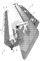
도 1은 몰드가 개방 위치에 있는 본 발명의 실시예에 따른 파이프 형성 장치의 개략도이다.
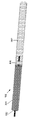
도 2는 몰드가 폐쇄 위치에 있는 도 1의 파이프 형성 장치의 개략도이다.
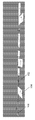
도 3은 도 1의 파이프 형성 장치의 브레이크를 도시하는 개략도이다.
도 4는 도 1의 파이프 형성 장치를 이용하여 연속 파이프를 형성하는 순서를 도시한다.Preferred features, embodiments and variations of the present invention may be identified from the following detailed description which provides sufficient information to those skilled in the art in carrying out the present invention. The detailed description is not to be considered as limiting in any way the scope of the preceding summary of the invention. The detailed description will refer to a number of drawings as follows:
1 is a schematic view of a pipe forming apparatus according to an embodiment of the invention with a mold in an open position;
Fig. 2 is a schematic view of the pipe forming apparatus of Fig. 1 with the mold in a closed position;
Fig. 3 is a schematic view showing a brake of the pipe forming apparatus of Fig. 1;
FIG. 4 shows a sequence of forming a continuous pipe using the pipe forming apparatus of FIG. 1 .
본 발명의 실시예에 따르면, 도 1에 도시된 주행 파이프 형성 장치(100)가 제공된다. 장치(100)는 설치 현장에서 연속적인 산업용 파이프를 형성한다. 장치(100)는 건조 시트 재료(104)가 권취되어 있는 회전 맨드릴(rotating mandrel) 형태의 중앙 포머(former)(102)를 포함한다. 몰드(106)는 권취된 재료(104)를 지지하는 포머(102)를 수용하도록 제공된다. 장치(100)는 몰드(106) 내의 재료(104)에 경화성 액체 수지를 주입하기 위한 주입기(108)(즉, 도포기)를 더 포함한다.According to an embodiment of the present invention, a traveling
유리하게, 파이프는 파이프라인의 효율적인 형성을 제공하기 위해서 설치 장소에 형성된다. 재료(104) 및 수지를 현장에 제공하는 ISO 컨테이너는 600 미터의 파이프라인 섹션을 제조할 수 있으며, 이는 종래 기술의 60 미터와 비교하여 효율성의 상당한 증가를 나타낸다.Advantageously, the pipe is formed at the installation site in order to provide an efficient formation of the pipeline. An ISO
장치(100)는 재료(104)의 롤(roll)을 유지하기 위한 홀더(109)를 포함한다. 또한, 장치(100)는 권취하는 동안 포머(102)를 따라 유지된 재료(104)를 축 방향으로 전진시키기 위한 랙킹 시스템(racking system)(110)(즉, 전진기)을 포함한다. 이러한 방식으로, 권취된 재료(102)의 단부는 인접한 권선에 대해 함께 상보적으로 끼워지는 단차(112)를 형성한다. 포머(102)의 각각의 회전에 대해서, 랙킹 시스템(110)은 설정된 양의 각도만큼 이동한다. 이동 정도는 각각의 회전에 대해 설정된 밀리미터 수이다. 예를 들어, 10 내지 12 mm 이동은 100 내지 120 mm 테이퍼화된 결합을 생성하고, 권취된 다음 섹션은 반대 방향으로 이러한 테이퍼를 복제하여 완전한 스카프(scarf) 또는 단차 결합(stepped join)을 생성할 것이다.The
포머(102)는 한 쌍의 테이퍼화된 벽 세그먼트(114a, 114b)를 포함한다. 벽 세그먼트(114a, 114b)는 재료(104)를 권취하기 위한 포머(102)의 단면적(CSA)을 줄이기 위해 안쪽으로 이동한다. 역으로, 벽 세그먼트(114a, 114b)는 수지 주입을 위한 포머(102)의 CSA를 증가시키기 위해 바깥쪽으로 이동한다.Former 102 includes a pair of tapered
장치(100)는 연속 파이프를 제조하기 위해서 장치(100)를 전진시키기 위한 추적 비히클(116)을 더 포함한다.The
도 2는 권취된 재료(104)를 지지하고 수지 주입을 위해 준비된 포머(102) 주위에서 폐쇄된 몰드(106)를 도시한다. 벽 세그먼트(114a, 114b)는 형성될 파이프의 내경까지 포머(102)의 CSA를 증가시키기 위해 바깥쪽으로 이동되었다. 장치(100)는 주입된 수지의 충격을 방지하기 위해서 65℃의 고온 수를 몰드를 통해 제공함으로써 몰드(106)를 가열하기 위한 고온 수 시스템(200)을 포함한다. 모든 파이프 재료 및 구성요소는 일정한 온도로 유지되어 일정한 품질 제어 및 재료 취급을 보장한다.2 shows a
도 3을 참조하면, 장치(100)는 완성된 파이프(302)에 포머(102)를 잠그기 위한 잠금 브레이크(300)를 포함하는 반면에, 다른 인접 파이프에 재료(104)를 권취할 때 포머(102)가 여전히 회전할 수 있게 한다. 브레이크(300)는 완성된 파이프(302) 내에서 팽창하여 포머(102)를 제자리에 잠그고 포머(102)를 전진시킬 때 수축한다.Referring to FIG. 3 , the
포머(102)는 이전에 경화된 파이프 섹션(302) 내부에 남아 있는 동안 회전할 수 있다. 포머(102)의 트레일링 섹션은 건조 재료(104)를 지지하는 주요 섹션과 분리된다. 주행 섹션은 경화된 섹션(302)에 이를 잠그는 잠금 브레이크(300)를 통해 포머(102)의 더 긴 메인 섹션에 기계적으로 유지된다. 차례로, 2 개의 이전 섹션은 베어링 시스템과 연결되어 주행 섹션이 회전하지 않고 브레이크로 잠긴 상태를 유지하는 반면에, 선행 섹션은 유리 섬유 재료(104)를 받아 회전한다.The former 102 can rotate while remaining inside the previously hardened
장치(100)는 또한, 포머(102)를 둘러싸기 위한 슬리브(304)를 포함한다. 슬리브(304)는 수지의 고착에 저항하기 위해서 고착되지 않는 실리콘 재료로 형성된다. 슬리브(304)는 또한 추가의 이형제를 포함할 수 있다. 몰드(106)는 또한 슬리브(304)에 대해 밀봉하기 위한 단부 시일을 포함하여 권취된 재료(104)가 내부에 위치되는 기밀 공동을 형성한다.The
재료(104)는 복합 유리 섬유를 포함하고 약 12 미터 폭인 시트 형태로 제공된다. 대안적으로, 시트는 12 미터를 구성하는 더 작은 폭의 구성요소를 포함할 수 있다. 재료(104)는 권취된 재료가 그 자체에 고착되는 것을 용이하게 하기 위해서 그 밑면에 도포된 접착제를 포함한다. 수지가 주입되면 접착제가 용해된다.
장치(100)를 사용하여 설치 현장에서 연속 파이프를 형성하는 방법이 도 4를 참조하여 이제 설명된다.A method of forming a continuous pipe at an installation
처음 1 단계에서, 현장 장치(100)에는 회전 가능한 포머(102)가 제공된다.In a first step, the
2 단계에서, 시트 재료(104)는 감소된 CSA를 갖는 회전 포머(102)에 미리 결정된 벽 두께로 권취된다. 접착제는 저장 롤과 포머(102) 사이의 건조 재료(104)에 도포된다. 랙킹 시스템(110)은 단부 단차(112)를 생성하기 위해서 회전 포머(102)에 대해 재료(104)를 전진시킨다.In step 2, the
3 단계에서, 제 1 권선이 완료된다. 차례로, 몰드(106)는 권취된 재료(104)를 지지하는 포머(102)를 수용한다. 포머(102)의 CSA는 파이프의 원하는 내경으로 증가함으로써, 적층된 유리 섬유를 압축하여 궁극적인 수지 대 유리 비율을 보장한다. 그 다음, 수지는 재료(104)를 사후-함침시키기 위해서 몰드(106) 내에 주입됨으로써, 유리 섬유를 완전히 적셔 전체적으로 공극 없는 구조를 남긴다. 그 다음에, 액체 수지는 파이프(302)를 형성하도록 경화된다.In step 3, the first winding is completed. In turn,
포머(102)의 CSA가 감소되고 포머(102)를 포함한 장치(100)는 비히클(116)을 사용하여 경화된 파이프(302)에 대해 전진된다. 브레이크는 포머(102)를 경화된 파이프(302)에 잠근다.The CSA of the former 102 is reduced and the
4 단계에서, 시트 재료(104)가 2 단계와 관련하여 이전에 설명된 바와 같이 회전 포머(102)에 권취될 때, 다른 파이프가 형성된 파이프(302)에 인접하여 형성된다. 이전과 같이, 수지가 재료(104)를 사후-함침시키기 위해서 몰드(106) 내에 주입되고, 액체 수지는 경화되어 인접한 파이프(302)를 형성한다.In step 4, when the
5 단계에서, 2 개의 파이프(302)는 그들 단부에서 함께 끼워진다. 조인트는 몰드(106)에 수용되고 파이프를 함께 단단히 체결하도록 성형된다. 이러한 방식으로, 몰드(106)는 기계적 접합을 제공하는 환형 링의 작은 섹션 또는 널링 섹션(knurling section)을 가진다. 대안적으로, 파이프 단부는 함께 부착되거나 용접될 수 있다.In step 5, the two
6 단계에서, 포머(102)는 연속 파이프의 다음 섹션을 형성하기 위해서 다음 인접 위치로 전진하는 등의 방식이다. 이러한 방식으로, 연속 복합 파이프라인은 주요 적층체만큼 구조적으로 가능한 매끄럽고 검출 불가능한 결합으로 임의의 직경과 임의의 지정된 벽 두께의 12 미터 섹션에서 형성될 수 있다. 완성된 파이프라인은 파이프라인에 현재 사용되는 임의의 모든 재료를 운반할 수 있다.In step 6, former 102 is advanced to the next adjacent position to form the next section of continuous pipe, and so on. In this way, a continuous composite pipeline can be formed in a 12 meter section of any diameter and any specified wall thickness with as smooth and undetectable bonding as structurally possible as the main laminate. The completed pipeline can carry any and all materials currently used in the pipeline.
장치(100)는 지원을 위한 최소한의 외부 기계 또는 장비(즉, 크레인, 용접, 일관된 중량물 운송)로 현장에서 작동한다. 장치(100)는 지상, 지하, 강 위 또는 아래, 강어귀 또는 위 또는 아래의 해양 환경을 위한 파이프라인을 생성한다. 또한, 장치(100)는 GPS 안내 및 로봇 제어 핸들링 시스템과 함께 CNC에 의해 자동으로 제어된다.
당업자는 본 발명의 범위를 벗어나지 않고 많은 실시예 및 변형예가 만들어질 수 있음을 이해할 것이다.Those skilled in the art will appreciate that many embodiments and modifications can be made without departing from the scope of the present invention.
장치(100)는 모든 유형의 폴리에스테르, 비닐 에스테르, 에폭시, 페놀 수지와 플라스틱 중합체 및 오늘날 시장에서 이용 가능한 변형물을 사용하고 이에 제한되지 않는다. 장치(100)는 전술한 수지에 제한되지 않으며, 다른 그리고 새로운 첨단 재료가 이용 가능해지는 대로 사용될 수 있다. 또한, 경화성 액체는 수지에 첨가되는 촉매 또는 경화제를 포함할 수 있다.
일 실시예에서, 프리프레그(prepreg)가 사용될 수 있고, 그에 따라 강화 섬유가 특정 비율로 열가소성 또는 열경화성 수지 매트릭스로 사전-함침된 복합 재료(104)가 제공된다.In one embodiment, a prepreg may be used, thereby providing a
재료(104)는 탄소 섬유, 아라미드, E-유리, S-유리, Combimat, Mouldmat, 및/또는 조합물 및 변형물을 포함할 수 있다.
전술한 테이퍼화된 접합 설계는 엔지니어가 지정한 설계 매개변수의 변수에 맞게 수정 및 조정될 수 있다.The tapered joint design described above can be modified and adjusted to fit the parameters of the design parameters specified by the engineer.
일 실시예에서, 회전 맨드릴 형태의 포머(102)는 파이프 해제를 보조하는 다양한 구멍/수단을 통해 해제될 수 있는 공기 압력을 사용한다. 공기는 맨드릴의 작은 구멍을 통해 방출된다. 피스톤과 같은 작은 밸브는 맨드릴과 같은 높이에 위치하고, 활성화될 때 이들은 수축하여 공기 압력이 파이프(302)의 해제를 돕게 한다.In one embodiment, the former 102 in the form of a rotating mandrel uses air pressure that can be released through various holes/means to assist in pipe release. Air is expelled through a small hole in the mandrel. Small valves, such as pistons, are positioned flush with the mandrel, and when activated they contract, allowing air pressure to assist in the release of
법규에 따라, 본 발명은 구조적 또는 방법론적 특징에 대해 다소 특정한 언어로 설명되었다. 본 명세서에서 설명된 수단이 본 발명을 실행하는 바람직한 형태를 포함하기 때문에 본 발명은 도시되거나 설명된 특정 특징으로 제한되지 않는다는 것을 이해해야 한다.By law, the present invention has been described in language more or less specific to its structural or methodological characteristics. It is to be understood that the invention is not limited to the specific features shown or described, since the means described herein include preferred forms of carrying out the invention.
본 명세서 전반에서 '일 실시예' 또는 '실시예'에 대한 언급은 실시예와 관련하여 설명된 특정 특징, 구조 또는 특성이 본 발명의 적어도 일 실시예에 포함됨을 의미한다. 따라서, 본 명세서 전반에 걸친 다양한 위치에서 '일 실시예에서' 또는 '실시예에서'라는 문구의 출현은 반드시 모두 동일한 실시예를 지칭하는 것은 아니다. 또한, 특정 특징, 구조 또는 특성은 하나 이상의 조합으로 임의의 적합한 방식으로 조합될 수 있다.Reference throughout this specification to 'one embodiment' or 'an embodiment' means that a particular feature, structure, or characteristic described in connection with the embodiment is included in at least one embodiment of the present invention. Thus, the appearances of the phrases 'in one embodiment' or 'in an embodiment' in various places throughout this specification are not necessarily all referring to the same embodiment. In addition, the particular features, structures, or properties may be combined in any suitable manner in one or more combinations.
Claims (21)
재료가 권취(winding)되는 포머(former);
권취된 재료를 지지하는 포머를 수용하기 위한 몰드(mold); 및
몰드 내에서 경화성 액체를 도포하기 위한 도포기(applicator)를 포함하는,
설치 현장에서 파이프를 형성하기 위한 파이프 형성 장치.A pipe forming apparatus for forming a pipe at an installation site, comprising:
a former on which the material is wound;
a mold for receiving the former supporting the wound material; and
comprising an applicator for applying a curable liquid in a mold;
A pipe forming device for forming pipes at the installation site.
설치 현장에 위치되며, 파이프는 설치 현장에서 파이프라인의 효과적인 형성을 제공하기 위해 현장에서 형성되는,
설치 현장에서 파이프를 형성하기 위한 파이프 형성 장치.The method of claim 1,
located at the installation site, the pipe being formed on site to provide effective shaping of the pipeline at the installation site;
A pipe forming device for forming pipes at the installation site.
종래 기술의 60 미터와 비교하여, 일반적으로 800 미터의 파이프라인 섹션(pipeline section)을 제조할 수 있는 현장에 재료 및 경화성 액체를 제공하여 효율성의 상당한 증가를 나타내는 운송된 ISO 컨테이너를 더 포함하는,
설치 현장에서 파이프를 형성하기 위한 파이프 형성 장치.The method of claim 1,
Further comprising a transported ISO container representing a significant increase in efficiency by providing materials and curable liquid to the site capable of manufacturing a pipeline section of typically 800 meters as compared to 60 meters in the prior art;
A pipe forming device for forming pipes at the installation site.
장치는 권취하는 동안 포머와 재료 사이의 상대 운동을 전진시키기 위한 전진기(advancer)를 더 포함하는,
설치 현장에서 파이프를 형성하기 위한 파이프 형성 장치.The method of claim 1,
the device further comprising an advancer for advancing relative motion between the former and the material during winding;
A pipe forming device for forming pipes at the installation site.
포머의 일 단부(end)에 권취된 재료는 다른 단부와 보완적인 끼워 맞춤(complementary fit)을 형성하며, 단부는 단차지는(stepped),
설치 현장에서 파이프를 형성하기 위한 파이프 형성 장치.The method of claim 1,
material wound on one end of the former forms a complementary fit with the other end, the ends being stepped;
A pipe forming device for forming pipes at the installation site.
포머는 회전 맨드릴(mandrel)을 포함하는,
설치 현장에서 파이프를 형성하기 위한 파이프 형성 장치.The method of claim 1,
The former comprises a rotating mandrel,
A pipe forming device for forming pipes at the installation site.
포머의 단면적(CSA)은 재료를 권취할 때 감소하고 경화성 액체를 도포할 때 증가하는,
설치 현장에서 파이프를 형성하기 위한 파이프 형성 장치.The method of claim 1,
The cross-sectional area (CSA) of the former decreases when the material is wound and increases when the curable liquid is applied.
A pipe forming device for forming pipes at the installation site.
포머는 CSA를 감소시킬 때 안쪽으로 이동하고 CSA를 증가시킬 때 바깥쪽으로 이동하는 하나 이상의 벽 세그먼트(wall segment)를 포함하며, 각각의 세그먼트는 테이퍼화되는(tapered),
설치 현장에서 파이프를 형성하기 위한 파이프 형성 장치.The method of claim 1,
the former comprises one or more wall segments that move inward when decreasing CSA and outward when increasing CSA, each segment being tapered;
A pipe forming device for forming pipes at the installation site.
완성된 파이프에 포머를 잠그기 위한 잠금부(lock)를 포함하는 한편, 다른 파이프에 재료를 권취할 때 포머가 회전할 수 있게 하는,
설치 현장에서 파이프를 형성하기 위한 파이프 형성 장치.The method of claim 1,
a lock for locking the former to the finished pipe, while allowing the former to rotate when winding material on another pipe;
A pipe forming device for forming pipes at the installation site.
장치는 포머를 둘러싸기 위한 슬리브(sleeve)를 포함하며, 슬리브는 고착되지 않거나(non-stick) 고착 저항 재료(stick resistant material)로 형성되는,
설치 현장에서 파이프를 형성하기 위한 파이프 형성 장치.The method of claim 1,
The device includes a sleeve for enclosing the former, the sleeve being formed of a non-stick or stick resistant material;
A pipe forming device for forming pipes at the installation site.
몰드는 권취된 재료가 위치되는 기밀 공동(airtight cavity)을 형성하며, 몰드는 슬리브에 대해 밀봉하기 위한 단부 시일(seal)을 포함하는,
설치 현장에서 파이프를 형성하기 위한 파이프 형성 장치.11. The method of claim 10,
wherein the mold defines an airtight cavity in which the wound material is positioned, the mold comprising an end seal for sealing against the sleeve;
A pipe forming device for forming pipes at the installation site.
도포기는 분무기를 포함하며 경화성 액체는 수지를 포함하는,
설치 현장에서 파이프를 형성하기 위한 파이프 형성 장치.The method of claim 1,
The applicator comprises a sprayer and the curable liquid comprises a resin;
A pipe forming device for forming pipes at the installation site.
몰드를 가열하기 위한 고온 수 시스템, 연속 파이프를 제조하기 위한 장치를 전진시키기 위한 추적 비히클(tracked vehicle) 및/또는 재료의 롤(roll)을 유지하기 위한 홀더(holder)를 포함하는,
설치 현장에서 파이프를 형성하기 위한 파이프 형성 장치.The method of claim 1,
a hot water system for heating the mold, a tracked vehicle for advancing an apparatus for making a continuous pipe, and/or a holder for holding a roll of material;
A pipe forming device for forming pipes at the installation site.
재료는 복합 유리 섬유를 포함하는 건조 시트(sheet) 재료이며, 재료는 그의 밑면에 접착제를 포함하는,
설치 현장에서 파이프를 형성하기 위한 파이프 형성 장치.The method of claim 1,
the material is a dry sheet material comprising composite glass fibers, the material comprising an adhesive on its underside;
A pipe forming device for forming pipes at the installation site.
포머에 재료를 권취하는 단계;
몰드 내에서 권취된 재료를 지지하는 포머를 수용하는 단계; 및
몰드 내에 경화성 액체를 도포하는 단계를 포함하는,
설치 현장에서 파이프를 형성하는 방법.A method of forming a pipe at an installation site, comprising:
winding the material on the former;
receiving a former supporting the wound material in a mold; and
applying a curable liquid into the mold;
How to form a pipe at the installation site.
권취하는 동안 포머와 재료 사이의 상대 운동을 전진시키는 단계를 포함하는,
설치 현장에서 파이프를 형성하는 방법.16. The method of claim 15,
advancing relative motion between the former and the material during winding;
How to form a pipe at the installation site.
권취하기 위한 포머의 단면적(CSA)을 감소시키고 액체의 도포를 위한 포머의 CSA를 증가시키는 단계를 포함하는,
설치 현장에서 파이프를 형성하는 방법.16. The method of claim 15,
reducing the cross-sectional area (CSA) of the former for winding and increasing the CSA of the former for application of a liquid;
How to form a pipe at the installation site.
파이프를 형성하기 위해서 액체를 권취 및/또는 경화하기 전에 재료에 접착제를 도포하는 단계를 포함하는,
설치 현장에서 파이프를 형성하는 방법.16. The method of claim 15,
applying an adhesive to the material prior to winding and/or curing the liquid to form a pipe;
How to form a pipe at the installation site.
형성된 파이프에 인접한 다른 파이프를 형성하고 파이프를 함께 끼워 맞추는 단계를 포함하는,
설치 현장에서 파이프를 형성하는 방법.16. The method of claim 15,
forming another pipe adjacent the formed pipe and fitting the pipes together;
How to form a pipe at the installation site.
몰드에서 끼워 맞춰진 파이프를 함께 성형하는 단계를 포함하는,
설치 현장에서 파이프를 형성하는 방법.20. The method of claim 19,
forming the fitted pipe together in a mold;
How to form a pipe at the installation site.
포머로부터 파이프를 해제하기 위해서 공기 압력을 가하는 단계를 포함하는,
설치 현장에서 파이프를 형성하는 방법.16. The method of claim 15,
applying air pressure to release the pipe from the former;
How to form a pipe at the installation site.
Applications Claiming Priority (3)
| Application Number | Priority Date | Filing Date | Title |
|---|---|---|---|
| AU2019904309A AU2019904309A0 (en) | 2019-11-15 | Pipe forming apparatus | |
| AU2019904309 | 2019-11-15 | ||
| PCT/IB2020/057241 WO2021094840A1 (en) | 2019-11-15 | 2020-07-31 | Pipe forming apparatus |
Publications (1)
| Publication Number | Publication Date |
|---|---|
| KR20220100658A true KR20220100658A (en) | 2022-07-15 |
Family
ID=75911871
Family Applications (1)
| Application Number | Title | Priority Date | Filing Date |
|---|---|---|---|
| KR1020227020011A KR20220100658A (en) | 2019-11-15 | 2020-07-31 | pipe forming device |
Country Status (9)
| Country | Link |
|---|---|
| US (1) | US20230085379A1 (en) |
| EP (1) | EP4058273A4 (en) |
| JP (1) | JP2023504357A (en) |
| KR (1) | KR20220100658A (en) |
| CN (1) | CN114650908A (en) |
| AU (1) | AU2020382988A1 (en) |
| BR (1) | BR112022009376A2 (en) |
| CA (1) | CA3161135A1 (en) |
| WO (1) | WO2021094840A1 (en) |
Family Cites Families (13)
| Publication number | Priority date | Publication date | Assignee | Title |
|---|---|---|---|---|
| US4558971A (en) * | 1984-03-06 | 1985-12-17 | David Constant V | Continuous pipeline fabrication method |
| JPS63173625A (en) * | 1987-01-13 | 1988-07-18 | Nitto Boseki Co Ltd | Manufacture of fiber reinforced resin cylinder |
| JPH06336B2 (en) * | 1989-02-09 | 1994-01-05 | 日東紡績株式会社 | Preform for molding fiber-reinforced plastic and method for producing the same |
| JPH086847B2 (en) * | 1989-11-16 | 1996-01-29 | 積水化学工業株式会社 | Composite pipe and manufacturing method thereof |
| CA2171267A1 (en) * | 1996-03-07 | 1997-09-08 | Michael Lee Roberts | Glass coated pipe system and testing method |
| CA2561402C (en) * | 1997-10-10 | 2009-08-04 | Fiberspar Corporation | Composite spoolable tube with sensor |
| US20120222771A1 (en) * | 2011-03-04 | 2012-09-06 | Pipestream B.V. | On-site manufacturing of composite pipeline |
| US20160053922A1 (en) * | 2012-06-04 | 2016-02-25 | Mohammad R. Ehsani | Endless on-site pipe manufacturing |
| DE102013001442B3 (en) * | 2013-01-29 | 2014-03-13 | Thyssenkrupp Presta Aktiengesellschaft | Steering column in fiber composite technology, based on pultrusion and braiding and / or winding technology |
| WO2017000025A1 (en) * | 2015-06-30 | 2017-01-05 | Wnr Systems Pte. Ltd. | A pipe forming assembly and method of use |
| CN204977492U (en) * | 2015-08-31 | 2016-01-20 | 浙江双林机械股份有限公司 | Container formula heavy -calibre winding pipeline apparatus for producing |
| CN105415698B (en) * | 2015-12-24 | 2018-08-10 | 浙江鑫宙竹基复合材料科技有限公司 | Bamboo winds tubulose product molding machine |
| CN106273533B (en) * | 2016-10-10 | 2018-06-15 | 东北林业大学 | A kind of filament wound composite tube body in-situ solidifying device and method |
-
2020
- 2020-07-31 US US17/776,992 patent/US20230085379A1/en active Pending
- 2020-07-31 KR KR1020227020011A patent/KR20220100658A/en unknown
- 2020-07-31 CA CA3161135A patent/CA3161135A1/en active Pending
- 2020-07-31 CN CN202080079047.5A patent/CN114650908A/en active Pending
- 2020-07-31 BR BR112022009376A patent/BR112022009376A2/en unknown
- 2020-07-31 EP EP20888624.2A patent/EP4058273A4/en active Pending
- 2020-07-31 WO PCT/IB2020/057241 patent/WO2021094840A1/en unknown
- 2020-07-31 JP JP2022527716A patent/JP2023504357A/en active Pending
- 2020-07-31 AU AU2020382988A patent/AU2020382988A1/en active Pending
Also Published As
| Publication number | Publication date |
|---|---|
| US20230085379A1 (en) | 2023-03-16 |
| JP2023504357A (en) | 2023-02-03 |
| CN114650908A (en) | 2022-06-21 |
| EP4058273A4 (en) | 2023-12-27 |
| CA3161135A1 (en) | 2021-05-20 |
| WO2021094840A1 (en) | 2021-05-20 |
| BR112022009376A2 (en) | 2022-08-09 |
| AU2020382988A1 (en) | 2022-06-16 |
| EP4058273A1 (en) | 2022-09-21 |
Similar Documents
| Publication | Publication Date | Title |
|---|---|---|
| RU2592595C2 (en) | Method of producing continuous composite pipe, device for producing continuous composite pipe | |
| US8074686B2 (en) | Tube for transporting high-viscosity materials | |
| US5409561A (en) | Lining of passageways | |
| EA027973B1 (en) | Pipe and method of construction thereof | |
| CN104081098B (en) | The construction of pipe | |
| US10377078B2 (en) | Inverted filament winder for pipeline rehabilitation | |
| US4329193A (en) | Method of making a coupling for rigid pressure pipe | |
| JPH05506821A (en) | Improvements in lining materials for conduits and channels and pipes made from such materials | |
| EP3574246B1 (en) | Fitting element for use in rehabilitation of pipelines and method for producing the same | |
| CN114060709B (en) | High-pressure tank and method for manufacturing high-pressure tank | |
| KR20220100658A (en) | pipe forming device | |
| WO1992021908A1 (en) | Laminated pipe and a process for making the same | |
| US4319950A (en) | Mandrel for making a coupling for rigid pressure pipe | |
| JP6611689B2 (en) | Pipe construction | |
| RU195573U1 (en) | Coating the inner surface of the pipeline | |
| US20230095131A1 (en) | Method for manufacturing a reinforced composite pipe using compression techniques | |
| CN113958775A (en) | Multi-layer liner, catheter system and method of manufacture | |
| JPS61139423A (en) | Joining method of fiber reinforced plastics | |
| JP2018192799A (en) | Construction of pipe | |
| JP2004255848A (en) | Fitting type fiber-reinforced composite material for reinforcing structure and reinforcing method | |
| JP2002310352A (en) | Connecting structure of fiber reinforced resin pipe | |
| JPH10225990A (en) | Repairing coat for pipeline and method for forming the coat | |
| SE408666B (en) | REINFORCED BITUMEN RODS AND SEEN TO MANUFACTURE |