KR20220091509A - Method and apparatus for transmitting and receiving a positioning reference signal by a terminal in a wireless communication system supporting sidelink - Google Patents
Method and apparatus for transmitting and receiving a positioning reference signal by a terminal in a wireless communication system supporting sidelink Download PDFInfo
- Publication number
- KR20220091509A KR20220091509A KR1020227016599A KR20227016599A KR20220091509A KR 20220091509 A KR20220091509 A KR 20220091509A KR 1020227016599 A KR1020227016599 A KR 1020227016599A KR 20227016599 A KR20227016599 A KR 20227016599A KR 20220091509 A KR20220091509 A KR 20220091509A
- Authority
- KR
- South Korea
- Prior art keywords
- prs
- psfch
- frequency resource
- frequency
- resource region
- Prior art date
Links
Images


Classifications
-
- H—ELECTRICITY
- H04—ELECTRIC COMMUNICATION TECHNIQUE
- H04L—TRANSMISSION OF DIGITAL INFORMATION, e.g. TELEGRAPHIC COMMUNICATION
- H04L5/00—Arrangements affording multiple use of the transmission path
- H04L5/003—Arrangements for allocating sub-channels of the transmission path
- H04L5/0048—Allocation of pilot signals, i.e. of signals known to the receiver
- H04L5/0051—Allocation of pilot signals, i.e. of signals known to the receiver of dedicated pilots, i.e. pilots destined for a single user or terminal
-
- H—ELECTRICITY
- H04—ELECTRIC COMMUNICATION TECHNIQUE
- H04L—TRANSMISSION OF DIGITAL INFORMATION, e.g. TELEGRAPHIC COMMUNICATION
- H04L1/00—Arrangements for detecting or preventing errors in the information received
- H04L1/08—Arrangements for detecting or preventing errors in the information received by repeating transmission, e.g. Verdan system
-
- H—ELECTRICITY
- H04—ELECTRIC COMMUNICATION TECHNIQUE
- H04L—TRANSMISSION OF DIGITAL INFORMATION, e.g. TELEGRAPHIC COMMUNICATION
- H04L5/00—Arrangements affording multiple use of the transmission path
- H04L5/0001—Arrangements for dividing the transmission path
- H04L5/0003—Two-dimensional division
- H04L5/0005—Time-frequency
- H04L5/0007—Time-frequency the frequencies being orthogonal, e.g. OFDM(A), DMT
- H04L5/0012—Hopping in multicarrier systems
-
- H—ELECTRICITY
- H04—ELECTRIC COMMUNICATION TECHNIQUE
- H04L—TRANSMISSION OF DIGITAL INFORMATION, e.g. TELEGRAPHIC COMMUNICATION
- H04L5/00—Arrangements affording multiple use of the transmission path
- H04L5/003—Arrangements for allocating sub-channels of the transmission path
- H04L5/0053—Allocation of signaling, i.e. of overhead other than pilot signals
-
- H—ELECTRICITY
- H04—ELECTRIC COMMUNICATION TECHNIQUE
- H04W—WIRELESS COMMUNICATION NETWORKS
- H04W4/00—Services specially adapted for wireless communication networks; Facilities therefor
- H04W4/30—Services specially adapted for particular environments, situations or purposes
- H04W4/40—Services specially adapted for particular environments, situations or purposes for vehicles, e.g. vehicle-to-pedestrians [V2P]
- H04W4/44—Services specially adapted for particular environments, situations or purposes for vehicles, e.g. vehicle-to-pedestrians [V2P] for communication between vehicles and infrastructures, e.g. vehicle-to-cloud [V2C] or vehicle-to-home [V2H]
-
- H04W72/0406—
-
- H—ELECTRICITY
- H04—ELECTRIC COMMUNICATION TECHNIQUE
- H04W—WIRELESS COMMUNICATION NETWORKS
- H04W72/00—Local resource management
- H04W72/04—Wireless resource allocation
- H04W72/044—Wireless resource allocation based on the type of the allocated resource
- H04W72/0453—Resources in frequency domain, e.g. a carrier in FDMA
-
- H04W72/0493—
-
- H—ELECTRICITY
- H04—ELECTRIC COMMUNICATION TECHNIQUE
- H04W—WIRELESS COMMUNICATION NETWORKS
- H04W72/00—Local resource management
- H04W72/12—Wireless traffic scheduling
- H04W72/1263—Mapping of traffic onto schedule, e.g. scheduled allocation or multiplexing of flows
-
- H04W72/1278—
-
- H—ELECTRICITY
- H04—ELECTRIC COMMUNICATION TECHNIQUE
- H04W—WIRELESS COMMUNICATION NETWORKS
- H04W72/00—Local resource management
- H04W72/50—Allocation or scheduling criteria for wireless resources
- H04W72/53—Allocation or scheduling criteria for wireless resources based on regulatory allocation policies
-
- H—ELECTRICITY
- H04—ELECTRIC COMMUNICATION TECHNIQUE
- H04W—WIRELESS COMMUNICATION NETWORKS
- H04W72/00—Local resource management
- H04W72/20—Control channels or signalling for resource management
-
- H—ELECTRICITY
- H04—ELECTRIC COMMUNICATION TECHNIQUE
- H04W—WIRELESS COMMUNICATION NETWORKS
- H04W92/00—Interfaces specially adapted for wireless communication networks
- H04W92/16—Interfaces between hierarchically similar devices
- H04W92/18—Interfaces between hierarchically similar devices between terminal devices
Abstract
다양한 실시예에 따른 사이드링크 통신을 지원하는 무선 통신 시스템에서 사이드링크 피드백 채널(PSFCH)을 통한 포지셔닝 참조 신호 (PRS)를 제1 단말이 전송하는 방법 및 장치를 개시한다. 제 상기 PSFCH에 대한 자원 영역 내에서 피드백 신호와 다중화되도록 PRS에 대한 제1 주파수 자원 영역을 할당하는 단계, 상기 제1 주파수 자원 영역에 대한 할당 정보를 전송하는 단계, 및 상기 할당 정보에 기초하여 상기 PRS 및 상기 피드백 신호를 상기 PSFCH를 통해 전송하는 단계를 포함하고, 상기 제1 주파수 자원 영역의 크기는 상기 피드백 신호에 대하여 미리 구성된 주파수 자원 크기 및 다중화 타입에 기초하여 결정되고, 상기 할당 정보는 상기 다중화 타입, 상기 제1 주파수 자원 영역의 크기 및 상기 제1 주파수 자원의 시작 주파수에 대한 정보를 포함하는 방법 및 장치가 개시된다.Disclosed are a method and an apparatus for a first terminal to transmit a positioning reference signal (PRS) through a sidelink feedback channel (PSFCH) in a wireless communication system supporting sidelink communication according to various embodiments. Allocating a first frequency resource region for the PRS to be multiplexed with a feedback signal in the resource region for the first PSFCH, transmitting allocation information for the first frequency resource region, and based on the allocation information transmitting the PRS and the feedback signal through the PSFCH, wherein the size of the first frequency resource region is determined based on a frequency resource size and a multiplexing type configured in advance for the feedback signal, and the allocation information includes the A multiplexing type, a size of the first frequency resource region, and information on a start frequency of the first frequency resource are provided.
Description
사이드링크를 지원하는 무선통신시스템에서 단말이 PRS (Positioning Reference Signal)를 사이드링크 피드백 채널을 통하여 송수신하는 방법 및 이를 위한 장치에 대한 것이다.A method for transmitting and receiving a Positioning Reference Signal (PRS) by a terminal through a sidelink feedback channel in a wireless communication system supporting sidelink, and an apparatus therefor.
무선 통신 시스템은 가용한 시스템 자원(예를 들어, 대역폭, 전송 전력 등)을 공유하여 다중 사용자와의 통신을 지원하는 다중 접속(multiple access) 시스템이다. 다중 접속 시스템의 예로는 CDMA(code division multiple access) 시스템, FDMA(frequency division multiple access) 시스템, TDMA(time division multiple access) 시스템, OFDMA(orthogonal frequency division multiple access) 시스템, SC-FDMA(single carrier frequency division multiple access) 시스템, MC-FDMA(multi carrier frequency division multiple access) 시스템 등이 있다.A wireless communication system is a multiple access system that supports communication with multiple users by sharing available system resources (eg, bandwidth, transmission power, etc.). Examples of the multiple access system include a code division multiple access (CDMA) system, a frequency division multiple access (FDMA) system, a time division multiple access (TDMA) system, an orthogonal frequency division multiple access (OFDMA) system, and a single carrier frequency (SC-FDMA) system. There is a division multiple access) system, a multi carrier frequency division multiple access (MC-FDMA) system, and the like.
사이드링크(sidelink, SL)란 단말(User Equipment, UE)들 간에 직접적인 링크를 설정하여, 기지국(Base Station, BS)을 거치지 않고, 단말 간에 음성 또는 데이터 등을 직접 주고 받는 통신 방식을 말한다. SL는 급속도로 증가하는 데이터 트래픽에 따른 기지국의 부담을 해결할 수 있는 하나의 방안으로서 고려되고 있다.A sidelink (SL) refers to a communication method in which a direct link is established between user equipment (UE), and voice or data is directly exchanged between terminals without going through a base station (BS). SL is being considered as a method to solve the burden of the base station due to the rapidly increasing data traffic.
V2X(vehicle-to-everything)는 유/무선 통신을 통해 다른 차량, 보행자, 인프라가 구축된 사물 등과 정보를 교환하는 통신 기술을 의미한다. V2X는 V2V(vehicle-to-vehicle), V2I(vehicle-to-infrastructure), V2N(vehicle-to- network) 및 V2P(vehicle-to-pedestrian)와 같은 4 가지 유형으로 구분될 수 있다. V2X 통신은 PC5 인터페이스 및/또는 Uu 인터페이스를 통해 제공될 수 있다.V2X (vehicle-to-everything) refers to a communication technology that exchanges information with other vehicles, pedestrians, and infrastructure-built objects through wired/wireless communication. V2X can be divided into four types: vehicle-to-vehicle (V2V), vehicle-to-infrastructure (V2I), vehicle-to-network (V2N), and vehicle-to-pedestrian (V2P). V2X communication may be provided through a PC5 interface and/or a Uu interface.
한편, 더욱 많은 통신 기기들이 더욱 큰 통신 용량을 요구하게 됨에 따라, 기존의 무선 액세스 기술(Radio Access Technology, RAT)에 비해 향상된 모바일 광대역 (mobile broadband) 통신에 대한 필요성이 대두되고 있다. 이에 따라, 신뢰도(reliability) 및 지연(latency)에 민감한 서비스 또는 단말을 고려한 통신 시스템이 논의되고 있는데, 개선된 이동 광대역 통신, 매시브 MTC(Machine Type Communication), URLLC(Ultra-Reliable and Low Latency Communication) 등을 고려한 차세대 무선 접속 기술을 새로운 RAT(new radio access technology) 또는 NR(new radio)이라 칭할 수 있다. NR에서도 V2X(vehicle-to-everything) 통신이 지원될 수 있다.On the other hand, as more and more communication devices require a larger communication capacity, the need for improved mobile broadband communication compared to the existing radio access technology (RAT) is emerging. Accordingly, a communication system in consideration of a service or terminal sensitive to reliability and latency is being discussed, and improved mobile broadband communication, massive machine type communication (MTC), and URLLC (Ultra-Reliable and Low Latency Communication) are being discussed. A next-generation radio access technology in consideration of the like may be referred to as a new radio access technology (RAT) or a new radio (NR). Even in NR, vehicle-to-everything (V2X) communication may be supported.
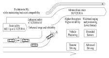
도 1은 NR 이전의 RAT에 기반한 V2X 통신과 NR에 기반한 V2X 통신을 비교하여 설명하기 위한 도면이다1 is a diagram for explaining by comparing V2X communication based on RAT before NR and V2X communication based on NR
V2X 통신과 관련하여, NR 이전의 RAT에서는 BSM(Basic Safety Message), CAM(Cooperative Awareness Message), DENM(Decentralized Environmental Notification Message)과 같은 V2X 메시지를 기반으로, 안전 서비스(safety service)를 제공하는 방안이 주로 논의되었다. V2X 메시지는, 위치 정보, 동적 정보, 속성 정보 등을 포함할 수 있다. 예를 들어, 단말은 주기적인 메시지(periodic message) 타입의 CAM, 및/또는 이벤트 트리거 메시지(event triggered message) 타입의 DENM을 다른 단말에게 전송할 수 있다.In relation to V2X communication, in RAT prior to NR, based on V2X messages such as BSM (Basic Safety Message), CAM (Cooperative Awareness Message), and DENM (Decentralized Environmental Notification Message), a method of providing a safety service (safety service) This was mainly discussed. The V2X message may include location information, dynamic information, attribute information, and the like. For example, the UE may transmit a periodic message type CAM and/or an event triggered message type DENM to another UE.
예를 들어, CAM은 방향 및 속도와 같은 차량의 동적 상태 정보, 치수와 같은 차량 정적 데이터, 외부 조명 상태, 경로 내역 등 기본 차량 정보를 포함할 수 있다. 예를 들어, 단말은 CAM을 방송할 수 있으며, CAM의 지연(latency)은 100ms보다 작을 수 있다. 예를 들어, 차량의 고장, 사고 등의 돌발적인 상황이 발행하는 경우, 단말은 DENM을 생성하여 다른 단말에게 전송할 수 있다. 예를 들어, 단말의 전송 범위 내에 있는 모든 차량은 CAM 및/또는 DENM을 수신할 수 있다. 이 경우, DENM은 CAM 보다 높은 우선 순위를 가질 수 있다.For example, the CAM may include basic vehicle information such as dynamic state information of the vehicle such as direction and speed, vehicle static data such as dimensions, external lighting conditions, and route details. For example, the UE may broadcast a CAM, and the CAM latency may be less than 100 ms. For example, when an unexpected situation such as a breakdown of a vehicle or an accident occurs, the terminal may generate a DENM and transmit it to another terminal. For example, all vehicles within the transmission range of the terminal may receive the CAM and/or DENM. In this case, the DENM may have a higher priority than the CAM.
이후, V2X 통신과 관련하여, 다양한 V2X 시나리오들이 NR에서 제시되고 있다. 예를 들어, 다양한 V2X 시나리오들은, 차량 플라투닝(vehicle platooning), 향상된 드라이빙(advanced driving), 확장된 센서들(extended sensors), 리모트 드라이빙(remote driving) 등을 포함할 수 있다.Since, in relation to V2X communication, various V2X scenarios are being presented in NR. For example, various V2X scenarios may include vehicle platooning, advanced driving, extended sensors, remote driving, and the like.
예를 들어, 차량 플라투닝을 기반으로, 차량들은 동적으로 그룹을 형성하여 함께 이동할 수 있다. 예를 들어, 차량 플라투닝에 기반한 플라툰 동작들(platoon operations)을 수행하기 위해, 상기 그룹에 속하는 차량들은 선두 차량으로부터 주기적인 데이터를 수신할 수 있다. 예를 들어, 상기 그룹에 속하는 차량들은 주기적인 데이터를 이용하여, 차량들 사이의 간격을 줄이거나 넓힐 수 있다. For example, based on vehicle platooning, vehicles can be dynamically grouped and moved together. For example, to perform platoon operations based on vehicle platooning, vehicles belonging to the group may receive periodic data from a leading vehicle. For example, the vehicles belonging to the group may reduce or widen the distance between the vehicles by using periodic data.
예를 들어, 향상된 드라이빙을 기반으로, 차량은 반자동화 또는 완전 자동화될 수 있다. 예를 들어, 각 차량은 근접 차량 및/또는 근접 로지컬 엔티티(logical entity)의 로컬 센서(local sensor)에서 획득된 데이터를 기반으로, 궤도(trajectories) 또는 기동(maneuvers)을 조정할 수 있다. 또한, 예를 들어, 각 차량은 근접한 차량들과 드라이빙 인텐션(driving intention)을 상호 공유할 수 있다. For example, based on improved driving, the vehicle can be semi-automated or fully automated. For example, each vehicle may adjust trajectories or maneuvers based on data obtained from local sensors of the proximate vehicle and/or proximate logical entity. Also, for example, each vehicle may share driving intention with adjacent vehicles.
예를 들어, 확장 센서들을 기반으로, 로컬 센서들을 통해 획득된 로 데이터(raw data) 또는 처리된 데이터(processed data), 또는 라이브 비디오 데이터(live video data)는 차량, 로지컬 엔티티, 보행자들의 단말 및/또는 V2X 응용 서버 간에 상호 교환될 수 있다. 따라서, 예를 들어, 차량은 자체 센서를 이용하여 감지할 수 있는 환경 보다 향상된 환경을 인식할 수 있다. For example, on the basis of extended sensors, raw data or processed data obtained through local sensors, or live video data, is a vehicle, a logical entity, a terminal of pedestrians and / or can be interchanged between V2X application servers. Accordingly, for example, the vehicle may recognize an environment that is improved over an environment that can be detected using its own sensor.
예를 들어, 리모트 드라이빙을 기반으로, 운전을 하지 못하는 사람 또는 위험한 환경에 위치한 리모트 차량을 위해, 리모트 드라이버 또는 V2X 애플리케이션은 상기 리모트 차량을 동작 또는 제어할 수 있다. 예를 들어, 대중 교통과 같이 경로를 예측할 수 있는 경우, 클라우드 컴퓨팅 기반의 드라이빙이 상기 리모트 차량의 동작 또는 제어에 이용될 수 있다. 또한, 예를 들어, 클라우드 기반의 백엔드 서비스 플랫폼(cloud-based back-end service platform)에 대한 액세스가 리모트 드라이빙을 위해 고려될 수 있다.For example, based on remote driving, for a person who cannot drive or a remote vehicle located in a dangerous environment, a remote driver or V2X application may operate or control the remote vehicle. For example, when a route can be predicted, such as in public transportation, cloud computing-based driving may be used to operate or control the remote vehicle. Also, for example, access to a cloud-based back-end service platform may be considered for remote driving.
한편, 차량 플라투닝, 향상된 드라이빙, 확장된 센서들, 리모트 드라이빙 등 다양한 V2X 시나리오들에 대한 서비스 요구사항(service requirements)들을 구체화하는 방안이 NR에 기반한 V2X 통신에서 논의되고 있다.Meanwhile, a method of specifying service requirements for various V2X scenarios such as vehicle platooning, enhanced driving, extended sensors, and remote driving is being discussed in NR-based V2X communication.
해결하고자 하는 과제는 사이드링크 측위 (sidelink positioning)에 필요한 PRS를 한정된 사이드링크 피드백 채널 (PSFCH) 자원 (Resource) 내에서 피드백 신호와 다중화시켜 전송하되, 상기 PSFCH에서 전송되는 피드백 신호와의 관계를 고려하여 PRS에 대한 주파수 자원 영역의 크기 및 다중화 타입을 결정하여 효율적으로 PSFCH 자원 (Resource)을 활용하는 방법 및 장치를 제공하고자 한다.The task to be solved is to transmit a PRS required for sidelink positioning by multiplexing it with a feedback signal within a limited sidelink feedback channel (PSFCH) resource, but considering the relationship with the feedback signal transmitted in the PSFCH Accordingly, an object of the present invention is to provide a method and apparatus for efficiently utilizing PSFCH resources by determining the size and multiplexing type of the frequency resource region for the PRS.
기술적 과제들은 이상에서 언급한 기술적 과제들로 제한되지 않으며, 언급하지 않은 또 다른 기술적 과제들은 아래의 기재로부터 본 발명이 속하는 기술분야에서 통상의 지식을 가진 자에게 명확하게 이해될 수 있을 것이다.The technical problems are not limited to the technical problems mentioned above, and other technical problems not mentioned will be clearly understood by those of ordinary skill in the art to which the present invention belongs from the description below.
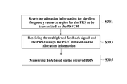
일 측면에 따른 사이드링크 통신을 지원하는 무선 통신 시스템에서 사이드링크 피드백 채널(PSFCH)을 통한 포지셔닝 참조 신호 (PRS)를 제1 단말이 전송하는 방법은, 상기 PSFCH에 대한 자원 영역 내에서 피드백 신호와 다중화되도록 PRS에 대한 제1 주파수 자원 영역을 할당하는 단계, 상기 제1 주파수 자원 영역에 대한 할당 정보를 전송하는 단계, 및 상기 할당 정보에 기초하여 상기 PRS 및 상기 피드백 신호를 상기 PSFCH를 통해 전송하는 단계를 포함하고, 상기 제1 주파수 자원 영역의 크기는 상기 피드백 신호에 대하여 미리 구성된 주파수 자원 크기 및 다중화 타입에 기초하여 결정되고, 상기 할당 정보는 상기 다중화 타입, 상기 제1 주파수 자원 영역의 크기 및 상기 제1 주파수 자원의 시작 주파수에 대한 정보를 포함할 수 있다.According to an aspect, a method for a first terminal to transmit a positioning reference signal (PRS) through a sidelink feedback channel (PSFCH) in a wireless communication system supporting sidelink communication according to an aspect comprises: a feedback signal within a resource region for the PSFCH; Allocating a first frequency resource region for the PRS to be multiplexed, transmitting allocation information for the first frequency resource region, and transmitting the PRS and the feedback signal through the PSFCH based on the allocation information step, wherein the size of the first frequency resource region is determined based on a frequency resource size and a multiplexing type configured in advance for the feedback signal, and the allocation information includes the multiplexing type, the size of the first frequency resource region, and Information on the start frequency of the first frequency resource may be included.
또는, 상기 할당 정보는 PSCCH (Physical Sidelink Control Channel)를 통해 전송되거나 PSSCH (Physical Sidelink Shared Channel)에 피기백되어 전송되는 것을 특징으로 한다.Alternatively, the allocation information is transmitted through a Physical Sidelink Control Channel (PSCCH) or is piggybacked on a Physical Sidelink Shared Channel (PSSCH) and transmitted.
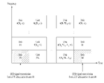
또는, 상기 다중화 타입이 콤브 (comb) 타입인 경우, 상기 제1 주파수 자원 영역은 상기 PSFCH에 대한 자원 영역 내에 복수개 할당되고, 상기 복수의 제1 주파수 자원 영역들 각각은 상기 PSFCH에 대한 자원 영역 내에서 상기 피드백 신호에 대해 할당된 제2 주파수 자원 영역의 주파수 크기만큼 서로 이격된 것을 특징으로 한다.Alternatively, when the multiplexing type is a comb type, a plurality of the first frequency resource regions are allocated in the resource region for the PSFCH, and each of the plurality of first frequency resource regions is within the resource region for the PSFCH. It is characterized in that it is spaced apart from each other by the frequency size of the second frequency resource region allocated to the feedback signal.
또는 상기 다중화 타입이 버스트 타입인 경우, 상기 제1 주파수 자원 영역은 상기 PSFCH에 대한 자원 영역 내에 하나만이 할당되고, 상기 제1 주파수 자원 영역은 상기 PSFCH에 대한 자원 영역 내에서 상기 피드백 신호에 대해 할당된 제2 주파수 자원 영역과 미리 구성된 가드 RE만큼 이격된 것을 특징으로 한다.Alternatively, when the multiplexing type is a burst type, only one of the first frequency resource region is allocated within the resource region for the PSFCH, and the first frequency resource region is allocated for the feedback signal within the resource region for the PSFCH. It is characterized in that it is spaced apart from the second frequency resource region by a preconfigured guard RE.
또는, 상기 버스트 타입은 제1 버스트 타입과 제2 버스트 타입을 포함하고, 상기 다중화 타입이 제1 버스트 타입인 경우, 상기 제1 주파수 자원 영역은 상기 제2 주파수 자원 영역 사이에 할당되는 것을 특징으로 한다.Alternatively, the burst type includes a first burst type and a second burst type, and when the multiplexing type is the first burst type, the first frequency resource region is allocated between the second frequency resource regions. do.
또는, 상기 PRS에 대한 PRS 패턴 ID는 상기 단말의 이동 속도 및 상기 PSFCH와 관련된 채널 상태 중 적어도 하나에 기초하여 결정되는 것을 특징으로 한다.Alternatively, the PRS pattern ID for the PRS is characterized in that it is determined based on at least one of a movement speed of the terminal and a channel state related to the PSFCH.
또는, 상기 단말이 상기 PRS를 반복 전송하는 경우, 상기 PRS는 미리 설정된 호핑 패턴에 기초하여 주파수 호핑된 상기 제1 주파수 자원 영역에서 전송되는 것을 특징으로 한다.Alternatively, when the terminal repeatedly transmits the PRS, the PRS is characterized in that it is transmitted in the first frequency resource region that is frequency-hopped based on a preset hopping pattern.
또는 상기 미리 설정된 호핑 패턴은 상기 피드백 신호에 대한 호핑 패턴에 기초하여 미리 설정되는 것을 특징으로 한다.Alternatively, the preset hopping pattern may be preset based on a hopping pattern for the feedback signal.
또는, 상기 슬롯은 상기 요청 PRS 자원 풀 및 상기 응답 PRS 자원 풀 사이에 가드 OFDM 심볼을 더 포함하는 것을 특징으로 하는 한다.Alternatively, the slot is characterized in that it further includes a guard OFDM symbol between the request PRS resource pool and the response PRS resource pool.
다른 측면에 따른 사이드링크를 지원하는 무선통신시스템에서 제1 단말이 사이드링크 피드백 채널(PSFCH)을 통한 PRS를 전송하는 방법은 상기 PSFCH에 대한 자원 영역 내에서 피드백 신호와 다중화되도록 PRS에 대한 제1 주파수 자원 영역을 할당하는 단계, 상기 제1 주파수 자원 영역에 대한 할당 정보를 전송하는 단계, 및 상기 할당 정보에 기초하여 상기 PRS 및 상기 피드백 신호를 상기 PSFCH를 통해 전송하는 단계를 포함하고, 상기 제1 주파수 자원 영역의 크기는 상기 피드백 신호에 대하여 미리 구성된 주파수 자원 크기 및 다중화 타입에 기초하여 결정되고, 상기 PRS에 대한 PRS 패턴 ID는 상기 미리 구성된 주파수 자원 크기 및 상기 단말의 이동 속도에 기초하여 결정되는 것을 특징으로 한다.According to another aspect, in a method for a first terminal to transmit a PRS through a sidelink feedback channel (PSFCH) in a wireless communication system supporting a sidelink according to another aspect, the first method for PRS is multiplexed with a feedback signal within a resource region for the PSFCH. Allocating a frequency resource region, transmitting allocation information for the first frequency resource region, and transmitting the PRS and the feedback signal through the PSFCH based on the allocation information, The size of one frequency resource region is determined based on a frequency resource size and a multiplexing type configured in advance for the feedback signal, and a PRS pattern ID for the PRS is determined based on the preset frequency resource size and the movement speed of the terminal characterized by being
다른 측면에 따른 사이드링크 통신을 지원하는 무선 통신 시스템에서 사이드링크 피드백 채널(PSFCH)을 통한 포지셔닝 참조 신호 (PRS)를 제2 단말이 수신하는 방법은 상기 PSFCH에 대한 자원 영역 내에서 상기 PRS에 대해 할당된 제1 주파수 자원 영역에 대한 할당 정보를 수신하는 단계 및 상기 할당 정보에 기초하여 주파수 영역에서 피드백 신호와 다중화된 상기 PRS를 상기 PSFCH를 통해 수신하는 단계를 포함하고, 상기 할당 정보는 상기 피드백 신호에 대하여 미리 구성된 주파수 자원 크기 및 다중화 타입에 기초하여 결정된 제1 주파수 자원 영역의 크기에 대한 정보, 상기 다중화 타입 및 상기 제1 주파수 자원 영역의 시작 주파수에 대한 정보를 포함할 수 있다.In a wireless communication system supporting sidelink communication according to another aspect, a method for a second terminal to receive a positioning reference signal (PRS) through a sidelink feedback channel (PSFCH) in a resource region for the PSFCH is for the PRS Receiving allocation information for an allocated first frequency resource region and receiving the PRS multiplexed with a feedback signal in a frequency domain on the basis of the allocation information through the PSFCH, wherein the allocation information is the feedback Information on the size of the first frequency resource region determined based on the frequency resource size and the multiplexing type configured in advance for the signal, the multiplexing type, and information on the start frequency of the first frequency resource region may be included.
또는, 상기 PRS가 시간 자원을 달리하여 반복 수신된 경우, 상기 제2 단말은 이동 속도 또는 상기 PSFCH와 관련된 채널 상태에 기초하여 결합할 PRS의 개수를 결정하는 것을 특징으로 한다.Alternatively, when the PRS is repeatedly received with different time resources, the second terminal determines the number of PRSs to be combined based on a movement speed or a channel state related to the PSFCH.
다른 측면에 따른 사이드링크를 지원하는 무선통신시스템에서 사이드링크 피드백 채널(PSFCH)을 통한 포지셔닝 참조 신호 (PRS)를 전송하는 제1 단말 (User Equipment)은 RF(Radio Frequency) 송수신기 및 상기 RF 송수신기와 연결되는 프로세서를 포함하고. 상기 프로세서는 상기 PSFCH에 대한 자원 영역 내에서 피드백 신호와 다중화되도록 PRS에 대한 제1 주파수 자원 영역을 할당하고, 상기 RF 송수신기를 제어하여 상기 제1 주파수 자원 영역에 대한 할당 정보를 전송하며, 상기 할당 정보에 기초하여 상기 PRS 및 상기 피드백 신호를 상기 PSFCH를 통해 전송하며, 상기 제1 주파수 자원 영역의 크기는 상기 피드백 신호에 대하여 미리 구성된 주파수 자원 크기 및 다중화 타입에 기초하여 결정되고, 상기 할당 정보는 상기 다중화 타입, 상기 제1 주파수 자원 영역의 크기 및 상기 제1 주파수 자원의 시작 주파수에 대한 정보를 포함할 수 있다.In a wireless communication system supporting a sidelink according to another aspect, a first terminal (User Equipment) transmitting a positioning reference signal (PRS) through a sidelink feedback channel (PSFCH) includes an RF (Radio Frequency) transceiver and the RF transceiver and a processor to which it is connected. The processor allocates a first frequency resource region for the PRS to be multiplexed with a feedback signal within the resource region for the PSFCH, controls the RF transceiver to transmit allocation information for the first frequency resource region, and the allocation The PRS and the feedback signal are transmitted through the PSFCH based on the information, and the size of the first frequency resource region is determined based on a frequency resource size and a multiplexing type configured in advance for the feedback signal, and the allocation information is The multiplexing type, the size of the first frequency resource region, and information on the start frequency of the first frequency resource may be included.
다른 측면에 따른 사이드링크를 지원하는 무선통신시스템에서 사이드링크 피드백 채널(PSFCH)을 통해 포지셔닝 참조 신호 (PRS)를 수신하는 제2 단말 (User Equipment)은 RF(Radio Frequency) 송수신기 및 상기 RF 송수신기와 연결되는 프로세서를 포함하고. 상기 프로세서는 상기 RF 송수신기를 제어하여 상기 PSFCH에 대한 자원 영역 내에서 상기 PRS에 대해 할당된 제1 주파수 자원 영역에 대한 할당 정보를 수신하고, 상기 할당 정보에 기초하여 주파수 영역에서 피드백 신호와 다중화된 상기 PRS를 상기 PSFCH를 통해 수신하며, 상기 할당 정보는 상기 피드백 신호에 대하여 미리 구성된 주파수 자원 크기 및 다중화 타입에 기초하여 결정된 제1 주파수 자원 영역의 크기에 대한 정보, 상기 다중화 타입 및 상기 제1 주파수 자원 영역의 시작 주파수에 대한 정보를 포함할 수 있다.A second terminal (User Equipment) that receives a positioning reference signal (PRS) through a sidelink feedback channel (PSFCH) in a wireless communication system supporting a sidelink according to another aspect includes an RF (Radio Frequency) transceiver and the RF transceiver and a processor to which it is connected. The processor controls the RF transceiver to receive allocation information for a first frequency resource region allocated for the PRS within the resource region for the PSFCH, and multiplexed with a feedback signal in the frequency domain based on the allocation information The PRS is received through the PSFCH, and the allocation information includes information on a size of a first frequency resource region determined based on a frequency resource size and a multiplexing type configured in advance for the feedback signal, the multiplexing type, and the first frequency Information on the start frequency of the resource region may be included.
다른 측면에 사이드링크를 지원하는 무선통신시스템에서 사이드링크 피드백 채널(PSFCH)을 통한 포지셔닝 참조 신호 (PRS)를 전송하는 칩 셋은 적어도 하나의 프로세서 및 상기 적어도 하나의 프로세서와 동작 가능하게 연결되고, 실행될 때, 상기 적어도 하나의 프로세서가 동작을 수행하도록 하는 적어도 하나의 메모리를 포함하며, 상기 동작은 상기 PSFCH에 대한 자원 영역 내에서 피드백 신호와 다중화되도록 PRS에 대한 제1 주파수 자원 영역을 할당하고, 상기 제1 주파수 자원 영역에 대한 할당 정보를 전송하며, 상기 할당 정보에 기초하여 상기 PRS 및 상기 피드백 신호를 상기 PSFCH를 통해 전송하며, 상기 제1 주파수 자원 영역의 크기는 상기 피드백 신호에 대하여 미리 구성된 주파수 자원 크기 및 다중화 타입에 기초하여 결정되고, 상기 할당 정보는 상기 다중화 타입, 상기 제1 주파수 자원 영역의 크기 및 상기 제1 주파수 자원의 시작 주파수에 대한 정보를 포함할 수 있다.On the other side, a chip set for transmitting a positioning reference signal (PRS) through a sidelink feedback channel (PSFCH) in a wireless communication system supporting a sidelink is operatively connected to at least one processor and the at least one processor, and at least one memory that, when executed, causes the at least one processor to perform an operation, wherein the operation allocates a first frequency resource region for the PRS to be multiplexed with a feedback signal within the resource region for the PSFCH; The allocation information for the first frequency resource region is transmitted, and the PRS and the feedback signal are transmitted through the PSFCH based on the allocation information, and the size of the first frequency resource region is configured in advance for the feedback signal. It is determined based on a frequency resource size and a multiplexing type, and the allocation information may include information on the multiplexing type, the size of the first frequency resource region, and a start frequency of the first frequency resource.
또는, 상기 프로세서는 상기 제1 주파수 자원 영역의 크기에 기초하여 상기 칩 셋과 연결된 장치의 주행 모드를 제어하는 것을 특징으로 한다.Alternatively, the processor may control the driving mode of the device connected to the chip set based on the size of the first frequency resource region.
다른 측면에 따른 사이드링크를 지원하는 무선통신시스템에서 적어도 하나의 프로세서가 사이드링크 피드백 채널(PSFCH)을 통한 포지셔닝 참조 신호 (PRS)를 전송하는 적어도 하나의 컴퓨터 프로그램을 포함하는 컴퓨터 판독 가능한 저장 매체는, 상기 적어도 하나의 프로세서가 상기 PRS의 전송하는 동작을 수행하도록 하는 적어도 하나의 컴퓨터 프로그램, 및 상기 적어도 하나의 컴퓨터 프로그램이 저장된 컴퓨터 판독 가능한 저장 매체를 포함하고, 상기 동작은 상기 PSFCH에 대한 자원 영역 내에서 피드백 신호와 다중화되도록 PRS에 대한 제1 주파수 자원 영역을 할당하고, 상기 제1 주파수 자원 영역에 대한 할당 정보를 전송하며, 상기 할당 정보에 기초하여 상기 PRS 및 상기 피드백 신호를 상기 PSFCH를 통해 전송하는 동작을 포함하고, 상기 제1 주파수 자원 영역의 크기는 상기 피드백 신호에 대하여 미리 구성된 주파수 자원 크기 및 다중화 타입에 기초하여 결정되고, 상기 할당 정보는 상기 다중화 타입, 상기 제1 주파수 자원 영역의 크기 및 상기 제1 주파수 자원의 시작 주파수에 대한 정보를 포함할 수 있다.A computer-readable storage medium comprising at least one computer program for transmitting a positioning reference signal (PRS) through a sidelink feedback channel (PSFCH) by at least one processor in a wireless communication system supporting a sidelink according to another aspect, , at least one computer program for causing the at least one processor to perform an operation of transmitting the PRS, and a computer readable storage medium storing the at least one computer program, wherein the operation is a resource area for the PSFCH allocates a first frequency resource region for the PRS so as to be multiplexed with a feedback signal in and transmitting, wherein the size of the first frequency resource region is determined based on a frequency resource size and a multiplexing type configured in advance with respect to the feedback signal, and the allocation information includes the multiplexing type and the size of the first frequency resource region. It may include information on the size and the start frequency of the first frequency resource.
다양한 실시예들은 사이드링크 측위 (sidelink positioning)에 필요한 PRS를 한정된 사이드링크 피드백 채널 (PSFCH) 자원 (Resource) 내에서 피드백 신호와 다중화시켜 전송하되, 상기 PSFCH에서 전송되는 피드백 신호와의 관계를 고려하여 PRS에 대한 주파수 자원 영역의 크기 및 다중화 타입을 결정하여 효율적으로 PSFCH 자원 (Resource)을 활용할 수 있다.Various embodiments transmit a PRS required for sidelink positioning by multiplexing it with a feedback signal in a limited sidelink feedback channel (PSFCH) resource, but taking into account the relationship with the feedback signal transmitted in the PSFCH It is possible to efficiently utilize PSFCH resources by determining the size and multiplexing type of the frequency resource region for the PRS.
다양한 실시예에서 얻을 수 있는 효과는 이상에서 언급한 효과들로 제한되지 않으며, 언급하지 않은 또 다른 효과들은 아래의 기재로부터 본 발명이 속하는 기술분야에서 통상의 지식을 가진 자에게 명확하게 이해될 수 있을 것이다.Effects obtainable in various embodiments are not limited to the above-mentioned effects, and other effects not mentioned may be clearly understood by those of ordinary skill in the art to which the present invention pertains from the description below. There will be.
본 명세서에 첨부되는 도면은 본 발명에 대한 이해를 제공하기 위한 것으로서 본 발명의 다양한 실시형태들을 나타내고 명세서의 기재와 함께 본 발명의 원리를 설명하기 위한 것이다.
도 1은 NR 이전의 RAT에 기반한 V2X 통신과 NR에 기반한 V2X 통신을 비교하여 설명하기 위한 도면이다
도 2은 LTE 시스템의 구조를 나타낸다.
도 3은 NR 시스템의 구조를 나타낸다.
도 4은 NR의 무선 프레임의 구조를 나타낸다.
도 5은 NR 프레임의 슬롯 구조를 나타낸다.
도 6은 SL 통신을 위한 무선 프로토콜 구조(radio protocol architecture)를 나타낸다.
도 7은 V2X 또는 SL 통신을 수행하는 단말을 나타낸다.
도 8는 V2X 또는 SL 통신을 위한 자원 단위를 나타낸다.
도 9은 단말이 전송 모드에 따라 V2X 또는 SL 통신을 수행하는 절차를 나타낸다.
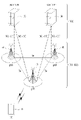
도 10은 본 발명이 적용될 수 있는 OTDOA(Observed Time Difference Of Arrival) 측위 방법을 설명하기 위한 도면이다.
도 11 및 도 12는 PSFCH-feedback 및 PSFCH-PRS 간의 멀티플렉싱 타입을 설명하기 위한 도면이다.
도 13은 PSFCH-PRS 주파수 자원 영역에서 복수의 PRS들을 멀티플렉싱하는 방법을 설명하기 위한 도면이다.
도 14 및 15는 하나의 PSFCH-PRS 주파수 자원 영역에 멀티플렉싱된 복수의 PRS들을 주파수 호핑 또는 반복 전송하는 방법을 설명하기 위한 도면이다.
도 16는 사전에 미리 할당 및 구성된 측위 자원 구조를 설명하기 위한 도면이다.
도 17은 PRS 전송 주기 및 전송 횟수 관련 예약 정보를 설명하기 위한 도면이다.
도 18은 제1 단말이 PSFCH를 통해 PRS를 전송하는 방법을 설명하기 위한 도면이다.
도 19은 제2 단말이 PSFCH를 통해 PRS를 수신하는 방법을 설명하기 위한 도면이다.
도 20는 본 발명에 적용되는 통신 시스템을 예시한다.
도 21는 본 발명에 적용될 수 있는 무선 기기를 예시한다.
도 22은 본 발명에 적용되는 무선 기기의 다른 예를 나타낸다. 무선 기기는 사용-예/서비스에 따라 다양한 형태로 구현될 수 있다
도 23은 본 발명에 적용되는 차량 또는 자율 주행 차량을 예시한다.BRIEF DESCRIPTION OF THE DRAWINGS The accompanying drawings are intended to provide an understanding of the present invention, and represent various embodiments of the present invention, and together with the description of the specification, serve to explain the principles of the present invention.
1 is a diagram for explaining by comparing V2X communication based on RAT before NR and V2X communication based on NR
2 shows the structure of an LTE system.
3 shows the structure of the NR system.
4 shows the structure of a radio frame of NR.
5 shows a slot structure of an NR frame.
6 shows a radio protocol architecture for SL communication.
7 shows a terminal performing V2X or SL communication.
8 shows a resource unit for V2X or SL communication.
9 shows a procedure for the terminal to perform V2X or SL communication according to the transmission mode.
10 is a diagram for explaining an Observed Time Difference Of Arrival (OTDOA) positioning method to which the present invention can be applied.
11 and 12 are diagrams for explaining a multiplexing type between PSFCH-feedback and PSFCH-PRS.
13 is a diagram for explaining a method of multiplexing a plurality of PRSs in a PSFCH-PRS frequency resource domain.
14 and 15 are diagrams for explaining a method of frequency hopping or repeatedly transmitting a plurality of PRSs multiplexed in one PSFCH-PRS frequency resource region.
16 is a diagram for explaining the structure of a positioning resource allocated and configured in advance in advance.
17 is a diagram for explaining reservation information related to a PRS transmission period and transmission number.
18 is a diagram for describing a method in which a first terminal transmits a PRS through a PSFCH.
19 is a diagram for describing a method in which a second terminal receives a PRS through a PSFCH.
20 illustrates a communication system applied to the present invention.
21 illustrates a wireless device applicable to the present invention.
22 shows another example of a wireless device to which the present invention is applied. The wireless device may be implemented in various forms according to use-examples/services.
23 illustrates a vehicle or an autonomous driving vehicle to which the present invention is applied.
무선 통신 시스템은 가용한 시스템 자원(예를 들어, 대역폭, 전송 파워 등)을 공유하여 다중 사용자와의 통신을 지원하는 다중 접속(multiple access) 시스템이다. 다중 접속 시스템의 예로는 CDMA(code division multiple access) 시스템, FDMA(frequency division multiple access) 시스템, TDMA(time division multiple access) 시스템, OFDMA(orthogonal frequency division multiple access) 시스템, SC-FDMA(single carrier frequency division multiple access) 시스템, MC-FDMA(multi carrier frequency division multiple access) 시스템 등이 있다.The wireless communication system is a multiple access system that supports communication with multiple users by sharing available system resources (eg, bandwidth, transmission power, etc.). Examples of the multiple access system include a code division multiple access (CDMA) system, a frequency division multiple access (FDMA) system, a time division multiple access (TDMA) system, an orthogonal frequency division multiple access (OFDMA) system, and a single carrier frequency (SC-FDMA) system. There is a division multiple access) system, a multi carrier frequency division multiple access (MC-FDMA) system, and the like.
사이드링크(sidelink)란 단말(User Equipment, UE)들 간에 직접적인 링크를 설정하여, 기지국(Base Station, BS)을 거치지 않고, 단말 간에 음성 또는 데이터 등을 직접 주고 받는 통신 방식을 말한다. 사이드링크는 급속도로 증가하는 데이터 트래픽에 따른 기지국의 부담을 해결할 수 있는 하나의 방안으로서 고려되고 있다.A sidelink refers to a communication method in which a direct link is established between user equipment (UE), and voice or data is directly exchanged between terminals without going through a base station (BS). The sidelink is being considered as one way to solve the burden of the base station due to the rapidly increasing data traffic.
V2X(vehicle-to-everything)는 유/무선 통신을 통해 다른 차량, 보행자, 인프라가 구축된 사물 등과 정보를 교환하는 통신 기술을 의미한다. V2X는 V2V(vehicle-to-vehicle), V2I(vehicle-to-infrastructure), V2N(vehicle-to- network) 및 V2P(vehicle-to-pedestrian)와 같은 4 가지 유형으로 구분될 수 있다. V2X 통신은 PC5 인터페이스 및/또는 Uu 인터페이스를 통해 제공될 수 있다.V2X (vehicle-to-everything) refers to a communication technology that exchanges information with other vehicles, pedestrians, and infrastructure-built objects through wired/wireless communication. V2X can be divided into four types: vehicle-to-vehicle (V2V), vehicle-to-infrastructure (V2I), vehicle-to-network (V2N), and vehicle-to-pedestrian (V2P). V2X communication may be provided through a PC5 interface and/or a Uu interface.
한편, 더욱 많은 통신 기기들이 더욱 큰 통신 용량을 요구하게 됨에 따라, 기존의 무선 액세스 기술(Radio Access Technology, RAT)에 비해 향상된 모바일 광대역 (mobile broadband) 통신에 대한 필요성이 대두되고 있다. 이에 따라, 신뢰도(reliability) 및 지연(latency)에 민감한 서비스 또는 단말을 고려한 통신 시스템이 논의되고 있는데, 개선된 이동 광대역 통신, 매시브 MTC, URLLC(Ultra-Reliable and Low Latency Communication) 등을 고려한 차세대 무선 접속 기술을 새로운 RAT(new radio access technology) 또는 NR(new radio)이라 칭할 수 있다. NR에서도 V2X(vehicle-to-everything) 통신이 지원될 수 있다.On the other hand, as more and more communication devices require a larger communication capacity, the need for improved mobile broadband communication compared to the existing radio access technology (RAT) is emerging. Accordingly, a communication system in consideration of a service or terminal sensitive to reliability and latency is being discussed. The access technology may be referred to as new radio access technology (RAT) or new radio (NR). Even in NR, vehicle-to-everything (V2X) communication may be supported.
이하의 기술은 CDMA(code division multiple access), FDMA(frequency division multiple access), TDMA(time division multiple access), OFDMA(orthogonal frequency division multiple access), SC-FDMA(single carrier frequency division multiple access) 등과 같은 다양한 무선 통신 시스템에 사용될 수 있다. CDMA는 UTRA(universal terrestrial radio access)나 CDMA2000과 같은 무선 기술로 구현될 수 있다. TDMA는 GSM(global system for mobile communications)/GPRS(general packet radio service)/EDGE(enhanced data rates for GSM evolution)와 같은 무선 기술로 구현될 수 있다. OFDMA는 IEEE(institute of electrical and electronics engineers) 802.11(Wi-Fi), IEEE 802.16(WiMAX), IEEE 802-20, E-UTRA(evolved UTRA) 등과 같은 무선 기술로 구현될 수 있다. IEEE 802.16m은 IEEE 802.16e의 진화로, IEEE 802.16e에 기반한 시스템과의 하위 호환성(backward compatibility)를 제공한다. UTRA는 UMTS(universal mobile telecommunications system)의 일부이다. 3GPP(3rd generation partnership project) LTE(long term evolution)은 E-UTRA(evolved-UMTS terrestrial radio access)를 사용하는 E-UMTS(evolved UMTS)의 일부로써, 하향링크에서 OFDMA를 채용하고 상향링크에서 SC-FDMA를 채용한다. LTE-A(advanced)는 3GPP LTE의 진화이다. The following technologies include code division multiple access (CDMA), frequency division multiple access (FDMA), time division multiple access (TDMA), orthogonal frequency division multiple access (OFDMA), single carrier frequency division multiple access (SC-FDMA), etc. It can be used in various wireless communication systems. CDMA may be implemented with a radio technology such as universal terrestrial radio access (UTRA) or CDMA2000. TDMA may be implemented with a radio technology such as global system for mobile communications (GSM)/general packet radio service (GPRS)/enhanced data rates for GSM evolution (EDGE). OFDMA may be implemented with a wireless technology such as Institute of Electrical and Electronics Engineers (IEEE) 802.11 (Wi-Fi), IEEE 802.16 (WiMAX), IEEE 802-20, and evolved UTRA (E-UTRA). IEEE 802.16m is an evolution of IEEE 802.16e, and provides backward compatibility with a system based on IEEE 802.16e. UTRA is part of the universal mobile telecommunications system (UMTS). 3rd generation partnership project (3GPP) long term evolution (LTE) is a part of evolved UMTS (E-UMTS) that uses evolved-UMTS terrestrial radio access (E-UTRA), and employs OFDMA in downlink and SC in uplink - Adopt FDMA. LTE-A (advanced) is an evolution of 3GPP LTE.
5G NR은 LTE-A의 후속 기술로서, 고성능, 저지연, 고가용성 등의 특성을 가지는 새로운 Clean-slate 형태의 이동 통신 시스템이다. 5G NR은 1GHz 미만의 저주파 대역에서부터 1GHz~10GHz의 중간 주파 대역, 24GHz 이상의 고주파(밀리미터파) 대역 등 사용 가능한 모든 스펙트럼 자원을 활용할 수 있다.5G NR is a successor technology of LTE-A, and is a new clean-slate type mobile communication system with characteristics such as high performance, low latency, and high availability. 5G NR can utilize all available spectrum resources, from low frequency bands below 1 GHz, to intermediate frequency bands from 1 GHz to 10 GHz, and high frequency (millimeter wave) bands above 24 GHz.
설명을 명확하게 하기 위해, LTE-A 또는 5G NR을 위주로 기술하지만 실시예(들)의 기술적 사상이 이에 제한되는 것은 아니다.For clarity of explanation, LTE-A or 5G NR is mainly described, but the technical spirit of the embodiment(s) is not limited thereto.
도 2은 적용될 수 있는 LTE 시스템의 구조를 나타낸다. 이는 E-UTRAN(Evolved-UMTS Terrestrial Radio Access Network), 또는 LTE(Long Term Evolution)/LTE-A 시스템이라고 불릴 수 있다.2 shows the structure of an applicable LTE system. This may be called an Evolved-UMTS Terrestrial Radio Access Network (E-UTRAN), or a Long Term Evolution (LTE)/LTE-A system.
도 2을 참조하면, E-UTRAN은 단말(10)에게 제어 평면(control plane)과 사용자 평면(user plane)을 제공하는 기지국(20; Base Station, BS)을 포함한다. 단말(10)은 고정되거나 이동성을 가질 수 있으며, MS(Mobile Station), UT(User Terminal), SS(Subscriber Station), MT(Mobile Terminal), 무선기기(Wireless Device) 등 다른 용어로 불릴 수 있다. 기지국(20)은 단말(10)과 통신하는 고정된 지점(fixed station)을 말하며, eNB(evolved-NodeB), BTS(Base Transceiver System), 액세스 포인트(Access Point) 등 다른 용어로 불릴 수 있다.Referring to FIG. 2 , the E-UTRAN includes a base station (BS) 20 that provides a control plane and a user plane to the terminal 10 . The terminal 10 may be fixed or mobile, and may be referred to by other terms such as a mobile station (MS), a user terminal (UT), a subscriber station (SS), a mobile terminal (MT), and a wireless device. . The
기지국(20)들은 X2 인터페이스를 통하여 서로 연결될 수 있다. 기지국(20)은 S1 인터페이스를 통해 EPC(Evolved Packet Core, 30), 보다 상세하게는 S1-MME를 통해 MME(Mobility Management Entity)와 S1-U를 통해 S-GW(Serving Gateway)와 연결된다. The
EPC(30)는 MME, S-GW 및 P-GW(Packet Data Network-Gateway)로 구성된다. MME는 단말의 접속 정보나 단말의 능력에 관한 정보를 가지고 있으며, 이러한 정보는 단말의 이동성 관리에 주로 사용된다. S-GW는 E-UTRAN을 종단점으로 갖는 게이트웨이이며, P-GW는 PDN을 종단점으로 갖는 게이트웨이이다.The
단말과 네트워크 사이의 무선인터페이스 프로토콜(Radio Interface Protocol)의 계층들은 통신시스템에서 널리 알려진 개방형 시스템간 상호접속(Open System Interconnection, OSI) 기준 모델의 하위 3개 계층을 바탕으로 L1 (제 1 계층), L2 (제 2 계층), L3(제 3 계층)로 구분될 수 있다. 이 중에서 제 1 계층에 속하는 물리 계층은 물리 채널(Physical Channel)을 이용한 정보전송서비스(Information Transfer Service)를 제공하며, 제 3 계층에 위치하는 RRC(Radio Resource Control) 계층은 단말과 네트워크 간에 무선 자원을 제어하는 역할을 수행한다. 이를 위해 RRC 계층은 단말과 기지국간 RRC 메시지를 교환한다.The layers of the Radio Interface Protocol between the terminal and the network are based on the lower three layers of the Open System Interconnection (OSI) standard model widely known in communication systems, L1 (Layer 1), It may be divided into L2 (second layer) and L3 (third layer). Among them, the physical layer belonging to the first layer provides an information transfer service using a physical channel, and the RRC (Radio Resource Control) layer located in the third layer is a radio resource between the terminal and the network. plays a role in controlling To this end, the RRC layer exchanges RRC messages between the terminal and the base station.
도 3은 NR 시스템의 구조를 나타낸다.3 shows the structure of the NR system.
도 3을 참조하면, NG-RAN은 단말에게 사용자 평면 및 제어 평면 프로토콜 종단(termination)을 제공하는 gNB 및/또는 eNB를 포함할 수 있다. 도 7에서는 gNB만을 포함하는 경우를 예시한다. gNB 및 eNB는 상호 간에 Xn 인터페이스로 연결되어 있다. gNB 및 eNB는 5세대 코어 네트워크(5G Core Network: 5GC)와 NG 인터페이스를 통해 연결되어 있다. 보다 구체적으로, AMF(access and mobility management function)과는 NG-C 인터페이스를 통해 연결되고, UPF(user plane function)과는 NG-U 인터페이스를 통해 연결된다. Referring to FIG. 3 , the NG-RAN may include a gNB and/or an eNB that provides user plane and control plane protocol termination to the UE. 7 illustrates a case in which only gNBs are included. The gNB and the eNB are connected to each other through an Xn interface. The gNB and the eNB are connected to the 5G Core Network (5GC) through the NG interface. More specifically, it is connected to an access and mobility management function (AMF) through an NG-C interface, and is connected to a user plane function (UPF) through an NG-U interface.
도 4은 NR의 무선 프레임의 구조를 나타낸다.4 shows the structure of a radio frame of NR.
도 4을 참조하면, NR에서 상향링크 및 하향링크 전송에서 무선 프레임을 사용할 수 있다. 무선 프레임은 10ms의 길이를 가지며, 2개의 5ms 하프-프레임(Half-Frame, HF)으로 정의될 수 있다. 하프-프레임은 5개의 1ms 서브프레임(Subframe, SF)을 포함할 수 있다. 서브프레임은 하나 이상의 슬롯으로 분할될 수 있으며, 서브프레임 내 슬롯 개수는 부반송파 간격(Subcarrier Spacing, SCS)에 따라 결정될 수 있다. 각 슬롯은 CP(cyclic prefix)에 따라 12개 또는 14개의 OFDM(A) 심볼을 포함할 수 있다. Referring to FIG. 4 , radio frames may be used in uplink and downlink transmission in NR. The radio frame has a length of 10 ms and may be defined as two 5 ms half-frames (HF). A half-frame may include 5 1ms subframes (Subframe, SF). A subframe may be divided into one or more slots, and the number of slots in a subframe may be determined according to a subcarrier spacing (SCS). Each slot may include 12 or 14 OFDM(A) symbols according to a cyclic prefix (CP).
노멀 CP(normal CP)가 사용되는 경우, 각 슬롯은 14개의 심볼을 포함할 수 있다. 확장 CP가 사용되는 경우, 각 슬롯은 12개의 심볼을 포함할 수 있다. 여기서, 심볼은 OFDM 심볼 (또는, CP-OFDM 심볼), SC-FDMA(Single Carrier - FDMA) 심볼 (또는, DFT-s-OFDM(Discrete Fourier Transform-spread-OFDM) 심볼)을 포함할 수 있다.When a normal CP (normal CP) is used, each slot may include 14 symbols. When the extended CP is used, each slot may include 12 symbols. Here, the symbol may include an OFDM symbol (or a CP-OFDM symbol), a single carrier-FDMA (SC-FDMA) symbol (or a Discrete Fourier Transform-spread-OFDM (DFT-s-OFDM) symbol).
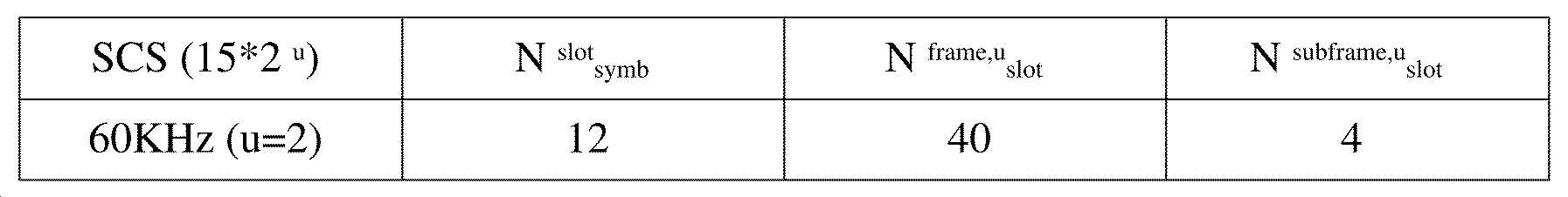
다음 표 1은 노멀 CP가 사용되는 경우, SCS 설정(u)에 따라 슬롯 별 심볼의 개수((Nslot symb), 프레임 별 슬롯의 개수((Nframe,u slot)와 서브프레임 별 슬롯의 개수((Nsubframe,u slot)를 예시한다.The following Table 1 shows the number of symbols per slot ((N slot symb ), the number of slots per frame ((N frame, u slot ) and the number of slots per subframe according to the SCS configuration (u) when normal CP is used. ((N subframe,u slot ) is exemplified.

표 2는 확장 CP가 사용되는 경우, SCS에 따라 슬롯 별 심볼의 개수, 프레임 별 슬롯의 개수와 서브프레임 별 슬롯의 개수를 예시한다.Table 2 illustrates the number of symbols per slot, the number of slots per frame, and the number of slots per subframe according to SCS when the extended CP is used.
NR 시스템에서는 하나의 단말에게 병합되는 복수의 셀들 간에 OFDM(A) 뉴머놀로지(numerology)(예, SCS, CP 길이 등)가 상이하게 설정될 수 있다. 이에 따라, 동일한 개수의 심볼로 구성된 시간 자원(예, 서브프레임, 슬롯 또는 TTI)(편의상, TU(Time Unit)로 통칭)의 (절대 시간) 구간이 병합된 셀들 간에 상이하게 설정될 수 있다. In the NR system, OFDM(A) numerology (eg, SCS, CP length, etc.) may be set differently between a plurality of cells merged into one UE. Accordingly, an (absolute time) interval of a time resource (eg, a subframe, a slot, or a TTI) (commonly referred to as a TU (Time Unit) for convenience) composed of the same number of symbols may be set differently between the merged cells.
NR에서, 다양한 5G 서비스들을 지원하기 위한 다수의 뉴머놀로지(numerology) 또는 SCS가 지원될 수 있다. 예를 들어, SCS가 15kHz인 경우, 전통적인 셀룰러 밴드들에서의 넓은 영역(wide area)이 지원될 수 있고, SCS가 30kHz/60kHz인 경우, 밀집한-도시(dense-urban), 더 낮은 지연(lower latency) 및 더 넓은 캐리어 대역폭(wider carrier bandwidth)이 지원될 수 있다. SCS가 60kHz 또는 그보다 높은 경우, 위상 잡음(phase noise)을 극복하기 위해 24.25GHz보다 큰 대역폭이 지원될 수 있다.In NR, multiple numerology or SCS to support various 5G services may be supported. For example, when SCS is 15 kHz, wide area in traditional cellular bands can be supported, and when SCS is 30 kHz/60 kHz, dense-urban, lower latency) and a wider carrier bandwidth may be supported. For SCS of 60 kHz or higher, bandwidths greater than 24.25 GHz may be supported to overcome phase noise.
NR 주파수 밴드(frequency band)는 두 가지 타입의 주파수 범위(frequency range)로 정의될 수 있다. 상기 두 가지 타입의 주파수 범위는 FR1 및 FR2일 수 있다. 주파수 범위의 수치는 변경될 수 있으며, 예를 들어, 상기 두 가지 타입의 주파수 범위는 하기 표 3과 같을 수 있다. NR 시스템에서 사용되는 주파수 범위 중 FR1은 "sub 6GHz range"를 의미할 수 있고, FR2는 "above 6GHz range"를 의미할 수 있고 밀리미터 웨이브(millimeter wave, mmW)로 불릴 수 있다.The NR frequency band may be defined as two types of frequency ranges. The two types of frequency ranges may be FR1 and FR2. The numerical value of the frequency range may be changed. For example, the two types of frequency ranges may be as shown in Table 3 below. Among the frequency ranges used in the NR system, FR1 may mean "sub 6GHz range", FR2 may mean "above 6GHz range", and may be referred to as a millimeter wave (mmW).

상술한 바와 같이, NR 시스템의 주파수 범위의 수치는 변경될 수 있다. 예를 들어, FR1은 하기 표 4와 같이 410MHz 내지 7125MHz의 대역을 포함할 수 있다. 즉, FR1은 6GHz (또는 5850, 5900, 5925 MHz 등) 이상의 주파수 대역을 포함할 수 있다. 예를 들어, FR1 내에서 포함되는 6GHz (또는 5850, 5900, 5925 MHz 등) 이상의 주파수 대역은 비면허 대역(unlicensed band)을 포함할 수 있다. 비면허 대역은 다양한 용도로 사용될 수 있고, 예를 들어 차량을 위한 통신(예를 들어, 자율주행)을 위해 사용될 수 있다.As mentioned above, the numerical value of the frequency range of the NR system can be changed. For example, FR1 may include a band of 410 MHz to 7125 MHz as shown in Table 4 below. That is, FR1 may include a frequency band of 6 GHz (or 5850, 5900, 5925 MHz, etc.) or higher. For example, a frequency band of 6GHz (or 5850, 5900, 5925 MHz, etc.) or higher included in FR1 may include an unlicensed band. The unlicensed band may be used for various purposes, for example, for communication for a vehicle (eg, autonomous driving).

도 5은 NR 프레임의 슬롯 구조를 나타낸다.5 shows a slot structure of an NR frame.
도 5을 참조하면, 슬롯은 시간 영역에서 복수의 심볼들을 포함한다. 예를 들어, 노멀 CP의 경우 하나의 슬롯이 14개의 심볼을 포함하나, 확장 CP의 경우 하나의 슬롯이 12개의 심볼을 포함할 수 있다. 또는 노멀 CP의 경우 하나의 슬롯이 7개의 심볼을 포함하나, 확장 CP의 경우 하나의 슬롯이 6개의 심볼을 포함할 수 있다.Referring to FIG. 5 , a slot includes a plurality of symbols in the time domain. For example, in the case of a normal CP, one slot may include 14 symbols, but in the case of an extended CP, one slot may include 12 symbols. Alternatively, in the case of a normal CP, one slot may include 7 symbols, but in the case of an extended CP, one slot may include 6 symbols.
반송파는 주파수 영역에서 복수의 부반송파들을 포함한다. RB(Resource Block)는 주파수 영역에서 복수(예를 들어, 12)의 연속한 부반송파로 정의될 수 있다. BWP(Bandwidth Part)는 주파수 영역에서 복수의 연속한 (P)RB((Physical) Resource Block)로 정의될 수 있으며, 하나의 뉴머놀로지(numerology)(예, SCS, CP 길이 등)에 대응될 수 있다. 반송파는 최대 N개(예를 들어, 5개)의 BWP를 포함할 수 있다. 데이터 통신은 활성화된 BWP를 통해서 수행될 수 있다. 각각의 요소는 자원 그리드에서 자원요소(Resource Element, RE)로 지칭될 수 있고, 하나의 복소 심볼이 맵핑될 수 있다.A carrier wave includes a plurality of subcarriers in the frequency domain. A resource block (RB) may be defined as a plurality of (eg, 12) consecutive subcarriers in the frequency domain. BWP (Bandwidth Part) may be defined as a plurality of consecutive (P)RB ((Physical) Resource Block) in the frequency domain, and may correspond to one numerology (eg, SCS, CP length, etc.) have. A carrier wave may include a maximum of N (eg, 5) BWPs. Data communication may be performed through the activated BWP. Each element may be referred to as a resource element (RE) in the resource grid, and one complex symbol may be mapped.
한편, 단말과 단말 간 무선 인터페이스 또는 단말과 네트워크 간 무선 인터페이스는 L1 계층, L2 계층 및 L3 계층으로 구성될 수 있다. 본 개시의 다양한 실시 예에서, L1 계층은 물리(physical) 계층을 의미할 수 있다. 또한, 예를 들어, L2 계층은 MAC 계층, RLC 계층, PDCP 계층 및 SDAP 계층 중 적어도 하나를 의미할 수 있다. 또한, 예를 들어, L3 계층은 RRC 계층을 의미할 수 있다.Meanwhile, the wireless interface between the terminal and the terminal or the wireless interface between the terminal and the network may be composed of an L1 layer, an L2 layer, and an L3 layer. In various embodiments of the present disclosure, the L1 layer may mean a physical layer. Also, for example, the L2 layer may mean at least one of a MAC layer, an RLC layer, a PDCP layer, and an SDAP layer. Also, for example, the L3 layer may mean an RRC layer.
이하, V2X 또는 SL(sidelink) 통신에 대하여 설명한다.Hereinafter, V2X or SL (sidelink) communication will be described.
도 6는 SL 통신을 위한 무선 프로토콜 구조(radio protocol architecture)를 나타낸다. 구체적으로, 도 6의 (a)는 NR의 사용자 평면 프로토콜 스택을 나타내고, 도 6의 (b)는 NR의 제어 평면 프로토콜 스택을 나타낸다.6 shows a radio protocol architecture for SL communication. Specifically, FIG. 6(a) shows a user plane protocol stack of NR, and FIG. 6(b) shows a control plane protocol stack of NR.
이하, SL 동기 신호(Sidelink Synchronization Signal, SLSS) 및 동기화 정보에 대해 설명한다.Hereinafter, an SL synchronization signal (Sidelink Synchronization Signal, SLSS) and synchronization information will be described.
SLSS는 SL 특정적인 시퀀스(sequence)로, PSSS(Primary Sidelink Synchronization Signal)와 SSSS(Secondary Sidelink Synchronization Signal)를 포함할 수 있다. 상기 PSSS는 S-PSS(Sidelink Primary Synchronization Signal)라고 칭할 수 있고, 상기 SSSS는 S-SSS(Sidelink Secondary Synchronization Signal)라고 칭할 수 있다. 예를 들어, 길이-127 M-시퀀스(length-127 M-sequences)가 S-PSS에 대하여 사용될 수 있고, 길이-127 골드-시퀀스(length-127 Gold sequences)가 S-SSS에 대하여 사용될 수 있다. 예를 들어, 단말은 S-PSS를 이용하여 최초 신호를 검출(signal detection)할 수 있고, 동기를 획득할 수 있다. 예를 들어, 단말은 S-PSS 및 S-SSS를 이용하여 세부 동기를 획득할 수 있고, 동기 신호 ID를 검출할 수 있다.The SLSS is an SL-specific sequence and may include a Primary Sidelink Synchronization Signal (PSSS) and a Secondary Sidelink Synchronization Signal (SSSS). The PSSS may be referred to as a Sidelink Primary Synchronization Signal (S-PSS), and the SSSS may be referred to as a Sidelink Secondary Synchronization Signal (S-SSS). For example, length-127 M-sequences may be used for S-PSS, and length-127 Gold sequences may be used for S-SSS. . For example, the terminal may detect an initial signal using S-PSS and may obtain synchronization. For example, the UE may acquire detailed synchronization using S-PSS and S-SSS, and may detect a synchronization signal ID.
PSBCH(Physical Sidelink Broadcast Channel)는 SL 신호 송수신 전에 단말이 가장 먼저 알아야 하는 기본이 되는 (시스템) 정보가 전송되는 (방송) 채널일 수 있다. 예를 들어, 상기 기본이 되는 정보는 SLSS에 관련된 정보, 듀플렉스 모드(Duplex Mode, DM), TDD UL/DL(Time Division Duplex Uplink/Downlink) 구성, 리소스 풀 관련 정보, SLSS에 관련된 어플리케이션의 종류, 서브프레임 오프셋, 방송 정보 등일 수 있다. 예를 들어, PSBCH 성능의 평가를 위해, NR V2X에서, PSBCH의 페이로드 크기는 24 비트의 CRC를 포함하여 56 비트일 수 있다.PSBCH (Physical Sidelink Broadcast Channel) may be a (broadcast) channel through which basic (system) information that the UE needs to know first before transmission and reception of an SL signal is transmitted. For example, the basic information is information related to SLSS, duplex mode (Duplex Mode, DM), TDD UL/DL (Time Division Duplex Uplink/Downlink) configuration, resource pool related information, type of application related to SLSS, It may be a subframe offset, broadcast information, or the like. For example, for evaluation of PSBCH performance, in NR V2X, the payload size of PSBCH may be 56 bits including a CRC of 24 bits.
S-PSS, S-SSS 및 PSBCH는 주기적 전송을 지원하는 블록 포맷(예를 들어, SL SS(Synchronization Signal)/PSBCH 블록, 이하 S-SSB(Sidelink-Synchronization Signal Block))에 포함될 수 있다. 상기 S-SSB는 캐리어 내의 PSCCH(Physical Sidelink Control Channel)/PSSCH(Physical Sidelink Shared Channel)와 동일한 뉴머놀로지(즉, SCS 및 CP 길이)를 가질 수 있고, 전송 대역폭은 (미리) 설정된 SL BWP(Sidelink BWP) 내에 있을 수 있다. 예를 들어, S-SSB의 대역폭은 11 RB(Resource Block)일 수 있다. 예를 들어, PSBCH는 11 RB에 걸쳐있을 수 있다. 그리고, S-SSB의 주파수 위치는 (미리) 설정될 수 있다. 따라서, 단말은 캐리어에서 S-SSB를 발견하기 위해 주파수에서 가설 검출(hypothesis detection)을 수행할 필요가 없다. S-PSS, S-SSS, and PSBCH may be included in a block format supporting periodic transmission (eg, SL SS (Synchronization Signal)/PSBCH block, hereinafter S-SSB (Sidelink-Synchronization Signal Block)). The S-SSB may have the same numerology (ie, SCS and CP length) as a Physical Sidelink Control Channel (PSCCH)/Physical Sidelink Shared Channel (PSSCH) in the carrier, and the transmission bandwidth is (pre)set SL Sidelink (BWP) BWP). For example, the bandwidth of the S-SSB may be 11 resource blocks (RBs). For example, the PSBCH may span 11 RBs. And, the frequency position of the S-SSB may be set (in advance). Therefore, the UE does not need to perform hypothesis detection in frequency in order to discover the S-SSB in the carrier.
한편, NR SL 시스템에서, 서로 다른 SCS 및/또는 CP 길이를 가지는 복수의 뉴머놀로지가 지원될 수 있다. 이 때, SCS가 증가함에 따라서, 전송 단말이 S-SSB를 전송하는 시간 자원의 길이가 짧아질 수 있다. 이에 따라, S-SSB의 커버리지(coverage)가 감소할 수 있다. 따라서, S-SSB의 커버리지를 보장하기 위하여, 전송 단말은 SCS에 따라 하나의 S-SSB 전송 주기 내에서 하나 이상의 S-SSB를 수신 단말에게 전송할 수 있다. 예를 들어, 전송 단말이 하나의 S-SSB 전송 주기 내에서 수신 단말에게 전송하는 S-SSB의 개수는 전송 단말에게 사전에 설정되거나(pre-configured), 설정(configured)될 수 있다. 예를 들어, S-SSB 전송 주기는 160ms 일 수 있다. 예를 들어, 모든 SCS에 대하여, 160ms의 S-SSB 전송 주기가 지원될 수 있다. Meanwhile, in the NR SL system, a plurality of numerologies having different SCS and/or CP lengths may be supported. In this case, as the SCS increases, the length of the time resource for the transmitting terminal to transmit the S-SSB may be shortened. Accordingly, the coverage of the S-SSB may be reduced. Accordingly, in order to guarantee the coverage of the S-SSB, the transmitting terminal may transmit one or more S-SSBs to the receiving terminal within one S-SSB transmission period according to the SCS. For example, the number of S-SSBs that the transmitting terminal transmits to the receiving terminal within one S-SSB transmission period may be pre-configured or configured in the transmitting terminal. For example, the S-SSB transmission period may be 160 ms. For example, for all SCSs, an S-SSB transmission period of 160 ms may be supported.
예를 들어, SCS가 FR1에서 15kHz인 경우, 전송 단말은 하나의 S-SSB 전송 주기 내에서 수신 단말에게 1개 또는 2개의 S-SSB를 전송할 수 있다. 예를 들어, SCS가 FR1에서 30kHz인 경우, 전송 단말은 하나의 S-SSB 전송 주기 내에서 수신 단말에게 1개 또는 2개의 S-SSB를 전송할 수 있다. 예를 들어, SCS가 FR1에서 60kHz인 경우, 전송 단말은 하나의 S-SSB 전송 주기 내에서 수신 단말에게 1개, 2개 또는 4개의 S-SSB를 전송할 수 있다.For example, when the SCS is 15 kHz in FR1, the transmitting terminal may transmit one or two S-SSBs to the receiving terminal within one S-SSB transmission period. For example, when the SCS is 30 kHz in FR1, the transmitting terminal may transmit one or two S-SSBs to the receiving terminal within one S-SSB transmission period. For example, when the SCS is 60 kHz in FR1, the transmitting terminal may transmit one, two or four S-SSBs to the receiving terminal within one S-SSB transmission period.
예를 들어, SCS가 FR2에서 60kHz인 경우, 전송 단말은 하나의 S-SSB 전송 주기 내에서 수신 단말에게 1개, 2개, 4개, 8개, 16개 또는 32개의 S-SSB를 전송할 수 있다. 예를 들어, SCS가 FR2에서 120kHz인 경우, 전송 단말은 하나의 S-SSB 전송 주기 내에서 수신 단말에게 1개, 2개, 4개, 8개, 16개, 32개 또는 64개의 S-SSB를 전송할 수 있다.For example, if the SCS is 60 kHz in FR2, the transmitting terminal can transmit 1, 2, 4, 8, 16 or 32 S-SSBs to the receiving terminal within one S-SSB transmission period. have. For example, when SCS is 120 kHz in FR2, the transmitting terminal sends 1, 2, 4, 8, 16, 32 or 64 S-SSBs to the receiving terminal within one S-SSB transmission period. can be transmitted.
한편, SCS가 60kHz인 경우, 두 가지 타입의 CP가 지원될 수 있다. 또한, CP 타입에 따라서 전송 단말이 수신 단말에게 전송하는 S-SSB의 구조가 상이할 수 있다. 예를 들어, 상기 CP 타입은 Normal CP(NCP) 또는 Extended CP(ECP)일 수 있다. 구체적으로, 예를 들어, CP 타입이 NCP인 경우, 전송 단말이 전송하는 S-SSB 내에서 PSBCH를 맵핑하는 심볼의 개수는 9 개 또는 8 개일 수 있다. 반면, 예를 들어, CP 타입이 ECP인 경우, 전송 단말이 전송하는 S-SSB 내에서 PSBCH를 맵핑하는 심볼의 개수는 7 개 또는 6 개일 수 있다. 예를 들어, 전송 단말이 전송하는 S-SSB 내의 첫 번째 심볼에는, PSBCH가 맵핑될 수 있다. 예를 들어, S-SSB를 수신하는 수신 단말은 S-SSB의 첫 번째 심볼 구간에서 AGC(Automatic Gain Control) 동작을 수행할 수 있다.Meanwhile, when the SCS is 60 kHz, two types of CPs may be supported. Also, the structure of the S-SSB transmitted from the transmitting terminal to the receiving terminal may be different according to the CP type. For example, the CP type may be a Normal CP (NCP) or an Extended CP (ECP). Specifically, for example, when the CP type is NCP, the number of symbols for mapping the PSBCH in the S-SSB transmitted by the transmitting terminal may be 9 or 8. On the other hand, for example, when the CP type is ECP, the number of symbols for mapping the PSBCH in the S-SSB transmitted by the transmitting terminal may be 7 or 6. For example, the PSBCH may be mapped to the first symbol in the S-SSB transmitted by the transmitting terminal. For example, the receiving terminal receiving the S-SSB may perform an automatic gain control (AGC) operation in the first symbol period of the S-SSB.
도 7은 V2X 또는 SL 통신을 수행하는 단말을 나타낸다.7 shows a terminal performing V2X or SL communication.
도 7을 참조하면, V2X 또는 SL 통신에서 단말이라는 용어는 주로 사용자의 단말을 의미할 수 있다. 하지만, 기지국과 같은 네트워크 장비가 단말 사이의 통신 방식에 따라 신호를 송수신하는 경우, 기지국 또한 일종의 단말로 간주될 수도 있다. 예를 들어, 단말 1은 제 1 장치(100)일 수 있고, 단말 2 는 제 2 장치(200)일 수 있다. Referring to FIG. 7 , the term terminal in V2X or SL communication may mainly refer to a user's terminal. However, when network equipment such as a base station transmits and receives signals according to a communication method between terminals, the base station may also be regarded as a kind of terminal. For example, terminal 1 may be the
예를 들어, 단말 1은 일련의 자원의 집합을 의미하는 자원 풀(resource pool) 내에서 특정한 자원에 해당하는 자원 단위(resource unit)를 선택할 수 있다. 그리고, 단말 1은 상기 자원 단위를 사용하여 SL 신호를 전송할 수 있다. 예를 들어, 수신 단말인 단말 2는 단말 1이 신호를 전송할 수 있는 자원 풀을 설정 받을 수 있고, 상기 자원 풀 내에서 단말 1의 신호를 검출할 수 있다.For example,
여기서, 단말 1이 기지국의 연결 범위 내에 있는 경우, 기지국이 자원 풀을 단말 1에게 알려줄 수 있다. 반면, 단말 1이 기지국의 연결 범위 밖에 있는 경우, 다른 단말이 단말 1에게 자원 풀을 알려주거나, 또는 단말 1은 사전에 설정된 자원 풀을 사용할 수 있다.Here, when the
일반적으로 자원 풀은 복수의 자원 단위로 구성될 수 있고, 각 단말은 하나 또는 복수의 자원 단위를 선택하여 자신의 SL 신호 전송에 사용할 수 있다.In general, the resource pool may be composed of a plurality of resource units, and each terminal may select one or a plurality of resource units to use for its own SL signal transmission.
도 8는 V2X 또는 SL 통신을 위한 자원 단위를 나타낸다.8 shows a resource unit for V2X or SL communication.
도 8를 참조하면, 자원 풀의 전체 주파수 자원이 NF개로 분할될 수 있고, 자원 풀의 전체 시간 자원이 NT개로 분할될 수 있다. 따라서, 총 NF * NT 개의 자원 단위가 자원 풀 내에서 정의될 수 있다. 도 8는 해당 자원 풀이 NT 개의 서브프레임의 주기로 반복되는 경우의 예를 나타낸다.Referring to FIG. 8 , the total frequency resources of the resource pool may be divided into NF, and the total time resources of the resource pool may be divided into NT. Accordingly, a total of NF * NT resource units may be defined in the resource pool. 8 shows an example in which the corresponding resource pool is repeated in a period of NT subframes.
도 8에 나타난 바와 같이, 하나의 자원 단위(예를 들어, Unit #0)는 주기적으로 반복하여 나타날 수 있다. 또는, 시간 또는 주파수 차원에서의 다이버시티(diversity) 효과를 얻기 위해서, 하나의 논리적인 자원 단위가 맵핑되는 물리적 자원 단위의 인덱스가 시간에 따라 사전에 정해진 패턴으로 변화할 수도 있다. 이러한 자원 단위의 구조에 있어서, 자원 풀이란 SL 신호를 전송하고자 하는 단말이 전송에 사용할 수 있는 자원 단위들의 집합을 의미할 수 있다. As shown in FIG. 8 , one resource unit (eg, Unit #0) may appear periodically and repeatedly. Alternatively, in order to obtain a diversity effect in the time or frequency dimension, an index of a physical resource unit to which one logical resource unit is mapped may change in a predetermined pattern according to time. In the structure of such a resource unit, the resource pool may mean a set of resource units that a terminal that wants to transmit an SL signal can use for transmission.
자원 풀은 여러 종류로 세분화될 수 있다. 예를 들어, 각 자원 풀에서 전송되는 SL 신호의 컨텐츠(content)에 따라, 자원 풀은 아래와 같이 구분될 수 있다. A resource pool can be subdivided into several types. For example, according to the content of the SL signal transmitted from each resource pool, the resource pool may be divided as follows.
(1) 스케쥴링 할당(Scheduling Assignment, SA)은 전송 단말이 SL 데이터 채널의 전송으로 사용하는 자원의 위치, 그 외 데이터 채널의 복조를 위해서 필요한 MCS(Modulation and Coding Scheme) 또는 MIMO(Multiple Input Multiple Output) 전송 방식, TA(Timing Advance)등의 정보를 포함하는 신호일 수 있다. SA는 동일 자원 단위 상에서 SL 데이터와 함께 멀티플렉싱되어 전송되는 것도 가능하며, 이 경우 SA 자원 풀이란 SA가 SL 데이터와 멀티플렉싱되어 전송되는 자원 풀을 의미할 수 있다. SA는 SL 제어 채널(control channel)로 불릴 수도 있다. (1) Scheduling assignment (Scheduling Assignment, SA) is a location of a resource used by a transmitting terminal for transmission of an SL data channel, MCS (Modulation and Coding Scheme) or MIMO (Multiple Input Multiple Output) required for demodulation of other data channels ) may be a signal including information such as a transmission method and TA (Timing Advance). SA may also be multiplexed and transmitted together with SL data on the same resource unit. In this case, the SA resource pool may mean a resource pool in which SA is multiplexed with SL data and transmitted. The SA may be referred to as an SL control channel.
(2) SL 데이터 채널(Physical Sidelink Shared Channel, PSSCH)은 전송 단말이 사용자 데이터를 전송하는데 사용하는 자원 풀일 수 있다. 만약 동일 자원 단위 상에서 SL 데이터와 함께 SA가 멀티플렉싱되어 전송되는 경우, SA 정보를 제외한 형태의 SL 데이터 채널만이 SL 데이터 채널을 위한 자원 풀에서 전송 될 수 있다. 다시 말해, SA 자원 풀 내의 개별 자원 단위 상에서 SA 정보를 전송하는데 사용되었던 REs(Resource Elements)는 SL 데이터 채널의 자원 풀에서 여전히 SL 데이터를 전송하기 위해 사용될 수 있다. 예를 들어, 전송 단말은 연속적인 PRB에 PSSCH를 맵핑시켜서 전송할 수 있다.(2) SL data channel (Physical Sidelink Shared Channel, PSSCH) may be a resource pool used by the transmitting terminal to transmit user data. If SA is multiplexed and transmitted together with SL data on the same resource unit, only the SL data channel of the form excluding SA information may be transmitted from the resource pool for the SL data channel. In other words, REs (Resource Elements) used to transmit SA information on individual resource units in the SA resource pool may still be used to transmit SL data in the resource pool of the SL data channel. For example, the transmitting terminal may transmit by mapping the PSSCH to the continuous PRB.
(3) 디스커버리 채널은 전송 단말이 자신의 ID 등의 정보를 전송하기 위한 자원 풀일 수 있다. 이를 통해, 전송 단말은 인접 단말이 자신을 발견하도록 할 수 있다.(3) The discovery channel may be a resource pool for the transmitting terminal to transmit information such as its ID. Through this, the transmitting terminal can allow the neighboring terminal to discover itself.
이상에서 설명한 SL 신호의 컨텐츠가 동일한 경우에도, SL 신호의 송수신 속성에 따라서 상이한 자원 풀을 사용할 수 있다. 일 예로, 동일한 SL 데이터 채널이나 디스커버리 메시지라 하더라도, SL 신호의 전송 타이밍 결정 방식(예를 들어, 동기 기준 신호의 수신 시점에서 전송되는지 아니면 상기 수신 시점에서 일정한 타이밍 어드밴스를 적용하여 전송되는지), 자원 할당 방식(예를 들어, 개별 신호의 전송 자원을 기지국이 개별 전송 단말에게 지정해주는지 아니면 개별 전송 단말이 자원 풀 내에서 자체적으로 개별 신호 전송 자원을 선택하는지), 신호 포맷(예를 들어, 각 SL 신호가 한 서브프레임에서 차지하는 심볼의 개수, 또는 하나의 SL 신호의 전송에 사용되는 서브프레임의 개수), 기지국으로부터의 신호 세기, SL 단말의 송신 전력 세기 등에 따라서 다시 상이한 자원 풀로 구분될 수도 있다.Even when the contents of the SL signals described above are the same, different resource pools may be used according to the transmission/reception properties of the SL signals. For example, even in the same SL data channel or discovery message, the transmission timing determining method of the SL signal (eg, whether it is transmitted at the reception time of the synchronization reference signal or is transmitted by applying a certain timing advance at the reception time), resource Allocation method (eg, whether the base station designates an individual signal transmission resource to an individual transmission terminal or whether an individual transmission terminal selects an individual signal transmission resource by itself within a resource pool), a signal format (eg, each SL It may be divided into different resource pools again according to the number of symbols occupied by a signal in one subframe, or the number of subframes used for transmission of one SL signal), the signal strength from the base station, the transmission power strength of the SL terminal, and the like.
이하, SL에서 자원 할당(resource allocation)에 대하여 설명한다.Hereinafter, resource allocation in the SL will be described.
도 9은 단말이 전송 모드에 따라 V2X 또는 SL 통신을 수행하는 절차를 나타낸다. 본 개시의 다양한 실시 예에서, 전송 모드는 모드 또는 자원 할당 모드라고 칭할 수 있다. 이하, 설명의 편의를 위해, LTE에서 전송 모드는 LTE 전송 모드라고 칭할 수 있고, NR에서 전송 모드는 NR 자원 할당 모드라고 칭할 수 있다.9 shows a procedure for the terminal to perform V2X or SL communication according to the transmission mode. In various embodiments of the present disclosure, the transmission mode may be referred to as a mode or a resource allocation mode. Hereinafter, for convenience of description, a transmission mode in LTE may be referred to as an LTE transmission mode, and a transmission mode in NR may be referred to as an NR resource allocation mode.
예를 들어, 도 9의 (a)는 LTE 전송 모드 1 또는 LTE 전송 모드 3과 관련된 단말 동작을 나타낸다. 또는, 예를 들어, 도 24의 (a)는 NR 자원 할당 모드 1과 관련된 단말 동작을 나타낸다. 예를 들어, LTE 전송 모드 1은 일반적인 SL 통신에 적용될 수 있고, LTE 전송 모드 3은 V2X 통신에 적용될 수 있다.For example, (a) of FIG. 9 shows a terminal operation related to
예를 들어, 도 9의 (b)는 LTE 전송 모드 2 또는 LTE 전송 모드 4와 관련된 단말 동작을 나타낸다. 또는, 예를 들어, 도 24의 (b)는 NR 자원 할당 모드 2와 관련된 단말 동작을 나타낸다. For example, (b) of FIG. 9 shows a terminal operation related to
도 9의 (a)를 참조하면, LTE 전송 모드 1, LTE 전송 모드 3 또는 NR 자원 할당 모드 1에서, 기지국은 SL 전송을 위해 단말에 의해 사용될 SL 자원을 스케쥴링할 수 있다. 예를 들어, 기지국은 단말 1에게 PDCCH(보다 구체적으로 DCI(Downlink Control Information))를 통해 자원 스케쥴링을 수행할 수 있고, 단말 1은 상기 자원 스케쥴링에 따라 단말 2와 V2X 또는 SL 통신을 수행할 수 있다. 예를 들어, 단말 1은 PSCCH(Physical Sidelink Control Channel)를 통해 SCI(Sidelink Control Information)를 단말 2에게 전송한 후, 상기 SCI에 기반한 데이터를 PSSCH(Physical Sidelink Shared Channel)를 통해 단말 2에게 전송할 수 있다.Referring to FIG. 9A , in
예를 들어, NR 자원 할당 모드 1에서, 단말은 동적 그랜트(dynamic grant)를 통해 하나의 TB(Transport Block)의 하나 이상의 SL 전송을 위한 자원을 기지국으로부터 제공 또는 할당받을 수 있다. 예를 들어, 기지국은 동적 그랜트를 이용하여 PSCCH 및/또는 PSSCH의 전송을 위한 자원을 단말에게 제공할 수 있다. 예를 들어, 전송 단말은 수신 단말로부터 수신한 SL HARQ(Hybrid Automatic Repeat Request) 피드백을 기지국에게 보고할 수 있다. 이 경우, 기지국이 SL 전송을 위한 자원을 할당하기 위한 PDCCH 내의 지시(indication)를 기반으로, SL HARQ 피드백을 기지국에게 보고하기 위한 PUCCH 자원 및 타이밍(timing)이 결정될 수 있다.For example, in NR
예를 들어, DCI는 DCI 수신과 DCI에 의해 스케쥴링된 첫 번째 SL 전송 사이의 슬롯 오프셋을 나타낼 수 있다. 예를 들어, SL 전송 자원을 스케쥴링하는 DCI와 첫 번째 스케쥴링된 SL 전송 자원 사이의 최소 갭은 해당 단말의 처리 시간(processing time)보다 작지 않을 수 있다.For example, DCI may indicate a slot offset between DCI reception and a first SL transmission scheduled by DCI. For example, the minimum gap between the DCI for scheduling the SL transmission resource and the first scheduled SL transmission resource may not be less than the processing time of the corresponding terminal.
예를 들어, NR 자원 할당 모드 1에서, 단말은 설정된 그랜트(configured grant)를 통해 복수의 SL 전송을 위해 주기적으로 자원 세트를 기지국으로부터 제공 또는 할당받을 수 있다. 예를 들어, 상기 설정될 그랜트는 설정된 그랜트 타입 1 또는 설정된 그랜트 타입 2를 포함할 수 있다. 예를 들어, 단말은 주어진 설정된 그랜트(given configured grant)에 의해 지시되는 각각의 경우(occasions)에서 전송할 TB를 결정할 수 있다.For example, in NR
예를 들어, 기지국은 동일한 캐리어 상에서 SL 자원을 단말에게 할당할 수 있고, 서로 다른 캐리어 상에서 SL 자원을 단말에게 할당할 수 있다.For example, the base station may allocate the SL resource to the terminal on the same carrier, and may allocate the SL resource to the terminal on different carriers.
예를 들어, NR 기지국은 LTE 기반의 SL 통신을 제어할 수 있다. 예를 들어, NR 기지국은 LTE SL 자원을 스케쥴링하기 위해 NR DCI를 단말에게 전송할 수 있다. 이 경우, 예를 들어, 상기 NR DCI를 스크램블하기 위한 새로운 RNTI가 정의될 수 있다. 예를 들어, 상기 단말은 NR SL 모듈 및 LTE SL 모듈을 포함할 수 있다. For example, the NR base station may control LTE-based SL communication. For example, the NR base station may transmit the NR DCI to the terminal to schedule the LTE SL resource. In this case, for example, a new RNTI for scrambling the NR DCI may be defined. For example, the terminal may include an NR SL module and an LTE SL module.
예를 들어, NR SL 모듈 및 LTE SL 모듈을 포함하는 단말이 gNB로부터 NR SL DCI를 수신한 후, NR SL 모듈은 NR SL DCI를 LTE DCI 타입 5A로 변환할 수 있고, NR SL 모듈은 X ms 단위로 LTE SL 모듈에 LTE DCI 타입 5A를 전달할 수 있다. 예를 들어, LTE SL 모듈이 NR SL 모듈로부터 LTE DCI 포맷 5A를 수신한 후, LTE SL 모듈은 Z ms 후에 첫 번째 LTE 서브프레임에 활성화 및/또는 해제를 적용할 수 있다. 예를 들어, 상기 X는 DCI의 필드를 사용하여 동적으로 표시될 수 있다. 예를 들어, 상기 X의 최솟값은 단말 능력(UE capability)에 따라 상이할 수 있다. 예를 들어, 단말은 단말 능력에 따라 하나의 값(single value)을 보고할 수 있다. 예를 들어, 상기 X는 양수일 수 있다.For example, after the terminal including the NR SL module and the LTE SL module receives the NR SL DCI from the gNB, the NR SL module may convert the NR SL DCI to LTE DCI type 5A, and the NR SL module is X ms LTE DCI type 5A may be delivered to the LTE SL module as a unit. For example, after the LTE SL module receives LTE DCI format 5A from the NR SL module, the LTE SL module may apply activation and/or release to the first LTE subframe after Z ms. For example, the X may be dynamically indicated using a field of DCI. For example, the minimum value of X may be different according to UE capability. For example, the terminal may report a single value according to the terminal capability. For example, X may be a positive number.
도 9의 (b)를 참조하면, LTE 전송 모드 2, LTE 전송 모드 4 또는 NR 자원 할당 모드 2에서, 단말은 기지국/네트워크에 의해 설정된 SL 자원 또는 미리 설정된 SL 자원 내에서 SL 전송 자원을 결정할 수 있다. 예를 들어, 상기 설정된 SL 자원 또는 미리 설정된 SL 자원은 자원 풀일 수 있다. 예를 들어, 단말은 자율적으로 SL 전송을 위한 자원을 선택 또는 스케쥴링할 수 있다. 예를 들어, 단말은 설정된 자원 풀 내에서 자원을 스스로 선택하여, SL 통신을 수행할 수 있다. 예를 들어, 단말은 센싱(sensing) 및 자원 (재)선택 절차를 수행하여, 선택 윈도우 내에서 스스로 자원을 선택할 수 있다. 예를 들어, 상기 센싱은 서브채널 단위로 수행될 수 있다. 그리고, 자원 풀 내에서 자원을 스스로 선택한 단말 1은 PSCCH를 통해 SCI를 단말 2에게 전송한 후, 상기 SCI에 기반한 데이터를 PSSCH를 통해 단말 2에게 전송할 수 있다. Referring to Figure 9 (b), in
예를 들어, 단말은 다른 단말에 대한 SL 자원 선택을 도울 수 있다. 예를 들어, NR 자원 할당 모드 2에서, 단말은 SL 전송을 위한 설정된 그랜트(configured grant)를 설정받을 수 있다. 예를 들어, NR 자원 할당 모드 2에서, 단말은 다른 단말의 SL 전송을 스케쥴링할 수 있다. 예를 들어, NR 자원 할당 모드 2에서, 단말은 블라인드 재전송을 위한 SL 자원을 예약할 수 있다.For example, the terminal may help select an SL resource for another terminal. For example, in NR
예를 들어, NR 자원 할당 모드 2에서, 제 1 단말은 SCI를 이용하여 SL 전송의 우선 순위를 제 2 단말에게 지시할 수 있다. 예를 들어, 제 2 단말은 상기 SCI를 디코딩할 수 있고, 제 2 단말은 상기 우선 순위를 기반으로 센싱 및/또는 자원 (재)선택을 수행할 수 있다. 예를 들어, 상기 자원(재)선택 절차는, 제 2 단말이 자원 선택 윈도우에서 후보 자원을 식별하는 단계 및 제 2 단말이 식별된 후보 자원 중에서 (재)전송을 위한 자원을 선택하는 단계를 포함할 수 있다. 예를 들어, 자원 선택 윈도우는 단말이 SL 전송을 위한 자원을 선택하는 시간 간격(time interval)일 수 있다. 예를 들어, 제 2 단말이 자원 (재)선택을 트리거한 이후, 자원 선택 윈도우는 T1 ≥ 0에서 시작할 수 있고, 자원 선택 윈도우는 제 2 단말의 남은 패킷 지연 버짓(remaining packet delay budget)에 의해 제한될 수 있다. 예를 들어, 제 2 단말이 자원 선택 윈도우에서 후보 자원을 식별하는 단계에서, 제 2 단말이 제 1 단말로부터 수신한 SCI에 의해 특정 자원이 지시되고 및 상기 특정 자원에 대한 L1 SL RSRP 측정값이 SL RSRP 임계값을 초과하면, 상기 제 2 단말은 상기 특정 자원을 후보 자원으로 결정하지 않을 수 있다. 예를 들어, SL RSRP 임계값은 제 2 단말이 제 1 단말로부터 수신한 SCI에 의해 지시되는 SL 전송의 우선 순위 및 제 2 단말이 선택한 자원 상에서 SL 전송의 우선 순위를 기반으로 결정될 수 있다.For example, in NR
예를 들어, 상기 L1 SL RSRP는 SL DMRS(Demodulation Reference Signal)를 기반으로 측정될 수 있다. 예를 들어, 자원 풀 별로 시간 영역에서 하나 이상의 PSSCH DMRS 패턴이 설정되거나 사전에 설정될 수 있다. 예를 들어, PDSCH DMRS 설정 타입 1 및/또는 타입 2는 PSSCH DMRS의 주파수 영역 패턴과 동일 또는 유사할 수 있다. 예를 들어, 정확한 DMRS 패턴은 SCI에 의해 지시될 수 있다. 예를 들어, NR 자원 할당 모드 2에서, 전송 단말은 자원 풀에 대하여 설정된 또는 사전에 설정된 DMRS 패턴 중에서 특정 DMRS 패턴을 선택할 수 있다. For example, the L1 SL RSRP may be measured based on an SL DMRS (Demodulation Reference Signal). For example, one or more PSSCH DMRS patterns may be set or preset for each resource pool in the time domain. For example, the PDSCH
예를 들어, NR 자원 할당 모드 2에서, 센싱 및 자원 (재)선택 절차를 기반으로, 전송 단말은 예약 없이 TB(Transport Block)의 초기 전송을 수행할 수 있다. 예를 들어, 센싱 및 자원 (재)선택 절차를 기반으로, 전송 단말은 제 1 TB와 연관된 SCI를 이용하여 제 2 TB의 초기 전송을 위한 SL 자원을 예약할 수 있다.For example, in NR
예를 들어, NR 자원 할당 모드 2에서, 단말은 동일한 TB(Transport Block)의 이전 전송과 관련된 시그널링을 통해, 피드백 기반의 PSSCH 재전송을 위한 자원을 예약할 수 있다. 예를 들어, 현재 전송을 포함하여 하나의 전송에 의해 예약되는 SL 자원의 최대 개수는 2개, 3개 또는 4개일 수 있다. 예를 들어, 상기 SL 자원의 최대 개수는 HARQ 피드백이 인에이블되는지 여부와 관계 없이 동일할 수 있다. 예를 들어, 하나의 TB에 대한 최대 HARQ (재)전송 횟수는 설정 또는 사전 설정에 의해 제한될 수 있다. 예를 들어, 최대 HARQ (재)전송 횟수는 최대 32일 수 있다. 예를 들어, 상기 설정 또는 사전 설정이 없으면, 최대 HARQ (재)전송 횟수는 지정되지 않은 것일 수 있다. 예를 들어, 상기 설정 또는 사전 설정은 전송 단말을 위한 것일 수 있다. 예를 들어, NR 자원 할당 모드 2에서, 단말이 사용하지 않는 자원을 해제하기 위한 HARQ 피드백이 지원될 수 있다. For example, in NR
예를 들어, NR 자원 할당 모드 2에서, 단말은 SCI를 이용하여 상기 단말에 의해 사용되는 하나 이상의 서브채널 및/또는 슬롯을 다른 단말에게 지시할 수 있다. 예를 들어, 단말은 SCI를 이용하여 PSSCH (재)전송을 위해 상기 단말에 의해 예약된 하나 이상의 서브채널 및/또는 슬롯을 다른 단말에게 지시할 수 있다. 예를 들어, SL 자원의 최소 할당 단위는 슬롯일 수 있다. 예를 들어, 서브채널의 사이즈는 단말에 대하여 설정되거나 미리 설정될 수 있다.For example, in NR
이하, SCI(Sidelink Control Information)에 대하여 설명한다.Hereinafter, SCI (Sidelink Control Information) will be described.
기지국이 PDCCH를 통해 단말에게 전송하는 제어 정보를 DCI(Downlink Control Information)라 칭하는 반면, 단말이 PSCCH를 통해 다른 단말에게 전송하는 제어 정보를 SCI라 칭할 수 있다. 예를 들어, 단말은 PSCCH를 디코딩하기 전에, PSCCH의 시작 심볼 및/또는 PSCCH의 심볼 개수를 알고 있을 수 있다. 예를 들어, SCI는 SL 스케쥴링 정보를 포함할 수 있다. 예를 들어, 단말은 PSSCH를 스케쥴링하기 위해 적어도 하나의 SCI를 다른 단말에게 전송할 수 있다. 예를 들어, 하나 이상의 SCI 포맷(format)이 정의될 수 있다.Control information transmitted by the base station to the terminal through the PDCCH may be referred to as downlink control information (DCI), whereas control information transmitted by the terminal to another terminal through the PSCCH may be referred to as SCI. For example, before decoding the PSCCH, the UE may know the number of start symbols of the PSCCH and/or the number of symbols of the PSCCH. For example, the SCI may include SL scheduling information. For example, the UE may transmit at least one SCI to another UE to schedule the PSSCH. For example, one or more SCI formats may be defined.
예를 들어, 전송 단말은 PSCCH 상에서 SCI를 수신 단말에게 전송할 수 있다. 수신 단말은 PSSCH를 전송 단말로부터 수신하기 위해 하나의 SCI를 디코딩할 수 있다. For example, the transmitting terminal may transmit the SCI to the receiving terminal on the PSCCH. The receiving terminal may decode one SCI to receive the PSSCH from the transmitting terminal.
예를 들어, 전송 단말은 PSCCH 및/또는 PSSCH 상에서 두 개의 연속적인 SCI(예를 들어, 2-stage SCI)를 수신 단말에게 전송할 수 있다. 수신 단말은 PSSCH를 전송 단말로부터 수신하기 위해 두 개의 연속적인 SCI(예를 들어, 2-stage SCI)를 디코딩할 수 있다. 예를 들어, (상대적으로) 높은 SCI 페이로드(payload) 크기를 고려하여 SCI 구성 필드들을 두 개의 그룹으로 구분한 경우에, 제 1 SCI 구성 필드 그룹을 포함하는 SCI를 제 1 SCI 또는 1st SCI라고 칭할 수 있고, 제 2 SCI 구성 필드 그룹을 포함하는 SCI를 제 2 SCI 또는 2nd SCI라고 칭할 수 있다. 예를 들어, 전송 단말은 PSCCH를 통해서 제 1 SCI를 수신 단말에게 전송할 수 있다. 예를 들어, 전송 단말은 PSCCH 및/또는 PSSCH 상에서 제 2 SCI를 수신 단말에게 전송할 수 있다. 예를 들어, 제 2 SCI는 (독립된) PSCCH를 통해서 수신 단말에게 전송되거나, PSSCH를 통해 데이터와 함께 피기백되어 전송될 수 있다. 예를 들어, 두 개의 연속적인 SCI는 서로 다른 전송(예를 들어, 유니캐스트(unicast), 브로드캐스트(broadcast) 또는 그룹캐스트(groupcast))에 대하여 적용될 수도 있다.For example, the transmitting terminal may transmit two consecutive SCIs (eg, 2-stage SCI) to the receiving terminal on the PSCCH and/or the PSSCH. The receiving terminal may decode two consecutive SCIs (eg, 2-stage SCI) to receive the PSSCH from the transmitting terminal. For example, when the SCI configuration fields are divided into two groups in consideration of the (relatively) high SCI payload size, the SCI including the first SCI configuration field group is called the first SCI or the 1st SCI. may be referred to, and the SCI including the second SCI configuration field group may be referred to as a second SCI or a 2nd SCI. For example, the transmitting terminal may transmit the first SCI to the receiving terminal through the PSCCH. For example, the transmitting terminal may transmit the second SCI to the receiving terminal on the PSCCH and/or the PSSCH. For example, the second SCI may be transmitted to the receiving terminal through (independent) PSCCH or may be piggybacked and transmitted together with data through PSSCH. For example, two consecutive SCIs may be applied for different transmissions (eg, unicast, broadcast, or groupcast).
예를 들어, 전송 단말은 SCI를 통해서, 아래 정보 중에 일부 또는 전부를 수신 단말에게 전송할 수 있다. 여기서, 예를 들어, 전송 단말은 아래 정보 중에 일부 또는 전부를 제 1 SCI 및/또는 제 2 SCI를 통해서 수신 단말에게 전송할 수 있다. For example, the transmitting terminal may transmit some or all of the following information to the receiving terminal through SCI. Here, for example, the transmitting terminal may transmit some or all of the following information to the receiving terminal through the first SCI and/or the second SCI.
- PSSCH 및/또는 PSCCH 관련 자원 할당 정보, 예를 들어, 시간/주파수 자원 위치/개수, 자원 예약 정보(예를 들어, 주기), 및/또는- PSSCH and / or PSCCH related resource allocation information, for example, time / frequency resource location / number, resource reservation information (eg, period), and / or
- SL CSI 보고 요청 지시자 또는 SL (L1) RSRP (및/또는 SL (L1) RSRQ 및/또는 SL (L1) RSSI) 보고 요청 지시자, 및/또는- SL CSI report request indicator or SL (L1) RSRP (and/or SL (L1) RSRQ and/or SL (L1) RSSI) report request indicator, and/or
- (PSSCH 상의) SL CSI 전송 지시자 (또는 SL (L1) RSRP (및/또는 SL (L1) RSRQ 및/또는 SL (L1) RSSI) 정보 전송 지시자), 및/또는- (on PSSCH) SL CSI transmission indicator (or SL (L1) RSRP (and / or SL (L1) RSRQ and / or SL (L1) RSSI) information transmission indicator), and / or
- MCS 정보, 및/또는- MCS information, and/or
- 전송 전력 정보, 및/또는- transmit power information, and/or
- L1 데스티네이션(destination) ID 정보 및/또는 L1 소스(source) ID 정보, 및/또는- L1 destination ID information and/or L1 source ID information, and/or
- SL HARQ 프로세스(process) ID 정보, 및/또는- SL HARQ process ID information, and / or
- NDI(New Data Indicator) 정보, 및/또는- New Data Indicator (NDI) information, and/or
- RV(Redundancy Version) 정보, 및/또는- Redundancy Version (RV) information, and/or
- (전송 트래픽/패킷 관련) QoS 정보, 예를 들어, 우선 순위 정보, 및/또는- (transmission traffic/packet related) QoS information, eg, priority information, and/or
- SL CSI-RS 전송 지시자 또는 (전송되는) SL CSI-RS 안테나 포트의 개수 정보- SL CSI-RS transmission indicator or (transmitted) information on the number of SL CSI-RS antenna ports
- 전송 단말의 위치 정보 또는 (SL HARQ 피드백이 요청되는) 타겟 수신 단말의 위치 (또는 거리 영역) 정보, 및/또는- Location information of the transmitting terminal or location (or distance area) information of the target receiving terminal (for which SL HARQ feedback is requested), and/or
- PSSCH를 통해 전송되는 데이터의 디코딩 및/또는 채널 추정과 관련된 참조 신호(예를 들어, DMRS 등) 정보, 예를 들어, DMRS의 (시간-주파수) 맵핑 자원의 패턴과 관련된 정보, 랭크(rank) 정보, 안테나 포트 인덱스 정보;- Reference signal (eg, DMRS, etc.) information related to decoding and/or channel estimation of data transmitted through PSSCH, for example, information related to a pattern of (time-frequency) mapping resource of DMRS, rank (rank) ) information, antenna port index information;
예를 들어, 제 1 SCI는 채널 센싱과 관련된 정보를 포함할 수 있다. 예를 들어, 수신 단말은 PSSCH DMRS를 이용하여 제 2 SCI를 디코딩할 수 있다. PDCCH에 사용되는 폴라 코드(polar code)가 제 2 SCI에 적용될 수 있다. 예를 들어, 자원 풀에서, 제 1 SCI의 페이로드 사이즈는 유니캐스트, 그룹캐스트 및 브로드캐스트에 대하여 동일할 수 있다. 제 1 SCI를 디코딩한 이후에, 수신 단말은 제 2 SCI의 블라인드 디코딩을 수행할 필요가 없다. 예를 들어, 제 1 SCI는 제 2 SCI의 스케쥴링 정보를 포함할 수 있다.For example, the first SCI may include information related to channel sensing. For example, the receiving terminal may decode the second SCI by using the PSSCH DMRS. A polar code used for the PDCCH may be applied to the second SCI. For example, in the resource pool, the payload size of the first SCI may be the same for unicast, groupcast and broadcast. After decoding the first SCI, the receiving terminal does not need to perform blind decoding of the second SCI. For example, the first SCI may include scheduling information of the second SCI.
한편, 본 개시의 다양한 실시 예에서, 전송 단말은 PSCCH를 통해 SCI, 제 1 SCI 및/또는 제 2 SCI 중 적어도 어느 하나를 수신 단말에게 전송할 수 있으므로, PSCCH는 SCI, 제 1 SCI 및/또는 제 2 SCI 중 적어도 어느 하나로 대체/치환될 수 있다. 그리고/또는, 예를 들어, SCI는 PSCCH, 제 1 SCI 및/또는 제 2 SCI 중 적어도 어느 하나로 대체/치환될 수 있다. 그리고/또는, 예를 들어, 전송 단말은 PSSCH를 통해 제 2 SCI를 수신 단말에게 전송할 수 있으므로, PSSCH는 제 2 SCI로 대체/치환될 수 있다.Meanwhile, in various embodiments of the present disclosure, since the transmitting terminal may transmit at least one of SCI, the first SCI, and/or the second SCI to the receiving terminal through the PSCCH, the PSCCH is the SCI, the first SCI and/or the first SCI. 2 may be substituted/substituted with at least one of SCI. And/or, for example, SCI may be replaced/substituted with at least one of PSCCH, first SCI, and/or second SCI. And/or, for example, since the transmitting terminal may transmit the second SCI to the receiving terminal through the PSSCH, the PSSCH may be replaced/substituted with the second SCI.
이하, SL 단말의 동기 획득에 대하여 설명한다.Hereinafter, synchronization acquisition of the SL terminal will be described.
TDMA(time division multiple access) 및 FDMA(frequency division multiples access) 시스템에서, 정확한 시간 및 주파수 동기화는 필수적이다. 시간 및 주파수 동기화가 정확하게 되지 않으면, 심볼 간 간섭(Inter Symbol Interference, ISI) 및 반송파 간 간섭(Inter Carrier Interference, ICI)으로 인해 시스템 성능이 저하될 수 있다. 이는, V2X에서도 마찬가지이다. V2X에서는 시간/주파수 동기화를 위해, 물리 계층에서는 SL 동기 신호(sidelink synchronization signal, SLSS)를 사용할 수 있고, RLC(radio link control) 계층에서는 MIB-SL-V2X(master information block-sidelink-V2X)를 사용할 수 있다.In time division multiple access (TDMA) and frequency division multiples access (FDMA) systems, accurate time and frequency synchronization is essential. If time and frequency synchronization is not accurately performed, system performance may be degraded due to Inter Symbol Interference (ISI) and Inter Carrier Interference (ICI). This is the same in V2X. For time/frequency synchronization in V2X, an SL synchronization signal (sidelink synchronization signal, SLSS) can be used in the physical layer, and MIB-SL-V2X (master information block-sidelink-V2X) in the RLC (radio link control) layer can be used
Tx/Rx beam sweepTx/Rx beam sweep
mmWave와 같은 아주 높은 주파수를 사용하는 경우에는 높은 일반적으로 경로 손실 (pathloss)를 극복하는 목적으로 빔포밍(Beamforming)이 이용될 수 있다. 빔포밍(beamforming)을 이용하기 위해서, 먼저 송신단과 수신단간의 여러 빔페어(beam pair) 중에서 가장 좋은 빔페어(best beam pair)를 검출해야 한다. 이러한 과정을 수신단 입장에서 빔 획득 (Beam acquisition) 또는 빔 트래킹 (Beam tracking) 이라고 할 수 있다. 특히, mmWave에서는 아날로그 빔 포밍 (analog beamforming)을 이용하기 때문에 차량은 빔 획득 (Beam acquisition) 또는 빔 트래킹 (Beam tracking) 과정에서 자신의 안테나 어레이 (antenna array)를 이용하여 서로 다른 시간에 서로 다른 방향으로 빔 (beam)을 스위칭 (switching)하는 빔 스위핑 (beam sweeping)을 수행할 필요가 있다.When a very high frequency such as mmWave is used, beamforming may be used for the purpose of overcoming a high general pathloss. In order to use beamforming, it is first necessary to detect a best beam pair from among several beam pairs between a transmitter and a receiver. This process can be called beam acquisition or beam tracking from the standpoint of the receiver. In particular, since mmWave uses analog beamforming, the vehicle uses its own antenna array in the process of beam acquisition or beam tracking in different directions at different times. It is necessary to perform beam sweeping for switching a beam.
도 10은 본 발명이 적용될 수 있는 OTDOA(Observed Time Difference Of Arrival) 측위 방법을 설명하기 위한 도면이다10 is a diagram for explaining an Observed Time Difference Of Arrival (OTDOA) positioning method to which the present invention can be applied.
OTDOA 측위 방법은 UE가 eNB, ng-eNB 및 PRS 전용 TP를 포함하는 다수의 TP들로부터 수신된 하향링크 신호들의 측정 타이밍을 이용한다. UE는 위치 서버로부터 수신된 위치 보조 데이터를 이용하여 수신된 하향링크 신호들의 타이밍을 측정한다. 그리고 이러한 측정 결과 및 이웃 TP들의 지리적 좌표들을 기반으로 UE의 위치를 결정할 수 있다.The OTDOA positioning method uses the measurement timing of downlink signals received by the UE from multiple TPs including an eNB, an ng-eNB, and a PRS dedicated TP. The UE measures the timing of the received downlink signals by using the location assistance data received from the location server. In addition, the location of the UE may be determined based on the measurement result and the geographic coordinates of the neighboring TPs.
gNB에 연결된 UE는 TP로부터 OTDOA 측정을 위한 측정 갭(gap)을 요청할 수 있다. 만약, UE가 OTDOA 보조 데이터 내의 적어도 하나의 TP를 위한 SFN을 인지하지 못하면, UE는 RSTD (Reference Signal Time Difference) 측정(Measurement)을 수행하기 위한 측정 갭을 요청하기 전에 OTDOA 참조 셀(reference cell)의 SFN을 획득하기 위해 자율적인 갭(autonomous gap)을 사용할 수 있다. A UE connected to the gNB may request a measurement gap for OTDOA measurement from the TP. If the UE does not recognize the SFN for at least one TP in the OTDOA assistance data, the UE requests a measurement gap for performing a Reference Signal Time Difference (RSTD) measurement. OTDOA reference cell (reference cell) An autonomous gap can be used to obtain an SFN of .
여기서, RSTD는 참조 셀과 측정 셀로부터 각각 수신된 2개의 서브프레임들의 경계 간의 가장 작은 상대적인 시간 차를 기반으로 정의될 수 있다. 즉, 측정 셀로부터 수신된 서브 프레임의 시작 시간에 가장 가까운 참조 셀의 서브프레임의 시작 시간 간의 상대적인 시간 차이를 기반으로 계산될 수 있다. 한편, 참조 셀은 UE에 의해 선택될 수 있다.Here, the RSTD may be defined based on the smallest relative time difference between the boundaries of two subframes respectively received from the reference cell and the measurement cell. That is, it may be calculated based on a relative time difference between the start time of the subframe of the closest reference cell and the start time of the subframe received from the measurement cell. Meanwhile, the reference cell may be selected by the UE.
정확한 OTDOA 측정을 위해서는 지리적으로 분산된 3개 이상의 TP들 또는 기지국들로부터 수신된 신호의 TOA(time of arrival)을 측정하는 것이 필요하다. 예를 들어, TP 1, TP 2 및 TP 3 각각에 대한 TOA를 측정하고, 3개의 TOA를 기반으로 TP 1-TP 2에 대한 RSTD, TP 2-TP 3에 대한 RSTD 및 TP 3-TP 1에 대한 RSTD를 계산하여, 이를 기반으로 기하학적 쌍곡선을 결정하고, 이러한 쌍곡선이 교차하는 지점을 UE의 위치로 추청할 수 있다. 이 때, 각 TOA 측정에 대한 정확도 및/또는 불확실성이 생길 수 있는 바, 추정된 UE의 위치는 측정 불확실성에 따른 특정 범위로 알려질 수도 있다.For accurate OTDOA measurement, it is necessary to measure the time of arrival (TOA) of a signal received from three or more geographically dispersed TPs or base stations. For example, measure the TOA for each of
예를 들어, 두 TP에 대한 RSTD는 수학식 1을 기반으로 산출될 수 있다.For example, the RSTD for the two TPs may be calculated based on Equation (1).

여기서, c는 빛의 속도이고, {xt, yt}는 타겟 UE의 (알려지지 않은) 좌표이고, {xi, yi}는 (알려진) TP의 좌표이며, {x1, y1}은 참조 TP (또는 다른 TP)의 좌표일 수 있다. 여기서, (Ti-T1)은 두 TP 간의 전송 시간 오프셋으로서, "Real Time Differences" (RTDs)로 명칭될 수 있으며, ni, n1은 UE TOA 측정 에러에 관한 값을 나타낼 수 있다.where c is the speed of light, {xt, yt} is the (unknown) coordinate of the target UE, {xi, yi} is the coordinate of the (known) TP, and {x1, y1} is the reference TP (or other TP). Here, (Ti-T1) is a transmission time offset between two TPs, which may be referred to as “Real Time Differences” (RTDs), and ni and n1 may represent values related to UE TOA measurement errors.
E-CID (Enhanced Cell ID): 셀 ID (CID) 측위 방법에서, UE의 위치는 UE의 서빙 ng-eNB, 서빙 gNB 및/또는 서빙 셀의 지리적 정보를 통해 측정될 수 있다. 예를 들어, 서빙 ng-eNB, 서빙 gNB 및/또는 서빙 셀의 지리적 정보는 페이징(paging), 등록(registration) 등을 통해 획득될 수 있다.Enhanced Cell ID (E-CID): In the Cell ID (CID) positioning method, the location of the UE may be measured through geographic information of the UE's serving ng-eNB, serving gNB and/or serving cell. For example, geographic information of the serving ng-eNB, the serving gNB, and/or the serving cell may be obtained through paging, registration, or the like.
한편, E-CID 측위 방법은 CID 측위 방법에 더하여 UE 위치 추정치를 향상 시키기 위한 추가적인 UE 측정 및/또는 NG-RAN 무선 자원 등을 이용할 수 있다. E-CID 측위 방법에서, RRC 프로토콜의 측정 제어 시스템과 동일한 측정 방법들 중 일부를 사용할 수 있지만, 일반적으로 UE의 위치 측정만을 위하여 추가적인 측정을 하지 않는다. 다시 말해, UE의 위치를 측정하기 위하여 별도의 측정 설정 (measurement configuration) 또는 측정 제어 메시지(measurement control message)는 제공되지 않을 수 있으며, UE 또한 위치 측정만을 위한 추가적인 측정 동작이 요청될 것을 기대하지 않고, UE가 일반적으로 측정 가능한 측정 방법들을 통해 획득된 측정 값을 보고할 수 있다.Meanwhile, the E-CID positioning method may use additional UE measurement and/or NG-RAN radio resources for improving the UE position estimate in addition to the CID positioning method. In the E-CID positioning method, some of the same measurement methods as the measurement control system of the RRC protocol may be used, but in general, additional measurement is not performed only for the location measurement of the UE. In other words, in order to measure the location of the UE, a separate measurement configuration or measurement control message may not be provided, and the UE does not expect an additional measurement operation only for location measurement to be requested. , the UE may report a measurement value obtained through generally measurable measurement methods.
예를 들어, 서빙 gNB는 UE로부터 제공되는 E-UTRA 측정치를 사용하여 E-CID 측위 방법을 구현할 수 있다.For example, the serving gNB may implement the E-CID positioning method using the E-UTRA measurement provided from the UE.
E-CID 측위를 위해 사용할 수 있는 측정 요소의 예를 들면 다음과 같을 수 있다.Examples of measurement elements that can be used for E-CID positioning may be as follows.
- UE 측정: E-UTRA RSRP (Reference Signal Received Power), E-UTRA RSRQ (Reference Signal Received Quality), UE E-UTRA 수신-송신 시간차 (Rx-Tx Time difference), GERAN/WLAN RSSI (Reference Signal Strength Indication), UTRAN CPICH (Common Pilot Channel) RSCP (Received Signal Code Power), UTRAN CPICH Ec/Io- UE measurement: E-UTRA RSRP (Reference Signal Received Power), E-UTRA RSRQ (Reference Signal Received Quality), UE E-UTRA reception-transmission time difference (Rx-Tx Time difference), GERAN/WLAN RSSI (Reference Signal Strength) Indication), UTRAN CPICH (Common Pilot Channel) RSCP (Received Signal Code Power), UTRAN CPICH Ec/Io
- E-UTRAN 측정: ng-eNB 수신-송신 시간차 (Rx-Tx Time difference), 타이밍 어드밴스 (Timing Advance; TADV), Angle of Arrival (AoA)- E-UTRAN measurement: ng-eNB reception-transmission time difference (Rx-Tx Time difference), Timing Advance (TADV), Angle of Arrival (AoA)
여기서, TADV는 아래와 같이 Type 1과 Type 2로 구분될 수 있다.Here, TADV can be divided into
TADV Type 1 = (ng-eNB 수신-송신 시간차)+(UE E-UTRA 수신-송신 시간차)
TADV Type 2 = ng-eNB 수신-송신 시간차
한편, AoA는 UE의 방향을 측정하는데 사용될 수 있다. AoA는 기지국/TP로부터 반 시계 방향으로 UE의 위치에 대한 추정 각도로 정의될 수 있다. 이 때, 지리적 기준 방향은 북쪽일 수 있다. 기지국/TP는 AoA 측정을 위해 SRS (Sounding Reference Signal) 및/또는 DMRS (Demodulation Reference Signal)과 같은 상향링크 신호를 이용할 수 있다. 또한, 안테나 어레이의 배열이 클수록 AoA의 측정 정확도가 높아지며, 동일한 간격으로 안테나 어레이들이 배열된 경우, 인접한 안테나 소자들에서 수신된 신호들은 일정한 위상 변화(Phase-Rotate)를 가질 수 있다.On the other hand, AoA may be used to measure the direction of the UE. AoA may be defined as an estimated angle for the position of the UE in a counterclockwise direction from the base station/TP. In this case, the geographic reference direction may be north. The base station/TP may use an uplink signal such as a sounding reference signal (SRS) and/or a demodulation reference signal (DMRS) for AoA measurement. In addition, the larger the antenna array arrangement, the higher the AoA measurement accuracy. When the antenna arrays are arranged at the same interval, signals received from adjacent antenna elements may have a constant phase-rotate.
UTDOA (Uplink Time Difference of Arrival): UTDOA는 SRS의 도달 시간을 추정하여 UE의 위치를 결정하는 방법이다. 추정된 SRS 도달 시간을 산출할 때, 서빙 셀이 참조 셀로 사용하여, 다른 셀 (혹은 기지국/TP)와의 도달 시간 차이를 통해 UE의 위치를 추정할 수 있다. UTDOA를 구현하기 위해 E-SMLC는 타겟 UE에게 SRS 전송을 지시하기 위해, 타겟 UE의 서빙 셀을 지시할 수 있다. 또한, E-SMLC는 SRS의 주기적/비주기적 여부, 대역폭 및 주파수/그룹/시퀀스 호핑 등과 같은 설정(configuration)을 제공할 수 있다.Uplink Time Difference of Arrival (UTDOA): UTDOA is a method of determining the location of the UE by estimating the arrival time of the SRS. When calculating the estimated SRS arrival time, the serving cell may use it as a reference cell to estimate the location of the UE through the difference in arrival time with another cell (or base station/TP). To implement UTDOA, the E-SMLC may indicate a serving cell of the target UE to instruct the target UE to transmit SRS. In addition, the E-SMLC may provide configuration such as whether the SRS is periodic/aperiodic, bandwidth and frequency/group/sequence hopping.
한편, 종래의 NR 시스템에서 단말의 위치 정보는 OTDoA, UTDoA, Multi-RTT등 절대적 위치 정보를 제공하는 기지국 또는 GPS등의 인프라를 통해 측정 및 획득되었다. 반면에 이와 같은 인프라 기반 단말의 위치 측정 방법은 터널이나 고층 빌딩이 밀집한 도심 등 단말과 기지국 (또는 GPS)간 LOS (Line of Sight) 확보가 어렵거나 또는 단말이 인프라 커버리지 밖에 존재하거나 또는 인프라가 존재하지 않은 환경에서는 동작 수행이 어려운 문제점을 지닌다. Meanwhile, in the conventional NR system, location information of a terminal was measured and acquired through an infrastructure such as a base station or GPS that provides absolute location information such as OTDoA, UTDoA, and Multi-RTT. On the other hand, in such a method of measuring the location of an infrastructure-based terminal, it is difficult to secure a Line of Sight (LOS) between a terminal and a base station (or GPS), such as in a tunnel or a city center where high-rise buildings are dense, or the terminal exists outside the infrastructure coverage or there is an infrastructure There is a problem in that it is difficult to perform an operation in an environment where the operation is not performed.
따라서, 단말의 절대적 위치 정보를 획득하기 어려운 환경에서 센서처럼 단말의 상대적 위치 정보를 측정 및 획득하여 다양한 서비스에 적용하는 연구가 활발히 진행되고 있다. 예컨대, 향후 자율 주행 차량 (또는 로봇) 등에서 차량간의 상대적 위치 정보는 주행 중인 차량이 주변 차량의 존재를 인지하고 차량간의 안전거리 확보를 통한 차량간 충돌 방지에 효과적으로 사용될 수 있다.Therefore, in an environment in which it is difficult to obtain the absolute location information of the terminal, research is being actively conducted to measure and acquire the relative location information of the terminal like a sensor and apply it to various services. For example, relative position information between vehicles in future autonomous vehicles (or robots), etc. can be effectively used to prevent collisions between vehicles by recognizing the existence of surrounding vehicles and securing a safe distance between vehicles.
다만, 종래의 측위는 측위 단말이 주변 단말의 상대적 위치 측정을 위해 필요한 신호 및 정보를 주변 단말과의 핸드쉐이킹 (handshaking) 과정을 통해 획득하며 결과적으로 속도가 빠른 차량과 같은 단말간에 야기될 수 있는 다양한 충돌 시나리오에 효과적으로 적용하는데 문제점을 지닌다. 이에 빠른 온디맨드 상대 측위 수행 절차에 대한 연구가 필요하다.However, in the conventional positioning, the positioning terminal acquires signals and information necessary for measuring the relative position of the peripheral terminal through a handshaking process with the peripheral terminal, and as a result, it can be caused between terminals such as a high-speed vehicle. It has a problem in effectively applying it to various collision scenarios. Therefore, it is necessary to study the procedure for performing fast on-demand relative positioning.
이하에서는, NR-V2X 시스템에서 측위 단말이 사이드링크를 통해서 주변 단말의 상대적 위치를 측정하는 방법을 설명한다. 상기 주변 단말의 상대적 위치 측정 방법은 측위 단말이 주변 단말간의 거리를 측정하는 방법과 측위 단말을 기준으로 주변 단말이 위치하는 방향을 측정하는 방법을 포함할 수 있다. 이와 같은 주변 단말의 상대적 위치 정보는 주변 단말의 절대적 위치 (absolute position/location) 정보를 획득하기 어려운 환경에서 센서처럼 주변 단말의 존재를 인지하고 주변 단말간의 안전거리 확보를 통한 단말간 충돌 방지에 효과적으로 사용될 수 있다. 한편, 상기 측위 단말 및/또는 주변 단말은 모바일 디바이스, V2X 모듈, IoT 디바이스등이 될 수 있다. 이와 같이 단말의 상대적 위치 정보는 mmWAVE 통신, 면허 대역 (licensed band) 통신, 비면허 대역 (unlicensed) 통신, ITS 대역 통신등 다양한 시스템에서 유용하게 이용될 수 있다.Hereinafter, a method for the positioning terminal to measure the relative position of a neighboring terminal through a sidelink in the NR-V2X system will be described. The method for measuring the relative position of the neighboring terminals may include a method in which the positioning terminal measures a distance between the neighboring terminals and a method of measuring a direction in which the neighboring terminals are located based on the positioning terminal. Such relative location information of nearby terminals is effective in preventing collisions between terminals by recognizing the presence of nearby terminals like a sensor and securing a safe distance between adjacent terminals in an environment where it is difficult to obtain absolute position/location information of nearby terminals. can be used On the other hand, the positioning terminal and / or the peripheral terminal may be a mobile device, V2X module, IoT device, and the like. As such, the relative location information of the terminal can be usefully used in various systems such as mmWAVE communication, licensed band communication, unlicensed communication, ITS band communication, and the like.
PSFCH resource allocations for PRS in NR-V2X positioningPSFCH resource allocations for PRS in NR-V2X positioning
사이드링크 NR-V2X에서 사이드링크 측위 (sidelink positioning)에 필요한 PRS (Positioning Reference Signal)는 PSFCH (Physical Sidelink Feedback Channel)를 통해 전송될 수 있다. 이를 위해서, 이하에서는, 한정된 PSFCH 자원 (Resource) 또는 자원 영역을 NR-V2X feedback 정보와 PRS 전송에 효율적으로 이용하기 위한 다중화 (Multiplexing)와 자원 할당 (Resource allocation) 방법을 제안한다. 또한, 사이드링크 측위 성능 및 PRS 전송 효율성을 최대화 하기 위해 NR-V2X feedback 정보 전송을 위한 자원을 할당하지 않고 단지 PRS 전송을 위한 자원만이 할당되는 방법을 제안한다.In sidelink NR-V2X, a Positioning Reference Signal (PRS) required for sidelink positioning may be transmitted through a Physical Sidelink Feedback Channel (PSFCH). To this end, below, a multiplexing and resource allocation method for efficiently using a limited PSFCH resource or resource region for NR-V2X feedback information and PRS transmission is proposed. In addition, in order to maximize sidelink positioning performance and PRS transmission efficiency, we propose a method in which only resources for PRS transmission are allocated without allocating resources for NR-V2X feedback information transmission.
아래 설명에서 PSFCH-feedback 자원 (PSFCH resource for feedback information)은 ACK/NACK-HARQ, CSI (Channel State Information)등의 피드백 정보 또는 피드백 신호의 전송을 위해 할당된 시간 (time), 주파수 (frequency), 코드 (code) 자원을 포함하며, PSFCH-PRS 자원(PSFCH resource for PRS)은 PRS 전송을 위해 할당된 시간, 주파수, 코드 자원을 포함한다. In the description below, PSFCH-feedback resource (PSFCH resource for feedback information) is a time allocated for transmission of feedback information or feedback signals such as ACK / NACK-HARQ, CSI (Channel State Information) (time), frequency (frequency), It includes a code (code) resource, and the PSFCH-PRS resource (PSFCH resource for PRS) includes a time, frequency, and code resource allocated for PRS transmission.
표 5는 PSFCH와 관련된 release-16 agreement에 대한 것이다.Table 5 is for release-16 agreement related to PSFCH.

PSFCH을 이용한 사이드링크 측위 수행에 있어 필요한 시스템 정보 및 제어 정보 (SPCI: Sidelink Positioning Control Information)는 PSBCH를 통해 전송되는 SIB, PSCCH를 통해 전송되는 1st-stage SCI 및/또는 PSSCH를 통해 전송되는 2nd-stage SCI에 포함될 수 있다.System information and control information (SPCI: Sidelink Positioning Control Information) necessary for performing sidelink positioning using PSFCH is SIB transmitted through PSBCH, 1st-stage SCI transmitted through PSCCH and/or 2nd- transmitted through PSSCH It can be included in stage SCI.
이 경우, SIB, 1st-stage SCI 및/또는 2nd-stage SCI에 전송될 수 있는 PSFCH-PRS 자원 구성 및 운영 방법, PRS 관련 정보는 하기와 같은 방식으로 제공 또는 설정될 수 있다. 한편, PSFCH-PRS 자원은 PSFCH에서 PRS를 위해 할당된 자원 또는 자원 영역으로써 PSFCH-PRS 자원 영역과 대응할 수 있고, PSFCH-feedback 자원은 PSFCH에 피드백 정보의 전송을 위해 할당된 자원 영역으로 PSFCH-feedback 자원 영역과 대응할 수 있다.In this case, the PSFCH-PRS resource configuration and operation method that can be transmitted to the SIB, the 1st-stage SCI and/or the 2nd-stage SCI, and PRS-related information may be provided or set in the following manner. Meanwhile, the PSFCH-PRS resource may correspond to the PSFCH-PRS resource region as a resource or resource region allocated for PRS in the PSFCH, and the PSFCH-feedback resource is a resource region allocated for transmission of feedback information to the PSFCH. It can correspond to the resource area.
- PSFCH-PRS resource on/off는 사이드링크 측위를 위한 PSFCH-PRS 자원 할당 여부를 지시할 수 있다. PSFCH-PRS resource가 on ('1')은 상기 PSFCH에 사이드링크 측위를 위한 PSFCH-PRS 자원 (또는, PSFCH-PRS 자원 영역)이 할당을 되었음을 지시하고, PSFCH-PRS resource off ('0')는 사이드링크 측위를 위한 PSFCH-PRS 자원 (또는, PSFCH-PRS 자원 영역)이 할당되어 있지 않았음을 지시할 수 있다.- PSFCH-PRS resource on/off may indicate whether to allocate PSFCH-PRS resources for sidelink positioning. PSFCH-PRS resource on ('1') indicates that a PSFCH-PRS resource (or PSFCH-PRS resource region) for sidelink positioning is allocated to the PSFCH, and PSFCH-PRS resource off ('0') may indicate that the PSFCH-PRS resource (or PSFCH-PRS resource region) for sidelink positioning is not allocated.
- PSFCH-PRS multiplexing type은 PSFCH-PRS 자원 (또는, PSFCH-PRS 자원 영역)이 PSFCH-feedback 자원 (또는, PSFCH-feedback 자원 영역)과 다중화하는 방법을 나타낼 수 있다. 구체적으로, 콤브 타입 (Comb-type)은 PSFCH-PRS 자원(또는, PSFCH-PRS 자원 영역)이 PSFCH-feedback 자원 (또는, PSFCH-feedback 자원 영역)과 comb 형태로 다중화된 구조를 나타낸다. Burst-type은 PSFCH-PRS 자원이 연접 (burst) 형태로 PSFCH-feedback 자원과 다중화된 구조를 나타낸다. No multiplexing은 PSFCH-feedback 자원 할당 없이 PSFCH-PRS 자원이 PSFCH 자원을 모두 점유한 구조를 나타낸다. - The PSFCH-PRS multiplexing type may indicate a method in which a PSFCH-PRS resource (or a PSFCH-PRS resource region) is multiplexed with a PSFCH-feedback resource (or a PSFCH-feedback resource region). Specifically, the comb type (Comb-type) represents a structure in which a PSFCH-PRS resource (or a PSFCH-PRS resource region) is multiplexed with a PSFCH-feedback resource (or a PSFCH-feedback resource region) in a comb form. Burst-type indicates a structure in which PSFCH-PRS resources are multiplexed with PSFCH-feedback resources in the form of bursts. No multiplexing indicates a structure in which PSFCH-PRS resources occupy all PSFCH resources without PSFCH-feedback resource allocation.
- PSFCH 자원 주기 (N)은 논리적 슬롯 또는 물리적 슬롯을 기준으로 PSFCH이 할당된 주기 (예, N=1, 2, 4)를 나타낸다.- The PSFCH resource period (N) indicates a period (eg, N=1, 2, 4) to which the PSFCH is allocated based on a logical slot or a physical slot.
- PSFCH-PRS 자원 할당 주기는 다음과 같이 물리적 슬롯 또는 논리적 슬롯을 기준으로 정의 및 설정될 수 있다. 이 경우, PSFCH-PRS 자원 할당 주기는 프레임 (또는, 논리적 프레임)에서 슬롯 (또는, 논리적 슬롯)을 기준으로 정의 될 수 있다. 구체적으로, PSFCH을 포함한 슬롯 (또는, 논리적 슬롯)의 주기는 프레임 (또는, 논리적 프레임)의 인수 또는 약수(factor, submultiple)가 되도록 설정될 수 있고, PSFCH를 통한 전송 주기는 N의 정수배이면서 프레임 (또는, 논리적 프레임)의 인수가 되도록 설정될 수 있다. 예컨대, PSFCH를 포함한 슬롯 (또는, 논리적 슬롯) 주기가 N=1, 2, 4인 경우, 각 주기에 대한 설정 가능한 후보 PRS 전송 주기 (P)는 N이 1이면 후보 P는 1, 2, 4 등이고, N이 2이면 후보 P는 2, 4 등이며, N이 4이면 후보 P는 4 등으로 설정될 수 있다.- The PSFCH-PRS resource allocation period may be defined and set based on a physical slot or a logical slot as follows. In this case, the PSFCH-PRS resource allocation period may be defined based on a slot (or logical slot) in a frame (or logical frame). Specifically, the period of the slot (or logical slot) including the PSFCH may be set to be a factor or submultiple of the frame (or logical frame), and the transmission period through the PSFCH is an integer multiple of N and a frame (or logical frame) may be set to be an argument. For example, when the slot (or logical slot) period including the PSFCH is N = 1, 2, 4, the configurable candidate PRS transmission period (P) for each period is 1, 2, 4 if N is 1, then the candidate P is 1, 2, 4 etc., if N is 2, the candidate P is 2, 4, etc., if N is 4, the candidate P may be set to 4, etc.
- PRS CDM on/off는 코드를 적용한 자원 할당 방법인 CDM 적용 여부를 나타낼 수 있다.- PRS CDM on/off may indicate whether CDM, which is a resource allocation method to which a code is applied, is applied.
- PSFCH-PRS 멀티플렉싱 개수 (multiplexing number)는 한 개의 심볼 내에 멀티플렉싱 될 수 있는 최대 PRS 개수를 나타낸다.- The PSFCH-PRS multiplexing number indicates the maximum number of PRSs that can be multiplexed in one symbol.
- PSFCH-PRS 자원 크기 (resource size)는 PSFCH-PRS 자원 또는 PSFCH-PRS 자원 영역에 할당된 REs 개수 또는 PRB 개수를 나타낸다.- PSFCH-PRS resource size (resource size) indicates the number of REs or PRBs allocated to a PSFCH-PRS resource or a PSFCH-PRS resource region.
- PSFCH-PRS 시작 (starting) RE 또는 시작 RB는 PSFCH에서 PSFCH-PRS 자원이 시작하는 위치를 나타낸다. 구체적으로, 실제 PSFCH-PRS 전송의 시그널링 주파수 자원은 리소스 풀에서 RB들 중 비트맵이 지시하는 RB들 중 하나로 선택될 수 있다 (or, for signaling frequency resources of actual PSFCH-PRS transmission, down select one of followings: Bitmap indicates RBs in a resource pool).- PSFCH-PRS starting (starting) RE or starting RB indicates a position where the PSFCH-PRS resource starts in the PSFCH. Specifically, the signaling frequency resource of actual PSFCH-PRS transmission may be selected as one of RBs indicated by the bitmap among RBs in the resource pool (or, for signaling frequency resources of actual PSFCH-PRS transmission, down select one of followings: Bitmap indicates RBs in a resource pool).
- PRS 주파수 호핑 (또는, PRS cyclic-shifting) on/off는 PRS주파수 호핑 (또는 PRS 순환 쉬프트) 동작 적용 여부를 나타낸다.- PRS frequency hopping (or PRS cyclic-shifting) on/off indicates whether a PRS frequency hopping (or PRS cyclic-shifting) operation is applied.
- PRS 반복 전송 (repetition) on/off는 PRS 반복 전송 동작 적용 여부를 나타낸다. 또는, 상기 PRS 주파수 호핑 동작에서 PRS를 순환 쉬프트하지 않을 경우에 PRS 반복 전송으로 간주할 수 있다 (예컨대, PRS cyclic-shifting가 off인 경우에 PRS repetition on을 나타낼 수 있다).- PRS repetitive transmission (repetition) on/off indicates whether PRS repetitive transmission operation is applied. Alternatively, when the PRS is not cyclically shifted in the PRS frequency hopping operation, it may be regarded as PRS repeated transmission (eg, when PRS cyclic-shifting is off, PRS repetition on may be indicated).
- PRS 반복 또는 PRS 주파수 호핑과 관련된 논리적 슬롯의 수 (The number of logical slots associated PRS repetition or PRS frequency-hopping)는 PRS 반복 및 PRS 호핑에 관여한 슬롯 (또는, 논리적 슬롯)의 수를 나타낸다.- The number of logical slots associated PRS repetition or PRS frequency-hopping indicates the number of slots (or logical slots) involved in PRS repetition and PRS hopping.
- PRS 모드 지시자 (mode indicator)는 사이드링크 측위 운영 방법에 따라 PSFCH를 통해 전송되는 PRS가 요청 PRS (또는, PRS의 전송을 요청하는 PRS, TX-PRS)인지 응답 PRS (또는, 요청 PRS에 응답하여 전송되는 PRS, RX-PRS) 인지를 지시하는 지시자이다. 예컨대, PRS mode indicator가 0인 경우, 상기 PRS가 요청 PRS 모드에 따라 전송되는 요청 PRS임을 나타내고 (또는, request PRS 모드 또는 TX-PRS 모드), 상기 PRS 모드 지시자가 1인 경우, 상기 PRS가 응답 PRS 모드에 따라 전송되는 응답 PRS임을 나타낼 수 있다 (response PRS 모드 또는 RX-PRS 모드). 또는, PRS 모드 지시자의 시그널링이 존재하지 않을 경우, PRS 모드 지시자는 디폴트로 0이 설정된 것으로 간주될 수 있다.- PRS mode indicator (mode indicator) is a response PRS (or a response to the request PRS) whether the PRS transmitted through the PSFCH according to the sidelink positioning operation method is a request PRS (or PRS, TX-PRS requesting transmission of PRS) It is an indicator indicating whether PRS, RX-PRS) transmitted by For example, when the PRS mode indicator is 0, it indicates that the PRS is a requested PRS transmitted according to the requested PRS mode (or request PRS mode or TX-PRS mode), and when the PRS mode indicator is 1, the PRS responds It may indicate that the response PRS is transmitted according to the PRS mode (response PRS mode or RX-PRS mode). Alternatively, when signaling of the PRS mode indicator does not exist, the PRS mode indicator may be considered to be set to 0 as a default.
- 요청 PRS-응답 PRS 시간 갭 (G)은 논리적 슬롯 또는 물리적 슬롯을 기준으로 요청 PRS를 수신받은 UE가 상기 요청 PRS의 수신 후 응답 PRS를 전송하기 까지 소요되는 시간을 나타낸다 (예컨대, G=2, 3 또는 2 슬롯, 3 슬롯).- The requested PRS-response PRS time gap (G) indicates the time it takes for the UE receiving the requested PRS based on a logical slot or a physical slot to transmit the response PRS after receiving the requested PRS (eg, G=2) , 3 or 2 slots, 3 slots).
- PRS 자원 (frequency/time/code) 할당 (resource assignment)은 요청 PRS ID 및 응답 PRS ID에 대한 것일 수 있다. 여기서, 요청 PRS ID는 요청 PRS 패턴에 대한 패턴 ID를 나타내며, 이 경우, 상기 패턴 또는 패턴 ID는 PRS 시작 RE (또는, PRS starting RB)의 주파수 오프셋 (frequency offset), 기본 시퀀스 (base sequence) 및 순환 쉬프트 등을 고려하여 사전에 구성될 수 있다. 또한, 상기 응답 PRS ID는 응답 PRS와 관련된 패턴의 ID 또는 패턴 ID를 나타내며, 상기 패턴 또는 패턴 ID는 PRS 시작 RE (또는, PRS starting RB)의 주파수 오프셋 (frequency offset), 기본 시퀀스 (base sequence) 및 순환 쉬프트 등을 고려하여 사전에 구성될 수 있다.- PRS resource (frequency/time/code) assignment (resource assignment) may be for a request PRS ID and a response PRS ID. Here, the requested PRS ID indicates a pattern ID for the requested PRS pattern, and in this case, the pattern or pattern ID is a frequency offset of a PRS starting RE (or PRS starting RB), a base sequence, and It may be configured in advance in consideration of cyclic shift and the like. In addition, the response PRS ID indicates an ID or pattern ID of a pattern related to the response PRS, and the pattern or pattern ID is a frequency offset of a PRS starting RE (or PRS starting RB), a base sequence And it may be configured in advance in consideration of the cyclic shift and the like.
- 포지셔닝 우선 순위 (Positioning priority)는 신뢰 레벨 (confidential level) 또는 PQI (Positioning Quality Indicator)에 의해서 사전에 정의되어 구성될 수 있다. 여기서, 신뢰 레벨 또는 PQI는 오차의 크기에 따라 오름차순 또는 내림차순으로 정의될 수 있다. 예컨대, 0인 신뢰 레벨은 PE (Positioning Error)가 x cm 초과인 경우로 정의될 수 있다.- Positioning priority (Positioning priority) may be configured in advance by a confidence level (confidential level) or PQI (Positioning Quality Indicator). Here, the confidence level or PQI may be defined in ascending or descending order according to the magnitude of the error. For example, a confidence level of 0 may be defined as a case in which a Positioning Error (PE) is greater than x cm.
다음으로, NR-V2X feedback 정보와 PRS 전송에 PSFCH 자원을 효율적으로 이용하기 위한 PSFCH-feedback/PSFCH-PRS 자원 할당 방법 및 PSFCH-feedback 자원과 PSFCH-PRS 자원 간의 다중화 또는 멀티플렉싱 방법을 서술한다. 또한, 사이드링크 측위 성능 및 PRS 전송 효율성을 최대화하기 위해 PSFCH-feedback 자원 할당 없이 PSFCH-PRS 자원만을 할당하는 방법에 대해서도 서술한다. 한편, Release-16와 관련된 PSFCH-feedback 자원 할당에 대한 특징은 다음과 같다.Next, a PSFCH-feedback/PSFCH-PRS resource allocation method and multiplexing or multiplexing method between the PSFCH-feedback resource and the PSFCH-PRS resource for efficiently using the PSFCH resource for NR-V2X feedback information and PRS transmission will be described. In addition, a method of allocating only PSFCH-PRS resources without allocating PSFCH-feedback resources in order to maximize sidelink positioning performance and PRS transmission efficiency is also described. Meanwhile, the characteristics of PSFCH-feedback resource allocation related to Release-16 are as follows.
PSFCH 자원 할당은 한 개 (a single) 심볼 (또는, OFDM 심볼)내에서 정의될 수 있고, PSFCH-feedback 정보 전송은 m-PRB 크기의 sequence-based PSFCH format을 기반할 수 있다. 여기서, 한 개의 심볼 내에서 PSFCH-feedback 주파수 자원 할당은 PSFCH-feedback 자원이 위치하는 PRB를 비트맵 (bitmap)의 시그널링을 통하여 수행될 수 있다.PSFCH resource allocation may be defined within a single symbol (or OFDM symbol), and PSFCH-feedback information transmission may be based on a sequence-based PSFCH format of m-PRB size. Here, the PSFCH-feedback frequency resource allocation within one symbol may be performed through signaling of a PRB in which the PSFCH-feedback resource is located through a bitmap.
도 11 및 도 12는 PSFCH-feedback 및 PSFCH-PRS 간의 다중화 타입을 설명하기 위한 도면이다.11 and 12 are diagrams for explaining a multiplexing type between PSFCH-feedback and PSFCH-PRS.
PSFCH-feedback/PSFCH-PRS 자원 할당 및 다중화 타입은 (a) Comb-type, (b) Burst-type-1, (c) Burst-type-2, (d) No multiplexing 등 4가지로 구분될 수 있다. 도 11에서 m-PRB는 m (0≤m≤L1)개의 연속된 PRB로 구성된 PRB그룹을 의미하며, x-RE은 x (0≤x≤L2)개의 연속된 RE로 구성된 RE 그룹을 의미하며, y-RE는 y (0≤y≤L3)개의 연속된 RE로 구성된 RE 그룹을 의미할 수 있다.PSFCH-feedback/PSFCH-PRS resource allocation and multiplexing types can be divided into four types: (a) Comb-type, (b) Burst-type-1, (c) Burst-type-2, and (d) No multiplexing. have. 11, m-PRB means a PRB group consisting of m (0≤m≤L1) consecutive PRBs, and x-RE means an RE group consisting of x (0≤x≤L2) consecutive REs, , y-RE may mean an RE group consisting of y (0≤y≤L3) consecutive REs.
도 11 (a)를 참조하면, 콤브 타입 (Comb-type)은 PSFCH-feedback 주파수 자원과 PSFCH-PRS 주파수 자원이 주파수 축에서 교대로 배치되어 있는 형태 또는 다중화 타입으로 정의될 수 있다. PSFCH-feedback 주파수 자원 (또는, PSFCH-feedback 주파수 자원 영역) 과 PSFCH-PRS 주파수 자원 (또는, PSFCH-PRS 주파수 자원 영역) 간의 구체적인 자원 할당 방법은 하기와 같다.Referring to FIG. 11 ( a ), the comb-type may be defined as a form in which a PSFCH-feedback frequency resource and a PSFCH-PRS frequency resource are alternately disposed on a frequency axis or a multiplexing type. A detailed resource allocation method between the PSFCH-feedback frequency resource (or PSFCH-feedback frequency resource region) and the PSFCH-PRS frequency resource (or PSFCH-PRS frequency resource region) is as follows.
PSFCH-feedback 주파수 자원의 할당과 관련하여, 1-bit PSFCH-feedback 정보 전송에서는 1-PRB의 주파수 자원이 PSFCH-feedback 주파수 자원으로 할당되고, X-bit PSFCH-feedback 정보 전송에서는 m-PRB가 PSFCH-feedback 주파수 자원으로 할당될 수 있다. 여기서,'m'은 사전에 정의되어 구성((pre-) configured) 될 수 있다. 도 11 (a)에 도시된 바와 같이, PSFCH-feedback 주파수 자원은 x-RE 간격으로 균일하게 분포된 다수개의 m-PRB에 할당될 수 있다. x-RE에 대한 자세한 설명은 PSFCH-PRS 주파수 자원 할당을 참조한다.Regarding the allocation of PSFCH-feedback frequency resources, in 1-bit PSFCH-feedback information transmission, 1-PRB frequency resources are allocated as PSFCH-feedback frequency resources, and in X-bit PSFCH-feedback information transmission, m-PRB is PSFCH -Feedback It can be allocated as a frequency resource. Here, 'm' may be defined in advance and configured ((pre-) configured). As shown in FIG. 11 ( a ), the PSFCH-feedback frequency resource may be allocated to a plurality of m-PRBs uniformly distributed at an x-RE interval. For a detailed description of x-RE, refer to PSFCH-PRS frequency resource allocation.
PSFCH-PRS 주파수 자원 할당과 관련하여, PSFCH-PRS는 다수개의 x-RE 이용하여 전송될 수 있다. 여기서,'x'는 사전에 정의되어 구성될 수 있다. x-RE 크기는 1-PRB 크기의 정수배이거나, m-PRB 크기의 정수배일 수 있다 (또는, x-RE 크기는 1-PRB 크기의 정수배가 아니거나, m-PRB 크기의 정수배가 아닐 수 있다). 한 개의 심볼 내에서 PSFCH-PRS 주파수 자원 할당은 PSFCH-PRS 자원이 위치하는 RE 그룹을 비트맵 (bitmap)을 통한 시그널링으로 수행될 수 있다. 도 11 (a)에 도시된 바와 같이, 적어도 하나의 x-RE는 m-PRS 간격으로 균일하게 분포될 수 있다.In relation to PSFCH-PRS frequency resource allocation, the PSFCH-PRS may be transmitted using a plurality of x-REs. Here, 'x' may be defined and configured in advance. The x-RE size may be an integer multiple of the 1-PRB size or an integer multiple of the m-PRB size (or the x-RE size may not be an integer multiple of the 1-PRB size or may not be an integer multiple of the m-PRB size) ). PSFCH-PRS frequency resource allocation within one symbol may be performed by signaling the RE group in which the PSFCH-PRS resource is located through a bitmap. 11 (a) , at least one x-RE may be uniformly distributed at an m-PRS interval.
m-PRB 크기의 PSFCH-feedback 자원과 x-RE 크기의 PSFCH-PRS 자원은 교대로 배치되어 멀티플렉싱될 수 있다. 다시 말하자면, PSFCH-feedback 자원 또는 PSFCH-feedback 자원 영역은 x-RE 간격으로 이격되어 할당되고, PSFCH-PRS 자원 또는 PSFCH-PRS 자원 영역은 m-PRB 크기로 이격되어 할당될 수 있다.The PSFCH-feedback resource of the m-PRB size and the PSFCH-PRS resource of the x-RE size may be alternately arranged and multiplexed. In other words, the PSFCH-feedback resource or the PSFCH-feedback resource region may be allocated spaced apart at an x-RE interval, and the PSFCH-PRS resource or the PSFCH-PRS resource region may be allocated spaced apart from the m-PRB size.
도 11 (b)를 참조하면, PSFCH-feedback 주파수 자원과 PSFCH-PRS 주파수 자원은 주파수 축에서 서로 연접하여 배치되어 있다. 이와 같은 다중화 타입은 제1 버스트 타입 (Burst-typ-1)으로 정의될 수 있다. 제1 버스트 타입 (Burst-typ-1)은 한 개의 심볼만이 단말 간 (또는 단말과 기지국간) 거리 측정 성능에 사용될 경우에 콤브 타입 대비 연속된 PRS를 제공할 수 있다. 이 경우, 제1 버스트 타입 (Burst-typ-1)은 콤브 타입 보다 향상된 성능의 사이드링크 측위를 제공할 수 있다.Referring to FIG. 11 (b), the PSFCH-feedback frequency resource and the PSFCH-PRS frequency resource are arranged adjacent to each other on the frequency axis. Such a multiplexing type may be defined as a first burst type (Burst-typ-1). The first burst type (Burst-typ-1) can provide a continuous PRS compared to the comb type when only one symbol is used for distance measurement performance between terminals (or between terminals and a base station). In this case, the first burst type (Burst-typ-1) may provide sidelink positioning with improved performance than the comb type.
제1 버스트 타입 (Burst-typ-1)과 관련하여, PSFCH-feedback은 도 11 (b)에 도시된 바와 같이 주파수 축에서 심볼 양쪽 끝 A 부분 (Part A) 및 B 부분 (Part B구간)에서의 PRB 그룹에 연접하여 배치 또는 할당될 수 있다. 여기서, A 부분 (Part A) 및 B 부분 (Part B구간) 각각을 구성하는 m-PRB 개수가 서로 같거나 다를 수 있다.In relation to the first burst type (Burst-typ-1), the PSFCH-feedback is performed at both ends of the symbol A (Part A) and B (Part B section) on the frequency axis as shown in FIG. 11 (b). It can be placed or assigned contiguously to a PRB group of Here, the number of m-PRBs constituting each of the part A (Part A) and the part B (part B section) may be the same or different from each other.
제1 버스트 타입 (Burst-typ-1)과 관련하여, PSFCH-PRS은 주파수 축에서 심볼 가운데 (또는, A 부분 및 B 부분 사이의 주파수 자원들)에서 연접 또는 연속되게 배치또는 할당될 수 있다. 여기서, PSFCH-PRS 주파수 자원은 x-RE로 구성될 수 있으며, x-RE 크기는 1-PRB 크기의 정수배이거나, m-PRB 크기의 정수배일 수 있다 (또는, x-RE 크기는 1-PRB 크기의 정수배가 아니거나, m-PRB 크기의 정수배가 아닐 수 있다). 한편, 콤브 타입에서 x-RE의 주파수 크기는 m-PRB의 주파수 크기와 상응하게 결정될 수 있다. 또한, 제1 버스트 타입 (Burst-typ-1)에서 x-RE의 주파수 크기는 m-PRB의 크기의 특정 정수배로 결정되고, 상기 특정 정수배는 PSFCH-feedback 자원 영역을 제외한 나머지 PSFCH 자원 영역의 크기를 m-PRB로 나눈 값과 대응할 수 있다.With respect to the first burst type (Burst-typ-1), the PSFCH-PRS may be arranged or allocated contiguously or contiguously in the middle of a symbol (or, frequency resources between the A part and the B part) on the frequency axis. Here, the PSFCH-PRS frequency resource may consist of x-RE, and the size of x-RE may be an integer multiple of the size of 1-PRB or an integer multiple of the size of m-PRB (or, the size of x-RE is 1-PRB). It may not be an integer multiple of the size, or it may not be an integer multiple of the size of m-PRB). Meanwhile, in the comb type, the frequency magnitude of the x-RE may be determined to correspond to the frequency magnitude of the m-PRB. In addition, in the first burst type (Burst-typ-1), the frequency size of x-RE is determined to be a specific integer multiple of the size of m-PRB, and the specific integer multiple is the size of the remaining PSFCH resource region except for the PSFCH-feedback resource region. It may correspond to a value obtained by dividing by m-PRB.
구체적으로, PSFCH-PRS 주파수 자원은 한 개의 심볼 내에서 PSFCH-PRS 자원이 시작하는 RE 위치와 x-RE 크기에 대한 정보의 시그널링으로 할당될 수 있다. 한편, PSFCH-PRS 주파수 자원 양쪽 끝에 y-RE (또는, 가드 RE)가 추가적으로 할당 또는 포함될 수 있다. 이 경우, 서로 인접한 PSFCH-feedback 주파수 자원과 PSFCH-PRS 주파수 자원간에 발생할 수 있는 IBI (Inter-Block Interference)의 영향을 최소화할 수 있다. 여기서,‘y’는 (0≤y≤N) 범위에서 사전에 정의되어 구성되거나 SCI를 통해 설정 될 수 있다. y=0인 경우, IBI 영향을 최소화하기 위한 상기 가드 RE는 삽입되지 않는다.Specifically, the PSFCH-PRS frequency resource may be allocated by signaling information on the RE position and the x-RE size at which the PSFCH-PRS resource starts within one symbol. Meanwhile, y-RE (or guard RE) may be additionally allocated or included at both ends of the PSFCH-PRS frequency resource. In this case, the influence of Inter-Block Interference (IBI) that may occur between the adjacent PSFCH-feedback frequency resources and the PSFCH-PRS frequency resources can be minimized. Here, ‘y’ may be predefined and configured in the range (0≤y≤N) or may be set through SCI. When y=0, the guard RE to minimize the IBI effect is not inserted.
상술한 바와 같이, PSFCH-feedback은 주파수 축에서 심볼 양쪽 끝 A 부분 및 B 부분에서의 연속된 주파수 자원들에 배치 또는 할당되고, PSFCH-PRS은 주파수 축에서 심볼 가운데에서의 연속된 주파수 자원들에 배치 또는 할당될 수 있다.As described above, the PSFCH-feedback is placed or allocated to continuous frequency resources in the A and B portions at both ends of the symbol on the frequency axis, and the PSFCH-PRS is the continuous frequency resources in the middle of the symbol on the frequency axis. It can be placed or assigned.
도 11 (b)를 참조하면, PSFCH-feedback 주파수 자원 및 PSFCH-PRS 주파수 자원은 주파수 축에서 연접하여 배치될 수 있다. 이와 같은 다중화 타입은 제2 버스트 타입 (Burst-type-2)으로 정의될 수 있다.Referring to FIG. 11B , a PSFCH-feedback frequency resource and a PSFCH-PRS frequency resource may be contiguously disposed on a frequency axis. Such a multiplexing type may be defined as a second burst type (Burst-type-2).
제2 버스트 타입 (Burst-type-2)와 관련하여, PSFCH-feedback은 주파수 축에서 심볼 한쪽 끝에서의 연속된 주파수 자원들에 배치 또는 할당될 수 있다.Regarding the second burst type (Burst-type-2), the PSFCH-feedback may be allocated or allocated to consecutive frequency resources at one end of a symbol in the frequency axis.
제2 버스트 타입 (Burst-type-2)와 관련하여, PSFCH-PRS은 주파수 축에서 PSFCH-feedback 주파수 자원과 대응하는 심볼 한쪽 끝에서의 연속된 주파수 자원들에 배치 또는 할당될 수 있다. 여기서, PSFCH-PRS 주파수 자원은 x-RE로 구성될 수 있으며, x-RE 크기는 1-PRB 크기의 정수배이거나, m-PRB 크기의 정수배일 수 있다 (또는, x-RE 크기는 1-PRB 크기의 정수배가 아니거나, m-PRB 크기의 정수배가 아닐 수 있다). 한편, 콤브 타입에서 x-RE의 주파수 크기는 m-PRB의 주파수 크기와 상응하게 결정될 수 있다. 또한, 제1 버스트 타입 (Burst-typ-1)에서 x-RE의 주파수 크기는 m-PRB의 크기의 특정 정수배로 결정되고, 상기 특정 정수배는 PSFCH-feedback 자원 영역을 제외한 나머지 PSFCH 자원 영역의 크기를 m-PRB로 나눈 값과 대응할 수 있다. PSFCH-PRS 에 대한 주파수 자원 할당은 한 개의 심볼 내에서의 PSFCH-PRS의 주파수 자원이 시작하는 RE 위치와 x-RE 크기에 대한 정보의 시그널링을 통해 수행될 수 있다.In relation to the second burst type (Burst-type-2), the PSFCH-PRS may be allocated or allocated to a PSFCH-feedback frequency resource and continuous frequency resources at one end of a symbol corresponding to the frequency axis. Here, the PSFCH-PRS frequency resource may consist of x-RE, and the size of x-RE may be an integer multiple of the size of 1-PRB or an integer multiple of the size of m-PRB (or, the size of x-RE is 1-PRB). It may not be an integer multiple of the size, or it may not be an integer multiple of the size of m-PRB). Meanwhile, in the comb type, the frequency magnitude of the x-RE may be determined to correspond to the frequency magnitude of the m-PRB. In addition, in the first burst type (Burst-typ-1), the frequency size of x-RE is determined to be a specific integer multiple of the size of m-PRB, and the specific integer multiple is the size of the remaining PSFCH resource region except for the PSFCH-feedback resource region. It may correspond to a value obtained by dividing by m-PRB. Frequency resource allocation for the PSFCH-PRS may be performed through signaling of information on an RE location and an x-RE size where a frequency resource of the PSFCH-PRS within one symbol starts.
또는, 서로 인접한 PSFCH-feedback 주파수 자원과 PSFCH-PRS 주파수 자원간에 발생될 수 있는 IBI 영향을 최소화하기 위해, PSFCH-PRS가 할당된 주파수 자원의 한쪽 끝에 y-RE (가드 RE)가 할당될 수 있다. 여기서, 'y'는 사전에 정의되어 구성될 수 있다. 또는, y=0인 경우, IBI 영향을 최소화하기 위한 RE는 삽입되지 않는다.Alternatively, in order to minimize the IBI effect that may occur between the adjacent PSFCH-feedback frequency resource and the PSFCH-PRS frequency resource, y-RE (guard RE) may be allocated to one end of the frequency resource to which the PSFCH-PRS is allocated. . Here, 'y' may be defined and configured in advance. Alternatively, when y=0, the RE for minimizing the IBI effect is not inserted.
PSFCH-feedback에 대한 주파수 자원과 PSFCH-PRS에 대한 주파수 자원은 주파수 축에서 각각 심볼 한쪽 끝에 연접하여 배치될 수 있다. 이 경우, PSFCH-feedback에 대한 주파수 자원과 PSFCH-PRS에 대한 주파수 자원은 위치를 바꿔 심볼의 다른 한쪽 끝에 연접하여 배치될 수 있다. 다시 말하자면, 하나의 심볼에 포함된 주파수 자원들 중 PSFCH-feedback에 대한 주파수 자원이 낮은 주파수로부터 연속되게 배치된 경우에, PSFCH-PRS에 대한 주파수 자원은 높은 주파수로부터 연속되게 배치될 수 있다. 또한, 하나의 심볼에 포함된 주파수 자원들 중 PSFCH-feedback에 대한 주파수 자원이 높은 주파수로부터 연속되게 배치된 경우에, PSFCH-PRS에 대한 주파수 자원은 낮은 주파수로부터 연속되게 배치될 수 있다.A frequency resource for PSFCH-feedback and a frequency resource for PSFCH-PRS may be arranged adjacent to one end of each symbol on the frequency axis. In this case, the frequency resource for the PSFCH-feedback and the frequency resource for the PSFCH-PRS may be arranged adjacent to the other end of the symbol by changing positions. In other words, when frequency resources for PSFCH-feedback are continuously arranged from a low frequency among frequency resources included in one symbol, frequency resources for PSFCH-PRS may be continuously arranged from a high frequency. In addition, when a frequency resource for PSFCH-feedback among frequency resources included in one symbol is continuously arranged from a high frequency, a frequency resource for PSFCH-PRS may be continuously arranged from a low frequency.
또는, 도 11 (d)를 참조하면, 사이드링크 측위 성능 및 PRS 전송 효율성을 최대화 하기 위해 PSFCH에 대한 하나의 심볼에서 PSFCH-PRS에 대한 주파수 자원만을 배치될 수 있다 (no multiplexing). 구체적으로, PSFCH는 존재하지만 PSFCH-feedback 정보 전송을 위한 주파수 자원은 할당되지 않을 수 있다. 즉, PSFCH-feedback 자원에 할당된 PRB 개수는 '0' (또는 0-PRB)이다. 이 경우, PSFCH-PRS 주파수 자원은 상기 PSFCH에 대한 하나의 심볼에 포함된 연속된 주파수 자원들로 구성될 수 있다. 예컨대, 상기 PSFCH에 대해 측정된 채널 상태가 소정의 임계 미만이거나, 단말의 이동 속도가 임계 이상인 경우에 상기 PRS의 성능 향상을 위해서 PSFCH-feedback 정보 전송을 위한 주파수 자원의 할당 없이 PSFCH-PRS에 대한 주파수 자원만을 할당할 수 있다. 여기서, PSFCH-PRS 주파수 자원은 x-RE로 구성될 수 있으며, x-RE 크기는 1-PRB 크기의 정수배이거나, m-PRB 크기의 정수배일 수 있다 (또는, x-RE 크기는 1-PRB 크기의 정수배가 아니거나, m-PRB 크기의 정수배가 아닐 수 있다).Alternatively, referring to FIG. 11 (d), in order to maximize sidelink positioning performance and PRS transmission efficiency, only frequency resources for PSFCH-PRS in one symbol for PSFCH may be allocated (no multiplexing). Specifically, although the PSFCH exists, a frequency resource for transmitting PSFCH-feedback information may not be allocated. That is, the number of PRBs allocated to the PSFCH-feedback resource is '0' (or 0-PRB). In this case, the PSFCH-PRS frequency resource may be composed of continuous frequency resources included in one symbol for the PSFCH. For example, if the measured channel state for the PSFCH is less than a predetermined threshold or the mobile speed of the UE is greater than or equal to the threshold, for the PSFCH-PRS without allocating a frequency resource for PSFCH-feedback information transmission in order to improve the performance of the PRS Only frequency resources can be allocated. Here, the PSFCH-PRS frequency resource may consist of x-RE, and the size of x-RE may be an integer multiple of the size of 1-PRB or an integer multiple of the size of m-PRB (or, the size of x-RE is 1-PRB). It may not be an integer multiple of the size, or it may not be an integer multiple of the size of m-PRB).
한편, 한 개 심볼 내에서 PSFCH-PRS에 대한 주파수 자원에 대한 할당 정보는 PSFCH-PRS의 주파수 자원이 시작하는 RE 위치와 x-RE 크기에 대한 정보를 통해 시그널링될 수 있다. 이 경우, PSFCH-PRS 주파수 자원만이 할당되므로, 상기 PSFCH-PRS 주파수 자원과 상기 PSFCH-feedback 주파수 자원 간의 다중화는 없다. Meanwhile, allocation information for a frequency resource for a PSFCH-PRS within one symbol may be signaled through information on an RE location and an x-RE size from which a frequency resource of the PSFCH-PRS starts. In this case, since only the PSFCH-PRS frequency resource is allocated, there is no multiplexing between the PSFCH-PRS frequency resource and the PSFCH-feedback frequency resource.
다음으로, 도 12를 참조하면, PSFCH-PRS는 슬롯 (또는, logical slot) 마다 PRS 주파수 호핑 (또는 PRS 순환 쉬프트) 또는 PRS 반복될 수 있다. 구체적으로, PSFCH-PRS은 (a) Comb-type, (b) Burst-type-1, (c) Burst-type-2, (d) No multiplexing 등 4가지 형태 별로 슬롯 (또는, logical slot) 간에 PRS 주파수 호핑 (또는 PRS 순환 쉬프트) 또는 PRS 반복이 수행될 수 있다. 이 경우, 서로 다른 슬롯 (또는, logical slot) 간 PRS 주파수 호핑을 이용한 PRS 전송은 단말 간 (또는 단말과 기지국간) 거리 측정 시 SNR (Signal-to-Noise ratio) 손실 없이 PRS 사이의 거리를 가깝게 함으로써 사이드링크 측위 성능을 향상 시킬 수 있다. 또는, PRS 반복을 이용한 PRS 전송은 단말간 거리 측정시 SNR 이득을 제공함으로써 사이드링크 측위 성능을 향상 시킬 수 있다. 나아가, PSFCH-PRS에 대한 하나의 주파수 자원에서 멀티플렉싱 되는 PRS 개수는 PRS 주파수 호핑과 관련된 logical 개수보다 크거나 같을 수 있다.Next, referring to FIG. 12 , the PSFCH-PRS may be repeated PRS frequency hopping (or PRS cyclic shift) or PRS per slot (or logical slot). Specifically, the PSFCH-PRS is divided into slots (or logical slots) for each of four types: (a) Comb-type, (b) Burst-type-1, (c) Burst-type-2, and (d) No multiplexing. PRS frequency hopping (or PRS cyclic shift) or PRS repetition may be performed. In this case, PRS transmission using PRS frequency hopping between different slots (or logical slots) closes the distance between PRSs without loss of signal-to-noise ratio (SNR) when measuring the distance between the terminals (or between the terminal and the base station). By doing so, it is possible to improve the sidelink positioning performance. Alternatively, PRS transmission using PRS repetition can improve sidelink positioning performance by providing an SNR gain when measuring the distance between terminals. Furthermore, the number of PRSs multiplexed in one frequency resource for PSFCH-PRS may be greater than or equal to the logical number related to PRS frequency hopping.
다음은 4가지 PSFCH에 대한 자원 할당 형태 (PSFCH-PRS 및 PSFCH-feedback 간의 멀티플렉싱 타입)를 고려한 구체적인 PRS 주파수 호핑 및/또는 PRS 반복에 대한 설명한다. The following describes detailed PRS frequency hopping and/or PRS repetition in consideration of resource allocation types (multiplexing types between PSFCH-PRS and PSFCH-feedback) for four PSFCHs.
서로 다른 슬롯 (logical slot)은 도 12에 도시된 바와 같이 PSFCH 발생 주기에 따라서 논리적 도메인 (logical domain)에서 서로 인접하거나 또는 인접하지 않을 수 있다. k-PRB는 k (0≤k≤L4)개의 연속된 RE로 구성된 RE 그룹으로 정의될 수 있다.As shown in FIG. 12 , different logical slots may or may not be adjacent to each other in a logical domain according to the PSFCH generation period. The k-PRB may be defined as an RE group consisting of k (0≤k≤L4) consecutive REs.
도 12 (a)를 참조하면, 콤브 타입 (comb-type, 도 11 (a) 참조)으로 할당된 PSFCH-PRS 자원 영역에서 전송되는 PSFCH-PRS은 슬롯 단위로 미리 구성된 PRS 주파수 호핑/반복 전송 패턴에 기초하여 주파수 호핑 및/또는 반복 전송될 수 있다. 또는, 상기 PSFCH-PRS 자원 영역은 미리 구성된 PRS 주파수 호핑/반복 전송 패턴에 기초하여 슬롯 단위로 주파수 호핑이 적용되어 할당될 수 있다.Referring to FIG. 12 (a), the PSFCH-PRS transmitted in the PSFCH-PRS resource region allocated to the comb-type (refer to FIG. 11 (a)) is a PRS frequency hopping/repeated transmission pattern configured in advance in units of slots. Frequency hopping and/or repeated transmission may be performed based on . Alternatively, the PSFCH-PRS resource region may be allocated by applying frequency hopping in units of slots based on a preconfigured PRS frequency hopping/repetitive transmission pattern.
여기서, PRS 주파수 호핑/반복 전송과 관련된 (또는 주파수 호핑에 참여하는) 슬롯 (logical slot)의 개수 (N)은 단말/기지국/LMF등에 의해 결정되거나 또는 사전에 정의되어 구성될 수 있다. 또한, 상기 개수에 대한 정보는 2-stage SCI를 통해 단말간 전송될 수 있다. 또는, PRS 주파수 호핑 (또는, PSFCH-PRS에 대한 주파수 호핑)은 주파수 축에서 k-RE 만큼 PRS를 순환 쉬프트 시키는 동작을 통해 수행될 수 있다. 이 경우, ‘k’는 사전에 정의되어 구성되거나 SCI를 통해 설정될 수 있다. 또한, 상기 k에 대한 정보는 2-stage SCI를 통해 단말간 전송될 수 있다. Here, the number (N) of logical slots related to PRS frequency hopping/repetitive transmission (or participating in frequency hopping) may be determined by the terminal/base station/LMF or the like or configured in advance. In addition, information on the number may be transmitted between terminals through 2-stage SCI. Alternatively, PRS frequency hopping (or frequency hopping for PSFCH-PRS) may be performed through an operation of cyclically shifting the PRS by k-RE on the frequency axis. In this case, ‘k’ may be defined and configured in advance or set through SCI. Also, the information on k may be transmitted between terminals through 2-stage SCI.
예컨대, 상기 PSFCH-PRS는 도 12 (a)에 도시된 바와 같이 주파수 호핑과 관련된 슬롯 (또는, logical slot) 개수 (N)가 2로 설정되고, m-RE 만큼 주파수 호핑될 수 있다. For example, in the PSFCH-PRS, the number of slots (or logical slots) related to frequency hopping (N) is set to 2 as shown in FIG. 12 (a), and frequency hopping may be performed by m-RE.
여기서, PRS 주파수 호핑과 관련된 서로 다른 슬롯 (또는, logical slot)을 통해 전송되는 PRS는 서로 다른 PRS sequence 또는 패턴을 가질 수 있다. 또는, k가 0 인 경우, 상기 PSFCH-PRS는 주파수 호핑이 적용되지 않고 반복 전송될 수 있고, 서로 다른 슬롯에서 전송되는 PSFCH-PRS들은 서로 동일 또는 상이한 PRS sequence (또는, PSR 패턴)을 가질 수 있다Here, PRSs transmitted through different slots (or logical slots) related to PRS frequency hopping may have different PRS sequences or patterns. Alternatively, when k is 0, the PSFCH-PRS may be repeatedly transmitted without frequency hopping applied, and PSFCH-PRSs transmitted in different slots may have the same or different PRS sequences (or PSR patterns). have
이와 같이 PSFCH-PRS가 주파수 호핑/반복 전송될 경우에 수신 단말은 상기 적어도 하나의 슬롯에서 전송된 PSFCH-PRS들을 결합하여 ToA 측위를 수행할 수 있다. 구체적으로, 수신 단말은 PRS 주파수 호핑과 관련된 적어도 하나의 슬롯 (또는, logical slot)으로부터 수신된 PRS들을 모두 결합하여 (combing) PRS 사이의 거리를 가깝게 할 수 있다. 이와 같이 조합된 PRS들을 통해 수신 단말은 ToA 정확도 및 성능을 향상 시킬 수 있다. 예컨대, 도 12 (a)에 도시된 바와 같이, 수신 단말은 PRS 주파수 호핑과 관련된 적어도 하나의 슬롯 (또는, logical slot)으로부터 수신된 PRS들을 모두 결합하면 도 11 (d)의 no multiplexing 타입의 PSFCH-PRS 주파수 자원과 같이 마치 하나의 연속된 PRS (또는, 연속된 자원 영역에서 PRS들을)를 수신한 것과 같은 효과를 가질 수 있다.In this way, when the PSFCH-PRS is frequency hopping/repeatedly transmitted, the receiving terminal may perform ToA positioning by combining the PSFCH-PRSs transmitted in the at least one slot. Specifically, the receiving terminal may make the distance between the PRSs closer by combining all PRSs received from at least one slot (or logical slot) related to PRS frequency hopping. Through the PRSs combined in this way, the receiving terminal can improve ToA accuracy and performance. For example, as shown in FIG. 12 (a), when the receiving terminal combines all PRSs received from at least one slot (or logical slot) related to PRS frequency hopping, the PSFCH of the no multiplexing type of FIG. 11 (d) -PRS may have the same effect as receiving one continuous PRS (or PRSs in a continuous resource region) like a frequency resource.
또는, 수신 단말은 이동 속도에 기초하여 ToA 측정을 위해 결합하는 슬롯의 개수 또는 PRS의 개수를 조절할 수 있다. 예컨대, 단말의 이동 속도에 따라 결합할 수 있는 PRS의 개수 (K)가 사전에 정의할 수 있으며, 상기 K는 N 보다 같거나 작게 설정될 수 있다.Alternatively, the receiving terminal may adjust the number of slots or the number of PRSs combined for ToA measurement based on the movement speed. For example, the number (K) of PRSs that can be combined according to the movement speed of the terminal may be defined in advance, and K may be set equal to or smaller than N.
또는, 수신 단말은 측정된 채널 상태에 기초하여 ToA 측정을 위해 결합하는 PRS 개수를 조절할 수 있다. 예컨대, 채널의 시간 선택성 (time selectivity)과 주파수 선택성 (frequency selectivity) 정도에 따라 결합할 수 있는 PRS 개수 (K)가 사전에 정의할 수 있다.Alternatively, the receiving terminal may adjust the number of PRSs combined for ToA measurement based on the measured channel state. For example, the number of PRSs that can be combined according to the degree of time selectivity and frequency selectivity of a channel (K) may be defined in advance.
도 12 (b)를 참조하면, 제1 버스트 타입 (Burst-type-1, 도 11 (b) 참조)으로 할당된 PSFCH-PRS 자원 영역에서 전송되는 PSFCH-PRS은 슬롯 단위로 미리 구성된 PRS 주파수 호핑/반복 전송 패턴에 기초하여 주파수 호핑 및/또는 반복 전송될 수 있다. 또는, 상기 PSFCH-PRS 자원 영역은 미리 구성된 PRS 주파수 호핑/반복 전송 패턴에 기초하여 슬롯 단위로 주파수 호핑이 적용되어 할당될 수 있다. Referring to FIG. 12 (b), PSFCH-PRS transmitted in the PSFCH-PRS resource region allocated to the first burst type (Burst-type-1, see FIG. 11 (b)) is a PRS frequency hopping preconfigured in slot units. It may be frequency hopping and/or repeated transmission based on /repetitive transmission pattern. Alternatively, the PSFCH-PRS resource region may be allocated by applying frequency hopping in units of slots based on a preconfigured PRS frequency hopping/repetitive transmission pattern.
다시 말하자면, 도 11 (b)에서 설명한 PSFCH 자원 할당 및 다중화를 기반한 제1 버스트 타입에서 서로 다른 슬롯 (또는, logical slot)간 PRS 주파수 호핑 및/또는 PRS 반복 전송이 적용될 수 있다.In other words, in the first burst type based on PSFCH resource allocation and multiplexing described in FIG. 11B , PRS frequency hopping and/or PRS repeated transmission between different slots (or logical slots) may be applied.
여기서, PRS 주파수 호핑/반복 전송과 관련된 (또는 주파수 호핑에 참여하는) 슬롯 (logical slot)의 개수 (N)은 단말/기지국/LMF등에 의해 결정되거나 또는 사전에 정의되어 구성될 수 있다. 또한, 상기 개수에 대한 정보는 2-stage SCI를 통해 단말간 전송될 수 있다. 또는, PRS 주파수 호핑 (또는, PSFCH-PRS에 대한 주파수 호핑)은 주파수 축에서 k-RE 만큼 PRS를 순환 쉬프트 시키는 동작을 통해 수행될 수 있다. 이 경우, ‘k’는 사전에 정의되어 구성되거나 SCI를 통해 설정될 수 있다. 또한, 상기 k에 대한 정보는 2-stage SCI를 통해 단말간 전송될 수 있다.Here, the number (N) of logical slots related to PRS frequency hopping/repetitive transmission (or participating in frequency hopping) may be determined by the terminal/base station/LMF or the like or configured in advance. In addition, information on the number may be transmitted between terminals through 2-stage SCI. Alternatively, PRS frequency hopping (or frequency hopping for PSFCH-PRS) may be performed through an operation of cyclically shifting the PRS by k-RE on the frequency axis. In this case, ‘k’ may be defined and configured in advance or set through SCI. Also, the information on k may be transmitted between terminals through 2-stage SCI.
또는, PSFCH-feedback에 대한 주파수 자원이 연접하여 배치된 A 부분과 B 부분에 대해 주파수 축에서의 PRS 순환 쉬프트 동작이 수행되지 않을 수 있고 (k=0), PRS 순환 쉬프트 동작이 수행되더라도 A 부분과 B 부분 내에서만 수행될 수 있다.Alternatively, the PRS cyclic shift operation on the frequency axis may not be performed on the A part and the B part in which the frequency resources for PSFCH-feedback are contiguously disposed (k=0), and even if the PRS cyclic shift operation is performed, the A part It can only be performed within parts B and B.
또는, PSFCH-PRS에 대한 주파수 자원이 연접하여 배치된 구간에서, PSFCH-PRS에 대한 PRS 순환 쉬프트 동작이 수행되거나 수행되지 않을 수 있다. 다음은 실시 예에 대한 설명이다. 한 개의 PRS가 PSFCH-PRS 주파수 자원을 모두 사용하여 전송되는 경우, PRS 주파수 호핑 동작이 수행되지 않을 수 있다. 또는, CDM된 다수개의 PRS가 PSFCH-PRS 주파수 자원을 모두 사용하여 전송되는 경우 PRS 주파수 호핑 동작이 수행되지 않는다.Alternatively, in a section in which the frequency resources for the PSFCH-PRS are contiguously arranged, the PRS cyclic shift operation for the PSFCH-PRS may or may not be performed. The following is a description of the embodiment. When one PRS is transmitted using all of the PSFCH-PRS frequency resources, the PRS frequency hopping operation may not be performed. Alternatively, when a plurality of CDM PRSs are transmitted using all of the PSFCH-PRS frequency resources, the PRS frequency hopping operation is not performed.
또는, 복수의 PRS들이 서로 다른 PSFCH-PRS 주파수 자원 (또는, 서로 다른 에 PSFCH-PRS 주파수 자원 영역)에 다중화되어 전송되는 경우, PRS 주파수 호핑 동작이 수행될 수 있다. PRS 주파수 호핑은 주파수 축에서 k-RE 만큼 PRS를 순환 쉬프트 시키는 동작을 통해 수행될 수 있으며, ‘k’는 사전에 정의되어 구성되거나 SCI를 통해 설정될 수 있다. 여기서, PRS 주파수 호핑된 PRS는 슬롯 (또는, logical slot) 별로 다른 PRS sequence 또는 패턴을 가질 수 있다.Alternatively, when a plurality of PRSs are multiplexed and transmitted on different PSFCH-PRS frequency resources (or different PSFCH-PRS frequency resource regions), a PRS frequency hopping operation may be performed. PRS frequency hopping may be performed through an operation of cyclically shifting the PRS by k-RE on the frequency axis, and ‘k’ may be predefined and configured or set through SCI. Here, the PRS frequency-hopped PRS may have a different PRS sequence or pattern for each slot (or logical slot).
또는, PRS 반복 전송을 통한 PSFCH 자원 할당은 도 12 (b)에서 k=0 인 경우 (또는 0-RE 만큼 PRS 순환 쉬프트)에 해당되며, 이 경우 서로 다른 슬롯 (또는, logical slot)을 통해 전송되는 PRS는 서로 같거나 또는 다른 PRS sequence 또는 패턴을 가질 수 있다.Alternatively, PSFCH resource allocation through repeated PRS transmission corresponds to the case k = 0 (or PRS cyclic shift by 0-RE) in FIG. 12 (b), and in this case, transmission is performed through different slots (or logical slots) The PRSs to be used may have the same or different PRS sequences or patterns.
도 12 (c)를 참조하면, 제2 버스트 타입 (Burst-type-2, 도 11 (c) 참조)으로 할당된 PSFCH-PRS 자원 영역에서 전송되는 PSFCH-PRS은 슬롯 단위로 미리 구성된 PRS 주파수 호핑/반복 전송 패턴에 기초하여 주파수 호핑 및/또는 반복 전송될 수 있다. 또는, 상기 PSFCH-PRS 자원 영역은 미리 구성된 PRS 주파수 호핑/반복 전송 패턴에 기초하여 슬롯 단위로 주파수 호핑이 적용되어 할당될 수 있다.12 (c), the PSFCH-PRS transmitted in the PSFCH-PRS resource region allocated to the second burst type (Burst-type-2, see FIG. 11 (c)) is a PRS frequency hopping preconfigured in slot units. It may be frequency hopping and/or repeated transmission based on /repetitive transmission pattern. Alternatively, the PSFCH-PRS resource region may be allocated by applying frequency hopping in units of slots based on a preconfigured PRS frequency hopping/repetitive transmission pattern.
다시 말하자면, 도 11 (c)에서 설명된 제2 버스트 타입의 PSFCH 자원 할당 및 멀티플렉싱을 기반한 PSFCH-PRS (또는 PRS)는 서로 다른 슬롯 (또는, logical slot)에서 PRS 주파수 호핑 및 PRS 반복 전송이 적용되어 전송될 수 있다.In other words, in the PSFCH-PRS (or PRS) based on the PSFCH resource allocation and multiplexing of the second burst type described in FIG. 11(c), PRS frequency hopping and PRS repeated transmission are applied in different slots (or logical slots). and can be transmitted.
여기서, k-RE는 주파수 축에서 주파수 호핑을 위해 PRS가 순환 시프트되는 RE의 크기와 대응할 수 있고, 주파수 호핑된 PRS는 슬롯 별로 다른 PRS 시퀀스 또는 패턴을 가질 수 있다. 이 경우, PRS 주파수 호핑과 관련된 슬롯 (또는, logical slot)으로부터 수신된 PRS를 모두 결합할 경우, PRS 사이의 거리가 가까워 질 수 있고, 이에 따라 측위의 성능이 향상될 수 있다. 즉, 수신 UE가 주파수 호핑이 적용된 PRS들을 결합할 경우, 상기 수신 UE는 도 11 (d)의 no multiplexing을 통한 PSFCH-PRS 주파수 자원과 같이 마치 하나의 연속된 PRS를 수신한 것과 같은 효과를 얻을 수 있다.Here, k-RE may correspond to the size of RE to which the PRS is cyclically shifted for frequency hopping on the frequency axis, and the frequency-hopped PRS may have a different PRS sequence or pattern for each slot. In this case, when all PRSs received from slots (or logical slots) related to PRS frequency hopping are combined, the distance between the PRSs may become close, and thus positioning performance may be improved. That is, when the receiving UE combines PRSs to which frequency hopping is applied, the receiving UE obtains an effect as if receiving one continuous PRS like the PSFCH-PRS frequency resource through no multiplexing of FIG. 11 (d). can
또는, PRS 반복 전송을 통한 PSFCH 자원 할당은 도 12 (c)에서 k=0 인 경우 (또는 0-RE 만큼 PRS 순환 쉬프트)와 대응하며, 이 경우 서로 다른 슬롯 (또는, logical slot)을 통해 전송되는 PRS는 서로 같거나 또는 다른 PRS sequence 또는 패턴을 가질 수 있다.Alternatively, PSFCH resource allocation through repeated PRS transmission corresponds to the case k = 0 (or PRS cyclic shift by 0-RE) in FIG. 12 (c), and in this case, transmitted through different slots (or logical slots) The PRSs to be used may have the same or different PRS sequences or patterns.
도 12 (d)를 참조하면, 도 11 (d)에서 설명한 No multiplexing의 PSFCH 자원 할당 및 멀티플렉싱을 기반하여 서로 다른 슬롯 (logical slot) 간 PRS 주파수 호핑 및 PRS 반복 전송이 적용될 수 있다. 다시 말하자면, 도 11 (d)에서 설명한 No multiplexing의 PSFCH 자원 할당 및 멀티플렉싱을 기반한 PSFCH-PRS (또는 PRS)는 서로 다른 슬롯 (또는, logical slot)에서 PRS 주파수 호핑 및 PRS 반복 전송이 적용되어 전송될 수 있다. 여기서, PRS 주파수 호핑과 관련된 logical slot 개수가 2이며 (N=2), PRS 주파수 호핑은 주파수 축에서 k-RE 만큼 PRS를 순환 쉬프트 시키는 동작을 통해 수행될 수 있다. Referring to FIG. 12(d), PRS frequency hopping and PRS repeated transmission between different logical slots may be applied based on the PSFCH resource allocation and multiplexing of No multiplexing described in FIG. 11(d). In other words, PSFCH-PRS (or PRS) based on PSFCH resource allocation and multiplexing of No multiplexing described in FIG. 11 (d) is transmitted by applying PRS frequency hopping and PRS repetitive transmission in different slots (or logical slots). can Here, the number of logical slots related to PRS frequency hopping is 2 (N=2), and PRS frequency hopping can be performed through an operation of cyclically shifting the PRS by k-RE on the frequency axis.
또는, 한 개의 PRS가 PSFCH-PRS 주파수 자원을 모두 사용하여 전송되는 경우, PRS 주파수 호핑 동작이 수행되지 않을 수 있다. 또는, CDM된 다수개의 PRS가 PSFCH-PRS 주파수 자원을 모두 사용하여 전송되는 경우, PRS 주파수 호핑 동작이 수행되지 않을 수 있다. Alternatively, when one PRS is transmitted using all of the PSFCH-PRS frequency resources, the PRS frequency hopping operation may not be performed. Alternatively, if a plurality of CDM PRSs are transmitted using all of the PSFCH-PRS frequency resources, the PRS frequency hopping operation may not be performed.
또는, 복수의 PRS가 서로 다른 PSFCH-PRS 주파수 자원에 멀티플렉싱되어 전송되는 경우, PRS 주파수 호핑 동작이 수행될 수 있다.Alternatively, when a plurality of PRSs are multiplexed on different PSFCH-PRS frequency resources and transmitted, a PRS frequency hopping operation may be performed.
또는, k=0 인 경우 (또는 0-RE 만큼 PRS 순환 쉬프트), PSFCH-PRS는 주파수 호핑의 적용 없이 반복 전송될 수 있다. (또는, PRS 반복 전송을 통한 PSFCH 자원 할당이 수행될 수 있다). 이 경우 서로 다른 슬롯을 통해 전송되는 PRS는 서로 같거나 또는 다른 PRS sequence 또는 패턴을 가질 수 있다.Alternatively, when k=0 (or PRS cyclic shift by 0-RE), the PSFCH-PRS may be repeatedly transmitted without application of frequency hopping. (Or, PSFCH resource allocation may be performed through repeated PRS transmission). In this case, PRSs transmitted through different slots may have the same or different PRS sequences or patterns.
이와 같이, 단말은 다중화 타입에 따라 PSFCH-PRS의 주파수 호핑 또는 반복 전송 방식을 결정할 수 있으며, 각 타입 별로 주파수 호핑 또는 반복 전송 방식이 달리 결정될 수 있다.In this way, the UE may determine the frequency hopping or repeated transmission scheme of the PSFCH-PRS according to the multiplexing type, and the frequency hopping or repeated transmission scheme may be determined differently for each type.
도 13은 PSFCH-PRS 주파수 자원 영역에서 복수의 PRS들을 다중화하는 방법을 설명하기 위한 도면이다.13 is a diagram for explaining a method of multiplexing a plurality of PRSs in a PSFCH-PRS frequency resource domain.
도 13을 참조하면, 하나의 PSFCH-PRS 주파수 자원 영역에서 복수의 PRS들이 멀티플렉싱될 수 있다. 즉, 도 11에서 설명된 (a) Comb-type, (b) Burst-type-1, (d) No multiplexing 등 3가지 형태에 대해 한 개의 PSFCH-PRS 주파수 자원을 이용한 다수개의 PRS들이 멀티플렉싱될 수 있다. 이 경우, PRS 주파수 호핑 및 PRS 반복 전송은 적용되지 않을 수 있다.Referring to FIG. 13 , a plurality of PRSs may be multiplexed in one PSFCH-PRS frequency resource domain. That is, a plurality of PRSs using one PSFCH-PRS frequency resource can be multiplexed for three types such as (a) Comb-type, (b) Burst-type-1, and (d) No multiplexing described in FIG. 11 . have. In this case, PRS frequency hopping and PRS repeated transmission may not be applied.
이 경우, 다음과 같은 조건이 가정될 수 있다; 1) 3개의 서로 다른 PRS가 다중화되며, 2) PSFCH-feeback 주파수 자원 영역은 다수개의 1-PRB로 구성되며, 3) PSFCH-PRS 주파수 자원 영역은 다수개의 4-RE로 구성된다. 이하에서는, 3가지 PSFCH 자원 할당 형태에 대해 PSFCH-PRS 주파수 자원을 이용한 다수개의 PRS들을 다중화하는 방법을 설명한다.In this case, the following conditions can be assumed; 1) 3 different PRSs are multiplexed, 2) PSFCH-feeback frequency resource region consists of a plurality of 1-PRBs, and 3) PSFCH-PRS frequency resource region consists of a plurality of 4-REs. Hereinafter, a method of multiplexing a plurality of PRSs using PSFCH-PRS frequency resources for three PSFCH resource allocation types will be described.
도 13 (a)를 참조하면, 복수의 PRS들은 comb-type의 PSFCH-PRS 주파수 자원 영역 (도 11 (a) 참조)을 이용하여 다중화될 수 있다. 도 13 (a)-1에 도시된 바와 같이, 복수의 PRS들은 CDM을 통해 각 PSFCH-PRS 주파수 자원 영역에서 다중화될 수 있다. 이 경우, 각 PRS는 할당된 PSFCH-PRS 주파수 자원 영역 모두를 사용할 수 있다. 도 13 (a)-2에 도시된 바와 같이, 복수의 PRS들은 각 PSFCH-PRS 주파수 자원 영역에 포함된 서로 직교한 주파수 자원들 각각에서 다중화 수 있으며, 각 PRS는 할당된 하나의 PSFCH-PRS 주파수 자원 영역을 분배하여 사용할 수 있다. 다시 말하자면, 복수의 PRS들은 하나의 PSFCH-PRS 자원 영역에 포함된 주파수 자원들 각각에 분배되어 다중화될 수 있다.Referring to FIG. 13 (a), a plurality of PRSs may be multiplexed using a comb-type PSFCH-PRS frequency resource region (refer to FIG. 11 (a)). As shown in FIG. 13 (a)-1, a plurality of PRSs may be multiplexed in each PSFCH-PRS frequency resource domain through CDM. In this case, each PRS may use all of the allocated PSFCH-PRS frequency resource regions. As shown in FIG. 13 (a)-2, a plurality of PRSs can be multiplexed on each of mutually orthogonal frequency resources included in each PSFCH-PRS frequency resource region, and each PRS is assigned one PSFCH-PRS frequency. It can be used by distributing the resource area. In other words, the plurality of PRSs may be distributed and multiplexed to each of the frequency resources included in one PSFCH-PRS resource region.
도 13 (b)를 참조하면, 복수의 PRS들은 제1 버스트 타입에서의 PSFCH-PRS 주파수 자원 영역 (도 11 (b) 참조)을 이용하여 다중화될 수 있다. 도 13 (b)에 도시된 바와 같이, 복수의 PRS는 PSFCH-PRS 주파수 자원 영역에 포함된 서로 직교한 주파수 자원들 각각에서 다중화될 수 있으며 (또는, 서로 직교한 PFSCH-PRS 주파수 자원을 이용하여 다중화할 수 있으며), 이 경우, 각 PRS는 할당된 PFSCH-PRS 주파수 자원을 분배하여 사용할 수 있다. 다시 말하자면, 복수의 PRS들은 하나의 PSFCH-PRS 자원 영역에 포함된 주파수 자원들 각각에 분배되어 다중화될 수 있다. 또는, 도 13 (a)-1과 유사하게, 복수의 PRS들은 CDM을 통해 다중화되며, 각 PRS는 상기 PFSCH-PRS 주파수 자원 영역 모두를 사용할 수 있다.Referring to FIG. 13(b), a plurality of PRSs may be multiplexed using a PSFCH-PRS frequency resource region (refer to FIG. 11(b)) in the first burst type. 13 (b), a plurality of PRSs may be multiplexed on each of mutually orthogonal frequency resources included in the PSFCH-PRS frequency resource region (or using mutually orthogonal PFSCH-PRS frequency resources) may be multiplexed), and in this case, each PRS may use the allocated PFSCH-PRS frequency resource by distributing it. In other words, the plurality of PRSs may be distributed and multiplexed to each of the frequency resources included in one PSFCH-PRS resource region. Alternatively, similar to FIG. 13 (a)-1, a plurality of PRSs are multiplexed through CDM, and each PRS may use all of the PFSCH-PRS frequency resource regions.
도 13 (c)를 참조하면, 복수의 PRS들은 No multiplexing의 PSFCH-PRS 주파수 자원 영역 (도 11 (c) 참조)을 이용하여 다중화될 수 있다. 도 13 (c)에 도시된 바와 같이, 복수의 PRS는 PSFCH-PRS 주파수 자원 영역에 포함된 서로 직교한 주파수 자원들 각각에서 다중화될 수 있으며 (또는, 서로 직교한 PFSCH-PRS 주파수 자원을 이용하여 다중화 할 수 있으며), 이 경우, 각 PRS는 할당된 PFSCH-PRS 주파수 자원을 분배하여 사용할 수 있다. 다시 말하자면, 복수의 PRS들은 하나의 PSFCH-PRS 자원 영역에 포함된 주파수 자원들 각각에 분배되어 다중화될 수 있다. 또는, 도 13 (a)-1과 유사하게, 복수의 PRS들은 CDM을 통해 다중화되며, 이 경우, 각 PRS는 상기 PFSCH-PRS 주파수 자원 영역 모두를 사용할 수 있다.Referring to FIG. 13(c), a plurality of PRSs may be multiplexed using a PSFCH-PRS frequency resource region of No multiplexing (refer to FIG. 11(c)). 13 (c), a plurality of PRSs may be multiplexed on each of mutually orthogonal frequency resources included in the PSFCH-PRS frequency resource region (or using mutually orthogonal PFSCH-PRS frequency resources) may be multiplexed), and in this case, each PRS may use the allocated PFSCH-PRS frequency resource by distributing it. In other words, the plurality of PRSs may be distributed and multiplexed to each of the frequency resources included in one PSFCH-PRS resource region. Alternatively, similar to FIG. 13 (a)-1, a plurality of PRSs are multiplexed through CDM, and in this case, each PRS may use all of the PFSCH-PRS frequency resource regions.
도 14 및 15는 하나의 PSFCH-PRS 주파수 자원 영역에 다중화된 복수의 PRS들을 주파수 호핑 또는 반복 전송하는 방법을 설명하기 위한 도면이다.14 and 15 are diagrams for explaining a method of frequency hopping or repeatedly transmitting a plurality of PRSs multiplexed in one PSFCH-PRS frequency resource region.
도 14를 참조하면, (a) Comb-type, (b) Burst-type-1 2가지 형태에 따른 적어도 하나의 PSFCH-PRS 주파수 자원 영역 각각에서 복수의 PRS들이 멀티플렉싱되고, 상기 복수의 PRS들은 슬롯 별로 주파수 호핑 및 반복 전송이 적용될 수 있다. Referring to FIG. 14, a plurality of PRSs are multiplexed in each of at least one PSFCH-PRS frequency resource region according to two types of (a) Comb-type and (b) Burst-type-1, and the plurality of PRSs are slotted. Frequency hopping and repeated transmission may be applied for each.
이 경우, 1) 3개의 서로 다른 PRS가 멀티플렉싱되며, 2) PRS 주파수 호핑 및 PRS 반복 전송과 관련된 logical slot 개수는 3개이며, 3) PSFCH-feeback 주파수 자원은 다수개의 1-PRB로 구성되며, 4) PSFCH-PRS 주파수 자원은 복수의 4-RE들로 구성된다고 전제될 수 있다. 다음은 2가지 PSFCH 자원할당 형태에 대해 PSFCH-PRS 주파수 자원을 이용한 복수의 PRS 멀티플렉싱 방법에 대한 설명이다.In this case, 1) 3 different PRSs are multiplexed, 2) the number of logical slots related to PRS frequency hopping and PRS repeated transmission is 3, 3) PSFCH-feeback frequency resource consists of a plurality of 1-PRBs, 4) The PSFCH-PRS frequency resource may be assumed to consist of a plurality of 4-REs. The following is a description of a plurality of PRS multiplexing methods using PSFCH-PRS frequency resources for two types of PSFCH resource allocation.
도 14 (a)를 참조하면, 복수의 PRS들은 comb-type의 PSFCH-PRS 주파수 자원 영역을 이용하여 다중화된 복수의 PRS들 (도 13 (a) 참조)은 PRS 주파수 호핑 및 PRS 반복 전송될 수 있다. 복수의 1-PRB로 구성된 PSFCH-PRS 주파수 자원 영역은 2-PRB PSFCH-feedback 주파수 자원 크기를 가지며 균일하게 분포되고, PRS 주파수 호핑은 주파수 축에서 1-PRS 만큼 PRS를 순환 쉬프트 시키는 동작을 통해 수행될 수 있다. 이 경우, PSFCH-PRS 주파수 자원 영역은 도 13 (a)에서 설명 되었듯이 복수의 PRS들이 멀티플렉싱될 수 있다.Referring to FIG. 14 (a), the plurality of PRSs are multiplexed using the comb-type PSFCH-PRS frequency resource region (see FIG. 13 (a)). PRS frequency hopping and PRS repeated transmission. have. The PSFCH-PRS frequency resource region composed of a plurality of 1-PRBs has a 2-PRB PSFCH-feedback frequency resource size and is uniformly distributed, and PRS frequency hopping is performed by cyclically shifting the PRS by 1-PRS on the frequency axis. can be In this case, a plurality of PRSs may be multiplexed in the PSFCH-PRS frequency resource region as described with reference to FIG. 13 (a).
이와 같은 주파수 호핑 및 PRS 반복 전송을 통해, 수신 UE는 적어도 하나의 슬롯을 통해 수신된 PRS들의 결합으로 도 11 (d)의 no multiplexing을 통한 PSFCH-PRS 주파수 자원 영역에서 복수의 PRS들을 수신한 것과 동일한 효과를 획득할 수 있다. Through such frequency hopping and repeated PRS transmission, the receiving UE receives a plurality of PRSs in the PSFCH-PRS frequency resource domain through no multiplexing of FIG. 11 (d) by combining the PRSs received through at least one slot. The same effect can be obtained.
한편, PRS 반복 전송을 통한 PSFCH-PRS 자원 할당은 0-RE 만큼의 PRS 순환 쉬프트한 경우와 대응할 수 있다.Meanwhile, PSFCH-PRS resource allocation through repeated PRS transmission may correspond to the case of PRS cyclic shift by 0-RE.
도 14 (b)를 참조하면, 복수의 PRS들은 제1 버스트 타입에서의 PSFCH-PRS 주파수 자원 영역을 이용하여 다중화된 복수의 PRS들 (도 13 (b) 참조)은 PRS 주파수 호핑 및 PRS 반복 전송될 수 있다. 복수의 5-PRB로 구성된 PSFCH-PRS 주파수 자원 영역은 3개의 서로 다른 PRS 전송을 위해서 균일하게 분포되어 있으며, PRS 주파수 호핑은 주파수 축에서 4-RE 만큼 PRS를 순환 쉬프트 시키는 동작을 통해 수행될 수 있다. 이 경우, 한 개의 PSFCH-PRS 주파수 자원 영역에서 다중화되는 PRS의 개수는 PRS 주파수 호핑과 관련된 논리적 슬롯의 개수보다 크거나 같을 수 있다.Referring to FIG. 14 (b), the plurality of PRSs are multiplexed using the PSFCH-PRS frequency resource region in the first burst type (see FIG. 13 (b)), PRS frequency hopping and PRS repeated transmission can be The PSFCH-PRS frequency resource region composed of a plurality of 5-PRBs is uniformly distributed for three different PRS transmissions, and PRS frequency hopping can be performed by cyclically shifting the PRS by 4-RE on the frequency axis. have. In this case, the number of PRSs multiplexed in one PSFCH-PRS frequency resource domain may be greater than or equal to the number of logical slots related to PRS frequency hopping.
이와 같은 주파수 호핑 및 PRS 반복 전송을 통해, 수신 UE는 적어도 하나의 슬롯을 통해 수신된 PRS들의 결합으로 도 11 (d)의 no multiplexing을 통한 PSFCH-PRS 주파수 자원 영역에서 복수의 PRS들을 수신한 것과 동일한 효과를 획득할 수 있다. 한편, PRS 반복 전송을 통한 PSFCH-PRS 자원 할당은 0-RE 만큼의 PRS 순환 쉬프트한 경우와 대응할 수 있다.Through such frequency hopping and repeated PRS transmission, the receiving UE receives a plurality of PRSs in the PSFCH-PRS frequency resource domain through no multiplexing of FIG. 11 (d) by combining the PRSs received through at least one slot. The same effect can be obtained. Meanwhile, PSFCH-PRS resource allocation through repeated PRS transmission may correspond to the case of PRS cyclic shift by 0-RE.
PSFCH-PRS 자원 영역 (또는, PSFCH-PRS 자원)은 슬롯 (logical slot)을 기준으로 미리 구성된 주기 (P)로 할당될 수 있다. 도 15를 참조하면, PSFCH 할당 주기가 N=1과 N=2인 경우, PSFCH-PRS 자원 영역이 P (1 및/또는 4)를 주기로 PSFCH-feedback 자원과 멀티플렉싱될 수 있다. 추가적으로 PSFCH-feedback 자원 할당 없이 PSFCH-PRS 자원만이 P (1 및/또는 4)를 주기로 할당될 수도 있다.The PSFCH-PRS resource region (or PSFCH-PRS resource) may be allocated with a period P configured in advance based on a logical slot. Referring to FIG. 15 , when the PSFCH allocation period is N=1 and N=2, the PSFCH-PRS resource region may be multiplexed with the PSFCH-feedback resource with a period of P (1 and/or 4). Additionally, without PSFCH-feedback resource allocation, only PSFCH-PRS resources may be allocated with a period of P (1 and/or 4).
Resource allocations for PSFCH-based on-demand SL positioningResource allocations for PSFCH-based on-demand SL positioning
이하에서는 단말과 단말간 또는 단말과 RSU간에 PSFCH을 통한 온디맨드 측위 (On-demand positioning) 수행을 위해 필요한 측위 제어 정보 SPCI (Sidelink Positioning Control Information) 전송을 위한 자원과 PRS (Positioning Reference Signal) 전송을 위한 PSFCH-PRS 자원 (PSFCH resource for PRS)을 예약하는 방법을 서술한다. 특히, 종래의 V2X 데이터 통신을 위한 자원 예약 과정에 기반하여 측위 수행에 필요한 자원을 예약하는 방법에 대해 제안한다. 즉, 측위 수행을 위한 자원 예약 과정은 독립적으로 요청 및 수행되지 않으며 V2X 데이터 통신을 위한 자원 예약 과정이 수행될 경우에 한에서 요청 및 수행될 수 있다. 이와 같은 자원 예약 운영 방식은 전체 V2X 주파수 자원 및 시간 자원 사용에 대한 효율성을 향상 시킬 수 있다. 다음은 아래의 기술에서 사용되는 용어에 대한 설명이다.Hereinafter, resources and PRS (Positioning Reference Signal) transmission for positioning control information SPCI (Sidelink Positioning Control Information) required for on-demand positioning through PSFCH between UE and UE or between UE and RSU are transmitted. Describes a method for reserving a PSFCH-PRS resource (PSFCH resource for PRS). In particular, based on the resource reservation process for conventional V2X data communication, we propose a method for reserving resources required to perform positioning. That is, the resource reservation process for performing positioning is not independently requested and performed, and may be requested and performed only when the resource reservation process for V2X data communication is performed. This resource reservation operation method can improve the efficiency of the entire V2X frequency resource and time resource use. The following is a description of the terms used in the following description.
- 데이터는 메시지 정보, 음성/영상 정보, 센서 정보, 위치 정보등을 포함한다. - Data includes message information, audio/video information, sensor information, location information, etc.
- 측위를 위한 자원은 다음과 같이 측위 제어 SPCI 전송을 위한 자원과 PRS 전송을 위한 PSFCH-PRS 자원으로 구성될 수 있다. 구체적으로, SPCI는 SIB and/or 1st-stage SCI and/or 2nd-stage SCI를 통해 전송될 수 있으며, SPCI전송 자원은 PBSCH and/or PSCCH and/or PSSCH를 포함한다. 이 경우, SPCI는 주요하게 PRS 전송을 위한 PSFCH 구성 정보, 측위 관련 다양한 측정 (Measurement) 정보, PRS 전송을 위한 자원 예약 정보등을 포함할 수 있다. PRS 전송을 위한 PSFCH-PRS 자원은 시간 영역 (Time domain) and/or 주파수 영역 (Frequency domain) and/or CDM (Code Division Multiplexing) 영역에서의 자원을 포함할 수 있다.- The resource for positioning may be composed of a resource for positioning control SPCI transmission and a PSFCH-PRS resource for PRS transmission as follows. Specifically, SPCI may be transmitted through SIB and/or 1st-stage SCI and/or 2nd-stage SCI, and SPCI transmission resources include PBSCH and/or PSCCH and/or PSSCH. In this case, the SPCI may mainly include PSFCH configuration information for PRS transmission, various measurement information related to positioning, resource reservation information for PRS transmission, and the like. The PSFCH-PRS resource for PRS transmission may include resources in a time domain and/or a frequency domain and/or a code division multiplexing (CDM) domain.
- 온디맨드 측위는 절대적 측위 (Absolute positioning)와 상대적 측위 (Relative positioning)등을 포함한다.- On-demand positioning includes absolute positioning and relative positioning.
- 상위 계층 (Upper layer)은 어플리케이션 계층 (Application layer)과 퍼실리티 계층 (Facilities layer)을 포함한다.- The upper layer includes an application layer and a facility layer.
- 온디맨드 측위에서 PRS는 request PRS (TX-PRS)와 response PRS (RX-PRS)를 구분하여 포함한다.- In on-demand positioning, PRS includes request PRS (TX-PRS) and response PRS (RX-PRS) separately.
다음은 V2X 데이터 통신을 위한 자원을 예약하면서 동시에 측위 수행에 필요한 자원을 예약하는 방법으로 다음과 같이 1) 동적 측위 자원 예약 (Dynamic positioning resource reservation)과 2) 정적 측위 자원 예약 (Static positioning resource reservation)에 대해 서술한다.The following is a method of reserving resources for V2X data communication while simultaneously reserving resources required for positioning, as follows: 1) Dynamic positioning resource reservation and 2) Static positioning resource reservation write about
1) 동적 측위 자원 예약 방법1) How to reserve dynamic positioning resources
동적 측위 자원 예약은 상위 계층으로부터 측위 요구와 더불어 측위를 위한 자원 예약 요청이 있을 경우에 수행되며, 상위 계층으로부터 측위를 위한 자원 예약 요청이 없으면 수행되지 않는다. 이러한 동적 측위 자원 예약은 측위를 수행하는 단말의 수가 많거나 또는 하나의 단말이 1개 이상의 측위에 동시에 참여할 경우 한정된 시간/주파수 자원에 대한 사용 효율성을 증가시킨다. 반면에 이와 같은 동적 측위 자원 예약은 상위 계층으로부터 V2X 데이터 통신을 위한 자원 요청이 있을 경우에 한에서 동작되기 때문에 측위에 대한 필요성이 발생하더라도 i) V2X 데이터 통신을 위한 자원 예약 요청이 없거나 또는 ii) V2X 데이터 통신을 위한 자원 예약이 이미 완료된 경우 측위를 위한 자원 예약이 요청되지 않으며 측위 수행에 지연이 발생할 수 있다.Dynamic positioning resource reservation is performed when there is a resource reservation request for positioning along with a positioning request from an upper layer, and is not performed if there is no resource reservation request for positioning from an upper layer. This dynamic positioning resource reservation increases the efficiency of use of limited time/frequency resources when the number of terminals performing positioning is large or when one terminal participates in one or more positioning at the same time. On the other hand, since this dynamic positioning resource reservation is operated only when there is a resource request for V2X data communication from the upper layer, even if the need for positioning occurs i) there is no resource reservation request for V2X data communication or ii) If the resource reservation for V2X data communication has already been completed, the resource reservation for positioning is not requested and a delay may occur in positioning.
또는, 단말은 Uu 인터페이스(Uu interface-assisted)를 이용한 동적 측위 자원에 대한 예약을 수행할 수 있다. 단말이 네트워크 내 (in-network coverage)에 있을 경우, V2X 데이터 통신을 위한 자원과 측위를 위한 자원에 대한 할당 및 예약은 location server/LMF and/or 기지국에 의해 수행된 후 Uu 인터페이스를 통해 단말에게 전달 될 수 있다. 다음은 Uu 인터페이스를 이용한 동적 측위 자원 예약을 위해 단말과 기지국간에 수행하는 주요 동작에 대한 설명이다.Alternatively, the terminal may perform a reservation for a dynamic positioning resource using a Uu interface-assisted. When the terminal is in the network (in-network coverage), the allocation and reservation of resources for V2X data communication and resources for positioning are performed by the location server/LMF and/or base station, and then to the terminal through the Uu interface. can be transmitted The following is a description of the main operations performed between the terminal and the base station for dynamic positioning resource reservation using the Uu interface.
구체적으로, 단말은 기지국에 SR (Scheduling Request)를 통해 V2X 데이터 통신과 측위를 위한 자원 할당 및 예약을 요청하며, BSR (Buffer State Report)를 통해 버퍼에 저장된 V2X 데이터 양과 수행하고자 하는 측위 종류에 필요한 데이터 양을 보고한다. 이때 BSR은 V2X 데이터 통신을 위한 자원과 측위를 위한 자원을 구분하여 수행될 수 있으며, 또는 구분하지 않고 필요한 총 자원의 양을 보고함으로써 수행될 수 있다. 또한 SR은 단말이 수행하고자 하는 측위의 종류 및 요구 지연 (latency budget)등의 정보를 포함할 수 있다.Specifically, the terminal requests resource allocation and reservation for V2X data communication and positioning through SR (Scheduling Request) to the base station, and the amount of V2X data stored in the buffer through BSR (Buffer State Report) and required for the type of positioning to be performed Report the amount of data. In this case, the BSR may be performed by dividing the resource for V2X data communication and the resource for positioning, or it may be performed by reporting the total amount of resources required without distinction. In addition, the SR may include information such as the type of positioning to be performed by the terminal and a required delay (latency budget).
기지국은 단말로부터 수신된 SR/BSR 정보를 이용하여 PSCCH 및 PSSCH 전송에 필요한 적정한 MCS를 결정하고, 단말에게 MCS를 포함하는 전송 포멧 (transport format)을 PDCCH (Downlink Grant)를 통해서 알려준다. 이때 PSCCH와 PSSCH는 SPCI 전송을 위한 1st-stage SCI 자원과 2nd-stage SCI 자원을 포함한다. 더불어 기지국은 단말에게 V2X 데이터 전송을 위한 주기적 또는 비주기적 자원 예약 및 관련 구성 정보와 측위에 필요한 PRS 전송을 위한 주기적 또는 비주기적 PSFCH-PRS 자원 예약 및 구성 정보를 PDCCH and/or PDSCH를 통해 알려준다. 이때 PSFCH-PRS 전송 자원은 PRS가 전송되는 PSFCH의 시간 자원, PSFCH의 주파수 자원, PRS 패턴등의 정보를 포함할 수 있다.The base station determines an appropriate MCS required for PSCCH and PSSCH transmission using the SR/BSR information received from the terminal, and informs the terminal of a transport format including the MCS through a downlink grant (PDCCH). In this case, the PSCCH and PSSCH include a 1st-stage SCI resource and a 2nd-stage SCI resource for SPCI transmission. In addition, the base station informs the UE of periodic or aperiodic resource reservation and related configuration information for V2X data transmission and periodic or aperiodic PSFCH-PRS resource reservation and configuration information for PRS transmission required for positioning through PDCCH and/or PDSCH. In this case, the PSFCH-PRS transmission resource may include information such as a time resource of the PSFCH through which the PRS is transmitted, a frequency resource of the PSFCH, and a PRS pattern.
기지국은 단말이 멀티 V2X 데이터 통신을 위해 다수개의 자원 할당 및 예약 요청과 더불어 측위를 위한 자원 할당 및 예약을 요청할 경우, 측위 수행을 위한 자원이 다수개의 V2X 데이터 통신을 위해 자원 중 어느 자원에 포함되는지 또는 몇 개의 V2X 데이터 전송 자원과 분포되어 있는지 등의 정보를 제공한다. 실시 예로써 V2X 데이터 전송을 위한 다수개의 자원의 주기 및 전송 횟수가 서로 다른 경우, 기지국은 SR을 통해 단말로부터 요청된 측위 수행에 가장 적합한 자원을 선택하여 단말에게 알려준다.When the base station requests resource allocation and reservation for positioning along with a plurality of resource allocation and reservation requests for multi-V2X data communication, the resource for positioning is included in which resource among the resources for multiple V2X data communication Or it provides information such as how many V2X data transmission resources and distribution. As an embodiment, when the period and the number of transmissions of a plurality of resources for V2X data transmission are different from each other, the base station selects the most suitable resource for performing the positioning requested from the terminal through the SR and informs the terminal.
단말은 V2X 데이터 전송을 위한 자원 예약 정보, 측위 수행을 위한 PSFCH-PRS 자원 예약 정보, PRS를 하나의 슬롯 안에 전송할 수 있으며, 이때 PRS 전송 여부는 SCI를 통해 알려줄 수 있다.The UE may transmit resource reservation information for V2X data transmission, PSFCH-PRS resource reservation information for performing positioning, and PRS in one slot, and in this case, whether the PRS is transmitted may be informed through SCI.
또는, 단말은 센싱 (sensing)을 이용한 동적 측위 자원을 예약할 수 있다. 단말이 네트워크 내 (in-network coverage)에 있거나 또는 네트워크 밖 (out-of-network coverage)에 있을 경우, V2X 데이터 통신을 위한 자원과 측위를 위한 자원에 대한 할당 및 예약은 단말의 센싱 동작을 통해 수행될 수 있다. 다음은 센싱을 통한 단말의 주요 동작에 대한 설명이다.Alternatively, the UE may reserve a dynamic positioning resource using sensing. When the terminal is in the network (in-network coverage) or out of the network (out-of-network coverage), allocation and reservation of resources for V2X data communication and resources for positioning are performed through the sensing operation of the terminal. can be performed. The following is a description of the main operations of the terminal through sensing.
단말은 상위 계층으로부터 V2X 데이터 통신과 측위를 위한 자원 할당 및 예약 요청이 있으면 일정 시간 동안 주변 단말로부터 수신되는 (또는 센싱되는) SCI를 분석하여 사용 가능한 자원을 선택 및 예약한다. 이때 V2X 데이터 전송을 위한 주기적 또는 비주기적 자원 예약 및 관련 구성 정보와 측위에 필요한 PRS 전송을 위한 주기적 또는 비주기적 PSFCH-PRS 자원 예약 및 구성 정보를 전송하는 PSCCH와 PSSCH 자원 크기는 버퍼에 저장된 V2X 데이터 양과 수행하고자 하는 측위 종류 및 운영 방안에 필요한 데이터 양을 고려하여 선택된다. 이때 단말은 전체 sidelink 자원의 사용률과 전송하고자 하는 데이터양을 고려하여 MCS를 조절 및 결정할 수 있다. When there is a resource allocation and reservation request for V2X data communication and positioning from the upper layer, the terminal analyzes the SCI received (or sensed) from the neighboring terminal for a certain time to select and reserve available resources. At this time, the PSCCH and PSSCH resource sizes for transmitting periodic or aperiodic resource reservation and related configuration information for V2X data transmission and periodic or aperiodic PSFCH-PRS resource reservation and configuration information for PRS transmission required for positioning are V2X data stored in the buffer. It is selected in consideration of the amount, the type of positioning to be performed, and the amount of data required for the operation plan. In this case, the UE may adjust and determine the MCS in consideration of the usage rate of all sidelink resources and the amount of data to be transmitted.
단말은 주변 단말로부터 수신되는 SCI를 분석하여 V2X 데이터 전송을 위한 PSSCH/PSSCH 자원 선택 및 예약과 더불어 PRS 전송을 위한 PSFCH-PRS 자원을 선택 및 예약한다. 이후 V2X 데이터 전송을 위한 자원 예약 및 관련 구성 정보와 PSFCH-PRS 자원 예약 및 구성 정보는 1st-stage SCI와 2nd-stage SCI를 통해 전송된다.The UE analyzes the SCI received from the neighboring UE to select and reserve a PSFCH-PRS resource for PRS transmission along with PSSCH/PSSCH resource selection and reservation for V2X data transmission. Thereafter, resource reservation and related configuration information for V2X data transmission and PSFCH-PRS resource reservation and configuration information are transmitted through 1st-stage SCI and 2nd-stage SCI.
단말은 상위 계층으로부터 멀티 V2X 데이터 통신을 위해 다수개의 자원 할당 및 예약 요청과 측위를 위한 자원 할당 및 예약을 요청할 경우, 측위 수행에 가장 적합한 자원을 선택한다. 즉 V2X 데이터 전송을 위한 다수개의 자원의 주기 및 전송 횟수가 서로 다른 경우, 단말은 측위 특성에 가장 부합하는 자원을 선택하며, 필요하면 다수개의 V2X 데이터 전송 자원 중 어느 자원에 포함하는지 지시할 수 있다.When the terminal requests a plurality of resource allocation and reservation requests for multi-V2X data communication from the upper layer and resource allocation and reservation for positioning, the terminal selects the most suitable resource for positioning. That is, when the period and the number of transmissions of a plurality of resources for V2X data transmission are different from each other, the terminal selects the resource that best matches the positioning characteristics, and if necessary, it can indicate which resource is included among the plurality of V2X data transmission resources. .
단말은 V2X 데이터 전송을 위한 자원 예약 정보, 측위 수행을 위한 PSFCH-PRS 자원 예약 정보, PRS를 하나의 슬롯 안에 전송할 수 있으며, 이때 PRS 전송 여부는 SCI를 통해 알려줄 수 있다.The UE may transmit resource reservation information for V2X data transmission, PSFCH-PRS resource reservation information for positioning, and PRS in one slot, and at this time, whether the PRS is transmitted may be informed through SCI.
2) 정적 측위 자원 예약 방법2) How to reserve static positioning resources
도 16는 사전에 미리 할당 및 구성된 측위 자원 구조를 설명하기 위한 도면이다.16 is a diagram for explaining the structure of a positioning resource allocated and configured in advance in advance.
정적 측위 자원 예약은 상위 계층으로부터 측위를 위한 자원 예약 요청 여부와 상관없이 V2X 데이터 통신을 위한 자원을 예약하면서 동시에 측위 수행에 필요한 자원을 예약하는 방법이다. 이러한 정적 측위 자원 예약 방법은 동적 측위 자원 예약과 다르게 측위를 위한 자원이 사전에 미리 할당 및 구성되어 있기 때문에 상위 계층으로부터 측위에 대한 요청이 있을 경우 빠르게 수행이 가능하다. 반면에 측위를 수행하는 단말의 수가 많거나 또는 하나의 단말이 1개 이상의 측위에 동시에 참여할 경우 한정된 자원에 대한 사용 효율성을 감소시킨다. The static positioning resource reservation is a method of reserving resources required for positioning while simultaneously reserving resources for V2X data communication regardless of whether a resource reservation request for positioning is requested from the upper layer. Unlike dynamic positioning resource reservation, this static positioning resource reservation method can be performed quickly when there is a request for positioning from a higher layer because resources for positioning are allocated and configured in advance in advance. On the other hand, when the number of terminals performing positioning is large or when one terminal participates in more than one positioning at the same time, the efficiency of using limited resources is reduced.
도 16를 참조하면, SPCI 전송을 위한 PSCCH 및/또는 PSSCH내에 측위를 위한 자원은 정적 측위 자원 예약을 통해 사전에 할당될 수 있다. PRS 전송을 위한 PSFCH-PRS자원은 사전에 정의되어 구성되거나 또는 location server/LMF and/or 기지국에 의해 결정되거나 또는 센싱을 통해 예약될 수 있다. 예약된 PSFCH-PRS 예약 정보는 사전에 할당된 PSCCH의 1st-stage SCI와 PSSCH의 2nd-stage SCI를 통해 전송될 수 있다. 예컨대, 도 16 (a)는 PSCCH와 PSSCH자원을 이용한 PSCI 전송하는 구조, 도 16 (b)는 PSCCH자원을 이용한 PSCI 전송 구조, 도 16 (c)는 PSSCH자원을 이용한 PSCI 전송 구조를 나타낸다.Referring to FIG. 16 , a resource for positioning in a PSCCH and/or a PSSCH for SPCI transmission may be allocated in advance through static positioning resource reservation. The PSFCH-PRS resource for PRS transmission may be defined and configured in advance, determined by the location server/LMF and/or base station, or reserved through sensing. The reserved PSFCH-PRS reservation information may be transmitted through the 1st-stage SCI of the pre-allocated PSCCH and the 2nd-stage SCI of the PSSCH. For example, FIG. 16 (a) shows a PSCI transmission structure using PSCCH and PSSCH resources, FIG. 16 (b) shows a PSCI transmission structure using PSCCH resources, and FIG. 16 (c) shows a PSCI transmission structure using PSSCH resources.
정적 측위 자원 예약 운영 여부 및 운영 방법은 SIB를 통해서 단말에게 전달된다. 구체적으로, 상위 계층으로부터 측위 수행이 요청되지 않을 경우 (또는 PRS 전송이 요청되지 않을 경우), 측위 수행을 위해 사전에 할당된 1st-stage SCI and/or 2nd-stage SCI 자원은 더미 (dummy)로 채워지거나 또는 0으로 채워지거나 또는 비워질 수 (또는 전송되지 않을 수) 있다. 상위 계층으로부터 측위 수행이 요청되는 경우 (또는 PRS 전송이 요청되는 경우), 측위 수행을 위해 사전에 할당된 1st-stage SCI and/or 2nd-stage SCI 자원은 PSFCH-PRS 예약 정보 및 측위 운영과 관련된 정보를 포함한다.Whether and how to operate the static positioning resource reservation is delivered to the terminal through the SIB. Specifically, when positioning is not requested from the upper layer (or when PRS transmission is not requested), the 1st-stage SCI and/or 2nd-stage SCI resources previously allocated for positioning are dummy. It may be filled or zero-filled or empty (or not transmitted). When positioning is requested from the upper layer (or when PRS transmission is requested), the 1st-stage SCI and/or 2nd-stage SCI resource allocated in advance for positioning is related to PSFCH-PRS reservation information and positioning operation. include information.
또는, 정적 측위 자원에 대하 예약은 Uu 인터페이스를 통해 수행될 수 있다.Alternatively, the reservation for the static location resource may be performed through the Uu interface.
구체적으로, 동적 측위 자원 예약과 유사하게 단말이 네트워크 내에 있을 경우, V2X 데이터 통신을 위한 자원과 측위를 위한 자원에 대한 할당 및 예약은 location server/LMF and/or 기지국에 의해 수행된 후 Uu 인터페이스를 통해 단말에게 전달 될 수 있다. Uu 인터페이스를 이용한 정적 측위 자원 예약을 위해 단말과 기지국간에 수행하는 주요 동작은 하기와 같다.Specifically, when the terminal is in the network, similar to dynamic positioning resource reservation, allocation and reservation of resources for V2X data communication and resources for positioning are performed by the location server/LMF and/or base station and then the Uu interface can be transmitted to the terminal through The main operations performed between the terminal and the base station for static positioning resource reservation using the Uu interface are as follows.
단말은 기지국에 SR를 통해 V2X 데이터 통신과 측위를 위한 자원 할당 및 예약을 요청하며, BSR를 통해 버퍼에 저장된 V2X 데이터 양과 수행하고자 하는 측위 종류에 필요한 데이터 양을 보고할 수 있다. 기지국은 단말로부터 수신된 SR/BSR 정보를 이용하여 PSCCH 및 PSSCH 전송에 필요한 적정한 MCS를 결정하고, 단말에게 MCS를 포함하는 전송 포맷)을 PDCCH를 통해서 알려준다. 기지국은 단말이 멀티 V2X 데이터 통신을 위해 다수개의 자원 할당 및 예약 요청과 더불어 측위를 위한 자원 할당 및 예약을 요청할 경우, 측위 수행을 위한 자원이 다수개의 V2X 데이터 통신을 위해 자원 중 어느 자원에 포함되는지 또는 몇 개의 V2X 데이터 전송 자원과 분포되어 있는지 등의 정보를 제공할 수 있다.The terminal requests resource allocation and reservation for V2X data communication and positioning from the base station through the SR, and may report the amount of V2X data stored in the buffer and the amount of data required for the type of positioning to be performed through the BSR. The base station determines an appropriate MCS required for PSCCH and PSSCH transmission using the SR/BSR information received from the terminal, and informs the terminal of the transmission format including the MCS) through the PDCCH. When the base station requests resource allocation and reservation for positioning along with a plurality of resource allocation and reservation requests for multi-V2X data communication, the resource for positioning is included in which resource among the resources for multiple V2X data communication Alternatively, it is possible to provide information such as how many V2X data transmission resources and how many are distributed.
또는, 정적 측위 자원은 센싱를 이용하여 예약될 수 있다. 동적 측위 자원 예약과 유사하게 단말이 네트워크 내에 있거나 또는 네트워크 밖에 있을 경우, V2X 데이터 통신을 위한 자원과 측위를 위한 자원에 대한 할당 및 예약은 단말의 센싱 동작을 통해 수행될 수 있다. 구체적으로, 단말은 상위 계층으로부터 V2X 데이터 통신과 측위를 위한 자원 할당 및 예약 요청이 있으면 일정 시간 동안 주변 단말로부터 수신되는 (또는 센싱되는) SCI를 분석하여 사용 가능한 자원을 선택 및 예약한다. 이때 V2X 데이터 전송을 위한 주기적 또는 비주기적 자원 예약 및 관련 구성 정보와 측위에 필요한 PRS 전송을 위한 주기적 또는 비주기적 PSFCH-PRS 자원 예약 및 구성 정보를 전송하는 PSCCH와 PSSCH 자원 크기는 버퍼에 저장된 V2X 데이터 양과 수행하고자 하는 측위 종류 및 운영 방안에 필요한 데이터 양을 고려하여 선택된다. 이때 단말은 전체 sidelink 자원의 사용률과 전송하고자 하는 데이터양을 고려하여 MCS를 조절 및 결정할 수 있다. 단말은 상위 계층으로부터 측위 수행이 요청되는 경우 (또는 PRS 전송이 요청되는 경우), 주변 단말로부터 수신되는 SCI를 분석하여 사용 가능한 PSFCH-PRS 자원 및 PRS ID 또는 PRS 패턴을 선택하며, 이후 측위 수행을 위해 사전에 할당된 1st-stage SCI and/or 2nd-stage SCI 자원을 이용하여 PSFCH-PRS 예약 관련 정보를 제공할 수 있다.Alternatively, the static location resource may be reserved using sensing. Similar to dynamic positioning resource reservation, when the terminal is in the network or outside the network, allocation and reservation of resources for V2X data communication and resources for positioning may be performed through a sensing operation of the terminal. Specifically, when there is a request for resource allocation and reservation for V2X data communication and positioning from the upper layer, the terminal analyzes the SCI received (or sensed) from the neighboring terminal for a predetermined time to select and reserve available resources. At this time, the PSCCH and PSSCH resource sizes for transmitting periodic or aperiodic resource reservation and related configuration information for V2X data transmission and periodic or aperiodic PSFCH-PRS resource reservation and configuration information for PRS transmission required for positioning are V2X data stored in the buffer. It is selected in consideration of the amount, the type of positioning to be performed, and the amount of data required for the operation plan. In this case, the UE may adjust and determine the MCS in consideration of the usage rate of all sidelink resources and the amount of data to be transmitted. When positioning is requested from the upper layer (or when PRS transmission is requested), the UE analyzes the SCI received from the neighboring UE and selects an available PSFCH-PRS resource and PRS ID or PRS pattern, and then performs positioning PSFCH-PRS reservation related information may be provided by using the 1st-stage SCI and/or 2nd-stage SCI resources allocated in advance for
다음은 다양한 온디맨드 측위 시나리오에 대해 측위 관련 주요 자원 예약 과정 및 수행 절차에 대해서 기술한다.The following describes the main resource reservation process and execution procedure related to positioning for various on-demand positioning scenarios.
온디맨드 측위 시나리오On-demand positioning scenario
상위 계층은 주변 단말에 대한 절대적 위치 (Absolute position) 또는 상대적 위치 (Relative position) 정보에 대한 신뢰 수준 (Confidence level)이 일정 수준을 만족하지 못하여 주변 단말에 대한 위치 정보 업데이트가 필요하다고 판단이 되는 경우, 하위 계층에게 V2X 데이터 통신을 위한 자원을 요청하면서 동시에 온디맨드 측위 수행을 위한 자원 예약을 요청할 수 있다. 이때 주변 단말은 자신과 유니캐스트 모드 (Unicast mode) 동작 또는 그룹캐스트 모드 (Groupcast mode) 동작을 수행하는 단말을 포함할 수 있으며 또한 유니캐스트/그룹캐스트 관계를 가지지 않은 불특정 단말을 포함할 수 있다. 상위 계층은 단말에 대한 위치 정보가 없을 경우, 하위 계층에게 V2X 데이터 통신을 위한 자원을 요청하면서 동시에 관련 측위 수행을 위한 자원 예약을 요청할 수 있다.When it is determined that the upper layer needs to update the location information for the peripheral terminal because the confidence level for the absolute position or the relative position information for the peripheral terminal does not satisfy a certain level , it is possible to request a resource reservation for on-demand positioning while requesting a resource for V2X data communication from the lower layer. In this case, the neighboring terminal may include a terminal performing a unicast mode operation or a groupcast mode operation with itself, and may also include an unspecified terminal that does not have a unicast/groupcast relationship. When there is no location information for the terminal, the upper layer may request a resource for V2X data communication from the lower layer and at the same time request a resource reservation for performing related positioning.
상위 계층은 자신의 절대 또는 상대적 위치정보에 대한 PTE (Positioning Tracking Error) 가 임계치 (Threshold)를 초과하거나 또는 신뢰 수준이 일정 수준을 만족하지 못하여 위치 정보 업데이트가 필요하다고 판단이 되는 경우, 하위 계층에게 V2X 데이터 통신을 위한 자원을 요청하면서 동시에 관련 측위 수행을 위한 자원 예약을 요청할 수 있다.When the upper layer determines that it is necessary to update the location information because the PTE (Positioning Tracking Error) for its absolute or relative location information exceeds a threshold or the confidence level does not meet a certain level, the lower layer While requesting resources for V2X data communication, it is possible to request resource reservation for performing related positioning.
다음은 i) 상위 계층이 하위 계층에게 제공하는 측위 관련 정보, ii) PBSCH, PSCCH, PSSCH를 통해 전송되는 측위 관련 SIB, 1st-stage SPCI, 2nd-stage SPCI, iii) PSSCH를 통해 전송되는 측위 관련 데이터 정보에 대해 설명한다.The following are i) positioning-related information provided by the upper layer to the lower layer, ii) positioning-related SIB transmitted through PBSCH, PSCCH, and PSSCH, 1st-stage SPCI, 2nd-stage SPCI, iii) positioning-related information transmitted through PSSCH Data information will be described.
i)과 관련하여, 상위 계층이 하위 계층에게 제공하는 측위 관련 정보는 측위 요청 지시자 (Positioning request indicator)를 포함할 수 있다. 상위 계층은 측위 요청 지시자를 통해 측위 자원 예약을 포함한 측위 수행을 요청하는 지시자일 수 있다. 예컨대, 측위 요청 지시자 (Positioning request indicator)가 0으로 설정된 경우, 상위 계층이 측위 수행을 요청하지 않는 경우를 나타낸다. 또한 1st-stage SPCI는 2nd-stage SPCI의 위치 및 크기 정보를 알려줄 수 있다. 또는, 측위 요청 지시자 (Positioning request indicator)가 1을 지시하는 경우에 상위 계층이 측위 수행을 요청한 경우를 나타낸다.In relation to i), the positioning-related information provided by the upper layer to the lower layer may include a positioning request indicator. The upper layer may be an indicator for requesting positioning including positioning resource reservation through the positioning request indicator. For example, when the positioning request indicator is set to 0, it indicates a case in which the upper layer does not request positioning. In addition, the 1st-stage SPCI may inform the location and size information of the 2nd-stage SPCI. Or, when the positioning request indicator (Positioning request indicator) indicates 1, it indicates a case where the upper layer requests positioning.
ii)와 관련하여, 측위와 관련된 제어 정보로써 1st-stage SPCI, 2nd-stage SPCIrk 제공될 수 있다.In relation to ii), 1st-stage SPCI and 2nd-stage SPCIrk may be provided as control information related to positioning.
1st-stage SPCI는 PSCCH를 통해 전송되는 측위와 관련된 제어 정보이다. 구체적으로, 1st-stage SPCI는 2nd-stage SPCI가 존재하는지 여부를 알려주는 지시자가 포함될 수 있다. 예컨대, 1st-stage SPCI와 관련된 지시자가 “1” 인 경우는 2nd-stage SPCI가 존재함을 나타내며, 1st-stage SPCI와 관련된 지시자가 “0” 인 경우는 2nd-stage SPCI가 존재하지 않음을 나타낸다. 또한, 1st-stage SPCI는 2nd-stage SCI에서의 2nd-stage SPCI의 위치 정보 및 크기 정보를 알려줄 수 있다.1st-stage SPCI is control information related to positioning transmitted through the PSCCH. Specifically, the 1st-stage SPCI may include an indicator indicating whether the 2nd-stage SPCI exists. For example, when the indicator related to 1st-stage SPCI is “1”, it indicates that the 2nd-stage SPCI exists, and when the indicator related to 1st-stage SPCI is “0”, it indicates that the 2nd-stage SPCI does not exist. . In addition, the 1st-stage SPCI may inform location information and size information of the 2nd-stage SPCI in the 2nd-stage SCI.
2nd-stage SPCI는 PSSCH를 통해 전송되는 측위와 관련 제어 정보일 수 있다. 구체적으로, 2nd-stage SPCI는 측위에 참여하는 단말 ID 관련 정보, PRS ID또는 패턴 관련 예약 정보, PRS transmission indicator, PRS 전송 주기, 전송 횟수 관련 예약 정보, PRS 전송 오프셋 관련 예약 정보 및/또는 측위에 참여하고 있는 각 단말의 위치정보를 포함할 수 있다. 이하에서는, 2nd-stage SPCI에 포함될 수 있는 각 정보를 구체적으로 정의한다.The 2nd-stage SPCI may be positioning and related control information transmitted through the PSSCH. Specifically, the 2nd-stage SPCI includes information related to UE ID participating in positioning, reservation information related to PRS ID or pattern, PRS transmission indicator, PRS transmission period, reservation information related to the number of transmissions, reservation information related to PRS transmission offset, and/or reservation information related to positioning. It may include location information of each participating terminal. Hereinafter, each piece of information that can be included in the 2nd-stage SPCI is specifically defined.
- 측위에 참여하는 단말 ID 관련 정보: 측위에 참여하는 단말 ID 관련 정보는 positioning source ID와 positioning destination ID를 포함할 수 있다. 단말이 유니캐스트 모드 또는 그룹캐스트 모드 동작에 참여하고 있을 경우에 positioning source ID는 source ID와 같거나 다를 수 있으며, positioning destination ID는 destination ID와 같거나 다를 수 있다. 여기서, positioning source ID는 측위를 요청하는 또는 측위를 수행하고자 하는 또는 request PRS를 전송하는 단말의 ID일 수 있다. positioning destination ID는 측위를 요청 받는 또는 측위에 참여하는 또는 response PRS를 전송하는 단말의 ID일 수 있다.- Terminal ID related information participating in positioning: The terminal ID related information participating in positioning may include a positioning source ID and a positioning destination ID. When the terminal participates in unicast mode or groupcast mode operation, the positioning source ID may be the same as or different from the source ID, and the positioning destination ID may be the same as or different from the destination ID. Here, the positioning source ID may be an ID of a terminal that requests positioning or wants to perform positioning or transmits a request PRS. The positioning destination ID may be an ID of a terminal that receives a request for positioning or participates in positioning or transmits a response PRS.
- PRS ID 또는 패턴 관련 예약 정보: PRS는 request PRS와 response PRS로 구성 될 수 있으며, PRS ID 예약 방법은 request PRS와 response PRS간 사전 구성 ((pre-)configured) 관계에 따라 달리 구성될 수 있다. 구체적으로, Request PRS와 response PRS의 관계가 사전에 맵핑 및 구성되어 있는 경우, request PRS ID와 response PRS ID 중 하나만을 예약할 수 있다. 예컨대, 단말과 단말간 1:1 측위 수행을 고려할 경우, 하나의 단말에서 전송된 request PRS ID를 수신한 다른 하나의 단말은 응답으로 별도의 response PRS ID 선택 과정 없이 사전에 구성된 (또는 약속된) response PRS ID에 따라 response PRS를 전송할 수 있다. 이와 달리, Request PRS와 response PRS의 관계가 사전에 맵핑 및 구성되어 있지 않는 경우, request PRS ID와 response PRS ID로 구분하여 예약될 수 있다.- PRS ID or pattern related reservation information: PRS can be composed of request PRS and response PRS, and the PRS ID reservation method can be configured differently depending on the pre-configured ((pre-)configured) relationship between request PRS and response PRS. . Specifically, when the relationship between the request PRS and the response PRS is mapped and configured in advance, only one of the request PRS ID and the response PRS ID can be reserved. For example, when considering the 1:1 positioning between the terminal and the terminal, the other terminal that has received the request PRS ID transmitted from one terminal responds to a preconfigured (or promised) response PRS ID without a separate response PRS ID selection process. The response PRS may be transmitted according to the response PRS ID. On the other hand, when the relationship between the request PRS and the response PRS is not mapped and configured in advance, the reservation may be made by dividing the request PRS ID and the response PRS ID.
- PRS 전송 지시자 (transmission indicator): 현재 slot에서 PRS가 전송되는지 여부를 알려주는 지시자를 나타낸다. 예컨대, PRS 전송 지시자가 1이면, 현재 slot에서 PRS가 전송되고 있음을 나타내고, PRS 전송 지시자가 0이면, 현재 slot에서 PRS가 전송되고 있지 않음을 나타낸다- PRS transmission indicator (transmission indicator): indicates an indicator indicating whether PRS is transmitted in the current slot. For example, if the PRS transmission indicator is 1, it indicates that PRS is being transmitted in the current slot, and if the PRS transmission indicator is 0, it indicates that PRS is not being transmitted in the current slot.
- PRS 전송 주기, 전송 횟수 관련 예약 정보- Reservation information related to PRS transmission cycle and transmission frequency
- PRS 전송 오프셋 관련 예약 정보: PRS 전송 시점은 V2X 데이터 통신 전송 시점과 같거나 다를 수 있다. 예컨대, PRS 전송 시점은 V2X 데이터 통신 전송 시점과 비교시 "X=1 or 2" slot 만큼 지연 후에 전송 될 수 있다. 이때, "X" slot 만큼 지연 시간은 PRS 전송 오프셋을 의미할 수 있다.- Reservation information related to PRS transmission offset: The PRS transmission time may be the same as or different from the V2X data communication transmission time. For example, the PRS transmission time may be transmitted after a delay by "X=1 or 2" slot when compared with the V2X data communication transmission time. In this case, the delay time by the "X" slot may mean a PRS transmission offset.
- 측위에 참여하고 있는 각 단말의 위치정보: 각 단말의 자신의 위치 정보를 주변 단말에게 제공할 수 있으며, 이때 위치 정보는 절대적 위치정보 및/또는 상대적 위치 정보를 포함할 수 있다.- Location information of each terminal participating in the positioning: It is possible to provide its own location information of each terminal to neighboring terminals, and in this case, the location information may include absolute location information and/or relative location information.
iii)과 관련하여, PSSCH를 통해 전송되는 측위 관련 데이터 정보는 Response PRS 전송 시간과 request PRS 수신 시간과의 시간 차이 정보, RSRP (Reference Signal Reception Power)/AoA (Angle of Arrival)/Doppler measurement 정보, PRS 멀티플렉싱 관련 정보 및/또는 TRTD (Tx-Rx Time Difference) 정보를 포함할 수 있다.In relation to iii), the positioning-related data information transmitted through the PSSCH includes time difference information between the Response PRS transmission time and the request PRS reception time, RSRP (Reference Signal Reception Power)/AoA (Angle of Arrival)/Doppler measurement information, It may include PRS multiplexing related information and/or TRTD (Tx-Rx Time Difference) information.
- Response PRS 전송 시간과 request PRS 수신 시간과의 시간 차이 정보 (Y): 하나의 단말에서 전송된 request PRS를 수신한 단말이 응답으로 response PRS를 전송하기까지 소요되는 시간으로 request PRS와 response PRS간 사전 구성 관계에 따라 다음과 같이 다를 수 있다. Response PRS 전송 시간과 request PRS 수신 시간과의 시간 차이 “Y slot”는 사전에 정의 및 구성될 수 있다. 실시 예로써 “Y=2” 인 경우, request PRS를 수신한 단말은 “Y=2” slot 지연 후에 response PRS를 전송할 수 있다. 한편, Response PRS 전송 시간과 request PRS 수신 시간과의 시간 차이가 사전에 정의되지 않을 경우, response PRS 전송 시간은 response PRS 예약 시간에 따라 달라질 수 있다.- Information on the time difference between the response PRS transmission time and the request PRS reception time (Y): The time it takes for the UE to transmit the response PRS as a response after receiving the request PRS transmitted from one UE between the request PRS and the response PRS Depending on the pre-configuration relationship, it can be different as follows: A time difference “Y slot” between the response PRS transmission time and the request PRS reception time may be defined and configured in advance. As an embodiment, when “Y=2”, the UE receiving the request PRS may transmit the response PRS after a “Y=2” slot delay. Meanwhile, when the time difference between the response PRS transmission time and the request PRS reception time is not defined in advance, the response PRS transmission time may vary according to the response PRS reservation time.
- RSRP (Reference Signal Reception Power)/AoA (Angle of Arrival)/Doppler measurement 정보: request PRS를 수신한 단말은 RSRP 측정 and/or AoA 측정 and/or 도플러 측정 정보를 request PRS를 전송한 단말에게 제공할 수 있다. 이와 같은 measurements는 PSSCH 데이터를 통해 전송될 수 있다.- RSRP (Reference Signal Reception Power)/AoA (Angle of Arrival)/Doppler measurement information: The terminal receiving the request PRS provides RSRP measurement and/or AoA measurement and/or Doppler measurement information to the terminal that transmitted the request PRS. can Such measurements may be transmitted through PSSCH data.
- PRS 멀티플렉싱 관련 정보: PRS 멀티플렉싱 정보는 시스템 정보로써 SIB에 포함되거나 다음과 같이 2nd-stage SCI에 추가적으로 포함될 수 있다. 구체적으로, 2nd-stage SCI는 PRS가 HARQ-feedback 정보와 멀티플렉싱 되어 있는 형태를 알려주는 정보, PRS가 주파수 호핑 (frequency-hopping) 동작을 수행하는지 여부를 알려주는 정보 및/또는 PRS가 몇 번 반복적으로 전송되는지 알려주는 정보를 추가적으로 포함할 수 있다.- PRS multiplexing related information: PRS multiplexing information may be included in SIB as system information or may be additionally included in 2nd-stage SCI as follows. Specifically, the 2nd-stage SCI includes information indicating the form in which the PRS is multiplexed with HARQ-feedback information, information indicating whether the PRS performs a frequency-hopping operation, and/or information indicating whether the PRS is repeated several times. It may additionally include information indicating whether it is transmitted to
- TRTD (Tx-Rx Time Difference) 정보: 단말에서 거리 측정을 위해 사용되는 시간 정보로서, 측위에 참여하는 단말이 request PRS 수신 후 응답으로 response PRS을 송신하기까지 소요되는 시간을 나타낸다. 이와 같은 measurements는 PSSCH 데이터를 통해 전송될 수 있다.- TRTD (Tx-Rx Time Difference) information: As time information used for distance measurement in the terminal, it indicates the time it takes for the terminal participating in the positioning to transmit the response PRS as a response after receiving the request PRS. Such measurements may be transmitted through PSSCH data.
도 17은 PRS 전송 주기 및 전송 횟수 관련 예약 정보를 설명하기 위한 도면이다.17 is a diagram for explaining reservation information related to a PRS transmission period and transmission number.
도 17을 참조하면, V2X 데이터 slot은 V2X 데이터 통신을 위해 예약된 slot으로 SPCI 전송을 위한 PSCCH와 PSSCH 자원을 포함하고 있으며, PSFCH-PRS 자원은 V2X 데이터 통신을 위한 자원을 예약하면서 동시에 PRS 전송을 위해 예약한 자원을 나타낸다. SPCI 전송을 위한 PSCCH와 PSSCH 자원은 앞서 설명으로부터 동적으로 할당되거나 정적으로 할당 될 수 있다. 또한, 도 17에 도시된 바와 같이, N1은 V2X 데이터 통신 전송 주기를 나타내고, N2는 PRS 전송 주기를 나타내며, PRS 전송 주기는 V2X 데이터 통신 전송 주기와 같거나 클 수 있다. 또한 PRS 전송 횟수는 V2X 데이터 통신 전송 횟수와 같거나 작을 수 있다.Referring to FIG. 17, the V2X data slot is a slot reserved for V2X data communication and includes PSCCH and PSSCH resources for SPCI transmission, and the PSFCH-PRS resource reserves the resources for V2X data communication while simultaneously performing PRS transmission. Indicates a resource reserved for PSCCH and PSSCH resources for SPCI transmission may be dynamically allocated or statically allocated from the above description. In addition, as shown in FIG. 17 , N1 indicates a V2X data communication transmission period, N2 indicates a PRS transmission period, and the PRS transmission period may be equal to or greater than the V2X data communication transmission period. In addition, the number of PRS transmissions may be equal to or smaller than the number of V2X data communication transmissions.
도 18은 제1 단말이 PSFCH를 통해 PRS를 전송하는 방법을 설명하기 위한 도면이다.18 is a diagram for describing a method in which a first terminal transmits a PRS through a PSFCH.
도 18을 참조하면, 제1 단말은 상기 PSFCH에 대한 자원 영역 내에서 피드백 신호와 다중화되도록 PRS에 대한 제1 주파수 자원 영역을 할당할 수 있다 (S201). 여기서, 상기 PRS 및 피드백 신호가 다중화되는 타입은 상술한 바와 같이 콤브 (comb) 타입, 제1 버스트 타입, 제2 버스트 타입 또는 no-multiplexing 중 어느 하나일 수 있다. 또한, 상기 PSFCH에 대한 자원 영역은 하나의 OFDM 심볼로 구성될 수 있다. 또한, 상기 제1 주파수 자원 영역은 주파수 영역에서 연속된 RB 또는 주파수 자원을 포함할 수 있다.Referring to FIG. 18 , the first terminal may allocate a first frequency resource region for the PRS to be multiplexed with a feedback signal within the resource region for the PSFCH (S201). Here, the type in which the PRS and the feedback signal are multiplexed may be any one of a comb type, a first burst type, a second burst type, and no-multiplexing as described above. In addition, the resource region for the PSFCH may consist of one OFDM symbol. In addition, the first frequency resource region may include continuous RBs or frequency resources in the frequency domain.
상기 제1 단말은 상기 PSFCH에 대한 자원 영역 내에서 상기 피드백 신호에 대한 제2 주파수 자원 영역도 할당하며, 상기 제1 주파수 자원 영역과 상기 제2 주파수 자원 영역은 주파수 영역에서 구분되도록 다중화될 수 있다.The first terminal also allocates a second frequency resource region for the feedback signal within the resource region for the PSFCH, and the first frequency resource region and the second frequency resource region may be multiplexed to be distinguished in the frequency domain. .
구체적으로, 상기 다중화 타입이 콤브 (comb) 타입인 경우, 도 11 (a)에 도시된 바와 같이, 상기 PSFCH에 대한 자원 영역에 복수의 제1 주파수 자원 영역 및 복수의 제2 주파수 자원 영역이 할당될 수 있고, 상기 복수의 제1 주파수 자원 영역 및 상기 복수의 제2 주파수 자원 영역이 주파수 영역에서 서로 교차하도록 할당될 수 있다. Specifically, when the multiplexing type is a comb type, as shown in FIG. 11 (a), a plurality of first frequency resource regions and a plurality of second frequency resource regions are allocated to the resource region for the PSFCH. and the plurality of first frequency resource regions and the plurality of second frequency resource regions may be allocated to cross each other in the frequency domain.
또는, 상기 다중화 타입이 제1 버스트 타입인 경우, 도 11 (b)에 도시된 바와 같이, 상기 PSFCH에 대한 자원 영역에 두 개의 제2 주파수 자원 영역 및 하나의 제1 주파수 자원 영역이 포함될 수 있고, 상기 제1 주파수 자원 영역은 상기 두 개의 제2 주파수 자원 영역들 사이에 할당될 수 있다. 또는, 상기 다중화 타입이 제2 버스트 타입인 경우, 도 11 (c)에 도시된 바와 같이, 상기 PSFCH에 대한 자원 영역에 제1 주파수 자원 영역 및 제2 주파수 자원 영역 각각 하나가 할당될 수 있고, 상기 제1 주파수 자원 영역은 상기 제2 주파수 자원 영역의 한쪽 끝에서 연접하여 할당될 수 있다. 또는, 상기 피드백 신호와 상기 PRS 간의 간섭을 최소화하기 위해서, 상기 제1 주파수 자원 영역과 상기 제2 주파수 자원 영역 사이에 가드 RE가 더 포함될 수 있다.Alternatively, when the multiplexing type is the first burst type, two second frequency resource regions and one first frequency resource region may be included in the resource region for the PSFCH as shown in FIG. 11 (b), and , the first frequency resource region may be allocated between the two second frequency resource regions. Alternatively, when the multiplexing type is the second burst type, as shown in FIG. 11 (c), one of the first frequency resource region and the second frequency resource region may be allocated to the resource region for the PSFCH, respectively, The first frequency resource region may be allocated contiguously at one end of the second frequency resource region. Alternatively, in order to minimize the interference between the feedback signal and the PRS, a guard RE may be further included between the first frequency resource region and the second frequency resource region.
또는, 상기 다중화 타입이 no-multiplexing 타입인 경우, 상기 도 11 (d)에 도시된 바와 같이, 상기 PSFCH에 대한 자원 영역에 상기 제1 주파수 자원 영역만 할당될 수 있다. no-multiplexing 타입은 상기 다중화 타입들 중 상기 제1 주파수 자원 영역에 포함된 연속된 주파수 자원의 개수가 가장 많은 타입으로, 가장 높은 측위 성능을 제공할 수 있다. Alternatively, when the multiplexing type is a no-multiplexing type, only the first frequency resource region may be allocated to the resource region for the PSFCH as shown in FIG. 11(d). The no-multiplexing type has the largest number of consecutive frequency resources included in the first frequency resource region among the multiplexing types, and may provide the highest positioning performance.
또는, 상기 다중화 타입은 상기 PSFCH의 채널 상태 및/또는 상기 제1 단말의 속도에 기초하여 결정될 수 있다. 예컨대, 상기 PSFCH의 채널 상태가 미리 구성된 임계 상태 미만이거나 상기 제1 단말의 속도가 미리 구성된 임계 속도 이상인 경우, 상기 다중화 타입은 제1 버스트 타입 또는 제2 버스트 타입으로 결정될 수 있다. 또는, 상기 PSFCH의 채널 상태가 미리 구성된 임계 상태 미만이거나 상기 제1 단말의 속도가 미리 구성된 임계 속도 이상인 경우, 상기 다중화 타입은 no-multiplexing 타입으로 결정될 수도 있다. 예컨대, 상기 PSFCH의 채널 상태가 악화되거나, 상기 제1 단말의 속도가 미리 구성된 임계 이상일 경우에, 상기 제1 단말은 상기 PRS에 따른 위치 측위의 성능을 향상시키기 위해서 피드백 정보가 존재하더라도 상기 PSFCH에서 상기 PRS에 대한 제1 주파수 자원 영역만을 할당할 수 있다.Alternatively, the multiplexing type may be determined based on the channel state of the PSFCH and/or the speed of the first terminal. For example, when the channel state of the PSFCH is less than the preset threshold or the speed of the first terminal is greater than or equal to the preset threshold, the multiplexing type may be determined as the first burst type or the second burst type. Alternatively, when the channel state of the PSFCH is less than the preset threshold or the speed of the first terminal is equal to or greater than the preset threshold, the multiplexing type may be determined as a no-multiplexing type. For example, when the channel state of the PSFCH is deteriorated or the speed of the first terminal is greater than or equal to a preconfigured threshold, the first terminal in the PSFCH is Only the first frequency resource region for the PRS may be allocated.
또는, 상기 PSFCH의 채널 상태가 미리 구성된 임계 상태 이상이거나 상기 제1 단말의 속도가 미리 구성된 임계 속도 미만인 경우, 상기 다중화 타입은 콤브 타입으로 결정될 수 있다. 즉, PRS가 전송되는 제1 주파수 자원 영역에 연속된 주파수 자원들이 많을수록 상기 PRS에 기초한 측위 성능이 증가하므로, 채널 상태가 악화되거나 상기 제1 단말의 속도의 증가로 채널 상태가 악화될 우려가 높은 경우, 측위 성능을 향상시키기 위해서 상기 다중화 타입은 제1 버스트 타입 또는 제2 버스트 타입으로 결정될 수 있다.Alternatively, when the channel state of the PSFCH is equal to or greater than the preset threshold or the speed of the first terminal is less than the preset threshold, the multiplexing type may be determined as a comb type. That is, as the number of continuous frequency resources in the first frequency resource region in which the PRS is transmitted increases, the positioning performance based on the PRS increases, so that the channel condition may deteriorate or the channel condition may deteriorate due to an increase in the speed of the first terminal. In this case, in order to improve positioning performance, the multiplexing type may be determined to be a first burst type or a second burst type.
다음으로, 상기 제1 단말은 상기 PRS에 대해 할당된 제1 주파수 자원 영역 및/또는 상기 피드백 신호에 대해 할당된 제2 주파수 자원 영역에 대한 할당 정보를 상대 단말 또는 제2 단말에게 전송할 수 있다 (S203). 여기서, 상기 할당 정보는 사이드링크 제어 정보(SCI)로써 상기 제2 단말에게 전송될 수 있으며, 상기 1st-stage SCI로써 PSCCH를 통해 전송되거나, 2nd-stage SCI로써 PSSCH에 피기백되어 전송될 수 있다. 또는, 상기 1st-stage SCI는 상기 2nd-stage SCI에서 전송되는지 상기 할당 정보가 여부를 지시하는 지시 정보를 더 포함하고, 상기 지시 정보에 따라 상기 2nd-stage SCI에서 상기 할당 정보가 전송될 수 있다.Next, the first terminal may transmit allocation information for the first frequency resource region allocated for the PRS and/or the second frequency resource region allocated for the feedback signal to the opposite terminal or the second terminal ( S203). Here, the allocation information may be transmitted to the second terminal as sidelink control information (SCI), and may be transmitted through the PSCCH as the 1st-stage SCI or piggybacked to the PSSCH as the 2nd-stage SCI and transmitted. . Alternatively, the 1st-stage SCI further includes indication information indicating whether the allocation information is transmitted in the 2nd-stage SCI, and the allocation information may be transmitted in the 2nd-stage SCI according to the indication information. .
상기 할당 정보는 상기 상대 단말 또는 상기 제2 단말에게 특정 다중화 타입으로 상기 PSFCH에서의 상기 PRS 전송에 대한 정보를 제공할 수 있다. 또한, 상기 할당 정보는 상기 제2 단말이 상기 PRS가 전송되는 주파수 자원의 위치를 특정하기 위한 상기 제1 주파수 자원 영역의 시작 주파수, 상기 제1 주파수 자원 영역의 크기 정보를 더 포함할 수 있다. 여기서, 상기 제1 주파수 자원 영역의 크기 정보는 상기 다중화 타입 및/또는 상기 피드백 신호에 포함된 피드백 정보에 대해 미리 구성된 주파수 자원 크기 (즉, X-bit PSFCH-feedback 정보 전송에 대해 미리 구성된 m-PRB)에 기초하여 결정될 수 있다. The allocation information may provide information on the PRS transmission in the PSFCH to the counterpart terminal or the second terminal in a specific multiplexing type. In addition, the allocation information may further include a start frequency of the first frequency resource region for the second terminal to specify a location of a frequency resource in which the PRS is transmitted, and information on the size of the first frequency resource region. Here, the size information of the first frequency resource region is a frequency resource size preconfigured for the multiplexing type and/or feedback information included in the feedback signal (that is, m-preconfigured for transmission of X-bit PSFCH-feedback information) PRB).
예컨대, 상기 제1 주파수 자원 영역의 크기는 상기 미리 구성된 주파수 자원 크기의 정수배가 되도록 구성될 수 있다. 또한, 상기 정수배의 크기는 상기 다중화 타입에 따라 결정될 수 있다. 예컨대, 상기 다중화 타입이 콤브 타입인 경우, 상기 제1 주파수 자원 영역의 크기는 상기 미리 구성된 주파수 자원 크기와 동일할 수 있다. 또는, 상기 다중화 타입이 버스트 타입인 경우, 상기 피드백 정보의 전송에 필요한 제2 주파수 자원 영역의 크기를 고려하여 상기 정수배가 결정될 수 있다. 예컨대, 상기 미리 구성된 주파수 자원 크기가 3PRB이고 상기 제1 주파수 자원 영역의 크기가 12PRB이며, 상기 PSFCH에 대한 자원 영역에 25PRB가 포함된 경우, 상기 정수배는 상기 PSFCH에 대한 자원 영역에서 12PRB를 제외한 13PRB에 기초하여 4로 결정될 수 있다. 한편, 여기서 나머지 1PRB는 상기 제1 주파수 자원 영역과 상기 제2 주파수 자원 영역 사이의 가드 RB로 구성될 수 있다.For example, the size of the first frequency resource region may be configured to be an integer multiple of the preset frequency resource size. Also, the size of the integer multiple may be determined according to the multiplexing type. For example, when the multiplexing type is a comb type, the size of the first frequency resource region may be the same as the size of the preconfigured frequency resource. Alternatively, when the multiplexing type is a burst type, the integer multiple may be determined in consideration of the size of the second frequency resource region required for transmission of the feedback information. For example, when the preconfigured frequency resource size is 3PRB, the size of the first frequency resource region is 12PRB, and 25PRB is included in the resource region for the PSFCH, the integer multiple is 13PRB except 12PRB in the resource region for the PSFCH It can be determined as 4 based on . Meanwhile, the remaining 1PRB may be configured as a guard RB between the first frequency resource region and the second frequency resource region.
또는, 상기 할당 정보는 PSFCH에 PRS에 대한 제1 주파수 자원 영역의 할당 여부에 대한 정보, PSFCH에서 상기 PRS가 전송되는 주기, CDM의 적용 여부에 대한 정보, 주파수 호핑의 적용 여부 또는 PRS의 반복 전송 여부에 대한 정보, PRS 반복 및 PRS 호핑에 관여한 슬롯 (또는, 논리적 슬롯)의 수에 대한 정보, PRS 모드 지시자 (mode indicator), 요청 PRS-응답 PRS 시간 갭 (G), 요청 PRS ID 및/또는 응답 PRS ID에 대한 정보, 및/또는 포지셔닝 우선 순위 (Positioning priority)에 대한 정보를 포함할 수 있다.Alternatively, the allocation information includes information on whether the first frequency resource region for the PRS is allocated to the PSFCH, a period in which the PRS is transmitted in the PSFCH, information on whether CDM is applied, whether frequency hopping is applied, or repeated transmission of the PRS Information on whether or not, information on the number of slots (or logical slots) involved in PRS repetition and PRS hopping, PRS mode indicator (mode indicator), request PRS-response PRS time gap (G), request PRS ID and / Alternatively, information on the response PRS ID and/or information on positioning priority may be included.
다음으로, 상기 제1 단말은 상기 할당 정보에 기초하여 상기 피드백 신호 및 상기 PRS를 상기 PSFCH를 통해 전송할 수 있다 (S205). 즉, 상기 PRS는 상기 할당 정보에 따라 상기 피드백 신호와 다중화되어 상기 PSFCH를 통해 전송될 수 있다.Next, the first terminal may transmit the feedback signal and the PRS through the PSFCH based on the allocation information (S205). That is, the PRS may be multiplexed with the feedback signal according to the allocation information and transmitted through the PSFCH.
또는, 상기 PRS는 상기 제1 주파수 자원 영역 내에서 미리 구성된 PRS 패턴으로 전송될 수 있다. 상기 PRS 패턴 또는 상기 PRS 패턴 ID는 PRS 시작 RE (또는, PRS starting RB)의 주파수 오프셋 (frequency offset), 기본 시퀀스 (base sequence) 및 순환 쉬프트 등을 고려하여 사전에 구성될 수 있다. 또한, 상기 PRS 패턴 ID는 상기 제1 단말의 이동 속도 및/또는 상기 PSFCH와 관련된 채널 상태 중 적어도 하나에 기초하여 미리 구성될 수도 있다. 예컨대, 채널 상태가 특정 임계 상태 미만으로 떨어지거나, 제1 단말의 이동 속도가 특정 임계 속도 이상인 경우에 상기 PRS 패턴은 톤 간의 간격이 좁은 PRS 패턴 ID으로 결정될 수 있다.Alternatively, the PRS may be transmitted in a preconfigured PRS pattern within the first frequency resource region. The PRS pattern or the PRS pattern ID may be configured in advance in consideration of a frequency offset, a base sequence, and a cyclic shift of a PRS starting RE (or PRS starting RB). In addition, the PRS pattern ID may be configured in advance based on at least one of a movement speed of the first terminal and/or a channel state related to the PSFCH. For example, when the channel state falls below a specific threshold state or when the moving speed of the first terminal is greater than or equal to a specific threshold speed, the PRS pattern may be determined as a PRS pattern ID having a narrow interval between tones.
또는, 상기 PRS는 N 슬롯 단위로 주파수 호핑이 적용되어 반복 전송될 수 있다. 예컨대, 상기 PRS는 N 슬롯 마다 k-RE만큼 순환 시프트되어 전송될 수 있다. 도 12 (a) 및 도 12 (c)와 같이 주파수 호핑에 따라 상기 제1 주파수 자원 영역도 주파수 호핑될 수 있다. 즉, 상기 PRS는 상기 제1 주파수 자원 영역 내에서 주파수 호핑이 적용되어 전송되거나, 주파수 호핑된 상기 제1 주파수 자원 영역에서 전송될 수 있다. 여기서, 상기 PRS 또는 제1 주파수 자원 영역에 적용되는 호핑 패턴은 상기 피드백 신호에 대해 미리 구성된 주파수 호핑 패턴에 기초하여 결정될 수 있다. 또는, 상기 k가 0인 경우, 상기 PRS는 주파수 호핑의 적용 없이 N 슬롯 단위로 반복 전송될 수 있다.Alternatively, the PRS may be repeatedly transmitted by applying frequency hopping in units of N slots. For example, the PRS may be cyclically shifted by k-RE for every N slot and transmitted. 12 (a) and 12 (c), according to frequency hopping, the first frequency resource region may also be frequency-hoped. That is, the PRS may be transmitted by applying frequency hopping in the first frequency resource region, or may be transmitted in the frequency hopping first frequency resource region. Here, the hopping pattern applied to the PRS or the first frequency resource region may be determined based on a frequency hopping pattern previously configured for the feedback signal. Alternatively, when k is 0, the PRS may be repeatedly transmitted in units of N slots without applying frequency hopping.
도 19은 제2 단말이 PSFCH를 통해 PRS를 수신하는 방법을 설명하기 위한 도면이다.19 is a diagram for describing a method in which a second terminal receives a PRS through a PSFCH.
도 19를 참조하면, 상기 제2 단말은 PSFCH에서 전송될 PRS에 대한 제1 주파수 자원 영역에 대한 할당 정보를 상기 제1 단말로부터 수신 받을 수 있다 (S301). 또한, 상기 할당 정보는 상기 PRS와 다중화되어 전송될 피드백 신호에 대한 제2 주파수 자원 영역에 대한 정보를 더 포함할 수 있다. 상기 제1 주파수 자원 영역 및 상기 제2 주파수 자원 영역 각각은 주파수 영역에서 연속된 주파수 자원들을 포함하는 영역이다.Referring to FIG. 19 , the second terminal may receive allocation information for the first frequency resource region for the PRS to be transmitted on the PSFCH from the first terminal (S301). In addition, the allocation information may further include information on a second frequency resource region for a feedback signal to be transmitted multiplexed with the PRS. Each of the first frequency resource region and the second frequency resource region is a region including continuous frequency resources in the frequency domain.
상기 할당 정보는 PSFCH에서 다중화되어 전송되는 상기 PRS 및 상기 피드백 신호에 대한 다중화 타입 정보를 포함할 수 있다. 또한, 상기 할당 정보는 상기 PSFCH 내에서 상기 PRS가 전송되는 주파수 자원의 위치를 특정하기 위한 상기 제1 주파수 자원 영역의 시작 주파수, 상기 제1 주파수 자원 영역의 크기 정보를 더 포함할 수 있다. 이 경우, 상기 제2 단말은 상기 다중화 타입에 대한 정보, 상기 시작 주파수 및 크기 정보에 기초하여 PSFCH에 대한 자원 영역에서 상기 PRS가 전송될 제1 주파수 자원 영역 및/또는 상기 피드백 신호가 전송될 제2 주파수 자원 영역을 특정할 수 있다.The allocation information may include multiplexing type information for the PRS and the feedback signal multiplexed and transmitted on the PSFCH. In addition, the allocation information may further include a start frequency of the first frequency resource region for specifying a location of a frequency resource in which the PRS is transmitted in the PSFCH, and information on the size of the first frequency resource region. In this case, the second terminal transmits the first frequency resource region in which the PRS is transmitted and/or the feedback signal in the resource region for the PSFCH based on the information on the multiplexing type, the start frequency, and the size information. 2 The frequency resource region can be specified.
여기서, 상기 할당 정보에 포함된 상기 제1 주파수 자원 영역의 크기 정보는 상기 다중화 타입 및/또는 상기 피드백 신호에 포함된 피드백 정보에 대해 미리 구성된 주파수 자원 크기 (즉, X-bit PSFCH-feedback 정보 전송에 대해 미리 구성된 m-PRB)에 기초하여 결정될 수 있다. 예컨대, 상기 제1 주파수 자원 영역의 크기는 상기 미리 구성된 주파수 자원 크기의 정수배가 되도록 구성될 수 있다. 또한, 상기 정수배의 크기는 상기 다중화 타입에 따라 결정될 수 있다. Here, information on the size of the first frequency resource region included in the allocation information is a frequency resource size preconfigured for the multiplexing type and/or feedback information included in the feedback signal (that is, X-bit PSFCH-feedback information transmission). It may be determined based on a preconfigured m-PRB). For example, the size of the first frequency resource region may be configured to be an integer multiple of the preset frequency resource size. Also, the size of the integer multiple may be determined according to the multiplexing type.
또는, 상기 할당 정보는 PSFCH에 PRS에 대한 제1 주파수 자원 영역의 할당 여부에 대한 정보, PSFCH에서 상기 PRS가 전송되는 주기, CDM의 적용 여부에 대한 정보, 주파수 호핑의 적용 여부 또는 PRS의 반복 전송 여부에 대한 정보, PRS 반복 및 PRS 호핑에 관여한 슬롯 (또는, 논리적 슬롯)의 수에 대한 정보, PRS 모드 지시자 (mode indicator), 요청 PRS-응답 PRS 시간 갭 (G), 요청 PRS ID 및/또는 응답 PRS ID에 대한 정보, 및/또는 포지셔닝 우선 순위 (Positioning priority)에 대한 정보를 포함할 수 있다.Alternatively, the allocation information includes information on whether the first frequency resource region for the PRS is allocated to the PSFCH, a period in which the PRS is transmitted in the PSFCH, information on whether CDM is applied, whether frequency hopping is applied, or repeated transmission of the PRS Information on whether or not, information on the number of slots (or logical slots) involved in PRS repetition and PRS hopping, PRS mode indicator (mode indicator), request PRS-response PRS time gap (G), request PRS ID and / Alternatively, information on the response PRS ID and/or information on positioning priority may be included.
다음으로, 상기 제2 단말은 다중화된 상기 피드백 신호 및 상기 PRS를 상기 할당 정보에 기초하여 상기 PSFCH를 통해 수신할 수 있다 (S303). 여기서, 상기 PSFCH는 하나의 OFDM 심볼로 구성되며, 상기 PRS 및 상기 피드백 신호는 상기 할당 정보에 포함된 다중화 타입에 따라 FDM되어 수신될 수 있다.Next, the second terminal may receive the multiplexed feedback signal and the PRS through the PSFCH based on the allocation information (S303). Here, the PSFCH consists of one OFDM symbol, and the PRS and the feedback signal may be received by FDM according to the multiplexing type included in the allocation information.
구체적으로, 상기 다중화 타입이 콤브 타입인 경우, 상기 제2 단말은 복수의 제1 주파수 자원 영역 및 복수의 제2 주파수 자원 영역에서 상기 PRS 및 상기 피드백 신호를 상기 PSFCH를 통해 수신 받을 수 있다. 여기서, 상기 복수의 제1 주파수 자원 영역 및 상기 복수의 제2 주파수 자원 영역은 도 11 (a)에 도시된 바와 같이 상기 PSFCH 내에서 주파수 영역 상 서로 교차하며, 상기 복수의 제1 주파수 자원 영역들 간의 주파수 간격은 상기 제2 주파수 자원 영역의 주파수 크기와 대응한다.Specifically, when the multiplexing type is a comb type, the second terminal may receive the PRS and the feedback signal through the PSFCH in a plurality of first frequency resource regions and a plurality of second frequency resource regions. Here, the plurality of first frequency resource regions and the plurality of second frequency resource regions intersect each other in a frequency domain within the PSFCH as shown in FIG. 11 (a), and the plurality of first frequency resource regions The frequency interval between them corresponds to the frequency size of the second frequency resource region.
또는, 상기 다중화 타입이 제1 버스트 타입인 경우, PSFCH에 대한 자원 영역은 두 개의 제2 주파수 자원 영역 및 하나의 제1 주파수 자원 영역으로 구성될 수 있다. 이 경우, 상기 제2 단말은 상기 두 개의 제2 주파수 자원 영역들로부터 피드백 신호를 수신 받고, 상기 하나의 제1 주파수 자원 영역에서 PRS를 수신 받을 수 있다. 여기서, 상기 제1 주파수 자원 영역은 상기 두 개의 제2 주파수 자원 영역들 사이에 할당될 수 있다. 또는, 상기 피드백 신호와 상기 PRS 간의 간섭을 최소화하기 위해서, 상기 제1 주파수 자원 영역과 상기 제2 주파수 자원 영역 사이에 가드 RE가 더 포함될 수 있다.Alternatively, when the multiplexing type is the first burst type, the resource region for the PSFCH may include two second frequency resource regions and one first frequency resource region. In this case, the second terminal may receive a feedback signal from the two second frequency resource regions and may receive a PRS from the one first frequency resource region. Here, the first frequency resource region may be allocated between the two second frequency resource regions. Alternatively, in order to minimize the interference between the feedback signal and the PRS, a guard RE may be further included between the first frequency resource region and the second frequency resource region.
또는, 상기 다중화 타입이 제2 버스트 타입인 경우, PSFCH에 대한 자원 영역은 도 11 (c)에 도시된 바와 같이 하나의 제1 주파수 자원 영역 및 하나의 제2 주파수 자원 영역으로 구성될 수 있다. 여기서, 상기 제1 주파수 자원 영역은 상기 제2 주파수 자원 영역의 한쪽 끝에서 연접하여 할당될 수 있다. 또는, 상기 피드백 신호와 상기 PRS 간의 간섭을 최소화하기 위해서, 상기 제1 주파수 자원 영역과 상기 제2 주파수 자원 영역 사이에 가드 RE가 더 포함될 수 있다.Alternatively, when the multiplexing type is the second burst type, the resource region for the PSFCH may be composed of one first frequency resource region and one second frequency resource region as shown in FIG. 11C . Here, the first frequency resource region may be allocated contiguously at one end of the second frequency resource region. Alternatively, in order to minimize the interference between the feedback signal and the PRS, a guard RE may be further included between the first frequency resource region and the second frequency resource region.
또는, 상기 다중화 타입이 no-multiplexing 타입인 경우, 상기 도 11 (d)에 도시된 바와 같이, 상기 PSFCH에 대한 자원 영역에 상기 제1 주파수 자원 영역만 할당될 수 있다. no-multiplexing 타입은 상기 다중화 타입들 중 상기 제1 주파수 자원 영역에 포함된 연속된 주파수 자원의 개수가 가장 많은 타입으로, 가장 높은 측위 성능을 제공할 수 있다.Alternatively, when the multiplexing type is a no-multiplexing type, only the first frequency resource region may be allocated to the resource region for the PSFCH as shown in FIG. 11(d). The no-multiplexing type has the largest number of consecutive frequency resources included in the first frequency resource region among the multiplexing types, and may provide the highest positioning performance.
다음으로, 상기 제2 단말은 상기 수신된 PRS에 기초하여 ToA를 측정할 수 있다 (S305). 여기서, 상기 제2 단말은 상기 PRS가 특정 주기로 반복 수신된 경우에 상기 반복 수신된 PRS를 결합하여 ToA를 측정할 수도 있다.Next, the second terminal may measure the ToA based on the received PRS (S305). Here, when the PRS is repeatedly received at a specific period, the second terminal may measure the ToA by combining the repeatedly received PRS.
또는, 상기 제2 단말은 N 슬롯 단위로 주파수 호핑이 적용되어 반복 전송되는 PRS를 반복 수신할 수 있다. 예컨대, 상기 반복 수신되는 PRS는 N 슬롯 마다 k-RE만큼 순환 시프트되어 전송될 수 있다. 상기 제2 단말은 상기 반복 수신된 PRS를 결합하고, 결합된 PRS에 기반하여 측위를 수행할 수 있다. 즉, 제2 단말은 PRS 주파수 호핑과 관련된 logical slot으로부터 수신된 PRS를 모두 결합하여 (combing) PRS 사이의 거리를 가깝게 함으로써 ToA 정확도 성능을 향상 시킬 수 있다. Alternatively, the second terminal may repeatedly receive a PRS that is repeatedly transmitted with frequency hopping applied in units of N slots. For example, the repeatedly received PRS may be cyclically shifted by k-RE for every N slot and transmitted. The second terminal may combine the repeatedly received PRS and perform positioning based on the combined PRS. That is, the second terminal can improve the ToA accuracy performance by combining all the PRSs received from the logical slots related to PRS frequency hopping and making the distance between the PRSs close.
또는, 상기 제2 단말은 자신의 이동 속도 또는 PSFCH에 대해 측정된 채널 상태에 기초하여 결합하는 PRS 개수를 조정할 수 있다. 예컨대, 상기 제2 단말은 자신의 이동 속도가 미리 결정된 임계 속도 이상이거나, 상기 PSFCH에 대해 측정된 채널 상태가 소정의 채널 상태 미만인 경우에 결합하는 PRS 개수를 감소시킬 수 있다. 또는, 상기 제2 단말의 이동 속도에 따라 결합할 수 있는 PRS 개수 K를 사전에 정의할 수 있고, 채널의 시간 선택성 (time selectivity)과 주파수 선택성 (frequency selectivity) 정도에 따라 결합할 수 있는 PRS 개수 K를 사전에 정의될 수 있다. 예컨대, 상기 제2 단말의 이동 속도가 상기 미리 구성된 임계값 이상이거나, 상기 채널 상태가 소정의 채널 상태 미만인 경우에, K는 N보다 작게 설정될 수 있다.Alternatively, the second terminal may adjust the number of combined PRSs based on its movement speed or a channel state measured for the PSFCH. For example, the second terminal may reduce the number of combined PRSs when its movement speed is greater than or equal to a predetermined threshold speed or the channel state measured for the PSFCH is less than a predetermined channel state. Alternatively, the number K of PRSs that can be combined according to the movement speed of the second terminal can be defined in advance, and the number of PRSs that can be combined according to the degree of time selectivity and frequency selectivity of a channel K may be predefined. For example, when the moving speed of the second terminal is equal to or greater than the preset threshold value or the channel state is less than a predetermined channel state, K may be set to be smaller than N.
발명이 적용되는 통신 시스템 예Examples of communication systems to which the invention applies
이로 제한되는 것은 아니지만, 본 문서에 개시된 본 발명의 다양한 설명, 기능, 절차, 제안, 방법 및/또는 동작 순서도들은 기기들간에 무선 통신/연결(예, 5G)을 필요로 하는 다양한 분야에 적용될 수 있다.Although not limited thereto, the various descriptions, functions, procedures, suggestions, methods, and/or operation flowcharts of the present invention disclosed in this document may be applied to various fields requiring wireless communication/connection (eg, 5G) between devices. have.
이하, 도면을 참조하여 보다 구체적으로 예시한다. 이하의 도면/설명에서 동일한 도면 부호는 다르게 기술하지 않는 한, 동일하거나 대응되는 하드웨어 블록, 소프트웨어 블록 또는 기능 블록을 예시할 수 있다. Hereinafter, it will be exemplified in more detail with reference to the drawings. In the following drawings/descriptions, the same reference numerals may represent the same or corresponding hardware blocks, software blocks, or functional blocks, unless otherwise indicated.
도 20은 본 발명에 적용되는 통신 시스템을 예시한다.20 illustrates a communication system applied to the present invention.
도 20을 참조하면, 본 발명에 적용되는 통신 시스템(1)은 무선 기기, 기지국 및 네트워크를 포함한다. 여기서, 무선 기기는 무선 접속 기술(예, 5G NR(New RAT), LTE(Long Term Evolution))을 이용하여 통신을 수행하는 기기를 의미하며, 통신/무선/5G 기기로 지칭될 수 있다. 이로 제한되는 것은 아니지만, 무선 기기는 로봇(100a), 차량(100b-1, 100b-2), XR(eXtended Reality) 기기(100c), 휴대 기기(Hand-held device)(100d), 가전(100e), IoT(Internet of Thing) 기기(100f), AI기기/서버(400)를 포함할 수 있다. 예를 들어, 차량은 무선 통신 기능이 구비된 차량, 자율 주행 차량, 차량간 통신을 수행할 수 있는 차량 등을 포함할 수 있다. 여기서, 차량은 UAV(Unmanned Aerial Vehicle)(예, 드론)를 포함할 수 있다. XR 기기는 AR(Augmented Reality)/VR(Virtual Reality)/MR(Mixed Reality) 기기를 포함하며, HMD(Head-Mounted Device), 차량에 구비된 HUD(Head-Up Display), 텔레비전, 스마트폰, 컴퓨터, 웨어러블 디바이스, 가전 기기, 디지털 사이니지(signage), 차량, 로봇 등의 형태로 구현될 수 있다. 휴대 기기는 스마트폰, 스마트패드, 웨어러블 기기(예, 스마트워치, 스마트글래스), 컴퓨터(예, 노트북 등) 등을 포함할 수 있다. 가전은 TV, 냉장고, 세탁기 등을 포함할 수 있다. IoT 기기는 센서, 스마트미터 등을 포함할 수 있다. 예를 들어, 기지국, 네트워크는 무선 기기로도 구현될 수 있으며, 특정 무선 기기(200a)는 다른 무선 기기에게 기지국/네트워크 노드로 동작할 수도 있다.Referring to FIG. 20 , the
무선 기기(100a~100f)는 기지국(200)을 통해 네트워크(300)와 연결될 수 있다. 무선 기기(100a~100f)에는 AI(Artificial Intelligence) 기술이 적용될 수 있으며, 무선 기기(100a~100f)는 네트워크(300)를 통해 AI 서버(400)와 연결될 수 있다. 네트워크(300)는 3G 네트워크, 4G(예, LTE) 네트워크 또는 5G(예, NR) 네트워크 등을 이용하여 구성될 수 있다. 무선 기기(100a~100f)는 기지국(200)/네트워크(300)를 통해 서로 통신할 수도 있지만, 기지국/네트워크를 통하지 않고 직접 통신(e.g. 사이드링크 통신(sidelink communication))할 수도 있다. 예를 들어, 차량들(100b-1, 100b-2)은 직접 통신(e.g. V2V(Vehicle to Vehicle)/V2X(Vehicle to everything) communication)을 할 수 있다. 또한, IoT 기기(예, 센서)는 다른 IoT 기기(예, 센서) 또는 다른 무선 기기(100a~100f)와 직접 통신을 할 수 있다.The
무선 기기(100a~100f)/기지국(200), 기지국(200)/기지국(200) 간에는 무선 통신/연결(150a, 150b, 150c)이 이뤄질 수 있다. 여기서, 무선 통신/연결은 상향/하향링크 통신(150a)과 사이드링크 통신(150b)(또는, D2D 통신), 기지국간 통신(150c)(e.g. relay, IAB(Integrated Access Backhaul)과 같은 다양한 무선 접속 기술(예, 5G NR)을 통해 이뤄질 수 있다. 무선 통신/연결(150a, 150b, 150c)을 통해 무선 기기와 기지국/무선 기기, 기지국과 기지국은 서로 무선 신호를 송신/수신할 수 있다. 예를 들어, 무선 통신/연결(150a, 150b, 150c)은 다양한 물리 채널을 통해 신호를 송신/수신할 수 있다. 이를 위해, 본 발명의 다양한 제안들에 기반하여, 무선 신호의 송신/수신을 위한 다양한 구성정보 설정 과정, 다양한 신호 처리 과정(예, 채널 인코딩/디코딩, 변조/복조, 자원 매핑/디매핑 등), 자원 할당 과정 등 중 적어도 일부가 수행될 수 있다.Wireless communication/
본 발명이 적용되는 무선 기기 예Examples of wireless devices to which the present invention is applied
도 21는 본 발명에 적용될 수 있는 무선 기기를 예시한다.21 illustrates a wireless device applicable to the present invention.
도 21를 참조하면, 제1 무선 기기(100)와 제2 무선 기기(200)는 다양한 무선 접속 기술(예, LTE, NR)을 통해 무선 신호를 송수신할 수 있다.Referring to FIG. 21 , the
제1 무선 기기(100)는 하나 이상의 프로세서(102) 및 하나 이상의 메모리(104)를 포함하며, 추가적으로 하나 이상의 송수신기(106) 및/또는 하나 이상의 안테나(108)을 더 포함할 수 있다. 프로세서(102)는 메모리(104) 및/또는 송수신기(106)를 제어하며, 본 문서에 개시된 설명, 기능, 절차, 제안, 방법 및/또는 동작 순서도들을 구현하도록 구성될 수 있다. 예를 들어, 프로세서(102)는 메모리(104) 내의 정보를 처리하여 제1 정보/신호를 생성한 뒤, 송수신기(106)을 통해 제1 정보/신호를 포함하는 무선 신호를 전송할 수 있다. 또한, 프로세서(102)는 송수신기(106)를 통해 제2 정보/신호를 포함하는 무선 신호를 수신한 뒤, 제2 정보/신호의 신호 처리로부터 얻은 정보를 메모리(104)에 저장할 수 있다. 메모리(104)는 프로세서(102)와 연결될 수 있고, 프로세서(102)의 동작과 관련한 다양한 정보를 저장할 수 있다. 예를 들어, 메모리(104)는 프로세서(102)에 의해 제어되는 프로세스들 중 일부 또는 전부를 수행하거나, 본 문서에 개시된 설명, 기능, 절차, 제안, 방법 및/또는 동작 순서도들을 수행하기 위한 명령들을 포함하는 소프트웨어 코드를 저장할 수 있다. 여기서, 프로세서(102)와 메모리(104)는 무선 통신 기술(예, LTE, NR)을 구현하도록 설계된 통신 모뎀/회로/칩셋의 일부일 수 있다. 송수신기(106)는 프로세서(102)와 연결될 수 있고, 하나 이상의 안테나(108)를 통해 무선 신호를 송신 및/또는 수신할 수 있다. 송수신기(106)는 송신기 및/또는 수신기를 포함할 수 있다. 송수신기(106)는 RF(Radio Frequency) 유닛과 혼용될 수 있다. 본 발명에서 무선 기기는 통신 모뎀/회로/칩셋을 의미할 수도 있다.The
구체적으로, 상기 UE는 상기 RF 송수신기와 연결되는 프로세서 (102)와 메모리(104)를 포함할 수 있다. 메모리(104)는 도 11 내지 도 19에서 설명된 실시예들과 관련된 동작을 수행할 수 있는 적어도 하나의 프로그램들이 포함될 수 있다. Specifically, the UE may include a
프로세서(102)는 상기 프로세서는 상기 PSFCH에 대한 자원 영역 내에서 다중화되도록 PRS에 대한 제1 주파수 자원 영역 및 피드백 신호에 대한 제2 주파수 자원 영역을 할당하고, 상기 RF 송수신기를 제어하여 상기 제1 주파수 자원 영역 및 상기 제2 주파수 자원 영역에 대한 할당 정보를 전송하며, 상기 할당 정보에 기초하여 상기 PRS 및 상기 피드백 신호를 상기 PSFCH를 통해 전송하고. 상기 제1 주파수 자원 영역의 크기는 상기 피드백 신호에 대하여 미리 구성된 주파수 자원 크기 및 다중화 타입에 기초하여 결정되고, 상기 할당 정보는 상기 다중화 타입, 상기 제1 주파수 자원 영역의 크기 및 상기 제1 주파수 자원의 시작 주파수에 대한 정보를 포함할 수 있다.The
또는, 프로세서 (102) 및 메모리(104)를 포함하는 칩 셋이 구성될 수 있다. 이 경우, 칩 셋은 적어도 하나의 프로세서 및 상기 적어도 하나의 프로세서와 동작 가능하게 연결되고, 실행될 때, 상기 적어도 하나의 프로세서가 동작을 수행하도록 하는 적어도 하나의 메모리를 포함하고, 상기 PSFCH에 대한 자원 영역 내에서 다중화되도록 PRS에 대한 제1 주파수 자원 영역 및 피드백 신호에 대한 제2 주파수 자원 영역을 할당하고, 상기 RF 송수신기를 제어하여 상기 제1 주파수 자원 영역 및 상기 제2 주파수 자원 영역에 대한 할당 정보를 전송하며, 상기 할당 정보에 기초하여 상기 PRS 및 상기 피드백 신호를 상기 PSFCH를 통해 전송하고. 상기 제1 주파수 자원 영역의 크기는 상기 피드백 신호에 대하여 미리 구성된 주파수 자원 크기 및 다중화 타입에 기초하여 결정되고, 상기 할당 정보는 상기 다중화 타입, 상기 제1 주파수 자원 영역의 크기 및 상기 제1 주파수 자원의 시작 주파수에 대한 정보를 포함할 수 있다. 또한, 상기 동작은 메모리(104)에 포함된 프로그램에 기초하여 도 11 내지 도 19에서 설명한 실시예들에 따라 PRS를 전송하는 동작들을 수행할 수 있다.Alternatively, a chipset including the
또는, 상기 적어도 하나의 프로세서가 동작을 수행하도록 하는 적어도 하나의 컴퓨터 프로그램을 포함하는 컴퓨터 판독 가능한 저장 매체가 제공되며, 상기 동작은, 상기 PSFCH에 대한 자원 영역 내에서 다중화되도록 PRS에 대한 제1 주파수 자원 영역 및 피드백 신호에 대한 제2 주파수 자원 영역을 할당하고, 상기 제1 주파수 자원 영역 및 상기 제2 주파수 자원 영역에 대한 할당 정보를 전송하며, 제상기 할당 정보에 기초하여 상기 PRS 및 상기 피드백 신호를 상기 PSFCH를 통해 전송하며, 상기 제1 주파수 자원 영역의 크기는 상기 피드백 신호에 대하여 미리 구성된 주파수 자원 크기 및 다중화 타입에 기초하여 결정되고, 상기 할당 정보는 상기 다중화 타입, 상기 제1 주파수 자원 영역의 크기 및 상기 제1 주파수 자원의 시작 주파수에 대한 정보를 포함할 수 있다. 또한, 상기 동작은 메모리(104)에 포함된 프로그램에 기초하여 도 11 내지 도 19에서 설명한 실시예들에 따라 상기 PRS를 전송하는 동작들을 수행할 수 있다.Alternatively, there is provided a computer-readable storage medium including at least one computer program for causing the at least one processor to perform an operation, the operation comprising: a first frequency for a PRS to be multiplexed within a resource region for the PSFCH Allocating a second frequency resource region to a resource region and a feedback signal, transmitting allocation information for the first frequency resource region and the second frequency resource region, and based on the defrost allocation information, the PRS and the feedback signal is transmitted through the PSFCH, the size of the first frequency resource region is determined based on a frequency resource size and a multiplexing type configured in advance for the feedback signal, and the allocation information includes the multiplexing type and the first frequency resource region. It may include information on the size of and the start frequency of the first frequency resource. In addition, the operation may perform operations of transmitting the PRS according to the embodiments described with reference to FIGS. 11 to 19 based on a program included in the
제2 무선 기기(200)는 하나 이상의 프로세서(202), 하나 이상의 메모리(204)를 포함하며, 추가적으로 하나 이상의 송수신기(206) 및/또는 하나 이상의 안테나(208)를 더 포함할 수 있다. 프로세서(202)는 메모리(204) 및/또는 송수신기(206)를 제어하며, 본 문서에 개시된 설명, 기능, 절차, 제안, 방법 및/또는 동작 순서도들을 구현하도록 구성될 수 있다. 예를 들어, 프로세서(202)는 메모리(204) 내의 정보를 처리하여 제3 정보/신호를 생성한 뒤, 송수신기(206)를 통해 제3 정보/신호를 포함하는 무선 신호를 전송할 수 있다. 또한, 프로세서(202)는 송수신기(206)를 통해 제4 정보/신호를 포함하는 무선 신호를 수신한 뒤, 제4 정보/신호의 신호 처리로부터 얻은 정보를 메모리(204)에 저장할 수 있다. 메모리(204)는 프로세서(202)와 연결될 수 있고, 프로세서(202)의 동작과 관련한 다양한 정보를 저장할 수 있다. 예를 들어, 메모리(204)는 프로세서(202)에 의해 제어되는 프로세스들 중 일부 또는 전부를 수행하거나, 본 문서에 개시된 설명, 기능, 절차, 제안, 방법 및/또는 동작 순서도들을 수행하기 위한 명령들을 포함하는 소프트웨어 코드를 저장할 수 있다. 여기서, 프로세서(202)와 메모리(204)는 무선 통신 기술(예, LTE, NR)을 구현하도록 설계된 통신 모뎀/회로/칩의 일부일 수 있다. 송수신기(206)는 프로세서(202)와 연결될 수 있고, 하나 이상의 안테나(208)를 통해 무선 신호를 송신 및/또는 수신할 수 있다. 송수신기(206)는 송신기 및/또는 수신기를 포함할 수 있다 송수신기(206)는 RF 유닛과 혼용될 수 있다. 본 발명에서 무선 기기는 통신 모뎀/회로/칩을 의미할 수도 있다.The
또는, 상기 프로세서는 상기 PSFCH에 대한 자원 영역 내에서 상기 PRS에 대해 할당된 제1 주파수 자원 영역 및 피드백 신호에 대해 할당된 상기 제2 주파수 자원 영역에 대한 할당 정보를 수신하고, 상기 할당 정보에 기초하여 상기 PRS 및 상기 피드백 신호를 상기 PSFCH를 통해 수신하며, 상기 할당 정보는 상기 피드백 신호에 대하여 미리 구성된 주파수 자원 크기 및 다중화 타입에 기초하여 결정된 제1 주파수 자원 영역의 크기에 대한 정보, 상기 다중화 타입 및 상기 제1 주파수 자원 영역의 시작 주파수에 대한 정보를 포함할 수 있다. 또한, 상기 동작은 메모리(204)에 포함된 프로그램에 기초하여 도 11 내지 도 19에서 설명한 실시예들에 따라 상기 PRS를 수신 받기 위한 동작들을 수행할 수 있다.Alternatively, the processor receives allocation information for the first frequency resource region allocated for the PRS and the second frequency resource region allocated for the feedback signal in the resource region for the PSFCH, and based on the allocation information to receive the PRS and the feedback signal through the PSFCH, and the allocation information includes information on a size of a first frequency resource region determined based on a frequency resource size and a multiplexing type configured in advance for the feedback signal, the multiplexing type and information on a start frequency of the first frequency resource region. In addition, the operation may perform operations for receiving the PRS according to the embodiments described with reference to FIGS. 11 to 19 based on a program included in the
이하, 무선 기기(100, 200)의 하드웨어 요소에 대해 보다 구체적으로 설명한다. 이로 제한되는 것은 아니지만, 하나 이상의 프로토콜 계층이 하나 이상의 프로세서(102, 202)에 의해 구현될 수 있다. 예를 들어, 하나 이상의 프로세서(102, 202)는 하나 이상의 계층(예, PHY, MAC, RLC, PDCP, RRC, SDAP와 같은 기능적 계층)을 구현할 수 있다. 하나 이상의 프로세서(102, 202)는 본 문서에 개시된 설명, 기능, 절차, 제안, 방법 및/또는 동작 순서도들에 따라 하나 이상의 PDU(Protocol Data Unit) 및/또는 하나 이상의 SDU(Service Data Unit)를 생성할 수 있다. 하나 이상의 프로세서(102, 202)는 본 문서에 개시된 설명, 기능, 절차, 제안, 방법 및/또는 동작 순서도들에 따라 메시지, 제어정보, 데이터 또는 정보를 생성할 수 있다. 하나 이상의 프로세서(102, 202)는 본 문서에 개시된 기능, 절차, 제안 및/또는 방법에 따라 PDU, SDU, 메시지, 제어정보, 데이터 또는 정보를 포함하는 신호(예, 베이스밴드 신호)를 생성하여, 하나 이상의 송수신기(106, 206)에게 제공할 수 있다. 하나 이상의 프로세서(102, 202)는 하나 이상의 송수신기(106, 206)로부터 신호(예, 베이스밴드 신호)를 수신할 수 있고, 본 문서에 개시된 설명, 기능, 절차, 제안, 방법 및/또는 동작 순서도들에 따라 PDU, SDU, 메시지, 제어정보, 데이터 또는 정보를 획득할 수 있다.Hereinafter, hardware elements of the
하나 이상의 프로세서(102, 202)는 컨트롤러, 마이크로 컨트롤러, 마이크로 프로세서 또는 마이크로 컴퓨터로 지칭될 수 있다. 하나 이상의 프로세서(102, 202)는 하드웨어, 펌웨어, 소프트웨어, 또는 이들의 조합에 의해 구현될 수 있다. 일 예로, 하나 이상의 ASIC(Application Specific Integrated Circuit), 하나 이상의 DSP(Digital Signal Processor), 하나 이상의 DSPD(Digital Signal Processing Device), 하나 이상의 PLD(Programmable Logic Device) 또는 하나 이상의 FPGA(Field Programmable Gate Arrays)가 하나 이상의 프로세서(102, 202)에 포함될 수 있다. 본 문서에 개시된 설명, 기능, 절차, 제안, 방법 및/또는 동작 순서도들은 펌웨어 또는 소프트웨어를 사용하여 구현될 수 있고, 펌웨어 또는 소프트웨어는 모듈, 절차, 기능 등을 포함하도록 구현될 수 있다. 본 문서에 개시된 설명, 기능, 절차, 제안, 방법 및/또는 동작 순서도들은 수행하도록 설정된 펌웨어 또는 소프트웨어는 하나 이상의 프로세서(102, 202)에 포함되거나, 하나 이상의 메모리(104, 204)에 저장되어 하나 이상의 프로세서(102, 202)에 의해 구동될 수 있다. 본 문서에 개시된 설명, 기능, 절차, 제안, 방법 및/또는 동작 순서도들은 코드, 명령어 및/또는 명령어의 집합 형태로 펌웨어 또는 소프트웨어를 사용하여 구현될 수 있다. One or
하나 이상의 메모리(104, 204)는 하나 이상의 프로세서(102, 202)와 연결될 수 있고, 다양한 형태의 데이터, 신호, 메시지, 정보, 프로그램, 코드, 지시 및/또는 명령을 저장할 수 있다. 하나 이상의 메모리(104, 204)는 ROM, RAM, EPROM, 플래시 메모리, 하드 드라이브, 레지스터, 캐쉬 메모리, 컴퓨터 판독 저장 매체 및/또는 이들의 조합으로 구성될 수 있다. 하나 이상의 메모리(104, 204)는 하나 이상의 프로세서(102, 202)의 내부 및/또는 외부에 위치할 수 있다. 또한, 하나 이상의 메모리(104, 204)는 유선 또는 무선 연결과 같은 다양한 기술을 통해 하나 이상의 프로세서(102, 202)와 연결될 수 있다.One or
하나 이상의 송수신기(106, 206)는 하나 이상의 다른 장치에게 본 문서의 방법들 및/또는 동작 순서도 등에서 언급되는 사용자 데이터, 제어 정보, 무선 신호/채널 등을 전송할 수 있다. 하나 이상의 송수신기(106, 206)는 하나 이상의 다른 장치로부터 본 문서에 개시된 설명, 기능, 절차, 제안, 방법 및/또는 동작 순서도 등에서 언급되는 사용자 데이터, 제어 정보, 무선 신호/채널 등을 수신할 수 있다. 예를 들어, 하나 이상의 송수신기(106, 206)는 하나 이상의 프로세서(102, 202)와 연결될 수 있고, 무선 신호를 송수신할 수 있다. 예를 들어, 하나 이상의 프로세서(102, 202)는 하나 이상의 송수신기(106, 206)가 하나 이상의 다른 장치에게 사용자 데이터, 제어 정보 또는 무선 신호를 전송하도록 제어할 수 있다. 또한, 하나 이상의 프로세서(102, 202)는 하나 이상의 송수신기(106, 206)가 하나 이상의 다른 장치로부터 사용자 데이터, 제어 정보 또는 무선 신호를 수신하도록 제어할 수 있다. 또한, 하나 이상의 송수신기(106, 206)는 하나 이상의 안테나(108, 208)와 연결될 수 있고, 하나 이상의 송수신기(106, 206)는 하나 이상의 안테나(108, 208)를 통해 본 문서에 개시된 설명, 기능, 절차, 제안, 방법 및/또는 동작 순서도 등에서 언급되는 사용자 데이터, 제어 정보, 무선 신호/채널 등을 송수신하도록 설정될 수 있다. 본 문서에서, 하나 이상의 안테나는 복수의 물리 안테나이거나, 복수의 논리 안테나(예, 안테나 포트)일 수 있다. 하나 이상의 송수신기(106, 206)는 수신된 사용자 데이터, 제어 정보, 무선 신호/채널 등을 하나 이상의 프로세서(102, 202)를 이용하여 처리하기 위해, 수신된 무선 신호/채널 등을 RF 밴드 신호에서 베이스밴드 신호로 변환(Convert)할 수 있다. 하나 이상의 송수신기(106, 206)는 하나 이상의 프로세서(102, 202)를 이용하여 처리된 사용자 데이터, 제어 정보, 무선 신호/채널 등을 베이스밴드 신호에서 RF 밴드 신호로 변환할 수 있다. 이를 위하여, 하나 이상의 송수신기(106, 206)는 (아날로그) 오실레이터 및/또는 필터를 포함할 수 있다.One or
본 발명이 적용되는 무선 기기 활용 예Examples of application of wireless devices to which the present invention is applied
도 22은 본 발명에 적용되는 무선 기기의 다른 예를 나타낸다. 무선 기기는 사용-예/서비스에 따라 다양한 형태로 구현될 수 있다(도 23 참조).22 shows another example of a wireless device to which the present invention is applied. The wireless device may be implemented in various forms according to use-examples/services (refer to FIG. 23 ).
도 22을 참조하면, 무선 기기(100, 200)는 도 21의 무선 기기(100,200)에 대응하며, 다양한 요소(element), 성분(component), 유닛/부(unit), 및/또는 모듈(module)로 구성될 수 있다. 예를 들어, 무선 기기(100, 200)는 통신부(110), 제어부(120), 메모리부(130) 및 추가 요소(140)를 포함할 수 있다. 통신부는 통신 회로(112) 및 송수신기(들)(114)을 포함할 수 있다. 예를 들어, 통신 회로(112)는 도 21의 하나 이상의 프로세서(102,202) 및/또는 하나 이상의 메모리(104,204) 를 포함할 수 있다. 예를 들어, 송수신기(들)(114)는 도 21의 하나 이상의 송수신기(106,206) 및/또는 하나 이상의 안테나(108,208)을 포함할 수 있다. 제어부(120)는 통신부(110), 메모리부(130) 및 추가 요소(140)와 전기적으로 연결되며 무선 기기의 제반 동작을 제어한다. 예를 들어, 제어부(120)는 메모리부(130)에 저장된 프로그램/코드/명령/정보에 기반하여 무선 기기의 전기적/기계적 동작을 제어할 수 있다. 또한, 제어부(120)는 메모리부(130)에 저장된 정보를 통신부(110)을 통해 외부(예, 다른 통신 기기)로 무선/유선 인터페이스를 통해 전송하거나, 통신부(110)를 통해 외부(예, 다른 통신 기기)로부터 무선/유선 인터페이스를 통해 수신된 정보를 메모리부(130)에 저장할 수 있다.Referring to FIG. 22 ,
추가 요소(140)는 무선 기기의 종류에 따라 다양하게 구성될 수 있다. 예를 들어, 추가 요소(140)는 파워 유닛/배터리, 입출력부(I/O unit), 구동부 및 컴퓨팅부 중 적어도 하나를 포함할 수 있다. 이로 제한되는 것은 아니지만, 무선 기기는 로봇(도 20, 100a), 차량(도 20, 100b-1, 100b-2), XR 기기(도 20, 100c), 휴대 기기(도 20, 100d), 가전(도 20, 100e), IoT 기기(도 20, 100f), 디지털 방송용 단말, 홀로그램 장치, 공공 안전 장치, MTC 장치, 의료 장치, 핀테크 장치(또는 금융 장치), 보안 장치, 기후/환경 장치, AI 서버/기기(도 20, 400), 기지국(도 20, 200), 네트워크 노드 등의 형태로 구현될 수 있다. 무선 기기는 사용-예/서비스에 따라 이동 가능하거나 고정된 장소에서 사용될 수 있다.The
도 22에서 무선 기기(100, 200) 내의 다양한 요소, 성분, 유닛/부, 및/또는 모듈은 전체가 유선 인터페이스를 통해 상호 연결되거나, 적어도 일부가 통신부(110)를 통해 무선으로 연결될 수 있다. 예를 들어, 무선 기기(100, 200) 내에서 제어부(120)와 통신부(110)는 유선으로 연결되며, 제어부(120)와 제1 유닛(예, 130, 140)은 통신부(110)를 통해 무선으로 연결될 수 있다. 또한, 무선 기기(100, 200) 내의 각 요소, 성분, 유닛/부, 및/또는 모듈은 하나 이상의 요소를 더 포함할 수 있다. 예를 들어, 제어부(120)는 하나 이상의 프로세서 집합으로 구성될 수 있다. 예를 들어, 제어부(120)는 통신 제어 프로세서, 어플리케이션 프로세서(Application processor), ECU(Electronic Control Unit), 그래픽 처리 프로세서, 메모리 제어 프로세서 등의 집합으로 구성될 수 있다. 다른 예로, 메모리부(130)는 RAM(Random Access Memory), DRAM(Dynamic RAM), ROM(Read Only Memory), 플래시 메모리(flash memory), 휘발성 메모리(volatile memory), 비-휘발성 메모리(non-volatile memory) 및/또는 이들의 조합으로 구성될 수 있다.In FIG. 22 , various elements, components, units/units, and/or modules in the
본 발명이 적용되는 차량 또는 자율 주행 차량 예Examples of vehicles to which the present invention is applied or autonomous vehicles
도 23는 본 발명에 적용되는 차량 또는 자율 주행 차량을 예시한다. 차량 또는 자율 주행 차량은 이동형 로봇, 차량, 기차, 유/무인 비행체(Aerial Vehicle, AV), 선박 등으로 구현될 수 있다.23 illustrates a vehicle or an autonomous driving vehicle to which the present invention is applied. The vehicle or autonomous driving vehicle may be implemented as a mobile robot, a vehicle, a train, an aerial vehicle (AV), a ship, and the like.
도 23를 참조하면, 차량 또는 자율 주행 차량(100)은 안테나부(108), 통신부(110), 제어부(120), 구동부(140a), 전원공급부(140b), 센서부(140c) 및 자율 주행부(140d)를 포함할 수 있다. 안테나부(108)는 통신부(110)의 일부로 구성될 수 있다. 블록 110/130/140a~140d는 각각 도 22의 블록 110/130/140에 대응한다.Referring to FIG. 23 , the vehicle or
통신부(110)는 다른 차량, 기지국(e.g. 기지국, 노변 기지국(Road Side unit) 등), 서버 등의 외부 기기들과 신호(예, 데이터, 제어 신호 등)를 송수신할 수 있다. 제어부(120)는 차량 또는 자율 주행 차량(100)의 요소들을 제어하여 다양한 동작을 수행할 수 있다. 제어부(120)는 ECU(Electronic Control Unit)를 포함할 수 있다. 구동부(140a)는 차량 또는 자율 주행 차량(100)을 지상에서 주행하게 할 수 있다. 구동부(140a)는 엔진, 모터, 파워 트레인, 바퀴, 브레이크, 조향 장치 등을 포함할 수 있다. 전원공급부(140b)는 차량 또는 자율 주행 차량(100)에게 전원을 공급하며, 유/무선 충전 회로, 배터리 등을 포함할 수 있다. 센서부(140c)는 차량 상태, 주변 환경 정보, 사용자 정보 등을 얻을 수 있다. 센서부(140c)는 IMU(inertial measurement unit) 센서, 충돌 센서, 휠 센서(wheel sensor), 속도 센서, 경사 센서, 중량 감지 센서, 헤딩 센서(heading sensor), 포지션 모듈(position module), 차량 전진/후진 센서, 배터리 센서, 연료 센서, 타이어 센서, 스티어링 센서, 온도 센서, 습도 센서, 초음파 센서, 조도 센서, 페달 포지션 센서 등을 포함할 수 있다. 자율 주행부(140d)는 주행중인 차선을 유지하는 기술, 어댑티브 크루즈 컨트롤과 같이 속도를 자동으로 조절하는 기술, 정해진 경로를 따라 자동으로 주행하는 기술, 목적지가 설정되면 자동으로 경로를 설정하여 주행하는 기술 등을 구현할 수 있다.The
일 예로, 통신부(110)는 외부 서버로부터 지도 데이터, 교통 정보 데이터 등을 수신할 수 있다. 자율 주행부(140d)는 획득된 데이터를 기반으로 자율 주행 경로와 드라이빙 플랜을 생성할 수 있다. 제어부(120)는 드라이빙 플랜에 따라 차량 또는 자율 주행 차량(100)이 자율 주행 경로를 따라 이동하도록 구동부(140a)를 제어할 수 있다(예, 속도/방향 조절). 자율 주행 도중에 통신부(110)는 외부 서버로부터 최신 교통 정보 데이터를 비/주기적으로 획득하며, 주변 차량으로부터 주변 교통 정보 데이터를 획득할 수 있다. 또한, 자율 주행 도중에 센서부(140c)는 차량 상태, 주변 환경 정보를 획득할 수 있다. 자율 주행부(140d)는 새로 획득된 데이터/정보에 기반하여 자율 주행 경로와 드라이빙 플랜을 갱신할 수 있다. 통신부(110)는 차량 위치, 자율 주행 경로, 드라이빙 플랜 등에 관한 정보를 외부 서버로 전달할 수 있다. 외부 서버는 차량 또는 자율 주행 차량들로부터 수집된 정보에 기반하여, AI 기술 등을 이용하여 교통 정보 데이터를 미리 예측할 수 있고, 예측된 교통 정보 데이터를 차량 또는 자율 주행 차량들에게 제공할 수 있다.For example, the
여기서, 본 명세서의 무선 기기(XXX, YYY)에서 구현되는 무선 통신 기술은 LTE, NR 및 6G뿐만 아니라 저전력 통신을 위한 Narrowband Internet of Things를 포함할 수 있다. 이때, 예를 들어 NB-IoT 기술은 LPWAN(Low Power Wide Area Network) 기술의 일례일 수 있고, LTE Cat NB1 및/또는 LTE Cat NB2 등의 규격으로 구현될 수 있으며, 상술한 명칭에 한정되는 것은 아니다. 추가적으로 또는 대체적으로, 본 명세서의 무선 기기(XXX, YYY)에서 구현되는 무선 통신 기술은 LTE-M 기술을 기반으로 통신을 수행할 수 있다. 이때, 일 예로, LTE-M 기술은 LPWAN 기술의 일례일 수 있고, eMTC(enhanced Machine Type Communication) 등의 다양한 명칭으로 불릴 수 있다. 예를 들어, LTE-M 기술은 1) LTE CAT 0, 2) LTE Cat M1, 3) LTE Cat M2, 4) LTE non-BL(non-Bandwidth Limited), 5) LTE-MTC, 6) LTE Machine Type Communication, 및/또는 7) LTE M 등의 다양한 규격 중 적어도 어느 하나로 구현될 수 있으며 상술한 명칭에 한정되는 것은 아니다. 추가적으로 또는 대체적으로, 본 명세서의 무선 기기(XXX, YYY)에서 구현되는 무선 통신 기술은 저전력 통신을 고려한 지그비(ZigBee), 블루투스(Bluetooth) 및 저전력 광역 통신망(Low Power Wide Area Network, LPWAN) 중 적어도 어느 하나를 포함할 수 있으며, 상술한 명칭에 한정되는 것은 아니다. 일 예로 ZigBee 기술은 IEEE 802.15.4 등의 다양한 규격을 기반으로 소형/저-파워 디지털 통신에 관련된 PAN(personal area networks)을 생성할 수 있으며, 다양한 명칭으로 불릴 수 있다.Here, the wireless communication technology implemented in the wireless device (XXX, YYY) of the present specification may include a narrowband Internet of Things for low-power communication as well as LTE, NR, and 6G. At this time, for example, NB-IoT technology may be an example of LPWAN (Low Power Wide Area Network) technology, and may be implemented in standards such as LTE Cat NB1 and/or LTE Cat NB2, and is limited to the above-mentioned names. not. Additionally or alternatively, the wireless communication technology implemented in the wireless device (XXX, YYY) of the present specification may perform communication based on the LTE-M technology. In this case, as an example, the LTE-M technology may be an example of an LPWAN technology, and may be called various names such as enhanced machine type communication (eMTC). For example, LTE-M technology is 1)
이상에서 설명된 실시예들은 본 발명의 구성요소들과 특징들이 소정 형태로 결합된 것들이다. 각 구성요소 또는 특징은 별도의 명시적 언급이 없는 한 선택적인 것으로 고려되어야 한다. 각 구성요소 또는 특징은 다른 구성요소나 특징과 결합되지 않은 형태로 실시될 수 있다. 또한, 일부 구성요소들 및/또는 특징들을 결합하여 본 발명의 실시예를 구성하는 것도 가능하다. 본 발명의 실시예들에서 설명되는 동작들의 순서는 변경될 수 있다. 어느 실시예의 일부 구성이나 특징은 다른 실시예에 포함될 수 있고, 또는 다른 실시예의 대응하는 구성 또는 특징과 교체될 수 있다. 특허청구범위에서 명시적인 인용 관계가 있지 않은 청구항들을 결합하여 실시예를 구성하거나 출원 후의 보정에 의해 새로운 청구항으로 포함시킬 수 있음은 자명하다.The embodiments described above are those in which elements and features of the present invention are combined in a predetermined form. Each component or feature should be considered optional unless explicitly stated otherwise. Each component or feature may be implemented in a form that is not combined with other components or features. It is also possible to configure embodiments of the present invention by combining some elements and/or features. The order of operations described in the embodiments of the present invention may be changed. Some features or features of one embodiment may be included in another embodiment, or may be replaced with corresponding features or features of another embodiment. It is apparent that claims that are not explicitly cited in the claims can be combined to form an embodiment or included as a new claim by amendment after filing.
본 문서에서 본 발명의 실시예들은 주로 단말과 기지국 간의 신호 송수신 관계를 중심으로 설명되었다. 이러한 송수신 관계는 단말과 릴레이 또는 기지국과 릴레이간의 신호 송수신에도 동일/유사하게 확장된다. 본 문서에서 기지국에 의해 수행된다고 설명된 특정 동작은 경우에 따라서는 그 상위 노드(upper node)에 의해 수행될 수 있다. 즉, 기지국을 포함하는 복수의 네트워크 노드들(network nodes)로 이루어지는 네트워크에서 단말과의 통신을 위해 수행되는 다양한 동작들은 기지국 또는 기지국 이외의 다른 네트워크 노드들에 의해 수행될 수 있음은 자명하다. 기지국은 고정국(fixed station), Node B, eNode B(eNB), 억세스 포인트(access point) 등의 용어에 의해 대체될 수 있다. 또한, 단말은 UE(User Equipment), MS(Mobile Station), MSS(Mobile Subscriber Station) 등의 용어로 대체될 수 있다.In this document, embodiments of the present invention have been mainly described focusing on the signal transmission/reception relationship between the terminal and the base station. This transmission/reception relationship is equally/similarly extended to signal transmission/reception between a terminal and a relay or a base station and a relay. A specific operation described in this document to be performed by a base station may be performed by an upper node thereof in some cases. That is, it is obvious that various operations performed for communication with the terminal in a network including a plurality of network nodes including the base station may be performed by the base station or other network nodes other than the base station. The base station may be replaced by terms such as a fixed station, a Node B, an eNode B (eNB), and an access point. In addition, the terminal may be replaced with terms such as User Equipment (UE), Mobile Station (MS), and Mobile Subscriber Station (MSS).
본 발명에 따른 실시예는 다양한 수단, 예를 들어, 하드웨어, 펌웨어(firmware), 소프트웨어 또는 그것들의 결합 등에 의해 구현될 수 있다. 하드웨어에 의한 구현의 경우, 본 발명의 일 실시예는 하나 또는 그 이상의 ASICs(application specific integrated circuits), DSPs(digital signal processors), DSPDs(digital signal processing devices), PLDs(programmable logic devices), FPGAs(field programmable gate arrays), 프로세서, 콘트롤러, 마이크로 콘트롤러, 마이크로 프로세서 등에 의해 구현될 수 있다.Embodiments according to the present invention may be implemented by various means, for example, hardware, firmware, software, or a combination thereof. In the case of implementation by hardware, an embodiment of the present invention provides one or more application specific integrated circuits (ASICs), digital signal processors (DSPs), digital signal processing devices (DSPDs), programmable logic devices (PLDs), FPGAs ( field programmable gate arrays), a processor, a controller, a microcontroller, a microprocessor, and the like.
펌웨어나 소프트웨어에 의한 구현의 경우, 본 발명의 일 실시예는 이상에서 설명된 기능 또는 동작들을 수행하는 모듈, 절차, 함수 등의 형태로 구현될 수 있다. 소프트웨어 코드는 메모리 유닛에 저장되어 프로세서에 의해 구동될 수 있다. 상기 메모리 유닛은 상기 프로세서 내부 또는 외부에 위치하여, 이미 공지된 다양한 수단에 의해 상기 프로세서와 데이터를 주고 받을 수 있다.In the case of implementation by firmware or software, an embodiment of the present invention may be implemented in the form of modules, procedures, functions, etc. that perform the functions or operations described above. The software code may be stored in the memory unit and driven by the processor. The memory unit may be located inside or outside the processor, and may transmit/receive data to and from the processor by various well-known means.
본 발명은 본 발명의 특징을 벗어나지 않는 범위에서 다른 특정한 형태로 구체화될 수 있음은 당업자에게 자명하다. 따라서, 상기의 상세한 설명은 모든 면에서 제한적으로 해석되어서는 아니되고 예시적인 것으로 고려되어야 한다. 본 발명의 범위는 첨부된 청구항의 합리적 해석에 의해 결정되어야 하고, 본 발명의 등가적 범위 내에서의 모든 변경은 본 발명의 범위에 포함된다.It is apparent to those skilled in the art that the present invention may be embodied in other specific forms without departing from the characteristics of the present invention. Accordingly, the above detailed description should not be construed as restrictive in all respects but as exemplary. The scope of the present invention should be determined by a reasonable interpretation of the appended claims, and all modifications within the equivalent scope of the present invention are included in the scope of the present invention.
상술한 바와 같은 본 발명의 실시형태들은 다양한 이동통신 시스템에 적용될 수 있다.Embodiments of the present invention as described above can be applied to various mobile communication systems.
Claims (17)
상기 PSFCH에 대한 자원 영역 내에서 피드백 신호와 다중화되도록 상기 PRS에 대한 제1 주파수 자원 영역을 할당하는 단계;
상기 제1 주파수 자원 영역에 대한 할당 정보를 전송하는 단계; 및
상기 할당 정보에 기초하여 상기 PRS 및 상기 피드백 신호를 상기 PSFCH를 통해 전송하는 단계를 포함하고,
상기 제1 주파수 자원 영역의 크기는 상기 피드백 신호에 대하여 미리 구성된 주파수 자원 크기 및 다중화 타입에 기초하여 결정되고,
상기 할당 정보는 상기 다중화 타입, 상기 제1 주파수 자원 영역의 크기 및 상기 제1 주파수 자원의 시작 주파수에 대한 정보를 포함하는, 방법.A method for a first terminal to transmit a positioning reference signal (PRS) through a sidelink feedback channel (PSFCH) in a wireless communication system supporting sidelink communication, the method comprising:
allocating a first frequency resource region for the PRS to be multiplexed with a feedback signal within the resource region for the PSFCH;
transmitting allocation information for the first frequency resource region; and
Transmitting the PRS and the feedback signal through the PSFCH based on the allocation information,
The size of the first frequency resource region is determined based on a frequency resource size and a multiplexing type configured in advance for the feedback signal,
The allocation information includes information on the multiplexing type, the size of the first frequency resource region, and the start frequency of the first frequency resource.
상기 할당 정보는 PSCCH (Physical Sidelink Control Channel)를 통해 전송되거나 PSSCH (Physical Sidelink Shared Channel)에 피기백되어 전송되는 것을 특징으로 하는, 방법.According to claim 1,
The allocation information is transmitted through a PSCCH (Physical Sidelink Control Channel) or PSSCH (Physical Sidelink Shared Channel), characterized in that the transmission is piggybacked.
상기 제1 단말은 상기 할당 정보가 PSSCH (Physical Sidelink Shared Channel)에 피기백되어 전송되는지 여부를 나타내는 지시자를 PSCCH (Physical Sidelink Control Channel)를 통해 전송하는 것을 특징으로 하는, 방법.According to claim 1,
The method, characterized in that the first terminal transmits an indicator indicating whether the allocation information is piggybacked on a Physical Sidelink Shared Channel (PSSCH) and transmitted through a Physical Sidelink Control Channel (PSCCH).
상기 다중화 타입이 콤브 (comb) 타입인 경우, 상기 제1 주파수 자원 영역은 상기 PSFCH에 대한 자원 영역 내에 복수개 할당되고,
상기 복수의 제1 주파수 자원 영역들 각각은 상기 PSFCH에 대한 자원 영역 내에서 상기 피드백 신호에 대해 할당된 제2 주파수 자원 영역의 주파수 크기만큼 서로 이격된 것을 특징으로 하는, 방법.According to claim 1,
When the multiplexing type is a comb type, a plurality of the first frequency resource regions are allocated in the resource region for the PSFCH,
Each of the plurality of first frequency resource regions is characterized in that it is spaced apart from each other by a frequency size of a second frequency resource region allocated for the feedback signal within the resource region for the PSFCH.
상기 다중화 타입이 버스트 타입인 경우, 상기 제1 주파수 자원 영역은 상기 PSFCH에 대한 자원 영역 내에 하나만이 할당되고,
상기 제1 주파수 자원 영역은 상기 PSFCH에 대한 자원 영역 내에서 상기 피드백 신호에 대해 할당된 제2 주파수 자원 영역과 미리 구성된 가드 RE만큼 이격된 것을 특징으로 하는 방법.According to claim 1,
When the multiplexing type is a burst type, only one of the first frequency resource region is allocated within the resource region for the PSFCH,
The first frequency resource region is spaced apart from the second frequency resource region allocated for the feedback signal in the resource region for the PSFCH by a preconfigured guard RE.
상기 버스트 타입은 제1 버스트 타입과 제2 버스트 타입을 포함하고,
상기 다중화 타입이 제1 버스트 타입인 경우, 상기 제1 주파수 자원 영역은 상기 제2 주파수 자원 영역 사이에 할당되는 것을 특징으로 하는, 방법6. The method of claim 5,
The burst type includes a first burst type and a second burst type,
When the multiplexing type is a first burst type, the first frequency resource region is allocated between the second frequency resource regions, the method
상기 PRS에 대한 PRS 패턴 ID는 상기 단말의 이동 속도 및 상기 PSFCH와 관련된 채널 상태 중 적어도 하나에 기초하여 결정되는 것을 특징으로 하는, 방법.According to claim 1,
The PRS pattern ID for the PRS is characterized in that it is determined based on at least one of a movement speed of the terminal and a channel state related to the PSFCH.
상기 단말이 상기 PRS를 반복 전송하는 경우, 상기 PRS는 미리 설정된 호핑 패턴에 기초하여 주파수 호핑된 상기 제1 주파수 자원 영역에서 전송되는 것을 특징으로 하는, 방법.According to claim 1,
When the terminal repeatedly transmits the PRS, the PRS is characterized in that it is transmitted in the first frequency resource region frequency-hoped based on a preset hopping pattern.
상기 미리 설정된 호핑 패턴은 상기 피드백 신호에 대한 호핑 패턴에 기초하여 미리 설정되는 것을 특징으로 하는, 방법.According to claim 1,
The preset hopping pattern is characterized in that it is preset based on a hopping pattern for the feedback signal.
상기 PSFCH에 대한 자원 영역 내에서 피드백 신호와 다중화되도록 PRS에 대한 제1 주파수 자원 영역을 할당하는 단계;
상기 제1 주파수 자원 영역에 대한 할당 정보를 전송하는 단계; 및
상기 할당 정보에 기초하여 상기 PRS 및 상기 피드백 신호를 상기 PSFCH를 통해 전송하는 단계를 포함하고,
상기 제1 주파수 자원 영역의 크기는 상기 피드백 신호에 대하여 미리 구성된 주파수 자원 크기 및 다중화 타입에 기초하여 결정되고,
상기 PRS에 대한 PRS 패턴 ID는 상기 미리 구성된 주파수 자원 크기 및 상기 단말의 이동 속도에 기초하여 결정되는 것을 특징으로 하는, 방법.A method for a first terminal to transmit a PRS through a sidelink feedback channel (PSFCH) in a wireless communication system supporting sidelink, the method comprising:
allocating a first frequency resource region for the PRS to be multiplexed with a feedback signal within the resource region for the PSFCH;
transmitting allocation information for the first frequency resource region; and
Transmitting the PRS and the feedback signal through the PSFCH based on the allocation information,
The size of the first frequency resource region is determined based on a frequency resource size and a multiplexing type configured in advance for the feedback signal,
The PRS pattern ID for the PRS is characterized in that it is determined based on the size of the preconfigured frequency resource and the movement speed of the terminal.
상기 PSFCH에 대한 자원 영역 내에서 상기 PRS에 대해 할당된 제1 주파수 자원 영역에 대한 할당 정보를 수신하는 단계; 및
상기 할당 정보에 기초하여 주파수 영역에서 피드백 신호와 다중화된 상기 PRS를 상기 PSFCH를 통해 수신하는 단계를 포함하고,
상기 할당 정보는 상기 피드백 신호에 대하여 미리 구성된 주파수 자원 크기 및 다중화 타입에 기초하여 결정된 제1 주파수 자원 영역의 크기에 대한 정보, 상기 다중화 타입 및 상기 제1 주파수 자원 영역의 시작 주파수에 대한 정보를 포함하는, 방법.A method for a second terminal to receive a positioning reference signal (PRS) through a sidelink feedback channel (PSFCH) in a wireless communication system supporting sidelink communication, the method comprising:
receiving allocation information for a first frequency resource region allocated for the PRS within the resource region for the PSFCH; and
Receiving the PRS multiplexed with a feedback signal in a frequency domain on the basis of the allocation information through the PSFCH,
The allocation information includes information on the size of the first frequency resource region determined based on the frequency resource size and multiplexing type configured in advance for the feedback signal, the multiplexing type and information on the start frequency of the first frequency resource region How to.
상기 PRS가 시간 자원을 달리하여 반복 수신된 경우, 상기 제2 단말은 이동 속도 또는 상기 PSFCH와 관련된 채널 상태에 기초하여 결합할 PRS의 개수를 결정하는 것을 특징으로 하는, 방법.12. The method of claim 11,
When the PRS is repeatedly received with different time resources, the second terminal determines the number of PRSs to be combined based on a movement speed or a channel state related to the PSFCH.
RF(Radio Frequency) 송수신기; 및
상기 RF 송수신기와 연결되는 프로세서를 포함하고,
상기 프로세서는 상기 PSFCH에 대한 자원 영역 내에서 피드백 신호와 다중화되도록 PRS에 대한 제1 주파수 자원 영역을 할당하고, 상기 RF 송수신기를 제어하여 상기 제1 주파수 자원 영역에 대한 할당 정보를 전송하며, 상기 할당 정보에 기초하여 상기 PRS 및 상기 피드백 신호를 상기 PSFCH를 통해 전송하고,
상기 제1 주파수 자원 영역의 크기는 상기 피드백 신호에 대하여 미리 구성된 주파수 자원 크기 및 다중화 타입에 기초하여 결정되고, 상기 할당 정보는 상기 다중화 타입, 상기 제1 주파수 자원 영역의 크기 및 상기 제1 주파수 자원의 시작 주파수에 대한 정보를 포함하는, 제1 단말.In a first terminal (User Equipment) for transmitting a positioning reference signal (PRS) through a sidelink feedback channel (PSFCH) in a wireless communication system supporting sidelink,
RF (Radio Frequency) transceiver; and
A processor connected to the RF transceiver,
The processor allocates a first frequency resource region for the PRS to be multiplexed with a feedback signal within the resource region for the PSFCH, controls the RF transceiver to transmit allocation information for the first frequency resource region, and the allocation Transmitting the PRS and the feedback signal through the PSFCH based on the information,
The size of the first frequency resource region is determined based on a frequency resource size and a multiplexing type configured in advance for the feedback signal, and the allocation information includes the multiplexing type, the size of the first frequency resource region, and the first frequency resource. Containing information on the starting frequency of, the first terminal.
RF(Radio Frequency) 송수신기; 및
상기 RF 송수신기와 연결되는 프로세서를 포함하고,
상기 프로세서는 상기 RF 송수신기를 제어하여 상기 PSFCH에 대한 자원 영역 내에서 상기 PRS에 대해 할당된 제1 주파수 자원 영역에 대한 할당 정보를 수신하고, 상기 할당 정보에 기초하여 주파수 영역에서 피드백 신호와 다중화된 상기 PRS를 상기 PSFCH를 통해 수신하며, 상기 할당 정보는 상기 피드백 신호에 대하여 미리 구성된 주파수 자원 크기 및 다중화 타입에 기초하여 결정된 제1 주파수 자원 영역의 크기에 대한 정보, 상기 다중화 타입 및 상기 제1 주파수 자원 영역의 시작 주파수에 대한 정보를 포함하는, 제2 단말.In a second terminal (User Equipment) for receiving a positioning reference signal (PRS) through a sidelink feedback channel (PSFCH) in a wireless communication system supporting sidelink,
RF (Radio Frequency) transceiver; and
A processor connected to the RF transceiver,
The processor controls the RF transceiver to receive allocation information for a first frequency resource region allocated for the PRS within the resource region for the PSFCH, and multiplexed with a feedback signal in the frequency domain based on the allocation information The PRS is received through the PSFCH, and the allocation information includes information on a size of a first frequency resource region determined based on a frequency resource size and a multiplexing type configured in advance for the feedback signal, the multiplexing type, and the first frequency The second terminal, including information on the start frequency of the resource region.
적어도 하나의 프로세서; 및
상기 적어도 하나의 프로세서와 동작 가능하게 연결되고, 실행될 때, 상기 적어도 하나의 프로세서가 동작을 수행하도록 하는 적어도 하나의 메모리를 포함하며, 상기 동작은:
상기 PSFCH에 대한 자원 영역 내에서 피드백 신호와 다중화되도록 PRS에 대한 제1 주파수 자원 영역을 할당하고, 상기 제1 주파수 자원 영역에 대한 할당 정보를 전송하며, 상기 할당 정보에 기초하여 상기 PRS 및 상기 피드백 신호를 상기 PSFCH를 통해 전송하고,
상기 제1 주파수 자원 영역의 크기는 상기 피드백 신호에 대하여 미리 구성된 주파수 자원 크기 및 다중화 타입에 기초하여 결정되고, 상기 할당 정보는 상기 다중화 타입, 상기 제1 주파수 자원 영역의 크기 및 상기 제1 주파수 자원의 시작 주파수에 대한 정보를 포함하는 칩 셋.A chip set for transmitting a positioning reference signal (PRS) through a sidelink feedback channel (PSFCH) in a wireless communication system supporting sidelink,
at least one processor; and
at least one memory operatively coupled to the at least one processor and, when executed, causing the at least one processor to perform an operation, the operation comprising:
Allocating a first frequency resource region for the PRS to be multiplexed with a feedback signal within the resource region for the PSFCH, transmitting allocation information for the first frequency resource region, and based on the allocation information, the PRS and the feedback transmit a signal through the PSFCH,
The size of the first frequency resource region is determined based on a frequency resource size and a multiplexing type configured in advance for the feedback signal, and the allocation information includes the multiplexing type, the size of the first frequency resource region, and the first frequency resource. A chipset containing information about the starting frequency of
상기 프로세서는 상기 제1 주파수 자원 영역의 크기에 기초하여 상기 칩 셋과 연결된 장치의 주행 모드를 제어하는 것을 특징으로 하는, 칩 셋.16. The method of claim 15,
The chip set, characterized in that the processor controls the driving mode of the device connected to the chipset based on the size of the first frequency resource region.
상기 적어도 하나의 프로세서가 상기 PRS의 전송하는 동작을 수행하도록 하는 적어도 하나의 컴퓨터 프로그램; 및
상기 적어도 하나의 컴퓨터 프로그램이 저장된 컴퓨터 판독 가능한 저장 매체를 포함하고,
상기 동작은 상기 PSFCH에 대한 자원 영역 내에서 피드백 신호와 다중화되도록 PRS에 대한 제1 주파수 자원 영역을 할당하고, 상기 제1 주파수 자원 영역에 대한 할당 정보를 전송하며, 상기 할당 정보에 기초하여 상기 PRS 및 상기 피드백 신호를 상기 PSFCH를 통해 전송하는 동작을 포함하고,
상기 제1 주파수 자원 영역의 크기는 상기 피드백 신호에 대하여 미리 구성된 주파수 자원 크기 및 다중화 타입에 기초하여 결정되고, 상기 할당 정보는 상기 다중화 타입, 상기 제1 주파수 자원 영역의 크기 및 상기 제1 주파수 자원의 시작 주파수에 대한 정보를 포함하는 컴퓨터 판독 가능한 저장 매체.A computer readable storage medium comprising at least one computer program for at least one processor to transmit a positioning reference signal (PRS) through a sidelink feedback channel (PSFCH) in a wireless communication system supporting sidelink, the computer program comprising:
at least one computer program for causing the at least one processor to perform an operation of transmitting the PRS; and
a computer-readable storage medium storing the at least one computer program;
The operation allocates a first frequency resource region for the PRS to be multiplexed with a feedback signal within the resource region for the PSFCH, transmits allocation information for the first frequency resource region, and based on the allocation information, the PRS and transmitting the feedback signal through the PSFCH,
The size of the first frequency resource region is determined based on a frequency resource size and a multiplexing type configured in advance for the feedback signal, and the allocation information includes the multiplexing type, the size of the first frequency resource region, and the first frequency resource. A computer readable storage medium containing information about the starting frequency of
Applications Claiming Priority (5)
| Application Number | Priority Date | Filing Date | Title |
|---|---|---|---|
| KR1020190161585 | 2019-12-06 | ||
| KR20190161585 | 2019-12-06 | ||
| KR20190164717 | 2019-12-11 | ||
| KR1020190164717 | 2019-12-11 | ||
| PCT/KR2020/017611 WO2021112610A1 (en) | 2019-12-06 | 2020-12-04 | Method and device for terminal to transmit positioning reference signal in wireless communication system supporting sidelink communication |
Publications (1)
| Publication Number | Publication Date |
|---|---|
| KR20220091509A true KR20220091509A (en) | 2022-06-30 |
Family
ID=76221778
Family Applications (1)
| Application Number | Title | Priority Date | Filing Date |
|---|---|---|---|
| KR1020227016599A KR20220091509A (en) | 2019-12-06 | 2020-12-04 | Method and apparatus for transmitting and receiving a positioning reference signal by a terminal in a wireless communication system supporting sidelink |
Country Status (3)
| Country | Link |
|---|---|
| EP (1) | EP4072195A4 (en) |
| KR (1) | KR20220091509A (en) |
| WO (1) | WO2021112610A1 (en) |
Cited By (2)
| Publication number | Priority date | Publication date | Assignee | Title |
|---|---|---|---|---|
| WO2024010343A1 (en) * | 2022-07-05 | 2024-01-11 | 엘지전자 주식회사 | Method and apparatus for performing wireless communication on basis of prs |
| WO2024028704A1 (en) * | 2022-08-01 | 2024-02-08 | Lenovo (Singapore) Pte. Ltd. | Performing a wideband positioning reference signal measurement based on multiple sub-bands |
Families Citing this family (27)
| Publication number | Priority date | Publication date | Assignee | Title |
|---|---|---|---|---|
| KR20220121856A (en) * | 2019-12-26 | 2022-09-01 | 엘지전자 주식회사 | Pre-configured PRS transmission method for sidelink positioning and apparatus therefor |
| WO2022198640A1 (en) * | 2021-03-26 | 2022-09-29 | 华为技术有限公司 | Resource mapping method and communication apparatus |
| US11601910B2 (en) | 2021-07-07 | 2023-03-07 | Qualcomm Incorporated | Sidelink control information (SCI)-triggered sidelink positioning |
| US11929951B2 (en) * | 2021-07-19 | 2024-03-12 | Qualcomm Incorporated | Sidelink positioning reference signal transmissions |
| US11804935B2 (en) | 2021-07-23 | 2023-10-31 | Qualcomm Incorporated | Channel access techniques for positioning reference signal transmission |
| CN115707133A (en) * | 2021-08-02 | 2023-02-17 | 中信科智联科技有限公司 | Resource selection method and device for direct link and user equipment |
| US11916825B2 (en) * | 2021-09-22 | 2024-02-27 | Qualcomm Incorporated | Sidelink positioning reference signal indication and associated resource grant |
| US20230092660A1 (en) * | 2021-09-22 | 2023-03-23 | Qualcomm Incorporated | Sidelink control message for sidelink position estimation procedure |
| EP4344493A1 (en) * | 2021-10-22 | 2024-04-03 | ZTE Corporation | Systems and methods for side-link communication for positioning information |
| CN116208909A (en) * | 2021-12-01 | 2023-06-02 | 维沃移动通信有限公司 | Positioning method, positioning device, terminal and communication equipment |
| KR20230085589A (en) * | 2021-12-07 | 2023-06-14 | 삼성전자주식회사 | A method and apparatus for sidelink positioning in wireless communication system |
| WO2023110089A1 (en) * | 2021-12-15 | 2023-06-22 | Nokia Technologies Oy | Conflict avoidance for reference signal |
| WO2023108631A1 (en) * | 2021-12-17 | 2023-06-22 | Lenovo (Beijing) Limited | Methods and apparatuses for sidelink positioning reference signal transmission |
| CN116366216A (en) * | 2021-12-24 | 2023-06-30 | 维沃移动通信有限公司 | Processing method and equipment for positioning reference signals and readable storage medium |
| WO2023123051A1 (en) * | 2021-12-29 | 2023-07-06 | Oppo广东移动通信有限公司 | Communication method and terminal devices |
| US20230269735A1 (en) * | 2022-01-27 | 2023-08-24 | Qualcomm Incorporated | Network-controlled sidelink scheduling techniques |
| WO2023149991A1 (en) * | 2022-02-04 | 2023-08-10 | Qualcomm Incorporated | Sidelink control information (sci) for sidelink-positioning reference signal (sl-prs) |
| WO2023166396A1 (en) * | 2022-03-02 | 2023-09-07 | Lenovo (Singapore) Pte. Ltd. | Configuring sidelink positioning reference signals from base station |
| WO2023193918A1 (en) * | 2022-04-07 | 2023-10-12 | Nokia Technologies Oy | Indicating radio resources of sidelink transmission |
| WO2023197121A1 (en) * | 2022-04-11 | 2023-10-19 | 北京小米移动软件有限公司 | Method for transmitting direct ranging signal and apparatus |
| CN116981077A (en) * | 2022-04-15 | 2023-10-31 | 维沃移动通信有限公司 | Method, terminal and network side equipment for determining SL positioning reference signal resource |
| WO2023204575A1 (en) * | 2022-04-21 | 2023-10-26 | 엘지전자 주식회사 | Method and apparatus for transmitting or receiving sl prs |
| WO2023204669A1 (en) * | 2022-04-22 | 2023-10-26 | 엘지전자 주식회사 | Method and device for selecting sl prs transmission resource for sl rtt positioning |
| KR20230154005A (en) * | 2022-04-24 | 2023-11-07 | 엘지전자 주식회사 | Switching gap setting method and device in SL RTT positioning |
| WO2023211641A1 (en) * | 2022-04-28 | 2023-11-02 | Apple Inc. | Sidelink reference signal for positioning |
| WO2024025704A1 (en) * | 2022-07-28 | 2024-02-01 | Qualcomm Incorporated | Signaling for sidelink positioning |
| CN117675134A (en) * | 2022-08-11 | 2024-03-08 | 夏普株式会社 | Method performed by user equipment and user equipment |
Family Cites Families (1)
| Publication number | Priority date | Publication date | Assignee | Title |
|---|---|---|---|---|
| US20220015067A1 (en) * | 2018-11-29 | 2022-01-13 | Beijing Xiaomi Mobile Software Co., Ltd. | Csi measurement feedback method and apparatus |
-
2020
- 2020-12-04 WO PCT/KR2020/017611 patent/WO2021112610A1/en unknown
- 2020-12-04 KR KR1020227016599A patent/KR20220091509A/en unknown
- 2020-12-04 EP EP20897514.4A patent/EP4072195A4/en active Pending
Cited By (2)
| Publication number | Priority date | Publication date | Assignee | Title |
|---|---|---|---|---|
| WO2024010343A1 (en) * | 2022-07-05 | 2024-01-11 | 엘지전자 주식회사 | Method and apparatus for performing wireless communication on basis of prs |
| WO2024028704A1 (en) * | 2022-08-01 | 2024-02-08 | Lenovo (Singapore) Pte. Ltd. | Performing a wideband positioning reference signal measurement based on multiple sub-bands |
Also Published As
| Publication number | Publication date |
|---|---|
| WO2021112610A1 (en) | 2021-06-10 |
| EP4072195A4 (en) | 2024-01-10 |
| EP4072195A1 (en) | 2022-10-12 |
Similar Documents
| Publication | Publication Date | Title |
|---|---|---|
| EP4072195A1 (en) | Method and device for terminal to transmit positioning reference signal in wireless communication system supporting sidelink communication | |
| US20230062805A1 (en) | Pre-configured prs transmission method for sidelink positioning, and apparatus therefor | |
| US20240031975A1 (en) | Network-based positioning method using relay in nr-v2x system, and device therefor | |
| EP4047999A1 (en) | Method for performing positioning by user equipment in wireless communication system supporting sidelink, and apparatus therefor | |
| US20220365163A1 (en) | Method for performing relative positioning by terminal in wireless communication system supporting sidelink, and apparatus therefor | |
| EP4236154A1 (en) | Method and device for transmitting or receiving positioning-related signal by terminal in wireless communication system supporting sidelink | |
| US20230337171A1 (en) | Method for transmitting or receiving signal related to positioning by terminal in wireless communication system supporting sidelink, and apparatus therefor | |
| US20220386093A1 (en) | Positioning method in wireless communication system, and device therefor | |
| CN114375555B (en) | Method for user equipment in wireless communication system | |
| KR20220098741A (en) | Control information transmission method for sidelink positioning and apparatus therefor | |
| US20220416976A1 (en) | Method and device for terminal to transmit positioning reference signal in wireless communication system supporting sidelink communication | |
| CN114342427A (en) | Method of user equipment in wireless communication system | |
| US20230198708A1 (en) | Method and device for performing positioning on basis of signal from neighbor terminal in wireless communication system | |
| US20230319761A1 (en) | Positioning method using sidelink, and device therefor | |
| US20230254838A1 (en) | Method and device for performing positioning by means of beamformed signal in wireless communication system | |
| US20230171793A1 (en) | Method and device for transmitting/receiving signal in wireless communication system | |
| US20240069148A1 (en) | Positioning method in wireless communication system, and device therefor | |
| US20230152413A1 (en) | Method and apparatus for positioning terminal in wireless communication system | |
| US20230171714A1 (en) | Method by which terminal transmits/receives signal in wireless communication system, and device | |
| CN116669190A (en) | Method and apparatus for measurement gap formation for SL positioning | |
| EP4290970A1 (en) | Method for transmitting and receiving sidelink signal on unlicensed band by terminal in wireless communication system supporting sidelink, and device therefor | |
| US20230180264A1 (en) | Method and device for transmitting signal in wireless communication system | |
| US20230224931A1 (en) | Method and apparatus for transmitting signal in wireless communication system | |
| US20240048326A1 (en) | Method by which terminal transmits and receives signals related to positioning in wireless communication system supporting sidelink, and device therefor | |
| EP4270828A1 (en) | Network-based positioning method using relay in nr-v2x system, and device therefor |