KR20220080953A - Touch Sensing Circuit and its controling method for enhancing performance of glove touch - Google Patents
Touch Sensing Circuit and its controling method for enhancing performance of glove touch Download PDFInfo
- Publication number
- KR20220080953A KR20220080953A KR1020200170270A KR20200170270A KR20220080953A KR 20220080953 A KR20220080953 A KR 20220080953A KR 1020200170270 A KR1020200170270 A KR 1020200170270A KR 20200170270 A KR20200170270 A KR 20200170270A KR 20220080953 A KR20220080953 A KR 20220080953A
- Authority
- KR
- South Korea
- Prior art keywords
- touch
- circuit
- driving signal
- interface
- control circuit
- Prior art date
Links
Images


Classifications
-
- G—PHYSICS
- G06—COMPUTING; CALCULATING OR COUNTING
- G06F—ELECTRIC DIGITAL DATA PROCESSING
- G06F3/00—Input arrangements for transferring data to be processed into a form capable of being handled by the computer; Output arrangements for transferring data from processing unit to output unit, e.g. interface arrangements
- G06F3/01—Input arrangements or combined input and output arrangements for interaction between user and computer
- G06F3/03—Arrangements for converting the position or the displacement of a member into a coded form
- G06F3/041—Digitisers, e.g. for touch screens or touch pads, characterised by the transducing means
- G06F3/044—Digitisers, e.g. for touch screens or touch pads, characterised by the transducing means by capacitive means
- G06F3/0446—Digitisers, e.g. for touch screens or touch pads, characterised by the transducing means by capacitive means using a grid-like structure of electrodes in at least two directions, e.g. using row and column electrodes
-
- G—PHYSICS
- G06—COMPUTING; CALCULATING OR COUNTING
- G06F—ELECTRIC DIGITAL DATA PROCESSING
- G06F3/00—Input arrangements for transferring data to be processed into a form capable of being handled by the computer; Output arrangements for transferring data from processing unit to output unit, e.g. interface arrangements
- G06F3/01—Input arrangements or combined input and output arrangements for interaction between user and computer
- G06F3/03—Arrangements for converting the position or the displacement of a member into a coded form
- G06F3/041—Digitisers, e.g. for touch screens or touch pads, characterised by the transducing means
- G06F3/0416—Control or interface arrangements specially adapted for digitisers
-
- G—PHYSICS
- G06—COMPUTING; CALCULATING OR COUNTING
- G06F—ELECTRIC DIGITAL DATA PROCESSING
- G06F13/00—Interconnection of, or transfer of information or other signals between, memories, input/output devices or central processing units
- G06F13/38—Information transfer, e.g. on bus
- G06F13/42—Bus transfer protocol, e.g. handshake; Synchronisation
- G06F13/4282—Bus transfer protocol, e.g. handshake; Synchronisation on a serial bus, e.g. I2C bus, SPI bus
-
- G—PHYSICS
- G06—COMPUTING; CALCULATING OR COUNTING
- G06F—ELECTRIC DIGITAL DATA PROCESSING
- G06F3/00—Input arrangements for transferring data to be processed into a form capable of being handled by the computer; Output arrangements for transferring data from processing unit to output unit, e.g. interface arrangements
- G06F3/01—Input arrangements or combined input and output arrangements for interaction between user and computer
- G06F3/03—Arrangements for converting the position or the displacement of a member into a coded form
- G06F3/041—Digitisers, e.g. for touch screens or touch pads, characterised by the transducing means
- G06F3/0412—Digitisers structurally integrated in a display
-
- G—PHYSICS
- G06—COMPUTING; CALCULATING OR COUNTING
- G06F—ELECTRIC DIGITAL DATA PROCESSING
- G06F2203/00—Indexing scheme relating to G06F3/00 - G06F3/048
- G06F2203/041—Indexing scheme relating to G06F3/041 - G06F3/045
- G06F2203/04106—Multi-sensing digitiser, i.e. digitiser using at least two different sensing technologies simultaneously or alternatively, e.g. for detecting pen and finger, for saving power or for improving position detection
Abstract
본 실시예는 전원회로로 전달되는 구동신호를 제어하는 터치센싱회로에 관한 것으로서, 더욱 상세하게는 패널에 포함된 터치 전극을 구동하기 위한 구동신호를 출력하는 리드아웃회로, 리드아웃회로로 구동 전원을 공급하는 전원회로 및 전원회로와 연결되어 구동신호의 진폭을 제어하는 터치제어회로를 포함하는 터치센싱회로 및 터치센싱회로의 구동 방법에 관한 것이다.The present embodiment relates to a touch sensing circuit for controlling a driving signal transmitted to a power supply circuit, and more particularly, a read-out circuit for outputting a driving signal for driving a touch electrode included in a panel, and a driving power supply to the read-out circuit To a touch sensing circuit and a method of driving the touch sensing circuit, which include a power supply circuit for supplying a touch control circuit connected to the power circuit to control the amplitude of a driving signal.

Description
본 실시예는 글러브(Glove) 터치의 성능 향상을 위한 터치센싱기술에 관한 것이다.This embodiment relates to a touch sensing technology for improving the performance of a glove touch.
터치패널에 근접하거나 터치패널을 터치하는 외부 오브젝트를 인식하는 기술을 터치센싱기술이라고 한다. 터치패널은 평면상에서 표시패널과 같은 위치에 놓이게 되는데, 이에 따라, 사용자들은 표시패널의 영상을 보면서 터치패널로 사용자조작신호를 입력할 수 있게 된다. 이러한 사용자조작신호 발생방법은 그 이전의 다른 사용자조작신호 입력방식-예를 들어, 마우스 입력방식이나 키보드 입력방식-에 비해 놀라운 사용자 직관성을 제공해 준다.A technology for recognizing an external object that is close to the touch panel or touches the touch panel is called a touch sensing technology. The touch panel is placed on the same position as the display panel on a plane. Accordingly, users can input a user operation signal to the touch panel while viewing an image of the display panel. This user manipulation signal generating method provides surprising user intuition compared to other previous user manipulation signal input methods - for example, a mouse input method or a keyboard input method.
이러한 장점에 따라, 디스플레이패널을 포함하고 있는 다양한 전자장치들에 터치센싱기술이 적용되고 있다. 터치센싱회로는 터치패널에 배치되는 구동전극으로 구동신호를 공급하고 센싱전극에 형성되는 반응신호를 수신하여 터치패널에 대한 외부 오브젝트의 터치 혹은 근접을 센싱할 수 있다. 터치패널은 구동전극과 센싱전극 사이에 정전용량을 만들어내는데, 상기 정전용량의 변화는 상기 외부 오브젝트의 터치 또는 근접을 나타낼 수 있다. According to these advantages, touch sensing technology is applied to various electronic devices including display panels. The touch sensing circuit may sense a touch or proximity of an external object to the touch panel by supplying a driving signal to a driving electrode disposed on the touch panel and receiving a reaction signal formed on the sensing electrode. The touch panel creates a capacitance between the driving electrode and the sensing electrode, and a change in the capacitance may indicate a touch or proximity of the external object.
외부 오브젝트의 터치 혹은 근접이 외부물체에 의해 방해를 받는 경우 센싱감도가 떨어지게 되므로, 터치센싱회로는 터치패널에 배치되는 구동전극으로 전달되는 구동신호를 증폭하여 전달하고 있다.When a touch or proximity of an external object is disturbed by an external object, the sensing sensitivity is reduced. Therefore, the touch sensing circuit amplifies and transmits the driving signal transmitted to the driving electrode disposed on the touch panel.
다만, 종래의 기술에 따른 터치센싱회로는 외부물체의 존재 여부를 판단하지 않고, 외부물체에 의해 터치가 방해를 받지 않아 낮은 터치 센싱감도가 요구되는 경우에도 고전압의 구동전압을 일률적으로 전달하게 되므로, 터치패널의 소비 전력을 효율적으로 사용할 수 없게 된다.However, the touch sensing circuit according to the prior art does not determine the existence of an external object, and the touch is not disturbed by the external object, so even when low touch sensing sensitivity is required, a high voltage driving voltage is uniformly transmitted. , the power consumption of the touch panel cannot be used efficiently.
또한, 종래의 기술에 따른 터치센싱회로는 외부물체-예를 들어, 사용자가 낀 글러브(Glove)-의 존재를 판단하지 않고, 터치제어회로와 터치전원회로 사이에 양방향으로 통신하는 인터페이스를 포함하지 않으므로 프레임별로 구동전압을 효과적으로 제어할 수 없게 된다.In addition, the touch sensing circuit according to the prior art does not determine the presence of an external object - for example, a glove worn by the user - and does not include an interface for bidirectional communication between the touch control circuit and the touch power circuit. Therefore, it is impossible to effectively control the driving voltage for each frame.
이러한 배경에서, 본 발명의 목적은, 터치센싱회로의 터치전원회로와 터치제어회로가 양방향으로 통신할 수 있는 인터페이스를 제공하여 글러브(Glove) 터치의 센싱 감도를 향상시키고 전력 소비를 줄일 수 있는 기술을 제공하는 것이다.Against this background, an object of the present invention is to provide an interface for bidirectional communication between the touch power circuit and the touch control circuit of the touch sensing circuit, thereby improving the sensing sensitivity of the glove touch and reducing power consumption. is to provide
전술한 목적을 달성하기 위하여, 제1 실시예는, 패널에 배치되는 터치 전극으로 구동신호를 송신하는 리드아웃회로; 상기 리드아웃회로로 상기 구동신호를 공급하는 터치전원회로; 및 상기 터치전원회로와의 사이에 제어인터페이스를 가지고, 상기 제어인터페이스를 통해 상기 구동신호의 진폭을 제어하는 터치제어회로를 포함하는 터치센싱회로를 제공할 수 있다.In order to achieve the above object, a first embodiment includes a read-out circuit for transmitting a driving signal to a touch electrode disposed on a panel; a touch power circuit supplying the driving signal to the readout circuit; and a touch control circuit having a control interface between the touch power supply circuit and controlling the amplitude of the driving signal through the control interface.
터치센싱회로에 있어서 상기 터치제어회로와 상기 터치전원회로 사이에 복수의 인터페이스를 포함하는, 터치센싱회로를 제공할 수 있다.In the touch sensing circuit, it is possible to provide a touch sensing circuit including a plurality of interfaces between the touch control circuit and the touch power circuit.
터치센싱회로에 있어서 상기 터치제어회로와 상기 터치전원회로 사이에 연결된 인터페이스 중 하나 이상은 터치제어회로에서 판단된 터치 입력의 종류에 관한 정보를 포함하는 제어신호를 전달하는, 터치센싱회로를 제공할 수 있다.In the touch sensing circuit, at least one of the interfaces connected between the touch control circuit and the touch power circuit transmits a control signal including information on the type of touch input determined by the touch control circuit to provide a touch sensing circuit. can
터치센싱회로에 있어서 상기 터치제어회로의 인터페이스는 I2C(Inter-Integrated Circuit) 방식으로 통신하는, 터치센싱회로를 제공할 수 있다.In the touch sensing circuit, the interface of the touch control circuit may provide a touch sensing circuit that communicates in an I2C (Inter-Integrated Circuit) method.
터치센싱회로에 있어서 상기 터치 입력의 종류는 글러브(Glove) 터치 또는 일반 터치인, 터치센싱회로를 제공할 수 있다.In the touch sensing circuit, the type of the touch input may be a glove touch or a general touch, and a touch sensing circuit may be provided.
터치센싱회로에 있어서 상기 터치제어회로는 기 설정된 프레임의 기간 동안 기준 범위 이내의 터치 센싱값을 가지는 경우에 글러브(Glove) 터치 모드로 진입하고 , 상기 글러브(Glove) 터치 모드에서는 일반 터치 모드보다 상기 구동신호의 진폭을 증가시키는, 터치센싱회로를 제공할 수 있다.In the touch sensing circuit, the touch control circuit enters the glove touch mode when the touch sensing value is within the reference range for the period of the preset frame, and in the glove touch mode, the touch mode is higher than the normal touch mode. It is possible to provide a touch sensing circuit that increases the amplitude of the driving signal.
전술한 목적을 달성하기 위하여, 제2 실시예는, 패널에 배치되는 터치 전극으로 구동신호를 송신하는 리드아웃회로; 상기 리드아웃회로로 전원을 공급하는 터치전원회로; 및 상기 리드아웃회로와의 사이에 제어인터페이스를 가지고, 상기 제어인터페이스를 통해 상기 구동신호의 진폭을 제어하는 터치제어회로를 포함하는 터치센싱회로를 제공할 수 있다.In order to achieve the above object, the second embodiment includes a read-out circuit for transmitting a driving signal to a touch electrode disposed on a panel; a touch power circuit supplying power to the read-out circuit; and a touch control circuit having a control interface between the readout circuit and controlling the amplitude of the driving signal through the control interface.
터치센싱회로에서 터치제어회로는 일반 터치 모드 또는 글러브 터치 모드에 따라 리드아웃회로로 변경된 구동신호를 전달하는, 터치센싱회로를 제공할 수 있다.In the touch sensing circuit, the touch control circuit may provide a touch sensing circuit that transmits the changed driving signal to the readout circuit according to the general touch mode or the glove touch mode.
전술한 목적을 달성하기 위하여, 제3 실시예는, 전원을 공급하는 터치전원회로 및 터치제어회로와 연결되고, 터치전원회로 구동신호를 전달하는 제1 인터페이스; 터치전원회로 및 터치제어회로와 연결되고, 터치전원회로 제어신호를 전달하는 제1 인터페이스와 구별되는 제2 인터페이스; 및 패널에 포함된 터치 전극을 구동하는 리드아웃회로 및 터치제어회로와 연결되고, 리드아웃회로 구동신호를 전달하는 제3 인터페이스를 포함하고, 상기 제1 인터페이스는 터치전원회로 구동신호의 파형을 전달하고, 상기 제2 인터페이스는 터치전원회로 구동신호의 진폭을 변경하는 터치전원회로 제어신호를 전달하는, 터치제어회로를 제공할 수 있다.In order to achieve the above object, the third embodiment includes a first interface connected to a touch power circuit and a touch control circuit for supplying power, and transmitting a touch power circuit driving signal; a second interface connected to the touch power circuit and the touch control circuit, the second interface being distinct from the first interface for transmitting the touch power circuit control signal; and a third interface connected to a readout circuit and a touch control circuit for driving the touch electrodes included in the panel, and transmitting a readout circuit driving signal, wherein the first interface transmits a waveform of the touch power circuit driving signal And, the second interface may provide a touch control circuit that transmits a touch power circuit control signal for changing the amplitude of the touch power circuit driving signal.
터치제어회로에서 상기 터치제어회로는 상기 리드아웃회로의 터치 센싱값을 기초로 터치 입력의 종류를 판단하고, 터치 입력의 종류에 따라 상기 제2 인터페이스로 전달되는 터치전원회로 제어신호를 조절하는, 터치제어회로를 제공할 수 있다.In the touch control circuit, the touch control circuit determines a type of a touch input based on a touch sensing value of the readout circuit, and adjusts a touch power circuit control signal transmitted to the second interface according to the type of touch input, A touch control circuit may be provided.
터치제어회로에서 상기 구동신호는 사인파 신호이고, 상기 터치전원회로 또는 상기 리드아웃회로는 피드백 저항의 비율 조절을 통해 사인파의 진폭을 제어하는, 터치제어회로를 제공할 수 있다.In the touch control circuit, the driving signal is a sine wave signal, and the touch power circuit or the read-out circuit may provide a touch control circuit that controls the amplitude of the sine wave by adjusting a ratio of a feedback resistor.
터치제어회로에서 기 설정된 프레임의 기간 동안 기준 범위 이내의 터치 센싱값을 가지는 경우에 글러브(Glove) 터치로 판단하고, 글러브(Glove) 터치 모드에서는 일반 터치 모드보다 상기 터치전원회로 구동신호의 진폭을 증가시키는, 터치제어회로를 제공할 수 있다.When the touch control circuit has a touch sensing value within the reference range during the preset frame period, it is determined as a glove touch, and in the glove touch mode, the amplitude of the touch power circuit driving signal is higher than that in the general touch mode. To increase, it is possible to provide a touch control circuit.
터치제어회로에서 터치 입력의 종류에 관한 신호를 상기 터치전원회로 또는 상기 리드아웃회로로 전달하는, 터치제어회로를 제공할 수 있다.It is possible to provide a touch control circuit that transmits a signal related to a type of a touch input from the touch control circuit to the touch power supply circuit or the readout circuit.
전술한 목적을 달성하기 위하여, 제4 실시예는, 터치 입력의 종류를 판단하고, 터치 입력의 종류에 따라 터치전원회로로 전달하는 제어신호를 결정하는 단계; 및 터치전원회로와 터치제어회로 사이에 연결된 제어인터페이스를 통해 구동신호를 전달하는 단계를 포함하는, 터치제어회로의 구동 방법을 제공할 수 있다.In order to achieve the above object, a fourth embodiment includes the steps of determining a type of a touch input and determining a control signal to be transmitted to a touch power circuit according to the type of the touch input; and transmitting a driving signal through a control interface connected between the touch power circuit and the touch control circuit.
터치제어회로의 구동 방법에 있어서 터치 입력의 종류를 판단하는 단계는, 리드아웃회로로 전달되는 터치 센싱값의 크기를 판단하는 단계; 상기 터치 센싱값의 크기가 기준 범위 이내에 있는지를 판단하는 단계; 및 상기 상기 터치 센싱값의 크기가 기준 범위 이내에서 기준 프레임 동안 지속되는지 판단하는 단계를 더 포함하는, 터치제어회로의 구동 방법을 제공할 수 있다.In the driving method of the touch control circuit, determining the type of the touch input may include: determining the size of a touch sensing value transmitted to the readout circuit; determining whether the size of the touch sensing value is within a reference range; and determining whether the magnitude of the touch sensing value is maintained during a reference frame within a reference range.
이상에서 설명한 바와 같이 본 실시예에 의하면, 터치센싱회로의 터치전원회로와 터치제어회로가 양방향으로 통신할 수 있는 인터페이스를 제공하여 글러브(Glove) 터치 모드에서 터치 구동전압을 증폭시킬 수 있고, 터치센싱회로의 신호 대 잡음비(SNR: Signal-to-noise Ratio)가 향상될 수 있다.As described above, according to this embodiment, the touch driving voltage can be amplified in the glove touch mode by providing an interface for bidirectional communication between the touch power circuit and the touch control circuit of the touch sensing circuit, and the touch Signal-to-noise ratio (SNR) of the sensing circuit may be improved.
또한, 본 실시예에 의하면, 터치전원회로와 터치제어회로 사이의 인터페이스를 통해 터치 구동전압을 변경할 수 있으므로, 표시장치의 전력 사용량을 감소시킬 수 있다.In addition, according to the present embodiment, since the touch driving voltage can be changed through the interface between the touch power circuit and the touch control circuit, the power consumption of the display device can be reduced.
도 1은 일 실시예에 따른 표시장치의 구성도이다.
도 2는 일 실시예에 따른 터치센싱 과정을 설명하기 위한 도면이다.
도 3은 일 실시예에 따른 터치센싱회로의 구성도이다.
도 4는 일 실시예에 따라 마이크로컨트롤러와 터치전원회로 사이에 인터페이스를 추가한 경우의 구동전압 변화를 나타낸 도면이다.
도 5는 일 실시예에 따른 표시장치의 터치 감도 향상을 위한 제어방법을 나타낸 제1 예시 흐름도이다.
도 6은 일 실시예에 따른 표시장치의 터치 감도 향상을 위한 제어방법을 나타낸 제1 예시 흐름도이다.
도 7은 일 실시예에 따른 글러브 터치의 센싱값 변화를 설명하기 위한 도면이다.
도 8은 일 실시예에 따른 터치센싱회로에서 시간에 따른 터치 센싱값 변화를 나타낸 예시 도면이다.
도 9는 일 실시예에 따른 터치센싱회로에서 터치 입력의 종류를 판단하는 방법을 나타낸 제1 예시 흐름도이다.
도 10는 일 실시예에 따른 터치센싱회로에서 터치 입력의 종류를 판단하는 방법을 나타낸 제2 예시 흐름도이다.1 is a block diagram of a display device according to an exemplary embodiment.
2 is a view for explaining a touch sensing process according to an embodiment.
3 is a block diagram of a touch sensing circuit according to an embodiment.
4 is a diagram illustrating a change in driving voltage when an interface is added between a microcontroller and a touch power circuit according to an embodiment.
5 is a first exemplary flowchart illustrating a control method for improving touch sensitivity of a display device according to an exemplary embodiment.
6 is a first exemplary flowchart illustrating a control method for improving touch sensitivity of a display device according to an exemplary embodiment.
7 is a view for explaining a change in a sensing value of a glove touch according to an exemplary embodiment.
8 is an exemplary diagram illustrating a change in a touch sensing value according to time in a touch sensing circuit according to an embodiment.
9 is a first exemplary flowchart illustrating a method of determining a type of a touch input in a touch sensing circuit according to an embodiment.
10 is a second exemplary flowchart illustrating a method of determining a type of a touch input in a touch sensing circuit according to an embodiment.
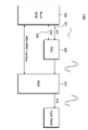
도 1은 일 실시예에 따른 표시장치의 구성도이다.1 is a block diagram of a display device according to an exemplary embodiment.
도 1을 참조하면, 표시장치(100)는 패널(110), 데이터구동회로(120), 게이트구동회로(130), 터치센싱회로(140), 제어회로(150) 등을 포함할 수 있다. Referring to FIG. 1 , the
패널(110)에는 데이터구동회로(120)와 연결되는 복수의 데이터라인(DL)이 형성되고, 게이트구동회로(130)와 연결되는 복수의 게이트라인(GL)이 형성될 수 있다. 또한, 패널(110)에는 복수의 데이터라인(DL)과 복수의 게이트라인(GL)의 교차 지점에 대응되는 다수의 화소(P: Pixel)가 정의될 수 있다. A plurality of data lines DL connected to the
이러한 각 화소(P)에는 제1 전극(예를 들어, 소스전극 또는 드레인전극)이 데이터라인(DL)과 연결되고, 게이트전극이 게이트라인(GL)과 연결되며, 제2 전극(예를 들어, 드레인전극 또는 소스전극)이 표시전극과 연결되는 트랜지스터가 형성될 수 있다. In each of these pixels P, a first electrode (eg, a source electrode or a drain electrode) is connected to the data line DL, a gate electrode is connected to the gate line GL, and a second electrode (eg, a second electrode) is connected to the gate line GL. , a drain electrode or a source electrode) may be formed with a transistor connected to the display electrode.
또한, 패널(110)에는, 복수의 터치전극(TE)이 서로 이격되어 더 형성될 수 있다. 터치전극(TE)이 위치하는 영역에는 하나의 화소(P)가 위치할 수도 있고 다수의 화소(P)가 위치할 수도 있다.In addition, a plurality of touch electrodes TE may be further formed on the
패널(110)은 표시패널(display panel)과 터치패널(TSP: touch screen panel)을 포함할 수 있는데, 여기서 표시패널과 터치패널은 일부 구성요소를 서로 공유할 수 있다. 예를 들어, 복수의 터치전극(TE)은 표시패널의 일 구성(예를 들어, 공통전압을 인가하는 공통전극)일 수 있고 동시에 터치패널의 일 구성(터치를 감지하기 위한 터치전극)일 수 있다. 표시패널과 터치패널의 일부 구성요소가 서로 공유되어 있다는 측면에서, 이러한 패널(110)을 일체형 패널이라고 부르기도 하지만 본 발명이 이로 제한되는 것은 아니다. 또한, 표시패널과 터치패널의 일부 구성요소가 서로 공유되는 형태로서 인셀(In-Cell) 타입의 패널이 알려져 있지만 이는 전술한 패널(110)의 일 예시일 뿐 본 발명이 적용되는 패널이 이러한 인셀(In-Cell)타입 패널로 제한되는 것은 아니다.The
데이터구동회로(120)는 이미지를 패널(110)의 각 화소(P)에 표시하기 위해 데이터라인(DL)으로 데이터신호를 공급한다.The
이러한 데이터구동회로(120)는 적어도 하나의 데이터드라이버집적회로를 포함할 수 있는데, 이러한 적어도 하나의 데이터드라이버집적회로는, 테이프 오토메티드 본딩(TAB: tape automated bonding) 방식 또는 칩 온 글래스(COG: chip on glass) 방식으로 패널(110)의 본딩 패드(bonding pad)에 연결되거나, 패널(110)에 직접 형성될 수도 있으며, 경우에 따라서, 패널(110)에 집적화되어 형성될 수도 있다. 또한, 데이터구동회로(120)는 칩 온 필름(COF: chip on film) 방식으로 구현될 수도 있다.The
게이트구동회로(130)는 각 화소(P)에 위치하는 트랜지스터를 턴온 혹은 턴오프시키기 위해 게이트라인(GL)으로 스캔신호를 순차적으로 공급한다.The
이러한 게이트구동회로(130)는, 구동 방식에 따라서, 본 도면에 도시된 바와 같이 패널(110)의 한 측에만 위치할 수도 있고, 2개로 나누어져 패널(110)의 양측에 위치할 수도 있다. The
또한, 게이트구동회로(130)는, 적어도 하나의 게이트드라이버집적회로를 포함할 수 있는데, 이러한 적어도 하나의 게이트드라이버집적회로는, 테이프 오토메티드 본딩(TAB) 방식 또는 칩 온 글래스(COG) 방식으로 패널(110)의 본딩 패드에 연결되거나, GIP(gate in panel) 타입으로 구현되어 패널(110)에 직접 형성될 수도 있으며, 경우에 따라서, 패널(110)에 집적화되어 형성될 수도 있다. 또한, 게이트구동회로(130)는 칩 온 필름(COF: chip on film) 방식으로 구현될 수도 있다.Also, the
터치센싱회로(140)는 센싱라인(SL)과 연결된 복수의 터치전극(TE)의 전체 또는 일부로 구동신호를 인가한다. The
이러한 터치센싱회로(140)는, 본 도면에 도시된 바와 같이 데이터구동회로(120) 및 게이트구동회로(130)와는 별도의 구성으로서, 데이터구동회로(120) 및 게이트구동회로(130)의 외부에 있을 수도 있지만, 구현 방식에 따라서, 데이터구동회로(120) 및 게이트구동회로(130) 중 적어도 하나를 포함하는 다른 별도의 드라이버집적회로의 내부 구성으로 구현될 수도 있으며, 또는, 데이터구동회로(120) 또는 게이트구동회로(130)의 내부 구성으로 구현될 수도 있다. As shown in this figure, the
따라서, 터치센싱회로(140)가 복수의 터치전극(TE)의 전체 또는 일부로 구동신호를 인가하는 것은, 터치센싱회로(140)를 포함하는 별도의 드라이버집적회로가 복수의 터치전극(TE)의 전체 또는 일부로 구동신호를 인가하는 것으로도 볼 수 있다. 또한, 설계 방식에 따라서는, 터치센싱회로(140)를 포함하는 데이터구동회로(120) 또는 게이트구동회로(130)가 복수의 터치전극(TE)의 전체 또는 일부로 구동신호를 인가하는 것으로도 볼 수도 있다.Accordingly, when the
이러한 터치센싱회로(140)는 구현 및 설계 방식에 제한되지 않고, 본 명세서에서 기재되는 그 수행 기능만 동일 또는 유사하다면, 다른 구성 그 자체일 수도 있고 다른 구성의 내부 또는 외부에 위치하는 구성일 수도 있다. The
또한, 본 도면에서 하나의 터치센싱회로(140)가 표시장치(100)에 위치한 것으로 도시되어 있으나, 표시장치(100)는 둘 이상의 터치센싱회로(140)를 포함할 수도 있다. Also, although one
한편, 터치센싱회로(140)가 구동신호를 복수의 터치전극(TE)의 전체 또는 일부로 인가하기 위해서는, 복수의 터치전극(TE) 각각에 연결되는 센싱라인(SL)이 필요하다. 이에 따라, 복수의 터치전극(TE) 각각에 연결되어 구동신호를 전달하는 센싱라인(SL)이 제1 방향(예: 세로방향) 또는 제2 방향(예: 가로방향)으로 패널(110)에 형성될 수 있다. Meanwhile, in order for the
한편, 표시장치(100)는 터치전극(TE)을 통해 정전용량의 변화를 감지함으로써 물체의 근접 혹은 터치를 인식하는 정전식 터치방식을 채용할 수 있다.Meanwhile, the
이러한 정전식 터치방식은, 일 예로, 상호정전용량터치 방식과 자체정전용량터치 방식으로 나눌 수 있다. The capacitive touch method may be divided into, for example, a mutual capacitive touch method and a self-capacitive touch method.
정전식 터치방식의 한 종류인 상호정전용량터치 방식은, 일 터치전극(Tx전극)으로 구동신호를 인가하고 상기 Tx전극과 상호 커플링된 다른 일 터치전극(Rx전극)을 센싱한다. 이러한 상호정전용량터치 방식에서는, 손가락, 펜 등의 물체의 근접 혹은 터치에 따라 Rx전극에서 센싱되는 값이 달라지는데, 상호정전용량터치 방식은 이러한 Rx전극에서의 센싱값을 이용하여 터치 유무, 터치 좌표 등을 검출한다.In the mutual capacitive touch method, which is a type of the capacitive touch method, a driving signal is applied to one touch electrode (Tx electrode) and the other touch electrode (Rx electrode) coupled to the Tx electrode is sensed. In this mutual capacitive touch method, the value sensed by the Rx electrode varies according to proximity or touch of an object such as a finger or pen. detect etc.
정전식 터치방식의 다른 한 종류인 자체정전용량터치 방식은, 일 터치전극(TE)으로 구동신호를 인가한 후 다시 해당 일 터치전극(TE)을 센싱한다. 이러한 자체정전용량터치 방식에서는, 손가락, 펜 등의 물체의 근접 혹은 터치에 따라 해당 일 터치전극(TE)에서 센싱되는 값이 달라지는데, 자체정전용량터치 방식은 이러한 센싱값을 이용하여 터치 유무, 터치 좌표 등을 검출한다. 이러한 자체정전용량터치 방식은 구동신호를 인가하는 터치전극(TE)과 센싱하는 터치전극(TE)이 동일하기 때문에, Tx전극과 Rx전극의 구분이 없다.In the self-capacitance touch method, which is another type of the capacitive touch method, a driving signal is applied to one touch electrode TE and then the one touch electrode TE is sensed again. In this self-capacitive touch method, the value sensed by the corresponding one touch electrode (TE) varies according to the proximity or touch of an object such as a finger or pen. coordinates, etc. In this self-capacitance touch method, since the touch electrode TE for applying the driving signal and the touch electrode TE for sensing are the same, there is no distinction between the Tx electrode and the Rx electrode.
표시장치(100)는, 전술한 2가지의 정전식터치방식(상호 정전용량 터치방식, 자체 정전용량 터치방식) 중 하나를 채용할 수 있다. 다만, 본 명세서에서는, 설명의 편의를 위해, 자체정전용량터치 방식이 채용된 것으로 가정하여 실시예를 설명한다. The
한편, 표시장치(100)는 표시구간과 터치구간을 구분하여 터치전극(TE)을 구동할 수 있다. 일 예로서, 표시장치(100)의 터치센싱회로(140)는 데이터신호를 공급하는 구간에서는 터치전극(TE)의 전체 또는 일부로 구동신호를 인가하지 않을 수 있다.Meanwhile, the
또한 표시장치(100)는 표시구간과 터치구간을 구분하지 않고 터치전극(TE)을 구동할 수 있다. 일 예로서, 표시장치(100)의 터치센싱회로(140)는 데이터신호를 공급하는 구간에서 터치전극(TE)의 전체 또는 일부로 구동신호를 인가할 수 있다Also, the
제어회로(150)는 데이터구동회로(120), 게이트구동회로(130) 및 터치센싱회로(140)로 각종 제어신호를 공급할 수 있다. 제어회로(150)는 각 타이밍에 맞게 데이터구동회로(120)가 각 화소(P)로 데이터전압을 공급하도록 제어하는 데이터제어신호(DCS: Data Control Signal)를 전송하거나, 게이트구동회로(130)로 게이트제어신호(GCS: Gate Control Signal)를 전송하거나, 터치센싱회로(140)로 센싱신호를 전송할 수 있다. 제어회로(150)는 타이밍컨트롤러(T-Con: Timing Controller)이거나, 타이밍컨트롤러(Timing Controller)를 포함하여 다른 제어기능도 더 수행할 수 있다.The
도 2는 일 실시예에 따른 터치센싱 과정을 설명하기 위한 도면이다.2 is a diagram for explaining a touch sensing process according to an embodiment.
도 2를 참조하면, 터치센싱시스템(200)은 패널(110) 및 터치센싱회로(140)를 포함할 수 있다.Referring to FIG. 2 , the
패널(110)에는 복수의 터치전극(TE)이 배치될 수 있다. A plurality of touch electrodes TE may be disposed on the
터치센싱회로(140)는 구동신호(STX)를 터치전극(TE)으로 공급할 수 있다. 구동신호(STX)는 전압 또는 전류 형태의 신호일 수 있고, 전압 형태의 구동신호(STX)는 구동전압으로 정의될 수 있다. 구동신호는 제1 기간과 제2 기간으로 이루어지는 하나의 구동주기를 포함할 수 있다. The
터치센싱회로(140)는 구동신호(STX)에 대한 반응신호(SRX)를 터치전극(TE)으로부터 수신하고 반응신호(SRX)를 복조하여 패널(110)에 대한 오브젝트(10)의 터치 혹은 근접을 센싱할 수 있다. 반응신호(SRX)는 전류 또는 전압 형태의 신호일 수 있다.The
도 3은 일 실시예에 따른 터치센싱회로의 구성도이다.3 is a block diagram of a touch sensing circuit according to an embodiment.
도 3을 참조하면, 터치센싱회로(140)는 리드아웃회로(310), 터치전원회로(320), 터치제어회로(330) 등을 포함할 수 있다.Referring to FIG. 3 , the
리드아웃회로(310)은 일정한 진폭을 가지는 구동신호(STX)-예를 들어, 구동 전압-를 터치전극으로 공급할 수 있다. 구동신호(STX) 및 반응신호(SRX)는 구형파 신호일 수 있고, 사인파 신호일 수 있다.The
리드아웃회로(310)는 다른 진폭를 가지는 구동신호(STX)로 터치전극을 구동할 수 있다. 리드아웃회로(310)에 포함된 구동부(미도시)는 터치제어회로(330)로부터 변경된 진폭을 가지는 구동신호(STX)를 수신하고, 상기 변경된 진폭으로 터치전극을 구동하여 터치 센싱감도를 다르게 할 수 있다. 또한, 리드아웃회로(310)에 포함된 센싱부(미도시)는 구동신호(STX)에 대한 반응신호(SRX)를 터치전극으로부터 수신하여 패널에 대한 외부 오브젝트의 터치 혹은 근접을 센싱할 수 있다. 센싱부(미도시)는 반응신호(SRX)를 복조하여 터치센싱데이터-예를 들어, 터치 센싱값-를 생성할 수 있다.The
리드아웃회로(310)은 필요에 따라 소스드라이버집적회로(SDIC: Source Driver Integrated Circuit)을 포함하는 통합집적회로(SRIC: Synchronous Rectification Integrated Circuit)를 형성할 수 있다.The
터치전원회로(320)는 패널(110)의 구동에 필요한 기준전압 신호와 구동 전압을 포함하는 각종 전원 신호를 생성하여 리드아웃회로(310), 터치제어회로(330) 등으로 공급할 수 있다. 필요에 따라 터치전원회로(320)은 터치파워집적회로(TPIC: Touch Power Integrated Circuit)로 정의될 수 있다.The
터치전원회로(320)은 터치제어회로(330)으로부터 전달받은 구동신호를 증폭하거나 감소시킬 수 있고, 증폭된 구동신호를 리드아웃회로(310)으로 전달할 수 있다.The
리드아웃회로(310) 또는 터치전원회로(320)는 피드백 저항의 비율 조절을 통해 사인파 형태의 구동신호의 진폭을 제어할 수 있다.The
터치제어회로(330)는 리드아웃회로(310)와 터치전원회로(320)를 제어하기 위하여 제어신호(CS)를 생성할 수 있다. 터치제어회로(330)가 제어신호(CS: Controlling Signal)를 리드아웃회로(310)과 터치전원회로(320)으로 전달하면, 구동부(미도시) 및 센싱부(미도시)는 제어신호(CS)에 따라 동작할 수 있다.The
예시적으로, 터치제어회로(330)가 구동전압을 증폭시키거나 감소시키는 제어신호(CS)를 리드아웃회로(310) 또는 터치전원회로(320)로 전달하면, 리드아웃회로(310) 또는 터치전원회로(320)는 제어신호(CS)에 대응하여 구동 전압을 증폭시키거나 감소시킬 수 있다.For example, when the
터치제어회로(330)은 리드아웃회로(310)과 연결된 인터페이스를 가질 수 있고, 터치전원회로(320)과 연결된 인터페이스를 가질 수 있다. The
터치제어회로(330)와 리드아웃회로(310) 사이에 연결된 인터페이스 또는 터치제어회로(330)과 터치전원회로(320) 사이에 연결된 인터페이스는 I2C(Inter-Integrated Circuit) 방식으로 통신할 수 있다. An interface connected between the
I2C 버스는 양 방향 오픈 드레인 라인인 SCL(Serial Clock)과 SDA(Serial Data)로 이루어진, 마스터-슬레이브(Master-Slave) 형태로 동작할 수 있다. SCL은 통신의 동기를 위한 클럭용 선일 수 있고, SDA는 데이터용 선으로서 각 터치 신호를 제어할 수 있다.The I2C bus can operate in the form of a master-slave, consisting of a bidirectional open drain line SCL (Serial Clock) and SDA (Serial Data). The SCL may be a line for a clock for communication synchronization, and the SDA may be a line for data and may control each touch signal.
종래의 기술에 따른 터치제어회로는 기 설정된 구동신호를 리드아웃회로 전달하거나, 전원회로에 전달하는 단일한 인터페이스를 형성함으로써 터치 입력의 종류에 따라 구동회로의 진폭을 증가시키거나 감소시킬 수 없다는 문제점이 있다. 예시적으로, 종래의 기술에 따른 터치제어회로와 전원회로 사이의 단일한 인터페이스는 기준전압만을 전달할 수 있고, 구동전압의 제어 신호를 전달할 수 없다. The touch control circuit according to the prior art has a problem in that it is impossible to increase or decrease the amplitude of the driving circuit according to the type of touch input by forming a single interface that transmits a preset driving signal to the readout circuit or to the power circuit. There is this. Illustratively, a single interface between the touch control circuit and the power circuit according to the prior art may transmit only the reference voltage and may not transmit the control signal of the driving voltage.
터치제어회로(330)과 터치전원회로(320) 사이에 인터페이스를 추가하여 터치제어회로(330)에서 판단한 터치 입력의 종류에 따른 구동신호 또는 제어신호를 터치전원회로(320)으로 전달할 수 있다. 예시적으로, 터치제어회로(330)과 터치전원회로(320) 사이의 인터페이스는 I2C(Inter-Integrated Circuit)는 통신으로 정의되는 양방향 통신포트를 형성하여 터치 입력의 종류에 따른 구동신호 또는 제어신호를 송수신할 수 있다.By adding an interface between the
터치제어회로(330)과 터치전원회로(320)에는 제1 인터페이스(331), 제2 인터페이스(332)가 연결될 수 있다. 제1 인터페이스(331)은 구동신호 레벨에 관한 정보를 포함하는 신호(CS1)를 송수신할 수 있다. 필요에 따라 제2 인터페이스(332)는 터치 입력의 종류의 종류를 포함하는 신호(CS2)를 송수신할 수 있다.A
일 실시예에 따른 터치센싱회로는 Auto향 회로 또는 패널에 적용되어 보다 효율적인 전력 사용을 발생시킬 수 있다.The touch sensing circuit according to an embodiment may be applied to an auto-direction circuit or panel to generate more efficient power use.
터치제어회로(330)은 터치전원회로(320)에서는 구동전원만을 공급하고, 리드아웃회로(310)을 통해 구동신호의 진폭을 제어할 수 있다. 이 경우 타이밍컨트롤러(T-CON)이 전원회로와 추가적인 인터페이스를 형성할 필요가 없고, 리드아웃회로(310)와의 연결만으로 구동신호를 제어할 수 있게 된다.The
일 실시예에 따른 인터페이스는 복수의 시스템 사이의 연결 방법으로 정의될 수 있고, 하드웨어적인 구성-예를 들어, 통신 포트 등- 또는 소프트웨어적인 통신방법에 따른 규약 등으로 정의될 수 있다.An interface according to an embodiment may be defined as a connection method between a plurality of systems, and may be defined as a hardware configuration (eg, a communication port, etc.) or a protocol according to a software communication method.
도 4는 일 실시예에 따라 마이크로컨트롤러와 터치전원회로 사이에 인터페이스를 추가한 경우의 구동전압 변화를 나타낸 도면이다.4 is a diagram illustrating a change in driving voltage when an interface is added between a microcontroller and a touch power circuit according to an exemplary embodiment.
도 4를 참조하면, 마이클로컨트롤러(MCU: Micro Controller Unit)와 터치파워집적회로(TPIC: Touch Power Integrated Circuit) 사이에 추가적인 인터페이스를 형성한 경우의 구동전압의 변화를 확인할 수 있다.Referring to FIG. 4 , it can be seen a change in driving voltage when an additional interface is formed between a micro controller unit (MCU) and a touch power integrated circuit (TPIC).
종래의 터치센싱회로는 마이클로컨트롤러(MCU)와 터치파워집적회로(TPIC) 사이에 추가적인 인터페이스를 형성하지 않으므로, 터치 입력의 변화에도 터치파워집적회로(TPIC)로 전달되는 신호를 제어할 수 없다.Since the conventional touch sensing circuit does not form an additional interface between the microcontroller (MCU) and the touch power integrated circuit (TPIC), it is not possible to control a signal transmitted to the touch power integrated circuit (TPIC) even when a touch input is changed. .
종래의 터치센싱회로에서 터치파워집적회로(TPIC)는 터치 입력의 종류에 관한 정보를 획득할 수 없으므로 터치 입력의 종류가 변화하더라도 출력되는 구동신호의 진폭을 그대로 유지하게 된다. 이 경우 구동전압의 진폭(ΔV)은 일정하게 유지된다.In the conventional touch sensing circuit, since the touch power integrated circuit (TPIC) cannot obtain information on the type of the touch input, the amplitude of the output driving signal is maintained even if the type of the touch input is changed. In this case, the amplitude ΔV of the driving voltage is maintained constant.
일 실시예에 따른 터치센싱회로(140)는 마이클로컨트롤러(MCU)와 터치파워집적회로(TPIC) 사이에 추가적인 인터페이스를 형성하므로, 터치 입력 종류의 변화에 따라 터치파워집적회로(TPIC)에서 출력되는 구동신호를 제어할 수 있다.Since the
일 실시예에 따른 터치센싱회로(140)에서는 마이크로컨트롤러(MCU)에서 낮은 감도의 터치 데이터가 일정 프레임동안 유지되는 경우 글러브 터치로 판단할 수 있다. 마이크로컨트롤러(MCU) 는 터치파워집적회로(TPIC)의 구동전압의 진폭을 증가시켜 터치센싱의 감도를 증가시키기 위해 터치파워집적회로(TPIC)로 제어신호를 전달할 수 있다. 마이크로컨트롤러(MCU)에서 전달한 제어신호에 대응하여 터치파워집적회로(TPIC)의 구동신호의 진폭이 변할 수 있다. 예시적으로, 터치 입력의 종류가 일반 터치모드에서 글러브 터치로 변경된 경우 진폭의 크기(ΔV)는 증폭될 수 있다.In the
일 실시예에 따른 터치센싱회로(140)에서는 마이크로컨트롤러(MCU)가 터치 입력의 종류를 판단하고, 판단된 터치 입력의 종류를 터치파워집적회로(TPIC)에서 전달받을 수 있도록 MCU-TPIC 사이에 추가 인터페이스를 형성되므로, 구동전압의 진폭을 변경하여 더욱 효과적으로 터치 감도를 조절할 수 있게 된다.In the
일 실시예에 따른 마이클로컨트롤러(MCU)는 터치 입력의 종류를 글러브(Glove) 터치로 판단하고, 제2 인터페이스(332)를 통해 구동신호의 진폭을 커지게 변경할 수 있다. 다른 실시예에 따른 마이크로컨트롤러(MCU)는 터치 입력의 종류를 일반적인 터치로 판단하고, 제2 인터페이스(332)를 통해 구동신호의 진폭을 작게 변경할 수 있다.The microcontroller (MCU) according to an embodiment may determine the type of touch input as a glove touch, and may increase the amplitude of the driving signal through the
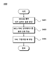
도 5는 일 실시예에 따른 표시장치의 터치 감도 향상을 위한 제어방법을 나타낸 제1 예시 흐름도이다.5 is a first exemplary flowchart illustrating a control method for improving touch sensitivity of a display device according to an exemplary embodiment.
도 5를 참조하면, 표시장치의 터치 감도 향상을 위한 제어방법(400)은 터치 입력의 종류 판단 단계(S401), MCU-TPIC 인터페이스를 통한 신호 전송 단계(S402), TIPC 구동전압 폭 변경 단계(S403)을 포함할 수 있다.Referring to FIG. 5 , the
터치 입력의 종류 판단 단계(S401)는 마이크로컨트롤러(MCU)를 통해 터치 입력의 종류를 판단할 수 있다.In the step of determining the type of the touch input ( S401 ), the type of the touch input may be determined through the microcontroller (MCU).
리드아웃회로(310)는 터치 패널의 복수의 전극 각각에 소정 주기와 진폭을 가지는 구동신호(SRX)를 인가하고, 반응신호(SRX)를 수신할 수 있다. 리드아웃회로(310)는 정전용량의 변화에 기초한 반응신호(SRX)를 통해 터치 입력의 유무를 감지할 수 있고, 터치 입력의 세기를 판단할 수 있다. The
터치제어회로(330)는 터치 입력이 발생하지 않는 터치 미발생 데이터를 기준값 또는 오프셋(Off-set)으로 정의하고, 일정한 크기 이상의 터치 센싱값을 터치 발생으로 판단할 수 있고, 일정한 범위 이내의 터치 센싱값을 글러브(Glove) 터치 발생으로 판단할 수 있다.The
터치제어회로(330)은 터치 입력의 면적에 따라 터치 입력의 종류를 다르게 정의할 수 있다. 기 설정된 터치 입력의 면적 또는 반경을 기준으로, 기준치 미만의 터치 입력 면적 또는 반경에 대해서는 스타일러스 펜 터치 또는 노이즈로 판단할 수 있고, 기준치 이상의 면적 또는 반경에 대해서는 일반 손가락 터치 또는 글로브 손가락 터치로 판단할 수 있다.The
터치제어회로(330)은 터치 입력의 종류를 판단하고, 터치 입력의 종류에 따라 터치 패널의 구동신호를 제어하여 터치 감도를 조절할 수 있다.The
MCU-TPIC 인터페이스를 통한 신호 전송 단계(S402)에서는 마이크로컨트롤러(MCU)와 터치파워집적회로(TPIC) 사이에 형성된 인터페이스를 통해 구동신호 또는 제어신호를 전송할 수 있다.In the signal transmission step S402 through the MCU-TPIC interface, a driving signal or a control signal may be transmitted through an interface formed between the microcontroller (MCU) and the touch power integrated circuit (TPIC).
터치제어회로(330)-예를 들어, 마이크로컨트롤러(MCU)-는 설정된 프레임 기간별로 터치 입력의 종류를 판단하고, 터치 입력의 종류의 변경 여부 및 변경된 터치 입력의 종류에 따른 구동신호 변경 제어신호를 발생시킬 수 있다.The touch control circuit 330 - for example, a microcontroller (MCU) - determines the type of the touch input for each set frame period, and changes the driving signal according to whether the type of the touch input is changed and the changed type of the touch input. can cause
마이크로컨트롤러(MCU)와 터치파워집적회로(TPIC) 사이에 복수 개의 인터페이스가 형성되는 경우 일부의 인터페이스는 기준신호-예를 들어, 구동신호의 기준 전압, 구동신호의 형태, 구동신호의 스위칭 타이밍-을 송수신할 수 있다. 또 다른 일부의 인터페이스는 제어신호-예를 들어, 구동전압의 진폭 변경 신호-를 송수신할 수 있다.When a plurality of interfaces are formed between the microcontroller (MCU) and the touch power integrated circuit (TPIC), some interfaces have a reference signal - for example, a reference voltage of a driving signal, a shape of a driving signal, and a switching timing of a driving signal - can be sent and received. Another part of the interface may transmit/receive a control signal (eg, a signal for changing the amplitude of the driving voltage).
또한, 마이크로컨트롤러(MCU)와 터치파워집적회로(TPIC) 사이의 인터페이스를 MCU-TPIC 인터페이스로 정의할 수 있다.Also, an interface between a microcontroller (MCU) and a touch power integrated circuit (TPIC) may be defined as an MCU-TPIC interface.
MCU-TPIC 인터페이스는 통해 터치제어회로에서 판단된 터치 입력의 종류-예를 들어, 일반 터치 모드 또는 글러브 터치 모드-에 관한 정보를 전달할 수 있다.The MCU-TPIC interface may transmit information regarding the type of touch input determined by the touch control circuit - for example, a normal touch mode or a glove touch mode.
터치 입력의 종류는 리드아웃회로(310)에서 수신된 터치 센싱값과, 설정된 기준치, 설정된 기준시간을 고려하여 판단할 수 있다.The type of touch input may be determined in consideration of a touch sensing value received from the
TIPC 구동전압 폭 변경 단계(S403)에서는 MCU-TPIC 인터페이스를 통해 전달받은 제어신호에 기초하여 터치파워집적회로(TPIC)의 구동전압 진폭을 변경할 수 있다.In the TIPC driving voltage width changing step S403 , the driving voltage amplitude of the touch power integrated circuit (TPIC) may be changed based on the control signal received through the MCU-TPIC interface.
글러브 모드에서는 오브젝트와 터치전극 사이에 형성되는 정전용량이 감소하게 되므로, 구동전압의 진폭을 증가시켜 터치 센싱의 감도를 증가시킬 수 있다.In the glove mode, since the capacitance formed between the object and the touch electrode is reduced, it is possible to increase the amplitude of the driving voltage to increase the sensitivity of the touch sensing.
일반 터치 모드에서는 오브젝트와 터치전극 사이에 별도의 외부물체가 존재하지 않으므로 글러브 모드에 비해 구동전압의 진폭을 감소시켜 터치 센싱의 감도를 유지하고 전력 사용량을 감소시킬 수 있다. 터치파워집적회로(TPIC)의 구동전압 진폭을 감소시킴에 따라 표시장치의 전력 사용량을 감소시킬 수 있다.In the general touch mode, since there is no external object between the object and the touch electrode, the amplitude of the driving voltage is reduced compared to the glove mode, thereby maintaining the sensitivity of touch sensing and reducing power consumption. As the driving voltage amplitude of the touch power integrated circuit (TPIC) is reduced, the power consumption of the display device may be reduced.
도 6은 일 실시예에 따른 표시장치의 터치 감도 향상을 위한 제어방법을 나타낸 제1 예시 흐름도이다.6 is a first exemplary flowchart illustrating a control method for improving touch sensitivity of a display device according to an exemplary embodiment.
도 6을 참조하면, 표시장치의 터치 감도 향상을 위한 제어방법(500)은 터치 유무 판단 단계(S501), 터치 센싱값의 크기를 판단하는 단계(S503), 터치 입력의 종류를 판단하는 단계(S505), 터치 입력의 종류에 따라 센싱 감도를 조절하는 단계(S507)을 포함할 수 있다.Referring to FIG. 6 , the
터치 유무 판단 단계(S501)에서는 리드아웃회로(310)에서 수신된 터치데이터를 기초로 오프셋데이터로부터 일정한 비율 또는 크기의 터치데이터 변화를 확인하는 경우 터치가 발생하였는지 여부를 판단할 수 있다. In the touch presence determination step S501 , it can be determined whether a touch has occurred when a change in touch data of a certain ratio or size is checked from the offset data based on the touch data received from the
예시적으로, 일정 프레임 동안의 오프셋데이터의 평균값을 기준으로, 다음 프레임 동안의 터치데이터의 평균값을 비교하여, 터치데이터의 변화 비율을 산정할 수 있다. 다른 예시적으로, 일정 프레임 동안의 수신된 터치데이터가 기준치 이상의 크기를 가지는 경우 터치가 발생한 것으로 판단할 수 있다.For example, by comparing the average value of the touch data for the next frame based on the average value of the offset data for a certain frame, the rate of change of the touch data may be calculated. As another example, when the received touch data for a certain frame has a size greater than or equal to a reference value, it may be determined that a touch has occurred.
터치 센싱값의 크기를 판단하는 단계(S503)에서는 리드아웃회로(310)에서 수신되는 아날로그 신호를 디지털 신호로 변환하여 터치 센싱값을 계산할 수 있다. 측정되는 터치 센싱값을 프레임별로, 터치전극별로 계산하여 메모리(미도시)에 저장할 수 있고, 각각의 프레임, 터치전극의 터치 센싱값의 크기를 기준값과 비교할 수 있다.In the step of determining the size of the touch sensing value ( S503 ), the analog signal received from the
터치 입력의 종류를 판단하는 단계(S505)에서는 터치제어회로(330)가 리드아웃회로(310)에서 계산된 터치 센싱값을 수신하여, 터치 입력의 종류를 판단할 수 있다.In step S505 of determining the type of the touch input, the
터치 센싱값의 크기가 기 설정된 기준치 이상인 경우에는 일반적인 터치 상태로 판단할 수 있고, 터치제어회로(330)는 일반 터치 모드 상태를 유지하거나 일반 터치 모드 상태로 변경할 수 있다.When the size of the touch sensing value is equal to or greater than the preset reference value, it may be determined as a general touch state, and the
터치 센싱값의 크기가 기 설정된 기준치 이하인 경우에는 글러브(Glove) 터치 상태 또는 터치 미발생 상태로 판단할 수 있다. 터치 센싱값의 크기가 기 설정된 기준 범위 이내인 경우에는 글러브(Glove) 터치 상태로 판단할 수 있고, 터치제어회로(330)는 글러브 터치 모드 상태를 유지하거나 글러브 터치 모드 상태로 변경할 수 있다. 터치제어회로(330)는 터치 센싱값의 크기가 오프셋데이터로부터 일정한 범위 이내에 있거나, 기준치 이하인 경우에는 터치 미발생 상태로 판단할 수 있다.When the size of the touch sensing value is less than or equal to a preset reference value, it may be determined as a glove touch state or a touch non-occurrence state. When the size of the touch sensing value is within a preset reference range, it may be determined as a glove touch state, and the
터치 입력의 종류를 판단하기 위하여 매 프레임별 터치 입력의 종류를 판단할 수 있지만, 기 설정된 기준 프레임의 기간동안 터치입력을 센싱하고 터치 입력의 종류를 판단할 수 있다.In order to determine the type of the touch input, the type of the touch input may be determined for each frame, but the touch input may be sensed during the period of a preset reference frame and the type of the touch input may be determined.
예시적으로, 낮은 감도의 터치가 일정 프레임 이상 유지되는 경우 글러브 터치 모드로 진입할 수 있다.For example, when a low-sensitivity touch is maintained for a predetermined frame or more, the glove touch mode may be entered.
터치 입력의 종류에 따라 센싱 감도를 조절하는 단계(S507)에서는 터치 입력의 종류에 따라 터치패널의 센싱 감도를 조절할 수 있다.In the step of adjusting the sensing sensitivity according to the type of the touch input ( S507 ), the sensing sensitivity of the touch panel may be adjusted according to the type of the touch input.
일반적으로, 터치 패널로 전달되는 구동신호의 크기에 따라 센싱 감도가 증가하지만, 필요에 따라 다르게 정의될 수 있다.In general, the sensing sensitivity increases according to the magnitude of the driving signal transmitted to the touch panel, but may be defined differently if necessary.
터치 미발생 상태에서는 터치 패널로 전달되는 구동신호의 크기를 감소시켜 최소한의 전력만으로 터치 패널을 구동할 수 있고, 일반 터치 상태에서는 기준 구동신호를 전달하여 터치 패널을 구동할 수 있다.In the non-touch state, the size of the driving signal transmitted to the touch panel is reduced to drive the touch panel with minimal power, and in the normal touch state, the touch panel can be driven by transmitting the reference driving signal.
글러브 터치에서는 외부물체에 의해 오브젝트와 터치전극사이의 물리적 거리가 멀어지는 등의 이유로 터치전극에 형성되는 정전용량이 감소하게 된다. 따라서 동일한 터치 강도를 유지하기 위하여는 터치전극으로 전달되는 구동신호의 진폭을 증가시켜 터치 센싱 감도를 증가시켜야 하므로, 글러브 터치 모드에서는 터치제어회로와 리드아웃회로에 연결된 인터페이스를 통해 구동신호의 진폭을 증가시키거나 터치제어회로와 전압회로 사이에 연결된 인터페이스를 통해 구동신호의 진폭을 증가시킬 수 있다.In the glove touch, the capacitance formed in the touch electrode decreases due to the reason that the physical distance between the object and the touch electrode is increased by an external object. Therefore, in order to maintain the same touch intensity, it is necessary to increase the amplitude of the driving signal transmitted to the touch electrode to increase the touch sensing sensitivity. It is possible to increase or increase the amplitude of the driving signal through an interface connected between the touch control circuit and the voltage circuit.
터치제어회로(330)에서 판단한 터치 입력의 종류에 따른 제어신호를 리드아웃회로(310) 또는 전압회로(320)로 전달하여, 터치 센싱의 감도를 조절할 수 있다.By transmitting a control signal according to the type of touch input determined by the
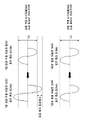
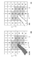
도 7은 일 실시예에 따른 글러브 터치의 센싱값 변화를 설명하기 위한 도면이다.7 is a view for explaining a change in a sensing value of a glove touch according to an exemplary embodiment.
도 7을 참조하면, 일반적인 터치 상태에서의 터치 센싱값(601)과 글러브 터치 상태에서의 터치 센싱값(602)의 변화를 비교할 수 있다.Referring to FIG. 7 , a change in the
x축과 y축으로 정의된 터치 패널의 터치전극 또는 영역별로 터치 센싱값을 획득할 수 있다. 기준치 이상의 터치 센싱값을 가지는 영역을 터치가 발생한 영역(Ⅰ)으로 정의할 수 있다.A touch sensing value may be obtained for each touch electrode or region of the touch panel defined by the x-axis and the y-axis. An area having a touch sensing value greater than or equal to the reference value may be defined as an area (I) in which a touch occurs.
예시적으로, 일반적인 터치 상태에서 터치가 발생한 영역(Ⅰ)의 터치 센싱값(601)은 125, 163, 168, 182, 131, 161, 146, 147, 120으로 측정되더라도, 동일한 조건에서 글러브 터치 상태에서 터치가 발생한 영역(Ⅰ)의 터치 센싱값(602)은 110, 124, 144, 157, 126, 151, 139, 132, 114로 측정될 수 있다.Exemplarily, even if the
터치 입력의 종류에 따른 터치가 발생한 영역(Ⅰ)의 터치 센싱값은 각 터치전극 또는 영역의 개별 값들을 사용할 수 있으나, 이들의 평균값을 사용할 수도 있다.Individual values of each touch electrode or region may be used for the touch sensing value of the region I in which the touch occurs according to the type of touch input, but an average value thereof may also be used.
도 8은 일 실시예에 따른 터치센싱회로에서 시간에 따른 터치 센싱값 변화를 나타낸 예시 도면이다.8 is an exemplary diagram illustrating a change in a touch sensing value according to time in a touch sensing circuit according to an embodiment.
도 8을 참조하면, 터치센싱회로에서 시간에 따른 터치 센싱값 변화 그래프(700)은 터치 미발생 상태의 터치 센싱값(T_Val1), 글러브 터치 상태의 터치 센싱값(T_Val2), 일반 터치 상태의 터치 센싱값(T_Val3)을 포함할 수 있다.Referring to FIG. 8 , a
일 실시예에 따른 터치 센싱값은 예시적으로 각 영역의 평균 터치 센싱값을 정의한 것으로서, 실제 구동 과정에서 사용되는 터치 센싱값의 계산 방법은 이에 한정되지 않는다.The touch sensing value according to an embodiment is illustratively defined as an average touch sensing value of each region, and the method of calculating the touch sensing value used in the actual driving process is not limited thereto.
첫번째 터치 구동 기간(t1)에서 측정되는 터치 센싱값(T_Val1)은 터치 미발생 상태에서 계산된 터치 센싱값일 수 있다.The touch sensing value T_Val1 measured in the first touch driving period t1 may be a touch sensing value calculated in a non-touch state.
두번째 터치 구동 기간 (t2)에서 측정되는 터치 센싱값(T_Val3)은 일반적인 터치 상태에서 계산된 터치 센싱값일 수 있다. 필요에 따라 터치제어회로(330)는 기준치(T_Ref2) 이상의 터치 센싱값을 가지는 터치가 일정 프레임 이상 지속되는 경우에 일반 터치 상태로 판단할 수 있다.The touch sensing value T_Val3 measured in the second touch driving period t2 may be a touch sensing value calculated in a general touch state. If necessary, the
세번째 터치 구동 기간 (t3)에 측정되는 터치 센싱값(T_Val1)은 첫번째 터치 구동 기간(t1)에서 측정되는 터치 센싱값과 동일한 터치 센싱값이거나, 이와 일정한 범위 이내의 터치 센싱값으로서 터치 미발생 상태에서 계산된 터치 센싱값일 수 있다.The touch sensing value T_Val1 measured in the third touch driving period t3 is the same touch sensing value as the touch sensing value measured in the first touch driving period t1, or as a touch sensing value within a certain range, a touch non-occurrence state It may be a touch sensing value calculated in .
네번째 터치 구동 기간(t4)에 측정되는 터치 센싱값 (T_Val2)는 글러브(Glove) 터치 상태에서 계산된 터치 센싱값일 수 있다. 필요에 따라 터치제어회로(330)는 기준치(T_Ref2) 미만의 터치 센싱값을 가지는 터치가 일정 프레임 이상 지속되는 경우에 글러브 터치 상태로 판단할 수 있다. 보다 정확한 판단을 위하여 터치제어회로(330)는 기준치(T_Ref1)과 기준치(T_Ref2) 사이의 터치 센싱값을 가지는 터치가 일정 프레임 이상 지속되는 경우에 글러브 터치 상태로 판단할 수 있다. 필요에 따라 기준 범위는 기준치(T_Ref1) 이상의 센싱값과 기준치(T_Ref2) 미만의 센싱값의 범위로 정의될 수 있다.The touch sensing value T_Val2 measured in the fourth touch driving period t4 may be a touch sensing value calculated in a glove touch state. If necessary, the
터치제어회로(330)는 글러브 터치 상태 판단을 위해서 일정한 프레임동안 기준치(T_Ref1)과 기준치(T_Ref2) 사이의 터치 센싱값이 유지되는지 여부를 판단할 수 있다.The
도 9는 일 실시예에 따른 터치센싱회로에서 터치 입력의 종류를 판단하는 방법을 나타낸 제1 예시 흐름도이다.9 is a first exemplary flowchart illustrating a method of determining a type of a touch input in a touch sensing circuit according to an embodiment.
도 9를 참조하면, 터치센싱회로에서 터치 입력의 종류를 판단하는 방법(800)은 터치 센싱값을 수신하는 단계(S801), 터치 센싱값이 기준 범위 이내인지 판단하는 단계(S803), 터치 센싱값이 기준시간 동안 유지되는지를 판단하는 단계(S805)를 포함할 수 있다.Referring to FIG. 9 , the
터치 센싱값을 수신하는 단계(S801)에서는 리드아웃회로(310)을 통해 터치 전극의 정전용량 변화를 수신하여, 아날로그 신호를 디지털 신호로 변환할 수 있다. 터치신호는 최종적으로 터치 센싱값으로 획득될 수 있다.In step S801 of receiving the touch sensing value, a change in capacitance of the touch electrode may be received through the
터치 센싱값이 기준 범위 이내인지 판단하는 단계(S803)에서는 터치제어회로(330)에서 리드아웃회로(310)으로부터 수신된 터치 센싱값의 크기를 확인하고 기준 범위내에 포함되어 있는지 여부를 판단할 수 있다.In the step of determining whether the touch sensing value is within the reference range (S803), the
터치제어회로(330)은 기준 범위 이내의 터치 센싱값을 가지는 경우에 글러브 터치의 후보 터치로 판단할 수 있고, 기준 범위 밖의 터치 센싱값을 가지는 경우에는 일반 터치 모드로 정의할 수 있다.When the
터치 센싱값이 기준시간 동안 유지되는지를 판단하는 단계(S805)에서는 터치제어회로(330)에서 리드아웃회로(310)으로부터 수신된 터치 센싱값의 변화를 확인하고 기준시간동안 터치가 유지되는지 여부를 판단할 수 있다.In the step of determining whether the touch sensing value is maintained for the reference time (S805), the
터치제어회로(330)은 기준 범위 이내의 터치 센싱값이 기준시간 이상 유지되는 경우에만 글러브 터치 모드(S809)로 판단할 수 있고, 기준시간 내에 터치 센싱값의 변화가 발생하는 경우 일시적인 터치 변화로 판단하고 일반 터치 모드(S807)로 정의할 수 있다.The
일반 터치 모드(S807) 및 글러브 터치 모드(S809)에서 터치센싱회로는 도 3 내지 도 8 등에 전술한 터치 입력의 종류에 따라 구동신호를 달리 제어할 수 있다.도 10는 일 실시예에 따른 터치센싱회로에서 터치 입력의 종류를 판단하는 방법을 나타낸 제2 예시 흐름도이다.In the normal touch mode (S807) and the glove touch mode (S809), the touch sensing circuit may differently control the driving signal according to the type of the touch input described above in FIGS. 3 to 8 and the like. It is a second exemplary flowchart showing a method of determining the type of touch input in the sensing circuit.
도 10을 참조하면, 터치센싱회로에서 터치 입력의 종류를 판단하는 방법(900)은 터치 센싱값을 수신하는 단계(S901), 터치 영역의 특징을 판단하는 단계(S902), 프레임간 터치센싱값의 평균값을 산출하는 단계(S903), 터치 센싱값이 기준 범위 이내인지 판단하는 단계(S904), 터치 센싱값이 기준시간 동안 유지되는지를 판단하는 단계(S905)를 포함할 수 있다.Referring to FIG. 10 , the
터치 센싱값을 수신하는 단계(S901)는 전술한 도 8의 방법을 사용할 수 있다.Receiving the touch sensing value ( S901 ) may use the method of FIG. 8 described above.
터치 영역의 특징을 판단하는 단계(S902)에서는 터치 센싱값을 기초로 터치 영역의 크기를 판단할 수 있다. 일정한 기준 영역 미만의 터치가 발생한 경우에는 터치가 발생하지 않거나 스타일러스 펜에 의해 터치가 발생한 것으로 정의할 수 있고, 일정한 기준 영역 이상의 터치가 발생한 경우에만 글러브 터치 여부를 판단할 수 있다.In the step of determining the characteristics of the touch area ( S902 ), the size of the touch area may be determined based on the touch sensing value. When a touch less than a predetermined reference area occurs, it can be defined as no touch or a touch caused by a stylus pen, and whether a glove touch occurs only when a touch greater than a predetermined reference area occurs can be determined.
프레임간 터치센싱값의 평균값을 산출하는 단계(S903)에서는 설정된 프레임 동안의 터치 센싱값의 평균값을 산출할 수 있다. 각 프레임의 터치 센싱값의 평균값을 사용하여 매 프레임 터치 센싱값의 변화를 측정할 수 있지만, 기준이 되는 터치 프레임-예를 들어, N 프레임(N은 2 이상의 자연수)-동안의 터치 센싱값을 평균하여 터치 입력의 종류를 판단하기 위해 사용할 수 있다.In the step of calculating the average value of the inter-frame touch sensing values ( S903 ), the average value of the touch sensing values for the set frame may be calculated. The change of the touch sensing value in each frame can be measured by using the average value of the touch sensing value of each frame, but the touch sensing value during the reference touch frame - for example, N frames (N is a natural number greater than or equal to 2) - is measured. The average may be used to determine the type of touch input.
필요에 따라, 프레임간 터치 센싱값의 평균값이 아닌 대표값을 산정하여 터치 입력의 종류를 판단할 수 있고, 상기 대표값은 기 설정된 프레임 내에서 가장 많이 측정된 터치 센싱값으로 정의될 수 있다.If necessary, the type of touch input may be determined by calculating a representative value rather than an average value of the touch sensing values between frames, and the representative value may be defined as the most measured touch sensing value within a preset frame.
터치 센싱값이 기준 범위 이내인지 판단하는 단계(S904), 터치 센싱값이 기준시간 동안 유지되는지를 판단하는 단계(S905)는 전술한 도 8의 방법을 사용할 수 있다.The above-described method of FIG. 8 may be used for determining whether the touch sensing value is within the reference range ( S904 ) and determining whether the touch sensing value is maintained for the reference time ( S905 ).
터치 센싱값이 기준 범위 이내이고, 기준시간 이상 유지되는 경우에는 터치제어회로(330)은 구동 전압의 크기를 변경하는 제어 신호를 전원회로(320) 또는 리드아웃회로(310)으로 전달할 수 있다.When the touch sensing value is within the reference range and is maintained for more than the reference time, the
터치 센싱값이 기준 범위를 벗어나거나, 기준시간동안 유지되지 않는 경우에는 경우에는 터치제어회로(330)은 구동 전압의 크기를 유지할 수 있다.When the touch sensing value is out of the reference range or is not maintained for the reference time, the
Claims (14)
상기 리드아웃회로로 상기 구동신호를 공급하는 터치전원회로; 및
제어 인터페이스를 통해 상기 구동신호의 진폭을 제어하는 터치제어회로
를 포함하는 터치센싱회로. a read-out circuit for transmitting a driving signal to the touch electrode disposed on the panel;
a touch power circuit supplying the driving signal to the readout circuit; and
A touch control circuit for controlling the amplitude of the driving signal through a control interface
A touch sensing circuit comprising a.
상기 터치제어회로와 상기 터치전원회로 사이에 복수의 인터페이스를 포함하는, 터치센싱회로.The method of claim 1,
A touch sensing circuit comprising a plurality of interfaces between the touch control circuit and the touch power circuit.
상기 터치제어회로와 상기 터치전원회로 사이에 연결된 인터페이스 중 하나 이상은 터치제어회로에서 판단된 터치 입력의 종류에 관한 정보를 포함하는 제어신호를 전달하는, 터치센싱회로.3. The method of claim 2,
At least one of the interfaces connected between the touch control circuit and the touch power circuit transmits a control signal including information on the type of touch input determined by the touch control circuit.
상기 터치제어회로의 인터페이스는 I2C(Inter-Integrated Circuit) 방식으로 통신하는, 터치센싱회로.3. The method of claim 2,
The interface of the touch control circuit communicates in an I2C (Inter-Integrated Circuit) method, a touch sensing circuit.
상기 터치 입력의 종류는 글러브(Glove) 터치 또는 일반 터치인, 터치센싱회로.4. The method of claim 3,
The type of the touch input is a glove touch or a general touch, a touch sensing circuit.
상기 터치제어회로는 기 설정된 프레임의 기간 동안 기준 범위 이내의 터치 센싱값을 가지는 경우에 글러브(Glove) 터치 모드로 진입하고, 상기 글러브(Glove) 터치 모드에서는 일반 터치 모드보다 상기 구동신호의 진폭을 증가시키는, 터치센싱회로.6. The method of claim 5,
The touch control circuit enters the glove touch mode when the touch sensing value is within the reference range during the preset frame period, and increases the amplitude of the driving signal in the glove touch mode than in the general touch mode. increasing, touch sensing circuitry.
상기 리드아웃회로로 전원을 공급하는 터치전원회로; 및
상기 리드아웃회로와의 사이에 제어인터페이스를 가지고, 상기 제어인터페이스를 통해 상기 구동신호의 진폭을 제어하는 터치제어회로를 포함하고,
상기 터치제어회로는 일반 터치 모드 또는 글러브 터치 모드에 따라 리드아웃회로로 변경된 구동신호를 전달하는, 터치센싱회로. a read-out circuit for transmitting a driving signal to the touch electrode disposed on the panel;
a touch power circuit supplying power to the read-out circuit; and
a touch control circuit having a control interface between the readout circuit and controlling the amplitude of the driving signal through the control interface;
The touch control circuit transmits the changed driving signal to the readout circuit according to the general touch mode or the glove touch mode, the touch sensing circuit.
터치전원회로 및 터치제어회로와 연결되고, 터치전원회로 제어신호를 전달하는 제1 인터페이스와 구별되는 제2 인터페이스; 및
패널에 포함된 터치 전극을 구동하는 리드아웃회로 및 터치제어회로와 연결되고, 리드아웃회로 구동신호를 전달하는 제3 인터페이스를 포함하고,
상기 제1 인터페이스는 터치전원회로 구동신호의 파형을 전달하고, 상기 제2 인터페이스는 터치전원회로 구동신호의 진폭을 변경하는 터치전원회로 제어신호를 전달하는, 터치제어회로.a first interface connected to the touch power circuit and the touch control circuit for supplying power, and transmitting a driving signal for the touch power circuit;
a second interface connected to the touch power circuit and the touch control circuit, the second interface being distinct from the first interface for transmitting the touch power circuit control signal; and
and a third interface connected to a readout circuit and a touch control circuit for driving the touch electrodes included in the panel, and transmitting a readout circuit driving signal,
The first interface transmits the waveform of the touch power circuit driving signal, and the second interface transmits the touch power circuit control signal for changing the amplitude of the touch power circuit driving signal.
상기 터치제어회로는 상기 리드아웃회로의 터치 센싱값을 기초로 터치 입력의 종류를 판단하고, 터치 입력의 종류에 따라 상기 제2 인터페이스로 전달되는 터치전원회로 제어신호를 조절하는, 터치제어회로.9. The method of claim 8,
The touch control circuit determines a type of a touch input based on a touch sensing value of the readout circuit, and adjusts a touch power circuit control signal transmitted to the second interface according to the type of the touch input.
상기 구동신호는 사인파 신호이고,
상기 터치전원회로 또는 상기 리드아웃회로는 피드백 저항의 비율 조절을 통해 사인파의 진폭을 제어하는, 터치제어회로.10. The method of claim 9,
The driving signal is a sine wave signal,
The touch power circuit or the readout circuit controls the amplitude of the sine wave by adjusting the ratio of the feedback resistor, the touch control circuit.
기 설정된 프레임의 기간 동안 기준 범위 이내의 터치 센싱값을 가지는 경우에 글러브(Glove) 터치로 판단하고, 글러브(Glove) 터치 모드에서는 일반 터치 모드보다 상기 터치전원회로 구동신호의 진폭을 증가시키는, 터치제어회로.9. The method of claim 8,
When the touch sensing value is within the reference range during the preset frame period, it is determined as a glove touch, and in the glove touch mode, the amplitude of the touch power circuit driving signal is increased than in the general touch mode. control circuit.
터치 입력의 종류에 관한 신호를 상기 터치전원회로 또는 상기 리드아웃회로로 전달하는, 터치제어회로.9. The method of claim 8,
A touch control circuit for transferring a signal related to the type of touch input to the touch power circuit or the readout circuit.
터치 입력의 종류를 판단하고, 상기 터치 입력의 종류에 따라 제2 인터페이스를 통해 구동신호의 진폭을 변경시키는, 터치제어회로.9. The method of claim 8,
A touch control circuit for determining a type of a touch input and changing an amplitude of a driving signal through a second interface according to the type of the touch input.
리드아웃회로로 전달되는 터치 센싱값의 크기를 판단하고, 상기 터치 센싱값의 크기가 기준 범위 이내에서 기준 프레임 동안 지속되는 경우에 제2 인터페이스를 통해 상기 구동신호의 진폭을 변경시키는, 터치제어회로.9. The method of claim 8,
A touch control circuit that determines the size of the touch sensing value transmitted to the readout circuit, and changes the amplitude of the driving signal through the second interface when the size of the touch sensing value continues within a reference range for a reference frame .
Priority Applications (4)
| Application Number | Priority Date | Filing Date | Title |
|---|---|---|---|
| KR1020200170270A KR20220080953A (en) | 2020-12-08 | 2020-12-08 | Touch Sensing Circuit and its controling method for enhancing performance of glove touch |
| US17/518,131 US11720217B2 (en) | 2020-12-08 | 2021-11-03 | Touch sensing circuit for enhancing performance of glove touch and method for operating same |
| CN202111315168.8A CN114625268A (en) | 2020-12-08 | 2021-11-08 | Touch sensing circuit and touch control circuit |
| TW110142191A TW202223614A (en) | 2020-12-08 | 2021-11-12 | Touch sensing circuit and touch control circuit |
Applications Claiming Priority (1)
| Application Number | Priority Date | Filing Date | Title |
|---|---|---|---|
| KR1020200170270A KR20220080953A (en) | 2020-12-08 | 2020-12-08 | Touch Sensing Circuit and its controling method for enhancing performance of glove touch |
Publications (1)
| Publication Number | Publication Date |
|---|---|
| KR20220080953A true KR20220080953A (en) | 2022-06-15 |
Family
ID=81847977
Family Applications (1)
| Application Number | Title | Priority Date | Filing Date |
|---|---|---|---|
| KR1020200170270A KR20220080953A (en) | 2020-12-08 | 2020-12-08 | Touch Sensing Circuit and its controling method for enhancing performance of glove touch |
Country Status (4)
| Country | Link |
|---|---|
| US (1) | US11720217B2 (en) |
| KR (1) | KR20220080953A (en) |
| CN (1) | CN114625268A (en) |
| TW (1) | TW202223614A (en) |
Family Cites Families (10)
| Publication number | Priority date | Publication date | Assignee | Title |
|---|---|---|---|---|
| KR20140114721A (en) | 2013-03-13 | 2014-09-29 | 삼성전자주식회사 | Method for operating touchscreen and electronic device implementing the same |
| AU2014201384A1 (en) * | 2013-03-13 | 2014-10-02 | Samsung Electronics Co., Ltd. | Method and apparatus for operating touch screen |
| US9122332B2 (en) * | 2013-03-15 | 2015-09-01 | Cellco Partnership | Automatic detection for touch through glove |
| US10146359B2 (en) * | 2015-04-28 | 2018-12-04 | Apple Inc. | Common electrode auto-compensation method |
| KR20160134273A (en) | 2015-05-15 | 2016-11-23 | 삼성전기주식회사 | Touchscreen apparatus and method for sensing touch input |
| KR102592849B1 (en) * | 2015-09-30 | 2023-10-20 | 엘지디스플레이 주식회사 | Apparatus for generating touch driving signal and apparatus for driving touch comprising the same, display apparatus and method for driving thereof |
| KR102468743B1 (en) | 2015-12-31 | 2022-11-21 | 엘지디스플레이 주식회사 | Display device, touch sensing circuit, and driving method |
| CN107908353B (en) | 2016-09-30 | 2020-12-18 | 禾瑞亚科技股份有限公司 | Electronic system, touch control processing device and method thereof |
| KR102599277B1 (en) | 2018-12-13 | 2023-11-07 | 엘지디스플레이 주식회사 | Touch sensor display device and interfacing method thereof |
| US11216109B2 (en) * | 2020-01-07 | 2022-01-04 | Sigmasense, Llc. | Drive-sense control for extended sensor panels |
-
2020
- 2020-12-08 KR KR1020200170270A patent/KR20220080953A/en unknown
-
2021
- 2021-11-03 US US17/518,131 patent/US11720217B2/en active Active
- 2021-11-08 CN CN202111315168.8A patent/CN114625268A/en active Pending
- 2021-11-12 TW TW110142191A patent/TW202223614A/en unknown
Also Published As
| Publication number | Publication date |
|---|---|
| TW202223614A (en) | 2022-06-16 |
| CN114625268A (en) | 2022-06-14 |
| US11720217B2 (en) | 2023-08-08 |
| US20220179520A1 (en) | 2022-06-09 |
Similar Documents
| Publication | Publication Date | Title |
|---|---|---|
| US10866672B2 (en) | Signal transmission device and display using the same | |
| KR102601364B1 (en) | Touch sensing circuit, touch display device, and touch sensing method | |
| US10241597B2 (en) | Active stylus pen and touch sensing system including the same | |
| US9436314B2 (en) | Display device | |
| EP3506065B1 (en) | Display device including touch sensor | |
| KR102599277B1 (en) | Touch sensor display device and interfacing method thereof | |
| KR20130132197A (en) | Touch sensing apparatus and driving method thereofp | |
| KR20140137096A (en) | Display device and driving method thereof | |
| KR101461036B1 (en) | Apparatus and method for driving touch sensor | |
| KR20170050952A (en) | Touch driving apparatus | |
| KR20150000586A (en) | Display device and method of driving the same | |
| KR20210081584A (en) | Touch sensing device for avoiding noise and display device including the same | |
| KR102378398B1 (en) | Display with touch screen and driving circuit | |
| KR102484984B1 (en) | Techniques for driving panel | |
| KR102279817B1 (en) | Input System and Method for Detecting Touch Using the Same | |
| KR20220080953A (en) | Touch Sensing Circuit and its controling method for enhancing performance of glove touch | |
| KR20190067087A (en) | Drive integrated circuit and display device using the same | |
| US11294524B2 (en) | Touch sensing device and method | |
| KR20220088215A (en) | Touch Sensing Circuit and its touch sensing method | |
| KR20210060770A (en) | Touch sensing device and touch sensing system | |
| US20240028160A1 (en) | Touch sensing device, touch sensing method, and display device | |
| KR20240013007A (en) | Touch sensing apparatus, touch sensing method, and display apparatus having a touch sensor | |
| KR20220093836A (en) | Display device | |
| KR20230083638A (en) | Touch sensing device, touch display device including the same and method for operating touch display device | |
| KR20230143910A (en) | Light emitting diode driving circuit and backlight apparatus of display |