KR20220059465A - Method, apparatus and system for fastening a child car seat to a vehicle seat in a tight fit without using a detachable vehicle installation base or vehicle seat belt, and a vehicle calling method related thereto - Google Patents
Method, apparatus and system for fastening a child car seat to a vehicle seat in a tight fit without using a detachable vehicle installation base or vehicle seat belt, and a vehicle calling method related thereto Download PDFInfo
- Publication number
- KR20220059465A KR20220059465A KR1020227000641A KR20227000641A KR20220059465A KR 20220059465 A KR20220059465 A KR 20220059465A KR 1020227000641 A KR1020227000641 A KR 1020227000641A KR 20227000641 A KR20227000641 A KR 20227000641A KR 20220059465 A KR20220059465 A KR 20220059465A
- Authority
- KR
- South Korea
- Prior art keywords
- car seat
- seat
- infant car
- anchor
- vehicle
- Prior art date
Links
- 238000009434 installation Methods 0.000 title claims abstract description 58
- 238000000034 method Methods 0.000 title claims description 172
- 230000007246 mechanism Effects 0.000 claims abstract description 246
- 238000003860 storage Methods 0.000 claims abstract description 123
- 230000005484 gravity Effects 0.000 claims abstract description 66
- 238000012360 testing method Methods 0.000 claims description 69
- 230000000452 restraining effect Effects 0.000 claims description 57
- 208000027418 Wounds and injury Diseases 0.000 claims description 22
- 230000006378 damage Effects 0.000 claims description 21
- 208000014674 injury Diseases 0.000 claims description 19
- 230000033001 locomotion Effects 0.000 claims description 12
- 230000008878 coupling Effects 0.000 claims description 7
- 238000010168 coupling process Methods 0.000 claims description 7
- 238000005859 coupling reaction Methods 0.000 claims description 7
- 230000003993 interaction Effects 0.000 claims description 4
- 230000033228 biological regulation Effects 0.000 description 15
- 238000006073 displacement reaction Methods 0.000 description 14
- 230000006870 function Effects 0.000 description 10
- 238000013461 design Methods 0.000 description 9
- 230000008859 change Effects 0.000 description 8
- 230000029305 taxis Effects 0.000 description 8
- 210000002414 leg Anatomy 0.000 description 7
- 238000010586 diagram Methods 0.000 description 6
- 239000000463 material Substances 0.000 description 6
- 230000008901 benefit Effects 0.000 description 5
- 239000000969 carrier Substances 0.000 description 5
- 230000008569 process Effects 0.000 description 5
- 230000000994 depressogenic effect Effects 0.000 description 4
- 230000006872 improvement Effects 0.000 description 4
- 239000002184 metal Substances 0.000 description 4
- 238000004873 anchoring Methods 0.000 description 3
- 210000003127 knee Anatomy 0.000 description 3
- 238000005259 measurement Methods 0.000 description 3
- 238000013519 translation Methods 0.000 description 3
- 238000013459 approach Methods 0.000 description 2
- 230000009286 beneficial effect Effects 0.000 description 2
- 238000012790 confirmation Methods 0.000 description 2
- 238000011161 development Methods 0.000 description 2
- 210000004197 pelvis Anatomy 0.000 description 2
- 238000003825 pressing Methods 0.000 description 2
- 230000002265 prevention Effects 0.000 description 2
- 230000001105 regulatory effect Effects 0.000 description 2
- 230000002787 reinforcement Effects 0.000 description 2
- 206010019196 Head injury Diseases 0.000 description 1
- 230000009471 action Effects 0.000 description 1
- 230000000712 assembly Effects 0.000 description 1
- 238000000429 assembly Methods 0.000 description 1
- 238000006243 chemical reaction Methods 0.000 description 1
- 230000006835 compression Effects 0.000 description 1
- 238000007906 compression Methods 0.000 description 1
- 238000010276 construction Methods 0.000 description 1
- 230000001276 controlling effect Effects 0.000 description 1
- 230000003247 decreasing effect Effects 0.000 description 1
- 201000010099 disease Diseases 0.000 description 1
- 208000037265 diseases, disorders, signs and symptoms Diseases 0.000 description 1
- 230000001747 exhibiting effect Effects 0.000 description 1
- 238000010348 incorporation Methods 0.000 description 1
- 230000010354 integration Effects 0.000 description 1
- 238000004519 manufacturing process Methods 0.000 description 1
- 238000012986 modification Methods 0.000 description 1
- 230000004048 modification Effects 0.000 description 1
- 230000007935 neutral effect Effects 0.000 description 1
- 230000008520 organization Effects 0.000 description 1
- 239000011435 rock Substances 0.000 description 1
- 238000006467 substitution reaction Methods 0.000 description 1
- 230000007704 transition Effects 0.000 description 1
- 230000001960 triggered effect Effects 0.000 description 1
- 238000005303 weighing Methods 0.000 description 1
- 238000004804 winding Methods 0.000 description 1
Images


Classifications
-
- B—PERFORMING OPERATIONS; TRANSPORTING
- B60—VEHICLES IN GENERAL
- B60N—SEATS SPECIALLY ADAPTED FOR VEHICLES; VEHICLE PASSENGER ACCOMMODATION NOT OTHERWISE PROVIDED FOR
- B60N2/00—Seats specially adapted for vehicles; Arrangement or mounting of seats in vehicles
- B60N2/24—Seats specially adapted for vehicles; Arrangement or mounting of seats in vehicles for particular purposes or particular vehicles
- B60N2/26—Seats specially adapted for vehicles; Arrangement or mounting of seats in vehicles for particular purposes or particular vehicles for children
- B60N2/28—Seats readily mountable on, and dismountable from, existing seats or other parts of the vehicle
- B60N2/2821—Seats readily mountable on, and dismountable from, existing seats or other parts of the vehicle having a seat and a base part
- B60N2/2824—Seats readily mountable on, and dismountable from, existing seats or other parts of the vehicle having a seat and a base part part of the base being supported by the vehicle frame
-
- B—PERFORMING OPERATIONS; TRANSPORTING
- B60—VEHICLES IN GENERAL
- B60N—SEATS SPECIALLY ADAPTED FOR VEHICLES; VEHICLE PASSENGER ACCOMMODATION NOT OTHERWISE PROVIDED FOR
- B60N2/00—Seats specially adapted for vehicles; Arrangement or mounting of seats in vehicles
- B60N2/24—Seats specially adapted for vehicles; Arrangement or mounting of seats in vehicles for particular purposes or particular vehicles
- B60N2/26—Seats specially adapted for vehicles; Arrangement or mounting of seats in vehicles for particular purposes or particular vehicles for children
- B60N2/28—Seats readily mountable on, and dismountable from, existing seats or other parts of the vehicle
- B60N2/2887—Fixation to a transversal anchorage bar, e.g. isofix
- B60N2/2893—Fixation to a transversal anchorage bar, e.g. isofix coupled to the seat sub-frame
-
- B—PERFORMING OPERATIONS; TRANSPORTING
- B60—VEHICLES IN GENERAL
- B60N—SEATS SPECIALLY ADAPTED FOR VEHICLES; VEHICLE PASSENGER ACCOMMODATION NOT OTHERWISE PROVIDED FOR
- B60N2/00—Seats specially adapted for vehicles; Arrangement or mounting of seats in vehicles
- B60N2/24—Seats specially adapted for vehicles; Arrangement or mounting of seats in vehicles for particular purposes or particular vehicles
- B60N2/26—Seats specially adapted for vehicles; Arrangement or mounting of seats in vehicles for particular purposes or particular vehicles for children
- B60N2/28—Seats readily mountable on, and dismountable from, existing seats or other parts of the vehicle
- B60N2/2887—Fixation to a transversal anchorage bar, e.g. isofix
- B60N2/289—Fixation to a transversal anchorage bar, e.g. isofix coupled to the vehicle frame
-
- B—PERFORMING OPERATIONS; TRANSPORTING
- B60—VEHICLES IN GENERAL
- B60N—SEATS SPECIALLY ADAPTED FOR VEHICLES; VEHICLE PASSENGER ACCOMMODATION NOT OTHERWISE PROVIDED FOR
- B60N2/00—Seats specially adapted for vehicles; Arrangement or mounting of seats in vehicles
- B60N2/24—Seats specially adapted for vehicles; Arrangement or mounting of seats in vehicles for particular purposes or particular vehicles
- B60N2/26—Seats specially adapted for vehicles; Arrangement or mounting of seats in vehicles for particular purposes or particular vehicles for children
- B60N2/28—Seats readily mountable on, and dismountable from, existing seats or other parts of the vehicle
- B60N2/2821—Seats readily mountable on, and dismountable from, existing seats or other parts of the vehicle having a seat and a base part
-
- B—PERFORMING OPERATIONS; TRANSPORTING
- B60—VEHICLES IN GENERAL
- B60N—SEATS SPECIALLY ADAPTED FOR VEHICLES; VEHICLE PASSENGER ACCOMMODATION NOT OTHERWISE PROVIDED FOR
- B60N2/00—Seats specially adapted for vehicles; Arrangement or mounting of seats in vehicles
- B60N2/24—Seats specially adapted for vehicles; Arrangement or mounting of seats in vehicles for particular purposes or particular vehicles
- B60N2/26—Seats specially adapted for vehicles; Arrangement or mounting of seats in vehicles for particular purposes or particular vehicles for children
- B60N2/28—Seats readily mountable on, and dismountable from, existing seats or other parts of the vehicle
- B60N2/2842—Seats readily mountable on, and dismountable from, existing seats or other parts of the vehicle adapted to carry the child, when dismounted from the vehicle
- B60N2/2845—Seats readily mountable on, and dismountable from, existing seats or other parts of the vehicle adapted to carry the child, when dismounted from the vehicle having handles
-
- B—PERFORMING OPERATIONS; TRANSPORTING
- B60—VEHICLES IN GENERAL
- B60N—SEATS SPECIALLY ADAPTED FOR VEHICLES; VEHICLE PASSENGER ACCOMMODATION NOT OTHERWISE PROVIDED FOR
- B60N2/00—Seats specially adapted for vehicles; Arrangement or mounting of seats in vehicles
- B60N2/24—Seats specially adapted for vehicles; Arrangement or mounting of seats in vehicles for particular purposes or particular vehicles
- B60N2/26—Seats specially adapted for vehicles; Arrangement or mounting of seats in vehicles for particular purposes or particular vehicles for children
- B60N2/28—Seats readily mountable on, and dismountable from, existing seats or other parts of the vehicle
- B60N2/2857—Seats readily mountable on, and dismountable from, existing seats or other parts of the vehicle characterised by the peculiar orientation of the child
- B60N2/2863—Seats readily mountable on, and dismountable from, existing seats or other parts of the vehicle characterised by the peculiar orientation of the child backward facing
-
- B—PERFORMING OPERATIONS; TRANSPORTING
- B60—VEHICLES IN GENERAL
- B60N—SEATS SPECIALLY ADAPTED FOR VEHICLES; VEHICLE PASSENGER ACCOMMODATION NOT OTHERWISE PROVIDED FOR
- B60N2/00—Seats specially adapted for vehicles; Arrangement or mounting of seats in vehicles
- B60N2/24—Seats specially adapted for vehicles; Arrangement or mounting of seats in vehicles for particular purposes or particular vehicles
- B60N2/26—Seats specially adapted for vehicles; Arrangement or mounting of seats in vehicles for particular purposes or particular vehicles for children
- B60N2/28—Seats readily mountable on, and dismountable from, existing seats or other parts of the vehicle
- B60N2/2884—Seats readily mountable on, and dismountable from, existing seats or other parts of the vehicle with protection systems against abnormal g-forces
Abstract
유아 카시트 시스템은 분리 가능한 차량 설치 베이스를 사용하지 않고 차량 안전벨트를 사용하지 않고 유아 카시트를 차량 시트에 편리하게 고정하기 위해 앵커 시스템이 통합된 유아 카시트를 포함한다. 앵커 시스템은 유아 카시트의 무게 중심에 기초하여 배치된 하나 이상의 기계적 구속 지점 및 앵커 시스템이 차량 하부 앵커와 맞물리는 각각의 앵커 지점에서 유아 카시트에 결합된다. 앵커 시스템은 강성 앵커 시스템 또는 벨트식 앵커 시스템일 수 있으며, 시스템은 신속한 분리 메커니즘을 위한 해제 액추에이터, 상이한 차량 시트를 수용하고 꽉 끼임을 보장하기 위한 조정 풋, 및/또는 사용되지 않을 때 앵커 시스템의 부분을 저장하기 위한 하나 이상의 저장 격실 중 하나 이상을 포함할 수 있다.The infant car seat system includes an infant car seat with an integrated anchor system to conveniently secure the infant car seat to the vehicle seat without using a detachable vehicle installation base and without using a vehicle seat belt. The anchor system is coupled to the infant car seat at one or more mechanical restraint points positioned based on the center of gravity of the infant car seat and at each anchor point at which the anchor system engages an undercarriage anchor. The anchor system may be a rigid anchor system or a belted anchor system, the system comprising a release actuator for a quick disengagement mechanism, an adjustment foot to accommodate different vehicle seats and ensure tight fit, and/or of the anchor system when not in use. one or more of the one or more storage compartments for storing portions.
Description
관련 출원에 대한 상호 참조 CROSS-REFERENCE TO RELATED APPLICATIONS
본 출원은 미국 가출원 번호 제62/884,863호(출원일: 2019년 8월 9일, 발명의 명칭: "INFANT CAR SEAT WITH INTEGRATED LOWER ANCHORS")에 대한 우선권을 주장하고, 이 기초 출원은 본 명세서에 전문이 참조에 의해 원용된다.This application claims priority to U.S. Provisional Application No. 62/884,863 (filed on August 9, 2019, titled "INFANT CAR SEAT WITH INTEGRATED LOWER ANCHORS"), which is incorporated herein by reference in its entirety. incorporated by this reference.
자동차는 전세계적으로 어린이의 많은 부모 및 간병인을 위한 공통적인 수송 형태이다. 때때로, 부모 및 간병인은 또한, 버스, 비행기 및 기차와 같은 다른 수송 소스에 의존할 수 있다 - 집합적으로, 이 다양한 교통 모드는 본 명세서에서 일반적으로 "차량"으로서 언급된다. 많은 종래의 차량, 특히 자동차는 종종, 특정 연령(예컨대, 적어도 9세) 및/또는 크기(예컨대, 적어도 신장이 57인치)의 성인 및/또는 어린이를 보호하도록 설계되는 구속장치(예컨대, 안전벨트)를 포함한다. 그러나, 상대적으로 더 어리고/어리거나 더 작은 어린이, 특히 유아에 대해, 그러나 다양한 차량의 구속장치가 일반적으로 적절한 보호를 제공하지 않는다. 상기 내용을 고려하여, 여행 동안 어린이를 적절하게 보호하기 위해, 부모 및 간병인은 종종 어린이를 차량으로 수송할 때 어린이 안전 시트를 활용한다.Cars are a common mode of transport for many parents and caregivers of children worldwide. At times, parents and caregivers may also rely on other transport sources such as buses, planes and trains—collectively, these various modes of transport are generally referred to herein as “vehicles”. Many conventional vehicles, particularly automobiles, often have restraints (eg, seat belts) designed to protect adults and/or children of a certain age (eg, at least 9 years old) and/or size (eg, at least 57 inches in height). ) is included. However, for relatively younger and/or smaller children, especially infants, however, restraints in various vehicles generally do not provide adequate protection. In view of the above, in order to adequately protect children during travel, parents and caregivers often utilize child safety seats when transporting children by vehicle.
어린이가 전형적으로, 생후 첫 5년 동안 상당한 신체 발달을 경험하기 때문에, 어린이가 성장함에 따라 차량으로 수송하는 동안 어린이가 충분히 구속되고 보호된 채로 유지되는 것을 보장하기 위해 상이한 유형의 어린이 안전 시트가 사용된다. 더 구체적으로, 어린이의 크기, 체중, 및/또는 연령에 기초하여, 주어진 어린이 안전 시트가 일반적으로 선택되고, 차량에 특정 방식으로 설치된다. 전세계의 다양한 정부 및 규제 기관은 이 인자에 기초하여 상이한 유형의 어린이 안전 시트를 권장, 명시, 규제 및/또는 요구한다. 어린이 안전 시트에 관한 정부 지침의 하나의 예는 미국 질병 통제 예방 센터(CDC) 및 국립 상해 예방 및 통제 센터에 의해 발행된 문서 "Child Passenger Safety"를 포함하고, 이 공보는 이에 의해 본 명세서에 참조에 의해 원용된다(www.cdc.gov/injury/features/child-passenger-safety/index.html 참조). 어린이 안전 시트에 관한 정부 감독의 또 다른 관련 예는 유엔 유럽 지역 표준 ECE R44/04, "Uniform provisions concerning the approval of restraining devices for child occupants of power-driven vehicles"에 의해 주어지고, 이 표준은 이에 의해 본 명세서에 참조에 의해 원용된다. ECE R44/04는 관련 시트의 다양한 특성에 부분적으로 기초하여 어린이 안전 시트를 4개의 그룹(예컨대, 그룹 0, 그룹 1, 그룹 2 및 그룹 3)으로 분류한다.Because children typically experience significant physical development during the first five years of life, different types of child safety seats are used to ensure that children remain sufficiently restrained and protected during transportation in vehicles as they grow. do. More specifically, based on the size, weight, and/or age of the child, a given child safety seat is generally selected and installed in a particular manner in the vehicle. Various governments and regulatory bodies around the world recommend, specify, regulate and/or require different types of child safety seats based on this factor. One example of government guidance regarding child safety seats includes the document "Child Passenger Safety" issued by the US Centers for Disease Control and Prevention (CDC) and the National Center for Injury Prevention and Control, which publication is hereby incorporated herein by reference. (See www.cdc.gov/injury/features/child-passenger-safety/index.html). Another relevant example of government oversight regarding child safety seats is given by the United Nations European regional standard ECE R44/04, "Uniform provisions concerning the approval of restraining devices for child occupants of power-driven vehicles", which standard is thereby which is incorporated herein by reference. ECE R44/04 classifies child safety seats into four groups (eg,
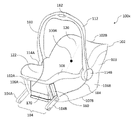
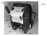
"유아 카시트"는 차량으로 수송되는 유아를 위해 구체적으로 맞춰진 일 유형의 어린이 안전 시트(즉, ECE R44/04에 따른 "그룹 0 또는 그룹 0+" 시트)이다. "유아"는 일반적으로, 아직 걷는 법을 배우지 않은 어린이를 언급하고 전형적으로, 나이로 0 내지 약 12개월이고 및/또는 최대 약 20 내지 30파운드의 무게가 나가는 어린이에 대응한다. 도 1a는 유아 카시트(10) 및 분리 가능한 차량 설치 베이스(20)를 포함하는 종래의 유아 카시트 시스템을 도시한다. 도 1a가 이 각각의 구성요소가 분리된 상태로 도시되고, 차량에서 사용하는 동안 분리 가능한 베이스(20)가 먼저 차량에 설치된 다음, 유아 카시트(10)가 카시트(10)의 바닥(도 1a에서는 보이지 않음)에 잠금자체만큼 및 베이스(20)에 잠금 장치(15A 및 15B)를 통해 분리 가능한 베이스(20)와 기계적으로 맞물린다(예컨대, 이에 딸깍 소리가 난다). 도 1a에 도시된 종래의 유아 카시트 시스템은 또한, 유아 카시트가 기계적으로 맞물리는 유모차(도시되지 않음)와 조합될 수 있으며; 이 조합은 일반적으로, 유아 카시트가 유모차에 딸깍 소리가 나거나 차량에 설치된 분리 가능한 베이스(20)에 딸깍 소리가 날 때 유아 카시트(10)로 유아의 휴대용 수송을 용이하게 하기 위해 "이동 시스템(travel system)"으로서 언급된다.A "infant car seat" is a type of child safety seat (ie a "
유아 카시트(10)는 더 일반적으로 차량이나 유모차 너머로 유아를 안고 운반하기 위해 사용될 수 있다. 특히, 가정 환경이나 다른 환경에서 유아를 고정 및 운반하기 위해 단독으로 사용된 유아 카시트는 일반적으로 "유아 캐리어"로서 언급된다. 조직 ASTM International은 이에 의해 본 명세서에 참조에 의해 원용된 유아 캐리어를 관리하는 세계적으로 인식된 국제적 합의 표준 즉, ASTM F2050-19, "Standard Consumer Safety Specification for Hand-Held Infant Carriers"를 개발 및 제공했다(www.astm.org/Standards/F2050.htm 참조). 미국 소비자 제품 안전 위원회(CPSC)는 또한, ASTM F2050-19를 참조에 의해 원용하고, 연방 규정, 16 C.F.R. §1225(www.federalregister.gov/documents/2020/05/20/2020-09166/safety-standard-for-hand-held-infant-carriers 참조)의 규정집에서 미국 법으로 성문화되는 핸드 헬드 유아 캐리어에 대한 소비자 제품 안전 표준을 갖는다. 16 C.F.R. §1225는 또한, 이에 의해 본 명세서에 참조에 의해 원용된다.The
도 1a에 도시된 종래의 유아 카시트(10)는 더 작은 크기의 유아 및 이동성이 제한되는 유아를 수용하고 유아의 휴대성을 용이하게 하기 위해 다양한 구조적 특징을 포함함으로써 부분적으로, 다른 유형의 어린이 안전 시트와 구별된다. 먼저, 유아 카시트(10) 및 분리 가능한 베이스(20)는 분리 가능한 베이스에 딸깍 소리가 날 때 유아 카시트가 차량의 후방을 향하도록 차량에 설치되어야 한다. 둘째, 유아 카시트(10)는 차량에 장착된 분리 가능한 베이스에 딸깍 소리가 나고/나거나 그로부터 제거될 때 유아 카시트에 유아가 남아 있을 수 있도록 설계된다. 이를 위해, 다른 유형의 카 안전 시트와 달리, 유아 카시트(10)는 운반 손잡이(12)를 포함하여 유아를 수송하는 부모 및/또는 간병인의 휴대성 및 취급 용이를 용이하게 한다. 셋째, 다시 다른 유형의 카 안전 시트와 달리, 유아 카시트(10)는 종종, 만곡된 바닥(17)을 포함하여 유아 카시트가 분리 가능한 베이스(20)(또는 이동 시스템의 유모차)에 고정되지 않을 때 유아를 편안하게 하기 위한 요동 기능을 제공한다.The conventional
일반적으로, 유아 카시트는 최대 약 9 내지 12개월까지의 나이 및 약 20파운드의 체중의 유아를 편안하게 수용하며; 이 단계에서, 유아는 점점 더 활동적이고 무거워진다(그리고 부모/간병인이 유아 카시트로 운반하는 것이 덜 편리하다). 일단 어린이가 유아 카시트보다 커지면, 차량의 유아 카시트 시스템은 일반적으로, "컨버터블(convertible)" 카시트(즉, 유엔 유럽 지역 표준 ECE R44/04에 따른 그룹 0+/1 시트)로 교체된다. 유아 카시트 시스템과 달리, 컨버터블 카시트는 크기가 더 크며 일반적으로, 어린이의 신체 발달을 수용하도록 후방을 향하고 전면을 향하는 구성 둘 다를 지원한다. 부가적으로, 유아 카시트와 달리, 컨버터블 카시트는 휴대형이 아니고, 오히려 차량 내부에 남아 있는 고정 디바이스이며, 즉 어린이는 차량 여행의 시작 및 끝에서 컨버터블 카시트에 배치되고/되거나 그 밖으로 꺼내어진다. 그것이 어린이를 차량 밖으로 운반하도록 의도되지 않기 때문에, 종래의 컨버터블 카시트는 유아 카시트에서 발견되는 운반 손잡이를 포함하지 않고; 유사하게, 컨버터블 카시트는 유아를 요동하기 위한 만곡된 로커 바닥을 포함하지 않을 것이다. 일단 어린이가 컨버터블 카시트보다 커지면, 컨버터블 카시트는 그 다음, 훨씬 더 큰 시트(예컨대, 차량에 영구적으로 고정되어 그것을 제자리에 고정하기 위해 성인 안전벨트를 사용하는 그룹 1 또는 그룹 2 어린이 안전 시트), 또는 궁극적으로 부스터 시트(즉, 어린이를 제지하기 위해 차량의 안전벨트를 또한 활용하는 그룹 3 시트)로 교체될 수 있다. 어린이는 그들이 부스터 시트의 도움 없이 차량의 시트 및 구속장치를 안전하게 사용할 수 있을 때까지 부스터 시트를 계속 사용할 수 있다.Generally, an infant car seat comfortably accommodates an infant up to about 9 to 12 months of age and weighing about 20 pounds; At this stage, the infant becomes increasingly active and heavy (and less convenient for a parent/caregiver to carry in an infant car seat). Once the child is larger than the infant car seat, the vehicle's infant car seat system is generally replaced with a "convertible" car seat (ie a
차량에 설치하는 것과 관련하여, 초기 버전의 어린이 안전 시트(이의 일부는 일반적으로 1990년대 중반에 도입됨)는 차량에 어린이 안전 시트를 고정하기 위해 차량의 기존의 안전벨트를 활용하였다. 이를 위해, 다양한 어린이 안전 시트는 차량의 기존의 안전벨트가 어린이 안전 시트를 차량 시트에 고정시키기 위해 통과할 수 있는 차량 벨트 경로를 포함한다. 차량의 하나의 유형의 종래의 안전벨트는 골반 구속을 위한 "무릎 벨트"이고, 또 다른 유형의 종래의 안전벨트는 가슴과 어깨 부위의 움직임을 억제하는 "어깨 벨트"이다(미국에서는 어깨 벨트가 차량 안전벨트 어셈블리로서 무릎 벨트와 결부하여 단지 사용된다). 본 발명의 목적을 위해, 무릎 벨트 자체 또는 어깨 벨트와 조합된 것 둘 다는 일반적으로, "차량 안전벨트"로서 언급된다. 하나 이상의 기존의 차량 안전벨트를 사용하여 차량에 설치된 어린이 안전 시트는 어린이에 대한 개선된 보호를 제공하지만(차량 안전벨트(들)를 사용하여 차량에 어린이를 직접적으로 고정하는 것과 반대임); 초기 버전의 어린이 안전 시트에서는 기존의 차량 안전벨트를 사용하여 다양한 차량에 설치하는 것이 당시에, 차량의 상이한 제조사와 모델에서 활용된 상이한 유형의 차량 안전벨트 구성이 존재했기 때문에 상당한 표준화가 부족했다.Regarding installation in vehicles, early versions of child safety seats (some of which were generally introduced in the mid-1990s) utilized the vehicle's existing seat belts to secure the child safety seat to the vehicle. To this end, various child safety seats include vehicle belt paths through which the vehicle's existing seat belts can pass to secure the child safety seat to the vehicle seat. One type of conventional seat belt in a vehicle is a "knee belt" for pelvic restraints, and another type of conventional seat belt is a "shoulder belt" that restrains movement of the chest and shoulder region (in the United States, shoulder belts are used only in conjunction with lap belts as vehicle seat belt assemblies). For the purposes of the present invention, both the lap belt itself or in combination with the shoulder belt are generally referred to as "vehicle seat belts". Child safety seats installed in vehicles using one or more conventional vehicle seat belts provide improved protection for children (as opposed to directly securing children to the vehicle using vehicle seat belt(s)); In early versions of child safety seats, installation in a variety of vehicles using existing vehicle seat belts lacked significant standardization as there were different types of vehicle seat belt configurations utilized in different make and models of vehicles at the time.
결과적으로, 1990년대 후반과 2000년대 초반에 표준화를 개선하고, 일부 측면에서 기존의 차량 안전벨트를 사용하는 것에 대안을 제공하기 위한 노력으로 전세계적으로 어린이 안전 시트 및 차량 내 그들의 설치에 대한 다양한 가이드라인이 개발되었다. 예를 들면, ISOFIX는 승용차의 차량 시트의 만곡부(bight)에 위치된 "차량 하부 앵커"를 사용하는 어린이 안전 시트를 위한 부착 지점에 대한 국제 표준이고, 현재 유럽에서 활용된다. 2002년 9월 1일부로 발효된 차량 하부 앵커 및 다른 부착 지점에 대한 미국의 유사한 표준화된 앵커 시스템은 어린이를 위한 하부 앵커 및 테더("Lower Anchors and Tethers for Children": LATCH)로서 지칭되고 캐나다의 또 다른 유사한 표준화된 앵커 시스템은 하부 범용 앵커리지 시스템("Lower Universal Anchorage System"; LUAS) 또는 CANFIX로서 지칭된다.Consequently, in the late 1990s and early 2000s, in an effort to improve standardization and, in some respects, provide an alternative to the use of conventional vehicle seat belts, various guides to child safety seats and their installation in vehicles worldwide line was developed. For example, ISOFIX is an international standard for attachment points for child safety seats using "undercarriage anchors" located on the beats of vehicle seats in passenger cars, and is currently utilized in Europe. A similar standardized anchoring system in the United States for vehicle undercarriage anchors and other attachment points, effective September 1, 2002, is referred to as "Lower Anchors and Tethers for Children" (LATCH) and is Another similar standardized anchor system is referred to as the "Lower Universal Anchorage System" (LUAS) or CANFIX.
부가적으로, 차량 안전에 대한 다양한 기준, 어린이 안전 시트의 사용 및 차량에서의 이러한 시트의 설치를 정의한 안전 규정이 전세계의 상이한 관할 구역에서 도입되었을 뿐만 아니라, 어린이 안전 시트의 하중의 유형은 부딪힘이나 충돌의 불행한 사건에서 견뎌야 한다. 미국에서, 연방 자동차 안전 표준(FMVSS)은 자동차 및 규제 대상 자동차 안전 관련 구성요소, 시스템, 및 설계 특징에 대한 설계, 구성, 성능, 및 내구성 요구조건을 명시하는 연방 규정이다. FMVSS는 NHTSA(National Highway Traffic Safety Administration)에 의해 개발 및 시행되고 미국 연방 규정집, 49 C.F.R. §571에서 미국 법으로 성문화된다. FMVSS 표준 번호 213(FMVSS-213)은 승용차, 다목적 승용차, 트럭, 및 버스에 사용되는 어린이 구속 시스템 및 다른 유형의 자동차 및 항공기에 사용하기 위한 어린이 구속 시스템에 대한 요구조건을 명시한다. FMVSS-213은 미국 연방 규정집, 49 C.F.R. §571.213에서 미국 법으로 성문화되고, 이는 본 명세서에 참조에 의해 원용된다. 상기 언급된 바와 같이, 유럽 연합 및 관련된 관할 구역은 유엔 유럽 지역 표준 ECE R44/04에서 유사한 안전 규정을 확립했고; 유사하게, 캐나다는 CMVSS-213, "Motor Vehicle Restraint Systems and Booster Seats Safety Regulations"에서 유사한 규정을 성문화했으며, 이는 이에 의해 본 명세서에 참조에 의해 원용되었고(laws-lois.justice.gc.ca/eng/regulations/SOR-2010-90/ 참조), 호주 및 뉴질랜드는 AS/NZS 1754, "Safety Standard: Child Restraint Systems For Use In Motor Vehicles"에서 유사한 규정을 성문화했으며, 이는 이에 의해 본 명세서에 참조에 의해 원용된다.Additionally, different jurisdictions around the world have introduced various standards for vehicle safety, the use of child safety seats, and safety regulations that define the installation of such seats in vehicles, as well as the type of load on child safety seats depends on impact or impact. have to endure in the unfortunate event of a collision. In the United States, the Federal Motor Vehicle Safety Standard (FMVSS) is a federal regulation that specifies design, construction, performance, and durability requirements for automobiles and regulated automobile safety-related components, systems, and design features. FMVSS is developed and implemented by the National Highway Traffic Safety Administration (NHTSA) and is published in the United States Code of Federal Regulations, 49 C.F.R. Codified into U.S. law in § 571. FMVSS Standard No. 213 (FMVSS-213) specifies the requirements for child restraint systems for use in passenger cars, utility vehicles, trucks, and buses, and for use in other types of automobiles and aircraft. FMVSS-213 is the United States Code of Federal Regulations, 49 C.F.R. Codified into United States law in § 571.213, which is incorporated herein by reference. As noted above, the European Union and related jurisdictions have established similar safety regulations in the United Nations European Regional Standard ECE R44/04; Similarly, Canada has codified similar regulations in CMVSS-213, "Motor Vehicle Restraint Systems and Booster Seats Safety Regulations," which are hereby incorporated by reference herein (laws-lois.justice.gc.ca/eng). /regulations/SOR-2010-90/), Australia and New Zealand have codified similar regulations in AS/NZS 1754, "Safety Standard: Child Restraint Systems For Use In Motor Vehicles", which is hereby incorporated by reference herein. is used
어린이 안전 시트 및 이의 설치에 대한 표준화를 개선하기 위한 상기 안전 규정에 더하여, 미국에서, CPS(National Child Passenger Safety) 인증 교육 프로그램은 미국에 있는 사람을 어린이 승객 안전 기술자 및 강사로서 인증하여 어린이 구속 시스템 및 안전벨트의 적절한 사용을 위해 부모 및 간병인에 대한 실제 지원을 제공한다. 미국 CPS 인증 프로그램은 어린이 승객 안전 인증에 대해 전세계적으로 "최적 표준"으로 널리 간주된다. CPS에 따르면, 어린이 안전 시트는 차량에 적절하게 설치되었을 때 "인치 테스트"를 통과해야 하고, 즉 적절하게 설치된 어린이 안전 시트는 안전벨트 경로에서 당겨질 때 앞에서 뒤로 또는 측 간 일 인치보다 많이 이동하면 안된다. 이 규칙은 유아 카시트와 같은, 전방을 향한 어린이 안전 시트 및 후방을 향한 어린이 안전 시트에 대해, 및 어린이 안전 시트가 기존의 차량 안전벨트 또는 차량 하부 앵커(예컨대, LATCH)를 포함하는 표준화된 앵커 시스템을 사용하여 차량 시트에 고정될 때 적용된다.In addition to the above safety regulations to improve standardization of child safety seats and their installation, in the United States, the National Child Passenger Safety (CPS) certification training program certifies persons in the United States as child passenger safety technicians and instructors for child restraint systems. and providing practical support to parents and caregivers for proper use of seat belts. The US CPS accreditation program is widely regarded worldwide as the "best standard" for child passenger safety certification. According to CPS, child safety seats must pass an "inch test" when properly installed in a vehicle, i.e. properly installed child safety seats must not move more than one inch from front to back or side to side when pulled out of the seat belt path. . This rule provides for standardized anchor systems for forward-facing child safety seats and rear-facing child safety seats, such as infant car seats, and where the child safety seats include conventional vehicle seat belts or undercarriage anchors (eg LATCH). It is applied when fixed to the vehicle seat using
다시 도 1a을 참조하면, 종래의 유아 카시트 시스템의 분리 가능한 차량 설치 베이스(20)는 상기 언급된 다양한 국제 표준화 및 인증 노력과 안전 규정으로부터 비롯되는 설계 개선으로서 2000년대에 본질적으로 도입되었다. 특히, 분리 가능한 차량 설치 베이스(20)는 차량 시트에 조심스럽고 안전하게 장착되며(기존의 차량 안전벨트 또는 차량 하부 앵커를 이용하는 표준화된 앵커 시스템을 사용함) 일반적으로 장기간 동안(예컨대, 차량에서의 다수의 여행에 걸쳐) 차량 내에 남아 있다. 유아 카시트(10) 및 분리 가능한 베이스(20)의 두 부분으로 된 시스템이 도입된 이후 수년에 걸쳐, 유아 카시트 자체의 설계는 본질적으로 변경되지 않은 채로 유지되었지만; 분리 가능한 베이스(20)는 안전을 보장하고 적용 가능한 표준 및 규정의 준수를 용이하게 하기 위해 지속적인 개선으로 진화했다. 특히, 유아 카시트 시스템에 분리 가능한 베이스(20)를 포함하는 것은 시스템이 CPS "인치 테스트"를 통과하는 것을 허용한다(반면에, 기존의 차량 안전벨트를 사용하여 자체적으로 설치된 레거시 유아 카시트는 이 테스트를 통과하지 못할 것이다).Referring back to FIG. 1A , the detachable
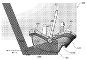
차량 하부 앵커를 이용하는 표준화된 앵커 시스템을 사용한 분리 가능한 베이스(20)의 설치에 관하여, 도 1b는 분리 가능한 베이스(20)가 베이스(20)를 차량 시트의 시트 만곡부에 있는 각각의 차량 하부 앵커(도시되지 않음)에 결합하기 위한 시트 앵커(32)를 포함하는 것을 도시한다. 도 1b에 도시된 바와 같이, 시트 앵커(32)는 테더(tether)(38)를 통해 베이스(20)에 영구적으로 부착되는 벨트(34)에 연결된다. 벨트(34)는 차량 시트에 대해 베이스(20)를 안전하게 배치하기 위한 벨트 조임 메커니즘(36)를 포함한다. 일단 베이스(20)가 차량에 안전하고 확실하게 설치되면, 유아를 운반하는 유아 카시트(10)는 그 다음, 차량에서 여행을 시작하기 전에 베이스(20)에 잠겨지고, 여행의 끝에서 차량으로부터 유아를 제거하기 위해 베이스(20)로부터 해제될 수 있다.Regarding the installation of the
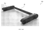
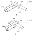
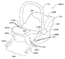
수년에 걸쳐, 분리 가능한 차량 설치 베이스(20)와 차량 하부 앵커 사이의 시트 앵커(32)에 대해 상이한 유형의 기계적 연결이 도입되었다. 예를 들면, 도 1c는 한 쌍의 시트 앵커(32a 및 32b) 및 벨트 조임 메커니즘(36)에 연결된 벨트(34)를 포함하는, 분리 가능한 베이스(20)에서 이용될 수 있는 벨트식 앵커 시스템(30a)을 도시한다. 또 다른 예에서, 도 1d는 한 쌍의 시트 앵커(32a 및 32b)가 베이스(20)를 통과하는 강성 교차 부재(38)를 통해 함께 결합되는 강성 앵커 시스템(30b)을 도시한다. 벨트식 앵커 시스템과 같이, 강성 앵커 시스템(30a)은 베이스(20)에 직접적으로 및 영구적으로 장착된다.Over the years, different types of mechanical connections have been introduced for the
상기 논의된 바와 같이, 분리 가능한 차량 설치 베이스와 함께 유아 카시트를 조합하는 것은 특히 차량이 부모 및/또는 간병인에 의해 소유되고/되거나 동작될 때 부모 및/또는 간병인에게 차량으로 유아를 안전하게 수송하는 편리한 방식을 제공한다. 이러한 상황에서, 부모 및/또는 간병인, 또는 대안적으로 부모/간병인과 상담하거나 함께 협력하는 공인된 CPS(어린이 승객 안전) 기술자는 시간을 내어 다수의 여행에 걸쳐 차량으로 수송하는 동안 유아의 안전을 보장하기 위해 부모/간병인의 차량(예컨대, CPS "인치 테스트"를 통과함)에 분리 가능한 차량 설치 베이스를 적절하게 설치하는 중요한 단계에 주의 깊게 참석할 수 있다. As discussed above, combining an infant car seat with a detachable vehicle mounting base is a convenient way to safely transport an infant in a vehicle to a parent and/or caregiver, particularly when the vehicle is owned and/or operated by the parent and/or caregiver. provides a way In these circumstances, the parent and/or caregiver, or alternatively a certified CPS (Child Passenger Safety) technician who consults or works with the parent/caregiver, takes the time to ensure the safety of the infant during transportation by vehicle over multiple trips. Careful attention can be given to the critical step of properly installing the detachable vehicle mounting base on the parent/caregiver's vehicle (eg, passing the CPS "inch test") to ensure that it is properly installed.
자신이 차량을 소유하고 있지 않거나 달리 용이하게 액세스하여 스스로 차량을 동작할 수 없는 부모 및/또는 간병인을 위해, 고용된 수송 서비스는 일부 사례에서, 대체 수송 모드를 제공할 수 있다. 택시 및 약속 기반 자동차 서비스와 같은 고용된 수송 서비스(관련 기술에서 "대여를 위한 교통수단"으로서 또한 언급됨)에 대한 다양한 종래의 옵션이 수년 동안 이용 가능했다. 그러나, 택시 및 종래의 약속 기반 자동차 서비스는 역사적으로, 유아와 함께 여행하는 부모 및/또는 간병인에게 다수의 도전을 제기했다.For parents and/or caregivers who do not own a vehicle or otherwise cannot readily access and operate the vehicle on their own, hired transportation services may, in some instances, provide an alternative transportation mode. Various conventional options for hired transport services (also referred to in the art as “transportation for hire”), such as taxis and appointment-based car services, have been available over the years. However, taxis and conventional appointment-based car services have historically presented a number of challenges for parents and/or caregivers traveling with infants.
예를 들면, 일부 사례에서, 구형 택시에는 심지어 표준화된 차량 하부 앵커가 구비되지 않고, 따라서, 택시에서의 기존의 차량 안전벨트는 종래의 유아 카시트 시스템의 분리 가능한 베이스를 설치하기 위해 사용해야 할 필요가 있을 것이다. 부모/간병인은 분리 가능한 베이스 및 기존의 차량 안전벨트를 사용하지 않고, 택시에 유아 카시트를 단독으로 설치하는 것을 고려할 수 있지만; 그렇게 하는 것은 CPS "인치 테스트"를 통과하지 못할 유아 카시트의 열등한(따라서 가능하게 안전하지 않음) 설치를 야기할 것이다.For example, in some instances, older cabs are not even equipped with standardized undercarriage anchors, and thus, existing vehicle seat belts in cabs need not be used to install the detachable base of conventional child car seat systems. There will be. Parents/caregivers may consider installing the infant car seat alone in the cab, without the use of a detachable base and conventional vehicle seat belts; Doing so would result in an inferior (and possibly unsafe) installation of the infant car seat that would not pass the CPS "inch test".
택시에 차량 하부 앵커가 구비되어 있더라도, 부모 및/또는 간병인은 유아 카시트, 별개의 분리 가능한 베이스, 및 임의의 다른 여행 수하물/짐에 유아를 태운 채로 택시를 호출하거나 대기하는 불편에 직면하고, 긴 줄 및/또는 긴 대기 기간, 및/또는 악천후를 통해 이동하는 붐비는 택시/택시 정류장에서 그렇게 할 수 있다. 일단 택시가 도착하면, 부모/간병인은 또 다른 즉각적인 도전에 직면하게 되는데, 즉, 유아 카시트 시스템의 분리 가능한 베이스를 설치하는 동안 유아를 주시하는 방법이다. 아마도, 부모/간병인은 동시에 어떻게든 유아에게 적절한 주의를 기울이기를 시도하면서, 유아가 있는 유아 카시트를 아무데나 놓고 그 다음, 택시 뒤쪽에 분리 가능한 베이스의 설치와 조정을 급하게 처리해야 할 것이다. 부가적인 좌절은 일부 택시의 일반적으로 열악한 위생 환경이 부모 및/또는 간병인이 택시를 여행 모드로서 사용하는 것을 더 억제할 수 있는 환경을 생성한다는 것이다.Even if the taxi is equipped with an undercarriage anchor, parents and/or caregivers face the inconvenience of calling or waiting for a taxi with the infant in the infant car seat, separate detachable base, and any other travel luggage/luggage, It may do so at crowded taxi/taxi stops traveling through lines and/or long waiting periods, and/or bad weather. Once the taxi arrives, the parent/caregiver faces another immediate challenge: how to keep an eye on the infant while installing the detachable base of the infant car seat system. Presumably, the parent/caregiver will have to place the infant car seat with the infant anywhere, while at the same time somehow attempting to give the infant adequate attention, and then hasten the installation and adjustment of the detachable base in the back of the cab. An additional frustration is that the generally poor sanitary environment of some taxis creates an environment that may further discourage parents and/or caregivers from using the taxi as a mode of travel.
종래의 약속 기반 자동차 서비스는 또한, 그 자체로 특정 도전을 제기한다. 예를 들면, 자동차 서비스를 이용하는 여행은 종종, 여행에 훨씬 앞서 일정을 잡아야 할 필요가 있는데, 이는 (예컨대, 유아의 많은 예측 가능하지 않고, 종종 변화하는 요구를 고려할 때) 부모 및/또는 간병인의 일정에 불편할 수 있다. 부가적으로, 부모 및/또는 간병인은 특히, 교통량이 많은 시간에 서비스의 가용성 부족으로 인해 약속 기반 자동차 서비스로 여행을 예약하지 못할 수 있다. 종래의 약속 기반 자동차 서비스의 비용은 또한, 택시보다 전형적으로 더 높으며, 이는 일부 사례에서 또한 재정적 방해 요소가 될 수 있다.Conventional appointment-based car services also pose certain challenges in their own right. For example, trips with car service often need to be scheduled well in advance of the trip, which may (eg, given the many unpredictable and often changing needs of infants) of parents and/or caregivers. It can be inconvenient for your schedule. Additionally, parents and/or caregivers may not be able to book trips with an appointment-based car service due to lack of availability of the service, particularly during high traffic hours. The cost of conventional appointment-based car service is also typically higher than taxis, which in some instances can also be a financial hindrance.
따라서, 택시 및/또는 종래의 약속 기반 자동차 서비스 사용과 연관된 다양한 도전은 역사적으로 유아와 함께 여행하는 부모 및/또는 간병인을 위한 대안적인 수송 모드로서의 그들의 사용을 제한했다. 그러나, 본 발명자는 우버(Uber) 및 리프트(Lyft)와 같은 차량 호출 및 차량 공유 서비스의 최근 성장 및 인기가 유아의 부모 및/또는 간병인에게 새로운 고용된 수송 옵션을 제공한다는 것을 인식하고 이해했다. 본 발명의 목적을 위해, "차량 호출"은 모바일 디바이스에서 동작하고 우버 또는 리프트와 같은 수송 네트워크 회사(TNC)가 제공하는 "앱"을 통해 차량에서 여행을 예약하고 여행 비용을 지불하는 프로세스를 언급한다. 용어 "차량 공유"는 TNC에서 제공하는 서비스를 설명하기 위해 유사하게 사용되었지만, 더 일반적으로 이 용어는 한 사람이 통근(예컨대, 출근) 시에 한 명 이상의 다른 개인과 차량을 공유하는 "카풀링"과 유사한 방식으로 사용될 수 있다.Accordingly, various challenges associated with the use of taxis and/or conventional appointment-based car services have historically limited their use as alternative modes of transport for parents and/or caregivers traveling with infants. However, the inventors have recognized and understood that the recent growth and popularity of ride-hailing and ride-sharing services, such as Uber and Lyft, provide new hired transportation options to parents and/or caregivers of infants. For the purposes of the present invention, "car call" refers to the process of booking and paying for travel in a vehicle through an "app" that operates on a mobile device and is provided by a transport network company (TNC) such as Uber or Lyft. do. The term "car sharing" is similarly used to describe the services provided by TNC, but more generally the term is "carpooling" in which one person shares a vehicle with one or more other individuals while commuting (eg, to work). " can be used in a similar way.
차량 호출 또는 차량 공유의 관점에서, 이 더 새로운 유형의 고용된 교통 서비스는 유아의 부모 및/또는 간병인을 위한 종래의 약속 기반 자동차 서비스 및 택시와 연관된 과거의 도전 중 일부를 완화한다. 예를 들면, 차량 호출 또는 차량 공유 서비스는 전형적으로, 요청 시 및/또는 짧은 통지로 승차 일정을 예약하는 것을 허용함으로써 부모 및/또는 간병인에게 더 유연한 일정을 제공한다(예컨대, 승차는 유아가 여행할 수 있고 여행할 준비가 될 때 예약될 수 있다). 또 다른 예에서, 차량 호출 또는 차량 공유 서비스는 일반적으로, 운전자가 도착할 때까지 부모 및/또는 간병인이 보호되고/되거나 실내 환경(예컨대, 그들의 집)에서 그들의 유아와 함께 기다리는 것을 허용한다. 이것은 결과적으로, 또한, 부모 및/또는 간병인이 긴 줄 및/또는 긴 대기 시간으로 인해 혼잡한 장소를 회피하는 것을 가능하게 한다. 또한, 일반적인 관찰로서, 차량 호출 또는 차량 공유 서비스에 사용되는 차량은 택시보다 더 깨끗하고 유아 및 그들의 부모/간병인에게 더 친절하게 대하는 경향이 있다.In terms of ride-hailing or ride-sharing, this newer type of hired transport service alleviates some of the past challenges associated with traditional appointment-based car services and taxis for parents and/or caregivers of young children. For example, ride-hailing or ride-sharing services typically provide more flexible scheduling for parents and/or caregivers (e.g., rides are can and can be booked when you are ready to travel). In another example, ride-hailing or ride-sharing services generally allow parents and/or caregivers to wait with their infant in a sheltered and/or indoor environment (eg, their home) until the driver arrives. This in turn also enables parents and/or caregivers to avoid crowded places due to long lines and/or long waiting times. Also, as a general observation, vehicles used for ride-hailing or ride-sharing services tend to be cleaner than taxis and more friendly to infants and their parents/caregivers.
유아와 함께 여행하는 부모 및/또는 간병인을 위한 차량 호출 및 차량 공유 서비스의 잠재적인 이득을 인식함에 있어서, 본 발명자는 분리 가능한 차량 설치 베이스를 포함하는 종래의 유아 카시트 시스템이 특히, 다양한 이유로 차량 호출 및 차량 공유 서비스와 같은 고용된 수송 수단을 위해 완전히 적합하지 않다는 것을 또한 인식하였다.In recognizing the potential benefits of ride-hailing and ride-sharing services for parents and/or caregivers traveling with infants, the present inventors have discovered that prior art child car seat systems comprising a detachable vehicle mounting base are particularly useful for ride-hailing for a variety of reasons. And it was also recognized that it is not entirely suitable for hired transportation such as ride-sharing services.
첫째, 택시 또는 종래의 약속 기반 자동차 서비스에서와 같이, 부모 및/또는 간병인은 분리 가능한 베이스(유아 카시트 자체만큼 클 수 있음)의 크기와 무게를 고려할 때 현저하게 불편한 차량 호출 또는 차량 공유 서비스(유아와 함께 하는 여행에 수반된 임의의 다른 수하물/짐과 함께)를 사용할 때 유아 카시트(거기에 유아가 있음) 및 분리 가능한 베이스 둘 다를 운반할 필요가 있을 것이다. 대안적으로, 부모/간병인은 분리 가능한 베이스를 가져오지 않고 차량 호출/차량 공유 차량에 기존의 차량 안전벨트를 사용하여 유아 카시트 자체만 설치하는 것을 고려할 수 있다. 그러나, 상기 언급된 바와 같이, 그렇게 하는 것은 CPS "인치 테스트"를 통과하지 못할 유아 카시트의 열악하고 위험한 설치를 야기할 것이다.First, as in taxis or conventional appointment-based car services, parents and/or caregivers are notably inconvenient in ride-hailing or ride-sharing services (infants You will need to carry both the infant car seat (with the infant there) and the detachable base when using (along with any other baggage/luggage accompanying your travel with Alternatively, the parent/caregiver may consider installing only the infant car seat itself using the existing vehicle seat belts in the ride/sharing vehicle without bringing a detachable base. However, as noted above, doing so would result in a poor and risky installation of the infant car seat that would not pass the CPS "inch test".
둘째, 분리 가능한 베이스를 차량 시트에 적절하게 설치하는 것(예컨대, "인치 테스트"를 통과하기 위해)은 시간이 걸리고 설치를 수행하는 사람의 주의가 필요하다. 그러나, 차량 호출 또는 차량 공유 서비스 차량이 여행의 출발점에 도착할 때, 동시에 유아에게 계속 세심한 주의를 기울이면서, 부모/간병인이 유아 카시트 시스템의 분리 가능한 베이스를 신속하고 안전하게 설치하는데 필요한 시간을 할애할 기회가 거의 또는 전혀 없을 수 있다. 부모/간병인이 유아와 혼자 여행하는 경우, 부모/간병인이 차량 시트에 분리 가능한 베이스를 동시에 설치하면서 유아를 적절하게 모니터링하는 것이 사실상 불가능할 수 있다. 게다가, 부모/간병인은 각각의 차량 호출/차량 공유 여행을 위해 분리 가능한 베이스를 설치한 다음 제거할 필요가 있을 것이다.Second, properly installing the detachable base to a vehicle seat (eg, to pass an "inch test") takes time and requires the attention of the person performing the installation. However, when the ride-hailing or ridesharing service vehicle arrives at the starting point of the trip, while at the same time continuing to pay close attention to the infant, the opportunity for parents/caregivers to dedicate the time needed to quickly and safely install the detachable base of the infant car seat system. may have little or no When a parent/caregiver is traveling alone with an infant, it may be virtually impossible for the parent/caregiver to properly monitor the infant while simultaneously installing the detachable base on the vehicle seat. In addition, the parent/caregiver will need to install and then remove the detachable base for each ride/sharing trip.
유아와 함께 여행할 때 고용된 수송 수단을 사용하는 도전의 관점에서, 본 발명은 유아 카시트가 특히, 분리 가능한 베이스 또는 차량 안전벨트를 사용하지 않고 차량 시트에 직접적으로 고정되도록 구성되는 유아 카시트 시스템의 다양한 독창적인 구현에 관한 것이다. 본 명세서에서 설명된 다양한 예에서, 분리가능한 베이스 또는 차량 안전벨트를 요구하지 않는 것에 더하여, 독창적인 유아 카시트 시스템은 또한, 개선된 충돌 시험 성능 및 감소된 부상 기준을 성취하기 위해 상단 테더 또는 로드 레그(load leg)를 요구하지 않는다. 분리 가능한 베이스를 요구하는 대신에, 본 발명에 따른 유아 카시트 시스템은 각각 및 다양한 조합으로 유아의 부모 또는 간병인이 다음을 수행하는데 도움이 되는 다른 유용한 특징을 포함한다: 1) 대부분의 분리 가능한 베이스 없이 차량으로 및 차량으로부터 유아를 용이하게 및 편리하게 수송하고; 2) 유아의 편안함과 안전을 보장하기 위해, 유아 카시트와 유아를 여행 시작 시에 차량의 차량 시트에 직접적으로 꽉 끼는 상태로 신속하게 고정하고; 3) 여행의 끝에서 차량으로부터 유아 및 유아 카시트를 신속하게 제거한다.In view of the challenges of using a vehicle employed when traveling with an infant, the present invention relates to an infant car seat system wherein the infant car seat is configured to be secured directly to the vehicle seat without the use of, inter alia, a removable base or vehicle seat belt. It concerns a variety of original implementations. In the various examples described herein, in addition to not requiring a detachable base or vehicle seat belt, the inventive infant car seat system also provides a top tether or load leg to achieve improved crash testing performance and reduced injury criteria. It does not require a load leg. Instead of requiring a detachable base, the infant car seat system according to the present invention, each and in various combinations, includes other useful features that help the infant's parent or caregiver to: 1) without most of the detachable base facilitate and conveniently transport infants to and from vehicles; 2) To ensure the comfort and safety of the infant, the infant car seat and the infant are quickly secured in a tight fit directly to the vehicle seat of the vehicle at the beginning of the trip; 3) Promptly remove the infant and child car seat from the vehicle at the end of the trip.
예시적인 구현에서, 이 목적은 유아 카시트에 직접적으로 결합되고 차량 하부 앵커에 대한 편리한 액세스 및 부착을 제공하도록 배치된 앵커 시스템에 의해 부분적으로 촉진된다. 하나의 양태에서, 앵커 시스템은 특히, 충돌 사건 동안 차량 시트의 후방으로부터 멀어지는 유아 카시트의 후면의 회전을 상당히 완화하기 위해(및 또한 다른 부상 기준을 현저하게 감소시킴), 유아 카시트의 무게 중심에 부분적으로 기초하여 기계적 구속 지점에 배치된다.In an exemplary implementation, this objective is facilitated in part by an anchor system that engages directly to the infant car seat and is arranged to provide convenient access and attachment to an undercarriage anchor. In one aspect, the anchor system is located at the center of gravity of the infant car seat in particular to significantly mitigate (and also significantly reduce other injury criteria) rotation of the rear of the infant car seat away from the rear of the vehicle seat during a crash event. It is placed on the basis of mechanical restraint points.
분리 가능한 베이스 없이 설치를 용이하게 하기 위해, 또 다른 양태에서, 유아 카시트 시스템은 설치 동안 차량 시트의 후방을 향한 유아 카시트의 후면의 회전을 완화하기 위해 유아 카시트의 전면에 근접하게 장착된 조정 풋(adjustment foot)을 포함한다. 이 방식으로, 조정 풋은 부모 및/또는 간병인이 유아의 안락함을 유지하고, 앵커 시스템을 차량 하부 앵커와 더 용이하게 정렬시키고 맞물리도록 차량에 유아 카시트를 배치하고, 동시에 차량 시트에 대한 꽉 끼임을 용이하게 하도록 차량 시트의 시트 팬에 대한 지렛대를 제공하는데 도움이 된다.To facilitate installation without a detachable base, in another aspect, the infant car seat system comprises an adjustment foot mounted proximate to the front of the infant car seat to mitigate rotation of the rear of the infant car seat towards the rear of the vehicle seat during installation. adjustment foot). In this way, the adjustment foot allows parents and/or caregivers to maintain the comfort of the infant, position the infant car seat on the vehicle to more easily align and engage the anchor system with the undercarriage anchor, while at the same time providing a tight fit against the vehicle seat. It helps to provide leverage for the seat pan of the vehicle seat to facilitate.
다른 양태에서, 유아 카시트는 또한, 유아 카시트를 차량 안팎으로 옮길 때 휴대성 및 취급 용이성을 용이하게 하는 운반 손잡이, 및 차량 외부에서 유아 카시트가 사용될 때 유아를 편안하게 하기 위한 요동 기능을 제공하는 만곡된 로커 바닥을 포함한다. 일부 사례에서, 유아 카시트를 상이한 구성의 차량 시트에 끼우는 것을 복잡하게 할 수 있는 만곡된 로커 바닥과 관련하여, 상기 언급된 조정 풋은 또한, 로커 바닥의 만곡된 프로파일을 보상하여 차량 시트와의 신뢰 가능한 꽉 끼임이 어린이 고객 안전(CPS) 지침에 따라 성취됨을 보장하기 위해 특히 유용하다(예컨대, 유아 카시트 설치는 CPS "인치 테스트"를 통과한다).In another aspect, the infant car seat also provides a carrying handle that facilitates portability and ease of handling when moving the infant car seat in and out of the vehicle, and a flexion to provide a rocking function to comfort the infant when the infant car seat is used outside the vehicle. included rocker bottoms. With respect to curved rocker floors, which, in some instances, can complicate fitting an infant car seat into a vehicle seat of a different configuration, the aforementioned adjustment foot also compensates for the curved profile of the rocker floor to ensure trust with the vehicle seat. It is particularly useful to ensure that the tight fit possible is achieved in accordance with Child Customer Safety (CPS) guidelines (eg, infant car seat installations pass the CPS "inch test").
다른 유리한 측면에서, 일부 구현예에서, 부모/간병인은 차량으로부터 유아 및 유아 카시트를 용이하게 제거하기 위해 원터치 액추에이터로 여행의 끝에서 차량 시트로부터 앵커 시스템을 분리할 수 있다. 부가적으로, 유아 카시트 내에 또는 유아 카시트에 구축된 하나 이상의 저장 영역은 손상이나 부상(뿐만 아니라, 유아 카시트가 이동 시스템의 일부로서 사용되는 경우 유모차와의 간섭)을 방지하기 위해 사용하지 않을 때 앵커 시스템을 편리하게 저장하고 유아 카시트의 세련된 설계를 제공한다.In another advantageous aspect, in some embodiments, the parent/caregiver can detach the anchor system from the vehicle seat at the end of the trip with a one-touch actuator to facilitate removal of the infant and infant car seat from the vehicle. Additionally, one or more storage areas built into or in the infant car seat may be anchored when not in use to prevent damage or injury (as well as interference with the stroller if the infant car seat is used as part of a mobility system). It conveniently stores the system and provides a stylish design of the infant car seat.
유아 카시트 시스템으로부터 분리 가능한 베이스를 제거하는 것은 부모/간병인이 분리 가능한 베이스의 크기, 무게, 및 저장에 대해 걱정할 필요가 없기 때문에, 차량으로 및 그로부터 유아를 훨씬 더 편리하고 편의적으로 수송하게 한다. 분리 가능한 베이스가 없고, 안전 및 편의성을 지원하는 다수의 특징을 갖는 시스템 설계는 간병인이 종종, 동시에 유아의 편안함과 안전을 보장하면서, 유아 카시트에 유아를 태우고(임의의 다른 여행 수하물/짐과 함께) 차량 호출/차량 공유 차량에 신속하게 승하차해야 하는 차량 호출 또는 차량 공유 상황에 특히 적합하게 한다.Removal of the detachable base from the infant car seat system makes transporting the infant to and from the vehicle much more convenient and convenient as the parent/caregiver does not have to worry about the size, weight, and storage of the detachable base. The system design with no detachable base and multiple features to support safety and convenience allows caregivers to often carry the infant in an infant car seat (along with any other travel baggage/luggage) while simultaneously ensuring the comfort and safety of the infant. ) Ride/Ride Sharing Makes it particularly suitable for ride-hailing or ride-sharing situations where you need to quickly get on and off the car.
본 명세서에 개시된 독창적인 유아 카시트 시스템의 앵커 시스템은 일반적으로, 유아 카시트 시스템을 차량 시트에 고정하기 위한 다양한 전세계적 표준에 따르는 기계적 설계를 갖는 하나 이상의 연결기(또한 때때로 "앵커"로서 언급됨)를 포함할 수 있다. 상기 언급된 바와 같이, 이러한 표준의 예는 어린이를 위한 하부 앵커 및 테더(LATCH), ISOFIX, 하부 범용 앵커리지 시스템(LUAS), 및 범용 어린이 안전 시트 시스템(USCSS)을 포함하지만, 이로 제한되지 않는다. 이 다양한 표준에 따라, 유아 카시트 앵커 시스템 연결기는 차량 시트의 만곡부에서 발견된 각각의 차량 하부 앵커에 신속하고 안전한 연결을 허용하는 래칭 메커니즘을 포함한다.The anchor systems of the inventive infant car seat systems disclosed herein generally include one or more connectors (also sometimes referred to as "anchors") having a mechanical design conforming to various worldwide standards for securing the infant car seat system to a vehicle seat. may include As noted above, examples of such standards include, but are not limited to, the Lower Anchor and Tether for Children (LATCH), ISOFIX, the Lower Universal Anchorage System (LUAS), and the Universal Child Safety Seat System (USCSS). In accordance with these various standards, the infant car seat anchor system coupler includes a latching mechanism that allows a quick and secure connection to each undercarriage anchor found in the curvature of the vehicle seat.
일부 구현예에서, 독창적인 유아 카시트 시스템의 앵커 시스템은 유아 카시트에 견고하게 결합된 한 쌍의 연결기를 포함하는 강성 앵커 시스템일 수 있다. 하나의 양태에서, 강성 앵커 시스템의 연결기는 차량 시트의 만곡부에 있는 차량 하부 앵커에 대한 안전한 연결을 용이하게 하기 위해 유아 카시트에 대해 회전 가능하고/하거나 병진 이동식으로 조정 가능할 수 있다. 또 다른 양태에서, 강성 앵커 시스템의 연결기의 회전 및/또는 병진 이동은 또한, 사용하지 않을 때 연결기의 용이한 저장을 용이하게 한다.In some embodiments, the anchor system of the inventive infant car seat system may be a rigid anchor system comprising a pair of connectors rigidly coupled to the infant car seat. In one aspect, the connector of the rigid anchor system may be rotatably and/or translatably adjustable relative to the infant car seat to facilitate secure connection to a vehicle undercarriage anchor at a flexure of the vehicle seat. In another aspect, rotational and/or translational movement of the connector of the rigid anchor system also facilitates easy storage of the connector when not in use.
다른 구현에서, 앵커 시스템은 하나 이상의 벨트를 통해 유아 카시트에 결합된 한 쌍의 연결기를 포함하는 벨트식 앵커 시스템일 수 있다. 벨트식 앵커 시스템은 일단 연결기가 차량 하부 앵커와 기계적으로 맞물리면 유아 카시트가 차량 시트에 용이하고 견고하게 끼워지는 것을 보장하기 위해 벨트 조임 메커니즘뿐만 아니라, 잠금 메커니즘(예컨대, 캠)을 더 포함할 수 있다.In another implementation, the anchor system may be a belted anchor system comprising a pair of connectors coupled to the infant car seat via one or more belts. The belted anchor system may further include a locking mechanism (eg, a cam), as well as a belt tightening mechanism, to ensure that the infant car seat easily and securely fits to the vehicle seat once the connector is mechanically engaged with the undercarriage anchor. .
앵커 시스템의 전부 또는 일부를 저장하기 위한 하나 이상의 통합된 저장 격실과 관련하여, 저장 격실(들)은 앵커 시스템의 유형(예컨대, 강성 앵커 시스템 또는 벨트식 앵커 시스템)에 기초하여 맞춰질 수 있다. 예를 들면, 강성 앵커 시스템은 저장된 위치(예컨대, 교차 부재가 접혀 있고 앵커 시스템 연결기가 저장을 위해 회전됨)와 동작 위치(예컨대, 교차 부재가 연장되고 앵커 시스템 연결기가 차량 하부 앵커에 부착되도록 배치됨) 사이에 이동하기 위해 신축적으로 조정 가능한 교차 부재를 포함할 수 있다. 강성 앵커 시스템을 위한 저장 격실은 연결기 공동(예컨대, 유아 카시트의 시트 셸 레일(seat shell rail)에 의해 또는 그 내에 정의됨) 내에 연결기를 저장하도록 맞춰질 수 있다. 또 다른 예에서, 유아 카시트는 벨트식 앵커 시스템의 벨트 및/또는 연결기를 저장하기 위해 유아 카시트 내부 및/또는 외부에 다양한 저장 격실을 포함할 수 있다.With respect to the one or more integrated storage compartments for storing all or part of the anchor system, the storage compartment(s) may be tailored based on the type of anchor system (eg, a rigid anchor system or a belted anchor system). For example, the rigid anchor system may be positioned such that it has a stored position (eg, the cross member is folded and the anchor system connector rotated for storage) and an operating position (eg, the cross member is extended and the anchor system connector is attached to the undercarriage anchor). ) may include a telescoping member that is elastically adjustable to move between them. The storage compartment for the rigid anchor system may be adapted to store the connector within a connector cavity (eg, defined by or within a seat shell rail of an infant car seat). In another example, the infant car seat may include various storage compartments inside and/or outside the infant car seat to store the belts and/or connectors of the belted anchor system.
강성이든 벨트식이든 앵커 시스템은 분리 가능한 베이스를 사용하지 않고 유아 카시트를 차량 시트에 고정하기 위해 기존의 차량 안전벨트를 사용할 필요성을 제거하고; 그렇게 함으로써, 앵커 시스템은 또한, 구속장치가 유아의 상단을 지나는 것(예컨대, 종래의 차량 벨트 경로를 통해 및 유아의 다리, 무릎, 또는 골반의 상단을 가로질러)을 완화한다. 게다가, 분리 가능한 베이스 없이 설치를 위해 차량 안전벨트를 사용하는 것에 대한 실행 가능한 대안을 제공함으로써, 앵커 시스템은 분리 가능한 베이스를 사용하지 않더라도, 유아 카시트의 설치가 CPS "인치 테스트"를 통과함을 보장하는데 도움을 준다.Whether rigid or belted, the anchor system eliminates the need to use conventional vehicle seat belts to secure the infant car seat to the vehicle seat without the use of a detachable base; In doing so, the anchor system also relieves restraints from passing over the infant's top (eg, via conventional vehicle belt paths and across the infant's legs, knees, or top of the pelvis). Furthermore, by providing a viable alternative to using a vehicle seat belt for installation without a detachable base, the anchor system ensures that the installation of the infant car seat passes the CPS "inch test", even without the use of a detachable base. help to do
상기 간략히 언급되고 하기에 더 상세하게 논의된 바와 같이, 앵커 시스템은 하나 이상의 기계적 구속 지점(예컨대, 시트 셸의 하나 이상의 개구, 슬롯, 또는 노치)에서 유아 카시트의 시트 셸의 각각의 측에 직접적으로 장착될 수 있다. 예시적인 구현에서, 기계적 구속 지점은 특히, 충돌 테스트 성능을 크게 개선하고 부상 기준을 감소시키기 위해 유아 카시트 및 대표적인 유아(예컨대, 의인화 테스트 디바이스(anthropomorphic test device) 또는 ATD)의 시스템 무게 중심에 기초하여 배치된다. 이를 위해, 일부 구현예에서, 앵커 시스템에 대한 기계적 구속 지점(들)은 무게 중심을 통과하는 제1 축 및 앵커 시스템의 연결기가 차량 시트의 만곡부에서 차량 하부 앵커와 맞물리는 각각의 앵커 지점을 통과하는 제2 축에 의해 획정된 평면 위에 위치된다. 앵커 시스템 기계적 구속 지점(들)의 이 특정한 위치 결정은 충돌 사건 동안 유아의 머리와 가슴에 가해지는 힘의 크기를 감소시킬 뿐만 아니라, 특히 충돌 사고 동안 유아 카시트(수직 기준)의 등받이의 회전 변위를 감소시키는 것으로 관찰된다. 예시적인 구현에서, 앵커 시스템 기계적 구속 지점은 충돌 사건 동안 유아 카시트의 등받이의 회전 변위가 수직에 대해 70도 미만임을 보장한다.As mentioned briefly above and discussed in more detail below, the anchor system is directly at each side of the seat shell of the infant car seat at one or more mechanical restraint points (eg, one or more openings, slots, or notches in the seat shell). can be mounted In an exemplary implementation, the mechanical restraint points are based on the system center of gravity of the infant car seat and representative infant (eg, an anthropomorphic test device or ATD), inter alia, to significantly improve crash test performance and reduce injury criteria. are placed To this end, in some embodiments, the mechanical restraint point(s) for the anchor system pass through the first axis passing through the center of gravity and through each anchor point where the connector of the anchor system engages the undercarriage anchor at the flexure of the vehicle seat. is located on a plane defined by a second axis. This specific positioning of the anchor system mechanical restraint point(s) not only reduces the magnitude of the forces on the infant's head and chest during a crash event, but also reduces the rotational displacement of the backrest of the infant car seat (vertical reference), particularly during a crash event. observed to decrease. In an exemplary implementation, the anchor system mechanical restraint points ensure that the rotational displacement of the backrest of the infant car seat during a crash event is less than 70 degrees with respect to vertical.
요컨대, 본 명세서에서 설명된 독창적인 유아 카시트 시스템은 특히 차량 호출 또는 차량 공유 서비스를 사용할 때 종래의 유아 카시트 시스템의 한계를 해결하기 위한 몇몇 장점을 제공한다. 첫째, 유아 카시트 시스템은 유아 카시트가 차량 시트에 견고하게 끼워짐을 보장하기 위해(예컨대, CPS "인치 테스트"를 통과하도록), 유아 카시트를 차량 시트에 신속하고 안전하게 부착하도록 구성되는 연결기를 갖는 앵커링 시스템, 및 유아 카시트의 만곡된 로커 바닥뿐만 아니라, 상이한 유형의 차량 시트 및/또는 상이한 시트 팬 각도를 용이하게 보상하기 위한 조정 풋을 포함할 수 있다. 둘째, 유아 카시트 시스템은 차량으로부터 유아 카시트 시스템을 용이하게 제거하기 위한 신속 분리 메커니즘을 제공하는 하나 이상의 해제 액추에이터를 포함할 수 있다. 셋째, 저장 격실은 유아 카시트 시스템에서 매달리고/매달리거나 노출된 구성요소의 수를 감소시키기 위해 유아 카시트에 통합될 수 있다. 넷째, 유아 카시트를 차량 시트에 직접적으로 설치하는 것은 차량에 유아 카시트 시스템을 설치 및/또는 제거하는 동안 부모 및/또는 간병인이 유아 카시트 내에 상주하는 유아에 주의를 기울이는 것을 허용한다. 다섯째, 유아 카시트 시스템으로부터 분리 가능한 차량 설치 베이스를 제거하는 것은 부모 및/또는 간병인이 유아와 함께 여행하는 동안 운반하고 저장해야 하는 구성요소의 수를 감소시킨다.In summary, the inventive infant car seat system described herein provides several advantages for solving the limitations of conventional infant car seat systems, particularly when using ride-hailing or ride-sharing services. First, the infant car seat system is an anchoring system having a connector configured to quickly and securely attach the infant car seat to the vehicle seat to ensure that the infant car seat fits securely to the vehicle seat (eg, to pass the CPS "inch test"). , and adjustable feet to easily compensate for different types of vehicle seats and/or different seat pan angles, as well as the curved rocker bottom of the infant car seat. Second, the infant car seat system may include one or more release actuators that provide a quick release mechanism for facilitating removal of the infant car seat system from the vehicle. Third, the storage compartment may be integrated into the infant car seat to reduce the number of suspended and/or exposed components in the infant car seat system. Fourth, installing the infant car seat directly to the vehicle seat allows the parent and/or caregiver to pay attention to the infant residing within the infant car seat during installation and/or removal of the infant car seat system to the vehicle. Fifth, removing the detachable vehicle mounting base from the infant car seat system reduces the number of components that parents and/or caregivers must transport and store while traveling with an infant.
본 명세서에 개시된 유아 카시트 시스템의 다양한 특징이 특히, 유아를 수송할 때 차량 호출 또는 차량 공유 서비스의 사용을 용이하게 할 수 있을지라도, 이 시스템은 차량 호출 또는 차량 공유 서비스 및/또는 고용된 수송 서비스에만 적용 가능하도록 제한되지 않는다. 물론, 부모 및/또는 간병인은 개시된 유아 카시트 시스템을 자신의 차량에서 사용하는 것으로부터 용이하게 이점을 얻을 수 있고 - 이렇게 함으로써, 그들은 또한, 종래의 유아 카시트 시스템의 분리 가능한 차량 설치 베이스가 달리 차지할 그들의 차량의 뒷좌석에서 귀중한 공간을 확보할 것이다.Although various features of the infant car seat system disclosed herein may facilitate the use of a ride-hailing or ride-sharing service, particularly when transporting an infant, the system provides a ride-hailing or ride-sharing service and/or a hired transport service. It is not limited to be applicable only to Of course, parents and/or caregivers can readily benefit from using the disclosed baby car seat system in their vehicle - and in doing so, they can also benefit from their own vehicle installation base that would otherwise be occupied by the detachable vehicle installation base of a conventional child car seat system. It will free up valuable space in the back seat of the vehicle.
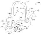
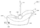
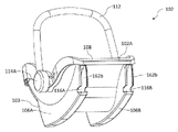
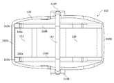
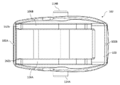
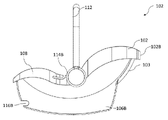
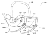
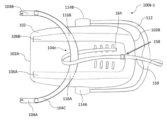
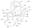
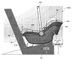
요컨대, 일 구현예는 유아 카시트 시스템(100x)에 관한 것이고, 유아 카시트 시스템은: 차량(500)으로 및 이로부터 유아를 운반하고 유아 카시트의 전면이 차량의 후방을 향하는 차량으로 유아를 안전하게 수송하기 위해, 전면(102A) 및 후면(102B)을 갖는 유아 카시트(102)로서: 제1 만곡된 로커 바닥(107A)을 갖는 제1 시트 셸 레일(106A); 제2 만곡된 로커 바닥(107B)을 갖는 제2 시트 셸 레일(106B); 운반 손잡이(112); 운반 손잡이를 유아 카시트에 부착하기 위한 제1 운반 손잡이 부착 메커니즘(114A); 및 운반 손잡이를 유아 카시트에 부착하기 위한 제2 운반 손잡이 부착 메커니즘(114B)을 포함하는, 상기 유아 카시트; 유아 카시트 분리 가능한 베이스(20)를 사용하지 않고 차량 안전벨트를 사용하지 않으며, 유아 카시트의 전면이 차량의 후방을 향하도록 요구하는 꽉 끼는 상태로 차량의 차량 시트(50)에 유아 카시트를 직접적으로 고정하기 위해 유아 카시트에 결합된 앵커 시스템(104)으로서: 차량 시트의 제1 차량 앵커(52A)와 기계적으로 맞물리도록, 유아 카시트의 전면과 제1 운반 손잡이 부착 메커니즘 사이의 제1 시트 셸 레일의 제1 부분에 기계적으로 결합되고 이에 의해 구속된 제1 유아 카시트 앵커(104A); 및 차량 시트의 제2 차량 앵커(52B)와 기계적으로 맞물리도록, 유아 카시트의 전면과 제2 운반 손잡이 부착 메커니즘 사이의 제2 시트 셸 레일의 제1 부분에 기계적으로 결합되고 이에 의해 구속된 제2 유아 카시트 앵커(104B)를 포함하는, 상기 앵커 시스템; 제1 시트 셸 레일과 제2 시트 셸 레일 사이에서 유아 카시트의 전면에 근접하게 배치된 조정 풋(170); 유아 카시트를 차량 시트에 고정하기 위해 앵커 시스템을 사용하지 않을 때 제1 유아 카시트 앵커 및 제2 유아 카시트 앵커를 저장하기 위한 적어도 하나의 저장 영역(160); 및 적어도 하나의 액추에이터의 단일 작동을 통해 제1 차량 앵커와의 기계적 맞물림으로부터 제1 유아 카시트 앵커 및 제2 차량 앵커와의 기계적 맞물림으로부터 제2 유아 카시트 앵커 둘 다를 해제하기 위해, 유아 카시트 및 앵커 시스템에 결합된 적어도 하나의 액추에이터(180)를 포함한다.In summary, one embodiment relates to an infant
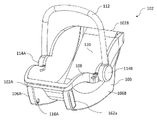
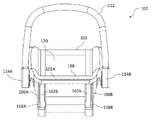
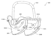
또 다른 구현예는 유아 카시트 시스템(100)에 관한 것이고, 유아 카시트 시스템은: 차량(500)으로 및 이로부터 유아를 운반하고 유아 카시트의 전면이 차량의 후방을 향하는 차량으로 유아를 안전하게 수송하기 위해, 전면(102A) 및 후면(102B)을 갖는 유아 카시트(102)로서, 무게 중심(330A)을 갖고: 운반 손잡이(112); 운반 손잡이를 유아 카시트의 제1 측에 부착하기 위한 제1 운반 손잡이 부착 메커니즘(114A); 및 운반 손잡이를 유아 카시트의 제2 측에 부착하기 위한 제2 운반 손잡이 부착 메커니즘(114B)을 포함하는, 상기 유아 카시트; 및 유아가 차량으로 수송하기 위해 유아 카시트에 있을 때 유아 카시트 분리 가능한 베이스(20)를 사용하지 않고 유아의 상단 위로 차량 안전벨트를 사용하지 않고 꽉 끼는 상태로, 및 유아 카시트의 전면이 차량의 후방을 향하는 차량의 차량 시트(50)에 유아 카시트를 직접적으로 고정하기 위해 유아 카시트에 결합된 앵커 시스템(104)으로서: 차량 시트의 제1 차량 앵커(52A)와 기계적으로 맞물리도록 제1 구속 지점(322A)에서 유아 카시트에 결합된 제1 유아 카시트 앵커(104A); 및 차량 시트의 제2 차량 앵커(52B)와 기계적으로 맞물리도록 제1 구속 지점과 상이한 제2 구속 지점(322B)에서 유아 카시트에 결합된 제2 유아 카시트 앵커(104B)로서, 제1 구속 지점 및 제2 구속 지점은 충돌 사건 동안 차량 시트의 등받이(56)로부터 멀어지는 유아 카시트의 후면의 회전을 상당히 완화하기 위해 적어도 유아 카시트의 무게 중심에 적어도 부분적으로 기초하여 유아 카시트에 대해 각각 배치되는, 상기 제1 유아 카시트 앵커 및 상기 제2 유아 카시트 앵커를 포함하는, 상기 앵커 시스템; 및 차량에 유아 카시트를 설치하는 동안 차량 시트의 등받이를 향한 유아 카시트의 후면의 회전을 상당히 완화하기 위해 유아 카시트의 전면에 근접하게 배치된 조정 풋(170)을 포함하고, 조정 풋은 차량 시트에 대한 꽉 끼임을 용이하게 하도록 차량 시트의 등받이 또는 시트 팬(58) 중 적어도 하나에 대해 조정 가능한 지렛대를 제공하기 위해 조정 가능한 신축 메커니즘(telescoping mechanism) 또는 조정 가능한 회전 메커니즘 중 적어도 하나를 포함한다.Another embodiment relates to an infant
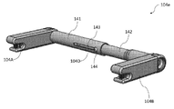
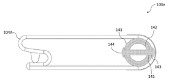
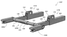
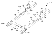
또 다른 구현예는 유아 카시트 시스템에 관한 것이고, 유아 카시트 시스템은 전면(102A) 및 후면(102B)을 갖는 유아 카시트(102)로서: 제1 시트 셸 레일(106A); 및 제2 시트 셸 레일(106B)을 포함하는, 상기 유아 카시트; 및 유아 카시트 분리 가능한 베이스(20)를 사용하지 않고 꽉 끼는 상태로 유아 카시트를 차량 시트(50)에 직접적으로 부착하기 위해 유아 카시트에 결합된 앵커 시스템(104)을 포함하고, 앵커 시스템은: 제1 시트 셸 레일 및 제2 시트 셸 레일을 통과하는 강성 교차 부재(104D); 차량 시트의 제1 차량 앵커(52A)와 기계적으로 맞물리도록 강성 교차 부재에 부착된 제1 유아 카시트 앵커(104A)로서, 강성 교차 부재에 의해 획정된 회전 축을 중심으로 회전 가능한, 상기 제1 유아 카시트 앵커; 및 차량 시트의 제2 차량 앵커(52B)와 기계적으로 맞물리도록 강성 교차 부재에 부착된 제2 유아 카시트 앵커(104B)로서, 강성 교차 부재에 의해 획정된 회전 축을 중심으로 회전 가능한, 상기 제2 유아 카시트 앵커를 포함한다.Another embodiment relates to an infant car seat system, the infant car seat system comprising: a first seat shell rail (106A); and a second seat shell rail (106B); and an anchor system (104) coupled to the infant car seat for directly attaching the infant car seat to the vehicle seat (50) in a tight fit condition without using the infant car seat detachable base (20), the anchor system comprising: a
또 다른 구현예는 유아 카시트 시스템에 관한 것이고, 유아 카시트 시스템은: 차량으로 및 이로부터 유아를 운반하고 유아 카시트의 전면이 차량의 후방을 향하는 차량으로 유아를 안전하게 수송하기 위해, 전면(102A) 및 후면(102B)을 갖는 유아 카시트(102)로서: 제1 만곡된 로커 바닥(107A)을 갖는 제1 시트 셸 레일(106A); 제2 만곡된 로커 바닥(107B)을 갖는 제2 시트 셸 레일(106B); 운반 손잡이(112); 운반 손잡이를 제1 시트 셸 레일에 부착하기 위한 제1 운반 손잡이 부착 메커니즘(114A); 및 운반 손잡이를 제2 시트 셸 레일에 부착하기 위한 제2 운반 손잡이 부착 메커니즘(114B)을 포함하는, 상기 유아 카시트; 및 유아 카시트 분리 가능한 베이스(20)를 사용하지 않고 꽉 끼는 상태로 차량의 차량 시트(50)에 유아 카시트를 직접적으로 고정하기 위해 유아 카시트에 결합된 앵커 시스템(104)을 포함하고, 앵커 시스템은: 유아 카시트에 영구적으로 부착된 적어도 하나의 벨트(104C)로서, 조정 가능한 길이를 갖고: 유아 카시트의 전면과 제1 운반 손잡이 부착 메커니즘 사이의 제1 시트 셸 레일의 제1 부분; 또는 유아 카시트의 전면과 제2 운반 손잡이 부착 메커니즘 사이의 제2 시트 셸 레일의 제1 부분 중 적어도 하나에 의해 기계적으로 구속되는, 상기 적어도 하나의 벨트; 차량 시트의 제1 차량 앵커(52A)와 기계적으로 맞물리도록 적어도 하나의 벨트에 부착된 제1 유아 카시트 앵커(104A); 및 차량 시트의 제2 차량 앵커(52B)와 기계적으로 맞물리도록 적어도 하나의 벨트에 부착된 제2 유아 카시트 앵커(104B)를 포함한다.Another embodiment relates to an infant car seat system, comprising: a front surface 102A and an infant car seat system comprising: a front surface 102A and An infant car seat (102) having a rear surface (102B), comprising: a first seat shell rail (106A) having a first curved rocker bottom (107A); a second seat shell rail 106B having a second curved rocker bottom 107B; carrying handle 112; a first carrying handle attachment mechanism 114A for attaching the carrying handle to the first seat shell rail; and a second carrying handle attachment mechanism (114B) for attaching the carrying handle to the second seat shell rail; and an anchor system 104 coupled to the infant car seat for directly fixing the infant car seat to the vehicle seat 50 of the vehicle in a tight fit state without using the infant car seat detachable base 20, the anchor system comprising: : at least one belt (104C) permanently attached to the infant car seat, having an adjustable length, comprising: a first portion of the first seat shell rail between the front of the infant car seat and the first carrying handle attachment mechanism; or at least one belt mechanically constrained by at least one of the first portion of the second seat shell rail between the front of the infant car seat and the second carrying handle attachment mechanism; a first infant car seat anchor 104A attached to the at least one belt to mechanically engage a first vehicle anchor 52A of the vehicle seat; and a second infant car seat anchor 104B attached to the at least one belt to mechanically engage the second vehicle anchor 52B of the vehicle seat.
또 다른 구현예는 유아 카시트 시스템에 관한 것이고, 유아 카시트 시스템은: 적어도 하나의 저장 영역(160A)을 포함하는 유아 카시트(102); 및 유아 카시트 분리 가능한 베이스(20)를 사용하지 않고 꽉 끼는 상태로 유아 카시트를 차량 시트(50)에 직접적으로 부착하기 위해 유아 카시트에 결합된 앵커 시스템(104)을 포함하고, 앵커 시스템은: 유아 카시트에 영구적으로 부착된 적어도 하나의 벨트(104C)로서, 조정 가능한 길이를 갖는, 상기 적어도 하나의 벨트; 차량 시트의 제1 차량 앵커(52A)와 기계적으로 맞물리도록 적어도 하나의 벨트에 부착된 제1 유아 카시트 앵커(104A); 및 차량 시트의 제2 차량 앵커(52B)와 기계적으로 맞물리도록 적어도 하나의 벨트에 부착된 제2 유아 카시트 앵커(104B)를 포함하고, 유아 카시트의 적어도 하나의 저장 영역은 앵커 시스템이 유아 카시트를 차량 시트에 부착하기 위해 사용되지 않을 때 제1 유아 카시트 앵커 및 제2 유아 카시트 앵커 중 적어도 하나의 저장을 용이하게 한다.Another embodiment relates to an infant car seat system, comprising: an
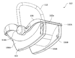
또 다른 구현예는 유아 카시트 시스템에 관한 것이고, 유아 카시트 시스템은: 전면(102A) 및 후면(102B)을 갖는 유아 카시트(102)로서: 제1 시트 셸 레일(106A); 제2 시트 셸 레일(106B); 및 제1 시트 셸 레일과 제2 시트 셸 레일 사이에서 유아 카시트의 전면에 근접하게 배치된 조정 풋(170)을 포함하는, 상기 유아 카시트; 및 유아 카시트 분리 가능한 베이스(20)를 사용하지 않고 꽉 끼는 상태로 유아 카시트를 차량 시트(50)에 직접적으로 부착하기 위해 유아 카시트에 결합된 앵커 시스템(104)을 포함하고, 앵커 시스템은: 차량 시트의 제1 차량 앵커(52A)와 기계적으로 맞물리는 제1 유아 카시트 앵커(104A); 및 차량 시트의 제2 차량 앵커(52B)와 기계적으로 맞물리는 제2 유아 카시트 앵커(104B)를 포함한다.Another embodiment relates to an infant car seat system, comprising: an infant car seat (102) having a front (102A) and a rear (102B): a first seat shell rail (106A); a second
또 다른 구현예는 유아 카시트 시스템에 관한 것이고, 유아 카시트 시스템은: 유아 카시트(102); 유아 카시트 분리 가능한 베이스(20)를 사용하지 않고 꽉 끼는 상태로 유아 카시트를 차량 시트(50)에 직접적으로 부착하기 위해 유아 카시트에 결합된 앵커 시스템(104)으로서: 차량 시트의 제1 차량 앵커(52A)와 기계적으로 맞물리는 제1 유아 카시트 앵커(104A); 및 차량 시트의 제2 차량 앵커(52B)와 기계적으로 맞물리는 제2 유아 카시트 앵커(104C)를 포함하는, 상기 앵커 시스템; 및 적어도 하나의 액추에이터의 단일 작동 시에 제1 차량 앵커와의 기계적 맞물림으로부터 제1 유아 카시트 앵커 및 제2 차량 앵커와의 기계적 맞물림으로부터 제2 유아 카시트 앵커 둘 다를 해제하기 위해, 유아 카시트 및 앵커 시스템에 결합된 적어도 하나의 액추에이터(180)를 포함한다.Another embodiment relates to an infant car seat system, comprising: an infant car seat (102); An anchor system (104) coupled to an infant car seat for directly attaching the infant car seat to the vehicle seat (50) in a tight fit condition without using the infant car seat detachable base (20), comprising: a first vehicle anchor of the vehicle seat ( 52A) a first infant car seat anchor mechanically engaged with the
또 다른 구현예는 유아 카시트(102)에 관한 것이고, 유아 카시트는: 제1 평평한 바닥을 갖는 제1 시트 셸 레일(106A); 제1 시트 셸 레일에 결합된 제1 연장 가능한 만곡된 로커(190A); 제2 평평한 바닥을 갖는 제2 시트 셸 레일(106B); 및 제2 시트 셸 레일에 결합된 제2 연장 가능한 만곡된 로커(190B)를 포함한다.Another embodiment relates to an
하기에 더 상세하게 논의된 상기 개념 및 부가적인 개념의 모든 조합(이러한 개념이 상호 모순되지 않으면)이 본 명세서에 개시된 독창적인 주제의 일부인 것으로서 고려됨을 이해해야 한다. 특히, 본 발명의 끝에 나타나는 청구된 주제의 모든 조합은 본 명세서에 개시된 독창적인 주제의 일부인 것으로서 고려된다. 또한, 참조에 의해 원용된 임의의 개시에 또한 나타날 수 있는 본 명세서에서 명시적으로 이용된 전문용어가 본 명세서에 개시된 특정한 개념과 가장 일치하는 의미와 부합되어야 함을 이해해야 한다.It is to be understood that all combinations of the above and additional concepts discussed in greater detail below (provided such concepts do not contradict each other) are considered to be part of the inventive subject matter disclosed herein. In particular, all combinations of claimed subject matter appearing at the end of the invention are contemplated as being part of the inventive subject matter disclosed herein. It is also to be understood that terminology explicitly employed herein, which may also appear in any disclosure incorporated by reference, is to be accorded a meaning most consistent with the particular concept disclosed herein.
숙련자는 도면이 주로 예시 목적을 위한 것이며 본 명세서에서 설명된 독창적인 주제의 범위를 제한하도록 의도되지 않는다는 것을 이해할 것이다. 도면은 반드시 축척대로 도시되지 않는다. 일부 사례에서, 본 명세서에 개시된 독창적인 주제의 다양한 양태는 상이한 특징의 이해를 용이하게 하기 위해 도면에서 과장되거나 확대되어 도시될 수 있다. 도면에서, 유사한 참조 문자는 일반적으로, 유사한 특징부(예컨대, 기능적으로 유사하고/하거나 구조적으로 유사한 요소)를 언급한다.
도 1a는 종래의 유아 카시트 시스템을 도시한 도면.
도 1b는 도 1a의 종래의 유아 카시트 시스템의 분리 가능한 차량 설치 베이스를 도시한 도면.
도 1c는 도 1b에 도시된 분리 가능한 차량 설치 베이스에서 이용될 수 있는 벨트 앵커의 일례를 도시한 도면.
도 1d는 도 1b에 도시된 분리 가능한 차량 설치 베이스에서 이용될 수 있는 강성 앵커의 일례를 도시한 도면.
도 2a는 본 발명에 개시된 다양한 예시적인 구현에 따른 독창적인 유아 카시트 시스템이 분리 가능한 차량 설치 베이스를 사용하지 않고 차량 안전벨트를 사용하지 않고 설치되는 차량을 도시한 도면.
도 2b는 하나의 독창적인 구현에 따른, 도 2a의 차량의 차량 시트에 결합된 유아 카시트 시스템의 일례를 도시한 도면.
도 2c는 도 2a의 유아 카시트 시스템이 맞물리는 전형적인 차량 시트 및 차량 하부 앵커의 다이어그램을 도시한 도면.
도 2d는 도 2c의 차량 시트에서 전형적인 차량 시트 하부 앵커의 다이어그램을 도시한 도면.
도 2e는 또 다른 독창적인 구현에 따른 유아 카시트 시스템의 일례를 도시한 도면.
도 2F-1 및 도 2F-2는 다른 독창적인 구현에 따른 유아 카시트 시스템의 예를 도시한 도면.
도 3a는 도 2a에 도시된 것과 유사한 유아 카시트 시스템의 사시도이고, 여기서 의인화 테스트 디바이스(ATD)는 시스템의 유아 카시트에 배치된다.
도 3b-1, 도 3b-2, 도 3b-3 및 도 3b-4는 유아 카시트 자체의 무게 중심의 변화, 및 유아 카시트와 유아 카시트에 배치된 상이한 ATD의 조합을 표현하는 각각의 도면.
도 3c는 충돌 사건 이전("충돌 전" 조건)의 도 3a의 유아 카시트 시스템의 측면도.
도 3d는 차량 시트 및 유아 카시트 시스템에 충돌력이 가해진 후의 도 3c의 동일한 측면도.
도 3e는 유아 카시트의 앵커 시스템의 기계적 구속 지점을 배치하기 위해 사용된 기준 평면의 근사치를 도시하는 도 3a의 유아 카시트 시스템의 측면도.
도 4a는 충돌 테스트를 받고 있는 도 3a의 유아 카시트 시스템에 대응하는 일 예시적인 유아 카시트 시스템의 측면도이다. 앵커 시스템은 위치(P1)에서 유아 카시트에 결합된 것으로 도시된다.
도 4b는 충돌 테스트를 받고 있는 도 3a의 유아 카시트 시스템에 대응하는 일 예시적인 유아 카시트 시스템의 측면도이다. 앵커 시스템은 P1보다 유아 카시트를 따라 더 높은 위치(P2)에서 유아 카시트에 결합된 것으로 도시된다.
도 4c는 충돌 테스트를 받고 있는 도 3a의 유아 카시트 시스템에 대응하는 일 예시적인 유아 카시트 시스템의 측면도이다. 앵커 시스템은 P2보다 유아 카시트를 따라 더 높은 위치(P3)에서 유아 카시트에 결합된 것으로 도시된다.
도 5는 통합된 앵커 시스템, 해제 액추에이터, 저장 격실, 및 조정 풋을 포함하는 또 다른 예시적인 구현에 따른 독창적인 유아 카시트 시스템을 도시한 도면.
도 6은 강성 앵커 시스템을 갖는 일 예시적인 유아 카시트 시스템을 도시한 도면.
도 7a는 도 6의 유아 카시트 시스템의 변형을 도시한 도면이고, 여기서 시트 앵커는 시트 앵커를 작동시키기 위한 트위스트 손잡이를 포함한다.
도 7b는 도 7a의 시트 앵커의 확대도.
도 8a는 도 6의 유아 카시트 시스템의 변형을 도시한 도면이고, 여기서 시트 앵커는 시트 앵커를 작동시키는 푸시 버튼 메커니즘을 포함한다.
도 8b는 도 8a의 시트 앵커의 확대도.
도 9는 회전 가능하고 병진 이동식으로 조정 가능한 강성 앵커 시스템을 갖는 일 예시적인 유아 카시트 시스템을 도시한 도면.
도 10a는 강성 앵커가 강성 교차 부재에 대해 병진 이동식으로 조정 가능한 일 예시적인 앵커 시스템의 분해도.
도 10b는 도 10a의 조립된 앵커 시스템의 사시도.
도 11은 강성 앵커 시스템 및 유아 카시트의 후면에 장착된 해제 액추에이터를 갖는 일 예시적인 유아 카시트 시스템을 도시한 도면.
도 12는 강성 앵커 시스템 및 유아 카시트의 운반 손잡이에 장착된 해제 액추에이터를 갖는 일 예시적인 유아 카시트 시스템을 도시한 도면.
도 13은 앵커 시스템에 시트 앵커를 저장하기 위해 측 저장 격실을 갖는 일 예시적인 유아 카시트 시스템을 도시한 도면.
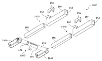
도 14a는 신축 앵커 시스템 및 측 저장 격실을 갖는 일 예시적인 유아 카시트 시스템의 상단 사시도를 도시한 도면이다. 앵커 시스템은 저장된 위치에 도시된다.
도 14b는 도 14a의 유아 카시트 시스템의 상단 사시도이고, 여기서 앵커 시스템은 동작 위치에 있는 것으로 도시된다.
도 14c는 도 14b의 유아 카시트 시스템의 저면 사시도.
도 14d는 도 14b의 유아 카시트 시스템의 평면도.
도 14e는 도 14b의 유아 카시트 시스템의 저면도.
도 14f는 도 14b의 유아 카시트 시스템의 정면도.
도 14g는 도 14b의 유아 카시트 시스템의 우측면도.
도 15a는 도 14a의 유아 카시트 시스템에서의 유아 카시트의 상단 사시도.
도 15b는 도 15a의 유아 카시트의 저면 사시도.
도 15c는 도 15a의 유아 카시트의 평면도.
도 15d는 도 15a의 유아 카시트의 저면도.
도 15e는 도 15a의 유아 카시트의 정면도.
도 15f는 도 15a의 유아 카시트의 우측면도.
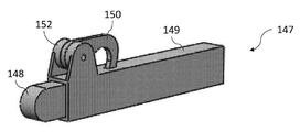
도 16a는 저장된 위치에 있는 도 14a의 앵커 시스템의 상단 사시도.
도 16b는 동작 위치에 있는 도 16a의 앵커 시스템의 상단 사시도.
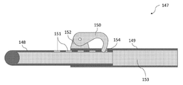
도 16c는 도 16a의 앵커 시스템의 평면도.
도 16d는 도 16a의 앵커 시스템의 상단 분해 사시도.
도 16e는 도 16c의 평면(A-A)에 대응하는 앵커 시스템의 단면도.
도 17은 앵커 시스템에 시트 앵커를 저장하기 위한 전면 저장 격실을 갖는 일 예시적인 유아 카시트 시스템을 도시한 도면.
도 18a는 신축 앵커 시스템 및 전면 저장 격실을 갖는 일 예시적인 유아 카시트 시스템의 상단 사시도이다. 앵커 시스템은 저장된 위치에 도시된다.
도 18b는 도 18a의 유아 카시트 시스템의 상단 사시도이고, 여기서 앵커 시스템은 동작 위치에 도시된다.
도 18c는 도 18b의 유아 카시트 시스템의 저면 사시도.
도 18d는 도 18b의 유아 카시트 시스템의 평면도.
도 18e는 도 18b의 유아 카시트 시스템의 저면도.
도 18f는 도 18b의 유아 카시트 시스템의 정면도.
도 18g는 도 18b의 유아 카시트 시스템의 우측면도.
도 19a는 도 18a의 유아 카시트 시스템에서의 유아 카시트의 상단 사시도.
도 19b는 도 19a의 유아 카시트의 저면 사시도.
도 19c는 도 19a의 유아 카시트의 평면도.
도 19d는 도 19a의 유아 카시트의 저면도.
도 19e는 도 19a의 유아 카시트의 정면도.
도 19f는 도 19a의 유아 카시트의 우측면도.
도 20은 신축적 레일 가이드를 갖는 앵커 시스템 및 전면 저장 격실을 갖는 일 예시적인 유아 카시트 시스템을 도시한 도면.
도 21a는 신축적 레일 가이드 및 전면 저장 격실을 갖는 신축 앵커 시스템을 갖는 일 예시적인 유아 카시트 시스템의 상단 사시도이다. 앵커 시스템은 저장된 위치에 도시된다.
도 21b는 도 21a의 유아 카시트 시스템의 상단 사시도이고, 여기서 앵커 시스템은 동작 위치에 도시된다.
도 21c는 도 21a의 유아 카시트 시스템의 저면 사시도.
도 21d는 도 21a의 유아 카시트 시스템의 평면도.
도 21e는 도 21a의 유아 카시트 시스템의 저면도.
도 21f는 도 21a의 유아 카시트 시스템의 정면도.
도 21g는 도 21a의 유아 카시트 시스템의 우측면도.
도 21h는 도 21d의 평면(A-A)에 대응하는 유아 카시트 시스템의 단면도.
도 22a는 도 21a의 유아 카시트 시스템에서의 유아 카시트의 상단 사시도.
도 22b는 도 22a의 유아 카시트의 저면 사시도.
도 22c는 도 22a의 유아 카시트의 평면도.
도 22d는 도 22a의 유아 카시트의 저면도.
도 22e는 도 22a의 유아 카시트의 정면도.
도 22f는 도 22a의 유아 카시트의 우측면도.
도 23a는 도 21a의 유아 카시트 시스템의 앵커 시스템의 상단 사시도.
도 23b는 도 23a의 앵커 시스템의 평면도이고, 여기서 신축적 레일 가이드는 수축된 위치에 있다.
도 23c는 도 23a의 앵커 시스템의 상단 분해 사시도.
도 23d는 도 23a의 앵커 시스템의 저면 분해 사시도.
도 23e는 수축된 위치에 있는 도 23a의 앵커 시스템에서 신축적 레일 가이드의 상단 사시도.
도 23f는 연장된 위치에 있는 도 23a의 앵커 시스템에서 신축적 레일 가이드의 상단 사시도.
도 23g는 도 23b의 평면(A-A)에 대응하는 도 23f의 신축적 레일 가이드의 단면도.
도 24a는 도 6의 유아 카시트 시스템에 대응하는 시제품 유아 카시트 시스템의 좌측면도.
도 24b는 도 24a의 유아 카시트 시스템의 상단 사시도.
도 24c는 도 24a의 유아 카시트 시스템의 우측면도.
도 24d는 도 24a의 유아 카시트 시스템의 저면 사시도.
도 25a는 차량 시트에 장착된 도 11의 유아 카시트 시스템에 대응하는 해제 액추에이터를 갖는 시제품 유아 카시트 시스템의 상단 좌측 사시도.
도 25b는 도 25a의 유아 카시트 시스템에서의 앵커 시스템 및 차량 시트 앵커의 확대도.
도 25c는 차량 시트로부터 제거된 도 25a의 유아 카시트 시스템의 상단 좌측 사시도.
도 25d는 도 25c의 유아 카시트 시스템의 상단 전면 좌측 사시도.
도 25e는 도 25c의 유아 카시트 시스템의 상단 전면 사시도.
도 26은 벨트가 유아 카시트의 각각의 시트 셸 레일의 개구를 통해 라우팅되는 벨트식 앵커 시스템을 갖는 일 예시적인 유아 카시트 시스템을 도시한 도면.
도 27은 각각의 시트 앵커가 유아 카시트의 시트 셸 레일의 개구를 통해 라우팅되는 대응하는 벨트를 갖는 벨트식 앵커 시스템을 갖는 일 예시적인 유아 카시트 시스템을 도시한 도면.
도 28은 벨트가 차량 시트 경로를 통해 라우팅되는 벨트식 앵커 시스템을 갖는 일 예시적인 유아 카시트 시스템을 도시한 도면.
도 29는 유아 카시트의 각각의 측에 테더를 포함하는 도 28의 유아 카시트 시스템의 변형을 도시한 도면.
도 30은 각각의 시트 앵커가 차량 시트 경로의 일부를 통해 라우팅되는 대응하는 벨트를 갖는 벨트식 앵커 시스템을 갖는 일 예시적인 유아 카시트 시스템을 도시한 도면.
도 31은 각각의 시트 앵커가 유아 카시트의 시트 림에 부착되는 대응하는 벨트를 갖는 벨트식 앵커 시스템을 갖는 일 예시적인 유아 카시트 시스템을 도시한 도면.
도 32는 벨트가 시트 셸과 시트 패드 사이에서 유아 카시트를 통해 라우팅되는 벨트식 앵커 시스템을 갖는 일 예시적인 유아 카시트 시스템을 도시한 도면.
도 33은 각각의 시트 앵커가 유아 카시트의 각각의 측에 배치된 캠 잠금 메커니즘을 통해 조여지는 대응하는 벨트를 갖는 벨트식 앵커 시스템을 갖는 일 예시적인 유아 카시트 시스템을 도시한 도면.
도 34는 벨트식 앵커 시스템 및 캠 잠금 풀리 메커니즘(cam lock pulley mechanism)을 갖는 일 예시적인 유아 카시트 시스템을 도시한 도면이고, 여기서 캠 잠금 풀리 메커니즘의 스트랩은 유아 카시트에 고정되고 벨트식 앵커 시스템의 벨트 주위를 감싼다.
도 35는 벨트식 앵커 시스템 및 캠 잠금 풀리 메커니즘을 갖는 일 예시적인 유아 카시트 시스템을 도시한 도면이고, 여기서 캠 잠금 풀리 메커니즘의 스트랩은 벨트식 앵커 시스템의 벨트 주위를 감싸는 루프를 형성한다.
도 36은 벨트식 앵커 시스템 및 캠 잠금 풀리 메커니즘을 갖는 일 예시적인 유아 카시트 시스템을 도시한 도면이고, 여기서 캠 잠금 풀리 메커니즘의 스트랩은 벨트식 앵커 시스템의 벨트에 직접적으로 스티칭된다.
도 37은 각각의 시트 앵커가 대응하는 벨트 및 대응하는 캠 잠금 메커니즘을 갖는 벨트식 앵커 시스템을 갖는 일 예시적인 유아 카시트 시스템을 도시한 도면.
도 38은 각각의 시트 앵커가 단일 캠 잠금 메커니즘에 함께 스티칭되는 대응하는 벨트를 갖는 벨트식 앵커 시스템을 갖는 일 예시적인 유아 카시트 시스템을 도시한 도면.
도 39a는 벨트식 앵커 시스템 및 통합된 래칫 메커니즘(ratcheting mechanism)을 갖는 일 예시적인 유아 카시트 시스템을 도시한 도면.
도 39b는 래칫 메커니즘이 작동되는 도 39a의 유아 카시트 시스템을 도시한 도면.
도 40은 벨트식 앵커 시스템 및 스프링 보조 리트랙터(spring-assisted retractor)와 스풀(spool)을 갖는 일 예시적인 유아 카시트 시스템을 도시한 도면.
도 41a는 벨트식 앵커 시스템 및 유아 카시트의 후면에 장착된 해제 액추에이터를 갖는 일 예시적인 유아 카시트 시스템을 도시한 도면.
도 41b는 도 41a의 유아 카시트 시스템의 해제 액추에이터의 다이어그램을 도시한 도면.
도 42는 벨트식 앵커 시스템 및 유아 카시트의 운반 손잡이에 장착된 해제 액추에이터를 갖는 일 예시적인 유아 카시트 시스템을 도시한 도면.
도 43은 벨트식 앵커 시스템 및 유아 카시트의 측에 장착된 해제 액추에이터를 갖는 일 예시적인 유아 카시트 시스템을 도시한 도면.
도 44는 도 33의 유아 카시트 시스템에 대응하는 벨트식 앵커 시스템 및 앵커 시스템에서 벨트의 웨빙(webbing) 내부에 라우팅된 케이블이 있는 해제 액추에이터를 갖는 일 예시적인 유아 카시트 시스템을 도시한 도면.
도 45는 앵커 시스템에 시트 앵커를 저장하기 위해 유아 카시트에 벨트식 앵커 시스템 및 측 저장 격실을 갖는 일 예시적인 유아 카시트 시스템을 도시한 도면.
도 46은 앵커 시스템에 시트 앵커를 저장하기 위해 유아 카시트의 로커 공동에 위치된 저장 격실 및 벨트식 앵커 시스템을 갖는 일 예시적인 유아 카시트 시스템을 도시한 도면.
도 47은 앵커 시스템에 시트 앵커를 저장하기 위해 유아 카시트의 측 외부 측에 배치된 하나 이상의 핀 및 벨트식 앵커 시스템을 갖는 일 예시적인 유아 카시트 시스템을 도시한 도면.
도 48은 앵커 시스템에 시트 앵커를 저장하기 위해 시트 팬 아래에 및 각각의 시트 셸 레일 사이에 위치된 전면 저장 격실 및 벨트식 앵커 시스템을 갖는 일 예시적인 유아 카시트 시스템을 도시한 도면.
도 49는 앵커 시스템에 각각의 시트 앵커를 저장하기 위해 각각의 시트 셸 레일에 위치된 각각의 전면 저장 격실 및 벨트식 앵커 시스템을 갖는 일 예시적인 유아 카시트 시스템을 도시한 도면.
도 50은 차량 시트에 대한 유아 카시트의 기대기 각도(recline angle)를 조정하기 위한 조정 풋을 갖는 일 예시적인 유아 카시트 시스템의 우측면도.
도 51a는 신축 조정 풋을 갖는 일 예시적인 유아 카시트 시스템을 도시한 도면.
도 51b는 도 51a의 유아 카시트 시스템의 저면도이고, 여기서 조정 풋은 또한, 앵커 시스템에서 하나 이상의 시트 앵커를 위한 저장장치로서 사용된다.
도 52는 회전 가능한 조정 풋을 갖는 일 예시적인 유아 카시트 시스템을 도시한 도면.
도 53은 유아 카시트의 각각의 시트 셸 레일에 배치된 튀어나온 로커 풋(pop out rocker foot)을 갖는 일 예시적인 유아 카시트 시스템을 도시한 도면.
도 54는 더 큰 휴대성을 위해 유아 카시트로부터 분리된 미니 베이스를 포함하는 고정 시스템을 갖는 일 예시적인 유아 카시트 시스템을 도시한 도면.
도 55a, 도 55b, 도 55c 및 도 56은 본 명세서에 개시된 다양한 구현에 따른 유아 카시트 시스템을 포함하는 차량 호출/차량 공유 방법에 관한, 앱으로부터의 흐름도, 및 스크린샷을 도시한 도면.Those skilled in the art will understand that the drawings are primarily for illustrative purposes and are not intended to limit the scope of the inventive subject matter described herein. The drawings are not necessarily drawn to scale. In some instances, various aspects of the inventive subject matter disclosed herein may be shown exaggerated or enlarged in the drawings to facilitate understanding of the different features. In the drawings, like reference characters generally refer to like features (eg, functionally similar and/or structurally similar elements).
Figure 1a is a view showing a conventional infant car seat system.
Figure 1b is a view showing a removable vehicle installation base of the conventional infant car seat system of Figure 1a.
Fig. 1c shows an example of a belt anchor that can be used in the detachable vehicle installation base shown in Fig. 1b;
FIG. 1D shows an example of a rigid anchor that may be used in the detachable vehicle mounting base shown in FIG. 1B ;
FIG. 2A is a view showing a vehicle in which an inventive infant car seat system according to various exemplary implementations disclosed in the present invention is installed without using a detachable vehicle installation base and without using a vehicle seat belt; FIG.
FIG. 2B shows an example of an infant car seat system coupled to a vehicle seat of the vehicle of FIG. 2A , according to one inventive implementation;
FIG. 2C is a diagram of a typical vehicle seat and under vehicle anchor to which the infant car seat system of FIG. 2A engages; FIG.
FIG. 2D shows a diagram of a typical vehicle seat underside anchor in the vehicle seat of FIG. 2C ; FIG.
Figure 2e is a view showing an example of the infant car seat system according to another original implementation.
2F-1 and 2F-2 are views showing an example of an infant car seat system according to another inventive implementation.
3A is a perspective view of an infant car seat system similar to that shown in FIG. 2A , wherein an anthropomorphic test device (ATD) is disposed in the infant car seat of the system;
3B-1, 3B-2, 3B-3, and 3B-4 are respective views illustrating a change in the center of gravity of the infant car seat itself, and a combination of the infant car seat and the different ATDs disposed in the infant car seat.
3C is a side view of the infant car seat system of FIG. 3A prior to the crash event (“pre-crash” condition);
Fig. 3D is the same side view of Fig. 3C after a crash force is applied to the vehicle seat and the infant car seat system;
Fig. 3E is a side view of the infant car seat system of Fig. 3A showing an approximation of a reference plane used to position the mechanical restraint points of the anchor system of the infant car seat;
4A is a side view of an exemplary infant car seat system corresponding to the infant car seat system of FIG. 3A being subjected to a crash test; The anchor system is shown coupled to the infant car seat in position P1 .
4B is a side view of an exemplary infant car seat system corresponding to the infant car seat system of FIG. 3A being subjected to a crash test; The anchor system is shown coupled to the infant car seat at a higher position P2 along the infant car seat than P1.
4C is a side view of an exemplary infant car seat system corresponding to the infant car seat system of FIG. 3A being subjected to a crash test; The anchor system is shown coupled to the infant car seat at a higher position P3 along the infant car seat than P2.
5 illustrates an inventive infant car seat system according to another exemplary implementation including an integrated anchor system, a release actuator, a storage compartment, and an adjustment foot;
6 illustrates an exemplary infant car seat system having a rigid anchor system;
Fig. 7a is a view showing a variant of the infant car seat system of Fig. 6, wherein the seat anchor includes a twist handle for actuating the seat anchor;
Fig. 7b is an enlarged view of the seat anchor of Fig. 7a;
Fig. 8a shows a variant of the infant car seat system of Fig. 6, wherein the seat anchor includes a push button mechanism for actuating the seat anchor;
Fig. 8b is an enlarged view of the seat anchor of Fig. 8a;
9 illustrates an exemplary infant car seat system having a rotatable and translatably adjustable rigid anchor system;
10A is an exploded view of an exemplary anchor system in which the rigid anchor is translationally adjustable relative to the rigid cross member.
Fig. 10B is a perspective view of the assembled anchor system of Fig. 10A;
11 illustrates an exemplary infant car seat system having a rigid anchor system and a release actuator mounted to the back of the infant car seat;
12 depicts an exemplary infant car seat system having a rigid anchor system and a release actuator mounted to the carrying handle of the infant car seat;
13 illustrates an exemplary infant car seat system having a side storage compartment for storing seat anchors in the anchor system.
14A is a top perspective view of an exemplary infant car seat system having a telescoping anchor system and a side storage compartment. The anchor system is shown in a stored location.
14B is a top perspective view of the infant car seat system of FIG. 14A , wherein the anchor system is shown in an operative position;
Figure 14c is a bottom perspective view of the infant car seat system of Figure 14b.
14D is a plan view of the infant car seat system of FIG. 14B;
14E is a bottom view of the infant car seat system of FIG. 14B;
Fig. 14f is a front view of the infant car seat system of Fig. 14b;
14G is a right side view of the infant car seat system of FIG. 14B;
Fig. 15A is a top perspective view of the infant car seat in the infant car seat system of Fig. 14A;
Figure 15b is a bottom perspective view of the infant car seat of Figure 15a.
Fig. 15c is a plan view of the infant car seat of Fig. 15a;
Fig. 15D is a bottom view of the infant car seat of Fig. 15A;
Fig. 15E is a front view of the infant car seat of Fig. 15A;
Fig. 15f is a right side view of the infant car seat of Fig. 15a;
Fig. 16A is a top perspective view of the anchor system of Fig. 14A in a stored position;
Fig. 16B is a top perspective view of the anchor system of Fig. 16A in an operative position;
Fig. 16c is a plan view of the anchor system of Fig. 16a;
Fig. 16D is a top exploded perspective view of the anchor system of Fig. 16A;
Fig. 16e is a cross-sectional view of the anchor system corresponding to plane AA of Fig. 16c;
17 illustrates an exemplary infant car seat system having a front storage compartment for storing seat anchors in the anchor system.
18A is a top perspective view of an exemplary infant car seat system having a telescoping anchor system and a front storage compartment. The anchor system is shown in a stored location.
FIG. 18B is a top perspective view of the infant car seat system of FIG. 18A , wherein the anchor system is shown in an operative position;
Figure 18c is a bottom perspective view of the infant car seat system of Figure 18b.
18D is a plan view of the infant car seat system of FIG. 18B;
18E is a bottom view of the infant car seat system of FIG. 18B;
18f is a front view of the infant car seat system of FIG. 18b;
18G is a right side view of the infant car seat system of FIG. 18B;
19A is a top perspective view of the infant car seat in the infant car seat system of FIG. 18A;
19B is a bottom perspective view of the infant car seat of FIG. 19A;
19C is a plan view of the infant car seat of FIG. 19A;
19D is a bottom view of the infant car seat of FIG. 19A;
19E is a front view of the infant car seat of FIG. 19A;
19F is a right side view of the infant car seat of FIG. 19A;
20 depicts an exemplary infant car seat system having an anchor system with telescoping rail guides and a front storage compartment.
21A is a top perspective view of an exemplary infant car seat system having a telescoping anchor system with telescoping rail guides and a front storage compartment. The anchor system is shown in a stored location.
FIG. 21B is a top perspective view of the infant car seat system of FIG. 21A , wherein the anchor system is shown in an operative position;
Figure 21c is a bottom perspective view of the infant car seat system of Figure 21a.
Fig. 21D is a plan view of the infant car seat system of Fig. 21A;
Fig. 21E is a bottom view of the infant car seat system of Fig. 21A;
Figure 21f is a front view of the infant car seat system of Figure 21a.
21G is a right side view of the infant car seat system of FIG. 21A;
Figure 21h is a cross-sectional view of the infant car seat system corresponding to the plane (AA) of Figure 21d.
22A is a top perspective view of the infant car seat in the infant car seat system of FIG. 21A;
22B is a bottom perspective view of the infant car seat of FIG. 22A;
22C is a plan view of the infant car seat of FIG. 22A;
22D is a bottom view of the infant car seat of FIG. 22A;
22E is a front view of the infant car seat of FIG. 22A;
22F is a right side view of the infant car seat of FIG. 22A;
Fig. 23A is a top perspective view of the anchor system of the infant car seat system of Fig. 21A;
23B is a top view of the anchor system of FIG. 23A , wherein the telescoping rail guide is in a retracted position;
Fig. 23C is a top exploded perspective view of the anchor system of Fig. 23A;
Fig. 23D is a bottom exploded perspective view of the anchor system of Fig. 23A;
Fig. 23E is a top perspective view of the telescoping rail guide in the anchor system of Fig. 23A in a retracted position;
23F is a top perspective view of the telescoping rail guide in the anchor system of FIG. 23A in an extended position;
Fig. 23G is a cross-sectional view of the telescoping rail guide of Fig. 23F corresponding to plane AA of Fig. 23B;
24A is a left side view of a prototype infant car seat system corresponding to the infant car seat system of FIG.
Fig. 24B is a top perspective view of the infant car seat system of Fig. 24A;
Fig. 24c is a right side view of the infant car seat system of Fig. 24a;
24D is a bottom perspective view of the infant car seat system of FIG. 24A;
25A is a top left perspective view of a prototype infant car seat system having a release actuator corresponding to the infant car seat system of FIG. 11 mounted to a vehicle seat;
25B is an enlarged view of an anchor system and a vehicle seat anchor in the infant car seat system of FIG. 25A ;
25C is a top left perspective view of the infant car seat system of FIG. 25A removed from the vehicle seat;
Figure 25d is a top front left perspective view of the infant car seat system of Figure 25c.
Fig. 25E is a top front perspective view of the infant car seat system of Fig. 25C;
26 illustrates an exemplary infant car seat system having a belted anchor system in which the belt is routed through an opening in each seat shell rail of the infant car seat;
27 depicts an exemplary infant car seat system having a belted anchor system with each seat anchor having a corresponding belt routed through an opening in the seat shell rail of the infant car seat;
28 depicts an exemplary infant car seat system having a belted anchor system in which the belt is routed through a vehicle seat path.
FIG. 29 shows a variant of the infant car seat system of FIG. 28 including tethers on each side of the infant car seat;
30 depicts an exemplary infant car seat system having a belted anchor system with each seat anchor having a corresponding belt routed through a portion of a vehicle seat path.
31 illustrates an exemplary infant car seat system having a belted anchor system with each seat anchor having a corresponding belt attached to the seat rim of the infant car seat;
32 depicts an exemplary infant car seat system having a belted anchor system in which the belt is routed through the infant car seat between the seat shell and the seat pad.
33 depicts an exemplary infant car seat system having a belted anchor system with each seat anchor having a corresponding belt tightened through a cam lock mechanism disposed on each side of the infant car seat;
34 is a diagram illustrating an exemplary infant car seat system having a belted anchor system and a cam lock pulley mechanism, wherein the straps of the cam lock pulley mechanism are secured to the infant car seat and the belted anchor system wrap around the belt
35 illustrates an exemplary infant car seat system having a belted anchor system and a cam lock pulley mechanism, wherein the straps of the cam lock pulley mechanism form a loop that wraps around the belt of the belted anchor system.
36 is a diagram illustrating an exemplary infant car seat system having a belted anchor system and a cam lock pulley mechanism, wherein the straps of the cam lock pulley mechanism are stitched directly to the belt of the belted anchor system.
37 depicts an exemplary infant car seat system having a belted anchor system in which each seat anchor has a corresponding belt and a corresponding cam lock mechanism;
38 depicts an exemplary infant car seat system having a belted anchor system with each seat anchor having a corresponding belt stitched together to a single cam lock mechanism.
39A depicts an exemplary infant car seat system having a belted anchor system and an integrated ratcheting mechanism;
Fig. 39B shows the infant car seat system of Fig. 39A with the ratchet mechanism activated;
40 depicts an exemplary infant car seat system having a belted anchor system and a spring-assisted retractor and spool.
41A illustrates an exemplary infant car seat system having a belted anchor system and a release actuator mounted to the back of the infant car seat;
FIG. 41B is a diagram of a release actuator of the infant car seat system of FIG. 41A ;
42 depicts an exemplary infant car seat system having a belted anchor system and a release actuator mounted to the carrying handle of the infant car seat;
43 depicts an exemplary infant car seat system having a belted anchor system and a release actuator mounted to the side of the infant car seat.
44 shows an exemplary infant car seat system having a belted anchor system corresponding to the infant car seat system of FIG. 33 and a release actuator with cables routed inside the webbing of the belt in the anchor system;
45 illustrates an exemplary infant car seat system having a belted anchor system and side storage compartments in an infant car seat for storing seat anchors in the anchor system;
46 depicts an exemplary infant car seat system having a belted anchor system and a storage compartment positioned in a locker cavity of the infant car seat for storing seat anchors in the anchor system.
47 depicts an exemplary infant car seat system having one or more pins and belted anchor systems disposed on the outer side of the infant car seat for storing seat anchors in the anchor system.
48 illustrates an exemplary infant car seat system having a front storage compartment and a belted anchor system positioned below the seat pan and between each seat shell rail for storing seat anchors in the anchor system.
49 depicts an exemplary infant car seat system having a respective front storage compartment and a belted anchor system positioned on each seat shell rail for storing respective seat anchors in the anchor system.
50 is a right side view of an exemplary infant car seat system having an adjustment foot for adjusting the recline angle of the infant car seat relative to the vehicle seat;
51A illustrates an exemplary infant car seat system with telescoping feet.
FIG. 51B is a bottom view of the infant car seat system of FIG. 51A , wherein the adjustment foot is also used as a storage device for one or more seat anchors in the anchor system;
52 depicts an exemplary infant car seat system having a rotatable adjustable foot.
53 illustrates an exemplary infant car seat system having a pop out rocker foot disposed on each seat shell rail of the infant car seat;
54 depicts an exemplary infant car seat system having a securing system that includes a mini base separated from the infant car seat for greater portability.
55A, 55B, 55C, and 56 are flowcharts, and screenshots from an app, of a ride-hailing/vehicle sharing method including an infant car seat system in accordance with various implementations disclosed herein;
다음 하기의 내용은 분리 가능한 차량 설치 베이스를 사용하지 않고 차량 안전벨트를 사용하지 않고 유아 카시트를 차량 시트에 고정하기 위한 통합된 앵커 시스템을 갖는 유아 카시트를 포함하는 유아 카시트 시스템과 관련된 다양한 개념, 및 이의 구현의 더 상세한 설명이다. 상기 도입되고 하기에 더 상세하게 논의된 다양한 개념이 다수의 방식으로 구현될 수 있음을 이해해야 한다. 특정 구현 및 적용의 예는 당업자가 당업자에게 명백한 구현 및 대안을 실행하는 것을 가능하기 위해 주로 예시적인 목적을 위해 제공된다.The following describes various concepts related to an infant car seat system, including an infant car seat having an integrated anchor system for securing the infant car seat to a vehicle seat without the use of a detachable vehicle installation base and without the use of a vehicle seat belt, and A more detailed description of its implementation. It should be understood that the various concepts introduced above and discussed in greater detail below may be implemented in numerous ways. Examples of specific implementations and applications are provided primarily for illustrative purposes, to enable those skilled in the art to practice implementations and alternatives that will be apparent to those skilled in the art.
하기에 설명된 도면 및 예시적인 구현예는 본 구현의 범위를 단일 실시형태로 제한하는 것을 의미하지 않는다. 설명되거나 도시된 요소의 일부 또는 전부의 교환에 의해 다른 구현이 가능하다. 게다가, 개시된 예시적인 구현의 특정 요소가 알려진 구성요소를 사용하여 부분적으로 또는 완전히 구현될 수 있는 경우, 일부 사례에서 본 구현의 이해를 위해 필요한 이러한 알려진 구성요소의 그 부분만이 설명되고, 이러한 알려진 구성요소의 다른 부분의 상세한 설명은 현재 구현을 모호하게 하지 않도록 생략된다.The drawings and exemplary implementations described below are not meant to limit the scope of the implementation to a single embodiment. Other implementations are possible by exchange of some or all of the elements described or shown. Moreover, where certain elements of the disclosed example implementations can be partially or fully implemented using known components, in some instances only those portions of those known components necessary for an understanding of the present implementations are described, and those known components are described. Detailed descriptions of different parts of the components are omitted so as not to obscure the current implementation.
하기의 논의에서, 독창적인 유아 카시트 시스템의 다양한 예가 제공되며, 주어진 예 또는 예의 세트는 유아 카시트, 강성 앵커 시스템, 벨트식 앵커 시스템, 해제 액추에이터, 저장 격실, 조정 풋, 및 튀어나온 로커 바닥의 하나 이상의 특정한 특징을 소개한다. 유아 카시트 시스템의 주어진 예와 관련하여 논의된 하나 이상의 특징이, 본 명세서에 개시된 다양한 특징이 본 발명에 따라 주어진 유아 카시트 시스템에서 용이하게 조합될 수 있도록, (각각의 특징이 상호 모순되지 않는 경우) 본 발명에 따른 유아 카시트 시스템의 다른 예에서 이용될 수 있음을 이해해야 한다.In the discussion that follows, various examples of inventive child car seat systems are provided, wherein a given example or set of examples is one of a child car seat, a rigid anchor system, a belted anchor system, a release actuator, a storage compartment, an adjustment foot, and a protruding rocker bottom. The above specific features are introduced. One or more of the features discussed in connection with a given example of a baby car seat system may be readily combined in a given infant car seat system in accordance with the present invention, provided that each feature does not contradict each other; It should be understood that other examples of the infant car seat system according to the present invention may be used.
통합된 앵커 시스템을 갖는 유아 카시트 시스템Infant car seat system with integrated anchor system
도 2a는 본 명세서에 개시된 다양한 예시적인 구현에 따른 독창적인 유아 카시트 시스템(100)이 설치되는 차량 시트(50)를 포함하는 차량(500)(예컨대, 차량 호출 또는 차량 공유 차량)을 도시한다. 도 2a는 또한, 삽입물로서 차량 시트(50)의 유아 카시트 시스템(100)의 확대도를 도시한다(이 삽입물의 또 다른 상세는 도 50과 관련하여 하기에서 더 상세히 논의된다).2A depicts a vehicle 500 (eg, a ride-hailing or ride-sharing vehicle) including a
도 2b는 유아 카시트(102)가 통합된 앵커 시스템(104)을 통해 도 2a의 차량(500)의 차량 시트(50)에 고정되는 유아 카시트 시스템(100)의 일례를 도시한다. 차량 시트(50)는 차량 등받이(56), 차량 시트 팬(58), 및 시트 만곡부(54)(즉, 등받이(56)와 시트 팬(58)의 교차부)를 갖는다. 앵커 시스템(104)은 분리 가능한 차량 설치 베이스를 사용하지 않고 차량 안전벨트를 사용하지 않고 유아 카시트(102)를 차량 시트(50)에 고정한다(예컨대, 유아가 차량으로 수송하기 위해 유아 카시트에 있을 때 유아의 다리, 무릎 또는 골반의 상단을 통과한다). 본 명세서에서 상세하게 설명된 다양한 예시적인 구현에서, 앵커 시스템(104)은 그럼에도 불구하고 분리 가능한 베이스를 사용하지 않고(그리고 부가적으로 차량 안전벨트를 사용하지 않고) 유아 카시트의 설치가 CPS "인치 테스트"를 통과하는 차량 시트(50)에 꽉 끼임을 제공하는 것을 보장함을 돕는다.FIG. 2B shows an example of an infant
앵커 시스템(104)이 유아 카시트(102)를 차량 시트(50)에 고정하는 방식을 미리 강조하기 위해, 유아 카시트 시스템(100)은 이후 도면에 설명된 유아 카시트 시스템(하기에 상세하게 설명되는 해제 액추에이터, 하나 이상의 저장 격실, 및/또는 조정 풋과 같은 이러한 특징부를 포함함)의 다양한 다른 예시적인 구현에 존재할 수 있는 다수의 특징 없이 도 2b에 도시된다. 도 2a 및 도 2b에 도시된 바와 같이, 유아 카시트(102)는 후방을 향하는 방향으로 차량 시트(50)에 고정되며, 여기서 유아 카시트(102)의 전면(102A)은 차량 등받이(56)를 향하고 유아 카시트(102)의 후면(102B)은 차량 등받이로부터 멀리 향한다.In order to pre-emphasize how the
도 2b의 예에서, 유아 카시트(102)는 등받이(120) 및 시트 팬(122)을 함께 정의하는 시트 셸(103) 및 시트 셸 림(108)을 포함하고, 여기서 시트 패드는 시트(102)에 배치되는 유아를 지지하도록 배치된다. 일부 예에서, 시트 셸(103)은 등받이 및 시트 팬을 정의하고 유아를 위한 시트 패드를 지지하는 단일의 실질적으로 꽉 차거나 부분적으로 중공 구조(도 2f-1 및 도 2f-2와 관련하여 하기에서 또한 논의됨)일 수 있다. 다른 예에서, 도 2b에 도시된 바와 같이, 시트 셸(103)은 유아 카시트(102)의 각각의 대향 측에 시트 셸 레일(106A 및 106B)을 포함할 수 있다. 도 2b에서 용이하게 관찰될 수 있는 바와 같이, 시트 셸 레일(106A 및 106B)은 유아 카시트가 차량 시트(50)에 고정될 때 차량 시트 팬(58)과 접촉한다. 일부 구현예에서, 시트 셸 레일(106A 및 106B)은 유아 카시트가 차량 외부에서(예컨대, 가정 환경에서) 사용될 때 유아를 편안하게 하기 위해 요동 동작을 제공하기 위해 대응하는 만곡된 로커 하부(107A 및 107B)를 각각 가질 수 있다.In the example of FIG. 2B , the
도 2b의 예에서 유아 카시트(102)는 또한, 부착 메커니즘(114A 및 114B)을 통해 시트 셸(103)의 대향 측에(예컨대, 시트 셸 레일(106A 및 106B)에) 결합된 운반 손잡이(112)를 포함한다. 일부 구현예에서, 부착 메커니즘(114A 및 114B)은 운반 손잡이(112)가 유아에 대한 액세스를 제공하기 위해 시트 셸(103)에 대해 회전하는 것을 허용할 수 있다. 부착 메커니즘(114A 및 114B)은 또한, 시트 셸(103)에 대해 원하는 방향으로 운반 손잡이(112)을 유지하기 위해 통합된 잠금 메커니즘을 포함할 수 있다.In the example of FIG. 2B the
도 2b의 예에 도시된 바와 같이, 유아 카시트 시스템(100)의 통합된 앵커 시스템(104)은 일반적으로, 시트 셸(103)의 전면 하부 부분에 장착된다. 도시된 예에서, 앵커 시스템(104)은 강성 앵커 시스템인 반면에, 다른 예에서 앵커 시스템은 벨트식 앵커 시스템일 수 있다(강성 및 벨트식 앵커 시스템 둘 다는 다양한 도면과 관련하여 하기에서 더 상세하게 설명된다). 도 2b에서, 앵커 시스템(104)은 시트 셸(103)의 시트 셸 레일(106A 및 106B)의 기계적 구속 지점(322A 및 322B)에 각각 선회 가능하게 결합된 한 쌍의 시트 앵커(104A 및 104B)를 포함한다. 하기에 논의된 바와 같이, 2개의 기계적 구속 지점(322A 및 322B)이 도 2b의 유아 카시트(102)의 각각의 측에 도시될지라도, 다른 예시적인 구현에서 앵커 시스템(104)은 더 일반적으로, 유아 카시트의 측(들)에 반드시 배치될 필요가 없는 하나 이상의 기계적 구속 지점에서 유아 카시트에 결합될 수 있다(예컨대, 도 2f-1 및 도 2F-2 참조).As shown in the example of FIG. 2B , the
앵커 시스템(103)의 시트 앵커(104A 및 104B)는 일반적으로, 가늘고 긴 형상(예컨대, 장방형 직사각형)을 갖고 앵커 지점(324A 및 324B) 각각에서 차량 시트의 시트 만곡부(54)의 또는 이와 근접하여 대응하는 차량 하부 앵커(52A 및 52B)와 맞물리는 잠금 메커니즘(예컨대, 래치)를 포함한다. 이 방식으로, 앵커 시스템(104)은 분리 가능한 차량 설치 베이스를 사용하지 않고 차량 안전벨트를 사용하지 않고 유아 카시트(102)를 차량 시트(50)에 직접적으로 결합할 수 있다. 부가적으로, 시트 앵커(104A 및 104B)는 차량으로부터의 유아 카시트 시스템의 제거를 위해 차량 시트 앵커(52A 및 52B)로부터 시트 앵커(104A 및 104B)를 풀기 위한 해제 메커니즘(예컨대, 버튼, 손잡이, 활주 가능한 탭)을 포함할 수 있다(또는 이와 결합될 수 있다). 다양한 구현에서, 시트 앵커(104A 및 104B) 및 차량 하부 앵커(52A 및 52B)는 완전하게 확립된 안전 표준 및/또는 규정을 충족하도록 구성될 수 있으며, 이의 예는 LATCH, ISOFIX, LUAS 및 UCSS 표준을 포함하지만, 이로 제한되지 않는다.The seat anchors 104A and 104B of the
예시적인 구현에서(예컨대, 도 3a 및 도 3c와 관련하여 하기에서 또한 논의된 바와 같이), 시트 앵커(104A 및 104B)가 구성 및 배열되며, 앵커 시스템(104)에 대한 기계적 구속 지점(들)은 특히, 차량에 유아 카시트 시스템의 설치를 용이하게 하기 위해 시트 만곡부(54)에 또는 이에 근접하게 위치된 차량 시트 앵커(52A 및 52B)와의 상대적으로 용이한 결합을 위해 배치된다. 또한, 시트 앵커(104A 및 104B)가 구성 및 배열되고, 기계적 구속 지점(들)은 특히, 시트 앵커(104A 및 104B)가 차량 하부 앵커(52A 및 52B)와 맞물릴 때, 유아 카시트 시스템(100)과 차량 시트(50) 사이의 꽉 끼임이 존재하도록(예컨대, 설치된 유아 카시트 시스템이 CPS "인치 테스트"를 통과함) 배치된다.In an exemplary implementation (eg, as also discussed below with respect to FIGS. 3A and 3C ), seat anchors 104A and 104B are constructed and arranged, and mechanical restraint point(s) for
하나의 양태에서, 앵커 시스템(104)의 시트 앵커(104A 및 104B)는 차량 시트(50)의 차량 하부 앵커(52A 및 52B)의 표준 장치와의 정렬을 용이하게 하도록 배열된다. 예를 들면, 도 2c는 차량 하부 앵커(52A 및 52B, 52C 및 52D, 및 52E 및 52F)의 3개 세트(쌍)를 갖는 표준 차량 시트(50)의 다이어그램을 도시한다. 도 2c에 도시된 바와 같이, 차량 하부 앵커의 각각의 쌍은 차량 등받이(56)와 차량 시트 팬(58) 사이의 차량 시트(50)의 시트 만곡부(54)에 또는 이에 근접하게 배치된다. 차량 시트의 시트 만곡부(54)의 또는 이와 근접한 차량 하부 앵커의 위치를 고려할 때, 유아 카시트 시스템(100)의 앵커 시스템(104)은 일반적으로, 차량 하부 앵커와의 편리한 연결을 용이하게 하기 위해 시트 셸(103)의 전면 하부 부분에 배치된다(예컨대, 시트 앵커(104A 및 104B)는 각각 제1 및 제2 시트 셸 레일(106A 및 106B)의 전면 하부 측을 따라 배치된다).In one aspect, the seat anchors 104A and 104B of the
도 2c에서, 차량 하부 앵커(52A 및 52B, 52C 및 52D, 및 52E 및 52F)의 각각의 쌍은 차량 시트(50)의 특정한 착석 위치(즉, 좌측, 중앙, 및 우측 착석 위치)에 대응한다. 각각의 차량 하부 앵커(52A 내지 52F)의 상대 위치는 49 CFR §571.3에 따라 착석 기준 지점(SgRP)에 대해 정의된다. 도시된 바와 같이, 주어진 착석 위치에서 한 쌍의 차량 하부 앵커 사이의 공칭 중심 간 거리(예컨대, 한 쌍의 하부 앵커(52E 및 52F) 사이의 거리("d"))는 약 280㎜이다. 따라서, 앵커 시스템(104)의 시트 앵커(104A 및 104B)는 약 280㎜의 중심 간 거리를 갖도록 유사하게 배열될 수 있다.In FIG. 2C , each pair of vehicle undercarriage anchors 52A and 52B, 52C and 52D, and 52E and 52F corresponds to a specific seating position (ie, left, center, and right seating positions) of the
도 2d는 개별적인 차량 하부 앵커(52)의 확대도를 또한 도시한다. 도시된 바와 같이, 차량 하부 앵커(52)는 약 25㎜와 약 60㎜ 사이의 범위의 공칭 폭을 갖는 U자형 레일일 수 있다. 앵커 시스템(104)의 시트 앵커(104A 및 104B)는 차량의 상이한 제조사 및/또는 모델에 대한 상이한 차량 시트(50)에 걸친 호환성을 보장하기 위해 가장 작은 크기의 차량 시트 앵커(52)에 부착되도록 구성될 수 있다.2d also shows an enlarged view of the
도 2e 및 도 2f-1와 도 2f-2는 다른 예시적인 구현에 따른 독창적인 유아 카시트 시스템(100-1, 100-2, 및 100-3)을 도시한다. 도 2e는 도 2b에 도시된 것과 실질적으로 유사한 시스템(100-1)이지만 상이하게 구성된 앵커 시스템(104-1)을 포함하고, 여기서 시트 앵커(104A 및 104B)는 유아 카시트(102-1)의 각각의 시트 셸 레일의 기계적 구속 지점(322A 및 322B)에 선회 가능하게 결합되는 단일 구조로서 형성된다. 도 2F-1 및 도 2F-2에서, 각각의 유아 카시트(102-2 및 102-3)는 각각의 시트 셸 레일을 갖지 않고; 대신에, 이 유아 카시트(102-2 및 102-3)는 각각 시트 셸(103-2 및 103-3)을 가지며, 이의 각각은 등받이 및 시트 팬을 정의하고 유아를 위한 시트 패드를 지지하는 단일의 실질적으로 꽉 차거나 부분적으로 중공 구조이다. 도 2f-1에 도시된 예시적인 시스템(100-2)에서, 앵커 시스템(104-2)은 시트 셸(103-2)의 전면 부분의 기계적 구속 지점(322-2)에 선회 가능하게 결합된 강성 앵커 시스템이다. 도 2f-2에 도시된 예시적인 시스템(100-3)에서, 앵커 시스템(104-3)은 시트 셸(103-3)의 전면 부분의 기계적 구속 지점(322-3)에 선회 가능하고 유연하게 결합된 벨트식 앵커 시스템이다.2E and 2F-1 and 2F-2 show inventive infant car seat systems 100-1, 100-2, and 100-3 according to other exemplary implementations. FIG. 2E is a system 100-1 substantially similar to that shown in FIG. 2B , but includes a differently configured anchor system 104-1, wherein seat anchors 104A and 104B are used for the infant car seat 102-1. It is formed as a unitary structure pivotally coupled to mechanical restraint points 322A and 322B of the respective seat shell rails. 2F-1 and 2F-2, each infant car seat 102-2 and 102-3 does not have a respective seat shell rail; Instead, these infant car seats 102-2 and 102-3 have seat shells 103-2 and 103-3, respectively, each of which defines a backrest and a seat pan and is a single unit that supports a seat pad for an infant. of a substantially full or partially hollow structure. In the exemplary system 100-2 shown in FIG. 2F-1, the anchor system 104-2 is pivotally coupled to a mechanical restraint point 322-2 of the front portion of the seat shell 103-2. It is a rigid anchor system. In the exemplary system 100-3 shown in FIG. 2F-2, the anchor system 104-3 is pivotable and flexibly at a mechanical restraint point 322-3 of the front portion of the seat shell 103-3. It is a combined belt-type anchor system.
본 명세서에서 논의된 유아 카시트 시스템의 다양한 예에서, 앵커 시스템(104)은 차량 시트(50)와 유아 카시트(102) 사이의 직접적인 물리적 링크의 역할을 하고, 시트 앵커(104A 및 104B)는 차량 충돌 사건의 경우에 유아 카시트(102)를 차량 시트(50)에 고정하기 위해 유일한 구속장치를 제공한다. 특히, 본 명세서에 개시된 예시적인 시스템은 유아 카시트(102)를 차량 시트(50)에 고정하기 위해 분리 가능한 차량 설치 베이스 또는 차량 안전벨트에 대한 필요성을 제거할 뿐만 아니라, 그들은 테더(예컨대, 유아 카시트를 차량의 상단 테더 앵커에 부착하기 위해 유아 카시트의 후면에 부착된 상단 테더 스트랩) 또는 로드 레그(예컨대, 유아 카시트(102)와 차량의 바닥 사이의 지지 레그)와 같은 다른 제지 디바이스를 요구하거나 포함하지 않는다.In the various examples of infant car seat systems discussed herein,
따라서, 유아 카시트(102) 및 차량 시트(50)에 대한 시트 앵커(104A 및 104B)의 배치 및 방향은 충돌 사건 동안 유아 카시트(102)에 가해지는 다양한 힘(예컨대, 유아의 머리 및 가슴에 가해질 힘, 뿐만 아니라 수직에 대한 유아 카시트의 등받이(120)의 회전 변위) 및 이러한 힘으로부터 발생하는 유아 카시트 시스템의 운동학을 적어도 부분적으로 결정한다. 상기 내용을 염두에 두고, 하나의 양태에서 앵커 시스템은 충돌 사건 동안 차량 시트의 후방으로부터 멀리 유아 카시트의 후면의 회전을 상당히 완화하기 위해(및 또한 유아의 머리 및 가슴에 가해질 힘과 관련된 다른 부상 기준을 현저히 감소시킴), 부분적으로 유아 카시트의 무게 중심에 기초하여, 하나 이상의 특별히 배치된 기계적 구속 지점에 선회 가능하게 결합된다.Accordingly, the placement and orientation of the seat anchors 104A and 104B relative to the
개선된 충돌 성능 및 감소된 부상 기준을 염두에 두고, 상기 언급된 바와 같이 시트 앵커(104A 및 104B)의 배치 및 방향은 각각의 차량 하부 앵커(52A 및 52B)와의 앵커(104A 및 104B)의 맞물림을 용이하게 함으로써 부모 및/또는 간병인을 위한 사용 용이성 및 편의성 문제를 또한 고려한다. 게다가, 시트 앵커(104A 및 104B)의 배치 및 방향은 설치가 CPS "인치 테스트"를 통과하도록 차량 카시트에 유아 카시트의 꽉 끼임을 보장한다. 따라서, 개선된 충돌 성능 및 감소된 부상 기준, 차량에 대한 꽉 끼임, 및 설치 용이성은 앵커 시스템이 유아 카시트에 선회 가능하게 결합되는 하나 이상의 구속 지점의 적절한 위치 결정에 의해 모두 실현된다.With improved crash performance and reduced injury criteria in mind, as noted above, the placement and orientation of seat anchors 104A and 104B depend on the engagement of
도 2b에서, 유아 카시트의 무게 중심(330A)은 각각의 부착 메커니즘(114A 및 114B)을 통과하는 축(328)과 대략 일치하는 유아 카시트(102)의 등받이(120) 및 시트 팬(122)의 교차부 근처에 표시된다. 당업자가 용이하게 이해할 바와 같이, 객체의 무게 중심은 본체 또는 시스템의 무게가 작용하는 것으로 간주될 수 있는 지점이다(균일한 중력에서, 무게 중심은 객체/시스템의 질량 중심과 동일하다). 도 2b의 예시적인 시스템에서, 축(328)은 유아 카시트(102)의 각각의 측을 향한 무게 중심(330A)의 투영에 적합하게 근사하도록 취해진다.In FIG. 2B , the center of
도 2b의 사시도에서 용이하게 관찰될 수 있는 바와 같이, 제1 시트 앵커(104A)를 위한 제1 구속 지점(322A) 및 제2 시트 앵커(104B)를 위한 제2 구속 지점(322B)은 유아 카시트의 후면(102B)보다 유아 카시트의 전면(102A)에 더 가깝게 배치된다. 더 구체적으로, 제1 구속 지점(322A)은 유아 카시트의 전면과 제1 운반 손잡이 부착 메커니즘(114A) 사이에 배치되고, 제2 구속 지점(322B)은 유아 카시트의 전면과 제2 운반 손잡이 부착 메커니즘(114B) 사이에 배치된다. 도 2b에 또한 도시된 바와 같이, 제1 유아 카시트 앵커(104A)는 제1 차량 하부 앵커(52A)와 기계적으로 맞물리고 시스템이 차량에 설치될 때 제1 앵커 지점을 정의하는 제1 연결 단부(324A)를 갖고, 제2 유아 카시트 앵커(104B)는 제2 차량 하부 앵커(52B)와 기계적으로 맞물리고 시스템이 차량에 설치될 때 제2 앵커 지점을 정의하는 제2 연결 단부(324B)를 갖는다.As can be readily observed from the perspective view of FIG. 2B , the
도 2b에서, 라인(326B)은 제2 시트 앵커(104B)의 제2 연결 단부(324B) 및 축(328)을 통과하는 부착 허브(114B)로부터 차량 하부 앵커(52B)로 연장되도록 그려진다. 예시적인 구현에서, 제2 구속 지점(322B)은 라인(326B) 위에 배치된다. 도 2b의 사시도에서 보이지 않지만, 유사한 라인이 유아 카시트의 반대 측에 그려질 수 있고(즉, 부착 허브(114A)로부터 제1 시트 앵커(104A)의 제1 연결 단부(324A) 및 축(328)을 통과하여 차량 하부 앵커(52A)로 연장되도록), 제1 구속 지점(322A)은 이 라인 위에 배치될 수 있다. 이 라인 위에 기계적 구속 지점(322A 및 322B)을 배치하는 것은 충돌 성능을 개선하고 무게 중심을 고려한 부상 기준을 감소시키는 것뿐만 아니라, 유아 카시트 시스템과 차량 시트 사이의 꽉 끼임을 보장하는데 부분적으로 기초한다. 이 개념은 도 3a의 도움으로 또한 설명된다.In FIG. 2B ,
도 3a는 도 2a 및 도 2b에 도시된 것과 유사한 유아 카시트 시스템(100)의 사시도를 도시하고, 여기서 의인화 테스트 디바이스(ATD)(40)가 시스템(100)의 유아 카시트(102)에 배치된다(그리고 차량 시트(50)는 명료화를 기하기 위하여 도시되어 있지 않다). 상기 언급된 바와 같이, 예시적인 구현에서, 각각의 시트 앵커(104A 및 104B)(예컨대, 지점(322A 및 322B))에 대한 하나 이상의 기계적 구속 지점은 유아 카시트 자체의 무게 중심(330A)(도 2b 참조)에 또는 유아 카시트에 배치된 ATD(40) 및 유아 카시트의 조합된 무게 중심(330B)(도 3a에 도시된 바와 같음)에 적어도 부분적으로 기초할 수 있다. 도 3e과 관련하여 하기에서 또한 논의된 하나의 구현에서, 시트 앵커에 대한 기계적 구속 지점(들)이 기초하는 무게 중심은 대안적으로, 유아 카시트의 시트 팬 오프셋 및 등받이 오프셋 만큼 충분히 근사화될 수 있다. 일반적으로 말하면, 상기 언급된 바와 같이, 시트 앵커에 대한 기계적 구속 지점(들)은 유아 카시트를 차량의 상단 테더 앵커에 부착하기 위해 유아 카시트의 후면에 부착된 테더 스트랩을 사용하지 않고 유아 카시트와 차량의 바닥 사이에 로드 레그를 사용하지 않고, 유아 카시트의 충돌 성능을 크게 개선하고 부상 기준을 감소시키기 위해 각각 배치된다.3A shows a perspective view of an infant
도 3a에서, 유아 카시트(102)는 유아 카시트를 우측 및 좌측 부분으로 분할하는 종방향 평면(332)("시상면"으로서 또한 언급됨)을 갖는다. 축(320)(CG로서 라벨링됨)은 유아 카시트의 종방향 평면에 수직이고 무게 중심(330B)을 통과하는 것으로 도시되고; 유사하게, 축(A)은 각각의 시트 앵커(104A 및 104B)의 제1 연결 단부(324A) 및 제2 연결 단부(324B)에 의해 획정된 앵커 지점을 통과하고, 축(P)은 제1 및 제2 구속 지점(322A 및 322B)을 통과한다. 이 3개의 축은 종방향 평면(332)에 더하여 3개의 평면, 즉 평면(A-P), 평면(P-CG), 및 평면(A-CG)을 정의한다. 이 후자의 평면(A-CG)은 본 명세서에서 하부 구속 경계 평면(310)으로서 언급된다.In FIG. 3A , the
더 구체적으로, 유아 카시트의 하부 구속 경계 평면(310)은 축(320), 제1 차량 앵커(52A)와 맞물릴 때 제1 유아 카시트 앵커(104A)의 제1 연결 단부(324A), 및 제2 차량 앵커(52B)와 맞물릴 때 제2 유아 카시트 앵커(104B)의 제2 연결 단부(324B)에 의해 획정된다. 도 3a에서 용이하게 관찰되는 바와 같이, 축(P)이 통과하는 제1 구속 지점(322A) 및 제2 구속 지점(322B)은 하부 구속 경계 평면(310) 위에 있다.More specifically, the lower
도 3a에서, 무게 중심(330B)은 유아 카시트와 ATD(40)의 조합에 관한 것이지만; 상기 언급된 바와 같이, 하부 구속 경계 평면(310)을 정의할 목적을 위해, 유아 카시트 자체의 무게 중심(330A)(도 2b 참조)이 대안적으로 사용될 수 있다. 또한, ATD(40)와 유아 카시트 시스템의 조합의 무게 중심(330B)이 사용되는 구현에서, ATD(40)는 유아 카시트(102)에 배치될 수 있는 상이한 연령 및/또는 크기의 유아를 나타내는 다수의 상이한 유형의 ATD 중 하나일 수 있다. In FIG. 3A , the center of
일반적인 관찰로서, 본 발명자는 무게 중심이 유아 카시트 자체와 상이한 ATD와의 유아 카시트의 조합 사이에서 변화할지라도, 이 변화가 서로에 대해 상대적으로 공칭이라는 것을 인식하고 이해하였다. 특히, 유아 카시트 자체의 무게 중심은 하부 구속 경계 평면(310)을 효과적으로 정의하기 위한 적합한 기준을 제공하고, 결과적으로 충돌 성능을 충분히 개선하고 부상 기준을 감소시키기 위해 기계적 구속 지점(322A 및 322B)의 특정한 배치를 제공한다. 즉, 이 결과는 일부 사례에서, 상이한 ATD와의 유아 카시트의 조합의 무게 중심을 사용하여 하부 구속 경계 평면(310)을 정의할 때 훨씬 더 개선될 수 있다. 이를 위해, 하나의 예시적인 구현에서, ATD(40)는 유아 카시트와 ATD의 조합의 무게 중심을 통과하는 축(320)이 유아 카시트(102)를 따라 축의 가장 높고 가장 앞쪽 위치에 있도록 선택될 수 있다. 이 목적을 위해 무게 중심을 확립하기 위해 유아 카시트와 조합하여 사용될 수 있는 상이한 ATD의 예는, 이에 의해 본 명세서에 참조에 의해 원용되는 미국 연방 규정집 49 C.F.R. §572에 정의된 바와 같이, 신생아 테스트 더미, 6개월된 유아 테스트 더미, 9개월된 어린이 테스트 더미, 어린이 구속 에어백 상호작용(CRABI) 12개월된 테스트 더미, 또는 하이브리드 III 3세 어린이 테스트 더미를 포함되지만 이로 제한되지 않는다(신생아 테스트 더미는 Subpart K, §§572.90, 572.91에 정의되고; 6개월된 유아 테스트 더미는 Subpart D, §572.25에 정의되고; 9개월된 어린이 테스트 더미는 Subpart J, §§572.80 내지 572.86에 정의되고; 12개월된 CRABI 테스트 더미는 Subpart R, §§572.150 내지 572.155에 정의되며; 하이브리드 III 3세 어린이 테스트 더미는 Subpart P, §§572.140 내지 572.146에 정의됨).As a general observation, the inventors have recognized and understood that although the center of gravity varies between the infant car seat itself and the combination of the infant car seat with a different ATD, this change is nominal relative to each other. In particular, the center of gravity of the infant car seat itself provides a suitable criterion for effectively defining the lower
도 3b-1, 도 3b-2, 도 3b-3 및 도 3b-4는 유아 카시트 자체의 무게 중심의 변화, 및 유아 카시트와 유아용 카시트에 배치된 상이한 ATD의 조합을 도시하는 각각의 측면도를 도시한다. 더 구체적으로, 도 3b-1은 유아 카시트 자체 및 유아 카시트(즉, 도면의 평면에 평행함)를 통해 및 무게 중심을 통해 종방향 평면에 수직으로 이어지는 축(320A)을 도시한다. 유사하게, 도 3b-2는 유아 카시트와 신생아 테스트 더미의 조합 및 조합의 무게 중심을 관통하는 축(320B)을 도시한다. 도 3b-3은 유아 카시트와 12개월된 CRABI 테스트 더미의 조합 및 조합의 무게 중심을 관통하는 축(320C)을 도시하고, 도 3b-4는 유아 카시트와 하이브리드 III 3세 어린이 테스트 더미의 조합 및 조합의 무게 중심을 통과하는 축(320D)을 도시한다. FMVSS-213에 따르면, 충돌 테스트를 위해 단지 신생아 및 12개월된 CRABI 테스트 더미가 요구되지만; 완전성을 위해 FMVSS-213 충돌 테스트 요구조건을 준수함을 보장하기 위해 하이브리드 III 3세 어린이 테스트 더미가 종종 또한 활용된다. 임의의 사건에서, 이 도면에서 용이하게 관찰될 수 있는 바와 같이, 무게 중심의 변화는 특히, (도 2b에 도시된 축(328)이 캐리어 손잡이 부착 메커니즘(114A 및 114B)을 통해 일부 예시적인 구현에서, 도 3a에 도시된 축(320)에 대한 적합한 근사치이도록) 캐리어 손잡이 부착 메커니즘(114B)에 대해 상대적으로 공칭이다.3B-1 , 3B-2, 3B-3 and 3B-4 show respective side views showing the change in the center of gravity of the infant car seat itself and the combination of different ATDs disposed in the infant car seat and the infant car seat; do. More specifically, FIG. 3B-1 shows the
도 3c는 ATD(40)가 내부에 배치된 도 3a에 도시된 유아 카시트 시스템(100)의 측면도이다. 도 3c에서, 유아 카시트 시스템(100)은 " 충돌 전" 조건(즉, 충돌 사건 이전)을 나타내는 정상 차량 동작 위치에서 꽉 끼는 상태로 차량 시트(50)에 고정된다. 도면 중 도 3b 시리즈에서와 같이, 유아 카시트(102)를 통한 종방향 평면(시상면)은 그것이 도면의 평면에 평행하기 때문에 명시적으로 도시되지 않는다. 그에 따라, 하부 구속 경계 평면(310)은 평면의 측을 따라 뷰잉되고 따라서, 도 3c의 측면도에서 라인으로서 나타난다. 도 3c는 또한, 유아 카시트의 상부 구속 경계 평면(312)이 하부 구속 경계 평면(310)에 수직하도록 정의될 수 있고 축(320)(무게 중심(330B)를 통과함)을 포함하는 것을 도시한다. 도 3c의 예에서, 제1 구속 지점(322A) 및 제2 구속 지점(322B)은 특히, 하부 구속 경계 평면(310) 위에, 더 구체적으로 하부 구속 경계 평면(310)과 상부 구속 경계 평면(312) 사이에 배치된다.3C is a side view of the infant
도 3c는 또한, 충돌 사건 동안 충돌력의 방향을 나타내는 화살표를 도시한다. 또 다른 예시로서, 도 3d는 충돌력이 가해진 후에 유아 카시트 시스템(100) 및 ATD(40)의 결과적인 변위를 도시한다. 도 3d에서 유아 카시트의 후면이 차량 시트(50)의 등받이로부터 멀리 회전할지라도, 충돌력의 적용 시에, 하부 구속 경계 평면(310) 위의, 더 구체적으로 하부 구속 경계 평면(310)과 상부 구속 경계 평면(312) 사이의 제1 및 제2 구속 지점(322A 및 322B)의 특정한 위치 결정은 충돌 사건 동안 유아 카시트의 등받이의 회전 변위가 수직에 대해 70도 미만임을 보장한다.Figure 3c also shows arrows indicating the direction of the impact force during the impact event. As another example, FIG. 3D shows the resulting displacement of the infant
도 3c에서 또한 관찰될 수 있는 바와 같이, 본 발명자는 무게 중심, 더 구체적으로 하부 구속 경계 평면(310)을 통한 축(320)에 대한 구속 지점(322A 및 322B)의 특정한 위치 결정의 또 다른 개선이 충돌 성능 및 감소된 부상 기준에서 유리한 개선뿐만 아니라, 설치의 용이성을 야기하고 유아 카시트를 차량 시트에 꽉 끼울 수 있게 함을 인식하고 이해했다. 이를 위해, 도 3c는 또한, 차량 시트(50)의 시트 만곡부(54)를 통과하는 수직 평면(375)을 도시한다(수직 평면(375)은 도 3c의 에지에서 뷰잉되고 도면의 평면에 수직이다). 예시적인 구현에서, 앵커 시스템이 유아 카시트에 선회 가능하게 결합되는 하나 이상의 구속 지점(예컨대, 구속 지점(322A 및 322B))의 위치 결정은 하부 구속 경계 평면(310)과 상부 구속 경계 평면(312) 사이에 뿐만 아니라, 시트 만곡부(54)를 통한 수직 평면(375)과 하부 구속 경계 평면(310) 사이에 있다. 구속 지점(들)이 시트 만곡부(54)를 통해 등받이(56)와 수직 평면(375) 사이의 영역에 배치되지 않음을 보장함으로써, 설치 동안 및 그 이후에 카시트의 선회(이는 등받이(56)과 유아 카시트(102) 사이에 과도한 공간을 허용할 수 있음)가 상당히 완화된다. 이것은 결과적으로, 유아 카시트와 CPS "인치 테스트"를 통과하는 차량 시트 사이에 꽉 끼임을 통한 설치를 제공한다.As can also be observed in FIG. 3C , the inventors have further improved the determination of the specific positioning of the constraint points 322A and 322B with respect to the center of gravity, more specifically the
도 3e는 유아 카시트(102)의 시트 팬 오프셋 및 등받이 오프셋에 기초한 하부 구속 경계 평면(310A)의 적합한 근사치를 도시하기 위해 도 3a의 유아 카시트 시스템(100)의 또 다른 측면도를 도시한다. 하나의 양태에서, 이 방식으로 하부 구속 경계 평면을 근사화하는 것은 도 3b-1 내지 도 3b-4에 도시된 무게 중심의 변화를 관찰한 것 및 유아 카시트가 차량의 차량 시트에 고정될 때 등받이가 40도와 60도 사이의 범위의 각도를 이룬다는 전제 하에, 유아 카시트의 등받이 및 시트 팬에 대한 이 변화의 평균 측정치를 취한 것에 기초한다.3E depicts another side view of the infant
더 구체적으로, 도 3e의 예에서, 유아 카시트의 근사화된 하부 구속 경계 평면(310A)은 유아 카시트의 등받이의 윤곽을 충분히 근사하는 등받이 평면으로부터의 등받이 오프셋(334)에 의해 획정된다. 상이한 ATD(40)를 사용한 다수의 측정치에 기초하여, 하나의 예에서 적합한 등받이 오프셋은 (등받이 평면이 유아 카시트가 차량의 차량 시트에 고정될 때 수평에 대해 40도와 60도 사이의 범위의 각도에 있다고 가정하면) 대략 7센티미터이다. 또한, 근사화된 상부 구속 경계 평면(312A)은 유아 카시트의 시트 팬의 윤곽을 충분히 근사하는 시트 팬 평면으로부터의 시트 팬 오프셋(336)에 의해 획정된다. 상이한 ATD(40)를 사용한 다수의 측정치에 기초하여, 하나의 예에서 적합한 시트 팬 오프셋은 대략 22센티미터이다.More specifically, in the example of FIG. 3E , the approximated lower
상기 언급된 바와 같이, 특히 상기 논의된 다양한 고려사항에 기초하여 기계적 구속 지점(322A 및 322B)을 위치 결정하는 것은 충돌 테스트 성능을 상당히 증가시키고 유아 카시트 시스템(100)에 대한 부상 기준을 감소시킨다. 기계적 구속 지점을 특히 위치 결정하는 유효성을 도시하기 위해, 도 4a 내지 도 4c는 분리 가능한 차량 설치 베이스가 없는 차량 시트에 부착된 각각의 테스트 유아 카시트 시스템(100t-1, 100t-2, 및 100t-3)의 연속적인 이미지, 및 그들의 연관된 부상 기준을 도시한다. 이 도면에 도시된 바와 같이, 각각의 테스트 시스템의 유아 카시트(102)는 앵커 시스템(104)을 통해 차량 시트(50)에 결합되고 기계적 구속 지점(322A 및 322B)의 위치는 하부 구속 경계 평면(310)에 대해 각각의 테스트 시스템에서 변경된다. 시스템의 테스팅은 FMVSS-213에 제시된 다양한 기준에 따라 수행된다.As noted above, particularly locating mechanical restraint points 322A and 322B based on the various considerations discussed above significantly increases crash test performance and reduces injury criteria for infant
도 4a는 기계적 구속 지점(322B) 뿐만 아니라, 기계적 구속 지점(322A)(측면도에서는 보이지 않음)이 하부 구속 경계 평면(310) 아래에 위치하여 479의 머리 부상 기준(HIC) 값, 54.3G의 가슴 G 힘, 및 수직으로부터 71.1도의 등받이 회전 변위를 야기한 하나의 테스트 예를 도시한다. 따라서, 본 테스트 예는 충돌 시험 성능이 열등하였으며, 특히 수직으로부터 70도를 초과하는 등받이 회전 변위를 나타내었다.4A shows that
도 4b는 기계적 구속 지점(322B 및 322A)이 하부 구속 경계 평면(310) 위에 위치되는 또 다른 테스트 예를 도시한다. 이 경우에, 유아 카시트 시스템은 411의 개선된 HIC 값, 51.2G의 개선된 가슴 G 힘, 및 수직으로부터 69.2도의 개선된 등받이 회전 변위를 산출했으며, 이 모든 값은 도 4a에서 묘사된 제1 경우보다 낮다. 도 4c는 기계적 구속 지점(322B 및 322A)이 하부 구속 경계 평면(310)보다 훨씬 더 높게 위치되어, 396의 개선된 HIC 값, 47.1G의 개선된 가슴 G 힘, 및 수직으로부터 67.5도의 개선된 등받이 회전 변위를 야기하는 여전히 또 다른 테스트 예를 도시한다. 도 4a 내지 도 4c에 기초하여, ATD(40)는 기계적 구속 지점(322A 및 322B)이 하부 구속 경계 평면(310)의 아래로부터 위로(및 그 다음, 그보다 높이) 배치될 때 유아 카시트의 등받이(120)의 점진적으로 더 작은 크기의 힘 및 더 작은 회전 변위의 영향을 받는다.4B shows another test example in which mechanical restraint points 322B and 322A are located above the lower
안전, 편안함 및 편의성을 위해 향상된 특징을 갖는 유아 카시트 시스템Infant car seat system with enhanced features for safety, comfort and convenience
도 5는 유아의 안전 및 편안함뿐만 아니라, 유아를 수송하는 부모 및/또는 간병인을 위한 편의성과 관련된, 도 2a 및 도 3a 내지 도 3e와 관련하여 상기 논의된 것 외에, 다수의 부가적인 독창적인 특징을 포함하는 또 다른 예시적인 유아 카시트(100x)를 도시한다. 결과적으로 하기에 더 상세하게 논의되는 이러한 특징의 예는 해제 액추에이터(180), 저장 격실(160), 및 유아 카시트(102)에 통합된 조정 풋(170)을 포함한다. 하나의 양태에서, 독창적인 유아 카시트 시스템의 상이한 구현에서 다양한 조합으로 또는 각각 이용된 이 부가적인 특징은 차량 호출/차량 공유 서비스로 유아 카시트 시스템의 사용을 용이하게 하는 다수의 장점을 제공한다.5 shows a number of additional inventive features, in addition to those discussed above with respect to FIGS. 2A and 3A-3E , related to the safety and comfort of the infant, as well as convenience for parents and/or caregivers to transport the infant; It shows another exemplary
상기 언급된 바와 같이, 도 5에 도시된 유아 카시트(102)는 차량(예컨대, 도 2a에 도시된 차량(500))에 설치될 때 차량 시트(50)를 향하는 전면(102A) 및 차량 시트(50)로부터 멀리 향하는 후면(102B)을 갖는 후방을 향하는 시트가 되도록 구성된다. 유아 카시트(102)는 등받이(120)를 정의하는 시트 셸(103) 및 시트 셸 림(108)과 시트 패드 및 유아를 지지하기 위한 시트 팬(122)을 포함한다. 시트 셸(103)은 각각 만곡된 바닥 로커(107A 및 107B)를 갖는 시트 셸 레일(106A 및 106B)을 더 포함한다. 운반 손잡이(112)는 부착 메커니즘(114A 및 114B)를 통해 시트 셸(103)에 장착된다. 앵커 시스템(104)은 시트 앵커(104A 및 104B)를 통해 유아 카시트(102)를 차량 시트(50)에 결합하기 위해 시트 셸(103)에 장착된다.As mentioned above, the
해제 액추에이터(180)는 차량으로부터 유아 카시트 시스템(100)을 제거하기 위해 신속한 분리 메커니즘을 제공한다. 해제 액추에이터(180)는 유아 카시트(102)에 통합될 수 있고 시트 앵커(104A 및 104B) 중 적어도 하나 또는 둘 다에 결합된 케이블(184) 및 액추에이터 손잡이(182)를 포함할 수 있다. 부모 및/또는 간병인이 차량으로부터 유아 카시트 시스템(100)을 제거하기를 원할 때, 그들은 액추에이터 손잡이(182)를 작동시킬 수 있고, 이는 결과적으로, 시트 앵커(104A 및 104B)의 해제 메커니즘을 작동시키고, 따라서 차량 시트 앵커(52A 및 52B)로부터 시트 앵커(104A 및 104B)를 해제한다. 이 방식으로, 해제 액추에이터(180)는 유아 카시트 시스템(100)을 제거하는 시간을 상당히 감소시킬 수 있으며, 이는 유아와 함께 여행하는 부모 및/또는 간병인이 차량 호출 또는 차량 공유 서비스를 사용하고 있을 때 특히 이로울 수 있다.The
하나 이상의 저장 격실(160)은 사용하지 않을 때, 시트 앵커(104A 및 104B)와 같은, 앵커 시스템(104)의 다양한 구성요소를 저장하기 위해 유아 카시트(102) 내에 및/또는 이에 공간(들)을 제공한다. 저장 격실(160)은 따라서, 유아 카시트(102)에 매달리거나 돌출된 부분의 수를 감소시킬 수 있고, 따라서 유아 카시트 시스템(100)이, 유아 카시트 시스템(100)을 차량의 안 및/또는 밖으로 옮길 때 차량의 다른 부분(예컨대, 도어, 전면 시트 포켓)에 걸리는 위험을 감소시킨다. 부가적으로, 저장 격실(들)(160)은 유아 카시트(102)가 이전의 유아 카시트와 실질적으로 유사한 형상 및/또는 치수를 유지하는 것을 허용할 수 있어서 유아 카시트(102)가 유모차와 같은 다른 수정되지 않은 수송 디바이스에 용이하게 설치될 수 있게 한다. 또한, 저장 격실(들)(160)은 사용하지 않을 때 앵커 시스템(104)이 손상될 위험을 감소시킬 수 있다.One or
조정 풋(170)은 차량에 유아 카시트 시스템을 설치하는 동안 유아 카시트의 후면(120)이 차량 시트의 후방을 향해 회전하는 것을 완화하기 위해 유아 카시트(102)의 전면에 근접하게 장착된다. 이 방식으로, 조정 풋은 부모 및/또는 간병인이, 유아의 편안함을 유지하고, 차량 하부 앵커와 앵커 시스템(104)을 더 용이하게 정렬 및 맞물리며, 동시에 차량 시트에 대한 꼭 끼임을 용이하게 하기 위해 차량 시트의 시트 팬에 대해 지렛대를 제공하도록 차량에 유아 카시트를 배치하는 것을 돕는다. 조정 풋(170)는 또한, 차량 시트와의 신뢰 가능한 꽉 끼임이 어린이 승객 안전(CPS) 지침(예컨대, 유아 카시트 설치가 CPS "인치 테스트"를 통과함)에 따라 성취됨을 보장하도록 로커 바닥(107A 및 107B)의 만곡된 프로파일을 보상하기 위해 특히 유용하다.The
도 2의 삽입도를 다시 참조하면(및 도 50과 관련하여 하기에서 더 상세히 논의되는 바와 같이), 전형적으로 차량 시트 팬(56)은 약 6도와 약 23도 사이의 범위인 각도(α1)로 수평 평면에 대해 기울어질 수 있다. 유아의 편안함과 안전을 보장하기 위해, 유아 카시트(102), 특히 등받이(120)는 약 40도와 약 60도 사이의 범위인 각도(α2)로 수평 평면에 대해 기울어져야 한다. 도시된 바와 같이, 조정 풋(170)은 등받이(120)의 기대기 각도(α2)를 조정하기 위한 지렛대를 제공하기 위해 유아 카시트(102)의 전면, 바닥 부분에 장착될 수 있다. 일부 구현예에서, 조정 풋(170)은 또한 특히, 시트 셸 레일(106A 및 106B)이 만곡된 바닥 로커(107A 및 107B)를 갖는 경우에 예를 들면, 유아 카시트(102)가 차량 시트 팬(56)에 안정적으로 안착하도록 지렛대를 제공함으로써 차량 시트(50)에 대한 유아 카시트(102) 사이의 꽉 끼임을 보장하기 위해 사용될 수 있다.Referring back to the inset of FIG. 2 (and as discussed in greater detail below with respect to FIG. 50 ), the
본 발명의 다음 섹션에서, 유아 카시트 시스템(100x)의 다양한 특징의 또 다른 상세가 결과적으로 설명될 것이다. 이 특징이 단독으로 또는 본 명세서에서 설명된 다른 특징과의 다양한 조합으로 사용될 수 있음을 이해해야 한다. 특히 강성 또는 벨트식 앵커 시스템에 통합될 때, 특정한 특징의 상이한 변형에 대한 기본의 기계적 고려사항에 관한 부가적인 상세가 또한 제공될 것이다.In the next section of the present invention, further details of various features of the infant
강성 앵커 시스템을 갖는 유아 카시트 시스템Infant car seat system with rigid anchor system
상이한 유형의 앵커 시스템(104)이 유아 카시트(102)에 통합될 수 있다. 예를 들면, 도 6은 강성 앵커 시스템(104a)을 갖는 일 예시적인 유아 카시트 시스템(100a-1)을 도시한다. 유아 카시트 시스템(100a-1)은 유아 카시트 시스템(100x)과 관련하여 이전에 설명된 많은 동일한 특징을 갖는 유아 카시트(102)를 포함할 수 있다. 간결함을 위해, 유아 카시트(102)와 연관된 다양한 특징의 상세한 설명은 본 명세서에서 반복되지 않을 것이지만, 상기 설명된 특징 중 하나 이상이 또한, 유아 카시트 시스템(100a-1)의 유아 카시트(102)에 통합될 수 있음을 이해해야 한다.Different types of
강성 앵커 시스템(104a)은 유아 카시트(102)를 차량 시트(50)의 차량 시트 앵커(52A 및 52B)에 결합하기 위해 이전과 같이 시트 앵커(104A 및 104B)를 포함할 수 있다. 이 예에서, 시트 앵커(104A 및 104B)는 강성 교차 부재(104D)를 통해 함께 결합될 수 있다. 일부 구현예에서, 교차 부재(104D)는 단일 부분일 수 있다. 일부 구현예에서, 교차 부재(104D)는 부가적인 조정 축(예컨대, 시트 앵커(104A 및 104B) 사이의 간격을 조정하기 위한 신축적 조정)을 제공하도록 또한 구성될 수 있는 다수의 부분의 어셈블리일 수 있다.The
도 6에 도시된 바와 같이, 시트 앵커(104A 및 104B)는 일반적으로, 유아 카시트(102)의 외부의 외면(예컨대, 시트 셸 레일(106A 및 106B)의 외부 측)에 배치될 수 있고 교차 부재(104D)는 유아 카시트(102)에 대한 연결을 위해 시트 셸 레일(106A 및 106B)에서 각각의 개구(116A 및 116B)를 통해 라우팅될 수 있다. 개구(116A 및 116B)는 따라서, 기계적 구속 지점(322A 및 322B)을 정의할 수 있고, 따라서 충돌의 경우에 유아 카시트 시스템(100)의 안전에 대한 개선에 관한 상기 설명에 따라 시트 셸 레일(106A 및 106B)을 따라 위치될 수 있다.As shown in FIG. 6 , seat anchors 104A and 104B may be generally disposed on the exterior exterior surface of the infant car seat 102 (eg, the exterior side of the seat shell rails 106A and 106B) and
일부 구현예에서, 강성 앵커 시스템(104a)은 유아 카시트(102)에 견고하게 고정될 수 있다. 즉, 시트 셸(103)에 대한 시트 앵커(104A 및 104B)의 방향은 부모 및/또는 간병인에 의해 변경되지 않을 수 있다. 일부 구현예에서, 강성 앵커 시스템(104a)은 특정한 차량 시트(50)에 더 양호하게 끼워지도록 시트 앵커(104A 및 104B)의 위치 및/또는 방향을 조정하는 방식을 부모 및/또는 간병인에게 제공하기 위해 유아 카시트(102)에 대해 이동 가능할 수 있다.In some implementations, the
예를 들면, 도 6은 강성 앵커 시스템(104a)이 개구(116A 및 116B)의 중심 지점과 일치하는 회전 축(300)을 중심으로 유아 카시트(102)에 대해 회전 가능하게 조정 가능할 수 있음을 도시한다. 일부 구현예에서, 강성 앵커 시스템(104a)의 회전 가능한 조정은 부분적으로, 원형 개구(116A 및 116B) 및 물리적으로 유아 카시트(102)와 접촉하는 적어도 부분을 따라 원형 단면을 갖는 교차 부재(104D)를 활용함으로써 달성될 수 있다. 일부 구현예에서, 앵커 시스템(104a)이 유아 카시트(102)에 대해 원활하게 회전할 수 있도록 및/또는 교차 부재(104D)와 시트 셸 레일(106A 및 106B) 사이의 마모를 감소시키기 위해 베어링이 개구(116A 및 116B)의 각각에 통합될 수 있다. 베어링은 또한, 개구(116A 및 116B) 및/또는 교차 부재(104D)가 타원, 다각형(예컨대, 정사각형, 육각형), 및 상기 언급한 것의 임의의 조합을 포함하지만 이로 제한되지 않는 비 원형 형상을 갖는 것을 허용할 수 있다.For example, FIG. 6 shows that the
일부 구현예에서, 유아 카시트 시스템(100a-1)은 유아 카시트(102)에 대해 원하는 회전 위치에서 시트 앵커(104A 및 104B)를 잠그기 위한 잠금 메커니즘(도시되지 않음)을 포함할 수 있다. 예를 들면, 잠금 메커니즘은 시트 앵커(104A 및 104B)를 세트 증분으로 잠그는 래칫 메커니즘일 수 있다. 또 다른 예에서, 잠금 메커니즘은 마찰을 통해 충분히 조여질 때 시트 앵커(104A 및 104B)를 잠그는 나비 나사(thumbscrew)를 포함한다. 일부 구현예에서, 잠금 메커니즘은 또한, 시트 앵커(104A 및 104B)가 기대기 조정 메커니즘으로서 사용되는 것을 가능하게 할 수 있다. 예를 들면, 시트 앵커(104A 및 104B)는 더 큰 경사각으로 회전될 수 있어서 유아 카시트(102)의 만곡된 바닥 로커(107A 및 107B)와 차량 시트 팬(56) 사이의 접촉 지점이 유아 카시트(102)의 후면(102B)을 향해 더 이동하게 한다.In some implementations, the infant
상기 설명된 바와 같이, 시트 앵커(104A 및 104B)는 차량 시트 앵커(52A 및 52B)에 결합하기 위한 통합된 래칭 메커니즘을 포함할 수 있다. 시트 앵커(104A 및 104B)는 부모 및/또는 간병인이 차량 시트(50)로부터 시트 앵커(104A 및 104B)를 수동으로 해제하는 것을 허용하기 위한 해제 메커니즘을 더 포함할 수 있다. 일부 구현예에서, 각각의 시트 앵커(104A 및 104B)는 시트 앵커(104A 및 104B)를 별개로 해제하는 푸시, 트위스트, 또는 풀(pull) 작동 해제 메커니즘 또는 스프링 장착 게이트와 같은 각각의 해제 메커니즘을 포함할 수 있다.As described above, seat anchors 104A and 104B may include an integrated latching mechanism for coupling to vehicle seat anchors 52A and 52B. The seat anchors 104A and 104B may further include a release mechanism to allow a parent and/or caregiver to manually release the seat anchors 104A and 104B from the
일부 구현예에서, 시트 앵커(104A 및 104B)는 단일 해제 메커니즘이 시트 앵커(104A 및 104B) 둘 다를 동시에 해제하도록 함께 기계적으로 결합될 수 있다. 예를 들면, 도 7a 및 도 7b는 트위스트 해제 메커니즘을 통합하는 강성 앵커 시스템(104b)을 갖는 일 예시적인 유아 카시트 시스템(100a-2)을 도시한다. 구체적으로, 도 7b는 시트 앵커(104B)가 연결 부재(131 및 132)를 통해 해제 손잡이(133)에 기계적으로 결합된 래치(130)를 포함할 수 있음을 도시한다. 손잡이(133)는 훨씬 더 용이한 액세스를 위해 시트 앵커(104A 및 104B)의 외측의 측에 배치될 수 있다. 스프링(도시되지 않음)은 래치(130)를 폐쇄 상태로 유지하는 스프링 바이어스(예컨대, 토크)를 적용하기 위해 시트 앵커(104B)에 통합될 수 있다. 손잡이(133)가 충분히 회전될 때, 래치(130)로 하여금 개방하게 하는 반작용 토크가 래치(130)에 가해질 수 있다.In some implementations, seat anchors 104A and 104B may be mechanically coupled together such that a single release mechanism simultaneously releases both seat anchors 104A and 104B. For example, FIGS. 7A and 7B show an exemplary infant
도시된 바와 같이, 시트 앵커(104B)의 손잡이(133)는 막대(129)를 통해 시트 앵커(104A)의 대응하는 손잡이(133)에 결합될 수 있다. 막대(129)는 단일 손잡이(133)가 작동될 때 손잡이(133) 둘 다가 함께 회전하도록 배치될 수 있다. 이 방식으로, 부모 및/또는 간병인은 유아 카시트 시스템(100b)을 차량 시트(50)로부터 해제하기 위해 유아 카시트(102)의 어느 하나의 측에 있는 하나의 손잡이(133)를 단지 작동시켜야 한다. 일부 구현예에서, 막대(129)가 교차 부재(104D) 내에 배치될 수 있다. 일부 구현예에서, 막대(129)는 앵커 시스템(104b)에서 교차 부재(104D)로서 기능할 수 있다.As shown, the
또 다른 예에서, 도 8a 및 도 8b는 푸시 버튼 해제 메커니즘을 통합하는 강성 앵커 시스템(104c)을 갖는 일 예시적인 유아 카시트 시스템(100a-3)을 도시한다. 특히, 도 8b는 앵커 시스템(104c)의 시트 앵커(104B)의 단면도를 도시한다. 도시된 바와 같이, 시트 앵커(104B)는 핀(135)을 통해 연결 부재(136)에 회전 가능하게 결합되는 래치(130)를 포함할 수 있다. 연결 부재(136)는 막대(129)의 노치(137)와 맞물리는 후크를 포함할 수 있다. 막대(129)는 시트 앵커(104B)로부터 외측으로 돌출하는 통합된 버튼(138)을 포함할 수 있다. 버튼(138)이 눌려질 때, 막대(129)는 시트 앵커(104A)를 향해 수평으로 내측으로 미끄러져 연결 부재(136)의 후크로 하여금 노치(137)의 경사 표면과 접촉하게 한다. 이것은 결과적으로, 막대(129)로 하여금 연결 부재(136)에 대해 당기게 하고, 따라서 래치(130)를 해제를 위한 개방된 위치로 회전시킨다.In another example, FIGS. 8A and 8B show an exemplary infant
노치(137)는 래치(130)가 폐쇄된 위치에 있을 때 연결 부재(136)의 후크의 대향 측에 배치되는 2개의 경사 표면을 포함할 수 있다. 시트 앵커(104A)의 버튼(138)이 눌려지면, 막대(129)는 다시 시트 앵커(104A)로부터 외측으로 멀리 수평으로 미끄러질 수 있어서 연결 부재(136)로 하여금 병진 이동하게 하고, 결과적으로 래치(130)가 개방된 위치로 회전하게 한다. 이 방식으로, 부모 및/또는 간병인은 시트 앵커 둘 다를 동시에 해제하기 위해 시트 앵커(104A 및 104B) 중 어느 하나의 버튼(138)을 누를 수 있다.The
앵커 시스템(104c)은 연결 부재(136)의 후크가 노치(137)를 중심으로 중앙에 있는 위치에서 막대(129)를 유지하는 복원력을 제공하기 위한 스프링(도시되지 않음)을 포함할 수 있고, 따라서 래치(130)를 폐쇄된 위치로 유지한다. 예를 들면, 스프링은 시트 앵커(104B) 내부에 배치되고 하나의 단부에서 시트 앵커(104B)의 하우징에 연결되고 또 다른 단부에서 막대(129)에 연결될 수 있다. 스프링은 막대(129)가 내측 또는 외측 방향을 따라 변위될 때 복원력을 제공하기 위해 연결 부재(136)가 노치(137)를 중심으로 중앙에 있을 때 중립 상태(즉, 어떠한 압축도 없고, 어떠한 장력도 없음)에 있도록 구성될 수 있다. 일부 구현예에서, 막대(129)는 막대(129)가 원하는 변위(예컨대, 버튼(138)의 깊이) 이상으로 변위되는 것을 방지하기 위해 기계적 정지부의 역할을 하는 립(lip)(128)을 더 포함할 수 있다.The
도 9는 차량 시트(50)를 더 양호하게 끼우도록 시트 앵커(104A 및 104B)를 배치 및/또는 지향시키기 위한 부가적인 조정 축을 제공하기 위해 유아 카시트(102)에 대해 회전식으로 및 병진 이동식으로 조정 가능한 강성 앵커 시스템(100a)을 갖는 또 다른 예시적인 유아 카시트 시스템(100b)을 도시한다. 도시된 바와 같이, 개구(116A 및 116B)는 교차 부재(104D) 및 연장에 의해, 시트 앵커(104A 및 104B)가 개구(116A 및 116B)에 의해 획정된 병진 이동 축(302)을 따라 병진 이동하는 것을 허용하기 위한 슬롯으로서 형성될 수 있다. 개구(116A 및 116B)는 또한, 앵커 시스템(104a)이 병진 이동될 때 교차 부재(104D)와 함께 이동하는 회전 축(300)을 중심으로 교차 부재(104D)가 회전하는 것을 허용할 수 있다.9 shows rotationally and translationally adjustment of the
유아 카시트 시스템(100a-1)과 유사하게, 유아 카시트 시스템(100b)에서 앵커 시스템(104a)의 병진 이동은 부분적으로, 슬롯형 개구(116A 및 116B)와 유사한 폭을 갖도록 형성되는 교차 부재(104D)에 의해 달성될 수 있고 따라서, 개구(116A 및 116B)에 의해 획정된 경로로 앵커 시스템(104a)의 동작을 구속한다. 도 9에서, 개구(116A 및 116B)는 실질적으로 수평 평면을 따라 지향된(예컨대, 유아 카시트(102)의 전면(102A)으로부터 후면(102B)으로) 병진 이동 축(302)을 정의하는 것으로서 묘사된다. 그러나, 슬롯형 개구(116A 및 116B)가 수평 평면에 대해 상이한 각도로 지향될 수 있음(예컨대, 슬롯은 30도, 45도, 또는 60도 경사로 지향될 수 있음)을 이해해야 한다.Similar to the infant
일부 구현예에서, 슬롯형 개구(116A 및 116B)의 방향은 시트 셸 레일(106A 및 106B)의 개구(116A 및 116B)의 위치에 부분적으로 의존할 수 있다. 예를 들면, 개구(116A 및 116B)는 개구(116A 및 116B)가 시트 셸 레일(106A 및 106B)에서 더 높게 배치될 때 더 기울어질 수 있다. 일부 구현예에서, 슬롯형 개구(116A 및 116B)는 또한, 앵커 시스템(104a)이 따라 미끄러지는 만곡된 경로를 정의할 수 있다.In some implementations, the orientation of the slotted
일부 구현예에서, 강성 앵커 시스템(104a)의 시트 앵커(104A 및 104B)만이 전체 앵커 시스템(104a) 대신에 유아 카시트(102)에 대해 병진 이동식으로 조정 가능할 수 있다. 즉, 시트 앵커(104A 및 104B)는 교차 부재(104D)에 대해 병진 이동식으로 조정 가능할 수 있고 교차 부재(104D)는 유아 카시트(102)의 위치에 고정된 채로 유지될 수 있다.In some implementations, only the seat anchors 104A and 104B of the
예를 들면, 도 10a 및 도 10b는 시트 앵커(104A)가 연결 단부(105A)로부터 대향 단부에 위치된 슬롯(139)을 포함하고 교차 부재(104D)가 슬롯(139)에 활주 가능하게 결합되는 레일(140)을 포함하는 일 예시적인 앵커 시스템(104d)을 도시한다. 도시된 바와 같이, 레일(140)은 시트 앵커(104A)가 회전 없이 슬롯(139)을 따라 병진 이동할 수 있도록 정사각형 형상의 단부를 가질 수 있다. 이 방식으로, 시트 앵커(104A) 및 교차 부재(104D)는 앵커 시스템(104a)에서 이전과 같이 함께 회전할 수 있다. 레일(140)이 정사각형 형상 단부로 제한되지 않지만, 대신에 다른 다각형(예컨대, 육각형, 팔각형)을 포함하지만 이로 제한되지 않는 다른 형상을 가질 수 있다는 것을 이해해야 한다. 부가적으로, 슬롯(139)은 선형 경로를 정의하는 것으로 제한되지 않을 수 있지만, 대신에 시트 앵커(104A)가 교차 부재(104D)에 대해 미끄러질 수 있는 만곡된 경로를 정의할 수 있다.For example, FIGS. 10A and 10B show that the
일부 구현예에서, 시트 앵커(104A)가 사용될 때 교차 부재(104D)로부터 분리되지 않는 것을 보장하기 위해 레일(140)이 슬롯(139)에 삽입된 후에 하나 이상의 기계적 정지부가 슬롯(139)에 결합될 수 있다. 일부 구현예에서, 적어도 하나의 기계적 정지부는 슬롯(139)의 일부를 따라 시트 앵커(104A)에 통합될 수 있다.In some implementations, one or more mechanical stops engage the
강성 앵커 시스템 및 해제 액추에이터를 갖는 유아 카시트 시스템Infant Car Seat System with Rigid Anchor System and Release Actuator
일부 구현예에서, 유아 카시트 시스템은 차량으로부터 유아 카시트 시스템을 제거하기 위한 신속한 분리 메커니즘을 제공하는 해제 액추에이터(180)를 포함할 수 있다. 해제 액추에이터(180)를 유아 카시트 시스템에 통합하는 것은 부분적으로, 사용된 앵커 시스템(104)의 유형(예컨대, 강성 앵커 시스템, 벨트식 앵커 시스템)에 의존할 수 있다. 강성 앵커 시스템의 경우에, 해제 액추에이터(180)는 일반적으로, 시트 앵커(104A 및 104D)와의 부착을 위해 유아 카시트(102)의 다양한 부분을 통해 라우팅되는 케이블(184)을 포함할 수 있다. 케이블(184)은 하나의 단부에서 각각의 시트 앵커의 해제 메커니즘에 결합되고 또 다른 단부에서 액추에이터 손잡이(182)에 결합될 수 있다.In some implementations, the infant car seat system may include a
예를 들면, 도 11은 케이블(184)이 유아 카시트(102)의 바닥 부분(예컨대, 등받이(120)의 바닥)을 따라 배치되고 액추에이터 손잡이(184)가 시트 셸(103)의 후면(102B)에 배치되는 해제 액추에이터(182)를 갖는 일 예시적인 유아 카시트 시스템(100c-1)을 도시한다. 도시된 바와 같이, 케이블(184)은 시트 셸 레일(106)을 통해 라우팅될 수 있어서, 시트 앵커(104B)에 근접한 개구(도시되지 않음)로부터 외측으로 돌출하고 시트 앵커(104B)의 해제 메커니즘에 부착된다. 유아 카시트(102) 외부에 노출된 케이블(184)의 길이는 케이블(184)이 차량의 또 다른 객체에 걸리는 것을 방지하기에 충분히 작게 유지될 수 있고, 이는 우발적인 해제를 야기할 수 있다. 대응하는 케이블(184)(도시되지 않음)은 유사한 방식으로 시트 셸 레일(106A)을 통해 라우팅되고 시트 앵커(104A)의 해제 메커니즘에 부착될 수 있다.For example, FIG. 11 shows that the
액추에이터 손잡이(182)는 시트 셸 레일(106A 및 106B) 사이에서 시트 셸(103)의 후면(102B)을 따라 형성된 오목부 내에 배치될 수 있다. 따라서, 액추에이터 손잡이(182)는 시트 셸(103)에 의해 부분적으로 가려질 수 있고, 이는 또한 예를 들면, 액추에이터 손잡이(182)가 차량의 또 다른 객체와 접촉함으로써 야기된 우발적인 해제의 가능성을 감소시킬 수 있다. 액추에이터 손잡이(182)는 시트 앵커(104A 및 104B)에 부착된 각각의 케이블(184)에 또한 결합될 수 있어서 액추에이터 손잡이(182)의 작동이 시트 앵커(104A 및 104B) 둘 다로 하여금 동시에 해제하게 한다.The actuator handle 182 may be disposed in a recess formed along the
부모 및/또는 간병인이 액추에이터 손잡이(182)를 작동시킬 때, 케이블(184)은 작동력이 시트 앵커(104B)의 해제 메커니즘에 가해지도록 수축될 수 있다. 예를 들면, 액추에이터 손잡이(182)는 액추에이터 손잡이(182)를 당기는 것이 케이블(184)의 변위를 야기하고, 이는 결과적으로, 케이블(184)로 하여금 시트 앵커(104B)의 해제 메커니즘을 당기게 하는 풀 메커니즘으로서 구성될 수 있다. 이 배열은 자전거의 브레이크 케이블 시스템과 유사할 수 있다. 그러나, 해제 액추에이터(180a)가 풀 메커니즘으로 제한되지 않지만, 푸시 메커니즘(예컨대, 버튼이 눌림) 및 트위스트 메커니즘(예컨대, 손잡이를 돌림)을 포함하지만, 이로 제한되지 않는 다른 메커니즘을 통합할 수 있음을 이해해야 한다.When the parent and/or caregiver actuates the
도 12는 운반 손잡이(112)에 부분적으로 통합되는 해제 액추에이터(180b)를 갖는 또 다른 예시적인 유아 카시트 시스템(100c-2)을 도시한다. 이전과 같이, 해제 액추에이터(180b)는 시트 앵커(104A 및 104B) 각각과의 연결을 위한 각각의 케이블(184A 및 184B)을 포함할 수 있다. 케이블(184A 및 184B)은 또한, 액추에이터 손잡이(182)에 함께 연결될 수 있다. 이 구현에서, 그러나, 케이블(184A 및 184B)은 운반 손잡이를 통해 부분적으로 라우팅될 수 있고 액추에이터 손잡이(182)는 운반 손잡이(112)의 상단에 배치될 수 있다. 이 구성은 부모 및/또는 간병인이 유아 카시트 시스템(100)을 차량 시트(50)로부터 해제하고 오직 하나의 팔 및/또는 손을 사용하여 차량 밖으로 유아 카시트 시스템(100)을 이동시키는 것을 가능하게 할 수 있다(즉, 부모 및/또는 간병인은 전체 제거 프로세스 동안 운반 손잡이(112)를 잡을 수 있다).12 shows another exemplary infant
운반 손잡이(112)는 부착 메커니즘(114A 및 114B)을 통해 유아 카시트(102)에 부착될 수 있다. 부착 메커니즘(114A 및 114B)은, 일반적으로, (예컨대, 유아를 태우고/태우거나 꺼낼 때 간극(clearance)을 제공하고, 유아 카시트(102)가 운반되는 방향을 조정하기 위해) 운반 손잡이(112)가 유아 카시트(102)에 대해 회전 가능하도록 허용할 수 있다. 케이블(184A 및 184B)은 따라서, 케이블(184A 및 184B)이 운반 손잡이(112)가 회전될 때 유아 카시트(102)에 의해 조여지고/지거나 그렇지 않으면, 구속되지 않음을 보장하기 위해 충분히 큰 간극으로 부착 메커니즘(114A 및 114B)의 개구(도시되지 않음)를 통해 라우팅될 수 있다. 케이블(184A 및 184B)은 또한, 유아 카시트(102)에 설치될 때 충분한 유격을 갖는 컴플라이언트 구성요소(compliant components)일 수 있어서 케이블(184A 및 184B)이 운반 손잡이(112)의 회전 동작을 용이하게 따를 수 있게 한다.Carrying
강성 앵커 시스템 및 하나 이상의 저장 격실을 갖는 유아 카시트 시스템Infant car seat system having a rigid anchor system and one or more storage compartments
유아 카시트 시스템은 또한, 사용하지 않을 때 시트 앵커(104A 및 104B)와 같은, 앵커 시스템(104)의 부분을 저장하기 위한 저장 격실(160)을 포함할 수 있다(예컨대, 유아 카시트 시스템(160)은 부모 및/또는 간병인에 의해 운반되거나 유모차에 장착될 수 있다). 해제 액추에이터(180)와 유사하게, 유아 카시트 시스템으로의 저장 격실(160)의 통합은 부분적으로, 사용된 앵커 시스템(104)의 유형에 의존할 수 있다. 강성 앵커 시스템에 대해, 저장 격실(160)은 일반적으로, 유아 카시트(102)의 전면 부분을 따라 형성될 수 있다. 일부 구현예에서, 강성 앵커 시스템은 또한, 저장된 위치와 동작 위치 사이를 전환하는 접을 수 있고/있거나 연장 가능한 메커니즘일 수 있다.The infant car seat system may also include a
예를 들면, 도 13은 상기 설명된 강성 앵커 시스템(104a) 및 저장 격실(160a)을 갖는 일 예시적인 유아 카시트 시스템(100d-1)을 도시한다. 이 구현에서, 시트 앵커(104A 및 104B)는 시트 셸 레일(106A 및 106B)의 외측으로 향하는 측으로부터 외측으로 돌출되지 않을 수 있다. 대신에, 시트 셸 레일(106A 및 106B)은 각각, 저장 격실(160a)이 시트 셸 레일(106A 및 106B)의 전면, 측 부분을 따라 오목형 포켓으로서 형성될 수 있도록 유아 카시트 시스템(100a-1)에 비해 더 큰 폭을 가질 수 있다. 저장 격실(160a)의 형상은 시트 앵커(104A 및 104B)의 측단면의 형상과 대응할 수 있다. 부가적으로, 저장 격실(160a)은 시트 앵커(104A 및 104B)가 유아 카시트(102) 내에서 상당한 체적을 점유하지 않고 저장 격실(160a) 내에 완전히 배치될 수 있음을 보장하기 위해 시트 앵커(104A 및 104B)의 측단면과 실질적으로 유사한 크기가 되도록 치수화될 수 있다.For example, FIG. 13 shows an exemplary infant
배치될 때, 시트 앵커(104A 및 104B)는 유아 카시트(102)의 전면으로부터 돌출될 수 있다(즉, 시트 앵커(104A 및 104B)는 전면(102A)을 지나 연장된다). 시트 앵커(104A 및 104B)를 저장하기 위해, 앵커 시스템(104a)은 시트 앵커(104A 및 104B)가 각각의 저장 격실(160a) 내에 배치될 때까지 회전될 수 있다(예컨대, 시트 앵커(104A 및 104B)는 거의 수직으로 지향된다). 시트 앵커(104A 및 104B)를 저장 격실(160a)에 유지하기 위해, 저장 격실(160a) 및/또는 시트 앵커(104A 및 104B)는 통합된 잠금 메커니즘을 포함할 수 있다. 예를 들면, 시트 앵커(104A 및 104B)는 상기 설명된 잠금 메커니즘(예컨대, 래칫 메커니즘, 나비 나사)을 포함할 수 있다.When deployed, the seat anchors 104A and 104B may protrude from the front of the infant car seat 102 (ie, the seat anchors 104A and 104B extend beyond the front 102A). To store seat anchors 104A and 104B,
일부 구현예에서, 저장 격실(160a)은 예를 들면, 저장 격실(160a) 내로 연장되는 시트 셸 레일(106B)의 일부에 배치된 탭 및/또는 범프를 포함하는 스냅-핏 잠금 메커니즘(snap-fit locking mechanism)을 포함할 수 있다. 시트 앵커(104B)를 저장 격실(160a)에 저장하기 위해, 부모 및/또는 간병인은 시트 앵커(104B)를 탭 및/또는 범프를 지나 저장 격실(160a) 내로 회전 가능하게 이동시키기에 충분히 큰 힘을 제공할 수 있다. 그 다음, 탭 및/또는 범프는 부모 및/또는 간병인에 의해 충분히 큰 힘이 가해지지 않는 한 시트 앵커(104B)가 이동하는 것을 방지할 수 있다.In some implementations, the
도 14a 및 도 14b는 신축적으로 조정 가능한 앵커 시스템(104e) 및 시트 셸 레일(106A 및 106B)의 전면 측 부분을 따라 형성된 저장 격실(160a)을 갖는 또 다른 예시적인 유아 카시트 시스템(100d-2)을 도시한다. 이 구현에서, 앵커 시스템(104e)은 시트 앵커(104A 및 104B) 사이의 거리를 조정하기 위해 신축적으로 조정 가능한 교차 부재(104D)를 포함할 수 있다. 이 방식으로, 앵커 시스템(104e)은 앵커 시스템(104e)이 유아 카시트(102) 내에 완전히 배치되는 저장된 위치와 앵커 시스템(104e), 특히 시트 앵커(104A 및 104B)가 차량 시트(50)에 대한 부착을 위해 배치되는 동작 위치 사이에서 전환될 수 있다.14A and 14B show another exemplary infant
예를 들면, 도 14b는 시트 앵커(104A 및 104B)가 시트 셸 레일(106A 및 106B)의 측으로부터 및 차량 시트(50)에 설치하기 위한 유아 카시트(102)의 전면으로 돌출되도록 교차 부재(104D)가 연장되는 동작 위치에 있는 앵커 시스템(104e)을 도시한다. 저장을 위해, 시트 앵커(104A 및 104B)는 시트 앵커(104A 및 104B)가 저장 격실(160a)로의 진입을 위해 각각의 개구(162a)와 정렬되도록 위쪽으로 회전될 수 있다. 일단 정렬되면, 교차 부재(104d)는 신축적으로 수축될 수 있어서 시트 앵커(104A 및 104B)가 각각의 저장 격실(160a)로 이동하게 한다. 따라서, 시트 앵커(104A 및 104B)는 활주 또는 회전에 의해 제자리에 유지될 수 있다. 스프링 장착 메커니즘은 시트 앵커를 배치하기 위해 이용될 수 있고; 대안적으로, 시트 앵커에는 배치를 위해 손가락으로 움켜잡을 수 있는 스쿠프(scoop)가 구비될 수 있다.For example, FIG. 14B shows the
도 14c 내지 도 14f는 앵커 시스템(104e)이 동작 위치에 있는 유아 카시트 시스템(100d-2)의 부가적인 도면을 도시한다. 도 14c 및 도 14d에 도시된 바와 같이, 저장 격실(160a)은 시트 셸 레일(106A 및 106B)에 의해 각각 정의된 각각의 로커 공동(118A 및 118B)의 부분으로부터 형성될 수 있다. 시트 셸 레일(106A 및 106B)은 로커 공동(118A 및 188B)이 등받이(120) 및 시트 팬(122)의 측 아래에 및 측에 위치되도록 속이 빈 얇은 벽 구조일 수 있다. 이 방식으로, 저장 격실(160a)은 다양한 케이블링의 라우팅을 위한 것 외에는 전형적으로 사용되지 않는 유아 카시트(102) 내의 공간을 점유한다.14C-14F show additional views of the infant
저장된 위치에 있을 때, 앵커 시스템(104e)은 유아 카시트(102) 내에 완전히 배치될 수 있고, 따라서 유아 카시트 시스템(100d-2)의 전체 엔벨로프(envelope)는 유아 카시트(102)의 엔벨로프에 대응할 수 있다. 즉, 유아 카시트(102)에 통합된 신축적으로 조정 가능한 앵커 시스템(104e)을 포함하는 것은 베이스가 없는 유아 카시트 시스템이 종래의 유아 캐리어와 크기가 유사하게 유지되는 것을 허용한다. 이것은 결과적으로, 유모차와 같은 다른 디바이스와의 유아 카시트 시스템(100d-2)의 호환성을 가능하게 한다.When in the stored position, the
도 15a 내지 도 15f는 앵커 시스템(104e)이 없는 유아 카시트 시스템(100d-2)의 유아 카시트(102)의 몇몇 도면을 도시한다. 도시된 바와 같이, 저장 격실(160a)로의 진입을 위한 개구(162a)는 시트 셸 레일(106A 및 106B)의 각각의 측에 형성될 수 있다. 일부 구현예에서, 개구(162A)는 시트 앵커(104A 및 104B)의 측단면에 기초하여 형성 및/또는 치수화될 수 있다. 부가적으로, 개구(162A)는 저장된 위치에 있을 때 시트 앵커(104A 및 104B)의 원하는 방향과 대응하도록 지향될 수 있다.15A-15F show some views of the
도 15a 및 도 15b는 또한, 개구(116A 및 116B)가 시트 셸 레일(106A 및 106B)의 내부 측에 형성될 수 있음을 도시한다. 개구(116A 및 116B)는 교차 부재(104D)의 단면 형상에 따라 형성될 수 있다. 따라서, 개구(116A 및 116B)는 시트 앵커(104A 및 104B)가 유아 카시트(102)에 장착되는 기계적 구속 지점(322A 및 322B)의 위치를 정의할 수 있다. 일부 예에서, 개구는 개구에 근접한 시트 셸의 부가적인 플라스틱, 및/또는 개구 주위에 적용되거나 그렇지 않으면, 개구에 근접한 플라스틱 또는 금속 보강 조각으로 보강될 수 있다. 15A and 15B also show that
도 15f에 도시된 바와 같이, 개구(116B)는 개구(162a)와 중첩될 수 있다. 일부 구현예에서, 개구(116A 및 116B)와 개구(162a) 사이의 상대 위치는 부분적으로, 앵커 시스템(104e)에서 교차 부재(104D) 및 시트 앵커(104A 및 104B)의 형상 및/또는 배열에 의존할 수 있다. 일부 구현예에서, 개구(116A 및 116B)는 시트 앵커(104A 및 104B)가 시트 림(108)과 접촉하지 않고 유아 카시트(102)에 삽입되도록 충분한 간극을 제공하기 위해 시트 림(108) 아래(그러나 평면(310) 위)에 충분히 배치될 수 있다.As shown in FIG. 15F , opening 116B may overlap opening 162a. In some implementations, the relative positions between
도 16a 및 도 16b는 또한, 저장된 위치 및 동작 위치 각각에 있는 앵커 시스템(104e)을 도시한다. 도 16c 내지 도 16e는 앵커 시스템(104e)의 부가적인 도면을 도시한다. 도시된 바와 같이, 앵커 시스템(104e)은 시트 앵커(104A 및 104B) 및 교차 부재(104D)를 포함할 수 있다. 이전과 같이, 교차 부재(104D)는 연결 단부(105A 및 105B)로부터 반대편에 있는 시트 앵커(104A 및 104B)의 단부에 결합될 수 있다.16A and 16B also show the
이 구현에서, 교차 부재(104D)는 외부 튜브(141) 및 내부 튜브(142)를 포함하는 구성요소의 어셈블리일 수 있다. 내부 튜브(142)는 내부 튜브(142)가 외부 튜브(141)에 대해 신축적으로 활주 가능하도록 도 16e에 도시된 바와 같이 외부 튜브(141) 내에 끼워지도록 형성 및/또는 치수화될 수 있다. 외부 튜브(141)는 하나 이상의 슬롯(143)을 더 포함할 수 있고 내부 튜브(142)는 도 16d에 도시된 바와 같이 하나 이상의 개구(145)를 포함할 수 있다. 핀(144)은 내부 튜브(142)의 개구(145) 및 외부 튜브(141)의 슬롯(143)을 통해 삽입될 수 있고, 따라서 슬롯(143)에 의해 획정된 경로를 따라 내부 튜브(142) 및 외부 튜브(141)의 상대적인 움직임을 구속한다. 이 방식으로, 슬롯(143)은 시트 앵커(104A 및 104B)가 신축적으로 조정 가능한 유아 카시트(102)에 대한 동작 범위를 정의할 수 있다.In this implementation, the
도 17은 시트 앵커(104A 및 104B)에 진입부를 제공하여 저장 격실(160a)로 진입하도록 시트 셸 레일(106A 및 106B)의 전면 측에만 개구(162b)가 형성된 또 다른 예시적인 유아 카시트 시스템(100e-1)을 도시한다. 유아 카시트 시스템(100e-1)은 다시 한번 강성 앵커 시스템(104a)을 포함할 수 있다. 유아 카시트 시스템(100e-1)의 시트 앵커(104A 및 104B)는 유아 카시트 시스템(100d-1)과 실질적으로 유사한 프로세스를 사용하여 저장될 수 있다. 예를 들면, 앵커 시스템(104a)은 배치된 위치(즉, 시트 앵커(104A 및 104B)가 유아 카시트(102)의 전면으로 연장됨)로부터 시트 앵커(104A 및 104B)가 각각의 개구(162b)를 통과하는 저장된 위치(즉, 시트 앵커(104A 및 104B)가 실질적으로 유아 카시트(102) 내에 위치된 저장 격실(160a) 내에 저장됨)로 회전될 수 있다. 주요 차는 시트 앵커(104A 및 104B)가 시트 셸 레일(106A 및 106B)의 전면 측에만 형성되는 개구(162b)를 통과한다는 것이다.17 is another exemplary infant
도 18a 및 도 18b는 신축적으로 조정 가능한 강성 앵커 시스템(104e) 및 전면 개구(162b)를 포함하는 또 다른 예시적인 유아 카시트 시스템(100e-2)을 도시한다. 특히, 도 18a는 저장된 위치에 있는 앵커 시스템(104e)을 도시하고 도 18b는 동작 위치에 있는 앵커 시스템(104e)을 도시한다. 이 구현에서, 앵커 시스템(104e)은 먼저 시트 앵커(104A 및 104B)를 신축적으로 수축시킴으로써 동작 위치로부터 저장된 위치로 전환할 수 있다. 일단 시트 앵커(104A 및 104B)가 개구(162b)와 정렬되면, 앵커 시스템(104e)은 시트 앵커(104A 및 104B)가 유아 카시트(102)의 저장 격실(160a) 내에 배치될 때까지 회전될 수 있다.18A and 18B show another exemplary infant
도 18c 내지 도 18g는 동작 위치에 배치된 앵커 시스템(104e)을 갖는 유아 카시트 시스템(100e-2)의 몇몇 도면을 도시한다. 이전과 같이, 저장 격실(160a)은 시트 셸 레일(106A 및 106B)에 의해 획정된 로커 공동(118A 및 118B)의 부분 내에 배치될 수 있다.18C-18G show some views of the infant
도 19a 내지 도 19f는 앵커 시스템(104e)이 없는 유아 카시트(102)의 몇몇 도면을 도시한다. 도 19a 및 도 19b에 도시된 바와 같이, 개구(162b)는 시트 셸 레일(106A 및 106B)의 전면 부분을 실질적으로 점유할 수 있다. 즉, 만곡된 바닥 로커(107A 및 107B) 및 시트 셸 레일(106A 및 106B)의 측은 개구(162b)를 정의할 수 있다. 일부 구현예에서, 부분적으로 시트 셸 레일(106A 및 106B) 및 바닥 만곡된 로커(107A 및 107B)의 형상 및/또는 치수에 의해 획정되는 개구(162b)의 형상 및/또는 치수는 시트 앵커(104A 및 104B)의 상단 및/또는 바닥 단면 형상 및 치수와 실질적으로 일치하도록 맞춰질 수 있다.19A-19F show some views of the
도 19a 및 도 19b는 또한, 유아 카시트(102)가 앵커 시스템(104e)에서 교차 부재(104D)와 물리적으로 맞물리고 지지하기 위해 개구(116A 및 116B)를 포함할 수 있음을 도시한다. 도시된 바와 같이, 개구(116A 및 116B)는 개구(162b)의 일부와 교차하는 각각의 노치로서 형성될 수 있다. 따라서, 앵커 시스템(104e)은 조립 동안 유아 카시트(102)의 개구(116A 및 116B)와 맞물리기 위해 전면(102A)으로부터 단일 어셈블리로서 삽입될 수 있다. 예를 들면, 교차 부재(104D)가 개구(116A 및 116B)를 형성하는 시트 셸 레일(106A 및 106B)의 후방 에지와 물리적으로 접촉할 때까지 교차 부재(104D)는 개구(116A 및 116B) 내로 눌려질 수 있다. 개구(116A 및 116B)가 시트 셸 레일(106A 및 106B)로 연장되는 깊이는 부분적으로, 시트 앵커(104A 및 104B)가 교차 부재(104D)를 중심으로 회전될 때 저장 격실(160a) 내에 전체적으로 배치됨을 보장하도록 선택될 수 있다. 도면에서 명시적으로 보이지는 않지만, 일부 예에서 시트 셸 레일의 내부 벽은 (도 21a에 도시된 것과 유사한 방식으로) 교차 부재를 완전히 둘러쌀 것이다.19A and 19B also show that the
도 20은 활주 가능한 조정 메커니즘을 통해 저장된 위치와 동작 위치 사이를 전환하도록 구성된 앵커 시스템(104a)을 갖는 또 다른 예시적인 유아 카시트 시스템(100f-1)을 도시한다. 도시된 바와 같이, 유아 카시트(102)는 개구(116A)에 의해 획정된 경로를 따라 교차 부재(104D)의 병진 동작을 구속하기 위한 슬롯으로서 형성되는 시트 셸 레일(106A)의 개구(116A)를 포함할 수 있다. 유사한 개구(도시되지 않음)가 시트 셸 레일(106B)에 형성될 수 있다. 따라서, 앵커 시스템(104a)은 배치될 때 유아 카시트(102)에 대해 병진 이동식으로 및 회전식으로 조정 가능할 수 있다.20 shows another exemplary infant
저장 격실(160b)은 개구(116A)에 근접하게 배치되고 저장 격실(160b) 내에 배치될 때, 시트 앵커(104A)가 유아 카시트(102) 내에서 실질적으로 수평으로 지향되도록 지향될 수 있다. 유아 카시트(102)는 시트 앵커(104A 및 104B)의 전면/후방 단면 형상 및 치수에 기초하여 형성 및/또는 치수화되는 대응하는 개구(162c)를 더 포함할 수 있다. 유아 카시트 시스템(100d-1 및 100e-1) 각각의 개구(162a 및 162b)와 비교하여, 개구(162c)는 상당히 작을 수 있고, 이는 시트 셸 레일(106A 및 106B)의 구조적 강성을 유지하는데 이로울 수 있다.The
시트 앵커(104A 및 104B)를 저장 격실(160b)에 저장하기 위해, 앵커 시스템(104a)은 먼저, 시트 앵커(104A 및 104B)가 수평으로 지향되고 따라서, 시트 셸 레일(106A 및 106B)의 전면 부분을 따라 형성된 개구(162c)와 정렬되도록 회전될 수 있다. 부모 및/또는 간병인은 그 다음, 시트 앵커(104A 및 104B)가 저장 격실(160b)에 완전히 배치될 때까지 개구(116A)를 따라 교차 부재(104D)를 활주 가능하게 이동시키기 위해 개구(162c)를 통해 시트 앵커(104A 및 104B)를 밀어낼 수 있다. 일부 구현예에서, 앵커 시스템(104a)이 동작 위치 또는 저장된 위치 각각에 있을 때 교차 부재(104D)가 개구(116A)의 각각의 전면 및 후방 단부와 접촉하도록 개구(116A)의 위치 및 길이가 맞춰질 수 있다.To store the seat anchors 104A and 104B in the
도 21a 및 도 21b는 신축적으로 조정 가능한 앵커 시스템(104f) 및 저장 격실(160b)을 갖는 또 다른 예시적인 유아 카시트 시스템(100f-2)을 도시한다. 특히, 도 21a는 저장된 위치에 있는 앵커 시스템(104f)을 도시하고 도 21b는 동작 위치에 있는 것을 도시한다. 이 예에서, 개구(162c)는 시트 셸 레일(106A 및 106B)의 전면 및 측 부분을 따라 형성될 수 있어서 시트 앵커(104A 및 104B) 사이의 간격이 동작 및 저장된 위치 사이에서 신축적으로 조정 가능하게 할 수 있다. 유아 카시트 시스템(100f-1)과 유사하게, 유아 카시트 시스템(100f-2)의 유아 카시트(102)는 슬롯으로서 형성되고 개구(162c)와 정렬된 개구(116A 및 116B)를 포함할 수 있다. 하나의 양태에서, 신축적 레일 가이드의 스프링은 (예컨대, 버튼(146B)이 눌릴 때) 유아 카시트 밖으로 시트 앵커를 밀어낸다.21A and 21B show another exemplary infant
동작 위치에서, 도 21b는 교차 부재(104D)의 신축적 메커니즘이 시트 앵커(104A 및 104B) 사이의 간격을 증가시키도록 조정될 수 있음을 도시한다. 저장된 위치로 전환할 때, 시트 앵커(104A 및 104B)는 수평 방향으로 회전될 수 있고 교차 부재(104D)는 신축적으로 수축될 수 있고, 따라서 시트 앵커(104A 및 104B) 사이의 간격을 감소시킨다. 이 단계 동안, 시트 앵커(104A 및 104B)의 일부는 시트 셸 레일(106A 및 106B)의 측을 따라 형성된 개구(162c)의 각각의 측 부분을 통과할 수 있다. 시트 앵커(104A 및 104B)는 그 다음, 개구(162c)의 전면 부분을 통과함으로써 저장 격실(160b) 내로 밀어질 수 있다. 이전과 같이, 개구(116A 및 116B)는 동작 및 저장된 위치 사이의 활주 가능한 조정의 범위를 결정할 수 있다.In the operating position, FIG. 21B shows that the telescoping mechanism of the
앵커 시스템(104f)은 개구(116A 및 116B)를 따라 시트 앵커(104A 및 104B)의 활주 가능한 조정을 제어하기 위해 저장 격실(160b) 내에 배치된 신축적 레일 가이드(147A 및 147B)를 더 포함할 수 있다. 특히, 신축적 레일 가이드(147A 및 147B)는 각각, 유아 카시트(102)(예컨대, 로커 공동(118A 및 118B) 내의 시트 셸 레일(106A 및 106B)의 일부)에 장착된 가이드(149) 및 시트 앵커(104A 및 104B) 및 교차 부재(104D)에 장착된 레일(148)을 포함할 수 있다. 레일(148)은 가이드(149)에 대해 신축적으로 조정 가능할 수 있다.
신축적 레일 가이드(147A 및 147B)는 개구(116A 및 116B)를 따르는 설정된 위치에서 교차 부재(104D) 및 시트 앵커(104A 및 104B)의 위치를 잠그는 통합된 잠금 메커니즘을 더 포함할 수 있다. 유아 카시트 시스템(100f-2)은 또한, 시트 셸 레일(106A 및 106B)의 측을 따라 위치된 한 쌍의 버튼(146A 및 146B)을 포함할 수 있으며, 이는 신축적 레일 가이드(147A 및 147B)의 잠금 메커니즘 각각에 기계적으로 결합된다. 부모 및/또는 간병인이 시트 앵커(104A 및 104B) 및 교차 부재(104D)의 위치를 조정하기를 원할 때, 그들은 신축적 레일 가이드(147A 및 147B)의 잠금 메커니즘을 해제하고 그 다음, 그에 따라 시트 앵커(104A 및 104B)를 활주 가능하게 조정하기 위해 버튼(146A 및 146B)을 누를 수 있다.The telescoping rail guides 147A and 147B may further include an integrated locking mechanism that locks the position of the
도 21c 내지 도 21h는 앵커 시스템(104f)이 저장된 위치에 있는 유아 카시트 시스템(100f-2)의 몇몇 부가적인 도면을 도시한다. 특히, 도 21d는 시트 앵커(104A 및 104B) 및 신축적 레일 가이드(147A 및 147B)가 시트 셸 레일(106A 및 106B) 각각에 의해 획정된 로커 공동(118A 및 118B) 내에 배치될 수 있음을 도시한다. 이전과 같이, 시트 앵커(104A 및 104B)는 유아 카시트 시스템(100f-2)의 전체 엔벨로프가 이전의 유아 카시트와 유사함을 보장하기 위해 저장될 때 유아 카시트(102) 내에 완전히 배치될 수 있다. 도 21h는 유아 카시트 시스템(100f-2)의 단면도를 도시하고, 특히 시트 팬(122) 및 등받이(120)에 대한 로커 공동(118B)의 신축적 레일 가이드(147B) 및 시트 앵커(104B)의 배치를 도시한다.21C-21H show some additional views of the infant
도 22a 내지 도 22f는 앵커 시스템(104f)이 없는 유아 카시트(102)의 몇몇 도면을 도시한다. 도 22a 및 도 22b는 개구(162c) 및 개구(116A 및 116B)가 서로에 대해 수평으로 정렬될 수 있음을 도시한다. 개구(162c)의 형상 및/또는 치수는 그러나, 시트 앵커(104A 및 104B)의 높이/두께와 대응할 수 있고 개구(116A 및 116B)의 형상 및/또는 치수는 교차 부재(104D)의 형상과 대응할 수 있다. 도시된 바와 같이, 개구(162c) 및 개구(116A 및 116B)는 시트 셸 레일(106A 및 106B)의 일부에 의해 분리될 수 있다. 일부 예에서, 이 영역은 시트 셸 레일의 여분의 재료, 및/또는 플라스틱 또는 금속 보강 부분에 의해 보강될 수 있다. 도 22f는 또한, 유아 카시트(102)가 버튼(146A 및 146B)을 장착하기 위해 시트 셸 레일(106A 및 106B)의 측에 개구(117A 및 117B)를 포함할 수 있음을 도시한다.22A-22F show some views of the
도 23a 내지 도 23g는 앵커 시스템(104f), 특히 신축적 가이드 레일(147A 및 147B)(본 명세서에서 신축적 레일 가이드(147)로서 집합적으로 언급됨)의 몇몇 도면을 도시한다. 도시된 바와 같이, 시트 앵커(104A 및 104B) 및 교차 부재(104D)는 앵커 시스템(104e)과 실질적으로 동일할 수 있다. 신축적 가이드 레일(147A 및 147B)의 레일(148)은 교차 부재(104D)의 부분에 결합될 수 있어서 시트 앵커(104A 및 104B) 및 교차 부재(104D)가 레일(148)과 함께 활주 가능하게 조정 가능하게 한다. 도시된 바와 같이, 신축적 레일 가이드(147A)의 레일(148)은 외부 튜브(141)에 회전 가능하게 결합될 수 있고 신축적 레일 가이드(147B)의 레일(148)은 내부 튜브(142)에 회전 가능하게 결합될 수 있어서 시트 앵커(104A 및 104B)가 회전식으로 조정 가능하게 한다.23A-23G show several views of an
레일(148)은 가이드(149) 내에 끼워지도록 형성 및/또는 치수화될 수 있어서 레일(148)이 단일 축을 따라 가이드(149)에 대해 신축적으로 조정 가능하게 한다. 신축적 가이드 레일(147A 및 147B)은 가이드(149)의 지지 섹션(152)에 의해 지지된 회전 가능한 후크(150)를 포함하는 잠금 메커니즘을 더 포함할 수 있다. 후크(150)는 레일(147)을 따라 배치된 하나 이상의 슬롯(151)과 맞물리기 위해 가이드(149)의 개구(154)를 통과하도록 구성될 수 있다. 따라서, 레일(147)의 슬롯(151)은 시트 앵커(104A 및 104B) 및 교차 부재(104D)가 배치되고 잠길 수 있는 개구(116A 및 116B)를 따라 몇몇 위치를 정의할 수 있다. 도 23e 및 도 23f는 수축된 위치 및 연장된 위치 각각에 있는 신축적 레일 가이드(147)를 도시한다. 도 23g는 또한, 레일(147)의 하나의 슬롯(151)과 맞물리기 위해 가이드(149)의 개구(154)를 통과하는 후크(150)의 단면도를 도시한다.
일부 구현예에서, 각각의 신축적 가이드 레일(147A 및 147B)의 후크(150)는 예를 들면, 하나 이상의 회전 가능하게 결합된 연결 부재(도시되지 않음)를 사용하여 버튼(146A 및 146B)에 기계적으로 연결될 수 있다. 예를 들면, 버튼(146A)의 누름은 후크(150)를 회전시키는 힘을 전달하고, 따라서 슬롯(151)으로부터 후크(150)를 분리한다. 일부 구현예에서, 스프링은 후크(150)를 슬롯(151)과 맞물린 채로 유지하는, 토크와 같은 스프링 기반을 부여하기 위해 신축적 레일 가이드(147)에 통합될 수 있다. 일부 구현예에서, 버튼(146A 및 146B) 및/또는 신축적 가이드 레일(147A 및 147B)의 후크(150)는 부모 및/또는 간병인이 단지, 조정을 위해 신축적 가이드 레일(147A 및 147B)을 해제하기 위해 버튼(146A 및 146B) 중 하나를 누르게 해야 하도록 함께 기계적으로 결합될 수 있다.In some implementations, the
강성 앵커 시스템을 갖는 유아 카시트 시스템의 일 예시적인 입증One Exemplary Demonstration of an Infant Car Seat System with a Rigid Anchor System
도 24a 내지 도 24d는 강성 앵커 시스템(104a)을 갖는 유아 카시트 시스템(100a)의 일 예시적인 시제품의 몇몇 도면을 도시한다. 도시된 바와 같이, 유아 카시트 시스템(102)은 통합된 앵커 시스템(104a)을 지지하기 위해 표준 시트 셸(103a)에 시트 셸 섹션(103b)을 부착함으로써 조립되었다. 이 예에서, 시트 셸 섹션(103b)은 시트 앵커(104A 및 104B)가 시트 셸(103a)의 시트 셸 레일(106A 및 106B) 아래에 배치되도록 시트 셸(103a)의 바닥에 배치된다. 그러나, 유아 카시트 시스템(100a)의 다른 구현에서, 교차 부재(104D)가 개구(예컨대, 개구(116A 및 116B))를 통해 돌출될 수 있어서 시트 앵커(104A 및 104B)가 시트 셸 레일(106A 및 106B)의 측 밖으로 및 만곡된 로커 바닥(107A 및 107B) 위로 돌출하게 함을 이해해야 한다.24A-24D show some views of an example prototype of an infant
일부 구현예에서, 유아 카시트 시스템(100), 특히 유아 카시트(102)는 그럼에도 불구하고, 시트 셸 섹션(103b)이 분리 가능한 차량 설치 베이스를 제거하기 위해 제조업체가 조립하는 동안 또는 부모 및/또는 간병인이 구매한 후에 표준 시트 셸(103a)에 결합될 수 있는 액세서리인 두 부분으로 이루어지는 어셈블리로서 형성될 수 있다. 이 방식으로, 제조 비용을 감소시키기 위해 동일한 시트 셸(103a)이 다수의 제품 라인에 걸쳐 사용될 수 있다. 그러나, 다른 구현에서, 유아 카시트(102)가 단일 구성요소로서 형성될 수 있다는 것을 이해해야 한다.In some embodiments, the infant
도 25a 내지 도 25e는 강성 앵커 시스템(104a) 및 해제 액추에이터(180a)를 포함하는 유아 카시트 시스템(100c-1)의 또 다른 예시적인 시제품의 몇몇 도면을 도시한다. 도 24a 내지 도 24d에 도시된 시제품 유아 카시트 시스템(100a-1)과 유사하게, 유아 카시트 시스템(100c-1)의 유아 카시트(102)는 입증의 목적을 위해 표준 세트 셸(103a)에 장착된 시트 셸 섹션(103b)을 포함할 수 있다. 도 25a는 차량 시트(50)에 결합된 시제품 유아 카시트 시스템(100c-1)을 도시한다. 도시된 바와 같이, 시트 셸 섹션(130b)은 시트 앵커(104A 및 104B)를 지지하고 유아 카시트 시스템(100c-1)이 더 꽉 끼임을 위해 차량 시트 팬(56) 및 차량 등받이(58)에 접하는 표면을 제공할 수 있다. 도 25b는 또한, 부착 이전의 차량 시트 앵커(52)에 근접한 시트 앵커(104A)를 도시한다.25A-25E show some views of another exemplary prototype of an infant
도 25a는 또한, 시트 앵커(104A)로부터 유아 카시트(102)의 후면(102B)을 따라 위치된 액추에이터 손잡이(182)로 라우팅된 케이블(184)을 갖는 유아 카시트(102)에 통합된 해제 액추에이터(180a)를 도시한다. 도 25c 및 도 25d에 도시된 바와 같이, 케이블(184)은 시트 앵커(104A)에 대한 부착을 위해 유아 카시트(102)로부터 밖으로 돌출된 작은 부분과 함께 대개 유아 카시트(102) 내에서 라우팅될 수 있다. 도 25b는 케이블(184)이 시트 앵커(104A)의 해제 메커니즘에 연결될 수 있음을 도시한다. 액추에이터 손잡이(182)가 작동될 때, 케이블(184)은 그 다음, 해제를 위해 시트 앵커(104A)를 개방하도록 해제 메커니즘을 당길 수 있다.25A also shows a release actuator integrated into the
벨트식 앵커 시스템을 갖는 유아 카시트 시스템Infant car seat system with belt anchor system
상기 설명된 유아 카시트 시스템(100)의 다양한 구현예는 강성 앵커 시스템의 몇몇 예를 보여주었다. 그러나, 유아 카시트 시스템(100)이 강성 앵커 시스템으로 제한되지 않지만, 다른 유형의 앵커 시스템(104)을 또한 지지할 수 있음을 이해해야 한다. 다음에서, 벨트식 앵커 시스템을 통합하는 유아 카시트 시스템의 몇몇 예가 이제 설명될 것이다.The various implementations of the infant
도 26은 벨트식 앵커 시스템(104g)을 갖는 일 예시적인 유아 카시트 시스템(100g-1)을 도시한다. 유아 카시트 시스템(100g-1)은 다른 독창적인 구현과 관련하여 상기 설명된 많은 동일한 특징을 갖는 유아 카시트(102)를 포함할 수 있다. 간결함을 위해, 유아 카시트(102)와 연관된 다양한 특징의 상세한 설명은 본 명세서에서 반복되지 않을 것이지만, 상기 설명된 특징 중 하나 이상이 또한, 유아 카시트 시스템(100g-1)의 유아 카시트(102)에 통합될 수 있음을 이해해야 한다.26 shows an exemplary infant
도시된 바와 같이, 앵커 시스템(104g)은 이전과 같이 시트 앵커(104A 및 104B)를 포함할 수 있다. 이 구현에서, 그러나, 시트 앵커(104A 및 104B)는 컴플라이언트 벨트(104C)를 통해 함께 결합될 수 있다. 벨트(104C)는 부모 및/또는 간병인에게 상기 설명된 강성 앵커 시스템과 비교하여 시트 앵커(104A 및 104B)를 배치하고 지향시키기 위해 더 큰 용이함을 제공할 수 있다(즉, 벨트(104C)의 컴플라이언트 속성은 조정의 다수의 축을 제공한다). 벨트(104C)는 유아 카시트(102)에 부착하기 위해 시트 셸 레일(106A 및 106B)에 형성된 개구(116A 및 116B)를 통해 라우팅될 수 있다. 앵커 시스템(104g)은 벨트(104C)를 조이기 위해 벨트 조임 메커니즘(155)를 더 포함할 수 있어서 벨트(104C)가 꽉 끼는 상태로 유아 카시트(102)를 차량 시트(50)에 결합하게 한다. 즉, 벨트(104C)는 벨트(104C)에서 원치 않는 유격을 제거하도록 충분히 조여질 때 장력 하에 있을 수 있으며, 이는 그렇지 않으면 유아 카시트(102)가 차량 시트(50)에 대해 이동 및/또는 밀리는 것을 허용할 수 있다.As shown,
전형적인 설치 동안, 부모 및/또는 간병인은 유아 카시트(102)가 후방을 향하는 구성에 있도록 유아 카시트 시스템(100g-1)을 배치할 수 있다. 벨트(104C)는 초기에 느슨해질 수 있어서 시트 앵커(104A 및 104B)가 차량 시트 앵커(52A 및 52B)에 부착하기 위해 용이하게 배치되고 지향될 수 있게 한다. 일단 시트 앵커(104A 및 104B)가 설치되면, 부모 및/또는 간병인은 유아 카시트(102)가 차량 등받이(58) 및/또는 차량 시트 팬(56)에 대해 당겨질 때까지 벨트 조임 메커니즘(155)을 사용하여 벨트(104C)를 조일 수 있다. 일부 구현예에서, 앵커 시스템(104g)은 단일 벨트 조임 메커니즘(155)(예컨대, 부모 및/또는 간병인이 단지, 설치 동안 하나의 스트랩을 당겨야 함) 또는 다수의 벨트 조임 메커니즘(155)(예컨대, 한 쌍의 벨트 조임 메커니즘(155)이 벨트가 유아 카시트(102)의 측 둘 다에서 유사하게 조여짐을 보장하기 위해 시트 앵커(104A 및 104B)에 근접하게 배치됨)을 포함할 수 있다.During a typical installation, a parent and/or caregiver may position the infant
개구(116A 및 116B)는 적어도 벨트(104C) 및/또는 가능하게 시트 앵커(104A 및 104B)가 통과하는 것을 허용하도록 형성될 수 있다. 일단 조여지면, 개구(116A 및 116B)는 따라서, 시트 앵커(104A 및 104B)가 효과적으로 장착되는 유아 카시트(102)의 기계적 구속 지점(322A 및 322B)으로서 기능할 수 있다. 따라서, 도 26에서 시트 셸 레일(106A 및 106B)의 하부 전면 부분을 따라 위치되는 것으로서 묘사되는 개구(116A 및 116B)는 충돌 사건 동안 유아에게 가해지는 힘 및 회전 변위를 감소시키기 위해 강성 앵커 시스템과 유사한 방식으로 배치될 수 있다. 즉, 개구(116A 및 116B)는 CG(320) 및 앵커 지점(324A 및 324B) 또는 적어도 이의 평면(310)의 근사치에 의해 획정된 평면(310) 위에 배치될 수 있다.
도 27은 벨트식 앵커 시스템(104h)을 갖는 또 다른 예시적인 유아 카시트 시스템(100g-2)을 도시하며, 여기서 각각의 시트 앵커(104A 및 104B)는 유아 카시트(102)에 부착된 별개의 벨트(104C-1 및 104C-2)를 각각 갖는다. 이 구현에서, 유아 카시트(102)는 유아 카시트 시스템(100g-1)과 실질적으로 동일할 수 있다. 도시된 바와 같이, 벨트(104C-1)는 개구(116A) 둘레에 폐쇄된 루프를 형성할 수 있고, 유사하게 벨트(104C-2)는 개구(116B) 둘레에 폐쇄된 루프를 형성할 수 있다. 벨트(104C-1 및 104C-2)의 각각은 설치를 위해 벨트(104C-1 및 104C-2)를 조일 뿐만 아니라, 루프를 형성하기 위해 사용될 수 있는 벨트 조임 메커니즘(155)(예컨대, 걸쇠)를 포함할 수 있다.27 shows another exemplary infant
도 28은 벨트(104C)가 차량 안전벨트 경로(즉, 차량 안전벨트가 유아 및/또는 유아 카시트(102)를 제지하기 위해 통과할 수 있는 유아 카시트(102)를 따른 경로)를 따라 적어도 부분적으로 라우팅되는 벨트식 앵커 시스템(104i)를 갖는 또 다른 예시적인 유아 카시트 시스템(100h-1)을 도시한다. 도시된 바와 같이, 유아 카시트(102)는 부착 메커니즘(114A 및 114B)에 근접한 시트 림(108)에 배치된 벨트 후크(119A 및 119B)를 포함할 수 있다. 앵커 시스템(104i)의 벨트(104C)는 벨트(104c)의 일부가 유아 카시트(102)의 시트 팬(122)을 가로질러 연장되도록 벨트 후크(119A 및 119B)를 통해 라우팅될 수 있다. 이전과 같이, 벨트(104C)는 시트 앵커(104A 및 104B)를 함께 연결할 수 있고 벨트 조임 메커니즘(155)은 설치 동안 벨트(104C)를 조이도록 통합될 수 있다.28 shows that the
벨트 후크(119A 및 119B)는 차량 안전벨트가 앵커 시스템(104i)에서 벨트(104C)와 함께 유아 카시트(102)에 여전히 결합되도록 형성될 수 있다. 이 방식으로, 벨트 후크(119A 및 119B)는 유아 카시트(102)에서 다수의 기능을 제공할 수 있다. 이것은 결과적으로, 시트 셸 레일(106A 및 106B)의 개구(116A 및 116B)를 제거함으로써 유아 카시트(102)의 설계를 단순화할 수 있다. 이 예에서, 벨트 후크(119A 및 119B)는 기계적 구속 지점(322A 및 322B)을 정의할 수 있다.Belt hooks 119A and 119B may be configured such that the vehicle seat belt still engages the
도 29는 벨트(104C)의 라우팅을 또한 구속하기 위해 테더(156)를 포함하는 유아 카시트 시스템(100h-1)의 변형인 또 다른 예시적인 유아 카시트 시스템(100h-2)을 도시한다. 도시된 바와 같이, 테더(156)는 벨트(104C) 둘레에 루프되는 시트 셸 레일(106B)에 결합된 스트랩 및/또는 벨트일 수 있다. 일부 구현예에서, 테더(156)는 벨트(104C)를 유아 카시트(102)에 더 견고하게 구속하는 실질적으로 강성 구성요소일 수 있다. 테더는 또한, 시트 셸 레일(106A)에 배치되고 벨트(104C)의 일부 주위에 유사하게 루프될 수 있다. 테더(156)는 카시트로부터 벨트(104C)를 제거하는 것을 금지한다.29 shows another exemplary infant
도 30은 각각의 시트 앵커(104A 및 104B)가 벨트 후크(119A 및 119B) 각각을 통해 부분적으로 라우팅된 대응하는 벨트(104C-1 및 104C-2)를 갖는 벨트식 앵커 시스템(104k)을 갖는 또 다른 예시적인 유아 카시트 시스템(100h-3)을 도시한다. 도시된 바와 같이, 벨트(104C-1 및 104C-2)의 각각은 유아 카시트 시스템(100g-2)과 유사한 대응하는 벨트 조임 메커니즘(155)를 포함할 수 있다. 이 구현에서, 그러나, 벨트(104C-1)는 벨트 후크(119A)를 통과하고, 후속적으로 시트 셸 레일(106A)의 내부 측을 따라 아래쪽으로 라우팅될 수 있다. 벨트(104C-1)는 그 다음, 앵커 지점(157a)에서 금속 바 또는 판을 통해 예를 들면, 만곡된 바닥 로커(107A)에 고정될 수 있다. 벨트(104C-2)는 유사하게, 벨트 후크(119B)를 가로질러 및 그것이 그 다음, 시트 셸 레일(106B)의 또 다른 앵커 지점(157a)에 고정되는 시트 셸 레일(106B)의 내부 측을 따라 아래쪽으로 라우팅될 수 있다.30 shows a belted
벨트(104C-1 및 104C-2)는 앵커 지점(157a)에서 유아 카시트(102)에 견고하게 장착될 수 있다. 그러나, 벨트 후크(119A 및 119B)를 통해 벨트(104C-1 및 104C-2)를 라우팅함으로써, 벨트 후크(119A 및 119B)는 기계적 구속 지점(322A 및 322B)을 여전히 효과적으로 정의할 수 있다. 즉, 벨트(104C-1 및 104C-2)는 벨트(104C-1 및 104C-2)가 갑작스러운 충돌력이 유아 카시트 시스템(100h-3)에 가해질 때 유아 카시트(102)에 대해 이동할 수 없도록 벨트 후크(119A 및 119B)에 의해 구속될 수 있다.
도 31은 벨트식 앵커 시스템(104j)을 갖는 또 다른 예시적인 유아 카시트 시스템(100h-4)을 도시한다. 시트 앵커(104A 및 104B)는 시트 앵커(104A 및 104B)를 유아 카시트(102)에 개별적으로 결합하기 위해 다시 한 번 각각의 벨트(104C-1 및 104C-2)를 가질 수 있다. 이 구현에서, 그러나, 벨트(104C-1 및 104C-2)는 예를 들면, 벨트(104C-1 및 104C-2)에 견고하게 장착되는 금속 판 또는 바를 사용하여 대응하는 앵커 지점(157b)에서 시트 림(108)에 직접적으로 부착될 수 있다. 앵커 지점(157b)은 따라서, 기계적 구속 지점(322A 및 322B)를 정의할 수 있다.31 shows another exemplary infant
도 32는 벨트(104C)가 시트 셸 레일(106A 및 106B)의 개구(116A 및 116B)를 통해 각각 라우팅되는 벨트식 앵커 시스템(104l)을 갖는 또 다른 예시적인 유아 카시트 시스템(100i)을 도시한다. 유아 카시트 시스템(100g-1)과 비교하여, 벨트(104C)는 시트 팬(122) 위로, 그러나 시트 팬(122) 및 등받이(120)에 배치된 시트 패드(도시되지 않음) 아래로 라우팅될 수 있다. 일부 구현예에서, 개구(116A 및 116B)는 벨트(104C)가 개구(116A 및 116B)를 통해 삽입될 때 시트 팬(122)을 가로질러 놓일 수 있도록 시트 셸 레일(106A 및 106B)을 따라 배치될 수 있다. 이 방식으로, 시트 팬(122)의 표면은 설치 동안 벨트(104C)가 조여질 수 있는 더 큰 표면을 제공할 수 있다.32 shows another exemplary infant
또 다른 방식으로 말하면, 유아 카시트 시스템(100i)에 가해지고 후속적으로, 벨트(104C)로 전달된 충돌력의 일부는 벨트(104C)와 시트 팬(122) 사이의 더 큰 접촉 면적으로 인해 더 큰 표면에 걸쳐 분산될 수 있다. 이것은 결과적으로, 벨트(104C) 및/또는 유아 카시트(102)에 가해진 기계적 응력을 감소시킬 수 있다.Stated another way, a portion of the impact force applied to the infant
유아 카시트의 벨트식 앵커 시스템의 배치 및 구성에 의존하여, 유아 카시트(102)와 차량 시트(50) 사이의 꽉 끼임을 용이하게 하기 위해 벨트 걸쇠, 한 쌍의 O-링 및/또는 D-링, 및 캠 잠금 장치를 포함하지만 이로 제한되지 않는 다양한 벨트 조임 메커니즘(155)이 사용될 수 있다.Depending on the arrangement and configuration of the infant car seat's belted anchor system, a belt clasp, a pair of O-rings and/or a D-ring to facilitate a tight fit between the
예를 들면, 도 33은 벨트 조임 메커니즘이 캠 잠금 장치(158)를 포함하는 벨트식 앵커 시스템(104m)을 갖는 일 예시적인 유아 카시트 시스템(100j)을 도시한다. 도시된 바와 같이, 앵커 시스템(104m)의 시트 앵커(104b)는 벨트(104C)의 중앙 부분이 유아 카시트(102) 내에 배치되는 동안 벨트(104C)의 단부가 유아 카시트(102) 외부에 배치되도록 한 쌍의 개구(116B-1 및 116B-2)를 통해 라우팅되는 벨트(104C)를 가질 수 있다. 일부 구현예에서, 개구(116B-1)는 기계적 구속 지점(322B)을 정의할 수 있다.For example, FIG. 33 shows an exemplary infant
개구(116B-2)로부터 외측으로 연장되는 벨트(104C)의 부분은 벨트(104C)와 일렬로 배치되는 캠 잠금 장치(158)를 포함할 수 있다. 벨트(104C)는 그 다음, 부모 및/또는 간병인이 잡을 수 있는 루프를 형성할 수 있다(예컨대, 벨트(104C)의 단부 부분은 루프를 형성하기 위해 벨트(104C)의 중간 부분에 스티칭될 수 있다). 유사한 벨트(104C) 및 캠 잠금 장치(158)는 시트 앵커(104A)를 위한 시트 셸 레일(106A)에 별개로 장착될 수 있다.The portion of
캠 잠금 장치(158)는 전면(102A)을 향한 이동을 제한하면서 벨트(104C)가 유아 카시트(102)의 후면(102B)을 향해 미끄러지는 것을 허용하는 메커니즘일 수 있다. 예를 들면, 캠 잠금 장치(158)는 유아 카시트(102)의 전면(102A)을 향해 당겨질 때 벨트(104C)를 잡도록 배열되는 톱니의 어레이를 포함할 수 있다. 따라서, 부모 및/또는 간병인은 먼저 유아 카시트(102)를 원하는 대로 차량 시트(50)에 배치시키고 그 다음, 유아 카시트(102)가 차량 시트(50)에 견고하게 끼워질 때까지 벨트(104C)를 당김으로써(예컨대, 루프를 통해) 벨트(104C)를 조일 수 있다. 캠 잠금 장치(158)는 예를 들면, 유아 카시트 시스템(100j)의 제거 및/또는 벨트(104C)의 재조정 동안 벨트(104C)를 해제 및 느슨하게 하도록 수동으로 작동될 수 있는 해제 메커니즘을 더 포함할 수 있다.The
일부 구현예에서, 캠 잠금 장치(158)는 벨트식 앵커 시스템을 조이는 힘의 양을 감소시키기 위해 풀리 기반 조임 메커니즘을 형성하는 별개의 스트랩을 사용하여 통합될 수 있다. 예를 들면, 도 34는 캠 잠금 장치(158)가 있는 풀리 스트랩(pulley strap)(159)을 통해 조여지는 벨트식 앵커 시스템(104n)을 갖는 또 다른 예시적인 유아 카시트 시스템(100k-1)을 도시한다. 앵커 시스템(104n)의 시트 앵커(104A 및 104B)는 벨트(104C)를 통해 함께 결합될 수 있고, 벨트는 시트 셸 레일(106A 및 106B) 각각을 따라 각각의 개구(116A 및 116B)를 통해 라우팅될 수 있다. 도시된 바와 같이, 벨트(104C)의 중앙 부분은 시트 셸 레일(106A 및 106B) 사이의 시트 팬(122) 아래에 배치될 수 있다.In some implementations, the
풀리 스트랩(159)은 앵커 지점(164)에서 시트 셸(103)의 바닥에 고정되고 그 다음, 도 34에 도시된 바와 같이 시트 셸 레일(106A 및 106B) 사이의 벨트(104C)의 중앙 부분 둘레에 감길 수 있다. 풀리 스트랩(159)은 그 다음, 시트 셸(103)에 견고하게 장착되는 캠 잠금 장치(158)를 통해 공급될 수 있다. 일부 구현예에서, 풀리 스트랩(159)은 그 다음, 손잡이로서 기능하는 루프를 형성할 수 있다. 이 장치로, 부모 및/또는 간병인은 풀리 스트랩(159)을 유아 카시트(102)의 후면(102B)을 향해 당길 수 있고, 이는 결과적으로, 풀리 스트랩(159)으로 하여금 벨트(104C)에 대해 당기게 한다.A
도 35는 풀리 스트랩(159)이 벨트(104C) 둘레에 루프를 형성하고 따라서, 캠 잠금 장치(158)를 통해 유아 카시트(102)에 단지 고정되는 유아 카시트 시스템(100k-1)의 변형인 또 다른 예시적인 유아 카시트 시스템(100k-2)을 도시한다. 도시된 바와 같이, 풀리 스트랩(159)의 하나의 단부는 벨트(104C) 둘레에 루프되고 후속적으로, 앵커 지점(164)에서 풀리 스트랩(159)의 중앙 부분에 (예컨대, 스티칭을 통해) 고정될 수 있다. 이전과 같이, 풀리 스트랩(159)은 벨트(104C)를 조이도록 당겨질 수 있다.35 is another variation of the infant
도 36은 풀리 스트랩(159)이 벨트(104C)에 직접적으로 부착되는 유아 카시트 시스템(100k-1)의 여전히 또 다른 변형인 유아 카시트 시스템(100k-3)을 도시한다. 도시된 바와 같이, 풀리 스트랩(159)의 하나의 단부는 도시된 바와 같이 앵커 지점(164)에서 벨트(104C)의 중앙 부분에 직접적으로 스티칭될 수 있다. 다시 한번, 풀리 스트랩(159)은 캠 잠금 장치(158)에 의해 유아 카시트(102)에 단지 고정될 수 있다.36 shows an infant
일부 구현예에서, 풀리 기반 조임 메커니즘은 심지어 다수의 벨트가 있는 벨트식 앵커 시스템에 대해 통합될 수 있다. 예를 들면, 도 37은 벨트식 앵커 시스템(104o)을 갖는 일 예시적인 유아 카시트 시스템(100k-4)을 도시한다. 도시된 바와 같이, 시트 앵커(104A 및 104B)는 각각 벨트(104C-1 및 104C-2) 각각에 결합될 수 있다. 벨트(104C-1 및 104C-2)는 결과적으로, 유아 카시트(102)의 개구(116A 및 116B) 각각을 통해 라우팅될 수 있다. 이 구현에서, 벨트(104C-1 및 104C-2)의 단부는 시트 팬(122) 아래 및 시트 셸 레일(106A 및 106B) 사이의 앵커 지점(164)에서 풀리 스트랩(159)과 함께 스티칭될 수 있다.In some implementations, a pulley-based tightening mechanism may be integrated for even multiple belted belted anchor systems. For example, FIG. 37 shows an exemplary infant
도 38은 앵커 시스템(104o)의 각각의 벨트(104C-1 및 104C-2)가 자체 대응하는 풀리 기반 조임 메커니즘을 갖는 또 다른 예시적인 유아 카시트 시스템(100k-5)을 도시한다. 도시된 바와 같이, 벨트(104C-1)는 풀리 스트랩(159A)에 결합될 수 있고, 유사하게 벨트(104C-2)는 풀리 스트랩(159B)에 결합될 수 있다. 풀리 스트랩(159A 및 159B)은 각각 유아 카시트(102)에 장착된 대응하는 캠 잠금 장치(158A 및 158B)를 가질 수 있다. 이 구성에서, 벨트(104C-1 및 104C-2)는 별개로, 풀리 스트랩(158A 및 158B)을 각각 당김으로써 조여질 수 있다.38 shows another exemplary infant
도 39a 및 도 39b는 벨트식 앵커 시스템에서 벨트를 조이는 래칫 메커니즘을 통합하는 또 다른 예시적인 유아 카시트 시스템(100l)을 도시한다. 도시된 바와 같이, 유아 카시트 시스템(100l)은 시트 앵커(104A 및 104B)를 갖는 벨트식 앵커 시스템(104p)을 포함할 수 있다. 시트 앵커(104B)는 시트 셸 레일(106B)의 개구(116B)를 통과하는 벨트(104C)에 결합될 수 있다. 벨트(104C)는 그 다음, 유아 카시트(102) 내의 스풀(166) 주위에 감길 수 있다. 스풀(166)은 벨트(104C)가 유아 카시트(102) 내에서 점유하는 체적을 현저하게 증가시키지 않으면서 더 긴 벨트(104C)가 사용되는 것을 허용할 수 있다. 시트 앵커(104A)는 시트 셸 레일(106A)의 제2 스풀 둘레에 감긴 벨트(104C)를 유사하게 포함할 수 있다.39A and 39B show another exemplary infant car seat system 100l incorporating a ratchet mechanism to tighten the belt in a belted anchor system. As shown, the infant car seat system 100l may include a belted
스풀(166)은 벨트(104C)가 풀리는 대향 방향을 따라 이동을 제한하면서 벨트(104C)를 감는 방향을 따라서 벨트(104C)가 이동하는 것을 단지 허용하는 래칫 메커니즘을 포함할 수 있다. 스풀(166)은 시트 셸 레일(106B)의 외부 측에 배치될 수 있는 손잡이(165)에 기계적으로 결합될 수 있다. 손잡이(165)는 벨트(104C)를 점진적으로 감고 따라서, 도 39b에 도시된 바와 같이 벨트(104C)를 조이기 위해 부모 및/또는 간병인이 손잡이(165)을 반복적으로 당겨야 하도록 구성될 수 있다.The
일부 구현예에서, 스풀(166)은 벨트(104C)가 느슨해지도록 허용하는 해제 메커니즘을 포함할 수 있다. 해제 메커니즘은 손잡이(165)의 상이한 작동 조작에 의해 트리거링(triggering)될 수 있다(예컨대, 손잡이(165)는 유아 카시트로 내측으로 밀리게 될 수 있다). 일부 구현예에서, 벨트(104C)는 손잡이(165)을 누르고 시트 앵커(104B)를 동시에 당김으로써 풀릴 수 있다. 일부 구현예에서, 스풀(166)은 부모 및/또는 간병인이 손잡이(165)을 작동시킬 때 벨트(104C)를 자동으로 풀기 위해 스프링 바이어스를 부여하는 스프링(도시되지 않음)을 포함할 수 있다.In some implementations,
도 40은 벨트식 앵커 시스템을 조이기 위해 스프링 보조 수축 메커니즘을 통합하는 여전히 또 다른 예시적인 유아 카시트 시스템(100m)을 도시한다. 도시된 바와 같이, 벨트식 앵커 시스템(104q)은 별개의 벨트(104C)를 갖는 시트 앵커(104A 및 104B)를 포함할 수 있다. 벨트(104C)는 유아 카시트(102) 내에 배치된 스풀(166) 둘레에 다시 한번 감길 수 있다. 이 구현에서, 그러나, 스풀(166)은 부모 및/또는 간병인에 의한 임의의 부가적인 입력 없이 벨트를 수축시키도록 구성된 스프링을 포함할 수 있다. 유사한 스프링 작동식 스풀(166)은 시트 앵커(104A)에 결합된 벨트(104C)를 위해 별개로 포함될 수 있다. 따라서, 벨트(104C)는 일단 시트 앵커(104A 및 104B)가 차량 시트(50)에 부착되면 자동으로 조여질 수 있다.40 illustrates still another exemplary infant
유아 카시트 시스템(100m)을 설치하기 위해, 스풀(166)은 충분히 큰 힘이 가해질 때 부모 및/또는 간병인이 유아 카시트(102)로부터 밖으로 벨트(104C)를 당기는 것을 허용하도록 구성될 수 있다. 일부 구현예에서, 스풀(166)은 짧은 시간 기간 동안 큰 힘(예컨대, 충돌력)이 가해질 때에만 벨트(104C)의 풀림을 방지하도록 구성될 수 있다. 또 다른 방식으로 말하면, 부모 및/또는 간병인은 장기간 동안 시트 앵커(104B)를 부드럽게 당김으로써 벨트(104C)를 풀 수 있다. 일부 구현예에서, 유아 카시트 시스템(100m)은 수축 스풀(166)을 해제하는 버튼(도시되지 않음)을 포함할 수 있어서 벨트(104C)가 더 적은 힘으로 시트 앵커(104B)를 당김으로써 더 용이하게 풀릴 수 있다.To install the infant
벨트식 앵커 시스템 및 해제 액추에이터를 갖는 유아 카시트 시스템Infant Car Seat System with Belt Anchor System and Release Actuator
벨트식 앵커 시스템을 갖는 유아 카시트 시스템은 또한, 차량 시트로부터 앵커 시스템을 해제하기 위해 신속한 분리 메커니즘을 제공하기 위한 해제 액추에이터를 포함할 수 있다. 강성 앵커 시스템에 대해 상기 설명된 해제 액추에이터와 같이, 벨트식 앵커 시스템에 대한 해제 액추에이터는 상이한 방식으로 유아 카시트에 통합될 수 있다.An infant car seat system having a belted anchor system may also include a release actuator to provide a quick release mechanism to release the anchor system from the vehicle seat. Like the release actuators described above for rigid anchor systems, the release actuators for belted anchor systems can be integrated into the infant car seat in different ways.
예를 들면, 도 41a 및 도 41b는 유아 카시트 시스템(100c-1) 및 벨트식 앵커 시스템(104h)의 해제 액추에이터(180a)를 갖는 일 예시적인 유아 카시트 시스템(100n-1)을 도시한다. 도시된 바와 같이, 해제 액추에이터(180a)는 시트 셸(103), 특히 유아 카시트(102)의 시트 셸 레일(106A 및 106B)의 부분을 통해 라우팅된 케이블(184A 및 184B)을 다시 한 번 포함할 수 있다. 케이블(184A 및 184B)은 시트 셸 레일(106A 및 106B) 사이의 및 시트 림(108) 아래의 유아 카시트(102)의 후면(102B)에 배치되는 액추에이터 손잡이(182)에 결합될 수 있다. 케이블(184A 및 184B)은 또한, 시트 앵커(104A 및 104B)와의 연결을 위해 시트 셸 레일(106A 및 106B)의 개구를 통해 라우팅될 수 있다.For example, FIGS. 41A and 41B show an exemplary infant
벨트식 앵커 시스템에 대해, 벨트(104C-1 및 104C-2)의 컴플라이언스(compliance)는 해제 액추에이터(180a)의 작동이 시트 앵커(104C-1 및 104C-2)로 하여금 시트 앵커(104A 및 104B)의 해제 메커니즘을 작동시키는 대신 이동하게 할 수 있음을 의미한다. 그에 따라, 시스(sheath)는 액추에이터 단부에서 시트 셸과 접촉하고 그 단부에서 연결기 하우징과 접촉한다. 시스 내부의 케이블은 연결기를 해제하기 위해 액추에이터에 연결되고 래치(또는 래치를 분리하는 부분)에 연결된다. 도 41b는 케이블(184B)이 래치(130) 및 액추에이터 손잡이(182) 둘 다에 직접적으로 부착될 수 있어서 액추에이터 손잡이(182)의 이동이 래치(130)를 해제하기 위해 시트 앵커(104B)로 직접적으로 전달될 수 있게 함을 도시한다.For belted anchor systems, the compliance of
도 42는 유아 카시트 시스템(100c-2) 및 벨트식 앵커 시스템(1004h)에 해제 액추에이터(180b)를 통합하는 또 다른 예시적인 유아 카시트 시스템(100n-2)을 도시한다. 해제 액추에이터(180b)는 케이블(184A 및 184B)이 시트 앵커(104A 및 104B)의 래치(130) 및 액추에이터 손잡이(182)에 직접적으로 결합될 수 있는 유아 카시트 시스템(100n-1)의 해제 액추에이터(180a)와 동일한 방식으로 동작할 수 있다. 케이블(184A 및 184B)은 다시 한번, 운반 손잡이(112)를 통해 라우팅되고 운반 손잡이(112)의 회전 위치에 대한 변경을 수용하기에 충분한 유격을 제공받을 수 있다.42 shows another exemplary infant
도 43은 벨트식 앵커 시스템(104h)에 결합된 해제 액추에이터(180c)를 갖는 또 다른 예시적인 유아 카시트 시스템(100n-3)을 도시한다. 이 구현에서, 해제 액추에이터(180c)는 시트 앵커(104A 및 104B)를 별개로 해제하기 위해 2개의 액추에이터 손잡이를 포함할 수 있다. 도시된 바와 같이, 액추에이터 손잡이(182B)은 시트 셸 레일(106B)의 측에 배치되고 케이블(184B)에 결합될 수 있다. 일부 구현예에서, 액추에이터 손잡이(182B)은 부모 및/또는 간병인이 시트 앵커(104B)를 해제하기 위해 손잡이(182B)을 미끄러뜨려야 하는 활주 메커니즘이 되도록 구성될 수 있다. 그러나, 액추에이터 손잡이(182B)가 또한, 푸시/풀 메커니즘 또는 트위스트 메커니즘이 되도록 구성될 수 있음을 이해해야 한다. 케이블(184A)은 시트 셸 레일(106A)의 유사한 액추에이터 손잡이에 연결될 수 있다. 일부 구현예에서, 케이블(184A 및 184B)은 손잡이(182B)가 시트 앵커(104A 및 104B) 둘 다를 동시에 해제할 수 있도록 라우팅될 수 있다.43 shows another exemplary infant
일부 구현예에서, 해제 액추에이터는 벨트 조임 메커니즘과 함께 통합될 수 있다. 예를 들면, 도 44는 직렬(in-line) 캠 잠금 장치(158)를 포함하는 벨트형 앵커 시스템(104m) 및 해제 액추에이터(180d)를 갖는 또 다른 예시적인 유아 카시트 시스템(100n-4)을 도시한다. 도시된 바와 같이, 해제 액추에이터(180d)의 케이블(184)은 벨트(104C)에서 웨빙(186)을 통해 라우팅되고(예컨대, 벨트(104C)에 배치된 웨빙 섹션을 통해) 그 다음, 부분적으로 유아 카시트(102)를 통해 액추에이터 손잡이(도시되지 않음)로 라우팅될 수 있다. 케이블(184)은 따라서, 벨트(104C)가 조여질 때 벨트(104C)와 함께 이동할 수 있다. 이 방식으로, 벨트(104B)의 변위에 의해 야기된 시트 앵커(104B)의 부주의한 해제의 가능성은 실질적으로 감소될 수 있다.In some implementations, the release actuator may be integrated with the belt tightening mechanism. For example, FIG. 44 shows another exemplary infant
벨트식 앵커 시스템 및 저장 격실을 갖는 유아 카시트 시스템Infant Car Seat System with Belted Anchor System and Storage Compartment
벨트식 앵커 시스템을 갖는 유아 카시트 시스템은 또한, 시트 앵커(104A 및 104B) 및/또는 벨트(104C)의 부분을 저장하기 위한 하나 이상의 저장 격실(160)을 포함할 수 있다. 예를 들면, 도 45는 시트 앵커(104A 및 104B)를 저장하기 위해 시트 셸 레일(106A 및 106B)의 로커 공동(118A 및 118B)에 배치된 저장 격실(160c)을 포함하는 일 예시적인 유아 카시트 시스템(100o)을 도시한다. 도시된 바와 같이, 유아 카시트(102)는 시트 앵커(104A 및 104B)가 저장 격실(160c)에 진입하거나 빠져나오기 위해 시트 셸 레일(106A 및 106B)의 전면, 측 부분을 따라 형성된 개구(162c)를 포함할 수 있다.An infant car seat system with a belted anchor system may also include one or
저장 격실(160c)은 시트 앵커(104A 및 104B)가 저장될 때 실질적으로 수평 방향으로 놓이도록 배열될 수 있다. 일부 구현예에서, 시트 앵커(104B)(또는 시트 앵커(104A))는 시트 셸 레일(106B)의 개구(116B)를 통해 라우팅되는 벨트(104C)에 결합될 수 있다. 따라서, 벨트(104C)는 유아 카시트(102) 내에 부분적으로 배치될 수 있다. 벨트(104C)는 또한, 이동될 때 벨트(104C)가 저장 격실(160c)을 통해 이동하도록 저장 격실(160c)을 통해 라우팅될 수 있다. 벨트(104C)는 또한, 벨트 조임 메커니즘(도시되지 않음)에 결합될 수 있다. 유아 카시트 시스템(100o)이 차량 시트에 부착되지 않을 때, 벨트 조임 메커니즘의 작동은 벨트(104C)로 하여금 시트 앵커(104B)를 저장 격실(160c)로 당기게 할 수 있다. 배치를 위해, 벨트 조임 메커니즘은 부모 및/또는 간병인이 벨트(104C)와 함께 시트 앵커(104B)를 저장 격실(160c)로부터 밖으로 당기는 것을 허용하는 해제 메커니즘을 포함할 수 있다.The
도 46은 몇몇 저장 격실(160d-1, 160d-2, 및/또는 160d-3) 및 벨트식 앵커 시스템(104k)을 갖는 또 다른 예시적인 유아 카시트 시스템(100p)을 도시한다. 저장 격실(160d-1, 160d-2, 및/또는 160d-3)은 시트 셸 레일(104A 및 104B)에 의해 획정된 로커 공동(118A 및 118B) 내에 위치될 수 있다. 이 구현에서, 부모 및/또는 간병인은 벨트(104C-1 및 104C-2)를 느슨하게 함으로써 시트 앵커(104A 및 104B)를 저장할 수 있으며, 이는 일부 사례에서, 벨트(104C-1 및 104C-2)를 벨트 후크(119A 및 119B)로부터 분리하는 것, 및 시트 림(108) 위에 및 저장 격실(160d-1, 160d-2, 및/또는 160d-3)에 시트 앵커(104A 및 104B)를 배치하는 것을 포함할 수 있다. 저장될 때, 시트 앵커(104A 및 104B)(벨트(104C-1 및 104C-2)와 함께)는 시트 패드(도시되지 않음) 아래에 배치될 수 있다.46 shows another exemplary infant
도 47은 저장을 위해 유아 카시트(102)의 외부를 따라 배치된 다수의 핀(163) 및 벨트식 앵커 시스템(104j)을 갖는 또 다른 예시적인 유아 카시트 시스템(100q)을 도시한다. 도시된 바와 같이, 핀(163)은 시트 림(108)으로부터 외측으로 돌출될 수 있다. 시트 앵커(104A 및 104B)를 저장할 때, 부모 및/또는 간병인은 시트 앵커(104A 및 104B)를 핀(163) 중 적어도 하나에 래치할 수 있어서 시트 앵커(104A 및 104B) 및 벨트(104C-1 및 104C-2)가 유아 카시트(102)에 매달리지 않게 한다.47 shows another exemplary infant
일부 구현예에서, 시트 앵커(104A 및 104B)는 시트 앵커(104A 및 104B)가 핀(163)에 대해 회전 가능하게 이동 가능하도록 핀(163)에 느슨하게 걸릴 수 있다. 일부 구현예에서, 시트 앵커(104A 및 104B)는 시트 앵커(104A 및 104B)가 유아 카시트(102)에 대해 병진 이동식으로 또는 회전식으로 이동 가능하지 않도록 핀(163)에 안전하게 부착될 수 있다. 부가적으로, 핀(163)은 또한, 시트 셸(103) 및/또는 시트 셸 레일(106A 및 106B)의 외부 측 뿐만 아니라, 시트 셸 레일(106A 및 106B)의 내부 측(즉, 시트 팬(122) 아래의 공간)에 배치될 수 있다.In some implementations, seat anchors 104A and 104B may be loosely hooked to pin 163 such that seat anchors 104A and 104B are rotatably movable relative to pin 163 . In some implementations, the seat anchors 104A and 104B may be securely attached to the
도 48은 시트 팬(122) 아래에 및 시트 셸 레일(106A 및 106B) 사이에 배치된 저장 격실(160e)을 갖는 또 다른 예시적인 유아 카시트 시스템(100r)을 도시한다. 도시된 바와 같이, 유아 카시트 시스템(100r)은 벨트식 앵커 시스템(104j)을 포함할 수 있다. 이 구현에서, 저장 격실(160e)은 시트 앵커(104A 및 104B)가 벨트(104C-1 및 104C-2)의 부분과 함께 저장 격실(160e)에 수동으로 배치되는 것을 허용하는 개구를 갖는 유아 카시트(102)의 전면(102A) 근처에 위치된 공간을 제공할 수 있다.48 shows another exemplary infant
도 49는 유아 카시트 시스템(100f-1 및 100f-2)의 저장 격실(160b)과 유사하게 형성되고 배치되는 저장 격실(160f)을 갖는 또 다른 예시적인 유아 카시트 시스템(100s)을 도시한다. 도시된 바와 같이, 저장 격실(160f)은 시트 셸 레일(106A 및 106B)의 로커 공동(118A 및 118B)의 전면 부분 내에 배치될 수 있다. 시트 셸 레일(106A 및 106B)의 전면 측의 개구는 시트 앵커(104A 및 104B)가 저장 격실(160f)에 배치되도록 진입부를 제공할 수 있다.49 shows another exemplary infant
조정 풋을 갖는 유아 카시트 시스템Infant car seat system with adjustable feet
상기 설명된 바와 같이, 차량 시트(50)의 형상, 방향, 및 전체 배열은 상이한 유형의 시트 및/또는 상이한 차량 사이에서 달라질 수 있다. 이 가변성은 전형적으로, 안전하고 꽉 끼는 상태로 종래의 유아 카시트 시스템을 설치하는 것을 어렵게 만든다. 본 명세서에서 설명된 유아 카시트 시스템에 대해, 유아 카시트(102)는 또한, 설치를 훨씬 더 어렵게 할 수 있는 불안정한 플랫폼(예컨대, 유아 카시트(102)가 앞뒤로 요동하는 경향이 있음)을 생성하는 만곡된 로커 바닥(107A 및 107B)을 가질 수 있다.As described above, the shape, orientation, and overall arrangement of the
상이한 차량 시트(50) 및 만곡된 로커 바닥(107A 및 107B)을 갖는 유아 카시트(102)를 수용하기 위해, 유아 카시트 시스템(100)은 유아 카시트(102)의 기대기 각도를 수정하기 위한 조정 풋(170)을 포함할 수 있다. 예를 들면, 도 50은 유아 카시트(102)가 시트 셸(103)의 전면 바닥 부분을 따라 배치된 조정 풋(170)을 포함하는 일 예시적인 유아 카시트 시스템(100u)을 도시한다. 도시된 바와 같이, 차량 시트 팬(56)의 시트 팬 각도(α1)는 일반적으로, 수평에 대해 6도와 23도 사이에서 달라질 수 있다. 또한, 유아 카시트(102)의 등받이(120)는 바람직하게, 유아(40)의 안전 및 편안함을 보장하기 위해 수평에 대해 약 40도와 약 60도 사이의 기대기 각도(α2)로 지향되어야 한다.To accommodate
조정 풋(170)은, 특히 유아 카시트를 차량 시트에 설치하는 프로세스 동안, 유아 카시트(102)가 차량 시트(50)에 안착하기 위해 안정적인 플랫폼을 제공하도록 만곡된 바닥 로커(107A 및 107B)와 함께 작동할 수 있다. 일부 구현예에서, 조정 풋(170)은 일반적으로 차량 시트의 시트 팬 및/또는 등받이에 대한 지렛대를 제공하기 위해 차량 등받이(58) 및/또는 차량 시트 팬(56)과 접하도록 형성 및/또는 조정되고, 그에 의해 유아 카시트를 차량 시트(예컨대, CPS "인치 테스트"를 통과한 설치)에 견고하고 안전하게 끼우는 것을 용이하게 할 수 있다. 시트 팬 각도(α1)의 변동을 수용하기 위해, 유아 카시트(102)에 대한 조정 풋(170)의 위치 및/또는 방향은 그에 따라 기대기 각도(α2)를 변경하도록 조정 가능할 수 있다. 조정 풋(170)은 부모 및/또는 간병인에 의해 일단 설정되면 원하는 기대기 각도가 유지되는 것을 보장하기 위해 통합된 위치 결정 메커니즘을 더 포함할 수 있다.The
조정 풋(170)은 몇몇 방식으로 유아 카시트 시스템(100)에 통합될 수 있다. 예를 들면, 도 52a 및 도 52b는 신축적 조정 풋(170a)을 갖는 일 예시적인 유아 카시트 시스템(100u-1)을 도시한다. 도시된 바와 같이, 조정 풋(170a)은 (예컨대, 조정 풋의 전체 높이 치수를 변경하기 위해) 유아 카시트(102)에 장착되는 베이스(172) 및 베이스(172)에 대해 신축적으로 활주 가능한 풋(174)을 포함할 수 있다. 베이스(172) 및 풋(174)은 차량 시트(50)와 만곡된 바닥 로커(107A 및 107B) 사이의 접촉의 균형을 맞추기 위해 시트 셸 레일(106A 및 106B) 사이에 배치되고 유아 카시트(102)의 전면(102A) 근처에 위치될 수 있으며, 이는 전형적으로, 유아 카시트(102)의 후면(102B)을 향해 발생한다.The
베이스(172)는 풋(174)이 병진 이동 축(171)을 따라 이동하도록 지향될 수 있다. 베이스(172)로부터 풋(174)을 수축 및/또는 연장함으로써, 기대기 각도(α2)가 각각 증가 또는 감소될 수 있다.The base 172 may be oriented such that the
베이스(172)는 베이스(172)에 대한 풋(174)의 위치를 잠그기 위한 위치 결정 메커니즘(176)을 더 포함할 수 있다. 일부 구현예에서, 위치 결정 메커니즘(176)은 베이스(172)에 관하여 설정되고 유지되도록 풋(174)에 대한 별개의 세트의 위치를 정의하는 래칫 메커니즘을 포함할 수 있다. 위치 결정 메커니즘(176)은 또한, 푸시 버튼, 회전 가능한 손잡이, 및 활주 메커니즘을 포함하지만 이로 제한되지 않는 몇몇 방식으로 작동될 수 있다. 따라서, 부모 및/또는 간병인은 풋(174)의 잠금을 해제하기 위해 위치 결정 메커니즘(176)을 작동시킬 수 있으며, 이는 그 다음, 그에 따라 풋(174)의 위치가 조정되는 것을 허용한다. 일단 풋(174)의 원하는 위치가 설정되면, 부모 및/또는 간병인은 풋(174)을 제자리에 잠그기 위해 위치 결정 메커니즘(176)을 해제할 수 있다.The base 172 may further include a
일부 구현예에서, 조정 풋(170a)은 또한, 유아 카시트(102)에 대해 회전 가능할 수 있다. 특히, 베이스(172)는 베이스(172) 및 풋(174)이 저장된 위치와 동작 위치 사이에서 회전하는 것을 허용하는 막대, 튜브, 또는 바(178)를 통해 유아 카시트(102)에 장착될 수 있다. 예를 들면, 도 51b는 베이스(172) 및 풋(174)이 시트 팬(122)의 바닥에 대해 실질적으로 같은 높이로 놓이는 저장된 위치에 있는 조정 풋(170a)을 도시한다. 일부 구현예에서, 조정 풋(170a)은 또한, 저장된 위치에 있을 때 시트 앵커(104A 및 104B)를 저장하기 위해 저장 격실을 형성할 수 있다.In some implementations, the
도 52는 회전 가능한 조정 풋(170b) 및 벨트식 앵커 시스템(104k)을 갖는 또 다른 예시적인 유아 카시트 시스템(100u-2)을 도시한다. 도시된 바와 같이, 조정 풋(170b)은 기대기 각도(α2)를 조정하기 위해 피벗 축(179)을 중심으로 회전하도록 구성되는 풋(174)을 포함할 수 있다. 구체적으로, 풋(174)은 기대기 각도(α2)를 감소시키기 위해 아래쪽으로 회전될 수 있다. 일부 구현예에서, 조정 풋(170b)은 또한, 유아 카시트(102)에 대해 설정된 각도로 풋(174)을 유지하기 위한 위치 결정 메커니즘(도시되지 않음)을 포함할 수 있다. 조정 풋(170a)과 유사하게, 조정 풋(170b)의 위치 결정 메커니즘은 부모 및/또는 간병인이 원하는 대로 풋(174)의 회전 위치를 조정하는 것을 허용하도록 수동으로 작동될 수 있다.52 shows another exemplary infant
로커 풋을 갖는 유아 카시트 시스템Infant car seat system with rocker feet
상기 설명된 바와 같이, 유아 카시트(102)는 차량 시트(50)에 배치될 때 유아 카시트(102)를 위한 불안정한 플랫폼을 생성할 수 있는 만곡된 바닥 로커(107A 및 107B)를 갖는 시트 셸 레일(106A 및 106B)을 포함할 수 있다. 조정 풋(170)을 통합하는데 더하여, 유아 카시트 시스템(100)은 만곡된 바닥 로커(107A 및 107B) 대신에 평평한 바닥 측을 갖는 시트 셸 레일(102)을 단순히 통합할 수 있다. 그러나, 이 접근법은 유아 카시트(102)의 요동 기능을 제거한다.As described above, the
일부 구현예에서, 유아 카시트(102)는 수축 가능한 로커 풋을 통합함으로써 요동 기능 및 평평한 플랫폼 둘 다를 제공하도록 구성될 수 있다. 예를 들면, 도 53은 만곡된 로커 바닥(107A 및 107B)을 제공하기 위해, 시트 셸 레일(106A 및 106B) 내에 각각 배치된 튀어나온 로커 풋(190A 및 190B)을 갖는 일 예시적인 유아 카시트 시스템(100v)을 도시한다. 도 53에 도시된 바와 같이, 튀어나온 로커 풋(190B)은 수축 가능하고 사용하지 않을 때 로커 공동(118B) 내에 배치될 수 있다(시트 셸 레일(106A)은 풋(190A)을 저장하기 위해 도 53에 도시되지 않은 유사한 로커 공동을 포함할 수 있댜). 배치될 때, 수축 가능한 튀어나온 로커 풋(190A 및 190B)은 시트 셸 레일(106A 및 106B)의 바닥 측을 실질적으로 가로질러 연장될 수 있고, 따라서 만곡된 바닥 로커(107A 및 107B)와 유사한 만곡된 플랫폼을 제공한다.In some implementations, the
수축 가능한 튀어나온 로커 풋(190A 및 190B)은 원하는 경로(예컨대, 유아 카시트(102)가 수평 표면에 의해 지지될 때 실질적으로 수직으로 지향된 경로)를 따라 풋을 구속하는 활주 메커니즘(예컨대, 슬롯 및 레일)을 통해 그들의 대응하는 시트 셸 레일(106A 및 106B)에 결합될 수 있다. 시트 셸 레일(106A 및 106B)은 배치 및/또는 저장될 때 수축 가능한 튀어나온 풋(190A 및 190B)이 각각 통과할 수 있는 바닥 개구를 가질 수 있다.The retractable
튀어나온 로커 풋은 풋을 저장된 또는 동작 위치에 유지하기 위한 통합된 잠금 메커니즘(도시되지 않음)을 더 포함할 수 있다. 잠금 메커니즘은 탭 및/또는 버튼(194)에 의해 작동될 수 있다. 예를 들면, 부모 및/또는 간병인은 탭/버튼(194)을 눌러 튀어나온 로커 풋을 배치할 수 있다. 저장을 위해, 부모 및/또는 간병인은 탭/버튼(194)을 누르고 수축 가능한 튀어나온 로커 풋(190A 및 190B)을 대응하는 로커 공동(118A 및 118B)에 밀어넣을 수 있다.The protruding rocker foot may further include an integrated locking mechanism (not shown) for retaining the foot in a stored or operative position. The locking mechanism may be actuated by a tab and/or
각각의 시트 셸 레일(106A 및 106B)에 대한 튀어나온 로커 풋(190A 또는 190B)은 도 53에 도시된 바와 같이 개별적으로 작동될 수 있다. 그러나, 다른 구현에서, 유아 카시트(102)가 피트가 단지 하나의 탭/버튼(194)을 작동시킴으로써 동시에 배치 가능하고/하거나 저장 가능하도록 기계적으로 결합되는 한 쌍의 튀어나온 로커 풋(190A 및 190B)을 포함할 수 있음을 이해해야 한다.The protruding
미니 시트 베이스를 갖는 유아 카시트 시스템Infant car seat system with mini seat base
일부 구현예에서, 종래의 유아 카시트 시스템과 함께 차량 호출 또는 차량 공유 차량을 사용할 때 직면하는 도전은 부분적으로, 도 1a에 도시된 종래의 분리 가능한 차량 설치 베이스(20)보다 작은 시트 베이스를 사용함으로써 해결될 수 있다. 예를 들면, 도 54는 차량 시트(50)에 장착되고 유아 카시트(102)를 설치하기 위한 장착 인터페이스를 제공하는 미니 베이스(200)를 갖는 일 예시적인 유아 카시트 시스템(100w)을 도시한다.In some implementations, the challenges encountered when using a ride-hailing or ride-sharing vehicle with a conventional infant car seat system are in part by using a seat base that is smaller than the conventional detachable
도시된 바와 같이, 미니 베이스(200)는 시트 앵커(104A 및 104B)가 차량 시트(50)에 부착하기 위해 미니 베이스(200)에 직접적으로 장착되는 앵커 시스템(104s)을 포함할 수 있다. 미니 베이스(200)는 또한, 차량 안전벨트(도시되지 않음)를 수용하기 위해 벨트 후크(210)를 포함할 수 있어서 차량 안전벨트가 또한, 미니 베이스(200)를 차량 시트(50)에 결합할 수 있게 한다. 미니 베이스(200)는 유아 카시트(102)에 배치된 막대(204)를 수용하도록 구성된 맞물림 메커니즘(202)을 포함할 수 있다. 도 54에 도시된 바와 같이, 막대(204)는 시트 셸 레일(106A 및 106B) 사이 및 시트 팬(122) 아래에 배치될 수 있다.As shown, the
일부 구현예에서, 맞물림 메커니즘(202)은 유아 카시트(102)를 미니 베이스(200)에 안전하게 결합하기 위한 래칭 메커니즘을 포함할 수 있다. 미니 베이스(200) 및/또는 유아 카시트(102)는 부모 및/또는 간병인에 의해 작동될 때 미니 베이스(200)로부터 유아 카시트(102)를 해제하기 위한 해제 메커니즘(도시되지 않음)을 더 포함할 수 있다.In some implementations, the
이 접근법으로, 유아 카시트(102)는 여전히 실질적으로, 시트 셸 레일(106A 및 106B)을 통해 차량 시트(50)에 상주할 수 있다. 즉, 미니 베이스(200)는 유아 카시트(102)를 차량 시트(50)에 장착하기 위한 인터페이스를 단지 제공하며 종래의 유아 카시트 시스템(도 1a에 도시된 바와 같음)과 달리, 유아 카시트(102)를 지지하기 위한 플랫폼을 제공하지 않는다. 부가적으로, 시트 앵커(104A 및 104B)는 본 명세서에 개시된 통합된 앵커 시스템을 갖는 상기 독창적인 유아 카시트 시스템과 유사한 빠른 연결 및/또는 분리 메커니즘을 제공할 수 있다. 미니 베이스(200)는 또한, 미니 베이스(200)의 중량 및 크기 따라서, 부모 및/또는 간병인의 운반 부담을 감소시키는 종래의 시트 베이스보다 훨씬 더 작게 되도록 치수화될 수 있다.With this approach, the
일부 구현예에서, 유아 카시트(102)는 부모 및/또는 간병인에 의해 미니 베이스(200)에 사전 설치되고 후속적으로, 함께 차량 시트(50)에 설치될 수 있다. 유사하게, 유아 카시트(102) 및 미니 베이스(200)는 또한, 차량 시트(50)로부터 함께 제거될 수 있다. 이 방식으로, 미니 베이스(200)는 유아 카시트(102)에 탈착 가능하게 결합되는 액세서리로서 기능할 수 있다. 이것은 유아 카시트(102)가 더 낮은 무게를 유지하는 것을 허용하고 유아 카시트(102)의 특징부를 감소시키며, 이는 유아 카시트 시스템(100w)이 차량에 설치될 때 단지 사용될 수 있다.In some implementations, the
일부 구현예에서, 유아 카시트(102)는 맞물림 메커니즘(210), 또는 미니 베이스(200)를 저장하기 위한 저장 격실(160)을 통해 미니 베이스(200)에 기계적으로 결합될 수 있는 통합된 해제 액추에이터와 같은, 통합된 앵커 시스템을 갖는 유아 카시트 시스템과 관련하여 상기 설명된 하나 이상의 특징부를 포함할 수 있다.In some implementations, the
차량 호출/차량 공유를 통한 유아 수송Transportation of infants via ride-hailing/car sharing
상기 언급된 바와 같이, 본 명세서에 개시된 다양한 예시적인 구현에 따른 유아 카시트 시스템은 차량 호출 또는 차량 공유 서비스를 사용하여 유아의 수송을 상당히 용이하게 한다. 상기 내용을 고려하여, 도 55a는 차량 호출 또는 차량 공유 서비스를 제공하는 수송 네트워크 회사(TNC; 예컨대, 우버, 리프트)에 의해 유아 및 동반 부모/간병인을 위한 수송을 제공하는 방법(5500)을 도시한다.As mentioned above, the infant car seat system according to various example implementations disclosed herein significantly facilitates the transportation of an infant using a ride-hailing or ride-sharing service. In view of the above, FIG. 55A illustrates a
방법(5500)의 단계(5510)에서, 수송 네트워크 회사는 이미 설치된 독창적인 유아 카시트 시스템(100)을 포함하는 차량의 운전자와 계약을 체결한다. TNC와 운전자 사이의 계약은 운전자가 운전자의 모바일 디바이스에서 실행되는 앱을 사용하여 당사자(예컨대, 유아의 부모/간병인)로부터 차량 호출/차량 공유 여행을 위한 예약을 수신하고 수용하는 것을 허용한다. 수송 네트워크 회사와 운전자 사이의 계약은 예를 들면, 수송 네트워크 회사에 의해 운전자가 운전자 모바일 디바이스의 앱, 자동차의 차량의 컴퓨팅 디바이스에 있는 앱을 통해, 웹사이트를 통해, 등과 같은 것을 포함하는 임의의 적합한 수단을 사용하여 수용할 수 있는 제안으로서 제공된 계약 동의와 같은 법적으로 집행 가능한 계약을 야기하는 임의의 적합한 방식으로 형성될 수 있다. 운전자는 단순하게 앱 스토어로부터 앱을 다운로드하고 사용함으로써 운전자의 모바일 디바이스의 앱, 자동차의 차량의 컴퓨팅 디바이스, 웹사이트의 수용/동의 옵션을 클릭하는 것, 등과 같은 임의의 적합한 방식으로 수용할 수 있다. 계약 조건은 차량에 이미 설치된 유아 카시트 시스템(100)을 제공하기로 차량 운전자가 동의하는 것을 포함할 수 있다. 계약 조건은 부모/간병인(또는 부모/간병인을 대신하여 행동하는 또 다른 당사자)가 요청한 여행 및/또는 시간에 대해, 여행에 대한 요금을 TNC에서 청구할 것이고 선택적으로, 차량에 유아 카시트를 사용하는 경우 TNC에서 부가적인 요금을 청구할 것임을 또한 명시할 수 있다. 운전자의 모바일 디바이스에서 앱의 동작의 일부로서, 운전자는 예약 당사자가 제공한 여행의 출발지 및 목적지 표시를 수신할 것이다.At
단계(5520)에서, 단계(5510)의 계약에 따라, TNC는 운전자의 모바일 디바이스에 앱의 전자 다운로드를 제공 및/또는 그렇지 않으면 허용한다. 운전자는 그 다음, 유아 카시트가 구체적으로 요청되는 차량 호출/차량 공유 여행에 대한 예약을 수신하는 것이 가능해진다.At
차량의 운전자와 유사하게, 부모/간병인(또는 부모/간병인을 대신하여 예약하는 당사자)는 또한, 수송 네트워크 회사로부터 탑승자 특정 앱을 다운로드하여 유아 카시트 시스템(100)을 갖는 차량의 예약을 요청할 수 있다. 도 55b는 옵션(5550)에 의해 표시된 바와 같이, 당사자가 유아 카시트 시스템이 있는 차량을 요청하기 위해 사용할 수 있는 이러한 앱의 일 예시적인 인터페이스를 도시한다. 일부 구현예에서, 요청/예약은 유아와 함께 여행하는 부모/간병인(및 선택적으로 부가적인 사람), 및 유아 카시트 시스템(100)이 이미 설치된 차량에 대한 요청의 더 분명하거나 신속한 표시를 포함할 수 있다. 운전자 특정 앱은 예약 당사자로부터 요청의 표시를 수신할 수 있고(예컨대, 수송 네트워크 회사가 운전자의 차량이 요청/예약에 제시된 기준을 충족한다고 결정할 때) 자동으로 요청을 수용하거나(예컨대, 계약 또는 운전자가 명시한 선호도에 기초하여), 운전자가 자발적으로 요청을 수용하도록 요구할 수 있다.Similar to the driver of the vehicle, the parent/caregiver (or the party making the reservation on behalf of the parent/caregiver) may also request a reservation for a vehicle with the infant
일부 구현예에서, 탑승자 특정 앱은 예약 당사자가 유아 카시트 시스템(100)이 있는 차량을 요청하는 것을 허용할 수 있을 뿐만 아니라; 부가적으로 또는 대안적으로, 앱은 예를 들면, 몇 시간, 하루, 며칠, 일주일, 등과 같은 여행의 지속기간보다 긴 지속기간 동안 사용자가 유아 카시트 시스템(100)을 대여하는 것을 허용할 수 있다. 이러한 특징은 예를 들면, 부모/간병인이 요청된 여행의 필요성 이상으로 유아 카시트 시스템(100)에 대한 연장된 필요성을 예상할 때 유용할 수 있다. 이러한 필요성은 예를 들면, 부모/간병인이 다구간 여행(예컨대, 집으로부터 출발지 공항까지의 제1 차량 호출 여행, 출발지 공항으로부터 목적지 공항까지의 비행기 여행, 목적지 공항으로부터 조부모의 집까지의 제2 차량 호출 여행)에서 유아와 함께 여행하는 경우 발생할 수 있다. 도 55c는 예약 당사자가 탑승자 특정 앱의 인터페이스를 통해 유아 카시트 시스템(100)을 대여하기 위한 옵션(5555)(선택 가능한 "카시트 대여" 옵션으로서 도시됨)을 도시한다. 일부 구현예에서, 이러한 선택은 유아 카시트 시스템(100)의 대여와 연관된 부가적인 정보, 조건, 가격 책정, 등을 제공하고, 예약 당사자가 유아 카시트 시스템의 대여를 확인하기 전에 이러한 조건을 수용하도록 요구하기 위해 하나 이상의 부가적인 인터페이스를 예약 당사자에게 제공할 수 있다. 일단 옵션(5555)의 선택이 이루어지고/이루어지거나 그렇지 않으면 완료되면, 수송 네트워크 회사는 운전자 특정 앱을 통해, 부모/간병인이 그 후에 일부 시간 기간 동안 여행의 완료 시에 그들과 함께 유아 카시트 시스템(100)을 취할 의도가 있다는 표시를 운전자에게 제공할 수 있고, 따라서 운전자는 여행의 목적지에 도달한 후에 부모/간병인이 유아 카시트 시스템(100)을 제거하는 것을 허용해야 한다.In some implementations, the occupant specific app may not only allow the booking party to request a vehicle with the infant
단계(5530)에서, 일단 여행이 완료되면, 운전자는 운전자의 모바일 디바이스에서 실행되는 앱을 사용하여, 차량 호출 또는 차량 공유 여행을 위한 목적지에 도달했음을 나타낼 수 있다. 예를 들면, 운전자는 운전자의 모바일 디바이스에 있는 앱의 사용자 인터페이스에서 "여행 완료" 옵션을 클릭할 수 있고, 이는 그 다음, 수송 네트워크 회사로 송신된다. 이러한 표시를 수신한 후에, 수송 네트워크 회사는 예약 당사자에게 청구된 요금의 일부를 운전자에게 제공할 수 있다. 이 방식으로, 운전자는 부모/간병인에게 어메니티로서 유아 카시트 시스템(100)을 차량에 제공하는 것에 대해 보상을 받는다. 일부 구현예에서, 예약 당사자가 예약 시에 유아 카시트 시스템을 대여하기 위한 옵션(5555)을 선택할 때, 운전자는 운전자 특정 앱을 통해, 부모/간병인에게 유아 카시트 시스템(100)의 이전 확인을 나타내도록 지시받을 수 있다.At
부모/간병인이 수송 네트워크 회사와의 후속 여행 동안 유아 카시트 시스템을 반환하기를 원할 때, 그들은 카시트 대여 과정 동안 탑승자 특정 앱에서 이용 가능하게 될 수 있는 "카시트 반환" 옵션(5560)을 통해 이것을 나타낼 수 있다. 이러한 경우에, 수송 네트워크 회사와 계약한 차량의 운전자가 여행을 선택하고/하거나 이를 제공하도록 선택될 때, 그들은 운전자 특정 앱을 통해, 부모/간병인이 후속 여행의 완료 시에 유아 카시트 시스템(100)을 반환하도록 선택/요청했고, 부모/간병인(또는 부모/간병인을 대신한 예약한 당사자)에게 유아 카시트 시스템의 대여에 대한 부가적인 요금(후속 여행 자체에 대한 요금에 더하여)이 청구될 사양을 수신할 수 있다. 후속 여행이 완료될 때, 운전자는 유아 카시트 시스템(100)을 유지할 수 있고, 운전자 특정 앱은 유아 카시트 시스템의 대여를 위해 수송 네트워크 회사에서 부과하는 부가적인 요금을 예약 당사자에게 나타낼 수 있다. 일부 구현예에서, 운전자는 운전자 특정 앱을 통해, 유아 카시트 시스템(100)의 수령/반환의 확인을 예약 당사자에게 나타내도록 지시받을 수 있다. 일부 구현예에서, 운전자 특정 앱은 후속 여행의 차량의 운전자가 유아 카시트 시스템(100)을 사용 및/또는 후속 예약 당사자에게 대여하기 위해 이용 가능한 것으로서 자신의 차량을 나열하는 것을 허용할 수 있다.When a parent/caregiver wishes to return the infant car seat system during a subsequent trip with the transport network company, they can indicate this via a “Return Car Seat”
도 56은 차량 호출 또는 차량 공유 서비스를 제공하는 수송 네트워크 회사를 통해 유아를 위한 수송을 제공하는 또 다른 방법(5600)을 도시하고, 부모/간병인이 본 명세서에서 설명된 실시형태 중 임의의 것에 따라 유아 카시트 시스템(100)을 보유하고/하거나 그렇지 않으면, 소유하는 시나리오를 다룬다. 단계(5610)에서, 부모/간병인, 또는 부모/간병인을 대신하여 행동하는 또 다른 당사자는 수송 네트워크 회사를 통해 즉, 도 55a 내지 도 55c와 관련하여 상기 논의된 바와 같이, 이러한 여행 서비스를 제공하기 위해 수송 네트워크 회사와 계약하는 차량 및 운전자를 통해 차량에서 차량 호출 또는 차량 공유 여행을 호출, 요청, 및/또는 그렇지 않으면, 예약 및 지불할 수 있다. 일부 구현예에서, 지불이 선불이 아니지만, 여행이 완료된 후에 이루어진다. 요청은 수송 네트워크 회사에 의해 제공된 탑승자 특정 앱을 통해 예약 당사자에 의해 행해지고, 도 55a 내지 도 55c와 관련하여 일반적으로 상세하게 기술된 바와 같이 수송 네트워크 회사에 의해 제공된 운전자 특정 앱을 통해 운전자에 의해 수신/수용될 수 있다. 요청을 행할 때, 예약 당사자는 탑승자 특정 앱을 통해, 여행의 출발지 및 목적지를 명시할 수 있다. 일부 구현예에서, 요청은 예약 당사자가 유아 카시트 시스템에서 유아를 동반하는 부모/간병인이거나 이를 대신하여 여행을 요청한다는 표시를 포함할 수 있다. 일부 구현예에서, 이러한 표시를 제공하는 것은 예약 당사자로의 여행에 대한 증가된 요금/비용을 야기한다.56 illustrates another
일부 구현예에서, 부모/간병인은 도 55a 내지 도 55c과 관련하여 상기 논의된 바와 같이 수송 네트워크 회사를 통해 더 이른 여행으로부터 유아 카시트 시스템을 대여함으로써 유아 카시트 시스템을 소유하게 된다. 이러한 구현에서, 예약 당사자에 의해 행해진 요청은 부모/간병인이 여행 후에 카시트를 유지하려는, 즉 수송 네트워크 회사로부터 유아 카시트 시스템의 그들의 대여를 계속하려는 표시를 포함할 수 있다. 일부 구현예에서, 유아 카시트 시스템의 대여의 지속은 예약 당사자가 "카시트 반환" 옵션(5560)을 선택하지 않을 때(도 55c 참조) 암시된다. 일부 구현예에서, 유아 카시트 시스템을 유지하기 위한 이러한 선택, 또는 유지하기 위한 선택의 생략의 표시는 운전자 특정 앱을 통해 차량의 운전자에게 제공될 수 있다.In some embodiments, the parent/caregiver owns the infant car seat system by renting the infant car seat system from earlier travel through a transportation network company as discussed above with respect to FIGS. 55A-55C . In such implementations, the request made by the booking party may include an indication that the parent/caregiver would like to maintain the car seat after travel, ie, continue their rental of the infant car seat system from the transportation network company. In some implementations, continuation of rental of the infant car seat system is implied when the booking party does not select the “return car seat” option 5560 (see FIG. 55C ). In some implementations, an indication of this choice to maintain the infant car seat system, or omission of the choice to maintain, may be provided to the driver of the vehicle via a driver specific app.
단계(5620)에서, 방법(5600)은 차량이 예약 당사자에 의해 명시된 출발지에 도착 시에, 부모/간병인이 유아 카시트 시스템으로 유아를 차량으로 운반하는 단계 및 부모/간병인 및 운전자가 유아 카시트의 전면이 차량의 후방을 향하는 차량에 유아 카시트 시스템을 설치하는 단계를 더 포함한다. 일부 구현예에서, 상기 논의된 바와 같이, 유아 카시트는 분리 가능한 차량 설치 베이스를 포함하지 않고, 차량의 차량 안전벨트를 사용하지 않고 차량에 설치될 수 있다. 일부 구현예에서, 유아 카시트는 대응하는 만곡된 로커 바닥(예컨대, 바닥(107A 및 107B), 또는 이의 구조적으로/기능적으로 유사한 변형)을 갖는 한 세트의 시트 셸 레일(예컨대, 레일(106A 및 106B), 또는 이의 구조적으로/기능적으로 유사한 변형), 및 운반 손잡이(예컨대, 손잡이(112), 또는 이의 구조적으로/기능적으로 유사한 변형)를 포함한다. 유아 카시트는 또한, 손잡이를 시트 셸 레일에 부착하기 위한 손잡이 부착 메커니즘(예컨대, 메커니즘(114A 및 114B), 또는 이의 구조적으로/기능적으로 유사한 변형)을 포함할 수 있다. 유아 카시트 시스템은 또한, 유아 카시트를 꽉 끼는 상태로, 및 유아 카시트의 전면이 차량의 후방을 향하는 차량의 차량 시트(예컨대, 차량 시트(50)와 유사하거나, 이의 구조적으로/기능적으로 유사한 변형)에 직접적으로 고정하기 위해 유아 카시트에 결합된 앵커 시스템(예컨대, 앵커 시스템(104), 또는 이의 구조적으로/기능적으로 유사한 변형)을 포함할 수 있다.At
앵커 시스템은 대응하는 시트 셸 레일의 부분에 기계적으로 결합하는 시트 앵커(예컨대, 시트 앵커(104A 및 104B), 또는 이의 구조적으로/기능적으로 유사한 변형)를 포함할 수 있다. 이 방식으로, 각각의 앵커는 유아 카시트의 전면과 유아 카시트의 각각의 측에 있는 대응하는 손잡이 부착 메커니즘 사이의 이의 대응하는 시트 셸 레일에 의해 구속된다. 이 위치/설정에서, 각각의 유아 카시트 앵커는 그 다음, 차량 시트의 차량 하부 앵커(예컨대, 차량 하부 앵커(52A 및 52B))와 기계적으로 맞물린다.The anchor system may include a seat anchor (eg, seat anchors 104A and 104B, or a structurally/functionally similar variant thereof) that mechanically engages a portion of a corresponding seat shell rail. In this way, each anchor is constrained by its corresponding seat shell rail between the front of the infant car seat and the corresponding handle attachment mechanism on each side of the infant car seat. In this position/setting, each infant car seat anchor then mechanically engages with the vehicle seat's under vehicle anchor (eg, under vehicle anchors 52A and 52B).
단계(5630)에서, 및 목적지에 차량이 도착할 때, 부모/간병인 및/또는 운전자는 유아 카시트 및 앵커 시스템에 결합되는 액추에이터(예컨대, 액추에이터(180), 또는 이의 구조적으로/기능적으로 유사한 변형)를 이용함으로써 그들의 대응하는 차량 하부 앵커와의 기계적 맞물림으로부터 시트 앵커 둘 다를 해제할 수 있다. 일부 구현예에서, 예약 당사자가 여행에 유아 및 유아 카시트 시스템을 데려오는 능력에 대해 여분의 요금을 청구하는 경우, 수송 네트워크 회사로부터 예약 당사자로의 총 요금의 표시는 운전자 특정 앱을 통해 운전자에게 제공될 수 있다.At
결론conclusion
본 명세서에서 설명된 모든 파라미터, 치수, 재료, 및 구성은 예시적인 것으로 의도되고 실제 파라미터, 치수, 재료, 및/또는 구성은 독창적인 교시가 사용되는 특정 적용 또는 적용들에 의존할 것이다. 상기 실시형태가 주로 예로서 제공되고 첨부된 청구항 및 이에 대한 등가물의 범위 내에서, 독창적인 실시형태가 구체적으로 설명되고 청구된 것과 다르게 실시될 수 있음을 이해해야 한다. 본 발명의 독창적인 실시형태는 본 명세서에서 설명된 각각의 개별적인 특징, 시스템, 물품, 재료, 키트, 및/또는 방법에 관한 것이다.All parameters, dimensions, materials, and configurations described herein are intended to be exemplary and the actual parameters, dimensions, materials, and/or configurations will depend on the particular application or applications for which the inventive teaching is being used. It is to be understood that the above embodiments are provided primarily by way of example and that, within the scope of the appended claims and equivalents thereto, inventive embodiments may be practiced otherwise than as specifically described and claimed. A inventive embodiment of the invention is directed to each individual feature, system, article, material, kit, and/or method described herein.
이에 더하여, 이러한 특징, 시스템, 물품, 재료, 키트, 및/또는 방법이 상호 부합하지 않는 경우, 2개 이상의 이러한 특징, 시스템, 물품, 재료, 키트, 및/또는 방법의 임의의 조합은 본 발명의 독창적인 범위 내에 포함된다. 본 발명의 범위를 벗어나지 않고 예시적인 구현의 각각의 요소의 설계, 동작 조건 및 배열에 있어서 다른 대체, 수정, 변경, 및 생략이 행해질 수 있다. 수치 범위의 사용은 동일한 기능을 동일한 방식으로 수행하여 동일한 결과를 생성하는 범위를 벗어나는 등가물을 배제하지 않는다.In addition, to the extent such features, systems, articles, materials, kits, and/or methods are incompatible with each other, any combination of two or more such features, systems, articles, materials, kits, and/or methods may be used in accordance with the present invention. included within the original scope of Other substitutions, modifications, changes, and omissions may be made in the design, operating conditions, and arrangement of individual elements of the exemplary implementations without departing from the scope of the present invention. The use of numerical ranges does not exclude equivalents outside the range that perform the same function in the same manner and produce the same result.
또한, 다양한 독창적인 개념은 하나 이상의 방법으로서 구현될 수 있으며, 그 중 적어도 하나의 예가 제공되었다. 방법의 일부로서 수행된 동작은 일부 사례에서, 상이한 방식으로 순서화될 수 있다. 그에 따라, 일부 독창적인 구현에서, 주어진 방법의 각각의 동작은 구체적으로 도시된 것과 상이한 순서로 수행될 수 있으며, 이는 (이러한 동작이 예시적인 실시형태에서 순차적인 동작으로서 도시되더라도) 일부 동작을 동시에 수행하는 것을 포함할 수 있다.Also, various inventive concepts may be embodied in one or more ways, at least one example of which has been provided. The actions performed as part of a method may, in some instances, be ordered in a different manner. Accordingly, in some inventive implementations, each operation of a given method may be performed in an order different from that specifically shown, which may cause some operations to be performed simultaneously (even though such operations are shown as sequential operations in the exemplary embodiment). may include performing
본 명세서에 언급된 모든 공보, 특허 출원, 특허, 및 다른 참고문헌은 그 전체가 참조에 의해 원용된다.All publications, patent applications, patents, and other references mentioned herein are incorporated by reference in their entirety.
본 명세서에서 정의되고 사용된 바와 같은 모든 정의는 사전 정의, 참조에 의해 원용된 문서의 정의, 및/또는 정의된 용어의 일반적인 의미를 제어하도록 이해되어야 한다.All definitions as defined and used herein are to be understood as controlling the dictionary definitions, the definitions of the documents incorporated by reference, and/or the general meaning of the defined terms.
명세서 및 청구항에서, 본 명세서에서 사용된 바와 같이 부정관사 "a" 및 "an"은 명백하게 반대로 표시되지 않는 한 "적어도 하나"를 의미하는 것으로 이해되어야 한다.In the specification and claims, the indefinite articles “a” and “an” as used herein should be understood to mean “at least one” unless clearly indicated to the contrary.
명세서 및 청구항에서, 본 명세서에서 사용된 바와 같이 문구 "및/또는"은 그렇게 결합된 요소, 즉 일부 경우에 결합적으로 존재하고 다른 경우에 분리적으로 존재하는 요소의 "어느 하나 또는 둘 다"를 의미하는 것으로 이해되어야 한다. "및/또는"으로 나열된 다수의 요소는 동일한 방식으로 즉, 그렇게 결합된 요소 중 "하나 이상"으로 해석되어야 한다. "및/또는" 절에 의해 구체적으로 식별된 요소 이외의 다른 요소는, 구체적으로 식별된 그 요소와 관련되든 관련되지 않든 선택적으로 존재할 수 있다. 따라서, 비 제한적인 예로서, "포함하는"과 같은 개방형 언어와 결부하여 사용될 때 "A 및/또는 B"에 대한 언급은 하나의 실시형태에서, A만(선택적으로 B 이외의 요소를 포함함) 언급할 수 있고; 또 다른 실시형태에서, B만(선택적으로 A 이외의 요소를 포함함) 언급할 수 있으며; 여전히 또 다른 실시형태에서, A 및 B 둘 다(선택적으로 다른 요소를 포함함)를 언급할 수 있는 등이다.In the specification and claims, the phrase “and/or” as used herein refers to “either or both” of the elements so joined, i.e., in some cases present in combination and in other cases separately. should be understood to mean Multiple elements listed as “and/or” should be construed in the same way, ie, “one or more” of the elements so combined. Elements other than those specifically identified by the "and/or" clause may optionally be present, whether or not related to the specifically identified element. Thus, as a non-limiting example, reference to "A and/or B" when used in conjunction with an open language such as "comprising" refers, in one embodiment, to only A (optionally including elements other than B). ) can be mentioned; in another embodiment, only B (optionally including elements other than A) may be mentioned; In yet another embodiment, one may refer to both A and B (optionally including other elements), and so on.
명세서 및 청구항에서, 본 명세서에서 사용된 바와 같이 "또는"은 상기 정의된 바와 같이 "및/또는"과 동일한 의미를 갖는 것으로 이해되어야 한다. 예를 들면, 목록에서 항목을 분리할 때 "또는" 또는 "및/또는"은 포괄적인 것으로서 즉, 다수의 또는 목록의 요소, 및 선택적으로 부가적인 나열되지 않은 항목 중 적어도 하나의 포함뿐만 아니라, 하나보다 많은 것을 포함하는 것으로서 해석될 것이다. "~중 적어도 하나만" 또는 "~중 정확히 하나", 또는 청구항에서 사용될 때 "~로 구성된"과 같은, 명확하게 반대로 표시된 용어만 다수의 또는 목록의 요소 중 정확히 하나의 요소를 포함하는 것을 언급할 것이다. 일반적으로, 본 명세서에서 사용된 바와 같이 용어 "또는"은 단지, "어느 하나", "~중 하나", "~중 단지 하나", 또는 "~중 정확히 하나"와 같은 배타성 용어가 앞에 올 때 배타적 대안(즉, "하나 또는 다른 하나 그러나 둘 다는 아님")을 나타내는 것으로 해석될 것이다. 청구항에서 사용될 때 "본질적으로 구성되는"은 특허법 분야에서 사용된 바와 같이 이의 일반적인 의미를 가질 것이다.In the specification and claims, "or" as used herein should be understood to have the same meaning as "and/or" as defined above. For example, "or" or "and/or" when separating items from a list is inclusive, i.e., includes multiple or elements of the list, and optionally at least one of the additional unlisted items, as well as; will be construed as including more than one. Only terms explicitly indicated to the contrary, such as "at least one of" or "exactly one of", or "consisting of" when used in a claim, shall refer to the inclusion of a plurality or exactly one of the elements of the list. will be. Generally, as used herein, the term "or" is only preceded by an exclusive term such as "either", "one of", "only one of", or "exactly one of". It shall be construed as indicating an exclusive alternative (ie, “one or the other but not both”). "Consisting essentially of" when used in the claims shall have its ordinary meaning as used in the field of patent law.
명세서 및 청구항에서, 본 명세서에서 사용된 바와 같이, 하나 이상의 요소의 목록과 관련하여 문구 "적어도 하나"는 요소의 목록의 요소 중 임의의 하나 이상으로부터 선택되지만, 요소의 목록 내에 구체적으로 나열되고 요소의 목록의 요소의 임의의 조합을 배제하지 않는 각각의 모든 요소 중 적어도 하나를 반드시 포함할 필요가 없는 적어도 하나의 요소를 의미하도록 이해되어야 한다. 이 정의는 또한, 문구 "적어도 하나"가 구체적으로 식별된 그 요소와 관련되든 관련되지 않든 언급하는 요소의 목록 내에서 구체적으로 식별된 요소 이외의 요소가 선택적으로 존재할 수 있음을 허용한다. 따라서, 비 제한적인 예로서, "A 및 B 중 적어도 하나"(또는 동등하게 "A 또는 B 중 적어도 하나", 또는 동등하게 "A 및/또는 B 중 적어도 하나")는 하나의 실시형태에서, B가 존재하지 않고(및 선택적으로 B 이외의 요소를 포함함) 하나보다 많은 A를 선택적으로 포함하는 적어도 하나를 언급할 수 있고; 또 다른 실시형태에서, A가 존재하지 않고(및 선택적으로 A 이외의 요소를 포함함) 하나보다 많은 B를 선택적으로 포함하는 적어도 하나를 언급할 수 있고; 여전히 또 다른 실시형태에서, 하나보다 많은 A를 선택적으로 포함하는 적어도 하나, 및 하나보다 많은 B를 선택적으로 포함하는 적어도 하나(및 선택적으로 다른 요소들을 포함함)를 언급할 수 있고; 등이다.In the specification and claims, as used herein, the phrase “at least one” in reference to a list of one or more elements is selected from any one or more of the elements of the list of elements, but is specifically listed within the list of elements and is an element should be construed to mean at least one element which does not necessarily include at least one of each and every element, which does not exclude any combination of elements of the list. This definition also permits that elements other than the specifically identified element may optionally be present within the list of elements to which the phrase "at least one" refers, whether or not related to that specifically identified element. Thus, as a non-limiting example, "at least one of A and B" (or equivalently "at least one of A or B", or equivalently "at least one of A and/or B") means, in one embodiment, may refer to at least one in which B is absent (and optionally includes elements other than B) and optionally includes more than one A; in another embodiment, A may refer to at least one absent (and optionally including elements other than A) and optionally including more than one B; in yet another embodiment, mention may be made of at least one optionally including more than one A, and at least one optionally including more than one B (and optionally including other elements); etc.
청구항뿐만 아니라, 상기 명세서에서, "포함하는(comprising)", "포함하는(including)", "운반하는", "갖는", "함유하는", "수반하는", "보유하는", "~로 구성된", 등과 같은 모든 과도적인 문구는 개방형인 것으로, 즉 ~를 포함하지만 이로 제한되지 않는 것을 의미하도록 이해되어야 한다. 미국 특허청 특허 심사 절차 매뉴얼, 섹션 2111.03에 제시된 바와 같이, 단지 과도적인 문구 "~로 구성되는" 및 "~로 본질적으로 구성되는"은 각각 폐쇄형 또는 반 폐쇄형 과도적인 문구일 것이다.In the above specification, as well as in the claims, "comprising", "including", "carrying", "having", "containing", "accompanying", "having All transitional phrases such as "consisting of, etc. are to be understood as being open-ended, including but not limited to. As set forth in the United States Patent and Trademark Office Patent Examination Procedure Manual, section 2111.03, only the transitional phrases "consisting of" and "consisting essentially of" would be a closed or semi-closed transitional phrase, respectively.
Claims (200)
차량(500)으로 그리고 상기 차량으로부터 유아를 운반하고 유아 카시트의 전면이 상기 차량의 후방을 향하는 상기 차량으로 상기 유아를 안전하게 수송하기 위해, 전면(102A) 및 후면(102B)을 갖는 상기 유아 카시트(102)로서,
제1 만곡된 로커 바닥(107A)을 갖는 제1 시트 셸 레일(seat shell rail)(106A);
제2 만곡된 로커 바닥(107B)을 갖는 제2 시트 셸 레일(106B);
운반 손잡이(112);
상기 운반 손잡이를 상기 유아 카시트에 부착하기 위한 제1 운반 손잡이 부착 메커니즘(114A); 및
상기 운반 손잡이를 상기 유아 카시트에 부착하기 위한 제2 운반 손잡이 부착 메커니즘(114B)
을 포함하는, 상기 유아 카시트;
유아 카시트 분리 가능한 베이스(20)를 사용하지 않고 차량 안전벨트를 사용하지 않으며, 상기 유아 카시트의 전면이 상기 차량의 후방을 향하도록 요구하는 꽉 끼는 상태로 상기 차량의 차량 시트(50)에 상기 유아 카시트를 직접적으로 고정하기 위해 상기 유아 카시트에 결합된 앵커 시스템(104)으로서,
상기 차량 시트의 제1 차량 앵커(52A)와 기계적으로 맞물리도록, 상기 유아 카시트의 전면과 상기 제1 운반 손잡이 부착 메커니즘 사이의 상기 제1 시트 셸 레일의 제1 부분에 기계적으로 결합되고 상기 제1 부분에 의해 구속된 제1 유아 카시트 앵커(104A); 및
상기 차량 시트의 제2 차량 앵커(52B)와 기계적으로 맞물리도록, 상기 유아 카시트의 전면과 상기 제2 운반 손잡이 부착 메커니즘 사이의 상기 제2 시트 셸 레일의 제1 부분에 기계적으로 결합되고 상기 제2 시트 셸 레일의 제1 부분에 의해 구속된 제2 유아 카시트 앵커(104B)
를 포함하는, 상기 앵커 시스템;
상기 제1 시트 셸 레일과 상기 제2 시트 셸 레일 사이에서 상기 유아 카시트의 전면에 근접하게 배치된 조정 풋(adjustment foot)(170);
상기 유아 카시트를 상기 차량 시트에 고정하기 위해 상기 앵커 시스템을 사용하지 않을 때 상기 제1 유아 카시트 앵커 및 상기 제2 유아 카시트 앵커를 저장하기 위한 적어도 하나의 저장 영역(160); 및
적어도 하나의 액추에이터의 단일 작동을 통해 상기 제1 차량 앵커와의 기계적 맞물림으로부터 상기 제1 유아 카시트 앵커 및 상기 제2 차량 앵커와의 기계적 맞물림으로부터 상기 제2 유아 카시트 앵커 둘 다를 해제하기 위해, 상기 유아 카시트 및 상기 앵커 시스템에 결합된 상기 적어도 하나의 액추에이터(180)
를 포함하는, 유아 카시트 시스템.An infant car seat system (100x) comprising:
The infant car seat having a front surface 102A and a rear surface 102B for transporting an infant to and from a vehicle 500 and safely transporting the infant into the vehicle with the front of the infant car seat facing the rear of the vehicle; 102) as,
a first seat shell rail 106A having a first curved rocker bottom 107A;
a second seat shell rail 106B having a second curved rocker bottom 107B;
carrying handle 112;
a first carrying handle attachment mechanism (114A) for attaching the carrying handle to the infant car seat; and
A second carrying handle attachment mechanism (114B) for attaching the carrying handle to the infant car seat.
Including, the infant car seat;
The infant is placed in the vehicle seat 50 of the vehicle in a tight-fitting state that does not use the infant car seat removable base 20 and does not use the vehicle seat belt, and requires that the front of the infant car seat face the rear of the vehicle. An anchor system (104) coupled to the infant car seat for directly securing the car seat, comprising:
mechanically coupled to a first portion of the first seat shell rail between the front of the infant car seat and the first carrying handle attachment mechanism and for mechanically engaging the first vehicle anchor 52A of the vehicle seat and the first a first infant car seat anchor 104A constrained by the portion; and
Mechanically coupled to a first portion of the second seat shell rail between the front of the infant car seat and the second carrying handle attachment mechanism and to mechanically engage the second vehicle anchor 52B of the vehicle seat and the second A second infant car seat anchor 104B restrained by a first portion of the seat shell rail
comprising, the anchor system;
an adjustment foot (170) disposed proximate to the front surface of the infant car seat between the first seat shell rail and the second seat shell rail;
at least one storage area (160) for storing the first infant car seat anchor and the second infant car seat anchor when the anchor system is not used to secure the infant car seat to the vehicle seat; and
To release both the first child car seat anchor from mechanical engagement with the first vehicle anchor and the second child car seat anchor from mechanical engagement with the second vehicle anchor through a single actuation of at least one actuator, the infant the at least one actuator 180 coupled to the car seat and the anchor system
Including, infant car seat system.
상기 제1 운반 손잡이 부착 메커니즘은 상기 운반 손잡이를 상기 제1 시트 셸 레일에 부착하고; 그리고
상기 제2 운반 손잡이 부착 메커니즘은 상기 운반 손잡이를 상기 제2 시트 셸 레일에 부착하는, 유아 카시트 시스템.According to claim 1,
the first carrying handle attachment mechanism attaches the carrying handle to the first seat shell rail; And
and the second carry handle attachment mechanism attaches the carry handle to the second seat shell rail.
상기 차량 시트는 적어도 하나의 쌍의 LATCH 시스템 하부 앵커를 포함하고;
상기 제1 유아 카시트 앵커는 제1 유아 카시트 LATCH 시스템 연결기를 포함하고;
상기 제1 차량 앵커는 상기 차량 시트의 적어도 하나의 쌍의 LATCH 시스템 하부 앵커 중 제1 차량 LATCH 시스템 하부 앵커이고;
상기 제2 유아 카시트 앵커는 제2 유아 카시트 LATCH 시스템 연결기를 포함하고; 그리고
상기 제2 차량 앵커는 상기 차량 시트의 적어도 하나의 쌍의 LATCH 시스템 하부 앵커 중 제2 차량 LATCH 시스템 하부 앵커인, 유아 카시트 시스템.The method of claim 1,
the vehicle seat includes at least one pair of LATCH system lower anchors;
the first infant car seat anchor comprises a first infant car seat LATCH system connector;
the first vehicle anchor is a first vehicle LATCH system under anchor of at least one pair of LATCH system under anchor of the vehicle seat;
the second infant car seat anchor comprises a second infant car seat LATCH system connector; And
and the second vehicle anchor is a second vehicle LATCH system under anchor of the at least one pair of LATCH system under anchor of the vehicle seat.
상기 차량 시트는 적어도 하나의 쌍의 ISOFIX 시스템 하부 앵커를 포함하고;
상기 제1 유아 카시트 앵커는 제1 유아 카시트 ISOFIX 시스템 연결기를 포함하고;
상기 제1 차량 앵커는 상기 차량 시트의 적어도 하나의 쌍의 ISOFIX 시스템 하부 앵커 중 제1 차량 ISOFIX 시스템 하부 앵커이고;
상기 제2 유아 카시트 앵커는 제2 유아 카시트 ISOFIX 시스템 연결기를 포함하고; 그리고
상기 제2 차량 앵커는 상기 차량 시트의 적어도 하나의 쌍의 ISOFIX 시스템 하부 앵커 중 제2 차량 ISOFIX 시스템 하부 앵커인, 유아 카시트 시스템.The method of claim 1,
wherein the vehicle seat includes at least one pair of ISOFIX system lower anchors;
the first infant car seat anchor comprises a first infant car seat ISOFIX system connector;
the first vehicle anchor is a first vehicle ISOFIX system under anchor of at least one pair of ISOFIX system under anchor of the vehicle seat;
the second infant car seat anchor comprises a second infant car seat ISOFIX system connector; And
wherein the second vehicle anchor is a second vehicle ISOFIX system under anchor of at least one pair of ISOFIX system under anchor of the vehicle seat.
상기 앵커 시스템은 상기 유아 카시트에 영구적으로 부착된 적어도 하나의 벨트(104C)를 포함하는 벨트식 앵커 시스템이고, 상기 적어도 하나의 벨트는 조정 가능한 길이를 갖고;
상기 제1 유아 카시트 앵커는 상기 적어도 하나의 벨트를 통해 상기 유아 카시트의 전면과 상기 제1 운반 손잡이 부착 메커니즘 사이의 상기 제1 시트 셸 레일의 제1 부분에 유연하게 결합되고 상기 제1 시트 셸 레일의 제1 부분에 의해 구속되고; 그리고
상기 제2 유아 카시트 앵커는 상기 적어도 하나의 벨트를 통해 상기 유아 카시트의 전면과 상기 제2 운반 손잡이 부착 메커니즘 사이의 상기 제2 시트 셸 레일의 제1 부분에 유연하게 결합되고 상기 제2 시트 셸 레일의 제1 부분에 의해 구속되는, 유아 카시트 시스템.According to claim 1,
wherein said anchor system is a belted anchor system comprising at least one belt (104C) permanently attached to said infant car seat, said at least one belt having an adjustable length;
The first infant car seat anchor is flexibly coupled to a first portion of the first seat shell rail between the first carrying handle attachment mechanism and the front of the infant car seat via the at least one belt and the first seat shell rail bound by the first part of; And
The second infant car seat anchor is flexibly coupled to a first portion of the second seat shell rail between the front of the infant car seat and the second carrying handle attachment mechanism via the at least one belt and the second seat shell rail and a first portion of the infant car seat system.
상기 벨트식 앵커 시스템의 적어도 하나의 벨트는 제1 벨트 및 제2 벨트를 포함하고;
상기 제1 유아 카시트 앵커는 상기 제1 벨트를 통해 상기 유아 카시트의 전면과 상기 제1 운반 손잡이 부착 메커니즘 사이의 상기 제1 시트 셸 레일의 제1 부분에 유연하게 결합되고 상기 제1 시트 셸 레일의 제1 부분에 의해 구속되고; 그리고
상기 제2 유아 카시트 앵커는 상기 제2 벨트를 통해 상기 유아 카시트의 전면과 상기 제2 운반 손잡이 부착 메커니즘 사이의 상기 제2 시트 셸 레일의 제1 부분에 유연하게 결합되고 상기 제2 시트 셸 레일의 제1 부분에 의해 구속되는, 유아 카시트 시스템.8. The method of claim 7,
at least one belt of the belted anchor system comprises a first belt and a second belt;
The first infant car seat anchor is flexibly coupled to a first portion of the first seat shell rail between the first carrying handle attachment mechanism and the front side of the infant car seat via the first belt, and constrained by the first portion; And
The second infant car seat anchor is flexibly coupled to a first portion of the second seat shell rail between the front of the infant car seat and the second carrying handle attachment mechanism via the second belt and is configured to be attached to a portion of the second seat shell rail. An infant car seat system constrained by a first portion.
상기 앵커 시스템은 강성 앵커 시스템이고;
상기 제1 유아 카시트 앵커는 상기 유아 카시트의 전면과 상기 제1 운반 손잡이 부착 메커니즘 사이의 상기 제1 시트 셸 레일의 제1 부분에 견고하게 결합되고 상기 제1 시트 셸 레일의 제1 부분에 의해 구속되고; 그리고
상기 제2 유아 카시트 앵커는 상기 유아 카시트의 전면과 상기 제2 운반 손잡이 부착 메커니즘 사이의 상기 제2 시트 셸 레일의 제1 부분에 견고하게 결합되고 상기 제2 시트 셸 레일의 제1 부분에 의해 구속되는, 유아 카시트 시스템.The method of claim 1,
the anchor system is a rigid anchor system;
The first infant car seat anchor is rigidly coupled to a first portion of the first seat shell rail between the front of the infant car seat and the first carrying handle attachment mechanism and constrained by the first portion of the first seat shell rail. become; And
The second infant car seat anchor is rigidly coupled to a first portion of the second seat shell rail between the front side of the child car seat and the second carrying handle attachment mechanism and constrained by the first portion of the second seat shell rail. , an infant car seat system.
상기 제1 시트 셸 레일은 상기 제1 만곡된 로커 바닥을 제공하기 위해 상기 제1 시트 셸 레일에 결합된 제1 연장 가능한 만곡된 로커(190A)를 포함하고; 그리고
상기 제2 시트 셸 레일은 상기 제2 만곡된 로커 바닥을 제공하기 위해 상기 제2 시트 셸 레일에 결합된 제2 연장 가능한 만곡된 로커(190B)를 포함하는, 유아 카시트 시스템.The method of claim 1,
the first seat shell rail includes a first extendable curved rocker (190A) coupled to the first seat shell rail to provide the first curved rocker bottom; And
and the second seat shell rail includes a second extendable curved rocker (190B) coupled to the second seat shell rail to provide a second curved rocker bottom.
상기 제2 유아 카시트 앵커는 상기 차량 시트의 제2 차량 앵커와 기계적으로 맞물리는 제2 연결 단부(324B)를 갖고; 그리고
상기 제2 유아 카시트 앵커가 기계적으로 결합되는 상기 제2 시트 셸 레일의 제1 부분은 상기 제2 운반 손잡이 부착 메커니즘 및 상기 제2 유아 카시트 앵커의 제2 연결 단부를 포함하는 상기 유아 카시트의 제2 측을 따르는 라인(326B) 위에 있는, 유아 카시트 시스템.The method of claim 1,
the second infant car seat anchor has a second connecting end (324B) that mechanically engages with a second vehicle anchor of the vehicle seat; And
The first portion of the second seat shell rail to which the second infant car seat anchor is mechanically coupled is a second portion of the infant car seat comprising the second carrying handle attachment mechanism and a second connecting end of the second infant car seat anchor. On the line 326B along the side, the infant car seat system.
상기 제1 유아 카시트 앵커가 기계적으로 결합되는 상기 제1 시트 셸 레일의 제1 부분, 및 상기 제2 유아 카시트 앵커가 기계적으로 결합되는 상기 제2 시트 셸 레일의 제1 부분은 각각, 충돌 사고 동안 상기 차량 시트의 등받이(56)로부터 멀리어지는 상기 유아 카시트의 후면의 회전을 상당히 완화하기 위해 적어도 상기 유아 카시트의 무게 중심에 적어도 부분적으로 기초하여 상기 유아 카시트에 대해 배치되고;
상기 조정 풋은 상기 차량에 상기 유아 카시트를 설치하는 동안 상기 차량 시트의 등받이를 향한 상기 유아 카시트의 후면의 회전을 상당히 완화하기 위해 상기 유아 카시트의 전면에 근접하게 배치되고; 그리고
상기 조정 풋은 상기 차량 시트에 대한 상기 꽉 끼임을 용이하게 하기 위해 상기 차량 시트의 등받이 또는 시트 팬(58) 중 적어도 하나에 대해 조정 가능한 지렛대를 제공하기 위해 조정 가능한 신축 메커니즘 또는 조정 가능한 회전 메커니즘 중 적어도 하나를 포함하는, 유아 카시트 시스템.The method of claim 1,
A first portion of the first seat shell rail to which the first infant car seat anchor is mechanically coupled, and a first portion of the second seat shell rail to which the second child car seat anchor is mechanically coupled, respectively, during a crash accident positioned relative to the infant car seat based at least in part on the center of gravity of the infant car seat to significantly mitigate rotation of the rear of the infant car seat away from the backrest (56) of the vehicle seat;
the adjustment foot is disposed proximate the front of the child car seat to significantly mitigate rotation of the rear of the child car seat towards the back of the vehicle seat during installation of the infant car seat in the vehicle; And
The adjustment foot is one of an adjustable telescoping mechanism or an adjustable rotation mechanism to provide an adjustable leverage against at least one of a seat pan 58 or a back of the vehicle seat to facilitate the tight fit against the vehicle seat. A child car seat system comprising at least one.
상기 제1 유아 카시트 앵커(104A)는 제1 구속 지점(322A)에서 상기 유아 카시트에 결합되고 상기 차량 시트의 제1 차량 앵커와 기계적으로 맞물리는 제1 연결 단부(324A)를 갖고;
상기 제2 유아 카시트 앵커(104B)는 상기 제1 구속 지점과 상이한 제2 구속 지점(322B)에서 상기 유아 카시트에 결합되고 상기 차량 시트의 제2 차량 앵커와 기계적으로 맞물리는 제2 연결 단부(324B)를 갖고;
상기 유아 카시트는 상기 유아 카시트를 우측 및 좌측 부분으로 분할하는 종방향 평면(332)을 갖고;
상기 유아 카시트의 하부 구속 경계 평면(310)은,
상기 유아 카시트의 종방향 평면에 수직이고 적어도 상기 유아 카시트의 무게 중심을 통과하는 축(320);
상기 제1 차량 앵커와 맞물릴 때 상기 제1 유아 카시트 앵커의 제1 연결 단부; 및
상기 제2 차량 앵커와 맞물릴 때 상기 제2 유아 카시트 앵커의 제2 연결 단부에 의해 획정되고; 그리고
상기 제1 구속 지점 및 상기 제2 구속 지점은 상기 유아 카시트의 하부 구속 경계 평면 위에 있는, 유아 카시트 시스템.The method of claim 1,
the first infant car seat anchor 104A has a first connecting end 324A coupled to the infant car seat at a first restraining point 322A and mechanically engaged with a first vehicle anchor of the vehicle seat;
The second infant car seat anchor 104B is coupled to the infant car seat at a second restraint point 322B different from the first restraint point and a second connecting end 324B mechanically engaged with a second vehicle anchor of the vehicle seat. ) have;
the infant car seat has a longitudinal plane 332 dividing the infant car seat into right and left portions;
The lower restraining boundary plane 310 of the infant car seat is,
an axis (320) perpendicular to the longitudinal plane of the infant car seat and passing through at least the center of gravity of the infant car seat;
a first connecting end of the first infant car seat anchor when engaged with the first vehicle anchor; and
defined by a second connecting end of the second infant car seat anchor when engaged with the second vehicle anchor; And
wherein the first restraint point and the second restraint point are above a lower restraint boundary plane of the infant car seat.
상기 차량 시트는 시트 만곡부(seat bight)(54)를 포함하고;
상기 제1 구속 지점은 상기 제1 유아 카시트 앵커의 제1 연결 단부가 상기 제1 차량 앵커와 맞물릴 때 상기 시트 만곡부를 통과하는 수직 평면(375)과 상기 하부 구속 경계 평면 사이의 상기 제1 시트 셸 레일의 제1 부분에 있고; 그리고
상기 제2 구속 지점은 상기 제2 유아 카시트 앵커의 제2 연결 단부가 상기 제2 차량 앵커와 맞물릴 때 상기 시트 만곡부를 통과하는 상기 수직 평면과 상기 하부 구속 경계 평면 사이의 상기 제2 시트 셸 레일의 제1 부분에 있는, 유아 카시트 시스템.14. The method of claim 13,
the vehicle seat includes a seat bit (54);
The first restraint point is the first seat between the lower restraint boundary plane and a vertical plane 375 passing through the seat flexure when the first connecting end of the first infant car seat anchor engages the first vehicle anchor. in the first portion of the shell rail; And
The second restraint point is the second seat shell rail between the lower restraint boundary plane and the vertical plane passing through the seat flexure when the second connecting end of the second infant car seat anchor engages the second vehicle anchor. In the first part of a child car seat system.
상기 앵커 시스템은 상기 유아가 상기 차량으로 수송하기 위해 상기 유아 카시트에 있을 때 상기 유아의 상단을 통과하는 상기 차량 안전벨트를 사용하지 않고 상기 유아 카시트를 상기 차량 시트에 직접적으로 고정하고;
상기 제1 유아 카시트 앵커는 상기 차량 시트의 제1 차량 앵커와 기계적으로 맞물리고; 그리고
상기 제2 유아 카시트 앵커는 상기 차량 시트의 제2 차량 앵커와 기계적으로 맞물리는, 유아 카시트 시스템.15. The method according to any one of claims 1 to 14, wherein in combination with the vehicle,
the anchor system directly secures the infant car seat to the vehicle seat without using the vehicle seat belt passing through the top of the infant when the infant is in the infant car seat for transport in the vehicle;
the first infant car seat anchor mechanically engages with a first vehicle anchor of the vehicle seat; And
and the second infant car seat anchor mechanically engages a second vehicle anchor of the vehicle seat.
상기 앵커 시스템은 상기 유아가 상기 차량으로 수송하기 위해 상기 유아 카시트에 있을 때 상기 유아의 상단을 통과하는 상기 차량 안전벨트를 사용하지 않고 상기 유아 카시트를 상기 차량 시트에 직접적으로 고정하고;
상기 제1 유아 카시트 앵커는 상기 차량 시트의 제1 차량 앵커와 기계적으로 맞물리고; 그리고
상기 제2 유아 카시트 앵커는 상기 차량 시트의 제2 차량 앵커와 기계적으로 맞물리는, 유아 카시트 시스템.The method of claim 1, wherein in combination with the vehicle,
the anchor system directly secures the infant car seat to the vehicle seat without using the vehicle seat belt passing through the top of the infant when the infant is in the infant car seat for transport in the vehicle;
the first infant car seat anchor mechanically engages with a first vehicle anchor of the vehicle seat; And
and the second infant car seat anchor mechanically engages a second vehicle anchor of the vehicle seat.
A) 수송 네트워크 회사로서, 앱이 상기 차량에서 차량 호출 또는 차량 공유 여행을 위해 운전자의 모바일 디바이스에서 실행되고 있을 때, 상기 운전자의 모바일 디바이스에서 실행되는 상기 앱을 사용하여 당사자로부터 예약을 수신하고 수용하기 위해 상기 유아 카시트와 조합하여 상기 차량의 운전자와 계약을 체결하는 단계로서, 요금은 상기 수송 네트워크 회사에 의해 상기 당사자에게 청구되고, 상기 앱은 상기 운전자의 모바일 디바이스에서 실행될 때 상기 차량 호출 또는 차량 공유 여행의 출발지 및 목적지를 명시하는, 상기 계약을 체결하는 단계;
B) A)에서의 상기 계약에 따라, 상기 수송 네트워크 회사로서, 상기 운전자의 모바일 디바이스에 전자 다운로드를 통해 상기 앱을 제공하는 단계; 및
C) 상기 운전자의 모바일 디바이스에서 실행되는 상기 앱을 사용하여 상기 운전자가 상기 차량 호출 또는 차량 공유 여행을 위한 상기 목적지에 도달했음을 상기 수송 네트워크 회사에 표시한 후에, 상기 수송 네트워크 회사로서, 상기 운전자에게 상기 당사자에게 부과된 상기 요금의 일부를 제공하는 단계를 포함하는, 유아 카시트 시스템 및 차량.17. The infant car seat system and vehicle of claim 16 for use in a method of providing transportation via ride-hailing or ridesharing, the method comprising:
A) As a transport network company, when an App is running on a driver's mobile device for a ride-hailing or ride-sharing trip in the vehicle, using the App running on the driver's mobile device to receive and accept reservations from a party entering into a contract with the driver of the vehicle in combination with the infant car seat in order to entering into the contract specifying the origin and destination of the shared travel;
B) according to the contract in A), providing, as the transport network company, the app via electronic download to the mobile device of the driver; and
C) as the transport network company, to the driver after using the app running on the driver's mobile device to indicate to the transport network company that the driver has reached the destination for the ride-hailing or ride-sharing trip and providing a portion of the fee charged to the party.
상기 차량에서의 상기 차량 호출 또는 차량 공유 여행이 상기 유아 및 상기 유아를 동반하는 간병인을 위한 것이고; 그리고
상기 차량이 이미 상기 차량 시트에 고정된 상기 유아 카시트와 함께 상기 차량 호출 또는 차량 공유 여행의 출발점에 도착한다는 사실을 요청했음을 상기 운전자에게 명시하는, 방법.The method according to claim 17, wherein when the app downloaded to the driver's mobile device in B) is executed on the driver's mobile device, the
the ride-hailing or ride-sharing trip in the vehicle is for the infant and a caregiver accompanying the infant; And
specifying to the driver that the vehicle has requested the fact that it arrives at the starting point of the ride-hailing or ride-sharing trip with the infant car seat already secured to the vehicle seat.
상기 차량 호출 또는 차량 공유 여행의 목적지에 도달한 후에 상기 유아 카시트를 상기 차량으로부터 제거하고; 그리고
상기 운송 네트워크 회사에 의해 상기 당사자에게 부과된 부가적인 요금을 받는 대가로 상기 유아를 상기 차량 밖으로 운반하기 위해 시간 기간 동안 상기 유아 카시트를 유지하도록 요청했음을 상기 운전자에게 명시하는, 방법.19. The method of claim 18, wherein when the app downloaded to the driver's mobile device in B) is executed on the driver's mobile device, the
removing the infant car seat from the vehicle after reaching the destination of the ride-hailing or ride-sharing trip; And
specifying to the driver that it has requested to maintain the infant car seat for a period of time to transport the infant out of the vehicle in exchange for an additional fee charged to the party by the transportation network company.
차량(500)으로 그리고 상기 차량으로부터 유아를 운반하고 유아 카시트의 전면이 상기 차량의 후방을 향하는 상기 차량으로 상기 유아를 안전하게 수송하기 위해, 전면(102A) 및 후면(102B)을 갖는 상기 유아 카시트(102)로서,
제1 만곡된 로커 바닥(107A)을 갖는 제1 시트 셸 레일(106A);
제2 만곡된 로커 바닥(107B)을 갖는 제2 시트 셸 레일(106B);
운반 손잡이(112);
상기 운반 손잡이를 상기 제1 시트 셸 레일에 부착하기 위한 제1 운반 손잡이 부착 메커니즘(114A); 및
상기 운반 손잡이를 상기 제2 시트 셸 레일에 부착하기 위한 제2 운반 손잡이 부착 메커니즘(114B)을 포함하는, 상기 유아 카시트;
유아 카시트 분리 가능한 베이스(20)를 사용하지 않고 차량 안전벨트를 사용하지 않으며, 상기 유아 카시트의 전면이 상기 차량의 후방을 향하도록 요구하는 꽉 끼는 상태로 상기 차량의 차량 시트(50)에 상기 유아 카시트를 직접적으로 고정하기 위해 상기 유아 카시트에 결합된 앵커 시스템(104)으로서,
상기 차량 시트의 제1 차량 앵커(52A)와 기계적으로 맞물리도록, 상기 유아 카시트의 전면과 상기 제1 운반 손잡이 부착 메커니즘 사이의 상기 제1 시트 셸 레일의 제1 부분에 기계적으로 결합되고 상기 제1 부분에 의해 구속된 제1 유아 카시트 앵커(104A); 및
상기 차량 시트의 제2 차량 앵커(52B)와 기계적으로 맞물리도록, 상기 유아 카시트의 전면과 상기 제2 운반 손잡이 부착 메커니즘 사이의 상기 제2 시트 셸 레일의 제1 부분에 기계적으로 결합되고 상기 제2 시트 셸 레일의 제1 부분에 의해 구속된 제2 유아 카시트 앵커(104B)를 포함하고,
상기 차량 시트는 적어도 하나의 쌍의 LATCH 시스템 하부 앵커를 포함하고;
상기 제1 유아 카시트 앵커는 제1 유아 카시트 LATCH 시스템 연결기를 포함하고;
상기 제1 차량 앵커는 상기 차량 시트의 적어도 하나의 쌍의 LATCH 시스템 하부 앵커 중 제1 차량 LATCH 시스템 하부 앵커이고;
상기 제2 유아 카시트 앵커는 제2 유아 카시트 LATCH 시스템 연결기를 포함하고; 그리고
상기 제2 차량 앵커는 상기 차량 시트의 적어도 하나의 쌍의 LATCH 시스템 하부 앵커 중 제2 차량 LATCH 시스템 하부 앵커인, 상기 앵커 시스템;
상기 차량에 상기 유아 카시트를 설치하는 동안 상기 차량 시트의 등받이를 향한 상기 유아 카시트의 후면의 회전을 상당히 완화하기 위해, 상기 제1 시트 셸 레일과 상기 제2 시트 셸 레일 사이의 상기 유아 카시트의 전면에 근접하게 배치된 조정 풋(170);
상기 유아 카시트를 상기 차량 시트에 고정하기 위해 상기 앵커 시스템을 사용하지 않을 때 상기 제1 유아 카시트 앵커 및 상기 제2 유아 카시트 앵커를 저장하기 위한 적어도 하나의 저장 영역(160); 및
적어도 하나의 액추에이터의 단일 작동을 통해 상기 제1 차량 앵커와의 기계적 맞물림으로부터 상기 제1 유아 카시트 앵커 및 상기 제2 차량 앵커와의 기계적 맞물림으로부터 상기 제2 유아 카시트 앵커 둘 다를 해제하기 위해, 상기 유아 카시트 및 상기 앵커 시스템에 결합된 상기 적어도 하나의 액추에이터(180)를 포함하는, 유아 카시트 시스템.An infant car seat system (100x) comprising:
The infant car seat having a front surface 102A and a rear surface 102B for transporting an infant to and from a vehicle 500 and safely transporting the infant into the vehicle with the front of the infant car seat facing the rear of the vehicle; 102) as,
a first seat shell rail 106A having a first curved rocker bottom 107A;
a second seat shell rail 106B having a second curved rocker bottom 107B;
carrying handle 112;
a first carrying handle attachment mechanism (114A) for attaching the carrying handle to the first seat shell rail; and
the infant car seat comprising a second carrying handle attachment mechanism (114B) for attaching the carrying handle to the second seat shell rail;
The infant is placed in the vehicle seat 50 of the vehicle in a tight-fitting state that does not use the infant car seat removable base 20 and does not use the vehicle seat belt, and requires that the front of the infant car seat face the rear of the vehicle. An anchor system (104) coupled to the infant car seat for directly securing the car seat, comprising:
mechanically coupled to a first portion of the first seat shell rail between the front of the infant car seat and the first carrying handle attachment mechanism and for mechanically engaging the first vehicle anchor 52A of the vehicle seat and the first a first infant car seat anchor 104A constrained by the portion; and
Mechanically coupled to a first portion of the second seat shell rail between the front of the infant car seat and the second carrying handle attachment mechanism and to mechanically engage the second vehicle anchor 52B of the vehicle seat and the second a second infant car seat anchor (104B) constrained by the first portion of the seat shell rail;
the vehicle seat includes at least one pair of LATCH system lower anchors;
the first infant car seat anchor comprises a first infant car seat LATCH system connector;
the first vehicle anchor is a first vehicle LATCH system under anchor of at least one pair of LATCH system under anchor of the vehicle seat;
the second infant car seat anchor comprises a second infant car seat LATCH system connector; And
the second vehicle anchor being a second vehicle LATCH system under anchor of at least one pair of LATCH system under anchor of the vehicle seat;
The front of the infant car seat between the first and second seat shell rails to significantly mitigate rotation of the rear of the infant car seat towards the back of the vehicle seat during installation of the infant car seat in the vehicle. an adjustment foot 170 disposed proximate to;
at least one storage area (160) for storing the first infant car seat anchor and the second infant car seat anchor when the anchor system is not used to secure the infant car seat to the vehicle seat; and
To release both the first child car seat anchor from mechanical engagement with the first vehicle anchor and the second child car seat anchor from mechanical engagement with the second vehicle anchor through a single actuation of at least one actuator, the infant a car seat and said at least one actuator (180) coupled to said anchor system.
상기 차량 시트에 대한 상기 꽉 끼임을 용이하게 하기 위해 상기 차량 시트의 등받이 또는 시트 팬(58) 중 적어도 하나에 대해 조정 가능한 지렛대를 제공하기 위한 조정 가능한 신축 메커니즘(telescoping mechanism) 또는 조정 가능한 회전 메커니즘 중 적어도 하나를 포함하는, 유아 카시트 시스템.22. The method of claim 21, wherein the adjustment foot comprises:
an adjustable telescoping mechanism or an adjustable rotational mechanism to provide an adjustable lever against at least one of a backrest or seat pan 58 of the vehicle seat to facilitate the tight fitting to the vehicle seat. A child car seat system comprising at least one.
상기 앵커 시스템은 상기 유아 카시트에 영구적으로 부착된 적어도 하나의 벨트(104C)를 포함하는 벨트식 앵커 시스템이고, 상기 적어도 하나의 벨트는 조정 가능한 길이를 갖고;
상기 제1 유아 카시트 앵커는 상기 적어도 하나의 벨트를 통해 상기 유아 카시트의 전면과 상기 제1 운반 손잡이 부착 메커니즘 사이의 상기 제1 시트 셸 레일의 제1 부분에 유연하게 결합되고 상기 제1 시트 셸 레일의 제1 부분에 의해 구속되고; 그리고
상기 제2 유아 카시트 앵커는 상기 적어도 하나의 벨트를 통해 상기 유아 카시트의 전면과 상기 제2 운반 손잡이 부착 메커니즘 사이의 상기 제2 시트 셸 레일의 제1 부분에 유연하게 결합되고 상기 제2 시트 셸 레일의 제1 부분에 의해 구속되는, 유아 카시트 시스템.22. The method of claim 21,
wherein said anchor system is a belted anchor system comprising at least one belt (104C) permanently attached to said infant car seat, said at least one belt having an adjustable length;
The first infant car seat anchor is flexibly coupled to a first portion of the first seat shell rail between the first carrying handle attachment mechanism and the front of the infant car seat via the at least one belt and the first seat shell rail bound by the first part of; And
The second infant car seat anchor is flexibly coupled to a first portion of the second seat shell rail between the front of the infant car seat and the second carrying handle attachment mechanism via the at least one belt and the second seat shell rail and a first portion of the infant car seat system.
상기 벨트식 앵커 시스템의 적어도 하나의 벨트는 제1 벨트 및 제2 벨트를 포함하고;
상기 제1 유아 카시트 앵커는 상기 제1 벨트를 통해 상기 유아 카시트의 전면과 상기 제1 운반 손잡이 부착 메커니즘 사이의 상기 제1 시트 셸 레일의 제1 부분에 유연하게 결합되고 상기 제1 시트 셸 레일의 제1 부분에 의해 구속되고; 그리고
상기 제2 유아 카시트 앵커는 상기 제2 벨트를 통해 상기 유아 카시트의 전면과 상기 제2 운반 손잡이 부착 메커니즘 사이의 상기 제2 시트 셸 레일의 제1 부분에 유연하게 결합되고 상기 제2 시트 셸 레일의 제1 부분에 의해 구속되는, 유아 카시트 시스템.24. The method of claim 23,
at least one belt of the belted anchor system comprises a first belt and a second belt;
The first infant car seat anchor is flexibly coupled to a first portion of the first seat shell rail between the first carrying handle attachment mechanism and the front side of the infant car seat via the first belt, and constrained by the first portion; And
The second infant car seat anchor is flexibly coupled to a first portion of the second seat shell rail between the front of the infant car seat and the second carrying handle attachment mechanism via the second belt and is configured to be attached to a portion of the second seat shell rail. An infant car seat system constrained by a first portion.
상기 앵커 시스템은 강성 앵커 시스템이고;
상기 제1 유아 카시트 앵커는 상기 유아 카시트의 전면과 상기 제1 운반 손잡이 부착 메커니즘 사이의 상기 제1 시트 셸 레일의 제1 부분에 견고하게 결합되고 상기 제1 시트 셸 레일의 제1 부분에 의해 구속되고; 그리고
상기 제2 유아 카시트 앵커는 상기 유아 카시트의 전면과 상기 제2 운반 손잡이 부착 메커니즘 사이의 상기 제2 시트 셸 레일의 제1 부분에 견고하게 결합되고 상기 제2 시트 셸 레일의 제1 부분에 의해 구속되는, 유아 카시트 시스템.22. The method of claim 21,
the anchor system is a rigid anchor system;
The first infant car seat anchor is rigidly coupled to a first portion of the first seat shell rail between the front of the infant car seat and the first carrying handle attachment mechanism and constrained by the first portion of the first seat shell rail. become; And
The second infant car seat anchor is rigidly coupled to a first portion of the second seat shell rail between the front side of the child car seat and the second carrying handle attachment mechanism and constrained by the first portion of the second seat shell rail. , an infant car seat system.
상기 앵커 시스템은 상기 유아가 상기 차량으로 수송하기 위해 상기 유아 카시트에 있을 때 상기 유아의 상단을 통과하는 상기 차량 안전벨트를 사용하지 않고 상기 유아 카시트를 상기 차량 시트에 직접적으로 고정하고;
상기 제1 유아 카시트 앵커는 상기 차량 시트의 제1 차량 앵커와 기계적으로 맞물리고; 그리고
상기 제2 유아 카시트 앵커는 상기 차량 시트의 제2 차량 앵커와 기계적으로 맞물리는, 유아 카시트 시스템.22. The method of claim 21, wherein in combination with the vehicle,
the anchor system directly secures the infant car seat to the vehicle seat without using the vehicle seat belt passing through the top of the infant when the infant is in the infant car seat for transport in the vehicle;
the first infant car seat anchor mechanically engages with a first vehicle anchor of the vehicle seat; And
and the second infant car seat anchor mechanically engages a second vehicle anchor of the vehicle seat.
A) 수송 네트워크 회사로서, 앱이 상기 차량에서 차량 호출 또는 차량 공유 여행을 위해 운전자의 모바일 디바이스에서 실행되고 있을 때, 상기 운전자의 모바일 디바이스에서 실행되는 상기 앱을 사용하여 당사자로부터 예약을 수신하고 수용하기 위해 상기 유아 카시트와 조합하여 상기 차량의 운전자와 계약을 체결하는 단계로서, 요금은 상기 수송 네트워크 회사에 의해 상기 당사자에게 청구되고, 상기 앱은 상기 운전자의 모바일 디바이스에서 실행될 때 상기 차량 호출 또는 차량 공유 여행의 출발지 및 목적지를 명시하는, 상기 계약을 체결하는 단계;
B) A)에서의 상기 계약에 따라, 상기 수송 네트워크 회사로서, 상기 운전자의 모바일 디바이스에 전자 다운로드를 통해 상기 앱을 제공하는 단계; 및
C) 상기 운전자의 모바일 디바이스에서 실행되는 상기 앱을 사용하여 상기 운전자가 상기 차량 호출 또는 차량 공유 여행을 위한 상기 목적지에 도달했음을 상기 수송 네트워크 회사에 표시한 후에, 상기 수송 네트워크 회사로서, 상기 운전자에게 상기 당사자에게 부과된 상기 요금의 일부를 제공하는 단계
를 포함하는, 유아 카시트 시스템 및 차량.27. The infant car seat system and vehicle of claim 26 for use in a method of providing transportation via ride-hailing or ride-sharing, the method comprising:
A) As a transport network company, when an App is running on a driver's mobile device for a ride-hailing or ride-sharing trip in the vehicle, using the App running on the driver's mobile device to receive and accept reservations from a party entering into a contract with the driver of the vehicle in combination with the infant car seat in order to entering into the contract specifying the origin and destination of the shared travel;
B) according to the contract in A), providing, as the transport network company, the app via electronic download to the mobile device of the driver; and
C) as the transport network company, to the driver after using the app running on the driver's mobile device to indicate to the transport network company that the driver has reached the destination for the ride-hailing or ride-sharing trip providing a portion of the fee charged to the party;
Including, infant car seat system and vehicle.
상기 차량에서의 상기 차량 호출 또는 차량 공유 여행이 상기 유아 및 상기 유아를 동반하는 간병인을 위한 것이고; 그리고
상기 차량이 이미 상기 차량 시트에 고정된 상기 유아 카시트와 함께 상기 차량 호출 또는 차량 공유 여행의 출발점에 도착한다는 사실을 요청했음을 상기 운전자에게 명시하는, 방법.28. The method of claim 27, wherein when the app downloaded to the driver's mobile device in B) is executed on the driver's mobile device, the
the ride-hailing or ride-sharing trip in the vehicle is for the infant and a caregiver accompanying the infant; And
specifying to the driver that the vehicle has requested the fact that it arrives at the starting point of the ride-hailing or ride-sharing trip with the infant car seat already secured to the vehicle seat.
상기 차량 호출 또는 차량 공유 여행의 목적지에 도달한 후에 상기 유아 카시트를 상기 차량으로부터 제거하고; 그리고
상기 운송 네트워크 회사에 의해 상기 당사자에게 부과된 부가적인 요금을 받는 대가로 상기 유아를 상기 차량 밖으로 운반하기 위해 시간 기간 동안 상기 유아 카시트를 유지하도록 요청했음을 상기 운전자에게 명시하는, 방법.29. The method of claim 28, wherein when the app downloaded to the driver's mobile device in B) is executed on the driver's mobile device, the
removing the infant car seat from the vehicle after reaching the destination of the ride-hailing or ride-sharing trip; And
specifying to the driver that it has requested to maintain the infant car seat for a period of time to transport the infant out of the vehicle in exchange for an additional fee charged to the party by the transportation network company.
차량(500)으로 그리고 상기 차량으로부터 유아를 운반하고 유아 카시트의 전면이 상기 차량의 후방을 향하는 상기 차량으로 상기 유아를 안전하게 수송하기 위해, 전면(102A) 및 후면(102B)을 갖는 상기 유아 카시트(102)로서,
제1 만곡된 로커 바닥(107A)을 갖는 제1 시트 셸 레일(106A);
제2 만곡된 로커 바닥(107B)을 갖는 제2 시트 셸 레일(106B);
운반 손잡이(112);
상기 운반 손잡이를 상기 제1 시트 셸 레일에 부착하기 위한 제1 운반 손잡이 부착 메커니즘(114A); 및
상기 운반 손잡이를 상기 제2 시트 셸 레일에 부착하기 위한 제2 운반 손잡이 부착 메커니즘(114B)을 포함하는, 상기 유아 카시트;
유아 카시트 분리 가능한 베이스(20)를 사용하지 않고 차량 안전벨트를 사용하지 않으며, 상기 유아 카시트의 전면이 상기 차량의 후방을 향하도록 요구하는 꽉 끼는 상태로 상기 차량의 차량 시트(50)에 상기 유아 카시트를 직접적으로 고정하기 위해 상기 유아 카시트에 결합된 앵커 시스템(104)으로서,
상기 차량 시트의 제1 차량 앵커(52A)와 기계적으로 맞물리도록, 상기 유아 카시트의 전면과 상기 제1 운반 손잡이 부착 메커니즘 사이의 상기 제1 시트 셸 레일의 제1 부분에 기계적으로 결합되고 상기 제1 부분에 의해 구속된 제1 유아 카시트 앵커(104A); 및
상기 차량 시트의 제2 차량 앵커(52B)와 기계적으로 맞물리도록, 상기 유아 카시트의 전면과 상기 제2 운반 손잡이 부착 메커니즘 사이의 상기 제2 시트 셸 레일의 제1 부분에 기계적으로 결합되고 상기 제2 시트 셸 레일의 제1 부분에 의해 구속된 제2 유아 카시트 앵커(104B)를 포함하는, 상기 앵커 시스템;
상기 제1 시트 셸 레일과 상기 제2 시트 셸 레일 사이에서 상기 유아 카시트의 전면에 근접하게 배치된 조정 풋(170);
상기 유아 카시트를 상기 차량 시트에 고정하기 위해 상기 앵커 시스템을 사용하지 않을 때 상기 제1 유아 카시트 앵커 및 상기 제2 유아 카시트 앵커를 저장하기 위한 적어도 하나의 저장 영역(160); 및
적어도 하나의 액추에이터의 단일 작동을 통해 상기 제1 차량 앵커와의 기계적 맞물림으로부터 상기 제1 유아 카시트 앵커 및 상기 제2 차량 앵커와의 기계적 맞물림으로부터 상기 제2 유아 카시트 앵커 둘 다를 해제하기 위해, 상기 유아 카시트 및 상기 앵커 시스템에 결합된 상기 적어도 하나의 액추에이터(180)를 포함하고,
상기 제1 유아 카시트 앵커(104A)는 제1 구속 지점(322A)에서 상기 유아 카시트에 결합되고 상기 차량 시트의 제1 차량 앵커와 기계적으로 맞물리는 제1 연결 단부(324A)를 갖고;
상기 제2 유아 카시트 앵커(104B)는 상기 제1 구속 지점과 상이한 제2 구속 지점(322B)에서 상기 유아 카시트에 결합되고 상기 차량 시트의 제2 차량 앵커와 기계적으로 맞물리는 제2 연결 단부(324B)를 갖고;
상기 유아 카시트는 상기 유아 카시트를 우측 및 좌측 부분으로 분할하는 종방향 평면(332)을 갖고;
상기 유아 카시트의 하부 구속 경계 평면(310)은,
상기 유아 카시트의 종방향 평면에 수직이고 적어도 상기 유아 카시트의 무게 중심을 통과하는 축(320);
상기 제1 차량 앵커와 맞물릴 때 상기 제1 유아 카시트 앵커의 제1 연결 단부; 및
상기 제2 차량 앵커와 맞물릴 때 상기 제2 유아 카시트 앵커의 제2 연결 단부에 의해 획정되고;
상기 차량 시트는 시트 만곡부(54)를 포함하고;
상기 제1 구속 지점은 상기 제1 유아 카시트 앵커의 제1 연결 단부가 상기 제1 차량 앵커와 맞물릴 때 상기 시트 만곡부를 통과하는 수직 평면(375)과 상기 하부 구속 경계 평면 사이의 상기 제1 시트 셸 레일의 제1 부분에 있고; 그리고
상기 제2 구속 지점은 상기 제2 유아 카시트 앵커의 제2 연결 단부가 상기 제2 차량 앵커와 맞물릴 때 상기 시트 만곡부를 통과하는 상기 수직 평면과 상기 하부 구속 경계 평면 사이의 상기 제2 시트 셸 레일의 제1 부분에 있는, 유아 카시트 시스템.An infant car seat system (100x) comprising:
The infant car seat having a front surface 102A and a rear surface 102B for transporting an infant to and from a vehicle 500 and safely transporting the infant into the vehicle with the front of the infant car seat facing the rear of the vehicle; 102) as,
a first seat shell rail 106A having a first curved rocker bottom 107A;
a second seat shell rail 106B having a second curved rocker bottom 107B;
carrying handle 112;
a first carrying handle attachment mechanism (114A) for attaching the carrying handle to the first seat shell rail; and
the infant car seat comprising a second carrying handle attachment mechanism (114B) for attaching the carrying handle to the second seat shell rail;
The infant is placed in the vehicle seat 50 of the vehicle in a tight-fitting state that does not use the infant car seat removable base 20 and does not use the vehicle seat belt, and requires that the front of the infant car seat face the rear of the vehicle. An anchor system (104) coupled to the infant car seat for directly securing the car seat, comprising:
mechanically coupled to a first portion of the first seat shell rail between the front of the infant car seat and the first carrying handle attachment mechanism and for mechanically engaging the first vehicle anchor 52A of the vehicle seat and the first a first infant car seat anchor 104A constrained by the portion; and
Mechanically coupled to a first portion of the second seat shell rail between the front of the infant car seat and the second carrying handle attachment mechanism and to mechanically engage the second vehicle anchor 52B of the vehicle seat and the second the anchor system comprising a second infant car seat anchor (104B) constrained by the first portion of the seat shell rail;
an adjustment foot (170) disposed proximate to the front surface of the infant car seat between the first seat shell rail and the second seat shell rail;
at least one storage area (160) for storing the first infant car seat anchor and the second infant car seat anchor when the anchor system is not used to secure the infant car seat to the vehicle seat; and
To release both the first child car seat anchor from mechanical engagement with the first vehicle anchor and the second child car seat anchor from mechanical engagement with the second vehicle anchor through a single actuation of at least one actuator, the infant the at least one actuator (180) coupled to the car seat and the anchor system;
the first infant car seat anchor 104A has a first connecting end 324A coupled to the infant car seat at a first restraining point 322A and mechanically engaged with a first vehicle anchor of the vehicle seat;
The second infant car seat anchor 104B is coupled to the infant car seat at a second restraint point 322B different from the first restraint point and a second connecting end 324B mechanically engaged with a second vehicle anchor of the vehicle seat. ) have;
the infant car seat has a longitudinal plane 332 dividing the infant car seat into right and left portions;
The lower restraining boundary plane 310 of the infant car seat is,
an axis (320) perpendicular to the longitudinal plane of the infant car seat and passing through at least the center of gravity of the infant car seat;
a first connecting end of the first infant car seat anchor when engaged with the first vehicle anchor; and
defined by a second connecting end of the second infant car seat anchor when engaged with the second vehicle anchor;
the vehicle seat includes a seat flexure 54;
The first restraint point is the first seat between the lower restraint boundary plane and a vertical plane 375 passing through the seat flexure when the first connecting end of the first infant car seat anchor engages the first vehicle anchor. in the first portion of the shell rail; And
The second restraint point is the second seat shell rail between the lower restraint boundary plane and the vertical plane passing through the seat flexure when the second connecting end of the second infant car seat anchor engages the second vehicle anchor. In the first part of a child car seat system.
상기 차량 시트는 적어도 하나의 쌍의 LATCH 시스템 하부 앵커를 포함하고;
상기 제1 유아 카시트 앵커는 제1 유아 카시트 LATCH 시스템 연결기를 포함하고;
상기 제1 차량 앵커는 상기 차량 시트의 적어도 하나의 쌍의 LATCH 시스템 하부 앵커 중 제1 차량 LATCH 시스템 하부 앵커이고;
상기 제2 유아 카시트 앵커는 제2 유아 카시트 LATCH 시스템 연결기를 포함하고; 그리고
상기 제2 차량 앵커는 상기 차량 시트의 적어도 하나의 쌍의 LATCH 시스템 하부 앵커 중 제2 차량 LATCH 시스템 하부 앵커인, 유아 카시트 시스템.32. The method of claim 31,
the vehicle seat includes at least one pair of LATCH system lower anchors;
the first infant car seat anchor comprises a first infant car seat LATCH system connector;
the first vehicle anchor is a first vehicle LATCH system under anchor of at least one pair of LATCH system under anchor of the vehicle seat;
the second infant car seat anchor comprises a second infant car seat LATCH system connector; And
and the second vehicle anchor is a second vehicle LATCH system under anchor of the at least one pair of LATCH system under anchor of the vehicle seat.
상기 차량 시트는 적어도 하나의 쌍의 ISOFIX 시스템 하부 앵커를 포함하고;
상기 제1 유아 카시트 앵커는 제1 유아 카시트 ISOFIX 시스템 연결기를 포함하고;
상기 제1 차량 앵커는 상기 차량 시트의 적어도 하나의 쌍의 ISOFIX 시스템 하부 앵커 중 제1 차량 ISOFIX 시스템 하부 앵커이고;
상기 제2 유아 카시트 앵커는 제2 유아 카시트 ISOFIX 시스템 연결기를 포함하고; 그리고
상기 제2 차량 앵커는 상기 차량 시트의 적어도 하나의 쌍의 ISOFIX 시스템 하부 앵커 중 제2 차량 ISOFIX 시스템 하부 앵커인, 유아 카시트 시스템.32. The method of claim 31,
wherein the vehicle seat includes at least one pair of ISOFIX system lower anchors;
the first infant car seat anchor comprises a first infant car seat ISOFIX system connector;
the first vehicle anchor is a first vehicle ISOFIX system under anchor of at least one pair of ISOFIX system under anchor of the vehicle seat;
the second infant car seat anchor comprises a second infant car seat ISOFIX system connector; And
wherein the second vehicle anchor is a second vehicle ISOFIX system under anchor of at least one pair of ISOFIX system under anchor of the vehicle seat.
상기 앵커 시스템은 상기 유아 카시트에 영구적으로 부착된 적어도 하나의 벨트(104C)를 포함하는 벨트식 앵커 시스템이고, 상기 적어도 하나의 벨트는 조정 가능한 길이를 갖고;
상기 제1 유아 카시트 앵커는 상기 적어도 하나의 벨트를 통해 상기 유아 카시트의 전면과 상기 제1 운반 손잡이 부착 메커니즘 사이의 상기 제1 시트 셸 레일의 제1 부분에 유연하게 결합되고 상기 제1 부분에 의해 구속되고; 그리고
상기 제2 유아 카시트 앵커는 상기 적어도 하나의 벨트를 통해 상기 유아 카시트의 전면과 상기 제2 운반 손잡이 부착 메커니즘 사이의 상기 제2 시트 셸 레일의 제1 부분에 유연하게 결합되고 상기 제2 시트 셸 레일의 제1 부분에 의해 구속되는, 유아 카시트 시스템.32. The method of claim 31,
wherein said anchor system is a belted anchor system comprising at least one belt (104C) permanently attached to said infant car seat, said at least one belt having an adjustable length;
The first infant car seat anchor is flexibly coupled to a first portion of the first seat shell rail between the first carrying handle attachment mechanism and the front of the infant car seat via the at least one belt and by the first portion. bound; And
The second infant car seat anchor is flexibly coupled to a first portion of the second seat shell rail between the front of the infant car seat and the second carrying handle attachment mechanism via the at least one belt and the second seat shell rail and a first portion of the infant car seat system.
상기 벨트식 앵커 시스템의 적어도 하나의 벨트는 제1 벨트 및 제2 벨트를 포함하고;
상기 제1 유아 카시트 앵커는 상기 제1 벨트를 통해 상기 유아 카시트의 전면과 상기 제1 운반 손잡이 부착 메커니즘 사이의 상기 제1 시트 셸 레일의 제1 부분에 유연하게 결합되고 상기 제1 시트 셸 레일의 제1 부분에 의해 구속되고; 그리고
상기 제2 유아 카시트 앵커는 상기 제2 벨트를 통해 상기 유아 카시트의 전면과 상기 제2 운반 손잡이 부착 메커니즘 사이의 상기 제2 시트 셸 레일의 제1 부분에 유연하게 결합되고 상기 제2 시트 셸 레일의 제1 부분에 의해 구속되는, 유아 카시트 시스템.35. The method of claim 34,
at least one belt of the belted anchor system comprises a first belt and a second belt;
The first infant car seat anchor is flexibly coupled to a first portion of the first seat shell rail between the first carrying handle attachment mechanism and the front side of the infant car seat via the first belt, and constrained by the first portion; And
The second infant car seat anchor is flexibly coupled to a first portion of the second seat shell rail between the front of the infant car seat and the second carrying handle attachment mechanism via the second belt and is configured to be attached to a portion of the second seat shell rail. An infant car seat system constrained by a first portion.
상기 앵커 시스템은 강성 앵커 시스템이고;
상기 제1 유아 카시트 앵커는 상기 유아 카시트의 전면과 상기 제1 운반 손잡이 부착 메커니즘 사이의 상기 제1 시트 셸 레일의 제1 부분에 견고하게 결합되고 상기 제1 시트 셸 레일의 제1 부분에 의해 구속되고; 그리고
상기 제2 유아 카시트 앵커는 상기 유아 카시트의 전면과 상기 제2 운반 손잡이 부착 메커니즘 사이의 상기 제2 시트 셸 레일의 제1 부분에 견고하게 결합되고 상기 제2 시트 셸 레일의 제1 부분에 의해 구속되는, 유아 카시트 시스템.32. The method of claim 31,
the anchor system is a rigid anchor system;
The first infant car seat anchor is rigidly coupled to a first portion of the first seat shell rail between the front of the infant car seat and the first carrying handle attachment mechanism and constrained by the first portion of the first seat shell rail. become; And
The second infant car seat anchor is rigidly coupled to a first portion of the second seat shell rail between the front side of the child car seat and the second carrying handle attachment mechanism and constrained by the first portion of the second seat shell rail. , an infant car seat system.
상기 앵커 시스템은 상기 유아가 상기 차량으로 수송하기 위해 상기 유아 카시트에 있을 때 상기 유아의 상단을 통과하는 상기 차량 안전벨트를 사용하지 않고 상기 유아 카시트를 상기 차량 시트에 직접적으로 고정하고;
상기 제1 유아 카시트 앵커는 상기 차량 시트의 제1 차량 앵커와 기계적으로 맞물리고; 그리고
상기 제2 유아 카시트 앵커는 상기 차량 시트의 제2 차량 앵커와 기계적으로 맞물리는, 유아 카시트 시스템.32. The method of claim 31, wherein in combination with the vehicle,
the anchor system directly secures the infant car seat to the vehicle seat without using the vehicle seat belt passing through the top of the infant when the infant is in the infant car seat for transport in the vehicle;
the first infant car seat anchor mechanically engages with a first vehicle anchor of the vehicle seat; And
and the second infant car seat anchor mechanically engages a second vehicle anchor of the vehicle seat.
A) 수송 네트워크 회사로서, 앱이 상기 차량에서 차량 호출 또는 차량 공유 여행을 위해 운전자의 모바일 디바이스에서 실행되고 있을 때, 상기 운전자의 모바일 디바이스에서 실행되는 상기 앱을 사용하여 당사자로부터 예약을 수신하고 수용하기 위해 상기 유아 카시트와 조합하여 상기 차량의 운전자와 계약을 체결하는 단계로서, 요금은 상기 수송 네트워크 회사에 의해 상기 당사자에게 청구되고, 상기 앱은 상기 운전자의 모바일 디바이스에서 실행될 때 상기 차량 호출 또는 차량 공유 여행의 출발지 및 목적지를 명시하는, 상기 계약을 체결하는 단계;
B) A)에서의 상기 계약에 따라, 상기 수송 네트워크 회사로서, 상기 운전자의 모바일 디바이스에 전자 다운로드를 통해 상기 앱을 제공하는 단계; 및
C) 상기 운전자의 모바일 디바이스에서 실행되는 상기 앱을 사용하여 상기 운전자가 상기 차량 호출 또는 차량 공유 여행을 위한 상기 목적지에 도달했음을 상기 수송 네트워크 회사에 표시한 후에, 상기 수송 네트워크 회사로서, 상기 운전자에게 상기 당사자에게 부과된 상기 요금의 일부를 제공하는 단계를 포함하는, 유아 카시트 시스템 및 차량.38. The infant car seat system and vehicle of claim 37 for use in a method of providing transportation via ride-hailing or ride-sharing, the method comprising:
A) As a transport network company, when an App is running on a driver's mobile device for a ride-hailing or ride-sharing trip in the vehicle, using the App running on the driver's mobile device to receive and accept reservations from a party entering into a contract with the driver of the vehicle in combination with the infant car seat in order to entering into the contract specifying the origin and destination of the shared travel;
B) according to the contract in A), providing, as the transport network company, the app via electronic download to the mobile device of the driver; and
C) as the transport network company, to the driver after using the app running on the driver's mobile device to indicate to the transport network company that the driver has reached the destination for the ride-hailing or ride-sharing trip and providing a portion of the fee charged to the party.
상기 차량에서의 상기 차량 호출 또는 차량 공유 여행이 상기 유아 및 상기 유아를 동반하는 간병인을 위한 것이고; 그리고
상기 차량이 이미 상기 차량 시트에 고정된 상기 유아 카시트와 함께 상기 차량 호출 또는 차량 공유 여행의 출발점에 도착한다는 사실을 요청했음을 상기 운전자에게 명시하는, 방법.39. The method of claim 38, wherein when the app downloaded to the driver's mobile device in B) is executed on the driver's mobile device, the
the ride-hailing or ride-sharing trip in the vehicle is for the infant and a caregiver accompanying the infant; And
specifying to the driver that the vehicle has requested the fact that it arrives at the starting point of the ride-hailing or ride-sharing trip with the infant car seat already secured to the vehicle seat.
상기 차량 호출 또는 차량 공유 여행의 목적지에 도달한 후에 상기 유아 카시트를 상기 차량으로부터 제거하고; 그리고
상기 운송 네트워크 회사에 의해 상기 당사자에게 부과된 부가적인 요금을 받는 대가로 상기 유아를 상기 차량 밖으로 운반하기 위해 시간 기간 동안 상기 유아 카시트를 유지하도록 요청했음을 상기 운전자에게 명시하는, 방법.40. The method of claim 39, wherein when the app downloaded to the driver's mobile device in B) is executed on the driver's mobile device, the
removing the infant car seat from the vehicle after reaching the destination of the ride-hailing or ride-sharing trip; And
specifying to the driver that it has requested to maintain the infant car seat for a period of time to transport the infant out of the vehicle in exchange for an additional fee charged to the party by the transportation network company.
차량(500)으로 그리고 상기 차량으로부터 유아를 운반하고 상기 유아 카시트의 전면이 상기 차량의 후방을 향하는 상기 차량으로 상기 유아를 안전하게 수송하기 위해, 전면(102A) 및 후면(102B)을 갖는 유아 카시트(102)로서, 무게 중심(330A)을 갖고; 그리고
운반 손잡이(112);
상기 운반 손잡이를 상기 유아 카시트의 제1 측에 부착하기 위한 제1 운반 손잡이 부착 메커니즘(114A); 및
상기 운반 손잡이를 상기 유아 카시트의 제2 측에 부착하기 위한 제2 운반 손잡이 부착 메커니즘(114B)
을 포함하는, 상기 유아 카시트; 및
상기 유아가 상기 차량으로 수송하기 위해 상기 유아 카시트에 있을 때 유아 카시트 분리 가능한 베이스(20)를 사용하지 않고 상기 유아의 상단 위로 차량 안전벨트를 사용하지 않고 꽉 끼는 상태로, 및 상기 유아 카시트의 전면이 상기 차량의 후방을 향하는 상기 차량의 차량 시트(50)에 상기 유아 카시트를 직접적으로 고정하기 위해 상기 유아 카시트에 결합된 앵커 시스템(104)으로서,
상기 차량 시트의 제1 차량 앵커(52A)와 기계적으로 맞물리도록, 제1 구속 지점(322A)에서 상기 유아 카시트에 결합된 제1 유아 카시트 앵커(104A); 및
상기 차량 시트의 제2 차량 앵커(52B)와 기계적으로 맞물리도록, 상기 제1 구속 지점 또는 상기 제1 구속 지점과 상이한 제2 구속 지점(322B) 중 하나에서 상기 유아 카시트에 결합된 제2 유아 카시트 앵커(104B)
를 포함하되, 적어도 상기 제1 구속 지점은 충돌 사건 동안 상기 차량 시트의 등받이(56)로부터 멀어지는 상기 유아 카시트의 후면의 회전을 상당히 완화하기 위해 적어도 상기 유아 카시트의 무게 중심에 적어도 부분적으로 기초하여 상기 유아 카시트에 대해 배치되는, 상기 앵커 시스템; 및
상기 차량에 상기 유아 카시트를 설치하는 동안 상기 차량 시트의 등받이를 향한 상기 유아 카시트의 후면의 회전을 상당히 완화하기 위해 상기 유아 카시트의 전면에 근접하게 배치된 조정 풋(170)을 포함하고, 상기 조정 풋은 상기 차량 시트에 대한 상기 꽉 끼임을 용이하게 하도록 상기 차량 시트의 등받이 또는 시트 팬(58) 중 적어도 하나에 대해 조정 가능한 지렛대를 제공하기 위해 적어도 하나의 조정 가능한 메커니즘
을 포함하는, 유아 카시트 시스템.An infant car seat system (100), comprising:
an infant car seat having a front side 102A and a rear side 102B for transporting an infant to and from the vehicle 500 and safely transporting the infant into the vehicle with the front side of the infant car seat facing the rear of the vehicle; 102), having a center of gravity 330A; And
carrying handle 112;
a first carrying handle attachment mechanism (114A) for attaching the carrying handle to the first side of the infant car seat; and
A second carrying handle attachment mechanism (114B) for attaching the carrying handle to the second side of the infant car seat.
Including, the infant car seat; and
When the infant is in the infant car seat for transport by the vehicle, the infant car seat is tightly fitted over the top of the infant without using the detachable base 20 without using a vehicle seat belt, and the front of the infant car seat An anchor system (104) coupled to the infant car seat for directly securing the infant car seat to the vehicle seat (50) of the vehicle facing the rear of the vehicle, comprising:
a first infant car seat anchor (104A) coupled to the infant car seat at a first restraint point (322A) for mechanical engagement with a first vehicle anchor (52A) of the vehicle seat; and
a second infant car seat coupled to the infant car seat at one of the first restraint point or a second restraint point 322B different from the first restraint point to mechanically engage a second vehicle anchor 52B of the vehicle seat Anchor (104B)
wherein at least the first restraining point is based at least in part on the center of gravity of the child car seat to significantly mitigate rotation of the rear of the child car seat away from the backrest (56) of the vehicle seat during a crash event. the anchor system disposed relative to the infant car seat; and
an adjustment foot (170) disposed proximate the front side of the child car seat to significantly mitigate rotation of the rear side of the child car seat towards the backrest of the vehicle seat during installation of the infant car seat on the vehicle; The foot includes at least one adjustable mechanism to provide an adjustable lever against at least one of a backrest of the vehicle seat or a seat pan 58 to facilitate the tight fit against the vehicle seat.
Including, infant car seat system.
상기 유아 카시트의 제1 측의 제1 시트 셸 레일(106A)로서, 제1 만곡된 로커 바닥(107A)을 갖는, 상기 제1 시트 셸 레일; 및
상기 유아 카시트의 제2 측의 제2 시트 셸 레일(106B)로서, 제2 만곡된 로커 바닥(107B)을 갖는, 상기 제2 시트 셸 레일을 더 포함하되,
상기 제1 운반 손잡이 부착 메커니즘은 상기 운반 손잡이를 상기 제1 시트 셸 레일에 부착하고; 그리고
상기 제2 운반 손잡이 부착 메커니즘은 상기 운반 손잡이를 상기 제2 시트 셸 레일에 부착하는, 유아 카시트 시스템.46. The method of claim 45,
a first seat shell rail (106A) on the first side of the infant car seat, the first seat shell rail (106A) having a first curved rocker bottom (107A); and
a second seat shell rail (106B) on the second side of the infant car seat, the second seat shell rail having a second curved rocker bottom (107B);
the first carrying handle attachment mechanism attaches the carrying handle to the first seat shell rail; And
and the second carrying handle attachment mechanism attaches the carrying handle to the second seat shell rail.
상기 차량 시트는 적어도 하나의 쌍의 LATCH 시스템 하부 앵커를 포함하고;
상기 제1 유아 카시트 앵커는 제1 유아 카시트 LATCH 시스템 연결기를 포함하고;
상기 제1 차량 앵커는 상기 차량 시트의 적어도 하나의 쌍의 LATCH 시스템 하부 앵커 중 제1 차량 LATCH 시스템 하부 앵커이고;
상기 제2 유아 카시트 앵커는 제2 유아 카시트 LATCH 시스템 연결기를 포함하고; 그리고
상기 제2 차량 앵커는 상기 차량 시트의 적어도 하나의 쌍의 LATCH 시스템 하부 앵커 중 제2 차량 LATCH 시스템 하부 앵커인, 유아 카시트 시스템.43. The method of claim 42,
the vehicle seat includes at least one pair of LATCH system lower anchors;
the first infant car seat anchor comprises a first infant car seat LATCH system connector;
the first vehicle anchor is a first vehicle LATCH system under anchor of at least one pair of LATCH system under anchor of the vehicle seat;
the second infant car seat anchor comprises a second infant car seat LATCH system connector; And
and the second vehicle anchor is a second vehicle LATCH system under anchor of the at least one pair of LATCH system under anchor of the vehicle seat.
상기 차량 시트는 적어도 하나의 쌍의 ISOFIX 시스템 하부 앵커를 포함하고;
상기 제1 유아 카시트 앵커는 제1 유아 카시트 ISOFIX 시스템 연결기를 포함하고;
상기 제1 차량 앵커는 상기 차량 시트의 적어도 하나의 쌍의 ISOFIX 시스템 하부 앵커 중 제1 차량 ISOFIX 시스템 하부 앵커이고;
상기 제2 유아 카시트 앵커는 제2 유아 카시트 ISOFIX 시스템 연결기를 포함하고; 그리고
상기 제2 차량 앵커는 상기 차량 시트의 적어도 하나의 쌍의 ISOFIX 시스템 하부 앵커 중 제2 차량 ISOFIX 시스템 하부 앵커인, 유아 카시트 시스템.43. The method of claim 42,
wherein the vehicle seat includes at least one pair of ISOFIX system lower anchors;
the first infant car seat anchor comprises a first infant car seat ISOFIX system connector;
the first vehicle anchor is a first vehicle ISOFIX system under anchor of at least one pair of ISOFIX system under anchor of the vehicle seat;
the second infant car seat anchor comprises a second infant car seat ISOFIX system connector; And
wherein the second vehicle anchor is a second vehicle ISOFIX system under anchor of at least one pair of ISOFIX system under anchor of the vehicle seat.
상기 제2 유아 카시트 앵커는 상기 제2 구속 지점에서 상기 유아 카시트에 결합되고; 그리고
상기 제1 구속 지점 및 상기 제2 구속 지점은 적어도 상기 유아 카시트의 무게 중심에 적어도 부분적으로 기초하여 배치되는, 유아 카시트 시스템.43. The method of claim 42,
the second infant car seat anchor is coupled to the infant car seat at the second restraint point; And
wherein the first restraint point and the second restraint point are disposed based at least in part on a center of gravity of the infant car seat.
상기 제1 구속 지점 및 상기 제2 구속 지점은 적어도 상기 유아 카시트의 무게 중심에 적어도 부분적으로 기초하여 상기 유아 카시트의 후면보다 상기 유아 카시트의 전면에 더 가깝게 배치되는, 유아 카시트 시스템.54. The method of claim 53,
wherein the first restraint point and the second restraint point are disposed closer to the front surface of the infant car seat than to the rear surface of the infant car seat based at least in part on a center of gravity of the infant car seat.
상기 제1 구속 지점은 상기 유아 카시트의 전면과 상기 제1 운반 손잡이 부착 메커니즘 사이에 배치되고; 그리고
상기 제2 구속 지점은 상기 유아 카시트의 전면과 상기 제2 운반 손잡이 부착 메커니즘 사이에 배치되는, 유아 카시트 시스템.55. The method of claim 54,
the first restraint point is disposed between the front side of the infant car seat and the first carrying handle attachment mechanism; And
and the second restraint point is disposed between the front side of the infant car seat and the second carrying handle attachment mechanism.
상기 제2 유아 카시트 앵커는 상기 차량 시트의 제2 차량 앵커와 기계적으로 맞물리는 제2 연결 단부(324B)를 갖고; 그리고
상기 제2 구속 지점은 상기 제2 운반 손잡이 부착 메커니즘 및 상기 제2 유아 카시트 앵커의 제2 연결 단부를 포함하는 상기 유아 카시트의 제2 측을 따르는 라인(326B) 위에 배치되는, 유아 카시트 시스템.56. The method of claim 55,
the second infant car seat anchor has a second connecting end (324B) that mechanically engages with a second vehicle anchor of the vehicle seat; And
and the second restraint point is disposed above a line (326B) along a second side of the infant car seat comprising the second connecting end of the second carrying handle attachment mechanism and the second infant car seat anchor.
상기 제1 유아 카시트 앵커는 상기 차량 시트의 제1 차량 앵커와 기계적으로 맞물리는 제1 연결 단부(324A)를 갖고; 그리고
상기 제1 구속 지점은 상기 제1 운반 손잡이 부착 메커니즘 및 상기 제1 유아 카시트 앵커의 제1 연결 단부를 포함하는 상기 유아 카시트의 제1 측을 따르는 라인 위에 배치되는, 유아 카시트 시스템.57. The method of claim 56,
the first infant car seat anchor has a first connecting end (324A) that mechanically engages with a first vehicle anchor of the vehicle seat; And
and the first restraint point is disposed on a line along a first side of the infant car seat comprising the first carrying handle attachment mechanism and the first connecting end of the first infant car seat anchor.
상기 제1 유아 카시트 앵커는 상기 차량 시트의 제1 차량 앵커와 기계적으로 맞물리는 제1 연결 단부(324A)를 갖고;
상기 제2 유아 카시트 앵커는 상기 차량 시트의 제2 차량 앵커와 기계적으로 맞물리는 제2 연결 단부(324B)를 갖고;
상기 유아 카시트는 상기 유아 카시트를 우측 및 좌측 부분으로 분할하는 종방향 평면(332)을 갖고;
상기 유아 카시트의 하부 구속 경계 평면(310)은,
상기 유아 카시트의 종방향 평면에 수직이고 적어도 상기 유아 카시트의 무게 중심을 통과하는 축(320);
상기 제1 차량 앵커와 맞물릴 때 상기 제1 유아 카시트 앵커의 제1 연결 단부; 및
상기 제2 차량 앵커와 맞물릴 때 상기 제2 유아 카시트 앵커의 제2 연결 단부에 의해 획정되고; 그리고
상기 제1 구속 지점 및 상기 제2 구속 지점은 상기 유아 카시트의 하부 구속 경계 평면 위에 있는, 유아 카시트 시스템.54. The method of claim 53,
the first infant car seat anchor has a first connecting end (324A) that mechanically engages with a first vehicle anchor of the vehicle seat;
the second infant car seat anchor has a second connecting end (324B) that mechanically engages with a second vehicle anchor of the vehicle seat;
the infant car seat has a longitudinal plane 332 dividing the infant car seat into right and left portions;
The lower restraining boundary plane 310 of the infant car seat is,
an axis (320) perpendicular to the longitudinal plane of the infant car seat and passing through at least the center of gravity of the infant car seat;
a first connecting end of the first infant car seat anchor when engaged with the first vehicle anchor; and
defined by a second connecting end of the second infant car seat anchor when engaged with the second vehicle anchor; And
wherein the first restraint point and the second restraint point are above a lower restraint boundary plane of the infant car seat.
상기 유아 카시트의 상부 구속 경계 평면(312)은 상기 하부 구속 경계 평면에 수직이고, 상기 유아 카시트의 종방향 평면에 수직이고 상기 유아 카시트의 무게 중심을 통과하는 축을 포함하고; 그리고
상기 제1 구속 지점 및 상기 제2 구속 지점은 상기 유아 카시트의 하부 구속 경계 평면과 상부 구속 경계 평면 사이에 있는, 유아 카시트 시스템.59. The method of claim 58,
the upper restraining boundary plane 312 of the infant car seat is perpendicular to the lower restraining boundary plane, and includes an axis perpendicular to the longitudinal plane of the infant car seat and passing through the center of gravity of the infant car seat; And
wherein the first restraint point and the second restraint point are between a lower restraint boundary plane and an upper restraint boundary plane of the infant car seat.
상기 차량 시트는 시트 만곡부(54)를 포함하고;
상기 제1 구속 지점 및 상기 제2 구속 지점은 상기 제1 유아 카시트 앵커의 제1 연결 단부가 상기 제1 차량 앵커와 맞물릴 때 상기 시트 만곡부를 통과하는 수직 평면(375)과 상기 하부 구속 경계 평면 사이에 있는, 유아 카시트 시스템.59. The method of claim 58,
the vehicle seat includes a seat flexure 54;
The first restraint point and the second restraint point are a vertical plane 375 passing through the seat flexure when the first connecting end of the first infant car seat anchor engages the first vehicle anchor and the lower restraint boundary plane. In between, the infant car seat system.
상기 앵커 시스템은 상기 유아 카시트에 영구적으로 부착된 적어도 하나의 벨트(104C)를 포함하는 벨트식 앵커 시스템이고, 상기 적어도 하나의 벨트는 조정 가능한 길이를 갖고;
상기 제1 유아 카시트 앵커는 상기 적어도 하나의 벨트를 통해 상기 제1 구속 지점에 유연하게 결합되고; 그리고
상기 제2 유아 카시트 앵커는 상기 적어도 하나의 벨트를 통해 상기 제2 구속 지점에 유연하게 결합되는, 유아 카시트 시스템.59. The method of claim 58,
wherein said anchor system is a belted anchor system comprising at least one belt (104C) permanently attached to said infant car seat, said at least one belt having an adjustable length;
the first infant car seat anchor is flexibly coupled to the first restraint point via the at least one belt; And
and the second infant car seat anchor is flexibly coupled to the second restraint point via the at least one belt.
상기 벨트식 앵커 시스템의 적어도 하나의 벨트는 제1 벨트 및 제2 벨트를 포함하고;
상기 제1 유아 카시트 앵커는 상기 제1 벨트를 통해 상기 제1 구속 지점에 유연하게 결합되고; 그리고
상기 제2 유아 카시트 앵커는 상기 제2 벨트를 통해 상기 제2 구속 지점에 유연하게 결합되는, 유아 카시트 시스템.62. The method of claim 61,
at least one belt of the belted anchor system comprises a first belt and a second belt;
the first infant car seat anchor is flexibly coupled to the first restraining point via the first belt; And
and the second infant car seat anchor is flexibly coupled to the second restraint point via the second belt.
상기 앵커 시스템은 강성 앵커 시스템이고,
상기 제1 유아 카시트 앵커는 상기 제1 구속 지점에 견고하게 결합되고; 그리고
상기 제2 유아 카시트 앵커는 상기 제2 구속 지점에 견고하게 결합되는, 유아 카시트 시스템.59. The method of claim 58,
wherein the anchor system is a rigid anchor system;
the first infant car seat anchor is rigidly coupled to the first restraining point; And
and the second infant car seat anchor is rigidly coupled to the second restraining point.
상기 유아 카시트의 제1 측의 제1 시트 셸 레일(106A)로서, 제1 만곡된 로커 바닥(107A)을 갖는, 상기 제1 시트 셸 레일; 및
상기 유아 카시트의 제2 측의 제2 시트 셸 레일(106B)로서, 제2 만곡된 로커 바닥(107B)을 갖는, 상기 제2 시트 셸 레일을 더 포함하되,
상기 제1 운반 손잡이 부착 메커니즘은 상기 운반 손잡이를 상기 제1 시트 셸 레일에 부착하고; 그리고
상기 제2 운반 손잡이 부착 메커니즘은 상기 운반 손잡이를 상기 제2 시트 셸 레일에 부착하는, 유아 카시트 시스템.65. The method of claim 64,
a first seat shell rail (106A) on the first side of the infant car seat, the first seat shell rail (106A) having a first curved rocker bottom (107A); and
a second seat shell rail (106B) on the second side of the infant car seat, the second seat shell rail having a second curved rocker bottom (107B);
the first carrying handle attachment mechanism attaches the carrying handle to the first seat shell rail; And
and the second carrying handle attachment mechanism attaches the carrying handle to the second seat shell rail.
상기 차량 시트는 적어도 하나의 쌍의 LATCH 시스템 하부 앵커를 포함하고;
상기 제1 유아 카시트 앵커는 제1 유아 카시트 LATCH 시스템 연결기를 포함하고;
상기 제1 차량 앵커는 상기 차량 시트의 적어도 하나의 쌍의 LATCH 시스템 하부 앵커 중 제1 차량 LATCH 시스템 하부 앵커이고;
상기 제2 유아 카시트 앵커는 제2 유아 카시트 LATCH 시스템 연결기를 포함하고; 그리고
상기 제2 차량 앵커는 상기 차량 시트의 적어도 하나의 쌍의 LATCH 시스템 하부 앵커 중 제2 차량 LATCH 시스템 하부 앵커인, 유아 카시트 시스템.59. The method of claim 58,
the vehicle seat includes at least one pair of LATCH system lower anchors;
the first infant car seat anchor comprises a first infant car seat LATCH system connector;
the first vehicle anchor is a first vehicle LATCH system under anchor of at least one pair of LATCH system under anchor of the vehicle seat;
the second infant car seat anchor comprises a second infant car seat LATCH system connector; And
and the second vehicle anchor is a second vehicle LATCH system under anchor of the at least one pair of LATCH system under anchor of the vehicle seat.
상기 차량 시트는 적어도 하나의 쌍의 ISOFIX 시스템 하부 앵커를 포함하고;
상기 제1 유아 카시트 앵커는 제1 유아 카시트 ISOFIX 시스템 연결기를 포함하고;
상기 제1 차량 앵커는 상기 차량 시트의 적어도 하나의 쌍의 ISOFIX 시스템 하부 앵커 중 제1 차량 ISOFIX 시스템 하부 앵커이고;
상기 제2 유아 카시트 앵커는 제2 유아 카시트 ISOFIX 시스템 연결기를 포함하고; 그리고
상기 제2 차량 앵커는 상기 차량 시트의 적어도 하나의 쌍의 ISOFIX 시스템 하부 앵커 중 제2 차량 ISOFIX 시스템 하부 앵커인, 유아 카시트 시스템.59. The method of claim 58,
wherein the vehicle seat includes at least one pair of ISOFIX system lower anchors;
the first infant car seat anchor comprises a first infant car seat ISOFIX system connector;
the first vehicle anchor is a first vehicle ISOFIX system under anchor of at least one pair of ISOFIX system under anchor of the vehicle seat;
the second infant car seat anchor comprises a second infant car seat ISOFIX system connector; And
wherein the second vehicle anchor is a second vehicle ISOFIX system under anchor of at least one pair of ISOFIX system under anchor of the vehicle seat.
신생아 테스트 더미;
6개월된 유아 테스트 더미;
9개월된 어린이 테스트 더미;
어린이 구속 에어백 상호작용(CRABI) 12개월된 테스트 더미; 또는
하이브리드 III 3세 어린이 테스트 더미
중 하나인, 유아 카시트 시스템.72. The method of claim 71, wherein the ATD comprises:
newborn test dummy;
6 month old infant test dummy;
9 month old child test dummy;
Child Restraint Airbag Interaction (CRABI) 12 month old test dummy; or
Hybrid III 3-year-old child test dummy
One of them is the infant car seat system.
상기 제1 유아 카시트 앵커는 상기 차량 시트의 제1 차량 앵커와 기계적으로 맞물리는 제1 연결 단부를 갖고;
상기 제2 유아 카시트 앵커는 상기 차량 시트의 제2 차량 앵커와 기계적으로 맞물리는 제2 연결 단부를 갖고;
상기 유아 카시트는 상기 유아 카시트를 우측 및 좌측 부분으로 분할하는 종방향 평면(332)을 갖고;
상기 유아 카시트의 하부 구속 경계 평면(310)은,
상기 유아 카시트의 종방향 평면에 수직이고 상기 유아 카시트 및 상기 ATD의 조합된 무게 중심을 통과하는 축(320);
상기 제1 차량 앵커와 맞물릴 때 상기 제1 유아 카시트 앵커의 제1 연결 단부; 및
상기 제2 차량 앵커와 맞물릴 때 상기 제2 유아 카시트 앵커의 제2 연결 단부에 의해 획정되고; 그리고
상기 제1 구속 지점 및 상기 제2 구속 지점은 상기 유아 카시트의 하부 구속 경계 평면 위에 있는, 유아 카시트 시스템.73. The method of claim 72,
the first infant car seat anchor has a first connecting end that mechanically engages with a first vehicle anchor of the vehicle seat;
the second infant car seat anchor has a second connecting end that mechanically engages with a second vehicle anchor of the vehicle seat;
the infant car seat has a longitudinal plane 332 dividing the infant car seat into right and left portions;
The lower restraining boundary plane 310 of the infant car seat is,
an axis (320) perpendicular to the longitudinal plane of the infant car seat and passing through the combined center of gravity of the infant car seat and the ATD;
a first connecting end of the first infant car seat anchor when engaged with the first vehicle anchor; and
defined by a second connecting end of the second infant car seat anchor when engaged with the second vehicle anchor; And
wherein the first restraint point and the second restraint point are above a lower restraint boundary plane of the infant car seat.
상기 유아 카시트의 상부 구속 경계 평면(312)은 상기 하부 구속 경계 평면에 수직이고, 상기 유아 카시트의 종방향 평면에 수직이고 상기 유아 카시트의 무게 중심을 통과하는 축을 포함하고; 그리고
상기 제1 구속 지점 및 상기 제2 구속 지점은 상기 유아 카시트의 하부 구속 경계 평면과 상부 구속 경계 평면 사이에 있는, 유아 카시트 시스템.74. The method of claim 73,
the upper restraining boundary plane 312 of the infant car seat is perpendicular to the lower restraining boundary plane, and includes an axis perpendicular to the longitudinal plane of the infant car seat and passing through the center of gravity of the infant car seat; And
wherein the first restraint point and the second restraint point are between a lower restraint boundary plane and an upper restraint boundary plane of the infant car seat.
상기 차량 시트는 시트 만곡부(54)를 포함하고;
상기 제1 구속 지점 및 상기 제2 구속 지점은 상기 제1 유아 카시트 앵커의 제1 연결 단부가 상기 제1 차량 앵커와 맞물릴 때 상기 시트 만곡부를 통과하는 수직 평면(375)과 상기 하부 구속 경계 평면 사이에 있는, 유아 카시트 시스템.74. The method of claim 73,
the vehicle seat includes a seat flexure 54;
The first restraint point and the second restraint point are a vertical plane 375 passing through the seat flexure when the first connecting end of the first infant car seat anchor engages the first vehicle anchor and the lower restraint boundary plane. In between, the infant car seat system.
상기 앵커 시스템은 상기 유아 카시트에 영구적으로 부착된 적어도 하나의 벨트(104C)를 포함하는 벨트식 앵커 시스템이고, 상기 적어도 하나의 벨트는 조정 가능한 길이를 갖고;
상기 제1 유아 카시트 앵커는 상기 적어도 하나의 벨트를 통해 상기 제1 구속 지점에 유연하게 결합되고; 그리고
상기 제2 유아 카시트 앵커는 상기 적어도 하나의 벨트를 통해 상기 제2 구속 지점에 유연하게 결합되는, 유아 카시트 시스템.74. The method of claim 73,
wherein said anchor system is a belted anchor system comprising at least one belt (104C) permanently attached to said infant car seat, said at least one belt having an adjustable length;
the first infant car seat anchor is flexibly coupled to the first restraint point via the at least one belt; And
and the second infant car seat anchor is flexibly coupled to the second restraint point via the at least one belt.
상기 벨트식 앵커 시스템의 적어도 하나의 벨트는 제1 벨트 및 제2 벨트를 포함하고;
상기 제1 유아 카시트 앵커는 상기 제1 벨트를 통해 상기 제1 구속 지점에 유연하게 결합되고; 그리고
상기 제2 유아 카시트 앵커는 상기 제2 벨트를 통해 상기 제2 구속 지점에 유연하게 결합되는, 유아 카시트 시스템.77. The method of claim 76,
at least one belt of the belted anchor system comprises a first belt and a second belt;
the first infant car seat anchor is flexibly coupled to the first restraining point via the first belt; And
and the second infant car seat anchor is flexibly coupled to the second restraint point via the second belt.
상기 앵커 시스템은 강성 앵커 시스템이고,
상기 제1 유아 카시트 앵커는 상기 제1 구속 지점에 견고하게 결합되고; 그리고
상기 제2 유아 카시트 앵커는 상기 제2 구속 지점에 견고하게 결합되는, 유아 카시트 시스템.74. The method of claim 73,
wherein the anchor system is a rigid anchor system;
the first infant car seat anchor is rigidly coupled to the first restraining point; And
and the second infant car seat anchor is rigidly coupled to the second restraining point.
상기 유아 카시트의 제1 측의 제1 시트 셸 레일(106A)로서, 제1 만곡된 로커 바닥(107A)을 갖는, 상기 제1 시트 셸 레일; 및
상기 유아 카시트의 제2 측의 제2 시트 셸 레일(106B)로서, 제2 만곡된 로커 바닥(107B)을 갖는, 상기 제2 시트 셸 레일을 더 포함하되,
상기 제1 운반 손잡이 부착 메커니즘은 상기 운반 손잡이를 상기 제1 시트 셸 레일에 부착하고; 그리고
상기 제2 운반 손잡이 부착 메커니즘은 상기 운반 손잡이를 상기 제2 시트 셸 레일에 부착하는, 유아 카시트 시스템.80. The method of claim 79,
a first seat shell rail (106A) on the first side of the infant car seat, the first seat shell rail (106A) having a first curved rocker bottom (107A); and
a second seat shell rail (106B) on the second side of the infant car seat, the second seat shell rail having a second curved rocker bottom (107B);
the first carrying handle attachment mechanism attaches the carrying handle to the first seat shell rail; And
and the second carrying handle attachment mechanism attaches the carrying handle to the second seat shell rail.
상기 차량 시트는 적어도 하나의 쌍의 LATCH 시스템 하부 앵커를 포함하고;
상기 제1 유아 카시트 앵커는 제1 유아 카시트 LATCH 시스템 연결기를 포함하고;
상기 제1 차량 앵커는 상기 차량 시트의 적어도 하나의 쌍의 LATCH 시스템 하부 앵커 중 제1 차량 LATCH 시스템 하부 앵커이고;
상기 제2 유아 카시트 앵커는 제2 유아 카시트 LATCH 시스템 연결기를 포함하고; 그리고
상기 제2 차량 앵커는 상기 차량 시트의 적어도 하나의 쌍의 LATCH 시스템 하부 앵커 중 제2 차량 LATCH 시스템 하부 앵커인, 유아 카시트 시스템.74. The method of claim 73,
the vehicle seat includes at least one pair of LATCH system lower anchors;
the first infant car seat anchor comprises a first infant car seat LATCH system connector;
the first vehicle anchor is a first vehicle LATCH system under anchor of at least one pair of LATCH system under anchor of the vehicle seat;
the second infant car seat anchor comprises a second infant car seat LATCH system connector; And
and the second vehicle anchor is a second vehicle LATCH system under anchor of the at least one pair of LATCH system under anchor of the vehicle seat.
상기 차량 시트는 적어도 하나의 쌍의 ISOFIX 시스템 하부 앵커를 포함하고;
상기 제1 유아 카시트 앵커는 제1 유아 카시트 ISOFIX 시스템 연결기를 포함하고;
상기 제1 차량 앵커는 상기 차량 시트의 적어도 하나의 쌍의 ISOFIX 시스템 하부 앵커 중 제1 차량 ISOFIX 시스템 하부 앵커이고;
상기 제2 유아 카시트 앵커는 제2 유아 카시트 ISOFIX 시스템 연결기를 포함하고; 그리고
상기 제2 차량 앵커는 상기 차량 시트의 적어도 하나의 쌍의 ISOFIX 시스템 하부 앵커 중 제2 차량 ISOFIX 시스템 하부 앵커인, 유아 카시트 시스템.74. The method of claim 73,
wherein the vehicle seat includes at least one pair of ISOFIX system lower anchors;
the first infant car seat anchor comprises a first infant car seat ISOFIX system connector;
the first vehicle anchor is a first vehicle ISOFIX system under anchor of at least one pair of ISOFIX system under anchor of the vehicle seat;
the second infant car seat anchor comprises a second infant car seat ISOFIX system connector; And
wherein the second vehicle anchor is a second vehicle ISOFIX system under anchor of at least one pair of ISOFIX system under anchor of the vehicle seat.
상기 유아 카시트는 등받이(120)를 포함하고;
상기 유아 카시트의 하부 구속 경계 평면(310A)은 상기 유아 카시트의 등받이의 제1 윤곽을 충분히 근사화하는 등받이 평면으로부터의 등받이 오프셋(334)에 의해 획정되고, 상기 등받이 오프셋은 적어도 상기 유아 카시트의 근사화된 무게 중심과 관련되고; 그리고
상기 제1 구속 지점 및 상기 제2 구속 지점은 상기 유아 카시트의 하부 구속 경계 평면 위에 있는, 유아 카시트 시스템.54. The method of claim 53,
the infant car seat includes a backrest (120);
The lower restraining boundary plane 310A of the infant car seat is defined by a backrest offset 334 from the backrest plane that sufficiently approximates a first contour of the backrest of the infant car seat, the backrest offset being at least an approximated contour of the infant car seat. related to the center of gravity; And
wherein the first restraint point and the second restraint point are above a lower restraint boundary plane of the infant car seat.
상기 차량 시트는 시트 만곡부(54)를 포함하고; 그리고
상기 제1 구속 지점 및 상기 제2 구속 지점은 상기 제1 유아 카시트 앵커의 제1 연결 단부가 상기 제1 차량 앵커와 맞물릴 때 상기 시트 만곡부를 통과하는 수직 평면(375)과 상기 하부 구속 경계 평면 사이에 있는, 유아 카시트 시스템.87. The method of claim 86,
the vehicle seat includes a seat curve (54); And
The first restraint point and the second restraint point are a vertical plane 375 passing through the seat flexure when the first connecting end of the first infant car seat anchor engages the first vehicle anchor and the lower restraint boundary plane. In between, the infant car seat system.
상기 유아 카시트는 시트 팬(122)을 포함하고;
상기 상부 구속 경계 평면(312A)은 상기 유아 카시트의 시트 팬의 제2 윤곽을 충분히 근사화하는 시트 팬 평면으로부터의 시트 팬 오프셋(336)에 의해 획정되고, 상기 시트 팬 오프셋은 적어도 상기 유아 카시트의 근사화된 무게 중심과 관련되고; 그리고
상기 제1 구속 지점 및 상기 제2 구속 지점은 상기 유아 카시트의 하부 구속 경계 평면과 상부 구속 경계 평면 사이에 있는, 유아 카시트 시스템.87. The method of claim 86,
the infant car seat includes a seat pan (122);
The upper restraining boundary plane 312A is defined by a seat pan offset 336 from a seat pan plane that sufficiently approximates a second contour of the seat pan of the infant car seat, the seat pan offset being at least an approximation of the infant car seat. associated with a given center of gravity; And
wherein the first restraint point and the second restraint point are between a lower restraint boundary plane and an upper restraint boundary plane of the infant car seat.
상기 등받이 오프셋은 대략 7센티미터이고; 그리고
상기 시트 팬 오프셋은 대략 22센티미터인, 유아 카시트 시스템.91. The method of claim 90,
the backrest offset is approximately 7 centimeters; And
wherein the seat pan offset is approximately 22 centimeters.
신생아 테스트 더미;
6개월된 유아 테스트 더미;
9개월된 어린이 테스트 더미;
어린이 구속 에어백 상호작용(CRABI) 12개월된 테스트 더미; 또는
하이브리드 III 3세 어린이 테스트 더미
중 적어도 하나를 포함하는, 유아 카시트 시스템.94. The method of claim 93, wherein the at least one ATD comprises:
newborn test dummy;
6 month old infant test dummy;
9 month old child test dummy;
Child Restraint Airbag Interaction (CRABI) 12 month old test dummy; or
Hybrid III 3-year-old child test dummy
Including at least one of, the infant car seat system.
상기 앵커 시스템은 상기 유아 카시트에 영구적으로 부착된 적어도 하나의 벨트(104C)를 포함하는 벨트식 앵커 시스템이고, 상기 적어도 하나의 벨트는 조정 가능한 길이를 갖고;
상기 제1 유아 카시트 앵커는 상기 적어도 하나의 벨트를 통해 상기 제1 구속 지점에 유연하게 결합되고; 그리고
상기 제2 유아 카시트 앵커는 상기 적어도 하나의 벨트를 통해 상기 제2 구속 지점에 유연하게 결합되는, 유아 카시트 시스템.87. The method of claim 86,
wherein said anchor system is a belted anchor system comprising at least one belt (104C) permanently attached to said infant car seat, said at least one belt having an adjustable length;
the first infant car seat anchor is flexibly coupled to the first restraint point via the at least one belt; And
and the second infant car seat anchor is flexibly coupled to the second restraint point via the at least one belt.
상기 벨트식 앵커 시스템의 적어도 하나의 벨트는 제1 벨트 및 제2 벨트를 포함하고;
상기 제1 유아 카시트 앵커는 상기 제1 벨트를 통해 상기 제1 구속 지점에 유연하게 결합되고; 그리고
상기 제2 유아 카시트 앵커는 상기 제2 벨트를 통해 상기 제2 구속 지점에 유연하게 결합되는, 유아 카시트 시스템.96. The method of claim 95,
at least one belt of the belted anchor system comprises a first belt and a second belt;
the first infant car seat anchor is flexibly coupled to the first restraining point via the first belt; And
and the second infant car seat anchor is flexibly coupled to the second restraint point via the second belt.
상기 앵커 시스템은 강성 앵커 시스템이고,
상기 제1 유아 카시트 앵커는 상기 제1 구속 지점에 견고하게 결합되고; 그리고
상기 제2 유아 카시트 앵커는 상기 제2 구속 지점에 견고하게 결합되는, 유아 카시트 시스템.87. The method of claim 86,
wherein the anchor system is a rigid anchor system;
the first infant car seat anchor is rigidly coupled to the first restraining point; And
and the second infant car seat anchor is rigidly coupled to the second restraining point.
상기 유아 카시트의 제1 측의 제1 시트 셸 레일(106A)로서, 제1 만곡된 로커 바닥(107A)을 갖는, 상기 제1 시트 셸 레일; 및
상기 유아 카시트의 제2 측의 제2 시트 셸 레일(106B)로서, 제2 만곡된 로커 바닥(107B)을 갖는, 상기 제2 시트 셸 레일을 더 포함하되,
상기 제1 운반 손잡이 부착 메커니즘은 상기 운반 손잡이를 상기 제1 시트 셸 레일에 부착하고; 그리고
상기 제2 운반 손잡이 부착 메커니즘은 상기 운반 손잡이를 상기 제2 시트 셸 레일에 부착하는, 유아 카시트 시스템.99. The method of claim 98,
a first seat shell rail (106A) on the first side of the infant car seat, the first seat shell rail (106A) having a first curved rocker bottom (107A); and
a second seat shell rail (106B) on the second side of the infant car seat, the second seat shell rail having a second curved rocker bottom (107B);
the first carrying handle attachment mechanism attaches the carrying handle to the first seat shell rail; And
and the second carrying handle attachment mechanism attaches the carrying handle to the second seat shell rail.
적어도 하나의 액추에이터의 단일 작동을 통해 상기 제1 차량 앵커와의 기계적 맞물림으로부터 상기 제1 유아 카시트 앵커 및 상기 제2 차량 앵커와의 기계적 맞물림으로부터 상기 제2 유아 카시트 앵커 둘 다를 해제하기 위해, 상기 유아 카시트 및 상기 앵커 시스템에 결합된 상기 적어도 하나의 액추에이터(180)를 더 포함하는, 유아 카시트 시스템.87. The method of claim 86,
To release both the first child car seat anchor from mechanical engagement with the first vehicle anchor and the second child car seat anchor from mechanical engagement with the second vehicle anchor through a single actuation of at least one actuator, the infant and the at least one actuator (180) coupled to the car seat and the anchor system.
상기 차량 시트는 적어도 하나의 쌍의 LATCH 시스템 하부 앵커를 포함하고;
상기 제1 유아 카시트 앵커는 제1 유아 카시트 LATCH 시스템 연결기를 포함하고;
상기 제1 차량 앵커는 상기 차량 시트의 적어도 하나의 쌍의 LATCH 시스템 하부 앵커 중 제1 차량 LATCH 시스템 하부 앵커이고;
상기 제2 유아 카시트 앵커는 제2 유아 카시트 LATCH 시스템 연결기를 포함하고; 그리고
상기 제2 차량 앵커는 상기 차량 시트의 적어도 하나의 쌍의 LATCH 시스템 하부 앵커 중 제2 차량 LATCH 시스템 하부 앵커인, 유아 카시트 시스템.87. The method of claim 86,
the vehicle seat includes at least one pair of LATCH system lower anchors;
the first infant car seat anchor comprises a first infant car seat LATCH system connector;
the first vehicle anchor is a first vehicle LATCH system under anchor of at least one pair of LATCH system under anchor of the vehicle seat;
the second infant car seat anchor comprises a second infant car seat LATCH system connector; And
and the second vehicle anchor is a second vehicle LATCH system under anchor of the at least one pair of LATCH system under anchor of the vehicle seat.
상기 차량 시트는 적어도 하나의 쌍의 ISOFIX 시스템 하부 앵커를 포함하고;
상기 제1 유아 카시트 앵커는 제1 유아 카시트 ISOFIX 시스템 연결기를 포함하고;
상기 제1 차량 앵커는 상기 차량 시트의 적어도 하나의 쌍의 ISOFIX 시스템 하부 앵커 중 제1 차량 ISOFIX 시스템 하부 앵커이고;
상기 제2 유아 카시트 앵커는 제2 유아 카시트 ISOFIX 시스템 연결기를 포함하고; 그리고
상기 제2 차량 앵커는 상기 차량 시트의 적어도 하나의 쌍의 ISOFIX 시스템 하부 앵커 중 제2 차량 ISOFIX 시스템 하부 앵커인, 유아 카시트 시스템.87. The method of claim 86,
wherein the vehicle seat includes at least one pair of ISOFIX system lower anchors;
the first infant car seat anchor comprises a first infant car seat ISOFIX system connector;
the first vehicle anchor is a first vehicle ISOFIX system under anchor of at least one pair of ISOFIX system under anchor of the vehicle seat;
the second infant car seat anchor comprises a second infant car seat ISOFIX system connector; And
wherein the second vehicle anchor is a second vehicle ISOFIX system under anchor of at least one pair of ISOFIX system under anchor of the vehicle seat.
차량(500)으로 그리고 상기 차량으로부터 유아를 운반하고 상기 유아 카시트의 전면이 상기 차량의 후방을 향하는 상기 차량으로 상기 유아를 안전하게 수송하기 위해, 전면(102A) 및 후면(102B)을 갖는 유아 카시트(102)로서, 무게 중심(330A)을 갖고;
운반 손잡이(112);
상기 운반 손잡이를 상기 유아 카시트의 제1 측에 부착하기 위한 제1 운반 손잡이 부착 메커니즘(114A); 및
상기 운반 손잡이를 상기 유아 카시트의 제2 측에 부착하기 위한 제2 운반 손잡이 부착 메커니즘(114B)을 포함하는, 상기 유아 카시트; 및
상기 유아가 상기 차량으로 수송하기 위해 상기 유아 카시트에 있을 때 유아 카시트 분리 가능한 베이스(20)를 사용하지 않고 상기 유아의 상단 위로 차량 안전벨트를 사용하지 않고 꽉 끼는 상태로, 및 상기 유아 카시트의 전면이 상기 차량의 후방을 향하는 상기 차량의 차량 시트(50)에 상기 유아 카시트를 직접적으로 고정하기 위해 상기 유아 카시트에 결합된 앵커 시스템(104)으로서,
상기 차량 시트의 제1 차량 앵커(52A)와 기계적으로 맞물리도록, 제1 구속 지점(322A)에서 상기 유아 카시트에 결합된 제1 유아 카시트 앵커(104A); 및
상기 차량 시트의 제2 차량 앵커(52B)와 기계적으로 맞물리도록, 상기 제1 구속 지점 또는 상기 제1 구속 지점과 상이한 제2 구속 지점(322B) 중 하나에서 상기 유아 카시트에 결합된 제2 유아 카시트 앵커(104B)를 포함하는, 상기 앵커 시스템을 포함하되,
상기 차량 시트는 시트 만곡부(54)를 포함하고; 그리고
적어도 상기 제1 구속 지점은 상기 시트 만곡부를 통과하는 수직 평면(375) 및 적어도 상기 유아 카시트의 무게 중심에 적어도 부분적으로 기초하여 상기 유아 카시트에 대해 배치되는, 유아 카시트 시스템.An infant car seat system (100), comprising:
an infant car seat having a front side 102A and a rear side 102B for transporting an infant to and from the vehicle 500 and safely transporting the infant into the vehicle with the front side of the infant car seat facing the rear of the vehicle; 102), having a center of gravity 330A;
carrying handle 112;
a first carrying handle attachment mechanism (114A) for attaching the carrying handle to the first side of the infant car seat; and
the infant car seat comprising a second carrying handle attachment mechanism (114B) for attaching the carrying handle to a second side of the infant car seat; and
When the infant is in the infant car seat for transport by the vehicle, the infant car seat is tightly fitted over the top of the infant without using the detachable base 20 without using a vehicle seat belt, and the front of the infant car seat An anchor system (104) coupled to the infant car seat for directly securing the infant car seat to the vehicle seat (50) of the vehicle facing the rear of the vehicle, comprising:
a first infant car seat anchor (104A) coupled to the infant car seat at a first restraint point (322A) for mechanical engagement with a first vehicle anchor (52A) of the vehicle seat; and
a second infant car seat coupled to the infant car seat at one of the first restraint point or a second restraint point 322B different from the first restraint point to mechanically engage a second vehicle anchor 52B of the vehicle seat the anchor system comprising an anchor (104B);
the vehicle seat includes a seat flexure 54; And
at least the first restraining point is disposed relative to the infant car seat based at least in part on a vertical plane (375) passing through the seat flexure and at least in part on the center of gravity of the infant car seat.
상기 차량에 상기 유아 카시트를 설치하는 동안 상기 차량 시트의 등받이를 향한 상기 유아 카시트의 후면의 회전을 상당히 완화하기 위해 상기 유아 카시트의 전면에 근접하게 배치된 조정 풋(170)을 더 포함하고, 상기 조정 풋은 상기 차량 시트에 대한 상기 꽉 끼임을 용이하게 하도록 상기 차량 시트의 등받이 또는 시트 팬(58) 중 적어도 하나에 대해 조정 가능한 지렛대를 제공하기 위해 적어도 하나의 조정 가능한 메커니즘을 포함하는, 유아 카시트 시스템.107. The method of claim 105,
and an adjustment foot (170) disposed proximate the front of the child car seat to significantly mitigate rotation of the rear of the infant car seat towards the back of the vehicle seat during installation of the infant car seat in the vehicle; wherein the adjustment foot includes at least one adjustable mechanism to provide an adjustable lever against at least one of a backrest or seat pan (58) of the vehicle seat to facilitate the tight fit against the vehicle seat. system.
상기 유아 카시트의 제1 측의 제1 시트 셸 레일(106A)로서, 제1 만곡된 로커 바닥(107A)을 갖는, 상기 제1 시트 셸 레일; 및
상기 유아 카시트의 제2 측의 제2 시트 셸 레일(106B)로서, 제2 만곡된 로커 바닥(107B)을 갖는, 상기 제2 시트 셸 레일을 더 포함하되,
상기 제1 운반 손잡이 부착 메커니즘은 상기 운반 손잡이를 상기 제1 시트 셸 레일에 부착하고; 그리고
상기 제2 운반 손잡이 부착 메커니즘은 상기 운반 손잡이를 상기 제2 시트 셸 레일에 부착하는, 유아 카시트 시스템.109. The method of claim 108,
a first seat shell rail (106A) on the first side of the infant car seat, the first seat shell rail (106A) having a first curved rocker bottom (107A); and
a second seat shell rail (106B) on the second side of the infant car seat, the second seat shell rail having a second curved rocker bottom (107B);
the first carrying handle attachment mechanism attaches the carrying handle to the first seat shell rail; And
and the second carrying handle attachment mechanism attaches the carrying handle to the second seat shell rail.
상기 차량 시트는 적어도 하나의 쌍의 LATCH 시스템 하부 앵커를 포함하고;
상기 제1 유아 카시트 앵커는 제1 유아 카시트 LATCH 시스템 연결기를 포함하고;
상기 제1 차량 앵커는 상기 차량 시트의 적어도 하나의 쌍의 LATCH 시스템 하부 앵커 중 제1 차량 LATCH 시스템 하부 앵커이고;
상기 제2 유아 카시트 앵커는 제2 유아 카시트 LATCH 시스템 연결기를 포함하고; 그리고
상기 제2 차량 앵커는 상기 차량 시트의 적어도 하나의 쌍의 LATCH 시스템 하부 앵커 중 제2 차량 LATCH 시스템 하부 앵커인, 유아 카시트 시스템.107. The method of claim 105,
the vehicle seat includes at least one pair of LATCH system lower anchors;
the first infant car seat anchor comprises a first infant car seat LATCH system connector;
the first vehicle anchor is a first vehicle LATCH system under anchor of at least one pair of LATCH system under anchor of the vehicle seat;
the second infant car seat anchor comprises a second infant car seat LATCH system connector; And
and the second vehicle anchor is a second vehicle LATCH system under anchor of the at least one pair of LATCH system under anchor of the vehicle seat.
상기 차량 시트는 적어도 하나의 쌍의 ISOFIX 시스템 하부 앵커를 포함하고;
상기 제1 유아 카시트 앵커는 제1 유아 카시트 ISOFIX 시스템 연결기를 포함하고;
상기 제1 차량 앵커는 상기 차량 시트의 적어도 하나의 쌍의 ISOFIX 시스템 하부 앵커 중 제1 차량 ISOFIX 시스템 하부 앵커이고;
상기 제2 유아 카시트 앵커는 제2 유아 카시트 ISOFIX 시스템 연결기를 포함하고; 그리고
상기 제2 차량 앵커는 상기 차량 시트의 적어도 하나의 쌍의 ISOFIX 시스템 하부 앵커 중 제2 차량 ISOFIX 시스템 하부 앵커인, 유아 카시트 시스템.107. The method of claim 105,
wherein the vehicle seat includes at least one pair of ISOFIX system lower anchors;
the first infant car seat anchor comprises a first infant car seat ISOFIX system connector;
the first vehicle anchor is a first vehicle ISOFIX system under anchor of at least one pair of ISOFIX system under anchor of the vehicle seat;
the second infant car seat anchor comprises a second infant car seat ISOFIX system connector; And
wherein the second vehicle anchor is a second vehicle ISOFIX system under anchor of at least one pair of ISOFIX system under anchor of the vehicle seat.
상기 제2 유아 카시트 앵커는 상기 제2 구속 지점에서 상기 유아 카시트에 결합되고; 그리고
상기 제1 구속 지점 및 상기 제2 구속 지점은 적어도 상기 유아 카시트의 무게 중심에 적어도 부분적으로 기초하여 배치되는, 유아 카시트 시스템.107. The method of claim 105,
the second infant car seat anchor is coupled to the infant car seat at the second restraint point; And
wherein the first restraint point and the second restraint point are disposed based at least in part on a center of gravity of the infant car seat.
상기 제1 구속 지점 및 상기 제2 구속 지점은 적어도 상기 유아 카시트의 무게 중심에 적어도 부분적으로 기초하여 상기 유아 카시트의 후면보다 상기 유아 카시트의 전면에 더 가깝게 배치되는, 유아 카시트 시스템.117. The method of claim 116,
wherein the first restraint point and the second restraint point are disposed closer to the front surface of the infant car seat than to the rear surface of the infant car seat based at least in part on a center of gravity of the infant car seat.
상기 제1 구속 지점은 상기 유아 카시트의 전면과 상기 제1 운반 손잡이 부착 메커니즘 사이에 배치되고; 그리고
상기 제2 구속 지점은 상기 유아 카시트의 전면과 상기 제2 운반 손잡이 부착 메커니즘 사이에 배치되는, 유아 카시트 시스템.118. The method of claim 117,
the first restraint point is disposed between the front side of the infant car seat and the first carrying handle attachment mechanism; And
and the second restraint point is disposed between the front side of the infant car seat and the second carrying handle attachment mechanism.
상기 제2 유아 카시트 앵커는 상기 차량 시트의 제2 차량 앵커와 기계적으로 맞물리는 제2 연결 단부(324B)를 갖고; 그리고
상기 제2 구속 지점은 상기 제2 운반 손잡이 부착 메커니즘 및 상기 제2 유아 카시트 앵커의 제2 연결 단부를 포함하는 상기 유아 카시트의 제2 측을 따르는 라인(326B) 위에 배치되는, 유아 카시트 시스템.118. The method of claim 117,
the second infant car seat anchor has a second connecting end (324B) that mechanically engages with a second vehicle anchor of the vehicle seat; And
and the second restraint point is disposed above a line (326B) along a second side of the infant car seat comprising the second connecting end of the second carrying handle attachment mechanism and the second infant car seat anchor.
상기 제1 유아 카시트 앵커는 상기 차량 시트의 제1 차량 앵커와 기계적으로 맞물리는 제1 연결 단부(324A)를 갖고; 그리고
상기 제1 구속 지점은 상기 제1 운반 손잡이 부착 메커니즘 및 상기 제1 유아 카시트 앵커의 제1 연결 단부를 포함하는 상기 유아 카시트의 제1 측을 따르는 라인 위에 배치되는, 유아 카시트 시스템.120. The method of claim 119,
the first infant car seat anchor has a first connecting end (324A) that mechanically engages with a first vehicle anchor of the vehicle seat; And
and the first restraint point is disposed on a line along a first side of the infant car seat comprising the first carrying handle attachment mechanism and the first connecting end of the first infant car seat anchor.
상기 제1 유아 카시트 앵커는 상기 차량 시트의 제1 차량 앵커와 기계적으로 맞물리는 제1 연결 단부(324A)를 갖고;
상기 제2 유아 카시트 앵커는 상기 차량 시트의 제2 차량 앵커와 기계적으로 맞물리는 제2 연결 단부(324B)를 갖고;
상기 유아 카시트는 상기 유아 카시트를 우측 및 좌측 부분으로 분할하는 종방향 평면(332)을 갖고;
상기 유아 카시트의 하부 구속 경계 평면(310)은,
상기 유아 카시트의 종방향 평면에 수직이고 적어도 상기 유아 카시트의 무게 중심을 통과하는 축(320);
상기 제1 차량 앵커와 맞물릴 때 상기 제1 유아 카시트 앵커의 제1 연결 단부; 및
상기 제2 차량 앵커와 맞물릴 때 상기 제2 유아 카시트 앵커의 제2 연결 단부에 의해 획정되고; 그리고
상기 제1 구속 지점 및 상기 제2 구속 지점은 상기 유아 카시트의 하부 구속 경계 평면 위에 있는, 유아 카시트 시스템.117. The method of claim 116,
the first infant car seat anchor has a first connecting end (324A) that mechanically engages with a first vehicle anchor of the vehicle seat;
the second infant car seat anchor has a second connecting end (324B) that mechanically engages with a second vehicle anchor of the vehicle seat;
the infant car seat has a longitudinal plane 332 dividing the infant car seat into right and left portions;
The lower restraint boundary plane 310 of the infant car seat is,
an axis (320) perpendicular to the longitudinal plane of the infant car seat and passing through at least the center of gravity of the infant car seat;
a first connecting end of the first infant car seat anchor when engaged with the first vehicle anchor; and
defined by a second connecting end of the second infant car seat anchor when engaged with the second vehicle anchor; And
wherein the first restraint point and the second restraint point are above a lower restraint boundary plane of the infant car seat.
상기 유아 카시트의 상부 구속 경계 평면(312)은 상기 하부 구속 경계 평면에 수직이고, 상기 유아 카시트의 종방향 평면에 수직이고 상기 유아 카시트의 무게 중심을 통과하는 축을 포함하고; 그리고
상기 제1 구속 지점 및 상기 제2 구속 지점은 상기 유아 카시트의 하부 구속 경계 평면과 상부 구속 경계 평면 사이에 있는, 유아 카시트 시스템.122. The method of claim 121,
the upper restraining boundary plane 312 of the infant car seat is perpendicular to the lower restraining boundary plane, and includes an axis perpendicular to the longitudinal plane of the infant car seat and passing through the center of gravity of the infant car seat; And
wherein the first restraint point and the second restraint point are between a lower restraint boundary plane and an upper restraint boundary plane of the infant car seat.
상기 제1 구속 지점 및 상기 제2 구속 지점은 상기 제1 유아 카시트 앵커의 제1 연결 단부가 상기 제1 차량 앵커와 맞물릴 때 상기 시트 만곡부를 통과하는 수직 평면(375)과 상기 하부 구속 경계 평면 사이에 있는, 유아 카시트 시스템.122. The method of claim 121,
The first restraint point and the second restraint point are a vertical plane 375 passing through the seat flexure when the first connecting end of the first infant car seat anchor engages the first vehicle anchor and the lower restraint boundary plane. In between, the infant car seat system.
상기 앵커 시스템은 상기 유아 카시트에 영구적으로 부착된 적어도 하나의 벨트(104C)를 포함하는 벨트식 앵커 시스템이고, 상기 적어도 하나의 벨트는 조정 가능한 길이를 갖고;
상기 제1 유아 카시트 앵커는 상기 적어도 하나의 벨트를 통해 상기 제1 구속 지점에 유연하게 결합되고; 그리고
상기 제2 유아 카시트 앵커는 상기 적어도 하나의 벨트를 통해 상기 제2 구속 지점에 유연하게 결합되는, 유아 카시트 시스템.117. The method of claim 116,
wherein said anchor system is a belted anchor system comprising at least one belt (104C) permanently attached to said infant car seat, said at least one belt having an adjustable length;
the first infant car seat anchor is flexibly coupled to the first restraint point via the at least one belt; And
and the second infant car seat anchor is flexibly coupled to the second restraint point via the at least one belt.
상기 벨트식 앵커 시스템의 적어도 하나의 벨트는 제1 벨트 및 제2 벨트를 포함하고;
상기 제1 유아 카시트 앵커는 상기 제1 벨트를 통해 상기 제1 구속 지점에 유연하게 결합되고; 그리고
상기 제2 유아 카시트 앵커는 상기 제2 벨트를 통해 상기 제2 구속 지점에 유연하게 결합되는, 유아 카시트 시스템.125. The method of claim 124,
at least one belt of the belted anchor system comprises a first belt and a second belt;
the first infant car seat anchor is flexibly coupled to the first restraining point via the first belt; And
and the second infant car seat anchor is flexibly coupled to the second restraint point via the second belt.
상기 앵커 시스템은 강성 앵커 시스템이고,
상기 제1 유아 카시트 앵커는 상기 제1 구속 지점에 견고하게 결합되고; 그리고
상기 제2 유아 카시트 앵커는 상기 제2 구속 지점에 견고하게 결합되는, 유아 카시트 시스템.117. The method of claim 116,
wherein the anchor system is a rigid anchor system;
the first infant car seat anchor is rigidly coupled to the first restraining point; And
and the second infant car seat anchor is rigidly coupled to the second restraining point.
차량으로 그리고 상기 차량으로부터 유아를 운반하고 유아 카시트의 전면이 상기 차량의 후방을 향하는 상기 차량으로 상기 유아를 안전하게 수송하기 위해, 전면(102A) 및 후면(102B)을 갖는 상기 유아 카시트(102)로서,
제1 만곡된 로커 바닥(107A)을 갖는 제1 시트 셸 레일(106A);
제2 만곡된 로커 바닥(107B)을 갖는 제2 시트 셸 레일(106B);
운반 손잡이(112);
상기 운반 손잡이를 상기 제1 시트 셸 레일에 부착하기 위한 제1 운반 손잡이 부착 메커니즘(114A); 및
상기 운반 손잡이를 상기 제2 시트 셸 레일에 부착하기 위한 제2 운반 손잡이 부착 메커니즘(114B)을 포함하고,
유아 카시트는 상기 유아 카시트를 우측 및 좌측 부분으로 분할하는 종방향 평면(332)을 갖고;
유아 카시트와 상기 유아 카시트에 배치된 의인화 테스트 디바이스(ATD)(40)의 조합은 상기 유아 카시트의 종방향 평면에서 무게 중심(330B)을 갖고, 상기 ATD는,
신생아 테스트 더미;
6개월된 유아 테스트 더미;
9개월된 어린이 테스트 더미;
어린이 구속 에어백 상호작용(CRABI) 12개월된 테스트 더미; 또는
하이브리드 III 3세 어린이 테스트 더미
중 하나인, 상기 유아 카시트; 및
상기 유아가 상기 차량으로 수송하기 위해 상기 유아 카시트에 있을 때 유아 카시트 분리 가능한 베이스(20)를 사용하지 않고 상기 유아의 상단 위로 차량 안전벨트를 사용하지 않고 꽉 끼는 상태로, 및 상기 유아 카시트의 전면이 상기 차량의 후방을 향하는 상기 차량의 차량 시트(50)에 상기 유아 카시트를 직접적으로 고정하기 위해 상기 유아 카시트에 결합된 앵커 시스템(104)으로서,
제1 구속 지점(322A)에서 상기 유아 카시트에 결합된 제1 유아 카시트 앵커(104A)로서, 상기 차량 시트의 제1 차량 앵커(52A)와 기계적으로 맞물리도록 제1 연결 단부(324A)를 갖는, 상기 제1 유아 카시트 앵커; 및
상기 제1 구속 지점 또는 제2 구속 지점(322B) 중 하나에서 상기 유아 카시트에 결합된 제2 유아 카시트 앵커(104B)로서, 상기 차량 시트의 제2 차량 앵커(52B)와 기계적으로 맞물리도록 제2 연결 단부(324B)를 갖는, 상기 제2 유아 카시트 앵커를 포함하는, 상기 앵커 시스템을 포함하되,
상기 유아 카시트의 하부 구속 경계 평면(310)은,
상기 유아 카시트의 종방향 평면에 수직이고 상기 유아 카시트와 상기 ATD의 조합의 무게 중심을 통과하는 축(320);
상기 제1 차량 앵커와 맞물릴 때 상기 제1 유아 카시트 앵커의 제1 연결 단부; 및
상기 제2 차량 앵커와 맞물릴 때 상기 제2 유아 카시트 앵커의 제2 연결 단부에 의해 획정되고; 그리고
상기 제1 구속 지점 및 상기 제2 구속 지점은 상기 유아 카시트의 하부 구속 경계 평면 위에 있는, 유아 카시트 시스템.An infant car seat system (100), comprising:
As the infant car seat (102) having a front (102A) and a rear (102B) for transporting an infant to and from a vehicle and safely transporting the infant into the vehicle with the front of the infant car seat facing the rear of the vehicle, ,
a first seat shell rail 106A having a first curved rocker bottom 107A;
a second seat shell rail 106B having a second curved rocker bottom 107B;
carrying handle 112;
a first carrying handle attachment mechanism (114A) for attaching the carrying handle to the first seat shell rail; and
a second carrying handle attachment mechanism (114B) for attaching the carrying handle to the second seat shell rail;
the infant car seat has a longitudinal plane 332 dividing the infant car seat into right and left portions;
The combination of an infant car seat and an anthropomorphic test device (ATD) 40 disposed on the infant car seat has a center of gravity 330B in the longitudinal plane of the infant car seat, the ATD comprising:
newborn test dummy;
6 month old infant test dummy;
9 month old child test dummy;
Child Restraint Airbag Interaction (CRABI) 12 month old test dummy; or
Hybrid III 3-year-old child test dummy
One of, the infant car seat; and
When the infant is in the infant car seat for transport by the vehicle, the infant car seat is tightly fitted over the top of the infant without using the detachable base 20 without using a vehicle seat belt, and the front of the infant car seat An anchor system (104) coupled to the infant car seat for directly securing the infant car seat to the vehicle seat (50) of the vehicle facing the rear of the vehicle, comprising:
A first infant car seat anchor (104A) coupled to the infant car seat at a first restraint point (322A), having a first connecting end (324A) for mechanically engaging a first vehicle anchor (52A) of the vehicle seat; the first infant car seat anchor; and
a second infant car seat anchor (104B) coupled to the infant car seat at one of the first or second restraint points (322B) for mechanically engaging a second vehicle anchor (52B) of the vehicle seat; the anchor system comprising the second infant car seat anchor having a connecting end (324B);
The lower restraining boundary plane 310 of the infant car seat is,
an axis (320) perpendicular to the longitudinal plane of the infant car seat and passing through the center of gravity of the combination of the infant car seat and the ATD;
a first connecting end of the first infant car seat anchor when engaged with the first vehicle anchor; and
defined by a second connecting end of the second infant car seat anchor when engaged with the second vehicle anchor; And
wherein the first restraint point and the second restraint point are above a lower restraint boundary plane of the infant car seat.
상기 차량 시트는 시트 만곡부(54)를 포함하고;
상기 제1 구속 지점 및 상기 제2 구속 지점은 상기 제1 유아 카시트 앵커의 제1 연결 단부가 상기 제1 차량 앵커와 맞물릴 때 상기 시트 만곡부를 통과하는 수직 평면(375)과 상기 하부 구속 경계 평면 사이에 있는, 유아 카시트 시스템.127. The method of claim 127,
the vehicle seat includes a seat flexure 54;
The first restraint point and the second restraint point are a vertical plane 375 passing through the seat flexure when the first connecting end of the first infant car seat anchor engages the first vehicle anchor and the lower restraint boundary plane. In between, the infant car seat system.
상기 유아 카시트의 상부 구속 경계 평면(312)은 상기 하부 구속 경계 평면에 수직이고, 상기 유아 카시트의 종방향 평면에 수직이고 상기 유아 카시트와 상기 ATD의 조합의 무게 중심을 통과하는 축을 포함하고; 그리고
상기 제1 구속 지점 및 상기 제2 구속 지점은 상기 유아 카시트의 하부 구속 경계 평면과 상부 구속 경계 평면 사이에 있는, 유아 카시트 시스템.127. The method of claim 127,
the upper restraint boundary plane 312 of the infant car seat is perpendicular to the lower restraint boundary plane, and includes an axis perpendicular to the longitudinal plane of the infant car seat and passing through the center of gravity of the combination of the infant car seat and the ATD; And
wherein the first restraint point and the second restraint point are between a lower restraint boundary plane and an upper restraint boundary plane of the infant car seat.
상기 유아 카시트는 유아 또는 상기 ATD가 안착되는 등받이(120) 및 시트팬(122)을 포함하고;
상기 하부 구속 경계 평면은 상기 유아 카시트의 등받이로부터 제1 거리(334)만큼 오프셋되고; 그리고
상기 상부 구속 경계 평면은 상기 유아 카시트의 시트 팬으로부터 제2 거리(336)만큼 오프셋되는, 유아 카시트 시스템.130. The method of claim 129,
The infant car seat includes a backrest 120 and a seat pan 122 on which the infant or the ATD is seated;
the lower restraining boundary plane is offset from the backrest of the infant car seat by a first distance (334); And
and the upper restraining boundary plane is offset from the seat pan of the infant car seat by a second distance (336).
상기 제1 거리는 대략 7센티미터이고; 그리고
상기 제2 거리는 대략 22센티미터인, 유아 카시트 시스템.130. The method of claim 130,
the first distance is approximately 7 centimeters; And
and the second distance is approximately 22 centimeters.
A) 앱을 통해 상기 차량 호출 또는 차량 공유 여행에 대한 출발지 및 목적지를 명시함으로써, 수송 네트워크 회사를 통해 차량에서 차량 호출 또는 차량 공유 여행을 예약하고 지불하기 위해 모바일 디바이스에서 실행되는 앱을 사용하는 단계;
B) 상기 출발지에 상기 차량이 도착할 때, 유아 카시트 분리 가능한 베이스를 사용하지 않고 상기 차량의 차량 안전벨트를 사용하지 않고, 상기 유아 카시트의 전면이 상기 차량의 후방을 향하는 상기 차량에 유아 카시트에 있는 유아를 운반하고 상기 차량에 상기 유아 카시트를 설치하는 단계로서, 상기 유아 카시트는,
제1 만곡된 로커 바닥(107A)을 갖는 제1 시트 셸 레일(106A);
제2 만곡된 로커 바닥(107B)을 갖는 제2 시트 셸 레일(106B);
운반 손잡이(112);
상기 운반 손잡이를 상기 제1 시트 셸 레일에 부착하기 위한 제1 운반 손잡이 부착 메커니즘(114A);
상기 운반 손잡이를 상기 제2 시트 셸 레일에 부착하기 위한 제2 운반 손잡이 부착 메커니즘(114B); 및
상기 유아 카시트의 전면이 상기 차량의 후방을 향하는 상기 차량의 차량 시트(50)에 꽉 끼는 상태로 상기 유아 카시트를 직접적으로 고정하기 위해 상기 유아 카시트에 결합된 앵커 시스템(104)으로서,
상기 차량 시트의 제1 차량 앵커(52A)와 기계적으로 맞물리도록, 상기 유아 카시트의 전면과 상기 제1 운반 손잡이 부착 메커니즘 사이의 상기 제1 시트 셸 레일의 제1 부분에 기계적으로 결합되고 상기 제1 부분에 의해 구속된 제1 유아 카시트 앵커(104A); 및
상기 차량 시트의 제2 차량 앵커(52B)와 기계적으로 맞물리도록, 상기 유아 카시트의 전면과 상기 제2 운반 손잡이 부착 메커니즘 사이의 상기 제2 시트 셸 레일의 제1 부분에 기계적으로 결합되고 상기 제2 시트 셸 레일의 제1 부분에 의해 구속된 제2 유아 카시트 앵커(104B)를 포함하는, 상기 앵커 시스템을 포함하는, 상기 유아를 운반하고 상기 차량에 상기 유아 카시트를 설치하는 단계; 및
C) 상기 목적지에 상기 차량이 도착할 때, 상기 유아 카시트 및 상기 앵커 시스템에 결합된 적어도 하나의 액추에이터의 단일 작동을 통해, 상기 제1 차량 앵커와의 기계적 맞물림으로부터 상기 제1 유아 카시트 앵커 및 상기 제2 차량 앵커와의 기계적 맞물림으로부터 상기 제2 유아 카시트 앵커 둘 다를 해제하는 단계
를 포함하는, 차량 호출 또는 차량 공유를 통해 유아를 수송하는 방법.A method of transporting an infant via ride-hailing or ride-sharing, comprising:
A) using the app running on the mobile device to book and pay for a ride-hailing or ride-sharing trip in a vehicle via a transportation network company, by specifying the origin and destination for the ride-hailing or ride-sharing trip through the app; ;
B) When the vehicle arrives at the departure point, without using the infant car seat removable base and without using the vehicle seat belt of the vehicle, the front of the infant car seat is in the infant car seat in the vehicle facing the rear of the vehicle Carrying an infant and installing the infant car seat in the vehicle, the infant car seat comprising:
a first seat shell rail 106A having a first curved rocker bottom 107A;
a second seat shell rail 106B having a second curved rocker bottom 107B;
carrying handle 112;
a first carrying handle attachment mechanism (114A) for attaching the carrying handle to the first seat shell rail;
a second carrying handle attachment mechanism (114B) for attaching the carrying handle to the second seat shell rail; and
An anchor system (104) coupled to the infant car seat for directly fixing the infant car seat with the front of the infant car seat tightly fitted to the vehicle seat (50) of the vehicle facing the rear of the vehicle,
mechanically coupled to a first portion of the first seat shell rail between the front of the infant car seat and the first carrying handle attachment mechanism and for mechanically engaging the first vehicle anchor 52A of the vehicle seat and the first a first infant car seat anchor 104A constrained by the portion; and
Mechanically coupled to a first portion of the second seat shell rail between the front of the infant car seat and the second carrying handle attachment mechanism and to mechanically engage the second vehicle anchor 52B of the vehicle seat and the second carrying the infant and installing the infant car seat in the vehicle comprising the anchor system comprising a second infant car seat anchor (104B) constrained by a first portion of the seat shell rail; and
C) upon arrival of the vehicle at the destination, the first infant car seat anchor and the first infant car seat anchor from mechanical engagement with the first vehicle anchor through a single actuation of at least one actuator coupled to the infant car seat and the anchor system 2 releasing both of the second child car seat anchors from mechanical engagement with the vehicle anchors.
A method of transporting an infant via ride-hailing or ride-sharing, comprising:
전면(102A) 및 후면(102B)을 갖는 유아 카시트(102)로서,
제1 시트 셸 레일(106A); 및
제2 시트 셸 레일(106B)
을 포함하는, 상기 유아 카시트; 및
유아 카시트 분리 가능한 베이스(20)를 사용하지 않고 꽉 끼는 상태로 상기 유아 카시트를 차량 시트(50)에 직접적으로 부착하기 위해 상기 유아 카시트에 견고하게 결합된 앵커 시스템(104)
을 포함하되, 상기 앵커 시스템은,
상기 차량 시트의 제1 차량 앵커(52A)와 기계적으로 맞물리도록, 상기 유아 카시트에 회전 가능하고 선회 가능하게 결합된 제1 유아 카시트 앵커(104A); 및
상기 차량 시트의 제2 차량 앵커(52B)와 기계적으로 맞물리도록, 상기 유아 카시트에 회전 가능하고 선회 가능하게 결합된 제2 유아 카시트 앵커(104B)
를 포함하는, 유아 카시트 시스템.An infant car seat system comprising:
An infant car seat (102) having a front (102A) and a rear (102B), comprising:
a first seat shell rail 106A; and
Second seat shell rail (106B)
Including, the infant car seat; and
An anchor system 104 rigidly coupled to the infant car seat to directly attach the infant car seat to the vehicle seat 50 in a tight fitting state without using the infant car seat removable base 20
Including, wherein the anchor system,
a first infant car seat anchor (104A) rotatably and pivotally coupled to the infant car seat to mechanically engage the first vehicle anchor (52A) of the vehicle seat; and
A second infant car seat anchor 104B rotatably and pivotally coupled to the infant car seat to mechanically engage the second vehicle anchor 52B of the vehicle seat.
Including, infant car seat system.
상기 제1 시트 셸 레일 및 상기 제2 시트 셸 레일을 통과하는 강성 교차 부재(104D)를 더 포함하되,
상기 제1 유아 카시트 앵커는 상기 강성 교차 부재에 부착되고 상기 강성 교차 부재에 의해 획정된 회전 축을 중심으로 회전 가능하고; 그리고
상기 제2 유아 카시트 앵커는 상기 강성 교차 부재에 부착되고 상기 강성 교차 부재에 의해 획정된 상기 회전 축을 중심으로 회전 가능한, 유아 카시트 시스템.134. The method of claim 133, wherein the anchor system comprises:
a rigid intersecting member (104D) passing through the first seat shell rail and the second seat shell rail;
the first infant car seat anchor is attached to the rigid cross member and is rotatable about an axis of rotation defined by the rigid cross member; And
and the second infant car seat anchor is attached to the rigid cross member and is rotatable about the axis of rotation defined by the rigid cross member.
상기 앵커 시스템이 상기 유아 카시트를 상기 차량 시트에 부착하기 위해 사용되지 않을 때, 상기 제1 유아 카시트 앵커 및 상기 제2 유아 카시트 앵커 중 상기 적어도 하나의 회전 또는 병진 이동 중 적어도 하나를 통해, 상기 제1 유아 카시트 앵커 및 상기 제2 유아 카시트 앵커 중 적어도 하나의 저장을 용이하게 하기 위한 적어도 하나의 저장 영역(160)을 더 포함하는, 유아 카시트 시스템.134. The method of claim 133, wherein the infant car seat,
When the anchor system is not used to attach the infant car seat to the vehicle seat, through at least one of rotational or translational movement of the at least one of the first infant car seat anchor and the second infant car seat anchor, the second The infant car seat system further comprising at least one storage area (160) for facilitating storage of at least one of the first infant car seat anchor and the second infant car seat anchor.
상기 적어도 하나의 저장 영역은 상기 제1 유아 카시트 앵커를 저장하기 위한 제1 저장 영역 및 상기 제2 유아 카시트 앵커를 저장하기 위한 제2 저장 영역을 포함하고;
상기 제1 저장 영역은 상기 제1 시트 셸 레일의 제1 외부 측에 배치되고; 그리고
상기 제2 저장 영역은 상기 제2 시트 셸 레일의 제2 외부 측에 배치되는, 유아 카시트 시스템.137. The method of claim 136,
the at least one storage area includes a first storage area for storing the first infant car seat anchor and a second storage area for storing the second infant car seat anchor;
the first storage area is disposed on a first outer side of the first seat shell rail; And
and the second storage area is disposed on a second outer side of the second seat shell rail.
상기 적어도 하나의 저장 영역은 상기 제1 유아 카시트 앵커를 저장하기 위한 제1 저장 영역 및 상기 제2 유아 카시트 앵커를 저장하기 위한 제2 저장 영역을 포함하고;
상기 제1 저장 영역은 상기 제1 시트 셸 레일의 제1 전면 에지에 배치되고; 그리고
상기 제2 저장 영역은 상기 제2 시트 셸 레일의 제2 전면 에지에 배치되는, 유아 카시트 시스템.137. The method of claim 136,
the at least one storage area includes a first storage area for storing the first infant car seat anchor and a second storage area for storing the second infant car seat anchor;
the first storage area is disposed at a first front edge of the first seat shell rail; And
and the second storage area is disposed at a second front edge of the second seat shell rail.
상기 적어도 하나의 저장 영역은 상기 제1 유아 카시트 앵커를 저장하기 위한 제1 저장 영역 및 상기 제2 유아 카시트 앵커를 저장하기 위한 제2 저장 영역을 포함하고;
상기 제1 저장 영역은 상기 제1 시트 셸 레일 내부에 배치되고; 그리고
상기 제2 저장 영역은 상기 제2 시트 셸 레일 내부에 배치되는, 유아 카시트 시스템.137. The method of claim 136,
the at least one storage area includes a first storage area for storing the first infant car seat anchor and a second storage area for storing the second infant car seat anchor;
the first storage area is disposed inside the first seat shell rail; And
and the second storage area is disposed inside the second seat shell rail.
적어도 하나의 액추에이터의 단일 작동을 통해 상기 제1 차량 앵커와의 기계적 맞물림으로부터 상기 제1 유아 카시트 앵커 및 상기 제2 차량 앵커와의 기계적 맞물림으로부터 상기 제2 유아 카시트 앵커 둘 다를 해제하기 위해, 상기 유아 카시트 및 상기 앵커 시스템에 결합된 상기 적어도 하나의 액추에이터(180)를 더 포함하는, 유아 카시트 시스템.134. The method of claim 133, wherein the infant car seat,
To release both the first child car seat anchor from mechanical engagement with the first vehicle anchor and the second child car seat anchor from mechanical engagement with the second vehicle anchor through a single actuation of at least one actuator, the infant and the at least one actuator (180) coupled to the car seat and the anchor system.
상기 유아 카시트는 운반 손잡이를 포함하고; 그리고
상기 적어도 하나의 액추에이터 손잡이는 상기 유아 카시트의 운반 손잡이에 배치되는, 유아 카시트 시스템.145. The method of claim 141,
the infant car seat includes a carrying handle; And
wherein the at least one actuator handle is disposed on a carrying handle of the infant car seat.
차량으로 그리고 상기 차량으로부터 유아를 운반하고 유아 카시트의 전면이 상기 차량의 후방을 향하는 상기 차량으로 상기 유아를 안전하게 수송하기 위해, 전면(102A) 및 후면(102B)을 갖는 상기 유아 카시트(102)로서,
제1 만곡된 로커 바닥(107A)을 갖는 제1 시트 셸 레일(106A);
제2 만곡된 로커 바닥(107B)을 갖는 제2 시트 셸 레일(106B);
운반 손잡이(112);
상기 운반 손잡이를 상기 제1 시트 셸 레일에 부착하기 위한 제1 운반 손잡이 부착 메커니즘(114A); 및
상기 운반 손잡이를 상기 제2 시트 셸 레일에 부착하기 위한 제2 운반 손잡이 부착 메커니즘(114B)
을 포함하는, 상기 유아 카시트; 및
유아 카시트 분리 가능한 베이스(20)를 사용하지 않고 꽉 끼는 상태로 상기 차량의 차량 시트(50)에 상기 유아 카시트를 직접적으로 고정하기 위해 상기 유아 카시트에 결합된 앵커 시스템(104)
을 포함하되, 상기 앵커 시스템은,
상기 유아 카시트에 영구적으로 부착된 적어도 하나의 벨트(104C)로서, 조정 가능한 길이를 갖고,
상기 유아 카시트의 전면과 상기 제1 운반 손잡이 부착 메커니즘 사이의 상기 제1 시트 셸 레일의 제1 부분; 또는
상기 유아 카시트의 전면과 상기 제2 운반 손잡이 부착 메커니즘 사이의 상기 제2 시트 셸 레일의 제1 부분
중 적어도 하나에 의해 기계적으로 구속되는, 상기 적어도 하나의 벨트;
상기 차량 시트의 제1 차량 앵커(52A)와 기계적으로 맞물리도록 상기 적어도 하나의 벨트에 부착된 제1 유아 카시트 앵커(104A); 및
상기 차량 시트의 제2 차량 앵커(52B)와 기계적으로 맞물리도록 상기 적어도 하나의 벨트에 부착된 제2 유아 카시트 앵커(104B)
를 포함하는, 유아 카시트 시스템.An infant car seat system comprising:
As the infant car seat (102) having a front (102A) and a rear (102B) for transporting an infant to and from a vehicle and safely transporting the infant into the vehicle with the front of the infant car seat facing the rear of the vehicle. ,
a first seat shell rail 106A having a first curved rocker bottom 107A;
a second seat shell rail 106B having a second curved rocker bottom 107B;
carrying handle 112;
a first carrying handle attachment mechanism (114A) for attaching the carrying handle to the first seat shell rail; and
A second carrying handle attachment mechanism (114B) for attaching the carrying handle to the second seat shell rail.
Including, the infant car seat; and
An anchor system 104 coupled to the infant car seat for directly fixing the infant car seat to the vehicle seat 50 of the vehicle in a tight fitting state without using the infant car seat removable base 20
Including, wherein the anchor system,
at least one belt (104C) permanently attached to the infant car seat, having an adjustable length;
a first portion of the first seat shell rail between the front of the infant car seat and the first carrying handle attachment mechanism; or
a first portion of the second seat shell rail between the front of the infant car seat and the second carrying handle attachment mechanism
at least one belt mechanically constrained by at least one of;
a first infant car seat anchor (104A) attached to the at least one belt to mechanically engage a first vehicle anchor (52A) of the vehicle seat; and
A second infant car seat anchor 104B attached to the at least one belt for mechanical engagement with a second vehicle anchor 52B of the vehicle seat.
Including, infant car seat system.
상기 차량 시트는 적어도 하나의 쌍의 LATCH 시스템 하부 앵커를 포함하고;
상기 제1 유아 카시트 앵커는 제1 유아 카시트 LATCH 시스템 연결기를 포함하고;
상기 제1 차량 앵커는 상기 차량 시트의 LATCH 시스템 하부 앵커의 쌍 중 제1 차량 LATCH 시스템 앵커이고;
상기 제2 유아 카시트 앵커는 제2 유아 카시트 LATCH 시스템 연결기를 포함하고; 그리고
상기 제2 차량 앵커는 상기 차량 시트의 LATCH 시스템 하부 앵커의 쌍 중 제2 차량 LATCH 시스템 앵커인, 유아 카시트 시스템.134. The method of claim 133,
the vehicle seat includes at least one pair of LATCH system lower anchors;
the first infant car seat anchor comprises a first infant car seat LATCH system connector;
the first vehicle anchor is a first vehicle LATCH system anchor of a pair of LATCH system lower anchors of the vehicle seat;
the second infant car seat anchor comprises a second infant car seat LATCH system connector; And
wherein the second vehicle anchor is a second vehicle LATCH system anchor of a pair of LATCH system lower anchors of the vehicle seat.
상기 차량 시트는 적어도 하나의 쌍의 ISOFIX 시스템 하부 앵커를 포함하고;
상기 제1 유아 카시트 앵커는 제1 유아 카시트 ISOFIX 시스템 연결기를 포함하고;
상기 제1 차량 앵커는 상기 차량 시트의 ISOFIX 시스템 하부 앵커의 쌍 중 제1 차량 ISOFIX 시스템 앵커이고;
상기 제2 유아 카시트 앵커는 제2 유아 카시트 ISOFIX 시스템 연결기를 포함하고; 그리고
상기 제2 차량 앵커는 상기 차량 시트의 ISOFIX 시스템 하부 앵커의 쌍 중 제2 차량 ISOFIX 시스템 앵커인, 유아 카시트 시스템.134. The method of claim 133,
wherein the vehicle seat includes at least one pair of ISOFIX system lower anchors;
the first infant car seat anchor comprises a first infant car seat ISOFIX system connector;
the first vehicle anchor is a first vehicle ISOFIX system anchor of a pair of ISOFIX system lower anchors of the vehicle seat;
the second infant car seat anchor comprises a second infant car seat ISOFIX system connector; And
and the second vehicle anchor is a second vehicle ISOFIX system anchor of the pair of ISOFIX system lower anchors of the vehicle seat.
상기 유아 카시트의 전면과 상기 제1 운반 손잡이 부착 메커니즘 사이의 상기 제1 시트 셸 레일의 제1 부분; 및
상기 유아 카시트의 전면과 상기 제2 운반 손잡이 부착 메커니즘 사이의 상기 제2 시트 셸 레일의 제1 부분
에 의해 기계적으로 구속되는, 유아 카시트 시스템.134. The method of claim 133, wherein the at least one belt comprises:
a first portion of the first seat shell rail between the front of the infant car seat and the first carrying handle attachment mechanism; and
a first portion of the second seat shell rail between the front of the infant car seat and the second carrying handle attachment mechanism
A child car seat system that is mechanically restrained by
상기 제2 유아 카시트 앵커(104B)는 상기 차량 시트의 제2 차량 앵커(52B)와 기계적으로 맞물리는 제2 연결 단부(324B)를 갖고; 그리고
상기 적어도 하나의 벨트는 상기 제2 시트 셸 레일(106B)의 제1 부분의 적어도 하나의 구속 지점(322B)에서 기계적으로 구속되고, 상기 적어도 하나의 구속 지점은 상기 제2 운반 손잡이 부착 메커니즘(114B) 및 상기 제2 유아 카시트 앵커의 제2 연결 단부(324B)를 포함하는 상기 제2 시트 셸 레일을 따라 라인(326B) 위에 배치되는, 유아 카시트 시스템.134. The method of claim 133,
the second infant car seat anchor (104B) has a second connecting end (324B) that mechanically engages with a second vehicle anchor (52B) of the vehicle seat; And
The at least one belt is mechanically restrained at at least one restraint point 322B of the first portion of the second seat shell rail 106B, the at least one restraint point being the second carrying handle attachment mechanism 114B. ) and a second connecting end (324B) of the second infant car seat anchor disposed above a line (326B) along the second seat shell rail.
상기 제1 유아 카시트 앵커(104A)는 상기 차량 시트의 제1 차량 앵커(52A)와 기계적으로 맞물리는 제1 연결 단부(324A)를 갖고;
상기 제2 유아 카시트 앵커(104B)는 상기 차량 시트의 제2 차량 앵커(52B)와 기계적으로 맞물리는 제2 연결 단부(324B)를 갖고; 그리고
상기 하나 이상의 벨트는,
상기 제1 시트 셸 레일의 제1 부분의 적어도 하나의 제1 구속 지점(322A)으로서, 상기 유아 카시트가 상기 차량 시트에 고정될 때 상기 제1 운반 손잡이 부착 메커니즘, 상기 제2 운반 손잡이 부착 메커니즘, 상기 제1 유아 카시트 앵커의 제1 연결 단부, 및 상기 제2 유아 카시트 앵커의 제2 연결 단부를 포함하는 평면(326) 위에 배치되는, 상기 적어도 하나의 제1 구속 지점; 및
상기 제2 시트 셸 레일의 제1 부분의 적어도 하나의 제2 구속 지점(322B)으로서, 상기 유아 카시트가 상기 차량 시트에 고정될 때 상기 제1 운반 손잡이 부착 메커니즘, 상기 제2 운반 손잡이 부착 메커니즘, 상기 제1 유아 카시트 앵커의 제1 연결 단부, 및 상기 제2 유아 카시트 앵커의 제2 연결 단부를 포함하는 상기 평면 위에 배치되는, 상기 적어도 하나의 제2 구속 지점
중 적어도 하나에서 기계적으로 구속되는, 유아 카시트 시스템.134. The method of claim 133,
the first infant car seat anchor (104A) has a first connecting end (324A) that mechanically engages with a first vehicle anchor (52A) of the vehicle seat;
the second infant car seat anchor (104B) has a second connecting end (324B) that mechanically engages with a second vehicle anchor (52B) of the vehicle seat; And
The one or more belts,
at least one first restraining point (322A) of the first portion of the first seat shell rail, the first carrying handle attachment mechanism, the second carrying handle attachment mechanism, when the infant car seat is secured to the vehicle seat; the at least one first restraining point disposed above a plane (326) comprising a first connecting end of the first infant car seat anchor and a second connecting end of the second infant car seat anchor; and
at least one second restraining point (322B) of the first portion of the second seat shell rail, wherein the first carrying handle attachment mechanism, the second carrying handle attachment mechanism, when the infant car seat is secured to the vehicle seat; the at least one second restraining point disposed above the plane comprising a first connecting end of the first infant car seat anchor and a second connecting end of the second infant car seat anchor
mechanically restrained in at least one of the infant car seat systems.
상기 제1 시트 셸 레일 위로 라우팅된 제1 벨트; 및
상기 제2 시트 셸 레일 위로 라우팅된 제2 벨트
를 포함하는, 유아 카시트 시스템.150. The method of claim 150, wherein the at least one belt comprises:
a first belt routed over the first seat shell rail; and
a second belt routed over the second seat shell rail
Including, infant car seat system.
상기 제1 시트 셸 레일을 통해 라우팅된 제1 벨트; 및
상기 제2 시트 셸 레일을 통해 라우팅된 제2 벨트
를 포함하는, 유아 카시트 시스템.153. The method of claim 152, wherein the at least one belt comprises:
a first belt routed through the first seat shell rail; and
a second belt routed through the second seat shell rail
Including, infant car seat system.
상기 유아 카시트는 등받이(120) 및 시트 팬(122)을 갖고;
상기 적어도 하나의 벨트는 상기 제1 시트 셸 레일 및 상기 제2 시트 셸 레일을 통해 상기 유아 카시트의 시트 팬 위로 라우팅되는, 유아 카시트 시스템.152. The method of claim 152,
the infant car seat has a backrest 120 and a seat pan 122;
and the at least one belt is routed over the seat pan of the infant car seat via the first seat shell rail and the second seat shell rail.
상기 제1 시트 셸 레일에 고정된 제1 벨트; 및
상기 제2 시트 셸 레일에 고정된 제2 벨트
를 포함하는, 유아 카시트 시스템.156. The method of claim 155, wherein the at least one belt comprises:
a first belt secured to the first seat shell rail; and
a second belt secured to the second seat shell rail
Including, infant car seat system.
유아 카시트(102); 및
유아 카시트 분리 가능한 베이스(20)를 사용하지 않고 꽉 끼는 상태로 상기 유아 카시트를 차량 시트(50)에 직접적으로 부착하기 위해 상기 유아 카시트에 결합된 앵커 시스템(104)으로서,
상기 유아 카시트에 영구적으로 부착된 적어도 하나의 벨트(104C)로서, 조정 가능한 길이를 갖는, 상기 적어도 하나의 벨트;
상기 차량 시트의 제1 차량 앵커(52A)와 기계적으로 맞물리도록 상기 적어도 하나의 벨트에 부착된 제1 유아 카시트 앵커(104A); 및
상기 차량 시트의 제2 차량 앵커(52B)와 기계적으로 맞물리도록 상기 적어도 하나의 벨트에 부착된 제2 유아 카시트 앵커(104B)
를 포함하는, 상기 앵커 시스템; 및
상기 차량 시트에 대한 상기 유아 카시트의 꽉 조임을 성취하도록 상기 제1 차량 앵커 및 상기 제2 차량 앵커에 대한 상기 제1 유아 카시트 앵커 및 상기 제2 유아 카시트 앵커 각각의 조임 및 잠금을 용이하게 하기 위해, 상기 앵커 시스템의 적어도 하나의 벨트 및 상기 유아 카시트에 결합된 적어도 하나의 캠 잠금 메커니즘(150)
을 포함하는, 유아 카시트 시스템.An infant car seat system comprising:
infant car seat 102; and
An anchor system (104) coupled to the infant car seat to directly attach the infant car seat to the vehicle seat (50) in a tight fit state without using the infant car seat detachable base (20),
at least one belt (104C) permanently attached to the infant car seat, the at least one belt having an adjustable length;
a first infant car seat anchor (104A) attached to the at least one belt to mechanically engage a first vehicle anchor (52A) of the vehicle seat; and
A second infant car seat anchor 104B attached to the at least one belt for mechanical engagement with a second vehicle anchor 52B of the vehicle seat.
comprising, the anchor system; and
To facilitate tightening and locking of each of the first and second infant car seat anchors relative to the first vehicle anchor and the second vehicle anchor to achieve tightness of the infant car seat relative to the vehicle seat. , at least one cam lock mechanism 150 coupled to the infant car seat and at least one belt of the anchor system.
Including, infant car seat system.
적어도 하나의 저장 영역(160)을 포함하는 유아 카시트(102); 및
유아 카시트 분리 가능한 베이스(20)를 사용하지 않고 꽉 끼는 상태로 상기 유아 카시트를 차량 시트(50)에 직접적으로 부착하기 위해 상기 유아 카시트에 결합된 앵커 시스템(104)
을 포함하되, 상기 앵커 시스템은,
상기 유아 카시트에 영구적으로 부착된 적어도 하나의 벨트(104C)로서, 조정 가능한 길이를 갖는, 상기 적어도 하나의 벨트;
상기 차량 시트의 제1 차량 앵커(52A)와 기계적으로 맞물리도록 상기 적어도 하나의 벨트에 부착된 제1 유아 카시트 앵커(104A); 및
상기 차량 시트의 제2 차량 앵커(52B)와 기계적으로 맞물리도록 상기 적어도 하나의 벨트에 부착된 제2 유아 카시트 앵커(104B)
를 포함하고, 상기 유아 카시트의 적어도 하나의 저장 영역은 상기 앵커 시스템이 상기 유아 카시트를 상기 차량 시트에 부착하기 위해 사용되지 않을 때 상기 제1 유아 카시트 앵커 및 상기 제2 유아 카시트 앵커 중 적어도 하나의 저장을 용이하게 하는, 유아 카시트 시스템.An infant car seat system comprising:
an infant car seat (102) comprising at least one storage area (160); and
An anchor system 104 coupled to the infant car seat to directly attach the infant car seat to the vehicle seat 50 in a tight fit state without using the infant car seat removable base 20
Including, wherein the anchor system,
at least one belt (104C) permanently attached to the infant car seat, the at least one belt having an adjustable length;
a first infant car seat anchor (104A) attached to the at least one belt to mechanically engage a first vehicle anchor (52A) of the vehicle seat; and
A second infant car seat anchor 104B attached to the at least one belt for mechanical engagement with a second vehicle anchor 52B of the vehicle seat.
wherein the at least one storage area of the infant car seat comprises at least one of the first infant car seat anchor and the second infant car seat anchor when the anchor system is not used to attach the infant car seat to the vehicle seat. An infant car seat system that facilitates storage.
상기 유아 카시트는 전면(102A) 및 후면(102B)을 갖고; 그리고
상기 제1 시트 셸 레일(106A); 및
상기 제2 시트 셸 레일(106B)
을 더 포함하고; 그리고
상기 적어도 하나의 벨트는,
상기 유아 카시트의 전면에 근접한 상기 제1 시트 셸 레일의 제1 부분; 및
상기 유아 카시트의 전면에 근접한 상기 제2 시트 셸 레일의 제1 부분
에 의해 기계적으로 구속되는, 유아 카시트 시스템.164. The method of claim 163,
the infant car seat has a front face (102A) and a rear face (102B); And
the first seat shell rail (106A); and
The second seat shell rail 106B
further comprising; And
the at least one belt,
a first portion of the first seat shell rail proximate the front of the infant car seat; and
a first portion of the second seat shell rail proximate the front of the infant car seat
A child car seat system that is mechanically restrained by
상기 유아 카시트는 전면(102A) 및 후면(102B)을 갖고; 그리고
상기 제1 시트 셸 레일(106A);
상기 제2 시트 셸 레일(106B);
운반 손잡이(112);
상기 운반 손잡이를 상기 제1 시트 셸 레일에 부착하기 위한 제1 운반 손잡이 부착 메커니즘(114A); 및
상기 운반 손잡이를 상기 제2 시트 셸 레일에 부착하기 위한 제2 운반 손잡이 부착 메커니즘(114B)
을 더 포함하고; 그리고
상기 적어도 하나의 벨트는,
상기 유아 카시트의 전면과 상기 제1 운반 손잡이 부착 메커니즘 사이의 상기 제1 시트 셸 레일의 제1 부분; 및
상기 유아 카시트의 전면과 상기 제2 운반 손잡이 부착 메커니즘 사이의 상기 제2 시트 셸 레일의 제1 부분
에 의해 기계적으로 구속되는, 유아 카시트 시스템.164. The method of claim 163,
the infant car seat has a front face (102A) and a rear face (102B); And
the first seat shell rail (106A);
the second seat shell rail (106B);
carrying handle 112;
a first carrying handle attachment mechanism (114A) for attaching the carrying handle to the first seat shell rail; and
A second carrying handle attachment mechanism (114B) for attaching the carrying handle to the second seat shell rail.
further comprising; And
the at least one belt,
a first portion of the first seat shell rail between the front of the infant car seat and the first carrying handle attachment mechanism; and
a first portion of the second seat shell rail between the front of the infant car seat and the second carrying handle attachment mechanism
A child car seat system that is mechanically restrained by
전면(102A) 및 후면(102B)을 갖는 유아 카시트(102)로서,
제1 시트 셸 레일(106A);
제2 시트 셸 레일(106B); 및
상기 제1 시트 셸 레일과 상기 제2 시트 셸 레일 사이에서 상기 유아 카시트의 전면에 근접하게 배치된 조정 풋(170)
을 포함하는, 상기 유아 카시트; 및
유아 카시트 분리 가능한 베이스(20)를 사용하지 않고 꽉 끼는 상태로 상기 유아 카시트를 차량 시트(50)에 직접적으로 부착하기 위해 상기 유아 카시트에 결합된 앵커 시스템(104)
을 포함하되, 상기 앵커 시스템은,
상기 차량 시트의 제1 차량 앵커(52A)와 기계적으로 맞물리는 제1 유아 카시트 앵커(104A); 및
상기 차량 시트의 제2 차량 앵커(52B)와 기계적으로 맞물리는 제2 유아 카시트 앵커(104B)
를 포함하는, 유아 카시트 시스템.An infant car seat system comprising:
An infant car seat (102) having a front (102A) and a rear (102B), comprising:
a first seat shell rail 106A;
a second seat shell rail 106B; and
An adjustment foot 170 disposed proximate the front of the infant car seat between the first seat shell rail and the second seat shell rail
Including, the infant car seat; and
An anchor system 104 coupled to the infant car seat to directly attach the infant car seat to the vehicle seat 50 in a tight fit state without using the infant car seat removable base 20
Including, wherein the anchor system,
a first infant car seat anchor (104A) mechanically engaged with a first vehicle anchor (52A) of the vehicle seat; and
A second infant car seat anchor 104B mechanically engaged with a second vehicle anchor 52B of the vehicle seat.
Including, infant car seat system.
조정 풋은 신축적 및/또는 회전 가능할 수 있는, 유아 카시트 시스템.169. The adjustment foot of claim 167, wherein the adjustment foot comprises at least one adjustment to provide an adjustable lever against at least one of a backrest of the vehicle seat or a seat pan (58) to facilitate the tight fit to the vehicle seat. including possible mechanisms;
The adjustment foot may be flexible and/or rotatable.
상기 유아 카시트는 무게 중심(330A)을 갖고; 그리고
운반 손잡이(112);
상기 유아 카시트의 제1 측에 상기 운반 손잡이를 부착하기 위한 제1 운반 손잡이 부착 메커니즘(114A); 및
상기 유아 카시트의 제 2 측에 상기 운반 손잡이를 부착하기 위한 제2 운반 손잡이 부착 메커니즘(114B)
을 더 포함하고;
상기 제1 유아 카시트 앵커(104A)는 제1 구속 지점(322A)에서 상기 유아 카시트에 결합되고; 그리고
상기 제2 유아 카시트 앵커(104B)는 상기 차량 시트의 제2 차량 앵커(52B)와 기계적으로 맞물리도록, 상기 제1 구속 지점 또는 상기 제1 구속 지점과 상이한 제2 구속 지점(322B) 중 하나에서 상기 유아 카시트에 결합되고,
적어도 상기 제1 구속 지점은 충돌 사건 동안 상기 차량 시트의 등받이(56)로부터 멀어지는 상기 유아 카시트의 후면의 회전을 상당히 완화하기 위해 적어도 상기 유아 카시트의 무게 중심에 적어도 부분적으로 기초하여 상기 유아 카시트에 대해 배치되는, 유아 카시트 시스템.169. The method of claim 168,
the infant car seat has a center of gravity 330A; And
carrying handle 112;
a first carrying handle attachment mechanism (114A) for attaching the carrying handle to a first side of the infant car seat; and
A second carrying handle attachment mechanism (114B) for attaching the carrying handle to the second side of the infant car seat.
further comprising;
the first infant car seat anchor 104A is coupled to the infant car seat at a first restraint point 322A; And
The second infant car seat anchor 104B is mechanically engaged with a second vehicle anchor 52B of the vehicle seat at one of the first restraint point or a second restraint point 322B different from the first restraint point. coupled to the infant car seat,
At least the first restraining point is relative to the infant car seat based at least in part on the center of gravity of the infant car seat to significantly mitigate rotation of the rear of the infant car seat away from the backrest 56 of the vehicle seat during a crash event. Deployed, infant car seat system.
상기 제1 유아 카시트 앵커는 상기 유아 카시트의 전면에 근접한 상기 제1 시트 셸 레일의 제1 부분에 의해 기계적으로 구속되고; 그리고
상기 제2 유아 카시트 앵커는 상기 유아 카시트의 전면에 근접한 상기 제2 시트 셸 레일의 제1 부분에 의해 기계적으로 구속되는, 유아 카시트 시스템.170. The method of claim 170,
the first infant car seat anchor is mechanically constrained by a first portion of the first seat shell rail proximate the front of the infant car seat; And
and the second infant car seat anchor is mechanically constrained by a first portion of the second seat shell rail proximate the front of the infant car seat.
상기 제1 시트 셸 레일은 제1 만곡된 로커 바닥(107A)을 갖고; 그리고
상기 제2 시트 셸 레일은 제2 만곡된 로커 바닥(107B)을 갖는, 유아 카시트 시스템.174. The method of claim 173,
the first seat shell rail has a first curved rocker bottom (107A); And
and the second seat shell rail has a second curved rocker bottom (107B).
적어도 하나의 액추에이터의 단일 작동을 통해 상기 제1 차량 앵커와의 기계적 맞물림으로부터 상기 제1 유아 카시트 앵커 및 상기 제2 차량 앵커와의 기계적 맞물림으로부터 상기 제2 유아 카시트 앵커 둘 다를 해제하기 위해, 상기 유아 카시트 및 상기 앵커 시스템에 결합된 상기 적어도 하나의 액추에이터(180)를 더 포함하는, 유아 카시트 시스템.170. The method of claim 170,
To release both the first child car seat anchor from mechanical engagement with the first vehicle anchor and the second child car seat anchor from mechanical engagement with the second vehicle anchor through a single actuation of at least one actuator, the infant and the at least one actuator (180) coupled to the car seat and the anchor system.
상기 차량 시트는 적어도 하나의 쌍의 LATCH 시스템 하부 앵커를 포함하고;
상기 제1 유아 카시트 앵커는 제1 유아 카시트 LATCH 시스템 연결기를 포함하고;
상기 제1 차량 앵커는 상기 차량 시트의 적어도 하나의 쌍의 LATCH 시스템 하부 앵커 중 제1 차량 LATCH 시스템 하부 앵커이고;
상기 제2 유아 카시트 앵커는 제2 유아 카시트 LATCH 시스템 연결기를 포함하고; 그리고
상기 제2 차량 앵커는 상기 차량 시트의 적어도 하나의 쌍의 LATCH 시스템 하부 앵커 중 제2 차량 LATCH 시스템 하부 앵커인, 유아 카시트 시스템.170. The method of claim 170,
the vehicle seat includes at least one pair of LATCH system lower anchors;
the first infant car seat anchor comprises a first infant car seat LATCH system connector;
the first vehicle anchor is a first vehicle LATCH system under anchor of at least one pair of LATCH system under anchor of the vehicle seat;
the second infant car seat anchor comprises a second infant car seat LATCH system connector; And
and the second vehicle anchor is a second vehicle LATCH system under anchor of at least one pair of LATCH system under anchor of the vehicle seat.
상기 차량 시트는 적어도 하나의 쌍의 ISOFIX 시스템 하부 앵커를 포함하고;
상기 제1 유아 카시트 앵커는 제1 유아 카시트 ISOFIX 시스템 연결기를 포함하고;
상기 제1 차량 앵커는 상기 차량 시트의 적어도 하나의 쌍의 ISOFIX 시스템 하부 앵커 중 제1 차량 ISOFIX 시스템 하부 앵커이고;
상기 제2 유아 카시트 앵커는 제2 유아 카시트 ISOFIX 시스템 연결기를 포함하고; 그리고
상기 제2 차량 앵커는 상기 차량 시트의 적어도 하나의 쌍의 ISOFIX 시스템 하부 앵커 중 제2 차량 ISOFIX 시스템 하부 앵커인, 유아 카시트 시스템.170. The method of claim 170,
wherein the vehicle seat includes at least one pair of ISOFIX system lower anchors;
the first infant car seat anchor comprises a first infant car seat ISOFIX system connector;
the first vehicle anchor is a first vehicle ISOFIX system under anchor of at least one pair of ISOFIX system under anchor of the vehicle seat;
the second infant car seat anchor comprises a second infant car seat ISOFIX system connector; And
and the second vehicle anchor is a second vehicle ISOFIX system lower anchor of the at least one pair of ISOFIX system lower anchors of the vehicle seat.
상기 제2 유아 카시트 앵커는 상기 제2 구속 지점에서 상기 유아 카시트에 결합되고; 그리고
상기 제1 구속 지점 및 상기 제2 구속 지점은 적어도 상기 유아 카시트의 무게 중심에 적어도 부분적으로 기초하여 배치되는, 유아 카시트 시스템.170. The method of claim 170,
the second infant car seat anchor is coupled to the infant car seat at the second restraint point; And
wherein the first restraint point and the second restraint point are disposed based at least in part on a center of gravity of the infant car seat.
상기 제1 유아 카시트 앵커는 상기 차량 시트의 제1 차량 앵커와 기계적으로 맞물리는 제1 연결 단부(324A)를 갖고;
상기 제2 유아 카시트 앵커는 상기 차량 시트의 제2 차량 앵커와 기계적으로 맞물리는 제2 연결 단부(324B)를 갖고;
상기 유아 카시트는 상기 유아 카시트를 우측 및 좌측 부분으로 분할하는 종방향 평면(332)을 갖고;
상기 유아 카시트의 하부 구속 경계 평면(310)은,
상기 유아 카시트의 종방향 평면에 수직이고 적어도 상기 유아 카시트의 무게 중심을 통과하는 축(320);
상기 제1 차량 앵커와 맞물릴 때 상기 제1 유아 카시트 앵커의 제1 연결 단부; 및
상기 제2 차량 앵커와 맞물릴 때 상기 제2 유아 카시트 앵커의 제2 연결 단부
에 의해 획정되고; 그리고
상기 제1 구속 지점 및 상기 제2 구속 지점은 상기 유아 카시트의 하부 구속 경계 평면 위에 있는, 유아 카시트 시스템.180. The method of claim 179,
the first infant car seat anchor has a first connecting end (324A) that mechanically engages with a first vehicle anchor of the vehicle seat;
the second infant car seat anchor has a second connecting end (324B) that mechanically engages with a second vehicle anchor of the vehicle seat;
the infant car seat has a longitudinal plane 332 dividing the infant car seat into right and left parts;
The lower restraint boundary plane 310 of the infant car seat is,
an axis (320) perpendicular to the longitudinal plane of the infant car seat and passing through at least the center of gravity of the infant car seat;
a first connecting end of the first infant car seat anchor when engaged with the first vehicle anchor; and
a second connecting end of the second infant car seat anchor when engaged with the second vehicle anchor
defined by; And
wherein the first restraint point and the second restraint point are above a lower restraint boundary plane of the infant car seat.
상기 유아 카시트의 상부 구속 경계 평면(312)은 상기 하부 구속 경계 평면에 수직이고, 상기 유아 카시트의 종방향 평면에 수직이고 상기 유아 카시트의 무게 중심을 통과하는 축을 포함하고; 그리고
상기 제1 구속 지점 및 상기 제2 구속 지점은 상기 유아 카시트의 하부 구속 경계 평면과 상부 구속 경계 평면 사이에 있는, 유아 카시트 시스템.190. The method of claim 180,
the upper restraining boundary plane 312 of the infant car seat is perpendicular to the lower restraining boundary plane and includes an axis perpendicular to the longitudinal plane of the infant car seat and passing through the center of gravity of the infant car seat; And
wherein the first restraint point and the second restraint point are between a lower restraint boundary plane and an upper restraint boundary plane of the infant car seat.
상기 차량 시트는 시트 만곡부(54)를 포함하고;
상기 제1 구속 지점 및 상기 제2 구속 지점은 상기 제1 유아 카시트 앵커의 제1 연결 단부가 상기 제1 차량 앵커와 맞물릴 때 상기 시트 만곡부를 통과하는 수직 평면(375)과 상기 하부 구속 경계 평면 사이에 있는, 유아 카시트 시스템.190. The method of claim 180,
the vehicle seat includes a seat curve (54);
The first restraint point and the second restraint point are a vertical plane 375 passing through the seat flexure when the first connecting end of the first infant car seat anchor engages the first vehicle anchor and the lower restraint boundary plane. In between, the infant car seat system.
상기 앵커 시스템은 상기 유아 카시트에 영구적으로 부착된 적어도 하나의 벨트(104C)를 포함하는 벨트식 앵커 시스템이고, 상기 적어도 하나의 벨트는 조정 가능한 길이를 갖고;
상기 제1 유아 카시트 앵커는 상기 적어도 하나의 벨트를 통해 상기 제1 구속 지점에 유연하게 결합되고; 그리고
상기 제2 유아 카시트 앵커는 상기 적어도 하나의 벨트를 통해 상기 제2 구속 지점에 유연하게 결합되는, 유아 카시트 시스템.182. The method of claim 182,
wherein said anchor system is a belted anchor system comprising at least one belt (104C) permanently attached to said infant car seat, said at least one belt having an adjustable length;
the first infant car seat anchor is flexibly coupled to the first restraining point via the at least one belt; And
and the second infant car seat anchor is flexibly coupled to the second restraint point via the at least one belt.
상기 벨트식 앵커 시스템의 적어도 하나의 벨트는 제1 벨트 및 제2 벨트를 포함하고;
상기 제1 유아 카시트 앵커는 상기 제1 벨트를 통해 상기 제1 구속 지점에 유연하게 결합되고; 그리고
상기 제2 유아 카시트 앵커는 상기 제2 벨트를 통해 상기 제2 구속 지점에 유연하게 결합되는, 유아 카시트 시스템.184. The method of claim 183,
at least one belt of the belted anchor system comprises a first belt and a second belt;
the first infant car seat anchor is flexibly coupled to the first restraining point via the first belt; And
and the second infant car seat anchor is flexibly coupled to the second restraint point via the second belt.
상기 앵커 시스템은 강성 앵커 시스템이고,
상기 제1 유아 카시트 앵커는 상기 제1 구속 지점에 견고하게 결합되고; 그리고
상기 제2 유아 카시트 앵커는 상기 제2 구속 지점에 견고하게 결합되는, 유아 카시트 시스템.182. The method of claim 182,
wherein the anchor system is a rigid anchor system;
the first infant car seat anchor is rigidly coupled to the first restraining point; And
and the second infant car seat anchor is rigidly coupled to the second restraining point.
유아 카시트(102);
유아 카시트 분리 가능한 베이스(20)를 사용하지 않고 꽉 끼는 상태로 상기 유아 카시트를 차량 시트(50)에 직접적으로 부착하기 위해 상기 유아 카시트에 결합된 앵커 시스템(104)으로서,
상기 차량 시트의 제1 차량 앵커(52A)와 기계적으로 맞물리는 제1 유아 카시트 앵커(104A); 및
상기 차량 시트의 제2 차량 앵커(52B)와 기계적으로 맞물리는 제2 유아 카시트 앵커(104C)
를 포함하는, 상기 앵커 시스템; 및
적어도 하나의 액추에이터의 단일 작동 시에 상기 제1 차량 앵커와의 기계적 맞물림으로부터 상기 제1 유아 카시트 앵커 및 상기 제2 차량 앵커와의 기계적 맞물림으로부터 상기 제2 유아 카시트 앵커 둘 다를 해제하기 위해, 상기 유아 카시트 및 상기 앵커 시스템에 결합된 상기 적어도 하나의 액추에이터(180)
를 포함하는, 유아 카시트 시스템.An infant car seat system comprising:
infant car seat 102;
An anchor system (104) coupled to the infant car seat to directly attach the infant car seat to the vehicle seat (50) in a tight fit state without using the infant car seat detachable base (20),
a first infant car seat anchor (104A) mechanically engaged with a first vehicle anchor (52A) of the vehicle seat; and
A second infant car seat anchor 104C mechanically engaged with a second vehicle anchor 52B of the vehicle seat.
comprising, the anchor system; and
To release both the first child car seat anchor from mechanical engagement with the first vehicle anchor and the second child car seat anchor from mechanical engagement with the second vehicle anchor upon a single actuation of at least one actuator, the infant the at least one actuator 180 coupled to the car seat and the anchor system
Including, infant car seat system.
제1 평평한 바닥을 갖는 제1 시트 셸 레일(106A);
상기 제1 시트 셸 레일에 결합된 제1 연장 가능한 만곡된 로커(190A);
제2 평평한 바닥을 갖는 제2 시트 셸 레일(106B); 및
상기 제2 시트 셸 레일에 결합된 제2 연장 가능한 만곡된 로커(190A)
를 포함하는, 유아 카시트.An infant car seat (102), comprising:
a first seat shell rail 106A having a first flat bottom;
a first extendable curved rocker (190A) coupled to the first seat shell rail;
a second seat shell rail 106B having a second flat bottom; and
A second extendable curved rocker 190A coupled to the second seat shell rail
Including, infant car seat.
제187항의 유아 카시트(102); 및
유아 카시트 분리 가능한 베이스(20)를 사용하지 않고 꽉 끼는 상태로 상기 유아 카시트를 차량 시트(50)에 직접적으로 부착하기 위해 상기 유아 카시트에 결합된 앵커 시스템(104)
을 포함하되, 상기 앵커 시스템은,
상기 차량 시트의 제1 차량 앵커(52A)와 기계적으로 맞물리는 제1 유아 카시트 앵커(104A); 및
상기 차량 시트의 제2 차량 앵커(52B)와 기계적으로 맞물리는 제2 유아 카시트 앵커(104B)
를 포함하는, 유아 카시트 시스템.An infant car seat system comprising:
187. infant car seat 102; and
An anchor system 104 coupled to the infant car seat to directly attach the infant car seat to the vehicle seat 50 in a tight fit state without using the infant car seat removable base 20
Including, wherein the anchor system,
a first infant car seat anchor (104A) mechanically engaged with a first vehicle anchor (52A) of the vehicle seat; and
A second infant car seat anchor 104B mechanically engaged with a second vehicle anchor 52B of the vehicle seat.
Including, infant car seat system.
차량(500)으로 그리고 상기 차량으로부터 유아를 운반하고 유아 카시트의 전면이 상기 차량의 후방을 향하는 상기 차량으로 상기 유아를 안전하게 수송하기 위해, 전면(102A) 및 후면(102B)을 갖는 상기 유아 카시트(102)로서,
적어도 하나의 만곡된 로커 바닥(107)을 갖는 시트 셸(103);
운반 손잡이(112);
상기 운반 손잡이를 상기 유아 카시트에 부착하기 위한 제1 운반 손잡이 부착 메커니즘(114A); 및
상기 운반 손잡이를 상기 유아 카시트에 부착하기 위한 제2 운반 손잡이 부착 메커니즘(114B)
을 포함하는, 상기 유아 카시트;
상기 유아 카시트의 전면에 근접하게 배치된 조정 풋(170); 및
유아 카시트 분리 가능한 베이스(20)를 사용하지 않고 차량 안전벨트를 사용하지 않으며, 상기 유아 카시트의 전면이 상기 차량의 후방을 향하도록 요구하는 꽉 끼는 상태로 상기 차량의 차량 시트(50)에 상기 유아 카시트를 직접적으로 고정하기 위해 상기 유아 카시트에 결합된 앵커 시스템(104)
을 포함하되, 상기 앵커 시스템은,
상기 차량 시트의 제1 차량 앵커(52A)와 기계적으로 맞물리도록, 상기 유아 카시트의 전면과 상기 제1 운반 손잡이 부착 메커니즘 사이의 상기 시트 셸에 선회 가능하게 결합되고 상기 시트 셸에 의해 구속된 제1 유아 카시트 앵커(104A); 및
상기 차량 시트의 제2 차량 앵커(52B)와 기계적으로 맞물리도록, 상기 유아 카시트의 전면과 상기 제2 운반 손잡이 부착 메커니즘 사이의 상기 시트 셸에 기계적으로 결합되고 상기 시트 셸에 의해 구속된 제2 유아 카시트 앵커(104B)를 포함하는, 유아 카시트 시스템.An infant car seat system (100), comprising:
The infant car seat having a front side 102A and a rear side 102B for transporting an infant to and from a vehicle 500 and safely transporting the infant into the vehicle with the front of the infant car seat facing the rear of the vehicle; 102) as,
a seat shell (103) having at least one curved rocker bottom (107);
carrying handle 112;
a first carrying handle attachment mechanism (114A) for attaching the carrying handle to the infant car seat; and
A second carrying handle attachment mechanism (114B) for attaching the carrying handle to the infant car seat.
Including, the infant car seat;
an adjustment foot 170 disposed proximate to the front of the infant car seat; and
The infant in the vehicle seat 50 of the vehicle in a tight-fitting state that does not use the infant car seat removable base 20 and does not use the vehicle seat belt, and requires that the front of the infant car seat face the rear of the vehicle An anchor system 104 coupled to the infant car seat to directly secure the car seat
Including, wherein the anchor system,
a first pivotally coupled to and constrained by the seat shell between the front of the infant car seat and the first carrying handle attachment mechanism to mechanically engage the first vehicle anchor 52A of the vehicle seat. infant car seat anchor (104A); and
A second infant mechanically coupled to and restrained by the seat shell between the front of the infant car seat and the second carrying handle attachment mechanism to mechanically engage the second vehicle anchor 52B of the vehicle seat. An infant car seat system comprising a car seat anchor (104B).
상기 시트 셸(103)은,
제1 만곡된 로커 바닥(107A)을 갖는 제1 시트 셸 레일(106A); 및
제2 만곡된 로커 바닥(107B)을 갖는 제2 시트 셸 레일(106B)
을 포함하고;
상기 제1 운반 손잡이 부착 메커니즘은 상기 운반 손잡이를 상기 제1 시트 셸 레일에 부착하고;
상기 제2 운반 손잡이 부착 메커니즘은 상기 운반 손잡이를 상기 제2 시트 셸 레일에 부착하고;
상기 제1 유아 카시트 앵커(104A)는 상기 차량 시트의 제1 차량 앵커(52A)와 기계적으로 맞물리도록, 상기 유아 카시트의 전면과 상기 제1 운반 손잡이 부착 메커니즘 사이의 상기 제1 시트 셸 레일의 제1 부분에 기계적으로 결합되고 상기 제1 시트 셸 레일의 제1 부분에 의해 구속되고; 그리고
상기 제2 유아 카시트 앵커(104B)는 상기 차량 시트의 제2 차량 앵커(52B)와 기계적으로 맞물리도록, 상기 유아 카시트의 전면과 상기 제2 운반 손잡이 부착 메커니즘 사이의 상기 제2 시트 셸 레일의 제1 부분에 기계적으로 결합되고 상기 제2 시트 셸 레일의 제1 부분에 의해 구속되는, 유아 카시트 시스템.190. The method of claim 189,
The seat shell 103 is
a first seat shell rail 106A having a first curved rocker bottom 107A; and
Second seat shell rail 106B with second curved rocker bottom 107B
comprising;
the first carrying handle attachment mechanism attaches the carrying handle to the first seat shell rail;
the second carrying handle attachment mechanism attaches the carrying handle to the second seat shell rail;
The first child car seat anchor 104A is configured to mechanically engage the first vehicle anchor 52A of the vehicle seat, the first child car seat anchor of the first seat shell rail between the front of the child car seat and the first carrying handle attachment mechanism. mechanically coupled to the first portion and constrained by the first portion of the first seat shell rail; And
The second child car seat anchor 104B is configured to mechanically engage the second vehicle anchor 52B of the vehicle seat, the second seat shell rail between the front of the child car seat and the second carrying handle attachment mechanism. An infant car seat system mechanically coupled to the first portion and constrained by the first portion of the second seat shell rail.
상기 차량 시트는 적어도 하나의 쌍의 LATCH 시스템 하부 앵커를 포함하고;
상기 제1 유아 카시트 앵커는 제1 유아 카시트 LATCH 시스템 연결기를 포함하고;
상기 제1 차량 앵커는 상기 차량 시트의 적어도 하나의 쌍의 LATCH 시스템 하부 앵커 중 제1 차량 LATCH 시스템 하부 앵커이고;
상기 제2 유아 카시트 앵커는 제2 유아 카시트 LATCH 시스템 연결기를 포함하고; 그리고
상기 제2 차량 앵커는 상기 차량 시트의 적어도 하나의 쌍의 LATCH 시스템 하부 앵커 중 제2 차량 LATCH 시스템 하부 앵커인, 유아 카시트 시스템.190. The method of claim 189,
the vehicle seat includes at least one pair of LATCH system lower anchors;
the first infant car seat anchor comprises a first infant car seat LATCH system connector;
the first vehicle anchor is a first vehicle LATCH system under anchor of at least one pair of LATCH system under anchor of the vehicle seat;
the second infant car seat anchor comprises a second infant car seat LATCH system connector; And
and the second vehicle anchor is a second vehicle LATCH system under anchor of at least one pair of LATCH system under anchor of the vehicle seat.
상기 차량 시트는 적어도 하나의 쌍의 ISOFIX 시스템 하부 앵커를 포함하고;
상기 제1 유아 카시트 앵커는 제1 유아 카시트 ISOFIX 시스템 연결기를 포함하고;
상기 제1 차량 앵커는 상기 차량 시트의 적어도 하나의 쌍의 ISOFIX 시스템 하부 앵커 중 제1 차량 ISOFIX 시스템 하부 앵커이고;
상기 제2 유아 카시트 앵커는 제2 유아 카시트 ISOFIX 시스템 연결기를 포함하고; 그리고
상기 제2 차량 앵커는 상기 차량 시트의 적어도 하나의 쌍의 ISOFIX 시스템 하부 앵커 중 제2 차량 ISOFIX 시스템 하부 앵커인, 유아 카시트 시스템.190. The method of claim 189,
wherein the vehicle seat includes at least one pair of ISOFIX system lower anchors;
the first infant car seat anchor comprises a first infant car seat ISOFIX system connector;
the first vehicle anchor is a first vehicle ISOFIX system under anchor of at least one pair of ISOFIX system under anchor of the vehicle seat;
the second infant car seat anchor comprises a second infant car seat ISOFIX system connector; And
and the second vehicle anchor is a second vehicle ISOFIX system lower anchor of the at least one pair of ISOFIX system lower anchors of the vehicle seat.
상기 앵커 시스템은, 각각의 벨트가 상기 유아 카시트에 영구적으로 부착되고 조정 가능한 길이를 갖는 제1 벨트 및 제2 벨트를 포함하는 벨트식 앵커 시스템이고;
상기 제1 유아 카시트 앵커는 상기 제1 벨트를 통해 상기 유아 카시트의 전면과 상기 제1 운반 손잡이 부착 메커니즘 사이의 상기 제1 시트 셸 레일의 제1 부분에 유연하게 및 선회 가능하게 결합되고 상기 제1 시트 셸 레일의 제1 부분에 의해 구속되고; 그리고
상기 제2 유아 카시트 앵커는 상기 제2 벨트를 통해 상기 유아 카시트의 전면과 상기 제2 운반 손잡이 부착 메커니즘 사이의 상기 제2 시트 셸 레일의 제1 부분에 유연하게 및 선회 가능하게 결합되고 상기 제2 시트 셸 레일의 제1 부분에 의해 구속되는, 유아 카시트 시스템.194. The method of any one of claims 189-193,
wherein the anchor system is a belted anchor system, each belt being permanently attached to the infant car seat and comprising a first belt and a second belt having an adjustable length;
The first infant car seat anchor is flexibly and pivotally coupled to a first portion of the first seat shell rail between the first carrying handle attachment mechanism and the front of the infant car seat via the first belt and constrained by the first portion of the seat shell rail; And
The second infant car seat anchor is flexibly and pivotally coupled to a first portion of the second seat shell rail between the front of the infant car seat and the second carrying handle attachment mechanism via the second belt and the second An infant car seat system constrained by a first portion of the seat shell rail.
상기 앵커 시스템은 강성 앵커 시스템이고;
상기 제1 유아 카시트 앵커는 상기 유아 카시트의 전면과 상기 제1 운반 손잡이 부착 메커니즘 사이의 상기 제1 시트 셸 레일의 제1 부분에 견고하게 및 선회 가능하게 결합되고 상기 제1 시트 셸 레일의 제1 부분에 의해 구속되고; 그리고
상기 제2 유아 카시트 앵커는 상기 유아 카시트의 전면과 상기 제2 운반 손잡이 부착 메커니즘 사이의 상기 제2 시트 셸 레일의 제1 부분에 견고하게 및 선회 가능하게 결합되고 상기 제2 시트 셸 레일의 제1 부분에 의해 구속되는, 유아 카시트 시스템.194. The method of any one of claims 189-193,
the anchor system is a rigid anchor system;
The first infant car seat anchor is rigidly and pivotally coupled to a first portion of the first seat shell rail between the front surface of the infant car seat and the first carrying handle attachment mechanism and includes a first portion of the first seat shell rail. bound by the part; And
The second infant car seat anchor is rigidly and pivotally coupled to a first portion of the second seat shell rail between the front side of the infant car seat and the second carrying handle attachment mechanism and is configured to be coupled to a first portion of the second seat shell rail. An infant car seat system, restrained by a part.
상기 제1 유아 카시트 앵커 및 상기 제2 유아 카시트 앵커가 결합되는 상기 시트 셸의 제1 부분은 상기 유아 카시트를 상기 차량의 상부 테더 앵커에 부착하기 위해 상기 유아 카시트의 후면에 부착된 테더 스트랩을 사용하지 않고 상기 유아 카시트와 상기 차량의 바닥 사이에 로드 레그를 사용하지 않고 상기 유아 카시트의 충돌 성능을 상당히 개선하고 부상 기준을 감소시키도록 배치되는, 유아 카시트 시스템.194. The method of any one of claims 189-193,
The first portion of the seat shell to which the first infant car seat anchor and the second infant car seat anchor are coupled uses a tether strap attached to the rear of the infant car seat to attach the infant car seat to the upper tether anchor of the vehicle. and without the use of load legs between the infant car seat and the floor of the vehicle, significantly improving the crash performance of the infant car seat and reducing the risk of injury.
제1 유아 카시트 앵커(104A)는 상기 차량 시트의 제1 차량 앵커(52A)와 기계적으로 맞물리도록 제1 구속 지점(322A)에서 상기 유아 카시트에 결합되고;
제2 유아 카시트 앵커(104B)는 상기 차량 시트의 제2 차량 앵커(52B)와 기계적으로 맞물리도록 상기 제1 구속 지점과 상이한 제2 구속 지점(322B)에서 상기 유아 카시트에 결합되고, 상기 제1 구속 지점 및 상기 제2 구속 지점은 충돌 사건 동안 상기 차량 시트의 등받이(56)로부터 멀어지는 상기 유아 카시트의 후면의 회전을 상당히 완화하기 위해 적어도 상기 유아 카시트의 무게 중심에 적어도 부분적으로 기초하여 상기 유아 카시트에 대해 각각 배치되고; 그리고
상기 조정 풋은 상기 차량에 상기 유아 카시트를 설치하는 동안 상기 차량 시트의 등받이를 향한 상기 유아 카시트의 후면의 회전을 상당히 완화하기 위해 상기 유아 카시트의 전면에 근접하게 배치되고, 상기 조정 풋은 상기 차량 시트에 대한 상기 꽉 끼임을 용이하게 하도록 상기 차량 시트의 등받이 또는 시트 팬(58) 중 적어도 하나에 대해 조정 가능한 지렛대를 제공하기 위해 조정 가능한 신축 메커니즘 또는 조정 가능한 회전 메커니즘 중 적어도 하나를 포함하는, 유아 카시트 시스템.190. The method of claim 189,
a first infant car seat anchor (104A) is coupled to the infant car seat at a first restraint point (322A) for mechanically engaging the first vehicle anchor (52A) of the vehicle seat;
A second infant car seat anchor 104B is coupled to the infant car seat at a second restraint point 322B different from the first restraint point to mechanically engage a second vehicle anchor 52B of the vehicle seat, the first The restraint point and the second restraint point are based, at least in part, on the center of gravity of the infant car seat at least in part to significantly mitigate rotation of the rear of the infant car seat away from the backrest 56 of the vehicle seat during a crash event. are respectively placed for; And
wherein the adjustment foot is disposed proximate to the front of the child car seat to significantly mitigate rotation of the rear of the child car seat towards the backrest of the vehicle seat during installation of the infant car seat in the vehicle at least one of an adjustable telescoping mechanism or an adjustable rotatable mechanism to provide an adjustable leverage against at least one of the seat pan or back of the vehicle seat to facilitate the tight fit to the seat. car seat system.
상기 앵커 시스템은, 각각의 벨트가 상기 유아 카시트에 영구적으로 부착되고 조정 가능한 길이를 갖는 제1 벨트 및 제2 벨트를 포함하는 벨트식 앵커 시스템이고;
상기 제1 유아 카시트 앵커는 상기 제1 벨트를 통해 상기 제1 구속 지점에 유연하게 결합되고 상기 제1 구속 지점에 의해 구속되고; 그리고
상기 제2 유아 카시트 앵커는 상기 제2 벨트를 통해 상기 제2 구속 지점에 유연하게 결합되고 상기 제2 구속 지점에 의해 구속되고; 또는
상기 앵커 시스템은 강성 앵커 시스템이고;
상기 제1 유아 카시트 앵커는 상기 제1 구속 지점에 견고하게 결합되고 상기 제1 구속 지점에 의해 구속되고 상기 제1 구속 지점 및 상기 제2 구속 지점을 통해 회전 축을 중심으로 회전 가능하고; 그리고
상기 제2 유아 카시트 앵커는 상기 제2 구속 지점에 견고하게 결합되고 상기 제2 구속 지점에 의해 구속되고 상기 제1 구속 지점 및 상기 제2 구속 지점을 통해 상기 회전 축을 중심으로 회전 가능한, 유아 카시트 시스템.199. The method of claim 199,
wherein the anchor system is a belted anchor system, each belt being permanently attached to the infant car seat and comprising a first belt and a second belt having an adjustable length;
the first infant car seat anchor is flexibly coupled to the first restraining point via the first belt and constrained by the first restraining point; And
the second infant car seat anchor is flexibly coupled to the second restraint point via the second belt and is restrained by the second restraint point; or
the anchor system is a rigid anchor system;
the first infant car seat anchor is rigidly coupled to the first restraint point and constrained by the first restraint point and is rotatable about an axis of rotation through the first restraint point and the second restraint point; And
wherein the second infant car seat anchor is rigidly coupled to the second restraint point and constrained by the second restraint point and is rotatable about the axis of rotation through the first restraint point and the second restraint point. .
Priority Applications (1)
| Application Number | Priority Date | Filing Date | Title |
|---|---|---|---|
| KR1020237027324A KR20230125330A (en) | 2019-08-09 | 2020-08-10 | Methods, apparatus and systems for securing an infant car seat to a vehicle seat with a tight fit and without using a detachable vehicle installation base or a vehicle seat belt, and ride-hailing methods relating to same |
Applications Claiming Priority (3)
| Application Number | Priority Date | Filing Date | Title |
|---|---|---|---|
| US201962884863P | 2019-08-09 | 2019-08-09 | |
| US62/884,863 | 2019-08-09 | ||
| PCT/US2020/045576 WO2021030243A1 (en) | 2019-08-09 | 2020-08-10 | Methods, apparatus and systems for securing an infant car seat to a vehicle seat with a tight fit and without using a detachable vehicle installation base or a vehicle seat belt, and ride-hailing methods relating to same |
Related Child Applications (1)
| Application Number | Title | Priority Date | Filing Date |
|---|---|---|---|
| KR1020237027324A Division KR20230125330A (en) | 2019-08-09 | 2020-08-10 | Methods, apparatus and systems for securing an infant car seat to a vehicle seat with a tight fit and without using a detachable vehicle installation base or a vehicle seat belt, and ride-hailing methods relating to same |
Publications (1)
| Publication Number | Publication Date |
|---|---|
| KR20220059465A true KR20220059465A (en) | 2022-05-10 |
Family
ID=74571234
Family Applications (2)
| Application Number | Title | Priority Date | Filing Date |
|---|---|---|---|
| KR1020237027324A KR20230125330A (en) | 2019-08-09 | 2020-08-10 | Methods, apparatus and systems for securing an infant car seat to a vehicle seat with a tight fit and without using a detachable vehicle installation base or a vehicle seat belt, and ride-hailing methods relating to same |
| KR1020227000641A KR20220059465A (en) | 2019-08-09 | 2020-08-10 | Method, apparatus and system for fastening a child car seat to a vehicle seat in a tight fit without using a detachable vehicle installation base or vehicle seat belt, and a vehicle calling method related thereto |
Family Applications Before (1)
| Application Number | Title | Priority Date | Filing Date |
|---|---|---|---|
| KR1020237027324A KR20230125330A (en) | 2019-08-09 | 2020-08-10 | Methods, apparatus and systems for securing an infant car seat to a vehicle seat with a tight fit and without using a detachable vehicle installation base or a vehicle seat belt, and ride-hailing methods relating to same |
Country Status (11)
| Country | Link |
|---|---|
| US (1) | US20220250513A1 (en) |
| EP (2) | EP4253141A3 (en) |
| JP (2) | JP2022543776A (en) |
| KR (2) | KR20230125330A (en) |
| CN (2) | CN215826535U (en) |
| AU (1) | AU2020329161A1 (en) |
| CA (1) | CA3139504A1 (en) |
| DE (1) | DE212020000696U1 (en) |
| SG (1) | SG11202112184PA (en) |
| TW (2) | TW202348460A (en) |
| WO (1) | WO2021030243A1 (en) |
Families Citing this family (2)
| Publication number | Priority date | Publication date | Assignee | Title |
|---|---|---|---|---|
| US11618353B2 (en) | 2019-08-09 | 2023-04-04 | Wonderland Switzerland Ag | Methods, apparatus and systems for securing an infant car seat to a vehicle seat with a tight fit and without using a detachable vehicle installation base or a vehicle seat belt, and ride-hailing methods relating to same |
| US11951885B2 (en) * | 2020-11-04 | 2024-04-09 | Mary Skaria | Simulator and method of testing safety of car travel for infants |
Family Cites Families (22)
| Publication number | Priority date | Publication date | Assignee | Title |
|---|---|---|---|---|
| GB9307446D0 (en) * | 1993-04-08 | 1993-06-02 | Britax Excelsior | Child safety seat |
| FR2755411B1 (en) * | 1996-11-06 | 1998-12-04 | Peugeot | CHILD SEAT ADAPTABLE TO A MOTOR VEHICLE SEAT |
| US6799799B2 (en) | 1999-10-09 | 2004-10-05 | Britax Romer Kindersicherheit Gmbh | Child safety seat |
| US7066536B2 (en) * | 2002-02-11 | 2006-06-27 | Graco Children's Products Inc. | Child seat |
| AU2002951170A0 (en) * | 2002-09-03 | 2002-09-19 | Britax Childcare Pty Ltd | Improved security strap system |
| US8282165B2 (en) | 2004-04-28 | 2012-10-09 | Recaro Child Safety Gmbh & Co. Kg | Reboard system |
| JP2007099214A (en) * | 2005-10-07 | 2007-04-19 | Takata Corp | Child seat |
| US20080067845A1 (en) * | 2006-02-28 | 2008-03-20 | Britax Child Safety, Inc. | Carry handle seat latch for child safety seat |
| TW200916350A (en) * | 2007-05-25 | 2009-04-16 | Combi Corp | Child seat |
| US8123295B2 (en) * | 2007-12-09 | 2012-02-28 | Wonderland Nurserygoods Co., Ltd. | Car seat recline mechanism with double acting actuator |
| CA2773778C (en) * | 2011-04-15 | 2015-06-30 | Bp Children's Products Hk Co., Limited | Child safety seat |
| CN103057444B (en) | 2011-10-20 | 2016-02-24 | 明门香港股份有限公司 | Child safety seat and adjustable anchorage mechanism thereof |
| WO2013082321A1 (en) * | 2011-11-30 | 2013-06-06 | Seatcure, Llc | Child carrier restraint system |
| CN103465805B (en) * | 2012-06-07 | 2016-02-03 | 宝钜儿童用品香港股份有限公司 | Child safety seat |
| US9789791B2 (en) * | 2013-10-23 | 2017-10-17 | Wonderland Nurserygoods Company Limited | Child safety seat |
| US9616782B2 (en) | 2014-08-29 | 2017-04-11 | Pidyon Controls Inc. | Car seat vehicle connection system, apparatus, and method |
| CN108025660B (en) | 2015-05-12 | 2021-06-25 | 皮迪耶恩控制公司 | Automobile seat and connecting system |
| CA2940813C (en) * | 2015-09-03 | 2017-08-22 | Wonderland Nurserygoods Company Limited | Infant carrier |
| CN106218459B (en) | 2016-08-25 | 2018-03-20 | 浙江感恩科技股份有限公司 | A kind of basket type safety seat |
| EP3300946B1 (en) * | 2016-09-28 | 2021-06-02 | BRITAX RÖMER Kindersicherheit GmbH | Apparatus for use in a child safety seat |
| US10065529B1 (en) * | 2017-02-22 | 2018-09-04 | Ford Global Technologies, Llc | Child safety seat anchor assembly |
| CN108688527A (en) * | 2018-05-03 | 2018-10-23 | 莆田市超逸贸易有限公司 | A kind of children's chairs attachment device of automobile |
-
2020
- 2020-08-10 DE DE212020000696.2U patent/DE212020000696U1/en active Active
- 2020-08-10 SG SG11202112184PA patent/SG11202112184PA/en unknown
- 2020-08-10 EP EP23191952.3A patent/EP4253141A3/en active Pending
- 2020-08-10 WO PCT/US2020/045576 patent/WO2021030243A1/en unknown
- 2020-08-10 CN CN202021649884.0U patent/CN215826535U/en active Active
- 2020-08-10 AU AU2020329161A patent/AU2020329161A1/en active Pending
- 2020-08-10 US US17/609,590 patent/US20220250513A1/en active Pending
- 2020-08-10 KR KR1020237027324A patent/KR20230125330A/en active Search and Examination
- 2020-08-10 CA CA3139504A patent/CA3139504A1/en active Pending
- 2020-08-10 KR KR1020227000641A patent/KR20220059465A/en unknown
- 2020-08-10 CN CN202080038095.XA patent/CN114641409A/en active Pending
- 2020-08-10 TW TW112132312A patent/TW202348460A/en unknown
- 2020-08-10 JP JP2022506432A patent/JP2022543776A/en active Pending
- 2020-08-10 EP EP20852328.2A patent/EP4010223A4/en active Pending
- 2020-08-10 TW TW109127112A patent/TWI817033B/en active
-
2023
- 2023-08-08 JP JP2023129410A patent/JP2023138691A/en active Pending
Also Published As
| Publication number | Publication date |
|---|---|
| CA3139504A1 (en) | 2021-02-18 |
| SG11202112184PA (en) | 2021-12-30 |
| DE212020000696U1 (en) | 2022-07-25 |
| AU2020329161A1 (en) | 2021-12-02 |
| TWI817033B (en) | 2023-10-01 |
| KR20230125330A (en) | 2023-08-29 |
| EP4253141A3 (en) | 2024-01-10 |
| TW202348460A (en) | 2023-12-16 |
| US20220250513A1 (en) | 2022-08-11 |
| JP2023138691A (en) | 2023-10-02 |
| EP4010223A4 (en) | 2023-09-06 |
| WO2021030243A1 (en) | 2021-02-18 |
| CN114641409A (en) | 2022-06-17 |
| EP4010223A1 (en) | 2022-06-15 |
| JP2022543776A (en) | 2022-10-14 |
| CN215826535U (en) | 2022-02-15 |
| TW202126511A (en) | 2021-07-16 |
| EP4253141A2 (en) | 2023-10-04 |
Similar Documents
| Publication | Publication Date | Title |
|---|---|---|
| JP2023138691A (en) | Infant car seat system for securing infant car seat to vehicle seat | |
| US7380878B2 (en) | Compact folding seat | |
| US7887140B1 (en) | Automobile seat with integral child safety restraining assembly | |
| US20050264059A1 (en) | Compact folding seat with reverse cantilevered pivot | |
| US9487111B2 (en) | Spinning infant car seat | |
| CN104540709A (en) | A base unit for a child restraint | |
| US20230311723A1 (en) | Methods, apparatus and systems for securing an infant car seat to a vehicle seat with a tight fit and without using a detachable vehicle installation base or a vehicle seat belt, and ride-hailing methods relating to same | |
| US20070205644A1 (en) | Seat Belt Buckle Positioning System | |
| TWI784317B (en) | Child restraint with rotating seat | |
| NL2003029C2 (en) | Child vehicle seat for forwardly facing and rearwardly facing use. | |
| US20050168026A1 (en) | Travel pack and child safety seat | |
| EP1157880B1 (en) | Child seat | |
| EP4163151A2 (en) | Child car seat | |
| EP2066535A1 (en) | Safety device |