KR20220041237A - Broadband satellite communication system using optical feeder links - Google Patents
Broadband satellite communication system using optical feeder links Download PDFInfo
- Publication number
- KR20220041237A KR20220041237A KR1020227009026A KR20227009026A KR20220041237A KR 20220041237 A KR20220041237 A KR 20220041237A KR 1020227009026 A KR1020227009026 A KR 1020227009026A KR 20227009026 A KR20227009026 A KR 20227009026A KR 20220041237 A KR20220041237 A KR 20220041237A
- Authority
- KR
- South Korea
- Prior art keywords
- optical
- beamformer
- output
- satellite
- coupled
- Prior art date
Links
- 230000003287 optical effect Effects 0.000 title claims abstract description 497
- 238000004891 communication Methods 0.000 title claims abstract description 22
- 238000000034 method Methods 0.000 claims description 84
- 238000012545 processing Methods 0.000 claims description 3
- 230000004044 response Effects 0.000 claims description 3
- 229920000638 styrene acrylonitrile Polymers 0.000 description 92
- 239000011159 matrix material Substances 0.000 description 62
- 230000002441 reversible effect Effects 0.000 description 28
- 239000002131 composite material Substances 0.000 description 24
- 238000012937 correction Methods 0.000 description 18
- 238000010586 diagram Methods 0.000 description 16
- 238000005562 fading Methods 0.000 description 13
- 230000005540 biological transmission Effects 0.000 description 11
- 238000005516 engineering process Methods 0.000 description 6
- 230000000670 limiting effect Effects 0.000 description 6
- 230000010287 polarization Effects 0.000 description 6
- 238000001228 spectrum Methods 0.000 description 6
- 230000010363 phase shift Effects 0.000 description 5
- 230000002829 reductive effect Effects 0.000 description 5
- 230000008569 process Effects 0.000 description 4
- 238000003491 array Methods 0.000 description 3
- 239000000969 carrier Substances 0.000 description 3
- 230000008901 benefit Effects 0.000 description 2
- 230000000694 effects Effects 0.000 description 2
- 230000007774 longterm Effects 0.000 description 2
- 230000007246 mechanism Effects 0.000 description 2
- 230000003068 static effect Effects 0.000 description 2
- 230000002411 adverse Effects 0.000 description 1
- 230000002238 attenuated effect Effects 0.000 description 1
- 238000006243 chemical reaction Methods 0.000 description 1
- 230000008878 coupling Effects 0.000 description 1
- 238000010168 coupling process Methods 0.000 description 1
- 238000005859 coupling reaction Methods 0.000 description 1
- 230000001934 delay Effects 0.000 description 1
- 230000009977 dual effect Effects 0.000 description 1
- 230000007717 exclusion Effects 0.000 description 1
- 230000002349 favourable effect Effects 0.000 description 1
- 230000000116 mitigating effect Effects 0.000 description 1
- 238000012986 modification Methods 0.000 description 1
- 230000004048 modification Effects 0.000 description 1
- 239000013307 optical fiber Substances 0.000 description 1
- 230000005855 radiation Effects 0.000 description 1
- 230000011218 segmentation Effects 0.000 description 1
- 238000007493 shaping process Methods 0.000 description 1
- 238000010561 standard procedure Methods 0.000 description 1
- 230000001360 synchronised effect Effects 0.000 description 1
Images


Classifications
-
- H—ELECTRICITY
- H04—ELECTRIC COMMUNICATION TECHNIQUE
- H04B—TRANSMISSION
- H04B7/00—Radio transmission systems, i.e. using radiation field
- H04B7/14—Relay systems
- H04B7/15—Active relay systems
- H04B7/185—Space-based or airborne stations; Stations for satellite systems
- H04B7/1853—Satellite systems for providing telephony service to a mobile station, i.e. mobile satellite service
- H04B7/18539—Arrangements for managing radio, resources, i.e. for establishing or releasing a connection
-
- H—ELECTRICITY
- H01—ELECTRIC ELEMENTS
- H01Q—ANTENNAS, i.e. RADIO AERIALS
- H01Q1/00—Details of, or arrangements associated with, antennas
- H01Q1/27—Adaptation for use in or on movable bodies
- H01Q1/28—Adaptation for use in or on aircraft, missiles, satellites, or balloons
- H01Q1/288—Satellite antennas
-
- H—ELECTRICITY
- H01—ELECTRIC ELEMENTS
- H01Q—ANTENNAS, i.e. RADIO AERIALS
- H01Q25/00—Antennas or antenna systems providing at least two radiating patterns
-
- H—ELECTRICITY
- H04—ELECTRIC COMMUNICATION TECHNIQUE
- H04B—TRANSMISSION
- H04B10/00—Transmission systems employing electromagnetic waves other than radio-waves, e.g. infrared, visible or ultraviolet light, or employing corpuscular radiation, e.g. quantum communication
- H04B10/11—Arrangements specific to free-space transmission, i.e. transmission through air or vacuum
- H04B10/118—Arrangements specific to free-space transmission, i.e. transmission through air or vacuum specially adapted for satellite communication
-
- H—ELECTRICITY
- H04—ELECTRIC COMMUNICATION TECHNIQUE
- H04B—TRANSMISSION
- H04B10/00—Transmission systems employing electromagnetic waves other than radio-waves, e.g. infrared, visible or ultraviolet light, or employing corpuscular radiation, e.g. quantum communication
- H04B10/25—Arrangements specific to fibre transmission
-
- H—ELECTRICITY
- H04—ELECTRIC COMMUNICATION TECHNIQUE
- H04B—TRANSMISSION
- H04B10/00—Transmission systems employing electromagnetic waves other than radio-waves, e.g. infrared, visible or ultraviolet light, or employing corpuscular radiation, e.g. quantum communication
- H04B10/29—Repeaters
- H04B10/291—Repeaters in which processing or amplification is carried out without conversion of the main signal from optical form
- H04B10/2912—Repeaters in which processing or amplification is carried out without conversion of the main signal from optical form characterised by the medium used for amplification or processing
-
- H—ELECTRICITY
- H04—ELECTRIC COMMUNICATION TECHNIQUE
- H04B—TRANSMISSION
- H04B10/00—Transmission systems employing electromagnetic waves other than radio-waves, e.g. infrared, visible or ultraviolet light, or employing corpuscular radiation, e.g. quantum communication
- H04B10/29—Repeaters
- H04B10/291—Repeaters in which processing or amplification is carried out without conversion of the main signal from optical form
- H04B10/293—Signal power control
- H04B10/294—Signal power control in a multiwavelength system, e.g. gain equalisation
-
- H—ELECTRICITY
- H04—ELECTRIC COMMUNICATION TECHNIQUE
- H04B—TRANSMISSION
- H04B10/00—Transmission systems employing electromagnetic waves other than radio-waves, e.g. infrared, visible or ultraviolet light, or employing corpuscular radiation, e.g. quantum communication
- H04B10/60—Receivers
- H04B10/66—Non-coherent receivers, e.g. using direct detection
- H04B10/67—Optical arrangements in the receiver
- H04B10/671—Optical arrangements in the receiver for controlling the input optical signal
-
- H—ELECTRICITY
- H04—ELECTRIC COMMUNICATION TECHNIQUE
- H04B—TRANSMISSION
- H04B10/00—Transmission systems employing electromagnetic waves other than radio-waves, e.g. infrared, visible or ultraviolet light, or employing corpuscular radiation, e.g. quantum communication
- H04B10/60—Receivers
- H04B10/66—Non-coherent receivers, e.g. using direct detection
- H04B10/69—Electrical arrangements in the receiver
-
- H—ELECTRICITY
- H04—ELECTRIC COMMUNICATION TECHNIQUE
- H04B—TRANSMISSION
- H04B7/00—Radio transmission systems, i.e. using radiation field
- H04B7/14—Relay systems
- H04B7/15—Active relay systems
- H04B7/185—Space-based or airborne stations; Stations for satellite systems
- H04B7/1851—Systems using a satellite or space-based relay
- H04B7/18513—Transmission in a satellite or space-based system
-
- H—ELECTRICITY
- H04—ELECTRIC COMMUNICATION TECHNIQUE
- H04B—TRANSMISSION
- H04B7/00—Radio transmission systems, i.e. using radiation field
- H04B7/14—Relay systems
- H04B7/15—Active relay systems
- H04B7/185—Space-based or airborne stations; Stations for satellite systems
- H04B7/1851—Systems using a satellite or space-based relay
- H04B7/18515—Transmission equipment in satellites or space-based relays
-
- H—ELECTRICITY
- H04—ELECTRIC COMMUNICATION TECHNIQUE
- H04B—TRANSMISSION
- H04B7/00—Radio transmission systems, i.e. using radiation field
- H04B7/14—Relay systems
- H04B7/15—Active relay systems
- H04B7/185—Space-based or airborne stations; Stations for satellite systems
- H04B7/1851—Systems using a satellite or space-based relay
- H04B7/18517—Transmission equipment in earth stations
-
- H—ELECTRICITY
- H04—ELECTRIC COMMUNICATION TECHNIQUE
- H04B—TRANSMISSION
- H04B7/00—Radio transmission systems, i.e. using radiation field
- H04B7/14—Relay systems
- H04B7/15—Active relay systems
- H04B7/204—Multiple access
- H04B7/2041—Spot beam multiple access
-
- H—ELECTRICITY
- H04—ELECTRIC COMMUNICATION TECHNIQUE
- H04J—MULTIPLEX COMMUNICATION
- H04J14/00—Optical multiplex systems
- H04J14/02—Wavelength-division multiplex systems
Abstract
광학 피더 링크들을 사용하는 광대역 위성 통신 시스템들이 개시된다. 고정된 스폿 빔, 온보드 빔 형성, 및 지상 기반 빔 형성 광대역 위성 시스템들에 대한 개선된 용량을 제공할 수 있는 다양한 광학 변조 스킴들이 개시된다.Broadband satellite communication systems using optical feeder links are disclosed. Various optical modulation schemes are disclosed that can provide improved capacity for fixed spot beam, onboard beamforming, and terrestrial based beamforming broadband satellite systems.
Description
개시된 기술들은 광대역 위성 통신 링크들에 관한 것이며, 더 구체적으로는 위성 액세스 노드들과 위성들 사이의 광대역 통신을 위해 광학 링크들을 사용하는 위성들에 관한 것이다.The disclosed techniques relate to broadband satellite communication links, and more particularly, to satellites using optical links for wideband communication between satellite access nodes and satellites.
위성 통신 시스템들은 오디오, 비디오 및 다양한 다른 종류의 데이터를 포함한 데이터가 한 위치에서 다른 위치로 통신될 수 있게 하는 수단을 제공한다. 그러한 위성 통신 시스템들의 사용은 광대역 통신에 대한 필요성이 커짐에 따라 대중화되었다. 따라서, 각각의 위성에 대한 더 큰 용량에 대한 필요성이 커지고 있다.Satellite communication systems provide a means by which data, including audio, video, and various other types of data, can be communicated from one location to another. The use of such satellite communication systems has become popular due to the growing need for broadband communication. Accordingly, there is a growing need for greater capacity for each satellite.
위성 시스템들에서, 정보는 본 명세서에서 위성 액세스 노드(SAN)로 지칭되는 국(일부 예들에서는 육상 기반이지만, 공중, 해상 등일 수 있음)에서 생성되어 위성까지 송신된다. 일부 실시예에서, 위성은 정지 위성이다. 정지 위성들은 지구의 회전에 동기화된 궤도들을 가져서, 위성이 지구에 대해 본질적으로 정지 상태로 유지된다. 대안적으로, 위성은 위성이 그의 궤도 경로를 통과함에 따라 위성의 풋프린트가 지구의 표면 위에서 이동하게 하는 지구 주위의 궤도 내에 있다.In satellite systems, information is generated in a station referred to herein as a satellite access node (SAN) (which is land-based in some examples, but may be airborne, maritime, etc.) and transmitted to the satellite. In some embodiments, the satellite is a geostationary satellite. Geostationary satellites have orbits synchronized to the Earth's rotation, so that the satellite remains essentially stationary with respect to the Earth. Alternatively, the satellite is in orbit around the Earth, causing the satellite's footprint to move above the Earth's surface as it passes through its orbital path.
위성에 의해 수신된 정보는 지구 상의 사용자 빔 커버리지 영역으로 재송신되고, 여기서 그것은 제2 국(예를 들어, 사용자 단말기)에 의해 수신된다. 통신은 (예를 들어, SAN으로부터 사용자 단말기로의) 단방향 통신이거나 양방향 통신(즉, SAN 및 사용자 단말기 둘 모두에서 생성되어 위성을 통한 다른 것으로의 경로를 통과함)일 수 있다. 비교적 많은 수의 SAN 및 스폿 빔을 제공하고, 위성이 여러 상이한 SAN과 동일한 주파수 상에서 통신할 수 있게 하는 주파수 재사용 계획을 확립함으로써, 시스템의 용량을 증가시키는 것이 가능할 수 있다. 사용자 스폿 빔들은 신호들을 특정 사용자 커버리지 영역으로 지향시키는 안테나 패턴들(예를 들어, 다수의 피드가 공통 반사기를 조명하고, 각각의 피드가 상이한 스폿 빔을 생성하는 멀티 빔 안테나)이다. 그러나, 각각의 SAN은 구축 및 유지에 비용이 많이 든다. 따라서, 그러한 SAN을 거의 사용하지 않고서 고용량을 제공할 수 있는 기술을 찾는 것이 바람직하다.Information received by the satellite is retransmitted to the user beam coverage area on Earth, where it is received by a second station (eg, a user terminal). The communication may be one-way (eg, from the SAN to the user terminal) or two-way communication (ie, generated in both the SAN and the user terminal and passing a path to the other via satellite). It may be possible to increase the capacity of a system by providing a relatively large number of SANs and spot beams, and establishing a frequency reuse plan that allows satellites to communicate on the same frequency with several different SANs. User spot beams are antenna patterns that direct signals to a specific user coverage area (eg, a multi-beam antenna in which multiple feeds illuminate a common reflector, and each feed produces a different spot beam). However, each SAN is expensive to build and maintain. Therefore, it would be desirable to find a technology that can provide high capacity with little use of such a SAN.
또한, 위성 통신 시스템의 용량이 증가함에 따라, 다양한 문제들에 직면하게 된다. 예를 들어, 스폿 빔들은 증가된 주파수 재사용(그리고 이에 따라 증가된 용량)을 가능하게 할 수 있지만, 스폿 빔들은 용량에 대한 실제 요구와 잘 맞지 않을 수 있는데, 이때 일부 스폿 빔들은 과다 가입되고 다른 스폿 빔들은 과소 가입될 수 있다. 증가된 용량은 또한 피더 링크 대역폭에 대한 증가된 요구를 야기하는 경향이 있다. 그러나, 피더 링크들에 할당된 대역폭은 사용자 링크들에 사용 가능한 대역폭을 감소시킬 수 있다. 따라서, 고용량 광대역 위성 시스템들을 제공하기 위한 개선된 기술들이 바람직하다.In addition, as the capacity of the satellite communication system increases, various problems are encountered. For example, spot beams may enable increased frequency reuse (and thus increased capacity), but spot beams may not match the actual need for capacity, where some spot beams are oversubscribed and others Spot beams may be undersubscribed. Increased capacity also tends to result in increased demands on feeder link bandwidth. However, the bandwidth allocated to the feeder links may reduce the bandwidth available to the user links. Accordingly, improved techniques for providing high capacity broadband satellite systems are desirable.
하나 이상의 다양한 실시예에 따른 개시된 기술들이 다음의 도면들을 참조하여 설명된다. 도면들은 예시의 목적으로만 제공되며, 단지 개시된 기술의 일부 실시예들의 예들을 묘사할 뿐이다. 이들 도면은 개시된 기술에 대한 독자의 이해를 용이하게 하기 위해 제공된다. 이들은 청구된 발명의 폭, 범위 또는 적용 가능성을 제한하는 것으로 간주되어서는 안 된다. 명료함 및 예시의 용이함을 위해, 이들 도면은 반드시 일정한 축척으로 작성된 것은 아님에 유의해야 한다.
도 1은 위성과 통신하기 위해 무선 주파수 신호들을 사용하고 고용량 시스템을 생성하기 위해 비교적 많은 수의 위성 액세스 노드("SAN", "게이트웨이"로도 알려짐)를 갖는 위성 통신 시스템의 예의 예시이다.
도 2는 RF 신호들을 사용하여 SAN들과 통신하는 단순화된 위성의 예시이다.
도 3은 순방향 링크 상에서 사용되는 중계기들의 예의 단순화된 예시이다.
도 4는 광학 링크가 피더 링크 상에서 통신하는 데 사용되는 3개의 시스템 아키텍처 중 제1 아키텍처의 예의 단순화된 개략도이다.
도 5는 일부 실시예들에서 시스템에 의해 사용되는 IF 신호들, 광학 채널들 및 광학 대역들의 관계의 예를 도시한다.
도 6은 광학 신호들 상에의 2진 데이터 스트림의 광학 변조를 수행하는 데 사용되는 광학 송신기의 예를 도시한다.
도 7은 도 4의 시스템에 대한 역방향 경로의 예의 예시이다.
도 8은 광학 링크가 피더 링크 상에서 통신하는 데 사용되는 제3 시스템 아키텍처의 예의 단순화된 개략도이다.
도 9는 도 8의 시스템 내의 서브채널들, 캐리어들 및 광학 신호들 사이의 관계의 예의 예시이다.
도 10은 SAN의 예의 단순화된 예시이다.
도 11은 도 8의 시스템에 대한 역방향 링크의 예의 예시이다.
도 12는 위성이 온보드 빔 형성을 갖는 시스템 아키텍처의 예의 단순화된 개략도이다.
도 13은 가중/결합기 모듈의 예의 단순화된 블록도이다.
도 14는 광학 신호가 SAN에서 RF 변조되고, 온보드 빔 형성 능력을 갖는 위성으로 전송되는 시스템 아키텍처의 예의 단순화된 개략도이다.
도 15는 지상 기반 빔 형성을 사용하고 광학 순방향 업링크 및 무선 주파수 순방향 다운링크를 포함하는 위성 통신 시스템의 순방향 링크의 예의 예시이다.
도 16은 지상 기반 빔 형성을 수행하는 시스템에서 사용되는 순방향 빔 형성기의 예이다.
도 17은 예 내의 역방향 링크 컴포넌트들의 예의 더 상세한 예시이고, 도 18은 지상 기반 빔 형성을 사용하는 예시적인 시스템의 순방향 링크를 수신 및 송신하는 데 사용되는 위성의 컴포넌트들의 단순화된 예시이다.
도 18은 위성의 컴포넌트들의 예를 더 상세하게 도시한다.
도 19는 미 대륙에 걸쳐 형성된 사용자 빔 커버리지 영역들의 예의 예시이다.
도 20은 빔 요소 신호들 및 타이밍 파일럿 신호의 타이밍을 조정하기 위한 타이밍 모듈을 갖는 광학 송신기의 예의 예시이다.
도 21은 K개의 순방향 빔 입력 신호 각각이 S개의 500 ㎒ 폭 서브채널을 포함하는 시스템이다.
도 22는 빔 형성기의 예의 단순화된 블록도이다.
도 23은 SAN의 예의 예시이다.
도 24는 지상 기반 빔 형성을 갖는 시스템을 위한 역방향 링크의 예의 예시이다.
도 25는 역방향 링크 내의 SAN들 중 하나의 예의 예시이다.
도 26은 예시적인 역방향 빔 형성기의 예시의 예이다.
도면들은 총망라한 것으로, 또는 청구된 발명을 개시된 정확한 형태로 제한하도록 의도되지 않는다. 개시된 기술들은 수정 및 변경을 갖고서 실시될 수 있으며, 본 발명은 청구범위 및 그의 등가물들에 의해서만 제한되어야 한다는 것이 이해되어야 한다.The disclosed techniques in accordance with one or more various embodiments are described with reference to the following drawings. The drawings are provided for illustrative purposes only, and merely depict examples of some embodiments of the disclosed technology. These drawings are provided to facilitate the reader's understanding of the disclosed technology. They should not be construed as limiting the breadth, scope or applicability of the claimed invention. It should be noted that, for the sake of clarity and ease of illustration, these drawings are not necessarily to scale.
1 is an illustration of an example of a satellite communication system using radio frequency signals to communicate with the satellites and having a relatively large number of satellite access nodes (“SANs”, also known as “gateways”) to create a high capacity system.
2 is an illustration of a simplified satellite communicating with SANs using RF signals.
3 is a simplified illustration of an example of repeaters used on a forward link.
4 is a simplified schematic diagram of an example of a first of three system architectures in which an optical link is used to communicate over a feeder link;
5 shows an example of the relationship of IF signals, optical channels and optical bands used by the system in some embodiments.
6 shows an example of an optical transmitter used to perform optical modulation of a binary data stream onto optical signals.
7 is an illustration of an example of a reverse path for the system of FIG. 4 ;
8 is a simplified schematic diagram of an example of a third system architecture in which an optical link is used to communicate over a feeder link.
9 is an illustration of an example of a relationship between subchannels, carriers and optical signals in the system of FIG. 8 .
10 is a simplified illustration of an example of a SAN.
11 is an illustration of an example of a reverse link for the system of FIG. 8 ;
12 is a simplified schematic diagram of an example of a system architecture in which a satellite has onboard beamforming.
13 is a simplified block diagram of an example of a weight/combiner module.
14 is a simplified schematic diagram of an example system architecture in which optical signals are RF modulated in a SAN and transmitted to a satellite with onboard beamforming capability.
15 is an illustration of an example forward link of a satellite communication system that uses terrestrial based beamforming and includes an optical forward uplink and a radio frequency forward downlink.
16 is an example of a forward beamformer used in a system that performs terrestrial based beamforming.
17 is a more detailed illustration of an example of reverse link components in the example, and FIG. 18 is a simplified illustration of components of a satellite used to receive and transmit the forward link of an example system using terrestrial based beamforming.
18 shows an example of the components of a satellite in more detail.
19 is an illustration of an example of user beam coverage areas formed across the continental United States.
20 is an illustration of an example of an optical transmitter having a timing module for adjusting the timing of beam element signals and a timing pilot signal.
21 is a system in which each of K forward beam input signals includes
22 is a simplified block diagram of an example of a beamformer.
23 is an illustration of an example of a SAN.
24 is an illustration of an example of a reverse link for a system with terrestrial based beamforming.
25 is an illustration of an example of one of the SANs in the reverse link.
26 is an example of an example of an exemplary reverse beamformer.
The drawings are not intended to be exhaustive or to limit the claimed invention to the precise form disclosed. It is to be understood that the disclosed techniques may be practiced with modifications and variations, and that the invention should be limited only by the claims and their equivalents.
처음에, 위성 액세스 노드들(SAN)과 위성 간의 무선 주파수(RF) 통신 링크들을 사용하는 시스템이 논의된다. 이 소개에 이어서, 광대역 용량 위성들에 대한 여러 광학 송신 기술이 논의된다. 광학 피더 링크를 갖는 시스템들의 소개 논의에 이어서, 광학 피더 링크 상의 신호들을 변조하기 위한 세 가지 기술이 논의된다. 또한, 기술들을 구현하기 위한 3개의 아키텍처가 제공된다.Initially, a system using radio frequency (RF) communication links between satellite access nodes (SAN) and satellites is discussed. Following this introduction, several optical transmission techniques for wideband capacity satellites are discussed. Following an introductory discussion of systems with an optical feeder link, three techniques for modulating signals on an optical feeder link are discussed. In addition, three architectures are provided for implementing the techniques.
도 1은 비교적 큰 용량의 시스템(100)을 생성하기 위해 피더 링크 및 사용자 링크 둘 모두 상의 RF 신호들을 사용하여 비교적 많은 수의 국(본 명세서에서 "SAN"으로 지칭됨, "게이트웨이"로도 지칭됨)(102)이 위성(104)과 통신하는 위성 통신 시스템(100)의 예시이다. 정보는 SAN들(102)로부터 위성(104)을 통해, 복수의 사용자 단말기(106)가 존재할 수 있는 사용자 빔 커버리지 영역으로 송신된다. 일부 실시예들에서, 시스템(100)은 수천 개의 사용자 단말기(106)를 포함한다. 일부 그러한 실시예들에서, SAN들(102) 각각은 위성(104)으로의 피더 업링크(108)를 확립하고 위성(104)으로부터 피더 다운링크(110)를 수신할 수 있다. 일부 실시예들에서, SAN(102)으로부터 위성(104)으로의 피더 업링크들(108)은 3.5 ㎓의 대역폭을 갖는다. 일부 실시예들에서, 피더 업링크 신호는 16 직교 진폭 변조(QAM)를 사용하여 변조될 수 있다. 16 QAM 변조의 사용은 헤르츠당 초당 약 3 비트를 생성한다. 스폿 빔당 3.5 ㎓ 대역폭을 사용함으로써, 각각의 스폿 빔은 약 10 내지 12 Gbps의 용량을 제공할 수 있다. 각자가 3.5 ㎓ 대역폭 신호를 송신할 수 있는 88개의 SAN을 사용함으로써, 시스템은 대략 308 ㎓ 대역폭 또는 약 1000 Gbps(즉, 1 Tbps)의 용량을 갖는다.1 illustrates a relatively large number of stations (referred to herein as “SANs”, also referred to as “gateways”) using RF signals on both a feeder link and a user link to create a relatively
도 2는 도 1의 시스템에서 사용될 수 있는 단순화된 위성의 예시이며, 여기서 위성은 RF 신호들을 사용하여 SAN들과 통신한다. 도 3은 도 2의 위성에서 순방향 링크 상에서 사용되는 중계기들(201)(즉, RF 피더 업링크를 수신하고 RF 사용자 다운링크를 송신함)의 단순화된 예시이다. 위성(104)의 피더 링크 안테나(도시되지 않음) 내의 피드(202)가 SAN(102)으로부터 RF 신호를 수신한다. 상세히 도시되지는 않았지만, 사용자 링크 안테나는 하나 이상의 멀티 빔 안테나 어레이(예를 들어, 다수의 피드가 공유 반사기를 조명함), 직접 방사 피드들, 또는 다른 적합한 구성들 중 임의의 것일 수 있다. 또한, 사용자 및 피더 링크 안테나들은 (예를 들어, 이중 대역 결합 송신, 수신을 사용하는) 피드들, 반사기들, 또는 이들 둘 모두를 공유할 수 있다. 일 실시예에서, 피드(202)는 2개의 직교 편광(즉, 우선회 편광(right-hand circular polarization, RHCP) 및 좌선회 편광(left-hand circular polarization, LHCP) 또는 대안적으로 수평 및 수직 편광들)으로 신호들을 수신할 수 있다. 하나의 그러한 실시예에서, 하나의 편광(예를 들어, RHCP)으로부터의 출력(203)은 제1 중계기(201)에 제공된다. 출력은 저잡음 증폭기(LNA)(304)(도 3 참조)의 입력에 결합된다. LNA(304)의 출력은 다이플렉서(306)의 입력에 결합된다. 다이플렉서는 신호를 제1 출력 신호(308) 및 제2 출력 신호(310)로 분할한다. 제1 출력 신호(308)는 제1 RF 주파수를 갖는다. 제2 출력 신호(310)는 제2 RF 주파수를 갖는다. 출력 신호들(308, 310) 각각은 주파수 변환기(312, 314)에 결합된다. 국부 발진기(LO)(315)가 또한 주파수 변환기들(312, 314) 각각에 결합된다. 주파수 변환기들은 출력 신호들의 주파수를 사용자 다운링크 송신 주파수로 시프트시킨다. 일부 실시예들에서, 동일한 LO 주파수가 주파수 변환기들(312, 314) 둘 모두에 인가된다. 주파수 변환기들(312, 314)의 출력은 채널 필터(316, 318)를 통해 하이브리드(320)에 결합된다. 하이브리드(320)는 2개의 채널 필터(316, 318)의 출력을 결합하고, 결합된 신호를 선형화 채널 증폭기(322)에 결합한다.FIG. 2 is an illustration of a simplified satellite that may be used in the system of FIG. 1 , where the satellite communicates with SANs using RF signals. 3 is a simplified illustration of repeaters 201 (ie, receiving an RF feeder uplink and transmitting an RF user downlink) used on the forward link in the satellite of FIG. 2 . A
하이브리드(320) 내의 신호들을 결합하는 것은 신호들이 하나의 진행파 튜브 증폭기(TWTA)(324)에 의해 증폭될 수 있게 한다. 선형화 채널 증폭기(322)의 출력은 TWTA(324)에 결합된다. TWTA(324)는 신호를 증폭하고, 증폭된 출력을 고역 통과 필터 및 다이플렉서(326)의 입력에 결합한다. 고역 통과 필터 및 다이플렉서(326)는 신호들의 주파수에 기초하여 신호를 다시 2개의 출력으로 분할하는데, 이때 신호의 고주파수 부분은 제1 안테나 피드(328)에 결합되고, 신호의 저주파수 부분은 제2 안테나 피드(330)에 결합된다. 제1 안테나 피드(328)는 사용자 다운링크 빔을 제1 사용자 빔 커버리지 영역(U1)으로 송신한다. 제2 안테나 피드(330)는 사용자 다운링크 빔을 제2 사용자 빔 커버리지 영역(U3)으로 송신한다.Combining the signals in the hybrid 320 allows the signals to be amplified by a single traveling wave tube amplifier (TWTA) 324 . The output of the
제2 편광(예를 들어, LHCP)으로부터의 피드(202)의 출력(331)은 중계기의 제2 아암(332)에 결합된다. 제2 아암(332)은 제1 아암(201)과 유사한 방식으로 기능하지만, 사용자 빔 커버리지 영역들(U2 및 U4)로 송신된 출력 주파수들은 사용자 빔 커버리지 영역들(U1 및 U3)로 송신된 주파수들과는 상이할 것이다.An
일부 실시예들에서, 광학 링크는 각각의 SAN(102)으로부터 위성(104)으로의 피더 업링크(108) 및 위성으로부터 각각의 SAN(102)으로의 피더 다운링크(110)의 대역폭을 증가시키는 데 사용될 수 있다. 이것은 더 많은 스펙트럼을 사용자 링크들에 사용 가능하게 만드는 것을 포함한 많은 이익을 제공할 수 있다. 또한, 피더 링크들(108, 110)의 대역폭을 증가시킴으로써, SAN들(102)의 수가 감소될 수 있다. 각각의 SAN(102)으로의/으로부터의 각각의 피더 링크의 대역폭을 증가시킴으로써 SAN들(102)의 수를 감소시키는 것은 시스템 용량을 감소시킴이 없이 시스템의 전체 비용을 감소시킨다. 그러나, 광학 송신 신호들의 사용과 관련된 문제들 중 하나는 광학 신호들이 대기를 통과할 때 감쇠될 수 있다는 것이다. 특히, 위성으로부터 SAN들로의 경로를 따라 하늘이 맑지 않은 경우, 광학 신호는 신호들의 감쇠로 인해 상당한 전파 손실을 겪을 것이다.In some embodiments, the optical link increases the bandwidth of the
감소된 가시성으로 인한 감쇠에 더하여, 불리한 대기 조건들하에서 섬광이 발생한다. 따라서, 대기 조건들로 인한 광학 신호의 페이딩(fading)의 효과들을 완화하기 위한 기술들이 사용될 수 있다. 특히, 아래에 더 상세히 논의될 바와 같이, 광학 신호들을 수신하는 데 사용되는 위성의 온보드 렌즈들 및 광학 신호들을 송신하는 데 사용되는 위성의 온보드 레이저들은 여러 개의 SAN 중 하나로 지향될 수 있다. SAN들은 지구 도처에 분산되며, 따라서 그들은 상이한 시간들에 열악한 대기 조건들을 겪는 경향이 있다(즉, 위성과 특정 SAN 사이의 경로 상에서 페이딩이 발생할 가능성이 있을 때, 위성과 나머지 SAN들 각각 사이의 경로 상에서는 페이딩이 발생할 가능성이 상대적으로 낮을 것이다).In addition to attenuation due to reduced visibility, flashing occurs under adverse atmospheric conditions. Accordingly, techniques may be used to mitigate the effects of fading of the optical signal due to atmospheric conditions. In particular, as will be discussed in more detail below, the satellite's onboard lenses used to receive optical signals and the satellite's onboard lasers used to transmit optical signals may be directed to one of several SANs. SANs are distributed throughout the globe, so they tend to experience poor atmospheric conditions at different times (ie, when fading is likely to occur on the path between a satellite and a particular SAN, the path between the satellite and each of the rest of the SANs) fading will be relatively low).
국가의 상이한 부분들에서의 대기 조건들의 차이들을 고려함으로써, 위성과 특정 SAN 사이의 대기가 광학 신호의 송신에 불리할 때, 대기 조건들이 더 유리한 상이한 SAN을 사용하는 결정이 이루어질 수 있다. 예를 들어, 미 대륙의 남서부는 비교적 맑은 하늘을 갖는다. 따라서, SAN들은 데이터에 대한 포털을 제공하기 위해 국가의 이러한 맑은 위치들에 위치될 수 있는데, 데이터는 그렇지 않으면 국가의 다른 부분들 내의 SAN들과 위성 사이의 하늘이 가로막힐 때 그러한 SAN들을 통해 전송될 것이다.By taking into account the differences in atmospheric conditions in different parts of the country, a decision can be made to use a different SAN in which the atmospheric conditions are more favorable when the atmosphere between the satellite and a particular SAN is unfavorable for the transmission of optical signals. For example, the southwestern part of the continental United States has relatively clear skies. Thus, SANs can be located in these clear locations of the country to provide a portal to data, through which data is otherwise transmitted when the sky between SANs and satellites in other parts of the country is blocked. will be
위성이 위성으로의/으로부터의 유리한 대기 경로를 갖는 SAN들과 통신하게 하는 것에 더하여, 여러 개의 광학 수신기/송신기 중 하나를 통해 위성에 의해 수신/송신되는 신호들은 선택된 사용자 빔 커버리지 영역으로의 송신을 위해 여러 안테나 중 하나로 지향될 수 있다. 광학 업링크 상에서 광학 신호들이 그것으로부터 수신될 수 있는 소스를 결정함에 있어서의 유연성과, 소스로부터 수신된 신호들이 그것을 통해 송신될 특정 안테나를 선택할 수 있는 능력의 조합은, 시스템이 SAN들과 위성 사이의 가변적인 대기 조건들의 부정적인 영향을 완화할 수 있게 한다.In addition to allowing the satellite to communicate with SANs that have an advantageous atmospheric path to/from the satellite, signals received/transmitted by the satellite via one of several optical receivers/transmitters may facilitate transmission to the selected user beam coverage area. can be directed to one of several antennas for The combination of flexibility in determining the source from which optical signals may be received on the optical uplink, and the ability to select a particular antenna through which signals received from a source will be transmitted, allows the system to be able to connect between SANs and satellites. to mitigate the negative effects of variable atmospheric conditions of
본 명세서에 개시된 바와 같이, SAN들로부터 위성을 통해, 사용자 단말기들이 존재할 수 있는 사용자 빔 커버리지 영역들로 정보를 통신하는 데 사용될 수 있는 적어도 3개의 상이한 기술. 이제, 3개의 그러한 기술이 설명될 것이다. 각각의 매우 간단한 요약이 제공되며, 각각의 아키텍처의 더 상세한 개시가 이어진다.At least three different technologies that may be used to communicate information from SANs, via satellite, to user beam coverage areas in which user terminals may exist, as disclosed herein. Now, three such techniques will be described. A very brief summary of each is provided, followed by a more detailed disclosure of each architecture.
간략하게, 제1 기술은 업링크 상에서 2진 변조 광학 신호를 사용한다. 여러 SAN은 각각 사용자 빔 커버리지 영역들 내에 존재하는 사용자 단말기들로 송신될 정보를 수신한다. 광학 신호는 디지털 정보로 변조된다. 일부 실시예들에서, 각각의 SAN은 그러한 2진 변조 광학 신호를 위성으로 송신한다. 디지털 정보는 사용자 단말기들이 존재할 수 있는 사용자 빔 커버리지 영역으로 송신되도록 의도된 정보의 표현일 수 있다. 신호는 포토다이오드와 같은 광학 검출기를 사용하여 위성에서 검출된다. 일부 실시예들에서, 이어서, 결과적인 디지털 신호는 중간 주파수(IF) 신호의 2진 위상 시프트 키잉(BPSK) 변조와 같은 2진 인코딩을 제공하는 데 사용된다. 이어서, IF 신호는 위성 RF 다운링크 캐리어 주파수로 상향 변환된다. BPSK로 RF 신호를 변조하는 것은 위성 상의 크기, 전력 및 열 조절이 작은 경우에 비교적 간단하게 행해질 수 있다. 그러나, 사용자 다운링크(114) 상의 RF 신호에 대한 기저 대역 변조로서 BPSK를 사용하는 것은 시스템의 최대 용량을 제공하지 못할 수 있다. 즉, RF 사용자 다운링크(114)의 최대 잠재력이 RF 사용자 다운링크(114) 상의 BPSK 대신에 16 QAM과 같은 고밀도의 변조 스킴이 사용되는 경우에 가능할 수 있는 것으로부터 감소된다.Briefly, the first technique uses a binary modulated optical signal on the uplink. The various SANs each receive information to be transmitted to user terminals residing within the user beam coverage areas. Optical signals are modulated with digital information. In some embodiments, each SAN transmits such a binary modulated optical signal to the satellite. Digital information may be a representation of information intended to be transmitted to a user beam coverage area in which user terminals may exist. The signal is detected from the satellite using an optical detector such as a photodiode. In some embodiments, the resulting digital signal is then used to provide a binary encoding, such as a binary phase shift keying (BPSK) modulation of an intermediate frequency (IF) signal. The IF signal is then upconverted to the satellite RF downlink carrier frequency. Modulating an RF signal with BPSK can be done relatively simply if the size, power and thermal control on the satellite is small. However, using BPSK as the baseband modulation for the RF signal on the
제2 기술이 또한 2진 변조 스킴을 사용하여 업링크 상에서 광학 신호를 변조한다. 변조된 광학 신호는 포토다이오드에 의해 검출된다. 결과적인 디지털 신호는 모뎀에 결합된다. 모뎀은 직교 진폭 변조(QAM)와 같은 비교적 대역폭 효율적인 변조 스킴을 사용하여 디지털 정보를 IF 신호 상에 인코딩한다. QAM은 본 명세서에서 예를 들어 직교 위상 시프트 키잉(QPSK), 오프셋 QPSK, 8진 위상 시프트 키잉, 16진 QAM, 32진 QAM, 진폭 위상 시프트 키잉(APSK), 및 관련 변조 포맷들을 포함한, 심벌당 2 비트 초과를 인코딩하는 변조 포맷들을 지칭하는 데 사용된다. 고밀도 QAM 스킴의 사용이 RF 사용자 링크의 더 효율적인 사용을 제공하지만, RF 사용자 다운링크(114) 상에서 그러한 인코딩을 사용하는 것은 비교적 복잡한 디지털/중간 주파수(IF) 변환 블록(예를 들어, 모뎀)을 필요로 한다. 그러한 복잡성은 크기, 질량, 비용, 전력 소비, 및 방산될 열을 증가시킨다.The second technique also modulates the optical signal on the uplink using a binary modulation scheme. The modulated optical signal is detected by a photodiode. The resulting digital signal is coupled to a modem. The modem encodes digital information onto the IF signal using a relatively bandwidth-efficient modulation scheme, such as Quadrature Amplitude Modulation (QAM). QAM is defined herein per symbol, including, for example, quadrature phase shift keying (QPSK), offset QPSK, octal phase shift keying, hexadecimal QAM, 32 digit QAM, amplitude phase shift keying (APSK), and related modulation formats. Used to refer to modulation formats encoding more than two bits. Although the use of a high-density QAM scheme provides for more efficient use of the RF user link, the use of such encoding on the
제3 기술은 (처음 두 기술의 2진 변조 광학 신호들과는 대조적으로) RF 변조 광학 신호를 사용한다. 이 실시예에서는, 사용자 빔 커버리지 영역으로 송신될 디지털 정보로 광학 신호를 변조하기보다는, RF 신호가 광학 캐리어 상에 직접 변조(즉, 강도 변조)된다. 이어서, 위성은 단지 광학 신호로부터 RF 변조 신호를 검출(즉, 광학 신호의 강도 포락선을 검출)하고 그 신호를 사용자 다운링크 주파수로 주파수 상향 변환하여, 위성의 복잡한 모뎀에 대한 필요성을 제거하면 된다. RF 변조 광학 신호의 사용은 위성의 복잡성을 감소시키면서, 사용자 링크 RF 신호의 고밀도 변조를 허용함으로써 통신 시스템의 전체 용량을 증가시킨다. 광학 신호에서의 이용 가능한 대역폭으로 인해, 많은 RF 캐리어가 광학 캐리어 상에 다중화될 수 있다. 그러나, RF 신호로 강도 변조된 광학 신호들은 광학 신호의 페이딩을 포함한 여러 요인으로 인해 에러들에 취약하다.The third technique uses an RF modulated optical signal (as opposed to the binary modulated optical signals of the first two techniques). In this embodiment, rather than modulating the optical signal with digital information to be transmitted to the user beam coverage area, the RF signal is directly modulated (ie, intensity modulated) onto the optical carrier. The satellite then only needs to detect the RF modulated signal from the optical signal (ie, detect the intensity envelope of the optical signal) and frequency upconvert the signal to a user downlink frequency, eliminating the satellite's need for a complex modem. The use of RF modulated optical signals increases the overall capacity of the communications system by allowing high-density modulation of user link RF signals while reducing satellite complexity. Due to the available bandwidth in the optical signal, many RF carriers can be multiplexed onto the optical carrier. However, optical signals intensity-modulated with an RF signal are susceptible to errors due to several factors including fading of the optical signal.
이들 세 가지 기술 각각은 SAN들로부터 위성으로의 신뢰할 수 없는 광학 채널이 있다는 사실로 인해 어려움을 겪는다. 따라서, 신뢰할 수 없는 광학 피더 링크 채널들의 문제들을 완화하기 위한 세 가지 시스템 아키텍처가 논의된다. 각각의 구성에서, 위성에 대한 광학 링크들의 고유한 비신뢰성을 상쇄시키기 위해 추가 SAN들이 사용된다. 신호들은 SAN들 중 임의의 것으로부터 사용자 빔 커버리지 영역들 중 임의의 것으로 라우팅될 수 있다. 추가 SAN들을 사용하는 것은 위성에 대한 고품질 광학 링크를 갖는 원하는 수의 SAN이 이용 가능한 것을 보장한다. 또한, 위성을 통한 라우팅의 유연성(즉, "피더 링크 다이버시티"라고 함)은 유연한 방식으로 피더 링크 상의 위성 및 사용자 링크 상의 사용자 스폿 빔들에 대한 원하는 품질의 광학 채널을 갖는 SAN들로부터 데이터가 송신될 수 있게 한다.Each of these three technologies suffers from the fact that there is an unreliable optical channel from the SANs to the satellite. Accordingly, three system architectures are discussed for mitigating the problems of unreliable optical feeder link channels. In each configuration, additional SANs are used to counteract the inherent unreliability of the optical links to the satellite. Signals may be routed from any of the SANs to any of the user beam coverage areas. Using additional SANs ensures that a desired number of SANs with a high quality optical link to the satellite are available. Additionally, the flexibility of routing via satellite (i.e., referred to as “feeder link diversity”) allows data to be transmitted from SANs having an optical channel of the desired quality to the satellite on the feeder link and the user spot beams on the user link in a flexible manner. make it possible
이제, 이들 세 가지 기술 각각이 상세히 논의될 것이다. 이들 기술 각각은 특정 수의 컴포넌트(즉, SAN들, SAN당 레이저들, 위성 내의 트랜스폰더들 등)를 갖는 실시예들과 관련하여 논의된다. 그러나, 그러한 특정 실시예들은 단지 논의의 명료성 및 용이성을 위해 제공된다. 또한, 광범위한 IF 및/또는 RF 주파수들, 광학 파장들, SAN들의 수, 위성 상의 트랜스폰더들의 수 등은 개시된 실시예들의 범위 내에 있다. 따라서, 특정 주파수들, 파장들, 안테나 어레이 요소들, 및 유사한 병렬 채널들, 컴포넌트들, 장치들, 사용자 빔 커버리지 영역들의 수 등은, 여기에 첨부된 청구범위에 의해 명확히 제한되는 경우를 제외하고는, 개시된 시스템들이 구현될 수 있는 방식에 대한 제한으로 이해되어서는 안 된다.Each of these three techniques will now be discussed in detail. Each of these techniques is discussed in the context of embodiments having a specific number of components (ie, SANs, lasers per SAN, transponders within a satellite, etc.). However, such specific examples are provided merely for clarity and ease of discussion. Also, a wide range of IF and/or RF frequencies, optical wavelengths, number of SANs, number of transponders on the satellite, etc. are within the scope of the disclosed embodiments. Accordingly, certain frequencies, wavelengths, antenna array elements, and similar parallel channels, components, devices, number of user beam coverage areas, etc., except where expressly limited by the claims appended hereto is not to be construed as a limitation on how the disclosed systems may be implemented.
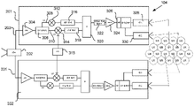
도 4는 전술한 세 가지 기술 중 제1 기술의 단순화된 개략도이다. 제1 기술을 구현하기 위한 시스템(600)은 복수의 SAN(602), 적어도 하나의 빔당 단일 피드 안테나(638, 640)를 갖는 위성(604), 및 사용자 빔 커버리지 영역들(1801)(도 19 참조) 내의 복수의 사용자 단말기(606)를 포함한다. 대안적으로, 임의의 안테나가 사용될 수 있는데, 여기서 안테나는 다수의 입력을 가지며, 입력들 각각은 직접 방사 안테나 등과 같이 사용자 빔 커버리지 영역으로 사용자 스폿 빔에서 송신될 수 있는 신호를 수신할 수 있다. 안테나들(638, 640)은 직접 방사 어레이 또는 반사기/안테나 시스템의 일부일 수 있다. 일부 실시예들에서, 시스템(600)은 M개의 SAN(602)을 갖는다. 예시적인 시스템(600)에서, 그리고 본 개시 전반에 걸쳐 논의된 예시적인 시스템들 각각에 대해, M = 8이다. 그러나, 본 명세서에 개시된 시스템들 중 어느 것도 이 수로 제한되어서는 안 된다. M = 8은 편리한 예일 뿐이고, 다른 실시예들에서 M은 2, 4, 10, 12, 16, 20, 32, 40 또는 임의의 다른 적합한 값일 수 있다. 일부 실시예들에서, SAN들(602)은 정보 네트워크(예를 들어, 인터넷)로부터 정보를 수신할 수 있는 소스(예를 들어, 코어 노드, 도시되지 않음)로부터 시스템을 통해 통신될 "순방향 트래픽"을 수신한다. 코어 노드로부터 SAN(602)으로 통신되는 데이터는 2진 데이터 스트림을 포함한, SAN(602)으로의 데이터의 효율적인 통신을 가능하게 하는 임의의 형태로 제공될 수 있다. 일부 실시예들에서, 데이터는 광학 신호 상에 변조되고 광섬유 상에서 SAN으로 송신되는 2진 데이터 스트림으로서 제공된다. 순방향 트래픽은 특정 사용자 빔 커버리지 영역(1801)으로 식별되는 스트림들 내에서 수신된다. 일부 실시예들에서, 데이터는 또한 데이터가 그것으로 송신될 특정 사용자 단말기 또는 사용자 단말기들의 그룹과 관련될 수 있다. 일부 실시예들에서, 데이터는 데이터를 운반하는 신호의 주파수 및/또는 타이밍에 기초하여 단말기와 관련된다. 대안적으로, 데이터 헤더 또는 다른 식별자가 데이터와 함께 제공되거나 데이터에 포함되거나 데이터에 있을 수 있다.4 is a simplified schematic diagram of the first of the three techniques described above. A
일단 수신되면, 순방향 트래픽은 2진 데이터 스트림(601)이다. 즉, 일부 실시예들에서, 순방향 트래픽은 강도 변조 또는 위상 변조 광학 신호와 같은 2진 표현이다. 대안적인 실시예들에서, 순방향 트래픽은 임의의 다른 2진 표현으로 디코딩될 수 있다.Once received, the forward traffic is a binary data stream (601). That is, in some embodiments, the forward traffic is a binary representation, such as an intensity modulated or phase modulated optical signal. In alternative embodiments, the forward traffic may be decoded into any other binary representation.
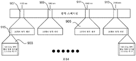
도 5는 일부 실시예들에서 시스템에 의해 사용되는 IF 신호들(903), 광학 채널들(915) 및 광학 대역들(907, 909, 911, 913)의 관계를 도시한다. 대역폭, 주파수, 채널 수 및 파장의 특정 선택은 개념들의 개시를 더 쉽게 하기 위해 제공되는 예들일 뿐이다. 다른 광학 파장, 채널 수 및 다른 RF 및/또는 IF 대역폭 및 주파수뿐만 아니라 대안적인 변조 스킴이 사용될 수 있다. 도시된 스킴은 단지 사용될 수 있는 하나의 특정 스킴을 예시하기 위해 제공된다. 도시된 바와 같이, 복수의 3.5 ㎓ 폭 2진 변조 IF 신호(예를 들어, 64개)(903)는 하나의 사용자 스폿 빔에서 송신될 2진 데이터를 운반한다. 사용될 수 있는 다른 대역폭들의 예는 500 ㎒, 900 ㎒, 1.4 ㎓, 1.5 ㎓, 1.9 ㎓, 2.4 ㎓ 또는 임의의 다른 적합한 대역폭을 포함한다.5 shows the relationship of IF signals 903 ,
각각의 3.5 ㎓ 폭 2진 변조 IF 신호(903) 상에 변조된 2진(즉, 디지털) 콘텐츠는 4개의 광학 대역(905) 중 하나 내의 16개의 광학 채널 중 하나의 2진 강도 변조를 수행하는 데 사용된다. 일부 실시예들에서, 광학 스펙트럼의 4개의 대역(907, 909, 911, 913)은 1100 nm, 1300 nm, 1550 nm 및 2100 nm이다. 그러나, 유용한 광학 스펙트럼(즉, 대기를 통한 과도한 감쇠 없이 적어도 최소로 이용 가능한 광학 스펙트럼의 부분) 내의 어딘가에 위치하는 대역들이 선택될 수 있다. 일반적으로, 선택되지 않는 대역들보다 더 많은 감쇠를 갖지 않는 광학 대역들이 선택된다. 즉, 몇몇 광학 대역은 나머지보다 적은 감쇠를 가질 수 있다. 그러한 실시예들에서, 그러한 광학 대역들의 서브세트가 선택된다. 그러한 선택된 대역들 중 몇몇은 매우 유사한 감쇠를 나타낼 수 있다.Binary (ie, digital) content modulated on each 3.5 GHz wide binary modulated IF
일례에서, 각각의 광학 채널은 채널의 중심에서의 파장에 의해 정의되고, 각각의 광학 채널은 대략 0.8 nm(즉, 100 ㎓ 폭)만큼 이격된다. 광학 채널 상에 변조된 RF 신호(903)는 단지 3.5 ㎓ 폭이지만, 이 간격은 광학 신호들이 효율적으로 역다중화될 수 있게 한다. 일부 실시예들에서, 각각의 SAN(602)은 몇몇(예를 들어, 64개)의 그러한 3.5 ㎓ 광학 신호(903)(즉, 4 × 16)를 광학 출력 신호 상에 함께 파장 분할 다중화(WDM)한다. 따라서, 하나의 SAN(602)으로부터 64개의 광학 채널의 디지털 콘텐츠가 전송될 수 있다.In one example, each optical channel is defined by a wavelength at the center of the channel, and each optical channel is spaced apart by approximately 0.8 nm (ie, 100 GHz wide). Although the RF signal 903 modulated on the optical channel is only 3.5 GHz wide, this spacing allows the optical signals to be efficiently demultiplexed. In some embodiments, each
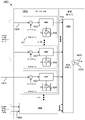
도 6은 광학 신호들 상에의 2진 데이터 스트림(601)의 광학 변조를 수행하는 데 사용되는 광학 송신기(607)를 도시한다. 도 5에 도시된 스킴을 구현하는 실시예에 따르면, 광학 송신기(607)는 4개의 광학 대역 모듈(608a 내지 608d)(간략화를 위해 2개가 도시됨) 및 광학 결합기(609)를 포함한다. 4개의 광학 대역 모듈(608) 각각은 총 64개의 변조기(611)에 대한 16개의 광학 변조기(611)(간략화를 위해 2개가 도시됨)를 포함한다. 64개의 변조기(611) 각각은 64개의 광학 채널(915)(도 5 참조) 중 하나에 존재하는 광학 신호를 출력한다. 채널들은 4개의 광학 대역(907, 909, 911, 913)으로 분할된다.6 shows an
변조기(611)는 광학 신호를 생성하는 광원(654)의 파장(λ1)에 기초하여 광학 채널(915)을 결정한다. MZM(652)은 제1 광원(654)의 출력을 2진 데이터 스트림(601)의 진폭에 비례하는 강도로 강도 변조한다. 2진 데이터 스트림(601)은 합산기(656)에서 DC 바이어스와 합산된다. 2진 데이터 스트림(610)이 디지털 신호(즉, 단지 2개의 진폭을 가짐)이기 때문에, 결과적인 광학 신호는 2진 변조 광학 신호이다. MZM 변조기(652)로부터의 변조된 광학 출력은 광학 결합기(609)에 결합된다. 도 5에 예시된 것과 같은 변조 스킴을 사용하는 시스템의 경우, 동일한 광학 대역 모듈(608) 내에 존재하는 16개의 광원(654) 각각은 16개의 상이한 파장(λ1) 중 하나에서 광학 신호를 출력한다. 16개의 파장은 제1 광학 대역(907) 내의 16개의 광학 채널(915)에 대응한다. 마찬가지로, 각각의 다른 광학 대역 모듈(608) 내의 광학 변조기들(611) 내의 광원들(654)은 대응하는 광학 대역(909, 911, 913) 내의 채널들의 파장과 동일한 λ1의 파장을 갖는 광학 신호를 출력한다. 따라서, 4개의 광학 대역 모듈(608a 내지 608d)로부터의 64개의 광학 출력(915)은 각각 상이한 파장을 가지며, 64개의 광원(654)에 의해 생성되는 신호들의 파장들(λ1)에 의해 정의되는 4개의 대역의 16개의 광학 채널에 속한다. 광학 결합기(609)는 각각의 신호(915)의 합성물인 파장 분할 다중화(WDM) 광학 신호(660)를 출력한다.The
SAN(602)은 광학 피더 업링크(108)(도 4 참조)를 통해 광학 신호(660)를 위성(604)에 전송한다. 광학 송신기(607)에 의해 방출되는 광학 신호는 위성(604) 내의 렌즈(610)에 의해 수신된다. 일부 실시예들에서, 렌즈(610)는 광학 수신기(622) 내의 망원경의 일부이다. 일부 실시예들에서, 렌즈(610)는 조종 가능하다(즉, 시스템 내의 여러 개의 SAN(602) 중 임의의 하나 또는 서브세트 내로부터의 임의의 하나를 향하도록 지향될 수 있다). 렌즈들(610)이 SAN들(602) 중 하나 초과의 SAN들로 지향되도록 허용함으로써, 렌즈(610)는 현재 신호 페이딩을 겪지 않는 위성으로의 광학 경로를 갖는 SAN(602)으로 지향될 수 있다. 렌즈(610)는 기계적 2축 위치 설정 메커니즘들을 사용하여 지향될 수 있다. 렌즈의 지향은 광학 채널을 통해 송신된 신호의 수신 신호 강도를 측정하고 신호 강도를 사용하여 렌즈가 충분한 품질(즉, 원하는 품질 임계치 초과)의 광학 링크를 갖는 SAN을 향하는 때를 식별함으로써 성취될 수 있다. 지상 커맨드들 또는 온보드 처리 중 어느 하나는 원하는 SAN(602)에서 렌즈(610)를 올바르게 지향시키도록 렌즈 위치 설정 메커니즘들에 지시를 제공할 수 있다.The
광학 수신기(622)는 필터 또는 프리즘과 같은 광학 역다중화기(650)를 추가로 포함한다. 광학 수신기(622)는 복수의 출력을 가지며, 각각의 출력은 광학 파장과 대응한다. 도 4에 도시된 바와 같이, 광학 수신기(622)는 64개의 출력을 갖는다. 그러나, 전술한 바와 같이, 특정 주파수, 광학 대역의 수 및 파장 선택, 그리고 이에 따라 광학 수신기(622)로부터의 출력의 수는 본 명세서에서 단지 예로서 제공되며, 시스템(600)과 같은 시스템들을 특정 수로 제한하도록 의도되지 않는다.
일부 실시예들에서, 각각의 파장은 4개의 광학 대역(907, 909, 911, 913) 중 하나 내에 존재한다. 각각의 광학 파장은 광학 채널의 중심에 있다. 하나의 대역 내의 광학 채널들은 대략 0.8 nm(즉, 100 ㎓)만큼 이격된다. 광학 채널들을 넓게 이격시키는 것은, 광학 신호를 역다중화하여 64개의 광학 채널 각각을 별개의 출력 상에서 제공할 수 있는 광학 역다중화기(650)를 제공하는 것을 더 용이하게 한다. 일부 실시예들에서, 광학 역다중화기(650)의 출력을 포토다이오드(612)와 같은 광학 검출기의 입력으로 포커싱하기 위해 추가 렌즈(613)가 제공된다. 포토다이오드(612)는 포토다이오드에 대한 광학 입력에서 제공되는 광학 신호(660)의 강도 포락선을 검출함으로써 전기 신호를 생성한다. 광학 신호(660)가 2개의 강도 레벨 중 하나로 강도 변조된 일부 실시예들에서, 논리 "1"을 나타내는 제1 강도 레벨은 논리 "1"을 또한 나타내는 제1 진폭을 갖는 전기 신호를 유발한다. 논리 "0"을 나타내는 제2 강도 레벨은 논리 "0"을 나타내는 진폭 전기 신호를 유발한다. 따라서, 전기 신호는 광학 신호(660)의 강도가 논리 "1"을 나타내는 상태에 있을 때 제1 상태에 놓이고, 광학 신호(660)의 강도가 논리 "0"을 나타내는 상태에 있을 때 제2 상태에 놓인다. 따라서, 광학 수신기는 복수의 디지털 출력(615)을 갖는다. 포토다이오드(612)의 디지털 출력(615)으로부터 출력된 전기 신호는 2상 변조기와 같은 변조기(614)에 결합된다. 도 4의 실시예와 같은 일부 실시예들에서, LNA(617)가 포토다이오드(612)와 2상 변조기(614) 사이에 제공된다. 2상 변조기(614)의 출력은 2개의 위상을 갖는 BPSK 변조 IF 신호(즉, 아날로그 신호)이다. BPSK 변조기(614)는 제1 진폭(즉, 제1 상태)의 전기 입력 신호에 응답하여 논리 "1"을 나타내는 제1 위상을 갖는 신호를 출력한다. 변조기(614)에 대한 입력이 논리 "0"(즉, 제2 상태)을 나타내는 진폭을 가질 때, BPSK 변조기(614)의 출력의 위상은 제1 위상과는 상이한 제2 위상으로 시프트된다. 변조기(614)의 출력은 스위치 행렬(616)의 입력에 결합된다.In some embodiments, each wavelength is within one of four
도 4의 단순화된 개략도에서, 제2 SAN(602), 렌즈(610), 광학 수신기(622) 및 복수의 2상 변조기(614)(즉, 64개)가 스위치 행렬(616)에 결합된다. 도 4에는 2개의 SAN(602)만이 도시되지만, 위성은 여러 개의 SAN(602)(예를 들어, 8개)으로부터 광학 신호들을 수신할 수 있음을 이해해야 한다.In the simplified schematic diagram of FIG. 4 , a
일부 실시예들에서, 도 4에 도시된 스위치 행렬(616)은 각각의 렌즈(610)에 대한 복수(예를 들어, 64개)의 입력을 갖는다. 즉, 위성(604)이 8개의 렌즈(610)를 갖는 경우, 행렬 스위치(616)는 각자가 변조기들(614) 중 하나에 결합되는 512개의 입력을 갖는다. 스위치 행렬(616)은 스위치 행렬(616)의 출력들에서의 신호들이 스위치 행렬(616)의 입력들에 선택적으로 결합될 수 있게 한다. 일부 실시예들에서, 임의의 입력이 임의의 출력에 결합될 수 있다. 그러나, 일부 실시예들에서, 하나의 입력만이 임의의 하나의 출력에 결합될 수 있다. 대안적으로, 입력들과 출력들은 함께 그룹화되며, 따라서 입력들이 동일 그룹 내의 출력들에만 결합될 수 있다. 입력이 그것에 결합될 수 있는 출력들의 수를 제한하는 것은 시스템에서의 감소된 유연성의 희생으로 스위치 행렬(616)의 복잡성을 감소시킨다.In some embodiments, the
스위치 행렬(616)의 출력들은 각각 상향 변환기(626)에 결합된다. 상향 변환기(626)는 신호를 사용자 다운링크 캐리어의 주파수로 상향 변환한다. 예를 들어, 일부 실시예들에서, 스위치 행렬(616)로부터 출력되는 신호는 3.5 ㎓ 폭 IF 신호이다. 3.5 ㎓ 폭 IF 신호는 중심 주파수가 20 ㎓인 RF 캐리어로 상향 변환된다. 각각의 상향 변환기(626)의 출력은 대응하는 전력 증폭기(630)에 결합된다. 각각의 증폭기(630)의 출력은 안테나들(638, 640) 중 하나의 입력들(예를 들어, 도시되지 않은 안테나 피드들)과 같은 복수의 안테나 입력 중 하나에 결합된다. 따라서, 스위치 행렬(616)의 출력들 각각은 안테나 입력들 중 대응하는 하나에 효과적으로 결합된다. 일부 실시예들에서, 각각의 안테나(638, 640)의 각각의 입력은 하나의 사용자 빔 커버리지 영역(1801)(도 19 참조)으로 사용자 스폿 빔을 송신한다. 스위치 행렬(616)은 어느 입력(즉, 2상 변조기(614))이 어느 출력(즉, 상향 변환기(626))에 결합되는지를 선택할 수 있다. 따라서, SAN들(602) 중 하나로부터의 신호가 페이딩되고, 에러들이 허용 불가능해질 때(또는 그 전에), 스위치 행렬(616)은 상향 변환기(626)의 입력(즉, 관련된 안테나 피드)을 상당한 페이딩을 겪고 있지 않는 광학 신호를 전송하고 있는 SAN(602)에 결합할 수 있다. 일부 실시예들에서, 스위치 행렬(616)은 특정 SAN으로부터의 콘텐츠가 하나 초과의 사용자 스폿 빔(즉, 안테나 피드)에 분배될 수 있도록 안테나 입력들에 제공되는 콘텐츠가 시분할 다중화될 수 있게 한다.The outputs of the
즉, 각각의 렌즈(610)가 그것이 지향하고 있는 SAN(602)으로부터 신호를 수신하고 있을 때, 그 렌즈(610)와 관련된 광학 수신기(622)로부터의 64개의 출력 각각은 신호를 가질 것이다. 안테나들(638, 640)에 대한 각각의 안테나 입력이 특정 사용자 커버리지 영역(1801)으로 사용자 스폿 빔을 송신하는 실시예에서, 모든 사용자 커버리지 영역들(1801)은 신호를 수신할 것이다(스위치 행렬(616)이 각각의 입력을 하나의 출력에 결합하도록 매핑되는 것으로 가정함). 스위치 행렬(616)은 2상 변조기(614)로부터의 어느 아날로그 출력이 각각의 안테나 입력에 결합될지(즉, 각각의 사용자 스폿 빔에서) (예를 들어, 빔당 단일 피드 안테나(638, 640)의 각각의 피드로 송신될지)를 선택한다. 그러나, 특정 SAN(602)으로부터의 광학 신호가 페이딩될 때, 신호가 여전히 모든 안테나 입력들에 제공되어 사용자 커버리지 영역들(1801)이 커버리지를 잃지 않는 것을 보장한다. 하나의 SAN으로부터의 신호들을 64개 초과의 안테나 입력으로 시간 다중화하는 것은 하나의 SAN(602)이 64개 초과의 사용자 커버리지 영역(1801)에 신호들을 제공할 수 있게 한다. 시스템의 총 용량은 감소되지만, 각각의 사용자 커버리지 영역에 콘텐츠를 제공하는 시스템의 가용성이 향상된다. 이는 광학 피더 링크를 갖는 시스템에서 유리하다. 일부 실시예들에서, 그러한 시간 다중화는 약한 광학 링크를 갖는 SAN(602)으로 지향되는 렌즈(610)가 더 강한 광학 링크가 있는 다른 SAN으로 방향 전환되는 짧은 시간 동안 행해진다. 더 일반적으로, 행렬(616)은 광학 수신기(622)로부터 출력된 아날로그 신호들을 하나 초과의 사용자 스폿 빔으로 시간 다중화하는 데 사용될 수 있으며, 따라서 제1 기간 동안 아날로그 신호는 제1 사용자 빔 커버리지 영역으로 지향되는 사용자 스폿 빔을 송신하는 제1 안테나 입력(예를 들어, 피드)에 결합된다. 제2 기간 동안, 아날로그 신호는 제2 사용자 빔 커버리지 영역으로 지향되는 사용자 스폿 빔을 송신하는 제2 안테나 입력(예를 들어, 피드)에 결합된다.That is, when each
일단 각각의 렌즈(610)가 충분히 강한 광학 신호를 수신하고 있으면, 스위치 행렬(616)은 입력 대 출력의 일대일 대응으로 각각의 출력을 고유 출력에 다시 매핑할 수 있다. 일부 그러한 실시예들에서, 스위치 행렬(616)의 제어는 제어국으로부터의 원격 측정 신호에 의해 제공된다. 대부분의 실시예들에서, 동일 SAN(602)으로부터의 64개의 IF 신호 모두가 함께 저하될 것이기 때문에, 스위치 행렬(616)은 K/64개의 출력 중에서 선택할 수 있으면 되고, 여기서 K는 사용자 스폿 빔의 수이고, 64는 하나의 광학 수신기(622) 내의 포토다이오드들(612)의 수이다. 전술한 바와 같이, SAN들(602)을 사용자 스폿 빔들에 매핑하기 위해 위성을 통한 라우팅을 제어하는 프로세스는 본 명세서에서 피더 링크 다이버시티로 지칭된다. 이하에서 논의될 바와 같이, 피더 링크 다이버시티는 3개의 상이한 방식으로 제공될 수 있다.Once each
일부 실시예들에서, 위성(604)은 트랜스폰더들보다 많은 안테나 입력들(즉, 광학 수신기로부터 스위치들(634, 636)로의 경로들)을 갖는다. 즉, 전력 증폭기들(PA들)(630), 상향 변환기들(626) 등을 포함하는 제한된 수의 트랜스폰더가 비교적 많은 수의 사용자 빔 커버리지 영역으로 신호들을 송신하는 데 사용될 수 있다. 안테나 입력들 사이에서 트랜스폰더들을 공유함으로써, 각각의 포토다이오드(612)로부터의 출력은 위성(604) 상에 제공된 트랜스폰더들의 수보다 많은 수의 사용자 빔 커버리지 영역을 서비스하도록 시간 다중화될 수 있다. 이 실시예에서, RF 스위치들(634)은 상이한 시간들에 안테나들(638, 640) 중 하나 또는 둘 모두의 상이한 입력들로 PA(630)의 출력을 지향시키는 데 사용된다. 시간들은 신호 상에 존재하는 정보가 입력이 그것으로 지향되는(즉, 피드가 지향되는) 사용자 빔 커버리지 영역으로 송신되도록 의도되도록 조정된다. 따라서, 하나의 트랜스폰더는 시간 다중화 방식으로 여러 사용자 빔 커버리지 영역에 정보를 제공하는 데 사용될 수 있다. 신호를 특정 안테나(638, 640)로 지향시키도록 스위치들(634, 636)을 설정함으로써, 렌즈들(610) 각각에 의해 수신된 신호는 특정 스폿 빔으로 지향될 수 있다. 이는 시스템의 동적 할당 용량에 있어서 유연하게 제공한다.In some embodiments,
스위치들(634, 636)은 신호를 위성에 장착된 안테나들(638, 640) 중 임의의 것의 입력들로 지향시킨다. 일부 실시예들에서, 스위치들(634, 636)로부터의 출력은 안테나들의 서브세트로 지향될 수 있다. 각각의 안테나(638, 640)는 특정 사용자 빔 커버리지 영역으로 지향되는 빔당 단일 피드 안테나이며, 이에 의해 스폿 빔을 생성한다. 대안적인 실시예들에서, PA들(630)은 안테나 입력들에 직접 접속될 수 있으며, 이때 행렬 스위치(616)는 각각의 특정 포토다이오드(612)에 의해 검출된 신호들 중 어느 것이 사용자 빔 커버리지 영역들 중 어느 것으로 송신될지를 결정한다. 또한, 동일한 수의 위성 트랜스폰더들과 안테나 입력들이 존재하는 실시예들에서도, 스위치들(634, 636)을 갖는 것은 스위치 행렬(616)의 복잡성을 감소시킬 수 있다. 즉, 스위치 행렬(616)과 스위치들(634, 636)의 조합을 사용하면, 스위치 행렬(616)은 각각의 입력을 각각의 출력에 결합할 수 있을 필요가 없다. 오히려, 행렬 입력들, 출력들 및 안테나 입력들은 그룹의 임의의 입력이 그 동일 그룹의 임의의 출력에만 결합될 수 있도록 그룹화될 수 있다. 스위치들(634, 636)은 하나의 그룹의 출력들이 다른 그룹의 안테나 입력에 결합될 수 있게 하기 위해 안테나 입력들(예를 들어, 피드들) 사이에서 스위칭할 수 있다.
스위치 행렬(616)은 정적으로 또는 동적 시분할 다중 액세스 모드로 동작될 수 있다. 정적 동작 모드에서, 스위치 행렬(616)을 통한 경로들의 구성은 본질적으로 비교적 긴 기간 동안 설정된 상태로 유지된다. 스위치 행렬(616)의 구성은 송신되는 트래픽의 양에 있어서의 비교적 장기간 변화, 특정 링크의 품질에 있어서의 장기간 변화 등을 수용하기 위해서만 변경된다. 대조적으로, 동적 시분할 다중 액세스 모드에서, 스위치 행렬(616)은 상이한 순방향 다운링크 안테나 입력들 사이에 데이터를 시간 다중화하는 데 사용된다. 따라서, 스위치 행렬(616)은 어느 입력들을 스위치 행렬(616)의 출력에 결합할지를 선택한다. 이러한 선택은 입력 신호가 사용자 단말기(842, 844)에서의 신호의 복조 동안 직면하게 되는 에러들의 수가 허용 가능한 것을 보장할 만큼 충분히 강한지에 기초한다. 일부 그러한 실시예들에서, 광학 수신기(622)의 아날로그 출력들을 상이한 안테나 입력들로 시간 다중화하는 것은 하나의 SAN(602)이 하나 초과의 사용자 빔 커버리지 영역을 서비스할 수 있게 한다. 제1 기간 동안, 광학 수신기(622)로부터 출력된 하나 이상의 신호는 각각 안테나 입력들의 제1 세트 중 고유한 하나에 결합(즉, 사용자 빔 커버리지 영역들의 제1 세트 중 고유한 하나로 지향)될 수 있다. 제2 기간 동안, 그러한 동일 신호들 중 하나 이상은 상이한 안테나 입력들(즉, 상이한 사용자 빔 커버리지 영역들)에 결합될 수 있다. 광학 수신기(622)로부터의 아날로그 출력들(615)의 그러한 시간 다중화는 광학 수신기(622)의 렌즈(610) 중 하나가 "약한" SAN(602)(즉, 품질 임계치 미만의 광학 링크를 갖는 SAN(602))을 향하는 것에 응답하여 수행될 수 있다. 그러한 실시예에서, 약한 SAN(602)으로 초기에 설정된 제1 데이터 스트림은 코어 노드에 의해 "강한" SAN(602)(즉, 품질 임계치 초과의 광학 링크를 갖는 SAN(602))으로 방향 전환될 수 있다. 강한 SAN(602)은 그 정보를 시간 다중화하며, 따라서 시간의 일부 동안, 강한 SAN(602)은 제1 데이터 스트림이 그것으로 전송되도록 의도되는 사용자 빔 커버리지 영역들의 제1 세트로 지향되는 정보를 송신한다. 제2 기간 동안, 강한 SAN(602)은 사용자 빔 커버리지 영역들의 제2 세트로 지향되는 제2 데이터 스트림을 송신한다. 따라서, 하나의 기간 동안, 약한 SAN(602)과 위성(604) 사이의 열악한 광학 링크에 의해 위성(604)에 도달하는 것이 차단되었을 정보가 강한 SAN(602)을 통해 위성(604)으로 송신될 수 있다. 이 시간 동안, 약한 SAN(602)을 향하는 렌즈(610)는 아직 위성(604)으로 송신하고 있지 않은 강한 SAN(602)을 향하도록 방향 전환될 수 있다. 전술한 바와 같이, 약한 SAN으로부터 강한 SAN으로 정보를 방향 전환시키는 이러한 프로세스는 피더 링크 다이버시티의 태양이다.The
피더 업링크 신호가 수용 불가능한 페이딩을 겪고 있는 때를 결정함으로써, 데이터는 장애가 있는 피더 업링크를 사용하고 있는 SAN(602)으로부터 벗어나서 수용 가능한 신호 레벨을 갖는 피더 업링크 신호를 갖는 SAN(602)으로 라우팅될 수 있다. 피더 링크 다이버시티의 프로세스에 의해, 선택된 SAN(602)을 통해 송신된 신호는 이어서 스위치 행렬(616)을 통해, 데이터가 그것으로 전송되도록 의도되는 스폿 빔으로 라우팅될 수 있다.By determining when the feeder uplink signal is undergoing unacceptable fading, data is transferred from the
시스템(600)은 위성(604) 내에서 구현하기가 비교적 간단하다는 이점을 갖는다. 포토다이오드들(612) 및 2상 변조기들(614)을 사용하여 2진 변조 광학 데이터를 BPSK 변조 IF 신호로 변환하는 것은 비교적 간단하다. 그러한 2상 변조기들은 구축하기가 비교적 쉽고 저렴하고, 비교적 적은 전력을 요구하며, 비교적 작고 가볍게 제조될 수 있다. 그러나, RF 사용자 다운링크(114) 상에서 BPSK 변조를 사용하는 것은 제한된 RF 스펙트럼의 가장 효율적인 사용은 아니다. 즉, RF 사용자 다운링크(114)(도 1 참조)의 더 큰 용량은 RF 사용자 다운링크(114) 상의 BPSK 대신에 16 QAM과 같은 고밀도 변조 스킴을 사용함으로써 달성될 수 있다.
예를 들어, 전술한 세 가지 기술 중 제2 기술을 구현하는 시스템(600)의 대안적인 실시예에서, 사용자 다운링크 상에서 송신될 아날로그 신호(618)는 고밀도 변조 스킴으로 변조된다. 아날로그 신호(618)에 대해 복잡한 변조를 생성하는 것은, 변조기가 디지털 데이터 스트림을 취하여 데이터 스트림을 하나 이상의 복잡한 변조 신호로 변환하는 매우 복잡한 변조기일 것을 요구한다. 복잡한 변조 신호(618)는 예를 들어 64 QAM, 8psk, QPSK와 같은 고차 변조일 수 있다. 대안적으로, 심벌들을 IF 캐리어 상에 변조할 수 있는 임의의 다른 변조 스킴이 사용될 수 있으며, 여기서 심벌들은 2개 초과의 논리 상태를 나타낸다. 즉, 광학 신호의 2진 강도 변조는 광학 수신기(622)의 출력(615)이 기본 콘텐츠를 나타내는 2진 변조를 갖는 전자 신호를 제공하는 결과를 가져온다. 16 QAM과 같은 더 복잡한 변조 스킴으로 아날로그 신호(618)를 변조하기 위해, 변조기(614)는 QAM 변조기이며, 이에 따라 포토다이오드(612)로부터 출력된 디지털 콘텐츠에 기초하여 IF 신호의 QAM 변조를 수행한다.For example, in an alternative embodiment of
따라서, 일부 실시예들에서, 시스템(600)의 2상 변조기(614)는 QAM 변조기(614)(즉, 각각의 심벌이 2 비트 초과를 나타내는 변조기)로 대체된다. 따라서, IF 신호들(618)의 변조를 BPSK와 같은 2진 변조 스킴(즉, 2개의 논리 상태)으로 제한하기보다는, 변조기(614)는 IF 신호들(618)이 고밀도 변조 스킴(즉, 심벌들이 2개 초과의 값을 나타낼 수 있는 스킴들, 예를 들어 QAM)으로 변조될 수 있게 한다. 더 복잡한 QAM 변조기는 IF 신호들(618)의 더 효율적인 변조를 제공하지만(QAM 대 BPSK), 그것은 더 복잡하고, 더 많은 전력을 요구하며, 2상 변조기보다 더 무겁고 비싸다.Accordingly, in some embodiments, the two-
도 7은 시스템(600)에 대한 역방향 경로의 예시이다. 사용자 단말기들(606)은 2진 변조 신호를 위성(604)으로 송신한다. 안테나(예를 들어, 피드당 단일 빔 안테나들(404, 406))의 각각의 요소에 결합된 스위치들(402)은 저잡음 증폭기(LNA)(408), 주파수 변환기(409) 및 디지털 디코더(410)를 포함하는 위성 트랜스폰더들 중에서 선택한다. 주파수 변환기(409)는 수신된 신호를 사용자 업링크 주파수로부터 IF로 하향 변환한다. 디코더들(410)은 수신된 IF 신호 상의 2진 변조를 디코딩한다. 따라서, 각각의 디코더(410)의 출력은 디지털 신호이다. 디지털 디코더들(410)은 스위치 행렬(416)에 대한 입력들에 결합된다. 스위치 행렬(416)은 각각의 사용자 스폿 빔을 통해 수신된 신호들이 각각의 SAN(602)에 대한 광학 다운링크 상에 상당한 페이딩이 존재하는지에 따라 상이한 광학 링크들 상에 변조될 수 있게(즉, 상이한 SAN들(602)로 송신될 수 있게) 한다. 스위치 행렬(416)의 출력들은 광학 송신기들(607)에 대한 입력들에 결합된다. 각각의 광학 송신기(607)는 도 6에 도시되고 위에서 논의된 광학 송신기(607)와 본질적으로 동일하다. 광학 스펙트럼이 순방향 피더 링크 상에서 사용되는 것과 본질적으로 동일한 방식으로 사용되는 일부 실시예들에서(도 5 참조), 4개의 광학 대역 모듈(608) 각각은 광학 송신기(607)에 대한 총 64개의 입력에 대해 행렬 스위치(416)로부터 16개의 출력을 수신한다. 위성이 8개의 SAN(602)으로부터 광학 신호들을 수신할 수 있는 일부 실시예들에서, 스위치 행렬(416)로부터 총 512개의 출력을 수신할 수 있는 8개의 그러한 광학 송신기(607)가 있다. 각각의 광학 송신기(607)는 광학 신호(660)를 출력한다. 광학 신호(660)는 SAN(602) 내의 광학 수신기(414) 내의 렌즈(412)에 의해 수신된다. 광학 수신기(414) 및 렌즈(412)는 도 4를 참조하여 전술한 바와 같은 위성(604) 내의 광학 수신기(622) 및 렌즈(610)와 본질적으로 동일하다. 따라서, 광학 수신기(414)의 출력은 2진 데이터 스트림이다. 광학 수신기의 출력은 순방향 트래픽을 SAN(602)에 제공하는 네트워크와 같은 정보 네트워크로 전송된다.7 is an illustration of a reverse path for
대안적인 실시예에서, 시스템(600)에 대한 역방향 링크, 사용자 단말기들(606)로부터 위성(604)으로의 역방향 업링크 상에서 사용되는 변조는 2진 변조보다 효율적인 변조 스킴이다. 따라서, 2진 변조기(410)는 더 복잡한 변조기(410)이다. 복조기(410)로부터 출력된 2진 데이터는 사용자 단말기(606)에 의해 IF 신호 상에 변조된 변조 심벌들을 디코딩한 결과이다. 예를 들어, 16 QAM이 사용자 업링크 상에서 사용된 경우, 복조기로부터 출력된 신호는 16 QAM 심벌에 의해 표현되는 값들의 디지털 스트림이다. 변환기(502)로부터 출력된 2진 신호는 스위치 행렬(416)에 대한 입력에 결합된다. 2진 복조기 및 복잡한 복조기(410) 둘 모두는 광학 송신기(607)에 의해 피더 다운링크 상에서 송신된 광학 신호의 2진 변조를 수행하는 데 사용될 디지털 데이터 스트림을 출력한다.In an alternative embodiment, the modulation used on the reverse link to
도 8은 제3 기술을 구현하기 위한 시스템(800)의 단순화된 개략도이다. 시스템(800)의 일부 실시예들에서, SAN(802)은 기저 대역 대 IF 변환기(1605)의 입력들에 결합되는 "기저 대역" 신호들(809)로서 순방향 트래픽을 수신한다. 일부 실시예들에서, 7개의 500 ㎒ 폭 기저 대역 서브채널(809)이 3.5 ㎓ 폭 IF 신호(811)에서 결합된다. 3.5 ㎓ 폭 신호들(811) 각각은 하나의 사용자 커버리지 영역(1801)으로 송신된다. 도 9는 시스템(800) 내의 기저 대역 서브채널들(809), IF 신호들(811) 및 광학 신호들 간의 관계를 예시한다.8 is a simplified schematic diagram of a
사용될 수 있는 다른 대역폭들의 예는 500 ㎒(예를 들어, 단일 500 ㎒ 서브채널), 900 ㎒, 1.4 ㎓, 1.5 ㎓, 1.9 ㎓, 2.4 ㎓, 또는 임의의 다른 적합한 대역폭을 포함한다.Examples of other bandwidths that may be used include 500 MHz (eg, a single 500 MHz subchannel), 900 MHz, 1.4 GHz, 1.5 GHz, 1.9 GHz, 2.4 GHz, or any other suitable bandwidth.
도 10은 도 8에 도시된 SAN(802)과 같은 SAN(802)의 단순화된 예시이다. 일부 실시예들에서, 16개의 변환기(1605)를 각각 포함하는 4개의 IF 결합기(1602)로 구성되는 것으로 도시된 64개의 기저 대역 대 IF 변환기(1605)가 있다. IF 변환기들(1602) 내의 기저 대역 대 IF 변환기들(1605)의 그룹화는 도면의 단순화를 위해 도 8에 도시되지 않는다. 64개의 기저 대역 대 IF 변환기(1605) 각각은 S개의 입력을 가지며, 여기서 S는 서브채널들(809)의 수이다. 서브채널(809)이 500 ㎒의 대역폭을 갖고, 신호(811)가 3.5 ㎓의 대역폭을 갖는 일부 실시예들에서, S는 7이다. 각각의 입력은 서브채널들(809) 중 하나를 대응하는 주파수 변환기(1606)에 결합한다. 주파수 변환기들(1606)은 서브채널들(809)의 서브세트(예를 들어, 도 10에서 S = 7)가 합산기(1608)에서 합산될 수 있게 하기 위해 주파수 오프셋을 제공한다. 따라서, 도 10에 예시된 것과 같은 일부 실시예들에서, SAN(802)은 각각 3.5 ㎓ 폭의, 64개의 채널을 처리한다. 일부 실시예들에서, 3.5 ㎓ 폭 신호는 DC를 중심으로 할 수 있다(즉, 제로 IF 변조를 사용함). 대안적으로, 신호(811)는 특정 RF 주파수를 중심으로 할 수 있다. 하나의 특정 실시예에서, RF 캐리어(811)가 RF 다운링크 주파수를 중심으로 한다(이 경우, 위성은 아래에서 더 설명되는 바와 같이 어떠한 상향 변환기(626)도 필요로 하지 않을 것이다). 각각의 합산 회로(1608)로부터의 출력(811)은 64개의 광학 변조기(611) 중 하나에 결합되는 IF 신호(811)이다. 64개의 광학 변조기(611)는 4개의 광학 대역 모듈(608)로 그룹화된다. 각각의 광학 변조기(611)는 도 6에 도시되고 위에서 논의된 광학 변조기(611)와 본질적으로 동일하게 동작한다. 그러나, 각각의 광학 변조기(608)에 대한 입력(811)은 아날로그 신호이기 때문에, 각각의 광학 변조기(611)로부터 출력된 광학 신호는 IF 신호(811)의 진폭을 따르는 진폭 포락선을 갖는 강도 변조 광학 신호이다.FIG. 10 is a simplified illustration of a
광학 결합기(609)는 64개의 광학 변조기(611) 각각으로부터의 출력들을 결합하여 파장 분할 다중화(WDM) 합성 광학 신호(1624)를 생성한다. 기저 대역 대 IF 변환기들(1605)의 수와 광학 대역 모듈(608) 내의 광학 변조기들(611)의 수는 다를 수 있다. 도 9에 도시된 바와 같이, 4개의 광학 변조기(611)는 1100 나노미터, 1300 나노미터, 1550 나노미터 및 2100 나노미터를 중심으로 하는 파장들을 갖는 광학 신호들을 출력하도록 설계될 수 있다.An
시스템(800)에서, (도 4의 광학 송신기(607)와 유사한) 광학 송신기(607)는 RF 변조 합성 광학 신호(1624)를 방출한다. RF 변조 합성 광학 신호(1624)는 렌즈(610)(도 8 참조)에 의해 위성(804) 내에서 수신된다. 렌즈(610)는 광학 신호를 위성(804)에 송신할 수 있는 복수의 SAN(802) 중 임의의 것으로 지향될 수 있다. 렌즈(610)의 출력은 포토다이오드(612)(예를 들어, PIN 다이오드)와 같은 광학 검출기의 입력에 결합된다. 포토다이오드(612)는 광학 신호의 포락선(즉, 강도의 윤곽)을 검출하고, 광학 신호의 포락선을 전기 신호로 변환한다. 광학 신호는 IF 신호(811)로 강도 변조되기 때문에, 포토다이오드(612)로부터 출력되는 결과적인 전기 신호는 SAN(802)에 의해 합성 광학 신호(1624) 상에 변조된 IF 신호(811)와 본질적으로 동일하다. 포토다이오드(612)는 증폭기(808)에 결합된다. 이어서, 증폭기(808)로부터 출력된 신호는 행렬 스위치(616)의 입력에 결합된다. 행렬 스위치(616)는 위에서 도 4와 관련하여 논의된 행렬 스위치(616)와 동일한 방식으로 동작한다. 따라서, 스위치 행렬(616)은 어느 입력들을 스위치 행렬(616)의 출력에 결합할지를 선택한다. 행렬 스위치(616)의 출력은 신호(811)가 제로 IF를 갖는 실시예에서 전술한 시스템(600)에서와 동일하게 처리된다. SAN 내의 기저 대역 대 IF 모듈(607)로부터 출력되는 신호(811)가 위성(804)으로부터 직접 송신될 주파수를 갖는 실시예에서, 상향 변환기(626)가 요구되지 않는다는 사실을 제외하고는, 처리는 동일할 것이다.In
도 11은 시스템(800)에 대한 역방향 링크의 예시이다. 시스템(800)에 대한 역방향 링크는 도 7에 도시된 것과 본질적으로 동일하다. 그러나, 사용자 단말기들(606)이 2진 변조를 갖는 신호를 송신하기보다는, 사용자 단말기들(606)은 더 효율적인 변조(예를 들어, QPSK보다는 16 QAM)를 갖는 신호를 송신한다. 따라서, 출력 디지털 디코더(410)는 필요하지 않다. 하향 변환기(850)는 사용자 업링크 상에서 사용되는 RF 주파수를 적절한 IF 주파수로 하향 변환한다. 일부 실시예들에서, IF 주파수 신호는 3.5 ㎓ 폭인 제로 IF 신호이다. 각각의 하향 변환기(850)의 출력은 스위치 행렬(416)의 입력에 결합된다. 따라서, MZM 변조기(652)(도 6 참조)의 입력들은 스위치 행렬(416)로부터 아날로그 신호를 수신한다. 따라서, 각각의 광학 변조기(611)의 출력은 강도 포락선이 하향 변환기(850)로부터 출력된 신호를 추적하는 강도 변조 광학 신호이다. 일부 실시예들에서, 광학 변조기(611)는 RF 사용자 업링크 주파수를 광학 신호 상에 직접 변조한다. 따라서, 주파수 변환기(850)는 필요하지 않다. 하향 변환기(850)가 사용자 업링크 주파수를 제로 IF 신호로 감소시키는 실시예에서, 결합된 광학 신호(660)는 도 7과 관련하여 논의된 것과 동일한 방식으로 처리된다. 광학 신호가 사용자 업링크 주파수로 변조되는 실시예에서, 하향 변환기는 모뎀(418) 내에, 또는 광학 수신기(414)로부터의 신호를 모뎀(418)에 결합하기 전에 포함될 수 있다.11 is an illustration of a reverse link for
피더 링크 상에 신호들을 변조하기 위한 3개의 상이한 기술을 논의하였는데, 이들 각각은 사용자 스폿 빔들에 대한 수신된 캐리어들의 유연한 할당을 가능하게 하기 위해 행렬 스위치(616)를 사용하는 위성을 갖는 제1 시스템 아키텍처를 사용하며, 제2 및 제3 시스템 아키텍처들이 논의된다. 제2 시스템 아키텍처는 온보드 빔 형성을 갖는 위성을 포함한다. 제3 시스템 아키텍처는 지상 기반 빔 형성을 사용한다.We have discussed three different techniques for modulating signals on a feeder link, each of which has a first system with a satellite that uses a
도 12는 도 4에 도시된 기술(즉, 2진 변조로 광학 피더 업링크를 변조하고, 그러한 2진 콘텐츠를 사용하여 RF 사용자 다운링크를 변조함)을 사용하는 시스템(1000)의 단순화된 개략도이다. 그러나, 시스템(1000)은 위성(1004)이 온보드 빔 형성을 수행할 수 있는 제2 시스템 아키텍처를 사용한다. 시스템(1000)은 전술한 시스템(600)과 유사하게 동작한다. 그러나, 각각의 2상 변조기(614)로부터의 IF 출력은 스위치 행렬(616)보다는 가중/결합기 모듈(1006)에 결합된다.12 is a simplified schematic diagram of a
도 13은 K개의 순방향 빔 신호(1002)가 빔 형성기 입력 모듈(1052)에 의해 가중/결합기 모듈(1006)에서 수신되는 가중/결합기 모듈(1006)의 단순화된 블록도이다. K개의 신호(1002)는 입력 모듈(1052)에 의해 N-웨이 분할 모듈(1054)로 라우팅된다. N-웨이 분할 모듈(1054)은 K개의 신호(1002) 각각을 각각의 순방향 빔 신호의 N개의 사본으로 분할하며, 여기서 N은 K개의 사용자 스폿 빔을 형성하는 데 사용될 안테나 어레이 내의 요소들의 수이다.13 is a simplified block diagram of a weighter/
도 4와 관련하여 전술한 시스템의 예에서, 8개의 활성 SAN이 있으며, 이들 각각은 64개의 광학 채널을 포함하는 광학 신호를 송신한다. 64개의 광학 채널 각각은 3.5 ㎓ IF 신호(즉, 순방향 빔 신호)를 운반한다. 따라서, 512개의 순방향 빔 신호(즉, 8개의 SAN × 64개의 IF 신호)가 있다. 따라서, K = 512이다. 일부 실시예들에서, 위성은 512개의 어레이 요소를 갖는 안테나 어레이(1008)를 갖는다. 따라서, N = 512이다.In the example of the system described above with respect to FIG. 4 , there are eight active SANs, each of which transmits an optical signal comprising 64 optical channels. Each of the 64 optical channels carries a 3.5 GHz IF signal (ie, a forward beam signal). Thus, there are 512 forward beam signals (ie, 8 SAN x 64 IF signals). Therefore, K = 512. In some embodiments, the satellite has an
N-웨이 분할 모듈(1054)로부터의 각각의 출력은 512개의 가중 및 합산 모듈(1056) 중 하나의 대응하는 입력에 결합된다. 512개의 가중 및 합산 모듈(1056) 각각은 512개의 가중 회로(1058)를 포함한다. 512개의 가중 회로(1058) 각각은 N-웨이 분할 모듈(1054)로부터 출력된 512개의 신호 중 대응하는 하나에 가중치를 부여한다(즉, 증폭 및 위상 시프트시킨다). 가중 회로들(1058)로부터의 가중 출력들은 합산기(1060)에 의해 합산되어 512개의 빔 요소 신호(1062)를 형성한다. 512개의 빔 요소 신호(1062) 각각은 빔 형성기 출력 모듈(1064)을 통해 출력된다. 도 12를 다시 참조하면, 가중/결합기 모듈(1006)로부터 출력된 512개의 빔 요소 신호(1062)는 각각 512개의 상향 변환기(626) 중 대응하는 하나에 결합된다. 상향 변환기들(626)은 PA들(630)에 결합된다. PA들(630)의 출력들은 각각 안테나 어레이(1008)의 512개의 안테나 요소 중 대응하는 하나에 결합된다. 안테나 어레이는 직접 방사 어레이(여기서 각각의 안테나 요소는 원하는 방향으로 직접 방사함), 어레이 피드 반사기(여기서 각각의 안테나 요소는 모든 안테나 요소들에 의해 공유되는 반사기를 조명함), 또는 임의의 다른 적합한 안테나 구성 중 임의의 것일 수 있다. 안테나 어레이(1008)와 가중 결합기 모듈(1006)의 조합은 위상 어레이 안테나로도 지칭된다.Each output from the N-
위상 어레이 안테나(1008) 내의 위치들 각각에서 요소들에 인가되는 신호들의 상대적인 가중들은 복수의 가중 신호들이 서로 중첩되고 이에 따라 가간섭적으로 결합하여 사용자 빔을 형성하게 할 것이다.The relative weightings of the signals applied to the elements at each of the locations within the phased
따라서, 가중/결합기 모듈(1006)로부터 출력된 빔 요소 신호들(1062)을 생성하기 위해 원하는 가중을 복수의 신호(1002)에 적용함으로써, 가중/결합기 모듈(1006)의 각각의 입력에 인가된 신호(1002)가 복수의 사용자 빔 커버리지 영역 중 하나로 지향될 수 있다. 위성(1004)은 수신된 신호들 중 임의의 것을 사용자 빔 커버리지 영역들 중 임의의 것으로 지향시키기 위해 가중/결합기 모듈(1006) 및 어레이 안테나(1008)를 사용할 수 있기 때문에, 그렇지 않으면 허용 불가능한 페이딩을 겪고 있는 특정 피더 업링크를 통해 송신될 정보가 다른 SAN들 중 하나로 라우팅될 수 있다. 따라서, 정보는 행렬 스위치(616)와 관련하여 전술한 바와 같이, 피드 링크 다이버시티를 제공하기 위해 허용 불가능한 페이딩을 겪고 있지 않는 SAN(602)을 통해 위성(1004)으로 송신될 수 있다. 전술한 바와 같이 여러 사용자 스폿 빔에서 렌즈들(610) 중 하나에 의해 수신된 신호들을 송신하기 위해 유사한 시분할 다중화가 행해질 수 있다.Thus, by applying a desired weight to the plurality of
온보드 빔 형성을 갖는 위성(1004)을 사용하는 것은 복수의 SAN(602)으로부터 수신된 신호에 대해 피더 링크 다이버시티를 가능하게 하는 유연성을 제공한다. 온보드 빔 형성의 사용은 도 4에 도시된 스위치 행렬(616)에 대한 필요성을 제거한다. 유사한 아키텍처가 역방향 경로들(즉, 사용자 업링크 및 피더 다운링크) 상에서 사용될 수 있다. 즉, 사용자 지상 단말기들(606)은 사용자 업링크 상에서 위성(1004)으로 RF 신호를 송신한다. 안테나 어레이(1008) 내의 수신 요소는 RF 신호를 수신한다. 가중/결합기 모듈(1006)은 수신 빔을 생성하기 위해 안테나(1008)의 각각의 수신 요소에 의해 수신된 수신 신호를 가중한다. 가중/결합기 모듈(1006)로부터의 출력은 RF로부터 IF로 하향 변환된다.Using
일부 실시예들에서, 상향 변환기들(626)은 출력들보다는 가중/결합기 모듈(1006)의 입력에 배치된다. 따라서, RF 신호들(예를 들어, 20 ㎓ 신호들)은 가중되고 합산된다. 이어서, 빔 요소 신호들은 안테나 어레이 요소들 각각을 통해 송신된다.In some embodiments, the up-
일부 실시예들에서, 위성은 여러 개의 가중/결합기 모듈(간략화를 위해 도시되지 않음)을 갖는다. 각각의 가중/결합기 모듈에 대한 입력들은 하나 이상의 광학 수신기(622)에 결합된다. 일부 실시예들에서, 하나의 광학 수신기(622)로부터의 출력들 모두는 동일한 가중/결합기 모듈에 결합된다. 각각의 가중/결합기 모듈은 N개의 출력을 생성한다. 각각의 가중/결합기 모듈로부터의 N개의 출력은 하나의 N-요소 안테나 어레이의 요소들에 일대일로 결합된다(간략화를 위해 하나만 도시됨). 따라서, 안테나 어레이들(1008)과 가중/결합기 모듈들(1006) 사이에 일대일 관계가 있다.In some embodiments, the satellite has multiple weight/combiner modules (not shown for brevity). The inputs for each weight/combiner module are coupled to one or more
일부 실시예들에서, 도 12에 도시된 제2 아키텍처(즉, 온보드 빔 형성)는 시스템(600)과 유사하게 QAM 변조기(614)와 함께 사용된다. 그러나, 위성(1104)은 온보드 빔 형성을 갖는다.In some embodiments, the second architecture shown in FIG. 12 (ie, onboard beamforming) is used with a
도 14는 광학 신호가 SAN(802)에서 RF 변조되는 도 8과 관련하여 논의된 기술을 이용하는 시스템(1200)의 단순화된 개략도이다. 그러나, 위성 아키텍처는 위성(1204)이 온보드 빔 형성 능력을 갖는 도 12 및 도 11의 것과 유사하다. SAN들(802), 렌즈들(810), 광학 검출기들(예를 들어, 포토다이오드들(812)), 증폭기들(613) 및 상향 변환기들(626)은 모두 도 8과 관련하여 설명된 것들과 유사하다. 그러나, 가중/결합기 모듈(1006) 및 어레이 안테나(1008)는 도 10, 도 10a 및 도 11과 관련하여 설명된 것들과 유사하다. 도 12에 묘사된 아키텍처와 유사하게, 가중/결합기(1006) 및 어레이 안테나(1008)는 위성(1004)이 SAN들(802) 중 하나 이상으로부터 수신된 신호들의 콘텐츠를 사용자 빔 커버리지 영역들 중 임의의 것에 송신하여서, 피더 링크 다이버시티를 제공할 수 있게 한다. 따라서, SAN들(802)로부터 위성으로의 피더 업링크들 중 하나 이상이 허용 불가능한 페이딩을 갖는 경우, 그렇지 않으면 그 피더 업링크 상에서 전송될 콘텐츠는 대신에 허용 불가능한 페이딩을 겪고 있지 않는 피더 업링크를 사용하는 다른 SAN들(802) 중 하나를 통해 전송될 수 있다.FIG. 14 is a simplified schematic diagram of a
도 15는 광학 순방향 업링크(1402) 및 무선 주파수 순방향 다운링크(1404)를 포함하는 제3 시스템 아키텍처(즉, 지상 기반 빔 형성)를 사용하는 위성 통신 시스템(1400)의 순방향 링크의 예시이다. 일부 실시예들에서, 시스템(1400)은 512개의 사용자 빔 커버리지 영역(1801)(아래에서 상세히 논의되는 도 19 참조) 내에 위치하는 사용자 단말기(806)와 통신하기 위한 비교적 큰 용량의 고 신뢰성 시스템을 생성하기 위해 순방향 링크 지상 기반 빔 형성기(1406), 위성(1408) 및 비교적 많은 수(M)의 SAN(1410)을 포함한다. 시스템(1400)에 대한 논의 전반에서, 이 예에서 M = 8개의 SAN(1410)이 도시된다. 그러나, M = 8은 편리한 예일 뿐이며, 시스템(1400)과 같은 개시된 시스템을 특정 수의 SAN(1410)으로 제한하려는 의도는 없다. 유사하게, 64개의 광학 채널이 시스템(1400)의 예에 도시되어 있다. 마찬가지로, 안테나 어레이는 512개의 요소를 갖는 것으로 도시되어 있다. 전술한 바와 같이, 특정 주파수들, 파장들, 안테나 어레이 요소들, 및 유사한 병렬 채널들, 컴포넌트들, 장치들, 사용자 빔 커버리지 영역들의 수 등은, 여기에 첨부된 청구범위에 의해 명확히 제한되는 경우를 제외하고는, 개시된 시스템들이 구현될 수 있는 방식에 대한 제한으로 이해되어서는 안 된다.15 is an illustration of a forward link of a
시스템(1400)을 통해 통신될 순방향 트래픽(즉, 순방향 빔 입력 신호(1407))은 처음에 코어 노드 또는 유사한 엔티티(도시되지 않음)와 같은 분배 장비를 통해 인터넷과 같은 소스로부터 빔 형성기(1406)에 제공된다. 분배 장비는, 다른 기능을 수행하는 것에 더하여, 개별 사용자 단말기로의 송신을 위해 주파수 및/또는 시간 슬롯의 할당을 관리하고, 특정 빔으로 송신되도록 예정된 데이터를 함께 그룹화할 수 있다. 빔 형성기(1406)에 대한 입력 신호들(1407)(또는 순방향 빔 입력 신호(1407)에 의해 운반되는 정보의 소정 부분)은 512개의 사용자 빔 각각으로 지향되는 데이터 스트림들(또는 변조 데이터 스트림들)을 나타낼 수 있다. 일 실시예에서, 512개의 순방향 빔 입력 신호(1407) 각각은 3.5 ㎓ 폭 IF 신호이다. 일부 실시예들에서, 순방향 빔 입력 신호(1407)는 빔 형성기(1406)의 입력에 결합되는 합성 3.5 ㎓ 폭 캐리어이다.Forward traffic to be communicated through system 1400 (i.e., forward beam input signal 1407) is initially transmitted from a source such as the Internet via distribution equipment such as a core node or similar entity (not shown) to
순방향 빔 입력 신호들(1407) 각각은 빔 형성기(1406)에 의해 사용자 빔 커버리지 영역(1801)으로 "지향"된다. 빔 형성기(1406)는 (아래에서 도 16과 관련하여 추가로 설명되는 바와 같이) 빔 가중치들을 512개의 순방향 빔 입력 신호(1407)에 적용하여 N개의 빔 요소 신호(1409)의 세트를 형성함으로써 특정 사용자 빔 커버리지 영역(1801)으로 순방향 빔 입력 신호(1407)를 지향시킨다. 일반적으로, N은 K 이상이다. 일부 실시예들에서, N = 512이고 K = 512이다. 512개의 빔 요소 신호(1409)는 증폭되고 주파수 변환되어 RF 빔 요소 신호들(1411)을 형성한다. 각각은 N-요소(즉, 512-요소) 안테나 어레이(1416)의 요소로부터 송신된다. RF 빔 요소 신호들(1411)은 사용자 빔 커버리지 영역(1801) 내에서 서로 중첩된다. 송신된 RF 빔 요소 신호들(1411)의 중첩은 사용자 빔 커버리지 영역들(1801) 내에 사용자 빔들을 형성한다.Each of the forward beam input signals 1407 is “directed” by a
일부 실시예들에서, 512개의 빔 요소 신호(1409)는 여러 개의 SAN(1410) 사이에 분할된다. 따라서, 빔 요소 신호들(1409)의 서브세트(예를 들어, 512/8)는 각각의 SAN(1410)에 결합되며, 여기서 8은 SAN들(1410)의 수이다. 따라서, 8개의 SAN(1410)의 조합은 빔 형성기(1406)로부터 위성(1408)으로 512개의 빔 요소 신호(1409)를 송신할 것이다. 일부 실시예들에서, 빔 형성기(1406)는 SAN들(1410) 중 하나와 같은 장소에 위치된다. 대안적으로, 빔 형성기(1406)는 다른 장소에 위치된다. 또한, 일부 실시예들에서, 빔 형성기(1406)는 여러 장소에 분산될 수 있다. 하나의 그러한 실시예에서, 빔 형성기(1406)의 일부는 각각의 SAN(1410)과 같은 장소에 위치된다. 빔 형성기(1406)의 각각의 그러한 부분은 순방향 트래픽(1407) 모두를 수신하지만, 빔 형성기(1406)의 그 부분과 같은 장소에 위치된 SAN(1410)으로 송신될 그러한 64(즉, 512/8)개의 신호(1409)에만 빔 가중치들을 적용한다. 일부 실시예들에서, 여러 개의 빔 형성기가 제공된다(간략화를 위해 도시되지 않음). 각각의 빔 형성기는 N개의 출력(즉, 빔 요소 신호)을 생성한다. N개의 빔 요소 신호는 위성(1408) 상의 하나의 N-요소 안테나 어레이의 요소들에 일대일로 결합될 것이다(간략화를 위해 하나만 도시됨). 따라서, 안테나 어레이들(1416)과 빔 형성기들(1406) 사이에 일대일 관계가 있다. 하나의 빔 형성기(1406)로부터의 빔 요소들 모두가 하나의 SAN(1410)을 통해 위성(1408)에 송신되는 일부 실시예들에서, 상이한 SAN들(1410)로부터의 송신들의 타이밍을 조정할 필요가 없다. 대안적으로, 동일한 빔 형성기(1406)로부터 출력된 빔 요소들이 상이한 SAN들을 통해 위성(1408)에 송신되는 실시예들에서, 빔 요소 신호들의 타이밍은 아래에서 추가로 논의되는 바와 같이 타이밍 제어를 사용하여 고려된다.In some embodiments, the 512
안테나 어레이(1416)의 N개의 요소 각각으로부터 송신된 RF 빔 요소 신호들(1411) 각각과 각각의 상대 진폭 사이의 위상 관계는, 빔 요소 신호들이 원하는 사용자 빔 커버리지 영역들(1801) 내에 빔들을 형성하도록 적절하게 중첩될지를 결정한다. 8개의 SAN(1410)(즉, M=8)이 있는 일부 실시예들에서, 각각의 SAN(1410)은 64개의 빔 요소 신호(1409)를 수신한다.The phase relationship between each relative amplitude and each of the RF
512개의 RF 빔 요소 신호(1411) 각각의 서로에 대한 위상 및 진폭 관계를 유지하기 위해, 빔 형성기(1406)는, N개의 빔 요소 신호(1409)에 더하여, 각각의 SAN(1410)에 대해 하나씩, 8개의 타이밍 파일럿 신호(1413)를 출력한다. 각각의 타이밍 파일럿 신호(1413)는 빔 형성기(1406)로부터 각각의 SAN(1410)으로의 송신시 다른 타이밍 파일럿 신호들과 정렬된다. 또한, 각각의 타이밍 파일럿 신호(1413)의 진폭은 동일하게 된다.To maintain the phase and amplitude relationship of each of the 512 RF
도 16은 순방향 빔 형성기(1406)의 상세한 예시이다. 순방향 빔 형성기(1406)는 시스템(1400)을 통해 전송될 순방향 트래픽을 나타내는 512개의 순방향 빔 신호(1407)를 수신한다. 신호들(1407)은 행렬 곱셈기(1501)에 의해 수신된다. 행렬 곱셈기(1501)는 빔 형성기 입력 모듈(1502), 512-웨이 분할 모듈(1504) 및 512개의 가중 및 합산 모듈(1506)을 포함한다. 행렬 곱셈기의 다른 배열, 구현 또는 구성이 사용될 수 있다. 512개의 순방향 빔 신호(1407) 각각은 512개의 사용자 빔 커버리지 영역(1801) 중 대응하는 하나 내에서 수신되도록 의도된다. 따라서, 512개의 사용자 빔 커버리지 영역(1801)과 512개의 순방향 빔 신호(1407) 사이에 일대일 관계가 있다. 일부 실시예들에서, 순방향 트래픽을 빔 형성기(1406)에 제공하는 분배 장비(예를 들어, 코어 노드)는 특정 사용자 빔 커버리지 영역(1801)으로 송신될 정보가 그 사용자 빔 커버리지 영역(1801)에 대응하는 순방향 빔 입력 신호(1407) 내에 포함되는 것을 보장한다.16 is a detailed illustration of a
512-웨이 분할 모듈(1504)은 512개의 순방향 빔 신호(1407) 각각을 512개의 동일한 신호로 분할하여, 512 × 512(즉, N × K)개의 신호가 512-웨이 분할 모듈(1504)로부터 출력되게 한다. N이 512이고 K가 512인 경우, 분할 모듈(1504)은 512 × 512 = 524,288개의 신호를 출력한다. 분할 모듈(1504)로부터 출력된 512개의 고유 신호는 512개의 가중 및 합산 모듈(1506) 각각에 결합된다. 가중 및 합산 모듈들(1506) 각각에 결합된 신호들은 순방향 빔 가중치 생성기(1508)에 의해 계산된 빔 가중치들에 따라 가중(즉, 위상 시프트 및 진폭 조정)된다. 동일한 어레이 요소 N에 대응하는 512개의 가중 신호 각각은 512개의 합산기(1512) 중 하나에서 합산된다.The 512-
합산기들(1512)로부터의 64개의 출력의 각각의 그룹이 8개의 SAN(1410) 중 상이한 하나에 결합되고 그것에 의해 송신될 것이기 때문에, 타이밍 모듈(1514)이 제공된다. 타이밍 모듈(1514)은 빔 요소 신호들(1409)이 빔 형성기로부터 전송되는 때를 조정하여, 64개의 IF 빔 요소 신호(1409)의 각각의 그룹이 적절한 시간에 사용자 빔 커버리지 영역(1801)에 도달하는 것을 보장하여, 신호들(1409)의 중첩이 사용자 빔의 적절한 형성을 유발하는 것을 보장한다. 대안적으로, 순방향 빔 가중치들은 각각의 SAN(1410)으로부터 위성(1408)으로의 경로들의 길이들 및 특성들에 있어서의 차이들을 고려하여 생성될 수 있다. 따라서, 신호(2122)는 순방향 빔 가중치 생성기(1508)에 결합될 것이다. 일부 실시예들에서, 타이밍 모듈(1514)은 순방향 빔 형성기(1406)로부터 각각의 SAN(1410)에 송신된 타이밍 파일럿 신호(1413)를 생성한다. 일부 실시예들에서, 하나의 타이밍 파일럿 신호(1413)가 생성되고 동일한 진폭의 8개의 사본으로 분할되며, 하나의 사본이 각각의 SAN(1410)에 전송된다. 대안적으로, 사본들의 진폭은 미리 결정된 비율일 수 있다. 타이밍 파일럿 신호들(1413) 사이의 비율이 알려진 한, RF 빔 요소 신호들(1411)은 그들이 서로 중첩되어 원하는 사용자 스폿 빔들을 형성하는 것을 보장하도록 균등화될 수 있다. 정렬에 대한 정정이 빔 형성기(1406) 내의 타이밍 모듈(1514)에서 이루어지는 일부 실시예들에서, 각각의 SAN(1410)은 SAN 타이밍 정정 신호(1419)로부터 도출된 신호(2122)를 빔 형성기에 대한 타이밍 제어 입력에 반환하여, 순방향 빔 형성기(1406)가 각각의 SAN(1410)에 대한 신호들의 정렬에 대한 정정을 결정할 수 있게 한다. 일부 실시예들에서, 이어서, SAN 타이밍 정정 신호(1419)는 빔 요소 신호들(1409)의 타이밍을 조정하기 위해 타이밍 모듈(1514)에 의해 사용된다. 다른 실시예들에서, SAN 타이밍 정정 신호(1419)는, 순방향 빔 가중치 생성기(1508)에 의해, 빔 가중치들을 조정하여 빔 형성기(1406)로부터 SAN들(1410) 각각을 통한 위성(1408)으로의 경로들에 있어서의 차이들을 해결하는 데 사용된다. 전술한 바와 같이, 정렬에 대한 정정은 대안적으로 각각의 SAN(1410)에서 이루어질 수 있다.Since each group of 64 outputs from
일단 빔 요소 신호들(1409)이 적절하게 가중되고 임의의 필요한 타이밍 조정이 이루어지면, 512개의 신호(1409) 각각은 SAN들(1410) 중 하나에 결합된다. 즉, 8개의 SAN(1410) 각각은 순방향 빔 형성기(1406)로부터 64개의 빔 요소 신호(1409)(즉, 512/8)를 수신한다. 각각의 SAN(1410) 내의 광학 송신기(1401)는 그것이 광학 캐리어 상에서 수신하는 그러한 64개의 빔 요소 신호(1409)를 수신하고, 다중화하고, 변조한다.Once the beam element signals 1409 are properly weighted and any necessary timing adjustments are made, each of the 512 signals 1409 is coupled to one of the
도 17은 시스템(1400)의 일부 실시예들에서 사용되는 광학 송신기(1401)의 예시이다. 광학 송신기(1401)는 도 10과 관련하여 위에서 논의된 광학 송신기(607)와 유사하다. 그러나, 입력 신호들(1409)은 상이한데, 이는 그들이 빔 형성기(1406)에 의해 빔 가중되기 때문이다. 또한, 빔 형성기(1406)에 의해 제공된 타이밍 파일럿 신호(1413)는 광학 변조기(611)에 결합되고, 그 광학 변조기(608) 내의 광원(654)의 파장에 의해 결정되는 바와 같은, 동일한 광학 대역 모듈(1403) 내의 다른 광학 변조기들(611)의 대역과 동일한 대역 내의 광학 캐리어 상에 변조된다. 일부 실시예들에서, 각각의 광학 대역 모듈(1403)은 동일하다. 그러나, 타이밍 파일럿 신호(1413)를 변조하는 것은 하나의 그러한 광학 대역 모듈(1403)에서만 행해지면 된다. 대안적으로, 도 17에 도시된 바와 같이, 하나의 광학 대역 모듈(1403)만이 타이밍 파일럿 신호(1413)를 변조하도록 구성된다. 다른 광학 대역 모듈들(608)은 도 6에 도시되고 위에서 설명된 광학 대역 모듈(608)과 유사할 수 있다. 어느 하나의 실시예에서, 도 5에 도시된 바와 같이, 8개의 SAN(1410)이 각각 64개의 빔 요소 신호(1409)를 수신하고 그들을 4개의 상이한 광학 대역 내에서 16개의 광학 채널 상에 변조하는 시스템에서, 각각의 SAN(1410) 내의 광학 송신기(1401) 내에 4개의 광학 대역 모듈이 있다.17 is an illustration of an
타이밍 파일럿 신호(1413)는 IF 빔 요소 신호들(1409)과 동일한, 위성으로의 경로를 따른다. 따라서, 위성(1408)에서 각각의 SAN(1410)으로부터 전송된 타이밍 파일럿 신호들의 도달 시간을 비교함으로써, IF 빔 요소 신호들의 도달 시간들에 있어서의 차이들이 결정될 수 있고, 정정 신호들이 생성되고 각각의 SAN(1410)에 송신될 수 있다. 광학 송신기(607)와 유사하게, 도 17에 도시된 각각의 광학 변조기(611)에 의해 출력된 광학 채널들(915)은 광학 결합기(609)에서 결합된다. 합성 광학 신호(1624)는 광학 송신기(1401) 내의 광학 렌즈(2002)로부터 방출된다. 광학 렌즈(2002)는 광학 신호를 위성(1408)에 송신할 수 있는 광학 신호 송신기로서 동작한다.The
64개의 빔 요소 신호(1409) 및 타이밍 파일럿 신호(1413)를 갖는 SAN들(1410) 각각으로부터의 합성 광학 신호(1624)는 광학 순방향 업링크(1402) 상에서 위성(1408)으로 송신되고 위성(1408) 내의 8개의 광학 수신기(1412) 중 하나에 의해 수신된다. 위성(1408) 내의 8개의 광학 수신기(1412) 각각은 합성 광학 신호(1624)로부터 64개의 광학 채널(915)을 역다중화한다.A composite
도 18은 위성(1408)(도 15 참조)의 컴포넌트들을 더 상세하게 도시한다. 위성(1408)은, 도 15를 참조하여 전술한 바와 같이, 지상 기반 빔 형성을 사용하는 시스템의 일부 실시예들에 따라 순방향 링크를 수신 및 송신한다. 위성(1408)의 순방향 링크의 컴포넌트들은 8개의 광학 수신기(1412), 8개의 증폭기/변환기 모듈(1414) 및 512-요소 안테나 어레이(1416)를 포함한다. 8개의 SAN(즉, M = 8)이 있는, 도 9, 도 13 및 도 16에 도시된 실시예들과 유사한, 시스템(1400)의 일부 실시예들에서, 수신된 합성 신호(1624)는 3.5 ㎓ 폭 IF 채널을 각각 운반하는, 16개의 각각의 광학 채널의 4개 대역으로 분할된 64개의 광학 채널을 포함한다. 또한, 안테나 어레이에는 K = 512개의 사용자 빔 커버리지 영역(1801) 및 N = 512개의 요소가 존재한다. 본 논의의 다른 곳에서 언급된 바와 같이, 이들 숫자는 단지 예로서 그리고 논의의 편의를 위해 제공된다.18 shows the components of satellite 1408 (see FIG. 15) in greater detail.
각각의 광학 수신기(1412)는 대응하는 증폭기/변환기 모듈(1414)과 관련된다. 광학 수신기들(1412)은 각각 렌즈 모듈(1701), 및 포토다이오드(1703)와 같은 복수의 광학 검출기를 포함한다. 렌즈 모듈(1701)은 렌즈(1702)(일부 실시예들에서 도 4와 관련하여 전술한 렌즈(610)와 유사할 수 있음), 광학 역다중화기(1704), 복수의 광학 역다중화기(1706) 및 복수의 출력 렌즈(1708)를 포함한다.Each
동작시, 합성 광학 신호(1624)는 8개의 SAN(1410) 각각으로부터 수신된다. 렌즈(1702)는 각각의 합성 광학 신호(1624)를 수신하도록 제공된다. 일부 실시예들에서, 렌즈(1702)는 렌즈(1702)가 그것으로부터 합성 광학 신호(1624)를 수신할 SAN(1410)에 포커싱될 수 있다(일부 실시예들에서, 기계적으로 지향될 수 있다). 렌즈(1702)는 나중에 상이한 SAN(1410)을 향하도록 리포커싱될 수 있다. 렌즈(1702)는 여러 SAN(1410) 중 하나로부터 합성 광학 신호(1624)를 수신하도록 포커싱될 수 있기 때문에, 위성(1408)은 더 큰 수 8+X개의 SAN(1410) 중에서 선택된 8개의 SAN(1410)으로부터 신호를 수신할 수 있다. 일부 실시예들에서, X = 24이다. 따라서, 32개의 상이한 SAN(1410)은 시스템에서 사용자 빔 커버리지 영역(1801)으로 통신되도록 의도된 정보를 수신할 수 있다. 그러나, 32개의 SAN(1410) 중 8개만이 위성(1408)에 의해 수신되도록 송신되는 정보를 갖도록 선택된다.In operation, a composite
위성(1408)의 순방향 링크를 통한 합성 광학 신호들(1624) 중 하나의 신호 경로가 이제 더 상세히 설명된다. 위성(1408)의 순방향 링크를 통해 8개의 수신된 합성 광학 신호(1624)에 의해 취해진 8개의 신호 경로 각각은 동일하게 동작한다는 것을 이해해야 한다. 렌즈(1702)에 의해 수신된 합성 광학 신호(1624)는 광학 역다중화기(1704)로 지향된다. 도 9에 예시된 변조 스킴을 사용하는 시스템에서, 광학 역다중화기(1702)는 합성 광학 신호(1624)를 4개의 대역(907, 909, 911, 913)으로 분할한다(도 9 참조). 즉, 광학 역다중화기(1704)는 합성 광학 신호(1624)를, 합성 광학 신호(1624)를 전송한 SAN(1410)에 의해 빔 요소 신호들(1407)이 그것 상에 변조된 4개의 광학 파장으로 분할한다. 광학 역다중화기(1704)로부터의 광학 출력들 각각은 대응하는 광학 역다중화기(1706)에 결합된다. 4개의 광학 역다중화기(1706) 각각은 총 4 ×(512/(4 × 8) = 512/8 = 64개의 광학 신호에 대해 512/(4 × 8)개의 광학 신호를 출력한다. 4개의 광학 역다중화기(1706)로부터 출력된 16개의 광학 신호 각각은 출력 렌즈(1708)로 지향된다. 출력 렌즈들(1708) 각각은 대응하는 광학 신호를 포토다이오드(1703)와 같은 대응하는 광학 검출기에 포커싱한다. 각각의 포토다이오드(1703)는 그의 입력에서 광학 신호의 진폭 포락선을 검출하고, 검출된 진폭 포락선에 대응하는 RF 송신 빔 요소 신호(1418)를 출력한다. 따라서, 광학 수신기들(1412)로부터 출력된 RF 송신 빔 요소 신호들(1418)은 본질적으로 SAN들(1410)에 의해 광학 신호들 상에 변조된 빔 요소 신호들(1409)이다.The signal path of one of the composite
이어서, RF 출력 신호들은 증폭기/변환기 모듈(1414)에 결합된다. 증폭기/변환기 모듈(1414)은 512/8개의 신호 경로를 포함한다. 일부 실시예들에서, 각각의 신호 경로는 저잡음 증폭기(LNA)(1710), 주파수 변환기(1712) 및 PA(1714)를 포함한다. 다른 실시예들에서, 신호 경로는 주파수 변환기(1712) 및 PA(1714)만을 포함한다. 또 다른 실시예들에서, 신호 경로는 PA(1714)만을 포함한다(주파수 변환기(1712)는 SAN들에 의해 생성된 피드 신호들이 이미 원하는 순방향 다운링크 주파수를 갖는 경우에 생략될 수 있다). 주파수 변환기(1712)는 RF 송신 빔 요소 신호들(1418)을 순방향 다운링크 캐리어 주파수로 주파수 변환한다. 일부 실시예들에서, 각각의 상향 변환기(1712)의 출력은 20 ㎓의 중심 주파수의 RF 캐리어이다. 8개의 증폭기/변환기 모듈(1414)로부터의 512개의 출력 각각은 512-요소 안테나 어레이(1416)의 512개의 요소 중 대응하는 하나에 결합된다. 따라서, 안테나 어레이(1416)는 512개의 순방향 다운링크 빔 요소 신호(1718)를 송신한다.The RF output signals are then coupled to an amplifier/
도 19는 일부 실시예들에 따른 미 대륙에 걸쳐 형성된 사용자 빔 커버리지 영역들(1801)의 예시이다. 다른 실시예들에서, 사용자 빔 커버리지 영역들은 상이한 위치들에, 그리고 상이한 간격 및 패턴들을 갖고서 위치될 수 있다. 도 4, 도 8 및 도 12에 도시된 실시예들과 같은 일부 실시예들에서, 안테나의 각각의 피드는 사용자 스폿 빔을 하나의 사용자 빔 커버리지 영역으로 지향시키도록 포커싱된다. 도 10, 도 11, 도 12, 도 14 및 도 14a에 도시된 것과 같은 다른 실시예들에서, 512개의 순방향 다운링크 빔 요소 신호(1718)는 서로 중첩되어 사용자 빔 커버리지 영역들(1801)로 지향되는 사용자 빔들을 형성한다. 도 19에 도시된 바와 같이, 사용자 빔 커버리지 영역들은 사용자 빔 커버리지 영역들(1801)보다 상당히 더 큰 위성 서비스 영역에 걸쳐 분산된다. 512 요소 안테나 어레이(1416)는 RF 빔 요소 신호들(1411)을 순방향 다운링크(1404)를 통해 512개의 사용자 빔 커버리지 영역(1801) 각각에 송신한다. 각각의 사용자 빔 커버리지 영역(1801) 내의 사용자 단말기들(806)은 512 요소 안테나 어레이(1416)의 512개의 요소 각각으로부터 송신된 RF 빔 요소 신호들(1411)의 중첩에 의해 그러한 특정 사용자 빔 커버리지 영역(1801)으로 지향되는 사용자 빔을 수신한다.19 is an illustration of user
각각의 광학 수신기(1412)로부터 출력된 IF 빔 요소 신호들(1418)에 더하여, 각각의 광학 수신기(1412)는 합성 광학 신호(1624)로부터의 위성 타이밍 신호(1415)를 역다중화한다. 위성 타이밍 신호(1415)가 각각의 수신기(1412)로부터 출력되고, 대응하는 증폭기/변환기 모듈(1414)에 결합된다. 증폭기/변환기 모듈(1414) 내의 LNA(1710)가 위성 타이밍 신호(1415)를 증폭한다. LNA(1710)의 출력(1416)은 위성 타이밍 모듈(1417)에 결합된다. 일부 실시예들에서, 위성 타이밍 모듈(1417)은 각각의 광학 수신기(1412)에 의해 수신된 위성 타이밍 신호(1415)를 비교하여 그들이 정렬되는지를 결정한다. 위성 타이밍 모듈(1417)은 8개의 SAN 타이밍 정정 신호(1419)를 출력하며, 하나씩 8개의 SAN(1410) 각각으로 반환된다. 일부 실시예들에서, 각각의 SAN 타이밍 정정 신호(1419)는 역방향 증폭기/변환기 모듈(1904)(도 24 참조)에 대한 입력에 결합된다. 각각의 SAN 타이밍 정정 신호(1419)는 증폭되고, 순방향 다운링크 주파수로 주파수 변환되고, SAN(1410)에 제공된 광학 송신기(1401)와 유사한, 위성(1408) 내의 8개의 광학 송신기(1401) 중 하나에 대한 입력에 결합된다. 일부 실시예들에서, 8개 중 하나는 다른 7개에 대한 기준이다. 따라서, 기준 위성 타이밍 신호가 그것으로부터 전송된 SAN(1410)으로부터 송신된 신호들의 타이밍에 대해 정정이 이루어지지 않는다. 따라서, 그 SAN(1410)에 대해 SAN 타이밍 정정 신호(1419)가 전송되지 않는다. SAN 타이밍 정정 신호(1419)는 위성(1408)에 의해 각각의 SAN(1410)에 송신된 각각의 합성 광학 신호 상에 변조된다.In addition to the IF
각각의 SAN 타이밍 정정 신호(1419)는 타이밍 파일럿 신호(1413)가 다른 타이밍 파일럿 신호들(예를 들어, 기준 위성 타이밍 신호(1415))에 대하여 정렬로부터 얼마나 벗어나는지를 나타내는 타이밍 정렬 정보를 제공한다. 일부 실시예들에서, 타이밍 정보는 SAN들(1410)을 통해 빔 형성기(1406) 내의 타이밍 모듈(1514)(도 16 참조)에 송신된다. 타이밍 모듈(1514)은 빔 요소들을 각각의 SAN(1410)에 전송하기 전에 그들의 정렬을 조정한다. 대안적으로, 타이밍 정렬 정보는 각각의 SAN(1410)으로부터의 RF 빔 요소 신호들(1411)이 정렬되어 위성(1408)에 도달하는 것을 보장하도록 SAN(1410)으로부터의 송신들의 타이밍을 조정하기 위해 각각의 SAN(1410)에 의해 사용된다. 도 20은 빔 요소 신호들(1409) 및 타이밍 파일럿 신호(1413)의 타이밍을 조정하기 위한 타이밍 모듈(1462)을 갖는 광학 송신기(1460)의 예시이다. 타이밍 모듈(1462)은 역방향 다운링크를 통해 위성(1408)으로부터 타이밍 제어 신호(1464)를 수신한다(아래에서 추가로 논의됨). 타이밍 모듈은 신호들(1409, 1413)에 적절한 지연을 적용하여, SAN(1410)에 의해 송신된 신호들을 시스템(1400)의 다른 SAN들(1410)에 의해 송신된 신호들과 정렬시킨다.Each SAN
대안적인 실시예에서, 위성 타이밍 모듈(1417)에 의해 생성된 제어 신호들에 기초하여 위성 내의 RF 빔 요소 신호들(1411)에 대해 타이밍 조정이 이루어질 수 있다. 일부 그러한 실시예들에서, 제어 신호들은 각각의 RF 빔 요소 신호(1411)에 대한 광학 수신기(1412)와 안테나 어레이(1416) 사이의 신호 경로에 배치된 프로그래밍 가능 지연들을 제어한다.In an alternative embodiment, timing adjustments may be made to the RF
대안적인 실시예에서, 위성 타이밍 신호들(1415) 중 적어도 2개는 위성으로부터 각각의 SAN(1410)으로 다시 송신된다. 제1 신호는 모든 SAN들에 다시 송신되는 공통 위성 타이밍 신호(1415)이다. 즉, 수신된 위성 타이밍 신호들(1415) 중 하나는 모든 다른 것들이 그것에 정렬될 표준으로서 선택된다. 제2 신호는 위성 타이밍 신호(1415)의 루프백이다. 공통 위성 타이밍 신호(1415)를 루프백 위성 타이밍 신호(1415)와 비교함으로써, 각각의 SAN(1410)은 2개의 신호를 정렬하고 이에 따라 위성(1410) 내의 각각의 SAN(1410)으로부터의 IF 빔 요소 신호들(1418)을 정렬하는 데 필요한 조정의 양을 결정할 수 있다.In an alternative embodiment, at least two of the satellite timing signals 1415 are transmitted back from the satellite to the
도 21은 K개의 순방향 빔 입력 신호(1452) 각각이 S개의 500 ㎒ 폭 서브채널을 포함하는 시스템(1450)이다. 일부 실시예들에서, K = 512이고 S = 7이다. 예를 들어, 일부 실시예들에서, 7개의 500 ㎒ 폭 서브채널이 하나의 사용자 커버리지 영역(1801)으로 송신된다. 도 22는 순방향 빔 입력 신호들(1452)이 빔 형성기(1300)에 대한 고유 입력에 각각 결합된 7개의 500 ㎒ 폭 서브채널을 포함하는 빔 형성기(1300)의 예시이다. 따라서, 전술한 바와 같이, 서브채널들은 도 14, 도 15에 도시된 바와 같이 IF 캐리어에 결합된 후에 빔 형성될 수 있다. 대안적으로, 도 14a, 도 13에 도시된 바와 같이, 서브채널들(1452)은 빔 형성기(1300)를 사용하여 결합되기 전에 빔 형성될 수 있다. 따라서, 빔 형성기(1300)는 S × N개의 빔 요소 신호를 출력하며, 이때 (S × N)/M개의 그러한 빔 요소 신호가 각각의 SAN(1410)으로 전송된다. 예시적인 시스템(1450)에서, S = 7이고, N = 512이고, M = 8이다. 전술한 바와 같이, 이들 숫자는 편리한 예로서 제공되며, 시스템(1450)과 같은 시스템을 이들 특정 값으로 제한하도록 의도되지 않는다.21 is a
도 22는 각각의 캐리어가 S개의 서브채널(1452) - 여기서, S = 7임 - 을 포함하는 빔 형성기(1300)의 단순화된 블록도이다. 서브채널들(1452) 각각은 빔 형성기(1300) 내의 행렬 곱셈기(1301)에 대한 독립적인 입력으로서 제공된다. 따라서, 512 × 7개의 서브채널(1452)이 행렬 곱셈기(1301)에 입력되고, 여기서 512개의 사용자 스폿 빔이 형성되며, 7은 각각의 캐리어 내의 서브채널들의 수인데; 즉 K = 512이고 S = 7이다. 512-웨이 분할기(1304)는 512 × 7개의 서브채널(1407) 각각을 수신하며, 여기서 512는 안테나 어레이(1416) 내의 요소들의 수이다. 대안적으로, N은 안테나 요소들의 임의의 수일 수 있다. 각각의 서브채널(1452)은 512개의 웨이로 분할된다. 따라서, 512 × 512 × 7개의 신호가 분할기(1304)로부터 3차원 행렬로 출력된다. 신호 1, 1, 1 내지 신호 1, K, 1(즉, 1, 512, 1, 여기서 K = 512임)은 가중 및 합산 모듈(1306)에서 가중 및 합산된다. 마찬가지로, 신호 1, 1, 7 내지 신호 1, 512, 7은 가중 및 합산 모듈(1313)에서 가중 및 합산된다. 유사한 방식으로, 다른 가중치 및 합산 모듈들 각각은 분할기(1304)로부터 출력들을 가중 수신하고, 출력들을 가중 및 합산한다. 가중 및 합산 모듈들(1306, 1313)로부터의 512 × 7개의 출력은 타이밍 모듈(1514)의 입력들에 결합된다. 타이밍 모듈은 위에서 논의된 빔 형성기(1406)의 타이밍 모듈(1514)과 본질적으로 동일하게 기능한다. 빔 형성기(1300)는 512 × 7개의 빔 요소 신호(1454)를 SAN들(1410)로 출력한다. 8개의 SAN(1410) 각각은 IF 결합기(1602)를 포함한다.22 is a simplified block diagram of a
도 23은 시스템(1450)의 SAN(1456)의 예시이다. 일부 실시예들에서, 제1 기저 대역 대 IF 변환기(805)는 도 10과 관련하여 위에서 논의된 기저 대역 대 IF 변환기(805)와 유사한 방식으로 동작한다. 변환기(805)는 7개의 500 ㎒ 빔 요소 신호(1454)의 조합인 신호(811)를 출력한다. 또한, 일부 실시예들에서, 기저 대역 대 IF 변환기들(1605) 중 적어도 하나는 추가 주파수 변환기(1607)를 포함한다. 추가 주파수 변환기(1607)는 빔 형성기(1300)로부터 타이밍 파일럿 신호(1413)를 수신한다. 타이밍 파일럿 신호(1413)는 빔 요소 서브채널들(1452)과 결합되고, 광학 송신기(607)에 결합된다. 광학 송신기(607)에 결합된 IF 신호들(811) 각각은 각각의 SAN(1410)의 광학 결합기들(609)에서 결합되어 송신된 합성 광학 신호(1624)를 형성한다. 타이밍 파일럿 신호(1413)는 주파수 변환기(1607)의 입력에 결합된다. 주파수 변환기(1607)는, 타이밍 파일럿 신호가 합산기(1608)에 의해 빔 요소 신호들(1454)과 합산될 수 있게 하는 주파수에 타이밍 파일럿 신호를 배치한다. 대안적으로, 타이밍 파일럿 신호(1413)는 타이밍 파일럿 신호(1413)의 변조에 전용된 추가 광학 변조기(1610)에 직접 결합될 수 있다. 추가 변조기(1610)의 출력은 결합기(609)에 결합되고, 타이밍 파일럿 신호에 전용된 고유 광학 채널 상의 다른 신호들과 결합된다.23 is an illustration of
도 24는 지상 기반 빔 형성을 갖는 시스템(1400)에 대한 역방향 링크의 예시이다. 복수의 512개의 사용자 빔 커버리지 영역(1801) 내에 위치한 사용자 단말기들(806)은 RF 신호들을 위성(1408)에 송신한다. 위성(1408) 상의 512-요소 안테나 어레이(1902)(안테나 어레이(1416)와 동일할 수 있거나 동일하지 않을 수 있음)는 사용자 단말기들(806)로부터 RF 신호들을 수신한다. 512-요소 안테나 어레이(1902)로부터의 512/8개의 출력은 8개의 증폭기/변환기 모듈(1904) 각각에 결합된다. 즉, 안테나 어레이(1902)의 각각의 요소는 증폭기/변환기 모듈들(1904) 중 하나 내의 하나의 LNA(1906)에 결합된다. 각각의 LNA(1906)의 출력은 주파수 변환기(1908) 및 전치 증폭기(1910)에 대한 입력에 결합된다. LNA(1906)의 증폭된 출력은 RF 사용자 업링크 주파수로부터 IF로 주파수 하향 변환된다. 일부 실시예들에서, IF 신호는 3.5 ㎓의 대역폭을 갖는다. 일부 실시예들에서, 전치 증폭기(1910)는 광학 캐리어 상에의 변조 전에 추가 이득을 제공한다. 각각의 증폭기/변환기 모듈들(1904)의 출력들은 도 4의 광학 송신기(607)와 유사한, 8개의 광학 송신기(1401) 중 하나에 대한 대응하는 입력들에 결합된다. 8개의 광학 송신기(1401) 각각은 광학 신호를 대응하는 SAN(1410)으로 출력 및 송신한다. SAN(1410)은 광학 신호를 수신한다. SAN(1410)은 512/8개의 역방향 빔 요소 신호(1914)를 다운링크 빔 형성기(1916)로 출력한다. 다운링크 빔 형성기(1916)는 역방향 빔 요소 신호들(1914)을 처리하고, 512개의 사용자 빔 커버리지 영역(1801) 중 하나와 각각 대응하는 512개의 빔 신호(1918)를 출력한다.24 is an illustration of a reverse link for a
증폭기/변환기 모듈(1904)로부터 광학 송신기(607)에 제공된 IF 신호들은 각각 512/8개의 광학 변조기(611) 중 하나에 결합된다. 예를 들어, 안테나 어레이(1902)에 512개의 요소가 존재하고(즉, N = 512임) 시스템(1900)에 8개의 SAN(1410)이 있는 경우, 512/8 = 64이다. IF 신호들이 도 9에 도시된 바와 같은 4개의 대역으로 분할된 파장들 상에 변조되는 시스템에서, 광학 변조기들(611)은 512/(4 × 8)개의 광학 변조기(611)를 갖는 광학 대역 모듈(608)에서 함께 그룹화된다.The IF signals provided from the amplifier/
각각의 광학 변조기(611)는 전술한 도 10에 도시된 SAN(1410)의 업링크 광학 모듈들(611)과 본질적으로 동일하다. 동일한 광학 대역 모듈(608) 내의 각각의 광학 변조기(611)는 16개의 파장(λ) 중 하나를 갖는 광학 신호를 생성하는 광원(654)을 갖는다. 따라서, 각각의 광학 변조기(611)의 출력은 상이한 파장을 가질 것이다. 동일한 광학 대역 모듈(608) 내에서 생성된 그러한 광학 신호들은 동일한 광학 대역에 있는 파장들을 가질 것이다(즉, 예를 들어, 도 9에 도시된 경우에서, 광학 대역들은 1100 nm, 1300 nm, 1550 nm 및 2100 nm이다). 그러한 광학 신호들 각각은 파장들(λ2)에 기초하여 대역 내의 16개의 광학 채널 중 하나에 있을 것이다. 각각의 광학 변조기(611)로부터의 광학 출력들은 광학 결합기(609)에 결합된다. 광학 결합기(609)의 출력은 광학 렌즈(2016)를 통해 SAN들(1410) 중 하나로 송신되는 합성 광학 신호이다. 광학 렌즈(2016)는 여러 개의 SAN(1410) 중 하나로 지향될 수 있다. 따라서, 8개의 광학 송신기는 각각 8개의 광학 신호 중 하나를 8개의 SAN(1410) 중 하나에 송신한다. 위성과 각각의 후보 SAN 사이의 광학 링크의 품질에 따라 후보 SAN들의 더 큰 그룹으로부터 8개의 SAN의 특정 세트가 선택될 수 있다.Each
도 25는 역방향 링크 내의 SAN들(1410) 중 하나의 예시이다. 광학 수신기(622)는 렌즈(2016)에 의해 위성으로부터 SAN(1410)으로 지향된 광학 신호들을 수신하는 렌즈(2102)를 포함한다. 광학 대역 역다중화기(2104)는 광학 신호들을 광학 대역들로 분리한다. 예를 들어, 4개의 그러한 대역이 있는 일부 실시예들에서, 4개의 광학 출력(2106) 각각은 광학 채널 역다중화기(2108)에 결합된다. 광학 채널 역다중화기(2108)는 위성(1408)에서 결합된 512/(4×8)개의 신호를 분리한다. 4개의 광학 채널 역다중화기(2108)로부터의 출력들 각각은 광학 채널 역다중화기들(2108)의 광학 출력을 포토다이오드(2112)와 같은 광학 검출기 상에 포커싱하는 대응하는 렌즈(2110)에 결합된다. 포토다이오드들(2112)로부터의 출력 신호들(2116)은 각각 512/8개의 LNA(2114) 중 하나에 결합된다. 각각의 LNA(2114)로부터의 출력은 역방향 링크 빔 형성기(1916)에 결합된다(도 24 참조). 또한, 광학 수신기(622)로부터의 하나의 채널 출력은 위성 타이밍 모듈에 의해 역방향 증폭기/변환기 모듈(1414)에 제공된 본질적으로 SAN 타이밍 정정 신호(1419)(도 18 참조)인 타이밍 정정 신호(1464)를 출력한다. 일부 실시예들에서, 타이밍 정정 신호(1464)는 타이밍 파일럿 모뎀(2120)에 결합된다. 타이밍 파일럿 모뎀은 순방향 빔 형성기(1406)로 전송되는 신호(2122)를 출력한다. 다른 실시예들에서, 타이밍 정정 신호(1464)는 위에서 논의된 타이밍 모듈(1462)(도 20 참조)의 타이밍 제어 입력에 결합된다.25 is an illustration of one of
도 26은 개시된 기술들의 일부 실시예들에 따른 역방향 빔 형성기(1916)를 더 상세히 예시한다. 512개의 출력 신호(2116) 각각은 SAN들(1410) 각각으로부터 역방향 빔 형성기(1916)에 의해 수신된다. 역방향 빔 형성기는 빔 형성 입력 모듈(2203), 타이밍 모듈(2201), 행렬 곱셈기(2200) 및 빔 형성기 출력 모듈(2205)을 포함한다. 행렬 곱셈기(2200)는 K-웨이 분할 모듈(2202) 및 512개의 가중 및 합산 모듈(2204)을 포함한다. 행렬 곱셈기(2200)는 가중치 행렬과 빔 신호들의 벡터를 곱한다. 행렬 곱셈기(2200)의 다른 배열, 구현 또는 구성이 사용될 수 있다. 각각의 신호(2116)는 빔 형성기 입력 모듈(2203) 내의 빔 형성기(1916)에 의해 수신되고, 타이밍 모듈(2201)에 결합된다. 타이밍 모듈(2201)은 위성으로부터 SAN(1410)으로의 그리고 SAN(1410)으로부터 역방향 빔 형성기(1916)로의 경로의 길이 및 특성들에 있어서의 임의의 차이들이 해결되는 것을 보장한다. 일부 실시예들에서, 이것은 역방향 빔 형성기(1916)로부터 각각의 SAN(1410)으로, 위성까지 하나의 파일럿 신호를 송신하고 파일럿 신호를 다시 SAN(1410)을 통해 역방향 빔 형성기(1916)로 재송신함으로써 행해질 수 있다. 역방향 빔 형성기(1916)와 위성 사이의 경로들에 있어서의 차이들이 측정되고 해결될 수 있다.26 illustrates a
타이밍 모듈의 출력은 각각의 신호를 512개의 동일한 신호로 분할하는 K-웨이 분할기(2202)에 결합된다. 512개의 고유 신호가 512개의 가중 및 합산 회로(2204) 각각에 인가된다. 가중 회로(2206) 내에서 512개의 고유 신호 각각이 가중되고(즉, 위상 및 진폭이 조정되고), 따라서 합산 회로(2208)에서 512개의 다른 가중 신호 각각과 합산될 때, 역방향 링크 사용자 빔이 역방향 빔 형성기의 출력에서 형성된다.The output of the timing module is coupled to a K-
전술한 아키텍처들 각각은 위성에 대한 광학 업링크에 대해 도시된다. 또한, 위성으로부터 지구 상의 SAN들로의 광학 다운링크는 본질적으로 설명된 광학 업링크들의 반대로 동작한다. 예를 들어, 도 4에 도시된 아키텍처와 관련하여, 위성(602)으로부터 SAN(604)으로의 광학 다운링크는 광대역 다운링크를 제공한다. 광학 업링크를 수신하기 위한 렌즈들(610)보다는, 레이저들이 광학 다운링크를 송신하기 위해 제공된다. 또한, 2상 변조기(614)가 RF 캐리어 상에서 송신될 BPSK 변조 신호를 생성하기보다는, 2상 변조기는 광학 2진 변조 스킴을 사용하여 광학 신호를 변조한다. 유사하게, 도 4에 도시된 것과 유사한 아키텍처를 사용하여 광학 다운링크가 제공될 수 있다. 이 실시예에서, 변조기(614)는 대신에 QAM 변조 RF 또는 IF 신호를 수신하고 각각의 심벌의 비트들을 복조하고 광학 다운링크를 통한 송신을 위해 광학 신호의 2진 광학 변조를 이용하는 QAM 복조기일 것이다. 도 8에 도시된 아키텍처의 실시예에서, 위성으로부터 SAN으로의 피더 다운링크가 광학적인 유사한 아키텍처가 사용될 수 있으며, 이때 사용자 단말기들(842, 844)로부터의 수신된 RF 신호들은 행렬 스위치에 의해 신호를 수신하도록 선택된 특정 SAN을 향하는 레이저로 지향된다. RF 신호는 피더 업링크 광학 신호가 SAN(802) 내의 기저 대역/RF 모뎀(811)에 의해 RF 변조되는 방식과 유사하게 광학 신호 상에 RF 변조된다.Each of the aforementioned architectures is shown for an optical uplink to the satellite. Also, the optical downlink from the satellite to the SANs on Earth operates essentially inverse of the optical uplinks described. For example, with respect to the architecture shown in FIG. 4 , the optical downlink from the
일부 실시예들에서, 광학 피더 다운링크 신호를 송신하는데 사용되는 레이저들은 여러 SAN 중 하나로 지향된다. SAN들은 도 4, 도 8 및 도 12의 SAN들이 선택되는 방식과 유사하게 위성으로부터 각각의 이용 가능한 SAN으로의 광학 경로에서의 신호 페이딩의 양에 기초하여 선택된다.In some embodiments, the lasers used to transmit the optical feeder downlink signal are directed to one of several SANs. SANs are selected based on the amount of signal fading in the optical path from the satellite to each available SAN, similar to the way the SANs of FIGS. 4, 8 and 12 are selected.
개시된 기술들이 실시예들 및 구현들의 다양한 예들의 면에서 전술되었지만, 개별 실시예들 중 하나 이상에서 설명된 특정한 특징, 태양 및 기능은 그들이 설명되는 특정 실시예에 대한 그들의 적용 가능성에 있어서 제한되지 않는다는 것을 이해해야 한다. 따라서, 청구된 발명의 폭 및 범위는 위에서 개시된 실시예들을 설명함에 있어서 제공된 예들 중 임의의 것에 의해 제한되어서는 안 된다.While the disclosed techniques have been described above in terms of various examples of embodiments and implementations, it is to be understood that certain features, aspects, and functions described in one or more of the individual embodiments are not limited in their applicability to the particular embodiment in which they are described. have to understand Accordingly, the breadth and scope of the claimed invention should not be limited by any of the examples provided in describing the embodiments disclosed above.
본 문서에 사용된 용어들 및 어구들, 및 그들의 변형들은, 달리 명백히 언급되지 않는 한, 제한하는 것과는 대조적으로 개방형(open ended)으로 해석되어야 한다. 전술한 것의 예들로서: 용어 "포함하는"은 "제한없이 포함하는" 등을 의미하는 것으로 해석되어야 하고; 용어 "예"는 논의되는 아이템의 인스턴스들의 예들을 제공하기 위해 사용되는 것이지, 그것의 총망라한 또는 제한적인 리스트는 아니고; 용어 "하나(a 또는 an)"는 "적어도 하나", "하나 이상" 등을 의미하는 것으로 해석되어야 하고; "종래의", "전통적인", "보통의", "표준적인", "알려진" 및 유사한 의미의 용어들과 같은 형용사들은 설명되는 아이템을 주어진 기간으로 또는 주어진 시간부터 이용 가능한 아이템으로 제한하는 것으로 해석되어서는 안 되며, 대신에 현재 또는 미래의 임의의 시간에 이용 가능하거나 알려질 수 있는 종래의, 전통적인, 보통의, 또는 표준적인 기술들을 포함하는 것으로 해석되어야 한다. 마찬가지로, 본 문서가 당업자에게 명백하거나 공지될 기술들을 언급하는 경우, 그러한 기술들은 현재 또는 미래의 임의의 시간에 당업자에게 명백하거나 공지되는 것들을 포함한다.Terms and phrases used in this document, and variations thereof, should be construed as open ended, as opposed to limiting, unless expressly stated otherwise. As examples of the foregoing: the term "comprising" should be construed to mean "including without limitation" and the like; The term “example” is used to provide examples of instances of the item being discussed, and is not an exhaustive or limiting list thereof; the term “a or an” should be construed to mean “at least one”, “one or more” and the like; Adjectives such as "conventional," "traditional," "ordinary," "standard," "known," and similarly meaning terms refer to limiting the item being described to those available to a given period of time or from a given time. It should not be construed as including, instead, conventional, traditional, common, or standard techniques that may be available or known at any time now or in the future. Likewise, where this document refers to techniques that will be apparent or known to those of ordinary skill in the art, such techniques include those which will be apparent or known to those skilled in the art at any time now or in the future.
접속사 "및"으로 이어진 아이템들의 군은 그러한 아이템들의 각각 및 모두가 그 군 내에 존재하는 것을 필요로 하는 것으로 해석되어서는 안 되며, 달리 명백히 언급되지 않는다면 오히려 "및/또는"으로 해석되어야 한다. 유사하게, 접속사 "또는"으로 이어진 아이템들의 군은 그 군 내의 상호 배타성을 필요로 하는 것으로 해석되어서는 안 되며, 달리 명백히 언급되지 않는다면 오히려 "및/또는"으로 또한 해석되어야 한다. 또한, 개시된 기술의 아이템들, 요소들 또는 컴포넌트들이 단수로 설명되거나 청구될 수 있지만, 단수에 대한 제한이 명시적으로 언급되지 않는 한, 복수가 그의 범위 내에 있는 것으로 고려된다.A group of items followed by the conjunction “and” should not be construed as requiring each and all of such items to be present within the group, but rather should be construed as “and/or” unless expressly stated otherwise. Similarly, a group of items followed by the conjunction “or” should not be construed as requiring mutual exclusion within that group, but rather should also be construed as “and/or” unless expressly stated otherwise. Also, although items, elements, or components of the disclosed technology may be described or claimed in the singular, the plural is contemplated as being within its scope unless limitation to the singular is explicitly stated.
일부 경우에 "하나 이상", "적어도", "그러나 ~으로 제한되지 않는" 또는 다른 유사한 어구들과 같은 확장 단어들 및 어구들의 존재는 그러한 확장 어구들이 없을 수 있는 예에서 더 좁은 경우가 의도되거나 요구된다는 것을 의미하는 것으로 해석되어서는 안 된다. 용어 "모듈"의 사용은 모듈의 일부로서 설명되거나 청구되는 컴포넌트들 또는 기능이 모두 공통 패키지 내에 구성된다는 것을 의미하지는 않는다. 실제로, 제어 논리이든 또는 다른 컴포넌트들이든 관계없이, 모듈의 다양한 컴포넌트들 중 임의의 것 또는 전부는 단일 패키지 내에 결합되거나 별도로 유지될 수 있으며, 또한 다수의 그룹 또는 패키지 내에 또는 다수의 위치에 걸쳐 분산될 수 있다.In some cases the presence of expansion words and phrases such as “one or more,” “at least,” “but not limited to,” or other similar phrases is intended to be narrower in instances where such expansion phrases may not be present or It should not be construed as implying that it is required. The use of the term “module” does not imply that components or functionality described or claimed as part of a module are all organized within a common package. Indeed, any or all of the various components of a module, whether control logic or other components, may be combined within a single package or maintained separately, and may also be distributed within multiple groups or packages or across multiple locations. can be
또한, 여기에 설명된 다양한 실시예들은 블록도들, 흐름도들 및 다른 예시들의 도움으로 설명된다. 본 문서를 읽은 후에 당업자에게 명백해질 바와 같이, 예시된 실시예들 및 그들의 다양한 대안들은 예시된 예들에 얽매이지 않고서 구현될 수 있다. 예를 들어, 블록도들 및 그들의 수반되는 설명은 특정 아키텍처 또는 구성을 요구하는 것으로 해석되어서는 안 된다.Further, various embodiments described herein are illustrated with the aid of block diagrams, flow diagrams and other examples. As will become apparent to those skilled in the art after reading this document, the illustrated embodiments and their various alternatives may be implemented without being bound by the illustrated examples. For example, the block diagrams and their accompanying description should not be construed as requiring a specific architecture or configuration.
Claims (72)
복수의 디지털 출력을 갖는 광 수신기;
상기 광 수신기의 상기 복수의 디지털 출력 중 하나에 연결되는 디지털 입력 및 아날로그 출력을 갖는 복수의 무선 주파수 변조기;
상기 아날로그 출력 중 대응하는 출력에 연결된 복수의 빔형성기 입력 및 복수의 빔형성기 출력을 갖는 빔형성기로서, 빔형성기 입력의 수는 상기 빔형성기에 의해 형성될 사용자 스팟 빔 수와 동일한 빔형성기; 및
복수의 안테나 요소를 갖는 안테나 어레이로서, 각 안테나 요소는 상기 빔형성기 출력 중 대응하는 하나에 연결된 입력을 갖는 안테나 어레이를 포함하는 위성.As a satellite,
an optical receiver having a plurality of digital outputs;
a plurality of radio frequency modulators having a digital input and an analog output coupled to one of the plurality of digital outputs of the optical receiver;
a beamformer having a plurality of beamformer inputs and a plurality of beamformer outputs coupled to corresponding ones of the analog outputs, the number of beamformer inputs equal to the number of user spot beams to be formed by the beamformer; and
An antenna array having a plurality of antenna elements, each antenna element comprising an antenna array having an input coupled to a corresponding one of the beamformer outputs.
복수의 LNA를 더 포함하고, 각 LNA는 상기 빔형성기 입력 중 대응하는 하나와 상기 복수의 변조기 중 하나 사이에 연결되는 위성.According to claim 1,
A satellite further comprising a plurality of LNAs, each LNA coupled between a corresponding one of the beamformer inputs and one of the plurality of modulators.
상기 안테나 요소 중 적어도 일부의 안테나 패턴은 그로부터 전송된 신호가 서로 중첩되어 코히런트 결합하여 사용자 스팟 빔을 형성하도록 중첩되는 위성.According to claim 1,
Antenna patterns of at least some of the antenna elements overlap each other so that signals transmitted therefrom are coherently combined to form a user spot beam.
상기 사용자 스팟 빔은 사용자 빔 커버리지 영역으로 향하는 위성.According to claim 1,
The user spot beam is a satellite directed to a user beam coverage area.
사용자 스팟 빔은 사용자 빔 커버리지 영역보다 실질적으로 더 큰 위성 서비스 커버리지 영역 도처에 분산된 사용자 빔 커버리지 영역으로 향하는 위성.5. The method of claim 4,
A user spot beam is a satellite directed to a user beam coverage area distributed throughout a satellite service coverage area that is substantially larger than the user beam coverage area.
상기 광 수신기는 입력 및 복수의 출력을 갖는 광 디멀티플렉서를 포함하고, 각 출력은 대응하는 광 파장과 관련되는 위성.According to claim 1,
wherein the optical receiver includes an optical demultiplexer having an input and a plurality of outputs, each output associated with a corresponding optical wavelength.
상기 광 디멀티플렉서의 출력과 관련된 파장은 광 대역으로 그룹화되는 위성.7. The method of claim 6,
The wavelengths associated with the output of the optical demultiplexer are grouped into optical bands.
동일한 광 대역의 파장은 고유한 광 채널을 정의하는 위성.8. The method of claim 7,
Wavelengths in the same optical band define unique optical channels for satellites.
상기 광 수신기는 복수의 위성 수신기 광 검출기를 포함하고, 각 위성 수신기 광 검출기는 상기 광 수신기의 대응하는 디지털 출력에 연결된 디지털 출력을 갖는 위성.According to claim 1,
wherein the optical receiver comprises a plurality of satellite receiver optical detectors, each satellite receiver optical detector having a digital output coupled to a corresponding digital output of the optical receiver.
각 위성 수신기 광 검출기는 광 입력을 갖고, 상기 디지털 출력은 2개의 논리 상태를 갖고, 상기 위성 수신기 광 검출기의 입력에 연결된 수신된 광 신호와 관련된 제1 논리 상태는 제1 세기 수준 위에 있고 상기 신호와 관련된 제2 논리 상태는 제2 세기 수준 아래에 있는 위성.10. The method of claim 9,
Each satellite receiver photodetector has an optical input, the digital output has two logic states, a first logical state associated with a received optical signal coupled to the input of the satellite receiver photodetector is above a first intensity level and the signal The second logical state associated with the satellite is below the second intensity level.
대응하는 빔형성기 출력과 대응하는 안테나 요소 입력 사이에 연결된 적어도 하나의 주파수 변환기를 더 포함하는 위성.According to claim 1,
and at least one frequency converter coupled between a corresponding beamformer output and a corresponding antenna element input.
주파수 변환기의 출력과 대응하는 안테나 요소 입력 사이에 연결된 전력 증폭기를 더 포함하는 위성.14. The method of claim 13,
A satellite further comprising a power amplifier coupled between the output of the frequency converter and the corresponding antenna element input.
복수의 광 수신기를 더 포함하고, 각 광 수신기는 복수의 광 수신기 출력을 갖고, 각 광 수신기 출력은 대응하는 변조기의 디지털 입력에 연결되는 위성.According to claim 1,
A satellite, further comprising a plurality of optical receivers, each optical receiver having a plurality of optical receiver outputs, each optical receiver output coupled to a digital input of a corresponding modulator.
추가 빔형성기 및 추가 광 수신기를 더 포함하고, 각 추가 광 수신기는 복수의 디지털 출력을 갖고, 상기 추가 빔형성기는 상기 추가 광 수신기의 상기 아날로그 출력 중 대응하는 출력에 연결된 복수의 빔형성기 입력을 갖고, 빔형성기 입력의 수는 상기 빔형성기에 의해 형성될 사용자 스팟 빔의 수와 동일하고, 상기 빔형성기는 복수의 빔형성기 출력을 더 갖고, 각 추가 빔형성기로부터의 빔형성기 출력의 수는 하나의 사용자 스팟 빔을 형성하기 위해 사용된 빔 요소 신호의 수와 동일한 위성.According to claim 1,
an additional beamformer and an additional optical receiver, each additional optical receiver having a plurality of digital outputs, the additional beamformer having a plurality of beamformer inputs coupled to corresponding ones of the analog outputs of the additional optical receiver; , the number of beamformer inputs is equal to the number of user spot beams to be formed by the beamformer, the beamformer further having a plurality of beamformer outputs, and the number of beamformer outputs from each additional beamformer is one A satellite equal to the number of beam element signals used to form the user spot beam.
복수의 광 변조기를 포함하는 광 송신기로서, 각 광 변조기는 무선 주파수(RF) 입력 및 광 출력을 갖는 광 송신기, 및
복수의 입력을 갖는 광 결합기로서, 각 입력은 상기 복수의 광 변조기 중 대응하는 하나의 광 출력에 연결되는 광 결합기. 및
렌즈를 포함하는 적어도 하나의 위성 액세스 노드(SAN); 및
복수의 무선 주파수(RF) 출력을 갖는 광 수신기,
상기 RF 출력 중 대응하는 출력에 연결된 복수의 빔형성기 입력 및 복수의 빔형성기 출력을 갖는 빔형성기로서, 빔형성기 입력의 수는 상기 빔형성기에 의해 형성될 사용자 스팟 빔의 수와 동일한 빔형성기; 및
복수의 안테나 요소를 갖는 안테나 어레이로서, 각 안테나 요소는 상기 빔형성기 출력 중 대응하는 하나에 연결된 입력을 갖는 안테나 어레이를 포함하는 위성을 포함하는 시스템.As a system,
An optical transmitter comprising a plurality of optical modulators, each optical transmitter having a radio frequency (RF) input and an optical output; and
An optical coupler having a plurality of inputs, each input coupled to an optical output of a corresponding one of the plurality of optical modulators. and
at least one satellite access node (SAN) comprising a lens; and
an optical receiver having a plurality of radio frequency (RF) outputs;
a beamformer having a plurality of beamformer inputs and a plurality of beamformer outputs coupled to corresponding ones of the RF outputs, wherein the number of beamformer inputs is equal to the number of user spot beams to be formed by the beamformer; and
A system comprising: an antenna array having a plurality of antenna elements, each antenna element comprising an antenna array having an input coupled to a corresponding one of the beamformer outputs.
복수의 저잡음 증폭기(LNA)를 더 포함하고, 각 LNA는 광 수신기 출력과 대응하는 빔형성기 입력 사이에 연결되는 시스템.18. The method of claim 17,
A system further comprising a plurality of low noise amplifiers (LNAs), each LNA coupled between an optical receiver output and a corresponding beamformer input.
상기 안테나 요소 중 적어도 일부의 안테나 패턴은 그로부터 전송된 신호가 서로 중첩되어 코히런트 결합하여 사용자 스팟 빔을 형성하도록 중첩되는 위성.18. The method of claim 17,
Antenna patterns of at least some of the antenna elements overlap each other so that signals transmitted therefrom are coherently combined to form a user spot beam.
사용자 스팟 빔은 사용자 빔 커버리지 영역보다 실질적으로 더 큰 위성 서비스 커버리지 영역 도처에 분산된 사용자 빔 커버리지 영역으로 향하는 위성.20. The method of claim 19,
A user spot beam is a satellite directed to a user beam coverage area distributed throughout a satellite service coverage area that is substantially larger than the user beam coverage area.
상기 광 수신기는 입력 및 복수의 출력을 갖는 광 디멀티플렉서를 포함하고, 각 출력은 대응하는 광 파장과 관련되는 위성.21. The method of claim 20,
wherein the optical receiver includes an optical demultiplexer having an input and a plurality of outputs, each output associated with a corresponding optical wavelength.
상기 광 디멀티플렉서의 출력과 관련된 파장은 광 대역으로 그룹화되는 위성.22. The method of claim 21,
The wavelengths associated with the output of the optical demultiplexer are grouped into optical bands.
동일한 광 대역의 파장은 고유한 광 채널을 정의하는 위성.23. The method of claim 22,
Wavelengths in the same optical band define unique optical channels for satellites.
선택되는 광 대역은 선택되지 않은 대역보다 크지 않은 감쇠를 갖는 위성.23. The method of claim 22,
The wide band that is selected is a satellite with an attenuation no greater than that of the unselected band.
상기 광 수신기는 복수의 위성 수신기 광 검출기를 포함하고, 각 위성 수신기 광 검출기는 상기 광 수신기의 대응하는 RF 출력에 연결된 RF 출력을 갖는 위성.18. The method of claim 17,
wherein the optical receiver comprises a plurality of satellite receiver optical detectors, each satellite receiver optical detector having an RF output coupled to a corresponding RF output of the optical receiver.
상기 위성 수신기 광 검출기로부터 출력된 상기 RF 신호는 상기 위성 수신기 광 검출기 입력에 적용된 상기 광 신호의 세기를 추적하는 진폭을 갖는 위성.26. The method of claim 25,
The RF signal output from the satellite receiver photodetector has an amplitude that tracks the intensity of the optical signal applied to the satellite receiver photodetector input.
각 광 수신기는 상기 복수의 위성 수신기 광 검출기 중 적어도 하나의 입력에 연결된 출력을 갖는 가동 렌즈를 더 포함하는 위성.27. The method of claim 26,
each optical receiver further comprising a movable lens having an output coupled to an input of at least one of the plurality of satellite receiver optical detectors.
상기 위성 수신기 광 검출기는 광다이오드인 위성.27. The method of claim 26,
wherein the satellite receiver photodetector is a photodiode.
상기 빔형성기 출력 중 대응하는 하나와 상기 안테나 요소 입력 중 대응하는 하나 사이에 연결된 적어도 하나의 주파수 변환기를 더 포함하는 위성.18. The method of claim 17,
at least one frequency converter coupled between a corresponding one of the beamformer outputs and a corresponding one of the antenna element inputs.
상기 복수의 주파수 변환기 중 하나의 출력과 상기 안테나 요소 입력 중 대응하는 하나 사이에 연결된 전력 증폭기를 더 포함하는 위성.30. The method of claim 29,
and a power amplifier coupled between the output of one of the plurality of frequency converters and a corresponding one of the antenna element inputs.
복수의 광 수신기를 더 포함하고, 각 광 수신기는 복수의 광 수신기 출력을 갖고, 각 광 수신기 출력은 빔형성기 입력에 연결되는 위성.18. The method of claim 17,
A satellite, further comprising a plurality of optical receivers, each optical receiver having a plurality of optical receiver outputs, each optical receiver output coupled to a beamformer input.
복수의 광 변조기를 포함하는 광 송신기로서, 각 광 변조기는 전기 입력 및 광 출력을 갖는 광 송신기;
복수의 입력을 갖는 광 결합기로서, 각 입력은 상기 복수의 광 변조기 중 대응하는 하나의 광 출력에 연결되는 광 결합기; 및
렌즈를 포함하는 적어도 하나의 위성 액세스 노드(SAN); 및
상기 광 송신기로부터 광 신호를 수신하도록 구성되고, 복수의 디지털 출력을 갖는 적어도 하나의 광 수신기;
상기 광 수신기의 복수의 디지털 출력 중 하나에 연결되는 디지털 입력 및 아날로그 출력을 갖는 복수의 무선 주파수(RF) 변조기;
상기 아날로그 출력 중 대응하는 출력에 연결된 복수의 빔형성기 입력 및 복수의 빔형성기 출력을 갖는 빔형성기로서, 빔형성기 입력의 수는 상기 빔형성기에 의해 형성될 사용자 스팟 빔의 수와 동일한 빔형성기; 및
복수의 안테나 요소를 갖는 안테나 어레이로서, 각 안테나 요소는 상기 빔형성기 출력 중 대응하는 하나에 연결된 입력을 갖는 안테나 어레이를 포함하는 위성을 포함하는 위성 통신 시스템.A satellite communication system comprising:
An optical transmitter comprising a plurality of optical modulators, each optical modulator having an electrical input and an optical output;
an optical coupler having a plurality of inputs, each input coupled to an optical output of a corresponding one of the plurality of optical modulators; and
at least one satellite access node (SAN) comprising a lens; and
at least one optical receiver configured to receive an optical signal from the optical transmitter, the optical receiver having a plurality of digital outputs;
a plurality of radio frequency (RF) modulators having a digital input and an analog output coupled to one of a plurality of digital outputs of the optical receiver;
a beamformer having a plurality of beamformer inputs and a plurality of beamformer outputs coupled to corresponding ones of the analog outputs, the number of beamformer inputs equal to the number of user spot beams to be formed by the beamformer; and
A satellite communications system comprising: an antenna array having a plurality of antenna elements, each antenna element comprising an antenna array having an input coupled to a corresponding one of the beamformer outputs.
복수의 LNA을 더 포함하고, 각 LNA는 상기 복수의 전기 변조기 중 하나와 상기 빔형성기 입력 중 대응하는 하나 사이에 연결되는 시스템.33. The method of claim 32,
A system further comprising a plurality of LNAs, each LNA coupled between one of said plurality of electrical modulators and a corresponding one of said beamformer inputs.
상기 안테나 요소 중 적어도 일부의 안테나 패턴은 그로부터 전송된 신호가 서로 중첩되어 코히런트 결합하여 사용자 스팟 빔을 형성하도록 중첩되는 시스템.33. The method of claim 32,
Antenna patterns of at least some of the antenna elements overlap so that signals transmitted therefrom overlap each other and coherently combine to form a user spot beam.
상기 사용자 스팟 빔은 사용자 빔 커버리지 영역으로 향하는 시스템.33. The method of claim 32,
The user spot beam is directed to a user beam coverage area.
사용자 스팟 빔은 실질적으로 사용자 빔 커버리지 영역보다 더 큰 위성 서비스 커버리지 영역 도천에 분산된 사용자 빔 커버리지 영역으로 향하는 시스템.36. The method of claim 35,
A system in which user spot beams are directed to user beam coverage areas that are distributed across satellite service coverage areas that are substantially larger than user beam coverage areas.
상기 광 수신기는 입력 및 복수의 출력을 갖는 광 디멀티플렉서를 포함하고, 각 출력은 대응하는 광 파장과 관련되는 시스템.33. The method of claim 32,
wherein the optical receiver includes an optical demultiplexer having an input and a plurality of outputs, each output associated with a corresponding optical wavelength.
상기 광 디멀티플렉서의 출력과 관련된 파장은 광 대역으로 그룹화되는 시스템.38. The method of claim 37,
wherein the wavelengths associated with the output of the optical demultiplexer are grouped into optical bands.
동일한 광 대역의 파장은 고유한 광 채널을 정의하는 시스템.39. The method of claim 38,
A system in which wavelengths in the same optical band define unique optical channels.
상기 광 수신기는 복수의 위성 수신기 광 검출기를 포함하고, 각 위성 수신기 광 검출기는 상기 광 수신기의 대응하는 디지털 출력에 연결된 디지털 출력을 갖는 시스템.33. The method of claim 32,
wherein the optical receiver includes a plurality of satellite receiver optical detectors, each satellite receiver optical detector having a digital output coupled to a corresponding digital output of the optical receiver.
각 위성 수신기 광 검출기는 광 입력을 갖고, 상기 디지털 출력은 2개의 논리 상태를 갖고, 상기 위성 수신기 광 검출기의 입력에 연결된 수신된 광 신호와 관련된 제1 논리 상태는 제1 세기 수준 위에 있고 상기 신호와 관련된 제2 논리 상태는 제2 세기 수준 아래에 있는 시스템.41. The method of claim 40,
Each satellite receiver photodetector has an optical input, the digital output has two logic states, a first logical state associated with a received optical signal coupled to the input of the satellite receiver photodetector is above a first intensity level and the signal The second logical state associated with the system is below the second intensity level.
상기 변조기는 2상(bi-phase) 변조기인 시스템.33. The method of claim 32,
wherein the modulator is a bi-phase modulator.
상기 변조기는 QAM 변조기인 시스템.33. The method of claim 32,
wherein the modulator is a QAM modulator.
대응하는 빔형성기 출력과 대응하는 안테나 요소 입력 사이에 연결된 적어도 하나의 주파수 변환기를 더 포함하는 시스템.33. The method of claim 32,
The system further comprising at least one frequency converter coupled between a corresponding beamformer output and a corresponding antenna element input.
주파수 변환기의 출력과 대응하는 안테나 요소 입력 사이에 연결된 전력 증폭기를 더 포함하는 시스템.45. The method of claim 44,
A system further comprising a power amplifier coupled between the output of the frequency converter and the corresponding antenna element input.
복수의 광 수신기를 더 포함하고, 각 광 수신기는 복수의 광 수신기 출력을 갖고, 각 광 수신기 출력은 대응하는 변조기의 디지털 입력에 연결되는 시스템.33. The method of claim 32,
A system further comprising a plurality of optical receivers, each optical receiver having a plurality of optical receiver outputs, each optical receiver output coupled to a digital input of a corresponding modulator.
추가 빔형성기 및 추가 광 수신기를 더 포함하고, 각 추가 광 수신기는 복수의 디지털 출력을 갖고, 상기 추가 빔형성기는 상기 추가 광 수신기의 RF 출력 중 대응하는 출력에 연결된 복수의 빔형성기 입력을 갖고, 빔형성기 입력의 수는 상기 빔형성기에 의해 형성될 사용자 스팟 빔의 수와 동일하고, 상기 빔형성기는 복수의 빔형성기 출력을 더 갖고, 각 추가 빔형성기로부터의 빔형성기 출력의 수는 하나의 사용자 스팟 빔을 형성하기 위해 사용된 빔 요소 신호의 수와 동일한 시스템.33. The method of claim 32,
further comprising an additional beamformer and an additional optical receiver, each additional optical receiver having a plurality of digital outputs, the additional beamformer having a plurality of beamformer inputs coupled to corresponding ones of the RF outputs of the additional optical receivers; the number of beamformer inputs is equal to the number of user spot beams to be formed by the beamformer, the beamformer further having a plurality of beamformer outputs, and wherein the number of beamformer outputs from each additional beamformer is equal to one user A system equal to the number of beam element signals used to form the spot beam.
복수의 무선 주파수(RF) 출력을 갖는 광 수신기;
상기 RF 출력 중 대응하는 출력에 연결된 복수의 빔형성기 입력 및 복수의 빔형성기 출력을 갖는 빔형성기로서, 빔형성기 입력의 수는 상기 빔형성기에 의해 형성될 사용자 스팟 빔의 수와 동일한 빔형성기; 및
복수의 안테나 요소를 갖는 안테나 어레이로서, 각 안테나 요소는 상기 빔형성기 출력 중 대응하는 하나에 연결된 입력을 갖는 안테나 어레이를 포함하는 위성.As a satellite,
an optical receiver having a plurality of radio frequency (RF) outputs;
a beamformer having a plurality of beamformer inputs and a plurality of beamformer outputs coupled to corresponding ones of the RF outputs, wherein the number of beamformer inputs is equal to the number of user spot beams to be formed by the beamformer; and
An antenna array having a plurality of antenna elements, each antenna element comprising an antenna array having an input coupled to a corresponding one of the beamformer outputs.
복수의 저잡음 증폭기(LNA)를 더 포함하고, 각 저잡음 증폭기(LNA)는 광 수신기 출력과 대응하는 빔형성기 입력 사이에 연결되는 위성.49. The method of claim 48,
A satellite further comprising a plurality of low noise amplifiers (LNAs), each low noise amplifier (LNA) coupled between an optical receiver output and a corresponding beamformer input.
상기 안테나 요소 중 적어도 일부의 안테나 패턴은 그로부터 전송된 신호가 서로 중첩되어 코히런트 결합하여 사용자 스팟 빔을 형성하도록 중첩되는 위성.49. The method of claim 48,
Antenna patterns of at least some of the antenna elements overlap each other so that signals transmitted therefrom are coherently combined to form a user spot beam.
사용자 스팟 빔은 실질적으로 사용자 빔 커버리지 영역보다 더 큰 위성 서비스 커버리지 영역 도처에 분산된 사용자 빔 커버리지 영역으로 향하는 위성.51. The method of claim 50,
A user spot beam is a satellite directed to a user beam coverage area that is distributed throughout a satellite service coverage area that is substantially larger than the user beam coverage area.
상기 광 수신기는 입력 및 복수의 출력을 갖는 광 디멀티플렉서를 포함하고, 각 출력은 대응하는 광 파장과 관련되는 위성.52. The method of claim 51,
wherein the optical receiver includes an optical demultiplexer having an input and a plurality of outputs, each output associated with a corresponding optical wavelength.
상기 광 디멀티플렉서의 출력과 관련된 파장은 광 대역으로 그룹화되는 위성.53. The method of claim 52,
The wavelengths associated with the output of the optical demultiplexer are grouped into optical bands.
동일한 광 대역의 파장은 고유한 광 채널을 정의하는 위성.54. The method of claim 53,
Wavelengths in the same optical band define unique optical channels for satellites.
선택되는 광 대역은 선택되지 않은 대역보다 크지 않은 감쇠를 갖는 위성.54. The method of claim 53,
The wide band that is selected is a satellite with an attenuation no greater than that of the unselected band.
상기 광 수신기는 복수의 위성 수신기 광 검출기를 포함하고, 각 위성 수신기 광 검출기는 광 수신기의 대응하는 RF 출력에 연결된 RF 출력을 갖는 위성.49. The method of claim 48,
wherein the optical receiver comprises a plurality of satellite receiver optical detectors, each satellite receiver optical detector having an RF output coupled to a corresponding RF output of the optical receiver.
상기 위성 수신기 광 검출기로부터 출력된 상기 RF 신호는 상기 위성 수신기 광 검출기 입력에 적용된 상기 광 신호의 세기를 추적하는 진폭을 갖는 위성.57. The method of claim 56,
The RF signal output from the satellite receiver photodetector has an amplitude that tracks the intensity of the optical signal applied to the satellite receiver photodetector input.
각 광 수신기는 상기 복수의 위성 수신기 광 검출기 중 적어도 하나의 입력에 연결된 출력을 갖는 가동 렌즈를 더 포함하는 위성.58. The method of claim 57,
each optical receiver further comprising a movable lens having an output coupled to an input of at least one of the plurality of satellite receiver optical detectors.
상기 가동 렌즈는 지상 명령에 응답하여 적어도 2개의 축을 중심으로 회전하여 배치될 수 있는 위성.59. The method of claim 58,
wherein the movable lens is rotatably disposed about at least two axes in response to a terrestrial command.
상기 가동 렌즈는 온보드 처리에 응답하여 적어도 2개의 축을 중심으로 회전하여 배치될 수 있는 위성.59. The method of claim 58,
wherein the movable lens is rotatably disposed about at least two axes in response to onboard processing.
상기 위성 수신기 광 검출기는 광다이오드인 위성.58. The method of claim 57,
wherein the satellite receiver photodetector is a photodiode.
상기 빔형성기 출력 중 대응하는 하나와 상기 안테나 요소 입력 중 대응하는 하나 사이에 연결된 적어도 하나의 주파수 변환기를 더 포함하는 위성.49. The method of claim 48,
at least one frequency converter coupled between a corresponding one of the beamformer outputs and a corresponding one of the antenna element inputs.
상기 복수의 주파수 변환기 중 하나의 출력과 상기 안테나 요소 입력 중 대응하는 하나 사이에 연결된 전력 증폭기를 더 포함하는 위성.63. The method of claim 62,
and a power amplifier coupled between the output of one of the plurality of frequency converters and a corresponding one of the antenna element inputs.
복수의 광 수신기를 더 포함하고, 각 광 수신기는 복수의 광 수신기 출력을 갖고, 각 광 수신기 출력은 빔형성기 입력에 연결되는 위성.49. The method of claim 48,
A satellite, further comprising a plurality of optical receivers, each optical receiver having a plurality of optical receiver outputs, each optical receiver output coupled to a beamformer input.
복수의 안테나 출력을 갖는 안테나;
각 주파수 변환기가 상기 복수의 안테나 출력 중 대응하는 하나에 연결되는 복수의 주파수 변환기;
복수의 빔형기 입력 및 빔형성기 출력을 갖는 빔형성기로서, 각 빔형성기 입력은 상기 주파수 변환기 중 대응하는 하나에 연결되는 빔형성기;
각 무선 주파수(RF) 복조기가 대응하는 빔형성기 출력으로부터 RF 신호를 수신하도록 구성되고 디지털 데이터 스트림을 출력하도록 구성된 RF 복조기 입력을 갖는 복수의 무선 주파수(RF) 복조기; 및
각 디지털 입력이 상기 RF 복조기 중 대응하는 하나의 출력에 연결되는 복수의 디지털 입력을 갖고 상기 디지털 데이터 스트림이 변조된 멀티플렉싱된 광 채녈을 갖는 광 신호를 출력하도록 구성된 광 출력을 갖는 광 송신기를 포함하는 위성.As a satellite,
an antenna having a plurality of antenna outputs;
a plurality of frequency converters, each frequency converter coupled to a corresponding one of the plurality of antenna outputs;
a beamformer having a plurality of beamformer inputs and a beamformer output, each beamformer input coupled to a corresponding one of said frequency converters;
a plurality of radio frequency (RF) demodulators, each radio frequency (RF) demodulator having an RF demodulator input configured to receive an RF signal from a corresponding beamformer output and configured to output a digital data stream; and
an optical transmitter having a plurality of digital inputs, each digital input coupled to an output of a corresponding one of the RF demodulators, and an optical output configured to output an optical signal having a multiplexed optical channel on which the digital data stream is modulated; satellite.
상기 RF 복조기는 이진 복조기인 위성.66. The method of claim 65,
wherein the RF demodulator is a binary demodulator.
상기 RF 복조기는 QAM 복조기인 위성.66. The method of claim 65,
The RF demodulator is a QAM demodulator.
복수의 안테나 출력을 갖는 안테나;
각 주파수 변환기가 상기 안테나 출력 중 대응하는 출력에 연결된 변환기 입력을 갖고 변환기 출력을 갖는 복수의 주파수 변환기;
복수의 빔형성기 입력 및 빔형성기 출력을 갖는 빔형성기로서, 상기 빔형성기 입력 각각은 상기 복수의 주파수 변환기 중 하나의 대응하는 출력에 연결되는 빔형성기; 및
각 RF 입력이 대응하는 빔형성기 출력에 연결되는 복수의 RF 입력을 갖고 광 출력을 갖는 광 송신기로서, 상기 광 출력은 상기 RF 입력에 연결된 신호에 의해 변조된 멀티플렉싱된 광 채널을 갖는 광 신호를 출력하도록 구성되는 광 송신기를 포함하는 위성.As a satellite,
an antenna having a plurality of antenna outputs;
a plurality of frequency converters, each frequency converter having a converter input coupled to a corresponding one of the antenna outputs and having a converter output;
a beamformer having a plurality of beamformer inputs and a beamformer output, each beamformer input coupled to a corresponding output of one of said plurality of frequency converters; and
An optical transmitter having a plurality of RF inputs coupled to a corresponding beamformer output and having an optical output, each RF input outputting an optical signal having a multiplexed optical channel modulated by a signal coupled to the RF input A satellite comprising an optical transmitter configured to:
복수의 안테나 출력을 갖는 안테나;
각 주파수 변환기가 상기 안테나 출력 중 대응하는 하나에 연결되는 복수의 주파수 변환기;
복수의 빔형성기 입력 및 빔형성기 출력을 갖는 빔형성기로서, 각 빔형성기 입력은 상기 주파수 변환기 중 대응하는 하나에 연결되는 빔형성기;
복수의 무선 주파수(RF) 복조기로서, 각 RF 복조기는 대응하는 빔형성기 출력으로부터 RF 신호를 수신하도록 구성되고 디지털 데이터 스트림을 출력하도록 구성된 RF 복조기 입력을 갖는 복수의 무선 주파수(RF) 복조기; 및
각 디지털 입력이 상기 RF 복조기 중 대응하는 하나의 출력에 연결되는 복수의 디지털 입력을 갖고 상기 디지털 데이터 스트림이 변조된 멀티플렉싱된 광 채널을 갖는 광 신호를 출력하도록 구성된 광 출력을 갖는 광 송신기를 포함는 위성; 및
상기 위성으로부터 광 신호를 수신하도록 구성된 가동 광학 렌즈;
상기 광학 렌즈로부터 상기 광 신호를 수신하기 위해 연결된 디멀티플렉서(demux) 입력 및 상기 광 신호로부터 디멀티플렉싱된 광 채널을 출력하도록 구성된 복수의 디멀티플렉서 출력을 갖는 광 디멀티플렉서; 및
각각 상기 디멀티플렉서 출력 중 대응하는 하나에 연결되고, 검출기 출력을 갖는 복수의 광 검출기를 포함하는 위성 액세스 노드(SAN)를 포함하는 위성 통신 시스템.A satellite communication system comprising:
an antenna having a plurality of antenna outputs;
a plurality of frequency converters, each frequency converter coupled to a corresponding one of the antenna outputs;
a beamformer having a plurality of beamformer inputs and a beamformer output, each beamformer input coupled to a corresponding one of said frequency converters;
a plurality of radio frequency (RF) demodulators, each RF demodulator having an RF demodulator input configured to receive an RF signal from a corresponding beamformer output and configured to output a digital data stream; and
and an optical transmitter having a plurality of digital inputs, each digital input coupled to an output of a corresponding one of the RF demodulators, and an optical output configured to output an optical signal having a multiplexed optical channel on which the digital data stream is modulated. ; and
a movable optical lens configured to receive an optical signal from the satellite;
an optical demultiplexer having a demultiplexer input coupled to receive the optical signal from the optical lens and a plurality of demultiplexer outputs configured to output a demultiplexed optical channel from the optical signal; and
and a satellite access node (SAN), each of which is coupled to a corresponding one of said demultiplexer outputs, said satellite access node (SAN) comprising a plurality of photodetectors having a detector output.
상기 검출기 출력은 디지털 데이터 스트림을 출력하도록 구성되는 위성 통신 시스템.70. The method of claim 69,
wherein the detector output is configured to output a digital data stream.
상기 검출기 출력은 RF 신호를 출력하도록 구성되고, 상기 진폭은 상기 디멀티플렉서 출력 중 대응하는 하나로부터 상기 검출기에 연결된 신호의 세기와 비례하는 위성 통신 시스템.70. The method of claim 69,
wherein the detector output is configured to output an RF signal, wherein the amplitude is proportional to a strength of a signal coupled to the detector from a corresponding one of the demultiplexer outputs.
복수의 안테나 출력을 갖는 안테나;
각 주파수 변환기가 상기 안테나 출력 중 대응하는 출력에 연결된 변환기 입력을 갖고, 변환기 출력을 갖는 복수의 주파수 변환기;
복수의 빔형성기 입력 및 빔형성기 출력을 갖는 빔형성기로서, 빔형성기 입력 각각은 상기 복수의 주파수 변환기 중 하나의 대응하는 출력에 연결되는 빔형성기; 및
각 RF 입력이 대응하는 빔형성기 출력에 연결되는 복수의 RF 입력을 갖고 상기 RF 입력에 연결된 신호에 의해 변조된 멀티플렉싱된 광 채널을 갖는 광 신호를 출력하도록 구성된 광 출력을 갖는 광 송신기를 포함하는 위성; 및
상기 위성으로부터 광 신호를 수신하도록 구성된 가동 광학 렌즈;
상기 광학 렌즈로부터 상기 광 신호를 수신하기 위해 연결된 디멀티플렉서(demux) 입력 및 상기 광 신호로부터 디멀티플렉싱된 광 채널을 출력하도록 구성된 복수의 디멀티플렉서 출력을 갖는 광 디멀티플렉서; 및
각각 상기 디멀티플렉서 출력 중 대응하는 하나에 연결되고, 검출기 출력을 갖는 복수의 광 검출기를 포함하는 위성 액세스 노드(SAN)를 포함하는 위성 통신 시스템.
A satellite communication system comprising:
an antenna having a plurality of antenna outputs;
a plurality of frequency converters, each frequency converter having a converter input coupled to a corresponding one of the antenna outputs, each frequency converter having a converter output;
a beamformer having a plurality of beamformer inputs and a beamformer output, each beamformer input coupled to a corresponding output of one of said plurality of frequency converters; and
A satellite comprising: an optical transmitter having a plurality of RF inputs, each RF input coupled to a corresponding beamformer output, and an optical output configured to output an optical signal having a multiplexed optical channel modulated by the signal coupled to the RF input ; and
a movable optical lens configured to receive an optical signal from the satellite;
an optical demultiplexer having a demultiplexer input coupled to receive the optical signal from the optical lens and a plurality of demultiplexer outputs configured to output a demultiplexed optical channel from the optical signal; and
and a satellite access node (SAN), each satellite access node (SAN) coupled to a corresponding one of the demultiplexer outputs, the satellite access node (SAN) comprising a plurality of photodetectors having a detector output.
Applications Claiming Priority (4)
| Application Number | Priority Date | Filing Date | Title |
|---|---|---|---|
| US201562273730P | 2015-12-31 | 2015-12-31 | |
| US62/273,730 | 2015-12-31 | ||
| PCT/US2016/069628 WO2017117584A1 (en) | 2015-12-31 | 2016-12-30 | Broadband satellite communication system using optical feeder links |
| KR1020187020488A KR102410749B1 (en) | 2015-12-31 | 2016-12-30 | Broadband satellite communication system using optical feeder links |
Related Parent Applications (1)
| Application Number | Title | Priority Date | Filing Date |
|---|---|---|---|
| KR1020187020488A Division KR102410749B1 (en) | 2015-12-31 | 2016-12-30 | Broadband satellite communication system using optical feeder links |
Publications (1)
| Publication Number | Publication Date |
|---|---|
| KR20220041237A true KR20220041237A (en) | 2022-03-31 |
Family
ID=57882149
Family Applications (5)
| Application Number | Title | Priority Date | Filing Date |
|---|---|---|---|
| KR1020227008870A KR20220041230A (en) | 2015-12-31 | 2016-12-30 | Broadband satellite communication system using optical feeder links |
| KR1020227009023A KR20220041235A (en) | 2015-12-31 | 2016-12-30 | Broadband satellite communication system using optical feeder links |
| KR1020227009026A KR20220041237A (en) | 2015-12-31 | 2016-12-30 | Broadband satellite communication system using optical feeder links |
| KR1020227009025A KR20220041236A (en) | 2015-12-31 | 2016-12-30 | Broadband satellite communication system using optical feeder links |
| KR1020187020488A KR102410749B1 (en) | 2015-12-31 | 2016-12-30 | Broadband satellite communication system using optical feeder links |
Family Applications Before (2)
| Application Number | Title | Priority Date | Filing Date |
|---|---|---|---|
| KR1020227008870A KR20220041230A (en) | 2015-12-31 | 2016-12-30 | Broadband satellite communication system using optical feeder links |
| KR1020227009023A KR20220041235A (en) | 2015-12-31 | 2016-12-30 | Broadband satellite communication system using optical feeder links |
Family Applications After (2)
| Application Number | Title | Priority Date | Filing Date |
|---|---|---|---|
| KR1020227009025A KR20220041236A (en) | 2015-12-31 | 2016-12-30 | Broadband satellite communication system using optical feeder links |
| KR1020187020488A KR102410749B1 (en) | 2015-12-31 | 2016-12-30 | Broadband satellite communication system using optical feeder links |
Country Status (26)
| Country | Link |
|---|---|
| US (5) | US10454570B2 (en) |
| EP (3) | EP3937397A1 (en) |
| JP (2) | JP7037485B2 (en) |
| KR (5) | KR20220041230A (en) |
| CN (4) | CN113726420B (en) |
| AU (6) | AU2016381512B2 (en) |
| BR (4) | BR112018013347B1 (en) |
| CA (1) | CA3009795A1 (en) |
| CL (6) | CL2018001778A1 (en) |
| CO (1) | CO2018007822A2 (en) |
| DK (1) | DK3611850T3 (en) |
| DO (1) | DOP2020000254A (en) |
| ES (1) | ES2882628T3 (en) |
| HK (1) | HK1257867A1 (en) |
| IL (3) | IL278233B1 (en) |
| MX (4) | MX2018008156A (en) |
| MY (1) | MY186707A (en) |
| NZ (3) | NZ771357A (en) |
| PE (1) | PE20221738A1 (en) |
| PH (1) | PH12018501377A1 (en) |
| PL (1) | PL3611850T3 (en) |
| RU (1) | RU2733805C2 (en) |
| SG (3) | SG11201805447WA (en) |
| SV (1) | SV2018005719A (en) |
| WO (1) | WO2017117584A1 (en) |
| ZA (1) | ZA202104614B (en) |
Families Citing this family (22)
| Publication number | Priority date | Publication date | Assignee | Title |
|---|---|---|---|---|
| NZ771357A (en) | 2015-12-31 | 2022-10-28 | Viasat Inc | Broadband satellite communication system using optical feeder links |
| FR3059860B1 (en) * | 2016-12-02 | 2020-03-06 | Airbus Defence And Space Sas | SATELLITE PAYLOAD WITH OPTICAL GATEWAY LINK, SATELLITE TELECOMMUNICATIONS SYSTEM AND MONITORING METHOD |
| EP3711278A4 (en) * | 2017-11-14 | 2021-08-18 | ATC Technologies, LLC | Localized content delivery platform |
| US11152700B2 (en) | 2018-04-16 | 2021-10-19 | Phase Sensitive Innovations, Inc. | Beam steering antenna transmitter, multi-user antenna MIMO transmitter and related methods of communication |
| FR3088783B1 (en) * | 2018-11-15 | 2020-11-27 | Thales Sa | METHOD AND SYSTEM FOR ESTIMATING THE ATTENUATIONS OF THE LINKS RESPECTIVE AMOUNTS OF NOMINAL SATELLITE ACCESS STATION (S) TO A VERY HIGH SPEED VHTS TELECOMMUNICATIONS SATELLITE |
| WO2020163881A2 (en) | 2019-06-03 | 2020-08-13 | Futurewei Technologies, Inc. | Apparatus and methods for receiving signals using optical lens as a beamformer |
| CN110677187B (en) * | 2019-08-30 | 2021-10-01 | 西安空间无线电技术研究所 | High-throughput communication satellite transponder of distributed gateway station and gateway station |
| US20220393764A1 (en) * | 2019-11-25 | 2022-12-08 | Nippon Telegraph And Telephone Corporation | Wireless transmitting system, wireless receiving system, base station apparatus, wireless communication system, wireless transmitting method, and wireless receiving method |
| EP3840118A1 (en) * | 2019-12-19 | 2021-06-23 | Airbus Defence and Space Limited | Multibeam antenna |
| RU2750810C1 (en) * | 2020-01-22 | 2021-07-05 | Общество с ограниченной ответственностью "СМАРТС-Кванттелеком" | Device for quantum communication at side frequencies with radiation registration at the central frequency |
| CN111509404B (en) * | 2020-04-07 | 2021-08-17 | 成都锦江电子系统工程有限公司 | Multifunctional phased array antenna for satellite broadcast data reception and wind profile measurement |
| CN111525263A (en) * | 2020-04-29 | 2020-08-11 | 广州程星通信科技有限公司 | Full-airspace multilayer three-dimensional phased array antenna |
| EP4145720A4 (en) * | 2020-06-05 | 2023-06-21 | Mitsubishi Electric Corporation | Optical space communication terminal, receiver, optical space communication system, and optical space communication reception method |
| US11489585B2 (en) * | 2020-06-11 | 2022-11-01 | Alasdair Bruce Calder | Architecture of a communications subsystem supporting multi radio frequency band transmission |
| WO2022036279A1 (en) * | 2020-08-14 | 2022-02-17 | M.M.A. Design, LLC | Deployable electromagnetic radiation directing lens system |
| CN112367102B (en) * | 2020-09-30 | 2021-11-02 | 东方红卫星移动通信有限公司 | Low-profile transmitting-receiving antenna conformal time division multiplexing communication circuit and satellite communication terminal |
| US11398862B2 (en) | 2020-10-16 | 2022-07-26 | Rohde & Schwarz Gmbh & Co. Kg | Satellite uplink amplifier and method for providing a multiband uplink signal |
| US11184071B1 (en) * | 2020-12-04 | 2021-11-23 | Hughes Network Systems, Llc | Ground based beam forming with clustering |
| RU2770565C1 (en) * | 2021-06-07 | 2022-04-18 | ОБЩЕСТВО С ОГРАНИЧЕННОЙ ОТВЕТСТВЕННОСТЬЮ "КуРэйт" (ООО "КуРэйт") | Method and system for transmitting information via an optical channel between a receiver and a transmitter using beacon laser radiation |
| CN115037366B (en) * | 2022-06-20 | 2023-09-19 | 电子科技大学 | Laser arbitrary multi-user full duplex wireless optical communication system and method |
| CN115065406B (en) * | 2022-06-20 | 2023-10-20 | 电子科技大学 | Array multi-beam parallel wireless laser communication system and method |
| WO2024049775A1 (en) | 2022-08-30 | 2024-03-07 | Viasat, Inc. | Methods and apparatus for scheduling terminals in a satellite communications system |
Family Cites Families (53)
| Publication number | Priority date | Publication date | Assignee | Title |
|---|---|---|---|---|
| GB940509A (en) * | 1959-07-07 | 1963-10-30 | Cuttler Hammer Inc | Aircraft radio landing system |
| DE2147010C2 (en) * | 1970-09-23 | 1982-06-03 | Communications Satellite Corp., Washington, D.C. | Satellite transmission system for time and space division multiplex operation |
| DE2206098C3 (en) * | 1972-02-09 | 1980-03-13 | Philips Patentverwaltung Gmbh, 2000 Hamburg | Switching network for a switching system of communication channels, preferably in the optical frequency range |
| GB1493709A (en) * | 1975-02-25 | 1977-11-30 | Avramenko R | Method for transmitting two-dimensional information and apparatus for effecting same |
| US4545075A (en) | 1981-11-18 | 1985-10-01 | Times Fiber Communications, Inc. | Satellite block transmission using wideband fiber optic links |
| US5220320A (en) | 1988-03-11 | 1993-06-15 | Comsat | Switch matrix including both B switching elements and crossbar switch matrices |
| EP0472018B1 (en) | 1990-07-31 | 1996-04-17 | International Telecommunications Satellite Organization | Switchable on-board communication payload for multi-band and multi-beam applications |
| GB2324912B (en) * | 1994-04-18 | 1999-02-24 | Int Mobile Satellite Org | Beam-forming network |
| US5652750A (en) * | 1995-08-28 | 1997-07-29 | Ericsson Inc. | Optical satellite feeder links |
| US5870216A (en) * | 1995-10-26 | 1999-02-09 | Trw Inc. | Splitterless optical broadcast switch |
| US5661582A (en) | 1995-10-26 | 1997-08-26 | Trw Inc. | Photonic interconnect and photonic processing for communications and data handling satellites |
| US5956620A (en) * | 1997-01-17 | 1999-09-21 | Com Dev Limited | Analog processor for digital satellites |
| US6032041A (en) | 1997-06-02 | 2000-02-29 | Hughes Electronics Corporation | Method and system for providing wideband communications to mobile users in a satellite-based network |
| US6125261A (en) | 1997-06-02 | 2000-09-26 | Hughes Electronics Corporation | Method and system for communicating high rate data in a satellite-based communications network |
| CA2238606A1 (en) * | 1997-06-26 | 1998-12-26 | Michael Anthony Scobey | Cascaded optical multiplexing devices |
| US6181450B1 (en) * | 1998-05-12 | 2001-01-30 | Harris Corporation | System and method for free space optical communications |
| RU2179312C2 (en) * | 1999-01-15 | 2002-02-10 | Курский государственный технический университет | Electromagnetic multifrequency structure scope |
| US6295283B1 (en) | 1999-05-11 | 2001-09-25 | Trw Inc. | Method for providing connectionless data services over a connection-oriented satellite network by associating IP subnets with downlink beam identifiers |
| US7103280B1 (en) * | 1999-06-05 | 2006-09-05 | The Directv Group, Inc. | Architecture for an optical satellite communication network |
| US6763195B1 (en) | 2000-01-13 | 2004-07-13 | Lightpointe Communications, Inc. | Hybrid wireless optical and radio frequency communication link |
| US6535314B1 (en) | 2000-01-13 | 2003-03-18 | Trw Inc. | Satellite optical communication beam acquisition techniques |
| US7187907B2 (en) | 2000-05-09 | 2007-03-06 | Bernard Widrow | Simultaneous two-way transmission of information signals in the same frequency band |
| US20020089726A1 (en) | 2000-07-18 | 2002-07-11 | Zhan He | System and method for wavelength modulated free space optical communication |
| US6823170B1 (en) * | 2000-07-26 | 2004-11-23 | Ericsson Inc. | Satellite communications system using multiple earth stations |
| US6404398B1 (en) * | 2000-08-17 | 2002-06-11 | Trw Inc. | Indirect radiating array techniques |
| WO2002032020A1 (en) | 2000-10-13 | 2002-04-18 | Xo Communications, Inc. | Hybrid wireless communication system utilizing a combination of optical and non-optical channels |
| US20030206134A1 (en) * | 2001-08-03 | 2003-11-06 | Erik Lier | Partially deployed active phased array antenna array system |
| US20030138189A1 (en) | 2002-01-22 | 2003-07-24 | D. A. Rockwell | Optical cross-connect switch for high-bit-rate space-based communications |
| KR100745749B1 (en) | 2002-04-25 | 2007-08-02 | 삼성전자주식회사 | Method and apparatus for duplex communication in optical fiber-radio hybrid system |
| US7274876B2 (en) | 2002-06-06 | 2007-09-25 | At&T Corp. | Integrated electrical/optical hybrid communication system with revertive hitless switch |
| US20040001720A1 (en) * | 2002-06-27 | 2004-01-01 | Krill Jerry A. | Satellite-based mobile communication system |
| CN1816972B (en) * | 2003-03-12 | 2011-04-06 | 国际商业机器公司 | Method and apparatus for converting optical signals to radio channels |
| US6785446B1 (en) | 2003-03-20 | 2004-08-31 | Lucent Technologies Inc. | Multi-channel optical equalizer for intersymbol interference mitigation |
| US7593641B2 (en) * | 2003-11-10 | 2009-09-22 | Harris Corporation | System and method of free-space optical satellite communications |
| CN101136701B (en) * | 2006-08-28 | 2011-09-14 | 华为技术有限公司 | Wavelength division multiplexing optical access transmission system and method |
| US20080220731A1 (en) | 2007-03-08 | 2008-09-11 | West Lamar E | Reverse path optical link using frequency modulation |
| US7834807B2 (en) * | 2007-05-21 | 2010-11-16 | Spatial Digital Systems, Inc. | Retro-directive ground-terminal antenna for communication with geostationary satellites in slightly inclined orbits |
| DE102007061676B4 (en) | 2007-12-18 | 2010-01-21 | Deutsches Zentrum für Luft- und Raumfahrt e.V. | Method for free-space optical data transmission and system for carrying out the method |
| JP5246689B2 (en) * | 2008-07-01 | 2013-07-24 | 独立行政法人情報通信研究機構 | Space communication system |
| CN101719792B (en) * | 2009-11-27 | 2013-06-19 | 哈尔滨工业大学 | Platform for simulating link satellite photo-communication terminal-to-terminal relative sighting angle movement |
| WO2011119897A2 (en) | 2010-03-24 | 2011-09-29 | Massachusetts Institute Of Technology | Phase shift keyed optical communications |
| EP2615749B1 (en) * | 2011-12-20 | 2017-12-06 | Thales Alenia Space Schweiz AG | Method for optical data transmission from low earth orbit to earth and corresponding communication system |
| WO2013106475A2 (en) | 2012-01-09 | 2013-07-18 | Attochron, Llc | Uspl-fso lasercom point-to-point and point-to-multipoint optical wireless communication |
| CN102811094B (en) * | 2012-07-10 | 2014-12-31 | 北京邮电大学 | Protective changeover device of wave division-time division multiplexing passive optical network system and method |
| US8913894B2 (en) * | 2012-07-13 | 2014-12-16 | Raytheon Company | High-bandwidth optical communications relay architecture |
| FR2997251B1 (en) * | 2012-10-18 | 2015-11-27 | Thales Sa | HIGH CAPACITY SATELLITE TELECOMMUNICATIONS SYSTEM HAVING MULTIFUNCTION COVERAGE AND FREQUENCY REUSE |
| US9391702B2 (en) | 2013-05-15 | 2016-07-12 | Worldvu Satellites Limited | System and method for multiple layer satellite communication |
| JP5872594B2 (en) | 2014-01-08 | 2016-03-01 | 株式会社東芝 | Satellite communication system and antenna adjustment method |
| FR3023435B1 (en) | 2014-07-04 | 2016-07-01 | Thales Sa | METHOD FOR OBSERVING A REGION OF THE GROUND SURFACE, PARTICULARLY LOCATED WITH HIGH LATITUDES; SOIL STATION AND SATELLITE SYSTEM FOR IMPLEMENTING SAID METHOD |
| NZ771357A (en) | 2015-12-31 | 2022-10-28 | Viasat Inc | Broadband satellite communication system using optical feeder links |
| EP3711278A4 (en) | 2017-11-14 | 2021-08-18 | ATC Technologies, LLC | Localized content delivery platform |
| CN110518337B (en) | 2018-05-22 | 2021-09-24 | 深圳市超捷通讯有限公司 | Antenna structure and wireless communication device with same |
| CN110137698B (en) | 2019-05-23 | 2020-09-18 | 成都信息工程大学 | Based on MEMS array lens antenna |
-
2016
- 2016-12-30 NZ NZ771357A patent/NZ771357A/en unknown
- 2016-12-30 SG SG11201805447WA patent/SG11201805447WA/en unknown
- 2016-12-30 CN CN202111118727.6A patent/CN113726420B/en active Active
- 2016-12-30 EP EP21193629.9A patent/EP3937397A1/en active Pending
- 2016-12-30 BR BR112018013347-7A patent/BR112018013347B1/en active IP Right Grant
- 2016-12-30 BR BR122020025338-0A patent/BR122020025338B1/en active IP Right Grant
- 2016-12-30 CN CN201680076870.4A patent/CN108886402B/en active Active
- 2016-12-30 CN CN202111118521.3A patent/CN113726418B/en active Active
- 2016-12-30 MY MYPI2018001194A patent/MY186707A/en unknown
- 2016-12-30 SG SG10202000477PA patent/SG10202000477PA/en unknown
- 2016-12-30 BR BR122020025335-5A patent/BR122020025335B1/en active IP Right Grant
- 2016-12-30 EP EP19196280.2A patent/EP3611850B1/en active Active
- 2016-12-30 CA CA3009795A patent/CA3009795A1/en active Pending
- 2016-12-30 BR BR122020025341-0A patent/BR122020025341B1/en active IP Right Grant
- 2016-12-30 CN CN202111118608.0A patent/CN113726419B/en active Active
- 2016-12-30 IL IL278233A patent/IL278233B1/en unknown
- 2016-12-30 MX MX2018008156A patent/MX2018008156A/en unknown
- 2016-12-30 KR KR1020227008870A patent/KR20220041230A/en active IP Right Grant
- 2016-12-30 JP JP2018534159A patent/JP7037485B2/en active Active
- 2016-12-30 ES ES19196280T patent/ES2882628T3/en active Active
- 2016-12-30 NZ NZ771352A patent/NZ771352A/en unknown
- 2016-12-30 PL PL19196280T patent/PL3611850T3/en unknown
- 2016-12-30 PE PE2022001982A patent/PE20221738A1/en unknown
- 2016-12-30 KR KR1020227009023A patent/KR20220041235A/en active IP Right Grant
- 2016-12-30 KR KR1020227009026A patent/KR20220041237A/en not_active Application Discontinuation
- 2016-12-30 NZ NZ771354A patent/NZ771354A/en unknown
- 2016-12-30 EP EP16829477.5A patent/EP3398266A1/en active Pending
- 2016-12-30 RU RU2018126660A patent/RU2733805C2/en active
- 2016-12-30 WO PCT/US2016/069628 patent/WO2017117584A1/en active Application Filing
- 2016-12-30 IL IL309575A patent/IL309575A/en unknown
- 2016-12-30 KR KR1020227009025A patent/KR20220041236A/en active IP Right Grant
- 2016-12-30 KR KR1020187020488A patent/KR102410749B1/en active IP Right Grant
- 2016-12-30 AU AU2016381512A patent/AU2016381512B2/en active Active
- 2016-12-30 SG SG10201912681UA patent/SG10201912681UA/en unknown
- 2016-12-30 DK DK19196280.2T patent/DK3611850T3/en active
-
2018
- 2018-06-26 IL IL260276A patent/IL260276B/en active IP Right Grant
- 2018-06-27 PH PH12018501377A patent/PH12018501377A1/en unknown
- 2018-06-28 CL CL2018001778A patent/CL2018001778A1/en unknown
- 2018-06-29 US US16/023,320 patent/US10454570B2/en active Active
- 2018-06-29 SV SV2018005719A patent/SV2018005719A/en unknown
- 2018-06-29 MX MX2023000540A patent/MX2023000540A/en unknown
- 2018-06-29 MX MX2023000541A patent/MX2023000541A/en unknown
- 2018-06-29 MX MX2023000543A patent/MX2023000543A/en unknown
- 2018-07-27 CO CONC2018/0007822A patent/CO2018007822A2/en unknown
-
2019
- 2019-01-07 HK HK19100226.5A patent/HK1257867A1/en unknown
- 2019-08-21 US US16/547,081 patent/US10735089B2/en active Active
- 2019-10-14 AU AU2019246933A patent/AU2019246933B2/en active Active
- 2019-12-17 CL CL2019003700A patent/CL2019003700A1/en unknown
- 2019-12-17 CL CL2019003704A patent/CL2019003704A1/en unknown
- 2019-12-17 CL CL2019003705A patent/CL2019003705A1/en unknown
- 2019-12-17 CL CL2019003702A patent/CL2019003702A1/en unknown
- 2019-12-17 CL CL2019003703A patent/CL2019003703A1/en unknown
-
2020
- 2020-03-04 AU AU2020201591A patent/AU2020201591B2/en active Active
- 2020-05-04 US US16/865,520 patent/US11005562B2/en active Active
- 2020-12-23 DO DO2020000254A patent/DOP2020000254A/en unknown
-
2021
- 2021-01-04 US US17/140,530 patent/US11641236B2/en active Active
- 2021-05-26 AU AU2021203431A patent/AU2021203431B2/en active Active
- 2021-07-02 ZA ZA2021/04614A patent/ZA202104614B/en unknown
- 2021-08-12 AU AU2021215219A patent/AU2021215219B2/en active Active
-
2022
- 2022-03-04 JP JP2022033193A patent/JP7277634B2/en active Active
-
2023
- 2023-03-15 US US18/121,862 patent/US20230224029A1/en active Pending
- 2023-11-09 AU AU2023263520A patent/AU2023263520A1/en active Pending
Also Published As
Similar Documents
| Publication | Publication Date | Title |
|---|---|---|
| US11641236B2 (en) | Broadband satellite communication system using optical feeder links | |
| NZ744209B2 (en) | Broadband satellite communication system using optical feeder links |
Legal Events
| Date | Code | Title | Description |
|---|---|---|---|
| A107 | Divisional application of patent | ||
| E902 | Notification of reason for refusal | ||
| E902 | Notification of reason for refusal |