KR20220034603A - Refrigerator - Google Patents
Refrigerator Download PDFInfo
- Publication number
- KR20220034603A KR20220034603A KR1020200117188A KR20200117188A KR20220034603A KR 20220034603 A KR20220034603 A KR 20220034603A KR 1020200117188 A KR1020200117188 A KR 1020200117188A KR 20200117188 A KR20200117188 A KR 20200117188A KR 20220034603 A KR20220034603 A KR 20220034603A
- Authority
- KR
- South Korea
- Prior art keywords
- door
- storage space
- side cover
- cover
- inner case
- Prior art date
Links
Images


Classifications
-
- F—MECHANICAL ENGINEERING; LIGHTING; HEATING; WEAPONS; BLASTING
- F25—REFRIGERATION OR COOLING; COMBINED HEATING AND REFRIGERATION SYSTEMS; HEAT PUMP SYSTEMS; MANUFACTURE OR STORAGE OF ICE; LIQUEFACTION SOLIDIFICATION OF GASES
- F25D—REFRIGERATORS; COLD ROOMS; ICE-BOXES; COOLING OR FREEZING APPARATUS NOT OTHERWISE PROVIDED FOR
- F25D23/00—General constructional features
- F25D23/10—Arrangements for mounting in particular locations, e.g. for built-in type, for corner type
-
- F—MECHANICAL ENGINEERING; LIGHTING; HEATING; WEAPONS; BLASTING
- F25—REFRIGERATION OR COOLING; COMBINED HEATING AND REFRIGERATION SYSTEMS; HEAT PUMP SYSTEMS; MANUFACTURE OR STORAGE OF ICE; LIQUEFACTION SOLIDIFICATION OF GASES
- F25D—REFRIGERATORS; COLD ROOMS; ICE-BOXES; COOLING OR FREEZING APPARATUS NOT OTHERWISE PROVIDED FOR
- F25D23/00—General constructional features
- F25D23/06—Walls
- F25D23/065—Details
- F25D23/067—Supporting elements
-
- F—MECHANICAL ENGINEERING; LIGHTING; HEATING; WEAPONS; BLASTING
- F25—REFRIGERATION OR COOLING; COMBINED HEATING AND REFRIGERATION SYSTEMS; HEAT PUMP SYSTEMS; MANUFACTURE OR STORAGE OF ICE; LIQUEFACTION SOLIDIFICATION OF GASES
- F25D—REFRIGERATORS; COLD ROOMS; ICE-BOXES; COOLING OR FREEZING APPARATUS NOT OTHERWISE PROVIDED FOR
- F25D25/00—Charging, supporting, and discharging the articles to be cooled
- F25D25/02—Charging, supporting, and discharging the articles to be cooled by shelves
- F25D25/024—Slidable shelves
- F25D25/025—Drawers
-
- F—MECHANICAL ENGINEERING; LIGHTING; HEATING; WEAPONS; BLASTING
- F25—REFRIGERATION OR COOLING; COMBINED HEATING AND REFRIGERATION SYSTEMS; HEAT PUMP SYSTEMS; MANUFACTURE OR STORAGE OF ICE; LIQUEFACTION SOLIDIFICATION OF GASES
- F25D—REFRIGERATORS; COLD ROOMS; ICE-BOXES; COOLING OR FREEZING APPARATUS NOT OTHERWISE PROVIDED FOR
- F25D2201/00—Insulation
- F25D2201/10—Insulation with respect to heat
Abstract
Description
본 발명은 냉장고에 관한 것이다. The present invention relates to a refrigerator.
일반적으로 냉장고는 냉장고 도어에 의해 차폐되는 내부의 저장 공간에 음식물을 저온 저장할 수 있도록 하는 가전 기기로서, 냉동사이클을 순환하는 냉매와의 열교환을 통해 발생하는 냉기를 이용하여 저장 공간의 내부를 냉각함으로써 저장된 음식물들을 최적 상태로 보관할 수 있도록 구성된다.BACKGROUND ART In general, a refrigerator is a home appliance that allows food to be stored at a low temperature in an internal storage space that is shielded by a refrigerator door. It is configured to store the stored food in an optimal state.
이와 같은, 냉장고는 식생활의 변화 및 제품의 고급화의 추세에 따라 점차 대형화, 다기능화되고 있는 추세이며, 사용자의 편의를 고려한 다양한 구조 및 편의장치를 구비한 냉장고가 출시되고 있다.As such, refrigerators are gradually becoming larger and multifunctional in accordance with changes in dietary habits and the trend of luxury products, and refrigerators having various structures and convenience devices in consideration of user convenience are being released.
그리고, 냉장고가 배치되는 환경 또는 주위의 가구 또는 가전 제품과의 조화를 위해서 상기 냉장고의 도어 전면의 외관을 다양하게 하는 구조들이 개방되고 있다. 그리고, 상기 냉장고는 가구 또는 가전 제품과 함께 조합되어 빌트인 타입으로 벽면을 구성하도록 이루어질 수도 있다. In addition, in order to harmonize with the environment in which the refrigerator is disposed or with surrounding furniture or home appliances, structures for varying the exterior of the front door of the refrigerator are being opened. In addition, the refrigerator may be combined with furniture or home appliances to form a wall in a built-in type.
일반적인 냉장고 도어의 경우 빌트인 구조 또는 다른 가전 제품과 연속 배치되는 구조에서는 냉장고 도어의 개폐시 인접 배치되는 가구 또는 인접 배치되는 냉장고와 같은 가전제품들과 도어의 간섭이 발생할 수 있다.In the case of a typical refrigerator door, when the refrigerator door is opened or closed in a built-in structure or in a structure continuously arranged with other home appliances, the door may interfere with adjacent furniture or home appliances, such as a refrigerator, which are arranged adjacently.
이러한 문제를 방지하기 위해서, 대한민국공개특허 제10-2004-0049683호에는 캐비닛과 도어를 연결하는 멀티 링크 타입의 힌지가 구비되어, 인접하는 벽면과 가구 또는 가전 제품과 간섭되지 않으면서 도어가 완전히 개방될 수 있는 냉장고가 개시되어 있다.In order to prevent this problem, Korean Patent Application Laid-Open No. 10-2004-0049683 has a hinge of a multi-link type connecting a cabinet and a door, so that the door is completely opened without interfering with adjacent walls, furniture or home appliances. A refrigerator that can be
하지만, 이와 같은 냉장고의 경우 힌지가 복잡한 구조를 가지게 되고 그로 인한 부피의 증가로 도어 사이 간격이 커지는 문제가 있으며, 또한 도어의 과도한 개방으로 인한 냉기의 과도한 누설의 문제, 멀티 링크 구조의 힌지 사이에 사용자의 손가락이나 물건이 끼게 되어 안전상의 문제가 발생하는 문제가 있다.However, in the case of such a refrigerator, the hinge has a complicated structure, and there is a problem in that the gap between the doors increases due to the increase in volume. There is a problem in that a user's finger or an object is caught, resulting in a safety problem.
본 발명의 실시 예는 냉장고의 수납부재 인출입을 개선하고 동시에 냉기 누설을 방지할 수 있는 냉장고를 제공하는 것을 목적으로 한다.SUMMARY OF THE INVENTION An object of the present invention is to provide a refrigerator capable of improving the drawer and withdrawal of a storage member of the refrigerator and at the same time preventing cold air leakage.
본 발명의 실시 예는 캐비닛과 도어 사이의 냉기 누설을 방지하여 소비전력을 향상시킬 수 있는 냉장고를 제공하는 것을 목적으로 한다.An object of the present invention is to provide a refrigerator capable of improving power consumption by preventing leakage of cold air between a cabinet and a door.
본 발명의 실시 예는 단열 성능의 저하를 방지하여 냉각 성능을 유지할 수 있는 냉장고를 제공하는 것을 목적으로 한다.It is an object of the present invention to provide a refrigerator capable of maintaining cooling performance by preventing deterioration of thermal insulation performance.
본 발명의 실시 예에 의한 냉장고는, 외관을 형성하는 아웃 케이스, 저장 공간을 형성하는 이너 케이스, 아웃 케이스와 이너 케이스의 결합에 의해 형성되는 사이 공간에 채워지는 단열재를 포함하는 캐비닛; 상기 저장 공간에 인출입 가능하게 배치되는 수납부재; 상기 캐비닛에 회전 가능하게 장착되며, 상기 저장 공간을 개폐하는 도어; 상기 저장 공간의 좌우 양측면 중, 상기 도어의 회전축과 가까운 일측면에 구비되는 사이드 커버;를 포함하며, 상기 사이드 커버는, 상기 저장 공간의 전단을 따라 연장되며, 상기 도어가 닫힌 상태에서 상기 도어의 후면과 이너 케이스의 사이에 위치될 수 있다.A refrigerator according to an embodiment of the present invention includes: a cabinet including an outer case forming an exterior, an inner case forming a storage space, and an insulating material filled in a space formed by combining the outer case and the inner case; a accommodating member disposed so as to be drawn in and out of the storage space; a door rotatably mounted to the cabinet and configured to open and close the storage space; and a side cover provided on one side close to the rotation axis of the door among the left and right side surfaces of the storage space, the side cover extending along the front end of the storage space, It may be positioned between the rear surface and the inner case.
상기 도어는, 상기 도어 전면을 형성하는 아웃 케이스; 상기 도어 후면을 형성하는 도어 라이너; 및 상기 아웃 케이스와 도어 라이너의 사이에 구비되는 도어 단열재를 포함하며, 상기 도어 라이너에는 상기 사이드 커버와 대응하는 일측단을 제외한 나머지 둘레를 따라 돌출되며, 상기 저장 공간의 내측으로 삽입되는 도어 다이크가 더 형성될 수 있다.The door may include: an outer case forming a front surface of the door; a door liner forming a rear surface of the door; and a door insulating material provided between the outer case and the door liner, wherein the door liner has a door dike that protrudes along the perimeter except for one end corresponding to the side cover and is inserted into the storage space. more can be formed.
상기 도어가 닫힌 상태에서, 상기 도어 다이크의 돌출된 단부는 상기 사이드 커버의 전단보다 더 후방에 위치될 수 있다. In a state in which the door is closed, the protruding end of the door dike may be positioned more rearward than the front end of the side cover.
상기 도어 다이크는, 상기 도어의 상부를 따라 돌출되며, 상기 저장 공간의 상면과 오버랩 되도록 삽입되는 어퍼 파트; 상기 도어의 하부를 따라 돌출되며, 상기 저장 공간의 하면과 오버랩 되도록 삽입되는 로어 파트; 상기 어퍼 파트와 로어 파트의 단부를 따라 연장되며, 상기 사이드 커버가 장착된 면과 마주보는 상기 저장 공간의 측면과 오버랩 되도록 삽입되는 사이드 파트를 포함할 수 있다.The door dike may include an upper part protruding along an upper portion of the door and inserted to overlap an upper surface of the storage space; a lower part protruding along a lower portion of the door and inserted to overlap a lower surface of the storage space; It may include a side part extending along the ends of the upper part and the lower part and inserted to overlap the side of the storage space facing the surface on which the side cover is mounted.
상기 사이드 커버는, 상기 도어가 닫힌 상태에서 상기 어퍼 파트 및 로어 파트의 단부와 상기 이너 케이스의 사이에 배치될 수 있다.The side cover may be disposed between ends of the upper part and the lower part and the inner case when the door is closed.
상기 도어가 개방된 상태에서 상기 수납부재는 상기 어퍼 파트와 로어 파트의 사이로 인출입될 수 있다.In a state in which the door is opened, the accommodating member may be withdrawn between the upper part and the lower part.
상기 어퍼 파트와 로어 파트는 상기 수납부재의 측단보다 더 내측으로 돌출될 수 있다. The upper part and the lower part may protrude more inward than a side end of the accommodating member.
상기 사이드 커버는 상기 수납부재의 측면보다 더 외측에 위치되어 상기 순납부재의 인출입시 간섭되지 않을 수 있다. The side cover may be positioned more outside than the side of the receiving member so that it may not interfere with the withdrawal and insertion of the pure lead member.
상기 사이드 커버는 상기 저장 공간의 상단에서 하단까지 연장될 수 있다.The side cover may extend from an upper end to a lower end of the storage space.
상기 이너 케이스의 측면 전단에는, 전방으로 갈수록 아웃 케이스와 가까워지도록 기울어지는 경사면이 형성될 수 있다.An inclined surface may be formed at the front end of the side of the inner case to be inclined toward the outer case toward the front.
상기 사이드 커버는 상기 경사면을 차폐하도록 형성될 수 있다.The side cover may be formed to shield the inclined surface.
상기 도어는 개방된 상태에서 상기 아웃 케이스의 측면보다 더 돌출되지 않는 각도까지 개방될 수 있다.The door may be opened to an angle that does not protrude further than a side surface of the outer case in an open state.
상기 도어가 완전히 개방된 상태에서, 상기 도어 다이크는 상기 사이드 커버보다 더 내측으로 돌출될 수 있다. In a state in which the door is fully opened, the door dike may protrude further inward than the side cover.
상기 도어 후면은 상기 수납부재의 외측면 보다 더 외측에 위치될 수 있다.The rear surface of the door may be located more outside than the outer surface of the accommodating member.
상기 사이드 커버는, 상기 저장 공간의 내측을 향하는 면을 형성하는 커버면과; 상기 커버면의 둘레를 따라서 연장되며, 연장된 단부가 상기 이너 케이스와 접하여 상기 커버면과 이너 케이스 사이에 공간을 형성하는 테두리를 포함할 수 있다. The side cover may include: a cover surface forming a surface facing the inside of the storage space; A rim extending along the periphery of the cover surface and having an extended end in contact with the inner case to form a space between the cover surface and the inner case may be included.
상기 공간에는 커버 단열재가 구비될 수 있다. A cover insulating material may be provided in the space.
상기 공간에는 상기 공간과 대응하는 형상으로 형성되며, 축냉제가 채워진 축냉 부재가 장착될 수 있다.The space may be formed in a shape corresponding to the space, and a cooling storage member filled with a cooling agent may be mounted.
상기 커버면은, 상기 이너 케이스와 나란하게 연장되는 리어 파트와, 상기 리어 파트에서 상기 이너 케이스의 전단까지 연장되며, 전방으로 연장될 수록 상기 아웃 케이스와 가까워지도록 경사진 프론트 파트를 포함할 수 있다.The cover surface may include a rear part extending parallel to the inner case, and a front part extending from the rear part to a front end of the inner case, and inclined so as to be closer to the outer case as it extends forward. .
상기 테두리는 후면보다 전면의 폭이 더 크게 형성될 수 있다. The edge may be formed to have a greater width on the front side than on the rear side.
상기 저장 공간의 내측면에는 상기 수납부재를 좌우 양측에서 지지하며, 상기 수납부재의 인출입을 안내하는 가이드부재를 포함하며, 상기 사이드 커버는 상기 가이드부재와 연결될 수 있다.An inner surface of the storage space supports the accommodating member from both left and right sides, and includes a guide member for guiding the in/out of the accommodating member, and the side cover may be connected to the guide member.
제안되는 실시 예에 따른 냉장고에서는 다음과 같은 효과를 기대할 수 있다.In the refrigerator according to the proposed embodiment, the following effects can be expected.
본 발명의 실시 예에 의한 냉장고는, 상기 냉장고가 빌트인 설치되거나 가구 또는 가전제품이 인접 배치된 상태에서 상기 도어를 개방하여 상기 수납부재를 인출입 할 수 있다. 상기 수납부재의 인출입시 상기 도어와의 간섭을 방지하기 위해 상기 도어의 둘레중 상기 도어의 회전축과 인접한 측단에는 도어 다이크가 형성되지 않게 되며, 따라서 상기 수납부재는 상기 도어가 설정 각도만큼 개방된 상태에서 간섭되지 않고 인출입 될 수 있게 된다. In the refrigerator according to an embodiment of the present invention, the storage member can be drawn in and out by opening the door in a state in which the refrigerator is built-in installed or furniture or home appliances are adjacently disposed. In order to prevent interference with the door when the accommodating member is pulled out and entered, a door dike is not formed at a side end adjacent to the rotation shaft of the door among the perimeter of the door. can be withdrawn without interference.
상기 도어가 닫힌 상태에서 상기 저장 공간의 좌우 양측면 중 상기 도어의 회전축과 인접하는 일측면에는 사이드 커버가 형성될 수 있다. 그리고, 상기 사이드 커버는 상기 도어가 닫힌 상태에서 상기 도어의 후면과 인접 배치되어 상기 도어 다이크가 생략된 일측단에서의 냉기 누설을 방지할 수 있는 이점이 있다.A side cover may be formed on one side adjacent to the rotation shaft of the door among left and right side surfaces of the storage space when the door is closed. In addition, the side cover is disposed adjacent to the rear surface of the door in the closed state of the door to prevent leakage of cold air from one end of the door dyke omitted.
즉, 상기 수납부재의 인출입을 원활하게 하면서도 동시에 상기 저장 공간 내부의 냉기가 누설되는 것을 효과적으로 방지할 수 있다.That is, it is possible to effectively prevent the cold air from leaking in the storage space while smoothly taking out the storage member.
그리고, 상기 도어가 닫힌 상태에서, 상기 저장 공간의 상단과 하단 그리고 좌우 양측단 중 일측단은 상기 도어 다이크에 의해 냉기 누설을 방지하고, 상기 저장 공간의 좌우 양측단 중 다른 일측단은 상기 사이드 커버에 의해 냉기 누설을 방지할 수 있도록 한다.And, in a state in which the door is closed, one end of the upper and lower ends of the storage space and both ends of the left and right sides prevents cold air leakage by the door dyke, and the other end of the left and right ends of the storage space is the side cover to prevent cold air leakage.
따라서, 상기 도어가 닫힌 상태에서 상기 도어의 둘레를 통해 냉기의 누설 도는 전도에 의해 냉각 성능이 저하되는 것을 방지할 수 있으며, 결국 냉장고의 소비 전력을 향상시킬 수 있게 된다. Accordingly, it is possible to prevent deterioration of cooling performance due to leakage or conduction of cold air through the periphery of the door when the door is closed, and consequently, power consumption of the refrigerator can be improved.
그리고, 상기 사이드 커버는 상기 이너 케이스에 결합되는 구조를 가지며, 동시에 상기 가이드부재와 결합되는 구조를 가짐으로써 상기 사이드 커버가 견고하게 고정된 상태를 유지할 수 있는 이점이 있다.In addition, the side cover has a structure coupled to the inner case, and at the same time has a structure coupled to the guide member, so that the side cover can be securely maintained in a fixed state.
그리고, 상기 사이드 커버가 장착되어 형성되는 상기 사이드 커버와 상기 이너 케이스의 사이 공간에 커버 단열재가 구비될 수 있으며, 상기 커버 단열재에 의해서 단열이 취약한 상기 도어의 힌지축과 인접한 상기 저장 공간의 단부에서의 단열 성능을 보다 향상시킬 수 있는 이점이 있다.In addition, a cover insulating material may be provided in a space between the side cover and the inner case formed by mounting the side cover, and at an end of the storage space adjacent to the hinge shaft of the door, the insulation of which is weak by the cover insulating material. There is an advantage that can further improve the insulation performance of the.
그리고, 상기 사이드 커버가 장착되어 형성되는 상기 사이드 커버와 상기 이너 케이스의 사이 공간에 축열부재가 구비될 수 있으며, 상기 축열부재에 의해서 상기 저장 공간의 냉각 성능을 한 층더 향상시킬 수 있으며, 외기가 전도되어 상기 저장 공간의 온도에 영향을 주는 것을 방지할 수 있다. In addition, a heat storage member may be provided in a space between the side cover and the inner case formed by mounting the side cover, and the cooling performance of the storage space may be further improved by the heat storage member, and outside air It can be prevented from being conducted and affecting the temperature of the storage space.
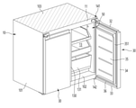
도 1은 본 발명의 실시 예에 의한 냉장고가 설치된 모습을 보인 사시도이다.
도 2는 상기 냉장고의 사시도이다.
도 3은 상기 냉장고의 도어가 개방된 절개 사시도이다.
도 4는 도3의 상태에서 수납부재가 인출된 모습을 보인 절개 사시도이다.
도 5는 상기 도어의 후면을 보인 사시도이다.
도 6은 본 발명의 실시 예에 의한 사이드 커버가 장착된 모습을 보인 사시도이다.
도 7은 상기 사이드 커버가 분리된 분해 사시도이다.
도 8은 상기 사이드 커버와 가이드부재가 결합된 모습을 보인 사시도이다.
도 9는 상기 사이드 커버와 가이드부재가 분리된 분해 사시도이다.
도 10은 도1의 X-X' 단면도이다.
도 11은 도 10의 상태에서 상기 도어가 개방된 단면도이다.
도 12는 도 11의 상태에서 상기 수납부재가 인출된 단면도이다.
도 13은 도 12의 A부 확대 도이다.
도 14는 본 발명의 다른 실시 예에 의한 상기 사이드 커버가 장착된 모습을 보인 단면도이다.
도 15는 본 발명의 또 다른 실시 예에 의한 상기 사이드 커버가 장착된 모습을 보인 단면도이다. 1 is a perspective view showing a state in which a refrigerator according to an embodiment of the present invention is installed.
2 is a perspective view of the refrigerator.
3 is a cutaway perspective view of an open door of the refrigerator.
4 is a cutaway perspective view showing a state in which the receiving member is drawn out in the state of FIG. 3 .
5 is a perspective view showing the rear surface of the door.
6 is a perspective view showing a side cover according to an embodiment of the present invention is mounted.
7 is an exploded perspective view in which the side cover is removed.
8 is a perspective view showing a state in which the side cover and the guide member are combined.
9 is an exploded perspective view in which the side cover and the guide member are separated.
FIG. 10 is a cross-sectional view taken along line XX′ of FIG. 1 .
11 is a cross-sectional view of the door opened in the state of FIG. 10 .
12 is a cross-sectional view in which the housing member is drawn out in the state of FIG. 11 .
13 is an enlarged view of part A of FIG. 12 .
14 is a cross-sectional view showing a state in which the side cover according to another embodiment of the present invention is mounted.
15 is a cross-sectional view showing a state in which the side cover according to another embodiment of the present invention is mounted.
이하에서는 본 발명의 구체적인 실시 예를 도면과 함께 상세히 설명하도록 한다. 그러나 본 발명은 본 발명의 사상이 제시되는 실시 예에 제한된다고 할 수 없으며, 또 다른 구성요소의 추가, 변경, 삭제 등에 의해서 퇴보적인 다른 발명이나 본 발명의 사상범위 내에 포함되는 다른 실시 예를 용이하게 제안할 수 있다.Hereinafter, specific embodiments of the present invention will be described in detail with drawings. However, the present invention cannot be said to be limited to the embodiments in which the spirit of the present invention is presented, and other inventions that are degenerative by addition, change, deletion, etc. of other components or other embodiments included within the scope of the present invention are easy. can suggest
설명에 앞서 방향을 정의한다. 본 발명의 실시 예는 도 2 에서 보이는 도어의 전면이 향하는 방향을 전방, 도어의 전면을 기준으로 캐비닛을 향하는 방향을 후방 그리고, 냉장고가 설치되는 바닥면을 향하는 방향을 하방, 그리고 바닥면에서 멀어지는 방향을 상방으로 정의할 수 있다. 그리고, 도 3에서 저장 공간을 향하는 방향을 내측, 캐비닛의 바깥쪽을 향하는 방향을 외측으로 정의 할 수 있으며, 이하에서 별도의 방향의 정의를 하지 않는 한 이와 같은 방향을 기준으로 설명하기로 한다. Before the description, the direction is defined. According to the embodiment of the present invention, the direction in which the front of the door faces as shown in FIG. 2 is forward, the direction toward the cabinet with respect to the front of the door is in the rear, and the direction toward the floor where the refrigerator is installed is downward, and away from the floor. The direction can be defined as upward. In addition, in FIG. 3 , the direction toward the storage space may be defined as the inside and the direction toward the outside of the cabinet may be defined as the outside.
도 1은 본 발명의 실시 예에 의한 냉장고가 설치된 모습을 보인 사시도이다. 그리고, 도 2는 상기 냉장고의 사시도이다.1 is a perspective view showing a state in which a refrigerator according to an embodiment of the present invention is installed. And, Figure 2 is a perspective view of the refrigerator.
도시된 것과 같이, 본 발명의 실시 예에 의한 냉장고(1)는 전면이 개구된 저장 공간을 형성하는 캐비닛(10)과, 상기 저장 공간을 개폐하는 도어(20,30)에 의해 전체적인 외관이 형성될 수 있다. As shown, the
그리고, 상기 냉장고(1)는 실내 공간의 가구 또는 벽체(O)와 조화를 이루도록 장착될 수 있다. 도시된 것과 같이, 상기 냉장고(1)는 주방과 같은 실내 공간에 설치될 수 있으며, 가구 또는 벽체(O)와 인접하여 조화를 이루도록 배치될 수 있다. 즉, 가구 또는 벽체(O)에 상기 냉장고(1)의 크기와 대응하는 공간이 제공되고 상기 냉장고(1)가 수용되거나, 빌트인 타입으로 배치될 수 있다. 그리고, 상기 냉장고(1)의 측방에는 다른 냉장고가 연속하여 병렬 배치될 수도 있다.In addition, the
상기 캐비닛(10)의 내부의 저장 공간은 상하로 구획될 수 있으며, 상기 캐비닛(10)의 상부에는 냉장실(12)이 형성될 수 있고 상기 캐비닛(10)의 하부에는 냉동실(13)이 형성될 수 있다.The storage space inside the
상기 도어는 냉장실 도어(20)와 냉동실 도어(30)로 구성될 수 있다. 상기 냉장실 도어(20)는 상기 냉장실(12)의 개구된 전면을 회동에 의해 개폐하며, 상기 냉동실 도어(30)는 상기 냉동실(13)의 개구된 전면을 회동에 의해 개폐하도록 구성될 수 있다. 한편, 상기 냉장실 도어(20)는 상방에 구비되므로 상부 도어라 부를 수 있으며, 상기 냉동실 도어(30)는 하방에 구비되므로 하부 도어라 부를 수 있다. The door may include a
그리고, 상기 냉장실 도어(20)는 좌우 한쌍이 구비되어 한쌍의 도어(20)에 의해 상기 냉장실(12)이 차폐되도록 구성될 수 있다. 그리고, 상기 냉동실 도어(30)는 좌우 한쌍이 구비되어 한쌍의 도어에 의해 상기 냉동실(13)을 개폐하도록 구성될 수 있다. 물론, 상기 냉동실 도어(30)는 필요에 따라서 서랍식으로 인출 가능하게 구성될 수 있으며, 하나 또는 그 이상으로 구성될 수도 있다.In addition, the refrigerating
한편, 한쌍의 상기 냉장실 도어(20) 중 적어도 일측의 도어(20)는 개구부가 형성된 메인 도어(20a)와 상기 개구부를 개폐하는 서브 도어(20b)로 구성될 수도 있다. Meanwhile, the
상기 냉동실 도어(30)는 상기 냉장실 도어(20)와 마찬가지로 좌우 한쌍이 구비되며, 한쌍의 도어(30)에 의해서 상기 냉동실(13)을 개폐하도록 구성될 수 있다. The
그리고, 이하에서는 상기 냉동실(13)을 개폐하는 냉동실 도어(30)를 기준으로 설명하기로 하며, 설명과 이해의 편의를 위해 상기 냉동실(13)은 저장 공간(13)이라 부르며, 상기 냉동실 도어(30)를 도어(30)라 부르기로 한다. And, hereinafter, the freezing
물론, 본 발명은 냉동실 및 냉동실 도어에만 적용되는 것이 아니라 회전식 도어가 구비되는 모든 타입의 냉장고에 적용될 수 있는 것을 미리 밝혀 둔다.Of course, the present invention is not only applied to the freezer compartment and the freezer compartment door, but it is disclosed in advance that it can be applied to all types of refrigerators provided with a rotary door.
이하에서는 상기 냉장고(1)의 저장 공간 내부의 구조에 관하여 도면을 참조하여 살펴보기로 한다.Hereinafter, a structure inside the storage space of the
도 3은 상기 냉장고의 도어가 개방된 절개 사시도이다. 그리고, 도 4는 도3의 상태에서 수납부재가 인출된 모습을 보인 절개 사시도이다.3 is a cutaway perspective view of an open door of the refrigerator. And, FIG. 4 is a cut-away perspective view showing the state in which the receiving member is drawn out in the state of FIG. 3 .
도시된 것과 같이, 상기 저장 공간(13)의 내부에는 세로 구획벽(130)이 구비될 수 있으며, 상기 저장 공간(13)이 좌우 양측으로 구획될 수 있다. 그리고, 좌우 양측의 각각의 저장 공간(13)은 한쌍의 상기 도어(30)에 의해 회전에 의해 개폐될 수 있다. 이를 위해 상기 도어(30)의 상단에는 상부 힌지(141)가 구비되고, 상기 도어(30)의 하단에는 하부 힌지(142)가 구비되며, 상기 캐비닛(10)에 회전 가능하게 체결될 수 있다. 즉, 상기 도어(30)는 상기 캐비닛(10)의 좌우 양측단에 구비되는 상부 힌지(141)와 하부 힌지(142)를 축으로 회전하여 상기 저장 공간(13)을 개폐할 수 있다. As illustrated, a
상기 상부 힌지(141)는 상기 상부 도어(20)와 하부 도어(30)의 사이에 구비되어 상기 상부 도어(20) 하단을 지지하고 상기 하부 도어(30) 상단을 지지하도록 구성될 수도 있으며, 이 경우, 상기 상부 힌지(141)는 센터 힌지라 부를 수도 있다. 그리고, 상기 상부 힌지(141)는 상기 상부 저장 공간(12)과 하부 저장 공간(13)의 사이에 구비되는 구획벽(11)의 전면에 장착될 수 있다. The
한편, 상기 캐비닛(10)은 외측면을 형성하는 아웃 케이스(101)와, 저장 공간(13)의 내측면을 형성하는 이너 케이스(102)에 의해 형성될 수 있다. 그리고, 상기 아웃 케이스(101)와 이너 케이스(102)는 사이에 이격된 공간을 형성하도록 결합될 수 있다. 상기 아웃 케이스(101)와 이너 케이스(102)의 결합에 의해 형성되는 공간에는 단열재(103)가 채워질 수 있다. 그리고, 상기 구획벽(11)과 세로 구획벽(130)의 내부에도 단열재가 채워질 수 있다. Meanwhile, the
상기 저장 공간(13)의 내부에는 다수의 수납부재(131)가 구비될 수 있다. 상기 수납부재(131)는 선반 또는 서랍의 형태로 구성될 수 있으며, 다수개가 상하 방향으로 이격 배치되어 상기 저장 공간(13) 내부에 다수의 수납 영역을 제공할 수 있다. A plurality of accommodating
다수의 상기 수납부재(131)는 상기 저장 공간(13)의 내부에서 인출입 될 수 있다. 즉, 상기 수납부재(131)는 상기 도어(30)가 개방된 상태에서 상기 저장 공간(13)의 개구된 전면 외측으로 인출될 수 있다. The plurality of accommodating
이를 위해서 상기 저장 공간(13) 내측의 좌우 양측면에는 가이드부재(40)가 구비될 수 있다. 상기 가이드부재(40)는 상기 수납부재(131)를 양측방에서 지지하며, 상기 수납부재(131)가 전후 방향으로 인출입될 수 있도록 안내할 수 있다. 상기 가이드부재(40)의 구체적인 구조와 형상은 아래에서 다시 설명하기로 한다.To this end, guide
그리고, 상기 저장 공간(13) 내측의 좌우 양측면 중 일측면에는 사이드 커버(50)가 구비될 수 있다. 상기 사이드 커버(50)는 상기 도어(30)가 닫힌 상태에서 상기 도어(30)와 상기 캐비닛(10) 사이의 냉기 누설을 방지하고, 냉각 성능이 저하되는 것을 방지할 수 있다. In addition, a
상기 사이드 커버(50)는 상기 이너 케이스(102)의 좌우 양측면 중 상기 도어(30)의 회전축과 인접한 일측면에 구비될 수 있다. 즉, 상기 도어(30)가 상기 캐비닛(10)의 좌우 양측면에 구비되는 경우 상기 저장 공간(13)의 좌우양 측면에 각각 구비될 수 있다.The side cover 50 may be provided on one side adjacent to the rotation shaft of the
상기 사이드 커버(50)는 상기 저장 공간(13)의 전단을 따라서 상하방향으로 연장될 수 있으며, 상기 저장 공간(13)의 상단에서 하단까지 연장될 수 있다. 그리고, 상기 사이드 커버(50)는 상기 저장 공간(13)의 전단에서 상기 가이드부재(40)의 전단 사이의 길이와 대응하는 폭을 가질 수 있다.The side cover 50 may extend in the vertical direction along the front end of the
한편, 상기 도어(30)는 상기 저장 공간(13)의 좌우 양측면 중 상기 사이드 커버(50)가 장착된 일면에 회전 가능하게 장착될 수 있다. 즉, 본 실시 예에서와 같이 좌우 양측에 도어(30)가 구비되는 경우에는 상기 이너 케이스(102)의 좌우 양측면에 각각 상기 사이드 커버(50)가 구비될 수 있다. 그리고, 상기 도어(30)가 하나만 구비되는 경우에는 상기 사이드 커버(50)는 상기 이너 케이스(102)의 좌우 양측면 상기 도어(30)가 장착되는 면과 인접한 일측면에만 구비될 수 있다. Meanwhile, the
이하에서는 상기 도어(30)의 구조에 관하여 도면을 참조하여 보다 상세하게 살펴보기로 한다. Hereinafter, the structure of the
도 5는 상기 도어의 후면을 보인 사시도이다. 5 is a perspective view showing the rear surface of the door.
도면에 도시된 것과 같이, 상기 도어(30)는 전면 외관을 형성하는 아웃 플레이트(31)와, 후면을 형성하는 도어 라이너(35) 그리고, 상기 아웃 플레이트(31)와 도어 라이너(35) 사이에 배치되는 도어 단열재(37)를 포함할 수 있다. As shown in the drawing, the
상기 아웃 플레이트(31)는 판상으로 형성될 수 있으며, 상기 도어(30)의 적어도 전면 외관을 형성할 수 있다. 상기 아웃 플레이트(31)는 유리 또는 금속 소재로 형성될 수 있으며, 상기 도어(30)의 전면 전체가 평면 형상이 되도록 할 수 있다.The
그리고, 상기 아웃 플레이트(31)는 상기 도어(30)에 탈착 가능한 구조를 가질 수 있다. 그리고, 상기 아웃 플레이트(31)는 그 소재에 제한되지 않고 상기 냉장고(1)가 배치되는 공간의 가구 또는 다른 가전 제품(O)과 어울릴 수 있도록 동일 소재로 형성될 수도 있다.In addition, the
그리고, 상기 도어(30)의 상면과 하면에는 어퍼 캡데코(32)와 로어 캡데코(33)가 구비될 수 있다. 상기 어퍼 캡데코(32)에는 함몰된 손잡이(321)가 형성되어 사용자가 상기 손잡이(321)를 잡고 상기 도어(30)를 회전 조작할 수 있다. 그리고, 상기 어퍼 캡데코(32)의 일단에는 상기 상부 힌지(141)와 결합되는 힌지 홀(322)이 형성될 수 있다. 도시되지는 않았지만, 상기 로어 캡데코(33)에도 상기 하부 힌지(142)와 결합되는 힌지 홀(322)이 더 형성될 수 있다. In addition, an
그리고, 상기 도어(30)의 좌우 양측면에는 사이드 데코(34)가 구비될 수 있다. 상기 사이드 데코(34)는 상기 어퍼 캡데코(32)와 로어 캡데코(33)의 좌우 양측단을 연결하도록 형성될 수 있다.In addition,
상기 어퍼 캡데코(32)와 로어 캡데코(33) 그리고 한쌍의 사이드 데코(34)는 상기 아웃 플레이트(31) 및 도어 라이너(35)와 결합될 수 있다. 그리고, 상기 어퍼 캡데코(32)와 로어 캡데코(33) 그리고 한쌍의 사이드 데코(34)는 상기 아웃 플레이트(31) 및 도어 라이너(35)의 결합에 의해 형성되는 사이 공간에는 도어 단열재(37)가 채워질 수 있다. The
한편, 상기 도어(30)의 배면 둘레 즉, 상기 도어 라이너(35)의 둘레를 따라서 가스켓(36)이 구비될 수 있다. 상기 가스켓(36)은 도어 다이크(351)의 바깥쪽 둘레를 따라서 배치될 수 있다. 상기 가스켓(36)은 상기 도어(30)가 닫혔을 때 상기 캐비닛(10)의 전면과 접하여 상기 저장 공간(13)을 기밀하도록 구성될 수 있다. Meanwhile, the
한편, 상기 도어 라이너(35)는 상대적으로 두께가 얇은 플라스틱 소재로 형성될 수 있으며, 둘레를 따라서 도어 다이크(351)가 성형될 수 있도록 형성될 수 있다. 즉, 상기 도어 라이너(35)는 진공 성형에 의해 형성될 수 있으며, 상기 도어 라이너(35)의 성형시 상기 도어 다이크(351)가 함께 형성될 수 있다. Meanwhile, the
상기 도어 다이크(351)는 상기 도어(30)의 배면 둘레를 따라 후방으로 돌출될 수 있으며, 상기 가스켓(36)의 내측 영역의 둘레를 따라 배치될 수 있다. 그리고, 상기 도어 다이크(351)는 상기 도어(30)의 둘레 중 상기 도어(30)의 회전축과 가까운 일측단을 제외한 나머지 영역을 따라서 형성될 수 있다. 일 예로, 도 5에서와 같이 상기 도어(30) 후면의 좌측단을 제외한 상단과 우측단 그리고 하단을 따라서 후방으로 돌출될 수 있다. The
상기 도어(30)가 닫힌 상태에서 상기 저장 공간(13)의 내측으로 삽입될 수 있으며, 삽입되는 부분이 상기 저장 공간(13)의 내측면과 오버랩 되도록 인접되어 상기 저장 공간(13) 내부의 냉기가 누설되거나 전도되는 것을 방지할 수 있다. The
상세히, 상기 도어 다이크(351)는 어퍼 파트(351a)와 로어 파트(351c) 그리고 상기 어퍼 파트(351a)와 로어 파트(351c)의 일단을 연결하는 사이드 파트(351b)를 포함할 수 있다. In detail, the door die 351 may include an
상기 어퍼 파트(351a)는 상기 도어(30)의 상단을 따라서 형성되며, 상기 도어(30) 상단의 좌측에서 우측단까지 연장될 수 있다. 상기 어퍼 파트(351a)는 상기 도어(30)가 닫히게 될 때 상기 저장 공간(13)의 내측으로 삽입될 수 있으며, 상기 저장 공간(13)의 상면과 인접할 수 있다. 그리고, 상기 도어(30)가 완전히 닫히게 되면 상기 어퍼 파트(351a)는 상기 저장 공간(13)의 상면 전단과 오버랩 될 수 있다.The
그리고, 상기 로어 파트(351c)는 상기 도어(30)의 하단을 따라서 형성되며, 상기 도어(30) 하단의 좌측에서 우측단까지 연장될 수 있다. 상기 로어 파트(351c)는 상기 도어(30)가 닫히게 될 때 상기 저장 공간(13)의 내측으로 삽입될 수 있으며, 상기 저장 공간(13)의 하면과 인접할 수 있다. 그리고, 상기 도어(30)가 완전히 닫히게 되면 상기 로어 파트(351c)는 상기 저장 공간(13)의 하면 전단과 오버랩 될 수 있다.In addition, the
그리고, 상기 사이드 파트(351b)는 상기 어퍼 파트(351a)와 로어 파트(351c)의 좌우 양측단 중 일측단을 연결할 수 있다. 상기 사이드 파트(351b)는 상기 도어(30)의 좌우 양측단 중 상기 도어(30)의 회전축과 먼 측단을 따라서 상하로 연장될 수 있다. 일 예로, 도 5 에서와 같이 상기 사이드 파트(351b)는 상기 어퍼 파트(351a)의 우측단과 상기 로어 파트(351c)의 우측단을 연결하도록 형성될 수 있다. 상기 사이드 파트(351b)는 상기 도어(30)가 닫히게 될 때 상기 저장 공간(13)의 내측으로 삽입될 수 있으며, 상기 저장 공간(13)의 우측면과 인접할 수 있다. 그리고, 상기 도어(30)가 완전히 닫히게 되면 상기 사이드 파트(351b)는 상기 저장 공간(13)의 우측면 전단과 오버랩 될 수 있다. In addition, the
따라서, 상기 도어 다이크(351)는 상기 도어(30)의 배면 둘레 중 좌측단을 제외한 나머지 둘레를 따라서 형성될 수 있다. 그리고, 상기 도어 다이크(351)가 형성되지 않은 상기 도어(30) 후면의 좌측단은 상기 도어 다이크(351) 내측 영역의 상기 도어(30) 후면과 동일 평면을 형성하게 된다.Accordingly, the door die 351 may be formed along the perimeter of the rear surface of the
상기 도어 다이크(351) 내측은 평면 형상으로 형성될 수 있으며, 상기 도어 라이너(35)의 굴곡을 방지하기 위한 홈이 가로 방향으로 연장 형성될 수 있으며, 다수개가 일정 간격으로 배치될 수 있다. The inside of the door die 351 may be formed in a planar shape, and a groove for preventing bending of the
상기 도어(30)의 후면은 평면 형상으로 형성되되 상기 도어(30)의 좌측단까지 동일 평면을 이루면서 연장될 수 있다. 따라서, 상기 도어(30)가 닫히게 되면, 상기 도어 다이크(351)가 형성되지 않은 상기 도어(30)의 후면 좌측단은 상기 사이드 커버(50)와 인접하게 된다. 즉, 상기 도어(30)가 닫힌 상태에서 상기 사이드 커버(50)가 상기 도어 다이크(351)의 역할을 대신할 수 있다. The rear surface of the
이하에서는, 상기 사이드 커버(50)의 구조 및 장착 구조에 관하여 도면을 참조하여 보다 상세하게 살펴보기로 한다.Hereinafter, the structure and mounting structure of the
도 6은 본 발명의 실시 예에 의한 사이드 커버가 장착된 모습을 보인 사시도이다. 그리고, 도 7은 상기 사이드 커버가 분리된 분해 사시도이다. 그리고, 도 8은 상기 사이드 커버와 가이드부재가 결합된 모습을 보인 사시도이다. 그리고, 도 9는 상기 사이드 커버와 가이드부재가 분리된 분해 사시도이다. 6 is a perspective view showing a side cover according to an embodiment of the present invention is mounted. And, FIG. 7 is an exploded perspective view in which the side cover is separated. And, FIG. 8 is a perspective view showing a state in which the side cover and the guide member are combined. And, FIG. 9 is an exploded perspective view in which the side cover and the guide member are separated.
도면에 도시된 것과 같이, 상기 사이드 커버(50)는 상기 저장 공간(13)의 내측을 형성하는 이너 케이스(102)에 장착될 수 있다.As shown in the drawing, the
상기 저장 공간(13)의 내측면은 상기 이너 케이스(102)에 의해 형성되며, 상기 저장 공간(13)의 좌우 양측면 중 상기 도어(30)가 장착되는 일측면, 즉, 도 7에서 우측면에는 경사부(102a)가 형성될 수 있다. The inner surface of the
상기 경사부(102a)는 상기 저장 공간(13)의 측면 전단에 형성될 수 있다. 그리고, 상기 경사부(102a)는 전방으로 갈수록 외측을 향하여 경사지게 형성될 수 있다. 즉, 상기 저장 공간(13)의 좌측면은 후단에서 상기 경사부(102a)까지는 상기 아웃 케이스(101)를 기준으로 동일 거리를 유지하면서 연장될 수 있으며, 상기 경사부(102a)는 전방을 향할수록 상기 아웃 케이스(101)와 점차 가까워지는 경사를 가질 수 있다. The
상기 가이드부재(40)가 장착되는 영역의 측벽면은 경사지지 않고 상기 저장 공간(13)의 좌우 폭이 동일한 상태로 연장 형성될 수 있다. 그리고, 상기 가이드부재(40) 전방에 상기 경사부(102a)가 형성될 수 있으며, 상기 경사부(102a)는 전방으로 갈수록 좌우 폭이 점차 커지도록 형성될 수 있다. The side wall surface of the region on which the
이와 같은 상기 경사부(102a)의 구조로 인하여 상기 이너 케이스(102)의 진공 성형을 용이하게 할 수 있게 된다. Due to the structure of the
한편, 상기 사이드 커버(50)는 상기 이너 케이스(102)에 결합될 수 있으며, 상기 경사부(102a)를 차폐할 수 있도록 형성될 수 있다. 즉, 상기 사이드 커버(50)가 장착된 상태에서 상기 경사부(102a)는 상기 사이드 커버(50)의 내측에 위치될 수 있다. Meanwhile, the
그리고, 상기 사이드 커버(50)의 상하 높이는 상기 저장 공간(13)의 상하 높이와 대응하도록 형성될 수 있으며, 상기 사이드 커버(50)의 전후 방향 폭은 상기 경사부(102a)의 전후 방향 길이보다 더 크게 형성될 수 있다. 따라서, 상기 사이드 커버(50)가 장착된 상태에서 상기 경사부(102a)를 차폐할 수 있으며, 상기 사이드 커버(50)는 상기 저장 공간(13)의 측면의 전단부 외관을 형성할 수 있다. 따라서, 상기 도어(30)가 개방되고, 상기 수납부재(131)가 인입된 상태에서는 상기 사이드 커버(50)가 외측으로 노출될 수 있다. In addition, the vertical height of the
상기 사이드 커버(50)의 구조를 살펴보면, 상기 사이드 커버(50)는 플라스틱 소재로 사출 형성될 수 있으며, 상기 이너 케이스(102)와 결합되어 내부에 공간을 형성할 수 있다. 그리고, 상기 사이드 커버(50)는 상기 저장 공간(13)의 측면을 형성하는 커버면(51)과, 상기 커버면(51)의 둘레를 따라 형성되는 테두리(52)를 포함할 수 있다. Looking at the structure of the
상세히, 상기 커버면(51)은 상기 경사부(102a)를 차폐할 수 있는 크기로 형성될 수 있으며, 상기 저장 공간(13)의 내측을 향하도록 배치될 수 있다. 그리고, 상기 커버면(51)은 리어 파트(511)와 프론트 파트(512)를 포함할 수 있다. In detail, the
상기 리어 파트(511)는 상기 커버면(51)의 후반부를 형성하며, 상기 아웃 케이스(101)와 나란하게 연장될 수 있다. 즉, 상기 리어 파트(511)는 경사지지 않은 상태로 연장될 수 있으며, 소정의 폭을 가지도록 형성될 수 있다.The
그리고, 상기 리어 파트(511)의 후단은 상기 가이드부재(40)의 전단과 접할 수 있다. 그리고, 상기 리어 파트(511)의 전단은 상기 경사부(102a)의 영역까지 연장될 수 있다. 그리고, 상기 리어 파트(511)에는 상기 사이드 커버(50)의 장착을 위한 장착 보스(518)가 형성될 수 있다. 상기 장착 보스(518)는 상기 리어 파트(511)의 외측면에서 상기 이너 케이스(102)를 향하여 연장되며, 상기 이너 케이스(102)에 밀착될 수 있다. 그리고, 상기 장착 보스(518)에는 스크류 홀(518a)이 형성될 수 있으며, 스크류(518b)가 관통되어 상기 이너 케이스(102)에 체결될 수 있다. 상기 장착 보스(518) 및 스크류(518b)는 다수개가 형성될 수 있으며, 상하 이격 배치될 수 있다. 그리고, 상기 장착 보스(518) 및 스크류(518b)는 전후 방향으로도 이격된 위치에 배치될 수 있다. In addition, the rear end of the
상기 리어 파트(511)의 전단에는 프론트 파트(512)가 형성될 수 있다. 상기 프론트 파트(512)는 상기 리어 파트(511)의 전단에서 상기 저장 공간(13)의 전단까지 연장되어 상기 프론트 파트(512)는 상기 커버면(51)의 전반부 형상을 형성할 수 있다. 상기 프론트 파트(512)는 전방을 향할수록 상기 아웃 플레이트(31)를 향하도록 경사지게 형성될 수 있으며, 상기 도어(30)가 닫히는 과정에서 상기 도어(30)의 후면과 부딪히거나 간섭되지 않도록 할 수 있다.A
그리고, 상기 프론트 파트(512)의 전후 방향 폭은 상기 도어(30) 후면의 도어 다이크(351)의 돌출 높이보다 더 크게 형성될 수 있다. 따라서, 상기 도어(30)가 닫힌 상태에서 상기 도어 다이크(351)는 상기 프론트 파트(512)와 대응하는 영역에 삽입될 수 있다. In addition, the front-rear width of the
상기 테두리(52)는 상기 사이드 커버(50)의 커버면(51)의 둘레를 따라서 형성되며, 외측을 향하도록 절곡 형성될 수 있다. 따라서, 상기 테두리(52)의 절곡된 단부가 상기 이너 케이스(102)와 접할 수 있다.The
상기 테두리(52)는 상기 사이드 커버(50)의 전면을 형성하는 전면(521)과, 후면을 형성하는 후면(522) 및 하면을 형성하는 하면(523)을 포함할 수 있다. 본 실시 예에서 상기 사이드 커버(50)의 상면은 개구도록 형성되지만, 필요에 따라서 상기 테두리(52)는 상기 사이드 커버(50)의 상면을 형성하는 상면을 더 포함할 수도 있다. The
상기 사이드 커버(50)의 개구된 상면은 상기 사이드 커버(50)의 장착시 상기 저장 공간(13)의 상면에 의해서 차폐될 수 있다. 그리고, 상기 사이드 커버(50)의 하면(523)은 상기 저장 공간(13)의 바닥면에 의해 지지될 수 있다.The opened upper surface of the
상기 사이드 커버(50)의 전면(521)은 상기 상기 도어(30)의 개방시 전방으로 노출되는 면을 형성할 수 있으며, 상기 캐비닛(10)의 전면 즉, 상기 이너 케이스(102)의 전단과 동일 평면상에 위치되거나 다수 후방에 위치될 수 있다. 그리고, 상기 도어(30)가 닫힌 상태에서는 상기 사이드 커버(50)의 전면(521)이 상기 도어(30)의 배면과 인접할 수 있다. 그리고, 상기 사이드 커버(50)의 전면의 폭은 상기 사이드 커버(50)의 후면(522)의 폭 보다 더 크게 형성될 수 있다.The
상기 사이드 커버(50)의 후면(522)은 상기 가이드부재(40)의 전면과 대응하는 위치에 위치될 수 있으며, 상기 가이드부재(40)와 접하도록 형성될 수 있다. 그리고, 상기 사이드 커버(50)의 후면(522)은 상기 가이드부재(40)의 전면(521)과 서로 결합될 수 있으며, 상기 사이드 커버(50)가 한층 더 견고하게 상기 저장 공간(13)의 내부에서 고정된 상태를 유지하도록 할 수 있다. The
상세히, 상기 사이드 커버(50)의 후면(522)에는 전방으로 함몰되어 상기 가이드부재(40)의 전단이 삽입되는 커버 함몰부(522a)가 형성될 수 있다. 상기 커버 함몰부(522a)는 상기 가이드부재(40)의 전단의 형상과 대응하는 형상으로 형성될 수 있으며, 상기 가이드부재(40)의 전단을 수용하여 상기 가이드부재(40)와 상기 사이드 커버(50)가 정확한 위치에서 서로 견고하게 고정되도록 할 수 있다. In detail, a
상기 커버 함몰부(522a)는 상기 복수개가 형성될 수 있으며, 상기 가이드부재(40)의 개수와 대응하는 개수만큼 형성될 수 있다. 즉, 복수의 상기 가이드부재(40)는 대응하는 커버 함몰부(522a)에 삽입되어 모두 장착 위치가 고정될 수 있다.The plurality of
한편, 상기 사이드 커버(50)의 후면(522)에는 후방으로 돌출되는 결합 돌기(53)가 돌출 형성될 수 있다. 상기 결합 돌기(53)는 상기 사이드 커버(50)의 후면과 수직하게 후방으로 돌출될 수 있으며, 상기 가이드부재(40) 전면의 결합구(412,422)의 내측으로 삽입되어 상기 사이드 커버(50)와 가이드부재(40)가 서로 결합되도록 할 수 있다. On the other hand, a
상기 결합 돌기(53)는 상기 사이드 커버(50)의 성형시 일체로 형성될 수 있으며, 상기 가이드부재(40)의 결합구(412,422)에 압입되어 상기 사이드 커버(50)와 상기 가이드부재(40)가 서로 견고한 결합 상태를 유지하도록 할 수 있다.The
상세히, 상기 결합 돌기(53)는 상기 사이드 커버(50)의 후면(522)에서 돌출되는 돌출부(531)와, 상기 돌출부(531)의 양측단에 상기 돌출부(531)와 이격되는 탄성부(532)를 형성하며, 상기 돌출부(531)와 탄성부(532)의 사이에는 상기 탄성부(532)의 탄성 변형을 위한 공간부(533)가 형성될 수 있다. In detail, the
상기 탄성부(532)는 상기 돌출부(531)의 상면과 하면에 각각 형성될 수 있으며, 상기 돌출부(531)의 전단과 상기 돌출부(531)의 후단을 연결할 수 있다. 그리고, 상기 탄성부(532)는 중앙부가 돌출되고, 전후단으로 갈수록 낮아지도록 형성될 수 있다. 그리고, 상기 탄성부(532)의 돌출 높이는 상기 결합구(412,422)의 단부보다 더 돌출되도록 형성될 수 있다.The
따라서, 상기 결합 돌기(53)가 상기 결합구(412,422)에 삽입될 때 상기 탄성부(532)가 탄성 변형되면서 상기 결합구(412,422) 내측으로 압입될 수 있다. 그리고, 상기 결합 돌기(53)가 상기 결합구(412,422)에 삽입 완료된 상태에서는 상기 탄성부(532)가 복원되어 상기 결합 돌기(53)가 상기 결합구(412,422) 내측에서 견고하게 결합된 상태를 유지할 수 있다. Accordingly, when the
한편, 상기 결합 돌기(53)는 상기 커버 함몰부(522a) 상에서 돌출될 수 있다. 그리고, 상기 가이드부재(40)의 상하 폭이 넓은 경우에는 결합 돌기(53)와 상기 커버 함몰부(522a)가 상하 이격 배치될 수도 있다. 즉, 상기 가이드부재(40)의 전단 일부는 상기 커버 함몰부(522a)에 삽입되어 고정되고, 나머지 일부는 상기 결합 돌기(53)와 상기 결합구(412,422)의 결합에 의해 고정될 수 있다.Meanwhile, the
상기 가이드부재(40)는 상기 수납부재(131)의 좌우 양측에 구비되며, 상기 이너 케이스(102)에 고정 장착될 수 있다. 상기 가이드부재(40)는 상기 저장 공간(13)의 후단에서 상기 사이드 커버(50)까지 연장될 수 있다. 상기 수납부재(131)가 상하로 복수개 구비되는 경우 상기 가이드부재(40) 또한 복수개가 구비될 수 있다. 일 예로, 상기 가이드부재(40)는 상방에 배치되는 어퍼 가이드부재(41)와 하방에 구비되는 로어 가이드부재(42)를 포함할 수 있다. The
상기 가이드부재(40)는 전체적으로, 전후 방향으로 연장되는 가이드 홈(411a,421a)을 형성하는 바디부(411,421)와, 상기 바디부(411,421)의 둘레를 따라서 연장되는 둘레부(413,423)를 포함할 수 있다. 상기 가이드 홈(411a,421a)은 전방으로 개구될 수 있으며, 상기 수납부재(131)의 양측면에 구비된 레일 또는 롤러가 출입되도록 형성될 수 있다. The
상기 가이드부재(40)는 상기 이너 케이스(102)에 장착된 상태에서 상기 사이드 커버(50)의 커버면(51)보다 더 내측으로 돌출될 수 있다. 따라서, 상기 가이드 홈(411a,421a)의 개구된 전면은 상기 사이드 커버(50)의 후방에서 노출될 수 있으며, 상기 수납부재(131)의 탈착이 가능할 수 있다. The
그리고, 상기 바디부(411,421)에는 다수의 스크류 보스(415)와 체결 돌기(416)가 형성될 수 있다. 상기 스크류 보스(415)와 체결 돌기(416)는 상기 바디부(411,421)에 다수개 구비되어 상기 가이드부재(40)가 전체적으로 상기 이너 케이스(102)에 결합될 수 있도록 한다. In addition, a plurality of
상기 스크류 보스(415)는 상기 이너 케이스(102)를 향하여 연장될 수 있으며, 상기 이너 케이스(102)에 체결되는 스크류가 관통되도록 형성될 수 있다. 그리고, 상기 체결 돌기(416)는 상기 이너 케이스(102)에 삽입되어 체결될 수 있다. 따라서, 상기 가이드부재(40)는 상기 스크류와 체결 돌기(416)에 의해서 상기 이너 케이스(102)에 고정될 수 있다. The
상기 둘레부(413,423)는 상기 바디부(411,421)의 둘레에서 외측으로 수직하게 절곡될 수 있으며, 상기 가이드부재(40)의 장착시 상기 이너 케이스(102)의 내측면과 접할 수 있다. 그리고, 상기 둘레부(413,423) 내측 즉, 상기 바디부(411,421)의 영역에는 서로 교차되는 다수개의 보강 리브(417)가 구비될 수 있다. 따라서 상기 가이드부재(40)는 무거운 수납부재(131)의 지지 및 인출입의 안내에도 변형되거나 파손되지 않게 된다. The peripheral portions 413,423 may be vertically bent outwardly around the
그리고, 상기 둘레부(413,423) 중 상기 가이드부재(40)의 후단에는 후방으로 돌출되는 리어 돌기(418)가 형성될 수 있다. 상기 리어 돌기(418)는 상기 저장 공간(13)의 후면에 삽입될 수 있다. 그리고, 상기 둘레부(413,423) 중 상기 가이드부재(40)의 전단은 상기 커버 함몰부(522a)에 삽입될 수 있다. 그리고, 상기 가이드부재(40)의 전단에는 상기 결합 돌기(53)가 삽입되는 상기 결합구(412,422)가 개구될 수 있다. 따라서, 상기 리어 돌기(418)와 상기 결합 돌기(53)에 의해서 상기 가이드부재(40)는 전후 방향의 유동 또한 견고하게 고정될 수 있다. In addition, a
이하에서는 상기와 같은 구조를 가지는 냉장고(1)의 동작에 관하여 도면을 참도하여 살펴보기로 한다. Hereinafter, the operation of the
도 10은 도1의 X-X' 단면도이다. 그리고, 도 11은 도 10의 상태에서 상기 도어가 개방된 단면도이다. 그리고, 도 12는 도 11의 상태에서 상기 수납부재가 인출된 단면도이다. 그리고, 도 13은 도 12의 A부 확대 도이다.FIG. 10 is a cross-sectional view taken along line X-X' of FIG. 1 . And, FIG. 11 is a cross-sectional view in which the door is opened in the state of FIG. 10 . And, FIG. 12 is a cross-sectional view in which the housing member is drawn out in the state of FIG. 11 . And, FIG. 13 is an enlarged view of part A of FIG. 12 .
도면에 도시된 것과 같이, 상기 냉장고(1)는 가구 또는 가전 제품(O)과 나란하게 배치될 수 있으며, 상기 가구 또는 가전 제품(O)은 상기 캐비닛(10) 보다 더 전방으로 돌출될 수 있다. 그리고, 도 10에 도시된 것 처럼, 상기 도어(30)가 닫힌 상태에서 상기 도어(30)의 전면은 인접하는 상기 가구 또는 가전 제품(O)과 비슷하게 돌출될 수 있다.As shown in the drawing, the
상기 도어(30)가 닫힌 상태에서 상기 가스켓(36)은 상기 캐비닛(10)의 전면과 접하는 상태가 될 수 있으며, 상기 저장 공간(13) 내부의 냉기가 외부로 누설되는 것을 차단할 수 있다. In a state in which the
그리고, 상기 도어(30)가 닫힌 상태에서 상기 도어 다이크(351)는 상기 저장 공간(13)의 내측으로 삽입될 수 있다. 이때, 상기 도어 다이크(351)는 상기 저장 공간(13)의 내측면 전단과 오버랩 될 수 있으며, 상기 저장 공간(13) 내부의 냉기 누설을 한층 더 방지할 수 있다. Also, in a state in which the
한편, 상기 도어(30)가 닫힌 상태에서 상기 사이드 커버(50)는 상기 이너 케이스(102)와 상기 도어(30)의 후면 사이에 위치되어 상기 저장 공간(13)의 냉기가 누설되는 것을 더 차단할 수 있다. On the other hand, in a state in which the
상세히, 상기 도어(30)의 좌우 양측 중 상기 도어(30)의 회전 축과 가까운 일측에는 상기 도어 다이크(351)가 형성되지 않게 되며, 상기 도어 다이크(351)가 형성되지 않은 부분의 공간을 상기 사이드 커버(50)가 채울 수 있게 된다. 즉, 상기 사이드 커버(50)의 전단은 상기 이너 케이스(102)에 결합된 상태로 상기 도어(30)의 후면과 인접하여 도어 다이크(351)가 형성된 것과 같이, 상기 저장 공간(13) 내부의 냉기가 누설되지 않도록 한다. In detail, the
특히, 상기 사이드 커버(50)의 전면(521)은 상기 도어(30)의 후면(522)과 마주보며 매우 가까이 위치되어 상기 저장 공간(13) 내부의 냉기가 누설되거나 전도에 의해 상기 가스켓(36) 외부로 전달되는 것을 최소화 할 수 있다. In particular, the
그리고, 상기 사이드 커버(50)의 커버면(51) 중 상기 프론트 파트(512)는 상기 어퍼 파트(351a)와 로어 파트(351c)의 단부와 마주보며 매우 가까이 위치될 수 있다. 뿐만 아니라 상기 상기 프론트 파트(512)와 상기 도어 다이크(351)의 단부 사이의 경로는 상기 사이드 커버의 전면(521)과 상기 도어(30) 후면(522)의 사이 경로와 꺽인 구조를 가지게 되어 상기 저장 공간(13) 내부의 냉기가 누설되거나 전도에 의해 상기 가스켓(36) 외부로 전달되는 것을 보다 줄일 수 있게 된다. In addition, the
그리고, 상기 어퍼 파트(351a)와 로어 파트(351c)의 단부는 상기 프론트 파트(512)와 대응하는 위치에 위치될 수 있으며, 따라서 상기 도어(30)가 개폐되는 과정에서도 상기 어퍼 파트(351a)와 로어 파트(351c)의 단부가 상기 사이드 커버(50)와 간섭되지 않도록 할 수 있다. In addition, the ends of the
한편, 이와 같은 상태에서 사용자는 상기 저장공간(13) 내부에 식품을 수납하기 위해서 상기 도어(30)를 개방할 수 있다. On the other hand, in this state, the user may open the
사용자는 상기 도어(30)를 회전시켜 개방되도록 할 수 있으며, 상기 도어(30)가 완전히 개방되면 도 11과 같은 상태가 될 수 있다. The user may rotate the
상기 도어(30)가 완전히 개방된 상태 또는 상기 도어(30)가 개방되는 과정에서 상기 도어(30)는 상기 캐비닛(10)의 측면보다 더 돌출되지 않도록 하며, 적어도 상기 도어(30)가 인접 배치되는 가구 또는 가전제품(O)과 간섭되지 않는 각도만큼 회전되어 개방될 수 있다. 일 예로, 상기 도어(30)가 완전히 개방되면 상기 도어(30)의 전면은 상기 캐비닛(10)의 전면과 대략 90°각도만큼 회전될 수 있다. When the
물론, 상기 도어(30)는 더 회전될 수도 있으며, 상기 도어(30)가 인접 배치되는 가구 또는 가전제품(O)과 간섭되지 않는 범위 내에서 더 회전될 수도 있다. 그리고, 상세하게 도시되지는 않았지만, 상기 도어(30)가 설정된 각도로 개방된 상태에서 더 개방되지 않도록 하는 구조가 상기 도어(30)와 상부 힌지(141) 또는 하부 힌지(142)에 제공될 수 있다. Of course, the
이와 같이 상기 도어(30)가 완전히 개방된 상태에서는 사용자는 상기 저장 공간(13) 내부의 수납부재(131)를 인출입 하여 식품을 수납할 수 있다. In this way, in a state in which the
상세히, 상기 도어(30)가 완전히 개방된 상태에서, 상기 도어 다이크(351)의 돌출 높이는 상기 이너 케이스(102) 및 상기 사이드 커버(50)의 내측면 보다 더 돌출될 수 있다. 하지만, 상기 도어 다이크(351)는 상기 도어(30)의 회전축과 인접한 측단에는 형성되지 않은 상태이며, 따라서, 상기 수납부재(131)가 상기 캐비닛(10)의 전단을 지나 상기 도어(30)의 영역까지 인출되더라도 상기 도어 다이크(351)와 수납부재(131)는 서로 간섭되지 않게 된다. In detail, in a state in which the
그리고, 상기 도어(30)의 후면(522)은 상기 수납부재(131)의 측면보다 더 외측에 위치되어 상기 수납부재(131)의 인출입시 상기 도어 다이크(351)는 물론 상기 도어(30)의 후면과도 간섭되지 않도록 할 수 있다. 즉, 상기 도어(30)가 완전히 개방된 상태에서는 도 12 및 도 13에 도시된 것과 같이 상기 수납부재(131)가 상기 도어(30)와 간섭되지 않고 인출입될 수 있다. In addition, the
한편, 본 발명은 전술한 실시 예 외에도 다양한 다른 실시 예가 가능할 수 있다. 본 발명의 다른 실시 예는 상기 사이드 커버의 내부에 단열재가 채워지는 구조를 가지는 것을 특징으로 한다. 본 발명의 다른 실시 예는 상기 단열재의 배치를 제외한 다른 구조는 전술한 실시 예와 모두 동일하며, 동일한 구성에 대해서는 공일한 도면 부호를 사용하여 표시하며, 그 상세한 설명은 생략하기로 한다. Meanwhile, the present invention may be capable of various other embodiments in addition to the above-described embodiments. Another embodiment of the present invention is characterized in that it has a structure in which an insulating material is filled inside the side cover. In another embodiment of the present invention, all other structures except for the arrangement of the heat insulating material are the same as those of the above-described embodiment, and the same reference numerals are used for the same components, and a detailed description thereof will be omitted.
도 14는 본 발명의 다른 실시 예에 의한 상기 사이드 커버가 장착된 모습을 보인 단면도이다.14 is a cross-sectional view showing a state in which the side cover according to another embodiment of the present invention is mounted.
도면에 도시된 것과 같이, 본 발명의 다른 실시 예에 의한 냉장고(1)의 캐비닛(10)의 전면에는 회전 가능하게 장착되는 도어(30)가 구비될 수 있다. As shown in the drawing, a
그리고, 상기 이너 케이스(102)의 좌우 양측면 중 상기 도어(30)의 회전축과 인접하는 일측면에는 상기 사이드 커버(50)가 구비될 수 있다. 상기 사이드 커버(50)는 상기 저장 공간(13)의 측면 전단에 배치될 수 있으며, 상기 경사부(102a)를 차폐하도록 배치될 수 있다. In addition, the
상기 사이드 커버(50)는 상기 저장 공간(13) 내측으로 노출되는 커버면(51)과, 상기 커버면(51)의 둘레를 따라서 연장되며 상기 이너 케이스(102)와 접하는 테두리(52)가 형성될 수 있다. The side cover 50 has a
그리고, 상기 사이드 커버(50)는 상기 사이드 커버(50)를 관통하여 체결되는 스크류(518b)에 의해 상기 이너 케이스(102)에 고정 장착될 수 있다. 그리고, 상기 사이드 커버(50)의 후단은 상기 가이드부재(40)의 전단과 결합되어 보다 고정될 수 있다. In addition, the
한편, 상기 사이드 커버(50)의 커버면(51)은 상기 아웃 케이스(101)와 나란하게 연장되는 리어 파트(511)와, 상기 리어 파트(511)에서 전방으로 연장되며 전방으로 연장될 수록 상기 아웃 케이스(101)를 향하도록 경사지게 형성되는 프론트 파트(512)를 포함할 수 있다.On the other hand, the
그리고, 상기 사이드 커버(50)의 테두리 중 상기 사이드 커버(50)의 전면(521)은 상기 전방으로 노출될 수 있으며, 상기 도어(30)가 닫힌 상태에서 상기 도어(30)의 후면(522)과 인접할 수 있다. In addition, the
그리고, 상기 사이드 커버(50)가 상기 이너 케이스(102)에 장착된 상태에서 상기 사이드 커버(50)와 상기 이너 케이스(102)의 사이에는 공간이 형성될 수 있으며, 상기 사이드 커버(50)가 형성하는 공간의 내부에는 커버 단열재(54)가 더 구비될 수 있다. 상기 커버 단열재(54)는 발포 단열재로 형성될수 있으며, 상기 테두리(52)에 의해 형성되는 내측의 공간 전체에 삽입될 수 있도록 형성될 수 있다. 상기 사이드 커버(50)는 상기 커버 단열재(54)가 상기 사이드 커버(50)에 삽입된 상태에서 상기 이너 케이스(102)에 결합될 수 있다. In addition, in a state in which the
상기 사이드 커버(50)의 내측에 상기 커버 단열재(54)가 채워짐으로써 상기 사이드 커버(50)의 영역만큼 단열이 보강될 수 있다. 그리고, 상기 도어(30)가 닫힌 상태에서 상기 도어(30)의 후면과 인접하여 상기 저장 공간(13) 내부의 냉기가 상기 가스켓(36) 측을 향하는 것을 보다 줄일 수 있으며, 상기 커버 단열재(54)로 인하여 냉기가 전도되는 것 또한 방지할 수 있게 된다.Since the
한편, 본 발명은 전술한 실시 예들 외에도 다양한 다른 실시 예가 가능할 수 있다. 본 발명의 또 다른 실시 예는 상기 사이드 커버의 내부에 축냉부재가 구비되는 구조를 가지는 것을 특징으로 한다. 본 발명의 다른 실시 예는 상기 축냉부재의 배치를 제외한 다른 구조는 전술한 실시 예와 모두 동일하며, 동일한 구성에 대해서는 공일한 도면 부호를 사용하여 표시하며, 그 상세한 설명은 생략하기로 한다. Meanwhile, the present invention may be capable of various other embodiments in addition to the above-described embodiments. Another embodiment of the present invention is characterized in that it has a structure in which a cooling member is provided inside the side cover. In another embodiment of the present invention, except for the arrangement of the cooling member, all other structures are the same as in the above-described embodiment, and identical reference numerals are used for the same components, and detailed descriptions thereof will be omitted.
도 15는 본 발명의 또 다른 실시 예에 의한 상기 사이드 커버가 장착된 모습을 보인 단면도이다. 15 is a cross-sectional view showing a state in which the side cover according to another embodiment of the present invention is mounted.
도면에 도시된 것과 같이, 본 발명의 다른 실시 예에 의한 냉장고(1)의 캐비닛(10)의 전면에는 회전 가능하게 장착되는 도어(30)가 구비될 수 있다. As shown in the drawing, a
그리고, 상기 이너 케이스(102)의 좌우 양측면 중 상기 도어(30)의 회전축과 인접하는 일측면에는 상기 사이드 커버(50)가 구비될 수 있다. 상기 사이드 커버(50)는 상기 저장 공간(13)의 측면 전단에 배치될 수 있으며, 상기 경사부(102a)를 차폐하도록 배치될 수 있다. In addition, the
상기 사이드 커버(50)는 상기 저장 공간(13) 내측으로 노출되는 커버면(51)과, 상기 커버면(51)의 둘레를 따라서 연장되며 상기 이너 케이스(102)와 접하는 테두리(52)가 형성될 수 있다. The side cover 50 has a
그리고, 상기 사이드 커버(50)는 상기 사이드 커버(50)를 관통하여 체결되는 스크류에 의해 상기 이너 케이스(102)에 고정 장착될 수 있다. 그리고, 상기 사이드 커버(50)의 후단은 상기 가이드부재(40)의 전단과 결합되어 보다 고정될 수 있다. In addition, the
한편, 상기 사이드 커버(50)의 커버면(51)은 상기 아웃 케이스(101)와 나란하게 연장되는 리어 파트(511)와, 상기 리어 파트(511)에서 전방으로 연장되며 전방으로 연장될수록 상기 아웃 케이스(101)를 향햐도록 경사지게 형성되는 프론트 파트(512)를 포함할 수 있다.On the other hand, the
그리고, 상기 사이드 커버(50)의 테두리(52) 중 상기 사이드 커버(50)의 전면(521)은 전방으로 노출될 수 있으며, 상기 도어(30)가 닫힌 상태에서 상기 도어(30)의 후면(522)과 인접할 수 있다. In addition, the
그리고, 상기 사이드 커버(50)가 상기 이너 케이스(102)에 장착된 상태에서 상기 사이드 커버(50)와 상기 이너 케이스(102)의 사이에는 공간이 형성될 수 있으며, 상기 사이드 커버(50)가 형성하는 공간의 내부에는 축냉부재(55)가 구비될 수 있다. 상기 축냉부재(55)는 내부에 축냉제(551)가 채워질 수 있으며, 상기 테두리(52)에 의해 형성되는 내측의 공간과 대응하는 형상으로 형성될 수 있다.In addition, in a state in which the
상기 축냉부재(55)는 상기 사이드 커버(50)의 내측에 구비될 수 있으며, 필요에 따라서 탈착 가능하게 구성될 수 있다. 그리고, 상기 사이드 커버(50)는 상기 축냉부재(55)가 상기 사이드 커버(50)에 장착된 상태에서 상기 이너 케이스(102)에 결합될 수 있다. The cooling
상기 사이드 커버(50)의 내측에 상기 축냉부재(55)가 구비됨으로써 상기 사이드 커버(50)의 영역에서는 추가적인 냉력을 제공할 수 있게 된다. 그리고, 상기 도어(30)가 닫힌 상태에서 상기 도어(30)의 후면과 인접하여 상기 저장 공간(13) 내부의 냉기가 상기 가스켓(36) 측을 향하는 것을 줄일 수 있으며 상기 저장 공간(13) 내부의 냉기 손실을 방지할 수 있다.Since the cooling
Claims (20)
상기 저장 공간에 인출입 가능하게 배치되는 수납부재;
상기 캐비닛에 회전 가능하게 장착되며, 상기 저장 공간을 개폐하는 도어;
상기 저장 공간의 좌우 양측면 중, 상기 도어의 회전축과 가까운 일측면에 구비되는 사이드 커버;를 포함하며,
상기 사이드 커버는,
상기 저장 공간의 전단을 따라 연장되며,
상기 도어가 닫힌 상태에서 상기 도어의 후면과 이너 케이스의 사이에 위치되는 냉장고.
a cabinet including an outer case forming an exterior, an inner case forming a storage space, and a heat insulating material filled in a space formed by combining the outer case and the inner case;
a accommodating member disposed so as to be drawn in and out of the storage space;
a door rotatably mounted to the cabinet and configured to open and close the storage space;
a side cover provided on one side close to the rotation shaft of the door among left and right side surfaces of the storage space; and
The side cover is
It extends along the front end of the storage space,
A refrigerator positioned between a rear surface of the door and an inner case when the door is closed.
상기 도어는,
상기 도어 전면을 형성하는 아웃 케이스;
상기 도어 후면을 형성하는 도어 라이너; 및
상기 아웃 케이스와 도어 라이너의 사이에 구비되는 도어 단열재를 포함하며,
상기 도어 라이너에는 상기 사이드 커버와 대응하는 일측단을 제외한 나머지 둘레를 따라 돌출되며, 상기 저장 공간의 내측으로 삽입되는 도어 다이크가 더 형성되는 냉장고.
The method of claim 1,
The door is
an outer case forming the front surface of the door;
a door liner forming a rear surface of the door; and
and a door insulating material provided between the outer case and the door liner,
The door liner further includes a door dike that protrudes along the perimeter except for one end corresponding to the side cover and is inserted into the storage space.
상기 도어가 닫힌 상태에서,
상기 도어 다이크의 돌출된 단부는 상기 사이드 커버의 전단보다 더 후방에 위치되는 냉장고.
3. The method of claim 2,
When the door is closed,
The protruding end of the door dike is located further back than the front end of the side cover.
상기 도어 다이크는,
상기 도어의 상부를 따라 돌출되며, 상기 저장 공간의 상면과 오버랩 되도록 삽입되는 어퍼 파트;
상기 도어의 하부를 따라 돌출되며, 상기 저장 공간의 하면과 오버랩 되도록 삽입되는 로어 파트;
상기 어퍼 파트와 로어 파트의 단부를 따라 연장되며, 상기 사이드 커버가 장착된 면과 마주보는 상기 저장 공간의 측면과 오버랩 되도록 삽입되는 사이드 파트를 포함하는 냉장고.
3. The method of claim 2,
The door dyke is
an upper part protruding along the upper part of the door and inserted to overlap the upper surface of the storage space;
a lower part protruding along a lower portion of the door and inserted to overlap a lower surface of the storage space;
and a side part extending along end portions of the upper part and the lower part and inserted to overlap a side surface of the storage space facing a surface on which the side cover is mounted.
상기 사이드 커버는,
상기 도어가 닫힌 상태에서 상기 어퍼 파트 및 로어 파트의 단부와 상기 이너 케이스의 사이에 배치되는 냉장고.
5. The method of claim 4,
The side cover is
The refrigerator is disposed between ends of the upper part and the lower part and the inner case when the door is closed.
상기 도어가 개방된 상태에서 상기 수납부재는 상기 어퍼 파트와 로어 파트의 사이로 인출입되는 냉장고.
5. The method of claim 4,
In a state in which the door is opened, the accommodating member is pulled out and inserted between the upper part and the lower part.
상기 어퍼 파트와 로어 파트는 상기 수납부재의 측단보다 더 내측으로 돌출되는 냉장고.
7. The method of claim 6,
The upper part and the lower part protrude more inward than a side end of the accommodating member.
상기 사이드 커버는 상기 수납부재의 측면보다 더 외측에 위치되어 상기 순납부재의 인출입시 간섭되지 않는 냉장고.
The method of claim 1,
The side cover is located more outside than the side of the storage member so that the refrigerator does not interfere with the withdrawal of the pure lead member.
상기 사이드 커버는 상기 저장 공간의 상단에서 하단까지 연장되는 냉장고.
The method of claim 1,
The side cover extends from an upper end to a lower end of the storage space.
상기 이너 케이스의 측면 전단에는, 전방으로 갈수록 아웃 케이스와 가까워지도록 기울어지는 경사면이 형성되는 냉장고.
The method of claim 1,
A refrigerator having an inclined surface inclined toward the front end of the inner case so as to be closer to the outer case.
상기 사이드 커버는 상기 경사면을 차폐하도록 형성되는 냉장고.
11. The method of claim 10,
The side cover is formed to shield the inclined surface.
상기 도어는 개방된 상태에서 상기 아웃 케이스의 측면보다 더 돌출되지 않는 각도까지 개방되는 냉장고.
3. The method of claim 2,
In an open state, the door is opened to an angle that does not protrude further than a side surface of the outer case.
상기 도어가 완전히 개방된 상태에서,
상기 도어 다이크는 상기 사이드 커버보다 더 내측으로 돌출되는 냉장고.
13. The method of claim 12,
When the door is fully opened,
The door dike protrudes further inward than the side cover.
상기 도어 후면은 상기 수납부재의 외측면 보다 더 외측에 위치되는 냉장고.
14. The method of claim 13,
The rear door of the refrigerator is located further outside than the outer surface of the storage member.
상기 사이드 커버는,
상기 저장 공간의 내측을 향하는 면을 형성하는 커버면과;
상기 커버면의 둘레를 따라서 연장되며, 연장된 단부가 상기 이너 케이스와 접하여 상기 커버면과 이너 케이스 사이에 공간을 형성하는 테두리를 포함하는 냉장고.
The method of claim 1,
The side cover is
a cover surface forming a surface facing the inside of the storage space;
and a rim extending along a periphery of the cover surface and having an extended end contacting the inner case to form a space between the cover surface and the inner case.
상기 공간에는 커버 단열재가 구비되는 냉장고.
16. The method of claim 15,
A refrigerator provided with a cover insulating material in the space.
상기 공간에는 상기 공간과 대응하는 형상으로 형성되며, 축냉제가 채워진 축냉 부재가 장착되는 냉장고.
16. The method of claim 15,
The refrigerator is formed in a shape corresponding to the space in the space and is equipped with a cooling storage member filled with a cooling agent.
상기 커버면은,
상기 이너 케이스와 나란하게 연장되는 리어 파트와,
상기 리어 파트에서 상기 이너 케이스의 전단까지 연장되며, 전방으로 연장될 수록 상기 아웃 케이스와 가까워지도록 경사진 프론트 파트를 포함하는 냉장고.
16. The method of claim 15,
The cover surface is
a rear part extending parallel to the inner case;
and a front part extending from the rear part to a front end of the inner case and inclined to be closer to the outer case as it extends forward.
상기 테두리는 후면보다 전면의 폭이 더 크게 형성되는 냉장고.
16. The method of claim 15,
The rim is a refrigerator in which the width of the front side is larger than the rear side.
상기 저장 공간의 내측면에는 상기 수납부재를 좌우 양측에서 지지하며, 상기 수납부재의 인출입을 안내하는 가이드부재를 포함하며,
상기 사이드 커버는 상기 가이드부재와 연결되는 냉장고.
16. The method of claim 15,
The inner surface of the storage space includes a guide member supporting the storage member from both left and right sides, and guiding the inlet and exit of the storage member,
The side cover is connected to the guide member.
Priority Applications (1)
| Application Number | Priority Date | Filing Date | Title |
|---|---|---|---|
| KR1020200117188A KR20220034603A (en) | 2020-09-11 | 2020-09-11 | Refrigerator |
Applications Claiming Priority (1)
| Application Number | Priority Date | Filing Date | Title |
|---|---|---|---|
| KR1020200117188A KR20220034603A (en) | 2020-09-11 | 2020-09-11 | Refrigerator |
Publications (1)
| Publication Number | Publication Date |
|---|---|
| KR20220034603A true KR20220034603A (en) | 2022-03-18 |
Family
ID=80936902
Family Applications (1)
| Application Number | Title | Priority Date | Filing Date |
|---|---|---|---|
| KR1020200117188A KR20220034603A (en) | 2020-09-11 | 2020-09-11 | Refrigerator |
Country Status (1)
| Country | Link |
|---|---|
| KR (1) | KR20220034603A (en) |
-
2020
- 2020-09-11 KR KR1020200117188A patent/KR20220034603A/en unknown
Similar Documents
| Publication | Publication Date | Title |
|---|---|---|
| US10145604B2 (en) | Refrigerator | |
| KR20140060431A (en) | Refrigerator and method of making the inner door thereof | |
| US9777958B2 (en) | Refrigerator | |
| KR20140060429A (en) | Refrigerator and method of making the inner door thereof | |
| US7293847B2 (en) | Cabinet for recessed refrigerators | |
| KR102028014B1 (en) | Refrigerator and method of making the inner door thereof | |
| KR101302757B1 (en) | Refrigerator | |
| US10240854B2 (en) | Refrigerator | |
| US11821676B2 (en) | Refrigerator | |
| US7967403B2 (en) | Home bar for refrigerator and assembly method thereof | |
| KR200164322Y1 (en) | Hinge for auxiliary door of refrigerator | |
| EP2893274B1 (en) | Refrigerator and manufacturing method thereof | |
| KR20220034603A (en) | Refrigerator | |
| JPH11211335A (en) | Cooling storage unit | |
| US11585590B2 (en) | Sealing assembly for cooling device doors and cooling device having the sealing assembly | |
| KR20220001781A (en) | Refrigerator | |
| KR20210156158A (en) | Refrigerator | |
| US20210364220A1 (en) | Refrigerator | |
| KR102610454B1 (en) | Refrigerator | |
| EP4296596A1 (en) | Refrigerator | |
| CN219550949U (en) | Refrigerating appliance | |
| KR20170001030A (en) | Refrigerator | |
| KR20220005183A (en) | Door for a refrigerator |