KR20210148415A - Multi-Conductor Rotary Connectors - Google Patents
Multi-Conductor Rotary Connectors Download PDFInfo
- Publication number
- KR20210148415A KR20210148415A KR1020217038841A KR20217038841A KR20210148415A KR 20210148415 A KR20210148415 A KR 20210148415A KR 1020217038841 A KR1020217038841 A KR 1020217038841A KR 20217038841 A KR20217038841 A KR 20217038841A KR 20210148415 A KR20210148415 A KR 20210148415A
- Authority
- KR
- South Korea
- Prior art keywords
- plug
- receptacle
- conductor ring
- electrically conductive
- contact
- Prior art date
Links
Images


Classifications
-
- H—ELECTRICITY
- H01—ELECTRIC ELEMENTS
- H01R—ELECTRICALLY-CONDUCTIVE CONNECTIONS; STRUCTURAL ASSOCIATIONS OF A PLURALITY OF MUTUALLY-INSULATED ELECTRICAL CONNECTING ELEMENTS; COUPLING DEVICES; CURRENT COLLECTORS
- H01R13/00—Details of coupling devices of the kinds covered by groups H01R12/70 or H01R24/00 - H01R33/00
- H01R13/02—Contact members
- H01R13/15—Pins, blades or sockets having separate spring member for producing or increasing contact pressure
- H01R13/17—Pins, blades or sockets having separate spring member for producing or increasing contact pressure with spring member on the pin
-
- F—MECHANICAL ENGINEERING; LIGHTING; HEATING; WEAPONS; BLASTING
- F16—ENGINEERING ELEMENTS AND UNITS; GENERAL MEASURES FOR PRODUCING AND MAINTAINING EFFECTIVE FUNCTIONING OF MACHINES OR INSTALLATIONS; THERMAL INSULATION IN GENERAL
- F16F—SPRINGS; SHOCK-ABSORBERS; MEANS FOR DAMPING VIBRATION
- F16F1/00—Springs
- F16F1/02—Springs made of steel or other material having low internal friction; Wound, torsion, leaf, cup, ring or the like springs, the material of the spring not being relevant
- F16F1/025—Springs made of steel or other material having low internal friction; Wound, torsion, leaf, cup, ring or the like springs, the material of the spring not being relevant characterised by having a particular shape
-
- H—ELECTRICITY
- H01—ELECTRIC ELEMENTS
- H01R—ELECTRICALLY-CONDUCTIVE CONNECTIONS; STRUCTURAL ASSOCIATIONS OF A PLURALITY OF MUTUALLY-INSULATED ELECTRICAL CONNECTING ELEMENTS; COUPLING DEVICES; CURRENT COLLECTORS
- H01R13/00—Details of coupling devices of the kinds covered by groups H01R12/70 or H01R24/00 - H01R33/00
- H01R13/02—Contact members
- H01R13/10—Sockets for co-operation with pins or blades
- H01R13/11—Resilient sockets
- H01R13/111—Resilient sockets co-operating with pins having a circular transverse section
-
- H—ELECTRICITY
- H01—ELECTRIC ELEMENTS
- H01R—ELECTRICALLY-CONDUCTIVE CONNECTIONS; STRUCTURAL ASSOCIATIONS OF A PLURALITY OF MUTUALLY-INSULATED ELECTRICAL CONNECTING ELEMENTS; COUPLING DEVICES; CURRENT COLLECTORS
- H01R13/00—Details of coupling devices of the kinds covered by groups H01R12/70 or H01R24/00 - H01R33/00
- H01R13/46—Bases; Cases
- H01R13/52—Dustproof, splashproof, drip-proof, waterproof, or flameproof cases
- H01R13/5202—Sealing means between parts of housing or between housing part and a wall, e.g. sealing rings
-
- H—ELECTRICITY
- H01—ELECTRIC ELEMENTS
- H01R—ELECTRICALLY-CONDUCTIVE CONNECTIONS; STRUCTURAL ASSOCIATIONS OF A PLURALITY OF MUTUALLY-INSULATED ELECTRICAL CONNECTING ELEMENTS; COUPLING DEVICES; CURRENT COLLECTORS
- H01R24/00—Two-part coupling devices, or either of their cooperating parts, characterised by their overall structure
- H01R24/58—Contacts spaced along longitudinal axis of engagement
-
- H—ELECTRICITY
- H01—ELECTRIC ELEMENTS
- H01R—ELECTRICALLY-CONDUCTIVE CONNECTIONS; STRUCTURAL ASSOCIATIONS OF A PLURALITY OF MUTUALLY-INSULATED ELECTRICAL CONNECTING ELEMENTS; COUPLING DEVICES; CURRENT COLLECTORS
- H01R39/00—Rotary current collectors, distributors or interrupters
- H01R39/64—Devices for uninterrupted current collection
-
- H—ELECTRICITY
- H01—ELECTRIC ELEMENTS
- H01R—ELECTRICALLY-CONDUCTIVE CONNECTIONS; STRUCTURAL ASSOCIATIONS OF A PLURALITY OF MUTUALLY-INSULATED ELECTRICAL CONNECTING ELEMENTS; COUPLING DEVICES; CURRENT COLLECTORS
- H01R13/00—Details of coupling devices of the kinds covered by groups H01R12/70 or H01R24/00 - H01R33/00
- H01R13/02—Contact members
- H01R13/15—Pins, blades or sockets having separate spring member for producing or increasing contact pressure
- H01R13/187—Pins, blades or sockets having separate spring member for producing or increasing contact pressure with spring member in the socket
Abstract
전기 커넥터는 리셉터클에 연결되도록 배열되고 설계된 플러그를 포함한다. 상기 플러그는 전기 절연 플러그 바디, 전도체 링, 및 플러그 전도체 링에 연결된 전도성 부재를 포함한다. 상기 리셉터클은 전기 절연 리셉터클 바디, 축방향 내부 보어 및 방사상 내측을 향한 환형 홈을 가진 전도체 링, 및 리셉터클 전도체 링에 연결된 전기 전도성 부재, 및 일반적으로 환형 프로파일을 가진 전기 전도성 접점을 포함하고, 전기 전도성 접점의 적어도 일부분은 환형 홈 내에 수용되고 환형 홈과 접촉하며, 전기 전도성 접점의 적어도 일부분은 환형 홈 내에 수용되지 않는다. 리셉터클로 플러그를 삽입하고 플러그와 리셉터클 전도체 링을 실질적으로 방사상으로 정렬시킬 때, 전기 전도성 접점은 탄성적으로 변형되고 플러그 전도체 링과 리셉터클 전도체 링 사이의 전기 접점을 제공한다.An electrical connector includes a plug arranged and designed for connection to a receptacle. The plug includes an electrically insulating plug body, a conductor ring, and a conductive member connected to the plug conductor ring. The receptacle comprises an electrically insulating receptacle body, a conductor ring having an axially inner bore and a radially inwardly-facing annular groove, and an electrically conductive member connected to the receptacle conductor ring, and an electrically conductive contact having a generally annular profile; At least a portion of the contact is received in and in contact with the annular groove, and at least a portion of the electrically conductive contact is not received in the annular groove. Upon insertion of the plug into the receptacle and substantially radial alignment of the plug and receptacle conductor ring, the electrically conductive contact elastically deforms and provides an electrical contact between the plug conductor ring and the receptacle conductor ring.
Description
본 발명은 일반적으로 전기, 다중 전도체 로터리 커넥터(multiple conductor rotary connectors)에 관한 것이며, 더욱 구체적으로는 전기, 다중 전도체 로터리 커넥터용 접점(contacts)에 관한 것이다.FIELD OF THE INVENTION The present invention relates generally to electrical, multiple conductor rotary connectors, and more particularly to contacts for electrical, multiple conductor rotary connectors.
전기 로터리 커넥터는 통상적으로 서로 맞물리고 서로에 대해 수형(male) 및 암형(female) 조립체의 회전을 허용하는 수형 조립체 및 암형 조립체를 포함한다. 종종, 수형과 암형 조립체의 연결은 스레드 부재(threaded members)의 결과로서 상대적인 회전을 갖게 된다. 때때로 서로에 대한 수형 및 암형 조립체의 결합(mating)시 전기 접점을 유지하면서 두 조립체들 사이에 상대적인 회전이 존재하는 것이 바람직하다.BACKGROUND OF THE INVENTION Electrical rotary connectors typically include a male assembly and a female assembly that engage with one another and permit rotation of the male and female assemblies relative to each other. Often, the connection of male and female assemblies will have relative rotation as a result of threaded members. It is sometimes desirable to have relative rotation between the two assemblies while maintaining electrical contact when mating the male and female assemblies to each other.
수형 조립체는 암형 조립체 내에 제거 가능하게 안착되도록 조정된다. 수형 조립체는 통상적으로 외측 표면 상에 적어도 두 개의 이격된 전도체 링(conductor rings)을 갖고 암형 조립체는 수형 조립체가 암형 조립체 내에 안착될 때 수형 조립체 전도체 링과 나란히 놓이도록(juxtaposed) 이격된 내부 표면 상에 상응하는 수의 이격된 전도체 링을 갖는다.The male assembly is adapted to removably seat within the female assembly. The male assembly typically has at least two spaced apart conductor rings on the outer surface and the female assembly on the spaced inner surface juxtaposed with the male assembly conductor rings when the male assembly is seated in the female assembly. has a corresponding number of spaced conductor rings.
통상적으로, 종종 접점 또는 전기 전도성 접점으로서 지칭되는 부재는 커넥터 구성(make-up), 제조 오차를 허용하고 수형 및 암형 조립체가 결합될 때 각 쌍의 나란히 놓인 전도체 링들 사이에 전기 연결성이 유지되는 것을 보장하기 위해 나란히 놓인 전도체 링들 사이의 환형 공간 내에 위치된다.Typically, a member, sometimes referred to as a contact or electrically conductive contact, allows for connector make-up, manufacturing errors and ensures that electrical connectivity is maintained between each pair of side-by-side conductor rings when the male and female assemblies are mated. positioned within the annular space between the juxtaposed conductor rings to ensure
Greene, Tweed & Company of Kulpsville, PA에 의해 사용되는 한 유형의 접점은 다중 판 스프링 접점(multi-leaf spring contact)이다. 다중-판 스프링 접점은 암형 조립체 내에 설치된다. 얇은 금속 판들은 암형 조립체의 후방을 향한 금속 판의 "자유 단부"와 축방향으로 전도체 링 주위에서 균일하게 이격된다. 고무 오링(O-ring)은 얇은 판 스프링에 에너지를 공급하기 위해 "자유 단부" 아래에 위치된다.One type of contact used by Greene, Tweed & Company of Kulpsville, PA is a multi-leaf spring contact. A multi-leaf spring contact is installed in the female assembly. The thin metal plates are spaced evenly around the conductor ring in the axial direction with the "free end" of the metal plate facing the rear of the female assembly. A rubber O-ring is positioned below the "free end" to energize the thin leaf spring.
O-링이 에너지를 공급하는 다중 판 스프링 접점의 몇 가지 단점은 다음과 같다: 얇은 금속 판은 약하고 쉽게 파괴된다; 얇은 금속 판은 걸레 등으로 청소하는 동안 쉽게 걸리므로 파손 및/또는 영구적인 손상을 일으킨다; 전류 용량을 제한하는 낮은 전도체 단면적; O-링 에너지 공급기(energizers)는 상승된 온도에서 압축 변형을 받는다; 많은 누출 경로로 인해 접점 주위에 통합된 플라스틱 몰딩을 허용하지 않는다; 및 축 방향으로 컴팩트(compact)하지 않다.Some disadvantages of multi-leaf spring contacts where O-rings are energized are: Thin metal plates are fragile and break easily; Thin metal plates easily snag during cleaning, such as with a mop, causing breakage and/or permanent damage; low conductor cross-sectional area limiting current capacity; O-ring energizers are subjected to compressive deformation at elevated temperatures; Many leak paths do not allow for integrated plastic molding around the contacts; and not compact in the axial direction.
Houston, TX의 Wireline Technologies, Inc.의 명칭 "탈착식 및 교체 가능한 접점이 있는 로터리 커넥터"의 미국 특허 제7,052,297호는 로터리 커넥터용 캔티드(canted) 코일 스프링을 개시한다. '297 특허의 발명의 목적은 로터리 커넥터의 대규모 분해 없이 현장에서 탈착식이며 쉽게 그리고 빠르게 교체되는 전기 전도성 접점을 제공하는 것이다. 캔티드 코일 스프링이 쉽게 교체되지만, 이는, 특히 고온, 고압 환경, 또는 로터리 커넥터가 사용되는 많은 분야에서 경험되는, 진동력, 또는 주기적인 하중을 받을 때와 같이, 가혹한 작동 조건에서 매우 낮은 내구성을 가진 것으로 의심하기 쉽다. 캔티드 코일 스프링은 종종 작동 중 균열되고 커넥터 세척 시 걸리거나 빠지기 쉽다. 캔티드 코일 스프링은 커플러(coupler)의 연결 또는 분리 중 또는 결합 커넥터의 약간의 오정렬을 야기할 수 있는 커넥터의 허용 제조 공차로 인해 빠지게 될 수 있다. 캔티드 코일 스프링은 로터리 커넥터의 결합 중 방사상으로 압착될 때 타원형이 되기 때문에 축방향으로 컴팩트하지 않다. US Patent No. 7,052,297, entitled "Rotary Connectors with Removable and Replaceable Contacts," to Wireline Technologies, Inc. of Houston, TX, discloses a canted coil spring for a rotary connector. It is an object of the invention of the '297 patent to provide electrically conductive contacts that are removable and easily and quickly replaced in the field without large-scale disassembly of the rotary connector. Although canted coil springs are easily replaced, they have very low durability under harsh operating conditions, such as when subjected to vibrational forces, or cyclic loads, especially experienced in high temperature, high pressure environments, or in many applications where rotary connectors are used. It is easy to suspect that you have Canted coil springs often crack during operation and are prone to snagging or dislodging when cleaning connectors. The canted coil spring can come off during connection or disconnection of a coupler or due to acceptable manufacturing tolerances in the connector which can cause slight misalignment of the mating connector. Canted coil springs are not axially compact because they become elliptical when compressed radially during mating of a rotary connector.
다른 종래 기술의 로터리 전기 커넥터는 스프링-장착 포고 핀(pogo pin) 접점을 포함한다. 포고 핀은 충격 및 진동 중 움직임이 가해지고 이에 따라 잠재적인 전기 신호 문제 및 기계적 손상이 야기된다. 포고 핀은 커넥터의 결합 중 전단되기 쉽고 이에 따라 영구적인 손상을 야기한다. 스프링-장착 포고 핀 접점의 다른 단점은: 포고 핀은 교체하기 쉽지 않다; 접점 주위의 일체화된 플라스틱 몰딩은 포고 캐니스터(pogo canister)의 후방 측면으로의 플라스틱 침투로 인해 불가능하다; 및 방사상 또는 축방향 컴팩트하지 않아서 커넥터가 컴팩트할 수 없다.Another prior art rotary electrical connector includes a spring-loaded pogo pin contact. Pogo pins are subjected to movement during shock and vibration, resulting in potential electrical signal problems and mechanical damage. Pogo pins are prone to shear during mating of the connector, thus causing permanent damage. Other disadvantages of spring-loaded pogo pin contacts are: Pogo pins are not easy to replace; Integral plastic molding around the contacts is not possible due to plastic penetration into the rear side of the pogo canister; and not radial or axial compact, so that the connector cannot be compact.
내구성이 있고, 격렬한 진동을 견딜 수 있으며, 피로 파괴에 강한 로터리 전기 커넥터를 갖는 것이 바람직하다. 커넥터가 수많은 연결 및 분리 주기에 걸쳐 내구성이 있는 것이 더욱 바람직하다. 로터리 전기 커넥터는 컴팩트한 것이 더욱 바람직하다. 로터리 전기 커넥터가 예를 들어 유전(oilfield)에서와 같이, 고온 고압(HTHP) 환경에서 작동할 수 있는 것이 추가로 바람직하다. 접점은 다음 특성 중 하나 이상을 갖는 것이 바람직하다: 높은 내구성, 높은 전류 용량, 매우 높은 충격 및 진동 오차, 및 유지 보수 중 및 로터리 커넥터의 연결 및 분리 중 낮은 손상 가능성.It is desirable to have a rotary electrical connector that is durable, can withstand violent vibrations, and is resistant to fatigue failure. It is further desirable that the connector be durable over numerous connection and disconnection cycles. More preferably, the rotary electrical connector is compact. It is further desirable that the rotary electrical connector be capable of operating in a high temperature high pressure (HTHP) environment, such as in an oilfield, for example. It is desirable that the contacts have one or more of the following characteristics: high durability, high current capacity, very high shock and vibration tolerances, and low potential for damage during maintenance and during connection and disconnection of the rotary connector.
본 발명의 바람직한 구현예는 작동 중 내구성이 높은 플러그 및 리셉터클(plug and a receptacle)을 가지며, 게다가 유지 보수 중 낮은 손상 가능성을 가진 로터리 커넥터를 제공한다. 드물게 접점이 손상된 경우, 접점은 교체될 수 있다. 로터리 커넥터는 매우 높은 충격 및 진동 내구력을 가지므로 극도로 어려운 환경에서 사용하기에 적합하다. 바람직한 구현예는 높은 전류 용량을 갖는 커넥터를 제공한다. 로터리 커넥터는 방사상 및 축방향으로 컴팩트하므로, 더 작은 폼 팩터 커넥터(form factor connector)를 허용한다. 구현예의 적어도 일부는 일체화된 몰드 조립체(molded assembly)를 허용한다.A preferred embodiment of the present invention provides a rotary connector having a plug and a receptacle that is highly durable during operation and, moreover, has a low potential for damage during maintenance. In rare cases where the contacts are damaged, the contacts can be replaced. Rotary connectors have very high shock and vibration resistance, making them suitable for use in extremely difficult environments. A preferred embodiment provides a connector having a high current capacity. Rotary connectors are radially and axially compact, allowing for smaller form factor connectors. At least some of the embodiments allow for integral molded assembly.
위에서 언급한 본 발명의 구현예의 관점, 특징 및 이점은 도면을 참조하여 보다 상세하게 설명되며, 여기서 동일한 참조 번호는 동일한 기본 기능을 갖는 유사한 요소를 나타낸다.
도 1은 리셉터클에 삽입된 플러그를 나타내는, 본 발명의 바람직한 구현예에 따른 로터리 커넥터의 단면도이다.
도 2는 도 1의 로터리 커넥터의 부분적인 사시도로서, 리셉터클의 일부가 제거되고 부분적으로 리셉터클 내에 있는 플러그를 나타내는 사시도이다.
도 3은 본 발명의 바람직한 구현예에 따른 전기-전도성 접점의 사시도이다.
도 4는 도 3에 나타낸 접점의 정면도이다.
도 5는 리셉터클 내의 전도체 링의 홈 내에 수용된 도 3 및 4의 접점의 사시도이며, 접점이 릴렉스된 위치로 나타낸다.
도 6은 도 5와 유사한 단면도로서, 점선으로 나타낸 플러그의 전도체 링을 가진 변형된 위치의 접점을 나타낸다.
도 7은 본 발명의 다른 구현예에 따른 접점의 사시도이다.
도 8은 도 7에 나타낸 접점의 정면도이다.
도 9는 본 발명의 다른 구현예에 따른 접점의 사시도이다.
도 10은 도 9에 나타낸 접점의 정면도이다.
도 11은 접점이 전도체 링의 슬롯으로 삽입된 리셉터클 전도체의 대안 구현예의 사시도이다.
도 12는 도 11에 나타낸 전도체 링 및 접점의 정면 단면도이다.
도 13은 전도체 링의 홀에 접점이 삽입된 전도체 링의 대안 구현예의 사시도이다.
도 14는 도 13에 나타낸 전도체 링 및 접점의 정면 단면도이다.
도 15는 로터리 커넥터의 대안 구현예의 부분적인 사시도이며, 상기 사시도는 리셉터클의 일부분이 제거되었고 리셉터클 내에 부분적으로 플러그가 나타나며 전기 전도성 접점은 플러그 상에 설치된다.
도 16은 플러그 상의 설치를 위한 전기 전도성 접점의 구현예의 정면도이다.
도 17은 플러그의 전도체 링의 홈에 수용된 도 16의 접점의 단면도이며, 상기 접점은 릴렉스된 위치로 나타난다.
도 18은 도 17과 유사한 단면도로서, 리셉터클의 전도체 링이 점선으로 나타난 변형된 위치의 접점을 나타낸다.
도 19는 도 12와 유사한 단면도로서, 변형된 위치의 접점을 가진 리셉터클 전도체 링 및 점선으로 나타낸 플러그 전도체 링을 나타낸다.
도 20은 도 14와 유사한 단면도로서, 변형된 위치의 접점을 가진 리셉터클 전도체 링 및 점선으로 나타낸 플러그 전도체 링을 나타낸다.Aspects, features and advantages of the above-mentioned embodiments of the present invention are described in more detail with reference to the drawings, wherein like reference numerals denote like elements having the same basic function.
1 is a cross-sectional view of a rotary connector according to a preferred embodiment of the present invention, showing a plug inserted into a receptacle;
FIG. 2 is a partial perspective view of the rotary connector of FIG. 1 , showing the plug partially within the receptacle with a portion of the receptacle removed;
3 is a perspective view of an electrically-conductive contact according to a preferred embodiment of the present invention;
Fig. 4 is a front view of the contact point shown in Fig. 3;
FIG. 5 is a perspective view of the contact of FIGS. 3 and 4 received within a groove of a conductor ring in the receptacle, with the contact in a relaxed position;
Fig. 6 is a cross-sectional view similar to Fig. 5, showing the contact in a modified position with the conductor ring of the plug indicated by the dashed line;
7 is a perspective view of a contact point according to another embodiment of the present invention.
Fig. 8 is a front view of the contact point shown in Fig. 7;
9 is a perspective view of a contact point according to another embodiment of the present invention.
Fig. 10 is a front view of the contact point shown in Fig. 9;
11 is a perspective view of an alternative embodiment of a receptacle conductor with a contact inserted into a slot in a conductor ring;
Fig. 12 is a front cross-sectional view of the conductor ring and contact shown in Fig. 11;
13 is a perspective view of an alternative embodiment of a conductor ring with contacts inserted into holes in the conductor ring;
Fig. 14 is a front cross-sectional view of the conductor ring and contact shown in Fig. 13;
15 is a partial perspective view of an alternative embodiment of a rotary connector, wherein a portion of the receptacle has been removed and a plug is partially revealed within the receptacle and electrically conductive contacts are installed on the plug.
16 is a front view of an embodiment of an electrically conductive contact for installation on a plug;
Fig. 17 is a cross-sectional view of the contact of Fig. 16 received in a groove in a conductor ring of a plug, said contact being shown in a relaxed position;
Fig. 18 is a cross-sectional view similar to Fig. 17, showing the contact point in a deformed position where the conductor ring of the receptacle is indicated by a dashed line;
Fig. 19 is a cross-sectional view similar to Fig. 12, showing the receptacle conductor ring with the contacts in a modified position and the plug conductor ring shown in dashed lines;
Fig. 20 is a cross-sectional view similar to Fig. 14, showing the receptacle conductor ring with the contacts in a modified position and the plug conductor ring shown in dashed lines;
하나 이상의 구현예의 예시적인 구현이 아래에 설명되지만, 개시된 조립체, 시스템 및 방법은 현재 알려져 있든 아직 존재하지 않든, 임의의 수의 기술을 사용하여 구현될 수 있다는 것을 처음부터 이해해야 한다. 본 개시는 아래에 설명된 예시적인 구현, 도면 및 기술로 제한되어서는 안되며, 등가물의 전체 범위와 함께 첨부된 청구범위의 범위 내에서 수정될 수 있다.While exemplary implementations of one or more embodiments are described below, it should be understood from the outset that the disclosed assemblies, systems, and methods may be implemented using any number of techniques, whether presently known or not yet existing. This disclosure is not to be limited to the exemplary implementations, drawings and description set forth below, but may be modified within the scope of the appended claims, along with the full scope of equivalents.
다음과 같은 용어의 간략한 정의가 출원 전체에 적용된다:Brief definitions of the following terms apply throughout the application:
"하나의 구현예에서", "하나의 구현예에 따라" 등의 문구는 일반적으로 문구 다음에 나오는 특정 특징, 구조 또는 특성이 본 발명의 적어도 하나의 구현예에 포함될 수 있음을 의미하며, 본 발명의 하나 이상의 구현예에 포함될 수 있다(중요하게는, 그러한 문구가 반드시 동일한 구현예를 지칭하는 것은 아님);Phrases such as “in one embodiment”, “according to an embodiment” and the like generally mean that a particular feature, structure, or characteristic that follows the phrase may be included in at least one embodiment of the invention, may be included in more than one embodiment of the invention (importantly, such phrases are not necessarily referring to the same embodiment);
명세서가 "대표적인" 또는 "실시예"로 무언가를 설명하는 경우, 비-배타적인 실시예를 나타내는 것으로 이해되어야 한다;Where the specification describes something as “representative” or “an embodiment,” it should be understood as indicating a non-exclusive embodiment;
"약" 또는 "대략" 등의 용어는 숫자와 함께 사용될 때 당업자에 의해 이해되는 특정 숫자, 또는 대안적으로 특정 숫자에 근접한 범위를 의미할 수 있다;Terms such as “about” or “approximately” when used in conjunction with a number may mean a particular number as understood by one of ordinary skill in the art, or alternatively a range close to the particular number;
명세서가 구성요소 또는 특징부를 "일 수 있다", "할 수 있다", "할 수 있다", "해야 한다", "할 것이다", "바람직하게는" "가능하게", "통상적으로", "선택적으로", "예를 들어", "종동", 또는 "~할 수 있는"(또는 기타 그러한 언어)이 포함되거나 특성이 있는 경우, 특정 구성요소 또는 특징부는 포함되거나 특성을 가질 필요가 없다. 이러한 구성요소 또는 특징부는 일부 구현예에서 선택적으로 포함될 수도 있고, 제외될 수도 있다.The specification "may", "may", "may", "should", "will", "preferably" "possibly", "usually", When "optionally", "for example," "followed", or "may" (or other such language) is included or characterized, then the particular component or feature need not be included or characterized. . Such components or features may be optionally included or excluded in some implementations.
이제 본 발명의 구현예가 도면을 참조하여 설명될 것이며, 도면에서 유사한 번호는 전체에 걸쳐 유사한 요소를 반영한다. 본원에 제시된 설명에 사용된 용어는 단순히 본 발명의 일정한 특정 구현예의 상세한 설명과 함께 활용되기 때문에 제한적이거나 제한된 방식으로 해석되도록 의도되지 않는다. 또한, 본 발명의 구현예는 몇 가지 신규한 특징을 포함할 수 있으며, 그 중 어느 하나가 그 바람직한 속성에 대해 단독으로 책임이 있거나 본원에 기재된 발명을 실시하는 데 필수적인 것은 아니다.BRIEF DESCRIPTION OF THE DRAWINGS Embodiments of the present invention will now be described with reference to the drawings in which like numbers reflect like elements throughout. The terminology used in the description presented herein is not intended to be construed in a limiting or limiting manner simply as it is employed in conjunction with the detailed description of certain specific embodiments of the invention. In addition, embodiments of the present invention may include several novel features, no one of which is solely responsible for its desirable attributes or essential to the practice of the invention described herein.
도 1을 참조하면, 일반적으로 (10)으로 지칭되는 로터리 커넥터는 리셉터클(40) 내에 완전히 삽입된 플러그(20)를 갖는 것으로 나타낸다. 도 1의 로터리 커넥터(10)는 8개 핀의, 계단식 로터리 커넥터이다. 플러그(20)가 리셉터클(40) 내에 안착될 때 리셉터클(40)의 8개의 전기 전도체 링(50)에 나란히 놓이거나 및/또는 실질적으로 방사상으로 정렬되는 플러그(20)의 8개의 전기 전도체 링(30)이 있다. 각 쌍의 대향하는 전도체 링(30, 50)은 로터리 커넥터(10)를 통해 전기를 전도하도록 협력적으로 작용하는 것을 이해해야 한다.Referring to FIG. 1 , a rotary connector, generally referred to as 10 , is shown having a
전기 와이어 또는 전도성 부재(W)는 플러그(20) 내에서 각각의 전도체 링(30)으로부터 라우팅되어(routed) 플러그(20)의 후방에서 빠져나가거나 또는 플러그(20)의 후방에서 터미널(terminal)로 연결된다. 유사하게, 전기 와이어 또는 전도성 부재(W)는 리셉터클(40) 내의 각각의 전도체 링(50)으로부터 라우팅되어 리셉터클(40)의 후방에서 빠져나가거나 또는 리셉터클(40)의 후방에서 터미널로 연결된다. 명확성의 목적을 위해, 도 1은 하나의 플러그 전도체 링(30)으로 연결된 오직 하나의 와이어(W) 및 하나의 리셉터클 전도체 링(50)으로 연결된 하나의 와이어(W)를 나타낸다. 종래 기술에서 잘 이해되는 바와 같이, 각각의 전도체 링(30, 50)은 각각의 플러그(20) 및 리셉터클(40)의 후방에서 접근 가능하거나 빠져나가는 별개의 와이어 또는 전도체 부재(W)로 연결된다.Electrical wires or conductive members W are routed from each
전도체 링(30, 50)의 쌍의 수는 특정 로터리 커넥터(10)에 필요한 전기 신호 또는 경로의 수에 의존할 것이라는 점을 이해해야 한다. 따라서, 8개의 쌍의 전도체 링이 도 1에 나타나지만, 이는 단지 예시를 위한 것이며 본 발명을 제한하지 않는다.It should be understood that the number of pairs of conductor rings 30 , 50 will depend on the number of electrical signals or paths required for a particular
전술한 바와 같이, 도 1에 나타낸 로터리 커넥터(10)는 계단식 로터리 커넥터이다. 플러그(20)는 계단식 외경을 가지며 리셉터클(40)은 계단식 내경을 갖는다. 이는 당업자에게 잘 알려져 있고 종종 로터리 커넥터(10) 내에 여러 쌍의 전도체 링(30, 50)이 있음을 이해해야 한다. 본 발명의 플러그(20) 및 리셉터클(40)이 모두 균일한 직경을 갖거나 모두 복수의 계단식 직경을 갖는 것을 이해해야 한다.As described above, the
도 1 및 2를 참고하면, 플러그(20)는 헤드부(24, head portion) 및 테일부(26, tail portion)를 가진 절연 바디(22)를 포함한다. 헤드부(24)는 헤드 직경(24d)을 갖고 테일부(26)는 테일 직경(26d)을 갖는다. 테이퍼진 전이부(28)는 바람직하게 헤드부(24)를 테일부(26)로 연결한다. 테일 직경(26d)은 헤드 직경(24d)보다 크다. 플러그 절연 바디(22)는 대안으로서 균일한 직경일 수 있음을 이해해야 한다. 플러그 절연 바디(22)는 바람직하게 유전체 또는 비-전기 전도체 재료로 만들어진다. 하나의 이러한 적절한 재료는 폴리에스터 에테르 케톤(PEEK, polyether ether ketone)이다. 플러그 절연 바디(22)의 전방 단부(27)는 가이드를 제공하기 위해 바람직하게 테이퍼지거나(tapered) 라운드진다(rounded).1 and 2 , the
도 1을 참고하면, 플러그(20)의 전기 전도체 링(30)은 바람직하게 원형이고 매끄러운 외측 표면을 갖는다. 도 1은 헤드부(24) 상에 3개 및 테일부(26) 상에 5개의 전도체 링(30)을 나타낸다. 플러그 전도체 링(30)의 수는 전기 신호의 수에 의존하거나 특정 로터리 커넥터(10)에 필요한 경로에 따를 것이다. 플러그 전도체 링(30)은 플러그(20)가 몰드 조립체인 경우 비-전도체 링, 스페이서 또는 플러그 절연 바디(22)의 일부분에 의해 서로 분리된다. 플러그(20)의 실제 조립체는 청구된 발명에 중요하지 않다. 당업자는 플러그(20)를 조립하는 다양한 방법에 익숙하다. 1 , the electrically
플러그 전도체 링(30)은 바람직하게는 도 1 및 2에 나타낸 구현예에서의 플러그 절연 바디(22)의 인접 부분의 상응하는 직경과 실질적으로 같거나 또는 약간 더 큰 외경을 갖는다. 헤드부(24) 상의 플러그 전도체 링(30)은 30h로 설계되고 테일부(26) 상의 플러그 전도체 링(30)은 30t로 설계된다. 플러그 전도체 링(30)은 예를 들어, 베릴륨 구리(beryllium copper)와 같은 전기 전도성 재료로 만들어진다.The
리셉터클(40)은 바람직하게는 실질적으로 원통형이며 리셉터클(40)의 전방 단부(46)에서 개방된 보어(44, bore)를 갖는 절연 바디(42)를 포함한다. 보어(44)는 플러그(20)의 헤드부 및 테일부(24, 26)의 크기 및 형태에 상응하기 위한 크기와 형태를 갖는다. 리셉터클(40)은 플러그 전도체 링(30)의 수에 상응하는 전도체 링(50)의 수를 포함한다. 헤드부(24) 상에서 플러그 전도체 링(30h)과 정렬되도록 배열되고 설계되는 리셉터클 전도체 링(50)은 50h로 설계되고 테일부(26) 상에서 플러그 전도체 링(30t)과 정렬되도록 배열되고 설계되는 것은 (50t)로 설계된다. 리셉터클 전도체 링(50h)은 바람직하게는 헤드 직경(24d)보다 약간 더 큰 내경 및 헤드부 전도체 링(30h)의 외경을 가진 축방향, 원형 내부 보어(50b)(도 5)를 갖는다. 유사하게, 리셉터클 전도체 링(50t)은 바람직하게는 테일 직경(26d)보다 약간 큰 내경 및 테일부 전도체 링(30t)의 외경을 가진 축방향, 원형 내부 보어를 갖는다. 리셉터클 전도체 링(50)은 예를 들어 베릴륨 구리와 같은 전기 전도성 재료로 만들어진다.The
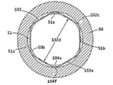
도 1 및 2에 나타낸 바람직한 구현예에서, 방사상으로 내부를 향한 홈(51)은, 바람직하게는 환형인, 전기 전도성 접점(100)을 적어도 부분적으로 수용하기 위한 리셉터클 전도체 링(50)에서 만들어진다. 바람직하게는, 내부를 향한 홈(51)은 리셉터클 전도체 링(50)의 내부 보어(50b)의 방사상으로 바깥으로 리세스된다(recessed). 접점(100)은 도 2에서 홈(51)으로 나타난다. 전기 전도성 접점(100)은 전기 전도성 재료로 만들어진다.1 and 2 , a radially inwardly facing
본 발명의 일부 구현예에서, 전기 전도성 접점(100)은 개구를 규정하는 일반적으로 환형 프로파일을 갖는다. 도 3 및 4는 전기 전도성 접점(100)을 위한 바람직한 설계를 나타낸다. 도 3 및 4는 아치형 부분 또는 둥근 코너 또는 정점(102c, vertices) 및 일반적으로 직선 세그먼트(102s)를 가진 일반적으로 다각형 형상의 접점(102)을 나타낸다. 도 3 및 4에 나타낸 일반적으로 다각형 형상의 접점(102)은 일반적으로 다각형 형상의 접점(102) 내에서 개구를 규정하는 둥근 코너(102c)에 의해 연결된 6개의 실질적으로 직선 세그먼트(102s)를 포함한다. 바람직하게는, 일반적으로 다각형 형상의 접점(102)은 비연속적이며 각각 제1 및 제2 단부(104f, 104s)를 갖는다. 도 3 및 4에 나타낸 접점(102)은 도 2의 리셉터클(40)에 나타낸 접점(100)이지만, 전기 전도성 접점(100)의 다른 구현예가 사용될 수 있다. 바람직하게는, 제1 및 제2 단부(104f, 104s)는 접점(102)이 리셉터클(40) 내에 설치될 때 둥근 코너(102c)에 위치되므로 단부(104f, 104s)는 어떤 것에도 걸리기 쉽지 않은 홈(51)에 있다.In some embodiments of the present invention, electrically
도 5는 리셉터클 전도체 링(50)의 홈(51) 내에 수용된 6면의 다각형 형상의 접점(102)의 단면도를 나타낸다. 홈(51)은 바람직하게는 홈 폭 및 홈 깊이를 규정하는 홈 베이스(51b)에 의해 연결된 한 쌍의 측벽(51s)(오직 하나만 도시됨)을 갖는다. 바람직하게, 측벽(51s)은 내부 보어(50b)로부터 홈 베이스(51b)로 방사상으로 바깥으로 연장괴고 측벽(51s)들 사이의 축방향 거리는 홈 폭을 규정한다. 바람직하게는, 홈 폭은 접점 폭(102w)보다 더 넓은, 약 0.001" 내지 0.015" 범위에 있다. 홈 깊이는 측벽(51s)의 방사상 길이에 의해 규정된다. 5 shows a cross-sectional view of a six-sided polygon-shaped
도 5의 접점(102)은 릴렉스된(relaxed) 위치에 있고 릴렉스된 내접 직경(102d)을 갖는다. 릴렉스된 위치의 일반적으로 직선 세그먼트(102s)는 릴렉스된 내접 직경(102d)을 규정한다. 도 5에 나타낸 접점(102)의 경우, 릴렉스된 내접 직경(102d)은 대향하게 마주하는 일반적으로 직선 세그먼트(102s) 사이의 최단 거리이다. 일반적으로 직선 세그먼트(102s)의 적어도 부분적으로, 통상적으로 중간부는 도 5에 나타낸 릴렉스된 위치의 홈(51)의 외부에 위치된다. 달리 말하면, 릴렉스된 내접 직경(102d)은 리셉터클 전도체 링(50)의 내경보다 작다. 바람직하게, 릴렉스된 내접 직경(102d)은 상응하는 플러그 전도체 링(30)의 외경보다 작다.Contact 102 of FIG. 5 is in a relaxed position and has a relaxed inscribed
도 5를 계속 참고하면, 접점(102)은 플러그(20)가 리셉터클(40)로부터 분리될 때 그리고 플러그(20)가 접점(102)과 나란히 놓이거나 접촉하지 않을 때 릴렉스된 위치에 있다. 일반적으로 다각형 형상의 접점(102)의 제1 및 제2 단부(104f, 104s)는 홈 베이스(51b)에 인접하고 바람직하게는 홈 베이스(51b)와 접촉하는 에지부(edge portion)를 갖는다. 바람직하게, 둥근 코너(102c) 각각은 릴렉스된 위치에 있을 때 홈 베이스(51b)와 접촉한다.With continued reference to FIG. 5 , the
도 6은 플러그(20)와 리셉터클(40)이 함께 완전히 연결되거나 결합될 때를 나타내며 접점(102)은 탄성적으로 변형된 위치에 있다. 플러그 전도체 링(30)의 외측 표면은 도 6에서 점선으로 나타낸다. 플러그 전도체 링(30)의 외경이 바람직하게는 접점(102)의 릴렉스된 내접 직경(102d)보다 적어도 약간 크기 때문에, 나란히 놓인 플러그 전도체 링(30)은 접점(102)이 약간 더 원형이 되도록 약간 바깥으로 구부러지도록 직선 세그먼트(102s)에 힘을 가한다. 도 6에 나타낸 바와 같이, 탄성적으로 변형된 직선 세그먼트(102s)는 플러그 전도체 링(30)의 외측 표면과 접촉하는 상당한 양의 표면적을 제공한다. 부가적으로, 접점(102)은 동시에 홈 베이스(51b)와 실질적인 접촉을 유지한다. 또한 홈 측벽(51s)을 향해 있는 접점(102)의 측면 표면의 일부가 또한 측벽(51s) 중 적어도 하나와 접촉하기 쉽다는 것을 또한 이해해야 한다. 플러그(20)와 리셉터클(40)이 완전히 결합될 때, 전기 접촉이 상응하는 플러그와 리셉터클 전도체 링(30, 50) 사이에서 달성되어 유지되고, 그러나 플러그(20)가 리셉터클(40)에서 분리되거나 제거될 때, 접점(102)은 홈(51)에 남아있고 결합된 플러그 전도체 링(30)의 외경보다 작은 내접 직경(102d)을 가진 릴렉스된 위치로 되돌아 가도록 접점(102)은 충분히 유연하다. 6 shows when the
플러그(20)와 리셉터클(40)의 결합 상태에서, 플러그 전도체 링(30)은 상응하는 리셉터클 전도체 링(50)과 방사상으로 정렬되거나, 실질적으로 방사상으로 정렬된다.In the mated state of the
홈(51)의 크기 및 형상이 다른 설계 요인에 더해서 사용된 접점(100)의 유형에 따른다. 도 3 및 4를 참고하면, 접점(102)은 폭(102w) 및 두께(102t)를 갖는다. 측벽(51s) 사이의 거리로 규정된 홈 폭은 바람직하게는 접점 폭(102w)보다 약간 더 넓다. 다음은 단지 구현예를 예시하기 위한 예시의 목적을 위한 홈(51) 및 접점(102)을 위한 일부 대표적인 치수이다. 이 실시예에서, 접점(102)은 0.060"(인치)의 폭(102w) 및 0.008"의 두께(102t)를 가지며 홈(51)은 다양한 요인에 따라 0.064"의 폭 및 0.016" 내지 0.027"의 범위의 깊이를 갖는다. 바람직하게는, 치수는 접점(102)이 홈(51) 내에 단단히 위치되고 탄성이 유지되도록 하는 것이다.The size and shape of the
로터리 커넥터의 바람직한 구현예는 다음의 이점들을 제공한다:A preferred embodiment of the rotary connector provides the following advantages:
작동 중 높은 내구성과 더불어 유지보수 중 손상 가능성이 매우 낮음;Very low chance of damage during maintenance with high durability during operation;
접점은 드물게 손상이 발생한 경우 교체될 수 있음;Contacts can be replaced in rare cases of damage;
높은 전류 용량;high current capacity;
매우 높은 충격 및 진동 내성;very high shock and vibration resistance;
따라서 방사상으로 그리고 축방향으로 컴팩트(compact)하여 더 작은 폼 팩터 커넥터를 허용함; 및thus radially and axially compact allowing for smaller form factor connectors; and
통합 몰드 조립체를 허용.Allows for integrated mold assembly.
도 7-14는 전기 전도성 접점(100)의 다른 구현예를 예시한다. 전기 전도성 접점(100)의 다음의 구현예가 상기 이점의 전체 또는 일부를 포함한다는 것을 이해해야 한다.7-14 illustrate another embodiment of an electrically
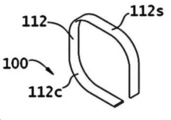
도 7 및 8에 나타낸 접점(100)은, 둥근 코너 또는 정점(112c)을 가진, 일반적으로 (112)으로 지칭되는, 다른 일반적인 다각형 형상의 접점이다. 도 7 및 8에 나타낸 일반적으로 다각형 형상의 접점(112)은 4개의 일반적으로 직선 세그먼트(112s)에 의해 분리된 둥근 코너(112c)를 포함한다. 바람직하게, 일반적으로 다각형 형상의 접점(112)은 비연속적이며 각각 제1 및 제2 단부(114f, 114s)를 갖는다. 바람직하게는, 제1 및 제2 단부(114f, 114s)는 내측으로 향하는 홈(51) 내에 남아 있고 홈 베이스(51b)와 접촉하도록 위치된다.Contact 100 shown in FIGS. 7 and 8 is another generally polygonal shaped contact, generally referred to as 112 , with rounded corners or
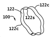
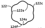
도 9 및 10은 복수의 둥근 외부 코너 또는 정점(122c)을 가진 일반적으로 마르셀 형상의 접점(122)을 나타낸다. 일반적으로 마르셀 형상의 접점(122)은 일반적으로 물결 모양 세그먼트(122s)에 의해 분리된 복수의 둥근 외부 코너(122c)를 포함한다. 바람직하게는, 일반적으로 마르셀 형상의 접점(122)은 비연속적이며 각각 제1 및 제2 단부(124f, 124s)를 갖는다. 바람직하게는, 제1 및 제2 단부(124f, 124s)는 내측으로 향하는 홈(51) 내에 남아 있고 홈 베이스(51b)와 접촉하도록 위치된다.9 and 10 show a generally Marcel shaped
도 11 및 12는 축방향 내측 보어(150b)를 가진 대안의 리셉터클 전도체 링(150)을 나타낸다. 축방향 내측 보어(150b)는 내측으로 향하는 홈을 가질 필요 없는, 연속하는 축방향 보어일 수 있다. 슬롯(154)은 전도체 링(150)을 통해 가로질러 연장되고 두 위치에서 내측 보어(150b)와 교차한다. 유연한 빔(flexible beam) 형태의 전기 전도성 접점(152)은 도 12에 나타낸 바와 같이 슬롯으로 그리고 내측 보어(150b)의 일부 내로 삽입된다. 접점(152)은 릴렉스된 위치를 가지며, 여기서 접점(152)이 도 11 및 12에 나타낸 바와 같이 리셉터클 전도체 링(150)의 내측 보어(150b) 내를 통과하는 실질적으로 직선 부재이다. 11 and 12 show an alternative
도 19는 플러그(20)와 리셉터클(40)이 완전히 결합되거나 함께 연결되고 접점(152)이 탄성적으로 변형된 위치에 있을 때를 나타낸다. 플러그 전도체 링(30)의 외부 표면은 점선으로 도시되어 있다. 플러그 전도체 링(30)의 외경은 플러그와 리셉터클이 결합될 때, 결합 플러그 전도체 링(30)이 내부 보어(150b) 내의 접점(152)과 접촉하고 탄성적으로 변형되도록 하는 크기이다. 접점(152)은 플러그 커넥터 링(30)에 의해 변형될 때 전기 접점이 달성될 정도로 충분히 탄성이 있지만, 플러그로부터 분리될 때 접점(152)은 릴렉스된 직선 상태로 복귀한다. 접점(152)은 다각형 또는 둥근 단면을 가질 수 있다. 이러한 대안에서, 접점(152)은 리셉터클(40)이 예를 들어 절연체 링 및 전도체 링을 적층함으로써 조립되는 경우 교체 가능하다.19 shows when
도 13 및 도 14는 도 11 및 도 12에 도시된 것과 유사한 다른 대안적인 리셉터클 전도체 링(250)을 나타낸다. 도 13 및 14는 축방향 내부 보어(250b)를 갖는 대안적인 리셉터클 전도체 링(250)을 나타낸다. 축방향 내부 보어(250b)는 내측을 향해 있는 홈을 가질 필요 없이, 연속적인 축방향 보어일 수 있다. 횡방향 보어(254, transverse bore)는 전도체 링(250)을 통해 연장되고 두 위치에서 축방향 내부 보어(250b)와 교차한다. 전기 전도성 접점(252)은 도 14에 나타낸 바와 같이 전도체 링(250)의 횡방향 보어(254) 내로 그리고 축방향 내부 보어(250b)의 일부 내에 삽입된다. 접점(252)은 접점(252)이 도 14에 나타낸 바와 같이 리셉터클 전도체 링(250)의 축방향 내부 보어(250b) 내를 통과하는 실질적으로 직선 부재인 릴렉스된 위치를 갖는다. 13 and 14 show other alternative receptacle conductor rings 250 similar to those shown in FIGS. 11 and 12 . 13 and 14 show an alternative
도 20은 플러그(20)와 리셉터클(40)이 완전히 연결되거나 함께 결합되고 접점(252)이 탄성적으로 변형된 위치에 있는 경우를 나타낸다. 플러그 전도체 링(30)의 외부 표면은 점선으로 나타낸다. 플러그 전도체 링(30)의 외경은 플러그(20)와 리셉터클(40)의 결합시, 결합한 플러그 전도체 링(30)이 내부 보어(250b) 내의 접점(252)과 접촉하여 탄성적으로 변형되도록 하는 크기이다. 접점(252)은 전기 접점이 플러그 커넥터 링(30)에 의해 변형될 때 달성될 정도로 충분히 탄성이 있지만, 플러그로부터 분리될 때 접점(252)은 릴렉스된 직선 상태로 복귀한다. 바람직하게는, 접점(252)은 원형 단면을 갖는다. 접점(252)이 전도체 링(250)에 압입되면, 이 구현예는 몰딩된 조립체에 사용될 수 있다. 접점(252)이 압입되지 않고 리셉터클이 분해될 수 있는 경우, 접점(252)은 교체가능할 수 있다.Fig. 20 shows a case in which the
도 15는 일반적으로 (10')로 표시된 로터리 커넥터의 대안적인 구현예를 나타내며, 이는 도 1 및 도 2에 나타낸 로터리 커넥터(10)와 많은 면에서 유사하다. 주요 차이점은 로터리 커넥터(10')가 플러그 전도체 링(30') 상에, 바람직하게는 바깥으로 향한 홈(51')에 설치된 전기 전도성 접점(100')을 갖고 리셉터클 전도체 링(50')은 매끄러운 내부 보어(50b')를 갖는다는 것이다. 나타낸 접점(102')은 도 3 및 도 4의 접점(102)과 형상이 유사하다. 접점(102')은 불연속적이며 바람직하게는 도 16에 나타낸 바와 같이 일반적으로 직선 세그먼트(102s')의 중간 부분에 제1 및 제2 단부(104f', 104s')를 갖는다. 15 shows an alternative embodiment of a rotary connector, generally designated 10', which is similar in many respects to the
도 17은 플러그 전도체 링(30')의 홈(51') 내에 수용된 6면 다각형 접점(102')의 단면도를 나타낸다. 홈(51')은 바람직하게 홈 폭 및 홈 깊이를 정의하는 홈 베이스(51b')에 의해 연결된 한 쌍의 측벽(51s')(하나만 도시됨)을 갖는다. 접점(102')은 릴렉스된 위치에 있고 릴렉스된 내접 직경(102d')을 갖는다. 릴렉스된 위치의 둥근 코너(102c')는 릴렉스된 내접 직경(102d')을 규정한다. 도 17에 나타낸 접점(102')의 경우, 릴렉스된 내접 직경(102d')은 대향하는 둥근 코너(102c') 사이의 가장 긴 거리이다. 둥근 코너(102c')의 적어도 일부, 통상적으로 중간 부분은 도 17에 나타낸 바와 같이 릴렉스된 위치에서 홈(51') 외부에 위치된다. 바람직하게는, 릴렉스된 내접 직경(102d')은 리셉터클 전도체 링(50')의 내경보다 크다. 바람직하게는, 릴렉스된 내접 직경(102d')은 상응하는 플러그 전도체 링(30')의 외경보다 크다.17 shows a cross-sectional view of a six-sided polygonal contact 102' received within a groove 51' of a plug conductor ring 30'. The groove 51' preferably has a pair of sidewalls 51s' (only one shown) connected by a
또한 도 17을 참조하면, 접점(102')은 플러그(20')가 리셉터클(40')로부터 분리될 때와 리셉터클(40')이 나란히 놓이지 않거나 접점(102')과 접촉하지 않을 때 릴렉스된 위치에 있다. 일반적으로 다각형 형상의 접점(102')의 제1 및 제2 단부(104f', 104s')는 바람직하게는 홈 베이스(51b')에 인접하고 바람직하게는 홈 베이스(51b')와 접촉하는 에지부를 갖는다. 바람직하게는, 일반적으로 직선 세그먼트(102s') 각각의 일부는 릴렉스된 위치에 있을 때 홈 베이스(51b')와 접촉한다.Referring also to FIG. 17 , contact 102' is relaxed when
도 18은 플러그(20')와 리셉터클(40')이 완전히 연결되거나 함께 결합되고 접점(102')이 탄성적으로 변형된 위치에 있을 때를 나타낸다. 리셉터클 전도체 링(50')의 내부 표면은 점선으로 나타낸다. 리셉터클 전도체 링(50')의 내경은 바람직하게는 접점(102')의 릴렉스된 내접 직경(102d')보다 약간 더 작기 때문에, 나란히 놓인 리셉터클 전도체 링(50')은 접점(102')이 약간 더 원형이 되도록 한다. 도 18에 나타낸 바와 같이, 탄성적으로 변형된 접점(102')은 홈 베이스(51b')와의 실질적인 접촉을 동시에 유지하면서 리셉터클 전도체 링(50')의 내부 표면과 상당한 양의 표면적 접촉을 제공한다. 또한, 홈 측벽(51s')에 향하는 접점(102')의 측면의 일부는 측벽(51s') 중 적어도 하나와 접촉할 가능성이 높다는 것이 또한 이해되어야 한다. 접점(102')은 플러그(20')와 리셉터클(40')이 완전히 결합될 때, 상응하는 플러그와 리셉터클 전도체 링(30', 50') 사이에서 전기적 접촉이 달성되지만, 플러그(20')가 리셉터클(40')로부터 분리되거나 제거될 때, 접점(102')이 홈(51')에 남아 있고 결합한 리셉터클 전도체 링(50')의 내경보다 큰 내접 직경(102d')을 갖는 릴렉스된 위치로 복귀되도록 충분히 탄성이 있다.18 shows when plug 20' and receptacle 40' are fully connected or joined together and contact 102' is in an elastically deformed position. The inner surface of the receptacle conductor ring 50' is indicated by a dotted line. Since the inner diameter of the receptacle conductor ring 50' is preferably slightly smaller than the relaxed inscribed
전술한 구현예에서 전도체 링의 홈은 접점의 크기, 형상 및 유형에 따라 변할 것임을 이해해야 한다. 홈은 접점의 각각의 크기에 필요한 힘을 생성하도록 설계된다.It should be understood that the grooves of the conductor ring in the embodiments described above will vary depending on the size, shape and type of contact point. The grooves are designed to create the required force for each size of the contact point.
도면에서 접점의 단면 형상은 예시된 형상(즉, 직사각형)으로 제한되지 않고, 원형을 포함하지만 이에 제한되지 않는 다른 형상을 포함할 수 있다는 것을 이해해야 한다.It should be understood that the cross-sectional shape of the contact points in the drawings is not limited to the illustrated shape (ie, rectangular), but may include other shapes including, but not limited to, circular.
인접한 접점 사이의 절연체는 개별 피스 또는 통합된 몰딩된 시스템일 수 있음을 이해해야 한다. 게다가, 시스템은 결합 하우징 내에서 전기 커넥터의 선택적 밀폐 밀봉(hermetic sealing)을 허용한다. It should be understood that the insulator between adjacent contacts may be a separate piece or an integrated molded system. In addition, the system allows for selective hermetic sealing of the electrical connector within the mating housing.
폭(102w)이 0.06"이고, 두께(102t)가 0.008"이며, 길이가 0.17"인 굽힘에서 항복하기 위해 도 3 내지 4에 나타낸 접점(102)에 필요한 힘의 분석은 1.58뉴턴 또는 0.355lbs의 힘이 발생한다. 본 발명의 배경기술에 기술된 다중 판 스프링 및 캔티드 코일 스프링 설계에 대한 비교 가능한 분석은 다음과 같이 바람직한 구현예에 대한 것보다 훨씬 더 낮은 힘으로 항복하는 결과를 가져온다:An analysis of the force required at the
설계design 힘(뉴턴)force (newtons) 힘(lbs)force (lbs)
도 3-4 구현예 1.58 0.355Figure 3-4 embodiment 1.58 0.355
다중 판 스프링 0.075 0.017multi leaf spring 0.075 0.017
캔티드 코일 스프링 0.175 0.039canted coil spring 0.175 0.039
본 발명의 전술한 개시 및 설명은 예시 및 설명이며, 도시된 구성의 세부사항뿐만 아니라 크기, 형상 및 재료의 다양한 변경은 본 발명의 사상을 벗어나지 않고 이루어질 수 있다. 따라서, 본 구현예는 단지 예시적이며 제한적이지 않은 것으로 간주되어야 하며, 본 발명의 범위는 전술한 설명이 아닌 청구범위에 의해 표시되며, 따라서 청구범위의 등가의 의미 및 범위 내에 있는 모든 변경은 여기에 포함되도록 의도된다.The foregoing disclosure and description of the present invention are examples and descriptions, and various changes in size, shape and material as well as the details of the illustrated construction may be made without departing from the spirit of the present invention. Accordingly, this embodiment is to be regarded as illustrative only and not restrictive, the scope of the present invention being indicated by the claims rather than the foregoing description, and therefore all modifications that come within the meaning and scope of equivalents of the claims are hereby intended to be included in
본 발명이 특정 구현예를 참조하여 위에서 상세하게 설명되었지만, 개시된 구현예의 수정 및 변경은 본 발명의 사상 및 범위를 벗어나지 않고 당업자에 의해 이루어질 수 있음을 이해할 것이다. 이러한 모든 수정 및 변경은 커버되는 것으로 의도된다. 또한, 본원에 인용된 모든 간행물은 해당 분야의 기술 수준을 나타내며 각각이 참조에 의해 개별적으로 통합되고 완전히 설명된 것처럼 전체가 참조에 의해 통합된다.Although the invention has been described in detail above with reference to specific embodiments, it will be understood that modifications and variations of the disclosed embodiments may be made by those skilled in the art without departing from the spirit and scope of the invention. All such modifications and variations are intended to be covered. Further, all publications cited herein represent the state of the art and are incorporated by reference in their entirety as if each were individually incorporated by reference and set forth in its entirety.
Claims (27)
a) 상기 플러그(20)는:
i) 전기 절연 플러그 바디(22);
ii) 외경을 가진 플러그 전도체 링(30); 및
iii) 상기 플러그 전도체 링(30)에 연결된 플러그 전기 전도성 부재(W), 상기 플러그 전기 전도성 부재(W)는 플러그 바디(22) 내에 있고 상기 플러그 바디(22)의 단부를 빠져나감;를 포함하며;
b) 상기 리셉터클(40)은:
i) 전기 절연 리셉터클 바디(42);
ii) 축방향 내부 보어(50b)를 가진 리셉터클 전도체 링(50);
iii) 상기 리셉터클 전도체 링(50)에 연결되고 상기 리셉터클 바디(42)의 단부를 빠져나가는 리셉터클 전기 전도성 부재(W);
iv) 상기 리셉터클 전도체 링(50)에 접촉하는 전기 전도성 접점(100), 상기 전기 전도성 접점(100)은 일반적으로 환형, 다각형-형상의 프로파일을 가지며, 축방향 개구를 규정하는 복수의 둥근 코너(102c)에 의해 연결된 복수의 실질적으로 직선 세그먼트(102s)를 포함하고, 상기 전기 전도성 접점(100)은 릴렉스된 위치와 탄성적으로 변형된 위치를 가짐;을 포함하고,
상기 릴렉스된 위치에서, 상기 전기 전도성 접점(100)은 플러그 전도체 링(30)의 외경보다 작은 릴렉스된 내접 직경(102d)을 가지며,
상기 탄성적으로 변형된 위치에서, 상기 전기 전도성 접점(100)은 플러그 전도체 링(30)에 의해 축방향 내부 보어(50b) 내에서 탄성적으로 변형되고, 상기 플러그 전도체 링(30)은 전기 전도성 접점(100)과 접촉하고, 전기 접점이 플러그 전도체 링(30)과 리셉터클 전도체 링(50) 사이에서 달성되고,
전기 전도성 접점(100)과의 접촉으로부터 플러그 전도체 링(30)의 제거시, 상기 전기 전도성 접점(100)은 릴렉스된 위치로 되돌아가는, 전기 커넥터(10).An electrical connector (10) comprising a plug (20) arranged and designed for connection to a receptacle (40), said connector (10) comprising:
a) the plug 20 comprises:
i) an electrically insulating plug body 22;
ii) a plug conductor ring 30 having an outer diameter; and
iii) a plug electrically conductive member (W) connected to the plug conductor ring (30), the plug electrically conductive member (W) being in a plug body (22) and exiting an end of the plug body (22); ;
b) the receptacle 40 comprises:
i) an electrically insulating receptacle body 42;
ii) a receptacle conductor ring (50) having an axial inner bore (50b);
iii) a receptacle electrically conductive member (W) connected to said receptacle conductor ring (50) and exiting an end of said receptacle body (42);
iv) an electrically conductive contact 100 contacting the receptacle conductor ring 50, the electrically conductive contact 100 having a generally annular, polygon-shaped profile and a plurality of rounded corners defining an axial opening ( 102c), comprising a plurality of substantially straight segments (102s) connected by means of which the electrically conductive contact (100) has a relaxed position and an elastically deformed position;
In the relaxed position, the electrically conductive contact (100) has a relaxed inscribed diameter (102d) that is less than the outer diameter of the plug conductor ring (30);
In the resiliently deformed position, the electrically conductive contact 100 is elastically deformed within the axial inner bore 50b by a plug conductor ring 30 , wherein the plug conductor ring 30 is electrically conductive contacting the contact 100 and an electrical contact is achieved between the plug conductor ring 30 and the receptacle conductor ring 50;
upon removal of the plug conductor ring (30) from contact with the electrically conductive contact (100), the electrically conductive contact (100) returns to a relaxed position.
상기 플러그 전도체 링(30)은 복수의 플러그 전도체 링(30) 중 하나이고, 리셉터클 전도체 링(50)은 복수의 리셉터클 전도체 링(50) 중 하나이며, 상기 전기 전도성 접점(100)은 복수의 전기 전도성 접점(100) 중 하나이고, 여기서 상기 플러그 전도체 링(30)의 수, 리셉터클 전도체 링(50)의 수 및 전기 전도성 접점(100)의 수는 동일한, 전기 커넥터(10).The method according to claim 1,
The plug conductor ring 30 is one of the plurality of plug conductor rings 30 , the receptacle conductor ring 50 is one of the plurality of receptacle conductor rings 50 , and the electrically conductive contact 100 is a plurality of electrically conductive contacts 100 . one of the conductive contacts ( 100 ), wherein the number of plug conductor rings ( 30 ), the number of receptacle conductor rings ( 50 ) and the number of electrically conductive contacts ( 100 ) are the same.
상기 리셉터클 전도체 링(50)은 방사상으로 내측을 향한 환형 홈(51)을 가지며, 상기 전기 전도성 접점(100)의 적어도 일부분은 환형 홈(51) 내에 있는, 전기 커넥터(10).The method according to claim 1,
The receptacle conductor ring (50) has a radially inwardly directed annular groove (51), wherein at least a portion of the electrically conductive contact (100) is within the annular groove (51).
상기 전기 전도성 접점(100)의 적어도 일부분은 환형 홈(51) 내에 있지 않은, 전기 커넥터(10).4. The method according to claim 3,
at least a portion of the electrically conductive contact (100) is not within the annular groove (51).
상기 전기 전도성 접점(100)은 불연속성이며 환형 홈(51) 내에 수용된 제1 및 제2 단부(104f, 104s)를 갖는, 전기 커넥터(10).4. The method according to claim 3,
The electrically conductive contact (100) is discontinuous and has first and second ends (104f, 104s) received in an annular groove (51).
상기 제1 및 제2 단부(104f, 104s)의 어느 부분도 상기 리셉터클 전도체 링(50)의 축방향 내부 보어 내에 있지 않는, 전기 커넥터(10).6. The method of claim 5,
and none of the first and second ends (104f, 104s) are within the axial inner bore of the receptacle conductor ring (50).
상기 복수의 실질적으로 직선 세그먼트(102s)의 적어도 일부분은 환형 홈(51) 내에 있지 않은, 전기 커넥터(10).4. The method according to claim 3,
at least a portion of the plurality of substantially straight segments (102s) is not within the annular groove (51).
상기 복수의 실질적으로 직선 세그먼트(102s) 각각의 적어도 일부분은 환형 홈(51) 내에 있지 않은, 전기 커넥터(10).4. The method according to claim 3,
at least a portion of each of the plurality of substantially straight segments (102s) is not within the annular groove (51).
상기 복수의 둥근 코너(102c)의 적어도 일부분은 환형 홈(51) 내에 있는, 전기 커넥터(10).4. The method according to claim 3,
at least a portion of the plurality of rounded corners (102c) is within the annular groove (51).
상기 복수의 둥근 코너(102c) 각각의 적어도 일부분은 환형 홈(51) 내에 있는, 전기 커넥터(10).4. The method according to claim 3,
at least a portion of each of said plurality of rounded corners (102c) is within an annular groove (51).
상기 환형 홈(51)은 내부 보어(50b)로부터 홈 베이스(51b)로 방사상으로 바깥으로 연장되는 한 쌍의 측벽(51s)을 포함하며, 복수의 둥근 코너(102c) 중 적어도 일부분은 홈 베이스(51b)와 접촉하는, 전기 커넥터(10).4. The method according to claim 3,
The annular groove 51 includes a pair of sidewalls 51s extending radially outwardly from the inner bore 50b to the groove base 51b, at least a portion of the plurality of rounded corners 102c having a groove base ( 51b), an electrical connector (10).
상기 환형 홈(51)은 내부 보어(50b)로부터 홈 베이스(51b)로 방사상으로 바깥으로 연장되는 한 쌍의 측벽(51s)을 포함하며, 복수의 둥근 코너(102c) 각각의 적어도 일부분은 홈 베이스(51b)와 접촉하는, 전기 커넥터(10).4. The method according to claim 3,
The annular groove 51 includes a pair of sidewalls 51s extending radially outwardly from the inner bore 50b to the groove base 51b, and at least a portion of each of the plurality of rounded corners 102c is at least a portion of the groove base. Electrical connector (10), in contact with (51b).
상기 환형 홈(51)은 내부 보어(50b)로부터 홈 베이스(51b)로 방사상으로 바깥으로 연장되는 한 쌍의 측벽(51s)을 포함하며, 상기 한 쌍의 측벽(51s)들 사이의 축방향 거리는 홈 폭을 규정하고, 전기 전도성 접점(100)은 접점 폭(102w)을 가지며,
여기서 상기 홈 폭은 접점 폭(102w)보다 넓은 약 0.001" 내지 0.015" 범위에 있는, 전기 커넥터(10).4. The method according to claim 3,
The annular groove 51 includes a pair of sidewalls 51s extending radially outwardly from the inner bore 50b to the groove base 51b, and the axial distance between the pair of sidewalls 51s is defining a groove width, the electrically conductive contact 100 having a contact width 102w;
wherein the groove width ranges from about 0.001″ to 0.015″ wider than the contact width (102w).
상기 플러그(20)를 리셉터클(40) 내로 삽입하고 상기 플러그 전도체 링(30)과 리셉터클 전도체 링(50)을 실질적으로 방사상으로 정렬할 때, 상기 복수의 실질적으로 직선 세그먼트(102s)는 탄성적으로 변형되고 플러그 전도체 링(30)과 전기적으로 접촉하며 상기 복수의 둥근 코너(102c)는 리셉터클 전도체 링(50)과 전기적으로 접촉하는, 전기 커넥터(10).The method according to claim 1,
Upon insertion of the plug 20 into the receptacle 40 and substantially radial alignment of the plug conductor ring 30 and the receptacle conductor ring 50, the plurality of substantially straight segments 102s resiliently An electrical connector (10) deformed and in electrical contact with a plug conductor ring (30) and wherein the plurality of rounded corners (102c) are in electrical contact with a receptacle conductor ring (50).
상기 측벽(51s)들 중 하나의 방사상 길이에 의해 홈 깊이가 규정되고, 상기 복수의 실질적으로 직선 세그먼트(102s)와 복수의 둥근 코너(102c)는 상기 홈 깊이보다 작은 접점 두께(102t)를 갖는, 전기 커넥터(10).12. The method of claim 11,
A groove depth is defined by the radial length of one of the sidewalls 51s, the plurality of substantially straight segments 102s and the plurality of rounded corners 102c having a contact thickness 102t less than the groove depth , electrical connector (10).
a) 플러그(20)는:
i) 전기 절연 플러그 바디(22);
ii) 플러그 전도체 링(30); 및
iii) 상기 플러그 바디(22) 내에 있고 플러그 바디(22)의 단부를 빠져나가는 플러그 전도체 링(30)에 연결된 전기 전도성 부재(W);를 포함하고,
b) 리셉터클(40)은:
i) 전기 절연 리셉터클 바디(42);
ii) 축방향 내부 보어(150b, 250b) 및 두 위치에서 상기 축방향 내부 보어(150b, 250b)와 교차하는 횡방향 개구(154, 254)를 가진 리셉터클 전도체 링(150, 250);
iii) 상기 리셉터클 전도체 링(150, 250)에 연결되고 리셉터클 바디(40)의 단부를 빠져나가는 전기 전도성 부재(W);
iv) 상기 횡방향 개구(154, 254)에 수용되고 릴렉스된 위치와 탄성적으로 변형된 위치를 가진 전기 전도성 접점(152, 252)을 포함하며,
여기서 상기 릴렉스된 위치에서 상기 전기 전도성 접점(152, 252)은 직선 부재이며 리셉터클 전도체 링(150, 250)의 축방향 내부 보어(150b, 250b) 내에서 횡방향으로 연장되고,
상기 탄성적으로 변형된 위치에서, 상기 전기 전도성 접점(152, 252)은 플러그 전도체 링(30)에 의해 축방향 내부 보어(150b, 250b) 내에서 탄성적으로 변형되고, 상기 플러그 전도체 링(30)은 전기 전도성 접점(152, 252)과 접촉하고 전기 접점이 플러그 전도체 링(30)과 리셉터클 전도체 링(150, 250) 사이에서 달성되며,
상기 전기 전도성 접점(152, 252)과의 접촉으로부터 플러그 전도체 링(30)의 제거시, 상기 전기 전도성 접점(152, 252)은 릴렉스된 위치로 복귀하는, 전기 커넥터(10).An electrical connector (10) comprising a plug (20) and a receptacle (40), comprising:
a) the plug 20 comprises:
i) an electrically insulating plug body 22;
ii) a plug conductor ring (30); and
iii) an electrically conductive member (W) in the plug body (22) and connected to a plug conductor ring (30) exiting an end of the plug body (22);
b) the receptacle 40 comprises:
i) an electrically insulating receptacle body 42;
ii) a receptacle conductor ring (150, 250) having an axial inner bore (150b, 250b) and a transverse opening (154, 254) intersecting the axial inner bore (150b, 250b) at two locations;
iii) an electrically conductive member (W) connected to said receptacle conductor ring (150, 250) and exiting an end of said receptacle body (40);
iv) an electrically conductive contact (152, 252) received in said transverse opening (154, 254) and having a relaxed position and an elastically deformed position;
wherein in the relaxed position the electrically conductive contacts (152, 252) are straight members and extend transversely within the axial inner bores (150b, 250b) of the receptacle conductor ring (150, 250);
In the resiliently deformed position, the electrically conductive contacts 152 , 252 are elastically deformed in the axial inner bore 150b , 250b by the plug conductor ring 30 , the plug conductor ring 30 . ) is in contact with an electrically conductive contact (152, 252) and an electrical contact is achieved between the plug conductor ring (30) and the receptacle conductor ring (150, 250),
upon removal of the plug conductor ring (30) from contact with the electrically conductive contact (152, 252), the electrically conductive contact (152, 252) returns to a relaxed position.
상기 횡방향 개구는 슬롯(154)이며, 전기 전도성 접점(152)은 유연한 빔인, 전기 커넥터(10).17. The method of claim 16,
wherein the transverse opening is a slot (154) and the electrically conductive contact (152) is a flexible beam.
상기 횡방향 개구는 횡방향 보어(254)이며, 전기 전도성 접점(252)은 원형 단면을 갖는, 전기 커넥터(10).17. The method of claim 16,
The transverse opening is a transverse bore (254) and the electrically conductive contact (252) has a circular cross-section.
상기 전기 전도성 접점(252)은 전도체 링(250)의 횡방향 보어(254)에 압입되는, 전기 커넥터(10).19. The method of claim 18,
The electrically conductive contact (252) is press-fitted into the transverse bore (254) of the conductor ring (250).
a) 상기 플러그(20)는:
i) 전기 절연 플러그 바디(22);
ii) 플러그 전도체 링(30); 및
iii) 상기 플러그 전도체 링(30)에 연결되고 상기 플러그 바디(22) 내에 있고 플러그 바디(22)의 단부를 빠져나가는 전기 전도성 부재(W);를 포함하고,
b) 상기 리셉터클(40)은:
i) 전기 절연 리셉터클 바디(42);
ii) 축방향 내부 보어(50b) 및 방사상 내측을 향하는 환형 홈(51)을 가진 리셉터클 전도체 링(50), 상기 환형 홈(51)은 축방향 홈 폭을 가짐;
iii) 상기 리셉터클 전도체 링(50)에 연결되고 리셉터클 바디(42)의 단부를 빠져나가는 전기 전도성 부재(W); 및
iv) 개구를 규정하는 일반적으로 환형 프로파일을 가지며 상기 축방향 홈 폭보다 작은 축방향의 접점 폭(102w)을 갖는 전기 전도성 접점(100), 상기 전기 전도성 접점(100)의 적어도 일부분은 환형 홈(51) 내에 수용되고 환형 홈(51)과 접촉하고 상기 전기 전도성 접점(100)의 적어도 일부분은 환형 홈(51) 내에 수용되지 않음;을 포함하며,
여기서 상기 리셉터클(40)로 플러그(20)가 삽입되고 플러그 전도체 링(30)과 리셉터클 전도체 링(50)이 실질적으로 방사상으로 정렬될 때, 상기 전기 전도성 접점(100)은 탄성적으로 변형되고 플러그 전도체 링(30)과 리셉터클 전도체 링(50) 사이에 전기 접점을 제공하는, 전기 커넥터(10).An electrical connector (10) comprising a plug (20) arranged and designed for connection to a receptacle (40), the electrical connector (10) comprising:
a) the plug 20 comprises:
i) an electrically insulating plug body 22;
ii) a plug conductor ring (30); and
iii) an electrically conductive member (W) connected to the plug conductor ring (30) and within the plug body (22) exiting an end of the plug body (22);
b) the receptacle 40 comprises:
i) an electrically insulating receptacle body 42;
ii) a receptacle conductor ring (50) having an axial inner bore (50b) and a radially inwardly facing annular groove (51), said annular groove (51) having an axial groove width;
iii) an electrically conductive member (W) connected to said receptacle conductor ring (50) and exiting an end of said receptacle body (42); and
iv) an electrically conductive contact 100 having a generally annular profile defining an opening and having an axial contact width 102w less than the axial groove width, at least a portion of the electrically conductive contact 100 being an annular groove ( received within 51 ) and in contact with the annular groove 51 , wherein at least a portion of the electrically conductive contact 100 is not received within the annular groove 51 ;
Here, when the plug 20 is inserted into the receptacle 40 and the plug conductor ring 30 and the receptacle conductor ring 50 are substantially radially aligned, the electrically conductive contact 100 is elastically deformed and the plug An electrical connector (10) that provides an electrical contact between the conductor ring (30) and the receptacle conductor ring (50).
상기 전기 전도성 접점(100)은 불연속적이며 홈(51) 내에 수용되는 제1 및 제2 단부(104f, 104s)를 가지며, 상기 제1 및 제2 단부(104f, 104s)의 어느 부분도 리셉터클 전도체 링(50)의 축방향 내부 보어(50b) 내에 있지 않은, 전기 커넥터(10).21. The method of claim 20,
The electrically conductive contact (100) is discontinuous and has first and second ends (104f, 104s) received in a groove (51), any portion of the first and second ends (104f, 104s) being a receptacle conductor The electrical connector (10), not within the axial inner bore (50b) of the ring (50).
상기 전기 전도성 접점(100)은 복수의 코너(102c)에 의해 연결된 복수의 실질적으로 직선 세그먼트(102s)를 포함하고, 상기 일반적으로 환형 프로파일과 규정된 개구는 일반적으로 다각형 형상인, 전기 커넥터(10).21. The method of claim 20,
The electrically conductive contact (100) comprises a plurality of substantially straight segments (102s) connected by a plurality of corners (102c), the generally annular profile and defined opening being generally polygonal in shape. ).
상기 복수의 실질적으로 직선 세그먼트(102s)의 적어도 일부분은 홈(51) 내에 있지 않은, 전기 커넥터(10).23. The method of claim 22,
at least a portion of the plurality of substantially straight segments (102s) is not within the groove (51).
상기 환형 홈(51)은 내부 보어(50b)로부터 홈 베이스(51b)로 방사상으로 바깥으로 연장되는 한 쌍의 측벽(51s)을 포함하며, 상기 한 쌍의 측벽(51s)들 사이의 축방향 거리는 홈 폭을 규정하고, 상기 전기 전도성 접점(100)은 접점 폭(102w)을 가지며,
여기서 상기 홈 폭은 접점 폭(102w)보다 넓은 0.001" 내지 0.015" 범위에 있는, 전기 커넥터(10).21. The method of claim 20,
The annular groove 51 includes a pair of sidewalls 51s extending radially outwardly from the inner bore 50b to the groove base 51b, and the axial distance between the pair of sidewalls 51s is defining a groove width, wherein the electrically conductive contact 100 has a contact width 102w;
wherein the groove width is in the range of 0.001" to 0.015" wider than the contact width 102w.
상기 전기 전도성 접점(100)은 복수의 둥근 외부 코너(102c)에 의해 연결된 복수의 물결 모양 세그먼트(122s)를 포함하는, 전기 커넥터(10).22. The method of claim 21,
wherein the electrically conductive contact (100) comprises a plurality of wavy segments (122s) connected by a plurality of rounded outer corners (102c).
상기 리셉터클(40)로 플러그(20)가 삽입되고 플러그 전도체 링(30)과 리셉터클 전도체 링(50)이 실질적으로 방사상으로 정렬될 때, 상기 복수의 실질적으로 직선 세그먼트(102s)는 탄성적으로 변형되고 플러그 전도체 링(30)과 전기적으로 접촉하고 복수의 코너(102c)는 리셉터클 전도체 링(50)과 전기적으로 접촉하는, 전기 커넥터(10).23. The method of claim 22,
When the plug 20 is inserted into the receptacle 40 and the plug conductor ring 30 and the receptacle conductor ring 50 are substantially radially aligned, the plurality of substantially straight segments 102s elastically deform. and in electrical contact with the plug conductor ring (30) and the plurality of corners (102c) in electrical contact with the receptacle conductor ring (50).
상기 환형 홈(51)은 축방향 내부 보어(50b)로부터 홈 베이스(51b)로 방사상으로 바깥으로 연장되는 한 쌍의 측벽(51s)을 포함하며,
상기 축방향 홈 폭은 한 쌍의 측벽(51s)들 사이의 축방향 거리로 규정되고 홈 깊이는 상기 측벽(51s) 중 하나의 방사상 길이로 규정되며,
상기 복수의 실질적으로 직선 세그먼트(102s)와 복수의 코너(102c)는 홈 깊이보다 작은 접점 두께(102t)를 갖는, 전기 커넥터(10).23. The method of claim 22,
The annular groove (51) includes a pair of sidewalls (51s) extending radially outward from the axial inner bore (50b) to the groove base (51b),
the axial groove width is defined as the axial distance between a pair of sidewalls 51s and the groove depth is defined as the radial length of one of the sidewalls 51s;
and the plurality of substantially straight segments (102s) and the plurality of corners (102c) have a contact thickness (102t) less than the groove depth.
Applications Claiming Priority (3)
| Application Number | Priority Date | Filing Date | Title |
|---|---|---|---|
| US201962842841P | 2019-05-03 | 2019-05-03 | |
| US62/842,841 | 2019-05-03 | ||
| PCT/US2020/030972 WO2020227074A1 (en) | 2019-05-03 | 2020-05-01 | Multi-conductor rotary connector |
Publications (1)
| Publication Number | Publication Date |
|---|---|
| KR20210148415A true KR20210148415A (en) | 2021-12-07 |
Family
ID=73016276
Family Applications (1)
| Application Number | Title | Priority Date | Filing Date |
|---|---|---|---|
| KR1020217038841A KR20210148415A (en) | 2019-05-03 | 2020-05-01 | Multi-Conductor Rotary Connectors |
Country Status (6)
| Country | Link |
|---|---|
| US (3) | US11217928B2 (en) |
| EP (1) | EP3963675A4 (en) |
| JP (1) | JP2022530495A (en) |
| KR (1) | KR20210148415A (en) |
| CA (1) | CA3136832A1 (en) |
| WO (1) | WO2020227074A1 (en) |
Families Citing this family (3)
| Publication number | Priority date | Publication date | Assignee | Title |
|---|---|---|---|---|
| EP3963675A4 (en) * | 2019-05-03 | 2023-05-10 | Rampart Products LLC | Multi-conductor rotary connector |
| DE102021102864B3 (en) * | 2021-02-08 | 2022-01-20 | Heraeus Deutschland GmbH & Co. KG | spring contact ring |
| CN113410712A (en) * | 2021-06-28 | 2021-09-17 | 中地装(重庆)地质仪器有限公司 | Multi-stage composite probe tube and inter-stage multi-terminal connector thereof |
Family Cites Families (28)
| Publication number | Priority date | Publication date | Assignee | Title |
|---|---|---|---|---|
| JPS4831590U (en) * | 1971-08-23 | 1973-04-17 | ||
| US4583798A (en) * | 1985-05-20 | 1986-04-22 | Blazowich Daniel L | Rotatable electrical connector |
| DE3918950A1 (en) * | 1989-06-09 | 1990-12-13 | Dunkel Otto Gmbh | WATER COOLED HIGH CURRENT DOCKING CONNECTOR |
| US5809136A (en) * | 1996-01-16 | 1998-09-15 | Turner; Robert A. | Circumferential-contact phone jack socket |
| US5769671A (en) * | 1997-02-05 | 1998-06-23 | Pacesetter, Inc. | Connector spring |
| US6332815B1 (en) * | 1999-12-10 | 2001-12-25 | Litton Systems, Inc. | Clip ring for an electrical connector |
| NL1017236C2 (en) * | 2001-01-30 | 2002-07-31 | Ocu Technologies B V | Rotation connector and a method for manufacturing such a connector. |
| JP2002231361A (en) * | 2001-02-01 | 2002-08-16 | Yutaka Seisakusho:Kk | Contact piece assembly for electrical connector |
| DE60310592T2 (en) * | 2002-09-30 | 2007-09-27 | Bal Seal Engineering Co., Inc., Foothill Ranch | TAILORED SCREW SPRINGS OF VARIOUS VERSION |
| US8078280B2 (en) * | 2003-04-25 | 2011-12-13 | Medtronic, Inc. | Implantable biomedical electrical connectors having integral side and inner walls |
| US7462957B2 (en) * | 2003-09-05 | 2008-12-09 | Extreme Engineering Ltd. | Multi-conductor plug and socket apparatus |
| US7052297B2 (en) * | 2004-08-25 | 2006-05-30 | Wireline Technologies, Inc. | Rotary connector having removable and replaceable contacts |
| WO2006026439A2 (en) * | 2004-08-27 | 2006-03-09 | Pmi Industries, Inc. | Flexible connector for implantable wiring harness |
| JP4801416B2 (en) * | 2004-11-04 | 2011-10-26 | オーデェウ ステッキフェルビンドゥングスシステエメ ゲゼルシャフト ミット ベシュレンクテル ハフツング ウント コンパニー コマンデイトゲゼルシャフト | Electrical plug connector socket and plug connector with such socket |
| US7798864B2 (en) * | 2008-03-12 | 2010-09-21 | Boston Scientific Neuromodulation Corporation | Low-profile connector for a neurostimulation lead |
| US8046074B2 (en) * | 2008-04-21 | 2011-10-25 | Boston Scientific Neuromodulation Corporation | High-resolution connector for a neurostimulation lead |
| CN201210565Y (en) | 2008-05-29 | 2009-03-18 | 宁波音王集团有限公司 | Injection mold type plug-in connector |
| US8590867B2 (en) * | 2009-09-15 | 2013-11-26 | Bal Seal Engineering, Inc. | Variable canted coil spring cross section |
| US8761887B2 (en) | 2010-04-29 | 2014-06-24 | Donatelle Plastics, Inc. | Header for implantable pulse generator and method of making same |
| EP2595250B1 (en) * | 2011-11-21 | 2014-01-08 | Wolf Neumann-Henneberg | Electrical connector |
| JP2013187164A (en) * | 2012-03-12 | 2013-09-19 | Furukawa Electric Co Ltd:The | Contact spring for connector terminal and female terminal, male terminal, and connector |
| US9186495B2 (en) | 2012-12-03 | 2015-11-17 | Boston Scientific Neuromodulation Corporation | Methods for making enhanced end portions of leads of electrical stimulation systems |
| US9306307B2 (en) * | 2014-01-29 | 2016-04-05 | Biotronik Se & Co. Kg | Contact element and method for producing a contact element |
| US9278224B1 (en) | 2014-11-03 | 2016-03-08 | Donatelle Plastics, Inc. | Electrical connector ring for implantable medical device |
| CA2946682C (en) * | 2015-10-27 | 2022-04-05 | Extensive Energy Technologies Partnership | Latching rotary connector system |
| US11139603B2 (en) * | 2017-10-03 | 2021-10-05 | Boston Scientific Neuromodulation Corporation | Connectors with spring contacts for electrical stimulation systems and methods of making and using same |
| CN111834852B (en) * | 2019-04-22 | 2022-03-01 | 上海莫仕连接器有限公司 | Electric connector combination |
| EP3963675A4 (en) * | 2019-05-03 | 2023-05-10 | Rampart Products LLC | Multi-conductor rotary connector |
-
2020
- 2020-05-01 EP EP20802798.7A patent/EP3963675A4/en active Pending
- 2020-05-01 KR KR1020217038841A patent/KR20210148415A/en not_active Application Discontinuation
- 2020-05-01 JP JP2021563655A patent/JP2022530495A/en not_active Ceased
- 2020-05-01 WO PCT/US2020/030972 patent/WO2020227074A1/en unknown
- 2020-05-01 US US16/864,643 patent/US11217928B2/en active Active
- 2020-05-01 CA CA3136832A patent/CA3136832A1/en active Pending
-
2021
- 2021-11-30 US US17/538,744 patent/US11489278B2/en active Active
- 2021-11-30 US US17/538,764 patent/US11588264B2/en active Active
Also Published As
| Publication number | Publication date |
|---|---|
| EP3963675A1 (en) | 2022-03-09 |
| US20220085537A1 (en) | 2022-03-17 |
| US11489278B2 (en) | 2022-11-01 |
| WO2020227074A1 (en) | 2020-11-12 |
| US11217928B2 (en) | 2022-01-04 |
| CA3136832A1 (en) | 2020-11-12 |
| US11588264B2 (en) | 2023-02-21 |
| EP3963675A4 (en) | 2023-05-10 |
| US20200350720A1 (en) | 2020-11-05 |
| JP2022530495A (en) | 2022-06-29 |
| US20220085538A1 (en) | 2022-03-17 |
Similar Documents
| Publication | Publication Date | Title |
|---|---|---|
| KR20210148415A (en) | Multi-Conductor Rotary Connectors | |
| EP1547203B1 (en) | High frequency, blind mate, coaxial interconnect | |
| US20040043653A1 (en) | High density probe device | |
| KR101792090B1 (en) | High-current plug-in connector | |
| US20110059623A1 (en) | System for connecting appliances to wall outlets | |
| EP1248326A2 (en) | Electrical connector having mixed grounded and non-grounded contacts | |
| EP1686660A2 (en) | Environmentally sealed connector with blind mating capability | |
| CN102301250B (en) | Flat plunger round barrel test probe | |
| EP3261188B1 (en) | Connectors and related methods | |
| WO2013066470A1 (en) | Electrical terminal and receptacle assembly | |
| EP2579394B1 (en) | In-line connectors and related methods | |
| WO2002073220A2 (en) | Method and apparatus for retaining a spring probe | |
| KR20170117018A (en) | Connector having a damping element | |
| US20170179624A1 (en) | Power terminal with compliant pin for electrical power connector | |
| EP3751321A1 (en) | Fiber optical adapter | |
| CN113363751A (en) | Power connector with crown spring | |
| EP0206722A1 (en) | Connector with removable socket elements | |
| US7867025B2 (en) | Cable connector with supported center conductor contact | |
| KR101601819B1 (en) | Plug connector for a star quad cable | |
| EP0209255A1 (en) | Connector system with modular socket insert assembly | |
| US20110028021A1 (en) | Electrical connector having a dielectric insert for retaining an electrical contact | |
| WO2018015876A1 (en) | Cable assembly | |
| KR101651398B1 (en) | Coixial connecter of radio frequency | |
| CN110690601A (en) | High-power jack | |
| CN114421243B (en) | Radio frequency coaxial connector |
Legal Events
| Date | Code | Title | Description |
|---|---|---|---|
| WITB | Written withdrawal of application |