KR20210133304A - Lighting devices for portable surgical instruments, surgical instruments and lighting devices with lighting devices and holsters for surgical instruments with kits - Google Patents
Lighting devices for portable surgical instruments, surgical instruments and lighting devices with lighting devices and holsters for surgical instruments with kits Download PDFInfo
- Publication number
- KR20210133304A KR20210133304A KR1020217033620A KR20217033620A KR20210133304A KR 20210133304 A KR20210133304 A KR 20210133304A KR 1020217033620 A KR1020217033620 A KR 1020217033620A KR 20217033620 A KR20217033620 A KR 20217033620A KR 20210133304 A KR20210133304 A KR 20210133304A
- Authority
- KR
- South Korea
- Prior art keywords
- surgical instrument
- distal end
- lighting device
- end portion
- outer housing
- Prior art date
Links
Images


Classifications
-
- F—MECHANICAL ENGINEERING; LIGHTING; HEATING; WEAPONS; BLASTING
- F21—LIGHTING
- F21V—FUNCTIONAL FEATURES OR DETAILS OF LIGHTING DEVICES OR SYSTEMS THEREOF; STRUCTURAL COMBINATIONS OF LIGHTING DEVICES WITH OTHER ARTICLES, NOT OTHERWISE PROVIDED FOR
- F21V21/00—Supporting, suspending, or attaching arrangements for lighting devices; Hand grips
- F21V21/08—Devices for easy attachment to any desired place, e.g. clip, clamp, magnet
- F21V21/088—Clips; Clamps
- F21V21/0885—Clips; Clamps for portable lighting devices
-
- A—HUMAN NECESSITIES
- A61—MEDICAL OR VETERINARY SCIENCE; HYGIENE
- A61B—DIAGNOSIS; SURGERY; IDENTIFICATION
- A61B90/00—Instruments, implements or accessories specially adapted for surgery or diagnosis and not covered by any of the groups A61B1/00 - A61B50/00, e.g. for luxation treatment or for protecting wound edges
- A61B90/30—Devices for illuminating a surgical field, the devices having an interrelation with other surgical devices or with a surgical procedure
- A61B90/35—Supports therefor
-
- A—HUMAN NECESSITIES
- A61—MEDICAL OR VETERINARY SCIENCE; HYGIENE
- A61B—DIAGNOSIS; SURGERY; IDENTIFICATION
- A61B18/00—Surgical instruments, devices or methods for transferring non-mechanical forms of energy to or from the body
- A61B18/04—Surgical instruments, devices or methods for transferring non-mechanical forms of energy to or from the body by heating
- A61B18/12—Surgical instruments, devices or methods for transferring non-mechanical forms of energy to or from the body by heating by passing a current through the tissue to be heated, e.g. high-frequency current
- A61B18/14—Probes or electrodes therefor
- A61B18/1402—Probes for open surgery
-
- A—HUMAN NECESSITIES
- A61—MEDICAL OR VETERINARY SCIENCE; HYGIENE
- A61B—DIAGNOSIS; SURGERY; IDENTIFICATION
- A61B90/00—Instruments, implements or accessories specially adapted for surgery or diagnosis and not covered by any of the groups A61B1/00 - A61B50/00, e.g. for luxation treatment or for protecting wound edges
- A61B90/36—Image-producing devices or illumination devices not otherwise provided for
- A61B90/361—Image-producing devices, e.g. surgical cameras
-
- A—HUMAN NECESSITIES
- A61—MEDICAL OR VETERINARY SCIENCE; HYGIENE
- A61B—DIAGNOSIS; SURGERY; IDENTIFICATION
- A61B90/00—Instruments, implements or accessories specially adapted for surgery or diagnosis and not covered by any of the groups A61B1/00 - A61B50/00, e.g. for luxation treatment or for protecting wound edges
- A61B90/50—Supports for surgical instruments, e.g. articulated arms
- A61B90/57—Accessory clamps
-
- F—MECHANICAL ENGINEERING; LIGHTING; HEATING; WEAPONS; BLASTING
- F21—LIGHTING
- F21L—LIGHTING DEVICES OR SYSTEMS THEREOF, BEING PORTABLE OR SPECIALLY ADAPTED FOR TRANSPORTATION
- F21L4/00—Electric lighting devices with self-contained electric batteries or cells
-
- F—MECHANICAL ENGINEERING; LIGHTING; HEATING; WEAPONS; BLASTING
- F21—LIGHTING
- F21S—NON-PORTABLE LIGHTING DEVICES; SYSTEMS THEREOF; VEHICLE LIGHTING DEVICES SPECIALLY ADAPTED FOR VEHICLE EXTERIORS
- F21S9/00—Lighting devices with a built-in power supply; Systems employing lighting devices with a built-in power supply
- F21S9/02—Lighting devices with a built-in power supply; Systems employing lighting devices with a built-in power supply the power supply being a battery or accumulator
-
- F—MECHANICAL ENGINEERING; LIGHTING; HEATING; WEAPONS; BLASTING
- F21—LIGHTING
- F21V—FUNCTIONAL FEATURES OR DETAILS OF LIGHTING DEVICES OR SYSTEMS THEREOF; STRUCTURAL COMBINATIONS OF LIGHTING DEVICES WITH OTHER ARTICLES, NOT OTHERWISE PROVIDED FOR
- F21V21/00—Supporting, suspending, or attaching arrangements for lighting devices; Hand grips
- F21V21/08—Devices for easy attachment to any desired place, e.g. clip, clamp, magnet
-
- F—MECHANICAL ENGINEERING; LIGHTING; HEATING; WEAPONS; BLASTING
- F21—LIGHTING
- F21V—FUNCTIONAL FEATURES OR DETAILS OF LIGHTING DEVICES OR SYSTEMS THEREOF; STRUCTURAL COMBINATIONS OF LIGHTING DEVICES WITH OTHER ARTICLES, NOT OTHERWISE PROVIDED FOR
- F21V33/00—Structural combinations of lighting devices with other articles, not otherwise provided for
- F21V33/0064—Health, life-saving or fire-fighting equipment
- F21V33/0068—Medical equipment
-
- A—HUMAN NECESSITIES
- A61—MEDICAL OR VETERINARY SCIENCE; HYGIENE
- A61B—DIAGNOSIS; SURGERY; IDENTIFICATION
- A61B17/00—Surgical instruments, devices or methods, e.g. tourniquets
- A61B2017/00477—Coupling
-
- A—HUMAN NECESSITIES
- A61—MEDICAL OR VETERINARY SCIENCE; HYGIENE
- A61B—DIAGNOSIS; SURGERY; IDENTIFICATION
- A61B17/00—Surgical instruments, devices or methods, e.g. tourniquets
- A61B2017/00681—Aspects not otherwise provided for
- A61B2017/00734—Aspects not otherwise provided for battery operated
-
- A—HUMAN NECESSITIES
- A61—MEDICAL OR VETERINARY SCIENCE; HYGIENE
- A61B—DIAGNOSIS; SURGERY; IDENTIFICATION
- A61B90/00—Instruments, implements or accessories specially adapted for surgery or diagnosis and not covered by any of the groups A61B1/00 - A61B50/00, e.g. for luxation treatment or for protecting wound edges
- A61B90/30—Devices for illuminating a surgical field, the devices having an interrelation with other surgical devices or with a surgical procedure
- A61B2090/309—Devices for illuminating a surgical field, the devices having an interrelation with other surgical devices or with a surgical procedure using white LEDs
-
- A—HUMAN NECESSITIES
- A61—MEDICAL OR VETERINARY SCIENCE; HYGIENE
- A61B—DIAGNOSIS; SURGERY; IDENTIFICATION
- A61B2560/00—Constructional details of operational features of apparatus; Accessories for medical measuring apparatus
- A61B2560/04—Constructional details of apparatus
- A61B2560/0406—Constructional details of apparatus specially shaped apparatus housings
-
- F—MECHANICAL ENGINEERING; LIGHTING; HEATING; WEAPONS; BLASTING
- F21—LIGHTING
- F21V—FUNCTIONAL FEATURES OR DETAILS OF LIGHTING DEVICES OR SYSTEMS THEREOF; STRUCTURAL COMBINATIONS OF LIGHTING DEVICES WITH OTHER ARTICLES, NOT OTHERWISE PROVIDED FOR
- F21V23/00—Arrangement of electric circuit elements in or on lighting devices
- F21V23/04—Arrangement of electric circuit elements in or on lighting devices the elements being switches
- F21V23/0414—Arrangement of electric circuit elements in or on lighting devices the elements being switches specially adapted to be used with portable lighting devices
-
- F—MECHANICAL ENGINEERING; LIGHTING; HEATING; WEAPONS; BLASTING
- F21—LIGHTING
- F21W—INDEXING SCHEME ASSOCIATED WITH SUBCLASSES F21K, F21L, F21S and F21V, RELATING TO USES OR APPLICATIONS OF LIGHTING DEVICES OR SYSTEMS
- F21W2131/00—Use or application of lighting devices or systems not provided for in codes F21W2102/00-F21W2121/00
- F21W2131/20—Lighting for medical use
-
- F—MECHANICAL ENGINEERING; LIGHTING; HEATING; WEAPONS; BLASTING
- F21—LIGHTING
- F21Y—INDEXING SCHEME ASSOCIATED WITH SUBCLASSES F21K, F21L, F21S and F21V, RELATING TO THE FORM OR THE KIND OF THE LIGHT SOURCES OR OF THE COLOUR OF THE LIGHT EMITTED
- F21Y2115/00—Light-generating elements of semiconductor light sources
- F21Y2115/10—Light-emitting diodes [LED]
Abstract
수술 기구를 그 위의 조명 장치로 지지하기 위한 홀스터, 및 수술 기구 및 조명 장치를 포함하는 키트와 함께, 휴대용 수술 기구와 함께 사용하기 위한 조명 장치가 개시되어 있다.A lighting device for use with portable surgical instruments is disclosed, along with a holster for supporting a surgical instrument with a lighting device thereon, and a kit comprising the surgical instrument and lighting device.
Description
관련 출원에 대한 상호 참고문헌CROSS-REFERENCE TO RELATED APPLICATIONS
본 출원은 2019년 3월 27일에 출원된 미국 가특허 출원번호 제 62/824,565 호 및 2020년 3월 19일에 출원된 미국 특허 출원번호 제 16/823,500 호의 우선권을 주장하며, 그 개시 내용 전체는 본 명세서에서 참고로 포함된다. This application claims priority to U.S. Provisional Patent Application No. 62/824,565, filed March 27, 2019, and U.S. Patent Application No. 16/823,500, filed March 19, 2020, the entire disclosures of which is incorporated herein by reference.
본 발명은 수술 기구에 관한 것으로, 보다 상세하게는 수술 기구와 함께 사용하기 위한 조명 장치, 그 위에 조명 장치가 있는 이러한 기구를 지지하기 위한 홀스터, 및 수술 기구 및 조명 장치를 포함하는 키트에 관한 것이다.FIELD OF THE INVENTION The present invention relates to surgical instruments, and more particularly to a lighting device for use with a surgical instrument, a holster for supporting such an instrument having a lighting device thereon, and a kit comprising the surgical instrument and the lighting device. .
조명 장치는 일반적으로 조작자가 조명된 시야를 갖는 공간 또는 영역을 조명하고, 이에 따라 보다 정밀하게 제어 및 개선할 수 있도록 하는 데 사용된다. 많은 경우. 조명 장치는 정기적으로 적절한 양의 빛을 받지 못하는 폐쇄되거나 제한된 공간을 조명하는 데 사용될 수 있다. Lighting devices are generally used to illuminate a space or area having an illuminated field of view, thereby allowing more precise control and improvement. In many cases. Lighting devices may be used to illuminate closed or confined spaces that do not receive an adequate amount of light on a regular basis.
기존의 조명 장치는 예를 들어 의료 장치 및 스크루 드라이버와 같은 수공구를 포함한 다양한 도구에 연결되어 장치 또는 도구가 사용되는 영역을 조명할 수 있다. 이러한 조명 장치 및 광원은 전원에 차례로 연결될 수 있는 연장된 전기 코드를 갖는 부착물, 배터리로 작동되는 부착물, 및 특정 시야에 빛을 향하게 하기 위해 도구 내에 일체로 형성된 광원을 포함한다. Existing lighting devices can be connected to a variety of tools, including, for example, medical devices and hand tools such as screwdrivers to illuminate the area in which the device or tool is being used. Such lighting devices and light sources include attachments having an extended electrical cord that can in turn be connected to a power source, battery operated attachments, and light sources integrally formed within the tool for directing light to a specific field of view.
의료 행위에서 조명 장치는 수술 또는 검사 중인 특정 영역에 빛을 비추는 데 사용된다. 예를 들어, 조명 장치는 전기 수술용 펜슬 또는 보다 구체적으로 조직을 절개하는 데 사용되는 BOVIE® 펜슬과 같은 휴대용 전기 수술용 장치 및 견인기(retractor), 세정기 및 집게와 같은 다양한 기타 수술 도구와 함께 사용될 수 있다. 조명 견인기는 일반적으로 수술 중 수술 공간 또는 수술 영역 내의 다른 영역을 밝히는 것을 돕는데 사용된다. In medical practice, lighting devices are used to illuminate a specific area under surgery or examination. For example, the lighting device may be used with a portable electrosurgical device such as an electrosurgical pencil or, more specifically, a BOVIE ® pencil used to dissect tissue, and various other surgical instruments such as retractors, scrubbers and forceps. can Illumination retractors are commonly used during surgery to help illuminate the operating space or other areas within the surgical area.
본 발명자들은 이전에 공지된 조명 장치의 수 많은 단점을 인식하였다. 예를 들어, 광원이 일체로 형성된 공지된 조명 장치는 일반적으로 고가이고 부피가 크며 부상을 입힐 수 있다. 알려진 무선 및 유선 조명 장치는 도구에 상당한 부피를 추가하여 사용자가 많은 경우에 요구되는 정밀도로 도구를 조작하는 것을 방지하고, 사용자가 도구를 좁은 공간으로 확장하는 것을 방지한다. 공지된 재사용 가능한 조명 장치는 재멸균이 번거롭거나 비용이 많이 들고 환자에게 감염 위험을 초래할 수 있다. The inventors have recognized a number of disadvantages of previously known lighting devices. For example, known lighting devices in which the light source is integrally formed are generally expensive, bulky and subject to personal injury. Known wireless and wired lighting devices add significant bulk to the tool, preventing the user from manipulating the tool with the precision required in many cases, and preventing the user from extending the tool into tight spaces. Known reusable lighting devices can be cumbersome or expensive to re-sterilize and pose an infection risk to the patient.
또한, 많은 조명 장치, 특히 유선 조명 장치는 일정한 재배치를 필요로 하고, 번거롭고, 유지 또는 재배치에 보조 의존적이며, 수술 분야에 지장을 줄 수 있다. 또한, 유선 조명 장치 및 도구 내에 일체로 형성된 광원이 뜨거워져 사용자 및/또는 환자에게 화상을 입힐 수 있으며, 심지어 화재를 일으킬 수도 있다. In addition, many lighting devices, particularly wired lighting devices, require constant relocation, are cumbersome, are auxiliary dependent on maintenance or relocation, and may interfere with the surgical field. In addition, light sources integrally formed within the wired lighting devices and tools may become hot and burn users and/or patients, and may even cause fires.
헤드라이트는 수술 도중에 조명 장치의 대안으로 사용될 수 있다. 그러나 다른 조명 장치와 마찬가지로, 헤드라이트는 부피가 크고 전원에 연결하는 데 케이블이 필요한 경우가 많으며, 지속적인 재조정이 필요하며 잠재적인 안전 위험을 초래할 수 있다. 또한, 외과 의사의 머리에 착용하는 방식으로, 수술 부위와 거리가 떨어져 있어 효율성이 떨어지고, 사용자에게 번거로움을 줄 수 있으며, 장시간 착용 시 피로감을 유발할 수 있다. Headlights can be used as an alternative to lighting devices during surgery. However, like other lighting devices, headlights are bulky, often require cables to connect to a power source, require constant readjustment, and pose a potential safety hazard. In addition, in a way that is worn on the surgeon's head, the distance from the surgical site is reduced, and thus the efficiency is reduced, which may cause inconvenience to the user, and may cause fatigue when worn for a long time.
휴대용 전기수술 장치에 부착하기 위한, 특히 전기수술용 펜슬과 함께 사용하기에 특히 유용한 조명 장치가 미국 특허 제 9,851,060 호에 개시되어 있으며, 그 개시내용 전체는 본 명세서에 참고로 포함된다. 본 발명은 본 명세서에 개시된 조명 장치의 유용성과 효율성을 향상시키기 위한 개선 제품 및 부대용품, 및 이러한 장치 및 부대용품을 포함하는 키트를 제공한다. An illumination device particularly useful for attachment to a portable electrosurgical device, particularly for use with an electrosurgical pencil, is disclosed in US Pat. No. 9,851,060, the disclosure of which is incorporated herein by reference in its entirety. The present invention provides improved products and accessories for enhancing the usefulness and effectiveness of the lighting devices disclosed herein, and kits comprising such devices and accessories.
발명의 개요Summary of invention
본 발명은 수술 기구에 관한 것으로, 특히 수술 기구와 함께 사용하기 위한 새롭고 유용한 조명 장치에 관한 것이다. 본 명세서에 개시된 많은 조명 장치는, 각각이 약간 다른 기하학적 구조를 갖는 다양한 휴대용 전기수술 기구를 포함하여 시장에서 이용 가능한 다양한 수술 장치와 함께 작동하도록 설계되었다는 것을 쉽게 이해할 것이다. FIELD OF THE INVENTION The present invention relates to surgical instruments, and more particularly to new and useful lighting devices for use with surgical instruments. It will be readily appreciated that many of the lighting devices disclosed herein are designed to work with a variety of surgical devices available on the market, including a variety of portable electrosurgical instruments, each having slightly different geometries.
본 발명의 일 실시형태에서, 조명 장치는 종방향 조명 축을 규정하고 LED 광원을 지지하는 내부 챔버를 갖는 연장된 조명 하우징, 종축을 따라 임의의 위치에서 조명 하우징을 수술 기구에 분리 가능하게 결합하기 위한 부착 기구, 및 조명 하우징을 부착 기구에 작동 가능하게 연결하기 위한 커넥터를 포함한다. In one embodiment of the present invention, the lighting device comprises an elongated lighting housing defining a longitudinal illumination axis and having an inner chamber supporting an LED light source, for releasably coupling the illumination housing to a surgical instrument at any location along the longitudinal axis. an attachment mechanism, and a connector for operatively connecting the lighting housing to the attachment mechanism.
일 실시형태에서, 커넥터는 부착 기구로부터 수직 상방으로 연장되는 포스트이고, 조명 하우징은 포스트의 상단부에 피벗 가능하게 연결된다. 예를 들어, 조명 하우징은 조명 하우징의 종방향 조명 축에 수직으로 연장되는 피벗 축을 중심으로 피벗 운동을 위해 장착될 수 있다. 대안적으로, 조명 하우징은 수술 기구의 종축에 대해 조명 하우징의 조명 축을 배향하도록 포스트의 상단부에 회전 가능하게 연결될 수 있다. 예를 들어, 볼 및 소켓 조인트는 조명 하우징을 포스트에 회전식으로 연결할 수 있다. In one embodiment, the connector is a post that extends vertically upwardly from the attachment mechanism, and the lighting housing is pivotally connected to an upper end of the post. For example, the lighting housing may be mounted for pivoting about a pivot axis extending perpendicular to the longitudinal lighting axis of the lighting housing. Alternatively, the lighting housing may be rotatably connected to the upper end of the post to orient the lighting axis of the lighting housing with respect to the longitudinal axis of the surgical instrument. For example, a ball and socket joint may rotatably connect the light housing to a post.
본 발명의 다른 실시형태에서, 포스트는 조명 하우징의 수직 높이의 2배 이상인 수직 높이를 가지며, 따라서 조명 하우징이 수술 기구의 근위 단부에 부착되면, 포스트의 수직 높이는 사용자의 손 위로 연장되고, 그 결과 조명 하우징의 종방향 조명 축은 그 말단 팁 부분에 인접한 수술 기구의 종방향 축과 교차한다. In another embodiment of the present invention, the post has a vertical height that is at least twice the vertical height of the lighting housing, so that when the lighting housing is attached to the proximal end of a surgical instrument, the vertical height of the post extends over the user's hand, resulting in The longitudinal illumination axis of the illumination housing intersects the longitudinal axis of the surgical instrument adjacent its distal tip portion.
본 발명의 일 실시형태에서, 부착 메커니즘은, 수술 기구의 일부를 수용하기 위한 개방 위치와 수술 기구의 일부를 결합하기 위한 폐쇄 위치와 사이에서, 조명 하우징의 종축에 평행하게 연장되는 축을 중심으로 피벗 운동하도록 구성된 한 쌍의 스프링 편향(biased) 날개를 포함하는 클램핑 메커니즘이다. In one embodiment of the present invention, the attachment mechanism pivots about an axis extending parallel to the longitudinal axis of the lighting housing between an open position for receiving a portion of the surgical instrument and a closed position for engaging a portion of the surgical instrument. A clamping mechanism comprising a pair of spring-biased vanes configured to move.
본 발명의 다른 실시형태에서, 부착 메커니즘은, 수술 드레이프(drape) 또는 신체 조직의 섹션을 수용하기 위한 개방 위치와 수술 드레이프 또는 신체 조직의 섹션을 결합하기 위한 폐쇄 위치 사이에서, 조명 하우징의 종축에 수직으로 연장되는 축을 중심으로 회전 운동하도록 구성된 한 쌍의 스프링 편향 날개를 포함하는 클램핑 메커니즘이다. 다수의 조명 하우징이 수술용 드레이프에 부착될 수 있고 수술 상처의 주변부 주위에 배치될 수 있으며, 조명 하우징이 수술 부위의 아레나(arena) 조명을 생성하도록 각을 이룰 수 있다는 것이 구상된다. In another embodiment of the present invention, the attachment mechanism is positioned on the longitudinal axis of the illumination housing between an open position for receiving a surgical drape or section of body tissue and a closed position for engaging the surgical drape or section of body tissue. A clamping mechanism comprising a pair of spring-biased vanes configured for rotational movement about a vertically extending axis. It is envisioned that multiple lighting housings may be attached to the surgical drape and disposed around the periphery of a surgical wound, and that the lighting housings may be angled to create arena illumination of a surgical site.
본 발명의 다른 실시형태에서, 부착 메커니즘은 후크 및 루프 유형의 고정 스트랩, 접착 스트립 또는 통합 기어 랙이 있는 유연한 테이프로 구성되고, 한쪽 단부에는 개방된 케이스 내에 래칫(ratchet)이 있는 케이블 타이의 형태를 취할 수 있다.In another embodiment of the invention, the attachment mechanism consists of a hook and loop type fastening strap, an adhesive strip or a flexible tape with an integrated gear rack, at one end in the form of a cable tie with a ratchet in an open case. can take
광 하우징은 LED 광원을 선택적으로 작동시키기 위한 스위치 어셈블리, 및 LED 광원에 전력을 공급하기 위한 적어도 하나의 배터리를 포함할 수 있다고 생각된다. 대안적으로, 조명 하우징은 LED 광원에 전력을 공급하기 위해 조명 하우징을 외부 전원에 연결하기 위한 전원 코드를 포함할 수 있다. 또한, 조명 하우징은 수술 부위를 원격으로 보기 위해 내부 챔버 내에서 카메라를 지지할 수 있다. It is contemplated that the light housing may include a switch assembly for selectively actuating the LED light source, and at least one battery for supplying power to the LED light source. Alternatively, the lighting housing may include a power cord for connecting the lighting housing to an external power source to power the LED light source. The illumination housing may also support the camera within the interior chamber for remote viewing of the surgical site.
본 발명은 또한 대향하는 근위 단부 및 원위 단부를 갖고, 수술 기구의 상부 표면과의 평면 정렬을 위한 사다리꼴 형상의 평면 상부 표면 부분을 규정하는 실질적으로 원추형 외부 몸체 부분을 포함하여, 수술 기구의 상부 표면을 따라 연장되는 시선이 조명 장치에 의해 방해받지 않고 유지되도록 하는 휴대용 수술 기구에 부착하기 위한 조명 장치에 관한 것이다. 고정 링은 수술 기구의 원위 단부 부분과 기계적으로 결합하기 위해 외부 몸체 부분의 근위 단부 내에 배치될 수 있다. 대안적으로, 고정 나사는 수술 기구의 원위 단부 부분과 선택적으로 결합하기 위해 외부 몸체 부분의 평평한 상부 표면 부분에 배치될 수 있다. The present invention also provides an upper surface of a surgical instrument comprising a substantially conical outer body portion having opposing proximal and distal ends and defining a trapezoidal shaped planar upper surface portion for planar alignment with an upper surface of the surgical instrument. It relates to an illumination device for attachment to a portable surgical instrument that allows a line of sight extending along the illuminator to be maintained unobstructed by the illumination device. A retaining ring may be disposed within the proximal end of the outer body portion for mechanically engaging the distal end portion of the surgical instrument. Alternatively, a set screw may be disposed on the flat upper surface portion of the outer body portion for selectively engaging the distal end portion of the surgical instrument.
본 발명의 다른 실시형태에서, 연장된 고정 빔은 수술 기구의 종축에 수직으로 연장되는 축을 중심으로 외부 몸체 부분의 근위 단부에 피벗 가능하게 부착되는데, 이는 수술 기구의 근위 단부 부분을 결합하기 위한 근위 편향 가능 걸쇠를 포함한다. In another embodiment of the present invention, the elongated fixation beam is pivotally attached to the proximal end of the outer body portion about an axis extending perpendicular to the longitudinal axis of the surgical instrument, which is for engaging the proximal end portion of the surgical instrument. Includes a deflectable clasp.
본 발명의 다른 실시형태에서, 고정 아암은 수술 기구의 종축에 평행하게 연장되는 축을 중심으로 외부 몸체 부분의 근위 단부 캡에 회전 가능하게 부착되고, 수술 기구의 원위 단부 부분과 마찰 결합하기 위한 접촉 표면 및 근위 단부 캡으로부터 돌출하는 유지 보스(boss)와 선택적으로 결합하기 위한 외부 탱(tang)을 포함한다. In another embodiment of the present invention, the fixation arm is rotatably attached to the proximal end cap of the outer body portion about an axis extending parallel to the longitudinal axis of the surgical instrument, and a contact surface for frictionally engaging the distal end portion of the surgical instrument. and an outer tang for selectively engaging a retaining boss projecting from the proximal end cap.
조명 장치는 또한 내부 몸체 부분의 내부 보어 내에서 수술 기구를 마찰 결합하기 위해 그 근위 단부에 인접한 외부 몸체 부분 내에 배치된 순응성(compliant) 고정 링을 포함할 수 있다. 대안적으로, 조명 장치는 내부 몸체 부분의 내부 보어 내에서 수술 기구와 기계적으로 결합하기 위한 복수의 반경 방향 내측으로 배향된 톱니를 갖는 그 근위 단부에 인접한 외부 몸체 부분 내에 배치된 고정 링을 포함할 수 있다. The lighting device may also include a compliant retaining ring disposed within the outer body portion adjacent the proximal end thereof for frictionally engaging the surgical instrument within the inner bore of the inner body portion. Alternatively, the lighting device may include a retaining ring disposed within the outer body portion adjacent its proximal end having a plurality of radially inwardly oriented teeth for mechanically engaging a surgical instrument within the inner bore of the inner body portion. can
비접촉 스위칭 메커니즘은 LED 광원을 작동시키기 위해 조명 장치의 내부 공동 내에 수용될 수 있다고 생각된다. 비접촉식 스위칭 메커니즘은 홀 효과(Hall-effect) 센서, 근접 센서 및 광센서로 구성된 그룹으로부터 선택된 센서를 통해 설치가 감지된 후 작동된다. It is contemplated that the contactless switching mechanism may be accommodated within the interior cavity of the lighting device for actuating the LED light source. The contactless switching mechanism is activated after installation is sensed via a sensor selected from the group consisting of a Hall-effect sensor, a proximity sensor and a light sensor.
홀 효과 센서는 자기장에 응답하여 출력 전압을 변화시키는 변환기이다. 홀 효과 센서는 근접 스위칭, 위치 지정, 속도 감지, 및 전류 감지 애플리케이션에 사용된다. 홀 효과 센서에서는, 얇은 금속 스트립에 전류가 가해진다. 근접 센서는 종종 전자기장 또는 전자기 방사선 빔(예를 들어, 적외선)을 방사하고 필드 또는 리턴 신호의 변화를 찾는다. 감지되는 물체는 종종 근접 센서의 대상이라고 한다. 서로 다른 근접 센서 대상에는 서로 다른 센서가 필요할 수 있다. A Hall Effect sensor is a transducer that changes its output voltage in response to a magnetic field. Hall effect sensors are used in proximity switching, positioning, speed sensing, and current sensing applications. In a Hall effect sensor, a current is applied to a thin metal strip. Proximity sensors often emit an electromagnetic field or beam of electromagnetic radiation (eg, infrared) and look for changes in the field or return signal. The object being detected is often referred to as the object of the proximity sensor. Different proximity sensor targets may require different sensors.
본 발명은 또한 휴대용 수술 기구에 부착하기 위한 조명 장치에 관한 것으로, 상기 조명 장치는 길이방향 축을 규정하고 배터리 구동 LED 광원을 지지하는 내부 챔버를 갖는 연장된 조명 하우징, 수술 기구의 근위 단부 부분에 조명 하우징을 탈착 가능하게 결합하기 위한 부착 메커니즘, 및 조명 하우징으로부터 원위 쪽으로 연장되고 수술 기구의 원위 단부 부분을 수용하고 둘러싸기 위해 그 원위 단부에 슬리브를 갖는 연장된 광 튜브를 포함한다. The present invention also relates to a lighting device for attachment to a portable surgical instrument, wherein the lighting device illuminates a proximal end portion of the surgical instrument, the lighting device having an inner chamber defining a longitudinal axis and supporting a battery-powered LED light source. an attachment mechanism for releasably coupling the housing, and an elongated light tube extending distally from the lighting housing and having a sleeve at the distal end for receiving and surrounding a distal end portion of a surgical instrument.
본 발명의 일 실시형태에서, 연장된 광 튜브 및 슬리브는 광 하우징으로부터 슬리브의 원위 단부로 빛을 전송하는 중합체 재료를 포함한다. 본질적으로, 중합체는 도파관으로서 기능한다(예를 들어, 미국 특허번호 7,510,524 및 10,068,173 참조). 본 발명의 다른 실시형태에서, 연장된 광 튜브 및 슬리브는 광 하우징으로부터 슬리브의 원위 단부로 빛을 전송하는 복수의 광섬유를 포함한다. 바람직하게는, 광섬유는 슬리브의 주변에 대해 이격된 관계로 분포된다. In one embodiment of the invention, the elongated light tube and sleeve comprise a polymeric material that transmits light from the light housing to the distal end of the sleeve. In essence, the polymer functions as a waveguide (see, eg, US Pat. Nos. 7,510,524 and 10,068,173). In another embodiment of the invention, the elongated light tube and sleeve include a plurality of optical fibers that transmit light from the light housing to the distal end of the sleeve. Preferably, the optical fibers are distributed in a spaced relationship with respect to the periphery of the sleeve.
본 발명은 또한 휴대용 수술 기구에 부착하기 위한 조명 장치에 관한 것으로, 상기 조명 장치는 종축을 정의하고 배터리 구동 LED 광원을 지지하는 내부 챔버를 갖는 연장된 조명 하우징, 수술 기구의 원위 단부 부분에 광 하우징을 착탈 가능하게 결합시키는 부착 메커니즘, 및 광 하우징과 작동 가능하게 연결되고 원위 단부로부터 빛을 지향시키기 위해 광 하우징 내에 지지되는 원위 단부 부분을 포함하고, 외부 광원과의 연결을 위한 근위 커플링을 갖는 연장된 광 튜브를 포함한다. 바람직하게는, 광 튜브는 광섬유 케이블을 포함하고, 그 장치는 광 튜브의 근위 단부 상의 커플링과 연통하는 외부 광원을 더 포함한다. 또한, 광섬유 케이블은 멸균 필드 외부에 수용된 자본 기구 장치(영구 또는 다용도 장치)에 부착된다. The present invention also relates to a lighting device for attachment to a portable surgical instrument, the lighting device having an elongated lighting housing defining a longitudinal axis and having an inner chamber supporting a battery-powered LED light source, and an optical housing at the distal end portion of the surgical instrument. a distal end portion operably connected with the light housing and supported within the light housing for directing light from the distal end, and a proximal coupling for connection with an external light source; It includes an extended light tube. Preferably, the light tube comprises a fiber optic cable and the apparatus further comprises an external light source in communication with the coupling on the proximal end of the light tube. In addition, fiber optic cables are attached to capital instrument devices (permanent or multipurpose devices) housed outside the sterile field.
본 발명은 수술 절차를 수행하기 위한 시스템에 관한 것으로, 상기 시스템은 수술 기구, 수술 기구의 원위 단부 부분에 부착되도록 구성된 배터리 구동식 조명 장치, 및 조명 장치가 부착된 수술 기구를 수용하기 위한 홀스터를 포함한다. 조명 장치는 휴대용 전기 수술 기구 등일 수 있다고 생각되지만, 본 발명은 이에 제한되지 않는다. 바람직하게는, 조명 장치는 수술 기구에 부착될 때 조명 장치를 켜기 위한 제1 스위치, 및 수술 기구와 부착된 조명 장치가 홀스터에 함께 삽입될 때 조명 장치를 끄기 위한 제2 스위치를 갖는다. The present invention relates to a system for performing a surgical procedure, the system comprising a surgical instrument, a battery powered lighting device configured to be attached to a distal end portion of the surgical instrument, and a holster for receiving the surgical instrument to which the lighting device is attached. include Although it is contemplated that the lighting device may be a portable electrosurgical instrument or the like, the present invention is not limited thereto. Preferably, the lighting device has a first switch for turning on the lighting device when attached to the surgical instrument, and a second switch for turning off the lighting device when the surgical instrument and the attached lighting device are inserted together in the holster.
본 발명의 실시형태에서, 홀스터는 조명 장치의 외부 주변부를 수용하도록 치수가 정해지고 구성되는 수용 보어가 내부에 형성된 내부 공동을 갖는 연장된 몸체에 의해 규정된다. 홀스터의 수용 보어는, 수술 기구가 부착된 조명 장치와 함께 홀스터에 삽입될 때 조명 장치의 제2 스위치와 상호작용하는 주변 접촉 표면을 갖는다. In an embodiment of the present invention, the holster is defined by an elongated body having an interior cavity formed therein having a receiving bore dimensioned and configured to receive the exterior perimeter of the lighting device. The receiving bore of the holster has a peripheral contact surface that interacts with a second switch of the lighting device when the surgical instrument is inserted into the holster with the attached lighting device.
본 발명의 다른 실시형태에서, 홀스터는 조명 장치의 외부 주변부에 있는 대응하는 외부 가이드 구조와 상호작용하기 위해 내부 표면을 따라 연장하는 내부 가이드 구조를 갖는 내부 공동을 갖는 연장된 몸체에 의해 규정되며, 접촉 구조는 조명 장치의 제2 스위치와 상호 작용하기 위한 내부 가이드 구조와 연결된다. In another embodiment of the present invention, the holster is defined by an elongated body having an inner cavity having an inner guide structure extending along an inner surface for cooperating with a corresponding outer guide structure at an outer periphery of the lighting device, The contact structure is connected with the inner guide structure for interacting with the second switch of the lighting device.
바람직하게는, 외부 가이드 구조는 대향하는 연장된 레일을 갖는 채널에 의해 규정되고, 내부 가이드 구조는 채널의 레일 사이에 끼워지도록 구성된 리브에 의해 규정되며, 조명 장치의 제2 스위치는 채널 내부에 배치되고, 접촉 구조는 리브에 형성된다. Preferably, the outer guide structure is defined by a channel having opposite elongated rails, the inner guide structure is defined by a rib configured to fit between the rails of the channel, and the second switch of the lighting device is disposed inside the channel and a contact structure is formed in the rib.
본 발명은 또한 패키징 인클로저, 인클로저 내에 배치된 수술 기구, 및 인클로저 내에 배치되고 수술 기구와 함께 사용하도록 구성된 적어도 하나의 배터리 구동식 조명 장치를 포함하는 수술에 사용하기 위한 키트에 관한 것이다. 바람직하게는, 수술 기구는 휴대용 전기 수술 기구 등이다. 본 발명의 일 실시형태에서, 키트는 또한 수술 중에 사용하기 위해 인클로저 내에 배치된 수술 매트릭스 재료를 포함한다. The present invention also relates to a kit for use in surgery comprising a packaging enclosure, a surgical instrument disposed within the enclosure, and at least one battery powered lighting device disposed within the enclosure and configured for use with the surgical instrument. Preferably, the surgical instrument is a portable electrosurgical instrument or the like. In one embodiment of the invention, the kit also includes a surgical matrix material disposed within the enclosure for use during surgery.
본 발명의 다른 실시형태에서, 키트는 또한 인클로저 내에 배치되고 수술 기구의 원위 단부 부분에 인접하여 배터리 구동식 조명 장치를 부착하도록 구성된 어댑터를 포함한다. 바람직하게는, 어댑터는 중심축을 따른 위치에서 수술 기구의 원위 단부 부분과 결합하도록 구성된 제1 몸체 부분, 및 수술 기구의 원위 단부 부분에 인접한 조명 장치를 지지하도록 구성된 제2 몸체 부분을 포함하여, 조명 장치의 조명 축이 수술 기구의 중심 축과 각도 있게 상호 교차한다. 여기에서 조명 장치에는 어댑터에 부착될 때 조명 장치를 켜기 위한 내부 스위치가 있다. In another embodiment of the present invention, the kit also includes an adapter disposed within the enclosure and configured to attach a battery powered lighting device adjacent a distal end portion of the surgical instrument. Preferably, the adapter comprises a first body portion configured to engage a distal end portion of the surgical instrument at a location along a central axis, and a second body portion configured to support a lighting device adjacent the distal end portion of the surgical instrument, the illumination The illumination axis of the device intersects at an angle with the central axis of the surgical instrument. Here the lighting device has an internal switch to turn on the lighting device when attached to the adapter.
본 발명의 또 다른 실시형태에서, 키트는 또한 인클로저 내에 배치되고 배터리 구동식 조명 장치가 원위 단부 부분에 부착된 수술 기구를 수용하도록 구성된 홀스터를 포함한다. 여기서, 조명 장치는 수술 기구에 부착될 때 조명 기구를 켜는 내부 스위치, 및 수술 기구와 부착된 조명 장치가 홀스터 내부에 함께 삽입될 때 조명 장치를 끄기 위한 외부 스위치를 갖는다. In another embodiment of the invention, the kit also includes a holster disposed within the enclosure and configured to receive a surgical instrument having a battery powered lighting device attached to the distal end portion. Here, the lighting device has an internal switch for turning on the lighting device when attached to the surgical instrument, and an external switch for turning off the lighting device when the surgical tool and the attached lighting device are inserted together inside the holster.
본 발명은 또한 휴대용 수술 기구에 부착하기 위한 조명 장치에 관한 것으로, 이 조명 장치는 대향하는 근위 단부와 원위 단부를 갖는 연장된 외부 하우징, 외부 하우징 내에 배치되고 수술 기구의 원위 단부 부분을 수용하기 위한 근위 개구를 갖는 연장된 내부 공동을 형성하는 내부 몸체, 원위 단부로부터 빛을 지향시키기 위해 외부 하우징 내에 배치된 광원, 광원을 작동시키기 위해 원위 단부에 인접한 외부 하우징 내에 배치된 스위치, 및 내부 몸체와 작동 가능하게 연결되고 광원을 작동시키기 위해 내부 몸체의 내부 공동 내로 수술 기구의 원위 단부를 삽입할 때 스위치와 접촉하도록 구성된 편향 가능한 접촉 레그를 포함한다. The present invention also relates to a lighting device for attachment to a portable surgical instrument, the lighting device having an elongated outer housing having opposing proximal and distal ends, disposed within the outer housing and configured to receive a distal end portion of a surgical instrument. operative with the inner body defining an elongated inner cavity having a proximal opening, a light source disposed within the outer housing to direct light from the distal end, a switch disposed within the outer housing adjacent the distal end to actuate the light source, and the inner body and a deflectable contact leg operably connected and configured to contact the switch upon insertion of the distal end of the surgical instrument into the interior cavity of the interior body to actuate the light source.
편향 가능한 접촉 레그는 바람직하게는 내부 몸체와 일체로 형성되고, 이는 내부 몸체의 내부 공동 내로 수술 기구의 원위 단부 부분의 삽입을 용이하게 하기 위한 경사진 캠 표면을 형성하는 원위 단부 부분에서 반경 방향 내측으로 돌출하는 풋(foot)을 포함한다. 일 실시형태에서, 조명 장치는 내부 몸체의 내부 공동의 중심 축을 향해 접촉 레그를 압박하기 위해 외부 하우징 내에 배치된 편향 스프링을 더 포함하고, 그 결과 접촉 레그가 스위치와 접촉하지 않고 삽입 시에 수술 기구의 원위 단부 부분과 상호작용하도록 배치된다. 일 실시형태에서, 편향 가능한 접촉 레그는 접촉 레그와 수술 기구의 원위 단부 부분의 상호작용 시에 스위치를 접촉시키기 위해 그 원위 단부에서 반경 방향 외측으로 돌출하는 풋을 포함한다. The deflectable contact leg is preferably integrally formed with the inner body, radially inward at the distal end portion defining a beveled cam surface for facilitating insertion of the distal end portion of the surgical instrument into the inner cavity of the inner body. It includes a foot that protrudes into the In one embodiment, the lighting device further comprises a biasing spring disposed within the outer housing to urge the contact leg toward the central axis of the inner cavity of the inner body, such that the contact leg does not contact the switch and upon insertion of the surgical instrument disposed to interact with the distal end portion of In one embodiment, the deflectable contact leg includes a foot projecting radially outwardly at its distal end for contacting the switch upon interaction of the contact leg with the distal end portion of the surgical instrument.
조명 장치는 외부 하우징 내에 배치되고, 내부 몸체의 내부 공동 내로 수술 기구의 원위 단부 부분의 삽입을 수용하기 위한 제1 위치와 조명 장치 내에서 수술 기구의 원위 단부 부분과 결합 및 유지하기 위한 제2 위치와의 사이에서 내부 몸체와 외부 하우징에 대해 이동하도록 장착된 스프링 편향된 결합 링을 더 포함한다. 내부 몸체는 외부 하우징 내에 결합 링을 수용하기 위한 아치형 슬롯을 포함한다. 돌출부는 내부 몸체의 내부 공동 내로 수술 기구의 원위 단부 부분의 삽입을 수용하기 위해 스프링 바이어스에 대항하여 제2 위치로부터 제1 위치로 결합 링을 수동으로 이동시키기 위한 외부 하우징의 액세스 포트를 통해 결합 링으로부터 반경 방향 외측으로 연장된다. 편향 스프링은 결합 링을 제2 위치로 편향시키기 위해 결합 링과 작동 가능하게 결합된다. 편향 스프링은 결합 링의 내부 주변부와 내부 몸체의 외부 표면 사이에 배치될 수 있거나, 또는 편향 스프링은 결합 링의 외부 주변부와 외부 하우징의 내부 표면 사이에 배치될 수 있다. 결합 링의 내주면 섹션은 마찰식으로, 탄력적으로 또는 접착식으로 결합하고 수술 기구의 원위 단부 부분을 유지하도록 구성된다. 편향 스프링은 코일 스프링, 판 스프링, 웨이브 스프링, 스프링 역할을 하는 압축 재료, 또는 기타 기하학적 구조물일 수 있다.The lighting device is disposed within the outer housing and has a first position for receiving insertion of a distal end portion of a surgical instrument into an interior cavity of the inner body and a second position for engaging and retaining a distal end portion of the surgical instrument within the lighting device. and a spring biased engagement ring mounted to move relative to the inner body and the outer housing between the and. The inner body includes an arcuate slot for receiving an engagement ring within the outer housing. The protrusion extends through an access port of the outer housing for manually moving the engagement ring from the second position to the first position against a spring bias to accommodate insertion of a distal end portion of a surgical instrument into the interior cavity of the inner body. extends radially outward from A biasing spring is operatively coupled with the engagement ring to bias the engagement ring to the second position. The biasing spring may be disposed between the inner periphery of the engagement ring and the outer surface of the inner body, or the biasing spring may be disposed between the outer periphery of the engagement ring and the inner surface of the outer housing. The inner circumferential section of the engagement ring is configured to frictionally, resiliently, or adhesively engage and retain a distal end portion of the surgical instrument. The bias spring may be a coil spring, a leaf spring, a wave spring, a compression material that acts as a spring, or other geometry.
바람직하게는, 광원은 인쇄 회로 기판 상에 이격된 관계로 배열된 복수의 LED 광원에 의해 규정되고, 하나 이상의 LED 광원은 UV 스펙트럼 범위의 빛을 제공할 수 있다. 스위치는 인쇄 회로 기판에 장착되고, 하나 이상의 배터리 셀은 광원에 전원을 공급하기 위해 인쇄 회로 기판에 접속된다. Preferably, the light source is defined by a plurality of LED light sources arranged in spaced-apart relationship on the printed circuit board, wherein at least one LED light source is capable of providing light in the UV spectral range. The switches are mounted to the printed circuit board, and one or more battery cells are connected to the printed circuit board to supply power to the light source.
본 발명은 또한 휴대용 수술 기구에 부착하기 위한 조명 장치에 관한 것으로, 이 조명 장치는 대향하는 근위 단부와 원위 단부를 갖는 연장된 외부 하우징, 외부 하우징 내에 배치되고 수술 기구의 원위 단부 부분을 수용하기 위한 근위 개구를 갖는 연장된 내부 공동을 규정하는 내부 몸체, 수술 기구의 원위 단부 부분이 내부 몸체의 내부 공동으로 삽입될 때 원위 단부로부터 빛을 지향시키기 위해 외부 하우징 내에 배치된 광원, 및 외부 하우징 내에 배치되고 수술 기구의 원위 단부 부분을 내부 몸체의 내부 공동으로 삽입하는 것을 수용하기 위한 제1 위치와 조명 장치 내에서 수술 기구의 원위 단부 부분과 결합 및 유지하기 위한 제2 위치 사이에서 내부 몸체 및 외부 하우징에 대해 이동하도록 장착된 스프링 편향 결합 링을 포함한다. The present invention also relates to a lighting device for attachment to a portable surgical instrument, the lighting device having an elongated outer housing having opposing proximal and distal ends, disposed within the outer housing and configured to receive a distal end portion of a surgical instrument. an inner body defining an elongated inner cavity having a proximal opening, a light source disposed within the outer housing for directing light from the distal end when a distal end portion of a surgical instrument is inserted into the inner cavity of the inner body, and disposed within the outer housing the inner body and the outer housing between a first position for receiving insertion of the distal end portion of the surgical instrument into the interior cavity of the inner body and a second position for engaging and retaining the distal end portion of the surgical instrument within the illumination device. and a spring biased engagement ring mounted to move with respect to the .
본 발명은 또한 휴대용 수술 기구에 부착하기 위한 조명 장치에 관한 것으로, 이 조명 장치는 대향하는 근위 단부와 원위 단부를 갖는 연장된 외부 하우징, 외부 하우징 내에 배치되고 수술 기구의 원위 단부 부분을 수용하기 위한 근위 개구를 갖는 연장된 내부 공동을 형성하는 내부 몸체, 원위 단부로부터 빛을 지향시키기 위해 외부 하우징 내에 배치된 광원, 광원을 작동시키기 위해 원위 단부에 인접한 외부 하우징 내에 배치된 스위치, 내부 몸체와 작동 가능하게 결합되거나 그렇지 않으면 일체로 형성되고 광원을 작동시키기 위해 내부 몸체의 내부 공동 내로 수술 기구의 원위 단부 부분을 삽입할 때 스위치와 접촉하도록 구성된 접촉 레그, 및 외부 하우징 내에 배치되고 내부 몸체의 내부 공동 내로 수술 기구의 원위 단부 부분의 삽입을 수용하기 위한 제1 위치와 조명 장치 내에 수술 기구의 원위 단부 부분을 결합 및 유지하기 위한 제2 위치를 갖는 결합 링을 포함한다. The present invention also relates to a lighting device for attachment to a portable surgical instrument, the lighting device having an elongated outer housing having opposing proximal and distal ends, disposed within the outer housing and configured to receive a distal end portion of a surgical instrument. an inner body defining an elongated inner cavity having a proximal opening, a light source disposed within the outer housing to direct light from the distal end, a switch disposed within the outer housing adjacent the distal end to actuate the light source, operable with the inner body a contact leg that is coupled or otherwise integrally formed and configured to contact the switch upon insertion of a distal end portion of a surgical instrument into the interior cavity of the interior body to actuate a light source, and a contact leg disposed within the exterior housing and into the interior cavity of the interior body and an engagement ring having a first position to receive insertion of a distal end portion of the surgical instrument and a second position to engage and retain the distal end portion of the surgical instrument within the illumination device.
본 명세서 전체에 걸쳐, LED 광원 또는 LED 광원들이 설명된다. 이와 관련하여, LED의 조립식 어레이인 "LED 칩"의 개념이 참조되고 있다. 이러한 구성 요소를 사용하는 이점은 원격 배터리 소스에 부착할 수 있기 때문에 조립 비용과 기하학적 구조에 있다. 또한, 조립식 칩은 일면(one-sided) 인쇄 회로 기판 어셈블리(PCBA)를 가능하게 하여, 제조 시간과 비용을 절약하고 생산 능력을 증가시킨다. Throughout this specification, an LED light source or LED light sources are described. In this regard, reference is made to the concept of "LED chips", which are prefabricated arrays of LEDs. The advantages of using these components are in assembly cost and geometry as they can be attached to a remote battery source. Prefabricated chips also enable one-sided printed circuit board assembly (PCBA), saving manufacturing time and cost and increasing production capacity.
본 발명의 이러한 특징 및 기타 특징은 본 발명이 속하는 기술 분야에서 통상의 지식을 가진 자에게 이하 도면의 간략한 설명으로부터 보다 명백하게 이해할 것이다.These and other features of the present invention will be more clearly understood by those skilled in the art from the following brief description of the drawings.
당업자가 과도한 실험 없이 본 발명의 조명 장치 및 보조 부품을 제조 및 사용하는 방법을 쉽게 이해할 수 있도록, 도면을 참조하여 이하에서 바람직한 실시형태를 상세히 설명한다.
도 1 내지 도 14는 휴대용 전기수술 기구의 원위 단부 부분을 수용하도록 구성된 한 쌍의 스프링 편향 날개를 포함하는 클램핑 메커니즘을 포함하는 본 발명에 따른 조명 장치의 실시형태를 도시한다.
도 15 내지 도 21은 조명 장치를 휴대용 수술 기구의 원위 단부 부분에 부착하기 위한 클리핑 조립체를 포함하는 본 발명의 조명 장치의 다른 실시형태를 도시하는 것으로서, 상기 조명 장치는 외과 의사 손과의 간섭을 피하기 위해 그리고 그로부터의 광 경로가 수술 기구의 축과 교차하도록 조명 장치를 각이 지게 하는 지렛대를 제공하기 위해 중앙 리브 위에 피벗식으로 지지된다.
도 22 내지 25는 휴대용 수술 기구에 부착하기 위한 가요성 후크 및 루프 유형 고정 스트립을 포함하는 본 발명에 따른 조명 장치의 다른 실시형태를 예시한다.
도 26 및 27은 휴대용 수술 기구에 부착하기 위한 접착제 스트립을 포함하는 조명 장치의 실시형태를 예시한다.
도 28 내지 도 36은 휴대용 수술 기구에 부착하기 위한 케이블 타이(cable-tie) 유형 스트립을 포함하는 조명 장치의 또 다른 실시형태를 예시한다.
도 37 및 38은 흡입/세정(irrigation) 기구와 관련된 본 발명에 따른 조명 어셈블리의 사시도이다.
도 39 내지 도 42는 휴대용 수술 기구의 원위 단부 부분이 조명 장치의 몸체에 삽입되고 비접촉 센서에 의해 검출되는 본 발명에 따른 조명 장치의 다른 실시형태를 예시한다.
도 43 내지 도 49는 소형 카메라 및 장치를 휴대용 수술 기구에 부착하기 위한 클램핑 어셈블리를 포함하는 본 발명에 따른 장치의 다른 실시형태를 예시한다.
도 50 내지 도 57은 도파관으로서 기능하는 중합체 재료로 형성된 서브-어셈블리 부착물을 포함하는 휴대용 수술 기구용 조명 장치의 또 다른 실시형태를 예시한다.
도 58 내지 도 61은 도파관으로서 기능하는 섬유를 갖는 서브-어셈블리 부착물을 포함하는 휴대용 수술 기구용 조명 장치의 또 다른 실시형태를 도시한다.
도 62 내지 도 70은 조명 장치에 전력을 공급하기 위해 전기 콘센트와 연결하기 위한 클램핑 메커니즘 및 전선을 갖는, 휴대용 수술 기구용 조명 장치의 다른 실시형태를 예시한다.
도 71 내지 도 79는 수술 부위를 조명하기 위해 환자의 신체 조직에 부착하기 위한 클램핑 기구를 포함하는 조명 장치의 다른 실시형태를 예시한다.
도 80 내지 도 83은 장치를 휴대용 수술 기구 어셈블리에 부착하기 위한 클램핑 메커니즘 및 원격 광원에 부착된 섬유 케이블을 포함하는 본 발명에 따른 조명 장치의 또 다른 실시형태를 예시한다.
도 84 내지 도 93은 본 발명에 따라 구성된 조명 장치의 또 다른 실시형태를 도시하며, 이 조명 장치는 사다리꼴 형상의 평면 상부 표면을 갖는 절두 원추형(frusto-conical) 외부 몸체 부분을 갖는 하우징을 포함한다.
도 94 내지 도 101은 휴대용 수술 기구의 원위 단부 부분에 장치를 고정하기 위한 나사 메커니즘을 포함하는 조명 장치의 또 다른 실시형태를 예시한다.
도 102 내지 도 110은 장치를 휴대용 수술 기구의 몸체에 고정하기 위한 결합 걸쇠를 갖는 피벗식 테일 바(tail bar)를 포함하는 조명 장치의 또 다른 실시형태를 예시한다.
도 111 내지 도 119는 휴대용 수술 기구의 원위 단부 부분과 결합하기 위한 피벗식 고정 아암을 포함하는 조명 장치의 실시형태를 예시한다.
도 1a 내지 도 16a는 휴대용 수술 기구의 원위 단부 부분에 부착되도록 구성된 배터리 구동식 조명 장치 및 부착된 조명 장치와 함께 수술 기구를 수용하기 위한 홀스터를 포함하는 수술을 수행하기 위한 시스템을 예시한다.
도 17a 내지 도 33a는 휴대용 수술 기구의 원위 단부 부분에 부착하기 위해 구성된 배터리 구동식 조명 장치의 다른 실시형태 및 조명 장치가 부착된 수술 기구를 수용하기 위한 홀스터의 또 다른 실시형태를 포함하는 수술을 수행하기 위한 또 다른 시스템을 예시한다.
도 1b 내지 도 4b는 수술 기구 및 조명 장치를 갖는 블리스터 패키지를 포함하는 키트의 실시형태를 예시한다.
도 5b 내지 도 8b는 수술 기구, 2개의 조명 장치 및 수술 기구에 조명 장치를 장착하기 위한 어댑터를 포함하는 블리스터 패키지를 포함하는 키트의 또 다른 실시형태를 예시한다.
도 9b 내지 도 12b는 수술 기구에 조명 장치를 장착하기 위한 어댑터 및 조명 장치를 갖는 블리스터 패키지를 포함하는 키트의 또 다른 실시형태를 예시한다.
도 13b 내지 16b는 수술 기구, 조명 장치 및 홀스터를 갖는 블리스터 패키지를 포함하는 키트의 또 다른 실시형태를 예시한다.
도 17b 내지 20b는 수술 기구, 조명 장치, 홀스터 및 한 조각의 인간 매트릭스 재료를 갖는 블리스터 패키지를 포함하는 키트의 또 다른 실시형태를 예시한다.
도 1c 내지 도 14c는 스위치를 작동시키도록 구성된 접촉 레그 및 수술 기구의 원위 단부 부분과 결합하고 유지하기 위한 결합 링을 포함하는 조명 장치의 또 다른 실시형태를 예시한다.
도 15c 내지 도 27c는 스위치를 작동시키도록 구성된 접촉 레그 및 수술 기구의 원위 단부 부분을 결합하고 유지하기 위한 결합 링을 포함하는 조명 장치의 또 다른 실시형태를 예시한다.
도 28c 내지 도 40c는 스위치를 작동시키고 수술 기구의 원위 단부 부분과 결합 및 유지하도록 구성된 접촉 레그를 포함하는 조명 장치의 또 다른 실시형태를 예시한다.DETAILED DESCRIPTION OF THE PREFERRED EMBODIMENTS Preferred embodiments are described in detail below with reference to the drawings so that those skilled in the art can easily understand how to make and use the lighting device and auxiliary parts of the present invention without undue experimentation.
1-14 show an embodiment of a lighting device according to the present invention comprising a clamping mechanism comprising a pair of spring biasing vanes configured to receive a distal end portion of a portable electrosurgical instrument.
15-21 illustrate another embodiment of a lighting device of the present invention comprising a clipping assembly for attaching the lighting device to a distal end portion of a portable surgical instrument, wherein the lighting device is free from interference with the surgeon's hand. It is pivotally supported over the central rib to provide a lever to angle the lighting device to avoid and such that the light path therefrom intersects the axis of the surgical instrument.
22-25 illustrate another embodiment of a lighting device according to the present invention comprising a flexible hook and loop type anchoring strip for attachment to a portable surgical instrument.
26 and 27 illustrate an embodiment of a lighting device comprising an adhesive strip for attachment to a portable surgical instrument.
28-36 illustrate another embodiment of a lighting device including a cable-tie type strip for attachment to a portable surgical instrument.
37 and 38 are perspective views of a lighting assembly in accordance with the present invention associated with a suction/irrigation mechanism;
39-42 illustrate another embodiment of a lighting device according to the invention in which a distal end portion of a portable surgical instrument is inserted into the body of the lighting device and detected by a non-contact sensor.
43-49 illustrate another embodiment of a device according to the present invention comprising a miniature camera and a clamping assembly for attaching the device to a portable surgical instrument.
50-57 illustrate another embodiment of a lighting device for a portable surgical instrument that includes a sub-assembly attachment formed of a polymeric material that functions as a waveguide.
58-61 illustrate another embodiment of a lighting device for a portable surgical instrument that includes a sub-assembly attachment having fibers that function as waveguides.
62-70 illustrate another embodiment of a lighting device for a portable surgical instrument, having a clamping mechanism and wires for connection with an electrical outlet to power the lighting device.
71-79 illustrate another embodiment of an illumination device including a clamping mechanism for attachment to a patient's body tissue to illuminate a surgical site.
80-83 illustrate another embodiment of a lighting device according to the present invention comprising a fiber cable attached to a remote light source and a clamping mechanism for attaching the device to a portable surgical instrument assembly.
84-93 show another embodiment of a lighting device constructed in accordance with the present invention, the lighting device comprising a housing having a frusto-conical outer body portion having a planar upper surface of trapezoidal shape; .
94-101 illustrate another embodiment of a lighting device that includes a screw mechanism for securing the device to a distal end portion of a portable surgical instrument.
102-110 illustrate another embodiment of a lighting device that includes a pivoting tail bar having an engaging clasp for securing the device to the body of a portable surgical instrument.
111-119 illustrate an embodiment of a lighting device that includes a pivoting locking arm for engaging a distal end portion of a portable surgical instrument.
1A-16A illustrate a system for performing a surgery that includes a battery powered lighting device configured to be attached to a distal end portion of a portable surgical instrument and a holster for receiving a surgical instrument with the attached lighting device.
17A-33A illustrate surgery including another embodiment of a battery powered lighting device configured for attachment to a distal end portion of a portable surgical instrument and another embodiment of a holster for receiving a surgical instrument to which the lighting device is attached; Another system for doing so is illustrated.
1B-4B illustrate an embodiment of a kit comprising a blister package having a surgical instrument and an illumination device.
5B-8B illustrate another embodiment of a kit comprising a blister package comprising a surgical instrument, two lighting devices and an adapter for mounting the lighting device to the surgical instrument.
9B-12B illustrate another embodiment of a kit comprising an adapter for mounting a lighting device to a surgical instrument and a blister package having a lighting device.
13B-16B illustrate another embodiment of a kit comprising a blister package having a surgical instrument, a lighting device, and a holster.
17B-20B illustrate another embodiment of a kit comprising a surgical instrument, a lighting device, a holster, and a blister package having a piece of human matrix material.
1C-14C illustrate another embodiment of a lighting device comprising a contact leg configured to actuate a switch and an engagement ring for engaging and retaining a distal end portion of a surgical instrument.
15C-27C illustrate another embodiment of a lighting device including a contact leg configured to actuate a switch and an engagement ring for engaging and retaining a distal end portion of a surgical instrument.
28C-40C illustrate another embodiment of a lighting device that includes a contact leg configured to actuate a switch and engage and retain a distal end portion of a surgical instrument.
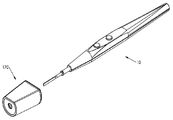
여기서 유사한 참조 번호가 본 발명의 유사한 구조적 요소 및 특징을 식별하는 도면을 참조하면, 도 1 내지 도 14에, 기구가 외과 의사에 의해 수술 중에 사용되고 있는 동안 수술 부위를 조명하기 위해 휴대용 전기 수술 기구(10)에 부착되도록 적합하게 구성된 조명 장치(20)가 예시되어 있다. 대안적으로, 조명 장치(20)는 수술 기구와 무관하게 인접한 수술 부위에 조명을 제공하기 위해 수술 드레이프 또는 신체 조직에 부착될 수 있다. Referring herein to the drawings in which like reference numerals identify similar structural elements and features of the present invention, in Figures 1-14, a portable electrosurgical instrument ( A
조명 장치(20)는 조명 서브-어셈블리(40)를 포함한다. 도 8에 가장 잘 도시된 바와 같이, 조명 서브-어셈블리(40)는 종방향 조명 축을 규정하고 내부 챔버를 갖는 가늘고 긴 직사각형 2부 구성 하우징(2,2')을 포함한다. 2부 구성 하우징(2,2')은 전면에 지지된 LED 광원(32)을 갖는 인쇄 회로 기판 또는 PCB(28)를 둘러싼다. 그 후면에는 광원(32)을 제어하기 위한 스위치(26)가 지지된다. 배터리 셀(24)은 광원(32)에 전원을 공급하기 위해 PCB(28)의 후면과 연결되고, 렌즈(8)는 광원(32)에서 방출되는 빛을 집속하기 위해 광원(32) 앞에 배치된다. 푸시 버튼 액츄에이터(12)는 도 7에 가장 잘 도시된 바와 같이 스위치(26)를 수동으로 작동시키기 위해 하우징(2,2')의 상부 표면에 제공된다. The
조명 장치(20)는 삼각형 커넥터 플레이트 또는 포스트(18)에 의해 조명 서브-어셈블리(40)에 연결된 부착 메커니즘 및 도 14에 가장 잘 도시된 바와 같이, 포스트(18)의 구멍(38)을 통해 연장되는 관련 횡방향 피벗 핀(14)을 더 포함한다. 피벗 핀(14)은 조명 장치(20) 상에 부착 메커니즘을 재 배치할 필요 없이 조명 서브-어셈블리(40)가 수술 기구에 대해 조정되는 것을 가능하게 한다. 조명 장치(20)의 부착 메커니즘은 바람직하게는 도 1 및 도 3에 도시된 바와 같이, 수술 기구(10)의 원위 단부 부분에 광 서브-어셈블리(40)를 분리 가능하게 결합하도록 적합하게 구성되지만, 수술 기구의 모양이나 기하학적 구조에 관계없이 수술 기구의 길이를 따라 임의의 위치에 쉽게 부착될 수 있다. The
부착 메커니즘은 아래에서 더 상세히 설명되는 바와 같이 서로 피벗 가능하게 부착되는 좌우 이동식 결합 날개(4,4')를 포함한다. 도 8에 도시된 바와 같이, 우측 및 좌측 순응성 또는 연질 고무 고정 플레이트(6,6')는 수술 기구의 표면을 파지하기 위한 접착제 또는 오버몰딩에 의해 우측 및 좌측 결합 날개(4,4')의 대향하는 내부 표면에 각각 부착된다. The attachment mechanism comprises left and right
도 12 및 도 13에서 가장 잘 알 수 있는 바와 같이, 우측 날개(4)는 한 쌍의 이격된 수용 보어(34)를 포함하고, 좌측 날개(4')는 한 쌍의 이격된 수용 보어(36)를 포함하는 반면, 포스트(18)는 단일 수용 보어(42)를 포함하며, 이들 모두는 연장된 피벗 핀(22)을 수용하도록 적합하게 구성된다. 피벗 핀(22)은 2개의 대향 날개가 서로에 대해 그리고 포스트(18)에 대해 회전할 수 있게 한다. 12 and 13 , the
V자형 토션 스프링(16)은 대향 날개(4,4')를 도 9에 도시된 정상 폐쇄 위치 또는 압축 위치로 편향시키기 위한 부착 메커니즘과 작동 가능하게 연결된다. 보다 구체적으로, 날개(4,4')는 도 9에 도시된 일반적으로 클램핑되거나 폐쇄된 위치 사이에서 이동하도록 적합하게 구성되며, 여기서 2개의 대향 날개(4,4') 사이의 거리는 도 10에 도시된 완전히 펼쳐지거나 열린 위치이며, 여기서 2개의 대향 날개(4,4') 사이의 거리는 L2이다. 대조적으로, 부착 메커니즘의 정상적인 파지 위치는 도 3 및 5에 도시되어 있으며, 여기서 대향하는 좌우 결합 날개(4,4')는 부분적으로 펼쳐진 개방 상태에 있다. A V-shaped
도 15 내지 도 21을 참조하면, 일반적으로 참조 번호 30으로 지정되고 조명 장치를 휴대용 수술 기구(10)의 일부에 부착하기 위한 클리핑 어셈블리를 포함하는 본 발명에 따른 조명 장치의 다른 실시형태가 도시되어 있으며, 여기서 조명 서브-어셈블리(40)는 외과 의사 손과의 간섭을 피하기 위해 횡방향 피벗 핀(14)에 의해 키가 큰 중심 포스트(44) 상단에 피벗식으로 지지된다. 바람직하게는, 중앙 포스트(44)는 서브-어셈블리(40)의 하우징의 수직 높이의 2배 이상의 수직 높이를 가지며, 그 결과 하우징이 수술 기구의 근위 단부에 부착되는 경우, 포스트(44)의 수직 높이는 사용자의 손 위로 연장되어 광 하우징의 종방향 조명 축이 원위 팁 부분에 인접한 수술 기구의 종방향 축과 교차하도록 한다. 15-21 , there is shown another embodiment of a lighting device in accordance with the present invention, generally designated 30 and including a clipping assembly for attaching the lighting device to a portion of a portable
더욱이, 조명 장치(30)는 그로부터의 광 경로가 수술 기구(10)의 축과 교차하도록 중앙 포스트(44)에 대해 조명 서브-어셈블리(40)를 각도 있게 할 수 있는 능력을 외과 의사에게 제공한다. 조명 서브-어셈블리(40)는 빛이 수술 부위로부터 멀어지게 지향되는 도 20에 도시된 최대 각도(A1)와 빛이 수술 부위를 향해 지향되는 도 21에 도시된 최소 각도(A2) 사이에서 피벗 핀(14)을 중심으로 이동할 수 있다. Moreover, the
도 73 내지 도 79를 참조하여 아래에서 더 상세히 설명될 본 발명의 대안적인 실시형태에서, 조명 서브-어셈블리는 수술 기구의 종축에 대한 조명 하우징의 조명 축을 배향하도록 포스트의 상 단부에 회전 가능하게 연결될 수 있다. 예를 들어, 볼 및 소켓 조인트는 조명 하우징을 포스트에 회전 가능하게 연결할 수 있다. In an alternative embodiment of the invention, which will be described in greater detail below with reference to FIGS. 73-79, the lighting sub-assembly may be rotatably connected to the upper end of the post to orient the illumination axis of the illumination housing relative to the longitudinal axis of the surgical instrument. can For example, a ball and socket joint may rotatably connect the light housing to a post.
도 22 내지 도 25를 참조하면, 일반적으로 참조 번호 50으로 지정된 본 발명에 따른 조명 장치의 다른 실시형태가 도시되어 있으며, 이는 조명 서브-어셈블리(40) 및 휴대용 수술 기구(10)에 부착하기 위한 가요성 후크 및 루프 유형 고정 스트립(46)을 포함한다. 보다 구체적으로, 서브-어셈블리(40)는 가요성 스트립(46)을 수용하기 위한 슬롯(45)을 갖는 피벗 연결 플레이트 또는 포스트(43)를 포함한다.22-25 , there is shown another embodiment of a lighting device according to the present invention, generally designated by
도 26 및 27을 참조하면, 일반적으로 참조 번호 60으로 지정된 본 발명의 조명 장치의 또 다른 실시형태가 도시되어 있으며, 이는 조명 서브-어셈블리(40) 및 휴대용 수술 기구(10)에 부착하기 위한 접착제 스트립(48)을 포함한다. 보다 구체적으로, 서브-어셈블리(40)는 제거 가능한 라이닝(52)에 의해 덮인 접착제 스트립(48)을 수용하기 위한 노치(49)를 갖는 피벗 연결 플레이트 또는 포스트(47)를 포함한다. 26 and 27 , another embodiment of a lighting device of the present invention, generally designated 60 , is shown, which is an adhesive for attachment to a
도 28 내지 도 36을 참조하면, 일반적으로 참조 번호 70으로 지정되는 본 발명의 조명 장치의 다른 실시형태가 도시되어 있으며, 이는 조명 서브-어셈블리(40) 및 휴대용 수술 기구(10)에 부착하기 위한 케이블 타이 유형 스트립(54)을 포함한다. 보다 구체적으로, 서브-어셈블리(40)는 케이블 타이 스트립(54)을 지지하기 위한 피벗 연결 플레이트 또는 포스트(56)를 포함한다. 케이블 타이 스트립(54)은, 도 33 내지 도 36에 가장 잘 도시된 바와 같이, 가요성 잠금 톱니(58)와 상호작용하도록 적합하게 구성되는 복수의 톱니(62)를 갖는다. 28-36, there is shown another embodiment of a lighting device of the present invention, generally designated 70, for attachment to a
도 37 및 38을 참조하면, 도 1 내지 도 14를 참조하여 위에서 상세히 설명된 본 발명의 조명 장치(20)가 도시되어 있지만, 여기서는 휴대용 전기 수술 기구(10)보다는 흡입/세정 기구(80)와 함께 도시되어 있다. 따라서, 당업자는 본 발명의 조명 장치가 전기 수술 기구 및 흡입/세정 장치를 제한 없이 포함하는 다양하고 상이한 수술 기구와 함께 이용될 수 있음을 쉽게 인식해야 한다. 37 and 38, there is shown the
도 39 내지 도 42를 참조하면, 일반적으로 참조 번호 90으로 지정되고 휴대용 수술 기구(10)의 원위 단부 부분을 수용하도록 적합하게 구성된 본 발명에 따른 조명 장치의 다른 실시형태가 도시되어 있다. 조명 장치(90)는 근위 단부 캡(104) 및 수술 기구(10)의 원위 단부 부분과 기계적으로 결합하기 위한 톱니를 갖는 링(106)을 갖는 거의 원통형인 2부 구성 하우징(102,102')을 갖는다. 내부 몸체 부분(108)은 수술 기구(10)의 원위 단부 부분을 수용하기 위해 하우징(102,102') 내에 배치된다. 39-42, there is shown another embodiment of a lighting device in accordance with the present invention, generally designated 90 and adapted to receive a distal end portion of a portable
PCB(116)는 하우징(102,102')의 원위 단부 부분 내에 배치되며, 수술 부위를 조명하기 위해 전면에 복수의 LED 광원(114)을 갖는다. 복수의 배터리 셀(112)은 LED 광원(114)에 전력을 공급하기 위해 PCB의 후면에 접속 가능하게 지지된다. 렌즈(124)는 LED 광원(114) 앞에 배치되고 스페이서(122)는 광원(114)에 대한 간극을 제공하기 위해 렌즈와 PCB(116) 사이에 배치된다. 비접촉 스위칭 메커니즘(118)은 LED 광원(114)을 작동시키기 위해 PCB(116)의 후면과 작동 가능하게 연결된다. The
비접촉 스위칭 메커니즘(118)은 홀 효과 센서, 근접 센서 및 광센서로 구성된 그룹으로부터 선택된 센서로 구성될 것이다. 홀 효과 센서는 자기장에 반응하여 출력 전압을 변화시키는 변환기이다. 홀 효과 센서는 근접 스위칭, 위치 지정, 속도 감지 및 전류 감지 애플리케이션에 사용된다. 홀 효과 센서에서, 얇은 금속 스트립에 전류가 가해진다. 근접 센서는 종종 전자기장 또는 전자기 방사선 빔(예를 들어 적외선)을 방사하고 전자기장 또는 리턴 신호의 변화를 찾는다. 감지되는 물체는 종종 근접 센서의 대상으로 지칭된다. 서로 다른 근접 센서 대상에는 서로 다른 센서가 필요할 수 있다. 스위칭 메커니즘은 비접촉 센서를 사용하여 전기 수술 기구의 존재, 설치 또는 사용을 감지하고, 광원에 공급하는 전원 회로를 활성화하여 작동한다.The
도 43 내지 도 49를 참조하면, 일반적으로 참조 번호 110으로 지정되고 휴대용 수술 기구(10)의 원위 단부 부분에 부착되도록 적합하게 구성된 본 발명에 따른 조명 장치의 또 다른 실시형태가 도시되어 있다. 조명 장치(110)가 수술 부위의 실시간 화상을 제공하기 위해 LED 조명 장치(32)에 추가로 소형 카메라(144)를 포함하는 것을 제외하고, 조명 장치(110)는 도 1 내지 도 14를 참조하여 상기에서 설명한 조명 장치(20)와 실질적으로 동일하다. 보다 구체적으로, 조명 장치(110)는 그 전면에 LED 광원(32)을 지지하는 직사각형 PCB(124)를 갖고 거의 직사각형의 2부 구성 하우징(142,142')을 포함하지만, 카메라(144)를 수용하기 위해 중심에서 벗어난 곳에 배치된다. 유사하게, 조명 장치(110)는 PCB(148) 상의 LED 광원(32)의 위치를 수용하기 위해 중심에서 벗어난 위치에 배치된 렌즈 표면을 갖는 렌즈 플레이트(146)를 포함한다. 비디오는 내부 저장 칩에 저장되거나 유선 또는 무선 접속을 통해 외부 저장 장치 또는 표시 장치(미도시)로 전송될 수 있다.43-49 , there is shown another embodiment of a lighting device according to the present invention, generally designated 110 and adapted to be attached to a distal end portion of a portable
도 50 내지 도 57을 참조하면, 일반적으로 참조 번호 120으로 지정되고 휴대용 수술 기구(10)와 함께 사용하도록 적합하게 구성되는 조명 장치의 또 다른 실시형태가 도시되어 있다. 조명 장치(120)는 그 전면에 한 쌍의 LED 광원(216)을 갖고 그 후면에 스위치(218) 및 배터리 셀(222)을 갖는 직사각형 PCB(214)를 둘러싸는 거의 직사각형인 2부 구성 하우징(202,202')을 갖는 조명 서브-어셈블리를 포함한다. 스위치(218)는 하우징 부분(202)에 연결된 푸시 버튼(212)에 의해 작동된다. Referring to FIGS. 50-57 , another embodiment of a lighting device, generally designated 120 and adapted for use with a portable
조명 서브-어셈블리의 하우징(202,202')은 또한 수술 기구(10)의 근위 단부 부분에 조명 장치(120)를 분리 가능하게 고정하기 위한 부착 메커니즘을 갖는다. 부착 메커니즘은 하우징 부분(202')의 바닥 표면으로부터 연장되는 제1 플랜지(207) 및 내부 표면에 탄성 패드(208)를 갖는 하우징 부분(202)의 바닥 표면으로부터 연장되는 제2 플랜지(209)에 형성된 구멍(205)에서 지지되는 조절 가능한 나사(206)를 포함한다. 사용 시, 도 54 및 55에서 가장 잘 알 수 있는 바와 같이, 수술 기구(10)의 근위 단부 부분은 플랜지(207)의 나사(206)의 단부와 플랜지(209)의 패드(208) 사이에서 압축된다. The
조명 장치(120)는 하우징(202,202')의 원위 단부와 결합하기 위한 테이퍼진 근위 리테이너 부분(215) 및 근위 리테이너 부분(215)으로부터 수술 기구(10)의 원위 단부 부분을 둘러싸도록 적합하게 구성되는 원위 슬리브 부분(219)까지 원위 측으로 연장되는 연장된 몸체 부분(217)을 갖는 연장된 도광(light guide) 서브-어셈블리(210)를 더 포함한다.The
도광 서브-어셈블리(210)의 몸체 부분(217) 및 원위 슬리브 부분(219)은 서로 일체형이고 도파관으로서 기능하는 중합체 재료로 형성된다. 보다 구체적으로, 몸체 부분(217) 및 슬리브 부분(219)은 LED 광원(216)으로부터의 빛을 몸체 부분(219)을 통해 슬리브 부분(219)의 원위 단부로 전달하는 중합체 재료를 포함한다. 본질적으로, 중합체는 도파관으로서 기능한다(예를 들어, 미국 특허번호 7,510,524 및 10,068,173 참조). The
도 58 내지 도 61을 참조하면, 조명 장치(120)와 함께 사용하도록 구성되고, 일반적으로 참조 번호 125로 지정된 도광 서브-어셈블리의 다른 실시형태가 예시되어 있다. 서브-어셈블리(125)는 근위 리테이너 부분(225), 긴 몸체 부분(224) 및 원위 슬리브 부분(225)을 포함하고, 여기서 몸체 부분(224) 및 슬리브 부분(225)은 LED 광원(216)으로부터의 빛을 몸체 부분(224)을 통해 슬리브 부분(225)의 원위 단부로 전송하는 복수의 광섬유(226)를 포함한다. 바람직하게는, 광섬유(226)는 도 59에 가장 잘 도시된 바와 같이 슬리브의 주변에 대해 이격된 관계로 분포된다. 58-61 , another embodiment of a light guide sub-assembly configured for use with a
도 62 내지 도 70은 일반적으로 참조 번호 130으로 지정되고 휴대용 수술 기구(10)의 원위 단부 부분에 부착되도록 적합하게 구성되는 휴대용 수술 기구용 조명 장치의 다른 실시형태를 예시한다. 조명 장치(130)는, 조명 장치(110)가 조명 장치에 전력을 공급하기 위해 전기 콘센트와 연결하기 위한 전선(304)을 포함하는 것을 제외하고는, 도 1 내지 14를 참조하여 위에서 설명된 조명 장치(20)와 실질적으로 유사하다. 다른 모든 측면에서, 이 장치는 렌즈(322) 및 전면에 LED 광원(312)이 있고 후면에 푸시 버튼 액추에이터(318)에 의해 작동되는 스위치 메커니즘(306)이 있는 PCB(308)를 갖는 2부 구성 하우징(302,302')을 포함한다는 점에서 조명 장치(20)와 거의 동일하다. 62-70 illustrate another embodiment of a lighting device for a portable surgical instrument, generally designated 130 , and adapted to be attached to a distal end portion of a portable
전선(304)은 도 68 및 69에 가장 잘 도시된 바와 같이 PCB(308)의 후면 상의 접점(332)과 통신한다. 조명 장치(130)는 또한 토션 스프링(316)에 의해 클램핑 위치로 스프링 편향되고 긴 핀(324)에 의해 플랜지(314)에 피벗 가능하게 연결된 각각의 내부 압축 패드(328,328')와 함께 한 쌍의 결합 날개(326,326')를 갖는 부착 서브-어셈블리를 포함하고, 여기서 플랜지 자체는 가로 핀(334)에 의해 하우징(302)에 회전 가능하게 연결된다.
도 71 내지 도 79를 참조하면, 일반적으로 참조 번호 140으로 지정되고 수술 부위를 조명하기 위해 환자의 신체 조직에 부착되도록 적합하게 구성되는 조명 장치의 다른 실시형태가 예시되어 있다. 여기서, 조명 장치(140)는, 연장된 피벗 핀(즉, 피벗 핀(22)에 의해 규정되는 클램핑 메커니즘의 피벗 축이 조명 서브-어셈블리의 길이방향 축에 수직으로 연장되고 그에 따라 조명 장치의 조명 축에 수직으로 연장되는 것을 제외하고, 도 1 내지 도 14에 도시된 조명 장치(20)와 사실상 유사하다. 71-79, another embodiment of an illumination device, generally designated 140, and adapted to be attached to body tissue of a patient to illuminate a surgical site, is illustrated. Here, the
조명 장치(140)의 이 실시형태는 개방 수술 부위를 포함하는 수술 중에 사용되는 수술 드레이프의 섹션에 부착하기 위해 사용될 수 있다는 것이 추가로 구상된다. 도 71 및 72에 도시된 유형의 다중 조명 장치는 수술용 드레이프에 쉽게 부착될 수 있고, 수술 상처의 둘레 주위에 배열될 수 있고, 조명 장치는 수술 부위에 대한 아레나 스타일 조명을 생성하도록 이러한 방식으로 각도를 이룰 수 있다는 것이 구상된다. It is further envisioned that this embodiment of the
도 73 내지 도 79를 참조하면, 일반적으로 참조 번호 150으로 지정되는 본 발명에 따른 조명 장치의 또 다른 실시예가 예시되어 있으며, 여기서 조명 서브-어셈블리(400)는 볼 및 소켓 조인트에 의해 클램핑 서브-어셈블리(425)에 회전 가능하게 연결되어 외과 의사가 수술 기구(10)의 종축에 대해 조명 장치(150)의 조명 축을 배향하게 할 수 있다.73 to 79, another embodiment of a lighting device according to the invention, generally designated 150, is illustrated, wherein the
도 77에서 가장 잘 볼 수 있는 바와 같이, 조명 장치(150)의 조명 서브-어셈블리(400)는, 그 전면에 LED 광원(422)이 있는 렌즈(406)와 PCB(420)를 갖는 2부 구성 하우징(402,402') 및 푸시 버튼 액츄에이터(404)에 의해 작동되는 후면의 배터리 셀(418) 및 스위치 메커니즘(424)을 포함하는 것을 제외하고는, 도 1 내지 도 14에 도시된 조명 장치(20)의 조명 서브-어셈블리와 실질적으로 동일하다. 조명 장치(150)의 클램핑 서브-어셈블리(425)는 V자형 토션 스프링(414)에 의해 클램핑 위치로 스프링 편향된 각각의 내부 압축 패드(412,412')를 갖는 한 쌍의 결합 날개(410,410')를 포함하고, 그리고 날개는 서로에 대해 그리고 연장된 핀(416)에 의해 연결 플랜지(408)에 피벗 가능하게 연결된다. 여기서, 연결 플랜지(408)는 피벗 핀(416)을 수용하기 위한 보어(430)와 조명 서브-어셈블리(400)의 하우징 부분(402,402')으로부터 각각 연장되는 2부 구성 볼(426,426)을 수용하기 위한 반구형 소켓(428)을 포함한다. As best seen in FIG. 77 , the
도 80 내지 83을 참조하면, 일반적으로 참조 번호 160으로 지정되고 수술 부위를 조명하기 위한 조명 서브-어셈블리(475), 장치를 휴대용 수술 기구(10)에 부착하기 위한 클램핑 서브-어셈블리(485), 및 커플링(452)에 의해 원격 광원(170)에 부착된 연장된 광 튜브 또는 광섬유 케이블(450)을 포함하는 본 발명에 따른 조명 장치의 또 다른 실시형태가 도시되어 있다. 대안적으로, 광섬유 케이블(450)은 멸균 필드의 외측에 수용된 자본 장비 장치(예를 들어, 영구 또는 다용도 장치)에 부착될 수 있다. 80-83 , designated generally by
여기서, 조명 서브-어셈블리(475)는 광섬유 케이블(450)의 원위 단부 부분을 수용하기 위한 정션(junction) 박스(456)를 갖는 2부 구성 하우징(454,54')을 포함하고, 클램핑 서브-어셈블리(485)는 v-형 토션 스프링(462)에 의해 클램핑 위치로 스프링 편향되는 각각의 내부 압축 패드(460,460')가 있는 한 쌍의 결합 날개(458,458')를 포함하고, 그들은 연장된 핀(468)에 의해 서로 그리고 연결 플랜지(464)에 피벗 가능하게 연결되고, 그리고 연결 플랜지는 가로 핀(466)에 의해 조명 서브-어셈블리(475)에 피벗 가능하게 연결된다. Here, the
도 84 내지 도 93을 참조하면, 일반적으로 참조 번호 170으로 지정되고 도 39 내지 도 42에 도시된 조명 장치(90)와 유사한 휴대용 수술 기구(10)와 함께 사용하기 위한 조명 장치의 또 다른 실시형태가 예시되어 있다. 그러나 본 발명의 이 실시형태에서, 조명 장치(170)의 외부 하우징(602)은 사다리꼴 형상의 상부 표면을 갖는 일반적으로 절두 원추형 구조를 갖는다. 평평한 상부 표면은 수술 기구(10)의 상부 표면을 따라 연장하는 시선이 조명 장치(170)에 의해 방해받지 않고 유지되도록 수술 기구(10)의 상부 표면과의 평면 정렬을 위해 구성된다. 84-93 , another embodiment of a lighting device for use with a portable
하우징(602)은 수술 기구(10)의 원위 단부 부분을 수용하기 위한 내부 몸체 부분(608), 그 전면에 복수의 LED 광원(622)이 있는 PCB(618), 및 그 후면에 수술 기구(10)의 원위 단부 부분의 삽입 시에 LED 광원을 작동시키기 위한 접촉 스위치(624)를 둘러싼다. 한 쌍의 배터리 셀(616)은 또한 LED 광원(622)에 전력을 공급하기 위해 PCB(622)의 후면과 연결된다. The
렌즈(604)는 광원을 집속하기 위해 하우징(622)의 원위 단부에 배치되고, 스페이서 또는 보호기(606)는 렌즈(604)와 LED 광원 사이에 배치된다. 조명 장치(170)에서, LED 광원(622)은 수술 기구의 종축에 대해 비대칭 구성으로 렌즈(604) 뒤에서 외부 하우징(602)의 원위 단부 주위로 연장된다. 순응성 고정 링(612)은 조명 장치(170) 내에서 수술 기구(10)의 원위 단부 부분을 기계적으로 결합 및 유지하기 위해 내부 몸체 부분(608)의 근위 단부에 인접한 외부 하우징(602)에 배치되고, 근위 단부 캡(614)은 순응 고정 링(612)이 제자리에 유지된다. A
도 94 내지 도 101을 참조하면, 일반적으로 참조 번호 180으로 지정되고, 적어도 외부 하우징의 기하학적 구조와 관련하여 도 84 내지 도 93에 도시된 조명 장치(170)와 실질적으로 유사한 본 발명에 따른 조명 장치의 다른 실시형태가 예시되어 있다. 이 실시형태에서, 조명 장치(180)는 외부 몸체 부분(502)의 평평한 상부 표면 상에 배치되는 수동으로 조절 가능한 고정 나사(504)를 포함한다. 고정 나사(504)는 수술 기구(10)가 조명 장치(180) 내로 삽입될 때 수술 기구(10)의 원위 단부 부분과 선택적으로 결합되도록 적합하게 구성된다. 94 to 101 , a lighting device according to the present invention designated generally by the
도 102 내지 도 110을 참조하면, 장치(190)를 휴대용 수술 기구(10)의 몸체에 고정하기 위한 피벗팅 테일 바(508)를 포함하고 일반적으로 참조 번호 190으로 지정된 본 발명에 따른 조명 장치의 또 다른 실시형태가 예시되어 있다. 테일 바(508)는 조명 장치(190)의 하우징(596)의 근위 단부로부터 연장되는 근위 보스 구조(512)와 피벗 가능하게 결합하기 위한 원위 보스 구조(514)를 포함한다. 편향 가능한 걸쇠(516)는 수술 기구(10)의 몸체를 기계적으로 결합하기 위해 테일 바(508)의 근위 단부에 형성된다. 편향 가능한 걸쇠(516)는 수술 기구(10)로부터 걸쇠(516)를 벌리고 해제하기 위한 대향 플랜지(518)를 포함한다. 102-110 , an illustration of a lighting device according to the present invention, generally designated 190, comprising a pivoting
도 111 내지 119를 참조하면, 일반적으로 도 84 내지 93에 도시된 조명 장치(170)와 실질적으로 유사한 참조 번호 210으로 지정된 본 발명에 따른 조명 장치의 다른 실시형태가 예시되어 있지만, 조명 장치(210)는 휴대용 수술 기구(10)의 원위 단부 부분과 기계적으로 또는 압축적으로 결합되도록 적합하게 구성되는 피벗식 고정 아암(634)을 더 포함한다. 111 - 119 , there is illustrated another embodiment of a lighting apparatus according to the present invention, generally designated by
보다 구체적으로, 고정 캠 아암(634)은 수술 기구(10)의 종축에 평행하게 연장되는 축 상에서 피벗 핀(638)을 중심으로 회전하기 위해 외부 몸체 부분(602)의 근위 단부 캡(632)에 회전 가능하게 부착된다. 고정 아암(634)의 자유 단부는, 도 115 및 116에 가장 잘 도시된 바와 같이, 아암(634)을 유지 위치에 유지하기 위해 단부 캡(632)의 표면으로부터 근위 방향으로 돌출하는 잠금 플랜지(636)를 포획하기 위한 탱(642)을 갖는다. More specifically, the fixed
현재, 화상(burn) 또는 우발적인 작동을 방지하기 위해 사용하지 않을 때 전기 수술 기구를 홀스터에 넣는 것으로 알려져 있다. 때때로 이 홀스터는 외과 의사가 쉽게 접근할 수 있도록 환자 근처의 수술 커튼에 묶여 있거나 매달려 있다. 조명 장치가 부착된 수술 기구에 맞도록 설계된 홀스터가 개시되며, 조명 장치를 사용하지 않을 때 사용자가 배터리 수명을 보존할 수 있도록 조명 장치도 끄도록 설계되었다. It is now known to place electrosurgical instruments in holsters when not in use to prevent burns or accidental actuation. Sometimes these holsters are tied to or hung from a surgical curtain near the patient for easy access by the surgeon. A holster designed to fit a surgical instrument to which a lighting device is attached is disclosed, and the lighting device is also designed to be turned off by a user to conserve battery life when the lighting device is not in use.
도 1a 내지 도 16a를 참조하면, 휴대용 수술 기구(10)의 원위 단부 부분에 부착되도록 구성된 배터리 구동식 조명 장치(1020) 및 조명 장치(1020)가 부착된 수술 기구(10)를 수용하기 위한 연장된 홀스터(1030)를 포함하고, 수술을 수행하기 위한 새롭고 유용한 시스템이 예시되어 있다. 1A-16A , a battery powered
도 11a 내지 도 16a에서 가장 잘 나타낸 바와 같이, 조명 장치(1020)는 내부 몸체 부분(1008)을 수용하는 우측 및 좌측 몸체 부분(1002,1002') 및 조명 장치(10)의 원위 단부 부분을 수용하기 위한 중앙 구멍이 있는 근위 단부 캡(1004)을 갖는 것을 포함한다. 원주 방향으로 이격된 톱니를 갖는 스탬핑된 결합 링(1006)은 내부 몸체 부분(1008)으로 삽입될 때 수술 기구(10)를 기계적으로 결합하기 위해 단부 캡(1004)에 인접하게 배치된다.As best shown in FIGS. 11A-16A , the
PCB(1024)는 조명 장치(1020)의 몸체(1002,1002')의 원위 단부 내에 배치되며, 그 전면에 원주 방향으로 이격된 복수의 LED 광원(1018)을 갖고, 제1 스위치(1022)는 수술 기구(10)를 조명 장치(1020)에 삽입할 때 LED 광원(1018)을 작동시키기 위해 PCB(1024)의 후면에 배치된다. 복수의 배터리 셀(1026)은 또한 LED 광원(1018)에 전력을 공급하기 위해 PCB(1024)의 후면과 연결되고, 렌즈(1014)는 LED 광원(1018) 앞에 배치된다. The
제2 스위치(1016)는, 수술 기구(10) 및 조명 장치(1020)가 홀스터(1030)에 함께 삽입될 때 LED 광원(1018)을 제어하기 위해 PCB(1024)의 후면에도 제공된다. 특히, 도 5a 및 도 6a에 도시된 바와 같이, 홀스터 몸체(1028)는 어셈블리가 내부에 수용될 때 LED 광원(1018)을 끄기 위해 스위치(1016)와 기계적으로 상호작용하는 거의 원통형인 주변 접촉 표면을 규정하는 내부 수용 보어(1032)를 포함한다. 이를 통해 사용자는 사용하지 않을 때 전기 수술 기구에 조명 장치를 설치한 상태로 유지하면서 배터리 수명을 보존할 수 있다. A
도 9a 및 도 10a에서 가장 잘 알 수 있는 바와 같이, 내부 수용 보어(1032)는 홀스터(1030) 내부로 기구(10) 및 조명 장치(1020)의 보다 용이한 삽입을 위해 모따기된(chamfered) 선단 에지(1034)를 갖는다. 홀스터 몸체(1028)는 또한 스트랩 또는 테더(tether)를 수용하도록 적합하게 구성된 상부 유지 플랜지(1035)를 포함하여 홀스터(1030)가 수술용 드레이프 등에 지지되거나 부착될 수 있다. As best seen in FIGS. 9A and 10A , the interior receiving bore 1032 has a chamfered tip for easier insertion of the
도 17a 내지 도 33a를 참조하면, 휴대용 수술 기구(10)의 원위 단부 부분에 부착하기 위해 구성된 배터리 구동식 조명 장치(1040) 및 부착된 조명 장치(1040)와 함께 수술 기구(10)를 수용하기 위한 연장된 홀스터(1050)를 포함하는 수술을 수행하기 위한 시스템의 다른 실시형태가 예시되어 있다. 17A-33A , receiving a
이 실시형태에서, 조명 장치(1040)는 내부 몸체 부분(1008)을 수용하고 근위 단부 캡(1004) 및 결합 링(1006)을 갖는 우측 및 좌측 몸체 부분(1052,1052')을 포함한다는 점에서, 도 11a 내지 도 16a에 도시된 조명 장치(102)와 실질적으로 유사하다. PCB(1024)는 몸체(1052,1052')의 원위 단부 내에 배치되고 그 전면에 LED 광원(1018)을 가지며, 제1 스위치(1022)는 수술 기구(10)를 조명 장치(1040)에 삽입할 때 LED 광원(1018)을 작동시키기 위해 그 후면에 배치된다. 복수의 배터리 셀(1026)은 또한 LED 광원(1018)에 전력을 공급하기 위해 PCB(1024)의 후면과 연결되고, 렌즈(1014)는 도 31a 내지 33a에서 가장 잘 알 수 있는 바와 같이 LED 광원(1018) 앞에 배치된다. In this embodiment, the
본 발명의 이 실시형태에서, LED 광원(1018)을 제어하기 위한 제2 스위치(1016)는, 도 19a 및 28a에 가장 잘 도시된 바와 같이, 몸체 부분(1052)의 외부 표면으로부터 방사상 외측으로 돌출하는 2개의 이격된 안내 리브(1054) 사이에 형성된 외부 채널에 배치된다. 도 29a에 도시된 바와 같이, 안내 리브(1054)의 제2 세트는 홀스터(1050)에 대한 안내 목적을 위해 몸체 부분(1052')과 연결되어 있다. In this embodiment of the present invention, the
보다 구체적으로, 도 20a 내지 도 22a에 도시된 바와 같이, 수술 기구(10) 및 조명 장치(1040)가 홀스터 몸체(1056)의 내부에 삽입될 때, 내부 리브 구조(1058)는 몸체 부분(1052)의 안내 리브(1054)와 정렬되고 그 사이에 위치된 스위치(1016)와 상호 작용하여 PCB(1024) 상의 LED 광원(1018)을 끈다. 동시에, 몸체 부분(1052')의 안내 리브(1054)는 도 23a 내지 27a에 도시된, 대향하는 리브 구조(1058) 사이에 형성된 채널과 정렬된다. More specifically, as shown in FIGS. 20A-22A , when the
도 26a에서 가장 잘 알 수 있는 바와 같이, 내부 홀스터 몸체(1056)는 또한 홀스터(1050) 내부로 수술 기구(10) 및 조명 장치(1040)의 보다 용이한 삽입을 위해 모따기된 선단 에지를 갖는다. 홀스터 몸체(1056)는 또한 스트랩 또는 테더를 수용하도록 적합하게 구성된 상부 유지 플랜지(1055)를 포함하고, 그 결과 홀스터(1050)는 수술용 드레이프 등에 지지되거나 부착될 수 있다. As best seen in FIG. 26A , the
본 발명은 또한 수술 도중에 사용하기 위한 일련의 상이한 키트에 관한 것이다. 도 1b 내지 도 4b에 예시된 이러한 키트 중 하나에는, 휴대용 전기수술 기구(10) 및 배터리 구동 조명 장치(2020)를 포함하는 미리 형성된 패키지(2030)가 있다. 도 5b 내지 도 8b에 도시된 키트의 다른 실시형태에서, 휴대용 전기 수술 기구(10), 2개의 배터리 구동 조명 장치(2020) 및 별도의 수술 기구에 조명 장치(2020)를 장착하기 위한 어댑터(2040)를 포함하는 미리 형성된 패키지(2050)가 있다. The present invention also relates to a series of different kits for use during surgery. In one of these kits illustrated in FIGS. 1B-4B is a preformed
여기서, 조명 장치(2020)는 어댑터(2040)에 부착될 때 조명 장치를 켜기 위한 내부 스위치를 가질 수 있다. 도 9b 내지 도 12b는 배터리 구동식 조명 장치(2020) 및 수술 기구에 조명 장치(2020)를 장착하기 위한 어댑터(2040)만을 갖는 미리 형성된 패키지(2060)를 포함하는 키트를 예시한다.Here, the
도 13b 내지 도 16b를 참조하면, 휴대용 전기 수술 기구(10), 배터리 구동식 조명 장치(2020) 및 조명 장치(2020)가 부착된 기구(10)를 수용하기 위한 홀스터(2070)를 갖는 미리 형성된 패키지(2080)를 포함하는 키트의 다른 실시형태가 예시되어 있다. 도 17b 내지 20b를 참조하면, 휴대용 전기 수술 기구(10), 배터리 구동식 조명 장치(2020), 홀스터(2070), 및 수술 도중에 사용하기 위한 수술 매트릭스 재료(2110)의 하나 이상의 세트를 갖는 미리 형성된 패키지(2090)를 포함하는 키트의 또 다른 실시형태가 예시되어 있다. 매트릭스 재료는 Alloderm, Allomax, FlexHD와 같은 상품 군에서 선택할 수 있습니다. 이러한 매트릭스 재료는 유방 복원 및 기타 성형 수술에 자주 사용된다. 따라서, 도 17b 내지 도 20의 키트는 유방 복원술을 가능하게 할 것이다. 13B-16B , a preformed portable
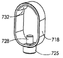
도 1c 내지 도 14c를 참조하면, 본 발명은 또한 휴대용 수술 기구(10)에 부착하기 위한 조명 장치(700)에 관한 것으로, 상기 조명 장치는 대향하는 근위 단부 및 원위 단부를 갖는 연장된 외부 하우징(704), 및 외부 하우징(704) 내에 배치되고 수술 기구(10)의 원위 단부 부분을 수용하기 위한 근위 개구를 갖는 연장된 내부 공동을 형성하는 내부 몸체(702)를 포함한다. 조명 장치(700)의 하우징(704)은 외과 의사에게 방해되지 않는 시선을 제공하기 위해 사다리꼴 형상의 평면 상부 표면을 갖는 절두 원추형 구성을 포함하는 위에서 설명된 유형이다. 1C-14C, the present invention also relates to a
도 7c 내지 도 9c에서 가장 잘 알 수 있는 바와 같이, PCB(716)는 조명 장치(700)의 하우징(704)의 원위 단부에 배치되고, 복수의 LED 광원(724)은 PCB(716)의 전면에 내장된다. 이러한 LED 광원(724) 중 하나 이상은 UV 스펙트럼 범위의 빛을 제공하여 수술 부위에서 박테리아의 감소와 같은 이점을 촉진할 수 있다. 커버(708)는 LED 광원(724)을 보호하기 위해 PCB(716)의 전면과 연결되고, 렌즈(706)는 LED 광원(724)으로부터의 빛을 지향시키기 위해 커버(708) 앞에 배치된다. 복수의 배터리 셀(712)은 LED 광원(724)에 전력을 공급하기 위해 PCB(716)의 후면과 연결되고, 기계적 스위치(714)는 또한 아래에서 상세히 설명되는 바와 같이 내부 몸체(702)의 내부 공동 내부로 수술 기구(10)의 원위 단부 부분을 삽입할 때 LED 광원을 작동시키기 위해 PCB(716)의 후면과 연결된다.As best seen in FIGS. 7C-9C , a
도 10c 및 도 11c에서 가장 잘 알 수 있는 바와 같이, 편향 가능한 접촉 레그(762)는 내부 몸체(702)와 일체로 형성된다. 접촉 레그(762)는 LED 광원(724)을 기계적으로 작동시키기 위해 내부 몸체(702)의 내부 공동 내부로 수술 기구(10)의 원위 단부 부분을 삽입할 때 PCB(716) 상의 스위치(714)와 접촉하도록 캔틸레버(cantilever) 방식으로 구성된다. 접촉 레그(762)는 내부 몸체(702)의 내부 공동 내부로 수술 기구(10)의 원위 단부 부분의 삽입을 용이하게 하기 위해 경사진 캠 표면을 형성하는 원위 단부에 반경방향 내측으로 돌출된 풋(758)을 포함한다. As best seen in FIGS. 10C and 11C , the
조명 장치(700)는 외부 하우징(704) 내에 배치된 스프링 편향된 결합 링(718)을 더 포함한다. 결합 링(718)은 도 6c에 도시된 축방향 정렬 위치 사이에서 내부 몸체(702) 및 외부 하우징(704)에 대한 이동을 위해 장착되며, 여기서 이는 수술 기구(10)의 원위 단부 부분을 내부 몸체(702)의 내부 공동으로 쉽게 삽입할 수 있도록 하고, 그리고 도 3c에 도시된 중심에서 약간 벗어난 위치에 대응하여 일반적으로 조명 장치(700) 내에 안착된다. The
도 6c에 도시된 바와 같이, 결합 링(718)에 의한 수술 기구(10)의 원위 단부 부분의 기계적 유지는 결합 링(718)의 내주면 섹션(732)에 의해 이루어진다. 보다 구체적으로, 도 6c에 도시된 바와 같이, 표면 섹션(732)은 수술 기구(10)의 원위 단부 부분을 탄성적으로 또는 접착식으로 유지하는 순응성 유지 재료(예를 들어, 고무 또는 실리콘 재료)를 그 위에 갖는다. 이 유지 재료는 결합 링(718)의 내주 면에 접착식으로 부착될 수 있거나 또는 결합 링(718)에 오버몰딩될 수 있다. As shown in FIG. 6C , mechanical retention of the distal end portion of the
도 11c에 가장 잘 도시되어 있는 바와 같이, 조명 장치(700)의 내부 몸체(702)는 외부 하우징(704) 내에 결합 링(718)을 수용하기 위한 아치형 슬롯(726)을 포함한다. 사용시, 결합 링(718)은 아치형 슬롯(726) 내에서 도 3c에 도시된 축방향 중심에서 벗어난 위치로부터 도 6c에 도시된 축방향 정렬 위치로 수동으로 이동된다. 이러한 움직임은 각각 도 3c 및 6c에서 거리 L1 및 L2를 비교함으로써 알 수 있다. As best shown in FIG. 11C , the
도 12c 내지 도 14c에 가장 잘 도시된 바와 같이, 돌출부 또는 버튼(725)은 도 3c의 중심에서 벗어난 위치로부터 도 6c의 중심 위치까지 결합 링(718)을 수동으로 이동시키기 위해 조명 장치(700)의 외부 하우징(704)에 있는 액세스 포트(715)를 통해 결합 링(718)으로부터 반경방향 외측으로 연장된다. 보다 구체적으로, 코일 스프링(722)은 결합 링(718)의 내주면으로부터 반경방향 내측으로 연장되는 포스트(728) 상에 지지된다. As best shown in FIGS. 12C-14C , the protrusion or
따라서, 코일 스프링(722)은 결합 링(718)의 내부 주변부와 내부 몸체(702)의 외부 표면 사이에 배치된다. 여기서, 코일 스프링(722)은 도 3c의 중심에서 벗어난 위치로부터 도 6c의 중심 또는 정렬된 위치까지 결합 링(718)의 수동 이동에 대한 스프링 힘을 제공한다. 다시 말해서, 코일 스프링(722)은 결합 링(718)을 도 3c의 정상적인 안착 위치로 편향시킨다. 코일 스프링이 도시되어 있지만, 판 또는 웨이브 스프링과 같은 다른 유형의 스프링이 사용될 수 있거나 탄성 재료가 또한 사용될 수 있다는 것은 본 발명의 범위 내에 있다. Accordingly, the
도 15c 내지 도 27c를 참조하면, 일반적으로 참조 번호 710으로 지정된 본 발명의 조명 장치의 다른 실시형태가 도시되어 있다. 조명 장치(710)는 도 1c 내지 도 14c에 도시된 조명 장치(700)와 실질적으로 유사하지만, 조명 장치의 이 실시형태에서 수술 기구(10)의 원위 단부 부분을 유지하는 결합 링은 상이하게 작동한다. 여기서, 일반적으로 참조 번호 754로 지정된 결합 링은 도 7c에 도시된 코일 스프링(722) 대신 판 스프링(756)에 의해 안착 위치로 일반적으로 편향된다. 도 26c 및 27c에 가장 잘 도시된 판 스프링(756)은 조명 장치(710)의 내부 몸체(752)의 외부 표면에 형성된 슬롯(764)에 고정된다. 이 위치에서, 그것은 외부 하우징(704)의 내부 표면의 결합 링(754)의 외부 주변부 사이에 배치된다. 15C - 27C , there is shown another embodiment of a lighting device of the present invention, generally designated 710 . The
사용 시, 결합 링(754) 상의 작동 버튼(755)이 수동으로 눌려질 때, 결합 링(754)은 판 스프링(756)의 편향력에 대항하여 내부 몸체(752)에 형성된 아치형 슬롯(768) 내에서 이동한다. 그렇게 함으로써, 결합 링(754)은 도 17c에 도시된 일반적으로 중심에서 벗어난 위치로부터 도 20c에 도시된 축방향 정렬 또는 중심 위치로 이동하여 수술 기구(10)의 원위 단부 부분을 조명 장치(710)에 용이하게 삽입할 수 있도록 한다. 이 이동은 각각 도 17c 및 20c에서 거리 L1 및 L2를 비교함으로써 알 수 있다. 판 스프링이 도시되어 있지만, 코일 또는 웨이브 스프링과 같은 다른 유형의 스프링이 사용될 수 있거나 탄성 재료가 또한 사용될 수 있다는 것은 본 발명의 범위 내에 있다. In use, when the
도 28c 내지 도 40c를 참조하면, 일반적으로 참조 번호 720으로 지정되고 본 발명에 따라 구성된 조명 장치의 또 다른 실시형태가 도시되어 있다. 조명 장치(720)는 수술 기구(10)의 원위 단부 부분을 수용하기 위한 내부 몸체 부분(802) 및 평면 상부 표면을 갖는 일체형 절두 원추형 외부 하우징(804)을 포함한다. 28c - 40c, there is shown another embodiment of a lighting device generally designated 720 and constructed in accordance with the present invention. The
도 34c에서 가장 잘 알 수 있는 바와 같이, PCB(716)는 조명 장치(720)의 외부 하우징(804)의 원위 단부 부분에 배치되고, 복수의 LED 광원(724)은 PCB(716)의 전면에 내장된다. 이들 LED 광원(724) 중 하나 이상이 UV 스펙트럼 범위의 빛을 제공할 수 있다. 커버(708)는 LED 광원(724)을 보호하기 위해 PCB(716)의 전면과 연결되고, 렌즈(706)는 LED 광원(724)으로부터의 빛을 지향시키기 위해 커버(708) 앞에 배치된다. 복수의 배터리 셀(712)은 LED 광원(724)에 전력을 공급하기 위해 PCB(716)의 후면과 연결되고, 기계적 스위치(714)는 또한 아래에서 상세히 설명되는 바와 같이 내부 몸체 부분(802)의 내부 공동 내로 수술 기구(10)의 원위 단부 부분을 삽입할 때 LED 광원을 작동시키기 위해 PCB(716)의 후면과 연결된다.As best seen in FIG. 34C , the
도 35c 내지 도 38c에서 가장 잘 알 수 있는 바와 같이, 편향 가능한 접촉 레그(808)는 캔틸레버 방식으로 내부 몸체 부분(802)에 일체로 형성되며, 이는 수술 기구(10)의 원위 단부 부분을 조명 장치(720)에 삽입할 때 PCB(716) 상의 스위치(714)와 상호작용한다. 도 39c 및 도 40c에 가장 잘 도시된 판 스프링(806)은 접촉 레그(808)의 바닥 표면과 외부 하우징(804)의 내부 표면 사이에 배치된다. 도 30c에서 가장 잘 알 수 있는 바와 같이, 판 스프링(806)은 일반적으로 편향 가능한 접촉 레그(808)를 반경 방향 내측으로 편향시키고, 그 결과 수술 기구(10)가 조명 장치(720)에 삽입될 때 수술 기구(10)의 원위 단부 부분과 기계적으로 상호작용하도록 내부 몸체 부분(802)의 중앙 수용 보어 내부로 돌출한다.35C-38C , the
사용시, 수술 기구(10)의 원위 단부 부분이 조명 장치(720)의 내부 몸체 부분(802)의 중앙 보어에 삽입될 때, 수술 기구의 원위 단부 부분은 접촉 레그(808)의 경사진 상부 표면을 따라 슬라이딩하여 도 33c에 도시된 바와 같이 판 스프링(806)을 압축하고, 그 결과 접촉 레그(808)의 원위 풋(812)이 PCB(706) 상의 스위치(714)와 접촉한다. 접촉 레그(808) 또는 그 일부는 순응성, 접착제, 질감 또는 다른 마찰 표면을 통해 전기 수술 기구와 마찰 결합하도록 설계될 수 있다. 결과적으로, PCB(706) 상의 LED 광원(724)은 배터리 셀(712)에 의해 전력을 공급받아 작동된다. 조명 장치(720)의 내부 몸체(802)로부터 수술 기구(10)의 철회 시, 편향 스프링(806)은 편향 가능한 접촉 레그(808)를 내부 몸체(802)의 중심 축을 향해 다시 압박하고, 그 결과 원위 풋(812)은 스위치(714)와 접촉하지 않아 PCB(706) 상의 LED 광원(724)을 작동시키지 않는다. 판 스프링이 도시되어 있지만, 코일 또는 웨이브 스프링과 같은 다른 유형의 스프링이 사용될 수 있거나 탄성 재료가 또한 사용될 수 있다는 것은 본 발명의 범위 내에 있다.In use, when the distal end portion of the
본 발명이 바람직한 실시형태를 참조하여 도시되고 설명되었지만, 당업자는 본 발명의 범위를 벗어나지 않고 그에 대한 변경 및/또는 수정이 이루어질 수 있음을 쉽게 이해할 것이다.While the present invention has been shown and described with reference to preferred embodiments, it will be readily understood by those skilled in the art that changes and/or modifications may be made thereto without departing from the scope of the invention.
2,2',102,102',142,142',202,202',302,302',402,402',454,454',602,622,596,704,804: 하우징
10: 수술 기구
20,30,90,110,120,130,140,150,170,180,190,210,700,710,720,1020,1040,2020: 조명 장치
26,218,624,714,1022,1016: 스위치
28,116,124,148,214,308,420,618,622,706,716,1024: PCB
32,114,170,216,312,422,622,7241018: 광원
40,125,400,425,475,485: 서브-어셈블리
108,608,702,752,802,1008: 내부 몸체
502,602: 외부 몸체
762,808 : 레그
758, 812: 풋
16,316,414,462: 토션 스프링
722: 코일 스프링
756,806 : 판 스프링
718,754,1006: 결합 링2,2',102,102',142,142',202,202',302,302',402,402',454,454',602,622,596,704,804: housing
10: surgical instruments
20,30,90,110,120,130,140,150,170,180,190,210,700,710,720,1020,1040,2020: lighting device
26,218,624,714,1022,1016: switch
28,116,124,148,214,308,420,618,622,706,716,1024: PCB
32,114,170,216,312,422,622,7241018: light source
40,125,400,425,475,485: sub-assembly
108,608,702,752,802,1008: inner body
502,602: outer body 762,808: leg
758, 812: Foot 16,316,414,462: Torsion spring
722: coil spring 756,806: leaf spring
718,754,1006: coupling ring
Claims (33)
a) 대향하는 근위 단부와 원위 단부를 갖는 연장된 외부 하우징;
b) 상기 외부 하우징 내에 배치되고 상기 수술 기구의 원위 단부 부분을 수용하기 위한 근위 개구를 갖는 연장된 내부 공동을 형성하는 내부 몸체;
c) 상기 원위 단부로부터 빛을 지향시키기 위해 상기 외부 하우징 내에 배치된 광원;
d) 상기 광원을 작동시키기 위해 상기 원위 단부에 인접한 상기 외부 하우징 내에 배치된 스위치; 및
e) 상기 내부 몸체와 작동 가능하게 연결되고 상기 광원을 작동시키기 위해 상기 수술 기구의 원위 단부 부분을 상기 내부 몸체의 상기 내부 공동 내부로 삽입할 때 상기 스위치와 접촉하도록 구성된 편향 가능한 접촉 레그를 포함하는 수술 기구 부착용 조명 장치.A lighting device for attachment to a portable surgical instrument, comprising:
a) an elongated outer housing having opposing proximal and distal ends;
b) an inner body disposed within the outer housing and defining an elongated inner cavity having a proximal opening for receiving a distal end portion of the surgical instrument;
c) a light source disposed within the outer housing to direct light from the distal end;
d) a switch disposed within the outer housing adjacent the distal end for actuating the light source; and
e) a deflectable contact leg operatively connected with the inner body and configured to contact the switch when inserting a distal end portion of the surgical instrument into the inner cavity of the inner body to actuate the light source; Illumination device for attaching surgical instruments.
상기 편향 가능한 접촉 레그는 상기 수술 기구를 상기 원위 단부 부분의 상기 내부 공동 내부로 용이하게 삽입하기 위해 경사진 캠 표면을 형성하는 원위 단부에서 반경 방향 내측으로 돌출하는 풋을 포함하는 것을 특징으로 하는 수술 기구 부착용 조명 장치.The method of claim 1,
wherein the deflectable contact leg includes a foot projecting radially inwardly at the distal end defining a beveled cam surface for facilitating insertion of the surgical instrument into the interior cavity of the distal end portion. Lighting device for attachment of instruments.
상기 접촉 레그가 상기 내부 몸체의 상기 내부 공동의 중심축을 향해 압박하도록 상기 외부 하우징 내에 배치되고, 그 결과 상기 접촉 레그가 상기 스위치와 접촉하지 않고 삽입 시 상기 수술 기구의 상기 원위 단부 부분과 상호 작용하도록 배치되는 편향 스프링을 더 포함하는 것을 특징으로 하는 수술 기구 부착용 조명 장치.The method of claim 1,
wherein the contact leg is disposed within the outer housing to urge toward the central axis of the inner cavity of the inner body, such that the contact leg interacts with the distal end portion of the surgical instrument upon insertion without contacting the switch Lighting device for attaching surgical instruments, characterized in that it further comprises a biasing spring disposed.
상기 편향 가능한 접촉 레그는 상기 접촉 레그와 상기 수술 기구의 상기 원위 단부 부분과의 상호작용 시에 상기 스위치와 접촉하기 위해 원위 단부에서 반경 방향 외측으로 돌출된 풋을 포함하는 것을 특징으로 하는 수술 기구 부착용 조명 장치.4. The method of claim 3,
wherein the deflectable contact leg includes a foot projecting radially outwardly from the distal end for contacting the switch upon interaction of the contact leg with the distal end portion of the surgical instrument. lighting device.
상기 외부 하우징 내에 배치되고, 상기 내부 몸체의 상기 내부 공동 내로 상기 수술 기구의 상기 원위 단부 부분의 삽입을 수용하기 위한 제1 위치와 상기 조명 장치 내에서 상기 수술 기구의 상기 원위 단부 부분과 결합 및 유지하기 위한 제2 위치와의 사이에서 상기 내부 몸체와 상기 외부 하우징에 대한 이동을 위해 장착된 스프링 편향된 결합 링을 더 포함하는 것을 특징으로 하는 수술 기구 부착용 조명 장치.The method of claim 1,
disposed within the outer housing and engages and retains the distal end portion of the surgical instrument within the lighting device and a first position for receiving insertion of the distal end portion of the surgical instrument into the inner cavity of the inner body. and a spring biased engagement ring mounted for movement relative to the inner body and the outer housing between a second position for performing a surgical instrument attachment.
상기 내부 몸체는 상기 외부 하우징 내에 상기 결합 링을 수용하기 위한 아치형 슬롯을 포함하는 것을 특징으로 하는 수술 기구 부착용 조명 장치.6. The method of claim 5,
wherein the inner body includes an arcuate slot for receiving the engagement ring within the outer housing.
돌출부는 상기 수술 기구의 상기 원위 단부 부분의 상기 내부 몸체의 내부 공동으로의 삽입을 수용하기 위해 상기 스프링의 편향에 대항하여 상기 제2 위치로부터 상기 제1 위치로 상기 결합 링을 수동으로 이동시키기 위한 상기 외부 하우징의 접근 포트를 통해 상기 결합 링으로부터 반경방향 외측으로 연장되는 것을 특징으로 하는 수술 기구 부착용 조명 장치.6. The method of claim 5,
A protrusion is for manually moving the engagement ring from the second position to the first position against the bias of the spring to accommodate insertion of the distal end portion of the surgical instrument into the interior cavity of the inner body. and extending radially outwardly from the engagement ring through the access port of the outer housing.
편향 스프링은 상기 결합 링이 상기 제2 위치로 편향되도록 상기 결합 링과 작동 가능하게 연결되는 것을 특징으로 하는 수술 기구 부착용 조명 장치.6. The method of claim 5,
and a biasing spring is operatively connected with the engagement ring to bias the engagement ring to the second position.
상기 편향 스프링이 상기 결합 링의 내부 주변부와 상기 내부 몸체의 외부 표면 사이에 배치되는 것을 특징으로 하는 수술 기구 부착용 조명 장치.9. The method of claim 8,
and the biasing spring is disposed between the inner periphery of the engagement ring and the outer surface of the inner body.
상기 편향 스프링이 상기 결합 링의 외부 주변부와 상기 외부 하우징의 내부 표면 사이에 배치되는 것을 특징으로 하는 수술 기구 부착용 조명 장치.9. The method of claim 8,
and the biasing spring is disposed between the outer periphery of the engagement ring and the inner surface of the outer housing.
상기 결합 링의 내주면 섹션이 상기 수술 기구의 상기 원위 단부 부분과 마찰식으로 결합 및 유지하도록 구성되는 것을 특징으로 하는 수술 기구 부착용 조명 장치.6. The method of claim 5,
and the inner circumferential section of the engagement ring is configured to frictionally engage and retain the distal end portion of the surgical instrument.
상기 결합 링의 내주면 섹션은 상기 수술 기구의 상기 원위 단부 부분과 탄성적으로 결합하고 유지하도록 구성되는 것을 특징으로 하는 수술 기구 부착용 조명 장치.6. The method of claim 5,
and the inner circumferential section of the engagement ring is configured to elastically engage and retain the distal end portion of the surgical instrument.
상기 결합 링의 내주면 섹션은 상기 수술 기구의 상기 원위 단부 부분을 접착식으로 결합 및 유지하도록 구성되는 것을 특징으로 하는 수술 기구 부착용 조명 장치.6. The method of claim 5,
and the inner circumferential section of the engagement ring is configured to adhesively engage and retain the distal end portion of the surgical instrument.
상기 광원은 인쇄 회로 기판 상에 이격된 관계로 배열된 복수의 LED 광원에 의해 규정되는 것을 특징으로 하는 수술 기구 부착용 조명 장치.The method of claim 1,
wherein said light source is defined by a plurality of LED light sources arranged in spaced relation on a printed circuit board.
하나 이상의 상기 LED 광원은 UV 스펙트럼 범위의 빛을 제공하는 것을 특징으로 하는 수술 기구 부착용 조명 장치.15. The method of claim 14,
The at least one LED light source provides light in the UV spectral range.
상기 스위치가 인쇄 회로 기판에 장착되는 것을 특징으로 하는 수술 기구 부착용 조명 장치.15. The method of claim 14,
Lighting device for attaching surgical instruments, characterized in that the switch is mounted on a printed circuit board.
하나 이상의 배터리 셀이 상기 광원에 전력을 전달하기 위해 상기 인쇄 회로 기판에 접속되는 것을 특징으로 하는 수술 기구 부착용 조명 장치.15. The method of claim 14,
wherein one or more battery cells are connected to the printed circuit board to deliver power to the light source.
a) 대향하는 근위 단부와 원위 단부를 갖는 연장된 외부 하우징;
b) 상기 외부 하우징 내에 배치되고, 상기 수술 기구의 원위 단부 부분을 수용하기 위한 근위 개구를 갖는 연장된 내부 공동을 형성하는 내부 몸체;
c) 상기 수술 기구의 원위 단부 부분이 상기 내부 몸체의 상기 내부 공동으로 삽입될 때 상기 원위 단부로부터 빛을 지향시키기 위해 상기 외부 하우징 내에 배치된 광원; 및
d) 상기 외부 하우징 내에 배치되고, 상기 내부 몸체 및 상기 외부 하우징에 대한 이동을 위해, 상기 내부 몸체의 상기 내부 공동 내로 상기 수술 기구의 상기 원위 단부 부분의 삽입을 수용하기 위한 제1 위치와 상기 조명 장치 내에서 상기 수술 기구의 상기 원위 단부 부분을 결합 및 유지하기 위한 제2 위치와의 사이에 장착된 스프링 편향 결합 링을 포함하는 수술 기구 부착용 조명 장치.A lighting device for attachment to a portable surgical instrument, comprising:
a) an elongated outer housing having opposing proximal and distal ends;
b) an inner body disposed within the outer housing and defining an elongated inner cavity having a proximal opening for receiving a distal end portion of the surgical instrument;
c) a light source disposed within the outer housing to direct light from the distal end when the distal end portion of the surgical instrument is inserted into the inner cavity of the inner body; and
d) said illumination and a first position disposed within said outer housing for receiving insertion of said distal end portion of said surgical instrument into said inner cavity of said inner body for movement relative to said inner body and said outer housing and a spring biased engagement ring mounted within the device with a second position for engaging and retaining the distal end portion of the surgical instrument.
상기 내부 몸체는 상기 외부 하우징 내에 상기 결합 링을 수용하기 위한 아치형 슬롯을 포함하는 것을 특징으로 하는 수술 기구 부착용 조명 장치.19. The method of claim 18,
wherein the inner body includes an arcuate slot for receiving the engagement ring within the outer housing.
돌출부는 상기 내부 몸체의 상기 내부 공동으로 상기 수술 기구의 상기 원위 단부 부분의 삽입을 수용하기 위해 상기 스프링의 편향에 대항하여 상기 제2 위치로부터 상기 제1 위치로 상기 결합 링을 수동으로 이동시키기 위한 상기 외부 하우징의 접근 포트를 통해 상기 결합 링으로부터 반경 방향 외측으로 연장되는 것을 특징으로 하는 수술 기구 부착용 조명 장치.19. The method of claim 18,
A protrusion is configured to manually move the engagement ring from the second position to the first position against bias of the spring to accommodate insertion of the distal end portion of the surgical instrument into the interior cavity of the inner body. A lighting device for attaching a surgical instrument, characterized in that it extends radially outwardly from the coupling ring through the access port of the outer housing.
편향 스프링이 상기 결합 링을 상기 제2 위치로 편향시키도록 상기 결합 링과 작동 가능하게 연결되는 것을 특징으로 하는 수술 기구 부착용 조명 장치.19. The method of claim 18,
and a biasing spring is operatively connected with the engagement ring to bias the engagement ring to the second position.
상기 편향 스프링이 상기 결합 링의 내부 주변부와 상기 내부 몸체의 외부 표면 사이에 배치되는 것을 특징으로 하는 수술 기구 부착용 조명 장치.22. The method of claim 21,
and the biasing spring is disposed between the inner periphery of the engagement ring and the outer surface of the inner body.
상기 편향 스프링이 상기 결합 링의 외부 주변부와 상기 외부 하우징의 내부 표면 사이에 배치되는 것을 특징으로 하는 수술 기구 부착용 조명 장치.22. The method of claim 21,
and the biasing spring is disposed between the outer periphery of the engagement ring and the inner surface of the outer housing.
상기 결합 링의 내주면 섹션이 상기 수술 기구의 상기 원위 단부 부분과 마찰 결합 및 유지하도록 구성되는 것을 특징으로 하는 수술 기구 부착용 조명 장치.19. The method of claim 18,
and the inner circumferential section of the engagement ring is configured to frictionally engage and retain the distal end portion of the surgical instrument.
상기 결합 링의 내주면 섹션은 상기 수술 기구의 상기 원위 단부 부분과 탄성적으로 결합 및 유지하도록 구성되는 것을 특징으로 하는 수술 기구 부착용 조명 장치.19. The method of claim 18,
and the inner circumferential section of the engagement ring is configured to elastically engage and retain the distal end portion of the surgical instrument.
상기 결합 링의 내주면 섹션은 상기 수술 기구의 상기 원위 단부 부분을 접착식으로 결합 및 유지하도록 구성되는 것을 특징으로 하는 수술 기구 부착용 조명 장치.19. The method of claim 18,
and the inner circumferential section of the engagement ring is configured to adhesively engage and retain the distal end portion of the surgical instrument.
상기 광원은 인쇄 회로 기판 상에 이격된 관계로 배열된 복수의 LED 광원에 의해 규정되는 것을 특징으로 하는 수술 기구 부착용 조명 장치.19. The method of claim 18,
wherein said light source is defined by a plurality of LED light sources arranged in spaced relation on a printed circuit board.
하나 이상의 상기 LED 광원은 UV 스펙트럼 범위의 빛을 제공하는 것을 특징으로 하는 수술 기구 부착용 조명 장치.28. The method of claim 27,
The at least one LED light source provides light in the UV spectral range.
상기 스위치는 광원을 작동시키기 위해 상기 인쇄 회로 기판에 장착되는 것을 특징으로 하는 수술 기구 부착용 조명 장치.28. The method of claim 27,
The switch is a lighting device for attaching surgical instruments, characterized in that mounted on the printed circuit board to operate the light source.
하나 이상의 배터리 셀이 상기 광원에 전력을 전달하기 위해 상기 인쇄 회로 기판에 접속되는 것을 특징으로 하는 수술 기구 부착용 조명 장치.28. The method of claim 27,
wherein one or more battery cells are connected to the printed circuit board to deliver power to the light source.
편향 가능한 접촉 레그가 상기 내부 몸체와 작동 가능하게 연결되고 상기 수술 기구의 상기 원위 단부 부분이 상기 내부 몸체의 상기 내부 공동 내로 삽입될 때 상기 스위치와 접촉하여 상기 광원을 작동시키도록 구성된 것을 특징으로 하는 수술 기구 부착용 조명 장치.30. The method of claim 29,
wherein a deflectable contact leg is operatively connected with the inner body and configured to contact the switch and actuate the light source when the distal end portion of the surgical instrument is inserted into the inner cavity of the inner body. Illumination device for attaching surgical instruments.
상기 편향 가능한 접촉 레그가 상기 내부 몸체와 일체로 형성되는 것을 특징으로 하는 수술 기구 부착용 조명 장치.32. The method of claim 31,
The lighting device for attaching a surgical instrument, characterized in that the deflectable contact leg is integrally formed with the inner body.
a) 대향하는 근위 단부와 원위 단부를 갖는 연장된 외부 하우징;
b) 상기 외부 하우징 내에 배치되고, 상기 수술 기구의 원위 단부 부분을 수용하기 위한 근위 개구를 갖는 연장된 내부 공동을 규정하는 내부 몸체;
c) 상기 원위 단부로부터 빛을 지향시키기 위해 상기 외부 하우징 내에 배치된 광원;
d) 상기 광원을 작동시키기 위해 상기 원위 단부에 인접한 상기 외부 하우징 내에 배치된 스위치;
e) 상기 내부 몸체와 작동 가능하게 연결되고, 상기 광원을 작동시키기 위해 상기 내부 몸체의 상기 내부 공동 내로 상기 수술 기구의 상기 원위 단부 부분을 삽입할 때 상기 스위치와 접촉하도록 구성된 접촉 레그; 및
f) 상기 외부 하우징 내에 배치되고, 상기 내부 몸체의 상기 내부 공동 내로 상기 수술 기구의 상기 원위 단부 부분의 삽입을 수용하기 위한 제1 위치 및 상기 광원 내에 상기 수술 기구의 상기 원위 단부 부분을 결합 및 유지하기 위한 제2 위치를 갖는 결합 링을 포함하는 수술 기구 부착용 조명 장치.
A lighting device for attachment to a portable surgical instrument, comprising:
a) an elongated outer housing having opposing proximal and distal ends;
b) an inner body disposed within the outer housing and defining an elongated inner cavity having a proximal opening for receiving a distal end portion of the surgical instrument;
c) a light source disposed within the outer housing to direct light from the distal end;
d) a switch disposed within the outer housing adjacent the distal end for actuating the light source;
e) a contact leg operatively connected with the inner body and configured to contact the switch upon insertion of the distal end portion of the surgical instrument into the inner cavity of the inner body to actuate the light source; and
f) engaging and retaining the distal end portion of the surgical instrument in the light source and in a first position disposed within the outer housing to accommodate insertion of the distal end portion of the surgical instrument into the inner cavity of the inner body. A lighting device for attaching a surgical instrument comprising an engagement ring having a second position for
Applications Claiming Priority (5)
| Application Number | Priority Date | Filing Date | Title |
|---|---|---|---|
| US201962824565P | 2019-03-27 | 2019-03-27 | |
| US62/824,565 | 2019-03-27 | ||
| PCT/US2020/023629 WO2020197933A1 (en) | 2019-03-27 | 2020-03-19 | Lighting devices for handheld surgical instruments, holsters for surgical instruments with lighting devices and kits containing surgical instruments and lighting devices |
| US16/823,500 | 2020-03-19 | ||
| US16/823,500 US11471243B2 (en) | 2019-03-27 | 2020-03-19 | Lighting devices for handheld surgical instruments, holsters for surgical instruments with lighting devices and kits containing surgical instruments and lighting devices |
Publications (1)
| Publication Number | Publication Date |
|---|---|
| KR20210133304A true KR20210133304A (en) | 2021-11-05 |
Family
ID=72606354
Family Applications (1)
| Application Number | Title | Priority Date | Filing Date |
|---|---|---|---|
| KR1020217033620A KR20210133304A (en) | 2019-03-27 | 2020-03-19 | Lighting devices for portable surgical instruments, surgical instruments and lighting devices with lighting devices and holsters for surgical instruments with kits |
Country Status (9)
| Country | Link |
|---|---|
| US (2) | US11471243B2 (en) |
| EP (1) | EP3917436A4 (en) |
| JP (1) | JP2022525940A (en) |
| KR (1) | KR20210133304A (en) |
| CN (1) | CN113677286A (en) |
| AU (1) | AU2020244736A1 (en) |
| CA (1) | CA3130448A1 (en) |
| IL (1) | IL286637A (en) |
| WO (1) | WO2020197933A1 (en) |
Families Citing this family (5)
| Publication number | Priority date | Publication date | Assignee | Title |
|---|---|---|---|---|
| WO2019045054A1 (en) * | 2017-08-31 | 2019-03-07 | 積水化学工業株式会社 | Active gas irradiation device |
| AU2019359811A1 (en) * | 2018-10-17 | 2021-05-20 | Pathy Medical, Llc | Lighting devices for attachment to a handheld electrosurgical instrument |
| US11471243B2 (en) * | 2019-03-27 | 2022-10-18 | Pathy Medical, Llc | Lighting devices for handheld surgical instruments, holsters for surgical instruments with lighting devices and kits containing surgical instruments and lighting devices |
| US20210145535A1 (en) * | 2019-11-15 | 2021-05-20 | Torque Neutral Corporation | Method and apparatus for breathing circuit illumination |
| DE102020106817A1 (en) * | 2020-03-12 | 2021-09-16 | Karl Storz Se & Co. Kg | Docking device, surgical fixture and method |
Family Cites Families (22)
| Publication number | Priority date | Publication date | Assignee | Title |
|---|---|---|---|---|
| US299277A (en) * | 1884-05-27 | Laryngoscope | ||
| US5448459A (en) * | 1994-09-09 | 1995-09-05 | Rogers; Clissie M. | Clip-on penlight |
| US5845986A (en) | 1996-09-24 | 1998-12-08 | Breen; William Charles | Light for manual rotary tool |
| DE29706249U1 (en) * | 1997-04-08 | 1997-05-22 | Tseng Kuo Hwa | Lighting device on a tool |
| JP3060211B2 (en) * | 1997-09-24 | 2000-07-10 | 株式会社ナカニシ | Connection structure between members |
| US20020105794A1 (en) * | 2001-02-06 | 2002-08-08 | Hanscom Eric A. | Solar-powered, light-emitting tool and method of use |
| US7510524B2 (en) | 2005-04-04 | 2009-03-31 | Invuity, Inc. | Optical waveguide sheath |
| US20070047223A1 (en) * | 2005-08-26 | 2007-03-01 | Mundhra Sudhir K | Finger light |
| US20080266845A1 (en) | 2007-04-25 | 2008-10-30 | Unity Opto Technology Co., Ltd. | Auxiliary lighting device |
| AU2010218473B2 (en) * | 2009-02-26 | 2014-03-06 | Stryker Corporation | Surgical tool arrangement having a handpiece usable with multiple surgical tools |
| KR20130034068A (en) | 2011-09-28 | 2013-04-05 | 양원동 | Dental devices that attach to ride an oral lighting devices |
| US20130197317A1 (en) * | 2012-02-01 | 2013-08-01 | InLight Medical, Inc. | Detachably-mountable, compact, light for surgical and diagnostic devices |
| US20130331657A1 (en) * | 2012-06-07 | 2013-12-12 | Kenneth Basson | Self-powered lighting system for use with an electrosurgical pencil |
| EP2981394B1 (en) * | 2013-04-01 | 2021-06-02 | Vinod V. Pathy | Lighting device |
| EP3685734B1 (en) * | 2014-05-22 | 2022-03-09 | Invuity, Inc. | Medical device featuring cladded waveguide |
| US9839491B2 (en) * | 2014-09-02 | 2017-12-12 | Cao Group, Inc. | Dental handpieces |
| US20160223174A1 (en) * | 2015-01-29 | 2016-08-04 | Terry Glynn Inscore | Illumination Device |
| MA44324A (en) | 2015-06-29 | 2018-05-02 | Fundacio Inst Dinvestigacio En Ciencies De La Salut Germans Trias I Pujol | LIGHTING OR ASSISTANCE DEVICES IN A MEDICAL PROCEDURE |
| DE102015113336B4 (en) * | 2015-08-13 | 2017-10-05 | Karl Leibinger Medizintechnik Gmbh & Co. Kg | Handle device for a surgical light with sensors and surgical light |
| AU2019359811A1 (en) * | 2018-10-17 | 2021-05-20 | Pathy Medical, Llc | Lighting devices for attachment to a handheld electrosurgical instrument |
| US11471243B2 (en) * | 2019-03-27 | 2022-10-18 | Pathy Medical, Llc | Lighting devices for handheld surgical instruments, holsters for surgical instruments with lighting devices and kits containing surgical instruments and lighting devices |
| US10716642B1 (en) * | 2019-07-23 | 2020-07-21 | Pathy Medical, Llc | Lighting device for handheld surgical instrument with smoke evacuation system |
-
2020
- 2020-03-19 US US16/823,500 patent/US11471243B2/en active Active
- 2020-03-19 CN CN202080024212.7A patent/CN113677286A/en active Pending
- 2020-03-19 WO PCT/US2020/023629 patent/WO2020197933A1/en unknown
- 2020-03-19 CA CA3130448A patent/CA3130448A1/en active Pending
- 2020-03-19 JP JP2021556546A patent/JP2022525940A/en active Pending
- 2020-03-19 EP EP20777547.9A patent/EP3917436A4/en active Pending
- 2020-03-19 AU AU2020244736A patent/AU2020244736A1/en not_active Abandoned
- 2020-03-19 KR KR1020217033620A patent/KR20210133304A/en unknown
-
2021
- 2021-09-23 IL IL286637A patent/IL286637A/en unknown
-
2022
- 2022-08-30 US US17/898,909 patent/US11826206B2/en active Active
Also Published As
| Publication number | Publication date |
|---|---|
| IL286637A (en) | 2021-10-31 |
| US11826206B2 (en) | 2023-11-28 |
| AU2020244736A1 (en) | 2021-08-26 |
| CA3130448A1 (en) | 2020-10-01 |
| US11471243B2 (en) | 2022-10-18 |
| US20230040314A1 (en) | 2023-02-09 |
| CN113677286A (en) | 2021-11-19 |
| WO2020197933A1 (en) | 2020-10-01 |
| JP2022525940A (en) | 2022-05-20 |
| EP3917436A4 (en) | 2023-02-22 |
| EP3917436A1 (en) | 2021-12-08 |
| US20200306001A1 (en) | 2020-10-01 |
Similar Documents
| Publication | Publication Date | Title |
|---|---|---|
| KR20210133304A (en) | Lighting devices for portable surgical instruments, surgical instruments and lighting devices with lighting devices and holsters for surgical instruments with kits | |
| EP2809240B1 (en) | Surgical retractor with light | |
| US10383698B2 (en) | Devices and kits for assisting in open surgeries | |
| US10405844B2 (en) | Surgical retractor with light | |
| ES2599994T3 (en) | Surgical instrument that includes accessory power feature | |
| US7611256B2 (en) | Illuminator for medical use | |
| US11872089B2 (en) | Lighting devices for attachment to a handheld electrosurgical instrument | |
| US20220361860A1 (en) | Adapter assembly for attaching a lighting device to a handheld electrosurgical instrument | |
| CA2349435C (en) | Hand-held dental transilluminating device | |
| US20210212748A1 (en) | Lighted electrocautery blade assembly for handheld electrosurgical instrument |