KR20210131203A - Apparatus for connecting drain pipe and drain pipe assembly including the same - Google Patents
Apparatus for connecting drain pipe and drain pipe assembly including the same Download PDFInfo
- Publication number
- KR20210131203A KR20210131203A KR1020200091769A KR20200091769A KR20210131203A KR 20210131203 A KR20210131203 A KR 20210131203A KR 1020200091769 A KR1020200091769 A KR 1020200091769A KR 20200091769 A KR20200091769 A KR 20200091769A KR 20210131203 A KR20210131203 A KR 20210131203A
- Authority
- KR
- South Korea
- Prior art keywords
- drain pipe
- tube
- introduction
- trap
- drain
- Prior art date
Links
Images


Classifications
-
- E—FIXED CONSTRUCTIONS
- E03—WATER SUPPLY; SEWERAGE
- E03F—SEWERS; CESSPOOLS
- E03F5/00—Sewerage structures
- E03F5/04—Gullies inlets, road sinks, floor drains with or without odour seals or sediment traps
- E03F5/0407—Floor drains for indoor use
-
- E—FIXED CONSTRUCTIONS
- E03—WATER SUPPLY; SEWERAGE
- E03C—DOMESTIC PLUMBING INSTALLATIONS FOR FRESH WATER OR WASTE WATER; SINKS
- E03C1/00—Domestic plumbing installations for fresh water or waste water; Sinks
- E03C1/12—Plumbing installations for waste water; Basins or fountains connected thereto; Sinks
- E03C1/122—Pipe-line systems for waste water in building
-
- E—FIXED CONSTRUCTIONS
- E03—WATER SUPPLY; SEWERAGE
- E03C—DOMESTIC PLUMBING INSTALLATIONS FOR FRESH WATER OR WASTE WATER; SINKS
- E03C2201/00—Details, devices or methods not otherwise provided for
- E03C2201/60—Reducing noise in plumbing systems
Abstract
Description
본 발명은 배수관 연결장치 및 이를 포함하는 배수관 조립체에 대한 발명이다. The present invention relates to a drain pipe connection device and a drain pipe assembly including the same.
일반적으로 다세대 주택, 아파트 등 공동주택뿐만 아니라 일반 가정에서 발생되는 하수처리를 위한 배수 구조는 각 가정 등에서 배출되는 각종 하수를 집수 처리할 수 있도록 집수조를 설치하고, 각 가정의 욕실 또는 베란다 등과 집수조를 파이프를 연결하는 방식으로 구현된다. 이러한 배수관은 우리 생활 주변의 화장실, 욕조 등과 같이 많은 양의 물과 오물을 함께 배출시키도록 구성되는데, 이때 각종 오물의 냄새가 역류하는 것을 방지하기 위해 배수관의 도입부에 배수트랩 및 배수관 연결장치가 설치되어 사용되고 있다.In general, the drainage structure for sewage treatment generated in general homes as well as multi-family houses and apartment houses, installs a water collecting tank to collect and treats various types of sewage discharged from each home, and installs a water collecting tank in each household's bathroom or veranda. It is implemented by connecting pipes. These drain pipes are configured to discharge a large amount of water and dirt together, such as toilets and bathtubs around our lives. has been and is being used.
이러한 배수트랩 및 배수관 연결장치는 건축물의 욕실, 세면대 및 씽크대 등은 물론 빗물 배수관 등 건축물의 외부에도 설치될 수 있다. 특히, 세면대 및 씽크대 등에 사용되는 종래의 배수관 연결장치는 세면대와 하수통로를 연통하는 하수관 상부에 설치된다. 이로 인해, 사용자는 배수관 연결장치를 하수관에 설치하기 위해서 하수관을 세면대로부터 분리시킨 후 배수관 연결장치를 세면대와 연결하여야 한다. Such a drain trap and drain pipe connection device may be installed outside the building, such as a rainwater drain pipe, as well as a bathroom, washbasin, and sink of the building. In particular, the conventional drain pipe connection device used for a washbasin and a sink is installed on the upper part of a sewage pipe that communicates with the sink and the sewage passage. For this reason, in order to install the drain pipe connecting device to the sewage pipe, the user must separate the sewage pipe from the sink and then connect the drain pipe connecting device to the sink.
그러나, 사용자는 배수관 연결장치를 세면대 또는 씽크대의 하부에 연결하기 위해서 허리를 숙여 하는 등 여러 불편함이 있다. 또한, 단일의 배수트랩을 거쳐서 물이 낙하하여 배수관을 따라 배출되는 과정에서 배수관과 충돌되거나, 한꺼번에 많은 물이 배출되면서 배수트랩으로부터 과도하게 물이 쏟아져 내리는 등의 이유로 인해 소음이 과도하게 발생됨에 따라 많은 불편함을 유발하는 문제가 있다.However, the user has various inconveniences such as bending the waist in order to connect the drain pipe connecting device to the lower part of the washbasin or sink. In addition, excessive noise is generated due to reasons such as water falling through a single drain trap and collided with a drain pipe in the process of being discharged along the drain pipe, or excessively pouring water from the drain trap while a lot of water is discharged at once. There is a problem that causes a lot of discomfort.
본 발명의 실시예들은 상기와 같은 배경에 착안하여 발명된 것으로서, 물이 배수관을 통해 배출되는 과정에서 발생되는 모든 소음을 획기적으로 줄일 수 있는 배수관 연결장치를 제공하고자 한다.Embodiments of the present invention were invented based on the above background, and an object of the present invention is to provide a drain pipe connecting device capable of remarkably reducing all noise generated in the process of discharging water through a drain pipe.
또한, 배수관의 하부에 연결되어 배수관과 하수통로를 연결할 수 있는 배수관 연결장치를 제공하고자 한다.In addition, it is intended to provide a drain pipe connecting device that is connected to the lower portion of the drain pipe to connect the drain pipe and the sewage passage.
또한, 배수관을 통하여 악취가 발생하는 것을 방지할 수 있는 배수관 연결장치를 제공하고자 한다.In addition, an object of the present invention is to provide a drain pipe connecting device capable of preventing odors from being generated through the drain pipe.
본 발명의 일 측면에 따르면, 배수관의 하부에 체결되어 상기 배수관의 하부를 커버하는 배수관 연결장치에 있어서, 상기 배수관과 연통할 수 있는 도입부; 상기 도입부의 적어도 일부가 삽입될 수 있도록 제공되며, 상기 도입부를 통과한 물을 일차적으로 수용하기 위해 제공되는 중판을 포함하는 내측 트랩부; 및 상기 내측 트랩부의 적어도 일부가 삽입될 수 있도록 제공되는 외측 트랩부를 포함하고, 상기 도입부는, 상기 배수관의 하부와 연결되기 위한 체결구; 및 상기 체결구와 연결되며, 상기 체결구로 내부로 유입된 물을 상기 중판을 향해 안내하는 가이드 관을 포함하고, 상기 외측 트랩부는, 상기 내측 트랩부로부터 배출되는 물을 이차적으로 수용하기 위해 형성되고, 중앙에 물이 배출되기 위한 홀이 형성되는 하판; 및 상기 하판의 중앙에 형성된 홀의 둘레를 따라 상하 방향으로 연장 형성되는 내측 관을 포함하는, 배수관 연결장치가 제공될 수 있다.According to an aspect of the present invention, there is provided a drain pipe connecting device fastened to a lower portion of a drain pipe to cover a lower portion of the drain pipe, comprising: an introduction part capable of communicating with the drain pipe; an inner trap portion provided so that at least a portion of the introduction portion can be inserted, and including a middle plate provided to primarily receive water that has passed through the introduction portion; and an outer trap portion provided so that at least a portion of the inner trap portion can be inserted, wherein the introduction portion includes: a fastener for connecting to a lower portion of the drain pipe; and a guide tube connected to the fastener and guiding the water introduced into the fastener toward the middle plate, wherein the outer trap portion is formed to receive secondary water discharged from the inner trap portion, a lower plate in which a hole for discharging water is formed in the center; and an inner pipe extending in the vertical direction along the circumference of the hole formed in the center of the lower plate, the drain pipe connection device may be provided.
또한, 상기 도입부는, 상기 가이드 관이 상기 외측 트랩부의 내측에 삽입되었을 때, 상기 외측 트랩부에 지지되는 도입 플랜지를 포함하고, 상기 가이드 관은, 상기 도입 플랜지의 하면으로부터 돌출 형성되는, 배수관 연결장치가 제공될 수 있다.In addition, the introduction part includes an introduction flange supported by the outer trap part when the guide tube is inserted inside the outer trap part, and the guide tube is formed to protrude from the lower surface of the introduction flange, drain pipe connection A device may be provided.
또한, 상기 도입 플랜지, 및 상기 가이드 관은 일체로 형성되는, 배수관 연결장치가 제공될 수 있다.In addition, the introduction flange, and the guide pipe are integrally formed, a drain pipe connection device may be provided.
또한, 상기 도입부는, 상기 가이드 관의 외주면으로부터 돌출 형성되며, 어느 일부가 상기 도입 플랜지에 대하여 하방으로 소정 각도로 경사지도록 연장 형성되는 도입 리브를 더 포함하고, 상기 도입 리브의 다른 일부는, 상기 내측 트랩부의 내주면과 접하는, 배수관 연결장치가 제공될 수 있다.In addition, the introduction part further includes an introduction rib which is formed to protrude from the outer circumferential surface of the guide tube and which is formed to extend downwardly at a predetermined angle with respect to the introduction flange, the other portion of the introduction rib, A drain pipe connecting device may be provided in contact with the inner circumferential surface of the inner trap portion.
또한, 상기 외측 트랩부는, 상기 외측 트랩부의 상부에 스텝 형상으로 형성되며, 제1 맞물림부가 구비된 외측 플랜지를 포함하고, 상기 도입 플랜지에는, 상기 제1 맞물림부와 맞물리기 위한 제2 맞물림부가 구비되며, 상기 외측 트랩부는 상기 제1 맞물림부와 상기 제2 맞물림부가 맞물림으로써 상기 도입부와 체결되는, 배수관 연결장치가 제공될 수 있다.In addition, the outer trap portion is formed in a step shape on the upper portion of the outer trap portion and includes an outer flange provided with a first engaging portion, and the introduction flange is provided with a second engaging portion for engaging with the first engaging portion. and the outer trap portion may be provided with a drain pipe connecting device that is fastened to the introduction portion by engaging the first engaging portion and the second engaging portion.
또한, 상기 외측 트랩부는, 상하 방향으로 연장되어 둘레면을 형성하는 외측 관을 더 포함하고, 상기 내측 트랩부로부터 배출되는 물은 상기 외측 관, 상기 하판 및 상기 내측 관에 의해 둘러싸인 외측 담수 공간에 수용되는, 배수관 연결장치가 제공될 수 있다.In addition, the outer trap portion further includes an outer tube extending in the vertical direction to form a circumferential surface, and the water discharged from the inner trap portion is in the outer freshwater space surrounded by the outer tube, the lower plate and the inner tube. A drain pipe connector may be provided, which is accommodated.
또한, 상기 내측 트랩부는, 상하 방향으로 연장 형성되며, 상기 중판과 연결되는 중간측 관을 더 포함하고, 상기 중판에 의해 상기 중간측 관의 내측에 형성된 공간이 구획되고, 상기 도입부를 통과한 물은 상기 중간측 관 및 상기 중판에 의해 둘러싸인 내측 담수 공간에 수용되는, 배수관 연결장치가 제공될 수 있다.In addition, the inner trap portion is formed extending in the vertical direction, further comprising a middle tube connected to the middle plate, a space formed inside the middle tube is partitioned by the middle plate, the water passing through the introduction portion is accommodated in the inner freshwater space surrounded by the intermediate side tube and the intermediate plate, a drain pipe connection device may be provided.
또한, 상기 외측 트랩부와 상기 내측 트랩부는, 상기 외측 담수 공간과 상기 내측 담수 공간이 상하 방향으로 서로 이격되도록 구성되는, 배수관 연결장치가 제공될 수 있다.In addition, the outer trap unit and the inner trap unit, the outer fresh water space and the inner fresh water space is configured to be spaced apart from each other in the vertical direction, a drain pipe connection device may be provided.
또한, 상기 중간측 관은 상기 외측 관과 소정 거리 이격되고, 상기 중간측 관에는, 하나 이상의 배수홀이 형성되며, 상기 내측 담수 공간에 수용된 물은 상기 배수홀을 통하여 상기 중간측 관과 상기 외측 관 사이로 유동하는, 배수관 연결장치가 제공될 수 있다.In addition, the intermediate tube is spaced apart from the outer tube by a predetermined distance, and at least one drain hole is formed in the intermediate tube, and the water accommodated in the inner fresh water space passes through the drain hole between the intermediate tube and the outer tube. A drain pipe connection may be provided, flowing between the pipes.
또한, 상기 가이드 관의 하단은 상기 배수홀 보다 하측에 위치하고, 상기 중판 보다 상측에 위치하는, 배수관 연결장치가 제공될 수 있다.In addition, the lower end of the guide pipe is located below the drain hole, located above the middle plate, a drain pipe connection device may be provided.
또한, 상기 내측 트랩부는, 상기 중간측 관의 외주면으로부터 돌출 형성되는 배수 리브를 더 포함하고, 상기 배수 리브는, 상기 외측 관과 접하는, 배수관 연결장치가 제공될 수 있다.In addition, the inner trap portion may further include a drain rib protruding from the outer circumferential surface of the intermediate tube, wherein the drain rib is in contact with the outer tube, a drain pipe connecting device may be provided.
또한, 상기 외측 관과 상기 중간측 관 사이의 이격 거리는 상기 중간측 관과 상기 내측 관 사이의 이격 거리보다 짧은, 배수관 연결장치가 제공될 수 있다.In addition, the separation distance between the outer tube and the middle side tube is shorter than the separation distance between the intermediate side tube and the inner tube, a drain pipe connection device may be provided.
또한, 상기 중간측 관의 하단이 상기 내측 관의 상단보다 낮은 높이에 위치하는, 배수관 연결장치가 제공될 수 있다.In addition, the lower end of the middle tube is located at a lower height than the upper end of the inner tube, a drain pipe connection device may be provided.
또한, 상기 외측 관의 외주면에 부착되는 하나 이상의 완충 부재를 더 포함하고, 상기 하나 이상의 완충 부재는, 상기 외측 관이 하수통로에 삽입될 때, 상기 하수통로와 상기 외측 관 사이에 끼워짐으로써 하수통로 내부의 악취가 외부로 누출되는 것을 방지하는, 배수관 연결장치가 제공될 수 있다.In addition, it further comprises one or more buffer members attached to the outer circumferential surface of the outer pipe, wherein the one or more buffer members, when the outer pipe is inserted into the sewage passage, by being sandwiched between the sewage passage and the outer tube A drain pipe connecting device may be provided to prevent the odor inside the passage from leaking to the outside.
또한, 상기 완충 부재는 탄성 재질을 가지는, 배수관 연결장치가 제공될 수 있다.In addition, the buffer member may be provided with a drain pipe connection device having an elastic material.
또한, 배수관; 및 상기 배수관의 하부에 체결되어 상기 배수관의 하부를 커버하는 배수관 연결장치를 포함하고, 상기 배수관 연결장치는, 상기 배수관과 연통할 수 있는 도입부; 상기 도입부의 적어도 일부가 삽입될 수 있도록 제공되며, 상기 도입부를 통과한 물을 일차적으로 수용하기 위해 제공되는 중판을 포함하는 내측 트랩부; 및 상기 내측 트랩부의 적어도 일부가 삽입될 수 있도록 제공되는 외측 트랩부를 포함하고, 상기 도입부는, 내부로 유입된 물을 상기 중판을 향해 안내하는 가이드 관을 포함하고, 상기 외측 트랩부는, 상기 내측 트랩부로부터 배출되는 물을 이차적으로 수용하기 위해 형성되고, 중앙에 물이 배출되기 위한 홀이 형성되는 하판; 및 상기 하판의 중앙에 형성된 홀의 둘레를 따라 상하 방향으로 연장 형성되는 내측 관을 포함하고, 상기 도입부는 상기 배수관의 하부에 결속되는, 배수관 조립체가 제공될 수 있다.Also, drain pipe; and a drain pipe connecting device fastened to a lower portion of the drain pipe to cover the lower portion of the drain pipe, wherein the drain pipe connecting device includes: an introduction part communicating with the drain pipe; an inner trap portion provided so that at least a portion of the introduction portion can be inserted, and including a middle plate provided to primarily receive water that has passed through the introduction portion; and an outer trap portion provided so that at least a portion of the inner trap portion can be inserted, wherein the introduction portion includes a guide tube for guiding the water introduced therein toward the middle plate, the outer trap portion, the inner trap a lower plate that is formed to receive secondary water discharged from the unit, and a hole for discharging water is formed in the center; and an inner tube extending in a vertical direction along a perimeter of a hole formed in the center of the lower plate, wherein the introduction part is bound to a lower portion of the drain pipe, the drain pipe assembly may be provided.
본 발명의 실시예들에 따르면, 물이 배수관을 통해 배출되는 과정에서 발생되는 모든 소음을 획기적으로 줄일 수 있는 효과가 있다.According to the embodiments of the present invention, there is an effect of remarkably reducing all noise generated in the process of discharging water through a drain pipe.
또한, 배수관의 하부에 연결되어 사용자가 용이하게 배수관 연결장치를 교체하고, 하수통로에 설치할 수 있는 효과가 있다.In addition, it is connected to the lower part of the drain pipe, so that the user can easily replace the drain pipe connection device, and there is an effect that can be installed in the sewage passage.
또한, 배수관을 통하여 발생하는 악취를 막을 수 있는 효과가 있다.In addition, there is an effect that can prevent odors generated through the drain pipe.
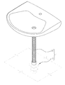
도 1은 본 발명의 일 실시예에 따른 배수관 조립체가 하수통로에 설치된 모습을 나타낸 사시도이다.
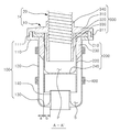
도 2는 본 발명의 일 실시예에 따른 배수관 연결장치의 사시도이다.
도 3은 도 2는 배수관 연결장치의 분해 사시도이다.
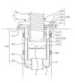
도 4는 도 2의 A-A'를 따라 절단한 종단면도이다.
도 5는 내측 담수 공간에 물이 일차적으로 수용되었을 때 도 1의 종 단면도이다.
도 6은 외측 담수 공간에 물이 넘쳐서 하수통로로 물이 배출될 때 도 1의 종 단면도이다.
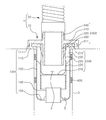
도 7은 본 발명의 다른 실시예에 따른 배수관 조립체의 종단면도이다.1 is a perspective view illustrating a state in which a drain pipe assembly according to an embodiment of the present invention is installed in a sewage passage.
2 is a perspective view of a drain pipe connection device according to an embodiment of the present invention.
3 is an exploded perspective view of the drain pipe connection device of FIG. 2 .
FIG. 4 is a longitudinal cross-sectional view taken along line A-A' of FIG. 2 .
5 is a longitudinal cross-sectional view of FIG. 1 when water is primarily accommodated in the inner fresh water space.
6 is a longitudinal cross-sectional view of FIG. 1 when water overflows into the outer fresh water space and the water is discharged to the sewage passage.
7 is a longitudinal cross-sectional view of a drain pipe assembly according to another embodiment of the present invention.
이하에서는 본 발명의 기술적 사상을 구현하기 위한 구체적인 실시예에 대하여 도면을 참조하여 상세히 설명하도록 한다. Hereinafter, specific embodiments for implementing the technical idea of the present invention will be described in detail with reference to the drawings.
아울러 본 발명을 설명함에 있어서 관련된 공지 구성 또는 기능에 대한 구체적인 설명이 본 발명의 요지를 흐릴 수 있다고 판단되는 경우에는 그 상세한 설명을 생략한다. In addition, in the description of the present invention, if it is determined that a detailed description of a related known configuration or function may obscure the gist of the present invention, the detailed description thereof will be omitted.
또한, 어떤 구성요소가 다른 구성요소에 '연결', '지지', '유입', '배출', '유동', '체결'된다고 언급된 때에는 그 다른 구성요소에 직접적으로 연결, 지지, 유입, 배출, 유동, 체결될 수도 있지만 중간에 다른 구성요소가 존재할 수도 있다고 이해되어야 할 것이다.In addition, when it is mentioned that a component is 'connected', 'supported', 'inflow', 'discharge', 'flow', or 'fastened' to another component, it is directly connected to, supported, introduced, It should be understood that they may be discharged, flowed, or engaged, but other components may exist in between.
본 명세서에서 사용된 용어는 단지 특정한 실시예를 설명하기 위해 사용된 것으로 본 발명을 한정하려는 의도로 사용된 것은 아니다. 단수의 표현은 문맥상 명백하게 다르게 뜻하지 않는 한 복수의 표현을 포함한다.The terminology used herein is only used to describe specific embodiments and is not intended to limit the present invention. The singular expression includes the plural expression unless the context clearly dictates otherwise.
또한, 제1, 제2 등과 같이 서수를 포함하는 용어는 다양한 구성요소들을 설명하는데 사용될 수 있지만, 해당 구성요소들은 이와 같은 용어들에 의해 한정되지는 않는다. 이 용어들은 하나의 구성요소들을 다른 구성요소로부터 구별하는 목적으로만 사용된다.Also, terms including an ordinal number such as 1st, 2nd, etc. may be used to describe various components, but the components are not limited by these terms. These terms are used only for the purpose of distinguishing one component from another.
명세서에서 사용되는 "포함하는"의 의미는 특정 특성, 영역, 정수, 단계, 동작, 요소 및/또는 성분을 구체화하며, 다른 특정 특성, 영역, 정수, 단계, 동작, 요소, 성분 및/또는 군의 존재나 부가를 제외시키는 것은 아니다.The meaning of "comprising," as used herein, specifies a particular characteristic, region, integer, step, operation, element and/or component, and other specific characteristic, region, integer, step, operation, element, component, and/or group. It does not exclude the existence or addition of
또한, 본 명세서에서 상부, 하부, 상측, 하측 등의 표현은 도면에 도시를 기준으로 설명한 것이며 해당 대상의 방향이 변경되면 다르게 표현될 수 있음을 미리 밝혀둔다. 한편 본 명세서의, 상하 방향은 도 2 내지 도 6의 상하 방향일 수 있다. In addition, in the present specification, expressions such as upper, lower, upper, lower, etc. are described with reference to the drawings in the drawings, and it is to be noted in advance that if the direction of the corresponding object is changed, it may be expressed differently. Meanwhile, in the present specification, the vertical direction may be the vertical direction of FIGS. 2 to 6 .
본 발명의 일 실시예에 따른 배수관 조립체(1)는 하수통로(3)의 입구부에 설치될 수 있다. 이하, 도면을 참조하여 본 발명의 일 실시예에 따른 배수관 조립체(1)의 구체적인 구성에 대하여 설명한다.The drain pipe assembly 1 according to an embodiment of the present invention may be installed at the inlet portion of the
이하, 도 1 및 도 2를 참조하면, 본 발명의 일 실시예에 따른 배수관 조립체(1)는 건축물의 외부 또는 내부에 설치되어 빗물, 하수 등을 배출시키는 배수관(20), 및 이러한 배수관(20)과 연결되는 배수관 연결장치(10)를 포함할 수 있다. 이러한 배수관 연결장치(10)는 배수관(20)의 하부를 커버하도록 배수관(20)의 하부에 연결될 수 있다. 또한, 배수관 연결장치(10)는 하수통로(3)에 삽입되어 하수통로(3)와 연통할 수 있다. 예를 들어, 배수관 연결장치(10)는 세면대와 연결된 배수관(20)의 하측에 연결되며, 세면대로부터 배출되는 하수를 하수통로(3)로 배출할 수 있다. 다시 말해, 배수관 연결장치(10)는 상측으로 배수관(20)과 연결되고 하측으로는 하수통로(3)와 연결될 수 있다. 여기서 하수통로(3)는 시멘트 등으로 형성된 바닥면에 뚫린 구멍으로써 하수가 외부로 배출되는 통로를 의미할 수 있다.Hereinafter, referring to FIGS. 1 and 2 , the drain pipe assembly 1 according to an embodiment of the present invention is a
이러한 배수관 연결장치(10)는 배수관(20)을 통해 배출되는 물을 임시로 다단으로 담수한 후 배출되도록 함으로써, 배수관(20)을 통해 배출되는 물에 의해 발생되는 소음과 악취를 효과적으로 저감할 수 있다. 배수관 연결장치(10)는 외측 트랩부(100), 내측 트랩부(200), 도입부(300) 및 완충 부재(400)를 포함할 수 있다.The drain
이하에서 서술하는 본 발명의 일 실시예에 따른 배수관 연결장치(10), 배수관(20)은 하수통로(3)의 단면과 대응하는 단면의 형상을 가질 수 있다. 예를 들어, 원형의 단면을 가지는 하수통로(3)에 배수관 조립체(1)가 설치될 경우, 배수관 연결장치(10)와 배수관(20)도 전체적으로 원형의 단면을 갖는 파이프 형상을 가질 수 있으나, 본 발명의 사상이 이에 한정되는 것은 아니다. 따라서, 배수관 연결장치(10), 배수관(20) 및 하수통로(3)는 사각형 또는 다각형 단면을 갖는 덕트 형상으로 구성되는 것도 가능하다. The drain
외측 트랩부(100)는 하수통로(3)에 삽입되어 설치될 수 있도록 제공되며, 배수관 연결장치(10)의 최외측 둘레면을 구성한다. 또한, 외측 트랩부(100)에는 내측 트랩부(200)의 일부가 삽입될 수 있다. 이러한 외측 트랩부(100)는 외측 플랜지(110), 외측 관(120), 하판(130) 및 내측 관(140)을 포함할 수 있다.The
외측 플랜지(110)는 외측 트랩부(100)의 상부에 형성되고, 스텝 형상으로 형성될 수 있다. 이러한 외측 플랜지(110)의 상측에는 후술하는 도입부(300)의 일부가 안착되어 지지될 수 있다. 또한, 외측 플랜지(110)는 하수통로(3)의 내측에 삽입되지 않고 하수통로(3) 외부에 걸리는 부분을 제공할 수 있다. 따라서, 외측 트랩부(100)는 하수통로(3)의 유입구에 지지될 수 있다. 이러한 외측 플랜지(110)에는 제1 맞물림부(111)가 구비될 수 있다. The
도 3을 참조하면, 제1 맞물림부(111)는 후술할 제2 맞물림부(311)와 맞물리기 위하여 외측 플랜지(110)에 구비될 수 있다. 예를 들어, 제1 맞물림부(111)에는 후술할 제2 맞물림부(311)에 형성된 암 나사산과 맞물리기 위한 수 나사산이 형성될 수 있다. 다만, 이는 예시에 불과하고, 제1 맞물림부(111)에 암 나사산이 형성되고, 제2 맞물림부(311)에 수 나사산이 형성되는 것도 가능하다.Referring to FIG. 3 , the first engaging
외측 관(120)은 외측 플랜지(110)로부터 하방으로 연장되어 외측 트랩부(100)의 둘레면을 형성할 수 있다. 이러한 외측 관(120)은 파이프 형상으로 제공될 수 있으며, 외측 플랜지(110)와 일체로 형성될 수 있다.The
도 4를 참조하면, 하판(130)은 내측 트랩부(200)로부터 배출되는 물을 임시로 수용하기 위해 외측 관(120)의 하단에 형성되며, 외측 트랩부(100)의 저면을 구성할 수 있다. 이러한 하판(130)의 중앙에는 물이 배출되기 위한 홀이 형성될 수 있다. 또한, 하판(130)은 외측 관(120)과 일체로 형성될 수 있다.Referring to FIG. 4 , the
내측 관(140)은 하판(130)의 중앙에 형성된 홀의 둘레를 따라 상하 방향으로 연장 형성될 수 있다. 이러한 내측 관(140)은 하수통로(3)와 연통할 수 있으며, 내측 관(140)을 통하여 물은 배수관 연결장치(10)로부터 하수통로(3)로 배출될 수 있다. 또한, 내측 관(140)은 하판(130)과 일체로 형성될 수 있다.The
한편, 외측 트랩부(100)에는 물이 하수통로(3)로 배출되기 전에 임시로 수용되는 외측 담수 공간(S)이 형성될 수 있다. 이러한 외측 담수 공간(S)은 외측 관(120), 하판(130) 및 내측 관(140)에 의해 둘러싸인 공간일 수 있다. 또한, 외측 담수 공간(S)에는 후술할 내측 담수 공간(P)에서 일차적으로 수용되었던 물이 이차적으로 수용될 수 있다. 예를 들어, 내측 트랩부(200)로부터 배출되는 물은 외측 담수 공간(S)에 채워지고, 외측 담수 공간(S)에 채워진 물의 높이가 내측 관(140) 보다 높아지면 내측 관(140)으로부터 넘쳐서 외측 트랩부(100)의 외부로 배출될 수 있다.On the other hand, the
내측 트랩부(200)는 외측 트랩부(100)에 삽입되어 설치될 수 있다. 또한, 내측 트랩부(200)에는 도입부(300)의 일부가 삽입될 수 있다. 이러한 내측 트랩부(200)는 내측 플랜지(210), 중간측 관(220), 배수 리브(230) 및 중판(240)을 포함할 수 있다.The
내측 플랜지(210)는 내측 트랩부(200)의 상부에 형성될 수 있으며, 스텝 형상으로 형성될 수 있다. 이러한 내측 플랜지(210)에는 도입부(300)의 후술할 도입 플랜지(310)가 안착되어 지지될 수 있다. 또한, 내측 플랜지(210)가 외측 플랜지(110) 상에 안착되어 지지됨으로써 내측 트랩부(200)가 외측 트랩부(100)에 삽입된 상태로 지지될 수 있다.The
중간측 관(220)은 상하 방향으로 연장되어 내측 트랩부(200)의 둘레면을 형성할 수 있다. 또한, 중간측 관(220)은 내측 플랜지(210)와 상하 방향으로 이격 배치될 수 있으며, 내측 플랜지(210)와 배수 리브(230)를 통하여 연결될 수 있다. 이때, 중간측 관(220)의 하단은 내측 관(140)의 상단보다 낮은 높이에 위치할 수 있다. 또한, 중간측 관(220)은 외측 관(120)과 일 방향(예를 들어, 도 4의 좌우 방향)으로 소정 거리 이격되도록 배치될 수 있다. 이러한 외측 관(120)과 중간측 관(220) 사이의 이격 거리(a)는 중간측 관(220)과 내측 관(140) 사이의 이격 거리(b)보다 짧게 형성된다. 예를 들어, 중간측 관(220)은 파이프 형상으로 제공될 수 있다.The
도 3을 다시 참조하면, 배수 리브(230)는 내측 플랜지(210)의 하단과 중간측 관(220)의 상단을 연결시킬 수 있다. 이러한 배수 리브(230)의 어느 일부는 내측 플랜지(210)의 외주면으로부터 돌출 형성되며, 다른 일부는 중간측 관(220)의 외주면으로부터 돌출 형성될 수 있다. 또한, 배수 리브(230)는 내측 플랜지(210) 및 중간측 관(220)과 일체로 형성될 수 있다. 이러한 배수 리브(230)의 하단은 중판(240)보다 상측에 위치할 수 있다.Referring back to FIG. 3 , the
또한, 배수 리브(230)는 복수 개로 제공될 수 있으며, 중간측 관(220)의 둘레를 따라 소정 간격으로 서로 이격되게 형성될 수 있다. 이러한 배수 리브(230)는 외측 관(120)의 내주면과 접할 수 있다. 이로 인해, 내측 관(140)은 외측 관(120)에 보다 안정적으로 지지될 수 있다. 또한, 배수 리브(230)의 하측 단부는 배수 리브(230)가 외측 트랩부(100)에 삽입될 때 간섭되지 않도록 일부가 경사진 테이퍼 형상을 가질 수 있다.In addition, a plurality of
중판(240)은 도입부(300)를 통과한 물을 일차적으로 수용하기 위해 제공될 수 있다. 이러한 중판(240)은 중간측 관(220)의 내부 중부에 배치될 수 있으며, 중간측 관(220)의 내측에 형성된 공간을 상하로 구획할 수 있다. 또한, 중판(240)은 중간측 관(220)과 일체로 형성될 수 있다.The
한편, 내측 트랩부(200)에는 내측 트랩부(200)로부터 외측 트랩부(100)로 물이 유동하기 위한 배수홀(250)이 형성될 수 있다. 예를 들어, 내측 담수 공간(P)에 수용된 물은 배수홀(250)을 통하여 외측 담수 공간(S)으로 유동할 수 있다. 또한, 배수홀(250)은 후술할 가이드 관(320)의 하단보다 상측에 위치할 수 있으며, 중판(240) 보다 상측에 위치할 수 있다. 이러한 배수홀(250)은 복수 개의 배수 리브(230)에 의해 복수 개의 홀로 구획될 수 있다.Meanwhile, a
또한, 도 5 및 도 6을 참조하면, 내측 트랩부(200)에는 도입부(300)를 통과한 물을 일차적으로 수용하기 위한 내측 담수 공간(P)이 형성될 수 있다. 이러한 내측 담수 공간(P)은 중간측 관(220) 및 중판(240)에 의해 둘러싸인 공간일 수 있다. 예를 들어, 내측 담수 공간(P)에 물이 소정 높이 이상 채워지면, 물은 배수홀(250)을 통하여 외측 담수 공간(S)으로 유동할 수 있다. 또한, 내측 담수 공간(P)은 외측 담수 공간(S) 보다 상측에 위치할 수 있다.In addition, referring to FIGS. 5 and 6 , an inner freshwater space P for primarily accommodating the water passing through the
도입부(300)는 배수관(20)에 고정 연결되어 배수관(20)과 연통할 수 있으며, 배수관(20)으로부터 배출되는 물을 내측 담수 공간(P)으로 안내할 수 있다. 이러한 도입부(300)는 배수관(20)의 하부에 고정될 수 있다. 또한, 도입부(300)는 내측 트랩부(200)에 삽입될 수 있으며, 외측 트랩부(100)와 고정 체결될 수 있다. 이러한 도입부(300)는 도입 플랜지(310), 가이드 관(320), 및 도입 리브(330) 및 체결구(340)를 포함할 수 있다.The
도입 플랜지(310)는 도입부(300)의 상부에 형성되고, 외측 플랜지(110) 및 내측 플랜지(210) 중 하나 이상에 안착되어 지지될 수 있다. 이러한 도입 플랜지(310)는 가이드 관(320) 및 체결구(340)와 일체로 형성될 수 있다. 또한, 도입 플랜지(310)에는 외측 플랜지(110)와 체결되기 위한 제2 맞물림부(311)가 구비될 수 있다.The
제2 맞물림부(311)는 제1 맞물림부(111)와 맞물리기 위하여 도입 플랜지(310)에 구비될 수 있다. 예를 들어, 도입부(300)는 제1 맞물림부(111)와 제2 맞물림부(311)가 맞물림으로써 외측 트랩부(100)와 체결될 수 있다.The second
가이드 관(320)은 도입 플랜지(310)의 하면으로부터 돌출 형성될 수 있으며, 상하 방향으로 연장 형성될 수 있다. 이러한 가이드 관(320)은 도입 플랜지(310)를 통하여 체결구(340)와 연결될 수 있으며, 체결구(340)로부터 내부로 유입된 물을 중판(240)을 향해 안내할 수 있다. 이러한 가이드 관(320)은 체결구(340)와 연통할 수 있다. 또한, 가이드 관(320)의 하단은 배수홀(250) 보다 하측에 위치하고, 중판(240) 보다 상측에 위치할 수 있다.The
도입 리브(330)는 가이드 관(320)이 중간측 관(220)에 보다 안정적으로 지지되도록 제공될 수 있다. 이러한 도입 리브(330)는 가이드 관(320)의 외주면으로부터 돌출 형성될 수 있다. 예를 들어, 도입 리브(330)의 하단부는 도입 플랜지(310)에 대하여 하방으로 소정 각도를 가지도록 연장 형성될 수 있다. 따라서, 도입 리브(330)가 내측 트랩부(200)에 삽입될 때, 내측 플랜지(210)와 간섭되지 않을 수 있다. 또한, 도입 리브(330)의 어느 일부는 중간측 관(220)의 내주면과 접할 수 있다. 이로 인해, 가이드 관(320)은 중간측 관(220)의 내주면과 접하지 않을 수 있으며, 내측 담수 공간(P)에 수용된 물이 배수홀(250)을 통과할 수 있다.The
체결구(340)는 배수관(20)의 하부와 연결되기 위해 제공될 수 있다. 이러한 체결구(340)는 배수관(20)의 외주면을 둘러싸도록 제공될 수 있으며, 체결구(340)는 도입 플랜지(310)의 상면으로부터 돌출 형성될 수 있다. 또한, 체결구(340)의 내측에 배수관(20)의 하부가 삽입됨으로써 체결구(340)와 배수관(20)은 연결될 수 있다. 예를 들어, 배수관(20)은 체결구(340)의 내측에 끼워짐으로써 체결구(340)와 연결될 수 있으며, 체결구(340)는 배수관(20)과 연결되기 위한 주지의 수단이 사용될 수 있다. 다만, 이는 예시에 불과하고, 체결구(340)는 배수관(20)의 하부와 일체로 형성될 수도 있다.The
완충 부재(400)는 하수통로(3) 내부의 악취가 외부로 누출되는 것을 방지하기 위하여 제공될 수 있다. 이러한 완충 부재(400)는 외측 관(120)의 외주면에 부착될 수 있으며, 복수 개로 제공될 수 있다. 또한, 완충 부재(400)는 외측 관(120)이 하수통로(3)에 삽입될 때, 하수통로(3)와 외측 관(120) 사이에 끼워질 수 있다. 이러한 완충 부재(400)는 외측 관(120)의 둘레를 따라서 연장 형성될 수 있다. 또한, 완충 부재(400)는 탄성 재질을 가는 재료를 포함할 수 있으며, 일 예로 스펀지를 포함할 수 있다.The
이하에서는 상술한 바와 같은 구성을 갖는 배수관 연결장치(10)의 작용 및 효과에 대하여 설명한다.Hereinafter, the operation and effect of the drain
사용자는 세면대 등의 배출부와 하수통로(3) 사이에 배수관 연결장치(10)를 설치할 수 있다. 구체적으로, 사용자는 배수관(20)의 하부에 배수관 연결장치(10)를 연결시킨 후 배수관 연결장치(10)를 하수통로(3)에 삽입함으로써 설치를 완료할 수 있다.The user may install the drain
이후, 배수관(20)으로부터 배출되는 물은 배수관 연결장치(10)를 거쳐 하수통로(3)로 배출될 수 있다. 먼저, 배수관(20)을 유동하는 물은 가이드 관(320)을 통과하여 내측 담수 공간(P)에 수용될 수 있다(도 5 참조). 내측 담수 공간(P)에 소정 높이 이상 물이 차오르면 물은 배수홀(250)을 통하여 외측 담수 공간(S)으로 유동할 수 있다. 또한, 외측 담수 공간(S)에 내측 관(140) 보다 높이 물이 차오르면 물은 내측 관(140)의 내부를 통하여 하수통로(3)로 배출될 수 있다(도 6 참조).Thereafter, the water discharged from the
이처럼, 배수관 연결장치(10)는 배수관 연결장치(10)를 유동하는 유체가 내측 담수 공간(P)에 일차적으로 물이 수용되고, 외측 담수 공간(S)에 이차적으로 수용됨으로써 물이 배출되는 과정에서 발생하는 소음을 저감시키는 효과가 있다.In this way, the drain
또한, 배수관 연결장치(10)가 배수관(20)의 하부와 연결됨으로써 사용자는 배수관 연결장치(10)를 배수관(20)으로부터 용이하게 교체할 수 있는 효과가 있다. In addition, since the drain
또한, 완충 부재(400)가 하수통로(3)와 배수관 연결장치(10) 사이의 갭을 실링함으로써 하수통로(3)에서 발생하는 악취가 외부로 누출되는 것을 방지할 수 있는 효과가 있다.In addition, since the
이하, 도 7을 참조하여, 다른 실시예를 설명한다. 본 발명의 다른 실시예를 설명함에 있어서, 상술한 실시예들과 비교하였을 때 차이점을 위주로 설명하며, 동일한 설명 및 도면부호는 상술한 실시예들을 원용한다. Hereinafter, another embodiment will be described with reference to FIG. 7 . In describing another embodiment of the present invention, the difference compared with the above-described embodiments will be mainly described, and the same description and reference numerals refer to the above-described embodiments.
도 7을 참조하면, 체결구(340)는 배수관 연결장치(10)와 배수관(20)을 연결시키기 위하여 제공될 수 있다. 이러한 체결구(340)는 도입 플랜지(310)의 상면으로부터 돌출 형성될 수 있다. 또한, 체결구(340)의 외주면에는 배수관(2)과 체결되기 위한 나사산이 형성될 수 있다. 이러한 나사산이 배수관(20)의 하부와 체결됨으로써 배수관 연결장치(10)는 배수관(20)의 하부와 체결될 수 있다. 또한, 체결구(340)는 가이드 관(320)과 연통할 수 있다. 배수관(20)을 유동하는 물은 체결구(340)를 통하여 유입되어 가이드 관(320)으로 유동할 수 있다. Referring to FIG. 7 , the
이상 본 발명의 실시예들을 구체적인 실시 형태로서 설명하였으나, 이는 예시에 불과한 것으로서, 본 발명은 이에 한정되지 않는 것이며, 본 명세서에 개시된 기술적 사상에 따르는 최광의 범위를 갖는 것으로 해석되어야 한다. 당업자는 개시된 실시형태들을 조합/치환하여 적시되지 않은 형상의 패턴을 실시할 수 있으나, 이 역시 본 발명의 범위를 벗어나지 않는 것이다. 이외에도 당업자는 본 명세서에 기초하여 개시된 실시형태를 용이하게 변경 또는 변형할 수 있으며, 이러한 변경 또는 변형도 본 발명의 권리범위에 속함은 명백하다.Although the embodiments of the present invention have been described as specific embodiments, these are merely examples, and the present invention is not limited thereto, and should be construed as having the widest scope according to the technical idea disclosed in the present specification. A person skilled in the art may implement a pattern of a shape not indicated by combining/substituting the disclosed embodiments, but this also does not depart from the scope of the present invention. In addition, those skilled in the art can easily change or modify the disclosed embodiments based on the present specification, and it is clear that such changes or modifications also fall within the scope of the present invention.
1: 배수관 조립체
3: 하수통로
10: 배수관 연결장치 20: 배수관
100: 외측 트랩부
110: 외측 플랜지 111: 제1 맞물림부
120: 외측 관 130: 하판
140: 내측관 200: 내측 트랩부
210: 내측 플랜지 220: 중간측 관
230: 배수 리브 240: 중판
250: 배수홀 300: 도입부
310: 도입 플랜지 320: 가이드 관
330: 도입 리브 340: 체결구
400: 완충 부재
S: 외측 담수 공간 P: 내측 담수 공간1: Drain pipe assembly 3: Sewage passage
10: drain pipe connector 20: drain pipe
100: outer trap portion
110: outer flange 111: first engaging portion
120: outer tube 130: lower plate
140: inner tube 200: inner trap portion
210: inner flange 220: middle side tube
230: drain rib 240: middle plate
250: drain hole 300: introduction
310: introduction flange 320: guide tube
330: introduction rib 340: fastener
400: buffer member
S: outer fresh water space P: inner fresh water space
Claims (16)
상기 배수관과 연통할 수 있는 도입부;
상기 도입부의 적어도 일부가 삽입될 수 있도록 제공되며, 상기 도입부를 통과한 물을 일차적으로 수용하기 위해 제공되는 중판을 포함하는 내측 트랩부; 및
상기 내측 트랩부의 적어도 일부가 삽입될 수 있도록 제공되는 외측 트랩부를 포함하고,
상기 도입부는,
상기 배수관의 하부와 연결되기 위한 체결구; 및
상기 체결구와 연결되며, 상기 체결구로 내부로 유입된 물을 상기 중판을 향해 안내하는 가이드 관을 포함하고,
상기 외측 트랩부는,
상기 내측 트랩부로부터 배출되는 물을 이차적으로 수용하기 위해 형성되고, 중앙에 물이 배출되기 위한 홀이 형성되는 하판; 및
상기 하판의 중앙에 형성된 홀의 둘레를 따라 상하 방향으로 연장 형성되는 내측 관을 포함하는,
배수관 연결장치.In the drain pipe connection device fastened to the lower part of the drain pipe to cover the lower part of the drain pipe,
an inlet that can communicate with the drain pipe;
an inner trap portion provided so that at least a portion of the introduction portion can be inserted, and including a middle plate provided to primarily receive water that has passed through the introduction portion; and
and an outer trap portion provided so that at least a portion of the inner trap portion can be inserted;
The introductory part is
a fastener for connection with the lower portion of the drain pipe; and
It is connected to the fastener and includes a guide tube for guiding the water introduced into the fastener toward the middle plate,
The outer trap portion,
a lower plate formed to receive secondary water discharged from the inner trap unit, and having a hole in the center for discharging water; and
Containing an inner tube extending in the vertical direction along the circumference of the hole formed in the center of the lower plate,
drain pipe connector.
상기 도입부는,
상기 가이드 관이 상기 외측 트랩부의 내측에 삽입되었을 때, 상기 외측 트랩부에 지지되는 도입 플랜지를 포함하고,
상기 가이드 관은, 상기 도입 플랜지의 하면으로부터 돌출 형성되는,
배수관 연결장치.The method of claim 1,
The introductory part is
When the guide tube is inserted inside the outer trap portion, it includes an introduction flange supported by the outer trap portion,
The guide tube is formed to protrude from the lower surface of the introduction flange,
drain pipe connector.
상기 도입 플랜지 및 상기 가이드 관은 일체로 형성되는,
배수관 연결장치.3. The method of claim 2,
The introduction flange and the guide tube are integrally formed,
drain pipe connector.
상기 도입부는,
상기 가이드 관의 외주면으로부터 돌출 형성되며, 어느 일부가 상기 도입 플랜지에 대하여 하방으로 소정 각도로 경사지도록 연장 형성되는 도입 리브를 더 포함하고,
상기 도입 리브의 다른 일부는, 상기 내측 트랩부의 내주면과 접하는,
배수관 연결장치.3. The method of claim 2,
The introductory part is
It is formed to protrude from the outer circumferential surface of the guide tube, and any part further comprises an introduction rib extending downwardly at a predetermined angle with respect to the introduction flange,
Another part of the introduction rib is in contact with the inner circumferential surface of the inner trap portion,
drain pipe connector.
상기 외측 트랩부는,
상기 외측 트랩부의 상부에 스텝 형상으로 형성되며, 제1 맞물림부가 구비된 외측 플랜지를 포함하고,
상기 도입 플랜지에는, 상기 제1 맞물림부와 맞물리기 위한 제2 맞물림부가 구비되며,
상기 외측 트랩부는 상기 제1 맞물림부와 상기 제2 맞물림부가 맞물림으로써 상기 도입부와 체결되는,
배수관 연결장치.3. The method of claim 2,
The outer trap portion,
It is formed in a step shape on the upper portion of the outer trap portion, and includes an outer flange provided with a first engaging portion,
The introduction flange is provided with a second engaging portion for engaging the first engaging portion,
The outer trap portion is engaged with the introduction portion by engaging the first engaging portion and the second engaging portion,
drain pipe connector.
상기 외측 트랩부는,
상하 방향으로 연장되어 둘레면을 형성하는 외측 관을 더 포함하고,
상기 내측 트랩부로부터 배출되는 물은 상기 외측 관, 상기 하판 및 상기 내측 관에 의해 둘러싸인 외측 담수 공간에 수용되는,
배수관 연결장치.The method of claim 1,
The outer trap portion,
Further comprising an outer tube extending in the vertical direction to form a circumferential surface,
The water discharged from the inner trap portion is accommodated in the outer fresh water space surrounded by the outer tube, the lower plate and the inner tube,
drain pipe connector.
상기 내측 트랩부는,
상하 방향으로 연장 형성되며, 상기 중판과 연결되는 중간측 관을 더 포함하고,
상기 중판에 의해 상기 중간측 관의 내측에 형성된 공간이 구획되고,
상기 도입부를 통과한 물은 상기 중간측 관 및 상기 중판에 의해 둘러싸인 내측 담수 공간에 수용되는,
배수관 연결장치.7. The method of claim 6,
The inner trap portion,
It is formed extending in the vertical direction, further comprising an intermediate tube connected to the middle plate,
A space formed inside the middle tube is partitioned by the middle plate,
The water passing through the inlet is accommodated in the inner fresh water space surrounded by the intermediate tube and the intermediate plate,
drain pipe connector.
상기 외측 트랩부와 상기 내측 트랩부는, 상기 외측 담수 공간과 상기 내측 담수 공간이 상하 방향으로 서로 이격되도록 구성되는,
배수관 연결장치.8. The method of claim 7,
The outer trap unit and the inner trap unit are configured such that the outer fresh water space and the inner fresh water space are spaced apart from each other in the vertical direction,
drain pipe connector.
상기 중간측 관은 상기 외측 관과 소정 거리 이격되고,
상기 중간측 관에는, 하나 이상의 배수홀이 형성되며,
상기 내측 담수 공간에 수용된 물은 상기 배수홀을 통하여 상기 중간측 관과 상기 외측 관 사이로 유동하는,
배수관 연결장치.8. The method of claim 7,
The middle tube is spaced apart from the outer tube by a predetermined distance,
At least one drain hole is formed in the middle side tube,
The water accommodated in the inner fresh water space flows between the middle tube and the outer tube through the drain hole,
drain pipe connector.
상기 가이드 관의 하단은 상기 배수홀 보다 하측에 위치하고, 상기 중판 보다 상측에 위치하는,
배수관 연결장치.10. The method of claim 9,
The lower end of the guide tube is located below the drain hole, located above the middle plate,
drain pipe connector.
상기 내측 트랩부는,
상기 중간측 관의 외주면으로부터 돌출 형성되는 배수 리브를 더 포함하고,
상기 배수 리브는, 상기 외측 관과 접하는,
배수관 연결장치.8. The method of claim 7,
The inner trap portion,
Further comprising a drainage rib protruding from the outer peripheral surface of the intermediate tube,
The drain rib is in contact with the outer tube,
drain pipe connector.
상기 외측 관과 상기 중간측 관 사이의 이격 거리는 상기 중간측 관과 상기 내측 관 사이의 이격 거리보다 짧은,
배수관 연결장치. 8. The method of claim 7,
The separation distance between the outer tube and the middle side tube is shorter than the separation distance between the intermediate side tube and the inner tube,
drain pipe connector.
상기 중간측 관의 하단이 상기 내측 관의 상단보다 낮은 높이에 위치하는,
배수관 연결장치.8. The method of claim 7,
The lower end of the middle tube is located at a lower height than the upper end of the inner tube,
drain pipe connector.
상기 외측 관의 외주면에 부착되는 하나 이상의 완충 부재를 더 포함하고,
상기 하나 이상의 완충 부재는, 상기 외측 관이 하수통로에 삽입될 때, 상기 하수통로와 상기 외측 관 사이에 끼워짐으로써 하수통로 내부의 악취가 외부로 누출되는 것을 방지하는,
배수관 연결장치.7. The method of claim 6,
Further comprising one or more cushioning members attached to the outer peripheral surface of the outer tube,
The at least one cushioning member prevents the odor inside the sewage passage from leaking to the outside by being sandwiched between the sewage passage and the outer tube when the outer tube is inserted into the sewage passage.
drain pipe connector.
상기 완충 부재는 탄성 재질을 가지는,
배수관 연결장치.15. The method of claim 14,
The buffer member has an elastic material,
drain pipe connector.
상기 배수관의 하부에 체결되어 상기 배수관의 하부를 커버하는 배수관 연결장치를 포함하고,
상기 배수관 연결장치는,
상기 배수관과 연통할 수 있는 도입부;
상기 도입부의 적어도 일부가 삽입될 수 있도록 제공되며, 상기 도입부를 통과한 물을 일차적으로 수용하기 위해 제공되는 중판을 포함하는 내측 트랩부; 및
상기 내측 트랩부의 적어도 일부가 삽입될 수 있도록 제공되는 외측 트랩부를 포함하고,
상기 도입부는,
내부로 유입된 물을 상기 중판을 향해 안내하는 가이드 관을 포함하고,
상기 외측 트랩부는,
상기 내측 트랩부로부터 배출되는 물을 이차적으로 수용하기 위해 형성되고, 중앙에 물이 배출되기 위한 홀이 형성되는 하판; 및
상기 하판의 중앙에 형성된 홀의 둘레를 따라 상하 방향으로 연장 형성되는 내측 관을 포함하고,
상기 도입부는 상기 배수관의 하부에 결속되는,
배수관 조립체.
drain; and
and a drain pipe connecting device fastened to the lower part of the drain pipe to cover the lower part of the drain pipe,
The drain pipe connection device,
an inlet that can communicate with the drain pipe;
an inner trap portion provided so that at least a portion of the introduction portion can be inserted, and including a middle plate provided to primarily receive water that has passed through the introduction portion; and
and an outer trap portion provided so that at least a portion of the inner trap portion can be inserted;
The introductory part is
Includes a guide tube for guiding the water introduced into the middle plate,
The outer trap portion,
a lower plate formed to receive secondary water discharged from the inner trap unit, and having a hole in the center for discharging water; and
Including an inner tube extending in the vertical direction along the circumference of the hole formed in the center of the lower plate,
The introduction part is bound to the lower part of the drain pipe,
drain assembly.
Applications Claiming Priority (2)
| Application Number | Priority Date | Filing Date | Title |
|---|---|---|---|
| KR20200049643 | 2020-04-23 | ||
| KR1020200049643 | 2020-04-23 |
Publications (1)
| Publication Number | Publication Date |
|---|---|
| KR20210131203A true KR20210131203A (en) | 2021-11-02 |
Family
ID=78476317
Family Applications (1)
| Application Number | Title | Priority Date | Filing Date |
|---|---|---|---|
| KR1020200091769A KR20210131203A (en) | 2020-04-23 | 2020-07-23 | Apparatus for connecting drain pipe and drain pipe assembly including the same |
Country Status (1)
| Country | Link |
|---|---|
| KR (1) | KR20210131203A (en) |
Cited By (1)
| Publication number | Priority date | Publication date | Assignee | Title |
|---|---|---|---|---|
| KR102451693B1 (en) | 2022-06-04 | 2022-10-06 | 주식회사 에스엠지 | Apparatus for connecting drain pipe |
-
2020
- 2020-07-23 KR KR1020200091769A patent/KR20210131203A/en not_active Application Discontinuation
Cited By (1)
| Publication number | Priority date | Publication date | Assignee | Title |
|---|---|---|---|---|
| KR102451693B1 (en) | 2022-06-04 | 2022-10-06 | 주식회사 에스엠지 | Apparatus for connecting drain pipe |
Similar Documents
| Publication | Publication Date | Title |
|---|---|---|
| US11346095B2 (en) | Floor sink | |
| KR20210131203A (en) | Apparatus for connecting drain pipe and drain pipe assembly including the same | |
| KR100954013B1 (en) | Drain traps | |
| KR20140040440A (en) | Drain trap | |
| JP4797205B2 (en) | Drain trap | |
| JP7249480B2 (en) | drain trap | |
| KR20090008537A (en) | Drain traps | |
| CN212561743U (en) | Confluence drainage device | |
| KR100658160B1 (en) | Drain structure of apartment house veranda | |
| KR102107796B1 (en) | Drain cover | |
| KR101729274B1 (en) | Apparatus for drain sewage having trap with attaching and isolating connection | |
| KR101100907B1 (en) | Drainage apparatus for ground part | |
| KR101194420B1 (en) | Drain unit for preventing smell of apartment house | |
| JP4967099B2 (en) | Drain trap | |
| KR20120110255A (en) | A assembly pipe with air vent | |
| JP2007023688A (en) | Drain trap | |
| JP4555122B2 (en) | Drainage container | |
| KR100886962B1 (en) | A trap and a trench having the above trap | |
| JP3460056B2 (en) | Drain trap | |
| KR102245460B1 (en) | Trap for Fluid Discharge Line | |
| JP6019287B2 (en) | Drain trap | |
| KR200447783Y1 (en) | Drain Trap Combined with Washstand Coupling Socket for Bathroom | |
| KR100671173B1 (en) | Coupling structure of a small manhole | |
| KR20230087363A (en) | Apparatus for connecting drain pipe | |
| JP4529938B2 (en) | Bathroom drainage structure |
Legal Events
| Date | Code | Title | Description |
|---|---|---|---|
| E902 | Notification of reason for refusal | ||
| E601 | Decision to refuse application |