KR20210117288A - Apparatus and method for monitoring valve inflation - Google Patents
Apparatus and method for monitoring valve inflation Download PDFInfo
- Publication number
- KR20210117288A KR20210117288A KR1020217025278A KR20217025278A KR20210117288A KR 20210117288 A KR20210117288 A KR 20210117288A KR 1020217025278 A KR1020217025278 A KR 1020217025278A KR 20217025278 A KR20217025278 A KR 20217025278A KR 20210117288 A KR20210117288 A KR 20210117288A
- Authority
- KR
- South Korea
- Prior art keywords
- prosthetic valve
- radiopaque marker
- indicator
- valve
- locking
- Prior art date
Links
Images


Classifications
-
- A—HUMAN NECESSITIES
- A61—MEDICAL OR VETERINARY SCIENCE; HYGIENE
- A61F—FILTERS IMPLANTABLE INTO BLOOD VESSELS; PROSTHESES; DEVICES PROVIDING PATENCY TO, OR PREVENTING COLLAPSING OF, TUBULAR STRUCTURES OF THE BODY, e.g. STENTS; ORTHOPAEDIC, NURSING OR CONTRACEPTIVE DEVICES; FOMENTATION; TREATMENT OR PROTECTION OF EYES OR EARS; BANDAGES, DRESSINGS OR ABSORBENT PADS; FIRST-AID KITS
- A61F2/00—Filters implantable into blood vessels; Prostheses, i.e. artificial substitutes or replacements for parts of the body; Appliances for connecting them with the body; Devices providing patency to, or preventing collapsing of, tubular structures of the body, e.g. stents
- A61F2/02—Prostheses implantable into the body
- A61F2/24—Heart valves ; Vascular valves, e.g. venous valves; Heart implants, e.g. passive devices for improving the function of the native valve or the heart muscle; Transmyocardial revascularisation [TMR] devices; Valves implantable in the body
- A61F2/2427—Devices for manipulating or deploying heart valves during implantation
- A61F2/243—Deployment by mechanical expansion
-
- A—HUMAN NECESSITIES
- A61—MEDICAL OR VETERINARY SCIENCE; HYGIENE
- A61F—FILTERS IMPLANTABLE INTO BLOOD VESSELS; PROSTHESES; DEVICES PROVIDING PATENCY TO, OR PREVENTING COLLAPSING OF, TUBULAR STRUCTURES OF THE BODY, e.g. STENTS; ORTHOPAEDIC, NURSING OR CONTRACEPTIVE DEVICES; FOMENTATION; TREATMENT OR PROTECTION OF EYES OR EARS; BANDAGES, DRESSINGS OR ABSORBENT PADS; FIRST-AID KITS
- A61F2/00—Filters implantable into blood vessels; Prostheses, i.e. artificial substitutes or replacements for parts of the body; Appliances for connecting them with the body; Devices providing patency to, or preventing collapsing of, tubular structures of the body, e.g. stents
- A61F2/02—Prostheses implantable into the body
- A61F2/24—Heart valves ; Vascular valves, e.g. venous valves; Heart implants, e.g. passive devices for improving the function of the native valve or the heart muscle; Transmyocardial revascularisation [TMR] devices; Valves implantable in the body
- A61F2/2412—Heart valves ; Vascular valves, e.g. venous valves; Heart implants, e.g. passive devices for improving the function of the native valve or the heart muscle; Transmyocardial revascularisation [TMR] devices; Valves implantable in the body with soft flexible valve members, e.g. tissue valves shaped like natural valves
- A61F2/2418—Scaffolds therefor, e.g. support stents
-
- A—HUMAN NECESSITIES
- A61—MEDICAL OR VETERINARY SCIENCE; HYGIENE
- A61F—FILTERS IMPLANTABLE INTO BLOOD VESSELS; PROSTHESES; DEVICES PROVIDING PATENCY TO, OR PREVENTING COLLAPSING OF, TUBULAR STRUCTURES OF THE BODY, e.g. STENTS; ORTHOPAEDIC, NURSING OR CONTRACEPTIVE DEVICES; FOMENTATION; TREATMENT OR PROTECTION OF EYES OR EARS; BANDAGES, DRESSINGS OR ABSORBENT PADS; FIRST-AID KITS
- A61F2/00—Filters implantable into blood vessels; Prostheses, i.e. artificial substitutes or replacements for parts of the body; Appliances for connecting them with the body; Devices providing patency to, or preventing collapsing of, tubular structures of the body, e.g. stents
- A61F2/02—Prostheses implantable into the body
- A61F2/24—Heart valves ; Vascular valves, e.g. venous valves; Heart implants, e.g. passive devices for improving the function of the native valve or the heart muscle; Transmyocardial revascularisation [TMR] devices; Valves implantable in the body
- A61F2/2472—Devices for testing
-
- A—HUMAN NECESSITIES
- A61—MEDICAL OR VETERINARY SCIENCE; HYGIENE
- A61F—FILTERS IMPLANTABLE INTO BLOOD VESSELS; PROSTHESES; DEVICES PROVIDING PATENCY TO, OR PREVENTING COLLAPSING OF, TUBULAR STRUCTURES OF THE BODY, e.g. STENTS; ORTHOPAEDIC, NURSING OR CONTRACEPTIVE DEVICES; FOMENTATION; TREATMENT OR PROTECTION OF EYES OR EARS; BANDAGES, DRESSINGS OR ABSORBENT PADS; FIRST-AID KITS
- A61F2220/00—Fixations or connections for prostheses classified in groups A61F2/00 - A61F2/26 or A61F2/82 or A61F9/00 or A61F11/00 or subgroups thereof
- A61F2220/0025—Connections or couplings between prosthetic parts, e.g. between modular parts; Connecting elements
- A61F2220/0091—Connections or couplings between prosthetic parts, e.g. between modular parts; Connecting elements connected by a hinged linkage mechanism, e.g. of the single-bar or multi-bar linkage type
-
- A—HUMAN NECESSITIES
- A61—MEDICAL OR VETERINARY SCIENCE; HYGIENE
- A61F—FILTERS IMPLANTABLE INTO BLOOD VESSELS; PROSTHESES; DEVICES PROVIDING PATENCY TO, OR PREVENTING COLLAPSING OF, TUBULAR STRUCTURES OF THE BODY, e.g. STENTS; ORTHOPAEDIC, NURSING OR CONTRACEPTIVE DEVICES; FOMENTATION; TREATMENT OR PROTECTION OF EYES OR EARS; BANDAGES, DRESSINGS OR ABSORBENT PADS; FIRST-AID KITS
- A61F2250/00—Special features of prostheses classified in groups A61F2/00 - A61F2/26 or A61F2/82 or A61F9/00 or A61F11/00 or subgroups thereof
- A61F2250/0004—Special features of prostheses classified in groups A61F2/00 - A61F2/26 or A61F2/82 or A61F9/00 or A61F11/00 or subgroups thereof adjustable
- A61F2250/0007—Special features of prostheses classified in groups A61F2/00 - A61F2/26 or A61F2/82 or A61F9/00 or A61F11/00 or subgroups thereof adjustable for adjusting length
-
- A—HUMAN NECESSITIES
- A61—MEDICAL OR VETERINARY SCIENCE; HYGIENE
- A61F—FILTERS IMPLANTABLE INTO BLOOD VESSELS; PROSTHESES; DEVICES PROVIDING PATENCY TO, OR PREVENTING COLLAPSING OF, TUBULAR STRUCTURES OF THE BODY, e.g. STENTS; ORTHOPAEDIC, NURSING OR CONTRACEPTIVE DEVICES; FOMENTATION; TREATMENT OR PROTECTION OF EYES OR EARS; BANDAGES, DRESSINGS OR ABSORBENT PADS; FIRST-AID KITS
- A61F2250/00—Special features of prostheses classified in groups A61F2/00 - A61F2/26 or A61F2/82 or A61F9/00 or A61F11/00 or subgroups thereof
- A61F2250/0004—Special features of prostheses classified in groups A61F2/00 - A61F2/26 or A61F2/82 or A61F9/00 or A61F11/00 or subgroups thereof adjustable
- A61F2250/001—Special features of prostheses classified in groups A61F2/00 - A61F2/26 or A61F2/82 or A61F9/00 or A61F11/00 or subgroups thereof adjustable for adjusting a diameter
-
- A—HUMAN NECESSITIES
- A61—MEDICAL OR VETERINARY SCIENCE; HYGIENE
- A61F—FILTERS IMPLANTABLE INTO BLOOD VESSELS; PROSTHESES; DEVICES PROVIDING PATENCY TO, OR PREVENTING COLLAPSING OF, TUBULAR STRUCTURES OF THE BODY, e.g. STENTS; ORTHOPAEDIC, NURSING OR CONTRACEPTIVE DEVICES; FOMENTATION; TREATMENT OR PROTECTION OF EYES OR EARS; BANDAGES, DRESSINGS OR ABSORBENT PADS; FIRST-AID KITS
- A61F2250/00—Special features of prostheses classified in groups A61F2/00 - A61F2/26 or A61F2/82 or A61F9/00 or A61F11/00 or subgroups thereof
- A61F2250/0058—Additional features; Implant or prostheses properties not otherwise provided for
- A61F2250/0096—Markers and sensors for detecting a position or changes of a position of an implant, e.g. RF sensors, ultrasound markers
- A61F2250/0098—Markers and sensors for detecting a position or changes of a position of an implant, e.g. RF sensors, ultrasound markers radio-opaque, e.g. radio-opaque markers
Abstract
보철 판막 전달 장치의 실시예들이 개시된다. 전달 장치는 보철 판막의 방사상 팽창 동안 보철 판막의 제1 단부에 대해 고정된 공간적 관계를 유지하도록 구성된 제1 부분, 및 보철 판막의 제2 단부에 대해 고정된 공간적 관계를 유지하도록 구성된 제2 부분을 포함한다. 제1 부분은 하나 이상의 기준 방사선 불투과성 마커들을 포함하고, 제2 부분은 표시자 방사선 불투과성 마커를 포함한다. 하나 이상의 기준 방사선 불투과성 마커들에 대한 표시자 방사선 불투과성 마커의 위치는 방사상으로 압축된 상태로부터 방사상으로 팽창된 상태로 보철 판막이 방사상으로 팽창됨에 따라, 보철 판막의 대응하는 직경을 표시하는, 보철 판막의 제1 및 제2 단부들 사이의 축방향 거리를 측정한다.Embodiments of a prosthetic valve delivery device are disclosed. The delivery device comprises a first portion configured to maintain a fixed spatial relationship to a first end of the prosthetic valve during radial expansion of the prosthetic valve, and a second portion configured to maintain a fixed spatial relationship to a second end of the prosthetic valve include The first portion includes one or more reference radiopaque markers and the second portion includes an indicator radiopaque marker. the position of the indicator radiopaque marker relative to the one or more reference radiopaque markers indicates a corresponding diameter of the prosthetic valve as the prosthetic valve is radially expanded from a radially compressed state to a radially expanded state; The axial distance between the first and second ends of the prosthetic valve is measured.
Description
관련 출원에 대한 상호 참조CROSS-REFERENCE TO RELATED APPLICATIONS
본 출원은 2019년 1월 16일에 출원된 미국 가출원 제62/793,116호의 이익을 주장하며, 이는 참조로서 본원에 통합된다.This application claims the benefit of U.S. Provisional Application No. 62/793,116, filed on January 16, 2019, which is incorporated herein by reference.
기술 분야technical field
본 개시내용은 보철 판막의 방사상 팽창을 모니터링하기 위한 시스템들 및 방법들의 실시예에 관한 것이다.The present disclosure relates to embodiments of systems and methods for monitoring radial expansion of a prosthetic valve.
인간의 심장은 다양한 판막(valvular) 질병들을 겪을 수 있다. 이러한 판막 질병들은 심장의 상당한 기능 부전을 초래할 수 있고, 궁극적으로 천연 판막의 치료를 요구하거나 천연 판막을 인공 판막으로 대체하는 것을 요구한다. 다수의 알려진 치료 디바이스들(예를 들어, 스텐트) 및 인공 판막들뿐만 아니라, 인간들에게 이러한 디바이스들 및 판막들을 이식하는 다수의 알려진 방법들이 있다. 종래의 심장 개방 수술과 연관된 단점들 때문에, 경피(percutaneous) 및 최소 침습 수술 절차들이 주목을 받고 있다. 일 기술에서, 보철 디바이스는 카테터 설치를 통해 덜 침습적인 절차로 이식되도록 구성된다. 예를 들어, 접을 수 있는(collapsible) 카테터경유(transcatheter) 보철 심장 판막이 압축된 상태로 주름지어질(crimped) 수 있고 카테터 상에 압축된 상태로 경피적으로 삽입되고, 원하는 위치에 기능적인 크기로 팽창될 수 있다. 경피 판막 기술의 최근의 진보에도 불구하고, 개선된 카테터경유 심장 판막들 및 이러한 판막들을 위한 전달 디바이스들(delivery devices)에 대한 필요가 남아 있다.The human heart can suffer from a variety of valvular diseases. These valve diseases can result in significant heart failure and ultimately require treatment of the native valve or replacement of the native valve with a prosthetic valve. There are many known therapeutic devices (eg, stents) and prosthetic valves, as well as many known methods of implanting such devices and valves in humans. Because of the drawbacks associated with conventional open heart surgery, percutaneous and minimally invasive surgical procedures are attracting attention. In one technique, a prosthetic device is configured to be implanted through a catheterization in a less invasive procedure. For example, a collapsible transcatheter prosthetic heart valve can be crimped in a compressed state and inserted percutaneously in a compressed state on a catheter, and inflated to a functional size in a desired location. can be Despite recent advances in transdermal valve technology, there remains a need for improved transcatheter heart valves and delivery devices for such valves.
본 개시내용은 환자의 신체 내부에서, 보철 판막의 방사상 팽창, 및 따라서 보철 판막의 크기를 모니터링하는 것에 관한 방법들 및 장치들에 관한 것이다. 본 개시는 또한 보철 판막을 원하는 팽창된 직경으로 잠그는(locking) 것과 관련된 방법 및 장치에 관한 것이다.The present disclosure relates to methods and devices for monitoring the radial expansion of a prosthetic valve, and thus the size of the prosthetic valve, inside a patient's body. The present disclosure also relates to methods and devices related to locking a prosthetic valve to a desired expanded diameter.
본 개시내용의 특정한 실시예들은 보철 판막의 방사상 팽창의 시각적 피드백을 제공하도록 구성된 전달 장치에 관한 것이다. 하나의 대표적인 실시예에서, 전달 장치는 제1 부분 및 제2 부분을 포함한다. 보철 판막의 방사상 팽창 동안 제1 부분은 보철 판막의 제1 단부에 대해 고정된 공간적 관계를 유지하도록 구성되고, 제2 부분은 보철 판막의 제2 단부에 대해 고정된 공간적 관계를 유지하도록 구성된다. 제1 부분은 하나 이상의 기준 방사선 불투과성 마커(reference radiopaque marker)를 포함할 수 있고, 제2 부분은 표시자 방사선 불투과성 마커(indicator radiopaque marker)를 포함할 수 있다. 하나 이상의 기준 방사선 불투과성 마커들에 대한 표시자 방사선 불투과성 마커의 위치는 방사상으로 압축된 상태로부터 방사상으로 팽창된 상태로 보철 판막이 방사상으로 팽창됨에 따라 보철 판막의 대응하는 직경을 표시하는 보철 판막의 제1 및 제2 단부들 사이의 축방향 거리를 측정할 수 있다.Certain embodiments of the present disclosure relate to delivery devices configured to provide visual feedback of radial expansion of a prosthetic valve. In one exemplary embodiment, the delivery device includes a first portion and a second portion. During radial expansion of the prosthetic valve, the first portion is configured to maintain a fixed spatial relationship with respect to a first end of the prosthetic valve, and the second portion is configured to maintain a fixed spatial relationship with respect to a second end of the prosthetic valve. The first portion may include one or more reference radiopaque markers and the second portion may include an indicator radiopaque marker. The position of the indicator radiopaque marker relative to the one or more reference radiopaque markers is indicative of a corresponding diameter of the prosthetic valve as the prosthetic valve is radially expanded from a radially compressed state to a radially expanded state. The axial distance between the first and second ends of the can be measured.
특정한 실시예들에서, 제1 부분은 보철 판막에 분리 가능하게 연결되도록 구성될 수 있고, 제2 부분은 보철 판막이 방사상으로 압축된 상태로부터 방사상으로 팽창된 상태로 방사상으로 팽창됨에 따라 제1 부분에 대해 축방향으로 이동하도록 구성될 수 있다.In certain embodiments, the first portion may be configured to be removably coupled to the prosthetic valve, and the second portion may be configured to be radially expanded from the radially compressed state to the radially expanded state of the prosthetic valve as the first portion is removably connected to the first portion. may be configured to move axially with respect to
특정한 실시예들에서, 제2 부분은 보철 판막에 분리 가능하게 연결되도록 구성될 수 있고, 제1 부분은 보철 판막이 방사상으로 압축된 상태로부터 방사상으로 팽창된 상태로 방사상으로 팽창됨에 따라 제2 부분에 대해 축방향으로 이동하도록 구성될 수 있다.In certain embodiments, the second portion may be configured to be removably connected to the prosthetic valve, the first portion being the second portion as the prosthetic valve is radially expanded from a radially compressed state to a radially expanded state may be configured to move axially with respect to
특정한 실시예들에서, 기준 및 표시자 방사선 불투과성 마커들은 보철 판막의 방사상 팽창 동안 형광 투시 하에서 기준 및 표시자 방사선 불투과성 마커들의 시각성을 향상시키기 위해 보철 판막의 프레임 외부에 위치되도록 구성될 수 있다.In certain embodiments, the fiducial and indicator radiopaque markers may be configured to be positioned outside the frame of the prosthetic valve to enhance visibility of the fiducial and indicator radiopaque markers under fluoroscopy during radial expansion of the prosthetic valve. have.
특정한 실시예들에서, 하나 이상의 기준 방사선 불투과성 마커들은 제1 기준 방사선 불투과성 마커 및 제1 기준 방사선 불투과성 마커로부터 이격된 제2 기준 방사선 불투과성 마커를 포함할 수 있다. 보철 판막이 방사상으로 압축된 상태로부터 방사상으로 팽창된 상태로 팽창되는 동안, 표시자 방사선 불투과성 마커와 제1 기준 방사선 불투과성 마커의 정렬은 보철 판막의 제1 팽창된 직경을 표시할 수 있고, 표시자 방사선 불투과성 마커와 제2 기준 방사선 불투과성 마커의 정렬은 보철 판막의 제2 팽창된 직경을 표시할 수 있다.In certain embodiments, the one or more reference radiopaque markers may include a first reference radiopaque marker and a second reference radiopaque marker spaced apart from the first reference radiopaque marker. While the prosthetic valve is inflated from a radially compressed state to a radially expanded state, the alignment of the indicator radiopaque marker with the first reference radiopaque marker may indicate a first expanded diameter of the prosthetic valve, Alignment of the indicator radiopaque marker with the second reference radiopaque marker may indicate a second dilated diameter of the prosthetic valve.
특정한 실시예들에서, 제1 부분 및 제2 부분은 제1 방향으로의 제1 및 제2 부분들 사이의 상대적 이동이 보철 판막을 방사상으로 압축된 상태로부터 방사상으로 팽창된 상태로 팽창하게 하고, 제1 방향과 반대인 제2 방향으로의 제1 및 제2 부분들 사이의 상대적 이동이 보철 판막을 방사상으로 팽창된 상태로부터 방사상으로 압축된 상태로 압축하게 하도록 보철 판막의 팽창 메커니즘과 인터페이스하도록 구성된다.In certain embodiments, the first portion and the second portion cause relative movement between the first and second portions in the first direction to expand the prosthetic valve from a radially compressed state to a radially expanded state, configured to interface with an inflation mechanism of the prosthetic valve such that relative movement between the first and second portions in a second direction opposite the first direction causes the prosthetic valve to compress from a radially expanded state to a radially compressed state. do.
특정한 실시예들에서, 팽창 메커니즘은 보철 판막을 고정된 직경으로 잠그도록 구성된 잠금 메커니즘을 포함할 수 있다. 잠금 메커니즘은 잠금 부재가 제1 또는 제2 부분에 의해 잠금 위치로 이동될 때 작동될 수 있다.In certain embodiments, the inflation mechanism may include a locking mechanism configured to lock the prosthetic valve to a fixed diameter. The locking mechanism may be actuated when the locking member is moved to the locked position by the first or second portion.
특정한 실시예들에서, 표시자 및 기준 방사선 불투과성 마커들 중 적어도 하나는 잠금 부재가 잠금 위치로 이동될 때 보철 판막의 방사선 불투과성 부분과 정렬되거나 그에 아주 근접하게 되도록 구성될 수 있다.In certain embodiments, at least one of the indicator and reference radiopaque markers may be configured to align with or proximate the radiopaque portion of the prosthetic valve when the locking member is moved to the locked position.
본 개시내용의 특정한 실시예들은 또한 보철 판막 전달 조립체에 관한 것이다. 조립체는 유입 단부 및 유출 단부를 갖는 보철 판막과, 제1 부분 및 제2 부분을 갖는 전달 장치를 포함할 수 있다. 제2 부분은 보철 판막이 방사상으로 압축된 상태로부터 방사상으로 팽창된 상태로 방사상으로 팽창됨에 따라 제1 부분에 대해 축방향으로 이동하도록 구성될 수 있다. 제1 부분은 하나 이상의 기준 방사선 불투과성 마커를 포함할 수 있고 제2 부분은 표시자 방사선 불투과성 마커를 포함할 수 있다. 하나 이상의 기준 방사선 불투과성 마커들에 대한 표시자 방사선 불투과성 마커의 위치는 보철 판막의 대응하는 직경을 표시하는 보철 판막의 축방향 길이를 측정할 수 있다.Certain embodiments of the present disclosure also relate to a prosthetic valve delivery assembly. The assembly may include a prosthetic valve having an inlet end and an outlet end, and a delivery device having a first portion and a second portion. The second portion may be configured to move axially relative to the first portion as the prosthetic valve expands radially from a radially compressed state to a radially expanded state. The first portion may include one or more reference radiopaque markers and the second portion may include an indicator radiopaque marker. The position of the indicator radiopaque marker relative to one or more reference radiopaque markers may measure an axial length of the prosthetic valve indicative of a corresponding diameter of the prosthetic valve.
특정한 실시예들에서, 보철 판막의 방사상 팽창 동안 제1 부분은 유출 단부에 대해 고정된 공간적 관계를 유지할 수 있고, 제2 부분은 유입 단부에 대해 고정된 공간적 관계를 유지할 수 있다.In certain embodiments, during radial expansion of the prosthetic valve, the first portion may maintain a fixed spatial relationship to the outlet end and the second portion may maintain a fixed spatial relationship to the inlet end.
특정한 실시예들에서, 보철 판막의 방사상 팽창 동안 제1 부분은 유입 단부에 대해 고정된 공간적 관계를 유지할 수 있고, 제2 부분은 유출 단부에 대해 고정된 공간적 관계를 유지할 수 있다.In certain embodiments, during radial expansion of the prosthetic valve, the first portion may maintain a fixed spatial relationship to the inlet end and the second portion may maintain a fixed spatial relationship to the outlet end.
특정한 실시예들에서, 보철 판막은 판막 팽창 메커니즘을 포함할 수 있다. 판막 팽창 메커니즘은 외부 부재 내에 적어도 부분적으로 수용되는 내부 부재를 포함할 수 있다. 외부 부재에 대한 내부 부재의 축방향 이동은 보철 판막의 방사상 팽창 또는 압축을 야기할 수 있다.In certain embodiments, the prosthetic valve may include a valve inflation mechanism. The valve inflation mechanism may include an inner member at least partially received within the outer member. Axial movement of the inner member relative to the outer member may cause radial expansion or compression of the prosthetic valve.
특정한 실시예들에서, 제2 부분을 제1 부분에 대해 축방향으로 후퇴시키는 것이 외부 부재에 대한 내부 부재의 축방향 이동을 야기하도록, 제1 부분은 외부 부재에 연결되도록 구성될 수 있고 제2 부분은 내부 부재에 연결되도록 구성될 수 있다.In certain embodiments, the first portion may be configured to connect to the outer member and the second portion may be configured to connect to the outer member such that axially retracting the second portion relative to the first portion causes axial movement of the inner member relative to the outer member. The portion may be configured to be connected to the inner member.
특정한 실시예들에서, 기준 및 표시자 방사선 불투과성 마커들은 보철 판막의 방사상 팽창 동안 형광 투시 하에서 마커들의 시각성을 증가시키기 위해 보철 판막의 프레임의 외부에 위치되도록 구성될 수 있다.In certain embodiments, the fiducial and indicator radiopaque markers may be configured to be positioned outside the frame of the prosthetic valve to increase the visibility of the markers under fluoroscopy during radial expansion of the prosthetic valve.
특정한 실시예들에서, 적어도 하나의 기준 방사선 불투과성 마커는 제1 기준 방사선 불투과성 마커 및 제1 기준 방사선 불투과성 마커로부터 이격된 제2 기준 방사선 불투과성 마커를 포함할 수 있다. 보철 판막이 방사상으로 압축된 상태로부터 방사상으로 팽창된 상태로 팽창되는 동안, 표시자 방사선 불투과성 마커와 제1 기준 방사선 불투과성 마커의 정렬은 보철 판막의 제1 팽창된 직경을 표시할 수 있고, 표시자 방사선 불투과성 마커와 제2 기준 방사선 불투과성 마커의 정렬은 보철 판막의 제2 팽창된 직경을 표시할 수 있다.In certain embodiments, the at least one reference radiopaque marker may include a first reference radiopaque marker and a second reference radiopaque marker spaced apart from the first reference radiopaque marker. While the prosthetic valve is inflated from a radially compressed state to a radially expanded state, the alignment of the indicator radiopaque marker with the first reference radiopaque marker may indicate a first expanded diameter of the prosthetic valve, Alignment of the indicator radiopaque marker with the second reference radiopaque marker may indicate a second dilated diameter of the prosthetic valve.
본 개시내용의 특정한 실시예들은 추가로 보철 판막을 이식하기 위한 방법에 관한 것이다. 방법은 전달 장치를 사용하여 환자의 신체 내의 목표 부위에 보철 판막을 위치시키는 단계, 방사상으로 압축된 상태로부터 방사상으로 팽창된 상태로 보철 판막을 방사상으로 팽창시키는 단계, 및 형광 투시 하에서 하나 이상의 기준 방사선 불투과성 마커들에 대한 표시자 방사선 불투과성 마커의 위치 변화에 기초하여 보철 판막의 직경을 모니터링하는 단계를 포함할 수 있다. 표시자 및 기준 방사선 불투과성 마커들은 전달 장치 상에 위치될 수 있다.Certain embodiments of the present disclosure further relate to a method for implanting a prosthetic valve. The method includes positioning a prosthetic valve at a target site within a patient's body using a delivery device, radially expanding the prosthetic valve from a radially compressed state to a radially expanded state, and one or more reference radiations under fluoroscopy. monitoring the diameter of the prosthetic valve based on a change in position of the indicator radiopaque marker relative to the opaque markers. The indicator and reference radiopaque markers may be positioned on the delivery device.
특정한 실시예들에서, 보철 판막을 팽창시키는 단계는 보철 판막의 축방향 길이를 감소시키고 직경을 증가시키기 위해 제2 단부를 제1 단부쪽으로 이동시키도록 보철 판막의 제2 단부에 맞서 축방향 힘을 가하면서 보철 판막의 제1 단부를 고정된 위치에 유지하는 단계를 포함할 수 있다.In certain embodiments, the step of expanding the prosthetic valve applies an axial force against the second end of the prosthetic valve to move the second end towards the first end to decrease the axial length and increase the diameter of the prosthetic valve. maintaining the first end of the prosthetic valve in a fixed position while applying the same.
특정한 실시예들에서, 보철 판막을 팽창시키는 단계는 판막 팽창 메커니즘을 작동시키는 단계를 포함할 수 있다. 판막 팽창 메커니즘은 외부 부재 내에 적어도 부분적으로 수용되는 내부 부재를 포함할 수 있다. 외부 부재에 대한 내부 부재의 축방향 이동은 보철 판막의 방사상 팽창 또는 압축을 야기할 수 있다.In certain embodiments, inflating the prosthetic valve may include actuating a valve inflation mechanism. The valve inflation mechanism may include an inner member at least partially received within the outer member. Axial movement of the inner member relative to the outer member may cause radial expansion or compression of the prosthetic valve.
특정한 실시예들에서, 전달 장치는 제1 부분 및 제2 부분을 포함할 수 있다. 제2 부분은 내부 부재에 연결될 수 있고, 판막 팽창 메커니즘을 작동시키는 단계는 내부 부재가 외부 부재에 대해 축방향으로 이동하도록 야기하기 위해 제2 부분을 후퇴시킴으로써 내부 부재를 후퇴시키는 동안 제1 부분을 외부 부재의 일 단부에 맞서(against) 유지하는 단계를 포함할 수 있다.In certain embodiments, the delivery device may include a first portion and a second portion. The second portion may be connected to the inner member, and wherein actuating the valve inflation mechanism comprises retracting the first portion while retracting the inner member by retracting the second portion to cause the inner member to move axially relative to the outer member. holding against one end of the outer member.
특정한 실시예들에서, 하나 이상의 기준 방사선 불투과성 마커들은 제1 부분에 위치될 수 있고, 표시자 방사선 불투과성 마커는 제2 부분에 위치될 수 있다.In certain embodiments, the one or more reference radiopaque markers may be located in the first portion and the indicator radiopaque marker may be located in the second portion.
특정한 실시예들에서, 전달 장치는 제1 부분 및 제2 부분을 포함할 수 있다. 제2 부분은 보철 판막이 방사상으로 압축된 상태로부터 방사상으로 팽창된 상태로 방사상으로 팽창됨에 따라 제1 부분에 관해 축방향으로 이동하도록 구성될 수 있다. 하나 이상의 기준 방사선 불투과성 마커들은 제1 부분에 위치될 수 있고, 표시자 방사선 불투과성 마커는 제2 부분에 위치될 수 있다.In certain embodiments, the delivery device may include a first portion and a second portion. The second portion may be configured to move axially relative to the first portion as the prosthetic valve expands radially from a radially compressed state to a radially expanded state. The one or more reference radiopaque markers may be located in the first portion and the indicator radiopaque marker may be located in the second portion.
특정한 실시예들에서, 방법은 잠금 부재를 잠금 위치로 이동시킴으로써 고정된 직경으로 보철 판막을 잠그는 단계를 더 포함할 수 있다.In certain embodiments, the method may further include locking the prosthetic valve to the fixed diameter by moving the locking member to the locked position.
특정한 실시예들에서, 방법은 표시자 및 기준 방사선 불투과성 마커들 중 적어도 하나가 형광 투시 하에서 보철 판막의 방사선 불투과성 부분에 아주 근접해 있음을 검증함으로써 잠금 부재가 잠금 위치로 이동되는 것을 확인하는 단계를 더 포함할 수 있다.In certain embodiments, the method includes confirming that the locking member is moved to the locked position by verifying that at least one of the indicator and the reference radiopaque markers is in close proximity to the radiopaque portion of the prosthetic valve under fluoroscopy. may further include.
본 발명의 전술한 그리고 다른 목적들, 특징들, 및 장점들은 첨부된 도면들을 참조하여 진행되는 다음의 상세한 설명들로부터 더 명백해질 것이다.The foregoing and other objects, features, and advantages of the present invention will become more apparent from the following detailed description taken with reference to the accompanying drawings.
도 1은 보철 판막 전달 조립체의 실시예의 측면도이다.
도 2a는 하나의 실시예에 따른, 판막 팽창 메커니즘의 내부 부재의 측면 사시도이다.
도 2b는 판막 팽창 메커니즘의 측면 사시도이다.
도 2c는 도 2b에 보여진 유형의 다수의 팽창 메커니즘들을 포함하는 보철 판막의 일 실시예의 측면 사시도이다.
도 3은 도 2b의 판막 팽창 메커니즘들 중 하나 및 전달 장치의 구성 요소들의 단면도이다.
도 4는 도 2b의 판막 팽창 메커니즘들 중 하나 및 전달 장치의 구성 요소들의 사시도이다.
도 5는 방사상으로 압축된 구성의 보철 판막을 보여준다.
도 6은 잠기지 않은 방사상 직경을 갖는 방사상으로 팽창된 구성의 도 5의 보철 판막을 보여준다.
도 7은 팽창된 상태에서 보철 판막을 잠그기 위해 잠금 메커니즘이 작동된 후의 도 5의 보철 판막을 보여준다.
도 8은 다수의 표시자 방사선 불투과성 마커들 및 다수의 기준 방사선 불투과성 마커들을 갖는 전달 장치의 일부의 대안적인 실시예를 도시한다.1 is a side view of an embodiment of a prosthetic valve delivery assembly;
2A is a side perspective view of an inner member of a valve inflation mechanism, according to one embodiment.
2B is a side perspective view of a valve inflation mechanism.
FIG. 2C is a side perspective view of one embodiment of a prosthetic valve including multiple inflation mechanisms of the type shown in FIG. 2B ;
3 is a cross-sectional view of one of the valve inflation mechanisms of FIG. 2B and components of the delivery device;
4 is a perspective view of one of the valve inflation mechanisms of FIG. 2B and components of the delivery device;
5 shows a prosthetic valve in a radially compressed configuration.
6 shows the prosthetic valve of FIG. 5 in a radially expanded configuration with an unlocked radial diameter.
FIG. 7 shows the prosthetic valve of FIG. 5 after the locking mechanism has been actuated to lock the prosthetic valve in the expanded state.
8 depicts an alternative embodiment of a portion of a delivery device having multiple indicator radiopaque markers and multiple reference radiopaque markers.
이식 절차 동안, 보철 이식물의 크기를 잠그는 것뿐만 아니라 보철 판막들(예를 들어, 보철 심장 판막들 또는 정맥 판막들), 스텐트들, 또는 이식물들(grafts)과 같은 기계적으로-팽창가능한 보철 이식물의 크기를 모니터링 및/또는 제어하는 의사의 능력을 개선할 수 있는 보철 이식물 전달 조립체들 및 그들의 구성 요소들의 예들이 본 명세서에 설명된다. 본 명세서에 개시된 보철 심장 판막들은 심장의 천연 판막들(대동맥(aortic), 이첨판(mitral), 삼첨판(tricuspid) 및 폐(pulmonary) 판막들) 중 임의의 것 내에 이식될 수 있다.During the implantation procedure, mechanically-expandable prosthetic implants such as prosthetic valves (eg, prosthetic heart valves or vein valves), stents, or grafts as well as locking the size of the prosthetic implant Examples of prosthetic implant delivery assemblies and their components that may improve a physician's ability to monitor and/or control size are described herein. The prosthetic heart valves disclosed herein can be implanted in any of the heart's native valves (aortic, mitral, tricuspid, and pulmonary valves).
본 명세서에 개시된 보철 판막들은 방사상으로 압축된 상태와 방사상으로 팽창된 상태 사이에서 방사상으로 압축 가능하고 팽창 가능할 수 있다. 따라서, 보철 판막들은 전달 동안 방사상으로 압축된 상태에서 이식 전달 장치에 의해 주름지어질 수 있거나 유지(retain)될 수 있고, 그 후 보철 판막이 이식 부위에 도달하면 방사상으로 팽창된 상태로 팽창된다.The prosthetic valves disclosed herein may be radially compressible and expandable between a radially compressed state and a radially expanded state. Thus, the prosthetic valves can be corrugated or retained by the implant delivery device in a radially compressed state during delivery, and then expanded to a radially expanded state when the prosthetic valve reaches the implantation site.
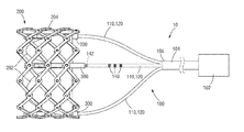
도 1은 본 개시내용의 일 실시예에 따른 보철 이식 전달 조립체(10)의 예를 보여준다. 전달 조립체(10)는 2개의 주요 구성 요소들: 보철 판막(200) 및 전달 장치(100)를 포함할 수 있다. 보철 판막(200)은 아래에 더 설명되는 것과 같이 하나 이상의 유지 및 액추에이터 조립체들(retention and actuator assemblies)(110)을 통해 전달 장치(100)에 해제 가능하게 결합될 수 있다. 본 명세서에 개시된 전달 장치(100) 및 다른 전달 장치들은 스텐트들 또는 이식물들과 같은 보철 판막들 이외의 보철 디바이스들을 이식하는 데 사용될 수 있다는 것이 이해되어야 한다.1 shows an example of a prosthetic
전달 장치(100)는 그 근위 단부에 핸들(102)을 포함할 수 있다. 전달 장치(100)는 핸들(102)에 결합된 하나 이상의 샤프트(104)를 포함할 수 있다. 보철 판막(200)의 전달 동안, 핸들(102)은 환자의 맥관 구조를 통해 전달 장치(100)를 전진 및 후퇴시키도록 외과의사에 의해 조종될 수 있다. 일부 실시예들에서, 핸들(102)은 보철 판막(10)을 팽창 및/또는 전개하기 위해 전달 장치(100)의 상이한 구성 요소들을 제어하기 위한 복수의 노브들(knobs) 또는 다른 작동 메커니즘들을 포함할 수 있다. 예를 들어, 핸들(102)은 하나 이상의 노브들 또는 다른 작동 메커니즘들을 포함할 수 있고, 각각은 전달 장치(100)의 각각의 유지 및 액추에이터 조립체(110)를 대응하는 판막 팽창 메커니즘(300)(또한 "판막 액추에이터들"이라고도 지칭됨)과 상호작용하도록 조작하여, 아래에 더 설명되는 것과 같이 보철 판막(200)을 팽창 또는 압축하고/하거나 원하는 직경으로 보철 판막(200)을 잠그도록 구성된다.The
도 2c는 보철 판막(200)의 사시도이다. 특정한 실시예에서, 보철 판막(200)은 천연 대동맥 고리(native aortic annulus)내에 이식될 수 있지만, 보철 판막은 또한 천연 이첨 판막, 천연 폐 판막, 천연 삼첨 판막을 포함하여 심장 내에 다른 위치들에 이식될 수도 있다. 보철 판막(200)은 근위 단부(206) 및 원위 단부(208)를 갖는 고리 스텐트 및 프레임(204)을 포함할 수 있다. 일부 실시예들에서, 근위 단부(206)는 유출 단부일 수 있고 원위 단부(208)는 유입 단부일 수 있다. 다른 실시예들에서, 근위 단부(206)는 유입 단부일 수 있고, 원위 단부(208)는 유출 단부 일 수 있다. 예를 들어, 보철 판막을 이식하는 역행 대퇴골경유의(retrograde transfemoral)접근에서, 근위 단부(206)는 유출 단부일 수 있고 원위 단부(208)는 유입 단부일 수 있다. 다른 예에서, 보철 판막을 이식하기 위한 순행 경중격의 경로(antegrade transseptal route)에서 근위 단부(206)는 유입 단부일 수 있고 원위 단부(208)는 유출 단부일 수 있다.2C is a perspective view of the
보철 판막(200)은 또한 프레임(204)에 장착되고 유입 단부로부터 유출 단부로 보철 판막(200)을 통해 혈류를 조절하도록 구성된 판막형 구조물(202)을 포함할 수도 있다. 예를 들어, 판막형 구조물은 가요성 재료로 만들어진 하나 이상의 리플릿들(leaflets)을 포함하는 리플릿 조립체를 포함할 수 있다. 리플릿 조립체의 리플릿들은 전체적으로 또는 부분적으로, 생물학적 재료, 생체 적합성(bio-compatible) 합성 재료들, 또는 다른 이러한 재료들로 만들어질 수 있다. 적절한 생물학적 재료는, 예를 들어, 소의 심막(bovine pericardium)(또는 다른 자원들로부터의 심막)을 포함할 수 있다. 판막형 구조물이 보철 판막의 프레임 상에 장착될 수 있는 방식을 포함하여, 카테터 경유 보철 심장 판막들에 대한 추가 상세들은, 예를 들어, 미국 특허 제6,730,118호, 제7,393,360호, 제7,510,575호, 제7,993,394호, 및 제8,252,202호, 및 미국 특허 출원 제62/614,299호에서 찾아볼 수 있으며, 이들 모두는 그들 전체로서 참조로 본 명세서에 통합된다.The
비록 보여지지는 않지만, 보철 판막(200)은 또한 하나 이상의 스커트들(skirts) 또는 밀봉 부재들을 포함할 수 있다. 예를 들어, 보철 판막(200)은 프레임의 내부 표면 상에 장착된 내부 스커트를 포함할 수 있다. 내부 스커트는 판막 주변의(perivalvular) 누출을 방지하거나 감소시키고, 리플렛들을 프레임에 고정(anchor)하고 및/또는 주름이 지어지는 동안 및 보철 판막의 동작 사이클들 동안 프레임과의 접촉에 의해 유발되는 손상에 대해 리플릿들을 보호하기 위해 밀봉 부재로 기능할 수 있다. 보철 판막(200)은 또한 프레임(204)의 외부 표면 상에 장착된 외부 스커트를 포함할 수도 있다. 외부 스커트는 천연 판막 고리의 조직에 대해 밀봉하여 보철 판막에 대한 밀봉 부재로 기능할 수 있고, 보철 판막을 넘어서는 판막 주위 누출(paravalvular leakage)을 감소시키는 것을 도울 수 있다. 내부 및 외부 스커트들은 임의의 다양한 합성 재료들(예를 들어, PET) 또는 자연 조직(예를 들어, 심막 조직)을 포함하는 임의의 다양한 적절한 생체 적합성 재료들로부터 형성될 수 있다.Although not shown, the
프레임(204)은 스테인리스 스틸, 코발트-크롬 합금(예를 들어, MP35N 합금), 또는 예를 들어 니티놀과 같은 니켈 티타늄 합금("NiTi")과 같이 임의의 다양한 적절한 재료들로 제조될 수 있다. 보여지는 것과 같이, 프레임(204)은 격자형 패턴으로 배열된 복수의 상호 연결된 지주들(struts)(210)을 포함할 수 있다. 지주들(210)은 대각선으로 위치되거나, 보철 판막(200)이 팽창된 구성에 있을 때 보철 판막(200)의 종축(longitudinal axis)(214)에 대해 비스듬히 오프셋되거나(offset at an angle), 및 종축(214)로부터 방사상으로 오프셋을 가지고 보여진다. 다른 구현들에서, 지주들(210)은 도 2c에 도시된 것과 상이한 양만큼 오프셋될 수 있거나, 지주들(210)의 일부 또는 전부가 보철 판막(200)의 종축에 평행하게 위치될 수 있다.
도시된 실시예에서, 지주들(210)은 각각의 지주의 길이를 따라 하나 이상의 피봇 조인트들(pivot joints)에 피봇 가능하게 서로에 결합된다. 예를 들어, 지주들(210) 각각은 지주의 대향하는 단부들에서의 개구들(212) 및 지주의 길이를 따라 이격된 개구들(212)을 갖도록 형성될 수 있다. 각각의 힌지들은 지주들(210)이 개구들을 통해 연장하는 리벳들 또는 핀들(216)(예를 들어, 도 3 참조)과 같은 체결구들을 통해 서로 중첩되는 위치들에 형성될 수 있다. 힌지들은 예를 들어 보철 판막(200)의 조립, 준비, 또는 이식 동안 프레임(204)이 방사상으로 팽창 또는 압축됨에 따라 지주들(210)이 서로에 대해 피봇하도록 허용할 수 있다.In the illustrated embodiment, the
일부 실시예들에서, 프레임(204)은 개별 구성 요소들(예를 들어 프레임의 지주들 및 체결구들)을 형성하고, 그 후 기계적으로 개별 구성 요소들을 함께 조립하고 연결하여 구성될 수 있다. 다른 실시예들에서, 지주들(210)은 각각의 힌지들에 의해 서로 결합되지 않지만, 프레임(204)의 방사상 팽창 및 수축을 허가하기 위해 서로에 대해 피봇 가능하거나 휘어질 수 있다. 예를 들어, 프레임(204)은 단일 피스의 재료(예를 들어, 금속 튜브)로부터 (예를 들어, 레이저 절단, 전기 주조 또는 물리적 기상 증착(physical vapor deposition)을 통해) 형성될 수 있다. 본 명세서에 개시된 전달 장치들과 함께 사용될 수 있는 프레임 및 보철 판막의 구성에 관한 추가 상세들은 미국 특허 출원 제2018/0153689호, 제2018/0344456호, 제2015/0135506호, 제2014/0296962호, 및 미국 특허 출원 제16,105,353호에 설명되어 있고, 이들 모두는 본 명세서에 참조로 통합된다.In some embodiments,
위에서 시사한 것과 같이, 보철 판막(200)은 하나 이상의 판막 팽창 메커니즘들(300)을 더 포함할 수 있다. 도 1에 보여진 것과 같이, 팽창 메커니즘들(300) 각각은 전달 장치(100)의 각각의 유지 및 액추에이터 조립체(110)와 해제 가능한 연결을 형성하도록 구성될 수 있다. 일부 실시예들에서, 판막 팽창 메커니즘들(300)은 프레임(204)의 내부 표면에 장착되고 그 주위에 균등하게 이격될 수 있다. 예를 들어, 도 2c는 프레임(204)의 내부 표면 주위에 균등하게 이격된 3개의 판막 팽창 메커니즘들(300)을 보여준다. 보철 판막(200)은 프레임의 외부 표면에 장착되거나 프레임 주변에 불균등하게 이격될 수 있는 임의의 수의 판막 팽창 메커니즘들을 가질 수 있다는 것이 이해되어야 한다.As suggested above, the
아래에 설명되는 것과 같이, 판막 팽창 메커니즘들(300)은 보철 판막(200)을 방사상으로 팽창 또는 압축하는 데 사용될 수 있다. 일부 실시예들에서, 판막 팽창 메커니즘들(300)은 또한 방사상으로 팽창된 상태에서 보철 판막(200)을 잠그는데 이용될 수도 있다.As described below, the
도 2a-2c를 참조하면, 도시된 실시예에서 판막 팽창 메커니즘(300)은 상대적으로 긴 상부 또는 원위 부분(304) 및 액추에이터 나사(302)의 근위 단부에 있는 상대적으로 짧은 하부 또는 근위 부분(306)을 포함하는 내부 부재 또는 액추에이터 나사(302)(도시된 실시예에서는 선형 액추에이터 또는 푸시-풀 부재로 기능함)를 포함할 수 있고, 여기서 근위 부분(306)은 상부 부분(304)보다 작은 직경을 가진다. 액추에이터 나사(302)의 원위 및 근위 부분들(304, 306) 둘 다는 외부 나사식(threaded) 표면들을 가질 수 있다.2A-2C , in the illustrated embodiment the
액추에이터 나사(302)는 방사상으로 연장되는 원위 판막 커넥터(310)를 갖는, 그 원위 단부에 부착된 원위 부착 피스(308)를 가질 수 있다. 원위 부착 피스(308)는 액추에이터 나사(302)에 고정될 수 있다(예를 들어 함께 용접되거나 하나의 피스로 제조될 수 있다). 원위 판막 커넥터(310)는 도 2c에 보여지는 것과 같이 2개 이상의 지주들이 교차하는 프레임 상의 위치에 형성된 프레임(204)의 원위 단부에 또는 근처에 있는 개구를 통해 연장할 수 있다. 원위 판막 커넥터(310)는 프레임(204)에 고정(예를 들어, 용접)될 수 있다. 지주들의 형상으로 인해, 프레임(204)의 원위 단부는 교대하는 일련의 원위 접합부들(250) 및 원위 정점들(apices)(252)을 포함한다. 도시된 예에서, 3개의 판막 팽창 메커니즘들(300)의 원위 판막 커넥터들(310)은 원위 접합부들(250)을 통해 프레임(204)에 연결된다. 다른 예들에서, 하나 이상의 원위 판막 커넥터들(310)은 원위 정점들(252)을 통해 프레임(204)에 연결될 수 있다. 다른 실시예들에서, 원위 판막 커넥터들(310)은 프레임(204)의 근위 단부(206)에 더 가까운 접합부들에 연결될 수 있다.The
판막 팽창 메커니즘(300)은 외부 부재 또는 슬리브(312)를 더 포함할 수 있다. 슬리브(312)는 액추에이터 나사(302)의 원위 부분(304) 주변에 고리 형태로 위치될 수 있고, 근위 및 원위 단부들에 축방향 개구들을 포함할 수 있으며, 그를 통해 액추에이터 나사(302)가 연장될 수 있다. 슬리브(312) 내의 축방향 개구들 및 루멘은 나사가 슬리브 내에서 자유롭게 이동할 수 있도록(액추에이터 나사(302)가 슬리브(312)에 대해 근위로 및 원위로 이동될 수 있도록) 액추에이터 나사(302)의 원위 부분(304)의 직경보다 더 큰 직경을 가질 수 있다. 액추에이터 나사(302)는 슬리브 내에서 자유롭게 이동할 수 있기 때문에, 아래에 더 상세히 개시되는 것과 같이 프레임(204)을 방사상으로 팽창 및/또는 수축하는 데 사용될 수 있다.The
슬리브(312)는 그 외부 표면으로부터 방사상으로 연장되는 근위 판막 커넥터(314)를 가질 수 있다. 근위 판막 커넥터(314)는 슬리브(312)에 고정(예를 들어, 용접)될 수 있다. 근위 판막 커넥터(314)는 근위 판막 커넥터가 프레임(204)의 근위 단부에서 또는 근처에서 개구를 통해 연장할 수 있도록 원위 판막 커넥터(310)로부터 축방향으로 이격될 수 있다. 프레임(204)의 근위 단부는 교대하는 일련의 근위 접합부들(260) 및 근위 정점들(262)을 포함한다. 도시된 예에서, 3개의 판막 팽창 메커니즘들(300)의 근위 판막 커넥터들(314)은 근위 접합부들(260)을 통해 프레임(204)에 연결된다. 다른 예들에서, 하나 이상의 근위 판막 커넥터들(314)은 근위 정점들(262)을 통해 프레임(204)에 연결될 수 있다. 다른 실시예들에서, 근위 판막 커넥터들(314)은 프레임(204)의 원위 단부에 더 가까운 접합부들에 연결될 수 있다.The
원위 및 근위 커넥터들(310, 314)은 프레임(204)의 대향 단부들에 연결될 필요가 없다는 것이 이해되어야 한다. 판막 팽창 메커니즘(300)은 원위 및 근위 커넥터들이 서로 축방향으로 이격되는 프레임 상의 각각의 접합부들에 연결되는 한, 프레임(204)을 팽창 및 압축하는 데 사용될 수 있다.It should be understood that the distal and
잠금 너트(316)는 슬리브(312)의 내부에 위치될 수 있고, 액추에이터 나사(302)의 외부 나사식 표면과 맞물릴 수 있는 내부 나사식 표면을 가질 수 있다. 잠금 너트(316)는 그 근위 단부에 노치형 부분(318)을 가질 수 있고, 그 목적은 아래에 설명된다. 잠금 너트는 아래에서 설명되는 것과 같이 프레임(204)을 특히 방사상으로 팽창된 상태로 잠그기 위해 사용될 수 있다.The
도 3-4는 전달 장치(100)의 유지 및 액추에이터 조립체(110)의 구성 요소들과 인터페이스하는 하나의 판막 팽창 메커니즘(300)을 보여준다. 보여지는 것과 같이 유지 및 액추에이터 조립체(110)는 지지 튜브(120), 액추에이터 부재(122), 및 잠금 도구(124)를 포함한다. 지지 튜브(120)의 근위 단부는 전달 조립체의 의사 또는 조작자가 본 명세서에 설명된 것과 같이 판막 팽창 메커니즘(300)을 동작시키는 데 이용하는 핸들 또는 다른 제어 디바이스(도시되지 않음)에 연결될 수 있다. 유사하게, 액추에이터 부재(122) 및 잠금 도구(124)의 근위 단부들은 핸들에 연결될 수 있다.3-4 show one
지지 튜브(120)는 잠금 도구(124)가 지지 튜브(120)의 루멘을 통해 연장하도록 잠금 도구(124)의 근위 부분을 고리형으로 둘러싼다. 지지 튜브(120) 및 슬리브(312)는 지지 튜브(120)가 슬리브(312)를 넘어 원위로 이동하는 것이 방지되도록 지지 튜브(120)의 원위 단부가 슬리브(312)의 근위 단부(330)에 접하거나 맞물릴 수 있는 크기를 갖는다.The
액추에이터 부재(122)는 잠금 도구(124)의 루멘을 통해 연장될 수 있다. 액추에이터 부재(122)는, 예를 들어, 샤프트, 막대, 케이블, 또는 와이어일 수 있다. 액추에이터 부재(122)의 원위 말단 부분은 액추에이터 나사(302)의 근위 부분(306)에 해제 가능하게 연결될 수 있다. 예를 들어, 액추에이터 나사(302)의 원위 말단 부분은 액추에이터 나사(302)의 근위 부분(306)의 외부 나사산들(threads)에 맞물릴 수 있는 내부 나사식 표면을 가질 수 있다. 대안적으로, 액추에이터 부재는 나사의 내부 나사식 부분과 맞물리는 외부 나사산들을 가질 수 있다. 다른 해제 가능한 연결 메커니즘들(예를 들어, 후프-앤-루프, 버클, 클립, 자기 등)이 또한 사용될 수도 있다. 따라서, 액추에이터 부재(122)가 액추에이터 나사(302)에 나사식 결합될 때, 액추에이터 부재(122)의 축방향 이동은 액추에이터 나사(302)의 축방향 이동을 야기할 수 있다.The
잠금 도구(124)의 원위 부분은 액추에이터 나사(302)를 고리형으로 둘러싸고 슬리브(312)의 루멘을 통해 연장될 수 있고, 잠금 도구(124)의 근위 부분은 액추에이터 부재(122)를 고리형으로 둘러싸고 지지 튜브(120)의 루멘을 통해 전달 장치(100)의 핸들(102)로 연장될 수 있다. 잠금 도구(124)는 잠금 도구(124)의 시계방향 또는 반시계방향 회전이 잠금 도구(124)로 하여금 각각 액추에이터 나사(302)를 따라 원위로 또는 근위로 전진하게 하도록 액추에이터 나사(302)의 외부 나사식 표면과 결합할 수 있는 내부 나사식 표면을 가질 수 있다.A distal portion of the
잠금 도구(124)의 원위 단부는 도 4에서 가장 잘 보일 수 있는 것과 같이, 노치(notched) 부분(326)을 포함할 수 있다. 잠금 도구(124)의 노치 부분(326)은, 잠금 도구의 회전(예를 들어, 시계방향 회전)이 잠금 너트(316)로 하여금 동일한 방향(예를 들어, 시계방향)으로 회전하고 액추에이터 나사(302)를 따라 원위로 전진하게 하도록 잠금 너트(316)의 노치형 부분(318)의 대응하는 형상의 맞물림 표면(319)과 맞물리도록 구성된 맞물림 표면(327)을 가질 수 있다. 도시된 실시예에서 노치 부분들(318, 326)은 반대 방향(예를 들어, 반시계방향)에서 잠금 도구(124)의 회전이 잠금 도구(124)의 노치 부분(326)이 잠금 너트(316)의 노치 부분(318)과 해제하는 것을 허용하도록, 즉, 잠금 도구(124)가 근위로 이동하게 하는 방향으로의 잠금 도구(124)의 회전이 잠금 너트(316)의 대응하는 회전을 야기하지 않도록 구성된다.The distal end of the
대안적인 실시예들에서, 잠금 도구(124)의 원위 말단 부분은 잠금 너트(316)와 맞물리도록, 및 너트를 원위로 이동시키기 위한 잠금 도구(124)의 회전시에 잠금 너트의 회전을 생성하도록 적응된 다양한 다른 구성들, 예를 들어 본 명세서에서 설명된 도구 구성들 중 임의의 것을 가질 수 있다. 일부 실시예들에서, 잠금 도구(124)의 원위 말단 부분은 잠금 너트(316)를 액추에이터 나사(302)를 따라 원위로 및 근위로 이동시키기 위해 양 방향으로 잠금 너트(316)의 회전을 생성하도록 적응될 수 있다.In alternative embodiments, the distal end portion of the
동작 시에, 이식 전에, 액추에이터 부재(122)는 액추에이터 나사(302)의 근위 부분(306) 상에 나사 결합될 수 있고, 잠금 너트(316)는 액추에이터 나사(302)의 근위 단부에 위치되도록 회전될 수 있다. 그 후 프레임(204)은 방사상으로 접혀진(collapsed) 상태로 배치될 수 있으며, 전달 조립체(200)는 환자 내로 삽입될 수 있다. 일단 보철 판막이 원하는 이식 부위에 있으면, 프레임(204)은 본 명세서에서 설명된 것과 같이 방사상으로 팽창될 수 있다.In operation, prior to implantation, the
프레임(204)을 방사상으로 팽창하기 위해, 지지 튜브(120)는 슬리브(312)에 맞서 견고하게 유지될 수 있다. 그 후 액추에이터 부재(122)는 예를 들어, 액추에이터 부재(122)의 근위 단부를 당기거나 액추에이터 부재(122)의 근위 이동을 생성하는 핸들 상의 제어 노브를 작동시킴으로써, 지지 튜브(120)를 통해 근위 방향으로 당겨질 수 있다. 지지 튜브(120)가 근위 판막 커넥터(314)에 의해 프레임(204)의 근위 단부에 연결되는 슬리브(312)에 맞서 유지되기 때문에, 프레임(204)의 근위 단부는 지지 튜브(120)에 대해 이동하는 것이 방지된다. 이와 같이, 액추에이터 부재(122)의 근위 방향으로의 이동은 액추에이터 나사(302)의 근위 방향으로의 이동을 야기할 수 있고(액추에이터 부재(122)가 액추에이터 나사(302) 상에 나사 결합되기 때문에) 따라서 프레임(204)이 축방향으로 단축되고(foreshorten) 방사상으로 팽창하게 야기한다. 대안적으로, 프레임(204)은 액추에이터 부재(122)를 정지 상태로 유지하면서 지지 튜브(120)를 원위로 이동시키거나, 액추에이터 부재(122)를 근위로 이동시키면서 지지 튜브(120)를 원위로 이동시킴으로써 팽창될 수 있다.To radially expand the
프레임(204)이 원하는 방사상으로 팽창된 크기로 팽창된 후, 프레임(204)은 본 명세서에 설명된 것과 같이 이 방사상으로 팽창된 크기로 잠길 수 있다. 프레임(204)을 잠그는 것은 잠금 도구(124)를 한 방향(예를 들어, 시계방향)으로 회전시킴으로써 잠금 도구의 노치 부분(326)을 잠금 너트(316)의 노치 부분(318)과 맞물리게 하고, 그에 의해 액추에이터 나사(302)를 따라 원위로 잠금 너트(316)를 전진시켜 달성될 수 있다. 잠금 도구(124)는 잠금 너트(316)가 슬리브(312)의 원위 단부에서 내부 숄더에 접하고 잠금 너트(316)가 더 이상 원위로 전진할 수 없을 때까지 그렇게 회전될 수 있다(예를 들어 도 4 참조). 이는 액추에이터 나사(302)가 슬리브(312)에 대해 원위로 전진하고 프레임(204)을 방사상으로 압축하는 것을 방지할 것이다. 그러나, 도시된 실시예에서, 잠금 너트(316) 및 액추에이터 나사(302)는 여전히 슬리브(312)를 통해 근위로 이동될 수 있고, 그에 의해 본 명세서에서 참조로 통합되는 미국 특허 공개 제2018/0153689호에서 설명된 것과 같이 나중에 판막-내-판막 절차 동안 또는 이식 동안 프레임(204)의 추가적인 팽창을 허용한다.After the
일단 프레임(204)이 방사상으로 팽창된 상태로 잠기면, 잠금 도구(124)는 잠금 도구(124)를 근위로(예를 들어, 반시계 방향으로) 이동시켜 잠금 너트(316)의 노치 부분(318)으로부터 노치 부분(326)을 결합 해제하고 잠금 도구(124)를 액추에이터 나사(304)로부터 나사 해제(unscrew) 하는 방향으로 회전될 수 있다. 추가적으로, 액추에이터 부재(122)가 액추에이터 나사(302)의 근위 부분(306)으로부터 액추에이터 부재(122)를 나사 해제하기 위한 방향으로 회전될 수 있다(예를 들어, 액추에이터 부재(122)가 반시계 방향으로 회전될 때 액추에이터 나사(302)로부터 맞물림 해제되도록 구성될 수 있다). 일단 잠금 도구(124) 및 액추에이터 부재(122)가 액추에이터 나사(304)로부터 나사 해제되면, 그들은 환자로부터 지지 튜브(120)와 함께 제거될 수 있어, 도 2c에 보여지는 것과 같이, 프레임(204)에 연결된 액추에이터 나사(302) 및 슬리브(312)를 남기고, 프레임(204)은 특정한 방사상으로 팽창된 상태로 잠긴다.Once the
대안적인 실시예에서, 잠금 도구(124)는 액추에이터 나사(302)의 외부 나사산들과 맞물리는 내부 나사산들 없이 형성될 수 있고, 이는 잠금 도구(124)가 슬리브(312)를 통해 원위로 및 근위로 미끄러지고 액추에이터 나사(302)를 따라 잠금 너트(316)와 맞물리고 맞물림 해제될 수 있게 한다.In an alternative embodiment, the
또 다른 실시예에서, 위에서 설명한 것과 같은 잠금 너트(316) 및 액추에이터 나사(304)를 사용하는 것 대신에, 모두 참조로서 본 명세서에 통합되는, 미국 특허 공개 제2018/0153689호, 2019년 12월 4일에 출원된 국제 출원 제PCT/US2019/64373호, 2019년 10월 30일에 출원된 미국 특허 출원 제62/928,291호, 및 2019년 12월 18일에 출원된 미국 특허 출원 제62/950,005호에 설명된 것과 같은 래칫(ratchet) 메커니즘과 같은 상이한 잠금 메커니즘을 사용하여 팽창된 크기로 프레임이 잠길 수 있다. 특정한 실시예들에서, 팽창 메커니즘(300) 대신에, 보철 판막(100)은 이러한 앞서 출원된 출원들에서 설명된 것과 같은 하나 이상의 래칫 메커니즘들을 포함할 수 있다. 하나 이상의 래칫 메커니즘들은 각각의 액추에이터들(110)에 결합될 수 있고, 프레임을 방사상으로 팽창 및 압축하고 프레임을 원하는 팽창된 직경으로 잠기도록 구성될 수 있다.In another embodiment, instead of using a
본 명세서에 개시된 전달 조립체들 중 임의의 것은 보철 판막(또는 다른 유형의 이식물)을 팽창하고 압축하는 조립체의 구성 요소들의 이동을 생성하도록 구성된 하나 이상의 액추에이터들 또는 제어부들을 갖는 다양한 핸들 구성들을 가질 수 있다. 일부 실시예들에서, 핸들은 핸들 상의 액추에이터들을 수동으로 회전시킴으로써 및/또는 수동으로 밀고/당김으로써 사용자에 의해 작동될 수 있는 액추에이터들을 가질 수 있다. 다른 실시예들에서, 핸들 상의 액추에이터들 및/또는 조립체의 다른 구성 요소들은 전기적으로(electrically), 공압적으로(pneumatically) 및/또는 유압적으로(hydraulically) 제어될 수 있다.Any of the delivery assemblies disclosed herein may have various handle configurations having one or more actuators or controls configured to produce movement of the components of the assembly that expand and compress the prosthetic valve (or other type of implant). have. In some embodiments, the handle may have actuators that may be actuated by a user by manually rotating and/or manually pushing/pulling actuators on the handle. In other embodiments, actuators on the handle and/or other components of the assembly may be electrically, pneumatically and/or hydraulically controlled.
예를 들어, 일부 실시예들에서, 핸들(102)은 액추에이터 나사들(302)의 선형 이동을 생성하도록 동작할 수 있는 하나 이상의 모터들, 및 (잠금 너트들(316)을 회전시키기 위한) 잠금 도구들(124)의 회전 이동을 생성하도록 동작할 수 있는 하나 이상의 모터들과 같이, 전달 조립체의 구성 요소들의 이동을 생성하도록 사용자에 의해 작동되는 하나 이상의 전기 모터들을 하우징할 수 있다. 하나의 특정 구현에서, 하나의 전기 모터는 보철 판막에 장착된 모든 액추에이터 나사들(302)의 선형 이동을 생성하는 데 사용되고, 하나의 전기 모터는 조립체 내에 포함된 모든 잠금 도구들(124)의 회전 이동을 생성하는 데 사용된다. 다른 구현에서, 하나의 전기 모터는 각각의 액추에이터 나사 및 각각의 잠금 도구(124)에 대해 제공될 수 있다. 전달 조립체 구성 요소들을 제어하기 위한 전기 모터들을 포함하는 핸들 구성들에 관한 추가 상세들은 미국 공개 제2014/0296962호에 개시되고, 이는 참조로서 본 명세서에 통합된다.For example, in some embodiments, the
추가적으로, 본 명세서에 개시된 전달 조립체들 중 임의의 것은 미국 공개 제2014/0296962호에 추가로 개시된 바와 같이 보철 판막의 팽창을 제어하도록 동작할 수 있는 소프트웨어 및/또는 하드웨어를 포함할 수 있다. 특정한 실시예들에서, 전달 조립체는 특정 알고리즘에 따라 보철 판막을 방사상으로 팽창시키도록 동작할 수 있는 (예를 들어 핸들에 하우징되는 것과 같은) 프로그래밍 가능한 제어기를 포함할 수 있다. 예를 들어, 전달 조립체는 특정 알고리즘에 따라 보철 판막을 방사상으로 팽창시키는 전자적 제어기에 의해 제어되는 하나 이상의 모터들(예를 들어, 전기 모터들)을 포함할 수 있다. 특정한 구현들에서, 예를 들어, 제어기는 미국 공개 제2014/0296962호에 추가로 개시된 것과 같이, 보철 판막의 박동성(pulsatile) 방사상 팽창을 생성하도록 프로그래밍될 수 있다.Additionally, any of the delivery assemblies disclosed herein may include software and/or hardware operable to control inflation of the prosthetic valve as further disclosed in US Publication No. 2014/0296962. In certain embodiments, the delivery assembly may include a programmable controller (eg, housed in a handle) operable to radially inflate the prosthetic valve according to a particular algorithm. For example, the delivery assembly may include one or more motors (eg, electric motors) controlled by an electronic controller that radially expands the prosthetic valve according to a particular algorithm. In certain implementations, for example, the controller may be programmed to produce a pulsatile radial expansion of the prosthetic valve, as further disclosed in US Publication No. 2014/0296962.
아래에 설명되는 것과 같이, 전달 장치(100)는 보철 판막(200)의 방사상 팽창에 대한 실시간의 시각적 피드백을 제공하도록 구성될 수 있다. 특정한 실시예들에서, 전달 장치(100)는 또한 보철 판막(200)이 원하는 방사상으로 팽창된 크기에 잠겼다는 시각적 확인을 제공하도록 구성될 수도 있다.As described below, the
일 실시예에서, 하나 이상의 기준 방사선 불투과성 마커들(140)이 유지 및 액추에이터 조립체(110) 내의 지지 튜브(120)의 외부 표면에 위치될 수 있고, 적어도 하나의 표시자 방사선 불투과성 마커(142)는 동일한 유지 및 액추에이터 조립체(110) 내의 잠금 도구(124)의 외부 표면에 위치될 수 있다.In one embodiment, one or more fiducial
표시자 및 기준 방사선 불투과성 마커들(140, 142) 각각은 금, 백금, 텅스텐, 백금 이리듐 합금, 팔라듐 등과 같은 방사선 불투과성 재료들을 포함할 수 있고, 따라서 그들은 보철 판막이 전달 장치에 의해 환자의 신체 내로 전달될 때 형광 투시 하에서 보인다. 마커들은 그 분야의 알려진 다양한 기술들 중 임의의 기술을 사용하여 형성될 수 있다. 일부 실시예들에서, 방사선 불투과성 마커들(140 및 142)은 방사선 불투과성 잉크들 및 접착제들에 의해 형성될 수 있고, 전달 장치 구성 요소 상에, 스크린 인쇄, 고속 롤러 인쇄, 코팅, 침지 등과 같은 다수의 방식으로 가해질 수 있다. 다른 실시예들에서, 마커들은 (예를 들어, 전달 장치 구성 요소들 상에 장착된 고리형 링들 또는 C-형상의 밴드들의 형태로) 별개로 형성된 구성 요소들일 수 있다. 기준 방사선 불투과성 마커들(140)을 제외하고, 지지 튜브(120)의 원위 말단 부분은 방사선 투과성 재료를 포함하거나 잠금 도구(124) 상의 표시자 방사선 불투과성 마커(142)가 형광 투시 하에서 보이도록 컷아웃 창(cut-out window)을 가질 수 있다.Each of the indicator and reference
일부 실시예들에서, 기준 방사선 불투과성 마커들(140)은 형광 투시 하에서 표시자 방사선 불투과성 마커(142)와 시각적으로 구별 가능하도록 구성된다. 예를 들어, 기준 방사선 불투과성 마커들(140)은 표시자 방사선 불투과성 마커(142)와는 상이한 폭 및/또는 원주(circumferential) 길이를 가질 수 있다.In some embodiments, the reference
위에서 언급된 것과 같이, 프레임(204)을 방사상으로 팽창시키기 위해, 프레임(204)의 근위 단부가 지지 튜브(120)에 대해 이동하는 것을 방지하도록, 지지 튜브(120)의 원위 단부는 슬리브(312)에 맞서 견고하게 유지될 수 있다. 따라서, 지지 튜브(120) 및 그에 위치된 기준 방사선 불투과성 마커들(140)이 보철 판막의 방사상 팽창 동안 프레임(204)의 근위 단부(206)에 대해 고정된 공간적 관계를 유지한다.As noted above, the distal end of the
또한 위에서 언급된 것과 같이, 지지 튜브(120)를 통해 근위 방향으로 액추에이터 부재(122)를 당기는 것은 액추에이터 나사(302)(또는 미국 특허 공개 제2018/0153689호, 국제 출원 제PCT/US2019/64373호, 미국 특허 출원 제62/928,291호, 또는 미국 특허 출원 제62/950,005호에 설명된 것과 같이 래칫 메커니즘이 사용될 때는 래칫 랙)의 근위 이동을 야기할 수 있고, 이는 차례로 프레임(204)이 축방향으로 단축되고 방사상으로 팽창하게 할 수 있다. 잠금 도구(124)는 액추에이터 나사(302)에 나사식으로 결합되기 때문에, 잠금 도구(124)는 프레임(204)의 방사상 팽창 동안 액추에이터 나사(302)와 함께 이동할 수 있다. 따라서, 잠금 도구(124) 및 그에 위치한 표시자 방사선 불투과성 마커(142)는 보철 판막의 방사상 팽창 동안 프레임(204)의 원위 단부(208)에 대해 고정된 공간적 관계를 유지할 수 있다.As also noted above, pulling the
따라서, 하나 이상의 기준 방사선 불투과성 마커들(140)에 대한 표시자 방사선 불투과성 마커(142)의 위치는 프레임(204)의 축방향 길이(즉, 근위 단부(206)와 원위 단부(208) 사이의 거리)를 측정할 수 있고 이는 보철 판막이 방사상으로 압축된 상태로부터 방사상으로 팽창된 상태로 방사상으로 팽창됨에 따라 보철 판막의 대응하는 직경을 표시한다. 즉, 기준 방사선 불투과성 마커들(140)은 "스케일"로서 효과적으로 기능할 수 있고 표시자 방사선 불투과성 마커(142)는 "스케일"에 대한 "다이얼"의 위치가 보철 판막의 대응하는 직경을 표시할 수 있도록 "다이얼" 또는 "포인터"로 효과적으로 기능할 수 있다.Accordingly, the position of the indicator
따라서, 조작자가 판막 팽창 메커니즘(300)을 동작시킴으로써 보철 판막을 방사상으로 팽창시킬 때, 조작자는 형광 투시 하의 기준 방사선 불투과성 마커들(140) 중 임의의 하나와 표시자 방사선 불투과성 마커(142)의 정렬에 기초하여 보철 판막의 직경을 실시간으로 모니터링 및/또는 측정할 수 있다.Thus, when the operator radially inflates the prosthetic valve by operating the
표시자 방사선 불투과성 마커(142)는 바람직하게는 표시자 방사선 불투과성 마커(142)가 보철 판막의 방사상 팽창 동안 형광 투시 하에서 항상 보이는 것을 보장하기 위해 프레임(204)의 외부에 위치되도록 구성된다. 예를 들어, 일부 실시예들에서, 표시자 방사선 불투과성 마커(142)는 프레임(204)의 근위 단부(206)와 슬리브(312)의 근위 단부(330) 사이에서 잠금 도구(124)의 근위 부분을 따라 위치될 수 있다. 다른 실시예들에서, 표시자 방사선 불투과성 마커(142)는 슬리브(312)의 근위 단부(330)에 대한 근위에서 잠금 도구(124)의 근위 부분을 따라 위치될 수 있다.The indicator
위에서 언급된 것과 같이, 지지 튜브(120)는 복수의 기준 방사선 불투과성 마커들(140)을 포함할 수 있다. 예를 들어, 도 5-7은 3개의 기준 방사선 불투과성 마커들(140a, 140b, 140c)을 보여주지만, 임의의 수의 기준 방사선 불투과성 마커들(140)이 사용될 수 있다는 것이 이해되어야 한다. 각각의 기준 방사선 불투과성 마커(140)는 보철 판막의 특정 직경에 대응할 수 있다. 예를 들어, 보철 판막이 방사상으로 압축된 상태로부터 방사상으로 팽창된 상태로 팽창될 때, 표시자 방사선 불투과성 마커(142)와 최원위 기준 방사선 불투과성 마커(140a)와의 정렬은 보철 판막의 제1 팽창된 직경을 표시할 수 있고, 표시자 방사선 불투과성 마커(142)와 중간 기준 방사선 불투과성 마커(140b)의 정렬은 보철 판막의 제2 팽창된 직경을 표시할 수 있으며, 여기서 제2 직경은 제1 직경보다 크고, 표시자 방사선 불투과성 마커(142)와 최근위 기준 방사선 불투과성 마커(140c)의 정렬은 보철 판막의 제3 팽창된 직경을 표시할 수 있으며, 여기서 제3 직경은 제2 직경보다 크다.As noted above, the
도시된 예들에서, 더 원위에 위치된 기준 방사선 불투과성 마커는 더 근위에 위치된 기준 방사선 불투과성 마커보다 더 작은 직경의 보철 판막을 표시한다. 예를 들어, 보철 판막은 최소 직경(Dmin)과 최대 직경(Dmax)에 의해 정의되는 작업 범위 내의 직경으로 팽창될 수 있다. 따라서, 기준 방사선 불투과성 마커(140a)는 최소 직경(Dmin)을 표시할 수 있고, 기준 방사선 불투과성 마커(140c)는 최대 직경(Dmax)을 표시할 수 있으며, 기준 방사선 불투과성 마커(140b)는 중간 직경(Dmed)을 표시할 수 있다. 예시적인 실시예에서, 기준 방사선 불투과성 마커들(140a, 140b, 및 140c)은 보철 판막이 각각 27㎜, 28㎜, 및 29㎜의 직경으로 팽창되는 것을 표시할 수 있다.In the examples shown, the more distally positioned reference radiopaque marker indicates a smaller diameter prosthetic valve than the more proximal positioned reference radiopaque marker. For example, the prosthetic valve may expand to a diameter within a working range defined by a minimum diameter (Dmin) and a maximum diameter (Dmax). Accordingly, the reference
지지 튜브(120)는 임의의 수의 기준 방사선 불투과성 마커들을 가질 수 있음이 이해되어야 한다. 예를 들어, 기준 방사선 불투과성 마커들(140)의 수는 단지 1개 또는 2개이거나, 또는 3개보다 많을 수 있다.It should be understood that the
일부 실시예들에서, 지지 튜브(120) 상에 위치된 다수의 기준 방사선 불투과성 마커들(140)은 임의의 2개의 인접한 기준 방사선 불투과성 마커들 사이에서 동일한 거리로 균등하게 이격된다. 다른 실시예들에서, 다수의 기준 방사선 불투과성 마커들(140)은 동일하지 않은 거리로 이격될 수 있다.In some embodiments, a plurality of reference
도 5-7에 도시된 실시예들이 유지 및 액추에이터 조립체(110)에 결합된 단지 하나의 팽창 메커니즘(300)을 보여주지만, 도 1에 도시된 것과 같이 팽창 메커니즘들 각각이 대응하는 유지 및 액추에이터 조립체에 연결될 수 있음이 이해되어야 한다. 일부 실시예들에서, 유지 및 액추에이터 조립체들(110) 중 단지 하나 또는 선택된 것들만이 대응하는 세트의 표시자 및 기준 방사선 불투과성 마커들을 가질 수 있다. 다른 실시예들에서, 유지 및 액추에이터 조립체들 각각은 보철 판막의 각도 위치에 관계없이 조작자가 방사선 불투과성 마커들을 보는 것을 용이하게 하기 위해 각각의 표시자 및 기준 방사선 불투과성 마커들을 포함할 수 있다.Although the embodiments shown in FIGS. 5-7 show only one
도 5-7에 도시된 실시예들이 유지 및 액추에이터 조립체(110)에 결합된 단지 하나의 유형의 팽창 및 잠금 메커니즘(300)만을 보여주지만, 미국 특허 공개 제2018/0153689호, 국제 출원 제PCT/US2019/64373호, 미국 특허 출원 제62/928,291호, 또는 미국 특허 출원 제62/950,005호에 설명된 것과 같은 하나 이상의 래칫 메커니즘들과 같은 다른 팽창 및 잠금 메커니즘들이 사용될 때 보철 판막의 방사상 직경 및/또는 프레임의 잠금 확인을 표시하기 위해 방사선 불투과성 마커들을 사용하는 동일한 개념이 적용될 수 있음이 이해되어야 한다.Although the embodiments shown in FIGS. 5-7 show only one type of inflation and
위에서 설명되고 도 6-7에서 더 도시된 것과 같이, 프레임(204)은 잠금 너트(316)를 슬리브(312)의 원위 단부에 전진시키기 위해 잠금 도구(124)를 회전시킴으로써 방사상으로 팽창된 크기로 잠길 수 있다. 일 실시예에 따르면, 적어도 하나의 방사선 불투과성 마커가 형광 투시 하에서 잠금 너트(316)가 프레임(204)을 잠그기 위해 원하는 위치로 이동되었는지를 시각적으로 확인하기 위해 사용될 수 있다.As described above and further shown in FIGS. 6-7 ,
예를 들어, 표시자 방사선 불투과성 마커(142)는 잠금 도구(124)가 잠금 너트(316)를 슬리브(312)의 원위 단부로 전진시킬 때 슬리브(312)의 근위 말단 부분(332)과 정렬하거나 그에 매우 근접하도록 구성될 수 있다. 일 실시예에서, 슬리브(312)의 근위 말단 부분(332)은 형광 투시 하에서 보일 수 있도록 방사선 불투과성 마커를 포함할 수 있다. 다른 실시예들에서, 슬리브(312)의 근위 말단 부분(332)은 방사선 불투과성 마커를 포함하지 않는다. 대신에, 슬리브(312)의 근위 말단 부분(332)은 형광 투시 하에서 주변 구조물들과 시각적으로 구별될 수 있는 크기 및/또는 형상이 될 수 있다. 예를 들어, 근위 말단 부분(332)은 지지 튜브(120)의 원위 단부보다 큰 직경을 가질 수 있다. 따라서, 프레임(204)의 잠금은 표시자 방사선 불투과성 마커(142)가 슬리브(312)의 근위 말단 부분(332)과 정렬이 되었는지를 검증하여 확인될 수 있다. 예로서, 도 6은 프레임(204)으로부터 근위로 이격된 "잠금 해제" 위치에 있는 표시자 방사선 불투과성 마커(142)를 보여주는 반면에, 도 7은 슬리브(312)의 근위 말단 부분(332)과 정렬하거나 그에 매우 근접한 "잠금" 위치에 있는 표시자 방사선 불투과성 마커(142)를 보여준다.For example, the indicator
일부 실시예들에서, 전달 장치(100)는 보철 판막의 방사상 직경에 대한 시각적 피드백 및 프레임의 잠금의 시각적 확인 둘 다를 제공하는 데 사용되는 한 세트의 방사선 불투과성 마커들(예를 들어, 마커들(140 및 142))만을 포함한다. 다른 실시예들에서, 전달 장치는 보철 판막의 방사상 직경만의 시각적 피드백을 위해 사용되는 한 세트의 방사선 불투과성 마커들, 및/또는 프레임의 잠금의 시각적 확인을 위해 사용되는 하나 이상의 상이한 방사선 불투과성 마커들을 포함할 수 있다.In some embodiments,
대안적인 실시예들Alternative embodiments
판막 팽창을 모니터링하고 프레임 잠금을 확인하기 위한 시스템들 및 방법들이 도 1-7에 도시된 특정 실시예들과 함께 설명되었지만, 개시된 실시예들은 비 제한적인 예들이고 본 명세서에 개시된 일반적인 개념은 대안적인 실시예들에서 구현될 수 있다는 것이 이해되어야 한다.Although systems and methods for monitoring valve inflation and verifying frame lock have been described in conjunction with specific embodiments shown in FIGS. 1-7 , the disclosed embodiments are non-limiting examples and the general concept disclosed herein is intended to provide alternative It should be understood that it may be implemented in embodiments.
예를 들어, 특정 실시예들에서, 표시자 방사선 불투과성 마커는 잠금 도구(124) 대신에 액추에이터 부재(122)상에 위치될 수 있다. 지지 튜브(120)에 대해 근위 방향으로 액추에이터 부재(122)를 당기는 것에 의해 판막 팽창이 야기되기 때문에, 지지 튜브(120)상의 기준 방사선 불투과성 마커들에 대한 액추에이터 부재(122) 상의 표시자 방사선 불투과성 마커의 위치는 또한 방사상 팽창 동안의 보철 판막의 직경을 표시할 수 있다.For example, in certain embodiments, the indicator radiopaque marker may be positioned on the
다른 실시예들에서, 표시자 방사선 불투과성 마커와 기준 방사선 불투과성 마커들의 상대적인 위치들이 전환될 수 있다. 예를 들어, 하나 이상의 기준 방사선 불투과성 마커들은 잠금 도구(124)의 외부 표면상에 위치될 수 있고, 적어도 하나의 표시자 방사선 불투과성 마커가 지지 튜브(120)의 외부 표면상에 위치될 수 있다. 따라서, 기준 방사선 불투과성 마커들이 판막 팽창 동안 표시자 방사선 불투과성 마커에 대해 축방향으로 이동하는 동안 표시자 방사선 불투과성 마커는 정지 상태로 유지된다. 유사하게, 기준 방사선 불투과성 마커들 중 하나 이상과 표시자 방사선 불투과성 마커의 정렬은 보철 판막의 대응하는 팽창된 직경을 표시할 수 있다.In other embodiments, the relative positions of the indicator radiopaque marker and the reference radiopaque marker may be switched. For example, one or more fiducial radiopaque markers may be positioned on an outer surface of locking
위에서 설명된 판막 팽창 메커니즘(300)은 이동하는 내부 부재(액추에이터 나사(302)) 및 고정된 외부 부재(슬리브(312))를 포함하지만, 판막 팽창 메커니즘은 제1 단부를 보철 판막의 제2 단부를 향해, 또는 그 반대로 밀어내는 것을 허용하는 한 상이하게 구성될 수 있다는 것이 이해되어야 한다. 일부 실시예들에서, 제1 단부는 유입 단부이고 제2 단부는 유출 단부이다. 다른 실시예들에서, 제1 단부는 유출 단부이고 제2 단부는 유입 단부이다.While the
예를 들어, 도 5-6에 관해 위에서 설명된 실시예들에서, 내부 부재를 외부 부재에 대해 근위 방향으로 당기면서 보철 판막의 근위 단부를 정지 상태로 유지함으로써 보철 판막이 팽창될 수 있다. 다른 실시예들에서, 내부 부재를 외부 부재에 대해 원위 방향으로 밀면서 보철 판막의 원위 단부를 정지 상태로 유지함으로써 보철 판막이 팽창될 수 있다. 또 다른 실시예들에서, 원위 단부를 근위 방향으로 당기면서 근위 단부를 원위 방향으로 밀어냄으로써 보철 판막이 팽창될 수 있다.For example, in the embodiments described above with respect to FIGS. 5-6 , the prosthetic valve may be inflated by holding the proximal end of the prosthetic valve stationary while pulling the inner member proximally relative to the outer member. In other embodiments, the prosthetic valve may be inflated by holding the distal end of the prosthetic valve stationary while pushing the inner member distally relative to the outer member. In still other embodiments, the prosthetic valve may be inflated by pulling the distal end in the proximal direction while pushing the proximal end in the distal direction.
대안적으로, 판막 팽창 메커니즘은 고정된 내부 부재, 및 내부 부재를 고리형으로 둘러싸는 이동할 수 있는 외부 부재를 갖도록 구성될 수 있다. 보철 판막을 팽창시키기 위해 외부 부재는 보철 판막의 유입 단부(또는 유출 단부)를 정지 상태로 유지하도록 구성될 수 있고 내부 부재는 유출 단부(또는 유입 단부)를 보철 판막의 유입 단부(또는 유출 단부)를 향해 당기도록(또는 밀도록) 구성될 수 있다.Alternatively, the valve inflation mechanism may be configured with a fixed inner member and a movable outer member that annularly surrounds the inner member. To inflate the prosthetic valve, the outer member may be configured to hold the inlet end (or outlet end) of the prosthetic valve stationary and the inner member secures the outlet end (or inlet end) to the inlet end (or outlet end) of the prosthetic valve. It can be configured to pull (or push) towards.
더 일반적으로, 판막 팽창 메커니즘은 서로에 대해 축방향으로 이동될 수 있는 2개의 부재들을 갖도록 구성될 수 있다. 일부 실시예들에서, 2개의 부재들은 공통 축을 가지는(coaxially) 대신에 나란히 배열될 수 있다. 보철 판막을 팽창시키기 위해, 하나의 부재는 보철 판막의 유입 단부(또는 유출 단부)를 정지 상태로 유지시키도록 구성될 수 있고 다른 부재는 유출 단부(또는 유입 단부)를 보철 판막의 유입 단부(또는 유출 단부)를 향해 당기도록(또는 밀도록) 구성될 수 있다.More generally, the valve inflation mechanism may be configured to have two members movable axially relative to each other. In some embodiments, the two members may be arranged side by side instead of coaxially. To inflate the prosthetic valve, one member may be configured to hold the inlet end (or outlet end) of the prosthetic valve stationary and the other member secures the outlet end (or inlet end) to the inlet end (or outlet end) of the prosthetic valve. outlet end).
판막 팽창 메커니즘이 어떻게 구성되는지에 관계없이, 위에서 설명된 동일한 개념을 적용함으로써 팽창된 보철 판막의 직경을 모니터링하는 것이 달성될 수 있다. 예를 들어, 전달 장치는 판막 팽창 메커니즘의 제1 부재에 해제 가능하게 연결된 제1 부분, 판막 팽창 메커니즘의 제2 부재에 해제 가능하게 연결된 제2 부분을 포함할 수 있고, 제1 및 제2 부재들은 서로에 대해 축방향으로 이동할 수 있도록 구성된다. 하나 이상의 기준 방사선 불투과성 마커들은 제1 부분(또는 제2 부분)에 위치될 수 있고 표시자 방사선 불투과성 마커는 제2 부분(또는 제1 부분)에 위치될 수 있다. 제1 부분에 대한 제2 부분의 축방향 이동은 제1 및 제2 부재들 사이에서 대응하는 축방향 이동을 야기할 수 있고, 따라서 보철 판막의 방사상 압축 및 방사상 팽창을 야기한다. 이와 같이, 하나 이상의 기준 방사선 불투과성 마커들과 표시자 방사선 불투과성 마커의 정렬은 팽창된 보철 판막의 직경을 표시할 수 있다.Regardless of how the valve inflation mechanism is configured, monitoring the diameter of the inflated prosthetic valve can be achieved by applying the same concepts described above. For example, the delivery device can include a first portion releasably connected to a first member of the valve inflation mechanism, a second portion releasably connected to a second member of the valve inflation mechanism, the first and second members They are configured to be movable axially with respect to each other. The one or more reference radiopaque markers may be located in the first portion (or second portion) and the indicator radiopaque marker may be located in the second portion (or first portion). Axial movement of the second portion relative to the first portion may cause a corresponding axial movement between the first and second members, thus resulting in radial compression and radial expansion of the prosthetic valve. As such, alignment of the one or more reference radiopaque markers with the indicator radiopaque marker may indicate the diameter of the inflated prosthetic valve.
비록 보철 판막이 기계적으로 팽창할 수 있는(balloon expandable) 프레임을 갖도록 설명되었지만, 본 명세서에서 개시된 동일한 개념이 또한 풍선 팽창할 수 있는 보철 판막들 및 자기-팽창할 수 있는(self-expandable) 보철 판막들과 같은 다른 유형의 보철 판막들에 적용될 수도 있다는 것이 이해되어야 한다. 예를 들어, 전달 장치는 보철 판막의 유입 단부(또는 유출 단부)에 해제 가능하게 연결된 제1 부분, 및 보철 판막의 유출 단부(또는 유입 단부)에 해제 가능하게 연결된 제2 부분을 포함할 수 있다. 하나 이상의 기준 방사선 불투과성 마커들은 제1 부분(또는 제2 부분)에 위치될 수 있고, 표시자 방사선 불투과성 마커는 제2 부분(또는 제1 부분)에 위치될 수 있다. 자체-팽창 메커니즘을 통해 또는 팽창식 풍선을 팽창(inflating)시킴으로써 보철 판막이 방사상으로 팽창됨에 따라, 보철 판막의 유입 및 유출 단부들 사이의 거리가 단축된다. 결과로서, 제2 부분은 제1 부분에 대해 축방향으로 이동한다. 따라서, 하나 이상의 기준 방사선 불투과성 마커들과 표시자 방사선 불투과성 마커의 정렬은 팽창된 보철 판막의 직경을 표시할 수 있다.Although the prosthetic valve has been described as having a mechanically balloon expandable frame, the same concept disclosed herein also applies to balloon expandable prosthetic valves and self-expandable prosthetic valves. It should be understood that other types of prosthetic valves may be applied, such as For example, the delivery device may include a first portion releasably connected to an inlet end (or outlet end) of the prosthetic valve, and a second portion releasably connected to an outlet end (or inlet end) of the prosthetic valve. . The one or more reference radiopaque markers may be located in the first portion (or second portion) and the indicator radiopaque marker may be located in the second portion (or first portion). As the prosthetic valve is inflated radially, either through a self-inflating mechanism or by inflating an inflatable balloon, the distance between the inlet and outlet ends of the prosthetic valve is shortened. As a result, the second portion moves axially relative to the first portion. Accordingly, alignment of the one or more reference radiopaque markers with the indicator radiopaque marker may indicate the diameter of the inflated prosthetic valve.
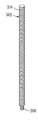
또 다른 실시예에서, 하나보다 많은 표시자 방사선 불투과성 마커들이 하나 이상의 기준 방사선 불투과성 마커들과 함께 사용될 수 있다. 예를 들어, 도 8은 거리(d1)만큼 균등하게 이격된 3개의 기준 방사선 불투과성 마커들(440a, 440b, 440c) 및 예를 들어, d1의 절반일 수 있는 거리(d2)만큼 이격된 2개의 표시자 방사선 불투과성 마커들(442a, 442b)을 갖는 유지 및 액추에이터 조립체(110)의 실시예를 도시한다. 최근위 표시자 방사선 불투과성 마커(442b)가 기준 방사선 불투과성 마커(440a, 440b, 또는 440c)와 각각 정렬될 때, 보철 판막의 직경은 D1, D2, 또는 D3로 표시된다. 한편, 최근위 표시자 방사선 불투과성 마커(442b)가 기준 방사선 불투과성 마커들인 440a와 440b 사이(또는, 440b와 440c 사이)에 위치되고, 최원위 표시자 방사선 불투과성 마커(442a)가 기준 방사선 불투과성 마커(440a)(또는 440b)와 정렬될 때, 보철 판막의 직경은 D1과 D2 사이(또는 D2와 D3 사이)의 중간 값, 예를 들어 D1과 D2의 평균(또는 D2와 D3의 평균)으로 표시될 수 있다. 따라서, 기준 방사선 불투과성 마커들과 상이한 간격을 갖는 다수의 표시자 방사선 불투과성 마커들을 사용하는 것은 판막의 직경의 상이한 측정 해상도들을 제공할 수 있다.In another embodiment, more than one indicator radiopaque markers may be used in conjunction with one or more reference radiopaque markers. For example, FIG. 8 shows three reference
유지 및 액추에이터 조립체가 임의의 수의 표시자 방사선 불투과성 마커들 및 임의의 수의 기준 방사선 불투과성 마커를 갖도록 구성될 수 있다는 것이 이해되어야 한다. 표시자 방사선 불투과성 마커들 사이의 마커간(inter-marker) 간격은 기준 방사선 불투과성 마커들 사이의 마커간 간격보다 크거나 작을 수 있다. 또한, 표시자 방사선 불투과성 마커들 사이의 마커간 간격 및/또는 기준 방사선 불투과성 마커들 사이의 마커간 간격은 균일하거나 불균일할 수 있다.It should be understood that the retention and actuator assembly may be configured to have any number of indicator radiopaque markers and any number of reference radiopaque markers. The inter-marker spacing between indicator radiopaque markers may be greater or less than the inter-marker spacing between reference radiopaque markers. Further, the inter-marker spacing between indicator radiopaque markers and/or the inter-marker spacing between reference radiopaque markers may be uniform or non-uniform.
일반적인 고려사항들General considerations
개시된 실시예들이 심장의 천연 고리들(예를 들어, 폐, 이첨판, 및 삼첨판 고리들) 중 임의의 고리 내에 보철 디바이스들을 전달 및 이식하도록 적응될 수 있고, 다양한 전달 접근법들(예를 들어, 역행(retrograde), 선행(antegrade), 경중격(transseptal), 경심실(transventricular), 경심방(transatrial) 등) 중 임의의 것과 함께 사용될 수 있다는 것이 이해되어야 한다.The disclosed embodiments may be adapted to deliver and implant prosthetic devices within any of the natural rings of the heart (eg, the lung, bicuspid, and tricuspid rings), and employ a variety of delivery approaches (eg, retrograde). (retrograde, antegrade, transseptal, transventricular, transatrial, etc.)
이 설명의 목적들을 위해, 본 개시내용의 실시예들의 특정한 태양들, 장점들, 및 신규한 특징들이 본 명세서에 설명된다. 개시된 방법들, 장치들, 및 시스템들은 어떠한 방식으로도 제한되는 것으로 해석되어서는 안 된다. 대신에, 본 개시내용은 다양한 개시된 실시예들의 모든 신규하고 자명하지 않은 특징들 및 태양들 단독 및 서로와의 다양한 조합들 및 하위 조합들에 관한 것이다. 방법들, 장치들, 및 시스템들은 임의의 특정 태양 또는 특징 또는 그들의 조합으로 제한되지 않고, 개시된 실시예들은 임의의 하나 이상의 특정 장점들이 존재하거나 문제들이 해결될 것을 요구하지도 않는다. 임의의 예로부터의 기술들은 다른 예들 중 임의의 하나 이상에 설명된 기술들과 조합될 수 있다. 개시된 기술의 원리들이 적용될 수 있는 많은 가능한 실시예들의 관점에서, 도시된 실시예들은 오직 바람직한 예들이고 개시된 기술의 범위를 제한하는 것으로 간주되지 않아야 한다는 것이 인식되어야 한다.For purposes of this description, certain aspects, advantages, and novel features of embodiments of the present disclosure are described herein. The disclosed methods, apparatuses, and systems should not be construed as limiting in any way. Instead, the present disclosure is directed to all novel and nonobvious features and aspects of the various disclosed embodiments, alone and in various combinations and subcombinations with each other. The methods, apparatuses, and systems are not limited to any particular aspect or feature or combination thereof, and the disclosed embodiments do not require that any one or more specific advantages or problems be solved. Techniques from any example may be combined with techniques described in any one or more of other examples. In view of the many possible embodiments to which the principles of the disclosed technology may be applied, it should be recognized that the illustrated embodiments are only preferred examples and should not be considered as limiting the scope of the disclosed technology.
개시된 실시예들 중 일부의 동작들이 편리한 제시를 위해 특정한 순차적인 순서로 설명되어 있지만, 이러한 설명의 방식은 아래에서 설명되는 특정 언어에 의해 특정한 순서가 요구되지 않는 한, 재배열을 포함한다는 것이 이해되어야 한다. 예를 들어, 순차적으로 설명된 동작들은 일부 경우들에서 재배열되거나 동시에 수행될 수 있다. 또한, 간략함을 위해, 첨부된 도면들은 개시된 방법들이 다른 방법들과 함께 사용될 수 있는 다양한 방식들을 보여주지 않을 수 있다. 또한, 설명은 때때로 개시된 방법들을 설명하기 위해 "제공하다" 또는 "달성하다"와 같은 용어들을 사용한다. 이러한 용어들은 수행되는 실제 동작들의 높은 레벨의 추상들이다. 이러한 용어들에 대응하는 실제 동작들은 특정한 구현에 따라 변할 수 있고 이 분야의 통상의 기술자에게 쉽게 인식될 수 있다.Although the operations of some of the disclosed embodiments are described in a particular sequential order for convenient presentation, it is to be understood that this manner of description encompasses rearrangement unless the specific order is required by the specific language described below. should be For example, operations described sequentially may in some cases be rearranged or performed concurrently. Also, for the sake of brevity, the appended drawings may not show the various ways in which the disclosed methods may be used in conjunction with other methods. Also, the description sometimes uses terms such as "provide" or "achieve" to describe the disclosed methods. These terms are high-level abstractions of the actual operations performed. Actual operations corresponding to these terms may vary depending on the particular implementation and may be readily recognized by one of ordinary skill in the art.
본 명세서에서 사용되는 것과 같이, 보철 판막, 전달 장치 및 전달 조립체의 다른 구성 요소들에 관련하여, "근위"는 환자의 외부에 있는 전달 조립체의 핸들에 더 가까운 디바이스의 위치, 방향, 또는 부분을 지칭하지만, 반면 "원위"는 핸들로부터 더 떨어진 디바이스의 위치, 방향, 또는 부분을 지칭한다. "종축의(longitudinal)" 및 "축방향의(axial)"라는 용어들은, 다르게 명시적으로 정의되지 않는 한, 근위 및 원위 방향들로 연장되는 축을 지칭한다.As used herein, with respect to the prosthetic valve, delivery device, and other components of the delivery assembly, “proximal” refers to the position, orientation, or portion of the device that is closer to the handle of the delivery assembly that is external to the patient. However, “distal” refers to a location, orientation, or portion of the device further away from the handle. The terms “longitudinal” and “axial” refer to an axis extending in the proximal and distal directions, unless explicitly defined otherwise.
본 출원 및 청구항들에서 사용되는 것과 같이, 단수 형태들인 "하나(a)", "하나(an)", 및 "그(the)"는 문맥이 명확하게 다르게 지시하지 않는 한 복수의 형태들을 포함한다. 또한, 용어 "포함하다(includes)"는 "포함하다(comprises)"를 의미한다. 추가로, 용어 "결합된" 및 "연결된"은 일반적으로 전기적으로, 전자기적으로, 및/또는 물리적으로(예를 들어, 기계적으로 또는 화학적으로) 결합되거나 링크되는 것을 의미하고, 특정 반대 언어가 없는 경우 결합된 또는 연관된 아이템들 사이의 중간 요소들의 존재를 배제하지 않는다.As used in this application and the claims, the singular forms "a", "an", and "the" include the plural forms unless the context clearly dictates otherwise. do. Also, the term “includes” means “comprises”. Additionally, the terms "coupled" and "coupled" generally mean electrically, electromagnetically, and/or physically (e.g., mechanically or chemically) coupled or linked to, with certain opposing languages being This does not preclude the presence of intermediate elements between combined or related items in their absence.
방향들 및 다른 상대적인 참조들(예를 들어, 내부, 외부, 상부, 하부 등)은 본 명세서의 도면들 및 원리들의 논의를 용이하게 하기 위해 사용될 수 있지만, 제한하는 것으로 의도되지는 않는다. 예를 들어, "내부", "외부", "상부", "하부", "실내", "실외", 및 이와 유사한 것들과 같은 특정한 용어들이 사용될 수 있다. 적용 가능한 경우, 이러한 용어들이 특히 도시된 실시예들에 관해 상대적인 관계들을 다룰 때 설명의 일부 명료성을 제공하기 위해 사용된다. 그러나, 이러한 용어들은 절대적인 관계들, 위치들, 및/또는 배향들을 암시하도록 의도되지는 않는다. 예를 들어, 객체에 관해, "상부" 부분은 단순히 객체를 뒤집음으로써 "하부" 부분이 될 수 있다. 그럼에도 불구하고, 이는 여전히 동일한 부분이고 객체는 동일하게 유지된다. 본 명세서에 사용될 때, "및/또는"은 "및" 또는 "또는" 뿐만 아니라 "및" 및 "또는"을 의미한다.Directions and other relative references (eg, inside, outside, top, bottom, etc.) may be used to facilitate discussion of the drawings and principles herein, but are not intended to be limiting. For example, certain terms may be used, such as "inside", "outside", "top", "bottom", "indoor", "outdoor", and the like. Where applicable, these terms are used to provide some clarity of description, particularly when dealing with relative relationships with respect to the illustrated embodiments. However, these terms are not intended to imply absolute relationships, positions, and/or orientations. For example, with respect to an object, a "top" part can become a "bottom" part by simply flipping the object. Nevertheless, it is still the same part and the object remains the same. As used herein, “and/or” means “and” or “or” as well as “and” and “or”.
개시된 발명의 원리들이 적용될 수 있는 많은 가능한 실시예들의 관점에서, 도시된 실시예들은 단지 바람직한 발명의 예들이며 발명의 범위를 제한하는 것으로 간주되지 않아야 함이 인식되어야 한다. 오히려, 발명의 범위는 다음의 청구항들에 의해 정의된다.In view of the many possible embodiments to which the principles of the disclosed invention may be applied, it should be recognized that the illustrated embodiments are merely examples of the preferred invention and should not be regarded as limiting the scope of the invention. Rather, the scope of the invention is defined by the following claims.
Claims (88)
상기 보철 판막의 방사상 팽창 동안 상기 보철 판막의 제1 단부에 대해 고정된 공간적 관계를 유지하도록 구성된 제1 부분 및 상기 보철 판막의 제2 단부에 대해 고정된 공간적 관계를 유지하도록 구성된 제2 부분
을 포함하고,
상기 제1 부분은 하나 이상의 기준 방사선 불투과성 마커들(reference radiopaque markers)을 포함하고, 상기 제2 부분은 표시자 방사선 불투과성 마커(indicator radiopaque marker)를 포함하며, 상기 하나 이상의 기준 방사선 불투과성 마커들에 대한 상기 표시자 방사선 불투과성 마커의 위치는 상기 보철 판막이 방사상으로 압축된 상태로부터 방사상으로 팽창된 상태로 방사상으로 팽창될 때 상기 보철 판막의 대응하는 직경을 표시하는 상기 보철 판막의 상기 제1 및 제2 단부 사이의 축방향 거리를 측정하는, 전달 장치.A delivery apparatus configured to provide visual feedback of radial expansion of a prosthetic valve, comprising:
A first portion configured to maintain a fixed spatial relationship to a first end of the prosthetic valve during radial expansion of the prosthetic valve and a second portion configured to maintain a fixed spatial relationship to a second end of the prosthetic valve
including,
The first portion comprises one or more reference radiopaque markers, the second portion comprises an indicator radiopaque marker, and the one or more reference radiopaque markers. The position of the indicator radiopaque marker relative to the first of the prosthetic valve indicates a corresponding diameter of the prosthetic valve when the prosthetic valve is radially expanded from a radially compressed state to a radially expanded state. measuring the axial distance between the first and second ends.
상기 제1 부분은 상기 보철 판막에 분리 가능하게(detachably) 연결되도록 구성되고, 상기 제2 부분은 상기 보철 판막이 상기 방사상으로 압축된 상태로부터 상기 방사상으로 팽창된 상태로 방사상으로 팽창될 때 상기 제1 부분에 대해 축방향으로 이동하도록 구성되는, 전달 장치.According to claim 1,
The first portion is configured to be detachably connected to the prosthetic valve, and the second portion is configured to be configured to be detachably connected to the prosthetic valve when the prosthetic valve is radially expanded from the radially compressed state to the radially expanded state. A delivery device configured to move axially with respect to one portion.
상기 제2 부분은 상기 보철 판막에 분리 가능하게 연결되도록 구성되고, 상기 제1 부분은 상기 보철 판막이 상기 방사상으로 압축된 상태로부터 상기 방사상으로 팽창된 상태로 방사상으로 팽창될 때 상기 제2 부분에 대해 축방향으로 이동하도록 구성되는, 전달 장치.According to claim 1,
The second portion is configured to be removably connected to the prosthetic valve, and the first portion is connected to the second portion when the prosthetic valve is radially expanded from the radially compressed state to the radially expanded state. a delivery device configured to move axially with respect to
상기 기준 및 표시자 방사선 불투과성 마커들은 상기 보철 판막의 프레임의 외부에 위치되도록 구성되는, 전달 장치.4. The method according to any one of claims 1 to 3,
and the fiducial and indicator radiopaque markers are configured to be positioned outside a frame of the prosthetic valve.
상기 하나 이상의 기준 방사선 불투과성 마커들은 제1 기준 방사선 불투과성 마커 및 상기 제1 기준 방사선 불투과성 마커로부터 이격된 제2 기준 방사선 불투과성 마커를 포함하고, 상기 보철 판막이 상기 방사상으로 압축된 상태로부터 상기 방사상으로 팽창된 상태로 팽창되는 동안, 상기 표시자 방사선 불투과성 마커와 상기 제1 기준 방사선 불투과성 마커의 정렬은 상기 보철 판막의 제1 팽창된 직경을 표시하고 상기 표시자 방사선 불투과성 마커와 상기 제2 기준 방사선 불투과성 마커의 정렬은 상기 보철 판막의 제2 팽창된 직경을 표시하는, 전달 장치.5. The method according to any one of claims 1 to 4,
wherein the one or more reference radiopaque markers include a first reference radiopaque marker and a second reference radiopaque marker spaced apart from the first reference radiopaque marker, wherein the prosthetic valve is removed from the radially compressed state. The alignment of the indicator radiopaque marker and the first reference radiopaque marker, while inflated to the radially expanded state, indicates a first expanded diameter of the prosthetic valve and is associated with the indicator radiopaque marker and and the alignment of the second reference radiopaque marker is indicative of a second expanded diameter of the prosthetic valve.
상기 제1 부분 및 상기 제2 부분은, 제1 방향으로의 상기 제1 및 제2 부분들 사이의 상대적인 이동이 상기 보철 판막으로 하여금 상기 방사상으로 압축된 상태로부터 상기 방사상으로 팽창된 상태로 팽창되게 하고, 상기 제1 방향과 반대인 제2 방향으로의 상기 제1 및 제2 부분들 사이의 상대적인 이동이 상기 보철 판막으로 하여금 상기 방사상으로 팽창된 상태로부터 상기 방사상으로 압축된 상태로 압축되게 하도록, 상기 보철 판막의 팽창 메커니즘과 인터페이스하도록 구성되는, 전달 장치.6. The method according to any one of claims 1 to 5,
The first portion and the second portion are configured such that relative movement between the first and second portions in a first direction causes the prosthetic valve to expand from the radially compressed state to the radially expanded state. and relative movement between the first and second portions in a second direction opposite the first direction causes the prosthetic valve to be compressed from the radially expanded state to the radially compressed state; a delivery device configured to interface with an inflation mechanism of the prosthetic valve.
상기 팽창 메커니즘은 상기 보철 판막을 고정된 직경으로 잠그도록 구성된 잠금 메커니즘(locking mechanism)을 포함하고, 상기 잠금 메커니즘은 잠금 부재가 상기 제1 또는 제2 부분에 의해 잠금 위치로 이동될 때 작동되는, 전달 장치.7. The method of claim 6,
wherein the inflation mechanism comprises a locking mechanism configured to lock the prosthetic valve to a fixed diameter, the locking mechanism being actuated when the locking member is moved to the locked position by the first or second portion; delivery device.
상기 표시자 및 기준 방사선 불투과성 마커들 중 적어도 하나는 상기 잠금 부재가 상기 잠금 위치로 이동될 때 상기 보철 판막의 방사선 불투과성 부분과 정렬되도록 구성되는, 전달 장치.8. The method of claim 7,
wherein at least one of the indicator and reference radiopaque markers is configured to align with the radiopaque portion of the prosthetic valve when the locking member is moved to the locked position.
유입 단부(inflow end) 및 유출 단부(outflow end)를 갖는 보철 판막; 및
제1 부분 및 제2 부분을 포함하는 전달 장치
를 포함하고,
상기 제2 부분은 상기 보철 판막이 방사상으로 압축된 상태로부터 방사상으로 팽창된 상태로 방사상으로 팽창됨에 따라 상기 제1 부분에 대해 축방향으로 이동하도록 구성되고;
상기 제1 부분은 하나 이상의 기준 방사선 불투과성 마커를 포함하고 상기 제2 부분은 표시자 방사선 불투과성 마커를 포함하며, 상기 하나 이상의 기준 방사선 불투과성 마커들에 대한 상기 표시자 방사선 불투과성 마커의 위치는 상기 보철 판막의 대응하는 직경을 표시하는 상기 보철 판막의 축방향 길이를 측정하는, 조립체.A prosthetic valve delivery assembly comprising:
a prosthetic valve having an inflow end and an outflow end; and
A delivery device comprising a first portion and a second portion
including,
the second portion is configured to move axially relative to the first portion as the prosthetic valve expands radially from a radially compressed state to a radially expanded state;
the first portion comprises one or more reference radiopaque markers and the second portion comprises an indicator radiopaque marker, the position of the indicator radiopaque marker relative to the one or more reference radiopaque markers measures the axial length of the prosthetic valve indicative of a corresponding diameter of the prosthetic valve.
상기 보철 판막의 방사상 팽창 동안 상기 제1 부분은 상기 유출 단부에 대해 고정된 공간적 관계를 유지하고 상기 제2 부분은 상기 유입 단부에 대해 고정된 공간적 관계를 유지하는, 조립체.10. The method of claim 9,
and the first portion maintains a fixed spatial relationship to the outlet end and the second portion maintains a fixed spatial relationship to the inlet end during radial expansion of the prosthetic valve.
상기 보철 판막의 방사상 팽창 동안 상기 제1 부분은 상기 유입 단부에 대해 고정된 공간적 관계를 유지하고 상기 제2 부분은 유출 단부에 대해 고정된 공간적 관계를 유지하는, 조립체.10. The method of claim 9,
and the first portion maintains a fixed spatial relationship to the inlet end and the second portion maintains a fixed spatial relationship to the outlet end during radial expansion of the prosthetic valve.
상기 보철 판막은 판막 팽창 메커니즘을 포함하고, 상기 판막 팽창 메커니즘은 외부 부재 내에 적어도 부분적으로 수용되는 내부 부재를 포함하며, 상기 외부 부재에 대한 상기 내부 부재의 축방향 이동은 상기 보철 판막의 방사상 팽창 또는 압축을 야기하는, 조립체.12. The method according to any one of claims 9 to 11,
wherein the prosthetic valve comprises a valve inflation mechanism, the valve inflation mechanism comprising an inner member at least partially housed within an outer member, wherein axial movement of the inner member relative to the outer member results in radial expansion of the prosthetic valve or An assembly that causes compression.
상기 제1 부분은 상기 외부 부재에 연결되도록 구성되고, 상기 제2 부분은 상기 내부 부재에 연결되도록 구성되어, 상기 제1 부분에 대해 축방향으로 상기 제2 부분을 후퇴시키는 것은 상기 외부 부재에 대한 상기 내부 부재의 축방향 이동을 야기하는, 조립체.13. The method of claim 12,
The first portion is configured to connect to the outer member, and the second portion is configured to connect to the inner member, such that retracting the second portion axially relative to the first portion is relative to the outer member. causing axial movement of the inner member.
상기 기준 및 표시자 방사선 불투과성 마커들은, 상기 기준 및 표시자 방사선 불투과성 마커들이 상기 보철 판막의 방사상 팽창 동안 형광 투시 하에 보이도록 상기 보철 판막의 프레임의 외부에 배치되도록 구성되는, 조립체.14. The method according to any one of claims 9 to 13,
and the fiducial and indicator radiopaque markers are configured to be disposed outside a frame of the prosthetic valve such that the fiducial and indicator radiopaque markers are visible under fluoroscopy during radial expansion of the prosthetic valve.
적어도 하나의 기준 방사선 불투과성 마커는 제1 기준 방사선 불투과성 마커 및 상기 제1 기준 방사선 불투과성 마커로부터 이격된 제2 기준 방사선 불투과성 마커를 포함하고, 상기 보철 판막이 상기 방사상으로 압축된 상태로부터 상기 방사상으로 팽창된 상태로 팽창되는 동안, 상기 표시자 방사선 불투과성 마커와 상기 제1 기준 방사선 불투과성 마커의 정렬은 상기 보철 판막의 제1 팽창된 직경을 표시하고, 상기 표시자 방사선 불투과성 마커와 상기 제2 기준 방사선 불투과성 마커의 정렬은 상기 보철 판막의 제2 팽창된 직경을 표시하는, 조립체.15. The method according to any one of claims 9 to 14,
The at least one reference radiopaque marker comprises a first reference radiopaque marker and a second reference radiopaque marker spaced apart from the first reference radiopaque marker, wherein the prosthetic valve is removed from the radially compressed state. Alignment of the indicator radiopaque marker with the first reference radiopaque marker while inflated to the radially expanded state indicates a first expanded diameter of the prosthetic valve, the indicator radiopaque marker and the alignment of the second fiducial radiopaque marker indicates a second expanded diameter of the prosthetic valve.
전달 장치를 사용하여 환자의 신체 내의 목표 부위에 보철 판막을 위치시키는 단계;
상기 보철 판막을 방사상으로 압축된 상태로부터 방사상으로 팽창된 상태로 방사상으로 팽창시키는 단계; 및
형광 투시 하에서 하나 이상의 기준 방사선 불투과성 마커에 대한 표시자 방사선 불투과성 마커의 위치 변화에 기초하여 상기 보철 판막의 직경을 모니터링하는 단계 - 상기 표시자 및 기준 방사선 불투과성 마커들은 상기 전달 장치 상에 위치됨 -
를 포함하는, 방법.A method for implanting a prosthetic valve, comprising:
positioning the prosthetic valve at a target site within the patient's body using the delivery device;
radially expanding the prosthetic valve from a radially compressed state to a radially expanded state; and
monitoring a diameter of the prosthetic valve based on a change in position of an indicator radiopaque marker relative to one or more reference radiopaque markers under fluoroscopy, wherein the indicator and reference radiopaque markers are positioned on the delivery device became -
A method comprising
상기 보철 판막을 팽창시키는 단계는 상기 보철 판막의 축방향 길이를 감소시키고 상기 직경을 증가시키기 위해, 상기 보철 판막의 제1 단부를 향해 상기 보철 판막의 제2 단부를 이동시키도록 상기 제2 단부에 맞서 축방향 힘을 가하는 동안 상기 제1 단부를 고정된 위치 내에 유지하는 단계를 포함하는, 방법.17. The method of claim 16,
The step of expanding the prosthetic valve includes moving the second end of the prosthetic valve toward the first end of the prosthetic valve to decrease the axial length and increase the diameter of the prosthetic valve at the second end. maintaining the first end in a fixed position while applying an opposing axial force.
상기 보철 판막을 팽창시키는 단계는 판막 팽창 메커니즘을 작동시키는 단계를 포함하고, 상기 판막 팽창 메커니즘은 외부 부재 내에 적어도 부분적으로 수용되는 내부 부재를 포함하고, 상기 외부 부재에 대한 상기 내부 부재의 축방향 이동은 상기 보철 판막의 방사상 팽창 또는 압축을 야기하는, 방법.18. The method of claim 17,
Inflating the prosthetic valve comprises actuating a valve inflation mechanism, the valve inflation mechanism comprising an inner member at least partially received within an outer member, wherein axial movement of the inner member relative to the outer member causes radial expansion or compression of the prosthetic valve.
상기 전달 장치는 제1 부분 및 제2 부분을 포함하고, 상기 제2 부분은 상기 내부 부재에 연결되고, 상기 판막 팽창 메커니즘을 작동시키는 단계는 상기 내부 부재로 하여금 상기 외부 부재에 대해 축방향으로 이동하도록 하기 위해 상기 제2 부분을 후퇴시킴으로써 상기 내부 부재를 후퇴시키는 동안 상기 제1 부분을 상기 외부 부재의 일 단부에 맞서 유지하는 단계를 포함하는, 방법.19. The method of claim 18,
The delivery device includes a first portion and a second portion, the second portion connected to the inner member, and wherein actuating the valve inflation mechanism causes the inner member to move axially relative to the outer member. holding the first portion against one end of the outer member while retracting the inner member by retracting the second portion to
상기 하나 이상의 기준 방사선 불투과성 마커들이 상기 제1 부분 상에 위치되고, 상기 표시자 방사선 불투과성 마커는 상기 제2 부분 상에 위치되는, 방법.20. The method of claim 19,
wherein the one or more reference radiopaque markers are located on the first portion and the indicator radiopaque marker is located on the second portion.
상기 전달 장치는 제1 부분 및 제2 부분을 포함하고, 상기 제2 부분은 상기 보철 판막이 상기 방사상으로 압축된 상태로부터 상기 방사상으로 팽창된 상태로 방사상으로 팽창됨에 따라 상기 제1 부분에 대해 축방향으로 이동하도록 구성되고, 상기 하나 이상의 기준 방사선 불투과성 마커들은 상기 제1 부분 상에 위치되고, 상기 표시자 방사선 불투과성 마커는 상기 제2 부분 상에 위치되는, 방법.19. The method according to any one of claims 16 to 18,
The delivery device includes a first portion and a second portion, wherein the second portion is axial with respect to the first portion as the prosthetic valve expands radially from the radially compressed state to the radially expanded state. direction, wherein the one or more reference radiopaque markers are located on the first portion and the indicator radiopaque marker is located on the second portion.
잠금 부재를 잠금 위치로 이동시킴으로써 상기 보철 판막을 고정된 직경으로 잠그는 단계를 더 포함하는, 방법.22. The method according to any one of claims 16 to 21,
and locking the prosthetic valve to a fixed diameter by moving the locking member to the locked position.
상기 표시자 및 기준 방사선 불투과성 마커들 중 적어도 하나가 형광 투시 하에서 상기 보철 판막의 방사선 불투과성 부분과 정렬되는 것을 검증함으로써 상기 잠금 부재가 상기 잠금 위치로 이동되는 것을 확인하는 단계를 더 포함하는, 방법.23. The method of claim 22,
confirming that the locking member is moved to the locked position by verifying that at least one of the indicator and reference radiopaque markers is aligned with the radiopaque portion of the prosthetic valve under fluoroscopy. Way.
상기 보철 판막의 판막 팽창 메커니즘과 인터페이스하도록 구성되는 제1 부분 및 제2 부분을 포함하고;
상기 제2 부분은 상기 보철 판막의 방사상 팽창 또는 압축을 위해 상기 판막 팽창 메커니즘을 작동시킬 때 상기 제1 부분에 대해 축방향으로 이동하도록 구성되며;
상기 제1 부분은 하나 이상의 기준 방사선 불투과성 마커들을 포함하고, 상기 제2 부분은 표시자 방사선 불투과성 마커를 포함하고;
상기 하나 이상의 기준 방사선 불투과성 마커들에 대한 상기 표시자 방사선 불투과성 마커의 위치는 상기 보철 판막의 방사상 직경을 표시하는, 전달 장치.A delivery device configured to provide visual feedback of radial expansion of a prosthetic valve, comprising:
a first portion and a second portion configured to interface with a valve inflation mechanism of the prosthetic valve;
the second portion is configured to move axially relative to the first portion when actuating the valve inflation mechanism for radial expansion or compression of the prosthetic valve;
the first portion comprises one or more reference radiopaque markers and the second portion comprises an indicator radiopaque marker;
the position of the indicator radiopaque marker relative to the one or more reference radiopaque markers indicates a radial diameter of the prosthetic valve.
상기 보철 판막의 방사상 팽창 동안 상기 제1 부분은 상기 보철 판막의 유입 단부에 대해 고정된 공간적 관계를 유지하도록 구성되고, 제2 부분은 상기 보철 판막의 유출 단부에 대해 고정된 공간적 관계를 유지하도록 구성되는, 전달 장치.25. The method of claim 24,
The first portion is configured to maintain a fixed spatial relationship to the inlet end of the prosthetic valve during radial expansion of the prosthetic valve and the second portion is configured to maintain a fixed spatial relationship to the outlet end of the prosthetic valve being a transmission device.
상기 제1 부분은 판막 팽창 메커니즘의 제1 부재에 해제 가능하게 연결되고, 상기 제2 부분은 상기 판막 팽창 메커니즘의 제2 부재에 해제 가능하게 연결되며, 상기 제1 부분에 대한 상기 제2 부분의 축방향 이동은 상기 판막 팽창 메커니즘의 상기 제1 부재에 대한 상기 제2 부재의 대응하는 축방향 이동에 연관되고, 이는 상기 보철 판막의 방사상 팽창 또는 압축을 야기하는, 전달 장치.26. The method of claim 24 or 25,
wherein the first portion is releasably connected to a first member of the valve inflation mechanism, and the second portion is releasably connected to a second member of the valve inflation mechanism, the second portion of the second portion relative to the first portion. axial movement is associated with a corresponding axial movement of the second member relative to the first member of the valve inflation mechanism, which causes radial expansion or compression of the prosthetic valve.
상기 제2 부분은 상기 팽창 메커니즘의 상기 제2 부재 상에 장착된 잠금 부재를 잠금 위치로 이동시켜 상기 보철 판막을 고정된 직경으로 잠그도록 구성되는, 전달 장치.27. The method of claim 26,
and the second portion is configured to move a locking member mounted on the second member of the inflation mechanism to a locked position to lock the prosthetic valve to a fixed diameter.
상기 표시자 방사선 불투과성 마커는 상기 잠금 부재가 상기 잠금 위치로 이동될 때 판막 팽창 메커니즘의 상기 제1 부재의 근위 단부 부분과 정렬하도록 구성되는, 전달 장치.28. The method of claim 27,
wherein the indicator radiopaque marker is configured to align with a proximal end portion of the first member of a valve inflation mechanism when the locking member is moved to the locked position.
상기 표시자 방사선 불투과성 마커는 상기 보철 판막의 방사상 팽창 또는 압축 동안 상기 보철 판막의 프레임의 외부에 위치되도록 구성되는, 전달 장치.29. The method according to any one of claims 24-28,
wherein the indicator radiopaque marker is configured to be positioned outside a frame of the prosthetic valve during radial expansion or compression of the prosthetic valve.
상기 하나 이상의 기준 방사선 불투과성 마커들은 제1 기준 방사선 불투과성 마커 및 상기 제1 기준 방사선 불투과성 마커로부터 이격된 제2 기준 방사선 불투과성 마커를 포함하고, 상기 보철 판막이 방사상으로 압축된 상태로부터 방사상으로 팽창된 상태로 팽창되는 동안, 제1 기준 방사선 불투과성 마커와 상기 표시자 방사선 불투과성 마커의 정렬은 상기 보철 판막의 제1 팽창된 직경을 표시하고, 상기 제2 기준 방사선 불투과성 마커와 상기 표시자 방사선 불투과성 마커의 정렬은 상기 보철 판막의 제2 팽창된 직경을 표시하는, 전달 장치.30. The method according to any one of claims 24-29,
wherein the one or more reference radiopaque markers include a first reference radiopaque marker and a second reference radiopaque marker spaced apart from the first reference radiopaque marker, wherein the prosthetic valve is radially from a radially compressed state. alignment of the first reference radiopaque marker and the indicator radiopaque marker while inflated to an expanded state to indicate a first expanded diameter of the prosthetic valve, the second reference radiopaque marker and the and the alignment of the indicator radiopaque marker indicates the second expanded diameter of the prosthetic valve.
상기 제2 기준 방사선 불투과성 마커는 상기 제1 기준 방사선 불투과성 마커에 근위에 위치되고, 상기 제2 팽창된 직경은 상기 제1 팽창된 직경보다 더 큰, 전달 장치.31. The method of claim 30,
wherein the second reference radiopaque marker is positioned proximal to the first reference radiopaque marker, and wherein the second expanded diameter is greater than the first expanded diameter.
상기 하나 이상의 기준 방사선 불투과성 마커들은 인접한 기준 방사선 불투과성 마커들의 임의의 쌍 사이에서 동일한 거리로 이격되는 적어도 3개의 기준 방사선 불투과성 마커들을 포함하는, 전달 장치.32. The method of any one of claims 24-31,
wherein the one or more reference radiopaque markers comprise at least three reference radiopaque markers spaced equidistantly between any pair of adjacent reference radiopaque markers.
상기 하나 이상의 기준 방사선 불투과성 마커들은 인접한 기준 방사선 불투과성 마커들의 쌍들 사이에 동일하지 않은 거리로 이격되는 적어도 3개의 기준 방사선 불투과성 마커를 포함하는, 전달 장치.32. The method of any one of claims 24-31,
wherein the one or more reference radiopaque markers comprise at least three reference radiopaque markers spaced an unequal distance between pairs of adjacent reference radiopaque markers.
상기 표시자 방사선 불투과성 마커는 복수의 표시자 방사선 불투과성 마커들 중 하나이고, 인접한 표시자 방사선 불투과성 마커들의 적어도 한 쌍 사이의 거리는 인접한 기준 방사선 불투과성 마커들의 적어도 한 쌍 사이의 거리와 상이한, 전달 장치.34. The method according to any one of claims 24-33,
the indicator radiopaque marker is one of a plurality of indicator radiopaque markers, wherein a distance between at least one pair of adjacent indicator radiopaque markers is different from a distance between at least one pair of adjacent reference radiopaque markers , delivery device.
지지 튜브;
상기 지지 튜브의 루멘을 통해 연장되는 잠금 도구; 및
상기 잠금 도구의 루멘을 통해 연장되는 액추에이터 부재
를 포함하고,
상기 지지 튜브는 판막 팽창 메커니즘의 슬리브와 인터페이스하도록 구성되고, 상기 잠금 도구 및 상기 액추에이터 부재는 상기 판막 팽창 메커니즘의 액추에이터 나사와 인터페이스하도록 구성되며, 상기 슬리브에 대한 상기 액추에이터 나사의 축방향 이동은 상기 보철 판막의 방사상 팽창 또는 압축을 야기하며;
상기 지지 튜브는 하나 이상의 기준 방사선 불투과성 마커들을 포함하고, 상기 잠금 도구는 표시자 방사선 불투과성 마커를 포함하며, 상기 하나 이상의 기준 방사선 불투과성 마커들에 대한 상기 표시자 방사선 불투과성 마커의 위치는 상기 보철 판막의 방사상 직경을 표시하는, 전달 장치.A delivery device configured to provide visual feedback of radial expansion of a prosthetic valve, comprising:
support tube;
a locking tool extending through the lumen of the support tube; and
an actuator member extending through the lumen of the locking tool
including,
wherein the support tube is configured to interface with a sleeve of the valve inflation mechanism, the locking tool and the actuator member are configured to interface with an actuator screw of the valve inflation mechanism, wherein axial movement of the actuator screw relative to the sleeve results in the prosthetic movement cause radial expansion or compression of the valve;
the support tube comprises one or more fiducial radiopaque markers, the locking tool comprises an indicator radiopaque marker, and wherein the position of the indicator radiopaque marker relative to the one or more fiducial radiopaque markers is indicating the radial diameter of the prosthetic valve.
상기 지지 튜브의 원위 단부는 상기 지지 튜브 및 상기 슬리브가 서로를 향해 더 이동하는 것을 방지하기 위해 상기 슬리브의 근위 단부에 인접하도록 구성되고, 상기 액추에이터 부재의 원위 말단 부분은 상기 지지 튜브에 대한 상기 액추에이터 부재의 축방향 이동이 상기 슬리브에 대한 상기 액추에이터 나사의 축방향 이동을 야기하여, 상기 보철 판막의 방사상 팽창 또는 압축을 유발하도록 상기 액추에이터 나사의 근위 부분에 해제 가능하게 연결되도록 구성되는, 전달 장치.36. The method of claim 35,
a distal end of the support tube is configured to abut a proximal end of the sleeve to prevent further movement of the support tube and the sleeve towards each other, and wherein the distal end portion of the actuator member is configured to align the actuator with respect to the support tube. and releasably connected to a proximal portion of the actuator screw such that axial movement of a member causes axial movement of the actuator screw relative to the sleeve, thereby causing radial expansion or compression of the prosthetic valve.
상기 잠금 도구는 상기 잠금 도구의 회전이 상기 잠금 도구로 하여금 상기 액추에이터 나사를 따라 축방향으로 이동하게 하도록 상기 액추에이터 부재에 나사식으로(threadably) 결합되는, 전달 장치.37. The method of claim 35 or 36,
wherein the locking tool is threadably coupled to the actuator member such that rotation of the locking tool causes the locking tool to move axially along the actuator screw.
상기 잠금 도구의 원위 단부는 상기 액추에이터 나사 상에 장착된 잠금 너트와 맞물리거나(engage) 맞물림 해제(disengage)되도록 구성되고, 그에 따라 제1 방향으로 상기 잠금 도구의 회전이 상기 잠금 도구로 하여금 상기 잠금 너트에 맞물리도록 야기하는 반면, 상기 제1 방향과 반대인 제2 방향으로의 상기 잠금 도구의 회전은 상기 잠금 도구로 하여금 상기 잠금 너트와 맞물림 해제되도록 유발하는, 전달 장치.38. The method of claim 37,
The distal end of the locking tool is configured to engage or disengage a lock nut mounted on the actuator screw, such that rotation of the locking tool in a first direction causes the locking tool to lock the locking tool. while causing engagement with the nut, rotation of the locking tool in a second direction opposite the first direction causes the locking tool to disengage with the lock nut.
상기 잠금 너트를 결합시킨 후에 상기 잠금 도구를 상기 제1 방향으로의 추가 회전시키는 것은 상기 잠금 너트가 상기 액추에이터 나사를 따라 상기 슬리브의 원위 단부에 위치된 잠금 위치로 원위로 이동하도록 야기하여, 상기 보철 판막을 고정된 직경으로 잠그는, 전달 장치.39. The method of claim 38,
Further rotating the locking tool in the first direction after engaging the lock nut causes the lock nut to move distally along the actuator screw to a locked position located at the distal end of the sleeve, such that the prosthetic valve A delivery device that locks the device to a fixed diameter.
상기 표시자 방사선 불투과성 마커는 상기 잠금 너트가 상기 잠금 위치로 이동될 때 상기 슬리브의 근위 말단 부분과 정렬되도록 구성되는, 전달 장치.40. The method of claim 39,
and the indicator radiopaque marker is configured to align with the proximal end portion of the sleeve when the lock nut is moved to the locked position.
상기 표시자 방사선 불투과성 마커는 상기 보철 판막의 방사상 팽창 또는 압축 동안 상기 보철 판막의 프레임의 외부에 위치되도록 구성되는, 전달 장치.41. The method of any one of claims 35-40,
wherein the indicator radiopaque marker is configured to be positioned outside a frame of the prosthetic valve during radial expansion or compression of the prosthetic valve.
상기 지지 튜브의 원위 말단 부분은 방사선 투과성(radiolucent) 재료를 포함하여, 상기 잠금 도구 상의 상기 표시자 방사선 불투과성 마커가 형광 투시 하에서 보이게 하는, 전달 장치.42. The method according to any one of claims 35 to 41,
and the distal end portion of the support tube comprises a radiolucent material such that the indicator radiopaque marker on the locking tool is visible under fluoroscopy.
상기 지지 튜브의 원위 말단 부분은 컷아웃 창(cut-out window)을 포함하여, 상기 잠금 도구 상의 상기 표시자 방사선 불투과성 마커가 형광 투시 하에서 상기 컷아웃 창을 통해 보이게 하는, 전달 장치.43. The method according to any one of claims 35 to 42,
and the distal end portion of the support tube includes a cut-out window such that the indicator radiopaque marker on the locking tool is visible through the cut-out window under fluoroscopy.
상기 하나 이상의 기준 방사선 불투과성 마커들은 상기 지지 튜브 상에 이격되어, 상기 보철 판막의 방사상 팽창 동안, 상기 표시자 방사선 불투과성 마커와 상기 하나 이상의 기준 방사선 불투과성 마커들의 정렬은 상기 보철 판막의 대응하는 직경을 표시하는, 전달 장치.44. The method according to any one of claims 35 to 43,
The one or more reference radiopaque markers are spaced apart on the support tube such that during radial expansion of the prosthetic valve, the alignment of the indicator radiopaque marker and the one or more reference radiopaque markers is such that the corresponding alignment of the prosthetic valve Indicating the diameter, the delivery device.
판막 팽창 메커니즘을 포함하는 보철 판막; 및
상기 판막 팽창 메커니즘과 인터페이스하는 제1 부분 및 제2 부분을 포함하는 전달 장치
를 포함하고,
상기 제2 부분은 상기 보철 판막의 방사상 팽창 또는 압축을 위해 상기 판막 팽창 메커니즘을 작동시킬 때 상기 제1 부분에 대해 축방향으로 이동하도록 구성되고;
상기 제1 부분은 하나 이상의 기준 방사선 불투과성 마커들을 포함하며, 상기 제2 부분은 표시자 방사선 불투과성 마커를 포함하고;
상기 하나 이상의 기준 방사선 불투과성 마커들에 대한 상기 표시자 방사선 불투과성 마커의 위치는 상기 보철 판막의 방사상 직경을 표시하는, 조립체.A prosthetic valve delivery assembly comprising:
a prosthetic valve comprising a valve inflation mechanism; and
a delivery device comprising a first portion and a second portion interfaced with the valve inflation mechanism
including,
the second portion is configured to move axially relative to the first portion when actuating the valve inflation mechanism for radial expansion or compression of the prosthetic valve;
the first portion comprises one or more reference radiopaque markers and the second portion comprises an indicator radiopaque marker;
the position of the indicator radiopaque marker relative to the one or more reference radiopaque markers indicates a radial diameter of the prosthetic valve.
상기 보철 판막의 방사상 팽창 동안 상기 제1 부분은 상기 보철 판막의 유입 단부에 대해 고정된 공간적 관계를 유지하도록 구성되고, 제2 부분은 상기 보철 판막의 유출 단부에 대해 고정된 공간적 관계를 유지하도록 구성되는, 조립체.46. The method of claim 45,
The first portion is configured to maintain a fixed spatial relationship to the inlet end of the prosthetic valve during radial expansion of the prosthetic valve and the second portion is configured to maintain a fixed spatial relationship to the outlet end of the prosthetic valve being an assembly.
상기 판막 팽창 메커니즘은 적어도 부분적으로 외부 부재 내에 수용된 내부 부재를 포함하고, 상기 외부 부재에 대한 상기 내부 부재의 축방향 이동은 상기 보철 판막의 방사상 팽창 또는 압축을 야기하는, 조립체.47. The method of claim 45 or 46,
wherein the valve inflation mechanism includes an inner member at least partially housed within an outer member, wherein axial movement of the inner member relative to the outer member causes radial expansion or compression of the prosthetic valve.
상기 외부 부재에 대한 상기 내부 부재의 축방향 이동이 상기 제1 부분에 대한 상기 제2 부분의 축방향 이동을 야기하도록, 상기 제1 부분은 상기 외부 부재에 연결되도록 구성되고 상기 제2 부분은 상기 내부 부재에 연결되도록 구성되는, 조립체.48. The method of claim 47,
the first portion is configured to be connected to the outer member and wherein the second portion is configured to be connected to the outer member such that axial movement of the inner member relative to the outer member causes axial movement of the second portion relative to the first portion An assembly configured to be connected to an inner member.
상기 제1 부분의 원위 단부는 상기 제1 부분 및 상기 외부 부재가 서로를 향해 더 이동하는 것을 방지하기 위해 외부 부재의 근위 단부에 인접하도록 구성되는, 조립체.49. The method of claim 47 or 48,
and the distal end of the first portion is configured to abut the proximal end of the outer member to prevent further movement of the first portion and the outer member towards each other.
상기 전달 장치는 액추에이터 부재를 더 포함하고, 상기 액추에이터 부재의 원위 말단 부분은 상기 액추에이터 부재의 축방향 이동이 상기 외부 부재에 대한 상기 내부 부재의 대응하는 축방향 이동을 야기하여, 이에 의해 상기 보철 판막의 방사상 팽창 또는 압축을 야기할 수 있도록, 상기 내부 부재의 근위 부분에 해제 가능하게 연결되도록 구성되는, 조립체.50. The method of claim 49,
The delivery device further comprises an actuator member, wherein the distal end portion of the actuator member causes axial movement of the actuator member to cause a corresponding axial movement of the inner member relative to the outer member, whereby the prosthetic valve and configured to releasably connect to the proximal portion of the inner member to cause radial expansion or compression.
상기 제2 부분은 상기 제2 부분의 회전이 상기 제2 부분으로 하여금 상기 내부 부재를 따라 축방향으로 이동하게 하도록 상기 내부 부재에 나사식으로 결합되는, 조립체.51. The method of any one of claims 47 to 50,
and the second portion is threadedly coupled to the inner member such that rotation of the second portion causes the second portion to move axially along the inner member.
상기 제2 부분의 원위 단부는 제1 방향으로의 상기 제2 부분의 회전이 상기 제2 부분으로 하여금 상기 잠금 부재와 맞물리게 하는 반면, 상기 제1 방향과 반대인 제2 방향으로의 상기 제2 부분의 회전이 상기 제2 부분으로 하여금 상기 잠금 부재와 맞물림 해제하게 하도록, 상기 내부 부재 상에 장착된 잠금 부재에 맞물리거나 맞물림 해제되도록 구성되는, 조립체.52. The method of claim 51,
The distal end of the second portion is configured such that rotation of the second portion in a first direction causes the second portion to engage the locking member while the second portion is in a second direction opposite the first direction. configured to engage or disengage a locking member mounted on the inner member such that rotation of the second portion causes the second portion to disengage with the locking member.
상기 잠금 부재는 상기 잠금 부재가 상기 외부 부재 내에 미리 정의된 잠금 위치에 위치될 때, 상기 보철 판막을 고정된 직경으로 잠그도록 구성되는, 조립체.53. The method of claim 52,
and the locking member is configured to lock the prosthetic valve to a fixed diameter when the locking member is positioned in a predefined locking position within the outer member.
상기 잠금 부재와 맞물린 후에 상기 제1 방향으로의 상기 제2 부재의 추가 회전은 상기 잠금 부재로 하여금 상기 내부 부재를 따라 상기 미리 정의된 잠금 위치로 이동하게 하는, 조립체.54. The method of claim 53,
and further rotation of the second member in the first direction after engaging the locking member causes the locking member to move along the inner member to the predefined locking position.
상기 표시자 방사선 불투과성 마커는 상기 잠금 부재가 상기 미리 정의된 잠금 위치로 이동될 때, 상기 외부 부재의 근위 말단 부분과 정렬되도록 구성되는, 조립체.55. The method of claim 54,
and the indicator radiopaque marker is configured to align with the proximal end portion of the outer member when the locking member is moved to the predefined locked position.
상기 표시자 방사선 불투과성 마커는 상기 보철 판막의 방사상 팽창 또는 압축 동안 상기 보철 판막의 프레임의 외부에 위치되도록 구성되는, 조립체.56. The method according to any one of claims 45 to 55,
and the indicator radiopaque marker is configured to be positioned outside a frame of the prosthetic valve during radial expansion or compression of the prosthetic valve.
상기 하나 이상의 기준 방사선 불투과성 마커들은, 상기 보철 판막의 방사상 팽창 동안, 상기 표시자 방사선 불투과성 마커와 상기 하나 이상의 기준 방사선 불투과성 마커들의 정렬이 상기 보철 판막의 대응하는 직경을 표시하도록 상기 제1 부분 상에 이격되는, 조립체.57. The method according to any one of claims 45 to 56,
The one or more reference radiopaque markers are configured such that, during radial expansion of the prosthetic valve, the alignment of the indicator radiopaque marker with the one or more reference radiopaque markers indicates a corresponding diameter of the prosthetic valve. an assembly spaced apart on a part.
상기 하나 이상의 기준 방사선 불투과성 마커는 형광 투시 하에서 상기 표시자 방사선 불투과성 마커와 시각적으로 구별 가능하도록 구성되는, 조립체.58. The method according to any one of claims 45 to 57,
and the one or more reference radiopaque markers are configured to be visually distinguishable from the indicator radiopaque marker under fluoroscopy.
전달 장치를 사용하여 환자의 신체 내의 목표 부위에 보철 판막을 위치시키는 단계;
상기 보철 판막을 방사상으로 팽창시키는 단계; 및
형광 투시 하에서 표시자 방사선 불투과성 마커가 기준 방사선 불투과성 마커와 정렬된다는 관찰에 기초하여 상기 보철 판막이 미리 결정된 직경으로 팽창되는 것을 확인하는 단계 - 상기 표시자 방사선 불투과성 마커 및 기준 방사선 불투과성 마커는 상기 전달 장치 상에 위치됨 -
를 포함하는, 방법.A method for implanting a prosthetic valve, comprising:
positioning the prosthetic valve at a target site within the patient's body using the delivery device;
radially expanding the prosthetic valve; and
confirming that the prosthetic valve is inflated to a predetermined diameter based on observation under fluoroscopy that the indicator radiopaque marker is aligned with the reference radiopaque marker - the indicator radiopaque marker and the reference radiopaque marker is located on the delivery device -
A method comprising
형광 투시 하에서 상기 표시자 방사선 불투과성 마커가 상기 기준 방사선 불투과성 마커와 정렬되는 것을 관찰한 후에 상기 보철 판막을 상기 미리 결정된 직경으로 잠그는 단계를 더 포함하는, 방법.60. The method of claim 59,
locking the prosthetic valve to the predetermined diameter after observing under fluoroscopy the indicator radiopaque marker aligns with the reference radiopaque marker.
형광 투시 하에서 상기 표시자 방사선 불투과성 마커가 상기 보철 판막의 미리 정의된 부분과 정렬되는 것을 관찰함으로써 상기 보철 판막이 상기 미리 결정된 직경으로 잠기는 것을 확인하는 단계를 더 포함하는, 방법.61. The method of claim 60,
confirming that the prosthetic valve is locked to the predetermined diameter by observing under fluoroscopy the indicator radiopaque marker aligns with a predefined portion of the prosthetic valve.
상기 보철 판막을 팽창시키는 단계는 상기 보철 판막의 축방향 길이를 감소시키고 상기 직경을 증가시키기 위해 상기 보철 판막의 제2 단부를 상기 보철 판막의 제1 단부쪽으로 이동시키도록 제2 단부에 대해 축방향 힘을 가하면서 상기 제1 단부를 고정된 위치에 유지하는 단계를 포함하는, 방법.62. The method of any one of claims 59-61,
The step of expanding the prosthetic valve may include moving the second end of the prosthetic valve toward the first end of the prosthetic valve in an axial direction relative to the second end to decrease the axial length of the prosthetic valve and increase the diameter. maintaining the first end in a fixed position while applying a force.
상기 보철 판막을 팽창시키는 단계는 판막 팽창 메커니즘을 작동시키는 단계를 포함하고, 상기 판막 팽창 메커니즘은 외부 부재에 적어도 부분적으로 수용되는 내부 부재를 포함하며, 상기 외부 부재에 대한 상기 내부 부재의 축방향 이동은 상기 보철 판막의 방사상 팽창 또는 압축을 야기하는, 방법.63. The method of claim 62,
Inflating the prosthetic valve includes actuating a valve inflation mechanism, the valve inflation mechanism comprising an inner member at least partially received in an outer member, wherein axial movement of the inner member relative to the outer member causes radial expansion or compression of the prosthetic valve.
상기 판막 팽창 메커니즘을 작동시키는 단계는 상기 외부 부재의 근위 단부에 맞서 상기 전달 장치의 지지 튜브를 배치하는 단계를 포함하는, 방법.64. The method of claim 63,
wherein actuating the valve inflation mechanism comprises positioning a support tube of the delivery device against a proximal end of the outer member.
상기 판막 팽창 메커니즘을 작동시키는 단계는 상기 전달 장치의 액추에이터 부재를 상기 내부 부재의 근위 말단 부분에 연결하는 단계를 포함하는, 방법.65. The method of claim 64,
wherein actuating the valve inflation mechanism comprises connecting an actuator member of the delivery device to a proximal end portion of the inner member.
상기 판막 팽창 메커니즘을 작동시키는 단계는, 상기 내부 부재가 상기 외부 부재에 대해 근위 방향으로 이동하게 하도록 상기 액추에이터 부재를 근위 방향으로 후퇴시키면서 상기 지지 튜브를 정지 상태로(stationary) 유지하는 단계를 포함하는, 방법.66. The method of claim 65,
Actuating the valve inflation mechanism includes maintaining the support tube stationary while retracting the actuator member proximally to cause the inner member to move proximally relative to the outer member. , Way.
상기 판막 팽창 메커니즘을 작동시키는 단계는, 상기 외부 부재로 하여금 상기 내부 부재에 대해 원위 방향으로 이동하게 하도록 상기 지지 튜브를 상기 원위 방향으로 밀면서 상기 액추에이터 부재를 정지 상태로 유지하는 단계를 포함하는, 방법.66. The method of claim 65,
Actuating the valve inflation mechanism comprises holding the actuator member stationary while pushing the support tube in the distal direction to cause the outer member to move distally relative to the inner member. .
상기 판막 팽창 메커니즘을 작동시키는 단계는, 상기 내부 부재 및 외부 부재로 하여금 반대 방향들로 이동하게 하도록 상기 액추에이터 부재를 근위 방향으로 후퇴시키면서 상기 지지 튜브를 원위 방향으로 정지 상태로 미는 단계를 포함하는, 방법.66. The method of claim 65,
actuating the valve inflation mechanism comprises pushing the support tube to a stationary state in a distal direction while retracting the actuator member proximally to cause the inner and outer members to move in opposite directions. Way.
상기 기준 방사선 불투과성 마커는 상기 지지 튜브의 외부 표면 상에 위치되는, 방법.69. The method according to any one of claims 64 to 68,
wherein the reference radiopaque marker is located on the outer surface of the support tube.
상기 표시자 방사선 불투과성 마커는 상기 액추에이터 부재 상에 위치되는, 방법.70. The method of any one of claims 65 to 69,
wherein the indicator radiopaque marker is located on the actuator member.
상기 전달 장치의 잠금 도구를 상기 내부 부재에 결합하는 단계를 더 포함하고, 상기 표시자 방사선 불투과성 마커는 상기 잠금 도구의 외부 표면 상에 위치되는, 방법.71. The method according to any one of claims 63 to 70,
and coupling a locking tool of the delivery device to the inner member, wherein the indicator radiopaque marker is located on an outer surface of the locking tool.
상기 보철 판막을 잠그는 단계는 상기 내부 부재 상에 장착된 잠금 부재에 맞물리고 상기 잠금 부재를 잠금 위치에 이동시키기 위해 상기 잠금 도구를 제1 방향으로 회전시키는 단계를 포함하고, 상기 잠금 부재는 상기 잠금 부재가 상기 잠금 위치에 위치될 때 상기 보철 판막을 고정된 직경으로 잠그도록 구성되는, 방법.72. The method of claim 71,
Locking the prosthetic valve includes rotating the locking tool in a first direction to engage a locking member mounted on the inner member and move the locking member into a locked position, wherein the locking member is and lock the prosthetic valve to a fixed diameter when a member is positioned in the locked position.
상기 보철 판막을 잠그는 단계는 상기 잠금 부재가 상기 잠금 위치로 이동된 후 상기 잠금 도구로부터 상기 잠금 부재를 맞물림 해제하기 위해 상기 잠금 도구를 상기 제1 방향과 반대인 제2 방향으로 회전시키는 단계를 더 포함하는, 방법.73. The method of claim 72,
locking the prosthetic valve further includes rotating the locking tool in a second direction opposite the first direction to disengage the locking member from the locking tool after the locking member is moved to the locked position Including method.
상기 표시자 방사선 불투과성 마커는 상기 잠금 부재가 상기 잠금 위치로 이동될 때 상기 외부 부재의 근위 말단 부분과 정렬되도록 구성되는, 방법.74. The method of claim 72 or 73,
wherein the indicator radiopaque marker is configured to align with the proximal end portion of the outer member when the locking member is moved to the locked position.
상기 기준 방사선 불투과성 마커는 복수의 기준 방사선 불투과성 마커들 중 하나이고, 상기 복수의 기준 방사선 불투과성 마커들은 상기 표시자 방사선 불투과성 마커와 상기 복수의 기준 방사선 불투과성 마커들 각각과의 정렬이 상기 보철 판막의 대응하는 직경을 표시하도록 상기 전달 장치 상에 이격되는, 방법.75. The method according to any one of claims 59 to 74,
the reference radiopaque marker is one of a plurality of reference radiopaque markers, wherein the plurality of reference radiopaque markers are in alignment with the indicator radiopaque marker and each of the plurality of reference radiopaque markers spaced on the delivery device to indicate a corresponding diameter of the prosthetic valve.
전달 장치를 사용하여 환자의 신체 내의 목표 부위에 보철 판막을 위치시키는 단계;
상기 보철 판막을 미리 결정된 직경으로 방사상으로 팽창시키는 단계;
상기 보철 판막을 상기 미리 결정된 직경으로 잠그는 단계; 및
형광 투시 하에서 표시자 방사선 불투과성 마커가 상기 보철 판막의 미리 정의된 부분과 정렬된다는 관찰에 기초하여 상기 보철 판막이 상기 미리 결정된 직경으로 잠기는지 확인하는 단계 - 상기 표시자 방사선 불투과성 마커는 상기 전달 장치 상에 위치됨 -
를 포함하는, 방법.A method for implanting a prosthetic valve, comprising:
positioning the prosthetic valve at a target site within the patient's body using the delivery device;
radially expanding the prosthetic valve to a predetermined diameter;
locking the prosthetic valve to the predetermined diameter; and
confirming that the prosthetic valve is immersed to the predetermined diameter based on observation under fluoroscopy that an indicator radiopaque marker is aligned with a predefined portion of the prosthetic valve, wherein the indicator radiopaque marker is the delivery located on the device -
A method comprising
형광 투시 하에서 상기 표시자 방사선 불투과성 마커가 기준 방사선 불투과성 마커와 정렬된다는 관찰에 기초하여 상기 보철 판막이 상기 미리 결정된 직경으로 팽창되는 것을 확인하는 단계를 더 포함하고, 상기 기준 방사선 불투과성 마커는 상기 전달 장치 상에 위치되는, 방법.77. The method of claim 76,
further comprising confirming that the prosthetic valve expands to the predetermined diameter based on observation under fluoroscopy that the indicator radiopaque marker is aligned with a reference radiopaque marker, wherein the reference radiopaque marker is located on the delivery device.
상기 보철 판막을 팽창시키는 단계는 판막 팽창 메커니즘을 작동시키는 단계를 포함하고, 상기 판막 팽창 메커니즘은 외부 부재 내에 적어도 부분적으로 수용된 내부 부재를 포함하며, 상기 외부 부재에 대한 상기 내부 부재의 축방향 이동은 상기 보철 판막의 방사상 팽창 또는 압축을 야기하고, 상기 미리 정의된 부분은 상기 외부 부재의 근위 말단 부분에 위치되는, 방법.78. The method of claim 76 or 77,
Inflating the prosthetic valve comprises actuating a valve inflation mechanism, the valve inflation mechanism comprising an inner member at least partially housed within an outer member, wherein axial movement of the inner member relative to the outer member comprises: causing radial expansion or compression of the prosthetic valve, wherein the predefined portion is located at the proximal end portion of the outer member.
상기 판막 팽창 메커니즘을 작동시키는 단계는 상기 외부 부재의 근위 단부에 맞서 상기 전달 장치의 지지 튜브를 배치하는 단계를 포함하는, 방법.79. The method of claim 78,
wherein actuating the valve inflation mechanism comprises positioning a support tube of the delivery device against a proximal end of the outer member.
상기 판막 팽창 메커니즘을 작동시키는 단계는 상기 전달 장치의 액추에이터 부재를 상기 내부 부재의 근위 말단 부분에 연결하는 단계를 포함하는, 방법.80. The method of claim 79,
wherein actuating the valve inflation mechanism comprises connecting an actuator member of the delivery device to a proximal end portion of the inner member.
상기 판막 팽창 메커니즘을 작동시키는 단계는 상기 내부 부재로 하여금 상기 외부 부재에 대해 근위 방향으로 이동하게 하도록 상기 액추에이터 부재를 근위 방향으로 후퇴시키면서 상기 지지 튜브를 정지 상태로 유지하는 단계를 포함하는, 방법.81. The method of claim 80,
wherein actuating the valve inflation mechanism comprises maintaining the support tube stationary while retracting the actuator member proximally to cause the inner member to move proximally relative to the outer member.
상기 판막 팽창 메커니즘을 작동시키는 단계는, 상기 외부 부재로 하여금 상기 내부 부재에 대해 원위 방향으로 이동하게 하도록 상기 지지 튜브를 원위 방향으로 밀면서 상기 액추에이터 부재를 정지 상태로 유지하는 단계를 포함하는, 방법.81. The method of claim 80,
Actuating the valve inflation mechanism comprises holding the actuator member stationary while pushing the support tube in a distal direction to cause the outer member to move distally relative to the inner member.
상기 판막 팽창 메커니즘을 작동시키는 단계는, 상기 내부 부재 및 외부 부재로 하여금 반대 방향들로 이동하게 하도록 상기 액추에이터 부재를 근위 방향으로 후퇴시키면서 상기 지지 튜브를 원위 방향으로 정지 상태로 미는 단계를 포함하는, 방법.81. The method of claim 80,
actuating the valve inflation mechanism comprises pushing the support tube to a stationary state in a distal direction while retracting the actuator member proximally to cause the inner and outer members to move in opposite directions. Way.
상기 기준 방사선 불투과성 마커는 상기 지지 튜브 상에 위치되는, 방법.84. The method of any one of claims 79-83,
wherein the reference radiopaque marker is located on the support tube.
상기 전달 장치의 잠금 도구를 상기 내부 부재에 결합하는 단계를 더 포함하고, 상기 표시자 방사선 불투과성 마커는 상기 잠금 도구 상에 위치되는, 방법.85. The method of any one of claims 78 to 84,
and coupling a locking tool of the delivery device to the inner member, wherein the indicator radiopaque marker is positioned on the locking tool.
상기 보철 판막을 잠그는 단계는 상기 내부 부재 상에 장착된 잠금 부재에 맞물리고 상기 잠금 부재를 잠금 위치에 이동시키기 위해 상기 잠금 도구를 제1 방향으로 회전시키는 단계를 포함하고, 상기 잠금 부재는 상기 잠금 부재가 상기 잠금 위치에 위치될 때 상기 보철 판막을 고정된 직경으로 잠그도록 구성되는, 방법.86. The method of claim 85,
Locking the prosthetic valve includes rotating the locking tool in a first direction to engage a locking member mounted on the inner member and move the locking member into a locked position, wherein the locking member is and lock the prosthetic valve to a fixed diameter when a member is positioned in the locked position.
상기 보철 판막을 잠그는 단계는 상기 잠금 부재가 상기 잠금 위치로 이동된 후 상기 잠금 부재를 상기 잠금 도구로부터 맞물림 해제하기 위해 상기 잠금 도구를 상기 제1 방향과 반대인 제2 방향으로 회전시키는 단계를 더 포함하는, 방법.87. The method of claim 86,
locking the prosthetic valve further includes rotating the locking tool in a second direction opposite the first direction to disengage the locking member from the locking tool after the locking member is moved to the locked position Including method.
상기 기준 방사선 불투과성 마커는 복수의 기준 방사선 불투과성 마커들 중 하나이고, 상기 복수의 기준 방사선 불투과성 마커는 상기 표시자 방사선 불투과성 마커와 상기 복수의 기준 방사선 불투과성 마커들 각각과의 정렬이 상기 보철 판막의 대응하는 직경을 표시하도록 상기 전달 장치 상에 이격되는, 방법.88. The method of any one of claims 77-87, wherein
the reference radiopaque marker is one of a plurality of reference radiopaque markers, wherein the plurality of reference radiopaque markers are in alignment with the indicator radiopaque marker and each of the plurality of reference radiopaque markers spaced on the delivery device to indicate a corresponding diameter of the prosthetic valve.
Applications Claiming Priority (3)
| Application Number | Priority Date | Filing Date | Title |
|---|---|---|---|
| US201962793116P | 2019-01-16 | 2019-01-16 | |
| US62/793,116 | 2019-01-16 | ||
| PCT/US2020/013429 WO2020150183A1 (en) | 2019-01-16 | 2020-01-14 | Apparatus and method for monitoring valve expansion |
Publications (1)
| Publication Number | Publication Date |
|---|---|
| KR20210117288A true KR20210117288A (en) | 2021-09-28 |
Family
ID=69650699
Family Applications (1)
| Application Number | Title | Priority Date | Filing Date |
|---|---|---|---|
| KR1020217025278A KR20210117288A (en) | 2019-01-16 | 2020-01-14 | Apparatus and method for monitoring valve inflation |
Country Status (10)
| Country | Link |
|---|---|
| US (1) | US20210307904A1 (en) |
| EP (1) | EP3911274A1 (en) |
| JP (2) | JP7416809B2 (en) |
| KR (1) | KR20210117288A (en) |
| CN (1) | CN113498334A (en) |
| AU (1) | AU2020209654A1 (en) |
| CA (1) | CA3126159A1 (en) |
| CR (1) | CR20210380A (en) |
| SG (1) | SG11202107448UA (en) |
| WO (1) | WO2020150183A1 (en) |
Families Citing this family (5)
| Publication number | Priority date | Publication date | Assignee | Title |
|---|---|---|---|---|
| WO2022040188A1 (en) * | 2020-08-18 | 2022-02-24 | Edwards Lifesciences Corporation | Prosthetic heart valve including an expansion and locking mechanism transitionable between locked and unlocked states |
| WO2022072564A1 (en) * | 2020-09-30 | 2022-04-07 | Edwards Lifesciences Corporation | Delivery apparatus for mechanically expandable valve |
| WO2023096897A1 (en) * | 2021-11-23 | 2023-06-01 | Edwards Lifesciences Corporation | Delivery apparatus for implanting prosthetic heart valves |
| WO2023113904A1 (en) * | 2021-12-17 | 2023-06-22 | Edwards Lifesciences Corporation | Apparatus and method for monitoring radial expansion of prosthetic device |
| CN114917458A (en) * | 2022-05-19 | 2022-08-19 | 南京脉创医疗科技有限公司 | Large-inner-cavity balloon guide catheter |
Family Cites Families (28)
| Publication number | Priority date | Publication date | Assignee | Title |
|---|---|---|---|---|
| EP0553960B1 (en) * | 1992-01-31 | 1997-08-27 | Advanced Cardiovascular Systems, Inc. | Protective membrane for stent-carrying ballon catheter |
| US5824042A (en) * | 1996-04-05 | 1998-10-20 | Medtronic, Inc. | Endoluminal prostheses having position indicating markers |
| US5669932A (en) * | 1996-05-29 | 1997-09-23 | Isostent, Inc. | Means for accurately positioning an expandable stent |
| JP2000279434A (en) | 1999-03-31 | 2000-10-10 | Terumo Corp | Intraluminal indwelling object |
| US6464723B1 (en) * | 1999-04-22 | 2002-10-15 | Advanced Cardiovascular Systems, Inc. | Radiopaque stents |
| DE29915724U1 (en) | 1999-09-07 | 1999-12-23 | Angiomed Ag | Stent delivery system |
| US6893460B2 (en) | 2001-10-11 | 2005-05-17 | Percutaneous Valve Technologies Inc. | Implantable prosthetic valve |
| US7597711B2 (en) * | 2004-01-26 | 2009-10-06 | Arbor Surgical Technologies, Inc. | Heart valve assembly with slidable coupling connections |
| JP5290573B2 (en) * | 2004-04-23 | 2013-09-18 | メドトロニック スリーエフ セラピューティクス,インコーポレイティド | Implantable prosthetic valve |
| US20050283226A1 (en) * | 2004-06-18 | 2005-12-22 | Scimed Life Systems, Inc. | Medical devices |
| EP2147081A1 (en) | 2007-05-17 | 2010-01-27 | DIC Corporation | Nematic liquid crystal composition and bistable nematic liquid crystal display |
| US9814611B2 (en) * | 2007-07-31 | 2017-11-14 | Edwards Lifesciences Cardiaq Llc | Actively controllable stent, stent graft, heart valve and method of controlling same |
| US8157853B2 (en) * | 2008-01-24 | 2012-04-17 | Medtronic, Inc. | Delivery systems and methods of implantation for prosthetic heart valves |
| WO2009094501A1 (en) * | 2008-01-24 | 2009-07-30 | Medtronic, Inc. | Markers for prosthetic heart valves |
| EP3799839A1 (en) | 2008-06-06 | 2021-04-07 | Edwards Lifesciences Corporation | Low profile transcatheter heart valve |
| JP5284165B2 (en) | 2009-03-31 | 2013-09-11 | テルモ株式会社 | Biological organ lesion improvement device |
| US8579964B2 (en) * | 2010-05-05 | 2013-11-12 | Neovasc Inc. | Transcatheter mitral valve prosthesis |
| US9370422B2 (en) * | 2011-07-28 | 2016-06-21 | St. Jude Medical, Inc. | Expandable radiopaque marker for transcatheter aortic valve implantation |
| US9827093B2 (en) | 2011-10-21 | 2017-11-28 | Edwards Lifesciences Cardiaq Llc | Actively controllable stent, stent graft, heart valve and method of controlling same |
| US10182928B2 (en) * | 2013-04-16 | 2019-01-22 | Kaneka Corporation | Medical tubular body |
| CN116158889A (en) | 2013-11-11 | 2023-05-26 | 爱德华兹生命科学卡迪尔克有限责任公司 | System and method for manufacturing a stent frame |
| JP2017530814A (en) * | 2014-10-13 | 2017-10-19 | シメティス・ソシエテ・アノニムSymetis Sa | Catheter delivery system for stent valves |
| US20180000619A1 (en) * | 2015-01-29 | 2018-01-04 | Intact Vascular, Inc. | Delivery device and method of delivery |
| EP3397214A1 (en) | 2016-01-01 | 2018-11-07 | Intact Vascular, Inc. | Delivery device and method of delivery |
| US20170231790A1 (en) * | 2016-02-17 | 2017-08-17 | Abbott Cardiovascular Systems Inc. | Bioresorbable scaffold delivery system with improved distal integrity |
| US10869991B2 (en) * | 2016-11-09 | 2020-12-22 | Medtronic Vascular, Inc. | Telescoping catheter |
| US10603165B2 (en) | 2016-12-06 | 2020-03-31 | Edwards Lifesciences Corporation | Mechanically expanding heart valve and delivery apparatus therefor |
| US10869759B2 (en) | 2017-06-05 | 2020-12-22 | Edwards Lifesciences Corporation | Mechanically expandable heart valve |
-
2020
- 2020-01-14 EP EP20706869.3A patent/EP3911274A1/en active Pending
- 2020-01-14 AU AU2020209654A patent/AU2020209654A1/en not_active Abandoned
- 2020-01-14 CR CR20210380A patent/CR20210380A/en unknown
- 2020-01-14 JP JP2021541108A patent/JP7416809B2/en active Active
- 2020-01-14 CA CA3126159A patent/CA3126159A1/en active Pending
- 2020-01-14 KR KR1020217025278A patent/KR20210117288A/en unknown
- 2020-01-14 CN CN202080016506.5A patent/CN113498334A/en active Pending
- 2020-01-14 SG SG11202107448UA patent/SG11202107448UA/en unknown
- 2020-01-14 WO PCT/US2020/013429 patent/WO2020150183A1/en unknown
-
2021
- 2021-06-21 US US17/353,702 patent/US20210307904A1/en active Pending
-
2023
- 2023-12-28 JP JP2023222714A patent/JP2024019721A/en active Pending
Also Published As
| Publication number | Publication date |
|---|---|
| CR20210380A (en) | 2022-03-24 |
| EP3911274A1 (en) | 2021-11-24 |
| JP2022518444A (en) | 2022-03-15 |
| JP7416809B2 (en) | 2024-01-17 |
| SG11202107448UA (en) | 2021-08-30 |
| WO2020150183A1 (en) | 2020-07-23 |
| CA3126159A1 (en) | 2020-07-23 |
| AU2020209654A1 (en) | 2021-07-29 |
| US20210307904A1 (en) | 2021-10-07 |
| JP2024019721A (en) | 2024-02-09 |
| CN113498334A (en) | 2021-10-12 |
Similar Documents
| Publication | Publication Date | Title |
|---|---|---|
| KR20210117288A (en) | Apparatus and method for monitoring valve inflation | |
| US20200237541A1 (en) | Delivery systems and methods of implantation for prosthetic heart valves | |
| US20220338978A1 (en) | Expansion and locking mechanism for mechanically expandable valves | |
| US20220387174A1 (en) | Apparatus and method for monitoring valve expansion | |
| US20230052124A1 (en) | Delivery apparatus and methods for implanting prosthetic heart valves | |
| US20220160497A1 (en) | Prosthetic heart valve having at least two types of struts | |
| JP2022538156A (en) | Heart valve prosthesis and delivery device therefor | |
| US20210244534A1 (en) | Prosthetic valve delivery assembly | |
| US20220104944A1 (en) | Force limiting mechanism for prosthetic heart valve delivery apparatus | |
| WO2023167851A1 (en) | Devices and methods for prosthetic valve positioning | |
| WO2023249885A1 (en) | Prosthetic valves with information indicators | |
| WO2023113904A1 (en) | Apparatus and method for monitoring radial expansion of prosthetic device |