KR20210113637A - a detector for determining a position of at least one object - Google Patents
a detector for determining a position of at least one object Download PDFInfo
- Publication number
- KR20210113637A KR20210113637A KR1020217024787A KR20217024787A KR20210113637A KR 20210113637 A KR20210113637 A KR 20210113637A KR 1020217024787 A KR1020217024787 A KR 1020217024787A KR 20217024787 A KR20217024787 A KR 20217024787A KR 20210113637 A KR20210113637 A KR 20210113637A
- Authority
- KR
- South Korea
- Prior art keywords
- detector
- pattern
- image
- feature
- reflective
- Prior art date
Links
- 230000003287 optical effect Effects 0.000 claims abstract description 215
- 238000011156 evaluation Methods 0.000 claims abstract description 166
- 238000006073 displacement reaction Methods 0.000 claims abstract description 112
- 239000011159 matrix material Substances 0.000 claims abstract description 63
- 238000005286 illumination Methods 0.000 claims description 220
- 230000006870 function Effects 0.000 claims description 91
- 238000000034 method Methods 0.000 claims description 82
- 238000004519 manufacturing process Methods 0.000 claims description 36
- 238000005259 measurement Methods 0.000 claims description 35
- 238000004422 calculation algorithm Methods 0.000 claims description 31
- 238000005516 engineering process Methods 0.000 claims description 21
- 238000003384 imaging method Methods 0.000 claims description 19
- 238000004891 communication Methods 0.000 claims description 12
- 238000003908 quality control method Methods 0.000 claims description 11
- 230000008859 change Effects 0.000 claims description 7
- 238000012545 processing Methods 0.000 description 38
- 230000033001 locomotion Effects 0.000 description 35
- 230000003595 spectral effect Effects 0.000 description 32
- 230000005540 biological transmission Effects 0.000 description 28
- 238000001514 detection method Methods 0.000 description 25
- 238000012544 monitoring process Methods 0.000 description 21
- 238000007689 inspection Methods 0.000 description 18
- 230000000670 limiting effect Effects 0.000 description 15
- 238000010191 image analysis Methods 0.000 description 14
- 241001465754 Metazoa Species 0.000 description 13
- 230000004044 response Effects 0.000 description 13
- 238000001444 catalytic combustion detection Methods 0.000 description 11
- 230000008569 process Effects 0.000 description 11
- 230000001902 propagating effect Effects 0.000 description 11
- 230000002829 reductive effect Effects 0.000 description 10
- 239000004065 semiconductor Substances 0.000 description 10
- 230000009466 transformation Effects 0.000 description 9
- XUIMIQQOPSSXEZ-UHFFFAOYSA-N Silicon Chemical compound [Si] XUIMIQQOPSSXEZ-UHFFFAOYSA-N 0.000 description 8
- 229910052710 silicon Inorganic materials 0.000 description 8
- 239000010703 silicon Substances 0.000 description 8
- 238000010276 construction Methods 0.000 description 7
- 230000005670 electromagnetic radiation Effects 0.000 description 7
- 230000000737 periodic effect Effects 0.000 description 7
- 239000000243 solution Substances 0.000 description 7
- 238000013500 data storage Methods 0.000 description 6
- 238000000354 decomposition reaction Methods 0.000 description 6
- 230000001419 dependent effect Effects 0.000 description 6
- 230000000694 effects Effects 0.000 description 6
- 230000014509 gene expression Effects 0.000 description 6
- 231100001261 hazardous Toxicity 0.000 description 6
- 239000000126 substance Substances 0.000 description 6
- 238000002604 ultrasonography Methods 0.000 description 6
- 241000196324 Embryophyta Species 0.000 description 5
- 238000004458 analytical method Methods 0.000 description 5
- 230000003190 augmentative effect Effects 0.000 description 5
- 230000008901 benefit Effects 0.000 description 5
- 238000004590 computer program Methods 0.000 description 5
- 238000003306 harvesting Methods 0.000 description 5
- 238000012423 maintenance Methods 0.000 description 5
- 239000000463 material Substances 0.000 description 5
- 230000036961 partial effect Effects 0.000 description 5
- 238000012549 training Methods 0.000 description 5
- 239000002023 wood Substances 0.000 description 5
- 241000282472 Canis lupus familiaris Species 0.000 description 4
- 241000288673 Chiroptera Species 0.000 description 4
- 230000009471 action Effects 0.000 description 4
- 230000006378 damage Effects 0.000 description 4
- 238000001914 filtration Methods 0.000 description 4
- 235000013305 food Nutrition 0.000 description 4
- 238000007726 management method Methods 0.000 description 4
- 238000013507 mapping Methods 0.000 description 4
- 238000007781 pre-processing Methods 0.000 description 4
- 230000035945 sensitivity Effects 0.000 description 4
- 238000003860 storage Methods 0.000 description 4
- 238000001356 surgical procedure Methods 0.000 description 4
- 238000010146 3D printing Methods 0.000 description 3
- 230000001133 acceleration Effects 0.000 description 3
- 230000003044 adaptive effect Effects 0.000 description 3
- 238000013459 approach Methods 0.000 description 3
- 238000004140 cleaning Methods 0.000 description 3
- 238000003745 diagnosis Methods 0.000 description 3
- 239000000383 hazardous chemical Substances 0.000 description 3
- 230000036541 health Effects 0.000 description 3
- 238000010438 heat treatment Methods 0.000 description 3
- 230000010354 integration Effects 0.000 description 3
- 230000003993 interaction Effects 0.000 description 3
- 238000010409 ironing Methods 0.000 description 3
- 238000004806 packaging method and process Methods 0.000 description 3
- 230000005855 radiation Effects 0.000 description 3
- 230000009183 running Effects 0.000 description 3
- 238000004088 simulation Methods 0.000 description 3
- 239000007787 solid Substances 0.000 description 3
- 241000251468 Actinopterygii Species 0.000 description 2
- 241000894006 Bacteria Species 0.000 description 2
- 241000282994 Cervidae Species 0.000 description 2
- 241000195493 Cryptophyta Species 0.000 description 2
- 241000282326 Felis catus Species 0.000 description 2
- 229910000530 Gallium indium arsenide Inorganic materials 0.000 description 2
- 241000238631 Hexapoda Species 0.000 description 2
- 241000607479 Yersinia pestis Species 0.000 description 2
- 240000008042 Zea mays Species 0.000 description 2
- 235000005824 Zea mays ssp. parviglumis Nutrition 0.000 description 2
- 235000002017 Zea mays subsp mays Nutrition 0.000 description 2
- 238000012271 agricultural production Methods 0.000 description 2
- 230000004075 alteration Effects 0.000 description 2
- 229910021417 amorphous silicon Inorganic materials 0.000 description 2
- 238000003491 array Methods 0.000 description 2
- 230000000386 athletic effect Effects 0.000 description 2
- 238000003705 background correction Methods 0.000 description 2
- 239000011324 bead Substances 0.000 description 2
- 238000005452 bending Methods 0.000 description 2
- 230000015572 biosynthetic process Effects 0.000 description 2
- 210000004027 cell Anatomy 0.000 description 2
- 235000005822 corn Nutrition 0.000 description 2
- 238000012937 correction Methods 0.000 description 2
- 238000002316 cosmetic surgery Methods 0.000 description 2
- 230000008878 coupling Effects 0.000 description 2
- 238000010168 coupling process Methods 0.000 description 2
- 238000005859 coupling reaction Methods 0.000 description 2
- 238000005520 cutting process Methods 0.000 description 2
- 238000013461 design Methods 0.000 description 2
- 238000009826 distribution Methods 0.000 description 2
- 238000005553 drilling Methods 0.000 description 2
- 235000013399 edible fruits Nutrition 0.000 description 2
- 235000013601 eggs Nutrition 0.000 description 2
- 230000004438 eyesight Effects 0.000 description 2
- 230000001815 facial effect Effects 0.000 description 2
- 230000004720 fertilization Effects 0.000 description 2
- 239000011521 glass Substances 0.000 description 2
- 239000004009 herbicide Substances 0.000 description 2
- 230000001771 impaired effect Effects 0.000 description 2
- 230000001965 increasing effect Effects 0.000 description 2
- 235000020061 kirsch Nutrition 0.000 description 2
- 238000004020 luminiscence type Methods 0.000 description 2
- 235000013372 meat Nutrition 0.000 description 2
- 229930014626 natural product Natural products 0.000 description 2
- 230000005693 optoelectronics Effects 0.000 description 2
- 230000002093 peripheral effect Effects 0.000 description 2
- 239000011295 pitch Substances 0.000 description 2
- 230000008635 plant growth Effects 0.000 description 2
- 230000002265 prevention Effects 0.000 description 2
- 229910052704 radon Inorganic materials 0.000 description 2
- SYUHGPGVQRZVTB-UHFFFAOYSA-N radon atom Chemical compound [Rn] SYUHGPGVQRZVTB-UHFFFAOYSA-N 0.000 description 2
- 230000011514 reflex Effects 0.000 description 2
- 238000004171 remote diagnosis Methods 0.000 description 2
- 230000003068 static effect Effects 0.000 description 2
- 230000009182 swimming Effects 0.000 description 2
- 238000009423 ventilation Methods 0.000 description 2
- 238000012800 visualization Methods 0.000 description 2
- 238000005406 washing Methods 0.000 description 2
- 239000002699 waste material Substances 0.000 description 2
- XLYOFNOQVPJJNP-UHFFFAOYSA-N water Substances O XLYOFNOQVPJJNP-UHFFFAOYSA-N 0.000 description 2
- LHMQDVIHBXWNII-UHFFFAOYSA-N 3-amino-4-methoxy-n-phenylbenzamide Chemical compound C1=C(N)C(OC)=CC=C1C(=O)NC1=CC=CC=C1 LHMQDVIHBXWNII-UHFFFAOYSA-N 0.000 description 1
- 240000002234 Allium sativum Species 0.000 description 1
- 244000003416 Asparagus officinalis Species 0.000 description 1
- 235000005340 Asparagus officinalis Nutrition 0.000 description 1
- 241000271566 Aves Species 0.000 description 1
- 241000538562 Banjos Species 0.000 description 1
- 208000023514 Barrett esophagus Diseases 0.000 description 1
- 241000283690 Bos taurus Species 0.000 description 1
- 244000257790 Brassica carinata Species 0.000 description 1
- 235000005156 Brassica carinata Nutrition 0.000 description 1
- 244000209117 Castanea crenata Species 0.000 description 1
- 235000003801 Castanea crenata Nutrition 0.000 description 1
- 241001077262 Conga Species 0.000 description 1
- 206010011878 Deafness Diseases 0.000 description 1
- LFQSCWFLJHTTHZ-UHFFFAOYSA-N Ethanol Chemical compound CCO LFQSCWFLJHTTHZ-UHFFFAOYSA-N 0.000 description 1
- 240000009088 Fragaria x ananassa Species 0.000 description 1
- 241000233866 Fungi Species 0.000 description 1
- 241000030361 Girellinae Species 0.000 description 1
- 244000068988 Glycine max Species 0.000 description 1
- 235000010469 Glycine max Nutrition 0.000 description 1
- 241000282412 Homo Species 0.000 description 1
- 235000008694 Humulus lupulus Nutrition 0.000 description 1
- 244000025221 Humulus lupulus Species 0.000 description 1
- 241000257303 Hymenoptera Species 0.000 description 1
- 229910000673 Indium arsenide Inorganic materials 0.000 description 1
- 240000008415 Lactuca sativa Species 0.000 description 1
- 244000070406 Malus silvestris Species 0.000 description 1
- 229910000661 Mercury cadmium telluride Inorganic materials 0.000 description 1
- 206010028980 Neoplasm Diseases 0.000 description 1
- 240000007594 Oryza sativa Species 0.000 description 1
- 235000007164 Oryza sativa Nutrition 0.000 description 1
- 238000001069 Raman spectroscopy Methods 0.000 description 1
- 235000004789 Rosa xanthina Nutrition 0.000 description 1
- 241000109329 Rosa xanthina Species 0.000 description 1
- 244000061456 Solanum tuberosum Species 0.000 description 1
- 235000002595 Solanum tuberosum Nutrition 0.000 description 1
- 241000282887 Suidae Species 0.000 description 1
- 241000982634 Tragelaphus eurycerus Species 0.000 description 1
- 241000722921 Tulipa gesneriana Species 0.000 description 1
- 241000405217 Viola <butterfly> Species 0.000 description 1
- 241000700605 Viruses Species 0.000 description 1
- 241000219094 Vitaceae Species 0.000 description 1
- 208000027418 Wounds and injury Diseases 0.000 description 1
- 238000010521 absorption reaction Methods 0.000 description 1
- 239000000654 additive Substances 0.000 description 1
- 230000000996 additive effect Effects 0.000 description 1
- 239000000853 adhesive Substances 0.000 description 1
- 230000001070 adhesive effect Effects 0.000 description 1
- 230000032683 aging Effects 0.000 description 1
- 238000004378 air conditioning Methods 0.000 description 1
- 235000021016 apples Nutrition 0.000 description 1
- 230000000712 assembly Effects 0.000 description 1
- 238000000429 assembly Methods 0.000 description 1
- 238000007681 bariatric surgery Methods 0.000 description 1
- 230000006399 behavior Effects 0.000 description 1
- 230000033228 biological regulation Effects 0.000 description 1
- 235000015895 biscuits Nutrition 0.000 description 1
- 230000000903 blocking effect Effects 0.000 description 1
- 210000000601 blood cell Anatomy 0.000 description 1
- 208000022266 body dysmorphic disease Diseases 0.000 description 1
- 210000004556 brain Anatomy 0.000 description 1
- 238000009395 breeding Methods 0.000 description 1
- 230000001488 breeding effect Effects 0.000 description 1
- 238000004364 calculation method Methods 0.000 description 1
- 201000011510 cancer Diseases 0.000 description 1
- 238000005266 casting Methods 0.000 description 1
- 235000013339 cereals Nutrition 0.000 description 1
- 230000000295 complement effect Effects 0.000 description 1
- 238000004883 computer application Methods 0.000 description 1
- 238000004624 confocal microscopy Methods 0.000 description 1
- 239000000356 contaminant Substances 0.000 description 1
- 238000001816 cooling Methods 0.000 description 1
- 239000002537 cosmetic Substances 0.000 description 1
- 230000001351 cycling effect Effects 0.000 description 1
- 230000007547 defect Effects 0.000 description 1
- 238000011161 development Methods 0.000 description 1
- 230000018109 developmental process Effects 0.000 description 1
- 229920005994 diacetyl cellulose Polymers 0.000 description 1
- 238000010586 diagram Methods 0.000 description 1
- 201000010099 disease Diseases 0.000 description 1
- 208000037265 diseases, disorders, signs and symptoms Diseases 0.000 description 1
- 235000011869 dried fruits Nutrition 0.000 description 1
- 239000003814 drug Substances 0.000 description 1
- 238000005108 dry cleaning Methods 0.000 description 1
- 238000005265 energy consumption Methods 0.000 description 1
- 230000007613 environmental effect Effects 0.000 description 1
- 230000003203 everyday effect Effects 0.000 description 1
- 230000001747 exhibiting effect Effects 0.000 description 1
- 230000008921 facial expression Effects 0.000 description 1
- 210000003608 fece Anatomy 0.000 description 1
- 239000003337 fertilizer Substances 0.000 description 1
- 239000000835 fiber Substances 0.000 description 1
- 230000005057 finger movement Effects 0.000 description 1
- 230000009187 flying Effects 0.000 description 1
- 230000037406 food intake Effects 0.000 description 1
- 239000000446 fuel Substances 0.000 description 1
- 239000000417 fungicide Substances 0.000 description 1
- 235000004611 garlic Nutrition 0.000 description 1
- 238000002575 gastroscopy Methods 0.000 description 1
- 239000010437 gem Substances 0.000 description 1
- 235000021021 grapes Nutrition 0.000 description 1
- 244000144993 groups of animals Species 0.000 description 1
- 230000017525 heat dissipation Effects 0.000 description 1
- 230000020169 heat generation Effects 0.000 description 1
- 230000010196 hermaphroditism Effects 0.000 description 1
- 230000006872 improvement Effects 0.000 description 1
- WPYVAWXEWQSOGY-UHFFFAOYSA-N indium antimonide Chemical compound [Sb]#[In] WPYVAWXEWQSOGY-UHFFFAOYSA-N 0.000 description 1
- RPQDHPTXJYYUPQ-UHFFFAOYSA-N indium arsenide Chemical compound [In]#[As] RPQDHPTXJYYUPQ-UHFFFAOYSA-N 0.000 description 1
- 230000001939 inductive effect Effects 0.000 description 1
- 208000015181 infectious disease Diseases 0.000 description 1
- 230000002458 infectious effect Effects 0.000 description 1
- 230000000977 initiatory effect Effects 0.000 description 1
- 238000002347 injection Methods 0.000 description 1
- 239000007924 injection Substances 0.000 description 1
- 208000014674 injury Diseases 0.000 description 1
- 229910010272 inorganic material Inorganic materials 0.000 description 1
- 239000011147 inorganic material Substances 0.000 description 1
- 230000002452 interceptive effect Effects 0.000 description 1
- 238000011835 investigation Methods 0.000 description 1
- 230000001788 irregular Effects 0.000 description 1
- 238000003973 irrigation Methods 0.000 description 1
- 230000002262 irrigation Effects 0.000 description 1
- 230000009191 jumping Effects 0.000 description 1
- 239000007788 liquid Substances 0.000 description 1
- 239000010871 livestock manure Substances 0.000 description 1
- 239000000696 magnetic material Substances 0.000 description 1
- 238000002595 magnetic resonance imaging Methods 0.000 description 1
- 230000007246 mechanism Effects 0.000 description 1
- 201000001441 melanoma Diseases 0.000 description 1
- 239000002184 metal Substances 0.000 description 1
- 238000005555 metalworking Methods 0.000 description 1
- 230000000813 microbial effect Effects 0.000 description 1
- 238000000386 microscopy Methods 0.000 description 1
- 239000008267 milk Substances 0.000 description 1
- 235000013336 milk Nutrition 0.000 description 1
- 210000004080 milk Anatomy 0.000 description 1
- 238000005065 mining Methods 0.000 description 1
- 238000000465 moulding Methods 0.000 description 1
- 238000010899 nucleation Methods 0.000 description 1
- 238000000399 optical microscopy Methods 0.000 description 1
- 238000005457 optimization Methods 0.000 description 1
- 210000000056 organ Anatomy 0.000 description 1
- 239000011368 organic material Substances 0.000 description 1
- 238000012856 packing Methods 0.000 description 1
- 239000003973 paint Substances 0.000 description 1
- 238000009527 percussion Methods 0.000 description 1
- 239000000575 pesticide Substances 0.000 description 1
- 238000009512 pharmaceutical packaging Methods 0.000 description 1
- 238000000554 physical therapy Methods 0.000 description 1
- 238000004801 process automation Methods 0.000 description 1
- 238000001671 psychotherapy Methods 0.000 description 1
- 238000004080 punching Methods 0.000 description 1
- 238000001303 quality assessment method Methods 0.000 description 1
- 230000002285 radioactive effect Effects 0.000 description 1
- 239000000941 radioactive substance Substances 0.000 description 1
- 238000001454 recorded image Methods 0.000 description 1
- 230000009467 reduction Effects 0.000 description 1
- 230000008439 repair process Effects 0.000 description 1
- 238000011160 research Methods 0.000 description 1
- 230000029058 respiratory gaseous exchange Effects 0.000 description 1
- 238000005316 response function Methods 0.000 description 1
- 230000002207 retinal effect Effects 0.000 description 1
- 235000009566 rice Nutrition 0.000 description 1
- 239000003128 rodenticide Substances 0.000 description 1
- 235000012045 salad Nutrition 0.000 description 1
- 238000007789 sealing Methods 0.000 description 1
- 230000035939 shock Effects 0.000 description 1
- 238000003307 slaughter Methods 0.000 description 1
- 238000009331 sowing Methods 0.000 description 1
- 238000001228 spectrum Methods 0.000 description 1
- 239000007921 spray Substances 0.000 description 1
- 238000005507 spraying Methods 0.000 description 1
- 230000007480 spreading Effects 0.000 description 1
- 238000003892 spreading Methods 0.000 description 1
- 238000009628 steelmaking Methods 0.000 description 1
- 230000000638 stimulation Effects 0.000 description 1
- 235000021012 strawberries Nutrition 0.000 description 1
- 230000035882 stress Effects 0.000 description 1
- 238000010408 sweeping Methods 0.000 description 1
- 208000011580 syndromic disease Diseases 0.000 description 1
- 230000002123 temporal effect Effects 0.000 description 1
- 238000012360 testing method Methods 0.000 description 1
- 238000004154 testing of material Methods 0.000 description 1
- 238000001931 thermography Methods 0.000 description 1
- 230000036962 time dependent Effects 0.000 description 1
- 238000003325 tomography Methods 0.000 description 1
- 238000000844 transformation Methods 0.000 description 1
- 230000001131 transforming effect Effects 0.000 description 1
- 238000013519 translation Methods 0.000 description 1
- 238000010200 validation analysis Methods 0.000 description 1
- 235000013311 vegetables Nutrition 0.000 description 1
- 238000001429 visible spectrum Methods 0.000 description 1
- 230000009184 walking Effects 0.000 description 1
- 238000004078 waterproofing Methods 0.000 description 1
- 238000004018 waxing Methods 0.000 description 1
- 238000003466 welding Methods 0.000 description 1
Images


Classifications
-
- G—PHYSICS
- G06—COMPUTING; CALCULATING OR COUNTING
- G06T—IMAGE DATA PROCESSING OR GENERATION, IN GENERAL
- G06T7/00—Image analysis
- G06T7/70—Determining position or orientation of objects or cameras
- G06T7/73—Determining position or orientation of objects or cameras using feature-based methods
- G06T7/74—Determining position or orientation of objects or cameras using feature-based methods involving reference images or patches
-
- G—PHYSICS
- G06—COMPUTING; CALCULATING OR COUNTING
- G06T—IMAGE DATA PROCESSING OR GENERATION, IN GENERAL
- G06T7/00—Image analysis
- G06T7/70—Determining position or orientation of objects or cameras
-
- G—PHYSICS
- G06—COMPUTING; CALCULATING OR COUNTING
- G06T—IMAGE DATA PROCESSING OR GENERATION, IN GENERAL
- G06T5/00—Image enhancement or restoration
- G06T5/50—Image enhancement or restoration by the use of more than one image, e.g. averaging, subtraction
-
- G06T5/70—
-
- G—PHYSICS
- G06—COMPUTING; CALCULATING OR COUNTING
- G06T—IMAGE DATA PROCESSING OR GENERATION, IN GENERAL
- G06T7/00—Image analysis
- G06T7/50—Depth or shape recovery
- G06T7/521—Depth or shape recovery from laser ranging, e.g. using interferometry; from the projection of structured light
-
- G—PHYSICS
- G06—COMPUTING; CALCULATING OR COUNTING
- G06T—IMAGE DATA PROCESSING OR GENERATION, IN GENERAL
- G06T7/00—Image analysis
- G06T7/50—Depth or shape recovery
- G06T7/55—Depth or shape recovery from multiple images
- G06T7/571—Depth or shape recovery from multiple images from focus
-
- G—PHYSICS
- G06—COMPUTING; CALCULATING OR COUNTING
- G06T—IMAGE DATA PROCESSING OR GENERATION, IN GENERAL
- G06T7/00—Image analysis
- G06T7/50—Depth or shape recovery
- G06T7/55—Depth or shape recovery from multiple images
- G06T7/579—Depth or shape recovery from multiple images from motion
-
- G—PHYSICS
- G06—COMPUTING; CALCULATING OR COUNTING
- G06V—IMAGE OR VIDEO RECOGNITION OR UNDERSTANDING
- G06V10/00—Arrangements for image or video recognition or understanding
- G06V10/10—Image acquisition
- G06V10/12—Details of acquisition arrangements; Constructional details thereof
- G06V10/14—Optical characteristics of the device performing the acquisition or on the illumination arrangements
-
- G—PHYSICS
- G06—COMPUTING; CALCULATING OR COUNTING
- G06V—IMAGE OR VIDEO RECOGNITION OR UNDERSTANDING
- G06V10/00—Arrangements for image or video recognition or understanding
- G06V10/20—Image preprocessing
- G06V10/25—Determination of region of interest [ROI] or a volume of interest [VOI]
-
- G—PHYSICS
- G06—COMPUTING; CALCULATING OR COUNTING
- G06V—IMAGE OR VIDEO RECOGNITION OR UNDERSTANDING
- G06V10/00—Arrangements for image or video recognition or understanding
- G06V10/40—Extraction of image or video features
- G06V10/60—Extraction of image or video features relating to illumination properties, e.g. using a reflectance or lighting model
-
- G—PHYSICS
- G06—COMPUTING; CALCULATING OR COUNTING
- G06T—IMAGE DATA PROCESSING OR GENERATION, IN GENERAL
- G06T2207/00—Indexing scheme for image analysis or image enhancement
- G06T2207/10—Image acquisition modality
- G06T2207/10024—Color image
-
- G—PHYSICS
- G06—COMPUTING; CALCULATING OR COUNTING
- G06T—IMAGE DATA PROCESSING OR GENERATION, IN GENERAL
- G06T2207/00—Indexing scheme for image analysis or image enhancement
- G06T2207/10—Image acquisition modality
- G06T2207/10032—Satellite or aerial image; Remote sensing
-
- G—PHYSICS
- G06—COMPUTING; CALCULATING OR COUNTING
- G06T—IMAGE DATA PROCESSING OR GENERATION, IN GENERAL
- G06T2207/00—Indexing scheme for image analysis or image enhancement
- G06T2207/10—Image acquisition modality
- G06T2207/10048—Infrared image
-
- G—PHYSICS
- G06—COMPUTING; CALCULATING OR COUNTING
- G06T—IMAGE DATA PROCESSING OR GENERATION, IN GENERAL
- G06T2207/00—Indexing scheme for image analysis or image enhancement
- G06T2207/10—Image acquisition modality
- G06T2207/10052—Images from lightfield camera
-
- G—PHYSICS
- G06—COMPUTING; CALCULATING OR COUNTING
- G06T—IMAGE DATA PROCESSING OR GENERATION, IN GENERAL
- G06T2207/00—Indexing scheme for image analysis or image enhancement
- G06T2207/30—Subject of image; Context of image processing
- G06T2207/30181—Earth observation
- G06T2207/30188—Vegetation; Agriculture
-
- G—PHYSICS
- G06—COMPUTING; CALCULATING OR COUNTING
- G06T—IMAGE DATA PROCESSING OR GENERATION, IN GENERAL
- G06T2207/00—Indexing scheme for image analysis or image enhancement
- G06T2207/30—Subject of image; Context of image processing
- G06T2207/30196—Human being; Person
-
- G—PHYSICS
- G06—COMPUTING; CALCULATING OR COUNTING
- G06T—IMAGE DATA PROCESSING OR GENERATION, IN GENERAL
- G06T2207/00—Indexing scheme for image analysis or image enhancement
- G06T2207/30—Subject of image; Context of image processing
- G06T2207/30196—Human being; Person
- G06T2207/30201—Face
-
- G—PHYSICS
- G06—COMPUTING; CALCULATING OR COUNTING
- G06T—IMAGE DATA PROCESSING OR GENERATION, IN GENERAL
- G06T2207/00—Indexing scheme for image analysis or image enhancement
- G06T2207/30—Subject of image; Context of image processing
- G06T2207/30221—Sports video; Sports image
-
- G—PHYSICS
- G06—COMPUTING; CALCULATING OR COUNTING
- G06T—IMAGE DATA PROCESSING OR GENERATION, IN GENERAL
- G06T2207/00—Indexing scheme for image analysis or image enhancement
- G06T2207/30—Subject of image; Context of image processing
- G06T2207/30232—Surveillance
-
- G—PHYSICS
- G06—COMPUTING; CALCULATING OR COUNTING
- G06T—IMAGE DATA PROCESSING OR GENERATION, IN GENERAL
- G06T2207/00—Indexing scheme for image analysis or image enhancement
- G06T2207/30—Subject of image; Context of image processing
- G06T2207/30242—Counting objects in image
-
- G—PHYSICS
- G06—COMPUTING; CALCULATING OR COUNTING
- G06T—IMAGE DATA PROCESSING OR GENERATION, IN GENERAL
- G06T2207/00—Indexing scheme for image analysis or image enhancement
- G06T2207/30—Subject of image; Context of image processing
- G06T2207/30248—Vehicle exterior or interior
- G06T2207/30252—Vehicle exterior; Vicinity of vehicle
Abstract
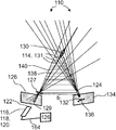
적어도 하나의 대상체(112)의 위치를 결정하는 검출기(110)가 제안된다. 검출기(110)는, 광학 센서(120)의 매트릭스(118)를 구비하는 적어도 하나의 센서 소자(116) - 광학 센서(120)의 각각에는 감광 영역(122)이 포함되고, 센서 소자(116)는, 대상체(112)의 적어도 하나의 반사 이미지(126)를 결정하도록 구성됨 - 와, 적어도 하나의 평가 장치(128)를 포함하고, 여기서, 평가 장치(128)는, 반사 이미지(126)의 적어도 하나의 반사 특징을 선택하도록 구성되고, 적어도 하나의 블러링 함수 fa를 최적화함으로써, 반사 이미지(126)의 선택된 반사 특징 중 적어도 하나의 거리 추정치(distance estimate)(130)를 결정하도록 구성 - 거리 추정치(130)는, 종 방향 좌표 z 및 오차 간격 ±ε에 의해 제공됨 - 되고, 거리 추정치(130)에 대응하는 적어도 하나의 기준 이미지(134)에서 적어도 하나의 변위 영역(132)을 결정하도록 구성되며, 변위 영역(132) 내의 적어도 하나의 기준 특징과 선택된 반사 특징을 매칭하도록 구성된다.A detector 110 for determining a position of at least one object 112 is proposed. The detector 110 comprises at least one sensor element 116 comprising a matrix 118 of optical sensors 120 , each of which includes a photosensitive region 122 , the sensor element 116 . is configured to determine at least one reflected image 126 of the object 112 , comprising: and at least one evaluation device 128 , wherein the evaluation device 128 comprises: configured to select one reflective feature, and to determine a distance estimate 130 of at least one selected reflective feature of the reflective image 126 by optimizing the at least one blurring function f a - distance The estimate 130 is - given by the longitudinal coordinate z and the error interval ±ε, and is configured to determine at least one displacement region 132 in the at least one reference image 134 corresponding to the distance estimate 130 . and is configured to match the selected reflective characteristic with at least one reference characteristic within the displacement region 132 .
Description
본 발명은 적어도 하나의 대상체의 위치를 결정하기 위한 검출기 및 방법에 관한 것이다. 본 발명은 또한 사용자와 기계 사이에서 적어도 하나의 정보 항목을 교환하기 위한 인간-기계 인터페이스, 엔터테인먼트 장치, 추적 시스템, 카메라, 스캐닝 시스템 및 검출기 장치의 다양한 용도에 관한 것이다. 본 발명에 따른 장치, 방법 및 용도는, 예를 들면, 일상생활, 게임, 교통 기술, 생산 기술, 보안 기술, 예술, 문서 또는 기술 목적을 위한 디지털 포토그래피 또는 비디오 포토그래피와 같은 포토그래피, 의료 기술 또는 과학 분야에, 특히, 사용될 수 있다. 또한, 본 발명은, 예컨대, 건축학, 측량학, 고고학, 예술, 의학, 공학 또는 제조업 분야에서, 대상체나 풍경의 깊이 프로파일(depth profile)을 생성하는 것과 같이, 하나 이상의 대상체 및/또는 풍경을 스캐닝하는 데 사용될 수 있다. 그러나, 다른 적용이 가능할 수도 있다.The present invention relates to a detector and method for determining the position of at least one object. The invention also relates to various uses of human-machine interfaces, entertainment devices, tracking systems, cameras, scanning systems and detector devices for exchanging at least one item of information between a user and a machine. The devices, methods and uses according to the invention may be used in photography, medical, such as digital photography or video photography for, for example, everyday life, gaming, transportation technology, production technology, security technology, artistic, documentary or technical purposes. It may be used, in particular, in technical or scientific fields. The present invention also provides a method for scanning one or more objects and/or landscapes, such as generating a depth profile of an object or landscape, for example in the fields of architecture, surveying, archaeology, art, medicine, engineering or manufacturing. can be used to However, other applications may be possible.
광학적 3D 감지 방법은 일반적으로 바이어싱 광원이나 반사 측정 대상체를 사용하여 다중 반사를 일으키는 환경의 경우에 신뢰할 수 없는 결과가 도출될 수 있다. 더욱이, 촬상 기능이 있는 3D 감지 방법은 종종 대응 문제(correspondence problem)를 해결하기 위해 높은 계산 능력이 요구된다. 필요한 계산 능력은, 특히, 모바일 장치에서, 프로세서나 FPGA(Field Programmable Gate Array), 환기 요건이나 하우징 방수 처리의 난이도를 고려한 열 제거, 전력 소비로 인한 높은 비용, 및 추가의 측정 불확실성을 초래할 수 있다.In general, the optical 3D sensing method may produce unreliable results in the case of multiple reflections using a biasing light source or a reflection measurement target. Moreover, a 3D sensing method with an imaging function often requires high computational power to solve a correspondence problem. The required computational power can lead to heat dissipation, high cost due to power consumption, and additional measurement uncertainty taking into account the difficulty of the processor or Field Programmable Gate Array (FPGA), ventilation requirements or housing waterproofing, especially in mobile devices. .
다수의 광학 장치는 삼각 측량 촬상 방법을 사용하는 종래 기술에 개시되어 있다. 예를 들어, 구조광 방법(structured light method) 또는 스테레오 방법(stereo method)이 개시되어 있다. 예를 들어, 고정된 상대적 방위에서 두 대의 카메라를 사용하는 수동 스테레오 방법(passive stereo method) 또는 추가의 광 프로젝터가 사용되는 능동 스테레오 기술(active stereo method)이 있다. 또 다른 예로는 고정된 상대적 방위에서 하나의 광 프로젝터와 하나의 카메라가 사용되는 구조광 접근 방식이 있다. 삼각 측량을 통해 깊이 이미지를 결정하기 위해서는 소위 대응 문제(correspondence problem)를 먼저 해결해야 한다. 따라서, 수동 스테레오 카메라 기술에서는 양 카메라의 시야에서 대응하는 특징점이 충분히 식별되어야 한다. 구조광 접근 방식에서는, 사전 저장된 의사 랜덤 광 패턴과 투영된 의사 랜덤 광 패턴 간의 대응(correspondence)이 결정되어야 한다. 이들 대응 문제의 확실한 해결을 위해, 투영된 포인트 패턴에서의 포인트 수에 따라 대략 2차식으로(quadratically) 스케일링하는 알고리즘과 같은 계산 촬상 알고리즘(computational imaging algorithm)이 사용되어야 한다. 예를 들어, 상대 거리가 고정된 2개의 검출기를 포함하는 스테레오 시스템을 사용하는 구조광 방법에서, 광원은 포인트, 의사 랜덤, 랜덤, 비주기적 또는 불규칙적인 포인트 패턴 등과 같은 패턴을 투영한다. 각각의 검출기는 반사 패턴의 이미지를 생성하고, 이미지 분석 작업은 두 이미지에서 대응하는 특징을 식별하는 것이다. 고정된 상대 위치로 인해, 두 이미지 중 하나에서 선택된 대응하는 특징점은 다른 이미지에서 공액선(epipolar line)을 따라 위치되어 있다. 그러나 이른바 대응 문제의 해결은 어려울 수 있다. 스테레오 및 삼각 측량 시스템에서, 공액선을 따르는 모든 특징점의 거리는 서로 합리적으로 대응해야 한다. 대응 결정(correspondence decision)은 연이어 이루어질 수 없다. 하나의 대응이 잘못되면, 이것은 다른 특징점에 불가시성(invisibility)과 같은 영향을 미친다. 이것은 일반적으로 2차 스케일링 평가 알고리즘을 산출한다.A number of optical devices are disclosed in the prior art using triangulation imaging methods. For example, a structured light method or a stereo method is disclosed. For example, there is the passive stereo method, which uses two cameras in a fixed relative orientation, or the active stereo method, in which an additional light projector is used. Another example is a structured light approach in which one light projector and one camera are used in a fixed relative orientation. In order to determine the depth image through triangulation, the so-called correspondence problem must first be solved. Therefore, in the passive stereo camera technology, the corresponding feature points in the field of view of both cameras must be sufficiently identified. In the structured light approach, the correspondence between the pre-stored pseudo-random light pattern and the projected pseudo-random light pattern must be determined. For a reliable solution of these corresponding problems, a computational imaging algorithm, such as an algorithm that scales approximately quadratically according to the number of points in the projected point pattern, must be used. For example, in a structured light method using a stereo system comprising two detectors with fixed relative distances, the light source projects a pattern such as points, pseudo-random, random, aperiodic or irregular point patterns, and the like. Each detector creates an image of the reflection pattern, and the task of image analysis is to identify corresponding features in the two images. Due to the fixed relative position, the corresponding feature point selected in one of the two images is located along an epipolar line in the other image. However, solving the so-called response problem can be difficult. In stereo and triangulation systems, the distances of all feature points along the conjugate line must correspond reasonably to each other. Correspondence decisions cannot be made sequentially. If one correspondence goes wrong, it has the same effect as invisibility on other feature points. This usually yields a quadratic scaling evaluation algorithm.
예를 들어, US 2008/0240502 A1 및 US 2010/0118123 A1은 조명 어셈블리를 포함하는 대상체를 매핑하는 장치를 기술하고, 여기서, 조명 어셈블리는 고정된 스폿 패턴으로 이루어진 단일 투명도(single transparency)를 포함한다. 광원은 패턴을 대상체에 투영하기 위해 단일 투명도의 광 방사선을 투과시킨다. 이미지 캡처 어셈블리는 단일 투명도를 사용하여 대상체 상에 투영된 패턴의 이미지를 캡처한다. 프로세서는 대상체의 3차원 맵을 재구성하기 위해 이미지 캡처 어셈블리에 의해 캡처된 이미지를 처리한다.For example, US 2008/0240502 A1 and US 2010/0118123 A1 describe a device for mapping an object comprising a lighting assembly, wherein the lighting assembly comprises a single transparency consisting of a fixed spot pattern. . The light source transmits light radiation of a single transparency to project the pattern onto the object. The image capture assembly captures an image of the pattern projected onto the object using a single transparency. The processor processes the image captured by the image capture assembly to reconstruct a three-dimensional map of the object.
US 2008/118143 A1은 복수의 구별되는 식별 가능한 특징 유형이 포함된 2차원 코딩된 광 패턴을 사용하여 정지하거나 이동하는 대상체의 3차원 형상을 결정하기 위한 이미지를 획득하는 방법 및 장치를 기술한다. 코딩된 광 패턴은 식별 가능한 공액선의 사전 정의된 섹션에 각각의 식별 가능한 특징 유형이 최대 한번 나타나도록 대상체 상에 투영된다. 대상체의 이미지가 캡처되고, 캡처된 이미지에서 알려진 공액선 상의 위치와 함께 반사된 특징 유형이 추출된다. 기준 좌표로부터 그들의 공액선을 따라 반사된 특징 유형의 변위는 공간에서의 대응하는 3차원 좌표를 결정하고, 그에 따라 임의의 시점에서 대상체 형상의 3D 맵핑 또는 모델을 결정한다.US 2008/118143 A1 describes a method and apparatus for acquiring an image for determining the three-dimensional shape of a stationary or moving object using a two-dimensional coded light pattern comprising a plurality of distinct and identifiable feature types. The coded light pattern is projected onto the object such that each identifiable feature type appears at most once in a predefined section of the identifiable conjugate line. An image of the object is captured, and the reflected feature type is extracted from the captured image along with the location on the known conjugate line. The displacements of the reflected feature types along their conjugate lines from the reference coordinates determine the corresponding three-dimensional coordinates in space and thus the 3D mapping or model of the object shape at any point in time.
US 2009/066929 A1은 스테레오 카메라로 영역 이미지를 생성하기 위한 포인트의 대응을 확립하는 것을 기술하고 있다. 장면은 두 번 조명되는 데, 그 중 적어도 한 번은 랜덤 또는 의사 랜덤 패턴으로 조명된다. 두 대의 카메라인 경우, 각각의 조명에 대해 이미지가 찍히고, 밝기의 몫은 픽셀 단위로 계산된다. 대응은 서로 다른 카메라의 공액선 상의 픽셀의 몫의 비교에 기초하여 수립된다. 조명 패턴은 공액선을 따라 고도로 변조되는 것이 바람직하고, 즉, 이것은 공액선에 대해 횡 방향 또는 대각선 방향으로 변조되지 않거나 약간만 변조된다. 조명을 위해, 바람직한 배열에서, 의사 랜덤 방식으로 변화하는 적어도 하나의 광원과, 격자를 통해 비추고 그에 따라 다른 의사 랜덤 패턴, 특히 모아레 패턴을 생성하는 2개의 가까이 인접하는 광원을 구비하는, 서로 거리를 두고 배치된 2개의 중첩된 격자 패턴을 포함하는 투영 유닛이 사용된다.US 2009/066929 A1 describes establishing a correspondence of points for generating an area image with a stereo camera. The scene is illuminated twice, at least once in a random or pseudo-random pattern. In the case of two cameras, an image is taken for each light, and the brightness quotient is calculated in pixels. A correspondence is established based on the comparison of the quotients of pixels on the conjugate lines of different cameras. The illumination pattern is preferably highly modulated along the conjugate line, ie it is not modulated or only slightly modulated transversely or diagonally to the conjugate line. For illumination, in a preferred arrangement, at least one light source that varies in a pseudo-random manner and two closely adjacent light sources that shine through a grating and thus produce a different pseudo-random pattern, in particular a moiré pattern, are distanced from each other. A projection unit comprising two superimposed grid patterns arranged in a spaced manner is used.
2016년 6월 1일자, IEEE, 2016년 13차 컴퓨터 및 로봇 비전(CRV) 컨퍼런스의 281-288 페이지의 Mannhan Fahim 등에 의한 "디포커스에서의 깊이에 대한 블러 보정(Blur Calibration for Depth from Defocus)"(XP033033015, DOI:10:1109/CRV.2016.62)에는 디포커스 기반 방법에서의 깊이에 대한 블러 커널의 모델링이 설명되어 있다. 디포커스에서의 깊이에 대한 블러 커널 보정을 수행하는 방법이 설명되어 있다."Blur Calibration for Depth from Defocus," by Mannhan Fahim et al., June 1, 2016, IEEE, pages 281-288 of the 13th Computer and Robot Vision (CRV) Conference 2016. (XP033033015, DOI:10:1109/CRV.2016.62) describes the modeling of blur kernels for depth in a defocus-based method. A method for performing blur kernel correction for depth at defocus is described.
전술한 장치 및 검출기에서 설명된 이점에도 불구하고, 몇몇 기술적 과제가 남아 있다. 따라서, 사용된 평가 알고리즘은 높은 계산 능력을 요구하는 데, 이는 막대한 비용 요인이 된다. 또한, 요구되는 계산 자원의 에너지 소비 및 열 생성으로 인해, 계산 수요는 실외 및 모바일 애플리케이션에서 이러한 3D 감지 방법의 사용을 제한한다.Despite the advantages described in the devices and detectors described above, several technical challenges remain. Therefore, the evaluation algorithm used requires high computational power, which becomes a huge cost factor. Additionally, due to the energy consumption and heat generation of the required computational resources, computational demands limit the use of these 3D sensing methods in outdoor and mobile applications.
따라서, 본 발명의 목적은 공지된 장치 및 방법의 전술한 기술적 과제에 대응하는 장치 및 방법을 제공하는 것이다. 구체적으로, 본 발명의 목적은, 특히, 기술적인 노력이 적고 기술 자원과 비용 관점에서 낮은 기술 노력으로, 공간에서 대상체의 위치를 신뢰성 있게 결정할 수 있는 장치 및 방법을 제공하는 것이다.Accordingly, it is an object of the present invention to provide an apparatus and method corresponding to the above-mentioned technical problems of the known apparatus and method. Specifically, it is an object of the present invention to provide an apparatus and method capable of reliably determining the position of an object in space, particularly with low technical effort and low technical effort in terms of technical resources and cost.
이 문제는 특허 청구 범위의 독립항의 특징을 포함하는 본 발명에 의해 해결된다. 개별적으로 또는 조합하여 실현될 수 있는 본 발명의 바람직한 전개는 종속항 및/또는 하기의 명세서 및 상세한 실시예에서 제시된다.This problem is solved by the invention comprising the features of the independent claims of the claims. Preferred developments of the invention, which can be realized individually or in combination, are set forth in the dependent claims and/or in the following specification and detailed examples.
이하에 사용되는 용어 "구비한다", "구성한다" 또는 "포함한다"나 그들의 임의의 문법적 변형어는 비배타적인 방식으로 사용된다. 따라서, 이들 용어는 이들 용어에 의해 도입된 특징 외에, 본 명세서에 설명된 개체에 더 이상의 추가 특징이 존재하지 않는 상황 및 적어도 하나의 추가 특징이 존재하는 상황 양쪽 모두를 의미할 수 있다. 예를 들어, "A는 B를 구비한다", "A는 B를 구성한다" 및 "A는 B를 포함한다"라는 표현은, B 이외에 다른 요소가 A에 존재하지 않는 상황(즉, A가 오로지 배타적으로 B로 구성되는 상황) 및 B 이외에, 요소 C, 요소 C 및 D 또는 심지어 다른 요소와 같은 하나 이상의 추가 요소가 대상체 A에 존재하는 모든 상황을 의미할 수 있다.As used hereinafter, the terms "comprises", "comprises" or "comprises" or any grammatical variations thereof are used in a non-exclusive manner. Accordingly, these terms may refer to both situations in which, in addition to the characteristics introduced by these terms, no further additional characteristics are present and at least one additional characteristic is present in the subject described herein. For example, the expressions "A includes B", "A constitutes B", and "A includes B" are used in situations where no other element is present in A other than B (i.e., A is Situations consisting exclusively of B) and B, may refer to any situation in which one or more additional elements such as elements C, elements C and D or even other elements are present in subject A.
또한, 특징 또는 요소가 전형적으로 하나 또는 하나보다 많이 존재할 수 있음을 나타내는 용어 "적어도 하나", "하나 이상" 또는 그 유사 표현은, 각각의 특징 또는 요소를 도입할 때, 한 번만 사용될 것이라는 점을 유의해야 한다. 이하에서, 대부분의 경우, 각각의 특징 또는 요소를 언급할 때, 각각의 특징 또는 요소가 하나 이상 존재할 수 있다는 사실에도 불구하고, "적어도 하나" 또는 "하나 이상"이라는 표현은 반복되지 않을 것이다.It is also noted that the terms "at least one", "one or more" or similar expressions indicating that there may typically be one or more than one feature or element will be used only once, when introducing each feature or element. Be careful. In the following, in most cases, when referring to each feature or element, the expression "at least one" or "one or more" will not be repeated, notwithstanding the fact that one or more of each feature or element may be present.
또한, 이하에서 사용되는 용어 "바람직하게", "더 바람직하게", "특히", "더욱 특히", "구체적으로", "더욱 구체적으로" 또는 유사한 용어는 대안적인 가능성을 제한하지 않으면서 선택적인 특징과 함께 사용된다. 따라서, 이러한 용어들에 의해 도입된 특징들은 선택적인 특징이며, 어떠한 방식으로도 청구 범위의 범주를 제한하려고 의도하는 것은 아니다. 당업자가 인식할 수 있는 바와 같이, 본 발명은 대안적인 특징들을 사용함으로써 수행될 수 있다. 마찬가지로, "본 발명의 일 실시예에서" 또는 유사 표현에 의해 도입된 특징은, 본 발명의 대안적인 실시예에 관한 임의의 제한 없이, 본 발명의 범주에 관한 임의의 제한 없이, 및 이러한 방식으로 도입된 특징들을 본 발명의 다른 선택적 또는 비선택적 특징과 조합할 가능성에 관한 임의의 제한 없이, 선택적 특징인 것으로 의도된다.Also, the terms “preferably,” “more preferably,” “particularly,” “more particularly,” “specifically,” “more specifically,” or similar terms used hereinafter are chosen without limiting the alternative possibilities. used with characteristic features. Accordingly, the features introduced by these terms are optional features and are not intended to limit the scope of the claims in any way. As one of ordinary skill in the art will recognize, the present invention may be practiced by using alternative features. Likewise, features introduced by “in one embodiment of the invention” or similar expressions are intended to be in this way without any limitation as to the scope of the invention, without any limitation as to alternative embodiments of the invention, and without any limitation as to the scope of the invention. Without any limitation as to the possibility of combining the introduced features with other optional or non-selective features of the invention, they are intended to be optional features.
본 발명의 제 1 양태에서, 적어도 하나의 대상체의 위치를 결정하는 검출기가 개시된다. 본 명세서에 사용되는 용어 "대상체(object)"는 적어도 하나의 광빔을 방출하는 포인트 또는 영역을 지칭한다. 광빔은 대상체 및/또는 광빔을 방출하는 대상체에 통합되거나 장착된 적어도 하나의 조명원과 같은 대상체로부터 비롯될 수 있거나, 또는 대상체를 직접 또는 간접적으로 비추는 조명원과 같이 다른 조명원으로부터 비롯될 수 있으며, 여기서, 광빔은 대상체에 의해 반사되거나 산란된다. 본 명세서에 사용되는 용어 "위치"는 대상체의 위치 및/또는 방위, 및/또는 공간에서 대상체의 적어도 한 부분에 관한 적어도 하나의 정보 항목을 지칭한다. 따라서, 적어도 하나의 정보 항목은 대상체의 적어도 하나의 포인트와 적어도 하나의 검출기 사이에서 적어도 하나의 거리를 의미할 수 있다. 이하에서 보다 상세하게 설명되는 바와 같이, 거리는 종 방향 좌표일 수 있거나 대상체의 포인트의 종 방향 좌표를 결정하는 데 기여할 수 있다. 부가적으로 또는 대안적으로, 대상체 및/또는 대상체의 적어도 한 부분의 위치 및/또는 방위에 관한 하나 이상의 다른 정보 항목이 결정될 수 있다. 일 예로서, 부가적으로, 대상체 및/또는 대상체의 적어도 한 부분의 적어도 하나의 횡 방향 좌표가 결정될 수 있다. 따라서, 대상체의 위치는 대상체 및/또는 대상체의 적어도 한 부분의 적어도 하나의 종 방향 좌표를 의미할 수 있다. 부가적으로 또는 대안적으로, 대상체의 위치는 대상체 및/또는 대상체의 적어도 한 부분의 적어도 하나의 횡 방향 좌표를 의미할 수 있다. 부가적으로 또는 대안적으로, 대상체의 위치는 대상체의 적어도 하나의 방위 정보를 의미할 수 있으며, 이는 공간에서의 대상체의 방위를 나타낸다.In a first aspect of the present invention, a detector for determining the position of at least one object is disclosed. As used herein, the term “object” refers to a point or area emitting at least one light beam. The light beam may originate from an object, such as at least one illumination source integrated or mounted to the object and/or the object emitting the light beam, or may originate from another illumination source, such as an illumination source directly or indirectly illuminating the object; , where the light beam is reflected or scattered by the object. As used herein, the term “location” refers to at least one item of information relating to the position and/or orientation of an object, and/or at least a portion of the object in space. Accordingly, the at least one information item may mean at least one distance between at least one point of the object and at least one detector. As described in more detail below, the distance may be a longitudinal coordinate or may contribute to determining the longitudinal coordinate of a point of an object. Additionally or alternatively, one or more other items of information regarding the position and/or orientation of the subject and/or at least a portion of the subject may be determined. As an example, additionally, at least one lateral coordinate of the object and/or at least a portion of the object may be determined. Accordingly, the position of the object may refer to at least one longitudinal coordinate of the object and/or at least one portion of the object. Additionally or alternatively, the position of the object may refer to at least one lateral coordinate of the object and/or at least a portion of the object. Additionally or alternatively, the position of the object may refer to at least one orientation information of the object, which indicates the orientation of the object in space.
검출기는,The detector is
· 광학 센서의 매트릭스를 포함하는 적어도 하나의 센서 소자 - 광학 센서의 각각에는 감광 영역이 포함되고, 센서 소자는 대상체의 적어도 하나의 반사 이미지를 결정하도록 구성됨 - 와,at least one sensor element comprising a matrix of optical sensors, each of the optical sensors comprising a photosensitive area, the sensor element configured to determine at least one reflected image of the object;
· 적어도 하나의 평가 장치를 포함하고, 여기서, 평가 장치는 반사 이미지의 적어도 하나의 반사 특징을 선택하도록 구성되고, 평가 장치는 적어도 하나의 블러링 함수 fa를 최적화함으로써 반사 이미지의 선택된 반사 특징 중 적어도 하나의 거리 추정치(distance estimate)를 결정하도록 구성되고, 여기서, 거리 추정치는 종 방향 좌표 z 및 오차 간격 ±ε에 의해 제공되며,at least one evaluation device, wherein the evaluation device is configured to select at least one reflective feature of the reflective image, the evaluation device among the selected reflective features of the reflective image by optimizing the at least one blurring function f a determine at least one distance estimate, wherein the distance estimate is provided by a longitudinal coordinate z and an error interval ±ε,
· 평가 장치는 거리 추정치에 대응하는 적어도 하나의 기준 이미지에서 적어도 하나의 변위 영역(displacement region)을 결정하도록 구성되며, 평가 장치는 변위 영역 내의 적어도 하나의 기준 특징과 선택된 반사 특징을 매칭하도록 구성된다.the evaluation device is configured to determine at least one displacement region in the at least one reference image corresponding to the distance estimate, the evaluation device is configured to match the selected reflective feature with the at least one reference feature in the displacement region .
본 명세서에 사용되는 "센서 소자"라는 용어는 일반적으로 적어도 하나의 파라미터를 감지하도록 구성된 장치나 복수의 장치의 조합을 의미한다. 이러한 경우, 파라미터는, 특히, 광학 파라미터일 수 있고, 센서 소자는, 특히, 광학 센서 소자일 수 있다. 센서 소자는 단일 장치로 일원화되거나 여러 장치의 조합으로 형성될 수 있다. 본 명세서에 사용되는 "매트릭스"라는 용어는 일반적으로 사전 결정된 기하학적 순서로 복수의 소자를 배열하는 것을 의미한다. 매트릭스는 하나 이상의 행과 하나 이상의 열로 이루어진 장방형 매트릭스일 수 있거나 이를 포함할 수 있다. 행 및 열은, 특히, 장방형 형태로 배열될 수 있다. 그러나, 장방형 배열이 아닌 배열과 같은 다른 배열도 가능하다는 것이 개략적으로 설명되어야 한다. 일 예로서, 소자가 중심 위치를 중심으로 동심원 또는 타원으로 배열되는 원형 배열도 가능할 수 있다. 예를 들어, 매트릭스는 단일 행의 픽셀일 수 있다. 다른 배열도 가능하다.As used herein, the term "sensor element" generally refers to a device or combination of a plurality of devices configured to sense at least one parameter. In this case, the parameter may in particular be an optical parameter and the sensor element may in particular be an optical sensor element. The sensor element may be integrated into a single device or may be formed as a combination of several devices. As used herein, the term “matrix” generally refers to an arrangement of a plurality of elements in a predetermined geometric order. The matrix may be or may include a rectangular matrix of one or more rows and one or more columns. Rows and columns can be arranged, in particular, in a rectangular form. However, it should be outlined that other arrangements are possible, such as arrangements other than a rectangular arrangement. As an example, a circular arrangement in which the elements are arranged in concentric circles or ellipses around a central position may also be possible. For example, the matrix may be a single row of pixels. Other arrangements are possible.
매트릭스의 광학 센서는, 특히, 크기, 감도 및 기타 광학적, 전기적 및 기계적 특성 중 하나 이상에서 동일할 수 있다. 매트릭스의 모든 광학 센서의 감광 영역은, 특히, 공통 평면에 위치될 수 있고, 공통 평면은 대상체로부터 검출기로 전파되는 광빔이 공통 평면상에 광 스폿을 생성할 수 있도록 대상체와 대향하는 것이 바람직하다.The optical sensors of the matrix may be identical, inter alia, in one or more of size, sensitivity and other optical, electrical and mechanical properties. The photosensitive areas of all optical sensors of the matrix may, inter alia, be located in a common plane, which preferably faces the object so that a light beam propagating from the object to the detector can create a light spot on the common plane.
본 명세서에 사용되는 "광학 센서"는 일반적으로 광빔을 검출하기 위한 감광 장치, 예컨대, 적어도 하나의 광빔에 의해 생성된 조명 및/또는 광 스팟을 검출하기 위한 감광 장치를 지칭한다. 본 명세서에서 또한 사용되는 "감광 영역"은 일반적으로 적어도 하나의 센서 신호가 생성되는 조명에 응답하여, 적어도 하나의 광빔에 의해 외부로 비춰질 수 있는 광학 센서의 영역을 지칭한다. 각각의 광학 센서는, 대상체로부터 검출기로 전파되는 광빔, 특히, 반사광빔에 의해, 각각의 감광 영역의 조명에 응답하여 적어도 하나의 센서 신호를 생성하도록 설계될 수 있다. 감광 영역은 구체적으로 각각의 광학 센서의 표면상에 위치될 수 있다. 그러나, 다른 실시예도 가능하다. 본 명세서에 사용되는 "적어도 하나의 감광 영역을 각각 구비하는 광학 센서"라는 용어는 하나의 감광 영역을 각각 구비하는 복수의 단일 광학 센서의 구성과, 복수의 감광 영역을 구비하는 하나의 결합된 광학 센서의 구성을 지칭한다. 따라서, "광학 센서"라는 용어는 또한 하나의 출력 신호를 생성하도록 구성된 감광 장치를 지칭하는 한편, 여기서는 2개 이상의 출력 신호를 생성하도록 구성된 감광 장치, 예를 들어, 적어도 하나의 CCD 및/또는 CMOS 장치가 2개 이상의 광학 센서로서 지칭된다. 이하에 더 상세히 설명되는 바와 같이, 각각의 광학 센서는, 하나의 감광 영역이 전체 광학 센서에 대해 정확하게 하나의 균일한 센서 신호가 생성되는 조명에 응답하여, 조명될 수 있는 하나의 감광 영역을 정확하게 제공하는 것과 같이, 각각의 광학 센서 내에 정확하게 존재하도록 구현될 수 있다. 따라서, 각각의 광학 센서는 단일 영역 광학 센서일 수 있다. 그러나 단일 영역 광학 센서의 사용은, 특히, 간단하고 효율적인 검출기의 셋업을 가능하게 한다. 따라서, 일 예로서, 상업적으로 이용 가능한 실리콘 광다이오드와 같이, 정확하게 하나의 감지 영역을 각각 구비하는 상업적으로 이용 가능한 광센서(photo-sensor)가 셋업에 사용될 수 있다. 그러나, 다른 실시예도 가능하다. 따라서, 일 예로서, 본 발명의 맥락에서 2개, 3개, 4개 또는 4개 초과의 광학 센서로 간주되는 2개, 3개, 4개 또는 4개 초과의 감광 영역을 포함하는 광학 장치가 사용될 수 있다. 전술한 바와 같이, 센서 소자는 광학 센서의 매트릭스를 포함한다. 따라서, 일 예로서, 광학 센서는 픽셀화된 광학 장치의 일부이거나 이를 구성할 수 있다. 일 예로서, 광학 센서는 픽셀 매트릭스를 구비하는 적어도 하나의 CCD 및/또는 CMOS 장치의 일부이거나 이를 구성할 수 있으며, 각 픽셀은 감광 영역을 형성한다.As used herein, "optical sensor" generally refers to a photosensitive device for detecting a light beam, such as a photosensitive device for detecting illumination and/or light spots generated by at least one light beam. As also used herein, “photosensitive area” generally refers to an area of an optical sensor that can be illuminated outwardly by at least one light beam in response to illumination from which at least one sensor signal is generated. Each optical sensor may be designed to generate at least one sensor signal in response to illumination of a respective photosensitive area by a light beam propagating from the object to the detector, in particular a reflected light beam. The photosensitive area may specifically be located on the surface of each optical sensor. However, other embodiments are possible. As used herein, the term "optical sensor each having at least one photosensitive area" refers to a configuration of a plurality of single optical sensors each having one photosensitive area, and a single combined optical sensor having a plurality of photosensitive areas. Refers to the configuration of the sensor. Accordingly, the term “optical sensor” also refers to a photosensitive device configured to generate one output signal, while here a photosensitive device configured to generate two or more output signals, eg, at least one CCD and/or CMOS. A device is referred to as two or more optical sensors. As will be described in greater detail below, each optical sensor accurately identifies one light-sensitive area that can be illuminated in response to illumination, resulting in exactly one uniform sensor signal for the entire optical sensor. As provided, it can be implemented to reside precisely within each optical sensor. Thus, each optical sensor may be a single area optical sensor. However, the use of a single-area optical sensor enables, in particular, a simple and efficient setup of the detector. Thus, as an example, commercially available photo-sensors each having exactly one sensing region, such as commercially available silicon photodiodes, may be used in the setup. However, other embodiments are possible. Thus, as an example, an optical device comprising two, three, four or more than four photosensitive regions, which is considered to be two, three, four or more than four optical sensors in the context of the present invention, is can be used As mentioned above, the sensor element comprises a matrix of optical sensors. Thus, as an example, the optical sensor may be part of or constitute a pixelated optical device. As an example, the optical sensor may be part of or constitute at least one CCD and/or CMOS device comprising a matrix of pixels, each pixel defining a photosensitive area.
광학 센서는, 특히, 광검출기(photodetectors), 바람직하게는 무기(inorganic) 광검출기, 더 바람직하게는 무기 반도체 광검출기, 가장 바람직하게는 실리콘 광검출기일 수 있거나 이를 포함할 수 있다. 구체적으로, 광학 센서는 적외선 스펙트럼 범위에서 감지할 수 있다. 매트릭스의 모든 광학 센서 또는 적어도 한 그룹의 매트릭스의 광학 센서는 구체적으로 동일할 수 있다. 매트릭스의 동일한 광학 센서의 그룹은, 특히, 상이한 스펙트럼 범위에 대하여 제공될 수 있거나, 모든 광학 센서가 스펙트럼 감도와 관련하여 동일할 수 있다. 또한, 광학 센서는 그 크기 및/또는 그들의 전자적 또는 광전자적 특성과 관련하여 동일할 수 있다.The optical sensor may in particular be or comprise photodetectors, preferably inorganic photodetectors, more preferably inorganic semiconductor photodetectors, most preferably silicon photodetectors. Specifically, the optical sensor can sense in the infrared spectral range. All optical sensors of the matrix or at least one group of optical sensors of the matrix may specifically be identical. Groups of identical optical sensors in the matrix may be provided, in particular for different spectral ranges, or all optical sensors may be identical with respect to spectral sensitivity. Further, the optical sensors may be identical with respect to their size and/or their electronic or optoelectronic properties.
구체적으로, 광학 센서는 적외선 스펙트럼 범위, 바람직하게는 780nm 내지 3.0㎛ 범위에서 감지되는 무기 광다이오드일 수 있거나 이를 포함할 수 있다. 구체적으로, 광학 센서는 실리콘 광다이오드가, 특히, 700nm 내지 1,000nm의 범위에서 적용 가능한 근적외선 영역의 부분에서 감지할 수 있다. 광학 센서용으로 사용될 수 있는 적외선 광학 센서는 D-67056 Ludwigshafen am Rhein, Germany 소재의 trinamiX GmbH사의 HertzstueckTM라는 상표명으로 시판되고 있는 적외선 광학 센서와 같은 상업적으로 이용 가능한 적외선 광학 센서일 수 있다. 따라서, 일 예로서, 광학 센서는 진성 광전형(intrinsic photovoltaic type)의 적어도 하나의 광학 센서, 더욱 바람직하게는 Ge 광다이오드, InGaAs 광다이오드, 확장된 InGaAs 광다이오드, InAs 광다이오드, InSb 광다이오드, HgCdTe 광다이오드로 이루어진 그룹 중에서 선택되는 적어도 하나의 반도체 광다이오드를 포함할 수 있다. 부가적으로 또는 대안적으로, 광학 센서는 적어도 하나의 외적 광전형(extrinsic photovoltaic type) 광학 센서, 더욱 바람직하게는 Ge:Au 광다이오드, Ge:Hg 광다이오드, Ge:Cu 광다이오드, Ge:Zn 광다이오드, Si:Ga 광다이오드, Si:As 광다이오드로 이루어진 그룹 중에서 선택되는 적어도 하나의 반도체 광다이오드를 포함할 수 있다. 부가적으로 또는 대안적으로, 광학 센서는 적어도 하나의 볼로미터(bolometer), 바람직하게는 VO 볼로미터 및 비정질 Si 볼로미터로 이루어진 그룹으로부터 선택되는 볼로미터를 포함할 수 있다.Specifically, the optical sensor may be or may include an inorganic photodiode sensing in the infrared spectral range, preferably in the range of 780 nm to 3.0 μm. Specifically, the optical sensor is capable of sensing in a portion of the near-infrared region where a silicon photodiode is applicable, particularly in the range of 700 nm to 1,000 nm. An infrared optical sensor that may be used for the optical sensor may be a commercially available infrared optical sensor, such as the infrared optical sensor sold under the trade name Hertzstueck TM from trinamiX GmbH, Ludwigshafen am Rhein, Germany, D-67056. Thus, as an example, the optical sensor comprises at least one optical sensor of the intrinsic photovoltaic type, more preferably a Ge photodiode, an InGaAs photodiode, an extended InGaAs photodiode, an InAs photodiode, an InSb photodiode, and at least one semiconductor photodiode selected from the group consisting of HgCdTe photodiodes. Additionally or alternatively, the optical sensor comprises at least one extrinsic photovoltaic type optical sensor, more preferably a Ge:Au photodiode, a Ge:Hg photodiode, a Ge:Cu photodiode, a Ge:Zn The photodiode may include at least one semiconductor photodiode selected from the group consisting of a photodiode, a Si:Ga photodiode, and a Si:As photodiode. Additionally or alternatively, the optical sensor may comprise at least one bolometer, preferably a bolometer selected from the group consisting of VO bolometers and amorphous Si bolometers.
매트릭스는 독립적인 광학 센서로 구성될 수 있다. 따라서, 무기 광다이오드의 매트릭스가 구성될 수 있다. 그러나, 대안적으로 CCD 검출기 칩과 같은 하나 이상의 CCD 검출기 및/또는 CMOS 검출기 칩과 같은 CMOS 검출기와 같이, 상업적으로 이용 가능한 매트릭스가 사용될 수도 있다.The matrix may consist of independent optical sensors. Thus, a matrix of inorganic photodiodes can be constructed. However, alternatively, commercially available matrices may be used, such as one or more CCD detectors, such as CCD detector chips, and/or CMOS detectors, such as CMOS detector chips.
따라서, 일반적으로, 검출기의 광학 센서는, 전술한 매트릭스와 같이, 센서 어레이를 형성할 수 있거나 센서 어레이의 일부일 수 있다. 따라서, 일 예로서, 검출기는 m개의 행과 n개의 열로 구성된 장방형 어레이와 같은 광학 센서의 어레이를 포함할 수 있고, 여기서, m, n은 독립적이고, 양의 정수이다. 바람직하게는, 하나 초과의 열 및 하나 초과의 행, 즉, n>1, m>1이 주어진다. 따라서, 일 예로서, n은 2 내지 16 또는 그 이상일 수 있고, m은 2 내지 16 또는 그 이상일 수 있다. 바람직하게는, 행의 개수와 열의 개수의 비율은 1에 가깝다. 일 예로서, m/n = 1:1, 4:3, 16:9 또는 이와 유사한 것을 선택하는 것과 같이, n과 m은 0.3≤m/n≤3인 것으로 선택될 수 있다. 일 예로서, 어레이는 m=2, n=2 또는 m=3, n=3 등을 선택하는 것과 같이, 같은 수의 행과 열로 구성된 정방형 어레이일 수 있다.Thus, in general, the optical sensor of the detector may form or be part of a sensor array, such as the matrix described above. Thus, as an example, the detector may comprise an array of optical sensors, such as a rectangular array of m rows and n columns, where m, n are independent and positive integers. Preferably, more than one column and more than one row are given, ie n>1, m>1. Thus, as an example, n may be 2 to 16 or more, and m may be 2 to 16 or more. Preferably, the ratio of the number of rows to the number of columns is close to one. As an example, n and m may be selected such that 0.3≤m/n≤3, such as selecting m/n = 1:1, 4:3, 16:9 or the like. As an example, the array may be a square array with the same number of rows and columns, such as selecting m=2, n=2 or m=3, n=3, and so on.
매트릭스는 구체적으로 적어도 하나의 행, 바람직하게는 복수의 행 및 복수의 열로 이루어진 장방형 매트릭스일 수 있다. 일 예로서, 행과 열은 실질적으로 수직 방향으로 지향될 수 있다. 본 명세서에 사용되는 "실질적으로 수직(essentially perpendicular)"이라는 용어는, 예를 들어, 허용 오차가 ±20° 이하, 바람직하게는 ±10° 이하, 더욱 바람직하게는 ±5° 이하인 수직 방위의 조건을 의미한다. 따라서, 일 예로서, 20° 미만, 특히 10° 미만 또는 심지어 5° 미만의 허용 오차가 허용될 수 있다. 넓은 범위의 시야를 제공하기 위해, 매트릭스는 구체적으로 적어도 10행, 바람직하게는 적어도 50행, 더 바람직하게는 적어도 100행으로 이루어질 수 있다. 마찬가지로, 매트릭스는 적어도 10열, 바람직하게는 적어도 50열, 더 바람직하게는 적어도 100열로 이루어질 수 있다. 매트릭스는 적어도 50개의 광학 센서, 바람직하게는 적어도 100개의 광학 센서, 더 바람직하게는 적어도 500개의 광학 센서를 포함할 수 있다. 매트릭스는 멀티메가 픽셀 범위의 많은 픽셀을 포함할 수 있다. 그러나, 다른 실시예도 가능하다. 따라서, 축 회전 대칭이 예상되는 셋업에서는, 픽셀이라고도 지칭되는 매트릭스의 광학 센서의 원형 배열 또는 동심원 배열이 바람직할 수 있다.The matrix may specifically be a rectangular matrix consisting of at least one row, preferably a plurality of rows and a plurality of columns. As an example, the rows and columns may be oriented in a substantially vertical direction. As used herein, the term “essentially perpendicular” refers to, for example, the condition of a vertical orientation with a tolerance of ±20° or less, preferably ±10° or less, more preferably ±5° or less. means Thus, as an example, a tolerance of less than 20°, in particular less than 10° or even less than 5°, can be tolerated. In order to provide a wide field of view, the matrix may specifically consist of at least 10 rows, preferably at least 50 rows, more preferably at least 100 rows. Likewise, the matrix may consist of at least 10 rows, preferably at least 50 rows, more preferably at least 100 rows. The matrix may comprise at least 50 optical sensors, preferably at least 100 optical sensors, more preferably at least 500 optical sensors. The matrix may contain many pixels in the range of multi-megapixels. However, other embodiments are possible. Thus, in setups where axial rotational symmetry is expected, a circular or concentric arrangement of optical sensors in a matrix, also referred to as pixels, may be desirable.
센서 소자는 검출기의 광축에 실질적으로 수직으로 지향되는 것이 바람직할 수 있다. 다시, "실질적으로 수직"이라는 용어와 관련하여, 위에 주어진 정의와 허용 오차가 참조될 수 있다. 광축은 직선 광축일 수 있거나 또는 하나 이상의 편향 요소 및/또는 하나 이상의 빔 스플리터를 사용하는 것과 같이, 구부러지거나 심지어 분할될 수 있고, 후자의 경우, 실질적으로 수직 방위는 광학 셋업 각각의 브랜치(branch) 또는 빔 경로 내의 로컬 광축을 지칭할 수 있다.It may be desirable for the sensor element to be oriented substantially perpendicular to the optical axis of the detector. Again, with regard to the term "substantially vertical", reference may be made to the definitions and tolerances given above. The optical axis may be a straight optical axis or it may be bent or even split, such as using one or more deflecting elements and/or one or more beam splitters, in the latter case the substantially vertical orientation is a branch of each of the optical setups. Alternatively, it may refer to a local optical axis in the beam path.
적어도 하나의 광빔은 대상체로부터 검출기를 향해 전파될 수 있다. 광빔은 대상체로부터 비롯될 수 있거나, 또는 대상체에 직접 또는 간접적으로 조명하는 조명원과 같은 조명원으로부터 비롯될 수 있고, 여기서, 광빔은 대상체에 의해 반사되거나 산란되고, 그로 인해 검출기를 향해 적어도 부분적으로 지향된다. 검출기는 능동 및/또는 수동 조명 시나리오에서 사용될 수 있다. 예를 들어, 적어도 하나의 조명원은 광빔을 반사하는 대상체를 향해 광빔을 지향시킴으로써 대상체를 비추도록 구성될 수 있다. 조명원은 적어도 하나의 다중 빔 광원이거나 이를 포함할 수 있다. 예를 들어, 조명원은 하나 이상의 레이저원과 하나 이상의 DOE(Diffractive Optical Element)를 포함할 수 있다. 부가적으로 또는 대안적으로, 검출기는 장면에 이미 존재하는 방사선, 예를 들어, 적어도 하나의 주변 광원으로부터의 방사선을 사용할 수 있다.The at least one light beam may propagate from the object toward the detector. The light beam may originate from an object, or may originate from an illumination source, such as an illumination source that illuminates the object directly or indirectly, wherein the light beam is reflected or scattered by the object, thereby at least partially toward the detector. is oriented The detector may be used in active and/or passive lighting scenarios. For example, the at least one illumination source may be configured to illuminate the object by directing the light beam towards the object that reflects the light beam. The illumination source may be or include at least one multi-beam light source. For example, the illumination source may include one or more laser sources and one or more Diffractive Optical Elements (DOEs). Additionally or alternatively, the detector may use radiation already present in the scene, for example radiation from at least one ambient light source.
광빔은, 구체적으로, 중심 신호가 생성되는 적어도 하나의 광학 센서가 완전히 광빔 내에 위치되고, 광빔의 폭이 센서 신호가 생성되는 적어도 하나의 광학 센서의 감광 영역보다 커지도록, 중심 신호가 생성되는 적어도 하나의 광학 센서를 완전히 비출 수 있다. 반대로, 광빔은 바람직하게는 광 스팟이 매트릭스 내에 완전히 위치되도록 매트릭스보다 작은 광 스팟을 전체 매트릭스 상에 생성할 수 있다. 이러한 상황은, 이하에 더욱 상세히 설명되는 바와 같이, 예컨대, 적절한 전송 장치를 사용하여, 광빔에 포커싱 또는 디포커싱 효과를 나타내는 하나 이상의 적절한 렌즈나 소자를 선택함으로써 광학 분야의 당업자에 의해 쉽게 조정될 수 있다. 본 명세서에서 추가로 사용되는 용어 "광 스폿"은 일반적으로 광빔에 의한 물품, 영역 또는 대상체의 가시 조명이나 검출 가능한 원형 또는 비원형 조명을 지칭한다.The light beam is, in particular, at least one at which the center signal is generated, such that the at least one optical sensor from which the center signal is generated is completely located within the light beam, and the width of the light beam is greater than the photosensitive area of the at least one optical sensor from which the sensor signal is generated. One optical sensor can fully illuminate. Conversely, the light beam may preferably create a light spot on the entire matrix that is smaller than the matrix such that the light spot is completely located within the matrix. This situation can be readily adjusted by one skilled in the art of optics by selecting one or more suitable lenses or elements that exhibit a focusing or defocusing effect on the light beam, for example, using an appropriate transmission device, as will be explained in more detail below. . As further used herein, the term “light spot” generally refers to visible or detectable circular or non-circular illumination of an article, area, or object by a light beam.
또한, 본 명세서에 사용되는 "센서 신호"라는 용어는 일반적으로 광빔에 의한 조명에 응답하여 광학 센서에 의해 생성된 신호를 의미한다. 구체적으로, 센서 신호는 적어도 하나의 아날로그 전기 신호 및/또는 적어도 하나의 디지털 전기 신호와 같은 적어도 하나의 전기 신호일 수 있거나 이를 포함할 수 있다. 더 구체적으로, 센서 신호는 적어도 하나의 전압 신호 및/또는 적어도 하나의 전류 신호이거나 이를 포함할 수 있다. 보다 구체적으로, 센서 신호는 적어도 하나의 광전류를 포함할 수 있다. 또한, 미가공 센서 신호를 사용하거나, 검출기, 광학 센서 또는 임의의 다른 소자가 센서 신호를 처리 또는 전처리하도록 구성되어, 2차 센서 신호를 생성할 수 있고, 이는 필터링 등에 의한 전처리와 같은 센서 신호로도 사용될 수 있다.Also, as used herein, the term “sensor signal” generally refers to a signal generated by an optical sensor in response to illumination by a light beam. Specifically, the sensor signal may be or include at least one electrical signal, such as at least one analog electrical signal and/or at least one digital electrical signal. More specifically, the sensor signal may be or include at least one voltage signal and/or at least one current signal. More specifically, the sensor signal may include at least one photocurrent. Also, using the raw sensor signal, a detector, optical sensor, or any other element may be configured to process or preprocess the sensor signal to generate a secondary sensor signal, which may also be used as a sensor signal, such as preprocessing by filtering, etc. can be used
감광 영역은, 특히, 대상체를 향해 지향될 수 있다. 본 명세서에 사용되는 "대상체를 향해 지향된다"라는 용어는 일반적으로 감광 영역의 각 표면이 대상체로부터 전체적 또는 부분적으로 가시화되는 상황을 의미한다. 구체적으로, 대상체의 적어도 하나의 포인트와 각 감광 영역의 적어도 하나의 포인트 사이의 적어도 하나의 상호 연결선은 감광 영역의 표면 요소와 0°와는 다른 각도, 예컨대, 20° 내지 90°, 바람직하게는 90°와 같은 80° 내지 90°의 각도를 형성할 수 있다. 따라서, 대상체가 광축 상에 또는 광축에 근접하여 위치될 때, 대상체로부터 검출기를 향해 전파하는 광빔은 실질적으로 광축에 평행할 수 있다. 본 명세서에 사용되는 "실질적으로 수직"이라는 용어는, 예를 들어, 허용 오차가 ±20° 이하, 바람직하게는 ±10° 이하, 더욱 바람직하게는 ±5° 이하인 수직 방위의 조건을 의미한다. 유사하게, "실질적으로 평행"이라는 용어는, 예를 들어, 허용 오차가 ±20° 이하, 바람직하게는 ±10° 이하, 더욱 바람직하게는 ±5° 이하인 평행 방위의 조건을 의미한다.The photosensitive area may be directed, in particular, towards the object. As used herein, the term “oriented toward an object” generally refers to a situation in which each surface of a photosensitive area is fully or partially visualized from the object. Specifically, the at least one interconnection line between the at least one point of the object and the at least one point of each photosensitive region is at an angle different from 0° with the surface element of the photosensitive region, for example 20° to 90°, preferably 90° It can form an angle of 80° to 90°, such as °. Accordingly, when the object is positioned on or close to the optical axis, the light beam propagating from the object toward the detector may be substantially parallel to the optical axis. As used herein, the term "substantially vertical" means, for example, a condition in a vertical orientation with a tolerance of ±20° or less, preferably ±10° or less, more preferably ±5° or less. Similarly, the term “substantially parallel” means a condition of parallel orientation, for example, with a tolerance of ±20° or less, preferably ±10° or less, more preferably ±5° or less.
본 명세서에 사용되는 "광선(ray)"이라는 용어는 일반적으로 에너지의 흐름 방향을 가리키는 광의 파면(wavefront)에 수직인 선을 의미한다. 본 명세서에 사용되는 "빔"이라는 용어는 일반적으로 광선의 집합을 지칭한다. 이하에서는 용어 "광선"과 "빔"은 동의어로 사용될 것이다. 또한, 본 명세서에 사용되는 "광빔"이라는 용어는 일반적으로 광량, 특히, 확산각(spreading angle)이나 광각(widening angle)을 포함하는 광빔의 가능성을 포함하여, 본질적으로 동일 방향으로 진행하는 광량을 의미한다. 광빔에는 공간적 확장성이 포함될 수 있다. 구체적으로, 광빔에는 비가우스 빔 프로파일(non-Gaussian beam profile)이 포함될 수 있다. 상기 빔 프로파일은 사다리꼴 빔 프로파일, 삼각형 빔 프로파일, 원추형 빔 프로파일로 이루어진 그룹 중에서 선택될 수 있다. 사다리꼴 빔 프로파일은 고원 영역(plateau region) 및 적어도 하나의 가장자리 영역으로 이루어질 수 있다. 광빔은, 구체적으로, 이하에 상세하게 설명하는 바와 같이, 가우스 광빔이나 가우스 광빔의 선형 조합일 수 있다. 그러나, 다른 실시예도 가능하다. 전송 장치는 빔 프로파일, 특히, 빔 프로파일의 형상을 조정, 정의 및 결정하는 것 중 하나 이상을 위해 구성될 수 있다.As used herein, the term "ray" generally refers to a line perpendicular to the wavefront of light that points in the direction of the flow of energy. The term "beam" as used herein generally refers to a collection of rays. Hereinafter, the terms “ray” and “beam” will be used synonymously. Also, as used herein, the term "light beam" generally refers to the amount of light propagating in essentially the same direction, including the possibility of a light beam including, in particular, a spreading angle or a widening angle. it means. The light beam may include spatial scalability. Specifically, the light beam may include a non-Gaussian beam profile. The beam profile may be selected from the group consisting of a trapezoidal beam profile, a triangular beam profile, and a conical beam profile. The trapezoidal beam profile may consist of a plateau region and at least one edge region. The lightbeam can be, specifically, a Gaussian lightbeam or a linear combination of Gaussian lightbeams, as detailed below. However, other embodiments are possible. The transmitting device may be configured for one or more of adjusting, defining and determining a beam profile, in particular a shape of the beam profile.
광학 센서는 자외선, 가시광선 또는 적외선 스펙트럼 범위 중 하나 이상에서 감지할 수 있다. 구체적으로, 광학 센서는 500nm 내지 780nm, 가장 바람직하게는 650nm 내지 750nm 또는 690nm 내지 700nm의 가시 스펙트럼 범위에서 감지할 수 있다. 구체적으로, 광학 센서는 근적외선 영역에서 감지할 수 있다. 구체적으로, 광학 센서는 실리콘 광다이오드가, 특히, 700nm 내지 1,000nm의 범위에서 적용 가능한 근적외선 영역의 부분에서 감지할 수 있다. 구체적으로, 광학 센서는 적외선 스펙트럼 범위, 특히, 780nm 내지 3.0㎛ 범위에서 감지할 수 있다. 예를 들어, 광학 센서 각각은, 독립적으로, 광다이오드(photodiode), 광전지(photocell), 광전도체(photoconductor), 광트랜지스터(phototransistor) 또는 이들의 임의의 조합으로 이루어진 그룹 중에서 선택된 적어도 하나의 소자이거나 이를 포함할 수 있다. 예를 들어, 광학 센서는 CCD 센서 소자, CMOS 센서 소자, 광다이오드, 광전지, 광전도체, 광트랜지스터 또는 이들의 임의의 조합으로 이루어진 그룹 중에서 선택된 적어도 하나의 소자를 포함하거나 이를 포함할 수 있다. 임의의 다른 유형의 감광성 소자가 사용될 수 있다. 이하에 더욱 상세하게 설명되는 바와 같이, 감광성 소자는 일반적으로 전체적 또는 부분적으로 무기 재료로 제조될 수 있고/있거나 전체적 또는 부분적으로 유기 재료로 제조될 수도 있다. 가장 일반적으로, 이하에 더욱 상세하게 설명하는 바와 같이, 상업적으로 이용 가능한 광다이오드, 예컨대, 무기 반도체 광다이오드와 같은 하나 이상의 광다이오드가 사용될 수 있다.The optical sensor can sense in one or more of the ultraviolet, visible, or infrared spectral ranges. Specifically, the optical sensor is capable of sensing in the visible spectrum range of 500 nm to 780 nm, most preferably 650 nm to 750 nm or 690 nm to 700 nm. Specifically, the optical sensor may detect in the near-infrared region. Specifically, the optical sensor is capable of sensing in a portion of the near-infrared region where a silicon photodiode is applicable, particularly in the range of 700 nm to 1,000 nm. Specifically, the optical sensor can detect in the infrared spectral range, in particular, in the range of 780 nm to 3.0 μm. For example, each of the optical sensors is, independently, at least one element selected from the group consisting of a photodiode, a photocell, a photoconductor, a phototransistor, or any combination thereof, or This may include. For example, the optical sensor may include or include at least one element selected from the group consisting of a CCD sensor element, a CMOS sensor element, a photodiode, a photocell, a photoconductor, a phototransistor, or any combination thereof. Any other type of photosensitive device may be used. As will be explained in more detail below, the photosensitive element may generally be made wholly or in part of an inorganic material and/or may be entirely or partly made of an organic material. Most generally, one or more photodiodes may be used, such as commercially available photodiodes, eg, inorganic semiconductor photodiodes, as described in more detail below.
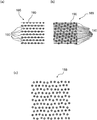
센서 소자는 대상체의 적어도 하나의 반사 이미지를 결정하도록 구성된다. 본 명세서에 사용되는 용어 "반사 이미지"는 적어도 하나의 반사 특징을 포함하는 센서 소자에 의해 결정된 이미지를 지칭한다. 본 명세서에 사용되는 용어 "반사 특징"은, 예를 들어, 적어도 하나의 조명 특징, 예컨대, 적어도 하나의 조명 특징을 구비하는 조명에 응답하여, 대상체에 의해 생성된 이미지 평면 내의 특징을 의미한다. 반사 이미지는 적어도 하나의 반사 특징을 포함하는 적어도 하나의 반사 패턴을 포함할 수 있다. 본 명세서에 사용되는 용어 "조명 특징"은 대상체를 비추도록 구성된 적어도 하나의 주변 광원이나 적어도 하나의 조명원에 의해 생성된 적어도 하나의 임의의 형상 특징을 지칭한다. 본 명세서에 사용되는 "적어도 하나의 반사 이미지를 결정하는 것"이라는 용어는 반사 이미지의 촬상, 기록 및 생성 중 하나 이상을 지칭한다.The sensor element is configured to determine at least one reflected image of the object. As used herein, the term “reflected image” refers to an image determined by a sensor element comprising at least one reflective feature. As used herein, the term “reflective feature” refers to a feature in an image plane generated by an object in response to, for example, illumination having at least one lighting feature, eg, at least one lighting feature. The reflective image may include at least one reflective pattern comprising at least one reflective feature. As used herein, the term “illumination feature” refers to at least one ambient light source configured to illuminate an object or at least one arbitrary shape feature generated by at least one illumination source. As used herein, the term “determining at least one reflected image” refers to one or more of imaging, recording, and generating of a reflected image.
반사 이미지는 적어도 하나의 반사 패턴을 포함할 수 있다. 본 명세서에 사용되는 용어 "반사 패턴"은 대상체 표면에서의 광의 반사 또는 산란에 의해 생성된 응답 패턴, 특히, 조명 패턴에 의한 조명에 응답하여 대상체에 의해 생성된 응답 패턴을 지칭한다. 조명 패턴은 대상체를 비추도록 구성된 적어도 하나의 특징을 포함할 수 있다. 조명 특징은 주변광 또는 적어도 하나의 조명원에 의해 생성될 수 있다. 반사 패턴은 조명 패턴의 적어도 하나의 특징에 대응하는 적어도 하나의 특징을 포함할 수 있다. 반사 패턴은 조명 패턴과 비교하여 적어도 하나의 왜곡된 패턴을 포함할 수 있고, 여기서, 왜곡은 대상체의 표면 특성과 같은 대상체의 거리에 좌우된다.The reflection image may include at least one reflection pattern. As used herein, the term “reflection pattern” refers to a response pattern generated by reflection or scattering of light on a surface of an object, in particular, a response pattern generated by an object in response to illumination by an illumination pattern. The illumination pattern may include at least one feature configured to illuminate the object. The lighting feature may be created by ambient light or at least one illumination source. The reflective pattern may include at least one feature corresponding to at least one feature of the illumination pattern. The reflective pattern may include at least one distorted pattern compared to the illumination pattern, wherein the distortion is dependent on a distance of the object, such as a surface characteristic of the object.
검출기는 조명원을 더 포함할 수 있다. 일 예로서, 조명원은 대상체를 비추기 위한 조명광빔을 생성하도록 구성될 수 있다. 검출기는 조명광빔이 검출기로부터 검출기의 광축을 따라 대상체를 향해 전파하도록 구성될 수 있다. 이 목적을 위해, 검출기는 조명광빔을 광축 상으로 편향시키기 위한 적어도 하나의 반사 소자, 바람직하게는 적어도 하나의 프리즘을 포함할 수 있다.The detector may further include an illumination source. As an example, the illumination source may be configured to generate an illumination light beam to illuminate the object. The detector may be configured such that the illumination light beam propagates from the detector along an optical axis of the detector towards the object. For this purpose, the detector may comprise at least one reflective element, preferably at least one prism, for deflecting the illumination light beam onto the optical axis.
조명원은 대상체의 조명을 위한 적어도 하나의 조명 패턴을 생성하도록 구성될 수 있다. 부가적으로 또는 대안적으로, 조명 패턴은 적어도 하나의 주변 광원에 의해 생성될 수 있다. 검출기는 조명 패턴이 검출기로부터, 특히, 하우징의 적어도 하나의 개구로부터 검출기의 광축에 평행하고/평행하거나 광축을 따라 대상체를 향해 전파하도록 구성될 수 있다. 이 목적을 위해, 검출기는 광축에 평행하거나 광축을 따라 전파하도록 조명을 편향시키기 위한 적어도 하나의 반사 요소, 바람직하게는 적어도 하나의 프리즘을 포함할 수 있다. 구체적으로, 조명원은 적어도 하나의 레이저 및/또는 레이저 광원을 포함할 수 있다. 반도체 레이저와 같은 다양한 유형의 레이저가 사용될 수 있다. 부가적으로 또는 대안적으로, LED 및/또는 전구와 같이 비레이저 광원이 사용될 수 있다. 본 명세서에 사용되는 용어 "패턴"은 적어도 하나의 임의 형상의 특징을 포함하는 임의의 공지되거나 사전 결정된 배열을 의미한다. 상기 패턴은 포인트 또는 심볼과 같은 적어도 하나의 특징을 포함할 수 있다. 상기 패턴은 복수의 특징을 포함할 수 있다. 상기 패턴은 주기적 또는 비주기적 특징의 배열을 포함할 수 있다. 본 명세서에 사용되는 용어 "조명 패턴"은 대상체를 비추는 패턴을 지칭한다. 조명 패턴은 적어도 하나의 주변 광원 또는 적어도 하나의 조명원에 의한 것과 같은 주변광에 의해 생성될 수 있다. 조명 패턴은, 적어도 하나의 포인트 패턴, 특히, 의사 랜덤 포인트 패턴; 랜덤 포인트 패턴 또는 의사 랜덤 패턴; 적어도 하나의 소볼 패턴(Sobol pattern); 적어도 하나의 준주기 패턴(quasiperiodic pattern); 적어도 하나의 알려진 특징을 포함하는 적어도 하나의 패턴; 적어도 하나의 정규 패턴; 적어도 하나의 삼각형 패턴; 적어도 하나의 육각형 패턴; 볼록한 균일한 타일링을 포함하는 적어도 하나의 직사각형 패턴; 적어도 하나의 라인을 포함하는 적어도 하나의 선 패턴; 평행선 또는 교차선과 같은 적어도 2개의 선을 포함하는 적어도 하나의 선 패턴으로 이루어진 그룹으로부터 선택된 적어도 하나의 패턴을 포함할 수 있다. 예를 들어, 조명원은 점 구름(cloud of points)을 생성 및/또는 투영하도록 구성될 수 있다. 조명 패턴은 삼각형 패턴, 직사각형 패턴, 육각형 패턴 또는 추가의 볼록한 타일링을 포함하는 패턴과 같은 규칙적 및/또는 일정 및/또는 주기적 패턴을 포함할 수 있다. 조명 패턴은 육각형 패턴이 바람직할 수 있도록 면적당 가능한 한 많은 특징을 포함할 수 있다. 조명 패턴의 2개의 특징간의 거리 및/또는 적어도 하나의 조명 특징의 영역은 이미지 내의 착란원(CoC, Circle of Confusion)에 의존할 수 있다.The illumination source may be configured to generate at least one illumination pattern for illumination of the object. Additionally or alternatively, the illumination pattern may be generated by at least one ambient light source. The detector may be configured such that the illumination pattern propagates from the detector, in particular from at least one opening in the housing, towards the object parallel to and/or along the optical axis of the detector. For this purpose, the detector may comprise at least one reflective element, preferably at least one prism, for deflecting the illumination to propagate parallel to or along the optical axis. Specifically, the illumination source may include at least one laser and/or a laser light source. Various types of lasers may be used, such as semiconductor lasers. Additionally or alternatively, non-laser light sources such as LEDs and/or light bulbs may be used. As used herein, the term "pattern" means any known or predetermined arrangement comprising at least one arbitrary shaped feature. The pattern may include at least one feature such as a point or a symbol. The pattern may include a plurality of features. The pattern may include an arrangement of periodic or aperiodic features. As used herein, the term “illumination pattern” refers to a pattern that illuminates an object. The illumination pattern may be generated by ambient light, such as by at least one ambient light source or at least one illumination source. The illumination pattern may include at least one point pattern, in particular a pseudo-random point pattern; random point pattern or pseudo-random pattern; at least one Sobol pattern; at least one quasiperiodic pattern; at least one pattern comprising at least one known feature; at least one regular pattern; at least one triangular pattern; at least one hexagonal pattern; at least one rectangular pattern comprising convex uniform tiling; at least one line pattern including at least one line; It may include at least one pattern selected from the group consisting of at least one line pattern including at least two lines such as parallel lines or intersecting lines. For example, the illumination source may be configured to create and/or project a cloud of points. The lighting pattern may comprise a regular and/or regular and/or periodic pattern such as a triangular pattern, a rectangular pattern, a hexagonal pattern or a pattern comprising additional convex tilings. The illumination pattern may include as many features per area as possible such that a hexagonal pattern may be desirable. The distance between two features of the illumination pattern and/or the area of at least one illumination feature may depend on a Circle of Confusion (CoC) within the image.
조명원은 적어도 하나의 광 프로젝터, 적어도 하나의 디지털 광 처리 프로젝터, 적어도 하나의 LCoS 프로젝터, 적어도 하나의 공간 광 변조기, 적어도 하나의 회절 광학 소자, 적어도 하나의 발광 다이오드 어레이, 적어도 하나의 레이저 광원의 어레이 중 하나 이상을 포함할 수 있다. 조명원은 조명 패턴을 직접 생성하도록 구성된 적어도 하나의 광원을 포함할 수 있다. 예를 들어, 조명원은 적어도 하나의 레이저 광원을 포함할 수 있다. 예를 들어, 조명원은 적어도 하나의 선 레이저(line laser)를 포함할 수 있다. 선 레이저는 레이저선, 예를 들어, 수평 또는 수직 레이저선을 대상체에 전송하도록 구성될 수 있다. 조명원은 복수의 선 레이저를 포함할 수 있다. 예를 들어, 조명원은 조명 패턴이 적어도 2개의 평행선이나 교차선을 포함하도록 배열될 수 있는 적어도 2개의 선 레이저를 포함할 수 있다. 조명원은 조명 패턴이 복수의 포인트 패턴을 포함할 수 있게 하기 위해 점 구름을 생성하도록 구성된 적어도 하나의 광 프로젝터를 포함할 수 있다. 조명원은 조명원에 의해 생성된 적어도 하나의 광빔으로부터 조명 패턴을 생성하도록 구성된 적어도 하나의 마스크를 포함할 수 있다. 조명원은 스마트폰과 같은 모바일 장치에 장착되거나 통합된 것일 수 있다. 조명원은 자동 초점 기능과 같은 이미지를 결정하는 데 사용될 수 있는 추가 기능용으로 사용될 수 있다. 조명 장치는 헤드폰 잭과 같은 USB 커넥터나 폰 커넥터와 같은 커넥터를 사용하여 모바일 장치에 장착될 수 있다.The illumination source comprises at least one light projector, at least one digital light processing projector, at least one LCoS projector, at least one spatial light modulator, at least one diffractive optical element, at least one light emitting diode array, at least one laser light source. may include one or more of the arrays. The illumination source may include at least one light source configured to directly generate an illumination pattern. For example, the illumination source may include at least one laser light source. For example, the illumination source may include at least one line laser. The line laser may be configured to transmit a laser line, for example, a horizontal or vertical laser line to the object. The illumination source may include a plurality of line lasers. For example, the illumination source may comprise at least two line lasers which may be arranged such that the illumination pattern comprises at least two parallel or intersecting lines. The illumination source may include at least one light projector configured to generate a point cloud to enable the illumination pattern to include a plurality of point patterns. The illumination source may include at least one mask configured to generate an illumination pattern from at least one light beam generated by the illumination source. The illumination source may be mounted or integrated in a mobile device such as a smartphone. The illumination source can be used for additional functions that can be used to determine the image, such as an autofocus function. The lighting device may be mounted to the mobile device using a USB connector such as a headphone jack or a connector such as a phone connector.
조명원은, 특히, 적외선 스펙트럼 범위에서 광을 방출하도록 구성될 수 있다. 그러나, 다른 스펙트럼 범위가 부가적으로 또는 대안적으로 실현 가능하다는 것을 유의해야 한다. 또한, 조명원은, 특히, 변조광이나 비변조광을 방출하도록 구성될 수 있다. 복수의 조명원이 사용되는 경우에, 다른 조명원은, 이하에 추가로 상세히 설명되는 바와 같이, 변조 주파수가 다를 수 있고, 이후에 광빔을 구별하는 데 사용될 수 있다. 검출기는 단일 광빔 또는 복수의 광빔을 평가하도록 구성될 수 있다. 복수의 광빔이 대상체로부터 검출기로 전파되는 경우, 광빔을 구별하기 위한 수단이 제공될 수 있다. 따라서, 광빔은 스펙트럼 특성이 상이할 수 있고, 검출기는 상이한 광빔을 구별하기 위한 하나 이상의 파장 선택 소자를 포함할 수 있다. 그 다음에, 각각의 광빔은 독립적으로 평가될 수 있다. 일 예로서, 파장 선택 소자는 하나 이상의 필터, 하나 이상의 프리즘, 하나 이상의 격자, 하나 이상의 이색성 거울(dichroitic mirror) 또는 이들의 임의 조합일 수 있거나 이를 포함할 수 있다. 또한, 부가적으로 또는 대안적으로, 2개 이상의 광빔을 구별하기 위해, 광빔은 특정 방식으로 변조될 수 있다. 따라서, 일 예로서, 광빔은 주파수 변조될 수 있고, 센서 신호는 상이한 광빔으로부터 유래하는 센서 신호를 그들의 복조 주파수에 따라 부분적으로 구별하기 위해 복조될 수 있다. 이들 기술은 일반적으로 고주파 전자 분야의 당업자에게 공지되어 있다. 일반적으로, 평가 장치는 상이한 변조로 이루어진 상이한 광빔을 구별하도록 구성될 수 있다.The illumination source may be configured to emit light, in particular in the infrared spectral range. It should be noted, however, that other spectral ranges are additionally or alternatively feasible. The illumination source may also be configured to emit, in particular, modulated or unmodulated light. When multiple illumination sources are used, different illumination sources may have different modulation frequencies and may then be used to differentiate the light beams, as described in further detail below. The detector may be configured to evaluate a single light beam or a plurality of light beams. When a plurality of light beams propagate from the object to the detector, a means for distinguishing the light beams may be provided. Accordingly, the light beams may have different spectral properties, and the detector may include one or more wavelength selective elements for differentiating the different light beams. Each light beam can then be evaluated independently. As an example, the wavelength selective element may be or include one or more filters, one or more prisms, one or more gratings, one or more dichroitic mirrors, or any combination thereof. Additionally or alternatively, in order to distinguish two or more light beams, the light beams may be modulated in a specific manner. Thus, as an example, the light beam may be frequency modulated, and the sensor signal may be demodulated to differentiate sensor signals originating from different light beams in part according to their demodulation frequencies. These techniques are generally known to those skilled in the art of high frequency electronics. In general, the evaluation device may be configured to distinguish different light beams of different modulations.
특히, 조명원 및 광학 센서는 공통 평면 또는 상이한 평면에 배열될 수 있다. 조명원 및 광학 센서는 공간적 방위가 상이할 수 있다. 특히, 조명원과 센서 소자는 트위스트 배열로 배열될 수 있다.In particular, the illumination source and the optical sensor may be arranged in a common plane or in different planes. The illumination source and the optical sensor may have different spatial orientations. In particular, the illumination source and the sensor element can be arranged in a twisted arrangement.
조명원은 점 구름(a cloud of points)을 생성 및/또는 투영하도록 구성하여 광학 센서의 매트릭스, 예를 들어, CMOS 검출기 상에 복수의 조명 영역이 생성되게 할 수 있다. 또한, 광학 센서의 매트릭스 상에 스페클 및/또는 외부광 및/또는 다중 반사로 인한 교란과 같은 장애가 존재할 수 있다. 평가 장치는 적어도 하나의 관심 영역, 예를 들어, 대상체의 종 방향 좌표의 결정을 위해 사용되는 광빔에 의해 비춰진 하나 이상의 픽셀을 결정하도록 구성될 수 있다. 예를 들어, 평가 장치는 필터링 방법, 예를 들어, 블롭 분석(blob-analysis) 및/또는 가장자리 필터 및/또는 대상체 인식 방법을 수행하도록 구성될 수 있다.The illumination source may be configured to generate and/or project a cloud of points, resulting in the creation of a plurality of illumination regions on a matrix of the optical sensor, eg, a CMOS detector. In addition, disturbances such as speckle and/or disturbances due to extraneous light and/or multiple reflections may exist on the matrix of the optical sensor. The evaluation device may be configured to determine at least one region of interest, eg, one or more pixels illuminated by a light beam used for determination of longitudinal coordinates of the object. For example, the evaluation device may be configured to perform a filtering method, for example, a blob-analysis and/or an edge filter and/or an object recognition method.
본 명세서에서 또한 사용되는 용어 "평가 장치"는 일반적으로 바람직하게는 적어도 하나의 데이터 처리 장치, 더 바람직하게는 적어도 하나의 프로세서 및/또는 적어도 하나의 ASIC(Application-Specific Integrated Circuit)을 사용하여, 지정된 동작을 수행하도록 구성된 임의의 장치를 지칭한다. 따라서, 일 예로서, 적어도 하나의 평가 장치는 다수의 컴퓨터 명령을 포함하는 소프트웨어 코드가 저장된 적어도 하나의 데이터 처리 장치를 포함할 수 있다. 평가 장치는 하나 이상의 지정된 동작을 수행하기 위한 하나 이상의 하드웨어 요소를 제공할 수 있고/있거나 하나 이상의 지정된 동작을 수행하기 위한 소프트웨어가 구동되는 하나 이상의 프로세서를 제공할 수 있다. 평가 장치는 기준 특징의 선택, 거리 추정치의 결정 및 대상체의 적어도 하나의 종 방향 좌표를 결정하는 것과 같은 이미지 분석을 수행하도록 구성된 하나 이상의 컴퓨터, ASIC(Application-Specific Integrated Circuit), DSP(Digital Signal Processor) 또는 FPGA(Field Programmable Gate Array)와 같은 하나 이상의 프로그래밍 가능 장치를 포함할 수 있다. 그러나, 부가적으로 또는 대안적으로, 평가 장치는 하드웨어에 의해 전체적 또는 부분적으로 구현될 수 있다.The term "evaluation device" as also used herein generally means using at least one data processing device, more preferably at least one processor and/or at least one Application-Specific Integrated Circuit (ASIC), Refers to any device configured to perform a specified action. Thus, as an example, the at least one evaluation device may include at least one data processing device in which a software code including a plurality of computer instructions is stored. The evaluation device may provide one or more hardware elements for performing one or more specified operations and/or may provide one or more processors on which software is run for performing one or more specified operations. The evaluation device may include one or more computers, Application-Specific Integrated Circuits (ASICs), Digital Signal Processors (DSPs) configured to perform image analysis such as selection of reference features, determination of distance estimates, and determination of at least one longitudinal coordinate of the object. ) or one or more programmable devices such as a Field Programmable Gate Array (FPGA). However, additionally or alternatively, the evaluation device may be implemented wholly or in part by hardware.
평가 장치는 반사 이미지의 적어도 하나의 반사 특징을 선택하도록 구성된다. 본 명세서에 사용되는 "적어도 하나의 반사 특징을 선택하는 것"이라는 용어는 반사 이미지의 적어도 하나의 반사 특징을 식별, 결정 및 선택하는 것 중 하나 이상을 지칭한다. 검출기는 반사 이미지의 적어도 하나의 반사 특징에 대한 대상체 포인트의 종 방향 좌표를 결정하도록 구성될 수 있다. 따라서, 검출기는 반사 이미지의 적어도 하나의 반사 특징을 사전에 분류하도록 구성될 수 있다. 이는 삼각형 패턴, 직사각형 패턴, 육각형 패턴 또는 추가의 볼록한 타일링을 포함하는 패턴과 같은 규칙적 및/또는 일정 및/또는 주기적 패턴을 포함하는 조명 패턴을 사용할 수 있게 한다. 조명 패턴은 육각형 패턴이 바람직할 수 있도록 영역당 가능한 한 많은 특징을 포함할 수 있다. 평가 장치는 반사 특징을 식별하기 위해 적어도 하나의 이미지 분석 및/또는 이미지 처리를 수행하도록 구성될 수 있다. 이미지 분석 및/또는 이미지 처리는 적어도 하나의 특징 검출 알고리즘을 사용할 수 있다. 이미지 분석 및/또는 이미지 처리는, 필터링; 적어도 하나의 관심 영역의 선택; 센서 신호에 의해 생성된 이미지와 적어도 하나의 오프셋 간의 차분 이미지 형성; 센서 신호에 의해 생성된 이미지를 반전시키는 것에 의한 센서 신호의 반전; 상이한 시간에 센서 신호에 의해 생성된 이미지 간의 차분 이미지 형성; 배경 보정; 컬러 채널로의 분해; 색조(hue)로의 분해; 채도(saturation); 및 밝기 채널; 주파수 분해; 단일값 분해(singular value decomposition); 캐니 에지 검출기(Canny edge detector) 적용; LoG 필터(Laplacian of Gaussian filter) 적용; DoG 필터(Difference of Gaussian filter) 적용; 소벨 연산자(Sobel operator) 적용; 라플라스 연산자(Laplacian operator) 적용; 샤르 연산자(Scharr operator) 적용; 프레위트 연산자(Prewitt operator) 적용; 로버츠 연산자(Roberts operator) 적용; 키르시 연산자(Kirsch operator) 적용; 고역 통과 필터 적용; 저역 통과 필터 적용; 푸리에 변환 적용; 라돈 변환(Radon transformation) 적용; 허프 변환(Hough transformation) 적용; 웨이블릿 변환(wavelet-transformation) 적용; 임계화(thresholding); 이진 이미지 생성 중 하나 이상을 포함할 수 있다. 관심 영역은 사용자에 의해 수동으로 결정될 수 있거나, 광학 센서에 의해 생성된 이미지 내의 대상체를 인식함으로써 자동적으로 결정될 수도 있다.The evaluation device is configured to select at least one reflective characteristic of the reflective image. As used herein, the term “selecting at least one reflective characteristic” refers to one or more of identifying, determining, and selecting at least one reflective characteristic of a reflective image. The detector may be configured to determine a longitudinal coordinate of the object point for at least one reflective feature of the reflected image. Accordingly, the detector may be configured to pre-classify at least one reflective feature of the reflective image. This makes it possible to use lighting patterns comprising regular and/or regular and/or periodic patterns, such as triangular patterns, rectangular patterns, hexagonal patterns or patterns comprising additional convex tilings. The illumination pattern may include as many features per area as possible such that a hexagonal pattern may be desirable. The evaluation device may be configured to perform at least one image analysis and/or image processing to identify reflective features. The image analysis and/or image processing may use at least one feature detection algorithm. Image analysis and/or image processing may include filtering; selection of at least one region of interest; forming a differential image between the image generated by the sensor signal and the at least one offset; inversion of the sensor signal by inverting the image generated by the sensor signal; differential image formation between images generated by sensor signals at different times; background correction; decomposition into color channels; decomposition into hue; saturation; and brightness channels; frequency resolution; singular value decomposition; Canny edge detector applied; Applying a Laplacian of Gaussian filter; DoG filter (Difference of Gaussian filter) applied; Apply the Sobel operator; Apply Laplacian operator; Apply the Scharr operator; Prewitt operator applied; Apply the Roberts operator; Apply the Kirsch operator; high-pass filter applied; low-pass filter applied; Apply Fourier Transform; Radon transformation applied; Hough transformation applied; application of wavelet-transformation; thresholding; It may include one or more of binary image generation. The region of interest may be determined manually by a user, or may be automatically determined by recognizing an object in an image generated by an optical sensor.
평가 장치는 적어도 하나의 블러링 함수 fa를 최적화함으로써 반사 이미지의 선택된 반사 특징 중 적어도 하나의 거리 추정치를 결정하도록 구성되고, 여기서, 거리 추정치는 종 방향 좌표 z 및 오차 간격 ±ε에 의해 제공된다. 본 명세서에 사용되는 용어 "거리 추정치(distance estimate)"는 종 방향 좌표의 적어도 하나의 추정치, 특히, 종 방향 좌표 z 및 종 방향 좌표 결정의 측정 불확실성 ±ε에 의해 정의된 적어도 하나의 불확실한 간격을 의미한다. 오차 간격 ε은 광학 센서의 측정 불확실성 및/또는 온도, 모션 등과 같은 추가 파라미터에 따라 달라질 수 있다. 광학 센서의 측정 불확실성은 사전 결정 및/또는 추정될 수 있고/있거나 평가 장치의 적어도 하나의 데이터 저장 유닛에 저장될 수 있다. 예를 들어, 오차 간격은 ±10%, 바람직하게는 ±5%, 더욱 바람직하게는 ±1%일 수 있다. 거리 추정치의 결정은 일반적으로 삼각 측량 방법보다 큰 에러 바(error bar)를 사용하여 거리 추정치를 산출할 수 있다. 거리 추정치는 디포커싱 깊이 알고리즘(depth-from-defocus algorithm)과 같은 적어도 하나의 컨볼루션 기반 알고리즘을 사용하여 결정될 수 있다. 반사 특징으로부터 거리를 얻기 위해, 디포커싱 깊이 알고리즘은 대상체의 디포커스를 추정한다. 이러한 추정을 위해, 블러링 함수(blurring function)를 가정한다. 본 명세서에 사용된 용어 "블러링 함수 fa"는 블러 커널 또는 포인트 확산 함수라고도 지칭되며, 대상체로부터의 조명에 대한 검출기의 응답 함수를 의미한다. 특히, 블러링 함수는 디포커싱된 대상체의 블러를 모델링한다. 적어도 하나의 블러링 함수 fa는 하나의 함수이거나, 또는 가우스(Gaussian), 싱크 함수(sinc function), 필박스 함수(pillbox function), 제곱 함수, 로렌츠 함수(Lorentzian function), 방사형 함수(radial function), 다항식, 에르미트 다항식(Hermite polynomial), 저니케 다항식(Zernike polynomial), 르장드르 다항식(Legendre polynomial)으로 구성된 그룹 중 하나 이상의 함수로 구성된 복합 함수일 수 있다.The evaluation device is configured to determine a distance estimate of at least one of the selected reflective features of the reflected image by optimizing the at least one blurring function f a , wherein the distance estimate is provided by the longitudinal coordinate z and the error interval ±ε . The term "distance estimate" as used herein refers to at least one estimate of a longitudinal coordinate, in particular at least one uncertain interval defined by the longitudinal coordinate z and the measurement uncertainty ±ε of determining the longitudinal coordinate. it means. The error interval ε may depend on the measurement uncertainty of the optical sensor and/or additional parameters such as temperature, motion, etc. The measurement uncertainty of the optical sensor may be predetermined and/or estimated and/or stored in at least one data storage unit of the evaluation device. For example, the error interval may be ±10%, preferably ±5%, more preferably ±1%. Determination of a distance estimate can generally yield a distance estimate using a larger error bar than triangulation methods. The distance estimate may be determined using at least one convolution based algorithm, such as a depth-from-defocus algorithm. To obtain the distance from the specular feature, the defocusing depth algorithm estimates the object's defocus. For this estimation, a blurring function is assumed. As used herein, the term “blurring function f a ” is also referred to as a blur kernel or point spread function, and refers to a response function of a detector to illumination from an object. In particular, the blurring function models the blur of the defocused object. At least one blurring function f a is a function, or a Gaussian, a sinc function, a pillbox function, a square function, a Lorentzian function, a radial function ), a polynomial, a Hermite polynomial, a Zernike polynomial, and a Legendre polynomial.
센서 소자는 적어도 하나의 반사 패턴을 결정하도록 구성될 수 있다. 평가 장치는 적어도 하나의 블러링 함수 fa를 최적화함으로써 반사 패턴의 적어도 하나의 특징을 선택하고, 반사 패턴의 선택된 특징의 거리 추정치를 결정하도록 구성될 수 있다.The sensor element may be configured to determine at least one reflection pattern. The evaluation apparatus may be configured to select at least one feature of the reflective pattern by optimizing the at least one blurring function f a and to determine a distance estimate of the selected feature of the reflective pattern.
블러링 함수는 적어도 하나의 블러링 함수의 파라미터들을 변경함으로써 최적화될 수 있다. 반사 이미지는 블러 이미지 ib일 수 있다. 평가 장치는 블러 이미지 ib 및 블러링 함수 fa로부터 종 방향 좌표 z를 재구성하도록 구성될 수 있다. 종 방향 좌표 z는, 블러링 함수의 파라미터 σ를 변경함으로써, 블러 이미지 ib 와, 적어도 하나의 추가 이미지 i'b’와 블러링 함수 fa의 컨볼루션(*) 사이의 차이를 최소화하는 것, 즉,The blurring function may be optimized by changing parameters of at least one blurring function. The reflection image may be a blur image i b . The evaluation device may be configured to reconstruct the longitudinal coordinate z from the blurred image i b and the blurring function f a . The longitudinal coordinate z is to minimize the difference between the blur image i b and the convolution (*) of the blurring image i b and the at least one additional image i'b' and the blurring function f a by changing the parameter σ of the blurring function , In other words,
![]()
![]()
에 의해 결정될 수 있다. σ(z)는 거리에 따른 블러링 파라미터의 세트이다. 추가 이미지는 흐리거나 선명할 수 있다. 본 명세서에서 사용되는 용어 "선명" 또는 "선명한 이미지"는 최대 콘트라스트를 갖는 블러 이미지를 지칭한다. 적어도 하나의 추가 이미지는 알려진 블러링 함수를 사용한 컨볼루션에 의해 블러 이미지 ib로부터 생성될 수 있다. 따라서, 디포커싱 깊이 알고리즘은 반사 특징의 거리 추정치를 얻기 위해 사용될 수 있다. 이 거리 추정치는 공액선이 선택되는 영역을 효율적으로 선택하는 데 사용될 수 있으며, 아래에서 더 상세하게 설명될 것이다. 그런 다음 삼각 측량과 선택된 공액선을 사용하여 거리를 계산할 수 있다. 거리 추정치의 결정은 대부분의 삼각 측량 방법과 달리 반사 이미지의 단일 특징에 적용될 수 있다. 따라서, 거리 추정치의 결정은, 대응 문제가 해결되는 더 작은 영역을 생성함으로써, 삼각 측량 방법의 속도를 증가시키는 데 사용될 수 있다.can be determined by σ(z) is the set of distance-dependent blurring parameters. Additional images may be blurred or sharp. As used herein, the term “sharp” or “sharp image” refers to a blurred image with maximum contrast. At least one additional image may be generated from the blur image i b by convolution using a known blurring function. Thus, a defocusing depth algorithm can be used to obtain a distance estimate of the reflective feature. This distance estimate can be used to efficiently select the region where the conjugate line is selected, which will be described in more detail below. The distance can then be calculated using triangulation and the selected conjugate line. Determination of distance estimates, unlike most triangulation methods, can be applied to a single feature of the reflected image. Thus, the determination of the distance estimate can be used to speed up the triangulation method by creating a smaller area in which the correspondence problem is solved.
평가 장치는 거리 추정치에 대응하는 적어도 하나의 기준 이미지에서 적어도 하나의 변위 영역을 결정하도록 구성된다. 본 명세서에서 사용되는 용어 "기준 이미지"는 반사 이미지와 비교하여 다른 공간 위치에서 결정되는 반사 이미지와는 상이한 이미지를 의미한다. 기준 이미지는 적어도 하나의 기준 특징을 기록하는 것, 적어도 하나의 기준 특징을 촬상하는 것, 기준 이미지를 계산하는 것 중 하나 이상에 의해 결정될 수 있다. 기준 이미지 및 반사 이미지는 고정 거리의 상이한 공간 위치에서 결정된 대상체의 이미지일 수 있다. 거리는 기준선(baseline)으로도 불리는 상대 거리일 수 있다. 평가 장치는 적어도 하나의 반사 특징에 대응하는 적어도 하나의 기준 이미지에서 적어도 하나의 기준 특징을 결정하도록 구성될 수 있다. 전술한 바와 같이, 평가 장치는 이미지 분석을 수행하고, 반사 이미지의 특징을 식별하도록 구성될 수 있다. 평가 장치는 선택된 반사 특징과 종 방향 좌표가 실질적으로 동일한 기준 이미지 내의 적어도 하나의 기준 특징을 식별하도록 구성될 수 있다. "실질적으로 동일한"이라는 용어는 10% 이내, 바람직하게는 5% 이내, 가장 바람직하게는 1% 이내로 동일한 것을 의미한다. 반사 특징에 대응하는 기준 특징은 공액 기하(epipolar geometry)를 사용하여 결정될 수 있다. 공액 기하에 대한 설명을 위해, 예를 들어, "3차원 컴퓨터 비전(Dreidimensionales Computersehen)"(Springer, Berlin Heidelberg, 1997. X. Jiang, H. Bunke)의 2장을 참조한다. 공액 기하는 기준 이미지 및 반사 이미지가 고정 거리의 상이한 공간 위치 및/또는 공간 방향에서 결정된 대상체의 이미지일 수 있음을 가정할 수 있다. 평가 장치는 기준 이미지 내의 공액선을 결정하도록 구성될 수 있다. 기준 이미지와 반사 이미지의 상대적 위치를 알 수 있다. 예를 들어, 기준 이미지와 반사 이미지의 상대 위치는 평가 장치의 적어도 하나의 저장 유닛 내에 저장될 수 있다. 평가 장치는 반사 이미지의 선택된 반사 특징으로부터 연장되는 직선을 결정하도록 구성될 수 있다. 직선은 선택된 특징에 대응할 수 있는 대상체 특징을 포함할 수 있다. 직선과 기준선은 공액면에 걸쳐 있다. 기준 이미지는 반사 이미지와는 상이한 상대적인 위치에서 결정되므로, 대응 가능한 대상체 특징은 기준 이미지에서 공액선이라 불리는 직선상에서 촬상될 수 있다. 따라서, 반사 이미지의 선택된 특징에 대응하는 기준 이미지의 특징은 공액선 상에 있다. 노화, 온도 변화, 기계적 스트레스 등으로 인한 이미지의 왜곡이나 시스템 파라미터의 변화로 인해, 공액선이 서로 교차하거나 매우 근접할 수 있고/있거나 기준 특징과 반사 특징 간의 대응 관계가 불분명할 수 있다. 또한, 현실 세계에서 알려진 각각의 위치나 대상체는 기준 이미지에 투영될 수 있고 그 반대일 수도 있다. 투영은 검출기의 보정으로 인해 알려질 수 있지만, 보정은 특정 카메라의 공액 기하의 티치 인(teach-in)과 비슷하다.The evaluation device is configured to determine at least one displacement region in the at least one reference image corresponding to the distance estimate. As used herein, the term "reference image" means an image that is different from the reflected image determined at a different spatial location compared to the reflected image. The reference image may be determined by one or more of recording the at least one reference feature, imaging the at least one reference feature, and calculating the reference image. The reference image and the reflected image may be images of the object determined at different spatial positions of a fixed distance. The distance may be a relative distance, also referred to as a baseline. The evaluation device may be configured to determine at least one reference feature in the at least one reference image corresponding to the at least one reflective feature. As described above, the evaluation device may be configured to perform image analysis and identify characteristics of the reflected image. The evaluation device may be configured to identify at least one reference feature in the reference image whose longitudinal coordinates are substantially the same as the selected reflective feature. The term "substantially identical" means within 10%, preferably within 5%, most preferably within 1%. A reference feature corresponding to the reflective feature may be determined using epipolar geometry. For a description of conjugate geometry, see, for example, Chapter 2 of "Dreidimensionales Computersehen" (Springer, Berlin Heidelberg, 1997. X. Jiang, H. Bunke). The conjugate geometry may assume that the reference image and the reflected image may be images of an object determined from different spatial locations and/or spatial directions of a fixed distance. The evaluation device may be configured to determine a conjugate line in the reference image. The relative positions of the reference image and the reflected image can be found. For example, the relative positions of the reference image and the reflected image may be stored in at least one storage unit of the evaluation device. The evaluation device may be configured to determine a straight line extending from the selected reflective feature of the reflective image. The straight line may include object features that may correspond to the selected features. The straight line and the baseline span the conjugate plane. Since the reference image is determined at a different relative position from the reflected image, corresponding object features can be imaged on a straight line called a conjugate line in the reference image. Thus, the feature of the reference image that corresponds to the selected feature of the reflected image is on the conjugate line. Due to image distortion or changes in system parameters due to aging, temperature changes, mechanical stress, etc., the conjugate lines may intersect or be very close to each other and/or the correspondence between the reference and reflective features may be unclear. In addition, each position or object known in the real world may be projected on the reference image or vice versa. The projection can be known due to the calibration of the detector, but the calibration is similar to the teach-in of the conjugate geometry of a particular camera.
평가 장치는 선택된 반사 특징을 변위 영역 내의 적어도 하나의 기준 특징과 매칭시키도록 구성된다. 본 명세서에서 사용되는 용어 "변위 영역"은 선택된 반사 특징에 대응하는 기준 특징이 촬상될 수 있는 기준 이미지 내의 영역을 의미한다. 구체적으로, 변위 영역은 선택된 반사 특징에 대응하는 기준 특징이 기준 이미지 내에 위치할 것으로 예상되는 기준 이미지 내의 영역일 수 있다. 대상체까지의 거리에 따라, 반사 특징에 대응하는 기준 특징의 이미지 위치는 반사 이미지 내의 반사 특징의 이미지 위치와 비교하여 기준 이미지 내에서 변위될 수 있다. 변위 영역은 단 하나의 기준 특징을 포함할 수 있다. 변위 영역은 하나보다 많은 기준 특징을 포함할 수도 있다. 변위 영역은 공액선 또는 공액선의 섹션을 포함할 수 있다. 변위 영역은 하나보다 많은 공액선 또는 하나보다 많은 공액선의 섹션을 포함할 수 있다. 본 명세서에 사용되는 용어 "기준 특징"은 기준 이미지의 적어도 하나의 특징을 지칭한다. 변위 영역은 공액선을 따라 연장되거나, 공액선에 직교하여 연장되거나, 또는 양쪽 모두일 수 있다. 평가 장치는 종 방향 좌표 z에 대응하는 공액선을 따라 기준 특징을 결정하고, 오차 간격 ±ε에 대응하는 공액선을 따르거나 공액선에 직교하는 변위 영역의 범위를 결정하도록 구성될 수 있다. 거리 추정치의 측정 불확실성은, 측정 불확실성이 방향에 따라 상이할 수 있기 때문에, 비원형인 변위 영역을 초래할 수 있다. 구체적으로, 공액선(들)을 따르는 측정 불확실성은 공액선(들)에 대한 직교 방향에서의 측정 불확실성보다 클 수 있다. 변위 영역은 공액선(들)에 대해 직교 방향으로 연장되는 것을 포함할 수 있다. 평가 장치는 반사 특징의 이미지 위치 주위에 변위 영역을 결정할 수 있다. 평가 장치는 거리 추정치를 결정하고, z±ε에 대응하는 공액선을 따라 변위 영역을 결정하도록 구성될 수 있다.The evaluation device is configured to match the selected reflective feature to at least one reference feature in the displacement region. As used herein, the term “displacement region” refers to an area within a reference image in which a reference feature corresponding to a selected reflective feature can be imaged. Specifically, the displacement region may be a region in the reference image in which the reference feature corresponding to the selected reflective feature is expected to be located in the reference image. Depending on the distance to the object, the image position of the reference feature corresponding to the reflective feature may be displaced in the reference image compared to the image position of the reflective feature in the reflective image. A displacement region may include only one reference feature. A displacement region may include more than one reference feature. The displacement region may comprise a conjugate line or a section of a conjugate line. The displacement region may include more than one conjugate line or more than one section of the conjugate line. As used herein, the term “reference feature” refers to at least one feature of a reference image. The displacement region may extend along the conjugate line, orthogonal to the conjugate line, or both. The evaluation device may be configured to determine a reference feature along a conjugate line corresponding to the longitudinal coordinate z, and to determine a range of a displacement region along or orthogonal to the conjugate line corresponding to the error interval ±ε. The measurement uncertainty of the distance estimate can result in a region of displacement that is non-circular, since the measurement uncertainty can vary with direction. Specifically, the measurement uncertainty along the conjugate line(s) may be greater than the measurement uncertainty in a direction orthogonal to the conjugate line(s). The displacement region may include extending in a direction orthogonal to the conjugate line(s). The evaluation device may determine a displacement region around the image location of the reflective feature. The evaluation device may be configured to determine a distance estimate and to determine a displacement region along a conjugate line corresponding to z±ε.
본 명세서에 사용되는 용어 "매칭"은 대응하는 기준 및 반사 특징을 결정 및/또는 평가하는 것을 지칭한다. 평가 장치는 결정된 거리 추정치를 고려하는 적어도 하나의 평가 알고리즘을 사용함으로써, 반사 이미지의 선택된 특징을 변위 영역 내의 기준 특징과 매칭시키도록 구성될 수 있다. 평가 알고리즘은 선형 스케일링 알고리즘일 수 있다. 평가 장치는 변위 영역에 가장 근접한 공액선 및/또는 변위 영역 내의 공액선을 결정하도록 구성될 수 있다. 평가 장치는 반사 특징의 이미지 위치에 가장 근접한 공액선를 결정하도록 구성될 수 있다. 공액선을 따르는 변위 영역의 범위는 공액선에 직교하는 변위 영역의 범위보다 클 수 있다. 평가 장치는 대응하는 기준 특징을 결정하기 전에 공액선을 결정하도록 구성될 수 있다. 평가 장치는 각각의 반사 특징의 이미지 위치 주위의 변위 영역을 결정할 수 있다. 평가 장치는 변위 영역에 가장 근접한 공액선 및/또는 변위 영역 내의 공액선 및/또는 공액선에 직교하는 방향을 따르는 변위 영역에 가장 근접한 공액선을 할당함으로써, 반사 특징의 각 이미지 위치의 변위 영역 각각에 공액선을 할당하도록 구성될 수 있다. 평가 장치는 할당된 변위 영역에 가장 근접한 기준 특징 및/또는 할당된 변위 영역 내의 기준 특징 및/또는 할당된 공액선을 따르는 할당된 변위 영역에 가장 근접한 기준 특징 및/또는 할당된 공액선을 따라 할당된 변위 영역 내의 기준 특징을 결정함으로써, 반사 특징의 이미지 위치에 대응하는 기준 특징을 결정하도록 구성될 수 있다.As used herein, the term “matching” refers to determining and/or evaluating corresponding reference and reflective characteristics. The evaluation device may be configured to match the selected feature of the reflected image with a reference feature in the displacement region by using at least one evaluation algorithm that takes into account the determined distance estimate. The evaluation algorithm may be a linear scaling algorithm. The evaluation device may be configured to determine a conjugate line closest to the displacement region and/or a conjugate line within the displacement region. The evaluation device may be configured to determine a conjugate line that is closest to the image location of the reflective feature. The range of the displacement region along the conjugate line may be greater than the range of the displacement region orthogonal to the conjugate line. The evaluation device may be configured to determine the conjugate line prior to determining the corresponding reference characteristic. The evaluation device may determine a displacement area around the image location of each reflective feature. The evaluation device assigns a conjugate line closest to the displacement region and/or a conjugate line within the displacement region and/or a conjugate line closest to the displacement region along a direction orthogonal to the conjugate line, so that each of the displacement regions of each image position of the reflective feature can be configured to assign a conjugate line to . The evaluation device assigns the reference feature closest to the assigned displacement region and/or the reference feature within the assigned displacement region and/or the reference feature closest to the assigned displacement region along the assigned conjugate line and/or along the assigned conjugate line. By determining the reference feature in the displaced region, it can be configured to determine the reference feature corresponding to the image location of the reflective feature.
평가 장치는 매칭된 기준 특징 및 선택된 반사 특징의 변위를 결정하도록 구성될 수 있다. 평가 장치는 종 방향 좌표와 변위 사이의 사전 결정된 관계를 사용하여 매칭된 특징의 종 방향 정보를 결정하도록 구성될 수 있다. 본 명세서에 사용되는 용어 "변위"는 기준 이미지 내의 위치와 반사 이미지 내의 위치 사이의 차이를 지칭한다. 본 명세서에 사용되는 용어 "종 방향 정보"는 종 방향 좌표에 관한 정보를 지칭한다. 예를 들어, 종 방향 정보는 거리값일 수 있다. 사전 결정된 관계는 경험적 관계(empiric relationship), 반경험적 관계(semi-empiric relationship) 및 분석적으로 도출된 관계(analytically derived relationship) 중 하나 이상일 수 있다. 평가 장치는 룩업 리스트 또는 룩업 테이블과 같은 사전 결정된 관계를 저장하기 위한 적어도 하나의 데이터 저장 장치를 포함할 수 있다. 평가 장치는 삼각 측량법을 이용하여 사전 결정된 관계를 결정하도록 구성될 수 있다. 반사 이미지에서 선택된 반사 특징의 위치 및 매칭된 기준 특징의 위치 및/또는 선택된 반사 특징 및 매칭된 기준 특징의 상대 변위가 알려져 있는 경우, 대응하는 대상체 특징의 종 방향 좌표는 삼각 측량에 의해 결정될 수 있다. 따라서, 평가 장치는, 예를 들어, 후속 및/또는 열별로 반사 특징을 선택하고, 기준 특징의 잠재적 위치 각각에 대해 삼각 측량을 사용하여 대응하는 거리값을 결정하도록 구성될 수 있다. 변위 및 대응 거리값은 평가 장치의 적어도 하나의 저장 장치에 저장될 수 있다. 평가 장치는, 예컨대, 적어도 하나의 프로세서, 적어도 하나의 DSP, 적어도 하나의 FPGA 및/또는 적어도 하나의 ASIC과 같은 적어도 하나의 데이터 처리 장치를 포함할 수 있다. 또한, 종 방향 좌표와 변위 사이의 적어도 하나의 사전 결정되거나 결정 가능한 관계를 저장하기 위해, 사전 결정된 관계를 저장하기 위한 하나 이상의 룩업 테이블을 제공하는 것과 같은 적어도 하나의 데이터 저장 장치가 제공될 수 있다. 평가 장치는 카메라 및/또는 검출기의 고유 보정 및/또는 외부 보정을 위한 파라미터를 저장하도록 구성될 수 있다. 평가 장치는 Tsai 카메라 보정을 수행함으로써 카메라 및/또는 검출기의 고유 보정 및/또는 외부 보정을 위한 파라미터를 생성하도록 구성될 수 있다. 평가 장치는 전송 장치의 초점 길이, 방사상 렌즈 왜곡 계수, 방사상 렌즈 왜곡의 중심 좌표, 스캐닝 및 디지털화를 위한 하드웨어 타이밍의 결함으로 인한 임의의 불확실성을 설명하기 위한 스케일 팩터, 현실 세계와 카메라 좌표 간의 변환을 위한 회전 각도, 현실 세계와 카메라 좌표 간의 변환을 위한 변환 구성 요소, 조리개 각도, 이미지 센서 포맷, 주요 포인트(principal point), 기울기 계수, 카메라 중심, 카메라 헤딩(camera heading), 카메라 및/또는 조명원 사이의 기준선, 회전 또는 변환 파라미터, 개구, 초점 거리 등과 같은 파라미터를 계산 및/또는 추정하도록 구성될 수 있다.The evaluation device may be configured to determine a displacement of the matched reference feature and the selected reflective feature. The evaluation device may be configured to determine longitudinal information of the matched feature using a predetermined relationship between the longitudinal coordinate and the displacement. As used herein, the term “displacement” refers to the difference between a location in a reference image and a location in a reflected image. As used herein, the term “longitudinal information” refers to information about longitudinal coordinates. For example, the longitudinal information may be a distance value. The predetermined relationship may be one or more of an empiric relationship, a semi-empiric relationship, and an analytically derived relationship. The evaluation device may include at least one data storage device for storing a predetermined relationship, such as a lookup list or a lookup table. The evaluation device may be configured to determine a predetermined relationship using triangulation. If the location of the selected reflective feature and the location of the matched reference feature in the reflected image and/or the relative displacement of the selected reflective feature and the matched reference feature are known, the longitudinal coordinates of the corresponding object feature can be determined by triangulation. . Thus, the evaluation device may be configured, for example, to select a reflective feature on a subsequent and/or column-by-column basis, and to determine a corresponding distance value using triangulation for each potential position of the reference feature. The displacement and corresponding distance values may be stored in at least one storage device of the evaluation device. The evaluation device may include, for example, at least one data processing device such as at least one processor, at least one DSP, at least one FPGA and/or at least one ASIC. Further, at least one data storage device may be provided for storing at least one predetermined or determinable relationship between the longitudinal coordinates and the displacement, such as providing one or more lookup tables for storing the predetermined relationship. . The evaluation device may be configured to store parameters for intrinsic and/or external calibration of the camera and/or detector. The evaluation device may be configured to generate parameters for intrinsic and/or external calibration of the camera and/or detector by performing Tsai camera calibration. The evaluation unit calculates the focal length of the transmitting unit, the radial lens distortion coefficient, the central coordinates of the radial lens distortion, a scale factor to account for any uncertainties due to imperfections in hardware timing for scanning and digitization, and transformations between real-world and camera coordinates. rotation angle for transformation, transformation component for transformation between real world and camera coordinates, aperture angle, image sensor format, principal point, tilt factor, camera center, camera heading, camera and/or light source It may be configured to calculate and/or estimate parameters such as baselines, rotation or translation parameters, apertures, focal lengths, and the like between.
부가적으로 또는 대안적으로, 평가 장치는, 다음의 단계를 수행하도록 구성될 수 있다.Additionally or alternatively, the evaluation device may be configured to perform the following steps.
· 각각의 반사 특징의 이미지 위치에 대한 변위 영역을 결정하는 단계;• determining a displacement region for the image location of each reflective feature;
· 공액선을 변위 영역에 가장 근접하게 및/또는 변위 영역 내에 및/또는 공액선에 직교하는 방향을 따라 변위 영역에 가장 근접하게 할당하도록 함으로써, 각각의 반사 특징의 변위 영역에 공액선을 할당하는 단계;Assigning a conjugate line to the displacement region of each reflective feature by having the conjugate line be assigned closest to and/or within the displacement region and/or closest to the displacement region along a direction orthogonal to the conjugate line; step;
· 기준 특징을 할당된 변위 영역에 가장 근접하게 및/또는 할당된 변위 영역 내에 및/또는 할당된 공액선을 따라 할당된 변위 영역에 가장 근접하게 및/또는 할당된 공액선을 따라 할당된 변위 영역 내에 할당하도록 함으로써, 각각의 반사 특징에 대해 적어도 하나의 기준 특징을 할당 및/또는 결정하는 단계.Set the reference feature to the closest assigned displacement region and/or to the assigned displacement region within the assigned displacement region and/or along the assigned conjugate line to the assigned displacement region closest to and/or along the assigned conjugate line. allocating and/or determining at least one reference feature for each reflective feature.
부가적으로 또는 대안적으로, 평가 장치는 기준 이미지 내에서 반사 특징 및/또는 공액선의 거리를 비교하고/비교하거나, 기준 이미지 내에서 반사 특징 및/또는 공액선의 ε 가중 거리와 같은 오차 가중 거리를 비교하여, 더 짧은 거리 및/또는 ε 가중 거리에서의 공액선 및/또는 기준 특징을, 기준 특징 및/또는 반사 특징에 할당함으로써, 반사 특징에 할당되는 둘 이상의 공액선 및/또는 기준 특징 사이를 결정하도록 구성될 수 있다.Additionally or alternatively, the evaluation device compares the distance of the reflective feature and/or the conjugate line within the reference image and/or calculates an error weighted distance, such as an ε weighted distance of the reflective feature and/or the conjugate line within the reference image. In comparison, by assigning conjugate lines and/or reference features at shorter distances and/or ε weighted distances to reference features and/or reflective features, it is possible to distinguish between two or more conjugate lines and/or reference features assigned to reflective features. can be configured to determine.
바람직하게는, 검출기는 하나의 기준 특징에 대해 모호하지 않은 할당이 가능하도록, 거리 추정치를 사용하여, 선택된 반사 특징을 사전 분류하도록 구성될 수 있다. 특히, 조명 패턴의 조명 특징은 기준 이미지의 대응하는 기준 특징이 공액선 상에서 서로에 대한 상대적인 거리를 가능한 한 크게 가질 수 있도록 배열될 수 있다. 조명 패턴의 조명 특징은 단지 소수의 기준 특징이 공액선 상에 위치하도록 배열될 수 있다. 예를 들어, 조명 패턴은 적어도 하나의 육각형 패턴을 포함할 수 있다. 바람직하게는, 조명 패턴은 적어도 하나의 육각형 패턴을 포함할 수 있고, 여기서, 이 패턴은 기준선에 대하여 회전된다. 바람직하게는, 조명 패턴은 적어도 하나의 변위된 육각형 패턴을 포함할 수 있고, 여기서, 육각형 패턴의 개별 포인트는 정규 위치로부터 임의의 거리만큼, 예를 들어, 그 포인트의 공액선에 직각으로 변위된다. 개별 포인트의 변위는 2개의 평행한 공액선 사이의 거리의 절반보다 작을 수 있고, 바람직하게는 2개의 평행한 공액선 사이의 거리의 1/4보다 작을 수 있다. 개개의 포인트의 변위는 두 포인트가 서로의 위로 변위하지 않도록 할 수 있다.Preferably, the detector can be configured to pre-classify the selected reflective feature, using the distance estimate, to allow for an unambiguous assignment to one reference feature. In particular, the illumination features of the illumination pattern can be arranged such that the corresponding reference features of the reference image have as large a distance as possible relative to each other on the conjugate line. The illumination features of the illumination pattern can be arranged such that only a few reference features are located on the conjugate line. For example, the illumination pattern may include at least one hexagonal pattern. Preferably, the illumination pattern may comprise at least one hexagonal pattern, wherein the pattern is rotated with respect to a reference line. Preferably, the illumination pattern may comprise at least one displaced hexagonal pattern, wherein individual points of the hexagonal pattern are displaced any distance from their normal position, for example orthogonal to the point's conjugate line. . The displacement of an individual point may be less than half the distance between two parallel conjugate lines, preferably less than one quarter the distance between two parallel conjugate lines. Displacement of the individual points may prevent the two points from being displaced over each other.
디포커싱 깊이 방법(depth-from-defocus method)을 사용하면, 오차 간격 ε 내의 종 방향 좌표 z와 같이 거리를 추정하게 할 수 있다. 추정된 종 방향 좌표 및 대응하는 오차 간격에 대응하는 변위 영역을 결정함으로써, 공액선을 따라 가능한 솔루션의 수를 상당히 감소시킬 수 있다. 가능한 솔루션의 수는 하나로 줄어들 수도 있다. 종 방향 좌표 z 및 오차 간격의 결정은, 선택된 반사 특징 및 기준 특징을 매칭시키기 전에, 사전 평가 동안 수행될 수 있다. 이것은 계산 수요를 감소시켜서 비용을 상당히 절감시키고, 모바일 장치 또는 실외 장치에서의 사용을 가능하게 할 수 있다.Using the depth-from-defocus method, it is possible to estimate the distance, such as the longitudinal coordinate z within the error interval ε. By determining the displacement regions corresponding to the estimated longitudinal coordinates and corresponding error intervals, it is possible to significantly reduce the number of possible solutions along the conjugate line. The number of possible solutions may be reduced to one. Determination of the longitudinal coordinate z and the error interval may be performed during pre-evaluation, prior to matching the selected reflective feature and the reference feature. This can reduce computational demands, resulting in significant cost savings, and enable use in mobile devices or outdoor devices.
또한, 일반적으로 삼각 측량 시스템에서 기준선은 긴 거리를 감지하기 위해 길어야 한다. 거리 추정치를 사용한 종 방향 좌표 z 및 오차 간격의 사전 평가와, 선택된 반사 특징 및 기준 특징의 후속 매칭은 짧은 기준선을 사용하여 소형 장치를 제공하는 것을 가능하게 할 수 있다. 또한, 디포커싱 깊이 결과는 광원의 기준선이나 위치에 의존하지 않는다. 또한, 디포커싱 깊이를 사용한 종 방향 좌표 z 및 오차 간격의 사전 평가와, 선택된 반사 특징 및 기준 특징의 후속 매칭은 종래의 삼각 측량 시스템에 비해 정확도 및/또는 속도를 향상시킬 수 있고/있거나 계산 수요를 낮출 수 있다.Also, in general, in triangulation systems, the baseline must be long to detect long distances. Pre-evaluation of the longitudinal coordinate z and the error interval using distance estimates and subsequent matching of selected reflective features and reference features may make it possible to provide a compact device using a short baseline. Also, the defocusing depth result does not depend on the baseline or position of the light source. Furthermore, prior evaluation of the longitudinal coordinate z and error interval using defocusing depth and subsequent matching of selected reflective features and reference features may improve accuracy and/or speed and/or computational demands over conventional triangulation systems. can lower
디포커싱 깊이 방법은 투영 포인트와 같은 이미지의 단일 특징으로부터의 거리를 추정하게 할 수 있다. 또한, 조명 패턴에서의 조명 포인트의 수와 같은 조명 특징의 수는 각 조명 포인트의 광 강도를 증가시키기 위해 눈 안전 규정을 준수하면서 주변 광과 경쟁하도록 감소될 수 있다. 종래의 삼각 측량 시스템에서, 조명 특징의 수가 감소되면, 반사 특징과 기준 특징에 매칭시키기 어려울 수 있다. 또한, 거리 측정의 분해능을 증가시키기 위해, 예컨대, 모바일 애플리케이션과 같은 평가 장치의 처리 전력을 증가시키지 않으면서 획득된 깊이 맵의 분해능을 증가시키기 위해, 조명 패턴에서의 조명 포인트의 수와 같은 조명 특징의 수가 증가될 수 있다.The defocusing depth method may allow estimating the distance from a single feature of the image, such as the projection point. Also, the number of lighting features, such as the number of lighting points in the lighting pattern, can be reduced to compete with ambient light while complying with eye safety regulations to increase the light intensity of each lighting point. In conventional triangulation systems, when the number of illumination features is reduced, it can be difficult to match the reflective features and the reference features. Also, to increase the resolution of the distance measurement, for example, to increase the resolution of the acquired depth map without increasing the processing power of the evaluation device, such as a mobile application, lighting characteristics such as the number of lighting points in the lighting pattern. number can be increased.
특히, CMOS 기반 디포커싱 깊이 시스템은 이미지의 영역을 통합하고 이들의 몫을 형성하여 단안 이미지(monocular image)로부터의 거리를 추정할 수 있다. 통합은 원 또는 가장자리 형상을 따라 수행될 수 있다. 대응 문제를 해결하기 전에 디포커싱 깊이 기반 거리 추정을 적용하면, 가능한 솔루션 수가 크게 감소될 수 있다. 선택된 특징점에 대해 거리 추정이 수행될 수 있다. 거리 추정치와 이의 에러 바(error bar)는 라인 Xi의 섹션에 대응할 수 있고, 따라서, 공액선의 섹션에 대응될 수 있다. 예컨대, 구조광에 대한 대응 문제를 해결하기 위한 2차원 스케일링 알고리즘은 선형 스케일링 알고리즘으로 축소될 수 있다. 대응 문제 중에서 계산 능력은 상당히 감소될 수 있는 심각한 비용 요인이다.In particular, CMOS-based defocusing depth systems can estimate distances from monocular images by integrating regions of the image and forming their quotients. Integration can be done along a circle or edge shape. Applying defocusing depth-based distance estimation before solving the correspondence problem can greatly reduce the number of possible solutions. Distance estimation may be performed on the selected feature point. The distance estimate and its error bar may correspond to the section of line X i and, thus, to the section of the conjugate line. For example, a two-dimensional scaling algorithm for solving the problem of correspondence to structured light may be reduced to a linear scaling algorithm. Among the countermeasures, computational power is a serious cost factor that can be significantly reduced.
예를 들어, 기준 이미지는 이미지 평면에서 조명원의 위치에 있는 조명 패턴의 이미지일 수 있다. 평가 장치는 반사 패턴의 선택된 특징의 거리 추정치에 대응하는 기준 이미지에서 변위 영역을 결정하도록 구성될 수 있다. 평가 장치는 반사 패턴의 선택된 특징을 변위 영역 내의 기준 패턴의 적어도 하나의 특징과 매칭시키도록 구성될 수 있다. 조명원 및 센서 소자는 고정된 거리만큼 분리될 수 있다.For example, the reference image may be an image of an illumination pattern at the location of the illumination source in the image plane. The evaluation device may be configured to determine a displacement region in the reference image corresponding to a distance estimate of the selected feature of the reflective pattern. The evaluation device may be configured to match the selected characteristic of the reflective pattern with at least one characteristic of the reference pattern in the displacement region. The illumination source and sensor element may be separated by a fixed distance.
예를 들어, 검출기는 각각 광학 센서의 매트릭스를 구비하는 적어도 2개의 센서 소자를 포함할 수 있다. 적어도 하나의 제 1 센서 소자 및 적어도 하나의 제 2 센서 소자는 상이한 공간 위치에 위치될 수 있다. 제 1 센서 소자와 제 2 센서 소자 사이의 상대적 거리는 고정될 수 있다. 적어도 하나의 제 1 센서 소자는 적어도 하나의 제 1 반사 패턴, 특히, 적어도 하나의 제 1 반사 특징을 결정하도록 구성될 수 있고, 적어도 하나의 제 2 센서 소자는 적어도 하나의 제 2 반사 패턴, 특히, 적어도 하나의 제 2 반사 특징을 결정하도록 구성될 수 있다. 평가 장치는 제 1 센서 소자 또는 제 2 센서 소자에 의해 결정된 적어도 하나의 이미지를 반사 이미지로서 선택하고, 제 1 센서 소자 또는 제 2 센서 소자 중 다른 하나에 의해 결정된 적어도 하나의 이미지를 기준 이미지로서 선택하도록 구성될 수 있다. 평가 장치는, 반사 이미지에서 적어도 하나의 반사 특징을 선택하고, 선택된 반사 특징의 거리 추정치를 결정하도록 구성될 수 있다. 평가 장치는 반사 패턴의 선택된 특징의 거리 추정치에 대응하는 기준 이미지에서 변위 영역을 결정하도록 구성될 수 있다. 평가 장치는 반사 패턴의 선택된 특징을 변위 영역 내의 기준 패턴의 적어도 하나의 특징과 매칭시키도록 구성될 수 있다.For example, the detector may comprise at least two sensor elements each comprising a matrix of optical sensors. The at least one first sensor element and the at least one second sensor element may be located at different spatial locations. The relative distance between the first sensor element and the second sensor element may be fixed. The at least one first sensor element may be configured to determine at least one first reflective pattern, in particular at least one first reflective characteristic, and the at least one second sensor element comprises at least one second reflective pattern, in particular , at least one second reflective characteristic. The evaluation device selects at least one image determined by the first sensor element or the second sensor element as the reflected image, and selects the at least one image determined by the other of the first sensor element or the second sensor element as a reference image can be configured to The evaluation device may be configured to select at least one reflective feature in the reflective image and determine a distance estimate of the selected reflective feature. The evaluation device may be configured to determine a displacement region in the reference image corresponding to a distance estimate of the selected feature of the reflective pattern. The evaluation device may be configured to match the selected characteristic of the reflective pattern with at least one characteristic of the reference pattern in the displacement region.
검출기는 하나 이상의 추가 광학 소자와 같은 하나 이상의 추가 소자를 더 포함할 수 있다. 또한, 검출기는 적어도 하나의 하우징에 전체적 또는 부분적으로 통합될 수 있다.The detector may further comprise one or more additional elements, such as one or more additional optical elements. Furthermore, the detector may be wholly or partially integrated in the at least one housing.
검출기는 적어도 하나의 렌즈 및/또는 적어도 하나의 렌즈 시스템과 같은 전송 장치, 적어도 하나의 회절 광학 소자로 이루어진 그룹으로부터 선택된 적어도 하나의 광학 소자를 포함할 수 있다. "전송 장치"라는 용어는, "전송 시스템"으로도 지칭되고, 예컨대, 광빔의 빔 파라미터, 광빔의 폭, 또는 광빔의 방향 중 하나 이상을 변형함으로써, 광빔을 변형하도록 구성되는 하나 이상의 광학 소자를 일반적으로 의미한다. 전송 장치는 광빔을 광학 센서 상으로 안내하도록 구성될 수 있다. 전송 장치는 구체적으로 적어도 하나의 렌즈, 예를 들어, 적어도 하나의 가변 초점 렌즈, 적어도 하나의 비구면 렌즈, 적어도 하나의 구면 렌즈, 적어도 하나의 프레넬 렌즈로 이루어진 그룹으로부터 선택된 적어도 하나의 렌즈; 적어도 하나의 회절 광학 소자; 적어도 하나의 오목 거울; 적어도 하나의 빔 편향 요소, 바람직하게는 적어도 하나의 미러; 적어도 하나의 빔 분할 소자, 바람직하게는 빔 분할 큐브 또는 빔 분할 미러 중 적어도 하나; 적어도 하나의 다중 렌즈 시스템 중 하나 이상을 포함할 수 있다. 본 명세서에 사용되는 전송 장치의 "초점 길이"라는 용어는 전송 장치에 충돌할 수 있는 입사 시준된 광선을, "초점 위치"로도 표시될 수 있는 "초점"으로 가져오는 거리를 의미한다. 따라서, 초점 길이는 충돌하는 광빔을 수렴하는 전송 장치의 능력을 측정하는 측도이다. 따라서, 전송 장치는 수렴 렌즈의 효과를 가질 수 있는 하나 이상의 촬상 소자를 포함할 수 있다. 예로서, 전송 장치는 하나 이상의 렌즈, 특히, 하나 이상의 굴절 렌즈 및/또는 하나 이상의 볼록 거울을 가질 수 있다. 이 예에서, 초점 길이는 얇은 굴절 렌즈의 중심으로부터 얇은 렌즈의 주요 초점 포인트까지의 거리로 정의될 수 있다. 볼록 렌즈나 얇은 양면 볼록 렌즈와 같은 얇은 수렴형 굴절 렌즈의 경우, 초점 길이는 양의 값인 것으로 간주될 수 있고, 전송 장치가 단일 포인트에 포커싱될 수 있기 때문에, 얇은 렌즈에 충돌하는 시준광의 빔으로 거리를 제공할 수 있다. 또한, 전송 장치는 적어도 하나의 파장 선택 소자, 예를 들어, 적어도 하나의 광학 필터를 포함할 수 있다. 또한, 전송 장치는, 예를 들어, 센서 영역 및 특히 센서 구역의 위치에서 전자기 방사선에 사전 정의된 빔 프로파일을 강조하도록 디자인될 수 있다. 전송 장치의 전술한 선택적 실시예는 원칙적으로 개별적으로 또는 임의의 원하는 조합으로 실현될 수 있다.The detector may comprise at least one optical element selected from the group consisting of at least one lens and/or a transmission device such as at least one lens system, at least one diffractive optical element. The term "transmission device", also referred to as "transmission system", refers to one or more optical elements configured to modify a light beam, for example, by modifying one or more of a beam parameter of the light beam, a width of the light beam, or a direction of the light beam. usually means The transmission device may be configured to direct the light beam onto the optical sensor. The transmission device may specifically include at least one lens, eg, at least one lens selected from the group consisting of at least one variable focus lens, at least one aspherical lens, at least one spherical lens, at least one Fresnel lens; at least one diffractive optical element; at least one concave mirror; at least one beam deflecting element, preferably at least one mirror; at least one beam splitting element, preferably at least one of a beam splitting cube or a beam splitting mirror; one or more of the at least one multi-lens system. The term "focal length" of a transmitting device as used herein means the distance that brings an incident collimated ray that may impinge on the transmitting device to a "focal", which may also be referred to as a "focal position". Thus, focal length is a measure of the ability of a transmitting device to converge an impinging light beam. Accordingly, the transmission device may comprise one or more imaging elements which may have the effect of a converging lens. By way of example, the transmission device may have one or more lenses, in particular one or more refractive lenses and/or one or more convex mirrors. In this example, the focal length may be defined as the distance from the center of the thin refractive lens to the primary focal point of the thin lens. For thin converging refractive lenses, such as convex or thin biconvex lenses, the focal length can be considered positive, and since the transmitting device can be focused on a single point, the distance to the beam of collimated light impinging on the thin lens. can provide In addition, the transmission device may include at least one wavelength selection element, for example, at least one optical filter. Furthermore, the transmitting device can be designed, for example, to emphasize a predefined beam profile in the electromagnetic radiation at the location of the sensor area and in particular the sensor area. The aforementioned alternative embodiments of the transmission device can in principle be realized individually or in any desired combination.
전송 장치는 하나의 광축을 포함할 수 있다. 특히, 검출기와 전송 장치는 공통 광축을 포함한다. 본 명세서에 사용되는 "전송 장치의 광축"이라는 용어는 일반적으로 렌즈 또는 렌즈 시스템의 거울 대칭축 또는 회전 대칭축을 의미한다. 검출기의 광축은 검출기의 광학 셋업의 대칭선일 수 있다. 검출기는 적어도 하나의 전송 장치, 바람직하게는 적어도 하나의 렌즈를 구비하는 적어도 하나의 전송 시스템을 포함한다. 일 예로서, 전송 시스템은 적어도 하나의 빔 경로를 포함할 수 있고, 빔 경로 내의 전송 시스템의 소자는 광축에 대해 회전 대칭 방식으로 위치될 수 있다. 계속해서, 이하에 더욱 상세히 설명되는 바와 같이, 빔 경로 내에 위치된 하나 이상의 광학 소자는 광축에 대하여 중심이 벗어나거나 경사질 수도 있다. 그러나, 이 경우, 빔 경로 내의 광학 소자의 중심을 상호 연결함으로써, 예를 들어, 렌즈의 중심을 상호 연결하는 것에 의한 것과 같이, 광축이 순차적으로 정의될 수 있고, 이러한 맥락에서, 광학 센서는 광학 소자에 포함되지 않는다. 광축은 일반적으로 빔 경로를 나타낼 수 있다. 여기서, 검출기는 대상체로부터 광학 센서로 진행될 수 있는 광빔을 따라 단일 빔 경로로 이루어질 수 있거나, 복수의 빔 경로로 이루어질 수 있다. 일 예로서, 단일 빔 경로가 주어지거나, 빔 경로가 2개 이상의 부분 빔 경로로 분할될 수도 있다. 후자의 경우, 각각의 부분 빔 경로는 자체 광축을 포함할 수 있다. 광학 센서는 하나의 동일한 빔 경로 또는 부분 빔 경로에 위치될 수 있다. 그러나, 대안적으로, 광학 센서는 상이한 부분 빔 경로에 위치될 수도 있다.The transmission device may include one optical axis. In particular, the detector and the transmission device comprise a common optical axis. As used herein, the term "optical axis of a transmission device" generally refers to the mirror or rotational axis of symmetry of a lens or lens system. The optical axis of the detector may be a line of symmetry of the optical setup of the detector. The detector comprises at least one transmission device, preferably at least one transmission system with at least one lens. As an example, the transmission system may include at least one beam path, and elements of the transmission system in the beam path may be positioned in a rotationally symmetrical manner with respect to the optical axis. Continuing, as described in greater detail below, one or more optical elements positioned in the beam path may be off-center or tilted with respect to the optical axis. In this case, however, the optical axes can be defined sequentially, such as by interconnecting the centers of the optical elements in the beam path, for example by interconnecting the centers of the lenses, in this context the optical sensor is not included in the An optical axis may generally represent a beam path. Here, the detector may be formed of a single beam path along a light beam that may travel from the object to the optical sensor, or may be formed of a plurality of beam paths. As an example, a single beam path may be given, or the beam path may be split into two or more partial beam paths. In the latter case, each partial beam path may comprise its own optical axis. The optical sensor may be located in one and the same beam path or partial beam path. Alternatively, however, the optical sensor may be located in a different partial beam path.
전송 장치는 좌표계를 구성할 수 있고, 여기서, 종 방향 좌표 I는 광축을 따르는 좌표이고, d는 광축으로부터의 공간 오프셋이다. 좌표계는 전송 장치의 광축이 z축을 형성하고, z축으로부터의 거리 및 극각(polar angle)이 추가 좌표로서 사용될 수 있는 극 좌표계가 사용될 수 있다. z축에 평행하거나 역평행한 방향은 종 방향으로 간주될 수 있고, z축을 따르는 좌표는 종 방향 좌표 I로 간주될 수 있다. z축에 수직인 임의의 방향은 횡 방향으로 간주될 수 있고, 극 좌표 및/또는 극각은 횡 방향 좌표로 간주될 수 있다.The transmitting device may constitute a coordinate system, wherein the longitudinal coordinate I is a coordinate along the optical axis and d is a spatial offset from the optical axis. The coordinate system may be a polar coordinate system in which the optical axis of the transmission device forms the z-axis, and the distance and polar angle from the z-axis may be used as additional coordinates. A direction parallel or antiparallel to the z-axis may be considered longitudinal, and a coordinate along the z-axis may be considered longitudinal coordinate I. Any direction perpendicular to the z-axis may be considered a transverse direction, and polar coordinates and/or polar angles may be considered transverse coordinates.
전송 장치는 측정 범위 내에서 초점 변화를 최대화하도록 배열 및/또는 구성될 수 있다. 디포커싱 깊이 방법을 사용하는 장치의 경우, 측정 범위 내에서 초점 변경을 최대화하는 것이 유리할 수 있고, 특히, 측정 범위 내에서 초점 깊이를 줄이는 것이 유리할 수 있다.The transmitting device may be arranged and/or configured to maximize the change in focus within the measurement range. For devices using the defocusing depth method, it may be advantageous to maximize the focus change within the measurement range, and in particular, to reduce the focal depth within the measurement range.
전술한 바와 같이, 검출기는 전체 대상체 또는 대상체의 하나 이상의 부분의 종 방향 좌표를 결정하는 옵션을 포함하여, 대상체의 적어도 하나의 종 방향 좌표를 결정하게 할 수 있다. 그러나, 하나 이상의 횡 방향 좌표 및/또는 회전 좌표를 포함하는 대상체의 다른 좌표는 또한 검출기, 특히, 평가 장치에 의해 결정될 수 있다. 따라서, 일 예로서, 하나 이상의 횡 방향 센서는 대상체의 적어도 하나의 횡 방향 좌표를 결정하는 데 사용될 수 있다. 전술한 바와 같이, 중심 신호가 발생되는 적어도 하나의 광학 센서의 위치는 대상체의 적어도 하나의 횡 방향 좌표에 대한 정보를 제공할 수 있으며, 여기서, 예를 들어, 간단한 렌즈 방정식이 광학 변환 및 횡 방향 좌표를 도출하기 위해 사용될 수 있다. 부가적으로 또는 대안적으로, 하나 이상의 추가의 횡 방향 센서가 사용될 수 있고 검출기에 포함될 수 있다. WO 2014/097181 A1에 개시된 횡 방향 센서 및/또는 쿼드런트 다이오드, CCD 또는 CMOS 칩 등과 같은 기타 위치 감지 장치(PSD, Position-Sensitive Device)와 같은 다양한 횡 방향 센서가 당업계에 일반적으로 알려져 있다. 부가적으로 또는 대안적으로, 일 예로서, 본 발명에 따른 검출기는 R.A.Street(Ed.): 비정질 실리콘의 기술과 응용(Technology and Applications of Amorphous Silicon), Springer-Verlag Heidelberg, 2010, pp.346~349에 개시된 하나 이상의 PSD를 포함할 수 있다. 다른 실시예도 가능하다. 또한 이들 장치는 일반적으로 본 발명에 따른 검출기로 구현될 수 있다. 일 예로서, 광빔의 일부는 적어도 하나의 빔 분할 소자에 의해, 검출기 내에서 분리될 수 있다. 일 예로서, 분할 부분은 CCD나 CMOS 칩 또는 카메라 센서와 같은 횡 방향 센서를 향해 안내될 수 있고, 횡 방향 센서상의 분할 부분에 의해 생성된 광 스폿의 횡 방향 위치가 결정되어 대상체의 적어도 하나의 횡 방향 좌표를 결정할 수 있다. 결과적으로, 본 발명에 따른 검출기는 단순 거리 측정 장치와 같은 1차원 검출기일 수도 있고, 2차원 검출기 또는 3차원 검출기로도 구현될 수 있다. 또한, 전술하거나 이하에 더 상세히 설명되는 바와 같이, 1차원 방식으로 풍경 또는 환경을 스캐닝함으로써, 3차원 이미지를 더 생성할 수 있다. 그 결과, 본 발명에 따른 검출기는 구체적으로는 1차원 검출기, 2차원 검출기 또는 3차원 검출기 중 하나일 수 있다. 평가 장치는 또한 대상체의 적어도 하나의 횡 방향 좌표 x, y를 결정하도록 구성될 수 있다. 평가 장치는 종 방향 좌표와 횡 방향 좌표의 정보를 결합하고, 공간에서 대상체의 위치를 결정하도록 구성될 수 있다.As described above, the detector may include an option to determine the longitudinal coordinates of the entire object or one or more portions of the object, allowing the determination of at least one longitudinal coordinate of the object. However, other coordinates of the object, including one or more transverse and/or rotational coordinates, can also be determined by means of a detector, in particular an evaluation device. Thus, as an example, one or more lateral sensors may be used to determine at least one lateral coordinate of the object. As described above, the position of the at least one optical sensor from which the central signal is generated may provide information about at least one transverse coordinate of an object, where, for example, a simple lens equation is applied to the optical transformation and transverse direction. It can be used to derive coordinates. Additionally or alternatively, one or more additional lateral sensors may be used and included in the detector. Various lateral sensors are generally known in the art, such as the lateral sensors disclosed in WO 2014/097181 A1 and/or other Position-Sensitive Devices (PSDs) such as quadrant diodes, CCDs or CMOS chips. Additionally or alternatively, as an example, a detector according to the present invention is RAStreet (Ed.): Technology and Applications of Amorphous Silicon, Springer-Verlag Heidelberg, 2010, pp.346 one or more PSDs disclosed in ~349. Other embodiments are possible. These devices can also generally be implemented with a detector according to the invention. As an example, a portion of the light beam may be split within the detector by at least one beam splitting element. As an example, the segmented portion may be guided towards a lateral sensor such as a CCD or CMOS chip or a camera sensor, and the lateral position of the light spot generated by the segmented portion on the lateral sensor may be determined so that at least one The transverse coordinates can be determined. Consequently, the detector according to the present invention may be a one-dimensional detector such as a simple distance measuring device, or may be implemented as a two-dimensional detector or a three-dimensional detector. Further, as described above or in more detail below, a three-dimensional image may be further generated by scanning a landscape or environment in a one-dimensional manner. As a result, the detector according to the present invention may specifically be one of a one-dimensional detector, a two-dimensional detector, or a three-dimensional detector. The evaluation device may also be configured to determine at least one transverse coordinate x, y of the object. The evaluation apparatus may be configured to combine information of longitudinal coordinates and transverse coordinates and determine a position of the object in space.
광학 센서의 매트릭스의 사용은 많은 장점 및 이점을 제공한다. 따라서, 광빔에 의해, 센서 소자 매트릭스의 광학 센서의 감광 영역의 공통 평면 상과 같은 센서 소자 상에 생성된 광 스폿의 중심은 대상체의 횡 방향 위치에 따라 달라질 수 있다. 따라서 광학 센서의 매트릭스를 사용하면, 대상체의 위치, 특히, 대상체의 횡 방향 위치의 관점에서 상당한 유연성을 제공한다. 센서 신호를 생성하는 적어도 하나의 광학 센서의 횡 방향 위치와 같은, 광학 센서의 매트릭스 상의 광 스폿의 횡 방향 위치는, 예를 들어, WO 2014/198629 A1에 개시된 바와 같이, 대상체의 횡 방향 위치상의 적어도 하나의 정보 항목이 도출될 수 있는 부가적인 정보 항목으로 사용될 수 있다. 부가적으로 또는 대안적으로, 본 발명에 따른 검출기는 적어도 하나의 종 방향 좌표 외에, 대상체의 적어도 하나의 횡 방향 좌표를 검출하기 위한 적어도 하나의 부가적인 횡 방향 검출기를 포함할 수 있다.The use of a matrix of optical sensors provides many advantages and advantages. Accordingly, the center of the light spot generated by the light beam on the sensor element, such as on the common plane of the photosensitive area of the optical sensor of the sensor element matrix, may vary depending on the lateral position of the object. Thus, the use of a matrix of optical sensors provides considerable flexibility in terms of the position of the object, in particular the lateral position of the object. The lateral position of the light spot on the matrix of the optical sensor, such as the lateral position of the at least one optical sensor generating the sensor signal, is, for example, on the lateral position of the object, as disclosed in WO 2014/198629 A1. At least one information item may be used as an additional information item from which it can be derived. Additionally or alternatively, the detector according to the invention may comprise, in addition to the at least one longitudinal coordinate, at least one additional lateral detector for detecting at least one lateral coordinate of the object.
본 발명의 또 다른 양태에서, 적어도 하나의 대상체의 위치를 결정하는 검출기 시스템이 개시된다. 검출기 시스템은, 예를 들어, 전술한 하나 이상의 실시예에 따라, 또는 이하에 개시된 하나 이상의 실시예에 따라, 본 발명에 따른 적어도 하나의 검출기를 포함한다. 검출기 시스템은 검출기를 향해 적어도 하나의 광빔을 지향시키도록 구성된 적어도 하나의 비콘 장치를 더 포함하고, 여기서, 비콘 장치는 대상체에 장착 가능하거나, 대상체에 의해 보유 가능하거나, 대상체에 통합 가능한 특징 중 적어도 하나의 특징을 가질 수 있다. 비콘 장치에 관한 보다 상세한 내용은 그것의 잠재적인 실시예를 포함하여 이하에 설명될 것이다. 따라서, 적어도 하나의 비콘 장치는, 예컨대, 레이저, LED, 전구 등의 하나 이상의 광원과 같은 하나 이상의 조명원을 포함하는 적어도 하나의 능동형 비콘 장치일 수 있거나, 이를 포함할 수 있다. 일 예로서, 조명원에 의해 방출된 광의 파장은 300 내지 500nm일 수 있다. 대안적으로, 상술한 바와 같이, 예컨대, 780nm 내지 3.0㎛의 적외선 스펙트럼 범위가 사용될 수 있다. 구체적으로, 실리콘 광다이오드가, 특히, 700nm 내지 1,000nm의 범위에서 적용 가능한 근적외선 영역이 사용될 수 있다. 하나 이상의 비콘 장치에 의해 방출된 광은 2개 이상의 광빔을 구별하기 위해, 상술한 바와 같이, 변조되거나 변조되지 않을 수 있다. 부가적으로 또는 대안적으로, 적어도 하나의 비콘 장치는, 예컨대, 하나 이상의 반사 소자를 포함하는 검출기를 향하여 하나 이상의 광빔을 반사시키도록 구성될 수 있다. 또한, 적어도 하나의 비콘 장치는 광빔을 산란시키기 위해 구성된 하나 이상의 산란 소자일 수도 있거나, 이를 포함할 수도 있다. 여기서, 탄성 또는 비탄성 산란이 사용될 수 있다. 적어도 하나의 비콘 장치가 검출기를 향해 1차 광빔을 반사 및/또는 산란시키도록 구성되면, 비콘 장치는 광빔의 스펙트럼 특성의 영향이 미치지 않도록 구성되거나, 대안적으로, 광빔의 파장을 변조하여 광빔의 스펙트럼 특성을 변경하도록 구성될 수 있다.In another aspect of the invention, a detector system for determining the position of at least one object is disclosed. The detector system comprises at least one detector according to the invention, for example according to one or more embodiments described above, or according to one or more embodiments disclosed below. The detector system further comprises at least one beacon device configured to direct the at least one light beam towards the detector, wherein the beacon device comprises at least one of a feature mountable to, retainable by, or incorporateable into the subject. It can have one characteristic. More details regarding the beacon device will be described below, including potential embodiments thereof. Accordingly, the at least one beacon device may be, or may comprise, at least one active beacon device comprising one or more illumination sources, such as, for example, one or more light sources such as lasers, LEDs, light bulbs, and the like. As an example, the wavelength of the light emitted by the illumination source may be between 300 and 500 nm. Alternatively, as described above, for example, an infrared spectral range of 780 nm to 3.0 μm may be used. Specifically, a near-infrared region in which a silicon photodiode is applicable, particularly in the range of 700 nm to 1,000 nm, may be used. The light emitted by the one or more beacon devices may or may not be modulated, as described above, to distinguish two or more light beams. Additionally or alternatively, the at least one beacon device may be configured to reflect one or more light beams, for example, towards a detector comprising one or more reflective elements. Further, the at least one beacon device may be, or may include, one or more scattering elements configured to scatter a light beam. Here, elastic or inelastic scattering may be used. If the at least one beacon device is configured to reflect and/or scatter the primary light beam towards the detector, the beacon device is configured such that the spectral properties of the light beam are not affected, or alternatively, it modulates the wavelength of the light beam to It may be configured to alter spectral properties.
본 발명의 또 다른 양태에서, 사용자와 기계간에 적어도 하나의 정보 항목을 교환하기 위한 인간-기계 인터페이스가 개시된다. 인간-기계 인터페이스는 전술한 실시예 및/또는 이하에 상세하게 개시된 하나 이상의 실시예에 따라, 적어도 하나의 검출기 시스템을 포함한다. 여기서, 적어도 하나의 비콘 장치는 사용자가 직간접적으로 부착하거나 사용자가 소지하는 것 중 적어도 하나로 되도록 구성된다. 인간-기계 인터페이스는 검출기 시스템에 의해 사용자의 적어도 하나의 위치를 결정하도록 설계되며, 인간-기계 인터페이스는 적어도 하나의 정보 항목의 위치를 할당하도록 설계된다.In another aspect of the invention, a human-machine interface for exchanging at least one item of information between a user and a machine is disclosed. The human-machine interface includes at least one detector system, according to the embodiments described above and/or one or more embodiments disclosed in detail below. Here, the at least one beacon device is configured to be at least one of which the user directly or indirectly attaches or the user possesses. The human-machine interface is designed for determining the at least one position of the user by means of the detector system, and the human-machine interface is designed for assigning the position of the at least one information item.
본 발명의 또 다른 양태에서, 적어도 하나의 엔터테인먼트 기능을 수행하기 위한 엔터테인먼트 장치가 개시된다. 엔터테인먼트 장치는 전술한 실시예 및/또는 이하에 상세하게 개시된 하나 이상의 실시예에 따라, 적어도 하나의 인간-기계 인터페이스를 포함한다. 엔터테인먼트 장치는 인간-기계 인터페이스를 통해 플레이어가 적어도 하나의 정보 항목을 입력할 수 있도록 구성된다. 엔터테인먼트 장치는 또한 정보에 따라 엔터테인먼트 기능을 변경시키도록 구성된다.In another aspect of the present invention, an entertainment device for performing at least one entertainment function is disclosed. The entertainment device includes at least one human-machine interface according to the embodiments described above and/or one or more embodiments detailed below. The entertainment device is configured to allow the player to input at least one item of information via the human-machine interface. The entertainment device is also configured to change the entertainment function according to the information.
본 발명의 또 다른 양태에서, 적어도 하나의 가동(movable) 대상체의 위치를 추적하기 위한 추적 시스템이 개시된다. 추적 시스템은, 전술하고/전술하거나 이하에 더욱 상세하게 설명하는 검출기 시스템을 참조하는 실시예 중 하나 이상에 따른 적어도 하나의 검출기 시스템을 포함한다. 추적 시스템은 적어도 하나의 추적 제어기를 더 포함한다. 추적 제어기는 특정 시점에서 대상체의 일련의 위치를 추적하도록 구성된다.In another aspect of the present invention, a tracking system for tracking the position of at least one movable object is disclosed. The tracking system comprises at least one detector system according to one or more of the embodiments described above and/or with reference to the detector system described in greater detail below. The tracking system further includes at least one tracking controller. The tracking controller is configured to track a series of positions of the object at a specific point in time.
본 발명의 추가 양태에서, 적어도 하나의 대상체를 촬상하기 위한 카메라가 개시된다. 카메라는 전술하거나 이하에 더욱 상세하게 설명하는 검출기를 참조하는 실시예들 중 어느 하나에 따른 적어도 하나의 검출기를 포함한다.In a further aspect of the present invention, a camera for imaging at least one object is disclosed. The camera comprises at least one detector according to any one of the embodiments above or with reference to the detector described in more detail below.
본 발명의 다른 양태에서, 적어도 하나의 대상체의 적어도 하나의 위치를 결정하는 것을 의미할 수도 있는 풍경의 깊이 프로파일을 결정하기 위한 스캐닝 시스템이 제공된다. 스캐닝 시스템은 상술한 하나 이상의 실시예 및/또는 이하의 하나 이상의 실시예에서 개시된 적어도 하나의 검출기와 같은 본 발명에 따른 적어도 하나의 검출기를 포함한다. 스캐닝 시스템은 조명광빔이나 주사광빔으로도 지칭될 수 있는 적어도 하나의 광빔으로 풍경을 스캔하도록 구성된 적어도 하나의 조명원을 더 포함한다. 본 명세서에 사용되는 "풍경"이라는 용어는 일반적으로 2차원 또는 3차원 범위의 적어도 하나의 기하학적 또는 공간적 특성을 검출기로 평가할 수 있도록, 검출기를 통해 볼 수 있는 2차원 또는 3차원 범위를 의미한다. 또한, 본 명세서에서 사용되는 용어 "스캔"은 일반적으로 상이한 영역에서의 연속적인 측정을 지칭한다. 따라서, 스캐닝은, 구체적으로, 제 1 방식으로 지향되거나 디렉팅되는 조명광빔을 구비하는 적어도 하나의 제 1 측정과, 제 1 방식과는 다른 제 2 방식으로 지향되거나 디렉팅되는 조명광빔을 구비하는 적어도 하나의 제 2 측정을 의미할 수 있다. 스캐닝은 연속 스캐닝 또는 단계적 스캐닝일 수 있다. 따라서, 연속적 또는 단계적 방식으로, 조명광빔은 풍경의 다른 영역으로 디렉팅될 수 있고, 검출기는 각 영역에 대해 적어도 하나의 종 방향 좌표와 같은 적어도 하나의 정보 항목을 생성하도록 검출될 수 있다. 일 예로서, 대상체를 스캐닝하기 위해, 하나 이상의 조명광빔은 연속적 또는 단계적으로 대상체의 표면상에 광 스폿을 생성할 수 있고, 여기서, 종 방향 좌표는 광 스폿에 대해 생성된다. 그러나, 대안적으로, 광 패턴이 스캐닝을 위해 사용될 수 있다. 스캐닝은 포인트 스캐닝이나 라인 스캐닝 또는 더 복잡한 광 패턴을 이용한 스캐닝일 수 있다. 스캐닝 시스템의 조명원은 검출기의 선택적인 조명원과 구별될 수 있다. 그러나, 대안적으로, 스캐닝 시스템의 조명원은 검출기의 적어도 하나의 선택적인 조명원과 전체적 또는 부분적으로 동일할 수도 있거나 이것에 통합될 수도 있다.In another aspect of the invention, a scanning system for determining a depth profile of a landscape, which may mean determining at least one location of at least one object, is provided. The scanning system comprises at least one detector according to the present invention, such as at least one detector disclosed in one or more embodiments described above and/or one or more embodiments below. The scanning system further comprises at least one illumination source configured to scan the landscape with at least one light beam, which may also be referred to as an illumination light beam or a scanning light beam. As used herein, the term "landscape" generally refers to a two-dimensional or three-dimensional range that can be viewed through a detector, such that at least one geometric or spatial characteristic of the two-dimensional or three-dimensional range can be evaluated by the detector. Also, as used herein, the term “scan” generally refers to successive measurements in different areas. Thus, the scanning specifically comprises at least one first measurement comprising an illumination light beam directed or directed in a first manner and at least one comprising an illumination light beam directed or directed in a second manner different from the first manner. may mean a second measurement of The scanning may be continuous scanning or stepwise scanning. Thus, in a continuous or stepwise manner, the illumination light beam may be directed to different regions of the landscape, and a detector may be detected to generate for each region at least one information item, such as at least one longitudinal coordinate. As an example, to scan an object, one or more illumination light beams may continuously or stepwise create a light spot on the surface of the object, wherein a longitudinal coordinate is generated with respect to the light spot. Alternatively, however, a light pattern may be used for scanning. Scanning may be point scanning or line scanning or scanning using more complex light patterns. The illumination source of the scanning system may be distinct from the optional illumination source of the detector. Alternatively, however, the illumination source of the scanning system may be wholly or partly identical to or integrated into the at least one optional illumination source of the detector.
따라서, 스캐닝 시스템은 적어도 하나의 대상체의 적어도 하나의 표면에 위치한 적어도 하나의 도트 조명용으로 구성된 적어도 하나의 광빔을 방출하도록 구성된 적어도 하나의 조명원을 포함할 수 있다. 본 명세서에서 사용된 바와 같이, "도트(dot)"라는 용어는, 예를 들어, 스캐닝 시스템의 사용자에 의해 선택되어 조명원에 의해 비추어질 수 있는 대상체 표면의 일부 영역, 특히, 작은 영역을 지칭한다. 바람직하게, 도트는, 한편으로는, 스캐닝 시스템이 스캐닝 시스템에 포함된 조명원과, 도트가 가능한 한 정확하게 위치될 수 있는 대상체 표면의 일부분 사이의 거리에 대한 값을 결정하도록 하기 위해, 가능한 한 작은 크기를 나타낼 수 있고, 다른 한편으로는, 스캐닝 시스템의 사용자 또는 스캐닝 시스템 자체, 특히, 자동화 절차에 의해 대상체 표면의 관련 부분 상에서 도트의 존재를 검출할 수 있게 하기 위해 가능한 한 크게 나타낼 수도 있다.Accordingly, the scanning system may comprise at least one illumination source configured to emit at least one light beam configured for illumination of at least one dot located on at least one surface of at least one object. As used herein, the term "dot" refers to some area, particularly a small area, of an object's surface that can be illuminated by an illumination source, for example selected by a user of a scanning system. do. Preferably, the dots are as small as possible, in order, on the one hand, to allow the scanning system to determine a value for the distance between an illumination source comprised in the scanning system and the part of the object surface on which the dot can be positioned as accurately as possible. size, on the other hand, as large as possible in order to be able to detect the presence of dots on relevant parts of the object surface by the user of the scanning system or the scanning system itself, in particular by means of an automated procedure.
이 목적을 위해, 조명원은 인공 조명원, 특히, 적어도 하나의 레이저 광원 및/또는 적어도 하나의 백열 램프 및/또는 적어도 하나의 반도체 광원, 예를 들어, 적어도 하나의 발광 다이오드, 특히, 유기 및/또는 무기 발광 다이오드를 포함할 수 있다. 일 예로서, 조명원에 의해 방출된 광의 파장은 300 내지 500nm일 수 있다. 부가적으로 또는 대안적으로, 780nm 내지 3.0㎛ 범위와 같은 적외선 스펙트럼 범위의 광이 사용될 수 있다. 구체적으로는, 700nm 내지 1,000nm의 범위에서 실리콘 광다이오드가 적용될 수 있는 근적외선 영역 부분의 광이 사용될 수 있다. 일반적으로 정의된 빔 프로파일 및 처리 가능한 다른 특성으로 인해, 적어도 하나의 레이저 광원을 조명원으로 사용하는 것이, 특히, 바람직하다. 여기서, 사용자가 쉽게 저장 및 전송할 수 있는 소형 스캐닝 시스템을 제공하는 것이 중요한 경우에는, 단일 레이저 광원을 사용하는 것이, 특히, 바람직할 수 있다. 따라서, 조명원은 바람직하게는 검출기의 구성 부품일 수 있고, 그에 따라, 특히, 검출기, 예컨대, 검출기의 하우징에 통합될 수 있다. 바람직한 실시예에서, 특히, 스캐닝 시스템의 하우징은 읽기 쉬운 방식으로 사용자에게 거리 관련 정보를 제공하도록 구성된 적어도 하나의 디스플레이를 포함할 수 있다. 추가의 바람직한 실시예에서, 특히, 스캐닝 시스템의 하우징은 하나 이상의 동작 모드를 설정하는 것과 같이, 스캐닝 시스템에 관한 적어도 하나의 기능을 동작하도록 구성될 수 있는 적어도 하나의 버튼을 더 포함할 수 있다. 또 다른 바람직한 실시예에서, 특히, 스캐닝 시스템의 하우징은, 특히, 사용자에 의해 스캐닝 시스템의 거리 측정 및/또는 처리 가능성의 정확도를 향상시키기 위해, 예컨대, 자성 재료를 포함하는 베이스 플레이트나 홀더와 같은 고무 받침(rubber foot), 베이스 플레이트 또는 벽 홀더(wall holder)와 같이, 다른 표면에 스캐닝 시스템을 고정하도록 구성될 수 있는 적어도 하나의 고정 유닛을 포함할 수 있다.For this purpose, the illumination source is an artificial light source, in particular at least one laser light source and/or at least one incandescent lamp and/or at least one semiconductor light source, for example at least one light-emitting diode, in particular organic and / or inorganic light emitting diodes. As an example, the wavelength of the light emitted by the illumination source may be between 300 and 500 nm. Additionally or alternatively, light in the infrared spectral range, such as in the range of 780 nm to 3.0 μm, may be used. Specifically, in the range of 700 nm to 1,000 nm, light in the near-infrared region to which a silicon photodiode can be applied may be used. Because of the generally defined beam profile and other processable properties, it is particularly preferred to use at least one laser light source as the illumination source. Here, it may be particularly desirable to use a single laser light source when it is important to provide a compact scanning system that the user can easily store and transmit. Thus, the illumination source can preferably be a component part of the detector, and thus can, in particular, be integrated into the detector, eg a housing of the detector. In a preferred embodiment, in particular, the housing of the scanning system may comprise at least one display configured to provide distance-related information to the user in an easy-to-read manner. In a further preferred embodiment, in particular, the housing of the scanning system may further comprise at least one button which may be configured to operate at least one function relating to the scanning system, such as setting one or more modes of operation. In another preferred embodiment, in particular, the housing of the scanning system, such as a base plate or holder comprising magnetic material, for example, in order to improve the accuracy of the range measurement and/or processability of the scanning system by the user, in particular. It may include at least one fixing unit that may be configured to secure the scanning system to another surface, such as a rubber foot, a base plate or a wall holder.
따라서, 스캐닝 시스템의 조명원은, 특히, 대상체의 표면에 위치한 단일 도트의 조명용으로 구성될 수 있는 단일 레이저 빔을 방출할 수 있다. 따라서, 본 발명에 따른 적어도 하나의 검출기를 사용함으로써, 적어도 하나의 도트와 스캐닝 시스템 사이의 거리에 관한 적어도 하나의 정보 항목이 생성될 수 있다. 이로써, 바람직하게는, 예컨대, 적어도 하나의 검출기에 포함된 평가 장치를 사용함으로써, 스캐닝 시스템에 포함된 조명 시스템과, 조명원에 의해 생성된 단일 도트 사이의 거리가 결정될 수 있다. 그러나, 스캐닝 시스템은, 특히, 이러한 목적을 위해 구성될 수 있는 추가의 평가 시스템을 포함할 수도 있다. 대안적으로 또는 부가적으로, 스캐닝 시스템의 크기, 특히, 스캐닝 시스템의 하우징의 크기가 고려될 수 있고, 따라서 스캐닝 시스템의 하우징상의 특정 포인트, 예컨대, 하우징의 전방 에지 또는 후방 에지와 단일 도트 사이의 거리가 대안적으로 결정될 수 있다. 조명원은 점 구름(cloud of points)을 생성 및/또는 투영하도록 적응될 수 있고, 예를 들어, 조명원은 적어도 하나의 DLP(Digital Light Processing) 프로젝터, 적어도 하나의 LCoS 프로젝터, 적어도 하나의 공간 광 변조기와, 적어도 하나의 회절 광학 소자와, 적어도 하나의 발광 다이오드 어레이 및 적어도 하나의 레이저 광원 어레이 중 하나 이상을 포함할 수 있다.Thus, the illumination source of the scanning system may emit a single laser beam, which may be configured, in particular, for illumination of a single dot located on the surface of an object. Thus, by using the at least one detector according to the invention, at least one item of information regarding the distance between the at least one dot and the scanning system can be generated. In this way, the distance between the illumination system comprised in the scanning system and the single dot produced by the illumination source can be determined, preferably, for example, by using an evaluation device comprised in the at least one detector. However, the scanning system may comprise, inter alia, a further evaluation system which may be configured for this purpose. Alternatively or additionally, the size of the scanning system, in particular the size of the housing of the scanning system, may be taken into account, so that certain points on the housing of the scanning system, for example between the front or rear edge of the housing and a single dot, may be taken into account. The distance may alternatively be determined. The illumination source may be adapted to generate and/or project a cloud of points, eg, the illumination source may include at least one Digital Light Processing (DLP) projector, at least one LCoS projector, at least one space. It may include at least one of a light modulator, at least one diffractive optical element, at least one light emitting diode array, and at least one laser light source array.
대안적으로, 스캐닝 시스템의 조명원은 빔의 방출 방향 사이에 직각과 같은 개별 각도를 제공하도록 구성될 수 있는 2개의 개별 레이저 빔을 방출할 수 있고, 이에 의해 동일한 대상체의 표면 또는 2개의 개별 대상체에서 2개의 상이한 표면에 위치된 2개의 도트가 각각 비춰질 수 있다. 그러나, 2개의 개별 레이저 빔 사이의 각도에 대한 다른 값도 가능할 수 있다. 이 특징은, 예를 들어, 스캐닝 시스템과 도트 사이에 하나 이상의 장애물이 존재하는 것으로 인해, 직접적으로 접근할 수 없는 간접 거리를 도출하는 것과 같은 간접 측정 함수용으로 사용될 수 있거나, 그렇지 않은 경우 도달하기가 어렵다. 예를 들어, 2개의 개별 거리를 측정하고 피타고라스 공식을 사용하여 높이를 도출함으로써, 대상체의 높이 값을 결정할 수 있다. 특히, 대상체에 대해 사전 정의된 레벨을 유지할 수 있기 때문에, 스캐닝 시스템은 적어도 하나의 레벨링 유닛, 특히, 사용자에 의해 사전 정의된 레벨을 유지하는 데 사용될 수 있는 일체화된 버블 바이알(bubble vial)을 더 포함할 수 있다.Alternatively, the illumination source of the scanning system may emit two separate laser beams, which may be configured to provide separate angles, such as a right angle, between the emission directions of the beams, whereby the surface of the same object or two separate objects Two dots located on two different surfaces can each be illuminated. However, other values for the angle between the two individual laser beams may be possible. This feature can be used for indirect measurement functions, such as deriving an indirect distance that is not directly accessible, for example due to the presence of one or more obstacles between the scanning system and the dot, or otherwise difficult to reach. difficult. For example, the height value of the object may be determined by measuring two separate distances and deriving the height using the Pythagorean formula. In particular, since it is possible to maintain a predefined level for the object, the scanning system further comprises at least one leveling unit, in particular an integrated bubble vial which can be used to maintain a predefined level by the user. may include
또 다른 대안으로서, 스캐닝 시스템의 조명원은 서로에 대해 각각의 피치, 특히, 정규 피치(regular pitch)를 나타낼 수 있고, 적어도 하나의 대상체의 적어도 하나의 표면상에 배치된 도트의 어레이를 생성하기 위한 방식으로 배열되는 레이저 빔의 어레이와 같은 복수의 개별 레이저 빔을 방출할 수 있다. 이 목적을 위해, 빔 분할 장치 및 미러와 같은 특별히 구성된 광학 소자가 제공되어, 레이저 빔의 상술한 어레이를 생성하게 할 수 있다. 특히, 조명원은 주기적 또는 비주기적 방식으로 광빔을 재지향시키기 위해 하나 이상의 가동 거울(movable mirror)을 사용함으로써 영역 또는 체적을 스캔하도록 디렉팅될 수 있다.As another alternative, the illumination sources of the scanning system may exhibit respective pitches with respect to each other, in particular a regular pitch, to generate an array of dots disposed on at least one surface of at least one object. It is possible to emit a plurality of individual laser beams, such as an array of laser beams arranged in such a way as to For this purpose, specially configured optical elements, such as beam splitting devices and mirrors, can be provided to produce the above-described array of laser beams. In particular, the illumination source may be directed to scan an area or volume by using one or more movable mirrors to redirect the light beam in a periodic or aperiodic manner.
따라서, 스캐닝 시스템은 하나 이상의 대상체의 하나 이상의 표면상에 위치된 하나 이상의 도트의 정적 배열을 제공할 수 있다. 대안적으로, 스캐닝 시스템의 조명원, 특히, 상술한 레이저 빔의 어레이와 같은 하나 이상의 레이저 빔은, 특히, 1개 이상의 미러, 예컨대, 상술한 마이크로미러의 배열 내에 포함되는 마이크로미러를 이동함으로써, 시간 경과에 따라 변화하는 강도를 나타낼 수 있는 하나 이상의 광빔 및/또는 시간의 경과에 따라 방출 방향이 교대로 적용될 수 있는 하나 이상의 광빔을 제공하도록 구성될 수 있다. 그 결과, 조명원은 스캐닝 시스템의 적어도 하나의 조명원에 의해 교번 특징(alternating features)이 생성된 하나 이상의 광빔을 사용함으로써, 적어도 하나의 대상체의 적어도 하나의 표면의 일부를 이미지로서 스캐닝하도록 구성될 수 있다. 따라서, 스캐닝 시스템은, 특히, 하나 이상의 대상체의 하나 이상의 표면을 순차적으로 또는 동시에 스캐닝하는 것과 같이, 적어도 하나의 행 스캔 및/또는 라인 스캔을 사용할 수 있다. 따라서, 스캐닝 시스템은, 3개 이상의 도트를 측정함으로써, 각도를 측정하도록 구성될 수 있거나, 또는 스캐닝 시스템은 종래의 측정 스틱을 사용하여 접근하기 어려울 수 있는 지붕의 게이블(gable)과 같은 모서리 또는 좁은 영역을 측정하도록 구성될 수 있다. 비제한적 예로서, 스캐닝 시스템은 안전 레이저 스캐너에 사용될 수 있고, 예컨대, 생산 환경에서 및/또는 3D 프린팅, 신체 스캐닝, 품질 관리와 관련한 것과 같이 대상체의 형상을 결정하는 데 사용되는 3D 스캐닝 장치에서, 거리 측정기(range meter)와 같은 건설 애플리케이션에서, 소포의 크기 또는 부피 측정을 위한 물류 애플리케이션, 로봇 진공청소기나 잔디 깎기와 같은 가정용 애플리케이션, 또는 스캐닝 단계를 포함하는 다른 종류의 애플리케이션에서 사용될 수 있다. 비제한적인 예로서, 스캐닝 시스템은 산업용 방화 커튼 애플리케이션에 사용될 수 있다. 비제한적인 예로서, 스캐닝 시스템은 청소(sweeping), 진공 청소(vacuuming), 걸레질(mopping) 또는 왁싱 기능, 또는 풀베기(mowing) 또는 써레질(raking)과 같은 마당 또는 정원 관리 기능을 수행하는 데 사용될 수 있다. 비제한적인 예로서, 스캐닝 시스템은 시준 광학계를 구비하는 LED 조명원을 사용할 수 있고, 보다 정확한 결과를 얻기 위해 조명원의 주파수를 다른 주파수로 시프트시키도록 구성될 수 있고/있거나 필터를 사용하여 특정 주파수를 감쇠시키는 동안 다른 주파수는 송신시킬 수 있다. 비제한적인 예로서, 스캐닝 시스템 및/또는 조명원은 전체적으로 회전될 수 있거나, 작동 중인 전용 모터를 사용하여, 미러, 빔 스플리터 등과 같은 특정 광학 패키지만을 회전시킬 수 있고, 여기서, 스캐닝 시스템은 스캐닝되는 영역을 추가로 증가시키기 위해 시야가 360도 전체일 수 있거나, 평면 밖으로 이동하고/이동하거나 회전될 수 있다. 또한, 조명원은 사전 결정된 방향으로 능동적으로 조준될 수 있다. 또한, 유선 전기 시스템의 회전을 허용하기 위해, 슬립 링, 광학 데이터 전송 또는 인덕티브 커플링이 사용될 수 있다.Accordingly, the scanning system may provide a static arrangement of one or more dots located on one or more surfaces of one or more objects. Alternatively, the illumination source of the scanning system, in particular one or more laser beams, such as an array of laser beams as described above, can, in particular, by moving one or more mirrors, such as micromirrors comprised within the array of micromirrors described above, It may be configured to provide one or more light beams capable of exhibiting varying intensity over time and/or one or more light beams capable of alternating emission directions over time. As a result, the illumination source may be configured to scan as an image a portion of at least one surface of the at least one object by using one or more light beams having alternating features generated by the at least one illumination source of the scanning system. can Accordingly, the scanning system may use at least one row scan and/or line scan, such as sequentially or concurrently scanning one or more surfaces of one or more objects, among others. Thus, the scanning system may be configured to measure an angle, by measuring three or more dots, or the scanning system may be in a narrow or narrow corner, such as a gable of a roof, which may be difficult to access using conventional measuring sticks. It may be configured to measure an area. As a non-limiting example, the scanning system may be used in a safety laser scanner, such as in a 3D scanning device used to determine the shape of an object, such as in a production environment and/or in connection with 3D printing, body scanning, quality control, It can be used in construction applications such as range meters, logistics applications for measuring the size or volume of parcels, household applications such as robotic vacuums or lawn mowers, or other kinds of applications involving scanning steps. As a non-limiting example, the scanning system may be used in an industrial fire curtain application. By way of non-limiting example, the scanning system may be used to perform yard or garden maintenance functions such as sweeping, vacuuming, mopping or waxing functions, or mowing or raking. can be used As a non-limiting example, the scanning system may use an LED illumination source having collimating optics, and may be configured to shift the frequency of the illumination source to another frequency to obtain more accurate results and/or may use filters to Other frequencies can be transmitted while attenuating frequencies. As a non-limiting example, the scanning system and/or illumination source may be rotated entirely or, using a dedicated motor in operation, only a particular optical package, such as a mirror, beam splitter, etc., may be rotated, where the scanning system is being scanned. The field of view may be full 360 degrees, or may be moved and/or rotated out of plane to further increase the area. Further, the illumination source may be actively aimed in a predetermined direction. Also, slip rings, optical data transmission or inductive couplings may be used to allow rotation of the wired electrical system.
비제한적인 예로서, 스캐닝 시스템은 삼각대에 장착될 수 있고, 몇몇 코너 및 표면으로 이루어진 대상체 또는 영역을 향해 포인팅될 수 있다. 하나 이상의 유연한 이동식 레이저 광원이 스캐닝 시스템에 장착된다. 하나 이상의 레이저 광원은 관심 포인트를 비추도록 이동된다. 스캐닝 시스템상의 지정된 버튼을 누를 때, 스캐닝 시스템에 대한 조명 포인트의 위치가 측정되고, 위치 정보가 무선 인터페이스를 통해 이동 전화로 전송된다. 위치 정보는 이동 전화 애플리케이션에 저장된다. 레이저 광원은 위치가 측정되어 휴대 전화 애플리케이션으로 전송되는 추가의 관심 포인트을 조명하기 위해 이동된다. 이동 전화 애플리케이션은 인접 포인트를 평면과 연결하여 포인트의 집합을 3D 모델로 변환할 수 있다. 3D 모델은 추가로 저장 및 처리될 수 있다. 측정된 포인트나 표면 사이의 거리 및/또는 각도는 위치 정보가 전송되는 스캐닝 시스템이나 이동 전화에 장착된 디스플레이상에 직접 디스플레이될 수 있다.As a non-limiting example, the scanning system may be mounted on a tripod and pointed towards an object or area made up of several corners and surfaces. One or more flexible movable laser light sources are mounted to the scanning system. One or more laser light sources are moved to illuminate a point of interest. When a designated button on the scanning system is pressed, the position of the light point relative to the scanning system is measured, and the position information is transmitted to the mobile phone via the wireless interface. The location information is stored in the mobile phone application. The laser light source is moved to illuminate additional points of interest whose position is measured and transmitted to the mobile phone application. A mobile phone application can convert a set of points into a 3D model by connecting adjacent points with a plane. The 3D model may be further stored and processed. The distance and/or angle between the measured points or surfaces may be displayed directly on a display mounted on a mobile phone or scanning system to which the position information is transmitted.
비제한적인 예로서, 스캐닝 시스템은 포인트를 투영하는 2개 이상의 가요성 가동 레이저 광원과, 추가로 라인을 투영하는 하나의 가동 레이저 광원을 포함할 수 있다. 라인은 라인을 따라 2개 이상의 레이저 스폿을 배열하는 데 사용될 수 있고, 스캐닝 장치의 디스플레이는, 예컨대, 등거리로 라인을 따라 배열될 수 있는 2개 이상의 레이저 스폿 간의 거리를 디스플레이할 수 있다. 레이저 스폿이 2개인 경우, 단일 레이저 광원이 사용될 수 있는 반면, 투영된 포인트의 거리는 하나 이상의 빔 스플리터 또는 프리즘을 사용하여 수정되며, 여기서, 빔 스플리터 또는 프리즘은 투영된 레이저 스폿이 서로 멀거나 가깝도록 이동될 수 있다. 또한, 스캐닝 시스템은, 예컨대, 직각, 원, 정사각형, 삼각형 등의 추가 패턴을 투영하도록 구성될 수 있고, 이 과정에서 레이저 스폿을 투영하고 그들의 위치를 측정함으로써, 측정이 수행될 수 있다.As a non-limiting example, the scanning system may include two or more flexible movable laser light sources to project a point, and one movable laser light source to further project a line. A line may be used to arrange two or more laser spots along a line, and the display of the scanning device may display a distance between two or more laser spots, which may be arranged along a line equidistantly, for example. In the case of two laser spots, a single laser light source may be used, while the distance of the projected points is modified using one or more beam splitters or prisms, where the beam splitters or prisms are arranged so that the projected laser spots are either farther or closer to each other. can be moved In addition, the scanning system may be configured to project additional patterns, such as, for example, right angles, circles, squares, triangles, etc., in the course of which measurements may be performed by projecting laser spots and measuring their positions.
비제한적인 예로서, 스캐닝 시스템은 라인 스캐닝 장치로서 적용될 수 있다. 특히, 스캐닝 시스템은 적어도 하나의 센서 라인 또는 행(row)를 포함할 수 있다. 삼각 측량 시스템은 근거리 필드에서 검출이 불가능할 정도로 충분한 기준선을 필요로 한다. 레이저 스폿이 전송 장치의 방향으로 기울어지면, 근거리 필드 검출이 가능할 수 있다. 그러나, 기울어짐은 광 스폿이 시야 밖으로 이동하게 되어 원거리 필드 영역에서의 검출이 제한된다. 이들 근거리 필드 및 원거리 필드 문제는 본 발명에 따른 검출기를 사용함으로써 극복될 수 있다. 특히, 검출기는 광학 센서의 CMOS 라인을 포함할 수 있다. 스캐닝 시스템은 CMOS 라인상에서 대상체로부터 검출기로 전파하는 복수의 광빔을 검출하도록 구성될 수 있다. 광빔은 대상체의 서로 다른 위치상에서 또는 조명원의 이동에 의해 생성될 수 있다. 스캐닝 시스템은, 전술하고 이하에 더욱 상세히 설명된 바와 같이, 광 포인트의 각각에 대해 적어도 하나의 종 방향 좌표를 결정하도록 구성될 수 있다.As a non-limiting example, the scanning system may be applied as a line scanning device. In particular, the scanning system may comprise at least one sensor line or row. Triangulation systems require enough baselines to be undetectable in the near field. If the laser spot is tilted in the direction of the transmitting device, near field detection may be possible. However, tilting causes the light spot to move out of view, limiting detection in the far field region. These near field and far field problems can be overcome by using a detector according to the present invention. In particular, the detector may comprise a CMOS line of an optical sensor. The scanning system may be configured to detect a plurality of light beams propagating from the object to the detector on the CMOS line. The light beam may be generated on different positions of the object or by movement of an illumination source. The scanning system may be configured to determine at least one longitudinal coordinate for each of the light points, as described above and in more detail below.
비제한적인 예로서, 스캐닝 시스템은 톱, 드릴 등과 같은, 목재 또는 금속 가공 공구와 같은 공구로 작업을 지원하도록 구성될 수 있다. 따라서, 스캐닝 시스템은 2개의 반대 방향에서 거리를 측정하고, 디스플레이에서 2개의 측정된 거리 또는 그 거리의 합을 표시하도록 구성될 수 있다. 또한, 스캐닝 시스템은 표면 가장자리까지의 거리를 측정하기 위해, 스캐닝 시스템이 표면에 배치되면, 거리 측정값이 표면의 모서리 또는 가장자리로 인해 급격한 변화를 보일 때까지, 레이저 포인트가 표면을 따라 스캐닝 시스템으로부터 자동적으로 멀리 이동되도록 구성될 수 있다. 이것은 스캐닝 시스템이 우드 플랭크(wood plank)상에 배치되지만, 그 끝으로부터 멀리 떨어져 있는 동안, 그 플랭크 끝까지의 거리를 측정할 수 있게 한다. 또한, 스캐닝 시스템은 한 방향에서 플랭크의 일단까지의 거리를 측정하고, 반대 방향에서 지정된 거리 내에서 선 또는 원 또는 포인트를 투영할 수 있다. 스캐닝 시스템은, 반대 방향에서 측정된 거리, 예컨대, 사전 결정된 총 거리에 따라 거리 내의 선 또는 원 또는 포인트를 투영하도록 구성될 수 있다. 이를 통해 공구로부터 안전한 거리에 스캐닝 시스템을 배치하는 동시에 투영된 위치에서 톱이나 드릴과 같은 공구로 작업할 수 있으며, 동시에 플랭크의 가장자리까지 사전 결정된 거리에서 공구를 사용하여 프로세스를 수행할 수 있다. 또한, 스캐닝 시스템은 사전 결정된 거리에서 2개의 반대 방향으로 포인트 또는 라인 등을 투영하도록 구성될 수 있다. 거리의 합이 변경되면, 투영된 거리 중 하나만 변경된다.As a non-limiting example, the scanning system may be configured to assist with operation with a tool, such as a wood or metalworking tool, such as a saw, drill, or the like. Accordingly, the scanning system may be configured to measure distances in two opposite directions and display the two measured distances or the sum of the distances on the display. In addition, the scanning system measures the distance to the edge of the surface so that when the scanning system is placed on the surface, the laser point moves from the scanning system along the surface until the distance measurement shows abrupt change due to the edge or edge of the surface. It may be configured to move away automatically. This allows the scanning system to measure the distance to the tip of the plank, while placed on the wood plank, but away from the tip. In addition, the scanning system can measure the distance from one end of the flank in one direction and project a line or circle or point within a specified distance in the opposite direction. The scanning system may be configured to project a line or circle or point within the distance according to a distance measured in the opposite direction, eg, a predetermined total distance. This allows you to position the scanning system at a safe distance from the tool while working with a tool such as a saw or drill in a projected position, while simultaneously performing the process with the tool at a predetermined distance to the edge of the flank. Further, the scanning system may be configured to project a point or line or the like in two opposite directions at a predetermined distance. If the sum of the distances changes, only one of the projected distances changes.
비제한적인 예로서, 스캐닝 시스템은 표면, 예를 들어, 절단, 톱질, 드릴링 등과 같은 작업이 수행되는 표면 상에 배치되고, 또한, 예를 들어, 스캐닝 시스템 상의 버튼을 이용하여 조정될 수 있는 사전 결정된 거리에 있는 표면에 라인을 투영하도록 구성될 수 있다.As a non-limiting example, the scanning system is disposed on a surface, eg, a surface on which an operation such as cutting, sawing, drilling, etc. is to be performed, and may also be adjusted using, for example, a button on the scanning system. It may be configured to project a line onto a surface at a distance.
비제한적 예로서, 스캐닝 시스템은 안전 레이저 스캐너에 사용될 수 있고, 예컨대, 생산 환경에서 및/또는 3D 프린팅, 신체 스캐닝, 품질 관리와 관련한 것과 같이 대상체의 형상을 결정하는 데 사용되는 3D 스캐닝 장치에서, 거리 측정기(range meter)와 같은 건설 애플리케이션에서, 소포의 크기 또는 부피 측정을 위한 물류 애플리케이션에서, 로봇 진공 청소기나 잔디 깎기와 같은 가정용 애플리케이션에서, 또는 스캐닝 단계를 포함할 수 있는 다른 종류의 애플리케이션에서 사용될 수 있다.As a non-limiting example, the scanning system may be used in a safety laser scanner, such as in a 3D scanning device used to determine the shape of an object, such as in a production environment and/or in connection with 3D printing, body scanning, quality control, to be used in construction applications such as range meters, in logistical applications for measuring the size or volume of parcels, in home applications such as robotic vacuums or lawn mowers, or in other kinds of applications that may include scanning steps. can
전송 장치는 바람직하게는 대상체로부터 검출기로 전파되는 광을 연속해서 광학 센서로 공급하도록 설계될 수 있다. 이러한 공급은 선택적으로 촬상 수단 또는 전송 장치의 비촬상 특성을 통해 영향을 받을 수 있다. 특히, 전송 장치는 광이 광학 센서에 공급되기 전에 전자기 방사선을 수집하도록 설계될 수 있다. 또한, 전송 장치는, 예컨대, 정의된 광학적 특성(예컨대, 정의되거나 정확하게 알려진 빔 프로파일)을 포함하는 광빔(예컨대, 적어도 하나의 가우스 빔의 선형 조합), 특히, 공지된 빔 프로파일을 포함하는 적어도 하나의 레이저 빔을 제공하도록 설계된 조명원에 의해, 적어도 하나의 선택적 조명원의 구성 부분의 전부 또는 일부일 수 있다.The transmission device may preferably be designed to continuously supply light propagating from the object to the detector to the optical sensor. This supply can optionally be influenced via the non-imaging characteristics of the imaging means or the transmission device. In particular, the transmission device may be designed to collect electromagnetic radiation before the light is supplied to the optical sensor. In addition, the transmitting device is a light beam (eg a linear combination of at least one Gaussian beam) comprising, for example, defined optical properties (eg a defined or precisely known beam profile), in particular at least one comprising a known beam profile. with an illumination source designed to provide a laser beam of
광학 조명원의 가능한 실시예에 대해서는 WO 2012/110924 A1을 참조할 수 있다. 여전히, 다른 실시예가 가능하다. 대상체로부터 방출되는 광은 대상체 자체에서 기원할 수 있지만, 선택적으로 그 기원이 다를 수 있고, 이 기원으로부터 대상체로 그리고 나서 횡 방향 및/또는 종 방향 광학 센서를 향해 전파될 수 있다. 후자의 경우는, 예를 들어, 사용되는 적어도 하나의 조명원에 의해 영향을 받을 수 있다. 이 조명원은, 예를 들어, 주변 조명원이거나 이를 포함할 수 있고/있거나 인공 조명원이거나 이를 포함할 수도 있다. 예를 들어, 검출기 자체는 적어도 하나의 조명원, 예컨대, 적어도 하나의 레이저 및/또는 적어도 하나의 백열 램프 및/또는 적어도 하나의 반도체 조명원, 예컨대, 적어도 하나의 발광 다이오드, 특히, 유기 및/또는 무기 발광 다이오드를 포함할 수 있다. 일반적으로 정의된 빔 프로파일 및 처리 가능한 다른 특성으로 인해, 하나 또는 복수의 레이저를 조명원으로서 또는 그것의 일부로서 사용하는 것이, 특히, 바람직하다. 조명원 자체는 검출기의 구성 요소일 수 있거나, 검출기와는 독립적으로 형성될 수 있다. 조명원은, 특히, 검출기, 예를 들어, 검출기의 하우징에 통합될 수 있다. 선택적으로 또는 부가적으로, 적어도 하나의 조명원은 적어도 하나의 비콘 장치, 또는 하나 이상의 비콘 장치 및/또는 대상체에 통합되거나 또는 대상체에 연결되거나 공간적으로 결합될 수 있다.Reference may be made to WO 2012/110924 A1 for possible embodiments of an optical illumination source. Still, other embodiments are possible. The light emitted from the object may originate in the object itself, but may optionally have a different origin and may propagate from this origin to the object and then towards the lateral and/or longitudinal optical sensor. The latter case can be influenced, for example, by the at least one illumination source used. The illumination source may be or include an ambient light source and/or may be or include an artificial light source, for example. For example, the detector itself may have at least one illumination source, such as at least one laser and/or at least one incandescent lamp and/or at least one semiconductor illumination source, such as at least one light-emitting diode, in particular organic and/or Alternatively, it may include an inorganic light emitting diode. Due to the generally defined beam profile and other processable properties, it is particularly preferable to use one or a plurality of lasers as the illumination source or as part of it. The illumination source itself may be a component of the detector, or may be formed independently of the detector. The illumination source can, in particular, be integrated in the detector, for example in a housing of the detector. Optionally or additionally, the at least one illumination source may be integrated into, coupled to or spatially coupled to the at least one beacon device, or one or more beacon devices and/or the object.
이에 따라, 적어도 하나의 선택적 비콘 장치로부터 방출되는 광은, 대안적으로 또는 추가적으로 상기 광이 각각의 비콘 장치 자체에서 발생하거나 조명원으로부터 방출되고/방출되거나 조명원에 의해 여기된다는 옵션에서 얻을 수 있다. 예를 들어, 비콘 장치로부터 방출되는 전자기적인 광은 비콘 장치 자체에 의해 방출될 수 있고/있거나 비콘 장치에 의해 반사될 수 있고/있거나 광이 검출기에 공급되기 전에 비콘 장치에 의해 산란될 수 있다. 이 경우, 전자기 방사선의 방출 및/또는 산란은 전자기 방사선의 스펙트럼에 영향을 미치는지 여부에 관계없이 수행될 수 있다. 따라서, 예를 들어, 스톡스(Stokes) 또는 라만(Raman)에 따른 산란 동안 파장 시프트가 발생될 수도 있다. 또한, 광의 방출은, 예를 들어, 1차 조명원(예컨대, 발광(luminescence), 특히, 인광(phosphorescence) 및/또는 형광(fluorescence)을 생성하기 위해 여기되고 있는 대상체나 대상체의 일부 영역)에 의해 여기될 수 있다. 원칙적으로 다른 방출 프로세스도 가능하다. 반사가 발생하면, 대상체는, 예를 들어, 적어도 하나의 반사 영역, 특히, 적어도 하나의 반사면을 구비할 수 있다. 이 반사면은 대상체 자체의 일부일 수 있지만, 예를 들어, 대상체에 연결되거나 공간적으로 결합된 반사 장치(reflector), 예를 들어, 대상체에 연결된 반사판(reflector plaque)일 수도 있다. 적어도 하나의 반사 장치가 사용되면, 이는 또한, 예를 들어, 검출기의 다른 구성 요소와는 독립적으로 대상체에 연결된 검출기의 일부로 간주될 수 있다.Accordingly, the light emitted from the at least one optional beacon device may alternatively or additionally be obtained at the option that said light originates in the respective beacon device itself or is emitted from and/or excited by an illumination source. . For example, electromagnetic light emitted from the beacon device may be emitted by the beacon device itself, may be reflected by the beacon device, and/or may be scattered by the beacon device before the light is supplied to the detector. In this case, the emission and/or scattering of electromagnetic radiation can be carried out irrespective of whether or not it affects the spectrum of the electromagnetic radiation. Thus, for example, a wavelength shift may occur during scattering according to Stokes or Raman. In addition, the emission of light may, for example, be directed to a primary illumination source (eg, a subject or some region of a subject that is being excited to produce luminescence, in particular phosphorescence and/or fluorescence). can be excited by In principle, other emission processes are possible. When reflection occurs, the object may have, for example, at least one reflective area, in particular, at least one reflective surface. The reflective surface may be a part of the object itself, but may be, for example, a reflector connected to or spatially coupled to the object, for example, a reflector plaque connected to the object. If at least one reflecting device is used, it can also be considered, for example, as part of a detector coupled to the object independently of other components of the detector.
비콘 장치 및/또는 적어도 하나의 선택적인 조명원은 일반적으로 자외선 스펙트럼 범위, 바람직하게는 200nm 내지 380nm의 범위이고, 가시 스펙트럼 범위(380nm 내지 780nm); 적외선 스펙트럼 범위, 바람직하게는 780nm 내지 3.0㎛ 범위, 가장 바람직하게는 실리콘 광다이오드가, 특히, 700nm 내지 1,000nm의 범위에서 적용 가능한 근적외선 영역의 부분 중 적어도 하나에서 광을 방출할 수 있다. 열 촬상 애플리케이션에서, 타겟은 원적외선 스펙트럼 범위, 바람직하게는 3.0㎛ 내지 20㎛ 범위에서 광을 방출할 수 있다. 예를 들어, 적어도 하나의 조명원은 가시 스펙트럼 범위, 바람직하게는 500nm 내지 780nm, 가장 바람직하게는 650nm 내지 750nm 또는 690nm 내지 700nm의 범위에서 광을 방출하도록 구성된다. 예를 들어, 적어도 하나의 조명원은 적외선 스펙트럼 범위의 광을 방출하도록 구성된다. 그러나, 다른 옵션도 가능하다.The beacon device and/or the at least one optional illumination source is generally in the ultraviolet spectral range, preferably in the 200 nm to 380 nm range, and has a visible spectral range (380 nm to 780 nm); A silicon photodiode is capable of emitting light in at least one of the parts of the near-infrared region applicable in the infrared spectral range, preferably in the range of 780 nm to 3.0 μm, most preferably in particular in the range of 700 nm to 1,000 nm. In thermal imaging applications, the target may emit light in the far infrared spectral range, preferably in the range of 3.0 μm to 20 μm. For example, the at least one illumination source is configured to emit light in the visible spectral range, preferably in the range of 500 nm to 780 nm, most preferably in the range of 650 nm to 750 nm or 690 nm to 700 nm. For example, the at least one illumination source is configured to emit light in the infrared spectral range. However, other options are possible.
특히, 광학 센서에의 광빔의 공급은, 예컨대, 단면이 원형, 타원형 또는 다르게 구성되는 광 스폿을 광학 센서의 선택적인 센서 영역 상에 생성하는 방식으로 수행될 수 있다. 예를 들어, 검출기는 시야 범위, 특히, 입체각 범위 및/또는 공간 범위를 포함할 수 있으며, 이러한 범위 내에서 대상체를 검출할 수 있다. 바람직하게는, 전송 장치는, 예를 들어, 검출기의 가시 범위 내에 배열된 대상체인 경우에, 광 스폿이 센서 영역 및/또는 광학 센서의 센서 영역 상에 완전히 배열되도록 설계될 수 있다. 예를 들어, 센서 영역은 이 상태를 보장하기 위해 대응하는 크기로 되도록 선택될 수 있다.In particular, the supply of the light beam to the optical sensor can be carried out in such a way that it creates, for example, a light spot of circular, elliptical or otherwise configured cross-section on an optional sensor area of the optical sensor. For example, the detector may include a field of view range, particularly a solid angle range and/or a spatial range, within which the detector may be detected. Preferably, the transmission device can be designed such that, for example, in the case of an object arranged within the visible range of the detector, the light spot is completely arranged on the sensor area and/or on the sensor area of the optical sensor. For example, the sensor area may be chosen to be of a corresponding size to ensure this condition.
다른 양태에서, 본 발명은, 전술하거나 이하에 더욱 상세하게 개시된 바와 같이, 검출기를 참조하는 실시예 중 하나 이상에 따라, 본 발명에 따른 검출기와 같은 검출기를 사용함으로써 적어도 하나의 대상체의 위치를 결정하는 방법을 개시한다. 여전히, 다른 유형의 검출기가 사용될 수 있다. 이 방법은 다음의 방법 단계를 포함하고, 여기서, 방법 단계는 주어진 순서 또는 상이한 순서로 수행될 수 있다. 또한, 열거되지 않은 하나 이상의 추가적인 방법 단계가 존재할 수 있다. 또한, 하나, 둘 이상 또는 심지어 모든 방법 단계가 반복적으로 수행될 수 있다.In another aspect, the invention provides for determining the location of at least one object by using a detector, such as a detector according to the invention, according to one or more of the embodiments referring to the detector, as disclosed above or in more detail below. discloses a method to Still, other types of detectors may be used. The method comprises the following method steps, wherein the method steps may be performed in a given order or in a different order. Also, there may be one or more additional method steps not listed. Furthermore, one, two or more or even all method steps may be performed repeatedly.
방법은 다음의 방법 단계들을 포함한다.The method includes the following method steps.
· 광학 센서의 매트릭스를 구비하는 적어도 하나의 센서 소자를 사용함으로써 대상체의 적어도 하나의 반사 이미지를 결정하는 단계 - 광학 센서의 각각에는 감광 영역이 마련됨 - ;determining at least one reflected image of the object by using at least one sensor element comprising a matrix of optical sensors, each of the optical sensors provided with a photosensitive area;
· 적어도 하나의 평가 장치를 사용하여 반사 이미지의 적어도 하나의 반사 특징을 선택하는 단계;selecting at least one reflective feature of the reflective image using the at least one evaluation device;
· 적어도 하나의 블러링 함수 fa를 최적화함으로써, 반사 이미지의 선택된 반사 특징 중 적어도 하나의 거리 추정치를 결정하는 단계 - 거리 추정치는 종 방향 좌표 z 및 오차 간격 ±ε에 의해 제공됨 - ;determining a distance estimate of at least one of the selected reflective features of the reflected image by optimizing at least one blurring function f a , the distance estimate being provided by the longitudinal coordinate z and the error interval ±ε;
· 거리 추정치에 대응하는 적어도 하나의 기준 이미지에서 적어도 하나의 변위 영역을 결정하는 단계;determining at least one region of displacement in the at least one reference image corresponding to the distance estimate;
· 선택된 반사 특징을 변위 영역 내의 적어도 하나의 기준 특징과 매칭시키는 단계.Matching the selected reflective feature to at least one reference feature in the displacement region.
세부 사항, 옵션 및 정의에 관해서는, 상술한 바와 같은 검출기를 참조할 수 있다. 따라서, 구체적으로 전술한 바와 같이, 이 방법은 상술하거나 이하에 상세하게 설명되는 하나 이상의 실시예에 따라 본 발명에 따른 검출기를 사용하는 것을 포함할 수 있다.For details, options and definitions, reference may be made to a detector as described above. Accordingly, as specifically described above, the method may comprise using a detector according to the present invention in accordance with one or more embodiments described above or detailed below.
본 발명의 또 다른 양태에서, 상기에 주어지거나 또는 이하에 더 상세히 주어진 하나 이상의 실시예와 같이, 본 발명에 따른 검출기의 용도는, 교통 기술에서의 위치 측정; 엔터테인먼트 애플리케이션; 보안 애플리케이션; 감시 애플리케이션; 안전 애플리케이션; 인간-기계 인터페이스 애플리케이션; 물류 애플리케이션; 추적 애플리케이션; 아웃도어 애플리케이션; 모바일 애플리케이션; 통신 애플리케이션; 포토그래피 애플리케이션; 머신 비전 애플리케이션; 로봇 애플리케이션; 품질 관리 애플리케이션; 제조 애플리케이션으로 이루어진 그룹으로부터 선택된 용도를 목적으로 하여 제안된다.In another aspect of the invention, as in one or more of the embodiments given above or in more detail below, the use of a detector according to the invention comprises: location measurement in traffic technology; entertainment applications; security applications; surveillance applications; safety applications; human-machine interface applications; logistics applications; tracking application; outdoor applications; mobile application; communication applications; photography applications; machine vision applications; robot applications; quality control applications; It is proposed for a purpose selected from the group consisting of manufacturing applications.
이 대상체는 일반적으로 생물이거나 무생물일 수 있다. 검출기 또는 검출기 시스템은 적어도 하나의 대상체, 즉, 검출기 시스템의 일부를 형성하는 대상체를 형성할 수도 있다. 그러나 대상체는 바람직하게 적어도 하나의 공간 차원에서 검출기로부터 독립적으로 이동할 수 있다. 대상체는 일반적으로 임의의 대상체일 수 있다. 일 실시예에서, 대상체는 강체(rigid object)일 수 있다. 다른 실시예는 대상체가 비강체(non-rigid object)이거나 그 형태가 변할 수 있는 대상체인 실시예도 가능하다.The subject may generally be either living or inanimate. The detector or detector system may form at least one object, ie an object that forms part of the detector system. However, the object is preferably able to move independently from the detector in at least one spatial dimension. A subject can generally be any subject. In an embodiment, the object may be a rigid object. In another embodiment, an embodiment in which the object is a non-rigid object or an object whose shape can be changed is also possible.
이하에 보다 상세하게 설명되는 바와 같이, 본 발명은, 특히, 기계, 게이밍 또는 스포츠 시뮬레이션을 제어하기 위해 사람의 위치 및/또는 모션을 추적하는 데 사용될 수 있다. 본 실시예 또는 다른 실시예에서, 구체적으로, 대상체는, 특히, 스포츠 장비의 물품, 바람직하게는 라켓, 클럽, 배트로 이루어진 그룹으로부터 선택된 물품과, 의류 물품과, 모자와 신발로 이루어진 그룹으로부터 선택될 수 있다.As will be described in more detail below, the present invention may be used to track the position and/or motion of a person, inter alia, to control a machine, gaming or sports simulation. In this or other embodiments, specifically, the subject is, in particular, an article of sports equipment, preferably an article selected from the group consisting of rackets, clubs, bats, an article of clothing, and a hat and a shoe selected from the group consisting of can be
따라서, 일반적으로, 검출기와 같은 본 발명에 따른 장치는 다양한 사용 분야에 적용될 수 있다. 구체적으로, 검출기는 교통 기술에서의 위치 측정; 엔터테인먼트 애플리케이션; 보안 애플리케이션; 인간-기계 인터페이스 애플리케이션; 추적 애플리케이션; 포토그래피 애플리케이션; 방, 건물 및 거리의 그룹으로부터 선택된 적어도 하나의 공간과 같은 적어도 하나의 공간에 대한 맵을 생성하는 맵핑 애플리케이션; 모바일 애플리케이션; 웹캠; 오디오 장치; 돌비 서라운드 오디오 시스템; 컴퓨터 주변 장치; 게이밍 애플리케이션; 카메라 또는 비디오 애플리케이션; 보안 애플리케이션; 감시 애플리케이션; 자동차 애플리케이션; 운송 애플리케이션; 의료 애플리케이션; 스포츠 애플리케이션; 머신 비전 애플리케이션; 차량 애플리케이션; 항공기 애플리케이션; 선박 애플리케이션; 우주선 애플리케이션; 건축 애플리케이션; 건설 애플리케이션; 지도 제작 애플리케이션; 제조 애플리케이션으로 이루어진 그룹으로부터 선택된 용도를 목적으로 하여 적용될 수 있다. 부가적으로 또는 대안적으로, 지역 및/또는 글로벌 포지셔닝 시스템의 애플리케이션, 특히, 랜드마크 기반의 위치 결정 및/또는 네비게이션은, 특히, 자동차 또는 다른 차량(예컨대, 열차, 오토바이, 자전거, 화물 운송용 트럭), 로봇 또는 보행자가 사용할 목적으로 명명될 수 있다. 또한, 실내의 위치 결정 시스템은 가정용 애플리케이션 및/또는 제조, 물류, 감시 또는 유지 보수 기술에 사용되는 로봇과 같은 잠재적인 애플리케이션으로 명명될 수 있다.Thus, in general, the device according to the present invention, such as a detector, can be applied to various fields of use. Specifically, the detector may be used to measure position in traffic technology; entertainment applications; security applications; human-machine interface applications; tracking application; photography applications; a mapping application that generates a map for at least one space, such as at least one space selected from the group of rooms, buildings and streets; mobile application; webcam; audio device; Dolby Surround Audio System; computer peripherals; gaming applications; camera or video application; security applications; surveillance applications; automotive applications; transportation applications; medical applications; sports applications; machine vision applications; vehicle applications; aircraft applications; marine applications; spaceship applications; architectural applications; construction applications; cartography applications; It may be applied for a purpose selected from the group consisting of manufacturing applications. Additionally or alternatively, applications of regional and/or global positioning systems, in particular landmark-based positioning and/or navigation, are, in particular, motor vehicles or other vehicles (eg trains, motorcycles, bicycles, freight trucks). ), for use by robots or pedestrians. Also, indoor positioning systems may be named for home applications and/or potential applications such as robots used in manufacturing, logistics, monitoring or maintenance technologies.
본 발명에 따른 장치는 휴대 전화, 태블릿 컴퓨터, 랩탑, 스마트 패널 또는 다른 고정형 또는 이동형 또는 웨어러블 컴퓨터나 통신 애플리케이션에 사용될 수 있다. 따라서, 본 발명에 따른 장치는 성능을 향상시키기 위해, 가시 범위 또는 적외선 스펙트럼 범위의 광을 방출하는 광원과 같은 적어도 하나의 활성 광원과 결합될 수 있다. 따라서, 일 예로서, 본 발명에 따른 장치는 환경, 대상체 및 생명체를 스캐닝 및/또는 검출하기 위한 모바일 소프트웨어와 결합하여 카메라 및/또는 센서로서 사용될 수 있다. 본 발명에 따른 장치는 촬상 효과를 증가시키기 위해 종래의 카메라와 같은 2D 카메라와 결합될 수도 있다. 본 발명에 따른 장치는, 특히, 음성 및/또는 동작 인식과 조합하여 감시 및/또는 기록하거나 모바일 장치를 제어하기 위한 입력 장치로서 사용될 수도 있다. 따라서, 구체적으로, 입력 장치로도 지칭되는 인간-기계 인터페이스로서 작동하는 본 발명에 따른 장치는 휴대 전화와 같은 모바일 장치를 통해 다른 전자 장치 또는 구성 요소를 제어하는 것과 같은 모바일 애플리케이션에 사용될 수 있다. 일 예로서, 본 발명에 따른 적어도 하나의 장치를 포함하는 모바일 애플리케이션은 텔레비전 세트, 게임 콘솔, 뮤직 플레이어나 뮤직 장치 또는 다른 엔터테인먼트 장치를 제어하는 데 사용될 수 있다.A device according to the invention may be used in a mobile phone, tablet computer, laptop, smart panel or other fixed or mobile or wearable computer or communication application. Thus, the device according to the invention may be combined with at least one active light source, such as a light source emitting light in the visible or infrared spectral range, to improve performance. Thus, as an example, a device according to the invention can be used as a camera and/or sensor in combination with mobile software for scanning and/or detecting the environment, objects and living beings. The device according to the invention may be combined with a 2D camera, such as a conventional camera, to increase the imaging effect. The device according to the invention may be used as an input device for monitoring and/or recording or controlling a mobile device, in particular in combination with voice and/or gesture recognition. Thus, specifically, the device according to the invention acting as a human-machine interface, also referred to as an input device, can be used in mobile applications such as controlling other electronic devices or components via a mobile device such as a mobile phone. As an example, a mobile application comprising at least one device according to the present invention may be used to control a television set, game console, music player or music device or other entertainment device.
또한, 본 발명에 따른 장치는 컴퓨팅 애플리케이션용 웹캠이나 다른 주변 장치에 사용될 수 있다. 따라서, 일 예로서, 본 발명에 따른 장치는 촬상, 기록, 감시, 스캐닝 또는 모션 검출을 위한 소프트웨어와 조합하여 사용될 수 있다. 인간-기계 인터페이스 및/또는 엔터테인먼트 장치와 관련하여 설명된 바와 같이, 본 발명에 따른 장치는 표정 및/또는 신체 표현에 의해 명령을 내리는 데 특히 유용하다. 본 발명에 따른 장치는, 예를 들어, 마우스, 키보드, 터치 패드, 마이크로폰 등과 같은 다른 입력 발생 장치와 결합될 수 있다. 또한, 본 발명에 따른 장치는 웹캠을 사용하는 것과 같은 게임용 애플리케이션에 사용될 수 있다. 또한, 본 발명에 따른 장치는 가상 트레이닝 애플리케이션 및/또는 화상 회의에 사용될 수 있다. 또한, 본 발명에 따른 장치는, 특히, 머리 장착형 디스플레이를 착용할 때, 가상 또는 증강 현실 애플리케이션에서 사용되는 손, 팔 또는 대상체를 인식 또는 추적하는 데 사용될 수 있다.In addition, the device according to the present invention may be used in a webcam or other peripheral device for computing applications. Thus, as an example, the device according to the invention can be used in combination with software for imaging, recording, monitoring, scanning or motion detection. As described in the context of human-machine interfaces and/or entertainment devices, the device according to the invention is particularly useful for giving commands by way of facial expressions and/or body expressions. The device according to the invention can be combined with other input generating devices such as, for example, a mouse, keyboard, touchpad, microphone, and the like. In addition, the device according to the invention can be used for gaming applications, such as using a webcam. Furthermore, the device according to the invention can be used for virtual training applications and/or video conferencing. The device according to the invention can also be used to recognize or track a hand, arm or object used in virtual or augmented reality applications, in particular when wearing a head mounted display.
또한, 본 발명에 따른 장치는, 부분적으로 상술한 바와 같이, 모바일 오디오 장치, 텔레비전 장치 및 게임용 장치에 사용될 수 있다. 특히, 본 발명에 따른 장치는 전자 장치, 엔터테인먼트 장치 등의 제어 또는 제어 장치로서 사용될 수 있다. 또한, 본 발명에 따른 장치는 2D 및 3D 디스플레이 기술, 특히, 증강 현실 애플리케이션용 투명 디스플레이와 같이, 눈 검출 또는 눈 추적용으로 사용될 수 있고/있거나, 디스플레이를 보고 있는지 및/또는 디스플레이를 어떤 시점에서 보고 있는지를 인식하기 위해 사용될 수 있다. 또한, 본 발명에 따른 장치는, 특히, 머리 장착형 디스플레이를 착용할 때, 가상 또는 증강 현실 애플리케이션과 관련하여 실내, 경계, 장애물 탐색용으로 사용될 수 있다.The device according to the invention can also be used in mobile audio devices, television devices and gaming devices, in part as described above. In particular, the device according to the present invention can be used as a control or control device of an electronic device, an entertainment device, or the like. In addition, the device according to the invention can be used for eye detection or eye tracking, such as transparent displays for 2D and 3D display technologies, in particular for augmented reality applications, and/or at what point in time the display is being viewed and/or the display is viewed. It can be used to recognize that you are watching. The device according to the invention can also be used for indoor, perimeter and obstacle navigation in connection with virtual or augmented reality applications, in particular when wearing a head mounted display.
또한, 본 발명에 따른 장치는 DSC 카메라와 같은 디지털 카메라에 사용되거나 디지털 카메라로서 사용될 수 있고/있거나, SLR 카메라와 같은 반사 카메라(reflex camera)에 사용되거나 반사 카메라로서 사용될 수 있다. 이들 애플리케이션에 대하여, 전술한 바와 같이, 휴대 전화와 같은 모바일 애플리케이션에서 본 발명에 따른 장치의 사용이 참조될 수 있다.Furthermore, the device according to the invention can be used in or as a digital camera, such as a DSC camera, and/or can be used in a reflex camera, such as an SLR camera, or used as a reflex camera. For these applications, reference may be made to the use of the device according to the invention in a mobile application, such as a mobile phone, as mentioned above.
또한, 본 발명에 따른 장치는 보안 또는 감시 애플리케이션용으로 사용될 수 있다. 따라서, 예를 들어, 본 발명에 따른 적어도 하나의 장치는, 대상체가 사전 결정된 영역 내부 또는 외부에 있을 경우, 신호를 제공할 수 있는 하나 이상의 디지털 및/또는 아날로그 전자 장치(예컨대, 은행이나 박물관 내의 감시 애플리케이션용)와 결합될 수 있다. 특히, 본 발명에 따른 장치는 광학 암호화용으로 사용될 수 있다. 본 발명에 따른 적어도 하나의 장치를 이용하는 것에 의한 검출은 IR, X선, UV-VIS, 레이더 또는 초음파 검출기와 같은 파장을 보완하기 위한 다른 검출 장치와 결합될 수 있다. 본 발명에 따른 장치는 낮은 조명 환경에서 검출할 수 있도록 능동 적외선 광원(active infrared light source)과 추가 결합될 수 있다. 본 발명에 따른 장치는 일반적으로 능동 검출기 시스템과 비교하여 유리한데, 이는, 본 발명에 따른 장치가, 특히, 예를 들어, 레이더 애플리케이션, 초음파 애플리케이션, LIDAR 또는 유사한 능동 검출기와 같이, 제 3 자에 의해 감지될 수 있는 신호를 능동적으로 전송하지 않기 때문이다. 따라서, 일반적으로, 본 발명에 따른 장치는 인식 및 탐지할 수 없는 이동 중인 대상체를 추적하는 데 사용될 수 있다. 부가적으로, 본 발명에 따른 장치는 일반적으로 종래의 장치와 비교하여 조작 및 자극에 덜 취약하다.In addition, the device according to the invention can be used for security or surveillance applications. Thus, for example, at least one device according to the present invention may be one or more digital and/or analog electronic devices (eg, in a bank or museum) capable of providing a signal when the object is inside or outside a predetermined area. for monitoring applications). In particular, the device according to the invention can be used for optical encryption. Detection by using at least one device according to the invention can be combined with other detection devices for complementing the wavelength, such as IR, X-ray, UV-VIS, radar or ultrasonic detectors. The device according to the invention may further be combined with an active infrared light source for detection in low light environments. The device according to the invention is generally advantageous in comparison with active detector systems, in that the device according to the invention can be used in particular for third parties, such as, for example, radar applications, ultrasound applications, LIDAR or similar active detectors. This is because it does not actively transmit a signal that can be detected by the Thus, in general, the device according to the present invention can be used to track a moving object that cannot be recognized and detected. Additionally, devices according to the invention are generally less susceptible to manipulation and stimulation compared to conventional devices.
또한, 본 발명에 따른 장치를 사용하는 것에 의해 3D 검출의 용이성 및 정확성이 주어지면, 본 발명에 따른 장치는 일반적으로 얼굴, 몸 그리고 사람의 인식 및 식별에 사용될 수 있다. 여기서, 본 발명에 따른 장치는 패스워드, 지문, 홍채 검출, 음성 인식 또는 다른 수단과 같이 식별이나 개인화 목적을 위한 다른 검출 수단과 결합될 수 있다. 따라서, 일반적으로, 본 발명에 따른 장치는 보안 장치 및 다른 개인화 애플리케이션에 사용될 수 있다.Furthermore, given the ease and accuracy of 3D detection by using the device according to the invention, the device according to the invention can generally be used for the recognition and identification of faces, bodies and people. Here, the device according to the invention may be combined with other detection means for identification or personalization purposes, such as password, fingerprint, iris detection, voice recognition or other means. Thus, in general, devices according to the present invention can be used in security devices and other personalization applications.
또한, 본 발명에 따른 장치는 제품 식별을 위한 3D 바코드 판독기로 사용될 수 있다.In addition, the device according to the invention can be used as a 3D barcode reader for product identification.
전술한 보안 및 감시 애플리케이션 이외에, 본 발명에 따른 장치는 일반적으로 공간 및 영역의 감시 및 모니터링에 사용될 수 있다. 따라서, 본 발명에 따른 장치는 공간 및 영역의 조사 및 모니터링용으로 사용되고, 예를 들어, 금지 구역을 침범하는 경우에 알람을 트리거하거나 실행하는 데 사용될 수 있다. 따라서, 일반적으로, 본 발명에 따른 장치는 영상 증배관(image intensifier) 또는 이미지 강화 장치 및/또는 광전자 증배관(photomultiplier)과 결합하여, 모션 또는 열 센서와 결합되는 것과 같이, 다른 유형의 센서와 선택적으로 결합하여 빌딩이나 박물관에서의 감시를 위해 사용될 수 있다. 또한, 본 발명에 따른 장치는 주차장에서의 도난과 같은 범죄의 발생이나, 공항에서의 무연고 수하물과 같은 무연고 대상체 등의 잠재적인 위험 활동을 탐지하기 위해 공공장소나 혼잡한 공간에서 사용될 수 있다.In addition to the security and surveillance applications described above, the device according to the invention can generally be used for surveillance and monitoring of spaces and areas. Thus, the device according to the invention can be used for inspection and monitoring of spaces and areas, for example to trigger or trigger an alarm in case of encroaching on a prohibited area. Thus, in general, the device according to the invention can be combined with an image intensifier or image intensifier and/or a photomultiplier with other types of sensors, such as in combination with motion or thermal sensors. Optionally combined, it can be used for surveillance in buildings or museums. In addition, the device according to the present invention can be used in public or congested spaces to detect potentially hazardous activities, such as the occurrence of crimes such as theft in parking lots, or unrelated objects such as unrelated baggage at airports.
또한, 본 발명에 따른 장치는 비디오 및 캠코더 애플리케이션과 같은 카메라 애플리케이션에 유리하게 적용될 수 있다. 따라서, 본 발명에 따른 장치는 모션 캡처 및 3D 영화 기록용으로 사용될 수 있다. 여기서, 본 발명에 따른 장치는 일반적으로 종래의 광학 장치에 비해 많은 이점을 제공한다. 따라서, 본 발명에 따른 장치는 일반적으로 광학 구성 요소에 대하여 더 낮은 복잡성을 요구한다. 따라서, 일 예로서, 하나의 렌즈만을 사용하는 본 발명에 따른 장치를 제공하는 것과 같이, 렌즈의 개수는 종래의 광학 장치에 비해 감소될 수 있다. 감소된 복잡성으로 인해, 휴대용과 같은 매우 작은 장치도 가능하다. 예컨대, 일반적으로 대형 빔 스플리터의 필요성으로 인해, 고품질의 2개 이상의 렌즈를 구비하는 종래의 광학 시스템은 일반적으로 대형이다. 또한, 본 발명에 따른 장치는 일반적으로 자동 초점 카메라와 같이, 초점/자동 초점 장치에 사용될 수 있다. 또한, 본 발명에 따른 장치는 광학 현미경, 특히, 공초점 현미경(confocal microscopy)에서도 사용될 수 있다.Furthermore, the device according to the invention can advantageously be applied to camera applications such as video and camcorder applications. Thus, the device according to the invention can be used for motion capture and 3D movie recording. Here, the device according to the invention generally offers many advantages over conventional optical devices. Accordingly, the device according to the invention generally requires lower complexity for the optical component. Thus, as an example, the number of lenses can be reduced compared to conventional optical devices, such as providing a device according to the present invention using only one lens. Due to the reduced complexity, even very small devices such as portables are possible. For example, conventional optical systems with two or more lenses of high quality are generally large, typically due to the need for large beam splitters. The device according to the invention can also be used in a focus/autofocus device, such as an autofocus camera in general. The device according to the invention can also be used in optical microscopy, in particular confocal microscopy.
또한, 본 발명에 따른 장치는 일반적으로 자동차 기술 및 운송 기술의 기술 분야에 적용할 수 있다. 따라서, 일 예로서, 본 발명에 따른 장치는, 예를 들어, 적응적인 크루즈 제어, 비상 브레이크 어시스트, 차선 이탈 경고, 서라운드 뷰, 사각 지대 검출, 교통 표지판 검출, 교통 표지판 인식, 차선 인식, 후방 교차 주행 경보, 접근 차량이나 추월 차량에 따른 헤드라이트 강도 및 범위를 적응시키기 위한 광원 인식, 적응형 전조등 시스템, 하이 빔 헤드라이트의 자동 제어, 전조등 시스템에서의 적응형 차단광, 눈부심 없는 하이 빔 전조등 시스템, 동물이나 장애물 또는 이와 유사한 것을 헤드라이트 조명에 의해 표시하는 것, 후방 교차 주행 경보, 및 진보적인 운전자 지원 시스템과 같은 다른 운전자 지원 시스템과 같은 거리 및 감시 센서, 또는 다른 자동차 및 교통 애플리케이션에 사용될 수 있다. 또한, 본 발명에 따른 장치는 충돌 회피 등을 위해 운전자의 조작을 미리 예상하는 운전자 보조 시스템에 사용될 수 있다. 아울러, 본 발명에 따른 장치는, 또한 본 발명에 따른 검출기를 사용하여 얻어진 위치 정보의 제 1 및 제 2 시간 미분을 분석함으로써, 속도 및/또는 가속도 측정용으로 사용될 수 있다. 이 특징은 일반적으로 자동차 기술, 운송 기술 또는 일반 교통 기술에 적용될 수 있다. 다른 기술 분야에의 응용도 가능하다. 내부의 위치 결정 시스템에서의 특정 애플리케이션은, 운송 시, 승객의 위치 검출, 더욱 상세하게는, 에어백과 같은 안전 시스템의 사용을 전자 제어하기 위한 것일 수 있다. 승객이 에어백의 사용으로 인해 심각한 부상을 입을 수 있는 곳에 위치한 경우, 에어백 사용을 막을 수 있다. 또한, 자동차, 기차, 비행기 등과 같은 차량, 특히, 자율 주행 차량에서, 본 발명에 따른 장치는 운전자가 교통 상황에 주의를 기울이거나, 산만하거나, 잠들거나, 피곤하거나, 또는, 예컨대, 알콜 등의 섭취로 인해 운전이 불가능한 지 여부를 결정하는 데 사용될 수 있다.Furthermore, the device according to the invention is generally applicable in the technical fields of automobile technology and transportation technology. Thus, by way of example, a device according to the invention may provide, for example, adaptive cruise control, emergency brake assist, lane departure warning, surround view, blind spot detection, traffic sign detection, traffic sign recognition, lane recognition, rear crossing Driving warning, light source recognition to adapt headlight intensity and range to approaching or overtaking vehicles, adaptive headlight system, automatic control of high-beam headlights, adaptive blocking light in headlight system, glare-free high-beam headlight system , distance and surveillance sensors, such as marking animals or obstacles or the like by headlight illumination, rear cross-traffic alerts, and other driver assistance systems such as advanced driver assistance systems, or other automotive and traffic applications. have. In addition, the device according to the present invention can be used in a driver assistance system that predicts the driver's manipulation in advance for collision avoidance or the like. Furthermore, the device according to the invention can also be used for velocity and/or acceleration measurement, by analyzing the first and second time derivatives of the positional information obtained using the detector according to the invention. This feature can generally be applied to automotive technology, transportation technology or general transportation technology. Applications to other technical fields are also possible. A particular application in an interior positioning system may be for electronic control of the detection of a passenger's position and, more particularly, the use of a safety system such as an airbag, during transportation. Airbag use can be prevented if the occupant is located in a location where the use of the airbag could result in serious injury. In addition, in vehicles such as automobiles, trains, airplanes, etc., in particular autonomous vehicles, the device according to the invention allows the driver to pay attention to traffic conditions, to be distracted, to fall asleep, to be tired, or, for example, to alcohol or the like. It can be used to determine whether ingestion makes driving impossible.
이들 또는 다른 애플리케이션에서, 일반적으로, 본 발명에 따른 장치는 독립형 장치로 또는 레이더 및/또는 초음파 장치와의 조합과 같이 다른 센서 장치와 조합하여 사용될 수 있다. 특히, 본 발명에 따른 장치는 자율 주행 및 안전 문제에 사용될 수 있다. 또한, 이들 애플리케이션에서, 본 발명에 따른 장치는 음파 센서, 2차원 카메라 또는 다른 유형의 센서인 레이더 센서, 적외선 센서와 조합하여 사용될 수 있다. 이들 애플리케이션에서, 본 발명에 따른 장치의 수동적 특성이 일반적으로 유리하다. 따라서, 본 발명에 따른 장치는 일반적으로 신호를 방출할 필요가 없기 때문에, 능동 센서 신호가 다른 신호원과 간섭하는 위험을 피할 수 있다. 본 발명에 따른 장치는, 특히, 표준 이미지 인식 소프트웨어와 같은 인식 소프트웨어와 결합하여 사용될 수 있다. 따라서, 본 발명에 따른 장치에 의해 제공되는 신호 및 데이터는 통상적으로 용이하게 처리할 수 있으므로, 일반적으로 확립된 3D 측정 시스템보다 낮은 계산 능력을 요구한다. 공간 수요가 적기 때문에, 카메라와 같은 본 발명에 따른 장치는 윈도우 스크린의 위 또는 뒤, 전방 후드 위, 범퍼 위, 조명 위, 거울 위 또는 다른 위치 등과 같이, 차량의 사실상 모든 위치에 배치될 수 있다. 본 발명에 개시된 효과에 기초한 하나 이상의 검출기와 같은 본 발명에 따른 다양한 검출기는 차량을 자율 주행시키거나 능동 안전 개념의 성능을 향상시키기 위해 결합될 수 있다. 따라서, 본 발명에 따른 다양한 장치는 본 발명에 따른 하나 이상의 다른 장치 및/또는 리어 윈도우, 사이드 윈도우 또는 프런트 윈도우와 같은 윈도우 내, 범퍼 위 또는 조명 위의 기존 센서와 결합될 수 있다.In these or other applications, in general, the device according to the invention may be used as a standalone device or in combination with other sensor devices, such as in combination with radar and/or ultrasound devices. In particular, the device according to the invention can be used for autonomous driving and safety issues. Furthermore, in these applications, the device according to the invention can be used in combination with a radar sensor, an infrared sensor, which is a sound wave sensor, a two-dimensional camera or other type of sensor. In these applications, the passive nature of the device according to the invention is generally advantageous. Thus, since the device according to the invention generally does not need to emit signals, the risk of active sensor signals interfering with other signal sources can be avoided. The device according to the invention can be used, inter alia, in combination with recognition software, such as standard image recognition software. Thus, the signals and data provided by the device according to the invention are usually easily processable and therefore generally require lower computational power than established 3D measurement systems. Due to the low space demand, the device according to the invention, such as a camera, can be placed in virtually any position in the vehicle, such as above or behind the window screen, on the front hood, above the bumper, above the lights, above the mirror or in another location. . Various detectors according to the invention, such as one or more detectors based on the effects disclosed herein, can be combined to make the vehicle autonomously driven or to improve the performance of the active safety concept. Thus, various devices according to the invention can be combined with one or more other devices according to the invention and/or existing sensors in windows, such as rear windows, side windows or front windows, on bumpers or on lights.
하나 이상의 강우 검출 센서(rain detection sensor)를 구비하는 본 발명에 따른 적어도 하나의 검출기와 같은 본 발명에 따른 적어도 하나의 장치의 조합도 또한 가능하다. 이는 본 발명에 따른 장치가, 특히, 호우 동안에 레이더와 같은 종래의 센서 기술보다 일반적으로 유리하다는 사실에 기인한다. 본 발명에 따른 적어도 하나의 장치와 레이더와 같은 적어도 하나의 종래의 감지 기술의 조합은 소프트웨어가 기상 조건에 따라 올바른 신호 조합을 선택할 수 있게 한다.A combination of at least one device according to the invention, such as at least one detector according to the invention with one or more rain detection sensors, is also possible. This is due to the fact that the device according to the invention is generally advantageous over conventional sensor technologies such as radars, in particular during heavy rains. The combination of at least one device according to the invention and at least one conventional sensing technology, such as radar, allows the software to select the correct signal combination according to the weather conditions.
또한, 본 발명에 따른 장치는 일반적으로 브레이크 보조 및/또는 주차 보조 및/또는 속도 측정용으로 사용될 수 있다. 속도 측정은 차량 내에 통합될 수 있거나, 예컨대, 교통 통제에서 다른 차량의 속도를 측정하기 위해 차량 외부에서 사용될 수도 있다. 또한, 본 발명에 따른 장치는 주차장의 빈 주차 공간을 검출하는 데 사용될 수 있다.In addition, the device according to the invention can generally be used for brake assistance and/or parking assistance and/or speed measurement. The speed measurement may be integrated within the vehicle or may be used outside the vehicle to measure the speed of another vehicle, for example in traffic control. Furthermore, the device according to the invention can be used to detect an empty parking space in a parking lot.
또한, 본 발명에 따른 장치는 의료 시스템 분야 및 스포츠 분야에서 사용될 수 있다. 따라서, 의료 기술 분야에서는, 상술한 바와 같이, 본 발명에 따른 장치가 작은 부피만을 필요로 하고 다른 장치에 통합될 수 있기 때문에, 예컨대, 내시경용의 수술용 로봇으로 명명될 수 있다. 특히, 하나의 렌즈를 구비하는 본 발명에 따른 장치는 내시경과 같은 의료 장치에서 3D 정보를 캡처링하는 데 사용될 수 있다. 또한, 본 발명에 따른 장치는, 이동의 추적 및 분석을 가능하게 하기 위해, 적절한 모니터링 소프트웨어와 결합될 수 있다. 이것은 내시경 또는 수술용 메스(scalpel)와 같은 의료 장치의 위치를, 예컨대, 자기 공명 촬영, X-선 촬영 또는 초음파 촬영으로부터 얻은 의료 영상의 결과와 함께 즉시 오버레이할 수 있게 한다. 이러한 애플리케이션은, 특히, 뇌 수술, 장거리 진단 및 원격 의료와 같이 정확한 위치 정보가 중요한 의료 처치에 유용하다. 또한, 본 발명에 따른 장치는 3D 인체 스캐닝에 사용될 수 있다. 신체 스캐닝은 치과 수술, 성형 수술, 비만 수술 또는 미용 성형 수술과 같은 의학적 분야에서 적용될 수 있거나, 또는 근위축성 통증 증후군, 암, 신체 이형 장애 또는 추가 질병의 진단과 같은 의료 진단에 적용될 수 있다. 신체 스캐닝은 또한 스포츠 분야에서 인체 공학적 용도 또는 스포츠 장비의 적합성을 평가하기 위해 적용될 수 있다. 또한, 본 발명에 따른 장치는 외골격(exoskeleton)이나 보철 등과 같은 웨어러블 로봇에 사용될 수 있다.In addition, the device according to the invention can be used in the field of medical systems and in the field of sports. Therefore, in the field of medical technology, as described above, since the device according to the present invention requires only a small volume and can be integrated into other devices, it can be named, for example, an endoscopic surgical robot. In particular, the device according to the invention with one lens can be used to capture 3D information in a medical device such as an endoscope. Furthermore, the device according to the invention can be combined with suitable monitoring software to enable tracking and analysis of movement. This makes it possible to immediately overlay the position of a medical device, such as an endoscope or a surgical scalpel, with the results of a medical image obtained, for example, from magnetic resonance imaging, X-ray imaging or ultrasonography. These applications are particularly useful for medical procedures where accurate location information is important, such as brain surgery, long-distance diagnostics, and telemedicine. In addition, the device according to the invention can be used for 3D human body scanning. Body scanning may be applied in medical fields such as dental surgery, plastic surgery, bariatric surgery or cosmetic plastic surgery, or may be applied in medical diagnosis such as diagnosis of amyotrophic pain syndrome, cancer, body dysmorphic disorder or further diseases. Body scanning may also be applied to evaluate the suitability of sports equipment or ergonomic use in the field of sports. In addition, the device according to the present invention can be used in a wearable robot such as an exoskeleton or a prosthesis.
신체 스캐닝은 옷의 적절한 크기와 피팅을 결정하는 것과 같이 의복 분야에서도 사용될 수 있다. 이 기술은 맞춤 의류 분야, 또는 인터넷이나 마이크로 키오스크 장치(micro kiosk device) 또는 고객 컨시어지 장치(customer concierge device)와 같은 셀프 쇼핑 서비스 장치에서 의류나 신발을 주문하는 분야에 사용될 수 있다. 의류 분야에서 신체 스캐닝은, 특히, 완전한 복장을 한 고객을 스캐닝하는 데 중요하다.Body scanning can also be used in the apparel sector, such as determining the appropriate size and fit for clothes. The technology could be used in the field of custom clothing, or ordering clothing or shoes from the Internet or from self-shopping service devices such as micro kiosk devices or customer concierge devices. In the apparel sector, body scanning is particularly important for scanning customers in full clothing.
또한, 본 발명에 따른 장치는 엘리베이터, 기차, 버스, 자동차 또는 비행기 내의 사람수를 세거나, 또는 복도, 문, 통로, 소매점, 경기장, 유흥지, 박물관, 도서관, 공공장소, 영화관, 극장 등을 통과하는 사람수를 세는 것과 같은 인원 계수 시스템의 분야에서 사용될 수 있다. 또한, 인원 계수 시스템의 3D 기능은 신장, 체중, 나이, 신체 건강(physical fitness) 등과 같이 카운팅되는 사람들에 대한 추가 정보를 얻거나 추정하는 데 사용될 수 있다. 이 정보는 비즈니스 인텔리전스 메트릭스 및/또는 사람들이 더 매력적이거나 안전하다고 여겨질 수 있는 지역의 최적화를 위해 사용될 수 있다. 소매 환경에서, 본 발명에 따른 장치는, 인원 계수와 관련하여, 재방문 고객 또는 교차 구매자를 인식하고, 쇼핑 행동을 평가하고, 구매하는 방문자의 비율을 평가하고, 직원 교대(shift)를 최적화하거나, 방문자당 쇼핑몰 비용을 모니터링하는 데 사용될 수 있다. 또한, 인원 계수 시스템은 인체 측정학적 조사(anthropometric surveys)에 사용될 수 있다. 또한, 본 발명에 따른 장치는 수송 거리에 따라 승객에게 자동으로 요금을 청구하는 대중교통 시스템(public transportation system)에 사용될 수 있다. 또한, 본 발명에 따른 장치는, 어린이 놀이터에서, 부상당한 어린이 또는 위험한 행동을 하는 어린이를 인식하고, 놀이터의 놀이 기구와의 추가적인 상호 작용을 허용하고, 놀이터의 놀이 기구 등의 안전한 사용을 보장하는 데 사용될 수 있다.In addition, the device according to the present invention can be used to count the number of people in an elevator, train, bus, car or airplane, or to use a hallway, door, aisle, retail store, stadium, entertainment venue, museum, library, public place, movie theater, theater, etc. It can be used in the field of people counting systems, such as counting the number of people passing by. In addition, the 3D functionality of the people counting system can be used to obtain or estimate additional information about the people being counted, such as height, weight, age, physical fitness, and the like. This information may be used for business intelligence metrics and/or optimization of areas where people may be considered more attractive or safer. In a retail environment, a device according to the present invention, with respect to headcount counts, is capable of recognizing returning customers or cross-shoppers, evaluating shopping behavior, assessing the percentage of visitors making a purchase, optimizing staff shifts or , can be used to monitor shopping mall costs per visitor. In addition, the people counting system can be used for anthropometric surveys. In addition, the device according to the present invention can be used in a public transportation system that automatically charges a passenger according to the transport distance. In addition, the device according to the invention provides a method for recognizing, in a children's playground, an injured child or a child acting dangerously, allowing further interaction with the playground equipment and ensuring the safe use of the playground equipment, etc. can be used to
또한, 본 발명에 따른 장치는, 표면이 평면인지 여부를 평가하거나, 정해진 순서대로 대상체를 정렬하거나 배치하기 위해, 대상체 또는 벽까지의 거리를 결정하는 거리 측정기와 같은 건설 도구에 사용되거나, 또는 건설 환경 등에서 사용하기 위한 검사 카메라에 사용될 수 있다.In addition, the device according to the invention is used in construction tools, such as distance meters, which determine the distance to an object or wall, for evaluating whether a surface is planar, for aligning or placing objects in a defined order, or for construction. It can be used in inspection cameras for use in environments, etc.
또한, 본 발명에 따른 장치는 트레이닝, 원격 지시 또는 경기 목적(competition purpose)과 같은 스포츠 및 운동 분야에 적용될 수 있다. 특히, 본 발명에 따른 장치는 춤, 에어로빅, 미식축구, 축구, 농구, 야구, 크리켓, 하키, 육상, 수영, 폴로, 핸드볼, 배구, 럭비, 스모, 유도, 펜싱, 복싱, 골프, 카 레이싱, 레이저 태그(laser tag), 전장 시뮬레이션(battlefield simulation) 등의 분야에 적용될 수 있다. 본 발명에 따른 장치는 스포츠 및 게임에서 볼, 배트, 칼, 모션 등의 위치를 검출하는 데 사용될 수 있는데, 예를 들어, 경기를 모니터링하거나, 심판을 지원하거나, 점수나 골이 실제로 이루어졌는지의 판정과 같은 스포츠에서의 특정 상황의 판정, 특히, 자동 판정을 위해 사용될 수 있다.In addition, the device according to the present invention can be applied in sports and athletic fields such as training, remote instruction or competition purpose. In particular, the device according to the invention is suitable for dancing, aerobics, american football, soccer, basketball, baseball, cricket, hockey, athletics, swimming, polo, handball, volleyball, rugby, sumo, judo, fencing, boxing, golf, car racing, It can be applied to fields such as laser tag and battlefield simulation. The device according to the invention can be used in sports and games to detect the position of balls, bats, knives, motions, etc., for example, to monitor matches, assist referees, or determine whether a score or goal has actually been scored. It can be used for judgment of certain situations in sports, such as judgment, in particular for automatic judgment.
또한, 본 발명에 따른 장치는, 차량의 위치 또는 차량의 트랙, 또는 이전의 트랙이나 이상적인 트랙으로부터의 편차 등을 결정하기 위해, 자동차 경주 또는 자동차 운전자 훈련 또는 자동차 안전 교육 등의 분야에서 사용될 수 있다.In addition, the device according to the invention can be used in the field of car racing or car driver training or car safety education, etc. .
또한, 본 발명에 따른 장치는, 예를 들어, 피들(fiddle), 바이올린, 비올라, 첼로, 베이스, 하프, 기타, 밴조(banjo), 우쿨렐레와 같은 현악기와, 피아노, 오르간, 키보드, 하프시코드(harpsichord), 하모늄(harmonium) 또는 아코디언과 같은 건반 악기 및/또는 드럼, 팀파니, 마림바(marimba), 실로폰, 비브라폰, 봉고, 콩가, 팀발레스(timbales), 젬베(djembe) 또는 타블로와 같은 타악기의 레슨, 특히, 원격 레슨으로 악기 연습을 지원하기 위해 사용될 수 있다.In addition, the device according to the present invention is, for example, a fiddle, a violin, a viola, a cello, a bass, a harp, a guitar, a banjo, a string instrument such as a ukulele, a piano, an organ, a keyboard, a harpsichord ( of keyboard instruments such as harpsichord, harmonium or accordion and/or percussion instruments such as drums, timpani, marimba, xylophone, vibraphone, bongo, conga, timbales, djembe or tablo It can be used to support instrument practice with lessons, in particular remote lessons.
본 발명에 따른 장치는 또한 트레이닝의 장려 및/또는 움직임의 조사 및 교정을 위해 재활 및 물리 치료에 사용될 수 있다. 여기서, 본 발명에 따른 장치는 거리 진단에도 또한 적용될 수 있다.The device according to the invention can also be used in rehabilitation and physical therapy for the promotion of training and/or investigation and correction of movements. Here, the device according to the present invention can also be applied to distance diagnosis.
또한, 본 발명에 따른 장치는 머신 비전 분야에 적용될 수 있다. 따라서, 본 발명에 따른 하나 이상의 장치는, 예를 들어, 자율 주행 및/또는 로봇 작업을 위한 수동 제어 유닛으로 사용될 수 있다. 이동 로봇과 조합하여, 본 발명에 따른 장치는 자율 이동 및/또는 부품 고장의 자동 검출을 가능하게 할 수 있다. 본 발명에 따른 장치는, 또한, 로봇, 생산 부품 및 생명체 간의 충돌을 포함하지만 이것으로 한정되지 않는 사고를 방지하기 위해 제조 및 안전 감시용으로 사용될 수 있다. 로봇 공학에서, 인간과 로봇의 안전하고 직접적인 상호 작용은 종종 문제가 되는데, 이는 로봇이 인식하지 못한 상태에서 인간을 심하게 다치게 할 수 있기 때문이다. 본 발명에 따른 장치는 로봇이 대상체와 인간을 더 잘 그리고 더 빨리 위치시켜서 안전한 상호 작용을 할 수 있도록 도울 수 있다. 본 발명에 따른 장치의 수동적 특성을 감안할 때, 본 발명에 따른 장치는 능동 장치에 비해 유리할 수 있고/있거나 레이더, 초음파, 2D 카메라, IR 검출 등과 같은 기존 솔루션에 보완적으로 사용될 수 있다. 본 발명에 따른 장치의 한 가지 특별한 장점은 신호 간섭의 가능성이 낮다는 것이다. 따라서, 여러 센서를 신호 간섭의 위험없이 동일한 환경에서 동시에 작동시킬 수 있다. 따라서, 본 발명에 따른 장치는 일반적으로 자동차, 광업, 제철 등과 같은 고도로 자동화된 생산 환경에서 유용할 수 있지만, 이들로 제한되는 것은 아니다. 본 발명에 따른 장치는 또한 생산 동안의 품질 관리, 예를 들면, 2D 촬상, 레이더, 초음파, IR 등과 같은 다른 센서와 조합하여 품질 관리 또는 기타 목적으로 사용할 수 있다. 또한, 본 발명에 따른 장치는 마이크로미터 범위부터 미터 범위까지의 제품 표면 평탄도나 특정 치수의 준수를 조사하는 것과 같은 표면 품질 평가에 사용될 수 있다. 다른 품질 관리 애플리케이션도 가능하다. 제조 환경에서, 본 발명에 따른 장치는, 특히, 대량의 폐자재를 피하기 위해 식품이나 목재와 같은 천연 제품을 복잡한 3차원 구조로 처리하는 데 유용하다. 또한, 본 발명에 따른 장치는 탱크, 사일로(silo) 등의 충전 레벨을 모니터링하는 데 사용될 수 있다. 또한, 본 발명에 따른 장치는, 예를 들어, 인쇄 회로 기판의 검사, 어셈블리나 서브어셈블리의 검사, 엔지니어링 부품의 검증, 엔진 부품 검사, 목재 품질 검사, 라벨 검사, 의료기기의 검사, 제품 오리엔테이션 검사, 포장 검사, 식품 팩킹 검사 등과 같은 자동 광학 검사에서, 복잡한 제품에 대한 누락 부품, 불완전한 부품, 느슨한 부품, 저품질 부품 등을 검사하는 데 사용될 수 있다.In addition, the apparatus according to the present invention can be applied in the field of machine vision. Thus, one or more devices according to the invention can be used, for example, as manual control units for autonomous driving and/or robotic work. In combination with a mobile robot, the device according to the invention may enable autonomous movement and/or automatic detection of component failures. The device according to the present invention may also be used for manufacturing and safety monitoring to prevent accidents, including but not limited to collisions between robots, production parts and living things. In robotics, safe and direct human-robot interaction is often problematic, as the robot can seriously injure a human without being aware of it. The device according to the invention can help the robot better and faster to position the object and the human for a safe interaction. Given the passive nature of the device according to the invention, the device according to the invention can be advantageous over active devices and/or can be used as a complement to existing solutions such as radar, ultrasound, 2D cameras, IR detection and the like. One particular advantage of the device according to the invention is that the possibility of signal interference is low. Thus, multiple sensors can be operated simultaneously in the same environment without the risk of signal interference. Accordingly, devices in accordance with the present invention may generally be useful in highly automated production environments such as, but not limited to, automotive, mining, steelmaking, and the like. The device according to the invention can also be used for quality control during production, for example for quality control or other purposes in combination with other sensors such as 2D imaging, radar, ultrasound, IR, etc. In addition, the device according to the invention can be used for surface quality assessment, such as examining product surface flatness or compliance with specific dimensions in the micrometer range to the metric range. Other quality control applications are possible. In a manufacturing environment, the device according to the invention is particularly useful for processing natural products such as food or wood into complex three-dimensional structures in order to avoid large amounts of waste material. In addition, the device according to the invention can be used to monitor the filling level of tanks, silos, etc. The device according to the invention can also be used for, for example, inspection of printed circuit boards, inspection of assemblies or subassemblies, validation of engineering parts, inspection of engine parts, inspection of wood quality, inspection of labels, inspection of medical devices, inspection of product orientation In automatic optical inspection such as , packaging inspection, food packing inspection, etc., it can be used to inspect missing parts, incomplete parts, loose parts, low quality parts, etc. for complex products.
또한, 본 발명에 따른 장치는 차량, 기차, 항공기, 선박, 우주선 및 기타 교통 애플리케이션에 사용될 수 있다. 따라서, 교통 애플리케이션과 관련하여 전술한 애플리케이션 외에도, 항공기, 차량 등을 위한 수동 추적 시스템이 제시될 수 있다. 이동하는 대상체의 속도 및/또는 방향을 모니터링하기 위해, 본 발명에 따른 적어도 하나의 검출기와 같은 본 발명에 따른 적어도 하나의 장치를 사용하는 것이 가능하다. 구체적으로, 육상, 바다, 그리고 공간을 포함하는 공중에서 빠르게 움직이는 대상체의 추적이 제시될 수 있다. 본 발명에 따른 적어도 하나의 검출기와 같은 본 발명에 따른 적어도 하나의 장치는 구체적으로 정지 장치 및/또는 이동 장치상에 장착될 수 있다. 본 발명에 따른 적어도 하나의 장치의 출력 신호는, 예를 들어, 다른 대상체의 자율 이동 또는 안내 이동을 위한 안내 매커니즘과 결합될 수 있다. 따라서, 충돌을 회피하거나, 추적된 대상체와 조향 대상체(steered object) 사이의 충돌을 가능하게 하는 애플리케이션이 가능하다. 본 발명에 따른 장치는 일반적으로 요구되는 낮은 계산력, 즉각적인 응답 및 검출 시스템의 수동적 특성으로 인해 유용하고 유리하며, 이는 일반적으로 능동 시스템, 예컨대, 레이더와 비교하여 검출 및 교란이 더 어렵다. 본 발명에 따른 장치는, 예를 들어, 속도 제어 및 항공 교통 제어 장치에 특히 유용하지만, 이것으로 한정되는 것은 아니다. 또한, 본 발명에 따른 장치는 통행료 지불을 위한 자동화된 요금 징수 시스템에 사용될 수 있다.In addition, the device according to the invention can be used in vehicles, trains, aircraft, ships, spacecraft and other transportation applications. Thus, in addition to the applications described above with respect to traffic applications, passive tracking systems for aircraft, vehicles, and the like may be presented. For monitoring the speed and/or direction of a moving object, it is possible to use at least one device according to the invention, such as at least one detector according to the invention. Specifically, tracking of a fast moving object in the air including land, sea, and space may be presented. The at least one device according to the invention, such as the at least one detector according to the invention, can in particular be mounted on a stationary device and/or a mobile device. The output signal of the at least one device according to the present invention may be combined with, for example, a guide mechanism for autonomous or guided movement of another object. Thus, applications that avoid collisions or enable collisions between a tracked object and a steered object are possible. The device according to the invention is useful and advantageous due to the generally required low computational power, instantaneous response and passive nature of the detection system, which is generally more difficult to detect and perturb compared to active systems such as radar. The device according to the invention is particularly useful, for example, but not limited to, for speed control and air traffic control devices. Furthermore, the device according to the invention can be used in an automated toll collection system for toll payment.
본 발명에 따른 장치는 일반적으로 수동 애플리케이션에 사용될 수 있다. 수동 애플리케이션은 항구나 위험 지역에 있는 선박 및 이착륙 시의 항공기에 대한 지침이 포함된다. 여기서, 정확한 지침을 위해 고정된 공지의 능동 표적이 사용될 수 있다. 광산 차량과 같이 위험하지만 잘 정의된 경로를 주행하는 차량에도 동일한 것이 사용될 수 있다. 또한, 본 발명에 따른 장치는 자동차, 기차, 비행체, 동물 등과 같은 빠르게 접근하는 대상체를 검색하는 데 사용될 수 있다. 또한, 본 발명에 따른 장치는 대상체의 속도 또는 가속도를 검출하거나 시간에 따라 그 위치, 속도 및/또는 가속도 중 하나 이상을 추적함으로써 대상체의 움직임을 예측하는 데 사용될 수 있다.The device according to the invention can generally be used for manual applications. Manual applications include guidance for ships in ports or hazardous areas and aircraft during takeoff and landing. Here, for accurate guidance, a fixed known active target can be used. The same can be used for vehicles traveling on dangerous but well-defined routes, such as mine vehicles. In addition, the device according to the present invention can be used to search for rapidly approaching objects such as cars, trains, flying vehicles, animals, and the like. In addition, the device according to the present invention may be used to predict the motion of an object by detecting the speed or acceleration of the object or tracking one or more of its position, speed and/or acceleration over time.
또한, 전술한 바와 같이, 본 발명에 따른 장치는 게임 분야에서 사용될 수 있다. 따라서, 본 발명에 따른 장치는 콘텐츠에 움직임을 통합하는 소프트웨어와 조합하여 움직임 검출 등과 같이 크기, 색상, 모양 등이 같거나 다른 복수의 대상체와 함께 사용하는 데 수동적일 수 있다. 특히, 그래픽 출력으로 움직임을 구현할 때, 애플리케이션이 사용될 수 있다. 또한, 명령을 내리기 위한 본 발명에 따른 장치의 애플리케이션은, 예를 들어, 제스처 또는 안면 인식을 위해 본 발명에 따른 하나 이상의 장치를 사용하는 것에 의해 실현 가능하다. 본 발명에 따른 장치는, 예를 들어, 낮은 조명 조건하에서 또는 주변 조건의 향상이 요구되는 다른 상황하에서 작동하기 위해 능동 시스템과 결합될 수 있다. 부가적으로 또는 대안적으로, 본 발명에 따른 하나 이상의 장치와 하나 이상의 IR 또는 VIS 광원의 조합이 가능하다. 본 발명에 따른 검출기와 특수 장치의 조합도 가능하고, 이는 시스템 및 그것의 소프트웨어에 의해 용이하게 구별될 수 있고, 예를 들어, 특별한 색, 형상, 다른 장치에 대한 상대 위치, 이동 속도, 빛, 장치의 광원을 변조하는 데 사용되는 주파수, 표면 특성, 사용된 재료, 반사 특성, 투명도, 흡수 특성 등에 의해 구별될 수 있지만, 이것으로 한정되는 것은 아니다. 이 장치는 다른 가능성 중에서도 스틱, 라켓, 클럽, 총, 칼, 휠(wheel), 반지, 핸들, 병, 공, 유리, 꽃병, 숟가락, 포크, 큐브, 주사위, 피규어, 인형, 테디, 비커(beaker), 페달, 스위치, 글러브, 보석, 악기 또는 플렉트럼(plectrum), 드럼 스틱 등과 같은 악기를 연주하기 위한 보조 장치와 유사할 수 있다. 다른 옵션도 가능하다.Also, as mentioned above, the device according to the invention can be used in the field of gaming. Therefore, the device according to the present invention may be passive for use with a plurality of objects having the same size, color, shape, etc. or different in size, color, shape, etc., such as motion detection in combination with software that integrates motion into content. In particular, the application can be used when implementing movement with graphic output. Furthermore, application of the device according to the invention for issuing commands is feasible, for example, by using one or more devices according to the invention for gesture or facial recognition. The device according to the invention can be combined with an active system to operate, for example, under low light conditions or under other circumstances where an improvement in ambient conditions is desired. Additionally or alternatively, a combination of one or more devices according to the invention and one or more IR or VIS light sources is possible. Combinations of detectors according to the invention and special devices are also possible, which can be easily distinguished by the system and its software, for example a particular color, shape, position relative to other devices, speed of movement, light, They can be distinguished by, but not limited to, the frequency used to modulate the light source of the device, the surface properties, the materials used, the reflective properties, the transparency, the absorption properties, and the like. This device has, among other possibilities, sticks, racquets, clubs, guns, knives, wheels, rings, handles, bottles, balls, glass, vases, spoons, forks, cubes, dice, figures, dolls, teddies, beakers ), pedals, switches, gloves, jewels, musical instruments or auxiliary devices for playing musical instruments such as plectrums, drum sticks, and the like. Other options are possible.
또한, 본 발명에 따른 장치는 고온 또는 추가의 발광 프로세스로 인한 것과 같이 자체적으로 발광하는 대상체를 검출 및/또는 추적하는 데 사용될 수 있다. 발광부는 배기 스트림(exhaust stream) 등일 수 있다. 또한, 본 발명에 따른 장치는 반사 대상체를 추적하고 이들 대상체의 회전이나 방위를 분석하는 데 사용될 수 있다.In addition, the device according to the invention can be used to detect and/or track objects that emit light on their own, such as due to high temperatures or additional luminescence processes. The light emitter may be an exhaust stream or the like. In addition, the device according to the present invention can be used to track reflective objects and analyze the rotation or orientation of these objects.
또한, 본 발명에 따른 장치는 일반적으로 건축, 건설 및 지도 제작(cartography) 분야에서 사용될 수 있다. 따라서, 일반적으로, 본 발명에 따른 하나 이상의 장치는, 예컨대, 시골 또는 빌딩과 같은 환경 영역을 측정 및/또는 모니터링하기 위해 사용될 수 있다. 여기서, 본 발명에 따른 하나 이상의 장치는 다른 방법 및 장치와 결합될 수 있거나, 단지 건축 프로젝트, 변하는 대상체, 주택 등의 진행 및 정확성을 모니터링하기 위해 단독으로 사용될 수 있다. 본 발명에 따른 장치는 지상 또는 대기의 양쪽 모두에서, 방, 거리, 주택, 지역 사회 또는 풍경(landscape)의 지도를 작성하기 위해, 스캐닝된 환경의 3차원 모델을 생성하는 데 사용될 수 있다. 잠재적인 적용 분야는 건설, 지도 제작, 부동산 관리, 토지 조사 등일 수 있다. 일 예로서, 본 발명에 따른 장치는, 빌딩, 생산 현장(production site), 침니(chimney), 밭과 같은 농산물 생산 환경, 생산 공장 또는 풍경을 모니터링하고, 구조 작업을 지원하고, 위험한 환경에서의 작업을 지원하고, 실내외의 화재 장소에서 소방대를 지원하며, 한 명 이상의 사람 또는 동물 등을 찾거나 모니터링하거나, 또는, 예를 들어, 드론이 헬멧, 마크, 비콘 장치 등을 따라가면서 스키나 사이클링과 같은 스포츠를 하는 한 명 이상의 사람을 추적하고 기록하는 것과 같은 엔터테인먼트의 목적을 위해, 드론이나 멀티콥터(multicopter)에 사용될 수 있다. 본 발명에 따른 장치는 장애물을 인식하거나, 사전 정의된 경로를 뒤따르거나, 에지, 파이프, 빌딩 등을 뒤따르거나 환경에 대한 글로벌 또는 로컬 맵을 기록하는 데 사용될 수 있다. 또한, 실내외의 위치 설정 및 드론의 위치 결정을 위해, 대기압 센서가 정확하지 않은 실내에서의 드론 높이를 안정화시키기 위해, 또는 여러 드론의 일치된 이동이나 대기중에서의 재충전 또는 재급유 등과 같은 복수 드론의 상호 작용을 위해, 본 발명에 따른 장치가 사용될 수 있다.Furthermore, the device according to the invention can be used in general in the fields of architecture, construction and cartography. Thus, in general, one or more devices according to the present invention may be used to measure and/or monitor environmental areas, such as, for example, rural areas or buildings. Here, one or more devices according to the present invention may be combined with other methods and devices, or used alone to monitor the progress and accuracy of only building projects, changing objects, houses, etc. The device according to the invention can be used to create a three-dimensional model of the scanned environment, both on the ground or in the atmosphere, to map a room, street, house, community or landscape. Potential applications could be construction, cartography, real estate management, land surveying, and more. As an example, a device according to the invention may be used to monitor agricultural production environments such as buildings, production sites, chimneys, fields, production plants or landscapes, to support rescue operations, and to operate in hazardous environments. assisting operations, assisting fire brigades in indoor and outdoor fire locations, finding or monitoring one or more people or animals, etc., or skiing or cycling and, for example, drones following helmets, marks, beacon devices, etc. For entertainment purposes, such as tracking and recording more than one person performing the same sport, it could be used on a drone or multicopter. The device according to the invention can be used to recognize obstacles, follow a predefined path, follow an edge, pipe, building, etc. or record a global or local map of the environment. In addition, for positioning and positioning drones indoors and outdoors, to stabilize the drone height indoors where the atmospheric pressure sensor is not accurate, or to coordinate the movement of multiple drones or to refuel or refuel in the air. For action, the device according to the invention can be used.
또한, 본 발명에 따른 장치는 CHAIN(Cedec Home Appliances Interoperating Network)과 같은 가전제품의 상호 연결 네트워크 내에서, 예컨대, 에너지 또는 부하 관리, 원격 진단, 반려동물 관련 기기, 아동 관련 기기, 아동 감시, 가전제품 관련 감시, 노인 또는 환자에 대한 지원이나 서비스, 주택 보안 및/또는 감시, 가전기기 작동의 원격 제어 및 자동 유지 보수 지원과 같은 가정에서의 기본적인 가전기기 관련 서비스를 상호 연결, 자동화 및 제어하는 데 사용할 수 있다. 또한, 본 발명에 따른 장치는, 특히, 한 명 이상의 사람의 위치에 따라 실내의 어느 부분을 소정의 온도나 습도로 유지해야 하는지를 결정하기 위해, 공조 시스템(air-conditioning system)과 같은 냉난방 시스템에 사용될 수 있다. 또한, 본 발명에 따른 장치는 가사 노동에 사용될 수 있는 서비스 로봇 또는 자율 로봇과 같은 가정용 로봇에 사용될 수 있다. 본 발명에 따른 장치는 충돌을 방지하거나 환경을 매핑하는 등의 다수의 상이한 용도로 사용될 수 있지만, 사용자를 식별하거나, 특정 사용자나 보안 목적 또는 제스처나 안면 인식에 맞춰 로봇의 성능을 개별 맞춤화하는 용도로도 사용될 수 있다. 일 예로서, 본 발명에 따른 장치는 로봇 진공 청소기, 바닥 청소 로봇, 건식 청소 로봇, 의류 다림질용 다림질 로봇, 개 또는 고양이 화장실 로봇과 같은 동물 화장실 로봇(animal litter robot), 전기차 충전 로봇, 침입자를 감지하는 보안 로봇, 로봇식 잔디 깍기, 자동 수영장 청소기, 배수로 세척 로봇, 로봇식 쇼핑 카트, 수하물 운반 로봇, 라인 추적 로봇, 세탁 로봇, 다림질 로봇, 유리창 세척 로봇, 장난감 로봇, 환자 모니터링 로봇, 아기 모니터링 로봇, 노인 모니터링 로봇, 어린이 모니터링 로봇, 운송 로봇, 텔레프레전스 로봇(telepresence robot), 전문 서비스 로봇, 프로그래밍 가능한 장난감 로봇, 패스파인더 로봇(pathfinder robot), 이동이 적은 사람들에게 친구를 제공하는 소셜 로봇, 팔로잉 로봇, 스마트 카드 팔로잉 로봇(smart card following robots), 심리 치료 로봇, 또는 음성을 수화로 또는 수화를 음성으로 변환하는 로봇에 사용될 수 있다. 노인과 같이 이동성이 적은 사람의 맥락에서, 본 발명에 따른 장치를 구비하는 가정용 로봇은 대상체를 픽업하고, 대상체를 운반하고, 대상체 및 사용자와 안전한 방식으로 상호 작용하는 데 사용될 수 있다. 또한, 본 발명에 따른 장치는 인간형 로봇, 특히, 인간형 손을 사용하여 대상체를 픽업 또는 유지 또는 배치하는 관점에서 사용될 수 있다. 또한, 본 발명에 따른 장치는, 특히, 온라인 또는 오프라인 컴퓨터 애플리케이션에 대한 인터페이스를 구비하는 디지털 보조장치로서 제공될 수 있는 가정용 로봇과의 조합에 오디오 인터페이스와 조합하여 사용될 수 있다. 또한, 본 발명에 따른 장치는 산업 및 가정용으로 스위치 및 버튼을 제어할 수 있는 로봇에 사용될 수 있다. 또한, 본 발명에 따른 장치는 Mayfield's Kuri와 같은 스마트 홈 로봇에 사용될 수 있다. 또한, 본 발명에 따른 장치는 위험한 물질이나 대상체 또는 위험한 환경에서 작동하는 로봇에 사용될 수 있다. 비제한적인 예로서, 본 발명에 따른 장치는 로봇이나 무인 원격 제어 차량에서, 특히, 재해 발생 후에 화학 물질 또는 방사성 물질과 같은 유해 물질, 또는 지뢰, 불발탄 등과 같은 다른 위험물이나 잠재적으로 위험한 대상체를 취급하기 위해 사용될 수 있거나, 근처의 불타는 대상체나 재해 지역과 같은 안전하지 않은 환경에서 작업 또는 조사하거나, 또는 공중, 바다, 지하 등에서 유인 또는 무인 구조 작업을 하는 데 사용될 수 있다.In addition, the device according to the present invention can be used within an interconnection network of home appliances such as CHAIN (Cedec Home Appliances Interoperating Network), for example, energy or load management, remote diagnosis, companion animal related device, child related device, child monitoring, home appliance. It is used to interconnect, automate and control basic appliance-related services in the home, such as product-related surveillance, assistance or services to the elderly or patients, home security and/or surveillance, remote control of appliance operation and automated maintenance assistance. Can be used. In addition, the device according to the invention is particularly suitable for heating and cooling systems, such as air-conditioning systems, in order to determine which part of the room should be maintained at a predetermined temperature or humidity depending on the location of one or more persons. can be used In addition, the device according to the invention can be used in household robots, such as service robots or autonomous robots, which can be used for housework. The device according to the present invention can be used for many different purposes, such as avoiding collisions or mapping the environment, but for identifying users or individualizing the robot's performance for specific users or security purposes or for gesture or facial recognition. can also be used as As an example, the device according to the present invention is a robot vacuum cleaner, a floor cleaning robot, a dry cleaning robot, an ironing robot for ironing clothes, an animal litter robot such as a dog or cat toilet robot, an electric vehicle charging robot, and an intruder. Sensing Security Robots, Robotic Lawn Mowers, Automatic Pool Cleaners, Ditch Wash Robots, Robotic Shopping Carts, Luggage Carrying Robots, Line Tracking Robots, Laundry Robots, Ironing Robots, Window Washing Robots, Toy Robots, Patient Monitoring Robots, Baby Monitoring Robots Robots, elderly monitoring robots, child monitoring robots, transport robots, telepresence robots, professional service robots, programmable toy robots, pathfinder robots, social robots that provide friends to people with low mobility , following robots, smart card following robots, psychotherapy robots, or robots that convert speech to sign language or sign language to speech. In the context of a person with low mobility, such as the elderly, a household robot equipped with the device according to the invention can be used to pick up objects, transport objects and interact with objects and users in a safe manner. In addition, the device according to the present invention can be used in terms of picking up, holding or placing an object using a humanoid robot, in particular a humanoid hand. The device according to the invention can also be used in combination with an audio interface, in particular in combination with a domestic robot, which can be provided as a digital assistant with an interface for online or offline computer applications. In addition, the device according to the invention can be used in robots capable of controlling switches and buttons for industrial and domestic use. In addition, the device according to the invention can be used in smart home robots such as Mayfield's Kuri. In addition, the device according to the invention can be used in hazardous substances or objects or robots operating in hazardous environments. As a non-limiting example, a device according to the present invention can handle hazardous substances such as chemical or radioactive substances, or other dangerous substances such as mines, unexploded ordnance or potentially hazardous objects, in particular after a disaster, in a robot or unmanned remote control vehicle. It can be used to perform manned or unmanned rescue operations in the air, at sea, underground, etc.
또한, 본 발명에 따른 장치는 접착제 비즈, 밀봉 비즈 등의 검사, 예컨대, 붕괴, 슬러브, 수축, 비대칭, 국소 결함 등을 인식하는 데 사용될 수 있다. 또한, 본 발명에 따른 장치는, 예컨대, 유사한 색상 및 형상의 과일이 서로 맞닿아 있는 경우와 같은 구별이 어려운 상황에서, 컨베이어 벨트상의 건조 과일과 같은 대상체를 계수하는 데 사용될 수 있다. 또한, 본 발명에 따른 장치는 흠없는 주조나 몰딩을 보장하거나, 표면 손상을 인식하거나, 마모된 공구를 인식하는 등과 같이 다이캐스트나 사출 성형 부품의 품질 관리에 사용될 수 있다. 또한, 본 발명에 따른 장치는 레이저의 품질 관리 및 위치 결정과 같은 레이저 스크라이빙(laser scribing)에 사용될 수 있다. 또한, 본 발명에 따른 장치는 대상체의 위치, 회전 및 형상을 검출하고, 이를 대상체의 데이터베이스와 비교하여 대상체를 분류하는 것과 같은 분류 시스템에 사용될 수 있다. 또한, 본 발명에 따른 장치는 스탬핑 부품 검사, 식품 및 제약 포장 검사와 같은 포장 검사, 필라멘트 검사 등에 사용될 수 있다.In addition, the device according to the present invention can be used to inspect adhesive beads, sealing beads, etc., for example, to recognize collapse, slub, shrinkage, asymmetry, local defects, and the like. In addition, the device according to the invention can be used to count objects, such as dried fruits on a conveyor belt, in situations where it is difficult to distinguish, for example when fruits of similar color and shape are abutting against each other. The device according to the invention can also be used for quality control of die cast or injection molded parts, such as to ensure flawless casting or molding, to recognize surface damage, to recognize worn tools, and the like. Furthermore, the device according to the invention can be used for laser scribing, such as quality control and positioning of lasers. In addition, the apparatus according to the present invention can be used in a classification system such as detecting the position, rotation, and shape of an object and comparing it with a database of the object to classify the object. In addition, the device according to the present invention can be used for inspection of stamped parts, inspection of packaging such as inspection of food and pharmaceutical packaging, inspection of filaments, and the like.
또한, 본 발명에 따른 장치는 GPS(Global Positioning System)를 충분히 신뢰할 수 없는 곳에서, 항법 목적으로 사용될 수 있다. GPS 신호는 일반적으로 계곡이나 수목 한계선(treeline) 아래의 숲의 실내나 야외에서 수신하기 어렵거나 차단되기 쉬운 전파를 사용한다. 또한, 특히 무인 자율 주행 차량의 경우, 시스템의 무게가 중요할 수 있다. 특히, 무인 자율 주행 차량은 신뢰할 수 있는 피드백과 제어 시스템의 안정성을 위해 고속 위치 데이터가 필요하다. 본 발명에 따른 장치를 사용하면, 무거운 장치로 인해 중량의 추가 없이 단시간의 응답 및 위치 결정을 가능하게 할 수 있다.In addition, the device according to the present invention can be used for navigation purposes, where the Global Positioning System (GPS) is not sufficiently reliable. GPS signals typically use radio waves that are difficult to receive or easily blocked indoors or outdoors in valleys or forests below treelines. Also, especially for unmanned autonomous vehicles, the weight of the system can be important. In particular, unmanned autonomous vehicles require high-speed location data for reliable feedback and stability of the control system. Using the device according to the invention, it is possible to enable a short response and positioning without adding weight due to the heavy device.
또한, 본 발명에 따른 장치는 냉장고, 전자 렌지, 세탁기, 윈도우 블라인드 또는 셔터, 가정용 알람, 에어컨, 난방 장치, 텔레비전, 오디오 장치, 스마트 시계, 휴대 전화, 전화기, 식기 세척기, 스토브 등의 가정용, 휴대용 또는 엔터테인먼트 장치에서, 사람의 존재를 검출하거나, 장치의 콘텐츠 또는 기능을 모니터링하거나, 사람과 상호 작용하고/작용하거나 해당 개인에 관한 정보를 추가적인 가정용, 휴대용 또는 엔터테인먼트 장치와 공유할 수 있다.In addition, the device according to the present invention is a refrigerator, a microwave oven, a washing machine, a window blind or shutter, a household alarm, an air conditioner, a heating device, a television, an audio device, a smart watch, a mobile phone, a telephone, a dishwasher, a stove, etc. Alternatively, the entertainment device may detect the presence of a person, monitor the content or functionality of the device, interact with the person and/or share information about that person with additional home, portable or entertainment devices.
또한, 본 발명에 따른 장치는, 예컨대, 가사 노동이나 작업장에서 대상체를 들고, 운반하거나, 줍는 장치, 또는 주변 환경의 장애물을 알리는 광학 신호 또는 음향 신호를 구비한 안전 시스템을 통해 노약자나 장애인 또는 시력이 제한되거나 없는 시각 장애인을 지원하는 데 사용될 수 있다.In addition, the device according to the present invention can be used, for example, by the elderly, the disabled or the eyesight through a device for carrying, transporting, or picking up objects in housework or worksites, or through a safety system with optical or acoustic signals to notify obstacles in the surrounding environment. This can be used to assist the visually impaired with or without limitations.
본 발명에 따른 장치는 농업, 예를 들어, 해충, 잡초 및/또는 감염된 농작물 - 농작물은, 곰팡이나 곤충에 의해 감염될 수 있음 - 을 전체 또는 부분적으로 검출 및 분류하는 데 추가로 사용될 수 있다. 또한, 작물을 수확하기 위해, 본 발명에 따른 장치는 수확 장치에 의해 해를 입을 수 있는 사슴과 같은 동물을 검출하는 데 사용될 수 있다. 또한, 본 발명에 따른 장치는, 특히, 밭이나 온실의 소정 영역 또는 심지어 소정 식물에 대한 물이나 비료 또는 작물 보호 제품의 양을 조절하기 위해, 밭이나 온실에서 식물의 성장을 모니터링하는 데 사용될 수 있다. 또한, 농업 생명 공학에서, 본 발명에 따른 장치는 식물의 크기 및 형상을 모니터링하는 데 사용될 수 있다.The device according to the invention can further be used in agriculture, for example to detect and classify in whole or in part pests, weeds and/or infected crops, which crops can be infected by fungi or insects. Furthermore, for harvesting crops, the device according to the invention can be used to detect animals such as deer that may be harmed by the harvesting device. In addition, the device according to the invention can be used to monitor the growth of plants in a field or greenhouse, in particular to control the amount of water or fertilizer or crop protection product for a given area of a field or a greenhouse or even for a given plant. have. Also in agricultural biotechnology, the device according to the invention can be used to monitor the size and shape of plants.
또한, 본 발명에 따른 장치는, 예를 들어, 제초제의 사용을 피하기 위해 기계적 수단으로 잡초를 자동으로 제거하는 데 사용될 수 있다. 또한, 본 발명에 따른 장치는 농업 분야, 특히, 적용 물질의 양을 줄이거나 꿀벌과 같은 특정 그룹의 동물을 보호하기 위해, 작물 보호 또는 수정 물질의 적용 여부를 결정하는 것과 같이, 특정 곤충을 검출 및/또는 위치 파악하는 데 사용될 수 있다.Furthermore, the device according to the invention can be used to automatically remove weeds by mechanical means, for example to avoid the use of herbicides. In addition, the device according to the invention detects specific insects, such as determining whether to apply crop protection or fertilization substances, in the agricultural sector, in particular to reduce the amount of applied substances or to protect specific groups of animals such as bees. and/or locating.
또한, 본 발명에 따른 장치는 면도, 이발 또는 화장 절차 등을 수행하는 동안 사용자를 안내하는 데 사용될 수 있다. 또한, 본 발명에 따른 장치는 바이올린과 같은 악기에서 연주되는 것을 녹음하거나 모니터링하는 데 사용될 수 있다. 또한, 본 발명에 따른 장치는, 예컨대, 냉장고의 내용물을 모니터링하고 내용물에 따라 알림을 전송하는 스마트 냉장고와 같은 스마트 가전제품에 사용될 수 있다. 또한, 본 발명에 따른 장치는, 예컨대, 숲의 사슴이나 나무 개체군과 같이, 인간, 동물 또는 식물의 개체군을 모니터링하거나 추적하는 데 사용될 수 있다. 또한, 본 발명에 따른 장치는, 예컨대, 포도, 옥수수, 홉, 사과, 곡류, 쌀, 딸기, 아스파라거스, 튤립, 장미, 대두 등의 작물, 꽃 또는 과일을 수확하는 것과 같은 수확 기계에 사용될 수 있다. 또한, 본 발명에 따른 장치는, 예컨대, 번식, 식품 생산, 농업 또는 연구 애플리케이션에서, 식물, 동물, 조류, 물고기 등의 성장을 모니터링하여, 관개, 수정, 습도, 온도, 또는 제초제, 살충제, 살균제, 쥐약 등의 사용을 제어하는 데 사용될 수 있다. 또한, 본 발명에 따른 장치는 소, 돼지, 고양이, 개, 새, 어류 등과 같은 동물이나 반려동물을 위한 사료 공급 기계에 사용될 수 있다. 또한, 본 발명에 따른 장치는, 예컨대, 자동화된 착유(milking) 공정이나 도살 공정에서 우유, 계란, 모피, 고기 등을 수집하는 것과 같은 동물 제품 생산 공정에 사용될 수 있다. 또한, 본 발명에 따른 장치는, 예컨대, 옥수수, 마늘, 나무, 샐러드 등을 심기 위해 자동 시딩 기계(automated seeding machine) 또는 파종기(sowing machine), 또는 플랜팅 머신(planting machine)에 사용될 수 있다. 또한, 본 발명에 따른 장치는, 예컨대, 구름, 안개 등의 기상 현상을 평가 또는 모니터링하거나, 눈사태, 해일, 강풍, 지진, 천둥 폭풍 등의 위험으로부터 경고하기 위해 사용될 수 있다. 또한, 본 발명에 따른 장치는, 예컨대, 지진 위험을 모니터링하기 위해 모션, 충격, 진동 등을 측정하는 데 사용될 수 있다. 또한, 본 발명에 따른 장치는 위험한 건널목을 모니터링하고, 교통량에 따라 교통 신호등을 제어하고, 공공장소를 모니터링하고, 도로, 체육관, 경기장, 스키 리조트, 공공 행사 등을 모니터링하는 교통 기술에 사용될 수 있다. 또한, 본 발명에 따른 장치는, 예컨대, 망막 스캔, 호흡 또는 맥파 측정, 위 내시경 검사, 환자 감시 등을 위해 박테리아, 혈액 세포, 세포, 조류(algae) 등을 카운팅하여, 기태(moles) 또는 흑색종(melanoma)과 같은 조직의 변화를, 조직, 의학 또는 생물학적으로 모니터링 또는 분석하는 것과 같은 의료 애플리케이션에 사용될 수 있다. 또한, 본 발명에 따른 장치는 드롭(drop), 스트림(stream), 제트(jet) 등의 형상, 크기 또는 둘레를 모니터링하거나, 바람 통로(wind channel) 등과 같은 가스나 액체의 흐름 또는 프로파일을 분석, 평가 또는 모니터링하는 데 사용될 수 있다. 또한, 본 발명에 따른 장치는, 자동차 또는 열차의 운전자와 같은 운전자가 아프거나 피곤할 때 등에, 그들에게 경고하기 위해 사용될 수 있다. 또한, 본 발명에 따른 장치는 변형(strain) 또는 장력(tension) 또는 균열(fissure) 등을 인식하기 위한 재료 시험에 사용될 수 있다. 또한, 본 발명에 따른 장치는, 항해에서, 자동으로 항해 위치를 모니터링하고 최적화하기 위해 사용될 수 있다. 또한, 본 발명에 따른 장치는 연료 레벨 게이지용으로 사용될 수 있다.In addition, the device according to the invention can be used to guide the user during shaving, haircutting or makeup procedures, etc. Furthermore, the device according to the invention can be used to record or monitor what is being played on an instrument such as a violin. In addition, the device according to the present invention can be used, for example, in a smart home appliance such as a smart refrigerator that monitors the contents of the refrigerator and transmits a notification according to the contents. In addition, the device according to the invention can be used to monitor or track a population of humans, animals or plants, such as, for example, deer or tree populations in the forest. The device according to the invention can also be used in harvesting machines, such as harvesting crops, flowers or fruits, for example grapes, corn, hops, apples, cereals, rice, strawberries, asparagus, tulips, roses, soybeans, etc. . The device according to the invention also monitors the growth of plants, animals, algae, fish, etc., for example in breeding, food production, agricultural or research applications, for irrigation, fertilization, humidity, temperature, or herbicides, pesticides, fungicides. , can be used to control the use of rodenticides, etc. In addition, the device according to the invention can be used in feeding machines for animals or companion animals such as cattle, pigs, cats, dogs, birds, fish and the like. The device according to the invention can also be used in animal product production processes, such as collecting milk, eggs, fur, meat, etc. in an automated milking process or a slaughter process. In addition, the device according to the present invention can be used, for example, in an automated seeding machine or sowing machine, or a planting machine, for planting corn, garlic, trees, salads, and the like. In addition, the device according to the invention can be used to evaluate or monitor meteorological phenomena such as, for example, clouds, fog, or to warn from dangers such as avalanches, tidal waves, strong winds, earthquakes, thunder storms, and the like. In addition, the device according to the invention can be used to measure motion, shock, vibration, etc., for example to monitor seismic risk. In addition, the device according to the present invention can be used in traffic technology to monitor dangerous crossings, control traffic lights according to traffic volume, monitor public places, roads, gyms, stadiums, ski resorts, public events, etc. . In addition, the device according to the present invention counts bacteria, blood cells, cells, algae, etc. for, for example, retinal scan, respiration or pulse wave measurement, gastroscopy, patient monitoring, and the like, so that moles or black It may be used in medical applications such as tissue, medical or biological monitoring or analysis of changes in tissues, such as melanomas. In addition, the device according to the present invention monitors the shape, size or circumference of a drop, stream, jet, etc., or analyzes the flow or profile of a gas or liquid such as a wind channel, etc. , can be used to evaluate or monitor. The device according to the invention can also be used to warn drivers, such as drivers of automobiles or trains, when they are sick or tired, etc. In addition, the device according to the present invention can be used for material testing for recognizing strain or tension or fissure and the like. In addition, the device according to the invention can be used, in a voyage, for automatically monitoring and optimizing the voyage position. The device according to the invention can also be used for fuel level gauges.
또한, 본 발명에 따른 장치는 화학 물질 또는 오염물을 검출하기 위한 센서, 전자 노우즈 칩(electronic nose chip), 박테리아 또는 바이러스 등을 검출하기 위한 미생물 센서 칩, 가이거 계수기(Geiger counter), 촉각 센서(tactile sensor), 열 센서 등과 결합될 수 있다. 예를 들어, 고감염성 환자의 치료, 매우 위험한 물질의 취급 또는 제거, 고방사능 영역이나 화학 물질 유출과 같은 고도로 오염된 지역의 청소, 농업에서의 해충 방제와 같은 위험하거나 어려운 작업을 처리하기 위해 구성된 스마트 로봇을 구축하는 데 사용될 수 있다.In addition, the device according to the present invention is a sensor for detecting chemical substances or contaminants, an electronic nose chip, a microbial sensor chip for detecting bacteria or viruses, a Geiger counter, a tactile sensor sensor), a thermal sensor, and the like. Designed to handle hazardous or difficult tasks, such as treatment of highly infectious patients, handling or removal of highly hazardous substances, cleaning of highly radioactive areas or highly contaminated areas such as chemical spills, or pest control in agriculture It can be used to build smart robots.
아울러 본 발명에 따른 하나 이상의 장치는, 예컨대, 적층 제조 및/또는 3D 프린팅을 위해 CAD나 유사한 소프트웨어와 조합하여 대상체를 스캐닝하는 데 사용될 수 있다. 따라서, 본 발명에 따른 장치를 높은 치수 정확도로, 예컨대, x, y 또는 z 방향에서 또는 이들 방향의 임의의 조합에서 동시에 사용할 수 있다. 또한, 본 발명에 따른 장치는, 예컨대, 파이프라인 검사 게이지(pipeline inspection gauges)와 같은 검사 및 유지 보수에 사용될 수 있다. 또한, 생산 환경에서, 본 발명에 따른 장치는, 예컨대, 형상이나 크기에 따라 야채나 기타 천연 제품을 분류하거나, 가공 단계에 필요한 정밀도보다 낮은 정밀도로 제조된 고기나 대상체와 같은 제품을 절단하는 것과 같이, 자연적으로 재배된 대상체와 같은 러프하게 정의된 형태의 대상체와 함께 작업하는 데 사용될 수 있다.Furthermore, one or more devices according to the present invention may be used to scan objects, for example in combination with CAD or similar software for additive manufacturing and/or 3D printing. The device according to the invention can thus be used simultaneously with high dimensional accuracy, for example in the x, y or z direction or in any combination of these directions. The device according to the invention can also be used for inspection and maintenance, for example pipeline inspection gauges. Further, in a production environment, the device according to the invention is suitable for, for example, sorting vegetables or other natural products according to shape or size, or for cutting products such as meat or objects prepared with a precision lower than that required for processing steps. As such, it can be used to work with objects of a roughly defined shape, such as those grown in nature.
또한, 본 발명에 따른 장치는 로컬 네비게이션 시스템에 사용되어, 자율적으로 또는 부분 자율적으로 차량 또는 멀티콥터 등을 실내 또는 실외 공간을 통해 이동할 수 있게 한다. 비제한적인 예는 대상체를 집어 다른 위치에 배치하기 위해 자동화된 저장소를 통해 이동하는 차량을 포함할 수 있다. 실내 내비게이션은 쇼핑몰, 소매점, 박물관, 공항 또는 기차역에서 추가로 사용되어 모바일 용품, 휴대기기, 수하물, 고객 또는 직원의 위치를 추적하거나, 지도상의 현재 위치와 같은 위치 관련 정보 또는 판매 상품에 관한 정보 등을 사용자에게 제공할 수 있다.In addition, the device according to the invention can be used in a local navigation system to enable autonomously or partially autonomously moving a vehicle or multicopter or the like through indoor or outdoor spaces. A non-limiting example may include a vehicle moving through an automated repository to pick up an object and place it in a different location. Indoor navigation is additionally used in shopping malls, retail stores, museums, airports or train stations to track the location of mobile goods, mobile devices, luggage, customers or employees, or to provide location-related information, such as the current location on a map, or information about merchandise sold. can be provided to users.
또한, 본 발명에 따른 장치는 속도, 경사, 다가오는 장애물, 도로의 불균일성 또는 커브 등을 모니터링함으로써 모터사이클의 주행 보조와 같은 모터사이클의 안전한 주행을 보장하는 데 사용될 수 있다. 특히, 본 발명에 따른 장치는 충돌을 피하기 위해 열차나 트램에 사용될 수 있다.In addition, the device according to the present invention can be used to ensure safe running of a motorcycle, such as driving assistance of a motorcycle by monitoring speed, inclination, oncoming obstacles, unevenness or curve of the road, and the like. In particular, the device according to the invention can be used on trains or trams to avoid collisions.
또한, 본 발명에 따른 장치는 물류 처리를 최적화하기 위해 포장이나 소포를 스캐닝하는 것과 같은 휴대용 장치에 사용될 수 있다. 또한, 본 발명에 따른 장치는 개인 쇼핑 장치, RFID 판독기, 의료용, 또는 환자나 환자의 보건 관련 정보를 획득, 교환 또는 기록하기 위한 것과 같이, 병원이나 보건 환경에서 사용하기 위한 휴대용 장치, 소매나 보건 환경을 위한 스마트 배지(smart badge) 등에 추가로 사용될 수 있다.The device according to the invention can also be used in portable devices, such as for scanning packages or parcels to optimize material handling. The device according to the present invention may also be a personal shopping device, RFID reader, medical, or portable device for use in a hospital or health environment, such as for obtaining, exchanging or recording patient or patient health related information, retail or health care. It can be used in addition to smart badges for the environment, etc.
또한, 상술한 바와 같이, 본 발명에 따른 장치는 제품 식별이나 크기 식별(예를 들어, 최적의 장소 또는 패키지를 발견하고, 폐기물 등을 감소시키는 등)과 같은 제조, 품질 관리 또는 식별 애플리케이션에 사용될 수 있다. 또한, 본 발명에 따른 장치는 물류 애플리케이션에 사용될 수 있다. 따라서, 본 발명에 따른 장치는 컨테이너나 차량의 적재 또는 포장을 최적화하기 위해 사용될 수 있다. 또한, 본 발명에 따른 장치는 적어도 하나의 이미지 매트릭스를 사용하고, 예컨대, 심볼의 폭 또는 높이를 사전 기록된 값과 비교하는 것과 같이, 사전 기록된 크기를 바코드, QR 코드 또는 사전 기록된 심볼의 기록된 이미지의 측정된 특성과 비교함으로써, 알려진 크기의 바코드, QR 코드 또는 사전 기록된 심볼을 사용하여 재보정될 수 있다. 또한, 본 발명에 따른 장치는 제조 분야에서 표면 손상의 모니터링이나 제어, 렌탈 차량과 같은 렌탈 대상체의 모니터링이나 제어, 및/또는 손해 평가와 같은 보험 애플리케이션에 사용될 수 있다. 또한, 본 발명에 따른 장치는, 특히, 로봇과 조합하여 최적의 재료 취급을 위한 것과 같이, 재료, 대상체 또는 공구의 크기를 식별하는 데 사용될 수 있다. 또한, 본 발명에 따른 장치는, 예컨대, 탱크의 충전 레벨을 관찰하기 위해 생산 과정에서 프로세스를 제어하는 데 사용될 수 있다. 또한, 본 발명에 따른 장치는 탱크, 파이프, 리액터, 공구 등과 같은 생산 자산을 유지 보수하는 데 사용될 수 있지만, 이것으로 제한되는 것은 아니다. 또한, 본 발명에 따른 장치는 3D 품질 표시를 분석하는 데 사용될 수 있다. 또한, 본 발명에 따른 장치는 치아 인레이(tooth inlays), 치아 교정기(tooth braces), 보철물(prosthesis), 의류 등과 같은 맞춤형 제품을 제조하는 데 사용될 수 있다. 본 발명에 따른 장치는 또한 신속한 프로토타이핑, 3D 복사 등을 위해 하나 이상의 3D 프린터와 결합될 수 있다. 또한, 본 발명에 따른 장치는 제품 불법 복제 방지 및 위조 방지 목적 등 하나 이상의 물품 형상을 검출하는 데 사용될 수 있다.Further, as noted above, the device according to the present invention may be used for manufacturing, quality control or identification applications such as product identification or size identification (eg, finding the best location or package, reducing waste, etc.). can Furthermore, the device according to the invention can be used in logistics applications. Thus, the device according to the invention can be used to optimize the loading or packaging of containers or vehicles. In addition, the device according to the invention uses at least one image matrix and compares the pre-recorded size of the barcode, QR code or pre-recorded symbol, for example by comparing the width or height of the symbol with a pre-recorded value. By comparing with the measured characteristics of the recorded image, it can be recalibrated using barcodes, QR codes or pre-recorded symbols of known size. In addition, the device according to the present invention may be used in the manufacturing sector for monitoring or controlling surface damage, monitoring or controlling rental objects such as rental vehicles, and/or insurance applications such as damage assessment. The device according to the invention can also be used to identify the size of a material, object or tool, such as for optimal material handling, in particular in combination with a robot. In addition, the device according to the invention can be used to control a process during production, for example to monitor the filling level of a tank. Furthermore, the apparatus according to the present invention can be used to maintain production assets such as, but not limited to, tanks, pipes, reactors, tools and the like. Furthermore, the device according to the invention can be used to analyze a 3D quality indication. In addition, the device according to the invention can be used to manufacture customized products such as tooth inlays, tooth braces, prostheses, clothing and the like. The device according to the invention may also be combined with one or more 3D printers for rapid prototyping, 3D copying, and the like. In addition, the device according to the present invention can be used to detect one or more article shapes, such as for product piracy prevention and counterfeit prevention purposes.
따라서, 구체적으로는, 본 출원은 포토그래피 분야에 적용될 수 있다. 따라서, 검출기는 사진기, 특히, 디지털 카메라의 일부일 수 있다. 특히, 검출기는 3D 포토그래피, 특히, 디지털 3D 포토그래피에 사용될 수 있다. 따라서, 검출기는 디지털 3D 카메라를 형성하거나, 디지털 3D 카메라의 일부일 수 있다. 본 명세서에 사용되는 용어 포토그래피(photography)는 일반적으로 적어도 하나의 대상체의 이미지 정보를 획득하는 기술을 의미한다. 본 명세서에서 또한 사용되는 바와 같이, 카메라는 일반적으로 포토그래피를 수행하도록 구성된 장치이다. 본 명세서에서 또한 사용되는 바와 같이, 디지털 포토그래피라는 용어는 일반적으로 조명의 강도 및/또는 색상, 바람직하게는, 디지털 전기 신호를 나타내는 전기 신호를 생성하도록 구성된 복수의 감광 소자를 사용함으로써 적어도 하나의 대상체의 이미지 정보를 획득하는 기술을 지칭한다. 본 명세서에서 또한 사용되는 바와 같이, 3D 포토그래피라는 용어는 일반적으로 3차원 공간에서 적어도 하나의 대상체의 이미지 정보를 획득하는 기술을 지칭한다. 따라서, 3D 카메라는 3D 포토그래피를 수행하도록 구성된 장치이다. 카메라는 일반적으로 단일 3D 이미지와 같은 단일 이미지를 획득하도록 구성될 수 있거나, 일련의 이미지와 같은 복수의 이미지를 획득하도록 구성될 수도 있다. 따라서, 카메라는 또한 디지털 비디오 시퀀스를 획득하는 것과 같은 비디오 애플리케이션용으로 구성된 비디오 카메라일 수 있다.Therefore, specifically, the present application can be applied to the field of photography. Thus, the detector may be part of a camera, in particular a digital camera. In particular, the detector may be used in 3D photography, in particular in digital 3D photography. Thus, the detector may form a digital 3D camera or be part of a digital 3D camera. As used herein, the term photography generally refers to a technique for acquiring image information of at least one object. As also used herein, a camera is generally a device configured to perform photography. As also used herein, the term digital photography generally refers to at least one photosensitive element configured to generate an electrical signal representative of the intensity and/or color of illumination, preferably a digital electrical signal. Refers to a technique for acquiring image information of an object. As also used herein, the term 3D photography generally refers to a technique for acquiring image information of at least one object in a three-dimensional space. Thus, a 3D camera is a device configured to perform 3D photography. A camera may be generally configured to acquire a single image, such as a single 3D image, or may be configured to acquire a plurality of images, such as a series of images. Thus, the camera may also be a video camera configured for video applications such as acquiring digital video sequences.
따라서, 일반적으로, 본 발명은 또한 적어도 하나의 대상체를 촬상하기 위한 카메라, 특히, 디지털 카메라, 보다 구체적으로는 3D 카메라 또는 디지털 3D 카메라를 지칭한다. 전술한 바와 같이, 본 명세서에서 사용된 촬상(imaging)이라는 용어는 일반적으로 적어도 하나의 대상체의 이미지 정보를 획득하는 기술을 의미한다. 카메라는 본 발명에 따른 적어도 하나의 검출기를 포함한다. 전술한 바와 같이, 카메라는 단일 이미지를 획득하거나, 이미지 시퀀스와 같은 복수의 이미지를 획득하도록, 바람직하게는 디지털 비디오 시퀀스를 획득하도록 구성될 수 있다. 따라서, 일 예로서, 카메라는 비디오 카메라일 수 있거나, 이를 포함할 수도 있다. 후자의 경우, 카메라는 이미지 시퀀스를 저장하기 위한 데이터 메모리를 포함하는 것이 바람직하다.Thus, in general, the present invention also refers to a camera, in particular a digital camera, more specifically a 3D camera or a digital 3D camera for imaging at least one object. As described above, the term imaging as used herein generally refers to a technique for acquiring image information of at least one object. The camera comprises at least one detector according to the invention. As mentioned above, the camera may be configured to acquire a single image, or to acquire a plurality of images, such as a sequence of images, preferably to acquire a digital video sequence. Thus, as an example, the camera may be or may include a video camera. In the latter case, the camera preferably includes a data memory for storing the image sequence.
본 발명에서 사용되는 표현 "위치"는 일반적으로 대상체의 하나 이상의 포인트의 절대 위치 및 방위 중 하나 이상에 관한 적어도 하나의 정보 항목을 의미한다. 따라서, 구체적으로, 위치는 직교 좌표계와 같은 검출기의 좌표계에서 결정될 수 있다. 부가적으로 또는 대안적으로, 극 좌표계 및/또는 구 좌표계와 같은 다른 유형의 좌표계가 사용될 수도 있다.As used herein, the expression “position” generally means at least one item of information relating to one or more of the absolute position and orientation of one or more points of an object. Thus, specifically, the position can be determined in the coordinate system of the detector, such as a Cartesian coordinate system. Additionally or alternatively, other types of coordinate systems may be used, such as polar and/or spherical coordinate systems.
전술한 바와 같이, 또한 이하에 더욱 상세하게 설명하는 바와 같이, 본 발명은 인간-기계 인터페이스 분야, 스포츠 분야 및/또는 컴퓨터 게임 분야에서 바람직하게 적용될 수 있다. 따라서, 대상체는 스포츠 장비의 물품, 바람직하게는 라켓, 클럽, 배트, 의류 물품, 모자, 신발로 이루어진 그룹으로부터 선택된 물품으로 구성되는 그룹으로부터 바람직하게 선택될 수 있다. 다른 실시예도 가능하다.As described above, and as will be described in more detail below, the present invention can be preferably applied in the field of human-machine interface, the field of sports and/or the field of computer games. Accordingly, the object may be preferably selected from the group consisting of articles of sports equipment, preferably articles selected from the group consisting of rackets, clubs, bats, articles of clothing, hats, and shoes. Other embodiments are possible.
본 명세서에 사용되는 대상체는 일반적으로 생물과 무생물 중에서 선택되는 임의의 대상체일 수 있다. 따라서, 일 예로서, 적어도 하나의 대상체는 적어도 하나의 물품 및/또는 물품의 적어도 한 부분을 포함할 수 있다. 부가적으로 또는 대안적으로, 대상체는 적어도 하나의 생물(예컨대, 사용자 및/또는 동물) 및/또는 그 생물의 적어도 한 부분(예컨대, 인간의 적어도 하나의 신체 부위)이거나 이를 포함할 수 있다.As used herein, a subject may be any subject generally selected from living and inanimate objects. Thus, as an example, the at least one object may include at least one article and/or at least a portion of the article. Additionally or alternatively, a subject may be or include at least one living organism (eg, a user and/or an animal) and/or at least a portion of the organism (eg, at least one body part of a human).
검출기의 좌표계일 수도 있는 대상체의 위치를 결정하기 위한 좌표계와 관련하여, 검출기는 검출기의 광축이 z축을 형성하고, z축에 수직인 x축 및 y축이 추가적으로 제공될 수 있고, 또한 이들이 서로 수직인 좌표계를 구성할 수 있다. 일 예로서, 검출기 및/또는 검출기의 일부는 이 좌표계의 원점과 같은 이 좌표계 내의 특정 포인트에 위치될 수 있다. 이 좌표계에서, z축에 평행하거나 역평행한(antiparallel) 방향은 종 방향으로 간주될 수 있고, z축을 따르는 좌표는 종 방향 좌표로 간주될 수 있다. 종 방향에 수직인 임의의 방향은 횡 방향으로 간주될 수 있고, x 및/또는 y 좌표는 횡 방향 좌표로 간주될 수 있다.With respect to the coordinate system for determining the position of the object, which may be the coordinate system of the detector, the detector may be provided with an optical axis of the detector forming a z-axis, an x-axis and a y-axis perpendicular to the z-axis may additionally be provided, and they are perpendicular to each other A coordinate system can be constructed. As an example, a detector and/or a portion of a detector may be located at a particular point within this coordinate system, such as the origin of this coordinate system. In this coordinate system, a direction parallel or antiparallel to the z-axis may be considered a longitudinal direction, and a coordinate along the z-axis may be considered a longitudinal coordinate. Any direction perpendicular to the longitudinal direction may be considered a transverse direction, and the x and/or y coordinates may be considered transverse coordinates.
대안적으로, 다른 유형의 좌표계가 사용될 수 있다. 따라서, 일 예로서, 광축이 z축을 형성하고, z축으로부터의 거리 및 극각(polar angle)이 추가 좌표로서 사용될 수 있는 극 좌표계가 사용될 수 있다. 다시, z축에 평행하거나 역평행한 방향은 종 방향으로 간주될 수 있고, z축을 따르는 좌표는 종 방향 좌표로 간주될 수 있다. z축에 수직인 임의의 방향은 횡 방향으로 간주될 수 있고, 극 좌표 및/또는 극각은 횡 방향 좌표로 간주될 수 있다.Alternatively, other types of coordinate systems may be used. Thus, as an example, a polar coordinate system can be used in which the optical axis forms the z-axis, and the distance from the z-axis and the polar angle can be used as additional coordinates. Again, a direction parallel or antiparallel to the z-axis may be considered a longitudinal direction, and a coordinate along the z-axis may be considered a longitudinal coordinate. Any direction perpendicular to the z-axis may be considered a transverse direction, and polar coordinates and/or polar angles may be considered transverse coordinates.
검출기는 적어도 하나의 대상체 및/또는 그의 일부분의 위치에 관한 적어도 하나의 정보 항목을 제공하도록 구성된 장치일 수 있다. 따라서, 위치는 바람직하게는 검출기의 좌표계에서 대상체 또는 그의 일부분의 위치를 완전히 기술하는 정보 항목을 의미할 수 있거나, 그 위치를 부분적으로만 기술하는 부분 정보를 의미할 수도 있다. 검출기는 일반적으로 비콘 장치로부터 검출기를 향해 전파되는 광빔과 같은 광빔을 검출하도록 구성된 장치일 수 있다.The detector may be a device configured to provide at least one item of information regarding the location of the at least one object and/or a portion thereof. Accordingly, the position may preferably mean an information item that completely describes the position of the object or a portion thereof in the coordinate system of the detector, or may mean partial information that only partially describes the position. A detector may generally be a device configured to detect a light beam, such as a light beam propagating from a beacon device towards the detector.
평가 장치와 검출기는 전체적 또는 부분적으로 단일 장치에 통합될 수 있다. 따라서, 일반적으로, 평가 장치는 또한 검출기의 일부를 형성할 수도 있다. 대안적으로, 평가 장치와 검출기는 전체적 또는 부분적으로 개별 장치로서 구현될 수 있다. 검출기는 추가 구성 요소를 포함할 수 있다.The evaluation device and the detector can be wholly or partially integrated into a single device. Thus, in general, the evaluation device may also form part of the detector. Alternatively, the evaluation device and the detector can be implemented wholly or partially as separate devices. The detector may include additional components.
검출기는 고정형 장치(stationary device) 또는 이동형 장치(mobile device)일 수 있다. 또한, 검출기는 독립형 장치(stand-alone device)이거나, 컴퓨터, 차량 또는 임의의 다른 장치와 같은 다른 장치의 일부를 형성할 수도 있다. 또한, 검출기는 휴대용 장치일 수 있다. 검출기의 다른 실시예가 가능하다.The detector may be a stationary device or a mobile device. The detector may also be a stand-alone device or form part of another device such as a computer, vehicle, or any other device. Also, the detector may be a portable device. Other embodiments of the detector are possible.
검출기는, 특히, 플렌옵틱(plenoptic) 또는 라이트 필드 카메라(light-field camera)에 필적하는 검출기의 렌즈나 렌즈 시스템 뒤의 라이트 필드를 기록하는 데 사용될 수 있다. 따라서, 구체적으로는, 검출기는 다수의 초점 평면에서 동시에 화상을 획득하기 위해 구성된 라이트 필드 카메라로서 구현될 수 있다. 본 명세서에 사용되는 용어 라이트 필드(light-field)는 일반적으로 카메라 내부와 같은 검출기 내부에서의 광의 공간 광 전파를 지칭한다. 본 발명에 따른 검출기는, 특히, 광학 센서의 스택을 포함하고, 렌즈 뒤에서와 같이 검출기 또는 카메라 내에서 직접 라이트 필드를 기록할 수 있는 능력을 구비할 수 있다. 복수의 센서는 렌즈로부터 상이한 거리에서 이미지를 기록할 수 있다. 예컨대, "초점 심도(depth from focus)" 또는 "디포커싱 깊이(depth-from-defocus)"와 같은 컨볼루션 기반 알고리즘을 사용하면, 렌즈 뒤의 전파 방향, 초점 포인트 및 광의 확산을 모델링할 수 있다. 렌즈 뒤의 모델링된 광의 전파로부터, 렌즈까지의 다양한 거리에서 이미지를 추출할 수 있고, 피사계 심도(depth of field)를 최적화할 수 있고, 다양한 거리에서 포커싱된 화상을 추출할 수 있거나, 대상체의 거리를 계산할 수 있다. 추가 정보가 추출될 수 있다.The detector can be used, inter alia, to record the light field behind the lens or lens system of the detector comparable to a plenoptic or light-field camera. Thus, specifically, the detector may be implemented as a light field camera configured to acquire images in multiple focal planes simultaneously. The term light-field as used herein generally refers to spatial light propagation of light inside a detector, such as inside a camera. A detector according to the invention may, inter alia, comprise a stack of optical sensors and be provided with the ability to record a light field directly within the detector or camera, such as from behind a lens. A plurality of sensors may record images at different distances from the lens. For example, using a convolution-based algorithm such as "depth from focus" or "depth-from-defocus", the propagation direction behind the lens, the focal point, and the spread of light can be modeled. . From the propagation of the modeled light behind the lens, images can be extracted at various distances to the lens, the depth of field can be optimized, the focused image can be extracted at various distances, or the distance of the object can be calculated. Additional information may be extracted.
몇몇 광학 센서의 사용은, 이미지를 기록한 후, 추가로 이미지 처리 단계에서 렌즈 오차를 보정할 수 있게 한다. 광학 기기는, 렌즈 오차를 수정해야 할 때, 종종 고가로 되고, 구조가 복잡해진다. 이들은 현미경과 망원경에서, 특히, 문제로 된다. 현미경에서, 일반적인 렌즈 오차는 광축까지 다양한 거리의 광선이 다르게 왜곡된다는 것이다(구면 수차). 망원경에서, 초점 변화는 대기 중의 상이한 온도에서 발생할 수 있다. 구면 수차와 같은 정적 오차나 생산 단계에서의 추가 오차는 보정 단계에서 오차를 결정한 후, 픽셀 및 센서의 고정된 세트와 같은 고정 이미지 처리를 사용하거나, 광 전파 정보를 사용하는 보다 복잡한 처리 기술을 사용하여 수정할 수 있다. 렌즈 오차가 시간에 크게 의존하는 경우, 즉, 망원경에서의 기상 조건에 따라, 렌즈 뒤에서의 광 전파, 확장된 피사계 심도 이미지 계산, 초점 심도 기술 등을 사용하여 렌즈 오차를 보정할 수 있다.The use of several optical sensors makes it possible to correct for lens errors in an additional image processing step after the image has been recorded. The optical device is often expensive and the structure is complicated when it is necessary to correct the lens error. These are particularly problematic in microscopes and telescopes. In microscopy, a common lens error is that light rays at various distances to the optical axis are distorted differently (spherical aberration). In telescopes, focal changes can occur at different temperatures in the atmosphere. Static errors, such as spherical aberration, or additional errors in the production stage, after determining the error in the calibration stage, use fixed image processing such as a fixed set of pixels and sensors, or use more complex processing techniques that use light propagation information can be modified by If the lens error is highly time dependent, i.e., depending on the weather conditions at the telescope, light propagation behind the lens, extended depth-of-field image calculations, depth-of-focus techniques, etc. can be used to correct the lens error.
본 발명에 따른 검출기는 컬러 검출을 추가로 허용할 수 있다. 컬러 검출을 위해, 스펙트럼 특성이 상이한 복수의 광학 센서가 사용될 수 있고, 이들 광학 센서의 센서 신호가 비교될 수 있다. 또한, 본 발명에 따른 장치는 제스처 인식과 관련하여 사용될 수 있다. 이와 관련해서, 본 발명에 따른 장치와 조합된 제스처 인식은, 특히, 신체, 신체 부위 또는 대상체의 모션을 통해 정보를 기계로 전송하기 위한 인간-기계 인터페이스로서 사용될 수 있다. 여기에서, 정보는, 바람직하게는, 손가락과 같은 손이나 손 부분의 모션을 통해, 특히, 대상체를 가리키거나, 예컨대, 청각 장애인을 위한 수어에 적용하거나, 숫자, 승인, 거부 등을 표시하거나, 예컨대, 누군가에게 다가가라고 할 때, 나가라고 할 때, 또는 누군가에게 인사하게 할 때, 대상체를 누르라고 할 때, 대상체를 가져가라고 할 때에 손을 흔들거나, 또는 스포츠나 음악 분야에서, 준비 운동과 같은 손이나 손가락 운동을 통해 전달될 수 있다. 또한, 정보는, 예컨대, 엔터테인먼트, 운동 또는 기계의 훈련 기능과 같이 스포츠나 음악을 목적으로 하여, 예컨대, 회전, 발차기, 잡기, 비틀기, 로테이팅, 스크롤링, 브라우징, 밀기, 구부리기, 펀칭, 흔들기, 팔, 다리, 양팔이나 양다리, 또는 팔 다리의 조합과 같은 팔이나 다리의 모션에 의해 전달될 수 있다. 또한, 정보는 "우회전", "좌회전", "진행", "저속", "정지" 또는 "엔진 정지"와 같은 정보를 전송하기 위해 공항에서나 교통경찰에 의해 사용되는 수화나, 또는 수영하는 척, 다이빙하는 척, 달리는 척, 사격하는 척 등 하거나 요가, 필라테스, 유도, 가라데, 춤, 발레와 같은 복잡한 모션이나 몸의 위치를 나타내는 것과 같이, 전신이나 주요 부분의 모션을 통해, 예컨대, 점핑, 회전 또는 복잡한 표시를 만드는 것에 의해 전달될 수 있다. 또한, 정보는 모의 장치(mock-up device)에 상응하는 가상 장치를 제어하기 위해 실제 또는 모의 장치를 사용하여 전달될 수 있고, 예를 들어, 컴퓨터 프로그램에서 가상 기타 기능을 제어하기 위해 모의 기타를 사용하는 것, 컴퓨터 프로그램에서 가상 기타 기능을 제어하기 위해 실제 기타를 사용하는 것, 전자책을 읽거나 페이지를 이동하거나 가상 문서를 통해 탐색하는 데 실제 또는 모의 책을 사용하는 것, 컴퓨터 프로그램에서 실제 또는 드로잉용 모의 펜을 사용하는 것 등에 의해 전달될 수 있다. 또한, 정보의 전송은 소리, 진동 또는 모션과 같은 사용자에의 피드백에 연결될 수 있다.The detector according to the invention may further allow color detection. For color detection, a plurality of optical sensors having different spectral characteristics may be used, and sensor signals of these optical sensors may be compared. In addition, the device according to the present invention can be used in connection with gesture recognition. In this regard, gesture recognition in combination with the device according to the invention can be used as a human-machine interface for transmitting information to the machine, in particular via the motion of a body, body part or object. Here, the information is preferably through motion of a hand or hand part, such as a finger, in particular pointing to an object, for example applying to a sign language for the deaf, indicating a number, approval, rejection, etc. , for example, waving when asking someone to approach you, telling you to leave, or saying hello to someone, to press an object, to take an object, or, in sports or music, to warm up It can be transmitted through hand or finger movements, such as The information may also be used for sports or music purposes, eg for entertainment, exercise or training functions of a machine, eg rotating, kicking, catching, twisting, rotating, scrolling, browsing, pushing, bending, punching, shaking. , an arm or a leg, both arms or both legs, or a combination of arms or legs. The information may also include sign language used at airports or by traffic police to transmit information such as "turn right", "turn left", "go ahead", "slow speed", "stop" or "stop engine", or pretend to be swimming. through motion of the whole body or major parts of the body, such as pretending to dive, pretending to run, pretending to shoot, etc., or representing a complex motion or body position, such as yoga, Pilates, judo, karate, dance, ballet, e.g., jumping, It can be conveyed by rotating or creating complex representations. Further, information may be communicated using a real or simulated device to control a virtual device corresponding to a mock-up device, for example, a mock-up device to control a virtual guitar function in a computer program. using a real guitar to control virtual guitar functions in a computer program, using a real or simulated book to read an e-book, page through or navigate through virtual documents, or a real guitar in a computer program; Alternatively, it may be delivered by using a simulation pen for drawing, or the like. Also, the transmission of information may be coupled to feedback to the user, such as sound, vibration or motion.
음악 및/또는 악기와 관련하여, 제스처 인식과 결합된 본 발명에 따른 장치는 모의 악기의 사용을 통해 또는 악기가 존재하는 척하는 것에 의해 연습 목적, 악기의 제어, 악기의 녹음, 음악의 재생 또는 녹음을 위해 사용될 수 있고, 예를 들어, 소음을 피하거나 녹음을 하기 위해 에어 기타(air guitar)를 연주하거나, 가상 오케스트라, 앙상블, 밴드, 빅 밴드, 합창단 등을 지휘하거나, 연습, 운동, 녹음 또는 오락 목적 등에 사용될 수 있다.In the context of music and/or musical instruments, the device according to the invention in combination with gesture recognition can be used for practice purposes, control of musical instruments, recording of musical instruments, playback of music or Can be used for recording, for example playing air guitar to avoid noise or recording, conducting virtual orchestra, ensemble, band, big band, choir, etc., practicing, exercising, recording Or it may be used for entertainment purposes.
또한, 안전 및 감시와 관련하여, 제스처 인식과 결합된 본 발명에 따른 장치는 걷거나 몸을 움직이는 방식으로 사람을 인식하는 것과 같이 사람의 모션 프로파일을 인식하거나, 손 표시나 움직임 또는 전신이나 신체 부위의 표시나 움직임을, 개인 식별 표시 또는 개인 식별 움직임과 같은 액세스나 식별 제어로 사용할 수 있다.In addition, with regard to safety and monitoring, the device according to the present invention combined with gesture recognition recognizes a person's motion profile, such as recognizing a person by walking or moving the body, or recognizes hand gestures or movements or body parts or body parts. Indications or movements may be used as access or identification controls, such as personally identifiable marks or personally identifiable movements.
또한, 스마트 홈 애플리케이션 또는 사물 인터넷과 관련하여, 제스처 인식과 결합된 본 발명에 따른 장치는, 냉장고, 중앙 난방, 에어컨, 전자레인지, 각빙 제조기(ice cube maker) 또는 온수기(water boiler)와 같은 가전기기 및/또는 가정용 장치, 또는 텔레비전, 스마트폰, 게임 콘솔, 비디오 레코더, DVD 플레이어, 개인용 컴퓨터, 랩톱, 태블릿 또는 이들의 조합과 같은 엔터테인먼트 장치, 또는 가정용 장치와 엔터테인먼트 장치의 조합의 상호 접속 네트워크의 일부일 수 있는 가정용 장치의 중앙 또는 비중앙 제어에 사용될 수 있다.In addition, in connection with smart home applications or the Internet of Things, the device according to the present invention combined with gesture recognition is a home appliance such as a refrigerator, central heating, air conditioner, microwave oven, ice cube maker or water boiler. appliances and/or home devices, or entertainment devices such as televisions, smartphones, game consoles, video recorders, DVD players, personal computers, laptops, tablets, or combinations thereof, or a combination of home devices and entertainment devices in an interconnection network of It may be used for centralized or non-centralized control of household devices that may be part of it.
또한, 가상 현실 또는 증강 현실과 관련하여, 제스처 인식과 결합된 본 발명에 따른 장치는 가상 현실 애플리케이션 또는 증강 현실 애플리케이션의 움직임 또는 기능을 제어하는 데 사용될 수 있고, 예컨대, 사인, 제스처, 신체 이동 또는 신체 부위 움직임 등을 사용하여 게임을 플레이하거나 제어하는 것, 가상 세계를 통해 움직이는 것, 가상의 대상체를 조작하는 것, 공, 체스 피규어, 바둑 돌, 악기, 도구, 붓과 같은 가상 대상체를 사용하여 스포츠, 예술, 공예품, 음악 또는 게임을 연습, 운동 또는 플레이하는 데 사용될 수 있다.Furthermore, with respect to virtual reality or augmented reality, the device according to the invention in combination with gesture recognition can be used to control a movement or function of a virtual reality application or an augmented reality application, for example a sign, a gesture, a body movement or Playing or controlling games using body part movements, etc., moving through virtual worlds, manipulating virtual objects, using virtual objects such as balls, chess figures, Go stones, musical instruments, tools, brushes, etc. It may be used to practice, exercise or play sports, arts, crafts, music or games.
또한, 의료 분야와 관련하여, 제스처 인식과 결합된 본 발명에 따른 장치는 재활 훈련, 원격 진단을 지원하거나, 수술 또는 치료를 모니터링하거나 조사하거나, 의료기기의 위치로 의료 영상을 오버레이하고 표시하거나, 수술 또는 치료 중에 기록된 내시경 또는 초음파 등으로부터의 이미지와 자기 공명 단층 촬영 또는 x선 등과 같은 사전 기록된 의료 영상을 오버레이하고 표시하는 데 사용될 수 있다.In addition, with respect to the medical field, the device according to the present invention combined with gesture recognition supports rehabilitation training, remote diagnosis, monitors or investigates surgery or treatment, overlays and displays medical images with the location of a medical device, It can be used to overlay and display pre-recorded medical images, such as magnetic resonance tomography or x-rays, with images from an endoscope or ultrasound, etc. recorded during surgery or treatment.
또한, 제조 및 프로세스 자동화와 관련하여, 제스처 인식과 결합된 본 발명에 따른 장치는 로봇, 드론, 무인 자율 주행 차량, 서비스 로봇, 이동 가능한 대상체 등을 제어, 교육 또는 프로그래밍하는 데 사용될 수 있고, 예를 들어, 프로그래밍, 제어, 제조, 조작, 수리 또는 교육 목적, 또는 안전상의 이유 또는 유지 보수 목적으로 대상체 또는 영역을 원격 조작하는 데 사용될 수 있다.Furthermore, with respect to manufacturing and process automation, the device according to the invention combined with gesture recognition can be used to control, train or program robots, drones, unmanned autonomous vehicles, service robots, movable objects, etc., e.g. For example, it may be used to remotely manipulate an object or area for programming, control, manufacturing, manipulation, repair or educational purposes, or for safety reasons or maintenance purposes.
또한, 비즈니스 인텔리전스 메트릭스(business intelligence metrics)와 관련하여, 제스처 인식과 결합된 본 발명에 따른 장치는 인원 계수, 고객 움직임 조사, 고객이 시간을 소비하는 영역, 대상체, 고객 테스트, 테이크, 조사 등을 위해 사용될 수 있다.Further, with respect to business intelligence metrics, the device according to the present invention combined with gesture recognition can measure people counting, customer movement surveys, areas where customers spend time, objects, customer tests, takes, surveys, etc. can be used for
또한, 본 발명에 따른 장치는, 특히, 드릴링 머신, 톱, 끌, 해머, 렌치, 스테이플 건, 디스크 커터, 금속 전단기 및 니블러, 앵글 그라인더, 드릴, 해머 드릴, 히트 건, 렌치, 샌더, 인그레이버(engraver), 네일러(nailer), 실톱(jig saw), 비스킷 조이너(biscuit joiner), 우드 라우터, 전동 대패, 폴리셔, 타일 커터, 와셔, 롤러, 월 체이서, 선반, 임팩트 드라이버, 조인터, 페인트 롤러, 스프레이 건, 모티서(morticer), 또는 용접기, 특히, 제조 시에, 안전 조치에 대한 최소 또는 최대 거리를 유지하기 위한 정확성을 지원하는 등과 같은 전기 또는 모터 구동 공구 또는 전동 공구와 같은 DIY(do-it-yourself) 공구 또는 전문 공구의 맥락에서 사용될 수 있다.In addition, the device according to the invention is particularly suitable for drilling machines, saws, chisels, hammers, wrenches, staple guns, disc cutters, metal shears and nibblers, angle grinders, drills, hammer drills, heat guns, wrenches, sanders, Engraver, nailer, jig saw, biscuit joiner, wood router, electric planer, polisher, tile cutter, washer, roller, wall chaser, lathe, impact driver, Electric or motor driven tools or power tools, such as jointers, paint rollers, spray guns, morticers, or welding machines, particularly in manufacturing, to support accuracy to maintain minimum or maximum distances for safety measures, etc. It can be used in the context of do-it-yourself (DIY) tools or professional tools, such as
또한, 본 발명에 따른 장치는 시각 장애인을 돕기 위해 사용될 수 있다. 또한, 본 발명에 따른 장치는, 예컨대, 위생상의 이유로 직접적인 접촉을 피하기 위해 터치 스크린에 사용될 수 있으며, 이는 소매 환경, 의료 애플리케이션, 생산 환경 등에서 사용될 수 있다. 또한, 본 발명에 따른 장치는 안정적인 청소 로봇, 달걀 수집 기계, 착유기, 수확 기계, 농기계, 수확기, 포워더(forwarder), 콤바인, 트랙터, 경운기, 쟁기, 디스토너(destoner), 써레(harrow), 스트립 틸(strip till), 파종기(broadcast seeder), 감자 플랜터와 같은 플랜터(planter), 두엄 살포기(manure spreader), 스프레이, 스프링클러 시스템, 스웨터(swather), 포장기(baler), 적재기, 포크리프트(forklift), 잔디 깎기(mower) 등과 같은 농업 생산 환경에서 사용될 수 있다.In addition, the device according to the invention can be used to assist the visually impaired. The device according to the invention can also be used in touch screens to avoid direct contact, for example for sanitary reasons, which can be used in retail environments, medical applications, production environments and the like. In addition, the device according to the invention is a stable cleaning robot, egg collecting machine, milking machine, harvesting machine, agricultural machine, harvester, forwarder, combine, tractor, tiller, plow, destoner, harrow, strip Planters such as strip till, broadcast seeder, potato planter, manure spreader, sprayer, sprinkler system, sweater, baler, loader, forklift ( It can be used in agricultural production environments such as forklifts, lawn mowers, etc.
또한, 본 발명에 따른 장치는 어린이 또는 장애인과 같은 제한된 의사 소통 기술이나 능력을 가진 사람이나 동물을 위한 의복, 신발, 안경, 모자, 보철물, 치아 교정기 등의 선택 및/또는 적용을 위해 사용될 수 있다. 또한, 본 발명에 따른 장치는 창고, 물류, 유통, 운송(shipping), 선적(loading), 하역, 스마트 매뉴팩처링, 4차 산업 등과 같은 맥락에서 사용될 수 있다. 또한, 제조 분야에서, 본 발명에 따른 장치는 처리, 분사, 벤딩, 재료 취급 등의 맥락에서 사용될 수 있다.In addition, the device according to the invention may be used for the selection and/or application of clothing, shoes, glasses, hats, prostheses, braces, etc. for persons or animals with limited communication skills or abilities, such as children or persons with disabilities. . In addition, the device according to the present invention can be used in contexts such as warehousing, logistics, distribution, shipping, loading, unloading, smart manufacturing, quaternary industry, and the like. Furthermore, in the field of manufacturing, the device according to the invention can be used in the context of processing, spraying, bending, material handling and the like.
평가 장치는 하나 이상의 ASIC(Application-Specific Integrated Circuit)과 같은 하나 이상의 집적 회로 및/또는 하나 이상의 컴퓨터, 바람직하게는 하나 이상의 마이크로컴퓨터 및/또는 마이크로컨트롤러, FPA(Field Programmable Array) 또는 DSP(Digital Signal Processor)와 같은 하나 이상의 데이터 처리 장치일 수 있거나 이를 포함할 수 있다. 하나 이상의 AD 변환기 및/또는 하나 이상의 필터와 같은 센서 신호의 수신 및/또는 전처리를 위한 하나 이상의 장치와 같은 하나 이상의 전처리 장치 및/또는 데이터 획득 장치와 같은 추가 구성 요소가 포함될 수 있다. 또한, 평가 장치는 전류 및/또는 전압을 측정하기 위한 하나 이상의 측정 장치와 같은 하나 이상의 측정 장치를 포함할 수 있다. 또한, 평가 장치는 하나 이상의 데이터 저장 장치를 포함할 수 있다. 또한, 평가 장치는 하나 이상의 무선 인터페이스 및/또는 하나 이상의 유선 인터페이스와 같은 하나 이상의 인터페이스를 포함할 수 있다.The evaluation device comprises one or more integrated circuits such as one or more Application-Specific Integrated Circuits (ASICs) and/or one or more computers, preferably one or more microcomputers and/or microcontrollers, Field Programmable Arrays (FPAs) or Digital Signals (DSPs). Processor) may be or include one or more data processing devices. Additional components may be included, such as one or more pre-processing devices and/or data acquisition devices, such as one or more devices for reception and/or pre-processing of sensor signals, such as one or more AD converters and/or one or more filters. In addition, the evaluation device may comprise one or more measuring devices, such as one or more measuring devices for measuring current and/or voltage. In addition, the evaluation device may include one or more data storage devices. Further, the evaluation device may comprise one or more interfaces, such as one or more wireless interfaces and/or one or more wired interfaces.
적어도 하나의 평가 장치는 본 발명에 따른 방법의 방법 단계 중 하나 이상이나 전체를 수행하거나 지원하도록 적용된 적어도 하나의 컴퓨터 프로그램과 같은 적어도 하나의 컴퓨터 프로그램을 수행하도록 구성될 수 있다. 일 예로서, 센서 신호를 입력 변수로 사용함으로써, 대상체의 위치를 결정할 수 있는 하나 이상의 알고리즘이 구현될 수 있다.The at least one evaluation device may be configured to execute at least one computer program, such as at least one computer program adapted to perform or support one or more or all of the method steps of the method according to the invention. As an example, by using a sensor signal as an input variable, one or more algorithms for determining the position of the object may be implemented.
평가 장치는, 예컨대, 광학 센서 및/또는 평가 장치에 의해 얻어진 정보의 디스플레이, 시각화, 분석, 분배, 통신 또는 추가 처리 중 하나 이상에 사용될 수 있는 적어도 하나의 추가 데이터 프로세싱 장치에 연결될 수 있거나 이를 포함할 수 있다. 일 예로서, 데이터 처리 장치는 디스플레이, 프로젝터, 모니터, LCD, TFT, 라우드 스피커, 다중 채널 사운드 시스템, LED 패턴, 또는 추가의 시각화 장치 중 적어도 하나에 연결되거나 이들에 통합될 수 있다. 또한, 하나 이상의 이메일, 문자 메시지, 전화, 블루투스, Wi-Fi, 적외선 또는 인터넷 인터페이스, 포트 또는 접속부 중 하나 이상을 사용하여 암호화되거나 암호화되지 않은 정보를 전송할 수 있는 통신 장치 또는 통신 인터페이스, 커넥터 또는 포트 중 적어도 하나를 연결하거나 통합할 수 있다. 또한, 프로세서, 그래픽 프로세서, CPU, OMAPTM(Open Multimedia Applications Platform), 집적 회로, Apple A 시리즈 또는 삼성 S3C2 시리즈의 제품과 같은 칩상의 시스템, 마이크로컨트롤러 또는 마이크로프로세서, ROM, RAM, EEPROM 또는 플래시 메모리와 같은 적어도 하나의 메모리 블록, 오실레이터 또는 위상 동기 루프(PLL, Phase Locked Loop), 카운터 타이머, 실시간 타이머 또는 파워 온 리셋 제너레이터(power-on reset generator)와 같은 타이밍 소스, 전압 레귤레이터, 전원 관리 회로 또는 DMA 제어기 중 적어도 하나를 연결하거나 통합할 수 있다. 개별 유닛은 추가로 AMBA 버스와 같은 버스에 의해 연결될 수 있거나, 사물 인터넷 또는 4차 산업형 네트워크에 통합될 수 있다.The evaluation device may be connected to or comprise at least one further data processing device which may be used, for example, in one or more of the display, visualization, analysis, distribution, communication or further processing of the information obtained by the optical sensor and/or the evaluation device. can do. As an example, the data processing device may be coupled to or integrated into at least one of a display, projector, monitor, LCD, TFT, loudspeaker, multi-channel sound system, LED pattern, or additional visualization device. Also, a communication device or communication interface, connector or port capable of transmitting encrypted or unencrypted information using one or more of email, text message, telephone, Bluetooth, Wi-Fi, infrared or Internet interface, port or connection. At least one of them may be connected or integrated. In addition, processors, graphics processors, CPUs, OMAP TM (Open Multimedia Applications Platform), integrated circuits, systems on a chip, such as products from the Apple A series or Samsung S3C2 series, microcontrollers or microprocessors, ROM, RAM, EEPROM or flash memory at least one memory block, such as an oscillator or phase locked loop (PLL), a counter timer, a real-time timer, or a timing source such as a power-on reset generator, a voltage regulator, a power management circuit, or At least one of the DMA controllers may be connected or integrated. The individual units may further be connected by a bus such as an AMBA bus, or may be integrated into the Internet of Things or Industry 4.0 network.
평가 장치 및/또는 데이터 프로세싱 장치는 하나 이상의 직렬 또는 병렬 인터페이스 또는 포트, USB, Centronics Port, FireWire, HDMI, 이더넷, 블루투스, RFID, Wi-Fi, USART 또는 SPI와 같은 추가의 외부 인터페이스 또는 포트, 또는 하나 이상의 ADC나 DAC와 같은 아날로그 인터페이스나 포트, 또는 CameraLink와 같은 RGB 인터페이스를 사용하는 2D 카메라 장치와 같은 추가 장치에 대해 표준화된 인터페이스나 포트에 의해 연결되거나 이들을 구비할 수 있다. 평가 장치 및/또는 데이터 처리 장치는 인터프로세서 인터페이스 또는 포트, FPGA-FPGA 인터페이스나, 직렬 또는 병렬 인터페이스 포트 중 하나 이상에 의해 추가로 접속될 수 있다. 평가 장치 및 데이터 처리 장치는 광디스크 드라이브, CD-RW 드라이브, DVD+RW 드라이브, 플래시 드라이브, 메모리 카드, 디스크 드라이브, 하드 디스크 드라이브, 솔리드 스테이트 디스크 또는 솔리드 스테이트 하드 디스크에 추가로 접속될 수 있다.The evaluation device and/or data processing device may have one or more serial or parallel interfaces or ports, additional external interfaces or ports such as USB, Centronics Port, FireWire, HDMI, Ethernet, Bluetooth, RFID, Wi-Fi, USART or SPI, or One or more analog interfaces or ports such as ADCs or DACs, or additional devices such as 2D camera devices using RGB interfaces such as CameraLink, may be connected by or provided with standardized interfaces or ports. The evaluation device and/or the data processing device may further be connected by one or more of an interprocessor interface or port, an FPGA-FPGA interface, or a serial or parallel interface port. The evaluation device and the data processing device may further be connected to an optical disk drive, a CD-RW drive, a DVD+RW drive, a flash drive, a memory card, a disk drive, a hard disk drive, a solid state disk or a solid state hard disk.
평가 장치 및/또는 데이터 처리 장치는 하나 이상의 전화 커넥터, RCA 커넥터, VGA 커넥터, 자웅동체형 커넥터(hermaphrodite connectors), USB 커넥터, HDMI 커넥터, 8P8C 커넥터, BCN 커넥터, IEC 60320 C14 커넥터, 광섬유 커넥터, D-서브미니어처 커넥터(D-subminiature connector), RF 커넥터, 동축 커넥터, SCART 커넥터, XLR 커넥터와 같은 하나 이상의 외부 커넥터에 추가로 연결되거나 이들을 포함할 수 있고/있거나 이들 커넥터 중 하나 이상에 대해 적어도 하나의 적합한 소켓을 통합시킬 수 있다.The evaluation unit and/or the data processing unit may include one or more telephone connectors, RCA connectors, VGA connectors, hermaphrodite connectors, USB connectors, HDMI connectors, 8P8C connectors, BCN connectors, IEC 60320 C14 connectors, fiber optic connectors, D - additionally connected to or including one or more external connectors, such as a D-subminiature connector, an RF connector, a coaxial connector, a SCART connector, an XLR connector, and/or at least one for one or more of these connectors Suitable sockets can be integrated.
예를 들어, 광학 센서, 광학 시스템, 평가 장치, 통신 장치, 데이터 처리 장치, 인터페이스, 칩 상의 시스템, 디스플레이 장치 또는 추가 전자 장치와 같은 본 발명에 따른 검출기, 평가 장치 또는 데이터 처리 장치 중 하나 이상을 통합하는 단일 장치의 가능한 실시예는 휴대전화, 개인용 컴퓨터, 태블릿 PC, 텔레비전, 게임 콘솔 또는 기타 엔터테인먼트 장치가 있을 수 있다. 다른 실시예에서, 이하에 보다 상세하게 설명될 3D 카메라 기능은 장치의 하우징 또는 외관상 현저한 차이 없이 종래의 2D 디지털 카메라로 사용할 수 있는 장치에 통합될 수 있고, 여기서, 사용자에 대한 현저한 차이는 3D 정보를 획득 및/또는 처리하는 기능일 수 있다. 또한, 본 발명에 따른 장치는 360° 디지털 카메라 또는 서라운드 뷰 카메라에 사용될 수 있다.One or more of a detector, evaluation device or data processing device according to the invention, for example an optical sensor, an optical system, an evaluation device, a communication device, a data processing device, an interface, a system on a chip, a display device or an additional electronic device. Possible embodiments of a single device incorporating may be a cell phone, personal computer, tablet PC, television, game console, or other entertainment device. In another embodiment, the 3D camera function, which will be described in more detail below, may be incorporated into a device that can be used as a conventional 2D digital camera without significant differences in the housing or appearance of the device, where the significant difference to the user is 3D information may be a function of acquiring and/or processing Furthermore, the device according to the invention can be used in a 360° digital camera or a surround view camera.
특히, 평가 장치 및/또는 데이터 처리 장치와 같은 검출기 및/또는 그 일부를 통합하는 실시예는 3D 카메라의 기능을 위한 디스플레이 장치, 데이터 처리 장치, 광학 센서, 선택적으로 센서 광학 장치 및 평가 장치를 포함하는 휴대 전화일 수 있다. 본 발명에 따른 검출기는, 특히, 엔터테인먼트 장치 및/또는 휴대전화와 같은 통신 장치에 통합하는 데 적합할 수 있다.In particular, embodiments incorporating a detector and/or a part thereof, such as an evaluation device and/or a data processing device, include a display device for the function of a 3D camera, a data processing device, an optical sensor, optionally a sensor optics device and an evaluation device It could be a mobile phone that says The detector according to the invention may be suitable, inter alia, for integration into entertainment devices and/or communication devices such as mobile phones.
본 발명의 추가 실시예는 다임러의 지능형 드라이브 시스템(Daimler’s Intelligent Drive system)과 같은 자동차용, 자율 주행용 또는 자동차 안전 시스템용으로 사용되는 장치에 평가 장치 및/또는 데이터 처리 장치와 같은 검출기 또는 그의 일부가 통합될 수 있고, 여기서, 예를 들어, 하나 이상의 광학 센서, 선택적인 하나 이상의 광학 시스템, 평가 장치, 선택적 통신 장치, 선택적 데이터 처리 장치, 선택적인 하나 이상의 인터페이스, 선택적인 칩 상의 시스템, 선택적인 하나 이상의 디스플레이 장치 또는 선택적 추가 전자 장치를 포함하는 장치는 차량, 자동차, 트럭, 기차, 자전거, 비행기, 선박, 모터사이클의 일부일 수 있다. 자동차 애플리케이션에서, 자동차 설계에 장치를 통합하는 것은 외부 또는 내부에서 최소한의 가시성으로 광학 센서, 선택적 광학 장치 또는 장치를 통합하는 것이 필요할 수 있다. 평가 장치 및/또는 데이터 처리 장치와 같은 검출기 또는 그의 일부는 이러한 자동차 설계와의 통합에 특히 적합할 수 있다.A further embodiment of the present invention relates to a detector, such as an evaluation device and/or a data processing device, or a part thereof, in a device used for automotive, autonomous driving or automotive safety systems, such as Daimler's Intelligent Drive system. may be incorporated, wherein, for example, one or more optical sensors, optional one or more optical systems, evaluation device, optional communication device, optional data processing device, optional one or more interfaces, optional on-chip system, optional A device comprising one or more display devices or optional additional electronic devices may be part of a vehicle, automobile, truck, train, bicycle, airplane, ship, motorcycle. In automotive applications, integrating devices into automotive designs may require integrating optical sensors, optional optics or devices with minimal visibility from outside or inside. A detector or part thereof, such as an evaluation device and/or a data processing device, may be particularly suitable for integration into such an automotive design.
본 명세서에 사용되는 용어 광(light)은 일반적으로 가시 스펙트럼 범위, 자외선 스펙트럼 범위 및 적외선 스펙트럼 범위 중 하나 이상의 전자기 방사선을 지칭한다. 여기서, 가시 스펙트럼 범위라는 용어는 일반적으로 380nm 내지 780nm의 스펙트럼 범위를 지칭한다. 적외선 스펙트럼 범위라는 용어는 일반적으로 780nm 내지 1mm의 범위, 바람직하게는 780nm 내지 3.0㎛ 범위에서의 전자기 방사선을 지칭한다. 자외선 스펙트럼 범위라는 용어는 일반적으로 1nm 내지 380nm의 범위, 바람직하게는 100nm 내지 380nm 범위의 전자기 방사선을 지칭한다. 바람직하게는, 본 발명에서 사용되는 광은 가시광, 즉, 가시 스펙트럼 범위 내의 광이다.As used herein, the term light generally refers to electromagnetic radiation of one or more of the visible spectral range, the ultraviolet spectral range, and the infrared spectral range. Here, the term visible spectral range generally refers to the spectral range of 380 nm to 780 nm. The term infrared spectral range generally refers to electromagnetic radiation in the range from 780 nm to 1 mm, preferably in the range from 780 nm to 3.0 μm. The term ultraviolet spectral range generally refers to electromagnetic radiation in the range from 1 nm to 380 nm, preferably from 100 nm to 380 nm. Preferably, the light used in the present invention is visible light, ie, light within the visible spectral range.
광빔이라는 용어는 일반적으로 특정 방향으로 방출 및/또는 반사되는 광의 양을 지칭한다. 따라서, 광빔은 광빔의 전파 방향에 수직인 방향으로 사전 결정된 연장을 포함하는 광선(light rays)의 묶음일 수 있다. 바람직하게는, 광빔은 빔 웨이스트, 레일리 길이(Rayleigh-length) 또는 임의의 다른 빔 파라미터, 또는 빔 직경 및/또는 공간에서의 빔 전파의 전개를 특성화하는 데 적합한 빔 파라미터들의 조합 중 하나 이상과 같은 하나 이상의 가우스 빔 파라미터에 의해 특성화될 수 있는 가우스 광빔의 선형 조합과 같은 하나 이상의 가우스 광빔일 수 있거나 이를 포함할 수 있다.The term light beam generally refers to the amount of light emitted and/or reflected in a particular direction. Thus, the light beam may be a bundle of light rays comprising a predetermined extension in a direction perpendicular to the direction of propagation of the light beam. Preferably, the light beam is such as one or more of a beam waist, Rayleigh-length or any other beam parameter, or a combination of beam parameters suitable for characterizing the beam diameter and/or the evolution of beam propagation in space. It may be or may include one or more Gaussian lightbeams, such as a linear combination of Gaussian lightbeams that may be characterized by one or more Gaussian beam parameters.
본 발명에 따른 검출기는 하나 이상의 다른 유형의 센서나 검출기와 추가 결합될 수 있다. 또한, 상기 검출기는 적어도 하나의 추가 검출기를 더 포함할 수 있다. 적어도 하나의 추가 검출기는 주변 환경의 온도 및/또는 밝기와 같은 주변 환경의 파라미터와, 검출기의 위치 및/또는 방위에 관한 파라미터와, 대상체의 위치, 예컨대, 공간에서의 대상체의 절대 위치 및/또는 대상체의 방위와 같은 검출될 대상체의 상태를 특정하는 파라미터 중 적어도 하나와 같은 적어도 하나의 파라미터를 검출하도록 구성될 수 있다. 따라서, 일반적으로, 본 발명의 원리는 추가 정보를 얻기 위해 및/또는 측정 결과를 검증하거나 측정 오차나 잡음을 감소시키기 위해 다른 측정 원리와 결합될 수 있다.A detector according to the invention may further be combined with one or more other types of sensors or detectors. In addition, the detector may further comprise at least one additional detector. The at least one additional detector includes parameters of the surrounding environment, such as temperature and/or brightness of the surrounding environment, parameters relating to the position and/or orientation of the detector, and the position of the object, eg, the absolute position and/or of the object in space. and detect at least one parameter, such as at least one of parameters specifying a state of the object to be detected, such as an orientation of the object. Thus, in general, the principles of the present invention may be combined with other measurement principles to obtain additional information and/or to verify measurement results or to reduce measurement errors or noise.
인간-기계 인터페이스는 사용자에게 직접적 또는 간접적으로 부착되고, 사용자에 의해 소지되는 것 중 적어도 하나로 되도록 구성된 복수의 비콘 장치를 포함할 수 있다. 따라서, 비콘 장치는 각각 적절한 고정 장치에 의한 것과 같은 임의의 적절한 수단에 의해 사용자에게 독립적으로 부착될 수 있다. 부가적으로 또는 대안적으로, 사용자는 적어도 하나의 비콘 장치나, 하나 이상의 비콘 장치를 자신의 손에 소지 및/또는 운반할 수 있고/있거나 적어도 하나의 비콘 장치 및/또는 비콘 장치를 포함하는 의복을 몸의 일부에 착용함으로써 소지 및/또는 운반할 수 있다.The human-machine interface may include a plurality of beacon devices configured to be at least one of attached directly or indirectly to a user and carried by the user. Accordingly, each of the beacon devices may be independently attached to the user by any suitable means, such as by means of a suitable securing device. Additionally or alternatively, a user may carry and/or carry in their hand at least one beacon device or one or more beacon devices and/or at least one beacon device and/or a garment comprising the beacon device. can be carried and/or carried by wearing it on a part of the body.
비콘 장치는 일반적으로 적어도 하나의 검출기에 의해 검출될 수 있고/있거나 적어도 하나의 검출기에 의해 검출을 용이하게 하는 임의의 장치일 수 있다. 따라서, 상술하거나 이하에 더욱 상세하게 설명되는 바와 같이, 비콘 장치는, 예를 들어, 적어도 하나의 광빔을 생성하기 위한 하나 이상의 조명원을 구비하는 것에 의해, 검출기에 의해 검출되는 적어도 하나의 광빔을 생성하도록 구성된 활성 비콘 장치일 수 있다. 부가적으로 또는 대안적으로, 비콘 장치는, 별도의 조명원에 의해 생성된 광빔을 반사시키도록 구성된 하나 이상의 반사 소자를 제공하는 것과 같은 수동형 비콘 장치로 전체적 또는 부분적으로 설계될 수 있다. 적어도 하나의 비콘 장치는 영구적으로 또는 일시적으로 직접 또는 간접적으로 사용자에게 부착될 수 있고/있거나 사용자에 의해 운반되거나 소지될 수 있다. 이 부착은 하나 이상의 부착 수단을 사용함으로써, 및/또는 사용자 자신에 의해, 예컨대, 사용자가 적어도 하나의 비콘 장치를 손으로 잡고/잡거나 사용자가 비콘 장치를 착용하는 것에 의해 수행될 수 있다.A beacon device may generally be any device capable of being detected by and/or facilitating detection by at least one detector. Thus, as described above or in more detail below, the beacon device may illuminate at least one light beam detected by the detector, for example by having one or more illumination sources for generating the at least one light beam. It may be an active beacon device configured to generate. Additionally or alternatively, the beacon device may be designed, in whole or in part, as a passive beacon device, such as providing one or more reflective elements configured to reflect a light beam generated by a separate illumination source. The at least one beacon device may be permanently or temporarily directly or indirectly attached to the user and/or carried or carried by the user. This attachment may be performed using one or more attachment means, and/or by the user himself, eg, by the user holding the at least one beacon device in his/her hand and/or by the user wearing the beacon device.
부가적으로 또는 대안적으로, 비콘 장치는 대상체에 부착되거나, 사용자가 소지하는 대상체에 통합되는 것 중 적어도 하나일 수 있고, 이는 본 발명의 관점에서 비콘 장치를 보유하는 사용자 옵션의 의미로 포함되어야 할 것이다. 따라서, 이하에 더욱 상세하게 설명되는 바와 같이, 비콘 장치는 인간-기계 인터페이스의 일부일 수 있고, 사용자가 소지하거나 운반할 수 있는 제어 소자에 부착되거나 통합될 수 있으며, 여기서, 방위는 검출기에 의해 인식될 수 있다. 따라서, 일반적으로, 본 발명은 또한 본 발명에 따른 적어도 하나의 검출기를 포함하고, 나아가 적어도 하나의 대상체를 포함할 수 있는 검출기 시스템을 지칭하고, 여기서, 비콘 장치는 대상체에 부착되고, 대상체에 의해 유지되며, 대상체에 통합되는 것 중 하나의 방식으로 마련된다. 일 예로서, 대상체에는 사용자가 방위를 인식할 수 있는 제어 소자가 형성되는 것이 바람직할 수 있다. 따라서, 검출기 시스템은, 전술하거나 이하에 더욱 상세히 설명하는 바와 같이, 인간-기계 인터페이스의 일부일 수 있다. 일 예로서, 사용자는 하나 이상의 명령을 기계에 전송하는 것과 같이, 하나 이상의 정보 항목을 기계에 전송하기 위해 제어 소자를 특정 방식으로 처리할 수 있다.Additionally or alternatively, the beacon device may be at least one of being attached to an object or incorporated into an object carried by the user, which in the context of the present invention should be included in the sense of the user's option to possess the beacon device. something to do. Accordingly, as described in more detail below, the beacon device may be part of a human-machine interface and may be attached to or integrated with a control element that may be carried or carried by the user, where the orientation is recognized by the detector. can be Thus, in general, the present invention also refers to a detector system comprising at least one detector according to the present invention, further comprising at least one subject, wherein the beacon device is attached to the subject and is operated by the subject. maintained and provided in one way or another of being incorporated into the subject. As an example, it may be preferable that a control element that allows a user to recognize a direction is formed on the object. Accordingly, the detector system may be part of a human-machine interface, as described above or in more detail below. As an example, a user may process the control element in a particular way to transmit one or more items of information to the machine, such as sending one or more commands to the machine.
대안적으로, 검출기 시스템은 다른 방식으로 사용될 수 있다. 따라서, 일 예로서, 검출기 시스템의 대상체는 사용자나 사용자의 신체 일부와는 다를 수 있고, 예컨대, 사용자와는 별개로 움직이는 대상체일 수 있다. 일 예로서, 검출기 시스템은 제조 공정 및/또는 로봇 공정과 같이, 장치 및/또는 산업 공정을 제어하는 데 사용될 수 있다. 따라서, 일 예로서, 대상체는 로봇 암과 같은 기계 및/또는 기계 부품일 수 있고, 그 방위는 검출기 시스템을 사용하여 검출될 수 있다.Alternatively, the detector system may be used in other ways. Accordingly, as an example, the object of the detector system may be different from the user or a part of the user's body, for example, may be an object that moves independently of the user. As an example, the detector system may be used to control a device and/or an industrial process, such as a manufacturing process and/or a robotic process. Thus, as an example, the object may be a machine and/or a mechanical part, such as a robotic arm, and its orientation may be detected using a detector system.
인간-기계 인터페이스는 검출기가 사용자나 사용자의 적어도 하나의 신체 일부의 위치에 관한 적어도 하나의 정보 항목을 생성하는 방식으로 적응될 수 있다. 특히, 적어도 하나의 비콘 장치를 사용자에게 부착하는 방법이 기지인 경우, 적어도 하나의 비콘 장치의 위치를 평가함으로써, 사용자나 사용자의 신체 일부에 대한 위치 및/또는 방위에 대한 적어도 하나의 정보 항목이 얻어질 수 있다.The human-machine interface may be adapted in such a way that the detector generates at least one item of information regarding the position of the user or of at least one body part of the user. In particular, when a method for attaching at least one beacon device to a user is known, by evaluating the position of the at least one beacon device, at least one information item on the position and/or orientation of the user or a body part of the user is obtained. can be obtained
비콘 장치는, 바람직하게는, 사용자의 신체 또는 신체 일부에 부착 가능한 비콘 장치 및 사용자에 의해 소지될 수 있는 비콘 장치 중 하나이다. 전술한 바와 같이, 비콘 장치는 전체적 또는 부분적으로 능동형 비콘 장치로 설계될 수 있다. 따라서, 비콘 장치는 검출기로 전송될 적어도 하나의 광빔, 바람직하게는 빔 특성이 알려진 적어도 하나의 광빔을 생성하도록 구성된 적어도 하나의 조명원을 포함할 수 있다. 부가적으로 또는 대안적으로, 비콘 장치는 조명원에 의해 생성된 광을 반사시키도록 적응된 적어도 하나의 반사기를 포함할 수 있고, 이를 통해 검출기로 전송될 반사광빔을 생성할 수 있다.The beacon device is preferably one of a beacon device attachable to the user's body or body part, and a beacon device that can be carried by the user. As mentioned above, the beacon device may be designed in whole or in part as an active beacon device. Accordingly, the beacon device may comprise at least one illumination source configured to generate at least one light beam to be transmitted to the detector, preferably at least one light beam whose beam properties are known. Additionally or alternatively, the beacon device may comprise at least one reflector adapted to reflect light generated by the illumination source, thereby generating a reflected light beam to be transmitted to the detector.
검출기 시스템의 일부를 형성할 수 있는 대상체는 일반적으로 임의의 형상을 가질 수 있다. 바람직하게는, 상기한 바와 같이, 검출기 시스템의 일부인 대상체는 수동으로 사용자에 의해 처리될 수 있는 제어 소자일 수 있다. 일 예로서, 제어 소자는 장갑, 자켓, 모자, 신발, 바지 및 양복, 손으로 쥘 수 있는 스틱(stick), 배트 및 클럽, 라켓, 지팡이, 장난감 총과 같은 장난감으로 이루어진 그룹으로부터 선택된 적어도 하나의 요소일 수 있거나, 이를 포함할 수도 있다. 따라서, 일 예로서, 검출기 시스템은 인간-기계 인터페이스 및/또는 엔터테인먼트 장치의 일부일 수 있다.An object that may form part of a detector system may generally have any shape. Preferably, as mentioned above, the object that is part of the detector system may be a control element that can be manually handled by the user. As an example, the control element may include at least one selected from the group consisting of toys such as gloves, jackets, hats, shoes, pants and suits, hand-held sticks, bats and clubs, racquets, canes, and toy guns. It may be an element or may include it. Thus, as an example, the detector system may be part of a human-machine interface and/or entertainment device.
본 명세서에 사용되는 바와 같이, 엔터테인먼트 장치는 한 명 이상의 사용자(이하에서는 한 명 이상의 플레이어라고도 함)의 여가 및/또는 오락의 목적으로 제공될 수 있는 장치이다. 일 예로서, 엔터테인먼트 장치는 게이밍, 바람직하게는 컴퓨터 게이밍을 목적으로 제공될 수 있다. 따라서, 엔터테인먼트 장치는 컴퓨터, 컴퓨터 네트워크 또는 컴퓨터 시스템으로 구현될 수 있거나, 적어도 하나의 게임 소프트웨어 프로그램을 구동하는 컴퓨터, 컴퓨터 네트워크 또는 컴퓨터 시스템을 포함할 수 있다.As used herein, an entertainment device is a device that may be provided for the leisure and/or entertainment of one or more users (hereinafter also referred to as one or more players). As an example, the entertainment device may be provided for gaming, preferably computer gaming. Accordingly, the entertainment device may be implemented as a computer, computer network or computer system, or may comprise a computer, computer network or computer system running at least one game software program.
엔터테인먼트 장치는, 예컨대, 전술한 적어도 하나의 실시예 및/또는 이하에 개시된 적어도 하나의 실시예와 같은 본 발명에 따른 적어도 하나의 인간-기계 인터페이스를 포함한다. 엔터테인먼트 장치는 인간-기계 인터페이스를 통해 플레이어가 적어도 하나의 정보 항목을 입력할 수 있도록 설계된다. 적어도 하나의 정보 항목은 엔터테인먼트 장치의 제어기 및/또는 컴퓨터에 의해 전송 및/또는 사용될 수 있다. 적어도 하나의 정보 항목은, 바람직하게는, 게임의 진행에 영향을 미치도록 구성된 적어도 하나의 명령을 포함할 수 있다. 따라서, 일 예로서, 적어도 하나의 정보 항목은 플레이어 및/또는 플레이어의 적어도 하나의 신체 일부 중 적어도 하나의 방위에 관한 적어도 하나의 정보 항목을 포함할 수 있고, 이에 의해 플레이어가 특정 위치 및/또는 방위 및/또는 게이밍에 요구되는 동작을 시뮬레이션할 수 있게 한다. 예를 들어, 다음 움직임들: 댄싱; 러닝; 점프; 라켓의 스윙; 배트의 스윙; 클럽의 스윙; 타겟을 향한 장난감 총의 포인팅과 같은 다른 대상체를 향한 대상체의 포인팅 중 하나 이상이 시뮬레이팅되어 엔터테인먼트 장치의 제어기 및/또는 컴퓨터에 전달될 수 있다.The entertainment device comprises at least one human-machine interface according to the invention, for example at least one embodiment described above and/or at least one embodiment disclosed below. The entertainment device is designed to allow a player to input at least one item of information via a human-machine interface. The at least one information item may be transmitted and/or used by a controller and/or computer of the entertainment device. The at least one information item may preferably include at least one instruction configured to affect the progress of the game. Thus, as an example, the at least one item of information may comprise at least one item of information relating to the orientation of at least one of the player and/or at least one body part of the player, whereby the player can be located at a specific location and/or Make it possible to simulate the motions required for orientation and/or gaming. For example, the following movements: dancing; running; jump; swing of the racket; swing of the bat; club swing; One or more of the pointing of an object towards another object, such as a pointing of a toy gun towards a target, may be simulated and communicated to a controller and/or computer of the entertainment device.
엔터테인먼트 장치의 일부 또는 전체로서, 바람직하게는 엔터테인먼트 장치의 제어기 및/또는 컴퓨터가 정보에 따라 오락 기능을 변화시키도록 설계된다. 따라서, 전술한 바와 같이, 게임의 진행은 적어도 하나의 정보 항목에 의해 영향을 받을 수 있다. 따라서, 엔터테인먼트 장치는 적어도 하나의 검출기의 평가 장치로부터 분리될 수 있고/있거나 적어도 하나의 평가 장치와 전체적 또는 부분적으로 동일하거나 또는 적어도 하나의 평가 장치를 포함할 수도 있는 하나 이상의 제어기를 포함할 수 있다. 바람직하게는, 적어도 하나의 제어기는 하나 이상의 컴퓨터 및/또는 마이크로제어기와 같은 하나 이상의 데이터 처리 장치를 포함할 수 있다.As part or all of the entertainment device, preferably the controller and/or computer of the entertainment device are designed to change the entertainment function according to the information. Thus, as described above, the progress of the game may be affected by at least one item of information. Accordingly, the entertainment device may comprise one or more controllers which may be separate from the evaluation device of the at least one detector and/or may be identical in whole or in part to the at least one evaluation device or which may comprise at least one evaluation device. . Preferably, the at least one controller may comprise one or more computers and/or one or more data processing devices such as microcontrollers.
본 명세서에서 또한 사용되는 추적 시스템은 적어도 하나의 대상체 및/또는 대상체의 적어도 일부에 대한 일련의 과거 위치에 관한 정보를 수집하도록 구성된 장치이다. 또한, 추적 시스템은 적어도 하나의 대상체나 대상체의 적어도 일부에 대한 적어도 하나의 예측되는 향후의 위치 및/또는 방위에 관한 정보를 제공하도록 구성될 수 있다. 추적 시스템은 전자 장치, 바람직하게는 적어도 하나의 데이터 처리 장치, 더 바람직하게는 적어도 하나의 컴퓨터 또는 마이크로컨트롤러에 의해 전체적 또는 부분적으로 구현될 수 있는 적어도 하나의 추적 제어기를 포함할 수 있다. 다시, 적어도 하나의 추적 제어기는 적어도 하나의 평가 장치를 전체적 또는 부분적으로 포함할 수 있고/있거나 적어도 하나의 평가 장치의 일부일 수 있고/있거나 적어도 하나의 평가 장치와 전체적 또는 부분적으로 동일할 수 있다.A tracking system, also used herein, is a device configured to collect information about a set of past locations for at least one subject and/or at least a portion of the subject. Further, the tracking system may be configured to provide information regarding at least one predicted future location and/or orientation for at least one object or at least a portion of an object. The tracking system may comprise at least one tracking controller which may be implemented in whole or in part by an electronic device, preferably at least one data processing device, more preferably at least one computer or microcontroller. Again, the at least one tracking controller may in whole or in part comprise the at least one evaluation device and/or may be part of the at least one evaluation device and/or may be wholly or partly identical to the at least one evaluation device.
추적 시스템은 상술한 하나 이상의 실시예 및/또는 이하의 하나 이상의 실시예에 개시된 적어도 하나의 검출기와 같이, 본 발명에 따른 적어도 하나의 검출기를 포함한다. 추적 시스템은 적어도 하나의 추적 제어기를 더 포함한다. 추적 제어기는, 데이터 또는 데이터 쌍의 그룹들을 기록하는 것과 같이, 특정 시점에서 대상체의 일련의 위치를 추적하도록 구성되고, 데이터 또는 데이터 쌍의 각 그룹은 적어도 하나의 위치 정보 및 적어도 하나의 시간 정보를 포함한다.The tracking system comprises at least one detector according to the present invention, such as at least one detector disclosed in one or more embodiments described above and/or one or more embodiments below. The tracking system further includes at least one tracking controller. The tracking controller is configured to track a series of positions of an object at a specific point in time, such as recording data or groups of data pairs, each group of data or data pairs comprising at least one positional information and at least one temporal information. include
상기 추적 시스템은 본 발명에 따른 적어도 하나의 검출기 시스템을 더 포함할 수 있다. 따라서, 적어도 하나의 검출기 및 적어도 하나의 평가 장치 및 적어도 하나의 선택적인 비콘 장치 외에, 추적 시스템은 비콘 장치를 포함하는 적어도 하나의 제어 소자와 같은 대상체 자체 또는 대상체의 일부를 더 포함할 수 있고, 여기서, 제어 소자는 추적될 대상체에 직접적 또는 간접적으로 부착 가능하거나 또는 그 대상체에 통합될 수 있다.The tracking system may further comprise at least one detector system according to the invention. Accordingly, in addition to the at least one detector and the at least one evaluation device and the at least one optional beacon device, the tracking system may further comprise the object itself or a part of the object, such as at least one control element comprising a beacon device, Here, the control element may be directly or indirectly attachable to or integrated into the object to be tracked.
추적 시스템은 추적 시스템 자체 및/또는 하나 이상의 개별 장치의 하나 이상의 동작을 개시하도록 구성될 수 있다. 후자의 목적을 위해, 추적 시스템, 바람직하게 추적 제어기는 적어도 하나의 동작을 개시하기 위해 하나 이상의 무선 및/또는 유선 인터페이스 및/또는 다른 유형의 제어 연결을 포함할 수 있다. 바람직하게는, 적어도 하나의 추적 제어기는 대상체의 적어도 하나의 실제 위치에 따라 적어도 하나의 동작을 개시하도록 구성될 수 있다. 일 예로서, 동작은 대상체의 향후 위치의 예측, 적어도 하나의 장치가 대상체 쪽을 향해 포인팅하는 것, 적어도 하나의 장치가 검출기 쪽을 향해 포인팅하는 것, 대상체를 비추는 것, 검출기를 비추는 것으로 이루어지는 그룹으로부터 선택될 수 있다.The tracking system may be configured to initiate one or more operations of the tracking system itself and/or one or more individual devices. For the latter purpose, the tracking system, preferably the tracking controller, may comprise one or more wireless and/or wired interfaces and/or other types of control connections for initiating at least one action. Preferably, the at least one tracking controller may be configured to initiate at least one action according to the at least one actual position of the object. As an example, the operation may include predicting a future position of the object, pointing the at least one device toward the object, pointing the at least one device toward the detector, illuminating the object, and illuminating the detector. can be selected from
추적 시스템의 적용예로서, 추적 시스템은 제 1 대상체 및/또는 제 2 대상체가 이동하더라도, 적어도 하나의 제 1 대상체가 적어도 하나의 제 2 대상체를 지속적으로 포인팅하는 데 사용될 수 있다. 다시 말해, 로봇 공학 및/또는 제조 라인이나 조립 라인에서 제조하는 동안에서와 같이 제품이 움직이는 경우에도, 제품에 대해 지속적으로 작업하는 산업 애플리케이션에서 잠재적인 예를 찾을 수 있다. 부가적으로 또는 대안적으로, 추적 시스템은, 대상체가 움직이고 있을지라도, 지속적으로 조명원을 대상체에 포인팅함으로써, 대상체를 계속 비추는 것과 같은 조명 목적으로 사용될 수 있다. 송신기를 움직이는 대상체를 향해 포인팅하게 함으로써, 움직이는 대상체에 정보를 지속적으로 전송하기 위한 것과 같은 추가의 애플리케이션이 통신 시스템에서 발견될 수 있다.As an application example of the tracking system, the tracking system may be used to continuously point the at least one first object to the at least one second object even when the first object and/or the second object move. In other words, potential examples can be found in robotics and/or industrial applications where the product is continuously worked on, such as during manufacturing on a manufacturing line or assembly line, even when the product is in motion. Additionally or alternatively, the tracking system may be used for lighting purposes, such as continuously illuminating an object by continuously pointing an illumination source at the object, even if the object is moving. Additional applications may be found in communication systems, such as for continuously transmitting information to a moving object, by having the transmitter point towards a moving object.
전반적으로, 본 발명과 관련하여, 다음의 실시예가 바람직한 것으로 간주된다.Overall, in connection with the present invention, the following examples are considered preferred.
실시예 1: 적어도 하나의 대상체의 위치를 결정하기 위한 검출기로서, 해당 검출기는,Embodiment 1: A detector for determining the position of at least one object, the detector comprising:
· 광학 센서의 매트릭스를 포함하는 적어도 하나의 센서 소자 - 센서 소자의 각각에는 감광 영역이 포함되고, 센서 소자는 대상체의 적어도 하나의 반사 이미지를 결정하도록 구성됨 - 와,at least one sensor element comprising a matrix of optical sensors, each of the sensor elements comprising a photosensitive region, the sensor element configured to determine at least one reflected image of the object;
· 적어도 하나의 평가 장치를 포함하고, 여기서, 평가 장치는 반사 이미지의 적어도 하나의 반사 특징을 선택하도록 구성되고, 적어도 하나의 블러링 함수 fa를 최적화함으로써 반사 이미지의 선택된 반사 특징 중 적어도 하나의 거리 추정치(distance estimate)를 결정하도록 구성 - 거리 추정치는 종 방향 좌표 z 및 오차 간격 ±ε에 의해 제공됨 - 되고, 거리 추정치에 대응하는 적어도 하나의 기준 이미지에서 적어도 하나의 변위 영역(displacement region)을 결정하도록 구성되며, 또한, 변위 영역 내의 적어도 하나의 기준 특징과 선택된 반사 특징을 매칭하도록 구성된다.at least one evaluation device, wherein the evaluation device is configured to select at least one reflective feature of the reflective image, wherein at least one of the selected reflective features of the reflective image is selected by optimizing the at least one blurring function f a configured to determine a distance estimate, the distance estimate being given by the longitudinal coordinate z and an error interval ±ε, and having at least one displacement region in at least one reference image corresponding to the distance estimate and to match the selected reflective characteristic with at least one reference characteristic within the displacement region.
실시예 2: 앞선 실시예에 따른 검출기에 있어서, 거리 추정치는 디포커싱 깊이 알고리즘(depth-from-defocus algorithm)과 같은 적어도 하나의 컨볼루션 기반 알고리즘(convolution-based algorithm)을 사용하여 결정된다.Embodiment 2: The detector according to the preceding embodiment, wherein the distance estimate is determined using at least one convolution-based algorithm, such as a depth-from-defocus algorithm.
실시예 3: 앞선 실시예들 중 어느 하나에 따른 검출기에 있어서, 블러링 함수는 적어도 하나의 블러링 함수의 파라미터를 변화시킴으로써 최적화된다.Embodiment 3: The detector according to any one of the preceding embodiments, wherein the blurring function is optimized by changing a parameter of at least one blurring function.
실시예 4: 앞선 실시예에 따른 검출기에 있어서, 반사 이미지는 블러 이미지 ib이고, 평가 장치는 블러 이미지 ib 및 블러링 함수 fa로부터 종 방향 좌표 z를 재구성하도록 구성된다.Embodiment 4: The detector according to the preceding embodiment, wherein the reflected image is a blur image i b , and the evaluation device is configured to reconstruct the longitudinal coordinate z from the blur image i b and the blurring function f a .
실시예 5: 앞선 실시예에 따른 검출기에 있어서, 종 방향 좌표 z는, 블러링 함수의 파라미터 σ를 변경함으로써, 블러 이미지 ib 와, 적어도 하나의 추가 이미지 i'b’와 블러링 함수 fa의 컨볼루션(*) 사이의 차이를 최소화하는 것, 즉,Embodiment 5: The detector according to the preceding embodiment, wherein the longitudinal coordinate z is, by changing the parameter σ of the blurring function, the blur image i b , the at least one additional image i'b' and the blurring function f a to minimize the difference between the convolutions of (*), i.e.,
![]()
![]()
에 의해 결정된다.is determined by
실시예 6: 앞선 실시예에 따른 검출기에 있어서, 추가 이미지는 블러 이미지이거나 선명한 이미지이다.Embodiment 6: The detector according to the preceding embodiment, wherein the additional image is a blur image or a sharp image.
실시예 7: 앞선 실시예들 중 어느 하나에 따른 검출기에 있어서, 적어도 하나의 블러링 함수 fa는 하나의 함수이거나, 또는 가우스(Gaussian), 싱크 함수(sinc function), 필박스 함수(pillbox function), 제곱 함수(sqaure function), 로렌츠 함수(Lorentzian function), 방사형 함수(radial function), 다항식(polynomial), 에르미트 다항식(Hermite polynomial), 저니케 다항식(Zernike polynomial), 르장드르 다항식(Legendre polynomial)으로 이루어진 그룹 중 하나 이상의 함수로 구성된 복합 함수이다.Embodiment 7: The detector according to any one of the preceding embodiments, wherein the at least one blurring function f a is a function, or a Gaussian, a sinc function, or a pillbox function ), square function, Lorentzian function, radial function, polynomial, Hermite polynomial, Zernike polynomial, Legendre polynomial ) is a complex function composed of one or more functions from the group consisting of .
실시예 8: 앞선 실시예들 중 어느 하나에 따른 검출기에 있어서, 평가 장치는 매칭된 기준 특징 및 선택된 반사 특징의 변위를 결정하도록 구성되고, 또한, 종 방향 좌표와 변위 사이의 사전 결정된 관계를 사용하여 매칭된 특징의 종 방향 정보를 결정하도록 구성된다.Embodiment 8: The detector according to any one of the preceding embodiments, wherein the evaluation device is configured to determine a displacement of the matched reference feature and the selected reflective feature, and further using a predetermined relationship between the longitudinal coordinate and the displacement to determine longitudinal information of the matched feature.
실시예 9: 앞선 실시예들 중 어느 하나에 따른 검출기에 있어서, 기준 이미지 및 반사 이미지는 거리가 고정된 상이한 공간 위치에서 결정된 대상체의 이미지이고, 평가 장치는 기준 이미지에서 공액선을 결정하도록 구성되고, 변위 영역은 공액선을 따라 연장되며, 평가 장치는 종 방향 좌표 z에 대응하는 공액선을 따라 기준 특징을 결정하고 오차 간격 ±ε에 대응하는 공액선을 따른 변위 영역의 범위를 결정하도록 구성된다.Embodiment 9: The detector according to any one of the preceding embodiments, wherein the reference image and the reflected image are images of an object determined at different spatial positions with a fixed distance, and the evaluation device is configured to determine a conjugate line in the reference image , the displacement region extends along the conjugate line, and the evaluation device is configured to determine a reference feature along the conjugate line corresponding to the longitudinal coordinate z and to determine the extent of the displacement region along the conjugate line corresponding to the error interval ±ε .
실시예 10: 앞선 실시예에 따른 검출기에 있어서, 평가 장치는 다음의 단계를 수행하도록 구성된다.Embodiment 10: The detector according to the preceding embodiment, wherein the evaluation device is configured to perform the following steps.
· 각각의 반사 특징의 이미지 위치에 대한 변위 영역을 결정하는 단계;• determining a displacement region for the image location of each reflective feature;
· 공액선을 변위 영역에 가장 근접하게 및/또는 변위 영역 내에 및/또는 공액선에 직교하는 방향을 따라 변위 영역에 가장 근접하게 할당하도록 함으로써, 각각의 반사 특징의 변위 영역에 공액선을 할당하는 단계;Assigning a conjugate line to the displacement region of each reflective feature by having the conjugate line be assigned closest to and/or within the displacement region and/or closest to the displacement region along a direction orthogonal to the conjugate line; step;
· 기준 특징을 할당된 변위 영역에 가장 근접하게 및/또는 할당된 변위 영역 내에 및/또는 할당된 공액선을 따라 할당된 변위 영역에 가장 근접하게 및/또는 할당된 공액선을 따라 할당된 변위 영역 내에 할당하도록 함으로써, 각각의 반사 특징에 대해 적어도 하나의 기준 특징을 할당 및/또는 결정하는 단계.Set the reference feature to the closest assigned displacement region and/or to the assigned displacement region within the assigned displacement region and/or along the assigned conjugate line to the assigned displacement region closest to and/or along the assigned conjugate line. allocating and/or determining at least one reference feature for each reflective feature.
실시예 11: 앞선 실시예들 중 어느 하나에 따른 검출기에 있어서, 평가 장치는 결정된 종 방향 좌표 z를 고려하는 적어도 하나의 평가 알고리즘을 사용함으로써 변위 영역 내에서 반사 이미지의 선택된 특징을 기준 특징과 매칭시키도록 구성되고, 여기서, 평가 알고리즘은 선형 스케일링 알고리즘이다.Embodiment 11: The detector according to any one of the preceding embodiments, wherein the evaluation device matches the selected feature of the reflected image with the reference feature in the displacement region by using at least one evaluation algorithm taking into account the determined longitudinal coordinate z wherein the evaluation algorithm is a linear scaling algorithm.
실시예 12: 앞선 실시예들 중 어느 하나에 따른 검출기에 있어서, 검출기는 적어도 하나의 조명원을 포함하고, 조명원은 대상체를 조명하기 위한 적어도 하나의 조명 패턴을 생성하도록 구성되고, 여기서, 조명 패턴은, 적어도 하나의 포인트 패턴, 특히, 의사 랜덤 포인트 패턴(pseudo-random point pattern); 랜덤 포인트 패턴 또는 준랜덤 패턴(quasi random pattern); 적어도 하나의 소볼 패턴(Sobol pattern); 적어도 하나의 준주기적 패턴(quasiperiodic pattern); 적어도 하나의 알려진 특징을 포함하는 적어도 하나의 패턴과, 적어도 하나의 정규 패턴; 적어도 하나의 삼각형 패턴; 적어도 하나의 육각형 패턴; 볼록한 균일 타일링을 포함하는 적어도 하나의 직사각형 패턴; 적어도 하나의 선을 포함하는 적어도 하나의 선 패턴; 및 평행선이나 교차선과 같은 적어도 2개의 선을 포함하는 적어도 하나의 선 패턴으로 이루어지는 그룹으로부터 선택된 적어도 하나의 패턴을 포함한다.Embodiment 12: The detector according to any one of the preceding embodiments, wherein the detector comprises at least one illumination source, the illumination source configured to generate at least one illumination pattern for illuminating the object, wherein the illumination The pattern may include at least one point pattern, in particular a pseudo-random point pattern; random point pattern or quasi random pattern; at least one Sobol pattern; at least one quasiperiodic pattern; at least one pattern comprising at least one known characteristic and at least one regular pattern; at least one triangular pattern; at least one hexagonal pattern; at least one rectangular pattern comprising convex uniform tiling; at least one line pattern including at least one line; and at least one pattern selected from the group consisting of at least one line pattern including at least two lines such as parallel lines or intersecting lines.
실시예 13: 앞선 실시예에 따른 검출기에 있어서, 조명 패턴은 적어도 하나의 육각형 패턴을 포함하고, 여기서, 패턴은 기준선을 중심으로 회전되고/회전되거나, 육각형 패턴은 적어도 하나의 변위된 육각형 패턴이며, 이 육각형 패턴의 개별 포인트는 정규 위치로부터 임의의 거리만큼 변위된다.Embodiment 13: The detector according to the preceding embodiment, wherein the illumination pattern comprises at least one hexagonal pattern, wherein the pattern is rotated about a reference line and/or the hexagonal pattern is at least one displaced hexagonal pattern , the individual points of this hexagonal pattern are displaced by an arbitrary distance from their normal position.
실시예 14: 앞선 2개의 실시예 중 어느 하나에 따른 검출기에 있어서, 센서 소자는 적어도 하나의 반사 패턴을 결정하도록 구성되고, 평가 장치는, 반사 패턴의 적어도 하나의 특징을 선택하고, 적어도 하나의 블러링 함수 fa를 최적화함으로써, 반사 패턴의 선택된 특징의 거리 추정치를 결정하도록 구성된다.Embodiment 14: The detector according to any one of the preceding two embodiments, wherein the sensor element is configured to determine at least one reflection pattern, and the evaluation device is configured to select at least one characteristic of the reflection pattern, the at least one and to determine a distance estimate of the selected feature of the reflective pattern by optimizing the blurring function f a .
실시예 15: 앞선 실시예에 따른 검출기에 있어서, 기준 이미지는 조명원의 위치에 있는 이미지 평면에서의 조명 패턴 이미지이고, 평가 장치는 반사 패턴의 선택된 특징의 거리 추정치에 대응하는 기준 이미지 내의 변위 영역을 결정하도록 구성되며, 또한, 반사 패턴의 선택된 특징을 변위 영역 내의 기준 패턴의 적어도 하나의 특징과 매칭시키도록 구성된다.Embodiment 15: The detector according to the preceding embodiment, wherein the reference image is an image of an illumination pattern in an image plane at the location of the illumination source, and the evaluation device is a displacement region in the reference image corresponding to a distance estimate of the selected feature of the reflection pattern and match the selected characteristic of the reflective pattern with at least one characteristic of the reference pattern in the displacement region.
실시예 16: 앞선 실시예들 중 어느 하나에 따른 검출기에 있어서, 검출기는 각각이 광학 센서의 매트릭스를 구비하는 적어도 2개의 센서 소자를 포함하고, 적어도 하나의 제 1 센서 소자와 적어도 하나의 제 2 센서 소자는 상이한 공간 위치에 위치되며, 평가 장치는 제 1 센서 소자 또는 제 2 센서 소자에 의해 결정된 적어도 하나의 이미지를 반사 이미지로서 선택하고, 제 1 센서 소자 또는 제 2 센서 소자 중 다른 하나에 의해 결정된 적어도 하나의 이미지를 기준 이미지로서 선택하도록 구성된다.Embodiment 16 The detector according to any one of the preceding embodiments, wherein the detector comprises at least two sensor elements each comprising a matrix of optical sensors, at least one first sensor element and at least one second The sensor elements are positioned at different spatial positions, and the evaluation device selects at least one image determined by the first sensor element or the second sensor element as a reflected image, and is determined by the other of the first sensor element or the second sensor element. and select the determined at least one image as a reference image.
실시예 17: 적어도 하나의 대상체의 위치를 결정하기 위한 검출기 시스템으로서, 검출기 시스템은 앞선 실시예들 중 어느 하나에 따른 적어도 하나의 검출기를 포함하고, 또한 검출기를 향해 적어도 하나의 광빔을 지향시키도록 구성된 적어도 하나의 비콘 장치를 더 포함하며, 여기서, 비콘 장치는 대상체에 장착 가능, 대상체에 의해 소지 가능, 및 대상체에 통합 가능한 특징 중 적어도 하나의 특징을 가질 수 있다.Embodiment 17: A detector system for determining the position of at least one object, the detector system comprising at least one detector according to any one of the preceding embodiments, and to direct the at least one light beam towards the detector The device may further include at least one configured beacon device, wherein the beacon device may have at least one of a feature that can be mounted on an object, can be carried by the object, and can be integrated into the object.
실시예 18: 사용자와 기계 사이에서 적어도 하나의 정보 항목을 교환하기 위한 인간-기계 인터페이스로서, 인간-기계 인터페이스는 앞선 실시예에 따른 적어도 하나의 검출기 시스템을 포함하고, 적어도 하나의 비콘 장치는 직접적 또는 간접적으로 사용자에게 장착되는 것과, 사용자가 소지하는 것 중 적어도 하나로 되도록 구성되고, 인간-기계 인터페이스는 검출기 시스템을 사용하여 사용자의 적어도 하나의 위치를 결정하도록 설계되며, 또한, 적어도 하나의 정보 항목을 해당 위치에 할당하도록 설계된다.Embodiment 18: A human-machine interface for exchanging at least one item of information between a user and a machine, wherein the human-machine interface comprises at least one detector system according to the preceding embodiment, wherein the at least one beacon device is directly or configured to be at least one of indirectly mounted on the user and carried by the user, wherein the human-machine interface is designed to determine at least one location of the user using the detector system, and further, the at least one information item. is designed to assign to that location.
실시예 19: 적어도 하나의 엔터테인먼트 기능을 수행하기 위한 엔터테인먼트 장치로서, 엔터테인먼트 장치는 앞선 실시예에 따른 적어도 하나의 인간-기계 인터페이스를 포함하고, 이 인간-기계 인터페이스를 사용하여 플레이어가 적어도 하나의 정보 항목을 입력할 수 있도록 설계되며, 또한, 그 정보에 따라 엔터테인먼트 기능이 변경되도록 설계된다.Embodiment 19: An entertainment device for performing at least one entertainment function, wherein the entertainment device comprises at least one human-machine interface according to the preceding embodiment, wherein the human-machine interface allows a player to use the at least one information It is designed to be able to input items, and it is also designed to change the entertainment function according to the information.
실시예 20: 적어도 하나의 가동 대상체의 위치를 추적하기 위한 추적 시스템으로서, 추적 시스템은 검출기 시스템을 지칭하는 앞선 실시예들 중 어느 하나에 따른 적어도 하나의 검출기 시스템을 포함하고, 또한 적어도 하나의 추적 제어기를 더 포함하며, 여기서, 추적 제어기는 특정 시점에서 대상체의 일련의 위치를 추적하도록 구성된다.Embodiment 20: A tracking system for tracking the position of at least one movable object, the tracking system comprising at least one detector system according to any one of the preceding embodiments referring to a detector system, and further comprising at least one tracking system Further comprising a controller, wherein the tracking controller is configured to track a series of positions of the object at a particular point in time.
실시예 21: 풍경의 깊이 프로파일을 결정하기 위한 스캐닝 시스템으로서, 스캐닝 시스템은 검출기를 지칭하는 앞선 실시예들 중 어느 하나에 따른 적어도 하나의 검출기를 포함하고, 또한 적어도 하나의 광빔으로 풍경을 스캐닝하도록 구성된 적어도 하나의 조명원을 더 포함한다.Embodiment 21: A scanning system for determining a depth profile of a landscape, the scanning system comprising at least one detector according to any one of the preceding embodiments referring to a detector, and configured to scan the landscape with at least one light beam It further comprises at least one illumination source configured.
실시예 22: 적어도 하나의 대상체를 촬상하기 위한 카메라로서, 카메라는 검출기를 지칭하는 앞선 실시예들 중 어느 하나에 따른 적어도 하나의 검출기를 포함한다.Embodiment 22: A camera for imaging at least one object, the camera comprising at least one detector according to any one of the preceding embodiments referring to a detector.
실시예 23: 검출기를 지칭하는 앞선 실시예 중 어느 하나에 따른 적어도 하나의 검출기를 사용하여 적어도 하나의 대상체의 위치를 결정하는 방법으로서,Embodiment 23: A method of determining the position of at least one object using at least one detector according to any one of the preceding embodiments referring to a detector,
· 광학 센서의 매트릭스를 구비하는 적어도 하나의 센서 소자를 사용함으로써 대상체의 적어도 하나의 반사 이미지를 결정하는 단계 - 광학 센서의 각각에는 감광 영역이 마련됨 - ;determining at least one reflected image of the object by using at least one sensor element comprising a matrix of optical sensors, each of the optical sensors provided with a photosensitive area;
· 적어도 하나의 평가 장치를 사용하여 반사 이미지의 적어도 하나의 반사 특징을 선택하는 단계;selecting at least one reflective feature of the reflective image using the at least one evaluation device;
· 적어도 하나의 블러링 함수 fa를 최적화함으로써, 반사 이미지의 선택된 반사 특징 중 적어도 하나의 거리 추정치를 결정하는 단계 - 거리 추정치는 종 방향 좌표 z 및 오차 간격 ±ε에 의해 제공됨 - ;determining a distance estimate of at least one of the selected reflective features of the reflected image by optimizing at least one blurring function f a , the distance estimate being provided by the longitudinal coordinate z and the error interval ±ε;
· 거리 추정치에 대응하는 적어도 하나의 기준 이미지에서 적어도 하나의 변위 영역을 결정하는 단계;determining at least one region of displacement in the at least one reference image corresponding to the distance estimate;
· 선택된 반사 특징을 변위 영역 내의 적어도 하나의 기준 특징과 매칭시키는 단계를 포함한다.· matching the selected reflective feature with at least one reference feature in the displacement region.
실시예 24: 검출기에 관한 앞선 실시예들 중 어느 하나에 따른 검출기의 용도로서, 사용 목적에 따라, 교통 기술 분야에서의 위치 측정, 엔터테인먼트 애플리케이션, 보안 애플리케이션, 감시 애플리케이션, 안전 애플리케이션, 인간-기계 인터페이스 애플리케이션, 물류 애플리케이션, 추적 애플리케이션, 아웃도어 애플리케이션, 모바일 애플리케이션, 통신 애플리케이션, 포토그래피 애플리케이션, 머신 비젼 애플리케이션, 로봇 애플리케이션, 품질 관리 애플리케이션, 제조 애플리케이션으로 이루어진 그룹으로부터 선택된다.Embodiment 24: The use of a detector according to any one of the preceding embodiments relating to a detector, depending on the intended use: location measurement in the field of traffic technology, entertainment application, security application, surveillance application, safety application, human-machine interface applications, logistics applications, tracking applications, outdoor applications, mobile applications, communications applications, photography applications, machine vision applications, robotics applications, quality control applications, manufacturing applications.
본 발명의 특징 및 추가의 선택적인 상세한 설명은 종속항과 함께 이하의 바람직한 예시적인 실시예의 설명으로부터 명백해질 것이다. 이러한 맥락에서, 특정 특징은 개별 방식으로 또는 다른 특징과 결합하여 구현될 수 있다. 본 발명은 예시적인 실시예로 한정되지 않는다. 예시적인 실시예가 도면에 개략적으로 도시된다. 각 도면에서 동일한 참조 부호는 동일한 소자 또는 동일한 기능을 갖는 소자, 또는 그 기능과 관련하여 서로 상응하는 소자를 지칭한다.
구체적으로, 도면에 있어서,
도 1은 본 발명에 따른 검출기의 제 1 실시예를 도시한다.
도 2는 본 발명에 따른 검출기의 추가 실시예를 도시한다.
도 3은 검출기 시스템, 카메라, 엔터테인먼트 장치, 추적 시스템의 실시예를 도시한다.
도 4a 내지 도 4c는 육각형 조명 패턴의 3개의 실시예를 도시한다.
도 5은 스캐닝 시스템의 실시예를 도시한다.The features of the invention and further optional detailed description will become apparent from the following description of preferred exemplary embodiments together with the dependent claims. In this context, certain features may be implemented in separate ways or in combination with other features. The present invention is not limited to the exemplary embodiments. Exemplary embodiments are schematically shown in the drawings. In each drawing, the same reference numerals refer to the same elements or elements having the same functions, or elements corresponding to each other in relation to the functions.
Specifically, in the drawings,
1 shows a first embodiment of a detector according to the invention;
2 shows a further embodiment of a detector according to the invention;
3 shows an embodiment of a detector system, a camera, an entertainment device, and a tracking system.
4A-4C show three embodiments of a hexagonal illumination pattern.
5 shows an embodiment of a scanning system.
도 1은 적어도 하나의 대상체(112)의 위치를 결정하기 위한 검출기(110)의 제 1 실시예를 매우 개략적인 방식으로 도시한다. 검출기(110)는 광학 센서(120)의 매트릭스(118)를 구비하는 적어도 하나의 센서 소자(116)를 포함한다. 광학 센서(120)의 각각에는 감광 영역(122)이 마련된다.1 shows in a very schematic manner a first embodiment of a
센서 소자(116)는 일원화된 단일 장치 또는 여러 장치의 조합으로 형성될 수 있다. 매트릭스(118)는 구체적으로 하나 이상의 행과 하나 이상의 열로 이루어진 직사각형 매트릭스일 수 있거나 이를 포함할 수 있다. 행 및 열은, 특히, 장방형 형태로 배열될 수 있다. 그러나, 직사각형 배열이 아닌 다른 배열이 가능하다. 일 예로서, 소자가 중심 위치를 중심으로 동심원 또는 타원으로 배열되는 원형 배열도 가능할 수 있다. 예를 들어, 매트릭스(118)는 단일 행의 픽셀일 수 있다. 다른 배열도 가능하다.The
매트릭스(118)의 광학 센서(120)는, 특히, 크기, 감도 및 기타 광학적, 전기적 및 기계적 특성 중 하나 이상에서 동일할 수 있다. 매트릭스(118)의 모든 광학 센서(120)의 감광 영역(122)은, 특히, 공통 평면에 위치될 수 있고, 공통 평면은, 바람직하게는, 대상체(112)로부터 검출기(110)로 전파되는 광빔이 공통 평면상에 광 스폿을 생성할 수 있도록 대상체(112)와 대향된다. 감광 영역(122)은 구체적으로 각각의 광학 센서(120)의 표면상에 위치될 수 있다. 그러나, 다른 실시예도 가능하다. 광학 센서(120)는, 예를 들어, 적어도 하나의 CCD 및/또는 CMOS 장치를 포함할 수 있다. 일 예로서, 광학 센서(120)는 픽셀화된 광학 장치의 일부이거나 이를 구성할 수 있다. 일 예로서, 광학 센서(120)는 픽셀의 매트릭스를 구비하는 적어도 하나의 CCD 및/또는 CMOS 장치의 일부이거나 이를 구성할 수 있으며, 각 픽셀에는 감광 영역(122)이 형성된다.The
광학 센서(120)는, 특히, 광검출기(photodetectors), 바람직하게는 무기 광검출기, 더 바람직하게는 무기 반도체 광검출기, 가장 바람직하게는 실리콘 광검출기일 수 있거나 이를 포함할 수 있다. 구체적으로, 광학 센서(120)는 적외선 스펙트럼 범위에서 감지할 수 있다. 매트릭스(118)의 모든 광학 센서(120) 또는 매트릭스(118)의 적어도 한 그룹의 광학 센서(120)는 특히 동일할 수 있다. 매트릭스(118)의 동일한 광학 센서(120)의 그룹은, 특히, 상이한 스펙트럼 범위에 대해 제공되거나, 모든 광학 센서가 스펙트럼 감도와 관련하여 동일할 수 있다. 또한, 광학 센서(120)는 그 크기 및/또는 그들의 전자적 또는 광전자적 특성과 관련하여 동일할 수 있다. 매트릭스(118)는 독립적인 광학 센서(120)로 구성될 수 있다. 따라서, 무기 광다이오드의 매트릭스(118)로 이루어질 수 있다. 그러나, 대안적으로, CCD 검출기 칩과 같은 하나 이상의 CCD 검출기 및/또는 CMOS 검출기 칩과 같은 CMOS 검출기와 같이, 상업적으로 이용 가능한 매트릭스가 사용될 수도 있다.The
광학 센서(120)는, 전술한 매트릭스와 같이, 센서 어레이를 형성할 수 있거나 센서 어레이의 일부일 수 있다. 따라서, 일 예로서, 검출기(110)는 m개의 행과 n개의 열로 구성된 장방형 어레이와 같은 광학 센서(120)의 어레이를 포함할 수 있고, 여기서, m, n은 독립적이고, 양의 정수이다. 바람직하게는, 하나 초과의 열 및 하나 초과의 행, 즉, n>1, m>1이 주어진다. 따라서, 일 예로서, n은 2 내지 16 또는 그 이상일 수 있고, m은 2 내지 16 또는 그 이상일 수 있다. 바람직하게는, 행의 개수와 열의 개수의 비율은 1에 가깝다. 일 예로서, m/n = 1:1, 4:3, 16:9 또는 이와 유사한 것을 선택하는 것과 같이, n과 m은 0.3 ≤ m/n ≤ 3인 것으로 선택될 수 있다. 일 예로서, 어레이는 m=2, n=2 또는 m=3, n=3 등을 선택하는 것과 같이, 같은 수의 행과 열로 구성된 정방형 어레이일 수 있다.The
매트릭스(118)는 구체적으로 적어도 하나의 행, 바람직하게는 복수의 행과 복수의 열로 이루어진 직사각형 매트릭스일 수 있다. 일 예로서, 행과 열은 실질적으로 수직 방향으로 지향될 수 있다. 넓은 범위의 시야를 제공하기 위해, 매트릭스(118)는 구체적으로 적어도 10행, 바람직하게는 적어도 50행, 더 바람직하게는 적어도 100행으로 이루어질 수 있다. 마찬가지로, 매트릭스는 적어도 10열, 바람직하게는 적어도 50열, 더 바람직하게는 적어도 100열로 이루어질 수 있다. 매트릭스(118)는 적어도 50개의 광학 센서(120), 바람직하게는 적어도 100개의 광학 센서(120), 더 바람직하게는 적어도 500개의 광학 센서(120)를 포함할 수 있다. 매트릭스(118)는 멀티메가 픽셀 범위의 많은 픽셀을 포함할 수 있다. 그러나, 다른 실시예도 가능하다.The
도 1에 도시된 실시예에서, 검출기(110)는 조명원(124)을 더 포함한다. 일 예로서, 조명원(124)은 대상체(112)를 비추기 위한 조명광빔을 생성하도록 구성될 수 있다. 검출기(110)는 조명광빔이 검출기(110)로부터 검출기(110)의 광축을 따라 대상체(112)를 향해 전파하도록 구성될 수 있다. 이 목적을 위해, 검출기(110)는 조명광빔을 광축 상으로 편향시키기 위한 적어도 하나의 반사 소자, 바람직하게는 적어도 하나의 프리즘을 포함할 수 있다.1 , the
조명원(124)은 대상체(112)를 비추기 위한 적어도 하나의 조명 패턴을 생성하도록 구성될 수 있다. 구체적으로, 조명원(124)은 적어도 하나의 레이저 및/또는 레이저 광원을 포함할 수 있다. 반도체 레이저와 같은 다양한 형태의 레이저가 사용될 수 있다. 부가적으로 또는 대안적으로, LED 및/또는 전구와 같이 비레이저 광원이 사용될 수 있다. 상기 패턴은 복수의 특징을 포함할 수 있다. 상기 패턴은 주기적 또는 비주기적 특징의 배열을 포함할 수 있다. 조명 패턴은 적어도 하나의 포인트 패턴, 특히, 의사 랜덤 포인트 패턴과, 적어도 하나의 알려진 특징을 포함하는 적어도 하나의 패턴으로 이루어진 그룹으로부터 선택된 적어도 하나의 패턴을 포함할 수 있다. 예를 들어, 조명원(124)은 점 구름을 생성 및/또는 투영하도록 구성될 수 있다. 조명원(124)은 적어도 하나의 광 프로젝터; 적어도 하나의 디지털 광 처리 프로젝터, 적어도 하나의 LCoS 프로젝터, 적어도 하나의 공간 광 변조기; 적어도 하나의 회절 광학 소자; 적어도 하나의 발광 다이오드 어레이; 적어도 하나의 레이저 광원의 어레이 중 하나 이상을 포함할 수 있다. 조명원(124)은 조명 패턴을 직접 생성하도록 구성된 적어도 하나의 광원을 포함할 수 있다. 조명원(124)은 조명 패턴이 복수의 포인트 패턴을 포함할 수 있도록 점 구름을 생성하게 구성된 적어도 하나의 광 프로젝터를 포함할 수 있다. 조명원(124)은 조명원(124)에 의해 생성된 적어도 하나의 광빔으로부터 조명 패턴을 생성하도록 구성된 적어도 하나의 마스크를 포함할 수 있다.The
도 1에 도시된 실시예에서, 조명원(124)은 조명 패턴으로 적어도 하나의 대상체(112)를 비출 수 있다. 조명 패턴은 이미지 특징으로서 복수의 포인트를 포함할 수 있다. 이들 점은 조명원(124)으로부터 나오는 광빔(115)으로서 도시되어 있다.In the embodiment shown in FIG. 1 , the
각각의 광학 센서(120)는, 대상체(112)로부터 검출기(110)로 전파되는 반사광빔에 의해, 광학 센서 각각의 감광 영역(122)의 조명에 응답하여 적어도 하나의 센서 신호를 생성하도록 설계된다.Each
또한, 센서 소자(116)는 적어도 하나의 반사 이미지(126)를 결정하도록 구성된다. 매트릭스(118)는 반사 이미지(126)를 포함할 수 있다. 예를 들어, 반사 이미지(126)는 반사 특징으로서 포인트를 포함할 수 있다. 이들 포인트는 적어도 하나의 대상체(112)로부터 기원하는 반사광빔(125)으로부터 발생될 수 있다. 조명광빔 및 반사광빔(125)의 교차점(131)은 적어도 하나의 대상체(112)의 가능한 위치(114)에 대응한다.Further, the
검출기(110)는 적어도 하나의 렌즈, 예를 들어, 적어도 하나의 가변 초점 렌즈, 적어도 하나의 비구면 렌즈, 적어도 하나의 구면 렌즈, 적어도 하나의 프레넬 렌즈로 이루어진 그룹으로부터 선택된 적어도 하나의 렌즈와, 적어도 하나의 회절 광학 소자와, 적어도 하나의 오목 거울과, 적어도 하나의 빔 편향 소자, 바람직하게는 적어도 하나의 미러와, 적어도 하나의 빔 분할 소자, 바람직하게는 빔 분할 큐브 또는 빔 분할 미러 중 적어도 하나, 및 적어도 하나의 다중 렌즈 시스템 중 하나 이상을 포함하는 적어도 하나의 전송 장치(127)를 포함할 수 있다. 특히, 전송 장치(127)는 이미지 평면에서 적어도 하나의 대상체 포인트를 포커싱하도록 구성된 적어도 하나의 시준 렌즈(collimating lens)를 포함할 수 있다.The
검출기(110)는 적어도 하나의 평가 장치(128)를 포함한다. 평가 장치(128)는 반사 이미지(126)의 적어도 하나의 반사 특징, 예를 들어, 선택된 반사 특징(129)을 선택하도록 구성된다. 평가 장치(128)는 반사 특징을 식별하기 위해 적어도 하나의 이미지 분석 및/또는 이미지 처리를 수행하도록 구성될 수 있다. 이미지 분석 및/또는 이미지 처리는 적어도 하나의 특징 검출 알고리즘을 사용할 수 있다. 이미지 분석 및/또는 이미지 처리는, 필터링; 적어도 하나의 관심 영역의 선택; 센서 신호에 의해 생성된 이미지와 적어도 하나의 오프셋 간의 차분 이미지 형성; 센서 신호에 의해 생성된 이미지를 반전시키는 것에 의한 센서 신호의 반전; 상이한 시간에 센서 신호에 의해 생성된 이미지 간의 차분 이미지 형성; 배경 보정; 컬러 채널로의 분해; 색조(hue)로의 분해; 포화(saturation); 및 밝기 채널; 주파수 분해; 단일값 분해(singular value decomposition); 캐니 에지 검출기(Canny edge detector) 적용; LoG 필터(Laplacian of Gaussian filter) 적용; DoG 필터(Difference of Gaussian filter) 적용; 소벨(Sobel operator) 연산자 적용; 라플라스 연산자(Laplacian operator) 적용; Scharr 연산자 적용; Prewitt 연산자 적용; Roberts 연산자 적용; Kirsch 연산자 적용; 고역 통과 필터 적용; 블롭 분석(blob analysis) 적용; 에지 필터(edge filter) 적용; 저역 통과 필터 적용; 푸리에 변환 적용; 라돈 변환(Radon transformation) 적용; 허프 변환(Hough transformation) 적용; 웨이블릿 변환(wavelet-transformation) 적용; 임계화(thresholding); 이진 이미지 생성 중 하나 이상을 포함할 수 있다. 관심 영역은 사용자에 의해 수동으로 결정될 수 있거나, 광학 센서에 의해 생성된 이미지 내의 대상체를 인식하는 것과 같이 함으로써 자동적으로 결정될 수도 있다.The
선택된 반사 특징(129)이 대응하는 기준 특징과 매칭되면, 대응하는 광빔은 매칭되어 대상체(112)의 거리가 계산될 수 있다. 선택된 반사 특징(129) 및 대응하는 반사광빔의 경우, 거리 추정치를 결정한 후에, 대응하는 조명광빔의 수와 그에 따른 대응하는 기준 특징(112)의 수는 감소될 수 있다.When the selected
평가 장치(128)는 적어도 하나의 블러링 함수 fa를 최적화함으로써 반사 이미지(126)의 선택된 반사 특징(129) 중 적어도 하나의 거리 추정치(130)를 결정하도록 구성되고, 여기서, 거리 추정치(130)는 종 방향 좌표 z 및 오차 간격 ±ε에 의해 제공된다. 오차 ε는 광학 센서(120), 특히, 센서 소자(116)의 측정 불확실성에 좌우될 수 있다. 광학 센서의 측정 불확실성은 사전 결정 및/또는 추정될 수 있고/있거나 평가 장치(128)의 적어도 하나의 데이터 저장 유닛에 저장될 수 있다. 예를 들어, 오차 간격은 ±10%, 바람직하게는 ±5%, 더욱 바람직하게는 ±1%일 수 있다. 거리 추정치의 결정은 일반적으로 삼각 측량 방법보다 큰 에러 바(error bar)를 사용하여 거리 추정치를 산출할 수 있다. 거리 추정치는 디포커싱 깊이 알고리즘(depth-from-defocus algorithm)과 같은 적어도 하나의 컨볼루션 기반 알고리즘을 사용하여 결정될 수 있다. 반사 특징으로부터 거리를 얻기 위해, 디포커싱 깊이 알고리즘은 대상체(112)의 디포커스를 추정한다. 이러한 추정을 위해, 블러링 함수(blurring function)를 가정한다. 특히, 블러링 함수는 디포커싱된 대상체(112)의 블러를 모델링한다. 적어도 하나의 블러링 함수 fa는 하나의 함수이거나, 또는 가우스(Gaussian), 싱크 함수(sinc function), 필박스 함수(pillbox function), 제곱 함수, 로렌츠 함수(Lorentzian function), 방사형 함수(radial function), 다항식, 에르미트 다항식(Hermite polynomial), 저니케 다항식(Zernike polynomial), 르장드르 다항식(Legendre polynomial)으로 구성된 그룹 중 하나 이상의 함수로 구성된 복합 함수일 수 있다.The
센서 소자(116)는 적어도 하나의 반사 패턴을 결정하도록 구성될 수 있다. 반사 패턴은 조명 패턴의 적어도 하나의 특징에 대응하는 적어도 하나의 특징을 포함할 수 있다. 반사 패턴은 조명 패턴과 비교하여 적어도 하나의 왜곡된 패턴을 포함할 수 있고, 여기서, 왜곡은 대상체의 표면 특성과 같은 대상체의 거리에 좌우된다. 평가 장치(128)는 적어도 하나의 블러링 함수 fa를 최적화함으로써 반사 패턴의 적어도 하나의 특징을 선택하고, 반사 패턴의 선택된 특징의 거리 추정치를 결정하도록 구성될 수 있다.The
블러링 함수는 적어도 하나의 블러링 함수의 파라미터들을 변경함으로써 최적화될 수 있다. 반사 이미지(126)는 블러 이미지 ib일 수 있다. 평가 장치(128)는 블러 이미지 ib 및 블러링 함수 fa로부터 종 방향 좌표 z를 재구성하도록 구성될 수 있다. 종 방향 좌표 z는 블러 이미지 ib와, 적어도 하나의 추가 이미지 i'b와 블러링 함수 fa의 컨볼루션(*) 사이의 차이를 최소화하는 것, 즉,The blurring function may be optimized by changing parameters of at least one blurring function. The
![]()
![]()
에 의해 결정될 수 있다.can be determined by
σ(z)는 거리에 따른 블러링 파라미터의 세트이다. 추가 이미지는 흐리거나 선명할 수 있다. 따라서, 디포커싱 깊이 알고리즘은 반사 특징의 거리 추정치를 얻기 위해 사용될 수 있다. 이 거리 추정치(130)는 공액선이 선택되는 영역을 효율적으로 선택하는 데 사용될 수 있다. 그런 다음 삼각 측량과 선택된 공액선을 사용하여 거리를 계산할 수 있다. 거리 추정치(130)의 결정은 대부분의 삼각 측량 방법과 달리 반사 이미지의 단일 특징에 적용될 수 있다. 따라서, 거리 추정치의 결정은, 대응 문제가 해결되는 더 작은 영역을 생성함으로써, 삼각 측량 방법의 속도를 증가시키는 데 사용될 수 있다.σ(z) is the set of distance-dependent blurring parameters. Additional images may be blurred or sharp. Thus, a defocusing depth algorithm can be used to obtain a distance estimate of the reflective feature. This
거리 추정치(130)의 결정은 전자적으로 수행될 수 있거나 소프트웨어에 의해 전체적으로 또는 부분적으로 수행될 수 있다. 반사 이미지의 반사 특징의 결정은 하나 이상의 소프트웨어 알고리즘을 사용하여 전자적으로 전체적 또는 부분적으로 수행될 수 있다. 특히, 평가 장치(128)는 반사 특징을 결정하기 위한 적어도 하나의 이미지 분석 장치(160)를 포함할 수 있다. 이미지 분석 장치(160)는, 특히, 소프트웨어로 전체적 또는 부분적으로 구현될 수 있고/있거나 하드웨어로 전체적 또는 부분적으로 구현될 수 있다. 이미지 분석 장치(160)는 적어도 하나의 센서 소자(116)에 전체적 또는 부분적으로 통합될 수 있고/있거나 센서 소자(116)와는 전체적 또는 부분적으로 독립 구현될 수도 있다.The determination of the
평가 장치(128)는 거리 추정치(130)에 대응하는 적어도 하나의 기준 이미지(134)에서 적어도 하나의 변위 영역(132)을 결정하도록 구성된다. 기준 이미지(134) 및 반사 이미지(126)는, 기준선이라고도 불리는, 구체적으로, 고정된 거리 b를 갖는 상이한 공간 위치에서 결정된 대상체(112)의 이미지일 수 있다. 평가 장치(128)는 기준 이미지(134) 내의 공액선(136)을 결정하도록 구성될 수 있다. 기준 이미지(134)와 반사 이미지(126)의 상대적 위치가 알려져 있다. 예를 들어, 기준 이미지(134)와 반사 이미지(126)의 상대 위치는 평가 장치(128)의 적어도 하나의 저장 유닛 내에 저장될 수 있다. 평가 장치(128)는 반사 이미지(126)의 선택된 반사 특징(129)으로부터 연장되는 직선(138)을 결정하도록 구성될 수 있다. 직선(138)은 가능한 대상체 위치(114)를 포함할 수 있다. 직선(138)과 기준선 b는 공액면(140)에 걸쳐 있다. 기준 이미지(134)는 반사 이미지와는 상이한 상대적인 위치에서 결정되므로, 대응하는 기준 특징은 기준 이미지(134) 내의 공액선(136) 상에 촬상될 수 있다.The
예를 들어, 도 1에 도시된 실시예에서, 기준 이미지(134)는 조명원(124)의 위치에서 이미지 평면 내의 조명 패턴의 이미지일 수 있다. 평가 장치(128)는 반사 패턴의 선택된 특징(129)의 거리 추정치(130)에 대응하는 기준 이미지(134) 내의 변위 영역(132)을 결정하도록 구성될 수 있다. 평가 장치(128)는 반사 패턴의 선택된 특징(129)을 변위 영역(132) 내의 기준 패턴의 적어도 하나의 특징과 매칭시키도록 구성될 수 있다. 조명원(124) 및 센서 소자(116)는 고정된 거리만큼 분리될 수 있다.For example, in the embodiment shown in FIG. 1 , the
변위 영역(132)은 공액선(136)을 따라 연장될 수 있다. 평가 장치(128)는 종 방향 좌표 z에 대응하는 공액선(136)을 따라 기준 특징을 결정하고, 오차 간격 ±ε에 대응하는 공액선(136)을 따라 변위 영역(132)의 범위를 결정하도록 구성될 수 있다. 평가 장치(128)는 선택된 반사 특징(129)을 변위 영역(132) 내의 적어도 하나의 기준 특징과 매칭시키도록 구성된다. 평가 장치(128)는 결정된 종 방향 좌표 z를 고려하는 적어도 하나의 평가 알고리즘을 사용함으로써, 반사 이미지의 선택된 특징을 변위 영역(132) 내의 기준 특징과 매칭시키도록 구성될 수 있다. 평가 알고리즘은 선형 스케일링 알고리즘일 수 있다.The
평가 장치(128)는 매칭된 기준 특징 및 선택된 반사 특징(129)의 변위를 결정하도록 구성될 수 있다. 평가 장치(128)는 종 방향 좌표와 변위 사이의 사전 결정된 관계를 사용하여 매칭된 특징들의 종 방향 정보를 결정하도록 구성될 수 있다. 예를 들어, 종 방향 정보는 거리값일 수 있다. 평가 장치(128)는 삼각 측량법을 이용하여 사전 결정된 관계를 결정하도록 구성될 수 있다. 반사 이미지(126)에서 선택된 반사 특징(129)의 위치 및 매칭된 기준 특징의 위치 및/또는 선택된 반사 특징 및 매칭된 기준 특징의 상대 변위가 알려져 있는 경우, 대응하는 대상체 특징(114)의 종 방향 좌표는 삼각 측량에 의해 결정될 수 있다. 따라서, 평가 장치(128)는, 예를 들어, 후속 및/또는 열별로 반사 특징을 선택하고, 기준 특징의 잠재적 위치 각각에 대해 삼각 측량을 사용하여 대응하는 거리값을 결정하도록 구성될 수 있다. 예를 들어, 도 1은 반사 이미지(126)에서 반사 특징을 생성하고, 기준 이미지(134)에서 기준 특징에 대응하는 가능한 투영선을 도시한다. 또한, 이들 선의 교차점은 대상체 위치에 대응하는 것을 나타낸다. 변위 및 대응하는 거리값은 평가 장치의 적어도 하나의 저장 장치에 저장될 수 있다. 평가 장치(128)는, 일 예로서, 적어도 하나의 프로세서, 적어도 하나의 DSP, 적어도 하나의 FPGA 및/또는 적어도 하나의 ASIC과 같은 적어도 하나의 데이터 처리 장치를 포함할 수 있다. 또한, 종 방향 좌표 z와 변위 사이의 적어도 하나의 사전 결정되거나 결정 가능한 관계를 저장하기 위해, 사전 결정된 관계를 저장하기 위한 하나 이상의 룩업 테이블을 제공하는 것과 같은 적어도 하나의 데이터 저장 장치가 제공될 수 있다.The
도 2에서, 검출기(110)의 실시예가 도시되며, 검출기(110)는 광학 센서(120)의 매트릭스(118)를 각각 구비하는 적어도 2개의 센서 소자(116)를 포함할 수 있다. 적어도 하나의 제 1 센서 소자(142) 및 적어도 하나의 제 2 센서 소자(144)는 상이한 공간 위치에 위치될 수 있다. 제 1 센서 소자(142)와 제 2 센서 소자(144) 사이의 상대 거리 b는 고정될 수 있다. 적어도 하나의 제 1 센서 소자(142)는 적어도 하나의 제 1 반사 패턴을 결정하도록 구성될 수 있고, 적어도 하나의 제 2 센서 소자(144)는 적어도 하나의 제 2 반사 패턴을 결정하도록 구성될 수 있다. 평가 장치(128)는 제 1 센서 소자(142) 또는 제 2 센서 소자(144)에 의해 결정된 적어도 하나의 이미지를 반사 이미지(126)로서 선택하고, 제 1 센서 소자(142) 또는 제 2 센서 소자(144) 중 다른 하나에 의해 결정된 적어도 하나의 이미지를 기준 이미지(134)로서 선택하도록 구성될 수 있다. 도 2에서, 제 1 센서 소자(142)의 이미지는 반사 이미지(126)로서 선택되는 반면, 제 2 센서 소자(144)의 이미지는 기준 이미지(134)로서 선택된다. 평가 장치(128)는, 도 1에 대하여 설명한 바와 같이, 반사 패턴 내의 적어도 하나의 반사 특징을 선택하고, 선택된 특징의 거리 추정치(130)를 결정하도록 구성될 수 있다. 평가 장치(128)는 반사 패턴의 선택된 특징(129)의 거리 추정치(130)에 대응하는 기준 이미지(134) 내의 변위 영역(132)을 결정하도록 구성될 수 있다. 평가 장치(128)는, 도 1에 대해 설명하는 바와 같이, 반사 패턴의 선택된 특징(129)을 변위 영역(132) 내의 기준 패턴의 적어도 하나의 특징과 매칭시키도록 구성될 수 있다.In FIG. 2 , an embodiment of a
디포커싱 깊이 기술(depth-from-defocus technique)을 사용하면, 오차 간격 내의 종 방향 좌표 z와 같이, 거리를 추정하게 할 수 있다. 추정된 종 방향 좌표 및 대응하는 오차 간격에 대응하는 변위 영역(132)을 결정함으로써, 공액선(136)을 따르는 가능한 솔루션의 수를 상당히 감소시킬 수 있다. 솔루션의 수는 하나로 감소될 수도 있다. 선택된 반사 특징과 기준 특징의 후속 매칭은 정확도가 향상될 수 있다. 종 방향 좌표 z 및 오차 간격의 결정은, 선택된 반사 특징(129) 및 기준 특징을 매칭시키기 전에, 사전 평가 동안 수행될 수 있다. 이것은 계산 수요를 감소시켜서 비용을 상당히 절감시키고, 배터리 수명이나 환기 또는 열관리가 문제로 되는 모바일 장치나 실외 장치에서의 사용을 가능하게 할 수 있다. 또한, 일반적으로 삼각 측량 시스템에서 기준선은 긴 거리를 감지하기 위해 커야 한다. 결합 센서 신호를 사용한 종 방향 좌표 z 및 오차 간격의 사전 평가와, 선택된 반사 특징(129) 및 기준 특징의 후속 매칭은 소형 장치를 제공하는 것이 가능할 수 있도록 짧은 기준선을 사용하게 할 수 있다. 또한, 종 방향 좌표 z 및 오차 간격의 사전 평가와 선택된 반사 특징 및 기준 특징의 후속 매칭은 삼각 측량 시스템과 비교하여 정확도를 향상시킬 수 있다. 또한, 해상도를 더욱 향상시키기 위해 밀도가 높은 패턴을 사용하거나, 포인트당 전력을 증가시키기 위해 더 적은 밀도 패턴을 사용하는 것이 가능할 수 있다.Using the depth-from-defocus technique, it is possible to estimate the distance, such as the longitudinal coordinate z within the error interval. By determining the
도 3은, 예를 들어, 도 2에 도시된 실시예에 따른 검출기(110)의 예시적인 실시예를 매우 개략적인 도면으로 나타낸다. 검출기(110)는, 구체적으로, 카메라(146)로 구현될 수 있고/있거나 카메라(146)의 일부일 수 있다. 카메라(146)는 촬상, 특히, 3D 촬상용으로 제작될 수 있고, 정지 이미지 및/또는 디지털 비디오 클립과 같은 이미지 시퀀스를 획득하기 위해 제작될 수 있다. 다른 실시예도 가능하다. 도 3은 검출기 시스템(148)의 실시예를 나타내고, 이 검출기 시스템은 적어도 하나의 검출기(110) 이외에, 하나 이상의 비콘 장치(150)를 포함하며, 이 예에서는, 이 비콘 장치가 대상체(112)에 부착 및/또는 통합되고, 그로 인해 그 위치가 검출기(110)를 사용하여 검출될 수 있다. 또한, 도 3은 적어도 하나의 검출기 시스템(148)을 포함하는 인간-기계 인터페이스(152)와, 그 인간-기계 인터페이스(152)를 포함하는 엔터테인먼트 장치(154)의 예시적인 실시예를 추가로 나타낸다. 도면은 또한 검출기 시스템(148)을 포함하고, 대상체(112)의 위치를 추적하기 위한 추적 시스템(156)의 실시예를 나타낸다. 장치와 시스템의 구성 요소는 이하에 더 상세히 설명될 것이다.3 shows in a very schematic diagram an exemplary embodiment of a
도 3은, 예컨대, 대상체(112)를 스캐닝 및/또는 적어도 하나의 대상체(112)의 적어도 하나의 위치를 결정하기 위해, 대상체(112)를 포함하는 풍경을 스캐닝하기 위한 스캐닝 시스템(158)의 예시적인 실시예를 추가로 나타낸다. 스캐닝 시스템(158)은, 여기에 설명하지는 않지만, 적어도 하나의 검출기(110)를 포함하고, 또한 적어도 하나의 조명원(124)과 적어도 하나의 추가 조명원을 선택적으로 포함한다. 조명원(124)은 일반적으로 적어도 하나의 도트(dot)의 조명과 같은 적어도 하나의 조명광빔을 방출하도록 구성되고, 예컨대, 비콘 장치(150)의 위치 중 하나 이상 및/또는 대상체(112)의 표면상에 위치한다. 스캐닝 시스템(158)은 대상체(112) 및/또는 대상체(112)의 프로파일을 포함하는 풍경의 프로파일을 생성하도록 설계될 수 있고/있거나, 적어도 하나의 검출기(110)를 사용하는 것에 의해, 적어도 하나의 도트와 스캐닝 시스템(158), 특히, 검출기(110) 사이의 거리에 대한 적어도 하나의 정보 항목을 생성하도록 설계될 수 있다.3 illustrates a
전술한 바와 같이, 도 3의 셋업에 사용될 수 있는 검출기(110)의 예시적인 실시예는 도 2에 도시되어 있다. 따라서, 검출기(110)는, 광학 센서(120) 이외에, 도 3에 상징적으로 도시된 바와 같이, 예컨대, 적어도 하나의 이미지 분석 장치(160) 및/또는 적어도 하나의 위치 평가 장치(162)를 구비하는 적어도 하나의 평가 장치(128)를 포함한다. 평가 장치(128)의 구성 요소는 전체적 또는 부분적으로 별개의 장치에 통합될 수 있고/있거나 검출기(110)의 다른 구성 요소에 전체적 또는 부분적으로 통합될 수 있다. 2개 이상의 구성 요소를 전체적 또는 부분적으로 결합할 가능성 외에, 하나 이상의 광학 센서(120) 및 평가 장치(128)의 하나 이상의 구성 요소는, 도 3에 상징적으로 나타내는 바와 같이, 하나 이상의 커넥터(164) 및/또는 하나 이상의 인터페이스와 상호 연결될 수 있다. 또한, 하나 이상의 커넥터(164)는 센서 신호를 변형 또는 전처리하기 위한 하나 이상의 드라이버 및/또는 하나 이상의 장치를 포함할 수 있다. 또한, 적어도 하나의 선택적인 커넥터(164)를 사용하는 대신, 평가 장치(128)는 광학 센서(120) 및/또는 검출기(110)의 하우징(166) 내 중 하나 또는 양쪽 모두에 전체적 또는 부분적으로 통합될 수 있다. 부가적으로 또는 대안적으로, 평가 장치(128)는 전체적 또는 부분적으로 별개의 장치로 설계될 수 있다.As discussed above, an exemplary embodiment of a
이러한 예시적인 실시예에서, 위치가 검출될 수 있는 대상체(112)는 스포츠 장비의 용품으로 설계될 수 있고/있거나, 제어 요소 또는 제어 장치(168)를 형성할 수 있고, 그 위치는 사용자(170)에 의해 조작될 수 있다. 일 예로서, 대상체(112)는 배트, 라켓, 클럽 또는 임의의 다른 스포츠 장비 용품 및/또는 유사 스포츠 장비(fake sports equipment)이거나 이를 포함할 수 있다. 다른 유형의 대상체(112)가 가능하다. 또한, 사용자(170)는 사용자 자신이 그 위치가 검출되어야 하는 대상체(112)로 간주될 수 있다.In this exemplary embodiment, the
전술한 바와 같이, 검출기(110)는 광학 센서(120)를 포함한다. 광학 센서(120)는 하우징(166) 내에 위치될 수 있다. 또한, 검출기(110)는, 예컨대, 하나 이상의 광학 시스템, 바람직하게는, 하나 이상의 렌즈를 포함하는 적어도 하나의 전송 장치(128)를 포함할 수 있다. 바람직하게는 검출기(110)의 광축(174)을 중심으로 하여 위치되는 하우징(166) 내의 개구(172)는 검출기(110)의 시야 방향(176)을 바람직하게 정의한다. 광축(174)에 평행한 방향 또는 역평행한 방향(anti-parallel direction)은 종 방향으로 정의될 수 있는 한편, 광축(174)에 수직인 방향은 횡 방향으로 정의될 수 있는 좌표계(178)가 정의될 수 있다. 도 3에 상징적으로 도시되는 좌표계(178)에서, 종 방향은 z로 표시되고, 횡 방향은 각각 x 및 y로 표시된다. 비직교 좌표계와 같은 다른 유형의 좌표계로도 실현할 수 있다.As described above, the
조명 패턴의 광빔과 같은 하나 이상의 광빔(180)은 대상체(112) 및/또는 하나 이상의 비콘 장치(150)로부터 검출기(110)를 향해 전파되고 있다. 검출기(110)는 적어도 하나의 대상체(112)의 위치를 결정하도록 구성된다. 조명원(124)이 사용되지 않는 경우, 비콘 장치(150) 및/또는 이들 비콘 장치(150) 중 적어도 하나는 발광 다이오드와 같은 집적된 조명원을 구비하는 능동 비콘 장치이거나 이를 포함할 수 있다. 대안적으로, 주변 광원이 사용될 수 있다.One or more
예를 들어, 적어도 하나의 조명 패턴과 같은 조명원(124)에 의해 생성된 광빔(180)은 하나 이상의 광학 소자를 사용하여 대상체를 향해 디렉팅될 수 있다. 대상체(112)는 조명에 응답하여 적어도 하나의 반사광빔(182)을 생성할 수 있다. 평가에 대한 상세는 상술한 도 1을 참조할 수 있다.For example, a
전술한 바와 같이, 검출기(110)를 사용하여 대상체(112)의 위치 및/또는 그것의 일부분의 위치를 결정하는 것은, 적어도 하나의 정보 항목을 기계(184)에 제공하기 위해, 인간-기계 인터페이스(152)를 제공하는 데 사용될 수 있다. 도 3에 개략적으로 도시되는 실시예에서, 기계(184)는 컴퓨터일 수 있고/있거나 컴퓨터를 포함할 수 있다. 다른 실시예도 가능하다. 평가 장치(128)는 심지어 컴퓨터 내와 같이, 기계(184)에 전체적 또는 부분적으로 통합될 수 있다.As described above, using the
전술한 바와 같이, 도 3은 또한 적어도 하나의 대상체(112) 및/또는 그 일부의 위치를 추적하도록 구성된 추적 시스템(156)의 예를 도시한다. 추적 시스템(156)은 검출기(110) 및 적어도 하나의 추적 제어기(186)를 포함한다. 추적 제어기(186)는 특정 시점에서 대상체(112)의 일련의 위치를 추적하도록 구성될 수 있다. 추적 제어기(186)는 독립적인 장치일 수 있고/있거나, 도 3에 도시되는 바와 같이, 기계(184), 특히, 컴퓨터 및/또는 평가 장치(128) 내에 전체적 또는 부분적으로 통합될 수 있다.As noted above, FIG. 3 also shows an example of a tracking system 156 configured to track the location of at least one
마찬가지로, 전술한 바와 같이, 인간-기계 인터페이스(152)는 엔터테인먼트 장치(154)의 일부를 형성할 수 있다. 기계(184), 특히, 컴퓨터는 엔터테인먼트 장치(154)의 일부를 또한 형성할 수도 있다. 따라서, 사용자(170)가 대상체(112)로서 기능하는 것 및/또는 사용자(170)가 대상체(112)로서 기능하는 제어 장치를 핸들링하는 것에 의해, 사용자(170)는 적어도 하나의 제어 명령과 같은 적어도 하나의 정보 항목을 컴퓨터에 입력함으로써, 예컨대, 컴퓨터의 과정을 제어하는 엔터테인먼트 기능을 변화시킨다.Likewise, as noted above, the human-machine interface 152 may form part of the entertainment device 154 . Machine 184 , in particular a computer, may also form part of entertainment device 154 . Accordingly, by the
도 4a 내지 도 4c는 육각형 조명 패턴(188)의 3개의 실시예를 도시한다. 조명원(124)은 대상체(112)를 비추기 위한 적어도 하나의 조명 패턴을 생성하도록 구성될 수 있다. 부가적으로 또는 대안적으로, 조명 패턴은 적어도 하나의 주변 광원에 의해 생성될 수 있다. 구체적으로, 조명원(124)은 적어도 하나의 레이저 및/또는 레이저 광원을 포함할 수 있다. 반도체 레이저와 같은 다양한 형태의 레이저가 사용될 수 있다. 부가적으로 또는 대안적으로, LED 및/또는 전구와 같이 비레이저 광원이 사용될 수 있다. 조명 패턴은 포인트 또는 심볼과 같은 적어도 하나의 특징을 포함할 수 있다. 조명 패턴은 복수의 특징을 포함할 수 있다. 조명 패턴은 주기적 또는 비주기적 특징의 배열을 포함할 수 있다. 조명 패턴은 적어도 하나의 주변 광원 또는 적어도 하나의 조명원에 의한 것과 같은 주변광에 의해 생성될 수 있다. 조명 패턴은, 적어도 하나의 포인트 패턴, 특히, 의사 랜덤 포인트 패턴, 랜덤 포인트 패턴 또는 의사 랜덤 패턴; 적어도 하나의 소볼 패턴(Sobol pattern); 적어도 하나의 준주기 패턴(quasiperiodic pattern); 적어도 하나의 알려진 특징을 포함하는 적어도 하나의 패턴; 적어도 하나의 정규 패턴; 적어도 하나의 삼각형 패턴; 적어도 하나의 육각형 패턴; 볼록한 균일한 타일링을 포함하는 적어도 하나의 직사각형 패턴; 적어도 하나의 라인을 포함하는 적어도 하나의 선 패턴; 평행선 또는 교차선과 같은 적어도 2개의 선을 포함하는 적어도 하나의 선 패턴으로 이루어진 그룹으로부터 선택된 적어도 하나의 패턴을 포함할 수 있다. 예를 들어, 조명원은 점 구름(cloud of points)을 생성 및/또는 투영하도록 구성될 수 있다. 조명 패턴은 삼각형 패턴, 직사각형 패턴, 육각형 패턴 또는 볼록한 타일링을 추가로 포함하는 패턴과 같은 규칙적 및/또는 일정 및/또는 주기적 패턴을 포함할 수 있다. 조명 패턴은, 육각형 패턴이 바람직하게 될 수 있도록, 면적당 가능한 한 많은 특징을 포함할 수 있다. 조명 패턴의 2개의 특징간의 거리 및/또는 적어도 하나의 조명 특징의 영역은 이미지 내의 착란원(CoC, Circle of Confusion)에 의존할 수 있다.4A-4C show three embodiments of a
조명 패턴의 조명 특징은 단지 소수의 기준 특징이 공액선 상에 위치하도록 배열될 수 있다. 도 4a에 도시되는 바와 같이, 조명 패턴(188)은 적어도 하나의 육각형 패턴을 포함할 수 있고, 개별 포인트는 공액선(190) 상에 위치 결정된다. 도 4b에 도시되는 바와 같이, 조명 패턴(188)은 적어도 하나의 육각형 패턴을 포함할 수 있고, 이 패턴은 기준선을 중심으로 회전된다. 이러한 조명 특징의 위치 결정은 각 공액선 상의 개별 포인트 사이의 거리를 증가시킨다. 도 4c에 도시되는 바와 같이, 조명 패턴(188)은 적어도 하나의 변위된 육각형 패턴을 포함할 수 있고, 여기서, 육각형 패턴의 개별 포인트는 정규 위치로부터 임의의 거리만큼, 예를 들어, 그 포인트의 공액선에 직각으로 변위된다. 개별 포인트의 변위는 2개의 평행한 공액선 사이의 거리의 절반보다 작을 수 있고, 바람직하게는 2개의 평행한 공액선 사이의 거리의 1/4보다 작을 수 있다. 개개의 포인트의 변위는 두 포인트가 서로의 위로 변위하지 않도록 할 수 있다.The illumination features of the illumination pattern can be arranged such that only a few reference features are located on the conjugate line. As shown in FIG. 4A , the
도 5는 스캐닝 시스템(158)의 실시예를 도시한다. 스캐닝 시스템(158)은 라인 스캐닝 장치로서 구성될 수 있다. 특히, 스캐닝 시스템(158)은 광학 센서(120)의 적어도 하나의 센서 라인 또는 행을 포함할 수 있다. 또한, 스캐닝 시스템(158)은 적어도 하나의 전송 장치(127) 및 적어도 하나의 조명원(124)을 포함할 수 있다. 삼각 측량 시스템은 충분한 기준선이 필요하지만, 근거리 필드 내의 기준선 때문에 검출이 불가능할 수 있다. 광 스폿이 전송 장치(127)의 방향으로 경사지면, 근거리 필드 검출이 가능할 수 있다. 그러나, 경사는 원거리 필드 영역에서의 검출을 제한하는 시야 밖으로 광 스폿이 이동하게 한다. 따라서 삼각 측량 시스템에서, 0이 아닌 기준선은 항상 측정 범위, 근거리 필드 및/또는 원거리 필드의 상당한 감소로 이어진다. 따라서, 본 발명에 따른 검출기(110)로 기준선을 최대한 감소시키면, 측정 범위가 항상 증가할 것이다. 또한, 이들 근거리 필드 및 원거리 필드 문제는 도 5의 스캐닝 시스템(158)을 사용함으로써 극복될 수 있다. 스캐닝 시스템(158)은 CMOS 라인 상에서 대상체(112)로부터 스캐닝 시스템(158)으로 전파하는 복수의 광빔(182)을 검출하도록 구성될 수 있다. 광빔(182)은 대상체(112) 상의 상이한 위치나 대상체(112)의 이동에 의해 생성될 수 있다. 스캐닝 시스템(158)은, 전술한 바와 같이, 거리 추정치(130)를 사용함으로써 광 포인트 각각에 대한 적어도 하나의 종 방향 좌표를 결정하도록 구성될 수 있다.5 shows an embodiment of a
110: 검출기
112: 대상체
114: 대상체 위치
116: 센서 소자
118: 매트릭스
120: 광학 센서
122: 감광 영역
124; 조명원
126: 반사 이미지
127: 전송 장치
128: 평가 장치
129: 선택된 반사 특징
130: 종 방향 영역
131: 교차점
132: 변위 영역
134: 기준 이미지
136: 공액선
138: 직선
140: 공액면
142: 제 1 센서 소자
144: 제 2 센서 소자
146: 카메라
148: 검출기 시스템
150: 비콘 장치
152: 인간-기계 인터페이스
154: 엔터테인먼트 장치
156: 추적 시스템
158: 스캐닝 시스템
160: 이미지 분석 장치
162: 위치 평가 장치
164: 커넥터
166: 하우징
168: 제어 장치
170: 사용자
172: 개구
174: 광축
176: 시야 방향
178: 좌표계
182: 반사광빔
184: 기계
186: 추적 제어기
188: 육각형 패턴
190: 공액선110: detector 112: object
114: object position 116: sensor element
118: matrix 120: optical sensor
122:
126: reflected image 127: transmission device
128: evaluation device 129: selected reflective characteristic
130: longitudinal area 131: intersection
132: displacement area 134: reference image
136: conjugate line 138: straight line
140: conjugated surface 142: first sensor element
144: second sensor element 146: camera
148: detector system 150: beacon device
152: human-machine interface 154: entertainment device
156: tracking system 158: scanning system
160: image analysis device 162: position evaluation device
164: connector 166: housing
168: control unit 170: user
172: aperture 174: optical axis
176: viewing direction 178: coordinate system
182: reflected light beam 184: machine
186: tracking controller 188: hexagonal pattern
190: conjugate line
Claims (22)
상기 위치는, 상기 대상체(112)의 위치 및/또는 방향에 관한 적어도 하나의 정보 항목 및/또는 공간에서의 상기 대상체(112)의 적어도 하나의 부분이며,
상기 검출기(110)는,
· 광학 센서(120)의 매트릭스(118)를 구비하는 적어도 하나의 센서 소자(116) - 상기 광학 센서(120)의 각각에는 감광 영역(122)이 포함되고, 상기 센서 소자(116)는, 상기 대상체(112)의 적어도 하나의 반사 이미지(126)를 결정하도록 구성됨 - 와,
· 적어도 하나의 평가 장치(128)를 포함하고, 여기서, 상기 평가 장치(128)는, 상기 반사 이미지(126)의 적어도 하나의 반사 특징을 선택하도록 구성되고, 적어도 하나의 블러링 함수 fa를 최적화함으로써, 상기 반사 이미지(126)의 상기 선택된 반사 특징 중 적어도 하나의 거리 추정치(distance estimate)(130)를 결정하도록 구성 - 상기 거리 추정치(130)는, 종 방향 좌표 z 및 오차 간격 ±ε에 의해 제공됨 - 되고, 상기 거리 추정치(130)에 대응하는 적어도 하나의 기준 이미지(134)에서 적어도 하나의 변위 영역(132) - 상기 변위 영역(130)은, 상기 선택된 반사 특징에 대응하는 상기 기준 특징이 기준 이미지(134)에 위치될 것으로 예상되는 상기 기준 이미지(134) 내의 영역임 - 을 결정하도록 구성되며, 또한, 상기 선택된 반사 특징을 상기 변위 영역(132) 내의 적어도 하나의 기준 특징과 매칭시키도록 구성되는,
검출기(110).A detector (110) for determining a position of at least one object (112), comprising:
the position is at least one item of information regarding the position and/or orientation of the object 112 and/or at least one portion of the object 112 in space,
The detector 110 is
at least one sensor element 116 comprising a matrix 118 of optical sensors 120 - each of said optical sensors 120 comprising a photosensitive region 122, said sensor element 116 comprising: configured to determine at least one reflected image 126 of the object 112;
at least one evaluation device (128), wherein the evaluation device (128) is configured to select at least one reflective feature of the reflective image (126) and calculates at least one blurring function f a by optimizing to determine a distance estimate 130 of at least one of the selected reflective features of the reflective image 126, the distance estimate 130 being: at least one displacement region 132 in at least one reference image 134 corresponding to the distance estimate 130 , wherein the displacement region 130 is the reference feature corresponding to the selected reflective feature. is an area within the reference image 134 that is expected to be located in the reference image 134 , and match the selected reflective feature with at least one reference feature within the displacement area 132 . constituted to
Detector 110 .
상기 거리 추정치(130)는, 디포커싱 깊이 알고리즘(depth-from-defocus algorithm)과 같은 적어도 하나의 컨볼루션 기반 알고리즘(convolution-based algorithm)을 사용함으로써 결정되는, 검출기(110).The method of claim 1,
The distance estimate (130) is determined by using at least one convolution-based algorithm, such as a depth-from-defocus algorithm.
상기 블러링 함수는, 적어도 하나의 블러링 함수의 파라미터를 변경함으로써 최적화되는, 검출기(110).3. The method according to claim 1 or 2,
The blurring function is optimized by changing a parameter of at least one blurring function.
상기 반사 이미지(126)는 블러 이미지 ib이고, 상기 평가 장치(128)는, 상기 블러 이미지 ib 및 상기 블러링 함수 fa로부터 상기 종 방향 좌표 z를 재구성하도록 구성되는, 검출기(110).4. The method of claim 3,
The reflected image (126) is a blur image i b , and the evaluation device (128) is configured to reconstruct the longitudinal coordinate z from the blur image i b and the blurring function f a .
상기 블러링 함수의 상기 파라미터 σ를 변경함으로써, 상기 블러 이미지 ib 와, 적어도 하나의 추가 이미지 i'b’와 상기 블러링 함수 fa의 컨볼루션(*) 사이의 차이를 최소화하는 것, 즉,
에 의해 결정되는,
검출기(110).5. The method of claim 4,
minimizing the difference between the blur image i b and the convolution (*) of the blurring function f a with the at least one additional image i'b' by changing the parameter σ of the blurring function, i.e. ,
determined by
Detector 110 .
상기 적어도 하나의 블러링 함수 fa는, 하나의 함수이거나, 또는 가우스(Gaussian), 싱크 함수(sinc function), 필박스 함수(pillbox function), 제곱 함수(sqaure function), 로렌츠 함수(Lorentzian function), 방사형 함수(radial function), 다항식(polynomial), 에르미트 다항식(Hermite polynomial), 저니케 다항식(Zernike polynomial), 르장드르 다항식(Legendre polynomial)으로 이루어진 그룹 중 하나 이상의 함수로 구성된 복합 함수인,
검출기(110).6. The method according to any one of claims 1 to 5,
The at least one blurring function f a is one function, or a Gaussian, a sink function, a pillbox function, a square function, a Lorentzian function. , a complex function consisting of one or more functions from the group consisting of a radial function, a polynomial, a Hermite polynomial, a Zernike polynomial, and a Legendre polynomial,
Detector 110 .
상기 평가 장치(128)는, 상기 매칭된 기준 특징 및 상기 선택된 반사 특징의 변위를 결정하도록 구성되며, 또한, 종 방향 좌표와 상기 변위 사이에서 사전 결정된 관계를 사용하여 상기 매칭된 특징의 종 방향 정보를 결정하도록 구성되는,
검출기(110).7. The method according to any one of claims 1 to 6,
The evaluation device 128 is configured to determine a displacement of the matched reference feature and the selected reflective feature, further comprising longitudinal information of the matched feature using a predetermined relationship between a longitudinal coordinate and the displacement. configured to determine
Detector 110 .
상기 기준 이미지(134) 및 상기 반사 이미지(126)는, 거리가 고정된 상이한 공간 위치에서 결정된 상기 대상체(112)의 이미지이고, 상기 평가 장치(128)는, 상기 기준 이미지(134)에서 공액선을 결정하도록 구성되고, 상기 변위 영역(132)은, 상기 공액선을 따라 연장되며, 상기 평가 장치(128)는, 상기 종 방향 좌표 z에 대응하는 상기 공액선을 따라 상기 기준 특징을 결정하고 상기 오차 간격 ±ε에 대응하는 상기 공액선을 따라 상기 변위 영역의 범위를 결정하도록 구성되는,
검출기(110).8. The method according to any one of claims 1 to 7,
The reference image 134 and the reflection image 126 are images of the object 112 determined at different spatial positions with fixed distances, and the evaluation device 128 is configured to include a conjugate line in the reference image 134 . wherein the displacement region 132 extends along the conjugate line, the evaluation device 128 determines the reference feature along the conjugate line corresponding to the longitudinal coordinate z and configured to determine the extent of the displacement region along the conjugate line corresponding to an error interval ±ε,
Detector 110 .
상기 평가 장치(128)는, 다음의 단계, 즉,
· 각각의 반사 특징의 상기 이미지 위치에 대한 상기 변위 영역(132)을 결정하는 단계와,
· 공액선을 변위 영역(132)에 가장 근접하게 및/또는 상기 변위 영역(132) 내에 및/또는 상기 공액선에 직교하는 방향을 따라 상기 변위 영역(132)에 가장 근접하게 할당하는 것과 같이 함으로써, 각각의 반사 특징의 상기 변위 영역(132)에 상기 공액선을 할당하는 단계와,
· 상기 기준 특징을 상기 할당된 변위 영역(132)에 가장 근접하게 및/또는 상기 할당된 변위 영역(132) 내에 및/또는 상기 할당된 공액선을 따라 상기 할당된 변위 영역(132)에 가장 근접하게 및/또는 상기 할당된 공액선을 따라 상기 할당된 변위 영역 내에 할당하는 것과 같이 함으로써, 각각의 반사 특징에 대해 적어도 하나의 기준 특징을 할당 및/또는 결정하는 단계를 수행하도록 구성되는,
검출기(110).9. The method of claim 8,
The evaluation device 128 performs the following steps, namely,
determining the displacement region (132) for the image position of each reflective feature;
By assigning the conjugate line closest to and/or within and/or closest to the displacement region 132 along a direction orthogonal to the displacement region 132 to the displacement region 132; , assigning the conjugate line to the displacement region (132) of each reflective feature;
o the reference feature closest to the assigned displacement region 132 and/or closest to the assigned displacement region 132 within and/or along the assigned conjugate line. and/or assigning and/or determining at least one reference feature for each reflective feature, such as by allocating within the assigned displacement region along the assigned conjugate line,
Detector 110 .
적어도 하나의 조명원(124)을 포함하고,
상기 조명원(124)은, 상기 대상체를 조명하기 위한 적어도 하나의 조명 패턴을 생성하도록 구성되고, 여기서, 상기 조명 패턴은, 적어도 하나의 포인트 패턴, 특히, 의사 랜덤 포인트 패턴(pseudo-random point pattern); 랜덤 포인트 패턴이나 준랜덤 패턴(quasi random pattern); 적어도 하나의 소볼 패턴(Sobol pattern); 적어도 하나의 준주기적 패턴(quasiperiodic pattern); 적어도 하나의 알려진 특징을 포함하는 적어도 하나의 패턴; 적어도 하나의 정규 패턴; 적어도 하나의 삼각형 패턴; 적어도 하나의 육각형 패턴; 볼록한 균일 타일링을 포함하는 적어도 하나의 직사각형 패턴; 적어도 하나의 선을 포함하는 적어도 하나의 선 패턴; 및 평행선이나 교차선과 같은 적어도 2개의 선을 포함하는 적어도 하나의 선 패턴으로 이루어지는 그룹으로부터 선택된 적어도 하나의 패턴을 포함하는,
검출기(110).10. The method according to any one of claims 1 to 9,
at least one illumination source (124);
The illumination source 124 is configured to generate at least one illumination pattern for illuminating the object, wherein the illumination pattern comprises at least one point pattern, in particular a pseudo-random point pattern. ); random point pattern or quasi random pattern; at least one Sobol pattern; at least one quasiperiodic pattern; at least one pattern comprising at least one known feature; at least one regular pattern; at least one triangular pattern; at least one hexagonal pattern; at least one rectangular pattern comprising convex uniform tiling; at least one line pattern including at least one line; and at least one pattern selected from the group consisting of at least one line pattern comprising at least two lines, such as parallel or intersecting lines,
Detector 110 .
상기 조명 패턴은, 적어도 하나의 육각형 패턴을 포함하고, 여기서, 상기 패턴은, 기준선을 중심으로 회전되고/회전되거나, 상기 육각형 패턴은, 적어도 하나의 변위된 육각형 패턴이며, 상기 육각형 패턴의 개별 포인트는, 상기 정규 위치로부터 임의의 거리만큼 변위되는,
검출기(110).11. The method of claim 10,
The illumination pattern includes at least one hexagonal pattern, wherein the pattern is rotated and/or rotated about a reference line, the hexagonal pattern is at least one displaced hexagonal pattern, wherein individual points of the hexagonal pattern are is displaced by an arbitrary distance from the normal position,
Detector 110 .
상기 센서 소자(116)는, 적어도 하나의 반사 패턴을 결정하도록 구성되고, 상기 평가 장치(128)는, 상기 반사 패턴의 적어도 하나의 특징을 선택하고, 상기 적어도 하나의 블러링 함수 fa를 최적화함으로써, 상기 반사 패턴의 상기 선택된 특징의 상기 거리 추정치를 결정하도록 구성되는,
검출기(110).12. The method of claim 10 or 11,
The sensor element 116 is configured to determine at least one reflection pattern, the evaluation device 128 selects at least one characteristic of the reflection pattern and optimizes the at least one blurring function f a . and to determine the distance estimate of the selected feature of the reflective pattern.
Detector 110 .
상기 기준 이미지(134)는, 상기 조명원(124)의 위치에서 이미지 평면에 있는 상기 조명 패턴의 이미지이고,
상기 평가 장치(128)는, 상기 반사 패턴의 상기 선택된 특징의 상기 거리 추정치(130)에 대응하는 상기 기준 이미지(134) 내의 상기 변위 영역(132)을 결정하도록 구성되며, 또한, 상기 반사 패턴의 상기 선택된 특징을 상기 변위 영역(132) 내에서의 상기 기준 패턴의 적어도 하나의 특징과 매칭시키도록 구성되는,
검출기(110).13. The method of claim 12,
the reference image 134 is an image of the illumination pattern in the image plane at the location of the illumination source 124;
The evaluation device 128 is configured to determine the displacement region 132 in the reference image 134 corresponding to the distance estimate 130 of the selected feature of the reflective pattern, further comprising: configured to match the selected feature with at least one feature of the reference pattern within the displacement region (132).
Detector 110 .
각각이 광학 센서(120)의 매트릭스(118)를 구비하는 적어도 2개의 센서 소자(116)를 포함하고,
적어도 하나의 제 1 센서 소자(142)와 적어도 하나의 제 2 센서 소자(144)는, 상이한 공간 위치에 위치되며,
상기 평가 장치(128)는, 상기 제 1 센서 소자(142) 또는 상기 제 2 센서 소자(144)에 의해 결정된 적어도 하나의 이미지를 반사 이미지(126)로 선택하고, 상기 제 1 센서 소자(142) 또는 상기 제 2 센서 소자(144) 중 다른 하나에 의해 결정된 적어도 하나의 이미지를 기준 이미지(134)로 선택하도록 구성되는,
검출기(110).14. The method according to any one of claims 1 to 13,
at least two sensor elements (116) each comprising a matrix (118) of optical sensors (120);
the at least one first sensor element 142 and the at least one second sensor element 144 are located at different spatial positions,
The evaluation device 128 selects at least one image determined by the first sensor element 142 or the second sensor element 144 as the reflected image 126 , and the first sensor element 142 . or to select at least one image determined by the other of the second sensor element (144) as the reference image (134).
Detector 110 .
제 1 항 내지 제 14 항 중 어느 한 항에 따른 적어도 하나의 검출기(110)와,
상기 검출기(110)를 향해 적어도 하나의 광빔을 지향시키도록 구성된 적어도 하나의 비콘 장치(150)를 포함하되,
상기 비콘 장치(150)는, 상기 대상체(112)에 장착 가능, 상기 대상체(112)가 소지 가능, 및 상기 대상체(112)에 통합 가능한 것 중 적어도 하나의 특징을 갖는
검출기 시스템(148).A detector system (148) for determining a position of at least one object (112), comprising:
at least one detector (110) according to any one of claims 1 to 14;
at least one beacon device (150) configured to direct at least one light beam towards the detector (110);
The beacon device 150 has at least one of features that can be mounted on the object 112 , can be carried by the object 112 , and can be integrated into the object 112 .
Detector system 148 .
제 15 항에 따른 적어도 하나의 검출기 시스템(148)을 포함하고, 상기 검출기 시스템(148)에 의해 상기 사용자(170)의 적어도 하나의 위치를 결정하도록 설계되고, 또한, 상기 적어도 하나의 정보 항목을 상기 위치에 할당하도록 설계되되,
상기 적어도 하나의 비콘 장치(150)는, 직접적 또는 간접적으로 상기 사용자(170)에게 장착되는 것, 상기 사용자(170)가 소지하는 것 중 적어도 하나로 구성되는,
인간-기계 인터페이스(152).A human-machine interface (152) for exchanging at least one item of information between a user (170) and a machine (184), comprising:
16 , comprising at least one detector system ( 148 ) according to claim 15 , designed for determining at least one location of the user ( 170 ) by means of the detector system ( 148 ), and further comprising: designed to be assigned to said location,
The at least one beacon device 150 is configured of at least one of directly or indirectly mounted on the user 170 and possessed by the user 170 ,
Human-machine interface 152 .
제 16 항에 따른 적어도 하나의 인간-기계 인터페이스(152)를 포함하고, 상기 인간-기계 인터페이스(152)에 의해 플레이어가 적어도 하나의 정보 항목을 입력할 수 있도록 설계되며, 상기 정보에 따라 상기 엔터테인먼트 기능을 변경하도록 설계되는,
엔터테인먼트 장치(154).An entertainment device (154) for performing at least one entertainment function, comprising:
at least one human-machine interface (152) according to claim 16, wherein said human-machine interface (152) is designed to allow a player to input at least one information item, according to said information said entertainment designed to change function,
entertainment device 154 .
검출기 시스템을 지칭하는 제 15 항에 따른 적어도 하나의 검출기 시스템(148)과, 적어도 하나의 추적 제어기(186)를 포함하되,
상기 추적 제어기(186)는, 특정 시점에 상기 대상체의 일련의 위치를 추적하도록 구성되는,
추적 시스템(156).A tracking system (156) for tracking the position of at least one movable object, comprising:
at least one detector system (148) according to claim 15, which refers to a detector system, and at least one tracking controller (186);
wherein the tracking controller 186 is configured to track a series of positions of the object at a specific point in time.
tracking system 156 .
검출기를 지칭하는 제 1 항 내지 제 14 항 중 어느 한 항에 따른 적어도 하나의 검출기(110)와, 적어도 하나의 광빔으로 상기 풍경을 스캐닝하도록 구성된 적어도 하나의 조명원을 포함하는,
스캐닝 시스템(158).A scanning system (158) for determining a depth profile of a landscape, comprising:
15. A method comprising: at least one detector (110) according to any one of claims 1 to 14 referring to a detector; and at least one illumination source configured to scan the landscape with at least one light beam,
Scanning system 158.
검출기를 지칭하는 제 1 항 내지 제 14 항 중 어느 한 항에 따른 적어도 하나의 검출기를 포함하는,
카메라(146).A camera (146) for imaging at least one object (112), comprising:
15. comprising at least one detector according to any one of claims 1 to 14 referring to a detector,
camera 146 .
상기 위치는, 상기 대상체(112)의 위치 및/또는 방향에 관한 적어도 하나의 정보 항목 및/또는 공간에서의 상기 대상체(112)의 적어도 하나의 부분이며,
상기 방법은,
· 광학 센서(120)의 매트릭스(118)를 구비하는 적어도 하나의 센서 소자(116)를 사용함으로써, 상기 대상체(112)의 적어도 하나의 반사 이미지(126)를 결정하는 단계 - 상기 광학 센서(120)의 각각에는 감광 영역(122)이 마련됨 - 와,
· 적어도 하나의 평가 장치(128)를 사용하여 상기 반사 이미지(126)의 적어도 하나의 반사 특징을 선택하는 단계와,
· 적어도 하나의 블러링 함수 fa를 최적화함으로써, 상기 반사 이미지(126)의 상기 선택된 반사 특징 중 적어도 하나의 거리 추정치(130)를 결정하는 단계 - 상기 거리 추정치(130)는, 종 방향 좌표 z 및 오차 간격 ±ε에 의해 제공됨 - 와,
· 상기 거리 추정치(130)에 대응하는 적어도 하나의 기준 이미지(134)에서 적어도 하나의 변위 영역(132)을 결정하는 단계 - 상기 변위 영역(130)은, 상기 선택된 반사 특징에 대응하는 상기 기준 특징이 상기 기준 이미지(134)에 위치될 것으로 예상되는 상기 기준 이미지(134) 내의 영역임 - 와,
· 상기 선택된 반사 특징을 상기 변위 영역(132) 내에서 적어도 하나의 기준 특징과 매칭시키는 단계를 포함하는,
방법.15. A method for determining the position of at least one object (112) using at least one detector (110) according to any one of claims 1 to 14 referring to a detector, the method comprising:
the position is at least one item of information regarding the position and/or orientation of the object 112 and/or at least one portion of the object 112 in space,
The method is
determining at least one reflected image 126 of the object 112 by using at least one sensor element 116 comprising a matrix 118 of optical sensors 120 - the optical sensor 120 ) is provided with a photosensitive area 122 in each of - and
selecting at least one reflective feature of the reflective image (126) using at least one evaluation device (128);
determining a distance estimate 130 of at least one of the selected reflective features of the reflective image 126 by optimizing at least one blurring function f a , the distance estimate 130 having a longitudinal coordinate z and the error interval ±ε - and
determining at least one displacement region (132) in at least one reference image (134) corresponding to the distance estimate (130), wherein the displacement region (130) is the reference feature corresponding to the selected reflective feature is an area within the reference image (134) that is expected to be located in the reference image (134);
· matching the selected reflective feature with at least one reference feature within the displacement region (132);
Way.
사용 목적에 따라, 교통 기술 분야에서의 위치 측정, 엔터테인먼트 애플리케이션, 보안 애플리케이션, 감시 애플리케이션, 안전 애플리케이션, 인간-기계 인터페이스 애플리케이션, 물류 애플리케이션, 추적 애플리케이션, 아웃도어 애플리케이션, 모바일 애플리케이션, 통신 애플리케이션, 포토그래피 애플리케이션, 머신 비젼 애플리케이션, 로봇 애플리케이션, 품질 관리 애플리케이션, 제조 애플리케이션으로 이루어진 그룹으로부터 선택되는,
검출기(110)의 용도.15. Use of a detector (110) according to any one of claims 1 to 14 in connection with the detector (110), comprising:
Depending on the intended use, location measurement, entertainment application, security application, surveillance application, safety application, human-machine interface application, logistics application, tracking application, outdoor application, mobile application, communication application, photography application in the field of traffic technology , machine vision applications, robotics applications, quality control applications, manufacturing applications,
Use of detector 110 .
Applications Claiming Priority (3)
| Application Number | Priority Date | Filing Date | Title |
|---|---|---|---|
| EP19150944 | 2019-01-09 | ||
| EP19150944.7 | 2019-01-09 | ||
| PCT/EP2020/050287 WO2020144218A1 (en) | 2019-01-09 | 2020-01-08 | Detector for determining a position of at least one object |
Publications (1)
| Publication Number | Publication Date |
|---|---|
| KR20210113637A true KR20210113637A (en) | 2021-09-16 |
Family
ID=65011888
Family Applications (1)
| Application Number | Title | Priority Date | Filing Date |
|---|---|---|---|
| KR1020217024787A KR20210113637A (en) | 2019-01-09 | 2020-01-08 | a detector for determining a position of at least one object |
Country Status (6)
| Country | Link |
|---|---|
| US (2) | US11908156B2 (en) |
| EP (1) | EP3909018A1 (en) |
| JP (1) | JP7438223B2 (en) |
| KR (1) | KR20210113637A (en) |
| CN (1) | CN113557549A (en) |
| WO (1) | WO2020144218A1 (en) |
Families Citing this family (13)
| Publication number | Priority date | Publication date | Assignee | Title |
|---|---|---|---|---|
| JP7242431B2 (en) * | 2019-05-31 | 2023-03-20 | 公益財団法人かずさDna研究所 | Three-dimensional measuring device, three-dimensional measuring method and three-dimensional measuring program |
| US20210025738A1 (en) * | 2019-07-24 | 2021-01-28 | EMC IP Holding Company LLC | System and method for device operation monitoring |
| EP3809186B1 (en) * | 2019-10-18 | 2022-12-07 | HTC Corporation | Head-mounted display device and adjusting method |
| JP2023522755A (en) * | 2020-04-22 | 2023-05-31 | トリナミクス ゲゼルシャフト ミット ベシュレンクテル ハフツング | Irradiation pattern for object depth measurement |
| US11691756B1 (en) * | 2020-05-21 | 2023-07-04 | Amazon Technologies, Inc. | Enhancing airborne visibility of ground markers by vertical variation |
| CN112498050A (en) * | 2020-12-09 | 2021-03-16 | 广东积微科技有限公司 | Motor home air conditioner and control method thereof |
| CN113063375B (en) * | 2021-03-16 | 2022-04-08 | 成都理工大学 | Unmanned aerial vehicle remote sensing extraction method for linear farming ridges |
| CN113124820B (en) * | 2021-06-17 | 2021-09-10 | 中国空气动力研究与发展中心低速空气动力研究所 | Monocular distance measurement method based on curved mirror |
| CN114963025B (en) * | 2022-04-19 | 2024-03-26 | 深圳市城市公共安全技术研究院有限公司 | Leakage point positioning method and device, electronic equipment and readable storage medium |
| CN114912663A (en) * | 2022-04-22 | 2022-08-16 | 黑龙江省气象局 | Method and device for estimating elastic quantity for artificial precipitation operation based on shadow cloud mode and computer equipment |
| CN114580211B (en) * | 2022-04-24 | 2022-07-15 | 天津航大天元航空技术有限公司 | Visual influence evaluation method and device for photovoltaic power generation equipment |
| CN115808129B (en) * | 2023-01-17 | 2023-05-26 | 长江勘测规划设计研究有限责任公司 | Method for identifying displacement and deformation of generator bus through machine vision |
| CN116945195B (en) * | 2023-09-19 | 2024-01-12 | 成都飞机工业(集团)有限责任公司 | Omnidirectional measurement device system arrangement, registration method, electronic device and storage medium |
Family Cites Families (14)
| Publication number | Priority date | Publication date | Assignee | Title |
|---|---|---|---|---|
| JP3481631B2 (en) * | 1995-06-07 | 2003-12-22 | ザ トラスティース オブ コロンビア ユニヴァーシティー イン ザ シティー オブ ニューヨーク | Apparatus and method for determining a three-dimensional shape of an object using relative blur in an image due to active illumination and defocus |
| EP1971820B1 (en) | 2006-01-08 | 2012-10-17 | Hermann Tropf | Creation of a distance image |
| US8090194B2 (en) | 2006-11-21 | 2012-01-03 | Mantis Vision Ltd. | 3D geometric modeling and motion capture using both single and dual imaging |
| TWI433052B (en) | 2007-04-02 | 2014-04-01 | Primesense Ltd | Depth mapping using projected patterns |
| US8150142B2 (en) | 2007-04-02 | 2012-04-03 | Prime Sense Ltd. | Depth mapping using projected patterns |
| EP2602761A4 (en) * | 2010-08-03 | 2017-11-01 | Panasonic Intellectual Property Management Co., Ltd. | Object detection device, object detection method, and program |
| CN103492835B (en) | 2011-02-15 | 2016-08-17 | 巴斯夫欧洲公司 | Detector at least one object of optical detection |
| JP2013210254A (en) | 2012-03-30 | 2013-10-10 | Canon Inc | Three-dimensional measuring device, three-dimensional measuring method and three-dimensional measuring program |
| AU2013365772B2 (en) | 2012-12-19 | 2017-08-10 | Basf Se | Detector for optically detecting at least one object |
| CN105452895B (en) | 2013-06-13 | 2018-12-18 | 巴斯夫欧洲公司 | For being detected optically by the detector of at least one object |
| WO2015059346A1 (en) | 2013-10-25 | 2015-04-30 | Nokia Technologies Oy | An apparatus and a method for producing a depth-map |
| JP2016024052A (en) | 2014-07-18 | 2016-02-08 | 国立大学法人 鹿児島大学 | Three-dimensional measurement system, three-dimensional measurement method and program |
| CN107438775B (en) | 2015-01-30 | 2022-01-21 | 特里纳米克斯股份有限公司 | Detector for optical detection of at least one object |
| GB2572755B (en) * | 2018-04-05 | 2020-06-10 | Imagination Tech Ltd | Matching local image feature descriptors |
-
2020
- 2020-01-08 JP JP2021540099A patent/JP7438223B2/en active Active
- 2020-01-08 CN CN202080019008.6A patent/CN113557549A/en active Pending
- 2020-01-08 EP EP20700051.4A patent/EP3909018A1/en active Pending
- 2020-01-08 US US17/421,544 patent/US11908156B2/en active Active
- 2020-01-08 KR KR1020217024787A patent/KR20210113637A/en unknown
- 2020-01-08 WO PCT/EP2020/050287 patent/WO2020144218A1/en unknown
-
2023
- 2023-12-18 US US18/543,015 patent/US20240119624A1/en active Pending
Also Published As
| Publication number | Publication date |
|---|---|
| EP3909018A1 (en) | 2021-11-17 |
| JP2022518391A (en) | 2022-03-15 |
| US20220101551A1 (en) | 2022-03-31 |
| JP7438223B2 (en) | 2024-02-26 |
| US20240119624A1 (en) | 2024-04-11 |
| US11908156B2 (en) | 2024-02-20 |
| CN113557549A (en) | 2021-10-26 |
| WO2020144218A1 (en) | 2020-07-16 |
Similar Documents
| Publication | Publication Date | Title |
|---|---|---|
| US11668828B2 (en) | Detector for determining a position of at least one object | |
| US11143736B2 (en) | Detector for determining a position of at least one object comprising at least one device to determine relative spatial constellation from a longitudinal coordinate of the object and the positions of reflection image and reference image | |
| US11719818B2 (en) | Detector for optically detecting at least one object | |
| KR102502094B1 (en) | Detector for optically detecting at least one object | |
| US11908156B2 (en) | Detector for determining a position of at least one object | |
| WO2019011803A1 (en) | Detector for optically detecting at least one object | |
| US11922657B2 (en) | Detector for determining a position of at least one object | |
| US11756226B2 (en) | Detector for determining a position of at least one object | |
| WO2019215211A1 (en) | Detector for optically detecting at least one object |