KR20210104029A - A tubular element having a thread for use with an aerosol-generating article - Google Patents
A tubular element having a thread for use with an aerosol-generating article Download PDFInfo
- Publication number
- KR20210104029A KR20210104029A KR1020217014986A KR20217014986A KR20210104029A KR 20210104029 A KR20210104029 A KR 20210104029A KR 1020217014986 A KR1020217014986 A KR 1020217014986A KR 20217014986 A KR20217014986 A KR 20217014986A KR 20210104029 A KR20210104029 A KR 20210104029A
- Authority
- KR
- South Korea
- Prior art keywords
- tubular element
- aerosol
- gel
- wrapper
- generating article
- Prior art date
Links
Images


Classifications
-
- A—HUMAN NECESSITIES
- A24—TOBACCO; CIGARS; CIGARETTES; SIMULATED SMOKING DEVICES; SMOKERS' REQUISITES
- A24D—CIGARS; CIGARETTES; TOBACCO SMOKE FILTERS; MOUTHPIECES FOR CIGARS OR CIGARETTES; MANUFACTURE OF TOBACCO SMOKE FILTERS OR MOUTHPIECES
- A24D1/00—Cigars; Cigarettes
- A24D1/20—Cigarettes specially adapted for simulated smoking devices
-
- A—HUMAN NECESSITIES
- A24—TOBACCO; CIGARS; CIGARETTES; SIMULATED SMOKING DEVICES; SMOKERS' REQUISITES
- A24B—MANUFACTURE OR PREPARATION OF TOBACCO FOR SMOKING OR CHEWING; TOBACCO; SNUFF
- A24B15/00—Chemical features or treatment of tobacco; Tobacco substitutes, e.g. in liquid form
- A24B15/10—Chemical features of tobacco products or tobacco substitutes
- A24B15/16—Chemical features of tobacco products or tobacco substitutes of tobacco substitutes
- A24B15/167—Chemical features of tobacco products or tobacco substitutes of tobacco substitutes in liquid or vaporisable form, e.g. liquid compositions for electronic cigarettes
-
- A—HUMAN NECESSITIES
- A24—TOBACCO; CIGARS; CIGARETTES; SIMULATED SMOKING DEVICES; SMOKERS' REQUISITES
- A24C—MACHINES FOR MAKING CIGARS OR CIGARETTES
- A24C5/00—Making cigarettes; Making tipping materials for, or attaching filters or mouthpieces to, cigars or cigarettes
- A24C5/01—Making cigarettes for simulated smoking devices
-
- A—HUMAN NECESSITIES
- A24—TOBACCO; CIGARS; CIGARETTES; SIMULATED SMOKING DEVICES; SMOKERS' REQUISITES
- A24D—CIGARS; CIGARETTES; TOBACCO SMOKE FILTERS; MOUTHPIECES FOR CIGARS OR CIGARETTES; MANUFACTURE OF TOBACCO SMOKE FILTERS OR MOUTHPIECES
- A24D1/00—Cigars; Cigarettes
- A24D1/002—Cigars; Cigarettes with additives, e.g. for flavouring
-
- A—HUMAN NECESSITIES
- A24—TOBACCO; CIGARS; CIGARETTES; SIMULATED SMOKING DEVICES; SMOKERS' REQUISITES
- A24D—CIGARS; CIGARETTES; TOBACCO SMOKE FILTERS; MOUTHPIECES FOR CIGARS OR CIGARETTES; MANUFACTURE OF TOBACCO SMOKE FILTERS OR MOUTHPIECES
- A24D1/00—Cigars; Cigarettes
- A24D1/02—Cigars; Cigarettes with special covers
-
- A—HUMAN NECESSITIES
- A24—TOBACCO; CIGARS; CIGARETTES; SIMULATED SMOKING DEVICES; SMOKERS' REQUISITES
- A24D—CIGARS; CIGARETTES; TOBACCO SMOKE FILTERS; MOUTHPIECES FOR CIGARS OR CIGARETTES; MANUFACTURE OF TOBACCO SMOKE FILTERS OR MOUTHPIECES
- A24D3/00—Tobacco smoke filters, e.g. filter-tips, filtering inserts; Filters specially adapted for simulated smoking devices; Mouthpieces for cigars or cigarettes
- A24D3/04—Tobacco smoke filters characterised by their shape or structure
- A24D3/048—Tobacco smoke filters characterised by their shape or structure containing additives
-
- A—HUMAN NECESSITIES
- A24—TOBACCO; CIGARS; CIGARETTES; SIMULATED SMOKING DEVICES; SMOKERS' REQUISITES
- A24D—CIGARS; CIGARETTES; TOBACCO SMOKE FILTERS; MOUTHPIECES FOR CIGARS OR CIGARETTES; MANUFACTURE OF TOBACCO SMOKE FILTERS OR MOUTHPIECES
- A24D3/00—Tobacco smoke filters, e.g. filter-tips, filtering inserts; Filters specially adapted for simulated smoking devices; Mouthpieces for cigars or cigarettes
- A24D3/06—Use of materials for tobacco smoke filters
- A24D3/062—Use of materials for tobacco smoke filters characterised by structural features
- A24D3/063—Use of materials for tobacco smoke filters characterised by structural features of the fibers
-
- A—HUMAN NECESSITIES
- A24—TOBACCO; CIGARS; CIGARETTES; SIMULATED SMOKING DEVICES; SMOKERS' REQUISITES
- A24F—SMOKERS' REQUISITES; MATCH BOXES; SIMULATED SMOKING DEVICES
- A24F40/00—Electrically operated smoking devices; Component parts thereof; Manufacture thereof; Maintenance or testing thereof; Charging means specially adapted therefor
- A24F40/10—Devices using liquid inhalable precursors
-
- A—HUMAN NECESSITIES
- A24—TOBACCO; CIGARS; CIGARETTES; SIMULATED SMOKING DEVICES; SMOKERS' REQUISITES
- A24F—SMOKERS' REQUISITES; MATCH BOXES; SIMULATED SMOKING DEVICES
- A24F40/00—Electrically operated smoking devices; Component parts thereof; Manufacture thereof; Maintenance or testing thereof; Charging means specially adapted therefor
- A24F40/40—Constructional details, e.g. connection of cartridges and battery parts
- A24F40/46—Shape or structure of electric heating means
- A24F40/465—Shape or structure of electric heating means specially adapted for induction heating
-
- D—TEXTILES; PAPER
- D21—PAPER-MAKING; PRODUCTION OF CELLULOSE
- D21H—PULP COMPOSITIONS; PREPARATION THEREOF NOT COVERED BY SUBCLASSES D21C OR D21D; IMPREGNATING OR COATING OF PAPER; TREATMENT OF FINISHED PAPER NOT COVERED BY CLASS B31 OR SUBCLASS D21G; PAPER NOT OTHERWISE PROVIDED FOR
- D21H21/00—Non-fibrous material added to the pulp, characterised by its function, form or properties; Paper-impregnating or coating material, characterised by its function, form or properties
- D21H21/14—Non-fibrous material added to the pulp, characterised by its function, form or properties; Paper-impregnating or coating material, characterised by its function, form or properties characterised by function or properties in or on the paper
- D21H21/16—Sizing or water-repelling agents
-
- D—TEXTILES; PAPER
- D21—PAPER-MAKING; PRODUCTION OF CELLULOSE
- D21H—PULP COMPOSITIONS; PREPARATION THEREOF NOT COVERED BY SUBCLASSES D21C OR D21D; IMPREGNATING OR COATING OF PAPER; TREATMENT OF FINISHED PAPER NOT COVERED BY CLASS B31 OR SUBCLASS D21G; PAPER NOT OTHERWISE PROVIDED FOR
- D21H5/00—Special paper or cardboard not otherwise provided for
- D21H5/12—Special paper or cardboard not otherwise provided for characterised by the use of special fibrous materials
- D21H5/14—Special paper or cardboard not otherwise provided for characterised by the use of special fibrous materials of cellulose fibres only
- D21H5/16—Tobacco or cigarette paper
-
- H—ELECTRICITY
- H05—ELECTRIC TECHNIQUES NOT OTHERWISE PROVIDED FOR
- H05B—ELECTRIC HEATING; ELECTRIC LIGHT SOURCES NOT OTHERWISE PROVIDED FOR; CIRCUIT ARRANGEMENTS FOR ELECTRIC LIGHT SOURCES, IN GENERAL
- H05B6/00—Heating by electric, magnetic or electromagnetic fields
- H05B6/02—Induction heating
- H05B6/10—Induction heating apparatus, other than furnaces, for specific applications
- H05B6/105—Induction heating apparatus, other than furnaces, for specific applications using a susceptor
Abstract
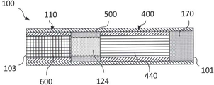
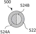
겔(125)이 로딩된 스레드를 포함하는 관형 요소(500)로서, 겔(124)은 에어로졸 발생 물품(100)과 함께 사용하기 위해, 바람직하게는 에어로졸 발생 장치(200)와 함께 사용하기 위해 활성제를 포함한다. 다양한 활성제는 바람직하게는 관형 요소(500)를 가열할 때, 관형 요소(500)로부터 에어로졸 내로 방출되거나, 발생되거나 방출될 수 있다.A tubular element ( 500 ) comprising a thread loaded with gel ( 125 ), wherein the gel ( 124 ) is an active agent for use with an aerosol-generating article ( 100 ), preferably for use with an aerosol-generating device ( 200 ). includes The various active agents may be released, generated or released from the tubular element 500 into the aerosol, preferably upon heating the tubular element 500 .
Description
본 개시는 에어로졸 발생 물품과 함께 사용하기 위한 관형 요소에 관한 것이며, 관형 요소는 겔이 로딩된 스레드를 포함한다.The present disclosure relates to a tubular element for use with an aerosol-generating article, the tubular element comprising a thread loaded with a gel.
에어로졸 발생 장치와 함께 사용하기 위한 니코틴을 포함하는 물품이 공지되어 있다. 종종 물품은 에어로졸을 방출하기 위해 코일형 전기 저항 필라멘트에 의해 가열되는, e-액체와 같은 액체를 포함한다. 액체를 포함하는 이러한 에어로졸 발생 물품의 제조, 운송 및 저장은 문제가 될 수 있고, 액체 및 액체의 내용물의 누출을 초래할 수 있다.Articles comprising nicotine for use with aerosol-generating devices are known. Often the article comprises a liquid, such as an e-liquid, which is heated by a coiled electrical resistance filament to emit an aerosol. The manufacture, transportation and storage of such aerosol-generating articles containing liquids can be problematic and can lead to leakage of liquids and their contents.
에어로졸 발생 물품 및 장치에 사용하기 위해 누출을 거의 나타내지 않거나 전혀 나타내지 않는 관형 요소를 제공하는 것이 바람직할 것이다.It would be desirable to provide a tubular element that exhibits little or no leakage for use in aerosol-generating articles and devices.
또한 에어로졸 발생 장치에 의해 가열될 때 관형 요소로부터 발생된 에어로졸을 효율적으로 전달하는 흐름 제어 시스템을 포함하는 관형 요소를 제공하는 것이 바람직할 것이다.It would also be desirable to provide a tubular element comprising a flow control system that efficiently delivers an aerosol generated from the tubular element when heated by an aerosol-generating device.
본 발명에 따르면, 관형 요소가 제공되며, 여기서 관형 요소는 제1 길이 방향 통로를 포함하고 겔이 로딩된 스레드를 더 포함하고, 겔은 활성제를 포함한다.According to the present invention, a tubular element is provided, wherein the tubular element comprises a first longitudinal passageway and further comprises a thread loaded with a gel, the gel comprising an active agent.
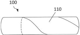
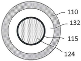
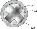
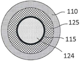
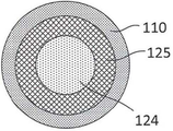
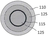
본 발명은 관형 요소를 제공하며, 관형 요소는 제1 길이 방향 통로를 형성하는 래퍼를 포함하고; 관형 요소는 겔이 로딩된 복수의 스레드를 더 포함하고; 겔은 활성제를 포함한다.The present invention provides a tubular element comprising a wrapper defining a first longitudinal passageway; the tubular element further comprises a plurality of threads loaded with gel; The gel contains an active agent.
일부 구현예에서, 관형 요소는 래퍼를 포함한다.In some embodiments, the tubular element comprises a wrapper.
일부 구현예에서, 관형 요소는 래퍼를 포함하며, 래퍼는 종이를 포함한다.In some embodiments, the tubular element comprises a wrapper, and the wrapper comprises paper.
일부 구현예에서, 관형 요소는 제1 길이 방향 통로를 형성하는 래퍼를 포함하며; 래퍼는 종이를 포함한다.In some embodiments, the tubular element includes a wrapper defining a first longitudinal passageway; The wrapper contains paper.
특정 구현예에서, 겔이 로딩된 단일 스레드가 있다. 그러나, 대안적인 구현예에서, 겔이 로딩된 복수의 스레드가 있다. 겔이 로딩된 각각의 스레드는 동일한 겔 또는 상이한 겔을 가질 수 있다.In certain embodiments, there is a single thread loaded with gel. However, in an alternative embodiment, there are multiple threads loaded with gel. Each thread loaded with gel may have the same gel or a different gel.
특정 구현예에서, 다른 특징부와 조합하여, 관형 요소는 겔이 로딩된 스레드, 바람직하게는 동일한 겔이 로딩된 스레드를 포함한다. 대안적으로, 다른 특정 구현예에서, 관형 요소는 상이한 겔을 포함한다. 특정 구현예에서, 관형 요소는 겔이 로딩된 스레드를 포함하며, 겔이 로딩된 2개의 상이한 스레드에는 상이한 겔이 로딩된다. 특정 구현예에서, 관형 요소는 하나 초과의 겔을 포함한다.In certain embodiments, in combination with other features, the tubular element comprises a thread loaded with a gel, preferably a thread loaded with the same gel. Alternatively, in certain other embodiments, the tubular element comprises a different gel. In certain embodiments, the tubular element comprises a thread loaded with a gel, two different threads loaded with a different gel loaded with a different gel. In certain embodiments, the tubular element comprises more than one gel.
다른 특징부와 조합하여, 관형 요소는 래퍼를 포함한다.In combination with other features, the tubular element includes a wrapper.
다른 특징부와 조합하여, 특정 구현예에서, 관형 요소는 겔이 로딩된 적어도 하나의 스레드에 인접한 서셉터를 포함한다. 서셉터는 얇고 세장형일 수 있다. 바람직하게는, 서셉터는 관형 요소 내에 길이 방향으로 위치된다. 바람직하게는, 서셉터는 겔이 로딩된 스레드에 의해 둘러싸인다. 대안적인 구현예에서, 서셉터는 래퍼의 내부 표면과 겔이 로딩된 스레드 사이에 위치된다. 특정 구현예에서, 래퍼는 서셉터를 포함한다. 대안적으로, 또는 추가적으로, 서셉터는 분말, 예를 들어 금속 분말의 형태일 수 있다. 분말은 겔, 또는 래퍼 내에 있을 수 있거나, 겔과 래퍼, 또는 이들의 조합 사이에 이격될 수 있다.In combination with other features, in certain embodiments, the tubular element comprises a susceptor adjacent to at least one thread loaded with gel. The susceptor may be thin and elongated. Preferably, the susceptor is positioned longitudinally within the tubular element. Preferably, the susceptor is surrounded by a thread loaded with gel. In an alternative embodiment, the susceptor is positioned between the inner surface of the wrapper and the gel loaded thread. In certain embodiments, the wrapper comprises a susceptor. Alternatively, or additionally, the susceptor may be in the form of a powder, for example a metal powder. The powder may be in a gel, or wrapper, or spaced between the gel and the wrapper, or a combination thereof.
다른 특징부와 조합하여, 특정 구현예에서, 관형 요소는 제2 관형 요소를 더 포함한다.In combination with other features, in certain embodiments, the tubular element further comprises a second tubular element.
본 발명에 따르면, 관형 요소를 제조하는 방법이 제공되며,According to the present invention, there is provided a method for manufacturing a tubular element,
상기 관형 요소는:The tubular element comprises:
제1 길이 방향 통로를 포함하고, 관형 요소는 겔이 로딩된 스레드를 더 포함하고; 겔은 활성제를 포함하고;a first longitudinal passageway, wherein the tubular element further comprises a gel loaded thread; The gel contains an active agent;
상기 방법은:The method is:
- 맨드릴 주위에 관형 요소용 재료를 배치하여 관형 요소를 형성하는 단계;- disposing material for the tubular element around the mandrel to form the tubular element;
- 맨드릴 내의 도관으로부터 겔이 로딩된 스레드를 분배하여, 겔이 로딩된 스레드가 관형 요소 내에 있도록 하는 단계를 포함하는, 방법.- dispensing the gel loaded thread from the conduit in the mandrel, such that the gel loaded thread is within the tubular element.
관형 요소는 길이로 절단될 수 있다. 다양한 길이가 요구될 수 있다. 길이는 일관될 필요는 없다.The tubular element may be cut to length. Various lengths may be required. The length does not have to be consistent.
특정 구현예에서, 관형 요소의 제조 방법은 관형 요소를 절단하는 추가 단계를 더 포함한다.In certain embodiments, the method of making the tubular element further comprises the additional step of cutting the tubular element.
특정 구현예에서, 관형 요소의 제조 방법은 맨드릴 주위에 관형 요소용 재료를 압출하여 관형 요소를 형성하는 단계를 더 포함한다.In certain embodiments, a method of making a tubular element further comprises extruding material for the tubular element around a mandrel to form the tubular element.
특정 구현예에서, 제조 방법은 래퍼로 관형 요소를 래핑하는 단계를 더 포함한다.In certain embodiments, the manufacturing method further comprises wrapping the tubular element with a wrapper.
본 발명에 따르면, 관형 요소를 제조하는 방법이 제공되며,According to the present invention, there is provided a method for manufacturing a tubular element,
상기 관형 요소는:The tubular element comprises:
제1 길이 방향 채널을 형성하는 래퍼를 포함하고 겔이 로딩된 스레드를 더 포함하고, 겔은 활성제를 포함하고,a wrapper defining a first longitudinal channel and further comprising a thread loaded with a gel, the gel comprising an active agent;
상기 방법은:The method is:
- 래핑 재료의 웹 위에 겔이 로딩된 스레드를 분배하는 단계;- dispensing the gel-loaded thread over the web of lapping material;
- 겔이 로딩된 스레드 주위에 래핑 재료의 웹을 래핑하여 겔이 로딩된 스레드의 래핑된 복합 구조를 형성하는 단계를 포함한다.- wrapping the web of wrapping material around the gel-loaded threads to form a wrapped composite structure of the gel-loaded threads.
특정 구현예에서, 관형 요소의 제조 방법은 겔이 로딩된 스레드의 래핑된 복합 구조를 길이로 절단하는 단계를 더 포함한다.In certain embodiments, the method of making the tubular element further comprises cutting the wrapped composite structure of the gel loaded thread to length.
본 발명에 따르면, 관형 요소를 제조하는 방법이 제공되며,According to the present invention, there is provided a method for manufacturing a tubular element,
상기 관형 요소는:The tubular element comprises:
- 래퍼;- wrapper;
- 활성제를 포함하는 겔이 로딩된 스레드; 및- a thread loaded with a gel comprising an active agent; and
- 제2 관형 요소를 포함하며;- a second tubular element;
상기 방법은:The method is:
- 래핑 재료의 웹 위에 겔이 로딩된 스레드를 분배하고, 래핑 재료의 웹 상의 겔이 로딩된 스레드 위에 제2 관형 요소를 분배하는 단계;- dispensing a gel-loaded thread over the web of lapping material and dispensing a second tubular element over the gel-loaded thread on the web of lapping material;
- 겔이 로딩된 스레드, 및 제2 관형 요소 주위에 래핑 재료의 웹을 래핑하여 겔이 로딩된 스레드 및 제2 관형 요소의 래핑된 복합 구조를 형성하는 단계를 포함한다.- wrapping the gel-loaded thread and the web of wrapping material around the second tubular element to form a wrapped composite structure of the gel-loaded thread and the second tubular element.
특정 구현예에서, 제조 방법은 겔이 로딩된 스레드 및 제2 관형 요소의 래핑된 복합 구조를 길이로 절단하는 단계를 더 포함한다.In certain embodiments, the manufacturing method further comprises cutting the wrapped composite structure of the gel loaded thread and the second tubular element to length.
본 발명에 따르면, 관형 요소를 제조하는 방법이 제공되며,According to the present invention, there is provided a method for manufacturing a tubular element,
상기 관형 요소는:The tubular element comprises:
- 스레드; 및- thread; and
- 래퍼를 포함하고;- wrappers;
- 겔을 더 포함하며, 겔은 활성제를 포함하고;- further comprising a gel, wherein the gel comprises an active agent;
상기 방법은:The method is:
- 래핑 재료의 웹 상에 스레드를 분배하는 단계;- dispensing the thread onto the web of lapping material;
- 래핑 재료의 웹 위의 스레드 위에 겔을 분배하여 겔이 스레드를 함침시키거나 코팅하고 스레드에는 겔이 로딩되게 하는 단계;- dispensing the gel over the threads over the web of lapping material so that the gel impregnates or coats the threads and the threads are loaded with the gel;
- 겔이 로딩된 스레드 주위에 래핑 재료를 래핑하여 겔이 로딩된 스레드의 복합 구조를 형성하는 단계를 포함한다.- wrapping a wrapping material around the gel-loaded thread to form a composite structure of the gel-loaded thread.
특정 구현예에서, 관형 요소를 제조하는 방법은 겔이 로딩된 스레드의 복합 구조를 길이로 분할하는 단계를 더 포함한다.In certain embodiments, the method of making the tubular element further comprises dividing the composite structure of the gel-loaded thread into lengths.
본 발명에 따르면, 에어로졸 발생 물품에서 사용하기 위한 관형 요소를 제조하는 방법이 제공되며,According to the present invention, there is provided a method of manufacturing a tubular element for use in an aerosol-generating article,
상기 관형 요소는:The tubular element comprises:
- 래퍼;- wrapper;
- 관형 요소의 길이를 따라 연장되는 제2 관형 요소;- a second tubular element extending along a length of the tubular element;
- 제2 관형 요소 사이에 위치되는 겔이 로딩되고 중공 관형 요소를 따라 연장되는 스레드로서, 첨가제가 겔 내에 분산되는 스레드; 및- a thread loaded with a gel positioned between the second tubular elements and extending along the hollow tubular element, wherein an additive is dispersed within the gel; and
- 겔 로딩된 스레드 및 중공 관형 요소 주위에 래핑되는 래퍼를 포함하고,- a gel loaded thread and a wrapper wrapped around the hollow tubular element;
상기 방법은:The method is:
- 형성 다이를 통해 그리고 중공 관형 요소 내에 중공 코어를 형성하는 맨드릴 주위에 중공 관형 요소용 재료를 압출하는 단계;- extruding material for the hollow tubular element through a forming die and around a mandrel forming a hollow core within the hollow tubular element;
- 형성 다이 내의 도관으로부터 그리고 중공 관형 요소 주위에 겔이 로딩된 스레드를 공압출하여 복합 코어를 형성하는 단계;- co-extruding the gel-loaded thread from the conduit in the forming die and around the hollow tubular element to form the composite core;
- 래핑 재료의 웹을 따라 복합 코어를 놓는 단계;- laying the composite core along the web of wrapping material;
- 복합 코어 주위에 래핑 재료를 래핑하여 래핑된 복합 구조를 형성하는 단계를 포함한다.- wrapping a wrapping material around the composite core to form a wrapped composite structure.
특정 구현예에서, 관형 요소의 제조 방법은 복합 구조를 길이로 분할하여 원하는 길이의 관형 요소를 형성하는 단계를 더 포함한다.In certain embodiments, a method of making a tubular element further comprises dividing the composite structure into lengths to form a tubular element of a desired length.
특정 구현예에서, 관형 요소를 제조하는 방법은 복수의 스레드를 분배하는 단계를 더 포함한다.In certain embodiments, a method of manufacturing a tubular element further comprises dispensing a plurality of threads.
본 발명에 따르면, 관형 요소가 제공되며, 관형 요소는 제1 길이 방향 통로를 포함하고, 관형 요소는 겔이 로딩된 다공성 매체를 더 포함하고; 겔은 활성제를 포함한다. 특정 구현예에서, 관형 요소는 래퍼를 더 포함한다.According to the present invention, there is provided a tubular element, the tubular element comprising a first longitudinal passageway, the tubular element further comprising a porous medium loaded with a gel; The gel contains an active agent. In certain embodiments, the tubular element further comprises a wrapper.
특정 구현예에서, 겔이 로딩된 다공성 매체는 래퍼 내의 관형 요소를 완전히 충진한다. 대안적으로, 다른 특정 구현예에서, 다공성 매체는 관형 요소를 부분적으로만 충진한다.In certain embodiments, the gel-loaded porous medium completely fills the tubular element within the wrapper. Alternatively, in certain other embodiments, the porous medium only partially fills the tubular element.
특정 구현예에서, 관형 요소는 제2 관형 요소를 더 포함하며, 제2 관형 요소는 길이 방향 측면, 및 근위 및 원위 단부를 갖고, 제2 관형 요소는 래퍼에 의해 형성된 제1 길이 방향 통로 내에 길이 방향으로 위치된다.In certain embodiments, the tubular element further comprises a second tubular element, the second tubular element having longitudinal sides, and proximal and distal ends, the second tubular element having a length within the first longitudinal passageway defined by the wrapper. located in the direction
특정 구현예에서, 제2 관형 요소의 길이 방향 측면은 종이, 또는 판지, 또는 셀룰로스 아세테이트를 포함한다.In certain embodiments, the longitudinal side of the second tubular element comprises paper, or cardboard, or cellulose acetate.
특정 구현예에서, 제2 관형 요소는 겔이 로딩된 다공성 매체를 포함한다. 그러나, 대안적인 특정 구현예에서, 제2 관형 요소는 겔을 포함한다.In certain embodiments, the second tubular element comprises a porous medium loaded with a gel. However, in certain alternative embodiments, the second tubular element comprises a gel.
일부 특정 구현예에서, 설명된 바와 같은 제1 및 제2 관형 요소 및 래퍼가 있는 경우, 겔이 로딩된 다공성 매체는 제1 길이 방향 채널을 형성하는 래퍼와 제2 관형 요소 사이에 위치된다.In some specific embodiments, where there are first and second tubular elements and a wrapper as described, the gel-loaded porous medium is positioned between the wrapper and the second tubular element defining a first longitudinal channel.
일부 대안적인 구현예에서, 제1 및 제2 관형 요소가 있는 경우, 겔은 적어도 하나의 길이 방향 채널을 형성하는 래퍼와 제2 관형 요소 사이에 위치된다.In some alternative embodiments, where there are first and second tubular elements, the gel is positioned between the second tubular element and a wrapper defining at least one longitudinal channel.
다른 특징부와 조합하여, 특정 구현예에서, 관형 요소는 제1 길이 방향 채널 내에 길이 방향으로 위치된 길이 방향 요소를 포함한다.In combination with other features, in certain embodiments, the tubular element comprises a longitudinal element positioned longitudinally within the first longitudinal channel.
다른 특징부와 조합하여, 특정 구현예에서, 래퍼는 강성이다. 대안적으로, 또는 추가적으로, 특정 구현예에서, 제2 관형 요소의 길이 방향 측면은 강성이다.In combination with other features, in certain embodiments, the wrapper is rigid. Alternatively, or additionally, in certain embodiments, the longitudinal side of the second tubular element is rigid.
다른 특징부와 조합하여, 특정 구현예에서, 래퍼는 내수성이다.In combination with other features, in certain embodiments, the wrapper is water resistant.
다른 특징부와 조합하여, 특정 구현예에서, 관형 요소는 서셉터를 더 포함한다.In combination with other features, in certain embodiments, the tubular element further comprises a susceptor.
특정 구현예에서, 겔이 로딩된 다공성 매체는 크림핑(crimped)된다. 다공성 매체는 겔이 로딩되기 전에 또는 로딩된 후에 크림핑될 수 있다.In certain embodiments, the gel-loaded porous medium is crimped. The porous medium may be crimped before or after the gel is loaded.
특정 구현예에서, 겔이 로딩된 다공성 매체는 파쇄된다. 다공성 매체는 겔이 로딩되기 전에 또는 로딩된 후에 파쇄될 수 있다.In certain embodiments, the gel-loaded porous medium is disrupted. The porous medium may be disrupted before or after the gel is loaded.
본 발명에 따르면, 임의의 이전 청구항에 청구된 바와 같은 관형 요소를 제조하는 방법이 제공되며,According to the present invention there is provided a method for manufacturing a tubular element as claimed in any previous claim,
상기 방법은:The method is:
- 래핑 재료의 웹 위에 겔이 로딩된 다공성 매체를 분배하는 단계; 및,- dispensing a gel-loaded porous medium over a web of wrapping material; and,
- 래핑 재료의 웹 위에 겔이 로딩된 다공성 매체 위에 제2 관형 요소를 분배하는 단계;- dispensing a second tubular element over a porous medium loaded with gel over a web of wrapping material;
- 겔이 로딩된 다공성 매체 및 제2 관형 요소 주위에 래핑 재료의 웹을 래핑하여 겔이 로딩된 다공성 매체 및 제2 관형 요소의 복합 구조를 형성하는 단계를 포함한다.- wrapping the web of wrapping material around the gel-loaded porous medium and the second tubular element to form a composite structure of the gel-loaded porous medium and the second tubular element.
특정 구현예에서, 관형 요소의 제조 방법은 겔이 로딩된 다공성 매체 및 제2 관형 요소의 래핑된 복합 구조를 길이로 절단하는 단계를 더 포함한다.In certain embodiments, the method of making the tubular element further comprises cutting the wrapped composite structure of the gel-loaded porous medium and the second tubular element to length.
본 발명에 따르면, 관형 요소가 제공되며, 관형 요소는 제1 길이 방향 통로를 형성하는 래퍼를 포함하고; 관형 요소는 겔을 더 포함하고; 겔은 활성제를 포함한다.According to the present invention, a tubular element is provided, the tubular element comprising a wrapper defining a first longitudinal passageway; the tubular element further comprises a gel; The gel contains an active agent.
특정 구현예에서, 겔은 래퍼 내의 관형 요소를 완전히 충진한다.In certain embodiments, the gel completely fills the tubular element within the wrapper.
대안적으로, 특정 구현예에서, 겔은 관형 요소를 부분적으로 충진할 수 있다. 예를 들어, 특정 구현예에서, 겔은 관형 요소의 내부 표면 상에 코팅으로서 제공된다. 관형 요소를 부분적으로만 충진하는 것의 장점은 예를 들어, 에어로졸이 관형 요소 내로 또는 관형 요소 밖으로 흐르도록 유체 경로를 남긴다는 것이다.Alternatively, in certain embodiments, the gel may partially fill the tubular element. For example, in certain embodiments, the gel is provided as a coating on the inner surface of the tubular element. An advantage of only partially filling the tubular element is that it leaves a fluid path for, for example, aerosol to flow into or out of the tubular element.
특정 구현예와 조합하여, 관형 요소는 제2 관형 요소를 포함한다.In combination with certain embodiments, the tubular element comprises a second tubular element.
특정 구현예와 조합하여, 관형 요소는 길이 방향 측면, 및 근위 및 원위 단부를 포함하는 제2 관형 요소를 포함하고; 제2 관형 요소는 제1 길이 방향 통로 내에 길이 방향으로 위치된다.In combination with certain embodiments, the tubular element comprises a second tubular element comprising a longitudinal side and proximal and distal ends; The second tubular element is longitudinally positioned within the first longitudinal passageway.
특정 구현예와 조합하여, 관형 요소는 복수의 제2 관형 요소를 포함한다.In combination with certain embodiments, the tubular element includes a plurality of second tubular elements.
특정 구현예에서, 관형 요소는 관형 요소의 길이 방향 길이를 따라 연장되도록 병렬로 배열된 복수의 제2 관형 요소를 포함한다. 선택적으로, 겔은 복수의 제2 관형 요소의 전부, 일부 내에 제공되거나, 전혀 제공되지 않는다. 또한, 특정 구현예에 따라, 제2 관형 요소 내에 겔이 있는 경우, 겔은 복수의 제2 관형 요소 각각을 완전히 충진하거나, 겔은 제2 관형 요소를 부분적으로 충진한다.In certain embodiments, the tubular element comprises a plurality of second tubular elements arranged in parallel to extend along a longitudinal length of the tubular element. Optionally, the gel is provided in all, some, or none of the plurality of second tubular elements. Also, according to certain embodiments, when there is a gel in the second tubular element, the gel completely fills each of the plurality of second tubular elements, or the gel partially fills the second tubular element.
특정 구현예에서, 관형 요소는 겔이 로딩된 다공성 매체를 포함한다.In certain embodiments, the tubular element comprises a porous medium loaded with a gel.
다른 특징부와 조합하여, 특정 구현예에서, 제2 관형 요소 중 하나 이상은 겔이 로딩된 다공성 매체를 포함한다. 겔이 로딩된 다공성 매체가 있는 경우, 겔이 로딩된 다공성 매체는 복수의 제2 관형 요소 각각을 완전히 충진하거나, 겔이 로딩된 다공성 매체는 제2 관형 요소를 부분적으로 충진한다.In combination with other features, in certain embodiments, at least one of the second tubular elements comprises a porous medium loaded with a gel. When there is a gel-loaded porous medium, the gel-loaded porous medium completely fills each of the plurality of second tubular elements, or the gel-loaded porous medium partially fills the second tubular element.
특정 구현예에서, 겔이 로딩된 다공성 매체는 제2 관형 요소와 래퍼 사이에 위치된다.In certain embodiments, the gel-loaded porous medium is positioned between the second tubular element and the wrapper.
특정 구현예에서, 제2 관형 요소의 길이 방향 측면은 종이, 또는 판지, 또는 셀룰로스 아세테이트를 포함한다.In certain embodiments, the longitudinal side of the second tubular element comprises paper, or cardboard, or cellulose acetate.
특정 구현예에서, 제2 관형 요소는 겔을 포함한다. 바람직하게는, 겔은 제2 관형 요소의 길이 방향 측면에 의해 적어도 부분적으로 둘러싸인다.In certain embodiments, the second tubular element comprises a gel. Preferably, the gel is at least partially surrounded by the longitudinal side of the second tubular element.
특정 구현예에서, 겔은 제1 길이 방향 통로를 형성하는 래퍼와 제2 관형 요소 사이에 위치될 수 있다.In certain embodiments, the gel may be positioned between a wrapper defining a first longitudinal passageway and a second tubular element.
특정 구현예와 조합하여, 관형 요소는 에어로졸 발생 물품의 외부 직경과 대략 동일한 외부 직경을 갖는다.In combination with certain embodiments, the tubular element has an outer diameter approximately equal to the outer diameter of the aerosol-generating article.
특정 구현예에서, 관형 요소는 5 mm 내지 12 mm, 예를 들어 5 mm 내지 10 mm 또는 6 mm 내지 8 mm의 외부 직경을 갖는다. 통상적으로, 관형 요소는 7.2 mm ±10%의 외부 직경을 갖는다.In certain embodiments, the tubular element has an outer diameter of between 5 mm and 12 mm, for example between 5 mm and 10 mm or between 6 mm and 8 mm. Typically, the tubular element has an outer diameter of 7.2 mm ±10%.
통상적으로, 관형 요소는 5 mm 내지 15 mm의 길이를 갖는다. 바람직하게는, 관형 요소는 6 mm 내지 12 mm의 길이를 가지며, 바람직하게는, 관형 요소는 7 mm 내지 10 mm의 길이를 가지며, 바람직하게는 관형 요소는 8 mm의 길이를 갖는다.Typically, the tubular element has a length of 5 mm to 15 mm. Preferably, the tubular element has a length of 6 mm to 12 mm, preferably, the tubular element has a length of 7 mm to 10 mm, preferably the tubular element has a length of 8 mm.
특정 구현예와 조합하여, 겔은 바람직하게는 겔이 가열될 때, 휘발성 화합물을 관형 요소를 통과하는 에어로졸 내로 방출할 수 있는 재료의 혼합물이다. 겔의 제공은 관형 요소, 에어로졸 발생 물품 또는 에어로졸 발생 장치로부터의 누출의 위험이 감소될 수 있으므로, 저장 및 운송에 유리하거나, 사용 동안 유리할 수 있다.In combination with certain embodiments, the gel is preferably a mixture of materials capable of releasing volatile compounds into the aerosol passing through the tubular element when the gel is heated. Provision of the gel may be advantageous for storage and transport, or during use, as the risk of leakage from the tubular element, aerosol-generating article or aerosol-generating device may be reduced.
유리하게는, 겔은 실온에서 고체이다. 이러한 문맥에서 "고체"는 겔이 안정한 크기와 형상을 가지며 유동하지 않음을 의미한다. 이러한 문맥에서 실온은 25℃를 의미한다.Advantageously, the gel is solid at room temperature. "Solid" in this context means that the gel has a stable size and shape and does not flow. Room temperature in this context means 25°C.
겔은 에어로졸 형성제를 포함할 수 있다. 이상적으로, 에어로졸 형성제는 관형 요소의 작동 온도에서 열적 열화에 대해 실질적으로 내성이다. 적절한 에어로졸 형성제는 당업계에 잘 공지되어 있으며, 트리에틸렌 글리콜, 1,3-부탄디올 및 글리세린과 같은 다가 알코올; 글리세롤 모노-, 디- 또는 트리아세테이트와 같은 다가 알코올의 에스테르; 및 디메틸 도데칸디오에이트(dimethyl dodecanedioate) 및 디메틸 테트라데칸디오에이트(dimethyl tetradecanedioate)와 같은, 모노-, 디- 또는 폴리카르복실산의 지방족 에스테르를 포함하지만 이에 한정되지 않는다. 다가 알코올 또는 이들의 혼합물은 트리에틸렌 글리콜, 1,3-부탄디올 및 글리세린 또는 폴리에틸렌 글리콜 중 하나 이상일 수 있다.The gel may include an aerosol former. Ideally, the aerosol former is substantially resistant to thermal degradation at the operating temperature of the tubular element. Suitable aerosol formers are well known in the art and include polyhydric alcohols such as triethylene glycol, 1,3-butanediol and glycerin; esters of polyhydric alcohols such as glycerol mono-, di- or triacetate; and aliphatic esters of mono-, di- or polycarboxylic acids, such as dimethyl dodecanedioate and dimethyl tetradecanedioate. The polyhydric alcohol or mixtures thereof may be one or more of triethylene glycol, 1,3-butanediol and glycerin or polyethylene glycol.
유리하게는, 겔은 예를 들어, 열가역성 겔을 포함한다. 이는 용융 온도로 가열될 때 겔이 유체가 되어 겔화 온도에서 다시 겔로 설정되는 것을 의미한다. 겔화 온도는 실온 및 대기압 이상일 수 있다. 대기압은 1 기압의 압력을 의미한다. 용융 온도는 겔화 온도보다 더 높을 수 있다. 겔의 용융 온도는 50℃, 또는 60℃, 또는 70℃ 초과일 수 있고, 80℃ 초과일 수 있다. 이러한 문맥에서 용융 온도는 겔이 더 이상 고체가 아니고 유동하기 시작하는 온도를 의미한다.Advantageously, the gel comprises, for example, a thermoreversible gel. This means that the gel becomes a fluid when heated to its melting temperature and sets back to a gel at its gelling temperature. The gelation temperature may be above room temperature and atmospheric pressure. Atmospheric pressure means a pressure of 1 atmosphere. The melting temperature may be higher than the gelling temperature. The melting temperature of the gel may be greater than 50°C, or 60°C, or 70°C, and may be greater than 80°C. Melting temperature in this context means the temperature at which the gel is no longer a solid and begins to flow.
대안적으로, 특정 구현예에서, 겔은 관형 요소의 사용 동안 용융되지 않는 비-용융 겔이다. 이러한 구현예에서, 겔은 사용중의 관형 요소의 작동 온도 이상이되, 겔의 용융 온도 미만인 온도에서 활성제를 적어도 부분적으로 방출할 수 있다.Alternatively, in certain embodiments, the gel is a non-melting gel that does not melt during use of the tubular element. In such embodiments, the gel is capable of at least partially releasing the active agent at a temperature above the operating temperature of the tubular element in use but below the melting temperature of the gel.
바람직하게는, 겔은 원하는 점도를 제공하기 위해 초당 50,000 내지 10 파스칼, 바람직하게는 초당 10,000 내지 1,000 파스칼의 점도를 갖는다.Preferably, the gel has a viscosity of 50,000 to 10 Pascals per second, preferably 10,000 to 1,000 Pascals per second to provide the desired viscosity.
특정 구현예와 조합하여, 겔은 겔화제를 포함한다. 특정 구현예에서, 겔은 한천 또는 아가로오스 또는 소듐 알지네이트 또는 젤란 검, 또는 이들의 혼합물을 포함한다.In combination with certain embodiments, the gel comprises a gelling agent. In certain embodiments, the gel comprises agar or agarose or sodium alginate or gellan gum, or a mixture thereof.
특정 구현예에서, 겔은 물을 포함하며, 예를 들어, 겔은 하이드로겔이다. 대안적으로, 특정 구현예에서, 겔은 비수성이다.In certain embodiments, the gel comprises water, eg, the gel is a hydrogel. Alternatively, in certain embodiments, the gel is non-aqueous.
바람직하게는, 겔은 활성제를 포함한다. 특정 구현예와 조합하여, 활성제는 예를 들어, 에어로졸에서 방출하기 위해 니코틴(예를 들어, 분말 형태 또는 액체 형태) 또는 담배 제품 또는 다른 목표 화합물을 포함한다. 특정 구현예에서, 니코틴은 에어로졸 형성제를 갖는 겔에 포함된다. 실온에서 니코틴을 겔로 고정하는 것은 누출을 방지하기 위해 바람직하다.Preferably, the gel comprises an active agent. In combination with certain embodiments, the active agent includes, for example, nicotine (eg, in powder or liquid form) or a tobacco product or other target compound for release in an aerosol. In certain embodiments, nicotine is included in a gel with an aerosol former. Fixing the nicotine into a gel at room temperature is desirable to prevent leakage.
특정 구현예에서, 겔은 가열될 때 향미 화합물을 방출하는 고체 담배 재료를 포함한다. 특정 구현예에 따라, 고체 담배 재료는 예를 들어, 식물 재료, 예컨대 허브 잎, 담배 잎, 담배 리브 조각, 재구성 담배, 균질화 담배, 압출 담배, 및 팽화 담배 중 하나 이상을 함유하는 분말, 과립, 펠릿, 슈레드, 스파게티, 스트립 또는 시트 중 하나 이상이다.In certain embodiments, the gel comprises a solid tobacco material that releases a flavor compound when heated. According to a particular embodiment, the solid tobacco material may be, for example, a powder, granule, or powder containing one or more of plant material, such as herbal leaves, tobacco leaves, tobacco rib pieces, reconstituted tobacco, homogenised tobacco, extruded tobacco, and puffed tobacco; one or more of pellets, shreds, spaghetti, strips, or sheets.
추가적으로 또는 대안적으로, 예를 들어, 겔이 다른 향미제, 예를 들어 멘톨을 포함하는 구현예가 있다. 멘톨은 겔의 형성 전에 물에 또는 에어로졸 형성제에 첨가될 수 있다.Additionally or alternatively, for example, there are embodiments wherein the gel comprises another flavoring agent, for example menthol. Menthol may be added to the water or to the aerosol former prior to the formation of the gel.
한천이 겔화제로서 사용되는 구현예에서, 겔은 예를 들어, 0.5 내지 5 중량%, 바람직하게는 0.8 내지 1 중량%의 한천을 포함한다. 바람직하게는, 겔은 0.1 내지 2 중량%의 니코틴을 더 포함할 수 있다. 바람직하게는, 겔은 30 중량% 내지 90 중량%(또는 70 중량% 내지 90 중량%)의 글리세린을 더 포함한다. 특정 구현예에서, 겔의 나머지는 물 및 향미제를 포함한다.In an embodiment in which agar is used as the gelling agent, the gel comprises, for example, 0.5 to 5% by weight, preferably 0.8 to 1% by weight of agar. Preferably, the gel may further comprise 0.1 to 2% by weight of nicotine. Preferably, the gel further comprises 30% to 90% (or 70% to 90%) glycerin by weight. In certain embodiments, the remainder of the gel comprises water and flavoring agent.
바람직하게는, 겔화제는 85℃ 초과의 온도에서 용융되고 약 40℃에서 겔로 되돌아가는 특성을 갖는 한천이다. 이러한 특성은 그것을 더운 환경에 적절하게 한다. 겔은 50℃에서 용융되지 않을 것이며, 이는 예를 들어, 시스템이 햇빛 속의 더운 자동차에 방치되는 경우에 유용하다. 약 85℃에서 액체로의 상전이는 에어로졸화를 유도하기 위해 겔이 비교적 저온으로 가열될 필요만이 있음을 의미하며, 이는 낮은 에너지 소비를 허용한다. 아가 대신 아가의 성분들 중 하나인 단지 아가로오스만을 사용하는 것이 유리할 수 있다.Preferably, the gelling agent is an agar that melts at a temperature greater than 85°C and returns to a gel at about 40°C. These properties make it suitable for hot environments. The gel will not melt at 50°C, which is useful, for example, if the system is left in a hot car in the sun. The phase transition from about 85° C. to liquid means that the gel only needs to be heated to a relatively low temperature to induce aerosolization, which allows for low energy consumption. It may be advantageous to use only agarose, one of the components of agar instead of agar.
젤란 검이 겔화제로서 사용될 때, 통상적으로 겔은 0.5 내지 5 중량%의 젤란 검을 포함한다. 바람직하게는, 겔은 0.1 내지 2 중량%의 니코틴을 더 포함할 수 있다. 바람직하게는, 겔은 30 중량% 내지 99.4 중량%의 글리세린을 포함한다. 특정 구현예에서, 겔의 나머지는 물 및 향미제를 포함한다.When gellan gum is used as the gelling agent, the gel typically contains 0.5 to 5% by weight of gellan gum. Preferably, the gel may further comprise 0.1 to 2% by weight of nicotine. Preferably, the gel comprises from 30% to 99.4% by weight of glycerin. In certain embodiments, the remainder of the gel comprises water and flavoring agent.
일 예에서, 겔은 2 중량% 니코틴, 70 중량% 글리세롤, 27 중량% 물 및 1 중량% 한천을 포함한다.In one example, the gel comprises 2 wt% nicotine, 70 wt% glycerol, 27 wt% water and 1 wt% agar.
다른 예에서, 겔은 65 중량% 글리세롤, 20 중량% 물, 14.3 중량% 담배 및 0.7 중량% 한천을 포함한다.In another example, the gel comprises 65 wt% glycerol, 20 wt% water, 14.3 wt% tobacco, and 0.7 wt% agar.
추가적으로, 또는 대안적으로, 일부 특정 구현예에서, 관형 요소는 겔이 로딩된 다공성 매체를 포함한다. 바람직하게는, 겔이 로딩된 다공성 매체는 제1 길이 방향 통로를 형성하는 래퍼와 제2 관형 요소 사이에 위치된다. 대안적으로, 일부 특정 구현예에서, 제2 관형 요소는 겔이 로딩된 다공성 매체를 포함한다. 이러한 구현예는 추가적으로 또는 대안적으로 다른 곳에 위치되는 겔 또는 겔이 로딩된 다공성 매체를 반드시 배제하는 것은 아니다. 특정 구현예에서, 관형 요소는 겔 및 겔이 로딩된 다공성 매체를 포함한다.Additionally, or alternatively, in some specific embodiments, the tubular element comprises a porous medium loaded with a gel. Preferably, the gel-loaded porous medium is positioned between the wrapper defining the first longitudinal passageway and the second tubular element. Alternatively, in some specific embodiments, the second tubular element comprises a porous medium loaded with a gel. These embodiments do not necessarily exclude a gel or gel-loaded porous medium that is additionally or alternatively located elsewhere. In certain embodiments, the tubular element comprises a gel and a porous medium loaded with a gel.
특정 구현예와 조합하여, 관형 요소는 제1 길이 방향 통로 내에 길이 방향으로 위치된 길이 방향 요소를 포함한다. 특정 구현예에서, 제1 길이 방향 통로 내에 길이 방향으로 위치되는 길이 방향 요소는 겔이 로딩된 다공성 매체이다. 다른 특정 구현예에서, 길이 방향 요소는 예를 들어, 관형 요소 내의 공간을 차지하거나, 열 또는 재료의 통과를 보조하거나 돕거나, 심지어 구조물의 강성도 또는 강성을 도울 수 있는, 임의의 재료의 길이 방향 요소일 수 있다.In combination with certain embodiments, the tubular element comprises a longitudinal element positioned longitudinally within the first longitudinal passageway. In certain embodiments, the longitudinal element positioned longitudinally within the first longitudinal passageway is a gel-loaded porous medium. In other specific embodiments, the longitudinal element may be, for example, occupying space within the tubular element, assisting or assisting the passage of heat or material, or even assisting the rigidity or rigidity of the structure in the longitudinal direction of any material. It can be an element.
일부 구현예에서, 래퍼는 관형 요소의 구조를 보조하기 위해 단단하거나, 강성이다. 본 발명에 사용된 겔은 반고체이고, 특히 사용시 형상을 유지할 수 있을 것으로 예상된다. 그러나, 본 발명은 고체 겔로 한정되지 않는다. 더 많은 유체 겔, 즉 고체 겔보다 더 높은 점도를 갖는 겔은 또한 본 발명의 구현예와 함께 사용될 수 있다. 따라서, 그 자체가 관형 요소 구조를 유지할 수 있는 래퍼를 갖는 것은 유익하지만, 필요하지 않다. 마찬가지로, 제2 관형 요소의 길이 방향 측면은 강성이거나, 단단할 수 있다. 제2 관형 요소의 래퍼 또는 길이 방향 측면, 또는 제2 관형 요소의 래퍼 및 길이 방향 측면 둘 모두를 단단하게 하거나 강성하게 하는 것은 관형 요소의 구조를 도울 수 있지만, 또한 제조를 도울 수 있다. 바람직하게는, 래퍼는 약 50 내지 150 μm의 두께를 갖는다.In some embodiments, the wrapper is rigid or rigid to assist in the construction of the tubular element. The gel used in the present invention is semi-solid and is expected to be able to retain its shape, particularly in use. However, the present invention is not limited to solid gels. More fluid gels, ie, gels with a higher viscosity than solid gels, may also be used with embodiments of the present invention. Thus, it would be beneficial, but not necessary, to have a wrapper capable of holding the tubular element structure by itself. Likewise, the longitudinal side of the second tubular element may be rigid or rigid. Hardening or stiffening the wrapper or longitudinal side of the second tubular element, or both the wrapper and longitudinal side of the second tubular element, may aid in the construction of the tubular element, but may also aid in manufacturing. Preferably, the wrapper has a thickness of about 50 to 150 μm.
다른 특징부와 조합하여, 특정 구현예에서, 래퍼는 내수성이다. 특정 구현예에서, 제2 관형 요소의 길이 방향 측면은 내수성이다. 제2 관형 요소의 래퍼 또는 길이 방향 측면의 이러한 내수 특성은 내수 재료를 사용하거나, 제2 관형 요소의 래퍼 또는 길이 방향 측면의 재료를 처리함으로써 달성될 수 있다. 이는 래퍼의 일측 또는 양측 또는 제2 관형 요소의 길이 방향 측면을 처리함으로써 달성될 수 있다. 내수성인 것은 구조, 강성도 또는 강성을 상실하지 않는 것을 보조할 것이다. 이는 또한, 특히 유체 구조의 겔이 사용될 때, 겔 또는 액체의 누출을 방지하는 것을 보조할 수 있다.In combination with other features, in certain embodiments, the wrapper is water resistant. In certain embodiments, the longitudinal side of the second tubular element is water resistant. This water resistant property of the wrapper or longitudinal side of the second tubular element can be achieved by using a water resistant material or by treating the material of the wrapper or longitudinal side of the second tubular element. This can be achieved by treating one or both sides of the wrapper or the longitudinal side of the second tubular element. Being water resistant will assist in not losing structure, stiffness or stiffness. It can also help prevent leakage of the gel or liquid, especially when a gel of a fluid structure is used.
특정 구현예와 조합하여, 관형 요소는 서셉터를 포함한다. 서셉터는 임의의 열 전달 재료일 수 있으며, 예를 들어 금속 스레드, 예를 들어 알루미늄 스레드, 또는 알루미늄 또는 알루미늄 분말과 같은 금속 분말을 포함하는 스레드일 수 있다. 통상적으로, 서셉터는 관형 요소 내에 길이 방향으로 위치된다. 서셉터는 겔 내에, 또는 겔에 인접하여, 또는 겔 근처에; 또는 겔이 로딩된 다공성 매체 내에, 이 매체에 인접하여, 또는 이 매체 근처에 위치될 수 있다.In combination with certain embodiments, the tubular element comprises a susceptor. The susceptor may be any heat transfer material, for example a metal thread, for example an aluminum thread, or a thread comprising a metal powder such as aluminum or aluminum powder. Typically, the susceptor is positioned longitudinally within the tubular element. The susceptor may be in, adjacent to, or near the gel; Alternatively, the gel can be positioned within, adjacent to, or near the porous medium loaded with the gel.
특정 구현예와 조합하여, 관형 요소는 스레드를 더 포함한다. 이는 임의의 재료, 천연 또는 합성일 수 있지만, 바람직하게는 면(cotton)일 수 있다. 스레드는 활성 성분, 예를 들어 향미를 운반하기 위한 비히클일 수 있다. 본 발명에 사용하기 위한 적절한 향미의 일 예는 멘톨일 수 있다. 스레드는 관형 요소 내에서 길이 방향으로 이어질 수 있다. 바람직하게는, 스레드는 겔 내에, 또는 겔에 인접하여, 또는 겔 근처에; 또는 겔이 로딩된 다공성 매체 내에, 또는 이 매체에 인접하여, 또는 이 매체 근처에 위치될 수 있다.In combination with certain embodiments, the tubular element further comprises a thread. It may be of any material, natural or synthetic, but preferably cotton. The thread may be a vehicle for delivering the active ingredient, for example a flavor. One example of a suitable flavor for use in the present invention may be menthol. The thread may run longitudinally within the tubular element. Preferably, the thread is in, adjacent to, or near the gel; Alternatively, the gel can be positioned within, adjacent to, or near the porous medium loaded with the gel.
특정 구현예와 조합하여, 관형 요소는 시트 재료를 더 포함한다. 특정 구현예와 조합하여, 겔이 로딩된 다공성 매체는 시트 재료를 포함한다. 겔이 로딩된 다공성 재료를 제공함으로써, 시트 재료는 제조에 있어서 장점을 가질 수 있고, 예를 들어, 시트 재료는 함께 모이기 쉬워서 적절한 구조를 제공할 수 있다. 겔은 함께 모이기 전에 시트 재료 내로 로딩될 수 있거나, 함께 모인 후에 시트 재료 내로 로딩될 수 있다.In combination with certain embodiments, the tubular element further comprises a sheet material. In combination with certain embodiments, the gel-loaded porous medium comprises a sheet material. By providing a gel-loaded porous material, the sheet material can have advantages in manufacturing, for example, the sheet material can be easily brought together to provide an appropriate structure. The gel may be loaded into the sheet material prior to being brought together, or may be loaded into the sheet material after being brought together.
본 발명에 따르면, 관형 요소가 제공되며, 관형 요소는 제1 길이 방향 채널을 형성하는 래퍼를 포함하고, 관형 요소는 겔이 로딩된 다공성 매체를 더 포함하고, 겔이 로딩된 다공성 매체는 활성제를 더 포함한다.According to the present invention, a tubular element is provided, the tubular element comprising a wrapper defining a first longitudinal channel, the tubular element further comprising a gel-loaded porous medium, the gel-loaded porous medium comprising: include more
특정 구현예에서, 겔이 로딩된 다공성 매체는 래퍼 내의 관형 요소를 완전히 충진한다. 대안적으로, 다른 특정 구현예에서, 다공성 매체는 관형 요소를 부분적으로만 충진한다.In certain embodiments, the gel-loaded porous medium completely fills the tubular element within the wrapper. Alternatively, in certain other embodiments, the porous medium only partially fills the tubular element.
특정 구현예에서, 관형 요소는 제2 관형 요소를 더 포함하며, 제2 관형 요소는 길이 방향 측면, 및 근위 및 원위 단부를 갖고, 제2 관형 요소는 래퍼에 의해 형성된 제1 길이 방향 채널 내에 길이 방향으로 위치된다.In certain embodiments, the tubular element further comprises a second tubular element, the second tubular element having longitudinal sides, and proximal and distal ends, the second tubular element having a length within a first longitudinal channel formed by the wrapper. located in the direction
특정 구현예에서, 제2 관형 요소의 길이 방향 측면은 종이, 또는 판지, 또는 셀룰로스 아세테이트를 포함한다.In certain embodiments, the longitudinal side of the second tubular element comprises paper, or cardboard, or cellulose acetate.
특정 구현예에서, 제2 관형 요소는 겔이 로딩된 다공성 매체를 포함한다.In certain embodiments, the second tubular element comprises a porous medium loaded with a gel.
일부 특정 구현예에서, 설명된 바와 같은 제1 및 제2 관형 요소가 있는 경우, 겔이 로딩된 다공성 매체는 제1 길이 방향 채널을 형성하는 래퍼와 제2 관형 요소 사이에 위치된다.In some specific embodiments, where there are first and second tubular elements as described, the gel-loaded porous medium is positioned between the second tubular element and a wrapper defining a first longitudinal channel.
일부 대안적인 구현예에서, 제1 및 제2 관형 요소가 있는 경우, 겔은 제1 길이 방향 채널을 형성하는 래퍼와 제2 관형 요소 사이에 위치된다.In some alternative embodiments, where there are first and second tubular elements, the gel is positioned between the second tubular element and a wrapper defining a first longitudinal channel.
본 발명에 따르면, 관형 요소를 제조하는 방법이 제공되며,According to the present invention, there is provided a method for manufacturing a tubular element,
상기 관형 요소는:The tubular element comprises:
적어도 하나의 길이 방향 통로를 포함하고 겔을 더 포함하고; 겔은 활성제를 포함하고;at least one longitudinal passageway and further comprising a gel; The gel contains an active agent;
상기 방법은:The method is:
- 관형 요소를 형성하는 맨드릴 주위에 관형 요소용 재료를 배치하는 단계;- disposing material for the tubular element around a mandrel forming the tubular element;
- 맨드릴 내의 도관으로부터 겔을 압출하여, 겔이 관형 요소 내에 있는 단계를 포함한다.- extruding the gel from a conduit in the mandrel so that the gel is within the tubular element.
방법은 맨드릴 주위에 관형 요소용 재료를 압출하여 관형 요소를 형성하는 단계를 더 포함할 수 있다.The method may further comprise extruding the material for the tubular element around the mandrel to form the tubular element.
제조 방법은 래퍼로, 관형 요소를 래핑하는 단계를 더 포함할 수 있다.The manufacturing method may further comprise wrapping the tubular element with a wrapper.
본 발명에 따르면, 관형 요소를 제조하는 방법이 제공되며,According to the present invention, there is provided a method for manufacturing a tubular element,
상기 관형 요소는:The tubular element comprises:
제1 길이 방향 채널을 형성하는 래퍼를 포함하고 겔이 로딩된 다공성 매체를 더 포함하고; 겔이 로딩된 다공성 매체는 활성제를 더 포함하고;a gel-loaded porous medium comprising a wrapper defining a first longitudinal channel; The gel-loaded porous medium further comprises an active agent;
방법은:Way:
- 래핑 재료의 웹 위에 겔이 로딩된 다공성 매체를 분배하는 단계;- dispensing a gel-loaded porous medium over a web of wrapping material;
- 겔이 로딩된 다공성 매체 주위에 래핑 재료를 래핑하는 단계를 포함한다.- wrapping a wrapping material around the gel-loaded porous medium.
특정 구현예에서, 관형 요소의 제조 방법은 래핑된 관형 요소를 길이로 절단하는 단계를 더 포함한다.In certain embodiments, the method of making the tubular element further comprises cutting the wrapped tubular element to length.
본 발명에 따르면, 관형 요소를 제조하는 방법이 제공되며,According to the present invention, there is provided a method for manufacturing a tubular element,
상기 관형 요소는:The tubular element comprises:
- 제1 길이 방향 채널을 형성하는 포함하고 겔이 로딩된 다공성 매체를 더 포함하고, 겔이 로딩된 다공성 매체는 활성제를 더 포함하고;- further comprising a gel-loaded porous medium defining a first longitudinal channel, wherein the gel-loaded porous medium further comprises an active agent;
- 제2 관형 요소를 포함하고,- a second tubular element;
방법은:Way:
- 래핑 재료의 웹 위에 겔이 로딩된 다공성 매체를 분배하는 단계; 및- dispensing a gel-loaded porous medium over a web of wrapping material; and
- 래핑 재료의 웹 위에 겔이 로딩된 다공성 매체 위에 제2 관형 요소를 분배하는 단계;- dispensing a second tubular element over a porous medium loaded with gel over a web of wrapping material;
- 겔이 로딩된 다공성 매체, 및 제2 관형 요소 주위에 래핑 재료를 래핑하는 단계를 포함한다.- wrapping the gel-loaded porous medium and a wrapping material around the second tubular element.
특정 구현예에서, 관형 요소의 제조 방법은 래핑된 관형 요소를 길이로 절단하는 단계를 더 포함한다.In certain embodiments, the method of making the tubular element further comprises cutting the wrapped tubular element to length.
본 발명의 관형 요소가 에어로졸 발생 물품에 사용되는 것으로 예상된다. 또한, 에어로졸 발생 물품이 장치, 예를 들어 에어로졸 발생 장치에 사용될 수 있는 것으로 예상된다. 에어로졸 발생 장치는 에어로졸 발생 물품을 유지 및 가열하여 재료를 방출하는 데 사용될 수 있다. 특히, 이는 본 발명의 관형 요소로부터 재료를 방출하기 위한 것일 수 있다.It is envisaged that the tubular elements of the present invention will be used in aerosol-generating articles. It is also contemplated that the aerosol-generating article may be used in a device, for example an aerosol-generating device. Aerosol-generating devices may be used to hold and heat an aerosol-generating article to release material. In particular, it may be for ejecting material from the tubular element of the invention.
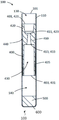
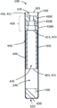
본 발명에 따르면, 에어로졸을 발생시키기 위한 에어로졸 발생 물품이 제공되며, 에어로졸 발생 물품은:According to the present invention, there is provided an aerosol-generating article for generating an aerosol, the aerosol-generating article comprising:
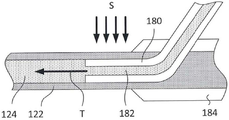
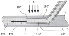
- 유체의 이동을 허용하는 유체 가이드 - 유체 가이드는 근위 단부 및 원위 단부를 갖고, 유체 가이드는 배리어에 의해 분리된 내부 길이 방향 영역 및 외부 길이 방향 영역을 갖고; 내부 길이 방향 영역은 원위 단부와 근위 단부 사이에 내부 길이 방향 통로를 포함하고, 외부 영역은 적어도 하나의 애퍼처를 통해 유체 가이드의 원위 단부로 외부 유체를 연통하는 길이 방향 통로를 포함하여, 외부 유체는 외부 길이 방향 통로를 따라 유체 가이드의 원위 단부로 이동할 수 있음 - ;- a fluid guide allowing movement of a fluid, the fluid guide having a proximal end and a distal end, the fluid guide having an inner longitudinal region and an outer longitudinal region separated by a barrier; wherein the inner longitudinal region comprises an inner longitudinal passageway between the distal end and the proximal end, and wherein the outer region comprises a longitudinal passageway communicating the outer fluid through the at least one aperture to the distal end of the fluid guide; may move along the external longitudinal passageway to the distal end of the fluid guide;
- 겔을 포함하는 관형 요소를 포함하고; 겔은 활성제를 포함하고; 관형 요소는 근위 단부 및 원위 단부를 갖고, 유체 가이드의 원위 측면 상에 위치된다.- a tubular element comprising a gel; The gel contains an active agent; The tubular element has a proximal end and a distal end and is located on a distal side of the fluid guide.
특정 구현예에서, 내부 길이 방향 통로 및 외부 길이 방향 통로를 분리하는 배리어는 예를 들어, 유체에 불투과성인 불투과성 배리어일 수 있다.In certain embodiments, the barrier separating the inner longitudinal passageway and the outer longitudinal passageway can be, for example, an impermeable barrier that is impermeable to a fluid.
본 발명에 따르면, 에어로졸 발생 물품이 제공되며, 에어로졸 발생 물품은:According to the present invention, there is provided an aerosol-generating article, the aerosol-generating article comprising:
- 유체의 이동을 허용하는 유체 가이드 - 유체 가이드는 근위 단부 및 원위 단부를 갖고, 유체 가이드는 배리어에 의해 분리된 내부 길이 방향 영역 및 외부 길이 방향 영역을 갖고; 내부 길이 방향 영역은 원위 단부와 근위 단부 사이에 내부 길이 방향 통로를 포함하고; 외부 영역은 적어도 하나의 애퍼처를 통해 유체 가이드의 원위 단부로 외부 유체를 연통하는 외부 길이 방향 통로를 포함하여, 외부 유체는 외부 길이 방향 통로를 따라 유체 가이드의 원위 단부로 이동할 수 있음 - ;- a fluid guide allowing movement of a fluid, the fluid guide having a proximal end and a distal end, the fluid guide having an inner longitudinal region and an outer longitudinal region separated by a barrier; the inner longitudinal region includes an inner longitudinal passageway between the distal end and the proximal end; the outer region comprises an external longitudinal passage communicating an external fluid through the at least one aperture to the distal end of the fluid guide, wherein the external fluid can travel along the external longitudinal passage to the distal end of the fluid guide;
- 활성제를 더 포함하는, 겔이 로딩된 다공성 매체를 포함하는 관형 요소를 포함하고; 관형 요소는 근위 단부 및 원위 단부를 갖고 유체 가이드의 원위에 위치된다.- a tubular element comprising a gel-loaded porous medium further comprising an active agent; The tubular element has a proximal end and a distal end and is positioned distal to the fluid guide.
바람직하게는, 일부 구현예에서, 관형 요소의 원위 단부는 적어도 하나의 애퍼처를 포함한다. 관형 요소의 원위 단부에서의 애퍼처는 에어로졸 발생 물품의 외부로부터의 유체, 예를 들어 공기가 관형 요소 내로 진입하고 관형 요소를 통해 이동하여 에어로졸을 생성하게 할 수 있다. 관형 요소를 통해 이동하는 유체는 활성제, 또는 임의의 다른 재료를 겔에서 집어서 이들을 하류(근위) 방향에서 겔 밖으로 통과시킬 수 있다.Preferably, in some embodiments, the distal end of the tubular element comprises at least one aperture. An aperture at the distal end of the tubular element may allow fluid, eg, air, from the outside of the aerosol-generating article to enter into and travel through the tubular element to generate an aerosol. The fluid moving through the tubular element can pick up the active agent, or any other material, from the gel and pass them out of the gel in a downstream (proximal) direction.
특정 구현예에서, 에어로졸 발생 물품은 유체 가이드의 원위 단부와 관형 요소의 근위 단부 사이에 위치된 공동을 포함할 수 있다. 따라서, 공동은 내부 길이 방향 통로의 상류 단부 및 관형 요소의 하류 단부에 있을 수 있다. 공동은 유체, 예를 들어 주변 공기가 외부 길이 방향 통로를 통해 공동까지 이동하고, 관형 요소 내의 겔과 접촉할 수 있게 한다. 관형 요소와 접촉하는 유체는 내부 길이 방향 통로로 그리고 유체 가이드의 근위 단부 및 에어로졸 발생 물품의 근위 단부로 복귀하기 전에, 관형 요소 내로 그리고 이를 통과할 수 있다. 이러한 유체, 예를 들어 주변 공기가 겔과 접촉할 때, 유체는 활성제 또는 임의의 다른 재료를 겔, 또는 관형 요소를 픽업할 수 있고, 이를 에어로졸 발생 물품의 근위 단부의 하류에 있는 내부 길이 방향 통로를 따라 통과시킬 수 있다. 겔과 접촉하기 위해, 주변 공기는 관형 요소를 통과하거나 겔을 통과하거나 겔의 표면, 또는 이들의 조합을 통과할 수 있다.In certain embodiments, the aerosol-generating article may include a cavity positioned between the distal end of the fluid guide and the proximal end of the tubular element. Thus, the cavity may be at an upstream end of the interior longitudinal passageway and a downstream end of the tubular element. The cavity allows a fluid, eg, ambient air, to travel through the external longitudinal passageway to the cavity and contact the gel in the tubular element. Fluid in contact with the tubular element may pass into and through the tubular element before returning to the interior longitudinal passageway and to the proximal end of the fluid guide and the proximal end of the aerosol-generating article. When such a fluid, eg, ambient air, comes into contact with the gel, the fluid may pick up the active agent or any other material, the gel, or the tubular element, passing it through an internal longitudinal passage downstream of the proximal end of the aerosol-generating article. can be passed through. To contact the gel, ambient air may pass through the tubular element, through the gel, through the surface of the gel, or a combination thereof.
특정 구현예에서, 적어도 하나의 애퍼처는 유체 가이드의 외부 통로 내에 위치된다.In certain embodiments, the at least one aperture is located within the external passageway of the fluid guide.
유체 가이드의 외부 통로 방식으로 위치되는 적어도 하나의 외부 연통 애퍼처를 갖는 것은 관형 요소와 적어도 하나의 외부 연통 애퍼처 사이의 거리를 허용한다. 이는 겔 및 그 내용물의 누출을 방지하는 것을 도울 수 있지만, 또한 원하는 에어로졸 흡인을 제공한다.Having the at least one external communication aperture positioned in an external passage way of the fluid guide allows a distance between the tubular element and the at least one external communication aperture. This can help prevent leakage of the gel and its contents, but also provide the desired aerosol suction.
특정 구현예에서, 적어도 하나의 애퍼처는 유체 가이드와 관형 요소 사이의 공동 내에 위치된다.In certain embodiments, the at least one aperture is located within the cavity between the fluid guide and the tubular element.
유체 가이드의 외부 통로 내에 위치되는 적어도 하나의 애퍼처를 갖는 것은 주변 유체가 관형 요소에 쉽게 도달하고 관형 요소와 유체 가이드 사이의 공동 내에서 쉽게 혼합될 수 있게 한다.Having at least one aperture positioned in the external passageway of the fluid guide allows the surrounding fluid to easily reach the tubular element and mix easily within the cavity between the tubular element and the fluid guide.
특정 구현예에서, 적어도 하나의 애퍼처는 관형 요소의 측벽면 내에 위치된다.In certain embodiments, the at least one aperture is located in a sidewall face of the tubular element.
관형 요소의 측벽면 내에 위치된 적어도 하나의 애퍼처를 갖는 것은 부압이 에어로졸 발생 물품의 근위 단부에 인가될 때 주변 유체가 일 방향으로 실질적으로 이동할 수 있게 한다. 관형 요소의 측벽면 내에 위치된 적어도 하나의 애퍼처를 갖는 것은 주변 유체가 관형 요소의 내용물과 쉽게 혼합될 수 있게 한다.Having at least one aperture located in the sidewall face of the tubular element allows the surrounding fluid to substantially move in one direction when a negative pressure is applied to the proximal end of the aerosol-generating article. Having at least one aperture positioned in the sidewall face of the tubular element allows the surrounding fluid to readily mix with the contents of the tubular element.
특정 구현예에서, 에어로졸 발생 물품은 래퍼를 포함한다. 래퍼는 임의의 적절한 재료로 이루어질 수 있으며, 예를 들어 래퍼는 종이를 포함할 수 있다. 바람직하게는, 래퍼는 유체 가이드의 애퍼처에 대한 대응하는 애퍼처를 가질 것이다. 유체 가이드 및 래퍼의 대응하는 애퍼처는 애퍼처가 물품의 래핑 후에 형성되는 것을 초래할 수 있다.In certain embodiments, the aerosol-generating article comprises a wrapper. The wrapper may be made of any suitable material, for example the wrapper may comprise paper. Preferably, the wrapper will have a corresponding aperture to that of the fluid guide. Corresponding apertures of the fluid guide and wrapper may result in the aperture being formed after wrapping of the article.
특정 구현예에서, 에어로졸 발생 물품의 외부 길이 방향 통로는 하나의 애퍼처 또는 복수의 애퍼처를 포함한다. 애퍼처는 유체, 예를 들어 주변 공기가 에어로졸 발생 물품을 통과하여 이 물품 내로 들어갈 수 있게 하는 임의의 애퍼처, 슬릿, 구멍 또는 통로일 수 있다. 이는 에어로졸 발생 물품의 외부로부터의 유체가 흡인될 수 있게 한다. 사용 시, 이는 에어로졸 발생 물품의 다른 부분으로 흡인되기 전에, 애퍼처를 통해 외부 길이 방향 통로 내로 에어로졸 발생 물품으로 흡인되는 외부 유체, 예를 들어 공기일 수 있다. 특정 구현예에서, 애퍼처는 에어로졸 발생 물품의 원주 주위에 균일하게 이격되며, 예를 들어 10개 또는 12개의 애퍼처가 있다. 애퍼처가 균일하게 이격된 것은 유체의 원활한 흐름을 제공하는 데 도움이 된다.In certain embodiments, the external longitudinal passageway of the aerosol-generating article comprises one aperture or a plurality of apertures. The aperture may be any aperture, slit, hole or passageway that allows a fluid, eg, ambient air, to pass through and into the aerosol-generating article. This allows fluid from the outside of the aerosol-generating article to be drawn in. In use, it may be an external fluid, eg air, drawn into the aerosol-generating article through the aperture and into the external longitudinal passageway before being drawn into other parts of the aerosol-generating article. In certain embodiments, the apertures are evenly spaced around the circumference of the aerosol-generating article, for example 10 or 12 apertures. Uniformly spaced apertures help to provide a smooth flow of fluid.
특정 구현예와 조합하여, 에어로졸 발생 물품은 관형 요소의 원위 단부 상에 위치된 단부 플러그를 포함하며, 여기서 단부 플러그는 높은 흡인 저항을 갖는다. 단부 플러그는 유체에 불투과성일 수 있거나, 유체에 거의 불투과성일 수 있다. 바람직하게는, 단부 플러그는 에어로졸 발생 물품의 극단 원위 단부에 위치된다. 높은 흡인 저항을 갖는 단부 플러그에 의해, 이는 유리하게는 부압이 에어로졸 발생 물품의 근위 단부에 인가될 때 외부 길이 방향 통로의 애퍼처를 통해 진입하도록 유체를 편향시킬 것이다. 일부 구현예에서, 단부 플러그는 유체 불투과성이다.In combination with certain embodiments, the aerosol-generating article comprises an end plug positioned on the distal end of the tubular element, wherein the end plug has a high resistance to aspiration. The end plug may be impermeable to the fluid, or may be substantially impermeable to the fluid. Preferably, the end plug is located at the extreme distal end of the aerosol-generating article. With an end plug having a high resistance to suction, this will advantageously deflect the fluid to enter through the aperture of the outer longitudinal passageway when a negative pressure is applied to the proximal end of the aerosol-generating article. In some embodiments, the end plug is fluid impermeable.
일부 구현예에서, 관형 요소는 단부 플러그를 포함한다. 유리하게는, 이는 제조의 용이성을 허용한다. 관형 요소의 단부 플러그는 바람직하게는 관형 요소의 일 단부에 위치될 것이다. 유리하게는, 이는 제조의 용이성을 허용한다. 일부 구현예에서, 관형 요소는 단부 플러그를 포함하며, 단부 플러그는 유체 불투과성이다. 관형 요소가 유체 불투과성인 단부 플러그를 포함할 때, 이는 겔 및 다른 유체가 관형 요소로부터 관형 요소의 단부 플러그를 통해 탈출하는 것을 방지한다.In some embodiments, the tubular element comprises an end plug. Advantageously, this allows for ease of manufacture. The end plug of the tubular element will preferably be located at one end of the tubular element. Advantageously, this allows for ease of manufacture. In some embodiments, the tubular element comprises an end plug, wherein the end plug is fluid impermeable. When the tubular element includes an end plug that is fluid impermeable, this prevents gels and other fluids from escaping from the tubular element through the end plug of the tubular element.
특정 구현예에서, 유체 가이드의 내부 영역의 내부 길이 방향 통로는 제한기를 포함한다. 일부 구현예에서, 제한기는 유체 가이드의 근위 단부에 또는 그 근처에 위치된다. 일부 구현예에서, 제한기는 유체 가이드의 하류 단부에 또는 그 근처에 위치된다. 그러나, 제한기는 존재하는 경우, 유체 가이드의 내부 길이 방향 통로, 또는 외부 길이 방향 통로의 중간 영역 내에 위치될 수 있다. 제한기는 또한 내부 길이 방향 통로의 원위 단부 근처에 또는 그것에 위치될 수 있다. 제한기는 내부 길이 방향 통로의 상류 단부에 또는 그 근처에 위치될 수 있다. 하나 초과의 제한기는 유체 가이드의 내부 길이 방향 통로 내에, 또는 외부 길이 방향 통로 내에 사용될 수 있다.In certain embodiments, the inner longitudinal passageway of the inner region of the fluid guide comprises a restrictor. In some embodiments, the restrictor is located at or near the proximal end of the fluid guide. In some embodiments, the restrictor is located at or near the downstream end of the fluid guide. However, the restrictor, if present, may be located in the inner longitudinal passageway of the fluid guide, or in an intermediate region of the outer longitudinal passageway. The restrictor may also be located near or at the distal end of the inner longitudinal passageway. The restrictor may be located at or near the upstream end of the inner longitudinal passageway. More than one restrictor may be used in the inner longitudinal passageway or in the outer longitudinal passageway of the fluid guide.
본 발명의 일부 특정 구현예와 함께 사용하기 위한 제한기는 벽과 같은 표면 내의 애퍼처, 또는 점진적인 제한과 같은 갑작스러운 좁아짐을 포함한다. 대안적으로, 다른 특정 구현예에서, 제한기는 점진적이거나 매끄러운 제한, 예를 들어 경사진 벽, 또는 개구로 좁아지는 깔때기 형상, 또는 통로의 폭을 가로지르는 점진적인 단계 제한을 포함한다. 제한기의 하류(근위) 측면 상에 점진적 또는 갑작스런 확장이 있을 수 있다. 특정 구현예는 제한기의 일측 또는 양측에 깔때기 형상을 포함한다. 따라서, 상류로부터 하류로(원위에서 근위로) 유체의 흐름에서, 통로의 측면이 제한기의 개구로 좁아짐에 따라 점진적인 흐름 제한이 있을 수 있고, 그 다음 제한기의 개구로부터 통로의 점진적인 넓어짐이 있을 수 있다. 통상적으로, 제한기의 개구는 통로의 가장 큰 단면적으로부터 60 또는 45% 또는 30% 제한을 가질 것이다. 따라서, 본 발명에서, 제한기는 일부 구현예에서, 예를 들어, 내부 길이 방향 통로의 가장 크거나 가장 넓은 부분의 단면적의 개구에 대해, 단면적이 단지 60 또는 45 또는 30%인 개구를 갖는 좁아짐을 포함할 수 있다. 통상적으로, 본 발명의 특정 구현예는 예를 들어, 원통형 통로의 단면 직경이 4 mm 내지 2.5 mm 또는 4 mm 내지 2.5 mm로 감소한다. 상이한 폭 감소 비율 및 폭 양; 제한기의 위치 설정; 제한기의 수; 및 감소의 기울기 및 넓어짐의 기울기를 변화시킴으로써, 특정 유체 유동 특성이 달성될 수 있다.Limiters for use with some specific embodiments of the present invention include apertures in surfaces, such as walls, or sudden narrowing, such as gradual restraints. Alternatively, in other specific embodiments, the restrictor comprises a gradual or smooth confinement, such as a sloping wall, or a funnel shape that narrows into an opening, or a gradual step confinement across the width of the passageway. There may be a gradual or sudden dilatation on the downstream (proximal) side of the restrictor. Certain embodiments include a funnel shape on one or both sides of the restrictor. Thus, in the flow of fluid from upstream to downstream (distal to proximal), there may be a gradual flow restriction as the side of the passage narrows into the opening of the restrictor, then there may be a gradual widening of the passage from the opening of the restrictor. can Typically, the opening of the restrictor will have a 60 or 45% or 30% restriction from the largest cross-sectional area of the passageway. Thus, in the present invention, the restrictor prevents narrowing, in some embodiments, with, for example, an opening having a cross-sectional area of only 60 or 45 or 30%, for an opening of the cross-sectional area of the largest or widest portion of the inner longitudinal passageway. may include Typically, certain embodiments of the present invention reduce the cross-sectional diameter of, for example, a cylindrical passage from 4 mm to 2.5 mm or from 4 mm to 2.5 mm. different width reduction ratios and width amounts; positioning of the limiter; number of limiters; and by varying the slope of the decrease and the slope of the widening, specific fluid flow characteristics can be achieved.
특정 구현예와 조합하여, 에어로졸 발생 물품은 서셉터와 같은 가열 요소를 포함하여, 열은 관형 요소 내의 겔로 전달될 수 있다. 관형 요소의 서셉터와 마찬가지로, 이는 임의의 적절한 재료, 바람직하게는 알루미늄과 같거나, 알루미늄을 포함하는 금속일 수 있다.In combination with certain embodiments, the aerosol-generating article comprises a heating element, such as a susceptor, such that heat can be transferred to the gel within the tubular element. Like the susceptor of the tubular element, it may be any suitable material, preferably a metal such as or comprising aluminum.
본 발명에 따르면, 에어로졸 발생 물품의 제조 방법이 제공되며, 에어로졸 발생 물품은:According to the present invention, there is provided a method of making an aerosol-generating article, the aerosol-generating article comprising:
- 유체의 전달을 허용하는 유체 가이드 - 유체 가이드는 근위 단부 및 원위 단부를 갖고, 유체 가이드는 배리어에 의해 분리된 내부 길이 방향 영역 및 외부 길이 방향 영역을 갖고; 내부 길이 방향 영역은 원위 단부와 근위 단부 사이에 내부 길이 방향 통로를 포함하고, 외부 영역은 적어도 하나의 애퍼처를 통해 유체 가이드의 원위 단부로 유체를 연통하는 외부 길이 방향 통로를 포함하여, 유체는 외부 유체 제어 영역의 외부 길이 방향 통로를 따라 유체 가이드의 원위 단부로 이동할 수 있음 - ;- a fluid guide permitting delivery of a fluid, the fluid guide having a proximal end and a distal end, the fluid guide having an inner longitudinal region and an outer longitudinal region separated by a barrier; The inner longitudinal region comprises an inner longitudinal passageway between the distal end and the proximal end, and the outer region comprises an outer longitudinal passageway communicating the fluid through the at least one aperture to the distal end of the fluid guide, the fluid comprising: moveable to the distal end of the fluid guide along an external longitudinal passageway of the external fluid control area;
- 겔을 포함하는 관형 요소로서; 겔은 활성제를 포함하고; 관형 요소는 근위 단부 및 원위 단부를 갖는 관형 요소를 포함하고;- a tubular element comprising a gel; The gel contains an active agent; the tubular element includes a tubular element having a proximal end and a distal end;
상기 방법은:The method is:
- 래핑 재료의 웹 상에 겔 및 유체 가이드를 포함하는 관형 요소를 선형으로 배열하는 단계; 및- linearly arranging a tubular element comprising a gel and a fluid guide on a web of wrapping material; and
- 관형 요소 및 유체 가이드를 래핑하고, 관형 요소 및 유체 가이드 주위에 래퍼를 단단히 위치시키는 단계를 포함한다.- wrapping the tubular element and the fluid guide and securely positioning the wrapper around the tubular element and the fluid guide.
본 발명에 따르면, 본원에 설명된 바와 같은 에어로졸 발생 물품의 원위 단부를 수용하도록 구성된 리셉터클을 포함하는 에어로졸 발생 장치가 제공된다.According to the present invention, there is provided an aerosol-generating device comprising a receptacle configured to receive a distal end of an aerosol-generating article as described herein.
장치의 리셉터클은 에어로졸 발생 물품의 원위 단부, 또는 원위 단부의 일부분이 리셉터클 내로 꼭 맞게 끼워질 수 있게 하고, 정상적인 사용 동안 에어로졸 발생 물품을 리셉터클 내에 유지하도록 형상 및 크기가 대응할 수 있다.The receptacle of the device may correspond in shape and size to allow the distal end, or a portion of the distal end, of the aerosol-generating article to fit snugly into the receptacle, and to retain the aerosol-generating article within the receptacle during normal use.
통상적으로, 리셉터클은 가열 요소를 포함한다. 이는 에어로졸 발생 물품의 가열; 관형 요소의 가열; 또는 바람직하게는 활성제를 포함하는 겔의 가열; 또는 겔이 로딩된 다공성 매체의 가열; 또는 에어로졸의 발생 또는 방출, 또는 에어로졸 내로의 재료 방출을 보조하기 위해 직접 또는 간접적으로, 이들의 임의의 조합을 가능하게 할 것이다. 그 다음, 에어로졸은 에어로졸 발생 물품의 근위 단부로 전달될 수 있다. 특정 구현예에서, 가열은 직접적이거나, 열 요소 또는 서셉터, 또는 둘 모두의 조합을 통해 간접적이다.Typically, the receptacle includes a heating element. This may include heating an aerosol-generating article; heating of tubular elements; or preferably heating the gel comprising the active agent; or heating the gel-loaded porous medium; or any combination thereof, directly or indirectly, to aid in the generation or release of the aerosol, or the release of material into the aerosol. The aerosol may then be delivered to the proximal end of the aerosol-generating article. In certain embodiments, heating is direct or indirect through a thermal element or susceptor, or a combination of both.
가열 수단은 공지된 임의의 가열 수단일 수 있다. 통상적으로, 가열 수단은 방사 또는 전도 또는 대류, 또는 이들의 조합에 의한 것일 수 있다.The heating means may be any known heating means. Typically, the heating means may be by radiation or conduction or convection, or a combination thereof.
특정 구현예와 조합하여, 관형 요소는 스레드를 더 포함한다. 특정 구현예에서, 스레드는 천연 재료 또는 합성 재료이거나, 스레드는 천연 및 합성 재료의 조합이다. 스레드는 반합성 재료를 포함할 수 있다. 스레드는 섬유로 제조되거나, 섬유를 포함하거나, 섬유를 부분적으로 포함할 수 있다. 스레드는 예를 들어 면, 셀룰로스 아세테이트 또는 종이로 제조될 수 있다. 복합 스레드가 사용될 수 있다. 스레드는 활성제를 포함하는 관형 요소의 제조를 도울 수 있다. 스레드는 활성제를 포함하는 관형 요소에 활성제를 도입하는 것을 도울 수 있다. 스레드는 활성제를 포함하는 관형 요소의 구조를 안정화시키는 데 도움이 될 수 있다.In combination with certain embodiments, the tubular element further comprises a thread. In certain embodiments, the thread is a natural or synthetic material, or the thread is a combination of natural and synthetic materials. The thread may comprise a semi-synthetic material. A thread may be made of, comprise, or partially comprise a fiber. The thread may be made of, for example, cotton, cellulose acetate or paper. Composite threads may be used. The thread may aid in the manufacture of the tubular element comprising the active agent. The thread may assist in introducing the active agent into the tubular element containing the active agent. The thread may help to stabilize the structure of the tubular element containing the active agent.
특정 구현예와 조합하여, 관형 요소는 겔이 로딩된 다공성 매체를 포함한다. 다공성 매체가 관형 요소 내에 사용되어 관형 요소 내에 공간을 생성할 수 있다. 다공성 매체는 겔을 유지시키거나 보유할 수 있다. 이는 겔의 전달 및 저장 및 겔을 포함하는 관형 요소의 제조를 돕는 장점을 갖는다. 겔이 로딩된 다공성 매체 내의 겔은 또한 활성제를 포함할 수 있으며; 또한 활성제 또는 다른 재료를 유지하거나 운반할 수 있다.In combination with certain embodiments, the tubular element comprises a porous medium loaded with a gel. A porous medium may be used within the tubular element to create a space within the tubular element. The porous medium may hold or retain the gel. This has the advantage of assisting in the delivery and storage of the gel and the production of tubular elements comprising the gel. The gel in the gel-loaded porous medium may also include an active agent; It may also hold or transport an active agent or other material.
다공성 매체는 겔을 유지하거나 보유할 수 있는 임의의 적절한 다공성 재료일 수 있다. 이상적으로, 다공성 매체는 겔이 그 내에서 이동하게 할 수 있다. 특정 구현예에서, 겔이 로딩된 다공성 매체는 천연 재료, 합성 재료, 또는 반합성 재료, 또는 이들의 조합을 포함한다. 특정 구현예에서, 겔이 로딩된 다공성 매체는 시트 재료, 발포체, 또는 섬유, 예를 들어 느슨한 섬유; 또는 이들의 조합을 포함한다. 특정 구현예에서, 겔이 로딩된 다공성 매체는 직조, 부직포, 또는 압출된 재료, 또는 이들의 조합을 포함한다. 바람직하게는, 겔이 로딩된 다공성 매체는 예를 들어, 면, 종이, 비스코스, PLA, 또는 셀룰로스 아세테이트, 이들의 조합을 포함한다. 바람직하게는, 겔이 로딩된 다공성 매체는 시트 재료, 예를 들어 면 또는 셀룰로스 아세테이트를 포함한다. 겔이 로딩된 다공성 매체의 장점은 겔이 다공성 매체 내에 보유된다는 것이고, 이는 겔의 제조, 저장 또는 운반을 도울 수 있다. 이는 특히 제조, 운송, 또는 사용 동안, 겔의 원하는 형상을 유지하는 것을 보조할 수 있다. 본 발명에 사용된 다공성 매체는 크림핑되거나 파쇄될 수 있다. 특정 구현예에서, 다공성 매체는 크림핑된 다공성 매체를 포함한다. 대안적인 구현예에서, 다공성 매체는 파쇄된 다공성 매체를 포함한다. 크림핑 또는 파쇄 공정은 겔이 로딩하기 전 또는 후일 수 있다.The porous medium can be any suitable porous material capable of holding or holding a gel. Ideally, the porous medium is capable of allowing the gel to migrate therein. In certain embodiments, the gel-loaded porous medium comprises a natural material, a synthetic material, or a semi-synthetic material, or a combination thereof. In certain embodiments, the gel-loaded porous medium is a sheet material, foam, or fiber, such as a loose fiber; or combinations thereof. In certain embodiments, the gel-loaded porous medium comprises a woven, non-woven, or extruded material, or a combination thereof. Preferably, the gel-loaded porous medium comprises, for example, cotton, paper, viscose, PLA, or cellulose acetate, combinations thereof. Preferably, the gel-loaded porous medium comprises a sheet material such as cotton or cellulose acetate. An advantage of gel-loaded porous media is that the gel is retained within the porous media, which can aid in the preparation, storage or transport of the gel. This can aid in maintaining the desired shape of the gel, particularly during manufacture, transportation, or use. The porous media used in the present invention may be crimped or crushed. In certain embodiments, the porous medium comprises a crimped porous medium. In an alternative embodiment, the porous medium comprises a crushed porous medium. The crimping or crushing process may be before or after the gel is loaded.
파쇄는 매체에 대한 높은 표면적 대 부피 비율을 제공하여 겔을 쉽게 흡수할 수 있다.Fracturing provides a high surface area-to-volume ratio to the medium, allowing the gel to be readily absorbed.
특정 구현예에서, 시트 재료는 복합 재료이다. 바람직하게는, 시트 재료는 다공성이다. 시트 재료는 겔을 포함하는 관형 요소의 제조를 도울 수 있다. 시트 재료는 겔을 포함하는 관형 요소에 활성제를 도입하는 것을 도울 수 있다. 시트 재료는 겔을 포함하는 관형 요소의 구조를 안정화시키는 데 도움이 될 수 있다. 시트 재료는 겔의 이송 또는 저장을 보조할 수 있다. 시트 재료를 사용하는 것은 예를 들어 시트 재료의 크림핑에 의해 다공성 매체에 구조를 추가할 수 있거나 이를 돕는다. 시트 재료의 권축은 구조를 통해 통로를 허용하기 위해 구조를 개선하는 혜택을 갖는다. 크림핑된 시트 재료를 통과하는 통로는 겔을 로딩하고, 겔을 보유하고, 또한 유체가 크림핑된 시트 재료를 통과하는 것을 보조한다. 따라서, 크림핑된 시트 재료를 다공성 매체로서 사용하는 장점이 있다.In certain embodiments, the sheet material is a composite material. Preferably, the sheet material is porous. The sheet material may aid in the manufacture of the tubular element comprising the gel. The sheet material may help introduce the active agent into the tubular element comprising the gel. The sheet material may help to stabilize the structure of the tubular element comprising the gel. The sheet material may assist in transport or storage of the gel. Using a sheet material can add or aid in structure to the porous medium, for example by crimping the sheet material. Crimping of the sheet material has the benefit of improving the structure to allow passage through the structure. The passageway through the crimped sheet material loads the gel, retains the gel, and also assists the fluid through the crimped sheet material. Accordingly, there is an advantage to using a crimped sheet material as a porous medium.
다공성 매체는 스레드일 수 있다. 스레드는 예를 들어, 면, 종이 또는 아세테이트 토우를 포함할 수 있다. 스레드에는 또한 임의의 다른 다공성 매체와 같은 겔이 로딩될 수 있다. 스레드를 다공성 매체로서 사용하는 장점은 그것이 제조의 용이성을 도울 수 있다는 것이다. 스레드에는 관형 요소의 제조에 사용되기 전에 겔이 미리 로딩될 수 있거나, 스레드에는 관형 요소의 조립체 내에 겔이 로딩될 수 있다.The porous medium may be a thread. The thread may comprise, for example, cotton, paper or acetate tow. The threads may also be loaded with a gel, such as any other porous medium. An advantage of using a thread as a porous medium is that it can aid ease of manufacture. The threads may be pre-loaded with gel prior to use in the manufacture of the tubular element, or the threads may be loaded with gel within the assembly of the tubular element.
스레드에는 임의의 공지된 수단에 의해 겔이 로딩될 수 있다. 스레드는 겔로 간단히 코팅될 수 있거나, 스레드에는 겔이 함침될 수 있다. 제조에서, 스레드에는 겔이 함침되고, 관형 요소의 조립체에 포함되도록 사용할 준비 상태로 저장될 수 있다. 다른 공정에서, 스레드는 겔이 로딩된 관형 요소의 제조에서 로딩 공정을 겪는다. 겔이 로딩된 다공성 매체, 또는 겔 단독과 마찬가지로, 바람직하게는 겔은 활성제를 포함한다. 활성제는 본원에 설명된 바와 같다.The thread may be loaded with gel by any known means. The threads may simply be coated with the gel, or the threads may be impregnated with the gel. In manufacturing, the threads may be impregnated with a gel and stored ready for use for inclusion in an assembly of tubular elements. In another process, the thread undergoes a loading process in the manufacture of a gel-loaded tubular element. As with the gel-loaded porous medium, or the gel alone, preferably the gel comprises an active agent. The active agent is as described herein.
관형 요소의 제조에서, 겔, 또는 다공성 매체, 또는 스레드는 다른 구성요소가 순차적으로 분배되고 있거나 분배됨에 따라 동시에 분배될 수 있다. 바람직하게는, 구성요소는 분배되지만, 구성요소는 임의의 공지된 방식으로 주름지거나 말리거나, 조합되거나 위치되어, 원하는 장소 내에 위치될 수 있다.In the manufacture of tubular elements, the gel, or porous medium, or thread may be dispensed simultaneously as other components are being dispensed or dispensed sequentially. Preferably, the components are dispensed, but the components may be corrugated, rolled, combined or positioned in any known manner and positioned in a desired location.
본원에서 사용된 바와 같이, 용어 “활성제”는 예를 들어, 화학 반응을 생성하거나 발생된 에어로졸을 변경할 수 있는, 활성이 가능한 제제이다. 활성제는 하나 초과의 제제일 수 있다.As used herein, the term “active agent” is an agent capable of activity, eg, capable of generating a chemical reaction or altering an aerosol generated. The active agent may be more than one agent.
본원에서 사용된 바와 같이, 용어 “에어로졸 발생 물품”은 에어로졸을 발생시키거나 방출할 수 있는 물품을 설명하는 데 사용된다.As used herein, the term “aerosol-generating article” is used to describe an article that generates or is capable of emitting an aerosol.
본원에서 사용된 바와 같이, 용어 “에어로졸 발생 장치”는 에어로졸의 발생 또는 방출을 가능하게 하기 위해 에어로졸 발생 물품과 함께 사용되는 장치이다.As used herein, the term “aerosol-generating device” is a device used with an aerosol-generating article to enable the generation or release of an aerosol.
본원에서 사용된 바와 같이, 용어 “에어로졸 형성제”는 사용 시, 예를 들어, 더 조밀한 에어로졸, 더 안정한 에어로졸, 또는 더 조밀한 에어로졸 및 더 안정한 에어로졸 둘 모두가 될 수 있는, 관형 요소 내로 수용된 초기 에어로졸의 개선을 용이하게 하는, 임의의 적절한 공지된 화합물 또는 화합물의 혼합물을 지칭한다.As used herein, the term "aerosol former" is contained within a tubular element, which in use can be, for example, a denser aerosol, a more stable aerosol, or both a denser aerosol and a more stable aerosol. Refers to any suitable known compound or mixture of compounds that facilitates the improvement of the initial aerosol.
본원에서 사용된 바와 같이, 용어 "에어로졸 발생 물질"은 에어로졸을 발생시키거나 방출할 수 있는 물질을 설명하는 데 사용된다.As used herein, the term “aerosol-generating material” is used to describe a material that can generate or emit an aerosol.
본원에서 사용된 바와 같이, 용어 “애퍼처”는 임의의 애퍼처, 슬릿, 구멍 또는 개구를 설명하는 데 사용된다.As used herein, the term “aperture” is used to describe any aperture, slit, hole or opening.
본원에서 사용된 바와 같이, 용어 “공동”은 구조에 적어도 부분적으로 둘러싸인 임의의 보이드 또는 공간을 설명하는 데 사용된다. 예를 들어, 본 발명에서, 공동은 (일부 구현예에서) 유체 가이드와 관형 요소 사이의 부분적으로 밀폐된 공간이다.As used herein, the term “cavity” is used to describe any void or space that is at least partially surrounded by a structure. For example, in the present invention, a cavity is (in some embodiments) a partially enclosed space between a fluid guide and a tubular element.
본원에서 사용된 바와 같이, 용어 “챔버”는 적어도 부분적으로 둘러싼 공간 또는 공동을 설명하는 데 사용된다.As used herein, the term “chamber” is used to describe a space or cavity that at least partially encloses.
본 개시의 목적을 위해, 제1 위치로부터 제2 위치로 “수축된” 내부 길이 방향 단면적은 내부 길이 방향 단면적이 제1 위치로부터 제2 위치로 직경이 감소된다는 것을 표시하는 데 사용된다. 이는 종종 “제한기”로 칭해진다. 따라서, 본원에서 사용된 바와 같이, 용어 “제한자”는 유체 통로에서의 좁아짐 또는 유체 통로에서의 단면적의 변화를 설명하는 데 사용된다.For the purposes of this disclosure, the inner longitudinal cross-sectional area “retracted” from the first position to the second position is used to indicate that the inner longitudinal cross-sectional area is reduced in diameter from the first position to the second position. This is often referred to as a “limiter”. Thus, as used herein, the term “limiter” is used to describe a narrowing in a fluid passageway or a change in cross-sectional area in a fluid passageway.
본원에서 사용된 바와 같이, 용어 “크림핑된”은 복수의 리지(ridge) 또는 물결주름을 갖는 시트를 나타낸다. 이는 또한 재료가 크림핑되게 하는 공정을 포함한다.As used herein, the term “crimped” refers to a sheet having a plurality of ridges or corrugations. It also includes the process of allowing the material to be crimped.
표현 “단면적”은 길이 방향을 가로지르는 평면에서 측정된 바와 같은 단면적을 설명하는 데 사용된다.The expression “cross-sectional area” is used to describe the cross-sectional area as measured in a plane transverse to the longitudinal direction.
본 개시의 목적을 위해, 본원에서 사용된 바와 같이, 용어 “직경” 또는 “폭”은 관형 요소, 에어로졸 발생 물품 또는 에어로졸 발생 장치, 그의 일부분 또는 부분, 관형 요소, 에어로졸 발생 물품 또는 에어로졸 발생 장치 중 어느 하나의 최대 가로방향 치수이다. 예로서, “직경”은 원형 가로방향 단면을 갖는 물체의 직경이거나, 직사각형 단면을 갖는 물체의 대각선 폭의 길이다.For the purposes of this disclosure, as used herein, the term “diameter” or “width” refers to any of a tubular element, aerosol-generating article or aerosol-generating device, a portion or portion thereof, a tubular element, an aerosol-generating article or an aerosol-generating device. One of the largest transverse dimensions. By way of example, “diameter” is the diameter of an object having a circular transverse cross-section, or the length of the diagonal width of an object having a rectangular cross-section.
본원에서 사용된 바와 같이, "정유"는 수득되는 식물의 특유의 냄새 및 맛을 갖는 오일을 설명하는 데 사용된다.As used herein, "essential oil" is used to describe an oil that has the characteristic odor and taste of the plant from which it is obtained.
본원에서 사용된 바와 같이, 용어 “외부 유체”는 에어로졸 발생 요소, 물품 또는 장치, 예를 들어 주변 공기의 외측에서 비롯되는 유체를 설명하는 데 사용된다.As used herein, the term “external fluid” is used to describe an aerosol-generating element, article, or device, eg, a fluid originating outside of ambient air.
본원에서 사용되는 바와 같은 용어 “향미제”는 에어로졸의 관능 품질에 영향을 미치는 조성물을 설명하는 데 사용된다.As used herein, the term “flavoring agent” is used to describe a composition that affects the organoleptic quality of an aerosol.
본원에서 사용되는 바와 같은 용어 “유체 가이드”는 유체 흐름을 변경할 수 있는 장치 또는 구성요소를 설명하는 데 사용된다. 바람직하게는, 이는 발생되거나 방출된 에어로졸의 유체 흐름 경로를 안내하거나 유도하는 것이다. 유체 가이드는 유체의 혼합을 야기할 가능성이 있다. 이는 통로가 단면적이 좁아질 때, 유체가 유체 가이드를 통해 이동하므로 유체의 가속을 도울 수 있거나, 통로의 단면이 넓어질 때, 유체가 통로를 따라 이동하므로 유체의 감속을 도울 수 있다.As used herein, the term “fluid guide” is used to describe a device or component capable of altering the flow of a fluid. Preferably, this is to guide or direct the fluid flow path of the generated or emitted aerosol. Fluid guides have the potential to cause mixing of fluids. This can help accelerate the fluid when the passage has a narrow cross-sectional area because the fluid moves through the fluid guide, or when the cross-section of the passage widens, it can help decelerate the fluid because the fluid moves along the passage.
본원에서 사용된 바와 같이, 용어 ‘주름진’은 에어로졸 발생 물품 또는 관형 요소의 길이 방향 축에 실질적으로 가로 방향으로 구불구불해지거나, 접혀 있거나, 또는 그렇지 않으면 압축되거나 수축되는 시트를 설명하는 데 사용된다.As used herein, the term 'corrugated' is used to describe a sheet that is tortuous, folded, or otherwise compressed or retracted substantially transverse to the longitudinal axis of the aerosol-generating article or tubular element. .
본원에서 사용된 바와 같이, 용어 “겔”은 다른 재료를 보유할 수 있고 재료를 에어로졸 내로 방출할 수 있는 3차원 망을 갖는 고체 젤리-유사 반-강성 재료를 설명하는 데 사용된다.As used herein, the term “gel” is used to describe a solid jelly-like semi-rigid material having a three-dimensional network capable of holding other materials and releasing materials into an aerosol.
용어 "초본 재료"는 초본 식물로부터의 재료를 나타내기 위해 사용된다. "초본 식물"은 방향족 식물이며, 식물의 잎 또는 다른 부분은 약용, 요리 또는 방향 목적으로 사용되고 향미를 에어로졸 발생 물품에 의해 생성된 에어로졸로 방출할 수 있다.The term "herbal material" is used to denote material from herbaceous plants. "Herbal plant" is an aromatic plant, the leaves or other parts of the plant being used for medicinal, culinary or aromatic purposes and capable of releasing flavor into the aerosol produced by the aerosol-generating article.
용어 “소수성”은 발수 특성을 나타내는 표면을 지칭한다. 소수성 특성은 물 접촉각에 의해 표현될 수 있다. “물 접촉각”은 액체를 통해 통상적으로 측정되며, 유체 계면은 고체 표면과 만나는 각도이다. 물 접촉각은 액체에 의한 고체 표면의 습윤성(wettability)을 영의 방정식(Young equation)으로 정량화한다.The term “hydrophobic” refers to a surface that exhibits water-repellent properties. The hydrophobic property can be expressed by the water contact angle. “Water contact angle” is commonly measured through a liquid, and the fluid interface is the angle it meets a solid surface. The water contact angle quantifies the wettability of a solid surface by a liquid using Young's equation.
본원에서 사용된 바와 같이, 용어 “불투과성”은 유체가 실질적으로 또는 쉽게 통과하지 않는, 아이템, 예를 들어 배리어를 설명하는 데 사용된다.As used herein, the term “impermeable” is used to describe an item, eg, a barrier, through which a fluid does not substantially or readily pass.
본원에서 사용된 바와 같이, 용어 “유도 가열”은 전자기 유도에 의해 객체를 가열하는 것을 설명하는 데 사용되며, 여기서 와전류(또한 푸코 전류로 알려짐)는 가열될 물체 내에 발생되고, 저항은 물체의 저항 가열을 초래한다.As used herein, the term “induction heating” is used to describe heating an object by electromagnetic induction, wherein an eddy current (also known as a Foucault current) is generated in the object to be heated and the resistance is the resistance of the object. cause heating
본원에서 사용된 바와 같이, 용어 “길이 방향 통로”는 유체 등이 이를 따라 흐를 수 있게 하는 통로 또는 개구를 설명하는 데 사용된다. 통상적으로, 공기, 또는 발생된 에어로졸 운반 재료, 예를 들어 고체 입자는 길이 방향 통로를 따라 흐른다. 통상적으로, 길이 방향 통로는 길이 방향 길이가 폭보다 더 길지만, 반드시 그러할 필요는 없다. 용어 “길이 방향 통로”는 또한 복수의 하나 초과의 길이 방향 통로를 포함한다.As used herein, the term “longitudinal passageway” is used to describe a passageway or opening through which a fluid or the like may flow. Typically, air, or generated aerosol-carrying material, such as solid particles, flows along the longitudinal passageway. Typically, a longitudinal passageway has a longitudinal length greater than its width, although this need not be the case. The term “longitudinal passageway” also includes a plurality of more than one longitudinal passageway.
용어 "길이 방향(longitudinal)"은 관형 요소, 에어로졸 발생 물품 또는 에어로졸 발생 장치의 근위 단부와 원위 단부 사이의 방향을 설명하는 데 사용된다.The term “longitudinal” is used to describe the direction between the proximal and distal ends of a tubular element, aerosol-generating article, or aerosol-generating device.
본원에서 사용된 바와 같이, 예를 들어 제2 관형 요소의 “길이 방향 측면”은 제2 관형 요소의 길이 방향 측면 또는 벽을 설명하는 데 사용된다. 일부 구현예에서, 이는 예를 들어, 관형 요소를 형성하는 셀룰로스 아세테이트, 또는 겔이 로딩된 다공성 매체와 일체형이다. 대안적인 구현예에서, 길이 방향 측면은 래퍼이다.As used herein, for example, “longitudinal side” of a second tubular element is used to describe a longitudinal side or wall of a second tubular element. In some embodiments, it is integral with a porous medium loaded with, for example, cellulose acetate, or gel, forming a tubular element. In an alternative embodiment, the longitudinal side is a wrapper.
본원에서 사용된 바와 같이, 용어 “맨드렐”은 다른 재료가 단조되거나 형상화된 샤프트를 설명하는 데 사용된다.As used herein, the term “mandrel” is used to describe a shaft from which other materials are forged or shaped.
본원에서 사용된 바와 같이, 용어 "민트"는 멘타(Mentha) 속 식물을 참조하는 데 사용된다.As used herein, the term "mint" is used to refer to plants of the genus Mentha.
용어 “마우스피스”는 에어로졸이 에어로졸 발생 물품을 빠져나가는 에어로졸 발생 물품의 요소, 구성요소 또는 부분을 설명하기 위해 본원에서 사용된다.The term “mouthpiece” is used herein to describe an element, component or portion of an aerosol-generating article through which the aerosol exits the aerosol-generating article.
본원에서 사용된 바와 같이, 유체 가이드를 참조하여 용어 “외부”는 유체 가이드의 단면 부분의 중간보다 유체 가이드의 길이 방향 원주를 더 향하는 부분을 설명하는 데 사용된다. 유사하게, 용어 “내부”는 유체 가이드의 원주에 가까운 것보다, 단면 부분의 더 중심인 유체 가이드의 일부분을 (유체 가이드를 참조하여) 설명하는 데 사용된다.As used herein, the term “outer” with reference to a fluid guide is used to describe a portion facing the longitudinal circumference of the fluid guide more than the middle of the cross-sectional portion of the fluid guide. Similarly, the term “inside” is used to describe the portion of the fluid guide (with reference to the fluid guide) that is more central to the cross-sectional portion than closer to the circumference of the fluid guide.
본원에서 사용된 바와 같이, 용어 “통로”는 그 사이의 접근을 허용할 수 있는 통로를 설명하는 데 사용된다.As used herein, the term “passage” is used to describe a passageway that may allow access therebetween.
본원에서 사용된 바와 같이, 용어 “가소제”는 가소성 또는 가요성을 생성하거나 촉진하고, 취성을 감소시키기 위해 첨가된 물질, 통상적으로 용매를 설명하는 데 사용된다.As used herein, the term “plasticizer” is used to describe a substance, usually a solvent, added to create or promote plasticity or flexibility and to reduce brittleness.
본원에서 사용되는 바와 같은 용어 “다공성 매체”는 겔을 유지, 보유 또는 지지할 수 있는 임의의 매체를 설명하는 데 사용된다. 통상적으로, 다공성 매체는 예를 들어 겔을 보유하기 위해 유체 또는 반고체를 보유하거나 유지하도록 충진될 수 있는 그의 구조 내에 통로를 가질 것이다. 바람직하게는, 겔은 또한 다공성 매체 내의 통로를 따라 그리고 이를 통해 통과되거나 전달될 수 있다. 본원에서 사용된 바와 같이, 용어 “젤이 로딩된 다공성 매체”는 겔을 포함하는 다공성 매체를 설명하는 데 사용된다. 겔이 로딩된 다공성 매체는 일정량의 겔을 유지, 보유, 또는 지지할 수 있다.As used herein, the term “porous medium” is used to describe any medium capable of holding, holding, or supporting a gel. Typically, a porous medium will have passageways within its structure that can be filled to retain or retain a fluid or semi-solid, for example to retain a gel. Preferably, the gel can also be passed or transferred along and through passageways in the porous medium. As used herein, the term “gel-loaded porous medium” is used to describe a porous medium comprising a gel. The gel-loaded porous medium is capable of holding, holding, or supporting an amount of gel.
본원에서 사용된 바와 같이, 용어 “플러그”는 에어로졸 발생 물품에 사용하기 위한 구성요소, 세그먼트 또는 요소를 설명하는 데 사용된다. 본원에서 사용된 바와 같이, 용어 "단부 플러그"는 에어로졸 발생 물품의 원위 단부에서, 에어로졸 발생 물품의 가장 먼 원위 구성요소 또는 플러그를 설명하는 데 사용된다. 바람직하게는, 이러한 단부 플러그는 높은 흡인 저항(RTD)을 가질 것이다.As used herein, the term “plug” is used to describe a component, segment or element for use in an aerosol-generating article. As used herein, the term “end plug” is used to describe, at the distal end of the aerosol-generating article, the most distal component or plug of the aerosol-generating article. Preferably, such end plugs will have a high resistance to attraction (RTD).
용어 "양자 공여"란 화학 반응에서 수소 또는 양자를 공여할 수 있는 작용기를 지칭한다.The term “proton donor” refers to a functional group capable of donating hydrogen or a proton in a chemical reaction.
에어로졸 발생 장치의 용어 “리셉터클”에 의해, 이러한 용어는 에어로졸 발생 물품의 일부분을 수용할 수 있는 에어로졸 발생 장치의 챔버를 설명하는 데 사용된다. 이는 일반적으로 물품의 원위 단부가지만 반드시 그런 것은 아니다.By the term “receptacle” of an aerosol-generating device, this term is used to describe a chamber of an aerosol-generating device capable of receiving a portion of an aerosol-generating article. This is usually but not necessarily the distal end of the article.
본원에서 사용된 바와 같이, 용어 “흡인 저항”(RTD)은 재료를 통해 흡인될 유체, 예를 들어 가스에 대한 저항을 설명하는 데 사용된다. 본원에서 사용된 바와 같이, 흡인 저항은 압력의 단위인 “mm WG” 또는 “mm 수위계(water gauge)”로 표현되고 ISO 6565:2002에 따라 측정된다.As used herein, the term “resistance to draw” (RTD) is used to describe the resistance to a fluid, such as a gas, to be drawn through a material. As used herein, resistance to suction is expressed in units of pressure "mm WG" or "mm water gauge" and is measured according to ISO 6565:2002.
본원에서 사용된 바와 같이, 용어 “높은 흡인 저항”(RTD)은 재료를 통해 흡인될 유체, 예를 들어 가스에 대한 저항을 설명하는 데 사용된다. 본원에서 사용된 바와 같이, 높은 흡인 저항은 200 “mm WG” “또는 “mm 수위계”를 초과하는 것을 의미하고 ISO 6565:2002에 따라 측정된다.As used herein, the term “high resistance to draw” (RTD) is used to describe the resistance to a fluid, such as a gas, to be drawn through a material. As used herein, high resistance to suction means greater than 200 “mm WG” “or “mm water gauge” and is measured according to ISO 6565:2002.
본원에서 사용된 바와 같이, 용어 ‘시트 재료’는 그의 폭 및 길이가 그의 두께보다 실질적으로 큰 일반적으로 평면 박층 요소(laminar element)를 설명하는 데 사용된다.As used herein, the term 'sheet material' is used to describe a generally planar laminar element whose width and length are substantially greater than its thickness.
본원에서 사용된 바와 같이, 용어 “밀봉부”는 예를 들어, 래퍼의 에지를 서로 또는 유체 가이드에 접합함으로써, 접합부이거나, 또는 “접합”하는 것이다. 이는 접착제 또는 글루의 사용에 의한 것일 수 있다. 그러나, 용어 밀봉부는 또한 간섭 끼워맞춤 접합부를 포함한다. 밀봉부는 유체 불투과성 밀봉부, 또는 배리어를 생성할 필요가 없다.As used herein, the term “seal” refers to a junction, or “bonding”, for example, by bonding the edges of the wrapper to each other or to a fluid guide. This may be due to the use of adhesives or glues. However, the term seal also includes an interference fit joint. The seal need not create a fluid impermeable seal, or barrier.
본원에서 사용된 바와 같이, 용어 “파쇄된”은 미세하게 절단된 것을 설명하는 데 사용된다.As used herein, the term “shredded” is used to describe a finely chopped thing.
본원에서 사용된 바와 같이, 용어 “단단함”은 아이템이 정상적인 사용 하에서 변화 형상에 저항하기에 충분히 강성이거나, 충분히 단단하거나, 또는 일반적으로 변형 형상에 저항하기에 충분히 단단한 것을 설명하는 데 사용된다. 이는 변형되면 원래의 형상으로 대체로 돌아갈 수 있도록 탄성일 수 있는 것을 포함한다. 마찬가지로, 본원에서 사용된 바와 같이, 용어 “강성”은 특히 정상적인 사용 하에서, 일반적으로 형상을 유지할 수 있는, 아이템이 구부러지거나 강제로 형상을 벗어나는 것에 저항하는 것을 설명한다.As used herein, the term “rigid” is used to describe that an item is sufficiently rigid, sufficiently rigid, or generally rigid enough to resist deformable shape under normal use. This includes those that may be elastic so that they can generally return to their original shape when deformed. Likewise, as used herein, the term “rigidity” describes the resistance of an item to bend or force it out of shape, particularly under normal use, which can generally retain its shape.
본원에서 사용된 바와 같이, 용어 “서셉터”는 가열 요소, 즉 전자기 에너지를 흡수하고 이를 열로 변환할 수 있는 임의의 재료를 설명하는 데 사용된다. 예를 들어, 본 발명에서, 서셉터 또는 열 요소는 열 에너지를 겔에 전달하여, 겔을 가열하는 것을 도와서, 겔로부터 재료를 방출하는 것을 보조할 수 있다.As used herein, the term “susceptor” is used to describe a heating element, ie, any material capable of absorbing electromagnetic energy and converting it into heat. For example, in the present invention, a susceptor or thermal element can transfer thermal energy to the gel to help heat the gel, thereby assisting in releasing material from the gel.
본원에서 사용된 바와 같이, 용어 ‘질감을 갖는 시트’는 크림핑된, 양각된, 음각된, 천공된 또는 그렇지 않으면 변형된 시트를 나타낸다.As used herein, the term 'textured sheet' refers to a crimped, embossed, engraved, perforated or otherwise deformed sheet.
본원에서 사용된 바와 같이, 용어 “젤이 로딩된 스레드”는 예를 들어, 코팅 또는 겔이 함침된 것을 포함하여, 겔을 유지, 보유 또는 지지하는 다공성 매체의 스레드를 설명하는 데 사용된다.As used herein, the term “gel loaded thread” is used to describe a thread in a porous medium that holds, retains, or supports a gel, including, for example, a coating or impregnated with a gel.
이러한 문헌 도처에서, 용어 “관형 요소”는 에어로졸 발생 물품에 사용하기에 적절한 구성요소를 설명하는 데 사용된다. 이상적으로, 관형 요소는 그의 폭보다 길이 방향 길이가 더 길 수 있지만, 그의 폭보다 길이 방향 길이가 이상적으로 더 길어질 다중 구성요소 아이템의 일부분일 수 있기 때문에 반드시 그러한 것은 아니다. 통상적으로, 관형 요소는 원통형이지만 반드시 그러하지는 않다. 예를 들어, 관형 요소는 타원형, 삼각형 또는 직사각형과 같은 다각형 또는 무작위 단면을 가질 수 있다. 관형 요소는 중공일 필요는 없다.Throughout this document, the term “tubular element” is used to describe a component suitable for use in an aerosol-generating article. Ideally, the tubular element may have a longitudinal length greater than its width, but this is not necessarily the case as it may be part of a multi-component item whose longitudinal length is ideally greater than its width. Typically, the tubular element is cylindrical, although this is not necessarily the case. For example, the tubular element may have a polygonal or random cross-section, such as an oval, triangular or rectangular. The tubular element need not be hollow.
용어 “상류” 및 “하류”는 주류 유체가 관형 요소, 에어로졸 발생 물품 또는 에어로졸 발생 장치 내로 흡인됨에 따라 주류 유체의 방향에 대한 상대 위치를 설명하는 데 사용된다. 일부 구현예에서, 유체가 에어로졸 발생 물품의 원위 단부로부터 진입하고 물품의 근위 단부를 향해 이동하는 경우, 에어로졸 발생 물품의 원위 단부는 또한 에어로졸 발생 물품의 상류 단부로서 설명될 수 있고, 에어로졸 발생 물품의 근위 단부는 또한 에어로졸 발생 물품의 하류 단부로서 설명될 수 있다. 이러한 구현예에서, 근위 단부와 원위 단부 사이에 위치된 에어로졸 발생 물품의 요소는 근위 단부의 상류, 또는 대안적으로 원위 단부의 하류에 있는 것으로서 설명될 수 있다. 그러나, 본 발명의 다른 구현예에서, 유체가 측면으로부터 에어로졸 발생 물품으로 진입하고 먼저 원위 단부를 향해 이동하며, 회전하고, 그 다음 에어로졸 발생 물품의 근위 단부를 향해 이동하는 경우, 에어로졸 발생 물품의 원위 단부는 각각의 기준점에 따라 상류 또는 하류일 수 있다.The terms “upstream” and “downstream” are used to describe the position relative to the direction of the mainstream fluid as it is drawn into a tubular element, aerosol-generating article, or aerosol-generating device. In some embodiments, when the fluid enters from the distal end of the aerosol-generating article and moves towards the proximal end of the article, the distal end of the aerosol-generating article can also be described as the upstream end of the aerosol-generating article, The proximal end may also be described as a downstream end of the aerosol-generating article. In such embodiments, the element of the aerosol-generating article positioned between the proximal end and the distal end may be described as being upstream of the proximal end, or alternatively downstream of the distal end. However, in other embodiments of the invention, when the fluid enters the aerosol-generating article from the side and first moves towards the distal end, rotates, and then moves toward the proximal end of the aerosol-generating article, the distal of the aerosol-generating article The ends may be upstream or downstream depending on the respective reference point.
본원에서 사용된 바와 같이, 용어 “내수성”은 물이 쉽게 통과할 수 없게 하거나, 물에 의해 쉽게 손상되지 않는, 재료, 예를 들어 제2 관형 요소의 래퍼, 또는 길이 방향 측면을 설명하는 데 사용된다. 내수성 재료는 수분 침투에 저항할 수 있다.As used herein, the term "water resistant" is used to describe a wrapper, or longitudinal side of a material, e.g., a second tubular element, that is impermeable to water or not easily damaged by water. do. Water resistant materials can resist moisture penetration.
특정 구현예에서, 관형 요소는 활성제를 포함한다. 특정 구현예에서, 겔은 활성제를 포함한다. 특정 구현예에서, 활성제는 니코틴을 포함한다. 특정 구현예에서, 활성제를 포함하는 겔 또는 관형 요소는 0.2 중량% 내지 5 중량%의 활성제, 예컨대 활성제의 1 중량% 내지 2 중량%의 활성제를 포함한다.In certain embodiments, the tubular element comprises an active agent. In certain embodiments, the gel comprises an active agent. In certain embodiments, the active agent comprises nicotine. In certain embodiments, the gel or tubular element comprising the active agent comprises 0.2% to 5% by weight of the active agent, such as 1% to 2% by weight of the active agent.
통상적으로, 특정 구현예에서, 관형 요소는 적어도 150 mg의 겔을 포함할 것이다.Typically, in certain embodiments, the tubular element will comprise at least 150 mg of gel.
특정 구현예에서, 활성제는 가소제를 포함한다.In certain embodiments, the active agent comprises a plasticizer.
특정 구현예에서, 활성제를 포함하는 겔은 글리세롤과 같은 에어로졸 형성제를 포함한다. 에어로졸 형성제가 존재하는 구현예에서, 통상적으로 예를 들어, 활성제를 포함하는 겔은 60 중량% 내지 95 중량%의 글리세롤, 예컨대 80 중량% 내지 90 중량%의 글리세롤을 포함한다.In certain embodiments, a gel comprising an active agent comprises an aerosol former such as glycerol. In embodiments where an aerosol former is present, typically, for example, a gel comprising an active agent comprises from 60% to 95% by weight of glycerol, such as from 80% to 90% by weight of glycerol.
특정 구현예에서, 활성제를 포함하는 겔은 예를 들어 알지네이트, 겔란, 구아, 또는 이들의 조합과 같은, 겔화제를 포함한다. 겔화제를 포함하는 구현예에서, 겔은 통상적으로 0.5 중량% 내지 10 중량%의 활성제, 예컨대 1 중량% 내지 3 중량%의 겔화제를 포함한다.In certain embodiments, the gel comprising the active agent comprises a gelling agent, such as, for example, alginate, gellan, guar, or combinations thereof. In embodiments comprising a gelling agent, the gel typically comprises from 0.5% to 10% by weight of an active agent, such as from 1% to 3% by weight of the gelling agent.
특정 구현예에서, 겔은 물을 포함한다. 이러한 구현예에서, 겔은 통상적으로 5 중량% 내지 25 중량%, 예컨대 10 중량% 내지 15 중량%의 물을 포함한다.In certain embodiments, the gel comprises water. In this embodiment, the gel typically comprises 5% to 25% by weight of water, such as 10% to 15% by weight of water.
바람직하게는, 겔은 겔화제를 포함한다. 겔화제는 에어로졸 형성제가 분산될 수 있는 고체 매체를 형성할 수 있다.Preferably, the gel comprises a gelling agent. The gelling agent may form a solid medium in which the aerosol former may be dispersed.
겔은 임의의 적절한 겔화제를 포함할 수 있다. 예를 들어, 겔화제는 2개 또는 3개의 생체 고분자와 같은, 하나 이상의 생체 고분자를 포함할 수 있다. 바람직하게는, 겔이 하나 초과의 생체 고분자를 포함하는 경우, 생체 고분자는 실질적으로 동일한 중량으로 존재한다. 생체 고분자는 다당류로 형성될 수 있다. 겔화제로서 적절한 생체 고분자는 예를 들어, 젤란 검(천연, 저 아실 젤란 검, 고 아실 젤란 검이고, 저 아실 젤란 검이 바람직함), 잔탄 검, 알지네이트(알긴산), 한천, 구아 검 등을 포함한다. 바람직하게는, 겔은 한천을 포함한다.The gel may include any suitable gelling agent. For example, the gelling agent may include one or more biopolymers, such as two or three biopolymers. Preferably, when the gel comprises more than one biopolymer, the biopolymers are present by substantially equal weight. Biopolymers can be formed from polysaccharides. Biopolymers suitable as the gelling agent include, for example, gellan gum (natural, low acyl gellan gum, high acyl gellan gum, preferably low acyl gellan gum), xanthan gum, alginate (alginic acid), agar, guar gum, etc. include Preferably, the gel comprises agar.
겔은 임의의 적절한 양의 겔화제를 포함할 수 있다. 예를 들어, 겔은 겔의 약 0.5 중량% 내지 약 7 중량% 범위의 겔화제를 포함한다. 바람직하게는, 겔은 약 1 중량% 내지 약 5 중량%, 예컨대 약 1.5 중량% 내지 약 2.5 중량% 범위의 겔화제를 포함한다.The gel may include any suitable amount of a gelling agent. For example, the gel comprises a gelling agent in the range of from about 0.5% to about 7% by weight of the gel. Preferably, the gel comprises from about 1% to about 5% by weight of the gelling agent, such as from about 1.5% to about 2.5% by weight.
일부 바람직한 구현예에서, 겔은 약 0.5 중량% 내지 약 7 중량%의 범위, 또는 약 1 중량% 내지 약 5 중량%, 또는 약 2 중량%의 범위의 한천을 포함한다.In some preferred embodiments, the gel comprises agar in the range of about 0.5% to about 7% by weight, or in the range of about 1% to about 5% by weight, or in the range of about 2% by weight.
일부 바람직한 구현예에서, 겔은 약 2 중량% 내지 약 5 중량%의 범위, 또는 약 2 중량% 내지 약 4 중량%, 또는 약 3 중량% 범위의 잔탄 검을 포함한다.In some preferred embodiments, the gel comprises xanthan gum in the range of about 2% to about 5% by weight, or in the range of about 2% to about 4% by weight, or in the range of about 3% by weight.
일부 바람직한 구현예에서, 겔은 잔탄 검, 젤란 검, 및 한천을 포함한다. 겔은 잔탄 검, 저 아실 젤란 검, 및 한천을 포함할 수 있다. 겔은 실질적으로 동일한 중량으로 잔탄 검, 젤란 검, 및 한천을 포함할 수 있다. 겔은 실질적으로 동일한 중량으로 잔탄 검, 저 아실 젤란 검, 및 한천을 포함할 수 있다. 겔은 약 1 중량% 내지 약 5 중량%의 범위(겔 내의 잔탄 검, 저 아실 젤란 검, 및 한천의 총 중량에 대해) 또는 약 1 중량% 내지 약 4 중량%, 또는 약 2 중량%의 범위인 잔탄 검, 저 아실 젤란 검, 및 한천을 포함할 수 있다. 겔은 약 1 중량% 내지 약 5 중량%, 또는 약 2 중량% 범위의 잔탄 검, 저 아실 젤란 검, 및 한천을 포함할 수 있으며, 여기서 잔탄 검, 젤란 검, 및 한천은 실질적으로 동일한 중량이다.In some preferred embodiments, the gel comprises xanthan gum, gellan gum, and agar. The gel may include xanthan gum, low acyl gellan gum, and agar. The gel may include xanthan gum, gellan gum, and agar in substantially equal weights. The gel may include xanthan gum, low acyl gellan gum, and an agar by substantially equal weight. The gel is in the range of about 1% to about 5% by weight (relative to the total weight of xanthan gum, low acyl gellan gum, and agar in the gel) or in the range of about 1% to about 4% by weight, or about 2% by weight. phosphorus xanthan gum, low acyl gellan gum, and agar. The gel can comprise in the range of about 1% to about 5%, or about 2% by weight xanthan gum, low acyl gellan gum, and agar, wherein the xanthan gum, gellan gum, and agar are substantially the same weight. .
겔은 2가 양이온을 포함할 수 있다. 바람직하게는, 2가 양이온은 용액 속의 젖산 칼슘과 같은 칼슘 이온을 포함한다. (칼슘 이온과 같은) 2가 양이온은 생체 고분자(다당류), 예컨대 젤란 검(천연, 저 아실 젤란 검, 고 아실 젤란 검), 잔탄 검, 알지네이트(알긴산), 한천, 구아 검 등을 포함하는 조성물의 겔 형성을 보조할 수 있다. 이온 효과는 겔 형성을 보조할 수 있다. 2가 양이온은 약 0.1 내지 약 1 중량%, 또는 약 0.5 중량%의 범위로 겔 조성물 내에 존재할 수 있다. 일부 구현예에서, 겔은 2가 양이온을 포함하지 않는다.The gel may contain divalent cations. Preferably, the divalent cation comprises a calcium ion such as calcium lactate in solution. Divalent cations (such as calcium ions) are biopolymers (polysaccharides), such as gellan gum (natural, low acyl gellan gum, high acyl gellan gum), xanthan gum, alginate (alginic acid), agar, a composition comprising guar gum, etc. may aid in gel formation. The ionic effect can aid in gel formation. The divalent cation may be present in the gel composition in the range of about 0.1 to about 1 weight percent, or about 0.5 weight percent. In some embodiments, the gel does not contain divalent cations.
산은 카르복실산을 포함할 수 있다. 카르복실산은 케톤기를 포함할 수 있다. 바람직하게는, 카르복실산은 10개 미만의 탄소 원자를 갖는 케톤기를 포함할 수 있다. 바람직하게는, 이러한 카르복실산은 5개의 탄소 원자(예컨대, 레불린산)를 갖는다. 레볼린산이 첨가되어 니코틴 겔의 pH를 중화시킬 수 있다. 이는 또한, 젤란 검(저 아실 젤란 검, 고 아실 젤란 검), 잔탄 검, 특히 알지네이트(알긴산), 한천, 구아 검 등과 같은 생체 고분자(다당류)를 포함하는 겔 형성을 보조할 수 있다. 레볼린산은 또한 겔 제형의 감각 프로파일을 향상시킬 수 있다. 일부 구현예에서, 겔은 카르복시산을 포함하지 않는다.The acid may include a carboxylic acid. The carboxylic acid may include a ketone group. Preferably, the carboxylic acid may comprise a ketone group having less than 10 carbon atoms. Preferably, this carboxylic acid has 5 carbon atoms (eg levulinic acid). Levolic acid can be added to neutralize the pH of the nicotine gel. It can also aid in the formation of gels comprising biopolymers (polysaccharides) such as gellan gum (low acyl gellan gum, high acyl gellan gum), xanthan gum, especially alginates (alginic acid), agar, guar gum, and the like. Levolic acid may also enhance the sensory profile of the gel formulation. In some embodiments, the gel does not include carboxylic acids.
특정 구현예에서, 활성제는 향미 또는 제약 물질, 또는 이들의 조합을 포함한다. 특정 예에서, 활성제는 임의의 형태의 니코틴이다. 활성제는 활성일 수 있으며, 예를 들어 화학 반응을 생성하거나 발생된 에어로졸을 적어도 변경할 수 있다.In certain embodiments, the active agent comprises a flavor or pharmaceutical substance, or a combination thereof. In certain instances, the active agent is any form of nicotine. The active agent may be active, for example, capable of generating a chemical reaction or at least altering the generated aerosol.
활성제는 향미일 수 있다. 특정 구현예에서, 활성제는 향미제를 포함한다. 겔은 향미제를 포함할 수 있다. 대안적으로, 또는 추가적으로, 향미제는 물품의 하나 이상의 다른 위치에 존재할 수 있다. 향미제는 향미를 부여하여 물품에 의해 발생된 유체 또는 에어로졸의 맛에 기여할 수 있다. 향미제는 에어로졸의 관능 품질에 영향을 미치는 임의의 천연 또는 인공 화합물이다. 향미제를 제공하는 데 사용될 수 있는 식물은 군, 꿀풀과(Lamiaceae)(예, 민트), 미나리과(Apiaceae)(예, 아니스, 회향), 녹나무과(Lauraceae)(예, 월계수, 계피, 로즈우드), 운향과(Rutaceae)(예, 감귤류), 도금양과(Myrtaceae)(예, 아니스 머틀), 및 콩과(Fabaceae)(예, 감초)에 속하는 것을 포함하지만, 이에 한정되지 않는다. 향미제 공급원의 비 한정적인 예는 민트 예컨대 페퍼민트 및 스피어민트, 커피, 차, 계피, 정향, 생강, 코코아, 바닐라, 초콜릿, 유칼립투스, 제라늄, 용설란, 쥬니퍼; 및 이들의 조합을 포함한다.The active agent may be a flavor. In certain embodiments, the active agent comprises a flavoring agent. The gel may include a flavoring agent. Alternatively, or additionally, the flavoring agent may be present in one or more other locations on the article. A flavoring agent may contribute to the taste of a fluid or aerosol generated by the article by imparting flavor. A flavoring agent is any natural or artificial compound that affects the organoleptic quality of the aerosol. Plants that may be used to provide flavoring agents include, but are not limited to, Lamiaceae (eg mint), Apiaceae (eg anise, fennel), Lauraceae (eg laurel, cinnamon, rosewood). , Rutaceae (eg, citrus), Myrtaceae (eg, anise myrtle), and Fabaceae (eg, licorice). Non-limiting examples of flavoring sources include mints such as peppermint and spearmint, coffee, tea, cinnamon, cloves, ginger, cocoa, vanilla, chocolate, eucalyptus, geranium, agave, juniper; and combinations thereof.
다수의 향미제는 정유, 또는 하나 이상의 정유의 혼합물이다. 적절한 정유는 이에 한정되지 않지만, 유제놀, 페퍼민트 오일, 스피어민트 오일을 포함한다. 많은 구현예에서, 향미제는 멘톨, 유제놀, 또는 멘톨 및 유제놀의 조합을 포함한다. 많은 구현예에서, 향미제는 아네톨, 리날로올, 또는 이들의 조합을 더 포함한다. 특정 구현예에서, 향미제는 초본 재료를 포함한다. 초본 재료는 이에 한정되지 않지만, 페퍼민트와 스피어민트 같은 민트류, 레몬 밤, 바질, 계피, 레몬 바질, 골파, 고수, 라벤더, 세이지, 차, 백리향, 캐러웨이 를 포함하는, 허브 잎 또는 초본 식물로부터의 다른 초본 재료를 포함한다. 적합한 유형의 민트 잎은 멘타 피페리타(Mentha piperita), 멘타 아벤시스(Mentha arvensis), 멘타 닐리아카(Mentha niliaca), 멘타 시트라타(Mentha citrata), 멘타 스피카타(Mentha spicata), 멘타 스피카타 크리스파(Mentha spicata crispa), 멘타 코르디폴리아(Mentha cordifolia), 멘타 롱기폴리아(Mentha longifolia), 멘타 풀레지움(Mentha pulegium), 멘타 수아베오렌스(Mentha suaveolens), 및 멘타 수아베오렌스 바리에가타(Mentha suaveolens variegata)를 포함하는 식물 품종으로부터 취해질 수 있으나, 이에 한정되지 않는다. 일부 구현예들에서, 향미제는 담배 물질을 포함할 수 있다.Many flavoring agents are essential oils, or mixtures of one or more essential oils. Suitable essential oils include, but are not limited to, eugenol, peppermint oil, spearmint oil. In many embodiments, the flavoring agent comprises menthol, eugenol, or a combination of menthol and eugenol. In many embodiments, the flavoring agent further comprises anetol, linalool, or a combination thereof. In certain embodiments, the flavoring agent comprises an herbal ingredient. Herbal materials include, but are not limited to, mints such as peppermint and spearmint, lemon balm, basil, cinnamon, lemon basil, chives, coriander, lavender, sage, tea, thyme, caraway from herbal leaves or herbaceous plants. Contains other herbal ingredients. Suitable types of mint leaves are Mentha piperita, Mentha arvensis, Mentha niliaca, Mentha citrata, Mentha spicata, Mentha spicata cri Spa (Mentha spicata crispa), Mentha cordifolia, Mentha longifolia, Mentha pulegium, Mentha suaveolens, and Mentha suaveolens (Mentha suaveolens) Mentha suaveolens variegata), but is not limited thereto. In some embodiments, the flavoring agent may include tobacco material.
하나의 특정 예에서, 다른 특징부와 조합하여, 겔은 대략 2 중량%의 니코틴, 70 중량%의 글리세롤, 27 중량%의 물 및 1 중량%의 한천을 포함한다. 다른 예에서, 겔은 65 중량%의 글리세롤, 20 중량%의 물, 14.3 중량%의 고체 분말 담배 및 0.7 중량%의 한천을 포함한다.In one specific example, in combination with other features, the gel comprises approximately 2% by weight nicotine, 70% by weight glycerol, 27% by weight water, and 1% by weight agar. In another example, the gel comprises 65% by weight glycerol, 20% by weight water, 14.3% by weight solid powdered tobacco, and 0.7% by weight agar.
본 발명에서, 유체 가이드는 2개의 별도의 영역, 예를 들어 외부 길이 방향 통로를 갖는 외부 영역 및 내부 길이 방향 통로를 갖는 내부 영역을 가질 수 있다. 따라서, 외부 길이 방향 통로는 유체 가이드의 원주에 가깝게 길이 방향으로 이어지고, 내부 유체 통로는 길이 방향 축을 따라 단면의 코어 또는 중앙에 가깝게 길이 방향으로 이어진다.In the present invention, the fluid guide may have two separate regions, for example an outer region with an outer longitudinal passageway and an inner region with an inner longitudinal passageway. Accordingly, the outer longitudinal passage runs longitudinally proximate to the circumference of the fluid guide, and the inner fluid passage runs longitudinally near the core or center of the cross-section along the longitudinal axis.
바람직하게는, 특정 구현예에서, 주변 공기는 래퍼 내의 애퍼처 및 유체 가이드 내의 애퍼처를 통해, 에어로졸 발생 물품의 원위 단부를 향해 그리고 활성제를 포함하는 겔을 포함하는 관형 요소의 영역 내에서 (유체 가이드의) 외부 길이 방향 통로에 진입한다. 바람직하게는, 유체는 활성제를 포함하는 겔과 접촉하여, 에어로졸 발생 물품의 외부로부터 유체를 포함하는 혼합 유체의 에어로졸, 및 활성제, 또는 제제를 포함하는 겔로부터 방출된 재료를 발생시키거나 방출할 것이다. 그 다음, 유체는 유체 가이드의 내부 길이 방향 통로를 따라, 에어로졸 발생 물품의 근위 단부를 향해 이동한다. 외부 및 내부 길이 방향 통로가 배리어에 의해 분리될 것으로 예상된다. 배리어는 유체에 불투과성이거나 이를 통과하는 유체에 저항할 수 있고, 따라서 유체를 원위 단부에 편향시킬 수 있다. 바람직하게는, 유체 가이드의 외부 길이 방향 통로는 유체 가이드의 외부, 및 바람직하게는 물품의 외부와 유체 연통하는 애퍼처를 포함한다. 또한, 사용시, 에어로졸 발생 물품의 외부로부터 수용된 유체가 유체 가이드의 원위 단부를 향해 주로 흐르도록 외부 길이 방향 통로가 그의 근위 단부에서 차단되는 것으로 예상된다. 유체 가이드의 외부 길이 방향 통로는 근위 단부에 또는 그 근처에 애퍼처를 갖지만, 그 다음 그의 원위 단부에서만 개방된다. 대조적으로, 유체 가이드의 내부 길이 방향 통로는 그의 근위 단부 및 그의 원위 단부 둘 모두에서 개방되지만, 그것은 그의 근위 단부와 원위 단부 사이에 다양한 흐름 제한 요소를 가질 수 있다. 유체 가이드의 내부 및 외부 길이 방향 통로를 분리하는 배리어는 외부 길이 방향 통로에 진입하는 유체가 외부 길이 방향 통로의 원위 단부로 그리고 바람직하게는 활성제를 포함하는 겔을 포함하는 관형 요소를 향해 이동하게 한다. 이는 바람직하게는 활성제를 포함하는 겔을 포함하는 관형 요소와 유체가 접촉하게 한다.Preferably, in certain embodiments, ambient air is directed through apertures in the wrapper and apertures in the fluid guide, towards the distal end of the aerosol-generating article and within the region of the tubular element comprising the gel comprising the active agent (fluid) of the guide) enters the longitudinal passageway. Preferably, the fluid will contact the gel comprising the active agent to generate or release an aerosol of a mixed fluid comprising the fluid from the outside of the aerosol-generating article, and material released from the gel comprising the active agent, or formulation. . The fluid then travels along the inner longitudinal passageway of the fluid guide towards the proximal end of the aerosol-generating article. It is expected that the outer and inner longitudinal passages will be separated by a barrier. The barrier may be impermeable to or resist fluid passing therethrough, thus deflecting the fluid to the distal end. Preferably, the external longitudinal passage of the fluid guide comprises an aperture in fluid communication with the exterior of the fluid guide, and preferably with the exterior of the article. It is also expected that, in use, the external longitudinal passageway is blocked at its proximal end such that fluid received from the outside of the aerosol-generating article flows primarily towards the distal end of the fluid guide. The external longitudinal passageway of the fluid guide has an aperture at or near its proximal end, but then only opens at its distal end. In contrast, the inner longitudinal passageway of the fluid guide is open at both its proximal and distal ends, but it may have various flow restricting elements between its proximal and distal ends. The barrier separating the inner and outer longitudinal passageways of the fluid guide allows fluid entering the outer longitudinal passageway to move toward the distal end of the outer longitudinal passageway and preferably towards a tubular element comprising a gel comprising an active agent. . This preferably brings in fluid contact with the tubular element comprising the gel comprising the active agent.
유체 가이드의 외부 길이 방향 통로는 하나의 통로 또는 하나 초과의 통로일 수 있다. 외부 길이 방향 통로는 유체 가이드 내에 있을 수 있거나, 유체 가이드의 외부 표면 상의 하나 이상의 통로일 수 있으며 유체 가이드는 외부 길이 방향 통로의 부분 벽을 형성하고 래퍼는 외부 길이 방향 통로에 다른 부분 벽을 형성한다. 유체 가이드의 외부 또는 내부 길이 방향 통로는 통로가 다공성 재료를 통해 횡단하도록 다공성 재료 예를 들어 발포체, 특히 망상 발포체를 포함할 수 있다. 특정 구현예에서, 유체 가이드는 다공성 재료, 예를 들어 발포체를 포함한다. 다공성 재료는 유체의 형상을 여전히 유지하면서 유체의 통과를 허용할 수 있다. 이러한 재료는 형상화가 용이하고 따라서 에어로졸 발생 물품의 제조를 보조할 수 있다.The external longitudinal passageway of the fluid guide may be one passageway or more than one passageway. The outer longitudinal passageway may be within the fluid guide, or may be one or more passageways on an outer surface of the fluid guide, the fluid guide forming a partial wall of the outer longitudinal passageway and the wrapper defining another partial wall in the outer longitudinal passageway. . The external or internal longitudinal passage of the fluid guide may comprise a porous material such as a foam, in particular a reticulated foam, such that the passage traverses through the porous material. In certain embodiments, the fluid guide comprises a porous material, such as a foam. The porous material may allow passage of the fluid while still maintaining the shape of the fluid. Such materials are easy to shape and thus can aid in the manufacture of aerosol-generating articles.
일부 구현예에서, 외부 길이 방향 통로는 실질적으로 래퍼의 내부 주위로 연장될 수 있다. 일부 구현예에서, 통로는 래퍼의 내부 주위에 전체 미만으로 연장될 수 있다.In some embodiments, the outer longitudinal passageway may extend substantially around the interior of the wrapper. In some embodiments, the passageway may extend less than fully around the interior of the wrapper.
본원에 설명된 에어로졸 발생 장치와 함께 사용하기 위한 에어로졸 발생 물품의 다양한 양태 또는 구현예는 현재 이용 가능하거나 이전에 설명된 에어로졸 발생 물품에 비해 하나 이상의 장점들을 제공할 수 있다. 예를 들어, 유체 가이드 및 유체 가이드의 내부 및 외부 유체 통로를 포함하는 에어로졸 발생 물품은 바람직하게는 활성제를 포함하는 겔을 포함하는 관형 요소로부터 발생된 에어로졸의 효율적인 전달을 허용한다. 또한, 활성제를 포함하는 겔은 활성제를 포함하는 액체 요소보다 에어로졸 발생 물품으로부터 누출될 가능성이 더 적다.Various aspects or embodiments of an aerosol-generating article for use with an aerosol-generating device described herein may provide one or more advantages over aerosol-generating articles currently available or previously described. For example, an aerosol-generating article comprising a fluid guide and internal and external fluid passageways of the fluid guide allows for efficient delivery of an aerosol generated from a tubular element, preferably comprising a gel comprising an active agent. In addition, a gel comprising an active agent is less likely to leak from an aerosol-generating article than a liquid component comprising the active agent.
에어로졸 발생 물품은 마우스 단부(근위 단부); 및 원위 단부를 포함할 수 있다. 바람직하게는, 원위 단부는 에어로졸 발생 물품의 원위 단부를 가열하도록 구성된 가열 요소를 갖는 에어로졸 발생 장치에 의해 수용된다. 바람직하게는 활성제를 포함하는 겔을 포함하는 관형 요소는 바람직하게는 에어로졸 발생 물품의 원위 단부에 근접하여 배치된다. 따라서, 에어로졸 발생 장치는 바람직하게는 에어로졸 발생 물품 내에 활성제를 포함하는 겔을 포함하는 관형 요소를 가열하여 활성제를 포함하는 에어로졸을 발생시킬 수 있다.The aerosol-generating article comprises a mouth end (proximal end); and a distal end. Preferably, the distal end is received by the aerosol-generating device having a heating element configured to heat the distal end of the aerosol-generating article. The tubular element, preferably comprising a gel comprising an active agent, is preferably disposed proximate the distal end of the aerosol-generating article. Accordingly, the aerosol-generating device may preferably heat a tubular element comprising a gel comprising an active agent within the aerosol-generating article to generate an aerosol comprising the active agent.
바람직하게는 활성제를 포함하는 겔을 포함하는, 관형 요소를 포함하는, 에어로졸 발생 물품, 또는 에어로졸 발생 물품의 일부는 일회용 에어로졸 발생 물품 또는 다중 사용 에어로졸 발생 물품일 수 있다. 일부 특정 구현예에서, 에어로졸 발생 물품의 일부는 재사용 가능하고, 일부는 단일 사용 후 폐기 가능하다. 예를 들어, 에어로졸 발생 물품은 재사용될 수 있는 마우스피스 및 예를 들어 니코틴을 더 포함하는, 겔 및 활성제를 포함하는 관형 요소를 포함하는 단일 사용 부분을 포함할 수 있다. 재사용 가능한 부분과 단일 사용 부분을 모두 포함하고 있는 구현예들에서, 재사용 가능한 부분은 일회용 부분으로부터 제거 가능할 수 있다.The aerosol-generating article, comprising a tubular element, preferably comprising a gel comprising an active agent, or a portion of the aerosol-generating article may be a disposable aerosol-generating article or a multi-use aerosol-generating article. In some specific embodiments, some of the aerosol-generating articles are reusable and some are disposable after a single use. For example, an aerosol-generating article may comprise a single use portion comprising a reusable mouthpiece and a tubular element comprising an active agent and a gel further comprising, for example, nicotine. In embodiments comprising both a reusable portion and a single use portion, the reusable portion may be removable from the disposable portion.
특정 구현예와 조합하여, 에어로졸 발생 물품은 래퍼를 포함한다. 에어로졸 발생 물품은 개방 단부, 근위 단부; 및 원위 단부를 가지며, 이는 상이한 특정 구현예에서 개방 또는 폐쇄될 수 있다. 바람직하게는, 니코틴을 선택적으로 포함하는, 활성제를 포함하는 겔을 포함하는 관형 요소는 바람직하게는 에어로졸 발생 물품의 원위 단부에 근접하여 배치된다. 개방 근위 단부 상에 부압을 인가하는 것은 바람직하게는 활성제를 포함하는 겔을 포함하는 관형 요소로부터의 재료가 방출되게 한다. 에어로졸 발생 물품은 근위 단부와 원위 단부 사이에 적어도 하나의 애퍼처를 정의한다. 적어도 하나의 애퍼처는 적어도 하나의 유체 유입구를 정의하여, 에어로졸 발생 물품의 개방 근위 단부 상에 부압의 인가 시, 유체, 예를 들어 공기는 애퍼처를 통해 에어로졸 발생 물품에 진입한다. 바람직하게는, 애퍼처를 통해 에어로졸 발생 물품 내로 흡인된 유체, 예를 들어 주변 공기는 에어로졸 발생 물품의 원위 단부에 근접하여, 유체 가이드의 외부 길이 방향 통로를 따라 바람직하게는 활성제를 포함하는 겔을 포함하는 관형 요소를 향해 흐른다. 그 다음, 유체는 원위 단부로부터 근위 단부로 유체 가이드의 내부 길이 방향 통로를 통해 그리고 개방 근위 단부에서 에어로졸 발생 물품 밖으로 흐른다.In combination with certain embodiments, the aerosol-generating article comprises a wrapper. The aerosol-generating article may include an open end, a proximal end; and a distal end, which may be open or closed in different specific embodiments. Preferably, the tubular element comprising a gel comprising an active agent, optionally comprising nicotine, is preferably disposed proximate the distal end of the aerosol-generating article. Applying negative pressure on the open proximal end causes material from the tubular element to be released, preferably comprising a gel comprising the active agent. The aerosol-generating article defines at least one aperture between the proximal end and the distal end. The at least one aperture defines at least one fluid inlet such that upon application of negative pressure on the open proximal end of the aerosol-generating article, a fluid, eg, air, enters the aerosol-generating article through the aperture. Preferably, the fluid drawn into the aerosol-generating article through the aperture, e.g. ambient air, proximate the distal end of the aerosol-generating article, along the external longitudinal passageway of the fluid guide, preferably a gel comprising the active agent. flows towards the containing tubular element. The fluid then flows through the inner longitudinal passageway of the fluid guide from the distal end to the proximal end and out of the aerosol-generating article at the open proximal end.
애퍼처를 에어로졸 발생 물품의 원위 단부로부터 이격시킴으로써, 애퍼처는 겔을 포함하는 관형 요소로부터 분리되어, 애퍼처를 통한 겔의 누출 가능성을 감소시킨다. 또한, 통로, 예를 들어 외부 길이 방향 통로를 제공함으로써, 애퍼처로부터 겔을 포함하는 관형 요소로의 기류에 대해, 애퍼처로부터의 유체는 겔 쪽으로 유도될 수 있고, 유체 가이드는 겔과 애퍼처 사이의 추가 장애물로서 작용할 수 있다. 이것의 장점은 애퍼처를 통한 관형 요소의 누출 가능성을 더 감소시킨다는 것이다. 또한, 유체 가이드의 내부 길이 방향 통로는 유체, 예를 들어 공기, 및 개방 근위 단부를 통한 에어로졸 발생 물품 밖으로 흡인될, 관형 요소로부터 발생되거나 방출되는 재료 또는 증기를 위한 경로를 제공한다. 유체 가이드의 내부 길이 방향 통로에 의해 제공된 경로는 에어로졸 발생 물품의 원위 단부로부터 에어로졸 발생 물품의 개방 근위 단부로, 관형 요소로부터 발생되거나 방출되는 에어로졸의 흐름을 변경하도록 내부 길이 방향 통로의 길이를 따라 변화되는 내부 길이 방향 흐름 단면적을 가질 수 있다.By spacing the aperture away from the distal end of the aerosol-generating article, the aperture is separated from the tubular element comprising the gel, reducing the potential for gel to leak through the aperture. Further, by providing a passageway, eg, an external longitudinal passageway, for airflow from the aperture to the tubular element comprising the gel, the fluid from the aperture can be directed towards the gel and the fluid guide is between the gel and the aperture. It can act as an additional obstacle in between. The advantage of this is that it further reduces the possibility of leakage of the tubular element through the aperture. The interior longitudinal passageway of the fluid guide also provides a path for fluid, eg, air, and material or vapor generated or discharged from the tubular element to be drawn out of the aerosol-generating article through the open proximal end. The path provided by the inner longitudinal passageway of the fluid guide varies along the length of the inner longitudinal passageway to alter the flow of aerosol generated or emitted from the tubular element from the distal end of the aerosol-generating article to the open proximal end of the aerosol-generating article. may have an internal longitudinal flow cross-sectional area that is
특정 구현예와 조합하여, 에어로졸 발생 물품은 유체 가이드를 포함한다. 에어로졸 발생 물품 및 유체 가이드, 또는 그의 일부는 단일 부분 또는 개별 부분으로서 형성될 수 있다. 하나의 단일 부분으로서 일체식으로 형성되는 유체 가이드 및 에어로졸 발생 물품의 장점은 다수의 부분보다는 단지 하나의 부품을 제조하기 쉬운 것이고, 그 다음 이러한 다수의 부분을 에어로졸 발생 물품 내에 나중에 조립하는 것이다. 그러나, 에어로졸 발생 물품은 다수의 구성요소가 함께 조립되는 것을 필요로 하는 다중 구성요소 구조이면, 이때 이것은 전체 제조 공정을 변경할 필요 없이 상이한 구성요소가 더 쉽게 변경될 수 있다는 장점을 갖는다. 마찬가지로, 유체 가이드는 동일한 이유 ― 원피스로서 일체식으로 제조되면 제조의 용이성을 위해 단일 부분 또는 개별 부분으로서 형성될 수 있지만, 유체 가이드의 구성요소를 조립하면 더 쉽게 적응될 수 있다. 유체 가이드는 에어로졸 발생 물품 내에 배치되고, 근위 단부, 원위 단부, 및 원위 단부와 근위 단부 사이의 내부 길이 방향 통로를 갖는다.In combination with certain embodiments, the aerosol-generating article comprises a fluid guide. The aerosol-generating article and fluid guide, or portions thereof, may be formed as a single part or as separate parts. An advantage of a fluid guide and aerosol-generating article that is integrally formed as one single part is that it is easier to manufacture just one part rather than multiple parts, and then assemble these multiple parts later into the aerosol-generating article. However, if the aerosol-generating article is a multi-component construction that requires multiple components to be assembled together, then this has the advantage that different components can be more easily changed without the need to change the overall manufacturing process. Likewise, fluid guides can be formed as a single part or as separate parts for ease of manufacture if integrally manufactured as one piece for the same reason, but may be more easily adapted if the components of the fluid guide are assembled. The fluid guide is disposed within the aerosol-generating article and has a proximal end, a distal end, and an internal longitudinal passageway between the distal and proximal ends.
유체 가이드의 내부 길이 방향 통로는 내부 단면적을 갖는다.The inner longitudinal passage of the fluid guide has an inner cross-sectional area.
에어로졸 발생 물품의 길이 방향에 대해 경사진 개구 또는 통로의 제공은 사용 동안 유체가 주류 유체의 흐름에 대한 각도로 근위 단부 공동 내로 유도되는 효과를 갖는다. 이는 유리하게는 유체의 혼합을 최적화하고 흡인 저항(RTD)을 생성한다. 혼합은 또한 근위 단부 공동을 통해 발생된 에어로졸 및 공기의 흐름의 난류를 증가시킬 수 있다. 주류 발생 에어로졸의 유동 역학에 관한 이러한 효과는 전술한 혜택을 향상시킬 수 있다. 개구 또는 통로 역학을 변화시킴으로써, 예를 들어, 통로를 단면적에서 더 작거나 더 크게 함으로써, 또는 통로의 벽의 각도를 변경함으로써, 또는 이들의 조합을 함으로써, 원하는 흡인 저항이 달성될 수 있다. 이러한 통로는, 특히 통로의 좁아짐이 있을 때 제한기 또는 흐름 제한 요소로서 공지되어 있다. 본 발명에 따르면, 외부 및 내부 길이 방향 통로 중 어느 하나 또는 둘 모두는 제한기를 가질 수 있지만, 바람직하게는 내부 길이 방향 통로만이 제한기를 포함한다. 상이한 구현예 및 따라서 결과적으로 유체의 흐름 방향 및 통로의 배향을 설명할 때, 아래의 설명을 돕기 위해, 내부 길이 방향 통로만이 설명된다. 그러나, 제한기는 본 발명의 외부 길이 방향 통로에 동일하게 사용될 수 있으며, 유체 흐름은 일반적으로 내부 길이 방향 유체 흐름 경로에 대해 반대 방향이다. 외부 길이 방향 통로 내의 일반 유동 경로는 근위에서 원위인 반면, 내부 길이 방향 통로에서 일반 유동 방향은 사용시 원위에서 근위이다. 애퍼처를 통과하는 환기된 유체는 에어로졸 발생 물품에 진입하고, 외부 길이 방향 통로를 따라 원위 방향으로 흐른다. 유체는 바람직하게는 활성제를 포함하는 겔을 포함하는 관형 요소와 접촉하고, 바람직하게는 활성제를 함유하는 에어로졸, 또는 관형 요소의 다른 내용물을 발생시키거나 방출한다.The provision of an opening or passageway that is inclined with respect to the longitudinal direction of the aerosol-generating article has the effect that during use the fluid is directed into the proximal end cavity at an angle to the flow of the mainstream fluid. This advantageously optimizes the mixing of the fluids and creates a drag resistance (RTD). Mixing may also increase the turbulence of the flow of aerosol and air generated through the proximal end cavity. These effects on the flow dynamics of mainstream-generated aerosols may enhance the aforementioned benefits. The desired resistance to suction can be achieved by changing the opening or passage dynamics, for example by making the passage smaller or larger in cross-sectional area, or by changing the angle of the walls of the passage, or a combination thereof. Such passageways are known as restrictors or flow restrictors, especially when there is narrowing of the passageways. According to the present invention, either or both of the outer and inner longitudinal passages may have a restrictor, but preferably only the inner longitudinal passage comprises a restrictor. When describing different embodiments and thus consequently the direction of flow of the fluid and the orientation of the passageways, only the inner longitudinal passageways are described to aid the description below. However, restrictors may equally be used in the external longitudinal passageways of the present invention, wherein the fluid flow is generally in the opposite direction to the internal longitudinal fluid flow path. The general flow path in the outer longitudinal passageway is proximal to distal, while the general flow direction in the inner longitudinal passageway is distal to proximal in use. The ventilated fluid passing through the aperture enters the aerosol-generating article and flows distally along the external longitudinal passageway. The fluid preferably contacts the tubular element comprising the gel comprising the active agent and generates or releases an aerosol, preferably containing the active agent, or other contents of the tubular element.
제한기는 낮은 RTD(흡인 저항)를 보상하기 위해 흡연 물품, 및 에어로졸 발생 물품 내에 제공되었다. 제한기는 예를 들어, 여과 재료의 플러그 또는 관 내에 내장될 수 있다. 또한, 제한기를 포함하는 필터 세그먼트는 수착제 또는 향미제와 같은, 다른 첨가제를 선택적으로 포함할 수 있는 다른 필터 세그먼트와 결합될 수 있다.Restrictors have been provided in smoking articles, and aerosol-generating articles to compensate for low RTD (resistance to aspiration). The restrictor may be embedded, for example, in a plug or tube of filtration material. In addition, filter segments comprising restrictors may be combined with other filter segments which may optionally contain other additives, such as sorbents or flavoring agents.
바람직하게는, 제한기의 횡단면적에서, 각각의 통로는 횡단면적의 반경을 따라 또는 각도 베타(β)만큼 반경으로부터 오프셋되는 선을 따라 연장된다. ‘반경’은 횡단면적의 중심으로부터 횡단면적의 에지로 연장되는 임의의 선을 지칭한다. 각도 베타(β)는 반경의 교차점과 통로의 중심 축 사이의 최소 각도로서 측정된다. 통로가 직선이 아닌 경우에, 각도는 필터의 길이 방향 축과 통로의 출구 사이에서 측정될 수 있다.Preferably, in the cross-sectional area of the restrictor, each passage extends along a radius of the cross-sectional area or along a line offset from the radius by an angle beta (β). “Radius” refers to any line extending from the center of the cross-sectional area to the edge of the cross-sectional area. The angle beta (β) is measured as the minimum angle between the intersection of the radii and the central axis of the passage. If the passage is not straight, the angle may be measured between the longitudinal axis of the filter and the outlet of the passage.
단면적을 하류 방향(내부 길이 방향 통로에 대한 원위에서 근위 단부)으로부터 볼 때, 각도 베타(β)는 반경에 대해 시계 방향 또는 반시계 방향으로 유도될 수 있다.When the cross-sectional area is viewed from the downstream direction (distal to proximal end to the inner longitudinal passageway), the angle beta (β) can be induced clockwise or counterclockwise with respect to the radius.
통로가 반경으로부터 오프셋되는 경우, 각도 베타(β)는 바람직하게는 시계 방향 또는 반시계 방향으로 60도 미만, 보다 바람직하게는 45도 미만, 가장 바람직하게는 15도 미만이다. 물품 및 환기된 유체로부터 발생된 임의의 유체의 혼합은 각도 베타(β)가 반경으로부터 오프셋되는 경우에 향상될 수 있다. 일부 경우에, 모든 통로는 시계 방향 또는 반시계 방향으로 유도될 수 있거나, 통로 중 일부는 시계 방향으로 유도되고, 이 중 일부는 반시계 방향으로 유도된다.When the passage is offset from the radius, the angle beta (β) is preferably less than 60 degrees, more preferably less than 45 degrees and most preferably less than 15 degrees in a clockwise or counterclockwise direction. Mixing of the article and any fluid generated from the vented fluid can be enhanced if the angle beta (β) is offset from the radius. In some cases, all passageways may be directed in a clockwise or counterclockwise direction, or some of the passageways are directed in a clockwise direction and some of the passageways are directed in a counterclockwise direction.
유체 가이드 내의 개구 또는 통로의 크기는 바람직하게는 1.0 제곱 mm 내지 4.0 제곱 mm(mm2), 보다 바람직하게는 1.5 제곱 mm 내지 3.5 제곱 mm(mm2)의 총 개방 면적을 제공한다. 바람직하게는, 유체 가이드의 내부 길이 방향 통로의 개구 또는 통로는 실질적으로 원형이지만, 횡단면의 다른 형상이 또한 가능하다. 단면에서 원형인 유체 가이드의 내부 길이 방향 통로의 장점은 비-원형 단면의 통로에 걸쳐 유체의 보다 균일한 흐름이 가능하다는 것이다. 통로의 형상을 변경하는 것은 원하는 흐름이 달성될 수 있게 한다.The size of the apertures or passageways in the fluid guide preferably provides a total open area of 1.0 square mm to 4.0 square mm (mm2), more preferably 1.5 square mm to 3.5 square mm (mm2). Preferably, the opening or passageway of the inner longitudinal passageway of the fluid guide is substantially circular, although other shapes of cross-section are also possible. An advantage of the inner longitudinal passage of a fluid guide that is circular in cross-section is that a more uniform flow of fluid is possible across passages of non-circular cross-section. Changing the shape of the passageway allows the desired flow to be achieved.
단일 개구 또는 통로는 유체 가이드 내에 제공될 수 있다. 대안적으로, 2개 이상의 이격된 개구 또는 통로는 유체 가이드 내에 제공될 수 있다. 예를 들어, 일 구현예에서, 한 쌍의 실질적으로 대향하는 통로가 제공된다. 하나 초과의 통로를 갖는 것은 통로를 통한 유체 흐름의 증가된 제어를 허용하는 데 유리하다. 하나의 통로를 갖는 것은 제조의 용이성에 유리하다.A single opening or passage may be provided in the fluid guide. Alternatively, two or more spaced apart openings or passageways may be provided in the fluid guide. For example, in one embodiment, a pair of substantially opposing passageways are provided. Having more than one passageway is advantageous to allow increased control of fluid flow through the passageway. Having one passage is advantageous for ease of manufacture.
2개 이상의 개구 또는 통로가 있는 내부 및 외부 길이 방향 통로와 관련하여, 개구 또는 통로는 서로 동일한 개방 구역 또는 상이한 개방 구역을 가질 수 있다. 모든 동일한 구역에서 2개 이상의 통로에 대해 동일한 개방 구역을 갖는 것은 모든 통로를 통해 유체의 균일한 흐름을 가능하게 하는 데 유리하다. 그러나, 상이한 개방 구역을 가진 2개 이상의 통로를 갖는 것은 유체가 2개 이상의 통로를 통과할 때 유체의 난류를 생성하는 데 유리하다.With respect to inner and outer longitudinal passageways having two or more openings or passageways, the openings or passageways may have the same open area as each other or different open areas. Having the same open zone for two or more passageways in all the same zones is advantageous to enable a uniform flow of fluid through all passageways. However, having two or more passageways with different open areas is advantageous for creating turbulence of the fluid as it passes through the two or more passageways.
2개 이상의 통로는 길이 방향 축과 동일하거나 상이한 각도로 제공될 수 있다. 길이 방향 축과 동일한 각도를 가진 2개 이상의 통로를 갖는 것은 모든 통로를 통해 유체의 균일한 흐름을 가능하게 하는 데 유리하다. 일반적으로, 유체의 균일한 흐름은 예측 및 설계가 용이하다. 길이 방향 축과 상이한 각도로 2개 이상의 통로를 갖는 것은 유체가 2개 이상의 통로를 통과할 때 유체의 난류를 생성하는 데 유리하다. 일반적으로, 난류 기류는 입자의 응집을 개선하여 에어로졸 액적을 형성할 수 있다.The two or more passageways may be provided at the same or different angles to the longitudinal axis. Having two or more passageways with the same angle as the longitudinal axis is advantageous to enable a uniform flow of fluid through all passageways. In general, a uniform flow of fluid is easy to predict and design. Having two or more passageways at different angles from the longitudinal axis is advantageous for creating turbulence of the fluid as it passes through the two or more passageways. In general, turbulent airflow can improve agglomeration of particles to form aerosol droplets.
2개 이상의 통로는 유체 가이드의 횡단면의 반경과 동일하거나 상이한 각도로 제공될 수 있다. 유체 가이드 구역의 횡단면의 반경과 동일한 각도로 2개 이상의 통로를 갖는 것은 모든 통로를 통해 유체의 균일한 흐름을 가능하게 하는 데 유리하다. 유체 가이드의 횡단면의 반경과 상이한 각도로 2개 이상의 통로를 갖는 것은 유체가 2개 이상의 통로를 통과할 때 유체의 난류를 생성하는 데 유리하다.The two or more passageways may be provided at an angle equal to or different from the radius of the cross-section of the fluid guide. Having two or more passageways at an angle equal to the radius of the cross-section of the fluid guide section is advantageous to enable uniform flow of the fluid through all passageways. Having the two or more passageways at an angle different from the radius of the cross-section of the fluid guide is advantageous for creating turbulence of the fluid as it passes through the two or more passageways.
내부 및 외부 길이 방향 통로와 관련하여, 2개 이상의 통로가 있는 경우, 통로는 유체 가이드의 길이를 따라 실질적으로 동일한 위치에 또는 서로 다른 길이 방향 위치에 위치될 수 있다. 유체 가이드의 길이를 따라 동일한 위치에 2개 이상의 통로를 갖는 것은 모든 통로를 통해 유체의 균일한 흐름을 가능하게 하는 데 유리하다. 서로 상이한 길이 방향 위치에 2개 이상의 통로를 갖는 것은 유체가 2개 이상의 통로를 통과할 때 유체의 난류를 생성하는 데 유리하다.With respect to the inner and outer longitudinal passageways, where there are two or more passageways, the passageways may be located at substantially the same location or at different longitudinal locations along the length of the fluid guide. Having two or more passageways at the same location along the length of the fluid guide is advantageous to enable uniform flow of the fluid through all passageways. Having two or more passageways at different longitudinal locations is advantageous for creating turbulence of the fluid as it passes through the two or more passageways.
애퍼처가 공동의 상류에 제공되는 구현예에서, 애퍼처와 공동 사이의 외부 길이 방향 통로는 유체가 에어로졸 발생 물품의 외부로부터 공동, 및 공동을 지나는 관형 요소까지, 원위 방향으로 전달될 수 있게 한다. 공동은 에어로졸 발생 물품의 래퍼에 의해 부분적으로 둘러싸일 수 있다. 이러한 구현예에서, 발생되거나 방출된 에어로졸과 유체, 예를 들어 주변 공기의 혼합은 에어로졸이 제한기를 통과하기 전에 일어나거나 부분적으로 일어날 수 있다.In embodiments in which the aperture is provided upstream of the cavity, the external longitudinal passageway between the aperture and the cavity allows fluid to be transferred in a distal direction from the exterior of the aerosol-generating article to the cavity and the tubular element passing through the cavity. The cavity may be partially surrounded by a wrapper of the aerosol-generating article. In such embodiments, mixing of the generated or emitted aerosol with the fluid, eg, ambient air, may occur or partially occur before the aerosol passes through the restrictor.
유체 가이드가 상이한 크기 단면적의 2개 이상의 제한기를 포함하는 경우, 바람직하게는 제1 상류 제한기는 가장 작은 단면적을 갖는다. 바람직하게는, 제1 제한기는 원위 측면과 근위 측면 사이에 환형 통로를 형성하기 위해 내부 길이 방향 통로의 전체 직경에 비해 감소된 외부 직경을 갖는다.Where the fluid guide comprises two or more restrictors of different size cross-sectional area, preferably the first upstream restrictor has the smallest cross-sectional area. Preferably, the first restrictor has an outer diameter reduced relative to the overall diameter of the inner longitudinal passageway to define an annular passageway between the distal side and the proximal side.
특정 구현예에서, 제한기는 실질적으로 구형이다. 그러나, 대안적인 형상들도 가능하다. 제한기 요소는, 예를 들어 실질적으로 원통형이거나 막으로서 제공될 수 있다. 예를 들어, 제한기는 물품의 길이 방향 축에 수직한 평면으로 연장되는 막으로서 제공될 수 있다.In certain embodiments, the restrictor is substantially spherical. However, alternative shapes are possible. The restrictor element may, for example, be substantially cylindrical or be provided as a membrane. For example, the restrictor may be provided as a membrane extending in a plane perpendicular to the longitudinal axis of the article.
대안적 설계에서, 제한기는 더 작은 입자들(예를 들어, 바인더에 의해 함께 유지되는 미립자들)의 집합체일 수 있다.In an alternative design, the restrictor may be an aggregate of smaller particles (eg, particulates held together by a binder).
특정 구현예와 조합하여, 유체 가이드의 내부 길이 방향 통로의 단면적은 원위 단부로부터 근위 단부로 실질적으로 일정하다. 이는 유체의 원활한 흐름을 가능하게 한다. 유체 가이드의 내부 길이 방향 통로의 내부 직경은 통상적으로 1 mm 내지 5 mm, 통상적으로 대략 2 mm의 범위이다. 내부 길이 방향 통로는 통상적으로 유체 가이드의 원위 단부에서 공동의 단면적보다 더 작은 내부 길이 방향 단면적을 갖는다. 이와 같이, 유체 가이드는 원위 단부에서 내부 길이 방향 통로에 진입하는 공기를 가속시키기 위한 수축된 내부 길이 방향 단면적을 제공한다.In combination with certain embodiments, the cross-sectional area of the inner longitudinal passageway of the fluid guide is substantially constant from the distal end to the proximal end. This enables smooth flow of the fluid. The inner diameter of the inner longitudinal passageway of the fluid guide typically ranges from 1 mm to 5 mm, typically approximately 2 mm. The inner longitudinal passageway typically has an inner longitudinal cross-sectional area that is less than the cross-sectional area of the cavity at the distal end of the fluid guide. As such, the fluid guide provides a constricted inner longitudinal cross-sectional area for accelerating air entering the inner longitudinal passage at the distal end.
특정 구현예와 조합하여, 내부 길이 방향 통로의 단면적은 원위 단부로부터 근위 단부로 변화된다. 이는 유체를 혼합하게 한다. 예를 들어, 내부 길이 방향 통로의 원위 단부에서의 단면적은 내부 길이 방향 통로의 근위 단부에서의 단면적보다 더 클 수 있다. 내부 길이 방향 통로의 단면적이 근위 단부에서보다 원위 단부에서 더 큰 경우, 근위 단부에서의 내부 길이 방향 통로의 직경은 바람직하게는 0.5 mm 내지 3 mm, 예컨대 대략 1 mm이고, 원위 단부에서의 내부 길이 방향 통로의 직경은 바람직하게는 1 mm 내지 5 mm, 예컨대 대략 2 mm이다.In combination with certain embodiments, the cross-sectional area of the internal longitudinal passageway is varied from the distal end to the proximal end. This causes the fluid to mix. For example, the cross-sectional area at the distal end of the inner longitudinal passageway may be greater than the cross-sectional area at the proximal end of the inner longitudinal passageway. If the cross-sectional area of the inner longitudinal passage is greater at the distal end than at the proximal end, the diameter of the inner longitudinal passage at the proximal end is preferably between 0.5 mm and 3 mm, such as approximately 1 mm, and the inner length at the distal end. The diameter of the directional passage is preferably between 1 mm and 5 mm, for example approximately 2 mm.
특정 구현예와 조합하여, 유체 가이드는 바람직하게는 길이가 3 mm 내지 50 mm, 바람직하게는 길이가 대략 25 mm이다.In combination with certain embodiments, the fluid guide is preferably between 3 mm and 50 mm in length, preferably approximately 25 mm in length.
특정 구현예와 조합하여, 유체 가이드의 내부 길이 방향 통로는 원위 단부로부터 근위 단부로 내부 길이 방향 통로를 통한 유체의 흐름을 변경하도록 적응된 원위 단부와 근위 단부 사이에 배열된 하나 이상의 부분을 가질 수 있다.In combination with certain embodiments, the inner longitudinal passageway of the fluid guide may have one or more portions arranged between the distal end and the proximal end adapted to alter the flow of fluid through the inner longitudinal passageway from the distal end to the proximal end. have.
유체 가이드의 내부 길이 방향 통로는 유체가 원위 단부로부터 유체 가이드의 근위 단부를 향해 흐르므로 유체를 가속하도록 구성된 근위 단부와 원위 단부 사이의 제1 부분을 포함할 수 있다. 내부 길이 방향 통로의 제1 부분은 유체가 원위 단부로부터 내부 길이 방향 통로의 근위 단부를 향해 내부 길이 방향 통로를 통해 흐르므로 공기를 가속하도록 임의의 적절한 방식으로 구성될 수 있다. 예를 들어, 내부 길이 방향 통로의 제1 부분은 수축된 내부 길이 방향 단면적을 정의하는 제한기를 포함할 수 있으며, 이는 유체가 원위 단부로부터 근위 단부를 향해 실질적으로 축 방향으로 가속되도록 한다. 바람직하게는, 내부 길이 방향 통로의 제1 부분은 원위에서 근위 방향으로 내부 길이 방향 통로의 제1 부분이다.The inner longitudinal passageway of the fluid guide may include a first portion between the proximal end and the distal end configured to accelerate the fluid as the fluid flows from the distal end toward the proximal end of the fluid guide. The first portion of the inner longitudinal passage may be configured in any suitable manner to accelerate air as the fluid flows through the inner longitudinal passage from the distal end toward the proximal end of the inner longitudinal passage. For example, the first portion of the inner longitudinal passageway can include a restrictor defining a retracted inner longitudinal cross-sectional area, such that the fluid is accelerated substantially axially from the distal end toward the proximal end. Preferably, the first portion of the inner longitudinal passageway is a first portion of the inner longitudinal passageway in a distal to proximal direction.
특정 구현예와 조합하여, 내부 길이 방향 통로의 제1 부분의 내부 길이 방향 단면적은 유체 가이드의 원위 단부에 더 가까운 위치로부터 유체 가이드의 근위 단부에 더 가까운 위치로 수축되어 유체가 원위 단부로부터 근위 단부를 향해 흐르므로 가속되게 할 수 있다. 제1 부분의 내부 길이 방향 단면적은 제1 부분의 원위 단부로부터 제1 부분의 근위 단부로 수축될 수 있다. 따라서, 내부 길이 방향 통로의 제1 부분의 원위 단부(유체 가이드의 원위 단부에 더 가까운 위치)은 제1 부분의 근위 단부(유체 가이드의 근위 단부에 더 가까운 위치)보다 더 큰 내부 직경을 가질 수 있다.In combination with certain embodiments, the internal longitudinal cross-sectional area of the first portion of the internal longitudinal passageway is contracted from a position closer to the distal end of the fluid guide to a position closer to the proximal end of the fluid guide such that the fluid flows from the distal end to the proximal end. It flows toward , so it can be accelerated. An inner longitudinal cross-sectional area of the first portion may be contracted from a distal end of the first portion to a proximal end of the first portion. Accordingly, the distal end of the first portion of the inner longitudinal passage (closer to the distal end of the fluid guide) may have a larger inner diameter than the proximal end of the first portion (closer to the proximal end of the fluid guide). have.
특정 구현예와 조합하여, 내부 길이 방향 통로의 제1 부분의 내부 길이 방향 단면적은 제1 부분의 원위 단부로부터 제1 부분의 근위 단부로 일정할 수 있다. 이러한 구현예에서, 내부 길이 방향 통로의 제1 부분의 일정한 내부 길이 방향 단면적은 내부 길이 방향 통로의 원위 단부에서 내부 길이 방향 단면적보다 더 작을 수 있다.In combination with certain embodiments, the inner longitudinal cross-sectional area of the first portion of the inner longitudinal passageway may be constant from the distal end of the first portion to the proximal end of the first portion. In such an embodiment, the constant inner longitudinal cross-sectional area of the first portion of the inner longitudinal passageway may be less than the inner longitudinal cross-sectional area at the distal end of the inner longitudinal passageway.
유체 가이드의 내부 길이 방향 통로가 원위 단부로부터 근위 단부로 수축되는 경우, 내부 길이 방향 통로의 수축은 통상적으로 유체 가이드의 원위 단부로부터 근위 단부로 내부 길이 방향 통로의 단면적의 점진적인 감소를 포함한다. 바람직하게는, 내부 길이 방향 통로의 직경의 감소는 제1 부분의 원위 단부로부터 근위 단부로 선형이며, 예를 들어 절두 원추형 형상이다. 단면적의 선형 감소, 예를 들어 절두 원추형 형상은 유체 가이드를 통한 유체의 원활한 흐름을 생성하는 데 유리하다.When the inner longitudinal passageway of the fluid guide is retracted from the distal end to the proximal end, the retraction of the inner longitudinal passageway typically comprises a gradual decrease in the cross-sectional area of the inner longitudinal passageway from the distal end to the proximal end of the fluid guide. Preferably, the decrease in diameter of the inner longitudinal passageway is linear from the distal end to the proximal end of the first portion, for example in a frusto-conical shape. A linear reduction in cross-sectional area, for example a frusto-conical shape, is advantageous for creating a smooth flow of fluid through the fluid guide.
대안적으로, 수축은 불균일하다. 예를 들어, 특정 구현예에서, 내부 길이 방향 통로의 수축은 단차형이며, 내부 길이 방향 통로의 단면적은 원위 단부로부터 근위 단부로 이산적인 증분 또는 단차로 수축된다. 내부 길이 방향 통로의 단면적의 불균일한 감소는 유체가 유체 가이드를 통과할 때 유체의 난류를 생성하는 데 유리하다.Alternatively, the shrinkage is non-uniform. For example, in certain embodiments, the retraction of the inner longitudinal passage is stepped, and the cross-sectional area of the inner longitudinal passage is retracted in discrete increments or steps from the distal end to the proximal end. The non-uniform reduction of the cross-sectional area of the inner longitudinal passage is advantageous in creating turbulence of the fluid as it passes through the fluid guide.
유체 가이드의 내부 길이 방향 통로는 유체가 원위 단부로부터 유체 가이드의 근위 단부를 향해 흐르므로 유체를 감속하도록 구성된 근위 단부와 원위 단부 사이의 제2 부분을 포함할 수 있다. 내부 길이 방향 통로의 제2 부분은 유체가 원위 단부로부터 내부 길이 방향 통로의 근위 단부를 향해 내부 길이 방향 통로를 통해 흐르므로 유체를 감속하도록 임의의 적절한 방식으로 구성될 수 있다. 예를 들어, 내부 길이 방향 통로의 제1 부분은 확장된 내부 길이 방향 단면적을 정의하는 가이드를 포함할 수 있으며, 이는 유체가 원위 단부로부터 근위 단부를 향해 실질적으로 축 방향으로 감속되도록 한다. 바람직하게는, 내부 길이 방향 통로의 제2 부분은 원위에서 근위 방향으로 제1 부분 뒤에 있다.The inner longitudinal passageway of the fluid guide may include a second portion between the proximal end and the distal end configured to decelerate the fluid as the fluid flows from the distal end toward the proximal end of the fluid guide. The second portion of the inner longitudinal passageway may be configured in any suitable manner to decelerate the fluid as it flows through the inner longitudinal passageway from the distal end toward the proximal end of the inner longitudinal passageway. For example, the first portion of the inner longitudinal passageway can include a guide defining an enlarged inner longitudinal cross-sectional area, which causes the fluid to decelerate substantially axially from the distal end toward the proximal end. Preferably, the second portion of the inner longitudinal passageway is behind the first portion in a distal to proximal direction.
특정 구현예와 조합하여, 내부 길이 방향 통로의 제1 부분의 내부 길이 방향 단면적은 유체 가이드의 원위 단부에 더 가까운 위치로부터 유체 가이드의 근위 단부에 더 가까운 위치로 확장하여, 유체가 원위 단부로부터 근위 단부를 향해 흐르므로 유체가 감속되게 할 수 있다. 제1 부분의 내부 길이 방향 단면적은 유체 가이드의 제2 부분의 원위 단부로부터 제2 부분의 근위 단부로 확장될 수 있다. 따라서, 내부 길이 방향 통로의 제2 부분의 원위 단부(유체 가이드의 원위 단부에 더 가까운 위치)은 제2 부분의 근위 단부(유체 가이드의 근위 단부에 더 가까운 위치)보다 더 작은 내부 직경을 가질 수 있다.In combination with certain embodiments, the inner longitudinal cross-sectional area of the first portion of the inner longitudinal passageway extends from a location closer to the distal end of the fluid guide to a location closer to the proximal end of the fluid guide, such that the fluid flows from the distal end to the proximal end. As it flows towards the end, it can cause the fluid to decelerate. An inner longitudinal cross-sectional area of the first portion may extend from a distal end of the second portion of the fluid guide to a proximal end of the second portion. Thus, the distal end of the second portion of the inner longitudinal passage (closer to the distal end of the fluid guide) may have a smaller inner diameter than the proximal end of the second portion (closer to the proximal end of the fluid guide). have.
특정 구현예와 조합하여, 내부 길이 방향 통로의 제2 부분의 단면적은 제2 부분의 원위 단부로부터 제2 부분의 근위 단부로 일정할 수 있다. 이러한 구현예에서, 내부 길이 방향 통로의 제2 부분의 일정한 단면적의 구역은 내부 길이 방향 통로의 제2 부분의 원위 단부에서의 단면적의 구역보다 더 클 수 있다.In combination with certain embodiments, the cross-sectional area of the second portion of the internal longitudinal passageway may be constant from the distal end of the second portion to the proximal end of the second portion. In such an embodiment, the area of constant cross-sectional area of the second portion of the inner longitudinal passageway may be greater than the area of the cross-sectional area at the distal end of the second portion of the inner longitudinal passageway.
유체 가이드의 내부 길이 방향 통로는 원위 단부로부터 근위 단부로 단면적이 확장되는 경우, 내부 길이 방향 통로의 단면적 확장은 통상적으로 제2 부분의 원위 단부로부터 유체 가이드의 근위 단부로 내부 길이 방향 통로의 단면적의 점진적인 확장을 포함한다. 바람직하게는, 내부 길이 방향 통로의 직경의 확장은 제2 부분의 원위 단부로부터 근위 단부로 선형, 예를 들어 절두 원추형 형상일 수 있다. 단면적의 선형 감소, 예를 들어 절두 원추형 형상은 유체 가이드를 통한 유체의 원활한 흐름을 생성하는 데 유리하다.Where the inner longitudinal passageway of the fluid guide extends in cross-sectional area from the distal end to the proximal end, the cross-sectional area expansion of the inner longitudinal passageway is typically equal to the cross-sectional area of the inner longitudinal passageway from the distal end of the second portion to the proximal end of the fluid guide. Includes gradual expansion. Preferably, the extension of the diameter of the inner longitudinal passageway may be linear, for example in a frusto-conical shape, from the distal end to the proximal end of the second portion. A linear reduction in cross-sectional area, for example a frusto-conical shape, is advantageous for creating a smooth flow of fluid through the fluid guide.
대안적으로, 수축은 불균일하다. 예를 들어, 특정 구현예에서, 내부 길이 방향 통로의 확장은 단차형이며, 내부 길이 방향 통로의 단면적은 원위 단부로부터 근위 단부로 이산적인 증분 또는 단차로 수축된다. 내부 길이 방향 통로의 단면적의 불균일한 감소는 유체가 유체 가이드를 통과할 때 유체의 난류를 생성하는 데 유리하다.Alternatively, the shrinkage is non-uniform. For example, in certain embodiments, the extension of the inner longitudinal passageway is stepped, and the cross-sectional area of the inner longitudinal passageway is contracted in discrete increments or steps from the distal end to the proximal end. The non-uniform reduction of the cross-sectional area of the inner longitudinal passage is advantageous in creating turbulence of the fluid as it passes through the fluid guide.
내부 길이 방향 통로의 근위 단부의 직경은 통상적으로 0.5 mm 내지 3 mm, 예컨대 0.8 mm, 1 mm, 또는 바람직하게는 1.2 mm이다.The diameter of the proximal end of the inner longitudinal passage is typically between 0.5 mm and 3 mm, such as 0.8 mm, 1 mm, or preferably 1.2 mm.
내부 길이 방향 통로의 원위 단부의 직경은 통상적으로 1 mm 내지 5 mm, 예컨대 1.2 mm, 2 mm, 또는 바람직하게는 2.2 mm이다.The diameter of the distal end of the inner longitudinal passage is typically between 1 mm and 5 mm, such as 1.2 mm, 2 mm, or preferably 2.2 mm.
내부 길이 방향 통로의 근위 단부의 직경 대 내부 길이 방향 통로의 원위 단부의 직경의 비율은 통상적으로 1:4 내지 3:4, 또는 2:5 내지 3:5, 또는 바람직하게는 1:2이다.The ratio of the diameter of the proximal end of the inner longitudinal passage to the diameter of the distal end of the inner longitudinal passage is typically from 1:4 to 3:4, or from 2:5 to 3:5, or preferably from 1:2.
즉, 내부 길이 방향 통로의 근위 단부와 원위 단부 사이의 거리는 임의의 적절한 거리일 수 있다. 예를 들어, 내부 길이 방향 통로의 길이는 통상적으로 3 mm 내지 15 mm, 예컨대 4 mm 내지 7 mm, 또는 바람직하게는 5.2 mm 내지 5.8 mm이다.That is, the distance between the proximal end and the distal end of the inner longitudinal passageway may be any suitable distance. For example, the length of the inner longitudinal passage is typically between 3 mm and 15 mm, such as between 4 mm and 7 mm, or preferably between 5.2 mm and 5.8 mm.
본 발명의 특정 구현예에서, 유체 가이드는 유체 가이드를 형성하는 2개 이상의 세그먼트를 포함하는 모듈형일 수 있다.In certain embodiments of the present invention, the fluid guide may be modular comprising two or more segments forming the fluid guide.
특정 구현예와 조합하여, 에어로졸 발생 물품은 래퍼의 애퍼처와 연통하는 적어도 하나의 외부 길이 방향 통로를 포함한다. 특정 구현예와 조합하여, 통로는 래퍼가 존재하는 경우, 래퍼에 의해 적어도 부분적으로 형성된다. 통로는 유체(예를 들어, 주변 공기)를 애퍼처로부터 활성제를 포함하는 관형 요소를 향해 유도한다. 특정 구현예에서, 외부 길이 방향 통로는 래퍼의 내부 표면 아래에 유체 가이드의 외부 부분 내에 형성된다.In combination with certain embodiments, the aerosol-generating article comprises at least one external longitudinal passageway in communication with the aperture of the wrapper. In combination with certain embodiments, the passageway, if present, is defined at least in part by the wrapper. The passageway directs a fluid (eg, ambient air) from the aperture towards the tubular element containing the active agent. In certain embodiments, the outer longitudinal passageway is formed in the outer portion of the fluid guide below the inner surface of the wrapper.
에어로졸 발생 물품은 하나 초과의 외부 길이 방향 통로를 포함할 수 있다. 특정 구현예에서, 에어로졸 발생 물품은 유체 가이드의 외부 부분에 2 내지 20개의 외부 길이 방향 통로를 포함한다. 예를 들어, 물품은 6 내지 14개의 외부 길이 방향 통로, 통상적으로 10 내지 12개의 통로를 포함할 수 있다. 상이한 수의 통로는 상이한 에어로졸 유동 역학을 허용한다.The aerosol-generating article may include more than one external longitudinal passageway. In certain embodiments, the aerosol-generating article comprises 2 to 20 external longitudinal passageways in the outer portion of the fluid guide. For example, the article may include 6 to 14 external longitudinal passageways, typically 10 to 12 passageways. Different numbers of passageways allow for different aerosol flow dynamics.
바람직하게는, 각각의 외부 길이 방향 통로는 래퍼를 통해 적어도 하나의 애퍼처와 연통한다. 그러나, 에어로졸 발생 물품은 애퍼처와 직접 연통하지 않는 하나 이상의 외부 길이 방향 통로를 포함할 수 있다. 바람직하게는, 각각의 외부 길이 방향 통로는 유체 가이드의 외부 벽을 통해 적어도 하나의 애퍼처와 연통한다. 존재하는 경우, 바람직하게는 래퍼를 통한 애퍼처 및 유체 가이드의 외부 벽을 통한 애퍼처는 에어로졸 발생 물품 내로 그리고 외부 길이 방향 통로를 따라 에어로졸 발생 물품의 원위 단부를 향해 유체의 효율적인 흐름을 허용하기 위해 서로 그리고 적어도 하나의 외부 길이 방향 통로에 정렬된다.Preferably, each outer longitudinal passageway communicates with the at least one aperture via a wrapper. However, the aerosol-generating article may include one or more external longitudinal passageways that do not communicate directly with the aperture. Preferably, each outer longitudinal passage communicates with the at least one aperture through an outer wall of the fluid guide. If present, preferably the aperture through the wrapper and the aperture through the outer wall of the fluid guide are to allow efficient flow of fluid into the aerosol-generating article and along the external longitudinal passageway towards the distal end of the aerosol-generating article. aligned with each other and at least one external longitudinal passageway.
바람직하게는, 외부 길이 방향 통로, 및 래퍼는 하나 초과의 애퍼처를 포함한다. 예를 들어, 특정 구현예와 조합하여, 외부 길이 방향 통로, 및 래퍼는 2 내지 20개의 애퍼처를 포함한다. 바람직하게는, 애퍼처의 수는 외부 길이 방향 통로의 수와 동일하고, 각각의 애퍼처는 별도의 외부 길이 방향 통로에 대응한다. 바람직하게는, 애퍼처는 균일하게 이격되며, 물품 주위에 원주방향으로 배치되어, 유체의 균일한 분포를 돕는다.Preferably, the outer longitudinal passageway, and the wrapper comprises more than one aperture. For example, in combination with certain embodiments, the outer longitudinal passageway, and the wrapper include between 2 and 20 apertures. Preferably, the number of apertures is equal to the number of outer longitudinal passages, each aperture corresponding to a separate outer longitudinal passage. Preferably, the apertures are evenly spaced and disposed circumferentially around the article to aid uniform distribution of the fluid.
특정 구현예와 조합하여, 외부 길이 방향 통로의 측벽면은 에어로졸 발생 물품의 길이 방향 길이의 적어도 일부를 따라, 유체 가이드의 외부와 래퍼의 내부 측면 사이에서 연장된다. 예를 들어, 특정 구현예에서, 유체 가이드는 래퍼의 존재로, 외부 길이 방향 통로를 형성하는 길이 방향 홈을 갖는다.In combination with certain embodiments, a sidewall surface of the outer longitudinal passageway extends along at least a portion of the longitudinal length of the aerosol-generating article between the exterior of the fluid guide and the interior side of the wrapper. For example, in certain embodiments, the fluid guide has, in the presence of a wrapper, a longitudinal groove defining an external longitudinal passageway.
특정 구현예와 조합하여, 외부 길이 방향 통로는 래퍼의 내부 주위에 완전히 연장된다. 대안적으로, 외부 길이 방향 통로는 유체 가이드의 원주 주위에서 90% 미만, 유체 가이드의 원주 주위에서 70% 미만, 또는 유체 가이드의 원주 주위에서 50% 미만과 같이, 유체 가이드의 원주 주위에서 완전히 미만으로 연장된다. 특정 구현예에서, 외부 길이 방향 통로는 유체 가이드의 주위에 적어도 5% 연장된다.In combination with certain embodiments, the outer longitudinal passageway extends completely around the interior of the wrapper. Alternatively, the outer longitudinal passageway is less than completely around the circumference of the fluid guide, such as less than 90% around the circumference of the fluid guide, less than 70% around the circumference of the fluid guide, or less than 50% around the circumference of the fluid guide. is extended to In certain embodiments, the outer longitudinal passageway extends at least 5% around the fluid guide.
특정 구현예와 조합하여, 외부 길이 방향 통로의 원위 단부는 에어로졸 발생 물품의 원위 단부로부터 이격된다. 대안적으로, 다른 특정 구현예에서, 외부 길이 방향 통로의 원위 단부는 유체 가이드의 원위 단부와 동일하다. 특정 구현예와 조합하여, 외부 길이 방향 통로의 원위 단부는 에어로졸 발생 물품의 원위 단부로부터 2 mm 내지 20 mm, 예컨대 에어로졸 발생 물품의 원위 단부로부터 10 mm 내지 12 mm일 수 있다.In combination with certain embodiments, the distal end of the external longitudinal passageway is spaced apart from the distal end of the aerosol-generating article. Alternatively, in another specific embodiment, the distal end of the external longitudinal passageway is the same as the distal end of the fluid guide. In combination with certain embodiments, the distal end of the external longitudinal passageway may be between 2 mm and 20 mm from the distal end of the aerosol-generating article, such as between 10 mm and 12 mm from the distal end of the aerosol-generating article.
특정 구현예와 조합하여, 외부 길이 방향 통로의 폭은 예를 들어, 0.5 mm 내지 2 mm, 통상적으로 0.75 mm 내지 1.8 mm이다.In combination with certain embodiments, the width of the outer longitudinal passage is, for example, between 0.5 mm and 2 mm, typically between 0.75 mm and 1.8 mm.
길이 방향 통로의 원위 단부는 외부 길이 방향 통로의 애퍼처에 진입하는 유체가 관형 요소와 접촉하고 에어로졸이 겔로부터 발생되거나 방출될 수 있게 하도록 에어로졸 발생 물품의 원위 단부로부터의 거리에 위치될 수 있다. 관형 요소에서 발생되거나 방출된 에어로졸은 유체 가이드의 내부 길이 방향 통로를 통해 에어로졸 발생 물품의 근위 단부로 전달될 수 있다.The distal end of the longitudinal passageway may be positioned at a distance from the distal end of the aerosol-generating article such that fluid entering the aperture of the outer longitudinal passageway may contact the tubular element and allow the aerosol to be generated or released from the gel. The aerosol generated or emitted from the tubular element may be delivered to the proximal end of the aerosol-generating article through the inner longitudinal passageway of the fluid guide.
바람직하게는, 에어로졸 발생 물품을 통해 흐르는 유체의 적어도 5%는 바람직하게는 활성제를 포함하는 관형 요소 및 겔과 접촉한다. 보다 바람직하게는, 물품을 통해 흐르는 공기의 적어도 25%가 활성제를 포함하는 관형 요소와 접촉한다.Preferably, at least 5% of the fluid flowing through the aerosol-generating article is in contact with the gel and the tubular element, preferably comprising the active agent. More preferably, at least 25% of the air flowing through the article is in contact with the tubular element comprising the active agent.
특정 구현예에서, 모든 유체가 관형 요소와 접촉하지는 않을 것이며, 예를 들어, 에어로졸 발생 물품을 통해 흐르는 유체의 적어도 5%는 관형 요소와 접촉하지 않을 것이지만, 다른 특정 구현예에서, 이는 에어로졸 발생 물품을 통해 흐르는 유체의 적어도 10%일 수 있다.In certain embodiments, not all fluids will contact the tubular element, eg, at least 5% of the fluid flowing through the aerosol-generating article will not contact the tubular element, but in other specific embodiments, it will may be at least 10% of the fluid flowing through it.
특정 구현예와 조합하여, 유체 가이드의 원위 단부는 에어로졸 발생 물품의 원위 단부로부터 이격된다. 특정 구현예와 조합하여, 유체 가이드의 원위 단부는 에어로졸 발생 물품의 원위 단부로부터 2 mm 내지 20 mm, 예컨대 에어로졸 발생 물품의 원위 단부로부터 7 mm 내지 17 mm, 바람직하게는 12 mm 내지 16 mm일 수 있다.In combination with certain embodiments, the distal end of the fluid guide is spaced apart from the distal end of the aerosol-generating article. In combination with certain embodiments, the distal end of the fluid guide may be between 2 mm and 20 mm from the distal end of the aerosol-generating article, such as between 7 mm and 17 mm, preferably between 12 mm and 16 mm from the distal end of the aerosol-generating article. have.
바람직하게는, 에어로졸 발생 물품은 전반적으로 원통형이다. 이는 에어로졸의 원활한 흐름을 쉽게 가능하게 한다. 에어로졸 발생 물품은 예를 들어 4 mm 내지 15 mm, 5 mm 내지 10 mm, 또는 6 mm 내지 8 mm의 외부 직경을 가질 수 있다. 에어로졸 발생 물품은 예를 들어 10 mm 내지 60 mm, 15 mm 내지 50 mm, 또는 20 mm 내지 45 mm의 길이를 가질 수 있다.Preferably, the aerosol-generating article is generally cylindrical. This facilitates the smooth flow of the aerosol. The aerosol-generating article may have an outer diameter of, for example, between 4 mm and 15 mm, between 5 mm and 10 mm, or between 6 mm and 8 mm. The aerosol-generating article may have a length of, for example, from 10 mm to 60 mm, from 15 mm to 50 mm, or from 20 mm to 45 mm.
에어로졸 발생 물품의 흡인 저항(RTD)은 다른 것 중에서, 통로의 길이 및 치수, 애퍼처의 크기, 내부 통로의 가장 수축된 단면적의 치수, 및 사용된 재료에 따라 가변될 것이다. 특정 구현예에서, 에어로졸 발생 물품의 RTD는 50 mm/물 내지 140 mm/물(mm H2O), 60 mm/물 내지 120 mm/물(mm H2O), 또는 80 mm/물 내지 100 mm/물(mm H2O)이다. 물품의 RTD는, 용적 유량(volumetric flow)이 마우스 단부에서 17.5ml/s인 정상 조건(steady conditions) 하에서 내부 길이 방향 통로에 의해 가로질러질 때, 하나 이상의 구멍들과 물품의 마우스 단부 간의 정압차(static pressure difference)를 지칭한다. 시료의 RTD는 ISO 표준 6565:2002에 규정된 방법을 사용하여 측정될 수 있다.The resistance to draw (RTD) of an aerosol-generating article will vary depending, among other things, on the length and dimensions of the passageways, the size of the apertures, the dimensions of the most constricted cross-sectional area of the interior passageways, and the material used. In certain embodiments, the RTD of the aerosol-generating article is from 50 mm/water to 140 mm/water (mm H 2 O), from 60 mm/water to 120 mm/water (mm H 2 O), or from 80 mm/water to 100 mm H 2 O mm/water (mm H 2 O). The RTD of the article is the difference in static pressure between the one or more apertures and the mouth end of the article when traversed by the internal longitudinal passage under steady conditions where the volumetric flow is 17.5 ml/s at the mouth end. (static pressure difference). The RTD of a sample may be measured using the method specified in ISO standard 6565:2002.
바람직하게는, 본 발명에 따른 에어로졸 발생 물품은 외부 길이 방향 통로를 따르는 위치에 애퍼처를 포함한다. 따라서, 애퍼처는 제한기의 상류 위치에 있다. 특정 구현예에서, 애퍼처는 래퍼, 또는 유체 가이드, 또는 유체 가이드 및 래퍼 둘 모두를 통한 애퍼처의 행 또는 행들로서 제공될 것이고, 유체가 에어로졸 발생 물품 내로 흡인될 수 있게 한다. 유체는 먼저 애퍼처를 통해 흡인된 다음 외부 길이 방향 통로(들)를 통해, 그 다음 에어로졸 발생 물품의 원위 단부를 향해 흡인되며, 여기서 유체는 내부 길이 방향 통로를 따라 그리고 그 구현예에 존재하면, 제한기를 통과하기 전에, 관형 요소, 및 바람직하게는 관형 요소 내의 겔, 바람직하게는 활성제를 포함하는 겔과 접촉할 수 있다. 바람직하게는, 애퍼처로부터 에어로졸 발생 물품의 근위 단부로의 유체의 총 내부 경로는 적어도 9 mm이다. 보다 바람직하게는, 적어도 10 mm는 다른 것 중에서, 흡인 저항 및 냉각 효과와 관련하여 최적의 에어로졸 형성을 제공하기 위한 것이다.Preferably, the aerosol-generating article according to the invention comprises an aperture at a location along the outer longitudinal passageway. Thus, the aperture is located upstream of the restrictor. In certain embodiments, the aperture will be provided as a wrapper, or a fluid guide, or a row or rows of apertures through both the fluid guide and the wrapper, allowing fluid to be drawn into the aerosol-generating article. The fluid is drawn first through the aperture and then through the outer longitudinal passageway(s) and then towards the distal end of the aerosol-generating article, wherein the fluid is drawn along the inner longitudinal passageway and in embodiments thereof, Prior to passing through the restrictor, it may be contacted with the tubular element, and preferably with a gel within the tubular element, preferably with a gel comprising the active agent. Preferably, the total internal path of the fluid from the aperture to the proximal end of the aerosol-generating article is at least 9 mm. More preferably, at least 10 mm is for providing optimal aerosol formation with respect to resistance to suction and cooling effect, among other things.
애퍼처의 수 및 크기를 조정함으로써, 흡인될 때 에어로졸 발생 물품 내로 허용된 유체의 양을 맞추는 것이 가능하다. 예를 들어, 애퍼처의 하나 또는 2개의 행은 에어로졸 발생 물품 내로 유체의 용이한 흐름을 가능하게 하도록 래퍼를 통해 형성될 수 있다. 대안적인 특정 구현예에서, 래퍼는 더 적은 애퍼처, 예를 들어 2 또는 4개를 포함한다. 애퍼처의 수, 및 애퍼처의 크기는 에어로졸 발생 물품 내로의 유체 흐름에 영향을 미칠 것이다. 흡인 저항(RTD) 및 에어로졸 발생 물품 내로의 유체 흐름의 상이한 조합은 상이한 에어로졸 형성을 초래할 수 있으므로, 본 발명에 따른 에어로졸 발생 물품은 더 넓은 스펙트럼의 설계 옵션을 제공한다.By adjusting the number and size of the apertures, it is possible to tailor the amount of fluid allowed into the aerosol-generating article when drawn in. For example, one or two rows of apertures may be formed through the wrapper to facilitate the flow of fluid into the aerosol-generating article. In certain alternative embodiments, the wrapper comprises fewer apertures, for example two or four. The number of apertures, and the size of the apertures, will affect fluid flow into the aerosol-generating article. Since different combinations of resistance to draw (RTD) and fluid flow into an aerosol-generating article can result in different aerosol formation, aerosol-generating articles according to the present invention provide a wider spectrum of design options.
특정 구현예에서, 에어로졸 발생 물품은 플라스틱 재료; 금속 재료; 셀룰로스 아세테이트와 같은 셀룰로오스 재료; 종이; 판지; 면; 또는 이들의 조합을 포함한다.In certain embodiments, the aerosol-generating article comprises a plastic material; metal material; cellulosic materials such as cellulose acetate; Paper; cardboard; noodle; or combinations thereof.
특정 구현예에서, 유체 가이드는 플라스틱 재료, 금속 재료, 셀룰로스 아세테이트와 같은 셀룰로오스 물질, 종이, 판지, 또는 이들의 조합을 포함한다.In certain embodiments, the fluid guide comprises a plastic material, a metal material, a cellulosic material such as cellulose acetate, paper, cardboard, or a combination thereof.
특정 구현예들과 조합하여, 래퍼는 하나보다 많은 재료들을 포함한다. 특정 구현예에서, 래퍼 또는 래퍼의 일부분은 금속 재료, 플라스틱 재료, 판지, 종이, 면 또는 이들의 조합을 포함한다. 래퍼가 판지 또는 종이를 포함하고 있을 때, 구멍들은 레이저 절단에 의해 형성될 수 있다.In combination with certain embodiments, the wrapper includes more than one material. In certain embodiments, the wrapper or portion of the wrapper comprises a metal material, a plastic material, cardboard, paper, cotton, or a combination thereof. When the wrapper contains cardboard or paper, the holes can be formed by laser cutting.
래퍼는 에어로졸 발생 물품을 위한 강도 및 구조적 강성을 제공한다. 종이 또는 판지가 래퍼에 사용되고 높은 수준의 강성이 요구되는 경우, 바람직하게는 60gsm 초과의 평량을 갖는다. 하나의 이러한 래퍼는 높은 구조적 강성을 제공할 수 있다. 래퍼는 제한기가, 존재하는 경우, 에어로졸 발생 물품 내에 내장되는 위치에서, 또는, 다른 위치 내에, 예를 들어, 구조적 지지가 적은 공동(존재하는 경우) 내에 에어로졸 발생 물품의 외측에 대한 변형에 저항할 수 있다. 일부 구현예에서, 관형 요소 래퍼는 금속층을 포함한다. 금속 층은 외부 인가 에너지를 집중시켜 관형 부재를 가열하는 데 사용될 수 있으며, 예를 들어, 금속 층은 전자기장을 위한 서셉터로서 작용하거나, 외부 열원에 의해 공급되는 복사 에너지를 수집할 수 있다. 내부 열원이 존재하는 경우, 금속층은 열이 래퍼를 통해 관형 요소를 떠나는 것을 방지할 수 있고, 이에 따라 가열의 효율을 증가시킨다. 이는 또한 관형 부재의 주변부를 따라 균일한 열의 분포를 제공할 수 있다.The wrapper provides strength and structural rigidity for the aerosol-generating article. When paper or cardboard is used for the wrapper and a high level of stiffness is required, it preferably has a basis weight of greater than 60 gsm. One such wrapper can provide high structural rigidity. The wrapper is capable of resisting deformation to the outside of the aerosol-generating article, where the restrictor, if present, is embedded within the aerosol-generating article, or in another location, for example, within a cavity with low structural support, if present. can In some embodiments, the tubular element wrapper comprises a metal layer. The metal layer can be used to heat the tubular member by concentrating externally applied energy, for example, the metal layer can act as a susceptor for an electromagnetic field or collect radiant energy supplied by an external heat source. When an internal heat source is present, the metal layer can prevent heat from leaving the tubular element through the wrapper, thus increasing the efficiency of heating. This may also provide for a uniform distribution of heat along the perimeter of the tubular member.
특정 구현예에서, 에어로졸 발생 물품은 유체 가이드의 외부와 래퍼의 내부 사이에 밀봉부를 포함한다. 래퍼는 그 후에 유체 가이드에 단단히 부착될 수 있다. 유체 불투과성 밀봉부를 생성할 필요가 없다.In certain embodiments, the aerosol-generating article comprises a seal between the exterior of the fluid guide and the interior of the wrapper. The wrapper can then be securely attached to the fluid guide. There is no need to create a fluid impermeable seal.
특정 구현예에서, 에어로졸 발생 물품은 마우스피스를 포함한다. 마우스피스는 유체 가이드, 또는 그의 일부를 포함할 수 있고, 에어로졸 발생 물품의 래퍼의 적어도 근위 부분을 형성할 수 있다. 마우스피스는 임의의 적합한 방식으로, 예컨대 억지 끼워맞춤, 나사 맞물림 등을 통해 래퍼 또는 래퍼의 원위 부분과 연결될 수 있다. 마우스피스는 필터를 포함할 수 있는 에어로졸 발생 물품의 부분일 수 있거나, 일부 경우에 마우스피스는 존재하는 경우, 티핑 종이의 정도에 의해 정의될 수 있다. 다른 구현예에서, 마우스피스는 에어로졸 발생 물품의 마우스 단부로부터 40mm로 연장되거나 에어로졸 발생 물품의 마우스 단부로부터 30mm로 연장되는 물품의 일부분으로서 정의될 수 있다.In certain embodiments, the aerosol-generating article comprises a mouthpiece. The mouthpiece may include a fluid guide, or a portion thereof, and may form at least a proximal portion of a wrapper of the aerosol-generating article. The mouthpiece may be connected with the wrapper or distal portion of the wrapper in any suitable manner, such as through an interference fit, threaded engagement, or the like. The mouthpiece may be part of an aerosol-generating article that may include a filter, or in some cases the mouthpiece, if present, may be defined by the extent of the tipping paper. In other embodiments, the mouthpiece may be defined as a portion of the article that extends 40 mm from the mouth end of the aerosol-generating article or 30 mm from the mouth end of the aerosol-generating article.
바람직하게는 활성제를 포함하는 겔을 포함하는 관형 요소는 에어로졸 발생 물품의 최종 조립 전에 원위 단부에 근접하여 에어로졸 발생 물품 내에 위치될 수 있다.A tubular element comprising a gel, preferably comprising an active agent, may be positioned within the aerosol-generating article proximate the distal end prior to final assembly of the aerosol-generating article.
완전히 조립되면, 에어로졸 발생 물품은 유체가 흐를 수 있는 유체 경로를 정의한다. 부압이 에어로졸 발생 물품의 마우스 단부(근위 단부)에 제공될 때, 유체는 래퍼(또는 유체 가이드, 또는 둘 다) 내의 애퍼처를 통해 에어로졸 발생 물품에 진입한 다음, 외부 길이 방향 통로를 통해 에어로졸 발생 물품의 원위 단부를 향해 흐른다. 그것은 활성제를 포함하는 관형 요소의 가열에 의해 선택적으로 발생된 에어로졸을 연행할 수 있다. 그 다음, 연행된 에어로졸을 갖는 유체는 유체 가이드의 내부 길이 방향 통로를 통해 그리고 에어로졸 발생 물품의 개방 마우스 단부를 통해 흐를 수 있다.When fully assembled, the aerosol-generating article defines a fluid pathway through which a fluid may flow. When a negative pressure is applied to the mouth end (proximal end) of the aerosol-generating article, the fluid enters the aerosol-generating article through an aperture in the wrapper (or fluid guide, or both) and then generates aerosol through an external longitudinal passageway. flows towards the distal end of the article. It is capable of entraining an aerosol selectively generated by heating of the tubular element comprising the active agent. The fluid with the entrained aerosol may then flow through the interior longitudinal passageway of the fluid guide and through the open mouth end of the aerosol-generating article.
바람직하게는, 에어로졸 발생 물품은 에어로졸 발생 장치의 가열 요소가 관형 요소를 포함하는 에어로졸 발생 물품의 섹션을 가열할 수 있도록 에어로졸 발생 장치에 의해 수용되도록 구성된다. 예를 들어, 관형 요소는 바람직하게는 활성제를 포함하는 겔을 포함하는 관형 요소가 에어로졸 발생 물품의 원위 단부에 또는 그 근처에 배치되어야 하는 에어로졸 발생 물품의 원위 단부일 수 있다.Preferably, the aerosol-generating article is configured to be received by the aerosol-generating device such that the heating element of the aerosol-generating device can heat a section of the aerosol-generating article comprising the tubular element. For example, the tubular element may be the distal end of an aerosol-generating article, preferably at which a tubular element comprising a gel comprising an active agent should be disposed at or near the distal end of the aerosol-generating article.
바람직하게는, 에어로졸 발생 물품은 에어로졸 발생 물품을 수용하기 위한 리셉터클 및 바람직하게는 활성제를 포함하는 겔을 포함하는 관형 요소를 포함하는 에어로졸 발생 물품의 섹션을 가열하도록 구성 및 위치된 가열 요소를 포함하는 적절하게 대응적으로 형상회되고 크기 설정된 에어로졸 발생 장치와 함께 사용하기 위해 형상화되고 크기 설정될 수 있다.Preferably, the aerosol-generating article comprises a heating element constructed and positioned to heat a section of the aerosol-generating article comprising a receptacle for receiving the aerosol-generating article and a tubular element comprising a gel preferably comprising an active agent It may be shaped and sized for use with an aerosol-generating device that is appropriately correspondingly shaped and sized.
에어로졸 발생 장치는 바람직하게는, 저항 가열 요소에 작동 가능하게 결합된 제어 전자기기를 포함한다. 제어 전자기기는 가열 요소의 가열을 제어하도록 구성되어 있을 수 있다. 제어 전자기기는 장치의 하우징 내부에 있을 수 있다.The aerosol-generating device preferably comprises control electronics operatively coupled to the resistive heating element. The control electronics may be configured to control heating of the heating element. The control electronics may be inside the housing of the device.
제어 전자기기는 임의의 적합한 형태로 제공될 수 있고, 예를 들어 제어기 또는 메모리와 제어기를 포함할 수 있다. 제어부는 주문형 집적 회로(ASIC) 상태 기계, 디지털 신호 프로세서, 게이트 어레이, 마이크로프로세서, 또는 동등한 별개의 또는 집적된 논리 회로 중 하나 이상을 포함할 수 있다. 제어 전자기기는 회로의 하나 이상의 구성요소가 제어 전자기기의 기능 또는 측면을 수행하게 하는 명령을 포함하는 메모리를 포함할 수 있다. 본 개시에서의 제어 전자기기에 기인하는 기능은 소프트웨어, 펌웨어, 및 하드웨어 중 하나 이상으로 구현될 수 있다.The control electronics may be provided in any suitable form and may include, for example, a controller or memory and a controller. The controller may include one or more of an application specific integrated circuit (ASIC) state machine, a digital signal processor, a gate array, a microprocessor, or equivalent discrete or integrated logic circuitry. The control electronics may include a memory containing instructions that cause one or more components of the circuitry to perform a function or aspect of the control electronics. Functions attributed to the control electronics in the present disclosure may be implemented in one or more of software, firmware, and hardware.
전자 회로는, 프로그래밍 가능한 마이크로프로세서일 수 있는 마이크로프로세서를 포함할 수 있다. 전기 회로는 가열 요소에 대한 전력 공급을 조절하도록 구성될 수 있다. 전력은 전류 펄스의 형태로 가열 요소에 공급될 수도 있다. 제어 전자기기는 가열 요소의 전기 저항을 모니터링하고, 가열 요소의 전기 저항에 따라 가열 요소로의 전력 공급을 제어하도록 구성될 수 있다. 이러한 방식으로, 제어 전자기기는 저항 요소의 온도를 조절할 수 있다.The electronic circuit may include a microprocessor, which may be a programmable microprocessor. The electrical circuit may be configured to regulate the power supply to the heating element. Power may be supplied to the heating element in the form of a current pulse. The control electronics may be configured to monitor an electrical resistance of the heating element and control the supply of power to the heating element in accordance with the electrical resistance of the heating element. In this way, the control electronics can regulate the temperature of the resistive element.
에어로졸 발생 장치는 가열 요소의 온도를 제어하기 위해 제어 전자기기에 작동 가능하게 결합된 열전대와 같은 온도 센서를 포함할 수 있다. 온도 센서는 임의의 적합한 위치에 위치될 수 있다. 예를 들어, 온도 센서는 가열 요소와 접촉하거나 근접할 수 있다. 센서는 감지된 온도에 관한 신호를 제어 전자기기에 전송하여 가열 요소의 가열을 조정하여 센서에서 적합한 온도를 달성할 수 있다.The aerosol-generating device may include a temperature sensor, such as a thermocouple, operatively coupled to the control electronics for controlling the temperature of the heating element. The temperature sensor may be located in any suitable location. For example, a temperature sensor may be in contact with or in proximity to a heating element. The sensor may transmit a signal regarding the sensed temperature to the control electronics to adjust the heating of the heating element to achieve a suitable temperature at the sensor.
에어로졸 발생 장치가 온도 센서를 포함하는지에 관계없이, 장치는 바람직하게는 에어로졸을 발생시키기에 충분한 정도로, 에어로졸 발생 물품 내에 배치되는, 활성제를 포함하는 겔을 포함하는 관형 요소를 가열하도록 구성될 수 있다.Irrespective of whether the aerosol-generating device comprises a temperature sensor, the device may be preferably configured to heat a tubular element comprising a gel comprising an active agent disposed within the aerosol-generating article to a sufficient extent to generate an aerosol. .
제어 전자기기는 전력 공급부에 작동 가능하게 결합될 수 있으며, 이는 하우징의 내부에 있을 수 있다. 에어로졸 발생 장치는 임의의 적절한 전력 공급부를 포함할 수 있다. 예를 들어, 에어로졸 발생 장치의 전력 공급부는 배터리, 또는 배터리 세트일 수 있다. 배터리 또는 전력 공급부 유닛은 충전식일뿐만 아니라 제거 가능하고 교체 가능할 수 있다.The control electronics may be operatively coupled to the power supply, which may be internal to the housing. The aerosol-generating device may include any suitable power supply. For example, the power supply of an aerosol-generating device may be a battery, or a set of batteries. The battery or power supply unit may be removable and replaceable as well as being rechargeable.
특정 구현예와 조합하여, 가열 요소는 저항 가열 구성요소, 예컨대 하나 이상의 저항 와이어 또는 다른 저항 요소를 포함한다. 저항 와이어는 더 넓은 구역에 걸쳐 생성된 열을 분포시키기 위해서 열 전도성 재료와 접촉할 수 있다. 적절한 전도성 재료의 예는 알루미늄, 구리, 아연, 니켈, 은, 및 이들의 조합을 포함한다. 바람직하게는, 저항 와이어가 열 전도성 재료와 접촉하면, 저항 와이어 및 열 전도성 재료 둘 모두는 가열 요소의 일부이다.In combination with certain embodiments, the heating element comprises a resistive heating component, such as one or more resistive wires or other resistive elements. The resistance wire may contact the thermally conductive material to distribute the generated heat over a larger area. Examples of suitable conductive materials include aluminum, copper, zinc, nickel, silver, and combinations thereof. Preferably, when the resistance wire is in contact with the thermally conductive material, both the resistance wire and the thermally conductive material are part of the heating element.
특정 구현예와 조합하여, 가열 요소는 물품의 원위 단부를 수용하고 둘러싸도록 구성된 공동을 포함한다. 가열 요소는 물품의 원위 단부가 장치에 의해 수용될 때 물품의 하우징의 측면을 따라 연장되도록 구성된 세장형 요소를 포함할 수 있다.In combination with certain embodiments, the heating element includes a cavity configured to receive and surround the distal end of the article. The heating element may include an elongate element configured to extend along a side of the housing of the article when the distal end of the article is received by the device.
대안적으로, 가열 요소를 에어로졸 발생 물품 내로 삽입하기 위해, 열은 에어로졸 발생 물품의 래퍼 주위에 열적으로 결합되는 열 재킷에 의해 관형 요소에 외부로 인가될 수 있다. 바람직하게는, 재킷은 관형 요소를 포함하는 에어로졸 발생 물품의 부분 내에 위치된다.Alternatively, to insert the heating element into the aerosol-generating article, heat may be externally applied to the tubular element by a thermal jacket that is thermally coupled around a wrapper of the aerosol-generating article. Preferably, the jacket is positioned within the portion of the aerosol-generating article comprising the tubular element.
다른 특정 구현예에서, 가열 요소는 유도 가열을 포함한다.In another specific embodiment, the heating element comprises induction heating.
특정 구현예에서, 활성제를 포함하는 겔을 바람직하게 포함하는 관형 요소는 유도 가열에 의해 가열된다.In certain embodiments, the tubular element, preferably comprising a gel comprising the active agent, is heated by induction heating.
바람직하게는, 관형 요소를 포함하는 에어로졸 발생 물품의 부분은 유도 가열을 위한 전자기 방사선을 발생시키는 가열 요소 또는 가열 요소들이 관형 요소를 포함하는 에어로졸 발생 물품의 부분에 근접하도록 에어로졸 발생 장치 내에 위치된다. 따라서, 바람직하게는, 에어로졸 발생 장치의 가열 요소는 에어로졸 발생 장치 내에 위치될 때, 에어로졸 발생 물품 내의 겔에 근접한다.Preferably, the portion of the aerosol-generating article comprising the tubular element is positioned within the aerosol-generating device such that the heating element or heating elements that generate electromagnetic radiation for induction heating are proximate to the portion of the aerosol-generating article comprising the tubular element. Thus, preferably, the heating element of the aerosol-generating device is proximate to the gel in the aerosol-generating article when positioned within the aerosol-generating device.
바람직하게는, 유도 가열과 함께 사용하기 위한 구현예에서, 에어로졸 발생 물품은 서셉터를 포함한다. 바람직하게는, 유도 가열과 함께 사용하기 위한 구현예에서, 관형 요소는 서셉터를 포함한다. 더욱 바람직하게는, 특정 구현예에서, 겔은 서셉터를 포함한다. 바람직하게는, 서셉터는 겔과 접촉하거나 겔에 근접한다. 따라서, 본 발명의 이러한 구현예에서, 방사선에 의해 서셉터를 가열할 시, 열 전달은 겔에 쉽게 일어나서, 겔, 예를 들어 활성제로부터 재료의 방출을 도울 수 있다.Preferably, in an embodiment for use with induction heating, the aerosol-generating article comprises a susceptor. Preferably, in an embodiment for use with induction heating, the tubular element comprises a susceptor. More preferably, in certain embodiments, the gel comprises a susceptor. Preferably, the susceptor is in contact with or proximate the gel. Thus, in this embodiment of the present invention, upon heating the susceptor by radiation, heat transfer can readily occur to the gel to aid in the release of material from the gel, eg, the active agent.
추가적으로, 또는 대안적으로, 본 발명의 다른 특징부와 조합하여, 겔이 로딩된 다공성 매체는 서셉터를 포함한다. 따라서, 서셉터는 겔이 로딩된 다공성 매체와 접촉할 수 있고, 겔이 로딩된 다공성 매체의 용이한 가열을 허용한다.Additionally, or alternatively, in combination with other features of the present invention, the gel-loaded porous medium comprises a susceptor. Thus, the susceptor can contact the gel-loaded porous medium, allowing for easy heating of the gel-loaded porous medium.
특정 구현예에서, 관형 요소 내의 겔은 초기에 관형 요소 내로 수용된 에어로졸로부터 분리될 수 있고, 취성 파티션의 파열에 반응하여 에어로졸 내로 연행되도록 방출될 수 있다. 선택적으로, 특정 구현예에서, 겔의 복수의 부분은 각각의 취성 파티션 뒤에 각각 밀봉될 수 있고, 적절한 수의 취성 파티션을 파열하는 것은 사용시, 관형 요소 내로 수용된 에어로졸 내로 활성제의 연행의 원하는 수준을 달성하는 데 요구된다.In certain embodiments, the gel within the tubular element may be separated from the aerosol initially received into the tubular element and released to be entrained into the aerosol in response to rupture of the brittle partition. Optionally, in certain embodiments, a plurality of portions of the gel may each be sealed behind each frangible partition, wherein rupturing an appropriate number of frangible partitions achieves, in use, a desired level of entrainment of the active agent into the aerosol contained within the tubular element. is required to
특정 구현예와 조합하여, 에어로졸 발생 장치는 본원에서 설명된 하나 초과의 에어로졸 발생 물품을 수용하도록 구성될 수 있다. 예를 들어, 에어로졸 발생 장치는 세장형 가열 요소가 연장되어 있는 수용부를 포함할 수 있다. 하나의 에어로졸 발생 물품은 가열 요소의 일 측면 상의 리셉터클 내에 수용될 수 있고, 다른 에어로졸 발생 물품은 가열 요소의 다른 측면 상의 리셉터클 내에 수용될 수 있다. 또는 다른 특정 구현예에서, 에어로졸 발생 장치는 하나 초과의 수용체를 포함한다. 따라서, 한 번에 하나 초과의 에어로졸 발생 물품을 수용할 수 있다.In combination with certain embodiments, an aerosol-generating device may be configured to receive more than one aerosol-generating article described herein. For example, the aerosol-generating device may include a receptacle in which an elongate heating element extends. One aerosol-generating article may be received in a receptacle on one side of the heating element and another aerosol-generating article may be received in a receptacle on the other side of the heating element. Or in other specific embodiments, the aerosol-generating device comprises more than one receptor. Thus, it may contain more than one aerosol-generating article at a time.
본 발명의 특정 구현예와 조합하여, 래퍼 또는 래퍼의 일부분은 내수성 또는 소수성이어서, 어느 정도의 방수성을 갖거나 수분 침투에 저항하는 특성을 제공한다. 이는 관형 요소의 래퍼, 또는 에어로졸 발생 물품에 대한 래퍼, 또는 관형 요소의 래퍼 및 에어로졸 발생 물품 둘 모두일 수 있다. 이는 또한 제1 관형 요소 내의 제2 관형 요소의 길이 방향 측면을 포함하는, 에어로졸 발생 물품의 임의의 다른 부분, 또는 에어로졸 발생 물품의 임의의 다른 구성요소에 대한 래퍼일 수 있다. 래퍼는 자연적으로 불투과성이고, 따라서 물 또는 수분 침투에 저항할 수 있다. 래퍼는 물의 통과를 방지하거나, 감소시키거나, 물 또는 수분의 침투에 적어도 저항하는 배리어를 갖는 다층일 수 있다. 특정 구현예와 조합하여, 래퍼의 소수성 배리어, 또는 소수성 처리제는 래퍼의 전체 구역에 걸쳐 있을 수 있다. 대안적으로, 다른 특정 구현예에서, 래퍼에 대한 소수성 배리어 또는 처리는 래퍼의 일부분에 대한 것이며, 예를 들어, 이는 래퍼의 일 측면, 래퍼의 내부 측면 또는 외부 측면 상에 있을 수 있거나; 래퍼의 양 측면 상에서 처리될 수 있다.In combination with certain embodiments of the present invention, the wrapper or portion of the wrapper is water resistant or hydrophobic, providing some degree of water resistance or resistance to moisture penetration. It may be a wrapper of a tubular element, or a wrapper for an aerosol-generating article, or both a wrapper of a tubular element and an aerosol-generating article. It may also be a wrapper for any other part of the aerosol-generating article, or any other component of the aerosol-generating article, including the longitudinal side of the second tubular element within the first tubular element. The wrapper is naturally impermeable and thus can resist water or moisture penetration. The wrapper may be multi-layered with a barrier that prevents, reduces, or at least resists penetration of water or moisture. In combination with certain embodiments, the hydrophobic barrier, or hydrophobic treatment agent, of the wrapper may span the entire area of the wrapper. Alternatively, in certain other embodiments, the hydrophobic barrier or treatment for the wrapper is for a portion of the wrapper, eg, it may be on one side of the wrapper, the inner side or the outer side of the wrapper; It can be processed on both sides of the wrapper.
래퍼의 소수성 영역은 지방산 할라이드를 포함하는 액체 조성물을 래퍼의 적어도 하나의 표면에 도포하는 단계, 및 대략 5분 동안, 표면을 120℃ 내지 180℃의 온도에서 유지하는 단계를 포함하는 공정에 의해 생성될 수 있다. 지방산 할라이드는 원 위치에서 래퍼 내의 재료의 양자 공여 작용기와 반응하여, 지방산 에스테르의 형성을 초래하고, 따라서 소수성 특성 및 수분 침투 저항을 제공한다.The hydrophobic region of the wrapper is produced by a process comprising applying a liquid composition comprising a fatty acid halide to at least one surface of the wrapper, and maintaining the surface at a temperature of 120° C. to 180° C. for approximately 5 minutes. can be The fatty acid halides react in situ with the proton donating functional groups of the material in the wrapper, resulting in the formation of fatty acid esters, thus providing hydrophobic properties and resistance to water penetration.
소수성 처리된 래퍼는 래퍼 내로의 물, 수분, 또는 액체 흡수 또는 래퍼를 통한 전달을 감소시키거나 방지할 수 있는 것으로 고려된다. 유리하게는, 소수성 처리된 래퍼는 물품의 맛에 부정적인 영향을 미치지 않는다.It is contemplated that hydrophobic treated wrappers may reduce or prevent water, moisture, or liquid absorption into or transfer through the wrapper. Advantageously, the hydrophobically treated wrapper does not negatively affect the taste of the article.
특정 구현예에서, 래퍼는 사용시 일반적으로 에어로졸 발생 물품의 외부 부분을 형성한다. 특정 구현예에서, 래퍼는 종이, 균질화 종이, 균질화 담배 함침 종이, 균질화 담배, 목재 펄프, 대마, 아마, 벼 짚, 에스파토, 유칼립투스, 면 등을 포함한다. 특정 구현예에서, 래퍼를 형성하는 기재 또는 종이는 제곱미터당 10 내지 50 그램, 예를 들어 제곱미터당 15 내지 45 그램의 범위 내에서 래퍼를 형성하는 기재 또는 종이의 평량을 갖는다. 특정 구현예와 조합하여, 래퍼를 형성하는 기재 또는 종이의 두께는 10 내지 100 μm, 또는 바람직하게는 30 내지 70 μm 범위이다.In certain embodiments, the wrapper, in use, generally forms the outer portion of the aerosol-generating article. In certain embodiments, the wrapper comprises paper, homogenized paper, homogenized tobacco impregnated paper, homogenized tobacco, wood pulp, hemp, flax, rice straw, espato, eucalyptus, cotton, and the like. In certain embodiments, the substrate or paper forming the wrapper has a basis weight of the substrate or paper forming the wrapper within the range of 10 to 50 grams per square meter, such as 15 to 45 grams per square meter. In combination with certain embodiments, the thickness of the substrate or paper forming the wrapper ranges from 10 to 100 μm, or preferably from 30 to 70 μm.
특정 구현예와 조합하여, 소수성 기는 래퍼의 내부 표면에 공유 결합된다. 다른 구현예에서, 소수성 기는 래퍼의 외부 표면에 공유 결합된다. 래퍼의 한 측면 또는 표면에만 소수성 기를 공유 결합시키는 것은 래퍼의 대향하는 측면 또는 표면에 소수성 특성을 부여하는 것으로 밝혀졌다. 소수성 래퍼 또는 소수성 처리된 래퍼는 유체, 예를 들어, 액체 향미제 또는 액체 방출 구성요소가 래퍼를 통해 염색 또는 흡수 또는 전달되는 것을 감소시키거나 방지할 수 있다.In combination with certain embodiments, the hydrophobic groups are covalently bonded to the inner surface of the wrapper. In another embodiment, the hydrophobic group is covalently bonded to the outer surface of the wrapper. It has been found that covalently attaching hydrophobic groups to only one side or surface of the wrapper imparts hydrophobic properties to the opposite side or surface of the wrapper. A hydrophobic wrapper or hydrophobically treated wrapper may reduce or prevent dyeing or absorption or transfer of a fluid, such as a liquid flavoring agent or liquid releasing component, through the wrapper.
다양한 특정 구현예에서, 활성제를 포함하는 겔을 바람직하게 포함하는 관형 요소에 인접한 래퍼 및 특히 래퍼 영역은 소수성이거나 하나 이상의 소수성 영역을 갖는다. 이러한 소수성 래퍼 또는 소수성 처리된 래퍼는 40 g/m2 미만, 35 g/m2 미만, 30 g/m2 미만, 또는 25 g/m2 미만의 Cobb 물 흡수(ISO535:1991) 값을 (60초에서) 가질 수 있다.In various specific embodiments, the wrapper and in particular the wrapper region adjacent the tubular element, preferably comprising a gel comprising an active agent, is hydrophobic or has one or more hydrophobic regions. Such hydrophobic wrappers or hydrophobically treated wrappers have a Cobb water absorption (ISO535:1991) value of less than 40 g/m 2 , less than 35 g/m 2 , less than 30 g/m 2 , or less than 25 g/m 2 (60 in seconds) can have.
다양한 특정 구현예에서, 바람직하게는 활성제를 포함하는 겔을 포함하는, 관형 요소에 인접한 래퍼 및 특히 래퍼 영역은 적어도 90도, 예를 들어 적어도 95도, 적어도 100도, 적어도 110도, 적어도 120도, 적어도 130도, 적어도 140도, 적어도 150도, 적어도 160도, 또는 적어도 170도의 물 접촉각을 갖는다. 소수성은, TAPPI T558 om-97 테스트법을 이용하여 측정되며, 그 결과는 계면 접촉각(interfacial contact angle)으로 나타나고, "도(degrees)"로 보고되며, 거의 0도 내지 180도의 범위를 가질 수 있다. 접촉각이 소수성이라는 용어와 함께 사용되어 특정되지 않은 경우, 물 접촉각은 적어도 90도이다.In various specific embodiments, the wrapper adjacent the tubular element and in particular the wrapper region, preferably comprising a gel comprising an active agent, is at least 90 degrees, for example at least 95 degrees, at least 100 degrees, at least 110 degrees, at least 120 degrees. , at least 130 degrees, at least 140 degrees, at least 150 degrees, at least 160 degrees, or at least 170 degrees. Hydrophobicity is measured using the TAPPI T558 om-97 test method, the results of which are expressed as the interfacial contact angle, reported in "degrees", and can range from nearly 0 degrees to 180 degrees. . If the contact angle is not specified as used in conjunction with the term hydrophobic, the water contact angle is at least 90 degrees.
특정 구현예와 조합하여, 소수성 표면은 래퍼의 길이를 따라 균일하게 존재하며, 대안적으로 다른 특정 구현예에서, 소수성 표면은 래퍼의 길이를 따라 균일하게 존재하지 않는다.In combination with certain embodiments, the hydrophobic surface is uniformly present along the length of the wrapper, alternatively in other specific embodiments, the hydrophobic surface is not uniformly present along the length of the wrapper.
바람직하게는, 래퍼는 임의의 적절한 셀룰로오스 재료, 바람직하게는 식물로부터 유래된 셀룰로오스 재료로 형성된다. 많은 구현예에서, 래퍼는 펜던트 양자 공여 작용기를 갖는 재료로 형성된다. 바람직하게는, 양자 공여 작용기는 이들에만 제한되지 않지만, 히드록실 작용기(-OH), 아민기(-NH2), 또는 설프히드릴기(-SH2)와 같은 반응성 친수성 작용기이다.Preferably, the wrapper is formed of any suitable cellulosic material, preferably a cellulosic material derived from plants. In many embodiments, the wrapper is formed of a material having pendant proton-donating functional groups. Preferably, the proton donating functional group is a reactive hydrophilic functional group, such as, but not limited to, a hydroxyl functional group (-OH), an amine group (-NH 2 ), or a sulfhydryl group (-SH 2 ).
본 발명에 적절한 특히 적절한 래퍼는 이제 예로서 설명될 것이다. 펜던트 히드록실 기를 갖는 래퍼 재료는 종이, 목재, 직물, 천연 뿐만 아니라 인조 섬유와 같은 셀룰로오스 재료를 포함한다. 래퍼는 또한 하나 이상의 필러 재료, 예를 들어 카보네이트, 카르복시 메틸셀룰로오스, 구연산칼륨, 구연산나트륨, 아세트산나트륨 또는 활성탄을 포함할 수 있다.A particularly suitable wrapper suitable for the present invention will now be described by way of example. Wrapper materials having pendant hydroxyl groups include cellulosic materials such as paper, wood, textiles, natural as well as man-made fibers. The wrapper may also include one or more filler materials, such as carbonate, carboxymethylcellulose, potassium citrate, sodium citrate, sodium acetate or activated carbon.
래퍼를 형성하는 셀룰로오스 재료의 소수성 표면 또는 영역은 임의의 적절한 소수성 반응제 또는 소수성 기로 형성될 수 있다. 소수성 반응제는 바람직하게는 셀룰로오스계 재료 또는 래퍼를 형성하는 셀룰로오스 재료의 펜던트 양자 공여 작용기에 화학적으로 결합된다. 많은 구현예에서, 소수성 반응제는 셀룰로오스계 물질 또는 셀룰로오스계 물질의 펜던트 양자 공여 작용기에 공유 결합된다. 예를 들어, 소수성 기는 래퍼를 형성하는 셀룰로오스 재료의 펜던트 히드록실 기와 공유 결합된다. 셀룰로오스 재료의 구조적 성분과 소수성 반응제 사이의 공유 결합은 래퍼를 형성하는 셀룰로오스 재료 상에 소수성 재료의 코팅을 단순 배치하는 것보다, 종이 재료에 더욱 단단히 부착되는 소수성 기를 형성할 수 있다. 코팅이 연속 시트를 형성하는 셀룰로오스 재료의 포어를 덮거나 차단하고 투과성을 감소시키는 경향이 있기 때문에, 표면을 덮도록 일괄적으로 소수성 재료의 층을 적용하기보다는 분자 수준에서 소수성 반응제를 원 위치에서 화학적으로 결합하여, 셀룰로오스 재료, 예를 들어 종이의 투과성이 더 잘 유지될 수 있게 한다. 소수성 기를 종이에 원 위치에서 화학적으로 결합하는 것은 또한 래퍼의 표면을 소수성으로 하기 위해 필요한 재료의 양을 감소시킬 수 있다. 본원에서 사용되는 바와 같은 용어 "원 위치에서"는 용액에 용해된 셀룰로오스와의 반응으로부터 구별가능한, 래퍼를 형성하는 고체 재료의 표면 위에 또는 그 근처에 발생하는 화학 반응의 장소를 지칭한다. 예를 들어, 반응은 이종 구조로 셀룰로오스 재료를 포함하는 래퍼를 형성하는 셀룰로오스 재료의 표면 위에 또는 그 근처에 발생한다. 그러나, 용어 "원 위치에서"는 화학 반응이 소수성 관 영역을 형성하는 셀룰로오스 재료 상에서 직접 발생하는 것을 필요로 하지 않는다.The hydrophobic surface or region of the cellulosic material forming the wrapper may be formed with any suitable hydrophobic reagent or hydrophobic group. The hydrophobic reagent is preferably chemically bonded to the cellulosic material or to the pendant proton-donating functional groups of the cellulosic material forming the wrapper. In many embodiments, the hydrophobic reagent is covalently bonded to the cellulosic material or to a pendant proton-donating functional group of the cellulosic material. For example, hydrophobic groups are covalently bonded to pendant hydroxyl groups of the cellulosic material forming the wrapper. Covalent bonds between the structural components of the cellulosic material and the hydrophobic reagent can form hydrophobic groups that adhere more tightly to the paper material than simply placing a coating of the hydrophobic material on the cellulosic material forming a wrapper. Because coatings tend to cover or block the pores of the cellulosic material forming the continuous sheet and reduce permeability, the hydrophobic reagent is applied in situ at the molecular level rather than applying a layer of hydrophobic material in batches to cover the surface. By chemically bonding, the permeability of cellulosic materials, such as paper, can be better maintained. In situ chemical bonding of hydrophobic groups to the paper can also reduce the amount of material required to render the surface of the wrapper hydrophobic. As used herein, the term “in situ” refers to the site of a chemical reaction that occurs on or near the surface of a solid material that forms a wrapper, distinguishable from reaction with cellulose dissolved in solution. For example, the reaction occurs on or near the surface of the cellulosic material to form a wrapper comprising the cellulosic material in a heterogeneous structure. However, the term “in situ” does not require that the chemical reaction occur directly on the cellulosic material forming the hydrophobic tubular region.
소수성 시약은 아실기 또는 지방산기를 포함할 수 있다. 아실 작용기 또는 지방산 작용기 또는 이들의 혼합물이 포화 또는 불포화될 수있다. 반응제 내에서(지방산 할라이드와 같은) 지방산 작용기는, 셀룰로오스계 물질의 히드록실 작용기와 같은 펜던트 양자 공여 작용기와 반응하여, 지방산을 셀룰로오스계 물질에 공유 결합시키는 에스테르 결합을 형성할 수 있다. 본질적으로, 이러한 펜던트 히드록실 작용기와의 반응은 셀룰로오스계 물질을 에스테르화할 수 있다.The hydrophobic reagent may include an acyl group or a fatty acid group. Acyl functional groups or fatty acid functional groups or mixtures thereof may be saturated or unsaturated. A fatty acid functional group (such as a fatty acid halide) in the reactant can react with a pendant proton donating functional group, such as a hydroxyl functional group of the cellulosic material, to form an ester linkage that covalently bonds the fatty acid to the cellulosic material. In essence, reaction with these pendant hydroxyl functional groups can esterify the cellulosic material.
래퍼의 일 구현예에서, 아실기 또는 지방산기는 C12-C30 알킬(12 내지 30개의 탄소 원자를 갖는 알킬기), C14-C24 알킬(14 내지 24개의 탄소 원자를 갖는 알킬기) 또는 바람직하게는 C16-C20 알킬(16 내지 20개의 탄소 원자를 갖는 알킬기)을 포함한다. 본 기술분야의 숙련자라면 본원에서 사용된 용어 "지방산"이 12 내지 30 개의 탄소 원자, 14 내지 24 개의 탄소 원자, 16 내지 20 개의 탄소 원자를 포함하거나 또는 15, 16, 17, 18, 19, 또는 20 개 보다 많은 탄소 원자를 갖는, 장쇄 지방족, 포화 또는 불포화 지방산을 의미한다는 것을 이해할 것이다. 바람직한 구현예들에서, 소수성 반응제는 예를 들어, 아실 할라이드, 지방산 할라이드, 예를 들어 팔미토일 클로라이드, 스테아로일 클로라이드 또는 베헤노일 클로라이드를 포함하는 지방산 클로라이드, 이들의 혼합물을 포함한다. 지방산 클로라이드와 연속 시트를 형성하는 셀룰로오스 재료 사이의 원 위치에서의 반응은 셀룰로오스의 지방산 에스테르 및 염산을 초래한다.In one embodiment of the wrapper, the acyl group or fatty acid group is C 12 -C 30 alkyl (alkyl group having 12 to 30 carbon atoms), C 14 -C 24 alkyl (alkyl group having 14 to 24 carbon atoms) or preferably includes C 16 -C 20 alkyl (alkyl groups having 16 to 20 carbon atoms). One of ordinary skill in the art means that the term "fatty acid" as used herein includes 12 to 30 carbon atoms, 14 to 24 carbon atoms, 16 to 20 carbon atoms, or 15, 16, 17, 18, 19, or It will be understood to mean long-chain aliphatic, saturated or unsaturated fatty acids having more than 20 carbon atoms. In preferred embodiments, the hydrophobic reagent comprises, for example, an acyl halide, a fatty acid halide such as a fatty acid chloride including palmitoyl chloride, stearoyl chloride or behenoyl chloride, mixtures thereof. The reaction in situ between the fatty acid chloride and the cellulosic material forming a continuous sheet results in a fatty acid ester of cellulose and hydrochloric acid.
임의의 적절한 방법은 소수성 반응제 또는 기를 소수성 관 영역을 형성하는 셀룰로오스 재료에 화학적으로 결합하는 데 이용될 수 있다. 소수성 기는 용매를 사용하지 않고 그 표면 상에 지방산 할라이드를 확산시킴으로써 셀룰로오스 재료에 공유 결합된다.Any suitable method may be used to chemically bond the hydrophobic reagent or group to the cellulosic material forming the hydrophobic tubular region. The hydrophobic group is covalently bonded to the cellulosic material by diffusing the fatty acid halide on its surface without the use of a solvent.
일 예로서, 소수성 반응제, 예컨대 아실 할라이드, 지방산 할라이드, 지방산 클로라이드, 팔미토일 클로라이드, 스테아로일 클로라이드 또는 베헤노일 클로라이드, 이들의 혼합물의 양은 제어된 온도로 래퍼 종이의 표면에서 용매(용매없는 공정) 없이, 예를 들어 표면 상에 20μm의 규칙적으로 이격된 원을 형성하는 반응제의 액적 없이 피착된다. 상기 반응제의 증기 장력(vapour tension)의 제어는, 미반응된 산 클로라이드를 지속적으로 방출하면서 지방산과 셀룰로오스 간의 에스테르 결합을 형성하는 확산에 의해, 반응의 전파를 촉진시킬 수 있다. 셀룰로오스의 에스테르화는, 일부 경우에, 셀룰로오스의 알콜 작용기 또는 펜던트 히드록실 작용기의 지방산 클로라이드를 비롯한 아실 클로라이드와 같은 아실 할라이드와의 반응에 기초한다. 소수성 반응제를 가열하는 데 사용될 수 있는 온도는 반응제의 화학적 성질에 좌우되며, 지방산 할라이드에 대해, 그것은 120℃ 내지 180℃의 범위이다.As an example, the amount of a hydrophobic reagent such as an acyl halide, fatty acid halide, fatty acid chloride, palmitoyl chloride, stearoyl chloride or behenoyl chloride, mixtures thereof is applied to the surface of the wrapper paper at a controlled temperature with a solvent (solvent-free process). ) and without, for example, droplets of reactant forming regularly spaced circles of 20 μm on the surface. Control of the vapor tension of the reactant may promote the propagation of the reaction by diffusion forming an ester bond between fatty acid and cellulose while continuously releasing unreacted acid chloride. The esterification of cellulose is, in some cases, based on the reaction of alcohol functional groups or pendant hydroxyl functional groups of cellulose with acyl halides, including acyl chlorides, including fatty acid chlorides. The temperature that can be used to heat the hydrophobic reagent depends on the chemistry of the reagent, and for fatty acid halides, it ranges from 120°C to 180°C.
소수성 반응제는 임의의 유용한 양 또는 평량으로 래퍼 종이의 셀룰로오스 재료에 적용될 수 있다. 많은 구현예에서, 소수성 반응제의 평량은 3gsm 미만, 2gsm 미만 또는 1gsm 미만이거나, 0.1 내지 3gsm의 범위, 0.1 내지 2gsm의 범위 또는 0.1 내지 1gsm의 범위에 있다. 소수성 반응제는 종이 표면 상에 적용되거나 프린트되고, 균일한 또는 불균일한 패턴을 정의할 수 있다.The hydrophobic reagent may be applied to the cellulosic material of the wrapper paper in any useful amount or basis weight. In many embodiments, the basis weight of the hydrophobic reagent is less than 3 gsm, less than 2 gsm, or less than 1 gsm, or is in the range of 0.1 to 3 gsm, in the range of 0.1 to 2 gsm, or in the range of 0.1 to 1 gsm. The hydrophobic reagent can be applied or printed on the paper surface and define a uniform or non-uniform pattern.
바람직하게는, 소수성 관 영역은 지방산 에스테르 기 또는 지방산 기를 래퍼 종이의 셀룰로오스 재료의 펜던트 히드록실 기와 반응시켜 소수성 표면을 형성함으로써 형성된다. 반응 단계는 지방산 에스테르기 또는 지방산기를 제공하는 지방산 할라이드(예를 들어 클로라이드와 같음)를 적용하여 래퍼 종이의 셀룰로오스 재료의 펜던트 히드록실 기와 화학 결합해서 소수성 표면을 형성함으로써 달성할 수 있다. 적용 단계는 액체 형태인 지방산 할라이드를 고체 지지체, 예컨대 브러쉬, 롤러, 또는 흡수성 또는 비-흡수성 패드 상에 로딩하고, 그 다음 고체 지지체를 종이의 표면과 접촉시킴으로써 수행될 수 있다. 또한 지방산 할라이드는 그라비아, 플렉소그래피, 잉크젯, 헬리오그래피 같은 프린트 기술에 의하거나, 분무에 의하거나, 습윤에 의하거나, 또는 지방산 할라이드를 포함하는 액체에 침지하여 적용될 수 있다. 적용 단계는 래퍼 종이의 표면 상에 소수성 구역의 균일한 또는 불균일한 패턴을 형성하는 반응제의 불연속 섬들(discrete island)을 피착할 수 있다. 래퍼 종이 상의 소수성 영역의 균일 또는 불균일 패턴은 적어도 100 불연속 소수성 섬, 적어도 500 불연속 소수성 섬, 적어도 1000 불연속 소수성 섬, 또는 적어도 5000 불연속 소수성 섬으로 형성될 수 있다. 불연속 소수성 섬은 예를 들어 원, 직사각형 또는 다각형과 같은 임의의 유용한 형상을 가질 수 있다. 상기 불연속 소수성 섬들은 임의의 유용한 평균 가로 치수(lateral dimension)를 가질 수 있다. 많은 구현예에서, 불연속 소수성 섬들은 5 내지 100μm의 범위, 또는 5 내지 50μm 범위의 평균 측방향 치수를 갖는다. 표면 상의 적용된 반응제의 확산을 돕기 위해, 가스 스트림은 또한 래퍼의 표면에 적용될 수 있다.Preferably, the hydrophobic tubular region is formed by reacting fatty acid ester groups or fatty acid groups with pendant hydroxyl groups of the cellulosic material of the wrapper paper to form a hydrophobic surface. The reaction step may be accomplished by applying a fatty acid ester group or a fatty acid halide (such as chloride) that provides fatty acid groups to chemically bond with pendant hydroxyl groups of the cellulosic material of the wrapper paper to form a hydrophobic surface. The application step can be carried out by loading the fatty acid halide in liquid form onto a solid support, such as a brush, roller, or absorbent or non-absorbent pad, and then contacting the solid support with the surface of the paper. In addition, the fatty acid halide may be applied by a printing technique such as gravure, flexography, inkjet, heliography, by spraying, by wetting, or by immersion in a liquid containing the fatty acid halide. The application step may deposit discrete islands of reagent that form a uniform or non-uniform pattern of hydrophobic regions on the surface of the wrapper paper. The uniform or non-uniform pattern of hydrophobic regions on the wrapper paper may be formed of at least 100 discrete hydrophobic islands, at least 500 discrete hydrophobic islands, at least 1000 discrete hydrophobic islands, or at least 5000 discrete hydrophobic islands. Discontinuous hydrophobic islands may have any useful shape, such as, for example, circles, rectangles, or polygons. The discrete hydrophobic islands may have any useful average lateral dimension. In many embodiments, the discrete hydrophobic islands have an average lateral dimension in the range of 5 to 100 μm, or in the range of 5 to 50 μm. A gas stream may also be applied to the surface of the wrapper to aid diffusion of the applied reagent onto the surface.
특정 구현예와 조합하여, 소수성 래퍼는 래퍼 종이의 적어도 하나의 표면에, 지방족 산 할라이드(바람직하게는 지방산 할라이드)를 포함하는 액체 조성물을 도포하는 단계, 선택적으로 가스 스팀을 래퍼의 표면에 도포하여 도포된 지방산 할라이드의 확산을 돕는 단계, 및 적어도 5 분 동안, 120℃ 내지 180℃ 온도에서 래퍼의 표면을 유지하는 단계를 포함하는 공정에 의해 생산될 수 있으며, 여기서 지방산 할라이드는 래퍼 종이 내의 셀룰로오스 재료의 히드록실 기와 원 위치에서 반응하여 지방산 에스테르의 형성을 초래한다. 바람직하게는, 래퍼 종이는 종이로 제조되고, 지방산 할라이드는 스테아로일 클로라이드, 팔미토일 클로라이드, 또는 아실 기의 16 내지 20개의 탄소 원자와 지방산 클로라이드의 혼합물이다. 따라서, 상기에서 설명된 공정에 의해 생산된 소수성 래퍼 종이는 셀룰로오스의 미리 제조된 지방산 에스테르의 층으로 표면을 코팅함으로써 제조된 재료와 구별 가능하다.In combination with certain embodiments, the hydrophobic wrapper may be prepared by applying a liquid composition comprising an aliphatic acid halide (preferably a fatty acid halide) to at least one surface of the wrapper paper, optionally by applying gaseous steam to the surface of the wrapper. Aiding the diffusion of an applied fatty acid halide, and maintaining the surface of the wrapper at a temperature of 120° C. to 180° C. for at least 5 minutes, wherein the fatty acid halide is the cellulosic material in the wrapper paper. Reacts in situ with the hydroxyl group of , resulting in the formation of fatty acid esters. Preferably, the wrapper paper is made of paper and the fatty acid halide is stearoyl chloride, palmitoyl chloride, or a mixture of fatty acid chloride with 16 to 20 carbon atoms of an acyl group. Thus, the hydrophobic wrapper paper produced by the process described above is distinguishable from the material produced by coating the surface with a layer of a pre-prepared fatty acid ester of cellulose.
소수성 래퍼는 액체 반응제 조성물을 0.1 내지 3gsm, 또는 0.1 내지 2gsm, 또는 0.1 내지 1gsm 범위의 속도로 래퍼 종이의 적어도 하나의 표면에 도포하는 공정에 의해 생성될 수 있다. 이러한 속도로 적용되는 액체 반응제는 래퍼 종이의 표면을 소수성이 되게 한다.The hydrophobic wrapper may be produced by a process in which the liquid reagent composition is applied to at least one surface of the wrapper paper at a rate ranging from 0.1 to 3 gsm, or from 0.1 to 2 gsm, or from 0.1 to 1 gsm. The liquid reagent applied at this rate renders the surface of the wrapper paper hydrophobic.
많은 특정 구현예에서, 래퍼 종이의 두께는 일 표면에 도포된 소수성 기 또는 반응제가 대향 표면 위로 확산될 수 있게 하여, 유사한 소수성 특성을 대향 양표면에 효과적으로 제공한다. 일 예에서, 래퍼 종이의 두께는 43μm이였고, 일 표면에 소수성 반응제로서 스테아로일 클로라이드를 사용한 그라비아 공정(프린팅)에 의해 양 표면이 소수성이 되었다.In many specific embodiments, the thickness of the wrapper paper allows hydrophobic groups or reagents applied to one surface to diffuse over the opposing surface, effectively providing similar hydrophobic properties to both opposing surfaces. In one example, the thickness of the wrapper paper was 43 μm, and both surfaces were made hydrophobic by a gravure process (printing) using stearoyl chloride as a hydrophobic reagent on one surface.
일부 특정 구현예에서, 소수성 관 영역의 소수성 성질을 생성하기 위한 재료 또는 방법은 다른 영역에서 래퍼의 투과성에 실질적으로 영향을 미치지 않는다. 바람직하게는, 소수성 관 영역을 생성하기 위한 반응제 또는 방법은 래퍼의 투과성을 이러한 처리된 영역에서 (미처리된 래퍼 재료에 비해) 10% 미만 또는 5% 미만 또는 1% 미만만큼 변화시킨다.In some specific embodiments, a material or method for creating the hydrophobic nature of a hydrophobic tubular region does not substantially affect the permeability of the wrapper in other regions. Preferably, the reagent or method for creating the hydrophobic tubular region changes the permeability of the wrapper in this treated region by less than 10% or less than 5% or less than 1% (relative to the untreated wrapper material).
많은 특정 구현예에서, 소수성 표면은 셀룰로오스 재료의 길이를 따라 반응제를 프린트함으로써 형성될 수 있다. 그라비아, 잉크젯 등과 같은 임의의 유용한 프린트 방법이 이용될 수 있다. 그라비아 프린트가 바람직하다. 반응제는 래퍼, 특히 래퍼의 셀룰로오스 재료 또는 셀룰로오스 재료의 펜던트 기에 화학 결합, 예를 들어 공유 결합될 수 있는 임의의 유용한 소수성 기를 포함할 수 있다.In many specific embodiments, the hydrophobic surface can be formed by printing a reagent along the length of the cellulosic material. Any useful printing method may be used, such as gravure, inkjet, and the like. Gravure printing is preferred. The reactive agent may comprise any useful hydrophobic group capable of chemically bonding, for example covalently bonding, to a wrapper, particularly a cellulosic material of the wrapper or a pendant group of the cellulosic material.
본 발명의 특정 구현예와 조합하여, 에어로졸 발생 물품은 서셉터를 포함한다. 특정 구현예와 조합하여, 관형 요소는 서셉터를 포함한다. 바람직하게는, 서셉터는 세장형이고, 관형 요소 내에 길이 방향으로 배열되고, 바람직하게는 서셉터는 겔 또는 겔이 로딩된 다공성 재료와 열 접촉한다. 이는 에어로졸 발생 장치 내의 가열 요소로부터 에어로졸 발생 물품으로, 그리고 이를 통해, 바람직하게는 관형 요소를 통해 서셉터로, 및 따라서, 서셉터에 근접해 있으면, 겔 또는 겔이 로딩된 다공성 매체로의 열 전달을 도울 수 있다. 가열이 유도 가열에 의한 것일 때, 변동 전자기장은 에어로졸 발생 물품을 통해, 바람직하게는 관형 요소를 통해 서셉터로 전달되어, 서셉터는 변동 필드를 열 에너지로 변경하며 따라서 겔, 또는 겔이 로딩된 다공성 재료를 근접하여 가열한다. 통상적으로, 서셉터는 10 내지 500μm의 두께를 갖는다. 바람직한 구현예에서, 서셉터는 10 내지 100μm의 두께를 갖는다. 대안적으로, 서셉터는 겔 내에 분산되는 분말의 형태일 수 있다. 통상적으로, 서셉터는 특정 인덕터와 함께 사용될 때 1 와트 내지 8 와트, 예를 들어 1.5 와트 내지 6 와트의 에너지를 소실하도록 구성된다. 구성된다는 것은, 세장형 서셉터가 특정 물질로 제조될 수도 있고, 공지된 주파수 및 공지된 자계 강도의 변동 자기장을 발생시키는 특정 전도체와 함께 사용된 때에 1와트와 8와트 사이의 에너지 소실을 허용하는 특정 치수를 가질 수도 있는 것을 의미한다.In combination with certain embodiments of the invention, the aerosol-generating article comprises a susceptor. In combination with certain embodiments, the tubular element comprises a susceptor. Preferably, the susceptor is elongate and arranged longitudinally within the tubular element, preferably the susceptor is in thermal contact with the gel or the porous material loaded with the gel. This results in heat transfer from the heating element in the aerosol-generating device to the aerosol-generating article and through, preferably through a tubular element, to the susceptor, and thus, when proximate to the susceptor, to the gel or gel-loaded porous medium. can help When the heating is by induction heating, the fluctuating electromagnetic field is transmitted through the aerosol-generating article, preferably through a tubular element, to the susceptor, which converts the fluctuating field into thermal energy and thus the gel, or the gel loaded The porous material is heated in proximity. Typically, the susceptor has a thickness of 10 to 500 μm. In a preferred embodiment, the susceptor has a thickness between 10 and 100 μm. Alternatively, the susceptor may be in the form of a powder dispersed in a gel. Typically, susceptors are configured to dissipate between 1 watt and 8 watts of energy, for example between 1.5 watts and 6 watts, when used with certain inductors. Constructed means that the elongate susceptor may be made of a specific material, allowing energy dissipation between 1 watt and 8 watts when used with a specific conductor that generates a fluctuating magnetic field of known frequency and known magnetic field strength. It means that it may have certain dimensions.
본 발명의 추가 양태에 따르면, 교번 또는 변동 전자기장을 생성하기 위한 인덕터를 갖는 전기 작동식 에어로졸 발생 장치, 및 본원에서 설명되고 정의된 서셉터를 포함하는 에어로졸 발생 물품을 포함하는 에어로졸 발생 시스템이 제공된다. 에어로졸 발생 물품은 에어로졸 발생 장치와 체결되어 인덕터에 의해 생성된 변동 전자기장이 서셉터 내에 전류를 유도하여 서셉터를 가열하게 한다. 전기 작동식 에어로졸 발생 장치는 바람직하게는 1 킬로 암페어/미터 내지 5 킬로 암페어/미터(kA/m), 바람직하게는 2 킬로 암페어/미터 내지 3 킬로 암페어/미터(kA/m), 예를 들어 2.5 킬로 암페어/미터(kA/m)의 자계 강도(H-필드 강도)를 가즌 변동 전자기장을 발생시킬 수 있다. 전기 작동식 에어로졸 발생 장치는 바람직하게는 1 메가 헤르츠(MHz) 내지 30 메가 헤르츠, 예를 들어 1 메가 헤르츠 내지 10 메가 헤르츠, 예를 들어 5 메가 헤르츠 내지 7 메가 헤르츠의 주파수를 갖는 변동성 전자기장을 발생시킬 수 있다.According to a further aspect of the present invention there is provided an aerosol-generating system comprising an electrically operated aerosol-generating device having an inductor for generating an alternating or fluctuating electromagnetic field, and an aerosol-generating article comprising a susceptor as described and defined herein . The aerosol-generating article is engaged with the aerosol-generating device such that a fluctuating electromagnetic field generated by the inductor induces a current in the susceptor to heat the susceptor. The electrically operated aerosol-generating device is preferably from 1 kiloampere/meter to 5 kiloampere/meter (kA/m), preferably from 2 kiloampere/meter to 3 kiloampere/meter (kA/m), for example A magnetic field strength (H-field strength) of 2.5 kiloamps/meter (kA/m) can generate a fluctuating electromagnetic field. The electrically actuated aerosol-generating device preferably generates a variable electromagnetic field having a frequency of 1 megahertz (MHz) to 30 megahertz, for example 1 megahertz to 10 megahertz, for example 5 megahertz to 7 megahertz. can do it
바람직하게는, 본 발명의 세장형 서셉터는 소모품의 일부이고, 따라서 한 번만 사용된다. 일련의 에어로졸 발생 물품의 향미는 새로운 서셉터가 각각의 에어로졸 발생 물품을 가열하는 역할을 한다는 사실로 인해 더욱 일관될 수 있다. 에어로졸 발생 장치의 세정을 위한 요건은 재사용 가능한 가열 요소를 갖는 장치에 대해 상당히 용이하고, 열원에 대한 손상 없이 달성될 수 있다. 또한, 에어로졸 형성 기재를 침투하는 데 필요한 가열 요소의 결여는 에어로졸 발생 장치 내로 에어로졸 발생 물품의 삽입 및 제거가 에어로졸 발생 물품 또는 에어로졸 발생 장치에 대한 부주의한 손상을 초래할 가능성이 적음을 의미한다. 따라서, 전체 에어로졸 발생 시스템은 견고하다.Preferably, the elongate susceptor of the present invention is part of a consumable and is therefore used only once. The flavor of a series of aerosol-generating articles may be more consistent due to the fact that the new susceptor serves to heat each aerosol-generating article. The requirements for cleaning the aerosol-generating device are fairly easy for devices with reusable heating elements and can be achieved without damage to the heat source. Furthermore, the lack of a heating element necessary to penetrate the aerosol-forming substrate means that insertion and removal of the aerosol-generating article into the aerosol-generating device is less likely to result in inadvertent damage to the aerosol-generating article or to the aerosol-generating device. Thus, the overall aerosol-generating system is robust.
서셉터가 변동 전자기장 내에 위치될 때, 서셉터 내에 유도된 와전류는 서셉터의 가열을 야기한다. 이상적으로, 서셉터는 관형 요소의 겔, 또는 겔이 로딩된 다공성 재료와 열 접촉하여 위치되고, 따라서 겔, 또는 겔이 로딩된 다공성 재료, 또는 겔 및 다공성 재료 둘 모두는 서셉터에 의해 가열된다.When the susceptor is placed in a fluctuating electromagnetic field, an eddy current induced in the susceptor causes heating of the susceptor. Ideally, the susceptor is placed in thermal contact with the gel of the tubular element, or the gel-loaded porous material, so that the gel, or the gel-loaded porous material, or both the gel and the porous material, is heated by the susceptor. .
특정 구현예와 조합하여, 에어로졸 발생 물품은 유도 열원을 포함하는 전기 작동식 에어로졸 발생 장치와 체결되도록 설계된다. 유도 열원, 또는 인덕터는 변동 전자기장 내에 위치되어 있는 서셉터의 가열을 위한 변동 전자기장을 발생시킨다. 사용시, 에어로졸 발생 물품은 서셉터가 인덕터에 의해 발생된 변동 전자기장 내에 위치되도록 에어로졸 발생 장치와 체결된다.In combination with certain embodiments, the aerosol-generating article is designed to engage an electrically operated aerosol-generating device comprising an induction heat source. An induction heat source, or inductor, generates a fluctuating electromagnetic field for heating of a susceptor positioned within the fluctuating electromagnetic field. In use, the aerosol-generating article engages the aerosol-generating device such that the susceptor is positioned within the fluctuating electromagnetic field generated by the inductor.
바람직하게는, 서셉터는 그의 폭 치수 또는 그의 두께 치수보다 더 큰 길이 치수, 예를 들어 그의 폭 치수 또는 그의 두께 치수의 2배를 초과하는 길이 치수를 갖는다. 따라서, 서셉터는 세장형 서셉터로서 설명될 수 있다. 이러한 서셉터는 로드 내에 실질적으로 길이 방향으로 배열된다. 이는 세장형 서셉터의 길이 치수가 에어로졸 발생 물품의 길이 방향에 대략 평행하게, 예를 들어 로드의 길이 방향에 대한 길이 방향 축에 ± 10도 내로 배열되는 것을 의미한다. 바람직한 구현예에서, 세장형 서셉터 요소는 에어로졸 발생 물품 내에서 반경방향 중심 위치 내에 위치될 수 있고, 에어로졸 발생 물품의 길이 방향 축을 따라 연장된다.Preferably, the susceptor has a length dimension that is greater than its width dimension or its thickness dimension, eg a length dimension greater than twice its width dimension or its thickness dimension. Thus, the susceptor can be described as an elongated susceptor. Such a susceptor is arranged substantially longitudinally within the rod. This means that the longitudinal dimension of the elongate susceptor is arranged approximately parallel to the longitudinal direction of the aerosol-generating article, for example within ±10 degrees of the longitudinal axis relative to the longitudinal direction of the rod. In a preferred embodiment, the elongate susceptor element can be positioned within a radially central position within the aerosol-generating article and extends along a longitudinal axis of the aerosol-generating article.
서셉터는 바람직하게는 핀, 로드, 스트립, 시트 또는 블레이드의 형태이다. 서셉터는 바람직하게는 5 mm 내지 15 mm, 예를 들어 6 mm 내지 12 mm, 또는 8 mm 내지 10 mm의 길이를 갖는다. 통상적으로, 서셉터의 길이는 적어도 관형 요소만큼 길며, 따라서, 통상적으로 관형 요소의 길이 방향 길이의 20% 내지 120%, 예를 들어, 관형 요소의 길이의 50% 내지 120%, 바람직하게는 관형 요소의 길이 방향 길이의 80% 내지 120%이다. 서셉터는 바람직하게는 1 mm 내지 5 mm의 폭을 갖고, 0.01 mm 내지 2 mm, 예를 들어 0.5 mm 내지 2 mm의 두께를 가질 수 있다. 바람직한 구현예는 10 μm와 500 μm 사이, 또는 더욱 더 바람직하게는 10 μm와 100 μm 사이의 두께를 가질 수 있다. 서셉터가 일정한 단면, 예를 들어 원형 단면을 가지면, 이는 1 mm 내지 5 mm의 바람직한 폭 또는 직경을 갖는다.The susceptor is preferably in the form of a pin, rod, strip, sheet or blade. The susceptor preferably has a length of 5 mm to 15 mm, for example 6 mm to 12 mm, or 8 mm to 10 mm. Typically, the length of the susceptor is at least as long as the tubular element, and thus typically 20% to 120% of the longitudinal length of the tubular element, for example 50% to 120% of the length of the tubular element, preferably the tubular element. 80% to 120% of the longitudinal length of the element. The susceptor preferably has a width of 1 mm to 5 mm and may have a thickness of 0.01 mm to 2 mm, for example 0.5 mm to 2 mm. Preferred embodiments may have a thickness between 10 μm and 500 μm, or even more preferably between 10 μm and 100 μm. If the susceptor has a constant cross-section, for example a circular cross-section, it has a preferred width or diameter of 1 mm to 5 mm.
서셉터는 에어로졸 형성 기재로부터 에어로졸을 생성하기에 충분한 온도로 유도 가열될 수 있는 임의의 재료로 형성될 수 있다. 바람직한 구현예에서, 서셉터는 금속 또는 탄소를 포함한다. 바람직한 서셉터는 강자성 재료, 예를 들어 페라이트 철, 또는 강자성 철 또는 스테인리스강을 포함할 수 있다. 다른 특정 구현예에서, 서셉터는 알루미늄을 포함한다. 바람직한 서셉터는 400계 스테인리스강, 예를 들어 410계, 또는 420계 또는 430계 스테인리스강으로 형성될 수 있다. 상이한 재료는 유사한 값의 주파수 및 자계 강도를 가진 전자기장 내에 위치될 경우 상이한 양의 에너지를 소실한다. 따라서, 재료 유형, 길이, 폭 및 두께와 같은 서셉터의 파라미터는 모두 공지된 전자기장 내의 목적하는 전력 소실을 제공하도록 변경될 수 있다.The susceptor may be formed of any material capable of induction heating to a temperature sufficient to generate an aerosol from the aerosol-forming substrate. In a preferred embodiment, the susceptor comprises metal or carbon. A preferred susceptor may comprise a ferromagnetic material, for example ferritic iron, or ferromagnetic iron or stainless steel. In another specific embodiment, the susceptor comprises aluminum. Preferred susceptors may be formed of 400 series stainless steel, for example 410 series, or 420 series or 430 series stainless steel. Different materials dissipate different amounts of energy when placed in an electromagnetic field with similar values of frequency and magnetic field strength. Accordingly, parameters of the susceptor, such as material type, length, width and thickness, can all be altered to provide the desired power dissipation within a known electromagnetic field.
바람직하게는, 서셉터는 250℃를 초과하는 온도로 가열된다. 그러나, 바람직하게는 서셉터는 서셉터와 접촉하는 재료의 연소를 방지하기 위해 350℃ 미만으로 가열된다. 적합한 서셉터는 비금속 코어 상에 배치된 금속층(예를 들어 세라믹 코어의 표면 상에 성형된 금속 트랙)을 포함할 수 있다.Preferably, the susceptor is heated to a temperature greater than 250°C. However, preferably the susceptor is heated below 350° C. to prevent burning of the material in contact with the susceptor. A suitable susceptor may include a metal layer disposed on a non-metallic core (eg, a metal track molded on the surface of a ceramic core).
서셉터는 보호성 외부층, 예를 들어 세장형 서셉터를 캡슐화하는 보호성 세라믹층 또는 보호성 유리층을 가질 수 있다. 서셉터는 서셉터 재료의 코어 상에 형성된, 유리, 세라믹, 또는 불활성 금속에 의해 형성된 보호용 코팅층을 포함할 수 있다.The susceptor may have a protective outer layer, for example a protective ceramic layer or a protective glass layer encapsulating the elongate susceptor. The susceptor may include a protective coating formed by glass, ceramic, or an inert metal formed on a core of susceptor material.
바람직하게는, 서셉터는 에어로졸 형성 기재와 열 접촉하여, 예를 들어 관형 요소 내에 배열된다. 따라서, 서셉터가 가열될 때, 에어로졸 형성 기재가 가열되고 재료가 겔로부터 방출되어 에어로졸 형성한다. 바람직하게는, 서셉터는 활성제를 포함하는 겔과 직접 물리적으로 접촉하여, 예를 들어, 관형 요소 내에 배열되며, 서셉터는 바람직하게는 겔, 또는 겔이 로딩된 다공성 매체에 의해 둘러싸인다.Preferably, the susceptor is arranged in thermal contact with the aerosol-forming substrate, for example within the tubular element. Thus, when the susceptor is heated, the aerosol-forming substrate is heated and material is released from the gel to form an aerosol. Preferably, the susceptor is arranged in direct physical contact with the gel comprising the active agent, for example within a tubular element, the susceptor preferably surrounded by the gel, or a porous medium loaded with the gel.
특정 구현예에서, 에어로졸 발생 물품, 또는 관형 요소는 단일 서셉터를 포함한다. 대안적으로, 다른 특정 구현예에서, 관형 요소, 또는 에어로졸 발생 물품은 하나 초과의 서셉터를 포함한다.In certain embodiments, the aerosol-generating article, or tubular element, comprises a single susceptor. Alternatively, in certain other embodiments, the tubular element, or aerosol-generating article, comprises more than one susceptor.
관형 요소, 에어로졸 발생 물품 또는 에어로졸 발생 장치의 특정 구현예, 양태 또는 예와 관련하여 본원에 설명된 특징 중 어느 하나는 관형 요소, 에어로졸 발생 물품 또는 에어로졸 발생 장치의 임의의 구현예에 동일하게 적용될 수 있다.Any of the features described herein with respect to a particular embodiment, aspect or example of a tubular element, aerosol-generating article or aerosol-generating device may be equally applied to any embodiment of the tubular element, aerosol-generating article or aerosol-generating device. have.
본 개시에 기재된 하나 이상의 측면을 도시하는 도면이 이제 참조될 것이다. 그러나, 도면에 도시되지 않은 다른 측면이 본 개시의 범위 내에 포함된다는 것이 이해될 것이다. 도면에서 사용되는 유사한 번호는 유사한 부품, 단계 등을 지칭한다. 그러나, 주어진 도면 내의 구성요소를 지칭하는 번호를 사용하는 것이 동일한 번호로 라벨링된 다른 도면 내의 구성요소를 한정하고자 하는 것이 아니라는 것을 이해해야 한다. 또한, 상이한 도면에서 구성요소를 지칭하는 상이한 번호를 사용하는 것은 상이한 번호의 구성요소가 다른 번호의 구성요소와 동일하거나 유사할 수 없음을 표시하고자 하는 것이 아니다. 도면은 제한의 목적이 아닌 예시의 목적으로 제시된다. 도면에 제시된 개략도는 반드시 축척대로 도시된 것은 아니다.
도 1은 에어로졸 발생 장치의 개략적인 단면도 및 에어로졸 발생 장치 내로 삽입될 수 있는 에어로졸 발생 물품의 개략적인 측면도이다.
도 2는 도 1에 도시된 에어로졸 발생 장치의 개략적인 단면도 및 에어로졸 발생 장치 내로 삽입되어 있는, 도 1에 도시된 물품의 개략적인 단면도이다.
도 3 내지 도 6은 에어로졸 발생 물품의 다양한 구현예의 개략적인 단면도이다.
도 7은 에어로졸 발생 물품의 개략적인 측면도이다.
도 8은 예시적인 목적을 위해 래퍼의 섹션이 제거되는 도 7에 도시된 에어로졸 발생 물품의 일 구현예의 개략적인 사시도이다.
도 9는 에어로졸 발생 물품의 개략적인 측면도이다.
도 10은 래퍼의 일부분이 제거된 도 9에 도시된 에어로졸 발생 물품의 일 구현예의 개략적인 측면도이다.
도 11은 샘플 에어로졸 발생 물품의 유체 가이드의 개략도이다.
도 12는 도 11에 도시된 유체 가이드가 삽입되는 샘플 에어로졸 발생 물품의 개략도이다.
도 13은 에어로졸 발생 물품의 길이를 따라 절단된 단면도를 도시한다.
도 14, 도 15 및 도 16은 에어로졸 발생 물품용 관형 요소의 사시도 및 2개의 단면도를 도시한다.
도 17은 에어로졸 발생 물품용 관형 요소에 대한 제조 공정의 일부를 도시한다.
도 18은 에어로졸 발생 물품용 관형 요소에 대한 추가 제조 공정의 일부를 도시한다.
도 19는 에어로졸 발생 물품용 관형 요소에 대한 대안적인 제조 공정의 일부를 도시한다.
도 20은 전기 가열식 에어로졸 발생 장치 및 에어로졸 발생 물품을 포함하는 에어로졸 발생 시스템을 도시한다.
도 21, 도 22 및 도 23은 에어로졸 발생 물품용 추가 관형 요소의 단면도를 도시한다.
도 24는 에어로졸 발생 물품의 길이를 따르는 단면도를 도시한다.
도 25 내지 도 29는 다양한 관형 요소의 개략적인 단면도를 도시한다.
도 30 내지 도 34는 다양한 관형 요소의 개략적인 단면도를 도시한다.
도 35는 겔이 로딩된 스레드를 포함하는 관형 요소의 개략적인 도면의 사시도를 도시한다.
도 36은 도 35에 예시된 관형 요소의 개략적인 도면의 단면도(근위에서 원위까지 절단됨)를 도시한다.
도 37은 도 35에 예시된 관형 요소의 단면도를 도시한다.
도 38은 관형 요소의 단면도를 도시한다.
도 39는 관형 요소의 단면도를 도시한다.Reference will now be made to drawings illustrating one or more aspects described in the present disclosure. However, it will be understood that other aspects not shown in the drawings are included within the scope of the present disclosure. Like numbers used in the drawings refer to like parts, steps, and the like. It should be understood, however, that the use of a number to refer to an element in a given figure is not intended to limit the element in another figure labeled with the same number. Further, the use of different numbers to refer to elements in different drawings is not intended to indicate that the different numbered elements cannot be the same or similar to the other numbered elements. The drawings are presented for purposes of illustration and not of limitation. The schematics presented in the drawings are not necessarily drawn to scale.
1 is a schematic cross-sectional view of an aerosol-generating device and a schematic side view of an aerosol-generating article that can be inserted into an aerosol-generating device;
Fig. 2 is a schematic cross-sectional view of the aerosol-generating device shown in Fig. 1 and a schematic cross-sectional view of the article shown in Fig. 1 being inserted into the aerosol-generating device;
3-6 are schematic cross-sectional views of various embodiments of an aerosol-generating article.
7 is a schematic side view of an aerosol-generating article;
8 is a schematic perspective view of one embodiment of the aerosol-generating article shown in FIG. 7 with a section of the wrapper removed for illustrative purposes;
9 is a schematic side view of an aerosol-generating article;
10 is a schematic side view of one embodiment of the aerosol-generating article shown in FIG. 9 with a portion of the wrapper removed;
11 is a schematic diagram of a fluid guide of a sample aerosol-generating article.
12 is a schematic view of a sample aerosol-generating article into which the fluid guide shown in FIG. 11 is inserted;
13 shows a cross-sectional view taken along the length of an aerosol-generating article.
14, 15 and 16 show a perspective view and two cross-sectional views of a tubular element for an aerosol-generating article.
17 shows a portion of a manufacturing process for a tubular element for an aerosol-generating article.
18 shows part of a further manufacturing process for a tubular element for an aerosol-generating article.
19 shows a portion of an alternative manufacturing process for a tubular element for an aerosol-generating article.
20 shows an aerosol-generating system comprising an electrically heated aerosol-generating device and an aerosol-generating article.
21 , 22 and 23 show cross-sectional views of further tubular elements for aerosol-generating articles.
24 shows a cross-sectional view along the length of the aerosol-generating article.
25-29 show schematic cross-sectional views of various tubular elements.
30-34 show schematic cross-sectional views of various tubular elements.
35 shows a perspective view of a schematic view of a tubular element comprising a thread loaded with gel;
FIG. 36 shows a cross-sectional view (cut proximal to distal) of a schematic view of the tubular element illustrated in FIG. 35 ;
37 shows a cross-sectional view of the tubular element illustrated in FIG. 35 ;
38 shows a cross-sectional view of a tubular element.
39 shows a cross-sectional view of a tubular element;
도 1 내지 도 6은 에어로졸 발생 물품(100)의 길이 방향 단면 절개도를 도시한다. 즉, 도 1 내지 도 6은 길이 방향으로 절반 절단된 에어로졸 발생 물품(100)의 도면을 도시한다. 도 1 내지 도 6 구현예에서, 에어로졸 발생 물품은 관형형이다. 도 1 내지 도 6의 에어로졸 발생 물품(100)의 전체 단부 면을 보면, 근위 단부(101) 또는 원위 단부(103)은 원형일 것이다. 관형 요소(500)는 도 1 내지 도 6의 구현예에 사용되거나 도시된 경우, 또한 관형이다. 관형 요소(500)는 도 1 내지 도 6 구현예의 관형 에어로졸 발생 물품(100)의 가능한 관형 구성요소이다. 도 1 내지 도 6 구현예에 사용되거나 도시된 관형 요소(500)의 전체 단부 면을 보면, 근위 단부가든 원위 단부가든, 관형 요소의 면은 원형일 것이다. 도 1 내지 도 6은 2차원 길이 방향 단면 절단도이므로, 다른 구성요소 중에서, 에어로졸 발생 물품 및 관형 요소(600)의 측면 곡률은 보여질 수 없다. 도면은 본 발명을 설명하기 위한 예시적인 목적을 위한 것이고, 축척에 비례하지 않을 수 있다. 도 1 내지 도 6에 도시된 경우, 관형 요소(500)는 에어로졸 발생 물품(100) 내의 관형 요소(500)를 예시하기 위한 것이지만, 에어로졸 발생 물품(100)의 특징부는 관형 요소(500)로 도시된 구현예에 선택적이고, 관형 요소(500)의 필수 특징부로서 보이지 않아야 한다.1-6 show longitudinal cross-sectional cut-away views of an aerosol-generating
도 1 내지 도 2는 예시적인 목적을 위해 본 발명의 관형 요소가 에어로졸 발생 물품 내에 어떻게 사용될 수 있는지, 및 에어로졸 발생 물품이 에어로졸 발생 장치와 함께 어떻게 사용될 수 있는지를 도시하기 위한 것이다. 관형 요소의 세부 사항은 이러한 도면에 상세히 도시되지 않는다.1 to 2 are intended to show, for illustrative purposes, how the tubular element of the present invention can be used in an aerosol-generating article, and how the aerosol-generating article can be used with an aerosol-generating device. Details of the tubular element are not shown in detail in these figures.
도 1 내지 도 2는 에어로졸 발생 물품(100) 및 에어로졸 발생 장치(200)의 일 예를 예시한다. 에어로졸 발생 물품(100)은 근위 또는 마우스 단부(101) 및 원위 단부(103)을 갖는다. 도 2에서, 에어로졸 발생 물품(100)의 원위 단부(103)은 에어로졸 발생 장치(200)의 리셉터클(220) 내에 수용된다. 에어로졸 발생 장치(200)는 리셉터클(220)를 정의하는 래퍼(110)을 포함하며, 이는 에어로졸 발생 물품(100)을 수용하도록 구성된다. 에어로졸 발생 장치(200)는 또한 바람직하게는 억지 끼워맞춤에 의해, 에어로졸 발생 물품(100)을 수용하도록 구성된 공동(235)을 형성하는 가열 요소(230)를 포함한다. 상기 가열 요소(230)는 전기 저항 가열 성분을 포함하고 있을 수도 있다. 또한, 상기 장치(200)는 가열 요소(230)의 가열을 제어하기 위해 협력하는 전력 공급부(240) 및 제어 전자기기(250)를 포함한다.1-2 illustrate an example of an aerosol-generating
가열 요소(230)는 관형 요소(500)(미도시)를 포함하는, 에어로졸 발생 물품(100)의 원위 단부(103)을 가열할 수 있다. 이러한 예에서, 관형 요소(500)는 활성제를 포함하는 겔(124)을 포함하고, 활성제는 니코틴을 포함한다. 에어로졸 발생 물품(100)의 가열은 활성제를 포함하는 겔(124)을 포함하는 관형 요소(500)가 활성제를 함유하는 에어로졸을 발생시키게 하며, 이는 근위 단부(101)에서 에어로졸 발생 물품(100) 밖으로 전달할 수 있다. 에어로졸 발생 장치(200)는 하우징(210)을 포함한다.The
도 1-2는 정확한 가열 기구를 보여주고 있지 않다.1-2 does not show the exact heating mechanism.
일부 예에서, 가열 기구는 열이 에어로졸 발생 장치(200)의 가열 요소(230)로부터 에어로졸 발생 물품(100)으로 전달되는 전도 가열에 의한 것일 수 있다. 이는 에어로졸 발생 물품(100)이 에어로졸 발생 장치(200)의 리셉터클(220) 및 원위 단부(103)(이는 바람직하게는 겔을 포함하는 관형 요소(500)가 위치되는 단부임) 내에 위치되고 이에 따라 에어로졸 발생 물품(100)이 에어로졸 발생 장치(200)의 가열 요소(230)와 접촉될 때 쉽게 일어날 수 있다. 특정 예에서, 가열 요소는 에어로졸 발생 장치(200)로부터 돌출되고 관형 요소(500)의 겔(124)과 직접 접촉되어 에어로졸 발생 물품(100) 내로 침투하기에 적절한 가열 블레이드를 포함한다.In some examples, the heating mechanism may be by conduction heating in which heat is transferred from the
이러한 예에서, 가열 기구는 에어로졸 발생 물품(100)이 에어로졸 발생 장치(200)의 리셉터클(220) 내에 위치될 때 가열 요소가 관형 요소에 의해 흡수되는 무선 자기 복사를 방출하는 유도에 의한 것이다.In this example, the heating mechanism is by induction that the heating element emits radio magnetic radiation that is absorbed by the tubular element when the aerosol-generating
도 3a 내지 도 13은 본 발명의 관형 요소와 함께 사용하기에 적절한, 에어로졸 발생 물품, 또는 에어로졸 발생 물품의 일부를 도시한다. 관형 요소의 모든 세부 사항은 반드시 이러한 도 3a 내지 도 13에 도시되거나, 라벨링되는 것은 아니다.3A-13 show an aerosol-generating article, or portion of an aerosol-generating article, suitable for use with the tubular element of the present invention. Not all details of the tubular element are necessarily shown or labeled in these Figures 3A-13.
도 3a 및 도 3b는 래퍼(110) 및 유체 가이드(400)를 포함하는 에어로졸 발생 물품(100)의 일 구현예를 도시한다. 도 3a 및 도 3b는 에어로졸 발생 물품(100)의 길이 방향 단면 절개도이다. 즉, 도 3a 및 도 3b는 길이 방향으로 절반 절단된 에어로졸 발생 물품(100)의 도면이다. 도 3a 및 도 3b 구현예에서, 에어로졸 발생 물품은 관형이다. 도 3a 또는 도 3b의 에어로졸 발생 물품(100)의 전체 단부 면을 보면, 근위 단부(101) 또는 원위 단부(103)은 원형일 것이다. 도 3a 또는 도 3b의 관형 요소(500)는 또한 관형이다. 관형 요소(500)는 도 3a 및 도 3b 구현예의 관형 에어로졸 발생 물품(100)의 관형 구성요소이다. 도 3a 또는 도 3b 구현예의 관형 요소(500)의 전체 단부 면을 보면, 근위 단부가든 원위 단부가든, 관형 요소의 면은 원형일 것이다. 도 3a 및 도 3b는 2차원 길이 방향 단면 절단도이므로, 다른 구성요소 중에서, 에어로졸 발생 물품 및 관형 요소(600)의 측면 곡률은 보여질 수 없다. 도 3a에서, 관형 요소(500)의 근위 단부는 직선 에지로 도시되지 않는다. 도 3b는 에어로졸 발생 물품의 폭을 가로지르는 직선으로서 관형 요소(500)의 근위 단부를 도시한다. 도면은 본 발명을 설명하기 위한 예시적인 목적을 위한 것이고, 축척에 비례하지 않을 수 있다. 관형 요소(500)는 도 3a 및 도 3b에 도시되어, 에어로졸 발생 물품 내의 관형 요소를 예시하지만, 관형 요소의 도시된 구현예에 선택적인 에어로졸 발생 물품(100)의 특징부를 예시하며, 관형 요소(500)의 필수 특징부로서 보이지 않아야 한다.3A and 3B show one embodiment of an aerosol-generating
유체 가이드(400)는 근위 단부(401), 원위 단부(403) 및 상기 원위 단부(403)으로부터 상기 근위 단부(401)까지의 내부 길이 방향 통로(430)를 가지고 있다. 내부 길이 방향 통로(430)는 제1 부분(410) 및 제2 부분(420)를 가지고 있다. 제1 부분(410)은 상기 제1 부분(410)의 원위 단부(413)으로부터 상기 제1 부분(410)의 근위 단부(411)으로 연장되어 있는 통로(430)의 제1 부분을 정의하고 있다. 제2 부분(420)은 상기 제2 부분(420)의 원위 단부(423)으로부터 상기 제2 부분(420)의 근위 단부(421)으로 연장되어 있는 통로(430)의 제2 부분을 정의하고 있다. 통로(430)의 제1 부분(410)은 부압이 에어로졸 발생 물품(100)의 근위 단부(101)에 인가될 때 내부 길이 방향 통로(430)의 이러한 제1 부분(410)을 통해 유체, 예를 들어 공기가 가속되게 하도록 제1 부분(410)의 원위 단부(413)으로부터 근위 단부(411)으로 이동하는 수축된 단면적을 갖는다. 내부 길이 방향 통로(430)의 제1 부분(410)의 단면적은 제1 부분(410)의 원위 단부(413)으로부터 근위 단부(411)으로 좁아진다. 내부 길이 방향 통로(430)의 제2 부분(420)은 상기 유체 가이드(400)의 제2 부분(420)의 원위 단부(423)으로부터 근위 단부(421)으로 확장하는 단면적을 갖는다. 내부 길이 방향 통로(430)의 제2 부분(420)에서, 유체는 감속될 수 있다.The
래퍼(110)는 에어로졸 발생 물품(100)의 개방 근위 단부(101) 및 원위 단부(103)을 정의한다. 활성제(미도시)를 포함하는 겔을 포함하는 관형 요소(500)는 에어로졸 발생 물품(100)의 원위 단부(103) 내에 배치된다. 에어로졸 발생 물품(100)은 그의 극단 원위 단부(103)에서 단부 플러그(600)를 포함한다. 단부 플러그(600)는 관형 요소(500)의 원위 측면에 위치된다. 단부 플러그(600)는 부압이 에어로졸 발생 물품(100)의 근위 단부(101)에 인가될 때 높은 흡인 저항의 재료를 포함하여, 애퍼처(150)를 통해 에어로졸 발생 물품(100)에 진입하도록 유체를 편향시킨다. 활성제를 포함하는 관형 요소(500)로부터 발생되거나 방출된 에어로졸은 가열될 때, 관형 요소(500)로부터 하류에 있는 에어로졸 발생 물품 내의 공동(140)에 진입하여 내부 길이 방향 통로(430)를 통해 운반될 수 있다.The
구멍(150)이 래퍼(110)을 통해 연장되어 있다. 적어도 하나의 구멍(150)은 상기 유체 가이드(400)의 외부 표면과 래퍼(110)의 내부 표면 사이에 형성되어 있는 외부 길이 방향 통로(440)와 연통되어 있다. 구멍(150)들과 마우스 단부(101) 사이의 위치에서 유체 가이드(400)와 래퍼(110) 사이에 밀봉부가 형성되어 있다.A
부압이 에어로졸 발생 물품(100)의 근위 단부(101)에 인가될 때, 유체는 애퍼처(150)에 진입하고, 외부 길이 방향 통로(440)를 통해 공동(140) 내로 그리고 활성제를 포함하는 겔을 포함하는 관형 요소(500)로 흐르며, 여기서 유체는 활성제를 포함하는 겔을 포함하는 관형 요소(500)가 가열될 때 에어로졸을 연행할 수 있다. 그 다음, 유체는 내부 길이 방향 통로(430), 및 에어로졸 발생 물품(100)의 근위 단부(101)을 통해 흐른다. 유체가 내부 길이 방향 통로(430)의 제1 부분(410)을 통해 흐르면, 유체는 가속된다. 유체가 내부 길이 방향 통로(430)의 제2 부분을 통해 흐르면, 유체는 감속된다. 도시된 구현예에서, 래퍼(110)는, 마우스 단부(101)을 빠져나가기 전에 유체를 감속시키는 역할을 할 수 있는, 유체 가이드(400)의 근위 단부(401)과 물품(100)의 근위 단부(101) 사이에 근위 공동(130)을 정의하고 있다.When a negative pressure is applied to the
도 4는 래퍼(110) 및 유체 가이드(400)를 포함하는 에어로졸 발생 물품(100)의 다른 구현예를 도시한다.4 shows another embodiment of an aerosol-generating
유체 가이드(400)는 근위 단부(401), 원위 단부(403) 및 상기 원위 단부(403)으로부터 상기 근위 단부(401)까지의 내부 길이 방향 통로(430)를 가지고 있다. 내부 길이 방향 통로(430)는 제1 부분(410), 제2 부분(420), 및 제3 부분(435)을 갖는다. 제1 부분(410)은 제2(420) 및 제3(435) 부분들 사이에 있다. 제1 부분(410)은 제1 부분(410)의 원위 단부(413)으로부터 제1 부분(410)의 근위 단부(411)으로 연장되는, 내부 길이 방향 통로(430)의 제1 부분을 정의한다. 제2 부분(420)은 제2 부분(420)의 원위 단부(423)으로부터 제2 부분(420)의 근위 단부(421)으로 연장되는, 내부 길이 방향 통로(430)의 제2 부분을 정의한다. 제3 부분(435)은 제3 부분의 원위 단부(433)으로부터 제3 부분의 근위 단부(431)으로 연장되는, 내부 길이 방향 통로(430)의 제3 부분을 정의한다. 제3 부분(435)은 근위 단부(431)으로부터 원위 단부(433)까지 실질적으로 일정한 내부 직경을 가지고 있다. 내부 길이 방향 통로(430)의 제1 부분(410)은 부압이 에어로졸 발생 물품(100)의 근위 단부(101)에 인가될 때 유체가 내부 길이 방향 통로(430)의 이러한 제1 부분(410)을 통해 가속되게 하도록, 제1 부분(410)의 원위 단부(413)으로부터 근위 단부(411)으로 이동하는 수축된 단면적을 갖는다. 내부 길이 방향 통로(430)의 제1 부분(410)의 단면적은 제1 부분(410)의 원위 단부(413)으로부터 근위 단부(411)으로 좁아진다. 내부 길이 방향 통로(430)의 제2 부분(420)은 내부 유체 통로(430)의 제2 부분(420)의 원위 단부(423)으로부터 근위 단부(421)으로 확장하는 단면적을 갖는다. 내부 길이 방향 통로(430)의 제2 부분(420)에서, 유체는 원위에서 근위 방향으로 이동함에 따라 감속될 수 있다.The
도 3에 도시된 물품(100)과 마찬가지로, 도 4에 도시된 물품은 개방 근위 단부(101) 및 높은 흡인 저항의 단부 플러그(600)를 갖는 원위 단부(103)을 정의하는 래퍼(110)를 포함한다. 활성제를 포합하는 겔을 포함하는 관형 요소(500)는 에어로졸 발생 물품의 원위 단부(103) 내에 배치된다. 활성제를 포함하는 겔로부터 방출된 에어로졸은 가열될 때 에어로졸 발생 물품(110) 내의 공동(140)에 진입하여 내부 길이 방향 통로(430)를 통해 운반될 수 있다.Like the
도 4에 도시되지 않았지만, 에어로졸 발생 물품(100)은 래퍼(110)를 통해 연장되고 유체 가이드(400)의 외부 표면과 래퍼(110)의 내부 표면 사이에 형성된 외부 길이 방향 통로(440)와 연통하고 있는 적어도 하나의 애퍼처(예컨대, 도 3에 도시된 애퍼처(150))를 포함한다. 밀봉부는 애퍼처와 근위 단부(101) 사이의 위치에서 유체 가이드(400)와 래퍼(110) 사이에 형성된다. 밀봉부가 유체 불투과성일 필요는 없지만, 본원에서의 밀봉부는 높은 흡인 저항 또는 어느 정도의 불투과성을 가져서, 관형 요소(500)를 향해 원위 방향으로 외부 길이 방향 통로를 따라 애퍼처(150)에 진입하는 유체를 편향시키는 것이 유리하다. 유체 가이드(400)의 제3 부분(435)은 유체 가이드(400)의 길이와 외부 길이 방향 통로(440)를 연장시켜 애퍼처(도 4에 도시되지 않으며, 이는 내부 길이 방향 통로의 근위 단부(401)에 근접하여 위치될 수 있음)와 활성제를 포함하는 겔을 포함하는 관형 요소(500) 사이에 추가 거리를 제공하여, 애퍼처(150)를 통한 활성제를 포함하는 겔의 누출 가능성이 없다.Although not shown in FIG. 4 , the aerosol-generating
부압이 도 4에 도시된 에어로졸 발생 물품(100)의 근위 단부(101)에 인가될 때, 유체는 애퍼처(150)에 진입하고, 외부 길이 방향 통로(440)를 통해 공동(140) 내로 그리고 활성제를 포함하는 겔을 포함하는 관형 요소(500)로 흐르며, 여기서 유체는 활성제를 포함하는 겔로 재료를 연행하여 가열될 수 있다. 그 다음, 유체는 내부 길이 방향 통로(430), 및 에어로졸 발생 물품의 근위 단부(101)을 통해 흐를 수 있다. 유체가 내부 길이 방향 통로(430)를 통해 흐르면서, 유체는 에어로졸 발생 물품(100)의 제3 부분(435), 제1 부분(410) 및 그 다음 제2 부분(420)을 통해 흐른다. 유체가 내부 길이 방향 통로(430)의 제1 부분(410)을 통해 흐르면, 유체는 가속된다. 유체가 내부 길이 방향 통로(430)의 제2 부분(420)을 통해 흐름에 따라, 유체는 감속된다. 대안적인 특정 구현예에서, 내부 길이 방향 통로(430)의 제2 부분(420) 및 제3 부분(435)은 선택적이다. 도시된 구현예에서, 래퍼는 근위 단부(101)을 빠져나가기 전에 유체를 감속시키는 역할을 할 수 있는, 유체 가이드(400)의 근위 단부(401)과 물품(100)의 근위 단부(101) 사이에 근위 공동(130)을 정의한다.When negative pressure is applied to the
도 5 및 도 6은 래퍼(110), 단부 플러그(600), 활성제를 포함하는 겔을 포함하는 관형 요소(500), 근위 공동(130), 공동(140), 및 유체 가이드(400)를 포함하는 에어로졸 발생 물품(100)의 추가 구현예를 도시한다. 유체 가이드(400)는 근위 단부(401), 원위 단부(403) 및 상기 원위 단부(403)으로부터 상기 근위 단부(401)까지의 내부 길이 방향 통로(430)를 가지고 있다. 내부 길이 방향 통로(430)는 제1 부분(410) 및 제3 부분(435)을 갖는다. 제1 부분(410)은 제1 부분(410)의 원위 단부(413)으로부터 제1 부분(410)의 근위 단부(411)으로 연장되는, 내부 길이 방향 통로(430)의 제1 부분(410)을 정의한다. 제3 부분(435)은 제3 부분(435)의 근위 단부(433)으로부터 제3 부분(435)의 원위 단부(431)으로 연장되는, 내부 길이 방향 통로(430)의 제3 부분을 정의한다. 제3 부분(435)은 근위 단부(433)으로부터 원위 단부(431)으로 실질적으로 일정한 내부 직경을 갖는다.5 and 6 include a
도 5에서, 내부 길이 방향 통로(430)의 제1 부분(410)은 제1 부분(410)의 원위 단부(413)으로부터 근위 단부(411)으로 실질적으로 일정한 내부 직경을 갖는다. 제1 부분(410)에서의 내부 길이 방향 통로(430)의 내부 직경은 제3 부분(435)에서의 내부 길이 방향 통로(430)의 내부 직경보다 더 작다. 제3 부분(435)에 관해, 제1 부분(410)에서 내부 길이 방향 통로(430)의 제한된 내부 직경은 유체가 제3 부분(435)으로부터 제1 부분(410)으로 흐르므로 유체가 가속되게 할 수 있다.In FIG. 5 , the
도 6에서, 유체 가이드(400)의 제1 부분(410)은 단차형 내부 직경을 갖는 다수의 세그먼트(410A, 410B, 410C)를 포함한다. 가장 원위 세그먼트(410A)는 최대 내부 직경을 갖고, 가장 근위 세그먼트(410C)는 최소 내부 직경을 갖는다. 유체가 내부 길이 방향 통로(430)를 통해 제1 세그먼트(410A)로부터 제2 세그먼트(401B)로 그리고 제2 세그먼트(410B)로부터 제3 세그먼트(410C)로 흐르면서, 유체는 내부 길이 방향 통로(430) 단면적이 단차 방식으로 수축함에 따라 가속될 수 있다.In FIG. 6 ,
도 5 및 도 6에서 제1 부분(410)은 제1 부분(410)을 형성하기 위해 이용된 재료가 쉽게 성형될 수 없을 때 유익할 수 있는 구성의 예를 제공한다. 예를 들어, 제1 부분(410) 또는 상기 제1 부분(410)의 부위들(410a, 410b, 410c)은 셀룰로스 아세테이트 토우로 형성될 수 있다. 대조적으로, 도 3 및 도 4에 도시된 유체 가이드(400)의 제1 부분(410)은 제1 부분(410)을 형성하기 위해 이용된 재료가 쉽게 성형될 때, 예컨대 제1 부분이 예를 들어 폴리에테르 에테르 케톤(PEEK)으로 형성될 때 유익할 수 있는 구성의 예를 제공한다.The
도 3 및 도 4에 도시된 에어로졸 발생 물품(100)과 마찬가지로, 도 5 및 도 6에 도시된 에어로졸 발생 물품은 개방 근위 단부(101) 및 단부 플러그(600)를 갖는 원위 단부(103)을 정의하는 래퍼(110)를 포함하며, 단부 플러그(600)는 높은 흡인 저항을 갖는다. 이러한 예에서, 활성제를 포함하는 겔(124)을 포함하는 관형 요소(500)는 에어로졸 발생 물품(100)의 원위 단부(103) 내에 배치된다. 활성제를 포함하는 겔(124)을 포함하는 관형 요소(500)로부터 방출된 에어로졸은 가열될 때, 에어로졸 발생 물품(100) 내의 공동(140)에 진입하여 내부 길이 방향 통로(430)를 통해 운반될 수 있다.Like the aerosol-generating
도 5 및 도 6에 도시되지 않았지만, 에어로졸 발생 물품(100)은 래퍼(110)를 통해 연장되고 유체 가이드(400)의 외부 표면과 래퍼(110)의 내부 표면 사이에 형성된 외부 길이 방향 통로(440)와 연통하는 적어도 하나의 애퍼처(예컨대, 도 3에 도시된 애퍼처(150))를 포함한다. 밀봉부는 애퍼처(150)와 근위 단부(101) 사이의 위치에서 유체 가이드(400)와 래퍼(110) 사이에 형성된다. 이는 관형 요소(500) 또는 원위 방향으로 외부 길이 방향 통로(440)를 따라 애퍼처(150)를 통해 진입하는 유체를 편향시키는 것을 돕는다. 내부 길이 방향 통로(430)의 제3 부분(435)은 다른 것 중에서, 유체 가이드(400)의 길이 및 외부 길이 방향 통로(440)를 연장시켜 애퍼처(150)(도 5 및 도 6에 도시되지 않으며, 외부 길이 방향 통로(440)의 근위 단부에 근접하여 위치될 수 있음)와 활성제를 포함하는 겔(124)을 포함하는 관형 요소(500) 사이에 추가 거리를 제공하는 역할을 하여 애퍼처(150)를 통한 활성제를 포함하는 겔(124)의 누출 가능성이 없다.Although not shown in FIGS. 5 and 6 , the aerosol-generating
부압이 도 5 및 도 6에 도시된 에어로졸 발생 물품(100)의 근위 단부(101)에 인가될 때, 유체는 애퍼처(150)에 진입하고, 외부 길이 방향 통로(440)를 통해 공동(140) 내로 활성제를 포함하는 겔(124)을 포함하는 관형 요소(500)까지 흐르며, 여기서 유체는 관형 요소(500)가 가열될 때 겔로부터 재료를 연행할 수 있다. 그 다음, 유체는 내부 길이 방향 통로(430) 및 근위 단부(101)을 통해 흐를 수 있다. 유체가 내부 길이 방향 통로(430)를 통해 흐르면서, 유체는 에어로졸 발생 물품(100)의 제3 부분(435) 및 그 다음 제1 부분(410)을 통해 흐른다. 공기가 내부 길이 방향 통로(430)의 제1 부분(410) 내로 흐르므로, 내부 길이 방향 통로(430)는 제1 부분(410)에서의 내부 길이 방향 통로(430)의 내부 직경이 제3 부분(435)보다 더 작기 때문에 가속될 수 있다. 도 6에 도시된 에어로졸 발생 물품(100)에서, 유체는 제1 부분(410)의 각각의 세그먼트(410A, 410B, 410C)를 통과할 때 가속될 수 있다.When negative pressure is applied to the
도 4 및 도 5에 도시된 구현예에서, 래퍼는 유체 가이드(400)의 근위 단부(401)과 에어로졸 발생 물품(100)의 근위 단부(101) 사이에 공동(130)을 정의하며, 이는 마우스 단부(101)을 빠져나가기 전에 유체 가이드(400)의 근위 단부(401)에서 내부 길이 방향 통로(430)를 빠져나가는 유체를 감속하는 역할을 할 수 있다.4 and 5 , the wrapper defines a
도 7 내지 도 8은 에어로졸 발생 물품(100)의 일 구현예를 예시한다. 에어로졸 발생 물품(100)은 래퍼(110) 및 래퍼(110)를 통한 애퍼처(150)를 포함한다. 에어로졸 발생 물품은 에어로졸 발생 물품(100)의 원위 단부(103)을 형성하는 단부 플러그(600)를 포함한다. 단부 플러그는 높은 흡인 저항을 갖는다. 활성제를 포함하는 겔을 포함하는 관형 요소(500)는 에어로졸 발생 물품(100) 내의, 단부 플러그(600)의 근위 측면 상에 배치된다. 가열될 때, 관형 요소(500)는 관형 요소(500)의 근위 측면에 공동(140)으로 진입하는 에어로졸을 형성할 수 있다.7-8 illustrate one embodiment of an aerosol-generating
도 7은 관형 에어로졸 발생 물품(100)의 측면도를 도시한다. 근위 단부(101) 또는 원위 단부(103) 중 어느 하나의 면을 보면, 단부 면은 원형일 것이다. 도 7은 2차원 도면이고 따라서 관형 에어로졸 발생 물품의 곡률은 보여질 수 없다. 도 8은 도 7에 도시되고 설명된 것과 동일한 구현예의 부분 절단 사시도이다. 부분적으로 차단되지만, 원위 단부의 면이 원형임을 알 수 있다. 부분적으로 절단되지만, 근위 단부(101)의 면이 또한 원형일 것임을 알 수 있다. 또한, 도 8로부터, 관형 요소(500)가 관형 형상인 것을 알 수 있다. 또한, 도 8로부터, 이러한 구현예를 위해, 단부 캡(600)이 또한 관형 형상인 것을 알 수 있다.7 shows a side view of a tubular aerosol-generating
애퍼처(150) 중 적어도 하나는 유체 가이드(400)와 래퍼(110) 사이에서 그리고 측벽면(450) 사이에서 적어도 하나의 외부 길이 방향 통로(440)와 연통한다. 유체 가이드(400)는 래퍼(110)의 내부 표면에 대해 가압하여 밀봉부를 형성하는 림(460)을 갖는다. 밀봉부는 마우스 단부(101)과 애퍼처(150) 사이에 형성된다.At least one of the
부압이 근위 단부(101)에 인가될 때, 유체, 예를 들어 공기는 애퍼처(150)에 진입하고, 외부 길이 방향 통로(440)를 통해 공동(140)으로 흐른 다음, 겔(124)로부터의 재료가 유체 내로 방출되는 관형 요소(500)를 통해 흐를 수 있다. 그 다음, 유체는 내부 길이 방향 통로(430)를 통해서 유체 가이드(400)를 통해, 래퍼(110)에 의해 정의된 공동(130) 내로, 그리고 에어로졸 발생 물품(100)의 근위 단부(101)을 통해 이동한다(그리고 빠져나감). 유체 가이드(400)의 내부 길이 방향 통로(430)는 도 3 내지 도 6에 도시된 예와 같은 임의의 적절한 방식으로 구성될 수 있다.When negative pressure is applied to the
도 9 내지 도 10은 래퍼(110)의 일부분을 형성하는 마우스피스(170) 및 에어로졸 발생 물품(100)의 유체 가이드(400)를 포함하는 에어로졸 발생 물품(100)의 일 구현예를 예시한다. 에어로졸 발생 물품(100)은 에어로졸 발생 물품(100)의 원위 단부(103)을 형성하고 또한 래퍼(110)의 일부분에 의해 형성되는 관형 요소(500)를 포함한다. 관형 요소(500)는 마우스피스(170)의 원위 부분에 의해, 예컨대 억지 끼워맞춤에 의해 수용되도록 구성된다. 활성제(미도시)를 포함하는 겔(124)을 포함하는 관형 요소는 원위 단부(103) 내에 배치될 수 있다. 에어로졸 발생 물품(100)은 그의 극단 원위 단부(103)에서 단부 플러그(600)를 포함한다. 단부 플러그(600)는 높은 흡인 저항을 갖는다.9-10 illustrate one embodiment of an aerosol-generating
도 9는 관형 에어로졸 발생 물품(100)의 절단 측면도의 일부를 도시한다. 근위 단부(101) 또는 원위 단부(103)의 전체 면을 보면, 단부 면은 원형일 것이다. 도 9는 2차원 도면이고 따라서 관형 에어로졸 발생 물품의 곡률은 보여질 수 없다. 도 10은 도 9에 도시되고 설명된 바와 같이 에어로졸 발생 물품(100)의 부분적으로 절단된 동일한 부분의 부분 절단 사시도이다. 부분적으로 차단되지만, 원위 단부의 면이 원형임을 알 수 있다. 부분적으로 절단되지만, 근위 단부(101)의 면이 또한 원형일 것임을 알 수 있다. 또한, 도 10으로부터, 관형 요소(500)가 관형 형상인 것을 알 수 있다. 또한, 도 10으로부터, 이러한 구현예에 대해, 단부 캡(600)이 또한 관형 형상인 것을 알 수 있다.9 shows a portion of a cutaway side view of a tubular aerosol-generating
유체 가이드(400)는 유체를 가속시키는 부분을 포함하고, 유체를 감속시키는 부분을 포함할 수 있는 내부 길이 방향 통로(430)(미도시)를 포함한다. 래퍼(110) 및 유체 가이드(400)가 단일 부분으로 형성되기 때문에, 밀봉부는 래퍼(110)와 유체 가이드(400) 사이에 형성된다. 애퍼처(150)는 래퍼(110) 내에 형성되고 래퍼(110)의 내부 표면에 의해 적어도 부분적으로 형성는 외부 길이 방향 통로(640)와 연통된다. 외부 길이 방향 통로(640)의 일부는 일반적으로 래퍼(110)의 내부 표면과 유체 가이드(400)의 외부 사이에 형성된다. 외부 길이 방향 통로(640)는 물품(100) 주위에 전체 거리 미만으로 연장된다. 이러한 구현예에서, 외부 길이 방향 통로(640)는 에어로졸 발생 물품(100)의 원주 주위의 거리의 50% 주위에 연장된다. 외부 길이 방향 통로(640)는 원위 단부(103)에 근접하여 애퍼처(150)로부터 관형 요소(500)(미도시)를 향해 유체, 예를 들어 공기를 유도한다.The
부압이 근위 단부(101)에 인가될 때, 유체, 예를 들어 주변 공기는 애퍼처(150)를 통해 에어로졸 발생 물품(100)에 진입한다. 유체는 원위 단부(103)에 배치된, 활성제를 포함하는 겔(124)을 포함하는, 관형 요소(500)를 향해 외부 길이 방향 통로(640)를 통해 흐른다. 그 다음, 유체는 유체 가이드(400)의 내부 길이 방향 통로(430)를 통해 흐르며, 여기서 유체는 가속되고 선택적으로 감속된다. 그 다음, 유체, 예를 들어 공기는 에어로졸 발생 물품(100)의 근위 단부(101)을 빠져나갈 수 있다.When negative pressure is applied to the
도 11은 컴퓨터 수치 제어(CNC) 기계가공에 의해 폴리에테르에테르케톤(PEEK) 재료로 형성된 유체 가이드(400)의 예시이다. 도 11에 도시된 유체 가이드(400)는 25 mm의 길이, 6.64 mm의 근위 단부에서의 외부 직경, 및 6.29 mm의 원위 단부에서의 외부 직경을 갖는다. 원위 단부에서의 외부 직경은 측벽면의 기저부로부터 원위 단부의 직경이다. 유체 가이드(400)는 그의 외부 표면 주위에 형성된 12개의 외부 길이 방향 통로(640)를 가지며, 각각의 측벽면은 실질적으로 반원형 횡단면적을 갖는다. 외부 길이 방향 통로(640)는 0.75 mm의 반경 및 20 mm의 길이를 갖는다. 유체 가이드(400)는 3개의 부분, 즉 제1 부분(유체 가속 부분), 제1 부분의 하류 또는 근위에 있는 제2 부분(유체 감속 부분) 및 제1 부분의 상류 또는 원위에 있는 제3 부분을 포함하는 내부 길이 방향 통로(430)(미도시)를 갖는다. 유체 가이드(400)의 내부 길이 방향 통로(430)의 제3 부분은 에어로졸 발생 물품(100)의 원위 단부(103)으로부터 연장되고 5.09 mm의 원위 단부에 내부 직경을 가지며, 이는 내부 길이 방향 통로(430)의 제1 부분의 근위 단부에서 4.83 mm의 직경에 이르기까지 테이퍼진다. 내부 길이 방향 통로의 제1 부분의 길이는 15 mm이다. 내부 길이 방향 통로(430)의 제1 부분은 제3 부분의 근위 단부에서의 원위 단부로부터 근위 단부로 연장된다. 내부 길이 방향 통로(430)의 제1 부분은 그의 원위 단부에서 2mm의 내부 직경을 가지며, 이는 근위 단부에서 1mm로 수축한다. 내부 길이 방향 통로의 제1 부분의 길이는 5.5 mm이다. 내부 길이 방향 통로(430)의 제2 부분은 제1 부분의 근위 단부에서의 원위 단부로부터 물품의 근위 단부에서의 근위 단부로 연장된다. 내부 길이 방향 통로(430)의 제2 부분은 제1 부분의 근위 단부에서의 내부 직경과 동일한, 그의 원위 단부에서의 1mm의 내부 직경을 갖는다. 제2 부분의 내부 직경은 5mm 직경의 내부 직경을 갖는, 근위 단부로의 감소하는 속도로(즉, 곡선으로) 증가한다. 제2 부분의 길이는 4.5mm이다. 따라서, 유체 가이드의 내부 통로를 통해, 원위 단부로부터 근위 단부로 흡인된 유체는 실질적으로 일정한 내부 직경을 갖는 챔버(제3 부분), 유체를 가속하도록 구성되는 수축된 섹션(제1 부분), 및 유체를 감속하도록 구성되는 확장된 섹션(제2 부분)에 직면한다. 가열된 관형 요소(500)(미도시)로부터 방출된 에어로졸을 위한 이러한 내부 길이 방향 통로(430)를 제공하는 것은 만족스러운 에어로졸이 방출되도록 에어로졸 부피 및 액적 크기가 제어될 수 있게 할 수 있다는 것이 밝혀졌다. 도 11은 관형 형상 유체 가이드(400)의 측면도이다. 도 11은 2차원 도면이고 따라서 이러한 구현예에서 유체 가이드(400)의 관형 형상의 곡률은 보여질 수 없다. 이러한 구현예의 유체 가이드(400)의 단부 면을 보면, 면은 원형일 것이다.11 is an illustration of a
도 12는 조립된 에어로졸 발생 물품(100)의 예시이다. 에어로졸 발생 물품(100)은 도 11의 유체 가이드(400)가 삽입되는 래퍼(110)를 포함한다. 도 12에 도시된 래퍼는 일반적으로 45 mm의 길이를 갖는 원통형 종이 관이다. 래퍼(110)의 일 단부는 관형 요소(500)(미도시)를 유지하기 위한 래퍼의 원위 단부를 제공하기 위해 원위이다. 외부 길이 방향 통로 위의 유체 가이드(400)의 외부의 근위 부분은 6.64 mm의 직경을 갖는다. 이러한 직경은 억지 끼워맞춤 밀봉부가 유체 가이드(400)의 외부의 근위 부분과 래퍼(110)의 내부 사이에 형성될 수 있도록 래퍼의 내부 직경과 실질적으로 동일하다. 외부 길이 방향 통로의 길이를 연장시키는, 유체 가이드(400)의 외부의 원위 부분은 유체 가이드(400)의 외부의 근위 부분의 직경보다 약간 더 작은 직경을 가질 수 있어, 유체 가이드는 억지 끼워맞춤이 이루어지는 외부의 근위 부분까지 래퍼(110) 내로 쉽게 삽입될 수 있다. 도 12는 에어로졸 발생 물품(100)의 측면도이다. 도 12는 2차원 도면이고 따라서 이러한 구현예에서, 에어로졸 발생 물품(100)의 관형 형상의 곡률은 보여질 수 없다. 이러한 구현예의 에어로졸 발생 물품(100)의 단부 면을 보면, 면은 원형일 것이다.12 is an illustration of an assembled aerosol-generating
도 13은 도 14, 도 15 및 도 16에 더 예시된 겔(124)을 포함하는 관형 요소(500)로 제조된 에어로졸 발생 물품(100)을 예시한다. 도 13은 에어로졸 발생 물품(100)의 길이 방향 단면 절단도이다. 도 13은 2차원 도면이고 따라서 이러한 구현에서, 유체 가이드(100)의 관형 형상의 곡률, 및 그의 구성요소, 예를 들어 관형 요소(500)의 곡률은 보여질 수 없다. 이러한 구현예의 에어로졸 발생 물품(100)의 전체 단부 면을 보면, 면은 원형일 것이다. 마찬가지로, 이러한 구현예의 관형 요소(500)의 전체 단부 면을 보면, 면은 원형일 것이다.13 illustrates an aerosol-generating
도 13의 에어로졸 발생 물품(100)은 동축 정렬로 배열된 4개의 요소를 포함한다: 원위 단부(103)에서의 높은 흡인 저항(RTD)의 단부 플러그(600), 겔(124)을 포함하는 관형 요소(500), 유체 가이드(400) 및 근위 단부(101)에서의 마우스피스(170). 이러한 4개의 요소는 순차적으로 배열되고 래퍼(110)에 의해 둘러싸여 에어로졸 발생 물품(100)을 형성한다. (유사하지만 대안적인 구현예에서, 유체 가이드(400)와 관형 요소(500) 사이에 공동(140)이 있다.) 에어로졸 발생 물품(100)은 근위 또는 마우스 단부(101), 및 근위 단부(101)으로부터 에어로졸 발생 물품(100)의 대향 단부에 위치된 원위 단부(103)을 갖는다. 관형 요소(500)의 모든 구성요소가 도 13에 반드시 도시되거나 라벨링되는 것은 아니다.The aerosol-generating
사용 시, 부압이 근위 단부(101)에 인가될 때, 유체, 예를 들어, 공기는 애퍼처(150)(도시되지 않지만 도 1 내지 도 10의 예에 대해 설명된 것과 유사함)를 경유하여 에어로졸 발생 물품(100)을 통해 흡인된다.In use, when a negative pressure is applied to the
단부 플러그(600)는 에어로졸 발생 물품(100)의 극단 원위 단부(103)에 위치된다.The
이러한 예에서, 관형 요소(500)는 단부 플러그(600)의 바로 하류에 위치되고 단부 플러그(600)와 접경한다.In this example, the
도 9에서, 에어로졸 발생 물품(100)의 외부 래퍼(110)의 원위 단부 부분은 티핑 페이퍼 밴드(미도시)에 의해 둘러싸인다.9 , the distal end portion of the
도 14, 도 15 및 도 16에 더 예시된 바와 같이, 관형 요소(500)는 코어 내에 겔(124)를 함유하는 셀룰로스 아세테이트 관(122)이고, 예를 들어 코어는 겔(124)로 충진된다. 이러한 예에서, 겔(124)은 활성제를 포함하고, 활성제는 니코틴 및 에어로졸 형성제이다. 이러한 예와 유사한 다른 예는 상이한 활성제를 포함하거나 전혀 포함하지 않는다. 도 14, 도 15 및 도 16의 관형 요소(500)의 모든 구성요소가 반드시 도시되거나 라벨링되는 것은 아니다.As further illustrated in FIGS. 14 , 15 and 16 , the
도 14는 관형 요소(500)의 사시도를 도시하며, 도 15는 관형 요소(500)의 중심 축과 동일 평면의 단면도를 도시하고, 도 16은 중심 축에 수직인 단면도를 도시한다. 도 16은 관형 요소(500)의 단부 면을 도시한다.FIG. 14 shows a perspective view of the
관형 요소(500)는 관형 요소(500)가 에어로졸 발생 장치(200)의 가열 요소에 의해 관통될 수 있도록 에어로졸 발생 물품(100)의 원위 단부(103)에서 에어로졸 발생 물품(100)(도 13) 내에 위치되어 있으며, 가열 요소는 이러한 예에서, (에어로졸 발생 물품(100)의 극단 원위 단부(103)에서) 단부 플러그(600)을 관통하여 겔(124)을 포함하는 관형 요소(500)와 접촉한다. 따라서, 가열 요소는 겔(124)과 접촉하거나 겔(124)에 매우 근접한다.The
겔(124)은 유체, 예를 들어 공기 내로 방출되고, 애퍼처(150)로부터 유체 가이드(400) 내의 외부 길이 방향 통로(미도시)를 따라 원위 단부(103) 부근의 관형 요소(500)로 흐른 다음, 내부 길이 방향 통로(430)(미도시)를 통해 근위 단부(101)으로 흐르는 활성제를 포함한다. 이러한 예시된 예에서, 활성제는 니코틴이다. 선택적으로, 겔(124)은 향미, 예를 들어, 멘톨을 더 포함한다.
관형 요소(500)는 가소제를 추가적으로 포함할 수 있다.The
유체 가이드(400)는 관형 요소(500)의 바로 하류에 위치되고 관형 요소(500)와 접경한다. (유사하지만 대안적인 특정 예, 예를 들어 도 24에서, 유체 가이드(400)와 관형 요소(500) 사이에 공동이 있으며, 따라서 유체 가이드는 관형 요소와 접촉하지 않는다). 사용시, 겔(124)을 포함하는 관형 요소(500)으로부터 방출된 재료는 유체 가이드(400)를 따라 에어로졸 발생 물품(100)의 근위 단부(101)을 향해 전달된다.The
도 13의 예에서, 마우스피스(170)는 유체 가이드(400)의 바로 하류에 위치되고 유체 가이드(400)와 접경한다. 도 13의 예에서, 마우스피스(170)는 낮은 여과 효율의 종래의 셀룰로스 아세테이트 토우 필터를 포함한다.In the example of FIG. 13 , the
에어로졸 발생 물품(100)을 조립하기 위해, 상술한 4개의 요소는 외부 래퍼(110)의 내에 정렬되고 래핑된다. 도 13에서, 외부 래퍼는 통상의 궐련지이다.To assemble the aerosol-generating
관형 요소(500)는 예를 들어 도 17에 예시된 바와 같이, 압출 공정에 의해 형성될 수 있다. 관형 요소(500)의 셀룰로스 아세테이트(122) 길이 방향 측면은 압출된 셀룰로스 아세테이트 재료의 이동 방향(T)에 대해 후방으로 돌출하는 다이(184)를 따라 그리고 맨드릴(180) 주위로 셀룰로스 아세테이트 재료를 압출함으로써 형성될 수 있다. 맨드릴(180)의 후방 돌기는 핀과 같이 형상화되고, 3 mm 내지 7 mm의 외부 직경을 갖고 55 mm 내지 100 mm의 길이를 갖는 원통형 부재이다. (설명을 보조하기 위해, 그것은 도면에서 축척대로 예시되지 않는다).The
이러한 예에서, 셀룰로스 아세테이트 재료(122)는 1바 초과의 압력에 있는 스팀(S)에의 노출에 의해, 열경화성이다.In this example, the
맨드릴(180)에는 도관(182)이 제공되며, 그를 따라 겔(124)은 이러한 예에서 관형 요소(500)의 길이 방향 측면을 형성하는 설정된 셀룰로스 아세테이트 재료(122)의 코어 내로 압출된다. 다른 예에서, 셀룰로스 아세테이트 재료(122)는 셀룰로스 아세테이트 재료(122)의 코어 내로 겔(124)을 압출하기 전에 열경화성이다.
복합 원통형 로드는 길이로 절단되어 개별 관형 요소(500)를 형성한다.The composite cylindrical rod is cut to length to form individual
복합 원통형 로드는 이러한 예에서 열간 압출 공정에 의해 형성된다. 복합 원통형 로드는 길이로 처리되기 전에 냉각되거나 냉각 공정을 받도록 허용된다. 대안적으로, 다른 예에서, 복합 원통형 로드는 냉간 압출 공정에 의해 형성될 수 있다.The composite cylindrical rod is formed in this example by a hot extrusion process. Composite cylindrical rods are allowed to cool or undergo a cooling process before being processed to length. Alternatively, in another example, the composite cylindrical rod may be formed by a cold extrusion process.
이러한 예의 예시된 관형 요소(500)에서, 셀룰로스 아세테이트(122)는 코어를 갖는 관형 요소(500)의 길이 방향 측면으로서 도시되며, 코어는 겔(124)로 충진된다. 그러나, 대안적으로, 다른 예에서, 셀룰로스 아세테이트(122) 길이 방향 측면은 일반적으로 관형 로드를 따라 연장되는 겔(124)을 수용하기 위한 코어(또는 하나 초과의 코어)를 갖는 임의의 형상을 가질 수 있다. 대안적인 특정 예에서, 코어는 겔(125)이 로딩된 다공성 매체로 충진된다.In the illustrated
본 예에서, 관형 요소의 셀룰로스 아세테이트(122) 길이 방향 측면은 0.6mm의 최소 두께를 갖는다.In this example, the
도 17에 예시된 제조 공정에서, 겔(124)은 연속적으로 압출된다.In the manufacturing process illustrated in FIG. 17 , the
도 18에 예시된 바와 같은 대안적인 예에서, 도 18에 도시된 바와 같이, 겔(124)은 갭(128)에 의해 분리된 파열로 압출될 수 있다. 대안적인 특정 예에서, 겔(125)이 로딩된 다공성 매체는 파열로 압출되어, 관형 로드의 코어 내에 분리 갭을 갖는다.In an alternative example as illustrated in FIG. 18 , as shown in FIG. 18 , the
겔(124)은 맨드릴(180) 내로 주입되기 전에 실온보다 높게 가열될 수 있다. 맨드릴(180)은 열 전도성(예를 들어, 금속 맨드릴)일 수 있고, (예를 들어, 스팀(S)으로부터의) 일부 외부적으로 인가된 열은 셀룰로스 아세테이트를 열경화시키기 위해 적용된다. 이는 열 에너지를 겔에 전달할 수 있고, 겔을 가열하는 것은 그의 점도를 감소시키고 그의 압출을 용이하게 할 수 있다.The
도 19에 예시된 바와 같은 대안적인 특정 예에서, 맨드릴(180)은 압출 전에 겔(124)의 가열을 감소시키도록 구성된다. 이러한 특정 예 중 일부에서, 맨드릴(180)은 실질적으로 열 절연 재료로 형성된다. 대안적으로, 또는 추가적으로, 맨드릴(180)은 예를 들어, 외부로 인가된 열(예를 들어, 스팀(S))과 겔(124) 사이에 열 배리어를 형성하는 냉각된 액체의 순환 층을 갖는, 액체 냉각 재킷(186)(예를 들어, 수냉식 재킷)을 가짐으로써 냉각된다. 겔(124)을 차가운 온도로 유지하는 것은 관형 요소(500)의 셀룰로스 아세테이트(122) 길이 방향 측면 내에서 겔(124)을 형상화하는 것을 용이하게 할 수 있다.In a specific alternative example as illustrated in FIG. 19 , the
이러한 예에서, 관형 요소(500)는 복합 로드의, 갭(128)을 통해 절단함으로써 형성되며, 이는 절단 기계가 겔(124)로 오염되는 것을 방지하는 것을 돕고, 따라서 절단 성능을 개선한다. 이러한 예에서, 복합 로드는 절단에 적절한 온도에 도달할 때까지 휴지 기간에 의해 절단 전에 냉각된다. 절단 후, 절단 길이는 갭(128)으로 절단되면 중공 단부를 가지며, 이는 일부 예에서, 관형 요소를 형성하기 위해, 그리고 에어로졸 발생 물품(100) 내로 조립되기 전에 트리밍 오프된다. 이 예에서 겔의 파열부(124)는 60 mm 길이이고 10 mm 갭만큼 분리된다. 다른 예에서, 중공 단부는 겔(124)과 유체 가이드(400) 사이에 공동(140)을 생성하기 위해 양 단부에서 트리밍되지 않는다.In this example, the
대안적으로, 여기에 예시된 예에 대해, 특정 예에서, 겔(124)은 실온에서 압출될 수 있다. 또한, 대안적으로 특정 예에서, 셀룰로스 아세테이트는 다른 재료, 예를 들어, 폴리락트산으로 대체된다.Alternatively, for the examples illustrated herein, in certain instances, the
도 19에서, 맨드릴은 관형 형상의 관형 요소의 제조를 돕기 위해 원통형 형상을 갖는다.19 , the mandrel has a cylindrical shape to aid in the manufacture of tubular shaped tubular elements.
도 20은 상술되고 도 13에 예시된 바와 같이, 부분적으로 삽입된 에어로졸 발생 물품(100)을 갖는 에어로졸 발생 장치(200)의 일부분을 예시한다.20 illustrates a portion of an aerosol-generating
에어로졸 발생 장치(200)는 가열 요소(230)를 포함한다. 도 20에 도시된 바와 같이, 가열 요소(230)는 에어로졸 발생 장치(200)의 에어로졸 발생 물품(100) 수용 챔버 내에 장착된다. 사용시, 에어로졸 발생 물품(100)은 에어로졸 발생 장치(200)의 에어로졸 발생 물품 수용 챔버 내로 삽입되어 가열 요소(230)는 도 20에 도시된 바와 같이 단부 플러그(600)를 통해 에어로졸 발생 물품(100)의 관형 요소(500) 내로 삽입된다. 도 20에서, 에어로졸 발생 장치(200)의 가열 요소(230)는 히터 블레이드이다.The aerosol-generating
에어로졸 발생 장치(200)는 가열 요소(230)가 작동될 수 있게 하는 전원 공급부 및 전자기기를 포함한다. 이러한 작동은 수동으로 작동될 수 있거나 부압이 에어로졸 발생 장치(200)의 에어로졸 발생 물품 수용 챔버 내로 삽입된 에어로졸 발생 물품(100)의 근위 단부에 인가되는 것에 반응하여 자동으로 발생할 수 있다. 복수의 개구는 공기가 에어로졸 발생 물품(100)으로 흐를 수 있게 하도록 에어로졸 발생 장치 내에 제공되고; 에어로졸 발생 장치(200) 내의 유체, 예를 들어 공기 흐름의 방향은 도 20에 화살표로 예시된다. 그 다음, 유체는 도시되지 않은 애퍼처(150)를 통해 에어로졸 발생 물품(100)에 진입할 수 있다.The aerosol-generating
내부 가열 요소(230)가 에어로졸 발생 물품(100)의 관형 요소(500) 내로 삽입되어 작동되면, 활성제를 포함하는 겔(124)을 포함하는 관형 요소(500)는 에어로졸 발생 장치(200)의 가열 요소(230)에 의해 375℃의 온도로 가열된다. 이러한 온도에서, 에어로졸 발생 물품(100)의 관형 요소(500)로부터의 재료는 겔을 남긴다. 부압이 에어로졸 발생 물품(100)의 근위 단부(101)에 인가될 때, 관형 요소(500)로부터의 이러한 재료는 에어로졸 발생 물품(100)을 통해 하류로 흡인되며, 특히, 유체 가이드(400)를 통해 근위 단부를 향해 에어로졸 발생 물품(100)의 근위 단부(101) 밖으로 흡인된다.When the
에어로졸이 에어로졸 발생 물품(100)을 통해 하류를 통과함에 따라, 에어로졸의 온도는 에어로졸로부터 유체 가이드(400)로의 열 에너지의 전달로 인해 감소된다. 이러한 예에서, 에어로졸이 유체 가이드(400)에 진입할 때, 에어로졸의 온도는 약 150℃이다. 유체 가이드(400) 내의 냉각으로 인해, 에어로졸의 온도는 그것이 유체 가이드(400)를 빠져나감에 따라 40℃이다. 이는 에어로졸 액적의 형성을 초래한다.As the aerosol passes downstream through the aerosol-generating
도 20의 예시된 예에서, 관형 요소(500)는 원통형 로드의 길이 방향 측면(122)을 형성하는 셀룰로스 아세테이트를 포함하며, 겔(124)은 관형 요소(500)의 코어 또는 중앙 부분에 있다. 대안적으로 다른 특정 예에서, 관형 요소(500)의 길이 방향 측면은 판지; 크림핑된 내열 종이 또는 크림핑된 양피지와 같은 크림핑된 종이; 또는 예를 들어 저밀도 폴리에틸렌(LDPE)과 같은 중합체 재료일 수 있다.In the illustrated example of FIG. 20 , the
도 14, 도 15, 도 16에서, 관형 요소(500)는 단일 겔(124)이 제공된 단일 코어를 가지며, 겔(124)은 관형 요소(500)의 길이 방향 측면을 따라 셀룰로스 아세테이트에 의해 둘러싸인 코어를 충진한다. 그러나, 대안적인 특정 예에서, 관형 요소(500)는 하나 초과의 코어를 포함한다. 특정 구현예에서, 관형 요소는 하나 초과의 겔(124)을 포함한다. 도 14, 도 15 및 도 16의 관형 요소(500)의 모든 구성요소가 반드시 도시되거나 라벨링되는 것은 아니다.14 , 15 , 16 , the
도 21의 예에 예시된 바와 같이, 관형 요소(500)는 도 21의 단면에 도시된 바와 같이, 관형 요소(500)의 코어의 축방향 길이를 따라 연장되는 복수의 겔(524A, 524B)을 포함한다. 이러한 구현예에서, 관형 요소(500)는 셀룰로스 아세테이트 길이 방향 측면(522, 622, 722)을 포함한다. 관형 요소(500)의 모든 구성요소가 도 21 구현예에서 반드시 도시되거나 라벨링되는 것은 아니다.As illustrated in the example of FIG. 21 , the
복수의 겔(524A, 524B)은 관형 요소(500)의 코어를 형성하는 맨드릴(미도시) 내의 별도의 도관을 통해 셀룰로스 아세테이트(522) 내로 압출될 수 있다. 상이한 휘발도를 갖는 겔(124)의 사용은 활성제의 전달의 최적화를 용이하게 할 수 있다.A plurality of
도 22에 예시된 예에서, 관형 요소(500)는 셀룰로스 아세테이트 길이 방향 측면(622)을 포함하며, 관형 요소(500)는 도 22의 단면에 도시된 바와 같이, 복수의 코어(624A, 624B, 624C)를 추가로 포함한다.In the example illustrated in FIG. 22 ,
관형 요소(500)의 모든 구성요소가 이러한 도 22 구현예에서 반드시 도시되거나 라벨링되는 것은 아니다.Not all components of
이러한 특정 예에서, 복수의 코어에는 상이한 겔(624A, 624B, 624C)이 제공되며, 겔은 도 22에 도시된 바와 같이 상이한 활성제, 예를 들어 상이한 니코틴 및 향미제를 갖는다. 상이한 휘발도를 갖는 겔의 사용은 활성 성분의 전달, 특히 에어로졸 발생 장치의 가열 사이클의 시간 경과에 따른 전달의 최적화를 용이하게 할 수 있다.In this particular example, the plurality of cores are provided with
다른 특정 예(미도시)에서, 복수의 코어(624A, 624B, 624C) 각각에는 동일한 겔(124)(미도시)이 제공된다. 복수의 코어의 사용은 관형 요소(500)를 통한 공기 흐름 성능을 최적화하는 것을 용이하게 한다.In another specific example (not shown), each of the plurality of
복수의 코어는 압출된 셀룰로스 아세테이트 재료의 이동 방향(T)에 대해 후방으로 연장되는 대응하는 복수의 돌기를 갖는 맨드릴(미도시)의 사용에 의해 형성될 수 있다. 겔은 복수의 후방으로 연장되는 맨드릴 돌기 내의 각각의 도관을 통해 압출될 수 있다.The plurality of cores may be formed by the use of a mandrel (not shown) having a corresponding plurality of projections extending rearward with respect to the direction of travel (T) of the extruded cellulose acetate material. The gel may be extruded through each conduit in a plurality of rearwardly extending mandrel projections.
도 14, 도 15, 도 16에서, 관형 요소(500)는 코어 내에 겔(124)로 채워진 셀룰로스 아세테이트(122) 길이 방향 측면을 포함한다. 그러나, 대안적으로, 다른 특징부와 조합된 특정 예에서, 관형 요소(500)의 코어는 축방향 길이에 수직인 단면을 가로질러 겔(124)로만 부분적으로 충진된다. 유리하게는, 이는 관형 요소(500)의 길이를 통해 축방향 기류를 용이하게 한다. 예를 들어, 도 23에 도시된 바와 같이, 겔(724)은 관형 요소(500)의 길이 방향 측면의 내부 면 상에 코팅으로서 제공될 수 있다. 관형 요소(500)의 모든 구성요소가 도 23 구현예에서 반드시 도시되거나 라벨링되는 것은 아니다.14 , 15 , 16 , the
이러한 예시된 예, 즉 도 23 구현예에서, 관형 요소(500)는 그 길이를 따라 축방향으로 연장되는 중공 도관(726)을 가지며, 중앙 로드는 제조 동안 겔(724)이 관 내로 압출되는 하류로 더 연장되어, 압출된 겔(724) 내에 중공 도관을 형성한다.In this illustrated example, the FIG. 23 embodiment, the
도 20은 에어로졸 발생 장치(200)의 블레이드형 가열 요소(230)와 함께 사용되는 에어로졸 발생 물품(100)을 예시하지만, 대안적으로, 관형 요소(500)는 상이하게 가열되는 다른 에어로졸 발생 물품(100)에 사용될 수 있다.20 illustrates an aerosol-generating
예를 들어, 도 24는 유도 가열에 적절하고 블레이드형 가열 요소로 가열하기에 적절한 에어로졸 발생 물품(100)의 일 예의 절단도를 예시한다. 도 24는 본 발명의 관형 요소와 함께 사용하기에 적절한 에어로졸 발생 물품(100)의 일 예를 예시한다. 도 24는 관형 에어로졸 발생 물품 및 그것의 구성요소, 예를 들어 관형 요소(500)의 단면 절단도이고, 따라서 관형 형상의 곡률을 나타내지 않는다. 관형 요소(500)의 모든 구성요소가 반드시 이러한 도 24에 도시되거나 라벨링되는 것은 아니다.For example, FIG. 24 illustrates a cutaway view of an example of an aerosol-generating
도 24 예에서, 에어로졸 발생 물품(100)은 근위 단부(101)에서의 마우스피스(170), 유체 가이드(400), 공동(700), 관형 요소(500) 및 단부 플러그(600)를 근위에서 원위 순으로 포함한다. 이러한 예에서, 관형 요소(500)는 활성제를 포함하는 겔(824)를 포함하고, 서셉터(둘 다 미도시)를 더 포함한다. 이러한 예에서 서셉터는 관형 요소(500)의 길이 방향 축을 따라 중앙에 위치된 단일 알루미늄 스트립이다. 에어로졸 발생 물품(100)의 원위 단부(103)이 에어로졸 발생 장치(200)(미도시) 내로 삽입될 때, 관형 요소(500)를 포함하는 에어로졸 발생 물품(100)의 부분은 에어로졸 발생 장치(200)(미도시)의 유도 가열 요소(230)(미도시)에 근접하도록 위치된다. 유도 가열 요소(230)에 의해 생성된 전자기 방사선은 서셉터에 의해 흡수되고, 관형 요소(500) 내의 겔(824)의 가열을 돕고, 결과적으로 부압이 에어로졸 발생 물품(100)의 근위 단부(101)에 인가될 때 겔(824), 예를 들어 통과 에어로졸 내로 연행된 활성제로부터 재료의 방출을 돕는다. 유체, 예를 들어, 공기는 애퍼처(150)(미도시)를 통해 외부 길이 방향 통로(834)에 진입하여 공동(700)으로 그 다음 관형 요소(500)로 전달되며, 여기서 유체는 겔(824)과 혼합되고 공동으로 복귀되기 전에 활성제와 연행되고 그 다음 근위 단부(101)에서 빠져나가기 전에 유체 가이드(400)의 내부 길이 방향 통로(미도시)를 통해 연행된다. 이러한 예에서, 관형 요소(500)의 길이 방향 측면(822)은 종이를 포함한다. 에어로졸 발생 물품은 외부 래퍼(850)를 포함한다. 도 24에 예시되고 설명된 바와 같은 이러한 에어로졸 발생 물품(100)은 도 1 내지 도 2에 도시된 바와 같은 그리고 설명된 바와 같은 에어로졸 발생 장치(200)와 함께 사용될 수 있다. 바람직하게는, 도 16의 에어로졸 발생 물품(100)은 에어로졸 발생 장치(200)로부터 유도에 의해 가열된다.In the example of FIG. 24 , the aerosol-generating
관형 요소(500)는 다른 것 중에서, 겔(124), 겔(125)이 로딩된 다공성 매체, 활성제, 내부 길이 방향 요소, 빈 공간, 충진 재료(바람직하게는 다공성) 및 래퍼의 다수의 상이한 조합을 가질 수 있다. 원하는 에어로졸은 그의 성분의 특정 조합 및 배열에 의해 생성될 수 있다.The
예를 들어:E.g:
도 25는 관형 요소(500)가: 래퍼(110); 제2 관형 요소(115) - 제2 관형 요소(115)는 겔(124)을 포함하고, 제2 관형 요소(115)는 종이 래퍼를 포함하고, 제2 관형 요소는 관형 요소(500)의 길이 방향 축을 따라 중앙에 위치됨 - ; 제2 관형 요소(115)와 래퍼(110) 사이에 위치된 다공성 필러 재료(132)를 포함하는 일 예를 예시한다. 다공성 필러 재료(132)는 제2 관형 요소를 관형 요소(500) 내에서 중앙에 유지하는 것을 돕는다. 이러한 예에서 겔(124)은 제2 관형 요소(115)의 중앙부 내에 위치된다.25 shows a
도 26은 관형 요소(500)가: 래퍼(110); 겔(124)을 포함하는 제2 관형 요소(115) - 제2 관형 요소는 종이 래퍼를 포함하고, 제2 관형 요소는 관형 요소(500)의 길이 방향 축을 따라 중앙에 위치됨 - ; 제2 관형 요소(115)와 래퍼(110) 사이에 위치된 겔(124)을 포함하는 일 예를 예시한다. 제2 관형 요소(115)와 래퍼(110) 사이에 위치된 겔은 제2 관형 요소(115)를 관형 요소(500) 내의 중앙에 유지하는 것을 돕는다. 이러한 예에서 겔(124)은 제2 관형 요소(115)의 중앙부 내에 위치될 뿐만 아니라 제2 관형 요소(115)와 래퍼(110) 사이에 위치된다.26 shows a
도 27은 관형 요소(500)가: 래퍼(110); 겔(125)이 로딩된 다공성 매체를 포함하는 내부 길이 방향 요소 - 겔(125)이 로딩된 다공성 매체를 포함하는 내부 길이 방향 요소는 관형 요소(500)의 길이 방향 축을 따라 중앙에 위치됨 - ; 겔(125)이 로딩된 다공성 매체를 포함하는 내부 길이 방향 요소와 래퍼(110) 사이에 위치된 겔(124)을 포함하는 일 예를 예시한다. 겔(124)은 겔(124)이 로딩된 다공성 매체를 포함하는 내부 길이 방향 요소를 관형 요소(500) 내의 중앙에 유지하는 것을 보조할 수 있다. 이러한 예에서, 내부 길이 방향 요소는 그의 길이 방향 단면에서, 십자형이고, 내부 길이 방향 요소의 부분은 래퍼(110)의 내부 표면과 접촉한다. 다른 예는 다른 형상 및 크기의 내부 길이 방향 요소를 사용할 수 있고, 따라서 래퍼(110)로부터 내부 표면과 반드시 접촉하는 것은 아닐 수 있다. 다른 특정 예는 또한 상이한 재료의 내부 길이 방향 요소를 사용할 수 있다.27 shows that the
도 28은 관형 요소(500)가: 래퍼(110); 겔(124)을 포함하는 제2 관형 요소(115) - 제2 관형 요소(115)는 종이 래퍼를 포함하고, 제2 관형 요소는 관형 요소(500)의 길이 방향 축을 따라 중앙에 위치됨 - ; 제2 관형 요소(115)와 래퍼(110) 사이에 위치된 겔(124)이 로딩된 다공성 매체를 포함하는 일 예를 예시한다. 이러한 예에서, 겔(124)이 로딩된 다공성 매체는 제2 관형 요소(115)를 관형 요소(500) 내의 중앙에 유지하는 것을 돕는다.28 shows a
도 29는 관형 요소(500)가: 래퍼(110); 겔(125)이 로딩된 다공성 매체; 및 겔(124)을 포함하는 일 예를 예시하며; 겔(125)이 로딩된 다공성 매체는 래퍼(110)의 내부 표면에 인접하여 위치되고, 겔(124)를 둘러싼다. 이러한 예에서, 겔(124) 및 겔(125)이 로딩된 다공성 매체 둘 모두가 있다. 겔(125)이 로딩된 다공성 매체는 래퍼의 내부 표면을 코팅하지만, 겔(125)이 로딩된 다공성 매체의 형상은 먼저 형성된 다음 래퍼(110)에 의해 래핑될 수 있다. 이러한 예에서, 겔(125)이 로딩된 다공성 매체는 겔(124)를 둘러싸며, 이는 관형 요소(500)의 길이 방향 축을 따라 중앙에 유지된다. 겔이 로딩된 다공성 매체는 중심 위치를 따라 겔(125)을 유지하는 것을 보조할 수 있다.29 shows a
도 30은 관형 요소(500)가: 래퍼(110); 겔(125)이 로딩된 다공성 매체를 포함하는 제2 관형 요소(115) - 제2 관형 요소(115)는 종이 래퍼를 포함하고; 제2 관형 요소(115)는 관형 요소(500)의 길이 방향 축을 따라 중앙에 위치됨 - ; 제2 관형 요소(115)와 래퍼(110) 사이에 위치된 다공성 필러 재료(132)를 포함하는 일 예를 예시한다. 다공성 필러 재료(132)는 제2 관형 요소를 관형 요소(500) 내에서 중앙에 유지하는 것을 돕는다. 이러한 예에서 겔(125)이 로딩된 다공성 매체는 제2 관형 요소(115)의 중앙 부분 내에 위치된다. 이러한 예에서, 제2 관형 요소(115)의 종이 래퍼는 겔이 로딩된 다공성 매체를 둘러싼다.30 shows a
도 31은 관형 요소(500)가: 래퍼(110); 겔(125)이 로딩된 다공성 매체를 포함하는 제2 관형 요소(115) - 제2 관형 요소(115)는 관형 요소(500)의 길이 방향 축을 따라 중앙에 위치되고, 제2 관형 요소는 종이 래퍼를 더 포함함 - ; 제2 관형 요소(115)와 래퍼(110) 사이에 위치된, 겔(125)이 로딩된 다공성 매체를 포함하는 일 예를 예시한다. 이러한 예에서, 겔(125)이 로딩된 다공성 매체는 2개의 위치, 즉 제2 관형 요소(115) 내에 그리고 제2 관형 요소와 래퍼(110) 사이에 있다. 이는 동일하거나 상이한, 다공성 매체, 겔, 또는 활성제를 가질 수 있다.31 shows a
도 32는 관형 요소(500)가: 래퍼(110); 다공성 필러 재료(132)를 포함하는 제2 관형 요소(115) - 제2 관형 요소(115)는 관형 요소(500)의 길이 방향 축을 따라 중앙에 위치되고, 제2 관형 요소(115)는 종이 래퍼를 더 포함함 - ; 제2 관형 요소(115)와 래퍼(110) 사이에 위치된 겔(125)이 로딩된 다공성 매체를 포함하는 일 예를 예시한다. 겔이 로딩된 다공성 매체는 제2 관형 요소(115)를 관형 요소(500)의 길이 방향 축을 따라 중앙에 유지하는 것을 보조할 수 있다. 이러한 예에서, 겔(125)이 로딩된 다공성 매체는 래퍼(110)의 내부 표면에 인접한다. 겔(125)이 로딩된 다공성 매체는 래퍼(110)의 내부 표면을 코팅한다.32 shows a
도 33은 관형 요소(500)가: 래퍼(110); 겔(125)이 로딩된 다공성 매체를 포함하는 제2 관형 요소(115) - 제2 관형 요소(115)는 관형 요소(500)의 길이 방향 축을 따라 중앙에 위치되고, 제2 관형 요소(115)는 종이 래퍼를 더 포함함 - ; 제2 관형 요소(115)와 래퍼(110) 사이에 위치된 겔(124)을 포함하는 일 예를 예시한다. 이러한 예에서, 겔(124)은 제2 관형 요소(115)를 관형 요소(500)의 길이 방향 축을 따라 중앙에 유지하는 것을 보조할 수 있다. 이러한 예에서, 겔(124)은 래퍼(110)의 내부 표면에 인접한다. 이러한 예에서, 겔(124)이 로딩된 다공성 매체는 제2 관형 요소(115)의 종이 래퍼에 의해 둘러싸인 제2 관형 요소(115) 내의 중앙에 위치된다.33 shows that the
도 34는 관형 요소(500)가: 래퍼(110); 겔(125)이 로딩된 다공성 매체를 포함하는 내부 길이 방향 요소 - 겔(125)이 로딩된 다공성 매체를 포함하는 내부 길이 방향 요소는 원통형이고, 관형 요소(500)의 길이 방향 축을 따라 중앙에 위치됨 - ; 겔(125)이 로딩된 다공성 매체를 포함하는 내부 길이 방향 요소와 래퍼(110) 사이에 위치된 겔(124)을 포함하는 일 예를 예시한다. 겔(124)은 겔(124)이 로딩된 다공성 매체를 포함하는 내부 길이 방향 요소를 관형 요소(500) 내의 중앙에 유지하는 것을 보조할 수 있다. 이러한 예에서, 내부 길이 방향 요소는 그의 길이 방향 단면에서 원통형 형상이고, 겔(124)에 의해 래퍼(110)의 내부 표면과 이격되어 유지된다. 다른 예는 다른 형상 및 크기의 내부 길이 방향 요소, 및 재료를 사용할 수 있다.34 shows that the
도 35, 도 36 및 도 37은 겔(125)이 로딩된 스레드를 포함하는 관형 요소(500)를 예시한다. 이러한 예에서, 겔(125)이 로딩된 스레드는 관형 요소(500)의 길이 방향 축에 실질적으로 평행하게 길이 방향으로 이어진다. 유리하게는, 이는 관형 요소를 통해 길이 방향으로 에어로졸 통과를 위한 채널을 생성한다. 이러한 예에서, 내부 래퍼(115)를 갖는 제2 관형 요소(304)가 있으며, 이는 관형 요소(500)의 중앙에 위치된다. 제2 관형 요소(304)는 또한 관형 요소(500) 내에 길이 방향으로 위치된다. 겔(125)이 로딩된 스레드는 제2 관형 요소(304)와 래퍼(110)의 내부 표면 사이에 위치된다. 도 35, 도 36 및 도 37에 예시된 예에서, 겔이 로딩된 스레드는 실질적으로 관형 요소의 전체 길이 방향으로 이어진다. 유리하게는, 이는 에어로졸 통과를 위해, 관형 요소의 길이로 채널을 생성한다.35 , 36 and 37 illustrate a
도 38은 또한 겔(125)이 로딩된 스레드를 포함하는 관형 요소(500)를 예시한다. 이러한 예에서, 3개의 제2 관형 요소(304)가 있고, 겔(125)이 로딩된 스레드는 3개의 제2 관형 요소 사이에 위치되고, 제2 관형 요소와 래퍼(110)의 내부 표면 사이에 위치된다.38 also illustrates a
도 39는 겔(125)이 로딩된 스레드를 포함하는 관형 요소를 예시하며, 여기서 관형 요소(500)는 하나 초과의 겔(124)을 포함한다. 겔(125)이 로딩된 스레드는 이러한 예에서 한 종류의 겔(124)의 겔(125A)이 로딩된 스레드와, 다른 종류의 겔(124)의 겔(125B)이 로딩된 스레드 사이에서 균일하게 분할된다.39 illustrates a tubular element comprising threads loaded with
본원에서 사용된 모든 과학 기술 용어는 달리 특정되지 않는 한 당업계에서 일반적으로 사용되는 의미를 갖는다. 본원에서 제공된 정의는 본원에서 빈번하게 사용되는 특정 용어의 이해를 용이하게 하기 위한 것이다.All scientific and technical terms used herein have their commonly used meanings in the art unless otherwise specified. Definitions provided herein are intended to facilitate understanding of certain terms frequently used herein.
본 명세서 및 첨부된 청구범위에서 사용된 바와 같이, 단수 형태(“a”, “an”, 및 “the”)는, 달리 그 내용이 명확하게 기술되지 않는 한, 복수의 지시 대상을 갖는 구현예를 포함한다.As used herein and in the appended claims, the singular forms (“a”, “an”, and “the”) refer to plural referents unless the content clearly dictates otherwise. includes
본 명세서 및 첨부된 청구범위에서 사용된 바와 같이, “또는”은 달리 그 내용이 명확하게 기술되지 않는 한 일반적으로 “및/또는”을 포함하는 의미로 사용된다.As used in this specification and the appended claims, “or” is generally used in its sense including “and/or” unless the content clearly dictates otherwise.
본원에서 사용된 바와 같이, “갖다”, “갖는”, “포함하다(include)”, “포함하는(including)”, “포함하다(comprise)”, “포함하는(comprising)” 등은 개방형의 의미로 사용되며, 일반적으로 “포함하지만, 이에 한정되지 않는” 것을 의미한다. “~로 본질적으로 이루어지는”, “~로 이루어지는” 등은 “포함하는(comprising)”등에 포함되는 것임이 이해될 것이다.As used herein, “have”, “having”, “include”, “including”, “comprise”, “comprising”, etc. are open-ended. used in the sense, generally means "including, but not limited to". It will be understood that "consisting essentially of", "consisting of" and the like are included in "comprising" and the like.
단어 “바람직한” 및 “바람직하게는”는 특정 환경 하에서 특정 이익을 제공할 수 있는 본 발명의 구현예를 지칭한다. 그러나, 다른 구현예가 동일 또는 다른 환경 하에서 바람직할 수 있다. 또한, 하나 이상의 바람직한 구현예의 설명은 다른 구현예가 유용하지 않음을 암시하지 않고, 청구항을 포함하는 본 개시의 범위로부터 다른 구현예를 배제하도록 의도되지 않는다.The words “preferred” and “preferably” refer to embodiments of the invention that may provide certain benefits under certain circumstances. However, other embodiments may be preferred under the same or other circumstances. Furthermore, the description of one or more preferred embodiments does not imply that other embodiments are not useful, and is not intended to exclude other embodiments from the scope of the present disclosure, including the claims.
"상단", "하단", "좌측", "우측", "상부", "하부", 및 다른 방향 또는 배향과 같은, 본원에서 언급된 임의의 방향은 명료성과 간결성을 위해 본원에서 설명된 것이지, 실제 장치 또는 시스템을 제한하려는 의도가 아니다. 본원에 설명된 장치 및 시스템은 다수의 방향 및 배향으로 사용될 수 있다.Any direction recited herein, such as “top”, “bottom”, “left”, “right”, “top”, “bottom”, and other directions or orientations, is set forth herein for clarity and conciseness , it is not intended to limit the actual device or system. The devices and systems described herein can be used in a number of directions and orientations.
예시된 구현예는 한정적인 것이 아니다. 전술한 구현예와 일치하는 다른 구현예가 당업자에게 자명할 것이다.The illustrated embodiments are not limiting. Other embodiments consistent with the embodiments described above will be apparent to those skilled in the art.
실시예Example
1. 관형 요소로서, 관형 요소는 제1 길이 방향 통로를 포함하고 겔이 로딩된 스레드를 더 포함하고; 겔은 활성제를 포함하는, 관형 요소.1. A tubular element, the tubular element comprising a first longitudinal passageway and further comprising a gel loaded thread; A gel is a tubular element comprising an active agent.
2. 실시예 1에 있어서, 관형 요소는 겔이 로딩된 복수의 스레드를 포함하는, 관형 요소.2. The tubular element of embodiment 1, wherein the tubular element comprises a plurality of threads loaded with gel.
3. 실시예 1 또는 2에 있어서, 관형 요소는 하나 초과의 겔을 포함하는, 관형 요소.3. The tubular element of embodiments 1 or 2, wherein the tubular element comprises more than one gel.
4. 실시예 2에 있어서, 겔이 로딩된 스레드는 겔이 로딩된 다른 스레드 내의 겔과 상이한 겔을 포함하는, 관형 요소.4. The tubular element of example 2, wherein the gel loaded thread comprises a different gel than the gel in another gel loaded thread.
5. 이전 실시예에 있어서, 활성제는 향미, 또는 제약, 또는 니코틴, 또는 에어로졸 형성제, 또는 임의의 또는 전부의 조합: 향미, 제약, 에어로졸 형성제, 또는 니코틴인, 관형 요소.5. The tubular element of the preceding example, wherein the active agent is a flavor, or pharmaceutical, or nicotine, or aerosol former, or any or all combination: flavor, pharmaceutical, aerosol former, or nicotine.
6. 임의의 이전 실시예에 있어서, 관형 요소는 열 전달을 돕기 위한 서셉터를 더 포함하는, 관형 요소.6. The tubular element according to any preceding embodiment, wherein the tubular element further comprises a susceptor to aid in heat transfer.
7. 임의의 이전 실시예에 있어서, 래퍼를 포함하는, 관형 요소.7. The tubular element according to any preceding embodiment, comprising a wrapper.
8. 실시예 7에 있어서, 래퍼는 열 전달을 돕기 위한 서셉터를 포함하는, 관형 요소.8. The tubular element of embodiment 7, wherein the wrapper comprises a susceptor to aid in heat transfer.
9. 실시예 7 또는 8 중 어느 하나에 있어서, 상기 래퍼는 강성인, 관형 요소.9. The tubular element according to any one of embodiments 7 or 8, wherein the wrapper is rigid.
10. 실시예 7, 8 또는 9 중 어느 하나에 있어서, 래퍼는 내수성인, 관형 요소.10. The tubular element of any one of embodiments 7, 8 or 9, wherein the wrapper is water resistant.
11. 임의의 이전 실시예에 있어서, 관형 요소는 겔이 로딩된 다공성 매체를 더 포함하는, 관형 요소.11. The tubular element according to any preceding embodiment, wherein the tubular element further comprises a porous medium loaded with a gel.
12. 임의의 이전 실시예에 있어서, 관형 요소는 제2 관형 요소를 더 포함하며, 제2 관형 요소는 제1 길이 방향 통로 내에 길이 방향으로 위치되는, 관형 요소.12. The tubular element of any preceding embodiment, wherein the tubular element further comprises a second tubular element, wherein the second tubular element is longitudinally positioned within the first longitudinal passageway.
13. 실시예 1 내지 12 중 어느 하나에 따른 관형 요소를 포함하는 물품.13. An article comprising the tubular element according to any one of embodiments 1-12.
14. 관형 요소를 제조하는 방법으로서,14. A method of manufacturing a tubular element comprising:
상기 관형 요소는:The tubular element comprises:
제1 길이 방향 통로를 포함하고 관형 요소는 겔이 로딩된 스레드를 더 포함하고; 겔은 활성제를 포함하고;the first longitudinal passageway and the tubular element further comprising a gel loaded thread; The gel contains an active agent;
상기 방법은:The method is:
- 관형 요소를 형성하는 맨드릴 주위에 관형 요소용 재료를 배치하는 단계;- disposing material for the tubular element around the mandrel forming the tubular element;
- 맨드릴 내의 도관으로부터 겔이 로딩된 스레드를 분배하여, 겔이 로딩된 스레드가 관형 요소 내에 있도록 하는 단계를 포함하는, 방법.- dispensing the gel loaded thread from the conduit in the mandrel, such that the gel loaded thread is in the tubular element.
15. 실시예 14에 있어서, 맨드릴 내의 도관으로부터 겔이 로딩된 복수의 스레드를 분배하는 단계를 더 포함하는, 방법. 15. The method of embodiment 14, further comprising dispensing a plurality of threads loaded with gel from a conduit in the mandrel.
Claims (15)
Applications Claiming Priority (3)
| Application Number | Priority Date | Filing Date | Title |
|---|---|---|---|
| EP18213030.2 | 2018-12-17 | ||
| EP18213030 | 2018-12-17 | ||
| PCT/EP2019/085438 WO2020127111A2 (en) | 2018-12-17 | 2019-12-16 | Tubular element with threads for use with an aerosol generating article |
Publications (1)
| Publication Number | Publication Date |
|---|---|
| KR20210104029A true KR20210104029A (en) | 2021-08-24 |
Family
ID=64744422
Family Applications (1)
| Application Number | Title | Priority Date | Filing Date |
|---|---|---|---|
| KR1020217014986A KR20210104029A (en) | 2018-12-17 | 2019-12-16 | A tubular element having a thread for use with an aerosol-generating article |
Country Status (7)
| Country | Link |
|---|---|
| US (1) | US20220046979A1 (en) |
| EP (1) | EP3897236A2 (en) |
| JP (1) | JP2022511111A (en) |
| KR (1) | KR20210104029A (en) |
| CN (1) | CN113163854B (en) |
| BR (1) | BR112021009143A2 (en) |
| WO (1) | WO2020127111A2 (en) |
Families Citing this family (3)
| Publication number | Priority date | Publication date | Assignee | Title |
|---|---|---|---|---|
| WO2023031209A2 (en) * | 2021-09-01 | 2023-03-09 | Philip Morris Products S.A. | Mouthpiece with condensation management feature |
| WO2023067039A1 (en) * | 2021-10-21 | 2023-04-27 | Philip Morris Products S.A. | Aerosol generating article comprising a heat-insulating sleeve |
| KR20230120683A (en) * | 2022-02-09 | 2023-08-17 | 주식회사 케이티앤지 | Aerosol generating article and aerosol generating system |
Family Cites Families (12)
| Publication number | Priority date | Publication date | Assignee | Title |
|---|---|---|---|---|
| GB2496906A (en) * | 2011-11-28 | 2013-05-29 | British American Tobacco Co | Additive release component for smoking article |
| UA123389C2 (en) * | 2014-10-29 | 2021-03-31 | Олтріа Клайєнт Сервісиз Ллк | Ethanol-free gel formulation cartridge for e-vaping device |
| CN107206198B (en) * | 2015-01-23 | 2021-05-04 | 陈苇濂 | Ultrasonic evaporation element |
| TW201701779A (en) * | 2015-07-01 | 2017-01-16 | 菲利浦莫里斯製品股份有限公司 | Hydrophobic smoking article tube |
| MX2018002696A (en) * | 2015-09-11 | 2018-04-13 | Philip Morris Products Sa | Multi-segment component for an aerosol-generating article. |
| WO2017137857A1 (en) * | 2016-02-09 | 2017-08-17 | Philip Morris Products S.A. | Smoking article with hydrophobic wrapper and reduced tobacco loose ends |
| JP7086859B2 (en) * | 2016-05-31 | 2022-06-20 | フィリップ・モーリス・プロダクツ・ソシエテ・アノニム | Aerosol generation system with heated aerosol generation article |
| US10004265B2 (en) * | 2016-10-12 | 2018-06-26 | Altria Client Services Llc | Application of a multi-chamber cartridge |
| US10433585B2 (en) * | 2016-12-28 | 2019-10-08 | Altria Client Services Llc | Non-combustible smoking systems, devices and elements thereof |
| GB2560162A (en) * | 2017-02-24 | 2018-09-05 | British American Tobacco Investments Ltd | Filter for tobacco industry product |
| WO2018206616A1 (en) * | 2017-05-10 | 2018-11-15 | Philip Morris Products S.A. | Aerosol-generating article, device and system for use with a plurality of aerosol-forming substrates |
| JP3212228U (en) * | 2017-06-16 | 2017-08-31 | 株式会社 東亜産業 | Electronic cigarette cartridge using tobacco plant or non-tobacco plant and supporting member thereof |
-
2019
- 2019-12-16 JP JP2021532384A patent/JP2022511111A/en active Pending
- 2019-12-16 WO PCT/EP2019/085438 patent/WO2020127111A2/en unknown
- 2019-12-16 CN CN201980077455.4A patent/CN113163854B/en active Active
- 2019-12-16 KR KR1020217014986A patent/KR20210104029A/en unknown
- 2019-12-16 BR BR112021009143-2A patent/BR112021009143A2/en unknown
- 2019-12-16 EP EP19828255.0A patent/EP3897236A2/en active Pending
- 2019-12-16 US US17/312,664 patent/US20220046979A1/en active Pending
Also Published As
| Publication number | Publication date |
|---|---|
| WO2020127111A2 (en) | 2020-06-25 |
| WO2020127111A3 (en) | 2020-07-23 |
| CN113163854B (en) | 2024-03-19 |
| EP3897236A2 (en) | 2021-10-27 |
| JP2022511111A (en) | 2022-01-28 |
| BR112021009143A2 (en) | 2021-08-10 |
| CN113163854A (en) | 2021-07-23 |
| US20220046979A1 (en) | 2022-02-17 |
Similar Documents
| Publication | Publication Date | Title |
|---|---|---|
| KR20210101218A (en) | A tubular element comprising a porous medium for use with an aerosol-generating article | |
| US11937645B2 (en) | Aerosol generating article for use with an aerosol generating device | |
| KR20210101213A (en) | A tubular element comprising a porous medium and a wrapper for use with an aerosol-generating article | |
| KR20210102214A (en) | Aerosol-generating articles comprising heat sources | |
| KR20210104029A (en) | A tubular element having a thread for use with an aerosol-generating article | |
| CN113613514B (en) | Tubular element for use with an aerosol-generating article | |
| RU2805320C2 (en) | Tubular element with threads for use with aerosol generating product | |
| RU2796529C2 (en) | Tubular element containing porous medium and wrapping for use with aerosol generating device | |
| RU2803909C2 (en) | System and method for manufacturing a tubular element for use with an aerosol-generating product (embodiments) | |
| RU2810159C2 (en) | Tubular element for use with aerosol-generating product, aerosol generating product containing tubular element, and method for manufacturing tubular element for use with aerosol-generating product | |
| RU2796278C9 (en) | Tubular element for use with aerosol generating article | |
| RU2796278C2 (en) | Tubular element for use with aerosol generating article | |
| RU2811971C2 (en) | Aerosol-generating article, method of its manufacture and aerosol-generating device containing such product | |
| US20220022523A1 (en) | System, apparatus and method of manufacturing a tubular element for use with an aerosol generating article |