KR20210098377A - Image processing apparatus, image processing method, program, and non-transitory computer-readable storage medium storing program - Google Patents
Image processing apparatus, image processing method, program, and non-transitory computer-readable storage medium storing program Download PDFInfo
- Publication number
- KR20210098377A KR20210098377A KR1020210013002A KR20210013002A KR20210098377A KR 20210098377 A KR20210098377 A KR 20210098377A KR 1020210013002 A KR1020210013002 A KR 1020210013002A KR 20210013002 A KR20210013002 A KR 20210013002A KR 20210098377 A KR20210098377 A KR 20210098377A
- Authority
- KR
- South Korea
- Prior art keywords
- dynamic range
- display
- luminance
- data
- conversion
- Prior art date
Links
- 238000012545 processing Methods 0.000 title claims abstract description 85
- 238000003860 storage Methods 0.000 title claims description 28
- 238000003672 processing method Methods 0.000 title claims description 6
- 238000007639 printing Methods 0.000 claims abstract description 46
- 238000006243 chemical reaction Methods 0.000 claims description 153
- 238000000034 method Methods 0.000 claims description 79
- 238000003384 imaging method Methods 0.000 claims description 11
- 238000012937 correction Methods 0.000 claims description 5
- 230000006870 function Effects 0.000 description 31
- 230000000875 corresponding effect Effects 0.000 description 23
- 230000009466 transformation Effects 0.000 description 18
- 238000012546 transfer Methods 0.000 description 17
- 230000008569 process Effects 0.000 description 16
- 238000007906 compression Methods 0.000 description 8
- 230000008859 change Effects 0.000 description 7
- 230000006835 compression Effects 0.000 description 7
- 230000005540 biological transmission Effects 0.000 description 4
- 238000010586 diagram Methods 0.000 description 4
- 238000005286 illumination Methods 0.000 description 4
- 230000003287 optical effect Effects 0.000 description 4
- 230000000007 visual effect Effects 0.000 description 4
- 238000009826 distribution Methods 0.000 description 3
- 230000007547 defect Effects 0.000 description 2
- 230000001419 dependent effect Effects 0.000 description 2
- 238000007641 inkjet printing Methods 0.000 description 2
- 238000004519 manufacturing process Methods 0.000 description 2
- 238000012986 modification Methods 0.000 description 2
- 230000004048 modification Effects 0.000 description 2
- 238000013139 quantization Methods 0.000 description 2
- 230000000740 bleeding effect Effects 0.000 description 1
- 210000004556 brain Anatomy 0.000 description 1
- 230000001276 controlling effect Effects 0.000 description 1
- 230000002596 correlated effect Effects 0.000 description 1
- 230000006866 deterioration Effects 0.000 description 1
- 239000000284 extract Substances 0.000 description 1
- 125000001475 halogen functional group Chemical group 0.000 description 1
- 230000010365 information processing Effects 0.000 description 1
- 230000000873 masking effect Effects 0.000 description 1
- 230000015654 memory Effects 0.000 description 1
- 230000005693 optoelectronics Effects 0.000 description 1
- 238000000926 separation method Methods 0.000 description 1
- 230000002194 synthesizing effect Effects 0.000 description 1
- 230000003936 working memory Effects 0.000 description 1
Images


Classifications
-
- G—PHYSICS
- G06—COMPUTING; CALCULATING OR COUNTING
- G06T—IMAGE DATA PROCESSING OR GENERATION, IN GENERAL
- G06T5/00—Image enhancement or restoration
- G06T5/90—Dynamic range modification of images or parts thereof
-
- H—ELECTRICITY
- H04—ELECTRIC COMMUNICATION TECHNIQUE
- H04N—PICTORIAL COMMUNICATION, e.g. TELEVISION
- H04N1/00—Scanning, transmission or reproduction of documents or the like, e.g. facsimile transmission; Details thereof
- H04N1/40—Picture signal circuits
- H04N1/407—Control or modification of tonal gradation or of extreme levels, e.g. background level
-
- G—PHYSICS
- G06—COMPUTING; CALCULATING OR COUNTING
- G06F—ELECTRIC DIGITAL DATA PROCESSING
- G06F3/00—Input arrangements for transferring data to be processed into a form capable of being handled by the computer; Output arrangements for transferring data from processing unit to output unit, e.g. interface arrangements
- G06F3/12—Digital output to print unit, e.g. line printer, chain printer
- G06F3/1201—Dedicated interfaces to print systems
- G06F3/1202—Dedicated interfaces to print systems specifically adapted to achieve a particular effect
- G06F3/1203—Improving or facilitating administration, e.g. print management
- G06F3/1208—Improving or facilitating administration, e.g. print management resulting in improved quality of the output result, e.g. print layout, colours, workflows, print preview
-
- G—PHYSICS
- G06—COMPUTING; CALCULATING OR COUNTING
- G06F—ELECTRIC DIGITAL DATA PROCESSING
- G06F3/00—Input arrangements for transferring data to be processed into a form capable of being handled by the computer; Output arrangements for transferring data from processing unit to output unit, e.g. interface arrangements
- G06F3/12—Digital output to print unit, e.g. line printer, chain printer
- G06F3/1201—Dedicated interfaces to print systems
- G06F3/1223—Dedicated interfaces to print systems specifically adapted to use a particular technique
- G06F3/1237—Print job management
- G06F3/1242—Image or content composition onto a page
-
- G—PHYSICS
- G06—COMPUTING; CALCULATING OR COUNTING
- G06T—IMAGE DATA PROCESSING OR GENERATION, IN GENERAL
- G06T3/00—Geometric image transformations in the plane of the image
-
- G06T5/009—
-
- G—PHYSICS
- G06—COMPUTING; CALCULATING OR COUNTING
- G06T—IMAGE DATA PROCESSING OR GENERATION, IN GENERAL
- G06T5/00—Image enhancement or restoration
- G06T5/90—Dynamic range modification of images or parts thereof
- G06T5/92—Dynamic range modification of images or parts thereof based on global image properties
-
- G—PHYSICS
- G06—COMPUTING; CALCULATING OR COUNTING
- G06T—IMAGE DATA PROCESSING OR GENERATION, IN GENERAL
- G06T5/00—Image enhancement or restoration
- G06T5/90—Dynamic range modification of images or parts thereof
- G06T5/94—Dynamic range modification of images or parts thereof based on local image properties, e.g. for local contrast enhancement
-
- G—PHYSICS
- G06—COMPUTING; CALCULATING OR COUNTING
- G06T—IMAGE DATA PROCESSING OR GENERATION, IN GENERAL
- G06T7/00—Image analysis
- G06T7/10—Segmentation; Edge detection
-
- H—ELECTRICITY
- H04—ELECTRIC COMMUNICATION TECHNIQUE
- H04N—PICTORIAL COMMUNICATION, e.g. TELEVISION
- H04N1/00—Scanning, transmission or reproduction of documents or the like, e.g. facsimile transmission; Details thereof
- H04N1/23—Reproducing arrangements
-
- H—ELECTRICITY
- H04—ELECTRIC COMMUNICATION TECHNIQUE
- H04N—PICTORIAL COMMUNICATION, e.g. TELEVISION
- H04N1/00—Scanning, transmission or reproduction of documents or the like, e.g. facsimile transmission; Details thereof
- H04N1/46—Colour picture communication systems
- H04N1/56—Processing of colour picture signals
- H04N1/60—Colour correction or control
- H04N1/6027—Correction or control of colour gradation or colour contrast
-
- H—ELECTRICITY
- H04—ELECTRIC COMMUNICATION TECHNIQUE
- H04N—PICTORIAL COMMUNICATION, e.g. TELEVISION
- H04N1/00—Scanning, transmission or reproduction of documents or the like, e.g. facsimile transmission; Details thereof
- H04N1/46—Colour picture communication systems
- H04N1/56—Processing of colour picture signals
- H04N1/60—Colour correction or control
- H04N1/6058—Reduction of colour to a range of reproducible colours, e.g. to ink- reproducible colour gamut
-
- H—ELECTRICITY
- H04—ELECTRIC COMMUNICATION TECHNIQUE
- H04N—PICTORIAL COMMUNICATION, e.g. TELEVISION
- H04N1/00—Scanning, transmission or reproduction of documents or the like, e.g. facsimile transmission; Details thereof
- H04N1/46—Colour picture communication systems
- H04N1/56—Processing of colour picture signals
- H04N1/60—Colour correction or control
- H04N1/6072—Colour correction or control adapting to different types of images, e.g. characters, graphs, black and white image portions
-
- H—ELECTRICITY
- H04—ELECTRIC COMMUNICATION TECHNIQUE
- H04N—PICTORIAL COMMUNICATION, e.g. TELEVISION
- H04N1/00—Scanning, transmission or reproduction of documents or the like, e.g. facsimile transmission; Details thereof
- H04N1/46—Colour picture communication systems
- H04N1/56—Processing of colour picture signals
- H04N1/60—Colour correction or control
- H04N1/6097—Colour correction or control depending on the characteristics of the output medium, e.g. glossy paper, matt paper, transparency or fabrics
-
- G—PHYSICS
- G06—COMPUTING; CALCULATING OR COUNTING
- G06K—GRAPHICAL DATA READING; PRESENTATION OF DATA; RECORD CARRIERS; HANDLING RECORD CARRIERS
- G06K15/00—Arrangements for producing a permanent visual presentation of the output data, e.g. computer output printers
- G06K15/02—Arrangements for producing a permanent visual presentation of the output data, e.g. computer output printers using printers
- G06K15/18—Conditioning data for presenting it to the physical printing elements
- G06K15/1867—Post-processing of the composed and rasterized print image
- G06K15/1872—Image enhancement
- G06K15/1878—Adjusting colours
- G06K15/188—Adjusting colours with provisions for treating some of the print data differently
-
- G—PHYSICS
- G06—COMPUTING; CALCULATING OR COUNTING
- G06T—IMAGE DATA PROCESSING OR GENERATION, IN GENERAL
- G06T2207/00—Indexing scheme for image analysis or image enhancement
- G06T2207/20—Special algorithmic details
- G06T2207/20048—Transform domain processing
- G06T2207/20056—Discrete and fast Fourier transform, [DFT, FFT]
-
- G—PHYSICS
- G06—COMPUTING; CALCULATING OR COUNTING
- G06T—IMAGE DATA PROCESSING OR GENERATION, IN GENERAL
- G06T2207/00—Indexing scheme for image analysis or image enhancement
- G06T2207/20—Special algorithmic details
- G06T2207/20172—Image enhancement details
- G06T2207/20208—High dynamic range [HDR] image processing
Landscapes
- Engineering & Computer Science (AREA)
- Theoretical Computer Science (AREA)
- Multimedia (AREA)
- Signal Processing (AREA)
- Physics & Mathematics (AREA)
- General Physics & Mathematics (AREA)
- General Engineering & Computer Science (AREA)
- Human Computer Interaction (AREA)
- Computer Vision & Pattern Recognition (AREA)
- Quality & Reliability (AREA)
- Image Processing (AREA)
- Facsimile Image Signal Circuits (AREA)
Abstract
Description
본 발명은, 하이 다이내믹 레인지 데이터(high dynamic range data)를 처리할 수 있는 화상 처리 장치, 화상 처리 방법, 프로그램, 및 프로그램을 저장하는 비일시적 컴퓨터 판독가능 저장 매체에 관한 것이다.The present invention relates to an image processing apparatus capable of processing high dynamic range data, an image processing method, a program, and a non-transitory computer-readable storage medium storing the program.
국제 공개 제2018/092711호는, 하이 다이내믹 레인지(HDR) 정지 화상의 HDR 데이터의 휘도 다이내믹 레인지를 인쇄 용지의 반사 휘도에 의해 결정되는 더 좁은 다이내믹 레인지를 갖는 정지 화상 데이터로 변환하는 것을 기재하고 있다. HDR 데이터는 동화상, 정지 화상 등의 촬상 데이터로서 사용된다. 최근, HDR 데이터를 표시하는 디스플레이에 표시될 수 있는 최대 휘도가 향상되었고, 화상의 하이라이트측(highlight side)으로부터 섀도우측(shadow side)까지의 HDR 데이터는 동시에 고화질로 표시될 수 있다.International Publication No. 2018/092711 describes converting the luminance dynamic range of HDR data of a high dynamic range (HDR) still image into still image data having a narrower dynamic range determined by the reflected luminance of the printing paper. . HDR data is used as imaging data such as moving images and still images. In recent years, the maximum luminance that can be displayed on a display displaying HDR data has been improved, and HDR data from a highlight side to a shadow side of an image can be displayed with high quality at the same time.
예를 들어, ITU-R(International Telecommunication Union Radiocommunication Sector(국제 전기통신 연합 무선통신 부문))의 권고 BT.2100-2(07/2018) Image parameter values for high dynamic range television for use in production and international programme exchange(제조 및 국제 프로그램 교환에서의 사용을 위한 하이 다이내믹 레인지 텔레비전에 대한 화상 파라미터 값)에서는, HDR 데이터의 2개의 화상 전달 함수로서 HLG(Hybrid Log Gamma)와 PQ(Perceptual Quantization)가 규정된다. 전달 함수에서는, 화상 전달에서 계조 불연속성이 시각적으로 검지되지 않도록 전달 함수와 비트수가 정의되어 있다.For example, ITU-R (International Telecommunication Union Radiocommunication Sector) Recommendation BT.2100-2 (07/2018) Image parameter values for high dynamic range television for use in production and international program In the exchange (image parameter values for high dynamic range televisions for use in manufacturing and international program exchange), HLG (Hybrid Log Gamma) and PQ (Perceptual Quantization) are specified as two image transfer functions of HDR data. In the transfer function, the transfer function and the number of bits are defined so that gradation discontinuity is not visually detected in image transfer.
이미징 방식은, 촬상측에서의 OETF(Opto-Electronic Transfer Function:광-전기 전달 함수), 표시측의 EOTF(Electro-Optical Transfer Function:전기-광 전달 함수), 및 씬 광(scene light)으로부터 표시 광으로의 변환의 종합적인 특성을 나타내는 OOTF(Opto-Optical Transfer Function:광-광 전달 함수)에 의해 규정된다.The imaging method is an OETF (Opto-Electronic Transfer Function) on the imaging side, an EOTF (Electro-Optical Transfer Function: an electrical-optical transfer function) on the display side, and scene light to display light. It is defined by OOTF (Opto-Optical Transfer Function), which represents the overall characteristics of the conversion of .
HLG 방식은, 흑색으로부터 백색까지의 레인지를 상대적인 계조로서 다루어서 촬상측의 OETF를 규정하는 방식이다. 표시측의 EOTF는, OETF의 역함수와 씬 광으로부터 표시 광으로의 변환의 종합적인 특성을 나타내는 OOTF에 의해 형성된다. HLG 방식에서는, OOTF의 특성을 결정하는 시스템 감마는 휘도 성분에만 적용된다. 또한, 시스템 감마는, 상이한 최대 표시가능 휘도값을 갖는 디스플레이 사이에서 화질이 어떻게 달라지는지를 고려함으로써 각각의 디스플레이의 휘도에 따라서 결정된다. 또한, PQ 방식은, 최대 10,000 cd/m2의 절대값에 의해 표시측 휘도를 나타냄으로써 상술한 표시측의 EOTF를 규정하는 방식이다. 촬상측의 OETF는 OOTF와 EOTF의 역함수에 의해 형성된다.The HLG method is a method for defining the OETF on the imaging side by treating the range from black to white as relative gradations. The EOTF on the display side is formed by the inverse function of the OETF and the OOTF indicating the overall characteristics of the conversion from the scene light to the display light. In the HLG method, the system gamma that determines the characteristics of the OOTF is applied only to the luminance component. In addition, the system gamma is determined according to the luminance of each display by considering how the image quality varies between displays having different maximum displayable luminance values. In addition, the PQ method is a method of stipulating the above-described EOTF on the display side by indicating the display-side luminance by an absolute value of up to 10,000 cd/m 2 . The OETF on the imaging side is formed by the inverse function of OOTF and EOTF.
한편, 인쇄 출력의 다이내믹 레인지는 HDR 데이터의 다이내믹 레인지보다 좁은 경향이 있다. 근년, 표시 휘도 레인지가 넓은 HDR 디스플레이가 등장할 때까지는, SDR(Standard Dynamic Range:표준 다이내믹 레인지) 디스플레이가 주류였다. 종래, SDR 데이터를 디스플레이에 표시할 때 사용되는 최대 휘도값은 100 cd/m2에 고정되는 것으로 생각하는 것이 통상이었다. 대조적으로, HDR 데이터를 디스플레이에 표시할 때 사용되는 휘도의 최대값은 HDR 데이터에 의해 규정되는 휘도값이나 HDR 디스플레이의 최대 휘도값에 따라 달라질 수 있다.On the other hand, the dynamic range of print output tends to be narrower than that of HDR data. In recent years, SDR (Standard Dynamic Range) displays were the mainstream until HDR displays with a wide display luminance range appeared. Conventionally, it is common to think that the maximum luminance value used when displaying SDR data on a display is fixed to 100 cd/m 2 . In contrast, the maximum value of luminance used when displaying HDR data on a display may vary depending on a luminance value defined by the HDR data or the maximum luminance value of the HDR display.
본 발명은, 표시 장치의 표시 정보에 대응하는 인쇄 출력을 가능하게 하는 화상 처리 장치, 화상 처리 방법, 프로그램, 및 프로그램을 저장하는 컴퓨터 판독가능 저장 매체를 제공한다.The present invention provides an image processing apparatus that enables print output corresponding to display information of a display apparatus, an image processing method, a program, and a computer-readable storage medium storing the program.
본 발명은 그 제1 양태에서 하이 다이내믹 레인지(HDR) 화상을 나타내는 HDR 데이터를 취득하도록 구성되는 제1 취득 유닛; 상기 제1 취득 유닛에 의해 취득된 상기 HDR 데이터에 기초하여 인쇄를 행하기 위한 인쇄 정보를 취득하도록 구성되는 제2 취득 유닛; 상기 HDR 데이터에 기초하여 표시를 행할 표시 장치의 표시 정보를 취득하도록 구성되는 제3 취득 유닛; 및 상기 제3 취득 유닛에 의해 취득되는 상기 표시 정보에 기초하여, 상기 제1 취득 유닛에 의해 취득되는 상기 HDR 데이터의 휘도의 다이내믹 레인지를 상기 제2 취득 유닛에 의해 취득되는 상기 인쇄 정보에 기초하여 인쇄가 행해지는 다이내믹 레인지로 변환하도록 구성되는 변환 유닛을 포함하는 화상 처리 장치를 제공한다.The present invention provides in its first aspect a first acquiring unit, configured to acquire HDR data representing a high dynamic range (HDR) image; a second acquiring unit configured to acquire print information for performing printing based on the HDR data acquired by the first acquiring unit; a third acquiring unit configured to acquire display information of a display device to perform display based on the HDR data; and a dynamic range of the luminance of the HDR data acquired by the first acquiring unit based on the print information acquired by the second acquiring unit based on the display information acquired by the third acquiring unit An image processing apparatus is provided that includes a conversion unit configured to convert into a dynamic range in which printing is performed.
본 발명은 그 제2 양태에서 화상 처리 장치에서 실행되는 화상 처리 방법을 제공하며, 상기 방법은 하이 다이내믹 레인지(HDR) 화상을 나타내는 HDR 데이터를 취득하는 단계; 취득된 상기 HDR 데이터에 기초하여 인쇄를 행하기 위한 인쇄 정보를 취득하는 단계; 상기 HDR 데이터에 기초하여 표시를 행할 표시 장치의 표시 정보를 취득하는 단계; 및 취득된 상기 표시 정보에 기초하여, 취득된 상기 HDR 데이터의 휘도의 다이내믹 레인지를 취득된 상기 인쇄 정보에 기초하여 인쇄가 행해지는 다이내믹 레인지로 변환하는 단계를 포함한다.The present invention, in its second aspect, provides an image processing method executed in an image processing apparatus, the method comprising: acquiring HDR data representing a high dynamic range (HDR) image; acquiring print information for performing printing based on the acquired HDR data; acquiring display information of a display device to be displayed based on the HDR data; and converting, based on the acquired display information, the dynamic range of the luminance of the acquired HDR data into a dynamic range in which printing is performed based on the acquired print information.
본 발명은 그 제3 양태에서 비일시적 컴퓨터 판독가능 저장 매체에 저장되는 프로그램을 제공하며, 상기 프로그램은 컴퓨터가 하이 다이내믹 레인지(HDR) 화상을 나타내는 HDR 데이터를 취득하고; 취득된 상기 HDR 데이터에 기초하여 인쇄를 행하기 위한 인쇄 정보를 취득하고; 상기 HDR 데이터에 기초하여 표시를 행할 표시 장치의 표시 정보를 취득하며; 취득된 상기 표시 정보에 기초하여, 취득된 상기 HDR 데이터의 휘도의 다이내믹 레인지를 취득된 상기 인쇄 정보에 기초하여 인쇄가 행해지는 다이내믹 레인지로 변환하도록 기능하게 한다.The present invention in a third aspect provides a program stored in a non-transitory computer-readable storage medium, the program comprising: a computer obtaining HDR data representing a high dynamic range (HDR) image; acquire print information for performing printing based on the acquired HDR data; acquire display information of a display device to perform display based on the HDR data; function to convert the dynamic range of the luminance of the acquired HDR data based on the acquired display information into a dynamic range in which printing is performed based on the acquired print information.
본 발명은 그 제4 양태에서 프로그램을 저장하는 비일시적 컴퓨터 판독가능 저장 매체를 제공하며, 상기 프로그램은 컴퓨터가 하이 다이내믹 레인지(HDR) 화상을 나타내는 HDR 데이터를 취득하고; 취득된 상기 HDR 데이터에 기초하여 인쇄를 행하기 위한 인쇄 정보를 취득하고; 상기 HDR 데이터에 기초하여 표시를 행할 표시 장치의 표시 정보를 취득하며; 취득된 상기 표시 정보에 기초하여, 취득된 상기 HDR 데이터의 휘도의 다이내믹 레인지를 취득된 상기 인쇄 정보에 기초하여 인쇄가 행해지는 다이내믹 레인지로 변환하도록 기능하게 한다.The present invention, in its fourth aspect, provides a non-transitory computer-readable storage medium storing a program, the program comprising: a computer acquiring HDR data representing a high dynamic range (HDR) image; acquire print information for performing printing based on the acquired HDR data; acquire display information of a display device to perform display based on the HDR data; function to convert the dynamic range of the luminance of the acquired HDR data based on the acquired display information into a dynamic range in which printing is performed based on the acquired print information.
본 발명에 따르면, 표시 장치의 표시 정보에 대응하는 인쇄 출력이 실행될 수 있다.According to the present invention, print output corresponding to the display information of the display device can be executed.
본 발명의 추가적인 특징은 첨부된 도면을 참고한 예시적인 실시형태에 대한 이하의 설명으로부터 명확해질 것이다.Additional features of the present invention will become apparent from the following description of exemplary embodiments with reference to the accompanying drawings.
도 1은 인쇄 시스템의 전체 구성을 도시하는 블록도이다.
도 2는 화상 처리 유닛의 구성을 도시하는 블록도이다.
도 3은 화상 처리의 절차를 도시하는 흐름도이다.
도 4a 및 도 4b는 변환 커브를 각각 도시하는 그래프이다.
도 5a 및 도 5b는 변환 커브를 각각 도시하는 그래프이다.
도 6은 변환 커브를 도시하는 그래프이다.
도 7은 다이내믹 레인지 변환 처리를 사용한 처리의 처리를 도시하는 흐름도이다.
도 8은 다이내믹 레인지 변환 처리의 절차를 도시하는 흐름도이다.
도 9a, 도 9b, 및 도 9c는 변환 커브를 각각 도시하는 그래프이다.
도 10은 화상 처리의 절차를 도시하는 흐름도이다.1 is a block diagram showing the overall configuration of a printing system.
2 is a block diagram showing the configuration of an image processing unit.
3 is a flowchart showing a procedure of image processing.
4A and 4B are graphs showing transformation curves, respectively.
5A and 5B are graphs showing transformation curves, respectively.
6 is a graph showing a transformation curve.
7 is a flowchart showing processing of processing using dynamic range conversion processing.
8 is a flowchart showing a procedure of dynamic range conversion processing.
9A, 9B, and 9C are graphs showing transformation curves, respectively.
10 is a flowchart showing a procedure of image processing.
이하, 첨부된 도면을 참고하여 실시형태에 대해서 상세하게 설명한다. 다음의 실시형태는 청구된 발명의 범위를 제한하도록 의도되지 않는다는 것에 유의한다. 실시형태에서 다수의 특징이 설명되지만, 이러한 특징 모두를 필요로 하는 발명으로 제한되지 않으며, 이러한 다수의 특징은 적절히 조합될 수 있다. 또한, 첨부된 도면에서, 동일하거나 유사한 구성에는 동일한 참조 번호가 부여되며, 그에 대한 중복하는 설명은 생략된다.Hereinafter, embodiments will be described in detail with reference to the accompanying drawings. Note that the following embodiments are not intended to limit the scope of the claimed invention. Although a number of features are described in the embodiments, it is not limited to an invention requiring all of these features, and such a plurality of features may be appropriately combined. In addition, in the accompanying drawings, the same or similar components are given the same reference numerals, and overlapping descriptions thereof are omitted.
상술한 HDR 데이터가 HLG 방식인 경우, 그것은 상대적인 휘도값에 기초하여 계조가 규정되는 데이터일 것이다. 따라서, 데이터를 복수의 디스플레이에 표시하는 경우, 상술한 바와 같이 각각의 디스플레이의 최대 휘도값에 따라서 표시되는 화상의 휘도는 달라질 것이다. PQ 방식의 경우, 데이터는 절대 휘도값에 의해 규정된다. 따라서, 데이터가 복수의 디스플레이에 표시되는 경우, 디스플레이 사이에서 공통으로 재현될 수 있는 휘도 레인지에 관해서는, 표시되는 화상의 휘도는 동일하다. 그러나, 디스플레이 사이에서 공통으로 재현될 수 없는 하이라이트 등의 휘도 레인지에 관해서는, 각각의 디스플레이의 최대 휘도 표시에 따라서 표시되는 화상의 휘도는 달라질 것이다. 데이터의 휘도 다이내믹 레인지와 디스플레이의 표시가능한 휘도 레인지가 동일한 경우에는 데이터에 대한 표시가 충실하게 실행된다. 한편, 데이터에 관하여 좁은 휘도 레인지를 갖는 디스플레이에서는, 표시할 수 없는 하이라이트부는, 예를 들어 최대 휘도값에서 완전히 백색으로 표시될 것이다. 한편, HDR 데이터가 인쇄 장치에 입력되는 경우, 국제 공개 제2018/092711호에서와 같이, HDR 데이터는 인쇄가능한 다이내믹 레인지로 변환된 데이터에 일-대-일 대응하는 균일한 인쇄물로서 출력될 것이다.When the above-described HDR data is an HLG method, it may be data in which a gradation is defined based on a relative luminance value. Accordingly, when data is displayed on a plurality of displays, the luminance of the displayed image will vary according to the maximum luminance value of each display as described above. In the case of the PQ method, data is defined by an absolute luminance value. Accordingly, when data is displayed on a plurality of displays, the luminance of the displayed image is the same as to the luminance range that can be commonly reproduced between the displays. However, as to the luminance range of highlights, etc., which cannot be commonly reproduced between displays, the luminance of the displayed image will vary according to the maximum luminance display of each display. When the luminance dynamic range of the data and the displayable luminance range of the display are the same, the display of the data is faithfully performed. On the other hand, in a display having a narrow luminance range with respect to data, a highlight portion that cannot be displayed will be displayed completely in white at the maximum luminance value, for example. On the other hand, when HDR data is input to a printing apparatus, as in International Publication No. 2018/092711, the HDR data will be output as a uniform print corresponding one-to-one to data converted into a printable dynamic range.
이와 같이, 표시 장치들은 동일한 HDR 데이터의 표시를 최대 휘도값 등과 같은 조건에 따라 적응적으로 변화시키지만, 인쇄 장치는 표시 장치들에 대응하는 HDR 데이터를 출력하는 것이 요구될 것이다. 따라서, 상이한 최대 휘도값을 갖는 디스플레이(표시 장치)가 최근 존재하지만, 인쇄 장치로는 각각의 디스플레이의 표시에 대응하는 인쇄 출력을 얻을 수 없다.In this way, although the display devices adaptively change the display of the same HDR data according to conditions such as the maximum luminance value, the printing device will be required to output HDR data corresponding to the display devices. Accordingly, although displays (display apparatuses) having different maximum luminance values exist recently, the printing apparatus cannot obtain a print output corresponding to the display of each display.
본 발명의 하나의 관점에 따르면, 표시 장치의 표시 정보에 대응하는 인쇄 출력을 얻을 수 있다.According to one aspect of the present invention, it is possible to obtain a print output corresponding to the display information of the display device.
[제1 실시형태][First embodiment]
[시스템 구성][System Configuration]
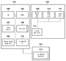
도 1은 본 실시형태에 따라 화상 처리 장치를 적용한 인쇄 시스템의 전체 구성을 도시하는 블록도이다. 본 인쇄 시스템은 퍼스널 컴퓨터 장치(정보 처리 장치)(101)(이하, "PC"라고도 칭함), 표시 장치(102), 및 출력 장치(103)를 포함한다.1 is a block diagram showing the overall configuration of a printing system to which an image processing apparatus according to the present embodiment is applied. The present printing system includes a personal computer device (information processing device) 101 (hereinafter also referred to as "PC"), a
표시 장치(102)는 디스플레이 I/F를 통해서 PC(101)에 연결된다. 표시 장치(102)는, HDR(High Dynamic Range) 디스플레이이며, HDMI 인터페이스에 의해 PC(101)에 연결된다. PC(101)와 표시 장치(102) 사이의 연결은, HDR(High Dynamic Range) 데이터를 전송할 수 있는 규격에 준거한, HDMI 인터페이스에 한정되지 않고, 다른 연결 방식일 수 있다. 또한, PC(101)와 표시 장치(102) 사이에서 전송되는 표시 정보(후술함)는, HDMI 인터페이스와는 상이한 전송 경로의 USB(Universal Serial Bus)를 사용해서 디스플레이 I/F(113)을 통해서 전송될 수 있다. 그러나, 표시 정보 전송 방식은, 표시 장치(102)와 PC(101) 또는 출력 장치(103) 사이에서 정보를 쌍방향으로 통신할 수 있는 한, USB 케이블에 한정되는 것은 아니다.The
또한, PC(101)에는, 네트워크, USB 케이블 또는 로컬 버스 등의 인터페이스를 통해서 출력 장치(103)가 연결되어 있다. 본 실시형태에서는, 출력 장치(103)의 일례로서 잉크젯 프린터(화상 처리 장치)를 사용하는 구성을 설명한다. PC(101)는, 출력 장치(103)에의 인쇄 제어 지시의 발행, 필요한 정보 및 데이터의 전송 등의 동작을 행한다. 저장 장치(105)는, OS, 시스템 프로그램, 각종 애플리케이션 소프트웨어, 본 실시형태에 필요한 파라미터 데이터 등을 저장 및 관리한다. 저장 장치(105)는, 예를 들어 하드 디스크나 플래시 ROM에 의해 형성된다. CPU(104)는, 작업 메모리(107)를 사용하여, 저장 장치(105)에 저장된 소프트웨어 또는 프로그램을 판독해서 처리를 실행한다. 유저 인터페이스로서의 역할을 하는 조작 유닛(이하, "UI"라고도 칭함)(106)은 처리의 실행에 관련된 유저로부터의 입력을 접수하고 유저에 대한 표시를 행한다. 조작 유닛(106)은 키보드, 마우스 등의 입력 기기를 포함한다. 또한, 데이터 입력/출력 장치(108)는, SD 카드 등의 외부 저장 매체에/로부터 데이터를 입력/출력하고, 예를 들어 촬상 장치의 데이터를 저장하는 외부 저장 매체에/로부터 데이터를 입력/출력할 수 있다. 또한, 촬상 장치(도시되지 않음)를 데이터 입력/출력 장치(108) 또는 데이터 전송 유닛(109)에 직접 연결함으로써 외부 저장 매체의 개입 없이 촬상 장치로/로부터의 데이터의 입력/출력을 행할 수 있다.In addition, the
출력 장치(103)는, 데이터 전송 유닛(109), 프린터 제어 유닛(112), 화상 처리 유닛(110), 인쇄 유닛(111)을 포함하며, 인쇄 데이터를 PC(101)로부터 수신한다. 본 실시형태에서는, 인쇄 데이터는 입력 화상 데이터인 HDR 데이터, 표시 장치(102)의 표시 정보, 저장 매체의 고유 데이터인 화상 처리 파라미터와 프린터 제어 데이터, 및 유저가 조작 유닛(106) 상에서 선택한 인쇄 품질, 인쇄 매체 등의 인쇄 정보를 포함한다. 이 경우, 인쇄 매체는, 예를 들어 인쇄 용지 등의 종이 매체이다.The
데이터 전송 유닛(109)은, PC(101)로부터 수신한 인쇄 데이터로부터, HDR 데이터, 표시 장치(102)의 표시 정보, 화상 처리 파라미터, 및 인쇄 정보를 취득하고, 이들 취득된 정보 및 데이터를 화상 처리 유닛(110)에 전송하여 프린터 제어 데이터를 취득하며, 취득된 프린터 제어 데이터를 프린터 제어 유닛(112)에 전송한다. 본 실시형태에서는, PC(101)의 저장 장치(105)에 저장되어 있는 HDR 데이터는 출력 장치(103)에 의해 수신되는 입력 화상 데이터로서의 역할을 한다. 또한, 본 실시형태에서는 화상 처리 유닛(110)은 표시 장치(102)에 형성되어 있지만, 이는 PC(101)에 형성될 수 있다.The
또한, 화상 처리 파라미터 및 프린터 제어 데이터는 PC(101)의 저장 장치(105) 또는 출력 장치(103)의 저장 장치(하드 디스크, ROM 등)(도시되지 않음)에 저장되어 있다. 이들 정보는 인쇄 데이터에 포함된 인쇄 정보에 기초하여 선택되고 화상 처리 유닛(110) 및 프린터 제어 유닛(112)에 전송되도록 구성될 수 있다. 프린터 제어 유닛(112)은 프린터 제어 데이터에 따라 인쇄 유닛(111)의 동작을 제어한다. 인쇄 유닛(111)은 잉크젯 인쇄 방식에 따라 인쇄를 행한다. 본 실시형태에서는 인쇄 유닛(111)에 의해 실행되는 인쇄에 채용되는 방식으로서 잉크젯 인쇄 방식이 예시되지만, 전자사진 방식 등의 다른 인쇄 방식이 채용될 수 있다. 표시 장치(102)는 화상 표시를 제어하는 디스플레이 컨트롤러(114)를 포함하며, 디스플레이 컨트롤러(114)는 예를 들어 표시 데이터를 생성한다.In addition, image processing parameters and printer control data are stored in a
도 2는 본 실시형태에 따른 화상 처리 유닛(110)의 구성을 도시하는 블록도이다. 본 실시형태에 따른 화상 처리 유닛(110)에서는, HDR 데이터, 표시 장치(102)의 표시 정보, 및 인쇄 정보가 다이내믹 레인지 변환 유닛(201)에 입력된다. 후술하는 바와 같이, 다이내믹 레인지 변환 유닛(201)은 각각의 입력된 정보를 사용하여 HDR 데이터를 출력 화상 생성 유닛(202)에 입력될 수 있는 다이내믹 레인지의 화상 데이터로 변환한다. 출력 화상 생성 유닛(202)에 입력되는 화상 데이터의 다이내믹 레인지는 휘도 레인지로서는 입력된 HDR 데이터의 하이 다이내믹 레인지보다 좁다. 출력 화상 생성 유닛(202)에 입력되는 다이내믹 레인지는, 예를 들어 SDR 데이터의 최대 휘도(100 cd/m2)를 갖는 다이내믹 레인지이다. 또한, 유저에 의해 설정되는 용지 정보에 의해 특정되는 반사 휘도에 의해 최대값이 설정되는 다이내믹 레인지가 사용될 수도 있다. 본 실시형태에서는, 다이내믹 레인지 변환 유닛(201)은 HDR 데이터의 다이내믹 레인지를 SDR 데이터의 다이내믹 레인지로 변환하는 것으로 상정한다.2 is a block diagram showing the configuration of the
이어서, 출력 화상 생성 유닛(202)은, 다이내믹 레인지 변환 유닛(201)으로부터 출력되는 화상 데이터(RGB 데이터)에 대하여, 인쇄 유닛(111)의 인쇄헤드에 의한 인쇄에 사용되는 데이터를 생성한다.Then, the output
도 3은 본 실시형태에 따른 화상 처리를 도시하는 흐름도이다. 단계 S301에서는, 다이내믹 레인지 변환 유닛(201)은 HDR 데이터의 RGB 데이터를 취득한다. 본 실시형태에 따른 HDR 데이터는 상대적인 휘도값에 기초하여 계조를 규정하는 상술한 HLG 방식에 따라서 저장된다. 이 단계에서는, 상대적인 휘도값에 기초하여 R, G, 및 B 요소 각각에 대해서 계조가 규정된다. 본 실시형태에서는 HLG 방식이 채용되지만, 계조가 상대적으로 규정되는 한 다른 방식이 채용될 수 있다. 본 실시형태에서는, 단계 S301에서 취득된 HDR 데이터는, HDR 디스플레이인 표시 장치(102)에 의해 실행되는 표시 동작에도 사용된다.3 is a flowchart showing image processing according to the present embodiment. In step S301, the dynamic
단계 S302에서는, 다이내믹 레인지 변환 유닛(201)은 표시 장치(102)의 표시 정보를 취득한다. 본 실시형태에서는, HDR 데이터가 나타내는 화상이 표시 장치(102) 상에 표시된다. 출력 장치(103)에 의한 인쇄를 행하는 유저가 인쇄 애플리케이션 상에서의 인쇄 지시 버튼 또는 출력 장치(103)의 패널 상에서의 인쇄 버튼을 누르는 시점에서, 다이내믹 레인지 변환 유닛(201)은 그때의 표시 장치(102)의 표시 상태를 저장하는 표시 정보를 표시 장치(102) 또는 PC(101)를 통해서 취득한다. 또한, 표시 정보가 디스플레이와 연동해서 PC(101)에 적시에 저장되는 경우, 다이내믹 레인지 변환 유닛(201)은 PC(101)로부터 표시 정보를 취득할 수 있다. 또한, 표시 정보는, 인쇄 애플리케이션 또는 출력 장치(103)가 기동된 시점에서 취득되거나 또는 표시 장치(102)측에서 표시 설정이 변경된 타이밍에 재취득되도록 구성될 수 있다. 즉, 인쇄 시에 유저가 보고 있는 디스플레이(표시 장치(102))의 표시 상태를 취득할 수 있으면 된다. 또한, 본 실시형태에서는 PC(101)에 1개의 디스플레이가 연결되어 있지만, 1개의 PC에 복수의 디스플레이가 동시에 연결되어 사용되는 경우도 있다. 복수의 디스플레이에 의해 확장 표시(복수의 디스플레이에 걸쳐 행해지는 표시)가 행해지는 경우에는, HDR 데이터의 인쇄 프리뷰를 표시하고 있는 디스플레이가 인식될 것이고, 이 디스플레이의 표시 정보가 취득될 것이다. 또한, 복수의 디스플레이 사이에서 복제 표시(복수의 디스플레이 사이에서 동일한 표시가 수행)가 행해지는 경우에는, 유저가 표시 정보를 취득할 디스플레이를 선택할 수 있거나 또는 표시 정보가 바람직하게 취득되는 표시 형태(display form)를 미리 설정할 수 있다.In step S302 , the dynamic
본 실시형태에서는, 표시 정보로서 디스플레이의 다이내믹 레인지 정보 및 시스템 감마 정보가 취득된다. 다이내믹 레인지 정보는, HDR 데이터가 HDR 디스플레이 상에 표시될 때의 표시가능 최대 휘도값(최대 휘도값) 및 흑색을 디스플레이에 표시하기 위한 휘도값을 포함한다. 본 실시형태에서는, 예를 들어 디스플레이의 최대 휘도값 및 흑색의 휘도값으로서 각각 1,000 cd/m2 및 0 cd/m2이 취득된다. 디스플레이의 다이내믹 레인지는, 표시 장치(102)의 표시 설정을 변경할 때 변화하고, 디스플레이 자체에 의해 표시가능한 휘도 다이내믹 레인지는 디스플레이의 성능에 따라 변화할 수 있다. 또한, 시스템 감마 정보는 디스플레이가 BT.2100에 준거한 디스플레이라는 것을 나타내는 정보 및 감마값(γ)을 포함한다. 디스플레이는 BT.2100에 준거하기 때문에 BT.2100에 의해 규정되는 HLG 방식의 OOTF의 감마값(γ)은 다음에 의해 산출될 수 있다:In this embodiment, dynamic range information and system gamma information of a display are acquired as display information. The dynamic range information includes a displayable maximum luminance value (maximum luminance value) when HDR data is displayed on the HDR display and a luminance value for displaying black on the display. In this embodiment, for example, 1,000 cd/m 2 and 0 cd/m 2 are obtained as the maximum luminance value of the display and the luminance value of black, respectively. The dynamic range of the display changes when the display setting of the
γ = 1.2 + 0.42Log10(Lw/1000) ...(1)γ = 1.2 + 0.42Log 10 (L w /1000) ...(1)
BT.2100는 식 (1)에 의해 규정되며, 예를 들어 최대 휘도값이 1,000 cd/m2일 때 1.2이 된다. 단, 표시되는 물체에 따라서는, 유저는 디스플레이 설정을 통해 이 감마값(γ)을 변경할 수 있고, 이 경우에 표시 정보로서 디스플레이 설정에 의해 설정되는 감마값(γ)이 적용될 것이다.BT.2100 is defined by Equation (1). For example , when the maximum luminance value is 1,000 cd/m 2 , it becomes 1.2. However, depending on the object to be displayed, the user may change this gamma value γ through the display setting, and in this case, the gamma value γ set by the display setting will be applied as the display information.
단계 S303에서는, 다이내믹 레인지 변환 유닛(201)은 인쇄 정보를 취득한다. 인쇄 정보는 다이내믹 레인지 변환 후의 다이내믹 레인지를 특정하기 위한 정보이다. 본 실시형태에서는, 예를 들어, 인쇄 정보로서 인쇄 모드 정보가 취득되고, 인쇄 모드 정보에 기초하여, 출력 화상 생성 유닛(202)에의 입력이 sRGB의 SDR 데이터인 것을 특정한다. 그 결과, SDR 데이터에 대해 변환 후의 휘도 다이내믹 레인지로서 100 cd/m2의 최대 휘도값이 특정된다. 인쇄 정보는, 용지 종류를 나타내는 정보를 취득함으로써 취득될 수 있으며, 용지 종류로부터 특정되는 반사 휘도를 특정할 수 있는 정보이면 된다. 정보가 인쇄 시의 휘도 다이내믹 레인지 정보가 취득될 수 있는 정보인 한은, 다른 정보가 사용될 수 있다. 또한, 인쇄물은 관찰 환경에 따라 다양한 종류의 조도의 조명에 의해 조사될 수 있다. 인쇄물에 조명이 조사되는 경우에는, 용지의 휘도 다이내믹 레인지는 특히 종이의 백색의 밝기의 증가로 인해 확대될 것이다. 따라서, 용지가 조명으로 조사될 때의 용지의 반사 휘도는 인쇄 시의 휘도 다이내믹 레인지 정보로서 취득될 수 있다.In step S303, the dynamic
단계 S304에서는, 다이내믹 레인지 변환 유닛(201)은, 단계 S302에서 취득된 표시 정보 및 단계 S303에서 취득된 인쇄 정보에 기초하여, HDR 데이터로부터 휘도 다이내믹 레인지를 변환함으로써 취득되는 화상 데이터를 생성한다. 즉, 본 실시형태에서는, 표시 정보로부터 취득되고 1,000 cd/m2의 최대 휘도값을 갖는 휘도 다이내믹 레인지를 취득된 표시 정보에 기초하여 인쇄 정보로부터 취득되고 100 cd/m2의 최대 휘도값을 갖는 휘도 다이내믹 레인지로 변환하기 위해 다이내믹 레인지 변환 처리가 행해진다. 상술한 바와 같이, 다이내믹 레인지 변환 후의 휘도 다이내믹 레인지는 인쇄 정보에 의해 특정되는 절대 휘도값에 의해 표현되는 휘도 다이내믹 레인지가 된다.In step S304, the dynamic
상술한 바와 같이, HDR 데이터의 2개의 화상 전달 함수로서는, 예를 들어 ITU-R(국제 전기통신 연합 무선통신 부문)의 권고 BT.2100에서, HLG(Hybrid Log Gamma)와 PQ(Perceptual Quantization)가 규정된다. 본 실시형태에 따른 HDR 데이터는, 상술한 HLG 방식의 전달 함수(OETF)에 의해 변환된 데이터이다. 따라서, 다이내믹 레인지 변환 유닛(201)은, HDR 데이터의 휘도 신호 레벨(x)이 다음의 식에 의해 결정되는 HLG 방식의 전달 함수 EOTF(OETF의 역함수) 및 전달 함수 OOTF를 사용하여 휘도 신호 레벨(y)로 변환되도록 HDR 데이터에 대해 휘도 변환을 행한다:As described above, as two image transfer functions of HDR data, for example, in Recommendation BT.2100 of ITU-R (International Telecommunication Union Radiocommunication Sector), HLG (Hybrid Log Gamma) and PQ (Perceptual Quantization) are stipulated The HDR data according to the present embodiment is data converted by the transfer function (OETF) of the HLG method described above. Therefore, the dynamic
![]()
![]()


![]()
![]()
γ은 식 (1)에 의해 산출되는 값이고, LW는 디스플레이의 최대 휘도값이며, LB는 디스플레이의 흑색의 휘도값이다. 본 실시형태에서는, LB는 0인 것으로 한다. E'은 HLG 방식 신호이며, x는 0 내지 1의 레인지로 정규화된 신호이다. α은 유저 게인을 위한 변수이고, YS는 정규화된 휘도값이며, E는 0 내지 1의 레인지로 정규화된 선형 광 신호이다.γ is a value calculated by the formula (1), L W is the maximum luminance value of the display, L B is a luminance value of the black display. In this embodiment, it is assumed that LB is 0. E' is an HLG method signal, and x is a signal normalized to a range of 0 to 1. α is a variable for user gain, Y S is a normalized luminance value, and E is a linear optical signal normalized to a range of 0 to 1.
이어서, 다이내믹 레인지 변환 유닛(201)은, OOTF 처리로부터 취득된 데이터를 최대 휘도값이 1,000 cd/m2인 데이터로서 설정하고, 이 데이터를 휘도 다이내믹 레인지가 인쇄 정보로부터 취득되는 값에 대응하는 100 cd/m2의 최대 휘도값을 갖는 데이터로 변환하기 위해 다이내믹 레인지 변환 처리를 행한다. 본 실시형태에서는, 다이내믹 레인지 변환 유닛(201)은, OOTF 처리에 의해 취득되는 RGB 데이터를 다음 식에 의해 휘도값(Y) 및 색차(CbCr)를 갖는 데이터로 변환한다:Then, the dynamic
Y = 0.29900 × R + 0.58700 × G + 0.114400 × B ...(3)Y = 0.29900 × R + 0.58700 × G + 0.114400 × B ...(3)
Cb = -0.16874 × R - 0.33126 × G + 0.50000 × B ...(4)Cb = -0.16874 × R - 0.33126 × G + 0.50000 × B ...(4)
Cr = 0.50000 × R - 0.41869 × G - 0.081 × B ...(5)Cr = 0.50000 × R - 0.41869 × G - 0.081 × B ...(5)
다이내믹 레인지 변환 유닛(201)은, 도 4a에 도시된 그래프(가로축은 입력 휘도값을 나타내며 세로축은 출력 휘도값을 나타낸다)에서 실선에 의해 나타내는 변환 커브에 기초하여, 변환된 휘도값(Y)의 데이터를 휘도값(Y')으로 변환하는 휘도 다이내믹 레인지 변환을 행한다. 도 4a에 도시된 짧은 파선은 입력 및 출력이 선형인 상태를 나타낸다. 본 실시형태에서는, 도 4a에 도시된 실선으로 나타낸 바와 같이, 암부로부터 특정한 휘도의 부분까지의 선형 변환이 행해지며, 하이라이트부에 대해서는 로그 특성(Log characteristic)에 의한 변환이 행해진다. 도 4a에 나타내는 바와 같이, HDR 데이터의 하이라이트 영역을 재현하면서 화상의 콘트라스트를 유지하기 위해 다이내믹 레인지 압축 처리를 행하는 것이 바람직하다. 또한, 도 4b는, 도 4a의 것과 유사한 다이내믹 레인지 압축 방법이 채용된 그래프이며, 디스플레이의 최대 휘도값이 2,000 cd/m2인 경우의 다이내믹 레인지 변환 전과 후의 휘도 관계를 도시한다. 도 4a 및 도 4b에 나타낸 바와 같이, 단계 S302에서 취득된 표시 정보 및 단계 S303에서 취득된 인쇄 정보에 기초하여, 디스플레이의 표시가능 다이내믹 레인지에 따라 다이내믹 레인지 변환을 행할 수 있다. 이어서, 다이내믹 레인지 변환 유닛(201)은, 변환된 휘도값(Y') 및 색차 성분을 합성하여 다음에 의해 RGB 데이터로의 변환을 행한다:The dynamic
R = Y + 1.40200 × Cr ...(6)R = Y + 1.40200 × Cr ...(6)
G = Y - 0.34414 × Cb - 0.71414 × Cr ...(7)G = Y - 0.34414 × Cb - 0.71414 × Cr ...(7)
B = Y + 1.77200 × Cb ...(8)B = Y + 1.77200 × Cb ...(8)
위에서는 휘도 다이내믹 레인지 압축에 대해서 설명했지만, 색 영역(color gamut)에 관해서도 HDR 데이터의 넓은 색 영역 공간(예를 들어, ITU-R BT.2020)을 SDR 데이터의 색 영역(예를 들어, ITU-R BT.709)으로 변환하는 색 영역 압축 처리를 행할 수 있다.Although the luminance dynamic range compression has been described above, the wide color gamut space of HDR data (eg, ITU-R BT.2020) is also of color gamut, and the color gamut of SDR data (eg, ITU). -R BT.709), a color gamut compression process can be performed.
이어서, 단계 S305에서는, 출력 화상 생성 유닛(202)은 인쇄 유닛(111)에 출력되는 출력 화상 데이터를 생성한다. 예를 들어, 출력 화상 생성 유닛(202)은, 단계 S304에서 출력된 SDR 데이터(RGB 데이터)를 디바이스 의존적 RGB 데이터로 변환하는 색 변환 처리를 행한다. 출력 화상 생성 유닛(202)은, 디바이스 의존적 RGB 데이터를 잉크 색 데이터로 변환하는 잉크 색 분해 처리를 행하며, 잉크 색 데이터가 인쇄 장치의 계조 특성과 선형적으로 연관되도록 계조 보정을 행하기 위해 계조 보정 처리를 행한다. 또한, 출력 화상 생성 유닛(202)은, 잉크 색 데이터를 잉크 도트 ON/OFF 정보로 변환하는 하프톤 처리, 인쇄헤드의 각각의 인쇄 주사에서 인쇄되는 2치 데이터를 생성하는 마스킹 데이터 변환 처리 등을 행한다.Next, in step S305 , the output
이어서, 단계 S306에서는, 출력 화상 생성 유닛(202)은, 생성된 출력 화상 데이터를 인쇄 유닛(111)에 전송하고, 그후 인쇄 매체 위에 화상이 출력된다.Next, in step S306 , the output
상술한 바와 같이, HLG 방식의 HDR 데이터는 표시 장치(102)의 성능에 따라 상이하게 표시된다. 본 실시형태에 따르면, HLG 방식의 HDR 데이터의 인쇄 시에 유저가 보고 있는 표시 장치(102)의 표시 정보 및 출력 장치(103)의 인쇄 정보를 사용할 수 있어, 디스플레이의 표시 상태에 대응하는 다이내믹 레인지 변환을 행할 수 있다. 그 결과, 다른 성능을 갖는 복수의 표시 장치(102)의 각각의 표시에 대응하는 인쇄 출력을 얻을 수 있다.As described above, the HDR data of the HLG method is displayed differently depending on the performance of the
[제2 실시형태][Second embodiment]
이하, 제2 실시형태에서 제1 실시형태와 상이한 점에 대해서 설명한다. 본 실시형태는 PQ 방식의 HDR 데이터가 입력되는 경우를 설명한다.Hereinafter, the point different from 1st Embodiment in 2nd Embodiment is demonstrated. This embodiment describes a case where HDR data of the PQ system is input.
본 실시형태에서는, 도 3의 단계 S301에서 취득되는 HDR 데이터(RGB 데이터)는, 상술한 절대 휘도값에서 계조를 규정하고 있는 PQ 방식에 따라서 기록된다. 본 실시형태에서는, HDR 데이터에는 10,000 cd/m2까지의 정보가 기록되어 있는 것으로 한다.In the present embodiment, the HDR data (RGB data) obtained in step S301 of Fig. 3 is recorded according to the PQ system that defines the gradation in the absolute luminance value described above. In the present embodiment, it is assumed that information up to 10,000 cd/m 2 is recorded in HDR data.
단계 S302에서는, 다이내믹 레인지 변환 유닛(201)은, 표시 정보로서, 디스플레이의 다이내믹 레인지 정보 및 휘도 다이내믹 레인지 변환 방법을 취득한다. 디스플레이의 다이내믹 레인지 정보에 대한 설명은 제1 실시형태의 것과 유사하다. 휘도 다이내믹 레인지 변환 방법은, 10,000 cd/m2의 최대 휘도값에 의해 규정되는 PQ 방식의 휘도 다이내믹 레인지를 디스플레이의 휘도 다이내믹 레인지로 변환하는 방법에 관한 정보이다. 이 정보는, 단계 S304의 처리에서 변환이 실행될 수 있게 하는 정보이면 되고, 변환이 주지의 방법에 의해 실행되는 경우 변환 방법명일 수 있거나 변환 모듈(예를 들어, 후술하는 변환 커브)이 저장되는 경로의 정보일 수 있다.In step S302, the dynamic
도 5a 및 도 5b는 디스플레이의 휘도 다이내믹 레인지 변환을 위한 2개의 종류의 변환 커브를 도시하는 그래프이다. 도 5a는, 값이 1,000 cd/m2보다 높고 HDR에 포함되는 디스플레이에 표시될 수 없는 높은 휘도 부분의 모든 데이터가 1,000 cd/m2로서 표시되는 변환 방법을 나타낸다. 한편, 도 5b는 암부로부터 특정한 휘도 부분까지의 데이터는 선형적으로 변환되고 하이라이트부는 Log 특성에 의해 변환되는 도 4a 및 도 4b와 유사한 방법을 나타낸다. 본 실시형태에서는, HDR 데이터가 PQ 방식이기 때문에, 도 5a의 변환 및 도 5b의 변환은 디스플레이에 의한 표시 동작과 관련하여 도 5a 및 도 5b의 휘도 레인지(501) 사이에 차이를 초래하지 않지만, 도 5a와 도 5b의 휘도 레인지(502) 사이에서 표시 동작의 차이가 관찰될 수 있다.5A and 5B are graphs showing two kinds of conversion curves for converting a luminance dynamic range of a display. 5A shows a conversion method in which all data of a high luminance portion whose value is higher than 1,000 cd/m 2 and cannot be displayed on a display included in HDR is displayed as 1,000 cd/m 2 . Meanwhile, FIG. 5B shows a method similar to FIGS. 4A and 4B in which data from a dark part to a specific luminance part is linearly converted and a highlight part is converted by a log characteristic. In the present embodiment, since the HDR data is of the PQ method, the conversion of Fig. 5A and the conversion of Fig. 5B do not cause a difference between the
단계 S303의 인쇄 정보 취득 처리는 제1 실시형태에 따른 것과 유사하다.The print information acquisition processing in step S303 is similar to that according to the first embodiment.
단계 S304에서는, 다이내믹 레인지 변환 유닛(201)은, 단계 S302에서 취득된 표시 정보 및 단계 S303에서 취득된 인쇄 정보에 기초하여, 휘도 다이내믹 레인지가 HDR 데이터의 것으로부터 변환된 데이터를 생성한다. 본 실시형태에서는, 다이내믹 레인지 변환 유닛(201)은, 10,000 cd/m2의 최대 휘도값을 갖는 HDR 데이터의 휘도 다이내믹 레인지의 정보를 100 cd/m2의 최대 휘도값을 갖는 인쇄 정보로부터 취득되는 휘도 다이내믹 레인지로 변환하는 다이내믹 레인지 변환 처리를 행한다.In step S304, the dynamic
본 실시형태에 따른 HDR 데이터는, 상술한 PQ 방식에 따라 전달 함수(EOTF의 역함수)에 의해 변환된 데이터이다. 따라서, 다이내믹 레인지 변환 유닛(201)은, 다음에 의해 규정되는 PQ 방식의 EOTF를 사용하여 HDR 데이터의 휘도 신호 레벨(x)이 휘도 신호 레벨(y)로 변환되도록 HDR 데이터에 대해 휘도 변환을 행한다:The HDR data according to the present embodiment is data converted by a transfer function (the inverse function of EOTF) according to the above-described PQ method. Therefore, the dynamic
![]()
![]()
![]()
![]()
본 실시형태에서는, LB는 0이다. E'은 PQ 방식 신호이며, x는 0 내지 1의 레인지로 정규화된 신호이다.In this embodiment, L B is zero. E' is a PQ system signal, and x is a signal normalized to a range of 0 to 1.
이어서, 다이내믹 레인지 변환 유닛(201)은, EOTF 처리로부터 변환된 데이터를 최대 휘도값이 10,000 cd/m2인 데이터로서 설정하며, 이 데이터를 휘도 다이내믹 레인지가 100 cd/m2의 최대 휘도값을 갖는 데이터로 변환하는 다이내믹 레인지 변환 처리를 행한다. 본 실시형태에서는, 다이내믹 레인지 변환 유닛(201)은, EOTF 처리에 의해 취득된 RGB 데이터를 식 (3), (4), 및 (5)에 의해 휘도값(Y) 및 색차(CbCr)의 데이터로 변환한다. 후속하여, 다이내믹 레인지 변환 유닛(201)은, 변환된 휘도값(Y)의 데이터에 대하여, 도 5a에 나타내는 변환 커브에 의해 변환을 행하고, 또한 도 4a에 나타내는 변환 커브에 의해 변환을 행함으로써 SDR 데이터를 변환의 결과로서 취득한다. 도 4a 및 도 5a에 나타내는 변환 커브에 의한 변환 동작 각각은 1DLUT에 의해 변환될 수 있기 때문에, 변환은 각각의 변환 커브의 1DLUT를 합성함으로써 취득되는 1DLUT를 사용해서 행해질 수 있다. 후속하여, 변환된 휘도값과 색차를 합성하여 식 (6), (7), 및 (8)에 의해 RGB 데이터로의 변환을 행한다. 또한, 상기 설명에서는 도 5a를 사용했지만, 도 5b 또한 사용될 수 있다.Next, the dynamic
단계 S305 및 S306의 처리는 제1 실시형태에 따른 처리와 유사하다.The processing of steps S305 and S306 is similar to the processing according to the first embodiment.
위에서 설명된 바와 같이, PQ 방식의 HDR 데이터에서는, 표시 장치(102)의 성능에 따라 데이터의 하이라이트부가 상이하게 표시될 수 있다. 본 실시형태에 따르면, PQ 방식의 HDR 데이터의 인쇄 시에 유저가 보는 표시 장치(102)의 표시 정보와 출력 장치(103)의 인쇄 정보를 사용할 수 있고, 따라서 디스플레이의 표시 상태에 대응하는 다이내믹 레인지 변환을 행할 수 있다. 그 결과, 다른 성능을 갖는 복수의 표시 장치(102)의 각각의 표시에 대응하는 인쇄 출력을 얻을 수 있다.As described above, in the HDR data of the PQ method, the highlight portion of the data may be differently displayed according to the performance of the
[제3 실시형태][Third embodiment]
이하, 제3 실시형태에서 제1 실시형태 및 제2 실시형태와 상이한 점에 대해서 설명한다. 본 실시형태는, PQ 방식의 HDR 데이터가 입력되고 표시 장치(102)측에서 휘도 다이내믹 레인지 변환이 행해져서 SDR 디스플레이에 표시되는 경우를 설명한다. 본 실시형태에서는, 표시 장치(102)는 SDR 디스플레이다.Hereinafter, the point different from 1st Embodiment and 2nd Embodiment in 3rd Embodiment is demonstrated. This embodiment describes a case where HDR data of the PQ system is input, luminance dynamic range conversion is performed on the
본 실시형태에서는, 도 3의 단계 S301에서 PQ 방식의 HDR 데이터가 취득된다.In the present embodiment, HDR data of the PQ system is acquired in step S301 of FIG. 3 .
단계 S302에서는, 제2 실시형태와 유사한 방식으로, 디스플레이의 다이내믹 레인지 정보 및 휘도 다이내믹 레인지 변환 방법이 취득된다. 본 실시형태에서는 표시 장치(102)는 SDR 디스플레이이기 때문에, 디스플레이의 최대 휘도값 및 흑색의 휘도값으로서 각각 100 cd/m2 및 0 cd/m2가 취득된다. 휘도 다이내믹 레인지 변환 방법의 취득에 대한 설명은 제2 실시형태에 따른 것과 유사하다.In step S302, in a manner similar to the second embodiment, the dynamic range information of the display and the luminance dynamic range conversion method are acquired. In the present embodiment, since the
도 6은 본 실시형태에 따른 디스플레이의 휘도 다이내믹 레인지 변환의 변환 커브를 도시하는 그래프이다. 도 6은 도 5b의 디스플레이의 휘도 다이내믹 레인지의 최대 휘도값이 100 cd/m2로 설정된 상태에 대응한다. 본 실시형태에서는 도 6에 나타내는 바와 같은 휘도 다이내믹 레인지 변환이 행해지지만, 다이내믹 레인지 변환 방법은 변환 커브(601 및 602)가 나타내는 바와 같이 디스플레이의 제조자 또는 모델에 따라 달라진다.6 is a graph showing a conversion curve of luminance dynamic range conversion of the display according to the present embodiment. FIG. 6 corresponds to a state in which the maximum luminance value of the luminance dynamic range of the display of FIG. 5B is set to 100 cd/m 2 . In this embodiment, the luminance dynamic range conversion as shown in Fig. 6 is performed, but the dynamic range conversion method varies depending on the manufacturer or model of the display as indicated by the conversion curves 601 and 602.
단계 S303의 인쇄 정보의 취득은 제1 실시형태에 따른 방식과 유사한 방식으로 행해진다.Acquisition of print information in step S303 is performed in a manner similar to that according to the first embodiment.
단계 S304에서는, 다이내믹 레인지 변환 유닛(201)은, 단계 S302에서 취득된 표시 정보 및 단계 S303에서 취득된 인쇄 정보에 기초하여, HDR 데이터의 휘도 다이내믹 레인지를 변환함으로써 취득되는 화상 데이터를 생성한다. 본 실시형태에서는, 다이내믹 레인지 변환 유닛(201)은, HDR 데이터가 갖는 휘도 다이내믹 레인지의 정보를, 휘도 다이내믹 레인지가 인쇄 정보로부터 취득되는 값에 대응하는 100 cd/m2의 최대 휘도값을 갖는 HDR 데이터로 변환하기 위해 다이내믹 레인지 변환 처리를 행한다.In step S304, the dynamic
HDR 데이터는, 제2 실시형태에서 설명된 바와 같이, 디스플레이의 휘도 신호 레벨에 대응하는 정보로 변환된다. 후속하여, 휘도 다이내믹 레인지를 최대 휘도값이 인쇄 정보로부터 취득되는 100 cd/m2인 휘도 다이내믹 레인지에 대응하는 것으로 변환하기 위해 변환된 데이터에 대해 다이내믹 레인지 변환 처리를 행한다. 본 실시형태에서는, 디스플레이측의 변환-후 휘도 다이내믹 레인지 및 인쇄측의 변환-후 휘도 다이내믹 레인지는 동등하게 100 cd/m2이다. 따라서, 본 실시형태의 단계 S304에서는, 도 6에 도시된 변환 커브를 사용하여 변환된 휘도값(Y)의 데이터에 대해 휘도 다이내믹 레인지 변환이 행해지며, 변환된 휘도 및 색차 성분은 합성되어 식 (6), (7), 및 (8)에 의해 SDR의 RGB 데이터로의 변환을 행한다.The HDR data is converted into information corresponding to the luminance signal level of the display, as described in the second embodiment. Subsequently, dynamic range conversion processing is performed on the converted data to convert the luminance dynamic range into one corresponding to the luminance dynamic range whose maximum luminance value is 100 cd/m 2 obtained from the print information. In this embodiment, the post-conversion luminance dynamic range on the display side and the post-conversion luminance dynamic range on the printing side are equally 100 cd/m 2 . Accordingly, in step S304 of the present embodiment, luminance dynamic range conversion is performed on the data of the luminance value Y converted using the conversion curve shown in Fig. 6, and the converted luminance and color difference components are synthesized to form the equation ( 6), (7), and (8) convert SDR to RGB data.
단계 S305 및 S306의 처리는 제1 실시형태의 것과 유사하다.The processing of steps S305 and S306 is similar to that of the first embodiment.
상술한 바와 같이, 표시 장치(102)측에 대해 휘도 다이내믹 레인지 변환 처리를 행함으로써 SDR 디스플레이에 표시가 행해지는 경우, 표시 장치(102)에 따라 휘도 다이내믹 레인지 변환 방법이 다르다는 사실에 따라 표시가 다를 수 있다. 본 실시형태에 따르면, HDR 데이터의 인쇄 시에 SDR 디스플레이의 표시 정보 및 출력 장치(103)의 인쇄 정보를 취득함으로써, 디스플레이의 표시 상태에 대응하는 다이내믹 레인지 변환이 행해질 수 있다. 그 결과, 다른 성능을 갖는 복수의 SDR 디스플레이의 각각의 표시에 대응하는 인쇄 출력을 얻을 수 있다.As described above, when display is performed on an SDR display by performing luminance dynamic range conversion processing on the
[제4 실시형태][Fourth embodiment]
이하, 제4 실시형태에서 제1 실시형태 내지 제3 실시형태의 것과 상이한 점에 대해서 설명한다. 제1 실시형태 내지 제3 실시형태에서는, 식 (2) 및 (9)에 의해 데이터를 디스플레이의 휘도 신호 레벨로 변환하는 처리를 행했다. 본 실시형태는, 디스플레이의 휘도 신호 레벨로 이미 변환된 데이터를 취득하는 구성을 설명한다. 본 실시형태에서는, 도 3의 단계 S301의 처리에서 취득되는 HDR 데이터는 HLG 방식 또는 PQ 방식 중 어느 쪽에도 준거할 수 있다.Hereinafter, in 4th Embodiment, the point different from that of 1st Embodiment - 3rd Embodiment is demonstrated. In the first to third embodiments, processing for converting data into the luminance signal level of the display by the formulas (2) and (9) was performed. This embodiment describes a configuration for acquiring data already converted to the luminance signal level of the display. In the present embodiment, the HDR data acquired in the process of step S301 in Fig. 3 can be compliant with either the HLG system or the PQ system.
단계 S302에서는, 다이내믹 레인지 변환 유닛(201)은, 표시 정보로서, 디스플레이의 휘도 다이내믹 레인지 정보, 및 디스플레이의 휘도 신호 레벨로 변환되고 계조가 절대 휘도값에 의해 규정되는 데이터를 취득한다. 즉, HLG 방식의 HDR 데이터를 취득하는 경우에는, 제1 실시형태에 따른 OOTF 처리가 행해진 RGB 데이터를 취득한다. 또한, PQ 방식의 HDR 데이터를 취득하는 경우에는, 제2 실시형태에 따른 EOTF 처리가 행해진 RGB 데이터에 대하여 도 5a의 변환 커브를 사용하여 변환을 행함으로써 취득된 RGB 데이터를 취득한다. 이들의 데이터에 대해 PQ 방식에 따른 OETF 처리(EOTF의 역함수)를 행함으로써 취득되는 데이터를 취득할 수도 있다. 이들 데이터는, 표시 장치(102)에서의 표시 처리의 화상 처리 과정에서 디스플레이 컨트롤러(114)에 의해 생성될 수 있으며, 표시 장치(102) 또는 PC(101) 등과 같은 표시 장치(102) 외부의 장치에서 생성될 수 있다. 이들 데이터는, 예를 들어 표시 장치(102)의 저장 유닛 또는 PC(101) 등과 같은 표시 장치(102) 외부의 장치의 저장 유닛에 저장된다. 유저가 인쇄 버튼을 누른 시점에서의 디스플레이의 표시 상태에 대응하는 데이터가 저장 유닛으로부터 취득될 수 있다.In step S302, the dynamic
단계 S303의 인쇄 정보 취득 처리는 제1 실시형태에 따른 것과 유사하다.The print information acquisition processing in step S303 is similar to that according to the first embodiment.
단계 S304에서는, 다이내믹 레인지 변환 유닛(201)은, 단계 S302에서 취득된 표시 정보 및 단계 S303에서 취득된 인쇄 정보에 기초하여, 휘도 다이내믹 레인지가 HDR 데이터의 것으로부터 변환된 화상 데이터를 생성한다. 본 실시형태에서는, 다이내믹 레인지 변환 유닛(201)은, 표시 정보에 기초하여, 단계 S301에서 취득된 HDR 데이터에 대하여 상술한 바와 같은 휘도 다이내믹 레인지 변환을 행하기 위해 도 4a의 변환 커브를 이용할 것이다. 다이내믹 레인지 변환 유닛(201)은, 최대 휘도값이 1,000 cd/m2인 데이터가 갖는 휘도 다이내믹 레인지의 정보를 휘도 다이내믹 레인지가 인쇄 정보로부터 취득되는 값에 대응하는 100 cd/m2의 최대 휘도값을 갖는 데이터를 변환할 것이다.In step S304, the dynamic
단계 S305와 S306의 처리는 제1 실시형태의 것과 유사하다.The processing of steps S305 and S306 is similar to that of the first embodiment.
위에서 설명한 바와 같이, 디스플레이의 휘도 신호 레벨로 변환되었고 계조가 절대 휘도값에 의해 규정되는 데이터를 표시 정보로서 취득하고, 휘도 다이내믹 레인지 변환을 행한다. 따라서, 다른 성능을 갖는 복수의 표시 장치(102)의 각각의 디스플레이에 대응하는 인쇄 출력을 얻을 수 있다. 또한, 다이내믹 레인지 변환 유닛(201)은 OOTF 처리 또는 EOTF 처리가 행해진 HDR 데이터를 사용할 것이므로, 출력 장치(103)측의 처리 부하를 경감하는 것이 가능할 것이다.As described above, data that has been converted to the luminance signal level of the display and whose gradation is defined by an absolute luminance value is acquired as display information, and luminance dynamic range conversion is performed. Accordingly, it is possible to obtain a print output corresponding to each display of the plurality of
본 실시형태에서는 YCbCr을 사용해서 휘도 다이내믹 레인지 변환을 행했지만, ICtCp를 사용해서 휘도 다이내믹 레인지 변환을 행할 수도 있다. ICtCp는, 넓은 색 영역 신호를 목적으로 하는 하이 다이내믹 레인지를 갖는 색 공간이다. 여기서, I를 휘도 성분으로 하고, CtCp를 색차 성분으로 한다. 휘도 성분(I)은, 넓은 휘도 레인지의 인간 시각 특성을 고려한 정보이다. 그 결과, ICtCp 색 공간을 사용함으로써 인간 시각 특성을 고려한 휘도 다이내믹 레인지 변환이 가능해진다.Although the luminance dynamic range conversion is performed using YCbCr in the present embodiment, the luminance dynamic range conversion can also be performed using ICtCp. ICtCp is a color space having a high dynamic range aimed at a wide color gamut signal. Here, I is a luminance component and CtCp is a color difference component. The luminance component (I) is information in consideration of human visual characteristics in a wide luminance range. As a result, by using the ICtCp color space, luminance dynamic range conversion in consideration of human visual characteristics becomes possible.
본 실시형태에서는, 도 4a 및 도 4b에 나타내는 특성에 기초하여 휘도 다이내믹 레인지 변환을 행하는 대신에, 도 7 및 도 8의 흐름도에 나타내는 처리에 따라 다이내믹 레인지 변환 처리를 행할 수 있다.In the present embodiment, instead of performing the luminance dynamic range conversion based on the characteristics shown in Figs. 4A and 4B, the dynamic range conversion processing can be performed according to the processing shown in the flowcharts of Figs. 7 and 8 .
도 7의 단계 S701에서는, 다이내믹 레인지 변환 유닛(201)은, OOTF 처리로부터 취득된 RGB 데이터를 식 (3), (4), 및 (5)에 의해 휘도 성분 및 색차 성분으로 분리한다.In step S701 of FIG. 7 , the dynamic
단계 S702에서는, 다이내믹 레인지 변환 유닛(201)은, 휘도 성분으로 변환된 데이터의 저주파 성분과 고주파 성분을 분리하는 처리를 행한다. 이것은, 레티넥스 이론(Retinex theory)에 기초하여 저주파 성분과 고주파 성분 사이에서 처리가 전환되기 때문이다. 레티넥스 이론은 인간 뇌가 광 및 색을 어떻게 인지하는지를 모델화한 이론이다. 이 이론에 따르면, 눈에 들어가는 광의 강도는, 물체의 반사율과 물체를 비추는 조명광의 곱에 의해 나타낼 수 있으며, 사람이 느끼는 밝기 및 색은 절대적인 광학량보다 주변으로부터의 상대적인 변화량에 크게 의존한다. 여기서, 절대적인 광학량은 물체를 비추는 조명광이며, 상대적인 변화량은 물체의 반사율이다.In step S702, the dynamic
단계 S702에서는, 다이내믹 레인지 변환 유닛(201)은, 물체를 비추는 조명광 성분으로서 화상 데이터의 저주파 성분을 추출한다. 저주파 성분을 생성하기 위해서는, 저역 통과 필터를 적용한다. 처리 방법으로서, 공간 필터를 적용할 수 있거나, 대상 주파수 성분을 FFT에 의해 일시적으로 공간 주파수로 변환하고 필터 처리 후에 IFFT에 의해 주파수 성분으로 복귀시킬 수 있다. 대상으로 하는 주파수는, 인쇄물이 관찰되는 용지의 용지 사이즈 또는 관찰 거리에 기초하여, 인간 시각 특성을 고려하여 결정될 수 있다. 고주파 성분을 취득하기 위해서는, 저역 통과 필터의 반대인 고역 통과 필터를 적용할 수 있거나, 취득된 저주파 성분이 원래의 화상으로부터 감산될 수 있다.In step S702, the dynamic
단계 S703에서는, 다이내믹 레인지 변환 유닛(201)은, 입력 휘도 다이내믹 레인지 정보 및 출력 휘도 다이내믹 레인지 정보에 기초하여 저주파 성분에 대해 다이내믹 레인지 변환 처리를 행한다. 단계 S703의 처리에 대해서 도 8을 참고하여 이하에서 상세하게 설명된다.In step S703, the dynamic
단계 S704에서는, 다이내믹 레인지 변환 유닛(201)은 고주파 성분에 대하여 콘트라스트 보정 처리를 행한다. 콘트라스트 보정 처리는 얻어진 화상에 계수 k를 곱하는 처리이다. 인쇄물이 입력 데이터에 충실하게 접근할 경우에는 k = 대략 1이다. 인쇄물에서의 잉크 번짐 등의 열화를 더 고려하는 경우에는, 1 이상의 값이 계수 k로서 설정된다.In step S704, the dynamic
단계 S705에서는, 다이내믹 레인지 변환 유닛(201)은, 저주파 성분에 대하여 다이내믹 레인지 변환이 행해진 화상 데이터와 고주파 성분에 대하여 콘트라스트 보정이 행해진 화상 데이터를 합성한다. 그 결과, 화상 데이터는 미리결정된 다이내믹 레인지로 압축되며, 보정된 콘트라스트를 갖는 휘도 화상이 얻어진다.In step S705, the dynamic
단계 S706에서는, 다이내믹 레인지 변환 유닛(201)은, 휘도 성분과 색차 성분을 합성하여, 식 (6), (7), 및 (8)에 의해 RGB 데이터로의 변환을 행한다. 단계 S706의 처리 후에, 도 7의 처리를 종료한다.In step S706, the dynamic
단계 S703의 다이내믹 레인지 변환 처리에 대해서 도 8의 흐름도를 사용해서 설명한다.The dynamic range conversion process in step S703 will be described using the flowchart in FIG.
단계 S801에서는, 다이내믹 레인지 변환 유닛(201)은 압축 레인지를 산출한다. 본 실시형태에서는, 표시 정보로부터 취득되고 1,000 cd/m2의 최대 휘도값을 갖는 휘도 다이내믹 레인지를 인쇄 정보로부터 취득되고 100 cd/m2의 최대 휘도값을 갖는 휘도 다이내믹 레인지로 변환하기 위해 다이내믹 레인지 변환 처리를 행한다. 또한, 다이내믹 레인지 변환 유닛(201)은, 노출 휘도값(Ya)을 HDR 데이터의 메타데이터로부터 취득한다. 이것은, 유저가 촬상 동작 동안 노출을 설정한 점이다. 본 실시형태에서는 노출 휘도값(Ya)이 18 cd/m2인 것으로 한다.In step S801, the dynamic
단계 S802에서는, 다이내믹 레인지 변환 유닛(201)은 HDR 데이터의 화상을 영역들로 분할한다. 화상의 영역 분할은, 화상을 미리결정된 직사각형 사이즈 영역들로 분할하거나 휘도 데이터의 정보에 기초하여 유사한 휘도 화소의 그룹을 생성함으로써 행해질 수 있다. 후자의 경우, 영역 분할된 특정한 휘도 레인지의 콘트라스트를 복원할 수 있고, 더 양호한 콘트라스트를 갖는 화상을 얻을 수 있다. 또한, 휘도 데이터뿐만 아니라 RGB 데이터를 사용하는 것도 가능하다. 결과적으로, RGB 데이터에 의해 화상 인식을 행할 수 있고, 인식된 영역의 각각의 종류에 따라 콘트라스트를 복원하는 방법이 채용될 수 있다.In step S802, the dynamic
단계 S803에서는, 다이내믹 레인지 변환 유닛(201)은 단계 S802에서 분할된 각각의 영역마다 변환 커브를 생성한다. 도 9a, 도 9b, 및 도 9c는 변환 커브의 일례를 각각 도시하는 그래프이다. 도 9a는 주어진 영역의 변환 커브를 나타내는 그래프이다. 가로축은 입력 휘도값을 나타내고, 세로축은 출력 휘도값을 나타내며, 굵은 선은 변환 커브를 나타낸다. 막대 그래프는 영역의 휘도 분포를 나타내며, 막대는 미리결정된 휘도 레인지의 도수에 대응한다(우측의 세로축에 대응). 도 9a, 도 9b 및 도 9c에서, Di는 변환-전 휘도 다이내믹 레인지를 나타내며, Do는 변환-후 휘도 다이내믹 레인지를 나타낸다. 기울기가 1, 즉 45°인 경우에는, 입력 휘도값과 출력 휘도값이 일치할 것이고, 이 부분에서는 화상 변화가 일어나지 않을 것이다. 즉, 다이내믹 레인지의 변환-전 콘트라스트가 유지될 것이다. 기울기가 작아짐에 따라(45° 미만의 각도로), 변환-후 콘트라스트는 변환-전 콘트라스트에 비교해서 저하된다. 적합한 변환-후 화상을 얻기 위해서는 콘트라스트는 유지될 필요가 있으며, 기울기를 1로 설정하는 것이 바람직하다. 이 경우에는 저주파 성분이 취급되기 때문에, 저주파 성분의 콘트라스트를 유지하기 위해서 가능한 한 기울기를 1로 설정하도록 변환이 행해질 필요가 있다. 도 9b는 다른 영역의 변환 커브를 나타내고 있지만, 휘도 분포가 고휘도측을 향해 치우쳐 있다. 도 9a와 마찬가지로, 분포의 도수에 따라 도수가 높은 휘도 그룹에 1에 가까운 기울기를 할당한다. 도 9c는 휘도가 균일하게 분포되어 있는 영역의 변환 커브를 나타낸다. 이 경우에는, 도수가 높은 휘도 그룹이 존재하는 경우에도 기울기를 1에 할당할 수 없다. 이는, 변환-후 휘도 다이내믹 레인지(Do)가 좁기 때문에 특정한 휘도 그룹에 1의 기울기를 할당하면 다른 휘도 그룹의 기울기가 0에 가깝게 설정되기 때문이다. 이러한 경우에는, 휘도 그룹 사이에서 평균적으로 기울기를 할당하고, 휘도 그룹 중에서 극단적으로 0에 가깝게 설정되는 기울기를 갖는 휘도 그룹이 없도록 각각의 도수에 대응하여 기울기를 분배한다. 또한, 화상의 상이한 영역을 나타내는 도 9a 내지 도 9c는 공통 부분을 갖는다. 이 공통 부분은, 예를 들어, 단계 S801에서 취득된 노출 휘도값(Ya)이며, 변환 후의 휘도값이 항상 미리결정된 값(Ya')이 되도록 각각의 변환 커브를 생성한다. 결과적으로, 고휘도측의 계조를 재현하면서, 유저가 촬상시에 설정한 노출 휘도가 유지될 수 있다.In step S803, the dynamic
단계 S804에서, 다이내믹 레인지 변환 유닛(201)은, 모든 분할된 영역에 대해서 변환 커브가 생성되었는지의 여부를 판정한다. 모든 분할된 영역에 대해 변환 커브가 생성되지 않았다고 판정되는 경우, 단계 S803으로부터 처리를 반복한다. 그렇지 않은 경우, 처리는 단계 S805로 진행된다.In step S804, the dynamic
단계 S805에서는, 다이내믹 레인지 변환 유닛(201)은, 각각의 생성된 변환 커브를 사용하여 각각의 화소에 대해 다이내믹 레인지 압축 처리를 행한다. 이때, 영역 사이에서 계조가 불연속적이 되는 구역을 생성하지 않도록 주위의 영역 정보를 고려하여 처리를 행한다. 더 구체적으로는, 영역과 동일한 정도의 윈도우에 포함되는 영역에 기초하여 가중치가 부여될 수 있도록 윈도우를 할당할 수 있으며, 그 비율에 기초하여 다이내믹 레인지 압축 처리를 행할 수 있다. 또한, 단순한 면적 비율은 경계에 생성되는 할로(halo) 등의 화상 결함을 야기할 수 있기 때문에, 대상 영역의 평균 휘도에 기초하여 가중치가 변화될 수 있다. 즉, 각각의 주위 영역의 평균 휘도값의 변동의 증가에 따라 대상 화소에 비해 가중치를 감소시킴으로써 화상 결함을 억제할 수 있다.In step S805, the dynamic
단계 S806에서는, 다이내믹 레인지 변환 유닛(201)은, 모든 화소에 대해 단계 S805의 처리가 행해졌는지의 여부를 판정한다. 모든 화소에 대해 처리가 행해지지 않았다고 판정되는 경우, 처리는 단계 S805로부터 반복된다. 그렇지 않을 경우, 도 10의 처리가 종료된다.In step S806, the dynamic
이와 같이, 레티넥스 이론에 기초하여 화상 데이터를 고주파 성분과 저주파 성분으로 분리하고 저주파 성분에 대하여 화상의 각각의 영역마다 변환 커브를 사용하여 휘도 다이내믹 레인지 변환을 행함으로써, 인간 시각 특성을 고려한 높은 콘트라스트 화상을 생성할 수 있다.As described above, high contrast in consideration of human visual characteristics by separating image data into high-frequency components and low-frequency components based on the Retinex theory and performing luminance dynamic range conversion for the low-frequency components using a transformation curve for each region of the image image can be created.
제1 실시형태와 제2 실시형태에서 표시 정보를 취득할 수 있는 경우가 있을 수 있다. 이러한 경우는, 예를 들어 표시 장치(102)로부터 표시 정보가 취득될 수 없는 경우, 표시 기능을 갖지 않는 출력 장치(103)에 직접 HDR 데이터가 입력되는 경우 등일 수 있다. 그러한 경우의 처리를 도 10에 도시한다. 도 10에서, 단계 S301의 처리 후에, 표시 정보가 취득될 수 없는지의 여부에 대한 판정이 행해진다. 표시 정보가 취득될 수 없다고 판정되는 경우, 단계 S302의 처리가 스킵되고, 단계 S303의 처리 후의 단계 S304의 처리에서 HDR 데이터와 인쇄 정보를 사용해서 휘도 다이내믹 레인지 변환에 의해 화상 데이터가 생성된다. 이러한 경우에 행해지는 휘도 다이내믹 레인지 변환에서는, 계조가 상대적인 휘도에 의해 규정되는 HDR 데이터의 경우, EOTF(OETF의 역함수) 처리가 행해진 후에, 데이터가 갖는 상대적인 값에 의해 규정되는 휘도 다이내믹 레인지를 출력 장치(103)의 휘도 다이내믹 레인지에 상대적으로 대응시킨다. 한편, PQ 방식의 HDR 데이터 등의 절대 휘도값에 의해 계조가 규정되는 HDR 데이터의 경우에, EOTF 처리 후에, 도 4a 및 도 4b에 나타낸 변환 커브 등을 사용하여 절대값에 의해 규정되는 데이터의 휘도 다이내믹 레인지를 인쇄 시의 휘도 다이내믹 레인지로 변환한다. 이와 같이, 표시 장치(102)로부터의 표시 정보의 취득의 유무에 따라, 적응적으로 인쇄 출력을 변화시킬 수 있다.There may be cases where display information can be acquired in the first and second embodiments. Such a case may be, for example, a case where display information cannot be obtained from the
또한, 휘도 다이내믹 레인지 압축을 표시 정보를 사용해서 행할지 또는 표시 정보를 사용하지 않고 행할지를, 유저가 UI를 통해 선택할 수 있도록 할 수 있다. 인쇄 출력이 표시 장치(102)의 표시에 대응하는 인쇄 출력인지 또는 HDR 데이터에 기초하는 인쇄 출력인지를 유저가 선택할 수 있도록 함으로써, 유저의 의도를 반영시킬 수 있다.In addition, it is possible to allow the user to select through the UI whether the luminance dynamic range compression is performed using the display information or not using the display information. By allowing the user to select whether the print output is a print output corresponding to the display of the
본 실시형태는, BT.2100 규격에 준거한 HDR 데이터를 표시 및 인쇄하는 예를 나타냈다. 그러나, 본 발명은 BT.2100 규격에 한정되지 않는다. 다른 규격에 준거한 처리가 행해질 수 있거나 OETF 및 EOTF에 의한 전달만이 행해질 수 있다. 예를 들어, 전달 함수로서 HLG 방식과 PQ 방식을 예시하였지만, 상대적인 휘도값 또는 절대 휘도값에 의해 계조를 규정함으로써 HDR 데이터를 처리하는 전달 함수가 사용되는 한 다른 방식이 사용될 수 있다. 이러한 경우에, 식 (1) 및 (2)에 나타낸 전달 함수 및 시스템 감마는 대응하는 규격에 준거하는 형태일 것이다. 또한, 예를 들어, 감마 변환 처리의 감마값 등의 디스플레이에 고유한 변환 정보를 표시 정보로서 취득할 수 있다.This embodiment shows an example of displaying and printing HDR data conforming to the BT.2100 standard. However, the present invention is not limited to the BT.2100 standard. Processing in accordance with other standards may be performed or only delivery by the OETF and EOTF may be performed. For example, although the HLG method and the PQ method have been exemplified as the transfer functions, other methods may be used as long as a transfer function that processes HDR data by defining a gradation by a relative luminance value or an absolute luminance value is used. In this case, the transfer function and system gamma shown in equations (1) and (2) will be in the form conforming to the corresponding standard. Also, for example, conversion information unique to the display, such as a gamma value of the gamma conversion process, can be acquired as display information.
도 4a 및 도 4b, 도 5a 및 도 5b, 및 도 6이 실시형태에 따른 휘도 다이내믹 레인지 변환 방법으로서 예시되었지만, 본 발명은 이들 방법으로 제한되지 않는다. 휘도 다이내믹 레인지의 변환을 행하는 방법인 한은 어떤 종류의 방법도 사용될 수 있다. 또한, 다이내믹 레인지 변환 처리의 입력/출력 휘도 다이내믹 레인지는 각각의 실시형태에서 예시된 휘도 다이내믹 레인지(1,000 cd/m2 등)로 한정되지 않는다. 또한, 실시형태에 따른 표시 장치(102)는, 스마트폰 또는 장치에 부착되는 패널 또는 터치 패널 등 정보를 표시할 수 있는 장치인 한, 디스플레이에 한정되지 않고 어떤 형태의 장치여도 된다.Although Figs. 4A and 4B, Figs. 5A and 5B, and Fig. 6 have been exemplified as the luminance dynamic range conversion method according to the embodiment, the present invention is not limited to these methods. Any kind of method may be used as long as it is a method for performing conversion of the luminance dynamic range. In addition, the input/output luminance dynamic range of the dynamic range conversion process is not limited to the luminance dynamic range (1,000 cd/m 2 , etc.) exemplified in each embodiment. In addition, the
본 발명은 상기 실시형태로 한정되지 않으며, 본 발명의 사상 및 범위 내에서 다양한 변경 및 변형이 이루어질 수 있다. 따라서, 본 발명의 범위를 공공에 알리기 위해서, 이하의 청구항이 만들어진다.The present invention is not limited to the above embodiments, and various changes and modifications can be made within the spirit and scope of the present invention. Accordingly, in order to inform the public of the scope of the present invention, the following claims are made.
다른 실시형태another embodiment
본 발명의 실시형태(들)는, 전술한 실시형태(들) 중 하나 이상의 기능을 실행하기 위해 저장 매체(보다 완전하게는 '비일시적 컴퓨터 판독가능 저장 매체'라 칭할 수도 있음)에 기록된 컴퓨터 실행가능 명령어(예를 들어, 하나 이상의 프로그램)를 판독 및 실행하고 그리고/또는 전술한 실시형태(들) 중 하나 이상의 기능을 실행하는 하나 이상의 회로(예를 들어, 주문형 집적 회로(ASIC))를 포함하는 시스템 또는 장치의 컴퓨터에 의해, 그리고 예를 들어 전술한 실시형태(들) 중 하나 이상의 기능을 실행하기 위해 저장 매체로부터 컴퓨터 실행가능 명령어를 판독 및 실행함으로써 그리고/또는 전술한 실시형태(들) 중 하나 이상의 기능을 실행하기 위해 하나 이상의 회로를 제어함으로써 상기 시스템 또는 장치의 컴퓨터에 의해 실행되는 방법에 의해 실현될 수도 있다. 컴퓨터는 하나 이상의 프로세서(예를 들어, 중앙 처리 유닛(CPU), 마이크로 처리 유닛(MPU))를 포함할 수 있고 컴퓨터 실행가능 명령어를 판독 및 실행하기 위한 개별 컴퓨터 또는 개별 프로세서의 네트워크를 포함할 수 있다. 컴퓨터 실행가능 명령어는 예를 들어 네트워크 또는 저장 매체로부터 컴퓨터에 제공될 수 있다. 저장 매체는, 예를 들어 하드 디스크, 랜덤 액세스 메모리(RAM), 리드 온리 메모리(ROM), 분산형 컴퓨팅 시스템의 스토리지, 광학 디스크(예를 들어, 콤팩트 디스크(CD), 디지털 다기능 디스크(DVD) 또는 블루레이 디스크(BD)™), 플래시 메모리 디바이스, 메모리 카드 등 중 하나 이상을 포함할 수 있다.The embodiment(s) of the present invention is a computer recorded on a storage medium (which may more fully be referred to as a 'non-transitory computer-readable storage medium') for executing the functions of one or more of the above-described embodiment(s). one or more circuits (eg, application specific integrated circuits (ASICs)) to read and execute executable instructions (eg, one or more programs) and/or to execute the functions of one or more of the foregoing embodiment(s); and/or by reading and executing computer-executable instructions by a computer of a containing system or apparatus and/or from a storage medium for, for example, carrying out the functions of one or more of the foregoing embodiment(s) and/or ) by controlling one or more circuits to execute one or more functions of the system or device, thereby A computer may include one or more processors (eg, central processing units (CPUs), microprocessing units (MPUs)) and may include individual computers or networks of individual processors for reading and executing computer-executable instructions. there is. The computer-executable instructions may be provided to the computer, for example, from a network or storage medium. A storage medium may be, for example, a hard disk, random access memory (RAM), read only memory (ROM), storage in a distributed computing system, optical disk (eg, compact disk (CD), digital versatile disk (DVD)). or Blu-ray Disc (BD)™), a flash memory device, a memory card, and the like.
(기타의 실시예)(Other Examples)
본 발명은, 상기의 실시형태의 1개 이상의 기능을 실현하는 프로그램을, 네트워크 또는 기억 매체를 개입하여 시스템 혹은 장치에 공급하고, 그 시스템 혹은 장치의 컴퓨터에 있어서 1개 이상의 프로세서가 프로그램을 읽어 실행하는 처리에서도 실현가능하다.In the present invention, a program for realizing one or more functions of the above embodiments is supplied to a system or device via a network or a storage medium, and one or more processors in the computer of the system or device read and execute the program processing is also feasible.
또한, 1개 이상의 기능을 실현하는 회로(예를 들어, ASIC)에 의해서도 실행가능하다.It is also executable by a circuit (for example, an ASIC) that realizes one or more functions.
본 발명을 예시적인 실시형태를 참고하여 설명하였지만, 본 발명은 개시된 예시적인 실시형태로 한정되지 않음을 이해해야 한다. 이하의 청구항의 범위는 이러한 모든 변형과 동등한 구조 및 기능을 포함하도록 최광의로 해석되어야 한다.While the present invention has been described with reference to exemplary embodiments, it is to be understood that the invention is not limited to the disclosed exemplary embodiments. The scope of the following claims is to be construed in the broadest possible manner to include all such modifications and equivalent structures and functions.
Claims (19)
하이 다이내믹 레인지(HDR) 화상을 나타내는 HDR 데이터를 취득하도록 구성되는 제1 취득 유닛;
상기 제1 취득 유닛에 의해 취득된 상기 HDR 데이터에 기초하여 인쇄를 행하기 위한 인쇄 정보를 취득하도록 구성되는 제2 취득 유닛;
상기 HDR 데이터에 기초하여 표시를 행할 표시 장치의 표시 정보를 취득하도록 구성되는 제3 취득 유닛; 및
상기 제3 취득 유닛에 의해 취득되는 상기 표시 정보에 기초하여, 상기 제1 취득 유닛에 의해 취득되는 상기 HDR 데이터의 휘도의 다이내믹 레인지를 상기 제2 취득 유닛에 의해 취득되는 상기 인쇄 정보에 기초하여 인쇄가 행해지는 다이내믹 레인지로 변환하도록 구성되는 변환 유닛을 포함하는, 화상 처리 장치.image processing device,
a first acquiring unit configured to acquire HDR data representing a high dynamic range (HDR) image;
a second acquiring unit configured to acquire print information for performing printing based on the HDR data acquired by the first acquiring unit;
a third acquiring unit configured to acquire display information of a display device to perform display based on the HDR data; and
Based on the display information acquired by the third acquiring unit, the dynamic range of the luminance of the HDR data acquired by the first acquiring unit is printed based on the print information acquired by the second acquiring unit and a conversion unit configured to convert into a dynamic range over which ?
상기 표시 정보는 상기 표시 장치의 다이내믹 레인지 정보를 포함하는, 화상 처리 장치.According to claim 1,
and the display information includes dynamic range information of the display device.
상기 인쇄 정보는, 상기 변환 유닛에 의한 상기 변환에 의해 취득되는 다이내믹 레인지를 특정하기 위한 정보인, 화상 처리 장치.According to claim 1,
and the print information is information for specifying a dynamic range obtained by the conversion by the conversion unit.
상기 인쇄 정보는 인쇄되는 용지의 종류를 나타내는 정보를 포함하는, 화상 처리 장치.4. The method of claim 3,
and the print information includes information indicating a type of paper to be printed.
상기 제1 취득 유닛에 의해 취득되는 상기 HDR 데이터는 촬상측에서의 휘도 변환-후 데이터인, 화상 처리 장치.According to claim 1,
and the HDR data acquired by the first acquiring unit are post-luminance conversion data on the imaging side.
상기 제1 취득 유닛에 의해 취득되는 상기 HDR 데이터는 출력측에서의 휘도 변환-전 데이터인, 화상 처리 장치.6. The method of claim 5,
and the HDR data acquired by the first acquiring unit are pre-luminance conversion data on the output side.
상기 변환 유닛은, 상기 출력측에서의 휘도 변환을 실행하고 상기 휘도 변환이 실행된 HDR 데이터에 대하여 다이내믹 레인지 변환을 행하는, 화상 처리 장치.7. The method of claim 6,
and the conversion unit performs luminance conversion on the output side and performs dynamic range conversion on HDR data on which the luminance conversion has been performed.
상기 제1 취득 유닛에 의해 취득되는 상기 HDR 데이터는 출력측에서의 휘도 변환-후 데이터인, 화상 처리 장치.6. The method of claim 5,
and the HDR data acquired by the first acquiring unit is post-luminance conversion data on the output side.
상기 변환 유닛은, 상기 표시 장치에 대응하며 다이내믹 레인지를 변환하기 위한 변환 정보를 사용해서 다이내믹 레인지 변환을 행하는, 화상 처리 장치.According to claim 1,
and the conversion unit performs dynamic range conversion by using conversion information corresponding to the display device for dynamic range conversion.
상기 변환 유닛은, 미리결정된 휘도 레인지에서 입력 휘도와 출력 휘도가 일치하도록, 상기 제1 취득 유닛에 의해 취득되는 상기 HDR 데이터의 휘도의 다이내믹 레인지를 인쇄가 행해지는 다이내믹 레인지로 변환하는, 화상 처리 장치.According to claim 1,
the conversion unit converts the dynamic range of the luminance of the HDR data acquired by the first acquiring unit into a dynamic range in which printing is performed so that the input luminance and the output luminance coincide in a predetermined luminance range. .
상기 HDR 데이터에 의해 표현되는 화상을 영역들로 분할하도록 구성되는 분할 유닛을 더 포함하며,
상기 변환 유닛은, 다이내믹 레인지를 변환하는 데 사용되며 상기 분할 유닛에 의해 분할된 각각의 영역마다 설정되는 변환 정보를 사용해서, 다이내믹 레인지 변환을 행하는, 화상 처리 장치.According to claim 1,
a dividing unit configured to divide the image represented by the HDR data into regions,
and the conversion unit performs dynamic range conversion, using conversion information used to convert the dynamic range and set for each region divided by the dividing unit.
상기 분할 유닛은, 상기 HDR 데이터에 의해 표현되는 상기 화상의 저주파 성분에 대하여 영역 분할을 행하는, 화상 처리 장치.12. The method of claim 11,
and the division unit performs region division on a low-frequency component of the image represented by the HDR data.
상기 HDR 데이터에 의해 표현되는 상기 화상의 고주파 성분에 대하여 콘트라스트 보정을 행하도록 구성되는 유닛을 더 포함하는, 화상 처리 장치.13. The method of claim 12,
and a unit configured to perform contrast correction on a high-frequency component of the image represented by the HDR data.
상기 변환 유닛에 의해 다이내믹 레인지 변환이 행해진 데이터에 기초하여 인쇄를 행하도록 구성되는 인쇄 유닛을 더 포함하는, 화상 처리 장치.14. The method according to any one of claims 1 to 13,
and a printing unit configured to perform printing based on data to which dynamic range conversion has been performed by the conversion unit.
상기 표시 장치는 HDR 디스플레이인, 화상 처리 장치.14. The method according to any one of claims 1 to 13,
The display device is an HDR display.
상기 표시 장치는 SDR 디스플레이인, 화상 처리 장치.14. The method according to any one of claims 1 to 13,
and the display device is an SDR display.
하이 다이내믹 레인지(HDR) 화상을 나타내는 HDR 데이터를 취득하는 단계;
취득된 상기 HDR 데이터에 기초하여 인쇄를 행하기 위한 인쇄 정보를 취득하는 단계;
상기 HDR 데이터에 기초하여 표시를 행할 표시 장치의 표시 정보를 취득하는 단계; 및
취득된 상기 표시 정보에 기초하여, 취득된 상기 HDR 데이터의 휘도의 다이내믹 레인지를 취득된 상기 인쇄 정보에 기초하여 인쇄가 행해지는 다이내믹 레인지로 변환하는 단계를 포함하는, 화상 처리 방법.An image processing method executed in an image processing apparatus,
acquiring HDR data representing a high dynamic range (HDR) image;
acquiring print information for performing printing based on the acquired HDR data;
acquiring display information of a display device to be displayed based on the HDR data; and
and converting a dynamic range of the luminance of the acquired HDR data based on the acquired display information into a dynamic range in which printing is performed based on the acquired print information.
상기 프로그램은, 컴퓨터가
하이 다이내믹 레인지(HDR) 화상을 나타내는 HDR 데이터를 취득하고;
취득된 상기 HDR 데이터에 기초하여 인쇄를 행하기 위한 인쇄 정보를 취득하고;
상기 HDR 데이터에 기초하여 표시를 행할 표시 장치의 표시 정보를 취득하며;
취득된 상기 표시 정보에 기초하여, 취득된 상기 HDR 데이터의 휘도의 다이내믹 레인지를 취득된 상기 인쇄 정보에 기초하여 인쇄가 행해지는 다이내믹 레인지로 변환하도록 기능하게 하는, 비일시적 컴퓨터 판독가능 저장 매체에 저장된 프로그램.A program stored in a non-transitory computer-readable storage medium,
The program, the computer
obtaining HDR data representing a high dynamic range (HDR) image;
acquire print information for performing printing based on the acquired HDR data;
acquire display information of a display device to perform display based on the HDR data;
stored in a non-transitory computer-readable storage medium, which causes, based on the acquired display information, to function to convert the dynamic range of the luminance of the acquired HDR data into a dynamic range in which printing is performed based on the acquired print information program.
상기 프로그램은, 컴퓨터가
하이 다이내믹 레인지(HDR) 화상을 나타내는 HDR 데이터를 취득하고;
취득된 상기 HDR 데이터에 기초하여 인쇄를 행하기 위한 인쇄 정보를 취득하고;
상기 HDR 데이터에 기초하여 표시를 행할 표시 장치의 표시 정보를 취득하며;
취득된 상기 표시 정보에 기초하여, 취득된 상기 HDR 데이터의 휘도의 다이내믹 레인지를 취득된 상기 인쇄 정보에 기초하여 인쇄가 행해지는 다이내믹 레인지로 변환하도록 기능하게 하는, 비일시적 컴퓨터 판독가능 저장 매체.A non-transitory computer-readable storage medium storing a program,
The program, the computer
obtaining HDR data representing a high dynamic range (HDR) image;
acquire print information for performing printing based on the acquired HDR data;
acquire display information of a display device to perform display based on the HDR data;
and function to convert a dynamic range of the luminance of the acquired HDR data based on the acquired display information into a dynamic range in which printing is performed based on the acquired print information.
Applications Claiming Priority (2)
| Application Number | Priority Date | Filing Date | Title |
|---|---|---|---|
| JP2020015535A JP7431595B2 (en) | 2020-01-31 | 2020-01-31 | Image processing device, image processing method and program |
| JPJP-P-2020-015535 | 2020-01-31 |
Publications (1)
| Publication Number | Publication Date |
|---|---|
| KR20210098377A true KR20210098377A (en) | 2021-08-10 |
Family
ID=74418212
Family Applications (1)
| Application Number | Title | Priority Date | Filing Date |
|---|---|---|---|
| KR1020210013002A KR20210098377A (en) | 2020-01-31 | 2021-01-29 | Image processing apparatus, image processing method, program, and non-transitory computer-readable storage medium storing program |
Country Status (5)
| Country | Link |
|---|---|
| US (1) | US20210241055A1 (en) |
| EP (1) | EP3860104A1 (en) |
| JP (1) | JP7431595B2 (en) |
| KR (1) | KR20210098377A (en) |
| CN (1) | CN113205460A (en) |
Families Citing this family (1)
| Publication number | Priority date | Publication date | Assignee | Title |
|---|---|---|---|---|
| CN115293994B (en) * | 2022-09-30 | 2022-12-16 | 腾讯科技(深圳)有限公司 | Image processing method, image processing device, computer equipment and storage medium |
Family Cites Families (16)
| Publication number | Priority date | Publication date | Assignee | Title |
|---|---|---|---|---|
| JP2002016816A (en) | 2000-06-29 | 2002-01-18 | Seiko Epson Corp | Color correction method and color correction device |
| US7941750B2 (en) * | 2001-10-11 | 2011-05-10 | Hewlett-Packard Development Company, L.P. | Method and system for defining separate print quality regions within a print job |
| KR100739731B1 (en) * | 2005-09-06 | 2007-07-13 | 삼성전자주식회사 | Image processing method and apparatus for printing displayed image |
| JP5457652B2 (en) * | 2008-09-01 | 2014-04-02 | キヤノン株式会社 | Image processing apparatus and method |
| US20110273731A1 (en) * | 2010-05-10 | 2011-11-10 | Canon Kabushiki Kaisha | Printer with attention based image customization |
| US9852499B2 (en) * | 2013-12-13 | 2017-12-26 | Konica Minolta Laboratory U.S.A., Inc. | Automatic selection of optimum algorithms for high dynamic range image processing based on scene classification |
| CN105469375B (en) * | 2014-08-28 | 2021-09-07 | 北京三星通信技术研究有限公司 | Method and device for processing high dynamic range panorama |
| KR102059256B1 (en) * | 2015-06-05 | 2019-12-24 | 애플 인크. | Render and display HDR content |
| KR102488954B1 (en) | 2016-05-16 | 2023-01-16 | 엘지전자 주식회사 | Image processing device and image processing method thereof |
| US10726315B2 (en) * | 2016-11-17 | 2020-07-28 | Panasonic Intellectual Property Management Co., Ltd. | Image processing device, image processing method, and program |
| WO2018092711A1 (en) | 2016-11-17 | 2018-05-24 | パナソニックIpマネジメント株式会社 | Image processing device, image processing method, and program |
| JP6789877B2 (en) * | 2017-04-28 | 2020-11-25 | キヤノン株式会社 | Information processing equipment, image processing system, control system and information processing method |
| JP2019080156A (en) | 2017-10-24 | 2019-05-23 | キヤノン株式会社 | Image processing method and image processing apparatus |
| JP7073191B2 (en) | 2018-05-25 | 2022-05-23 | キヤノン株式会社 | Image processing equipment, image processing methods and programs |
| JP7316768B2 (en) * | 2018-06-29 | 2023-07-28 | キヤノン株式会社 | Image processing device, image processing method, and program |
| JP7280670B2 (en) * | 2018-07-06 | 2023-05-24 | キヤノン株式会社 | Image processing device, control method, and program |
-
2020
- 2020-01-31 JP JP2020015535A patent/JP7431595B2/en active Active
-
2021
- 2021-01-29 CN CN202110135015.9A patent/CN113205460A/en active Pending
- 2021-01-29 KR KR1020210013002A patent/KR20210098377A/en active Search and Examination
- 2021-01-29 EP EP21154213.9A patent/EP3860104A1/en active Pending
- 2021-01-29 US US17/161,862 patent/US20210241055A1/en active Pending
Also Published As
| Publication number | Publication date |
|---|---|
| US20210241055A1 (en) | 2021-08-05 |
| CN113205460A (en) | 2021-08-03 |
| EP3860104A1 (en) | 2021-08-04 |
| JP2021124766A (en) | 2021-08-30 |
| JP7431595B2 (en) | 2024-02-15 |
Similar Documents
| Publication | Publication Date | Title |
|---|---|---|
| US11182883B2 (en) | Image processing apparatus, image processing method, and non-transitory computer-readable storage medium that output a second image of which brightness values of pixels are output brightness values based on relationship information and an input brightness value of a first image | |
| JP7117915B2 (en) | Image processing device, control method, and program | |
| JP7104575B2 (en) | Image processing equipment, control methods, and programs | |
| JP7105737B2 (en) | Image processing device, image processing method, and program | |
| US10848644B2 (en) | Image processing apparatus, image processing method, and non-transitory computer-readable storage medium | |
| US10764469B2 (en) | Image processing apparatus, image processing method, and storage medium that convert an input luminance signal included in image data into an output signal for printing by using a conversion parameter | |
| US11435961B2 (en) | Image processing apparatus, image processing method, control apparatus, control method, and storage medium that display converted image data whose maximum luminance has been set according to an obtained lighting luminance | |
| US20200137266A1 (en) | Image processing apparatus and image processing method | |
| KR20210098377A (en) | Image processing apparatus, image processing method, program, and non-transitory computer-readable storage medium storing program | |
| KR20210098378A (en) | Image processing apparatus, image processing method, program, and non-transitory computer-readable storage medium storing program | |
| US9124732B2 (en) | Image processing apparatus, image processing method, and program for the same | |
| US8818090B2 (en) | Color processing apparatus and computer readable medium storing program | |
| US8781242B2 (en) | Image processing apparatus, image processing method, and program | |
| US20230005110A1 (en) | Information processing apparatus, information processing method, and storage medium for storing program | |
| US20210360125A1 (en) | Image processing apparatus, control method thereof, and storage medium | |
| JP6482298B2 (en) | Liquid crystal display device and program using the same | |
| JP2017506443A (en) | Image processing method for maintaining small color / gray difference | |
| JP2008227955A (en) | Image processing device, image processing method and image processing system |
Legal Events
| Date | Code | Title | Description |
|---|---|---|---|
| A201 | Request for examination |