KR20210091816A - Capsule and brewing system with adaptable sealing element - Google Patents
Capsule and brewing system with adaptable sealing element Download PDFInfo
- Publication number
- KR20210091816A KR20210091816A KR1020217019861A KR20217019861A KR20210091816A KR 20210091816 A KR20210091816 A KR 20210091816A KR 1020217019861 A KR1020217019861 A KR 1020217019861A KR 20217019861 A KR20217019861 A KR 20217019861A KR 20210091816 A KR20210091816 A KR 20210091816A
- Authority
- KR
- South Korea
- Prior art keywords
- capsule
- flanged rim
- projection
- edge
- lateral wall
- Prior art date
Links
Images


Classifications
-
- B—PERFORMING OPERATIONS; TRANSPORTING
- B65—CONVEYING; PACKING; STORING; HANDLING THIN OR FILAMENTARY MATERIAL
- B65D—CONTAINERS FOR STORAGE OR TRANSPORT OF ARTICLES OR MATERIALS, e.g. BAGS, BARRELS, BOTTLES, BOXES, CANS, CARTONS, CRATES, DRUMS, JARS, TANKS, HOPPERS, FORWARDING CONTAINERS; ACCESSORIES, CLOSURES, OR FITTINGS THEREFOR; PACKAGING ELEMENTS; PACKAGES
- B65D85/00—Containers, packaging elements or packages, specially adapted for particular articles or materials
- B65D85/70—Containers, packaging elements or packages, specially adapted for particular articles or materials for materials not otherwise provided for
- B65D85/804—Disposable containers or packages with contents which are mixed, infused or dissolved in situ, i.e. without having been previously removed from the package
- B65D85/8043—Packages adapted to allow liquid to pass through the contents
-
- A—HUMAN NECESSITIES
- A47—FURNITURE; DOMESTIC ARTICLES OR APPLIANCES; COFFEE MILLS; SPICE MILLS; SUCTION CLEANERS IN GENERAL
- A47J—KITCHEN EQUIPMENT; COFFEE MILLS; SPICE MILLS; APPARATUS FOR MAKING BEVERAGES
- A47J31/00—Apparatus for making beverages
- A47J31/24—Coffee-making apparatus in which hot water is passed through the filter under pressure, i.e. in which the coffee grounds are extracted under pressure
- A47J31/34—Coffee-making apparatus in which hot water is passed through the filter under pressure, i.e. in which the coffee grounds are extracted under pressure with hot water under liquid pressure
- A47J31/36—Coffee-making apparatus in which hot water is passed through the filter under pressure, i.e. in which the coffee grounds are extracted under pressure with hot water under liquid pressure with mechanical pressure-producing means
- A47J31/3604—Coffee-making apparatus in which hot water is passed through the filter under pressure, i.e. in which the coffee grounds are extracted under pressure with hot water under liquid pressure with mechanical pressure-producing means with a mechanism arranged to move the brewing chamber between loading, infusing and ejecting stations
- A47J31/3623—Cartridges being employed
- A47J31/3633—Means to perform transfer from a loading position to an infusing position
-
- A—HUMAN NECESSITIES
- A47—FURNITURE; DOMESTIC ARTICLES OR APPLIANCES; COFFEE MILLS; SPICE MILLS; SUCTION CLEANERS IN GENERAL
- A47J—KITCHEN EQUIPMENT; COFFEE MILLS; SPICE MILLS; APPARATUS FOR MAKING BEVERAGES
- A47J31/00—Apparatus for making beverages
- A47J31/24—Coffee-making apparatus in which hot water is passed through the filter under pressure, i.e. in which the coffee grounds are extracted under pressure
- A47J31/34—Coffee-making apparatus in which hot water is passed through the filter under pressure, i.e. in which the coffee grounds are extracted under pressure with hot water under liquid pressure
- A47J31/36—Coffee-making apparatus in which hot water is passed through the filter under pressure, i.e. in which the coffee grounds are extracted under pressure with hot water under liquid pressure with mechanical pressure-producing means
- A47J31/3604—Coffee-making apparatus in which hot water is passed through the filter under pressure, i.e. in which the coffee grounds are extracted under pressure with hot water under liquid pressure with mechanical pressure-producing means with a mechanism arranged to move the brewing chamber between loading, infusing and ejecting stations
- A47J31/3623—Cartridges being employed
- A47J31/3628—Perforating means therefor
-
- B—PERFORMING OPERATIONS; TRANSPORTING
- B65—CONVEYING; PACKING; STORING; HANDLING THIN OR FILAMENTARY MATERIAL
- B65D—CONTAINERS FOR STORAGE OR TRANSPORT OF ARTICLES OR MATERIALS, e.g. BAGS, BARRELS, BOTTLES, BOXES, CANS, CARTONS, CRATES, DRUMS, JARS, TANKS, HOPPERS, FORWARDING CONTAINERS; ACCESSORIES, CLOSURES, OR FITTINGS THEREFOR; PACKAGING ELEMENTS; PACKAGES
- B65D77/00—Packages formed by enclosing articles or materials in preformed containers, e.g. boxes, cartons, sacks or bags
- B65D77/10—Container closures formed after filling
- B65D77/20—Container closures formed after filling by applying separate lids or covers, i.e. flexible membrane or foil-like covers
-
- B—PERFORMING OPERATIONS; TRANSPORTING
- B65—CONVEYING; PACKING; STORING; HANDLING THIN OR FILAMENTARY MATERIAL
- B65D—CONTAINERS FOR STORAGE OR TRANSPORT OF ARTICLES OR MATERIALS, e.g. BAGS, BARRELS, BOTTLES, BOXES, CANS, CARTONS, CRATES, DRUMS, JARS, TANKS, HOPPERS, FORWARDING CONTAINERS; ACCESSORIES, CLOSURES, OR FITTINGS THEREFOR; PACKAGING ELEMENTS; PACKAGES
- B65D85/00—Containers, packaging elements or packages, specially adapted for particular articles or materials
- B65D85/70—Containers, packaging elements or packages, specially adapted for particular articles or materials for materials not otherwise provided for
- B65D85/804—Disposable containers or packages with contents which are mixed, infused or dissolved in situ, i.e. without having been previously removed from the package
- B65D85/8043—Packages adapted to allow liquid to pass through the contents
- B65D85/8046—Pods, i.e. closed containers made only of filter paper or similar material
-
- B—PERFORMING OPERATIONS; TRANSPORTING
- B65—CONVEYING; PACKING; STORING; HANDLING THIN OR FILAMENTARY MATERIAL
- B65D—CONTAINERS FOR STORAGE OR TRANSPORT OF ARTICLES OR MATERIALS, e.g. BAGS, BARRELS, BOTTLES, BOXES, CANS, CARTONS, CRATES, DRUMS, JARS, TANKS, HOPPERS, FORWARDING CONTAINERS; ACCESSORIES, CLOSURES, OR FITTINGS THEREFOR; PACKAGING ELEMENTS; PACKAGES
- B65D85/00—Containers, packaging elements or packages, specially adapted for particular articles or materials
- B65D85/70—Containers, packaging elements or packages, specially adapted for particular articles or materials for materials not otherwise provided for
- B65D85/804—Disposable containers or packages with contents which are mixed, infused or dissolved in situ, i.e. without having been previously removed from the package
- B65D85/8043—Packages adapted to allow liquid to pass through the contents
- B65D85/8064—Sealing means for the interface with the processing machine
-
- B—PERFORMING OPERATIONS; TRANSPORTING
- B65—CONVEYING; PACKING; STORING; HANDLING THIN OR FILAMENTARY MATERIAL
- B65D—CONTAINERS FOR STORAGE OR TRANSPORT OF ARTICLES OR MATERIALS, e.g. BAGS, BARRELS, BOTTLES, BOXES, CANS, CARTONS, CRATES, DRUMS, JARS, TANKS, HOPPERS, FORWARDING CONTAINERS; ACCESSORIES, CLOSURES, OR FITTINGS THEREFOR; PACKAGING ELEMENTS; PACKAGES
- B65D85/00—Containers, packaging elements or packages, specially adapted for particular articles or materials
- B65D85/70—Containers, packaging elements or packages, specially adapted for particular articles or materials for materials not otherwise provided for
- B65D85/804—Disposable containers or packages with contents which are mixed, infused or dissolved in situ, i.e. without having been previously removed from the package
- B65D85/816—Disposable containers or packages with contents which are mixed, infused or dissolved in situ, i.e. without having been previously removed from the package into which liquid is added and the resulting preparation is retained, e.g. cups preloaded with powder or dehydrated food
Abstract
플랜지형의 림(4)과 측방 벽면(2)으로부터 이격되어 있고 상기 플랜지형의 림의 외측으로 확장되어 있는 밀봉 돌출부(5)로 이루어진 캡슐(1)과, 상기 캡슐의 적어도 일부를 수용하기 위하여 밀봉 챔버를 제공하기 위해서 수용판(22)에 대해 이동할 수 있는 용기(21)로 이루어진 침출 장치(20)를 포함하는 음료를 조제하기 위한 시스템에서, 상기 캡슐의 돌출부는, 상기 돌출부의 정상부(8) 및 측면으로부터 선택된 적어도 하나의 위치에서, 상기 용기(21)의 에지(10)의 외면 부위(10a)와 접촉하는 돌출부(5)를 가지도록, 플랜지형의 림의 평면에 대해 80 내지 40도 범위의 각도 α로 경사진 적어도 하나의 측면(7), 바람직하게 내부 측면을 갖는다.a capsule (1) comprising a flanged rim (4) and a sealing projection (5) spaced apart from the lateral wall (2) and extending outwardly of the flanged rim, for receiving at least a portion of said capsule In a system for dispensing a beverage comprising a leaching device (20) comprising a container (21) movable relative to a receiving plate (22) to provide a sealed chamber, the protrusion of the capsule comprises: ) and at at least one position selected from the side, 80 to 40 degrees with respect to the plane of the flanged rim so as to have a projection 5 in contact with the outer surface portion 10a of the edge 10 of the container 21 . It has at least one side 7, preferably an inner side, inclined at an angle α in the range.
Description
본 발명은 적합한 밀봉 부재를 갖는 캡슐과 침출 시스템에 관한 것이다. 더욱 상세하게, 본 발명은 캡슐에 포함되는 하나 이상의 일회분의 제품으로부터 커피와 같은 음료를 조제하기 위한 단일 용도, 예를 들면, 일회용의 캡슐 또는 카트리지와 캡슐과 상호 작용하는 음료 생산 장치[침출(浸出) 장치]를 포함하는 음료 생산 시스템에 관한 것이다. 본 발명에서 적합하다는 용어는 밀봉 부재가 다른 모델의 침출 장치에도 밀봉 효과를 제공하기에 적당하다는 것을 의미한다. The present invention relates to capsules and leaching systems with suitable sealing elements. More particularly, the present invention relates to a single use, e.g., disposable capsule or cartridge for preparing a beverage, such as coffee, from one or more batches of product contained in a capsule, and a beverage production apparatus [leaching]浸出) device] relates to a beverage production system including. In the present invention, the term suitable means that the sealing member is suitable for providing a sealing effect to other models of leaching devices.
음료 캡슐, 특히 커피 조제를 위한 일회용 캡슐은 1930년대부터 잘 알려져 왔다. 음료 캡슐은 적어도 하나의 추출 또는 재구성 가능한 제품의 일회분, 일반적으로 분쇄 커피, 뿐만 아니라 홍차 허벌 추출물, 인스탄트 예를 들면 분말 드링크와 액체 농축물을 수용하는 용기 부위로 이루어져 있다. 캡슐은 또한 원하는 음료의 조제를 위해 침출 장치와 상호 작용하는 부위로 이루어져 있다. 일반적인 침출 장치는 물 가열 수단(예를 들면 보일러), 밀봉 부재 또는, 조제실과 펌프 또는 유사 수단으로 구성하는 캡슐과 상호 작용하는 용기로 이루어져 있으므로 침출액, 바람직하게는 가압하에서 고온수가 여기에 포함된 일회분의 제품으로부터 음료의 추출 또는 재구성하도록 캡슐에 공급될 수 있다. Beverage capsules, particularly disposable capsules for coffee preparation, have been well known since the 1930's. Beverage capsules consist of a portion of a container containing at least one serving of an extractable or reconstituted product, usually ground coffee, as well as black tea herbal extracts, instant eg powdered drinks and liquid concentrates. The capsule also consists of a section that interacts with the leaching device for the preparation of the desired beverage. A typical leaching apparatus consists of a container which interacts with a water heating means (eg boiler), a sealing member or a capsule consisting of a dispensing chamber and a pump or similar means, so that the leachate, preferably hot water under pressure, is contained therein. Capsules can be supplied for extraction or reconstitution of beverages from the batch product.
항상, 침출 장치는 캡슐의 적어도 일부를 수용하기 위한 용기로 된 제1 부품과 캡슐로부터 음료의 추출에서 제1 부품과 상호 작용하는 제2 부품을 포함하고 있다. 제1 부품 및/또는 제2 부품은 서로에 대해 가동성이 있으며, 용기는 제2 부품의 하부 또는 상부 말단 부분에 항상 위치하는 하나의 에지를 갖고 있으며, 음료 조제 공정시 캡슐과 기밀 체결을 제공하기 위해서 침출 장치의 제2 부품에 대해 가압을 하기 위해서 캡슐의 밀봉 부재와 접촉하면서 들어가게 된다. Always, the leaching device comprises a first part as a container for receiving at least a part of the capsule and a second part which interacts with the first part in the extraction of a beverage from the capsule. The first part and/or the second part are movable with respect to each other, and the container has one edge which is always located at the lower or upper end portion of the second part, to provide an airtight fit with the capsule during the beverage preparation process. In order to pressurize the second part of the leaching device, it is brought into contact with the sealing member of the capsule.
공지의 음료 조제 공정에서, 캡슐은 침출 장치의 용기로 공급되고 침출액, 일반적으로 고온수가 주입된다. 주입된 고온수는 이를 통과해서 거기에 밀봉된 성분으로부터 음료를 추출한다. 이 음료는 캡슐을 나와서 음료 수집기에 도달하고 최종적으로 컵이나 그릇에 도달하게 된다.In known beverage preparation processes, the capsules are fed into a container of a leaching device and injected with the leaching liquid, usually hot water. The injected hot water passes through it and extracts the beverage from the ingredients sealed therein. The beverage leaves the capsule, reaches the beverage collector, and finally reaches the cup or bowl.
용기는 캡슐의 적어도 일부를 둘러싸고 있으며, 제한된 누출 없이 또는 제한된 누출을 동반한 음료 추출을 위해 고온수가 캡슐로 향할 수 있도록 기밀 체결 상태에서 제2 부품과 상호 작용을 한다. 음료의 추출 공정에서 침출액의 누출은 부정적인 영향을 줄 수 있으며, 음료의 맛이나 품질을 위태롭게 한다. The container surrounds at least a portion of the capsule and interacts with the second part in a tight fit such that hot water can be directed to the capsule for beverage extraction without or with limited leakage. Leakage of the leachate in the extraction process of beverages can have a negative effect and compromise the taste or quality of the beverage.
공지 타입의 캡슐은 실질적으로 원뿔대형 본체와 캡슐의 2개의 베이스 중 하나로부터 확장되어 있는 림 플랜지 부위를 갖는다. 침출 장치는 침출 단계시 요구되는 밀봉에 도달하기 위해서 플랜지에 대해서 용기를 가압하기 위한 수단을 포함하고 있다. 음료 출구가 위치하는 캡슐의 측면에 대응해서 위치하는 플랜지가 제공된 캡슐이 잘 알려져 있다. 음료는 플랜지가 위치하는 베이스로부터 캡슐을 떠나게 된다. 용기로부터 물이 누출되는 것을 피하기 위해서 플랜지와 용기 사이의 밀봉이 요구된다. Capsules of the known type have a substantially frusto-conical body and a portion of a rim flange extending from one of the two bases of the capsule. The leaching device comprises means for pressing the vessel against the flange in order to achieve the required seal during the leaching step. Capsules are well known which are provided with flanges positioned against the side of the capsule on which the beverage outlet is positioned. The beverage leaves the capsule from the base where the flange is located. A seal between the flange and the container is required to avoid water leakage from the container.
공지의 침출 장치에서, 캡슐과 용기의 기밀 체결은 일반적으로 림 플랜지에 압력을 가함으로써 얻어진다; 다시 말해서, 캡슐을 밀봉하기 위한 컵 형상의 용기가 캡슐의 플랜지형의 림에 대해서 가압을 하게 되는데, 예를 들어, 여기서 림은 캡슐의 측방 표면으로부터 그의 주변을 따라 캡슐의 출구 벽면을 천공하기 위한 수단이 위치하고 있는 수용판에 대해서 확장되어 있다. 플랜지는 따라서 용기와 제2 부품의 수용판 사이에서 가압되며 이들 부품 사이에 밀봉이 필요하다. In known leaching devices, the tight fit between the capsule and the container is generally achieved by applying pressure to the rim flange; In other words, the cup-shaped container for sealing the capsule presses against the flanged rim of the capsule, for example where the rim is for perforating the outlet wall of the capsule from the lateral surface of the capsule along its periphery. It extends with respect to the receiving plate on which the means is located. The flange is thus pressed between the container and the receiving plate of the second part and a seal is required between these parts.
문제는 캡슐, 특히 캡슐 플랜지와 침출 장치의 용기 간에 기밀 체결의 확보에 있다. 실제로 캡슐 외측으로 침출액의 누출은 캡슐 내측에서의 압력을 떨어뜨릴 수 있고, 커피 향미제의 추출을 감소시킬 수 있으며; 추가로 분배기의 드립-트라이로 배출되거나 컵으로 공급된 물은 보기에도 불괘할 수 있다. 약간의 물이 컵에 도달하면, 열악한 밀봉 부재 때문에 캡슐로부터 추출된 음료의 희석으로 인해, 관능 특성과 열악한 맛이 보다 떨어진 드링크를 전달하게 될 것이다. The problem lies in ensuring an airtight fit between the capsule, in particular the capsule flange and the container of the leaching device. In fact, leakage of the leachate outside the capsule can lower the pressure inside the capsule and reduce the extraction of coffee flavor; In addition, water drained from the drip-tri in the dispenser or fed into the cup can be unpleasant to look at. If some water reaches the cup, it will deliver a drink with less sensory properties and poor taste due to dilution of the beverage extracted from the capsule due to the poor sealing member.
추가로, 다른 타입의 공지의 침출 기계를 사용할 수 있는 캡슐이 가지는 문제점도 있다; 보통 1개 타입의 캡슐은 동일한 기술을 기초로 한다고 할지라도, 다른 모델의 침출 기계에서 작업할 수 없거나 작업에 어려움이 있다. 이것은 다른 타입의 기계에서 부정확한 엔지니어링 또는 의도적인 엔지니어링 선택의 부작용의 신중한 평가 때문인데, 예를 들어, 제1 및 제2 부품의 이동 길이가 정확하게 동일하지 않고, 그래서 2개의 부품이 함께 밀봉되거나 플랜지가 가압될 때, 밀봉 부재가 하나의 기계에서는 너무 크게(기계를 밀봉하는데 어려움을 일으킴) 되거나 특정 기계에 대해서는 너무 작게(물의 누출을 일으킴) 될 수 있다. Additionally, there are problems with capsules that can use other types of known leaching machines; Usually, one type of capsule cannot or is difficult to work with, even if it is based on the same technology, in a different model of leaching machine. This is due to careful evaluation of the side effects of incorrect engineering or deliberate engineering choices in different types of machines, for example, the travel lengths of the first and second parts are not exactly equal, so that the two parts are sealed together or flanged. When pressurized, the sealing member may become too large for one machine (causing difficulty in sealing the machine) or too small for a particular machine (causing water leakage).
WO 2009/115474에는 용기의 가압 부위, 예를 들면 캡슐과 접촉하게 되는 용기 부분이 환형의 리세스에 의해서 연결된 두 개의 원형 크라운을 가지며, 각각의 에지는 울퉁불퉁하고, 톱니 모양 및/또는 갭으로 제공되어 있는 침출 장치가 개시되어 있다(도 2a 참조). WO'74에 따르면, 장치가 캡슐의 삽입없이 작동한다면 누출을 제어하기 위해 흐름 직진 수단을 용기에 제공하기 위해서 용기의 에지들에 갭이 있다. 그럼에도 불구하고, 아마도 그렇게 놀라운 것은 아니지만, 이러한 용기와 상용성이 있는 특정한 캡슐을 갖는 장치를 사용하는 것은, 용기에서 커피를 모으는 컵으로의 물의 누출이 일어나고, 그래서 드립 트라이 용기를 과잉의 물로 신속하게 채우게 되는 단점을 언급할 필요없이 시각적으로 맛에 관한 한 부정적인 효과를 제공하게 된다. WO 2009/115474 discloses that the pressurized portion of the container, eg the portion of the container that comes into contact with the capsule, has two circular crowns connected by an annular recess, each edge being ragged, serrated and/or provided with a gap A leaching device is disclosed (see Fig. 2a). According to WO'74, there are gaps at the edges of the container to provide the container with flow-directing means to control leakage if the device operates without insertion of a capsule. Nevertheless, perhaps not so surprising, using a device with certain capsules compatible with these containers causes water to leak from the container to the coffee collecting cup, so quickly flush the drip tri container with excess water. It provides a negative effect visually as far as taste is concerned, without needing to mention the drawbacks it fills in.
또한, 일부 기계에서, 반복된 사용은 침출조로부터 가능한 물의 누출에서 시간에 따라 기계의 제1 부위와 제2 부위의 이동 거리 또는 불량 배열과 같은 마모 및 인열을 일으키는 약간의 변화의 원인이 될 수 있다. Also, on some machines, repeated use may cause slight changes that cause wear and tear, such as misalignment or travel distance of the first and second sections of the machine over time in possible water leaks from the leaching tank. there is.
EP1654966에는 가스킷 또는 밀봉 부재로 작용하는 탄력성 재료가 제공된 캡슐을 기재하고 있으며, 용기의 가압 부위를 체결하기 위해서, 원하는 기밀 체결을 제공하고, 용기와의 상호 작용을 위해서 플랜지형의 림이 대응해서 추가되어 있다. 이 재료는 캡슐에 추가되어 있으며, 불필요한 캡슐 비용의 증가를 가져온다. EP1654966 describes a capsule provided with a resilient material acting as a gasket or sealing member, for fastening the pressurized portion of the container, providing a desired tight tight fit, and correspondingly adding a flanged rim for interaction with the container has been This material is added to the capsule, which leads to an unnecessary increase in capsule cost.
용기와의 기밀 체결을 제공하기 위해서, 캡슐과 동일한 재료로 만들어지고 캡슐의 외부 표면으로 부터 확장되어 있으며, 특히 플랜지형의 림이 형성되어 있는 하나 이상의 돌출 부재를 가지는 캡슐이 이미 잘 알려져 있다. Capsules are already known which have one or more protruding members made of the same material as the capsule and extending from the outer surface of the capsule, in particular a flanged rim, in order to provide a tight fit with the container.
Ethical Coffee Company의 WO2010/084475에는 그의 외부 표면, 특히 플랜지형의 림의 상부 표면에 돌출 부재를 갖는 여러 가지 구현예의 캡슐이 기재되어 있다. 여기서 돌출 부재는 하나 이상으로 할 수 있다. WO2010/084475 to Ethical Coffee Company describes several embodiments of capsules having protruding members on their outer surface, in particular the upper surface of a flanged rim. Here, the protruding member may be one or more.
Sara Lee의 WO2010/137946에는 플랜지 상에 위치하는 용기와의 기밀 체결을 제공하기 위해서 적어도 하나의 돌출부를 가지는 캡슐이 기재되어 있다. 만일 돌출부가 플랜지와 통합된다면, 복수의 부재로 이루어지므로 밀봉이 보장되고; 도 1에 도시한 하나의 구현예에서, 다른 것 보다 높게 추가 부재가 존재하고, 용기가 나머지 짧은 부재 상에 있을 때 용기의 외부면과 인접되게 배열된다. Sara Lee's WO2010/137946 describes a capsule having at least one protrusion to provide an airtight fit with a container located on a flange. If the projection is integrated with the flange, sealing is ensured since it is made of a plurality of members; In one embodiment shown in FIG. 1 , there is an additional member higher than the other and is arranged adjacent to the outer surface of the container when the container is on the other short member.
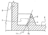
EP 2289820에서는 플랜지 림으로부터 실질적으로 수직 방향으로 돌출하는 복수의 '립스(lips)'를 사용하는 것을 교시하고 있으며, 일부 립스는 용기의 에지에 의해서 가압되며, 일부는 그렇치 않다; 특히 외부 또는 내부 립스는 물에 의해서 가해지는 압력에 의한 추가적인 밀봉이 제공되게 가압되지는 않는다. 이러한 구현예가 도 2에 표시되어 있다. EP 2289820 teaches the use of a plurality of 'lips' projecting substantially vertically from the flange rim, some lips pressed by the edges of the container, some not; In particular, the outer or inner lips are not pressurized to provide an additional seal by the pressure applied by the water. Such an embodiment is shown in FIG. 2 .
상기에 언급한 구현예들은 다른 기계에 완벽하게 적합한 밀봉 부재가 가지는 문제를 해결하지 못하고 있다. The above-mentioned embodiments do not solve the problem of sealing members perfectly suited to other machines.
본 발명의 목적은 상기한 문제를 해결하기 위한 것으로 용기의 가압 부위를 다른 형상 및 프로필로 사용할 수 있고, 조제 장치의 작동에 부정적인 영향을 줌이 없이, 예를 들면, 기계의 밀폐 또는 용기에/용기로부터 캡슐의 삽입/캡슐의 추출시 문제를 일으킴이 없이 다른 밀봉 메커니즘으로 사용할 수 있는 캡슐을 제공하는데 그 목적이 있다. It is an object of the present invention to solve the above problems that the pressurized part of the container can be used in different shapes and profiles, without adversely affecting the operation of the dispensing device, for example in the sealing of the machine or in the container/ It is an object of the present invention to provide a capsule that can be used with a different sealing mechanism without causing problems during insertion/extraction of the capsule from the container.
본 발명의 다른 목적은 생산하기에 편리한 캡슐을 제공하기 위한 것으로, 여기서 마모 및 인열, 부정확한 엔지니어링 또는 전적으로 다른 밀봉 메커니즘 때문에 용기에 제공된 결함이 있는 상품에 대한 밀봉 보상을 제공하기 위해서 탄력이 있는 밀봉 부재를 외부 표면에 추가할 필요 없이 밀봉 부재를 캡슐 본체와 일체로 만들 수 있다.It is another object of the present invention to provide a capsule convenient to produce, wherein a resilient seal is provided to provide sealing compensation for defective goods provided in containers due to wear and tear, incorrect engineering or entirely other sealing mechanisms. The sealing member can be made integral with the capsule body without the need to add the member to the outer surface.
이러한 목적 및 다른 목적 들은 청구항 제1항에 따른 음료를 조제하기 위한 시스템에 의해서 달성된다. These and other objects are achieved by a system for preparing a beverage according to
본 음료 생산 시스템은 캡슐의 적어도 일부를 감싸기 위한 용기를 가지는 침출 장치와 측방 벽면, 상부 벽면 및 하부 벽면이 제공된 상기 제품을 포함하는 중공형 본체의 캡슐로 이루어져 있다. 이 캡슐은 열가소성 재료, 예를 들면 폴리머 및/또는 폴리프로필렌 또는 폴리에틸렌의 코폴리머로 만들어진다.The beverage production system consists of a leaching device having a container for enclosing at least a portion of the capsule and a capsule of a hollow body containing the product provided with a lateral wall, an upper wall and a lower wall. These capsules are made of thermoplastic materials, for example polymers and/or copolymers of polypropylene or polyethylene.
침출 장치는 서로에 대해 움직일 수 있는 두 개의 부위로 이루어져 있다; 하나는 상기에 언급한 용기이고, 다른 하나는 침출 단계시 캡슐을 가압하는 수용판으로서 종래 기술에도 잘 알려져 있다(예를 들면 앞에서 언급한 종래 기술). 상기 캡슐은 추가로 캡슐로부터 측방향으로 확장되어 있는 플랜지형의 림과 해당 플랜지형의 림으로부터 확장되어 있는 돌출부 형태의 적어도 하나의 밀봉 부재로 이루어져 있다. 음료 생산 장치가 사용될 때, 예를 들면, 용기가 수용 플랜지에 대해 가압되도록 캡슐의 플랜지 림을 향해서 이동할 때, 용기의 가압 부위(또는 가압 에지)와 기밀 체결을 제공하기 위한 것이다. 따라서, 돌출 부위는 용기 쪽을 향해서, 예를 들면, 캡슐의 입구 벽면을 향해서 플랜지형의 림으로부터 확장된다. 이 방향은 '상향'이라고 언급할 것이다. The leaching device consists of two parts that are movable relative to each other; One is the vessel mentioned above and the other is well known in the prior art as a receiving plate for pressing the capsule during the leaching step (eg the prior art mentioned above). The capsule further comprises a flanged rim extending laterally from the capsule and at least one sealing member in the form of a projection extending from the flanged rim. To provide an airtight fit with the pressing portion (or pressing edge) of the container when the beverage production device is used, for example when the container is moved towards the flange rim of the capsule to be pressed against the receiving flange. The protrusion thus extends from the flanged rim towards the container, for example towards the inlet wall of the capsule. This direction will be referred to as 'upward'.
여기서 사용하는 '돌출부'는 캡슐의 플랜지형의 림으로부터 돌출하는 밀봉 부재를 지칭하는데 사용된다. 다른 말로 해서, 밀봉 돌출부는 해당 밀봉 돌출부 외측에 있는 플랜지형의 림의 부위에 대해 플랜지형의 림에서 두께가 증가된 부위를 형성한다. 특히 밀봉 부위는 캡슐의 측방 벽면에 인접한 플랜지형의 림의 부위의 두께에 대해 플랜지형의 림의 두께가 증가된 부위를 형성한다. 앞에서 언급한 바와 같이, 밀봉 돌출부는 캡슐의 측방 벽면과 이격되어 있으므로 용기의 에지(두 개의 크라운이 있는 경우에 용기의 에지 부분)이 측방 벽면과 밀봉 부위 사이에 수용될 수 있다. As used herein, 'projection' is used to refer to a sealing member protruding from the flanged rim of the capsule. In other words, the sealing projection forms a portion of the flanged rim of increased thickness relative to the portion of the flanged rim outside the sealing projection. In particular, the sealing portion forms a portion in which the thickness of the flanged rim is increased with respect to the thickness of the portion of the flanged rim adjacent to the lateral wall surface of the capsule. As mentioned earlier, the sealing protrusion is spaced apart from the lateral wall of the capsule so that the edge of the container (the edge portion of the container in the case of two crowns) can be received between the lateral wall and the sealing portion.
본 발명의 태양에 따르면, 플랜지의 두꺼운 부분을 형성하는 밀봉 돌출부는 플랜지형의 림의 주변 에지(주변 말단)을 향해서 확장되어 있다. 상기 캡슐은 또한 캡슐의 외부 벽면을 형성하고, 캡슐 본체의 플랜지 림에 일부가 부착되어 있는 리드를 추가로 포함하고 있다. According to an aspect of the present invention, the sealing projection forming the thick portion of the flange extends towards the peripheral edge (peripheral end) of the flanged rim. The capsule further comprises a lid forming an outer wall of the capsule and partly attached to the flange rim of the capsule body.
리드는 일반적으로 플라스틱 리드와 호일 부재로부터 선택되지만, 다른 재료로 만들 수도 있다; 일반적인 호일 부재는 신축성 및 가스 베리어 특성을 제공하기 위해서 플라스틱 층과 결합된 알루미늄층을 포함하지만, 그러나, 다른 재료, 플라스틱 층(들), 산소 베리어를 포함하는 통상적인 3층 적층체, 적당한 바이오 재료의 호일 또는 층, 또는 캡슐의 물 배출구를 위한 개구부 수단이 포함되지 않은 기계에 사용하기 위해서 미리 적당하게 천공된 호일, 이 기술분야의 통상의 기술자가 쉽게 이용할 수 있는 모든 것들을 사용할 수 있다. The lid is generally selected from plastic lids and foil members, but may be made of other materials; A typical foil member comprises an aluminum layer combined with a plastic layer to provide stretch and gas barrier properties, however, other materials, a plastic layer(s), a conventional three-layer laminate comprising an oxygen barrier, suitable biomaterials It is possible to use a foil or layer of , or a foil perforated beforehand suitable for use in machines which does not contain an opening means for the water outlet of the capsule, all readily available to the person skilled in the art.
다른 구현예로서, 리드, 바람직하게 열가소성 재료로 만들어진 리드는 음료의 통과를 위해 복수의 홀이 제공될 수 있다. In another embodiment, the lid, preferably made of a thermoplastic material, may be provided with a plurality of holes for the passage of the beverage.
특히 플라스틱 리드인 경우에, 플랜지와 리드 벽면은 플랜지 림의 에지와 밀봉 부재 사이의 장소에서 함께 용접된다. 리드를 호일 부재로 만드는 경우, 호일은 보통 밀봉 부재와 캡슐의 측방 벽면의 사이에서 플랜지의 해당 부위에 용접될 수도 있다. 자체 관통 출구를 갖는 플라스틱 리드의 바람직한 구현예의 실시예는 EP 출원 EP06821023.6에 기재되어 있다.Especially in the case of plastic leads, the flange and the lead wall are welded together in a place between the edge of the flange rim and the sealing member. When the lid is made of a foil member, the foil may be welded to that portion of the flange, usually between the sealing member and the lateral wall of the capsule. An example of a preferred embodiment of a plastic lid with its own through-outlet is described in EP application EP06821023.6.
본 발명에 따르면, 캡슐의 돌출부는 적어도 하나의 측면, 바람직하게는 내부 측면을 갖는다. 이 측면은 플랜지형의 림의 평면에 대해 각도 α(도 4)로 경사져 있고; 상기 각도 α는 돌출부에 대해 내부에 있는 각도로서, 예를 들면, 플랜지의 에지에 바라본 각도이다. 각도 α의 값(돌출부의 내부 측면의 경사도)은 80 내지 40도의 범위 내에 있다. 이 값에 추가해서, 돌출부의 위치(및 높이)는 돌출부의 정상부 및 내부 측면으로부터 선택된 적어도 하나 또는 물 모두의 위치에서 침출 기계의 용기의 에지의 외면 부위와 접촉하는 돌출부를 가질 수 있도록 배열되어 있다. 이들 모두는 돌출부에서, 용기의 에지의 외면 부위가 돌출부의 정상부와 돌출부의 다른 부위와 접촉하고, 상기 에지는 돌출부의 측면과 접촉하는 것을 의미한다. 이것은 침출 장치에서 캡슐의 배열 이탈을 보상하게 된다. According to the invention, the projection of the capsule has at least one side, preferably an inner side. This side is inclined at an angle α (Fig. 4) with respect to the plane of the flanged rim; The angle α is an angle that is internal to the projection, for example, an angle as viewed from the edge of the flange. The value of the angle α (the inclination of the inner side of the protrusion) is in the range of 80 to 40 degrees. In addition to this value, the position (and height) of the protrusion is arranged such that it can have the protrusion in contact with the outer surface portion of the edge of the container of the leaching machine at the location of at least one or both of the top and the inner side of the protrusion. . All of these mean that, in the protrusion, the portion of the outer surface of the edge of the container is in contact with the top of the protrusion and other portions of the protrusion, and the edge is in contact with the side of the protrusion. This will compensate for the dislocation of the capsules in the leaching device.
주목해야 할 점은, 밀봉 돌출부의 적어도 한 면의 경사 각도 α는 도면에서 보는 바와 같이, 경사 측면과 밀봉 돌출부 외측의 플랜지형의 림의 상부 표면을 통과하는 평면과의 사이에서 측정된다는 것이다. 다시 말해서, 경사 각도 α는 적어도 하나의 밀봉 돌출부 외측에 있는 플랜지형의 림의 표면(평면)으로부터 측정된다. 도면에 표시한 바와 같이, 경사 각도 α는 캡슐의 측방 벽면에 인접한 플랜지형의 림 부위의 상부 표면(평면)으로부터 측정되는 것이 바람직하다. It should be noted that the inclination angle α of at least one side of the sealing projection is measured between the inclined side and the plane passing through the upper surface of the flanged rim outside the sealing projection, as shown in the figure. In other words, the angle of inclination α is measured from the surface (plane) of the flanged rim outside the at least one sealing projection. As shown in the figure, the inclination angle α is preferably measured from the upper surface (plane) of the flanged rim portion adjacent to the lateral wall surface of the capsule.
본 발명의 태양에 따르면, 밀봉 상태 또는 침출 단계에서 용기의 에지는 캡슐의 플랜지형의 림으로부터 확장되는 돌출부와 캡슐의 측방 벽면 모두와 접촉을 한다. 이 위치에 도달하면, 캡슐과 침출 장치 간의 양호한 밀봉 체결이 얻어질 수 있다. According to an aspect of the invention, in the sealed or leaching phase the edge of the container is in contact with both the protrusion extending from the flanged rim of the capsule and the lateral wall of the capsule. Upon reaching this position, a good sealing engagement between the capsule and the leaching device can be obtained.
더욱이 본 발명의 가능한 다른 구현예에 따르면, 밀봉 상태 또는 침출 단계에서, 용기의 에지는 돌출부, 특히 그의 경사 측면의 적어도 한 지점, 캡슐의 측방 벽면 및 측방 벽면과 돌출부의 경사 측면 사이로 이루어진 캡슐의 플랜지형의 림의 적어도 한 부위와 접촉을 한다. 용기의 에지와 캡슐의 3개의 다른 표면 간의 접촉은 밀봉 효과의 증가를 가능하게 하므로 캡슐 속으로 주입된 침출액의 누출을 피할 수 있다. Furthermore, according to another possible embodiment of the invention, in the sealed state or in the leaching step, the edge of the container is a projection, in particular at least one point on its inclined side, a lateral wall of the capsule and a plane of the capsule consisting of the lateral wall and the inclined side of the projection. Make contact with at least one part of the rim of the terrain. The contact between the edge of the container and the three different surfaces of the capsule makes it possible to increase the sealing effect, thus avoiding leakage of the leachate injected into the capsule.
본 발명의 태양에 따르면, 밀봉 상태 또는 침출 단계에서, 용기의 에지는 처음에 밀봉 돌출부와 접촉을 한 다음, 압력과 온도 조건에 따라 음료 조제시 밀봉 돌출부와 침출 장치의 에지 간의 접촉 지점의 이동을 결정한다. 여기서 주목해야 할 점은, 상기에 언급한 모든 밀봉 상태에서, 정상부 및/또는 돌출부의 경사면은 용기의 에지의 외면 부위, 예를 들면 캡슐의 측방 벽면으로부터 떨어져서 대향하는 에지 부위에 의해서 접촉된다. According to an aspect of the invention, in the sealed state or the leaching step, the edge of the container is initially in contact with the sealing projection and then, depending on the pressure and temperature conditions, the movement of the contact point between the sealing projection and the edge of the leaching device during beverage preparation. decide It should be noted here that, in all of the above-mentioned sealing states, the beveled surfaces of the top and/or protrusions are contacted by the portion of the outer surface of the edge of the container, for example the portion of the edge opposite away from the lateral wall of the capsule.
여기서 주목해야 할 점은, 침출 장치의 용기는 다른 형상으로 제공될 수 있다. 도 3의 좌측면에 표시한 바와 같이, 용기는 부호 10과 19로 나타낸 바와 같이 두 개 이상의 크라운(에지)으로도 제공할 수 있다. 또한, 이들 경우에, 용기의, 부호 10a와 같이 에지 중 하나의 외면 부위, 바람직하게는 내부 에지의 외면 부위는 돌출부의 정상부 및 측면, 바람직하게는 돌출부의 측면으로부터 선택된 적어도 한 위치에서 밀봉 돌출부와 접촉을 한다. 다음의 상세한 설명에서 참조 부호 10은 용기의 에지를 구별하기 위해서 사용되는 것으로, 우측에 있는 도 3에서 볼 수 있는 단일 에지 또는 좌측에 있는 도 3에 표시한 이중 크라운 용기[에지(19)와 에지(10)로 이루어짐]의 내부 에지 중 어느 하나일 수 있다. 일반적으로 측방 벽면으로부터 떨어져서 대향하는 에지의 부위(예를 들어, 에지의 외면 부위 - 두 개 이상의 크라운인 경우에는 내면 또는 외면)는 밀봉 돌출부의 경사 측면에 대해서 가압된다. 본 발명은 또한 청구항 24항에 따른 음료를 조제하기 위한 캡슐에 관한 것이다. 이 캡슐은 측방 벽면, 입구 벽면, 플랜지형의 림 및 해당 플랜지형의 림의 외측으로 확장되어 있는 하나의 돌출부; 이 돌출부는 캡슐의 측방 벽면과 이격되어 있고 플랜지형의 림의 평면에 대해서 각도 α로 경사져 있으며, 경사 각도 α는 80 내지 40도 범위 내에 있다. It should be noted here that the vessel of the leaching device may be provided in different shapes. As indicated on the left side of FIG. 3 , the container may also be provided with two or more crowns (edges) as indicated by
밀봉 돌출부의 측면의 경사도는 침출 장치의 용기와의 효과적인 밀봉 채널을 얻을 수 있게 하고 동시에 용기 안쪽으로 캡슐을 밀봉하기 위해서 인가하고자 하는 힘의 감소를 가능하게 한다. 특히 80도 이상의 경사 각도는 밀봉 돌출부의 경사 측면이 너무 '수직'하기 때문에 용기와 효과적으로 접촉할 수 없다. 다른 한편으로, 경사 각도가 40도 이하일 경우에는 용기 에지와 접촉을 할 때 침출액에 대한 효과적인 베리어를 제공할 수 없다. The slope of the side of the sealing protrusion makes it possible to obtain an effective sealing channel with the container of the leaching device and at the same time reduce the force to be applied to seal the capsule into the container. In particular, an inclination angle of more than 80 degrees cannot effectively contact the container because the inclined side of the sealing protrusion is too 'vertical'. On the other hand, when the inclination angle is less than 40 degrees, it cannot provide an effective barrier to the leachate when in contact with the container edge.
본 발명의 태양에 따르면, 경사 각도 α는 80 내지 60도, 바람직하게 75 내지 60도, 더 바람직하게는 70 내지 65도 범위 내로 이루어진다. 경사 각도는 75 내지 60도의 범위가 바람직하며, 이것은 특히 침출 장치의 용기와의 효과적인 기밀 체결을 가능하게 하며, 동시에 침출 조제 공정시 캡슐을 용기의 안쪽에 밀봉시키는데 높은 압축력을 필요로 하지 않는다. 추가적으로 상기 범위 75 내지 60도는 침출공정 중에 밀봉 효과를 얻기 위해서, 캡슐을 밀봉하고 캡슐의 플랜지 림을 압축하는 용기와 함께 작동하는 대다수의 침출 장치에 대해 결과적으로 캡슐 밀봉 시스템의 적합성에 기인한다. 가장 바람직한 범위는 본 발명의 이점이 가장 명백한 70 내지 65도이다. According to an aspect of the invention, the angle of inclination α is within the range of 80 to 60 degrees, preferably 75 to 60 degrees, more preferably 70 to 65 degrees. The angle of inclination is preferably in the range of 75 to 60 degrees, which in particular enables an effective tight fit with the container of the leaching device, while at the same time not requiring high compressive forces to seal the capsule to the inside of the container during the leaching preparation process. Additionally, the range of 75 to 60 degrees is due to the suitability of the capsule sealing system as a result for the majority of leaching devices operating in conjunction with a container that seals the capsule and compresses the flange rim of the capsule to achieve a sealing effect during the leaching process. The most preferred range is 70 to 65 degrees where the advantages of the present invention are most evident.
바람직한 구현예는 종속항으로 나열되어 있다. 하나의 예시적인 구현예에 따르면, 돌출부의 내부 측면은 울퉁불퉁하거나 굴곡져 있으며, 이 구현예에서, 측면의 경사도, 및 각도 α는 도 6에 표시한 바와 같이 내부 측면의 정상부로부터 기저부로 확장하는 평면에 의해서 확인된다. 다른 태양에 따르면, 돌출부의 정상부는 적어도 일부가 가요적으로 변형될 수 있으며 장치의 용기에 의해서 변형될 때, 상기 돌출부의 높이는 20-30%까지 감소할 수 있다. Preferred embodiments are listed in the dependent claims. According to one exemplary embodiment, the inner side of the protrusion is bumpy or curved, in this embodiment, the slope of the side, and the angle α, is the plane extending from the top to the base of the inner side as shown in FIG. 6 . is confirmed by According to another aspect, at least a portion of the top of the protrusion can be flexibly deformed and when deformed by the container of the device, the height of the protrusion can be reduced by 20-30%.
예시적인 구현예에 따르면, 돌출부는 삼각형의 형상으로서, 삼각형의 정상부의 정점의 각도 β는 10 내지 60도, 바람직하게는 10 내지 44의 범위 내 또는 45도, 더 바람직하게는 10 내지 40도 및 가장 바람직하게는 15 내지 35도이며; 돌출부가 이등변 삼각형일 경우, 각도 α는 바람직하게 60 내지 45도이다. 다른 가능한 삼각형은 사각 및 부등변 삼각형으로부터 선택된다. 상기 값의 조합들은 돌출부의 정상부 및/또는 경사 측면이 다른 침출 장치에서 용기의 다른 수용 경로를 보상할 수 있게 변형될 수 있다. 따라서, 본 발명의 시스템의 침출 장치는 다른 용기를 가지는 복수의 침출 장치로부터 선택할 수 있으며; 캡슐 플랜지로부터의 돌출부는 각각의 장치와 함께 사용될 때, 용기 각각에 의해서 압축될 수 있는 장소 및 형상으로 되어 있다. According to an exemplary embodiment, the protrusion is in the shape of a triangle, wherein the angle β of the apex of the apex of the triangle is in the range of 10 to 60 degrees, preferably 10 to 44 or 45 degrees, more preferably 10 to 40 degrees and most preferably 15 to 35 degrees; When the projection is an isosceles triangle, the angle α is preferably 60 to 45 degrees. Other possible triangles are selected from quadrilateral and trapezoidal triangles. Combinations of the above values can be modified such that the top and/or inclined sides of the projections compensate for different receiving paths of the vessel in different leaching devices. Thus, the leaching device of the system of the present invention may be selected from a plurality of leaching devices having different containers; The protrusion from the capsule flange is shaped and positioned so that it can be compressed by the respective container when used with the respective device.
본 발명의 태양에 따르면, 밀봉 돌출부는 상기한 바와 같이 캡슐의 측방 벽면과 대향하는 경사 측면(예, 내부 경사 측면)을 가지며, 플랜지형의 림의 증가된 두께의 적어도 일부를 형성한다. 예시적인 구현예에서, 증가된 두께 부위는 돌출부의 적어도 한 측면으로부터 플랜지형의 림의 주변 에지 쪽으로 확장되어 있다. According to an aspect of the invention, the sealing protrusion has an inclined side (eg, an inner beveled side) opposite the lateral wall surface of the capsule as described above, and forms at least a portion of the increased thickness of the flanged rim. In an exemplary embodiment, the area of increased thickness extends from at least one side of the protrusion toward the peripheral edge of the flanged rim.
캡슐의 플랜지형의 림 부위의 증가된 두께를 형성하는 밀봉 부위는 경사 측면과 플랜지의 주변 에지 사이의 전체 공간에 확장될 수 있거나, 밀봉 돌출부에 의해서 형성된 것보다 두꺼운 부위는 밀봉 부위의 경사 측면과 플랜지형의 림의 주변 에지 사이의 플랜지형의 림의 단지 일부만 표시할 수 있다. The sealing portion, which forms an increased thickness of the flanged rim portion of the capsule, may extend over the entire space between the beveled side and the peripheral edge of the flange, or a thicker area than that formed by the sealing protrusion may be formed with the inclined side of the sealing portion and Only a portion of the flanged rim between the peripheral edges of the flanged rim may be marked.
본 발명의 태양에 따르면, 밀봉 돌출부는 캡슐의 측방 벽면과 이격되어 있으며, 밀봉 돌출부는 캡슐의 측방 벽면에 인접한 플랜지형의 림의 부위에 대해서 플랜지형의 림의 증가된 부위를 형성한다. 본 발명의 태양에 따르면, 플랜지형의 림의 증가된 두께의 부위는 경사 측면으로부터 플랜지형의 림의 에지로 확장하는 편평한 측면으로 이루어져 있다. 바람직하게는, 보다 두꺼운 부위의 편평한 표면은 밀봉 돌출부의 경사 측면의 정상부로부터 확장되어 있다.According to an aspect of the invention, the sealing projection is spaced apart from the lateral wall of the capsule, the sealing projection defining an increased portion of the flanged rim relative to the portion of the flanged rim adjacent the lateral wall of the capsule. According to an aspect of the invention, the portion of increased thickness of the flanged rim consists of a flat side extending from the inclined side to the edge of the flanged rim. Preferably, the flat surface of the thicker section extends from the top of the inclined side of the sealing projection.
주목해야 할 점은, 가능한 구현예에 따르면, 돌출부는 완벽한 삼각형의 형성은 아니며, 돌출부의 경사 측면으로부터 플랜지형의 림의 에지 쪽으로 확장하는 편평한 표면을 제공한다는 것이다. 돌출부의 정상부의 정점의 각도 β, 예를 들면 경사 측면과 경사 측면으로부터 확장하는 실질적으로 편평한 표면 사이는 60도 이상, 바람직하게는 90도 이상, 가장 바람직하게는 100도 이상이다. It should be noted that, according to a possible embodiment, the projection does not form a perfect triangle, but provides a flat surface extending from the inclined side of the projection towards the edge of the flanged rim. The angle β of the apex of the top of the protrusion, eg, between the inclined side and the substantially flat surface extending from the inclined side, is at least 60 degrees, preferably at least 90 degrees and most preferably at least 100 degrees.
본 발명의 태양에 따르면, 캡슐은 밀봉 돌출부의 밑에 및/또는 플랜지형의 림의 밑에 위치하는 적어도 하나의 캐비티로 이루어진다. According to an aspect of the invention, the capsule consists of at least one cavity located below the sealing projection and/or below the flanged rim.
본 발명의 다른 태양에 따르면, 적어도 하나의 캐비티는 캡슐의 입구 벽면으로부터 떨어져서 대향하는 플랜지형의 림의 표면에 배열되어 있다.According to another aspect of the invention, the at least one cavity is arranged on the surface of the flanged rim opposite away from the inlet wall of the capsule.
플랜지의 림의 에지는 만일 단면도로 본다면 실질적으로 L-자형일 수 있다. 바람직하게, L-자형의 에지의 말단 부위는 캡슐의 입구 벽면로부터 떨어져서 향하고 있다. 그러므로 플랜지형의 림의 L-자형의 에지는 플랜지형의 림의 하부 표면에 배열된 캐비티를 형성한다. 도 12와 도 12b에 표시한 예시적인 구현예에서, 플랜지의 L-자형 부위는 플랜지의 전체 높이 보다 작다. 예를 들면, 플랜지의 L-자형 부위의 하부 말단은 플랜지의 하부면의 평면으로부터의 어떤 거리에서 멈춘다; 플랜지의 하부면은 물을 위한 입구 벽면으로부터 떨어져서 대향하는 플랜지의 면을 의미한다.The edge of the rim of the flange may be substantially L-shaped if viewed in cross section. Preferably, the distal portion of the L-shaped edge faces away from the entrance wall of the capsule. The L-shaped edge of the flanged rim therefore forms a cavity arranged in the lower surface of the flanged rim. 12 and 12B, the L-shaped portion of the flange is less than the overall height of the flange. For example, the lower end of the L-shaped portion of the flange stops at some distance from the plane of the lower surface of the flange; The lower face of the flange means the face of the flange facing away from the inlet wall for the water.
본 발명의 다른 태양에 따르면, 캐비티는 압축시 밀봉 성능을 증가시키기 위해 밀봉 돌출부에 대응해서 플랜지와 캡슐의 리드 사이에 위치한다. According to another aspect of the present invention, a cavity is positioned between the flange and the lid of the capsule corresponding to the sealing protrusion to increase sealing performance upon compression.
본 발명의 다른 태양에 따르면, 캡슐은 방사형으로 확장하는 밀봉 부재, 또는 캡슐의 플랜지에 위치하고 그로부터 돌출되어 있는 릿지로 이루어져 있다. 예시적인 구현예에서, 상기 방사형으로 배열된 부재는 캡슐의 측방 벽면과 캡슐의 측방 벽면에 대해 원주 방향으로 된 밀봉 돌출부로부터 확장되어 있다. According to another aspect of the invention, the capsule consists of a radially extending sealing member, or a ridge located on the flange of the capsule and projecting therefrom. In an exemplary embodiment, the radially arranged member extends from a lateral wall of the capsule and a sealing projection circumferentially relative to the lateral wall of the capsule.
본 발명의 다른 목적은 캡슐의 플랜지 림으로부터 돌출되어 있고 캡슐의 축에 대해서 방사 방향으로 확장되어 있는 복수의 밀봉 부재로 이루어져 있다는 것이다. 적당한 방사형의 밀봉 부재를 사용함으로써, 밀봉 돌출부의 존재가 더 이상 요구되지 않을 것이다. Another object of the present invention is that it consists of a plurality of sealing members projecting from the flange rim of the capsule and extending radially with respect to the axis of the capsule. By using a suitable radial sealing member, the presence of a sealing projection will no longer be required.
상기에 기재한 하나의 태양의 조합은 여기서 참조로 기재한 것이며 상기 조합은 본 발명의 범위 내에 있다. Combinations of one aspect described above are incorporated herein by reference and such combinations are within the scope of the present invention.
본 발명은 종래 기술과 비교해서 여러 가지 이점을 제공한다. 앞에서 언급한 바와 같이, 캡슐은 다른 침출 장치에 사용할 수 있으며, 이들 모두에게 용기의 가압 에지와 플랜지 간에 매우 양호한 밀봉을 제공하며; 이 밀봉은 침출 공정의 첫번째 순간부터 효과적이다. 본 발명의 캡슐은 또한 용기 경로의 길이의 가능한 작은 변화(이에 따라 침출 장치를 밀봉하기 위해서 압축력이 요구됨)나 동일한 장치 내에서 시간에 따라 발생할 수 있는 불량 배열을 보상한다. The present invention provides several advantages over the prior art. As mentioned earlier, the capsules can be used in different leaching devices, all providing a very good seal between the pressurized edge of the container and the flange; This seal is effective from the first moment of the leaching process. The capsule of the present invention also compensates for possible small changes in the length of the vessel path (thus requiring a compressive force to seal the leaching device) or misalignment that may occur over time within the same device.
위와 같은 이점은 밀봉 캡슐과 물을 주입하기 위한 관통 부재를 가지는 장치를 포함하는 시스템과, 개방 캡슐과 블레이드 또는 다른 관통 장치를 가지지 않는 장치를 포함하는 시스템에 모두 부합한다. 이와 마찬가지로, 밀봉 상의 이점은 견고한 리드를 가지는 캡슐과 호일 또는 멤브레인으로 만들어진 리드를 가지는 캡슐에도 부합한다. 더욱이 이들은 주입 성형 기술로 만든 플라스틱 본체로 형성된 캡슐, 마찬가지로 스탬핑 또는 열성형 공정으로 만든 캡슐에도 부합한다. 후자의 공정은 상당히 부드러운 에지를 갖는 돌출부를 생산할 수 있고, 효과가 동일할지라도, 돌출부 아래에, 즉 플랜지의 반대면은 돌출부에 해당하는 오목부를 보유할 수 있다.The above advantages are compatible with both systems comprising a device having a sealing capsule and a penetrating member for injecting water, and systems comprising an open capsule and a device having no blade or other penetrating device. Likewise, the sealing advantages correspond to capsules with rigid lids and capsules with lids made of foil or membrane. Furthermore, they are also compatible with capsules formed from plastic bodies made by injection molding techniques, likewise capsules made by stamping or thermoforming processes. The latter process can produce a protrusion with a fairly smooth edge, and although with the same effect, underneath the protrusion, ie the opposite side of the flange, can have a recess corresponding to the protrusion.
도 1, 도 2, 도2a는 종래 기술의 예시적인 구현예이다.
도 3은 시스템의 예시적인 구현예의 개략적인 단면도이다.
도 4는 본 발명에 따른 예시적인 밀봉 부재의 확대 단면도이다.
도 5와 6은 밀봉 부재의 다른 예시적인 구현예의 단면도이다.
도 7a와 7b는 본 발명의 밀봉 돌출부에 대해 침출 장치의 용기의 두 개의 가능한 위치를 표시한 것이다.
도 8과 9는 본 발명의 다른 구현예를 표시한 두 개의 단면도로서, 용기의 가압 부위와 밀봉 돌출부의 상호 작용을 표시한 것이다.
도 10과 11은 본 발명의 또 다른 가능한 구현예이다.
도 12, 도 12a 및 도 12b는 본 발명에 따른 캡슐의 밀봉 돌출부의 다른 가능한 구현예의 확대 단면도이다.1 , 2 and 2A are exemplary embodiments of the prior art.
3 is a schematic cross-sectional view of an exemplary implementation of the system.
4 is an enlarged cross-sectional view of an exemplary sealing member in accordance with the present invention.
5 and 6 are cross-sectional views of another exemplary embodiment of a sealing member.
7a and 7b show two possible positions of the container of the leaching device with respect to the sealing protrusion of the present invention.
8 and 9 are two cross-sectional views showing another embodiment of the present invention, showing the interaction between the pressing portion of the container and the sealing protrusion.
10 and 11 are another possible embodiment of the present invention.
12, 12a and 12b are enlarged cross-sectional views of another possible embodiment of a sealing protrusion of a capsule according to the invention;
이들 및 다른 이점들은 첨부하는 도면에 의거하여 더 상세히 설명할 것이며, 이들 실시예들은 단지 예시하기 위한 것으로 본 발명의 범위를 제한하고자 하는 것은 아니다. These and other advantages will be described in more detail with reference to the accompanying drawings, wherein these embodiments are for illustrative purposes only and are not intended to limit the scope of the present invention.
처음의 도 1 내지 도 2a와 관련하여, 이들 도면들은 종래 기술에 관한 것이고, 시스템의 구성 요소의 위치와 크기가 정확한 범위에 있다면 시스템이 어떻게 동작하는지 예시한 것이다. 도 2a는 용기 타입을 사용하는 일부 상업적으로 이용할 수 있는 침출 장치로서 플랜지 상에서 캡슐의 양호한 밀봉을 얻는 것이 어렵다는 것을 예시한 것이다. 이 구현예에서, 용기는 환형의 리세스에 의해서 연결된 두 개의 원형 크라운(내부 에지와 외부 에지)으로 형성된 가압 부위를 가지고 있으며, 각각의 에지는 울퉁불퉁한 톱니 모양 및/또는 갭이 제공되어 있다. Referring initially to FIGS. 1 to 2A , these drawings are related to the prior art and illustrate how the system operates if the positions and sizes of the components of the system are within the correct range. Figure 2a illustrates the difficulty of obtaining a good seal of the capsule on the flange with some commercially available leaching devices using the container type. In this embodiment, the container has a pressing area formed by two circular crowns (inner and outer edges) connected by an annular recess, each edge being provided with a jagged serration and/or gap.
도 3은 본 발명에 따른 캡슐과 침출 장치의 일부를 조합하여 표시한 것이다. 더 상세하게는, 음료를 조제하기 위한 시스템은 캡슐(1)과 침출 장치로 이루어져 있다. 캡슐은 측방 벽면(2), 입구 벽면(3), 플랜지형의 림(4) 및 상기 플랜지 림에서 바깥 방향으로 확장되어 있는 돌출부(5)를 포함하는 중공형 본체(6)로 이루어져 있다. 일반적으로 돌출부(5)는 캡슐의 축에 해당하는 중심(또는 회전 대칭)을 갖는 원주 방향을 따라 확장되어 있으며; 측방 벽면(2)의 하부 또는 저부는 용기 내에서 캡슐의 중심 잡기를 돕도록 굴곡져 있는 것이 바람직하다. 3 shows a combination of a capsule and part of a leaching device according to the present invention. More particularly, the system for preparing a beverage consists of a
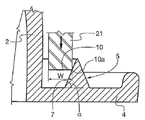
침출 장치(20)는 캡슐의 중공형 본체의 적어도 일부를 밀봉하는 용기(21)에 수용하기 위해서, 그리고 침출 단계 중에 캡슐 안쪽으로 가열 및 가압된 물을 공급할 때 캡슐 주위에 밀봉 챔버를 제공하기 위해서 해당 침출 장치의 수용판(22)에 대해 개방 위치에서 밀봉 위치로 이동 가능한 용기(21)로 이루어져 있다. 수용판(22)에는 마지막 용기에 음료가 흐르도록 하기 위해서 간단히 하나 또는 몇 개 또는 복수 개의 홀(14)이 제공되어 있다. The
용기(21)는, 외면 부위(10a), 예를 들면 캡슐의 측방 벽면(2)으로부터 떨어져서 대향하는 외면 부위를 가지는 압축 에지(10)가 제공되어 있다. 도 3의 좌측에 표시한 용기는 도 2a에 표시한 것과 유사하게, 이중 크라운을 가지는 타입으로서, 환형의 리세스(18)에 의해서 연결된 두 개의 원형 크라운[내부 에지(10)와 외부 에지(19)]을 갖는다. 각각의 에지는 울퉁불퉁한 톱니 모양 및/또는 갭으로 제공되어 있다. 외부 에지(19)는 내부 에지(10) 보다 짧다. The
본 발명에 따르면, 내부 에지(10) 만 아마도 환형의 리세스(18)를 원하는 밀봉으로 수행하는데 사용되고, 외부 에지(19)는 플랜지 또는 그의 일부를 압축하지 않는다. 도 3에서 우측에 표시한 용기는 외면 에지(10a)가 제공된 단일의 가압 에지(10)를 갖는 단일의 크라운이 있으며, 에지의 일부는 밀봉 돌출부(5)와 접촉할 것이다. According to the invention, only the
나머지 첨부한 도면에서, 용기(21)는 실질적으로 사각형의 단면 형상을 가지는 것으로 개략적으로 표시되어 있으며, 가압 에지(10)만 밀봉 동작을 수행하는 용기 부위를 표시한다. In the rest of the accompanying drawings, the
이럼에도 불구하고, 침출 장치의 용기(21)는 다른 형상, 예를 들면 둥근 에지 또는 불연속 에지를 제공할 수 있으며, 또한 이들 경우에서, 가압 에지(10)의 외면 부위(10a)는 예를 들어, 측방 외부 표면을 용기의 저부 가압 표면[예를 들면, 에지(10)]과 연결하는 부위 및 해당 연결 부위에 바로 인접한 에지(10)의 영역과 연결하는 부위와 동일할 수 있다. Notwithstanding this, the
본 발명의 예시적인 구현예에서, 측방 벽면(2)의 최대 외측의 직경, 예를 들면 플랜지(4)와의 교차점에서 측정한 직경은 용기(21)의 내부 직경과 동일하며, 용기(21)의 외측의 직경은 밀봉 돌출부(5)에 의해서 정의되는 원형의 직경과 동일하다(앞에서 언급한 바와 같이, 돌출부는 캡슐의 측방 벽면(2)과 동심원적인 원주 형태이다). In an exemplary embodiment of the present invention, the maximum outer diameter of the
캡슐은 또한 해당 캡슐의 외부 벽면을 형성하고, 캡슐 본체의 플랜지 림(4)에 부분적으로 부착되어 있는 리드(13)를 포함하고 있다. 도 3에 표시한 리드(13)는 임의로 캡슐 안쪽의 압력의 도움으로, 수용판(22)에 대해 압축되어질 때 자체 천공 출구로 작용하는 돌출 부위가 제공되어 있는 플라스틱 리드이다. 플랜지와 리드 벽면은 바람직하게 플랜지 림의 에지와 밀봉 돌출부(5) 사이의 위치에서 함께 용접된다. 리드에 대해서는 도면의 간소화를 위해서 도 4-11에서는 표시하지 않았다.The capsule also comprises a
앞에서 언급한 바와 같이, 리드는 앞에서 기재한 것과 다른 기술로 만들 수 있다. 예를 들면, 호일 부재는 적층 플라스틱 또는 바이오 재료와 같은 다른 재료로, 재생 가능한 에너지 또는 금속성 베이스를 포함하는 합금 재료에서 유래된 플라스틱이 있으며; 플랜지의 대응하는 부위에 용접되는 일반적인 호일 부재로는 기계적 및 가스 베리어 특성을 제공할 수 있도록 플라스틱 층과 결합한 알루미늄 층을 포함한다. 이 기술분야의 통상의 기술자에 유용한 다른 해법으로는 미리 천공된 플라스틱 호일, 미리 절단된 홀을 갖는 플라스틱 리드 또는 필터 페이퍼를 포함한다. As mentioned earlier, leads can be made with techniques other than those described above. For example, the foil member may be a laminated plastic or other material such as a biomaterial, a plastic derived from renewable energy or an alloying material with a metallic base; Common foil members welded to corresponding portions of the flange include a layer of aluminum combined with a layer of plastic to provide mechanical and gas barrier properties. Other solutions useful to those skilled in the art include pre-perforated plastic foil, plastic lids with pre-cut holes, or filter paper.
도 3의 예시적인 구현예에서, 캡슐(1)은 밀봉 캡슐로서 용기(21) 베이스의 채널(15)로부터 필요한 물을 수용하게 된다. 블레이드(16)는 캡슐로 들어가는 물을 위한 통로를 제공하기 위해서 입구 벽면(3)을 관통한다. 앞에서 이미 언급한 바와 같이, 다른 디자인의 용기와 물 공급 시스템을 사용할 수도 있다. 예를 들면 캡슐을 밀봉하지 않고, 입구 벽면(3)을 복수의 통로를 갖게 하거나 물 입구 벽면에 세워진 스파이크를 사용해서 호일을 관통시켜 캡슐의 물 입구 벽면에 물 입구를 제작할 수 있으며(본 출원인에 의한 WO2006/030461 참조), 블레이드(16)는 필요하지 않다. In the exemplary embodiment of FIG. 3 , the
플랜지(4)는 밀봉 돌출부(5)에 의해서 바람직하게는 동일 평면형을 가지는 두 부위로 분할되지만, 이 두 부위는 다른 평면에 놓일 수도 있다. 돌출부, 또는 밀봉 부재(5)는 어떤 적당한 단면 형상, 예를 들면 도 4, 7에 표시한 삼각형 또는 도 5와 6의 형상, 또는 도 12와 12a에 표시한 형상을 가질 수 있다. 돌출부의 단면으로 꼭대기를 자른 삼각형, 예를 들면 사다리꼴, 또는 다른 형상을 사용할 수 있다. 단, 정상부는 가요적으로 변형할 수 있으며, 외면 에지(10a)가 밀봉 상태로 유지될 수 있는 측면은 경사가 요구된다. 돌출부(5)의 단면 형상과는 무관하게 밀봉 돌출부(5)는 적어도 하나의 측면(7)을 가지며, 이 측면(7)은 플랜지형의 림(4)의 평면에 대해 내부 각도 α로 경사져 있다. 상기 각도 α, 플랜지에서의 돌출부의 위치와 돌출부의 높이 H(평면 P로부터 측정함, 도 4 참조)는 정상부(8), 돌출부의 측면(7), 또는 이들 모두로부터 선택된 적어도 한 장소를 용기(21)의 에지(10)의 외면 부위(10a)와 접촉하는 돌출부(5)를 가지도록 배열된다. The
밀봉 돌출부(5)의 적어도 한 측면(7)의 경사 각도 α는 도면에 표시한 바와 같이 경사 측면과 밀봉 부재(5) 외측의 플랜지형의 림의 상부 표면을 통과하는 평면 P 사이에서 측정된 것이다. The angle of inclination α of at least one
도면에서 보는 바와 같이, 경사 각도 α는 캡슐의 측방 벽면(2)에 인접하는 플랜지형의 림(4) 부위의 평면 P로부터 측정하는 것이 바람직하다. As shown in the figure, the inclination angle α is preferably measured from the plane P of the portion of the
각도 α는 80 내지 40도의 범위, 바람직하게는 80 내지 60도의 범위, 더 바람직하게는 75 내지 60도의 범위, 가장 바람직하게는 70 내지 65도의 범위이며, 측면(7)이 놓여 있는 평면을 기준으로 측정하며; 만일 상기 측면이 울퉁불퉁하거나 또는 오목/볼록하다면, 또는 평면이 아닌 형상을 갖는다면, 각도 α를 측정하기 위해서, 정상부(8)와 지점(7a) 사이에 선을 그어서 가상의 평면을 측면(7)으로 정의한다. 여기서 플랜지(4)는 도 6에 표시한 바와 같이, 측면(7)과 만나게 된다. 바람직한 구현예로서, 경사 측면(7)은 내부에 있는 측면이다. 예를 들어 이 측면은 캡슐(1)의 측방 벽면(2)과 마주한다. 앞에서 언급한 바와 같이, 측면(7)은 예를 들어 용기(21)의 에지(10)의 외면 부위와 접촉하게 될 것이며, 도 5와 같이 울퉁불퉁하거나 도 6과 같이 오목하거나, 다른 형상, 예를 들면 계단식일 수 있다. 모든 경우에, 측면(7)은 플랜지의 평면 P에 대해서 경사져 있으며, 내부의 각도 α로 정의된다. '내부의 각도'는 돌출부(5)에 대해 내부에 있는 각도, 예를 들면 캡슐의 측방 벽면(2)으로부터 떨어져서 대향하고 있는 각도를 의미한다. The angle α is in the range of 80 to 40 degrees, preferably in the range of 80 to 60 degrees, more preferably in the range of 75 to 60 degrees and most preferably in the range of 70 to 65 degrees, with respect to the plane in which the
돌출부(5)의 단면 형상은 일반적으로 삼각형 또는 꼭대기가 잘린 삼각형의 형태이며, 삼각형은 사각 및 부등변 삼각형으로부터 또는 이등변 삼각형으로 부터 선택되거나 될 수 있고; 돌출부가 이등변 삼각형의 형태일 경우, 각도 α는 바람직하게 80 내지 70도의 범위이다. 바람직하게, 삼각형의 꼭대기의 정점의 각도 β는 10 내지 44도의 범위, 바람직하게는 15 내지 35도이고, 같은 값을 다른 형상에도 적용하고, 이들 형상에 대해, 각도 β는 도 5와 6에서 표시한 가상의 평면(11,12)과 유사한 방식으로 돌출부의 측면에 대한 평면을 확인하는 것에 의해 정의한다. 이 방법에서 돌출부의 꼭대기 부분은 용기의 에지에 의해서 압축될 때 최소한 부분적으로 가요적으로 변형될 수 있도록 충분히 얇으므로 다른 침출 장치의 용기의 다른 말단 위치를 보상할 수 있고 여전히 최적의 밀봉 수단을 허용하는 것을 보장할 수 있다. The cross-sectional shape of the
다른 가능한 구현예에 따르면, 경사 측면(7)과 플랜지형의 림(4)의 주변 에지(4a) 사이에 있는 밀봉 돌출부(5)의 형상은 다를 수 있다. According to another possible embodiment, the shape of the sealing
상기에서 언급한 바와 같이, 밀봉 돌출부(5)는 플랜지형의 림(4)에서 두께가 증가된 적어도 하나의 부위를 형성하며, 가능한 구현예에 따르면, 밀봉 돌출부에서 두께가 증가한 부위는 적어도 한 측면(7)으로부터 확장되며 플랜지형의 림(4)의 주변 에지(4a)를 향하게 된다. As mentioned above, the sealing
주목해야 할 점은 캡슐의 플랜지형의 림(4)의 증가된 두께 부위를 형성하는 밀봉 돌출부(5)는, 도면 12a의 단면으로 표시한 구현예에 기재한 바와 같이, 적어도 하나의 경사 측면(7)과 플랜지의 주변 에지(4a) 사이의 전체 공간에 대해서 확장될 수 있다는 것이다. It should be noted that the sealing
더 상세하게, 도 12a에 표시한 구현예에서, 밀봉 돌출부(5)는 캡슐의 측방 벽면(2)과 대향하는 필요한 경사 각도 α를 가지는 경사 측면(7), 즉 내부에 있는 측면; 상기 측면(7)과 플랜지형의 림(4) 사이에서 완전히 확장되어 있는 증가된 두께 부위를 형성하는 돌출부(5)로 이루어져 있다. 다른 말로 해서, 도 12a에 표시한 구현예에서, 밀봉 돌출부(5)는 밀봉 돌출부의 외측에서 플랜지형의 림의 두께에 대해, 특히 캡슐의 측방 벽면(2)에 인접한 플랜지형의 림의 부위에 대해서 플랜지형의 림(4)의 증가된 두께를 형성한다. More particularly, in the embodiment shown in FIG. 12a , the sealing
도 12a에 표시한 바와 같이, 플랜지형의 림의 증가된 두께 부위는 밀봉 돌출부(5)의 정상부(8)로부터 플랜지형의 림(4)의 에지로 확장되어 있는 편평한 표면(12)으로 이루어져 있다. 표시한 구현예에서, 편평한 표면은 플랜지형의 림(4)의 저부 표면에 평행하므로 측면(7)과 플랜지형의 림(4)의 에지(4a) 사이에서 일정하게 증가된 두께를 가지는 부위가 형성된다. As shown in Figure 12a, the increased thickness portion of the flanged rim consists of a
하지만, 다른 구현예에 따르면, 도면에 표시되어 있지는 않지만, 편평한 표면은 정상부로부터는 거리를 두고 있지만, 밀봉 돌출부의 정상부로부터 확장되지 않을 수 있다. 바람직하게, 밀봉 돌출부(5)는 측면(7)과 플랜지(4)의 에지(4a) 사이에서 일정하게 증가된 두께로 형성된다. 예를 들면, 밀봉 돌출부는 측면(7)에 제공되어 있고 실질적으로 편평한 상부 표면(12)을 따라 플랜지(4)의 에지(4a)를 향해서 확장된다. However, according to another embodiment, although not shown in the figures, the flat surface may not extend from the top of the sealing protrusion at a distance from the top. Preferably, the sealing
하지만, 다른 가능한 구현예에 따르면, 측면(7)과 플랜지형의 림(4)의 에지(4a) 사이에 있는 밀봉 돌출부의 두께 변화를 제공할 수 있다. However, according to another possible embodiment, it is possible to provide a change in the thickness of the sealing protrusion between the
추가적으로, 주목해야 할 점은 캡슐의 중심축을 통과하는 반경 방향의 평면을 따라서 절취한 단면만 도 12a에 표시하였지만, 밀봉 돌출부(5)는 플랜지형의 림(4)의 전체 원주를 따라서 연속해서 확장되어 있다는 점이다. 다른 말로 해서, 플랜지형의 림(4)의 원주를 따라서 절취한 모든 단면은 서로 동일한 것이 바람직하다.Additionally, it should be noted that although only a cross-section taken along a radial plane passing through the central axis of the capsule is shown in FIG. 12A , the sealing
본 발명에 따른 캡슐의 다른 가능한 구현예에 따르면, 도 12를 참조해서, 플랜지형의 림(4)의 증가된 두께를 형성하는 밀봉 돌출부(5)가 경사 측면(7)과 플랜지형의 림(4)의 주변 에지(4a) 사이의 공간 부분만 확장되어 있다. According to another possible embodiment of the capsule according to the invention, with reference to FIG. 12 , a sealing
도 12에 표시한 구현예에서, 밀봉 돌출부(5)는 플랜지형의 림(4)의 평면에 대해서 내부 각도 α로 경사진 적어도 한 측면(7)을 포함하고 있다. 경사 측면(7)은 캡슐의 측방 벽면(2)과 마주하는 밀봉 돌출부(5)의 내부에 있는 측면이다. In the embodiment shown in FIG. 12 , the sealing
위에서 언급한 바와 같이, 각도 α는 80 내지 40도의 범위, 바람직하게 80 내지 60도의 범위, 더 바람직하게 75 내지 60도 범위, 가장 바람직하게는 70 내지 65도의 범위에 있으며, 측면(7)이 놓여 있는 평면과 밀봉 돌출부(5)가 돌출되어 있는 플랜지형의 림(4)의 표면을 통과하는 평면 P 사이에서 측정된 것이다. 예를 들면, 플랜지형의 림(4)의 표면으로부터 증가된 두께를 가지는 부위로 정의되는 밀봉 돌출부(5)가 돌출되어 있다.As mentioned above, the angle α is in the range of 80 to 40 degrees, preferably in the range of 80 to 60 degrees, more preferably in the range of 75 to 60 degrees and most preferably in the range of 70 to 65 degrees, and the
도 12에 표시한 바와 같이, 경사 각도 α는 측방 벽면(2)에 인접하는 플랜지형의 림(4) 부위의 상부 표면으로부터 측정된다. As shown in FIG. 12 , the inclination angle α is measured from the upper surface of the portion of the
표시한 구현예에서, 각도 α는 실질적으로 67도이다.In the embodiment shown, the angle α is substantially 67 degrees.
도 12에 표시한 구현예에서, 밀봉 돌출부(5)는 캡슐의 측방 벽면(2)에 인접한 플랜지의 부위에 대해 플랜지형의 림의 증가된 두께를 형성한다. In the embodiment shown in FIG. 12 , the sealing
또한, 이 구현예에서, 측면(7)은 울퉁불퉁하거나 오목/볼록형, 또는 일반적으로 평면이 아닌 형상이 제공될 수 있다. 이러한 경우에, 각도 α를 측정하기 위해서, 정상부(8)와 지점(7a) 사이에 선을 그어서 가상의 평면을 측면(7)으로 정의한다. 여기서 플랜지(4)는 도 12에 표시한 바와 같이, 측면(7)과 만나게 된다. Also, in this embodiment, the
주목해야 할 점은, 도 12에 표시한 구현예에서, 측면(7)이 플랜지형의 림(4)의 상부 표면(평면 P)과 둥근 경사지점을 갖고 있다고 할지라도 측면(7)의 돌출부와 플랜지형의 림의 표면(평면 P)의 돌출부가 경사져 있는 가상 지점을 확인하는 것이 가능하다. 추가적으로 플랜지 림(4)의 주변 에지(4a)를 향하는 경사도 때문에 측면(7)의 정상부(8)를 도 12에 표시한 구현예에서 확인할 수 있다. It should be noted that, in the embodiment shown in FIG. 12 , the protrusion of the
도 12b의 구현예에서, 측면(7)에 인접한 돌출부의 부분은 삼각형인 정점 또는 정상부(8)를 가지며, 림의 나머지 외측 부분은 도 12의 구현예와 동일하다. In the embodiment of FIG. 12B , the portion of the protrusion adjacent to the
후술하는 바와 같이, 돌출부(5)의 정상부(8)와 캡슐의 측방 벽면(2) 간의 거리 L은 0.6 mm 내지 1.0 mm의 범위에 있으며, 도 12에 표시한 구현예에서는 0.7 mm가 바람직하다. 이 구현예에서 거리 L은 0.5 mm 내지 0.6 mm가 바람직하다. As will be described later, the distance L between the top 8 of the
도 12에 표시한 바와 같이, 밀봉 돌출부(5)에 의해서 형성된 플랜지형의 림(4)의 증가된 두께는 플랜지형의 림의 에지(4a)에 대해 경사진 측면(7)으로부터 확장되는 편평한 표면으로 이루어진다. 바람직하게, 보다 두꺼운 부위의 편평한 표면은 밀봉 돌출부(5)의 경사 측면(7)의 정상부(8)로부터 확장된다. As shown in FIG. 12 , the increased thickness of the
표시한 구현예에서, 돌출부(5)의 정상부의 정점의 각도 β, 예를 들면 경사 측면(7)과 경사 측면(7)으로부터 확장되는 실질적으로 편평한 표면 사이에서 측정한 각도는 90도 이상, 바람직하게는 10도 이상이다. 도 12에 표시한 구현예에서, 각도 β는 실질적으로 110도이다. In the embodiment shown, the angle β of the apex of the top of the
이미 언급한 바와 같이, 가능한 구현예에 따르면, 도 12와 도 12b에 표시한 바와 같이, 밀봉 돌출부(5)는 밀봉 돌출부(5)의 경사 측면과 플랜지 형의 림(4)의 주변 에지 사이의 공간의 부분에 대해서만 확장되어 있는 플랜지 림의 보다 두꺼운 부위를 형성한다. As already mentioned, according to a possible embodiment, as shown in FIGS. 12 and 12b , the sealing
다른 말로 해서, 도 12에 표시한 바와 같이, 밀봉 돌출부(5)는 플랜지형의 림(4)의 완전한 확장은 아니지만, 플랜지형의 림(4)의 주변 에지(4a)를 향해서 확장되어 있다. In other words, as shown in FIG. 12 , the sealing
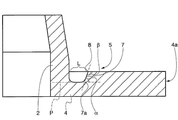
더 상세하게는, 도 12와 12b에 표시한 구현예에서, 플랜지형의 림(4)은 실질적으로 L- 자형의 에지(반경 방향의 단면도)로 끝난다. L-자형의 에지의 말단 부위는 캡슐의 입구 벽면(3)으로부터 멀리 떨어져 있다. 이러한 구조는 플랜지형의 림(4)의 하부 표면에 해당하는 곳에 캐비티(17)를 형성하는 것이 가능하다. More particularly, in the embodiment shown in FIGS. 12 and 12b , the
실제로, 플랜지형의 림(4)은 플랜지(4)의 밑에, 예를 들어 캡슐의 입구 벽면(3)으로부터 떨어져서 대향하는 플랜지(4)의 표면에 해당하는 곳에 캐비티(17)를 포함하도록 형성되어 있다. 캐비티(14)는 도 12에 표시한 구현예에서와 같이, 플랜지(4)의 에지(4a)에 상응하는 곳, 밀봉 돌출부(5)에 특히 인접한 곳에 배열되어 있다. 캐비티는 플랜지형의 림(4)의 모든 원주적인 확장부에 대해 확장되어 있다. In practice, the
하지만, 다른 가능한 구현예에 따르면, 도 8에 표시한 바와 같이, 더 상세하게 후술하겠지만, 캐비티(17)는 밀봉 돌출부(5)에 대응해서 배열될 수 있다. However, according to another possible embodiment, as indicated in FIG. 8 , the
실질적으로 플랜지형의 림(4)의 L-자형의 에지(4a)는 더 유연한 플랜지형의 림(4)의 에지를 만들므로 다른 침출 장치에도 적합할 수 있고, 음료 조제 공정의 종결 지점에서 침출 장치로부터 캡슐을 제거하는 어려움을 감소시키게 된다. The substantially L-shaped
도 12와 도 12b에 표시한 예시적인 구현예에서, 플랜지의 L-자형의 부위는 플랜지의 전체 높이 보다 짧다. 예를 들면 플랜지의 L-자형 부위의 하부 말단은 플랜지의 하부면의 평면 P'로부터의 어떤 거리에서 멈춘다; 플랜지의 하부면은 물을 위한 입구 벽면으로부터 떨어져서 대향하는 플랜지의 면을 의미한다. 단층(13)은 캐비티(17)가 플랜지(4)의 하부면의 평면 P'에 이르는 곳에 제공하는 것이 바람직하다. In the exemplary embodiment shown in FIGS. 12 and 12B , the L-shaped portion of the flange is shorter than the overall height of the flange. For example, the lower end of the L-shaped portion of the flange stops at some distance from the plane P' of the lower surface of the flange; The lower face of the flange means the face of the flange facing away from the inlet wall for the water. The
추가적으로, 도면 모두에 대해 유효한 바와 같이, 도 12a와 관련해서 상기에서 언급한 바와 같이, 밀봉 돌출부(5)는 원형으로서, 예를 들면 플랜지(4)의 전체 원주에 대해서 연속적으로 확장되어 있다. 다른 말로 해서, 플랜지(4)의 원주를 따라서 절취한 모든 부분은 서로 동일하게 하는 것이 바람직하다.Additionally, as is valid for all of the figures, as mentioned above with respect to FIG. 12A , the sealing
일반적인 규칙으로서, 돌출부(5)의 높이 H(도 4)는 예를 들어 입구 벽면(3)과 대향하는 표면인 플랜지(4)의 상부면의 평면 P로부터 측정해서 0.3 mm 내지 1.3 mm, 바람직하게는 0.6 mm 내지 1.0 mm, 가장 바람직하게는 0.8 mm 내지 0.9 mm 범위에 있다. 돌출부의 정상부(8)와 캡슐의 벽면(2) 간의 거리 L은 용기(21)의 에지(10)의 폭 W와 같거나 그 보다 큰 것이 바람직하다. 거리 L이 용기의 에지(10)의 폭 W 보다 큰 경우에는 거리 L은 에지(10)(도 4 참조)의 폭 W 보다 1.5배 이상으로 하는 것이 바람직하다. 예를 들면 1.0W≤L≤1.5W이다. 예시적인 구현예에서, L은 0.6 mm 내지 1.0 mm, 바람직하게는 0.7 mm의 범위에 있으며; L1은 0.4 mm 내지 0.7 mm, 바람직하게는 0.5 mm 내지 0.7 mm의 범위에 있다. As a general rule, the height H of the projection 5 ( FIG. 4 ) is 0.3 mm to 1.3 mm, preferably measured from the plane P of the upper surface of the
추가적으로, 거리 L1의 바람직한 값은 0.63 mm 내지 0.67 mm의 범위와 0.5 mm 내지 0.55 mm 범위에 있다. 가능한 구현예에 의하면, L1은 0.65 mm와 H는 0.8 mm이다. 어떤 경우든 L1은 항상 L 보다 작다. Additionally, preferred values of the distance L1 are in the range of 0.63 mm to 0.67 mm and in the range of 0.5 mm to 0.55 mm. According to a possible embodiment, L1 is 0.65 mm and H is 0.8 mm. In any case, L1 is always less than L.
본 발명에서, 에지의 폭 W은 용기의 일부분으로서 밀봉 작용에 효과적으로 포함된다. In the present invention, the width W of the edge is effectively included in the sealing action as part of the container.
기능한 구현예에 따르면, 캡슐의 측벽(4)과 돌출부(5)의 경사 측면(7)의 저부 말단(7a) 사이의 거리 L1(도 4 참조)은 용기의 에지(10)의 폭 W 보다 작다. 예를 들면 L1<W 이다. 저부 말단(7a)은 돌출부(5)의 경사 측면(7)과 플랜지형의 림(4)의 상부 표면의 교차에 의해서 정의된 지점이다. According to a functional embodiment, the distance L1 (see FIG. 4 ) between the
이 경우에 용기(21)의 가압 에지(10)의 외면 부위(10a)는 일반적으로 돌출부(5)의 정상부(8)와 캡슐(1)의 측방 벽면(2) 사이에 적어도 일부가 위치하게 되지만, 정상부(8)와 측방 벽면(2) 사이에 전체적으로 위치할 수도 있다. 에지(10)의 두 가지 가능한 위치가 도 7a와 7b에 표시되어 있으며, 본 발명의 돌출부가 압축 경로에서의 차이를 어떻게 보상하는지를 보여주고 있다. 도 7a에서 용기의 압축 경로는 도 7b에서 보다 작고, 플랜지(4)로부터 압축 에지(10)의 거리는 도 7b에서 보다 도 7a이 더 크다. 하지만, 밀봉 돌출부의 디자인 덕분에, 두 가지 경우에서 모두 밀봉이 얻어지며; 도 7a에서, 용기(21)의 에지(10)의 외면 부위(10a)는 돌출부(5)의 경사 측면(7) 상에 있다. 도 7b에서, 에지(10)와 플랜지(4) 간의 거리는 작으며, 에지(10)는 외면 부위(10a)와 가압 에지(10)의 적어도 한 부위와 함께 돌출부(5)의 경사 측면(7)(내부에 있는 측면) 상에 있으며, 여기서 내면 부위(10b)는 캡슐의 측방 벽면(2) 상에 있다. 돌출부(5)의 내부 측면(7)은 여분의 압축 경로를 수용하기 위해서 부분적으로 변형될 것이다. 추가적으로 돌출부(5)의 측면 방향으로의 이동의 정도는 열가소성 재료로 만들어진다는 사실 때문에, 도 7b의 부위에서 용기(21)를 수용하는데 도움이 될 것이다. In this case, the
침출 단계시, 이것은 용기 에지(10) 밑에 일종에 밀봉 챔버가 발생할 것이다. 더욱이 또 다른 가능한 구현예에 따르면, 도면에는 표시하지 않았지만, 밀봉 상태 또는 침출 단계에서, 용기(21)의 에지(10)는 돌출부(5), 특히 경사 측면(7)의 적어도 일부와 접촉하고, 캡슐의 측방 벽면(2)과 플랜지형의 림(4)의 적어도 한 부위는 측방 벽면(2)과 돌출부의 경사 측면(7) 사이에 있다.During the leaching step, this will result in a sealed chamber in some way below the
도 8은 본 발명의 다른 구현예를 표시한 것이다. 이 구현예에서, 돌출부(5)는 캐비티(17)가 제공되어 있으며, 돌출부(5)의 밑에 및/또는 플랜지(4) 밑에 위치한다. 도 8에서, 캐비티(17) 부분은 플랜지(4)의 좌측 부분에서 얻을 수 있지만, 돌출부(5)에 대해서 플랜지의 좌측면 또는 내측면으로도 확장될 수 있다. 캐비티의 기능은 밀봉 돌출부의 신축성을 추가로 제공하고, 다른 타입의 용기(21)에도 적합하게 변형 가능성을 향상시키기 위해서이다. 8 shows another embodiment of the present invention. In this embodiment, the
도 9는 도 8에서 화살표 방향으로 기울어진 도 8의 밀봉 돌출부의 가능성이 있는 압축 조건을 표시한 것이다. 정상부(8)를 압축하는 경우, 돌출부는 수직 방향으로 줄어들 것이다. 이 구현예에 대한 추가적인 상세한 내용은 본 출원인에 의해서 본 출원과 동일한 날에 출원되어 현재 출원 계류 중에 있는 EP12005215.4의 "CAPSULE WITH IMPROVED SEALING ELEMENT"에서 발견할 수 있을 것이다. 상기 서류의 내용은 참고로 여기에 삽입되어 있다. Fig. 9 shows the possible compression conditions of the sealing projection of Fig. 8 inclined in the direction of the arrow in Fig. 8; When compressing the top 8, the protrusion will shrink in the vertical direction. Additional details on this embodiment may be found in "CAPSULE WITH IMPROVED SEALING ELEMENT" of EP12005215.4, which was filed by the applicant on the same day as this application and is currently pending application. The contents of this document are incorporated herein by reference.
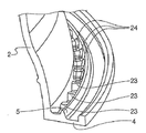
도 10과 11은 본 발명의 다른 구현예를 표시한 것으로, 복수의 릿지 또는 돌출 부재(24)가 캡슐의 측방 벽면(2)에서 밀봉 돌출부(5) 쪽으로 방사 형태로 확장되어 있다. 부재(24)의 기능은 울퉁불퉁하거나 톱니꼴 모양의 가압 에지(10) 또는 밀봉을 향상시키는데 적합하고, 이러한 목적으로 위해, 이 구현예에서는 부재(24)의 형상이 실질적으로 가압 에지(10)의 형상에 상응한다. 예를 들면 부재(24)는 둥근/타원형의 형상(도 10)을 갖는다. 도 10에서는 대안적으로 방사형으로 확장되는 부재(23)도 표시하고 있으며, 이들 부재들은 부재(24)와 동일한 기능을 가지지만, 캡슐의 측방 벽면(2) 또는 돌출부(5)로부터 방사형으로 확장되는 얇은 벽면의 형태이다. 부재(23, 24)는 돌출부로부터 캡슐까지 전체 길이를 따라서 확장할 필요는 없다. 이들 벽면은 가압 에지(10) 하에서 톱니 모양(존재 한다면)에 적합하게 변형할 수 있는 형상, 치수 및 위치에 있다. 10 and 11 show another embodiment of the invention, in which a plurality of ridges or protruding
요약해서, 본 발명의 밀봉 부재, 또는 돌출부(5)는 플랜지 평면(P)에 대해 80 내지 40도, 바람직하게는 80 내지 60도, 더 바람직하게는 75 내지 60도 및 가장 바람직하게는 70 내지 65도 범위의 내부 각도 α로 경사져 있는 돌출부(5)의 측면(7)과 가요적으로 변형할 수 있는 정상부와 결합한다. In summary, the sealing member, or
정상부는 밀봉 돌출부가 실질적으로 삼각형 형상이라면 또는 정상 각도가 60도, 바람직하게는 90도 및 가장 바람직하게는 100도 이상이고, 밀봉 돌출부가 예를 들면 도 12 및 12a에 예시한 바와 같이 경사 측면(7)으로부터 확장하는 증가된 두께의 부위로 이루어진다면, 15 내지 45도 각도로 구성할 수 있다. 캡슐의 측방 벽면(2)에서부터 돌출부(5)의 정상부(8) 까지의 거리 L은 용기(21)의 에지(10)의 폭 W와 같거나 또는 그 보다 크고, 돌출부의 정상부에 또는 바람직하게 돌출부의 측면에 유지되게 침출 장치의 용기(21)를 가지기 위한 것이다. 바람직한 구현예로서, 용기의 에지는 돌출부의 측면과 캡슐의 측방 벽면 모두에 유지되어 있다. 개시된 결합은 용기의 다른 압축 경로을 보상하는데 적합할 수 있고, 그러므로 용기(21)와 수용판(22)을 포함하는 침출 장치의 다른 모델에 사용할 수 있는 적당한 밀봉 부재를 제공하기 위한 것이다. 추가적으로, 상기 결합은 캡슐의 플랜지에서 용기를 밀봉하는데 필요한 전체 힘을 줄여준다. The top can be formed if the sealing protrusion is substantially triangular in shape or has a normal angle of at least 60 degrees, preferably 90 degrees and most preferably 100 degrees, and the sealing protrusion has an inclined side (eg, as illustrated in FIGS. 12 and 12A ) If it consists of a region of increased thickness extending from 7), it can be configured at an angle of 15 to 45 degrees. The distance L from the
추가로, 방사형으로 확장되는 부재(24)는 캡슐(4)의 플랜지(4)에서 또는 밀봉 돌출부와 결합해서 용기(21)의 향상된 밀봉을 제공한다.Additionally, the
1: 캡슐,
2: 측방 벽면,
3: 입구 벽면,
4: 플랜지형의 림,
5: 돌출부,
6: 중공형 본체,
7: 경사 측면,
7a: 저부 말단,
8: 정상부,
10: 가압 에지/내부 에지,
10a: 외면 부위/외면 에지,
10b: 내면 부위,
12: 편평한 표면,
14: 홀,
15: 채널,
16: 블레이드,
17: 캐비티,
18: 리세스,
19: 외부 에지,
21: 용기,
22: 수용판.1: capsule,
2: side wall,
3: Entrance wall panel,
4: Flanged rim,
5: protrusion,
6: hollow body,
7: inclined side,
7a: bottom end,
8: top,
10: pressure edge/inner edge,
10a: outer surface area/outer edge;
10b: inner region,
12: flat surface,
14: Hall,
15: channel,
16: blade,
17: cavity,
18: recess,
19: outer edge,
21: courage,
22: Receiving plate.
Claims (41)
- 상기 캡슐의 중공형 본체의 적어도 일부를 수용하기 위해서 밀봉 챔버를 제공하기 위해서, 침출 장치의 수용판(22)에 대해 개방 위치에서 밀봉 위치로 이동 가능한 용기(21)로 이루어진 침출 장치(20)를 포함하는 음료를 조제하기 위한 시스템에 있어서,
상기 시스템은 상기 캡슐의 상기 돌출부(5)는 상기 플랜지 림(4)의 평면에 대해서 80 내지 40도 범위의 내부 각도 α로 경사져 있는 적어도 하나의 측면(7)을 가지며, 상기 각도 α와 상기 돌출부(5)의 상기 측방 벽면(2)으로부터의 거리(L)는 상기 정상부(8)와 상기 돌출부의 측면으로부터 선택된 적어도 하나의 위치에서 상기 용기(21)의 에지(10)의 외면 부위(10a)와 접촉하는 상기 돌출부(5)를 가지도록 배열된 것을 특징으로 하는 시스템.- a hollow comprising a lateral wall (2), an inlet wall (3), a flanged rim (4) and a sealing protrusion (5) extending outwardly of the flanged rim and spaced apart from the lateral wall (5) a capsule (1) consisting of a mold body (6),
- a leaching device (20) consisting of a container (21) movable from an open position to a sealed position with respect to the receiving plate (22) of the leaching device, in order to provide a sealed chamber for receiving at least a part of the hollow body of said capsule In a system for preparing a beverage comprising:
The system is characterized in that the projection (5) of the capsule has at least one side surface (7) inclined at an internal angle α in the range of 80 to 40 degrees with respect to the plane of the flange rim (4), the angle α and the projection The distance L from the lateral wall 2 of (5) is the outer surface portion 10a of the edge 10 of the container 21 at at least one location selected from the side of the top 8 and the protrusion. A system, characterized in that arranged to have said projection (5) in contact with
상기 캡슐의 상기 돌출부(5)는 상기 측방 벽면(2)과 대향하고, 상기 플랜지형의 림(4)의 평면에 대해서 80 내지 40도 범위 내의 내부 각도 α로 경사져 있는 내부 측면(7)을 갖는 것을 특징으로 하는 캡슐. A hollow comprising a lateral wall (2), an inlet wall (3), a flanged rim (4) and a sealing protrusion (5) extending outwardly of the flanged rim and spaced apart from the lateral wall (2) In the capsule (1) consisting of a mold body (6),
The protrusion (5) of the capsule faces the lateral wall (2) and has an inner side (7) inclined at an inner angle α in the range of 80 to 40 degrees with respect to the plane of the flanged rim (4) Capsules, characterized in that.
18. A seal according to claim 17, further comprising a sealing projection (5) extending along the circumference of said flange, said sealing member being located between said lateral wall surface (2) and said sealing projection (5). capsules.
Applications Claiming Priority (4)
| Application Number | Priority Date | Filing Date | Title |
|---|---|---|---|
| EP12005216 | 2012-07-16 | ||
| EP12005216.2 | 2012-07-16 | ||
| KR1020157002995A KR102271739B1 (en) | 2012-07-16 | 2013-07-01 | Capsule and brewing system with adaptable sealing element |
| PCT/EP2013/063873 WO2014012783A2 (en) | 2012-07-16 | 2013-07-01 | Capsule and brewing system with adaptable sealing element |
Related Parent Applications (1)
| Application Number | Title | Priority Date | Filing Date |
|---|---|---|---|
| KR1020157002995A Division KR102271739B1 (en) | 2012-07-16 | 2013-07-01 | Capsule and brewing system with adaptable sealing element |
Publications (1)
| Publication Number | Publication Date |
|---|---|
| KR20210091816A true KR20210091816A (en) | 2021-07-22 |
Family
ID=48703583
Family Applications (2)
| Application Number | Title | Priority Date | Filing Date |
|---|---|---|---|
| KR1020157002995A KR102271739B1 (en) | 2012-07-16 | 2013-07-01 | Capsule and brewing system with adaptable sealing element |
| KR1020217019861A KR20210091816A (en) | 2012-07-16 | 2013-07-01 | Capsule and brewing system with adaptable sealing element |
Family Applications Before (1)
| Application Number | Title | Priority Date | Filing Date |
|---|---|---|---|
| KR1020157002995A KR102271739B1 (en) | 2012-07-16 | 2013-07-01 | Capsule and brewing system with adaptable sealing element |
Country Status (14)
| Country | Link |
|---|---|
| US (1) | US20150208852A1 (en) |
| EP (2) | EP2872421B1 (en) |
| JP (1) | JP6364407B2 (en) |
| KR (2) | KR102271739B1 (en) |
| CN (1) | CN105164025B (en) |
| AU (2) | AU2013292241B2 (en) |
| BR (1) | BR112015001039B1 (en) |
| CA (1) | CA2878896C (en) |
| DK (1) | DK2872421T3 (en) |
| ES (2) | ES2837416T3 (en) |
| HK (1) | HK1214803A1 (en) |
| PL (1) | PL2872421T3 (en) |
| RU (1) | RU2633241C2 (en) |
| WO (1) | WO2014012783A2 (en) |
Families Citing this family (51)
| Publication number | Priority date | Publication date | Assignee | Title |
|---|---|---|---|---|
| US10722066B2 (en) * | 2010-12-04 | 2020-07-28 | Adrian Rivera | Windowed single serving brewing material holder |
| US11832755B2 (en) * | 2007-07-13 | 2023-12-05 | Adrian Rivera | Brewing material container for a beverage brewer |
| SI3521207T1 (en) * | 2010-07-22 | 2020-07-31 | K-Fee System Gmbh | Portion capsule with barcode |
| US20150208852A1 (en) | 2012-07-16 | 2015-07-30 | TUTTOESPRESSO S.r.I. | Capsule and brewing system with adaptable sealing element |
| RU2015146994A (en) | 2013-04-03 | 2017-05-11 | Конинклейке Дауве Егбертс Б.В. | COFFEE LOAD FOR USE IN A COFFEE MACHINE |
| CA2908561C (en) | 2013-04-03 | 2021-01-26 | Koninklijke Douwe Egberts B.V. | Pad comprising a soluble beverage preparation product for use in a coffee machine |
| CA2908564C (en) | 2013-04-03 | 2021-08-17 | Koninklijke Douwe Egberts B.V. | Coffee pad with a relatively large outlet opening for use in a coffee machine. |
| RU2015146992A (en) * | 2013-04-03 | 2017-05-11 | Конинклейке Дауве Егбертс Б.В. | PALADA RELATED TO A LARGE OUTLET, CONTAINING A DISPERSABLE PRODUCT FOR PREPARING A DRINK, FOR USE IN A COFFEE MACHINE |
| CA2909206A1 (en) * | 2013-04-10 | 2014-10-16 | Tuttoespresso S.R.L. | Capsule and system for preparing beverages |
| GB201308927D0 (en) | 2013-05-17 | 2013-07-03 | Kraft Foods R & D Inc | A beverage preparation system, a capsule and a method for forming a beverage |
| BR122020005722B1 (en) | 2013-05-17 | 2021-04-13 | Koninklijke Douwe Egberts B.V. | SYSTEM FOR PREPARING A DRINK |
| ITMI20130975A1 (en) * | 2013-06-13 | 2014-12-14 | Goglio Spa | CARTRIDGE FOR SOLUBLE PRODUCTS WITH SEALING ELEMENT |
| ITVR20130243A1 (en) | 2013-11-08 | 2015-05-09 | Caffita System Spa | CAPSULE AND BEVERAGE PRODUCTION SYSTEM |
| WO2015101394A1 (en) * | 2013-12-30 | 2015-07-09 | Landmax Ltd | Capsule for a beverage preparation with deformable sealing element |
| CN106068087B (en) | 2014-01-03 | 2020-03-03 | 皇家戴维艾格伯茨有限公司 | Exchangeable supply pack for a beverage dispensing machine, dispenser, pump assembly and method of manufacturing |
| AU2015249445A1 (en) * | 2014-04-22 | 2016-11-03 | Macchiavelli S.R.L. | Capsule for infusion products, in particular coffee |
| CN107074436B (en) * | 2014-09-17 | 2020-04-28 | 戴维·鲁宾斯坦 | Sealed container for beverage preparation |
| GB201420262D0 (en) | 2014-11-14 | 2014-12-31 | Kraft Foods R & D Inc | A method of forming a cup-shaped body for a beverage capsule |
| AU2016264686B2 (en) | 2015-05-15 | 2021-07-29 | Koninklijke Douwe Egberts B.V. | A capsule, a system for preparing a potable beverage from such a capsule and use of such a capsule in a beverage preparation device |
| PL3134329T3 (en) | 2015-05-15 | 2019-12-31 | Koninklijke Douwe Egberts B.V. | A capsule, a system for preparing a potable beverage from such a capsule and use of such a capsule in a beverage preparation device |
| WO2016186492A1 (en) | 2015-05-15 | 2016-11-24 | Koninklijke Douwe Egberts B.V. | A capsule, a system for preparing a potable beverage from such a capsule and use of such a capsule in a beverage preparation device |
| KR20230153523A (en) * | 2015-05-15 | 2023-11-06 | 코닌클리케 도우베 에그베르츠 비.브이. | A capsule, a system for preparing a potable beverage from such a capsule and use of such a capsule in a beverage preparation device |
| DK3134331T3 (en) | 2015-05-15 | 2018-10-22 | Douwe Egberts Bv | COVER, SYSTEM FOR PREPARING A DRINKABLE BEVERAGE FROM SUCH A COVER AND USING SUCH A COVER IN A BEVERAGE COOKING DEVICE |
| DK3119702T3 (en) * | 2015-05-15 | 2020-02-24 | Douwe Egberts Bv | Capsule, system for preparing a potable beverage from such a capsule and use of such a capsule in a beverage preparation device |
| US20180148251A1 (en) * | 2015-05-29 | 2018-05-31 | Brian Bacon | Capsules for containing coffee or another substance from which a beverage can be extracted using hot water |
| PL3313755T3 (en) | 2015-06-26 | 2020-01-31 | Bisio Progetti S.P.A. | Single-dose capsule for the preparation of beverages |
| NL2017683B1 (en) | 2015-10-27 | 2017-05-31 | Douwe Egberts Bv | Capsule, system and method for preparing a beverage |
| BR112018013419B1 (en) * | 2015-12-31 | 2022-09-06 | Tuttoespresso S.R.L. | CAPSULE ARRANGEMENT, SYSTEM FOR PREPARING A DRINK AND METHOD FOR MAKING A DRINK |
| ES2580155B1 (en) * | 2016-01-05 | 2017-08-01 | Cup Out Of The Box, S.L. | SET, CAPSULE AND PROCEDURE TO PREPARE INFUSIONS |
| NL2016780B1 (en) | 2016-05-13 | 2017-11-16 | Douwe Egberts Bv | A capsule, a system for preparing a potable beverage from such a capsule and use of such a capsule in a beverage preparation device |
| NL2016779B1 (en) | 2016-05-13 | 2017-11-16 | Douwe Egberts Bv | A capsule and a system for preparing a potable beverage from such a capsule |
| GB2552796B (en) * | 2016-08-08 | 2022-08-24 | Leslie Alexander Gort Barten | Coffee capsule |
| NL2019254B9 (en) | 2016-10-07 | 2018-09-10 | Douwe Egberts Bv | A capsule, a system for preparing a potable beverage from such a capsule and use of such a capsule in a beverage preparation device |
| JP7157073B2 (en) * | 2017-04-04 | 2022-10-19 | ソシエテ・デ・プロデュイ・ネスレ・エス・アー | Beverage preparation capsule with integrally molded sealing member |
| IT201700071880A1 (en) * | 2017-06-27 | 2018-12-27 | Caffe Pascucci Torrefazione Spa | BIODEGRADABLE CAPSULE |
| NL2019253B1 (en) | 2017-07-14 | 2019-01-28 | Douwe Egberts Bv | Assembly of a capsule and a brew chamber, brew chamber, beverage preparation machine, capsule and use of a capsule. |
| RU2665595C1 (en) * | 2017-08-23 | 2018-08-31 | Общество с ограниченной ответственностью "ОРИМИ" (ООО "ОРИМИ") | Capsule for preparing beverage |
| WO2019149875A2 (en) | 2018-02-01 | 2019-08-08 | K-Fee System Gmbh | Portion capsule for preparing a beverage in a beverage preparation machine, method for producing a portion capsule, machine for producing a portion capsule, and method for producing a beverage using a beverage preparation machine and portion capsule |
| US20210107731A1 (en) * | 2018-04-11 | 2021-04-15 | Goglio S.P.A. | Capsules for preparing beverages, particularly coffees |
| US10696472B2 (en) | 2018-04-30 | 2020-06-30 | Joseph Borse | Single serve beverage container |
| PT3829982T (en) | 2018-07-27 | 2022-11-17 | Gcs German Capsule Solution Gmbh | Method for producing a portion capsule for preparing a beverage in a beverage production machine, portion capsule, and method for producing a beverage with a beverage production machine and a portion capsule |
| TW202023919A (en) | 2018-09-14 | 2020-07-01 | 瑞士商雀巢製品股份有限公司 | Capsule for beverage preparation with integrally formed sealing member |
| EP3863944A1 (en) | 2018-10-10 | 2021-08-18 | Société des Produits Nestlé S.A. | Capsule for beverage preparation with integrally formed sealing member |
| EP3863945A1 (en) * | 2018-10-10 | 2021-08-18 | Société des Produits Nestlé S.A. | Capsule for beverage preparation with integrally formed sealing member |
| NL2022265B1 (en) * | 2018-12-20 | 2020-07-15 | Douwe Egberts Bv | System for preparing a beverage from a capsule using a fluid supplied under pressure into the capsule and a capsule for use in such a system |
| PT3924271T (en) * | 2019-02-13 | 2023-06-26 | Gcs German Capsule Solution Gmbh | Single-serve capsule for preparing a beverage in a beverage preparation machine, and system for preparing a beverage from said single-serve capsule |
| EP3702298A1 (en) * | 2019-03-01 | 2020-09-02 | Delica AG | Capsule and system for for preparing a liquid food |
| IT201900006046A1 (en) * | 2019-04-18 | 2020-10-18 | Aroma System S R L | CAPSULE WITH SEAL |
| US11805934B1 (en) * | 2020-10-21 | 2023-11-07 | Adrian Rivera | Brewing material lid and container for a beverage brewer |
| WO2022122718A2 (en) | 2020-12-07 | 2022-06-16 | Gcs German Capsule Solution Gmbh | Single serve capsule for preparing a beverage in a beverage preparation machine, and method for producing a single serve capsule |
| FR3118761B1 (en) | 2021-01-14 | 2023-06-30 | My Tea Cup Ag | S-shaped sealing lip cap |
Family Cites Families (29)
| Publication number | Priority date | Publication date | Assignee | Title |
|---|---|---|---|---|
| GB150255A (en) | 1920-04-30 | 1920-09-02 | Albert Bulbick | Improvements in joint-making and gland packing |
| US3844439A (en) * | 1972-07-28 | 1974-10-29 | Consumers Glass Co Ltd | Linerless closures |
| KR20010096600A (en) * | 2000-03-13 | 2001-11-07 | 도케 케이시 | Synthetic resin container closure |
| GB2397504B (en) * | 2003-01-24 | 2005-07-13 | Kraft Foods R & D Inc | Machine for the preparation of beverages |
| AU2004323285B2 (en) | 2004-09-17 | 2011-11-10 | Tuttoespresso S.R.L. | Disposable capsule for drinks |
| DK1702543T3 (en) * | 2004-10-25 | 2008-01-07 | Nestec Sa | Capsule with sealants |
| RU48943U1 (en) * | 2005-05-19 | 2005-11-10 | Шерстнев Михаил Викторович | DISPOSABLE PACKAGING WITH BULK PRODUCT, SOLUBLE WITH LIQUID |
| BRPI0711738A2 (en) * | 2006-05-29 | 2011-12-06 | Nestec Sa | coffee pod with a deformable sealing element |
| ITBO20070014U1 (en) * | 2007-02-14 | 2008-08-15 | Arnoplast Srl | RIGID COFFEE CAPSULE OR OTHER SOLUBLE SOLUBLE IMPROVED SEALING |
| MX2009012445A (en) * | 2007-06-05 | 2009-12-01 | Nestec Sa | Method for preparing a beverage or liquid food and system using brewing centrifugal force. |
| KR101581482B1 (en) | 2008-03-20 | 2015-12-30 | 네스텍 소시에테아노님 | Beverage production device for producing a beverage from a single-use capsule |
| ATE529248T1 (en) * | 2008-07-15 | 2011-11-15 | Nestec Sa | METHOD FOR APPLYING A LIQUID RUBBER SEAL TO A CAPSULE |
| US20110297005A1 (en) | 2009-01-23 | 2011-12-08 | Alain Mariller | Capsule for preparing a drink |
| AU2009347070B2 (en) * | 2009-06-17 | 2016-04-07 | Koninklijke Douwe Egberts B.V. | Capsule, system and method for preparing a predetermined quantity of beverage suitable for consumption |
| US9414709B2 (en) * | 2009-07-24 | 2016-08-16 | Ethical Coffee Company Sa | Device for preparing a beverage extracted from a capsule |
| EP2289820B2 (en) | 2009-08-05 | 2021-11-24 | Société des Produits Nestlé S.A. | Capsule with relief-shaped sealing member |
| CN102316775B (en) * | 2009-11-19 | 2015-03-11 | 雀巢产品技术援助有限公司 | Capsule and method for preparing a beverage such as coffee from said capsule |
| IT1401828B1 (en) * | 2010-09-28 | 2013-08-28 | Macchiavelli Srl | SYSTEM FOR THE PREPARATION OF A BEVERAGE FROM AN INFUSION PRODUCT CONTAINED IN AN INTERCHANGEABLE CAPSULE |
| ES2490491T3 (en) * | 2010-11-30 | 2014-09-03 | Nestec S.A. | Capsule for the preparation of a beverage in a beverage preparation device |
| IT1403855B1 (en) | 2011-02-17 | 2013-11-08 | E T I S R L | CAP FOR CONTAINMENT OF A PREPARATION FOR HOT DRINK |
| PL2681126T3 (en) * | 2011-03-03 | 2018-05-30 | Biserkon Holdings Ltd. | Capsule for preparing a beverage by extraction |
| ES2573128T3 (en) * | 2011-03-03 | 2016-06-06 | Biserkon Holdings Ltd. | Capsule |
| EP2683626B1 (en) * | 2011-03-07 | 2018-02-28 | Ethical Coffee Company SA | Capsule for preparing a beverage |
| JP2014527891A (en) | 2011-09-28 | 2014-10-23 | トゥットエスプレッソ エス.アール.エル.Tuttoespresso S.R.L. | Beverage capsule with sealing element |
| WO2013076519A1 (en) | 2011-11-22 | 2013-05-30 | Tuttoespresso S.R.L. | Capsule for beverage preparation |
| ITVR20120043A1 (en) | 2012-03-14 | 2013-09-15 | Coffee Star S A | DRINK PRODUCTION SYSTEM |
| WO2013164669A1 (en) * | 2012-05-02 | 2013-11-07 | Russon Holdings Limited | Capsule for use in coffee extraction machines |
| ES1077395Y (en) * | 2012-06-26 | 2012-10-15 | Solubles S A Prod | Capsule to prepare infusions |
| US20150208852A1 (en) | 2012-07-16 | 2015-07-30 | TUTTOESPRESSO S.r.I. | Capsule and brewing system with adaptable sealing element |
-
2013
- 2013-07-01 US US14/415,483 patent/US20150208852A1/en not_active Abandoned
- 2013-07-01 ES ES17162061T patent/ES2837416T3/en active Active
- 2013-07-01 CN CN201380047889.2A patent/CN105164025B/en active Active
- 2013-07-01 DK DK13732572.6T patent/DK2872421T3/en active
- 2013-07-01 CA CA2878896A patent/CA2878896C/en active Active
- 2013-07-01 KR KR1020157002995A patent/KR102271739B1/en active IP Right Grant
- 2013-07-01 PL PL13732572T patent/PL2872421T3/en unknown
- 2013-07-01 AU AU2013292241A patent/AU2013292241B2/en not_active Ceased
- 2013-07-01 KR KR1020217019861A patent/KR20210091816A/en not_active Application Discontinuation
- 2013-07-01 BR BR112015001039-3A patent/BR112015001039B1/en not_active IP Right Cessation
- 2013-07-01 JP JP2015522027A patent/JP6364407B2/en not_active Expired - Fee Related
- 2013-07-01 WO PCT/EP2013/063873 patent/WO2014012783A2/en active Application Filing
- 2013-07-01 RU RU2015104965A patent/RU2633241C2/en active
- 2013-07-01 EP EP13732572.6A patent/EP2872421B1/en not_active Revoked
- 2013-07-01 EP EP17162061.0A patent/EP3199473B1/en active Active
- 2013-07-01 ES ES13732572.6T patent/ES2633171T3/en active Active
-
2016
- 2016-03-10 HK HK16102799.1A patent/HK1214803A1/en not_active IP Right Cessation
-
2018
- 2018-03-13 AU AU2018201780A patent/AU2018201780A1/en not_active Abandoned
Also Published As
| Publication number | Publication date |
|---|---|
| PL2872421T3 (en) | 2017-10-31 |
| EP2872421B1 (en) | 2017-03-22 |
| EP3199473B1 (en) | 2020-09-23 |
| ES2633171T3 (en) | 2017-09-19 |
| EP3199473A1 (en) | 2017-08-02 |
| RU2015104965A (en) | 2016-09-10 |
| KR102271739B1 (en) | 2021-07-02 |
| JP2015526146A (en) | 2015-09-10 |
| AU2013292241B2 (en) | 2017-12-14 |
| RU2633241C2 (en) | 2017-10-11 |
| AU2013292241A1 (en) | 2015-02-19 |
| JP6364407B2 (en) | 2018-07-25 |
| DK2872421T3 (en) | 2017-07-10 |
| HK1214803A1 (en) | 2016-08-05 |
| WO2014012783A3 (en) | 2014-04-10 |
| KR20150042193A (en) | 2015-04-20 |
| EP2872421A2 (en) | 2015-05-20 |
| CN105164025B (en) | 2019-06-21 |
| AU2018201780A1 (en) | 2018-04-05 |
| US20150208852A1 (en) | 2015-07-30 |
| WO2014012783A2 (en) | 2014-01-23 |
| CA2878896A1 (en) | 2014-01-23 |
| BR112015001039A2 (en) | 2017-06-27 |
| ES2837416T3 (en) | 2021-06-30 |
| BR112015001039B1 (en) | 2021-01-26 |
| CA2878896C (en) | 2023-02-14 |
| CN105164025A (en) | 2015-12-16 |
Similar Documents
| Publication | Publication Date | Title |
|---|---|---|
| KR102271739B1 (en) | Capsule and brewing system with adaptable sealing element | |
| KR102099484B1 (en) | Beverage capsule with sealing element | |
| KR102101048B1 (en) | Capsule with improved sealing element | |
| JP5017361B2 (en) | Capsule for preparing a beverage to which a sealing member is attached and method for producing the capsule | |
| CN109689533B (en) | Capsule for preparing infusion beverages and soluble beverages | |
| CN109689532B (en) | Capsule for preparing infusion beverages and soluble beverages |
Legal Events
| Date | Code | Title | Description |
|---|---|---|---|
| A107 | Divisional application of patent | ||
| A201 | Request for examination | ||
| E902 | Notification of reason for refusal | ||
| E601 | Decision to refuse application |