KR20210072761A - electrosurgical instruments - Google Patents
electrosurgical instruments Download PDFInfo
- Publication number
- KR20210072761A KR20210072761A KR1020217008633A KR20217008633A KR20210072761A KR 20210072761 A KR20210072761 A KR 20210072761A KR 1020217008633 A KR1020217008633 A KR 1020217008633A KR 20217008633 A KR20217008633 A KR 20217008633A KR 20210072761 A KR20210072761 A KR 20210072761A
- Authority
- KR
- South Korea
- Prior art keywords
- hollow needle
- instrument
- channel
- distal end
- electrosurgical
- Prior art date
Links
Images


Classifications
-
- A—HUMAN NECESSITIES
- A61—MEDICAL OR VETERINARY SCIENCE; HYGIENE
- A61B—DIAGNOSIS; SURGERY; IDENTIFICATION
- A61B18/00—Surgical instruments, devices or methods for transferring non-mechanical forms of energy to or from the body
- A61B18/04—Surgical instruments, devices or methods for transferring non-mechanical forms of energy to or from the body by heating
- A61B18/042—Surgical instruments, devices or methods for transferring non-mechanical forms of energy to or from the body by heating using additional gas becoming plasma
-
- A—HUMAN NECESSITIES
- A61—MEDICAL OR VETERINARY SCIENCE; HYGIENE
- A61B—DIAGNOSIS; SURGERY; IDENTIFICATION
- A61B18/00—Surgical instruments, devices or methods for transferring non-mechanical forms of energy to or from the body
- A61B18/04—Surgical instruments, devices or methods for transferring non-mechanical forms of energy to or from the body by heating
- A61B18/12—Surgical instruments, devices or methods for transferring non-mechanical forms of energy to or from the body by heating by passing a current through the tissue to be heated, e.g. high-frequency current
- A61B18/1206—Generators therefor
-
- A—HUMAN NECESSITIES
- A61—MEDICAL OR VETERINARY SCIENCE; HYGIENE
- A61B—DIAGNOSIS; SURGERY; IDENTIFICATION
- A61B18/00—Surgical instruments, devices or methods for transferring non-mechanical forms of energy to or from the body
- A61B18/04—Surgical instruments, devices or methods for transferring non-mechanical forms of energy to or from the body by heating
- A61B18/12—Surgical instruments, devices or methods for transferring non-mechanical forms of energy to or from the body by heating by passing a current through the tissue to be heated, e.g. high-frequency current
- A61B18/14—Probes or electrodes therefor
- A61B18/1477—Needle-like probes
-
- A—HUMAN NECESSITIES
- A61—MEDICAL OR VETERINARY SCIENCE; HYGIENE
- A61B—DIAGNOSIS; SURGERY; IDENTIFICATION
- A61B18/00—Surgical instruments, devices or methods for transferring non-mechanical forms of energy to or from the body
- A61B18/04—Surgical instruments, devices or methods for transferring non-mechanical forms of energy to or from the body by heating
- A61B18/12—Surgical instruments, devices or methods for transferring non-mechanical forms of energy to or from the body by heating by passing a current through the tissue to be heated, e.g. high-frequency current
- A61B18/14—Probes or electrodes therefor
- A61B18/1492—Probes or electrodes therefor having a flexible, catheter-like structure, e.g. for heart ablation
-
- A—HUMAN NECESSITIES
- A61—MEDICAL OR VETERINARY SCIENCE; HYGIENE
- A61B—DIAGNOSIS; SURGERY; IDENTIFICATION
- A61B18/00—Surgical instruments, devices or methods for transferring non-mechanical forms of energy to or from the body
- A61B18/18—Surgical instruments, devices or methods for transferring non-mechanical forms of energy to or from the body by applying electromagnetic radiation, e.g. microwaves
- A61B18/1815—Surgical instruments, devices or methods for transferring non-mechanical forms of energy to or from the body by applying electromagnetic radiation, e.g. microwaves using microwaves
-
- A—HUMAN NECESSITIES
- A61—MEDICAL OR VETERINARY SCIENCE; HYGIENE
- A61B—DIAGNOSIS; SURGERY; IDENTIFICATION
- A61B18/00—Surgical instruments, devices or methods for transferring non-mechanical forms of energy to or from the body
- A61B2018/00005—Cooling or heating of the probe or tissue immediately surrounding the probe
- A61B2018/00011—Cooling or heating of the probe or tissue immediately surrounding the probe with fluids
-
- A—HUMAN NECESSITIES
- A61—MEDICAL OR VETERINARY SCIENCE; HYGIENE
- A61B—DIAGNOSIS; SURGERY; IDENTIFICATION
- A61B18/00—Surgical instruments, devices or methods for transferring non-mechanical forms of energy to or from the body
- A61B2018/00053—Mechanical features of the instrument of device
- A61B2018/00059—Material properties
- A61B2018/00071—Electrical conductivity
- A61B2018/00077—Electrical conductivity high, i.e. electrically conducting
-
- A—HUMAN NECESSITIES
- A61—MEDICAL OR VETERINARY SCIENCE; HYGIENE
- A61B—DIAGNOSIS; SURGERY; IDENTIFICATION
- A61B18/00—Surgical instruments, devices or methods for transferring non-mechanical forms of energy to or from the body
- A61B2018/00053—Mechanical features of the instrument of device
- A61B2018/00059—Material properties
- A61B2018/00071—Electrical conductivity
- A61B2018/00083—Electrical conductivity low, i.e. electrically insulating
-
- A—HUMAN NECESSITIES
- A61—MEDICAL OR VETERINARY SCIENCE; HYGIENE
- A61B—DIAGNOSIS; SURGERY; IDENTIFICATION
- A61B18/00—Surgical instruments, devices or methods for transferring non-mechanical forms of energy to or from the body
- A61B2018/00053—Mechanical features of the instrument of device
- A61B2018/00107—Coatings on the energy applicator
- A61B2018/0013—Coatings on the energy applicator non-sticking
-
- A—HUMAN NECESSITIES
- A61—MEDICAL OR VETERINARY SCIENCE; HYGIENE
- A61B—DIAGNOSIS; SURGERY; IDENTIFICATION
- A61B18/00—Surgical instruments, devices or methods for transferring non-mechanical forms of energy to or from the body
- A61B2018/00053—Mechanical features of the instrument of device
- A61B2018/00172—Connectors and adapters therefor
- A61B2018/00178—Electrical connectors
-
- A—HUMAN NECESSITIES
- A61—MEDICAL OR VETERINARY SCIENCE; HYGIENE
- A61B—DIAGNOSIS; SURGERY; IDENTIFICATION
- A61B18/00—Surgical instruments, devices or methods for transferring non-mechanical forms of energy to or from the body
- A61B2018/00053—Mechanical features of the instrument of device
- A61B2018/00184—Moving parts
- A61B2018/00196—Moving parts reciprocating lengthwise
-
- A—HUMAN NECESSITIES
- A61—MEDICAL OR VETERINARY SCIENCE; HYGIENE
- A61B—DIAGNOSIS; SURGERY; IDENTIFICATION
- A61B18/00—Surgical instruments, devices or methods for transferring non-mechanical forms of energy to or from the body
- A61B2018/00571—Surgical instruments, devices or methods for transferring non-mechanical forms of energy to or from the body for achieving a particular surgical effect
- A61B2018/00577—Ablation
-
- A—HUMAN NECESSITIES
- A61—MEDICAL OR VETERINARY SCIENCE; HYGIENE
- A61B—DIAGNOSIS; SURGERY; IDENTIFICATION
- A61B18/00—Surgical instruments, devices or methods for transferring non-mechanical forms of energy to or from the body
- A61B2018/00571—Surgical instruments, devices or methods for transferring non-mechanical forms of energy to or from the body for achieving a particular surgical effect
- A61B2018/00589—Coagulation
-
- A—HUMAN NECESSITIES
- A61—MEDICAL OR VETERINARY SCIENCE; HYGIENE
- A61B—DIAGNOSIS; SURGERY; IDENTIFICATION
- A61B18/00—Surgical instruments, devices or methods for transferring non-mechanical forms of energy to or from the body
- A61B2018/00571—Surgical instruments, devices or methods for transferring non-mechanical forms of energy to or from the body for achieving a particular surgical effect
- A61B2018/00601—Cutting
-
- A—HUMAN NECESSITIES
- A61—MEDICAL OR VETERINARY SCIENCE; HYGIENE
- A61B—DIAGNOSIS; SURGERY; IDENTIFICATION
- A61B18/00—Surgical instruments, devices or methods for transferring non-mechanical forms of energy to or from the body
- A61B2018/00994—Surgical instruments, devices or methods for transferring non-mechanical forms of energy to or from the body combining two or more different kinds of non-mechanical energy or combining one or more non-mechanical energies with ultrasound
-
- A—HUMAN NECESSITIES
- A61—MEDICAL OR VETERINARY SCIENCE; HYGIENE
- A61B—DIAGNOSIS; SURGERY; IDENTIFICATION
- A61B18/00—Surgical instruments, devices or methods for transferring non-mechanical forms of energy to or from the body
- A61B18/18—Surgical instruments, devices or methods for transferring non-mechanical forms of energy to or from the body by applying electromagnetic radiation, e.g. microwaves
- A61B18/1815—Surgical instruments, devices or methods for transferring non-mechanical forms of energy to or from the body by applying electromagnetic radiation, e.g. microwaves using microwaves
- A61B2018/1823—Generators therefor
-
- A—HUMAN NECESSITIES
- A61—MEDICAL OR VETERINARY SCIENCE; HYGIENE
- A61B—DIAGNOSIS; SURGERY; IDENTIFICATION
- A61B18/00—Surgical instruments, devices or methods for transferring non-mechanical forms of energy to or from the body
- A61B18/18—Surgical instruments, devices or methods for transferring non-mechanical forms of energy to or from the body by applying electromagnetic radiation, e.g. microwaves
- A61B18/1815—Surgical instruments, devices or methods for transferring non-mechanical forms of energy to or from the body by applying electromagnetic radiation, e.g. microwaves using microwaves
- A61B2018/1861—Surgical instruments, devices or methods for transferring non-mechanical forms of energy to or from the body by applying electromagnetic radiation, e.g. microwaves using microwaves with an instrument inserted into a body lumen or cavity, e.g. a catheter
-
- A—HUMAN NECESSITIES
- A61—MEDICAL OR VETERINARY SCIENCE; HYGIENE
- A61B—DIAGNOSIS; SURGERY; IDENTIFICATION
- A61B18/00—Surgical instruments, devices or methods for transferring non-mechanical forms of energy to or from the body
- A61B18/18—Surgical instruments, devices or methods for transferring non-mechanical forms of energy to or from the body by applying electromagnetic radiation, e.g. microwaves
- A61B18/1815—Surgical instruments, devices or methods for transferring non-mechanical forms of energy to or from the body by applying electromagnetic radiation, e.g. microwaves using microwaves
- A61B2018/1869—Surgical instruments, devices or methods for transferring non-mechanical forms of energy to or from the body by applying electromagnetic radiation, e.g. microwaves using microwaves with an instrument interstitially inserted into the body, e.g. needles
-
- A—HUMAN NECESSITIES
- A61—MEDICAL OR VETERINARY SCIENCE; HYGIENE
- A61B—DIAGNOSIS; SURGERY; IDENTIFICATION
- A61B18/00—Surgical instruments, devices or methods for transferring non-mechanical forms of energy to or from the body
- A61B18/18—Surgical instruments, devices or methods for transferring non-mechanical forms of energy to or from the body by applying electromagnetic radiation, e.g. microwaves
- A61B18/1815—Surgical instruments, devices or methods for transferring non-mechanical forms of energy to or from the body by applying electromagnetic radiation, e.g. microwaves using microwaves
- A61B2018/1876—Surgical instruments, devices or methods for transferring non-mechanical forms of energy to or from the body by applying electromagnetic radiation, e.g. microwaves using microwaves with multiple frequencies
-
- A—HUMAN NECESSITIES
- A61—MEDICAL OR VETERINARY SCIENCE; HYGIENE
- A61B—DIAGNOSIS; SURGERY; IDENTIFICATION
- A61B2218/00—Details of surgical instruments, devices or methods for transferring non-mechanical forms of energy to or from the body
- A61B2218/001—Details of surgical instruments, devices or methods for transferring non-mechanical forms of energy to or from the body having means for irrigation and/or aspiration of substances to and/or from the surgical site
- A61B2218/002—Irrigation
-
- A—HUMAN NECESSITIES
- A61—MEDICAL OR VETERINARY SCIENCE; HYGIENE
- A61B—DIAGNOSIS; SURGERY; IDENTIFICATION
- A61B2218/00—Details of surgical instruments, devices or methods for transferring non-mechanical forms of energy to or from the body
- A61B2218/001—Details of surgical instruments, devices or methods for transferring non-mechanical forms of energy to or from the body having means for irrigation and/or aspiration of substances to and/or from the surgical site
- A61B2218/007—Aspiration
Abstract
한 양태에서, 본 발명은 원위 끝단으로부터 마이크로파 에너지를 방사함으로써 지혈을 수행하기 위한 전기 수술기구를 제공하며, 전도성 방사 전극은 절연성 비-점착성 재료로 코팅된다. 또 다른 양태에서, 본 발명은 고주파 또는 마이크로파 전자기 에너지를 사용하여 지혈을 수행하기 위한 전기 수술기구를 제공하며, 기구의 한 원위 끝단이 유체를 치료 부위로 전달하거나 또는 치료 부위로부터 유체를 전달하기 위한 전도성 중공 바늘을 포함하고, 중공 바늘은 전기적으로 접지된다. In one aspect, the present invention provides an electrosurgical instrument for performing hemostasis by radiating microwave energy from a distal end, wherein the conductive radiation electrode is coated with an insulating non-stick material. In another aspect, the present invention provides an electrosurgical instrument for performing hemostasis using radio frequency or microwave electromagnetic energy, wherein one distal end of the instrument is for delivering a fluid to or from a treatment site. a conductive hollow needle, wherein the hollow needle is electrically grounded.
Description
본 발명은 표적 조직을 절제하기 위해 마이크로파 에너지 및/또는 고주파 에너지를 생물학적 조직에 전달하기 위한 전기 수술기구에 관한 것이다. 전기 수술기구는 치료 부위에 유체를 전달하기 위해 바늘에 결합된 유체 전달 채널을 포함한다. 프로브는 카테터 또는 내시경의 채널을 통해 삽입되거나, 혹은 복강경 수술 또는 개복 수술에 사용될 수 있다. The present invention relates to an electrosurgical instrument for delivering microwave energy and/or radio frequency energy to a biological tissue to ablate a target tissue. The electrosurgical instrument includes a fluid delivery channel coupled to the needle for delivering fluid to a treatment site. The probe may be inserted through a catheter or channel of an endoscope, or used for laparoscopic or open surgery.
전자기(EM) 에너지, 및 특히, 마이크로파 및 고주파(RF) 에너지는 신체 조직을 절단, 응고 및 절제하는 기능을 위해 전기 수술에 유용한 것으로 밝혀졌다. 일반적으로, EM 에너지를 신체 조직에 전달하기 위한 장치는 EM 에너지 공급원을 포함하는 제너레이터 및 에너지를 조직에 전달하기 위해 제너레이터에 연결된 전기 수술기구를 포함한다. 종래의 전기 수술기구는 종종 환자의 신체에 경피적으로 삽입되도록 설계된다. 그러나, 예를 들어, 표적 부위가 위장(GI) 관의 얇은 벽 부분 또는 움직이는 폐 내에 있는 경우에, 기구를 신체 내에 경피적으로 배치하는 것이 어려울 수 있다. 그 밖의 다른 전기 수술기구는, 신체 내의 채널, 가령, 결장 또는 식도의 루멘 또는 기도를 통해 배열될 수 있는 수술용 검사 장치(예컨대, 내시경)에 의해, 표적 부위로 전달될 수 있다. 이는 최소 침습 치료를 가능하게 하여, 환자의 사망률을 줄이고 수술 중 및 수술 후 합병증을 줄일 수 있다. Electromagnetic (EM) energy, and in particular microwave and radio frequency (RF) energy, has been found useful in electrosurgery for its ability to cut, coagulate and ablate body tissue. Generally, an apparatus for delivering EM energy to body tissue includes a generator comprising a source of EM energy and an electrosurgical instrument coupled to the generator for delivering energy to the tissue. Conventional electrosurgical instruments are often designed to be inserted percutaneously into a patient's body. However, transdermal placement of the device within the body can be difficult, for example, when the target site is within a moving lung or a thin walled portion of the gastrointestinal (GI) tract. Other electrosurgical instruments may be delivered to the target site by means of a surgical examination device (eg, an endoscope) that may be disposed through a channel within the body, such as the lumen of the colon or esophagus or the airway. This enables minimally invasive treatment, which can reduce patient mortality and reduce intraoperative and postoperative complications.
마이크로파 EM 에너지를 사용하는 조직 절제는 생물학적 조직이 주로 물로 구성되어 있다는 사실에 따른다. 인간의 연 장기 조직은 일반적으로 수분 함량이 70% 내지 80% 사이이다. 물 분자는 영구적인 전기 쌍극자 모멘트를 가지며, 이는 분자 전체에 걸쳐 전하 불균형이 존재한다는 것을 의미한다. 이러한 전하 불균형은 분자가 전기 쌍극자 모멘트를 제공된 필드의 극성과 정렬하기 위해 회전함에 따라 시간에 따라 변하는 전기장의 제공에 의해 생성된 힘에 반응하여 분자를 움직이게 한다. 마이크로파 주파수에서 빠른 분자 진동으로 인해, 마찰 가열이 야기되며, 그에 따라, 필드 에너지가 열 형태로 소산하게 된다. 이는 유전체 가열로 알려져 있다. Tissue ablation using microwave EM energy relies on the fact that biological tissue is mainly composed of water. Human soft organ tissue generally has a water content between 70% and 80%. Water molecules have a permanent electric dipole moment, meaning that there is a charge imbalance across the molecule. This charge imbalance causes the molecule to move in response to the force generated by the provision of a time-varying electric field as the molecule rotates to align its electric dipole moment with the polarity of the provided field. Due to the fast molecular vibrations at microwave frequencies, frictional heating is caused, which in turn dissipates the field energy in the form of heat. This is known as dielectric heating.
이 원리는 마이크로파 절제 요법에서 활용되는데, 여기서 표적 조직의 물 분자는 마이크로파 주파수에서 국부적인 전자기장을 제공함으로써 신속하게 가열되며, 그에 따라 조직 응고 및 세포 사멸을 야기한다. 폐 및 그 밖의 다른 장기의 다양한 상태를 치료하기 위해 마이크로파 방출 프로브를 사용하는 방법도 알려져 있다. 예를 들어, 폐에서, 마이크로파 방사는 천식을 치료하고 종양 또는 병변을 절제하기 위해 사용될 수 있다. This principle is utilized in microwave ablation therapy, where water molecules in the target tissue are rapidly heated by providing a local electromagnetic field at microwave frequencies, thereby causing tissue coagulation and cell death. Methods of using microwave emission probes to treat various conditions of the lungs and other organs are also known. For example, in the lungs, microwave radiation can be used to treat asthma and to excise tumors or lesions.
RF EM 에너지는 생물학적 조직의 절단 및/또는 응고에 사용될 수 있다. RF 에너지를 사용하여 절단하는 방법은, 전류가 조직 매트릭스(세포의 이온 함량, 즉 소듐 및 포타슘에 의해 지원된)를 통과 할 때, 조직에 걸친 전자 흐름에 대한 임피던스가 열을 생성하는 원리에 따라 작동된다. 순수한 사인파(sine wave)가 조직 매트릭스에 제공되면, 세포 내에는 충분한 열이 발생하여 조직 내에 함유된 물을 증발시킨다. 따라서, 세포의 내부 압력이 현저하게 상승되는데 이는 세포 막에 의해 조절될 수 없어서 세포가 파열하게 된다. 이러한 현상이 광범위한 영역에 발생하게 되면, 조직이 파열된 것을 볼 수 있다. RF EM energy may be used for cutting and/or coagulation of biological tissue. The method of cutting using RF energy is based on the principle that when an electric current passes through a tissue matrix (supported by the ionic content of the cells, i.e. sodium and potassium), the impedance to the flow of electrons across the tissue creates heat. It works. When a pure sine wave is provided to the tissue matrix, sufficient heat is generated within the cells to evaporate the water contained in the tissue. Accordingly, the internal pressure of the cell is significantly increased, which cannot be controlled by the cell membrane and causes the cell to rupture. When this phenomenon occurs in a wide area, it can be seen that the tissue is ruptured.
RF 응고는, 증발시키는 대신에 덜 효율적인 파형(less efficient waveform)을 조직에 제공함으로써 작용되는데, 세포 내용물은 약 65℃로 가열된다. 이는 건조에 의해 조직을 건조하고 세포 벽을 형성하는 콜라겐과 혈관 벽 내의 단백질을 변성시킨다. 단백질 변성은 응고 캐스케이드에 대한 자극으로 작용하여, 덩어리가 증가된다. 이와 동시에, 세포 벽 내의 콜라겐은 봉(rod) 형태의 분자로부터 코일(coil)로 변성되어, 이에 따라 혈관이 수축하고 크기가 줄어들며, 덩어리가 고정 지점에 제공되어, 플러그 되는 영역이 줄어든다. RF coagulation works by providing the tissue with a less efficient waveform instead of evaporating, in which the cell contents are heated to about 65°C. It dries the tissue by drying and denatures the collagen that forms the cell wall and the proteins in the vessel wall. Protein denaturation acts as a stimulus to the coagulation cascade, resulting in increased mass. At the same time, collagen in the cell wall is denatured from rod-shaped molecules into coils, thereby constricting blood vessels and reducing their size, and providing a lump at the anchoring point, reducing the area to be plugged.
일부 전기 수술기구는 유체(예컨대, 액체 및/또는 가스)를 치료 부위로 전달하기 위해 유체 전달 시스템과 함께 사용될 수 있다. 몇몇 경우들에서, 유체 전달 시스템은 액체 약물을 치료 부위에 투여하기 위해 사용될 수 있다. 예를 들어, 심한 출혈 동안 혈관을 수축시키기 위해 출혈 부위에 아드레날린을 투여하는 방법이 알려져 있다. Some electrosurgical instruments may be used with a fluid delivery system to deliver a fluid (eg, liquid and/or gas) to a treatment site. In some cases, a fluid delivery system can be used to administer a liquid drug to a treatment site. For example, it is known to administer adrenaline to the site of bleeding to constrict blood vessels during heavy bleeding.
또 다른 예로서, 유체 전달 시스템은 아르곤 플라즈마 응고(APC)를 수행하기 위해 아르곤 가스를 처리 부위로 전달하도록 사용될 수 있다. APC는 전기 수술기구 및 표적 조직 사이의 물리적 접촉을 필요로 하지 않는 방식으로 출혈을 제어하는 수술 기법이다. APC에서, 아르곤 제트가 전기 수술기구에 의해 전달되는 마이크로파 및/또는 RF 에너지로 이온화되어, 응고 및 출혈을 제어한다. As another example, a fluid delivery system may be used to deliver argon gas to a treatment site to perform argon plasma coagulation (APC). APC is a surgical technique that controls bleeding in a manner that does not require physical contact between the electrosurgical instrument and the target tissue. In APC, an argon jet is ionized with microwave and/or RF energy delivered by an electrosurgical instrument to control coagulation and bleeding.
본 명세서의 개시는, 함께 또는 개별적으로 제공될 수 있는 두 가지 양태를 나타낸다. The disclosure herein refers to two aspects that may be provided together or separately.
제1 양태에서, 본 발명은 원위 끝단으로부터 마이크로파 에너지를 방사함으로써 지혈을 수행하기 위한 전기 수술기구를 제공하며, 마이크로파 에너지가 방사되는 전도성 전극은 절연성 비-점착성 재료로 코팅된다. In a first aspect, the present invention provides an electrosurgical instrument for performing hemostasis by radiating microwave energy from a distal end, wherein a conductive electrode from which microwave energy is radiated is coated with an insulating non-stick material.
제2 양태에서, 본 발명은 고주파(RF) 또는 마이크로파 전자기(EM) 에너지를 사용하여 지혈을 수행하기 위한 전기 수술기구를 제공하며, 기구의 한 원위 끝단이 유체를 치료 부위로 전달하거나 또는 치료 부위로부터 유체를 전달하기 위한 전도성 중공 바늘을 포함하고, 중공 바늘은 전기적으로 접지된다. In a second aspect, the present invention provides an electrosurgical instrument for performing hemostasis using radio frequency (RF) or microwave electromagnetic (EM) energy, wherein one distal end of the instrument delivers a fluid to or from a treatment site and a conductive hollow needle for transferring fluid from the hollow needle to electrically grounded.
제1 양태에 대해, 본 발명자들은 조직이 응고되거나 또는 절제될 때 기구 끝단에 달라 붙는 경향이 있음을 발견하였다. 이로 인해 조직이 손상되거나 또는 기구 끝단이 치료 부위로부터 제거될 때 출혈이 발생할 수 있다. 마이크로파 에너지가 방사되는, 적어도 전도성 요소(예컨대, 전극)에 비-점착성 코팅을 제공하면, 조직이 기구 끝단에 달라 붙는 것을 방지할 수 있다. 몇몇 예에서, 기구 끝단 전체가 코팅될 수 있다. 비-점착성 코팅을 제공하면, 마이크로파 에너지를 제공한 후, 치료 부위로부터 기구 끝단을 쉽게 제거할 수 있다. 비-점착성 코팅은 생체적합성 재료, 가령, 파릴렌 C 또는 파릴렌 D로 구성될 수 있다. For the first aspect, the inventors have found that tissue tends to stick to the instrument tip when coagulated or resected. This can result in tissue damage or bleeding when the instrument tip is removed from the treatment site. Providing a non-stick coating to at least the conductive element (eg, electrode) that emits microwave energy can prevent tissue from sticking to the instrument tip. In some instances, the entire instrument tip may be coated. Providing a non-stick coating allows for easy removal of the instrument tip from the treatment site after application of microwave energy. The non-stick coating may be composed of a biocompatible material such as Parylene C or Parylene D.
본 발명자들은 방사된 마이크로파 에너지를 사용하여 지혈이 효과적으로 수행될 수 있음을 깨달았다. 마이크로파 에너지가 사용되는 경우, 마이크로파 에너지가 방사 구조물로부터 방사되기 때문에 비-점착성 코팅은 절연성(즉, 비-전도성)일 수 있다. 다양한 절연성 생체적합성 비 점착성 재료가 알려져 있으며 이러한 목적으로 사용될 수 있다. 반대로, 지혈은 일반적으로 RF 에너지를 사용하여 수행된다. 이 경우, RF 전류가 표적 조직으로 흐르도록 전극을 노출해야 하므로, 절연성 비-점착성 코팅은 사용될 수 없다. 본 발명자들은 전도에 의한 에너지 전달에 의해 지혈을 수행하는 장치를 위한 비-점착성 코팅을 제공하기 위해 사용될 수 있는 생체적합성, 전도성 및 비-점착성인 임의의 적절한 재료를 알지 못한다. 따라서, 방사된 마이크로파 에너지로 지혈을 수행하면 기구 끝단을 절연성 비-점착성 재료로 코팅할 수 있어서, 조직이 기구 끝단에 달라 붙는 것을 방지하고 기구 사용을 용이하게 할 수 있다. The inventors have realized that hemostasis can be performed effectively using radiated microwave energy. When microwave energy is used, the non-stick coating may be insulating (ie, non-conductive) because the microwave energy is radiated from the radiating structure. Various insulating biocompatible non-stick materials are known and can be used for this purpose. Conversely, hemostasis is usually performed using RF energy. In this case, an insulating non-stick coating cannot be used as the electrode must be exposed so that the RF current flows into the target tissue. The inventors are not aware of any suitable material that is biocompatible, conductive and non-stick that can be used to provide a non-stick coating for a device that performs hemostasis by energy transfer by conduction. Therefore, performing hemostasis with radiated microwave energy can coat the instrument tip with an insulating non-stick material, thereby preventing tissue from sticking to the instrument tip and facilitating the use of the instrument.
제2 양태에서, 본 발명자들은 중공 바늘이 접지되지 않은 경우(예를 들어, 부동 상태로 두었을 때) 전기 수술기구에 의해 방출되는 마이크로파 및/또는 RF 에너지를 방해할 수 있음을 발견했다. 본 발명자들은 비-접지 중공 바늘로 인한 간섭 효과가 마이크로파 에너지에서 특히 두드러진다는 것을 발견했다. 이로 인해, 전기 수술기구의 방사 프로파일이 왜곡되거나 및/또는 EM 에너지가 표적 조직으로 전달되는 효율이 감소될 수 있다. In a second aspect, the inventors have discovered that a hollow needle can interfere with microwave and/or RF energy emitted by an electrosurgical instrument when it is not grounded (eg, left floating). The present inventors have found that the interference effect due to the non-grounded hollow needle is particularly pronounced at microwave energy. This may distort the radiation profile of the electrosurgical instrument and/or reduce the efficiency with which EM energy is delivered to the target tissue.
본 발명자들은 중공 바늘을 접지함으로써 전기 수술기구에 의해 방출된 마이크로파 및/또는 RF 에너지와 중공 바늘의 간섭이 감소될 수 있음을 발견했다. 이는, 예를 들어, 바늘이 연장될 때 원위 끝단 앞에서 너무 멀리 연장되는 것을 방지함으로써, 전기 수술기구의 방사 프로파일의 형태를 개선하도록 제공될 수 있다. 이는, 예컨대, 전달되는 에너지가 원위 끝단 바로 근처에 국한되도록 함으로써, EM 에너지가 표적 조직으로 전달되는 효율성을 향상시킬 수 있다. 그 결과, 표적 조직으로의 EM 에너지 전달 제어가 향상될 수 있다. The inventors have discovered that the interference of the hollow needle with microwave and/or RF energy emitted by an electrosurgical instrument can be reduced by grounding the hollow needle. This may serve to improve the shape of the radial profile of the electrosurgical instrument, for example, by preventing the needle from extending too far in front of the distal end when extended. This may improve the efficiency of delivery of EM energy to the target tissue, for example, by allowing the delivered energy to be confined in the immediate vicinity of the distal end. As a result, the control of EM energy delivery to the target tissue can be improved.
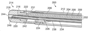
제1 양태에 따르면, 전기 수술기구가 제공될 수 있는데, 전기 수술기구는, 마이크로파 에너지를 전달하기 위한 동축 공급 케이블을 포함하되, 상기 동축 공급 케이블은 내부 컨덕터, 외부 컨덕터 및 내부 컨덕터와 외부 컨덕터를 분리하는 유전체 재료를 가지며; 마이크로파 에너지 및/또는 고주파 에너지를 수용하기 위해 동축 공급 케이블의 한 원위 단부에 배치된 기구 끝단; 및 유체를 기구 끝단으로 전달하기 위한 유체 채널을 포함하고, 기구 끝단은: 마이크로파 에너지를 생물학적 조직으로 방사하기 위한 방사 구조물; 및 유체 채널과 유체 연통하는 중공 바늘을 포함하고, 중공 바늘은 유체 채널로부터 치료 부위로 유체를 전달하도록 배열되고, 방사 구조물은 절연성 비-점착성 재료로 코팅된다. According to a first aspect, an electrosurgical instrument may be provided, the electrosurgical instrument comprising a coaxial supply cable for transmitting microwave energy, the coaxial supply cable comprising an inner conductor, an outer conductor and an inner conductor and an outer conductor having a dielectric material that separates; an instrument end disposed at a distal end of the coaxial supply cable for receiving microwave energy and/or radio frequency energy; and a fluid channel for delivering a fluid to an instrument tip, the instrument tip comprising: a radiating structure for radiating microwave energy into the biological tissue; and a hollow needle in fluid communication with the fluid channel, wherein the hollow needle is arranged to deliver fluid from the fluid channel to the treatment site, and wherein the radiating structure is coated with an insulating non-stick material.
절연성 비-점착성 재료는 기구 끝단의 전체 또는 일부분에 코팅으로서 제공될 수 있다. 예를 들어, 기구 끝단은 절연성 비-점착성 재료로 코팅되거나 또는 코팅이 방사 구조물로 제한될 수 있다. An insulating non-stick material may be provided as a coating on all or a portion of the instrument tip. For example, the instrument tip may be coated with an insulating non-stick material or the coating may be limited to a radiating structure.
절연성 비-점착성 재료의 코팅은 40 μm 또는 그 미만의 두께, 예컨대, 1-40 μm의 범위에 있는 두께를 가질 수 있다. 바람직하게는, 상기 두께는 10 μm 또는 그 미만, 예컨대, 3-4 μm 범위이다. 절연 재료의 두께는 절연 끝단에 따라 달라질 수 있다. 이는 방사 구조물 위에 배치된 얇은 부분을 가질 수 있다. The coating of insulating non-tacky material may have a thickness of 40 μm or less, such as in the range of 1-40 μm. Preferably, the thickness is in the range of 10 μm or less, eg 3-4 μm. The thickness of the insulating material may vary depending on the insulating end. It may have a thin portion disposed over the radiating structure.
절연성 비-점착성 재료는 생체적합성 일 수 있다. 몇몇 실시예들에서, 비-점착성 재료는 파릴렌 C 또는 파릴렌 D이다. The insulating non-stick material may be biocompatible. In some embodiments, the non-stick material is Parylene C or Parylene D.
제2 양태에 따르면, 전기 수술기구가 제공될 수 있는데, 전기 수술기구는, 마이크로파 에너지 및/또는 고주파 에너지를 전달하기 위한 동축 공급 케이블을 포함하되, 상기 동축 공급 케이블은 내부 컨덕터, 외부 컨덕터 및 내부 컨덕터와 외부 컨덕터를 분리하는 유전체 재료를 가지며; 마이크로파 에너지 및/또는 고주파 에너지를 수용하기 위해 동축 공급 케이블의 한 원위 단부에 배치된 기구 끝단; 및 유체를 기구 끝단으로 전달하기 위한 유체 채널을 포함하고, 기구 끝단은: 마이크로파 에너지 및/또는 고주파 에너지를 생물학적 조직으로 전달하기 위한 에너지 전달 구조물; 및 유체 채널과 유체 연통하는 중공 바늘을 포함하고, 에너지 전달 구조물은 마이크로파 에너지를 생물학적 조직으로 방사하기 위한 방사 구조물을 포함하며, 중공 바늘은 중공 바늘을 접지하기 위해 외부 컨덕터에 전기적으로 연결된다. According to a second aspect, an electrosurgical instrument may be provided, the electrosurgical instrument comprising a coaxial supply cable for transmitting microwave energy and/or high frequency energy, the coaxial supply cable comprising an inner conductor, an outer conductor and an inner conductor having a dielectric material separating the conductor and the outer conductor; an instrument end disposed at a distal end of the coaxial supply cable for receiving microwave energy and/or radio frequency energy; and a fluidic channel for delivering a fluid to a tip of the device, the tip comprising: an energy delivery structure for delivering microwave energy and/or radio frequency energy to a biological tissue; and a hollow needle in fluid communication with the fluid channel, wherein the energy transfer structure includes a radiating structure for radiating microwave energy into the biological tissue, wherein the hollow needle is electrically connected to an external conductor to ground the hollow needle.
제1 및 제2 양태는, 예를 들어, 접지된 바늘 및 절연성 비-점착성 코팅이 있는 전기 수술기구를 제공하기 위하여 결합될 수 있다. 두 양태 모두에 적용할 수 있는 추가적인 옵션 기능은 아래에 설명된다. The first and second aspects may be combined, for example, to provide an electrosurgical instrument having a grounded needle and an insulating non-stick coating. Additional optional features applicable to both aspects are described below.
기구는 신체 내의 표적 조직을 응고 및/또는 절제하도록 작동될 수 있다. 예를 들어, 기구는 폐 또는 위장관의 조직을 치료하는 데 사용될 수 있지만 그 밖의 다른 장기(예컨대, 자궁)의 조직을 치료하는 데 사용될 수도 있다. 표적 조직을 효율적으로 치료하기 위해 기구 끝단은 표적 조직에 가능한 최대한 가깝게(대부분의 경우, 내부에) 위치되어야 한다. 표적 조직(예컨대, 폐)에 도달하기 위하여, 장치는 통로(예컨대, 기도)를 통해 장애물 주변으로 안내되어야 할 수 있다. 이는, 기구가 이상적으로 가능한 최대한 가요성을 지니고 작은 횡단면을 가질 것임을 의미한다. 특히, 장치는 끝단 가까이에서 매우 유연해야 하므로 좁고 구부러질 수 있는 세기관지와 같은 좁은 통로를 따라 조종해야 할 수 있다. The device may be operable to coagulate and/or ablate target tissue within the body. For example, the device may be used to treat tissue of the lungs or gastrointestinal tract, but may also be used to treat tissue of other organs (eg, the uterus). To effectively treat the target tissue, the instrument tip should be positioned as close as possible to (in most cases, inside) the target tissue. In order to reach a target tissue (eg, lung), the device may have to be guided around an obstruction through a passageway (eg, an airway). This means that the instrument will ideally have as little cross-section as possible and as flexible as possible. In particular, the device must be very flexible near the tip, so it may be necessary to maneuver it along narrow passages such as bronchioles that are narrow and bendable.
동축 공급 케이블은 한 단부에서 전기 수술 제너레이터에 연결될 수 있는 기존의 저손실 동축 케이블 일 수 있다. 특히, 내부 컨덕터는 동축 공급 케이블의 종축을 따라 연장되는 기다란 컨덕터일 수 있다. 유전체 재료는 내부 컨덕터 주위에 배치될 수 있는데, 예컨대, 제1 유전체 재료는 내부 컨덕터가 연장되는 채널을 가질 수 있다. 외부 컨덕터는 유전체 재료의 표면에 배치된 전도성 재료로 제조된 슬리브 일 수 있다. 동축 공급 케이블은 케이블을 절연하고 보호하기 위한 외부 보호 쉬쓰를 추가로 포함할 수 있다. 몇몇 예에서, 보호 쉬쓰는 조직이 케이블에 달라 붙는 것을 방지하기 위해 비-점착성 재료로 제조되거나 코팅될 수 있다. The coaxial supply cable may be a conventional low loss coaxial cable that may be connected to an electrosurgical generator at one end. In particular, the inner conductor may be an elongated conductor extending along the longitudinal axis of the coaxial supply cable. A dielectric material may be disposed around the inner conductor, eg, the first dielectric material may have a channel through which the inner conductor extends. The outer conductor may be a sleeve made of a conductive material disposed on the surface of the dielectric material. The coaxial supply cable may further include an external protective sheath to insulate and protect the cable. In some instances, the protective sheath may be made of or coated with a non-stick material to prevent tissue from sticking to the cable.
유체 채널은 전기 수술기구의 근위 단부로부터 기구 끝단으로 유체(예컨대, 액체 또는 기체)를 전달하도록 제공될 수 있다. 유체 채널은 그 근위 단부에서 유체 공급원에 연결될 수 있다. 예를 들어, 유체 채널은 액체 약물(예컨대, 아드레날린)을 기구 끝단으로 전달하도록 사용될 수 있다. 전기 수술기구를 사용하여 APC를 수행하는 경우, 아르곤 가스를 기구 끝단으로 전달하기 위해 유체 채널이 사용될 수 있다. 유체 채널은 또한 기구 끝단으로부터 전기 수술기구의 근위 단부로 유체를 운반하도록 사용될 수 있다. 예를 들어, 기구 끝단 주위의 치료 부위에 존재하는 유체는 치료 부위로부터 유체를 배출하기 위해 중공 바늘을 통해 흡인되고 유체 채널을 통해 배출될 수 있다. 유체 채널은, 예를 들어, 전기 수술기구의 길이를 따라 연장되는, 예컨대, 전기 수술기구의 근위 단부로부터 기구 끝단으로 연장되는 가요성 튜브(루멘)를 포함할 수 있다. A fluid channel may be provided to deliver a fluid (eg, liquid or gas) from the proximal end of the electrosurgical instrument to the instrument end. The fluid channel may be connected to a fluid source at its proximal end. For example, a fluidic channel may be used to deliver a liquid drug (eg, adrenaline) to an instrument tip. When performing APC using an electrosurgical instrument, a fluid channel may be used to deliver argon gas to the instrument tip. The fluid channel may also be used to transport fluid from the instrument tip to the proximal end of the electrosurgical instrument. For example, fluid present at the treatment site around the instrument tip may be drawn through the hollow needle and expelled through the fluid channel to expel the fluid from the treatment site. The fluid channel can include, for example, a flexible tube (lumen) extending along the length of the electrosurgical instrument, eg, extending from the proximal end of the electrosurgical instrument to the instrument end.
몇몇 예에서, 유체 채널은 동축 공급 케이블을 따라 배열될 수 있다. 유체 채널 및 동축 공급 케이블은 가요성 기구 슬리브 내에 수용될 수 있으며, 기구 슬리브는 동축 공급 케이블 및 유체 채널을 운반하는 루멘을 형성할 수 있다. 기구 슬리브는 조직이 달라 붙는 것을 방지하기 위해 비-점착성 재료(예컨대, PTFE)로 제조되거나 코팅될 수 있다. 기구 슬리브 내에 유체 채널 및 동축 공급 케이블의 위치를 유지하기 위해 삽입체가 기구 슬리브에 제공될 수 있다. 대안으로, 기구 슬리브는, 동축 공급 케이블이 기구 슬리브의 제1 루멘 내에 수용되고 유체 채널이 기구 슬리브의 제2 루멘 내에 수용되도록, 다중-루멘 튜브 일 수 있다. In some examples, the fluid channel may be arranged along a coaxial supply cable. The fluid channel and the coaxial supply cable may be received within a flexible instrument sleeve, and the instrument sleeve may form a lumen carrying the coaxial supply cable and the fluid channel. The instrument sleeve may be made of or coated with a non-stick material (eg, PTFE) to prevent tissue sticking. An insert may be provided in the instrument sleeve to maintain the position of the fluid channel and coaxial supply cable within the instrument sleeve. Alternatively, the instrument sleeve may be a multi-lumen tube such that a coaxial supply cable is received within a first lumen of the instrument sleeve and a fluid channel is received within a second lumen of the instrument sleeve.
몇몇 예에서, 유체 채널은 동축 공급 케이블 내에 수용될 수 있다. 예를 들어, 동축 공급 케이블 내의 유전체 재료는 유체 채널이 연장되는 루멘을 포함할 수 있다. 또 다른 예에서, 내부 컨덕터는 중공 컨덕터 일 수 있는데, 예를 들어, 내부 컨덕터는 전도성 재료의 튜브에 의해 형성될 수 있다. 이 경우, 유체 채널은 중공 내부 컨덕터 내에 제공될 수 있다. 동축 공급 케이블 내에 유체 채널을 수용하면, 전기 수술기구의 외측 직경을 줄이도록 제공될 수 있다. In some examples, the fluid channel may be received within a coaxial supply cable. For example, the dielectric material in the coaxial supply cable may include a lumen from which the fluid channel extends. In another example, the inner conductor may be a hollow conductor, eg, the inner conductor may be formed by a tube of conductive material. In this case, the fluid channel may be provided in the hollow inner conductor. Receiving the fluid channel within the coaxial supply cable may serve to reduce the outer diameter of the electrosurgical instrument.
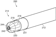
기구 끝단은 동축 공급 케이블의 원위 단부에 위치되며 동축 공급 케이블을 따라 이송되는 EM 에너지를 표적 조직으로 전달하도록 제공된다. 기구 끝단은 또한 유체 채널로부터 치료 부위로 유체를 전달하도록 제공된다. 유체 채널은 동축 공급 채널의 원위 단부 근처에서, 예컨대, 기구 끝단의 앞에서 종결될 수 있다(terminate). 대안으로, 유체 채널의 한 부분이 기구 끝단으로 연장될 수 있다. 기구 끝단은 동축 공급 케이블 및 유체 채널에 영구적으로 또는 착탈 가능하게 결부될 수 있다. An instrument tip is located at the distal end of the coaxial feed cable and is provided to deliver EM energy transported along the coaxial feed cable to the target tissue. The instrument tip is also provided for delivering fluid from the fluid channel to the treatment site. The fluid channel may terminate near the distal end of the coaxial supply channel, eg, in front of the instrument tip. Alternatively, a portion of the fluid channel may extend to the instrument tip. The instrument end may be permanently or removably attached to the coaxial supply cable and fluid channel.
에너지 전달 구조물은 동축 공급 케이블에 의해 전달되는 마이크로파 및/또는 RF 에너지를 전달하도록 배열된다. 방사 구조물은 마이크로파 에너지를 수용하기 위해 동축 공급 케이블에 전기적으로 연결된다. 방사 구조물은 기구가 원하는 방사 프로파일 및/또는 치료 타입(예컨대, 조직 절제, 절단 또는 응고)을 생성하도록 미리 결정된 에너지를 가진 마이크로파 에너지로 구성될 수 있다. 예를 들어, 방사 구조물은 모노폴라 마이크로파 안테나로 구성될 수 있으며, 예컨대, 방사 구조물은 내부 컨덕터에 연결되고 그 길이를 따라 마이크로파 에너지를 방사하도록 배열된 기다란 컨덕터를 포함할 수 있다. 대안으로, 방사 구조물은 바이폴라 마이크로파 안테나로 구성될 수 있으며, 예컨대, 방사 구조물은 내부 컨덕터 및 외부 컨덕터에 각각 연결되고 마이크로파 에너지를 방사하도록 배열된 한 쌍의 전극을 포함할 수 있다. The energy transmitting structure is arranged to transmit microwave and/or RF energy delivered by the coaxial supply cable. The radiating structure is electrically connected to the coaxial supply cable to receive the microwave energy. The radiating structure may be configured with microwave energy having a predetermined energy such that the instrument produces a desired radiation profile and/or type of treatment (eg, tissue ablation, cutting or coagulation). For example, the radiating structure may consist of a monopolar microwave antenna, eg, the radiating structure may include an elongated conductor coupled to an inner conductor and arranged to radiate microwave energy along its length. Alternatively, the radiating structure may consist of a bipolar microwave antenna, eg, the radiating structure may include a pair of electrodes each connected to an inner conductor and an outer conductor and arranged to radiate microwave energy.
에너지 전달 구조물이 RF 에너지를 전달하도록 구성된 경우, 에너지 전달 구조물은 내부 컨덕터 및 외부 컨덕터에 각각 연결된 한 쌍의 RF 전극을 포함할 수 있다. 한 쌍의 RF 전극은 활성 전극(active electrode) 및 복귀 전극(return electrode)으로 기능할 수 있으며, 전극 사이의 한 영역에 위치된 조직이 RF 에너지에 의해 절제되거나 응고된다. When the energy transmitting structure is configured to transmit RF energy, the energy transmitting structure may include a pair of RF electrodes each connected to an inner conductor and an outer conductor. A pair of RF electrodes may function as an active electrode and a return electrode, and tissue located in a region between the electrodes is ablated or coagulated by the RF energy.
전기 수술기구가 APC를 수행하는 데 사용되는 경우, 에너지 전달 구조물은 마이크로파 및/또는 RF 에너지를 사용하여 아르곤 가스로부터 플라즈마를 점화하고 유지하기 위해 속이 중공 바늘 근처에 배치된 한 쌍의 전극을 포함할 수 있다. When an electrosurgical instrument is used to perform APC, the energy transfer construct may include a pair of electrodes disposed near the hollow needle for igniting and maintaining a plasma from argon gas using microwave and/or RF energy. can
몇몇 경우들에서, 에너지 전달 구조물은 마이크로파 및 RF 에너지를 동시에 또는 순차적으로 전달하도록 구성될 수 있다. 예를 들어, 에너지 전달 구조물이 한 쌍의 전극을 포함하는 경우, 한 쌍의 전극은 RF 주파수에서 활성 및 복귀 전극으로 기능할 수 있으며, 마이크로파 주파수에서 바이폴라 안테나로 기능할 수 있다. In some cases, the energy transfer structure may be configured to deliver microwave and RF energy simultaneously or sequentially. For example, if the energy transfer structure includes a pair of electrodes, the pair of electrodes may function as active and return electrodes at RF frequencies and as bipolar antennas at microwave frequencies.
중공 바늘은 유체 채널로부터 치료 부위로 유체를 전달하도록 제공된다. 치료 부위는 기구 끝단 부근(예를 들어, 기구 끝단 앞)에 위치된 표적 생물학적 조직의 영역을 포함할 수 있다. 중공 바늘은 일정 길이의 튜브로 형성될 수 있다. 중공 바늘은 전도성 재료(예컨대, 금속)로 제조될 수 있다. 중공 바늘은 유체 채널과 유체 연통하는 한 근위 단부를 가질 수 있으며, 유체 채널로부터의 유체가 중공 바늘로 전달될 수 있다. 예를 들어, 중공 바늘의 근위 단부는 유체 채널의 원위 부분 내부에 위치될 수 있다. 유체 채널 및 중공 바늘 사이의 이음부에서 유체가 누출되는 것을 방지하기 위해, 중공 바늘 및 유체 채널 사이에 밀봉부가 형성될 수 있다. 중공 바늘은 개구를 갖는 원위 단부를 가질 수 있으며, 상기 개구를 통해 유체가 치료 부위로 분배될 수 있다. 유체는 치료 부위로부터 유체를 배출하기 위해 원위 단부의 개구를 통해 바늘로 흡인될 수 있다. 중공 바늘의 원위 단부는 조직에 중공 바늘의 삽입을 용이하게 하기 위해 날카로울 수 있다(예컨대, 뾰족할 수 있다). 예를 들어, 중공 바늘은 피하주사 바늘일 수 있다. A hollow needle is provided to deliver fluid from a fluid channel to a treatment site. The treatment site may include a region of target biological tissue located proximate to (eg, in front of) the tip of the device. The hollow needle may be formed of a tube of a certain length. The hollow needle may be made of a conductive material (eg, metal). The hollow needle may have one proximal end in fluid communication with the fluid channel, and fluid from the fluid channel may be delivered to the hollow needle. For example, the proximal end of the hollow needle may be located inside the distal portion of the fluid channel. To prevent fluid leakage at the joint between the fluid channel and the hollow needle, a seal may be formed between the hollow needle and the fluid channel. The hollow needle may have a distal end having an opening through which fluid may be dispensed to the treatment site. Fluid may be aspirated with a needle through an opening in the distal end to expel fluid from the treatment site. The distal end of the hollow needle may be sharp (eg, may be pointed) to facilitate insertion of the hollow needle into tissue. For example, the hollow needle may be a hypodermic needle.
중공 바늘은 동축 공급 케이블의 외부 컨덕터에 전기적으로 연결된다. 이것은 중공 바늘을 외부 컨덕터에 접지시키도록 제공된다. 일반적으로, 동축 공급 케이블의 외부 컨덕터는 전기 접지(예컨대, 0V)에 연결될 수 있으며, 외부 컨덕터와 중공 바늘은 모두 접지될 수 있다. 중공 바늘은 임의의 적절한 수단을 사용하여 외부 컨덕터에 전기적으로 연결될 수 있다. 예를 들어, 전도성 와이어 또는 그 밖의 다른 컨덕터가 외부 컨덕터 및 중공 바늘 사이에 연결될 수 있다. The hollow needle is electrically connected to the outer conductor of the coaxial supply cable. This serves to ground the hollow needle to the outer conductor. In general, the outer conductor of the coaxial supply cable may be connected to an electrical ground (eg 0V), and both the outer conductor and the hollow needle may be grounded. The hollow needle may be electrically connected to the external conductor using any suitable means. For example, a conductive wire or other conductor may be connected between the outer conductor and the hollow needle.
중공 바늘이 외부 컨덕터에 전기적으로 연결되기 때문에, 중공 바늘은 동축 공급 케이블에 대해 부동 전압(floating voltage)에 있지 않다. 중공 바늘 및 외부 컨덕터 사이의 전기 연결부는 또한 외부 컨덕터 및 중공 바늘 사이의 임의의 부동 커패시턴스를 감소시킬 수 있다. 그 결과, 에너지 전달 구조물에 의한 EM 에너지 전달에 대한 중공 바늘에 의한 간섭 효과가 감소될 수 있다. 이는, 본 발명자들이 중공 바늘에 의해 야기되는 간섭 효과가 마이크로파 주파수에서 더 두드러질 수 있다는 것을 발견함에 따라, 마이크로파 에너지의 전달에 특히 유리할 수 있다. 중공 바늘의 간섭 효과를 줄이면, 기구 끝단의 방사 프로파일을 향상시킬 수 있을 뿐만 아니라(예컨대, 간섭으로 인한 왜곡을 줄임으로써) 표적 조직에 대한 EM 에너지 전달의 효율성을 향상시킬 수 있다. 또한, 중공 바늘을 외부 컨덕터에 접지하면, 전기 수술기구의 안전성이 향상될 수 있는데, 이는 중공 바늘 및 에너지 전달 구조물 사이에 큰 전압이 발생하는 것을 방지할 수 있기 때문이다. Because the hollow needle is electrically connected to the external conductor, the hollow needle is not at a floating voltage with respect to the coaxial supply cable. The electrical connection between the hollow needle and the outer conductor may also reduce any floating capacitance between the outer conductor and the hollow needle. As a result, the interference effect by the hollow needle on the EM energy transfer by the energy transfer structure can be reduced. This may be particularly advantageous for the delivery of microwave energy, as the inventors found that the interference effect caused by the hollow needle may be more pronounced at microwave frequencies. Reducing the interference effect of the hollow needle can improve the efficiency of EM energy delivery to the target tissue as well as improve the radiation profile of the instrument tip (eg, by reducing distortion due to interference). Also, if the hollow needle is grounded to an external conductor, the safety of the electrosurgical instrument can be improved because it can prevent a large voltage from being generated between the hollow needle and the energy transfer structure.
몇몇 실시예들에서, 기구 끝단은 중공 바늘을 외부 컨덕터에 전기적으로 연결하도록 배열된 접지 요소를 포함할 수 있다. 따라서, 외부 컨덕터 및 중공 바늘 사이의 전기 연결부는 기구 끝단 자체에 위치될 수 있다. 접지 요소는 중공 바늘을 외부 컨덕터의 한 원위 부분에 전기적으로 연결될 수 있다. 몇몇 경우들에서, 외부 컨덕터의 원위 부분은 기구 끝단으로 연장될 수 있다. 접지 요소는 중공 컨덕터를 외부 컨덕터에 전기적으로 연결하는 전도성 재료의 한 부분을 포함할 수 있다. 접지 요소는, 임의의 적절한 수단, 예를 들어, 기계적 연결, 전도성 접착제(예컨대, 에폭시) 또는 납땜 또는 용접 접합에 의해, 외부 컨덕터 및 중공 바늘에 연결될 수 있다. 기구 끝단에 직접 접지 요소를 제공함으로써, 중공 바늘 및 외부 컨덕터 사이의 전기 경로의 길이를 줄일 수 있다. 이것은 중공 바늘 및 외부 컨덕터 사이의 우수한 전기 연결을 보장하고 전기 연결부의 형성을 용이하게 할 수 있다. In some embodiments, the instrument tip may include a grounding element arranged to electrically connect the hollow needle to an external conductor. Thus, the electrical connection between the outer conductor and the hollow needle can be located at the instrument tip itself. The grounding element may electrically connect the hollow needle to a distal portion of the outer conductor. In some cases, the distal portion of the outer conductor may extend to the instrument tip. The grounding element may comprise a piece of conductive material that electrically connects the hollow conductor to the outer conductor. The grounding element may be connected to the external conductor and the hollow needle by any suitable means, for example by mechanical connection, conductive adhesive (eg, epoxy) or soldering or welding bonding. By providing a grounding element directly at the instrument tip, the length of the electrical path between the hollow needle and the outer conductor can be reduced. This can ensure a good electrical connection between the hollow needle and the outer conductor and facilitate the formation of the electrical connection.
몇몇 실시예들에서, 접지 요소는 중공 바늘 및 외부 컨덕터를 각각 보유하도록 배열 된 제1 연결 표면 및 제2 연결 표면을 갖는 몸체를 포함할 수 있다. 제1 연결 표면 및 제2 연결 표면은, 예를 들어, 공통 전도성 몸체의 상이한 표면 영역들과 같이, 함께 전기적으로 연결될 수 있다. 중공 바늘은 제1 연결 표면에 전기적으로 연결될 수 있다. 외부 컨덕터는 제2 연결 표면에 전기적으로 연결될 수 있다. 중공 바늘과 외부 컨덕터가 모두 접지 요소의 몸체에 있는 표면에 연결되기 때문에, 접지 요소는 외부 컨덕터(따라서, 동축 공급 케이블)에 대해 중공 바늘의 한 위치를 고정하도록 제공될 수 있다. 따라서, 접지 요소는 중공 바늘을 외부 컨덕터에 전기적으로 연결하고 중공 바늘과 외부 컨덕터를 서로에 대해 제자리에 고정하는 이중 기능을 제공할 수 있다. 이는 기구 끝단의 무결성을 향상시키도록 제공될 수 있다. 접지 요소의 몸체는 전도성 재료(예컨대, 금속)로 제조된 단일 구성요소 일 수 있으며, 이 경우 중공 바늘과 외부 컨덕터는 접지 요소의 몸체에 의해 전기적으로 연결된다. 대안으로, 몸체는 절연 재료로 제조될 수 있고, 제1 및 제2 연결 표면은 몸체의 표면에 제공된 전도층에 의해 형성될 수 있다. 그 뒤, 제1 및 제2 연결 표면 사이의 전기 경로가 몸체 상에 또는 몸체 내에 제공될 수 있다. In some embodiments, the grounding element can include a body having a first connecting surface and a second connecting surface arranged to hold a hollow needle and an outer conductor, respectively. The first connection surface and the second connection surface may be electrically connected together, such as, for example, different surface regions of a common conductive body. The hollow needle may be electrically connected to the first connection surface. The external conductor may be electrically connected to the second connection surface. Since both the hollow needle and the outer conductor are connected to a surface on the body of the grounding element, the grounding element may be provided to secure one position of the hollow needle with respect to the outer conductor (and thus the coaxial supply cable). Thus, the grounding element may provide the dual function of electrically connecting the hollow needle to the outer conductor and securing the hollow needle and the outer conductor in place relative to each other. This may serve to improve the integrity of the instrument tip. The body of the grounding element may be a single component made of a conductive material (eg metal), in which case the hollow needle and the outer conductor are electrically connected by the body of the grounding element. Alternatively, the body may be made of an insulating material, and the first and second connecting surfaces may be formed by a conductive layer provided on the surface of the body. An electrical path between the first and second connecting surfaces may then be provided on or in the body.
중공 바늘은 임의의 적절한 수단을 사용하여 제1 연결 표면에 전기적으로 연결될 수 있다. 한 예에서, 중공 바늘은 그 사이에 전기적 접촉을 형성하기 위해 제1 연결 표면에 대해 고정될 수 있다. 대안으로, 중공 바늘은, 예를 들어, 전도성 접착제를 사용하거나, 또는 납땜 또는 용접 연결에 의해, 제1 연결 표면에 결부될 수 있다. 외부 컨덕터는 유사한 방식으로 제2 연결 표면에 전기적으로 연결될 수 있다. The hollow needle may be electrically connected to the first connection surface using any suitable means. In one example, the hollow needle may be secured against the first connecting surface to form electrical contact therebetween. Alternatively, the hollow needle may be attached to the first connection surface, for example using a conductive adhesive, or by soldering or welding connections. The external conductor may be electrically connected to the second connecting surface in a similar manner.
제1 연결 표면의 형태는 중공 바늘의 형태와 상호보완적 일 수 있다. 이것은 제1 연결 표면 및 중공 바늘 사이의 전기 연결부를 향상시킬 수 있다. 이것은 또한 중공 바늘의 원치 않은 움직임을 방지하기 위해 중공 바늘을 제자리에 고정시키도록 제공될 수 있다. 예를 들어, 중공 바늘이 원형 횡단면을 갖는 경우, 제1 연결 표면은 중공 바늘의 횡단면의 반경과 일치하는 곡률반경을 갖는 둥근 표면일 수 있다. 이와 유사하게, 제2 연결 표면의 형태는 외부 컨덕터의 형태에 상호보완적 일 수 있다. The shape of the first connecting surface may be complementary to that of the hollow needle. This may improve the electrical connection between the first connection surface and the hollow needle. It may also serve to hold the hollow needle in place to prevent unwanted movement of the hollow needle. For example, where the hollow needle has a circular cross-section, the first connecting surface may be a round surface with a radius of curvature that matches the radius of the cross-section of the hollow needle. Similarly, the shape of the second connecting surface may be complementary to the shape of the outer conductor.
몇몇 실시예들에서, 접지 요소의 몸체는 이를 통해 연장되는 제1 채널을 가질 수 있으며, 제1 연결 표면은 제1 채널 내에 형성된다. 접지 요소는 일반적으로 원통형 또는 원추형 형태를 가질 수 있으며, 제1 채널은 중공 바늘의 한 부분이 수용될 수 있는 중앙에 배치된 구멍이다. 제1 채널은 종방향, 즉 내부 컨덕터의 종축에 평행한 방향으로 몸체를 통해 연장될 수 있다. 제1 채널은 개방 채널일 수 있으며, 예컨대, 중공 바늘의 한 부분이 수용되는 홈을 구성할 수 있다. 대안으로, 제1 채널은 폐쇄된 채널일 수 있으며, 예컨대, 중공 바늘의 한 부분이 포함된 루멘을 형성할 수 있다. 제1 채널은 접지 요소에서 중공 바늘을 제자리에 고정시키도록 제공될 수 있다. 이것은 중공 바늘 및 제1 연결 표면 사이의 전기 연결부가 유지되는 것을 보장할 수 있다. 제1 채널은 또한 중공 바늘의 횡방향 이동, 예컨대, 종방향에 수직인 방향으로의 이동을 제한하도록 제공될 수 있다. 제1 연결 표면은 제1 채널의 한 표면 상에 제공될 수 있으며, 예컨대, 제1 연결 표면은 채널의 벽에 있을 수 있다. 접지 요소의 몸체가 전도성 재료로 제조되는 경우, 제1 채널의 벽은 제1 연결 표면을 제공할 수 있다. 제1 채널의 형태는 중공 바늘의 형태와 상호보완적 일 수 있다. In some embodiments, the body of the grounding element may have a first channel extending therethrough, the first connecting surface being formed in the first channel. The grounding element may have a generally cylindrical or conical shape and the first channel is a centrally disposed aperture in which a portion of the hollow needle can be received. The first channel may extend through the body in a longitudinal direction, ie in a direction parallel to the longitudinal axis of the inner conductor. The first channel may be an open channel, eg, may constitute a groove in which a portion of the hollow needle is received. Alternatively, the first channel may be a closed channel, for example forming a lumen containing a portion of a hollow needle. A first channel may be provided to hold the hollow needle in place at the grounding element. This may ensure that the electrical connection between the hollow needle and the first connection surface is maintained. The first channel may also be provided to limit lateral movement of the hollow needle, eg in a direction perpendicular to the longitudinal direction. The first connection surface may be provided on one surface of the first channel, for example, the first connection surface may be on a wall of the channel. If the body of the grounding element is made of a conductive material, the wall of the first channel may provide a first connection surface. The shape of the first channel may be complementary to that of the hollow needle.
중공 바늘이 기구 끝단에 대해 이동 가능한 경우, 제1 채널은 중공 바늘 및 접지 요소 사이에 슬라이딩 이동 가능한 전기 연결부를 제공할 수 있다. 따라서, 중공 바늘은 외부 컨덕터에 대해 슬라이딩 이동될 수 있고, 중공 바늘 및 외부 컨덕터 사이의 전기 연결부는 슬라이딩 인터페이스를 가로질러 통과할 수 있다. 제1 채널은 또한 끝단에 대해 이동될 때 중공 바늘을 안내하도록 기능할 수 있다. Where the hollow needle is movable relative to the instrument tip, the first channel may provide a slidingly movable electrical connection between the hollow needle and the grounding element. Thus, the hollow needle can slide relative to the outer conductor and the electrical connection between the hollow needle and the outer conductor can pass across the sliding interface. The first channel may also function to guide the hollow needle when moved relative to the tip.
몇몇 실시예들에서, 제1 채널은 제1 채널의 한 근위 단부에 위치된 플레어형 부분(flared portion)을 포함할 수 있는데, 플레어형 부분은 제1 채널의 근위 단부를 향해 증가되는 횡단면적을 갖는다. 플레어형 부분은 중공 바늘을 제1 채널로 안내하거나 또는 "깔때기" 형태로 삽입하도록 제공될 수 있다. In some embodiments, the first channel may include a flared portion located at one proximal end of the first channel, the flared portion having an increasing cross-sectional area towards the proximal end of the first channel. have The flared portion may be provided to guide the hollow needle into the first channel or to insert it in the form of a “funnel”.
몇몇 실시예들에서, 접지 요소의 몸체는 그를 통해 연장되는 제2 채널을 포함할 수 있으며, 제2 연결 표면은 제2 채널에 형성되고; 외부 컨덕터의 한 원위 부분이 제2 채널에 수용 될 수 있다. 제2 채널은 종방향으로 몸체를 통해 연장될 수 있다. 제2 채널은 제1 채널에 평행할 수 있다. 제2 채널은 개방 채널일 수 있는데, 예를 들어, 외부 컨덕터의 원위 부분이 수용되는 홈을 구성할 수 있다. 대안으로, 제2 채널은 폐쇄 채널일 수 있는데, 예를 들어, 외부 컨덕터의 원위 부분이 포함된 루멘을 형성할 수 있다. 제2 채널은 접지 요소에서 외부 컨덕터를 제자리에 고정하도록 제공될 수 있다. 이것은 외부 컨덕터 및 제2 연결 표면 사이의 전기 연결부가 유지되는 것을 보장할 수 있다. 제2 연결 표면은 제2 채널의 표면 상에 제공될 수 있는데, 예를 들어, 제1 연결 표면은 채널의 벽에 있을 수 있다. 접지 요소의 몸체가 전도성 재료로 제조되는 경우, 제2 채널의 한 벽이 제2 연결 표면을 제공할 수 있다. 제2 채널의 형태는 중공 바늘의 형태와 상호보완적 일 수 있다. 외부 컨덕터의 원위 부분은 동축 공급 케이블의 원위 단부에 위치되거나 또는 그 근처에 위치된 외부 컨덕터의 한 부분일 수 있다. 외부 컨덕터의 원위 부분은 기구 끝단으로 연장될 수 있다. In some embodiments, the body of the grounding element may include a second channel extending therethrough, the second connecting surface being formed in the second channel; One distal portion of the outer conductor may be received in the second channel. The second channel may extend through the body in a longitudinal direction. The second channel may be parallel to the first channel. The second channel may be an open channel, eg, may constitute a groove in which the distal portion of the outer conductor is received. Alternatively, the second channel may be a closed channel, for example forming a lumen containing the distal portion of the outer conductor. A second channel may be provided to hold the external conductor in place at the grounding element. This can ensure that the electrical connection between the outer conductor and the second connection surface is maintained. The second connection surface may be provided on a surface of the second channel, for example the first connection surface may be on a wall of the channel. If the body of the grounding element is made of a conductive material, one wall of the second channel may provide a second connection surface. The shape of the second channel may be complementary to that of the hollow needle. The distal portion of the outer conductor may be a portion of the outer conductor located at or near the distal end of the coaxial supply cable. A distal portion of the outer conductor may extend to the instrument tip.
접지 요소의 몸체는 동축 공급 케이블의 한 원위 부분에 결부된 한 근위 부분을 포함할 수 있다. 접지 요소의 몸체의 근위 부분은 접지 요소를 동축 공급 케이블에 고정시키도록 제공될 수 있다. 이것은 동축 공급 케이블 및 기구 끝단 사이의 인터페이스를 강화시키도록 제공될 수 있다. 이 구성은 또한 동축 공급 케이블에 대해 중공 바늘을 제자리에 고정시키도록 제공될 수 있다. 동축 공급 케이블의 원위 부분은 임의의 적절한 수단에 의해 몸체의 근위 부분에 고정될 수 있다. 예를 들어, 몸체의 근위 부분은 동축 공급 케이블의 원위 부분이 수용되고 고정되는 채널을 포함할 수 있다. 접지 요소의 몸체는 원위 부분을 추가로 포함할 수 있으며, 제1 및 제2 연결 표면은 상기 원위 부분에 위치된다. 접지 요소의 몸체는 동축 공급 케이블 및 기구 끝단 사이의 인터페이스에 걸쳐 배열될 수 있으며, 몸체의 근위 부분은 동축 공급 케이블의 원위 단부에 위치되고, 몸체의 원위 부분은 기구 끝단에 위치된다. 따라서, 접지 요소는 전기 수술기구의 무결성을 향상시키고 중공 바늘로 인한 간섭을 줄이도록 제공될 수 있다. The body of the grounding element may include a proximal portion coupled to a distal portion of the coaxial supply cable. A proximal portion of the body of the grounding element may be provided to secure the grounding element to the coaxial supply cable. This may serve to strengthen the interface between the coaxial feed cable and the instrument end. This configuration may also be provided to hold the hollow needle in place relative to the coaxial feed cable. The distal portion of the coaxial supply cable may be secured to the proximal portion of the body by any suitable means. For example, the proximal portion of the body may include a channel in which the distal portion of the coaxial supply cable is received and secured. The body of the grounding element may further comprise a distal portion, wherein the first and second connection surfaces are located at the distal portion. The body of the grounding element may be arranged over the interface between the coaxial supply cable and the instrument end, the proximal portion of the body being located at the distal end of the coaxial supply cable and the distal portion of the body being located at the instrument end. Accordingly, a grounding element may be provided to improve the integrity of the electrosurgical instrument and reduce interference due to the hollow needle.
몇몇 실시예들에서, 전기 수술기구는 중공 바늘이 제1 연결 표면과 접촉하도록 안내하기 위해 접지 요소의 한 근위 단부에 배치된 제1 절연 슬리브를 추가로 포함할 수 있다. 제1 절연 슬리브는 가요성 절연 재료(예컨대, 폴리이미드 튜브)로 제조될 수 있다. 제1 절연 슬리브는 그 주변으로부터 중공 바늘을 보호하고 절연시키도록 제공될 수 있다. 제1 절연 슬리브는 중공 바늘이 연장되고 중공 바늘이 제1 연결 표면과 접촉하도록 안내하는 통로를 형성할 수 있다. 제1 절연 슬리브는 접지 요소의 근위 단부로부터 기구의 근위 단부를 향해 종방향으로 연장될 수 있다. 이러한 방식으로, 제1 절연 슬리브는 종방향을 따라 중공 바늘을 정렬시키도록 제공될 수 있다. 제1 절연 슬리브는 종방향으로 중공 바늘의 이동을 안내하도록 기능할 수 있기 때문에 중공 바늘이 움직일 수 있는 경우에 특히 유리할 수 있다. In some embodiments, the electrosurgical instrument may further include a first insulating sleeve disposed at a proximal end of the grounding element to guide the hollow needle into contact with the first connection surface. The first insulating sleeve may be made of a flexible insulating material (eg, polyimide tube). A first insulating sleeve may be provided to protect and insulate the hollow needle from its periphery. The first insulating sleeve may define a passage through which the hollow needle extends and guides the hollow needle into contact with the first connecting surface. The first insulating sleeve may extend longitudinally from a proximal end of the grounding element toward a proximal end of the instrument. In this way, the first insulating sleeve may be provided to align the hollow needle along the longitudinal direction. The first insulating sleeve may be particularly advantageous where the hollow needle is movable as it may serve to guide the movement of the hollow needle in the longitudinal direction.
몇몇 실시예들에서, 전기 수술기구는 방사 구조물로부터 중공 바늘을 절연시키기 위해 접지 요소의 한 원위 단부에 배열된 제2 절연 슬리브를 추가로 포함할 수 있다. 제2 절연 슬리브는 가요성 절연 재료(예컨대, 폴리이미드 튜브)로 제조될 수 있다. 제2 절연 슬리브는 방사 구조물 및 기구 끝단의 그 밖의 다른 구성요소들로부터 중공 바늘을 절연시키도록 제공될 수 있다. 제2 절연 슬리브는 중공 바늘이 연장되는 통로를 형성할 수 있다. 제2 절연 슬리브는 접지 요소의 원위 단부로부터 기구 끝단의 한 원위 단부를 향해 중공 바늘을 안내할 수 있다. 예를 들어, 제2 절연 슬리브는 접지 요소의 원위 단부로부터 기구 끝단의 원위 단부로 연장될 수 있다. In some embodiments, the electrosurgical instrument may further include a second insulating sleeve arranged at one distal end of the grounding element to insulate the hollow needle from the radiating structure. The second insulating sleeve may be made of a flexible insulating material (eg, polyimide tube). A second insulating sleeve may be provided to insulate the hollow needle from the radiating structure and other components of the instrument tip. The second insulating sleeve may define a passageway through which the hollow needle extends. The second insulating sleeve may guide the hollow needle from the distal end of the grounding element towards one distal end of the instrument tip. For example, the second insulating sleeve may extend from the distal end of the grounding element to the distal end of the instrument tip.
몇몇 경우들에서, 제1 및 제2 절연 슬리브는 연속 절연 슬리브를 형성할 수 있으며, 상기 연속 절연 슬리브는 중공 바늘이 제1 연결 표면에 전기적으로 연결되는 구멍을 가진다. In some cases, the first and second insulating sleeves may form a continuous insulating sleeve, the continuous insulating sleeve having an aperture through which the hollow needle is electrically connected to the first connection surface.
전기 수술기구가 제1 절연 슬리브와 제2 절연 슬리브를 모두 포함하는 경우, 제1 절연 슬리브는 제2 절연 슬리브보다 큰 횡단면을 가질 수 있다. 이것은 중공 바늘이 접지 요소와 전기적으로 접촉하도록 하기 위해 중공 바늘을 제1 절연 슬리브에 삽입하는 것을 용이하게 할 수 있다. 이러한 방식으로, 더 큰 제1 절연 슬리브는 제1 연결 표면 및 접지 요소를 향해 중공 바늘을 "깔때기" 형태로 삽입하도록 기능할 수 있다. 더 큰 직경의 제1 절연 슬리브를 사용하면, 기구 끝단에 대해 이동될 때 중공 바늘로의 항력을 줄일 수 있다. 이것은 기구 끝단에 대해 중공 바늘의 이동을 용이하게 할 수 있다. When the electrosurgical instrument includes both the first insulating sleeve and the second insulating sleeve, the first insulating sleeve may have a larger cross-section than the second insulating sleeve. This may facilitate insertion of the hollow needle into the first insulating sleeve to bring the hollow needle into electrical contact with the grounding element. In this way, the larger first insulating sleeve can function to insert the hollow needle in a “funnel” form towards the first connection surface and the grounding element. The use of a larger diameter first insulating sleeve may reduce drag to the hollow needle when moved relative to the instrument tip. This may facilitate movement of the hollow needle relative to the instrument tip.
제2 절연 슬리브의 횡단면은 중공 바늘의 횡단면과 대략 일치할 수 있다. 이러한 방식으로, 제2 절연 슬리브는 기구 끝단 내에서 중공 바늘의 정확한 위치를 보장할 수 있다. A cross-section of the second insulating sleeve may approximately coincide with a cross-section of the hollow needle. In this way, the second insulating sleeve can ensure the correct positioning of the hollow needle within the instrument tip.
몇몇 실시예들에서, 중공 바늘은, 중공 바늘의 한 원위 단부가 기구 끝단의 한 원위 단부로부터 뒤로 설정되는 철회된 위치; 및 중공 바늘의 원위 단부가 기구 끝단의 원위 단부를 넘어 돌출되는 노출된 위치 사이에서 기구 끝단에 대해 이동될 수 있다. 이러한 방식으로, 중공 바늘을 사용하지 않을 때에는, 우발적인 조직 손상을 방지하기 위해 철회된 위치에 배열될 수 있다. 바늘은, 치료 부위로 유체를 전달하기를 원할 때, 예를 들어, 치료 부위에 약물을 투여하기 위해, 노출된 위치로 이동될 수 있다. 중공 바늘은 종방향으로 기구 끝단에 대해 상대적으로 움직일 수 있다. 중공 바늘이 철회된 위치에 있을 때 중공 바늘의 원위 단부는 기구 끝단 내부에 위치될 수 있다. 기구 끝단은 중공 바늘이 움직일 수 있는 채널을 포함할 수 있으며, 중공 바늘이 철회된 위치에 있을 때 중공 바늘의 원위 단부는 채널 내부에 위치된다. In some embodiments, the hollow needle comprises: a retracted position in which one distal end of the hollow needle is set back from one distal end of the instrument tip; and an exposed position in which the distal end of the hollow needle protrudes beyond the distal end of the instrument tip. In this way, the hollow needle can be arranged in a retracted position to prevent accidental tissue damage when not in use. The needle may be moved to the exposed position when it is desired to deliver fluid to the treatment site, eg, to administer a drug to the treatment site. The hollow needle is movable relative to the instrument tip in the longitudinal direction. The distal end of the hollow needle may be positioned within the instrument tip when the hollow needle is in the retracted position. The instrument tip may include a channel through which the hollow needle is movable, the distal end of the hollow needle being positioned within the channel when the hollow needle is in the retracted position.
중공 바늘은 임의의 적절한 메커니즘에 의해 기구 끝단에 대해 움직일 수 있다. 몇몇 실시예들에서, 중공 바늘은 중공 바늘에 결부된 제어 와이어를 작동시킴으로써(예를 들어, 밀거나 당김으로써) 이동될 수 있다. 제어 와이어는 유체 채널 내부에 위치될 수 있으며, 제어 와이어는 유체 채널 내부의 중공 바늘에 결부될 수 있다. 대안으로, 제어 와이어는 유체 채널을 따라 배열될 수 있다. The hollow needle may be movable relative to the instrument tip by any suitable mechanism. In some embodiments, the hollow needle may be moved by actuating (eg, pushing or pulling) a control wire attached to the hollow needle. A control wire may be positioned within the fluid channel, and the control wire may be coupled to a hollow needle within the fluid channel. Alternatively, the control wire may be arranged along the fluid channel.
중공 바늘 및 외부 컨덕터 사이의 전기 연결부는 기구 끝단에 대한 중공 바늘의 이동을 허용하도록 구성될 수 있다. 이러한 방식으로, 중공 바늘은 철회된 위치 또는 노출된 위치에 있는지에 상관없이 외부 컨덕터에 전기적으로 연결된 상태를 유지할 수 있다. 예를 들어, 중공 바늘 및 외부 컨덕터 사이의 전기 연결부는 슬라이딩 이동 가능한 전기 연결부일 수 있다. 접지 요소가 제1 연결 표면을 갖는 몸체를 포함하는 경우, 중공 바늘은 제1 연결 표면에 대해 슬라이딩 이동될 수 있다. 몇몇 경우들에서, 더 이상 외부 컨덕터에 전기적으로 연결되지 않도록, 기구로부터 중공 바늘을 완전히 빼낼 수도 있다. The electrical connection between the hollow needle and the outer conductor may be configured to allow movement of the hollow needle relative to the instrument tip. In this way, the hollow needle can remain electrically connected to the external conductor, whether in a retracted position or an exposed position. For example, the electrical connection between the hollow needle and the outer conductor may be a slidingly movable electrical connection. If the grounding element comprises a body having a first connecting surface, the hollow needle can be slid relative to the first connecting surface. In some cases, the hollow needle may be completely withdrawn from the instrument so that it is no longer electrically connected to the external conductor.
접지 요소가 제1 채널을 포함하는 경우, 제1 채널은 중공 바늘이 제1 연결 표면과 접촉 상태를 유지하면서 중공 바늘이 채널을 따라 종방향으로 슬라이딩 이동될 수 있도록 수치가 정해질 수 있다. Where the grounding element comprises a first channel, the first channel may be dimensioned such that the hollow needle can slide longitudinally along the channel while the hollow needle remains in contact with the first connecting surface.
중공 바늘 및 유체 채널 사이의 연결은 유체 채널에 대한 중공 바늘의 이동을 허용하도록 구성될 수 있다. 이러한 방식으로, 중공 바늘이 기구 끝단에 대해 이동될 때, 중공 바늘은 유체 채널과 유체 연통 상태를 유지할 수 있다. 예를 들어, 중공 바늘의 한 근위 단부가 유체 채널 내부에 위치되는 경우, 중공 바늘의 근위 단부는 유체 채널의 길이를 따라 이동될 수 있다. 중공 바늘 및 유체 채널 사이의 이음부에서 유체가 빠져 나가는 것을 방지하면서도 유체 채널에 대한 중공 바늘의 이동을 가능하게 하기 위하여, 중공 바늘 및 유체 채널 사이에 슬라이딩 밀봉부(sliding seal)이 형성될 수 있다. The connection between the hollow needle and the fluid channel may be configured to allow movement of the hollow needle relative to the fluid channel. In this way, when the hollow needle is moved relative to the instrument tip, the hollow needle can remain in fluid communication with the fluid channel. For example, if one proximal end of the hollow needle is positioned within the fluid channel, the proximal end of the hollow needle may be moved along the length of the fluid channel. A sliding seal may be formed between the hollow needle and the fluid channel to allow movement of the hollow needle relative to the fluid channel while preventing fluid from escaping at the joint between the hollow needle and the fluid channel. .
몇몇 실시예들에서, 기구 끝단은 그 원위 단부에 개구를 포함할 수 있으며, 중공 바늘이 철회된 위치에 있을 때에는 중공 바늘의 원위 단부가 기구 끝단에 위치될 수 있고 개구를 통해 돌출하지 않으며, 중공 바늘이 노출된 위치에 있을 때에는 중공 바늘의 원위 단부는 개구를 통해 돌출될 수 있다. 이러한 방식으로 중공 바늘은 철회된 위치에 있을 때 기구 끝단 내부에서 보호될 수 있다. In some embodiments, the instrument tip may include an opening at its distal end, wherein when the hollow needle is in the retracted position the distal end of the hollow needle may be positioned at the instrument tip and does not protrude through the opening, the hollow The distal end of the hollow needle may protrude through the opening when the needle is in the exposed position. In this way the hollow needle can be protected inside the instrument tip when in the retracted position.
몇몇 실시예들에서, 중공 바늘은 노출된 위치에 있을 때, 중공의 한 원위 단부로부터 이격되는 마이크로파 에너지의 정수 개수의 반파장에 상응하는 중공 바늘 상의 한 위치에서 외부 컨덕터에 전기적으로 연결될 수 있다. 예를 들어, 접지 요소는 중공 바늘의 원위 단부로부터 이격되어 반파장에 위치될 수 있다. 이것은 마이크로파 주파수에서 바늘의 원위 단부가 외부 컨덕터에 접지된 바늘 부분과 동일한 전압이 되도록 보장할 수 있다. 이것은 중공 바늘로 인한 간섭을 줄일 수 있다. 바늘이 기구 끝단에 대해 움직일 수 있는 경우, 철회된 위치 및 노출된 위치는, 각각의 위치에서, 중공 바늘의 원위 단부가 접지된 위치로부터 이격된 정수 개수의 파장이 되도록 설정될 수 있다. 이에 따라, 중공 바늘이 철회된 위치 및 노출된 위치에 있을 때 발생하는 간섭을 최소화 할 수 있다. In some embodiments, the hollow needle, when in the exposed position, can be electrically connected to the external conductor at a location on the hollow needle corresponding to an integer number of half-waves of microwave energy spaced apart from one distal end of the hollow. For example, the grounding element may be positioned half-wave away from the distal end of the hollow needle. This can ensure that at microwave frequencies the distal end of the needle is at the same voltage as the portion of the needle grounded to an external conductor. This can reduce interference due to the hollow needle. Where the needle is movable relative to the instrument tip, the retracted position and the exposed position may be set such that, at each position, the distal end of the hollow needle is an integer number of wavelengths spaced from the grounded position. Accordingly, it is possible to minimize the interference that occurs when the hollow needle is in the retracted position and the exposed position.
몇몇 실시예들에서, 기구 끝단은 유전체 몸체를 추가로 포함할 수 있고, 에너지 전달 구조물(즉, 방사 구조물)은 유전체 몸체 내부 및/또는 위에 형성될 수 있다. 유전체 몸체는 임의의 적절한 유전체(절연) 재료로 제조될 수 있다. 유전체 몸체의 재료는, EM 에너지가 표적 조직에 전달되는 효율을 향상시키기 위해 표적 조직과의 임피던스 매칭을 향상시키도록 선택될 수 있다. 몇몇 경우들에서, 유전체 몸체는 원하는 방식으로 방사 프로파일을 형성하도록 선택되고 배열되는 복수의 상이한 유전체 재료 부분을 포함할 수 있다. 유전체 몸체는 방사 구조물의 지지체로서 기능할 수 있는데, 예를 들어, 방사 구조물의 부분들은 유전체 몸체 상에 또는 그 내부에 형성될 수 있다. In some embodiments, the instrument tip may further include a dielectric body, and an energy transfer structure (ie, a radiating structure) may be formed within and/or over the dielectric body. The dielectric body may be made of any suitable dielectric (insulating) material. The material of the dielectric body may be selected to improve impedance matching with the target tissue to improve the efficiency with which EM energy is delivered to the target tissue. In some cases, the dielectric body may include a plurality of different portions of dielectric material that are selected and arranged to form a radiation profile in a desired manner. The dielectric body may serve as a support for the radiating structure, for example portions of the radiating structure may be formed on or within the dielectric body.
유전체 몸체는 동축 케이블과 정렬된 종축을 갖는 실린더일 수 있고, 유전체 몸체는 내부에 형성된 종방향으로 연장되는 채널을 포함하고, 중공 바늘의 한 부분이 종방향으로 연장되는 채널에 수용된다. 유전체 몸체의 채널은 기구 끝단에서 중공 바늘의 한 위치를 유지하도록 제공될 수 있다. 이러한 방식으로, 유전체 몸체의 채널은 중공 바늘의 횡방향 이동을 제한하거나 방지할 수 있다. 이것은, 중공 바늘을 표적 조직에 삽입하는 것을 용이하게 하기 위해 중공 바늘의 정확한 배치를 가능하게 한다. 유전체 몸체의 채널은 개방될 수 있으며, 예를 들어, 유전체 몸체의 한 표면에 있는 홈에 의해 형성될 수 있거나, 혹은 폐쇄될 수 있는데, 예를 들어, 유전체 몸체의 한 부분을 통과하는 터널(통로)에 의해 형성될 수 있다. 채널이 개방되는 경우, 유전체 몸체의 두 리지(ridge) 사이에 형성될 수 있다. 기구가 제2 절연 슬리브를 포함하는 경우, 제2 절연 슬리브는 중공 바늘을 방사 구조물로부터 분리시키기 위해 유전체 몸체의 채널 내에서 연장될 수 있다. The dielectric body may be a cylinder having a longitudinal axis aligned with the coaxial cable, the dielectric body including a longitudinally extending channel formed therein, and a portion of the hollow needle being received in the longitudinally extending channel. A channel in the dielectric body may be provided to hold a position of the hollow needle at the instrument tip. In this way, the channels of the dielectric body may limit or prevent lateral movement of the hollow needle. This allows for precise placement of the hollow needle to facilitate insertion of the hollow needle into the target tissue. A channel of the dielectric body may be open, for example formed by a groove in one surface of the dielectric body, or it may be closed, for example, a tunnel (passage) through a portion of the dielectric body. ) can be formed by When the channel is open, it may be formed between two ridges of the dielectric body. Where the instrument includes a second insulating sleeve, the second insulating sleeve may extend within the channel of the dielectric body to isolate the hollow needle from the radiating structure.
기구 끝단의 원위 단부에 있는 개구는 유전체 몸체의 채널의 한 원위 단부에 형성될 수 있다. An opening at the distal end of the instrument tip may be formed at one distal end of the channel of the dielectric body.
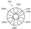
몇몇 실시예들에서, 방사 구조물은 내부 컨덕터에 전기적으로 연결된 제1 전극, 및 외부 컨덕터에 전기적으로 연결된 제2 전극을 포함 할 수 있으며, 제1 전극 및 제2 전극은 유전체 몸체의 표면에 노출된다. 제1 및 제2 전극은 바이폴라 RF 전극으로서 기능할 수 있는데, 예를 들어, RF 에너지가 기구 끝단으로 전달될 때, 각각 활성 및 복귀 전극으로서 기능할 수 있다. 이러한 방식으로, 제1 및 제2 전극 주변 영역에 위치된 생물학적 조직은 RF 에너지로 절제되거나 및/또는 응고될 수 있다. 제1 및 제2 전극은 원하는 치료 프로파일을 얻기 위해 유전체 몸체의 표면 상에 배열될 수 있다. 제1 전극은 유전체 몸체의 한 부분을 통해 연장되는 중간 컨덕터에 의해 내부 컨덕터에 전기적으로 연결될 수 있다. In some embodiments, the radiating structure may include a first electrode electrically connected to the inner conductor, and a second electrode electrically connected to the outer conductor, the first electrode and the second electrode being exposed to the surface of the dielectric body. . The first and second electrodes may function as bipolar RF electrodes, eg, as active and return electrodes, respectively, when RF energy is delivered to the instrument tip. In this way, biological tissue located in the region surrounding the first and second electrodes may be ablated and/or coagulated with RF energy. The first and second electrodes may be arranged on the surface of the dielectric body to obtain a desired treatment profile. The first electrode may be electrically connected to the inner conductor by an intermediate conductor extending through a portion of the dielectric body.
제1 및 제2 전극은 RF 및/또는 마이크로파 주파수로 조직을 치료할 수 있도록 구성될 수 있다. 예를 들어, RF 에너지가 기구 끝단으로 전달 될 때, 제1 및 제2 전극은 바이폴라 RF 전극으로서 기능할 수 있다. 마이크로파 에너지가 기구 끝단으로 전달될 때, 제1 및 제2 전극은 바이폴라 마이크로파 안테나로 기능할 수 있다. 유리하게는, 이는 수술 동안 전기 수술기구를 변경하지 않고도, 사용자가 치료 방식 사이에서(예컨대, RF 응고 및 마이크로파 절제) 빠르게 전환할 수 있도록 한다. The first and second electrodes may be configured to treat tissue with RF and/or microwave frequencies. For example, when RF energy is delivered to the instrument tip, the first and second electrodes may function as bipolar RF electrodes. When microwave energy is delivered to the instrument tip, the first and second electrodes may function as a bipolar microwave antenna. Advantageously, this allows the user to quickly switch between treatment modalities (eg RF coagulation and microwave ablation) without changing electrosurgical instruments during surgery.
몇몇 실시예들에서, 제2 전극은 접지 요소에 의해 외부 컨덕터에 전기적으로 연결될 수 있다. 이러한 방식으로, 중공 바늘 및 제2 전극은 접지 요소에 의해 외부 컨덕터에 전기적으로 연결될 수 있다. 그 결과, 오직 단일의 전기 연결부만 외부 컨덕터에 배열되면 되는데 즉 외부 컨덕터 및 접지 요소 사이에 하나만 배열되면 된다. 이것은 제2 전극을 외부 컨덕터에 전기적으로 연결하는 것을 용이하게 할 수 있다. In some embodiments, the second electrode may be electrically connected to the external conductor by a grounding element. In this way, the hollow needle and the second electrode can be electrically connected to the external conductor by means of a grounding element. As a result, only a single electrical connection need be arranged on the outer conductor, ie only one between the outer conductor and the grounding element. This may facilitate electrically connecting the second electrode to the external conductor.
몇몇 실시예들에서, 유전체 몸체는 제1 전극이 배치된 제1 홈 및 제2 전극이 배치된 제2 홈을 포함할 수 있다. 유전체 몸체의 유전체 재료의 두께는 제1 홈 및 제2 홈 사이에 배치될 수 있으며, 제1 및 제2 전극은 유전체 재료의 두께에 의해 분리된다. 제1 전극의 두께는 제1 홈의 깊이에 상응할 수 있으며, 제1 전극은 유전체 몸체의 외측 표면과 동일한 높이에 배열된다. 이와 유사하게, 제2 전극의 두께는 제2 홈의 깊이에 상응할 수 있으며, 제2 전극은 유전체 몸체의 외측 표면과 동일한 높이에 배열된다. 이것은 기구 끝단에 매끄러운 외측 표면을 제공할 수 있다. 이는 조직에 걸릴 수 있는 기구 끝단의 임의의 날카로운 모서리를 방지할 수 있다. 홈은 유전체 몸체의 외측 표면에 있는 만입부 또는 함몰부일 수 있다. 몇몇 경우들에서, 유전체 몸체의 둘 이상의 부분들 사이에 홈이 형성될 수 있다. In some embodiments, the dielectric body may include a first groove in which a first electrode is disposed and a second groove in which a second electrode is disposed. A thickness of the dielectric material of the dielectric body may be disposed between the first groove and the second groove, the first and second electrodes being separated by a thickness of the dielectric material. The thickness of the first electrode may correspond to the depth of the first groove, and the first electrode is arranged flush with the outer surface of the dielectric body. Similarly, the thickness of the second electrode may correspond to the depth of the second groove, the second electrode being arranged flush with the outer surface of the dielectric body. This can provide a smooth outer surface to the instrument tip. This may prevent any sharp edges of the instrument tip that could get caught in the tissue. The grooves may be indentations or depressions in the outer surface of the dielectric body. In some cases, a groove may be formed between two or more portions of the dielectric body.
몇몇 실시예들에서, 제1 전극은 유전체 몸체 주위에 외주 방향으로 배열된 제1 세트의 종방향으로 연장되는 전도성 핑거를 포함할 수 있다. 제1 전극의 전도성 핑거는 종방향을 따라 배향된 기다란 전도성 요소일 수 있다. 제1 세트의 전도성 핑거 모두는 제1 전극을 형성하기 위해 함께 전기적으로 연결된다. 제1 세트의 전도성 핑거는 실질적으로 평행할 수 있고 유전체 몸체의 외주 주위에 배열될 수 있는데, 예를 들어, 각각의 전도성 핑거는 유전체 몸체의 외주 주위에서 상이한 위치에 있을 수 있다. 예를 들어, 유전체 몸체가 원통형인 경우, 전도성 핑거는 원통형 몸체의 축에 평행할 수 있으며 원통형 몸체의 측면에서 상이한 위치에 배치될 수 있다. 다중 전도성 핑거가 유전체 몸체의 외주 주위에 배열되면, 생물학적 조직이 기구 끝단 주위에서 다중 방향으로 치료될 수 있게 한다. 제1 세트의 전도성 핑거는 유전체 몸체의 외주 주위에 균일하게 이격될 수 있다. 이것은 기구 끝단의 방사 프로파일의 축대칭을 향상시키고 기구 끝단 주위에 배치된 조직의 실질적으로 균일한 치료를 가능하게 한다. 제1 전극의 전도성 핑거는 유전체 몸체의 제1 세트의 홈에 위치될 수 있다. In some embodiments, the first electrode can include a first set of longitudinally extending conductive fingers arranged circumferentially around the dielectric body. The conductive fingers of the first electrode may be elongate conductive elements oriented along the longitudinal direction. All of the conductive fingers of the first set are electrically connected together to form a first electrode. The first set of conductive fingers may be substantially parallel and may be arranged around the perimeter of the dielectric body, eg, each conductive finger may be at a different location around the perimeter of the dielectric body. For example, if the dielectric body is cylindrical, the conductive fingers may be parallel to the axis of the cylindrical body and may be positioned at different positions on the sides of the cylindrical body. Multiple conductive fingers arranged around the perimeter of the dielectric body allow biological tissue to be treated in multiple directions around the instrument tip. The first set of conductive fingers may be evenly spaced around the perimeter of the dielectric body. This improves the axisymmetry of the radial profile of the instrument tip and allows for substantially uniform treatment of tissue disposed around the instrument tip. The conductive fingers of the first electrode may be located in the first set of grooves in the dielectric body.
몇몇 실시예들에서, 제2 전극은 유전체 몸체 주위에 외주 방향으로 배열된 제2 세트의 종방향으로 연장되는 전도성 핑거를 포함할 수 있으며, 제1 세트 및 제2 세트의 전도성 핑거는 유전체 몸체의 외주 주위에 교대로 배열될 수 있다. 제2 전극의 전도성 핑거는 종방향을 따라 배향된 기다란 전도성 요소일 수 있다. 제2 세트의 전도성 핑거 모두는 제1 전극을 형성하기 위해 함께 전기적으로 연결된다. 제2 세트의 전도성 핑거는 실질적으로 평행할 수 있고, 유전체 몸체의 외주 주위에 배열 될 수 있는데, 예를 들어, 각각의 전도성 핑거는 유전체 몸체의 외주 주위에서 상이한 위치에 있을 수 있다. 제2 전극의 전도성 핑거는 유전체 몸체의 제2 세트의 홈에 위치될 수 있다. 제1 세트의 홈 및 제2 세트의 홈은 유전체 몸체의 부분들에 의해 분리될 수 있으며, 제1 전극 및 제2 전극의 전도성 핑거는 유전체 몸체에 의해 서로 전기적으로 분리된다. In some embodiments, the second electrode may include a second set of longitudinally extending conductive fingers arranged circumferentially around the dielectric body, the first set and the second set of conductive fingers being the first and second sets of conductive fingers. They may be alternately arranged around the periphery. The conductive fingers of the second electrode may be elongate conductive elements oriented along the longitudinal direction. All of the conductive fingers of the second set are electrically connected together to form the first electrode. The second set of conductive fingers may be substantially parallel and may be arranged around the perimeter of the dielectric body, eg, each conductive finger may be at a different location around the perimeter of the dielectric body. The conductive fingers of the second electrode may be located in a second set of grooves in the dielectric body. The first set of grooves and the second set of grooves may be separated by portions of the dielectric body, and the conductive fingers of the first electrode and the second electrode are electrically isolated from each other by the dielectric body.
제1 및 제2 세트의 전도성 핑거는 유전체 몸체의 외주 주위에 교대로 배열될 수 있는데, 예를 들어, 전도성 핑거는 외주 주위에서 제1 세트 및 제2 세트 사이를 번갈아 배열되도록 주문될 수 있다. 이러한 방식으로, 각각의 제1 세트의 전도성 핑거는 제2 세트의 두 전도성 핑거 사이에 위치될 수 있다(반대의 경우도 마찬가지이다). 따라서, 제1 및 제2 전극은 서로 맞물린 전극일 수 있다. 이 구성은 기구 끝단 주위에 실질적으로 균일한 방사 프로파일을 제공하도록 할 수 있다. 이것은, 예를 들어, 조직이 기구 끝단 주위의 용적에서 균일하게 절제되거나 응고될 수 있게 한다. The first and second sets of conductive fingers may be alternately arranged around the perimeter of the dielectric body, for example, the conductive fingers may be ordered to alternate between the first and second sets around the perimeter. In this way, each first set of conductive fingers can be positioned between two conductive fingers of a second set (and vice versa). Accordingly, the first and second electrodes may be interdigitated electrodes. This configuration may be adapted to provide a substantially uniform radiation profile around the instrument tip. This allows, for example, tissue to be uniformly ablated or coagulated in a volume around the instrument tip.
몇몇 실시예들에서, 기구 끝단은 외부 컨덕터에 전기적으로 연결된 환형 컨덕터를 추가로 포함할 수 있고, 환형 컨덕터는 전기 수술기구의 외측 표면의 한 부분을 형성하고 동축 공급 케이블 및 방사 구조물 사이의 전기 연결부를 차폐한다. 환형 컨덕터는 전도성 재료의 중공의 원통형 부분일 수 있다. 환형 컨덕터는 동축 공급 케이블 및 방사 구조물 사이의 이음부 주변에서 기구 끝단의 한 근위 단부 근처에 배치될 수 있다. 동축 공급 케이블 및 방사 구조물 사이의 전기 연결부는 방사 구조물의 전도성 요소(예를 들어, 기다란 컨덕터) 및 내부 컨덕터 사이에 전기 연결부를 포함할 수 있다. 이러한 전기 연결부는 내부 컨덕터 및 방사 구조물 사이에 차폐되지 않은 와이어의 길이를 포함할 수 있다. 이러한 길이의 차폐되지 않은 와이어는 전기 간섭에 취약할 수 있다. 환형 컨덕터가 외부 컨덕터에 전기적으로 연결되기 때문에, 전기 간섭으로부터 환형 컨덕터 내부에 위치된 임의의 배선 또는 전기 연결부를 차폐하도록 제공될 수 있다. 따라서, 환형 컨덕터는 기구 끝단의 성능을 향상시키기 위해 동축 공급 케이블 및 방사 구조물 사이의 이음부에서 간섭을 줄일 수 있다. 환형 컨덕터는 또한 연결부 주위에 배리어(barrier)를 제공함으로써 동축 공급 케이블 및 방사 구조물 사이의 연결을 물리적으로 보호하도록 제공될 수 있다. 환형 컨덕터는 접지 요소에 의해 외부 컨덕터에 전기적으로 연결될 수 있다. In some embodiments, the instrument tip may further include an annular conductor electrically connected to the outer conductor, the annular conductor forming a portion of the outer surface of the electrosurgical instrument and an electrical connection between the coaxial supply cable and the radiating structure to shield The annular conductor may be a hollow cylindrical portion of a conductive material. An annular conductor may be disposed near one proximal end of the instrument end around the joint between the coaxial supply cable and the radiating structure. The electrical connection between the coaxial supply cable and the radiating structure may include an electrical connection between the inner conductor and a conductive element (eg, an elongated conductor) of the radiating structure. This electrical connection may include a length of unshielded wire between the inner conductor and the radiating structure. Unshielded wires of this length can be susceptible to electrical interference. Since the annular conductor is electrically connected to the outer conductor, it can be provided to shield any wiring or electrical connection located inside the annular conductor from electrical interference. Thus, the annular conductor can reduce interference at the joint between the coaxial supply cable and the radiating structure to improve the performance of the instrument end. Annular conductors may also be provided to physically protect the connection between the coaxial supply cable and the radiating structure by providing a barrier around the connection. The annular conductor may be electrically connected to the external conductor by a grounding element.
몇몇 경우들에서, 환형 컨덕터는 RF 에너지를 위한 복귀 전극을 구성할 수 있다. 기구 끝단이 유전체 몸체의 표면에 제1 및 제2 전극을 포함하는 경우, 환형 컨덕터는 제2 전극의 연장부를 구성할 수 있다. 이는 제2 전극의 유효 면적을 증가시키도록 제공될 수 있다. 몇몇 경우들에서, 환형 컨덕터는 제2 전극의 근위 부분일 수 있다. In some cases, the annular conductor may constitute a return electrode for RF energy. Where the instrument tip includes first and second electrodes on the surface of the dielectric body, the annular conductor may constitute an extension of the second electrode. This may serve to increase the effective area of the second electrode. In some cases, the annular conductor may be a proximal portion of the second electrode.
몇몇 실시예들에서, 기구 끝단의 한 원위 단부가 표적 영역에 압력 스폿(pressure spot)을 제공하기에 적합하도록 매끄럽게 윤곽진(smoothly contoured) 방식으로 형성될 수 있다. 예를 들어, 기구 끝단의 원위 단부는 둥글거나 및/또는 매끄럽게 테이퍼 형태로 형성될 수 있다. 이는 출혈을 막기 위해(예컨대, 지혈) 기구 끝단을 표적 부위에 대고 누를 수 있다. EM 에너지는 조직을 응고시키고 출혈을 멈추거나 제어하기 위해 기구 끝단에 의해 전달될 수 있다. In some embodiments, one distal end of the instrument tip may be formed in a smoothly contoured manner to be suitable for providing a pressure spot in the target area. For example, the distal end of the instrument tip may be rounded and/or smoothly tapered. This can be done by pressing the tip of the instrument against the target site to stop bleeding (eg, hemostasis). EM energy can be delivered by the instrument tip to coagulate tissue and stop or control bleeding.
위에서 논의된 전기 수술기구는 완전한 전기 수술 시스템의 일부를 형성할 수 있다. 예를 들어, 본 시스템은, 마이크로파 에너지 및 고주파 에너지를 공급하도록 배열된 전기 수술 제너레이터; 및 전기 수술 제너레이터로부터 마이크로파 에너지 및 고주파 에너지를 수용하도록 연결된 본 발명의 전기 수술기구를 포함할 수 있다. 전기 수술기구는 환자의 신체에 삽입하기 위한 가요성 삽입 코드를 갖는 수술용 검사 장치(예컨대, 내시경)를 추가로 포함할 수 있으며, 가요성 삽입 코드는 그 길이를 따라 배열된 기구 채널을 가지고, 전기 수술기구는 기구 채널 내에 끼워맞춤 되도록 수치가 정해진다. The electrosurgical instruments discussed above may form part of a complete electrosurgical system. For example, the system may include an electrosurgical generator arranged to supply microwave energy and high frequency energy; and an electrosurgical instrument of the present invention coupled to receive microwave energy and high frequency energy from the electrosurgical generator. The electrosurgical instrument may further include a surgical examination device (eg, an endoscope) having a flexible insertion cord for insertion into the body of a patient, the flexible insertion cord having an instrument channel arranged along its length; The electrosurgical instrument is dimensioned to fit within the instrument channel.
본 명세서에서, "마이크로파"는 400 MHz 내지 100 GHz의 주파수 범위, 바람직하게는 1 GHz 내지 60 GHz의 범위를 나타내기 위해 광범위하게 사용될 수 있다. 마이크로파 EM 에너지를 위해 바람직한 스폿 주파수는 915 MHz, 2.45 GHz, 3.3 GHz, 5.8 GHz, 10 GHz, 14.5 GHz 및 24 GHz를 포함한다. 5.8GHz가 바람직할 수 있다. 반대로, 본 명세서에서는, 최소 3배 더 낮은 주파수, 예컨대, 최대 300 MHz의 주파수 범위를 나타내기 위하여 "고주파" 또는 "RF"를 사용한다. 바람직하게는, RF 에너지는 신경 자극을 방지하기에 충분히 높은(예컨대, 10 kHz 이상) 주파수, 및 조직 블랜칭(blanching) 또는 열 확산을 방지하기에 충분히 낮은(예컨대, 10 MHz 이하) 주파수를 갖는다. RF 에너지를 위한 바람직한 주파수 범위는 100 kHz 내지 1 MHz 사이일 수 있다. In the present specification, "microwave" may be used broadly to denote the frequency range of 400 MHz to 100 GHz, preferably the range of 1 GHz to 60 GHz. Preferred spot frequencies for microwave EM energy include 915 MHz, 2.45 GHz, 3.3 GHz, 5.8 GHz, 10 GHz, 14.5 GHz and 24 GHz. 5.8 GHz may be desirable. Conversely, in this specification, "high frequency" or "RF" is used to refer to a frequency range of at least three times lower frequency, eg, up to 300 MHz. Preferably, the RF energy has a frequency high enough to prevent nerve stimulation (eg, greater than 10 kHz) and a frequency low enough to prevent tissue blanching or thermal spread (eg, less than or equal to 10 MHz). . A preferred frequency range for RF energy may be between 100 kHz and 1 MHz.
본 명세서에서, 용어 "근위(proximal)" 및 "원위(distal)"는 전기 수술기구의 단부들이 각각 치료 부위로부터 멀어지도록 위치되고 가까워지도록 위치되는 것을 의미한다. 따라서, 사용 시에, 전기 수술기구의 근위 단부는 RF 및/또는 마이크로파 에너지를 제공하기 위해 제너레이터에 가까이 위치되고, 원위 단부는 치료 부위 즉 환자의 표적 조직에 가깝게 위치된다. As used herein, the terms “proximal” and “distal” mean that the ends of the electrosurgical instrument are positioned away from and close to the treatment site, respectively. Thus, in use, the proximal end of the electrosurgical instrument is positioned proximate to the generator to provide RF and/or microwave energy, and the distal end is positioned proximate to the treatment site, i.
본 명세서에서, 용어 "전도성(conductive)"은, 그 외에 달리 지시되지 않는 한, 전기적으로 전도적인 것을 의미한다. As used herein, the term “conductive” means electrically conductive, unless otherwise indicated.
아래에 사용된 용어 "종방향(longitudinal)"은 동축 전송 라인의 축에 평행한 전기 수술기구의 길이를 따른 방향을 나타낸다. 용어 "내부(inner)"는 기구의 중심(예컨대, 축)에 반경 방향으로 가까운 것을 의미한다. 용어 "외부(outer)"는 기구의 중심(축)으로부터 반경 방향으로 먼 것을 의미한다. As used below, the term "longitudinal" refers to a direction along the length of the electrosurgical instrument parallel to the axis of the coaxial transmission line. The term “inner” means radially close to the center (eg, axis) of the instrument. The term “outer” means radially away from the center (axis) of the instrument.
용어 "전기 수술(electrosurgical)"은 수술 동안에 사용되며 마이크로파 및/또는 고주파 전자기(EM) 에너지를 사용하는 기구, 장치 또는 도구에 관해 사용된다. The term “electrosurgical” is used during surgery and is used in reference to instruments, devices or instruments that use microwave and/or high frequency electromagnetic (EM) energy.
이제, 본 발명의 실시예들은 밑에서 첨부도면들을 참조하여 예로서 기술될 것이다:
도 1은 본 발명의 한 실시예인 전기 수술 시스템의 개략적인 다이어그램;
도 2는 본 발명의 한 실시예인 전기 수술기구의 투시도로서, 상기 기구의 중공 바늘은 철회된 위치에 있고;
도 3은 도 2의 전기 수술기구의 투시도로서, 중공 바늘은 노출된 위치에 있으며;
도 4는 도 2의 전기 수술기구의 개략적인 횡단면도;
도 5는 도 2의 전기 수술기구의 투시도로서, 상기 기구의 가요성 기구 슬리브는 기구의 내부 구조를 보여주기 위해 생략되었으며;
도 6-8은 상이한 위치에 있는 중공 바늘을 보여주는 도 2의 전기 수술기구의 개략적인 횡단면도;
도 9a 및 9b는 본 발명의 한 실시예인 전기 수술기구에서 사용될 수 있는 접지 요소의 투시도; 도 10a는 본 발명의 한 실시예인 전기 수술기구에서 사용될 수 있는 유전체 몸체의 전면도;
도 10b는 도 10a의 유전체 몸체의 투시도. Now, embodiments of the present invention will be described below by way of example with reference to the accompanying drawings:
1 is a schematic diagram of an electrosurgical system that is one embodiment of the present invention;
Fig. 2 is a perspective view of an electrosurgical instrument in one embodiment of the present invention, the hollow needle of the instrument in a retracted position;
Fig. 3 is a perspective view of the electrosurgical instrument of Fig. 2, with the hollow needle in an exposed position;
Fig. 4 is a schematic cross-sectional view of the electrosurgical instrument of Fig. 2;
Fig. 5 is a perspective view of the electrosurgical instrument of Fig. 2, wherein the instrument's flexible instrument sleeve is omitted to show the internal structure of the instrument;
6-8 are schematic cross-sectional views of the electrosurgical instrument of FIG. 2 showing the hollow needle in different positions;
9A and 9B are perspective views of a grounding element that may be used in an electrosurgical instrument that is one embodiment of the present invention; 10A is a front view of a dielectric body that may be used in an electrosurgical instrument according to an embodiment of the present invention;
Fig. 10B is a perspective view of the dielectric body of Fig. 10A;
도 1은 침습 전기 수술기구의 원위 단부에 마이크로파 에너지 및 고주파 에너지를 공급할 수 있는 완전한 전기 수술 시스템(100)의 개략적인 다이어그램이다. 시스템(100)은 마이크로파 및 고주파 에너지를 제어 가능하게 공급하기 위한 제너레이터(102)를 포함한다. 이를 위해 적절한 제너레이터가 WO 2012/076844에 기술되어 있는데, 상기 국제출원은 본 명세서에서 참조문헌으로 통합된다. 제너레이터는 전달을 위한 적절한 전력 레벨을 결정하기 위하여 기구로부터 수용된 반사 신호를 모니터링 하도록 배열될 수 있다. 예를 들어, 제너레이터는 최적의 전달 전력 레벨을 결정하기 위하여 제너레이터의 원위 단부에서 볼 수 있는 임피던스를 계산하도록 배열될 수 있다. 제너레이터(102)는 인터페이스 케이블(104)에 의해 인터페이스 조인트(106)에 연결된다. 1 is a schematic diagram of a
시스템(100)은 또한 전기 수술기구와 함께 사용하기 위한 유체를 함유하는 유체 공급 유닛(108)을 포함한다. 유체는 액체(예컨대, 액체 약물) 또는 가스(예컨대, 아르곤 가스)일 수 있다. 유체 공급 유닛(108)은 유체 도관(109)에 의해 인터페이스 조인트(106)에 유체적으로 연결된다. 유체 공급 유닛(108)은 유체 도관(109)에 의해 내부에 함유된 유체를 분배할 수 있다. 예를 들어, 유체 공급 유닛(108)은 액체 약물을 분배하기 위한 주사기를 포함할 수 있다.
인터페이스 조인트(106)는, 예컨대, 하나 이상의 제어 와이어 또는 푸시로드(미도시)의 종방향(앞뒤) 운동을 조절하기 위하여, 트리거(110)를 슬라이딩 이동시킴으로써 작동 가능한 기구 제어 메커니즘을 수용한다. 복수의 제어 와이어가 있는 경우에는, 완전한 제어를 위해 인터페이스 조인트 상에 다수의 슬라이딩 트리거가 있을 수 있다. 인터페이스 조인트(106)의 기능은, 제너레이터(102), 유체 공급 유닛(108) 및 기구 제어 메커니즘으로부터의 입력을 인터페이스 조인트(106)의 원위 단부로부터 연장되는 단일의 가요성 샤프트(112)에 결합하는 것이다. 그 밖의 다른 실시예들에서, 다른 타입의 입력도 인터페이스 조인트(106)에 연결될 수 있다. The
가요성 샤프트(112)는 내시경(114)의 기구(작업) 채널의 전체 길이를 통해 삽입될 수 있다. 가요성 샤프트(112)는 내시경(114)의 기구 채널을 통과하고 내시경의 기구 채널의 원위 단부에서 돌출되도록(예를 들어, 환자 내부로) 형상화된 원위 조립체(118)(도 1에서 실측으로 도시되지 않음)를 가진다. 원위 단부 조립체(118)는 마이크로파 에너지 및 고주파 에너지를 생물학적 조직 내에 전달하기 위한 기구 끝단을 포함한다. 또한, 끝단은 유체 공급 유닛(108)으로부터 유체를 전달하도록 구성된다. 끝단 구성은 아래에서 더 자세히 논의된다. The
원위 조립체(118)의 구조는 작업 채널을 통과하기에 적합한 최대 외측 직경을 갖도록 배열 될 수 있다. 일반적으로, 내시경과 같은 수술용 검사 장치에서 작업 채널의 직경은 4.0mm 미만, 예컨대, 2.8mm, 3.2mm, 3.7mm, 3.8mm 중 임의의 하나이다. 가요성 샤프트(112)의 길이는 0.3m 또는 그 이상, 예를 들어, 2m 또는 그 이상일 수 있다. 그 밖의 다른 예에서, 원위 조립체(118)는 샤프트가 작업 채널을 통해 삽입된 후에(및 기구 코드가 환자에게 삽입되기 전에) 가요성 샤프트(112)의 원위 단부에 장착될 수 있다. 대안으로, 가요성 샤프트(112)는 근위 연결을 형성하기 전에 원위 단부로부터 작업 채널 내로 삽입될 수 있다. 이러한 배열에서, 원위 단부 조립체(118)는 수술용 검사 장치(114)의 작업 채널보다 큰 수치를 가질 수 있다. The structure of the
위에서 설명한 시스템은 기구를 환자의 신체에 삽입하는 한 가지 방법이다. 그 밖의 다른 기술도 가능하다. 예를 들어, 기구는 카테터를 사용하여 삽입될 수 있다. The system described above is one way to insert an instrument into a patient's body. Other techniques are possible. For example, the instrument may be inserted using a catheter.
도 2는 본 발명의 한 실시예인 전기 수술기구(200)의 한 원위 단부의 투시도를 도시한다. 전기 수술기구(200)의 원위 단부는, 예를 들어, 위에서 논의된 원위 조립체(118)에 상응할 수 있다. 도 3은 전기 수술기구(200)의 또 다른 투시도를 도시한다. 도 4는 전기 수술기구(200)의 한 횡단면 측면도를 도시한다. 도 5는 전기 수술기구(200)의 한 투시도를 도시하며, 기구의 가요성 기구 슬리브가 기구의 내부 구조를 나타내기 위해 생략되었다. 2 shows a perspective view of one distal end of an
전기 수술기구(200)는 마이크로파 에너지 및 RF 에너지를 전달하기 위해 그 근위 단부로부터 제너레이터(가령, 제너레이터(102))에 연결가능한 동축 공급 케이블(202)을 포함한다. 동축 공급 케이블(202)은 유전체 재료(208)에 의해 분리된 내부 컨덕터(204) 및 외부 컨덕터(206)를 포함한다. 동축 공급 케이블(202)은 바람직하게는 마이크로파 에너지에 대해 저손실이다. 원위 단부로부터 반사된 마이크로파 에너지의 역 전파를 억제하고 따라서 장치를 따라 역방향 가열을 제한하기 위하여, 초크(미도시)가 동축 공급 케이블(204)에 제공될 수 있다. 동축 공급 케이블(202)을 절연하고 보호하기 위해, 절연 코팅(209)이 외부 컨덕터(206)의 외측 표면에 제공된다. The
전기 수술기구(200)는 동축 공급 케이블(202)을 따라 연장되는 유체 채널(210)을 추가로 포함한다. 유체 채널(210)은 기구의 근위 단부로부터 기구의 원위 단부로 유체를 전달하도록 제공될 수 있다. 예를 들어, 유체 채널(210)의 한 근위 단부가 유체 공급 유닛(108)에 연결될 수 있다. 동축 공급 케이블(202) 및 유체 채널(210)은 모두 가요성기구 슬리브(212) 내에 수용된다. 가요성 기구 슬리브(212)는 조직이 슬리브에 들러 붙는 것을 방지하기 위해 생체적합성 비-점착성 재료(예컨대, PTFE)로 제조되거나 또는 이 재료로 코팅될 수 있다. The
전기 수술기구(200)는 동축 공급 케이블(202)의 한 원위 단부에 위치된 기구 끝단(214)을 포함한다. 기구 끝단(214)은 절연 재료(예를 들어, PEEK)로 제조된 유전체 몸체(216)를 포함한다. 유전체 몸체(216)는 외측 표면에 형성된 방사 구조물(radiating structure)를 가지며, 상기 방사 구조물은 내부 전극(218) 및 외부 전극(220)을 포함한다. 내부 전극(218)은 전기 연결부(222)에 의해 동축 공급 케이블(202)의 내부 컨덕터(204)에 전기적으로 연결된다(도 4 참조). 내부 컨덕터(204)의 구조는 분리된 유전체 몸체(216)를 도시한 도 10a 및 10b를 참조하여 아래에서 더 상세히 논의된다. 전기 연결부(222)는, 예를 들어, 납땜 또는 용접된 전기 연결부 일 수 있거나, 혹은 전도성 접착제(예를 들어, 전도성 에폭시)를 사용하여 형성될 수 있다. 내부 컨덕터(204) 및 내부 전극(218) 사이의 전기 연결부(222)는, 예를 들어, 포팅될 수 있는데(potted), 예컨대, 보호를 위해 고체 또는 젤라틴화 화합물에 둘러싸일 수 있다. The
기구 끝단(214)은 기구 끝단(214)의 근위 단부 근처에 위치된 접지 요소(224)를 추가로 포함한다. 접지 요소(224)는 전도성 재료(예를 들어, 금속)로 제조되고 단일 구성요소로 형성될 수 있다. 접지 요소(224)의 구조는 접지 요소(224)의 투시도를 도시하는 도 9a 및 9b에 더 상세히 예시되어 있다. 종방향으로 연장되는 제1 채널(226) 및 제2 채널(228)이 접지 요소(224)에 형성된다. 제1 채널(226)은 폐쇄 채널이며, 아래에 기술된 것과 같이 중공 바늘을 수용하도록 구성된다. 제2 채널(228)은 개방 채널, 즉 접지 요소(224)의 외측 표면 의 홈에 의해 형성된다. 동축 공급 케이블(202)의 한 원위 부분이 접지 요소(224)의 제2 채널(228)에 고정된다. 제2 채널(228)의 형태는 동축 공급 케이블(202)의 원위 부분의 형태에 대해 상호보완적 이다. 제2 채널(229)은 동축 공급 케이블(202)을 고정하도록(예를 들어, 억지 끼워맞춤에 의해) 형상화될 수 있다. 몇몇 경우들에서, 외부 컨덕터(206)는 예컨대, 전도성 에폭시를 사용하여 접지 요소(224)에 고정될 수 있다.
절연 코팅(209)은 접지 요소(224)의 제2 채널(228)에 고정되는 동축 케이블(202)의 원위 부분으로부터 벗겨진다. 이러한 방식으로, 동축 공급 케이블(202)의 원위 부분에 있는 외부 컨덕터(206)는 노출되며, 접지 요소(224)의 제2 채널(228)의 한 표면과 전기적으로 접촉된다. 이러한 방식으로, 외부 컨덕터(206)는 접지 요소(224)에 전기적으로 연결된다. The insulating
제2 전극(220)은 기구 끝단(214)의 근위 단부를 향해 연장되는 근위 부분(230)을 포함한다. 근위 부분(230)은 동축 공급 케이블(202)의 원위 부분 및 접지 요소(224) 주위에 배치되는 원통형 중공 컨덕터에 의해 형성된다. 근위 부분(230)은 외부 컨덕터(206)의 노출된 부분 및 접지 요소(224)의 외측 표면과 전기적으로 접촉된다. 이러한 방식으로, 제2 전극(220)은 외부 컨덕터(206)에 전기적으로 연결된다. 제2 전극(220)의 근위 부분(230)은 접지 요소(224) 및 외부 컨덕터(206) 사이의 전기 연결이 유지되도록 하기 위해 접지 요소(224)에 대해 외부 컨덕터(206)를 고정하도록 제공될 수 있다. 접지 요소(224)는 제2 전극(220)의 근위 부분(230)이 접하는 립(232)을 포함한다. 이는 근위 부분(230) 및 접지 요소의 상대적 위치를 유지하도록 제공될 수 있다. 외부 전극(220)의 근위 부분(230)은 외부 컨덕터(206) 및/또는 접지 요소에 납땜될 수 있거나, 혹은 그 밖의 다른 수단(예컨대, 전도성 에폭시)을 사용하여 고정될 수 있다. The
기구 끝단은 외부 전극(220)의 근위 부분(230) 주위에 배치된 외부 환형 컨덕터(231)를 추가로 포함한다. 환형 컨덕터(231)는 전도성 재료의 중공 원통형 부분이다. 환형 컨덕터(231)는 외부 전극(220)의 근위 부분(230)에 전기적으로 연결된다. 환형 컨덕터(231)는 내부 컨덕터(204) 및 내부 전극(218) 사이의 전기 연결부(222)를 차폐하도록 배열된다. 따라서, 환형 컨덕터(231)는 전기 연결부(222)를 전기적 간섭으로부터 보호할 뿐만 아니라 전기 연결부를 물리적 손상으로부터 보호할 수 있다. The instrument tip further includes an outer
바늘 통로가 유체 채널(210)과 유체 연통하는 중공 바늘(234)을 수용하기 위해 기구 끝단(214)에 형성된다. 중공 바늘(234)은 도 6-8에 관해 아래에서 논의되는 바와 같이 바늘 통로를 통해 기구 끝단(214)에 대해 이동될 수 있다. 예시를 위해, 중공 바늘(234)은도 4에서 생략되었다. A needle passageway is formed in the
바늘 통로는 기구 끝단(214)의 다중 구성요소에 의해 형성된다. 그 근위 단부에서, 바늘 통로는 접지 요소(224)의 제1 채널(226)에 의해 형성된다. 제1 채널(226)은 근위 단부에서 플레어형 부분(236)을 포함한다. 플레어형 부분(236)은 외부를 향해 플레어 형태로 형성되는데, 즉 플레어형 부분(236)의 횡단면적이 제1 채널(226)의 근위 단부를 향해 증가된다. 플레어형 부분(236)은 중공 바늘(234)을 제1 채널(226)로 안내하도록(예를 들어, 편향하거나 또는 깔때기 형태로 삽입하도록) 제공될 수 있다. 제1 절연 슬리브(238)가 제1 채널(226)로부터 근위 방향으로 유체 채널(210)을 향해 연장된다. 제1 절연 슬리브(238)는 중공 바늘(234)을 접지 요소(224)를 향해 제1 채널(226)로 안내하도록 제공될 수 있다. 제1 채널(226)은 접촉부(240)를 추가로 포함한다. 제1 채널(226)의 접촉부(238)는 중공 바늘(234)의 횡단면과 실질적으로 일치하는 횡단면을 갖는데 즉, 접촉부(238)의 형태는 중공 바늘(234)의 형태에 상호보완적 일 수 있다. 이러한 방식으로, 중공 바늘(234)이 제1 채널(226)의 접촉부(240)를 통해 연장될 때, 중공 바늘(234) 및 접지 요소(224) 사이에 전기적 접촉을 형성하기 위해 중공 바늘(234)은 제1 채널(226)의 한 표면(예를 들어, 제1 채널(226)의 한 벽)과 접촉할 수 있다. 이는 외부 컨덕터(206)에 연결된 중공 바늘(234)을 단락시키도록 제공될 수 있다. 외부 컨덕터(206)는 일반적으로 접지될 수 있으며(예를 들어, 0V 일 수 있음), 그에 따라 중공 바늘(234)도 제1 채널(226)에 있을 때 접지될 수 있다. The needle passageway is defined by multiple components of the
바늘 통로는 제1 채널(226)의 원위 단부로부터 연장하는 제2 절연 슬리브(242)를 추가로 포함한다. 제2 절연 슬리브(242)는 원위 끝단(214)을 통해 원위 끝단(214)의 원위 단부에 있는 개구(244)로 연장된다. 제2 절연 슬리브(242)는 유전체 몸체(216)에서 채널(246)을 통과한다. 제2 절연 슬리브(242)는 내부 전극(218)으로부터 중공 바늘(234)을 전기적으로 분리시키도록 제공된다. The needle passageway further includes a second
제2 절연 슬리브(242)의 횡단면은 제1 절연 슬리브(238)의 횡단면보다 작다. 제2 절연 슬리브(238)의 횡단면은제1 채널(226)의 접촉부(238)의 횡단면과 거의 동일한 크기이다. 이는, 기구 끝단(214)을 통해 이동할 때, 중공 바늘(234)의 정확한 위치를 보장하도록 제공될 수 있다. 제2 절연 슬리브(242)와 비교하여, 제1 절연 슬리브(238)를 위해 더 큰 횡단면을 사용함으로써,(예를 들어, 중공 바늘(234) 및 절연 슬리브 사이의 마찰로 인해) 중공 바늘(234)이 바늘 통로를 따라 이동하는 데 대한 저항이 감소될 수 있다. 이는 기구 끝단(214)에 대한 중공 바늘(234)의 이동을 용이하게 할 수 있다. The cross section of the second
중공 바늘(234)은 유체 채널(210)과 유체 연통한다. 중공 바늘(234)은 유체 채널의 한 원위 단부로부터 기구 끝단(214)을 향해 연장된다. 중공 바늘(234)을 조직 내에 용이하게 삽입하기 위하여, 중공 바늘(234)의 한 원위 끝단(248)이 뾰족하게 형성된다. 중공 바늘(234)은 유체를 조직에 주입하기에 적절한 재료, 가령, 예컨대, 스테인리스 스틸로 제조된 중공 튜브일 수 있다. 예를 들어, 중공 바늘(234)은 피하주사 바늘일 수 있다. 중공 바늘(234)의 한 근위 부분이 유체 채널(210)의 원위 부분에 수용되며, 유체 채널(210)에 의해 전달된 유체는 중공 바늘(234)로 흐를 수 있다. 유체가 누출되는 것을 방지하기 위해, 유체 채널(210) 및 중공 바늘(234) 사이에 밀봉부가 형성될 수 있다. The
도 6 내지 8은 중공 바늘(234)이 상이한 위치에 있는 전기 수술기구(200)의 횡단면 측면도를 도시한다. 도 6에서, 중공 바늘은 원위 끝단(248)이 제1 절연 슬리브(238) 내부에 위치되도록 제1 철회된 위치에 있다. 도 7에서, 중공 바늘(234)은 제2 철회된 위치에 있으며, 원위 끝단(248)은 제2 절연 슬리브(242) 내부에 위치하여 원위 끝단(214)에서 개구(244)를 통해 돌출되지 않는다. 도 8에서, 중공 바늘(234)은 노출된 위치에 있으며, 원위 끝단(248)은 개구(244)를 통해 돌출되고, 중공 바늘(234)의 원위 부분은 기구 끝단(214)을 넘어 연장된다. 6-8 show cross-sectional side views of the
중공 바늘(234)은 임의의 적절한 수단에 의해 도 6-8에 예시된 위치들 사이에서 이동될 수 있다. 예를 들어, 중공 바늘(234)은 유체 채널(210)을 통해 기구(200)의 근위 단부로 연장되는 제어 와이어(미도시)를 사용하여 이동될 수 있다. The
중공 바늘(234)이 제1 철회된 위치에 있을 때(도 6), 중공 바늘은 기구 끝단(214)으로부터 완전히 철회되는데 즉 기구 끝단(214)에 위치되지 않는다. 이 형상에서, 중공 바늘(234)은 외부 커넥터(206)에 전기적으로 연결되지 않는다. 중공 바늘(234)이 기구 끝단(214)으로부터 완전히 철회될 때, 중공 바늘(234)은 기구 끝단에서 방출되는(즉, 내부 및 외부 전극(218, 220)에 의해) 마이크로파 에너지와 방해되지 않는다. When the
중공 바늘(234)이 제2 철회된 위치에 있을 때(도 7), 중공 바늘(234)의 원위 끝단(248)은 기구 끝단(214)에 위치된다. 이 형상에서, 중공 바늘(234)의 한 부분이 접지 요소(224)의 제1 채널(226)의 접촉부(240) 내에 수용된다. 이러한 방식으로, 중공 바늘(234)은 접촉부(240)에서 접지 요소(224)에 전기적으로 연결된다. 그 결과, 중공 바늘(234)은 접지 요소(224)에 의해 동축 공급 케이블(202)의 외부 컨덕터(206)에 전기적으로 연결된다. 이는 기구 끝단(214)에 의해 방사된 EM 에너지로(즉, 내부 및 외부 전극(218, 220)에 의해) 중공 바늘(234)의 간섭을 감소하거나 방지할 수 있다. When the
중공 바늘(234)이 노출된 위치에 있을 때(도 8), 중공 바늘(234)은 기구 끝단(214)에서 개구(244)를 통해 돌출한다. 이 형상에서, 중공 바늘(234)은 유체를 유체 도관(210)으로부터 치료 부위에 분배하도록 사용될 수 있다. 예를 들어, 액체 약물을 표적 조직에 주입하기 위하여 중공 바늘(234)의 뾰족한 원위 끝단(248)이 표적 조직에 삽입될 수 있다. 제2 철회된 위치와 유사하게, 중공 바늘(234)의 한 부분이 접지 요소(224)의 제1 채널(226)의 접촉부(240)에 수용된다. 그 결과, 중공 바늘(234)은 접지 요소(224)에 의해 동축 공급 케이블(202)의 외부 컨덕터(206)에 전기적으로 연결되며, 이에 따라 중공 바늘(234)에 의해 야기되는 간섭을 감소시킬 수 있다. 따라서, 중공 바늘(234)이 제1 철회된 위치, 제2 철회된 위치 또는 노출된 위치에 있는지에 상관없이, 중공 바늘(234)이 방사된 EM 에너지와 간섭되는 것을 피할 수 있다. When the
따라서, 제1 채널(226)의 접촉부(240) 및 중공 바늘(234) 사이에 형성된 전기적 접촉은 바늘과 접지 요소 사이의 슬라이딩 인터페이스에 있을 수 있는데 즉 중공 바늘(234) 및 접지 요소(224) 사이가 전기적 접촉을 유지하는 동안 중공 바늘(234)은 제1 채널(226)을 통해 이동될 수 있다. Accordingly, the electrical contact formed between the
접지 요소(224)는, 중공 바늘이 제2 철회된 위치 및/또는 노출된 위치에 있을 때, 중공 바늘(234)의 원위 끝단(248)으로부터 이격된 정수 개수의 반 파장(전달된 마이크로파 에너지의)이 되도록, 기구 끝단(214)에 위치될 수 있다. 이는, 마이크로파 주파수에서, 중공 바늘(234)의 원위 끝단(248)과 제1 채널(226)의 중공 바늘(234)의 일부가 동일한 전압(즉, 외부 컨덕터(206)의 전압)에 있음을 보장할 수 있다. 예를 들어, 5.8GHz의 마이크로파 에너지 주파수의 경우, 마이크로파 에너지의 1/4 파장이 약 12.9mm 일 수 있다(도파관이 언로드 되었다고 가정). 중공 바늘(234)이 원위 끝단(248)으로부터 2 × 12.9 mm 이격된 접지(예를 들어, 0V)로 단락되면, 원위 끝단(248)도 접지로 단락될 수 있다. 따라서, 이 예에서, 접지 요소(224)는, 중공 바늘(234)이 노출된 위치에 있을 때, 중공 바늘(234)의 원위 끝단(248)으로부터 약 2 × 12.9 mm = 25.8 mm 이격되어 배치될 수 있다. 바늘의 이동 거리는, 접지 요소(224)에 대한 전기 연결부가 철회된 위치 및 노출된 위치 모두에서 원위 끝단으로부터 마이크로파 에너지의 다중 반파장이 되도록, 설정될 수 있다. The
도 10a는 기구 끝단(214)의 유전체 몸체(216)의 정면도를 도시한다. 도 10b는 기구 끝단(214)의 유전체 몸체(216)의 투시도를 도시한다. 유전체 몸체(216)는 일체형의 절연 재료(예컨대, PEEK)로 형성된다. 유전체 몸체(216)는 내부 전극(218)이 형성되는 제1 세트의 홈(250a, 250b, 250c) 및 외부 전극(220)이 형성되는 제2 세트의 홈(252a, 252b, 252c)을 포함한다. 제1 세트의 홈(250a-c) 및 제2 세트의 홈(252a-c)은 유전체 몸체(216)의 외측 표면(254)에 형성되고 종방향으로 연장된다. 도시된 예에서, 제1 세트의 홈(250a-c) 및 제2 세트의 홈(252a-c) 모두는 3개의 홈을 포함한다. 그 밖의 다른 예에서, 상이한 개수의 홈이 사용될 수 있다. 제1 세트 및 제2 세트의 홈은 유전체 몸체(216)의 외주 주위에 교대로 배열된다. 따라서, 제1 세트(250a-c)의 각각의 홈은 제2 세트(252a-c)의 2개의 홈 사이에 위치된다. 유전체 몸체(216)의 인접한 홈들은 유전체 몸체(216)의 한 부분에 의해 분리된다. 유전체 몸체(216)의 외측 표면(254)은 일반적으로 원통형 형태를 가지며 기구 끝단(214)의 외측 표면의 일부를 형성한다. 유전체 몸체(216)의 원위 단부(256)가, 예를 들어, 매끄럽게 윤곽진 방식으로 형성된다. 10A shows a front view of the
내부 전극(218)은 3개의 종방향으로 연장되는 전도성 핑거(258a, 258b, 258c)를 가진 일체형의 전도성 재료(예를 들어, 금속)에 의해 형성된다. 각각의 전도성 핑거(258a-c)는 유전체 몸체(216)에서 제1 세트의 홈(250a-c) 각각에 위치된다. 외부 전극(220)은 3개의 종방향으로 연장되는 전도성 핑거(260a, 260b, 260c)를 가진 일체형의 전도성 재료(예컨대, 금속)에 의해 형성된다. 각각의 전도성 핑거(260a-c)는 유전체 몸체(216)에서 제2 세트의 홈(252a-c) 각각에 위치된다. 내부 전극(218)의 전도성 핑거(258a-c)는 유전체 몸체(216)에 의해 외부 전극(220)의 전도성 핑거(260a-c)로부터 전기적으로 분리된다. 내부 전극(218)의 각각의 전도성 핑거는 외부 전극의 2 개의 전도성 핑거 사이에 위치된다(반대도 마찬가지이다). 이러한 방식으로, 내부 전극(218) 및 외부 전극(220)은 서로 맞물린 전극(interdigitated electrode)으로 간주될 수 있다. The
내부 전극(218) 및 외부 전극(220)은 유전체 몸체(216)의 원위 단부(256) 및 외측 표면(254)과 같은 높이에 배열되도록 형성된다. 이는 기구 끝단(214)에 매끄러운 외측 표면을 제공하여 조직이 기구 끝단(214)에 걸리는 것을 방지할 수 있다. 기구 끝단(214)은, 예컨대, 파릴렌 C 또는 파릴렌 D로 제조된 생체적합성 비-점착성 코팅으로 코팅된다. 이 예에서, 코팅의 두께는 약 3μm이지만 그 밖의 다른 두께, 예컨대, 최대 40μm의 두께도 사용될 수 있다. 대안으로 또는 그 외에도, 내부 전극(218) 및 외부 전극(220)은 조직 점착을 최소화하기 위해 폴리싱 될 수 있다. The
비-점착성 코팅은 응고된 조직이 기구 끝단에 달라 붙는 것을 방지한다. 그 결과, 기구 끝단(214)이 EM 에너지의 적용 후에 치료 부위로부터 제거될 때 조직에 대한 손상이 방지될 수 있다. The non-stick coating prevents the clotted tissue from sticking to the tip of the instrument. As a result, damage to the tissue can be prevented when the
전기 수술기구(200)는 출혈을 막거나 조절(지혈)하기 위해 마이크로파 에너지를 사용하여 조직을 응고시키는 데 특히 적합할 수 있다. 내부 전극(218) 및 외부 전극(220)은 마이크로파 에너지가 동축 공급 케이블(202)에 의해 기구 끝단(214)으로 전달될 때 바이폴라 마이크로파 안테나로 기능할 수 있다. 이러한 방식으로, 기구 끝단(214) 주위에 위치된 표적 조직은 마이크로파 에너지를 사용하여 응고될 수 있다. 기구 끝단(214)의 둥근 원위 단부는 출혈을 막기 위한 탐포네이드(tamponade)로서 기능하도록 치료 영역(예를 들어, 혈관)에 압력을 제공하는 데 적절한 기구 끝단을 형성할 수 있다. 조직을 응고하고 출혈을 막기 위해 치료 영역에 압력이 가해지는 동안, 기구 끝단(214)에 의해 마이크로파 에너지가 제공될 수 있다. The
외부 전극(220) 및 내부 전극(218)의 전도성 핑거가 기구 끝단(214)의 외주 주위에 교대로 배열되며, 기구 끝단에 의해 생성된 마이크로파 방사 프로파일이 기구 끝단(214) 주위에서 실질적으로 균일할 수 있다. 이는, 기구 끝단(214) 주위에 위치된 조직의 실질적으로 균일한 치료를 가능하게 한다. The conductive fingers of the
Claims (25)
마이크로파 에너지를 전달하기 위한 동축 공급 케이블을 포함하되, 상기 동축 공급 케이블은 내부 컨덕터, 외부 컨덕터 및 내부 컨덕터와 외부 컨덕터를 분리하는 유전체 재료를 가지며;
마이크로파 에너지 및/또는 고주파 에너지를 수용하기 위해 동축 공급 케이블의 한 원위 단부에 배치된 기구 끝단; 및
유체를 기구 끝단으로 전달하기 위한 유체 채널을 포함하며,
여기서, 기구 끝단은:
마이크로파 에너지를 생물학적 조직으로 방사하기 위한 방사 구조물; 및
유체 채널과 유체 연통하는 중공 바늘을 포함하되, 상기 중공 바늘은 유체 채널로부터 치료 부위로 유체를 전달하도록 배열되고, 및
방사 구조물은 절연성 비-점착성 재료로 코팅되는 것을 특징으로 하는 전기 수술기구. An electrosurgical instrument, wherein the electrosurgical instrument comprises:
a coaxial supply cable for transmitting microwave energy, the coaxial supply cable having an inner conductor, an outer conductor and a dielectric material separating the inner and outer conductors;
an instrument end disposed at a distal end of the coaxial supply cable for receiving microwave energy and/or radio frequency energy; and
a fluid channel for delivering fluid to the instrument tip;
where the instrument end is:
a radiating structure for radiating microwave energy into biological tissue; and
a hollow needle in fluid communication with the fluid channel, wherein the hollow needle is arranged to deliver fluid from the fluid channel to the treatment site; and
An electrosurgical instrument, characterized in that the radiating structure is coated with an insulating non-stick material.
마이크로파 에너지 및/또는 고주파 에너지를 전달하기 위한 동축 공급 케이블을 포함하되, 상기 동축 공급 케이블은 내부 컨덕터, 외부 컨덕터 및 내부 컨덕터와 외부 컨덕터를 분리하는 유전체 재료를 가지며;
마이크로파 에너지 및/또는 고주파 에너지를 수용하기 위해 동축 공급 케이블의 한 원위 단부에 배치된 기구 끝단; 및
유체를 기구 끝단으로 전달하기 위한 유체 채널을 포함하며;
여기서, 기구 끝단은:
마이크로파 에너지 및/또는 고주파 에너지를 생물학적 조직으로 전달하기 위한 에너지 전달 구조물; 및
유체 채널과 유체 연통하는 중공 바늘을 포함하되, 상기 중공 바늘은 유체 채널로부터 치료 부위로 유체를 전달하도록 배열되고,
에너지 전달 구조물은 마이크로파 에너지를 생물학적 조직으로 방사하기 위한 방사 구조물을 포함하며, 및
중공 바늘은 중공 바늘을 접지하기 위해 외부 컨덕터에 전기적으로 연결되는 것을 특징으로 하는 전기 수술기구. An electrosurgical instrument, wherein the electrosurgical instrument comprises:
a coaxial supply cable for transmitting microwave energy and/or high frequency energy, the coaxial supply cable having an inner conductor, an outer conductor and a dielectric material separating the inner and outer conductors;
an instrument end disposed at a distal end of the coaxial supply cable for receiving microwave energy and/or radio frequency energy; and
a fluid channel for delivering fluid to the instrument tip;
where the instrument end is:
an energy transfer structure for delivering microwave energy and/or radio frequency energy to a biological tissue; and
a hollow needle in fluid communication with a fluid channel, wherein the hollow needle is arranged to deliver fluid from the fluid channel to the treatment site;
The energy transfer structure comprises a radiation structure for radiating microwave energy into biological tissue, and
The hollow needle is electrically connected to an external conductor to ground the hollow needle.
접지 요소의 몸체는 관통 연장되는 제1 채널을 가지며, 제1 연결 표면은 제1 채널 내에 형성되고;
중공 바늘의 한 부분이 제1 채널에 수용되고; 및
제1 채널은 제1 채널의 한 근위 단부에 위치된 플레어형 부분을 포함하며, 상기 플레어형 부분은 제1 채널의 근위 단부를 향해 증가하는 횡단면적을 가지는 것을 특징으로 하는 전기 수술기구. 9. The method of claim 8:
the body of the grounding element has a first channel extending therethrough, the first connection surface being formed in the first channel;
a portion of the hollow needle is received in the first channel; and
The first channel includes a flared portion positioned at a proximal end of the first channel, the flared portion having a cross-sectional area that increases toward the proximal end of the first channel.
접지 요소의 몸체는 관통 연장되는 제2 채널을 포함하며, 제2 연결 표면은 제2 채널 내에 형성되고; 및
외부 컨덕터의 한 원위 부분이 제2 채널에 수용되는 것을 특징으로 하는 전기 수술기구. 10. The method of claim 8 or 9:
the body of the grounding element includes a second channel extending therethrough, the second connecting surface being formed in the second channel; and
and a distal portion of the outer conductor is received in the second channel.
중공 바늘이 제1 연결 표면과 접촉하도록 안내하기 위해 접지 요소의 한 근위 단부에 배열된 제1 절연 슬리브, 및
방사 구조물로부터 중공 바늘을 절연하기 위해 접지 요소의 한 원위 단부에 배열된 제2 절연 슬리브를 포함하는 것을 특징으로 하는 전기 수술기구. 11. The method of any one of claims 8 to 10, further comprising:
a first insulating sleeve arranged at one proximal end of the grounding element for guiding the hollow needle into contact with the first connecting surface, and
and a second insulating sleeve arranged at one distal end of the grounding element to insulate the hollow needle from the radiating structure.
중공 바늘의 한 원위 단부가 기구 끝단의 한 원위 단부로부터 뒤로 설정되는 철회된 위치; 및
중공 바늘의 원위 단부가 기구 끝단의 원위 단부를 넘어 돌출되는 노출된 위치 사이에서 이동 가능한 것을 특징으로 하는 전기 수술기구. The method of any one of the preceding claims, wherein the hollow needle comprises:
a retracted position in which one distal end of the hollow needle is set back from one distal end of the instrument tip; and
An electrosurgical instrument, wherein the distal end of the hollow needle is movable between an exposed position that protrudes beyond the distal end of the instrument tip.
중공 바늘이 철회된 위치에 있을 때에는, 중공 바늘의 원위 단부는 기구 끝단에 위치되고 개구를 통해 돌출되지 않으며;
중공 바늘이 노출된 위치에 있을 때에는, 중공 바늘의 원위 단부는 개구를 통해 돌출되는 것을 특징으로 하는 전기 수술기구. 14. The device of claim 12 or 13, wherein the instrument tip comprises an opening at its distal end, wherein:
When the hollow needle is in the retracted position, the distal end of the hollow needle is located at the instrument tip and does not protrude through the opening;
When the hollow needle is in the exposed position, the distal end of the hollow needle protrudes through the opening.
마이크로파 에너지 및/또는 고주파 에너지를 공급하도록 배열된 전기 수술 제너레이터; 및
전기 수술 제너레이터로부터 마이크로파 에너지 및/또는 고주파 에너지를 수용하도록 연결된 전항들 중 임의의 한 항에 따른 전기 수술기구를 포함하는 것을 특징으로 하는 전기 수술 시스템. An electrosurgical system for treating biological tissue, the system comprising:
an electrosurgical generator arranged to supply microwave energy and/or radio frequency energy; and
An electrosurgical system comprising an electrosurgical instrument according to any one of the preceding claims connected to receive microwave energy and/or radiofrequency energy from an electrosurgical generator.
Applications Claiming Priority (3)
| Application Number | Priority Date | Filing Date | Title |
|---|---|---|---|
| GB1816128.1A GB2577706A (en) | 2018-10-03 | 2018-10-03 | Electrosurgical instrument |
| GB1816128.1 | 2018-10-03 | ||
| PCT/EP2019/076567 WO2020070113A1 (en) | 2018-10-03 | 2019-10-01 | Electrosurgical instrument |
Publications (1)
| Publication Number | Publication Date |
|---|---|
| KR20210072761A true KR20210072761A (en) | 2021-06-17 |
Family
ID=68109333
Family Applications (1)
| Application Number | Title | Priority Date | Filing Date |
|---|---|---|---|
| KR1020217008633A KR20210072761A (en) | 2018-10-03 | 2019-10-01 | electrosurgical instruments |
Country Status (13)
| Country | Link |
|---|---|
| US (1) | US20210338326A1 (en) |
| EP (2) | EP3860487B1 (en) |
| JP (1) | JP2022504110A (en) |
| KR (1) | KR20210072761A (en) |
| CN (1) | CN113038896A (en) |
| AU (1) | AU2019353955A1 (en) |
| BR (1) | BR112021006086A2 (en) |
| CA (1) | CA3113762A1 (en) |
| GB (1) | GB2577706A (en) |
| IL (1) | IL281953A (en) |
| RU (1) | RU2770455C1 (en) |
| SG (1) | SG11202103067TA (en) |
| WO (1) | WO2020070113A1 (en) |
Families Citing this family (2)
| Publication number | Priority date | Publication date | Assignee | Title |
|---|---|---|---|---|
| US20210282849A1 (en) * | 2020-03-12 | 2021-09-16 | University Of Kentucky Research Foundation | Flexible suction coagulator |
| EP4124307A1 (en) * | 2021-07-26 | 2023-02-01 | Erbe Elektromedizin GmbH | Electrosurgical instrument with movable electrode |
Family Cites Families (22)
| Publication number | Priority date | Publication date | Assignee | Title |
|---|---|---|---|---|
| FR2765304B1 (en) * | 1997-06-30 | 1999-07-30 | Paul Riedel | INSULATING COMPLEX REDUCING ENERGY TRANSFERS FOR IMPROVING CONFORTS METHODS OF ASSEMBLY POSITION AND FIXING MODES |
| US6347251B1 (en) * | 1999-12-23 | 2002-02-12 | Tianquan Deng | Apparatus and method for microwave hyperthermia and acupuncture |
| US6770070B1 (en) * | 2000-03-17 | 2004-08-03 | Rita Medical Systems, Inc. | Lung treatment apparatus and method |
| US6622731B2 (en) * | 2001-01-11 | 2003-09-23 | Rita Medical Systems, Inc. | Bone-treatment instrument and method |
| GB2387544B (en) * | 2002-10-10 | 2004-03-17 | Microsulis Plc | Microwave applicator |
| GB2415630C2 (en) * | 2004-07-02 | 2007-03-22 | Microsulis Ltd | Radiation applicator and method of radiating tissue |
| JP2006166942A (en) * | 2004-12-10 | 2006-06-29 | Takayuki Asao | Electrode needle of puncture type electro cautery for laparoscopic surgery and production method thereof |
| GB0620061D0 (en) * | 2006-10-10 | 2006-11-22 | Medical Device Innovations Ltd | Oesophageal treatment apparatus and method |
| US8945114B2 (en) * | 2007-04-26 | 2015-02-03 | Medtronic, Inc. | Fluid sensor for ablation therapy |
| US10039601B2 (en) * | 2010-03-26 | 2018-08-07 | Covidien Lp | Ablation devices with adjustable radiating section lengths, electrosurgical systems including same, and methods of adjusting ablation fields using same |
| US20120029498A1 (en) * | 2010-07-30 | 2012-02-02 | Daniel Igor Branovan | Bipolar Radio Frequency Ablation Instrument |
| GB201021032D0 (en) | 2010-12-10 | 2011-01-26 | Creo Medical Ltd | Electrosurgical apparatus |
| GB2487199A (en) * | 2011-01-11 | 2012-07-18 | Creo Medical Ltd | Electrosurgical device with fluid conduit |
| GB2503673A (en) * | 2012-07-03 | 2014-01-08 | Creo Medical Ltd | Electrosurgical device with convex under surface |
| GB201308558D0 (en) * | 2013-05-13 | 2013-06-19 | Creo Medical Ltd | Electrosurgical apparatus |
| GB2521611B (en) * | 2013-12-23 | 2020-02-12 | Creo Medical Ltd | Electrosurgical apparatus and electrosurgical device |
| GB201323171D0 (en) * | 2013-12-31 | 2014-02-12 | Creo Medical Ltd | Electrosurgical apparatus and device |
| US20150216595A1 (en) * | 2014-02-06 | 2015-08-06 | Cedars-Sinai Medical Center | Optimized method of coating the microwave ablation probe for surgical application |
| GB2545179B (en) * | 2015-12-07 | 2020-09-09 | Creo Medical Ltd | Electrosurgical instrument |
| GB2545465A (en) * | 2015-12-17 | 2017-06-21 | Creo Medical Ltd | Electrosurgical probe for delivering microwave energy |
| GB2547941A (en) * | 2016-03-04 | 2017-09-06 | Creo Medical Ltd | Electrosurgical instrument |
| GB2563377A (en) * | 2017-05-04 | 2018-12-19 | Creo Medical Ltd | Electrosurgical apparatus and method of tissue ablation |
-
2018
- 2018-10-03 GB GB1816128.1A patent/GB2577706A/en not_active Withdrawn
-
2019
- 2019-10-01 JP JP2021518142A patent/JP2022504110A/en active Pending
- 2019-10-01 EP EP19780241.6A patent/EP3860487B1/en active Active
- 2019-10-01 CA CA3113762A patent/CA3113762A1/en active Pending
- 2019-10-01 EP EP21209631.7A patent/EP3977955A1/en active Pending
- 2019-10-01 AU AU2019353955A patent/AU2019353955A1/en not_active Abandoned
- 2019-10-01 RU RU2021108832A patent/RU2770455C1/en active
- 2019-10-01 US US17/280,135 patent/US20210338326A1/en active Pending
- 2019-10-01 CN CN201980063892.0A patent/CN113038896A/en active Pending
- 2019-10-01 SG SG11202103067TA patent/SG11202103067TA/en unknown
- 2019-10-01 WO PCT/EP2019/076567 patent/WO2020070113A1/en active Application Filing
- 2019-10-01 KR KR1020217008633A patent/KR20210072761A/en active Search and Examination
- 2019-10-01 BR BR112021006086-3A patent/BR112021006086A2/en unknown
-
2021
- 2021-03-31 IL IL281953A patent/IL281953A/en unknown
Also Published As
| Publication number | Publication date |
|---|---|
| GB2577706A (en) | 2020-04-08 |
| EP3860487C0 (en) | 2024-02-21 |
| AU2019353955A1 (en) | 2021-04-29 |
| IL281953A (en) | 2021-05-31 |
| RU2770455C1 (en) | 2022-04-18 |
| EP3860487A1 (en) | 2021-08-11 |
| JP2022504110A (en) | 2022-01-13 |
| BR112021006086A2 (en) | 2021-07-20 |
| EP3977955A1 (en) | 2022-04-06 |
| SG11202103067TA (en) | 2021-04-29 |
| US20210338326A1 (en) | 2021-11-04 |
| WO2020070113A1 (en) | 2020-04-09 |
| CA3113762A1 (en) | 2020-04-09 |
| CN113038896A (en) | 2021-06-25 |
| EP3860487B1 (en) | 2024-02-21 |
Similar Documents
| Publication | Publication Date | Title |
|---|---|---|
| JP7465549B2 (en) | Electrosurgical Instruments | |
| EP3668434B1 (en) | Electrosurgical apparatus for delivering rf and/or microwave energy into biological tissue | |
| EP3801325B1 (en) | Electrosurgical instrument | |
| EP3860487B1 (en) | Electrosurgical instrument | |
| JP7454266B2 (en) | electrosurgical instruments | |
| RU2778071C2 (en) | Electrosurgical instrument | |
| RU2772395C1 (en) | Electrosurgical instrument | |
| RU2772684C1 (en) | Electrosurgical instrument |
Legal Events
| Date | Code | Title | Description |
|---|---|---|---|
| A201 | Request for examination |