KR20210069736A - Systems and methods for determining the type and size of defects on a blank reticle - Google Patents
Systems and methods for determining the type and size of defects on a blank reticle Download PDFInfo
- Publication number
- KR20210069736A KR20210069736A KR1020217016889A KR20217016889A KR20210069736A KR 20210069736 A KR20210069736 A KR 20210069736A KR 1020217016889 A KR1020217016889 A KR 1020217016889A KR 20217016889 A KR20217016889 A KR 20217016889A KR 20210069736 A KR20210069736 A KR 20210069736A
- Authority
- KR
- South Korea
- Prior art keywords
- specimen
- defect
- defects
- images
- characterizing
- Prior art date
Links
- 230000007547 defect Effects 0.000 title claims abstract description 390
- 238000000034 method Methods 0.000 title claims abstract description 76
- 238000012549 training Methods 0.000 claims abstract description 54
- 238000010801 machine learning Methods 0.000 claims abstract description 48
- 238000012545 processing Methods 0.000 claims abstract description 38
- 230000000877 morphologic effect Effects 0.000 claims abstract description 37
- 230000008569 process Effects 0.000 claims abstract description 16
- 238000009499 grossing Methods 0.000 claims abstract description 14
- 238000001914 filtration Methods 0.000 claims abstract description 9
- 238000007689 inspection Methods 0.000 claims description 70
- 238000013178 mathematical model Methods 0.000 claims description 23
- 238000013528 artificial neural network Methods 0.000 claims description 9
- 238000007637 random forest analysis Methods 0.000 claims description 8
- 238000003707 image sharpening Methods 0.000 claims description 6
- 238000012706 support-vector machine Methods 0.000 claims description 6
- 238000012360 testing method Methods 0.000 claims description 4
- 230000003628 erosive effect Effects 0.000 claims description 3
- 230000010339 dilation Effects 0.000 claims description 2
- 230000001131 transforming effect Effects 0.000 claims 1
- 230000003287 optical effect Effects 0.000 description 36
- 230000006870 function Effects 0.000 description 25
- 238000005286 illumination Methods 0.000 description 20
- 238000010894 electron beam technology Methods 0.000 description 19
- 230000002950 deficient Effects 0.000 description 10
- 238000004519 manufacturing process Methods 0.000 description 9
- 238000010586 diagram Methods 0.000 description 8
- 238000007620 mathematical function Methods 0.000 description 8
- 238000012552 review Methods 0.000 description 8
- 238000004422 calculation algorithm Methods 0.000 description 4
- 238000012512 characterization method Methods 0.000 description 4
- 238000010276 construction Methods 0.000 description 4
- 238000002372 labelling Methods 0.000 description 4
- 238000003860 storage Methods 0.000 description 4
- 238000013527 convolutional neural network Methods 0.000 description 3
- 238000012986 modification Methods 0.000 description 3
- 230000004048 modification Effects 0.000 description 3
- 238000013459 approach Methods 0.000 description 2
- 238000010420 art technique Methods 0.000 description 2
- 230000008859 change Effects 0.000 description 2
- 230000008878 coupling Effects 0.000 description 2
- 238000010168 coupling process Methods 0.000 description 2
- 238000005859 coupling reaction Methods 0.000 description 2
- 238000013135 deep learning Methods 0.000 description 2
- 238000005516 engineering process Methods 0.000 description 2
- 238000005259 measurement Methods 0.000 description 2
- 239000002245 particle Substances 0.000 description 2
- 230000004044 response Effects 0.000 description 2
- 238000013519 translation Methods 0.000 description 2
- RYGMFSIKBFXOCR-UHFFFAOYSA-N Copper Chemical compound [Cu] RYGMFSIKBFXOCR-UHFFFAOYSA-N 0.000 description 1
- 230000000712 assembly Effects 0.000 description 1
- 238000000429 assembly Methods 0.000 description 1
- 239000003990 capacitor Substances 0.000 description 1
- 238000007796 conventional method Methods 0.000 description 1
- 230000007812 deficiency Effects 0.000 description 1
- 230000008021 deposition Effects 0.000 description 1
- 238000005530 etching Methods 0.000 description 1
- 239000000835 fiber Substances 0.000 description 1
- 239000004973 liquid crystal related substance Substances 0.000 description 1
- 238000001459 lithography Methods 0.000 description 1
- 238000005498 polishing Methods 0.000 description 1
- 230000005855 radiation Effects 0.000 description 1
- 239000004065 semiconductor Substances 0.000 description 1
- 235000012431 wafers Nutrition 0.000 description 1
Images


Classifications
-
- G—PHYSICS
- G06—COMPUTING; CALCULATING OR COUNTING
- G06T—IMAGE DATA PROCESSING OR GENERATION, IN GENERAL
- G06T7/00—Image analysis
- G06T7/0002—Inspection of images, e.g. flaw detection
- G06T7/0004—Industrial image inspection
- G06T7/001—Industrial image inspection using an image reference approach
-
- G—PHYSICS
- G01—MEASURING; TESTING
- G01N—INVESTIGATING OR ANALYSING MATERIALS BY DETERMINING THEIR CHEMICAL OR PHYSICAL PROPERTIES
- G01N21/00—Investigating or analysing materials by the use of optical means, i.e. using sub-millimetre waves, infrared, visible or ultraviolet light
- G01N21/84—Systems specially adapted for particular applications
- G01N21/88—Investigating the presence of flaws or contamination
- G01N21/95—Investigating the presence of flaws or contamination characterised by the material or shape of the object to be examined
- G01N21/9501—Semiconductor wafers
-
- G—PHYSICS
- G01—MEASURING; TESTING
- G01N—INVESTIGATING OR ANALYSING MATERIALS BY DETERMINING THEIR CHEMICAL OR PHYSICAL PROPERTIES
- G01N21/00—Investigating or analysing materials by the use of optical means, i.e. using sub-millimetre waves, infrared, visible or ultraviolet light
- G01N21/84—Systems specially adapted for particular applications
- G01N21/88—Investigating the presence of flaws or contamination
- G01N21/8851—Scan or image signal processing specially adapted therefor, e.g. for scan signal adjustment, for detecting different kinds of defects, for compensating for structures, markings, edges
-
- G—PHYSICS
- G06—COMPUTING; CALCULATING OR COUNTING
- G06F—ELECTRIC DIGITAL DATA PROCESSING
- G06F18/00—Pattern recognition
- G06F18/20—Analysing
- G06F18/24—Classification techniques
- G06F18/241—Classification techniques relating to the classification model, e.g. parametric or non-parametric approaches
- G06F18/2413—Classification techniques relating to the classification model, e.g. parametric or non-parametric approaches based on distances to training or reference patterns
-
- G—PHYSICS
- G06—COMPUTING; CALCULATING OR COUNTING
- G06F—ELECTRIC DIGITAL DATA PROCESSING
- G06F18/00—Pattern recognition
- G06F18/20—Analysing
- G06F18/24—Classification techniques
- G06F18/243—Classification techniques relating to the number of classes
- G06F18/2431—Multiple classes
-
- G—PHYSICS
- G06—COMPUTING; CALCULATING OR COUNTING
- G06N—COMPUTING ARRANGEMENTS BASED ON SPECIFIC COMPUTATIONAL MODELS
- G06N20/00—Machine learning
-
- G—PHYSICS
- G06—COMPUTING; CALCULATING OR COUNTING
- G06N—COMPUTING ARRANGEMENTS BASED ON SPECIFIC COMPUTATIONAL MODELS
- G06N20/00—Machine learning
- G06N20/20—Ensemble learning
-
- G—PHYSICS
- G06—COMPUTING; CALCULATING OR COUNTING
- G06T—IMAGE DATA PROCESSING OR GENERATION, IN GENERAL
- G06T3/00—Geometric image transformations in the plane of the image
- G06T3/40—Scaling of whole images or parts thereof, e.g. expanding or contracting
-
- G—PHYSICS
- G06—COMPUTING; CALCULATING OR COUNTING
- G06T—IMAGE DATA PROCESSING OR GENERATION, IN GENERAL
- G06T5/00—Image enhancement or restoration
- G06T5/73—Deblurring; Sharpening
-
- G—PHYSICS
- G06—COMPUTING; CALCULATING OR COUNTING
- G06T—IMAGE DATA PROCESSING OR GENERATION, IN GENERAL
- G06T7/00—Image analysis
- G06T7/0002—Inspection of images, e.g. flaw detection
- G06T7/0004—Industrial image inspection
-
- G—PHYSICS
- G06—COMPUTING; CALCULATING OR COUNTING
- G06T—IMAGE DATA PROCESSING OR GENERATION, IN GENERAL
- G06T7/00—Image analysis
- G06T7/60—Analysis of geometric attributes
- G06T7/62—Analysis of geometric attributes of area, perimeter, diameter or volume
-
- G—PHYSICS
- G06—COMPUTING; CALCULATING OR COUNTING
- G06V—IMAGE OR VIDEO RECOGNITION OR UNDERSTANDING
- G06V10/00—Arrangements for image or video recognition or understanding
- G06V10/70—Arrangements for image or video recognition or understanding using pattern recognition or machine learning
- G06V10/77—Processing image or video features in feature spaces; using data integration or data reduction, e.g. principal component analysis [PCA] or independent component analysis [ICA] or self-organising maps [SOM]; Blind source separation
- G06V10/776—Validation; Performance evaluation
-
- G—PHYSICS
- G06—COMPUTING; CALCULATING OR COUNTING
- G06V—IMAGE OR VIDEO RECOGNITION OR UNDERSTANDING
- G06V20/00—Scenes; Scene-specific elements
- G06V20/60—Type of objects
- G06V20/69—Microscopic objects, e.g. biological cells or cellular parts
-
- G—PHYSICS
- G01—MEASURING; TESTING
- G01N—INVESTIGATING OR ANALYSING MATERIALS BY DETERMINING THEIR CHEMICAL OR PHYSICAL PROPERTIES
- G01N21/00—Investigating or analysing materials by the use of optical means, i.e. using sub-millimetre waves, infrared, visible or ultraviolet light
- G01N21/84—Systems specially adapted for particular applications
- G01N21/88—Investigating the presence of flaws or contamination
- G01N21/8851—Scan or image signal processing specially adapted therefor, e.g. for scan signal adjustment, for detecting different kinds of defects, for compensating for structures, markings, edges
- G01N2021/8854—Grading and classifying of flaws
-
- G—PHYSICS
- G01—MEASURING; TESTING
- G01N—INVESTIGATING OR ANALYSING MATERIALS BY DETERMINING THEIR CHEMICAL OR PHYSICAL PROPERTIES
- G01N21/00—Investigating or analysing materials by the use of optical means, i.e. using sub-millimetre waves, infrared, visible or ultraviolet light
- G01N21/84—Systems specially adapted for particular applications
- G01N21/88—Investigating the presence of flaws or contamination
- G01N21/8851—Scan or image signal processing specially adapted therefor, e.g. for scan signal adjustment, for detecting different kinds of defects, for compensating for structures, markings, edges
- G01N2021/8883—Scan or image signal processing specially adapted therefor, e.g. for scan signal adjustment, for detecting different kinds of defects, for compensating for structures, markings, edges involving the calculation of gauges, generating models
-
- G—PHYSICS
- G01—MEASURING; TESTING
- G01N—INVESTIGATING OR ANALYSING MATERIALS BY DETERMINING THEIR CHEMICAL OR PHYSICAL PROPERTIES
- G01N21/00—Investigating or analysing materials by the use of optical means, i.e. using sub-millimetre waves, infrared, visible or ultraviolet light
- G01N21/84—Systems specially adapted for particular applications
- G01N21/88—Investigating the presence of flaws or contamination
- G01N21/8851—Scan or image signal processing specially adapted therefor, e.g. for scan signal adjustment, for detecting different kinds of defects, for compensating for structures, markings, edges
- G01N2021/8887—Scan or image signal processing specially adapted therefor, e.g. for scan signal adjustment, for detecting different kinds of defects, for compensating for structures, markings, edges based on image processing techniques
-
- G—PHYSICS
- G01—MEASURING; TESTING
- G01N—INVESTIGATING OR ANALYSING MATERIALS BY DETERMINING THEIR CHEMICAL OR PHYSICAL PROPERTIES
- G01N21/00—Investigating or analysing materials by the use of optical means, i.e. using sub-millimetre waves, infrared, visible or ultraviolet light
- G01N21/84—Systems specially adapted for particular applications
- G01N21/88—Investigating the presence of flaws or contamination
- G01N21/95—Investigating the presence of flaws or contamination characterised by the material or shape of the object to be examined
- G01N21/956—Inspecting patterns on the surface of objects
- G01N2021/95676—Masks, reticles, shadow masks
-
- G—PHYSICS
- G01—MEASURING; TESTING
- G01N—INVESTIGATING OR ANALYSING MATERIALS BY DETERMINING THEIR CHEMICAL OR PHYSICAL PROPERTIES
- G01N2201/00—Features of devices classified in G01N21/00
- G01N2201/12—Circuits of general importance; Signal processing
- G01N2201/129—Using chemometrical methods
- G01N2201/1296—Using chemometrical methods using neural networks
-
- G—PHYSICS
- G06—COMPUTING; CALCULATING OR COUNTING
- G06N—COMPUTING ARRANGEMENTS BASED ON SPECIFIC COMPUTATIONAL MODELS
- G06N20/00—Machine learning
- G06N20/10—Machine learning using kernel methods, e.g. support vector machines [SVM]
-
- G—PHYSICS
- G06—COMPUTING; CALCULATING OR COUNTING
- G06N—COMPUTING ARRANGEMENTS BASED ON SPECIFIC COMPUTATIONAL MODELS
- G06N3/00—Computing arrangements based on biological models
- G06N3/02—Neural networks
- G06N3/04—Architecture, e.g. interconnection topology
- G06N3/045—Combinations of networks
-
- G—PHYSICS
- G06—COMPUTING; CALCULATING OR COUNTING
- G06N—COMPUTING ARRANGEMENTS BASED ON SPECIFIC COMPUTATIONAL MODELS
- G06N5/00—Computing arrangements using knowledge-based models
- G06N5/01—Dynamic search techniques; Heuristics; Dynamic trees; Branch-and-bound
-
- G—PHYSICS
- G06—COMPUTING; CALCULATING OR COUNTING
- G06T—IMAGE DATA PROCESSING OR GENERATION, IN GENERAL
- G06T2207/00—Indexing scheme for image analysis or image enhancement
- G06T2207/10—Image acquisition modality
- G06T2207/10024—Color image
-
- G—PHYSICS
- G06—COMPUTING; CALCULATING OR COUNTING
- G06T—IMAGE DATA PROCESSING OR GENERATION, IN GENERAL
- G06T2207/00—Indexing scheme for image analysis or image enhancement
- G06T2207/10—Image acquisition modality
- G06T2207/10056—Microscopic image
- G06T2207/10061—Microscopic image from scanning electron microscope
-
- G—PHYSICS
- G06—COMPUTING; CALCULATING OR COUNTING
- G06T—IMAGE DATA PROCESSING OR GENERATION, IN GENERAL
- G06T2207/00—Indexing scheme for image analysis or image enhancement
- G06T2207/20—Special algorithmic details
- G06T2207/20036—Morphological image processing
-
- G—PHYSICS
- G06—COMPUTING; CALCULATING OR COUNTING
- G06T—IMAGE DATA PROCESSING OR GENERATION, IN GENERAL
- G06T2207/00—Indexing scheme for image analysis or image enhancement
- G06T2207/20—Special algorithmic details
- G06T2207/20081—Training; Learning
-
- G—PHYSICS
- G06—COMPUTING; CALCULATING OR COUNTING
- G06T—IMAGE DATA PROCESSING OR GENERATION, IN GENERAL
- G06T2207/00—Indexing scheme for image analysis or image enhancement
- G06T2207/20—Special algorithmic details
- G06T2207/20084—Artificial neural networks [ANN]
-
- G—PHYSICS
- G06—COMPUTING; CALCULATING OR COUNTING
- G06T—IMAGE DATA PROCESSING OR GENERATION, IN GENERAL
- G06T2207/00—Indexing scheme for image analysis or image enhancement
- G06T2207/30—Subject of image; Context of image processing
- G06T2207/30108—Industrial image inspection
- G06T2207/30148—Semiconductor; IC; Wafer
-
- G—PHYSICS
- G06—COMPUTING; CALCULATING OR COUNTING
- G06V—IMAGE OR VIDEO RECOGNITION OR UNDERSTANDING
- G06V2201/00—Indexing scheme relating to image or video recognition or understanding
- G06V2201/02—Recognising information on displays, dials, clocks
Landscapes
- Engineering & Computer Science (AREA)
- Theoretical Computer Science (AREA)
- Physics & Mathematics (AREA)
- General Physics & Mathematics (AREA)
- Computer Vision & Pattern Recognition (AREA)
- Software Systems (AREA)
- Evolutionary Computation (AREA)
- Data Mining & Analysis (AREA)
- Artificial Intelligence (AREA)
- Health & Medical Sciences (AREA)
- General Health & Medical Sciences (AREA)
- Life Sciences & Earth Sciences (AREA)
- General Engineering & Computer Science (AREA)
- Computing Systems (AREA)
- Medical Informatics (AREA)
- Multimedia (AREA)
- Quality & Reliability (AREA)
- Mathematical Physics (AREA)
- Biochemistry (AREA)
- Immunology (AREA)
- Analytical Chemistry (AREA)
- Chemical & Material Sciences (AREA)
- Pathology (AREA)
- Bioinformatics & Computational Biology (AREA)
- Biomedical Technology (AREA)
- Molecular Biology (AREA)
- Evolutionary Biology (AREA)
- Databases & Information Systems (AREA)
- Bioinformatics & Cheminformatics (AREA)
- Geometry (AREA)
- Signal Processing (AREA)
- Investigating Materials By The Use Of Optical Means Adapted For Particular Applications (AREA)
- Image Analysis (AREA)
- Analysing Materials By The Use Of Radiation (AREA)
- Image Processing (AREA)
Abstract
시편을 특성화하기 위한 시스템이 개시된다. 일 실시형태에서, 상기 시스템은 시편의 하나 이상의 결함에 대한 트레이닝 이미지를 수신하고; 상기 트레이닝 이미지에 기초하여 머신 러닝 분류자를 생성하고; 시편의 하나 이상의 결함에 대한 산출물 이미지를 수신하고; 상기 머신 러닝 분류자를 사용하여 하나 이상의 결함에 대한 하나 이상의 결함 유형 분류를 결정하고; 하나 이상의 스무딩 필터로 상기 산출물 이미지를 필터링하고; 이진화 프로세스를 수행하여 이진화된 산출물 이미지를 생성하고; 상기 이진화된 산출물 이미지에 대해 형태학적 이미지 프로세싱 동작을 수행하고; 상기 이진화된 산출물 이미지에 기초하여 상기 하나 이상의 결함에 대한 하나 이상의 알고리즘-추정 결함 크기를 결정하고; 및 상기 하나 이상의 알고리즘-추정 결함 크기 및 상기 하나 이상의 결함 유형 분류에 기초하여 상기 하나 이상의 결함의 하나 이상의 결함 크기에 대한 하나 이상의 개선된 추정치를 결정하도록 구성된 컨트롤러를 포함한다.A system for characterizing a specimen is disclosed. In one embodiment, the system receives training images for one or more defects in a specimen; generate a machine learning classifier based on the training image; receive a product image for one or more defects in the specimen; determine one or more defect type classifications for one or more defects using the machine learning classifier; filtering the output image with one or more smoothing filters; performing a binarization process to generate a binarized product image; perform a morphological image processing operation on the binarized product image; determine one or more algorithm-estimated defect sizes for the one or more defects based on the binarized artifact image; and a controller configured to determine one or more improved estimates for one or more defect sizes of the one or more defects based on the one or more algorithm-estimated defect sizes and the one or more defect type classifications.
Description
[관련 출원에 대한 상호참조][Cross-Reference to Related Applications]
본 출원은 발명자가 Ramaprasad Kulkarni, Ge Cong 및 Hawren Fang이고, 발명의 명칭이 "블랭크 레티클의 결함의 크기 및 유형을 결정하기 위한 방법(METHOD FOR DETERMINING SIZE AND TYPE OF DEFECTS OF BLANK RETICLES)"인 2018년 11월 2일에 출원된 미국 가특허출원 No. 62/754,880에 대해 우선권을 주장하며, 이 출원은 전체로서 본원에 참조로 포함된다.This application was filed in 2018 by the inventors Ramaprasad Kulkarni, Ge Cong and Hawren Fang, entitled "METHOD FOR DETERMINING SIZE AND TYPE OF DEFECTS OF BLANK RETICLES" U.S. Provisional Patent Application No. filed on November 2nd. 62/754,880, which is incorporated herein by reference in its entirety.
[기술분야][Technology]
본 발명은 일반적으로 시편(specimen) 특성화 및 계측 분야에 관한 것이며, 특히 머신 러닝(machine learning) 기술을 사용하여 결함의 유형 및 크기를 결정하기 위한 시스템 및 방법에 관한 것이다.FIELD OF THE INVENTION The present invention relates generally to the field of specimen characterization and metrology, and more particularly to systems and methods for determining the type and size of defects using machine learning techniques.
점점 더 작은 풋프린트(footprints) 및 피처(features)을 갖는 전자 로직 및 메모리 디바이스에 대한 수요는 원하는 스케일의 제조를 넘어 광범위한 제조 문제를 제시한다. 반도체 제조의 맥락에서 결함(defects)의 유형과 크기를 정확하게 식별하는 것은 스루풋(throughput)과 수율을 개선함에 있어서 중요한 단계이다. 특히 제조 및 검사 프로세스에서는 실제 결함 크기의 15 - 20 % 이내에서 결함의 크기가 정확하게 결정되는 것을 필요로 한다.The demand for electronic logic and memory devices with increasingly smaller footprints and features presents a wide range of manufacturing challenges beyond desired scale manufacturing. Accurately identifying the type and size of defects in the context of semiconductor manufacturing is an important step in improving throughput and yield. In particular, manufacturing and inspection processes require that defects be accurately sized to within 15 - 20% of the actual defect size.
종래의 기술을 이용하여, 결함 크기는 이미지에서 결함에 속하는 픽셀의 면적을 계산하고, 이에 픽셀 크기를 곱함으로써 추정된다. 이러한 종래 기술은 약 80 - 200 nm 사이의 결함 크기를 결정하는 데 사용될 수 있지만, 이러한 종래 기술은 상기 협소한 범위를 벗어난 결함의 크기(예를 들어, 80 nm보다 작은 결함, 200 nm보다 큰 결함)는 결정할 수 없다. 더욱이, 종래의 기술은 흔히 검사되는 결함의 유형을 결정할 수 없다. 결함 유형을 결정할 수 없기 때문에 실제 결함 크기의 15 - 20 % 이내에서 결함 크기를 정확하게 결정하기에 종래 기술의 능력은 더욱 제한된다.Using conventional techniques, the defect size is estimated by calculating the area of the pixel belonging to the defect in the image and multiplying it by the pixel size. While this prior art technique can be used to determine defect sizes between about 80-200 nm, such prior art techniques can be used to determine defect sizes outside of this narrow range (e.g., defects smaller than 80 nm, defects larger than 200 nm). ) cannot be determined. Moreover, the prior art is often unable to determine the type of defect being inspected. The inability to determine the defect type further limits the ability of the prior art to accurately determine defect size within 15-20% of the actual defect size.
따라서, 위에서 언급된 이전의 접근방식의 하나 이상의 결점을 치유하는 시스템 및 방법을 제공하는 것이 바람직할 것이다.Accordingly, it would be desirable to provide a system and method that addresses one or more of the deficiencies of the previous approaches noted above.
시편을 특성화하기 위한 시스템이 개시된다. 일 실시형태에서, 시스템은 메모리에 저장된 프로그램 명령어 세트를 실행하도록 구성된 하나 이상의 프로세서를 포함하는 컨트롤러를 포함하고, 상기 프로그램 명령어 세트는 상기 하나 이상의 프로세서가, 시편의 하나 이상의 결함에 대한 하나 이상의 트레이닝(training) 이미지를 수신하고; 상기 하나 이상의 트레이닝 이미지에 기초하여 머신 러닝 분류자(machine learning classifier)를 생성하고; 시편의 하나 이상의 결함에 대한 하나 이상의 산출물 이미지(product image)를 수신하고; 상기 머신 러닝 분류자를 사용하여 상기 하나 이상의 결함에 대한 하나 이상의 결함 유형 분류를 결정하고; 하나 이상의 스무딩(smoothing) 필터로 상기 하나 이상의 산출물 이미지를 필터링하고; 하나 이상의 이진화(binarization) 프로세스를 수행하여 하나 이상의 이진화된 산출물 이미지를 생성하고; 상기 하나 이상의 이진화된 산출물 이미지에 대해 하나 이상의 형태학적(morphological) 이미지 프로세싱 동작을 수행하고; 상기 하나 이상의 이진화된 산출물 이미지에 기초하여 상기 하나 이상의 결함에 대한 하나 이상의 알고리즘-추정 결함 크기를 결정하고; 및 상기 하나 이상의 알고리즘-추정 결함 크기 및 상기 하나 이상의 결함 유형 분류에 기초하여 상기 하나 이상의 결함의 하나 이상의 결함 크기에 대한 하나 이상의 개선된 추정치(refined estimates)를 결정하게 하도록 구성된다.A system for characterizing a specimen is disclosed. In one embodiment, a system comprises a controller comprising one or more processors configured to execute a set of program instructions stored in a memory, wherein the set of program instructions cause the one or more processors to perform one or more training ( training) to receive images; generate a machine learning classifier based on the one or more training images; receive one or more product images for one or more defects in the specimen; determine one or more defect type classifications for the one or more defects using the machine learning classifier; filtering the one or more artifact images with one or more smoothing filters; performing one or more binarization processes to generate one or more binarized product images; perform one or more morphological image processing operations on the one or more binarized product images; determine one or more algorithm-estimated defect sizes for the one or more defects based on the one or more binarized artifact images; and determine one or more refined estimates for one or more defect sizes of the one or more defects based on the one or more algorithm-estimated defect sizes and the one or more defect type classifications.
시편을 특성화하기 위한 시스템이 개시된다. 일 실시형태에서, 시스템은 시편의 하나 이상의 이미지를 획득하도록 구성된 검사 서브-시스템을 포함한다. 다른 실시형태에서, 시스템은 상기 검사 서브-시스템에 통신가능하게 커플링된 컨트롤러를 포함하고, 상기 컨트롤러는 상기 검사 서브-시스템으로부터 시편의 하나 이상의 결함에 대한 하나 이상의 트레이닝 이미지를 수신하고; 상기 하나 이상의 트레이닝 이미지에 기초하여 머신 러닝 분류자를 생성하고; 상기 검사 서브-시스템으로부터 시편의 하나 이상의 결함에 대한 하나 이상의 산출물 이미지를 수신하고; 상기 머신 러닝 분류자를 사용하여 상기 산출물 이미지의 상기 하나 이상의 결함에 대한 하나 이상의 결함 유형 분류를 결정하고; 상기 하나 이상의 산출물 이미지에 대해 하나 이상의 형태학적 이미지 프로세싱 동작을 수행하고; 상기 하나 이상의 산출물 이미지에 기초하여 상기 하나 이상의 결함에 대한 하나 이상의 알고리즘-추정 결함 크기를 결정하고; 및 상기 하나 이상의 알고리즘-추정 결함 크기 및 상기 하나 이상의 결함 유형 분류에 기초하여 상기 하나 이상의 결함의 하나 이상의 결함 크기에 대한 하나 이상의 개선된 추정치를 결정하도록 구성된다.A system for characterizing a specimen is disclosed. In one embodiment, the system includes an inspection sub-system configured to acquire one or more images of the specimen. In another embodiment, a system includes a controller communicatively coupled to the inspection sub-system, the controller receiving from the inspection sub-system one or more training images for one or more defects in a specimen; generate a machine learning classifier based on the one or more training images; receive one or more artifact images for one or more defects in the specimen from the inspection sub-system; determine one or more defect type classifications for the one or more defects in the artifact image using the machine learning classifier; perform one or more morphological image processing operations on the one or more product images; determine one or more algorithm-estimated defect sizes for the one or more defects based on the one or more artifact images; and determine one or more improved estimates for one or more defect sizes of the one or more defects based on the one or more algorithm-estimated defect sizes and the one or more defect type classifications.
시편을 특성화하는 방법이 개시된다. 일 실시형태에서, 방법은, 시편의 하나 이상의 결함에 대한 하나 이상의 트레이닝 이미지를 획득하는 단계; 상기 하나 이상의 트레이닝 이미지에 기초하여 머신 러닝 분류자를 생성하는 단계; 시편의 하나 이상의 결함에 대한 하나 이상의 산출물 이미지를 획득하는 단계; 상기 머신 러닝 분류자를 사용하여 상기 하나 이상의 결함에 대한 하나 이상의 결함 유형 분류를 결정하는 단계; 하나 이상의 스무딩 필터로 상기 하나 이상의 산출물 이미지를 필터링하는 단계; 하나 이상의 이진화 프로세스를 수행하여 하나 이상의 이진화된 산출물 이미지를 생성하는 단계; 상기 하나 이상의 이진화된 산출물 이미지에 대해 하나 이상의 형태학적 이미지 프로세싱 동작을 수행하는 단계; 상기 하나 이상의 이진화된 산출물 이미지에 기초하여 상기 하나 이상의 결함에 대한 하나 이상의 알고리즘-추정 결함 크기를 결정하는 단계; 및 상기 하나 이상의 알고리즘-추정 결함 크기 및 상기 하나 이상의 결함 유형 분류에 기초하여 상기 하나 이상의 결함의 하나 이상의 결함 크기에 대한 하나 이상의 개선된 추정치를 결정하는 단계를 포함한다.A method for characterizing a specimen is disclosed. In one embodiment, a method comprises: acquiring one or more training images for one or more defects in a specimen; generating a machine learning classifier based on the one or more training images; acquiring one or more artifact images for one or more defects in the specimen; determining one or more defect type classifications for the one or more defects using the machine learning classifier; filtering the one or more artifact images with one or more smoothing filters; performing one or more binarization processes to generate one or more binarized product images; performing one or more morphological image processing operations on the one or more binarized product images; determining one or more algorithm-estimated defect sizes for the one or more defects based on the one or more binarized artifact images; and determining one or more improved estimates for one or more defect sizes of the one or more defects based on the one or more algorithm-estimated defect sizes and the one or more defect type classifications.
전술한 일반적인 설명 및 다음의 상세한 설명은 단지 예시적이고 설명적인 것이며 청구된 본 발명을 반드시 제한하는 것은 아님을 이해해야 한다. 명세서에 포함되고 그 일부를 구성하는 첨부 도면은 본 발명의 실시형태를 예시하고 일반적인 설명과 함께 본 발명의 원리를 설명하는 역할을 한다.It is to be understood that the foregoing general description and the following detailed description are illustrative and illustrative only and not necessarily limiting of the claimed invention. The accompanying drawings, which are incorporated in and constitute a part of the specification, illustrate embodiments of the invention and, together with the general description, serve to explain the principles of the invention.
본 개시 내용의 수많은 이점은 다음의 첨부 도면을 참조하여 이 분야의 기술자에 의해 더 잘 이해될 수 있다.
도 1a는 본 개시의 하나 이상의 실시형태에 따른 시편을 특성화하기 위한 시스템을 도시한다.
도 1b는 본 개시의 하나 이상의 실시형태에 따른 시편을 특성화하기 위한 시스템을 도시한다.
도 1c는 본 개시의 하나 이상의 실시형태에 따른 시편을 특성화하기 위한 시스템을 도시한다.
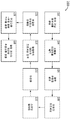
도 2는 본 개시의 하나 이상의 실시형태에 따른 시편을 특성화하기 위한 흐름도를 도시한다.
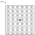
도 3은 본 개시의 하나 이상의 실시형태에 따른 다양한 유형의 결함에 대한 산출물 이미지를 도시한다.
도 4는 본 개시의 하나 이상의 실시형태에 따른 결함에 대한 리뷰 이미지를 도시한다.
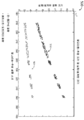
도 5는 본 개시의 하나 이상의 실시형태에 따른, 핀-홀(PH) 결함 및 레지스트 도트(RD) 결함에 대해 알고리즘-추정 결함 크기와 결함 크기의 개선된 추정치 사이의 관계를 나타내는 그래프이다.
도 6은 본 개시의 하나 이상의 실시형태에 따른 랜덤 포레스트(random forest) 분류자를 사용한 결함의 분류를 예시하는 그래프를 도시한다.
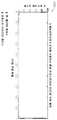
도 7은 본 개시의 하나 이상의 실시형태에 따른 심층 신경망(deep neural networks)을 사용한 결함의 분류를 예시하는 그래프를 도시한다.
도 8a는 본 개시의 하나 이상의 실시형태에 따른 시편을 특성화하기 위한 방법의 일부에 대한 흐름도를 예시한다.
도 8b는 본 개시의 하나 이상의 실시형태에 따른 시편을 특성화하기 위한 방법의 일부에 대한 흐름도를 예시한다.Numerous advantages of the present disclosure may be better understood by those skilled in the art with reference to the accompanying drawings that follow.
1A illustrates a system for characterizing a specimen in accordance with one or more embodiments of the present disclosure.
1B illustrates a system for characterizing a specimen in accordance with one or more embodiments of the present disclosure.
1C illustrates a system for characterizing a specimen in accordance with one or more embodiments of the present disclosure.
2 depicts a flow diagram for characterizing a specimen in accordance with one or more embodiments of the present disclosure.
3 depicts artifact images for various types of defects in accordance with one or more embodiments of the present disclosure.
4 depicts a review image for a defect in accordance with one or more embodiments of the present disclosure.
5 is a graph illustrating the relationship between algorithm-estimated defect size and improved estimates of defect size for pin-hole (PH) defects and resist dot (RD) defects, in accordance with one or more embodiments of the present disclosure.
6 depicts a graph illustrating classification of defects using a random forest classifier in accordance with one or more embodiments of the present disclosure.
7 depicts a graph illustrating classification of defects using deep neural networks in accordance with one or more embodiments of the present disclosure.
8A illustrates a flow diagram for a portion of a method for characterizing a specimen in accordance with one or more embodiments of the present disclosure.
8B illustrates a flow diagram for a portion of a method for characterizing a specimen in accordance with one or more embodiments of the present disclosure.
본 개시는 특정 실시형태 및 이의 구체적인 특징과 관련하여 특별히 도시되고 설명되었다. 여기에 설명된 실시형태는 제한적인 것이기 보다는 예시적인 것으로 고려된다. 이 분야의 통상의 기술자에게 본 개시 내용의 사상 및 범위를 벗어나지 않고 형태 및 세부사항에 있어서 다양한 변경 및 수정이 이루어질 수 있음은 명백할 것이다.The present disclosure has been particularly shown and described with respect to specific embodiments and specific features thereof. The embodiments described herein are to be considered illustrative rather than restrictive. It will be apparent to those skilled in the art that various changes and modifications can be made in form and detail without departing from the spirit and scope of the present disclosure.
첨부된 도면에 도시된, 개시된 본 발명에 대한 설명이 이제 상세하게 이루어질 것이다.DETAILED DESCRIPTION OF THE PREFERRED EMBODIMENTS The description of the disclosed invention, shown in the accompanying drawings, will now be made in detail.
본 개시의 실시형태들은 이미지 프로세싱 및 머신 러닝 기술을 사용하여 결함의 유형 및 크기를 결정하기 위한 시스템 및 방법에 관한 것이다. 특히, 본 개시의 실시형태들은 실제 결함 크기의 15 - 20 % 이내에서 결함 크기를 정확하게 결정할 수 있는 시스템 및 방법에 관한 것이다. 더욱이, 본 개시의 실시형태는 광범위한 실제 결함 크기에 대해 결함 유형 및 크기를 정확하게 결정할 수 있는 시스템 및 방법에 관한 것이다. 본 개시의 추가 실시형태는 결함의 크기를 보다 정확하게 결정하는 데 사용될 수 있는 결함 유형 분류를 결정하기 위해 머신 러닝 기술을 이용하는 것에 관한 것이다.Embodiments of the present disclosure relate to systems and methods for determining the type and size of a defect using image processing and machine learning techniques. In particular, embodiments of the present disclosure relate to systems and methods capable of accurately determining defect sizes within 15-20% of actual defect sizes. Moreover, embodiments of the present disclosure relate to systems and methods capable of accurately determining defect types and sizes over a wide range of actual defect sizes. Additional embodiments of the present disclosure relate to using machine learning techniques to determine a defect type classification that can be used to more accurately determine the size of a defect.
도 1a는 본 개시의 하나 이상의 실시형태에 따른 시편을 특성화하기 위한 시스템(100)을 예시한다. 특히, 도 1a는 머신 러닝 기술을 사용하여 블랭크 레티클(blank reticles) 상의 결함의 유형 및 크기를 결정하기 위한 시스템(100)을 도시한다. 시스템(100)은 하나 이상의 검사 서브-시스템(102)을 포함할 수 있지만 이에 제한되지는 않는다. 시스템(100)은 하나 이상의 프로세서(106), 메모리(108) 및 사용자 인터페이스(110)를 포함하는 컨트롤러(104)를 추가로 포함할 수 있지만 이에 제한되지는 않는다.1A illustrates a
검사 서브-시스템(102)은, 이에 제한되는 것은 아니지만, 광학-기반 검사 시스템, 하전 입자-기반 검사 시스템 등을 포함하는 이 분야에 알려진 임의의 검사 서브-시스템(102)을 포함할 수 있다. 예를 들어, 검사 서브-시스템(102)은 광학-기반 암시야(dark-field) 검사 시스템을 포함할 수 있다. 다른 실시예로서, 검사 서브-시스템(102)은 주사 전자 현미경(SEM) 검사 시스템을 포함할 수 있다. 일 실시형태에서, 컨트롤러(104)는 하나 이상의 검사 서브-시스템(102)에 통신가능하게(communicatively) 커플링된다. 이와 관련하여, 컨트롤러(104)의 하나 이상의 프로세서(106)는 검사 서브-시스템(102)의 하나 이상의 특성치(characteristics)를 조정하도록 구성된 하나 이상의 제어 신호를 생성하도록 구성될 수 있다.
도 1b는 본 개시의 하나 이상의 실시형태에 따라 시편을 특성화하기 위한 시스템(100)을 예시한다. 특히, 도 1b는 광학 검사 서브-시스템(102a)을 포함하는 시스템(100)을 도시한다.1B illustrates a
광학 검사 서브-시스템(102a)은, 이에 제한되는 것은 아니지만, 이미지-기반 계측 툴, 리뷰 툴 등을 포함하는 이 기술분야에 알려진 임의의 광학-기반 검사/특성화 시스템을 포함할 수 있다. 예를 들어, 검사 서브-시스템(102a)은 광학 암시야 검사 툴을 포함할 수 있다. 광학 검사 서브-시스템(102a)은, 이에 제한되는 것은 아니지만, 조명 소스(112), 조명 아암(arm)(111), 수집 아암(113) 및 검출기 어셈블리(126)를 포함할 수 있다.
일 실시형태에서, 광학 검사 서브-시스템(102a)은 스테이지 어셈블리(122) 상에 배치된 시편(120)을 검사 및/또는 측정하도록 구성된다. 조명 소스(112)는, 이에 제한되는 것은 아니지만, 광대역 방사선 소스를 포함하여, 조명(101)을 생성하기 위해 이 기술분야에 알려진 임의의 조명 소스를 포함할 수 있다. 다른 실시형태에서, 광학 검사 서브-시스템(102a)은 조명(101)을 시편(120)에 지향시키도록 구성된 조명 아암(111)을 포함할 수 있다. 광학 검사 서브-시스템(102a)의 조명 소스(112)는, 이에 제한되는 것은 아니지만, 암시야 배향(dark-field orientation), 명시야 배향(light-field orientation) 등을 포함하여 이 기술분야에 알려진 임의의 배향으로 구성될 수 있다는 점이 언급된다. 예를 들어, 하나 이상의 광학 요소(114, 124)는 검사 서브-시스템(102a)을 암시야 배향, 명시야 배향 등으로 구성하기 위해 선택적으로 조정될 수 있다.In one embodiment, the
시편(120)은, 이에 제한되는 것은 아니지만, 웨이퍼, 레티클, 포토마스크 등을 포함하여 이 기술분야에 알려진 임의의 시편을 포함할 수 있다. 예를 들어, 시편(120)은 블랭크 레티클을 포함할 수 있다. 일 실시형태에서, 시편(120)은 시편(120)의 이동을 용이하게 하기 위해 스테이지 어셈블리(122) 상에 배치된다. 다른 실시형태에서, 스테이지 어셈블리(122)는 작동가능한(actuatable) 스테이지이다. 예를 들어, 스테이지 어셈블리(122)는, 이에 제한되는 것은 아니지만, 하나 이상의 선형 방향(예를 들어, x-방향, y-방향 및/또는 z-방향)을 따라 시편(120)을 선택적으로 병진 이동시키기에 적합한 하나 이상의 병진 스테이지를 포함할 수 있다. 다른 실시예로서, 스테이지 어셈블리(122)는, 이에 제한되는 것은 아니지만, 회전 방향을 따라 시편(120)을 선택적으로 회전시키기에 적합한 하나 이상의 회전 스테이지를 포함할 수 있다. 다른 실시예로서, 스테이지 어셈블리(122)는, 이에 제한되는 것은 아니지만, 선형 방향을 따라 시편(120)을 선택적으로 병진 이동 및/또는 회전 방향을 따라 시편(120)을 회전시키기에 적합한 회전 스테이지 및 병진 스테이지를 포함할 수 있다. 여기서 시스템(100)은 이 기술분야에 알려진 임의의 스캐닝(scanning) 모드에서 동작할 수 있다는 것이 언급된다.
조명 아암(111)은 이 기술분야에서 알려진 임의의 수 및 유형의 광학 구성요소를 포함할 수 있다. 일 실시형태에서, 조명 아암(111)은 하나 이상의 광학 요소(114), 하나 이상의 광학 요소 세트(115), 빔 스플리터(116), 및 대물 렌즈(118)를 포함한다. 이와 관련하여, 조명 아암(111)은 조명 소스(112)로부터의 조명(101)을 시편(120)의 표면상에 집속(focus)시키도록 구성될 수 있다. 하나 이상의 광학 요소(114)는, 이에 제한되는 것은 아니지만, 하나 이상의 미러, 하나 이상의 렌즈, 하나 이상의 편광자(polarizer), 하나 이상의 빔 스플리터, 파장판(wave plates) 등을 포함하여 이 기술분야에서 알려진 임의의 광학 요소를 포함할 수 있다.
다른 실시형태에서, 광학 검사 서브-시스템(102a)은 시편(120)으로부터 반사되거나 산란되는 조명을 수집하도록 구성된 수집 아암(113)을 포함한다. 또 다른 실시형태에서, 수집 아암(113)은 반사 및 산란된 광을 하나 이상의 광학 요소(124)를 통해 검출기 어셈블리(126)의 하나 이상의 센서로 지향 및/또는 집속시킬 수 있다. 하나 이상의 광학 요소(124)는, 이에 제한되는 것은 아니지만, 하나 이상의 미러, 하나 이상의 렌즈, 하나 이상의 편광자, 하나 이상의 빔 스플리터, 파장판 등을 포함하여 이 기술분야에 알려진 임의의 광학 요소를 포함할 수 있다. 검출기 어셈블리(126)는 시편(120)으로부터 반사되거나 산란되는 조명을 검출하기 위한 이 기술분야에 알려진 임의의 센서 및 검출기 어셈블리를 포함할 수 있다는 점이 언급된다.In another embodiment, the
다른 실시형태에서, 광학 검사 서브-시스템(102)의 검출기 어셈블리(126)는 시편(120)으로부터 반사되거나 산란된 조명에 기초하여 시편(120)의 계측 데이터를 수집하도록 구성된다. 다른 실시형태에서, 검출기 어셈블리(126)는 수집된/획득된 이미지 및/또는 계측 데이터를 컨트롤러(104)로 전송하도록 구성된다.In another embodiment, the
여기서 앞서 언급된 바와 같이, 시스템(100)의 컨트롤러(104)는 하나 이상의 프로세서(106) 및 메모리(108)를 포함할 수 있다. 메모리(108)는 하나 이상의 프로세서(106)가 본 개시의 다양한 단계를 수행하게 하도록 구성된 프로그램 명령어를 포함할 수 있다. 일 실시형태에서, 프로그램 명령어는 시편(120)에 대한 하나 이상의 측정을 수행하기 위해 하나 이상의 프로세서(106)가 광학 검사 서브-시스템(102)의 하나 이상의 특성치를 조정하게 하도록 구성된다.As previously mentioned herein, the
추가 및/또는 대안적인 실시형태에서, 검사 서브-시스템(102)은 하전 입자-기반 검사 서브-시스템(102)을 포함할 수 있다. 예를 들어, 검사 서브-시스템(102)은 도 1c에 도시된 바와 같이 SEM 특성화 서브-시스템을 포함할 수 있다.In additional and/or alternative embodiments, the
도 1c는 본 개시의 하나 이상의 실시형태에 따라 시편(120)을 특성화하기 위한 시스템(100)을 도시한다. 특히, 도 1c는 SEM 검사 서브-시스템(102b)을 포함하는 시스템(100)을 도시한다.1C illustrates a
일 실시형태에서, SEM 검사 서브-시스템(102b)은 시편(120)에 대해 하나 이상의 측정을 수행하도록 구성된다. 이와 관련하여, SEM 검사 서브-시스템(102b)은 시편(120)에 대한 하나 이상의 이미지를 획득하도록 구성될 수 있다. SEM 검사 서브-시스템(102b)은, 이에 제한되는 것은 아니지만, 전자빔 소스(128), 하나 이상의 전자-광학 요소(130), 하나 이상의 전자-광학 요소(132), 및 하나 이상의 전자 센서(136)를 포함하는 전자 검출기 어셈블리(134)를 포함할 수 있다.In one embodiment, the
일 실시형태에서, 전자빔 소스(128)는 하나 이상의 전자빔(129)을 시편(120)으로 지향하도록 구성된다. 전자빔 소스(128)는 전자-광학 칼럼(column)을 형성할 수 있다. 다른 실시형태에서, 전자빔 소스(128)는 하나 이상의 전자빔(129)을 시편(120)의 표면에 집속 및/또는 지향시키도록 구성된 하나 이상의 추가 및/또는 대안적인 전자-광학 요소(130)를 포함한다. 다른 실시형태에서, SEM 검사 서브-시스템(102b)은 하나 이상의 전자빔(129)에 응답하여 시편(120)의 표면으로부터 방출되는 2차 및/또는 후방 산란 전자(131)를 수집하도록 구성된 하나 이상의 전자-광학 요소(132)를 포함한다. 상기 하나 이상의 전자-광학 요소(130) 및 하나 이상의 전자-광학 요소(132)는, 이에 제한되는 것은 아니지만, 하나 이상의 디플렉터, 하나 이상의 전자-광학 렌즈, 하나 이상의 콘덴서 렌즈(예를 들어, 자기 콘덴서 렌즈), 하나 이상의 대물 렌즈(예를 들어, 자기 콘덴서 렌즈) 등을 포함하여, 전자를 지향, 집속 및/또는 수집하도록 구성된 임의의 전자-광학 요소를 포함할 수 있다.In one embodiment, the
SEM 검사 서브-시스템(102b)의 전자 광학 어셈블리는 도 1c에 도시된 전자-광학 요소로 한정되지 않고 이는 단지 예시 목적으로 제공된다는 점이 언급된다. 시스템(100)은 하나 이상의 전자빔(129)을 시편(120)에 지향/집속시키고, 이에 응답하여 방출되는 2차 및/또는 후방 산란 전자(131)를 전자 검출기 어셈블리(134) 상으로 수집하고 이미지화하는 데 필요한 임의의 수 및 유형의 전자-광학 요소를 포함할 수 있다는 점이 더 언급된다.It is noted that the electro-optical assembly of the
예를 들어, 시스템(100)은 하나 이상의 전자빔 스캐닝 요소(미도시)를 포함할 수 있다. 예를 들어, 하나 이상의 전자빔 스캐닝 요소는, 이에 제한되는 것은 아니지만, 시편(120)의 표면에 대해 하나 이상의 전자빔(129)의 위치를 제어하기에 적합한 하나 이상의 전자기 스캐닝 코일 또는 정전(electrostatic) 디플렉터를 포함할 수 있다. 또한, 하나 이상의 스캐닝 요소는 선택된 패턴으로 시편(120)을 가로질러 하나 이상의 전자빔(129)을 스캔하는 데 사용될 수 있다.For example,
다른 실시형태에서, 2차 및/또는 후방 산란 전자(131)는 전자 검출기 어셈블리(134)의 하나 이상의 센서(136)로 지향된다. SEM 검사 서브-시스템(102)의 전자 검출기 어셈블리(134)는 시편(120)의 표면으로부터 방출되는 후방 산란 및/또는 2차 전자(131)를 검출하기에 적합한 이 기술분야에 알려진 임의의 전자 검출기 어셈블리를 포함할 수 있다. 일 실시형태에서, 전자 검출기 어셈블리(134)는 전자 검출기 어레이를 포함한다. 이와 관련하여, 전자 검출기 어셈블리(134)는 전자-검출부의 어레이를 포함할 수 있다. 또한, 전자 검출기 어셈블리(134)의 검출기 어레이의 각각의 전자-검출부는 입사하는 하나 이상의 전자빔(129) 중 하나와 관련된 시편(120)으로부터의 전자 신호를 검출하도록 배치될 수 있다. 전자 검출기 어셈블리(134)는 이 기술분야에서 알려진 임의의 유형의 전자 검출기를 포함할 수 있다. 예를 들어, 전자 검출기 어셈블리(134)는, 이에 제한되는 것은 아니지만, 다이오드 어레이 또는 애벌랜치 포토다이오드(avalanche photo diodes, APD)와 같은 마이크로-채널 플레이트(micro-channel plate, MCP), PIN 또는 p-n 접합 검출기 어레이를 포함할 수 있다. 다른 실시예로서, 전자 검출기 어셈블리(134)는 고속 신틸레이터(scintillator) 또는 광전자 증배관(photomultiplier tube, PMT) 검출기를 포함할 수 있다.In other embodiments, secondary and/or backscattered
도 1c는 SEM 검사 서브-시스템(102b)을 2차 전자 검출기 어셈블리만을 포함하는 전자 검출기 어셈블리(134)를 포함하는 것으로 도시하지만, 이는 본 개시의 제한으로 간주되지 않는다. 이와 관련하여, 전자 검출기 어셈블리(134)는, 이에 제한되는 것은 아니지만, 2차 전자 검출기, 후방 산란 전자 검출기 및/또는 1차 전자 검출기(예를 들어, 인-칼럼(in-column) 전자 검출기)를 포함할 수 있다는 점이 언급된다. 다른 실시형태에서, SEM 검사 서브-시스템(102)은 복수의 전자 검출기 어셈블리(134)를 포함할 수 있다. 예를 들어, 시스템(100)은 2차 전자 검출기 어셈블리(134a), 후방 산란 전자 검출기 어셈블리(134b) 및 인-칼럼 전자 검출기 어셈블리(134c)를 포함할 수 있다.1C shows the
일 실시형태에서, 컨트롤러(104)의 하나 이상의 프로세서(106)는 검출기 어셈블리(126)/전자 검출기 어셈블리(134)의 출력을 분석하도록 구성된다. 일 실시형태에서, 프로그램 명령어 세트는 하나 이상의 프로세서(106)가 검출기 어셈블리(126)/전자 검출기 어셈블리(134)로부터 수신된 이미지에 기초하여 시편(120)의 하나 이상의 특성치를 분석하게 하도록 구성된다. 다른 실시형태에서, 프로그램 명령어 세트는 하나 이상의 프로세서(106)가 시편(120) 및/또는 검출기 어셈블리(126)/전자 검출기 어셈블리(134)에 초점을 유지하기 위해 시스템(100)의 하나 이상의 특성치를 수정하게 하도록 구성된다. 예를 들어, 하나 이상의 프로세서(106)는 조명(101) 및/또는 하나 이상의 전자빔(129)을 시편(120)의 표면에 집속시키기 위해 조명 소스(112)/전자빔 소스(128) 및/또는 시스템(100)의 다른 요소의 하나 이상의 특성치를 조정하도록 구성될 수 있다. 또 다른 실시예로서, 하나 이상의 프로세서(106)는 시편(120)의 표면으로부터 조명 및/또는 2차 전자(131)를 수집하고 수집된 조명을 검출기 어셈블리(126)/전자 검출기 어셈블리(134) 상에 집속하기 위해 시스템(100)의 하나 이상의 요소를 조정하도록 구성될 수 있다. 다른 실시예로서, 하나 이상의 프로세서(106)는 하나 이상의 전자빔(129)의 위치 또는 정렬을 독립적으로 조정하고 시편(120)을 가로질러 전자빔(129)을 스캔하기 위해, 전자빔 소스(128)의 하나 이상의 정전 디플렉터에 인가되는 하나 이상의 집속 전압(focusing voltages)을 조정하도록 구성될 수 있다.In one embodiment, the one or
다른 실시형태에서, 도 1a-1c에 도시된 바와 같이, 시스템(100)은 컨트롤러(104)에 통신가능하게 커플링된 사용자 인터페이스(110)를 포함한다. 다른 실시형태에서, 사용자 인터페이스(110)는 사용자 입력 장치 및 디스플레이를 포함한다. 사용자 인터페이스(110)의 사용자 입력 장치는 사용자로부터 하나 이상의 입력 커맨드를 수신하도록 구성될 수 있고, 하나 이상의 입력 커맨드는 시스템(100)에 데이터를 입력하고 및/또는 시스템(100)의 하나 이상의 특성치를 조정하도록 구성될 수 있다. 다른 실시형태에서, 사용자 인터페이스(110)의 디스플레이는 시스템(100)의 데이터를 사용자에게 디스플레이하도록 구성될 수 있다.In another embodiment, as shown in FIGS. 1A-1C , the
일 실시형태에서, 하나 이상의 프로세서(106)는 메모리(108)에 통신가능하게 커플링될 수 있으며, 여기서 하나 이상의 프로세서(106)는 메모리(108)에 저장된 프로그램 명령어 세트를 실행하도록 구성되고, 상기 프로그램 명령어 세트는 하나 이상의 프로세서(106)가 본 개시의 다양한 기능 및 단계를 수행하게 하도록 구성된다. 이와 관련하여, 컨트롤러(104)는 검사 서브-시스템(102)으로부터 시편(120)의 하나 이상의 결함에 대한 하나 이상의 트레이닝 이미지(125)를 수신하고; 하나 이상의 트레이닝 이미지(125)에 기초하여 머신 러닝 분류자를 생성하고; 검사 서브-시스템(102)으로부터 시편(120)의 하나 이상의 결함에 대한 하나 이상의 산출물 이미지(135)를 수신하고; 상기 머신 러닝 분류자를 사용하여 상기 하나 이상의 결함에 대한 하나 이상의 결함 유형 분류를 결정하고; 하나 이상의 스무딩 필터로 상기 하나 이상의 산출물 이미지(135)를 필터링하고; 하나 이상의 이진화 프로세스를 수행하여 하나 이상의 이진화된 산출물 이미지를 생성하고; 상기 하나 이상의 이진화된 산출물 이미지에 대해 하나 이상의 형태학적 이미지 프로세싱 동작을 수행하고; 상기 하나 이상의 이진화된 산출물 이미지에 기초하여 상기 하나 이상의 결함에 대한 하나 이상의 알고리즘-추정 결함 크기를 결정하고; 및 상기 하나 이상의 알고리즘-추정 결함 크기 및 상기 하나 이상의 결함 유형 분류에 기초하여 상기 하나 이상의 결함의 하나 이상의 결함 크기에 대한 하나 이상의 개선된 추정치를 결정한다. 컨트롤러(104)의 이들 단계/기능 각각은 여기서 더 상세히 설명될 것이다.In one embodiment, one or
도 2는 본 개시의 하나 이상의 실시형태에 따라 시편(120)을 특성화하기 위한 흐름도(200)를 도시한다. 특히, 도 2는 이미지 프로세싱 및 머신 러닝 기술을 사용하여 결함의 유형 및 크기를 결정하기 위한 흐름도(200)를 도시한다. 이와 관련하여, 흐름도(200)는 컨트롤러(104)의 하나 이상의 프로세서(106)에 의해/내에서 수행되는 단계를 예시하는 개념적 흐름도로서 고려될 수 있다.2 depicts a flow diagram 200 for characterizing a
단계 202에서, 머신 러닝 분류자가 생성된다. 일 실시형태에서, 컨트롤러(104)는 시편(120)의 이미지 내에서 결함 유형을 식별하기 위해 사용될 수 있는 머신 러닝 분류자를 생성할 수 있다. 머신 러닝 분류자를 생성할 때, 컨트롤러(104)는 시편(120)에 대한 하나 이상의 트레이닝 이미지(125)를 획득하도록 구성될 수 있다. 예를 들어, 일 실시형태에서, 컨트롤러(104)는 검사 서브-시스템(102)으로부터 시편(120)의 하나 이상의 결함에 대한 하나 이상의 트레이닝 이미지(125)를 수신하도록 구성될 수 있다. 본 개시의 목적을 위해, 용어 "트레이닝 이미지(training images)"는 그 유형 및 크기가 알려진(known)/설계된(designed)/측정된(measured) 결함의 이미지로 간주될 수 있으며 이는 머신 러닝 분류자를 트레이닝하기 위한 입력으로 사용될 것이다.At
예를 들어, 도 1b에 도시된 바와 같이, 컨트롤러(104)는 광학 검사 서브-시스템(102a)으로부터 시편(120)의 하나 이상의 결함에 대한 하나 이상의 광학 트레이닝 이미지(125)를 수신하도록 구성될 수 있다. 다른 실시예로서, 도 1c에 도시된 바와 같이, 컨트롤러(104)는 SEM 검사 서브-시스템(102b)으로부터 시편(120)의 하나 이상의 결함에 대한 하나 이상의 SEM 트레이닝 이미지(125)를 수신하도록 구성될 수 있다. 이와 관련하여, 트레이닝 이미지(125)는 광학 트레이닝 이미지(125), SEM 트레이닝 이미지(125) 등을 포함할 수 있다. 추가 및/또는 대안적인 실시형태에서, 컨트롤러(104)는 상기 하나 이상의 검사 서브-시스템(102) 이외의 소스로부터 하나 이상의 트레이닝 이미지(125)를 수신하도록 구성될 수 있다. 예를 들어, 컨트롤러(104)는 외부 저장 장치 및/또는 메모리(108)로부터 시편(120)의 피처(features)에 대한 하나 이상의 트레이닝 이미지(125)를 수신하도록 구성될 수 있다. 다른 실시형태에서, 컨트롤러(104)는 또한 수신된 트레이닝 이미지(125)를 메모리(108)에 저장하도록 구성될 수 있다.For example, as shown in FIG. 1B , the
다른 실시형태에서, 컨트롤러(104)는 하나 이상의 수신된 트레이닝 이미지(125)에 기초하여 머신 러닝 분류자를 생성하도록 구성될 수 있다. 컨트롤러(104)는, 이에 제한되는 것은 아니지만, 지도 학습(supervised learning), 비지도 학습(unsupervised learning) 등을 포함하여 이 기술분야에서 알려진 임의의 기술을 통해 머신 러닝 분류자를 생성하도록 구성될 수 있다.In other embodiments, the
예를 들어, 지도 학습의 맥락에서, 트레이닝 이미지(125)는 알려진 크기 및/또는 알려진 결함 유형을 갖는 결함의 이미지를 포함할 수 있다. 이와 관련하여, 컨트롤러(104)는 트레이닝 이미지(125)에 표현된 결함과 연관된 하나 이상의 알려진 결함 유형 분류 및/또는 하나 이상의 알려진 결함 크기를 수신할 수 있다. 따라서, 트레이닝 이미지(125), 알려진 결함 유형 분류, 및 알려진 결함 크기는 머신 러닝 분류자를 트레이닝하기 위한 입력으로 사용될 수 있다. 알려진 결함 유형 분류는, 이에 제한되는 것은 아니지만, 핀-홀(pin-hole) 결함 분류, 레지스트-도트(resist-dot) 결함 분류, 스크래치(scratch) 결함 분류, 급속-국부(fast-localized) 결함 분류 등을 포함하여 이 기술 분야에 알려진 임의의 유형의 결함에 대한 분류를 포함할 수 있다. 컨트롤러(104)는 또한 메모리(108)에 알려진 결함 유형 분류, 알려진 결함 크기 및 생성된 머신 러닝 분류자를 저장하도록 구성될 수 있다.For example, in the context of supervised learning, the
단계(202)에서 생성된 머신 러닝 분류자는, 이에 제한되는 것은 아니지만, 랜덤 포레스트(random forest) 분류자, 서포트 벡터 머신(support vector machine, SVM) 분류자, 앙상블 러닝(ensemble learning) 분류자, 인공 신경망(artificial neural network, ANN) 등을 포함하여 이 기술분야에 알려진 임의의 유형의 머신 러닝 알고리즘/분류자 및/또는 딥 러닝(deep learning) 기술 또는 분류자를 포함할 수 있음이 추가로 언급된다. 다른 실시예로서, 머신 러닝 분류자는 심층 컨볼루션 신경망(deep convolutional neural network)을 포함할 수 있다. 예를 들어, 일부 실시형태에서, 머신 러닝 분류자는 ALEXNET 및/또는 GOOGLENET을 포함할 수 있다. 이와 관련하여, 머신 러닝 분류자는 시편(120)의 이미지 내의 결함 유형을 결정하도록 구성된 임의의 알고리즘, 분류자 또는 예측 모델을 포함할 수 있다. 이것은 여기에서 더 자세히 설명될 것이다.The machine learning classifier generated in
단계(204)에서, 하나 이상의 산출물 이미지가 획득된다. 일 실시형태에서, 컨트롤러(104)는 검사 서브-시스템(102)으로부터 하나 이상의 산출물 이미지(135)를 수신하도록 구성될 수 있다. 여기서 사용되는 용어 "산출물 이미지(product images)"는 결함의 유형과 결함의 크기가 결정될 결함의 이미지를 지칭하기 위해 사용될 수 있다. 따라서, "산출물 이미지"는 머신 러닝 분류자를 트레이닝하기 위한 입력으로 사용될 결함의 이미지로 간주될 수 있는 "트레이닝 이미지"와 구별될 수 있다.In
본 명세서에서 달리 언급하지 않는 한, 트레이닝 이미지(125)의 획득에 관한 임의의 설명은 산출물 이미지(135)의 획득에 적용되는 것으로 간주될 수 있다는 점이 언급된다. 따라서, 산출물 이미지(135)는 광학 검사 서브-시스템(102a) 및/또는 SEM 검사 서브-시스템(102b)으로부터 수신될 수 있다. 이와 관련하여, 산출물 이미지(135)는 광학 산출물 이미지(135), SEM 산출물 이미지(135) 등을 포함할 수 있다. 추가적인 및/또는 대안적인 실시형태에서, 콘트롤러(104)는 하나 이상의 검사 서브-시스템(102) 이외의 소스로부터 하나 이상의 산출물 이미지(135)를 수신하도록 구성될 수 있다. 예를 들어, 컨트롤러(104)는 외부 저장 장치 및/또는 메모리(108)로부터 시편(120)에 대한 하나 이상의 산출물 이미지(135)를 수신하도록 구성될 수 있다.It is noted that, unless otherwise stated herein, any description relating to the acquisition of the
도 3은 본 개시의 하나 이상의 실시형태에 따른 다양한 유형의 결함에 대한 산출물 이미지(135)를 도시한다. 특히, 도 3은 암시야 검사 툴(예를 들어, 검사 서브-시스템(102))에 의해 캡처된 다양한 유형의 결함에 대한 산출물 이미지(135a-135c)를 도시한다.3 illustrates
실시형태에서, 산출물 이미지(135a)는 핀-홀(PH) 결함 또는 레지스트-도트(RD) 결함을 예시하고, 산출물 이미지(135b)는 급속-국부 결함(FLD)을 예시하고, 산출물 이미지(135c)는 스크래치 결함을 예시한다. 도 3에서 보여지는 바와 같이. 암시야 검사 툴(예를 들어, 검사 서브-시스템(102))에 의해 캡처된 이미지는 32x32 픽셀 크기일 수 있다. 도 3은 더 밝은 픽셀을 각각의 결함과 연관시키는 스케일(302)을 더 도시한다.In an embodiment, the
실시형태에서, 시편(120)의 결함의 크기 및/또는 유형을 결정하기 위해 사용되는 하나 이상의 산출물 이미지(135)는 검사 중에 및/또는 검사 후에 획득될 수 있다. 다른 실시형태에서, 컨트롤러(104)는 또한 수신된 산출물 이미지(135)를 메모리(108)에 저장하도록 구성될 수 있다.In embodiments, one or
단계(206)에서, 시편(120)의 하나 이상의 결함에 대한 하나 이상의 결함 유형이 결정된다. 시편(120)의 하나 이상의 결함은, 이에 제한되는 것은 아니지만, 핀-홀 결함, 레지스트-도트 결함, 스크래치, 급속-국부 결함 등을 포함하여 시편(120) 제조/특성화 프로세스 전반에 걸쳐 관심 있을 수 있는 임의의 유형의 결함을 포함할 수 있다. 일부 실시형태에서, 컨트롤러(104)는 생성된 머신 러닝 분류자를 사용하여 산출물 이미지(135) 내의 하나 이상의 결함에 대한 하나 이상의 결함 유형 분류를 결정하도록 구성된다. 예를 들어, 컨트롤러(104)는 시편(120)의 핀-홀 결함을 묘사하는 산출물 이미지(135a)를 수신할 수 있다. 이 실시예에서, 컨트롤러(104)는 산출물 이미지(135a)가 핀-홀 결함을 포함한다고 결정하고 상기 결함을 핀-홀 결함 유형 분류와 연관시키도록 구성될 수 있다. 다른 실시예로서, 컨트롤러(104)는 시편(120)의 스크래치 결함을 묘사하는 산출물 이미지(135c)를 수신하고, 상기 산출물 이미지(135c)가 스크래치 결함을 포함한다고 결정하고, 상기 결함을 스크래치 결함 유형 분류와 연관시킬 수 있다.At
단계(208)에서, 하나 이상의 이미지 프로세싱 동작이 하나 이상의 산출물 이미지(135)에 대해 수행된다. 일 실시형태에서, 컨트롤러(104)는 하나 이상의 산출물 이미지(135)에 대해 하나 이상의 이미지 프로세싱 동작을 수행하도록 구성된다.In step 208 , one or more image processing operations are performed on one or
예를 들어, 암시야 검사 툴(예를 들어, 검사 서브-시스템(102))과 관련하여, 하나 이상의 산출물 이미지(135)는 그레이 스케일이고 크기가 32x32 픽셀인 시편(120) 상의 결함 이미지를 포함할 수 있다(도 2에 도시). 이러한 상대적으로 작은 이미지 크기는 추정된 결함 크기에 큰 편차(variations)를 초래할 수 있다. 따라서, 일부 실시형태에서, 하나 이상의 이미지 프로세싱 동작은 산출물 이미지(135)의 크기를 조정하도록 구성된 이미지 스케일링(scaling) 동작을 포함할 수 있다. 이미지 스케일링 동작(예를 들어, 이미지 프로세싱 동작) 동안, 컨트롤러(104)는 이미지 스케일링 동작으로 하나 이상의 산출물 이미지(135)의 크기를 조정하여 하나 이상의 스케일링된 산출물 이미지를 생성하도록 구성될 수 있다. 예를 들어, 32x32 픽셀 이미지의 경우, 컨트롤러(104)는 산출물 이미지(135)를 8 배로 업스케일링하기 위해 이미지 업스케일링(upscaling) 동작(예를 들어, 이미지 프로세싱 동작)을 수행하여 256x256 픽셀 크기의 스케일링된 산출물 이미지를 생성하도록 구성될 수 있다. 여기서, 이미지 스케일링 동작은 임의의 선택된 비율(factor)에 의해 산출물 이미지를 업스케일링 및/또는 다운스케일링(downscaling)하도록 구성된 업스케일링 및/또는 다운스케일링 동작을 포함할 수 있다는 점이 언급된다.For example, in the context of a dark field inspection tool (eg, inspection sub-system 102 ), the one or
이미지 업스케일링은 결함 주변의 경계가 블러링된(blurred) 스케일링된 산출물 이미지를 초래할 수 있다. 이러한 변화 및 블러링된 경계를 감소 및/또는 제거하기 위해, 하나 이상의 이미지 프로세싱 동작은 하나 이상의 이미지 사프닝(sharpening) 동작을 더 포함할 수 있다. 예를 들어, 이미지 업스케일링 동작을 수행하여 256x256 픽셀 크기로 스케일링된 산출물 이미지를 생성한 후, 컨트롤러는 하나 이상의 이미지 샤프닝 동작으로 상기 하나 이상의 스케일링된 산출물 이미지를 변경하도록 구성될 수 있다. 산출물 이미지(135) 및/또는 스케일링된 산출물 이미지는 이 기술분야에 공지된 임의의 기술을 사용하여 이미지 샤프닝 동작을 통해 변경될 수 있다. 예를 들어, 컨트롤러(104)는 라플라시안(Laplacian) 필터를 사용하여 수행되는 이미지 필터링 동작을 이용하여 스케일링된 산출물 이미지를 샤프닝하도록 구성될 수 있다. 이와 관련하여, 이미지 샤프닝 동작은 하나 이상의 이미지 필터링 동작을 포함할 수 있다.Image upscaling may result in a scaled artifact image with blurred boundaries around the defect. To reduce and/or eliminate such variations and blurred boundaries, the one or more image processing operations may further include one or more image sharpening operations. For example, after performing an image upscaling operation to generate a scaled product image to a size of 256x256 pixels, the controller may be configured to change the one or more scaled product images by one or more image sharpening operations. The
다른 예로서, 리뷰(review) 툴(예를 들어, 검사 서브-시스템(102))에 의해 캡처된 리뷰 이미지의 맥락에서, 상기 하나 이상의 산출물 이미지(135)는 컬러이고 512x512 픽셀 크기인 시편(120) 상의 결함의 이미지를 포함할 수 있다. 예를 들어, 도 4는 본 개시의 하나 이상의 실시형태에 따른 결함의 리뷰 이미지 (135d)를 도시한다. 특히, 도 4는 광학 리뷰 툴(예를 들어, 검사 서브-시스템(102))에 의해 캡처된 결함의 산출물 이미지(135d)를 도시하며, 결함을 나타내는 더 밝은 픽셀을 가진다. 이전에 언급한 바와 같이, 산출물 이미지(135d)는 컬러이고 512x512 픽셀 크기일 수 있다.As another example, in the context of review images captured by a review tool (eg, inspection sub-system 102 ), the one or
리뷰 툴에 의해 캡처된 리뷰 이미지(예를 들어, 산출물 이미지(135d))의 맥락에서, 컨트롤러(104)에 의해 수행되는 하나 이상의 이미지 프로세싱 동작은 상기 하나 이상의 산출물 이미지(135)를 제1 색 공간 시스템으로부터 제2 색 공간 시스템으로 변환하는 것을 포함할 수 있다. 색 공간 시스템은, 이에 제한되는 것은 아니지만, 빨강-초록-파랑(RGB) 색 공간 시스템 및 색조-채도-명도(hue-saturation-value)(HSV) 색 공간 시스템을 포함하여 이 기술 분야에서 알려진 임의의 색 공간 시스템을 포함할 수 있다. 예를 들어, 산출물 이미지(135d)는 RGB 색 공간 시스템에서 캡처될 수 있고, 컨트롤러(104)는 상기 산출물 이미지(135d)를 HSV 색 공간 시스템으로 변환하도록 구성될 수 있다. 여기서 HSV 색 공간 시스템의 명도(value) 채널은 RGB 색 공간 시스템과 비교하여 개선된 밝기값(intensity) 프로파일 및 결함 픽셀에 대한 보다 일관된 구별을 제공할 수 있다는 점이 언급된다.In the context of a review image (eg,
하나 이상의 이미지 프로세싱 동작은 이 기술 분야에 알려진 임의의 이미지 프로세싱 동작을 포함할 수 있다는 것이 여기서 더 언급된다. 이와 관련하여, 예시적인 이미지 프로세싱 동작은 예시 목적으로만 제공되며, 본 명세서에서 달리 언급되지 않는 한 본 개시를 제한하는 것으로 간주되어서는 안된다.It is further noted herein that the one or more image processing operations may include any image processing operations known in the art. In this regard, the example image processing operations are provided for illustrative purposes only, and should not be construed as limiting the disclosure unless otherwise stated herein.
단계(210)에서, 하나 이상의 산출물 이미지(135)가 하나 이상의 스무딩 필터로 필터링된다. 하나 이상의 산출물 이미지(135) 내의 결함 주변 영역에서 노이즈를 감소시키기 위해, 컨트롤러(104)는 하나 이상의 스무딩 필터로 하나 이상의 산출물 이미지(135)를 필터링하도록 구성될 수 있다. 하나 이상의 스무딩 필터는, 이에 제한되는 것은 아니지만, 평균값(mean) 필터, 라플라시안(Laplacian) 필터, 위너(Weiner) 필터, 가우시안(Gaussian) 필터, 최소/최대 필터, 중앙값(median) 필터, 중간점(midpoint) 필터 등을 포함하여 이 분야에 알려진 임의의 스무딩 필터를 포함할 수 있다. 예를 들어, 컨트롤러(104)는 가우시안 커널(Gaussian kernel)을 사용하여 컨볼빙(convolving)함으로써 하나 이상의 산출물 이미지(135)를 스무딩하도록 구성될 수 있다.In step 210, one or
단계(212)에서, 하나 이상의 이진화 프로세스가 수행되어 하나 이상의 이진화된 산출물 이미지를 생성한다. 일 실시형태에서, 컨트롤러(104)는 하나 이상의 이진화된 산출물 이미지를 생성하기 위해 산출물 이미지(135)에 대해 하나 이상의 이진화 프로세스를 수행하도록 구성된다. 이진화를 통해, 산출물 이미지(135)에서 결함과 관련된 픽셀(예를 들어, 결함 픽셀)은 하나 이상의 이진화 공식(binarization formulas)을 사용하여 산출물 이미지(135)의 배경 픽셀로부터 식별될 수 있다. 예를 들어, 결함 픽셀은 식 (1)에 의해 주어진 이진화 공식을 사용하여 배경 픽셀로부터 식별될 수 있다.In step 212, one or more binarization processes are performed to generate one or more binarized artifact images. In one embodiment, the

여기서 μ는 배경 픽셀의 그레이레벨의 평균값을 정의하고, σ는 배경 픽셀 그레이레벨의 표준 편차 값을 정의하고, w는 사용자 제공 가중치(예: 3)를 정의하고, δ는 사용자 제공 오프셋(예: 0.1)을 정의하고, I는 픽셀 위치(x, y)에서 각 산출물 이미지(135)(예를 들어, 단계(210)에서 하나 이상의 스무딩 필터를 사용하여 필터링된 산출물 이미지(135))의 그레이레벨을 정의하고, b(x, y)는 픽셀 위치(x, y)에서 이진화된 이미지를 정의한다. 식 (1)을 사용하여 처리된 그레이레벨 이미지를 단 2 개의 값을 갖는 이미지로 변환하는 단계 - 그레이레벨 1의 결함 픽셀과 그레이레벨 0의 나머지 픽셀 - 는 이진화(binarization)로 지칭될 수 있다. 다른 실시형태에서, 컨트롤러(104)는 메모리(108)에 하나 이상의 이진화된 산출물 이미지를 저장하도록 구성될 수 있다.where μ defines the average value of the gray level of the background pixel, σ defines the standard deviation value of the background pixel gray level, w defines the user-supplied weight (eg 3), and δ defines the user-supplied offset (eg 0.1), where I is the gray level of each artifact image 135 (e.g.,
이진화 후에, 산출물 이미지(135) 내의 결함은 결함의 중앙 주위에 어두운 윤곽선이 있고 결함의 중앙에서 더 밝게 보일 수 있다. 이는 결함 및/또는 시편(120)의 광학적 특성 때문일 수 있다. 이러한 경우에, 이 두 영역(예를 들어, 더 밝은 중앙 영역, 더 어두운 윤곽선)은 단계(212)에서 이진화 후에 단절된(disconnected) 것처럼 보일 수 있다. 이후에 상기 영역 중 하나만을 결함을 나타내는 것으로 선택하면 결함 크기가 과소 평가될 수 있다. 예를 들어, 밝은 중앙 영역만 선택함으로써 결함 크기가 과소 평가될 수 있다. 그러한 단절된 영역 사이의 갭을 연결(bridge)하기 위해, 형태학적(morphological) 이미지 프로세싱 동작이 수행될 수 있다.After binarization, defects in
단계(214)에서, 하나 이상의 형태학적 이미지 프로세싱 동작이 수행된다. 예를 들어, 실시형태에서, 컨트롤러(104)는 하나 이상의 산출물 이미지(135) 및/또는 하나 이상의 이진화된 산출물 이미지에 대해 하나 이상의 형태학적 이미지 프로세싱 동작을 수행하도록 구성될 수 있다. 하나 이상의 형태학적 이미지 프로세싱 동작은, 이에 제한되는 것은 아니지만, 형태학적 폐쇄(closing) 동작(예를 들어, 형태학적 이진 이미지 폐쇄 동작), 형태학적 침식(erosion) 동작, 형태학적 확장(dilation) 동작, 형태학적 개방(opening) 동작, 또는 형태학적 폐쇄 동작 등을 포함하여 이 기술 분야에 알려진 임의의 형태학적 이미지 프로세싱 동작을 포함할 수 있다. 여기서 앞서 언급한 바와 같이, 형태학적 이미지 프로세싱 동작은 이진화로 초래된 결함의 단절된 영역 사이의 갭을 연결하기 위해 수행될 수 있다.In
단계(216)에서, 연결된 구성요소 라벨링(connected component labeling)이 수행된다. 이진화 동작 및 형태학적 이미지 프로세싱 동작을 수행한 후, 노이즈 및 기타 요인으로 인해 결함에 해당하는 픽셀 클러스터(cluster)에 부가하여 픽셀들의 작은 클러스터들이 결함이 있는 것(예를 들어, 결함의 부분)으로 잘못 라벨링될 수 있다. 이와 관련하여, 결함에 대응하는 픽셀 클러스터만을 라벨링하고 선택하기 위해 연결된 구성요소 라벨링이 수행될 수 있다. 따라서, 컨트롤러(104)는 이진화된 산출물 이미지 내의 각각의 분리된 픽셀 클러스터를 식별하고 고유한 라벨로 라벨링함으로써 연결된 구성요소 라벨링을 수행하도록 구성될 수 있다. 노이즈에 기인하는 픽셀 클러스터들은 일반적으로 결함에 대응하는 픽셀 클러스터보다 작다는 사실로 인해, 컨트롤러(104)는 하나 이상의 픽셀 클러스터를 단일의 결함에 대응하거나 연관된 것으로 식별하고 라벨링하도록 구성될 수 있다.In
예를 들어, 컨트롤러(104)는 하나 이상의 이진화된 산출물 이미지 내에서 복수의 픽셀 클러스터를 식별하고, 상기 복수의 픽셀 클러스터 중 가장 큰 픽셀 클러스터를 하나 이상의 결함과 연관된 것으로 결정하도록 구성될 수 있다. 그 다음, 컨트롤러(104)는 또한 다른 픽셀 클러스터를 노이즈에 기인하는 것으로 무시(disregard) (예를 들어, 무시(ignore))하도록 구성될 수 있다.For example, the
단계(218)에서, 알고리즘-추정 결함 크기가 하나 이상의 결함에 대해 결정된다. 일 실시형태에서, 컨트롤러(104)는 하나 이상의 이진화된 산출물 이미지에 기초하여 하나 이상의 결함에 대한 하나 이상의 알고리즘-추정 결함 크기를 결정하도록 구성될 수 있다. 알고리즘-추정 결함 크기를 결정하는 데 사용되는 이진화된 산출물 이미지의 특성은, 이에 제한되는 것은 아니지만, 식별된/라벨링된 픽셀 클러스터, 최대 결함 픽셀 그레이레벨 값, 최소 결함 픽셀 그레이레벨 값 등을 포함할 수 있다.At step 218, an algorithm-estimated defect size is determined for one or more defects. In an embodiment, the
예를 들어, 결함과 관련된 것으로 이진화된 산출물 이미지 내의 픽셀 클러스터를 식별한 후, 컨트롤러(104)는 식별된 픽셀 클러스터에 기초하여 결함에 대한 알고리즘-추정 결함 크기를 결정하도록 구성될 수 있다. 본 명세서에서 사용되는, 용어 "알고리즘-추정(algorithm-estimated) 결함 크기"는 산출물 이미지(135)(예를 들어, 이진화된 산출물 이미지(135)) 내에서 결함과 연관된 것으로 결정된 픽셀의 수 및/또는 산출물 이미지(135)의 다른 특성치에 기반한 결함의 추정된 크기를 지칭할 수 있다. 이와 관련하여, "알고리즘-추정 결함 크기"는 여기에서 더 상세히 설명되는 바와 같이 "결함 크기의 개선된 추정(refined estimates)"과 구별될 수 있다.For example, after identifying the pixel clusters in the binarized artifact image as being associated with the defect, the
이미지의 픽셀들 만을 기초로 결함의 크기(예를 들어, 알고리즘-추정 결함 크기)를 추정하는 것은 결함 크기 결정에 일정 량의 오류를 도입할 수 있다는 것이 여기서 고려된다. 예를 들어, 각 결함 유형의 광학적 특성의 차이로 인해, 핀-홀 결함과 레지스트-도트 결함이, 두 결함의 크기가 사실 실제에서 크게 달라지더라도, 동일한 알고리즘-추정 결함 크기를 갖는 것으로 결정될 수 있다. 이는 또한 도 5를 참조하여 이해될 수 있다.It is contemplated herein that estimating the size of a defect (eg, algorithm-estimated defect size) based solely on pixels of the image may introduce some amount of error into the defect size determination. For example, due to the differences in the optical properties of each defect type, pin-hole defects and resist-dot defects can be determined to have the same algorithm-estimated defect size, even though the size of the two defects is in fact significantly different in reality. have. This can also be understood with reference to FIG. 5 .
도 5는 본 개시의 하나 이상의 실시형태에 따라, 핀-홀(PH) 결함 및 레지스트-도트(RD) 결함에 대해 알고리즘-추정 결함 크기와 실제(actual)/설계된(designed) 결함 크기 간의 관계를 나타내는 그래프(500)이다. 그래프(500)는 실제 및/또는 설계된 결함 크기와, 알고리즘-추정 결함 크기 사이의 관계를 도시한다. 곡선(502)은 레지스트-도트(RD) 결함에 대해 실제/설계된 결함 크기와 알고리즘-추정 결함 크기 사이의 관계를 나타내고, 곡선(504)은 핀-홀(PH) 결함에 대해 실제/설계된 결함 크기와 알고리즘-추정 결함 크기 사이의 관계를 도시한다.5 illustrates the relationship between algorithm-estimated defect sizes and actual/designed defect sizes for pin-hole (PH) defects and resist-dot (RD) defects, in accordance with one or more embodiments of the present disclosure; A
그래프(500)에서 볼 수 있는 바와 같이, 알고리즘-추정 결함 크기가 실제/설계된 결함 크기의 함수로 플로팅될 때, 다양한 결함 유형에 따라 뚜렷하고 독립적인 경향이 드러난다(예를 들어, RD 결함에 대해 곡선(502), PH 결함에 대해 곡선(504)). 일부 실시형태에서, 실제/설계된 결함 크기에 대한 알고리즘-추정 결함 크기를 플로팅하는 그래프(예를 들어, 그래프(500))는 트레이닝 이미지(125)를 통한 머신 러닝 분류자(단계(202))의 지도된(supervised) 트레이닝 동안 구성될 수 있다. 그래프(500)의 구성 시에, 별개의 수학적 모델/함수(예를 들어, 다항식 함수)가 곡선(502, 504)의 각각에 적합하도록 생성될 수 있다. 예를 들어, 알려진 결함 크기 및/또는 알려진 결함 유형을 갖는 결함을 표현하는 트레이닝 이미지(125)를 사용하는 지도된 학습 동안, 컨트롤러(104)는 다양한 유형의 결함에 대해 알고리즘-추정 결함 크기를 실제/설계된 결함 크기에 상관시키는 수학적 모델/함수(예를 들어, 다항식 함수)를 생성하도록 구성될 수 있다. 예를 들어, 컨트롤러(104)는 RD 결함에 대해 알고리즘-추정 결함 크기를 실제/설계된 결함 크기와 상관시키는 제1 수학적 모델(예를 들어, 수학적 함수, 다항식 함수), 및 PH 결함에 대해 알고리즘-추정 결함 크기를 실제/설계된 결함 크기와 상관시키는 제2 수학적 모델(예를 들어, 수학적 함수, 다항식 함수)을 생성하도록 구성될 수 있다. 생성된 수학적 모델은 메모리(108)에 저장될 수 있다. 이와 관련하여, 컨트롤러(104)는 지도된 학습 동안 수학적 모델/함수 모델링 곡선(502, 504)을 생성하도록 구성될 수 있다.As can be seen in
도 5에 도시된 바와 같이, 단일의 알고리즘-추정 결함 크기는 문제가되는 결함 유형에 따라, 각기 다른 실제/설계된 결함 크기를 나타낼 수 있다. 이와 관련하여, 알고리즘-추정 결함 크기 그 자체로는 결함 크기를 정확하게 결정하기에 충분하지 않다는 것을 알 수 있다.As shown in Figure 5, a single algorithm-estimated defect size may represent different actual/designed defect sizes, depending on the defect type in question. In this regard, it can be seen that the algorithm-estimated defect size by itself is not sufficient to accurately determine the defect size.
따라서, 이미지 내의 픽셀 클러스터만에 기초하여 결함 크기를 결정하려는 이전의 접근방식은 실제 결함 크기의 15-20 % 이내에서 결함 크기를 정확하게 결정하지 못할 수 있다. 비교해보면, 본 개시의 실시형태는 결함 크기의 개선된 추정치를 보다 정확하게 결정하기 위해 알고리즘-추정 결함 크기 및 결정된 결함 유형 분류를 모두 이용하도록 구성된다. 보다 구체적으로, 본 개시의 실시형태는 보다 정확하게 결함 크기의 개선된 추정치를 결정하기 위해 알고리즘-추정 결함 크기, 상기 알고리즘-추정 결함 크기를 실제/설계된 결함 크기와 상관시키는 수학적 모델/함수, 및 결함 유형 분류를 결정하는 모델(예를 들어, 랜덤 포레스트 분류자 모델, 심층 컨볼루션 신경망 모델 등)을 모두 활용하도록 구성된다.Therefore, previous approaches to determining defect size based only on pixel clusters in the image may not accurately determine defect size within 15-20% of the actual defect size. By comparison, embodiments of the present disclosure are configured to use both algorithm-estimated defect size and determined defect type classification to more accurately determine an improved estimate of defect size. More specifically, embodiments of the present disclosure provide an algorithm-estimated defect size, a mathematical model/function correlating the algorithm-estimated defect size with an actual/designed defect size, and a defect to more accurately determine an improved estimate of the defect size. It is configured to utilize all models that determine type classification (eg, random forest classifier models, deep convolutional neural network models, etc.).
단계(220)에서, 결함 크기에 대한 개선된 추정치가 결정된다. 일 실시형태에서, 컨트롤러(104)는 하나 이상의 알고리즘-추정 결함 크기(단계(218)) 및 하나 이상의 결함 유형 분류(단계(206))에 기초하여 하나 이상의 결함의 하나 이상의 결함 크기에 대한 하나 이상의 개선된 추정치(예를 들어, 참인(true)/실제(actual) 결함 크기에 대한 추정치)를 결정하도록 구성될 수 있다. 예를 들어, 컨트롤러(104)는 하나 이상의 알고리즘-추정 결함 크기(단계(218)), 하나 이상의 결함 유형 분류(단계(206)), 및 다양한 유형의 결함에 대해 실제/설계된 결함 크기에 알고리즘-추정 결함 크기를 상관시키는 하나 이상의 수학적 모델에 기초하여 하나 이상의 결함의 하나 이상의 결함 크기에 대한 하나 이상의 개선된 추정치(예를 들어, 참인/실제 결함 크기에 대한 추정치)를 결정하도록 구성될 수 있다.In
하나의 실시예는 예시적인 것으로 판명될 수 있다. 머신 러닝 분류자는 지도된 학습 기술을 사용하여 트레이닝(trained)/조정될(calibrated) 수 있다. 트레이닝 이미지(125), 알려진 결함 크기 및 알려진 결함 유형을 사용하는 지도된 학습 동안, 컨트롤러(104)는 다양한 유형의 결함에 대해 알고리즘-추정 결함 크기를 실제/설계된 결함 크기에 상관시키는 수학적 모델/함수(예를 들어, 다항식 함수)(예를 들어, 곡선(502, 504)을 모델링하는 수학적 함수)를 생성하도록 구성될 수 있다. 예를 들어, 조정/트레이닝 동안, 컨트롤러(104)는 곡선(502)과 연관된 제1 다항식 함수(예를 들어, 제1 수학적 모델) 및 곡선(504)과 연관된 제2 다항식 함수(예를 들어, 제2 수학적 모델)를 생성할 수 있다. 다항식 함수(예를 들어, 제1 수학적 모델, 제2 수학적 모델)는 메모리(108)에 저장될 수 있다.One embodiment may prove illustrative. Machine learning classifiers may be trained/calibrated using supervised learning techniques. During supervised learning using
동일한 실시예로 계속하여, 컨트롤러(104)는 결함의 산출물 이미지(135a)를 획득하도록 구성될 수 있다. 트레이닝된 머신 러닝 분류자를 사용하여, 컨트롤러(104)는 산출물 이미지(135a)에 묘사된 결함이 핀-홀 결함이라고 결정할 수 있고, 따라서 핀-홀 결함 분류를 상기 결함과 연관시킬 수 있다. 후속적으로, 흐름도(200)의 다양한 단계를 수행한 후, 컨트롤러(104)는 제2 다항식 함수(예를 들어, 핀-홀 결함에 대한 곡선(504)에 대한 제2 수학적 모델 모델링)를 사용하여 결함의 알고리즘-추정 결함 크기를 후속적으로 결정할 수 있다. 결정된 핀-홀 결함 분류, 제2 다항식 함수, 및 알고리즘-추정 결함 크기를 사용하여, 그 다음 컨트롤러(104)는 결함에 대한 참인/실제 크기를 추정하는 결함 크기에 대한 개선된 추정치를 결정하도록 구성될 수 있다.Continuing with the same embodiment, the
여기서 (알고리즘-추정 결함 크기와 실제/설계된 결함 크기를 상관시키는 트레이닝 중에 생성된 수학적 모델과 함께) 알고리즘-추정 결함 크기 및 결정된 결함 유형 분류 모두를 사용하는 것은 본 개시의 시스템 및 방법이, 광범위한 결함 유형 및 크기에 대해 실제 결함 크기의 15-20 % 이내에서 결함의 크기를 정확하게 추정(예를 들어, 실제 결함 크기의 15-20 % 이내에서 결함 크기의 개선된 추정치)하게 할 수 있다고 고려된다.Here, using both algorithm-estimated defect size and determined defect type classification (along with a mathematical model generated during training correlating algorithm-estimated defect size with actual/designed defect size) means that the systems and methods of the present disclosure allow for a wide range of defects. It is contemplated that for type and size, it is possible to accurately estimate the size of a defect within 15-20% of the actual defect size (eg, an improved estimate of the defect size within 15-20% of the actual defect size).
다양한 유형의 머신 러닝 분류자를 사용하여 결함 유형 분류를 결정하는 것의 효용성은 도 6 및 7을 참조하여 더 이해될 수 있다.The utility of determining the defect type classification using various types of machine learning classifiers can be further understood with reference to FIGS. 6 and 7 .
도 6은 본 개시의 하나 이상의 실시형태에 따라 랜덤 포레스트 분류자를 사용한 결함의 분류를 예시하는 그래프(600)를 도시한다. 도 7은 본 개시의 하나 이상의 실시형태에 따라 심층 신경망을 사용한 결함의 분류를 예시하는 그래프(700, 702)를 도시한다.6 depicts a
랜덤 포레스트 분류자(예를 들어, 머신 러닝 분류자)의 경우, 컨트롤러(104)는 이진화된 산출물 이미지 내에서 알고리즘-추정 결함 크기, 최소 결함 픽셀 그레이레벨 값, 및 최대 결함 픽셀 그레이레벨 값을 포함하는 피처(features)에 기초하여 3 차원(3D) 피처 벡터를 생성하도록 구성될 수 있다. 상기 피처는 다양한 결함 유형을 나타내도록 선택되며 완전하지는 않다(not exhaustive). 특정 실시형태에서, 3 개의 별개의 산출물 이미지(135)(예를 들어, 이진화된 산출물 이미지)가 각각의 결함에 대해 사용될 수 있으며, 결과적으로 총 9 개의 피처가 된다. 결과적으로, 9 개의 피처를 사용하는 랜덤 포레스트 분류자는 그래프(600)에서 볼 수 있는 바와 같이 테스트 데이터(예를 들어, 테스트 결함)에 대해 약 100 %의 정확도로 결함 유형 분류를 제공할 수 있다.For a random forest classifier (e.g., a machine learning classifier), the
비교해보면, 그래프(700, 702)는 원본 산출물 이미지(135)로 트레이닝된 심층 신경망을 사용하는 결함의 분류를 예시한다. 특히, 그래프(700)는 ALEXNET으로 결함의 분류를 예시하고, 그래프(702)는 GOOGLENET으로 결함의 분류를 예시한다.In comparison,
일부 실시형태에서, 컨트롤러(104)는 또한 결함 크기의 개선된 추정치 및 결정된 결함 유형 분류 중 적어도 하나에 기초하여 제어 신호를 생성하도록 구성될 수 있으며, 여기서 상기 하나 이상의 제어 신호는 하나 이상의 프로세스 툴의 하나 이상의 특성치를 선택적으로 조정하도록 구성된다. 예를 들어, 도 1a-1c를 참조하면, 시스템(100)은 컨트롤러(104)에 통신가능하게 커플링된 하나 이상의 제조 툴을 더 포함할 수 있다. 하나 이상의 제조 툴은, 이에 제한되는 것은 아니지만, 리소그래피 툴, 에칭 툴, 퇴적 툴, 연마 툴 등을 포함하여 시편(120)을 제조하도록 구성된 이 기술분야에 알려진 임의의 제조 툴을 포함할 수 있다. 동일한 실시예로 계속하면, 컨트롤러(104)는 결함 크기의 개선된 추정치 및 결정된 결함 유형 분류 중 적어도 하나를 수정하기 위해 피드-포워드(feed-forward) 또는 피드-백(feed-back) 루프에서 하나 이상의 제조 툴에 대한 하나 이상의 특성치를 조정하도록 구성된 하나 이상의 제어 신호를 생성하도록 구성될 수 있다.In some embodiments, the
여기서 본 개시의 시스템 및 방법은 광범위한 결함 크기(예를 들어, 80 nm 미만, 200 nm 초과)에 대해 보다 정확한 결함 유형 및 크기 결정을 가능하게 할 수 있다고 고려된다. 특히, 본 개시의 시스템 및 방법은 실제 결함 크기의 15-20 % 이내에서 결함 크기의 추정을 가능하게 할 수 있다(예를 들어, 실제 결함 크기의 15-20 % 이내에서 결함 크기에 대한 개선된 추정치).It is contemplated herein that the systems and methods of the present disclosure may enable more accurate defect type and size determination for a wide range of defect sizes (eg, less than 80 nm, greater than 200 nm). In particular, the systems and methods of the present disclosure may enable estimation of defect size within 15-20% of the actual defect size (eg, improved for defect size within 15-20% of the actual defect size). estimate).
여기서 시스템(100)의 하나 이상의 구성요소는 이 기술분야에 알려진 임의의 방식으로 시스템(100)의 다양한 다른 구성요소에 통신가능하게 커플링될 수 있음이 언급된다. 예를 들어, 하나 이상의 프로세서(106)는 유선(예를 들어, 구리 와이어, 광섬유 케이블 등) 또는 무선 연결(예를 들어, RF 커플링, IR 커플링, WiMax, 블루투스, 3G, 4G, 4G LTE, 5G 등)을 통해 서로 및 다른 구성요소에 통신가능하게 연결될 수 있다. 다른 실시예로서, 컨트롤러(104)는 이 기술분야에 알려진 임의의 유선 또는 무선 연결을 통해 검사 서브-시스템(102)의 하나 이상의 구성요소에 통신가능하게 커플링될 수 있다.It is noted herein that one or more components of
일 실시형태에서, 하나 이상의 프로세서(106)는 이 기술분야에 알려진 임의의 하나 이상의 프로세싱 요소를 포함할 수 있다. 이러한 의미에서, 하나 이상의 프로세서(106)는 소프트웨어 알고리즘 및/또는 명령어를 실행하도록 구성된 임의의 마이크로프로세서-유형 디바이스를 포함할 수 있다. 일 실시형태에서, 본 개시 전체에 걸쳐 설명된 바와 같이, 하나 이상의 프로세서(106)는 데스크탑 컴퓨터, 메인프레임 컴퓨터 시스템, 워크스테이션, 이미지 컴퓨터, 병렬 프로세서, 또는 시스템(100)을 작동하도록 구성된 프로그램을 실행하도록 구성된 다른 컴퓨터 시스템(예를 들어, 네트워크 컴퓨터)으로 구성될 수 있다. 본 개시 전체에 걸쳐 설명된 단계는 단일 컴퓨터 시스템 또는 대안적으로 다수의 컴퓨터 시스템에 의해 수행될 수 있음을 인식해야 한다. 또한, 본 개시 전체에 걸쳐 설명된 단계는 하나 이상의 프로세서(106) 중 임의의 하나 이상에서 수행될 수 있음을 인식해야 한다. 일반적으로, 용어 "프로세서"는 메모리(108)로부터 프로그램 명령어를 실행하는 하나 이상의 프로세싱 구성요소를 갖는 임의의 디바이스를 포함하도록 광범위하게 정의될 수 있다. 더욱이, 시스템(100)의 상이한 서브시스템(예를 들어, 조명 소스(112), 전자빔 소스(128), 검출기 어셈블리(126), 전자 검출기 어셈블리(134), 컨트롤러(104), 사용자 인터페이스(110) 등)은 본 개시 전체에 걸쳐 설명된 단계의 적어도 일 부분을 수행하기에 적합한 프로세서 또는 로직 요소를 포함할 수 있다. 따라서, 상기 설명은 본 발명에 대한 제한으로 해석되어서는 안되며 단지 예시에 불과하다.In one embodiment, the one or
메모리(108)는 관련된 하나 이상의 프로세서(106)에 의해 실행가능한 프로그램 명령어 및 검사 서브-시스템(102)으로부터 수신된 데이터를 저장하기에 적합한 이 기술분야에 알려진 임의의 저장 매체를 포함할 수 있다. 예를 들어, 메모리(108)는 비-일시적(non-transitory) 메모리 매체를 포함할 수 있다. 예를 들어, 메모리(108)는, 이에 제한되는 것은 아니지만, ROM(read-only memory), RAM(random-access memory), 자기 또는 광학 메모리 디바이스(예를 들어, 디스크), 자기 테이프, 솔리드-스테이트(solid-state) 드라이브 등을 포함할 수 있다. 또한, 메모리(108)는 하나 이상의 프로세서(106)와 함께 공통 컨트롤러 하우징에 수용될 수 있다는 것이 언급된다. 대안적인 실시형태에서, 메모리(108)는 프로세서(106), 컨트롤러(104) 등의 물리적 위치에 대해 원격으로 위치될 수 있다. 다른 실시형태에서, 메모리(108)는 하나 이상의 프로세서(106)가 본 개시에 걸쳐 설명된 다양한 단계를 수행하게 하기 위한 프로그램 명령어를 유지한다.
일 실시형태에서, 사용자 인터페이스(110)는 컨트롤러(104)에 통신가능하게 커플링된다. 일 실시형태에서, 사용자 인터페이스(110)는, 이에 제한되는 것은 아니지만, 하나 이상의 데스크탑, 태블릿, 스마트 폰, 스마트 워치, 등을 포함할 수 있다. 다른 실시형태에서, 사용자 인터페이스(110)는 시스템(100)의 데이터를 사용자에게 디스플레이하는 데 사용되는 디스플레이를 포함한다. 사용자 인터페이스(110)의 디스플레이는 이 분야에 알려진 임의의 디스플레이를 포함할 수 있다. 예를 들어, 디스플레이는, 이에 제한되는 것은 아니지만, 액정 디스플레이(LCD), 유기 발광 다이오드(OLED) 기반 디스플레이, 또는 CRT 디스플레이를 포함할 수 있다. 이 분야의 기술자들은 사용자 인터페이스(110)와 통합할 수 있는 임의의 디스플레이 장치가 본 개시의 구현에 적합하다는 것을 인식할 것이다. 다른 실시형태에서, 사용자는 사용자 인터페이스(110)의 사용자 입력 장치를 통해 사용자에게 디스플레이된 데이터에 대하여 선택 및/또는 명령어를 입력할 수 있다.In one embodiment, the
도 8a-8b는 본 개시의 하나 이상의 실시형태에 따라 시편(120)을 특성화하기 위한 방법(800)의 흐름도를 도시한다. 특히, 도 8a-8b는 머신 러닝 기술을 사용하여 시편(120)의 결함 유형 및 크기를 결정하기 위한 방법(800)을 도시한다. 여기서 방법(800)의 단계들은 시스템(100)에 의해 전부 또는 부분적으로 구현될 수 있다는 것이 언급된다. 그러나, 방법(800)은 추가적인 또는 대안적인 시스템-레벨 실시형태가 방법(800)의 단계들 전부 또는 부분을 수행할 수 있다는 점에서 시스템(100)으로 제한되지 않는다는 것을 또한 알 수 있다.8A-8B show a flow diagram of a
단계(802)에서, 시편의 하나 이상의 결함에 대한 하나 이상의 트레이닝 이미지가 획득된다. 예를 들어, 도 1b에 도시된 바와 같이, 컨트롤러(104)는 광학 검사 서브-시스템(102a)으로부터 시편(120)의 하나 이상의 피처에 대한 하나 이상의 광학 트레이닝 이미지(125)를 수신하도록 구성될 수 있다. 다른 실시예로서, 도 1c에 도시된 바와 같이, 컨트롤러(104)는 SEM 검사 서브-시스템(102b)으로부터 시편(120)의 하나 이상의 피처에 대한 하나 이상의 SEM 트레이닝 이미지(125)를 수신하도록 구성될 수 있다.In
단계(804)에서, 하나 이상의 트레이닝 이미지에 기초하여 머신 러닝 분류자가 생성된다. 예를 들어, 지도 학습(supervised learning)을 사용하여, 하나 이상의 트레이닝 이미지(125) 및 알려진 결함 크기 및/또는 알려진 결함 유형이 머신 러닝 분류자를 트레이닝하기 위한 입력으로 사용될 수 있다. 상기 머신 러닝 분류자는, 이에 제한되는 것은 아니지만, 랜덤 포레스트 분류자, 서포트 벡터 머신(SVM) 분류자, 앙상블 러닝 분류자, 인공 신경망(ANN), 심층 신경망 또는 컨볼루션 신경망(예를 들어, ALEXNET, GOOGLENET) 등을 포함하여, 이 분야에서 달려진 임의의 유형의 머신 러닝 알고리즘/분류자 및/또는 딥 러닝 기술 또는 분류자를 포함할 수 있다.At 804, a machine learning classifier is generated based on one or more training images. For example, using supervised learning, one or
단계(806)에서, 시편의 하나 이상의 결함에 대한 하나 이상의 산출물 이미지가 획득된다. 예를 들어, 도 1b에 도시된 바와 같이, 컨트롤러(104)는 광학 검사 서브-시스템(102a)으로부터 시편(120)의 하나 이상의 피처에 대한 하나 이상의 광학 산출물 이미지(135)를 수신하도록 구성될 수 있다. 다른 실시예로서, 도 1c에 도시된 바와 같이, 컨트롤러(104)는 SEM 검사 서브-시스템(102b)으로부터 시편(120)의 하나 이상 피처에 대한 하나 이상의 SEM 산출물 이미지(135)를 수신하도록 구성될 수 있다.In
단계(808)에서, 하나 이상의 결함에 대한 하나 이상의 결함 유형 분류가 머신 러닝 분류자로 결정된다. 예를 들어, 컨트롤러(104)는 시편(120)의 핀-홀 결함을 표현하는 산출물 이미지(135a)를 수신할 수 있다. 이 실시예에서, 컨트롤러(104)는 산출물 이미지(135a)가 핀-홀 결함을 포함한다고 결정하고 결함을 핀-홀 결함 분류와 연관시키도록 구성될 수 있다. 다른 실시예로서, 컨트롤러(104)는 시편(120)의 스크래치 결함을 표현하는 산출물 이미지(135c)를 수신하고, 산출물 이미지(135c)가 스크래치 결함을 포함한다고 결정하고, 결함을 스크래치 결함 분류와 연관시킬 수 있다.In
단계(810)에서, 하나 이상의 산출물 이미지가 하나 이상의 스무딩 필터로 필터링된다. 하나 이상의 스무딩 필터는, 이에 제한되는 것은 아니지만, 평균값 필터, 라플라시안 필터, 위너 필터, 가우시안 필터, 최소/최대 필터, 중앙값 필터, 중간점 필터 등을 포함하여 이 분야에 알려진 임의의 스무딩 필터를 포함할 수 있다. 예를 들어, 컨트롤러(104)는 가우시안 커널을 사용하여 컨볼빙함으로써 하나 이상의 산출물 이미지(135)를 스무딩하도록 구성될 수 있다.In
단계(812)에서, 하나 이상의 이진화된 산출물 이미지를 생성하기 위해 하나 이상의 이진화 프로세스가 수행된다. 예를 들어, 컨트롤러(104)는 하나 이상의 이진화된 산출물 이미지를 생성하기 위해 산출물 이미지(135)에 대해 하나 이상의 이진화 프로세스를 수행하도록 구성될 수 있다. 이진화를 통해, 산출물 이미지(135)에서 결함과 관련된 픽셀(예를 들어, 결함 픽셀)은 하나 이상의 이진화 공식을 사용하여 산출물 이미지(135)의 배경 픽셀로부터 식별될 수 있다.At
단계(814)에서, 하나 이상의 이진화된 산출물 이미지에 대해 하나 이상의 형태학적 이미지 프로세싱 동작이 수행된다. 예를 들어, 실시형태에서, 컨트롤러(104)는 하나 이상의 산출물 이미지(135) 및/또는 하나 이상의 이진화된 산출물 이미지에 대해 하나 이상의 형태학적 이미지 프로세싱 동작을 수행하도록 구성될 수 있다. 하나 이상의 형태학적 이미지 프로세싱 동작은, 이에 제한되는 것은 아니지만, 형태학적 폐쇄 동작(예를 들어, 형태학적 이진 이미지 폐쇄 동작), 형태학적 침식 동작, 형태학적 확장 동작, 형태학적 개방 동작, 또는 형태학적 폐쇄 동작 등을 포함하여 이 기술 분야에 알려진 임의의 형태학적 이미지 프로세싱 동작을 포함할 수 있다. 여기서 앞서 언급한 바와 같이, 형태학적 이미지 프로세싱 동작은 이진화로 초래된 결함의 단절된 영역 사이의 갭을 연결하기 위해 수행될 수 있다.In
단계(816)에서, 하나 이상의 결함에 대한 하나 이상의 알고리즘-추정 결함 크기가 하나 이상의 이진화된 산출물 이미지에 기초하여 결정된다. 예를 들어, 컨트롤러(104)는 하나 이상의 이진화된 산출물 이미지에 기초하여 하나 이상의 결함의 하나 이상 알고리즘-추정 결함 크기를 결정하도록 구성될 수 있다. 알고리즘-추정 결함 크기를 결정하는 데 사용되는 이진화된 산출물 이미지의 특성치는, 이에 제한되는 것은 아니지만, 식별된/라벨링된 픽셀 클러스터, 최대 결함 픽셀 그레이레벨 값, 최소 결함 픽셀 그레이레벨 값 등을 포함할 수 있다.In
단계(818)에서, 하나 이상의 알고리즘-추정 결함 크기 및 하나 이상의 결함 유형 분류에 기초하여 하나 이상의 결함의 하나 이상의 결함 크기에 대한 하나 이상의 개선된 추정치가 결정된다. 예를 들어, 컨트롤러(104)는 (예를 들면, 알려진/설계된 크기의 결함을 가진 트레이닝(125) 이미지를 통해) 알려진 특성치를 가진 다양한 유형의 결함에 대해 알고리즘-추정 결함 크기를 실제/설계된 결함 크기에 상관시키는 수학적 모델(예를 들어, 다항식 함수)을 생성하도록 구성될 수 있다. 이어서, 산출물 이미지를 획득한 후, 컨트롤러(104)는 결함과 관련된 핀-홀 결함 분류를 결정하고 알고리즘-추정 결함 크기를 결정하도록 구성될 수 있다. 그 다음 컨트롤러(104)는 결정된 결함 유형 분류, 생성된 수학적 모델, 및 결정된 알고리즘-추정 결함 크기에 기초하여 결함에 대한 결함 크기의 개선된 추정치를 결정하도록 구성될 수 있다.At 818 , one or more improved estimates for one or more defect sizes of the one or more defects are determined based on the one or more algorithm-estimated defect sizes and the one or more defect type classifications. For example, the
이 분야의 기술자는 여기에 설명된 구성 요소(예를 들어, 동작(operation)), 장치(device), 물건(objects) 및 이들에 수반되는 논의는 개념적 명료성을 위해 예시로서 사용된 것이고 다양한 구성 수정이 고려된다는 것을 인식할 것이다. 결과적으로, 여기에 사용된, 제시된 특정 예시 및 수반되는 논의는 보다 일반적인 클래스를 대표하는 것으로 의도된다. 일반적으로 임의의 특정 예시를 사용하는 것은 해당 클래스를 대효하기 위한 것이며, 특정 구성 요소(예를 들어, 동작), 장치 및 물건을 포함하지 않는 것이 제한으로 간주되어서는 안된다.Those skilled in the art will recognize that the components (eg, operations), devices, and objects described herein, and the accompanying discussion thereof, are used as examples for conceptual clarity and may be modified in various configurations. It will be appreciated that this will be considered. Consequently, the specific examples presented and the accompanying discussion, used herein, are intended to be representative of the more general class. In general, the use of any particular example is intended to represent the class in question, and the inclusion of particular components (eg, operations), devices, and objects should not be regarded as limiting.
이 분야의 기술자는 여기에 설명된 프로세스 및/또는 시스템 및/또는 기타 기술이 수행될 수 있는 다양한 수단(vehicles)(예를 들어, 하드웨어, 소프트웨어 및/또는 펌웨어)이 있고, 선호되는 수단은 상기 프로세스 및/또는 시스템 및/또는 기타 기술이 사용되는 상황에 따라 달라질 수 있다는 것을 이해할 것이다. 예를 들어, 구현자가 속도와 정확성이 가장 중요하다고 결정하면 구현자는 주로 하드웨어 및/또는 펌웨어 수단을 선택할 수 있다. 대안적으로 유연성이 가장 중요하다면 구현자는 주로 소프트웨어 구현을 선택할 수 있다. 또는 다른 대안으로, 구현자는 하드웨어, 소프트웨어 및/또는 펌웨어의 일부 조합을 선택할 수 있다. 따라서, 여기에 설명된 프로세스 및/또는 장치 및/또는 기타 기술이 수행될 수 있는 여러 가능한 수단이 있으며, 사용될 임의의 수단은 그 수단이 사용될 상황 및 구현자의 특정 관심사(예를 들어, 속도, 유연성 또는 예측 가능성)에 따른 선택이라는 점에서 그 어느 것도 본질적으로 다른 것보다 우위에 있지 않으며 그 어느 것도 변할 수 있다.Those skilled in the art will have a variety of vehicles (eg, hardware, software and/or firmware) on which the processes and/or systems and/or other techniques described herein may be performed, the preferred means being the above. It will be understood that processes and/or systems and/or other technologies may vary depending on the context in which they are used. For example, if an implementer determines that speed and accuracy are paramount, the implementer may choose primarily hardware and/or firmware means. Alternatively, if flexibility is paramount, implementors may choose primarily software implementations. Or alternatively, the implementer may choose some combination of hardware, software and/or firmware. Accordingly, there are several possible means by which the processes and/or apparatus and/or other techniques described herein may be performed, any means being used depend upon the circumstances in which the means will be used and the particular concerns of the implementer (eg, speed, flexibility or predictability), neither is inherently superior to the other in terms of choice, and neither is subject to change.
전술한 설명은 이 분야의 통상의 기술자가 특정 응용 및 그 요구 사항의 맥락에서 제공된 바와 같이 본 발명을 만들고 사용할 수 있도록 제시된다. 여기에 사용된 바와 같이, "상부(top)", "하부(bottom)", "위에(over)", "아래에(under)", "상부의(upper)", "위쪽으로(upward)", "하부의(lower)", "아래로(down)" 및 "아래쪽으로(downward)"와 같은 방향을 나타내는 용어는 설명 목적에서 상대적 위치를 제공하기 위한 것이며, 절대적인 기준틀을 지정하기 위한 것이 아니다. 설명된 실시형태에 대한 다양한 수정은 이 분야의 기술자에게 명백할 것이며, 여기에서 정의된 전반적인 원리가 다른 실시형태에 적용될 수 있다. 따라서, 본 발명은 도시되고 설명된 특정 실시형태로 한정되도록 의도되지 않고 여기에 개시된 원리 및 신규한 특징과 일치하는 가장 넓은 범위에 부합되어야 한다.The foregoing description is presented to enable any person skilled in the art to make and use the invention as provided in the context of a particular application and its requirements. As used herein, “top”, “bottom”, “over”, “under”, “upper”, “upward” Directional terms such as ", "lower," "down," and "downward" are for descriptive purposes only to provide relative positions, and are not intended to designate an absolute frame of reference. no. Various modifications to the described embodiments will be readily apparent to those skilled in the art, and the general principles defined herein may be applied to other embodiments. Accordingly, the present invention is not intended to be limited to the specific embodiments shown and described but is to be accorded the widest scope consistent with the principles and novel features disclosed herein.
여기서 실질적으로 임의의 복수 및/또는 단수 용어의 사용과 관련하여, 이 분야의 기술자는 문맥 및/또는 응용에 적절한 대로 복수에서 단수로 및/또는 단수에서 복수로 해석할 수 있다. 다양한 단수/복수 치환은 명확성을 위해 여기에서 명시적으로 설명되지 않는다.With respect to the use of substantially any plural and/or singular terms herein, those skilled in the art may interpret the plural from the singular and/or the singular to the plural as appropriate to the context and/or application. The various singular/plural permutations are not explicitly set forth herein for the sake of clarity.
여기서 설명된 모든 방법은 방법의 실시형태의 하나 이상 단계의 결과를 메모리에 저장하는 것을 포함할 수 있다. 상기 결과는 여기에 기술된 임의의 결과를 포함할 수 있으며 이 분야에 알려진 임의의 방식으로 저장될 수 있다. 메모리는 여기에 설명된 임의의 메모리 또는 이 분야에 알려진 임의의 기타 적절한 저장 매체를 포함할 수 있다. 결과가 저장된 후, 상기 결과는 메모리에서 액세스되고 여기에 설명된 임의의 방법 또는 시스템 실시형태에 의해 사용될 수 있고, 사용자에게 디스플레이하기 위해 포맷되고, 다른 소프트웨어 모듈, 방법 또는 시스템 등에 의해 사용될 수 있다. 또한, 상기 결과는 "영구적으로", "반영구적으로", "일시적으로" 또는 일정 기간 동안 저장될 수 있다. 예를 들어, 상기 메모리는 RAM(Random Access Memory)일 수 있으며 결과가 반드시 메모리에 무기한 유지되는 것은 아니다.Any of the methods described herein may include storing in a memory the results of one or more steps of an embodiment of the method. The results may include any of the results described herein and may be stored in any manner known in the art. Memory may include any memory described herein or any other suitable storage medium known in the art. After the results are stored, the results can be accessed in memory and used by any method or system embodiment described herein, formatted for display to a user, used by other software modules, methods or systems, and the like. In addition, the results may be stored “permanently”, “semi-permanently”, “temporarily” or for a period of time. For example, the memory may be random access memory (RAM) and the results are not necessarily held in memory indefinitely.
전술한 방법의 각각의 실시형태는 여기에 기술된 임의의 다른 방법(들)의 임의의 다른 단계(들)를 포함할 수 있음이 추가로 고려된다. 또한, 위에서 설명된 방법의 각각의 실시형태는 여기에 설명된 임의의 시스템에 의해 수행될 수 있다.It is further contemplated that each embodiment of the method described above may include any other step(s) of any other method(s) described herein. Further, each embodiment of the method described above may be performed by any system described herein.
여기에 설명된 대상은 때때로 다른 구성요소 내에 포함되거나 다른 구성요소와 연결되는 다양한 구성요소를 나타낸다. 그와 같이 설명된 아키텍쳐들은 단지 예시일 뿐이며 실제로 동일한 기능을 달성하는 많은 다른 아키텍처가 구현될 수 있음이 이해될 것이다. 개념적 의미에서, 동일한 기능을 달성하기 위한 구성요소의 임의의 배열은 효과적으로 "연관되어(associated)" 바람직한 기능이 달성될 수 있다. 따라서, 여기서 특정 기능을 달성하기 위해 결합된 임의의 두 구성요소는 아키텍처 또는 중간 구성요소에 관계없이 원하는 기능이 달성되도록 서로 "연관되어진(associated with)"것으로 볼 수 있다. 마찬가지로, 이와 같이 연관된 두 구성요소는 원하는 기능을 달성하기 위해 서로 "연결된(connected)" 또는 "커플링된(coupled)"것으로 볼 수 있으며, 그렇게 연관될 수 있는 두 구성요소는 원하는 기능을 달성하기 위해 서로 "커플링 가능한(couplable)" 것으로 볼 수도 있다. 커플링 가능한(couplable) 특정 예는 물리적으로 결합할 수(mateable) 있고/있거나 물리적으로 상호작용하는 구성요소 및/또는 무선으로 상호작용할 수 있고/있거나 무선으로 상호 작용하는 구성요소 및/또는 논리적으로 상호작용하고/하거나 논리적으로 상호작용할 수 있는 것을 포함하지만 이에 제한되지는 않는다.Subject matter described herein sometimes refers to various components that are included within or connected to other components. It will be understood that the architectures so described are exemplary only and that many other architectures may be implemented that actually achieve the same functionality. In a conceptual sense, any arrangement of components to achieve the same function is effectively “associated” such that the desired function can be achieved. Thus, any two components herein combined to achieve a particular function may be viewed as "associated with" each other such that the desired function is achieved, regardless of architecture or intermediate component. Likewise, two components so associated can be viewed as being “connected” or “coupled” to each other to achieve a desired function, and two components that may be so associated are to achieve a desired function. may be viewed as "coupleable" to each other for Specific examples of coupleable are physically mateable and/or physically interacting components and/or wirelessly interacting and/or wirelessly interacting components and/or logically interacting components. interact and/or logically interact with.
더욱이, 본 발명은 첨부된 청구 범위에 의해 정의된다는 것을 이해해야 한다. 이 분야의 기술자는 일반적으로 본 명세서, 특히 첨부된 청구범위(예를 들어, 첨부된 청구범위의 본문)에서 사용된 용어는 일반적으로 "개방된(open)" 용어로 의도된다(예를 들어, "포함하는(including)"이라는 용어는 "포함하지만 이에 제한되지 않는" 으로 해석될 수 있으며, "가지는(having)"이라는 용어는 "적어도 가지는"으로 해석되어야 하며, "포함한다(includes)"라는 용어는 "포함하지만 이에 제한되지 않는" 등으로 해석되어야 한다)는 것을 이해할 것이다. 도입된 클레임 기재(an introduced claim recitation)의 특정 수가 의도되는 경우, 그러한 의도는 상기 클레임에 명시적으로 기재될 것이며, 그러한 기재가 없는 경우 그러한 의도가 존재하지 않는다는 것을 당업자는 더 이해할 수 있을 것이다. 예를 들어, 이해를 돕기 위해, 다음의 첨부된 청구범위는 클레임 기재(claim recitations)를 도입하기 위해 "적어도 하나의(at least one)" 및 "하나 이상의(one or more)" 라는 도입 문구의 사용을 포함할 수 있다. 그러나 이러한 문구의 사용은, 부정관사 "하나의(a)" 또는 "하나의(an)"에 의한 클레임 기재의 도입이 그와 같이 도입된 클레임 기재를 포함하는 임의의 특정 클레임을 그러한 기재를 단지 하나만 포함하는 클레임들로 제한하는 것을 의미하는 것으로 해석되어서는 안된다, 동일한 클레임이 도입 문구 "하나 이상의" 또는 "적어도 하나의" 및 "하나의(a)" 또는 "하나의(an)"와 같은 부정관사를 포함하는 경우에도 그러하다(예: "하나의(a)" 및/또는 "하나의(an)"는 일반적으로 "적어도 하나의(at least one)" 또는 "하나 이상(one or more)"을 의미하는 것으로 해석되어야 함); 클레임 기재를 도입하는데 사용되는 정관사의 사용에 대해서도 마찬가지이다. 또한, 도입된 클레임 기재의 특정 수가 명시적으로 기재되는 경우라도, 이 분야의 기술자는 그러한 기재가 일반적으로 적어도 상기 기재된 수를 의미하는 것으로 해석되어야 한다는 것을 인식할 것이다(예를 들어, 다른 한정어가 없이 "두 개의 기재(two recitations)"라는 기재(bare recitation)는 일반적으로 적어도 두 개의 기재(at least two recitations) 또는 두 개 이상의 기재(two or more recitations)를 의미함). 또한, "A, B 및 C 중 적어도 하나 등"과 유사한 컨벤션(convention)이 사용되는 경우 일반적으로 그러한 구성은 당업자가 상기 컨벤션을 이해하는 의미로 의도된다(예를 들어, "A, B 및 C 중 적어도 하나를 갖는 시스템"은, A 단독, B 단독, C 단독, A와 B를 함께, A와 C를 함께, B와 C를 함께, 및/또는 A, B 및 C를 함께 등으로 가지는 시스템을 포함하지만, 이에 제한되지는 않는다). "A, B 또는 C 중 적어도 하나 등"에 유사한 컨벤션이 사용되는 경우, 일반적으로 그러한 구성은 당업자가 상기 컨벤션을 이해하는 의미로 의도된다(예를 들어, "A, B 또는 C 중 적어도 하나를 갖는 시스템"은 A 단독, B 단독, C 단독, A와 B를 함께, A와 C를 함께, B와 C를 함께, 및/또는 A, B 및 C를 함께 등으로 가지는 시스템을 포함하지만 이에 제한되지는 않는다). 또한, 설명, 청구범위 또는 도면에서 두 개 이상의 대체가능한(alternative) 용어를 나타내는 분리성(disjunctive) 단어 및/또는 구는 그 용어들 중 하나(one of the terms), 용어들 중 하나(either of the terms), 또는 두 용어 모두(both terms)를 포함할 수 있는 가능성을 고려하는 것으로 이해되어야 한다는 것이 당업자에 의해 이해될 것이다. 예를 들어, "A 또는 B" 라는 문구는 일반적으로 "A" 또는 "B" 또는 "A 및 B"의 가능성을 포함하는 것으로 이해될 것이다.Moreover, it is to be understood that the invention is defined by the appended claims. Those skilled in the art will generally understand that terms used in this specification, and particularly in the appended claims (eg, the text of the appended claims), are generally intended to be "open" terms (eg, The term “including” may be construed as “including, but not limited to,” and the term “having” should be construed as “at least having” and “includes”. It will be understood that the term should be interpreted as "including, but not limited to," and the like). It will be further appreciated by those skilled in the art that where a certain number of an introduced claim recitation is intended, such intent will be expressly recited in the claim, and in the absence of such recitation, no such intent exists. For example, for ease of understanding, the following appended claims provide for the introduction of "at least one" and "one or more" introductory phrases to introduce claim recitations. may include use. However, use of this phrase means that the introduction of a claim statement by the indefinite article “a” or “an” refers only to any particular claim, including the claim statement so introduced, as such. It should not be construed as meaning limiting to claims comprising one or more of the same claims as in the introductory phrases “one or more” or “at least one” and “a” or “an”. The same is true when including the indefinite article (eg, "a" and/or "an" generally means "at least one" or "one or more"). ) should be construed to mean "); The same is true for the use of definite articles used to introduce claim statements. Moreover, even where a particular number of introduced claim statements are expressly recited, those skilled in the art will recognize that such recitations should generally be construed to mean at least the recited number (e.g., other qualifiers Without "two recitations" a bare recitation generally means at least two recitations or two or more recitations). Also, where a convention similar to "at least one of A, B and C, etc." is used, such construction is generally intended to mean that one of ordinary skill in the art would understand the convention (eg, "A, B and C, etc."). "A system having at least one of" means a system having A alone, B alone, C alone, A and B together, A and C together, B and C together, and/or A, B and C together, etc. including, but not limited to). Where a similar convention is used for "at least one of A, B, or C, etc.", such construction is generally intended to mean that one of ordinary skill in the art would understand that convention (e.g., "at least one of A, B, or C"). "System having" includes, but is not limited to, systems having A alone, B alone, C alone, A and B together, A and C together, B and C together, and/or A, B and C together, etc. does not happen). Further, disjunctive words and/or phrases representing two or more alternative terms in the description, claims or drawings are one of the terms, either of the terms. terms), or both terms, it will be understood by those skilled in the art. For example, the phrase “A or B” will generally be understood to include the possibilities of “A” or “B” or “A and B”.
본 개시 및 그에 수반되는 많은 이점이 전술한 설명에 의해 이해될 것이며, 개시된 주제를 벗어나지 않거나 이의 모든 실질적인 이점들을 희생하지 않고서, 구성 요소의 형태, 구성 및 배열에 다양한 변경이 이루어질 수 있다는 것이 명백할 것이다. 설명된 형태는 단지 예시적인 것이며, 다음의 청구범위는 그러한 변경을 포괄하고 포함하는 것을 의도한다. 따라서, 본 발명은 첨부된 청구범위에 의해 정의된다는 것이 이해되어야 한다.While the present disclosure and its many advantages will be understood from the foregoing description, it will be apparent that various changes may be made in the form, construction and arrangement of elements without departing from the disclosed subject matter or sacrificing all substantial advantages thereof. will be. The form described is exemplary only, and the following claims are intended to embrace and embrace such modifications. Accordingly, it is to be understood that the present invention is defined by the appended claims.
Claims (23)
메모리 내에 저장된 프로그램 명령어 세트를 실행하도록 구성된 하나 이상의 프로세서를 포함하는 컨트롤러
를 포함하며, 상기 프로그램 명령어 세트는, 상기 하나 이상의 프로세서로 하여금,
상기 시편의 하나 이상의 결함의 하나 이상의 트레이닝 이미지를 수신하고;
상기 하나 이상의 트레이닝 이미지에 기초하여 머신 러닝 분류자(machine learning classifier)를 생성하고;
시편의 하나 이상의 결함의 하나 이상의 산출물 이미지(product image)를 수신하고;
상기 머신 러닝 분류자로 상기 하나 이상의 결함의 하나 이상의 결함 유형 분류를 결정하고;
하나 이상의 스무딩(smoothing) 필터로 상기 하나 이상의 산출물 이미지를 필터링하고;
하나 이상의 이진화 프로세스를 수행하여 하나 이상의 이진화된 산출물 이미지를 생성하고;
상기 하나 이상의 이진화된 산출물 이미지에 대해 하나 이상의 형태학적(morphological) 이미지 프로세싱 동작을 수행하고;
상기 하나 이상의 이진화된 산출물 이미지에 기초하여 상기 하나 이상의 결함의 하나 이상의 알고리즘-추정 결함 크기를 결정하고;
상기 하나 이상의 알고리즘-추정 결함 크기 및 상기 하나 이상의 결함 유형 분류에 기초하여 상기 하나 이상의 결함의 하나 이상의 결함 크기의 하나 이상의 개선된 추정치(refined estimate)를 결정하게 하도록
구성되는, 시편을 특성화하기 위한 시스템.A system for characterizing a specimen, comprising:
A controller comprising one or more processors configured to execute a set of program instructions stored within the memory.
wherein the program instruction set causes the one or more processors to:
receive one or more training images of one or more defects in the specimen;
generate a machine learning classifier based on the one or more training images;
receive one or more product images of one or more defects in the specimen;
determine one or more defect type classifications of the one or more defects with the machine learning classifier;
filtering the one or more artifact images with one or more smoothing filters;
performing one or more binarization processes to generate one or more binarized artifact images;
perform one or more morphological image processing operations on the one or more binarized product images;
determine one or more algorithm-estimated defect sizes of the one or more defects based on the one or more binarized artifact images;
determine one or more refined estimates of one or more defect sizes of the one or more defects based on the one or more algorithm-estimated defect sizes and the one or more defect type classifications;
A system for characterizing a specimen, which is constructed.
상기 시편의 하나 이상의 결함의 하나 이상의 트레이닝 이미지를 수신하는 것; 및
상기 하나 이상의 결함과 연관된 알려진 결함 유형 분류와 알려진 결함 크기 중 적어도 하나를 수신하는 것
을 포함하는, 시편을 특성화하기 위한 시스템.The method of claim 1 , wherein receiving one or more training images of one or more defects in the specimen comprises:
receiving one or more training images of one or more defects in the specimen; and
receiving at least one of a known defect size and a known defect type classification associated with the one or more defects.
A system for characterizing a specimen, comprising:
상기 하나 이상의 산출물 이미지에 대해 하나 이상의 이미지 프로세싱 동작을 수행하도록
구성되는, 시편을 특성화하기 위한 시스템.The method of claim 1 , wherein the controller further comprises:
to perform one or more image processing operations on the one or more artifact images;
A system for characterizing a specimen, which is constructed.
이미지 스케일링(scaling) 동작으로 상기 하나 이상의 산출물 이미지의 크기를 조정하여 하나 이상의 스케일링된 산출물 이미지를 생성하는 것; 및
하나 이상의 이미지 샤프닝(sharpening) 동작으로 상기 하나 이상의 스케일링된 산출물 이미지를 변경하는 것
을 포함하는, 시편을 특성화하기 위한 시스템.7. The method of claim 6, wherein performing the one or more image processing operations comprises:
generating one or more scaled product images by adjusting the size of the one or more product images through an image scaling operation; and
altering the one or more scaled artifact images with one or more image sharpening operations;
A system for characterizing a specimen, comprising:
라플라시안(Laplacian) 필터로 수행되는 이미지 필터링 동작
을 포함하는, 시편을 특성화하기 위한 시스템.The method of claim 7, wherein the one or more image sharpening operations include:
Image filtering operations performed with Laplacian filters
A system for characterizing a specimen, comprising:
상기 하나 이상의 산출물 이미지를 제1 색 공간 시스템으로부터 제2 색 공간 시스템으로 변환하는 것
을 포함하는, 시편을 특성화하기 위한 시스템.The method of claim 6 , wherein performing one or more image processing operations on the one or more product images comprises:
transforming the one or more artifact images from a first color space system to a second color space system;
A system for characterizing a specimen, comprising:
상기 하나 이상의 이진화된 산출물 이미지 내의 복수의 픽셀 클러스터를 식별하고;
상기 하나 이상의 결함과 연관될 상기 복수의 픽셀 클러스터 중 하나 이상의 픽셀 클러스터를 결정하도록
구성되는, 시편을 특성화하기 위한 시스템.The method of claim 1 , wherein the controller further comprises:
identify a plurality of pixel clusters within the one or more binarized artifact images;
determine one or more pixel clusters of the plurality of pixel clusters to be associated with the one or more defects;
A system for characterizing a specimen, which is constructed.
상기 하나 이상의 알고리즘-추정 결함 크기를 상기 하나 이상의 트레이닝 이미지 내의 하나 이상의 결함의 하나 이상의 알려진 결함 크기와 상관시키도록 구성된 하나 이상의 수학적 모델을 생성하도록
구성되는, 시편을 특성화하기 위한 시스템.The method of claim 1 , wherein the controller further comprises:
generate one or more mathematical models configured to correlate the one or more algorithm-estimated defect sizes with one or more known defect sizes of one or more defects in the one or more training images;
A system for characterizing a specimen, which is constructed.
상기 하나 이상의 생성된 수학적 모델에 적어도 부분적으로 기초하여 상기 하나 이상의 결함의 하나 이상의 결함 크기의 하나 이상의 개선된 추정치를 결정하는 것
을 포함하는, 시편을 특성화하기 위한 시스템.The method of claim 16 , wherein determining one or more improved estimates of one or more defect sizes of the one or more defects based on the one or more algorithm-estimated defect sizes and the one or more defect type classifications comprises:
determining one or more improved estimates of the size of one or more defects of the one or more defects based at least in part on the one or more generated mathematical models;
A system for characterizing a specimen, comprising:
시편의 하나 이상의 이미지를 획득하도록 구성된 검사 서브-시스템; 및
상기 검사 서브-시스템에 통신가능하게 커플링되고, 메모리 내에 저장된 프로그램 명령어 세트를 실행하도록 구성된 하나 이상의 프로세서를 포함하는 컨트롤러
를 포함하며, 상기 프로그램 명령어 세트는, 상기 하나 이상의 프로세서로 하여금,
상기 검사 서브-시스템으로부터 상기 시편의 하나 이상의 결함의 하나 이상의 트레이닝 이미지를 수신하고;
상기 하나 이상의 트레이닝 이미지에 기초하여 머신 러닝 분류자를 생성하고;
상기 검사 서브-시스템으로부터 시편의 하나 이상의 결함의 하나 이상의 산출물 이미지를 수신하고;
상기 머신 러닝 분류자로 상기 산출물 이미지의 하나 이상의 결함의 하나 이상의 결함 유형 분류를 결정하고;
상기 하나 이상의 산출물 이미지에 대해 하나 이상의 형태학적 이미지 프로세싱 동작을 수행하고;
상기 하나 이상의 산출물 이미지에 기초하여 상기 하나 이상의 결함의 하나 이상의 알고리즘-추정 결함 크기를 결정하고;
상기 하나 이상의 알고리즘-추정 결함 크기 및 상기 하나 이상의 결함 유형 분류에 기초하여 상기 하나 이상의 결함의 하나 이상의 결함 크기의 하나 이상의 개선된 추정치를 결정하게 하도록
구성되는, 시편을 특성화하기 위한 시스템.A system for characterizing a specimen, comprising:
an inspection sub-system configured to acquire one or more images of the specimen; and
a controller communicatively coupled to the test sub-system and comprising one or more processors configured to execute a set of program instructions stored in a memory.
wherein the program instruction set causes the one or more processors to:
receive one or more training images of one or more defects in the specimen from the inspection sub-system;
generate a machine learning classifier based on the one or more training images;
receive one or more artifact images of one or more defects in the specimen from the inspection sub-system;
determine one or more defect type classifications of the one or more defects of the artifact image with the machine learning classifier;
perform one or more morphological image processing operations on the one or more product images;
determine one or more algorithm-estimated defect sizes of the one or more defects based on the one or more artifact images;
determine one or more improved estimates of one or more defect sizes of the one or more defects based on the one or more algorithm-estimated defect sizes and the one or more defect type classifications;
A system for characterizing a specimen, which is constructed.
상기 하나 이상의 알고리즘-추정 결함 크기를 상기 하나 이상의 트레이닝 이미지 내의 하나 이상의 결함의 하나 이상의 알려진 결함 크기와 상관시키도록 구성된 하나 이상의 수학적 모델을 생성하도록
구성되는, 시편을 특성화하기 위한 시스템.19. The method of claim 18, wherein the controller further comprises:
generate one or more mathematical models configured to correlate the one or more algorithm-estimated defect sizes with one or more known defect sizes of one or more defects in the one or more training images;
A system for characterizing a specimen, which is constructed.
상기 하나 이상의 생성된 수학적 모델에 적어도 부분적으로 기초하여 상기 하나 이상의 결함의 하나 이상의 결함 크기의 하나 이상의 개선된 추정치를 결정하는 것
을 포함하는, 시편을 특성화하기 위한 시스템.20. The method of claim 19, wherein determining one or more improved estimates of one or more defect sizes of the one or more defects based on the one or more algorithm-estimated defect sizes and the one or more defect type classifications comprises:
determining one or more improved estimates of the size of one or more defects of the one or more defects based at least in part on the one or more generated mathematical models;
A system for characterizing a specimen, comprising:
시편의 하나 이상의 결함의 하나 이상의 트레이닝 이미지를 획득하는 단계;
상기 하나 이상의 트레이닝 이미지에 기초하여 머신 러닝 분류자를 생성하는 단계;
시편의 하나 이상의 결함의 하나 이상의 산출물 이미지를 획득하는 단계;
상기 머신 러닝 분류자로 상기 하나 이상의 결함의 하나 이상의 결함 유형 분류를 결정하는 단계;
하나 이상의 스무딩 필터로 상기 하나 이상의 산출물 이미지를 필터링하는 단계;
하나 이상의 이진화 프로세스를 수행하여 하나 이상의 이진화된 산출물 이미지를 생성하는 단계;
상기 하나 이상의 이진화된 산출물 이미지에 대해 하나 이상의 형태학적 이미지 프로세싱 동작을 수행하는 단계;
상기 하나 이상의 이진화된 산출물 이미지에 기초하여 상기 하나 이상의 결함의 하나 이상의 알고리즘-추정 결함 크기를 결정하는 단계; 및
상기 하나 이상의 알고리즘-추정 결함 크기 및 상기 하나 이상의 결함 유형 분류에 기초하여 상기 하나 이상의 결함의 하나 이상의 결함 크기의 하나 이상의 개선된 추정치를 결정하는 단계
를 포함하는, 시편을 특성화하기 위한 방법.A method for characterizing a specimen, comprising:
acquiring one or more training images of one or more defects in the specimen;
generating a machine learning classifier based on the one or more training images;
acquiring one or more artifact images of one or more defects in the specimen;
determining one or more defect type classifications of the one or more defects with the machine learning classifier;
filtering the one or more artifact images with one or more smoothing filters;
performing one or more binarization processes to generate one or more binarized product images;
performing one or more morphological image processing operations on the one or more binarized product images;
determining one or more algorithm-estimated defect sizes of the one or more defects based on the one or more binarized artifact images; and
determining one or more improved estimates of one or more defect sizes of the one or more defects based on the one or more algorithm-estimated defect sizes and the one or more defect type classifications;
A method for characterizing a specimen, comprising:
상기 하나 이상의 알고리즘-추정 결함 크기를 상기 하나 이상의 트레이닝 이미지 내의 하나 이상의 결함의 하나 이상의 알려진 결함 크기와 상관시키도록 구성된 하나 이상의 수학적 모델을 생성하는 단계
를 더 포함하는, 시편을 특성화하기 위한 방법.22. The method of claim 21,
generating one or more mathematical models configured to correlate the one or more algorithm-estimated defect sizes with one or more known defect sizes of one or more defects in the one or more training images;
Further comprising, a method for characterizing the specimen.
상기 하나 이상의 생성된 수학적 모델에 적어도 부분적으로 기초하여 상기 하나 이상의 결함의 하나 이상의 결함 크기의 하나 이상의 개선된 추정치를 결정하는 단계
를 포함하는, 시편을 특성화하기 위한 방법.23. The method of claim 22, wherein determining one or more improved estimates of one or more defect sizes of the one or more defects based on the one or more algorithm-estimated defect sizes and the one or more defect type classifications comprises:
determining one or more improved estimates of one or more defect sizes of the one or more defects based at least in part on the one or more generated mathematical models;
A method for characterizing a specimen, comprising:
Priority Applications (1)
| Application Number | Priority Date | Filing Date | Title |
|---|---|---|---|
| KR1020237034866A KR20230147764A (en) | 2018-11-02 | 2019-11-01 | System and method for determining type and size of defects on blank reticles |
Applications Claiming Priority (5)
| Application Number | Priority Date | Filing Date | Title |
|---|---|---|---|
| US201862754880P | 2018-11-02 | 2018-11-02 | |
| US62/754,880 | 2018-11-02 | ||
| US16/572,971 | 2019-09-17 | ||
| US16/572,971 US11468553B2 (en) | 2018-11-02 | 2019-09-17 | System and method for determining type and size of defects on blank reticles |
| PCT/US2019/059291 WO2020092856A1 (en) | 2018-11-02 | 2019-11-01 | System and method for determining type and size of defects on blank reticles |
Related Child Applications (1)
| Application Number | Title | Priority Date | Filing Date |
|---|---|---|---|
| KR1020237034866A Division KR20230147764A (en) | 2018-11-02 | 2019-11-01 | System and method for determining type and size of defects on blank reticles |
Publications (1)
| Publication Number | Publication Date |
|---|---|
| KR20210069736A true KR20210069736A (en) | 2021-06-11 |
Family
ID=70458860
Family Applications (2)
| Application Number | Title | Priority Date | Filing Date |
|---|---|---|---|
| KR1020237034866A KR20230147764A (en) | 2018-11-02 | 2019-11-01 | System and method for determining type and size of defects on blank reticles |
| KR1020217016889A KR20210069736A (en) | 2018-11-02 | 2019-11-01 | Systems and methods for determining the type and size of defects on a blank reticle |
Family Applications Before (1)
| Application Number | Title | Priority Date | Filing Date |
|---|---|---|---|
| KR1020237034866A KR20230147764A (en) | 2018-11-02 | 2019-11-01 | System and method for determining type and size of defects on blank reticles |
Country Status (7)
| Country | Link |
|---|---|
| US (1) | US11468553B2 (en) |
| JP (1) | JP7355817B2 (en) |
| KR (2) | KR20230147764A (en) |
| CN (1) | CN112955732A (en) |
| IL (1) | IL282249A (en) |
| TW (1) | TWI805857B (en) |
| WO (1) | WO2020092856A1 (en) |
Families Citing this family (14)
| Publication number | Priority date | Publication date | Assignee | Title |
|---|---|---|---|---|
| US10176966B1 (en) | 2017-04-13 | 2019-01-08 | Fractilia, Llc | Edge detection system |
| US10522322B2 (en) | 2017-04-13 | 2019-12-31 | Fractilia, Llc | System and method for generating and analyzing roughness measurements |
| CN113168085A (en) * | 2018-11-30 | 2021-07-23 | Asml荷兰有限公司 | Method for patterning a patterning device based on manufacturability |
| US11769242B2 (en) | 2020-05-21 | 2023-09-26 | Kla Corporation | Mode selection and defect detection training |
| US11774371B2 (en) * | 2020-05-22 | 2023-10-03 | Kla Corporation | Defect size measurement using deep learning methods |
| US11328410B2 (en) | 2020-08-03 | 2022-05-10 | KLA Corp. | Deep generative models for optical or other mode selection |
| CN112085722B (en) * | 2020-09-07 | 2024-04-09 | 凌云光技术股份有限公司 | Training sample image acquisition method and device |
| US20220122038A1 (en) * | 2020-10-20 | 2022-04-21 | Kyndryl, Inc. | Process Version Control for Business Process Management |
| CN113109369A (en) * | 2021-05-22 | 2021-07-13 | 盐城市盐都区荣海实验器材厂 | Production and preparation process of glass slide |
| US20230068328A1 (en) * | 2021-09-01 | 2023-03-02 | Caterpillar Inc. | Systems and methods for minimizing customer and jobsite downtime due to unexpected machine repairs |
| US20230153843A1 (en) * | 2021-11-12 | 2023-05-18 | Oracle International Corporation | System to combine intelligence from multiple sources that use disparate data sets |
| TWI799083B (en) * | 2022-01-14 | 2023-04-11 | 合晶科技股份有限公司 | Automatic optical defect detection device and method thereof |
| US20230402328A1 (en) * | 2022-06-09 | 2023-12-14 | Onto Innovation Inc. | Optical metrology with nuisance feature mitigation |
| CN115713487A (en) * | 2022-10-26 | 2023-02-24 | 上海船舶工艺研究所(中国船舶集团有限公司第十一研究所) | Defect identification method, device and storage medium for X-ray welding seam image |
Family Cites Families (32)
| Publication number | Priority date | Publication date | Assignee | Title |
|---|---|---|---|---|
| JP5161052B2 (en) | 2008-12-04 | 2013-03-13 | オリンパス株式会社 | Microscope system, specimen observation method and program |
| US20040081350A1 (en) * | 1999-08-26 | 2004-04-29 | Tadashi Kitamura | Pattern inspection apparatus and method |
| US6999614B1 (en) * | 1999-11-29 | 2006-02-14 | Kla-Tencor Corporation | Power assisted automatic supervised classifier creation tool for semiconductor defects |
| US6798515B1 (en) * | 2001-11-29 | 2004-09-28 | Cognex Technology And Investment Corporation | Method for calculating a scale relationship for an imaging system |
| US7162073B1 (en) | 2001-11-30 | 2007-01-09 | Cognex Technology And Investment Corporation | Methods and apparatuses for detecting classifying and measuring spot defects in an image of an object |
| US9002497B2 (en) | 2003-07-03 | 2015-04-07 | Kla-Tencor Technologies Corp. | Methods and systems for inspection of wafers and reticles using designer intent data |
| JP2007024737A (en) * | 2005-07-20 | 2007-02-01 | Hitachi High-Technologies Corp | Semiconductor defect inspection device and method thereof |
| US7747062B2 (en) * | 2005-11-09 | 2010-06-29 | Kla-Tencor Technologies Corp. | Methods, defect review tools, and systems for locating a defect in a defect review process |
| JP4890096B2 (en) | 2006-05-19 | 2012-03-07 | 浜松ホトニクス株式会社 | Image acquisition apparatus, image acquisition method, and image acquisition program |
| US20070280526A1 (en) * | 2006-05-30 | 2007-12-06 | Irfan Malik | Determining Information about Defects or Binning Defects Detected on a Wafer after an Immersion Lithography Process is Performed on the Wafer |
| US7831083B1 (en) * | 2006-07-13 | 2010-11-09 | Kla-Tencor Technologies Corporation | Image quality monitoring for substrate inspection |
| US8045145B1 (en) * | 2007-06-06 | 2011-10-25 | Kla-Tencor Technologies Corp. | Systems and methods for acquiring information about a defect on a specimen |
| JP2013072788A (en) * | 2011-09-28 | 2013-04-22 | Hitachi High-Technologies Corp | Method and device for inspecting substrate surface defect |
| WO2014074178A1 (en) * | 2012-11-08 | 2014-05-15 | The Johns Hopkins University | System and method for detecting and classifying severity of retinal disease |
| JP5948262B2 (en) * | 2013-01-30 | 2016-07-06 | 株式会社日立ハイテクノロジーズ | Defect observation method and defect observation apparatus |
| JP5760066B2 (en) * | 2013-11-06 | 2015-08-05 | 株式会社日立ハイテクノロジーズ | Defect inspection apparatus and defect inspection method |
| US9401016B2 (en) | 2014-05-12 | 2016-07-26 | Kla-Tencor Corp. | Using high resolution full die image data for inspection |
| US10074036B2 (en) * | 2014-10-21 | 2018-09-11 | Kla-Tencor Corporation | Critical dimension uniformity enhancement techniques and apparatus |
| CN104715481B (en) * | 2015-03-17 | 2017-07-25 | 西安交通大学 | Multiple dimensioned printed matter defect inspection method based on random forest |
| US9959599B2 (en) * | 2015-06-18 | 2018-05-01 | Sharp Laboratories Of America, Inc. | System for enhanced images |
| US11205119B2 (en) * | 2015-12-22 | 2021-12-21 | Applied Materials Israel Ltd. | Method of deep learning-based examination of a semiconductor specimen and system thereof |
| US10043261B2 (en) * | 2016-01-11 | 2018-08-07 | Kla-Tencor Corp. | Generating simulated output for a specimen |
| JP6673122B2 (en) * | 2016-09-29 | 2020-03-25 | 株式会社Sumco | Silicon wafer evaluation method, silicon wafer manufacturing process evaluation method, and silicon wafer manufacturing method |
| JP6833027B2 (en) * | 2016-10-17 | 2021-02-24 | ケーエルエー コーポレイション | Optimization of training sets used to set up inspection-related algorithms |
| US11047806B2 (en) * | 2016-11-30 | 2021-06-29 | Kla-Tencor Corporation | Defect discovery and recipe optimization for inspection of three-dimensional semiconductor structures |
| US10496781B2 (en) * | 2016-12-19 | 2019-12-03 | Kla Tencor Corporation | Metrology recipe generation using predicted metrology images |
| US10964013B2 (en) * | 2017-01-10 | 2021-03-30 | Kla-Tencor Corporation | System, method for training and applying defect classifiers in wafers having deeply stacked layers |
| US10565702B2 (en) * | 2017-01-30 | 2020-02-18 | Dongfang Jingyuan Electron Limited | Dynamic updates for the inspection of integrated circuits |
| JP6705777B2 (en) * | 2017-07-10 | 2020-06-03 | ファナック株式会社 | Machine learning device, inspection device and machine learning method |
| US10692203B2 (en) * | 2018-02-19 | 2020-06-23 | International Business Machines Corporation | Measuring defectivity by equipping model-less scatterometry with cognitive machine learning |
| US10733723B2 (en) * | 2018-05-22 | 2020-08-04 | Midea Group Co., Ltd. | Methods and system for improved quality inspection |
| US10706525B2 (en) * | 2018-05-22 | 2020-07-07 | Midea Group Co. Ltd. | Methods and systems for improved quality inspection |
-
2019
- 2019-09-17 US US16/572,971 patent/US11468553B2/en active Active
- 2019-10-09 TW TW108136515A patent/TWI805857B/en active
- 2019-11-01 JP JP2021523881A patent/JP7355817B2/en active Active
- 2019-11-01 WO PCT/US2019/059291 patent/WO2020092856A1/en active Application Filing
- 2019-11-01 CN CN201980072399.5A patent/CN112955732A/en active Pending
- 2019-11-01 KR KR1020237034866A patent/KR20230147764A/en active Application Filing
- 2019-11-01 KR KR1020217016889A patent/KR20210069736A/en not_active Application Discontinuation
-
2021
- 2021-04-12 IL IL282249A patent/IL282249A/en unknown
Also Published As
| Publication number | Publication date |
|---|---|
| JP2022506485A (en) | 2022-01-17 |
| TWI805857B (en) | 2023-06-21 |
| KR20230147764A (en) | 2023-10-23 |
| CN112955732A (en) | 2021-06-11 |
| IL282249A (en) | 2021-05-31 |
| US20200143528A1 (en) | 2020-05-07 |
| US11468553B2 (en) | 2022-10-11 |
| TW202029071A (en) | 2020-08-01 |
| JP7355817B2 (en) | 2023-10-03 |
| WO2020092856A1 (en) | 2020-05-07 |
Similar Documents
| Publication | Publication Date | Title |
|---|---|---|
| US11468553B2 (en) | System and method for determining type and size of defects on blank reticles | |
| US9053390B2 (en) | Automated inspection scenario generation | |
| KR102203112B1 (en) | Defect detection and classification based on attributes determined from a standard reference image | |
| US11798153B2 (en) | Frequency domain enhancement of low-SNR flat residue/stain defects for effective detection | |
| US11880193B2 (en) | System and method for rendering SEM images and predicting defect imaging conditions of substrates using 3D design | |
| TWI819229B (en) | System and method for determining defects | |
| CN109716495B (en) | Method and system for optical measurement of opening size in wafer | |
| KR102665588B1 (en) | Systems and methods for defining flexible areas on a sample during inspection | |
| TW202041850A (en) | Image noise reduction using stacked denoising auto-encoder | |
| JP2020532122A (en) | Defect detection for transparent or translucent wafers | |
| KR20180123173A (en) | System and method for wafer inspection by noise boundary threshold | |
| TWI754764B (en) | Generating high resolution images from low resolution images for semiconductor applications | |
| JPWO2020092856A5 (en) | ||
| Yang et al. | Surface defects evaluation system based on electromagnetic model simulation and inverse-recognition calibration method | |
| TW202037910A (en) | System and method for difference filter and aperture selection using shallow deep learning | |
| TWI840620B (en) | Inspection systems and inspection methods | |
| Stellari et al. | Automated contactless defect analysis technique using computer vision | |
| CN116802676A (en) | Method for using chip design data to improve optical inspection and metrology image quality |
Legal Events
| Date | Code | Title | Description |
|---|---|---|---|
| E902 | Notification of reason for refusal | ||
| E90F | Notification of reason for final refusal | ||
| E601 | Decision to refuse application |