KR20210068514A - SAFETY SYRINGE - Google Patents
SAFETY SYRINGE Download PDFInfo
- Publication number
- KR20210068514A KR20210068514A KR1020217012911A KR20217012911A KR20210068514A KR 20210068514 A KR20210068514 A KR 20210068514A KR 1020217012911 A KR1020217012911 A KR 1020217012911A KR 20217012911 A KR20217012911 A KR 20217012911A KR 20210068514 A KR20210068514 A KR 20210068514A
- Authority
- KR
- South Korea
- Prior art keywords
- syringe
- safety
- barrel
- plunger
- aperture
- Prior art date
Links
Images


Classifications
-
- A—HUMAN NECESSITIES
- A61—MEDICAL OR VETERINARY SCIENCE; HYGIENE
- A61M—DEVICES FOR INTRODUCING MEDIA INTO, OR ONTO, THE BODY; DEVICES FOR TRANSDUCING BODY MEDIA OR FOR TAKING MEDIA FROM THE BODY; DEVICES FOR PRODUCING OR ENDING SLEEP OR STUPOR
- A61M5/00—Devices for bringing media into the body in a subcutaneous, intra-vascular or intramuscular way; Accessories therefor, e.g. filling or cleaning devices, arm-rests
- A61M5/178—Syringes
- A61M5/31—Details
- A61M5/32—Needles; Details of needles pertaining to their connection with syringe or hub; Accessories for bringing the needle into, or holding the needle on, the body; Devices for protection of needles
- A61M5/3205—Apparatus for removing or disposing of used needles or syringes, e.g. containers; Means for protection against accidental injuries from used needles
- A61M5/321—Means for protection against accidental injuries by used needles
- A61M5/3243—Means for protection against accidental injuries by used needles being axially-extensible, e.g. protective sleeves coaxially slidable on the syringe barrel
- A61M5/3257—Semi-automatic sleeve extension, i.e. in which triggering of the sleeve extension requires a deliberate action by the user, e.g. manual release of spring-biased extension means
-
- A—HUMAN NECESSITIES
- A61—MEDICAL OR VETERINARY SCIENCE; HYGIENE
- A61M—DEVICES FOR INTRODUCING MEDIA INTO, OR ONTO, THE BODY; DEVICES FOR TRANSDUCING BODY MEDIA OR FOR TAKING MEDIA FROM THE BODY; DEVICES FOR PRODUCING OR ENDING SLEEP OR STUPOR
- A61M5/00—Devices for bringing media into the body in a subcutaneous, intra-vascular or intramuscular way; Accessories therefor, e.g. filling or cleaning devices, arm-rests
- A61M5/178—Syringes
- A61M5/31—Details
- A61M5/315—Pistons; Piston-rods; Guiding, blocking or restricting the movement of the rod or piston; Appliances on the rod for facilitating dosing ; Dosing mechanisms
- A61M5/31501—Means for blocking or restricting the movement of the rod or piston
-
- A—HUMAN NECESSITIES
- A61—MEDICAL OR VETERINARY SCIENCE; HYGIENE
- A61M—DEVICES FOR INTRODUCING MEDIA INTO, OR ONTO, THE BODY; DEVICES FOR TRANSDUCING BODY MEDIA OR FOR TAKING MEDIA FROM THE BODY; DEVICES FOR PRODUCING OR ENDING SLEEP OR STUPOR
- A61M5/00—Devices for bringing media into the body in a subcutaneous, intra-vascular or intramuscular way; Accessories therefor, e.g. filling or cleaning devices, arm-rests
- A61M5/178—Syringes
- A61M5/24—Ampoule syringes, i.e. syringes with needle for use in combination with replaceable ampoules or carpules, e.g. automatic
-
- A—HUMAN NECESSITIES
- A61—MEDICAL OR VETERINARY SCIENCE; HYGIENE
- A61M—DEVICES FOR INTRODUCING MEDIA INTO, OR ONTO, THE BODY; DEVICES FOR TRANSDUCING BODY MEDIA OR FOR TAKING MEDIA FROM THE BODY; DEVICES FOR PRODUCING OR ENDING SLEEP OR STUPOR
- A61M5/00—Devices for bringing media into the body in a subcutaneous, intra-vascular or intramuscular way; Accessories therefor, e.g. filling or cleaning devices, arm-rests
- A61M5/178—Syringes
- A61M5/31—Details
- A61M5/3129—Syringe barrels
- A61M5/3134—Syringe barrels characterised by constructional features of the distal end, i.e. end closest to the tip of the needle cannula
-
- A—HUMAN NECESSITIES
- A61—MEDICAL OR VETERINARY SCIENCE; HYGIENE
- A61M—DEVICES FOR INTRODUCING MEDIA INTO, OR ONTO, THE BODY; DEVICES FOR TRANSDUCING BODY MEDIA OR FOR TAKING MEDIA FROM THE BODY; DEVICES FOR PRODUCING OR ENDING SLEEP OR STUPOR
- A61M5/00—Devices for bringing media into the body in a subcutaneous, intra-vascular or intramuscular way; Accessories therefor, e.g. filling or cleaning devices, arm-rests
- A61M5/178—Syringes
- A61M5/31—Details
- A61M5/3129—Syringe barrels
- A61M5/3135—Syringe barrels characterised by constructional features of the proximal end
-
- A—HUMAN NECESSITIES
- A61—MEDICAL OR VETERINARY SCIENCE; HYGIENE
- A61M—DEVICES FOR INTRODUCING MEDIA INTO, OR ONTO, THE BODY; DEVICES FOR TRANSDUCING BODY MEDIA OR FOR TAKING MEDIA FROM THE BODY; DEVICES FOR PRODUCING OR ENDING SLEEP OR STUPOR
- A61M5/00—Devices for bringing media into the body in a subcutaneous, intra-vascular or intramuscular way; Accessories therefor, e.g. filling or cleaning devices, arm-rests
- A61M5/178—Syringes
- A61M5/31—Details
- A61M5/3129—Syringe barrels
- A61M5/3137—Specially designed finger grip means, e.g. for easy manipulation of the syringe rod
-
- A—HUMAN NECESSITIES
- A61—MEDICAL OR VETERINARY SCIENCE; HYGIENE
- A61M—DEVICES FOR INTRODUCING MEDIA INTO, OR ONTO, THE BODY; DEVICES FOR TRANSDUCING BODY MEDIA OR FOR TAKING MEDIA FROM THE BODY; DEVICES FOR PRODUCING OR ENDING SLEEP OR STUPOR
- A61M5/00—Devices for bringing media into the body in a subcutaneous, intra-vascular or intramuscular way; Accessories therefor, e.g. filling or cleaning devices, arm-rests
- A61M5/178—Syringes
- A61M5/31—Details
- A61M5/315—Pistons; Piston-rods; Guiding, blocking or restricting the movement of the rod or piston; Appliances on the rod for facilitating dosing ; Dosing mechanisms
- A61M5/31565—Administration mechanisms, i.e. constructional features, modes of administering a dose
- A61M5/31576—Constructional features or modes of drive mechanisms for piston rods
- A61M5/31583—Constructional features or modes of drive mechanisms for piston rods based on rotational translation, i.e. movement of piston rod is caused by relative rotation between the user activated actuator and the piston rod
- A61M5/31585—Constructional features or modes of drive mechanisms for piston rods based on rotational translation, i.e. movement of piston rod is caused by relative rotation between the user activated actuator and the piston rod performed by axially moving actuator, e.g. an injection button
-
- A—HUMAN NECESSITIES
- A61—MEDICAL OR VETERINARY SCIENCE; HYGIENE
- A61M—DEVICES FOR INTRODUCING MEDIA INTO, OR ONTO, THE BODY; DEVICES FOR TRANSDUCING BODY MEDIA OR FOR TAKING MEDIA FROM THE BODY; DEVICES FOR PRODUCING OR ENDING SLEEP OR STUPOR
- A61M5/00—Devices for bringing media into the body in a subcutaneous, intra-vascular or intramuscular way; Accessories therefor, e.g. filling or cleaning devices, arm-rests
- A61M5/178—Syringes
- A61M5/31—Details
- A61M5/32—Needles; Details of needles pertaining to their connection with syringe or hub; Accessories for bringing the needle into, or holding the needle on, the body; Devices for protection of needles
- A61M5/3205—Apparatus for removing or disposing of used needles or syringes, e.g. containers; Means for protection against accidental injuries from used needles
- A61M5/321—Means for protection against accidental injuries by used needles
- A61M5/3243—Means for protection against accidental injuries by used needles being axially-extensible, e.g. protective sleeves coaxially slidable on the syringe barrel
- A61M5/326—Fully automatic sleeve extension, i.e. in which triggering of the sleeve does not require a deliberate action by the user
-
- A—HUMAN NECESSITIES
- A61—MEDICAL OR VETERINARY SCIENCE; HYGIENE
- A61M—DEVICES FOR INTRODUCING MEDIA INTO, OR ONTO, THE BODY; DEVICES FOR TRANSDUCING BODY MEDIA OR FOR TAKING MEDIA FROM THE BODY; DEVICES FOR PRODUCING OR ENDING SLEEP OR STUPOR
- A61M5/00—Devices for bringing media into the body in a subcutaneous, intra-vascular or intramuscular way; Accessories therefor, e.g. filling or cleaning devices, arm-rests
- A61M5/50—Devices for bringing media into the body in a subcutaneous, intra-vascular or intramuscular way; Accessories therefor, e.g. filling or cleaning devices, arm-rests having means for preventing re-use, or for indicating if defective, used, tampered with or unsterile
- A61M5/5013—Means for blocking the piston or the fluid passageway to prevent illegal refilling of a syringe
- A61M5/502—Means for blocking the piston or the fluid passageway to prevent illegal refilling of a syringe for blocking the piston
-
- A—HUMAN NECESSITIES
- A61—MEDICAL OR VETERINARY SCIENCE; HYGIENE
- A61M—DEVICES FOR INTRODUCING MEDIA INTO, OR ONTO, THE BODY; DEVICES FOR TRANSDUCING BODY MEDIA OR FOR TAKING MEDIA FROM THE BODY; DEVICES FOR PRODUCING OR ENDING SLEEP OR STUPOR
- A61M5/00—Devices for bringing media into the body in a subcutaneous, intra-vascular or intramuscular way; Accessories therefor, e.g. filling or cleaning devices, arm-rests
- A61M5/178—Syringes
- A61M5/24—Ampoule syringes, i.e. syringes with needle for use in combination with replaceable ampoules or carpules, e.g. automatic
- A61M2005/2433—Ampoule fixed to ampoule holder
- A61M2005/2437—Ampoule fixed to ampoule holder by clamping means
-
- A—HUMAN NECESSITIES
- A61—MEDICAL OR VETERINARY SCIENCE; HYGIENE
- A61M—DEVICES FOR INTRODUCING MEDIA INTO, OR ONTO, THE BODY; DEVICES FOR TRANSDUCING BODY MEDIA OR FOR TAKING MEDIA FROM THE BODY; DEVICES FOR PRODUCING OR ENDING SLEEP OR STUPOR
- A61M5/00—Devices for bringing media into the body in a subcutaneous, intra-vascular or intramuscular way; Accessories therefor, e.g. filling or cleaning devices, arm-rests
- A61M5/178—Syringes
- A61M5/31—Details
- A61M5/3129—Syringe barrels
- A61M2005/3131—Syringe barrels specially adapted for improving sealing or sliding
-
- A—HUMAN NECESSITIES
- A61—MEDICAL OR VETERINARY SCIENCE; HYGIENE
- A61M—DEVICES FOR INTRODUCING MEDIA INTO, OR ONTO, THE BODY; DEVICES FOR TRANSDUCING BODY MEDIA OR FOR TAKING MEDIA FROM THE BODY; DEVICES FOR PRODUCING OR ENDING SLEEP OR STUPOR
- A61M5/00—Devices for bringing media into the body in a subcutaneous, intra-vascular or intramuscular way; Accessories therefor, e.g. filling or cleaning devices, arm-rests
- A61M5/178—Syringes
- A61M5/31—Details
- A61M5/3129—Syringe barrels
- A61M5/3137—Specially designed finger grip means, e.g. for easy manipulation of the syringe rod
- A61M2005/3139—Finger grips not integrally formed with the syringe barrel, e.g. using adapter with finger grips
-
- A—HUMAN NECESSITIES
- A61—MEDICAL OR VETERINARY SCIENCE; HYGIENE
- A61M—DEVICES FOR INTRODUCING MEDIA INTO, OR ONTO, THE BODY; DEVICES FOR TRANSDUCING BODY MEDIA OR FOR TAKING MEDIA FROM THE BODY; DEVICES FOR PRODUCING OR ENDING SLEEP OR STUPOR
- A61M5/00—Devices for bringing media into the body in a subcutaneous, intra-vascular or intramuscular way; Accessories therefor, e.g. filling or cleaning devices, arm-rests
- A61M5/178—Syringes
- A61M5/31—Details
- A61M2005/3143—Damping means for syringe components executing relative movements, e.g. retarders or attenuators slowing down or timing syringe mechanisms
-
- A—HUMAN NECESSITIES
- A61—MEDICAL OR VETERINARY SCIENCE; HYGIENE
- A61M—DEVICES FOR INTRODUCING MEDIA INTO, OR ONTO, THE BODY; DEVICES FOR TRANSDUCING BODY MEDIA OR FOR TAKING MEDIA FROM THE BODY; DEVICES FOR PRODUCING OR ENDING SLEEP OR STUPOR
- A61M5/00—Devices for bringing media into the body in a subcutaneous, intra-vascular or intramuscular way; Accessories therefor, e.g. filling or cleaning devices, arm-rests
- A61M5/178—Syringes
- A61M5/31—Details
- A61M5/315—Pistons; Piston-rods; Guiding, blocking or restricting the movement of the rod or piston; Appliances on the rod for facilitating dosing ; Dosing mechanisms
- A61M5/31511—Piston or piston-rod constructions, e.g. connection of piston with piston-rod
- A61M2005/3152—Piston or piston-rod constructions, e.g. connection of piston with piston-rod including gearings to multiply or attenuate the piston displacing force
-
- A—HUMAN NECESSITIES
- A61—MEDICAL OR VETERINARY SCIENCE; HYGIENE
- A61M—DEVICES FOR INTRODUCING MEDIA INTO, OR ONTO, THE BODY; DEVICES FOR TRANSDUCING BODY MEDIA OR FOR TAKING MEDIA FROM THE BODY; DEVICES FOR PRODUCING OR ENDING SLEEP OR STUPOR
- A61M5/00—Devices for bringing media into the body in a subcutaneous, intra-vascular or intramuscular way; Accessories therefor, e.g. filling or cleaning devices, arm-rests
- A61M5/178—Syringes
- A61M5/31—Details
- A61M5/32—Needles; Details of needles pertaining to their connection with syringe or hub; Accessories for bringing the needle into, or holding the needle on, the body; Devices for protection of needles
- A61M5/3205—Apparatus for removing or disposing of used needles or syringes, e.g. containers; Means for protection against accidental injuries from used needles
- A61M5/321—Means for protection against accidental injuries by used needles
- A61M5/3243—Means for protection against accidental injuries by used needles being axially-extensible, e.g. protective sleeves coaxially slidable on the syringe barrel
- A61M5/326—Fully automatic sleeve extension, i.e. in which triggering of the sleeve does not require a deliberate action by the user
- A61M2005/3265—Degree of extension of sleeve to its needle covering position is progressively established by the degree of piston insertion into the syringe barrel
-
- A—HUMAN NECESSITIES
- A61—MEDICAL OR VETERINARY SCIENCE; HYGIENE
- A61M—DEVICES FOR INTRODUCING MEDIA INTO, OR ONTO, THE BODY; DEVICES FOR TRANSDUCING BODY MEDIA OR FOR TAKING MEDIA FROM THE BODY; DEVICES FOR PRODUCING OR ENDING SLEEP OR STUPOR
- A61M5/00—Devices for bringing media into the body in a subcutaneous, intra-vascular or intramuscular way; Accessories therefor, e.g. filling or cleaning devices, arm-rests
- A61M5/178—Syringes
Abstract
안전 주사기는 그 단부에 구멍을 가지는 통(barrel) 및 통의 안에 위치되는 마개(bung)-마개는 마개와 구멍 사이에 볼륨(volume)을 생성함-를 포함한다.
안전 주사기는 통에 고정되는(secured) 손잡이 부분(portion) 및 손잡이 부분과 슬라이딩 방식으로(slidably) 맞물리고(engaged) 그리고 내부 방향의 스트로크로 통 안에서 이동하여 통 안에서 전방으로 마개를 구동하여 볼륨 내의 물질이 구멍에서 배출되도록 구성되는 주사기 플런저(plunger)를 포함한다.
안전 주사기는 회전력(rotational force)이 상기 통에 적용되도록 상기 주사기 플런저가 상기 마개와 접하는 경우에 상기 내부 방향의 스트로크 중에 한 지점(point)에서 상기 통 안의 상기 주사기 플런저를 회전시키도록 구성되는 회전 기구(mechanism) 및 손잡이 부분에 연결되고, 그리고 통에 가해지는 회전력에 저항하는 마찰력(frictional force)을 제공하도록 구성되는 브레이크를 포함한다.A safety injector includes a barrel having an aperture at its end and a bung positioned within the barrel, the bung creating a volume between the bung and the aperture.
The safety syringe has a portion secured to the barrel and slidably engaged with the handle portion and moves within the barrel in an inward stroke to actuate the stopper forward within the barrel to create an intra-volume and a syringe plunger configured to expel material from the orifice.
The safety syringe is a rotating mechanism configured to rotate the syringe plunger in the barrel at a point during the inward stroke when the syringe plunger abuts the bung so that a rotational force is applied to the barrel. and a brake coupled to the mechanism and the handle portion and configured to provide a frictional force against a rotational force applied to the barrel.
Description
본 발명은 안전 주사기들로 주사기들을 변환하기 위해 안전 주사기 및 장치에 관련된 것이다. 특히 구현들에서 본 발명은 패시브(passive) 안전 주사기들 및 관련된 장치들에 관한 것이나, 반드시 이에 한정되는 것은 아니다.The present invention relates to a safety injector and device for converting syringes into safety injectors. In particular embodiments, the present invention relates to, but is not necessarily limited to, passive safety injectors and related devices.
대략적으로, 주사기들은 한 단부에 피하 주사기(hypodermic) 바늘을 가지는 통(barrel) 및 플런저의 내부 방향의 스트로크로 인해 통 내에 포함된 물질이 바늘을 통해 배출되도록 통 안에서 움직이도록 구성되는 플런저를 포함한다.Roughly speaking, syringes include a barrel having a hypodermic needle at one end and a plunger configured to move within the barrel such that an inward stroke of the plunger causes the material contained therein to be expelled through the needle. .
안전 주사기들은 일반적으로 환자에게 주입되는 후에 피하 주사기 바늘로부터 의료 종사자들을 보호하기 위한 안전 기구를 포함한다. 예시적인 안전 주사기들은 바늘을 덮기 위한 시스(sheath)를 포함하거나, 또는 바늘로 하여금 주사기의 통 안에서 들어가도록 할 수 있다. Safety syringes generally include a safety mechanism to protect healthcare workers from hypodermic needles after being injected into a patient. Exemplary safety syringes may include a sheath to cover the needle, or may allow the needle to enter the barrel of the syringe.
안전 주사기들은 대략 '액티브(active)'와 '패시브'로 나눌 수 있다. 액티브 주사기들은 일반적으로 안전 기구와 맞물리게 하기 위해 주사기 사용자의 어떤 조치가 필요하다. 그러한 조치는 환자로부터 바늘을 제거한 후 취하거나, 또는 환자로부터 바늘을 제거하는 동안 취할 수 있다. 일반적으로, 안전 기구와 맞물리게 하기 위해 요구되는 조치는 플런저의 내부 스트로크를 야기시키기 위해 요구되는 조치와 별개이다. 패시브 안전 주사기들은 일반적으로 사용자가 어떤 특정 조치를 취하지 않고, 즉, 주사기를 사용하기 위해 보통 취하는 조치 이외의 다른 어떤 조치도 없이 안전 기구와 맞물리게 한다.Safety injectors can be roughly divided into 'active' and 'passive'. Active syringes generally require some action from the syringe user to engage the safety mechanism. Such action may be taken after removal of the needle from the patient, or during removal of the needle from the patient. In general, the action required to engage the safety mechanism is independent of the action required to cause the inner stroke of the plunger. Passive safety injectors generally allow the user to engage the safety mechanism without taking any specific action, ie, no action other than those normally taken to use the syringe.
주사기의 사용 후에 바늘을 덮기 위한 안전 기구는 사용자가 안전 기구 그 자체에 뜻하지 않게 접촉하는 경우의 침 부상(stick injury)들을 포함하는, 사용자의 침 부상을 예방하기에 충분해야 한다.The safety mechanism for covering the needle after use of the syringe should be sufficient to prevent needle injuries to the user, including stick injuries when the user accidentally contacts the safety mechanism itself.
제 1 양상의 발명에 따르면, 안전 주사기(safety syringe)에 있어서, 상기 안전 주사기는: 그 단부에 구멍을 가지는 통(barrel); 상기 통의 안에 위치되는 마개(bung)-상기 마개는 상기 마개와 상기 구멍 사이에 볼륨(volume)을 생성함-; 상기 통에 고정되는(secured) 손잡이 부분(portion); 상기 손잡이 부분과 슬라이딩 방식으로(slidably) 맞물리고(engaged), 그리고 내부 방향의 스트로크로 상기 통 안에서 이동하여 상기 통 안에서 전방으로 상기 마개를 구동하여 상기 볼륨 내의 물질이 상기 구멍에서 배출되도록 구성되는 주사기 플런저(plunger); 회전력(rotational force)이 상기 통에 적용되도록 상기 주사기 플런저가 상기 마개와 접하는 경우에 상기 내부 방향의 스트로크 중에 한 지점(point)에서 상기 통 안의 상기 주사기 플런저를 회전시키도록 구성되는 회전 기구(mechanism); 및 상기 손잡이 부분에 연결되고, 그리고 상기 통에 가해지는 상기 회전력에 저항하는 마찰력(frictional force)을 제공하도록 구성되는 브레이크;를 포함한다.According to a first aspect of the invention, there is provided a safety syringe, the safety syringe comprising: a barrel having an orifice at its end; a bung positioned within the bin, the bung creating a volume between the bung and the aperture; a portion of a handle secured to the barrel; A syringe slidably engaged with the handle portion and configured to move in the vat in an inward stroke to drive the bung forward in the vat to expel material in the volume from the orifice plunger; a rotational mechanism configured to rotate the syringe plunger in the barrel at a point during the inward stroke when the syringe plunger abuts the bung such that a rotational force is applied to the barrel ; and a brake coupled to the handle portion and configured to provide a frictional force that resists the rotational force applied to the barrel.
선택적으로, 상기 손잡이 부분은 상기 통에 대해 직접 또는 간접적으로 압축된 브레이크 상태로 유지하도록 구성된다.Optionally, the handle portion is configured to maintain a compressed brake state directly or indirectly relative to the barrel.
선택적으로, 상기 브레이크는 상기 통의 측벽(sidewall)에 상기 마찰력을 가하도록 구성된다.Optionally, the brake is configured to apply the friction force to a sidewall of the vat.
선택적으로, 상기 브레이크는 상기 통이 수용되는 상기 손잡이 부분의 애퍼처(aperture)의 적어도 일부를 형성한다.Optionally, the brake defines at least a portion of an aperture of the handle portion in which the barrel is received.
선택적으로, 상기 브레이크는 상기 애퍼처의 내부 둘레의 적어도 일부를 형성한다.Optionally, the brake defines at least a portion of an inner perimeter of the aperture.
선택적으로, 상기 통은 상기 브레이크와 상기 통 사이에 억지 끼워맞춤(interference fit)이 형성되도록 상기 애퍼처의 안에서 수용된다.Optionally, the canister is received within the aperture such that an interference fit is formed between the brake and the canister.
선택적으로, 상기 브레이크는 그로밋(grommet)을 포함한다. 상기 그로밋은 탄력적으로 변형될 수 있으며, 일부 예들에서는 탄성 중합체(elastomeric)일 수 있다.Optionally, the brake comprises a grommet. The grommet may be elastically deformable and, in some instances, may be elastomeric.
선택적으로, 상기 통이 애퍼처의 안에 수용되기 전에, 상기 애퍼처의 지름은 상기 안전 주사기의 상기 통의 지름보다 크고, 그리고, 상기 브레이크는 상기 애퍼처의 안의 상기 통을 수용하면 맞물릴 수 있다.Optionally, before the canister is received within the aperture, the diameter of the aperture is greater than the diameter of the canister of the safety injector, and the brake is engageable upon receiving the canister within the aperture .
선택적으로, 상기 그로밋은 상기 통의 측면과 만나기 위한 상기 그로밋의 측면의 움직임 및/또는 상기 통의 테두리(flange)에 의한 상기 그로밋의 압축에 의해 상기 브레이크와 맞물리도록 하기 위해 상기 손잡이 부분 및/또는 상기 통과 상호 작용하도록 구성된다. Optionally, the grommet is adapted to engage the handle portion and/or to engage the brake by movement of the side of the grommet to meet the side of the canister and/or compression of the grommet by the flange of the canister. The passage is configured to interact.
선택적으로, 상기 손잡이 부분은 상기 손잡이 부분에 대하여 상기 그로밋 상에 축력(axial force)을 가하는 경우에 상기 그로밋을 측면으로 움직이거나 그리고/또는 압축을 하도록 구성되는 반응 표면(reaction surface)을 포함한다.Optionally, the handle portion comprises a reaction surface configured to laterally move and/or compress the grommet upon application of an axial force on the grommet against the handle portion.
선택적으로, 상기 반응 표면은 상기 손잡이 부분에 대하여 상기 그로밋의 축방향의 이동 시에 측면의 내부로 상기 그로밋을 변위시키기 위해 각을 이룬다(angled).Optionally, the reaction surface is angled to displace the grommet into the interior of a side surface upon axial movement of the grommet relative to the handle portion.
선택적으로, 상기 반응 표면은 상기 그로밋 상의 상기 축력이 상기 그로밋을 측면으로 팽창 및/또는 압축을 하도록, 상기 손잡이 부분에 대하여 상기 그로밋의 축방향의 이동에 저항하기 위해 구성된다.Optionally, the responsive surface is configured to resist axial movement of the grommet relative to the handle portion such that the axial force on the grommet laterally expands and/or compresses the grommet.
선택적으로, 상기 그로밋의 후방(rearward) 표면은 상기 통이 상기 애퍼처를 수용하는 경우에, 상기 통의 상기 테두리에 접촉하도록 구성된다.Optionally, a rearward surface of the grommet is configured to contact the rim of the canister when the canister receives the aperture.
선택적으로, 상기 후방 표면은 상기 애퍼처의 후방 단부에서 확장된다.Optionally, the rear surface extends at the rear end of the aperture.
선택적으로, 상기 손잡이 부분은 상기 통의 전방 이동을 방지하기 위해 상기 애퍼처의 내부에서 상기 통을 수용하면 상기 통의 테두리에 접촉하도록 구성된 하단 외부(bottom out) 표면을 포함한다.Optionally, the handle portion comprises a bottom out surface configured to contact the rim of the canister upon receiving the canister within the aperture to prevent forward movement of the canister.
선택적으로, 상기 손잡이 부분은, 상기 애퍼처를 열기 위해 작동할 수 있고, 그리고, 상기 애퍼처 내부에 상기 통을 삽입하고 난 후, 상기 브레이크와 맞물리기 위해, 상기 애퍼처를 닫도록 추가로 작동할 수 있다.Optionally, the handle portion is operable to open the aperture and, after inserting the canister into the aperture, further operable to close the aperture to engage the brake can do.
선택적으로, 상기 손잡이 부분은 상기 애퍼처를 열기 위해 분리되는 두 영역들을 포함한다.Optionally, the handle portion comprises two regions separated for opening the aperture.
선택적으로, 상기 두 영역들은 경첩(hinge)으로 연결된다.Optionally, the two regions are connected by a hinge.
선택적으로, 안전 주사기는 상기 브레이크에 맞물리도록 구성되고, 그리고 상기 손잡이 부분에 끼울 수 있는(fittable) 인서트(insert)를 더 포함한다.Optionally, the safety injector further comprises an insert configured to engage the brake and fittable in the handle portion.
선택적으로, 상기 인서트는 측방향으로 내부로 상기 그로밋을 변위시키기 위해 상기 그로밋과 상호 작용을 하도록 구성되는 하나 이상의 변위 피처(feature)들을 포함한다.Optionally, the insert includes one or more displacement features configured to interact with the grommet to laterally displace the grommet.
선택적으로, 상기 브레이크는 상기 통의 후방 표면에 접촉한다.Optionally, the brake contacts the rear surface of the vat.
선택적으로, 상기 인서트는 상기 통의 상기 후방 표면에 대해 압축된 상기 브레이크를 유지하도록 구성된다.Optionally, the insert is configured to maintain the brake compressed against the rear surface of the barrel.
선택적으로, 안전 주사기는 안전 플런저(safety syringe)의 내부 방향의 스트로크가 상기 주사기 플런저의 상기 내부 방향의 스트로크를 유발하도록 상기 주사기 플런저에 종방향으로(longitudinally) 연결되는 상기 안전 플런저를 더 포함한다.Optionally, the safety syringe further comprises a safety plunger connected longitudinally to the syringe plunger such that an inward stroke of the safety syringe causes the inward stroke of the syringe plunger.
선택적으로, 안전 주사기는 상기 손잡이 부분과 직접 또는 간접적으로 슬라이딩 방식으로 맞물리고, 그리고 상기 통의 상기 구멍을 적어도 부분적으로 덮기 위해 구성되는 시스(sheath)를 더 포함한다.Optionally, the safety injector further comprises a sheath configured to directly or indirectly slidably engage the handle portion and at least partially cover the aperture of the barrel.
선택적으로, 상기 안전 플런저는 상기 내부 방향의 스트로크로 제 1 지점에서 상기 시스와 종방향으로 연결되도록 구성되고, 그리고 상기 안전 플런저가 상기 주사기 플런저의 독립적으로 종방향으로 움직일 수 있도록 상기 내부 방향의 스트로크로 제 2 지점에서 상기 주사기 플런저로부터 종방향으로 분리되도록 구성되고, 그리고 종방향으로 분리되고 난 후에 상기 안전 플런저의 추가적인 움직임은 상기 시스가 상기 통의 상기 구멍을 적어도 부분적으로 덮는 것을 야기한다.Optionally, the safety plunger is configured to longitudinally connect with the sheath at a first point in the inward stroke, and wherein the safety plunger is longitudinally movable independently of the syringe plunger, the inward stroke configured to disengage longitudinally from the syringe plunger at a second point, and further movement of the safety plunger after longitudinal disengagement causes the sheath to at least partially cover the orifice of the canister.
선택적으로, 상기 안전 주사기의 작동 전에, 상기 안전 플런저는 상시 시스에서 종방향으로 분리되고, 그리고 상기 내부 방향의 스트로크로 상기 제 1 지점에서 상기 시스와 종방향으로 연결되도록 구성된다.Optionally, prior to actuation of the safety injector, the safety plunger is configured to longitudinally disengage from the sheath and longitudinally engage the sheath at the first point with the inward stroke.
선택적으로, 상기 회전력은 상기 안전 플런저 및 상기 주사기 플런저를 종방향으로 분리한 후에 상기 통에 가해진다.Optionally, the rotational force is applied to the barrel after longitudinally separating the safety plunger and the syringe plunger.
선택적으로, 상기 회전 기구는 상기 안전 플런저 상의 제 1 나사산(screw thread) 및 상기 주사기 플런저 상의 제 2 나사산을 포함하고, 그리고 종방향으로 분리한 후의 상기 안전 플런저의 이동 시에 상기 주사기 플런저를 회전시키기 위해 상기 제 1 나사산에 맞물리도록 구성된다.Optionally, the rotation mechanism comprises a first screw thread on the safety plunger and a second thread on the syringe plunger, and is adapted to rotate the syringe plunger upon movement of the safety plunger after longitudinal disengagement. configured to engage the first thread for
선택적으로, 상기 회전 기구는, 종방향으로 분리한 후의 상기 안전 플런저의 주행 속도를 제어하도록 더 구성된다.Optionally, the rotating mechanism is further configured to control a traveling speed of the safety plunger after disengagement in the longitudinal direction.
추가적인 양상의 본 발명에 따르면, 그 단부에 구멍을 가지는 통 및 상기 통의 안에 위치되는 마개 -상기 마개는 상기 마개와 상기 구멍 사이에 볼륨을 생성함-를 포함하는 주사기를 사용하는 안전 주사기 장치(safety syringe apparatus)가 제공되고, 상기 안전 주사기 장치는: 상기 통에 고정하기 위한 손잡이 부분; 상기 손잡이 부분과 슬라이딩 방식으로 맞물리고, 그리고 상기 손잡이 부분이 상기 통에 고정되는 경우에, 내부 방향의 스트로크로 상기 통 안에서 이동하여 상기 통 내에서 상기 마개를 전방으로 구동하여 상기 볼륨 내의 물질이 상기 구멍에서 배출되도록 구성되는 주사기 플런저; 회전력이 상기 통에 적용되도록 상기 주사기 플런저가 상기 마개와 접하는 경우에 내부 방향의 스트로크 중에 한 지점에서 상기 통 안의 상기 주사기 플런저를 회전시키도록 구성되는 회전 기구; 및 상기 손잡이 부분에 연결되고, 그리고 상기 통에 가해지는 상기 회전력에 저항하는 마찰력을 제공하도록 구성되는 브레이크;를 포함한다.According to a further aspect of the present invention, a safety injector device using a syringe comprising a barrel having an aperture at its end and a stopper positioned within the barrel, the stopper creating a volume between the stopper and the aperture; A safety syringe apparatus is provided, the safety syringe apparatus comprising: a handle portion for fixing to the barrel; In sliding engagement with the handle portion, and when the handle portion is secured to the vat, it moves within the vat with an inward stroke to drive the bung forward within the vat so that the material in the volume is removed from the vat. a syringe plunger configured to eject from the orifice; a rotation mechanism configured to rotate the syringe plunger in the barrel at a point during an inward stroke when the syringe plunger abuts the bung so that a rotational force is applied to the barrel; and a brake connected to the handle portion and configured to provide a frictional force that resists the rotational force applied to the barrel.
추가적인 양상의 본 발명에 따르면, 그 단부에 구멍을 가지는 통 및 상기 통의 안에 위치되는 마개 -상기 마개는 상기 마개와 상기 구멍 사이에 볼륨을 생성함-를 포함하는 주사기를 사용하는 장치를 형성하는 부품들의 키트(kit of parts)가 제공되고, 상기 부품들의 키트는, 상기 통에 고정하는 손잡이 부분; 상기 손잡이 부분과 슬라이딩 방식으로 맞물리고, 그리고 상기 손잡이 부분이 상기 통에 고정되는 경우에, 내부 방향의 스트로크로 상기 통 안에서 이동하여 상기 통 내에서 상기 마개를 전방으로 구동하여 상기 볼륨 내의 물질이 상기 구멍에서 배출되도록 구성되는 주사기 플런저; 회전력이 상기 통에 적용되도록 상기 주사기 플런저가 상기 마개와 접하는 경우에 내부 방향의 스트로크 중에 한 지점에서 상기 통 안의 상기 주사기 플런저를 회전시키도록 구성되는 회전 기구; 및 상기 손잡이 부분에 연결될 수 있고, 그리고 상기 통에 가해지는 상기 회전력에 저항하는 마찰력을 제공하도록 구성되는 브레이크;를 포함한다.According to a further aspect of the present invention, there is provided a device for using a syringe comprising a barrel having an aperture at its end and a stopper positioned within the barrel, the stopper creating a volume between the stopper and the aperture. A kit of parts is provided, the kit of parts comprising: a handle portion for securing to the vat; In sliding engagement with the handle portion, and when the handle portion is secured to the vat, it moves within the vat with an inward stroke to drive the bung forward within the vat so that the material in the volume is removed from the vat. a syringe plunger configured to eject from the orifice; a rotation mechanism configured to rotate the syringe plunger in the barrel at a point during an inward stroke when the syringe plunger abuts the bung so that a rotational force is applied to the barrel; and a brake connectable to the handle portion and configured to provide a frictional force that resists the rotational force applied to the barrel.
선택적으로, 상기 손잡이 부분은 통에 고정되어 있는 경우에, 상기 통에 대해 직접 또는 간접적으로 압축된 브레이크 상태로 유지하도록 구성된다.Optionally, the handle portion is configured to maintain a compressed brake state directly or indirectly relative to the vat when secured to the vat.
선택적으로, 부품들의 키트는, 안전 플런저의 내부 방향의 스트로크가 상기 주사기 플런저의 상기 내부 방향의 스트로크를 유발하도록 상기 주사기 플런저에 종방향으로 연결되도록 구성되는 상기 안전 플런저; 및 상기 통의 상기 구멍을 적어도 부분적으로 덮기 위해 구성되는 시스;를 더 포함하고, 상기 안전 플런저는 상기 내부 방향의 스트로크로 제 1 지점에서 상기 시스와 종방향으로 연결되도록 구성되고, 그리고 상기 안전 플런저가 상기 주사기 플런저의 독립적으로 종방향으로 움직일 수 있도록 상기 내부 방향의 스트로크로 제 2 지점에서 상기 주사기 플런저로부터 종방향으로 분리되도록 구성되고, 그리고 종방향으로 분리되고 난 후에 상기 안전 플런저의 추가적인 움직임은 상기 시스가 상기 통의 상기 구멍을 적어도 부분적으로 덮는 것을 야기한다.Optionally, the kit of parts comprises: a safety plunger configured to be longitudinally connected to the syringe plunger such that an inward stroke of the safety plunger causes the inward stroke of the syringe plunger; and a sheath configured to at least partially cover the aperture of the vat, wherein the safety plunger is configured to longitudinally connect with the sheath at a first point in the inward stroke, and wherein the safety plunger is configured to longitudinally disengage from the syringe plunger at a second point with the inward stroke such that the syringe plunger is longitudinally movable independently of the syringe plunger, and further movement of the safety plunger after longitudinal disengagement is causing the sheath to at least partially cover the aperture of the vat.
추가적인 양상의 본 발명에 따르면, 안전 주사기 장치가 제공되고, 안전 주사기 장치는: 그 단부에 구멍을 가지고, 그리고 그것에 맞춰지는 피하 주사기 바늘을 가지는 통; 통의 안에 위치되는 마개 -마개는 마개와 구멍 사이에 볼륨을 생성함-; 통에 고정되는 손잡이 부분; 손잡이 부분과 슬라이딩 방식으로 맞물리고, 내부 방향의 스트로크로 통 안에서 이동하여 통 내에서 마개를 전방으로 구동하여 볼륨 내의 물질이 구멍에서 배출되도록 구성되는 주사기 플런저; 손잡이 부분과 직접 또는 간접적으로 슬라이딩 방식으로 맞물리고, 그리고 내부 방향의 스트로크의 단부 전에 내부 방향의 스트로크의 한 지점에 배치할 수 있고(deployable), 그리고 피하 주사기 바늘을 적어도 부분적으로 덮기 위해 주사기 플런저에 제공되는 힘을 제어하는 시스;를 포함한다. 여기서, 사용하는 중에, 시스의 배치는 시스가 주사 부위로부터 피하 주사기 바늘을 빼내도록 주사 부위의 표면에 접촉하는 것을 야기한다.According to a further aspect of the present invention, there is provided a safety injector device comprising: a barrel having a bore at an end thereof and having a hypodermic syringe needle fitted thereto; a stopper positioned within the vat, the stopper creating a volume between the stopper and the hole; a part of the handle fixed to the barrel; a syringe plunger slidably engaged with the handle portion and configured to move within the vat with an inward stroke to drive the bung forward within the vat to expel material in the volume from the orifice; direct or indirect sliding engagement with the handle portion, and deployable at a point of the inward stroke prior to the end of the inward stroke, and on the syringe plunger to at least partially cover the hypodermic syringe needle. a sheath that controls the force provided; Here, during use, placement of the sheath causes the sheath to contact the surface of the injection site to withdraw the hypodermic syringe needle from the injection site.
선택적으로, 물질의 적어도 일부는 내부 방향의 스트로크의 단부 전에 내부 방향의 스트로크의 지점에 남아있다.Optionally, at least a portion of the material remains at the point of the inward stroke before the end of the inward stroke.
선택적으로, 물질의 적어도 일부는 0.01ml 내지 0.2ml; 0.01ml 내지 0.05ml; 또는 0.01ml 내지 0.02ml;의 범위의 볼륨을 가진다.Optionally, at least a portion of the substance comprises 0.01 ml to 0.2 ml; 0.01 ml to 0.05 ml; or 0.01 ml to 0.02 ml;
선택적으로, 시스는 내부 방향의 스트로크의 단부 전에 내부 방향의 스트로크의 지점에서 주사기의 통의 전방으로 단부를 지나 움직이기 위해 구성된다.Optionally, the sheath is configured to move past the forward end of the barrel of the syringe at a point of the inward stroke prior to the end of the inward stroke.
선택적으로, 시스가 상기 통의 목의 전방 단부(forward end)를 지나 움직이는 경우에 물질의 적어도 일부는 통에 남아 있다.Optionally, at least a portion of the material remains in the vat when the sheath moves past the forward end of the neck of the vat.
선택적으로, 안전 주사기는 안전 플런저의 내부 방향의 스트로크가 주사기 플런저의 내부 방향의 스트로크를 유발하도록 상기 주사기 플런저에 종방향으로 연결되는 안전 플런저를 더 포함한다.Optionally, the safety syringe further comprises a safety plunger longitudinally connected to the syringe plunger such that an inward stroke of the safety plunger causes an inward stroke of the syringe plunger.
선택적으로, 안전 플런저는 안전 플런저의 내부 방향의 스트로크의 추가적인 움직임이 시스를 배치함에 따라, 주사기 플런저의 내부 방향의 스트로크의 지점에서 시스와 종방향으로 연결되도록 구성된다.Optionally, the safety plunger is configured to longitudinally engage the sheath at the point of the inward stroke of the syringe plunger as further movement of the inward stroke of the safety plunger deploys the sheath.
선택적으로, 시스는 적어도 하나의 종방향의 채널(channel)을 포함한다.Optionally, the sheath comprises at least one longitudinal channel.
선택적으로, 안전 플런저는 적어도 하나의 채널의 안에 수용되고, 그리고 적어도 하나의 채널 안의 적어도 하나의 암(arm)의 이동을 허용하기 위해 배열되는 적어도 하나의 암을 포함한다.Optionally, the safety plunger includes at least one arm received within the at least one channel and arranged to allow movement of the at least one arm within the at least one channel.
선택적으로, 적어도 하나의 암은 주사기 플런저의 내부 방향의 스트로크의 지점에서 적어도 하나의 채널의 전방 단부에 접촉하기 위해 구성된다.Optionally, the at least one arm is configured for contacting the forward end of the at least one channel at a point of inward stroke of the syringe plunger.
선택적으로, 적어도 하나의 암은 시스에 안전 플런저를 종방향으로 연결하기 위해 적어도 하나의 채널의 전방 단부에 접촉하도록 구성된다.Optionally, the at least one arm is configured to contact the front end of the at least one channel to longitudinally connect the safety plunger to the sheath.
추가적인 양상의 본 발명에 따르면, 그 단부에 구멍을 가지고, 그리고 그것에 맞춰지는 피하 주사기 바늘을 가지는 통 및 통의 안에 위치되는 마개 -마개는 마개와 구멍 사이에 볼륨을 생성함-를 포함하는 주사기와 함께 사용하는 안전 주사기 장치가 제공되고, 안전 주사기 장치는: 통에 고정하기 위한 손잡이 부분; 손잡이 부분과 슬라이딩 방식으로 맞물리고, 그리고 손잡이 부분이 통에 고정되는 경우에, 내부 방향의 스트로크로 통 안에서 이동하여 통 내에서 마개를 전방으로 구동하여 볼륨 내의 물질이 구멍에서 배출되도록 구성되는 주사기 플런저; 및 손잡이 부분과 직접 또는 간접적으로 슬라이딩 방식으로 맞물리고, 그리고 내부 방향의 스트로크의 단부 전에 내부 방향의 스트로크의 한 지점에 배치할 수 있고, 그리고 피하 주사기 바늘을 적어도 부분적으로 덮기 위해 주사기 플런저에 제공되는 힘을 제어하는 시스;를 포함한다. 여기서, 사용하는 중에, 시스의 배치는 시스가 주사 부위로부터 피하 주사기 바늘을 빼내도록 주사 부위의 표면에 접촉하는 것을 야기한다.According to a further aspect of the present invention, there is provided a syringe comprising: a barrel having an aperture at its end, and a hypodermic syringe needle fitted thereto; and a stopper positioned within the barrel, the stopper creating a volume between the stopper and the aperture; A safety injector device for use is provided, comprising: a handle portion for securing to a barrel; a syringe plunger configured to slidingly engage the handle portion and, when the handle portion is secured to the barrel, move within the barrel with an inward stroke to drive the bung forward within the barrel to expel material in the volume from the orifice ; and directly or indirectly slidingly engaged with the handle portion, and disposed at a point of the inward stroke before the end of the inward stroke, and provided on the syringe plunger for at least partially covering the hypodermic syringe needle. A sheath that controls the force; includes. Here, during use, placement of the sheath causes the sheath to contact the surface of the injection site to withdraw the hypodermic syringe needle from the injection site.
추가적인 양상의 본 발명에 따르면, 그 단부에 구멍을 가지고, 그리고 그것에 맞춰지는 피하 주사기 바늘을 가지는 통 및 통의 안에 위치되는 마개 -마개는 마개와 구멍 사이에 볼륨을 생성함-를 포함하는 주사기와 함께 사용하는 장치를 형성하는 부품들의 키트가 제공되고, 부품들의 키트는: 통에 고정하기 위한 손잡이 부분; 손잡이 부분과 슬라이딩 방식으로 맞물리고, 그리고 손잡이 부분이 통에 고정되는 경우에, 내부 방향의 스트로크로 통 안에서 이동하여 통 내에서 마개를 전방으로 구동하여 볼륨 내의 물질이 구멍에서 배출되도록 구성되는 주사기 플런저; 및 손잡이 부분과 직접 또는 간접적으로 슬라이딩 방식으로 맞물리고, 손잡이 부분에 맞닿는 경우에, 내부 방향의 스트로크의 단부 전에 내부 방향의 스트로크의 한 지점에 배치할 수 있고(deployable), 그리고 피하 주사기 바늘을 적어도 부분적으로 덮기 위해 주사기 플런저에 제공되는 힘을 제어하는 시스;를 포함한다. 여기서, 사용하는 중에, 시스의 배치는 시스가 주사 부위로부터 피하 주사기 바늘을 빼내도록 주사 부위의 표면에 접촉하는 것을 야기한다.According to a further aspect of the present invention, there is provided a syringe comprising: a barrel having an aperture at its end, and a hypodermic syringe needle fitted thereto; and a stopper positioned within the barrel, the stopper creating a volume between the stopper and the aperture; A kit of parts is provided that forms a co-operative device, the kit of parts comprising: a handle portion for securing to a vat; a syringe plunger configured to slidingly engage the handle portion and, when the handle portion is secured to the barrel, move within the barrel with an inward stroke to drive the bung forward within the barrel to expel material in the volume from the orifice ; and directly or indirectly slidably engaged with the handle portion and, when abutting the handle portion, deployable at a point of the inward stroke prior to the end of the inward stroke, and placing the hypodermic syringe needle at least a sheath that controls the force applied to the syringe plunger for partial coverage. Here, during use, placement of the sheath causes the sheath to contact the surface of the injection site to withdraw the hypodermic syringe needle from the injection site.
추가적인 양상의 본 발명에 따르면, 안전 주사기를 제공한다. 안전 주사기는: 그 단부에 구멍을 가지는 통; 통의 안에 위치되는 마개 -상기 마개는 상기 마개와 상기 구멍 사이에 볼륨을 생성함-; 손잡이 부분과 슬라이딩 방식으로 맞물리고, 그리고 내부 방향의 스트로크로 통 안에서 이동하여 통 안에서 전방으로 마개를 구동하여 볼륨 내의 물질이 구멍에서 배출되도록 구성되는 주사기 플런저; 및 손잡이 부분과 직접 또는 간접적으로 슬라이딩 방식으로 맞물리고, 그리고 주사기를 사용한 후에 통의 안에 적어도 부분적으로 구멍을 덮기 위해 배치할 수 있는 시스를 포함한다. 여기서 시스는 시스의 내부 치수를 정의하는 통의 외부의 벽을 적어도 부분적으로 둘러싼다. 그리고 여기서 시스는 전방 단부에서 애퍼처를 포함하고, 애퍼처는 통의 외부의 치수보다 작은 치수를 가진다.According to a further aspect of the present invention, there is provided a safety injector. The safety syringe comprises: a barrel having an orifice at its end; a closure positioned within the vat, wherein the closure creates a volume between the closure and the aperture; a syringe plunger slidably engaged with the handle portion and configured to move within the vat with an inward stroke to drive the bung forward in the vat to expel material in the volume from the orifice; and a sheath that is directly or indirectly slidably engaged with the handle portion and is deployable to at least partially cover the aperture within the barrel after use of the syringe. wherein the sheath at least partially encloses an exterior wall of the vat defining the interior dimensions of the sheath. and wherein the sheath includes an aperture at the front end, the aperture having a dimension smaller than a dimension of the exterior of the vat.
선택적으로, 립(lip)은 애퍼처의 외부의 가장자리와 시스의 내부의 벽 사이에 형성된다.Optionally, a lip is formed between the outer edge of the aperture and the inner wall of the sheath.
선택적으로, 립은 통의 숄더(shoulder)와 접촉되도록 배치된다.Optionally, the lip is disposed to contact a shoulder of the vat.
선택적으로, 주사기의 통은 8.15mm 보다 큰 지름을 가지거나 그리고/또는 12mm의 지름을 가진다.Optionally, the barrel of the syringe has a diameter greater than 8.15 mm and/or a diameter of 12 mm.
선택적으로, 시스는 시스의 전방 단부에서 통의 구멍에 맞춰지는 피하 주사기 바늘의 전방 단부를 지나 2mm에서 10mm 사이의 범위의 정도까지 배치할 수 있다.Optionally, the sheath may be positioned to the extent of between 2 mm and 10 mm past the forward end of the hypodermic needle that fits into the bore of the barrel at the forward end of the sheath.
추가적인 양상의 본 발명에 따르면, 그 단부에 구멍을 가지는 통 및 상기 통의 안에 위치되는 마개 -상기 마개는 상기 마개와 상기 구멍 사이에 볼륨을 생성함-를 포함하는 주사기를 사용하는 안전 주사기 장치가 제공되고, 안전 주사기 장치는: 통에 고정하기 위한 손잡이 부분; 손잡이 부분과 슬라이딩 방식으로 맞물리고, 그리고 손잡이 부분이 통에 고정되는 경우에, 내부 방향의 스트로크로 통 안에서 이동하여 통 내에서 마개를 전방으로 구동하여 볼륨 내의 물질이 구멍에서 배출되도록 구성되는 주사기 플런저; 손잡이 부분과 직접 또는 간접적으로 슬라이딩 방식으로 맞물리고, 손잡이 부분에 맞닿는 경우에, 내부 방향의 스트로크의 단부 전에 내부 방향의 스트로크의 한 지점에 배치할 수 있고, 그리고 피하 주사기 바늘을 적어도 부분적으로 덮기 위해 주사기 플런저에 제공되는 힘을 제어하는 시스;를 포함한다. 여기서, 안전 주사기 장치에 주사기가 맞춰지는 경우에, 시스는 시스의 내부 치수를 정의하는 통의 외부의 벽을 적어도 부분적으로 둘러싼다. 그리고 여기서 시스는 전방 단부에서 애퍼처를 포함하고, 애퍼처는 통의 외부의 치수보다 작은 치수를 가진다.According to a further aspect of the invention, there is provided a safety injector device using a syringe comprising a vat having an aperture at its end and a bung positioned within the bung, the bung creating a volume between the bung and the aperture. A safety injector device is provided, comprising: a handle portion for securing to the barrel; a syringe plunger configured to slidingly engage the handle portion and, when the handle portion is secured to the barrel, move within the barrel with an inward stroke to drive the bung forward within the barrel to expel material in the volume from the orifice ; direct or indirect sliding engagement with the handle portion and, when abutting the handle portion, may be disposed at a point of the inward stroke before the end of the inward stroke, and to at least partially cover the hypodermic needle; and a sheath that controls the force applied to the syringe plunger. wherein, when the syringe is fitted to the safety injector device, the sheath at least partially surrounds the outer wall of the barrel defining the inner dimensions of the sheath. and wherein the sheath includes an aperture at the front end, the aperture having a dimension smaller than a dimension of the exterior of the vat.
추가적인 양상의 본 발명에 따르면, 그 단부에 구멍을 가지는 통 및 상기 통의 안에 위치되는 마개 -상기 마개는 상기 마개와 상기 구멍 사이에 볼륨을 생성함-를 포함하는 주사기를 형성하는 부품들의 키트가 제공되고, 부품들의 키트는: 통에 고정하기 위한 손잡이 부분; 손잡이 부분과 슬라이딩 방식으로 맞물리고, 그리고 손잡이 부분이 통에 고정되는 경우에, 내부 방향의 스트로크로 통 안에서 이동하여 통 내에서 마개를 전방으로 구동하여 볼륨 내의 물질이 구멍에서 배출되도록 구성되는 주사기 플런저; 및 손잡이 부분과 직접 또는 간접적으로 슬라이딩 방식으로 맞물리고, 그리고 주사기를 사용 후에 통의 구멍을 적어도 부분적으로 덮기 위해 배치할 수 있도록 구성되는 시스를 포함한다. 여기서 부품들의 키트가 주사기에 조립되는 경우에, 시스는 시스의 내부 치수를 정의하는 통의 외부의 벽을 적어도 부분적으로 둘러싼다. 그리고 여기서 시스는 전방 단부에서 애퍼처를 포함하고, 애퍼처는 통의 외부의 치수보다 작은 치수를 가진다.According to a further aspect of the present invention, there is provided a kit of parts forming a syringe comprising a vat having an aperture at its end and a bung positioned within the bung, the bung creating a volume between the bung and the aperture. A kit of parts is provided, comprising: a handle portion for securing to a barrel; a syringe plunger configured to slidingly engage the handle portion and, when the handle portion is secured to the barrel, move within the barrel with an inward stroke to drive the bung forward within the barrel to expel material in the volume from the orifice ; and a sheath configured to slidably engage the handle portion, either directly or indirectly, and to allow placement of the syringe to at least partially cover the aperture of the barrel after use. wherein when the kit of parts is assembled into a syringe, the sheath at least partially surrounds the outer wall of the vat defining the inner dimensions of the sheath. and wherein the sheath includes an aperture at the front end, the aperture having a dimension smaller than a dimension of the exterior of the vat.
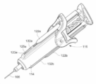
도 1은 안전 주사기의 단면도이다.
도 2a는 내부 방향의 스트로크를 따라 제 1 지점에 안전 주사기의 평면도이다.
도 2b는 내부 방향의 스트로크를 따라 제 2 지점에 안전 주사기의 평면도이다.
도 2c는 내부 방향의 스트로크를 따라 제 3 지점에 안전 주사기의 평면도이다.
도 3은 안전 주사기의 등각 투영도이다.
도 4는 회전 기구 또는 안전 주사기의 개략도이다.
도 5a는 손잡이 부분의 평면도이다.
도 5b는 손잡이 부분 및 주사기 플런저의 등각 투영도이다.
도 5c는 손잡이 부분 및 주사기 플런저 사이의 단면이다.
도 6a는 크롭 테두리를 포함하는 주사기의 통의 평면도이다.
도 6b는 둥근 테두리를 포함하는 주사기의 통의 평면도이다.
도 7은 안전 주사기 사이의 단면도이다.
도 8a 내지 8f는 예시적인 브레이크 구성들을 도시한다.
도 9는 안전 주사기의 평면도이다.1 is a cross-sectional view of a safety injector;
Fig. 2a is a top view of the safety injector at a first point along a stroke in the inward direction;
Figure 2b is a top view of the safety syringe at a second point along the stroke in the inward direction;
Figure 2c is a top view of the safety syringe at a third point along the stroke in the inward direction;
3 is an isometric view of a safety injector;
4 is a schematic view of a rotating mechanism or safety injector;
5A is a plan view of a handle portion;
5B is an isometric view of a handle portion and a syringe plunger;
5C is a cross-section between the handle portion and the syringe plunger.
6A is a top view of a barrel of a syringe including a cropped rim.
6B is a plan view of a barrel of a syringe including a rounded rim.
7 is a cross-sectional view between the safety syringes.
8A-8F show exemplary brake configurations.
9 is a plan view of the safety injector;
일반적으로 이 문서에서 공개된 안전 주사기들은 바늘이 노출되는 제 1 지점에서 주사기의 바늘이 덮이도록 배치되는 지점으로 이동할 수 있는 시스(sheath)를 포함한다. 시스는 주사기의 정상적인 작동 중에 즉, 주사기의 통(barrel)에서 물질을 배출하기 위해 주사기 플런저(plunger)의 내부 방향의 스트로크 중에 사용자가 가하는 힘으로 움직일 수 있다. 예시적인 안전 주사기들에서 시스는 내부 방향의 스트로크 중에 주사기의 통을 따라 이동할 수 있고, 그리고 그 경우 바늘을 덮기 위해 통의 단부를 지나 이동할 수 있다. 또한, 예시적인 시스들은 시스가 통의 길이를 따라 움직이도록 허용하는 전방(forward) 및 후방(rearward) 단부들에 애퍼처(aperture)를 포함한다.The safety syringes disclosed in this document generally include a sheath that is movable from a first point at which the needle is exposed to a point at which the needle of the syringe is disposed to be covered. The sheath can be moved by the force exerted by the user during normal operation of the syringe, ie during an inward stroke of the syringe plunger to expel material from the barrel of the syringe. In exemplary safety syringes the sheath may move along the barrel of the syringe during an inward stroke, and in that case it may move past the end of the barrel to cover the needle. Exemplary sheaths also include apertures at the forward and rear ends that allow the sheath to move along the length of the barrel.
침 부상(stick injury)들을 방지하기 위하여, 시스가 완전히 배치된 경우에, 시스의 전방 단부(forward end)(또한, 그리고 전방 단부의 애퍼처)는 바늘의 단부를 지나 일정 거리를 연장하도록 요구될 수 있다. 이것은 손가락 또는 사용자의 몸의 다른 일부가 애퍼처에 들어가고, 그리고 바늘에 접촉하는 위험을 줄인다. 시스의 전방 단부가 바늘의 단부를 지나 일정 거리를 연장할 수 있는 거리를 결정하기 위한 하나의 테스트는 시스가 배치되는 경우에 시스의 전방 단부에 애퍼처에 대해 고정되는 12mm 구체(sphere)를 수반한다. 시스의 치수들은 애퍼처에 대해 고정되는 경우에 12mm의 구체가 접촉되지 않을 정도이여야 한다.To prevent stick injuries, when the sheath is fully deployed, the forward end of the sheath (and the aperture of the forward end) may be required to extend a certain distance beyond the end of the needle. can This reduces the risk of a finger or other part of the user's body entering the aperture and contacting the needle. One test to determine how far the front end of the sheath can extend a certain distance past the end of the needle involves a 12 mm sphere secured against an aperture at the front end of the sheath when the sheath is deployed. do. The dimensions of the sheath should be such that a sphere of 12 mm would not contact when clamped against the aperture.
발명가들은 더 큰 지름의 통들을 사용하는 경우에, 테스트의 요구 조건들을 충족시키기 위해서 주사기를 지나 연장하도록 하는 시스의 거리가 증가된다는 것을 깨달았다. 예시적인 안전 주사기들에서 이것은 주사기의 플런저의 전체적인 스토로크 길이를 증가시킬 수 있고, 이는 결국 주사기를 작동하기 위해 그들의 손을 뻗는(stretch) 사용자의 능력에 영향을 줄 수 있다. 발명가들은 시스의 전방 단부에 애퍼처의 지름을 줄이면 바늘의 단부를 지나 이동하기 위해 요구되는 시스의 거리를 줄일 수 있다는 것을 추가로 깨달았다. The inventors realized that when using larger diameter barrels, the distance of the sheath to extend past the syringe was increased to meet the requirements of the test. In exemplary safety syringes this may increase the overall stroke length of the plunger of the syringe, which in turn may affect the user's ability to stretch their hand to actuate the syringe. The inventors further realized that reducing the diameter of the aperture at the front end of the sheath could reduce the distance of the sheath required to move past the end of the needle.
또한, 예시적인 시스들은 통을 적어도 부분적으로 둘러싸고, 통은 시스의 내부 치수를 정의한다. 시스의 전방 단부에 애퍼처는 시스의 내부 치수보다 작은 치수를 가진다. 시스의 애퍼처는 통의 외부의 치수보다 작은 치수를 가질 수 있다. 일부의 배열들에서 시스의 전방 단부에 애퍼처는 시스의 배치 전에 통의 주요 부분의 전방에 위치될 수 있고, 그리고 통의 목에 인접하게 위치될 수 있다.In addition, exemplary sheaths at least partially surround the vat, the vat defining an internal dimension of the sheath. The aperture at the front end of the sheath has a dimension smaller than the inner dimension of the sheath. The aperture of the sheath may have a dimension smaller than the dimension of the exterior of the vat. In some arrangements the aperture at the front end of the sheath may be positioned in front of the major portion of the vat prior to placement of the sheath, and may be positioned adjacent the neck of the vat.
본 설명서 전체에서 '전방(forward)'이라는 용어는 안전 주사기의 단부가 환자에게 향하도록 하는 것을 지칭한다. 다시 말해서, 안전 주사기의 전방 단부는 사용 중에 주사 부위의 근위의(proximal) 단부이다. 마찬가지로, '뒤쪽(rear)' 또는 '후방(rearward)'이라는 용어들은 안전 주사기 또는 그 구성요소의 환자를 향하지 않는 단부를 지칭한다. 다시 말해서, '후방(rearward)'이라는 용어는 사용 중에 주사 부위로부터 멀거나 멀리 떨어져 있는 것을 의미한다. 축(axial), 종방향(longitudinal) 및 이와 같은 상대적인 용어들은 장치의 서술에 도움이 되도록 사용된다.Throughout this manual, the term 'forward' refers to having the end of the safety injector facing the patient. In other words, the front end of the safety syringe is the proximal end of the injection site during use. Likewise, the terms 'rear' or 'rearward' refer to the non-patient end of the safety injector or component thereof. In other words, the term 'rearward' refers to being far or far away from the injection site during use. The terms axial, longitudinal, and relative terms such as these are used to aid in the description of the device.
도 1은 통(barrel)(102), 통 목(barrel neck)(104) 및 피하 주사기 바늘(hypodermic needle)(106)을 포함하는 주사기를 포함하는 안전 주사기(safety syringe)(100)를 도시한다. 피하 주사기 바늘(106)은 비어 있다. 통(102)은 환자에게 주입할 물질을 수용하도록 구성된다. 통은 통목(104)쪽으로 좁아지는 숄더(108)를 포함한다. 통 목(104)은 통(102)과 바늘(106)의 빈 채널(channel) 사이에 유체 경로가 존재하도록 피하 주사기 바늘(106)을 수용하도록 구성된 구멍을 포함한다. 예시적인 안전 주사기들(100)에서 바늘(106)은 통 목(104)을 통해 통(102)에 고정적으로 부착된다. 그러한 안전 주사기들(100)에서 바늘(106)은 동일하거나 또는 다른 유형의 다른 바늘들로 대체될 수 있다.1 shows a
주사기는 주사기 플런저(plunger)(110) 및 마개(bung)(112)를 더 포함한다. 주사기 플런저(110)는 통(102) 안에 수용되고, 그리고 마개(112)와 연결되도록 구성된다. 주사기 플런저(110) 및 마개(112)는 통(102)의 안에서 움직일 수 있도록 구성된다. 주사기 플런저(110)는 내부 방향의 스트로크로 움직일 수 있다. 여기서, 주사기 플런저(110)는 통(102) 안에서 더 움직인다. 또는 주사기 플런저(110)는 외부 방향의 스트로크로 움직일 수 있다. 여기서, 주사기 플런저(110)는 통의 밖으로 당겨진다. 주사기 플런저(110) 및 마개(112)는 주사기 플런저의 내부 방향의 스트로크로 인해 마개(112)의 내부 방향의 이동이 발생하고, 그리고 통에 고정된 물질(마개(112)와 통 목(104)의 단부 사이에 형성되는 볼륨(volume)에)이 마개(112)로부터 통(102)의 열린 단부에서 그리고 피하 주사기 바늘(106)을 통해 배출되도록 구성된다.The syringe further includes a
안전 주사기(100)는 시스(sheath)(114), 통(102)에 고정된 관계인 손잡이 부분(116), 및 안전 플런저(plunger)(118)를 포함하는 안전 주사기 장치를 더 포함한다.The
도 1의 예시적인 장치에서 안전 플런저(118)는 헤드(120) 및 암(arm)들(122a, 122b)을 포함한다. 암들(122a, 122b)은 안전 플런저(118)의 내부 스트로크에 지점에서 시스(114)와 맞물리도록 구성되는 시스 접촉 표면들을 포함할 수 있다. 시스 접촉 표면들은 시스(114)의 표면에 직접적으로 접촉하여 시스(114)와 맞물릴 수 있다. 도 2a의 예시적인 장치에서 시스 접촉 표면들(123a, 123b)은 암들(122a, 122b)의 후방 자리에 위치되고, 그리고 시스(118)에 후방 자리에 위치되는 시스의 표면(119a, 119b)에 접촉하도록 구성된다(도 2b에 보여진 바와 같이). 대안적인 방식들(도 3에서 보여진 것과 같은)에서 시스 접촉 표면들(123a, 123b)은 암들(122a, 122b)의 전방 단부에서 위치될 수 있고, 그리고 시스의 전방 자리에 위치되는 시스의 표면에 접촉하도록 구성될 수 있다. 예를 들어, 시스 접촉 표면들은 암들(125a, 125b)의 단부 표면들일 수 있다. The
시스(114)는 시스(114)의 내부 치수를 정의하는 통(102)의 외벽(121)을 둘러싼다. 시스(114)는 전방 단부에서 애퍼처(126)를 포함한다. 애퍼처(126)는 시스(114)의 배치 전에 숄더(108)의 전방에 위치될 수 있다. 애퍼처(126)는 시스(114)의 내부 치수(예를 들어, 지름(diameter))보다 더 작은 치수(예를 들어, 지름)이다. 예시적인 안전 주사기들에서 시스(114)의 애퍼처(126)는 통(102)의 외벽(121)보다 더 작은 치수(예를 들어, 지름)일 수 있다.The
도 1의 예시적인 안전 주사기에서 시스는 립(lip)(128)을 포함한다. 립(128)은 애퍼처(126)를 정의하기 위한 시스(114)의 내벽(130)으로부터 방사상으로(radially) 내부 방향으로 연장한다. 도 1에서 립은 애퍼처의 지름이 통의 외벽(121)보다 더 작은 직경인 지점에서 내부 방향으로 연장한다. 립(128)은 시스의 배치 전에 안전 주사기(100)의 숄더(108)와 접촉하도록 구성될 수 있다. 다른 방식들에서 립(128)은 시스(114)의 배치 전에 숄더(108)의 전방의 어떤 지점일 수 있다. 그렇게 함으로써, 통(102)의 외부 지름보다 더 작은 지름이 되는 애퍼처(126)를 허용한다.In the exemplary safety syringe of FIG. 1 , the sheath includes a
시스(114)는 채널들(132a, 132b)을 포함한다. 채널들(132a, 132b)은 안전 플런저(118)의 암들(122a, 122b)에 상응하고, 그리고 내부 방향의 스트로크 중에 각 채널(132a, 132b) 안에서 암들(122a, 122b) 중 하나의 이동을 허용하도록 구성된다.
도 1의 시스(114)는 통(102)의 대체로 전체 길이를 따라 통(102)을 둘러싸는 것으로 도시된다. 다른 방식들에서 시스는 통(102)의 바늘 단부, 전방에서만 통을 둘러쌀 수 있다. 이러한 방식들에서 시스(114)가 바늘(106)을 덮을 경우에, 시스(114)는 적어도 일부의 시스가 여전히 통(102)을 둘러싸는 길이일 수 있다.The
손잡이 부분(116)은 본체(main body)(134) 및 본체(134)로부터 측면으로 확장하는 테두리(flange)들(136a, 136b)을 포함한다. 본체(134)는 통(102)을 둘러싸는 부분을 포함하고, 그리고 거기에 고정된다. 테두리들(136a, 136b)은 엄지손가락이 안전 플런저(118)의 헤드(120)에 힘을 가하는 동안 사용자의 집게손가락 및 가운뎃손가락을 수용하도록 구성된다. 하지만, 손가락들 및/또는 엄지손가락의 어떤 조합도 사용될 수 있다. 손잡이 부분(116)은 바늘(106)에 연결되는 구멍의 원위단(distal end)에서 통(102)의 단부를 수용하도록 구성되는 애퍼처(138)에 의해 통(102)에 고정된다. 도 1의 실시예에서 통(102)는 손잡이 부분(116)에서 수용되는 방사상으로 돌출되는 립(139)을 포함하지만, 대안적인 방식들에서 손잡이 부분(116)은 방사상으로 돌출되는 립들 없이 주사기 통들을 수용할 수 있다.The
시스(114)는 손잡이 부분(116)의 본체(134) 안에 적어도 부분적으로 수용될 수 있다.The
안전 플런저(118)의 암들(122a, 122b)은 안전 플런저(118)가 손잡이 부분(116)에 상대적인 스트로크로 이동할 수 있도록 하는 손잡이 부분(116) 그리고, 통(102)을 통해 통과하도록 구성된다.
안전 주사기(100)는 안전 플런저(118)와 주사기 플런저(110)를 연결하도록 구성되는 연결 장치(coupling arrangement)를 포함할 수 있으며, 이는 내부 방향의 스트로크에서 안전 플런저(118)의 움직임이 주사기 플런저(110)의 내부 방향의 스트로크를 야기한다. 안전 주사기(100)는 안전 플런저(118)와 주사기 플런저(110)를 분리시키도록 구성되는 분리 장치(decoupling arrangement)를 포함할 수 있으며, 이는 주사기 플런저(110)에 관하여 안전 플런저(118)의 상대적인 움직임이 가능하다.The
숙련자는 많은 연결 및 분리 기구(mechanism)들을 활용할 수 있다는 점을 인정할 것이다. 예를 들어, 주사기 플런저 및 안전 플런저 중 하나는 주사기 플런저 및 안전 플런저 중 다른 하나의 연결 러그(coupling lug)들을 수신하도록 구성되는 연결 리세스(coupling recess)들을 포함할 수 있다. 러그들은 주사기 플런저와 안전 플런저를 연결하기 위해 연결 리세스와 맞물리고, 그리고, 주사기 플런저와 안전 플런저를 분리시키기 위해 연결 리세스로부터 분리되도록 구성될 수 있다. 대체 가능한 연결 및 분리 장치들은 아래에 서술되어 있다.The skilled artisan will appreciate that many connection and disconnection mechanisms can be utilized. For example, one of the syringe plunger and safety plunger may include coupling recesses configured to receive coupling lugs of the other of the syringe plunger and safety plunger. The lugs may be configured to engage the connecting recess to connect the syringe plunger and the safety plunger, and to disengage from the connecting recess to disconnect the syringe plunger and the safety plunger. Alternative connection and disconnection devices are described below.
도 2a 내지 2c는 안전 플런저(118)의 내부 방향의 스트로크를 따라 다양한 위치들에서 안전 주사기(100)의 도면들을 도시한다. 안전 주사기(100)의 작동은 도 2a 내지 2c를 참조하여 아래에 서술될 것이다.2A-2C show views of the
도 2a는 주사기 플런저(110)와 안전 플런저(118) 둘 다 완전히 확장되고, 그리고 그것들의 스트로크들의 가장 바깥쪽의(outermost) 지점들에서의 안전 주사기(100)를 도시한다. 주사기 플런저(110)는 안전 플런저(118)와 연결된다. 2A shows the
사용자는 손잡이 부분(116)의 테두리들(136a, 136b)에 한 손의 집게손가락 및 가운뎃손가락을 배치할 수 있고, 그리고 안전 플런저(118)의 헤드(120)에 같은 손의 엄지손가락을 배치할 수 있다. 그리고, 사용자는 엄지손가락을 집게손가락 및 가운뎃손가락을 향하도록 마무리하여 헤드(120)와 손잡이 부분(116)에 상대적인 힘을 가한다.명확성을 위해, 이 상대적인 힘은 헤드(120)에 대한 힘으로 여기에서 고려될 것이다.The user may place the index and middle fingers of one hand on the
헤드(120)에 가해지는 힘은 안전 플런저(118)의 내부 방향의 스트로크에서 시작된다. 안전 플런저(118) 및 주사기 플런저(110)가 연결되면, 주사기 플런저(110)의 내부 방향의 스트로크 또한 시작된다. 즉, 주사기 플런저(110) 및 안전 플런저(118)는 그것들이 안전 플런저(118)의 내부 방향 및/또는 외부 방향의 스트로크에 같이 움직인다는 점에서 종방향(longitudinally)으로 연결될 수 있다. 암들(122a, 122b)은 손잡이 부분(116)을 통해 이동하고, 그리고 시스(114)의 채널들(132a, 132b) 안에서 이동한다. 안전 플런저(118)의 암들(122a, 122b)은 시스 접촉 표면들(123a, 123b)이 시스(114)와 맞물리는 경우까지 계속 이동한다.The force applied to the
도 2b는 안전 플런저(118)와 시스(114)의 종방향의 연결을 제공하기 위해 시스 접촉 표면들(123a, 123b)이 시스(114)와 맞물리는 지점을 도시한다. 도 2b에서 보여지는 예시적인 방식에서 안전 플런저(118)의 시스 접촉 표면들(123a, 123b)은 시스 채널들(132a, 132b)의 후방 단부에 위치되는 시스의 표면들(119a, 119b)과 맞물린다. 도 2b에서 시스 접촉 표면들(123a, 123b)과 시스 채널들(132a, 132b)의 표면들(119a, 119b) 사이의 맞물림(engagement)은 접합부(abutment)로 제공된다. 또한, 내부 방향의 스트로크에 안전 플런저(118)의 헤드(120)에 힘의 지속적인 적용이 바늘(106)을 부분적으로 덮기 위한 시스의 움직임을 야기하도록 안전 플런저(118)는 시스(114)와 연결된다. FIG. 2B shows the point where the
대안적인 방식들에서 암들(122a, 122b)의 단부 표면들(125a, 125b)은 접합부를 제공하기 위한 채널들(132a, 132b)의 전방 단부에서 위치되는 표면에 접촉할 수 있다(도 3 참조). 이러한 방식은 암들(122a, 122b)이 시스(114)보다 더 튼튼한 재질로 제조된 경우에 유리할 수 있다. 시스(114)에 가해지는 어떤 전방 힘이 시스(114)의 비교적 약한 채널들(132a, 132b)과는 대조적으로 암들(122a, 122b)을 통해 통과할 것이기 때문이다.In alternative manners the
안전 플런저(118)와 시스(114) 사이에 종방향으로 연결이 발생하는 지점은 주사기 플런저(110)가 내부 방향의 스토로크를 완료시키는 지점일 수 있다. 즉, 연결은 주사기 플런저(110)의 스트로크의 중심부의(innermost) 지점에서 발생할 수 있다(이것은 필수적인 것은 아님). 이러한 방식들은 시스가 바늘을 덮기 위해 배치되기 전에 주사기(100)에서 통(102) 안에 포함되는(contained) 모든 물질이 배출된다. 다른 대안적인 방식들에서 안전 플런저(118) 및 시스(114)는 주사기 플런저(110)의 내부 방향의 스트로크의 완료 전에 지점에서 종방향으로 연결된다(아래에 더 자세하게 서술됨).The point at which the longitudinal connection occurs between the
도 2a 내지 도 2c의 예시적인 방식에서, 안전 플런저(118)와 시스(114)가 종방향으로 연결되는 지점은 주사기 플런저(110) 및 안전 플런저(118)가 종방향으로 분리되는 지점이다. 대안적으로, 안전 플런저(118)와 주사기 플런저(110)는 시스(114)와 안전 플런저(118)의 종방향의 연결 후 또는 전에 지점에서 종방향으로 분리될 수 있다.In the exemplary manner of FIGS. 2A-2C , the point at which the
안전 플런저(118)는 종방향의 분리 후에 주사기 플런저(110)에 상대적인 내부 방향의 스트로크에 종방향으로 자유롭게 움직일 수 있다. 예를 들어, 안전 플런저(118)는 주사기 플런저(110)가 종방향으로 상당히 정지되어 있는 경우에 종방향으로 자유롭게 움직일 수 있다(아래에 더 자세하게 서술됨). 대안적으로, 안전 플런저(118)의 종방향의 움직임의 속도는 종방향의 분리 후에 주사기 플런저(110)의 종방향의 움직임의 속도와 다를 수 있다. 종방향의 분리 후에 헤드(120)에 대한 힘의 지속적인 적용은 안전 플런저(118)의 내부 방향의 스트로크가 계속될 것이다. 시스(114)가 시스 연결 표면들(123a, 123b)에서 안전 플런저(118)와 종방향으로 연결되고 난 이후, 안전 플런저(118)의 지속적인 내부 방향의 움직임으로 인해 시스(114)의 내부 방향의 움직임이 발생한다.The
사용자가 헤드(120)에 힘을 계속 가하면, 안전 플런저(118)는 손잡이 부분(116)을 통해 계속 통과하고 그리고 시스는 통 목(104)을 적어도 부분적으로 둘러싸기 위해 움직이기 시작한다.As the user continues to apply force to the
도 2c에 도시된 바와 같이, 안전 플런저(118)의 내부 스트로크가 완료된 경우, 헤드(120)는 손잡이 부분(116)에 인접해 있고 그리고 주사기 플런저(110)의 헤드와 인접해 있다. 이 위치에서 시스(114)는 바늘(106) 및 통 목(104)을 둘러싸도록 확장한다. 시스(114)의 전방 단부는 바늘이 노출되지 않도록 바늘(106)의 끝부분(tip)을 넘어서 확장한다. 이 위치에서, 안전 플런저(118)는 바늘(106)이 노출되지 않도록 바늘(106)과 통(102)에 관하여 잠길 수 있다. 예시적인 안전 주사기들에서, 안전 플런저(110)는 손잡이 부분(116)에 잠겨질 수 있다.As shown in FIG. 2C , when the inner stroke of the
시스(114)의 배치 전에 통(102)의 숄더(108)의 전방으로 시스(114)의 애퍼처를 배치하여, 시스의 애퍼처(126)를 줄일 수 있다. 이는 애퍼처가 통(102)의 지름 주위로 확장하지 않고 통의 목(104)만 확장해야 되기 때문인데, 이는 통(102)에 비해 치수가 축소된 것이다. 이는 시스(114)가 침 부상들을 방지하기 위해 바늘(106)의 전방 단부의 앞쪽까지 확장할 필요가 없다는 것을 의미한다(통의 지름과 동일한 애퍼처(126)와 비교됨). 안전 주사기 장치를 더 큰 주사기들(일반적으로 더 큰 통의 지름을 가짐)과 함께 사용하는 경우, 시스(118)의 전방 단부가 바늘의 전방 단부를 지나 확장하는 거리를 늘릴 필요가 없다. 예를 들어, 주사기의 통은 8.05mm(1ml 주사기의 일반적인 지름)보다 클 수 있고 그리고 10.75mm(2.25ml 주사기의 일반적인 지름)이상일 수 있다. 시스의 전방 단부에 애퍼처는 통의 지름보다 더 작은 0.5mm 내지 2mm의 범위, 최대 1mm, 또는 최대 2mm의 지름을 가질 수 있다 또한, 시스는 바늘(106)과 통 목(104)의 길이를 조금 넘는 거리만 이동하면 되기 때문에, 내부 스트로크의 거리는 증가되지 않는다.By placing the aperture of the
도 4를 참조하면, 안전 주사기(100)는 주사기 플런저와 안전 플런저(118)의 종방향의 분리 후에 시스의 배치의 속도를 제어하기 위해 장치를 더 포함할 수 있다. 이 장치는 아래에서 설명되는 바와 같이 통에 회전력(rotational force)을 전한다는 점에서 회전 기구로 여겨질 수 있다. 회전력은 기구 자체에서 제공되는 속도 제어의 부산물(by-product)이다. 숙련자는 다른 기구들이 주사기의 통에 회전력을 전할 수 있다는 점을 인정할 것이고 그리고 여기에 공개된 방법들 및 장치는 아래에 서술된 구체적인 기구와 같은 기구들에 동일하게 적용할 수 있다. 예시적인 방법들 및 장치들은 통의 회전에 저항해야되는 모든 방식에서 사용될 수 있다.Referring to FIG. 4 ,
예시적인 장치는 안전 플런저(118) 상의 제 1 나사산(142) 및 제 1 나사산(142)과 맞물리도록 구성되는, 그리고 주사기 플런저(110) 상의 상응하는 제 2 나사산(144)을 포함한다.The exemplary device includes a
안전 주사기는 시스의 배치의 속도를 제어 및/또는 한정하고, 그렇게 함으로써 피험자로부터 바늘(106)의 추출의 속도를 제어 및/또는 한정하도록 구성된다. 도시되는 예시적인 장치는 종방향으로 분리된 후에, 내부로 제 2 나사산을 포함하는 주사기 플런저(110)로 확장하도록 구성되는 부재(member)(140)를 포함한다.The safety injector is configured to control and/or limit the rate of deployment of the sheath, thereby controlling and/or limiting the rate of extraction of the
분리 후에, 안전 플런저(118)의 부재(140) 상의 제 1 나사산(142)은 회전력을 전하기 위한 주사기 플런저(110)에 제 2 나사산(144)과 상호 작용을 한다. 회전력으로 인해 주사기 플런저가 안전 주사기(100)의 통(102)의 안에서 회전한다. 또한, 그것들이 종방향으로 분리된다고 하더라도, 안전 플런저(118)와 주사기 플런저(110)는 회전하면서 결합된 상태를 유지한다.After separation, the
통(102) 내에서 주사기 플런저(110)의 회전은 마개(112)와 주사기 플런저(110)의 전방 단부 사이에 마찰에 의해 저항되고 그리고 이것은 주사기 플런저(110)로부터 분리된 후에 안전 플런저(118)의 움직임의 속도를 제어 및/또는 한정한다.Rotation of the
마개(112)는 고무로 된 재질과 같은 탄력 있게 변형할 수 있는 재질로 형성될 수 있고, 그리고 통(102)의 내부의 지름보다 조금 더 크게 지름을 가져서, 마개(112)가 통(102) 안에 넣어지는 경우에 밀봉 부분(seal)이 형성된다. 밀봉 부분은 통(102) 내에서 주사기 플런저(110)의 회전 운동에 저항을 제공할 수 있다. 대안적으로 또는 추가적으로, 나사산들(142, 144)은 예를 들어 나사산들(142, 144) 사이에 마찰로부터 주사기 플런저(110)의 회전 운동에 저항하도록 구성될 수 있다. 나사산(142, 144)의 상호 작용하는 표면들은 특정한 마찰력(frictional force)을 제공하도록 구성될 수 있다. 또한, 주사기 플런저(110)는 마개(112)에 고정되지 않을 수 있고 그리고 그 안에서 자유롭게 회전할 수 있다. 그런 방식들에서, 주사기 플런저(110)의 회전 저항력의 적어도 일부는 마개(112)와 주사기 플런저(110) 사이에 마찰에 의해 제공될 수 있다. The
도 5a는 손잡이 부분(116)의 단면도(end elevation)를 도시한다. 도 5b는 손잡이 부분(116)을 통해 부분적으로 통과된 주사기 플런저(110)의 투시도(perspective view)를 도시한다. 도 5c는 손잡이 부분(116)을 통해 완전히 통과된 주사기 플런저(110)을 통한 단면도(section)를 도시한다. 명확하게 하기 위해, 도 5a 내지 5c는 안전 주사기(100)의 다른 특징들은 도시하지 않는다.5A shows an end elevation of the
예시적인 장치에서, 안전 플런저(118)는 그것의 내부 방향의 스트로크의 적어도 일부를 따라 주사기 플런저(110)의 회전을 방지하여 주사기 플런저(110)와 연결될 수 있다. 주사기 플런저(110)의 회전이 방지되어, 제 1 및 제 2 나사산(142, 144)은 주사기 플런저(110)가 회전하기 위해 상호 작용할 수 없기 때문에 주사기 플런저(110)는 안전 플런저(118)에 가해지는 힘에 따라 그것의 내부 방향의 스트로크를 따라 움직인다. 주사기 플런저(118)와 안전 플런저(110)는 내부 방향(또는 외부 방향)의 스트로크 상에 같이 이동하면서 종방향으로 연결된다.In the exemplary device, the
예시적인 장치에서, 손잡이 부분(116)은 손잡이 부분(116)의 쐐기가 있는(keyed) 애퍼처(152)를 포함할 수 있다. 도 5b에 도시된 바와 같이, 주사기 플런저(110)의 키잉 피처(keying features)들(156a, 156b)이 손잡이 부분(116)의 키잉 피처들(154a, 154b)과 맞물리는 경우에 주사기 플런저(110)의 회전이 방지되기 위해, 쐐기가 있는 애퍼처(152)는 주사기 플런저(110) 상의 키잉 피처들(156a, 156b)에 상응하는 키잉 피처들(154a, 154b)을 포함한다.In the exemplary device, the
주사기 플런저(110)가 손잡이 부분(116)에서 분리되고 그리고 회전하도록 허용되는 경우에 안전 플런저(118)에서 분리시킨다. 예시적인 장치에서, 주사기 플런저(110)의 키잉 피처들(156a, 156b)이 더 이상 손잡이 부분(116)의 키잉 피처들(154a, 154b)과 맞물리지 않게 제공될 수 있다. 예를 들어, 주사기 플런저(110)는 그것의 길이 상의 한 부분인 키잉 피처들(156a, 156b)을 포함할 수 있고 그리고 키잉 피처들(156a, 156b)이 쐐기가 있는 애퍼처(152)를 통해 통과하는 경우에, 주사기 플런저(110)는 자유롭게 회전할 수 있다.The
대안적으로, 도 5a 내지 5c에 도시된 바와 같이, 주사기 플런저(110)의 헤드(158)는 쐐기가 있는 애퍼처(152)를 통해 통과할 수 있도록 구성될 수 있다. 예시적인 주사기 플런저들(110)에서, 헤드(158)는 키잉 피처들(156a, 156b)을 포함하는 주사기 플런저(110)의 영역과 동일한 단면을 가질 수 있다. 이러한 예시적인 경우, 도 5c에 도시된 바와 같이, 주사기 플런저(110)는 완전히 애퍼처(152)를 통해 통과되도록 구성된다. 안전 플런저(110)가 쐐기가 있는 애퍼처(152)를 통해 통과되는 경우, 주사기 플런저(110)의 키잉 피처들(156a, 156b)은 더 이상 쐐기가 있는 애퍼처(152)의 키잉 피처들(154a, 154b)과 맞물리지 않고 그리고 주사기 플런저(110)는 자유롭게 회전할 수 있다. 여기서, 주사기 플런저(110)와 안전 플런저(118)는 종방향으로 분리된다.Alternatively, as shown in FIGS. 5A-5C , the
"분리(decoupled)"라는 용어는 안전 플런저와 주사기 플런저 사이에서 상대적인 움직임이 허용되는 모든 상황을 포함한다는 점에서 유의된다. 특정 장치에서, 상대적인 운동은 상대적인 종방향의 운동일 수 있다. 이것은 여기서 공개된 모든 장치들에게 적용한다. 즉, 주사기 플런저는 그것을 분리하기 위해 안전 플런저로부터 분리되거나(separated), 또는 떼어내거나(detached)할 필요가 없다. 또한, 그것들은 분리된 후에 그것의 내부 방향(또는 외부 방향)의 스트로크를 따라 안전 플런저의 일부의 움직임이 아직 있을 수 있지만, 주사기 플런저와 안전 플런저 사이에 움직임의 속도 사이에는 차이가 있다. 예를 들어, 종방향의 분리 후에 통 안에 회전의 움직임뿐만 아니라 내부 방향의 스트로크를 따라 안전 플런저의 일부 종방향으로 움직일 수 있지만, 주사기 플런저와 안전 플런저의 움직임의 비율이 1:1이 아니다. 발명가들은 예를 들어 2.25ml와 3ml의 주사기들을 사용하는 것이 단일분사(single injection) 동안에 환자에게 1ml 이상의 약을 전달하는 것과 관련된 문제를 가져올 수 있다는 것을 더 인식하고 있다. 경우에 따라, 주사 부위로 1ml 이상의 볼륨의 약물 전달은 전체 투여량을 흡수하지 못하는 환자에 대한 문제가 발생할 수 있다. 또한, 바늘이 제거된 후에 일부 약물은 주사 부위로부터 누출될 수 있다.It is noted that the term “decoupled” encompasses any situation in which relative movement between the safety plunger and the syringe plunger is permitted. In certain devices, the relative motion may be a relative longitudinal motion. This applies to all devices disclosed herein. That is, the syringe plunger does not need to be separated from, or detached from, the safety plunger to release it. Also, there may still be movement of a portion of the safety plunger along its inward (or outward) stroke after they are separated, but there is a difference between the speed of movement between the syringe plunger and the safety plunger. For example, some longitudinal movement of the safety plunger along an inward stroke as well as a rotational movement in the barrel after longitudinal separation may occur, but the ratio of movement of the syringe plunger to the safety plunger is not 1:1. The inventors are further aware that the use of, for example, 2.25 ml and 3 ml syringes may present problems associated with delivering more than 1 ml of drug to a patient during a single injection. In some cases, delivery of drugs in volumes greater than 1 ml to the injection site may cause problems for patients unable to absorb the full dose. Also, some drugs may leak from the injection site after the needle is removed.
일반적으로 공개된 안전 주사기들은 완전히 약물이 전달되기 전에 주사 부위 안에 주사기 바늘의 깊이를 제어하거나 또는 변경하도록 작동할 수 있다. 예시적인 방식들에서는 완전히 전달되기 전에 주사기 바늘의 부분적인 회수를 포함할 수 있다. 예시적인 안전 주사기들은 시스와 그리고 통 안에 물질을 분사하기 위해 주사기 통 안에 마개를 구동시키도록 구성되는 주사기 플런저를 포함한다. 예시적인 안전 주사기들에서, 바늘은 배치되는 시스에 의해 부위에 가해진 힘으로 주사 부위로부터 추출된다. 일부 장치들에서는 이것이 통 안에 모든 약물이 전달된 후에 완료된다. 여기에 공개된 예시적인 방식들에서, 시스는 주사기 플런저가 약물을 완전히 분사하기 전에 바늘을 추출하기 위해 환자의 피부에 힘을 가하도록, 시스는 내부 방향의 스트로크의 단부 전에 내부 방향의 스트로크 상의 한 지점에 배치될 수 있다.Commonly disclosed safety syringes are operable to control or change the depth of the syringe needle within the injection site before the drug is fully delivered. Exemplary modalities may include partial withdrawal of the syringe needle prior to full delivery. Exemplary safety syringes include a sheath and a syringe plunger configured to actuate a stopper within the syringe barrel to dispense a substance into the syringe barrel. In exemplary safety syringes, the needle is withdrawn from the injection site with a force applied to the site by a deployed sheath. In some devices this is done after all the drug has been delivered in the vat. In the exemplary manners disclosed herein, the sheath applies a force to the patient's skin to extract the needle before the syringe plunger fully ejects the drug, so that the sheath is placed on the inward stroke before the end of the inward stroke. It can be placed at a point.
약물이 완전히 분사되기 전에 시스 배치(그리고 바늘 회수(withdrawal))의 개념은 많은 안전 주사기 방식들에서 적용될 수 있다. 그러나, 아래에 서술되는 구체적인 방식은 앞서 서술된 예시적인 안전 주사기들을 참조한다.The concept of sheath placement (and needle withdrawal) before the drug is fully dispensed can be applied to many safety injector schemes. However, the specific manner described below refers to the exemplary safety injectors described above.
예시적인 안전 주사기들은 앞서 서술된 실질적으로 동일한 방식으로 작동할 수 있지만 주사기 플런저가 그것의 내부 방향의 단부에 도달되기 전에 시스에 안전 플런저를 종방향으로 연결하도록 구성될 수 있다. 예시적인 방식들에서, 안전 플런저 암들의 단부의 후방 표면(도 2b에 도시됨) 또는 안전 플런저 암들의 단부인 시스 접촉 표면들은 안전 플런저와 주사기 플런저가 종방향으로 분리되기 전에 안전 플런저 암들과 시스가 종방향으로 연결되도록 위치된다. 이러한 방식들에서 안전 플런저, 주사기 플런저 및 시스는 안전 플런저의 내부 방향의 스트로크의 일부에 대해 같이 종방향으로 연결되고 그리고 같이 전방으로 이동한다. 또한, 시스의 전방 단부는 시스와 안전 플런저의 종 방향의 연결 후에, 주사기 플런저가 그것의 내부 방향의 스트로크 상에 가장 안쪽의 지점에 있기 전에 시스의 전방 단부는 통의 목의 전방 단부의 전방에 있도록 통의 목의 전방 단부와 상대적으로 위치된다. 이로 인해 시스의 전방 단부는 주사 부위와 접촉되고 그리고 통의 안에 약물이 완전히 전달되기 전에 바늘을 부분적으로 빼낸다.Exemplary safety syringes may operate in substantially the same manner described above but may be configured to longitudinally connect the safety plunger to the sheath before the syringe plunger reaches its inwardly end. In exemplary manners, the rear surface of the end of the safety plunger arms (shown in FIG. 2B ) or the sheath-contacting surfaces that are the ends of the safety plunger arms are the safety plunger arms and the sheath before the safety plunger and syringe plunger are longitudinally separated. positioned to be connected in the longitudinal direction. In these manners the safety plunger, syringe plunger and sheath are longitudinally connected together and move forward together for part of the inward stroke of the safety plunger. Also, after the longitudinal connection of the sheath and the safety plunger, the front end of the sheath is in front of the front end of the neck of the barrel before the syringe plunger is at its innermost point on its inward stroke. so that it is positioned relative to the front end of the neck of the barrel. This causes the anterior end of the sheath to contact the injection site and partially withdraw the needle before full delivery of the drug into the vat.
발명가들은 회전력이 주사기 플런저에 가해지는 예시적인 안전 주사기에 대해 인식하고 있다. 예를 들어, 주사기 플런저와 안전 플런저의 종방향의 분리 후에 제 1 및 제 2 나사산에 의한 주사기 플런저(앞서 서술됨)의 회전에 의해 회전력이 통에 가해질 수 있다. 안전 주사기들에서, 통 자체의 회전을 야기하는 회전력을 방지하는 것이 바람직할 수 있다.The inventors are aware of an exemplary safety syringe in which a rotational force is applied to the syringe plunger. For example, a rotational force may be applied to the barrel by rotation of the syringe plunger (described above) by first and second threads after longitudinal separation of the syringe plunger and safety plunger. In safety syringes, it may be desirable to prevent rotational forces that cause rotation of the barrel itself.
다수의 통 디자인들은 전체 테두리(flange), 크롭(cropped) 테두리 또는 테두리가 없는 상태로 존재한다. 도 6a는 잘린 테두리(660)(키잉 표면들(662a, 662b)을 포함함)를 포함하는 통을 도시하고, 도 6b는 둥근 테두리(664)를 포함하는 통을 도시한다. 크롭 테두리들을 포함하는 주사기 통들에서, 손잡이 부분(통이 수용되는 내부)의 내벽(inner wall)에 쐐기가 있는 표면들은 통의 회전을 방지하기 위해 활용될 수 있다. 하지만, 회전 방지를 위한 대안적인 방법이 전체(또는 둥근) 테두리들을 포함하는 주사기 통들에게 필요할 수 있다. 하지만, 아래에 설명된 회전을 방지하기 위한 방식들은 대체로 모든 통 테두리 기하학적 구조(geometry)(크롭 테두리들도 포함됨)와 함께 활용될 수 있다고 이해될 수 있다. 본 발명은 안전 주사기 장치와 같은 안전 주사기 장치와 함께 사용하기 위한 브레이크가 있고, 주사기 통에 회전력을 가하는 것을 저항하기 위한 마찰력을 제공하도록 구성된다. 브레이크는 통과 접촉할 수 있다.Many barrel designs exist with full flanges, cropped rims, or no rims. 6A shows a vat including a truncated rim 660 (including keying
브레이크는 회전 정지 통(rotationally stationary barrel)에 가해지는 회전력에 저항하도록 구성될 수 있다. 또한, 브레이크는 통과 브레이크 사이에 상대적인 회전 움직임을 가능하게 하기 위해 극복하는 것이 필요한 통과 브레이크 사이에 정지 마찰력(static friction)(또는 정지 마찰(stiction))을 증가시킬 수 있다. 마찰력을 증가시켜 브레이크가 회전하기 시작하는 통에 저항한다.The brake may be configured to resist a rotational force applied to a rotationally stationary barrel. In addition, the brake may increase the static friction (or stiction) between the pass brakes that needs to be overcome to enable relative rotational movement between the pass brakes. By increasing friction, the brake resists the barrel starting to rotate.
도 7은 예시적인 안전 주사기를 도시한다. 안전 주사기(700)의 많은 특징들은 앞서 설명한 예시적인 안전 주사기들의 특징들과 동일하거나 또는 유사할 수 있고, 그리고 '7'로 시작하는 경우를 제외하고, 동일한 참조 번호들을 이러한 특징들에 활용할 수 있다. 또한, 안전 주사기(700)의 모든 특징들은 반복되는 것을 피하기 위해 모두 서술되는 것은 아니다. 다음 설명의 초점은 이미 앞서 설명된 특징들과 다른 안전 주사기의 특징들이다.7 depicts an exemplary safety injector. Many features of
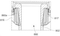
안전 주사기(700)는 통(702), 마개(712) 및 주사기 플런저(710)을 포함하는 주사기를 포함한다. 안전 주사기(700)는 주사기와 함께 사용하기 위한 안전 주사기 장치를 더 포함할 수 있다. 안전 주사기 장치는 시스(714), 손잡이 부분(716), 안전 플런저(718), 회전 기구(740) 및 브레이크(760)를 포함할 수 있다.
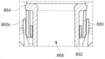
앞서 서술된 바와 같이, 예시적인 안전 주사기들(700)에서, 주사기 플런저(710)는 안전 플런저(714)로부터 종방향으로 분리되고 난 후에 통(702) 안에서 회전하도록 구성될 수 있다. 주사기 플런저(710)의 회전은 앞서 서술된 제 1 및 제 2 나사산들에 의해 야기될 수 있다. 도 7에 미도시 되었지만, 주사기 플런저(710)는 그것이 내부 방향의 스트로크의 단부에서 회전하는 동안 마개(712)와 맞물리게 된다. 또한, 안전 플런저 상의 제 1 및 제 2 나사산과 주사기 플런저(710)는 주사기 플런저(710)을 회전시킬 뿐만 아니라 마개(712)에 상대적인 주사기 플런저(710) 전방으로 밀기 위해 각각 상호 작용한다. 마개(712)는 통의 단부에 억제된다. 이 동작은 마개(712)에 주사기 플런저(710)의 회전력을 전달하는 행동을 하는 마개(712)와 주사기 플런저(710) 사이에 마찰을 야기한다. 마개(712)는 통의 안에 억지 끼워맞춤(interference fit)dl 되기 때문에, 회전력은 통에 전달된다. 이 회전력은 브레이크(760)에 의해 저항될 수 있다. 통의 회전은 방지될 수 있다. As previously described, in the
브레이크(760)는 직접적으로 통(702)과 접촉해 있을 수 있다. 도 7의 예시적인 안전 주사기(700)에서, 브레이크(760)는 통(702)의 측벽(sidewall)(721)에 접촉하고 있다. 대안적인 방식들에서, 브레이크(760)는 통(702)에 간접적으로 접촉하고 있다. 예를 들어, 칼라(collar)(또는 다른 부품(component))는 통(702)에 종방향 및 회전되게 고정될 수 있고 그리고 통(702)의 회전에 저항하기 위해서 칼라에 브레이크가 접촉할 수 있다. 예시적인 안전 주사기(700)에서, 손잡이 부분(716)은 통(702)에 관하여 종방향으로 고정된다. 손잡이 부분은 통(702)이 수용되는 안에 애퍼처를 포함한다.Brake 760 may be in direct contact with
손잡이 부분(716)은 브레이크(760)를 수용하고 그리고 조립되는 경우 통(702)에 대해 압축한 브레이크(760)를 유지하도록 구성된다. 그림 7의 안전 주사기(700)에서, 브레이크(760)는 통(702)에 대해 직접적으로 압축하여 유지된다. 대안적인 방식들에서 브레이크(760)는 통(702)에 대해 간접적으로 압축하여 유지할 수 있다, 예를 들어, 브레이크(760)는 통에 연결된 추가의 부품에 대해 압축된 상태로 유지될 수 있다.The
도 7에 도시된 안전 주사기(700)에서, 브레이크의 방사상(radial)의 두께는 통이 수용되는 경우, 손잡이 부분(716)과 통(702) 사이에 형성된 간격(gap)보다 조금 더 클 수 있다. 또한, 브레이크(760)는 그들 사이에 억지 끼워맞춤으로 손잡이 부분(716)과 통(702) 사이에서 압축된 상태로 유지될 수 있다.In the
예시적인 안전 주사기(700)에서, 브레이크는 그로밋을 포함할 수 있다. 그로밋은 통에 접촉하는 고무 또는 탄성중합체(elastomer) 엘리먼트(element) 같이 탄력 있게 변형할 수 있는 재료를 포함할 수 있다. 도 7에서, 그로밋의 탄성중합체 엘리먼트는 통과 직접적으로 접촉하지만, 대안적인 방식들에서 탄성중합체 엘리먼트는 통(702)과 간접적으로 접촉할 수 있다(예를 들어 통과 연결된 추가 부품). In the
그로밋은 주사기의 통(704)이 수용되도록 구성되는 애퍼처(766)를 포함한다. 애퍼처(766)는 억지 끼워맞춤이 통(704)과 그로밋 사이에 형성되도록 통(704)의 외부의 치수들보다 조금 작은 치수들일 수 있다. 또한, 브레이크(760)는 애퍼처(766)의 내부의 둘레(circumference)에 의해 형성될 수 있다. 즉, 마개(712)에 의해 가해지는 통(702)의 회전 움직임에 저항하기 위한 마찰력들은 억지 끼워맞춤 때문에 그로밋으로부터 통(704)의 측벽에 가해지는 압축력(compressive force)에 의해 제공될 수 있다. 통과 브레이크의 재료는 통의 회전 움직임의 저항을 극대화하기 위해 높은 마찰의 계수를 제공하도록 구성될 수 있다. 예를 들어, 브레이크는 열가소성 수지(thermoplastic) 엘라스토머로 제조될 수 있다(예를 들어 Dryflex® 또는 Mediprene®). The grommet includes an
도 8a 내지 8f는 브레이크의 구현을 위한 예시적인 방식들을 통한 단면도들을 도시한다.8A-8F show cross-sectional views through exemplary ways for the implementation of a brake.
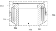
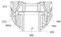
도 8a에서, 통(802)는 손잡이 부분(816)에 애퍼처의 안이 도시된다. 애퍼처는 측벽(817)에 의해 정의된다. 브레이크(860a)는 이 예에서는 탄력 있게 변형할 수 있는 그로밋을 포함한다. 그로밋(860a)의 내부의 측벽들은 전방 뒤쪽 지점부터 내부 방향으로 각을 이룬다. 즉, 그로밋(860a)의 내부의 측벽들은 전방 방향에 점점 더 좁아지는 애퍼처를 정의한다. 도 8a에 도시된 바와 같이, 그로밋(860a)의 내부의 측벽의 전방 영역은 통(802)의 측벽에 만난다. 브레이크는 맞물려져 있다.In FIG. 8A ,
도 8b는 통(802)의 외부의 지름보다 더 큰 지름을 가지는 애퍼처(866)를 형성하는 그로밋(860b)을 도시한다. 통(802)은 그로밋(860b)의 간섭 없이 애퍼처(866)를 통해 통과할 수 있다. 즉, 통(802)은 그로밋(860b)의 내부의 측벽들과 만나는 통(802)의 측벽들 없이 애퍼처(866)를 통해 통과할 수 있다. 간격(clearance)(880)은 그로밋(860b)과 통(802)의 측벽 사이에 존재한다. 이번 그리고 다른 예시적인 방식들에서, 간격은 최대 0.5mm, 최대 0.75mm, 최대 1mm 또는 1.25mm일 수 있다. 8B shows a grommet 860b defining an
또한, 통(802)이 애퍼처(866)에 진입하는 경우, 브레이크는 맞물리지 않는다. 브레이크는 통(802)이 애퍼처(866)에 진입되고 난 후에 맞물리게 된다.Also, when the
도 8b의 예시적인 방식에서 그로밋(860b)은 반응 표면(reaction surface)(880)에 대해 놓인다(rest). 반응 표면(880)는 그로밋(860b)의 전방 움직에 저항한다. 도 8a에서, 반응 표면은 안전 주사기의 축 방향으로 가로로 놓인다(transverse).In the exemplary manner of FIG. 8B , grommet 860b rests against
이번 그리고 다른 예시적인 방식들에서, 그로밋(860b)는 애퍼처(866)의 뒤쪽 단부로부터 후방으로 확장한다. 즉, 그로밋(860b)의 뒤쪽 부분은 손잡이 부분에 형성된 애퍼처(866)를 자랑스러워한다(proud). 이것은 통(802)의 테두리(864)와 상호작용을 하기 위해 그로밋(860b)이 허용될 수 있다. 테두리(864)와 그로밋(860b)의 뒤쪽 부분이 만나기 때문에 전방 힘이 그로밋(860b)에 가해진다. 전방 힘은 반응 표면(882)에 의해 저항된다. 그로밋(860b)은 압축되어 있다. 그로밋(860b)의 압축은 테두리(864)와 그로밋(860b) 사이에 정지 마찰을 생산한다. 그렇게 함으로써 브레이크가 맞물리게 된다. 테두리(864)의 밑면(underside)과 그로밋(860b) 사이에서 생성하는 정지 마찰은 주사기를 사용하는 동안 사용자에게 가해지는 힘이 그로밋(860b)의 압축이 증가하고 그리고 정지 마찰이 증가하는 이점을 가진다. 의심을 방지하기 위해, 여기서 사용된 바와 같이, 용어 "정지 마찰(stiction)"은 정지된 표면들이 움직이는 것을 방지하기 위한 경향이 있는 마찰을 포함한다.In this and other exemplary manners, the grommet 860b extends rearwardly from the rear end of the
테두리(864)의 밑면(underside)과 그로밋(860b) 사이에서 생성하는 정지 마찰 뿐만 아니라, 그로밋(860b)는 압축 중에 측면으로 확장될 수 있다. 그로밋(860b)의 내부의 측벽은 통(802)의 측벽과 만날 수 있다. 또한 정지 마찰은 통(802)의 측벽에 대해 생성될 수 있다.In addition to the static friction it creates between the grommet 860b and the underside of the
도 8c는 통(802)의 외부의 지름보다 더 큰 지름을 가지는 애퍼처(866)를 형성하는 그로밋(860c)을 도시한다. 도 8b와 유사한 간격(880)은 형성되고 그리고 통(802)이 애퍼처(866)에 진입하는 경우에 브레이크가 맞물리지 않는다.8C shows a
도 8의 방식에는 반응 표면(884)도 포함한다. 반응 표면(884)은 방사상의 내부 방향으로 각을 이룬다. 그로밋(860c)의 축 방향 움직임 상에, 그로밋(860c)은 반응 표면(884)과 상호 작용을 하고 그리고 방사상의 내부 방향으로 가이드 된다(guided). 그로밋(860c)은 정지 마찰을 생성하는 통(802)의 측벽과 만난다. 다른 예시적인 방식들과 같이, 그로밋(860c)의 후방 표면은 통(802)의 테두리(864)와 접촉되도록 구성될 수 있다. 전방 방향에 통(802)의 추가 움직임은 그로밋(860c) 상에 전방 힘이 발생한다. 그로밋(860c)은 반응 표면(884)과 상호 작용을 하고 그리고 측면으로, 이 경우에는 방사상의 내부 방향으로 이동된다. 도 8b와 같이, 그로밋(860c)은 애퍼처(866)의 뒤쪽 단부로부터 후방으로 확장할 수 있다.The scheme of FIG. 8 also includes a reaction surface 884 . Response surface 884 is angled in a radially inward direction. Upon axial movement of the
그럼 8d는 손잡이 부분(816)에 끼울 수 있는(fittable) 인서트(insert)(872)의 방식을 도시한다. 통(802)이 애퍼처(866) 안에 수용되는 후에 인서트(872)는 손잡이 부분(816)에 끼워질 수 있다. 인서트(872)는 브레이크와 맞물리도록 구성된다. 예시적인 방식들에서, 인서트(872)는 정지 마찰을 생성하기 위해 통(802)에 대해 그로밋(860d)의 적어도 일부를 압축하는 브레이크와 맞물릴 수 있다.8d then shows the manner of an
그림 8d의 예에서, 인서트는 적어도 하나의 측면의 변위 피처(displacement feature)(886)를 포함한다. 측면의 변위 피처(886)는 통(802)(그리고, 테두리가 있는 경우, 테두리(864))의 측벽의 방사상으로 바깥쪽 손잡이 부분(816)으로 확장하도록 구성되는 일반적인 원형의 모양 벽을 포함한다. 측면의 변위 피처(886)는 일반적인 원형의 모양 벽의 복수의 별개의 부분들을 포함할 수 있다. 측면의 변위 피처(886)는 손잡이 부분(816)으로 확장하는 모든 엘리먼트를 포함할 수 있고 그리고 그로밋(860)을 측면으로(예를 들어, 측면 내부의 방향) 변위하도록 구성될 수 있다.In the example of FIG. 8d , the insert includes at least one
그로밋(860d)은 애퍼처(866)의 내부에 위치된다. 간격(880)은 통(802)과 그로밋(860d)의 내부의 측벽 사이에 제공된다(앞서 서술된 바와 같이).A
인서트(872)는 손잡이 부분(816)에 끼워지면, 측면의 변위 피처(886)는 방사상의 내부 방향으로 변위하는 그로밋(860d)과 접촉한다. 그로밋(860d)은 통(802)의 측벽과 만나고 그리고 정지 마찰을 생성한다. 하나 또는 둘 다의 측면의 변위 피처(886) 및 그로밋은 방사상의 내부 방향의 그로밋(860d)의 측면 변위의 챔퍼처리된(chamfered) 표면을 포함한다.When the
일부 예시적인 방식들에서, 브레이크(예를 들어 그로밋)는 하위 어셈블리(sub-assembly)를 형성하기 위해 주사기의 통(802)에 끼워질 수 있다. 하위 어셈블리는 손잡이 부분(816)에 대해 상대적으로 축의 방향 및 회전되게 고정되도록 손잡이 부분(816)으로 끼워질 수 있다. 또한, 예시적인 방식들에서, 손잡이 부분(816)은 통(802)이 애퍼처(866)에 완전히 삽입된 후에 통(802)의 플런저(864)가 놓이는 곳에 대해 하단 외부(bottom out) 표면을 포함할 수 있다. 하단 외부 표면은 통(802)의 추가적인 전방 움직임을 방지한다.In some exemplary manners, a brake (eg, a grommet) may be fitted into the
도 8e 및 도 8f는 손잡이 부분(816e, 816f)이 애퍼처(866)를 열기 위해 작동하는 예시적인 방식들을 도시한다. 애퍼처(866)을 개방함으로써, 예시적인 방식들은 통(802)의 지름보다 더 크게 애퍼처(866)의 지름을 증가시킬 수 있다. 다른 방식들에서, 도 8e 및 도 8f에 도시된 바와 같이, 애퍼처(866)는 그것이 갈라지도록 개방되고 통(802)은 측면으로 삽입될 수 있다. 애퍼처(866)로 통(802)(측면으로 또는 통과하여)의 삽입 후에, 손잡이 부분(816e, 816f)는 통(802) 주위에 애퍼처(866)를 닫기 위해 작동할 수 있다. 애퍼처(866)는 그로밋(860e, 860f)을 포함할 수 있다. 지름이 통(802)의 지름 보다 크기 위해 증가되도록 애퍼처(866)가 개방되면, 그로밋은 단일 부분에 있을 수 있다. 도 8e 및 도 8f에 도시된 예들에서, 애퍼처가 갈라지고 그리고 그로밋(860e, 860f)은 복수의 분리된 부분들에 있다(이들 경우들에서, 두 부분들). 8E and 8F show example ways in which the
도 8e 및 도 8f에 손잡이 부분(816e, 816f)은 애퍼처(866)가 갈라지거나 또는 개방하기 위해 분리 가능한 두 부분들을 포함할 수 있다. 손잡이(816e)의 부분들은 경첩(hinge)으로 연결되고 경첩을 열어서 분리 가능하고, 그리고 손잡이 부분(816f)의 부분들은 완전히 분리된다. 애퍼처(866)는 열리고 그리고 통(802)은 애퍼처(866)에 삽입된다. 애퍼처(866)는 예를 들어 힌지를 닫거나 또는 손잡이 부분(816e, 816f)의 부분들을 합침으로써 닫힌다. 그로밋(860e, 860f)은 통(802)의 측벽에 닿도록 눌러져 있어 정지 마찰을 생성하고 그리고 브레이크에 맞물린다.The
추가적인 방식은 도 9에 도시된다. 도 9의 안전 주사기(900)의 많은 특징들은 앞서 설명한 모범 안전 주사기들의 특징들과 동일하거나 또는 유사할 수 있고, 그리고 '9'로 시작하는 경우를 제외하고, 동일한 참조 번호들을 이러한 특징들에 활용할 수 있다. 또한, 안전 주사기(900)의 모든 특징들은 반복되는 것을 피하기 위해 모두 서술되는 것은 아니다. 다음 설명의 초점은 이미 앞서 설명된 특징들과 다른 안전 주사기의 특징들이다.A further scheme is shown in FIG. 9 . Many features of the safety injector 900 of FIG. 9 may be the same or similar to those of the exemplary safety injectors described above, and the same reference numbers may be utilized for these features, except where they begin with a '9'. can Also, not all features of safety injector 900 have been described in order to avoid repetition. The focus of the following description is on features of the safety injector that differ from those already described above.
도 9에 도시된 바와 같이, 브레이크(960)은 통(902)의 상단(또는 뒤쪽) 표면(917)에 접촉할 수 있다. 통(902)은 통(902)의 상단 표면(917)이 압축 상태인 브레이크(960)를 유지하도록 손잡이 부분(916) 안에 유지된다. 브레이크(960)는 그로밋을 다시 포함할 수 있다.As shown in FIG. 9 , the
이 대안적인 방식에서 안전 주사기(900)은 손잡이 부분(916)에 끼워지는 인서트(972)를 더 포함할 수 있다. 이러한 방식에서, 안전 주사기 장치는 주사기의 바늘 단부가 손잡이 애퍼처를 처음 통과하도록 손잡이 부분(916)의 뒤쪽 면으로부터 손잡이 부분(916)의 애퍼처(도 9에 미도시)로 주사기(그리고 브레이크(960)을 삽입함으로써 조립된다. 인서트(972)는 삽입된 주사기 위로 손잡이 부분(916)의 뒤쪽 면에 끼워질 수 있다. 예를 들어, 인서트(972)는 손잡이 부분(916)의 뒤쪽 면에 스냅핏(snap-fit)하기 위해 구성될 수 있다. In this alternative manner, the safety injector 900 may further include an
인서트(972)는 통(917)의 상단 표면에 대해 압축 상태에 브레이크(960)를 유지하기 위해 구성될 수 있다. 인서트(972)가 손잡이에 끼워진 경우에 통(902)의 상단 표면(917)과 인서트의 전방 표면(974) 사이에 형성되는 간격은 종방향에서 브레이크(960)의 두께보다 조금 작은 치수이다. 또한, 인서트(972)와 통(902) 사이에서 브레이크(960)의 압축 상태의 결과 인해 통의 상단에 가해지는 힘으로부터 통(902)의 회전의 움직임을 저항하기 위한 마찰력들이 제공될 수 있다.
도 9에 도시된 방식에서, 인서트(972)는 통(902)의 테두리(962)에 대해 압축 상태인 브레이크(960)를 유지할 수 있다. 하지만 대안적인 방식들에서, 통(902)은 테두리가 없을 수 있다. 그러한 방식에서, 인서트(972)가 손잡이 부분(916)에 끼워지는 경우에, 테두리(962)(또는 테두리들이 없는 방식들에서 통의 상단)와 인서트(972)의 전방 표면(974) 사이에 형성된 간격은 브레이크(960)가 삽입되는 경우에 브레이크(960)의 종방향의 두께보다 조금 작은 치수들이다.In the manner shown in FIG. 9 , the
도 7에서 가장 잘 도시된 것에 따르면, 인서트(772,972)는 주사기 플런저(710)에 키잉 피처들에 상응하는 쐐기가 있는 애퍼처(752)(도 7 참조)을 포함할 수 있고 그리고 안전 주사기와에 관하여 앞서 서술된 분리되는 경우까지 회전을 방지하도록 구성된다. 또한, 인서트(772,972)는 앞서 서술된 방식의 브레이크와 활용될 수 있다. 대안적으로, 인서트(772,972)는 브레이크(760, 960)로부터 분리하여 활용될 수 있고 그리고 둥근 테두리를 포함하는 통들과 함께 활용될 수 있다. As best shown in FIG. 7 , inserts 772 , 972 may include wedged apertures 752 (see FIG. 7 ) corresponding to keying features in
숙련자들은 예시적인 방식들이 예시적인 것일 뿐이며 첨부된 청구항들에서 정의되는 발명의 범위를 제한하는 것으로 간주되어서는 안 된다는 점을 인지할 것이다.Skilled artisans will appreciate that the illustrative manners are illustrative only and should not be construed as limiting the scope of the invention as defined in the appended claims.
Claims (29)
그 단부에 구멍을 가지는 통(barrel);
상기 통의 안에 위치되는 마개(bung)-상기 마개는 상기 마개와 상기 구멍 사이에 볼륨(volume)을 생성함-;
상기 통에 고정되는(secured) 손잡이 부분(portion);
상기 손잡이 부분과 슬라이딩 방식으로(slidably) 맞물리고(engaged), 그리고 내부 방향의 스트로크로 상기 통 안에서 이동하여 상기 통 안에서 전방으로 상기 마개를 구동하여 상기 볼륨 내의 물질이 상기 구멍에서 배출되도록 구성되는 주사기 플런저(plunger);
회전력(rotational force)이 상기 통에 적용되도록 상기 주사기 플런저가 상기 마개와 접하는 경우에 상기 내부 방향의 스트로크 중에 한 지점(point)에서 상기 통 안의 상기 주사기 플런저를 회전시키도록 구성되는 회전 기구(mechanism); 및
상기 손잡이 부분에 연결되고, 그리고 상기 통에 가해지는 상기 회전력에 저항하는 마찰력(frictional force)을 제공하도록 구성되는 브레이크;
를 포함하고,
상기 손잡이 부분은 상기 통에 대해 직접 또는 간접적으로 압축된 브레이크 상태로 유지하도록 구성되는,
안전 주사기.
A safety syringe comprising:
a barrel having a hole at its end;
a bung positioned within the bin, the bung creating a volume between the bung and the aperture;
a portion of a handle secured to the barrel;
A syringe slidably engaged with the handle portion and configured to move in the vat in an inward stroke to drive the bung forward in the vat to expel material in the volume from the orifice plunger;
a rotational mechanism configured to rotate the syringe plunger in the barrel at a point during the inward stroke when the syringe plunger abuts the bung such that a rotational force is applied to the barrel ; and
a brake coupled to the handle portion and configured to provide a frictional force against the rotational force applied to the barrel;
including,
wherein the handle portion is configured to maintain a compressed brake state directly or indirectly relative to the barrel;
safety syringe.
상기 브레이크는 상기 통의 측벽(sidewall)에 상기 마찰력을 가하도록 구성되는,
안전 주사기.
The method of claim 1,
wherein the brake is configured to apply the friction force to a sidewall of the barrel;
safety syringe.
상기 브레이크는 상기 통이 수용되는 상기 손잡이 부분의 애퍼처(aperture)의 적어도 일부를 형성하는,
안전 주사기.
3. The method according to claim 1 or 2,
wherein the brake forms at least a portion of an aperture of the handle portion in which the barrel is received.
safety syringe.
상기 브레이크는 상기 애퍼처의 내부 둘레의 적어도 일부를 형성하는,
안전 주사기.
4. The method of claim 3,
wherein the brake forms at least a portion of an inner perimeter of the aperture;
safety syringe.
상기 통은 상기 브레이크와 상기 통 사이에 억지 끼워맞춤(interference fit)이 형성되도록 상기 애퍼처의 안에서 수용되는,
안전 주사기.
4. The method of claim 3,
wherein the canister is received within the aperture such that an interference fit is formed between the brake and the canister;
safety syringe.
상기 브레이크는 탄성 중합체의(elastomeric) 그로밋(grommet)으로 구성되는,
안전 주사기.
The method of claim 1,
wherein the brake consists of an elastomeric grommet;
safety syringe.
상기 통이 애퍼처의 안에 수용되기 전에, 상기 애퍼처의 지름은 상기 안전 주사기의 상기 통의 지름보다 크고, 그리고,
상기 브레이크는 상기 애퍼처의 안의 상기 통을 수용하면 맞물릴 수 있는,
안전 주사기.
7. The method of claim 6,
before the barrel is received within the aperture, the diameter of the aperture is greater than the diameter of the barrel of the safety injector; and
wherein the brake is engageable upon receiving the barrel within the aperture;
safety syringe.
상기 그로밋은 상기 통의 측면과 만나기 위한 상기 그로밋의 측면의 움직임 또는 상기 통의 테두리(flange)에 의한 상기 그로밋의 압축 중 적어도 하나에 의해 상기 브레이크와 맞물리도록 하기 위해 상기 손잡이 부분 또는 상기 통 중 적어도 하나와 상호 작용하도록 구성되는,
안전 주사기.
8. The method of claim 7,
The grommet is adapted to engage the brake by at least one of movement of the side of the grommet to meet the side of the canister or compression of the grommet by a flange of the canister. configured to interact with one,
safety syringe.
상기 손잡이 부분은 상기 손잡이 부분에 대하여 상기 그로밋 상에 축력(axial force)을 가하는 경우에 상기 그로밋을 측면으로 움직이거나 또는 압축하는 것 중 적어도 하나를 하도록 구성되는 반응 표면(reaction surface)을 포함하는,
안전 주사기.
9. The method of claim 8,
wherein the handle portion comprises a reaction surface configured to at least one of laterally move or compress the grommet upon application of an axial force on the grommet against the handle portion.
safety syringe.
상기 반응 표면은 상기 손잡이 부분에 대하여 상기 그로밋의 축방향의 이동 시에 측면의 내부로 상기 그로밋을 변위시키기 위해 각을 이루는(angled),
안전 주사기.
10. The method of claim 9,
wherein the reaction surface is angled to displace the grommet into the interior of a side surface upon axial movement of the grommet relative to the handle portion
safety syringe.
상기 반응 표면은 상기 그로밋 상의 상기 축력이 상기 그로밋을 측면으로 팽창 또는 압축 중 적어도 하나를 하도록, 상기 손잡이 부분에 대하여 상기 그로밋의 축방향의 이동에 저항하기 위해 구성되는,
안전 주사기.
10. The method of claim 9,
wherein the responsive surface is configured to resist axial movement of the grommet relative to the handle portion such that the axial force on the grommet causes at least one of laterally expanding or compressing the grommet.
safety syringe.
상기 그로밋의 후방(rearward) 표면은 상기 통이 상기 애퍼처를 수용하는 경우에, 상기 통의 상기 테두리에 접촉하도록 구성되는,
안전 주사기.
10. The method of claim 9,
a rearward surface of the grommet is configured to contact the rim of the canister when the canister receives the aperture;
safety syringe.
상기 후방 표면은 상기 애퍼처의 후방 단부에서 확장되는,
안전 주사기.
13. The method of claim 12,
wherein the rear surface extends at the rear end of the aperture;
safety syringe.
상기 손잡이 부분은 상기 통의 전방 이동을 방지하기 위해 상기 애퍼처의 내부에서 상기 통을 수용하면 상기 통의 테두리에 접촉하도록 구성된 하단 외부(bottom out) 표면을 포함하는,
안전 주사기.
13. The method of claim 12,
wherein the handle portion includes a bottom out surface configured to contact the rim of the canister upon receiving the canister within the aperture to prevent forward movement of the canister;
safety syringe.
상기 손잡이 부분은,
상기 애퍼처를 열기 위해 작동할 수 있고, 그리고,
상기 애퍼처 내부에 상기 통을 삽입하고 난 후, 상기 브레이크와 맞물리기 위해, 상기 애퍼처를 닫도록 추가로 작동할 수 있는,
안전 주사기.
15. The method of claim 14,
The handle is
operable to open the aperture, and
after inserting the canister into the aperture, further operable to close the aperture for engagement with the brake;
safety syringe.
상기 손잡이 부분은 상기 애퍼처를 열기 위해 분리되는 두 영역들을 포함하는,
안전 주사기.
16. The method of claim 15,
wherein the handle portion comprises two regions separated for opening the aperture;
safety syringe.
상기 두 영역들은 경첩(hinge)으로 연결되는,
안전 주사기.
17. The method of claim 16,
the two regions are connected by a hinge,
safety syringe.
상기 브레이크에 맞물리도록 구성되고, 그리고 상기 손잡이 부분에 끼울 수 있는(fittable) 인서트(insert)를 더 포함하는,
안전 주사기.
9. The method of claim 8,
and an insert configured to engage the brake and fittable in the handle portion;
safety syringe.
상기 인서트는 측방향으로 내부로 상기 그로밋을 변위시키기 위해 상기 그로밋과 상호 작용을 하도록 구성되는 하나 이상의 변위 피처(feature)들을 포함하는,
안전 주사기.
19. The method of claim 18,
wherein the insert comprises one or more displacement features configured to interact with the grommet to displace the grommet laterally inward.
safety syringe.
상기 브레이크는 상기 통의 후방 표면에 접촉하는,
안전 주사기.
19. The method of claim 18,
wherein the brake contacts the rear surface of the barrel;
safety syringe.
상기 인서트는 상기 통의 상기 후방 표면에 대해 압축된 상기 브레이크를 유지하도록 구성되는,
안전 주사기.
21. The method of claim 20,
wherein the insert is configured to maintain the brake compressed against the rear surface of the vat.
safety syringe.
안전 플런저(safety syringe)의 내부 방향의 스트로크가 상기 주사기 플런저의 상기 내부 방향의 스트로크를 유발하도록 상기 주사기 플런저에 종방향으로(longitudinally) 연결되는 상기 안전 플런저; 및
상기 손잡이 부분과 직접 또는 간접적으로 슬라이딩 방식으로 맞물리고, 그리고 상기 통의 상기 구멍을 적어도 부분적으로 덮기 위해 구성되는 시스(sheath),
를 더 포함하고,
상기 안전 플런저는 상기 내부 방향의 스트로크로 제 1 지점에서 상기 시스와 종방향으로 연결되도록 구성되고, 그리고 상기 안전 플런저가 상기 주사기 플런저의 독립적으로 종방향으로 움직일 수 있도록 상기 내부 방향의 스트로크로 제 2 지점에서 상기 주사기 플런저로부터 종방향으로 분리되도록 구성되고, 그리고
종방향으로 분리되고 난 후에 상기 안전 플런저의 추가적인 움직임은 상기 시스가 상기 통의 상기 구멍을 적어도 부분적으로 덮는 것을 야기하는,
안전 주사기.
The method of claim 1,
the safety plunger longitudinally connected to the syringe plunger such that an inward stroke of the safety syringe causes the inward stroke of the syringe plunger; and
a sheath configured to slidably engage the handle portion, directly or indirectly, and at least partially cover the aperture of the vat;
further comprising,
the safety plunger is configured to longitudinally connect with the sheath at a first point in the inward stroke, and in a second inward stroke such that the safety plunger is longitudinally movable independently of the syringe plunger configured to longitudinally disengage from the syringe plunger at a point, and
Further movement of the safety plunger after disengagement in the longitudinal direction causes the sheath to at least partially cover the aperture of the vat.
safety syringe.
상기 안전 주사기의 작동 전에, 상기 안전 플런저는 상시 시스에서 종방향으로 분리되고, 그리고 상기 내부 방향의 스트로크로 상기 제 1 지점에서 상기 시스와 종방향으로 연결되도록 구성되는,
안전 주사기.
23. The method of claim 22,
prior to actuation of the safety injector, the safety plunger is normally disengaged longitudinally from the sheath and configured to longitudinally engage the sheath at the first point with the inward stroke;
safety syringe.
상기 회전력은 상기 안전 플런저 및 상기 주사기 플런저를 종방향으로 분리한 후에 상기 통에 가해지는,
안전 주사기.
24. The method of claim 22 or 23,
wherein the rotational force is applied to the barrel after longitudinally separating the safety plunger and the syringe plunger;
safety syringe.
상기 회전 기구는 상기 안전 플런저 상의 제 1 나사산(screw thread) 및 상기 주사기 플런저 상의 제 2 나사산을 포함하고, 그리고 종방향으로 분리한 후의 상기 안전 플런저의 이동 시에 상기 주사기 플런저를 회전시키기 위해 상기 제 1 나사산에 맞물리도록 구성되는,
안전 주사기.
24. The method of claim 22 or 23,
The rotation mechanism includes a first screw thread on the safety plunger and a second thread on the syringe plunger, and wherein the first screw thread is provided for rotating the syringe plunger upon movement of the safety plunger after longitudinal disengagement. 1 configured to engage a thread;
safety syringe.
상기 회전 기구는, 종방향으로 분리한 후의 상기 안전 플런저의 주행 속도를 제어하도록 더 구성되는,
안전 주사기.
26. The method of claim 25,
wherein the rotating mechanism is further configured to control the travel speed of the safety plunger after disengagement in the longitudinal direction;
safety syringe.
상기 통에 고정하기 위한 손잡이 부분;
상기 손잡이 부분과 슬라이딩 방식으로 맞물리고, 그리고 상기 손잡이 부분이 상기 통에 고정되는 경우에, 내부 방향의 스트로크로 상기 통 안에서 이동하여 상기 통 내에서 상기 마개를 전방으로 구동하여 상기 볼륨 내의 물질이 상기 구멍에서 배출되도록 구성되는 주사기 플런저;
회전력이 상기 통에 적용되도록 상기 주사기 플런저가 상기 마개와 접하는 경우에 내부 방향의 스트로크 중에 한 지점에서 상기 통 안의 상기 주사기 플런저를 회전시키도록 구성되는 회전 기구; 및
상기 손잡이 부분에 연결되고, 그리고 상기 통에 가해지는 상기 회전력에 저항하는 마찰력을 제공하도록 구성되는 브레이크;
를 포함하고,
상기 손잡이 부분은 상기 통에 대해 직접 또는 간접적으로 압축된 브레이크 상태로 유지하도록 구성되는,
안전 주사기 장치.
A safety syringe apparatus using a syringe comprising: a barrel having an aperture at its end; and a stopper positioned within the barrel, the stopper creating a volume between the stopper and the aperture; The safety syringe device is:
a handle portion for fixing to the barrel;
In sliding engagement with the handle portion, and when the handle portion is secured to the vat, it moves within the vat with an inward stroke to drive the bung forward within the vat so that the material in the volume is removed from the vat. a syringe plunger configured to eject from the orifice;
a rotation mechanism configured to rotate the syringe plunger in the barrel at a point during an inward stroke when the syringe plunger abuts the bung so that a rotational force is applied to the barrel; and
a brake coupled to the handle portion and configured to provide a frictional force that resists the rotational force applied to the barrel;
including,
wherein the handle portion is configured to maintain a compressed brake state directly or indirectly relative to the barrel;
safety syringe device.
상기 통에 고정하는 손잡이 부분;
상기 손잡이 부분과 슬라이딩 방식으로 맞물리고, 그리고 상기 손잡이 부분이 상기 통에 고정되는 경우에, 내부 방향의 스트로크로 상기 통 안에서 이동하여 상기 통 내에서 상기 마개를 전방으로 구동하여 상기 볼륨 내의 물질이 상기 구멍에서 배출되도록 구성되는 주사기 플런저;
회전력이 상기 통에 적용되도록 상기 주사기 플런저가 상기 마개와 접하는 경우에 내부 방향의 스트로크 중에 한 지점에서 상기 통 안의 상기 주사기 플런저를 회전시키도록 구성되는 회전 기구; 및
상기 손잡이 부분에 연결되고, 그리고 상기 통에 가해지는 상기 회전력에 저항하는 마찰력을 제공하도록 구성되는 브레이크;
를 포함하고,
상기 손잡이 부분은 상기 통에 대해 직접 또는 간접적으로 압축된 브레이크 상태로 유지하도록 구성되는,
키트.
a kit of parts forming a device using a syringe comprising a vat having an aperture at its end and a bung positioned within the bung, the bung creating a volume between the bung and the aperture. In the kit of parts,
a handle portion fixed to the barrel;
In sliding engagement with the handle portion, and when the handle portion is secured to the vat, it moves within the vat with an inward stroke to drive the bung forward within the vat so that the material in the volume is removed from the vat. a syringe plunger configured to eject from the orifice;
a rotation mechanism configured to rotate the syringe plunger in the barrel at a point during an inward stroke when the syringe plunger abuts the bung so that a rotational force is applied to the barrel; and
a brake coupled to the handle portion and configured to provide a frictional force that resists the rotational force applied to the barrel;
including,
wherein the handle portion is configured to maintain a compressed brake state directly or indirectly relative to the barrel;
kit.
안전 플런저의 내부 방향의 스트로크가 상기 주사기 플런저의 상기 내부 방향의 스트로크를 유발하도록 상기 주사기 플런저에 종방향으로 연결되도록 구성되는 상기 안전 플런저; 및
상기 통의 상기 구멍을 적어도 부분적으로 덮기 위해 구성되는 시스;
를 더 포함하고,
상기 안전 플런저는 상기 내부 방향의 스트로크로 제 1 지점에서 상기 시스와 종방향으로 연결되도록 구성되고, 그리고 상기 안전 플런저가 상기 주사기 플런저의 독립적으로 종방향으로 움직일 수 있도록 상기 내부 방향의 스트로크로 제 2 지점에서 상기 주사기 플런저로부터 종방향으로 분리되도록 구성되고, 그리고
종방향으로 분리되고 난 후에 상기 안전 플런저의 추가적인 움직임은 상기 시스가 상기 통의 상기 구멍을 적어도 부분적으로 덮는 것을 야기하는,
키트.
29. The method of claim 28,
the safety plunger configured to be longitudinally connected to the syringe plunger such that an inward stroke of the safety plunger causes the inward stroke of the syringe plunger; and
a sheath configured to at least partially cover the aperture of the barrel;
further comprising,
the safety plunger is configured to longitudinally connect with the sheath at a first point in the inward stroke, and in a second inward stroke such that the safety plunger is longitudinally movable independently of the syringe plunger configured to longitudinally disengage from the syringe plunger at a point, and
Further movement of the safety plunger after disengagement in the longitudinal direction causes the sheath to at least partially cover the aperture of the vat.
kit.
Applications Claiming Priority (3)
| Application Number | Priority Date | Filing Date | Title |
|---|---|---|---|
| GB1815824.6 | 2018-09-28 | ||
| GB1815824.6A GB2578286B (en) | 2018-09-28 | 2018-09-28 | Safety syringe |
| PCT/EP2019/076187 WO2020065010A1 (en) | 2018-09-28 | 2019-09-27 | Safety syringe |
Publications (1)
| Publication Number | Publication Date |
|---|---|
| KR20210068514A true KR20210068514A (en) | 2021-06-09 |
Family
ID=64108968
Family Applications (1)
| Application Number | Title | Priority Date | Filing Date |
|---|---|---|---|
| KR1020217012911A KR20210068514A (en) | 2018-09-28 | 2019-09-27 | SAFETY SYRINGE |
Country Status (8)
| Country | Link |
|---|---|
| US (1) | US20210393882A1 (en) |
| EP (1) | EP3856292A1 (en) |
| JP (1) | JP2022502154A (en) |
| KR (1) | KR20210068514A (en) |
| CN (3) | CN115737986A (en) |
| GB (1) | GB2578286B (en) |
| TW (1) | TW202026023A (en) |
| WO (1) | WO2020065010A1 (en) |
Families Citing this family (6)
| Publication number | Priority date | Publication date | Assignee | Title |
|---|---|---|---|---|
| USD938022S1 (en) | 2016-08-10 | 2021-12-07 | Owen Mumford Limited | Safety pen needle |
| USD914208S1 (en) | 2019-06-14 | 2021-03-23 | Owen Mumford Limited | Syringe component |
| TWD206925S (en) | 2019-06-14 | 2020-09-01 | 英商歐恩.曼佛爾德股份有限公司 | Syringe |
| USD959651S1 (en) | 2020-04-08 | 2022-08-02 | Owen Mumford Limited | Medical instrument |
| USD972745S1 (en) | 2020-05-07 | 2022-12-13 | Owen Mumford Limited | Testing device |
| USD992729S1 (en) * | 2021-03-29 | 2023-07-18 | Owen Mumford Limited | Syringe |
Family Cites Families (11)
| Publication number | Priority date | Publication date | Assignee | Title |
|---|---|---|---|---|
| GB0110443D0 (en) * | 2001-04-28 | 2001-06-20 | Owen Mumford Ltd | Improvements relating to syringe holders |
| CA2522527C (en) * | 2003-04-16 | 2012-03-06 | Mallinckrodt Inc. | Radiation shield for a safety syringe having a needle sheath |
| US8088104B2 (en) * | 2006-05-24 | 2012-01-03 | Safeshot Technologies, Llc | Syringe |
| US9656019B2 (en) * | 2007-10-02 | 2017-05-23 | Medimop Medical Projects Ltd. | Apparatuses for securing components of a drug delivery system during transport and methods of using same |
| FR2961403B1 (en) * | 2010-06-17 | 2013-06-14 | Rexam Healthcare La Verpillier | SET OF A SYRINGE AND A SAFETY DEVICE |
| US20130245492A1 (en) * | 2012-03-15 | 2013-09-19 | Smarthealth, Inc. | Dispensing Device for Prefilled Syringe |
| FR3007989B1 (en) * | 2013-07-05 | 2016-01-01 | Aptar France Sas | Autoinjector. |
| GB2529621B (en) * | 2014-08-21 | 2016-12-07 | Owen Mumford Ltd | Safety syringe |
| US10086145B2 (en) * | 2015-09-22 | 2018-10-02 | West Pharma Services Il, Ltd. | Rotation resistant friction adapter for plunger driver of drug delivery device |
| GB2546499A (en) * | 2016-01-19 | 2017-07-26 | Owen Mumford Ltd | Safety syringe |
| MX2018014363A (en) * | 2016-05-24 | 2019-04-11 | Unl Holdings Llc | Accurate dose control mechanisms and drug delivery syringes. |
-
2018
- 2018-09-28 GB GB1815824.6A patent/GB2578286B/en active Active
-
2019
- 2019-09-27 CN CN202310013668.9A patent/CN115737986A/en active Pending
- 2019-09-27 KR KR1020217012911A patent/KR20210068514A/en active Search and Examination
- 2019-09-27 CN CN202310013346.4A patent/CN115770338A/en active Pending
- 2019-09-27 CN CN201980071552.2A patent/CN112930205B/en active Active
- 2019-09-27 WO PCT/EP2019/076187 patent/WO2020065010A1/en unknown
- 2019-09-27 EP EP19779850.7A patent/EP3856292A1/en active Pending
- 2019-09-27 US US17/279,351 patent/US20210393882A1/en active Pending
- 2019-09-27 JP JP2021516788A patent/JP2022502154A/en active Pending
- 2019-10-01 TW TW108135543A patent/TW202026023A/en unknown
Also Published As
| Publication number | Publication date |
|---|---|
| EP3856292A1 (en) | 2021-08-04 |
| CN112930205B (en) | 2023-01-24 |
| GB2578286B (en) | 2021-06-16 |
| TW202026023A (en) | 2020-07-16 |
| CN112930205A (en) | 2021-06-08 |
| GB201815824D0 (en) | 2018-11-14 |
| JP2022502154A (en) | 2022-01-11 |
| US20210393882A1 (en) | 2021-12-23 |
| GB2578286A (en) | 2020-05-06 |
| CN115770338A (en) | 2023-03-10 |
| CN115737986A (en) | 2023-03-07 |
| WO2020065010A1 (en) | 2020-04-02 |
Similar Documents
| Publication | Publication Date | Title |
|---|---|---|
| KR20210068514A (en) | SAFETY SYRINGE | |
| US20220176038A1 (en) | Safety syringe | |
| EP3616739B1 (en) | Single use syringe with impulse reduction system | |
| US8721599B2 (en) | Dual chamber passive retraction needle syringe | |
| EP2175916B1 (en) | Injection device | |
| MX2013000841A (en) | Dual chamber syringe with retractable needle. | |
| EP0758256B1 (en) | Hypodermic syringe | |
| AU2018425441A1 (en) | Cap for an injection device | |
| CN107847679B (en) | Syringe for preventing accidental needle stick injuries | |
| EP4029550A1 (en) | Luer-lock fastening needle hub | |
| CN111617346B (en) | Syringe with multifunctional needle holder and retaining ring assembly | |
| US20200009328A1 (en) | Syringe assembly |
Legal Events
| Date | Code | Title | Description |
|---|---|---|---|
| A201 | Request for examination |