KR20210055202A - Gas furnace - Google Patents
Gas furnace Download PDFInfo
- Publication number
- KR20210055202A KR20210055202A KR1020190141387A KR20190141387A KR20210055202A KR 20210055202 A KR20210055202 A KR 20210055202A KR 1020190141387 A KR1020190141387 A KR 1020190141387A KR 20190141387 A KR20190141387 A KR 20190141387A KR 20210055202 A KR20210055202 A KR 20210055202A
- Authority
- KR
- South Korea
- Prior art keywords
- mixer
- gas
- gas furnace
- mixing chamber
- burners
- Prior art date
Links
- 238000002156 mixing Methods 0.000 claims abstract description 118
- 239000007789 gas Substances 0.000 claims abstract description 103
- 239000002737 fuel gas Substances 0.000 claims abstract description 43
- 239000000567 combustion gas Substances 0.000 claims abstract description 35
- 238000002485 combustion reaction Methods 0.000 claims abstract description 33
- 238000000034 method Methods 0.000 claims description 21
- 239000000126 substance Substances 0.000 claims description 3
- 239000000919 ceramic Substances 0.000 claims 1
- 239000000463 material Substances 0.000 claims 1
- 239000000203 mixture Substances 0.000 abstract description 8
- 230000007246 mechanism Effects 0.000 abstract description 7
- 230000006698 induction Effects 0.000 description 18
- 239000000446 fuel Substances 0.000 description 12
- 238000007664 blowing Methods 0.000 description 11
- XLYOFNOQVPJJNP-UHFFFAOYSA-N water Substances O XLYOFNOQVPJJNP-UHFFFAOYSA-N 0.000 description 10
- 238000009792 diffusion process Methods 0.000 description 3
- 230000000694 effects Effects 0.000 description 3
- 239000011148 porous material Substances 0.000 description 3
- IJGRMHOSHXDMSA-UHFFFAOYSA-N Atomic nitrogen Chemical compound N#N IJGRMHOSHXDMSA-UHFFFAOYSA-N 0.000 description 2
- 229910010293 ceramic material Inorganic materials 0.000 description 2
- 238000006243 chemical reaction Methods 0.000 description 2
- 230000001276 controlling effect Effects 0.000 description 2
- 238000007599 discharging Methods 0.000 description 2
- 238000005516 engineering process Methods 0.000 description 2
- 238000010438 heat treatment Methods 0.000 description 2
- 239000003949 liquefied natural gas Substances 0.000 description 2
- 239000003915 liquefied petroleum gas Substances 0.000 description 2
- VNWKTOKETHGBQD-UHFFFAOYSA-N methane Chemical compound C VNWKTOKETHGBQD-UHFFFAOYSA-N 0.000 description 2
- 230000002093 peripheral effect Effects 0.000 description 2
- 230000008569 process Effects 0.000 description 2
- 230000000644 propagated effect Effects 0.000 description 2
- 230000008439 repair process Effects 0.000 description 2
- 230000004044 response Effects 0.000 description 2
- 238000003915 air pollution Methods 0.000 description 1
- QVGXLLKOCUKJST-UHFFFAOYSA-N atomic oxygen Chemical compound [O] QVGXLLKOCUKJST-UHFFFAOYSA-N 0.000 description 1
- 230000009286 beneficial effect Effects 0.000 description 1
- 230000033228 biological regulation Effects 0.000 description 1
- 230000015572 biosynthetic process Effects 0.000 description 1
- 239000006227 byproduct Substances 0.000 description 1
- 230000008859 change Effects 0.000 description 1
- 238000004891 communication Methods 0.000 description 1
- 238000009833 condensation Methods 0.000 description 1
- 230000005494 condensation Effects 0.000 description 1
- 238000001816 cooling Methods 0.000 description 1
- 239000003344 environmental pollutant Substances 0.000 description 1
- 239000002657 fibrous material Substances 0.000 description 1
- 238000001914 filtration Methods 0.000 description 1
- 239000000411 inducer Substances 0.000 description 1
- 239000002184 metal Substances 0.000 description 1
- 238000012986 modification Methods 0.000 description 1
- 230000004048 modification Effects 0.000 description 1
- 239000003345 natural gas Substances 0.000 description 1
- 229910052757 nitrogen Inorganic materials 0.000 description 1
- 230000008520 organization Effects 0.000 description 1
- 239000001301 oxygen Substances 0.000 description 1
- 229910052760 oxygen Inorganic materials 0.000 description 1
- 239000003209 petroleum derivative Substances 0.000 description 1
- 238000005504 petroleum refining Methods 0.000 description 1
- 231100000719 pollutant Toxicity 0.000 description 1
- 230000001902 propagating effect Effects 0.000 description 1
- 230000001105 regulatory effect Effects 0.000 description 1
- 229910001220 stainless steel Inorganic materials 0.000 description 1
- 239000010935 stainless steel Substances 0.000 description 1
- 238000009423 ventilation Methods 0.000 description 1
Images


Classifications
-
- F—MECHANICAL ENGINEERING; LIGHTING; HEATING; WEAPONS; BLASTING
- F23—COMBUSTION APPARATUS; COMBUSTION PROCESSES
- F23D—BURNERS
- F23D14/00—Burners for combustion of a gas, e.g. of a gas stored under pressure as a liquid
- F23D14/46—Details, e.g. noise reduction means
- F23D14/70—Baffles or like flow-disturbing devices
-
- F—MECHANICAL ENGINEERING; LIGHTING; HEATING; WEAPONS; BLASTING
- F23—COMBUSTION APPARATUS; COMBUSTION PROCESSES
- F23D—BURNERS
- F23D14/00—Burners for combustion of a gas, e.g. of a gas stored under pressure as a liquid
- F23D14/02—Premix gas burners, i.e. in which gaseous fuel is mixed with combustion air upstream of the combustion zone
-
- F—MECHANICAL ENGINEERING; LIGHTING; HEATING; WEAPONS; BLASTING
- F23—COMBUSTION APPARATUS; COMBUSTION PROCESSES
- F23D—BURNERS
- F23D14/00—Burners for combustion of a gas, e.g. of a gas stored under pressure as a liquid
- F23D14/46—Details, e.g. noise reduction means
- F23D14/62—Mixing devices; Mixing tubes
-
- F—MECHANICAL ENGINEERING; LIGHTING; HEATING; WEAPONS; BLASTING
- F23—COMBUSTION APPARATUS; COMBUSTION PROCESSES
- F23L—SUPPLYING AIR OR NON-COMBUSTIBLE LIQUIDS OR GASES TO COMBUSTION APPARATUS IN GENERAL ; VALVES OR DAMPERS SPECIALLY ADAPTED FOR CONTROLLING AIR SUPPLY OR DRAUGHT IN COMBUSTION APPARATUS; INDUCING DRAUGHT IN COMBUSTION APPARATUS; TOPS FOR CHIMNEYS OR VENTILATING SHAFTS; TERMINALS FOR FLUES
- F23L5/00—Blast-producing apparatus before the fire
- F23L5/02—Arrangements of fans or blowers
-
- F—MECHANICAL ENGINEERING; LIGHTING; HEATING; WEAPONS; BLASTING
- F24—HEATING; RANGES; VENTILATING
- F24H—FLUID HEATERS, e.g. WATER OR AIR HEATERS, HAVING HEAT-GENERATING MEANS, e.g. HEAT PUMPS, IN GENERAL
- F24H9/00—Details
- F24H9/18—Arrangement or mounting of grates or heating means
- F24H9/1854—Arrangement or mounting of grates or heating means for air heaters
- F24H9/1877—Arrangement or mounting of combustion heating means, e.g. grates or burners
- F24H9/1881—Arrangement or mounting of combustion heating means, e.g. grates or burners using fluid fuel
-
- F—MECHANICAL ENGINEERING; LIGHTING; HEATING; WEAPONS; BLASTING
- F23—COMBUSTION APPARATUS; COMBUSTION PROCESSES
- F23D—BURNERS
- F23D2203/00—Gaseous fuel burners
- F23D2203/007—Mixing tubes, air supply regulation
-
- F—MECHANICAL ENGINEERING; LIGHTING; HEATING; WEAPONS; BLASTING
- F23—COMBUSTION APPARATUS; COMBUSTION PROCESSES
- F23D—BURNERS
- F23D2203/00—Gaseous fuel burners
- F23D2203/10—Flame diffusing means
- F23D2203/105—Porous plates
Abstract
Description
본 발명은 가스 퍼니스에 관한 것이다. 보다 상세하게는 연소 전에 공기와 연료가스를 예혼합하고, 공기와 연료가스의 혼합율의 극대화 및 혼합기의 복수 개의 버너로의 균등 분배를 통해 NOx 배출을 크게 저감할 수 있는 가스 퍼니스에 관한 것이다.The present invention relates to a gas furnace. More specifically, it relates to a gas furnace capable of significantly reducing NOx emissions by premixing air and fuel gas before combustion, maximizing the mixing ratio of air and fuel gas, and evenly distributing the mixer to a plurality of burners.
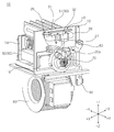
일반적으로 가스 퍼니스는 연료가스의 연소 시 발생되는 화염 및 고온의 연소가스와 열교환된 공기를 실내로 공급함으로써, 실내를 난방하는 기기로서, 도 1은 종래기술에 따른 가스 퍼니스를 도시하고 있다.In general, a gas furnace is a device for heating a room by supplying a flame generated during combustion of a fuel gas and air heat-exchanged with a high-temperature combustion gas to a room, and FIG. 1 shows a gas furnace according to the prior art.
도 1을 참조하면, 버너 어셈블리(4)에서 연료가스와 공기가 연소되어 화염 및 고온의 연소가스가 생성될 수 있다. 여기서, 연료가스는 가스밸브(미도시)로부터 매니폴드(3)를 거쳐 버너 어셈블리(4)로 유입된다. 고온의 연소가스는 열교환기(5)를 통과한 후 배기관(8)을 통해 외부로 배출될 수 있다. 이때, 송풍팬(6)에 의해 내기덕트(D1)를 통해 유입된 실내 공기가 열교환기(5)를 거치며 가열된 후 급기덕트(D2)를 통해 실내로 안내될 수 있고, 그 결과 실내가 난방될 수 있다.Referring to FIG. 1, fuel gas and air are burned in the
한편, 열교환기(5) 및 배기관(8)을 통과하는 연소가스의 유동은 유도팬(7)에 의해 이루어지며, 연소가스가 열교환기(5) 및/또는 배기관(8)을 통과하며 응축될 시 생성되는 응축수는 응축수 트랩(9)을 통해 외부로 배출될 수 있다.Meanwhile, the flow of the combustion gas passing through the
가스 퍼니스에서의 연료가스의 연소 과정에서 공기 중의 질소와 산소가 고온(보다 구체적으로, 화염온도가 약 1,800 K 이상인 상태)에서 화학 반응하여 생성되는 열적 녹스(thermal NOx, 이하 간략히 NOx 라고 함)는 대기오염을 일으키는 대표적인 오염물질로서 대기질 관리 기구에 의해 그 배출량이 규제되고 있다.Thermal NOx (thermal NOx, hereinafter simply referred to as NOx) generated by a chemical reaction of nitrogen and oxygen in the air at a high temperature (more specifically, the flame temperature is about 1,800 K or higher) during the combustion of fuel gas in a gas furnace is As a representative pollutant that causes air pollution, its emission is regulated by the air quality management organization.
예를 들어 북미의 경우, SCAQMD(South Coast Air Quality Management District)에서 NOx의 배출량을 규제하고 있고, 최근 허용되는 NOx 배출량을 40 ng/J(nano-grams per Joule)에서 14 ng/J 미만으로 낮추어 규제를 강화하였다.For example, in North America, the South Coast Air Quality Management District (SCAQMD) regulates NOx emissions, and recently allowed NOx emissions have been lowered from 40 ng/J (nano-grams per Joule) to less than 14 ng/J. The regulation has been strengthened.
이에, 가스 퍼니스에서의 NOx 배출을 저감하기 위한 기술 개발이 활발히 이루어지고 있으며, 미국 공개특허 제20120247444A1호의 경우 연소 전에 미리 공기와 연료가스를 혼합시키는 예혼합 가스 퍼니스를 개시하면서, 공기비를 증가함으로써 화염 온도를 제어해 NOx 발생을 저감하는 기술 구성을 개시하고 있다.Accordingly, technology for reducing NOx emissions from gas furnaces is being actively developed, and in the case of U.S. Patent Publication No. 20120247444A1, a premixed gas furnace in which air and fuel gas are mixed in advance before combustion is initiated, and by increasing the air ratio, the flame Disclosing a technology configuration that reduces NOx generation by controlling the temperature.
그러나, 상기 미국 공개특허의 경우 흡기관에 연료를 직접 분사하기에, 연료와 공기의 혼합이 불충분하게 이루어져 국부적인 온도 상승에 따른 NOx 생성을 야기하는 문제가 있었다.However, in the case of the United States Patent Publication, since fuel is directly injected into the intake pipe, there is a problem that the mixture of fuel and air is insufficient, resulting in the generation of NOx due to a local increase in temperature.
한편, 상기한 미국 공개특허를 비롯한 종래기술에 따른 가스 퍼니스의 경우, 혼합기가 복수 개의 버너 각각에 균일하게 공급되도록 하여 국부적인 온도 상승에 따른 NOx 생성을 방지하는 구조를 제시하지 못하였다.On the other hand, in the case of the gas furnace according to the prior art including the above-described U.S. Patent Publication, it is not possible to propose a structure that prevents the generation of NOx due to local temperature increase by uniformly supplying the mixer to each of the plurality of burners.
본 발명이 해결하고자 하는 제1 과제는, 완전 예혼합 메커니즘을 구성하여 NOx 배출을 저감할 수 있는 가스 퍼니스를 제공하는 데 있다.The first problem to be solved by the present invention is to provide a gas furnace capable of reducing NOx emissions by configuring a complete premixing mechanism.
본 발명이 해결하고자 하는 제2 과제는, 연료가스와 공기의 혼합율을 극대화하여 국부적인 화염 온도 상승을 방지함으로써, NOx 배출을 크게 저감할 수 있는 가스 퍼니스를 제공하는 데 있다.A second problem to be solved by the present invention is to provide a gas furnace capable of greatly reducing NOx emissions by maximizing the mixing ratio of fuel gas and air to prevent local flame temperature rise.
본 발명이 해결하고자 하는 제3 과제는, 연료가스와 공기의 혼합기를 복수 개의 버너 각각에 균일하게 분배하여 국부적인 화염 온도 상승을 방지함으로써, NOx 배출을 크게 저감할 수 있는 가스 퍼니스를 제공하는 데 있다.A third problem to be solved by the present invention is to provide a gas furnace that can significantly reduce NOx emissions by uniformly distributing a mixture of fuel gas and air to each of a plurality of burners to prevent local flame temperature rise. have.
본 발명의 과제들은 이상에서 언급한 과제들로 제한되지 않으며, 언급되지 않은 또 다른 과제들은 아래의 기재로부터 통상의 기술자에게 명확하게 이해될 수 있을 것이다.The problems of the present invention are not limited to the problems mentioned above, and other problems that are not mentioned will be clearly understood by those skilled in the art from the following description.
상기 과제를 해결하기 위하여, 본 발명에 따른 가스 퍼니스는, 흡기관 및 매니폴드 각각으로부터 유입된 공기 및 연료가스를 혼합시켜 혼합기를 형성하는 믹서; 상기 믹서를 통과한 혼합기가 유동하는 혼합관; 상기 혼합관을 통과한 혼합기를 연소시켜 연소가스를 생성하는 버너 어셈블리; 및 상기 연소가스가 유동하는 열교환기를 포함하고, 상기 버너 어셈블리는, 상기 혼합기가 연소될 시 생성되는 화염이 안착되는 복수 개의 버너; 상기 혼합관으로부터 상기 버너로의 상기 혼합기의 전달을 매개하는 혼합챔버를 포함한다. 이로써, 완전 예혼합 메커니즘이 구성되고, 연료가스와 공기의 혼합율이 극대화되어 NOx 배출을 크게 저감할 수 있다.In order to solve the above problems, a gas furnace according to the present invention includes: a mixer configured to form a mixer by mixing air and fuel gas introduced from each of an intake pipe and a manifold; A mixing pipe through which the mixer passing through the mixer flows; A burner assembly for generating combustion gas by combusting the mixer passing through the mixing pipe; And a heat exchanger through which the combustion gas flows, wherein the burner assembly includes: a plurality of burners on which flames generated when the mixer is burned are seated; And a mixing chamber for mediating the transfer of the mixer from the mixing tube to the burner. Thereby, a complete premixing mechanism is configured, and the mixing ratio of fuel gas and air is maximized, so that NOx emission can be greatly reduced.
또한, 상기 버너 어셈블리는, 상기 혼합챔버의 내부에 위치하고, 상기 혼합기가 상기 복수 개의 버너 각각에 균일하게 분배되도록 하는 균일 가이드를 포함한다. 이로써, 국부적인 화염 온도 상승이 방지되어, NOx 배출을 크게 저감할 수 있다.In addition, the burner assembly includes a uniform guide positioned inside the mixing chamber and configured to uniformly distribute the mixer to each of the plurality of burners. Thereby, a local increase in flame temperature is prevented, and NOx emission can be greatly reduced.
상기 균일 가이드는, 상기 혼합챔버의 내부 공간에 설치되고, 수평 방향으로 연장 형성되며 소정의 영역이 개구된 형태의 분배 플레이트로 형성되어진 것을 특징으로 할 수 있다.The uniform guide may be installed in an inner space of the mixing chamber, extended in a horizontal direction, and formed as a distribution plate having a predetermined area open.
상기 분배 플레이트는, 상기 혼합챔버의 수평 방향의 내측면에 결합되되, 수직 방향의 내측면으로부터는 소정 간격만큼 이격되게 배치될 수 있다.The distribution plate may be coupled to an inner surface of the mixing chamber in a horizontal direction, and may be disposed to be spaced apart from the inner surface in a vertical direction by a predetermined interval.
상기 균일 가이드는, 상기 혼합챔버의 내부 공간에 설치되고, 복수 개의 공극이 형성되는 분배 메쉬(mesh)로 형성되어진 것을 특징으로 할 수 있다.The uniform guide may be installed in the inner space of the mixing chamber and may be formed of a distribution mesh in which a plurality of voids are formed.
상기 분배 메쉬는, 상기 혼합챔버의 내측면에 결합될 수 있다. 상기 분배 메쉬는, 허니컴 세라믹(ceramic honeycomb) 재질로 형성되고, 상기 복수 개의 공극 각각은, 0.7 내지 1.3 mm² 의 크기를 갖을 수 있다.The distribution mesh may be coupled to the inner surface of the mixing chamber. The distribution mesh is formed of a honeycomb ceramic material, and each of the plurality of pores may have a size of 0.7 to 1.3 mm².
상기 균일 가이드는, 상기 혼합챔버의 내부 공간에 설치되고, 상기 혼합기와 함께 유동하는 이물질을 걸러내는 분배 필터로 형성되어진 것을 특징으로 할 수 있다. 상기 분배 필터는, 상기 혼합챔버의 내측면에 결합될 수 있다.The uniform guide may be installed in the inner space of the mixing chamber, and may be formed of a distribution filter that filters foreign substances flowing together with the mixer. The distribution filter may be coupled to an inner surface of the mixing chamber.
상기에서 언급되지 않은 과제의 해결수단은 본 발명의 실시예에 관한 설명으로부터 충분히 도출될 수 있을 것이다.Solutions to the problems not mentioned above may be sufficiently derived from the description of the embodiments of the present invention.
본 발명에 따르면 다음과 같은 효과가 하나 혹은 그 이상 있다.According to the present invention, there are one or more of the following effects.
첫째, 버너 어셈블리에서의 연소 전에 공기와 연료가스를 완전 예혼합함으로써, 희박 영역 운전을 위한 공기 흡입양을 용이하게 제어할 수 있고, 그 결과 NOx 배출을 용이하게 저감할 수 있다.First, by completely premixing the air and fuel gas before combustion in the burner assembly, it is possible to easily control the amount of air intake for operation in the lean region, and as a result, it is possible to easily reduce NOx emission.
둘째, 믹서 내부에서의 공기 및 연료가스의 혼합은 벤츄리 튜브를 거치며 이루어져, 이들간의 혼합율이 증대되어, 상대적으로 혼합율이 낮아 국부적으로 화염온도가 상승되는 경우에 비해, NOx 배출을 크게 저감할 수 있다.Second, the mixing of air and fuel gas inside the mixer is made through a venturi tube, and the mixing ratio between them is increased, so that the mixing ratio is relatively low, and compared with the case where the flame temperature is increased locally, NOx emission can be greatly reduced. .
셋째, 혼합챔버의 내부에 설치된 균일 가이드가 혼합기를 복수 개의 버너 각각에 균일하게 분배함으로써, 국부적인 화염 온도 상승에 따른 NOx 생성을 방지할 수 있다.Third, the uniform guide installed inside the mixing chamber uniformly distributes the mixer to each of the plurality of burners, thereby preventing the generation of NOx due to local increase in flame temperature.
넷째, 균일 가이드가 혼합챔버의 내부에 탈착 가능하게 설치됨으로써, 균일 가이드의 교체 및 수리를 용이하게 할 수 있다.Fourth, since the uniform guide is detachably installed inside the mixing chamber, it is possible to facilitate replacement and repair of the uniform guide.
다섯째, 혼합관의 적어도 일부가 혼합챔버의 내부로 삽입됨으로써, 혼합관으로부터 혼합챔버로의 혼합기의 이동 간에 혼합기가 누설되는 것을 방지할 수 있다.Fifth, since at least a part of the mixing tube is inserted into the mixing chamber, it is possible to prevent leakage of the mixer between the movement of the mixer from the mixing tube to the mixing chamber.
도 1은 종래기술에 따른 가스 퍼니스의 사시도,
도 2는 본 발명의 실시예에 따른 가스 퍼니스의 사시도,
도 3은 본 발명의 실시예에 따른 가스 퍼니스의 일부 구성이 도시된 사시도,
도 4는 본 발명의 실시예에 따른 가스 퍼니스의 일부 구성을 절개한 단면이 도시된 도면,
도 5는 본 발명의 실시예에 따른 가스 퍼니스의 균일 가이드가 혼합기를 복수 개의 버너 각각에 균일하게 분배하는 기능을 설명하기 위한 도면,
도 6은 본 발명의 제1 실시예에 따른 균일 가이드로서 분배 플레이트가 혼합챔버에 설치된 모습을 도시한 도면,
도 7은 본 발명의 제2 실시예에 따른 균일 가이드로서 분배 메쉬가 혼합챔버에 설치된 모습을 도시한 도면,
도 8은 본 발명의 제3 실시예에 따른 균일 가이드로서 분배 필터가 혼합챔버에 설치된 모습을 도시한 도면이다.1 is a perspective view of a gas furnace according to the prior art,
2 is a perspective view of a gas furnace according to an embodiment of the present invention,
3 is a perspective view showing a partial configuration of a gas furnace according to an embodiment of the present invention;
4 is a cross-sectional view showing a partial configuration of a gas furnace according to an embodiment of the present invention,
5 is a view for explaining a function of uniformly distributing a mixer to each of a plurality of burners by a uniform guide of a gas furnace according to an embodiment of the present invention;
6 is a view showing a distribution plate installed in the mixing chamber as a uniform guide according to the first embodiment of the present invention;
7 is a view showing a distribution mesh installed in a mixing chamber as a uniform guide according to a second embodiment of the present invention;
8 is a view showing a state in which a distribution filter is installed in a mixing chamber as a uniform guide according to a third embodiment of the present invention.
본 발명의 이점 및 특징, 그리고 그것들을 달성하는 방법은 첨부되는 도면과 함께 상세하게 후술되어 있는 실시예들을 참조하면 명확해질 것이다. 그러나 본 발명은 이하에서 개시되는 실시예들에 한정되는 것이 아니라 서로 다른 다양한 형태로 구현될 수 있으며, 단지 본 실시예들은 본 발명의 개시가 완전하도록 하고, 본 발명이 속하는 기술분야에서 통상의 지식을 가진 자에게 발명의 범주를 완전하게 알려주기 위해 제공되는 것이며, 본 발명은 청구항의 범주에 의해 정의될 뿐이다. 명세서 전체에 걸쳐 동일 참조 부호는 동일 구성 요소를 지칭한다.Advantages and features of the present invention, and a method of achieving them will become apparent with reference to the embodiments described below in detail together with the accompanying drawings. However, the present invention is not limited to the embodiments disclosed below, but may be implemented in a variety of different forms, and only these embodiments make the disclosure of the present invention complete, and are common knowledge in the technical field to which the present invention pertains. It is provided to completely inform the scope of the invention to those who have, and the invention is only defined by the scope of the claims. The same reference numerals refer to the same elements throughout the specification.
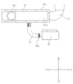
본 발명은, 도 2 등에 도시된 서로 직교하는 X축, Y축 및 Z축에 의한 공간 직교 좌표계를 기준으로 설명될 수도 있다. 본 명세서에서, 상하 방향을 Z축 방향으로 하고, 전후 방향을 X축 방향으로 하여 X축, Y축 및 Z축을 정의한다. 각 축 방향(X축 방향, Y축 방향, Z축 방향)은, 각 축이 뻗어나가는 양쪽 방향을 의미한다. 각 축 방향의 앞에 '+'부호가 붙는 것(+X축 방향, +Y축 방향, +Z축 방향)은, 각 축이 뻗어나가는 양쪽 방향 중 어느 한 방향인 양의 방향을 의미한다. 각 축방향의 앞에 '-'부호가 붙는 것(-X축 방향, -Y축 방향, -Z축 방향)은, 각 축이 뻗어나가는 양쪽 방향 중 나머지 한 방향인 음의 방향을 의미한다.The present invention may be described on the basis of a spatial Cartesian coordinate system of X-axis, Y-axis, and Z-axis that are orthogonal to each other shown in FIG. In this specification, the X-axis, Y-axis, and Z-axis are defined with the vertical direction as the Z-axis direction and the front-rear direction as the X-axis direction. Each axis direction (X axis direction, Y axis direction, Z axis direction) means both directions in which each axis extends. A'+' sign in front of each axis direction (+X-axis direction, +Y-axis direction, +Z-axis direction) means a positive direction, which is one of both directions in which each axis extends. A'-' sign in front of each axis direction (-X-axis direction, -Y-axis direction, -Z-axis direction) means a negative direction, which is the other direction of both directions in which each axis extends.
이하, 도 2 내지 도 8을 참조하여 본 발명의 실시예에 따른 가스 퍼니스를 설명한다.Hereinafter, a gas furnace according to an embodiment of the present invention will be described with reference to FIGS. 2 to 8.
도 2는 본 발명의 실시예에 따른 가스 퍼니스의 사시도이다.2 is a perspective view of a gas furnace according to an embodiment of the present invention.
본 발명의 실시예에 따른 가스 퍼니스(10, Gas furnace)는 연료가스(F)의 연소 시 발생되는 화염 및 고온의 연소가스(C)와 열교환된 공기를 실내로 공급함으로써, 실내를 난방하는 기기이다.A
도 2를 참조하면, 가스 퍼니스(10)는 공기(A)와 연료가스(F) 및/또는 배기가스(E)가 혼합되는 믹서(32)와, 믹서(32)를 통과한 혼합기가 유동하는 혼합관(33, mixing pipe)과, 혼합관(33)을 통과한 혼합기를 연소시켜 연소가스(C)를 생성하는 버너 어셈블리(40)와, 연소가스(C)가 유동하는 열교환기(50)를 포함한다.2, the
또한, 가스 퍼니스(10)는 연소가스(C)가 열교환기(50)를 거쳐 배기관(80)으로 배출되는 유동을 일으키는 유도팬(70)과, 열교환기(50) 주위로 실내에 공급되는 공기를 송풍시키는 송풍팬(60)과, 열교환기(50) 및/또는 배기관(80)에서 생성된 응축수를 수집하여 외부로 배출시키는 응축수 트랩(90)을 포함한다.In addition, the
공기(A)는 흡기관(31)을 거쳐 믹서(32)로 유입되고, 연료가스(F)는 가스밸브(20) 및 노즐(20a)로부터 매니폴드(21)를 거쳐 믹서(32)로 유입될 수 있다. 여기서, 연료가스(F)로는, 예를 들어 천연가스를 냉각하여 액화한 액화천연가스(LNG; Liquefied Natural Gas) 또는 석유 정제 공정의 부산물로 얻은 가스를 가압하여 액화한 액화석유가스(LPG; Liquefied Petroleum Gas)를 사용할 수 있다.Air (A) flows into the mixer (32) through the intake pipe (31), and the fuel gas (F) flows into the mixer (32) through the manifold (21) from the gas valve (20) and nozzle (20a). Can be. Here, as the fuel gas (F), for example, liquefied natural gas (LNG) obtained by cooling natural gas or liquefied petroleum gas (LPG) obtained by pressurizing the gas obtained as a by-product of the petroleum refining process. Petroleum Gas) can be used.
가스밸브(20)의 개폐에 따라 매니폴드(21)로 연료가스(F)가 공급되거나 차단될 수 있고, 가스밸브(20)의 개방 정도를 조절하여 매니폴드(21)로 연료가스(F)가 공급되는 양을 조절할 수 있다. 그 결과, 가스밸브(20)는 가스 퍼니스(10)의 화력을 조절할 수 있다.Depending on the opening and closing of the
혼합관(33)은 후술하는 바와 같이, 공기와 연료가스(F)가 혼합된 혼합기가 유동할 수 있다. 혼합관(33)은 상기 혼합기를 후술하는 버너 어셈블리(40)로 안내할 수 있고, 혼합관(33)을 통해 상기 혼합기가 버너 어셈블리(40)로 안내되는 동안에도 기체의 혼합이 지속될 수 있다.As will be described later, the mixing
버너 어셈블리(40)에 유입된 상기 혼합기는 점화기의 점화로 인해 연소될 수 있다. 이 경우, 상기 혼합기가 연소되어 화염 및 고온의 연소가스(C)가 생성될 수 있다.The mixer introduced into the
열교환기(50)에는 연소가스(C)가 유동할 수 있는 유로가 형성될 수 있다. 이하에서는 가스 퍼니스(10)가 후술하는 제1차 열교환기(51)와, 제2차 열교환기(52)로 구성되는 열교환기(50)를 포함하는 것으로 설명하나, 실시예에 따라 제1차 열교환기(51)만 구비하는 것도 가능함은 물론이다.A flow path through which the combustion gas C can flow may be formed in the
제1차 열교환기(51)는 일단이 버너 어셈블리(40)와 인접하게 배치될 수 있다. 제1차 열교환기(51)의 일단과 반대되는 타단은 HCB(14, Hot Collect Box)에 결합될 수 있다. 제1차 열교환기(51)의 일단으로부터 타단으로 유동하는 연소가스(C)는 HCB(14)를 통해 제2차 열교환기(52)로 전달될 수 있다.The
제2차 열교환기(52)의 일단은 HCB(14)와 연결될 수 있다. 제1차 열교환기(51)를 통과한 연소가스(C)는 제2차 열교환기(52)의 일단으로 유입되어, 제2차 열교환기(52)를 통과할 수 있다. 제2차 열교환기(52)는 제1차 열교환기(51)를 통과한 연소가스(C)를 제2차 열교환기(52) 주위를 통과하는 공기와 다시 한번 열교환시킬 수 있다. 즉, 제2차 열교환기(52)를 통해 제1차 열교환기(51)를 통과한 연소가스(C)의 열에너지를 추가로 이용함으로써, 가스 퍼니스(10)의 효율이 향상될 수 있다.One end of the
제2차 열교환기(52)를 통과하는 연소가스(C)는 제2차 열교환기(52) 주위를 통과하는 공기와의 열전달 과정에서 응축되어, 응축수를 생성할 수 있다. 다시 말해, 연소가스(C)에 포함된 수증기가 응축되어 응축수로 상태 변화할 수 있다. 이러한 이유 때문에, 제1차 열교환기(51) 및 제2차 열교환기(52)를 구비한 가스 퍼니스(10)는 콘덴싱(condensing) 가스 퍼니스로도 불리운다. 이때 생성된 응축수는 CCB(16, Cold Collect Box)에 수집될 수 있다. 이를 위해, 제2차 열교환기(52)의 일단과 반대되는 타단은 CCB(16)의 일측면에 연결될 수 있다.The combustion gas C passing through the
제2차 열교환기(52)에서 생성된 응축수는, CCB(16)를 통해 응축수 트랩(90)으로 빠져나간 후, 토출구를 거쳐 가스 퍼니스(10)의 외부로 배출될 수 있다. 이 경우, 응축수 트랩(90)은 CCB(16)의 타측면에 결합될 수 있다. 또한, 응축수 트랩(90)은 제2차 열교환기(52)에서 생성된 응축수뿐만 아니라, 유도팬(70)에 연결된 배기관(80)에서 생성된 응축수도 함께 수집하여 배출할 수 있다. 즉, 제2차 열교환기(52)의 타단에서 미처 응축되지 못한 연소가스(C)가, 배기관(80)을 통과하며 응축되는 경우에 생성되는 응축수와 함께 응축수 트랩(90)으로 수집되어 상기 토출구를 거쳐 가스 퍼니스(10) 외부로 배출될 수 있다.The condensed water generated in the
CCB(16)의 타측면에는 후술하는 유도팬(인듀서, inducer)(70)이 결합될 수 있다. 이하에서는, 간략한 설명을 위하여 유도팬(70)이 CCB(16)에 결합되는 것으로 설명하나, 유도팬(70)은 CCB(16)가 결합된 마운팅 플레이트(12)에 결합될 수도 있다.An induction fan (inducer) 70 to be described later may be coupled to the other side of the
CCB(16)에는 개구부가 형성될 수 있다. CCB(16)에 형성된 개구부를 매개로, 제2차 열교환기(52)의 타단과 유도팬(70)은 서로 연통될 수 있다. 즉, 제2차 열교환기(52)의 타단을 통과한 연소가스(C)는 CCB(16)에 형성된 개구부를 통해 유도팬(70)으로 빠져나간 후, 배기관(80)을 거쳐 가스 퍼니스(10)의 외부로 배출될 수 있다.An opening may be formed in the
유도팬(70)은 CCB(16)에 형성된 개구부를 매개로, 제2차 열교환기(52)의 타단과 연통될 수 있다. 유도팬(70)의 일단은 CCB(16)의 타측면에 결합되며, 유도팬(70)의 타단은 배기관(80)에 결합될 수 있다. 유도팬(70)은 연소가스(C)가 제1차 열교환기(51), HCB(14) 및 제2차 열교환기(52)를 통과하여, 배기관(80)으로 배출되는 유동을 일으킬 수 있다. 이 점에서, 유도팬(70)은 IDM(Induced Draft Motor)으로 부를 수 있다.The
송풍팬(블로어, blower)(60)은 가스 퍼니스(10)의 하부에 위치할 수 있다. 실내에 공급되는 공기는 송풍팬(60)에 의해 가스 퍼니스(10)의 하부로부터 상부로 이동할 수 있다. 이 점에서, 송풍팬(60)은 IBM(Indoor Blower Motor)으로 부를 수 있다.The blowing fan (blower) 60 may be located under the
송풍팬(60)은 열교환기(50) 주위로 공기를 통과시킬 수 있다. 송풍팬(60)에 의하여 열교환기(50) 주위를 통과하는 공기는, 열교환기(50)를 매개로 고온의 연소가스(C)로부터 열에너지를 전달받아 온도가 상승될 수 있다. 상기 온도가 상승된 공기가 실내에 공급됨으로써, 실내가 난방될 수 있다.The blowing
가스 퍼니스(10)는 도 1에 도시된 종래기술에 따른 가스 퍼니스(1)와 마찬가지로, 케이스(미부호)를 포함할 수 있다. 상기한 가스 퍼니스(10)의 구성들은 상기 케이스의 내부에 수용될 수 있다.The
상기 케이스의 하부에는 송풍팬(60)과 인접한 측면에 하부측 개구부(미부호)가 형성될 수 있다. 상기 하부측 개구부에는 실내로부터 유입된 공기(이하, 내기)(RA)가 통과하는 내기덕트(D1)가 설치될 수 있다. 상기 케이스의 상부에 형성된 상부측 개구부(미부호)에는 실내로 공급되는 공기(이하, 급기)(SA)가 통과하는 급기덕트(D2)가 설치될 수 있다.In the lower part of the case, a lower opening (not shown) may be formed on a side adjacent to the blowing
즉, 송풍팬(60)이 동작하면, 내기(RA)로서 내기덕트(D1)를 통해 실내로부터 유입된 공기가 열교환기(50)를 거치며 온도가 상승되어 급기(SA)로서 급기덕트(D2)를 통해 실내로 공급될 수 있고, 이로써 실내가 난방될 수 있다.That is, when the blowing
상기 및 후술하는 본 발명의 실시예에 따른 가스 퍼니스(10)와 비교해, 도 1에 도시된 종래기술에 따른 가스 퍼니스(1)는 다음과 같이 구성되는 차이가 있다.Compared with the
즉, 종래기술에 따른 가스 퍼니스(1)에서 매니폴드(3)에 설치된 노즐을 통해 매니폴드(3)를 통과한 연료가스가 버너 어셈블리(4)로 분사되고, 연료가스는 버너 어셈블리(4)의 벤츄리 튜브(미부호)를 통과하며 버너 어셈블리(4)로 자연 흡기된 공기와 혼합되어 혼합기를 형성할 수 있다. 다만, 이와 같이 구성되는 종래기술에 따른 가스 퍼니스(1)의 경우 다음과 같은 이유로 NOx 배출량을 저감하기 어려울 수 있다.That is, in the
먼저, 종래기술에 따른 가스 퍼니스(1)는 상기 노즐로부터 분사된 연료가스가 버너 어셈블리(4)의 하측과 상기 노즐 사이의 공간을 통해 유입된 제1차 공기와 함께 상기 벤츄리 튜브를 통과하며 혼합된 혼합기가, 이후 버너 어셈블리(4)의 상측과 열교환기(5) 사이의 공간을 통해 유입되는 제2차 공기와 함께 연소되어 확산 연소의 특성을 나타내는 부분 예혼합 메커니즘을 구성하는 것으로 이해될 수 있다.First, in the
그러나, 이와 같은 부분 예혼합 메커니즘을 구성하는 가스 퍼니스의 경우, 화염의 확산 속도가 연소 화학반응 속도보다 상당히 느린 확산 연소의 특성상, 제2차 공기가 과잉 공급되도록 제어하더라도 화염온도를 낮추기 어려울 수 있다. 나아가, 공기비(즉, 실제 공기량의 이론 공기량에 대한 비)를 제어하는 것도 어려워 NOx 배출량을 저감하는 데 한계가 있다.However, in the case of the gas furnace constituting such a partial premixing mechanism, it may be difficult to lower the flame temperature even if the secondary air is controlled to be excessively supplied due to the nature of the diffusion combustion, where the diffusion rate of the flame is considerably slower than the combustion chemical reaction rate. . Furthermore, it is difficult to control the air ratio (that is, the ratio of the actual air amount to the theoretical air amount), and there is a limit to reducing the NOx emission.
본 발명은 이와 같은 문제를 해결하고자 완전 예혼합 메커니즘을 구성하고 더 나아가 공기와 연료가스의 혼합율 증대 및 혼합기의 복수 개의 버너로의 균등 분배를 통해 높여 국부적인 화염 온도 상승을 방지할 수 있는 가스 퍼니스를 제공하기 위해 안출되었고, 보다 상세히는 후술한다.The present invention constitutes a complete premixing mechanism to solve such a problem, and furthermore, a gas furnace capable of preventing a local flame temperature increase by increasing the mixing ratio of air and fuel gas and evenly distributing the mixer to a plurality of burners. It was devised to provide, and will be described in more detail later.
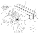
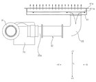
도 3은 본 발명의 실시예에 따른 가스 퍼니스의 일부 구성이 도시된 사시도이다.3 is a perspective view showing a partial configuration of a gas furnace according to an embodiment of the present invention.
도 2 및 도 3을 참조하면, 가스 퍼니스(10)는 믹서(32, mixer)와, 혼합관(33)과, 버너 어셈블리(40)와, 열교환기(50)와, 배기관(80)과, 유도팬(70)과, 송풍팬(60)을 포함한다.2 and 3, the
유도팬(70)은 흡기관(31)을 통해 공기(A)가 믹서(32)로 흡입되는 유동을 일으키고, 혼합관(33)으로부터 버너 어셈블리(40)로의 후술하는 혼합기의 유동을 일으키고, 버너 어셈블리(40)로부터 열교환기(50) 및 배기관(80)으로의 후술하는 연소가스(C)의 유동을 일으킬 수 있다. 한편, 송풍팬(60)은 열교환기(50)의 주위를 통과하는 공기의 유동을 일으킬 수 있다.The
믹서(32)는 흡기관(31) 및 매니폴드(21) 각각으로부터 유입된 공기(A) 및 연료가스(F)를 혼합시켜 혼합기를 형성한다. 여기서, 흡기관(31)은 일측이 외부에 노출되어 연소 반응에 참여하는 공기가 흡입되는 관(pipe)이고, 매니폴드(21)는 일측이 가스밸브(20)에 연결되어 연소 반응에 참여하는 연료가스(F)가 유동하는 관이고, 매니폴드(21)를 유동하는 연료가스(F)의 양은 가스밸브(20)의 개폐 여부 또는 개방 정도에 따라 조절될 수 있음은 상기한 바와 같다. 그리고, 가스 퍼니스(10)는 가스밸브(20)의 개폐 여부 또는 개방 정도를 조절하는 제어부를 더 포함할 수 있다.The
믹서(32)에서 형성된 혼합기는 혼합관(33)을 거쳐 버너 어셈블리(40)로 공급될 수 있고, 이와 같이 연소 반응에 참여하는 공기(A)는 연료가스(F)와 완전 예혼합된 상태로 버너 어셈블리(40)로 공급되므로 공기비 조절(즉, 연소 반응에 공기가 과잉 공급되도록 흡입되는 공기의 양을 조절)을 통해 화염온도를 낮추는 데 용이할 수 있다. 또한, 흡기관(31), 믹서(32), 혼합관(33), 버너 어셈블리(40) 및 열교환기(50)는 서로 연통되어 있으므로, 유도팬(70)의 동작을 통해 공기비를 용이하게 조절함으로써 화염온도를 낮추어 NOx 배출을 크게 저감할 수 있다. 다시 말해, NOx 배출 저감을 위한 희박 영역에서의 연소 조건의 달성을 용이하게 수행할 수 있다.The mixer formed in the
본 발명에서는 상기 및 후술하는 바와 같이 믹서(32)에서의 공기(A)와 연료가스(F)의 혼합율을 증대시키기 위해 벤츄리 효과(venturi effect)를 이용하고 있고, 보다 상세히는 후술한다.In the present invention, the venturi effect is used to increase the mixing ratio of the air (A) and the fuel gas (F) in the
믹서(32)는 믹서 하우징(32a)과, 벤츄리 튜브(32b)를 포함할 수 있다. 믹서 하우징(32a)은 전단에 흡기관(31)이 연결되고, 후단에 혼합관(33)이 연결되고, 측면에 매니폴드(21)가 연결될 수 있다. 여기서, 흡기관(31)은 흡기관 연결부(31a)를 매개로 믹서 하우징(32a)에 연결되고, 혼합관(33)은 믹서 하우징(32a)의 후단에 일체로서 연결될 수 있으나, 이에 한정되는 것은 아니다.The
즉, 흡기관(31) 및 매니폴드(21) 각각을 통해 공기(A)와 연료가스(F)가 믹서(32)의 내부로 유입되어 서로 혼합된 후 혼합관(33)으로 공급될 수 있다.That is, air (A) and fuel gas (F) through each of the
벤츄리 튜브(32b)는 믹서 하우징(32a)의 내부에 위치할 수 있다. 벤츄리 튜브(32b)의 후술하는 컨버징 섹션(321), 쓰로트(322), 다이버징 섹션(323) 각각의 외주면은 믹서 하우징(32a)의 내주면에 소정 간격만큼 이격되게 배치될 수 있다.The
다만, 벤츄리 튜브(32b)는 외주면으로부터 외측 방향으로 연장 형성되어 믹서 하우징(32a)의 내주면에 밀착되는 플랜지(326)를 포함하여, 벤츄리 튜브(32b)가 믹서 하우징(32a)의 내부에 고정될 수 있다.However, the venturi tube (32b) is formed to extend outward from the outer circumferential surface and includes a
벤츄리 튜브(32b)는 컨버징 섹션(321), 쓰로트(322) 및 다이버징 섹션(323)을 포함할 수 있다.The
컨버징 섹션(321, converging section)은 일단에 흡기관(31)을 통과한 공기(A)가 유입되는 유입부가 형성되고, 상기 일단의 외주면에 플랜지(328)가 형성될 수 있다. 플랜지(328)에는 압력센서가 설치되어 벤츄리 튜브(32b)로 유입되는 공기의 압력을 감지할 수 있다.The converging
컨버징 섹션(321)은 하류 방향으로 갈수록 직경이 작아지도록 형성될 수 있다. 이로써, 벤츄리 효과(venturi effect)로 알려진 바와 같이, 컨버징 섹션(321)을 통과하는 공기의 압력이 하강(또한, 유속 증가)하고, 부압(negative pressure)이 형성될 수 있다. 이때, 상기한 공기의 압력 하강으로 인해 후술하는 쓰로트(322)의 연료 유입홀(322a)을 통한 연료가스(F)의 유입이 용이해질 수 있다. 또한, 상기한 공기의 유속 증가로 인해 공기의 난류 강도가 증가되어 후술하는 공기(A)와 연료가스(F) 간의 혼합율이 증대될 수 있다.The converging
쓰로트(322, throat)는 컨버징 섹션(321)에 연결되고, 측면 중 적어도 일부에 매니폴드(21)를 통과한 연료가스(F)가 유입되는 연료 유입홀(322a)이 형성될 수 있다.The
연료 유입홀(322a)은 쓰로트(322)의 원주 방향으로 상호 소정 간격으로 이격되게 배치되는 복수 개의 연료 유입홀(322a)을 포함할 수 있고, 이로써 연료가스(F)가 벤츄리 튜브(32b)의 내부로 원활하게 유입될 수 있다.The
연료 유입홀(322a)은 쓰로트(322)의 측면으로서 플랜지(326) 및 믹서 하우징(32a) 중 매니폴드(21)가 연결되는 부분의 사이에 대응하는 위치에 형성될 수 있다. 이로써, 연료 유입홀(322a)이 믹서 하우징(32a) 중 매니폴드(21)가 연결되는 부분에 대응하는 위치에 형성되는 경우에 비해, 복수 개의 연료 유입홀(322a) 중 일부에 연료가스(F)가 집중 공급되는 것을 방지해, 복수 개의 연료 유입홀(321a) 전부에 균일하게 연료가스(F)가 공급되도록 할 수 있다.The
다이버징 섹션(323, diversing section)은 쓰로트(322)에 연결되고, 컨버징 섹션(321) 및 연료 유입홀(322a) 각각을 통과한 공기(A) 및 연료가스(F)가 혼합되어 혼합기를 형성하며 유동할 수 있다.The
다이버징 섹션(323)은 하류 방향으로 갈수록 직경이 커지도록 형성될 수 있다. 이로써, 컨버징 섹션(321)을 통과하며 하강된 압력은 다이버징 섹션(323)을 통과하며 소정값만큼 회복될 수 있고, 공기(A) 및 연료가스(F)의 혼합이 보다 용이해질 수 있다. 또한, 다이버징 섹션(323)은 일단에 혼합관(33)으로 상기 혼합기를 토출하는 토출부가 형성될 수 있다.The diverging
한편, 벤츄리 튜브(32b)는 컨버징 섹션(321) 중 쓰로트(322)에 연결되는 부분의 외주면으로부터 외측 방향으로 연장 형성되어 믹서 하우징(32a)의 내주면에 밀착되는 플랜지(326)를 포함할 수 있다. 플랜지(326)는 벤츄리 튜브(32b)를 믹서 하우징(32a) 내부에 고정시킬 뿐만 아니라, 매니폴드(21)를 통과한 연료가스(F)가 컨버징 섹션(321)의 외측으로 유동하는 것을 차단할 수 있다.Meanwhile, the
도 4는 본 발명의 실시예에 따른 가스 퍼니스의 일부 구성을 절개한 단면이 도시된 도면이다.4 is a cross-sectional view illustrating a partial configuration of a gas furnace according to an exemplary embodiment of the present invention.
도 4를 참조하면, 믹서(32)를 통과한 혼합기는 혼합관(33)을 유동할 수 있다. 혼합관(33)은 상기 혼합기를 버너 어셈블리(40)로 안내할 수 있다. 버너 어셈블리(40)는 혼합관(33)을 통과한 혼합기를 연소시켜 화염 및 고온의 연소가스(C)를 생성할 수 있다.Referring to FIG. 4, the mixer passing through the
버너 어셈블리(40)는 혼합챔버(41)와, 버너(42)와, 버너 플레이트(43)와, 연소챔버(44: 441, 442, 443, 444)와, 버너 박스(45)를 포함할 수 있다. 가스 퍼니스(10)는 복수 개의 제1차 열교환기(51)를 구비할 수 있다. 이 경우, 가스 퍼니스(10)는 제1차 열교환기(51)의 개수와 동일한 개수만큼의 복수 개의 버너(42) 및 연소챔버(44)를 포함할 수 있다. 예를 들면, 가스 퍼니스(10)는 4 개의 제1차 열교환기(51)가 서로 나란하게 배치되고, 이에 대응해 버너(42) 및 연소챔버(44)도 각각이 4 개씩 구비될 수 있다.The
혼합챔버(41)는 혼합관(33)으로부터 버너(42)로의 상기 혼합기의 전달을 매개할 수 있다. 즉, 혼합관(33)은 혼합챔버(41)의 일측에 형성된 연결구(410)에 연결되어, 혼합관(33)을 통과한 상기 혼합기가 연결구(410)를 통해 혼합챔버(41)의 내부로 유입된 후 버너(42)로 공급될 수 있다. 혼합챔버(41)를 통해 상기 혼합기가 버너(42)로 안내되는 동안에도 기체의 혼합이 지속될 수 있다. 또한, 혼합관(33)은 적어도 일부가 연결구(410)를 통해 혼합챔버(41)의 내부로 삽입될 수 있다. 이로써, 혼합관(33)으로부터 혼합챔버(41)로의 혼합기의 이동 간에 혼합기가 누설되는 것을 방지하고, 혼합기가 보다 빨리 혼합챔버(41)로 유입될 수 있다.The mixing
버너(42)는 상기 혼합기가 연소될 시 생성되는 화염이 안착될 수 있다. 예를 들면, 버너(42)는 버너 타공판(42a)과, 버너 매트(42b)를 포함할 수 있다.The burner 42 may settle the flame generated when the mixer is burned. For example, the burner 42 may include a burner perforated plate 42a and a burner mat 42b.
버너 타공판(42a)에는 혼합기가 분출되는 복수 개의 포트(port)가 형성될 수 있다. 예를 들면, 버너 타공판(42a)은 스테인레스 재질로 형성될 수 있다. 버너 타공판(42a)은 후술하는 버너 매트(42b)로 혼합기를 균일하게 분배하는 기능을 수행할 수 있고, 이 경우 버너 타공판(42a)과 버너 매트(42b)의 사이에서 혼합기의 유동 재분배가 이루어져 혼합기의 유동이 보다 균일하게 형성되는 데 도움을 줄 수 있다. 또한, 실시예에 따라 버너(42)가 버너 매트(42b)만을 구비하는 경우에 비해, 버너(42)가 버너 매트(42b) 뿐만 아니라 상기한 바와 같이 구성되는 버너 타공판(42a)을 구비하는 경우에 화염 안정성이 향상될 수 있다. 나아가, 버너 타공판(42a)은 버너 매트(42b)를 지지하는 기능도 수행할 수 있다.A plurality of ports through which the mixer is ejected may be formed on the burner perforated plate 42a. For example, the burner perforated plate 42a may be formed of stainless steel. The burner perforated plate 42a can perform a function of uniformly distributing the mixer to the burner mat 42b, which will be described later, and in this case, flow redistribution of the mixer is performed between the burner perforated plate 42a and the burner mat 42b. It can help to form a more uniform flow of. In addition, compared to the case where the burner 42 includes only the burner mat 42b according to the embodiment, the burner 42 includes not only the burner mat 42b but also the burner perforated plate 42a configured as described above. In flame stability can be improved. Furthermore, the burner perforated plate 42a may also perform a function of supporting the burner mat 42b.
버너 매트(42b)는 버너 타공판(42a)의 상측에 결합되어, 버너 타공판(42a)의 상기 포트를 통해 분출되는 혼합기를 보다 균일하게 분산시킬 수 있다. 이로써, 버너 매트(42b) 상에 화염이 보다 안정적으로 안착될 수 있다. 예를 들면, 버너 매트(42b)는 상기 포트의 직경보다 작은 틈새를 갖는 금속섬유(metal fiber) 재질로 형성될 수 있다. 이와 같이 구성되는 버너 매트(42b)는 혼합기가 분출되는 속도가 ‘0’에 가깝게 되는 원형 실린더들의 집합체로 이해될 수 있고, 이로써 버너 매트(42b)의 표면에 화염이 안정적으로 안착될 수 있다. 그 결과, 화염 안정성이 우수해져 가스 퍼니스의 화력을 넓은 범위에서 조절하는 데 유리할 수 있다. 즉, 이와 같이 구성되는 버너 매트(42b)는 가스 퍼니스의 화력을 상당히 낮춘 경우에서의 화염의 플래시백(flash back)을 방지하고, 가스 퍼니스의 화력을 상당히 높인 경우에서의 화염의 블로우아웃(blow out)을 방지하는 데 유리할 수 있다.The burner mat 42b is coupled to the upper side of the burner perforated plate 42a, so that the mixer ejected through the port of the burner perforated plate 42a can be more evenly dispersed. As a result, the flame may be more stably seated on the burner mat 42b. For example, the burner mat 42b may be formed of a metal fiber material having a gap smaller than the diameter of the pot. The burner mat 42b configured as described above may be understood as an assembly of circular cylinders whose speed at which the mixer is ejected is close to “0”, whereby the flame can be stably settled on the surface of the burner mat 42b. As a result, the flame stability becomes excellent, which can be advantageous in controlling the thermal power of the gas furnace in a wide range. That is, the burner mat 42b configured as described above prevents flash back of the flame when the thermal power of the gas furnace is significantly lowered, and blows out the flame when the thermal power of the gas furnace is significantly increased. ) Can be beneficial to prevent.
버너 플레이트(43)는 일측에 복수 개의 버너(42)가 결합될 수 있다. 버너 플레이트(43)의 바디에는 복수 개의 연소챔버(44)와 연통되는 복수 개의 버너홀이 형성될 수 있다.A plurality of burners 42 may be coupled to one side of the burner plate 43. A plurality of burner holes communicating with the plurality of
연소챔버(44)는 일단이 버너 플레이트(43)의 타측에 결합되고, 타단이 복수 개의 제1차 열교환기(51)에 인접하게 위치할 수 있다. 버너 박스(45)의 일단에 혼합챔버(41)가 결합되고, 타단에 마운팅 플레이트(12)의 일측이 결합될 수 있다. 그리고, 버너(42), 버너 플레이트(43) 및 연소챔버(44)는 버너 박스(45)의 내부에 위치할 수 있다.The
한편, 가스 퍼니스(10)는 연소챔버(44)의 내측에 위치하는 점화기(451, igniter)(451)를 더 포함할 수 있다. 예를 들면, 점화기(451)는 버너 박스(45)의 내측면에 설치되어, 연소챔버(44)에 형성된 홀에 삽입될 수 있다. 점화기(451)의 점화로 인해, 연결구(410)를 거쳐 버너(42)에 공급되는 혼합기가 연소되면 화염 및 고온의 연소가스(C)가 발생될 수 있고, 이때 생성된 화염은 버너(42)에 안착될 수 있다.Meanwhile, the
점화기(451)가 복수 개의 연소챔버(44) 중 어느 하나(즉, 제1 연소챔버(441))에만 위치하는 경우라도, 버너 플레이트(43)에 형성된 화염 전파구(435: 435a, 435b, 435c)를 통해 인접하는 버너 간에 화염이 전파될 수 있다. 이 경우, 버너 어셈블리(40)는 화염 전파구(435)가 형성되는 위치에 대응하는 위치로서, 인접하는 복수 개의 연소챔버(44)의 사이에 형성되어 화염 전파구(435)와의 사이에서 화염 전파통로를 형성하는 화염 전파터널(445: 445a, 445b, 445c)을 포함할 수 있다.Even when the
화염 전파터널(445)은 화염 전파구(435)에서 분출되는 혼합기가 외부로 누설되는 것을 방지하여, 화염 전파구(435)가 개별 버너 간의 화염 전파를 위한 구성으로서 기능하도록 할 수 있다.The flame propagation tunnel 445 may prevent the mixer ejected from the flame propagation port 435 from leaking to the outside, so that the flame propagation port 435 may function as a configuration for flame propagation between individual burners.
혼합관(33)을 통과한 혼합기는 혼합챔버(41)를 거쳐 복수 개의 버너(42) 뿐만 아니라 화염 전파구(435)에도 분배될 수 있고, 화염 전파구(435)와 화염 전파터널(445)의 사이에 형성되는 화염 전파통로를 통해 인접하는 버너(42) 간에 화염이 전파될 수 있다.The mixer passing through the mixing
즉, 화염 전파구(435)에 인접하는 버너(42) 중 어느 하나에 안착된 화염이, 화염 전파구(435)에서 분출되는 혼합기를 연소시켜 화염을 생성시키고, 이때 생성된 화염이 화염 전파구(435)에 인접하는 버너(42) 중 다른 하나에서 분출되는 혼합기를 연소시켜 화염을 생성시키는 메커니즘에 따라, 화염 전파구(435)를 매개로 개별 버너 간에 화염이 전파될 수 있다.That is, the flame seated in any one of the burners 42 adjacent to the flame propagation port 435 combusts the mixer ejected from the flame propagation port 435 to generate a flame, and the generated flame is the flame propagation port According to a mechanism for generating a flame by combusting the mixer ejected from the other one of the burners 42 adjacent to 435, the flame may be propagated between individual burners via the flame propagation port 435.
연소챔버(44)를 통과한 고온의 연소가스(C)는 열교환기(51)의 내부로 공급될 수 있다. 즉, 복수 개의 버너(42) 각각에서 생성되는 고온의 연소가스(C)는 복수 개의 연소챔버(44) 각각을 거쳐 복수 개의 열교환기(51) 각각으로 안내됨으로써, 복수 개의 열교환기에 대향하는 버너가 통합형으로 형성되는 경우(즉, 통합형 버너에서 생성되는 화염 및 고온의 연소가스(C) 중 일부는 복수 개의 열교환기의 사이로 빠져나가 열 손실이 발생하는 경우)에 비해, 열 손실을 줄일 수 있다.The high-temperature combustion gas C that has passed through the
한편, 가스 퍼니스(10)는 연소챔버(44)의 내측에 위치하는 화염 감지기(452)를 더 포함할 수 있다. 예를 들면, 화염 감지기(452)는 버너 박스(45)의 내측면에 설치되어, 연소챔버(44)에 형성된 홀에 삽입될 수 있다. 화염 감지기(452)가 복수 개의 연소챔버(44) 중 어느 하나에만 위치하는 경우라도, 본 발명의 상기 화염 전파구를 통해 화염이 차례로 전파되는 특성상, 가스 퍼니스의 동작에 대응해 화염이 생성되었는지를 감지할 수 있다. 만일, 가스 퍼니스의 동작에 대응해 화염이 생성되지 않은 것으로 감지되면 안전상의 위험이 있으므로 가스밸브(20)를 폐쇄해 매니폴드(21)로 연료가스(F)가 공급되는 것을 차단하여야 한다.Meanwhile, the
열교환기(50)에는 상기한 연소 반응에 따라 생성된 고온의 연소가스(C)가 유동하는 가스 유로가 형성될 수 있다. 열교환기(50)를 통과한 연소가스(이하, 배기가스(E)라고 함)는 상기한 바와 같이, 유도팬(70)을 거쳐 배기관(80)을 통해 외부로 배출될 수 있다. 이때, 열교환기(50), 특히 제2차 열교환기(52) 및 배기관(80)에서 응축되어 생성된 응축수는 응축수 트랩(90)에 수집되어 외부로 토출될 수 있음은 상기한 바와 같다.A gas flow path through which the high-temperature combustion gas C generated according to the above-described combustion reaction flows may be formed in the
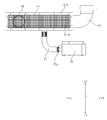
도 5는 본 발명의 실시예에 따른 가스 퍼니스의 균일 가이드가 혼합기를 복수 개의 버너 각각에 균일하게 분배하는 기능을 설명하기 위한 도면이다.5 is a view for explaining a function of uniformly distributing a mixer to each of a plurality of burners by a uniform guide of a gas furnace according to an embodiment of the present invention.
도 5를 참조하면, 균일 가이드(411)는 혼합챔버(41)의 내부 공간에 설치되어 상기 혼합기가 복수 개의 버너(42) 각각에 균일하게 분배되도록 할 수 있다. 특히, 균일 가이드(411)는 연결구(410)가 혼합챔버(41)의 수평 방향 중 어느 일 방향의 끝단부에 형성되어 있더라도, 상기 혼합기가 복수 개의 버너(42) 각각에 균일하게 분배되도록 할 수 있다.Referring to FIG. 5, the uniform guide 411 may be installed in the inner space of the mixing
균일 가이드(411)는 혼합관(33) 및 복수 개의 버너(42)의 사이로서, 혼합관(33) 및 복수 개의 버너(42) 각각으로부터 소정 간격만큼 이격되게 배치될 수 있다.The uniform guide 411 is between the mixing
즉, 혼합챔버(41) 내에 형성되는 혼합관(33)으로부터 복수 개의 버너(42)로이어지는 혼합기의 유로 상에 설치되는 균일 가이드(411)는, 소정의 압력 부하를 형성하여 혼합기의 각 버너로의 균일 유동장을 형성할 수 있다.That is, the uniform guide 411 installed on the flow path of the mixer leading from the mixing
균일 가이드(411)는 혼합챔버(41)의 내부에 탈착 가능하게 설치될 수 있다. 이로써, 균일 가이드(411)의 교체 및 수리가 필요할 시 균일 가이드(411)를 혼합챔버(41)로부터 용이하게 분리할 수 있다.The uniform guide 411 may be detachably installed inside the mixing
도 6은 본 발명의 제1 실시예에 따른 균일 가이드로서 분배 플레이트가 혼합챔버에 설치된 모습을 도시한 도면이다.6 is a view showing a state in which a distribution plate is installed in a mixing chamber as a uniform guide according to the first embodiment of the present invention.
도 6을 참조하면, 본 발명의 제1 실시예에 따른 균일 가이드(411)는 분배 플레이트(411a)를 포함할 수 있다. 분배 플레이트(411a)는 수평 방향(즉, X축 방향)으로 연장 형성될 수 있다. 예를 들면, 분배 플레이트(411a)는 장방형의 플레이트로 형성될 수 있다. 이 경우, 분배 플레이트(411a)는 혼합챔버(41)의 수평 방향의 내측면에 결합될 수 있다. 또한, 분배 플레이트(411a)는 소정의 영역이 개구된 형태로 형성될 수 있다.Referring to FIG. 6, the uniform guide 411 according to the first embodiment of the present invention may include a
예를 들면, 분배 플레이트(411a)에 의한 혼합기의 균일 유동장 형성이 방해받지 않도록, 분배 플레이트(411a)는 수평 방향의 양 끝단부가 상기 연결구를 향하는 방향과 반대되는 방향으로 절곡되어 혼합챔버(41)의 수평 방향의 내측면에 결합될 수 있다. 다만, 분배 플레이트(411a)가 혼합챔버(41)의 수평 방향의 내측면에 결합되는 수단 및 구조가 이에 한정되는 것은 아니다.For example, so that the formation of a uniform flow field of the mixer by the
한편, 분배 플레이트(411a)는 혼합챔버(41)의 수직 방향(즉, Z축 방향)의 내측면으로부터는 소정 간격(d)만큼 이격되게 배치될 수 있다.Meanwhile, the
예를 들면, 분배 플레이트(411a)는 혼합챔버(41)의 수직 방향의 내측면으로부터 2 내지 13 mm 의 간격(d)만큼 이격되게 배치될 수 있다. 그 결과, 혼합관(33)으로부터 혼합챔버(41)의 내부로 유입된 혼합기는 분배 플레이트(411a)의 너비 방향으로 분산된 후, 분배 플레이트(411a)의 상, 하측을 통해 균일하게 유동될 수 있다.For example, the
도 7은 본 발명의 제2 실시예에 따른 균일 가이드로서 분배 메쉬가 혼합챔버에 설치된 모습을 도시한 도면이다.7 is a view showing a state in which a distribution mesh is installed in a mixing chamber as a uniform guide according to a second embodiment of the present invention.
도 7을 참조하면, 본 발명의 제2 실시예에 따른 균일 가이드(411)는 분배 메쉬(mesh)(411b)를 포함할 수 있다. 분배 메쉬(411b)는 복수 개의 공극이 형성될 수 있다. 이 경우, 분배 메쉬(411b)는 혼합챔버(41)의 수평 및 수직 방향의 내측면에 결합될 수 있다.Referring to FIG. 7, the uniform guide 411 according to the second embodiment of the present invention may include a
또한, 상기 복수 개의 공극은 각각의 크기가 균일하도록 형성될 수 있다. 예를 들면, 분배 메쉬(411b)는 허니컴 세라믹(ceramic honeycomb) 재질로 형성되고, 상기 복수 개의 공극 각각은 0.7 내지 1.3 mm² 의 크기를 갖을 수 있다.In addition, the plurality of pores may be formed to have a uniform size. For example, the
그 결과, 혼합관(33)으로부터 혼합챔버(41)의 내부로 유입된 혼합기는 분배 메쉬(411b)에 의해 형성된 압력 부하에 따라, 상기 복수 개의 버너(42) 각각으로 균일하게 유동될 수 있다.As a result, the mixer introduced into the mixing
도 8은 본 발명의 제3 실시예에 따른 균일 가이드로서 분배 필터가 혼합챔버에 설치된 모습을 도시한 도면이다.8 is a view showing a state in which a distribution filter is installed in a mixing chamber as a uniform guide according to a third embodiment of the present invention.
도 8을 참조하면, 본 발명의 제3 실시예에 따른 균일 가이드(411)는 분배 필터(filter)(411c)를 포함할 수 있다. 분배 필터(411c)는 상기 혼합기와 함께 유동하는 이물질을 걸러내는 기능도 수행할 수 있다. 이 경우, 분배 필터(411c)는 혼합챔버(41)의 수평 및 수직 방향의 내측면에 결합될 수 있다.Referring to FIG. 8, the uniform guide 411 according to the third embodiment of the present invention may include a
그 결과, 혼합관(33)으로부터 혼합챔버(41)의 내부로 유입된 혼합기는 분배 필터(411c)에 의해 형성된 압력 부하에 따라, 상기 복수 개의 버너(42) 각각으로 균일하게 유동될 수 있다.As a result, the mixer introduced into the mixing
이상, 본 발명의 실시예에 따른 가스 퍼니스를 첨부도면을 참조하여 설명하였다. 그러나, 본 발명은 상기 실시예에 한정되는 것은 아니고, 본 발명의 요지를 벗어나지 않는 범위 내에서 본 발명이 속하는 기술분야에서 통상의 지식을 가진자가 예측할 수 있는 다양한 변형이나 균등한 범위내에서의 실시가 가능함은 물론이다.In the above, a gas furnace according to an embodiment of the present invention has been described with reference to the accompanying drawings. However, the present invention is not limited to the above embodiments, and various modifications that can be predicted by those of ordinary skill in the art to which the present invention pertains within the scope not departing from the gist of the present invention or implementation within an equivalent range. Of course it is possible.
10: 가스 퍼니스
20: 가스밸브
20a: 노즐
21: 매니폴드
31: 흡기관
32: 믹서
32a: 믹서 하우징
32b: 벤츄리 튜브
322a: 연료 유입홀
33: 혼합관
40: 버너 어셈블리
41: 혼합챔버
411: 균일 가이드
411a: 분배 플레이트
411b: 분배 메쉬
411c: 분배 필터
50: 열교환기
60: 송풍팬
70: 유도팬
80: 배기관
90: 응축수 트랩10: gas furnace 20: gas valve
20a: nozzle 21: manifold
31: intake pipe 32: mixer
32a:
322a: fuel inlet hole 33: mixing pipe
40: burner assembly 41: mixing chamber
411:
411b:
50: heat exchanger 60: blowing fan
70: induction fan 80: exhaust pipe
90: condensate trap
Claims (20)
상기 믹서를 통과한 혼합기가 유동하는 혼합관;
상기 혼합관을 통과한 혼합기를 연소시켜 연소가스를 생성하는 버너 어셈블리; 및
상기 연소가스가 유동하는 열교환기를 포함하고,
상기 버너 어셈블리는,
상기 혼합기가 연소될 시 생성되는 화염이 안착되는 복수 개의 버너;
상기 혼합관으로부터 상기 버너로의 상기 혼합기의 전달을 매개하는 혼합챔버; 및
상기 혼합챔버의 내부에 위치하고, 상기 혼합기가 상기 복수 개의 버너 각각에 균일하게 분배되도록 하는 균일 가이드를 포함하는 가스 퍼니스.A mixer configured to form a mixer by mixing air and fuel gas introduced from each of the intake pipe and the manifold;
A mixing pipe through which the mixer passing through the mixer flows;
A burner assembly for generating combustion gas by combusting the mixer passing through the mixing pipe; And
And a heat exchanger through which the combustion gas flows,
The burner assembly,
A plurality of burners on which flames generated when the mixer is burned are seated;
A mixing chamber for mediating the transfer of the mixer from the mixing tube to the burner; And
A gas furnace located inside the mixing chamber and including a uniform guide for uniformly distributing the mixer to each of the plurality of burners.
상기 열교환기는,
상기 복수 개의 버너의 개수에 대응한 개수만큼 구비되고, 상호 소정 간격만큼 이격되게 배치되는 복수 개의 열교환기를 포함하는 가스 퍼니스.The method of claim 1,
The heat exchanger,
A gas furnace comprising a plurality of heat exchangers provided as many as the number corresponding to the number of the plurality of burners and spaced apart from each other by a predetermined interval.
상기 혼합챔버는,
일측에 상기 혼합관이 연결되는 연결구가 형성되고, 상기 일측에 반대되는 타측은 개구되어 상기 복수 개의 버너가 위치하는 가스 퍼니스.The method of claim 1,
The mixing chamber,
A gas furnace in which a connector to which the mixing pipe is connected is formed on one side, and the other side opposite to the one side is opened to place the plurality of burners.
상기 복수 개의 버너는,
수평 방향으로 상호 소정 간격만큼 이격되게 배치되고,
상기 혼합챔버는,
수평 방향으로 연장 형성되는 내부 공간을 구획하는 가스 퍼니스.The method of claim 3,
The plurality of burners,
They are arranged to be spaced apart from each other by a predetermined interval in the horizontal direction,
The mixing chamber,
A gas furnace that defines an interior space extending in the horizontal direction.
상기 균일 가이드는,
상기 혼합챔버의 내부 공간에 설치되고, 수평 방향으로 연장 형성되며 소정의 영역이 개구된 형태의 분배 플레이트로 형성되어진 것을 특징으로 하는 가스 퍼니스.The method of claim 4,
The uniform guide,
A gas furnace, characterized in that the gas furnace is formed of a distribution plate installed in the inner space of the mixing chamber, extending in a horizontal direction, and opening a predetermined area.
상기 분배 플레이트는,
상기 혼합챔버의 수평 방향의 내측면에 결합되되, 수직 방향의 내측면으로부터는 소정 간격만큼 이격되게 배치되는 가스 퍼니스.The method of claim 5,
The distribution plate,
A gas furnace coupled to an inner surface of the mixing chamber in a horizontal direction and disposed to be spaced apart from the inner surface in a vertical direction by a predetermined interval.
상기 분배 플레이트는,
상기 혼합챔버의 수직 방향의 내측면으로부터 2 내지 13 mm 의 간격만큼 이격되게 배치되는 가스 퍼니스.The method of claim 6,
The distribution plate,
A gas furnace disposed to be spaced apart by a distance of 2 to 13 mm from an inner surface of the mixing chamber in a vertical direction.
상기 분배 플레이트는,
수평 방향의 양 끝단부가 상기 연결구를 향하는 방향과 반대되는 방향으로 절곡되어 상기 혼합챔버의 수평 방향의 내측면에 결합되는 가스 퍼니스.The method of claim 6,
The distribution plate,
A gas furnace where both ends in a horizontal direction are bent in a direction opposite to a direction toward the connector and are coupled to an inner surface of the mixing chamber in a horizontal direction.
상기 균일 가이드는,
상기 혼합챔버의 내부 공간에 설치되고, 복수 개의 공극이 형성되는 분배 메쉬(mesh)로 형성되어진 것을 특징으로 하는 가스 퍼니스.The method of claim 4,
The uniform guide,
A gas furnace, characterized in that it is installed in the inner space of the mixing chamber and is formed of a distribution mesh in which a plurality of voids are formed.
상기 분배 메쉬는,
상기 혼합챔버의 내측면에 결합되는 가스 퍼니스.The method of claim 9,
The distribution mesh,
A gas furnace coupled to the inner surface of the mixing chamber.
상기 복수 개의 공극은,
각각의 크기가 균일하도록 형성되는 가스 퍼니스.The method of claim 9,
The plurality of voids,
Gas furnaces that are formed so that each size is uniform.
상기 분배 메쉬는,
허니컴 세라믹(ceramic honeycomb) 재질로 형성되고,
상기 복수 개의 공극 각각은,
0.7 내지 1.3 mm² 의 크기를 갖는 가스 퍼니스.In clause 11,
The distribution mesh,
It is formed of a ceramic honeycomb material,
Each of the plurality of voids,
Gas furnaces with a size of 0.7 to 1.3 mm².
상기 균일 가이드는,
상기 혼합챔버의 내부 공간에 설치되고, 상기 혼합기와 함께 유동하는 이물질을 걸러내는 분배 필터로 형성되어진 것을 특징으로 하는 가스 퍼니스.The method of claim 4,
The uniform guide,
A gas furnace, characterized in that it is installed in the inner space of the mixing chamber and is formed of a distribution filter that filters foreign substances flowing together with the mixer.
상기 분배 필터는,
상기 혼합챔버의 내측면에 결합되는 가스 퍼니스.The method of claim 13,
The distribution filter,
A gas furnace coupled to the inner surface of the mixing chamber.
상기 균일 가이드는,
상기 혼합챔버의 내부에 탈착 가능하게 설치되는 가스 퍼니스.The method of claim 4,
The uniform guide,
A gas furnace detachably installed inside the mixing chamber.
상기 혼합관은,
적어도 일부가, 상기 연결구를 통해 상기 혼합챔버의 내부로 삽입되는 가스 퍼니스.The method of claim 4,
The mixing tube,
At least a portion of the gas furnace is inserted into the mixing chamber through the connector.
상기 균일 가이드는,
상기 혼합관 및 복수 개의 버너의 사이로서, 상기 혼합관 및 복수 개의 버너 각각으로부터 소정 간격만큼 이격되게 배치되는 가스 퍼니스.The method of claim 16,
The uniform guide,
A gas furnace disposed between the mixing pipe and the plurality of burners and spaced apart from each of the mixing pipe and the plurality of burners by a predetermined interval.
상기 연결구는,
상기 혼합챔버의 수평 방향 중 어느 일 방향의 끝단부에 형성되고,
상기 복수 개의 버너 중, 상기 연결구에 인접하는 버너의 상측에 설치되어 상기 혼합기를 점화하는 점화기를 더 포함하는 가스 퍼니스.The method of claim 4,
The connector,
It is formed at the end of the mixing chamber in any one of the horizontal directions,
A gas furnace further comprising an igniter installed on an upper side of a burner adjacent to the connector among the plurality of burners to ignite the mixer.
상기 복수 개의 버너 간의 화염전파를 매개하는 화염 전파구; 및
상기 복수 개의 버너 중, 상기 연결구로부터 가장 동떨어진 버너의 상측에 설치되어 상기 혼합기의 연소에 따라 화염이 생성되었는지를 감지하는 화염 감지기를 더 포함하는 가스 퍼니스.The method of claim 18,
A flame propagation port for mediating flame propagation between the plurality of burners; And
A gas furnace further comprising a flame detector installed on an upper side of a burner farthest from the connector among the plurality of burners to detect whether a flame is generated by combustion of the mixer.
상기 믹서는,
전단에 상기 흡기관이 연결되고, 후단에 상기 혼합관이 연결되고, 측면에 상기 매니폴드가 연결되는 믹서 하우징; 및
상기 믹서 하우징의 내부에 결합되는 벤츄리 튜브를 포함하는 가스 퍼니스.The method of claim 1,
The mixer,
A mixer housing in which the intake pipe is connected to a front end, the mixing pipe is connected to a rear end, and the manifold is connected to a side surface; And
Gas furnace comprising a venturi tube coupled to the interior of the mixer housing.
Priority Applications (2)
| Application Number | Priority Date | Filing Date | Title |
|---|---|---|---|
| KR1020190141387A KR102658124B1 (en) | 2019-11-07 | Gas furnace | |
| US17/091,188 US11767974B2 (en) | 2019-11-07 | 2020-11-06 | Gas furnace |
Applications Claiming Priority (1)
| Application Number | Priority Date | Filing Date | Title |
|---|---|---|---|
| KR1020190141387A KR102658124B1 (en) | 2019-11-07 | Gas furnace |
Publications (2)
| Publication Number | Publication Date |
|---|---|
| KR20210055202A true KR20210055202A (en) | 2021-05-17 |
| KR102658124B1 KR102658124B1 (en) | 2024-04-16 |
Family
ID=
Also Published As
| Publication number | Publication date |
|---|---|
| US11767974B2 (en) | 2023-09-26 |
| US20210140630A1 (en) | 2021-05-13 |
Similar Documents
| Publication | Publication Date | Title |
|---|---|---|
| JP4264004B2 (en) | Improved burner system with low NOx emission | |
| EP2294336B1 (en) | Low nox burner | |
| US11639793B2 (en) | Gas furnace | |
| US20130213378A1 (en) | Burner system for a furnace | |
| KR20200138040A (en) | Gas furnace | |
| EP3745026B1 (en) | Gas furnace | |
| US20090145419A1 (en) | Furnace heat exchanger | |
| US11428403B2 (en) | Gas furnace | |
| KR20200143253A (en) | Gas furnace | |
| KR102658124B1 (en) | Gas furnace | |
| KR20210055202A (en) | Gas furnace | |
| KR102658128B1 (en) | Gas furnace | |
| KR100242970B1 (en) | Premixed burner of gas boiler | |
| JP4179761B2 (en) | Burner device and fluid heating device including the same | |
| KR20210055204A (en) | Gas furnace | |
| JP4264003B2 (en) | Burner system using improved flue gas circulation | |
| JP2005521026A (en) | Removable ignition port plug for use in burners | |
| CN219120589U (en) | Organic waste gas incinerator | |
| CN212746465U (en) | Water-cooling full-premixing planar combustor and combustion panel and combustion system thereof | |
| US20210254860A1 (en) | ULTRA-LOW NOx BURNER | |
| US20210025621A1 (en) | Gas furnace | |
| KR100474178B1 (en) | The Premixed Combustion Gas Burner Having Separated Fire Hole Part | |
| JP2001074214A (en) | Low environmental pollution and high efficiency rich/ lean combustion burner for home utilizing porous plate consisting of porous metal fiber texture | |
| JP2756062B2 (en) | Light-burn combustion burner | |
| JPH01107010A (en) | Burner |
Legal Events
| Date | Code | Title | Description |
|---|---|---|---|
| A201 | Request for examination | ||
| E902 | Notification of reason for refusal | ||
| E701 | Decision to grant or registration of patent right | ||
| GRNT | Written decision to grant |