KR20210053999A - Conductive element - Google Patents
Conductive element Download PDFInfo
- Publication number
- KR20210053999A KR20210053999A KR1020217011679A KR20217011679A KR20210053999A KR 20210053999 A KR20210053999 A KR 20210053999A KR 1020217011679 A KR1020217011679 A KR 1020217011679A KR 20217011679 A KR20217011679 A KR 20217011679A KR 20210053999 A KR20210053999 A KR 20210053999A
- Authority
- KR
- South Korea
- Prior art keywords
- carbon nanotubes
- conductive element
- substrate
- metal
- metal substrate
- Prior art date
Links
Images


Classifications
-
- C—CHEMISTRY; METALLURGY
- C01—INORGANIC CHEMISTRY
- C01B—NON-METALLIC ELEMENTS; COMPOUNDS THEREOF; METALLOIDS OR COMPOUNDS THEREOF NOT COVERED BY SUBCLASS C01C
- C01B32/00—Carbon; Compounds thereof
- C01B32/15—Nano-sized carbon materials
- C01B32/158—Carbon nanotubes
-
- H—ELECTRICITY
- H01—ELECTRIC ELEMENTS
- H01B—CABLES; CONDUCTORS; INSULATORS; SELECTION OF MATERIALS FOR THEIR CONDUCTIVE, INSULATING OR DIELECTRIC PROPERTIES
- H01B13/00—Apparatus or processes specially adapted for manufacturing conductors or cables
-
- H—ELECTRICITY
- H01—ELECTRIC ELEMENTS
- H01B—CABLES; CONDUCTORS; INSULATORS; SELECTION OF MATERIALS FOR THEIR CONDUCTIVE, INSULATING OR DIELECTRIC PROPERTIES
- H01B13/00—Apparatus or processes specially adapted for manufacturing conductors or cables
- H01B13/0036—Details
-
- C—CHEMISTRY; METALLURGY
- C01—INORGANIC CHEMISTRY
- C01B—NON-METALLIC ELEMENTS; COMPOUNDS THEREOF; METALLOIDS OR COMPOUNDS THEREOF NOT COVERED BY SUBCLASS C01C
- C01B32/00—Carbon; Compounds thereof
- C01B32/15—Nano-sized carbon materials
- C01B32/158—Carbon nanotubes
- C01B32/16—Preparation
-
- C—CHEMISTRY; METALLURGY
- C01—INORGANIC CHEMISTRY
- C01B—NON-METALLIC ELEMENTS; COMPOUNDS THEREOF; METALLOIDS OR COMPOUNDS THEREOF NOT COVERED BY SUBCLASS C01C
- C01B32/00—Carbon; Compounds thereof
- C01B32/15—Nano-sized carbon materials
- C01B32/158—Carbon nanotubes
- C01B32/168—After-treatment
-
- C—CHEMISTRY; METALLURGY
- C08—ORGANIC MACROMOLECULAR COMPOUNDS; THEIR PREPARATION OR CHEMICAL WORKING-UP; COMPOSITIONS BASED THEREON
- C08K—Use of inorganic or non-macromolecular organic substances as compounding ingredients
- C08K3/00—Use of inorganic substances as compounding ingredients
- C08K3/02—Elements
- C08K3/04—Carbon
- C08K3/041—Carbon nanotubes
-
- C—CHEMISTRY; METALLURGY
- C23—COATING METALLIC MATERIAL; COATING MATERIAL WITH METALLIC MATERIAL; CHEMICAL SURFACE TREATMENT; DIFFUSION TREATMENT OF METALLIC MATERIAL; COATING BY VACUUM EVAPORATION, BY SPUTTERING, BY ION IMPLANTATION OR BY CHEMICAL VAPOUR DEPOSITION, IN GENERAL; INHIBITING CORROSION OF METALLIC MATERIAL OR INCRUSTATION IN GENERAL
- C23C—COATING METALLIC MATERIAL; COATING MATERIAL WITH METALLIC MATERIAL; SURFACE TREATMENT OF METALLIC MATERIAL BY DIFFUSION INTO THE SURFACE, BY CHEMICAL CONVERSION OR SUBSTITUTION; COATING BY VACUUM EVAPORATION, BY SPUTTERING, BY ION IMPLANTATION OR BY CHEMICAL VAPOUR DEPOSITION, IN GENERAL
- C23C16/00—Chemical coating by decomposition of gaseous compounds, without leaving reaction products of surface material in the coating, i.e. chemical vapour deposition [CVD] processes
- C23C16/22—Chemical coating by decomposition of gaseous compounds, without leaving reaction products of surface material in the coating, i.e. chemical vapour deposition [CVD] processes characterised by the deposition of inorganic material, other than metallic material
- C23C16/26—Deposition of carbon only
-
- C—CHEMISTRY; METALLURGY
- C23—COATING METALLIC MATERIAL; COATING MATERIAL WITH METALLIC MATERIAL; CHEMICAL SURFACE TREATMENT; DIFFUSION TREATMENT OF METALLIC MATERIAL; COATING BY VACUUM EVAPORATION, BY SPUTTERING, BY ION IMPLANTATION OR BY CHEMICAL VAPOUR DEPOSITION, IN GENERAL; INHIBITING CORROSION OF METALLIC MATERIAL OR INCRUSTATION IN GENERAL
- C23C—COATING METALLIC MATERIAL; COATING MATERIAL WITH METALLIC MATERIAL; SURFACE TREATMENT OF METALLIC MATERIAL BY DIFFUSION INTO THE SURFACE, BY CHEMICAL CONVERSION OR SUBSTITUTION; COATING BY VACUUM EVAPORATION, BY SPUTTERING, BY ION IMPLANTATION OR BY CHEMICAL VAPOUR DEPOSITION, IN GENERAL
- C23C28/00—Coating for obtaining at least two superposed coatings either by methods not provided for in a single one of groups C23C2/00 - C23C26/00 or by combinations of methods provided for in subclasses C23C and C25C or C25D
- C23C28/30—Coatings combining at least one metallic layer and at least one inorganic non-metallic layer
- C23C28/32—Coatings combining at least one metallic layer and at least one inorganic non-metallic layer including at least one pure metallic layer
-
- C—CHEMISTRY; METALLURGY
- C23—COATING METALLIC MATERIAL; COATING MATERIAL WITH METALLIC MATERIAL; CHEMICAL SURFACE TREATMENT; DIFFUSION TREATMENT OF METALLIC MATERIAL; COATING BY VACUUM EVAPORATION, BY SPUTTERING, BY ION IMPLANTATION OR BY CHEMICAL VAPOUR DEPOSITION, IN GENERAL; INHIBITING CORROSION OF METALLIC MATERIAL OR INCRUSTATION IN GENERAL
- C23C—COATING METALLIC MATERIAL; COATING MATERIAL WITH METALLIC MATERIAL; SURFACE TREATMENT OF METALLIC MATERIAL BY DIFFUSION INTO THE SURFACE, BY CHEMICAL CONVERSION OR SUBSTITUTION; COATING BY VACUUM EVAPORATION, BY SPUTTERING, BY ION IMPLANTATION OR BY CHEMICAL VAPOUR DEPOSITION, IN GENERAL
- C23C28/00—Coating for obtaining at least two superposed coatings either by methods not provided for in a single one of groups C23C2/00 - C23C26/00 or by combinations of methods provided for in subclasses C23C and C25C or C25D
- C23C28/30—Coatings combining at least one metallic layer and at least one inorganic non-metallic layer
- C23C28/34—Coatings combining at least one metallic layer and at least one inorganic non-metallic layer including at least one inorganic non-metallic material layer, e.g. metal carbide, nitride, boride, silicide layer and their mixtures, enamels, phosphates and sulphates
-
- C—CHEMISTRY; METALLURGY
- C25—ELECTROLYTIC OR ELECTROPHORETIC PROCESSES; APPARATUS THEREFOR
- C25D—PROCESSES FOR THE ELECTROLYTIC OR ELECTROPHORETIC PRODUCTION OF COATINGS; ELECTROFORMING; APPARATUS THEREFOR
- C25D5/00—Electroplating characterised by the process; Pretreatment or after-treatment of workpieces
- C25D5/54—Electroplating of non-metallic surfaces
-
- H—ELECTRICITY
- H01—ELECTRIC ELEMENTS
- H01B—CABLES; CONDUCTORS; INSULATORS; SELECTION OF MATERIALS FOR THEIR CONDUCTIVE, INSULATING OR DIELECTRIC PROPERTIES
- H01B1/00—Conductors or conductive bodies characterised by the conductive materials; Selection of materials as conductors
- H01B1/02—Conductors or conductive bodies characterised by the conductive materials; Selection of materials as conductors mainly consisting of metals or alloys
- H01B1/026—Alloys based on copper
-
- H—ELECTRICITY
- H01—ELECTRIC ELEMENTS
- H01B—CABLES; CONDUCTORS; INSULATORS; SELECTION OF MATERIALS FOR THEIR CONDUCTIVE, INSULATING OR DIELECTRIC PROPERTIES
- H01B1/00—Conductors or conductive bodies characterised by the conductive materials; Selection of materials as conductors
- H01B1/04—Conductors or conductive bodies characterised by the conductive materials; Selection of materials as conductors mainly consisting of carbon-silicon compounds, carbon or silicon
-
- H—ELECTRICITY
- H01—ELECTRIC ELEMENTS
- H01B—CABLES; CONDUCTORS; INSULATORS; SELECTION OF MATERIALS FOR THEIR CONDUCTIVE, INSULATING OR DIELECTRIC PROPERTIES
- H01B13/00—Apparatus or processes specially adapted for manufacturing conductors or cables
- H01B13/0016—Apparatus or processes specially adapted for manufacturing conductors or cables for heat treatment
-
- H—ELECTRICITY
- H01—ELECTRIC ELEMENTS
- H01B—CABLES; CONDUCTORS; INSULATORS; SELECTION OF MATERIALS FOR THEIR CONDUCTIVE, INSULATING OR DIELECTRIC PROPERTIES
- H01B5/00—Non-insulated conductors or conductive bodies characterised by their form
- H01B5/02—Single bars, rods, wires, or strips
-
- B—PERFORMING OPERATIONS; TRANSPORTING
- B82—NANOTECHNOLOGY
- B82Y—SPECIFIC USES OR APPLICATIONS OF NANOSTRUCTURES; MEASUREMENT OR ANALYSIS OF NANOSTRUCTURES; MANUFACTURE OR TREATMENT OF NANOSTRUCTURES
- B82Y30/00—Nanotechnology for materials or surface science, e.g. nanocomposites
-
- B—PERFORMING OPERATIONS; TRANSPORTING
- B82—NANOTECHNOLOGY
- B82Y—SPECIFIC USES OR APPLICATIONS OF NANOSTRUCTURES; MEASUREMENT OR ANALYSIS OF NANOSTRUCTURES; MANUFACTURE OR TREATMENT OF NANOSTRUCTURES
- B82Y40/00—Manufacture or treatment of nanostructures
-
- C—CHEMISTRY; METALLURGY
- C01—INORGANIC CHEMISTRY
- C01B—NON-METALLIC ELEMENTS; COMPOUNDS THEREOF; METALLOIDS OR COMPOUNDS THEREOF NOT COVERED BY SUBCLASS C01C
- C01B2202/00—Structure or properties of carbon nanotubes
- C01B2202/06—Multi-walled nanotubes
-
- C—CHEMISTRY; METALLURGY
- C01—INORGANIC CHEMISTRY
- C01B—NON-METALLIC ELEMENTS; COMPOUNDS THEREOF; METALLOIDS OR COMPOUNDS THEREOF NOT COVERED BY SUBCLASS C01C
- C01B2202/00—Structure or properties of carbon nanotubes
- C01B2202/08—Aligned nanotubes
-
- C—CHEMISTRY; METALLURGY
- C01—INORGANIC CHEMISTRY
- C01B—NON-METALLIC ELEMENTS; COMPOUNDS THEREOF; METALLOIDS OR COMPOUNDS THEREOF NOT COVERED BY SUBCLASS C01C
- C01B2202/00—Structure or properties of carbon nanotubes
- C01B2202/20—Nanotubes characterized by their properties
- C01B2202/22—Electronic properties
-
- C—CHEMISTRY; METALLURGY
- C01—INORGANIC CHEMISTRY
- C01P—INDEXING SCHEME RELATING TO STRUCTURAL AND PHYSICAL ASPECTS OF SOLID INORGANIC COMPOUNDS
- C01P2004/00—Particle morphology
- C01P2004/01—Particle morphology depicted by an image
- C01P2004/03—Particle morphology depicted by an image obtained by SEM
-
- C—CHEMISTRY; METALLURGY
- C08—ORGANIC MACROMOLECULAR COMPOUNDS; THEIR PREPARATION OR CHEMICAL WORKING-UP; COMPOSITIONS BASED THEREON
- C08K—Use of inorganic or non-macromolecular organic substances as compounding ingredients
- C08K2201/00—Specific properties of additives
- C08K2201/001—Conductive additives
-
- C—CHEMISTRY; METALLURGY
- C08—ORGANIC MACROMOLECULAR COMPOUNDS; THEIR PREPARATION OR CHEMICAL WORKING-UP; COMPOSITIONS BASED THEREON
- C08K—Use of inorganic or non-macromolecular organic substances as compounding ingredients
- C08K2201/00—Specific properties of additives
- C08K2201/011—Nanostructured additives
Abstract
전도성 요소 전구체 및 전도성 요소, 예컨대 테이프 또는 와이어의 제조 방법이 제공된다. 방법은 금속 기판 상의 복수의 탄소 나노튜브를 성장시키는 단계 및 금속 재료로 금속 기판 상의 복수의 탄소 나노튜브의 탄소 나노튜브를 코팅하는 단계를 포함한다.Conductive element precursors and methods of making conductive elements such as tapes or wires are provided. The method includes growing a plurality of carbon nanotubes on a metal substrate and coating the carbon nanotubes of the plurality of carbon nanotubes on the metal substrate with a metal material.
Description
본 발명은 전도성 요소 전구체의 제조 방법, 및 전도성 요소, 특히 와이어, 및 그의 제조 방법에 관한 것이다.The present invention relates to a method of making a conductive element precursor, and a conductive element, in particular a wire, and a method of making the same.
전도성 요소, 특히 배선은 우리의 일상 생활에서 어디에나 존재한다. 단지 몇 가지 적용을 명명하면 도체는 항공기, 자동차, 우주선에 존재하고 먼 거리에 걸쳐 전기를 운반하기 위한 전력 케이블에 존재한다. 이들 적용 각각에 있어서 전류 용량(current carrying capacity)을 증가시키고/거나 이러한 케이블의 중량을 감소시키고/거나 필요한 케이블의 크기를 감소시키는 것이 유리할 것이다. 항공우주 및 자동차 적용에 있어서 이러한 중량의 감소는 연료 소비 및 CO2 생성을 크게 감소시킬 것이다. 전류 용량의 증가는 전력 케이블을 통해 전기를 운반할 때 손실을 줄일 수 있다. 따라서 필요한 전도성 요소를 형성하는데 이용될 수 있는 개선된 전도성 요소 및 전구체를 생성하고자 하는 요구가 있다. 특히, 와이어 형태의 개선된 전도성 요소에 대한 요구가 있다.Conductive elements, especially wiring, exist everywhere in our daily lives. To name only a few applications, conductors exist in aircraft, automobiles, spacecraft, and in power cables to carry electricity over long distances. In each of these applications it would be advantageous to increase the current carrying capacity and/or reduce the weight of these cables and/or reduce the size of the cables required. In aerospace and automotive applications this weight reduction will significantly reduce fuel consumption and CO 2 production. Increasing the current capacity can reduce losses when carrying electricity through the power cable. Accordingly, there is a need to create improved conductive elements and precursors that can be used to form the necessary conductive elements. In particular, there is a need for improved conductive elements in the form of wires.
본 발명은 전도성 요소 전구체의 제조 방법을 제공하며, 상기 방법은 다음의 단계: 금속 기판 상에 복수의 탄소 나노튜브를 형성하는 단계; 금속 기판 상의 복수의 탄소 나노튜브에 제1 방향으로 전단력을 적용하는 단계; 및 금속 재료로 복수의 탄소 나노튜브의 탄소 나노튜브를 코팅하는 단계를 포함한다.The present invention provides a method of manufacturing a conductive element precursor, the method comprising the following steps: forming a plurality of carbon nanotubes on a metal substrate; Applying a shear force to a plurality of carbon nanotubes on a metal substrate in a first direction; And coating the carbon nanotubes of the plurality of carbon nanotubes with a metallic material.
추가로, 본 발명은 전도성 요소 전구체의 제조 방법을 제공하며, 상기 방법은 다음의 단계: 금속 기판 상에 복수의 탄소 나노튜브를 성장시키는 단계; 금속 기판 상의 복수의 탄소 나노튜브에 제1 방향으로 전단력을 적용하는 단계; 및 금속 재료로 금속 기판 상의 복수의 탄소 나노튜브의 탄소 나노튜브를 코팅하는 단계를 포함한다. 전단력의 적용 단계는 탄소 나노튜브의 코팅 단계 전에 또는 후에 수행할 수 있다.Additionally, the present invention provides a method of manufacturing a conductive element precursor, the method comprising the following steps: growing a plurality of carbon nanotubes on a metal substrate; Applying a shear force to a plurality of carbon nanotubes on a metal substrate in a first direction; And coating carbon nanotubes of a plurality of carbon nanotubes on a metal substrate with a metal material. The step of applying the shear force can be carried out before or after the step of coating the carbon nanotubes.
본 발명의 방법은 특정 방향으로 이동되고 캡슐화되는 탄소 나노튜브를 갖는 전구체를 제공한다. 이것은 전도성 요소를 형성하기 위해 후속 가공을 용이하게 적용할 수 있는 전구체를 제공한다.The method of the present invention provides a precursor having carbon nanotubes that are moved and encapsulated in a specific direction. This provides a precursor that can be easily subjected to subsequent processing to form the conductive element.
본 발명은 추가로 전도성 테이프의 제조 방법을 제공하며, 상기 방법은 다음의 단계: 금속 기판 상에 복수의 탄소 나노튜브를 형성하는 단계; 금속 기판 상의 복수의 탄소 나노튜브에 제1 방향으로 전단력을 적용하는 단계; 및 복수의 탄소 나노튜브를 갖는 금속 기판을, 그의 길이를 증가시켜 전도성 테이프를 형성할 정도로 압축하는 단계를 포함한다.The present invention further provides a method of manufacturing a conductive tape, the method comprising the following steps: forming a plurality of carbon nanotubes on a metal substrate; Applying a shear force to a plurality of carbon nanotubes on a metal substrate in a first direction; And compressing the metal substrate having a plurality of carbon nanotubes so as to increase the length thereof to form a conductive tape.
본 발명은 또한 전도성 요소의 제조 방법을 제공하며, 상기 방법은 다음의 단계: 금속 기판 상에 복수의 탄소 나노튜브를 형성하는 단계; 인서트를 형성하기 위해 복수의 탄소 나노튜브로 기판을 롤링하는 단계; 및 인서트를, 그의 길이를 증가시켜 전도성 요소를 형성하도록 견인하는 단계를 포함한다.The present invention also provides a method of manufacturing a conductive element, the method comprising the steps of: forming a plurality of carbon nanotubes on a metal substrate; Rolling the substrate with a plurality of carbon nanotubes to form an insert; And pulling the insert to increase its length to form a conductive element.
특히, 본 발명은 전도성 요소의 제조 방법을 제공하며, 상기 방법은 다음의 단계: 금속 기판 상에 복수의 탄소 나노튜브를 형성하는 단계; 금속 재료로 복수의 탄소 나노튜브의 탄소 나노튜브를 코팅하는 단계; 인서트를 형성하기 위해 코팅된 탄소 나노튜브로 기판을 롤링하는 단계; 및 인서트를, 그의 길이를 증가시켜 전도성 요소를 형성하도록 견인하는 단계를 포함한다.In particular, the present invention provides a method of manufacturing a conductive element, the method comprising the following steps: forming a plurality of carbon nanotubes on a metal substrate; Coating carbon nanotubes of a plurality of carbon nanotubes with a metal material; Rolling the substrate with coated carbon nanotubes to form an insert; And pulling the insert to increase its length to form a conductive element.
본 발명의 방법은 전도성 요소로의 탄소 나노튜브의 혼입을 돕기 위해 탄소 나노튜브가 금속 재료와 긴밀한 접촉을 하는 것을 보장한다. 추가로, 탄소 나노튜브의 코팅은 후속 가공 단계에서 탄소 나노튜브에 보호를 제공할 수 있다. 이것은 전도성 요소에 존재하는 양호한 품질의 탄소 나노튜브를 제공하는 것을 돕고 따라서 고-품질의 전도성 요소를 제공하며, 여기서 탄소 나노튜브는 전도에 기여한다.The method of the present invention ensures that the carbon nanotubes are in intimate contact with the metallic material to aid in the incorporation of the carbon nanotubes into the conductive element. Additionally, the coating of carbon nanotubes can provide protection to the carbon nanotubes in subsequent processing steps. This helps to provide a good quality carbon nanotube present in the conductive element and thus a high-quality conductive element, where the carbon nanotubes contribute to conduction.
전도성 요소는 포일의 형태를 포함하여, 임의의 형태를 가질 수 있다. 그러나, 본 발명의 방법에 따라, 최종 전도성 요소는 일반적으로 세장형 형태일 것이다. 따라서, 본 발명은 와이어 또는 테이프 형태의 전도성 요소를 제조하는데 특히 적합하다. 와이어는 일반적으로 원형 또는 정사각형 단면적을 갖는 반면, 테이프는 일반적으로 직사각형 단면적을 갖는다. 전도성 요소에 가장 바람직한 형태는 와이어의 형태이다.The conductive element can have any shape, including the shape of a foil. However, according to the method of the present invention, the final conductive element will generally be of an elongated shape. Accordingly, the invention is particularly suitable for producing conductive elements in the form of wires or tapes. Wires generally have a circular or square cross-sectional area, while tapes generally have a rectangular cross-sectional area. The most preferred form for the conductive element is the form of a wire.
전도성 테이프는 전도성 요소 전구체를, 그의 길이를 증가시켜 전도성 테이프를 형성할 정도로 압축함으로써 제조될 수 있다. 따라서 테이프는 기판의 롤링없이 형성될 수 있다. 압축 단계는 전도성 요소 전구체의 단면을 변화시킨다. 전도성 요소 전구체에 다중 압축 단계를 적용할 수 있다. 압축 단계 사이에, 전도성 요소 전구체에 본원에 기재된 바와 같은 어닐링 단계를 적용할 수 있다. 금속 롤링 공정의 일반적인 고려사항은 문헌 (Le and Sutcliffe, International Journal of Mechanical Sciences 43 (2001), p1405-1419)에서 고려된다.The conductive tape can be made by compressing the conductive element precursor to such an extent that it increases its length to form a conductive tape. Thus, the tape can be formed without rolling the substrate. The compression step changes the cross section of the conductive element precursor. Multiple compression steps can be applied to the conductive element precursor. Between the compression steps, the conductive element precursor may be subjected to an annealing step as described herein. General considerations of the metal rolling process are considered in Le and Sutcliffe, International Journal of Mechanical Sciences 43 (2001), p1405-1419.
전도성 요소 전구체를, 그의 길이를 증가시켜 전도성 테이프를 형성할 정도로 압축하는 단계는 금속 기판 상의 복수의 탄소 나노튜브에 제1 방향으로 전단력을 동시에 적용하는데 이용될 수 있다. 대안적으로, 전단력을 적용하는 별도의 단계를 이용할 수 있다.Compressing the conductive element precursor to such an extent that it increases its length to form a conductive tape may be used to simultaneously apply a shear force in a first direction to a plurality of carbon nanotubes on a metal substrate. Alternatively, a separate step of applying shear forces can be used.
금속 재료는 금속을 포함한다. 금속 재료는 바람직하게는 금속으로 본질적으로 이루어지고, 가장 바람직하게는 금속으로 이루어진다. 금속 재료는 금속 합금일 수 있다.Metallic materials include metals. The metallic material preferably consists essentially of a metal, and most preferably consists of a metal. The metal material may be a metal alloy.
방법은 금속 기판 상에 복수의 탄소 나노튜브를 형성하는 단계를 포함한다. 탄소 나노튜브는 금속 기판의 제1 표면에서 성장한다. 또한, 탄소 나노튜브는 금속 기판의 제2 표면에서 또한 성장할 수 있다. 이것은 탄소 나노튜브의 성장 공정 동안 두 표면을 모두 노출시킴으로써 동시에 발생할 수 있다. 제1 표면 및 제2 표면은 대향 표면일 수 있다. 금속 기판이 포일의 형태인 경우, 두 표면은 포일의 2개 주요 표면일 수 있다. 탄소 나노튜브가 표면으로부터 떨어져 성장하도록 금속 기판의 표면 상에 탄소 나노튜브를 형성할 수 있다. 탄소 나노튜브의 세로 축은 실질적으로 정렬될 수 있다. 탄소 나노튜브의 세로 축은 금속 기판의 제1 표면의 평면에 실질적으로 수직일 수 있다. 탄소 나노튜브의 세로 축은 금속 기판의 제2 표면의 평면에 실질적으로 수직일 수 있다.The method includes forming a plurality of carbon nanotubes on a metal substrate. Carbon nanotubes grow on the first surface of the metal substrate. In addition, carbon nanotubes can also grow on the second surface of the metal substrate. This can happen simultaneously by exposing both surfaces during the carbon nanotube growth process. The first surface and the second surface may be opposite surfaces. When the metal substrate is in the form of a foil, the two surfaces may be the two major surfaces of the foil. Carbon nanotubes can be formed on the surface of a metal substrate so that the carbon nanotubes grow away from the surface. The longitudinal axis of the carbon nanotubes can be substantially aligned. The longitudinal axis of the carbon nanotubes may be substantially perpendicular to the plane of the first surface of the metal substrate. The longitudinal axis of the carbon nanotubes may be substantially perpendicular to the plane of the second surface of the metal substrate.
금속 기판은, 예를 들어 포일의 형태로 존재함으로써 실질적으로 평면일 수 있다. 탄소 나노튜브의 성장 동안, 기판은 탄소 나노튜브가 주로 기판의 수직 표면 상에 형성하도록 배향될 수 있다. 평면 금속 기판의 경우 이것은 실질적으로 수직으로 배향된 그의 2개의 주요 표면을 가짐으로써 달성될 수 있다. 금속 기판은 후속 견인 방향, 또는 정렬이 요구되는 또 다른 방향이 수직이도록 배향될 수 있다. 이론에 의해 구속되는 것을 원하지 않지만, 기판을 이러한 방식으로 배향하는 것은 수직 방향을 따라 초기 정렬을 도입할 수 있는 중력의 영향하에 탄소 나노튜브가 성장할 수 있게 하는 것으로 여겨진다.The metal substrate may be substantially planar by being present in the form of a foil, for example. During the growth of carbon nanotubes, the substrate can be oriented such that the carbon nanotubes form primarily on the vertical surface of the substrate. In the case of a planar metal substrate this can be achieved by having its two main surfaces oriented substantially vertically. The metal substrate may be oriented such that the subsequent pulling direction, or another direction requiring alignment, is vertical. Without wishing to be bound by theory, it is believed that orienting the substrate in this way allows the carbon nanotubes to grow under the influence of gravity, which can introduce initial alignment along the vertical direction.
본원에서 수직 및 수평을 언급할 때, 수직은 연직선에 의해 표시된 바와 같은 중력의 방향으로서 정의된다. 수평 방향은 수직 방향에 수직이다.When referring to vertical and horizontal herein, vertical is defined as the direction of gravity as indicated by a vertical line. The horizontal direction is perpendicular to the vertical direction.
본원에서 사용된 바와 같이, 용어 "실질적으로 정렬된"은 탄소 나노튜브의 대부분이 45° 범위, 바람직하게는 25°, 또는 바람직하게는 20°, 또는 15°, 또는 10° 내에서, 또는 가장 바람직하게는 5° 내에서 그의 세로 축을 갖도록 탄소 나노튜브가 배향된 것을 지칭한다. 실질적으로 모든, 또는 모든 탄소 나노튜브는 이들 범위 내에서 그의 세로 축을 가질 수 있다.As used herein, the term “substantially aligned” means that the majority of carbon nanotubes are within the 45° range, preferably 25°, or preferably 20°, or 15°, or 10°, or most It refers to that the carbon nanotubes are oriented so as to have their longitudinal axis preferably within 5°. Substantially all, or all of the carbon nanotubes can have their longitudinal axis within these ranges.
본원에서 사용된 바와 같이, 용어 "실질적으로 수직인" 또는 "실질적으로 평행한"은 탄소 나노튜브의 대부분이 그의 세로 축이 수직 방향 또는 평행 방향 각각의 22.5°내에, 바람직하게는 20°, 또는 15° 내에, 또는 10° 내에, 또는 가장 바람직하게는 5° 내에 있도록 배향된 것을 의미한다. 실질적으로 모든, 또는 모든 탄소 나노튜브는 이들 범위 내에서 그의 세로 축을 가질 수 있다.As used herein, the term “substantially perpendicular” or “substantially parallel” means that the majority of carbon nanotubes are within 22.5° of each of their longitudinal or parallel directions, preferably 20°, or It means oriented so as to be within 15°, or within 10°, or most preferably within 5°. Substantially all, or all of the carbon nanotubes can have their longitudinal axis within these ranges.
금속 기판 상에 탄소 나노튜브를 형성함으로써, 생성된 탄소 나노튜브는 다발화되지 않은 상태에 있고, 즉 탄소 나노튜브의 대부분은 별도의 탄소 나노튜브로서 존재한다. 이것은 전도성 요소로 혼입될 경우 그의 전도도 특성이 유지될 수 있게 한다. 이것은 전도도 특성을 감소시켰던, 다발로 존재하는 탄소 나노튜브와 대조적이다. 탄소 나노튜브의 후속 코팅은 나노튜브가 분리되게 유지하는 것을 도울 수 있다.By forming carbon nanotubes on a metal substrate, the resulting carbon nanotubes are in an unbundled state, that is, most of the carbon nanotubes exist as separate carbon nanotubes. This allows its conductivity properties to be maintained when incorporated into a conductive element. This is in contrast to carbon nanotubes that exist in bundles, which have reduced their conductivity properties. Subsequent coating of carbon nanotubes can help keep the nanotubes separate.
본 발명에서, 탄소 나노튜브는 기판 상에서 성장하고, 전도성 요소 전구체 및 최종 전도성 요소 제품을 제조하기 위해 탄소 나노튜브는 후속 공정 전반에 걸쳐 기판 상에서 유지된다. 이것은 탄소 나노튜브의 취급 용이성을 증가시킨다.In the present invention, the carbon nanotubes are grown on the substrate, and the carbon nanotubes are held on the substrate throughout the subsequent process to produce the conductive element precursor and the final conductive element product. This increases the ease of handling of the carbon nanotubes.
금속 기판 상에 복수의 탄소 나노튜브를 형성하는 단계는 금속 기판 상에 직접 복수의 탄소 나노튜브를 형성하는 것을 포함할 수 있다. 대안적으로, 바람직하게는 금속 기판과 성장하는 탄소 나노튜브 사이에 개재 물질 층이 있다.Forming the plurality of carbon nanotubes on the metal substrate may include forming the plurality of carbon nanotubes directly on the metal substrate. Alternatively, there is preferably a layer of intervening material between the metal substrate and the growing carbon nanotubes.
금속 기판 상에 복수의 탄소 나노튜브를 형성하는 임의의 방법, 특히 정렬된 탄소 나노튜브를 제조하는 방법을 사용할 수 있다. 이러한 접근법은 페로센 또는 철 프탈로시아닌의 존재하에 아세틸렌, 부탄 또는 메탄과 같은 탄화수소 기체의 열분해를 포함한다.Any method of forming a plurality of carbon nanotubes on a metal substrate can be used, in particular a method of manufacturing aligned carbon nanotubes. This approach involves the pyrolysis of hydrocarbon gases such as acetylene, butane or methane in the presence of ferrocene or iron phthalocyanine.
특히 바람직한 접근법은 화학 기상 증착을 포함한다. 이용된 화학 기상 증착 공정은 직접 액체 주입 화학 기상 증착 (DLICVD) 접근법일 수 있다. 이 접근법에서, 액체 탄화수소 전구체가 주입되고, 기화된 다음 반응 챔버로 운반되며 여기서 탄소 나노튜브가 증착되고 기판 상에서 성장한다. 다양한 유형의 액체 탄화수소, 예를 들어 n-펜탄, 이소펜탄, 헥산, 헵탄, 옥탄, 시클로헥산, 벤젠, 톨루엔, 또는 크실렌이 이 접근법으로 사용될 수 있다.A particularly preferred approach involves chemical vapor deposition. The chemical vapor deposition process used may be a direct liquid injection chemical vapor deposition (DLICVD) approach. In this approach, a liquid hydrocarbon precursor is injected, vaporized, and transported to a reaction chamber where carbon nanotubes are deposited and grown on a substrate. Various types of liquid hydrocarbons such as n-pentane, isopentane, hexane, heptane, octane, cyclohexane, benzene, toluene, or xylene can be used with this approach.
탄소 나노튜브의 성장을 초기화하기 위해 촉매가 존재할 수 있다. 이 촉매는 금속 기판 상에 존재할 수 있다. 금속 기판 상의 촉매의 분포는 본질적으로 랜덤일 수 있다. 그러나, 촉매는 DLICVD 공정에서 탄화수소와 함께 액체에 포함되고 탄화수소와 함께 반응 챔버로 주입 및 도입되는 것이 특히 바람직하다. 촉매의 사용은 복수의 탄소 나노튜브가 다발화되지 않은 상태에 있도록 금속 기판의 표면 상에 복수의 탄소 나노튜브를 형성하는 것을 돕는다.Catalysts may be present to initiate the growth of carbon nanotubes. This catalyst may be present on a metal substrate. The distribution of the catalyst on the metal substrate can be essentially random. However, it is particularly preferred that the catalyst is contained in a liquid with hydrocarbons in the DLICVD process and injected and introduced into the reaction chamber together with the hydrocarbons. The use of a catalyst helps to form a plurality of carbon nanotubes on the surface of a metal substrate so that the plurality of carbon nanotubes are in an unbundled state.
탄소 나노튜브의 성장을 돕기 위한 잠재적인 촉매는 철, 코발트, 니켈, 루테늄, 팔라듐 및 백금을 포함한다. 촉매가 액체 탄화수소와 함께 도입될 경우, 촉매 금속의 전구체, 예를 들어 금속 염 및 유기금속 화합물이 선택된다. 특히 바람직한 화합물은 페로센, 니켈로센, 코발토센, 루테노센, 철 프탈로시아닌 및 니켈 프탈로시아닌이다.Potential catalysts to aid in the growth of carbon nanotubes include iron, cobalt, nickel, ruthenium, palladium and platinum. When the catalyst is introduced together with a liquid hydrocarbon, precursors of the catalytic metal, such as metal salts and organometallic compounds, are selected. Particularly preferred compounds are ferrocene, nickellocene, cobaltocene, lutenocene, iron phthalocyanine and nickel phthalocyanine.
금속 촉매 전구체가 액체 탄화수소와 조합된 경우, 이는 0.2 내지 15 중량%의 농도로 존재할 수 있다. 바람직하게는 1 내지 10 중량%, 또는 1.5 내지 7 중량%, 가장 바람직하게는 1.5 내지 5 중량%. 특히 바람직한 양은 2.5 중량%이다.When the metal catalyst precursor is combined with a liquid hydrocarbon, it may be present in a concentration of 0.2 to 15% by weight. Preferably 1 to 10% by weight, or 1.5 to 7% by weight, most preferably 1.5 to 5% by weight. A particularly preferred amount is 2.5% by weight.
DLICVD 공정에서, 주입된 액체는 바람직하게는 액적의 형태로 도입된다. 이것은 액체가 증발되고 반응 챔버로 운반될 수 있는 용이성을 증가시킨다.In the DLICVD process, the injected liquid is preferably introduced in the form of droplets. This increases the ease with which the liquid can be evaporated and transported to the reaction chamber.
열분해는 600 내지 1100℃, 바람직하게는 700 내지 1000℃, 가장 바람직하게는 700 내지 900℃의 온도에서 수행된다.Pyrolysis is carried out at a temperature of 600 to 1100°C, preferably 700 to 1000°C, and most preferably 700 to 900°C.
기판은 기판 자체의 저항 가열을 통해, 즉 기판을 통해 전류를 통과시킴으로써 반응 온도까지 가열될 수 있다.The substrate can be heated to the reaction temperature through resistive heating of the substrate itself, i.e. by passing an electric current through the substrate.
열분해는 필요한 양의 탄소 나노튜브를 형성하기 위해 임의의 적합한 양의 시간 동안 수행될 수 있다. 예를 들어, 열분해는 적어도 5 분 동안 수행될 수 있다. 열분해는 적어도 10 분, 또는 적어도 15 분 동안 수행될 수 있다.Pyrolysis can be carried out for any suitable amount of time to form the required amount of carbon nanotubes. For example, pyrolysis can be carried out for at least 5 minutes. Pyrolysis can be carried out for at least 10 minutes, or at least 15 minutes.
액적의 형태 및 액적이 주입되는 빈도는 공정에 의해 필요에 따라 달라질 수 있다. 예를 들어, 각 액적은 2 내지 100 ㎕의 부피를 가질 수 있다. 액적은 분당 0.9 내지 1200회 주입의 빈도, 가능하게는 분당 1 내지 60회 주입, 바람직하게는 분당 20 내지 30회 주입의 속도로 주입될 수 있다. 대안적으로, 액적은 분당 2000회 주입 이상, 예를 들어 분당 3000회 주입의 빈도로 주입될 수 있다. 이러한 높은 주입 빈도는 특히 효과적인 것으로 밝혀졌다.The shape of the droplet and the frequency at which the droplet is injected may vary as needed depending on the process. For example, each droplet may have a volume of 2 to 100 μl. The droplets may be injected at a frequency of 0.9 to 1200 injections per minute, possibly 1 to 60 injections per minute, preferably 20 to 30 injections per minute. Alternatively, the droplets can be injected at a frequency of at least 2000 injections per minute, for example 3000 injections per minute. This high infusion frequency has been found to be particularly effective.
탄소 나노튜브를 형성하기 이전에, 금속 기판은 그 위에 세라믹 층을 갖는 것이 바람직하다. 이어서 나노튜브는 이 세라믹 층 위에서 성장할 수 있다. 세라믹 층은 두께가 20 내지 500 nm, 가능하게는 두께가 400 nm일 수 있다. 세라믹 층에 가능한 세라믹은 SiO2, Al2O3, ZrO2, TiO2, Y2O3, SiC, SiCN, SiON 및 SiCN을 포함한다. 특히 바람직한 세라믹은 SiO2이다.Prior to forming the carbon nanotubes, it is preferred that the metal substrate has a ceramic layer thereon. The nanotubes can then be grown on this ceramic layer. The ceramic layer can be 20 to 500 nm thick, possibly 400 nm thick. Ceramics possible for the ceramic layer include SiO 2 , Al 2 O 3 , ZrO 2 , TiO 2 , Y 2 O 3 , SiC, SiCN, SiON and SiCN. A particularly preferred ceramic is SiO 2 .
세라믹 층은 복수의 탄소 나노튜브를 형성하기 전에 화학 기상 증착을 통해 증착될 수 있다. 특히, 세라믹 층은 DLICVD에 의해 형성될 수 있다. 임의의 적합한 세라믹 전구체가 사용될 수 있다. 세라믹 전구체는 액체에 용해되거나 또는 현탁될 수 있다. 가능한 세라믹 전구체는 Si(OEt)4, (iPrO)3Al, (BuO)4Zr, (BuO)4Sn, 티타늄 이소프로폭시드, 티타늄 아세틸아세토네이트, 이트륨 테트라메틸헵탄디오네이트, 디부톡시 디아세톡시 실란 또는 HMDS를 포함한다. 디부톡시 디아세톡시 실란의 사용은 특히 효과적인 것으로 밝혀졌다. 열분해는 전구체의 분해를 보장하기에 충분한 온도 및 압력에서 수행된다.The ceramic layer may be deposited through chemical vapor deposition prior to forming the plurality of carbon nanotubes. In particular, the ceramic layer can be formed by DLICVD. Any suitable ceramic precursor can be used. The ceramic precursor can be dissolved or suspended in a liquid. Possible ceramic precursors are Si(OEt) 4 , (iPrO) 3 Al, (BuO) 4 Zr, (BuO) 4 Sn, titanium isopropoxide, titanium acetylacetonate, yttrium tetramethylheptanedionate, dibutoxy diacet Oxysilane or HMDS. The use of dibutoxy diacetoxy silane has been found to be particularly effective. Pyrolysis is carried out at a temperature and pressure sufficient to ensure decomposition of the precursor.
세라믹 층의 화학 기상 증착 및 나노튜브의 화학 기상 증착은 동일한 반응기에서 수행할 수 있다. 대안적으로, 세라믹 층의 증착은 나노튜브의 증착에 대해 별도의 반응기에서 수행할 수 있다. 이것은 제1 반응기가 탄소 나노튜브 성장에 노출되지 않아 정기적인 세정을 필요로 하지 않는다는 이점을 갖는다. 또한, 탄소 나노튜브의 증착에 사용되는 반응기는 산소를 함유하는 기체를 도입하여 임의의 부유하는 그리고 잠재적으로 유해한 탄소 나노튜브를 태워 없앰으로써 선택적으로 폐쇄되고 세정될 수 있다. 따라서, 이것은 매우-깨끗하고 매우-안전한 공정을 용이하게 할 수 있다. 기판이 별도의 반응기 사이로 이송될 때 기판의 온도는 유지될 수 있다. 이것은 전체 공정의 효율성을 증가시킬 수 있다.Chemical vapor deposition of ceramic layers and chemical vapor deposition of nanotubes can be carried out in the same reactor. Alternatively, the deposition of the ceramic layer can be carried out in a separate reactor for the deposition of nanotubes. This has the advantage that the first reactor is not exposed to carbon nanotube growth and does not require periodic cleaning. In addition, the reactor used for the deposition of carbon nanotubes can be selectively closed and cleaned by introducing a gas containing oxygen to burn away any suspended and potentially harmful carbon nanotubes. Thus, this can facilitate a very-clean and very-safe process. When the substrate is transferred between separate reactors, the temperature of the substrate can be maintained. This can increase the efficiency of the whole process.
일반적으로, DLICVD 공정은 기화되고 후속적으로 운반 기체에 의해 반응 챔버로 운반되는 액체의 주입을 포함한다. 이러한 운반 기체는 통상 불활성 기체이다. 가능한 운반 기체는 아르곤, 헬륨, 질소 및 수소 또는 이들의 혼합물을 포함한다. 운반 기체는 1 내지 5 SLM, 바람직하게는 1 내지 3 SLM의 속도로 공급될 수 있다. 그러나, 반응기 크기에 적합한 임의의 운반 기체 속도가 이용될 수 있다.In general, the DLICVD process involves the injection of a liquid that is vaporized and subsequently conveyed by a carrier gas to a reaction chamber. These carrier gases are usually inert gases. Possible carrier gases include argon, helium, nitrogen and hydrogen or mixtures thereof. The carrier gas can be supplied at a rate of 1 to 5 SLM, preferably 1 to 3 SLM. However, any carrier gas velocity suitable for the size of the reactor may be used.
탄소 나노튜브의 성장은 문헌 (Sato et al., Carbon 136 (2018), pp 143-149)에 기재된 바와 같이, 운반 기체 스트림에서 H2O 또는 CO2의 존재를 이용함으로써 도움받을 수 있다. H2O 및 CO2의 존재는 탄소 나노튜브의 균일한 성장 및 증가된 수율에 특히 유리하다. H2O 또는 CO2는 탄소 나노튜브의 성장 단계에 이용되며, 이론에 의해 구속되는 것을 원하지 않지만, 이러한 첨가는 탄소 부산물을 제거하고/거나 촉매 입자의 오스트발트(Ostwald) 숙성을 억제함으로써 촉매 탈활성화를 방지하는데 도움이 되는 것으로 여겨진다.The growth of carbon nanotubes can be aided by utilizing the presence of H 2 O or CO 2 in the carrier gas stream, as described in Sato et al., Carbon 136 (2018), pp 143-149. The presence of H 2 O and CO 2 is particularly advantageous for uniform growth and increased yield of carbon nanotubes. H 2 O or CO 2 is used in the growth stage of the carbon nanotubes and is not wished to be bound by theory, but this addition removes the carbon by-products and/or suppresses the Ostwald ripening of the catalyst particles, thereby de-catalytic It is believed to help prevent activation.
복수의 탄소 나노튜브를 형성하는 단계 이후에, 임의의 느슨한 탄소 나노튜브는 불활성 기체, 예를 들어 아르곤으로 복수의 탄소 나노튜브를 송품함으로써 제거될 수 있다.After the step of forming the plurality of carbon nanotubes, any loose carbon nanotubes can be removed by feeding the plurality of carbon nanotubes with an inert gas, for example argon.
금속 기판은 임의의 금속을 포함할 수 있다. 금속 기판을 형성하는데 가능한 금속은 팔라듐, 백금, 금, 크로뮴, 망가니즈, 알루미늄 및 구리를 포함한다. 금속 합금, 예를 들어 강철은 금속 기판에 사용될 수 있다. 본 발명에 특히 바람직한 금속 기판은 구리이다.The metal substrate can include any metal. Metals possible to form a metal substrate include palladium, platinum, gold, chromium, manganese, aluminum and copper. Metal alloys, such as steel, can be used for metal substrates. A particularly preferred metal substrate for the present invention is copper.
본 발명의 방법은 바람직하게는 코팅 단계를 포함한다. 이 코팅 단계는 탄소 나노튜브가 금속 재료로 코팅되게 한다. 탄소 나노튜브는 바람직하게는 탄소 나노튜브가 금속 재료로 개별적으로 코팅되도록 코팅된다. 복수의 탄소 나노튜브의 각 탄소 나노튜브는 금속 재료로 코팅될 수 있다. 코팅 단계는 탄소 나노튜브가 금속 재료에 의해 실질적으로 둘러싸이게 한다. 이것은 나노튜브가 후속 가공 동안 보호되는 것을 보장하고 또한 탄소 나노튜브와 생성된 전도성 요소의 매트릭스 사이의 양호한 인터페이스를 보장한다. 이는 또한 탄소 나노튜브의 후속 가공 동안 탄소 나노튜브의 다발화를 피하는 것을 도울 수 있어 이들이 최종 전도성 요소에 존재하는 경우 이들의 전도도를 유지할 수 있다.The method of the invention preferably comprises a coating step. This coating step causes the carbon nanotubes to be coated with a metallic material. The carbon nanotubes are preferably coated such that the carbon nanotubes are individually coated with a metallic material. Each carbon nanotube of the plurality of carbon nanotubes may be coated with a metallic material. The coating step causes the carbon nanotubes to be substantially surrounded by a metallic material. This ensures that the nanotubes are protected during subsequent processing and also ensures a good interface between the carbon nanotubes and the matrix of the resulting conductive elements. This can also help avoid bundling of the carbon nanotubes during subsequent processing of the carbon nanotubes, thus maintaining their conductivity when they are present in the final conductive element.
코팅 단계는 탄소 나노튜브가 부분적으로, 실질적으로 또는 완전히 금속 재료 내에 봉입되게 하므로, 탄소 나노튜브는 본원에 기재된 어닐링의 후속 단계 동안 보호될 것이다.Since the coating step causes the carbon nanotubes to be partially, substantially or completely enclosed in the metallic material, the carbon nanotubes will be protected during the subsequent steps of the annealing described herein.
코팅 단계를 위한 가능한 금속 재료는 금속 기판을 위한 가능한 금속 재료로서 본원에 나열된 재료로부터 독립적으로 선택될 수 있다. 코팅에 사용되는 금속 재료는 바람직하게는 금속 기판과 동일하지만 상이할 수도 있다. 코팅 단계를 위한 금속 재료는 바람직하게는 구리이다.The possible metal materials for the coating step can be independently selected from the materials listed herein as possible metal materials for the metal substrate. The metal material used for the coating is preferably the same as the metal substrate, but may be different. The metallic material for the coating step is preferably copper.
코팅 단계는 복수의 탄소 나노튜브에 수성 과포화 금속 염 용액 또는 유기 용액을 침투시켜 수행될 수 있다. 수성 과포화 금속 염 용액이 이용되는 경우, 탄소 나노튜브를 친수성으로 만들기 위해 나노튜브는 침투 이전에 산소 플라즈마 기능화 단계를 겪을 수 있다. 침투 이후에 이어서 복수의 나노튜브를 건조시켜 금속 전구체를 증착시킨다. 이어서 이러한 금속 전구체를 금속 재료로 전환하기 위해 이를 환원시킬 수 있다. 이러한 침투 및 건조 단계는 원하는 정도로 탄소 나노튜브를 코팅하기 위해 여러 번 반복할 수 있다.The coating step may be performed by impregnating a plurality of carbon nanotubes with an aqueous supersaturated metal salt solution or an organic solution. When an aqueous supersaturated metal salt solution is used, the nanotubes may undergo an oxygen plasma functionalization step prior to penetration to make the carbon nanotubes hydrophilic. After penetration, the plurality of nanotubes are dried to deposit a metal precursor. This metal precursor can then be reduced to convert it into a metal material. This infiltration and drying step can be repeated several times to coat the carbon nanotubes to the desired degree.
탄소 나노튜브를 코팅하는데 특히 유리한 접근법은 화학 기상 증착을 이용한다. 화학 기상 증착을 사용하여 탄소 나노튜브를 완전히 코팅할 수 있다. 대안적으로, 코팅 단계는 두 단계로 수행할 수 있다. 첫 번째로, 탄소 나노튜브는 처음에 금속 재료로 장식될 수 있고(decorated) 이어서 두 번째 단계를 사용하여 추가 금속 재료로 코팅을 완료할 수 있다. 본원에서 사용된 바와 같이, 용어 "장식된"은 탄소 나노튜브의 표면 상의 금속 재료 입자의 증착을 지칭한다.A particularly advantageous approach to coating carbon nanotubes uses chemical vapor deposition. Chemical vapor deposition can be used to completely coat carbon nanotubes. Alternatively, the coating step can be carried out in two steps. First, the carbon nanotubes can be initially decorated with a metallic material and then a second step can be used to complete the coating with an additional metallic material. As used herein, the term “decorated” refers to the deposition of particles of metallic material on the surface of carbon nanotubes.
금속 재료로 탄소 나노튜브를 장식하는 첫 번째 단계는 초기 침투 단계, 예컨대 본원에 상술된 바와 같이 수성 과포화 금속 염 용액 또는 유기 용액을 침투시키는 것을 통해 수행할 수 있거나, 또는 대안적으로 CVD 접근법을 통해 수행할 수 있다. CVD 접근법을 이용함으로써, 탄소 나노튜브를 친수성으로 만들기 위해 이를 처리하거나 또는 유기 용매를 이용할 필요 없이 탄소 나노튜브를 코팅할 수 있다. 이 장식 단계를 위해 임의의 적합한 금속 전구체를 사용할 수 있다. 코팅이 수성 구리 도금 공정에 의해 후속적으로 완료될 수 있도록 초기 장식 단계는 탄소 나노튜브를 프라이밍한다. 초기 장식 단계는 금속 재료의 초기 부위가 탄소 나노튜브 전체에 형성될 수 있게 한다. CVD 접근법은 이를 달성하는데 특히 효과적이다. 증착된 금속 재료의 이러한 초기 영역은 탄소 나노튜브의 후속 균일한 코팅을 용이하게 한다. 추가로, 초기 장식 단계를 수행함으로써, 탄소 나노튜브는 코팅의 최종 단계 전에, 본원에 기재된 전단력의 적용과 같은 가공 단계를 겪을 때 다발화되지 않은 상태로 유지될 수 있다.The first step of decorating carbon nanotubes with a metallic material can be carried out through an initial permeation step, such as impregnating an aqueous supersaturated metal salt solution or organic solution as detailed herein, or alternatively via a CVD approach. You can do it. By using the CVD approach, it is possible to coat the carbon nanotubes without the need to treat them or use organic solvents to make them hydrophilic. Any suitable metal precursor can be used for this decoration step. The initial decorating step primes the carbon nanotubes so that the coating can be subsequently completed by an aqueous copper plating process. The initial decoration step allows the initial portion of the metallic material to form throughout the carbon nanotubes. The CVD approach is particularly effective in achieving this. This initial area of the deposited metallic material facilitates subsequent uniform coating of carbon nanotubes. Additionally, by performing the initial decorating step, the carbon nanotubes can remain unbundled when undergoing processing steps, such as the application of shear forces described herein, prior to the final step of coating.
탄소 나노튜브의 전기적 특성은 CVD 접근법을 사용하여 아이오딘과 같은 할로겐 분자로 탄소 나노튜브를 장식하는 도핑 단계를 포함함으로써 개선될 수 있다. 이 단계는 금속 재료로 탄소 나노튜브를 장식하는 단계 전에, 또는 후에, 또는 중간에 또는 동시에 수행될 수 있다. CVD를 통한 아이오딘 도핑에 사용하기 적합한 용액은 톨루엔 중 요오도에탄 (C2H5I), 특히 1부의 톨루엔에 대해 2부의 요오도에탄의 용액이다. CVD와 함께 사용하기 위한 대안적 용액은 톨루엔 중 I2 결정 용액이다.The electrical properties of carbon nanotubes can be improved by including a doping step to decorate the carbon nanotubes with halogen molecules such as iodine using a CVD approach. This step may be performed before, after, or in the middle or simultaneously the step of decorating the carbon nanotubes with a metallic material. A suitable solution for use in iodine doping via CVD is a solution of iodoethane in toluene (C 2 H 5 I), in particular 2 parts iodoethane to 1 part toluene. An alternative solution for use with CVD is a solution of I 2 crystals in toluene.
(가능하게는 제1 반응기에서) 세라믹 중간층을 증착하는 단계, (가능하게는 제2 반응기에서) 탄소 나노튜브를 증착하는 단계, 및 (가능하게는 제3 반응기에서) 탄소 나노튜브를 장식하는 단계에 CVD를 이용하는 것이 특히 유리하다. 이들 단계 각각에 CVD를 이용하는 것은 전체 공정의 효율성을 높여야 한다. 또한, 각 단계에 별도의 반응기 (챔버)를 이용하는 것은 각 반응기를 다른 반응기로부터 선택적으로 분리할 수 있는, 매우-깨끗하고 매우-안전한 공정을 유지하는데 도움이 된다.Depositing a ceramic interlayer (possibly in a first reactor), depositing carbon nanotubes (possibly in a second reactor), and decorating the carbon nanotubes (possibly in a third reactor) It is particularly advantageous to use CVD for. Using CVD in each of these steps should increase the efficiency of the entire process. In addition, the use of separate reactors (chambers) for each stage helps to maintain a very-clean and very-safe process, where each reactor can be selectively separated from the other reactors.
장식 단계 이후에, 코팅은 전기도금 단계를 사용함으로써 완료될 수 있다. 이러한 방식으로, 금속 재료는 나노튜브 상에 전기도금될 수 있다. 이 접근법은 코팅 단계에 의한 탄소 나노튜브의 양호한 커버리지를 보장한다.After the decoration step, the coating can be completed by using an electroplating step. In this way, the metallic material can be electroplated onto the nanotubes. This approach ensures good coverage of the carbon nanotubes by the coating step.
전기도금 단계에서, 상부에 탄소 나노튜브를 갖는 금속 기판은 전해 전지의 캐소드이고, 한편 애노드는 애노드 백 내의 전해 등급 금속 코팅 재료일 수 있다. 금속 기판은 전도성 클램프를 통해 전류 공급장치에 전기적으로 연결될 수 있다. 다수의 전도성 클램프는 금속 기판의 대향 말단에 연결될 수 있다. 전지는 균질한 코팅의 제공을 돕기 위해 애노드 백이 금속 기판과 기하학적으로 평행하게 연장되게 설정될 수 있다. 전기도금 조는 CuSO4를 포함할 수 있다. 전기도금 조는 황산, 염화나트륨, N-메틸 피롤리돈, 메탄올, 에탄올, 아세토니트릴, 세틸 트리메틸 암모늄 브로마이드, 옥틸페녹시폴리에톡시에탄올, 및/또는 도데실황산나트륨을 추가로 포함할 수 있다. 세틸 트리메틸 암모늄 브로마이드 및 옥틸페녹시폴리에톡시에탄올과 같은 양이온성 및 비-이온성 계면활성제의 조합을 포함하는 전기도금 조가 특히 효과적인 것으로 밝혀졌다.In the electroplating step, the metal substrate with carbon nanotubes on top is the cathode of the electrolytic cell, while the anode may be an electrolytic grade metal coating material in the anode bag. The metal substrate can be electrically connected to the current supply through a conductive clamp. Multiple conductive clamps can be connected to opposite ends of the metal substrate. The cell can be set such that the anode bag extends geometrically parallel to the metal substrate to help provide a homogeneous coating. The electroplating bath may contain CuSO 4. The electroplating bath may further contain sulfuric acid, sodium chloride, N-methyl pyrrolidone, methanol, ethanol, acetonitrile, cetyl trimethyl ammonium bromide, octylphenoxypolyethoxyethanol, and/or sodium dodecyl sulfate. Electroplating baths comprising a combination of cationic and non-ionic surfactants such as cetyl trimethyl ammonium bromide and octylphenoxypolyethoxyethanol have been found to be particularly effective.
전기도금 조는 최대 농도에 비해 10 내지 100%의 농도를 가질 수 있다. 특히, 농도는 최대 농도에 비해 30% 내지 60%, 예를 들어 40%일 수 있다.The electroplating bath may have a concentration of 10 to 100% relative to the maximum concentration. In particular, the concentration may be 30% to 60%, for example 40% compared to the maximum concentration.
전기도금 조는 전기도금 공정 동안 -20 ℃ 내지 50 ℃의 온도에서 유지될 수 있다. 특히, 온도는 -10 ℃ 내지 10 ℃, 예를 들어 -5 ℃일 수 있다.The electroplating bath may be maintained at a temperature of -20° C. to 50° C. during the electroplating process. In particular, the temperature may be -10 °C to 10 °C, for example -5 °C.
전기도금 조는 전기도금 공정 동안 교반될 수 있다. 적합한 교반 방법은 스파징(sparging), 스터링(stirring) (예를 들어 자석 교반기를 사용함에 의해), 및 초음파 교반을 포함한다.The electroplating bath can be stirred during the electroplating process. Suitable stirring methods include sparging, stirring (for example by using a magnetic stirrer), and ultrasonic agitation.
전기도금은 0.1 Hz 내지 100 kHz, 예를 들어 500 Hz의 펄스 도금 주파수를 사용하여 수행될 수 있다.Electroplating can be carried out using a pulse plating frequency of 0.1 Hz to 100 kHz, for example 500 Hz.
전기도금은 탄소 나노튜브를 완전히 코팅하는데 사용될 수 있다. 다시 말해서, 전기도금은 본원에 기재된 초기 장식 단계 없이 사용될 수 있다.Electroplating can be used to completely coat carbon nanotubes. In other words, electroplating can be used without the initial decoration steps described herein.
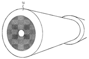
본 발명은 롤링 단계를 포함한다. 이 단계에서, 코팅된 탄소 나노튜브를 갖는 기판은 그 자체 둘레에 감겨있다. 다시 말해서, 기판 상에 형성된 코팅된 탄소 나노튜브를 갖는 기판은 카펫의 롤링과 유사한 방식으로 롤링된다. 따라서, 이 단계는 인서트를 형성하기 위해 코팅된 탄소 나노튜브로 기판을 롤링하는 것을 포함한다고 말할 수 있다. 다시 말해서, 이는 추가 가공 단계에서 그의 삽입을 돕게 하는 그러한 형태이다.The present invention includes a rolling step. In this step, the substrate with the coated carbon nanotubes is wound around itself. In other words, the substrate with the coated carbon nanotubes formed on the substrate is rolled in a manner similar to the rolling of a carpet. Thus, it can be said that this step involves rolling the substrate with coated carbon nanotubes to form the insert. In other words, it is such a form that aids in its insertion in further processing steps.
롤링 단계는 바람직하게는 금속 기판의 한 표면 상에 형성된 코팅된 탄소 나노튜브의 적어도 일부분이 금속 기판의 또 다른 표면과 접촉하도록 수행된다. 탄소 나노튜브가 기판의 대향 표면에서 성장한 경우, 금속 기판의 한 표면 상에 형성된 코팅된 탄소 나노튜브의 적어도 일부분은 금속 기판의 또 다른 표면 상에 형성된 코팅된 탄소 나노튜브와 접촉할 수 있다. 이러한 방식으로, 롤링 단계는 금속 기판의 층 사이에 코팅된 탄소 나노튜브의 적어도 일부분의 샌드위칭을 초래한다. 이것은 후속 단계에서 탄소 나노튜브의 최종 전도성 요소로의 혼입을 돕는 추가 금속 기판으로 탄소 나노튜브를 둘러싸는 이점을 갖는다.The rolling step is preferably carried out such that at least a portion of the coated carbon nanotubes formed on one surface of the metal substrate is in contact with another surface of the metal substrate. When the carbon nanotubes are grown on the opposite surface of the substrate, at least a portion of the coated carbon nanotubes formed on one surface of the metal substrate may contact the coated carbon nanotubes formed on another surface of the metal substrate. In this way, the rolling step results in sandwiching at least a portion of the coated carbon nanotubes between the layers of the metal substrate. This has the advantage of surrounding the carbon nanotubes with an additional metal substrate that aids in the incorporation of the carbon nanotubes into the final conductive element in a subsequent step.
롤링 단계를 돕기 위해, 금속 기판은 바람직하게는 시트의 형태이다. 다시 말해서, 기판은 비교적 큰 폭 및 길이 치수에 비해 비교적 작은 두께 치수를 갖는다. 시트는 특히 얇을 수 있어 포일로 지칭될 수 있다. 이러한 포일은 1 mm 미만, 또는 0.5 mm 미만, 바람직하게는 0.2 mm 미만, 가장 바람직하게는 0.1 mm 이하의 두께를 가질 수 있다. 10 ㎛ 내지 50 ㎛의 두께를 갖는 금속 기판이 특히 효과적인 것으로 밝혀졌다.To aid in the rolling step, the metal substrate is preferably in the form of a sheet. In other words, the substrate has a relatively small thickness dimension compared to a relatively large width and length dimension. The sheet may be particularly thin and may be referred to as a foil. Such foils may have a thickness of less than 1 mm, or less than 0.5 mm, preferably less than 0.2 mm, most preferably less than 0.1 mm. Metal substrates with a thickness of 10 μm to 50 μm have been found to be particularly effective.
금속 기판의 가능한 폭 및 길이 치수는 특별히 제한되지 않는다. 길이 치수는 폭 치수의 적어도 2배, 대안적으로는 폭 치수의 적어도 3배, 또는 폭 치수의 적어도 4배일 수 있다. 폭 치수는 적어도 50 mm 그리고 길이 치수는 적어도 100 mm일 수 있고, 대안적으로 폭 치수는 적어도 100 mm일 수 있고 길이 치수는 적어도 300 mm일 수 있다.The possible width and length dimensions of the metal substrate are not particularly limited. The length dimension may be at least 2 times the width dimension, alternatively at least 3 times the width dimension, or at least 4 times the width dimension. The width dimension can be at least 50 mm and the length dimension can be at least 100 mm, alternatively the width dimension can be at least 100 mm and the length dimension can be at least 300 mm.
금속 기판은, 롤링 단계가 기판이 그 자체 둘레에 적어도 2번 롤링되게 하도록 치수가 정해질 수 있다. 다시 말해서, 기판은 720°까지 롤링되도록, 바람직하게는 적어도 3번, 또는 4번, 또는 5번, 또는 6번 롤링되도록 롤링된다. 훨씬 더 바람직하게, 기판은 적어도 10번, 15번, 20번, 25번, 35번, 45번, 또는 50번 롤링되도록 롤링된다. 기판은 50번까지 롤링되도록 롤링될 수 있다. 기판이 그 자체 둘레에 롤링되는 횟수의 양을 늘림으로써, 기판 사이에 샌드위칭된 탄소 나노튜브의 층의 수는 증가한다. 이것은 최종 제품에서 전도가 발생할 수 있는 더 많은 탄소 나노튜브 재료를 제공한다.The metal substrate may be dimensioned such that the rolling step causes the substrate to be rolled around itself at least twice. In other words, the substrate is rolled to be rolled up to 720°, preferably at least 3 times, or 4 times, or 5 times, or 6 times. Even more preferably, the substrate is rolled to be rolled at least 10 times, 15 times, 20 times, 25 times, 35 times, 45 times, or 50 times. The substrate can be rolled up to 50 times. By increasing the number of times the substrate is rolled around itself, the number of layers of carbon nanotubes sandwiched between the substrates increases. This provides a more carbon nanotube material for conduction to occur in the final product.
롤링 단계는 바람직하게는 금속 보빈 둘레에 코팅된 탄소 나노튜브로 기판을 롤링하는 단계를 포함한다. 보빈의 이용은 롤링 단계를 용이하게 한다. 바람직하게 보빈 둘레에 기판을 롤링할 때 금속 기판은 금속 보빈과 접촉한다. 보빈은 바람직하게는 재료의 고체 조각이다. 특히, 보빈은 바람직하게는 기판과 동일한 재료이다. 이러한 방식으로, 금속 보빈은 기판과 함께 최종 제품의 금속 매트릭스에 기여한다. 훨씬 더 바람직하게, 코팅 단계에서 사용되는 금속 보빈, 금속 기판, 및 금속 재료는 모두 동일한 재료이고 모두 최종 제품의 금속 매트릭스에 기여한다. 금속 기판에 관한 설명에 따라, 금속 보빈은 금속 기판에 대해 강조한 금속 중 임의의 것을 포함할 수 있다. 금속 보빈은 바람직하게는 구리를 포함한다.The rolling step preferably comprises rolling the substrate with carbon nanotubes coated around a metal bobbin. The use of a bobbin facilitates the rolling step. Preferably the metal substrate contacts the metal bobbin when rolling the substrate around the bobbin. The bobbin is preferably a solid piece of material. In particular, the bobbin is preferably the same material as the substrate. In this way, the metal bobbin, together with the substrate, contributes to the metal matrix of the final product. Even more preferably, the metal bobbin, metal substrate, and metal material used in the coating step are all the same material and all contribute to the metal matrix of the final product. Following the description of the metal substrate, the metal bobbin may include any of the metals highlighted for the metal substrate. The metal bobbin preferably comprises copper.
금속 보빈의 치수는 특별히 제한되지 않는다. 후속 가공에 적합한 임의의 치수를 사용할 수 있다. 금속 보빈은 그의 가장 큰 지점에서 직경이 적어도 10 mm, 대안적으로는, 직경이 적어도 20 mm, 직경이 50 mm, 직경이 100 mm, 직경이 200 mm, 또는 직경이 300 mm일 수 있다. 직경의 증가는 보빈 상에 롤링될 수 있는 기판의 양을 증가시킨다.The dimensions of the metal bobbin are not particularly limited. Any dimensions suitable for subsequent processing can be used. The metal bobbin may be at least 10 mm in diameter, alternatively at least 20 mm in diameter, 50 mm in diameter, 100 mm in diameter, 200 mm in diameter, or 300 mm in diameter at its largest point. Increasing the diameter increases the amount of substrate that can be rolled on the bobbin.
롤링 단계 이전에 코팅된 탄소 나노튜브를 갖는 금속 기판을 전도성 보빈에 부착되는 것이 바람직하다. 이것은 롤링 단계를 용이하게 한다.It is preferred that the metal substrate with coated carbon nanotubes is attached to the conductive bobbin prior to the rolling step. This facilitates the rolling step.
금속 기판은 용접, 납땜, 경납땜 또는 기계적 수단에 의해 전도성 보빈에 부착될 수 있다. 용접과 관련하여, 마찰 교반 용접과 같은 임의의 적합한 형태의 용접을 사용할 수 있다.The metal substrate can be attached to the conductive bobbin by welding, soldering, brazing or mechanical means. With regard to welding, any suitable type of welding can be used, such as friction stir welding.
금속 기판은 금속 기판의 하나의 에지를 따라 금속 보빈에 부착될 수 있다. 이것은 제자리에 유지되는 보빈에 대해 하나의 고정된 에지를 제공하고, 반면 반대편 자유단은 금속 보빈 둘레에 기판을 롤링하기 위해 금속 보빈 둘레에 롤링된다. 금속 보빈은 하나의 에지를 따라 금속 기판을 유지하기 위해 금속 기판의 단부를 수용하도록 구성된 슬롯을 포함할 수 있다.The metal substrate may be attached to the metal bobbin along one edge of the metal substrate. This provides one fixed edge for the bobbin that is held in place, while the opposite free end is rolled around the metal bobbin to roll the substrate around the metal bobbin. The metal bobbin may include a slot configured to receive an end of the metal substrate to hold the metal substrate along one edge.
금속 보빈 둘레에 롤링된 금속 기판을 갖는 금속 보빈은 인서트를 형성하기 위해 금속 슬리브 내에 배치될 수 있다. 금속 보빈은 금속 기판이 롤링될 수 있는 리세스를 포함하도록 형상화될 수 있다. 금속 기판 및 보빈은 금속 기판이 보빈 상에 완전히 롤링될 경우 보빈의 외부 표면과 같은 높이가 되기 위해 리세스를 채우도록 크기가 정해된다. 이것은 상부에 금속 기판을 갖는 보빈이 슬리브 내로 슬라이딩될 수 있게 하고 슬리브에서 억지 끼워맞춤(tight fit)을 허용한다. 대안적으로, 금속 기판 및 보빈은 금속 기판이 보빈 상에 완전히 롤링될 경우 나머지 보빈의 튀어나온 부분을 앉히기 위해 리세스를 채우도록 크기가 정해된다. 이것은 보빈의 나머지가 후속 견인 단계 동안 금속 기판의 초기 압축을 방해하지 않고 인서트의 후속 가공 동안 고급 인터페이스의 생산을 촉진하는 것을 보장할 수 있다.A metal bobbin with a metal substrate rolled around the metal bobbin can be placed in a metal sleeve to form an insert. The metal bobbin can be shaped to include a recess through which the metal substrate can be rolled. The metal substrate and bobbin are sized to fill the recesses to be flush with the outer surface of the bobbin when the metal substrate is completely rolled on the bobbin. This allows a bobbin with a metal substrate on top to slide into the sleeve and allows a tight fit in the sleeve. Alternatively, the metal substrate and bobbin are sized to fill the recess to seat the protruding portion of the remaining bobbin when the metal substrate is fully rolled on the bobbin. This can ensure that the rest of the bobbin does not interfere with the initial compression of the metal substrate during the subsequent traction step and promotes the production of advanced interfaces during the subsequent processing of the insert.
슬리브 및 보빈은 보빈이 슬리브 내에서 수용될 수 있도록 임의의 적합한 길이일 수 있다. 슬리브는 최대 1 미터 길이일 수 있다. 보빈은 최대 400 mm 길이일 수 있다. 필요한 탄소 나노튜브를 포함하지 않는 임의의 부분을 제거하기 위해 최종 전도성 요소를 스캔하고 적절하게 절단할 수 있다. 이것은 견인 단계 전에 보빈에 비해 슬리브의 더 긴 길이에 의해 야기될 수 있다.The sleeve and bobbin can be of any suitable length so that the bobbin can be received within the sleeve. The sleeve can be up to 1 meter long. The bobbin can be up to 400 mm long. The final conductive element can be scanned and cut appropriately to remove any portions that do not contain the necessary carbon nanotubes. This can be caused by the longer length of the sleeve compared to the bobbin before the traction step.
금속 슬리브는 금속 기판과 관련하여 본원에서 나열된 임의의 금속을 포함할 수 있다. 금속 슬리브는 금속 보빈과 동일한 재료인 것이 바람직하다. 특히, 금속 슬리브는 바람직하게는 구리를 포함한다. 금속 슬리브는 최종 제품의 매트릭스에 기여한다. 따라서, 금속 슬리브, 금속 보빈, 금속 재료 및 금속 기판은 모두 동일한 재료이며, 이것은 구리를 포함하는 것이 특히 바람직하다. 금속 슬리브, 금속 보빈, 금속 재료 및 금속 기판이 모두 존재하는 것은 아닌 본 발명의 측면에서, 존재하는 것은 바람직하게는 모두 동일한 재료이며, 이것은 바람직하게는 구리이다.The metal sleeve may comprise any metal listed herein with respect to the metal substrate. The metal sleeve is preferably made of the same material as the metal bobbin. In particular, the metal sleeve preferably comprises copper. The metal sleeve contributes to the matrix of the final product. Therefore, the metal sleeve, metal bobbin, metal material and metal substrate are all the same material, and it is particularly preferred that it contains copper. In terms of the present invention in which the metal sleeve, metal bobbin, metal material and metal substrate are not all present, what is present is preferably all the same material, which is preferably copper.
본 발명의 방법은 롤링 단계 이전에 금속 기판 상의 복수의 탄소 나노튜브에 제1 방향으로 전단력을 적용하는 단계를 추가로 포함할 수 있다. 이것은 제1 방향을 향하여 복수의 탄소 나노튜브를 이동시키는, 바람직하게는 정렬시키는 효과를 갖는다. 이것은 정렬이 제품의 원하는 최종 구조에 비례하여 선택될 수 있게 한다. 금속 기판 상의 복수의 탄소 나노튜브에 제1 방향으로 전단력을 적용하는 단계는 롤링 단계 후에 수행할 수 있다. 복수의 탄소 나노튜브에 전단력을 적용하는 단계는 견인 단계의 적용 동안 적용된 전단력을 지칭할 수 있거나 또는 견인 단계와 별도로 전단력을 적용하는 단계일 수 있다.The method of the present invention may further include applying a shear force in a first direction to the plurality of carbon nanotubes on the metal substrate prior to the rolling step. This has the effect of moving, preferably aligning, a plurality of carbon nanotubes toward the first direction. This allows the alignment to be selected in proportion to the desired final structure of the product. The step of applying a shear force to the plurality of carbon nanotubes on the metal substrate in the first direction may be performed after the rolling step. The step of applying the shear force to the plurality of carbon nanotubes may refer to the shear force applied during the application of the traction step or may be a step of applying the shear force separately from the traction step.
전단력을 적용하는 이 단계는 코팅 단계 전에 수행될 수 있다. 이러한 방식으로, 탄소 나노튜브는 코팅된 후 이들을 이동시키는 것과는 대조적으로, 이동하기에 비교적 용이할 때 재배향된다. 전단력을 적용하는 단계는 코팅 단계 동안 수행될 수 있다. 예를 들어, 탄소 나노튜브는 코팅 공정의 초기 단계로서 본원에 기재된 바와 같이 장식될 수 있고, 이후의 코팅 단계가 수행되어 코팅 단계를 완료하기 전에 전단력이 이어서 적용될 수 있다. 이것은 전단력을 적용하는 단계 동안 다발화되지 않은 상태로 나노튜브를 유지하는데 도움이 될 수 있다. 전단력을 적용하는 단계는 코팅 단계 후에 수행될 수도 있다.This step of applying the shear force can be carried out before the coating step. In this way, carbon nanotubes are reorientated when they are relatively easy to move, as opposed to moving them after being coated. The step of applying a shear force can be carried out during the coating step. For example, carbon nanotubes may be decorated as described herein as an initial step in the coating process, and a shear force may then be applied before a subsequent coating step is performed to complete the coating step. This can help keep the nanotubes unbundled during the step of applying shear forces. The step of applying the shear force may be carried out after the coating step.
전단력은 공구, 예를 들어 평평한 에지를 가진 공구의 사용을 통해 적용될 수 있다. 공구를 탄소 나노튜브와 직접적으로 또는 간접적으로 접촉하게 유지하면서, 탄소 나노튜브가 형성된 금속 기판의 표면을 따라 공구를 이동시킬 수 있다. 이것은 탄소 나노튜브 상에 전단력을 발생시킨다. 탄소 나노튜브의 자유단에 적용된 전단력은 탄소 나노튜브가 제1 방향을 향해 이동하게 한다. 적용되는 힘의 양은 탄소 나노튜브를 재배향시키기 위해 충분한 힘을 적용하는 동안 탄소 나노튜브가 기판으로부터 벗겨지지 않게 하도록 조정될 수 있다. 전단력은 또한 탄소 나노튜브가 형성된 금속 기판의 표면을 따라 롤링되는 원통형 공구 (즉 롤러)를 사용하여 적용될 수 있다. 특히, 전단력은 한 쌍의 롤러 사이에서 탄소 나노튜브를 갖는 금속 기판을 이동시킴으로써 적용될 수 있다. 이것은 기판의 양면에 존재하는 탄소 나노튜브가 있는 경우 특히 효과적인 접근법이다.Shear force can be applied through the use of a tool, for example a tool with a flat edge. While keeping the tool in direct or indirect contact with the carbon nanotubes, it is possible to move the tool along the surface of the metal substrate on which the carbon nanotubes are formed. This creates a shear force on the carbon nanotubes. The shear force applied to the free end of the carbon nanotube causes the carbon nanotube to move in the first direction. The amount of force applied can be adjusted so that the carbon nanotubes do not peel off the substrate while applying sufficient force to reorient the carbon nanotubes. Shear force can also be applied using a cylindrical tool (ie roller) that is rolled along the surface of the metal substrate on which the carbon nanotubes are formed. In particular, shearing force can be applied by moving a metal substrate having carbon nanotubes between a pair of rollers. This is a particularly effective approach when there are carbon nanotubes present on both sides of the substrate.
전단력이 적용되는 제1 방향은 탄소 나노튜브가 형성되는 표면을 따르는 것이 특히 바람직하다. 이것은 탄소 나노튜브가 기판에 수직이기 보다는 기판의 표면과 더 많이 정렬되도록 탄소 나노튜브를 레이 다운(lay down)하는 효과를 갖는다.It is particularly preferred that the first direction in which the shear force is applied is along the surface on which the carbon nanotubes are formed. This has the effect of laying down the carbon nanotubes so that they are more aligned with the surface of the substrate rather than perpendicular to the substrate.
이러한 제1 방향은 롤링 단계에서 금속 기판이 롤링되는 회전 축과 실질적으로 평행한 것이 특히 바람직하다. 보빈을 이용하는 경우, 이것은 보빈의 회전 축이다. 이러한 방식으로, 모든 탄소 나노튜브는 대략 동일한 방향으로 실질적으로 정렬되어 이들이 모두 거의 회전 축을 따라, 예를 들어 보빈의 길이를 따라 향하게 되어야 한다는 것을 보장할 수 있다.It is particularly preferred that this first direction is substantially parallel to the axis of rotation on which the metal substrate is rolled in the rolling step. When using a bobbin, this is the axis of rotation of the bobbin. In this way, it is possible to ensure that all carbon nanotubes are substantially aligned in approximately the same direction so that they all have to be oriented approximately along the axis of rotation, for example along the length of the bobbin.
전도성 테이프를 형성할 때, 제1 방향은 최종 전도성 테이프에서 세로 방향과 실질적으로 평행한 것이 특히 바람직하다.When forming the conductive tape, it is particularly preferred that the first direction is substantially parallel to the longitudinal direction in the final conductive tape.
견인 방향은 견인 단계에서 인서트가 견인되는 방향이다. 제1 방향은 견인 단계의 견인 방향과 실질적으로 평행할 수 있다. 탄소 나노튜브는 견인 단계의 견인 방향에 따라 실질적으로 정렬될 수 있다. 이것은 회전 축, 및 탄소 나노튜브가 인서트의 세로 방향, 즉 그의 긴 축을 따라 배향되도록 보빈을 슬리브에 삽입함으로써 달성될 수 있다. 따라서, 인서트는 이어서 견인 단계 동안 이 긴 축을 따라 견인될 수 있다. 견인 단계 동안 인서트의 길이는 늘어나고 그의 단면적은 감소된다.The direction of pull is the direction in which the insert is pulled during the pull phase. The first direction can be substantially parallel to the direction of traction of the traction step. The carbon nanotubes may be substantially aligned according to the direction of traction of the traction step. This can be achieved by inserting the bobbin into the sleeve such that the axis of rotation and the carbon nanotubes are oriented along the longitudinal direction of the insert, ie along its long axis. Thus, the insert can then be pulled along this long axis during the pulling step. During the traction phase, the length of the insert increases and its cross-sectional area decreases.
견인 방향을 따라 실질적으로 정렬된 탄소 나노튜브를 갖는 것이 바람직한데 이것이 최종 제품의 긴 축을 따라 배향을 갖는 탄소 나노튜브를 개시하기 때문이다. 이것은 전도가 발생하는데 바람직한 배향이다. 그럼에도 불구하고, 견인 단계 자체는 비교적 뻣뻣한 탄소 나노튜브에 비해 매트릭스 물질의 유동으로 인해 탄소 나노튜브가 견인 방향을 따라 어느 정도 자체적으로 정렬되게 할 수 있다. 이러한 방식으로, 금속 기판 상의 탄소 나노튜브에 제1 방향으로 전단력을 적용하는 단계는 견인 단계와 연관된 전단력이 견인 방향으로 발생하는 견인 단계의 일부로서 수행할 수 있다. 이론에 의해 구속되는 것을 원하지 않지만, 견인 접근법은 다중-벽 탄소 나노튜브의 벽 사이에서 상대적 움직임으로 또한 이어질 수 있는 것으로 여겨진다. 이것은 정렬을 개선하는 나노튜브의 텔레스코핑으로 이어질 수 있다. 따라서, 본 방법은 최종 전도성 요소에서 탄소 나노튜브의 긴밀한 정렬, 또는 최고의 정렬을 야기할 수 있다.It is desirable to have carbon nanotubes substantially aligned along the direction of traction, as this discloses carbon nanotubes with orientation along the long axis of the final product. This is the preferred orientation for conduction to occur. Nevertheless, the traction step itself can cause the carbon nanotubes to align themselves to some extent along the traction direction due to the flow of the matrix material compared to the relatively stiff carbon nanotubes. In this way, the step of applying a shear force in the first direction to the carbon nanotubes on the metal substrate can be performed as part of the pulling step in which the shearing force associated with the pulling step is generated in the pulling direction. While not wishing to be bound by theory, it is believed that the traction approach can also lead to relative motion between the walls of multi-walled carbon nanotubes. This can lead to telescoping of the nanotubes, which improves alignment. Thus, this method can result in tight alignment, or best alignment of the carbon nanotubes in the final conductive element.
견인 단계 이후에 어닐링 단계가 있을 수 있다. 어닐링 단계는 견인 단계 동안 도입되었을 수 있는 경화 또는 내부 응력을 제거하거나 또는 감소시키기 위해 견인된 제품을 승온에서 유지한다. 어닐링은 금속 성분의 결정 입도를 성장시키기 위해 또한 사용될 수 있다. 이것은 결정 입계의 존재를 감소시키고 전도도 특성을 향상시킨다. 어닐링 온도는 임의의 적합한 온도, 예를 들어 400℃ 내지 700℃, 또는 550℃ 내지 800℃의 온도일 수 있다. 어닐링은 대략 700℃에서 수행될 수 있다. 어닐링 단계는 바람직하게는 저산소, 또는 실질적으로 무산소 환경에서 수행한다. 예를 들어, 어닐링은 아르곤 또는 질소 환경에서 수행할 수 있다. 금속 기판이 구리로부터 형성된 경우, 어닐링 온도는 400℃ 내지 700℃의 범위일 수 있고, 가장 바람직하게는 어닐링 온도는 550℃이다.There may be an annealing step after the traction step. The annealing step keeps the pulled product at an elevated temperature to remove or reduce hardening or internal stresses that may have been introduced during the pulling step. Annealing can also be used to grow the grain size of the metal component. This reduces the presence of grain boundaries and improves the conductivity properties. The annealing temperature can be any suitable temperature, for example 400°C to 700°C, or 550°C to 800°C. Annealing can be carried out at approximately 700°C. The annealing step is preferably carried out in a low oxygen, or substantially oxygen free environment. For example, annealing can be carried out in an argon or nitrogen environment. When the metal substrate is formed from copper, the annealing temperature may range from 400°C to 700°C, and most preferably the annealing temperature is 550°C.
견인된 제품의 직경을 점진적으로 감소시키고 그의 길이를 증가시키기 위해 견인 및 어닐링 단계를 여러 번 반복할 수 있는 것, 즉 견인에 이어 어닐링, 이에 이어 추가 견인 및 이어서 추가 어닐링 등이 가능하다. 이것은 와이어와 같은 세장형 도체를 제조하기 위한 표준 접근법이다. 어닐링 단계 사이에 5% 내지 75%만큼 와이어의 직경을 감소시키기 위해 견인 단계를 수행할 수 있다. 전도성 요소는 본 발명에서 와이어의 형태인 것이 특히 바람직하다. 와이어는 통상 금속의 원통형 및 가요성 스트랜드인 전도성 요소이다.It is possible to repeat the towing and annealing steps several times to gradually reduce the diameter of the towed product and to increase its length, ie towing followed by annealing, followed by further towing and then to further annealing, and the like. This is a standard approach for making elongated conductors such as wires. A traction step can be performed to reduce the diameter of the wire by 5% to 75% between the annealing steps. It is particularly preferred that the conductive element is in the form of a wire in the present invention. The wire is a conductive element that is usually a cylindrical and flexible strand of metal.
견인 단계와 관련하여, 인서트는 계속 감소하는 다이 크기의 선택을 통해 견인될 수 있다. 다이를 통해 인서트를 당김으로써, 그의 직경이 감소하고 그의 길이가 증가한다. 견인된 제품은 몇 번의 견인 적용 후에 또는 각 견인 적용 후에 어닐링될 수 있다. 견인 단계는 계속 감소하는 다이를 통해 인서트를 10번 이상, 또는 15번 이상, 또는 20번 이상 당기는 것을 포함할 수 있다. 다이는 고속도 강, 경화 강 또는 탄화텅스텐으로 제조될 수 있다.Regarding the pull step, the insert can be pulled through a choice of ever decreasing die sizes. By pulling the insert through the die, its diameter decreases and its length increases. The towed product can be annealed after several towing applications or after each towing application. The traction step may include pulling the
견인 단계의 초기 단계로서, 인서트를 더 작은 직경으로 변형시키기 위해 인서트에 압축 단계를 (예를 들어 회전 스웨징 또는 롤링에 의해) 적용할 수 있다. 이것은 인서트의 개별 영역을 함께 압축하는 것을 도울 수 있다. 이것은 결과적으로 인서트의 길이가 증가함에 따라 나머지 견인 단계 동안 공극의 형성을 피하는데 도움이 될 수 있다. 압축 단계는 슬리브와 보빈 및 롤링된 포일 사이의 그리고 포일의 층 사이의 임의의 공극을 제거하거나 또는 실질적으로 감소시킬 수 있다. 이 단계는 인서트의 직경의 감소, 및 길이의 증가를 초래하고, 견인 단계의 효율성을 향상시킨다.As an initial stage of the traction stage, a compression stage can be applied to the insert (for example by rotational swaging or rolling) to deform the insert to a smaller diameter. This can help to compress the individual areas of the insert together. This can help avoid the formation of voids during the rest of the traction phase as the length of the insert increases as a result. The compression step may eliminate or substantially reduce any voids between the sleeve and the bobbin and the rolled foil and between the layers of the foil. This step results in a decrease in the diameter and an increase in the length of the insert, and improves the efficiency of the traction step.
본 발명에서 사용되는 복수의 탄소 나노튜브는 바람직하게는 다중-벽 탄소 나노튜브를 포함한다. 이러한 탄소 나노튜브는 서로 안에 중첩된 다수의 탄소 나노튜브로 구성된다. 이러한 형태의 나노튜브는 생성된 제품의 전기 전도도에 기여하는데 특히 효과적이다.The plurality of carbon nanotubes used in the present invention preferably comprises multi-walled carbon nanotubes. These carbon nanotubes are composed of a number of carbon nanotubes superimposed within each other. Nanotubes of this type are particularly effective in contributing to the electrical conductivity of the resulting product.
또한 본 발명은 본원에 기재된 방법에 의해 형성된 전도성 요소 전구체, 인서트 및 전도성 요소에 관한 것이다.The invention also relates to conductive element precursors, inserts and conductive elements formed by the methods described herein.
본원에 기재된 전도성 요소는 절연 슬리브로 절연될 수 있다. 절연 슬리브는 임의의 적합한 절연 재료, 예컨대 실리콘 고무, 폴리비닐 클로라이드, 또는 PTFE일 수 있다.The conductive elements described herein can be insulated with an insulating sleeve. The insulating sleeve can be any suitable insulating material, such as silicone rubber, polyvinyl chloride, or PTFE.
추가로 본 발명은 매트릭스 - 매트릭스가 금속 재료를 포함함 -; 및 매트릭스 내의 복수의 탄소 나노튜브 - 복수의 탄소 나노튜브가 실질적으로 정렬됨- 를 포함하는 전도성 요소 전구체를 제공한다.The invention further relates to a matrix, wherein the matrix comprises a metallic material; And a plurality of carbon nanotubes in the matrix, wherein the plurality of carbon nanotubes are substantially aligned.
복수의 탄소 나노튜브는 외부 표면과 평행하게 실질적으로 정렬될 수 있다. 이것은 전구체가 전도성 요소로 가공될 수 있는 용이성을 증가시킨다.The plurality of carbon nanotubes may be substantially aligned parallel to the outer surface. This increases the ease with which the precursor can be processed into a conductive element.
추가로 본 발명은 매트릭스 - 매트릭스가 금속 재료를 포함함 -; 및 매트릭스 내의 복수의 탄소 나노튜브 - 복수의 탄소 나노튜브가 인서트의 세로 축을 따라 실질적으로 정렬됨 - 를 포함하는 인서트를 제공한다.The invention further relates to a matrix, wherein the matrix comprises a metallic material; And a plurality of carbon nanotubes in the matrix, wherein the plurality of carbon nanotubes are substantially aligned along the longitudinal axis of the insert.
또한 본 발명은 매트릭스 - 매트릭스가 금속 재료를 포함함 -; 및 매트릭스 내의 복수의 탄소 나노튜브 - 복수의 탄소 나노튜브가 세장형 전도성 요소의 세로 축을 따라 실질적으로 정렬됨 - 를 포함하는 세장형 전도성 요소를 제공한다.In addition, the present invention relates to a matrix-the matrix comprises a metallic material -; And a plurality of carbon nanotubes in the matrix, wherein the plurality of carbon nanotubes are substantially aligned along the longitudinal axis of the elongate conductive element.
전도성 요소 및 전도성 요소 전구체의 매트릭스는 실질적으로 연속 영역을 지칭한다. 매트릭스는 복수의 탄소 나노튜브를 포함한다.The matrix of the conductive element and the conductive element precursor refers to a substantially continuous region. The matrix includes a plurality of carbon nanotubes.
세장형 전도성 요소의 세로 축은 긴 방향을 따른다. 예를 들어, 세장형 요소가 와이어의 형태인 경우, 세로 축은 와이어의 길이를 따라 이어진다.The longitudinal axis of the elongate conductive element follows the long direction. For example, if the elongate element is in the form of a wire, the longitudinal axis runs along the length of the wire.
전도성 요소 및 인서트는 이들이 제조되는 방식으로 인해 매트릭스의 단면을 따라 복수의 별개의 탄소 나노튜브 층을 가질 수 있다. 예를 들어, 롤링 단계는 세로 축에 수직인 매트릭스의 단면을 따라, 탄소 나노튜브가 없는 영역에 의해 분리된, 탄소 나노튜브를 포함하는 층이 있다는 것을 의미한다. 이러한 탄소 나노튜브 층은 나머지 매트릭스와 구별되고 현미경 검사 또는 x-선 회절에 의해 식별될 수 있다.The conductive elements and inserts may have a plurality of distinct layers of carbon nanotubes along the cross-section of the matrix due to the way they are made. For example, the rolling step means that there is a layer comprising carbon nanotubes, separated by regions without carbon nanotubes, along the cross section of the matrix perpendicular to the longitudinal axis. These carbon nanotube layers can be distinguished from the rest of the matrix and identified by microscopy or x-ray diffraction.
본원의 방법과 관련하여 기재된 특징은 또한 최종 세장형 전도성 요소에 적용가능하다. 예를 들어, 전도성 재료의 매트릭스는 금속 재료일 수 있고 구리일 수 있다. 추가로 나노튜브가 실질적으로 정렬된 것으로 언급된 경우, 상기 주어진 허용오차는 제품에 동일하게 적용된다.The features described in connection with the method herein are also applicable to the final elongated conductive element. For example, the matrix of conductive material can be a metallic material and can be copper. In case it is further stated that the nanotubes are substantially aligned, the tolerances given above apply equally to the product.
전반적으로, 본 발명의 특히 바람직한 접근법은 탄소 나노튜브가 성장하는, 세라믹 층을 갖는 금속 기판을 이용한다. 이러한 탄소 나노튜브를 기판 상에 유지하고 탄소 나노튜브 전체에 금속 재료를 증착하기 위해 CVD를 사용하여 초기 장식 단계를 수행하고, 임의적으로 탄소 나노튜브 전체에 할로겐 입자를 증착하기 위해 CVD를 사용하여 도핑 단계를 수행한다. 이어서 탄소 나노튜브는 그의 자유단에서 전단력을 받아 금속 기판의 표면을 따라 실질적으로 그들을 정렬시킨다. 탄소 나노튜브의 코팅은 탄소 나노튜브가 완전히 캡슐화되게 하기 위해 전기도금 접근법을 사용하여 완료된다. 이것은 전도성 요소 전구체를 생성한다.Overall, a particularly preferred approach of the present invention uses a metal substrate with a ceramic layer on which carbon nanotubes are grown. Maintaining these carbon nanotubes on the substrate and performing an initial decoration step using CVD to deposit metallic materials all over the carbon nanotubes, and optionally doping using CVD to deposit halogen particles all over the carbon nanotubes. Follow the steps. The carbon nanotubes are then subjected to shear forces at their free ends to substantially align them along the surface of the metal substrate. The coating of carbon nanotubes is completed using an electroplating approach to ensure that the carbon nanotubes are completely encapsulated. This creates a conductive element precursor.
이제 본 발명을 도면과 함께 하기 구체적 예와 관련하여 설명할 것이다.The present invention will now be described with reference to the following specific examples together with the drawings.
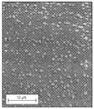
도 1은 구리 포일 상의 증착된 실리카 층의 표면의 SEM 이미지이다.
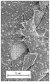
도 2는 실리카 층이 균열된 구리 포일 상의 증착된 실리카 층의 표면의 SEM 이미지이다.
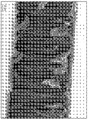
도 3은 구리 포일에서 성장한 탄소 나노튜브의 SEM 이미지이다.
도 4는 증착된 구리 입자를 갖는 탄소 나노튜브의 SEM 이미지이다.
도 5는 증착된 구리 입자를 갖는 탄소 나노튜브의 추가 SEM 이미지이다.
도 6은 증착된 구리 입자를 갖는 탄소 나노튜브의 또 다른 SEM 이미지이다.
도 7은 성장한 탄소 나노튜브에 전단력을 적용하는 단계를 개략적으로 도시한다.
도 8은 전기도금 공정의 개략도이다.
도 9는 전기도금 단계에 적용된 전류 프로파일의 개략도이다.
도 10은 전기도금 후 구리로 코팅된 탄소 나노튜브의 SEM 이미지이다.
도 11은 본 발명과 함께 사용될 수 있는 보빈을 개략적으로 도시한다.
도 12 및 13은 금속 기판이 보빈의 리세스 상에 권취되는 것을 개략적으로 도시한다.
도 14는 본 발명과 함께 사용될 수 있는 슬리브를 개략적으로 도시한다.
도 15는 보빈을 포함하는 슬리브의 단면을 개략적으로 도시한다.
도 16은 와이어-견인 단계를 개략적으로 도시한다.
도 17은 최종 와이어를 통한 단면을 개략적으로 도시한다.
도 18은 견인된 와이어의 단면의 2차 SEM 이미지 및 후방산란 SEM 이미지이다.
도 19는 도 18의 탄소 나노튜브 층의 세부사항이다.
도 20은 견인된 와이어의 에칭된 단면의 SEM 이미지이다.
도 21은 견인된 와이어의 에칭된 종단면의 SEM 이미지이다.1 is an SEM image of the surface of a deposited silica layer on a copper foil.
2 is an SEM image of the surface of a deposited silica layer on a copper foil in which the silica layer is cracked.
3 is an SEM image of carbon nanotubes grown on copper foil.
4 is an SEM image of carbon nanotubes with deposited copper particles.
5 is a further SEM image of carbon nanotubes with deposited copper particles.
6 is another SEM image of carbon nanotubes with deposited copper particles.
7 schematically shows the step of applying a shear force to the grown carbon nanotubes.
8 is a schematic diagram of an electroplating process.
9 is a schematic diagram of a current profile applied in an electroplating step.
10 is an SEM image of carbon nanotubes coated with copper after electroplating.
11 schematically shows a bobbin that can be used with the present invention.
12 and 13 schematically show that a metal substrate is wound on a recess of a bobbin.
14 schematically shows a sleeve that can be used with the present invention.
15 schematically shows a cross section of a sleeve comprising a bobbin.
16 schematically shows the wire-pulling step.
17 schematically shows a cross section through the final wire.
18 is a secondary SEM image and a backscattering SEM image of a cross section of a pulled wire.
19 is a detail of the carbon nanotube layer of FIG. 18.
20 is an SEM image of an etched cross section of a pulled wire.
21 is an SEM image of an etched longitudinal section of a pulled wire.
사용되는 기판은 구리, 또는 황동 샘플 홀더에 클램핑된 얇은 구리 포일 리본이다. 용어 "리본"은 구리 포일의 폭에 비해 그의 긴 길이 때문에 사용된다. 샘플 홀더는 측면 도어를 통해 제1 반응기 챔버에 도입되며, 여기서 샘플 홀더는 그 다음 챔버로의 그의 병진운동을 보장할 레일 위에 있다. 증착 챔버를 닫고 배기하고 아르곤으로 여러 번 다시 채워 대부분의 산소 및 수분을 제거한다. 이어서 압력은 1 SLM의 일정한 아르곤 유동을 가진 약 5 mbar의 값으로 설정된다.The substrate used is a thin copper foil ribbon clamped to a copper or brass sample holder. The term “ribbon” is used because of its long length compared to the width of the copper foil. The sample holder is introduced into the first reactor chamber through the side door, where the sample holder is then on a rail that will ensure its translation into the next chamber. The deposition chamber is closed, evacuated and refilled several times with argon to remove most of the oxygen and moisture. The pressure is then set to a value of about 5 mbar with a constant argon flow of 1 SLM.
실리카 증착:Silica deposition:
전류는 샘플 홀더 및 구리 포일 리본을 통해, 2개의 레일 사이에 흐르게 된다. 리본 온도가 650℃에 도달한 경우, 전구체 주입을 수행할 수 있다. 주입 주파수는 50 Hz이고, 0.7 ms의 개방 시간을 갖는다. 무수 톨루엔 중 0.1 M TEOS의 용액을 증발 용기에 주입하고, 이것을 190℃에서 가열한다. 2 SLM Ar 운반 기체 유동은 증발기를 통해 흐르게 된다. 15 분의 주입 후, 전구체의 유동을 중단하고, 챔버를 여러 번 배기하여 남은 미량의 전구체 용액을 제거한다.Current flows between the two rails, through the sample holder and the copper foil ribbon. When the ribbon temperature reaches 650° C., precursor injection can be performed. The injection frequency is 50 Hz and has an open time of 0.7 ms. A solution of 0.1 M TEOS in anhydrous toluene is poured into an evaporation vessel and it is heated at 190°C. The 2 SLM Ar carrier gas flow flows through the evaporator. After 15 minutes of injection, the flow of the precursor is stopped and the chamber is evacuated several times to remove the remaining traces of the precursor solution.
수득된 실리카 층은 평균 400 nm 두께이고, 도 1의 SEM 현미경 사진에서 보이는 바와 같이 매우 매끄럽다. 도 2는 예시 목적을 위해 아래에 놓인 구리 포일을 노출시키기 위해 실리카 층이 의도적으로 균열된 부분을 보여준다. 실제로, 균열을 피하기 위해, 실리카 층의 증착과 그 다음 탄소 나노튜브 숲 성장 단계 사이에 금속 기판의 상승된 온도를 유지할 수 있다.The obtained silica layer has an average thickness of 400 nm, and is very smooth as seen in the SEM micrograph of FIG. 1. FIG. 2 shows a portion of the silica layer intentionally cracked to expose the underlying copper foil for illustrative purposes. Indeed, to avoid cracking, it is possible to maintain the elevated temperature of the metal substrate between the deposition of the silica layer and the subsequent carbon nanotube forest growth step.
탄소 나노튜브 숲 성장:Carbon nanotube forest growth:
일단 세정이 완료되면, 챔버 내의 압력은 아르곤 기체로 채움으로써 상승되고 일단 대기압에 도달하면, 샘플 홀더는 게이트 밸브를 통해 그 다음 챔버로 이송된다. 일단 샘플이 제2 챔버에 있고 게이트 밸브가 잠기면, 탄소 나노튜브 주입 공정이 시작될 수 있다. 톨루엔 중 페로센의 3%wt 용액의 전구체가 실리카 전구체와 동일한 공정을 따라 주입된다. 주입 파라미터는 0.7 ms 개방 시간, 25 Hz 주파수 및 3 SLM Ar 운반 기체 유동이다. 증발기와 증착 챔버 사이에서 열리는 예열로를 725℃에서 가열한다. 공정은 10 분 동안 지속된다. 일단 공정이 완료되면, 구리 리본을 냉각시키고, 챔버를 배기하고 아르곤으로 다시 채워 남아 있는 미량의 전구체를 제거한다.Once cleaning is complete, the pressure in the chamber is raised by filling with argon gas and once atmospheric pressure is reached, the sample holder is transferred to the next chamber through the gate valve. Once the sample is in the second chamber and the gate valve is closed, the carbon nanotube implantation process can begin. A precursor of a 3% wt solution of ferrocene in toluene is injected following the same process as the silica precursor. Injection parameters are 0.7 ms open time, 25 Hz frequency and 3 SLM Ar carrier gas flow. The preheating furnace that opens between the evaporator and the deposition chamber is heated at 725°C. The process lasts for 10 minutes. Once the process is complete, the copper ribbon is cooled, the chamber is evacuated and refilled with argon to remove any traces of the remaining precursor.
이 공정에 의해 성장한 탄소 나노튜브 숲은 약 400 ㎛ 두께를 갖고, ㎠ 당 약 108개 탄소 나노튜브의 탄소 나노튜브 밀도 및 도 3에 도시된 바와 같은 매우 양호한 정렬을 갖는다.The carbon nanotube forest grown by this process has a thickness of about 400 μm, has a carbon nanotube density of about 10 8 carbon nanotubes per
느슨한 탄소 나노튜브 세정:Cleaning loose carbon nanotubes:
일단 탄소 나노튜브 숲 성장 공정이 완료되면, 샘플 홀더는 또 다른 게이트 밸브를 통해 중간 세정 챔버로 이송된다. 거기에서, 샘플 홀더는 임의의 느슨한 CNT를 송풍 제거하기 위해 높은 아르곤 유동에 제공된다. 일단 이 단계가 완료되면, 제3 증착 챔버로 이송된다.Once the carbon nanotube forest growth process is complete, the sample holder is transferred to the intermediate cleaning chamber through another gate valve. There, a sample holder is provided with a high argon flow to blow away any loose CNTs. Once this step is complete, it is transferred to a third deposition chamber.
구리 시딩:Copper seeding:
샘플이 제3 챔버에 위치해 있는 경우, 압력은 한 번 더 160 mbar로 저하되고, 전구체의 스트림은 실리카 증착에 대한 것과 동일한 공정을 따라 챔버에 주입된다. 주입된 전구체 용액은 톨루엔 중 Cu(acac)2의 0.25 M 용액이고, 0.7 ms의 펄스 길이 및 25 Hz의 주파수를 갖는다. 이어서 탄소 나노튜브 숲은 도 4, 도 5 및 도 6에 도시된 바와 같이, 구리 나노입자에 의해 장식된다. 이 단계는 그 다음 단계 동안 카펫의 두께로의 구리의 더 양호한 증착을 가능하게 한다.When the sample is placed in the third chamber, the pressure is once more reduced to 160 mbar and a stream of precursor is injected into the chamber following the same process as for silica deposition. The injected precursor solution is a 0.25 M solution of Cu(acac) 2 in toluene, and has a pulse length of 0.7 ms and a frequency of 25 Hz. The carbon nanotube forest is then decorated with copper nanoparticles, as shown in FIGS. 4, 5 and 6. This step allows for better deposition of copper into the thickness of the carpet during the next step.
이어서 제3 증착 챔버는 배기되고, 아르곤으로 플러싱되고 대기압으로 증가된다. 이어서 샘플 홀더는 측면 도어를 통해 추출된다.The third deposition chamber is then evacuated, flushed with argon and raised to atmospheric pressure. The sample holder is then extracted through the side door.
임의적인 할로겐 도핑Optional halogen doping
아이오딘은 도핑 할로겐으로서 사용되고 톨루엔 중 요오도에탄 (C2H5I)의 용액: 1부의 톨루엔에 대해 2부의 요오도에탄을 사용하여 주입된다. 주입은 구리 시딩 단계 동안 수행한다. 먼저 구리 전구체를 20 분 동안 주입한 다음, 15 ml의 용액이 주입될 때까지 동일한 파라미터를 사용하여 아이오딘-함유 용액을 주입한 다음, 구리 주입을 재개한다.Iodine is used as the doping halogen and is injected using a solution of iodoethane (C 2 H 5 I) in toluene: 2 parts iodoethane to 1 part toluene. The implantation is carried out during the copper seeding step. First, the copper precursor is injected for 20 minutes, and then the iodine-containing solution is injected using the same parameters until 15 ml of the solution is injected, and then the copper injection is resumed.
탄소 나노튜브 배향:Carbon nanotube orientation:
코팅된 포일 리본을 샘플 홀더로부터 제거하고, 도 7에 제시된 바와 같이, 리본의 폭 치수를 따라 2개의 회전하는 매끈한 석영 실린더(4, 6) 사이에 코팅된 리본(2)을 통과시켜 양면의 탄소 나노튜브 숲을 레이 다운한다. 이것은 탄소 나노튜브가 후속 견인 공정에 동축으로 배향될 수 있게 한다.Remove the coated foil ribbon from the sample holder and pass the
구리 침투:Copper penetration:
도 8에 도시된 바와 같이, 이어서 배향된 탄소 나노튜브 숲을 갖는 리본(2)을 랙에 설치하고 전기도금 조(7)에 담근다. 이 조는 0.67 mol/l 황산, 0.0027 mol/l 염화나트륨과 0.56 mol/l CuSO4 수용액의 용액으로 구성된다. 조에서의 이 용액의 부피는 250 ml이고 5 ml의 N-메틸 피롤리돈 (NMP), 5 ml의 메탄올 및 0.1 g 도데실황산나트륨 (SDS)의 첨가가 있다. 구리로 탄소 나노튜브 숲을 전기도금하기 위해 코팅된 구리 리본과 순수 구리 애노드 사이에 전류가 설정된다. 통상 구리 전기도금에 대해 수행되고, 문헌 (Schneider, Weiser, Doerfer et al. (2012), Surface Engineering, vol. 28, issue 6, pages 435 to 441)에 기재된 바와 같이, 전류가 인가되고 전위가 조정된다. 숲 내부의 구리 증착을 개선하기 위해, 전류는 (문헌 ("Mechanical Properties of Carbon Nanotubes/Metal Composites" doctoral dissertation by Ying Sun, University of Central Florida, 2010)에 기재된 바와 같이) 펄스-역전 패턴을 따르고, 비-증착 시간 동안 구리 이온에 적용된 전자이동력을 유지하기 위해 약간의 오프셋을 갖는다. 도 9는 사용된 전형적인 패턴을 나타내며, 여기서 IC는 도금 전류이고, IS는 스트리핑 전류이고, 도금 없이 구리 이온의 전자이동을 가능하게 하는 오프셋을 갖는다. 완전히 도금된 탄소 나노튜브는 도 10에 제시되어 있다.As shown in Fig. 8, a
와이어 견인:Wire towing:
인서트의 모든 공극이 실질적으로 없어질 때까지 인서트는 (예를 들어 회전 스웨징 기계 또는 열간 또는 냉각 압연 기계를 사용하여) 임의적으로 먼저 압축된다.The insert is optionally first compressed (eg using a rotary swaging machine or a hot or cold rolling machine) until substantially all voids in the insert are eliminated.
와이어 견인 공정은 300 mm의 길이 및 100 mm의 폭을 갖는 구리 기판을 사용하여 수행된다. 이 기판은 기판의 2개 주요 대향 표면 상에 레이 다운된 구리 나노튜브를 형성하기 위해 상기 단계를 겪는다. 권취된 기판을 수용하기 위해 오목한 영역(10)을 갖는 보빈(8)이 도 11에 도시된 바와 같이 제공된다. 이어서 기판(6)이 보빈(8) 상에 권취되어 직경이 18 mm인 보빈을 형성한다. 이것은 도 12 및 13에 도시되어 있다. 이 보빈(8)은 슬리브의 단부 중 하나의 캐비티로 슬라이딩함으로써 슬리브(12) 내로 슬라이딩된다. 슬리브는 22 mm의 외부 직경 및 500 mm의 길이를 갖고 도 14에 도시되어 있다. 내부에 보빈(8)을 갖는 슬리브(12)가 도 15에 도시되어 있다. 탄소 나노튜브는 인서트의 길이를 따라 실질적으로 정렬되도록 레이 다운되었다.The wire pulling process is carried out using a copper substrate having a length of 300 mm and a width of 100 mm. This substrate undergoes the above steps to form the laid down copper nanotubes on the two main opposing surfaces of the substrate. A
도 16에 도시된 바와 같이, 이어서 인서트는 인서트 직경에서의 10% 감소를 달성하기 위해 드로벤치(drawbench)에서 견인된다. 이어서 견인된 빌렛은 아르곤 분위기 속 550℃의 온도에서 어닐링된다.As shown in Figure 16, the insert is then pulled in a drawbench to achieve a 10% reduction in insert diameter. Subsequently, the pulled billet is annealed at a temperature of 550°C in an argon atmosphere.
인서트의 직경이 8 mm로 감소되고 길이가 3.75 m로 증가될 때까지 견인 및 어닐링의 단계를 반복한다.The steps of traction and annealing are repeated until the diameter of the insert is reduced to 8 mm and the length is increased to 3.75 m.
이어서 (견인 이전에 기판에 비해 빌렛의 더 긴 길이로 인해) 순수 구리인 부분을 식별하고 절단하기 위해 인서트의 단부에서 X-선 분석을 수행한다. 이어서 이 인서트를 로드 항복 기계(rod breakdown machine)에 통과시켜 직경을 2 mm로 감소시킨다. 이어서 이것을 와이어 견인 기계를 사용하여 1 mm에 이르기까지 견인하고 와이어를 이어서 감는다. 본 예에서 와이어의 최종 길이는 약 50 m이다.An X-ray analysis is then performed at the end of the insert to identify and cut portions that are pure copper (due to the longer length of the billet compared to the substrate prior to pulling). The insert is then passed through a rod breakdown machine to reduce the diameter to 2 mm. Then it is towed down to 1 mm using a wire traction machine and the wire is then wound. In this example, the final length of the wire is about 50 m.
도 17은, 구리 매트릭스(14)가 있고, 그 안에는 탄소 나노튜브를 포함하지 않는 층에 의해 분리된 탄소 나노튜브의 층이 있는, 최종 와이어의 묘사를 나타낸다. 탄소 나노튜브 층의 패턴은 롤링 공정에서 도입되었다.FIG. 17 shows a depiction of the final wire, with a
도 18은 1.5 mm에 이르기까지 견인된 와이어의 SEM 이미지를 보여준다. 이미지는 와이어의 단면이고 와이어의 반경을 따라 탄소 나노튜브의 적어도 13개 층을 나타낸다. 이들 층의 세부사항은 도 19에 도시되어 있다. 이 단면의 에칭된 샘플은 도 20에 도시되어 있고, 여기서 탄소 나노튜브의 단부의 정렬은 이미지의 중앙에서 탄소 나노튜브의 수집에 의해 인식될 수 있다.18 shows an SEM image of the wire pulled down to 1.5 mm. The image is a cross section of a wire and shows at least 13 layers of carbon nanotubes along the radius of the wire. Details of these layers are shown in FIG. 19. An etched sample of this cross section is shown in Figure 20, where the alignment of the ends of the carbon nanotubes can be recognized by collection of the carbon nanotubes in the center of the image.
도 21은 탄소 나노튜브의 세로 방향을 따라 이미지의 중앙에서 탄소 나노튜브의 실질적인 정렬을 갖는 와이어의 종단면을 보여준다.21 shows a longitudinal section of a wire with substantial alignment of carbon nanotubes at the center of the image along the longitudinal direction of the carbon nanotubes.
청구항에 열거된 특징의 조합에 더하여, 본원에 기재된 다양한 특징은 임의의 조합가능한 방식으로 조합될 수 있다.In addition to the combinations of features recited in the claims, the various features described herein may be combined in any combinable manner.
Claims (36)
금속 기판 상에 복수의 탄소 나노튜브를 형성하는 단계;
상기 금속 기판 상의 상기 복수의 탄소 나노튜브에 제1 방향으로 전단력을 적용하는 단계; 및
금속 재료로 상기 복수의 탄소 나노튜브의 탄소 나노튜브를 코팅하는 단계
를 포함하는, 방법.A method for preparing a conductive element precursor, the following steps:
Forming a plurality of carbon nanotubes on a metal substrate;
Applying a shear force to the plurality of carbon nanotubes on the metal substrate in a first direction; And
Coating the carbon nanotubes of the plurality of carbon nanotubes with a metal material
Including, the method.
제1항에 따라 상기 전도성 요소 전구체를 형성하는 단계;
상기 전도성 요소 전구체를, 그의 길이를 증가시켜 전도성 테이프를 형성할 정도로 압축하는 단계
를 포함하는, 방법.As a method of manufacturing a conductive tape, the following steps:
Forming the conductive element precursor according to claim 1;
Compressing the conductive element precursor so as to increase its length to form a conductive tape.
Including, the method.
금속 기판 상에 복수의 탄소 나노튜브를 형성하는 단계;
상기 금속 기판 상의 상기 복수의 탄소 나노튜브에 제1 방향으로 전단력을 적용하는 단계; 및
상기 복수의 탄소 나노튜브를 갖는 상기 금속 기판을, 그의 길이를 증가시켜 전도성 테이프를 형성할 정도로 압축하는 단계
를 포함하는, 방법.As a method of manufacturing a conductive tape, the following steps:
Forming a plurality of carbon nanotubes on a metal substrate;
Applying a shear force to the plurality of carbon nanotubes on the metal substrate in a first direction; And
Compressing the metal substrate having the plurality of carbon nanotubes to an extent to form a conductive tape by increasing the length thereof
Including, the method.
제1항에 따라 상기 전도성 요소 전구체를 형성하는 단계; 및
인서트를 형성하기 위해 코팅된 탄소 나노튜브로 상기 기판을 롤링하는 단계
를 포함하는, 방법.As a method of manufacturing an insert, the following steps:
Forming the conductive element precursor according to claim 1; And
Rolling the substrate with coated carbon nanotubes to form an insert
Including, the method.
제4항의 상기 인서트를 형성하는 단계; 및
상기 인서트를, 그의 길이를 증가시켜 전도성 요소를 형성하도록 견인하는 단계
를 포함하는, 방법.A method of manufacturing a conductive element, the following steps:
Forming the insert of claim 4; And
Pulling the insert to increase its length to form a conductive element.
Including, the method.
금속 기판 상에 복수의 탄소 나노튜브를 형성하는 단계;
인서트를 형성하기 위해 상기 복수의 탄소 나노튜브로 상기 기판을 롤링하는 단계; 및
상기 인서트를, 그의 길이를 증가시켜 전도성 요소를 형성하도록 견인하는 단계
를 포함하는, 방법.A method of manufacturing a conductive element, the following steps:
Forming a plurality of carbon nanotubes on a metal substrate;
Rolling the substrate with the plurality of carbon nanotubes to form an insert; And
Pulling the insert to increase its length to form a conductive element.
Including, the method.
상기 매트릭스 내의 복수의 탄소 나노튜브 - 상기 복수의 탄소 나노튜브는 실질적으로 정렬됨 -
를 포함하는, 전도성 요소 전구체.A matrix, the matrix comprising a metallic material; And
A plurality of carbon nanotubes in the matrix-the plurality of carbon nanotubes are substantially aligned-
Containing, a conductive element precursor.
상기 매트릭스 내의 복수의 탄소 나노튜브 - 상기 복수의 탄소 나노튜브는 인서트의 세로 축을 따라 실질적으로 정렬됨 -
를 포함하는, 인서트.A matrix, the matrix comprising a metallic material; And
A plurality of carbon nanotubes in the matrix, the plurality of carbon nanotubes being substantially aligned along the longitudinal axis of the insert
Containing, insert.
상기 매트릭스 내의 복수의 탄소 나노튜브 - 상기 복수의 탄소 나노튜브는 세장형 전도성 요소의 세로 축을 따라 실질적으로 정렬됨 -
를 포함하는, 세장형 전도성 요소.A matrix, the matrix comprising a metallic material; And
A plurality of carbon nanotubes in the matrix, the plurality of carbon nanotubes being substantially aligned along the longitudinal axis of the elongate conductive element
Containing, elongate conductive element.
Applications Claiming Priority (3)
| Application Number | Priority Date | Filing Date | Title |
|---|---|---|---|
| GB1815359.3 | 2018-09-20 | ||
| GB1815359.3A GB2578717B (en) | 2018-09-20 | 2018-09-20 | Conductive element |
| PCT/GB2019/052652 WO2020058728A1 (en) | 2018-09-20 | 2019-09-20 | Conductive element |
Publications (1)
| Publication Number | Publication Date |
|---|---|
| KR20210053999A true KR20210053999A (en) | 2021-05-12 |
Family
ID=64024408
Family Applications (1)
| Application Number | Title | Priority Date | Filing Date |
|---|---|---|---|
| KR1020217011679A KR20210053999A (en) | 2018-09-20 | 2019-09-20 | Conductive element |
Country Status (10)
| Country | Link |
|---|---|
| US (1) | US20220148764A2 (en) |
| EP (1) | EP3853871B1 (en) |
| JP (1) | JP2021535071A (en) |
| KR (1) | KR20210053999A (en) |
| CN (1) | CN112740337B (en) |
| AU (1) | AU2019341658A1 (en) |
| BR (1) | BR112021005351A2 (en) |
| CA (1) | CA3112991A1 (en) |
| GB (1) | GB2578717B (en) |
| WO (1) | WO2020058728A1 (en) |
Families Citing this family (1)
| Publication number | Priority date | Publication date | Assignee | Title |
|---|---|---|---|---|
| CN113564559B (en) * | 2021-07-28 | 2022-08-16 | 福州大学 | Rapid in-situ preparation method of CNTs @ TC4 composite powder |
Family Cites Families (10)
| Publication number | Priority date | Publication date | Assignee | Title |
|---|---|---|---|---|
| CN103474168B (en) * | 2012-06-07 | 2016-08-03 | 清华大学 | superconducting wire |
| EP1590498A4 (en) * | 2003-01-13 | 2008-01-16 | Nantero Inc | Methods of making carbon nanotube films, layers, fabrics, ribbons, elements and articles |
| CN101748380A (en) * | 2008-12-15 | 2010-06-23 | 索尼株式会社 | Method for preparing carbon nano tube films, carbon nano tube films and carbon nano tube elements |
| WO2011090133A1 (en) * | 2010-01-20 | 2011-07-28 | 古河電気工業株式会社 | Composite electric cable and process for producing same |
| WO2013127444A1 (en) * | 2012-02-29 | 2013-09-06 | Adamco Ag | Carbon nanotube enhanced electrical cable |
| US9796121B2 (en) * | 2012-04-26 | 2017-10-24 | University Of Cincinnati | Methods of growing carbon nanotubes and forming a carbon nanotube thread |
| WO2014189549A2 (en) * | 2013-05-24 | 2014-11-27 | Los Alamos National Security, Llc | Carbon nanotube composite conductors |
| JP6390024B2 (en) * | 2014-04-08 | 2018-09-19 | 矢崎総業株式会社 | Carbon nanotube composite material and manufacturing method thereof |
| US9872384B2 (en) * | 2016-05-18 | 2018-01-16 | The Boeing Company | Elongated, ultra high conductivity electrical conductors for electronic components and vehicles, and methods for producing the same |
| US10115492B2 (en) * | 2017-02-24 | 2018-10-30 | Delphi Technologies, Inc. | Electrically conductive carbon nanotube wire having a metallic coating and methods of forming same |
-
2018
- 2018-09-20 GB GB1815359.3A patent/GB2578717B/en active Active
-
2019
- 2019-09-20 WO PCT/GB2019/052652 patent/WO2020058728A1/en unknown
- 2019-09-20 CA CA3112991A patent/CA3112991A1/en active Pending
- 2019-09-20 JP JP2021516610A patent/JP2021535071A/en not_active Withdrawn
- 2019-09-20 EP EP19778611.4A patent/EP3853871B1/en active Active
- 2019-09-20 CN CN201980062081.9A patent/CN112740337B/en active Active
- 2019-09-20 AU AU2019341658A patent/AU2019341658A1/en not_active Abandoned
- 2019-09-20 BR BR112021005351-4A patent/BR112021005351A2/en unknown
- 2019-09-20 KR KR1020217011679A patent/KR20210053999A/en unknown
-
2021
- 2021-03-17 US US17/277,239 patent/US20220148764A2/en active Pending
Also Published As
| Publication number | Publication date |
|---|---|
| EP3853871B1 (en) | 2024-02-21 |
| BR112021005351A2 (en) | 2021-06-15 |
| JP2021535071A (en) | 2021-12-16 |
| GB2578717B (en) | 2020-12-09 |
| CN112740337A (en) | 2021-04-30 |
| GB201815359D0 (en) | 2018-11-07 |
| AU2019341658A1 (en) | 2021-05-20 |
| WO2020058728A1 (en) | 2020-03-26 |
| US20210241942A1 (en) | 2021-08-05 |
| GB2578717A (en) | 2020-05-27 |
| EP3853871A1 (en) | 2021-07-28 |
| US20220148764A2 (en) | 2022-05-12 |
| CN112740337B (en) | 2023-03-17 |
| CA3112991A1 (en) | 2020-03-26 |
Similar Documents
| Publication | Publication Date | Title |
|---|---|---|
| EP2535903B1 (en) | Method for manufacturing a graphene fiber | |
| US20100261058A1 (en) | Composite materials containing metallized carbon nanotubes and nanofibers | |
| US10017389B2 (en) | CNT metal composite material, and method for producing same | |
| CA2564421A1 (en) | Method of producing carbon nanostructure | |
| US20200294684A1 (en) | Enhanced performance ultraconductive copper and process of making | |
| US20220148764A2 (en) | Conductive element | |
| US20240055151A1 (en) | Conductive element | |
| US11512390B2 (en) | Method of site-specific deposition onto a free-standing carbon article | |
| US10388421B1 (en) | Graphene/metal molecular level lamination (GMMLL) | |
| CN111041542B (en) | Composite metal wire with composite electroplated nano carbon metal film and preparation method thereof | |
| CN109913851B (en) | Method for preparing MWCNT @ XY by adopting co-sputtering of post-annealing treatment and MWCNT @ XY | |
| CN113699503B (en) | Method and device for preparing graphene with multiphase composite carbon source on metal surface | |
| JP2010241655A (en) | Substrate for synthesizing conductive fine fiber and manufacturing method of the same | |
| KR101388839B1 (en) | Metal nanowire with carbon nanotube and method for manufacturing the same | |
| CN111118470B (en) | Composite metal wire with composite coating Gr on surface and preparation method thereof | |
| DE202019103560U1 (en) | Hot wire arrangement | |
| CN116536641A (en) | High-conductivity copper graphene composite material and continuous preparation method thereof | |
| KR20130124260A (en) | Metal nanowire with carbon nanotube and method for manufacturing the same | |
| Einarsson et al. | Electrodeposition of Ni Catalyst on Tungsten Substrates and Its Effect on the Formation of Carbon Nano-and Micro-coils |