KR20210038568A - Interconnected lens material constructed as a lens sheet for improved camouflage - Google Patents
Interconnected lens material constructed as a lens sheet for improved camouflage Download PDFInfo
- Publication number
- KR20210038568A KR20210038568A KR1020217003538A KR20217003538A KR20210038568A KR 20210038568 A KR20210038568 A KR 20210038568A KR 1020217003538 A KR1020217003538 A KR 1020217003538A KR 20217003538 A KR20217003538 A KR 20217003538A KR 20210038568 A KR20210038568 A KR 20210038568A
- Authority
- KR
- South Korea
- Prior art keywords
- lens sheet
- lenses
- lens
- sided
- sheet
- Prior art date
Links
- 239000000463 material Substances 0.000 title claims description 100
- 238000000034 method Methods 0.000 claims abstract description 108
- 230000009467 reduction Effects 0.000 claims description 29
- XLYOFNOQVPJJNP-UHFFFAOYSA-N water Substances O XLYOFNOQVPJJNP-UHFFFAOYSA-N 0.000 claims description 29
- 239000010410 layer Substances 0.000 claims description 26
- 230000007935 neutral effect Effects 0.000 claims description 26
- 238000004519 manufacturing process Methods 0.000 claims description 24
- 230000003667 anti-reflective effect Effects 0.000 claims description 20
- 239000006117 anti-reflective coating Substances 0.000 claims description 15
- 239000011248 coating agent Substances 0.000 claims description 10
- 238000000576 coating method Methods 0.000 claims description 10
- 239000012530 fluid Substances 0.000 claims description 7
- 239000011521 glass Substances 0.000 claims description 7
- 239000010408 film Substances 0.000 claims description 6
- 238000007664 blowing Methods 0.000 claims description 5
- 239000011159 matrix material Substances 0.000 claims description 5
- 230000001681 protective effect Effects 0.000 claims description 5
- 239000000428 dust Substances 0.000 claims description 4
- 230000005670 electromagnetic radiation Effects 0.000 claims description 4
- 229920003023 plastic Polymers 0.000 claims description 4
- 230000000873 masking effect Effects 0.000 claims description 3
- 239000004033 plastic Substances 0.000 claims description 3
- 239000011241 protective layer Substances 0.000 claims description 3
- NIXOWILDQLNWCW-UHFFFAOYSA-N acrylic acid group Chemical group C(C=C)(=O)O NIXOWILDQLNWCW-UHFFFAOYSA-N 0.000 claims description 2
- 230000000903 blocking effect Effects 0.000 claims description 2
- 238000001816 cooling Methods 0.000 claims description 2
- VVQNEPGJFQJSBK-UHFFFAOYSA-N Methyl methacrylate Chemical compound COC(=O)C(C)=C VVQNEPGJFQJSBK-UHFFFAOYSA-N 0.000 claims 1
- 229920005372 Plexiglas® Polymers 0.000 claims 1
- 238000005485 electric heating Methods 0.000 claims 1
- 230000000694 effects Effects 0.000 description 48
- 238000010586 diagram Methods 0.000 description 39
- 230000008901 benefit Effects 0.000 description 19
- 238000001514 detection method Methods 0.000 description 19
- 230000002829 reductive effect Effects 0.000 description 19
- 238000002370 liquid polymer infiltration Methods 0.000 description 13
- 230000033001 locomotion Effects 0.000 description 13
- 230000010287 polarization Effects 0.000 description 12
- 239000003086 colorant Substances 0.000 description 9
- 238000001228 spectrum Methods 0.000 description 9
- 230000000007 visual effect Effects 0.000 description 9
- 230000003287 optical effect Effects 0.000 description 8
- 239000000758 substrate Substances 0.000 description 8
- 230000001629 suppression Effects 0.000 description 8
- 238000005452 bending Methods 0.000 description 7
- 230000008859 change Effects 0.000 description 7
- 238000005516 engineering process Methods 0.000 description 7
- 239000003570 air Substances 0.000 description 6
- 230000004297 night vision Effects 0.000 description 6
- 230000003068 static effect Effects 0.000 description 6
- 241001465754 Metazoa Species 0.000 description 5
- 238000007639 printing Methods 0.000 description 5
- 230000004888 barrier function Effects 0.000 description 4
- 230000004438 eyesight Effects 0.000 description 4
- 230000006870 function Effects 0.000 description 4
- 239000007788 liquid Substances 0.000 description 4
- 239000004065 semiconductor Substances 0.000 description 4
- 239000004743 Polypropylene Substances 0.000 description 3
- 238000013459 approach Methods 0.000 description 3
- 230000009286 beneficial effect Effects 0.000 description 3
- 230000005540 biological transmission Effects 0.000 description 3
- 230000001413 cellular effect Effects 0.000 description 3
- 239000006185 dispersion Substances 0.000 description 3
- 238000002474 experimental method Methods 0.000 description 3
- 230000004927 fusion Effects 0.000 description 3
- 230000004313 glare Effects 0.000 description 3
- 238000010438 heat treatment Methods 0.000 description 3
- 238000005286 illumination Methods 0.000 description 3
- 229920000139 polyethylene terephthalate Polymers 0.000 description 3
- 239000005020 polyethylene terephthalate Substances 0.000 description 3
- -1 polypropylene Polymers 0.000 description 3
- 229920001155 polypropylene Polymers 0.000 description 3
- 230000005855 radiation Effects 0.000 description 3
- 230000003252 repetitive effect Effects 0.000 description 3
- 206010021403 Illusion Diseases 0.000 description 2
- 239000012080 ambient air Substances 0.000 description 2
- 238000003491 array Methods 0.000 description 2
- 230000015572 biosynthetic process Effects 0.000 description 2
- 238000006243 chemical reaction Methods 0.000 description 2
- 238000004040 coloring Methods 0.000 description 2
- 239000004020 conductor Substances 0.000 description 2
- 238000013461 design Methods 0.000 description 2
- 230000003278 mimic effect Effects 0.000 description 2
- 230000000116 mitigating effect Effects 0.000 description 2
- 230000036961 partial effect Effects 0.000 description 2
- 230000000737 periodic effect Effects 0.000 description 2
- 239000002985 plastic film Substances 0.000 description 2
- 239000004800 polyvinyl chloride Substances 0.000 description 2
- 239000003566 sealing material Substances 0.000 description 2
- 239000007787 solid Substances 0.000 description 2
- 230000009466 transformation Effects 0.000 description 2
- 239000012780 transparent material Substances 0.000 description 2
- ZAMOUSCENKQFHK-UHFFFAOYSA-N Chlorine atom Chemical compound [Cl] ZAMOUSCENKQFHK-UHFFFAOYSA-N 0.000 description 1
- 235000016936 Dendrocalamus strictus Nutrition 0.000 description 1
- VGGSQFUCUMXWEO-UHFFFAOYSA-N Ethene Chemical compound C=C VGGSQFUCUMXWEO-UHFFFAOYSA-N 0.000 description 1
- 239000005977 Ethylene Substances 0.000 description 1
- 241000282412 Homo Species 0.000 description 1
- 241000238413 Octopus Species 0.000 description 1
- 239000004793 Polystyrene Substances 0.000 description 1
- FAPWRFPIFSIZLT-UHFFFAOYSA-M Sodium chloride Chemical compound [Na+].[Cl-] FAPWRFPIFSIZLT-UHFFFAOYSA-M 0.000 description 1
- 230000006978 adaptation Effects 0.000 description 1
- 230000004075 alteration Effects 0.000 description 1
- 238000004458 analytical method Methods 0.000 description 1
- 238000000429 assembly Methods 0.000 description 1
- 230000000712 assembly Effects 0.000 description 1
- 239000012298 atmosphere Substances 0.000 description 1
- 230000033228 biological regulation Effects 0.000 description 1
- 238000005266 casting Methods 0.000 description 1
- 239000003795 chemical substances by application Substances 0.000 description 1
- 229910052801 chlorine Inorganic materials 0.000 description 1
- 239000000460 chlorine Substances 0.000 description 1
- 238000005520 cutting process Methods 0.000 description 1
- 238000011161 development Methods 0.000 description 1
- 238000006073 displacement reaction Methods 0.000 description 1
- 238000005553 drilling Methods 0.000 description 1
- 239000004519 grease Substances 0.000 description 1
- 229910052736 halogen Inorganic materials 0.000 description 1
- 150000002367 halogens Chemical class 0.000 description 1
- 230000010354 integration Effects 0.000 description 1
- 230000003993 interaction Effects 0.000 description 1
- 230000009545 invasion Effects 0.000 description 1
- 238000002372 labelling Methods 0.000 description 1
- 238000010030 laminating Methods 0.000 description 1
- 238000003475 lamination Methods 0.000 description 1
- 230000000670 limiting effect Effects 0.000 description 1
- 239000000314 lubricant Substances 0.000 description 1
- 230000007246 mechanism Effects 0.000 description 1
- 238000012986 modification Methods 0.000 description 1
- 230000004048 modification Effects 0.000 description 1
- 239000003973 paint Substances 0.000 description 1
- 238000010422 painting Methods 0.000 description 1
- 230000035699 permeability Effects 0.000 description 1
- 239000003208 petroleum Substances 0.000 description 1
- 229920000515 polycarbonate Polymers 0.000 description 1
- 239000004417 polycarbonate Substances 0.000 description 1
- 229920002223 polystyrene Polymers 0.000 description 1
- 229920000915 polyvinyl chloride Polymers 0.000 description 1
- 238000002360 preparation method Methods 0.000 description 1
- 230000008569 process Effects 0.000 description 1
- 238000007670 refining Methods 0.000 description 1
- 238000011160 research Methods 0.000 description 1
- 238000012827 research and development Methods 0.000 description 1
- 239000011435 rock Substances 0.000 description 1
- 230000035945 sensitivity Effects 0.000 description 1
- 235000002639 sodium chloride Nutrition 0.000 description 1
- 239000011780 sodium chloride Substances 0.000 description 1
- 239000002904 solvent Substances 0.000 description 1
- 230000003595 spectral effect Effects 0.000 description 1
- 238000006467 substitution reaction Methods 0.000 description 1
- 239000010409 thin film Substances 0.000 description 1
- 238000002834 transmittance Methods 0.000 description 1
- 238000009423 ventilation Methods 0.000 description 1
- 125000000391 vinyl group Chemical group [H]C([*])=C([H])[H] 0.000 description 1
- 229920002554 vinyl polymer Polymers 0.000 description 1
- 238000004804 winding Methods 0.000 description 1
Images


Classifications
-
- G—PHYSICS
- G02—OPTICS
- G02B—OPTICAL ELEMENTS, SYSTEMS OR APPARATUS
- G02B3/00—Simple or compound lenses
- G02B3/0006—Arrays
- G02B3/0037—Arrays characterized by the distribution or form of lenses
- G02B3/005—Arrays characterized by the distribution or form of lenses arranged along a single direction only, e.g. lenticular sheets
-
- F—MECHANICAL ENGINEERING; LIGHTING; HEATING; WEAPONS; BLASTING
- F41—WEAPONS
- F41H—ARMOUR; ARMOURED TURRETS; ARMOURED OR ARMED VEHICLES; MEANS OF ATTACK OR DEFENCE, e.g. CAMOUFLAGE, IN GENERAL
- F41H3/00—Camouflage, i.e. means or methods for concealment or disguise
-
- G—PHYSICS
- G02—OPTICS
- G02B—OPTICAL ELEMENTS, SYSTEMS OR APPARATUS
- G02B1/00—Optical elements characterised by the material of which they are made; Optical coatings for optical elements
- G02B1/10—Optical coatings produced by application to, or surface treatment of, optical elements
- G02B1/11—Anti-reflection coatings
-
- G—PHYSICS
- G02—OPTICS
- G02B—OPTICAL ELEMENTS, SYSTEMS OR APPARATUS
- G02B1/00—Optical elements characterised by the material of which they are made; Optical coatings for optical elements
- G02B1/10—Optical coatings produced by application to, or surface treatment of, optical elements
- G02B1/14—Protective coatings, e.g. hard coatings
-
- G—PHYSICS
- G02—OPTICS
- G02B—OPTICAL ELEMENTS, SYSTEMS OR APPARATUS
- G02B27/00—Optical systems or apparatus not provided for by any of the groups G02B1/00 - G02B26/00, G02B30/00
- G02B27/0018—Optical systems or apparatus not provided for by any of the groups G02B1/00 - G02B26/00, G02B30/00 with means for preventing ghost images
-
- G—PHYSICS
- G02—OPTICS
- G02B—OPTICAL ELEMENTS, SYSTEMS OR APPARATUS
- G02B3/00—Simple or compound lenses
- G02B3/0006—Arrays
- G02B3/0037—Arrays characterized by the distribution or form of lenses
- G02B3/0062—Stacked lens arrays, i.e. refractive surfaces arranged in at least two planes, without structurally separate optical elements in-between
- G02B3/0068—Stacked lens arrays, i.e. refractive surfaces arranged in at least two planes, without structurally separate optical elements in-between arranged in a single integral body or plate, e.g. laminates or hybrid structures with other optical elements
-
- G—PHYSICS
- G02—OPTICS
- G02B—OPTICAL ELEMENTS, SYSTEMS OR APPARATUS
- G02B30/00—Optical systems or apparatus for producing three-dimensional [3D] effects, e.g. stereoscopic images
- G02B30/20—Optical systems or apparatus for producing three-dimensional [3D] effects, e.g. stereoscopic images by providing first and second parallax images to an observer's left and right eyes
- G02B30/26—Optical systems or apparatus for producing three-dimensional [3D] effects, e.g. stereoscopic images by providing first and second parallax images to an observer's left and right eyes of the autostereoscopic type
- G02B30/27—Optical systems or apparatus for producing three-dimensional [3D] effects, e.g. stereoscopic images by providing first and second parallax images to an observer's left and right eyes of the autostereoscopic type involving lenticular arrays
-
- G—PHYSICS
- G02—OPTICS
- G02B—OPTICAL ELEMENTS, SYSTEMS OR APPARATUS
- G02B5/00—Optical elements other than lenses
- G02B5/04—Prisms
- G02B5/045—Prism arrays
-
- G—PHYSICS
- G02—OPTICS
- G02B—OPTICAL ELEMENTS, SYSTEMS OR APPARATUS
- G02B30/00—Optical systems or apparatus for producing three-dimensional [3D] effects, e.g. stereoscopic images
- G02B30/10—Optical systems or apparatus for producing three-dimensional [3D] effects, e.g. stereoscopic images using integral imaging methods
Abstract
본 발명은 다양한 응용에서 카무플라주 작용제로서의 렌즈 시트의 사용에 관한 것이다. 렌즈 시트 조립체의 다양한 실시예, 렌즈 시트 조립체의 다양한 실시예를 제조하는 방법, 및 조립체를 카무플라주될 물체와 관찰자 사이에 배치함으로써 실시예를 이용하는 방법이 개시된다. 물체로부터의 광은 물체가 관찰자로부터 실질적으로 숨겨지도록 굴절 및 반사 중 적어도 하나를 겪는다. The present invention relates to the use of lens sheets as camouflage agents in various applications. Various embodiments of the lens sheet assembly, methods of making various embodiments of the lens sheet assembly, and methods of using the embodiments by placing the assembly between an object to be camouflaged and an observer are disclosed. Light from an object undergoes at least one of refraction and reflection such that the object is substantially hidden from the observer.
Description
[관련 출원들에 대한 상호 참조][Cross reference to related applications]
본 출원은 2018년 7월 4일자로 출원된, 발명의 명칭이 "Improved Camouflage"인 미국 출원 일련번호 제62/693,959호에 대한 우선권을 주장하며, 그 내용은 본 명세서에 그 전체가 포함된다.This application claims priority to U.S. Application Serial No. 62/693,959, filed on July 4, 2018, entitled "Improved Camouflage", the contents of which are incorporated herein in their entirety.
본 발명은 일반적으로 향상된 카무플라주(camouflage)에 관한 것으로, 특히 향상된 카무플라주를 생성하기 위해 렌즈들의 시트로서 배열된 복수의 상호연결된 렌즈 재료로 구성된 하나 이상의 시트, 및 다양한 그러한 조합들의 이용에 관한 것이다. FIELD OF THE INVENTION The present invention relates generally to improved camouflage, and in particular to one or more sheets composed of a plurality of interconnected lens materials arranged as a sheet of lenses to create an improved camouflage, and the use of various such combinations.
발명의 명칭이 "Improved Camouflage"인 위에서 언급된 출원 일련 번호 제62/693,959호에 논의된 바와 같이, 카무플라주 개념은, 기술 및 엔터테인먼트에서와 같이 어떤 형태의 은닉 또는 프라이버시를 요구하는 실용적 인간 노력의 다양한 분야들에서는 물론이고, 야생 생물학 및 동물학의 연구에 있어서 강한 관심을 끄는 주제였다. 비가시성과 같은 카무플라주의 양태들은 예를 들어, 대중 문화, 문학 소설, 과학 소설, 과학 논문 및 다른 형식의 기술 및 예술 문헌에서 표현된 바와 같이 매우 높은 정도로 주기적으로 대중의 상상력을 사로잡았다. As discussed in application serial number 62/693,959 cited above, entitled "Improved Camouflage", the concept of camouflage is a variety of practical human efforts that require some form of concealment or privacy, such as in technology and entertainment. It was a subject of strong interest not only in fields but also in the study of wildlife biology and zoology. Aspects of camouflage, such as invisibility, have periodically captured the imagination of the public to a very high degree, as expressed, for example, in popular culture, literary novels, science fiction, scientific papers, and other forms of technical and artistic literature.
카무플라주 연구는 놀랍게도 긴 역사를 갖는다. 고대 그리스 철학자 아리스토텔레스는 그의 책인 "The History of Animals"에서 수중 생물에 대한 그의 관찰을 문서로 남겼는데, 특히 자신의 바로 주변과 비슷하도록 그 색을 변경함으로써 카무플라주를 이용할 수 있는 문어의 능력을 논의하였다. 더 최근에는, 박물학자 애봇 테이어(Abbott Thayer)는 "Concealing-Coloration in the Animal Kingdom"이라는 제목의 널리 공지된 책에서 모든 동물 채색이 카무플라주라는 진화적 목적을 가진다는 논쟁이 있는 주장을 옹호하였다. 다른 사람들은 또한 유사한 주장을 뒷받침하는 글을 쓰거나 또는 이런 주장을 반대하여 글을 썼는데, 이런 주장들은 다양한 시기에 걸쳐 주창되었다.The study of camouflage has a surprisingly long history. The ancient Greek philosopher Aristotle documented his observations of aquatic life in his book "The History of Animals," especially discussing the octopus' ability to use camouflage by changing its color to resemble its immediate surroundings. . More recently, naturalist Abbott Thayer defended the controversial claim that all animal coloring has an evolutionary purpose of camouflage in a well-known book titled "Concealing-Coloration in the Animal Kingdom." . Others have also written in support of or against similar arguments, which have been advocated over time.
긴 역사에도 불구하고, 다양한 형태의 카무플라주 연구는 여전히 연구 및 개발이 활동적으로 진행 중인 분야이다. 카무플라주 활동들은 종종 타겟 물체를 그의 배경 내에 단순히 융합하는 것을 훨씬 넘어서는 많은 다양한 접근법들 및 기술들을 채택한다. 종종 야생 생물학에서 처음에 관찰된 카무플라주 기술들은 또한 색 맞추기(color matching), 카운터 셰이딩(counter-shading), 및 분단성 채색(disruptive coloration)을 포함한다. Despite its long history, the study of various forms of camouflage is still an active field of research and development. Camouflage activities often employ many different approaches and techniques that go far beyond simply fusing the target object within its background. Often camouflage techniques initially observed in wildlife biology also include color matching, counter-shading, and disruptive coloration.
대중에게 매우 인기있는 주제는, 카무플라주와 관련이 있는데, 특히 어린이 시청자를 겨냥한 것들에 의한 것처럼, 영화 및 텔레비전과 같은 문화 매체에서 풍부한 표현을 찾아낸 투명 망토(invisibility cloak) 개념이다. 이것은 다음으로, 원하는 효과를 달성하기 위해 광과 광-굴절 재료에 대한 연구 및 효과적인 배열의 광학 기구에 대한 관련 연구의 영감을 일으키는데 도움을 주었다. A very popular theme with the public is the concept of an invisibility cloak, which is associated with camouflage, which finds a rich expression in cultural media such as film and television, especially by those aimed at children's viewers. This, in turn, helped to inspire the study of light and light-refractive materials and related studies of effective arrangement of optical instruments to achieve the desired effect.
투명 망토를 근사화하는 은닉 접근법들이 어떻게 작용할 수 있는지를 모델링하기 위한 시도들에서 많은 이론적 진전이 이루어졌다. 이는, 주로, 이제 때때로 변환 광학(transformation optics)이라고 불리는 연구 분야에 대한 이론적 기초를 제공하는 여러 논문들의 결과였다. Much theoretical progress has been made in attempts to model how concealment approaches that approximate invisibility cloaks can work. This was primarily the result of several papers that provided the theoretical basis for the field of research, now sometimes referred to as transformation optics.
변환 광학과 연관된 이론적 모델링이 비교적 새롭지만, 반사 및 굴절을 비롯한 흥미로운 광학적 특성을 나타내는 많은 재료가 공지되어 있다. 그러나, 이러한 재료들의 유용한 적용, 및 광과의 이들의 상호 작용에 영향을 주는 기저에 깔린 원리는 비교적 작은 세트의 상황들에 한정되었다. While the theoretical modeling associated with conversion optics is relatively new, many materials are known that exhibit interesting optical properties including reflection and refraction. However, the useful application of these materials, and the underlying principles that influence their interaction with light, have been limited to a relatively small set of situations.
변환 광학계에서의 아이디어의 대부분을 실제적으로 실현하는 것은, 부분적으로는 값비싼 셋업에 대한 필요성, 메타물질이라 불리는 특수화된 물질, 및 다른 구현상 난제로 인해, 매우 어려웠다. 실험실 연구자들의 실제 작업과는 대조적으로, 투명 망토 기술에 대해 작가들은 사변적 담론들을 그것의 잠재적인 미래의 이용들로 크게 진보시켰다. 본 발명의 목적들 중 하나는 경제적인 접근법들을 이용하여 향상된 카무플라주를 제공하는 것이다. Realizing most of the ideas in conversion optics has been very difficult, in part due to the need for expensive setups, specialized materials called metamaterials, and other implementation challenges. In contrast to the actual work of laboratory researchers, the writers have greatly advanced speculative discourses about the invisibility cloak technology into its potential future uses. One of the objects of the present invention is to provide an improved camouflage using economical approaches.
본 발명은 다양한 응용들에서 카무플라주 작용제로서 광선-광학(ray-optical) 메타물질들의 사용에 관한 것이다. 광선-광학 메타물질 시트들을 사용하는 일부 방법들은 카무플라주될 물체와 관찰자 사이에 메타물질을 배치하는 것을 수반하며, 그에 의해, 물체로부터 오는 광은 굴절 및 반사 중 하나를 겪고, 따라서 물체가 관찰자로부터 실질적으로 위장된다.The present invention relates to the use of ray-optical metamaterials as camouflage agents in various applications. Some methods of using ray-optic metamaterial sheets involve placing the metamaterial between the object to be camouflaged and the observer, whereby the light coming from the object undergoes one of refraction and reflection, so that the object is substantially from the observer. Is disguised as.
본 발명의 양태들은 아키텍처, 예술, 엔터테인먼트, 은닉, 시그니처 관리, 프라이버시 및 그와 유사한 것에서의 적용가능성을 갖는 바람직한 효과들을 달성하기 위해 메타물질들 또는 렌즈들 및 다른 광학 재료들의 다양한 배열들을 통해, 전자기 스펙트럼에서 가시 광 및 다른 파들의 굴절 및 반사 현상을 활용한다. 가시 광, 근적외선, 근자외선 또는 다른 형태의 광 또는 더 일반적으로는 전자기파를 굴절 및/또는 반사하는 방식으로 배열된 복수의 렌즈로 구성된 재료들은 원하는 예술적, 은닉 또는 시각적 카무플라주 효과를 달성하기 위해 이용된다.Aspects of the present invention are directed to electromagnetics, through various arrangements of metamaterials or lenses and other optical materials to achieve desirable effects with applicability in architecture, art, entertainment, concealment, signature management, privacy and the like. It utilizes the phenomenon of refraction and reflection of visible light and other waves in the spectrum. Materials consisting of a plurality of lenses arranged in a manner that refracts and/or reflects visible, near-infrared, near-ultraviolet or other forms of light or more generally electromagnetic waves are used to achieve the desired artistic, concealed or visual camouflage effect. .
그러한 재료의 예는 선형 또는 비선형 형상의 렌즈들의 규칙적 또는 반-규칙적(semi-regular) 패턴을 가질 수 있는 렌즈 시트이고, 이것은 특정 타겟으로부터 멀리 또는 원하는 영역상으로 광을 적어도 부분적으로 반사 또는 굴절시키기 위해 렌즈 내에서의 선형 라인들과 혼합될 수 있다. 렌티큘러 플라스틱 시트는, 하나의 매끄러운 면을 갖는 한편 다른 면은 2차원(2D) 이미지의 다양한 시각적 착시(illusion)로의 변환을 허용하는 렌티큘(lenticule)들이라고 불리는 작은 볼록 렌즈들로 만들어지는 반투명 플라스틱 시트이다. 각각의 렌티큘은 확대경으로 역할하여 아래의, 즉, 매끄러운 면상의 이미지 부분을 확대하고 디스플레이한다.An example of such a material is a lens sheet that may have a regular or semi-regular pattern of lenses of linear or nonlinear shape, which at least partially reflects or refracts light away from a specific target or onto a desired area. It can be mixed with linear lines within the lens for harm. A lenticular plastic sheet is a translucent plastic made of small convex lenses called lenticles that have one smooth side while the other side allows the transformation of a two-dimensional (2D) image into various visual illusions. It is a sheet. Each lenticular acts as a magnifying glass, magnifying and displaying a portion of the image below, that is, on a smooth surface.
이용될 수 있는 다른 재료로는 파리눈(fly's-eye) 렌즈 어레이라고 알려진 작은 구면 렌즈들의 어레이, 또는 많은 수의 작은 볼록 렌즈로 구성된 스크린이 포함된다. 이용될 수 있는 재료의 또 다른 예는 선형 또는 어레이 프리즘 시트이다. Other materials that may be used include an array of small spherical lenses known as a fly's-eye lens array, or a screen composed of a large number of small convex lenses. Another example of a material that can be used is a linear or array prism sheet.
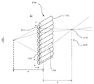
본 발명의 일 양태에 따르면, 양측에 렌즈들을 갖는 양면 렌즈 시트를 관찰자와 은닉될 타겟 물체 사이에 배치하는 것을 수반하는, 타겟 은닉 및 그림자 감소를 위한 장치 및 그 방법이 제공된다. 양면 렌즈 시트는 한 쌍의 단면 렌즈 시트들의 매끄러운 면들을 맞대어 함께 부착함으로써 구성될 수 있다. 이 실시예에서, 양면 렌즈 시트의 대향 측면들상의 대응하는 렌즈들은 서로 오프셋 관계를 갖는 엇갈린 방식(staggered manner)으로 배열된다. 오프셋 양면 렌즈 시트를 통과하는 타겟으로부터의 광은 수많은 방향들로 반사 및/또는 굴절되어, 타겟 물체의 가시성 또는 타겟 물체로부터의 그림자를 실질적으로 감소시킨다. According to one aspect of the present invention, an apparatus and method for target concealment and shadow reduction is provided, which involves placing a double-sided lens sheet having lenses on both sides between an observer and a target object to be concealed. The double-sided lens sheet can be constructed by attaching the smooth sides of a pair of single-sided lens sheets butting together. In this embodiment, the corresponding lenses on opposite sides of the double-sided lens sheet are arranged in a staggered manner having an offset relationship with each other. Light from the target passing through the offset double-sided lens sheet is reflected and/or refracted in a number of directions, substantially reducing the visibility of the target object or shadow from the target object.
본 발명의 또 다른 양태에 따르면, 양측에 렌즈들을 갖는 양면 렌즈 시트를 관찰자와 은닉될 타겟 물체 사이에 배치하는 것을 수반하는 타겟 은닉 및 그림자 감소를 위한 장치 및 그 방법이 제공된다. 양면 렌즈 시트는 한 쌍의 단면 렌즈 시트들의 매끄러운 면들을 맞대어 함께 부착함으로써 구성될 수 있다. 이 실시예에서, 양면 렌즈 시트의 대향 측면들상의 대응하는 렌즈들은 서로 줄을 서도록(line up) 배열된다. 인라인(in-line) 양면 렌즈 시트를 통과하는 타겟으로부터의 광은 수많은 방향으로 반사 및/또는 굴절되어, 타겟 물체의 가시성 또는 타겟 물체로부터의 그림자를 실질적으로 감소시킨다. According to another aspect of the present invention, there is provided an apparatus and method for target concealment and shadow reduction involving placing a double-sided lens sheet having lenses on both sides between an observer and a target object to be concealed. The double-sided lens sheet can be constructed by attaching the smooth sides of a pair of single-sided lens sheets butting together. In this embodiment, the corresponding lenses on opposite sides of the double-sided lens sheet are arranged line up with each other. Light from the target passing through the in-line double-sided lens sheet is reflected and/or refracted in a number of directions, substantially reducing the visibility of the target object or shadow from the target object.
본 발명의 또 다른 양태에 따르면, 2개의 양면 렌즈 시트(제1 양면 시트 및 제2 양면 렌즈 시트)를 배치하는 것을 수반하는 은닉 및 그림자 감소를 위한 장치 및 그 방법이 제공된다. 앞서 유의한 바와 같이, 양면 렌즈 시트는 한 쌍의 단면 렌즈 시트들의 매끄러운 면들을 맞대어 함께 부착함으로써 구성될 수 있다. 2개의 양면 렌즈 시트를 통과하는 타겟 물체로부터의 광은 수많은 방향으로 반사 및/또는 굴절되어, 타겟 물체의 가시성 또는 타겟 물체로부터의 그림자를 실질적으로 감소시킨다. 이 실시예에서, 제1 양면 렌즈 시트의 대향 측면들상의 대응하는 렌즈들은 서로 오프셋 관계를 갖는 엇갈린 방식으로 배열되는 한편, 제2 양면 렌즈 시트의 대향 측면들상의 대응하는 렌즈들은 서로 줄을 서도록 배열된다. 이 실시예는 미러 이미지를 생성하지 않고서 은닉될 물체 배후에 배경 장면을 제공하는 이점을 갖는다. According to another aspect of the present invention, an apparatus and method for concealment and shadow reduction involving placing two double-sided lens sheets (a first double-sided sheet and a second double-sided lens sheet) are provided. As noted above, the double-sided lens sheet can be constructed by attaching the smooth sides of a pair of single-sided lens sheets butting together. Light from the target object passing through the two double-sided lens sheets is reflected and/or refracted in a number of directions, substantially reducing the visibility of the target object or shadow from the target object. In this embodiment, the corresponding lenses on the opposite sides of the first double-sided lens sheet are arranged in a staggered manner having an offset relationship with each other, while the corresponding lenses on the opposite sides of the second double-sided lens sheet are arranged so as to line up with each other. do. This embodiment has the advantage of providing a background scene behind the object to be concealed without creating a mirror image.
본 발명의 또 다른 양태에 따르면, 2개의 양면 렌즈 시트(제1 양면 시트 및 제2 양면 렌즈 시트)를 배치하는 것을 수반하는 은닉 및 그림자 감소를 위한 장치 및 그 방법이 제공된다. 앞서 유의한 바와 같이, 양면 렌즈 시트는 한 쌍의 단면 렌즈 시트들의 매끄러운 면들을 맞대어 함께 부착함으로써 구성될 수 있다. 2개의 양면 렌즈 시트를 통과하는 타겟 물체로부터의 광은 수많은 방향으로 반사 및/또는 굴절되어, 타겟 물체의 가시성 또는 타겟 물체로부터의 그림자를 실질적으로 감소시킨다. 이 실시예에서, 제1 양면 렌즈 시트 및 제2 양면 렌즈 시트 둘 다의 대향 측면들상의 대응하는 렌즈들은 서로 줄을 서도록 배열된다. 이 실시예는 또한 미러 이미지를 생성하지 않고서 은닉될 물체 배후에 배경 장면을 정확하게 제시하는 이점을 갖는다. 이 실시예는 또한 미러 이미지를 생성하지 않고서 은닉될 물체 배후에 배경 장면을 정확하게 제시하는 이점을 갖는다.According to another aspect of the present invention, an apparatus and method for concealment and shadow reduction involving placing two double-sided lens sheets (a first double-sided sheet and a second double-sided lens sheet) are provided. As noted above, the double-sided lens sheet can be constructed by attaching the smooth sides of a pair of single-sided lens sheets butting together. Light from the target object passing through the two double-sided lens sheets is reflected and/or refracted in a number of directions, substantially reducing the visibility of the target object or shadow from the target object. In this embodiment, the corresponding lenses on opposite sides of both the first double-sided lens sheet and the second double-sided lens sheet are arranged to line up with each other. This embodiment also has the advantage of accurately presenting the background scene behind the object to be concealed without creating a mirror image. This embodiment also has the advantage of accurately presenting the background scene behind the object to be concealed without creating a mirror image.
도면들에서, 본 발명의 실시예를 단지 예로서 도시한다.
도 1은 가시 광에 관련됨에 따라 굴절 법칙의 원리를 도시하는 개략도이다.
도 2는 부분 단면도로 된, 렌티큘러 렌즈 시트의 단순화된 개략도이다.
도 3a는 광원과 타겟 사이에 배치된 렌즈 시트의 단순화된 개략도이다.
도 3b는 광원과 타겟 사이에 배치되고, 시트의 매끄러운 면이 반대 방향을 향하는 렌즈 시트의 또 다른 단순화된 개략도이다.
도 3c는 광원과 타겟 사이에 배치되고, 시트의 양측에 복수의 렌즈를 갖는 렌즈 시트의 또 다른 단순화된 개략도이다.
도 4는 광원과 타겟 사이에 제2 렌즈 시트가 배치된, 도 3의 실시예의 변형을 도시하는 단순화된 블록도이다.
도 5는 3차원 이미지를 시뮬레이트하는데 이용되는 렌티큘러 렌즈들을 도시하는 블록도이다.
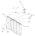
도 6은 타겟에 근접하여 배치된 렌즈 시트의 단순화된 사시 블록도이다.
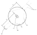
도 7은 타겟을 둘러싸는 도 2의 렌즈 시트의 평면도이다.
도 8은 관찰자와 타겟 사이에 배치된 다수의 선형 렌즈로 구성된 렌즈 시트의 블록도이다.
도 9는 타겟이 수평 프로파일을 갖는, 도 8과 유사한 또 다른 구성의 블록도이다.
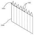
도 10은 다수의 1 각도 프리즘 렌즈로 구성된 프리즘 시트의 사시도이다.
도 11은 다수의 1 각도 프리즘 렌즈로 구성된 도 10의 프리즘 시트의 평면도이다.
도 12는 다수의 2 각도 프리즘 렌즈로 구성된 프리즘 시트에 대한 개략도의 사시도이다.
도 13은 도 12의 프리즘 시트의 평면도이다.
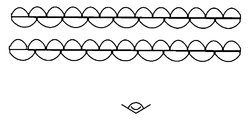
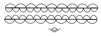
도 14는 도브 프리즘 렌즈 시트의 단순화된 개략도이다.
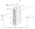
도 15는 타겟과 관찰자 사이에 배치된 오프셋 양면 렌즈 시트의 단순화된 개략도이다.
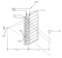
도 16은 타겟과 관찰자 사이에 배치된 오프셋 양면 렌즈 시트 및 인라인 양면 렌즈 시트의 단순화된 개략도이다.
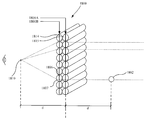
도 17a는 타겟과 관찰자 사이에 배치되지만 2개의 양면 렌즈 시트 사이에 외부 오프셋을 갖는, 도 16의 오프셋 양면 렌즈 시트 및 인라인 양면 렌즈 시트의 단순화된 개략도이다.
도 17b는 타겟과 관찰자 사이에 배치된, 도 16의 2개의 오프셋 양면 렌즈 시트의 단순화된 개략도이다.
도 18은 타겟과 관찰자 사이에 배치된 2개의 인라인 양면 렌즈 시트의 단순화된 개략도이다.
도 19는 2개의 양면 렌즈 시트 사이의 외부 오프셋을 갖는, 도 18의 2개의 인라인 양면 렌즈 시트의 단순화된 개략도이다.
도 20 내지 도 22는 중립 스트립들을 생성하는 반복 패턴으로 배경 이미지의 부분들을 병합함으로써 양면 렌즈 시트들에 의해 달성되는 은닉 효과의 개략도이다.
도 23a 및 도 23b는 관찰자와 배경 사이에 배치된 단면 렌즈 시트의 제각기 입면도 및 평면도의 단순화된 개략도이다.
도 24a 및 도 24b는 관찰자와 배경 사이에 배치된 양면 렌즈 시트의 제각기 입면도 및 평면도의 단순화된 개략도이다.
도 25a 및 도 25b는 관찰자와 배경 사이에 배치된 2개의 양면 렌즈 시트의 제각기 입면도 및 평면도의 단순화된 개략도이다.
도 26a 및 도 26b는 관찰자와 배경 사이에 배치된 양면 렌즈 시트 - 2개의 측면은 상이한 LPI를 가짐 - 의 제각기 입면도 및 평면도의 단순화된 개략도이다.
도 27a 및 도 27b는 관찰자와 배경 사이에 배치된 또 다른 양면 렌즈 시트 - 2개의 측면은 상이한 LPI를 가짐- 의 제각기 입면도 및 평면도 단순화된 개략도이다.
도 28a 및 도 28b는 관찰자와 배경 사이에 배치된 2개의 양면 렌즈 시트 - 각각의 시트의 2개의 측면은 상이한 LPI를 가짐 - 의 제각기 입면도 및 평면도의 단순화된 개략도이다.
도 29a 및 도 29b는 관찰자와 배경 사이에 배치된 2개의 양면 렌즈 시트 - 각각의 시트의 2개의 측면은 상이한 LPI를 가짐 - 의 제각기 입면도 및 평면도의 단순화된 개략도이다.
도 30a 및 도 30b는 관찰자와 배경 사이에 배치된 2개의 양면 렌즈 시트 - 각각의 시트의 2개의 측면은 상이한 LPI를 가짐 - 의 제각기 입면도 및 평면도의 단순화된 개략도이다.
도 31a 및 도 31b는 관찰자와 배경 사이에 배치된 2개의 양면 렌즈 시트 - 각각의 시트의 2개의 측면은 상이한 LPI를 가짐 - 의 입면도 및 평면도의 단순화된 개략도이다.
도 32는 수직 폴래리티(polarity) - 그에 의해 렌즈들이 수직으로 배치됨 - 를 갖는 단면 렌즈 시트의 단순화된 사시도이다.
도 33은 흐릿해진(blurred) 배경 이미지를 묘사하는 도 32의 렌즈 시트의 단순화된 사시도이다.
도 34는 배경의 입면도이다.
도 35는 수직 폴래리티의 베이스 렌즈들을 갖고 및 서브 렌즈들의 몇몇 각진 섹션들을 더 가짐으로써 각진 섹션들 내의 서브 렌즈들이 소정 각도로 배치되는 단면 렌즈 시트의 단순화된 사시도이다.
도 36은 대응하는 각진 섹션들에 의해 야기되는 상이한 유형의 아티팩트들을 갖는 흐릿해진 배경 이미지를 묘사하는 도 35의 렌즈 시트의 단순화된 사시도이다.
도 37은 수직 폴래리티의 베이스 렌즈들을 갖고 및 서브 렌즈들의 몇몇 각진 복잡한(complex) 섹션들을 더 가짐으로써 각진 복잡한 섹션들 내의 서브 렌즈들이 소정 각도로 배치되는 단면 렌즈 시트의 또 다른 단순화된 사시도이다.
도 38은 대응하는 복잡한 섹션들에 의해 야기되는 상이한 유형의 아티팩트들을 갖는 흐릿해진 배경 이미지를 묘사하는 도 37의 렌즈 시트의 단순화된 사시도이다.
도 39는 제1 LPI의 베이스 렌즈들을 갖고 및 서브 렌즈들의 몇몇 섹션들을 더 가짐으로써 베이스 렌즈들 및 서브 렌즈들이 수직으로 뻗어가지만 섹션들 내의 서브 렌즈들은 제1 LPI와 상이한 제2 각도/LPI를 갖는 단면 렌즈 시트의 단순화된 사시도이다.
도 40은 대응하는 섹션들에 의해 야기되는 상이한 유형의 아티팩트들을 갖는 흐릿해진 배경 이미지를 묘사하는 도 39의 렌즈 시트의 단순화된 사시도이다.
도 41은 향상된 은닉을 묘사하는 배경의 전방에 배치된 도 39의 렌즈 시트의 단순화된 입면도이다.
도 42는 렌즈들이 각각 내에 수평으로 배치된, 서로에 대해 제1 거리에서 오프셋된 2개의 단면 렌즈 시트에 의해 통해 본 이미지이다.
도 43은 렌즈들이 각각 내에 수평으로 배치된, 서로에 대해 제2 거리에서 오프셋된 2개의 단면 렌즈 시트에 의해 통해 본 또 다른 이미지이다.
도 44a 내지 도 44c는 2개의 시트 사이의 오프셋에 의존하는 다양한 은닉 속성들을 묘사하는, 수중에서의 2개의 단면 렌즈 시트에 의해 통해 본 이미지이다.
도 45는 맞대어 배치된 2개의 렌즈 시트를 묘사하고, 여기서 타겟은 상이한 관점 시야 위치들에서는 부분적으로 볼 수 있고 다른 시야 위치들에서는 완전히 볼 수 없다.
도 46은 투명 방패 본체 및 그 위에 배치된 렌즈 시트를 갖는 진압 방패의 개략도이다.
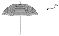
도 47 내지 도 49는 렌즈 시트들로부터 만들어진 우산들의 예시적 실시예들의 개략도이다.
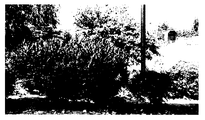
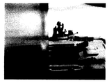
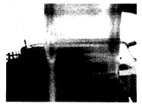
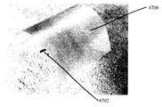
도 50 및 도 51은 항공 검출을 방지하기 위해 사용되는 렌즈 시트의 이미지들이다.
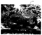
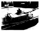
도 52는 항공 검출로부터 보호될 물체의 이미지이다.
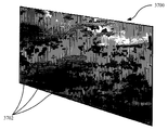
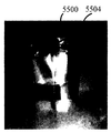
도 53은 항공 검출을 피하기 위해 렌즈 시트에 의해 커버되는 도 53의 물체의 이미지이다.
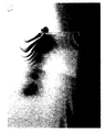
도 54는 군용 등급 야간 투시경 장비를 사용하는 도 53에 도시된 실시예의 이미지이다.
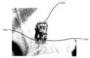
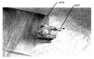
도 55, 도 56a 및 도 56b는 비행 동안 검출을 피하기 위해 렌즈 시트를 활용하는, 쿼드콥터 드론 형태의 도 55의 물체의 이미지들이다.
도 57a 내지 도 57d는 검출을 피하기 위해 원통형 렌즈 시트를 활용하는 물체들의 도시이다.
도 58a 내지 도 58d는 상공 관찰을 여전히 허용하면서 지상 관찰을 피하기 위해 렌즈 시트를 사용하는 셀룰러 타워 형태의 세장형 구조물의 도시이다.
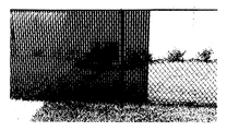
도 59a 및 도 59b는 본 발명의 예시적인 렌즈 시트들로 만들어진 체인 링크 펜스 프라이버시 삽입물(chain link fence privacy insert)들의 이미지이다.
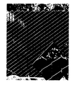
도 60은 현대의 카무플라주 그물들과 같은 구멍들을 갖는 유연한 렌즈 시트의 이미지이다.
도 61a 및 도 61b는 그물 프레임워크 상에 배치된 렌즈 시트 재료의 스트립들의 도면이다.
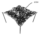
도 62는 시트의 구조적 무결성을 보유하도록 설계된 그물 프레임워크 상의 구멍들의 매트릭스를 갖는 카무플라주 시트의 또 다른 도면이다.
도 63은 가변 렌즈 요소들을 갖는 렌즈 시트의 도면이다.
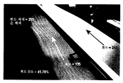
도 64 및 도 65는 렌즈 시트를 통한 광의 감소된 반사를 도시하는 이미지이다.
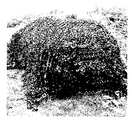
도 66 내지 도 69는 타겟 물체를 은닉하기 위해 활용되는 아치형 렌즈 시트의 이미지이다.
도 70은 투명한 골판형 재료의 도면이다.
도 71은 지지 구조체를 갖는 렌즈로서 기능하는 피스를 갖는 다른 골판형 재료 설계의 도면이다.
도 72는 본 발명의 예시적인 렌즈 시트를 이용하여 만들어진 예시적인 항공기 격납고의 이미지이다.In the drawings, an embodiment of the invention is shown by way of example only.
1 is a schematic diagram showing the principle of the law of refraction as it relates to visible light.
2 is a simplified schematic diagram of a lenticular lens sheet, in partial cross-sectional view.
3A is a simplified schematic diagram of a lens sheet disposed between a light source and a target.
3B is another simplified schematic diagram of a lens sheet disposed between the light source and the target, and the smooth side of the sheet facing in the opposite direction.
3C is another simplified schematic diagram of a lens sheet disposed between a light source and a target and having a plurality of lenses on both sides of the sheet.
4 is a simplified block diagram showing a variation of the embodiment of FIG. 3 with a second lens sheet disposed between the light source and the target.
5 is a block diagram showing lenticular lenses used to simulate a three-dimensional image.
6 is a simplified perspective block diagram of a lens sheet disposed close to a target.
7 is a plan view of the lens sheet of FIG. 2 surrounding a target.
8 is a block diagram of a lens sheet composed of a plurality of linear lenses disposed between an observer and a target.
9 is a block diagram of another configuration similar to FIG. 8, in which the target has a horizontal profile.
10 is a perspective view of a prism sheet composed of a plurality of one-angle prism lenses.
11 is a plan view of the prism sheet of FIG. 10 composed of a plurality of one-angle prism lenses.
12 is a schematic perspective view of a prism sheet composed of a plurality of two angle prism lenses.
13 is a plan view of the prism sheet of FIG. 12.
14 is a simplified schematic diagram of a dove prism lens sheet.
15 is a simplified schematic diagram of an offset double-sided lens sheet disposed between a target and an observer.
16 is a simplified schematic diagram of an offset double-sided lens sheet and an in-line double-sided lens sheet disposed between a target and an observer.
FIG. 17A is a simplified schematic diagram of the offset double-sided lens sheet and in-line double-sided lens sheet of FIG. 16 disposed between the target and the observer but with an external offset between the two double-sided lens sheets.
17B is a simplified schematic diagram of the two offset double-sided lens sheets of FIG. 16 disposed between the target and the observer.
18 is a simplified schematic diagram of two in-line double-sided lens sheets disposed between a target and an observer.
Fig. 19 is a simplified schematic diagram of the two in-line double-sided lens sheets of Fig. 18 with an external offset between the two double-sided lens sheets.
20 to 22 are schematic diagrams of the concealment effect achieved by double-sided lens sheets by merging portions of the background image into a repeating pattern creating neutral strips.
23A and 23B are simplified schematic diagrams of elevational and plan views, respectively, of a single-sided lens sheet disposed between an observer and a background.
24A and 24B are simplified schematic diagrams of elevational and plan views, respectively, of a double-sided lens sheet disposed between an observer and a background.
25A and 25B are simplified schematic diagrams of elevational and plan views, respectively, of two double-sided lens sheets disposed between the observer and the background.
26A and 26B are simplified schematic diagrams of elevational and plan views, respectively, of a double-sided lens sheet disposed between the observer and the background-the two sides have different LPIs.
27A and 27B are schematic elevational and plan view simplified schematics, respectively, of another double-sided lens sheet disposed between the observer and the background, the two sides having different LPIs.
28A and 28B are simplified schematic diagrams of elevational and plan views, respectively, of two double-sided lens sheets disposed between the observer and the background, the two sides of each sheet having different LPIs.
29A and 29B are simplified schematic diagrams of elevational and plan views, respectively, of two double-sided lens sheets disposed between the observer and the background, the two sides of each sheet having different LPIs.
30A and 30B are simplified schematic diagrams of elevational and plan views, respectively, of two double-sided lens sheets disposed between the observer and the background, the two sides of each sheet having different LPIs.
31A and 31B are simplified schematic diagrams of elevational and plan views of two double-sided lens sheets disposed between the observer and the background, the two sides of each sheet having different LPIs.
Fig. 32 is a simplified perspective view of a single-sided lens sheet having vertical polarity, whereby the lenses are arranged vertically.
FIG. 33 is a simplified perspective view of the lens sheet of FIG. 32 depicting a blurred background image.
34 is an elevational view of the background.
Fig. 35 is a simplified perspective view of a single-sided lens sheet in which the sub-lenses in the angular sections are disposed at a predetermined angle by having base lenses of vertical polarity and further having several angular sections of the sub-lenses.
FIG. 36 is a simplified perspective view of the lens sheet of FIG. 35 depicting a blurred background image with different types of artifacts caused by corresponding angled sections.
37 is another simplified perspective view of a single-sided lens sheet in which the sub-lenses in the angular complex sections are arranged at an angle by having base lenses of vertical polarity and further having several angled complex sections of the sub-lenses. .
FIG. 38 is a simplified perspective view of the lens sheet of FIG. 37 depicting a blurred background image with different types of artifacts caused by corresponding complex sections.
39 shows that the base lenses and the sub lenses extend vertically by having the base lenses of the first LPI and several sections of the sub lenses, but the sub lenses in the sections have a second angle/LPI different from the first LPI. It is a simplified perspective view of a single-sided lens sheet.
FIG. 40 is a simplified perspective view of the lens sheet of FIG. 39 depicting a blurred background image with different types of artifacts caused by the corresponding sections.
FIG. 41 is a simplified elevational view of the lens sheet of FIG. 39 placed in front of the background depicting improved concealment.
42 is an image seen through two single-sided lens sheets offset at a first distance relative to each other, with lenses disposed horizontally within each.
43 is another image viewed through two single-sided lens sheets offset at a second distance from each other, with lenses disposed horizontally within each.
44A-44C are images viewed through two single-sided lens sheets underwater, depicting various concealment properties depending on the offset between the two sheets.
FIG. 45 depicts two lens sheets arranged butt, where the target is partially visible in different viewing viewing positions and completely invisible in other viewing positions.
46 is a schematic diagram of a suppression shield having a transparent shield body and a lens sheet disposed thereon.
47-49 are schematic diagrams of exemplary embodiments of umbrellas made from lens sheets.
50 and 51 are images of a lens sheet used to prevent aerial detection.
52 is an image of an object to be protected from aerial detection.
FIG. 53 is an image of the object of FIG. 53 covered by a lens sheet to avoid aerial detection.
FIG. 54 is an image of the embodiment shown in FIG. 53 using military grade night vision equipment.
55, 56A and 56B are images of the object of FIG. 55 in the form of a quadcopter drone, utilizing a lens sheet to avoid detection during flight.
57A-57D are illustrations of objects utilizing a cylindrical lens sheet to avoid detection.
58A-58D are illustrations of an elongate structure in the form of a cellular tower that uses a lens sheet to avoid ground observation while still allowing aerial observation.
59A and 59B are images of chain link fence privacy inserts made of exemplary lens sheets of the present invention.
60 is an image of a flexible lens sheet having holes like modern camouflage nets.
61A and 61B are views of strips of lens sheet material disposed on a mesh framework.
62 is another view of a camouflage sheet having a matrix of perforations on a mesh framework designed to retain the structural integrity of the sheet.
63 is a diagram of a lens sheet with variable lens elements.
64 and 65 are images showing reduced reflection of light through the lens sheet.
66 to 69 are images of an arcuate lens sheet utilized to conceal a target object.
70 is a diagram of a transparent corrugated material.
71 is a diagram of another corrugated material design with a piece that functions as a lens with a support structure.
72 is an image of an exemplary aircraft hangar made using an exemplary lens sheet of the present invention.
실시예들의 설명Description of the embodiments
본 설명에서, 렌즈 시트들은 세장형 렌즈(elongate lense)들의 어레이로 구성된 반투명 시트들이다. 이러한 세장형 렌즈들은 종종 한 측면상에서 매끄러운 렌티큘들이라고 불리는 작은 볼록 렌즈들일 수 있다. 렌티큘들에 더하여, 이러한 세장형 렌즈들은 또한 프리즘 렌즈들, 도브 프리즘 렌즈들, 분할 도브 프리즘 렌즈들(즉, 세로로 절반으로 분할된 도브 프리즘 렌즈들), 1-각도 프리즘 렌즈들, 2-각도 프리즘 렌즈들 및 유사한 세장형 렌즈들을 포함한다. In this description, the lens sheets are translucent sheets composed of an array of elongate lenses. These elongate lenses can often be small convex lenses called lenticulars that are smooth on one side. In addition to lenticulars, these elongate lenses also include prism lenses, dove prism lenses, split dove prism lenses (i.e. dove prism lenses split in half lengthwise), 1-angle prism lenses, 2- Angular prism lenses and similar elongated lenses.
한 측면상에 렌티큘들과 같은 세장형 렌즈들을 가지며 대향 측면상에 매끄러운 평탄한 표면을 가진 렌즈 시트들은 다양한 흥미로운 시각적 효과를 갖는 것으로 보인다. Lens sheets with elongate lenses such as lenticulars on one side and a smooth flat surface on the opposite side appear to have a variety of interesting visual effects.
본 개시내용에서, 단면 렌즈 시트는 한 측면상에서 실질적으로 평행하게 전형적으로 배열되는 복수의 세장형 렌즈 및 대향 측면상에서 매끄럽고 전형적으로 평탄한 표면을 갖는 렌즈 시트를 지칭한다. 렌즈들은 렌티큘들, 프리즘 렌즈들, 도브 프리즘 렌즈들, 분할 도브 프리즘 렌즈들 또는 분할 프리즘 렌즈들일 수 있다. In the present disclosure, a single-sided lens sheet refers to a lens sheet having a plurality of elongated lenses that are typically arranged substantially parallel on one side and a smooth, typically flat surface on the opposite side. The lenses may be lenticulars, prism lenses, dove prism lenses, split dove prism lenses or split prism lenses.
본 개시내용에서, 양면 렌즈 시트는 각각의 측면에서 실질적으로 평행하게 전형적으로 배열된 복수의 세장형 렌즈를 갖는 렌즈 시트를 지칭한다. 다시금, 렌즈들은 렌티큘들, 프리즘 렌즈들, 도브 프리즘 렌즈들, 분할 도브 프리즘 렌즈들 또는 분할 프리즘 렌즈들일 수 있다. 양면 렌즈 시트는 한 쌍의 단면 렌즈 시트들의 평탄한 매끄러운 면들을 함께 맞대어 부착하거나 접착함으로써 또는 양 측면들에 렌즈들을 갖는 단일 시트를 제조함으로써 구성될 수 있다. In the present disclosure, a double-sided lens sheet refers to a lens sheet having a plurality of elongated lenses typically arranged substantially parallel on each side. Again, the lenses may be lenticulars, prism lenses, dove prism lenses, split dove prism lenses or split prism lenses. The double-sided lens sheet may be constructed by abutting or bonding the flat smooth sides of a pair of single-sided lens sheets together or by manufacturing a single sheet having lenses on both sides.
굴절refraction
빗각으로 재료 매질에 입사하는 광선이 그 방향을 바꾸는 것이 일반적으로 관찰된다. 이 현상을 굴절이라고 부른다. 굴절은 일반적으로 전파 속력에서의 변화로 인해 파동 전파의 방향에서의 변화를 수반한다. 광의 경우에, 광이 매질에 입사할 때 굴절은 광의 속력이 느려짐으로부터 유래할 수 있고, 광의 속력은 그의 진공 속도 ![]()
![]()
도 1은 스넬의 법칙이라고도 알려진 굴절 법칙의 도시를 묘사한다. 입사 광선(106)은, 초기 지점 P1로부터 공기와 같은 제1 매체(102)를 통해 이동하고, 제2 매체(104) 내로 들어간다. 입사 광선(106)은 계면(110)에서 굴절되어, 굴절된 광선(108)의 궤적이 지점 P2에 도달한다. 이는, 광은 최소 시간을 요구하는 경로를 따라 한 지점으로부터 또 다른 지점으로 이동한다고 진술하는 페르마의 최소 시간의 원리에 의해 설명된다. 입사각 θ1 및 굴절각 θ2는 P1에서 P2까지의 광 경로 길이를 최소화하도록 되어야만 한다. 도 1에 도시된 바와 같이, 제1 매질과 제2 매질의 굴절률이 제각기 n1 및 n2인 경우, 스넬의 법칙은 n1sinθ1 = n2sinθ2이라고 진술한다.1 depicts an illustration of the law of refraction, also known as Snell's law. The
위에서 언급한 바와 같이, 많은 수의 렌즈로 구성되고, 그 서브세트들이 가시 광, 근적외선 및/또는 근자외선을 굴절시키는 방식으로 서로 인접하거나 또는 매우 근접하게 배열된 재료들이 알려져 있다. 전형적인 예는 렌즈 시트이다. 렌즈 시트들은 반투명 플라스틱으로 만들어질 수 있다. 또한, 일부 렌즈 시트들은 한 측면상에서 매끄러울 수 있는 반면, 대향 측면은 렌티큘들이라고 불리는 작은 볼록 렌즈들로 만들어질 수 있다. 이러한 렌티큘들은 장면의 보통의 2차원(2D) 뷰를 만들 수 있으며, 다양한 흥미로운 시각적 효과를 갖는 것으로 나타난다. 예를 들어, 렌티큘은 확대경 역할을 할 수 있다.As mentioned above, materials are known which consist of a large number of lenses, and whose subsets are arranged adjacent to each other or very close to each other in such a way that they refract visible, near-infrared and/or near-ultraviolet rays. A typical example is a lens sheet. The lens sheets can be made of translucent plastic. Also, some lens sheets can be smooth on one side, while the opposite side can be made of small convex lenses called lenticulars. These lenticulars can create a normal two-dimensional (2D) view of the scene and appear to have a variety of interesting visual effects. For example, a lenticular can act as a magnifying glass.
도 2는 렌티큘러 렌즈 시트의 단면 개략도이다. 도시된 바와 같이, 렌티큘러 시트(200)는 복수의 렌즈 또는 렌티큘(202)을 포함한다. 렌티큘러 렌즈들로부터의 이미지들은, 시야각(204)에 대응하는 V-형상의 시야 영역 내에서 볼 수 있다. 시야각(204)은 작거나 클 수 있다. 작은 시야각(204)은 관찰자가 머리를 약간 돌리기만 하면 상이한 세트의 화상들이 보일 것이라는 의미에서 화상을 변화에 매우 민감하게 만든다. 광 시야각(204) 렌즈들의 경우, 관찰자는 상이한 세트의 화상을 보기 위해서는 그의 머리를 비교적 크게 변위하거나 돌려야 할 수 있어서, 관찰된 화상에서의 변화가 머리의 위치 또는 오리엔테이션의 변위에 그렇게 민감하지 않게 된다. 그 결과, 좁은 시야각 렌즈들은 3차원(3D) 효과에 적합하고 광 시야각 렌즈들은 애니메이션, 플립(flip), 모핑(morph) 또는 줌(zoom)과 같은 동적 프린트에 적합하다.2 is a schematic cross-sectional view of a lenticular lens sheet. As shown, the
렌즈 어레이의 시트의 개발 Development of sheet of lens array
특별한 안경이나 기타 거추장스러운 물건의 필요없이 관찰자에게 3차원 이미지를 제시하는 디스플레이를 때때로 무안경식 입체(auto-stereoscopic) 디스플레이라고 지칭한다. 처음 등장한 무안경식 입체 방법은 배리어 기술(barrier technique)인데, 이는 2개 이상의 화상을 스트라이프들로 분할하고 이들을 동일한 빈도의 일련의 수직으로 정렬된 불투명 막대(opaque bar)들 뒤에 정렬하는 것을 수반하였다. 이는 관찰자가 걸어서 지나갈 때 한 화상으로부터 또 다른 화상으로 변하는 것으로 보이는 G. A. Bois-Clair에 의한 페인팅에서 증명되었다. A display that presents a three-dimensional image to an observer without the need for special glasses or other cumbersome objects is sometimes referred to as an auto-stereoscopic display. The first-approaching autostereoscopic method was the barrier technique, which involved dividing two or more images into stripes and aligning them behind a series of vertically aligned opaque bars of equal frequency. This was demonstrated in painting by G. A. Bois-Clair, which appears to change from one image to another as the observer walks by.
나중에, 물리학자 Gabriel M. Lippmann은 불투명한 배리어 라인들 대신에 화상 표면에서 일련의 렌즈들을 사용했고, 모든 방향에서 시차를 갖는 완전한 공간 이미지를 기록할 수 있었다. 이 프로세스는, 파리눈 렌즈 어레이 또는 일체형 렌즈 어레라고 알려진 작은 구면 렌즈들의 어레이를 활용해 이미지를 기록하고 재생했다.Later, physicist Gabriel M. Lippmann used a series of lenses on the image surface instead of opaque barrier lines, and was able to record a complete spatial image with parallax in all directions. The process used an array of small spherical lenses known as fly-eye lens arrays or monolithic lens arrays to record and reproduce images.
몇몇 과학자들은 렌티큘러 렌즈 어레이를 통합시킴으로써 일체형 렌즈 어레이를 단순화했다. 렌티큘러 렌즈 시트는 두꺼운 평철(plano-convex) 원통형 렌즈들의 선형 어레이로 만들어질 수 있다. 렌즈 시트는 투명하거나 반투명하며, 초점면을 구성하는 배면은 전형적으로 평탄하다. 이는 또한 시차 배리어 스크린과 광학적으로 유사하다.Several scientists have simplified the all-in-one lens array by incorporating a lenticular lens array. The lenticular lens sheet can be made of a linear array of thick plano-convex cylindrical lenses. The lens sheet is transparent or translucent, and the back surface constituting the focal plane is typically flat. It is also optically similar to a parallax barrier screen.
요즘에는, 애니메이션, 3D 및 대형 포맷 및 대량 생산 기술을 위한 특유의 렌즈 설계가 있다. Nowadays, there are unique lens designs for animation, 3D and large format and mass production technologies.
렌티큘러 시트의 특성Characteristics of lenticular sheet
렌즈 시트를 만드는데 이용되는 종래의 재료들은 광을 굴절시키는 능력을 유지하면서 가능한 한 투명하게 만들어졌다. 재료의 더 높은 투명도는 종종 바람직하며, 프린팅과 같은 일부 응용에서는, 높은 투과율에 의해 더 깨끗하고 더 나은 시각적 효과를 실현할 수 있다. 재료는 또한, 렌티큘러 렌즈들의 시트가 선적을 위해 감아지거나 프린팅 프레스에 이용되는 것과 같은 많은 상황에서 이용될 수 있도록 열적으로 유도된 왜곡을 감소시키기에 충분히 안정적이어야 한다. 렌티큘러 시트는 전형적으로 아크릴, 폴리카보네이트, 폴리프로필렌, PVC 및 폴리스티렌 중 하나로 만들어진다. 렌즈들은, 종종 통상적으로 인치당 렌티큘로서 또는 인치당 렌즈(lens per inch: LPI)로서 측정되거나 표현되는 적절한 밀도로 배열될 수 있다. Conventional materials used to make lens sheets have been made as transparent as possible while maintaining their ability to refract light. Higher transparency of the material is often desirable, and in some applications, such as printing, a cleaner and better visual effect can be realized by a higher transmittance. The material must also be stable enough to reduce thermally induced distortion so that a sheet of lenticular lenses can be used in many situations, such as being rolled up for shipping or used in a printing press. Lenticular sheets are typically made of one of acrylic, polycarbonate, polypropylene, PVC and polystyrene. The lenses can be arranged at an appropriate density, often measured or expressed as lenticulars per inch or lenses per inch (LPI).
이들 렌즈들의 배열의 전형적인 실시예는, 도 2에 묘사되고 앞서 논의된 바와 같이 V-형상의 시야 영역을 제공한다. 관찰자 위치 변화에 대한 이미지 감도는 시야각(204)에 의존한다. 작은 시야각(204)은 관찰자가 머리를 약간 돌리기만 하면 상이한 세트의 화상들이 보일 것이라는 점에서 화상을 변화에 민감하게 만든다. 광각 렌즈들(204)의 경우, 관찰자는 상이한 세트의 화상들을 보기 위해 비교적 더 크게 머리를 돌려야 할 수 있어서 변화에 그렇게 민감하지 않다. 그 결과, 좁은 시야각 렌즈들은 3차원 효과에 및 동적 프린트에 적합하다.A typical embodiment of an arrangement of these lenses, as depicted in FIG. 2 and discussed above, provides a V-shaped viewing area. Image sensitivity to changes in the observer position depends on the
렌티큘러 렌즈 시트들을 만드는데 이용되는 재료는, 프린팅 프레스에서 이용될 수 있도록 유연성을 유지하면서 열 왜곡이 감소되도록 안정적인 것이 바람직하다. The material used to make the lenticular lens sheets is preferably stable so that thermal distortion is reduced while maintaining flexibility so that it can be used in a printing press.
제조 방법Manufacturing method
렌티큘러 렌즈 시트들은 전형적으로 이러한 목적을 위해 주문 제작된 머신 또는 디바이스를 이용하여 제조된다. 한 이러한 디바이스는, 2005년 8월 30일에 출원된 발명의 명칭이 "Lenticular lens pattern-forming device for producing a web roll of lenticular lens"인 미국 공개 특허 출원 제US2005/0286134A1호에서 설명되어 있으며, 그 내용은 참조에 의해 그 전체가 본 명세서에 포함된다. 이 공개된 출원은, 렌티큘러 렌즈, 및 특히 렌티큘러 렌즈 웹으로서의 렌즈를 제조하는 방법으로서, 절단, 라미네이팅 및 라벨링을 포함한 렌즈의 다양한 최종 용도의 응용과 같은 마무리 작업이 렌즈 웹의 제조와 한 줄로 달성되거나 감당될 수 있게 하는 방법을 설명한다. 공보는 또한, 중심 종축에 관해 회전가능한 하우징을 포함하는 렌티큘러 패턴-형성 디바이스를 개시한다. 하우징은 그루브 패턴(groove pattern)을 갖는 외측 표면을 갖는다. 그루브 패턴은 원주 방향 및 길이 방향으로 연장되는 그루브를 외측 표면상에 포함하고 그루브들은 동일한 그루브 폭들을 갖는다. 종방향으로 연장되는 그루브들은 중심 종축과 실질적으로 평행하고, 그루브들은 하우징의 외측 표면을 커버한다. 또한, 본 발명은 렌티큘러 이미지 웹을 만드는데 이용될 수 있는 렌티큘러 렌즈 웹을 생성하기 위해 렌티큘러 패턴 형성 디바이스를 이용하는 방법을 추가로 포함한다. 이미지 웹은, 벽지, 배너, 라벨 및 그와 유사한 것과 같은 제품을 생성하는데 이용될 수 있다.Lenticular lens sheets are typically manufactured using a machine or device customized for this purpose. One such device is described in US Published Patent Application No. US2005/0286134A1 entitled “Lenticular lens pattern-forming device for producing a web roll of lenticular lens” filed on August 30, 2005, The contents are incorporated herein in their entirety by reference. This published application is a method of manufacturing a lenticular lens, and in particular a lens as a lenticular lens web, in which finishing operations such as application of various end uses of the lens including cutting, laminating and labeling are achieved in one line with the manufacture of a lens web, or Explain how to be able to afford it. The publication also discloses a lenticular pattern-forming device comprising a housing rotatable about a central longitudinal axis. The housing has an outer surface with a groove pattern. The groove pattern includes a groove extending in the circumferential direction and in the length direction on the outer surface, and the grooves have the same groove widths. The grooves extending in the longitudinal direction are substantially parallel to the central longitudinal axis, and the grooves cover the outer surface of the housing. In addition, the present invention further includes a method of using a lenticular pattern forming device to create a lenticular lens web that can be used to make a lenticular image web. Image webs can be used to create products such as wallpaper, banners, labels and the like.
이후에 설명될 본 발명의 일부 실시예는, 향상된 카무플라주를 달성하기 위한 렌즈 시트들의 이용에 관한 것이다. 예를 들어, 하나의 적절한 유형의 렌티큘러 렌즈 시트가 2009년 10월 20일 출원된 발명의 명칭이 "Plastic sheets with lenticular lens array"인 미국 특허 번호 제8,411,363호에 설명되어 있으며, 그 내용이 참조에 의해 본 명세서에 포함된다. 이 특허는, 적어도 2개의 부분을 갖는 제1 표면, 대향하는 제2 표면, 및 제1 표면에 형성된 복수의 렌티큘러 렌즈를 포함하는 렌티큘러 시트를 개시한다. 제1 표면의 각각의 부분은 제1 표면의 인접한 부분의 센티미터 당 렌티큘러 렌즈들의 수와는 상이한 센티미터 당 렌티큘러 렌즈들의 수를 포함한다.Some embodiments of the invention, which will be described later, relate to the use of lens sheets to achieve an improved camouflage. For example, one suitable type of lenticular lens sheet is described in U.S. Patent No. 8,411,363, filed on October 20, 2009, entitled "Plastic sheets with lenticular lens array", the contents of which are incorporated herein by reference. Incorporated herein by reference. This patent discloses a lenticular sheet comprising a first surface having at least two portions, an opposing second surface, and a plurality of lenticular lenses formed on the first surface. Each portion of the first surface includes a number of lenticular lenses per centimeter that is different from the number of lenticular lenses per centimeter of an adjacent portion of the first surface.
렌즈 시트들을 만들기 위해 여러 재료가 사용될 수 있다. 이들은 비정질이 아니라 그 결정성을 보유하는 폴리에틸렌 테레프탈레이트(PET)를 포함한다. PET는 우수한 투명도, 양호한 가스 배리어 속성, 및 양호한 그리스(grease) 및 용매 내성을 갖는다. 폴리프로필렌(PP)은 또한 그 피스가 마감된 다이 절단 라미네이션 또는 제조이어야 하는 경우에 적합하다. 석유를 정제함으로써 생산되는 에틸렌과 암염(rock salt)으로부터 생산되는 염소를 결합함으로써 만들어지는 PVC(Polyvinyl chloride)도 역시 이용될 수 있다. 일반적으로, 유리와 같은 임의의 반투명 또는 심지어 투명 재료가 이러한 렌즈 시트들을 만들기 위해 사용될 수 있다.Several materials can be used to make the lens sheets. These include polyethylene terephthalate (PET) that is not amorphous but retains its crystallinity. PET has good transparency, good gas barrier properties, and good grease and solvent resistance. Polypropylene (PP) is also suitable where the piece must be finished die cut lamination or fabrication. Polyvinyl chloride (PVC) made by combining ethylene produced by refining petroleum and chlorine produced from rock salt can also be used. In general, any translucent or even transparent material such as glass can be used to make these lens sheets.
본 발명의 실시예의 예시적인 렌즈를 포함하는 다양한 유형의 재료, 이러한 재료의 제작 방법, 및 이러한 재료를 구현하는 제품의 구체적인 응용 및 용도가 설명될 것이다. Various types of materials including exemplary lenses of the embodiments of the present invention, methods of making such materials, and specific applications and uses of products embodying such materials will be described.
실시예 1 - 그림자 감소Example 1-Shadow reduction
본 발명의 예시적인 실시예에서, 볼록 렌즈들일 수 있는 복수의 선형 렌티큘러 렌즈로 만들어진 렌즈 시트 형태의 재료는 타겟 물체에 의해 드리워진 그림자를 감소시키기 위해 활용된다. 렌즈들은 타겟에 평행하게 뻗어나가도록 배열될 것이다. 그림자의 감소 또는 제거는 온실, 태양 에너지 생산, 아키텍처, 시각적 완화, 은닉, 및 시그니처 관리를 포함하는 몇몇 유익한 응용들을 갖는다. 지붕 타일들 상에 또는 지붕 타일들로서 종종 배치되는 태양 에너지를 전기 에너지로 변환하는 재료들은 본 발명의 실시예들의 예시적인 그림자 감소 재료들로부터 이익을 얻을 수 있다. In an exemplary embodiment of the present invention, a material in the form of a lens sheet made of a plurality of linear lenticular lenses, which may be convex lenses, is utilized to reduce the shadow cast by the target object. The lenses will be arranged to extend parallel to the target. Shadow reduction or removal has several beneficial applications including greenhouses, solar energy production, architecture, visual mitigation, concealment, and signature management. Materials that convert solar energy to electrical energy, often disposed on or as roof tiles, may benefit from the exemplary shadow reduction materials of embodiments of the present invention.
도 3a는 예시적인 실시예의 단순화된 개략도를 묘사한다. 광원(302)은 광원(302)과 타겟(310) 사이에 배치된 렌티큘러 렌즈들일 수 있는 렌즈들(304)의 시트(306)에 조명을 제공한다. 광원(302)으로부터의 광선(308)은 렌즈 시트(306)를 통과하고, 광선의 서브세트가 렌티큘러 렌즈들(304)로부터 수많은 방향으로 굴절된다. 3A depicts a simplified schematic diagram of an exemplary embodiment.
타겟(310)에 의한 그림자 형성에 기여할 수 있는 입사 광선(308)은 렌즈들(304)에 의해 굴절될 것이다. 가상적인 굴절되지 않은 광선(308b)과는 달리, 굴절된 광선들(312)은 타겟(310)을 직접 조명하지 않을 것이고, 그에 의해 광원(302)으로부터 타겟(310)에 의해 드리워졌을 그림자를 감소시키거나, 또는 일부 경우들에서 제거한다. Incident rays 308 that may contribute to shadow formation by the
광의 구부러짐 및/또는 굴절은 가시 광 스펙트럼의 모든 색들뿐만 아니라, 적외선 및 자외선과 같은 전자기 스펙트럼의 다른 비가시적 부분들에서도 발생할 수 있다.The bending and/or refraction of light can occur in all colors of the visible light spectrum, as well as other invisible parts of the electromagnetic spectrum such as infrared and ultraviolet.
묘사된 예시적인 실시예에서, 타겟(310)은 전형적인 수직 프로파일의 사람, 또는 폭보다 실질적으로 더 큰 높이를 갖는 또 다른 물체일 수 있다. 이러한 수직 프로파일을 갖는 타겟(310)을 갖는 실시예들에서, 선형 렌즈들(304)은 타겟(310)의 높이에 평행하게 뻗어가도록 배치될 수 있다. 따라서, 선형 렌즈들은 타겟 사람의 머리로부터 발끝까지 뻗어가는 동일한 방향으로 배열될 수 있다.In the illustrative embodiment depicted, the
일부 실시예들에서, 둘 이상의 렌즈 시트가 광원(302)과 타겟(310) 사이에, 또는 타겟(310) 옆에 배치될 수 있다. 반사방지 층, 코팅, 메시 커버, 텍스처된 표면 또는 다른 오버레이는 타겟 물체로부터 떨어져 대면하는 매끄러운 표면에 대해 요구될 수 있고 타겟 물체를 대면하는 대향 측면에 대해 요구될 수 있다.In some embodiments, two or more lens sheets may be disposed between the
도 3b는 도 3a에 묘사된 것과 실질적으로 유사하지만 반대 방향을 향하는 렌즈 시트를 갖는 예시적인 실시예의 단순화된 개략도를 묘사한다. 유사한 요소들은 도 3a의 대응 부분들로부터 그들을 구별하기 위해 도 3b의 요소들에 접미사로 붙여진 아포스트로프(')를 갖는 유사한 참조 번호들로 식별된다. 따라서, 광원(302')은 광원(302')과 타겟(310') 사이에 배치된 렌티큘러 렌즈들일 수 있는 렌즈(304')의 시트(306')에 조명을 제공한다. 광원(302')으로부터의 광선(308')은 렌즈 시트(306')를 통과하고, 광선의 서브세트는 렌티큘러 렌즈들(304')로부터 수많은 방향으로 굴절된다. 3B depicts a simplified schematic diagram of an exemplary embodiment having a lens sheet substantially similar to that depicted in FIG. 3A but facing in the opposite direction. Similar elements are identified by similar reference numbers with an apostrophe (') suffixed to the elements of FIG. 3B to distinguish them from the corresponding portions of FIG. 3A. Thus, light source 302' provides illumination to sheet 306' of lens 304', which may be lenticular lenses disposed between light source 302' and target 310'. Rays 308' from light sources 302' pass through lens sheet 306', and a subset of the rays are refracted from lenticular lenses 304' in a number of directions.
타겟(310')에 의한 그림자 형성에 기여할 수 있는 입사 광선(308')은 렌즈(304')에 의해 굴절될 것이다. 가상적인 굴절되지 않은 광선(308b')과는 달리, 굴절된 광선들(312')은 타겟(310')을 직접 조명하지 않을 것이고, 그에 의해 광원(302')으로부터 타겟(310')에 의해 드리워졌을 그림자를 감소시키거나 일부 경우에는 제거한다. Incident rays 308', which may contribute to shadow formation by target 310', will be refracted by lens 304'. Unlike the hypothetical
광의 구부러짐 및/또는 굴절은 가시 광 스펙트럼의 모든 색들뿐만 아니라, 적외선과 같은 전자기 스펙트럼의 다른 비가시적 부분들에서도 발생할 수 있다. 묘사된 예시적인 실시예에서, 타겟(310')은 전형적인 수직 프로파일의 사람일 수 있다; 즉, 폭보다 큰 높이를 갖는다. 이러한 수직 프로파일을 갖는 타겟(310')을 갖는 실시예들에서, 선형 렌즈들(304')은 이들이 타겟(310')의 높이에 평행하게 뻗어가도록 배치될 수 있다. 따라서, 선형 렌즈들은 타겟 사람의 머리로부터 발끝까지 뻗어가는 동일한 방향으로 배열될 수 있다.The bending and/or refraction of light can occur in all colors of the visible light spectrum, as well as other invisible parts of the electromagnetic spectrum such as infrared. In the illustrative embodiment depicted, the target 310' may be a person of a typical vertical profile; That is, it has a height greater than the width. In embodiments with a target 310' having such a vertical profile, the linear lenses 304' may be arranged such that they extend parallel to the height of the target 310'. Thus, the linear lenses can be arranged in the same direction extending from the target person's head to the toe.
전경 물체를 은닉하는 바람직하지 않은 부작용은 배경을 흐릿하게 하는 것이다. 배경의 흐릿함을 감소시키기 위해, 본 발명의 실시예들은 두 개의 선형 렌즈 시트를 동일한 폴래리티로 맞대어 배치하는 것을 활용할 수 있다. 대안적으로, 다른 실시예들은 양 측면들상에 렌즈들을 갖도록 제조된 하나의 시트를 사용하는데, 이는 도브 프리즘 렌즈와 유사하게 거동한다. An undesirable side effect of hiding foreground objects is blurring the background. In order to reduce the blurring of the background, embodiments of the present invention may utilize the arrangement of two linear lens sheets facing each other with the same polarity. Alternatively, other embodiments use one sheet made with lenses on both sides, which behaves similar to a dove prism lens.
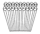
도 3c는 2개의 선형 렌즈 시트를 동일한 폴래리티로 맞대어 배치함으로써 만들어진 양면 선형 렌즈 시트(1300)를 묘사한다. 이 배열에서, 물체 클로즈업이 올바른 위치에 등장한다. 특정 거리 d를 넘어서, 위치(1310)보다 더 멀리 있는 보이는 물체가 미러 이미지에 등장할 것이다. 위치(1310)보다 더 가까이 있는 보이는 물체는 올바른 오리엔테이션으로 등장할 것이다. 3C depicts a double-sided
시트들의 폴러리제이션(polarization)으로 인해, 그 효과는 맞대어진 복수의 렌즈(1306)에 의해 광선들(1304)을 반사 광선들(1308)이 되도록 반사하여 이들이 위치(1310)에서 수렴하도록 하는 것이다. 따라서 동일한 폴래리티로 뻗어가는 물체들, 특히 보이는 물체들이 미러 이미지에 등장하기 시작하는 구역의 물체들이 시야로부터 제거되거나 감소될 수 있다. 도 3c가 수평으로 뻗어가는 맞대어진 복수의 렌즈(1306)를 도시하지만, 복수의 렌즈(1306)는 또한 수직으로 또는 소정 각도로 뻗어가지만 여전히 타겟 은닉을 달성할 수 있다. 또 다른 실시예에서, 복수의 렌즈(1306)를 포함하는 시트(1300)는 타겟 은닉 영역을 더 크게 하도록 만곡될 수 있다.Due to the polarization of the sheets, the effect is to reflect the
도 4는 둘 이상의 시트를 활용하는 또 다른 실시예의 예시적인 단순화된 개략도를 묘사한다. 도시된 바와 같이, 광원(402)은 광원(402)과 타겟(410) 사이에 배치된 렌즈들(404)의 제1 시트(406)에 조명을 제공한다. 광원(402)으로부터의 광선들(408)은 렌즈 시트(406)를 통과하고, 광선들의 서브세트는 렌티큘러 렌즈들(404)로부터 수많은 방향으로 굴절된다. 4 depicts an exemplary simplified schematic diagram of another embodiment utilizing more than one sheet. As shown, the
굴절된 광선들(412) 중 일부는 제1 시트(406)와 타겟(410) 사이에 배치된 렌즈들(404')의 제2 시트(406')에 의해 다시금 굴절될 수 있다. 일부 실시예들에서, 제1 및 제2 렌즈 시트들(406, 406')뿐만 아니라 렌즈들(404, 404')도 구성 및 광학적 속성에서 실질적으로 유사할 수 있다. Some of the refracted
따라서, 제1 시트(406)로부터 굴절된 광선(412)은 제2 렌즈 시트(406')를 통과하고 렌즈(404')의 평면에서 수많은 방향으로 렌티큘러 렌즈들(404')에 의해 다시금 굴절됨으로써, 타겟(410)으로부터의 그림자를 감소시키거나 제거한다.Therefore, the light rays 412 refracted from the
다른 실시예들(구체적으로 예시되지 않음)에서, 적어도 하나의 렌즈 시트가 광원과 타겟 사이의 정면이 아니라 타겟 옆에 배치될 수 있다. In other embodiments (not specifically illustrated), at least one lens sheet may be disposed next to the target rather than in front between the light source and the target.
실시예 1.1 태양열 타워, 튜브형 또는 원통형 태양 전지 Example 1.1 Solar Tower, Tubular or Cylindrical Solar Cell
관련된 실시예에서, 렌즈 시트들은 3차원(3D) 태양열 타워의 그림자를 감소시키기 위해 사용될 수 있는데, 여기서 그림자는 실질적으로 태양 전지 패널의 출력을 감소시키는 것으로 알려져 있지만, 근접한 이들의 배열로 인해 일부 타워는 그들 부근의 다른 타워상으로 그림자를 드리울 수 있다. 이러한 태양열 타원의 예들은 예컨대 ![]()
![]()
![]()
![]()
튜브형 또는 원통형 태양 전지의 예가 공지되어 있다. 예를 들어, 발명의 명칭이 "Hermetically sealed cylindrical solar cells"인 공개된 미국 특허 출원 US20100326429A1호는 원통형 태양 전지를 설명한다. 원통형 태양 전지 유닛은 튜브형 형상 또는 강성 고체 막대 형상인 기판, 기판상에 원주 방향으로 배치된 후방 전극, 후방 전극상에 원주 방향으로 배치된 반도체 접합 층, 및 반도체 접합상에 원주 방향으로 배치된 투명 전도성 층을 포함한다. 투명 튜브형 케이스는 원통형 태양 전지상으로 원주 방향으로 배치된다. 제1 밀봉재 캡은 투명 튜브형 케이스의 제1 단부에 기밀 밀봉된다. 제2 밀봉재 캡은 투명 튜브형 케이스의 제2 단부에 기밀 밀봉된다. 일부 사례에서, 태양 전지 유닛은 태양 전지들의 모놀리식 집적 배열이다. 일부 사례에서, 태양 전지 유닛은 태양 전지이다.Examples of tubular or cylindrical solar cells are known. For example, published US patent application US20100326429A1 entitled "Hermetically sealed cylindrical solar cells" describes a cylindrical solar cell. Cylindrical solar cell units include a tubular or rigid solid rod-shaped substrate, a rear electrode disposed on the substrate in a circumferential direction, a semiconductor bonding layer disposed on the rear electrode in a circumferential direction, and a transparent layer disposed on the semiconductor bonding in the circumferential direction. It includes a conductive layer. The transparent tubular case is arranged in a circumferential direction on a cylindrical solar cell. The first sealing material cap is hermetically sealed to the first end of the transparent tubular case. The second sealing material cap is hermetically sealed to the second end of the transparent tubular case. In some instances, the solar cell unit is a monolithic integrated arrangement of solar cells. In some instances, the solar cell unit is a solar cell.
Solyndra Inc.에 양도된 발명의 명칭이 "Monolithic integration of cylindrical solar cells"인 미국 특허 번호 제7,235,736호는 기판 및 복수의 광기전 셀을 포함하는 태양 전지 유닛을 설명하고 있다. 기판은 제1 단부 및 제2 단부를 갖는다. 기판상에 선형으로 배열된 복수의 광기전 셀은 제1 광기전 셀 및 제2 광기전 셀을 포함한다. 복수의 광기전 셀 중의 각각의 광기전 셀은 (i) 기판상에 원주 방향으로 배치된 배면 전극, (ii) 배면 전극상에 원주 방향으로 배치된 반도체 접합 층, 및 (iii) 반도체 접합상에 원주 방향으로 배치된 투명 전도성 층을 포함한다. 복수의 광기전 셀 중 제1 광기전 셀의 투명 전도성 층은 복수의 광기전 셀 중 제2 광기전 셀의 배면 전극과 직렬 전기적 연결 상태에 있다.US Patent No. 7,235,736, entitled "Monolithic integration of cylindrical solar cells" assigned to Solyndra Inc. describes a solar cell unit comprising a substrate and a plurality of photovoltaic cells. The substrate has a first end and a second end. The plurality of photovoltaic cells arranged linearly on the substrate includes a first photovoltaic cell and a second photovoltaic cell. Each of the photovoltaic cells among the plurality of photovoltaic cells includes (i) a back electrode disposed on the substrate in a circumferential direction, (ii) a semiconductor bonding layer disposed on the back electrode in a circumferential direction, and (iii) on the semiconductor junction. It includes a transparent conductive layer disposed in the circumferential direction. The transparent conductive layer of the first photovoltaic cell among the plurality of photovoltaic cells is in series electrical connection with the rear electrode of the second photovoltaic cell among the plurality of photovoltaic cells.
발명의 명칭이 "Elongated photovoltaic devices, methods of making same, and systems for making same"인 미국 특허 번호 제8,383,929호는 길이를 갖는 비평면 광기전 모듈을 설명하는데, (a) 세장형 비평면 기판; 및 (b) 세장형 비평면 기판상에 배치된 복수의 태양 전지를 포함하고, 여기서 복수의 태양 전지 중 각각의 태양 전지는 (i) 비평면 광기전 모듈 주위의 복수의 홈 및 (ii) 광전지 모듈의 길이를 따른 홈에 의해 정의된다. 일부 실시예들에서, 광기전 모듈 주위의 복수의 홈 중 각각의 홈은 독립적으로, 반복 패턴, 비반복 패턴을 갖거나, 또는 나선형이다. 일부 실시예들에서, 모듈은 인접한 태양 전지들 사이에 직렬 전기 연결을 제공하는 패터닝된 전도체를 추가로 포함한다. 일부 실시예들에서, 인접한 태양 전지들 사이에 직렬 전기 연결을 제공하는 패터닝된 전도체의 부분들은 광기전 모듈 주위의 복수의 홈 중 하나의 홈 내에 있다.U.S. Patent No. 8,383,929 entitled "Elongated photovoltaic devices, methods of making same, and systems for making same" describes a non-planar photovoltaic module having a length, including (a) an elongated non-planar substrate; And (b) a plurality of solar cells disposed on an elongated non-planar substrate, wherein each of the plurality of solar cells comprises (i) a plurality of grooves around the non-planar photovoltaic module and (ii) a photovoltaic cell. It is defined by a groove along the length of the module. In some embodiments, each of the plurality of grooves around the photovoltaic module is independently, has a repeating pattern, a non-repeating pattern, or is helical. In some embodiments, the module further includes a patterned conductor that provides a series electrical connection between adjacent solar cells. In some embodiments, portions of the patterned conductor that provide a series electrical connection between adjacent solar cells are in one of the plurality of grooves around the photovoltaic module.
원통형 태양 전지 패널들은 튜브들 사이의 갭들을 통해 오는 광을 반사시키기 위해 그 아래에 백색 페인트가 칠해진 일련의 튜브들 주위에 감긴 박막 태양 전지판들을 활용할 수 있다. 렌즈 시트 또는 렌즈들은 제1 튜브 층 아래에 배치된다. 따라서, 제1 층은 제1 층 아래의 또 다른 제2 튜브 층이 광을 수신하게 허용하는 광의 굴절을 제공한다. 제1 층은 또한 렌티큘러 렌즈 표면으로부터의 광을 제1 층의 밑면상으로 반사시킬 수 있고, 이는 동일한 풋프린트를 이용하면서 더 많은 출력을 허용하는 각각의 튜브 층 사이에 배치된 시트들 또는 렌즈들을 갖는 제3 또는 제4 층을 잠재적으로 허용한다. 태양열 타워들에 적용되는 상기의 예시적인 실시예들은, 발명의 명칭이 "System and Method of Amplifying Solar Panel Output"인 본 발명의 양수인에게 양도된 동시 계류 중인 출원에 개시되고, 이것의 내용은 본 명세서에 그 전체가 포함된다.Cylindrical solar panels may utilize thin film solar panels wound around a series of tubes painted white paint underneath to reflect light coming through the gaps between the tubes. The lens sheet or lenses are disposed under the first tube layer. Thus, the first layer provides a refraction of light that allows another second tube layer below the first layer to receive the light. The first layer can also reflect light from the lenticular lens surface onto the underside of the first layer, which allows for more output while using the same footprint while allowing for more output with sheets or lenses placed between each tube layer. Potentially allows a third or fourth layer to have. The above exemplary embodiments applied to solar towers are disclosed in a co-pending application assigned to the assignee of the present invention entitled "System and Method of Amplifying Solar Panel Output", the content of which is disclosed herein All of them are included.
상기 실시예들의 변형에서, 선형 프리즘 시트들 또는 어레이 프리즘 시트들이 또한 렌즈 시트들 대신에 사용될 수 있다. 파리눈(fly's-eye) 렌즈 어레이라고 알려진 작은 구면 렌즈들의 어레이가 스크린상에 배치될 수 있다. 따라서, 스크린은 매우 많은 수의 작은 볼록 렌즈들을 포함한다. In a variation of the above embodiments, linear prism sheets or array prism sheets may also be used instead of lens sheets. An array of small spherical lenses known as a fly's-eye lens array can be placed on the screen. Thus, the screen contains a very large number of small convex lenses.
태양열 에너지 생산에 적용되는 다른 실시예들에서, 거울들은 태양을 추적하고 태양광을 중심 타워상으로 반사시켜 전력을 생산하기 위해 사용되는 증기를 생성하기 위해 사용된다. 거울들은 이격되어 배치되며, 따라서 이웃하는 거울들로부터의 그림자가 타워상으로 반사된 광선들과 간섭하지 않는다. 이는 그림자 감소 또는 제거 잠재성을 갖는다. 거울들은 서로 더 가깝게 배치될 수 있고, 그에 의해 더 많은 반사된 광을 생성하고, 그에 의해 태양열 타원의 전력 출력을 증가시킨다. In other embodiments applied to solar energy production, mirrors are used to generate steam that is used to generate power by tracking the sun and reflecting sunlight onto a central tower. The mirrors are spaced apart, so shadows from neighboring mirrors do not interfere with the reflected rays onto the tower. This has the potential to reduce or eliminate shadows. The mirrors can be placed closer to each other, thereby generating more reflected light, thereby increasing the power output of the solar ellipse.
이들 렌즈들 또는 시트들 중 임의의 것상의 반사방지 필름 또는 코팅이 더 많은 광이 렌즈들 또는 시트들을 통과할 수 있게 함으로써 그림자 감소를 향상시키기 위해 이용될 수 있다. An antireflective film or coating on any of these lenses or sheets can be used to improve shadow reduction by allowing more light to pass through the lenses or sheets.
실시예 2- 광 구부러짐Example 2- Light bending
본 발명의 또 다른 실시예에 따르면, 복수의 렌즈를 갖는 재료가 타겟 물체의 가시적 부분의 적어도 일부를 숨기거나 은닉하기 위해 사용될 수 있다. 은닉은 전자기파들의 굴절을 활용함으로써 달성된다. 전자기파들의 범위는 가시 광, SWIR(short wave infrared), 근적외선, 근자외선 범위들, 및 전자기 스펙트럼의 다른 범위들을 포함한다. 본 발명자는, 재료가 0.9㎛ - 1.7㎛(900㎚ - 1700㎚)의 파장으로부터 오는 SWIR 범위에서 은닉을 달성할 수 있다는 것을 확인해 주는 실험을 수행하였는데, 여기서 스코프는 최첨단 군사용 스코프에 전형적인 바와 같이 1.5㎛ 또는 1500㎚의 한계를 갖는다. 그러나, 재료가 양쪽 끝에서 은닉할 수 있는 스펙트럼 범위에 대해서는 어떠한 제한도 확립되지 않았다. According to another embodiment of the present invention, a material having a plurality of lenses may be used to hide or conceal at least a portion of the visible portion of the target object. Concealment is achieved by utilizing the refraction of electromagnetic waves. The range of electromagnetic waves includes visible light, short wave infrared (SWIR), near infrared, near ultraviolet ranges, and other ranges of the electromagnetic spectrum. The inventors have conducted experiments confirming that the material can achieve concealment in the SWIR range coming from a wavelength of 0.9 μm-1.7 μm (900 nm-1700 nm), where the scope is 1.5 It has a limit of µm or 1500 nm. However, no limitations have been established on the spectral range that the material can conceal at both ends.
물체 자체로부터 방출되는 MWIR(mid-wave infrared) 및 LWIR(long-wave infrared) 광과는 달리, SWIR은 광자들이 물체에 의해 반사 또는 흡수되어, 고해상도 촬영에 필요한 강한 콘트라스트를 제공한다는 점에서 가시광과 유사하다. 주변 별의 광 및 배경 방사 또는 야광은 자연스럽게 SWIR을 방출하고 야외 야간 촬영을 위한 우수한 조명을 제공한다. 이 재료는 자외선(UV), 가시 광(VIS), 근적외선(NIR) 및 SWIR 범위에서 파들을 굴곡 및/또는 굴절시켜, 은닉 효과를 생성하는 것으로 보여졌다.Unlike MWIR (mid-wave infrared) and LWIR (long-wave infrared) light emitted from the object itself, SWIR reflects or absorbs photons by an object, providing a strong contrast required for high-resolution photographing. similar. The ambient star's light and background radiation or luminous light naturally emit SWIR and provide excellent lighting for outdoor night photography. This material has been shown to bend and/or refract waves in the ultraviolet (UV), visible (VIS), near infrared (NIR) and SWIR ranges, creating a concealing effect.
유리하게는, 이 재료는 또한 MWIR 및 LWIR 범위에서 재료 배후에 숨은 타겟으로부터의 열 시그니처(thermal signature) 또는 열 복사의 투과를 차단한다. 열 복사는 절대 0도보다 큰 온도에서, 즉, 임의의 온도 T > 0 Kelvin 또는 T > -273.1℃ 또는 T > -459.67°F에서 임의의 물질로부터 방출된 전자기 복사이다. Advantageously, this material also blocks transmission of thermal signatures or thermal radiation from targets hidden behind the material in the MWIR and LWIR ranges. Thermal radiation is electromagnetic radiation emitted from any material at a temperature greater than absolute zero degrees, that is, at any temperature T> 0 Kelvin or T> -273.1° C. or T> -459.67° F.
이 재료는 타겟으로부터 열을 픽업할 정도로 타겟에 충분히 근접하지 않는 한, 그 주위 영역의 주변 온도를 나타낸다. 이 재료는, 열을 픽업하지 않기 위해서 타겟으로부터 멀리 배치되는 경우, MWIR 및 LWIR 범위에서 타겟으로부터의 열 시그니처의 투과를 차단하는 것으로 보여졌다. 다시 말해서, 이 재료는 UV, VIS, NIR 및 SWIR 범위의 전자기파를 굴절시키지만, 이것은 열을 픽업하지 않도록 타겟으로부터 멀리 배치되는 경우, MWIR 및 LWIR 범위에서 타겟으로부터의 열 시그니처의 투과를 실제로 차단한다.This material represents the ambient temperature of the area around it, unless it is close enough to the target to pick up heat from the target. This material has been shown to block transmission of the thermal signature from the target in the MWIR and LWIR ranges when placed away from the target in order not to pick up heat. In other words, this material refracts electromagnetic waves in the UV, VIS, NIR and SWIR ranges, but when placed away from the target so as not to pick up heat, it actually blocks the transmission of the thermal signature from the target in the MWIR and LWIR ranges.
이는 최신의 야간 투시경들이 종종 NIR 또는 SWIR을 열 시그니처들과 조합하고, 군사 분야에서 "퓨전 나이트 비전(Fusion Night Vision)" 기기들로서 알려져 있기 때문에 중요하다. 퓨전 나이트 비전 기기들은 현재 기술로는 대응하기가 매우 어렵지만, 본 발명의 실시예들의 예시적인 재료들은 퓨전 나이트 비전 기기들에 의한 검출로부터 타겟들을 은닉할 수 있다. 열 스펙트럼은 차단되고, 그에 의해 타겟 열 시그니처를 예시적인 재료 배후에 숨긴다.This is important because modern night vision goggles often combine NIR or SWIR with thermal signatures and are known in the military field as "Fusion Night Vision" devices. Fusion night vision devices are very difficult to cope with with current technology, but exemplary materials of embodiments of the present invention can hide targets from detection by fusion night vision devices. The thermal spectrum is blocked, thereby hiding the target thermal signature behind the exemplary material.
이 재료에서의 렌즈들은 후술하는 바와 같이 광을 굴절시키기 위해 적절한 방식으로 배열된 볼록 렌즈들, 렌티큘러 렌즈들 또는 다른 유형의 렌즈들일 수 있다. 관찰자로부터의 타겟의 적어도 일부의 은닉은, 이 재료를 활용함으로써, 많은 응용들을 갖는다. 본 기술분야의 통상의 기술자가 알 수 있는 바와 같이, 이 속성은 아키텍처, 예술, 엔터테인먼트, 시각적 완화, 은닉 및 시그니처 관리를 포함하여 유익한 용도를 갖는다.The lenses in this material may be convex lenses, lenticular lenses or other types of lenses arranged in a suitable manner to refract light as described below. Concealment of at least a portion of the target from the observer, by utilizing this material, has many applications. As will be appreciated by those skilled in the art, this property has beneficial uses including architecture, art, entertainment, visual mitigation, concealment and signature management.
앞서 언급된 바와 같이, 그림자 감소에 추가하여, 렌티큘러 렌즈들 또는 렌티큘러 렌즈들의 시트들은 관찰자로부터 타겟을 은닉하는데 이용될 수 있다. As mentioned above, in addition to shadow reduction, lenticular lenses or sheets of lenticular lenses can be used to conceal the target from the observer.
실시예 2.1 - 시뮬레이트된 3D 이미지Example 2.1-Simulated 3D image
렌티큘러 렌즈들은 또한, 시트의 뒷면에 대해 그 뒤에 배치되는 것처럼 보이는 특별 프린트된 이미지의 시뮬레이트된 3차원 이미지를 생성하는데 이용될 수 있다. 이미지들은 시트 바로 뒤에 물리적으로 디스플레이되는 것이 아니라, 이미지가 렌즈들 또는 시트 뒷면 너머에 있는 것처럼 관찰자에게 보이는 광학적 효과 또는 광학적 착시를 렌즈들이 생성한다. Lenticular lenses can also be used to create a simulated three-dimensional image of a specially printed image that appears to be placed behind the back side of the sheet. The images are not physically displayed directly behind the sheet, but the lenses create an optical effect or optical illusion that appears to the observer as if the image is beyond the lenses or the back of the sheet.
도 5는 시뮬레이트된 3차원 효과를 갖는 디스플레이를 생성하는데 이용되는 배열을 묘사한다. 시야각(538)을 갖는 다수의 렌티큘러 렌즈(534)로 구성된 렌즈 시트(530)는 시뮬레이트된 3D 효과를 갖는 디스플레이를 생성하기 위해 사용된다. 렌티큘러 렌즈들(534)은 도 5에 묘사된 예시적인 실시예에 도시된 바와 같이 시트(530)의 매끄러운 배면(536)에 대해 그리고 그 바로 뒤에 배치될 수 있는 특수 프린트된 이미지(532)로부터 광을 수신한다.5 depicts an arrangement used to create a display with a simulated three-dimensional effect. A
실시예 2.3 - 평판 시트를 이용한 은닉Example 2.3-Concealment using a flat sheet
하나 이상의 렌티큘러 시트를 관찰자에 관해 타겟 앞에 또는 그 주변에 배치함으로써, 타겟 물체의 이미지 또는 시그니처는 타겟과 렌티큘러 시트 사이의 적절한 스탠드오프 거리를 가지며 대폭 감소되거나 심지어 제거될 수 있다. 스탠드오프 거리는 사용된 렌즈들의 유형, 렌즈들의 각도 및 전형적으로 제곱 인치당 지정된 렌즈들의 빈도를 고려함으로써 계산되거나 컴퓨팅될 수 있다. By placing one or more lenticular sheets in front of or around the target with respect to the observer, the image or signature of the target object has a suitable standoff distance between the target and the lenticular sheet and can be significantly reduced or even eliminated. The standoff distance can be calculated or computed by taking into account the type of lenses used, the angle of the lenses, and typically the frequency of specified lenses per square inch.
시트가 평탄하고 타겟과 관찰자 사이 내에 배치되는 경우, 그 효과는 굴절이다. 렌즈들은 타겟 물체의 양측 배후로부터의 광을 지향시킨다. 타겟이 렌티큘러 시트로부터 충분히 먼 경우, 최소의 시그니처만이 인식되거나 이미지가 관찰된다. 타겟 물체를 뒤로 추가로 이동시키는 것 또는 렌티큘러 시트를 관찰자에 더 가깝게 이동시키는 것은 타겟으로부터 시그니처를 완전히 제거하여, 은닉 또는 거의 비가시성을 달성할 수 있다.When the sheet is flat and placed within between the target and the observer, the effect is refraction. The lenses direct light from behind both sides of the target object. When the target is far enough from the lenticular sheet, only a minimal signature is recognized or an image is observed. Further moving the target object back or moving the lenticular sheet closer to the observer can completely remove the signature from the target, achieving concealment or near invisibility.
도 6은 본 발명의 예시적인 실시예의 단순화된 개략도를 묘사한다. 타겟(602)으로부터의 광선들은 관찰자(610)와 타겟(602) 사이에 배치된 렌즈들(604)의 시트(606)를 통과한다. 타겟(602)으로부터의 광선들이 렌즈 시트(606)를 통과함에 따라, 이들은 렌티큘러 렌즈(604)에 의해 수많은 방향으로 굴절된다. 굴절된 광선들(609)은 데드 존(dead zone)(603)을 생성함으로써 타겟(602)을 은닉하는 것을 돕고, 이에 의해 관찰자(610)의 뷰로부터 타겟(602)의 이미지를 감소시키거나 일부 경우들에서는 제거한다. 6 depicts a simplified schematic diagram of an exemplary embodiment of the present invention. Rays from
실시예 2.3 - 만곡 시트를 이용한 은닉Example 2.3-Concealment using a curved sheet
렌즈 시트가 타겟 주위에서 만곡되는 경우, 예증된 광학적 효과는 타겟 주위에서의 광의 구부러짐 또는 타겟으로부터 내부상에서의 광의 굴절/분산이며, 원기둥 외부로부터 보는 관찰자에 의해 인지되는 대로 타겟 주위에서 광의 구부러짐을 시뮬레이트한다.When the lens sheet is curved around the target, the illustrated optical effect is the bending of light around the target or the refraction/dispersion of light on the inside from the target, simulating the bending of light around the target as perceived by an observer looking from outside the cylinder. do.
도 7은 타겟(710) 주위의 원통형 벽(714)으로 만곡된 렌즈 시트의 단순화된 블록도의 평면도를 묘사한다. 원통형 벽(714)은 렌티큘러 렌즈의 대형 렌티큘러 시트를 반경 R의 원통 형상으로 감음으로써 형성될 수 있다. 7 depicts a top view of a simplified block diagram of a lens sheet curved with a
원통형 벽(714)의 중심은 타겟(710)의 가시성을 효과적으로 은닉하거나 실질적으로 감소시키기 위해 관찰자(702)의 눈(축척대로 도시되지 않음)과 타겟(710) 사이의 적절한 스탠드오프 거리 D에 배치될 수 있다. 타겟(710)은 원통형 시트의 중간에, 실린더 벽(714)으로부터 떨어져 배치된다. The center of the
입사 광선들(712)에 의해 횡단되는 경로는 도 7에서 볼 수 있다. 시트가 타겟(710) 주위에서 만곡되므로, 효과는 (예를 들어, 굴절/분산에 의해) 타겟(710) 주위에서 광을 효과적으로 만곡시키는 것이다. 벽(714) 내부에서의 광선들(708)의 굴절, 반사 및 분산은 원기둥 벽(714)의 외부로부터 보는 관찰자(702)에 의해 인지되는 대로 타겟(710) 주위의 광을 굽히는 것을 시뮬레이트한다.The path traversed by
본 발명자는 타겟이 관찰자에 대해 원통의 대향 측면의 외부상에 있는 경우, 타겟이 보여질 수 없는 원통에 가까운 영역이 있다는 것을 발견하였다. The inventors have found that when the target is on the outside of the opposite side of the cylinder to the observer, there are areas close to the cylinder where the target cannot be seen.
실시예 2.4 - 수직 프로파일을 갖는 물체의 은닉 Example 2.4-Concealment of objects with vertical profile
도 8은 관찰자(808)와 타겟(810) 사이에 배치된 다수의 선형 렌즈(804)로 구성된 렌즈 시트(802)를 묘사한다. 렌티큘러 렌즈들(804)은 타겟(810), 즉 Y 방향을 따라 서 있는 사람과 동일한 Y 방향으로 뻗어가는 길이들을 갖는다. 렌즈 시트(802)는 묘사된 바와 같이 X-Y 평면에 놓인다. 도 8에 묘사된 배열을 사용하여, 굴절된 광선들(806)은 관찰자(808)로부터 타겟(810)을 은닉한다.8 depicts a
앞서 언급된 바와 같이, 타겟(810)이 수직 프로파일을 가질 때, 즉, X 방향을 따른 폭보다 Y 방향을 따라 더 큰 높이를 가질 때, 선형 렌즈들은 은닉을 향상시키기 위해 동일한 Y 방향을 따라 뻗어가야 한다. 이것은 도 9에 묘사된 대조 시나리오로 도시된다.As mentioned above, when the
도 9는 도 8과 유사하지만, 타겟(910)이 수평 프로파일을 갖는 또 다른 구성을 도시한다. 도시된 바와 같이, 렌즈 시트(902)는 관찰자(908)와 타겟(910) 사이에 배치된 다수의 선형 렌즈(904)로 구성된다. 선형 렌즈들(904)은 Y 방향으로 뻗어가는 그들의 길이들을 갖는 반면, 타겟(910)은 Y 방향의 높이보다 X 방향을 따라 더 큰 폭을 갖는 차량이다. Figure 9 is similar to Figure 8, but shows another configuration in which the
렌즈 시트(902)는 묘사된 바와 같이 X-Y 평면에 놓인다. 도 9에 묘사된 배열을 사용하면, 굴절된 광선들(906)은 이미지(912)가 여전히 보일 수 있기 때문에 관찰자(908)로부터 타겟(910)을 완전히 은닉하지 못할 수 있다. 높이보다 큰 폭을 갖는 타겟(910)을 더 잘 은닉하기 위해, 렌티큘러 렌즈들이 수평으로 뻗어가도록 렌즈 시트(902)가 회전될 수 있다. The
실시예 2.5 - 프리즘 시트Example 2.5-Prism sheet
다른 실시예들에서, 타겟을 뷰로부터 제거하는 유사한 효과가 2 각도 또는 1 각도 프리즘 시트로 달성될 수 있다. 도 10은 다수의 1 각도 프리즘 렌즈(1002)로 구성된 프리즘 시트(1000)를 묘사한다. 프리즘 렌즈들은 1 각도(1004)에서 직각 각도로 있다.In other embodiments, a similar effect of removing the target from the view can be achieved with a two angle or one angle prism sheet. 10 depicts a
도 11은 다수의 1 각도 프리즘 렌즈(1002)로 구성된 도 11의 프리즘 시트(1000)의 평면도를 묘사한다. 프리즘 렌즈들은 각도(1004)로 도시된 바와 같이 직각을 이룬다. 광선들(1102)의 굴절은 관찰자(1108)로부터 타겟(1106)을 은닉하거나 숨기는 것을 돕는다. 반대 각도에서의 제2 세트의 렌즈들은 우측으로 계속되어 타겟(1106)이 시트(1000)의 중간에 숨겨지게 할 수 있다. FIG. 11 depicts a top view of the
또 다른 실시예에서, 타겟을 뷰로부터 제거하는 유사한 효과가 2 각도 프리즘 시트로 달성될 수 있다. 도 12는 다수의 1 각도 프리즘 렌즈(1202)로 구성된 프리즘 시트(1200)를 묘사한다. 도 10 또는 도 11과 달리, 프리즘 렌즈들에 대해 직각이 없다. In another embodiment, a similar effect of removing the target from the view can be achieved with a two angle prism sheet. 12 depicts a
도 13은 도 12의 프리즘 시트(1200)의 평면도를 묘사한다. 알 수 있는 바와 같이, 프리즘 시트(1200)는 다수의 2 각도 프리즘 렌즈(1202)로 구성된다. 프리즘 시트(1200)는 관찰자(1208) 소스와 타겟(1210) 사이에 배치된다.13 depicts a plan view of the
묘사된 바와 같은 광선들(1206)의 굴절은 관찰자(1208)로부터 타겟(1210)을 은닉하거나 숨기는 것을 돕는다. 굴절되지 않은 다른 광선들(1204)의 궤적들은 변하지 않고 유지되며, 따라서 타겟(1210)의 은닉에 기여하지도 방해하지도 않는다.Refraction of the
실시예 2.6 - 맞대는 선형 렌즈 시트들 Example 2.6-Butt Linear Lens Sheets
앞서 언급된 바와 같이, 전경 물체를 은닉하는 바람직하지 않은 부작용은 배경을 흐릿하게 하는 것이다. 배경의 흐릿함을 감소시키기 위해, 본 발명의 실시예들은 도브 프리즘 렌즈 시트를 활용할 수 있다. As mentioned earlier, an undesirable side effect of hiding a foreground object is blurring the background. In order to reduce the blurring of the background, embodiments of the present invention may utilize a dove prism lens sheet.
도 14는 위치(1402)에 있는 관찰자가 렌즈 시트(1400)로부터 어떤 거리에 있는 물체를 보는 도브 프리즘 렌즈 시트(1400)를 묘사한다. 시트(1400)와 위치(1410) 사이에 배치된 타겟 물체는 위치(1402)에서 관찰자에게 올바른 오리엔테이션으로 등장할 것이다. 그러나, 시트(1400)로부터 위치(1410)보다 더 멀리 떨어져 배치된 물체는 미러 이미지로 등장할 것이다. 14 depicts a dove
시트들의 폴러리제이션으로 인해, 그 효과는 광선들(1404)을 프리즘들(1406)에 의해 반사 광선들(1408)이 되도록 반사시켜 이들이 위치(1410)에 수렴하도록 하는 것이다. 따라서, 동일한 폴래리티로 뻗어가는 물체들, 특히 보이는 물체들이 미러 이미지로 등장하기 시작하는 위치(1410)보다 렌즈 시트(1400)로부터 더 멀리 떨어진 구역 주위의 물체들이 시야로부터 제거되거나 감소될 수 있다.Due to the polarization of the sheets, the effect is to reflect the
음의 굴절은 정상적으로는 자연에서 발생하지 않는 광의 특이한 구부러짐이다. 음의 유전율 및 투자율을 갖는 재료가 음의 굴절률을 갖는 것으로 관찰되었다. 이러한 재료들은 메타물질들의 형태로, 이들이 균일한 광학 매질로서 역할하는 파장 아래의 스케일에서 주기적인 공명 전자기 구조들의 형태로 최근에 만들어졌다. 렌즈들과 같은 광선-광학 컴포넌트들도 소형화되고 주기적으로 배열될 수 있다. 그러한 주기적 배열들의 단순한 조합들이 사용될 수 있지만, 이들은 메타물질들이 아니다. 이들은 불균일한 매질과 매우 유사하게 통과 광파에 영향을 미친다. 그러나, 이들은 균일한 매질처럼 광선들에 영향을 줄 수 있다. 이러한 의미에서, 이들은 광선-광학 메타물질들인 것으로 간주될 수 있다.Negative refraction is a peculiar bending of light that does not normally occur in nature. It was observed that materials with negative dielectric constant and permeability have negative refractive index. These materials have recently been made in the form of metamaterials, in the form of periodic resonant electromagnetic structures at a sub-wavelength scale where they serve as a uniform optical medium. Ray-optical components such as lenses can also be miniaturized and arranged periodically. Simple combinations of such periodic arrangements can be used, but these are not metamaterials. They affect the passing light waves very similarly to a non-uniform medium. However, they can affect the rays like a homogeneous medium. In this sense, they can be considered to be light-optical metamaterials.
실시예 2.7 - 오프셋 양면 렌즈 시트 Example 2.7-Offset double-sided lens sheet
도 15는 본 발명의 실시예의 예시적인 오프셋 양면 렌즈 시트(1500)를 묘사한다. 도 15의 실시예를 이용한 타겟 은닉 및 그림자 감소의 예시적인 방법은 시트의 양 측면상에 렌티큘러 렌즈들을 갖는 양면 렌즈 시트(1500)를 관찰자와 은닉될 타겟 물체 사이에 배치하는 것을 수반한다. 15 depicts an exemplary offset double-
도 15의 실시예에서, 양면 렌즈 시트(1500)의 대향 측면들에 있는 대응 렌즈들(렌즈(1512) 및 렌즈(1514)와 같은 것)은 서로 오프셋 관계를 갖는 엇갈린 방식으로 배열된다는 것을 알 수 있다. 오프셋 거리는 도 15에서 Δx로 묘사된다. 오프셋 거리 Δx는 범위 0 < Δx < H일 수 있으며, 여기서 H는 도 15에 도시된 렌티큘러 렌즈의 높이(또는 렌즈가 반원통일 때의 직경)이다. In the embodiment of FIG. 15, it can be seen that the corresponding lenses (such as
양면 렌즈 시트(1500)를 통과하는 타겟 물체로부터의 광선들은 수많은 방향으로 굴절되는데, 그 효과는 타겟 물체의 가시성 및 그 그림자에서의 상당한 감소이다. Rays from the target object passing through the double-
이 배열에서, 위치(1510)를 넘어서 보는, 특정 거리 d에 있는 물체는 미러 이미지로 등장할 것이다. 시트들의 폴러리제이션으로 인해, 그 효과는 맞대어진 복수의 렌즈(1506, 1507)에 의해 광선들을 반사하여 이들이 위치(1510)에서 다른 유사하게 반사된 광선들과 함께 수렴하도록 하는 것이다. In this arrangement, an object at a certain distance d, viewed beyond the
미러 이미지를 정정하는 한 가지 방법은 양면 렌즈를 렌즈 시트(1500)에 근접하게 배치하는 것이다. 그러한 배열은 도 16, 도 17, 도 18 및 도 19에 도시된다. 렌즈들이 수직으로 뻗어가는 경우, 오프셋은 배경의 뷰를 왼쪽 또는 오른쪽으로 시프트시킬 것이다. One way to correct a mirror image is to place a double-sided lens close to the
도 3c, 도 14 및 도 15의 실시예들에서, 타겟이 제각기 위치(1310, 1410 또는 1510)를 넘어 더 멀리, 즉 우측으로 있는 경우, 타겟은 미러 이미지로 등장할 것이다.In the embodiments of FIGS. 3C, 14 and 15, if the target is further beyond the
알 수 있는 바와 같이, 수렴 위치(1510)는 렌즈들이 오프셋보다는 인라인을 이루는 도 3c의 실시예에 대응하는 수렴 위치(1310')와는 상이한 위치에 있다. 수렴 위치(1310') 및 수렴 위치(1510)가 상이한 위치들에 있지만, 이들은 렌즈 시트(1500)의 장소로부터 떨어져 그리고 그에 평행하게, 동일한 거리 d에서, 동일한 또는 실질적으로 동일한 평면상에 유지된다는 점에 유의한다.As can be seen, the
수렴 위치(1510)는 오프셋 거리 Δx에 의해 제어될 수 있다. 후술되는 바와 같이, 양면 렌즈 시트를 제작하는 (예를 들어, 2개의 단면 렌즈 시트 사이에 물을 추가하는) 특정 방법은, 오프셋 거리 Δx가 상대적으로 용이하게 변경되는 것을 허용하는데, 이는 거리 d 및 기타의 요인들에 의존하여 특정한 정황에 대해 설명된 실시예의 적응을 허용한다. The
따라서, 동일한 폴래리티를 갖는 물체들, 특히 위치(1510) 주위의 구역에서 보이는 것들은 가시성이 제거되거나 감소될 수 있다. 도 15는 본 기술분야의 통상의 기술자에 의해 이해되는 바와 같이 수평으로 뻗어가는 렌즈들(1506)을 도시하지만, 렌즈들(1506)은 또한 수직으로 또는 소정 각도로 뻗어갈 수 있고 여전히 타겟 은닉을 달성할 수 있다. 또 다른 실시예에서, 복수의 렌즈(1506)를 포함하는 시트(1500)와 유사한 시트는 타겟 은닉 영역을 더 크게 만들도록 만곡될 수 있다. 이 오프셋은 배경 및 타겟을 좌측 또는 우측으로 시프트하는 능력을 제공하고, 렌즈 폴래리티가 수직인 경우, 시프트가 충분히 큰 경우, 타겟은 뷰로부터 제거된다. Thus, objects with the same polarity, particularly those seen in the area around the
실시예 2.8 - 오프셋 양면 렌즈 시트 및 인라인 양면 렌즈 시트Example 2.8-Offset double-sided lens sheet and in-line double-sided lens sheet
도 16은 본 발명의 실시예의 예시적인 제1 시트(1600A) 및 제2 시트(1600B)(집합적으로 시트(1600))로서 묘사된, 매우 근접하게 배치된 2개의 양면 렌즈 시트를 도시한다. 도 16의 실시예를 이용한 타겟 은닉 및 그림자 감소 방법은, 관찰자와 은닉될 타겟 물체 사이에, 각각이 양 측면상에 렌즈들을 갖는 이들 2개의 양면 렌즈 시트(1600)를 배치하는 것을 수반한다. Fig. 16 shows two double-sided lens sheets placed in close proximity, depicted as exemplary
도 16의 실시예에서, 오프셋된 양면 렌즈 시트(1600A)의 대향 측면들상의 대응하는 렌즈들(예를 들어, 렌즈(1612) 및 렌즈(1614))은 서로 오프셋 관계를 갖는 엇갈린 방식으로 배열된다는 것을 알 수 있다. 그러나, 제2 양면 렌즈 시트(1600B)의 대향 측면들상의 대응하는 렌즈들은 서로 줄을 서도록 배열된다. In the embodiment of Fig. 16, the corresponding lenses (e.g.,
따라서, 인라인 양면 렌즈 시트(1600B)상의 대향 측면들상의 대응하는 렌즈들은 시트의 상단 또는 하단에 대해 동일한 거리에 있다. 물론, 렌즈가 수직으로 배치되는 수직 폴러라이즈된 실시예들에서, 인라인 양면 렌즈 시트의 대향 측면들상의 대응하는 수직 렌즈들은 시트의 좌측 또는 우측에 대해 동일한 레벨 또는 높이를 가질 것이다. Thus, the corresponding lenses on opposite sides on the in-line double-
이 실시예는 미러 이미지를 생성하지 않고서, 은닉될 물체 뒤에 배경 장면을 정확하게 제시하는 이점을 갖는다. 오프셋 양면 렌즈 시트(1600A) 및 인라인 양면 렌즈 시트(1600B)를 통과하는 타겟 물체로부터의 광선들은 타겟 물체의 가시성 또는 그 그림자를 실질적으로 감소시키는 각도들로 굴절 및/또는 반사된다. This embodiment has the advantage of accurately presenting the background scene behind the object to be concealed, without creating a mirror image. Rays from the target object passing through the offset double-
이 배열에서, 도 3c의 실시예와는 대조적으로, 특정 거리 d에 있는 물체는 위치(1610)에서 볼 때 미러 이미지에 등장하지 않을 것이다. 시트(1600)에서의 렌즈의 폴러리제이션으로 인해, 그 효과는 렌즈들이 인라인인 도 3c의 실시예와는 달리 오프셋된 렌즈들(1606, 1607)에 의해 광선들을 반사된 광선들이 되도록 반사하는 것이다. In this arrangement, in contrast to the embodiment of FIG. 3C, an object at a certain distance d will not appear in the mirror image when viewed from
임의의 폴래리티의 물체들은 각도를 시프트하고 물체(및 주변 배경)를 시계(field of view) 밖으로 제거함으로써 가시성이 제거되거나 감소될 수 있거나 또는 중립 섹션들을 활용함으로써 동일한 폴래리티의 물체들이 뷰로부터 감소되거나 제거될 수 있는데, 이는 도 20, 도 21, 및 도 22에서 논의될 것이다. 반대 폴래리티의 물체들은 또한 그들의 폭이 이러한 중립 섹션들에서 숨겨질 수 있는 경우 가시성이 제거되거나 감소될 수 있다. Objects of arbitrary polarity can be removed or reduced in visibility by shifting the angle and removing the object (and surrounding background) out of the field of view, or by utilizing neutral sections, objects of the same polarity can be viewed. Can be reduced or eliminated from, which will be discussed in FIGS. 20, 21, and 22. Objects of opposite polarity can also be removed or reduced in visibility if their width can be hidden in these neutral sections.
도 16은 수평으로 뻗어가는 복수의 렌즈(1606, 1607)를 도시하지만, 복수의 렌즈는 또한 수직으로 또는 소정 각도로 뻗어갈 수 있고 여전히 타겟 은닉을 달성할 수 있다. 또 다른 실시예에서, 복수의 렌즈를 포함하는 시트들(1600)과 유사한 시트는 타겟 은닉 영역을 더 크게 하도록 만곡될 수 있다.16 shows a plurality of
실시예 2.9 - 오프셋 양면 렌즈 시트와 인라인 양면 렌즈 시트 사이의 외부 오프셋Example 2.9-External offset between the offset double-sided lens sheet and the in-line double-sided lens sheet
도 17a는 본 발명의 또 다른 실시예의 예시적인 제1 시트(1700A) 및 제2 시트(1700B)(집합적으로 시트(1700))로서 묘사된, 매우 근접하게 배치된 2개의 양면 렌즈 시트를 도시한다. 도 17a의 실시예를 이용한 타겟 은닉 및 그림자 감소의 방법은 관찰자와 은닉될 타겟 물체 사이에, 각각이 양 측면상에 렌즈들을 갖는 이들 2개의 양면 렌즈 시트(1700)를 배치하는 것을 수반한다. 이 실시예는 도 16의 실시예와 동일한 효과를 갖는 것으로 밝혀졌다.17A shows two double-sided lens sheets placed in close proximity, depicted as exemplary
도 17a의 실시예에서, 오프셋 양면 렌즈 시트(1700A)의 대향 측면들상의 대응하는 렌즈들(예를 들어, 렌즈(1706) 및 렌즈(1707))은 서로에 대해 오프셋 관계를 갖는 엇갈린 방식으로 배열된다는 것을 알 수 있다. 그러나, 제2 양면 렌즈 시트(1700B)의 대향 측면들상의 대응하는 렌즈들은 서로 줄을 서도록 배열된다. In the embodiment of Fig. 17A, the corresponding lenses (e.g.,
따라서, 양면 렌즈 시트들(1700A, 1700B)상의 대응하는 렌즈들(1714, 1715)은 제각기 공통 바닥에 대해 상이한 거리들에 있고, 따라서 외부적으로 오프셋되거나 엇갈린다. 물론, 렌즈가 수직으로 배치되는 수직 폴러라이즈된 실시예들에서, 인라인 양면 렌즈 시트의 대향 측면들상의 대응하는 수직 렌즈들은 시트의 좌측 또는 우측에 대해 동일한 레벨 또는 높이를 가질 것이다. Thus, the corresponding
이 실시예는 미러 이미지를 생성하지 않고서, 은닉될 물체 뒤에 배경 장면을 정확하게 제시하는 이점을 갖는다. This embodiment has the advantage of accurately presenting the background scene behind the object to be concealed, without creating a mirror image.
오프셋 양면 렌즈 시트(1700A) 및 인라인 양면 렌즈 시트(1700B)를 통과하는 타겟 물체로부터의 광선들은 타겟 물체의 가시성 또는 그 그림자를 실질적으로 감소시키는 각도들로 굴절 및/또는 반사된다. Rays from the target object passing through the offset double-
이 구성에서, 도 3c의 실시예와는 대조적으로, 특정 거리 d에 있는 물체(1702)는, 위치(1710)에서 볼 때, 미러 이미지에 등장하지 않을 것이다. 시트들(1700A, 1700B)의 폴러리제이션 및 배치로 인해, 그 효과는 물체(1702)가 올바른 오리엔테이션으로 관찰되도록 맞대어진 복수의 렌즈(1706, 1707)에 의해 광선들을 반사 또는 굴절시키는 것이다. In this configuration, in contrast to the embodiment of FIG. 3C, the
임의의 폴래리티의 물체들은 각도를 시프트하고 물체(및 주변 배경)를 시계 밖으로 제거함으로써 가시성이 제거되거나 감소될 수 있거나 또는 중립 섹션들을 활용함으로써 동일한 폴래리티의 물체들이 뷰로부터 감소되거나 제거될 수 있는데, 이는 도 20, 도 21, 및 도 22에서 논의될 것이다. 반대 폴래리티의 물체들은 또한 그들의 폭이 이러한 중립 섹션들에서 숨겨질 수 있는 경우 가시성이 제거되거나 감소될 수 있다. 도 17은 수평으로 뻗어가는 복수의 렌즈(1706, 1707)를 도시하지만, 복수의 렌즈는 수직으로 또는 소정 각도로 또한 뻗어갈 수 있고 여전히 타겟 은닉을 달성할 수 있다. 또 다른 실시예에서, 복수의 렌즈를 포함하는 시트들(1700)과 유사한 시트는 타겟 은닉 영역을 더 크게 만들도록 만곡될 수 있다. Objects of any polarity can be removed or reduced in visibility by shifting the angle and removing the object (and surrounding background) out of view, or by utilizing neutral sections, objects of the same polarity will be reduced or removed from the view. May be, which will be discussed in FIGS. 20, 21, and 22. Objects of opposite polarity can also be removed or reduced in visibility if their width can be hidden in these neutral sections. While FIG. 17 shows a plurality of
도 17a의 실시예에서는 렌즈 시트들(1700A, 1700B)의 대응하는 렌즈들(1714, 1715)이 제각기 외부 오프셋 관계에 있더라도, 도 17a의 실시예는 도 16의 실시예와 유사한 효과를 갖는 것으로 밝혀졌다. In the embodiment of FIG. 17A, although the corresponding
도 17b는, 본 발명의 또 다른 실시예의 예시적인 제1 시트(1700C) 및 제2 시트(1700D)(집합적으로 시트(1700'))로서 묘사된, 매우 근접하게 배치된 2개의 양면 렌즈 시트를 도시한다. 도 17b의 실시예는 양면 렌즈 시트들(1700C, 1700D) 둘 모두가 오프셋 관계로 배열된 대향 측면들상의 대응하는 렌즈들을 갖는 것을 제외하고는 도 17a의 실시예와 유사하다. 즉, 도 17b의 실시예에서, 둘 모두의 시트들상에서, 시트들(1700C, 1700D)의 대향 측면들상의 대응하는 렌즈들(예를 들어, 렌즈(1706') 및 렌즈(1707'))은 서로 오프셋 관계를 갖는 엇갈린 방식으로 배열된다는 것을 알 수 있다. 이는 (1700A)만이 오프셋 관계를 갖는 반면, 시트(1700B)는 인라인 배열을 갖는 도 17a의 실시예와 대조적이다. 17B shows two double-sided lens sheets placed in close proximity, depicted as an exemplary
도 17b의 실시예를 이용한 타겟 은닉 및 그림자 감소의 방법은 관찰자와 은닉될 타겟 물체 사이에, 각각이 양 측면상에 렌즈들을 갖는 이들 2개의 양면 렌즈 시트(1700')를 배치하는 것을 수반한다. 이 실시예는 도 16의 실시예와 동일한 효과를 갖는 것으로 밝혀졌다.The method of target concealment and shadow reduction using the embodiment of FIG. 17B involves placing these two double-sided lens sheets 1700', each having lenses on both sides, between the observer and the target object to be concealed. It was found that this example has the same effect as the example of FIG. 16.
양면 렌즈 시트들(1700C, 1700D)상의 대응하는 렌즈들(1714', 1715')은 제각기 공통 바닥에 대해 상이한 거리들에 있을 수 있고, 따라서 외부적으로 오프셋되거나 엇갈릴 수 있다. 물론, 렌즈가 수직으로 배치되는 수직 폴러라이즈된 실시예들에서, 인라인 양면 렌즈 시트의 대향 측면들상의 대응하는 수직 렌즈들은 시트의 좌측 또는 우측에 대해 동일한 레벨 또는 높이를 가질 것이다. The corresponding lenses 1714', 1715' on the double-
이 실시예는 또한 미러 이미지를 생성하지 않고서 은닉될 물체 배후에 배경 장면을 정확하게 제시하는 이점을 갖는다. This embodiment also has the advantage of accurately presenting the background scene behind the object to be concealed without creating a mirror image.
오프셋 양면 렌즈 시트들(1700C, 1700D)을 통과하는 타겟 물체로부터의 광선들은 수많은 방향들로 굴절 및/또는 반사되어, 타겟 물체의 가시성 또는 그 그림자를 실질적으로 감소시킨다. Rays from the target object passing through the offset double-
이 배열에서, 도 3c의 실시예와는 대조적으로, 특정 거리 d에 있는 물체(1702')는 위치(1710')에서 볼 때 미러 이미지에 등장하지 않을 것이다. 시트들(1700C, 1700D)의 폴러리제이션 및 배치로 인해, 그 효과는 물체(1702')가 올바른 오리엔테이션으로 관찰되도록 맞대어진 복수의 렌즈(1706', 1707')에 의해 광선들을 반사 또는 굴절시키는 것이다. In this arrangement, in contrast to the embodiment of FIG. 3C, the object 1702' at a certain distance d will not appear in the mirror image when viewed from location 1710'. Due to the polarization and placement of the
실시예 2.10 - 정렬된 2개의 인라인 양면 렌즈 시트 Example 2.10-Aligned two in-line double-sided lens sheets
도 18은 본 발명의 또 다른 실시예의 예시적인 제1 시트(1800A) 및 제2 시트(1800B)(집합적으로 시트들(1800))로서 묘사된, 매우 근접하게 배치된 2개의 양면 렌즈 시트를 도시한다. 도 18의 실시예를 이용한 타겟 은닉 및 그림자 감소의 방법은 관찰자와 은닉될 타겟 물체 사이에, 각각이 양 측면상에 렌즈들을 갖는 이들 2개의 양면 렌즈 시트(1800)를 배치하는 것을 수반한다. 이 실시예는 또한 상이한 각도들을 갖는 도 16의 실시예와 유사한 효과를 갖는 것으로 밝혀졌다.FIG. 18 shows two double-sided lens sheets placed in close proximity, depicted as an exemplary
도 18의 실시예에서, 오프셋된 양면 렌즈 시트(1800A)의 대향 측면들상의 대응하는 렌즈들(예를 들어, 렌즈(1812) 및 렌즈(1814))은 외부 오프셋 없이 정렬된다는 것을 알 수 있다. 양면 렌즈 시트(1800A, 1800B)의 대향 측면들상의 대응하는 렌즈들은 서로 줄을 서도록 배열된다. In the embodiment of FIG. 18, it can be seen that the corresponding lenses (eg, lens 1812 and lens 1814) on opposite sides of the offset double-
인라인 양면 렌즈 시트(1800A, 1800B)상의 대향 측면들상의 대응하는 렌즈들은 따라서 시트의 상단 또는 바닥에 대해 동일한 거리에 있다. 물론, 렌즈가 수직으로 배치되는 수직 폴러라이즈된 실시예들에서, 인라인 양면 렌즈 시트의 대향 측면들상의 대응하는 수직 렌즈들은 시트의 좌측 또는 우측에 대해 동일한 레벨 또는 높이를 가질 것이다. The corresponding lenses on opposite sides on the inline double-
이 실시예는 미러 이미지를 생성하지 않고서, 은닉될 물체 뒤에 배경 장면을 정확하게 제시하는 이점을 갖는다. This embodiment has the advantage of accurately presenting the background scene behind the object to be concealed, without creating a mirror image.
이 배열에서, 도 3c의 실시예와는 대조적으로, 특정 거리 d에 있는 물체(1802)는 위치(1810)에서 볼 때 미러 이미지에 등장하지 않을 것이다. 시트들(1800A, 1800B)의 폴러리제이션 및 배치로 인해, 그 효과는 물체(1802)가 올바른 오리엔테이션으로 관찰되도록 맞대어진 복수의 렌즈(1806, 1807)에 의해 광선들을 반사 또는 굴절시키는 것이다. In this arrangement, in contrast to the embodiment of FIG. 3C, the
동일한 폴래리티의 물체들은 도 20, 도 21, 도 22를 참조하여 논의될 중립 섹션들을 활용함으로써 가시성이 제거되거나 감소될 수 있다. 반대 폴래리티의 물체들은 또한 그들의 폭이 이러한 중립 섹션들에서 숨겨질 수 있는 경우 가시성이 제거되거나 감소될 수 있다. 도 18은 수평으로 뻗어가는 복수의 렌즈(1806, 1807)를 도시하지만, 복수의 렌즈는 또한 수직으로 또는 소정 각도로 뻗어갈 수 있고 여전히 타겟 은닉을 달성할 수 있다. 또 다른 실시예에서, 복수의 렌즈를 포함하는 시트들(1800)과 유사한 시트는 타겟 은닉 영역을 더 크게 하도록 만곡될 수 있다. Objects of the same polarity can be removed or reduced in visibility by utilizing neutral sections that will be discussed with reference to FIGS. 20, 21, and 22. Objects of opposite polarity can also be removed or reduced in visibility if their width can be hidden in these neutral sections. 18 shows a plurality of
도 18의 실시예에서는 렌즈 시트들(1800A, 1800B)의 대응하는 렌즈들(1814, 1815)이 제각기 외부 오프셋 관계에 있다 하더라도, 도 18의 실시예는 상이한 각도들을 갖는 도 16의 실시예와 유사한 효과를 갖는 것으로 밝혀졌다. In the embodiment of FIG. 18, although the corresponding
실시예 2.11 - 외부 오프셋을 갖는 2개의 인라인 양면 렌즈 시트Example 2.11-Two in-line double-sided lens sheets with external offset
도 19는 본 발명의 또 다른 실시예의 예시적인 제1 시트(1900A) 및 제2 시트(1900B)(집합적으로 시트들(1900))로서 묘사된, 매우 근접하게 배치된 2개의 양면 렌즈 시트를 도시한다. 도 19의 실시예를 이용한 타겟 은닉 및 그림자 감소의 방법은 관찰자와 은닉될 타겟 물체 사이에, 각각이 양 측면상에 렌즈들을 갖는 이들 2개의 양면 렌즈 시트(1900)를 배치하는 것을 수반한다. 이 실시예는 또한 상이한 각도들을 갖는 도 16의 실시예와 동일한 효과를 갖는 것으로 밝혀졌다.FIG. 19 shows two double-sided lens sheets placed in close proximity, depicted as an exemplary
도 19의 실시예에서, 양면 렌즈 시트들(1900A, 1900B)이 외부 오프셋을 갖는 것으로, 즉, 대응하는 렌즈들(예를 들어, 렌즈(1915) 및 렌즈(1914))가 정렬되지 않도록 오프셋되어 있는 것을 알 수 있다. In the embodiment of Fig. 19, the double-
동일한 렌즈 시트(1900A)의 대향 측면들상의(또는 렌즈 시트(1900B) 내에서의) 대응하는 렌즈들은 시트의 상단 또는 바닥에 대해 동일한 거리에 있다. 물론, 렌즈가 수직으로 배치되는 수직 폴러라이즈된 실시예들에서, 인라인 양면 렌즈 시트의 대향 측면들상의 대응하는 수직 렌즈들은 시트의 좌측 또는 우측에 대해 동일한 레벨 또는 높이를 가질 것이다. The corresponding lenses on opposite sides of the
이 실시예는 또한 미러 이미지를 생성하지 않고서 은닉될 물체 배후에 배경 장면을 정확하게 제시하는 이점을 갖는다. This embodiment also has the advantage of accurately presenting the background scene behind the object to be concealed without creating a mirror image.
이 구성에서, 도 3c의 실시예와는 대조적으로, 특정 거리 d에 있는 물체(1902)는, 위치(1910)에서 볼 때, 미러 이미지에 등장하지 않을 것이다. 시트들(1900A, 1900B)의 폴러리제이션 및 배치로 인해, 그 효과는 물체(1902)가 올바른 오리엔테이션으로 관찰되도록 맞대어진 복수의 렌즈(1906, 1907)에 의해 광선들을 반사 또는 굴절시키는 것이다. In this configuration, in contrast to the embodiment of FIG. 3C, the
동일한 폴래리티의 물체들은 도 20, 도 21, 도 22를 참조하여 논의될 중립 섹션들을 활용함으로써 가시성이 제거되거나 감소될 수 있다. 반대 폴래리티의 물체들은 또한 그들의 폭이 이러한 중립 섹션들에서 숨겨질 수 있는 경우 가시성이 제거되거나 감소될 수 있다. 도 19는 수평으로 뻗어가는 복수의 렌즈(1906, 1907)를 도시하지만, 복수의 렌즈는 또한 수직으로 또는 소정 각도로 뻗어갈 수 있고 여전히 타겟 은닉을 달성할 수 있다. 또 다른 실시예에서, 복수의 렌즈를 포함하는 시트들(1900)과 유사한 시트는 만곡되어, 타겟 은닉 영역을 더 크게 할 수 있다. Objects of the same polarity can be removed or reduced in visibility by utilizing neutral sections that will be discussed with reference to FIGS. 20, 21, and 22. Objects of opposite polarity can also be removed or reduced in visibility if their width can be hidden in these neutral sections. 19 shows a plurality of
도 19의 실시예에서는 렌즈 시트들(1900A, 1900B)의 대응하는 렌즈들(1914, 1915)이 제각기 외부 오프셋 관계에 있다 하더라도, 도 19의 실시예는 상이한 각도들을 갖는 도 16의 실시예와 유사한 효과를 갖는 것으로 밝혀졌다. In the embodiment of Fig. 19, although the corresponding
동작 중에, 도 3c, 도 14, 도 15, 도 16, 도 17a, 도 17b, 도 18, 및 도 19에 묘사된 실시예들 모두는 관찰자의 관점에서 병합된 반복 이미지들을 생성하는 능력에 의해 특징지어질 수 있다. In operation, all of the embodiments depicted in FIGS. 3C, 14, 15, 16, 17A, 17B, 18, and 19 are characterized by the ability to generate merged repetitive images from the perspective of the observer. Can be built.
일례가 도 20에 도시되어 있다. 렌즈 시트(2002)는 플래그폴(flagpole)(2006)을 묘사하는 배경 장면(2010)과 관찰자 사이에 배치된다. 시트(2002)를 통해 보이는 이미지는 배경 장면(2010)의 반복 부분들을 병합함으로써 형성된다. 플래그폴(2006)은 복수의 중립 섹션(2004), 및 반복 섹션들(2008)로 구성된 관찰된 이미지 내의 예상 위치에서 보이지 않는다.An example is shown in FIG. 20. The
이 반복 패턴을 달성하기 위해, 한 특정한 실시예에서, 두 가지 상이한 유형의 렌즈가 시트(2002)에서 맞대어 사용되는데, 여기서 렌티큘들이 상이한 시야각들을 갖는데, 하나는 42도(42°)를 갖고 다른 하나는 30도(30°)를 갖는다. 시야각들은 도 2에 개념적으로 도시되어 있다. To achieve this repeating pattern, in one specific embodiment, two different types of lenses are used opposite to the
이러한 방식으로 배열된 이 렌티큘들은 동일한 배경의 약간 상이한 관점을 각각 갖는 일련의 중복 또는 반복 서브이미지들을 생성한다. 반복 서브이미지들은, 폭이 약 1인치 또는 2인치인 위치들에서 병합되고, 도 20에서 중립 섹션들(2004)로서 식별되는, 볼 수 있는 이미지의 좌측 및 우측으로 구성된 흐릿한 뷰들이다. 이들 중립 섹션들(2004)은 반복되는 이들 서브이미지들의 먼 좌측 및 먼 우측의 병합 영역들이다. These lenticulars arranged in this way create a series of overlapping or repeating sub-images, each with slightly different viewpoints of the same background. Repetitive sub-images are blurred views composed of the left and right sides of the viewable image, merged at locations that are about 1 inch or 2 inches wide and identified as
중립 섹션(2004)에서의 타겟 물체는 시야로부터 숨겨질 것이다. 이것은 도 21 및 도 22에 보다 명확하게 도시되어 있다. The target object in the
도 21은 배경 장면(2106)과 관찰자 사이에 배치된, 1개 또는 2개의 양면 렌즈 시트로 만들어진 렌즈 시트(2102)를 묘사한다. 사용된 렌티큘러 렌즈들은 양 측면에서 동일한 LPI 및 동일한 시야각을 갖는다. 시트들(2102)을 통하여 보이는 이미지는 배경 장면(2002)의 부분들을 함께 병합함으로써 형성된다. 보이는 이미지는 중립 섹션(2104)을 포함한다. 손과 같은 타겟 물체가 렌즈 시트(2102)에 매우 가깝게 되는 경우, 그것은 손 이미지(2108)로서 부분적으로 보일 것이다. 그러나, 도 22에 묘사된 바와 같이, 손이 렌즈 시트로부터 멀리 이동될 때, 손은 중립 섹션(2204)에 숨겨질 것이다. 21 depicts a
도 22는 배경 장면(2206)과 관찰자 사이에 배치된 렌즈 시트(2202)를 도시한다. 시트(2202)를 통해 보이는 이미지는 배경 장면(2202)의 부분들을 함께 병합함으로써 형성된다. 보이는 이미지는 중립 섹션(2204)을 포함한다. 여기서, 타겟 물체(예를 들어, 손)는 렌즈 시트(2202)로부터 떨어져 유지되고, 따라서 중립 섹션(2204) 내에 숨겨진다. 22 shows a
렌즈 시트(2202)의 재료는 이러한 반복된 서브이미지들을 달성하기 위해 오프셋될 필요가 없다. 따라서, 서브이미지들을 반복하는 유사한 효과는 도 16 또는 도 17a 또는 도 18 또는 도 19에 묘사된 실시예들을 이용하여 실현될 수 있다.The material of the
도 3c, 도 14, 도 15, 도 16, 도 17, 도 18, 도 19의 실시예들과 관련하여, (서브이미지들이 수직 방향으로 반복되는) 도 20 내지 도 22의 묘사들은 부감도(overhead view)로서 가장 잘 이해된다는 점에 유의해야 한다. With respect to the embodiments of FIGS. 3C, 14, 15, 16, 17, 18, and 19, the depictions of FIGS. 20 to 22 (sub-images are repeated in the vertical direction) are overhead views. It should be noted that it is best understood as ).
그렇지 않고, 렌즈들이 수평으로 배치되는 실시예들에서, 이러한 서브이미지들은 대신에 수평으로 반복되고 다른 것 위에 적층되어, 예를 들어, 하나의 서브이미지에서의 하늘은 아래에 보여질 것이고, 인접한 서브이미지에서의 지면은 그렇게 보여질 것이다. Otherwise, in embodiments where the lenses are arranged horizontally, these sub-images are instead repeated horizontally and stacked on top of the other, e. The ground in the image will look like that.
고유한 서브조합들에서의 위의 실시예들의 변형들의 많은 버전들이 아래에 논의될 것이다. Many versions of variations of the above embodiments in unique subcombinations will be discussed below.
버전 1
도 23a 및 도 23b는 관찰자와 배경 사이에 배치된 단면 렌즈 시트의 제각기 입면도 및 평면도의 단순화된 개략도이다. 여기서 배경은 흐릿하다.23A and 23B are simplified schematic diagrams of elevational and plan views, respectively, of a single-sided lens sheet disposed between an observer and a background. The background here is blurry.
버전 2Version 2
도 24a 및 도 24b는 관찰자와 배경 사이에 배치된 양면 렌즈 시트의 제각기 입면도 및 평면도의 단순화된 개략도이다. 이 렌즈 시트를 통해 보이는 배경은 미러 이미지 오리엔테이션을 가지며, 이는 또한 관찰자의 움직임에 민감하게 만든다.24A and 24B are simplified schematic diagrams of elevational and plan views, respectively, of a double-sided lens sheet disposed between an observer and a background. The background seen through this lens sheet has a mirror image orientation, which also makes it sensitive to the observer's movement.
버전 3Version 3
도 25a 및 도 25b는 관찰자와 배경 사이에 배치된 2개의 양면 렌즈 시트의 제각기 입면도 및 평면도의 단순화된 개략도이다. 이 렌즈 시트를 통해 보이는 배경은 또한 올바른 오리엔테이션을 가지며 관찰자의 움직임과 매칭된다.25A and 25B are simplified schematic diagrams of elevational and plan views, respectively, of two double-sided lens sheets disposed between the observer and the background. The background seen through this lens sheet also has the correct orientation and matches the observer's movement.
버전 4Version 4
도 26a 및 도 26b는, 관찰자와 배경 사이에 배치된 양면 렌즈 시트의 제각기 입면도 및 평면도의 단순화된 개략도로서, 여기서 2개의 측면은 상이한 LPI를 갖는다. 더 큰 렌즈(예를 들어, 75 LPI)는 타겟에 가까운 반면, 더 작은 렌즈(100 LPI)는 관찰자에 더 가깝다. 보이는 이미지는 미러 이미지 오리엔테이션을 갖지만 도 24a 및 도 24b의 렌즈 시트보다 넓은 시계를 갖는다.26A and 26B are simplified schematic views, respectively, of an elevational and plan view of a double-sided lens sheet disposed between an observer and a background, wherein the two sides have different LPIs. A larger lens (eg, 75 LPI) is closer to the target, while a smaller lens (100 LPI) is closer to the viewer. The visible image has a mirror image orientation but has a wider field of view than the lens sheet of Figs. 24A and 24B.
버전 5Version 5
도 27a 및 도 27b는 관찰자와 배경 사이에 배치된 또 다른 양면 렌즈 시트의 제각기 입면도 및 평면도의 단순화된 개략도로서, 여기서 2개의 측면은 상이한 LPI를 가진다. 더 큰 렌즈(예를 들어, 75 LPI)는 관찰자에 가까운 반면, 더 작은 렌즈(100 LPI)는 타겟에 더 가깝다. 실시예에서의 이 뷰는 올바른 오리엔테이션에 있지만, 도 25a 및 도 25b보다 더 작은 시계를 특징으로 하고, 관찰자의 이동에 민감하다. 이 버전은 다수의 이미지 아티팩트를 보상하기 위해 관찰자를 향해 만곡될 수 있다. 관찰자가 렌즈 시트에 너무 가깝게 되는 경우, 이들이 렌즈 시트의 관찰자 측상에서 광선들의 수렴 구역에 부딪힐 때 이미지는 올바른 오리엔테이션으로 플립(flip)될 것이다. 27A and 27B are simplified schematic views, respectively, of an elevation and top view of another double-sided lens sheet disposed between the observer and the background, wherein the two sides have different LPIs. A larger lens (eg, 75 LPI) is closer to the viewer, while a smaller lens (100 LPI) is closer to the target. This view in the embodiment is in the correct orientation, but features a smaller field of view than FIGS. 25A and 25B and is sensitive to the movement of the observer. This version can be curved towards the observer to compensate for multiple image artifacts. If the observer gets too close to the lens sheet, the image will flip to the correct orientation as they hit the converging zone of the rays on the observer side of the lens sheet.
버전 6Version 6
도 28a 및 도 28b는 관찰자와 배경 사이에 배치된 2개의 양면 렌즈 시트의 제각기 입면도 및 평면도의 단순화된 개략도로서, 여기서 각각의 시트의 2개의 측면은 상이한 LPI를 갖는다. 이것은 도 26a 및 도 26b의 실시예들의 동등한 2개가 서로 근접하여 배치된 것이다. 관찰자 측상의 각각의 시트에서의 렌즈들은 더 작을 수 있는 반면(예를 들어, 100 LPI), 배경 또는 타겟 측상의 각각의 시트에서의 렌즈들은 더 클 수 있다(예를 들어, 75 LPI). 이 렌즈 시트를 통해 보이는 배경은 또한 올바른 오리엔테이션을 가지며 관찰자의 움직임과 매칭된다.28A and 28B are simplified schematic views, respectively, of elevational and plan views of two double-sided lens sheets disposed between the observer and the background, wherein the two sides of each sheet have different LPIs. This is the arrangement of two equivalents of the embodiments of FIGS. 26A and 26B close to each other. The lenses in each sheet on the observer side may be smaller (eg 100 LPI), while the lenses in each sheet on the background or target side may be larger (
버전 7Version 7
도 29a 및 도 29b는 관찰자와 배경 사이에 배치된 2개의 양면 렌즈 시트의 제각기 입면도 및 평면도의 단순화된 개략도로서, 각각의 시트의 2개의 측면은 상이한 LPI를 가진다. 이것은 버전 5의 실시예들의 동등한 2개가 서로 근접하여 배치된 것이다. 관찰자 측상의 각각의 시트에서의 렌즈들은 더 클 수 있는 반면(예를 들어, 75 LPI), 배경 또는 타겟 측상의 각각의 시트에서의 렌즈들은 더 작을 수 있다(예를 들어, 100 LPI). 이 버전에서, 올바른 오리엔테이션, 정확한 관점이 다수의 이미지 아티팩트 없이 달성될 수 있다.29A and 29B are simplified schematic views, respectively, of elevational and plan views of two double-sided lens sheets disposed between the observer and the background, with the two sides of each sheet having different LPIs. This is an equivalent two of the version 5 embodiments placed in close proximity to each other. The lenses in each sheet on the observer side may be larger (
버전 8Version 8
도 30a 및 도 30b는 관찰자와 배경 사이에 배치된 2개의 양면 렌즈 시트의 제각기 입면도 및 평면도의 단순화된 개략도로서, 여기서 각각의 시트의 2개의 측면은 상이한 LPI를 갖는다. 외측 렌즈들은 작은 반면(예를 들어, 100 LPI), 내측 렌즈들은 더 크다(예를 들어, 75 LPI). 이 버전은 미러 이미지 오리엔테이션을 디스플레이하고, 다수의 이미지를 디스플레이할 수 있다. 이 버전은 미러 이미지 또는 다수의 (반복되는) 아티팩트를 보상하도록 만곡될 수 없다. 30A and 30B are simplified schematic views, respectively, of an elevational and plan view of two double-sided lens sheets disposed between the observer and the background, wherein the two sides of each sheet have different LPIs. The outer lenses are small (eg, 100 LPI), while the inner lenses are larger (eg, 75 LPI). This version displays a mirror image orientation and can display multiple images. This version cannot be curved to compensate for a mirror image or multiple (repeated) artifacts.
버전 9Version 9
도 31a 및 도 31b는 관찰자와 배경 사이에 배치된 2개의 양면 렌즈 시트의 제각기 입면도 및 평면도의 단순화된 개략도로서, 여기서 각각의 시트의 2개의 측면은 상이한 LPI를 갖는다. 내측 렌즈들은 작지만(예를 들어, 100 LPI), 외측 렌즈들은 더 크다(예를 들어, 75 LPI). 이 버전은 다수의 이미지를 디스플레이할 수 있다. 이 버전은 다수의 이미지 아티팩트를 보상하도록 만곡될 수 없지만, 정확한 이미지 오리엔테이션을 보여준다. 31A and 31B are simplified schematic views, respectively, of elevational and plan views of two double-sided lens sheets disposed between the observer and the background, wherein the two sides of each sheet have different LPIs. The inner lenses are small (eg 100 LPI), but the outer lenses are larger (
베이스 렌즈 및 서브 렌즈 구성들Base lens and sub lens configurations
위에 묘사된 실시예들에 더하여, 본 발명의 다른 예시적인 실시예들은 상이한 폴래리티 또는 각도 또는 LPI의 렌즈들을 갖는 섹션들을 가진 렌즈 시트들을 포함한다. 용어 "서브 렌즈"는 도 32에 도시된 바와 같이 베이스 렌즈의 LPI 폭/협각 및/또는 전체 각도/폴래리티와 상이한 렌즈의 임의의 부분을 나타내기 위해 사용된다. 참조되는 모든 렌즈들은 하나의 피스로서 제조될 수 있다. In addition to the embodiments described above, other exemplary embodiments of the present invention include lens sheets having sections with lenses of different polarities or angles or LPI. The term “sub lens” is used to denote any portion of the lens that differs from the LPI width/narrow angle and/or overall angle/polarity of the base lens as shown in FIG. 32. All referenced lenses can be manufactured as one piece.
렌즈 시트들은 도 32 내지 도 41에 묘사된 바와 같이, 단면 렌즈 시트들에 대해서도 동일한 렌즈 시트 내에서 다양한 폴래리티를 갖도록 제조될 수 있다. The lens sheets can be manufactured to have various polarities within the same lens sheet even for single-sided lens sheets, as depicted in FIGS. 32 to 41.
예시적인 실시예들 중 일부에서 서브 렌즈가 수평에서 약간 벗어나는 것으로 도시되어 있지만, 상이한 형상들 내에서의 임의의 다른 각도 및/또는 상이한 크기의 렌즈들이 카무플라주를 모방하기 위해 사용될 수 있다. Although in some of the exemplary embodiments the sub-lens is shown slightly off-horizontal, lenses of any other angle and/or different size within different shapes may be used to mimic the camouflage.
위치들을 변경하는 것, 환경들을 변경하는 것, 계절들을 변경하는 것, 및 하루 중 시간을 변경하는 것으로 인해 정적 카무플라주와의 배경 컬러 매칭이 거의 불가능하기 때문에, 이러한 실시예들은 변수들 중 임의의 것이 변함에 따라 재료가 배경 색들과 매칭되도록 허용한다. Since changing locations, changing environments, changing seasons, and changing the time of day, background color matching with a static camouflage is almost impossible, these embodiments are not limited to any of the variables. It allows the material to match the background colors as it changes.
도 32는 수직 폴래리티를 갖는 단면 렌즈 시트(3200)의 단순화된 사시도로서, 렌즈들이 수직으로 배치되어 있다. 이러한 렌즈들은 베이스 렌즈들이라고 지칭될 수 있다. 32 is a simplified perspective view of a single-
배경 이미지가 도 32의 렌즈 시트(3200)를 통해 보여질 때, 보여지는 결과 이미지는 흐려진 배경 이미지를 묘사하는 도 33에 도시된 대로 표현된 것일 수 있다. 실제 배경은 도 34에 도시되어 있다. When the background image is viewed through the
버전 10Version 10
도 35는 수직 폴래리티의 베이스 렌즈들을 갖고 서브 렌즈들의 몇몇 각진 섹션들(3502)을 더 갖는 단면 렌즈 시트(3500)의 단순화된 사시도로서, 각진 섹션들 내에서의 서브 렌즈들은 소정 각도 또는 상이한 각도들로 배치된다(본 명세서에서 버전 10으로 지칭됨). FIG. 35 is a simplified perspective view of a single-
따라서, 도 35는 수직 폴러리제이션에서의 베이스 렌즈들의 단면 렌티큘러 렌즈를 나타내며, 서브 렌즈들에 대해서는 상이한 기하학적 형상들에서 2개의 상이한 각도가 있다. 묘사된 실시예에서, 섹션들(3502)에서의 서브 렌즈들의 어느 한 각도는 수직으로부터 약간 왼쪽이고 형상들의 약 절반에 등장하는 반면, 다른 한 각도는 수직으로부터 약간 오른쪽에 있다. 이는 제조 공정 후에 종종 약간의 어려움을 가지며 공들여서 행해질 수 있다. 편리하게는, 이는 제조 동안 더 쉽게 행해질 수 있는데, 여기서 렌즈 재료가 드럼으로부터 몰딩되고 그에 의해 몰드가 그 위에 형성된 모든 상이한 렌즈 각도들을 가질 것이다. Thus, Fig. 35 shows a cross-sectional lenticular lens of the base lenses in vertical polarization, and there are two different angles in different geometric shapes for the sub-lenses. In the depicted embodiment, one angle of the sub-lenses in
도 36은 대응하는 각진 섹션들(3502)에 의해 유발되는 상이한 유형의 아티팩트들을 갖는 흐릿해진 배경 이미지를 묘사하는 도 35의 렌즈 시트(3500)의 단순화된 사시도이다. 이는 배경을 깨뜨리는 데에 카무플라주와 유사한 효과를 가지며, 따라서 렌즈 재료는 관찰자에게 이상(anomaly)으로서 인지되지 않는다. 색들이 미리 결정되는 정적인 카무플라주와는 달리, 이 실시예의 추가된 이점은 모든 렌즈들이 배경의 주위 색들로 동적으로 구성된다는 것이다. FIG. 36 is a simplified perspective view of the
버전 11
도 37은 수직 폴래리티의 베이스 렌즈들을 갖고 및 서브 렌즈들의 몇몇 각진 복잡한 섹션들(3702)을 더 가짐으로써 각진 복잡한 섹션들 내의 서브 렌즈들이 소정 각도로 배치되는 단면 렌즈 시트(3700)의 또 다른 단순화된 사시도이다(본 명세서에서 버전 11로 지칭됨). 이 실시예는 야외의 삼림 지대 배경에서 사용하기 위한 보다 자연스러운 기하학적 형상을 더 잘 나타낸다. 패턴을 위해 섹션들(3702)에서의 서브 렌즈들의 배열을 위해 단일 각도가 사용되지만, 현실감을 증가시키기 위해 둘 이상의 각도가 사용될 수 있다. 또한, 단면 렌즈 시트들 이외의 렌즈 시트들이 활용될 수 있다. FIG. 37 is another view of a single-
도 38은 대응하는 복잡한 섹션들에 의해 야기되는 상이한 유형의 아티팩트들을 갖는 흐릿해진 배경 이미지를 묘사하는 도 37의 렌즈 시트의 단순화된 사시도이고; 및 특별히 제조된 렌즈 시트(3700)가 배경을 어떻게 표현하는지를 나타낸다. 이는 배경을 깨뜨리는 데에 카무플라주와 유사한 효과를 가지며, 따라서 재료는 관찰자에게 이상(anomaly)인 것으로 등장하지 않는다. 색들이 미리 결정되는 정적인 카무플라주와는 달리, 여기서 추가된 이점은 모든 렌즈들이 여전히 배경의 주위 색들을 끌어 당기고 있다는 것이다. FIG. 38 is a simplified perspective view of the lens sheet of FIG. 37 depicting a blurred background image with different types of artifacts caused by corresponding complex sections; And how the specially manufactured
버전 12Version 12
도 39는 제1 특성(예를 들어, 제1 LPI)의 베이스 렌즈들을 갖고 서브 렌즈들의 몇몇 섹션들을 더 갖는 단면 렌즈 시트(3900)의 단순화된 사시도이다(본 명세서에서 버전 12로 지칭됨). 베이스 렌즈들 및 서브 렌즈들은 둘 다 수직으로 배치되지만, 섹션들 내에서의 서브 렌즈들은 제1 특성과 상이한 제2 특성(예를 들어, 제2 LPI)을 갖는다(예를 들어, 제2 LPI는 제1 LPI와 상이함). 상이한 LPI들 사이의 차이들을 활용함으로써 서브 렌즈들의 각진 배열과 유사한 효과를 달성한다. 39 is a simplified perspective view of a single-
도 39에서, 베이스 렌즈들에 대한 제1 특성은 협각일 수 있는 반면, 서브 렌즈에 대한 제2 특성은 동일한 LPI의 광각 렌즈들일 수 있다. 반대로, 베이스 렌즈들에 대한 제1 특성은 광각일 수 있는 반면, 서브 렌즈들에 대한 제2 특성은 동일한 LPI의 협각 렌즈들일 수 있다. 다시금, 동일한 LPI의 협각 렌즈와 광각 렌즈 사이의 차이들을 활용하여, 서브 렌즈들의 각진 배열과 동일한 효과 또는 유사한 효과가 달성된다. In FIG. 39, the first characteristic for the base lenses may be narrow angle, while the second characteristic for the sub lens may be wide angle lenses of the same LPI. Conversely, the first characteristic for the base lenses may be wide angle, while the second characteristic for the sub lenses may be narrow angle lenses of the same LPI. Again, utilizing the differences between the narrow and wide-angle lenses of the same LPI, the same effect or similar effect as the angular arrangement of the sub-lenses is achieved.
위에서 언급된 바와 같이, 서브 렌즈들은 베이스 렌즈와 상이한 LPI 또는 상이한 각도로 이루어질 수 있다. 상이한 LPI 및/또는 상이한 각도들을 갖는 둘 이상의 서브 렌즈가 존재할 수 있다. As mentioned above, the sub-lenses can be made at different LPI or different angles than the base lens. There may be two or more sub-lenses with different LPI and/or different angles.
도 40은 대응하는 섹션들에 의해 야기되는 상이한 유형의 아티팩트들을 갖는 흐릿해진 배경 이미지를 묘사하는 도 39의 렌즈 시트의 단순화된 사시도이다.FIG. 40 is a simplified perspective view of the lens sheet of FIG. 39 depicting a blurred background image with different types of artifacts caused by the corresponding sections.
도 41은 배경의 전방에 배치된 도 39의 렌즈 시트의 단순화된 입면도인데, 향상된 은닉을 묘사한다. 도 39의 렌즈 시트의 배경으로의 시뮬레이트된 표현은 단지 폴래리티의 예시를 위해 흑색 수직을 묘사한다. 이러한 라인들은 관찰자에게 식별가능하지 않을 것이고, 실시예는 향상된 은닉을 제공한다. FIG. 41 is a simplified elevational view of the lens sheet of FIG. 39 placed in front of the background, depicting improved concealment. The simulated representation of the lens sheet of FIG. 39 to the background depicts black verticals for illustrative purposes only. These lines will not be identifiable to the observer, and embodiments provide improved concealment.
배경을 방해하기 위해 서브 렌즈들상에서 사용되는 패턴들은 환경에 특정적일 수 있다. 도시 환경에 대해, 벽, 바닥, 또는 계단을 나타내는 각도들이 사용될 수 있다. 건조한 사막의 경우, 이러한 환경에 도움이 되는 성긴 방해(sparse disruption)가 사용될 것이다. 눈(snow) 환경에 대해, 눈 환경에서 발견되는 그런 형상들을 시뮬레이트하는 패턴들이 사용될 것이다. The patterns used on the sub-lenses to obstruct the background may be environment specific. For an urban environment, angles representing walls, floors, or stairs may be used. In the case of dry deserts, sparse disruption will be used to help in this environment. For a snow environment, patterns that simulate those shapes found in a snow environment will be used.
한 렌티큘러 렌즈 내에서 상이한 패턴들을 제조하는 것이 공지되어 있다. 본 실시예들은 공지된 제조 기술을 이용하여 만들어질 수 있다. 공지된 제조 기술이 렌즈 재료를 이미지들의 위에 직접 활용하지만, 본 발명의 실시예들은 배경을 표현하고 타겟을 숨긴다. It is known to manufacture different patterns within one lenticular lens. These embodiments can be made using known manufacturing techniques. While known manufacturing techniques utilize the lens material directly on top of the images, embodiments of the present invention represent the background and hide the target.
실시예 3.1 양면 렌즈 시트 제조(영구적 접합)Example 3.1 Double-sided lens sheet manufacturing (permanent bonding)
앞서 언급된 바와 같이, 양면 렌즈 시트는 한 쌍의 단면 렌즈 시트들로부터 구성될 수 있다. 양면 렌즈 시트는 한 쌍의 단면 렌즈 시트들의 매끄러운 면들을 맞대어 영구적으로 또는 일시적으로 접합하거나, 접착하거나, 다르게는 부착함으로써 구성될 수 있다. 추가로, 후술되는 일부 실시예들에서, 양면 렌즈 시트의 가시성을 향상시키기 위해 각각의 단면 렌즈 시트의 매끄럽거나 평탄한 표면들 사이에 일시적 접합 요소들이 추가된다. As mentioned above, the double-sided lens sheet can be constructed from a pair of single-sided lens sheets. A double-sided lens sheet may be constructed by permanently or temporarily bonding, bonding, or otherwise attaching, by butting the smooth sides of a pair of single-sided lens sheets. Additionally, in some embodiments described below, temporary bonding elements are added between the smooth or flat surfaces of each single-sided lens sheet to improve visibility of the double-sided lens sheet.
실시예 3.2 양면 렌즈 시트의 제조(물 첨가)Example 3.2 Preparation of a double-sided lens sheet (addition of water)
양면 렌즈 시트를 구성하는 상기 방법의 변형에서, 발명자는 한 쌍의 단면 렌티큘러 렌즈의 매끄러운 측면들 사이에 물을 추가하는 것이 적절한 일시적 또는 이동가능 접합을 생성하는 것으로 밝혀지는 것을 발견하였다. 물은 어떤 반대 압력으로 서로에 대한 2개의 단면 렌즈 시트의 이동을 허용하는 적절한 접합을 생성한다. 유리하게는, 물을 첨가하는 것은 양면 렌즈 시트를 통해 배경을 볼 때 명료성을 개선시키는 것으로 밝혀졌다.In a variant of the above method of constructing a double-sided lens sheet, the inventors have found that adding water between the smooth sides of a pair of single-sided lenticular lenses has been found to create a suitable temporary or movable bond. The water creates a suitable bond that allows the movement of the two single-sided lens sheets relative to each other with some opposing pressure. Advantageously, it has been found that adding water improves clarity when viewing the background through a double-sided lens sheet.
2개의 렌즈 시트 사이에 물을 추가하는 것의 추가된 제2 이점은, 도 15를 참조하여 설명된 바와 같이, 물이 오프셋 거리 Δx의 조정을 허용한다는 것이다. 따라서, 이러한 특징은 오프셋을 갖지 않는 인라인 양면 렌즈 시트(여기서, 오프셋 거리 Δx=0)가 오프셋을 갖는 양면 렌즈 시트(여기서, 0 < Δx < H)로 변환되거나 전환되게 허용하고, 그 반대로도 가능하다.An added second advantage of adding water between the two lens sheets is that the water allows adjustment of the offset distance Δx, as described with reference to FIG. 15. Thus, this feature allows an inline double-sided lens sheet with no offset (here, offset distance Δx=0) to be converted or converted to a double-sided lens sheet with offset (here, 0 <Δx <H), and vice versa. Do.
물을 추가하는 것은 또한 2개의 렌티큘러 시트를 이용하고 둘 사이의 각도를 쉽게 변경하여 공명 파 패턴을 산출하는 능력을 제공하는 이점을 가지며, 이는 타겟의 관찰을 더 방해한다. 이 기술이 물 위에서 작동하지만, 타겟을 물 속에 숨기는 것이 필요할 수 있는데, 여기서 물의 굴절이 렌즈의 굴절 효과를 부정하거나 상쇄시킬 수 있다. Adding water also has the advantage of using two lenticular sheets and providing the ability to easily change the angle between the two to produce a resonant wave pattern, which further hinders the observation of the target. While this technique works on water, it may be necessary to hide the target under water, where the water's refraction can negate or counteract the refractive effect of the lens.
버전 13Version 13
도 42 및 도 43은 양쪽 렌즈들을 갖는 2개의 단면 렌즈 시트가 수평으로, 좌측에서 우측으로 뻗어감에 따라 2개의 이미지를 묘사한다. 도 42에 도시된 바와 같이 각도를 중심에서 조금 벗어나게 변화시키면, 2개 간의 간섭 패턴이 큰 방해 요소를 수직으로 생성한다는 것을 알 수 있다. 도 42 내지 도 45에 묘사된 렌즈 시트 배열의 실시예들은 본 명세서에서 버전 13이라고 지칭될 것이다. 상단 피스의 각도를 중심에서 훨씬 더 멀리 변화시키면, 간섭 패턴은 도 43에 도시된 대로 비교하여 상당히 엄격하다. 42 and 43 depict two images as the two single-sided lens sheets with both lenses extend horizontally, from left to right. As shown in FIG. 42, if the angle is changed slightly off the center, it can be seen that the interference pattern between the two generates a large disturbing element vertically. The embodiments of the lens sheet arrangement depicted in FIGS. 42-45 will be referred to herein as version 13. By varying the angle of the top piece much further away from the center, the interference pattern is quite strict compared as shown in FIG. 43.
물 표면상의 렌즈 시트의 단일 피스는 다이버를 아래에 숨기는 능력을 갖는다. 그러나, 렌즈 시트가 잠긴 경우, 관찰자가 아래의 다이버까지 똑바로 보게 허용할 수 있다. 물에서의 광의 굴절이 변경됨에 따라, 렌즈가 굴절시킬 수 있는 광의 각도가 그렇게 된다. 물체는 이것이 여기에 설명된 단일 렌즈 또는 임의의 다른 방법으로 물 위에 있는 것과 동일한 방식으로 여전히 숨겨질 수 있지만, 숨겨질 타겟과 렌즈 사이의 거리는 광선들에 대한 물의 추가 굴절 요소로 인해 물 아래에서 더 길 수 있다. 이는 또한 물 아래의 타겟 및 물 내의 또는 물 위의 광원에 의해 생성되는 그림자들의 감소에 적용되며, 여기서 렌즈는 광원과 타겟 사이에 있다. A single piece of lens sheet on the water surface has the ability to hide the diver underneath. However, if the lens sheet is locked, it can allow the observer to look straight up to the diver below. As the refraction of light in water changes, so is the angle of light that the lens can refract. The object can still be hidden in the same way that it is above the water with a single lens or any other way described here, but the distance between the target to be hidden and the lens is further under water due to the additional refractive element of the water for the rays. It can be long. This also applies to the reduction of shadows produced by a target under water and a light source in or above the water, where the lens is between the light source and the target.
다른 실시예들에서, 2개의 렌즈 시트는 동일한 폴래리티로(좌측에서 우측으로) 맞대어 또는 프론트-투-백(front-to-back)으로 또는 프론트-투-프론트(front-to-front)로 배치될 수 있고, 둘 모두는 잠길 수 있다. 둘 사이의 각도를 조절함으로써, 도 44a, 도 44b 및 도 44c에 도시된 바와 같은 간섭 패턴을 활용하여, 조심스런 은닉 또는 카무플라주 효과들이 관찰될 수 있다. 폴러리제이션들이 수렴할 때, 타겟 다이버는 렌즈 시트 재료의 양쪽 피스들을 통해 보일 수 있다. 관찰자가 타겟을 식별할 수 없는 정도까지 뷰를 왜곡시키는 것이 매우 유익하다. In other embodiments, the two lens sheets are face-to-face or front-to-back or front-to-front with the same polarity (left to right). Can be deployed as, and both can be locked. By adjusting the angle between the two, careful concealment or camouflage effects can be observed, utilizing the interference pattern as shown in FIGS. 44A, 44B and 44C. When the polarizations converge, the target diver can be seen through both pieces of the lens sheet material. It is very beneficial to distort the view to the extent that the observer cannot identify the target.
예를 들어, 렌즈 시트들 사이의 오프셋 정도에 기초하여 왜곡들을 변경시키는 것은 매우 상이한 결과들을 생성할 수 있다. 예를 들어, 도 44c에 도시된 이미지는 사람의 윤곽 또는 형상을 닮지 않았다.For example, changing distortions based on the degree of offset between lens sheets can produce very different results. For example, the image shown in FIG. 44C does not resemble a person's outline or shape.
도 45에 묘사된 또 다른 실시예에서, 동일한 폴래리티의 2개의 렌즈 시트(4502, 4504)를 이용하는 것은 맞대어 이용되지만 2개의 시트 사이의 각도에서는 약간의 오프셋을 동반한다. 이는 타겟(4506)이 관찰자(4508)의 상이한 관점 위치들에서 부분적으로 보이게 야기하고 다른 각도들에서는 보이지 않게 야기한다. 타겟(4506)이 무엇인가를 결정하는 것은 최상의 조건에서도 어려울 수 있다. 왜곡은 또한 타겟(4506)을 올바르게 조준하는 것을 방해할 수 있다. In another embodiment depicted in FIG. 45, using two
실시예 3.3 양면 렌즈 시트의 제조(일체형 단일 피스)Example 3.3 Manufacture of double-sided lens sheet (integrated single piece)
다른 실시예들에서, 양면 렌즈 시트는 단일 피스로서 일체형으로 구축 또는 제조될 수 있다. 이는 사용 시에 내구성 및 강도의 이점들을 가질 수 있다. In other embodiments, the double-sided lens sheet may be integrally built or manufactured as a single piece. This can have the advantages of durability and strength in use.
도 23a 및 도 24a의 렌즈 시트들(2300, 2400) 둘 모두가 제각기 동일한 유형의 재료를 활용하지만, 광선들의 궤적에 대한 효과는 상이하여 타겟을 숨기는 상이한 방식들로 이끈다. 렌즈 시트(2300)는 광을 굴절시키고, 이는 타겟이 배치될 수 있고 다른 측면상의 관찰자로부터 거의 완전히 숨겨질 수 있는 중간에서의 데드 존을 생성하였다. 저밀도 배경에서 이는 매우 잘 작동하며, 많은 상세사항들을 갖는 고밀도 배경에서 이는 렌즈의 오리엔테이션에 의존하여 수평 또는 수직으로 뻗어가는 얼룩(smear)을 생성하며, 이는 재료로 하여금 배경 내에서 두드러지고 또한 주의를 끌게 야기할 수 있다. Both the
도 24a의 렌즈 시트(2400)는 대향 측면상의 관찰자로부터 타겟을 여전히 제거하면서 렌즈 시트(2400)상의 배경에서 형상 및 더 높은 상세사항 중 일부를 제공함으로써 이러한 단점을 극복한다; 그러나, 배경의 이미지는 미러 이미지이다. The
도 25a의 렌즈 시트(2500)는 단순히 제1의 것의 앞 또는 뒤에서 제2 렌즈 시트(2400)를 이용함으로써 렌즈 시트(2400)의 미러 이미지 단점을 올바른 오리엔테이션으로 수정한다. 렌즈 시트(2400)와 렌즈 시트(2500) 사이에 이미지 품질의 약간의 감소가 있으며, 이들 대부분은 제조시 개선될 수 있다. The
렌즈 시트(2400)는 하나의 피스로 도시되어 있지만, 렌즈들의 매끄러운 면을 함께 접합시킨 2개의 별개의 단면 렌즈일 수도 있다. 이는 렌즈 시트(2500) 내의 재료에도 또한 적용될 것인데, 이는 단순히 서로의 앞에 렌즈 시트(2400)의 2개가 있다. The
도 25a에서, 렌즈 시트(2500)는 그것을 구성하는 (렌즈 시트(2400)와 유사한) 한 쌍의 개별 단면 렌즈 시트들 사이의 느슨한 갭으로 인해 리플 왜곡(ripple distortion)을 유발할 수 있다. 개별 렌즈 시트들의 접합은 리플을 방지하거나 감소시키기 위해 사용될 수 있다.In FIG. 25A, the
렌즈 시트(2500)는, 렌즈 시트(2400)(미러 이미지)에 비해 관찰자가 주위를 움직일 때 올바른 오리엔테이션, 적절한 형상 및 정확한 관점을 허용한다. 그러나, 관찰자로부터 숨겨질 물체는 이제 렌즈 시트(2500)를 통해 보인다. 이 문제에 대한 2가지 해결책이 있다. 첫 번째는 도 16, 도 17a 또는 도 17b에 도시된 바와 같이 2개의 양면 렌즈 시트 중 하나를 오프셋하는 것이다. 즉, 양면 렌즈 시트들 중 하나를 구성하는 2개의 단면 렌즈 시트 중 하나를 서로에 대해 오프셋시킨다. 이는 이미지를 오른쪽 또는 왼쪽으로 시프트하고, 관찰자의 시계로부터 타겟 물체를 제거하는 것을 허용한다.
렌즈 구성, LPI(lenses per inch) 및 렌즈의 각도에 좌우되어, 양쪽 렌즈 시트들(2400, 2500)과는 또 다른 방식으로 타겟을 숨길 수 있다. 이는 오프셋을 조절하여, 렌즈 시트(2400)에서 한 렌즈를 제2 렌즈의 좌측 또는 우측으로 이동시킴으로써 행해질 수 있다. 타겟 물체 이미지가 존재할 영역에는, 대신에 배경의 흐릿한 이미지가 존재한다는 점에 유의한다. 이는 재료가 볼 수 있는 배경의 가장 우측 및 가장 좌측을 병합하고 있음에 따라 발생하고, 이는 재료의 가장 좌측상에 나무의 절반이 있는 것처럼 보이는 이유이다. 이 이미지는 LPI 및 각도에 좌우되어 재료에서 반복될 것이다. 이는 물체들의 배치가 중립 병합 구역 내에 숨겨지는 것을 허용한다.Depending on the lens configuration, lenses per inch (LPI), and the angle of the lens, it is possible to hide the target in a different way from both the
렌즈 시트(2400)는 미러 이미지 플립 포인트(도 3c의 위치(1310))를 활용하여 구역 내의 물체를 숨길 수 있지만, 렌즈 시트(2500)는 그럴 수 없다. 그러나, 렌즈 시트(2500)는 배경을 오프셋하는 것을 활용하여 타겟을 숨기거나 타겟을 이미지의 병합 구역에 배치할 수 있다. 병합 구역을 설정하는 것은 오프셋을 렌즈 시트(2400) 및 렌즈 시트(2500) 둘 다에 의해 제2 재료 피스의 좌측 또는 우측으로 이동시킴으로써 달성될 수 있고, 재료의 중심 영역에 설정될 필요가 없다. The
렌즈 시트(2400)를 구성하기 위해 단면 렌즈 시트(2300)의 2개 피스 사이에 물을 추가하는 것은 그것 없이는 달성하기 어려웠을 재료를 통한 명료성을 제공한다. 물은 또한, 2개의 피스가 하나의 피스로서 제조되거나 또는 2개의 피스가 함께 접합되는 것을 시뮬레이트하는 것을 돕고, 실험을 위해 2개의 단면 렌즈 시트 각각을 각각의 피스에 대한 어떤 반대 압력으로 별개로 이동시키는 능력을 제공한다. Adding water between the two pieces of single-
타겟 물체들의 움직임 마스킹Masking the movement of target objects
본 발명의 일부 실시예들의 이점들 중에는, 물체들 자체를 카무플라주하거나 숨기는 것에 더하여, 렌즈 시트 재료가 관찰자로부터 렌즈 시트 뒤에서의 이동하는 또는 이동성 물체들의 이동을 마스킹하는 능력이 있다. Among the advantages of some embodiments of the present invention, in addition to camouflage or hiding the objects themselves, there is the ability of the lens sheet material to mask the movement of moving or moving objects from the viewer behind the lens sheet.
이는 정적 카무플라주들의 사용을 넘어서는 이점인데, 타겟 물체들을 은닉하는 정적 카무플라주의 능력은 물체들이 이동 가능한 경우에 종종 제한된다. 최상의 정적 카무플라주조차도 물체가 이동할 때 제한되는데, 그 이유는 움직임이 관찰자에게 이상 또는 수차를 제시하고, 이는 검출 요소에 도움이 되고 타겟을 인식하는 것을 돕기 때문이다. 초점 비전은 주위 비전에 대비하여 상세사항들을 더 잘 결정할 수 있다. 정확하게 구성될 때, 렌즈 시트는 타겟의 움직임과 연관된 대부분의 또는 모든 시각적 단서들을 마스킹한다.This is an advantage over the use of static camouflage, where the ability of static camouflage to conceal target objects is often limited if the objects are movable. Even the best static camouflage is limited when the object moves, because the motion presents an anomaly or aberration to the observer, which aids in the detection element and aids in recognizing the target. Focal vision can better determine details against the surrounding vision. When correctly constructed, the lens sheet masks most or all of the visual cues associated with the movement of the target.
본 발명자는 수직으로 뻗어가는 렌티큘러 렌즈들의 피스를 갖는 진압 방패(riot shield)가 커버되는 타겟의 대부분을 숨길 수 있다는 것을 발견하였다. The inventors have found that a riot shield with a piece of lenticular lenses extending vertically can hide most of the covered target.
진압 방패 실시예 Suppression Shield Example
본 발명의 예시적인 실시예는 진압 방패를 포함한다. 도 46은 투명 방패 몸체(4604) 및 그 상에 배치된 렌즈 시트(4606)를 갖는 진압 방패(4600)를 묘사한다. An exemplary embodiment of the present invention includes a suppression shield. 46 depicts a
핸들(4610, 4612)을 사용하여 방패를 잡고 있는 사람과 투명 방패 몸체(4604) 사이에 짧은 거리가 있는 이러한 실시예에서, 투명 진압 방패 몸체상의 렌즈 시트(460)는 배경을 더 많이 묘사하고 방패(4600)를 잡고 있는 사람 형태의 물체(4608)를 감추는 카무플라주를 제공한다.In this embodiment where there is a short distance between the
진압 방패(4600)상의 렌즈 시트(4606)가 배경을 잘 보여주는 이유는 렌즈 폴러리제이션이 수직이고, 이는 수평 에지들과 같은 수평 요소들을 유지하면서 배후에 폭보다 긴 높이를 갖는, 수직 종횡비를 갖는 사람을 숨기기 때문이다. 렌즈 시트(4606)는 수평을 굴절시키고 수직을 숨긴다. The reason why the
더 긴 핸들 및/또는 더 큰 각도를 갖는 렌티큘러 렌즈는 효과를 향상시킬 것이다. 렌즈에서의 더 큰 각도는 타겟이 보이지 않고서 더 가깝게 되도록 허용한다.Lenticular lenses with longer handles and/or larger angles will enhance the effect. A larger angle at the lens allows the target to be invisible and closer.
진압 방패(4600)에서의 렌즈 시트(4606)는, 때때로 본 개시내용에서 버전 1이라고 지칭되는 도 23b의 렌즈 시트(2300)와 유사하다. 그러나, 도 25b의 렌즈 시트(2500)(때때로 버전 3이라고 지칭함)와 같은 다른 버전들이 대신 사용될 수 있고 더 효과적일 수 있어서, 렌즈 시트 재료를 통해 볼 수 있는 배경 상세사항을 증가시키고, 매우 밝은 광원이 렌즈 시트 뒤에 있을 때 렌즈 시트(2300)에서 발생하는 렌즈 플레어(lens flare)를 감소시키거나, 최소화하거나, 심지어 제거하는 것을 돕는다. The
차량 창문Vehicle windows
진압 방패 이외에, 렌즈 시트(4606)와 같은 렌즈 시트는 차량 뒷쪽에 한 분 이상의 고위 관리 또는 중요한 손님을 수송하는 차량의 창문에 대해 응용을 찾을 수 있다. 외부로부터는 뒷좌석에 그 누구도 보이지 않지만, 그 위에 오버레이된 렌즈 시트를 갖는 창문들은 선명한 또는 약간 착색된 창문들로 나타난다. 창문들의 착색이 허용되지 않는 상황들에서, 금지, 법, 규제 또는 관례로 인해, 차량으로 이동하는 중요한 고위 관리들은 매우 가시적이고 취약할 것이다.In addition to suppression shields, lens seats, such as
항공 이동성 검출의 회피 - 우산Avoidance of Air Mobility Detection-Umbrella
이동성을 유지하면서 위의 카메라들, 항공기, 또는 드론들에 의한 항공 검출로부터 지면상의 타겟을 숨기는 간단하면서도 효과적인 예시적인 방법은 위에서 설명된 버전들 또는 실시예들 중 하나에서의 예시적인 렌즈 시트 재료를 갖는 우산의 사용을 수반한다. A simple yet effective exemplary method of hiding a target on the ground from aerial detection by above cameras, aircraft, or drones while maintaining mobility is to use the exemplary lens sheet material in one of the versions or embodiments described above. It entails the use of an umbrella to have.
도 47, 도 48, 및 도 49는 제각기 우산(4700), 우산(4800), 및 우산(4900)의 형태로 이러한 우산의 예시적인 실시예들을 묘사한다. 도 50 및 도 51에서 알 수 있는 바와 같이, 이러한 우산은, 우산 아래의 타겟 몸체를 보기 위해 상이한 각도로부터 관찰되지 않는 한 검출되지 않을 타겟 물체(5002)의 움직임을 마스킹하면서 배경 또는 지면의 색들을 제공한다.47, 48, and 49 depict exemplary embodiments of such an umbrella in the form of an
이러한 우산 또는 우산 유사 실시예들은 사람 및 사람의 등에 있는 것처럼 숨겨질 필요가 있을 만큼 충분히 높은 그 또는 그녀의 중요한 장비를 포함할 수 있는 타겟 물체의 아이덴티티를 마스킹한다. These umbrella or umbrella-like embodiments mask the identity of the target object, which may include the person and his or her critical equipment high enough to need to be hidden as if it were on the person's back.
물론, 더 큰 우산은 더 큰 영역들을 마스킹하고, 도 48의 우산(4800)과 같이 지면 근처까지 내려온 렌즈 시트 재료를 사용하는 수정된 우산은 전체 사람을 측면 뷰 또는 각진 뷰 위치들로부터도 숨길 수 있다. Of course, a larger umbrella masks larger areas, and a modified umbrella using a lens sheet material that has descended near the ground, such as the
도 50에 묘사된 실시예에서, 렌즈 시트(5004)는 렌즈 시트(2300)와 유사한 단면 렌즈 시트일 수 있다. 통상의 기술자에게 명백한 바와 같이, 전술한 예시적인 렌즈 시트들의 다른 실시예들은 또한 움직이는 사람 또는 장비의 항공 검출을 피하기 위해 사용될 수 있다. 렌즈 시트(5004)는 훨씬 더 큰 물체에 대한 항공 커버 또는 카무플라주를 제공하도록 스케일링될 수 있다. 도 51은 렌즈 시트(5004)에 의한 타겟 물체(5002)의 카무플라주의 또 다른 뷰를 묘사한다.In the embodiment depicted in FIG. 50,
도 52는 탱크의 포(5010)의 그림자(5008)를 포함하는 그림자를 드리우는 탱크 형태의 타겟 물체(5002)를 묘사한다. 도 53은 렌즈 시트(5006) 아래의 소형 탱크 모델의 형태로 동일한 타겟 물체(5002)를 도시한다. 이 실시예에서, 렌즈 시트(5006)는 렌즈 시트(5004)와 같은 동일한 렌즈 재료로 만들어지며, 움직이는 동안 탱크를 항공 검출로부터 보호하는데 이용된다.FIG. 52 depicts a
렌즈 시트(5006)는 탱크 위에 배치되지만, 충분한 스탠드오프 거리가 상공의 위협으로부터 탱크를 가리도록 허용하기 위해 충분히 상승된 위치에 부착될 수 있다. 렌즈 시트(5006)를 상승시키기 위해 적절한 종방향 지지체가 사용된다. The
물체(5002)의 임의의 움직임은 최소 이상(anomaly) 또는 인공물(artefact)이라는 결과를 낳고, 따라서 움직이는 물체는 상공 검출로부터 잘 숨겨진다. 렌즈 시트(5006)상의 반사방지 코팅은 광 반사를 더욱 감소시킨다. 도 52에서 볼 수 있는 건(5010)의 포신의 그림자(5008)는 탱크에 대해 또한 도 53에서 더 이상 명확하게 볼 수 없다. 도 53의 이미지는 방 안의 약 16개의 할로겐 광원으로 취해졌고, 따라서 태양과 같은 단지 하나의 광원으로는 그 결과가 만일 조금이라도 검출가능하다면 훨씬 더 희미한 그림자일 것이다. Any movement of the
도 54는 그 효과가 큰 범위의 전자기 스펙트럼에도 작용함을 보여주는, 군용 등급 야간 투시경 장비를 사용하는 도 53에 도시된 실시예의 사진을 묘사한다. FIG. 54 depicts a photograph of the embodiment shown in FIG. 53 using military grade night vision equipment, showing that the effect also works over a large range of the electromagnetic spectrum.
도 55는 이륙 전에 렌즈 시트가 적용될 쿼드콥터 드론 형태의 물체(5500)를 묘사한다. 이후 드론은 드론이 여전히 기능하고 예상대로 비행하는지를 알아보기 위해 테스트된다. 55 depicts an
도 56a에서, 렌즈 시트(5502)는 쿼드콥터 드론 물체(5500)의 전면 및 후면 안전 가드에 적용된다. 측면들은 커버되지 않고, 시트(5502)로부터 생기는 은닉에서의 차이를 보라. 반사는 반사방지 코팅으로 또는 렌즈 위의 메시 커버 또는 렌즈들에 대한 몰드 내에서의 파상의 또는 반-무작위 세트의 파들을 이용함으로써 완화될 수 있다. In FIG. 56A, the
도 56b는 블레이드 가드들이 제거되고 렌즈 시트(5502)가 실린더 형상으로 드론 물체(5500) 주위를 두른 드론 물체(5500)를 묘사한다. 이 실시예는 렌즈에 대해 볼 수 있었던 가드 재료를 제거하였고 훨씬 더 양호한 은닉을 제공하였다. 블레이드들이 급속하게 회전함에 따라, 숨겨야 할 블레이드의 고도로 가시적인 부분은 없다. 대부분의 드론들은 관찰자의 머리 위의 고도에서 비행하고, 따라서 드론의 상단 부분을 숨길 필요가 거의 없다.56B depicts the
도 55, 도 56a 및 도 56b에 묘사된 실시예들은 헬리콥터들과 함께 이용될 수 있고, 헬리콥터들은 로터들을 이용하여 물자를 들어올리고 로터들을 기울여서 블레이드의 피치를 조정함으로써 헬리콥터를 앞으로, 뒤로 또는 옆으로 이동시킨다. 헬리콥터의 수직 성능과 고정익 항공기의 속도 및 범위를 조합하는 고정익 항공기 또는 틸트로터 기술은 응용을 훨씬 더 어렵게 만들 수 있다.The embodiments depicted in FIGS. 55, 56A and 56B can be used with helicopters, which use rotors to lift material and tilt the rotors to adjust the pitch of the blades to move the helicopter forward, backward or sideways. Move. Fixed-wing aircraft or tiltrotor technology that combines the vertical performance of a helicopter with the speed and range of a fixed-wing aircraft can make applications even more difficult.
다시금, 반사는 반사방지 코팅으로 또는 렌즈들에 대한 몰드 내에서의 파상의 또는 반-무작위 세트의 파들을 이용함으로써, 또는 렌즈 플레어를 감소시키는 앞서 개시된 렌즈 시트의 다른 실시예들의 이용에 의해 완화될 수 있다. 도 24a 및 도 24b(버전 2)를 참조하여 앞서 논의된 렌즈 시트의 실시예는 배경으로서의 하늘에 대한 미러 이미지 효과가 이것이 지상에 있을 때 그럴 수 있는 것처럼 눈에 띄지는 않을 수 있기 때문에 최상으로 작용할 수 있다. 광들로부터의 반사를 감소시키는 것은 대폭적으로 더 작은 시각적 시그니처를 이끌어 내고, 전형적인 관측 거리들에서 드론 물체는 지면상의 관찰자에게 보이지 않을 수 있다. Again, reflection may be mitigated with an antireflective coating or by using a wavy or semi-random set of waves in the mold for the lenses, or by use of other embodiments of the previously disclosed lens sheet to reduce lens flare. I can. The embodiment of the lens sheet discussed above with reference to FIGS. 24A and 24B (version 2) would work best because the mirror image effect on the sky as a background may not be as noticeable as it would be when it was on the ground. I can. Reducing the reflection from the lights leads to a significantly smaller visual signature, and at typical viewing distances the drone object may be invisible to an observer on the ground.
도 57a 내지 도 57d는 물체의 적어도 일부의 검출을 피하기 위해 원통형 렌즈 시트(5700)를 활용하는 탱크 모델 형태의 물체를 도시한 것이다. 도 57b에 도시된 바와 같이, 전차장을 원통형 렌즈 시트(5700) 내부에 배치함으로써 그를 숨길 수 있다. 원통형 렌즈 시트(5700)가 탱크 옆의 지면상에 배치될 때, 전차장은 도 57d에 도시된 바와 같이 원통형 렌즈 시트(5700) 뒤에 있고, 그의 뷰에서의 재료 없이 전방을 향해 볼 수 있지만, 측면으로부터 그를 검출하는 것은 어려울 것이다.57A-57D illustrate an object in the form of a tank model utilizing a
셀 타워Cell tower
충분히 큰 렌즈 시트의 경우, 거의 모든 타겟 물체를 숨기는 것이 가능하다. 그러나, 특정 상황들에서는, 셀룰러 타워들을 지면 뷰에서 숨길 때에 그런 것처럼 안전 고려사항들을 참작해야 한다. In the case of a sufficiently large lens sheet, it is possible to hide almost all target objects. However, in certain situations, safety considerations must be taken into account, as is the case when hiding cellular towers from the ground view.
적절한 스탠드오프 거리로 원통을 셀 타워 주위에 두르는 것은 또한 타워를 항공기로부터 숨길 것이고 대부분의 경우에 그것은 용납될 수 없을 것이다. 본 발명의 실시예의 예시적인 제안된 방법은 여전히 상공 관찰이 도 58a, 도 58b, 도 58c, 및 도 58d에 예증되어 있으면서 셀룰러 타워들 또는 대형 안테나 또는 임의의 세장형 부재 또는 구조물을 지상 관찰로부터 숨기는 것이다.Wrapping a cylinder around the cell tower with an appropriate standoff distance will also hide the tower from the aircraft and in most cases it will be unacceptable. An exemplary proposed method of an embodiment of the present invention hides cellular towers or large antennas or any elongated member or structure from ground observation while still aerial observation is exemplified in FIGS. 58A, 58B, 58C, and 58D. will be.
도 58b에 도시된 바와 같이 소정 각도로 배치된 복수의 렌즈 시트(5802)를 갖는 셀 타워(5800)는 셀 타워(5800)를 도 58c에 도시된 것처럼 지면으로부터 올려다 보는 뷰(5804)로부터는 거의 보이지 않게 만들 것이다. 그러나, 도 58b에 도시된 배열은 (예컨대, 항공기 또는 드론 비행 상공으로부터의) 상공 뷰(5806)가 도 58d에 도시된 바와 같이 타워(5800)의 부분들을 포함하도록 허용할 것이다.A
사냥용 블라인드 및 울타리용 프라이버시 삽입물 Privacy inserts for hunting blinds and fences
사냥꾼이 몇가지 환경, 계절 및 하루 중 시간에 대해 하나의 블라인드를 사용하는 것을 허용하기 위해 사냥용 블라인드가 렌즈 시트 재료로 만들어질 수 있다. 본 발명의 실시예들에 따른 다른 예시적인 용도들은 도 59a 및 도 59b에 도시된 바와 같이 렌즈 시트들을 사용하여 만들어진 체인 링크 펜스 프라이버시 삽입물(chain link fence privacy insert)들을 포함한다. Hunting blinds can be made of lens sheet material to allow hunters to use one blind for several circumstances, seasons and times of the day. Other exemplary uses according to embodiments of the present invention include chain link fence privacy inserts made using lens sheets as shown in Figs. 59A and 59B.
도 23b의 렌즈 시트(2300)와 같은 예시적인 렌즈 시트의 버전 1은 주택 소유자들에게 양호한 흐릿한 색 매칭을 제공한다. 버전 2 내지 9는 배경의 상세한 이미지들을 제공하지만, 일부 물체들은 전술한 바와 같이 숨겨질 수 있다.
렌즈 시트 배열의 버전 10(도 35 및 도 36에 묘사됨), 버전 11(도 37 및 도 38에 묘사됨), 및 버전 12(도 39 내지 도 41에 묘사됨)는 색 매칭 카무플라주를 제공하기 위해 사용되어 렌즈 시트 재료를 통해 어떤 것도 식별될 수 없도록 할 수 있다. Version 10 (depicted in FIGS. 35 and 36), version 11 (depicted in FIGS. 37 and 38), and version 12 (depicted in FIGS. 39-41) of the lens sheet arrangement provide color matching camouflage. Can be used to make it impossible to identify anything through the lens sheet material.
버전 13(도 42 내지 도 45에 묘사됨)은 설정된 간섭 패턴들로 제조된 영구적 양면 렌즈 시트 재료에 의해 또는 사이에 갇힌 투명한 윤활유 또는 오일 및 사용자가 오프셋을 조절함으로써 간섭 패턴을 변화시키게 허용하는 메커니즘을 갖는 2개의 단면 피스에 의해 활용될 수 있다.Version 13 (depicted in Figures 42-45) is a transparent lubricant or oil trapped between or by a permanent double-sided lens sheet material made with set interference patterns and a mechanism that allows the user to change the interference pattern by adjusting the offset. It can be utilized by two cross-sectional pieces having a.
부드럽고 유연한 렌즈 시트 재료는 장대들 또는 로프들로부터 텐트처럼 매달릴 수 있거나 또는 팝 아웃 텐트(pop out tent)와 같은 단단한 프레임에 의해 지지될 수 있다. 현대의 카무플라주 네트들에서 행해지는 바와 같이 재료에서 구멍들을 뚫는 것은 도 60에 도시된 바와 같이 카무플라주에 유리할 수 있다. The soft and flexible lens sheet material can be suspended like a tent from poles or ropes or can be supported by a rigid frame such as a pop out tent. Drilling holes in the material as is done with modern camouflage nets can be advantageous for the camouflage as shown in FIG. 60.
도 61a 및 도 61b는 렌즈 시트 재료의 스트립들(6102)을 네트 프레임워크(6104)상으로 놓는 것을 묘사하고 있다. 61A and 61B depict the laying of
도 62는 대부분의 카무플라주 은닉을 유지하면서 바깥을 보기 위한 구멍들을 제공하는 한편 시트의 구조적 무결성을 유지하기 위해 구멍들의 매트릭스(6202)를 갖는 카무플라주 시트(6200)를 제공하는 예시적인 실시예를 묘사한다. 이는 타겟 물체가 모든 측면들에서 완전히 둘러싸인 경우 시트(6200)의 더 가벼운 무게 및 공기 환기를 허용했다. 대부분의 타겟의 열이 시트(6200)의 고체 섹션들에 의해 차단되었기 때문에, 이 구멍들을 통한 임의의 열 시그니처는 관찰자에게 거의 인식불가능하다. 관찰자가 무언가가 열을 발생했음을 검출할 수 있지만, 관찰자는 물체를 식별할 수 없을 것이다. 다른 실시예들에서, 예에 도시된 카무플라주 시트는 유사한 구멍들을 갖는 수많은 상이한 유형의 렌즈 구성들로 대체될 수 있다. Figure 62 depicts an exemplary embodiment of providing a
가변 렌즈 요소들을 갖는 렌즈 시트 Lens sheet with variable lens elements
일부 실시예들에서, 가변 렌즈 요소들을 갖는 렌즈 시트는 중립 구역이 나타나는지 여부와 나타나는 곳을 제어하는데 이용될 수 있다. 도 63에 도시된 바와 같이, 모든 렌즈들이 정확히 동일하지는 않은 가변 렌즈들이 렌즈 시트(6300)를 생성하기 위해 사용될 수 있다. 예를 들어, 렌즈 시트(6300)의 제1 세트의 렌즈들(우측에서 좌측으로)은 42 도의 시야각을 갖는 100 LPI일 수 있고, 이어서 다음 중간 세트의 15개 정도의 렌즈들은 49 도의 시야각을 갖는 75 LPI이고, 이어서 다음 세트의 렌즈들은 54 도의 시야각을 갖는 50 LPI이다.In some embodiments, a lens sheet with variable lens elements may be used to control whether and where a neutral zone appears. As shown in FIG. 63, variable lenses in which not all lenses are exactly the same can be used to create the
또 다른 가변 렌즈를 뒤에 배치함으로써, 렌즈 시트(6300)는 양면 형성될 수 있고, 중립 구역을 더 크거나 더 작게 하거나 또는 중립 구역을 완전히 제거하기 위해 상이한 구성이 사용될 수 있다. By placing another variable lens on the back, the
다른 실시예들에서, 도 35 내지 도 45에 묘사된 렌즈 시트들의 제조는 단순히 단면 렌즈로서가 아니라 잠재적으로 오프셋을 갖거나 갖지 않는 양면 또는 2개의 양면 렌즈 시트로서 이루어진다. 제2 측면상의 렌즈들은 각도 및 반대측상의 렌즈들을 매칭시키도록 만들어진다. 다른 실시예들에서, 도 35 내지 도 45에 묘사된 렌즈 시트들은 단순히 단면 렌즈 시트들로서뿐만 아니라, 오프셋을 갖거나 갖지 않고 하나 이상의 양면 렌즈 시트로 구성된 렌즈 시트 조립체들로서 제조될 수 있다. 제2 측면상의 렌즈들은 반대측상의 일부, 전부 또는 어느 것에도 매칭할 필요가 없다. 그러한 구성들은 제2 측면이 제1 측면에 대해 무작위 또는 반 무작위(semi random)인 것을 허용한다.In other embodiments, the manufacture of the lens sheets depicted in FIGS. 35-45 is not simply as a single-sided lens, but as a double-sided or two double-sided lens sheet with or without potentially offset. The lenses on the second side are made to match the lenses on the angular and opposite side. In other embodiments, the lens sheets depicted in FIGS. 35 to 45 may be manufactured not only as single-sided lens sheets, but also as lens sheet assemblies composed of one or more double-sided lens sheets with or without offset. The lenses on the second side need not match some, all or any of the other sides. Such configurations allow the second aspect to be random or semi-random with respect to the first aspect.
다른 양면 실시예들 Other double-sided embodiments
하나의 각도 프리즘 렌즈들을 갖는 도 10 및 도 11에 도시된 실시예들 및 2개의 각도 프리즘 렌즈들을 갖는 도 12 및 도 13의 실시예들은, 도 26b, 도 27b, 도 28b, 도 29b, 도 30b, 및 도 31b뿐만 아니라 도 35 내지 도 45의 구성들에 묘사된 바와 같은 렌즈 크기들의 변형들을 가지면서, 도 3c, 도 15, 및 도 2에 도시된 바와 같은 양면 렌즈 조립체, 도 16, 도 17a, 도 17b, 도 18 및 도 19와 같은 양면 렌즈 시트 조립체에서 사용될 수 있다.The embodiments shown in Figs. 10 and 11 having one angular prism lens and the embodiments of Figs. 12 and 13 having two angular prism lenses are shown in Figs. 26B, 27B, 28B, 29B, 30B. , And a double-sided lens assembly as shown in FIGS. 3C, 15, and 2, FIGS. 16 and 17A, with variations of lens sizes as depicted in the configurations of FIGS. 35 to 45 as well as FIG. 31B. , It can be used in the double-sided lens sheet assembly such as 17b, 18 and 19.
도 14의 도브 프리즘 렌즈 시트는 또한 중간에서 분할되어 오프셋 어셈블리를 허용하고 그리고 상기 단락에서 논의된 모든 구성들을 허용할 수 있다. The dove prism lens sheet of Fig. 14 can also be divided in the middle to allow an offset assembly and to allow all configurations discussed in the paragraph above.
다른 실시예들에서, 양면 시트는 상이한 각도들을 갖는 동일한 LPI일 수 있다. 2개의 양면 시트를 갖는 렌즈 시트 조립체는 양 측면상에서 동일한 제1 밀도의 LPI(예컨대, 100 LPI)를 가지는 제1 양면 렌즈 시트, 및 상이한 밀도(예컨대, 75 LPI)를 갖지만 양 측면상에서 동일한 제2 양면 시트로 구성될 수 있다.In other embodiments, the double-sided sheet may be the same LPI with different angles. The lens sheet assembly having two double-sided sheets has a first double-sided lens sheet having the same first density of LPI (e.g., 100 LPI) on both sides, and a second double-sided lens sheet having a different density (e.g., 75 LPI) but the same on both sides. It can be composed of a double-sided sheet.
인간은 시트를 볼 수 있지만 2색성 비전을 갖는 동물은 볼 수 없기 때문에, 렌즈 시트 또는 렌즈 시트 조립체의 일부에 사냥 및 다른 야생 응용을 위한 강한 주황색 색조(blaze orange tint)를 추가하는 것이 유리하다. 높은 가시성 색조를 추가하는 것은 또한 안전을 위해 상업적 응용에서 사용될 수 있다. Since humans can see the sheet but not animals with dichroic vision, it is advantageous to add a strong blaze orange tint for hunting and other wild applications to the lens sheet or part of the lens sheet assembly. Adding a high visibility hue can also be used in commercial applications for safety.
양면 렌즈를 갖는 다른 실시예들에서, 렌티큘러 측면들은 서로로부터 멀어지기보다는 서로 마주할 수 있다. 반사방지 층, 코팅, 메시 커버, 텍스처된 표면 또는 다른 오버레이가 타겟으로부터 떨어져 향하는 매끄러운 표면에 대해 요구될 수 있고 타겟을 향하는 매끄러운 표면에 대해 추가로 요구될 수 있다.In other embodiments with a double-sided lens, the lenticular sides may face each other rather than away from each other. An anti-reflective layer, coating, mesh cover, textured surface, or other overlay may be required for a smooth surface facing away from the target and additionally may be required for a smooth surface facing the target.
양면 렌즈를 갖는 다른 실시예들에서 프리즘 렌즈들에 대한 프리즘 측면들은 서로로부터 멀어지는 것이 아니라 서로 마주볼 수 있다. 반사방지 층, 코팅, 메시 커버, 텍스처된 표면 또는 다른 것이 타겟으로부터 떨어져 향하는 매끄러운 표면에 대해 요구될 수 있고 타겟을 향하는 매끄러운 표면에 대해 추가로 요구될 수 있다.In other embodiments having a double-sided lens, the prism sides of the prism lenses may face each other rather than away from each other. An anti-reflective layer, coating, mesh cover, textured surface or other may be required for a smooth surface facing away from the target and additionally may be required for a smooth surface facing the target.
반사방지 코팅Anti-reflective coating
렌티큘러 렌즈들 위에서의 반사방지 코팅의 추가는 본 발명의 실시예의 예시적인 렌즈 시트들의 이용을 개선한다. 이는 반사가 렌즈 시트의 효율성을 감소시키고 본 발명의 예시적인 방법의 광범위한 사용을 방해할 수 있기 때문이다. The addition of an anti-reflective coating over lenticular lenses improves the use of exemplary lens sheets of an embodiment of the present invention. This is because reflection can reduce the efficiency of the lens sheet and hinder the widespread use of the exemplary method of the present invention.
도 23a 및 도 23b에 묘사된 단면 버전 1 실시예의 매끄러운 표면이 관찰자를 향하는 일부 실시예들에서, 코팅, 파상 선(wavy line) 또는 메시와 같은 반사방지 처리가 렌티큘러 측면에 대해 요구될 수 있다. 양면 렌즈 시트가 관찰자를 향하는 렌티큘러 측면을 갖는 다른 응용에서, 유사한 반사방지 처리가 요구될 수 있다.In some embodiments where the smooth surface of the
렌즈 플레어 효과를 없애기 위해 반사방지 코팅 또는 파상 선들을 사용하는 것에 더하여, 태양 또는 다른 광원들이 렌즈 시트들로 야기하는 반사성 눈부심(reflective glare)을 감소시키기 위해 버그 스크린(bug screen)과 같은 메시를 추가하는 것이 가능하다.In addition to using anti-reflective coatings or wavy lines to eliminate the lens flare effect, adding a mesh such as a bug screen to reduce the reflective glare caused by the sun or other light sources to the lens sheets. It is possible to do.
도 64에 묘사된 이미지에서, 렌즈 시트는 위로 향하고 천장으로부터의 형광등 광을 반사하는 렌즈들을 갖는다. 커버되지 않은 부분은 (색당 8 비트를 갖는 24 비트 색 인코딩 포맷에 대해) 최대 순 백색인, 255의 RGB 스케일에 대해 249의 휘도를 갖는다. 커버된 부분은 135의 휘도를 가지며, 이는 45.78%의 감소를 나타낸다.In the image depicted in Fig. 64, the lens sheet has lenses facing up and reflecting fluorescent light from the ceiling. The uncovered part has a luminance of 249 on an RGB scale of 255, which is the maximum pure white (for a 24-bit color encoding format with 8 bits per color). The covered part has a luminance of 135, which represents a reduction of 45.78%.
배경을 모방하기 위해 이 구성에서 렌즈 시트 재료를 사용하려고 시도하는 것을 목표로 하지 않는 실험들로부터 취해진, 도 65에 묘사된 이미지에서, 감소는 31.82%이다.In the image depicted in Fig. 65, taken from experiments not aimed at attempting to use the lens sheet material in this configuration to mimic the background, the reduction is 31.82%.
버그 스크린은 흑색 메시로부터 만들어지며, 따라서 배경 색들을 여전히 유지하면서 눈부심을 감소시키는 더 양호한 전체적 효과를 위해 회색 또는 투명한 플라스틱 메시를 사용하는 것이 가능하다. 눈부심을 감소시키기 위해 많은 유형의 메시 재료들이 사용될 수 있다. The bug screen is made from a black mesh, so it is possible to use a gray or transparent plastic mesh for a better overall effect of reducing glare while still maintaining the background colors. Many types of mesh materials can be used to reduce glare.
일부 실시예들에서, 흑색, 백색, 유색 또는 투명 메시일 수 있는 메시 피스가 렌즈 시트 위에 직접 추가되어 반사방지 코팅을 생성할 수 있다. In some embodiments, a mesh piece, which may be a black, white, colored or transparent mesh, may be added directly over the lens sheet to create an anti-reflective coating.
다른 실시예들에서, 흑색, 백색, 유색 또는 투명 메시일 수 있는 메시 피스가 렌즈 시트의 매끄러운 측면 위에 직접 추가되어, 반사방지 코팅을 생성할 수 있다. 일부 다른 실시예들에서, 텍스처된 표면이 제조 동안 렌즈 시트의 매끄러운 측면에 추가되어 반사방지 표면을 생성할 수 있다. 또 다른 실시예들에서, 텍스처된 표면은 제조 동안 렌즈 시트의 렌티큘들 중 일부 또는 전부에 추가되어 반사방지 표면을 생성할 수 있다.In other embodiments, a mesh piece, which may be a black, white, colored or transparent mesh, may be added directly over the smooth side of the lens sheet to create an anti-reflective coating. In some other embodiments, a textured surface may be added to the smooth side of the lens sheet during manufacture to create an anti-reflective surface. In still other embodiments, the textured surface may be added to some or all of the lenticulars of the lens sheet during manufacture to create an anti-reflective surface.
아치 커버, 구조물 및 빌딩을 이용한 은닉 자산Hidden assets using arch covers, structures and buildings
아치는 무열(column-free), 클리어 스팬(clear span) 내부, 매우 긴 길이 및 높은 천장을 제공하기 때문에 주거용, 상업용 및 군용 기반시설들에서 종종 사용되는 만곡된 구조물이다. 아치의 강도는 또한 낙하하는 파편, 비 및 눈으로부터의 추가적인 보호를 허용한다. 이러한 방식으로 렌즈 시트를 구성하는 것의 추가의 이점은 이것이 종종 무열 및 클리어 스팬이라는 점이고, 아치는 충분한 이동성을 허용하면서 사람을 감추기 위해, 헤드기어 위에 배치되거나 멜빵(shoulder harness)을 이용하여 어깨 위에 장착되거나 배낭에 부착될 만큼 충분히 작을 수 있다. Arches are curved structures often used in residential, commercial and military infrastructures because they provide column-free, clear span interiors, very long lengths and high ceilings. The strength of the arch also allows additional protection from falling debris, rain and snow. An additional advantage of configuring the lens seat in this way is that it is often heatless and clear span, and the arch is placed over the headgear or mounted over the shoulder using a shoulder harness to conceal the person while allowing sufficient mobility. Or small enough to attach to a backpack.
탱크, 보트, 항공기, 빌딩 위에 배치될 때, 아치 형상의 렌즈 시트는 시각, 자외선, 적외선 또는 열 검출로부터 밑에 있는 물체들 및 그것들의 그림자들을 숨기기 위해 이용될 수 있다. 아치가 갖는 높이의 추가된 이점은 밑에 있는 물체들로부터의 임의의 열원들이 종종 렌즈 시트로부터 충분히 멀리 있어서 렌즈 시트 재료를 가열하고 검출가능한 열 시그니처를 제공하는 것을 피한다는 것이다. 렌즈 시트 아치의 단부들은 개방적이거나, 또는 대안적으로 동일한 렌즈 시트 재료로 완전히 또는 부분적으로 커버될 수 있다. 부분 커버리지는 공기 흐름을 허용한다.When placed over a tank, boat, aircraft, or building, the arch-shaped lens sheet can be used to hide underlying objects and their shadows from visual, ultraviolet, infrared or thermal detection. An added advantage of the height of the arch is that any heat sources from underlying objects are often far enough away from the lens sheet to avoid heating the lens sheet material and providing a detectable thermal signature. The ends of the lens sheet arch may be open, or alternatively, may be completely or partially covered with the same lens sheet material. Partial coverage allows airflow.
예시적인 아치형 렌즈 시트(6600)가 도 66에 도시되어 있다. 예시를 위해, 도 66에서, 원격 제어 모델 탱크(6202)가 렌즈 시트(6600)에 의해 부분적으로 커버되는 것으로 도시되어 있다. An exemplary
렌즈 시트(6600)가 확장가능하기 때문에, 실제 탱크를 감추도록 대규모 구조물을 만드는 것은 렌즈 및 렌즈 시트(6600)를 구성하는 렌즈 및 렌티큘들의 크기를 일정 비율로 키우는 것만큼 간단할 수 있다. 묘사된 렌즈 시트(6600)는 앞서 논의되고 도 23a 및 도 23b에 예시된 실시예들의 버전 1과 유사하게 도시되었지만, 렌즈들은 수평 방향으로 배치되어 높이보다 폭이 훨씬 더 긴 탱크를 숨긴다. 앞서 논의한 다른 예시적인 버전들의 렌즈 시트가 이 실시예에서 이용될 수 있다.Because the
예시적인 렌즈 시트의 버전 1이 렌즈에 대해 반대 폴러리제이션을 보여주기 쉬우므로, 면밀한 조사 후의 유일한 검출가능 요소들은 탱크(6202)의 수직선들 중 몇 개이고 바퀴들 사이의 몇 개의 수직 갭은 검출가능하지만 어떠한 기준도 없어서 관찰자는 어떠한 위협도 결정하지 못할 수 있다. Since
도 67은 소총(6702)의 형태인 물체를 감추기 위해 사용되는 예시적인 아치형 렌즈 시트(6700)를 묘사한다. 도 68 및 도 69는 소총(6702)의 점진적으로 더 큰 부분들을 커버함으로써 검출로부터의 은닉을 제공하는 렌즈 시트(6700)를 묘사한다.67 depicts an exemplary
저격수들은 종종 위치를 잡고 타겟이 그들의 시계 내에 들어오기를 기다리며 몇 시간 동안 숨는다. 저격수는 저격수 위치를 카무플라주하기 위해 동일한 영역에서 발견되는 아이템들로 종종 만들어지는 저격수 커버를 구축하기 위해 거의 자유롭게 움직일 수 있는 시간 또는 능력을 갖지 않을 수 있다. 따라서, 도 67에 도시된 예시적인 아치형 렌즈 시트(6700)는 그의 몸 및 그의 소총(6702)을 감추기 위해 저격수에 의해 사용될 수 있다. Snipers often hide for hours waiting for their position to be positioned and for the target to enter their watch. The sniper may not have the time or ability to move almost freely to build a sniper cover that is often made of items found in the same area to camouflage the sniper position. Thus, the exemplary
저격수, 첩보, 감시 또는 정찰하는 사람 또는 그룹에 대한 또 다른 추가된 이점은 거의 커버가 없는 개방 지형이 적군이 쉽게 그들을 검출하는 것을 허용하였지만, 이제는 숨고 관측할 잠재적 위치가 된다는 것이다. Another added advantage for snipers, espionage, surveillance or reconnaissance people or groups is that the open terrain with little cover allowed the enemy to easily detect them, but it is now a potential location to hide and observe.
저격수에 의한 관측 또는 침범을 막기 위해, 적군은 종종 나무, 덤불, 그루터기, 큰 바위, 언덕과 같은 커버가 없는 개방 지형에 의해 둘러싸인 위치를 선택할 것이다. 저격수는 렌즈 시트(6700)를 정면 차폐물로서 활용하여 검출되지 않고서 개방 지형 위치로 신속하게 이동할 수 있는데, 이런 것은 검출을 피하기 위한 렌즈 시트(6700)의 은닉 속성 없이는 훨씬 더 오래 걸릴 것이다. 아치 구조물은 위에서의 관측으로부터 저격수를 은닉할 수 있고, 또한 측면 관측으로부터 숨겨지도록 세워질 수 있다. 현재, 저격수들은 검출되지 않도록 가능한 한 움직이지 않아야 하지만, 그들의 전방 및 후방 위치들이 렌즈 시트(6700)로 은닉되어 있다면, 움직임 검출은 감소되거나 제거되어 추가의 움직임 자유를 허용할 것이다. To prevent observation or invasion by snipers, the enemy will often choose a location surrounded by open, uncovered terrain such as trees, bushes, stumps, large rocks, and hills. The shooter can use the
아치 렌즈 시트(6700)와 같은 아치들은 자체 지지식일 수 있는 반면, 다른 아치들은 단단한 형상 아치들 또는 팝업 텐트와 같이 펼쳐질 때 형상을 취할 가요성 막대들로 만들어질 수 있는 각각의 단부에서의 단단한 아치에 의해 지지될 수 있다. 지지 아치들은 또한 구조물 전체에 걸쳐 미리 결정된 길이들에서 요구될 수 있다. Arches such as
더 큰 피스들에 강도 추가Add strength to larger pieces
큰 아치형 렌즈 시트들은 여분의 지지를 요구할 수 있다. 활용될 수 있는 예시적인 지지 구조물은 도 70에 도시된 골판형 재료(7000)와 같은 투명 골판형 재료이다. 렌티큘러 렌즈는 또한 이 골판 형상으로 몰딩되어 골판 형상의 구조적 무결성과 렌즈 재료의 은닉 효과를 조합할 수 있다. Large arcuate lens sheets may require extra support. An exemplary support structure that may be utilized is a transparent corrugated material such as
사용될 수 있는 또 다른 예시적인 구조물은 도 71에 도시된 지지 구조물을 갖는 렌즈로서 기능하는 피스를 포함하는 골판 형상을 갖는 렌티큘러 재료(7100)이다. 골판형 재료(7000)의 형상의 특성은 렌티큘러 렌즈와 형상이 다소 유사하다. 렌티큘러 렌즈는 또한 이러한 골판 형상 또는 도시되지 않은 다른 형상으로 몰딩될 수 있다.Another exemplary structure that may be used is a
매우 큰 규모의 렌즈 시트가 도 2와 유사하게 제조될 수 있으며, 여기서 각각의 렌티큘러 폭은 도 72에 도시된 바와 같은 항공기 격납고(7200)에서의 또는 다른 더 큰 구조물에서의 이용을 위해 크기를 일정 비율로 키우는 것을 허용하기 위해, 인치, 피트, 야드 또는 그 이상으로 측정될 수 있다.Very large scale lens sheets can be manufactured similar to FIG. 2, where each lenticular width is sized for use in an
중공 렌티큘들 및 온도 조절Hollow lenticulars and temperature control
대규모 렌즈들의 무게는 운송 목적상 번거로울 수 있으므로, 렌즈들은 중공으로 제조되어 운송되고 제자리에서 조립된 다음, 물과 같은 투명한 유체로 채워져서 렌티큘러 카무플라주 기능을 허용할 수 있다. 위에 논의된 실시예들의 임의의 버전은 이러한 방식으로 일정 비율로 키워질 수 있고, 다른 골판 형상들이 제조될 수 있다.Since the weight of large-scale lenses can be cumbersome for transportation purposes, the lenses can be made hollow, transported, assembled in place, and then filled with a transparent fluid such as water to allow for a lenticular camouflage function. Any version of the embodiments discussed above can be scaled up in this way, and other corrugated shapes can be manufactured.
렌즈 시트 구조물들의 형상들은 아치 실시예에만 한정되지는 않고, 구조적 열들을 필요로 하는 구조물들에서 행해질 수 있는 것보다 더 양호한 카무플라주를 위해 무열, 클리어 스팬 구조물들을 생성하도록 많은 변형들이 이용될 수 있다. 도 70, 도 71 및 도 72에 도시된 예들은 단지 예시적인 것이며 결코 제한하는 것이 아니다. The shapes of the lens sheet structures are not limited to the arch embodiment only, and many variations can be used to create heatless, clear span structures for better camouflage than can be done in structures requiring structural columns. The examples shown in FIGS. 70, 71 and 72 are illustrative only and are by no means limiting.
대규모 응용을 위한 렌티큘러 렌즈들은 나중에 물과 같은 유체로 채워지거나, 또는 더 영구적인 구조물을 원한다면 투명한 매질이 되도록 응고되는 투명한 액체가 쓰일 수 있다. 이는 최종 렌즈 시트가 예상한 대로 기능할 수 있게 한다. 경량의 중공 렌티큘러 재료는 일단 투명 액체가 응고되어 렌티큘러 형상을 갖게 되면 몰드처럼 제거될 수 있다. Lenticular lenses for large-scale applications may be later filled with a fluid such as water, or a clear liquid that solidifies to become a transparent medium if a more permanent structure is desired. This allows the final lens sheet to function as expected. The lightweight hollow lenticular material can be removed like a mold once the transparent liquid has solidified and has a lenticular shape.
액체의 일부 또는 전부는 액체 가열이 온도 이상(temperature anomaly)을 생성하지 않도록 온도 조절될 수 있다. 대안적으로, 온도 조절은 탱크 대신에 농장 동물과 같은 미끼 열 이상(decoy thermal anomaly), 또는 탱크 대신에 자동차를 시뮬레이트하는 열 시그니처를 생성하기 위해 이용될 수 있다. 그러한 열적 조절은 물이 전형적으로 주변 공기보다 더 차갑고, 이는 표면에서 선박, 수영자, 및 잠수부의 용이한 열적 검출을 허용하는 해상 응용들에서 중요할 수 있다. 이러한 적외선 및 열 스펙트럼 내에서 해상 응용들에서 물체들을 은닉하는 것은 검출을 피하기 위해 재료가 수온과 일치하도록 냉각되는 것을 요구할 수 있다.Some or all of the liquid can be temperature controlled so that heating the liquid does not create a temperature anomaly. Alternatively, temperature control can be used to generate a decoy thermal anomaly, such as a farm animal instead of a tank, or a heat signature that simulates a car instead of a tank. Such thermal control can be important in marine applications where water is typically cooler than the ambient air, which allows easy thermal detection of ships, swimmers, and divers on the surface. Concealing objects in maritime applications within this infrared and thermal spectrum may require the material to be cooled to match the water temperature to avoid detection.
온도 조절은 또한, 중공형 또는 납작한 렌티큘들로 만들어진 렌즈 시트가 전형적으로 주위의 대기 온도를 취함에 따라 드론이나 항공기에 의해 대기에서 이용될 수 있는데, 지면 부근이 보통은 하늘보다 더 따뜻하고 따라서 고도가 100 미터인 예시적인 렌즈 시트를 가진 드론은 차가운 하늘 배경에 대하여 검출가능할 것이다. Temperature control can also be used in the atmosphere by drones or aircraft, as lens sheets made of hollow or flat lenticulars typically take on the ambient air temperature, where near the ground is usually warmer than the sky and hence the altitude. A drone with an exemplary lens sheet of 100 meters would be detectable against a cold sky background.
온도 조절은 해상 또는 지면 응용을 위해 중공형 렌즈 구조물을 통해 물과 같은 유체를 순환시킴으로써 달성될 수 있지만, 타겟 물체 측으로부터 또는 일부 경우들에서는 반대 측으로부터 재료상으로 뜨거운 또는 차가운 공기를 부는 것과 같이 단단한 렌티큘러 시트들에 대해 다른 시스템들이 채택될 수 있다. Temperature control can be achieved by circulating a fluid, such as water, through a hollow lens structure for marine or ground applications, but harder, such as blowing hot or cold air onto the material from the target object side or in some cases from the opposite side. Other systems may be employed for lenticular sheets.
복수의 세장형 렌즈 중 적어도 하나의 렌즈의 온도를 조절하는 것은 또한 따뜻한 공기를 부는 것, 차가운 공기를 부는 것, 전기적 가열 또는 전기적 냉각 중 하나 이상에 의해 달성될 수 있다.Adjusting the temperature of at least one of the plurality of elongate lenses may also be achieved by one or more of blowing warm air, blowing cold air, electrical heating or electrical cooling.
렌즈 시트 또는 렌즈 시트 조립체의 상기 실시예들 중 임의의 실시예를 이용할 때, 렌즈 시트 재료를 통해 보는 시야 영역을 제공하는 것이 필요할 수 있다. 그렇게 하는 하나의 방법은, 렌즈 시트 재료 내에 장착되거나, 재료의 표면상에 부착되거나, 렌즈 시트의 하나 이상의 에지상에 제공되는 소형 카메라 또는 핀홀 카메라(pinhole camera)를 활용하는 것이다. 카메라와 함께 사용하기 위한 스크린은 렌즈 시트 뒤의 충분한 거리에 숨겨질 수 있어서 그 볼 수 있는 시그니처가 감소되거나 제거될 수 있도록 한다. 스크린 또는 안경 또는 고글 또는 별도의 뷰 스크린상으로의 투사된 뷰를 갖는 안경 또는 고글이 사용될 수 있다. 360도 카메라의 경우, 인간 타겟은 넓은 상황 인식을 위해 이 기술을 활용할 수 있고 숨겨진 채로 있을 수 있다.When using any of the above embodiments of a lens sheet or lens sheet assembly, it may be necessary to provide a viewing area for viewing through the lens sheet material. One way to do so is to utilize a miniature camera or pinhole camera mounted within the lens sheet material, affixed on the surface of the material, or provided on one or more edges of the lens sheet. The screen for use with the camera can be hidden a sufficient distance behind the lens sheet so that its visible signature can be reduced or eliminated. Glasses or goggles with a projected view onto a screen or glasses or goggles or a separate view screen may be used. In the case of a 360-degree camera, human targets can utilize this technology for wider situational awareness and remain hidden.
감시 동작은 이들 카메라가 다른 위치로 브로드캐스트하거나 및/또는 임의의 위치에서 감시 시스템의 존재를 숨기도록 요구할 수 있다. 은닉될 타겟 물체는 사람일 필요는 없고, 장비, 센서, 태양 전지 패널, 카메라, 기술 또는 외부 시야 및 분석을 잠재적으로 요구하는 다른 설비 또는 디바이스일 수 있다. Surveillance operations may require these cameras to broadcast to other locations and/or hide the presence of the surveillance system at any location. The target object to be concealed need not be a person, but may be equipment, sensors, solar panels, cameras, technology or other equipment or devices that potentially require external visibility and analysis.
간단한 볼 수 있는 솔루션이 도 62에 제공되어, 타겟이 숨겨진 채로 유지될 수 있게 하면서 뒤에 있는 숨겨진 타겟이 그 섹션들을 통해 볼 수 있게 하는 구멍들의 매트릭스를 생성한다. 열 방지(anti-thermal) 검출 기능이 요구되는 응용들에서, 구멍들의 매트릭스는 뒤에 있는 임의의 타겟의 열 취득을 차단하면서 외향 비전을 허용하기 위해 렌즈와 동일한 재료의 투명 섹션들일 수 있다. A simple viewable solution is provided in FIG. 62 to create a matrix of holes that allow the hidden target behind it to see through its sections while allowing the target to remain hidden. In applications where anti-thermal detection functionality is required, the matrix of holes may be transparent sections of the same material as the lens to allow outward vision while blocking heat acquisition of any target behind it.
열리거나 단단하고 투명한 간단한 뷰 포트 또는 이동가능한 시야 포트 플랩(flap)은 눈 또는 머리의 시그니처가 타겟의 유일한 검출 가능한 부분인 특정 응용들에 대해 충분할 수 있거나, 대다수의 응용들에서 수용가능할 수 있다.A simple view port or a movable viewing port flap that is open or rigid and transparent may be sufficient for certain applications where the signature of the eye or head is the only detectable part of the target, or may be acceptable in many applications.
볼 수 있는 영역에 대한 또 다른 솔루션은 버스 윈도우들에 대한 비닐 광고에서 행해지는 것처럼 구멍들로 렌즈 시트 재료를 천공하여, 시트에 가까운 뷰어들은 볼 수 있지만 타겟을 취득하려고 시도하는 먼 거리에 있는 사람은 천공들을 통해 볼 수 없도록 하는 것이다. 이러한 천공들은 크거나 작을 수 있고, 제조 동안 또는 제조 후에 형성될 수 있는 구멍들일 수 있다. 이러한 구멍들은 제조 단계에서 투명 재료로 채워질 수 있다. 볼 수 있는 천공들은 선, 원, 타원, 정사각형, 직사각형, 삼각형, 육각형, 다각형 등을 포함하지만 이에 한정되지는 않는 많은 상이한 형상들을 취할 수 있다.Another solution for the viewable area is to perforate the lens sheet material with holes, as is done in vinyl advertisements for bus windows, so that viewers close to the sheet can see, but people at a distance trying to acquire the target. Is to make it impossible to see through perforations. These perforations may be large or small, and may be holes that may be formed during or after manufacturing. These holes can be filled with a transparent material at the manufacturing stage. Visible perforations can take many different shapes including, but not limited to, lines, circles, ellipses, squares, rectangles, triangles, hexagons, polygons, and the like.
보호 시트Protection sheet
렌즈 표면을 긁힘, 때, 먼지 등으로부터 보호하기 위해서, 렌즈 시트를 더욱 내구성 있게 하고 습기 축적, 때, 긁힘 및 전체적인 효과를 감소시킬 수 있는 기타 다른 것들에 견디게 하기 위해 세장형 렌즈들 또는 렌티큘들을 커버할 수 있는 투명 보호 시트 또는 투명 표면을 제조하는 것이 필요할 수 있다. 보호 층은 안개, 물, 화재, 때, 먼지, 긁힘, 열, 냉기, 자외선 등에 대항하기 위해 코팅에 의해 형성되거나 또는 보호 요소들로 제조될 수 있다.To protect the lens surface from scratches, dirt, dust, etc., elongate lenses or lenticulars are used to make the lens sheet more durable and resist moisture build-up, dirt, scratches and other things that can reduce the overall effect. It may be necessary to make a transparent protective sheet or transparent surface that can be covered. The protective layer may be formed by a coating or made of protective elements to combat fog, water, fire, dirt, dust, scratches, heat, cold, ultraviolet rays, and the like.
세장형 렌즈들을 커버하는 보호 시트는 또한 반사방지 층, 코팅, 메시 커버, 텍스처된 표면 또는 다른 오버레이를 활용할 수 있다. The protective sheet covering the elongate lenses may also utilize an antireflective layer, coating, mesh cover, textured surface or other overlay.
이와 같이 본 발명의 실시예들을 단지 예로서 설명하였으므로, 청구항들의 범위를 벗어나지 않고서 많은 변형 및 대체가 가능함에 따라 첨부된 청구항들에 의해 정의된 본 발명은 예시적인 실시예들의 상기 설명에 제시된 특정한 상세사항에 의해 제한되지 않는다는 것을 이해해야 한다.Since the embodiments of the present invention have been described by way of example only in this way, the present invention defined by the appended claims as many modifications and substitutions are possible without departing from the scope of the claims. It should be understood that it is not limited by matters.
Claims (82)
제1 방향으로, 제1 밀도로, 실질적으로 병렬로 배치된 제1 복수의 세장형 렌즈; 및
상기 제1 방향과 상이한 제2 방향으로, 제2 밀도로, 실질적으로 평행하게 배치된 제2 복수의 세장형 렌즈를 포함하고,
상기 제1 및 제2 복수의 세장형 렌즈들은 실질적으로 광 투과성 재료로 만들어지는 렌즈 시트.A lens sheet comprising a first side and a second side opposite to the first side, wherein at least one of the first side and the second side is:
A first plurality of elongate lenses disposed substantially in parallel in a first direction, at a first density; And
A second plurality of elongate lenses disposed substantially parallel to each other in a second direction different from the first direction, at a second density,
The first and second plurality of elongate lenses are substantially made of a light-transmitting material.
상기 세장형 렌즈들 각각은 렌티큘, 도브 프리즘 렌즈, 프리즘 렌즈 또는 하프 도브 프리즘 렌즈인 렌즈 시트.The method of claim 1,
Each of the elongate lenses is a lenticular, dove prism lens, prism lens, or half dove prism lens.
상기 제1 측면 및 상기 제2 측면 중 하나의 측면 뒤의 타겟 물체가 상기 대향 측면을 보는 관찰자로부터 숨겨지면서 시야 영역을 통해 볼 수 있도록 그 안에 형성된 상기 시야 영역을 추가로 포함하는 렌즈 시트. The method of claim 1,
A lens sheet further comprising the viewing area formed therein so that the target object behind one of the first side and the second side is hidden from an observer viewing the opposite side and can be viewed through the viewing area.
안개, 물, 화재, 때, 먼지, 긁힘, 열, 냉기, 및 자외선 중 하나 이상에 대항하여 상기 세장형 렌즈들을 보호하기 위해, 코팅에 의해 형성되거나 보호 요소들로 제조된 보호 층을 추가로 포함하는 렌즈 시트.The method of claim 1,
Further comprising a protective layer formed by a coating or made of protective elements to protect the elongate lenses against one or more of fog, water, fire, grime, dust, scratches, heat, cold, and ultraviolet rays. Lens sheet.
상기 시야 영역은 구멍들, 투명 섹션들, 천공들 또는 구멍들의 매트릭스 중 하나 이상을 포함하는 렌즈 시트.The method of claim 1,
The viewing area comprises one or more of apertures, transparent sections, perforations or a matrix of apertures.
상기 렌즈 시트에 탑재된 적어도 하나의 카메라를 추가로 포함하고, 상기 카메라로부터의 이미지들상으로의 스크린이 투과되는 렌즈 시트. The method of claim 1,
A lens sheet further comprising at least one camera mounted on the lens sheet, and through which a screen onto images from the camera is transmitted.
상기 제1 방향은 상기 제2 방향과 상이한 렌즈 시트.The method of claim 1,
The first direction is different from the second direction of the lens sheet.
상기 제1 밀도는 상기 제2 밀도와 상이한 렌즈 시트.The method of claim 1,
The first density is different from the second density of the lens sheet.
상기 제2 측면은 양면 렌즈 시트를 형성하기 위해 또 다른 복수의 세장형 렌즈를 포함하는 렌즈 시트. The method of claim 1,
The second side is a lens sheet including another plurality of elongate lenses to form a double-sided lens sheet.
상기 적어도 하나의 측면상에서, 제3 방향으로, 제3 밀도로 실질적으로 평행하게 배치된 제3 복수의 세장형 렌즈를 추가로 포함하고, 상기 제3 밀도는 상기 제2 밀도와 상이한 렌즈 시트.The method of claim 8,
On the at least one side surface, the lens sheet further comprises a third plurality of elongate lenses arranged substantially parallel to each other at a third density in a third direction, wherein the third density is different from the second density.
반사방지 층, 반사방지 코팅, 필름, 메시 커버, 텍스처된 표면 또는 오버레이 중 하나 이상이 상기 렌즈 시트의 측면들 중 적어도 하나상에 배치되어 반사를 줄이거나 그림자 감소를 개선하는 렌즈 시트.The method of claim 1,
A lens sheet in which at least one of an anti-reflective layer, an anti-reflective coating, film, mesh cover, textured surface or overlay is disposed on at least one of the side surfaces of the lens sheet to reduce reflection or improve shadow reduction.
상기 렌즈 시트는 원통 형상인 렌즈 시트.The method of claim 1,
The lens sheet is a cylindrical lens sheet.
상기 렌즈 시트는 아치 형상인 렌즈 시트.The method of claim 1,
The lens sheet is an arcuate lens sheet.
제1 복수의 세장형 렌즈들을 포함하는 제1 측면; 및
상기 제1 측면에 대향하는 제2 측면 - 상기 제2 측면은 제2 복수의 세장형 렌즈를 포함함 -; 을 포함하고,
상기 제1 복수의 세장형 렌즈 및 상기 제2 복수의 세장형 렌즈 각각은 실질적으로 광 투과성 재료로 만들어지는 양면 렌즈 시트.As a double-sided lens sheet:
A first side surface including a first plurality of elongate lenses; And
A second side opposite to the first side, the second side comprising a second plurality of elongate lenses; Including,
Each of the first plurality of elongate lenses and the second plurality of elongate lenses is substantially made of a light-transmitting material.
상기 제1 측면 또는 상기 제2 측면 중 하나의 측면 뒤의 타겟 물체가 제각기 대향하는 제2 측면 또는 상기 제1 측면을 보는 관찰자로부터 숨겨지면서 시야 영역을 통해 볼 수 있도록, 그 안에 형성된 상기 시야 영역을 추가로 포함하는 양면 렌즈 시트. The method of claim 14,
The viewing area formed therein so that the target object behind one of the first side or the second side can be viewed through the viewing area while being hidden from an observer viewing the second side or the first side facing each other. Double-sided lens sheet included in addition.
상기 세장형 렌즈들 각각은 렌티큘, 도브 프리즘 렌즈, 프리즘 렌즈 또는 하프 도브 프리즘 렌즈인 양면 렌즈 시트.The method of claim 14,
Each of the elongate lenses is a lenticular, dove prism lens, prism lens, or half dove prism lens.
상기 제1 및 제2 복수의 세장형 렌즈들 중 대응하는 렌즈들은 인라인(in-line)인 양면 렌즈 시트. The method of claim 14,
Corresponding lenses among the first and second plurality of elongate lenses are in-line.
상기 제1 및 제2 복수의 세장형 렌즈들 중 대응하는 렌즈들은 오프셋되는 양면 렌즈 시트. The method of claim 14,
A double-sided lens sheet in which corresponding lenses among the first and second plurality of elongate lenses are offset.
상기 제1 측면 및 상기 제2 측면 중 적어도 하나의 측면에 배치된 메시를 추가로 포함하는 양면 렌즈 시트.The method of claim 14,
A double-sided lens sheet further comprising a mesh disposed on at least one of the first side and the second side.
상기 메시 피스는 흑색, 백색, 유채색 또는 투명색 중 하나인 양면 렌즈 시트. The method of claim 19,
The mesh piece is a double-sided lens sheet in one of black, white, chromatic color, or transparent color.
상기 제1 복수의 세장형 렌즈는 제1 밀도 및 상기 제1 밀도와 상이한 제2 밀도로 세장형 렌즈들을 포함하는 양면 렌즈 시트.The method of claim 14,
The first plurality of elongate lenses is a double-sided lens sheet including elongated lenses having a first density and a second density different from the first density.
상기 제2 복수의 세장형 렌즈들은 제3 밀도 및 상기 제3 밀도와 상이한 제4 밀도로 세장형 렌즈들을 포함하는 양면 렌즈 시트.The method of claim 21,
The second plurality of elongate lenses is a double-sided lens sheet including elongated lenses having a third density and a fourth density different from the third density.
상기 렌즈 시트는 원통 형상인 양면 렌즈 시트.The method of claim 14,
The lens sheet is a double-sided lens sheet having a cylindrical shape.
상기 렌즈 시트는 아치 형상인 양면 렌즈 시트.The method of claim 14,
The lens sheet is a double-sided lens sheet having an arch shape.
단단한 형상 아치 및 가요성 막대 중 적어도 하나의 것의 형태로 상기 아치 형상 렌즈 시트를 위한 지지 구조물들을 추가로 포함하는 양면 렌즈 시트.The method of claim 24,
A double-sided lens sheet further comprising support structures for the arch-shaped lens sheet in the form of at least one of a rigid arch and a flexible rod.
반사방지 층, 반사방지 코팅, 필름, 메시 커버, 텍스처된 표면 또는 오버레이 중 하나 이상이 상기 렌즈 시트의 측면들 중 적어도 하나상에 배치되어 반사를 줄이거나 그림자 감소를 개선하는 양면 렌즈 시트.The method of claim 14,
A double-sided lens sheet in which at least one of an anti-reflective layer, an anti-reflective coating, film, mesh cover, textured surface or overlay is disposed on at least one of the side surfaces of the lens sheet to reduce reflection or improve shadow reduction.
안개, 물, 화재, 때, 먼지, 긁힘, 열, 냉기, 및 자외선 중 하나 이상에 대항하여 상기 세장형 렌즈들을 보호하기 위해, 코팅에 의해 형성되거나 보호 요소들로 제조된 보호 층을 추가로 포함하는 양면 렌즈 시트.The method of claim 14,
Further comprising a protective layer formed by a coating or made of protective elements to protect the elongate lenses against one or more of fog, water, fire, grime, dust, scratches, heat, cold, and ultraviolet rays. Double-sided lens sheet.
카무플라주될 물체와 관찰자 사이에 상기 렌즈 시트를 배치하는 단계 - 상기 물체로부터의 광은 상기 물체가 상기 관찰자에게 실질적으로 보이지 않도록 굴절 및 반사 중 적어도 하나를 겪음 - 를 포함하는 방법.As a method of using the double-sided lens sheet of claim 14:
Placing the lens sheet between an object to be camouflaged and an observer, wherein light from the object undergoes at least one of refraction and reflection such that the object is substantially invisible to the observer.
외측면 및 내측면 - 상기 외측면 및 상기 내측면 중 적어도 하나는 그 위에 배치된 복수의 세장형 렌즈를 갖고, 상기 복수의 세장형 렌즈 각각은 실질적으로 광 투과성 재료로 만들어짐 - 을 포함하고,
상기 외측면상에 입사하는 광선들이 상기 복수의 세장형 렌즈 중 적어도 하나에 의해 반사 및/또는 굴절되어 물체상에 입사하지 않고서 상기 원통형 렌즈 시트의 내부를 빠져나감에 따라, 상기 원통형 렌즈 시트 내측에 배치된 상기 물체가 상기 원통형 렌즈 시트 외측의 관찰자에게 실질적으로 보이지 않는 원통형 렌즈 시트.As a cylindrical lens sheet:
An outer surface and an inner surface, wherein at least one of the outer surface and the inner surface has a plurality of elongate lenses disposed thereon, and each of the plurality of elongate lenses is substantially made of a light-transmitting material,
As the light rays incident on the outer surface are reflected and/or refracted by at least one of the plurality of elongated lenses to exit the inside of the cylindrical lens sheet without incident on the object, it is disposed inside the cylindrical lens sheet The cylindrical lens sheet is substantially invisible to an observer outside the cylindrical lens sheet.
상기 세장형 렌즈들 각각은 렌티큘, 도브 프리즘 렌즈, 프리즘 렌즈 또는 하프 도브 프리즘 렌즈인 원통형 렌즈 시트.The method of claim 29,
Each of the elongate lenses is a lenticular lens, a dove prism lens, a prism lens, or a half dove prism lens.
상기 렌즈 시트 내측의 상기 물체가 상기 관찰자로부터 숨겨져 있으면서 상기 시야 영역을 통해 볼 수 있도록 그 안에 형성된 상기 시야 영역을 추가로 포함하는 원통형 렌즈 시트. The method of claim 29,
The cylindrical lens sheet further comprises the viewing area formed therein so that the object inside the lens sheet is hidden from the observer and can be seen through the viewing area.
상기 복수의 세장형 렌즈는 상기 내측면상에 배치되고 상기 외측면은 실질적으로 평탄한 원통형 렌즈 시트.The method of claim 29,
The plurality of elongate lenses are disposed on the inner surface and the outer surface is substantially flat cylindrical lens sheet.
상기 복수의 세장형 렌즈는 상기 외측면상에 배치되고, 상기 내측면은 실질적으로 평탄한 원통형 렌즈 시트.The method of claim 29,
The plurality of elongate lenses are disposed on the outer surface, and the inner surface is substantially flat cylindrical lens sheet.
상기 복수의 세장형 렌즈는 상기 외측면 및 상기 내측면 모두상에 배치되어 제1 양면 원통형 렌즈 시트를 형성하는 원통형 렌즈 시트.The method of claim 29,
The plurality of elongate lenses are disposed on both the outer surface and the inner surface to form a first double-sided cylindrical lens sheet.
상기 제1 양면 원통형 렌즈 시트와 동심을 이루는 제2 양면 원통형 렌즈 시트를 추가로 포함하는 원통형 렌즈 시트.The method of claim 34,
A cylindrical lens sheet further comprising a second double-sided cylindrical lens sheet concentric with the first double-sided cylindrical lens sheet.
반사방지 층, 반사방지 코팅, 메시 커버, 텍스처된 표면 또는 오버레이 중 하나 이상이 상기 측면들 중 적어도 하나상에 배치되어 반사를 감소시키거나 그림자 감소를 개선하는 원통형 렌즈 시트.The method of claim 29 or 35,
A cylindrical lens sheet in which at least one of an antireflective layer, an antireflective coating, a mesh cover, a textured surface or an overlay is disposed on at least one of the side surfaces to reduce reflection or improve shadow reduction.
외측면 및 내측면 - 상기 외측면 및 상기 내측면 중 적어도 하나는 그 위에 배치된 복수의 세장형 렌즈를 갖고, 상기 복수의 세장형 렌즈 각각은 실질적으로 광 투과성 재료로 만들어짐 - 을 포함하고,
상기 외측면상에 입사하는 광선들이 상기 복수의 세장형 렌즈 중 적어도 하나에 의해 반사 및/또는 굴절되어 물체상에 입사하지 않고서 상기 아치형 렌즈 시트의 내부를 빠져나감에 따라, 상기 아치형 렌즈 시트 아래에 배치된 상기 물체가 상기 아치형 렌즈 시트 외측의 관찰자에게 실질적으로 보이지 않는 아치형 렌즈 시트.As an arched lens sheet:
An outer surface and an inner surface, wherein at least one of the outer surface and the inner surface has a plurality of elongate lenses disposed thereon, and each of the plurality of elongate lenses is substantially made of a light-transmitting material,
As the light rays incident on the outer surface are reflected and/or refracted by at least one of the plurality of elongated lenses to exit the inside of the arcuate lens sheet without incident on the object, it is disposed under the arcuate lens sheet The arched lens sheet is substantially invisible to an observer outside the arcuate lens sheet.
지표면상에 상기 아치형 렌즈 시트를 지지하기 위한 복수의 지지 열을 추가로 포함하고, 상기 물체는 상기 지표면상에 있는 아치형 렌즈 시트.The method of claim 37,
The arcuate lens sheet further comprises a plurality of support rows for supporting the arcuate lens sheet on the ground surface, wherein the object is on the ground surface.
제1 밀도의 제1 복수의 세장형 렌즈를 포함하는 제1 측면; 및
제2 밀도의 제2 복수의 세장형 렌즈를 포함하는, 상기 제1 측면에 대향하는 제2 측면을 포함하고,
각각의 세장형 렌즈는 실질적으로 광 투과성 재료로 만들어지며, 상기 렌즈 시트는 평탄하거나, 만곡되거나, 강성이거나, 또는 가요성인 것 중 하나이고 상기 렌즈 시트는 광선 수렴 거리 d를 갖는 렌즈 시트. As a lens sheet:
A first side comprising a first plurality of elongated lenses of a first density; And
Comprising a second side opposite to the first side, comprising a second plurality of elongated lenses of a second density,
Each elongate lens is made of a substantially light-transmitting material, the lens sheet is one of flat, curved, rigid, or flexible, and the lens sheet has a light convergence distance d.
상기 세장형 렌즈들 각각은 렌티큘, 도브 프리즘 렌즈, 프리즘 렌즈 또는 하프 도브 프리즘 렌즈인 렌즈 시트.The method of claim 39,
Each of the elongate lenses is a lenticular, dove prism lens, prism lens, or half dove prism lens.
상기 제1 측면 및 상기 제2 측면 중 하나의 측면 뒤의 타겟 물체가 상기 대향 측면을 보는 관찰자로부터 숨겨지면서 시야 영역을 통해 볼 수 있도록 그 안에 형성된 상기 시야 영역을 추가로 포함하는 렌즈 시트. The method of claim 39,
A lens sheet further comprising the viewing area formed therein so that the target object behind one of the first side and the second side is hidden from an observer viewing the opposite side and can be viewed through the viewing area.
반사방지 층, 반사방지 코팅, 메시 커버, 텍스처된 표면 또는 오버레이 중 하나 이상이 상기 측면들 중 적어도 하나상에 배치되어 반사를 감소시키거나 그림자 감소를 개선하는 렌즈 시트.The method of claim 39,
One or more of an anti-reflective layer, anti-reflective coating, mesh cover, textured surface or overlay is disposed on at least one of the side surfaces to reduce reflection or improve shadow reduction.
상기 세장형 렌즈들 중 적어도 일부는 반사들을 감소시키기 위해 파상(wavy) 형상을 갖는 렌즈 시트.The method of claim 39,
At least some of the elongate lenses have a wavy shape to reduce reflections.
LPI(lenses per inch)로 측정되는 상기 제1 밀도 및 상기 제2 밀도는 동일한 렌즈 시트.The method of claim 39,
The first density and the second density measured by LPI (lenses per inch) are the same lens sheet.
상기 제1 복수의 세장형 렌즈는 상기 제2 복수의 세장형 렌즈로부터 오프셋되어, 상기 양면 렌즈 시트를 카무플라주될 물체와 관찰자 사이에 배치할 때, 상기 관찰자가 상기 배경의 상세사항을 보는 반면 상기 오프셋은 상기 물체를 상기 관찰자의 시계로부터 벗어나도록 시프트시키는 렌즈 시트. The method of claim 39,
The first plurality of elongated lenses are offset from the second plurality of elongated lenses, so that when placing the double-sided lens sheet between the object to be camouflaged and the observer, the observer sees the details of the background while the offset Is a lens sheet for shifting the object away from the observer's field of view.
상기 제1 복수의 세장형 렌즈는 상기 제2 복수의 세장형 렌즈로부터 오프셋되어, 배경에 대해 카무플라주될 물체와 관찰자 사이에 상기 양면 렌즈 시트를 배치할 때, 상기 오프셋은 상기 중립 섹션을 시프트시켜 상기 물체 및 중립 섹션 뒤의 주위 배경을 숨기고, 그에 의해 상기 물체를 보이지 않게 숨기는 렌즈 시트. The method of claim 39,
The first plurality of elongate lenses are offset from the second plurality of elongate lenses, so that when placing the double-sided lens sheet between the observer and the object to be camouflaged against the background, the offset shifts the neutral section so that the A lens sheet that hides the object and the surrounding background behind the neutral section, thereby making the object invisible.
상기 렌즈 시트는 상기 물체를 뒤에 숨기기 위해 상기 렌즈 시트의 미리 정의된 영역들에서 하나 이상의 중립 섹션을 갖는 단일 피스로서 제조되는 렌즈 시트.The method of claim 46,
The lens sheet is manufactured as a single piece having one or more neutral sections in predefined areas of the lens sheet to hide the object behind.
제1 양면 렌즈 시트 - 상기 제1 양면 렌즈 시트는:
제1 밀도의 제1 복수의 세장형 렌즈를 포함하는 제1 측면; 및
제2 밀도의 제2 복수의 세장형 렌즈를 포함하는, 상기 제1 측면에 대향하는 제2 측면을 포함함 -; 및
제2 양면 렌즈 시트 - 상기 제2 양면 렌즈 시트는:
제3 밀도의 제3 복수의 세장형 렌즈를 포함하는 제3 측면; 및
제4 밀도의 제4 복수의 세장형 렌즈를 포함하는, 상기 제3 측면에 대향하는 제4 측면을 포함함 - 를 포함하고,
각각의 세장형 렌즈는 실질적으로 광 투과성 재료로 만들어지고, 상기 렌즈 시트 조립체의 한 측면에 배치된 물체는 상기 렌즈 시트 조립체의 제2 대향 측면상의 관찰자에게 실질적으로 보이지 않는 렌즈 시트 조립체. As a lens sheet assembly:
First double-sided lens sheet-The first double-sided lens sheet is:
A first side comprising a first plurality of elongated lenses of a first density; And
Comprising a second side opposite to the first side, comprising a second plurality of elongate lenses of a second density; And
Second double-sided lens sheet-The second double-sided lens sheet is:
A third side comprising a third plurality of elongated lenses of a third density; And
Comprising a fourth side opposite to the third side, comprising a fourth plurality of elongate lenses of a fourth density,
Each elongate lens is made of a substantially light-transmitting material, and an object disposed on one side of the lens sheet assembly is substantially invisible to an observer on the second opposite side of the lens sheet assembly.
상기 세장형 렌즈들 각각은 렌티큘, 도브 프리즘 렌즈, 프리즘 렌즈 또는 하프 도브 프리즘 렌즈인 렌즈 시트 조립체.The method of claim 48,
Each of the elongate lenses is a lenticular, dove prism lens, prism lens, or half dove prism lens.
상기 제1 측면 및 상기 제2 측면 중 하나의 측면 뒤의 타겟 물체가 상기 대향 측면을 보는 관찰자로부터 숨겨지면서 시야 영역을 통해 볼 수 있도록 그 안에 형성된 상기 시야 영역을 추가로 포함하는 렌즈 시트 조립체. The method of claim 48,
A lens sheet assembly further comprising the viewing area formed therein so that the target object behind one of the first side and the second side is hidden from an observer viewing the opposite side and can be viewed through the viewing area.
반사방지 층, 반사방지 코팅, 필름, 메시 커버, 텍스처된 표면 또는 오버레이 중 하나 이상이 상기 측면들 중 적어도 하나상에 배치되어 반사를 감소시키거나 그림자 감소를 개선하는 렌즈 시트 조립체.The method of claim 48,
A lens sheet assembly in which one or more of an anti-reflective layer, anti-reflective coating, film, mesh cover, textured surface or overlay is disposed on at least one of the side surfaces to reduce reflection or improve shadow reduction.
LPI(lenses per inch)로 측정된 상기 제1, 제2, 제3 및 제4 밀도들은 동일한 LPI를 가지며, 상기 세장형 렌즈들은 동일한 렌즈 각도를 가지며, 이는 상기 양면 렌즈 시트들 중 하나 또는 둘 다의 대향하는 면들상에서 상기 세장형 렌즈들을 오프셋시켜 물체의 이미지 및 상기 물체의 주위 배경을 시프트시키는 것을 허용하는 렌즈 시트 조립체.The method of claim 48,
The first, second, third and fourth densities measured by LPI (lenses per inch) have the same LPI, and the elongate lenses have the same lens angle, which is one or both of the double-sided lens sheets. A lens sheet assembly that offsets the elongate lenses on opposite sides of the object to allow shifting the image of the object and the surrounding background of the object.
상기 시프트는 상기 이미지가 상기 관찰자의 시계로부터 벗어나게 야기하여, 상기 배경을 상기 물체 옆의 한쪽 또는 양쪽 측면들의 것으로 대체하는 렌즈 시트 조립체. The method of claim 48,
The shift causes the image to deviate from the observer's field of view, replacing the background with one or both sides of the object.
상기 세장형 렌즈들은 수직으로 배치되고 상기 물체는 왼쪽 또는 오른쪽으로 시프트되는 렌즈 시트 조립체.The method of claim 48,
The lens sheet assembly in which the elongate lenses are arranged vertically and the object is shifted left or right.
상기 양면 렌즈 시트들 중 하나 또는 둘 다를 오프셋시키는 것은 상기 중립 섹션 뒤의 상기 물체 타겟의 뷰의 시프트를 야기하여 그것을 뷰로부터 숨기는 렌즈 시트 조립체. The method of claim 48,
Offset one or both of the double-sided lens sheets causes a shift of the view of the object target behind the neutral section to hide it from view.
상기 제1 및 제2 양면 시트들 각각은 미리 결정된 위치에서 중립 섹션을 갖는 하나의 피스로서 제조되는 렌즈 시트 조립체.The method of claim 48,
Each of the first and second double-sided sheets is manufactured as one piece having a neutral section at a predetermined position.
제1 단면 렌즈 시트 - 상기 제1 단면 렌즈 시트는:
제1 밀도의 제1 복수의 세장형 렌즈를 포함하는 제1 측면; 및
상기 제1 측면에 대향하는 실질적으로 평탄한 제2 측면을 포함함 -; 및
제2 단면 렌즈 시트 - 상기 제2 단면 렌즈 시트는:
제2 밀도의 제2 복수의 세장형 렌즈를 포함하는 제3 측면; 및
상기 제3 측면에 대향하는 실질적으로 평탄한 제4 측면을 포함함 - 를 포함하고,
각각의 세장형 렌즈는 실질적으로 광 투과성 재료로 만들어지고, 상기 렌즈 시트 조립체의 한 측면에 배치된 물체는 상기 렌즈 시트 조립체의 제2 대향 측면상의 관찰자에게 실질적으로 보이지 않는 렌즈 시트 조립체. As a lens sheet assembly:
First single-sided lens sheet-The first single-sided lens sheet comprises:
A first side comprising a first plurality of elongated lenses of a first density; And
Comprising a second substantially flat side opposite the first side; And
Second single-sided lens sheet-The second single-sided lens sheet comprises:
A third side comprising a second plurality of elongated lenses of a second density; And
Comprising a substantially flat fourth side opposite to the third side,
Each elongate lens is made of a substantially light-transmitting material, and an object disposed on one side of the lens sheet assembly is substantially invisible to an observer on the second opposite side of the lens sheet assembly.
상기 세장형 렌즈들 각각은 렌티큘, 도브 프리즘 렌즈, 프리즘 렌즈 또는 하프 도브 프리즘 렌즈인 렌즈 시트 조립체.The method of claim 57,
Each of the elongate lenses is a lenticular, dove prism lens, prism lens, or half dove prism lens.
상기 제1 측면 및 상기 제2 측면 중 하나의 측면 뒤의 타겟 물체가 상기 대향 측면을 보는 관찰자로부터 숨겨지면서 시야 영역을 통해 볼 수 있도록 그 안에 형성된 상기 시야 영역을 추가로 포함하는 렌즈 시트 조립체. The method of claim 57,
A lens sheet assembly further comprising the viewing area formed therein so that the target object behind one of the first side and the second side is hidden from an observer viewing the opposite side and can be viewed through the viewing area.
반사방지 층, 반사방지 코팅, 필름, 메시 커버, 텍스처된 표면 또는 오버레이 중 하나 이상이 상기 측면들 중 적어도 하나상에 배치되어 반사를 감소시키거나 그림자 감소를 개선하는 렌즈 시트 조립체.The method of claim 57,
A lens sheet assembly in which one or more of an anti-reflective layer, anti-reflective coating, film, mesh cover, textured surface or overlay is disposed on at least one of the side surfaces to reduce reflection or improve shadow reduction.
상기 2개의 단면 렌즈 시트 사이의 오프셋 또는 각도는 상기 물체를 왜곡시키는 공명 파 패턴을 생성하는 렌즈 시트 조립체.The method of claim 57,
An offset or angle between the two single-sided lens sheets creates a resonant wave pattern that distorts the object.
상기 제1 밀도는 LPI(lenses per inch)로 측정되는 상기 제2 밀도와 상이한 렌즈 시트 조립체.The method of claim 57,
The lens sheet assembly wherein the first density is different from the second density, measured in lenses per inch (LPI).
상기 양면 렌즈 시트를 카무플라주될 물체와 관찰자 사이에 배치하는 단계를 포함하는 방법. As a method of using the lens sheet of claim 39:
Placing the double-sided lens sheet between an object to be camouflaged and an observer.
상기 물체는 상기 시트로부터 d의 상기 수렴 거리 내에 있는 방법.The method of claim 63,
Wherein the object is within the convergence distance of d from the sheet.
LPI(lenses per inch)로 측정되는 상기 제1 및 제2 밀도들은 동일하고, 상기 세장형 렌즈들에 대한 렌즈 각도는 동일하고, 상기 관찰자는 상기 물체의 배경의 상세사항을 보는 방법. The method of claim 64,
The first and second densities measured in LPI (lenses per inch) are the same, the lens angles for the elongate lenses are the same, and the observer sees details of the background of the object.
카무플라즈될 물체와 관찰자 사이에 상기 렌즈 시트를 배치하는 단계를 포함하고,
상기 물체는 배경의 앞에 있고, 상기 물체로부터의 전자기 방사의 범위가 굴절 및 반사 중 하나 이상을 겪어서 상기 물체가 상기 관찰자로부터 실질적으로 은닉되는 한편 상기 배경의 적어도 일부가 상기 관찰자에게 보이도록 하는 방법.As a method of using a lens sheet comprising a plurality of elongate lenses:
Placing the lens sheet between an object to be camouflaged and an observer,
The object is in front of a background, and a range of electromagnetic radiation from the object undergoes one or more of refraction and reflection such that the object is substantially concealed from the observer while at least a portion of the background is visible to the observer.
상기 전자기 방사의 범위는 자외선(UV), 가시 광(VIS), 근적외선(NIR), 단파 적외선(SWIR), 중파 적외선(MWIR) 및 장파 적외선(LWIR) 중 하나인 방법.The method of claim 1,
The range of the electromagnetic radiation is one of ultraviolet (UV), visible light (VIS), near infrared (NIR), short-wave infrared (SWIR), medium-wave infrared (MWIR), and long-wave infrared (LWIR).
광원과 타겟 사이에 하나 이상의 렌즈 시트를 배치하는 단계 - 상기 시트를 통과하는 광은 상기 렌즈들의 평면 내에서 수많은 방향으로 굴절됨으로써, 상기 타겟으로부터의 그림자의 가시성을 제거하거나 감소시킴 - 를 포함하는 방법. As a shadow reduction method:
Arranging at least one lens sheet between a light source and a target, wherein the light passing through the sheet is refracted in a number of directions within the plane of the lenses, thereby removing or reducing the visibility of a shadow from the target. .
광원이 타겟 앞에 있으면서 상기 타겟 뒤에 하나 이상의 렌즈 시트를 배치하는 단계 - 각각의 시트는 평면에 배열된 복수의 렌즈를 가지며, 상기 하나 이상의 렌즈 시트를 통과하는 광은 상기 평면 내에서 수많은 방향으로 굴절됨으로써, 상기 타겟으로부터의 그림자의 가시성을 감소시킴 - 를 포함하는 방법.As a shadow reduction method:
Arranging at least one lens sheet behind the target while the light source is in front of the target-Each sheet has a plurality of lenses arranged in a plane, and light passing through the at least one lens sheet is refracted in a number of directions within the plane. , Reducing the visibility of the shadow from the target.
상기 타겟에 인접하여 하나 이상의 렌즈 시트를 배치하는 단계 - 각각의 시트는 평면에 배열된 복수의 렌즈를 갖고, 광원으로부터의 것이고 상기 하나 이상의 렌즈 시트를 통과하는 광은 상기 렌즈들의 평면 내에서 수많은 방향으로 굴절됨으로써, 상기 타겟으로부터의 그림자의 가시성을 제거 또는 감소시킴 - 를 포함하는 방법. As a method of reducing the shadow of the target:
Arranging one or more lens sheets adjacent to the target-each sheet has a plurality of lenses arranged in a plane, and light from a light source and passing through the one or more lens sheets is in a number of directions within the plane of the lenses. By refracting to, thereby removing or reducing the visibility of the shadow from the target.
반사를 감소시키거나 그림자 감소를 개선하기 위해 반사방지 층, 반사방지 코팅, 필름, 메시 커버, 텍스처된 표면 및 반사방지 오버레이 중 하나 이상에 의해 반사방지 속성들을 갖는 상기 복수의 렌즈 중 적어도 일부를 제공하는 단계를 추가로 포함하는 방법.The method according to any one of claims 68 to 70,
Providing at least some of the plurality of lenses having anti-reflective properties by one or more of an anti-reflective layer, anti-reflective coating, film, mesh cover, textured surface, and anti-reflective overlay to reduce reflection or improve shadow reduction. The method further comprising the step of.
관찰자와 상기 타겟 사이에 렌티큘러 재료를 배치하는 단계 - 상기 렌티큘러 재료는 유리, 플렉시글라스(plexiglass), 플라스틱 또는 아크릴 중 적어도 하나를 포함하여, 상기 열 시그니처가 상기 검출기에 의해 검출되는 것이 방지되도록 함 - 를 포함하는 방법. As a method of masking the heat signature from the target reaching the heat detector:
Placing a lenticular material between the observer and the target, the lenticular material comprising at least one of glass, plexiglass, plastic, or acrylic to prevent the thermal signature from being detected by the detector- How to include.
상기 배치하는 단계는 차단 렌티큘러 재료로 상기 타겟을 감싸는 단계를 포함하는 방법.The method of claim 72,
The placing step includes wrapping the target with a blocking lenticular material.
상기 열 시그니처는 적외선 범위의 전자기 방사인 방법. The method of claim 72,
The thermal signature is electromagnetic radiation in the infrared range.
따뜻한 공기를 부는 것, 차가운 공기를 부는 것, 전기 가열 또는 전기 냉각 중 하나 이상에 의해 상기 복수의 세장형 렌즈 중 적어도 하나의 것의 온도를 조절하는 단계를 추가로 포함하는 방법.The method of claim 72,
The method further comprising adjusting the temperature of at least one of the plurality of elongated lenses by one or more of blowing warm air, blowing cold air, electric heating or electric cooling.
제1 단면 렌즈 시트를 제공하는 단계 - 상기 제1 단면 렌즈 시트는 제1 밀도의 제1 복수의 세장형 렌즈를 포함하는 제1 측면; 및 상기 제1 측면에 대향하는 실질적으로 평탄한 제2 측면을 포함함 -;
제2 단면 렌즈 시트를 제공하는 단계 - 상기 제2 단면 렌즈 시트는 제2 밀도의 제1 복수의 세장형 렌즈를 포함하는 제3 측면; 및 상기 제3 측면에 대향하는 실질적으로 평탄한 제4 측면을 포함함 -; 및
상기 렌즈 시트 조립체를 볼 때 공명 파 패턴을 생성하기 위해 상기 제1 및 제2 복수의 세장형 렌즈 사이의 오프셋 각도를 조절하는 단계를 포함하는 방법.As a method of manufacturing a lens sheet assembly:
Providing a first single-sided lens sheet, the first single-sided lens sheet comprising: a first side surface comprising a first plurality of elongated lenses of a first density; And a second substantially flat side opposite to the first side;
Providing a second single-sided lens sheet, the second single-sided lens sheet comprising: a third side surface including a first plurality of elongated lenses of a second density; And a substantially flat fourth side opposite to the third side; And
And adjusting an offset angle between the first and second plurality of elongated lenses to create a resonant wave pattern when viewing the lens sheet assembly.
반사를 감소시키거나 그림자 감소를 개선하기 위해 반사방지 층, 반사방지 코팅, 필름, 메시 커버, 텍스처된 표면 및 오버레이 중 하나 이상에 것에 의해 반사방지 속성들을 갖는 상기 복수의 세장형 렌즈 중 적어도 일부를 제공하는 단계를 추가로 포함하는 방법.The method of claim 76,
At least some of the plurality of elongate lenses having anti-reflective properties by one or more of an anti-reflective layer, anti-reflective coating, film, mesh cover, textured surface and overlay to reduce reflection or improve shadow reduction. The method further comprising the step of providing.
서로 인접한 복수의 중공 튜브를 제공하는 단계 - 상기 튜브들 각각은 세장형 렌즈와 같이 형상화됨 -; 및
유체로 상기 복수의 중공 튜브를 채우는 단계를 포함하는 방법.As a method of manufacturing a lens sheet assembly:
Providing a plurality of hollow tubes adjacent to each other, each of the tubes being shaped like an elongate lens; And
Filling the plurality of hollow tubes with a fluid.
상기 조립체를 형성하기 위해 상기 튜브들을 제거하는 단계를 추가로 포함하는 방법. The method of claim 78,
The method further comprising removing the tubes to form the assembly.
상기 튜브들 각각에서 상기 유체의 온도를 개별적으로 조절하는 단계를 추가로 포함하는 방법. The method of claim 78,
The method further comprising individually controlling the temperature of the fluid in each of the tubes.
상기 유체의 온도를 개별적으로 조절하는 단계는 상기 렌즈 시트 조립체를 관찰하는 열 검출기에 의해 관찰될 원하는 열 시그니처를 갖는 미끼를 생성하는 방법.The method of claim 80,
The step of individually controlling the temperature of the fluid produces a bait having a desired heat signature to be observed by a heat detector observing the lens sheet assembly.
상기 유체는 물인 방법.The method of claim 78,
The method wherein the fluid is water.
Applications Claiming Priority (7)
| Application Number | Priority Date | Filing Date | Title |
|---|---|---|---|
| US201862693959P | 2018-07-04 | 2018-07-04 | |
| US62/693,959 | 2018-07-04 | ||
| US201862732240P | 2018-09-17 | 2018-09-17 | |
| US62/732,240 | 2018-09-17 | ||
| PCT/CA2019/000019 WO2019161478A1 (en) | 2018-02-20 | 2019-02-13 | Display system |
| CAPCT/CA2019/000019 | 2019-02-13 | ||
| PCT/CA2019/000098 WO2020006621A1 (en) | 2018-07-04 | 2019-06-26 | Interconnected lens materials arranged as lens sheets for improved camouflage |
Publications (1)
| Publication Number | Publication Date |
|---|---|
| KR20210038568A true KR20210038568A (en) | 2021-04-07 |
Family
ID=69059644
Family Applications (1)
| Application Number | Title | Priority Date | Filing Date |
|---|---|---|---|
| KR1020217003538A KR20210038568A (en) | 2018-07-04 | 2019-06-26 | Interconnected lens material constructed as a lens sheet for improved camouflage |
Country Status (14)
| Country | Link |
|---|---|
| US (1) | US20210172709A1 (en) |
| EP (1) | EP3818402A4 (en) |
| JP (1) | JP2021529995A (en) |
| KR (1) | KR20210038568A (en) |
| CN (1) | CN112714880B (en) |
| AU (1) | AU2019298248A1 (en) |
| BR (1) | BR112021000013A2 (en) |
| CA (1) | CA3108042A1 (en) |
| EA (1) | EA202190210A1 (en) |
| IL (1) | IL279933A (en) |
| MX (1) | MX2021000049A (en) |
| PH (1) | PH12021550009A1 (en) |
| WO (1) | WO2020006621A1 (en) |
| ZA (1) | ZA202100755B (en) |
Families Citing this family (4)
| Publication number | Priority date | Publication date | Assignee | Title |
|---|---|---|---|---|
| US11624934B2 (en) | 2017-11-02 | 2023-04-11 | Interdigital Madison Patent Holdings, Sas | Method and system for aperture expansion in light field displays |
| US20210302756A1 (en) * | 2018-08-29 | 2021-09-30 | Pcms Holdings, Inc. | Optical method and system for light field displays based on mosaic periodic layer |
| WO2022209644A1 (en) * | 2021-03-30 | 2022-10-06 | 日本電気株式会社 | Concealment method and concealment system |
| US11974686B1 (en) * | 2021-12-28 | 2024-05-07 | Tyler Ruble | Device and method related to hiding delivered packages |
Family Cites Families (32)
| Publication number | Priority date | Publication date | Assignee | Title |
|---|---|---|---|---|
| US5101279A (en) * | 1989-12-14 | 1992-03-31 | Canon Kabushiki Kaisha | Liquid crystal display apparatus having lenticular elements oriented in relation to LC pixel aperture dimensions |
| EP0484073B1 (en) * | 1990-10-29 | 2000-04-05 | Kuraray Co., Ltd. | Lenticular lens sheet |
| US5763054A (en) * | 1996-09-13 | 1998-06-09 | Trw Inc. | Anti-reflection treatment for optical elements |
| BR0007172A (en) * | 1999-09-30 | 2001-09-04 | Koninkl Philips Electronics Nv | Lenticular device, and, set of lenticular devices |
| WO2001025715A2 (en) * | 1999-10-01 | 2001-04-12 | Larue John L | Camouflaged structure and method of camouflaging a structure |
| US20030047666A1 (en) * | 2001-01-08 | 2003-03-13 | Alden Ray M. | Three-dimensional signature control process and apparatus with military application |
| US6623366B2 (en) * | 2001-02-28 | 2003-09-23 | Mark Setteducati | Magic trick with vanishing effect |
| US20040136079A1 (en) | 2003-01-10 | 2004-07-15 | National Graphics, Inc. | Lenticular lens pattern-forming device for producing a web roll of lenticular lens |
| CN1742229A (en) * | 2003-01-23 | 2006-03-01 | 可乐丽股份有限公司 | Lenticular lens sheet, rear projection type screen, and rear projection type projector, and lenticular lens sheet producing method |
| CN2671807Y (en) * | 2003-12-16 | 2005-01-19 | 林武旭 | Device having high resolution antio-fake printing membrane |
| US20070177263A1 (en) * | 2004-07-23 | 2007-08-02 | Kuraray Co. Ltd | Back projection-type screen and back projection-type projection device |
| US7418202B2 (en) * | 2005-08-04 | 2008-08-26 | 3M Innovative Properties Company | Article having a birefringent surface and microstructured features having a variable pitch or angles for use as a blur filter |
| US7235736B1 (en) | 2006-03-18 | 2007-06-26 | Solyndra, Inc. | Monolithic integration of cylindrical solar cells |
| US20100326429A1 (en) | 2006-05-19 | 2010-12-30 | Cumpston Brian H | Hermetically sealed cylindrical solar cells |
| US8383929B2 (en) | 2008-07-18 | 2013-02-26 | Solyndra Llc | Elongated photovoltaic devices, methods of making same, and systems for making same |
| JP5526763B2 (en) * | 2009-12-24 | 2014-06-18 | 凸版印刷株式会社 | Illumination device and display device provided with concealment structure |
| KR101182261B1 (en) * | 2010-01-15 | 2012-09-14 | 토판 프린팅 컴파니,리미티드 | Light guiding body, concealment structure, and lighting device and display apparatus provided with same |
| JP2012079460A (en) * | 2010-09-30 | 2012-04-19 | Toppan Printing Co Ltd | Lighting unit using concealment lens sheet and display device equipped with this |
| KR101660410B1 (en) * | 2010-10-22 | 2016-09-28 | 삼성전자주식회사 | Changeable liquid lens array and method of manufacturing the same |
| JP2012103419A (en) * | 2010-11-09 | 2012-05-31 | Toppan Printing Co Ltd | Optical sheet, back-light unit, and display device |
| JP2012198423A (en) * | 2011-03-22 | 2012-10-18 | Dainippon Printing Co Ltd | Optical sheet, surface light source device and image display device |
| KR101324764B1 (en) * | 2013-04-24 | 2013-11-05 | 안병학 | Lenticular lense sheet with hidden effect |
| JP3185126U (en) * | 2013-05-21 | 2013-08-01 | 株式会社スリーライク | Polarizing sheet |
| KR101341072B1 (en) * | 2013-09-04 | 2013-12-19 | 안재광 | Label for identifying genuine article comprising multiple nano structure and stereoscopic lens |
| JP6588457B2 (en) * | 2014-03-04 | 2019-10-09 | シグニファイ ホールディング ビー ヴィ | Dual mode lighting fixture |
| JP6287551B2 (en) * | 2014-04-28 | 2018-03-07 | 大日本印刷株式会社 | Display with solar panel |
| KR102497982B1 (en) * | 2014-09-16 | 2023-02-09 | 크레인 시큐리티 테크놀로지스, 인크. | Secure lens layer |
| JP2018524952A (en) * | 2015-04-21 | 2018-08-30 | ユニバーシティー オブ ロチェスター | Cloaking system and method |
| TWI576608B (en) * | 2015-10-20 | 2017-04-01 | 梁伯嵩 | Optical invisible structure and optical invisible apparatus |
| JP2017092679A (en) * | 2015-11-09 | 2017-05-25 | 株式会社ニコン | Electronic apparatus, optical element, and imaging device |
| US20170276458A1 (en) * | 2016-03-23 | 2017-09-28 | Joel Scott Scarbrough | Living camouflage achieved from a substantially transparent substrate having an array of micro-lenses on one side and a colorized patterns opposite, where the lens array interacts with the patterns to exhibit color and or form change when viewed at differing angles, and a method of manufacture same |
| CN214892878U (en) * | 2021-03-31 | 2021-11-26 | 胥汉杰 | Optical assembly and optical invisible protection shield |
-
2019
- 2019-06-26 AU AU2019298248A patent/AU2019298248A1/en active Pending
- 2019-06-26 BR BR112021000013-5A patent/BR112021000013A2/en not_active Application Discontinuation
- 2019-06-26 MX MX2021000049A patent/MX2021000049A/en unknown
- 2019-06-26 CA CA3108042A patent/CA3108042A1/en active Pending
- 2019-06-26 EA EA202190210A patent/EA202190210A1/en unknown
- 2019-06-26 CN CN201980057308.0A patent/CN112714880B/en active Active
- 2019-06-26 US US17/257,735 patent/US20210172709A1/en active Pending
- 2019-06-26 JP JP2021500052A patent/JP2021529995A/en active Pending
- 2019-06-26 KR KR1020217003538A patent/KR20210038568A/en active Search and Examination
- 2019-06-26 WO PCT/CA2019/000098 patent/WO2020006621A1/en active Search and Examination
- 2019-06-26 EP EP19830008.9A patent/EP3818402A4/en active Pending
-
2021
- 2021-01-03 IL IL279933A patent/IL279933A/en unknown
- 2021-01-04 PH PH12021550009A patent/PH12021550009A1/en unknown
- 2021-02-03 ZA ZA2021/00755A patent/ZA202100755B/en unknown
Also Published As
| Publication number | Publication date |
|---|---|
| CN112714880A (en) | 2021-04-27 |
| PH12021550009A1 (en) | 2021-09-20 |
| CN112714880B (en) | 2024-01-30 |
| US20210172709A1 (en) | 2021-06-10 |
| EP3818402A4 (en) | 2022-05-18 |
| CA3108042A1 (en) | 2020-01-09 |
| MX2021000049A (en) | 2021-06-18 |
| EP3818402A1 (en) | 2021-05-12 |
| WO2020006621A1 (en) | 2020-01-09 |
| IL279933A (en) | 2021-03-01 |
| BR112021000013A2 (en) | 2021-04-06 |
| AU2019298248A1 (en) | 2021-02-25 |
| ZA202100755B (en) | 2024-01-31 |
| JP2021529995A (en) | 2021-11-04 |
| EA202190210A1 (en) | 2021-06-01 |
Similar Documents
| Publication | Publication Date | Title |
|---|---|---|
| KR20210038568A (en) | Interconnected lens material constructed as a lens sheet for improved camouflage | |
| RU2673868C2 (en) | Chromatic mirror, chromatic panel and application thereof | |
| US20170276458A1 (en) | Living camouflage achieved from a substantially transparent substrate having an array of micro-lenses on one side and a colorized patterns opposite, where the lens array interacts with the patterns to exhibit color and or form change when viewed at differing angles, and a method of manufacture same | |
| CN111971620B (en) | Display system | |
| CN103491290B (en) | Hidden apparatus | |
| US20120218633A1 (en) | Targets, target training systems, and methods | |
| AU775033B2 (en) | Camouflaged structure and method of camouflaging a structure against a background having a generally uniform composition | |
| Ravindran et al. | Camouflage Technology | |
| RU2711538C1 (en) | Method of countering television reconnaissance | |
| US11300385B2 (en) | Camouflage patterns, arrangements and objects utilizing the same | |
| GB2374222A (en) | Imaging and tracking apparatus | |
| Imam | Aerial Photography and Photogrammetary | |
| RU68114U1 (en) | ADAPTIVE MASK FILM | |
| Nielsen | The digital chameleon principle: computing invisibility by rendering transparency | |
| Quagliati | Playing Hide-and-Seek in the German Press: The Presence and Absence of Camouflage in wwi Narrations | |
| EP4300028A1 (en) | Holographic system and method of camouflage, concealment and defense | |
| Presnar et al. | Modeling and measurement of optical polarimetric image phenomenology in a complex urban environment | |
| Yoder | Aerial Viscosity | |
| Pu et al. | Visible in camouflage of military engineering application | |
| Matthews et al. | PROTOCOLS, FLOWS AND GLITCHES | |
| Matthews et al. | A productive ambiguity: Diffraction aberrations as a template for the architectural surface | |
| Matthews et al. | A productive ambiguity | |
| Mangus | Overview: On Aerial Photography, the Readymade, and Modern Warfare | |
| Snedic | The portrait landscape | |
| CN114866677A (en) | Camera system, protection cover plate and electronic equipment |
Legal Events
| Date | Code | Title | Description |
|---|---|---|---|
| A201 | Request for examination |