KR20210005215A - Characteristics of optical elements - Google Patents
Characteristics of optical elements Download PDFInfo
- Publication number
- KR20210005215A KR20210005215A KR1020207034453A KR20207034453A KR20210005215A KR 20210005215 A KR20210005215 A KR 20210005215A KR 1020207034453 A KR1020207034453 A KR 1020207034453A KR 20207034453 A KR20207034453 A KR 20207034453A KR 20210005215 A KR20210005215 A KR 20210005215A
- Authority
- KR
- South Korea
- Prior art keywords
- laser
- optical
- mirror
- cavity
- sam
- Prior art date
Links
- 230000003287 optical effect Effects 0.000 title claims abstract description 261
- 238000000034 method Methods 0.000 claims abstract description 64
- 238000013519 translation Methods 0.000 claims abstract description 32
- 238000012512 characterization method Methods 0.000 claims description 54
- 238000001514 detection method Methods 0.000 claims description 25
- 238000005259 measurement Methods 0.000 claims description 23
- 239000006096 absorbing agent Substances 0.000 claims description 18
- 230000010287 polarization Effects 0.000 claims description 12
- 239000000523 sample Substances 0.000 claims description 9
- 230000002123 temporal effect Effects 0.000 claims description 9
- 230000009022 nonlinear effect Effects 0.000 claims description 3
- 238000005086 pumping Methods 0.000 claims description 3
- 210000001624 hip Anatomy 0.000 description 21
- 238000000576 coating method Methods 0.000 description 18
- 230000008859 change Effects 0.000 description 17
- 239000011248 coating agent Substances 0.000 description 15
- 230000007547 defect Effects 0.000 description 14
- 239000000463 material Substances 0.000 description 11
- 238000010521 absorption reaction Methods 0.000 description 9
- 239000013307 optical fiber Substances 0.000 description 9
- 239000004065 semiconductor Substances 0.000 description 9
- 239000000835 fiber Substances 0.000 description 8
- 230000006870 function Effects 0.000 description 8
- 230000000694 effects Effects 0.000 description 7
- 230000001965 increasing effect Effects 0.000 description 7
- 230000005855 radiation Effects 0.000 description 7
- 238000013459 approach Methods 0.000 description 6
- 230000008901 benefit Effects 0.000 description 6
- 239000013078 crystal Substances 0.000 description 6
- 238000005286 illumination Methods 0.000 description 6
- 238000003860 storage Methods 0.000 description 6
- 229910052779 Neodymium Inorganic materials 0.000 description 5
- 230000005540 biological transmission Effects 0.000 description 5
- 229910052751 metal Inorganic materials 0.000 description 5
- 239000002184 metal Substances 0.000 description 5
- 238000012986 modification Methods 0.000 description 5
- 230000004048 modification Effects 0.000 description 5
- QEFYFXOXNSNQGX-UHFFFAOYSA-N neodymium atom Chemical compound [Nd] QEFYFXOXNSNQGX-UHFFFAOYSA-N 0.000 description 5
- 230000003595 spectral effect Effects 0.000 description 5
- 238000004458 analytical method Methods 0.000 description 4
- 238000010586 diagram Methods 0.000 description 4
- 239000002019 doping agent Substances 0.000 description 4
- 230000031700 light absorption Effects 0.000 description 4
- 230000033001 locomotion Effects 0.000 description 4
- 230000035945 sensitivity Effects 0.000 description 4
- 238000000926 separation method Methods 0.000 description 4
- 238000007493 shaping process Methods 0.000 description 4
- LSGOVYNHVSXFFJ-UHFFFAOYSA-N vanadate(3-) Chemical compound [O-][V]([O-])([O-])=O LSGOVYNHVSXFFJ-UHFFFAOYSA-N 0.000 description 4
- 230000003321 amplification Effects 0.000 description 3
- 238000004891 communication Methods 0.000 description 3
- 238000001816 cooling Methods 0.000 description 3
- 238000006073 displacement reaction Methods 0.000 description 3
- 238000004519 manufacturing process Methods 0.000 description 3
- 238000013507 mapping Methods 0.000 description 3
- 238000012544 monitoring process Methods 0.000 description 3
- 238000003199 nucleic acid amplification method Methods 0.000 description 3
- 229920000642 polymer Polymers 0.000 description 3
- 238000012545 processing Methods 0.000 description 3
- 238000002310 reflectometry Methods 0.000 description 3
- 239000007787 solid Substances 0.000 description 3
- 239000000758 substrate Substances 0.000 description 3
- 238000012546 transfer Methods 0.000 description 3
- JBRZTFJDHDCESZ-UHFFFAOYSA-N AsGa Chemical compound [As]#[Ga] JBRZTFJDHDCESZ-UHFFFAOYSA-N 0.000 description 2
- 239000004593 Epoxy Substances 0.000 description 2
- 239000000853 adhesive Substances 0.000 description 2
- 230000001070 adhesive effect Effects 0.000 description 2
- 229910052782 aluminium Inorganic materials 0.000 description 2
- XAGFODPZIPBFFR-UHFFFAOYSA-N aluminium Chemical compound [Al] XAGFODPZIPBFFR-UHFFFAOYSA-N 0.000 description 2
- 108010038083 amyloid fibril protein AS-SAM Proteins 0.000 description 2
- 239000006117 anti-reflective coating Substances 0.000 description 2
- 230000008878 coupling Effects 0.000 description 2
- 238000010168 coupling process Methods 0.000 description 2
- 238000005859 coupling reaction Methods 0.000 description 2
- 230000001419 dependent effect Effects 0.000 description 2
- 238000003384 imaging method Methods 0.000 description 2
- 230000006872 improvement Effects 0.000 description 2
- APFVFJFRJDLVQX-UHFFFAOYSA-N indium atom Chemical compound [In] APFVFJFRJDLVQX-UHFFFAOYSA-N 0.000 description 2
- 230000001939 inductive effect Effects 0.000 description 2
- 238000005305 interferometry Methods 0.000 description 2
- 238000012014 optical coherence tomography Methods 0.000 description 2
- 230000005693 optoelectronics Effects 0.000 description 2
- 230000008569 process Effects 0.000 description 2
- 230000009467 reduction Effects 0.000 description 2
- 238000011179 visual inspection Methods 0.000 description 2
- NMWSKOLWZZWHPL-UHFFFAOYSA-N 3-chlorobiphenyl Chemical compound ClC1=CC=CC(C=2C=CC=CC=2)=C1 NMWSKOLWZZWHPL-UHFFFAOYSA-N 0.000 description 1
- 229910000838 Al alloy Inorganic materials 0.000 description 1
- RYGMFSIKBFXOCR-UHFFFAOYSA-N Copper Chemical compound [Cu] RYGMFSIKBFXOCR-UHFFFAOYSA-N 0.000 description 1
- 101001082832 Saccharomyces cerevisiae (strain ATCC 204508 / S288c) Pyruvate carboxylase 2 Proteins 0.000 description 1
- BQCADISMDOOEFD-UHFFFAOYSA-N Silver Chemical compound [Ag] BQCADISMDOOEFD-UHFFFAOYSA-N 0.000 description 1
- 229910001069 Ti alloy Inorganic materials 0.000 description 1
- RTAQQCXQSZGOHL-UHFFFAOYSA-N Titanium Chemical compound [Ti] RTAQQCXQSZGOHL-UHFFFAOYSA-N 0.000 description 1
- 239000004775 Tyvek Substances 0.000 description 1
- 229920000690 Tyvek Polymers 0.000 description 1
- 229910009372 YVO4 Inorganic materials 0.000 description 1
- 230000009471 action Effects 0.000 description 1
- 230000003667 anti-reflective effect Effects 0.000 description 1
- 238000010420 art technique Methods 0.000 description 1
- 239000007844 bleaching agent Substances 0.000 description 1
- 238000005266 casting Methods 0.000 description 1
- 238000006243 chemical reaction Methods 0.000 description 1
- 230000001427 coherent effect Effects 0.000 description 1
- 239000002131 composite material Substances 0.000 description 1
- 239000004020 conductor Substances 0.000 description 1
- 239000000470 constituent Substances 0.000 description 1
- 239000000356 contaminant Substances 0.000 description 1
- 238000007796 conventional method Methods 0.000 description 1
- 229910052802 copper Inorganic materials 0.000 description 1
- 239000010949 copper Substances 0.000 description 1
- 230000003247 decreasing effect Effects 0.000 description 1
- 230000007812 deficiency Effects 0.000 description 1
- 230000006735 deficit Effects 0.000 description 1
- 238000005137 deposition process Methods 0.000 description 1
- 230000009977 dual effect Effects 0.000 description 1
- 230000005684 electric field Effects 0.000 description 1
- 230000008030 elimination Effects 0.000 description 1
- 238000003379 elimination reaction Methods 0.000 description 1
- 230000007613 environmental effect Effects 0.000 description 1
- 230000001747 exhibiting effect Effects 0.000 description 1
- 229910052839 forsterite Inorganic materials 0.000 description 1
- 238000010438 heat treatment Methods 0.000 description 1
- CPBQJMYROZQQJC-UHFFFAOYSA-N helium neon Chemical compound [He].[Ne] CPBQJMYROZQQJC-UHFFFAOYSA-N 0.000 description 1
- 238000002329 infrared spectrum Methods 0.000 description 1
- 238000007689 inspection Methods 0.000 description 1
- 239000007788 liquid Substances 0.000 description 1
- HCWCAKKEBCNQJP-UHFFFAOYSA-N magnesium orthosilicate Chemical compound [Mg+2].[Mg+2].[O-][Si]([O-])([O-])[O-] HCWCAKKEBCNQJP-UHFFFAOYSA-N 0.000 description 1
- 238000000691 measurement method Methods 0.000 description 1
- 239000000203 mixture Substances 0.000 description 1
- 230000006855 networking Effects 0.000 description 1
- 238000000879 optical micrograph Methods 0.000 description 1
- 230000002093 peripheral effect Effects 0.000 description 1
- 238000005289 physical deposition Methods 0.000 description 1
- 108090000623 proteins and genes Proteins 0.000 description 1
- 230000003014 reinforcing effect Effects 0.000 description 1
- 238000012827 research and development Methods 0.000 description 1
- 229920006395 saturated elastomer Polymers 0.000 description 1
- 238000012163 sequencing technique Methods 0.000 description 1
- 229910052709 silver Inorganic materials 0.000 description 1
- 239000004332 silver Substances 0.000 description 1
- 238000004611 spectroscopical analysis Methods 0.000 description 1
- 238000001228 spectrum Methods 0.000 description 1
- 230000006641 stabilisation Effects 0.000 description 1
- 238000011105 stabilization Methods 0.000 description 1
- 230000000087 stabilizing effect Effects 0.000 description 1
- 230000001360 synchronised effect Effects 0.000 description 1
- 238000012360 testing method Methods 0.000 description 1
- 229910052719 titanium Inorganic materials 0.000 description 1
- 239000010936 titanium Substances 0.000 description 1
- 230000007704 transition Effects 0.000 description 1
- 238000002834 transmittance Methods 0.000 description 1
- 238000005019 vapor deposition process Methods 0.000 description 1
- 230000000007 visual effect Effects 0.000 description 1
Images


Classifications
-
- H—ELECTRICITY
- H01—ELECTRIC ELEMENTS
- H01S—DEVICES USING THE PROCESS OF LIGHT AMPLIFICATION BY STIMULATED EMISSION OF RADIATION [LASER] TO AMPLIFY OR GENERATE LIGHT; DEVICES USING STIMULATED EMISSION OF ELECTROMAGNETIC RADIATION IN WAVE RANGES OTHER THAN OPTICAL
- H01S3/00—Lasers, i.e. devices using stimulated emission of electromagnetic radiation in the infrared, visible or ultraviolet wave range
- H01S3/0014—Monitoring arrangements not otherwise provided for
-
- G—PHYSICS
- G01—MEASURING; TESTING
- G01J—MEASUREMENT OF INTENSITY, VELOCITY, SPECTRAL CONTENT, POLARISATION, PHASE OR PULSE CHARACTERISTICS OF INFRARED, VISIBLE OR ULTRAVIOLET LIGHT; COLORIMETRY; RADIATION PYROMETRY
- G01J11/00—Measuring the characteristics of individual optical pulses or of optical pulse trains
-
- H—ELECTRICITY
- H01—ELECTRIC ELEMENTS
- H01S—DEVICES USING THE PROCESS OF LIGHT AMPLIFICATION BY STIMULATED EMISSION OF RADIATION [LASER] TO AMPLIFY OR GENERATE LIGHT; DEVICES USING STIMULATED EMISSION OF ELECTROMAGNETIC RADIATION IN WAVE RANGES OTHER THAN OPTICAL
- H01S3/00—Lasers, i.e. devices using stimulated emission of electromagnetic radiation in the infrared, visible or ultraviolet wave range
- H01S3/005—Optical devices external to the laser cavity, specially adapted for lasers, e.g. for homogenisation of the beam or for manipulating laser pulses, e.g. pulse shaping
- H01S3/0092—Nonlinear frequency conversion, e.g. second harmonic generation [SHG] or sum- or difference-frequency generation outside the laser cavity
-
- H—ELECTRICITY
- H01—ELECTRIC ELEMENTS
- H01S—DEVICES USING THE PROCESS OF LIGHT AMPLIFICATION BY STIMULATED EMISSION OF RADIATION [LASER] TO AMPLIFY OR GENERATE LIGHT; DEVICES USING STIMULATED EMISSION OF ELECTROMAGNETIC RADIATION IN WAVE RANGES OTHER THAN OPTICAL
- H01S3/00—Lasers, i.e. devices using stimulated emission of electromagnetic radiation in the infrared, visible or ultraviolet wave range
- H01S3/02—Constructional details
- H01S3/025—Constructional details of solid state lasers, e.g. housings or mountings
-
- H—ELECTRICITY
- H01—ELECTRIC ELEMENTS
- H01S—DEVICES USING THE PROCESS OF LIGHT AMPLIFICATION BY STIMULATED EMISSION OF RADIATION [LASER] TO AMPLIFY OR GENERATE LIGHT; DEVICES USING STIMULATED EMISSION OF ELECTROMAGNETIC RADIATION IN WAVE RANGES OTHER THAN OPTICAL
- H01S3/00—Lasers, i.e. devices using stimulated emission of electromagnetic radiation in the infrared, visible or ultraviolet wave range
- H01S3/02—Constructional details
- H01S3/04—Arrangements for thermal management
- H01S3/0405—Conductive cooling, e.g. by heat sinks or thermo-electric elements
-
- H—ELECTRICITY
- H01—ELECTRIC ELEMENTS
- H01S—DEVICES USING THE PROCESS OF LIGHT AMPLIFICATION BY STIMULATED EMISSION OF RADIATION [LASER] TO AMPLIFY OR GENERATE LIGHT; DEVICES USING STIMULATED EMISSION OF ELECTROMAGNETIC RADIATION IN WAVE RANGES OTHER THAN OPTICAL
- H01S3/00—Lasers, i.e. devices using stimulated emission of electromagnetic radiation in the infrared, visible or ultraviolet wave range
- H01S3/02—Constructional details
- H01S3/04—Arrangements for thermal management
- H01S3/042—Arrangements for thermal management for solid state lasers
-
- H—ELECTRICITY
- H01—ELECTRIC ELEMENTS
- H01S—DEVICES USING THE PROCESS OF LIGHT AMPLIFICATION BY STIMULATED EMISSION OF RADIATION [LASER] TO AMPLIFY OR GENERATE LIGHT; DEVICES USING STIMULATED EMISSION OF ELECTROMAGNETIC RADIATION IN WAVE RANGES OTHER THAN OPTICAL
- H01S3/00—Lasers, i.e. devices using stimulated emission of electromagnetic radiation in the infrared, visible or ultraviolet wave range
- H01S3/05—Construction or shape of optical resonators; Accommodation of active medium therein; Shape of active medium
- H01S3/08—Construction or shape of optical resonators or components thereof
- H01S3/08018—Mode suppression
- H01S3/0804—Transverse or lateral modes
- H01S3/0805—Transverse or lateral modes by apertures, e.g. pin-holes or knife-edges
-
- H—ELECTRICITY
- H01—ELECTRIC ELEMENTS
- H01S—DEVICES USING THE PROCESS OF LIGHT AMPLIFICATION BY STIMULATED EMISSION OF RADIATION [LASER] TO AMPLIFY OR GENERATE LIGHT; DEVICES USING STIMULATED EMISSION OF ELECTROMAGNETIC RADIATION IN WAVE RANGES OTHER THAN OPTICAL
- H01S3/00—Lasers, i.e. devices using stimulated emission of electromagnetic radiation in the infrared, visible or ultraviolet wave range
- H01S3/05—Construction or shape of optical resonators; Accommodation of active medium therein; Shape of active medium
- H01S3/08—Construction or shape of optical resonators or components thereof
- H01S3/08059—Constructional details of the reflector, e.g. shape
-
- H—ELECTRICITY
- H01—ELECTRIC ELEMENTS
- H01S—DEVICES USING THE PROCESS OF LIGHT AMPLIFICATION BY STIMULATED EMISSION OF RADIATION [LASER] TO AMPLIFY OR GENERATE LIGHT; DEVICES USING STIMULATED EMISSION OF ELECTROMAGNETIC RADIATION IN WAVE RANGES OTHER THAN OPTICAL
- H01S3/00—Lasers, i.e. devices using stimulated emission of electromagnetic radiation in the infrared, visible or ultraviolet wave range
- H01S3/05—Construction or shape of optical resonators; Accommodation of active medium therein; Shape of active medium
- H01S3/08—Construction or shape of optical resonators or components thereof
- H01S3/08072—Thermal lensing or thermally induced birefringence; Compensation thereof
-
- H—ELECTRICITY
- H01—ELECTRIC ELEMENTS
- H01S—DEVICES USING THE PROCESS OF LIGHT AMPLIFICATION BY STIMULATED EMISSION OF RADIATION [LASER] TO AMPLIFY OR GENERATE LIGHT; DEVICES USING STIMULATED EMISSION OF ELECTROMAGNETIC RADIATION IN WAVE RANGES OTHER THAN OPTICAL
- H01S3/00—Lasers, i.e. devices using stimulated emission of electromagnetic radiation in the infrared, visible or ultraviolet wave range
- H01S3/05—Construction or shape of optical resonators; Accommodation of active medium therein; Shape of active medium
- H01S3/08—Construction or shape of optical resonators or components thereof
- H01S3/08081—Unstable resonators
-
- H—ELECTRICITY
- H01—ELECTRIC ELEMENTS
- H01S—DEVICES USING THE PROCESS OF LIGHT AMPLIFICATION BY STIMULATED EMISSION OF RADIATION [LASER] TO AMPLIFY OR GENERATE LIGHT; DEVICES USING STIMULATED EMISSION OF ELECTROMAGNETIC RADIATION IN WAVE RANGES OTHER THAN OPTICAL
- H01S3/00—Lasers, i.e. devices using stimulated emission of electromagnetic radiation in the infrared, visible or ultraviolet wave range
- H01S3/05—Construction or shape of optical resonators; Accommodation of active medium therein; Shape of active medium
- H01S3/08—Construction or shape of optical resonators or components thereof
- H01S3/081—Construction or shape of optical resonators or components thereof comprising three or more reflectors
- H01S3/0813—Configuration of resonator
-
- H—ELECTRICITY
- H01—ELECTRIC ELEMENTS
- H01S—DEVICES USING THE PROCESS OF LIGHT AMPLIFICATION BY STIMULATED EMISSION OF RADIATION [LASER] TO AMPLIFY OR GENERATE LIGHT; DEVICES USING STIMULATED EMISSION OF ELECTROMAGNETIC RADIATION IN WAVE RANGES OTHER THAN OPTICAL
- H01S3/00—Lasers, i.e. devices using stimulated emission of electromagnetic radiation in the infrared, visible or ultraviolet wave range
- H01S3/05—Construction or shape of optical resonators; Accommodation of active medium therein; Shape of active medium
- H01S3/08—Construction or shape of optical resonators or components thereof
- H01S3/086—One or more reflectors having variable properties or positions for initial adjustment of the resonator
-
- H—ELECTRICITY
- H01—ELECTRIC ELEMENTS
- H01S—DEVICES USING THE PROCESS OF LIGHT AMPLIFICATION BY STIMULATED EMISSION OF RADIATION [LASER] TO AMPLIFY OR GENERATE LIGHT; DEVICES USING STIMULATED EMISSION OF ELECTROMAGNETIC RADIATION IN WAVE RANGES OTHER THAN OPTICAL
- H01S3/00—Lasers, i.e. devices using stimulated emission of electromagnetic radiation in the infrared, visible or ultraviolet wave range
- H01S3/09—Processes or apparatus for excitation, e.g. pumping
- H01S3/091—Processes or apparatus for excitation, e.g. pumping using optical pumping
- H01S3/094—Processes or apparatus for excitation, e.g. pumping using optical pumping by coherent light
- H01S3/0941—Processes or apparatus for excitation, e.g. pumping using optical pumping by coherent light of a laser diode
- H01S3/09415—Processes or apparatus for excitation, e.g. pumping using optical pumping by coherent light of a laser diode the pumping beam being parallel to the lasing mode of the pumped medium, e.g. end-pumping
-
- H—ELECTRICITY
- H01—ELECTRIC ELEMENTS
- H01S—DEVICES USING THE PROCESS OF LIGHT AMPLIFICATION BY STIMULATED EMISSION OF RADIATION [LASER] TO AMPLIFY OR GENERATE LIGHT; DEVICES USING STIMULATED EMISSION OF ELECTROMAGNETIC RADIATION IN WAVE RANGES OTHER THAN OPTICAL
- H01S3/00—Lasers, i.e. devices using stimulated emission of electromagnetic radiation in the infrared, visible or ultraviolet wave range
- H01S3/10—Controlling the intensity, frequency, phase, polarisation or direction of the emitted radiation, e.g. switching, gating, modulating or demodulating
- H01S3/105—Controlling the intensity, frequency, phase, polarisation or direction of the emitted radiation, e.g. switching, gating, modulating or demodulating by controlling the mutual position or the reflecting properties of the reflectors of the cavity, e.g. by controlling the cavity length
-
- H—ELECTRICITY
- H01—ELECTRIC ELEMENTS
- H01S—DEVICES USING THE PROCESS OF LIGHT AMPLIFICATION BY STIMULATED EMISSION OF RADIATION [LASER] TO AMPLIFY OR GENERATE LIGHT; DEVICES USING STIMULATED EMISSION OF ELECTROMAGNETIC RADIATION IN WAVE RANGES OTHER THAN OPTICAL
- H01S3/00—Lasers, i.e. devices using stimulated emission of electromagnetic radiation in the infrared, visible or ultraviolet wave range
- H01S3/10—Controlling the intensity, frequency, phase, polarisation or direction of the emitted radiation, e.g. switching, gating, modulating or demodulating
- H01S3/11—Mode locking; Q-switching; Other giant-pulse techniques, e.g. cavity dumping
- H01S3/1106—Mode locking
- H01S3/1112—Passive mode locking
- H01S3/1115—Passive mode locking using intracavity saturable absorbers
- H01S3/1118—Semiconductor saturable absorbers, e.g. semiconductor saturable absorber mirrors [SESAMs]; Solid-state saturable absorbers, e.g. carbon nanotube [CNT] based
-
- H—ELECTRICITY
- H01—ELECTRIC ELEMENTS
- H01S—DEVICES USING THE PROCESS OF LIGHT AMPLIFICATION BY STIMULATED EMISSION OF RADIATION [LASER] TO AMPLIFY OR GENERATE LIGHT; DEVICES USING STIMULATED EMISSION OF ELECTROMAGNETIC RADIATION IN WAVE RANGES OTHER THAN OPTICAL
- H01S3/00—Lasers, i.e. devices using stimulated emission of electromagnetic radiation in the infrared, visible or ultraviolet wave range
- H01S3/10—Controlling the intensity, frequency, phase, polarisation or direction of the emitted radiation, e.g. switching, gating, modulating or demodulating
- H01S3/13—Stabilisation of laser output parameters, e.g. frequency or amplitude
- H01S3/131—Stabilisation of laser output parameters, e.g. frequency or amplitude by controlling the active medium, e.g. by controlling the processes or apparatus for excitation
- H01S3/1312—Stabilisation of laser output parameters, e.g. frequency or amplitude by controlling the active medium, e.g. by controlling the processes or apparatus for excitation by controlling the optical pumping
-
- H—ELECTRICITY
- H01—ELECTRIC ELEMENTS
- H01S—DEVICES USING THE PROCESS OF LIGHT AMPLIFICATION BY STIMULATED EMISSION OF RADIATION [LASER] TO AMPLIFY OR GENERATE LIGHT; DEVICES USING STIMULATED EMISSION OF ELECTROMAGNETIC RADIATION IN WAVE RANGES OTHER THAN OPTICAL
- H01S3/00—Lasers, i.e. devices using stimulated emission of electromagnetic radiation in the infrared, visible or ultraviolet wave range
- H01S3/14—Lasers, i.e. devices using stimulated emission of electromagnetic radiation in the infrared, visible or ultraviolet wave range characterised by the material used as the active medium
- H01S3/16—Solid materials
- H01S3/1601—Solid materials characterised by an active (lasing) ion
- H01S3/1603—Solid materials characterised by an active (lasing) ion rare earth
- H01S3/1611—Solid materials characterised by an active (lasing) ion rare earth neodymium
-
- H—ELECTRICITY
- H01—ELECTRIC ELEMENTS
- H01S—DEVICES USING THE PROCESS OF LIGHT AMPLIFICATION BY STIMULATED EMISSION OF RADIATION [LASER] TO AMPLIFY OR GENERATE LIGHT; DEVICES USING STIMULATED EMISSION OF ELECTROMAGNETIC RADIATION IN WAVE RANGES OTHER THAN OPTICAL
- H01S3/00—Lasers, i.e. devices using stimulated emission of electromagnetic radiation in the infrared, visible or ultraviolet wave range
- H01S3/14—Lasers, i.e. devices using stimulated emission of electromagnetic radiation in the infrared, visible or ultraviolet wave range characterised by the material used as the active medium
- H01S3/16—Solid materials
- H01S3/163—Solid materials characterised by a crystal matrix
- H01S3/164—Solid materials characterised by a crystal matrix garnet
- H01S3/1643—YAG
-
- H—ELECTRICITY
- H01—ELECTRIC ELEMENTS
- H01S—DEVICES USING THE PROCESS OF LIGHT AMPLIFICATION BY STIMULATED EMISSION OF RADIATION [LASER] TO AMPLIFY OR GENERATE LIGHT; DEVICES USING STIMULATED EMISSION OF ELECTROMAGNETIC RADIATION IN WAVE RANGES OTHER THAN OPTICAL
- H01S3/00—Lasers, i.e. devices using stimulated emission of electromagnetic radiation in the infrared, visible or ultraviolet wave range
- H01S3/14—Lasers, i.e. devices using stimulated emission of electromagnetic radiation in the infrared, visible or ultraviolet wave range characterised by the material used as the active medium
- H01S3/16—Solid materials
- H01S3/163—Solid materials characterised by a crystal matrix
- H01S3/1645—Solid materials characterised by a crystal matrix halide
- H01S3/1653—YLiF4(YLF, LYF)
-
- H—ELECTRICITY
- H01—ELECTRIC ELEMENTS
- H01S—DEVICES USING THE PROCESS OF LIGHT AMPLIFICATION BY STIMULATED EMISSION OF RADIATION [LASER] TO AMPLIFY OR GENERATE LIGHT; DEVICES USING STIMULATED EMISSION OF ELECTROMAGNETIC RADIATION IN WAVE RANGES OTHER THAN OPTICAL
- H01S3/00—Lasers, i.e. devices using stimulated emission of electromagnetic radiation in the infrared, visible or ultraviolet wave range
- H01S3/14—Lasers, i.e. devices using stimulated emission of electromagnetic radiation in the infrared, visible or ultraviolet wave range characterised by the material used as the active medium
- H01S3/16—Solid materials
- H01S3/163—Solid materials characterised by a crystal matrix
- H01S3/1655—Solid materials characterised by a crystal matrix silicate
- H01S3/1658—Mg2SiO4 (Forsterite)
-
- H—ELECTRICITY
- H01—ELECTRIC ELEMENTS
- H01S—DEVICES USING THE PROCESS OF LIGHT AMPLIFICATION BY STIMULATED EMISSION OF RADIATION [LASER] TO AMPLIFY OR GENERATE LIGHT; DEVICES USING STIMULATED EMISSION OF ELECTROMAGNETIC RADIATION IN WAVE RANGES OTHER THAN OPTICAL
- H01S3/00—Lasers, i.e. devices using stimulated emission of electromagnetic radiation in the infrared, visible or ultraviolet wave range
- H01S3/14—Lasers, i.e. devices using stimulated emission of electromagnetic radiation in the infrared, visible or ultraviolet wave range characterised by the material used as the active medium
- H01S3/16—Solid materials
- H01S3/163—Solid materials characterised by a crystal matrix
- H01S3/1671—Solid materials characterised by a crystal matrix vanadate, niobate, tantalate
- H01S3/1673—YVO4 [YVO]
Landscapes
- Physics & Mathematics (AREA)
- Electromagnetism (AREA)
- Engineering & Computer Science (AREA)
- Plasma & Fusion (AREA)
- Optics & Photonics (AREA)
- Chemical & Material Sciences (AREA)
- Crystallography & Structural Chemistry (AREA)
- Materials Engineering (AREA)
- Nanotechnology (AREA)
- General Physics & Mathematics (AREA)
- Spectroscopy & Molecular Physics (AREA)
- Lasers (AREA)
- Mechanical Optical Scanning Systems (AREA)
- Laser Beam Printer (AREA)
- Semiconductor Lasers (AREA)
Abstract
광학 요소를 특성규정하기 위한 방법 및 장치. 광학 요소는 레이저의 일부이고, 캐버티내 레이저 빔에 대해 횡방향으로 광학 요소를 스캔하기 위해, 병진 스테이지에 장착된다. 레이저의 성능 특성은 광학 요소의 위치 함수로서 기록된다.Methods and apparatus for characterizing optical elements. The optical element is part of the laser and is mounted on a translation stage to scan the optical element transversely to the laser beam in the cavity. The performance characteristics of the laser are recorded as a function of the position of the optical element.
Description
관련 출원Related application
본 출원은 (35 USC 119(e))에 따라 2018년 5월 3일 출원된 발명의 명칭이 "CHARACTERIZING AN OPTICAL ELEMENT"인 미국 출원 번호 제62/666,677호의 우선권을 주장한다.This application claims priority to U.S. Application No. 62/666,677, filed May 3, 2018 under (35 USC 119(e)), entitled "CHARACTERIZING AN OPTICAL ELEMENT".
본 출원은 광학 요소를 특성규정하기 위한 디바이스 및 방법에 관한 것이다.The present application relates to a device and method for characterizing an optical element.
미러, 광학적 비선형 결정, 포화가능한 흡수체, 비선형 자체-포커싱 광학 요소, 및 빔 성형 컴포넌트 등의 (그러나 이들로 제한되지 않는) 광학 요소는 다양한 응용에서 이용된다. 레이저가 예상대로 작동하도록 보장하기 위해, 광학 요소를 이용하여 레이저를 형성하는 것 등의, 매우 특별한 속성을 요구하는 특정한 응용 분야가 있다.Optical elements such as (but not limited to) mirrors, optical nonlinear crystals, saturable absorbers, nonlinear self-focusing optical elements, and beam shaping components are used in a variety of applications. There are certain applications that require very special properties, such as forming a laser using optical elements to ensure that the laser works as expected.
예로서, SAM(saturable absorber mirror)은 레이저 캐버티(laser cavity)의 말단 미러(end mirror)로서 이용될 수 있다. SAM은 레이저를 수동 모드-고정되게 하여, 극초단 레이저 펄스를 생성한다. 극초단 광 펄스(즉, 약 100 피코초 미만의 광 펄스)는, 시간 영역 분석을 수반하는 상업적 응용 분야뿐만 아니라 다양한 연구 및 개발 분야에서 유용하다. 예를 들어, 극초단 광 펄스는, 시간 영역 분광법, 광학적 거리측정, 시간 영역 촬영(TDI), 광학 코히어런스 단층촬영(OCT), 형광 수명 촬영(FLI), 및 수명-해상 형광 유전자 염기서열 검출에 유용할 수 있다. 극초단 펄스는, 광학적 통신 시스템, 의료 응용, 및 광전자 디바이스 테스트를 포함한 상업적 응용에도 유용할 수 있다.As an example, a saturable absorber mirror (SAM) can be used as an end mirror of a laser cavity. The SAM causes the laser to be passive mode-locked, generating ultrashort laser pulses. Ultrashort optical pulses (ie, optical pulses less than about 100 picoseconds) are useful in a variety of research and development fields as well as commercial applications involving time domain analysis. For example, ultrashort light pulses can be used for time domain spectroscopy, optical distance measurement, time domain imaging (TDI), optical coherence tomography (OCT), fluorescence lifetime imaging (FLI), and lifetime-resolution fluorescent gene sequencing. May be useful for detection. Ultrashort pulses can also be useful in optical communication systems, medical applications, and commercial applications including optoelectronic device testing.
위에서-언급된 응용은, 전형적으로, 주어진 응용에서 극초단 광 펄스가 효과적이기 위한 특정한 요건을 가지고 있다. 예를 들어, 펄스 지속시간(시간적 펄스 폭, 또는 간단히 "펄스 폭"이라고도 함)은 일부 응용에 대해서는 임계값 레벨보다 작아야 하고, 광 파워는 일부 응용에 대해서 임계값 레벨보다 커야 한다. 레이저의 펄스 지속시간과 광 파워는, 대부분 SAM의 특성에 기초한다. 따라서, SAM은 특정한 응용에서 유용할만큼 충분히 큰 광 파워로 충분히 짧은 펄스를 생성할 수 있어야 한다.The above-mentioned applications typically have specific requirements for ultrashort light pulses to be effective in a given application. For example, the pulse duration (temporal pulse width, or simply referred to as "pulse width") should be less than the threshold level for some applications, and the optical power should be greater than the threshold level for some applications. The pulse duration and optical power of the laser are mostly based on the characteristics of the SAM. Thus, the SAM must be able to generate sufficiently short pulses with optical power large enough to be useful in a particular application.
추가로, 레이저를 제조할 때, SAM은, 레이저를, 명시된 펌프 파워에서 또는 그 아래에서 모드-고정시키고 Q-스위칭 등의 원치 않는 레이저 동작없이 모드-고정시키도록 선택되어야 한다. 미러 및/또는 SAM은 또한, 레이저의 동작 파워보다 높은 손상 임계값 및 수명을 나타내는 속성을 보여야 한다.Additionally, when manufacturing the laser, the SAM should be chosen to mode-lock the laser at or below a specified pump power and without unwanted laser operation such as Q-switching. The mirror and/or SAM should also exhibit properties that exhibit a damage threshold and lifetime higher than the operating power of the laser.
본 명세서에 설명된 기술은 광학 요소를 특성규정하기 위한 장치 및 방법에 관한 것이다.The techniques described herein relate to apparatus and methods for characterizing optical elements.
본 출원의 한 양태에 따르면, 광학 특성규정 장치가 제공된다. 광학 특성규정 장치는 레이저 빔을 생성하도록 구성된 레이저를 포함한다. 레이저는 제1 미러와 제2 미러를 포함한다. 제2 미러는, 제2 미러를 제1 방향 및 제2 방향으로 병진시키도록 구성된 2차원 병진 스테이지에 장착되고, 여기서, 제1 방향 및 제2 방향은 제2 미러의 위치에서 레이저 빔의 전파 방향에 의해 정의된 제3 방향에 수직이다. 제1 미러와 제2 미러는 레이저의 레이저 캐버티를 정의한다.According to one aspect of the present application, an optical characterization device is provided. The optical characterization device includes a laser configured to generate a laser beam. The laser includes a first mirror and a second mirror. The second mirror is mounted on a two-dimensional translation stage configured to translate the second mirror in a first direction and a second direction, wherein the first direction and the second direction are the propagation directions of the laser beam at the position of the second mirror Is perpendicular to the third direction defined by The first mirror and the second mirror define the laser cavity of the laser.
본 출원의 한 양태에 따르면, 광학 특성규정 장치가 제공된다. 광학 특성규정 장치는 빔 축을 갖는 캐버티내 레이저 빔(intracavity laser beam)을 생성하도록 구성된 레이저를 포함한다. 광학 특성규정 장치는 추가로, 광학 요소가 캐버티내 레이저 빔을 수신하도록 광학 요소를 유지하고 광학 요소를 축을 가로질러 이동시킬 수 있도록 배열된 위치결정 마운트를 포함한다.According to one aspect of the present application, an optical characterization device is provided. The optical characterization device comprises a laser configured to generate an intracavity laser beam having a beam axis. The optical characterization device further includes a positioning mount arranged to hold the optical element and move the optical element across an axis such that the optical element receives the laser beam in the cavity.
본 출원의 한 양태에 따르면, 광학 요소를 특성규정하는 방법이 제공된다. 이 방법은 : 빔 축을 갖는 캐버티내 레이저 빔을 가로질러 광학 요소를 스캔하는 단계; 및 스캔된 광학 요소의 위치의 함수로서 레이저의 성능 특성을 기록하는 단계를 포함한다.In accordance with one aspect of the present application, a method of characterizing an optical element is provided. The method comprises: scanning an optical element across an in-cavity laser beam having a beam axis; And recording the performance characteristics of the laser as a function of the position of the scanned optical element.
본 교시의 상기 및 다른 양태, 구현, 작용, 기능, 피처 및 실시예는, 첨부된 도면들과 연계하여 이하의 설명으로부터 더욱 완전하게 이해될 수 있다.The above and other aspects, implementations, actions, functions, features, and embodiments of the present teaching may be more fully understood from the following description in connection with the accompanying drawings.
본 기술분야의 통상의 기술자라면, 본 명세서에 설명된 도면들은 단지 예시의 목적임을 이해할 것이다. 일부 경우에 일부 실시예의 다양한 양태는 실시예의 이해를 용이화하기 위해 과장되거나 확대되어 도시될 수 있다는 것을 이해해야 한다. 도면에서, 유사한 참조 문자는, 일반적으로, 다양한 도면에 걸쳐, 유사한 피처, 기능적으로 유사한 및/또는 구조적으로 유사한 요소를 지칭한다. 도면들은 반드시 축척비율대로 그려진 것은 아니고, 대신에 본 교시의 원리를 예시하기 위해 강조가 이루어졌다. 도면은 어떤 식으로든 본 교시의 범위를 제한하려는 것이 아니다.
도 1은 일부 실시예에 따른 광학 특성규정 장치의 블록도이다.
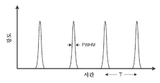
도 2는 일부 실시예에 따른 펄스열을 도시한다.
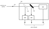
도 3은 일부 실시예에 따른 광학 검출 시스템의 개략도이다.
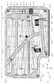
도 4는 일부 실시예에 따른 펄스 레이저의 개략도이다.
도 5는 일부 실시예에 따른 광학 특성규정 장치의 일부를 나타낸다.
도 6은 일부 실시예에 따른 광학 특성규정 장치를 위한 말단 미러 마운트를 나타낸다.
도 7은 일부 실시예에 따른 광학 특성규정 장치를 획득하기 위해 펄스 레이저를 수정하는 방법을 나타낸다.
도 8은 일부 실시예에 따른 펄스 반도체 레이저를 나타낸다.
도 9는 일부 실시예에 따른 펄스 섬유 레이저를 나타낸다.
도 10은 일부 실시예에 따른 광학 요소를 특성규정하는 방법의 플로차트이다.
도 11은 일부 실시예에 따른 모드-고정 펌프 임계값을 결정하기 위한 방법의 플로차트이다.
도 12는 일부 실시예에 따른 컴퓨팅 디바이스이다.
도 13a는 일부 실시예에 따른 예시적인 파워 맵이다.
도 13b는 일부 실시예에 따른 예시적인 펄스 폭 데이터이다.
도 13c는 일부 실시예에 따른 예시적인 펄스 폭 맵이다.
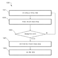
도 14a는 일부 실시예에 따른 예시적인 파워이다.
도 14b는 일부 실시예에 따른 예시적인 레이징 방식 맵(lasing regime map)이다.
도 14c는 일부 실시예에 따른 예시적인 펄스 폭 맵이다.
도 14d는 일부 실시예에 따른 예시적인 파워 맵이다.
도 14e는 일부 실시예에 따른 예시적인 레이징 방식 맵이다.
도 14f는 일부 실시예에 따른 예시적인 펄스 폭 맵이다.
도 15a는 일부 실시예에 따른 예시적인 레이징 방식 맵이다.
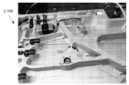
도 15b는 도 15a의 레이징 영역 맵과 비교하기 위한 광학 현미경 이미지이다.
본 출원은 피처 및 이점들은, 도면과 연계하여 취해지는 이하에서 개시되는 상세한 설명으로부터 더욱 명백해질 것이다. 도면을 참조하여 실시예를 설명할 때, 방향 참조("위", "아래", "상단", "하단", "좌측", "우측", "수평", "수직" 등)가 이용될 수 있다. 이러한 참조는 독자가 정상적인 배향으로 도면을 보는 것을 보조하기 위한 것일 뿐이다. 이들 방향 참조는 구현된 디바이스의 선호되거나 유일한 배향을 기술하기 위한 것이 아니다. 디바이스는 다른 배향으로 구현될 수 있다.Those of ordinary skill in the art will understand that the drawings described herein are for illustrative purposes only. It should be understood that in some instances various aspects of some embodiments may be exaggerated or enlarged to facilitate understanding of the embodiments. In the drawings, like reference characters generally refer to similar features, functionally similar and/or structurally similar elements, throughout the various drawings. The drawings are not necessarily drawn to scale, but instead emphasis has been made to illustrate the principles of this teaching. The drawings are not intended to limit the scope of the present teaching in any way.
1 is a block diagram of an optical characterization device according to some embodiments.
2 shows a pulse train according to some embodiments.
3 is a schematic diagram of an optical detection system in accordance with some embodiments.
4 is a schematic diagram of a pulsed laser in accordance with some embodiments.
5 shows a part of an optical characterization device in accordance with some embodiments.
6 shows an end mirror mount for an optical characterization device in accordance with some embodiments.
7 shows a method of modifying a pulsed laser to obtain an optical characterization device in accordance with some embodiments.
8 shows a pulsed semiconductor laser in accordance with some embodiments.
9 shows a pulsed fiber laser in accordance with some embodiments.
10 is a flow chart of a method of characterizing an optical element in accordance with some embodiments.
11 is a flowchart of a method for determining a mode-locked pump threshold in accordance with some embodiments.
12 is a computing device in accordance with some embodiments.
13A is an exemplary power map in accordance with some embodiments.
13B is exemplary pulse width data in accordance with some embodiments.
13C is an exemplary pulse width map in accordance with some embodiments.
14A is an exemplary power in accordance with some embodiments.
14B is an exemplary lasing regime map in accordance with some embodiments.
14C is an exemplary pulse width map in accordance with some embodiments.
14D is an exemplary power map in accordance with some embodiments.
14E is an exemplary lasing scheme map in accordance with some embodiments.
14F is an exemplary pulse width map in accordance with some embodiments.
15A is an exemplary lasing scheme map in accordance with some embodiments.
15B is an optical microscope image for comparison with the laser area map of FIG. 15A.
The features and advantages of the present application will become more apparent from the detailed description set forth below, taken in connection with the drawings. When describing the embodiments with reference to the drawings, directional references ("top", "bottom", "top", "bottom", "left", "right", "horizontal", "vertical", etc.) will be used. I can. These references are only intended to assist the reader in viewing the drawings in their normal orientation. These directional references are not intended to describe the preferred or unique orientation of the implemented device. Devices can be implemented in different orientations.
서언Preface
본 발명자들은 광학 요소를 특성규정하기 위한 종래 기술이 특정한 응용을 위한 레이저 시스템을 구축하는데 중요한 특성을 충분히 측정하지 못한다는 것을 인식하고 이해했다. 예를 들어, 미러 및 포화가능한 흡수체, 예를 들어, 포화가능한 흡수체 미러(SAM)는 통상적으로 현미경을 이용한 시각적 관찰 및/또는 외부 레이저 시스템에 의한 프로빙에 의해 특성규정된다. 이러한 기술은 광학 요소의 소정의 속성을 측정할 수 있지만, 광학 요소를 특성규정하기 위한 종래 기술은, 상기 광학 요소를 이용하는 레이저의 성능과 간접적으로 관련된 속성을 측정하고 특정한 속성을 가진 레이저 시스템을 구축하는데 중요한 특성을 직접 측정하지 않는다. 따라서, 본 발명자들은 종래 기술을 이용하여 측정될 수 없는 광학 요소에 관한 정보를 제공하는 광학 특성규정 기술을 고안하였다.The inventors have recognized and understood that prior art techniques for characterizing optical elements do not sufficiently measure properties that are important for building laser systems for specific applications. For example, mirrors and saturable absorbers, such as saturable absorber mirrors (SAMs), are typically characterized by visual observation with a microscope and/or probing with an external laser system. These techniques can measure certain properties of optical elements, but conventional techniques for characterizing optical elements measure properties that are indirectly related to the performance of lasers using the optical elements and build laser systems with specific properties. It does not directly measure the important characteristics. Accordingly, the inventors have devised an optical characterization technique that provides information about optical elements that cannot be measured using the prior art.
제한이 아닌 예로서, SAM은 극초단 광 펄스를 생성하는 레이저 캐버티의 말단 미러로서 이용될 수 있다. 통상적으로, SAM은 현미경으로 SAM을 시각적으로 검사하고/하거나 별도의 레이저 시스템을 이용하여 SAM을 프로빙함으로써 특성규정된다. 예를 들어, 불포화 상태에서 SAM의 반사율 및/또는 흡수율은 레이저 빔의 반사 측정법을 이용하여 측정될 수 있다. 추가로, SAM의 이완 시간, 예를 들어 SAM의 광전자가 전도대로부터 가전대로 이완하는데 걸리는 시간은, 통상적으로 펄스 레이저 시스템을 이용하는 펌프 프로브 기술을 통해 측정될 수 있다. 본 발명자들은, 시각적 검사, 반사율 및 이완 시간이 정량화할 SAM의 유용한 속성이 될 수 있지만, 이들 측정이 소정의 조건 및/또는 기준을 충족하도록 보장하는 것은, 레이저 시스템에서 그 SAM을 이용하는 것이 예상 성능 기준을 충족할 것이라고 결정하기에는 충분하지 않다는 것을 인식하고 이해했다. 예를 들어, 종래 기술은 SAM의 표면 품질에 대한 약간의 지침을 제공하지만, 상기 SAM을 이용하는 레이저의 모드-고정 및 파워 성능에 관한 직접적인 정보는 제공하지 않는다.By way of example and not limitation, the SAM can be used as an end mirror of a laser cavity that generates ultra-short light pulses. Typically, the SAM is characterized by visually examining the SAM under a microscope and/or probing the SAM using a separate laser system. For example, the reflectance and/or absorption rate of the SAM in the unsaturated state can be measured using a laser beam reflection measurement method. Additionally, the relaxation time of the SAM, for example the time it takes for the photoelectrons of the SAM to relax from the conduction band to the appliance, can be measured through a pump probe technique, typically using a pulsed laser system. We believe that visual inspection, reflectance and relaxation time can be useful attributes of the SAM to be quantified, but ensuring that these measurements meet certain conditions and/or criteria is the expected performance of using that SAM in a laser system. I recognized and understood that it was not enough to decide that I would meet the criteria. For example, the prior art provides some guidance on the surface quality of the SAM, but does not provide direct information on the mode-locking and power performance of the laser using the SAM.
본 발명자들은, 레이저 시스템에 SAM을 포함시키고 그 레이저 시스템의 속성을 측정하는 것이 그 특정한 SAM을 포함하는 레이저의 성능에 관한 직접적인 정보를 제공한다는 것을 인식하고 이해했다. 특히, 레이저의 모드-고정 성능(반복률, 펌프 임계값, 품질(예를 들어, Q-스위칭 없음)) 및 광 파워가 직접 측정될 수 있다. SAM의 임의의 결함은 파워 상실 또는 불량한 모드-고정 성능에 의해 입증되므로, 레이저 시스템의 제조업체가 레이저 시스템을 위한 원하는 성능 기준을 충족하는 고품질의 SAM을 선택하는 것을 허용한다.The inventors have recognized and understood that incorporating a SAM in a laser system and measuring the properties of that laser system provides direct information about the performance of a laser containing that particular SAM. In particular, the mode-fixed performance of the laser (repetition rate, pump threshold, quality (eg, no Q-switching)) and optical power can be measured directly. Any deficiencies of the SAM are evidenced by power loss or poor mode-locking performance, allowing manufacturers of laser systems to choose a high quality SAM that meets the desired performance criteria for the laser system.
본 발명자들은 또한, 레이저 시스템에 광학 요소를 포함시키는 광학 특성규정 기술이 SAM 이외의 광학 요소를 특성규정하는데 유용하다는 것을 인식하고 이해했다. 예를 들어, 충분한 출력 레이저 파워 및 모드-고정 성능을 보장하기 위해 이러한 시스템을 이용하여 미러가 특성규정될 수 있다. 광학 요소를 별개의 구분되는 레이저 시스템의 출력으로 프로빙함으로써 광학 컴포넌트의 피처를 측정하는 종래의 접근 방식과는 달리, 레이저 캐버티 내에 특성규정될 광학 요소를 포함시키는 것은, 종래 기술의 이용으로는 가능하지 않은 추가 감도를 역시 제공할 수 있다. 이 추가 감도는, 레이저 시스템의 출력 레이저 빔 특성이 레이저 시스템의 구성 컴포넌트의 품질과 특성의 함수라는 사실에서 비롯된다. 증가된 감도는, 부분적으로, 레이저 캐버티 내의 코히어런트 광 빔을 생성하는데 있어서 내재된 광학적 피드백에 기인한 것일 수 있다. 미러를 특성규정하는 것에 추가하여, 비선형 광학 요소가 레이저 캐버티 내에서 특성규정될 수 있고, 여기서, 캐버티내 레이저 빔을 이용하는 것은 종래 기술로는 이용가능하지 않은 비선형 광학 요소의 성능에 관한 추가 정보뿐만 아니라 증가된 감도를 제공할 수 있다.The inventors have also recognized and understood that optical characterization techniques for including optical elements in a laser system are useful for characterizing optical elements other than SAM. For example, mirrors can be characterized using such a system to ensure sufficient output laser power and mode-locked performance. In contrast to the conventional approach of measuring features of an optical component by probing the optical element to the output of a separate discrete laser system, the inclusion of an optical element to be characterized within a laser cavity is possible with the use of prior art. It can also provide additional sensitivity that has not been done. This additional sensitivity comes from the fact that the characteristics of the output laser beam of the laser system are a function of the quality and characteristics of the constituent components of the laser system. The increased sensitivity may be due in part to the optical feedback inherent in generating the coherent light beam within the laser cavity. In addition to characterizing the mirror, nonlinear optical elements can be characterized within the laser cavity, where using an intracavity laser beam is an addition regarding the performance of nonlinear optical elements not available in the prior art. It can provide information as well as increased sensitivity.
더욱이, 본 발명자들은 SAM 등의 광학 요소가 표면 전체에 걸쳐 반드시 일관적이지는 않음을 인식하고 이해했다. 레이저 파워 손실, 불량한 모드-고정 성능 또는 치명적인 고장의 원인이 될 수 있는 복수의 가능한 결함이 SAM에 있다. 따라서, 일부 실시예는 레이저 캐버티의 입사 레이저 빔에 수직인 평면에서 SAM을 병진시키도록 구성된 2차원 병진 스테이지 상에 SAM 또는 특성규정될 다른 광학 요소를 장착한다. 2차원 병진 스테이지를 이용함으로써, 레이저 빔의 조명 스폿이 SAM의 일부 또는 전체에 걸쳐 래스터(raster)될 수 있다. 따라서, SAM의 2차원 맵이 생성되어 SAM의 어느 부분이 레이저 시스템의 성능에 영향을 미치는 결함을 갖고 있는지를 보여줄 수 있다. 일부 예에서, 하나 이상의 크고 이용불가능한 영역을 갖는 SAM은 폐기되거나 레이저 시스템의 제조에 포함되지 않을 수 있다. SAM이, SAM의 작은 부분에 국한되거나 작은 이용불가능한 영역을 갖는다면, 이용가능한 것으로 간주되는 SAM의 영역에 레이저 빔의 조명 스폿이 입사되도록 SAM이 위치되고 배열되는 한 레이저 시스템에 SAM이 포함될 수 있다(예를 들어, 레이저 시스템은 SAM의 식별된 부분을 이용할 때 필요한 파워 및 모드-고정 능력을 나타낸다).Moreover, the inventors have recognized and understood that optical elements such as SAM are not necessarily consistent across the surface. There are a number of possible faults in the SAM that can cause laser power loss, poor mode-locking performance or fatal failure. Thus, some embodiments mount the SAM or other optical element to be characterized on a two-dimensional translation stage configured to translate the SAM in a plane perpendicular to the incident laser beam of the laser cavity. By using a two-dimensional translation stage, the illumination spot of the laser beam can be rastered over some or all of the SAM. Thus, a two-dimensional map of the SAM can be created to show which parts of the SAM have defects that affect the performance of the laser system. In some examples, a SAM with one or more large and unusable areas may be discarded or not included in the manufacture of the laser system. If the SAM is confined to a small portion of the SAM or has a small unusable area, the SAM can be included in the laser system as long as the SAM is positioned and arranged such that the illumination spot of the laser beam is incident on the area of the SAM that is considered available. (For example, a laser system exhibits the required power and mode-locking capabilities when using the identified part of the SAM).
본 발명자들은 또한, 광학 요소 특성규정 장치에서, 복수의 광학 요소가 효율적으로 특성규정될 수 있도록 광학 요소가 용이하게 제거되고 또 다른 광학 요소로 대체되도록 하는 것이 유용할 수 있다는 것을 인식하고 이해하였다. 따라서, 레이저 시스템의 하우징 내에 광학 요소를 위치시키는 것이 아니라, 광학 요소는 레이저 하우징의 외부에 위치된다. 일부 실시예에서, 광학 요소는 레이저 시스템의 평면에 수직으로 배향될 수 있다. 예를 들어, 레이저 시스템의 레이저 캐버티는, 특성규정될 광학 요소에 레이저 빔이 입사하도록 레이저 캐버티를 정의하는 광학소자에 수직인 방향으로 하우징 외부로 레이저 빔을 반사하는 미러를 포함할 수 있다. 특성규정될 광학 요소를 레이저 하우징 외부에 위치결정하는 것은, 2차원 병진 스테이지가 하우징에 설치될 필요가 없고 병진 스테이지의 움직임 범위가 하우징에 의해 제한되지 않는다는 추가적인 이점을 가질 수 있다. 광학 요소와 병진 스테이지를 하우징에 설치해야 하는 제약을 제거함으로써, 보통은 가능하지 않은 더 큰 광학 요소를 특성규정하는 것이 가능하다. 예를 들어, 임의의 크기(예를 들어, 1, 2, 3, 4 또는 5 인치 직경의 웨이퍼)의 전체 SAM 웨이퍼는, 웨이퍼를 개별 컴포넌트로 다이싱하기 전에 특성규정될 수 있다. 다이싱 전에 웨이퍼를 특성규정함으로써, SAM 웨이퍼의 불량한 품질의 부분이 폐기할 수 있어서, 완성된 레이저 시스템에서 궁극적으로 이용불가능한 개개의 컴포넌트를 제조하기 위해 종래에 소요되던 시간과 노력을 절감할 수 있다.The inventors have also recognized and understood that in an optical element characterization apparatus, it may be useful to allow an optical element to be easily removed and replaced with another optical element so that a plurality of optical elements can be efficiently characterized. Thus, rather than positioning the optical element within the housing of the laser system, the optical element is positioned outside of the laser housing. In some embodiments, the optical element may be oriented perpendicular to the plane of the laser system. For example, the laser cavity of the laser system may comprise a mirror that reflects the laser beam out of the housing in a direction perpendicular to the optical element defining the laser cavity such that the laser beam enters the optical element to be characterized. Positioning the optical element to be characterized outside the laser housing can have the additional advantage that the two-dimensional translation stage does not need to be installed in the housing and the range of motion of the translation stage is not limited by the housing. By removing the constraints of installing optical elements and translation stages in the housing, it is possible to characterize larger optical elements that are not normally possible. For example, an entire SAM wafer of any size (eg, 1, 2, 3, 4 or 5 inch diameter wafer) can be characterized prior to dicing the wafer into individual components. By characterizing the wafer prior to dicing, poor quality parts of the SAM wafer can be discarded, saving the time and effort conventionally required to manufacture individual components that are ultimately unavailable in a finished laser system. .
광학 요소를 특성규정하기 위한 기술 및 광학 요소를 특성규정하기 위한 디바이스의 다양한 예시적인 예가 아래에서 설명된다. 그러나, 실시예들은 아래의 임의의 예에 따라 동작하는 것으로 제한되지 않으며 다른 실시예도 가능하다는 것을 이해해야 한다.Various illustrative examples of techniques for characterizing optical elements and devices for characterizing optical elements are described below. However, it should be understood that the embodiments are not limited to operating according to any of the examples below, and other embodiments are possible.
도 1은, 일부 실시예에서, 극초단 펄스 레이저(110), 광학 검출 시스템(140), 2차원 병진 스테이지(145), 및 제어기(150)를 포함하는 예시적인 광학 특성규정 장치(100)를 도시한다. 극초단 펄스 레이저(110)는, (일부 실시예에서 고체 상태 재료일 수 있는) 이득 매체(105), 이득 매체를 여기하기 위한 펌프 소스(미도시), 및 광학 레이저 캐버티의 말단을 정의하는 적어도 2개의 캐버티 말단 미러(102, 104)를 포함한다. 일부 실시예에서, 빔 성형, 파장 선택 및/또는 펄스 형성을 위해 레이저 캐버티 내에 하나 이상의 추가적인 광학 요소가 있을 수 있다. 동작할 때, 펄스 레이저(110)는, 캐버티의 말단 미러(102, 104) 사이에서 및 이득 매체(105)를 통해 레이저 캐버티 내에서 전후로 순환하는 극초단 광 펄스(120)를 생성할 수 있다. 캐버티 미러(104) 중 하나는 순환 펄스의 일부를 부분적으로 투과시킬 수 있어, 일련의 광 펄스열(122)이 펄스 레이저(110)로부터 방출되게 한다. 일부 실시예에서, 말단 미러(102)는, 펄스 레이저(110)가 수동으로 모드-고정되는 것을 허용하는 SAM일 수 있다. 방출된 펄스는 빔 허리(w)를 특징으로 하는 (점선으로 표시된) 빔을 형성할 수 있다.FIG. 1 shows an exemplary
일부 실시예에서, 펄스 레이저(110)는 펄스 파장의 적어도 일부를 주파수 증배(frequency doubling)를 통해 더 짧은 파장으로 또는 파라메트릭 증폭을 통해 더 긴 파장으로 변환하기 위한, 비선형 결정 등의, 비선형 광학 요소(미도시)를 포함할 수 있다. 이러한 주파수 변환이 발생할 때, 펄스 레이저(110)는, 제1 파장의 광을 포함하는 제1 빔과 제2 파장의 광을 포함하는 제2 빔을 포함할 수 있다. 예를 들어, 이득 매체(105)는 1064 nm에서 레이징하여 1064 nm에서 펄스를 생성할 수 있다. 1064 nm 펄스는 KTP 또는 BBO 등의 비선형 결정을 이용하여 2차 고조파 생성(SHG; second harmonic generation)을 통해 532 nm 펄스로 변환될 수 있다. 따라서, 빔(122)은 1064 nm 펄스 및 532 nm 펄스 양쪽 모두를 포함할 수 있다.In some embodiments, the
방출된 펄스(122)의 측정된 시간적 강도 프로파일은 도 2에 도시된 바와 같이 나타날 수 있다. 일부 실시예에서, 방출된 펄스의 피크 강도 값은 대략 동일할 수 있고, 프로파일은 Gaussian 시간 프로파일을 가질 수 있지만, sech2 프로파일 등의 다른 프로파일이 가능할 수 있다. 일부 경우에, 펄스는 대칭적인 시간 프로파일을 갖지 않을 수 있으며 다른 시간적 형상을 가질 수 있다. 일부 실시예에서, 이득 및/또는 손실 역학은 비대칭 프로파일을 갖는 펄스를 생성할 수 있다. 각각의 펄스의 지속시간은, 도 2에 표시된 바와 같이, FWHM(full-width-half-maximum) 값에 의해 특성규정될 수 있다. 극초단 광 펄스는 100 피코초 미만의 FWHM 값을 가질 수 있다.The measured temporal intensity profile of the emitted
레이저로부터 방출되는 펄스는 규칙적인 간격 T에 의해 분리될 수 있다. 일부 실시예에서, T는 레이저의 능동 이득(active gain) 및/또는 손실 변조율(loss modulation rate)에 의해 결정될 수 있다. 모드-고정된 레이저의 경우, T는 캐버티 말단 미러들(102, 104) 사이의 왕복 이동 시간에 의해 결정될 수 있다. 일부 실시예에 따르면, 펄스 분리 시간(T)은 약 1 ns 내지 약 100 ns일 수 있다. 일부 경우에, 펄스 분리 시간(T)은 약 0.1 ns 내지 약 1 ns일 수 있다. 일부 구현에서, 펄스 분리 시간(T)은 약 100 ns 내지 약 2 μs일 수 있다.The pulses emitted from the laser can be separated by a regular interval T. In some embodiments, T may be determined by the active gain and/or loss modulation rate of the laser. In the case of a mode-locked laser, T can be determined by the round trip time between the cavity end mirrors 102 and 104. According to some embodiments, the pulse separation time T may be from about 1 ns to about 100 ns. In some cases, the pulse separation time (T) may be from about 0.1 ns to about 1 ns. In some implementations, the pulse separation time (T) can be from about 100 ns to about 2 μs.
일부 실시예에서, 광학 검출 시스템(140)은 레이저(110)로부터 펄스 빔(122)을 수신하고 레이저 빔의 하나 이상의 속성을 검출할 수 있다. 광학 검출 시스템(140)으로부터의 검출 결과는 분석을 위해 제어기(150)에 제공된다. 광학 검출 시스템(140)은 또한, 레이저 빔을 다양한 검출기들 중 하나로 안내하는 안내 광학소자를 포함할 수 있다. 예를 들어, 도 3은 안내 광학소자의 예로서 이색성 미러(dichroic mirror, 341) 및 빔 분할기(342)를 포함하는 예시적인 광학 검출 시스템(140)을 도시한다. 이색성 미러(341)는 제1 파장의 광을 반사하고 제2 파장의 광을 투과시킬 수 있다. 예를 들어, 레이저 빔(122)이 1064 nm 펄스 및 532 nm 펄스를 양쪽 모두를 포함한다면, 1064 nm 광은 1064 nm 광의 파워를 측정하기 위해 제1 파워 계측기(343)를 향해 반사될 수 있다. 빔 분할기(342)는 532 nm 광의 파워를 측정하기 위해 532 nm 광의 일부를 제2 파워 계측기(344)를 향해 전송할 수 있다. 빔 분할기(342)를 투과하는 532 nm 광은 펄스 특성규정 검출기(345)로 향한다. 펄스 특성규정 검출기(345)는 레이저 시스템(110)에 의해 출력된 532 nm 펄스의 펄스 폭을 측정하도록 구성된다. 일부 실시예에서, 펄스 특성규정 검출기(345)는 APE에 의해 제조된 pulseCheck 자기상관기 등의 자기상관기일 수 있다. 자기상관기는 레이저 펄스의 시간적 펄스 폭을 측정한다. 다른 실시예에서, 펄스 특성규정 검출기(345)는, 레이저 펄스의 시간적 펄스 폭뿐만 아니라 레이저 펄스의 전체 강도 및 위상 프로파일 양쪽 모두를 제공할 수 있는, SPIDER(spectral interferometry for direct electric field reconstruction, 직접 전기장 재구성을 위한 스펙트럼 간섭계) 또는 FROG(frequency resolved optical gating, 주파수 분해 광 게이팅)을 위한 스펙트럼 간섭측정을 수행하는 디바이스를 포함할 수 있다. 광학 검출 시스템(140)의 개개의 검출기들 각각으로부터의 검출 결과는 제어기(150)에 제공된다.In some embodiments,
실시예들은 특정한 광학 검출 시스템(140)으로 제한되지 않는다. 예를 들어, 도 1은 광학 검출 시스템(140)이 레이저 시스템(110)의 완전히 외부에 있는 것으로 도시한다. 그러나, 일부 실시예에서, 하나 이상의 검출기가 레이저 시스템 자체 내에 포함될 수 있다. 예를 들어, 레이저 캐버티가 복수의 내부 미러로 형성되는 실시예에서, 검출기는 미러를 투과하는 레이저 빔의 일부를 검출하기 위해 하나 이상의 미러 뒤에 배치될 수 있다. 이러한 검출기는 레이저의 파워를 측정하기 위해 레이저 시스템의 하우징 내에 위치될 수 있다. 일부 실시예에서, 광학 검출 시스템(140)은 하우징 외부 또는 하우징 내부에 있을 수 있는 고속 포토다이오드를 포함할 수 있다.The embodiments are not limited to a specific
다시 도 1을 참조하면, 광학 특성규정 장치(100)는, 말단 미러(102) 상의 레이저 빔의 조명 스폿이 말단 미러(102)의 표면을 가로질러 스캔될 수 있게끔, 말단 미러(102)를 병진시키도록 구성된 2차원 병진 스테이지(145)를 포함할 수 있다. 말단 미러(102)를 병진시키는 것은, 병진 스테이지(102)의 움직임이 레이저 빔의 입사 광 펄스(122)에 수직이기 때문에 레이저 캐버티의 길이를 변경하지 않는다. 도 1의 2차원 병진 스테이지(145)의 개략도 내에서 화살표는, 예시된 실시예에서 병진 스테이지가 말단 미러(102)를 이동시킨 2개의 방향(페이지의 평면에서 위아래로 및 페이지 안팎으로)을 도시한다. 일부 실시예에서, 2차원 병진 스테이지(145)는 제어기(150)에 의해 제어되는 모터화된 병진 스테이지이다. 일부 실시예에서, 2차원 병진 스테이지(145)는 제2 1차원 병진 스테이지 상에 장착된 제1 1차원 병진 스테이지를 포함할 수 있고 2개의 병진 스테이지의 움직임 방향은 서로 수직이다. 2차원 병진 스테이지(145)에 추가하여, 일부 실시예는 말단 미러(102)의 틸트(tilt)를 제어하기 위해 2 축 틸트 조정 마운트(미도시)를 포함할 수 있다. 기울기 조정 마운트는, 말단 미러(102)가 적절하게 정렬되어 펄스 레이저(110)의 성능을 최적화하도록 보장하기 위해 하나 이상의 파워 측정값으로부터의 피드백을 이용할 수 있다.Referring back to FIG. 1, the
전술된 바와 같이, 광학 특성규정 장치(100)는, 병진 스테이지(145)를 제어하고 광학 검출 시스템(140)으로부터 측정 데이터를 수신하기 위한 제어기(150)를 포함한다. 이하에서 더 상세히 설명되는 바와 같이, 제어기(150)는 저장 디바이스 및 프로세서를 포함할 수 있다. 저장 디바이스는, 광학 검출 시스템(140)으로부터 수신된 측정 데이터뿐만 아니라, 프로세서에 의해 실행될 때 프로세서가 측정 데이터를 분석하게 하는 명령어를 저장할 수 있다. 명령어는 병진 스테이지(145)의 움직임을 추가로 제어할 수 있다.As described above, the
실시예는 광학 특성규정 장치(100)의 특정한 광학적 레이아웃으로 제한되지 않는다. 일부 실시예에서, 광학 특성규정 장치(100)는 특성규정될 광학 요소가 궁극적으로 포함될 레이저 시스템의 레이아웃과 유사한 레이아웃을 갖는다. 이러한 경우에, 광학 특성규정 장치(100)의 많은 속성이 레이저 시스템과 동일하도록 보장하는 것이 유리할 수 있다. 예를 들어, 레이저 캐버티의 길이는, 광학 요소를 위한 광학 특성규정 장치(100) 및 레이저 시스템에서 동일할 수 있다. 일부 실시예에서, 광학 특성규정 장치(100)는 기존의 레이저 시스템을 수정함으로써 형성될 수 있다.The embodiment is not limited to a specific optical layout of the
모드-고정된 레이저 모듈Mode-fixed laser module
도 4를 참조하면, 광학 특성규정 장치(100)를 형성하도록 수정될 수 있는 컴팩트 모드-고정된 레이저 모듈(1-108)의 예가 도시되어 있다. 일부 실시예에 따른 컴팩트 모드-고정된 레이저 모듈(1-108)은, 레이저 캐버티(레이저 캐버티의 제1 말단 미러로서 기능할 수 있는 출력 결합기(1-111)와 레이저 캐버티의 제2 말단 미러로서 기능할 수 있는 포화가능한 흡수체 미러(SAM)(1-119) 사이에 광학 요소를 포함함), 모드-고정된 레이저(110)의 일부 또는 모든 컴포넌트가 장착되어 있는 (하우징이라고도 하는) 형성된 베이스 샤시(2-105), 모드-고정된 레이저의 동작을 안정화할 수 있는 적어도 하나의 캐버티내 광학 요소(2-128), 레이저의 출력을 더 짧은 파장으로 변환하는데 참여할 수 있는 주파수 증배 요소(2-170, 2-164, 2-160), (광 파워 등의) 레이저의 동작 파라미터를 모니터링하고 레이저에 의해 생성된 광 펄스에 동기화되는 전자 클록 신호를 생성하는 전자 컴포넌트(2-190, 2-154, 2-182, 2-116)를 포함할 수 있다. 펌프 모듈(2-140)은 베이스 샤시(2-105)에 장착되어 모드-고정된 레이저의 이득 매체(1-105)를 여기하는데 이용될 수 있다.Referring to FIG. 4, an example of a compact mode-fixed laser module 1 -108 that can be modified to form an
컴팩트 모드-고정된 레이저 모듈(1-108)의 베이스 샤시(2-105)는, 일부 실시예에 따르면, 길이 L이 약 20 cm 내지 약 30 cm, 높이 H가 약 10 cm 내지 약 20 cm이며, 두께는 약 10 mm 내지 약 30 mm로 측정될 수 있다. 일부 경우에, 하나 이상의 치수가 최대 20% 더 클 수 있다. 일부 실시예에 따르면, 컴팩트 모드-고정된 레이저 모듈(1-108)에 의해 점유된 체적은 약 30 cm × 18 cm × 3 cm 또는 약 1620 cm3일 수 있다. 일부 구현에 따르면, 모드-고정된 레이저 모듈(1-108)의 전체 형상 또는 폼 팩터는, 길이 L이 높이 H보다 길고 두께가 길이 또는 높이보다 훨씬 작은 슬래브(slab)이며, 2850 입방 cm미만 체적을 점유하고 약 2 킬로그램 또는 그 미만의 무게를 갖는다. 일부 경우에, 모듈(1-108)의 무게는 1 킬로그램 내지 2 킬로그램이다.The base chassis 2-105 of the compact mode-fixed laser module 1-108, according to some embodiments, has a length L of about 20 cm to about 30 cm, and a height H of about 10 cm to about 20 cm. , The thickness may be measured from about 10 mm to about 30 mm. In some cases, one or more dimensions can be up to 20% larger. According to some embodiments, the volume occupied by the compact mode-fixed laser module 1 -108 may be about 30 cm x 18 cm x 3 cm or about 1620 cm 3 . According to some implementations, the overall shape or form factor of the mode-locked laser module 1 -108 is a slab with a length L greater than the height H and a thickness much less than the length or height, with a volume of less than 2850 cubic cm. It occupies and has a weight of about 2 kilograms or less. In some cases, modules 1 -108 weigh between 1 kilogram and 2 kilograms.
일부 실시예에서, 베이스 샤시(2-105)는, 알루미늄, 티타늄, 알루미늄 합금, 또는 티타늄 합금으로 형성될 수 있다. 다른 실시예에서는 다른 재료가 사용될 수 있다. 일부 구현에서, 베이스 샤시(2-105)는, 기계가공되거나 기타의 방식으로(예를 들어, 주조 또는 조립에 의해) 베이스 샤시 내에 형성된 복수의 캐버티(2-102)를 포함할 수 있다. 일부 실시예에서, 모드-고정된 레이저(110)를 구성하기 위해 12.5 mm 직경의 광학 컴포넌트(또는 더 작은 것)가 이용될 수 있고, 베이스 샤시(2-105)의 캐버티(2-102) 내로 부분적으로 또는 완전히 오목화되어, 외부 환경 요인 및 오염 물질로부터 캐버티 내의 컴포넌트를 보호하도록 캐버티(2-102) 위에 커버(미도시)가 배치될 수 있다. 일부 실시예에서, 하나 이상의 캐버티를 밀폐하기 위해 캐버티(2-102) 위에 커버가 배치될 수 있다.In some embodiments, the base chassis 2-105 may be formed of aluminum, titanium, aluminum alloy, or titanium alloy. Other materials may be used in other embodiments. In some implementations, the base chassis 2-105 may include a plurality of cavities 2-102 that are machined or otherwise formed within the base chassis (eg, by casting or assembly). In some embodiments, a 12.5 mm diameter optical component (or smaller) may be used to configure the mode-locked
캐버티들(2-102) 사이에는 베이스 샤시(2-105)에 형성된 리브(rib)들, 2-107)가 있을 수 있다. 일부 리브에서, 캐버티내 레이저 빔이 리브를 통해 인접한 캐버티로 통과하는 것을 허용하는 구멍 또는 개구(보이지 않음)가 있을 수 있다. 일부 실시예에 따르면, 베이스 샤시(2-105)의 엣지에 관해 비스듬히 이어지는 하나 이상의 대각선 리브(2-107)가 있을 수 있다. 예를 들어, 대각선 리브(2-107)는 베이스 샤시(2-105)를 가로질러 코너-대-코너 방향으로 이어질 수 있다. 대각선 리브(2-107)는, 대각선 리브를 갖지 않는 것에 비해 베이스 샤시(2-105)의 비틀림 강성을 3배 증가시킬 수 있다. 증가된 비틀림 강성은, 레이저 동작의 불안정성을 방지하고 베이스 샤시(2-105)에 작용하는 섭동력에 대한 모듈의 저항을 개선하는데 도움이 될 수 있다. 일부 경우에, 리브의 적어도 일부는, 레이저 모듈(1-108)을 위한 하나 이상의 커버(미도시)가 리브에 부착될 수 있도록, 캐버티의 하단으로부터 베이스 샤시(2-105)의 상단 표면까지 연장될 수 있다. 이와 관련하여, 뻣뻣한 금속 커버(예를 들어, 대략 1 mm보다 큰 두께를 갖는 금속), 뻣뻣한 폴리머 커버(예를 들어, 대략 2 mm보다 큰 두께를 갖는 폴리머), 또는 베이스 샤시(2-105)에 밀봉되거나 지지물(예를 들어, 금속 프레임)로 베이스 샤시(2-105)에 맞대어 고정될 수 있는 가요성 재료(금속 또는 폴리머)를 포함한 그러나 이것으로 제한되지 않는 임의의 적절한 커버가 이용될 수 있다. 일부 경우에, 커버 재료는, 금속 프레임(약 1.5 mm 두께)으로 베이스 샤시에 맞대어 고정되는 Tyvek®(대략 0.25mm 두께)를 포함한다.There may be ribs 2-107 formed in the base chassis 2-105 between the cavities 2-102. In some ribs, there may be holes or openings (not shown) that allow the laser beam in the cavity to pass through the ribs into adjacent cavities. According to some embodiments, there may be one or more diagonal ribs 2-107 running at an angle with respect to the edge of the base chassis 2-105. For example, the diagonal ribs 2-107 can run in a corner-to-corner direction across the base chassis 2-105. The diagonal ribs 2-107 can increase the torsional rigidity of the base chassis 2-105 three times as compared to having no diagonal ribs. The increased torsional stiffness can help to prevent instability of laser operation and improve the module's resistance to perturbation forces acting on the base chassis 2-105. In some cases, at least a portion of the ribs extend from the bottom of the cavity to the top surface of the base chassis 2-105 so that one or more covers (not shown) for the laser modules 1-108 can be attached to the ribs. Can be extended. In this regard, a stiff metal cover (e.g., a metal having a thickness greater than approximately 1 mm), a stiff polymer cover (e.g., a polymer having a thickness greater than approximately 2 mm), or a base chassis (2-105). Any suitable cover may be used, including, but not limited to, a flexible material (metal or polymer) that can be sealed to or secured against the base chassis 2-105 with a support (e.g., a metal frame). have. In some cases, the cover material includes Tyvek® (approximately 0.25 mm thick) secured against the base chassis with a metal frame (approximately 1.5 mm thick).
일부 구현에서, 하나 이상의 장착 피처부(2-103)가 하나 이상의 리브(2-107)에 배치될 수 있다. 장착 피처(2-103)가 이용되어 컴팩트 레이저 모듈(1-108)을 기기 또는 기타의 플랫폼에 장착할 수 있다. 일부 경우에, 장착 피처는, 각각의 레이저 모듈(1-108) 또는 동일한 레이저 모듈이 거의 동일한 위치 및 정렬(예를 들어, ± 100 마이크론 이내)로 재현가능하게 장착되도록 운동학적 장착(kinematic mounting)을 제공한다. 운동학적 장착은 또한, 장착 프로세스로 인해 야기되는 응력을 감소시킬 수 있다. 장착 피처(2-103)는, 탭핑되거나 투명한 구멍을 포함할 수 있다. 구멍은 카운터싱크 또는 카운터보어될 수 있다. 운동학적 장착의 경우, 하단 표면(도 4에는 미도시)이 제1 장착 피처를 위한 원뿔형 접촉 표면 또는 링 접촉부, 제2 장착 피처를 위한 쐐기형 접촉 표면 또는 2 포인트 접촉 표면, 및 제3 장착 피처를 위한 납작한 표면 또는 단일 포인트 접촉부를 포함하는 3개의 장착 피처(2-103)가 있을 수 있다. 대안으로서, 장착 피처(2-103)에 있는 2개의 카운터싱크된 구멍을 이용하여 베이스 샤시(2-105)를 수용 지지 구조물에 정렬할 수 있다.In some implementations, one or more mounting features 2-103 may be disposed in one or more ribs 2-107. Mounting features 2-103 may be used to mount the compact laser module 1-108 to an instrument or other platform. In some cases, the mounting features are kinematic mounting such that each laser module 1-108 or the same laser module is reproducibly mounted in approximately the same position and alignment (e.g., within ± 100 microns). Provides. The kinematic mounting can also reduce the stress caused by the mounting process. Mounting features 2-103 may include tapped or transparent holes. The holes can be countersunk or counterbore. For kinematic mounting, the bottom surface (not shown in Figure 4) is a conical contact surface or ring contact for the first mounting feature, a wedge contact surface or two point contact surface for the second mounting feature, and a third mounting feature. There may be three mounting features 2-103 including a flat surface or single point contact for the. As an alternative, the base chassis 2-105 can be aligned with the receiving support structure using two countersunk holes in the mounting features 2-103.
레이저 모듈(1-108)의 모드-고정된 레이저(110)는 레이저 캐버티의 출력단에 있는 출력 결합기(1-111), 이득 매체(1-105), 및 레이저 캐버티의 반대쪽 말단에 있는 포화가능한 흡수체 미러(SAM)(1-119)를 포함할 수 있다. 레이저의 광학 축(1-125)을 접고 원하는 펄스 반복률 또는 펄스 분리 간격 T를 달성하기 위해 레이저 캐버티의 길이를 연장하는 복수의 미러(2-116, 2-117, 2-120, 2-121, 2-122, 2-123, 2-124, 2-125)가 레이저 캐버티 내에 있을 수 있다. 또한, 캐버티내 레이저 빔의 크기 및/또는 형상을 변경시키는 빔 성형 광학소자(예를 들어, 렌즈 및/또는 만곡형 미러)가 레이저 캐버티 내에 있을 수 있다.The mode-locked
이제, 1064 nm의 레이징 파장에서 동작하는 모드-고정된 레이저를 위한 예시적인 광학 컴포넌트가 설명될 것이다. 본 발명의 실시예는 설명된 광학 컴포넌트들만으로 제한되지 않음을 이해할 것이다. 일부 구현에서는 더 적거나 더 많은 광학 컴포넌트가 이용될 수 있고(예를 들어, 펄스 반복률을 변경하기 위해 미러를 추가하거나 제거), 컴포넌트 상의 광학 코팅은 상이한 파장들에서 레이징하는 레이저마다 상이할 수 있다.Now, an exemplary optical component for a mode-locked laser operating at a lasing wavelength of 1064 nm will be described. It will be appreciated that embodiments of the present invention are not limited to the described optical components only. In some implementations, fewer or more optical components may be used (e.g., adding or removing a mirror to change the pulse repetition rate), and the optical coating on the component may be different for different lasers lazing at different wavelengths. have.
이득 매체(1-105)는, 베이스 샤시(2-105)로 열을 발산하는 열전도성 마운트(예를 들어, 알루미늄 또는 구리 블록 또는 기타 열전도성 재료)에 장착된 네오디뮴-도핑된 재료를 포함할 수 있다. 모드-고정된 레이저가 높은 평균 파워(예를 들어, 300mW 이상)에서 동작할 때, 이득 매체(1-105)에서 열 렌징 효과(thermal lensing effect)가 발생한다. 일부 경우에는, 이러한 열 렌징이 레이저의 동작을 불안정화시킬 수 있다. 이득 매체로부터 열전도성 마운트로의 열 전달을 개선하기 위해, 인듐 호일 또는 열전도성 마운트로의 열전달을 개선하는 기타 임의의 적절한 재료로 이득 매체(1-105)를 감쌀 수 있다. 일부 경우에, 이득 결정(gain crystal)을 열 마운트에 고정하기 위해 은 에폭시(silver epoxy) 또는 기타 임의의 적절한 열전도성 접착제가 이용될 수 있다. 일부 경우에, 이득 매체(1-105) 및 열전도성 마운트는, 열을 베이스 샤시(2-105)로 방열할 수 있는 열전 냉각기(thermo-electric cooler; TEC)에 장착될 수 있다. TEC 또는 액체 냉각 등의 기타의 능동 냉각 기술은, 이득 매체(1-105)의 능동 온도 제어를 제공하고 열 렌징 효과를 감소시킬 수 있다.The gain medium 1 -105 may comprise a neodymium-doped material mounted to a thermally conductive mount (e.g., aluminum or copper block or other thermally conductive material) that dissipates heat to the base chassis 2 -105. I can. When the mode-locked laser operates at a high average power (eg, 300 mW or more), a thermal lensing effect occurs in the gain medium 1-105. In some cases, this thermal lensing can destabilize the operation of the laser. To improve heat transfer from the gain medium to the thermally conductive mount, the gain medium 1 -105 may be wrapped with indium foil or any other suitable material that improves heat transfer to the thermally conductive mount. In some cases, silver epoxy or any other suitable thermally conductive adhesive may be used to secure the gain crystal to the thermal mount. In some cases, the gain medium 1 -105 and the thermally conductive mount may be mounted on a thermo-electric cooler (TEC) capable of dissipating heat to the base chassis 2 -105. Other active cooling techniques, such as TEC or liquid cooling, can provide active temperature control of the gain medium 1-105 and reduce the thermal lensing effect.
이득 매체(1-105)의 능동 냉각의 제거는 레이저의 비용 및 복잡성을 감소시킬 수 있다. 이득 매체를 펌핑하기 위해 최대 10 와트의 광학 펌핑 파워가 이용되는 경우에도, 본 실시예의 모드-고정된 레이저(110)에 대해 이득 매체의 능동적 온도 제어가 이용될 필요는 없다. 놀랍게도, 모드-고정된 레이저(110)는, 연관된 열 렌징 효과(포지티브 렌징)가 이 펌프 파워 범위에서 이득 매체의 열-유도된 초점 길이를 0으로부터 약 15 디옵터로 변경할 수 있더라도, 이 범위의 펌프 파워에 걸쳐 안정적으로 모드 고정 상태를 유지한다. 15 디옵터를 초과하는 열 렌징의 경우, 레이저 캐버티는 모드-고정된 동작도 연속파 동작도 지원하지 않을 수 있는 불안정한 공진기가 될 수 있다. 이득 매체에서 이러한 넓은 범위의 열 렌징에 관한 모드-고정의 안정성은, 부분적으로, 모드-고정된 레이저(110)를 위한 광학 컴포넌트의 선택 및 배열에 기인한다. 한 실시예에 따르면, 모드-고정된 동작의 안정성 및 개선된 성능은 이득 매체에서 발생하는 열 렌징의 양에 결정적으로 의존한다. 실시예들에서, 모드-고정된 레이저(110)의 안정된 모드-고정된 동작은 포지티브 렌징 효과의 1 디옵터 내지 15 디옵터의 열 렌징 양에 대해 획득될 수 있다. 열 렌징이 이 범위에서 달라질 수 있지만, 안정적인 모드-고정을 유지하기 위해 레이저 캐버티에 대한 어떠한 기계적 조정도 필요없다. 이득 매체(1-105)에서의 열 렌징 양이 포지티브 열 렌징의 8 디옵터 내지 12 디옵터일 때 모드-고정된 레이저의 개선된 성능이 획득될 수 있다. 연속파 동작의 경우, 0 디옵터 내지 적어도 15 디옵터의 포지티브 열 렌징이 있을 수 있다. 연속파 레이저 프로브 빔(예를 들어, 헬륨 네온 레이저 또는 레이저 다이오드)을 이득 매체(1-105)에 (예를 들어, 비스듬히) 통과시키고 "펌프-빔-온"과 "펌프-빔-오프" 상태 사이에서 이득 매체로부터 소정 거리에서 프로브 빔의 상대 변위를 측정으로써 (약 4 디옵터보다 큰) 열 렌징의 양이 측정될 수 있다. 펌프-빔-온 상태는, 레이저 다이오드 펌프 빔이 온이고 레이저(110)의 모드-고정된 레이징을 위해 이득 매체(1-105)를 여기시키는 때이다. 4 디옵터 미만의 값은, 상대 변위가 작아지기 때문에, 정확하게 측정하기 어려울 수 있다.Elimination of active cooling of the gain media 1 -105 can reduce the cost and complexity of the laser. Even when optical pumping power of up to 10 watts is used to pump the gain medium, it is not necessary to use active temperature control of the gain medium for the mode-locked
이득 매체(1-105)에서 광학 펌프 빔의 흡수는 이득 매체에서 열 렌징을 야기할 수 있다. 실시예들에서, 이득 매체에서의 열 렌징의 양은, 이득 매체(1-105)에 인가되는 광학 펌프 빔의 파워량을 변경(예를 들어, 펌프 모듈(2-140)로부터의 파워량을 변경)시킴으로써 변경될 수 있다. 추가로 또는 대안으로서, 이득 매체에서의 열 렌징의 양은 이득 매체(1-105)를 여기시키는데 이용되는 광학 펌프 빔의 광학 파장을 튜닝함으로써 변경될 수 있다. 광학 펌프 빔의 파장 튜닝은, 예를 들어 펌프 모듈(2-140) 내의 레이저 다이오드의 온도를 튜닝함으로써 수행될 수 있다. 펌프 빔의 파장을 튜닝하는 것은, 이득 매체(1-105)에서의 광학 펌프 빔의 흡수량을 변경할 수 있다.Absorption of the optical pump beam in the gain medium 1-105 may cause thermal lensing in the gain medium. In embodiments, the amount of thermal lensing in the gain medium changes the amount of power of the optical pump beam applied to the gain medium 1-105 (e.g., changes the amount of power from the pump module 2-140). ) Can be changed. Additionally or alternatively, the amount of thermal lensing in the gain medium can be changed by tuning the optical wavelength of the optical pump beam used to excite the gain medium 1-105. The wavelength tuning of the optical pump beam can be performed, for example, by tuning the temperature of the laser diode in the pump module 2-140. Tuning the wavelength of the pump beam can change the amount of absorption of the optical pump beam in the gain medium 1-105.
일부 구현에서, 이득 매체(1-105)는 1064 nm에서 레이징을 제공할 수 있는 네오디뮴 바나데이트(예를 들어, Nd3+ : YVO4)를 포함할 수 있다. 다른 실시예에서는 Nd : YAG, Nd : YLF, 및 Cr : 포스테라이트(Forsterite) 등의 그러나 이것으로 제한되지 않는 다른 고체 상태 결정이 이용될 수 있다. 일부 구현에서, 캐버티 내의 광학 컴포넌트가 이 파장에서의 레이징을 위해 설계되고 코팅된다면, 1342 nm에서의 레이징을 제공하기 위해 네오디뮴 바나데이트 이득 매체(1-105)가 대안으로서 또는 추가로 이용될 수 있다. 이득 매체는, 일부 경우에, 3mm 내지 11 mm의 길이를 가질 수 있다. 일부 실시예에서, 이득 매체의 길이는 5mm 내지 9mm일 수 있다. 네오디뮴 도펀트 레벨(원자 %)은 일부 경우에 0.10 % 내지 1 %일 수 있다. 일부 구현에서, 도펀트 레벨은 0.10 % 내지 0.50 %일 수 있다. 일부 구현에서, 도펀트 레벨은 0.24 % 내지 0.30 %일 수 있다. 일부 실시예에 따르면, 결정 길이는 약 7mm일 수 있고 도펀트 레벨은 약 0.27 %일 수 있다. 약 7 mm의 길이에 대해 0.3 %보다 상당히 높은 도핑 레벨(원자 %)은, 더 높은 동작 파워에서 레이저 동작을 불안정화할 수 있어(예를 들어, 고차 공간 모드에서 레이징을 유도하거나, 모드-고정을 불안정화하거나 종료), 바람직하지 않게도 캐버티내 컴포넌트들의 재조정을 요구할 수 있다. 예를 들어, 1 % 도핑을 이용하면, 소정의 펌프 파워 레벨 위에서 모드-고정이 종료되고, 모드-고정을 다시 확보하기 위해 캐버티내 광학 요소들이 재조정되어야 했다. 이득 매체(1-105)의 가로 치수 또는 치수는 임의의 적절한 값(예를 들어, 1 mm 내지 4 mm)일 수 있다. 이득 매체는, 원통형 막대, 직사각형 막대, 또는 기타 임의의 형태일 수 있다.In some implementations, the gain medium 1 -105 may include neodymium vanadate (eg, Nd 3+ : YVO4) that may provide lasing at 1064 nm. In other embodiments, other solid state crystals such as, but not limited to, Nd:YAG, Nd:YLF, and Cr:Forsterite may be used. In some implementations, if the optical components within the cavity are designed and coated for lasing at this wavelength, a neodymium vanadate gain medium (1-105) is alternatively or additionally used to provide lasing at 1342 nm. Can be. The gain medium can, in some cases, have a length of 3 mm to 11 mm. In some embodiments, the length of the gain medium may be 5 mm to 9 mm. The neodymium dopant level (atomic %) can be between 0.10% and 1% in some cases. In some implementations, the dopant level can be between 0.10% and 0.50%. In some implementations, the dopant level can be between 0.24% and 0.30%. According to some embodiments, the crystal length may be about 7 mm and the dopant level may be about 0.27%. Doping levels significantly higher than 0.3% (atomic %) for a length of about 7 mm can destabilize laser operation at higher operating powers (e.g., inducing lasing in higher order spatial modes, or mode-locking Destabilize or terminate), undesirably, may require readjustment of components in the cavity. For example, using 1% doping, the mode-lock was terminated above a given pump power level, and the optical elements in the cavity had to be readjusted to regain the mode-lock. The transverse dimension or dimension of the gain medium 1 -105 may be any suitable value (eg, 1 mm to 4 mm). The gain medium can be a cylindrical rod, a rectangular rod, or any other shape.
이득 매체(1-105)의 말단 면은, 일부 실시예에 따라, 레이징 파장 λl(네오디뮴 바나데이트의 경우 약 1064 nm일 수 있음) 및 펌프 파장 λp(네오디뮴 바나데이트의 경우 약 808 nm일 수 있음)에 대해 반사방지 코팅될 수 있다. 일부 실시예에서, 이득 매체의 한 말단 면은, 말단 면이 레이저 캐버티의 말단 미러로서 작용하고 별도의 출력 결합기(1-111)가 이용될 필요가 없도록, 출력 결합기 코팅으로 코팅될 수 있다.The end face of the gain medium 1-105 may be, according to some embodiments, a lasing wavelength λl (which may be about 1064 nm for neodymium vanadate) and a pump wavelength λp (about 808 nm for neodymium vanadate). Yes) can be coated with antireflection. In some embodiments, one end face of the gain medium may be coated with an output coupler coating such that the end face acts as an end mirror of the laser cavity and a separate output coupler 1-11 11 need not be used.
이득 매체(1-105)는 이득 매체의 말단 면이 레이저 캐버티의 광학 축(1-125)에 대해 약 1 내지 약 3도의 각도로 배향된 법선 벡터를 갖는 배향으로 조정불가능한 마운트(세밀한 각도 또는 위치 조정을 제공하지 않는 마운트)에 장착될 수 있다. 예를 들어, 이득 매체를 위한 열전도성 마운트는 이득 매체(1-105)가 배치되는 오목부를 포함할 수 있다. 오목부는 이득 매체를 열전도성 마운트에 정렬할 수 있다. 그 다음 열전도성 마운트는 베이스 샤시(2-105) 상의 피처(예를 들어, 기계가공된 표면, 핀, 나사 구멍 중 임의의 하나 또는 조합)에 레지스터링되어 이득 매체를 레이저 캐버티의 광학 축(1-125)에 비스듬히 정렬할 수 있다. 일부 구현에 따르면, 이득 매체(1-105)는 절단되고, 레이징을 위한 선호되는 편광과 정렬되도록 그 마운트에서 배향될 수 있다. 예를 들어, 이득 매체(1-105)는 도 4의 Y 축에 평행한 선형 편광으로 레이징하도록 배향될 수 있다.The gain medium 1-105 is a mount that is non-adjustable in an orientation with a normal vector oriented with the distal side of the gain medium at an angle of about 1 to about 3 degrees with respect to the optical axis 1 -125 of the laser cavity. Can be mounted on a mount that does not provide positioning adjustment. For example, a thermally conductive mount for a gain medium may include a recess in which the gain medium 1 -105 is disposed. The recess may align the gain medium to the thermally conductive mount. The thermally conductive mount is then registered to a feature on the base chassis 2-105 (e.g., any one or combination of machined surfaces, pins, screw holes) to transfer the gain medium to the optical axis of the laser cavity ( 1-125) can be aligned at an angle. According to some implementations, the gain medium 1 -105 may be cut and oriented in its mount to align with the preferred polarization for lasing. For example, the gain medium 1 -105 may be oriented to laze with linearly polarized light parallel to the Y axis of FIG. 4.
일부 실시예에 따르면, 컴팩트 모드-고정된 레이저를 위한 출력 결합기(1-111)는 10-5(스크래치 및 디그(dig))의 표면 품질과 최대 λ/10의 파면 에러를 갖는 고품질 레이저 광학소자일 수 있다. 출력 결합기(1-111)의 한 표면은, 레이징 파장 λl에 대해 약 75 % 내지 약 95 %의 값을 갖는 반사율을 제공하고 이득 매체(1-105)를 여기하는데 이용되는 펌프 파장 λp의 투과를 (최소 반사로) 허용하기 위해 다층 유전체로 코팅될 수 있다. 일부 실시예에서, 레이징 파장은 약 1064 nm일 수 있고 펌프 파장은 약 808 nm일 수 있지만, 다른 실시예에서는 다른 파장이 이용될 수 있다. 일부 구현에서, 레이징 파장에서 출력 결합기의 반사율은 82 % 내지 88 %이다. 이 반사율 범위 내의 출력 결합기는 레이저의 안정적인 동작과 함께 원하는 양의 출력 파워를 제공하고 레이저의 동작 범위에 걸쳐 포화가능한 흡수체 미러(1-119)에 관해 적절한 양의 플루언스(fluence)를 제공한다.According to some embodiments, the output combiner (1-111) for a compact mode-fixed laser is a high-quality laser optical device with a surface quality of 10-5 (scratch and dig) and a wavefront error of up to λ/10. Can be One surface of the output coupler (1-111) provides a reflectance with a value of about 75% to about 95% for the lasing wavelength λ l and is used to excite the gain medium 1 -105 at the pump wavelength λ p It can be coated with a multilayer dielectric to allow the transmission of (with minimal reflection). In some embodiments, the lasing wavelength may be about 1064 nm and the pump wavelength may be about 808 nm, although other wavelengths may be used in other embodiments. In some implementations, the reflectance of the output coupler at the lasing wavelength is 82% to 88%. An output coupler within this reflectivity range provides the desired amount of output power with stable operation of the laser and an appropriate amount of fluence with respect to the saturable absorber mirror 1-119 over the operating range of the laser.
(레이저 출력을 향한) 출력 결합기(1-111)의 제2 표면은 펌프 파장 및 레이징 파장 양쪽 모두에 대해 반사방지 코팅으로 코팅될 수 있고, 출력 결합기의 반사 표면에 관해 비스듬하게 (예를 들어, 약 1도 내지 약 4도)로 배향될 수 있다. 출력 결합기(1-111)의 출력 (투과) 표면으로부터의 레이징 파장의 소량의 반사는 모드-고정된 레이저로부터의 펄스를 상당히 및 좋지 않게 넓힐 수 있다. 일부 실시예에 따르면, 출력 결합기 상의 코팅은 펌프 파장 λp를 무시할 정도의 반사와 함께 투과시키기 위해 이색성(dichroic)이다.The second surface of the output coupler (1-111) (towards the laser output) can be coated with an antireflective coating for both the pump wavelength and the lasing wavelength, and at an angle (for example, to the reflective surface of the output coupler). , From about 1 degree to about 4 degrees). A small amount of reflection of the lasing wavelength from the output (transmission) surface of the output combiner 1-111 can widen the pulses from the mode-locked laser significantly and badly. According to some embodiments, the coating on the output coupler is dichroic in order to transmit the pump wavelength λ p with negligible reflection.
일부 실시예에 따르면, 출력 결합기(1-111)는 2개의 직교 축 주변으로(예를 들어, 도 4의 Y 및 X 축 주변으로) 광학 축(1-125)에 관한 각도 조정을 제공하는 2축 조정식 마운트에 장착될 수 있다. 일부 실시예에서, 출력 결합기(1-111)는 베이스 샤시(2-105)에 통합될 수 있는 조정불가능한 마운트에 장착될 수 있다. 조정불가능한 마운트는 컴팩트 레이저의 비용과 복잡성을 감소시킨다. 역시 다른 실시예에서, 출력 결합기(1-111)는, 투명 기판 및 하나 이상의 광학 코팅을 포함하는 별도의 광학 컴포넌트 대신에 이득 매체(1-105)의 말단 면 상에 다층 광학 코팅으로서 형성될 수 있다.According to some embodiments, the output coupler 1-11 1 provides an angle adjustment with respect to the optical axis 1 -125 around two orthogonal axes (e.g., around the Y and X axes in FIG. 4). Can be mounted on an adjustable axis mount. In some embodiments, the output combiner 1-11 may be mounted on a non-adjustable mount that may be integrated into the base chassis 2-105. The non-adjustable mount reduces the cost and complexity of compact lasers. In yet another embodiment, the output coupler 1-11 may be formed as a multilayer optical coating on the end face of the gain medium 1 -105 instead of a separate optical component comprising a transparent substrate and one or more optical coatings. have.
출력 결합기(1-111)와 이득 매체(1-105) 사이의 거리를 변경하는 것은, 모드-고정된 펄스 시간 프로파일(펄스 지속시간이라고도 함)의 FWHM 값을 변경할 수 있다. 레이저의 모드-고정은 출력 결합기(1-111)와 이득 매체(1-105) 사이의 거리를 0 mm 내지 10 mm의 거리로 변동시키면서 달성될 수 있으며, 펄스 지속시간은, 상이한 펄스 지속시간을 획득하도록 상이한 거리를 선택함으로써 이 거리 범위에 걸쳐 약 9 피코초 내지 약 38 피코초로 변동될 수 있다. 일부 실시예에 따르면, 출력 결합기(1-111)와 이득 매체(1-105) 사이의 거리는 4 mm 내지 8mm로 설정된다.Changing the distance between the output combiner 1-11 and the gain medium 1 -105 can change the FWHM value of the mode-locked pulse time profile (also referred to as the pulse duration). The mode-locking of the laser can be achieved by varying the distance between the output combiner (1-111) and the gain medium (1-105) by a distance of 0 mm to 10 mm, and the pulse duration can be achieved with different pulse durations. It can vary from about 9 picoseconds to about 38 picoseconds over this distance range by choosing a different distance to obtain. According to some embodiments, the distance between the output coupler 1-11 1 and the gain medium 1 -105 is set between 4 mm and 8 mm.
출력 결합기(1-111)에서의 레이저의 캐버티내 빔 허리가 100 마이크론 내지 180 마이크론일 때(1/e2 레벨에서 측정된 빔 반경) 평균 레이징 파워 범위에 걸쳐 안정적이고 효율적인 동작이 달성된다. 출력 결합기(1-111)의 빔 허리의 값은, 부분적으로, 만곡형 미러(2-117) 등의 캐버티내 광학소자에 의해, 만곡형 미러까지의 출력 결합기의 거리에 의해, 및 이득 매체(1-105)에서의 펌프 빔 허리에 의해 결정된다. 일부 실시예에 따르면, 이득 매체에서의 레이징 파장의 빔 허리는, 이득 매체(1-105)에서의 펌프 빔 허리보다 상당히 더 작을 수 있다. 예를 들어, 이득 매체에서의 레이징 파장에 대한 빔 허리는 이득 매체에서 100 마이크론 내지 150 마이크론일 수 있고, 펌프 빔에 대한 가장 작은 허리는 180 마이크론 내지 250 마이크론일 수 있으며, 여기서, 펌프 빔은 광학 축에 관해 완전히 대칭이 아닐 수도 있다. 출력 결합기(1-111) 및 이득 매체(1-105)에서 빔 허리의 값은 또한, 제2 만곡형 미러(2-127)의 초점 길이 및 포화가능한 흡수체 미러(1-119)까지의 거리에 의해 영향을 받을 수 있다. 레이저 다이오드 펌프 빔보다 모드-고정된 레이저(110)의 레이징 빔에 대해 더 작은 빔 허리를 갖는 것은, 모드-고정된 레이저 동작의 안정성을 개선시킬 수 있다(예를 들어, 레이저가 이득 매체(1-105)에서의 레이저 빔과 레이저 다이오드 펌프 빔의 상대적 움직임으로 인한 파워 및 모드-고정 변동에 덜 민감하게 만들 수 있다). 용어 "빔 허리"는, 빔의 대향 측면들에서 레이저 빔 강도가 피크 값으로부터 1/e2 값으로 떨어지는 공간적 범위를 지칭하는데 사용된다. 둥근 빔은 단일의 빔 허리에 의해 특성규정될 수 있다. 타원형 빔은 2개의 빔 허리에 의해 특성규정될 수 있다 : 하나는 빔의 단축에 대한 것이고 다른 하나는 빔의 장축에 대한 것이다.Stable and efficient operation is achieved over the average lasing power range when the beam waist in the cavity of the laser at the output combiner 1-11 1 is between 100 microns and 180 microns (beam radius measured at 1/e 2 level). . The value of the beam waist of the output coupler 11-111 is, in part, by an optical element in the cavity such as the curved mirror 2-117, by the distance of the output coupler to the curved mirror, and the gain medium It is determined by the pump beam waist at (1-105). According to some embodiments, the beam waist of the lasing wavelength in the gain medium may be significantly smaller than the pump beam waist in the gain medium 1-105. For example, the beam waist for the lasing wavelength in the gain medium can be 100 microns to 150 microns in the gain medium, and the smallest waist for the pump beam can be 180 microns to 250 microns, where the pump beam is It may not be completely symmetric about the optical axis. The value of the beam waist in the output combiner 11-111 and the gain medium 1 -105 is also equal to the focal length of the second curved mirror 2-127 and the distance to the saturable absorber mirror 1-119. Can be affected by Having a smaller beam waist for the lasing beam of the mode-locked
레이저 캐버티의 반대쪽 말단에서, SAM(saturable absorber mirror)(1-119)이 장착될 수 있다. SAM은, 비선형 광 흡수(예를 들어, 다중 양자 우물)를 나타내는 다층 반도체 구조 및 기판 상에 형성된 고수준 반사기(예를 들어, Bragg 반사기)를 포함할 수 있다. 비선형 광 흡수는 레이저에서 수동 모드-고정을 유도할 수 있다. 예를 들어, SAM은 낮은 광학 강도에서 더 높은 흡수 및 손실을 나타낼 수 있으며, 높은 광학 강도에서 탈색되거나(bleach) 매우 적은 흡수 및 손실을 나타낼 수 있다. 반도체 구조는, 고수준 반사기에 입사되어 이에 의해 반사되는 광학 필드에 의해 생성된 광학 정재파의 대략적 피크 강도에 반도체 구조가 위치되도록 SAM의 고수준 반사기로부터 이격될 수 있다. SAM의 한 예는 독일 Jena의 BATOP Optoelectronics GmbH로부터 입수할 수 있는 파트 번호 SAM-1064-5-10ps-x이다. SAM의 비선형 광 흡수로 인해, 높은 강도의 광 펄스는 레이저의 더 낮은 강도의 연속파 동작보다 캐버티에서 더 적은 손실을 겪기 때문에 레이저는 펄스 동작 모드(수동 모드 고정됨)에서 우선적으로 동작한다.At the opposite end of the laser cavity, a saturable absorber mirror (SAM) (1-119) can be mounted. The SAM may include a multilayer semiconductor structure that exhibits nonlinear light absorption (eg, multiple quantum wells) and a high level reflector (eg, Bragg reflector) formed on a substrate. Nonlinear light absorption can lead to passive mode-locking in the laser. For example, the SAM may exhibit higher absorption and loss at low optical intensities, bleach at high optical intensities, or exhibit very little absorption and loss. The semiconductor structure can be spaced from the high level reflector of the SAM such that the semiconductor structure is positioned at an approximate peak intensity of an optical standing wave generated by an optical field incident on and reflected by the high level reflector. An example of a SAM is part number SAM-1064-5-10ps-x, available from BATOP Optoelectronics GmbH, Jena, Germany. Due to the non-linear light absorption of the SAM, the laser operates preferentially in the pulsed mode of operation (passive mode fixed) because high intensity light pulses suffer less loss in the cavity than the lower intensity continuous wave operation of the laser.
일부 실시예에 따르면, SAM은 갈륨-비소 반도체 조성물로부터 형성될 수 있다. SAM은 더 큰 기판이나 웨이퍼에서 절단할 수 있고, SAM의 면에 걸쳐 최대 치수가 1 mm 내지 3 mm인 정사각형 형상일 수 있다. SAM의 흡수의 이완 시간은 10 ps 내지 30 ps일 수 있다. SAM의 비포화된 흡수는 2 % 내지 6 %일 수 있다. SAM의 변조 깊이는 SAM 비포화된 흡수의 60 % 내지 74 %일 수 있다. 일부 구현에서, 이완 시간은 약 25 ps이고 비포화된 흡수는 약 4 %이다. 이러한 SAM(1-119)은, 12 ps 내지 20 ps의 펄스 지속시간을 갖는 모드-고정된 레이징을 지원할 수 있다. 일부 실시예에서, SAM의 포화 플루언스는 약 70 microJoules/cm2 (μJ/cm2)일 수 있다.According to some embodiments, the SAM may be formed from a gallium-arsenic semiconductor composition. The SAM can be cut from a larger substrate or wafer, and can be of a square shape with a maximum dimension of 1 mm to 3 mm over the face of the SAM. The relaxation time of absorption of the SAM can be between 10 ps and 30 ps. The unsaturated absorption of the SAM can be between 2% and 6%. The modulation depth of the SAM can be between 60% and 74% of the SAM unsaturated absorption. In some embodiments, the relaxation time is about 25 ps and the unsaturated absorption is about 4%. This SAM (1-119) may support mode-fixed lasing having a pulse duration of 12 ps to 20 ps. In some examples, the saturated fluence of the SAM may be about 70 microJoules/cm 2 (μJ/cm 2 ).
캐버티내 레이저 빔으로부터 SAM의 광학 플루언스는 갈륨-비소 SAM의 장시간 동작에 대해 2.5 milliJoules/cm2 (mJ/cm2) 아래로 유지되어야 한다. 5 mJ/cm2 이상의 값에서, SAM은 손상될 수 있다. 일부 구현에서 SAM의 플루언스는 SAM의 포화 플루언스의 약 10배 아래로 유지될 수 있다. SAM의 플루언스는, (예를 들어, 레이저 캐버티에 위치된 만곡형 미러(2-127)로) SAM에서의 빔 허리를 제어하고 출력 결합기(1-111)의 반사율을 선택하여 캐버티내 파워를 제어함으로써 제어될 수 있다. 일부 실시예에 따르면, SAM에서의 빔 허리는, 출력 결합기 반사율이 82 % 내지 88 %일 때 80 마이크론 내지 120 마이크론이다.The optical fluence of the SAM from the laser beam in the cavity should be kept below 2.5 milliJoules/cm 2 (mJ/cm 2 ) for the long operation of the gallium-arsenic SAM. At values of 5 mJ/cm 2 or more, the SAM can be damaged. In some implementations, the fluence of the SAM can be maintained below about 10 times the saturation fluence of the SAM. The fluence of the SAM is controlled by controlling the beam waist in the SAM (e.g., with a curved mirror (2-127) placed in the laser cavity) and selecting the reflectance of the output combiner (1-111) to It can be controlled by controlling the power. According to some embodiments, the beam waist in the SAM is between 80 microns and 120 microns when the output combiner reflectance is between 82% and 88%.
출력 결합기(1-111)와 SAM(1-119) 사이에는, 레이저 캐버티의 광학 축을 여러 번 접는 복수의 미러가 있을 수 있다. 이들 미러 중 일부(예를 들어, 미러 2-115, 2-120, 2-121, 2-122, 2-123, 2-124, 2-125)는 납작한 표면을 가질 수 있고 조정불가능한 마운트에 장착될 수 있다. 일부 실시예에 따르면, 미러들 중 2개(2-117, 2-127)는 만곡형 표면을 가질 수 있고 포커싱 반사기를 포함한다. 일부 경우에는, 미러(2-117, 2-127)에 대해 포커싱 반사기 대신에 또 다른 유형의 포커싱 광학소자(예를 들어, 렌즈 또는 복합 렌즈)가 이용될 수 있다(예를 들어, 캐버티내 빔이 미러 2-117 또는 미러 2-127의 위치에서 접히지 않은 경우). 레이저의 광학 축을 접는데 이용되는 납작한 만곡형 미러의 경우, 미러가 이용될 입사각에서 레이징 파장에 대해 미러의 반사율이 매우 높을 수 있다. 예를 들어, 이러한 미러의 반사율은, 일부 경우에 99 %보다 크고, 일부 경우에는 99.5 %보다 클 수 있다. 하나 이상의 폴딩 미러(folding mirror)의 표면 품질은 적어도 10-5(스크래치 및 디그)일 수 있고, 파면 에러는 최대 λ/10일 수 있다. 일부 경우에, 하나 이상의 폴딩 미러의 표면 품질은 적어도 40-20(스크래치 및 디그)일 수 있고, 파면 에러는 최대 λ/10일 수 있다. 스크래치-디그 표면 품질에 대한 더 높은 값은 폴딩 미러의 비용을 상당히 감소시킬 수 있다.Between the output coupler 11-111 and the SAM 1-119, there may be a plurality of mirrors that fold the optical axis of the laser cavity several times. Some of these mirrors (e.g. mirrors 2-115, 2-120, 2-121, 2-122, 2-123, 2-124, 2-125) may have a flat surface and are mounted on non-adjustable mounts. Can be. According to some embodiments, two of the mirrors (2-117, 2-127) may have a curved surface and include a focusing reflector. In some cases, another type of focusing optical element (e.g., a lens or a composite lens) may be used instead of the focusing reflector for the mirrors 2-117 and 2-127 (e.g., intracavity If the beam is not folded in the position of mirror 2-117 or mirror 2-127). In the case of a flat curved mirror used to fold the optical axis of a laser, the reflectance of the mirror may be very high with respect to the lasing wavelength at the angle of incidence where the mirror will be used. For example, the reflectivity of such a mirror may be greater than 99% in some cases and greater than 99.5% in some cases. The surface quality of one or more folding mirrors may be at least 10-5 (scratch and dig), and the wavefront error may be at most λ/10. In some cases, the surface quality of the one or more folding mirrors may be at least 40-20 (scratch and dig), and the wavefront error may be at most λ/10. A higher value for the scratch-dig surface quality can significantly reduce the cost of the folding mirror.
일부 구현에서, 미러들 중 적어도 하나(예를 들어, 미러 2-124)는 이득 매체(1-105)로부터 SAM(1-119)으로의 단일 천이를 위해 캐버티내 빔을 여러 번 접을 수 있다. 도 4에 도시된 예시적인 구성의 경우, 이득 매체(1-105)로부터 SAM(1-119)으로 이동하는 광 펄스(1-120)에 대한 바운스 시퀀스(bounce sequence)는 미러들(2-115, 2-117, 2-120, 2-121, 2-122, 2-123, 2-124, 2-125, 2-124, 2-127, 2-124)로부터 SAM(1-119)으로의 반사 시퀀스이다. 이 시퀀스에서, 캐버티내 미러들(2-124) 중 하나는 다중 반사에 이용되며, 빔이 레이저 캐버티의 한 말단으로부터 다른 말단으로 이동할 때 적어도 2번의 반사 동안 이 미러에서 입사각이 부호반전된다. 예를 들어 도 4를 참조하면 빔이 출력 결합기(1-111)로부터 SAM(1-119)으로 이동할 때 미러(2-124) 상에서 제1 입사각은 +Z 방향이고 제2 입사각은 -Z 방향이다. SAM(1-119)으로부터 반사된 후, 펄스는 역 바운스 시퀀스로 이득 매체로 귀환할 것이다. 컴팩트 레이저 모듈 내에 광학 축을 여러 번 접음으로써, 캐버티 길이가 연장되어 200 MHz 아래의 및 50MHz 정도의 낮은 펄스 반복률을 획득될 수 있다. 펄스 반복률은 레이저 캐버티의 길이에 의존하며, 이것은 부분적으로 캐버티 내의 미러들 사이의 바운스 수와 미러들 사이의 거리에 의해 결정된다. 일부 실시예에 따르면, 펄스 반복률은 미러를 재배치하고 제1 만곡형 미러(2-117)와 제2 만곡형 미러(2-127) 사이에서 캐버티 내에 미러를 추가 또는 제거하여 출력 결합기(110)와 포화가능한 흡수체 미러(1-119) 사이의 광 경로 길이를 증가시키거나 감소시킴으로써 변경될 수 있다. 캐버티내 빔은 제1 만곡형 미러(2-117)와 제2 만곡형 미러(2-127) 사이에서 대략적으로 시준되기 때문에, 빔이 이 영역에서 시준되지 않은 경우보다 펄스 반복률의 변경이 더 용이하게 이루어질 수 있다. 일부 구현에서, 상이한 펄스 반복률을 획득하기 위해 미러를 재배치하기 위해 추가의 일체형 광학 마운트가 베이스 샤시에 형성될 수 있다.In some implementations, at least one of the mirrors (e.g., mirror 2-124) may fold the beam in the cavity several times for a single transition from the gain medium 1-105 to the SAM 1-119. . In the case of the exemplary configuration shown in FIG. 4, the bounce sequence for the optical pulse 1120 moving from the gain medium 1-105 to the SAM 1-119 is mirrors 2-115. , 2-117, 2-120, 2-121, 2-122, 2-123, 2-124, 2-125, 2-124, 2-127, 2-124) to SAM (1-119) This is a reflection sequence. In this sequence, one of the intra-cavity mirrors 2-124 is used for multiple reflections, and the angle of incidence in this mirror is sign-inverted during at least two reflections as the beam travels from one end of the laser cavity to the other. . For example, referring to FIG. 4, when the beam moves from the output combiner 11-111 to the SAM 1-119, the first incident angle on the mirror 2-124 is in the +Z direction and the second incident angle is in the -Z direction. . After being reflected from the SAM (1-119), the pulse will return to the gain medium in an inverse bounce sequence. By folding the optical axis several times in the compact laser module, the cavity length can be extended to obtain pulse repetition rates below 200 MHz and as low as 50 MHz. The pulse repetition rate depends on the length of the laser cavity, which is determined in part by the number of bounces between the mirrors in the cavity and the distance between the mirrors. According to some embodiments, the pulse repetition rate is determined by rearranging the mirrors and adding or removing mirrors in the cavity between the first curved mirror 2-117 and the second curved mirror 2-127 to provide the
위에서 언급된 바와 같이, 본 발명자들은 200 MHz 아래 및 50 MHz 정도의 낮은 펄스 반복률이 바이오-광전자 칩 상의 샘플들의 대규모 병렬 분석에 바람직하다는 것을 인식하고 이해했다. 그러나, 일부 미러를 여러 번 이용하면서 복수의 미러를 이용하는 것은, 수 시간 동안 안정적인 모드-고정된 레이징을 유지하기 위해 서로에 관한 매우 높은 정도의 미러 안정성을 요구한다. 강화 리브를 포함하는 베이스 샤시(2-105)의 지지 표면에 맞댄 미러의 일체형 장착은, 미러의 필수 안정성과 안정적인 모드-고정된 동작을 달성할 수 있다.As mentioned above, the inventors have recognized and understood that pulse repetition rates as low as below 200 MHz and on the order of 50 MHz are desirable for large-scale parallel analysis of samples on a bio-optical chip. However, using some mirrors multiple times while using multiple mirrors requires a very high degree of mirror stability with respect to each other in order to maintain stable mode-locked lasing for several hours. The integral mounting of the mirror against the support surface of the base chassis 2-105 comprising reinforcing ribs can achieve the necessary stability and stable mode-locked operation of the mirror.
일부 구현에서, 하나의 폴딩 미러(2-115)는 캐버티내 방사광의 편광을 제어하고 (도 4에서 굵은 파선으로 표시된 바와 같이) 펌프 빔 방사광의 모니터링을 허용하도록 구성될 수 있다. 예를 들어, 폴딩 미러(2-115)는, 99 %보다 높은 반사율 또는 일부 경우에는 99.5 %보다 훨씬 높은 반사율로 s 편광(베이스 샤시의 평면에서 벗어난 Y 방향의 편광)을 반사하고 직교 p 편광에 대해 더 낮은 반사율을 가져 p 편광의 레이징이 방지되도록 코팅될 수 있다. 일부 경우에, 폴딩 미러(2-115)는 p 편광을 20 %보다 많이 투과하고 높은 반사율로 s 편광을 반사하는 편광 빔 분할기일 수 있다. 폴딩 미러(2-115)는, 펌프 빔 방사광의 대부분 또는 거의 전부를 미러 뒤에 위치된 광 검출기(2-116)에 추가로 전송할 수 있다. 폴딩 미러는, 일부 실시예에서, 펌프 빔 방사광의 투과를 허용하기 위해 이색성 코팅을 포함할 수 있다. 다른 실시예에서, 이색성 코팅은 이용되지 않을 수 있고, 레이징 파장에 대한 코팅은 검출을 위해 폴딩 미러(2-115)를 통한 펌프 빔 방사광의 충분한 투과를 허용할 수 있다. 광 검출기(2-116)의 출력은, 신호 처리 및/또는 외부 신호 프로세서로의 전송을 위해 PCB(2-190)에 제공될 수 있다.In some implementations, one folding mirror 2-115 may be configured to control the polarization of the radiation in the cavity and allow monitoring of the pump beam radiation (as indicated by bold dashed lines in FIG. 4 ). For example, the folding mirror 2-115 reflects s polarization (polarization in the Y direction out of the plane of the base chassis) with a reflectance higher than 99% or in some cases well above 99.5% and is reflected in orthogonal p polarization. It can be coated to prevent lasing of p-polarized light by having a lower reflectance of In some cases, the folding mirror 2-115 may be a polarization beam splitter that transmits p polarization more than 20% and reflects s polarization with a high reflectivity. The folding mirror 2-115 may further transmit most or almost all of the pump beam emission light to a photo detector 2-116 located behind the mirror. The folding mirror, in some embodiments, may include a dichroic coating to allow transmission of the pump beam radiation. In other embodiments, a dichroic coating may not be used, and a coating for the lasing wavelength may allow sufficient transmission of the pump beam emission light through the folding mirror 2-115 for detection. The output of the photodetector 2-116 may be provided to the PCB 2-190 for signal processing and/or transmission to an external signal processor.
일부 실시예에서, 2개의 만곡형 미러(2-117, 2-127)는 이득 매체(1-105) 및 SAM(1-119) 내에서 원하는 빔 허리 크기를 획득하도록 설계되고 레이저 캐버티 내에 위치될 수 있다. 제1 만곡형 미러(2-117)는 이득 매체(1-105) 부근의 레이저 캐버티의 제1 부분에 위치될 수 있다. 제2 만곡형 미러(2-127)는 SAM(1-119) 부근의 레이저 캐버티의 제2 부분에 위치될 수 있다. 적어도 만곡형 미러 사이에서, 레이저의 광학 축을 접고 캐버티 길이 연장 영역에서 레이저 캐버티 길이를 연장하는 복수의 폴딩 미러가 있을 수 있다. 캐버티 길이 연장 영역에서 캐버티의 길이를 연장하기 위해 캐버티내 레이저 빔을 여러 번 접는 미러(2-124)가 만곡형 미러(2-127)와 SAM(1-119) 사이에 추가로 있을 수 있다. 예를 들어, 만곡형 미러(2-127) 및 미러(2-124)는, 도 4에 표시된 바와 같이, 이들 2개의 반사기로부터의 바로 연속되는 바운스에서 캐버티내 빔을 3번 접을 수 있다.In some embodiments, two curved mirrors 2-117, 2-127 are designed to obtain the desired beam waist size within the gain medium 1-105 and the SAM 1-1 19 and positioned within the laser cavity. Can be. The first curved mirror 2-117 may be located in a first portion of the laser cavity near the gain medium 1-105. The second curved mirror 2-127 may be positioned in the second portion of the laser cavity near the SAM 1-19 19. At least between the curved mirrors, there may be a plurality of folding mirrors that fold the optical axis of the laser and extend the laser cavity length in the cavity length extension region. An additional mirror (2-124) that folds the laser beam in the cavity several times to extend the length of the cavity in the cavity length extension area is located between the curved mirror (2-127) and the SAM (1-119). I can. For example, the curved mirrors 2-127 and the mirrors 2-124 can fold the intracavity beam three times in immediately successive bounces from these two reflectors, as indicated in FIG. 4.
일부 실시예에 따르면, 제1 만곡형 미러(2-117)는 구면 반사기일 수 있고 240 mm 내지 260 mm의 초점 길이 f1을 가질 수 있다. 이 반사기의 초점 길이에 관한 허용공차는 초점 길이의 ±1 %일 수 있다. 본 발명자들은, 초점 길이가 약 250 mm인 제1 만곡형 미러(2-117)가 출력 결합기(1-111)로부터 230 mm 내지 310 mm에 배치될 수 있고 상이한 특성을 가진 안정적인 모드-고정된 동작이 획득될 수 있다는 것을 발견했다. 일부 실시예에 따르면, 제1 만곡형 미러는, 컴팩트 레이저 모듈의 넓은 범위의 동작 파워에 걸쳐 안정적인 모드-고정된 동작을 획득하기 위해 출력 결합기로부터 280 mm와 300 mm 사이에 위치될 수 있다. 이 구성에서, 이득 매체(1-105)는 출력 결합기로부터 4 mm 내지 8 mm에 위치될 수 있다. 제1 만곡형 미러(2-117)의 초점 길이와 이득 매체(1-105) 및 출력 결합기(1-111)에 관한 그 위치, 및 제2 만곡형 미러(2-127)의 초점 길이와 SAM에 관한 그 위치(1-119)는, 이득 매체에서의 캐버티내 빔의 빔 허리를 결정할 수 있다.According to some embodiments, the first curved mirror 2-117 may be a spherical reflector and may have a focal length f 1 of 240 mm to 260 mm. The tolerance with respect to the focal length of this reflector may be ±1% of the focal length. The present inventors have found that the first curved mirror 2-117 with a focal length of about 250 mm can be placed 230 mm to 310 mm from the output coupler 1-11 1 and has a stable mode-fixed operation with different characteristics. Found that it can be obtained. According to some embodiments, the first curved mirror may be positioned between 280 mm and 300 mm from the output combiner to obtain stable mode-locked operation over a wide range of operating powers of the compact laser module. In this configuration, the gain medium 1 -105 can be located 4 mm to 8 mm from the output coupler. The focal length of the first curved mirror 2-117 and its position relative to the gain medium 1-105 and the output coupler 1-11 1 and the focal length of the second curved mirror 2-127 and the SAM The position (1-119) of can determine the beam waist of the beam in the cavity in the gain medium.
제1 만곡형 미러(2-117)의 초점 길이는 다른 실시예에서 다른 값을 가질 수 있다. 예를 들어, 더 짧은 초점 길이 f1 < 230 mm는 더 낮은 파워에서 동작하는 더 컴팩트한 모드-고정된 레이저에 이용될 수 있다. 실시예들에서, 출력 결합기(1-111)는, 초점 길이(f1)의 30 % 내의 값 범위(예를 들어, 0.7f1 < d1 <1.3f1)에 있는 제1 만곡형 미러(2-117)로부터 거리 d1에 배치될 수 있다. 일부 경우에, 0.9f1 < d1 < 1.3f1이다.The focal length of the first curved mirror 2-117 may have different values in different embodiments. For example, shorter focal lengths f 1 <230 mm can be used for more compact mode-locked lasers operating at lower powers. In embodiments, the output combiner 1-11 1 is a first curved mirror in a range of values within 30% of the focal length f 1 (e.g., 0.7f 1 <d 1 <1.3f 1 ). 2-117) from the distance d 1 can be placed. In some cases, 0.9f 1 <d 1 <1.3f 1 .
일부 구현에서, 제1 만곡형 미러(2-117)는 미러의 배향 각도(평면내 및 평면외 각도)를 레이저의 광학 축에 관해 조정하기 위한 2개의 자유도만을 제공하는 조정가능한 마운트에 장착될 수 있다. 조정가능한 마운트는, 레이저가 레이징되고 있는 동안 오퍼레이터가 광학 컴포넌트의 위치(X, Y, Z 중 하나 이상) 및/또는 배향(입사 캐버티내 빔의 광학 축에 대한 피치 및/또는 요)을 미세 조정하는 것을 허용하여, 안정성, 빔 품질, 출력 파워 및/또는 펄스 특성을 위해 레이저의 동작이 튜닝될 수 있게 한다. 예를 들어, 미세 튜닝은 마이크로계측기 및/또는 미러 마운트의 미세 나사 조정에 의해 달성될 수 있다. 조정가능은 제1 경화 미러(2-117)에 대한 요구조건이 아니라는 점에 유의한다. 또한, 레이저 캐버티를 형성하는데 이용되는 다른 미러도 역시 캐버티 정렬을 미세하게 조정하는데 이용될 수 있다.In some implementations, the first curved mirror 2-117 may be mounted on an adjustable mount that provides only two degrees of freedom to adjust the orientation angle (in-plane and out-of-plane angle) of the mirror with respect to the optical axis of the laser. have. The adjustable mount allows the operator to determine the position (one or more of X, Y, Z) and/or orientation (pitch and/or yaw of the beam with respect to the optical axis of the beam in the incident cavity) of the optical component while the laser is being laser. Allows fine tuning, allowing the operation of the laser to be tuned for stability, beam quality, output power and/or pulse characteristics. For example, fine tuning can be achieved by fine screw adjustment of the micro-instrument and/or mirror mount. Note that adjustable is not a requirement for the first curing mirror 2-117. In addition, other mirrors used to form the laser cavity can also be used to fine tune the cavity alignment.
레이저가 레이징되고 있는 동안 레이저 캐버티를 실시간으로 정렬하기 위한 유일한 조정으로서 제1 만곡형 미러(2-117)에 대해 2개의 자유도만을 제공하고 폴딩 미러(예를 들어, 미러 2-123)에 대해 1개의 자유도만을 제공하는 것은, 컴팩트 모드-고정된 레이저 모듈의 비용과 복잡성을 감소시킬 수 있다. 다른 경우에, 제1 만곡형 미러(2-117)를 위한 미러 마운트는, 예를 들어, 미러의 위치를 조정하기 위한 추가적인 자유도를 포함할 수 있다. 일부 실시예에 따르면, 만곡형 미러(2-117)를 조정한 후에 펌프 모듈(2-140)에 대한 조정이 이루어져 펌프 빔을 정렬 또는 재정렬하고 모드-고정된 레이저로부터의 출력 파워를 증가시킬 수 있다.As the only adjustment to align the laser cavity in real time while the laser is being lased, it provides only two degrees of freedom for the first curved mirror 2-117 and the folding mirror (e.g., mirror 2-123). Providing only one degree of freedom for the compact mode-fixed laser module can reduce the cost and complexity of the laser module. In other cases, the mirror mount for the first curved mirror 2-117 may include an additional degree of freedom for adjusting the position of the mirror, for example. According to some embodiments, adjustments to the pump module 2-140 may be made after adjusting the curved mirror 2-117 to align or rearrange the pump beam and increase the output power from the mode-locked laser. have.
제2 만곡형 미러(2-127)은 구면 반사기일 수 있고 240 mm 내지 260 mm의 초점 길이 f2를 가질 수 있다. 이 반사기에 대한 초점 길이에 관한 허용공차는 초점 길이의 ± 1 %일 수 있다. 본 발명자들은, 초점 길이가 약 250 mm인 제2 만곡형 미러(2-127)가 SAM(1-119)으로부터 260 mm 내지 290 mm에 배치될 수 있고 상이한 특성을 가진 안정적인 모드-고정된 동작이 획득될 수 있다는 것을 발견했다. 일부 실시예에 따르면, 제2 만곡형 미러는, 컴팩트 레이저 모듈의 넓은 범위의 동작 파워에 걸쳐 안정적인 모드-고정된 동작을 획득하기 위해 SAM(1-119)으로부터 270 mm 내지 285 mm에 위치될 수 있다. 제2 만곡형 미러(2-127)의 초점 길이와 SAM(1-119)에 관한 그 위치는, SAM(1-119)에서의 캐버티내 빔의 빔 허리를 결정할 수 있고, 또한 이득 결정에서의 빔 허리에도 영향을 미칠 수 있다.The second curved mirror 2-127 may be a spherical reflector and may have a focal length f 2 of 240 mm to 260 mm. The tolerance for the focal length for this reflector may be ± 1% of the focal length. The inventors have found that a second curved mirror 2-127 with a focal length of about 250 mm can be placed at 260 mm to 290 mm from the SAM 1-1 19 and stable mode-fixed operation with different characteristics is achieved. Found that it can be acquired. According to some embodiments, the second curved mirror may be positioned 270 mm to 285 mm from the SAM (1-119) to obtain stable mode-locked operation over a wide range of operating powers of the compact laser module. have. The focal length of the second curved mirror 2-127 and its position relative to the SAM (1-119) can determine the beam waist of the beam in the cavity in the SAM (1-119), and can also determine the gain Of the beam can also affect the waist.
제2 만곡형 미러(2-127)의 초점 길이는 다른 실시예에서 다른 값을 가질 수 있다. 예를 들어, 더 짧은 초점 길이 f2 < 240 mm는 더 낮은 파워에서 동작하는 더 컴팩트한 모드-고정된 레이저에 이용될 수 있다. 실시예들에서, SAM(1-119)은, 초점 길이(f2)의 20 % 내의 값 범위(예를 들어, 0.8f2 < d2 <1.2f2)에 있는 제2 만곡형 미러(2-127)로부터 거리 d2에 배치될 수 있다. 일부 경우에, f2 < d2 < 1.2f2이다.The focal length of the second curved mirror 2-127 may have different values in different embodiments. For example, shorter focal lengths f 2 <240 mm can be used for more compact mode-locked lasers operating at lower powers. In embodiments, the SAM 1-119 is the second curved mirror 2 in a range of values within 20% of the focal length f 2 (e.g., 0.8f 2 <d 2 <1.2f 2 ). -127) can be placed at a distance d 2 . In some cases, f 2 <d 2 <2 is 1.2f.
제2 만곡형 미러(2-127)는, 예를 들어, 레이저 모듈의 비용과 복잡성을 감소시키기 위해 조정불가능한 마운트에 장착될 수 있다. 위에서 설명된 바와 같이, 레이저 캐버티 내의 모든 반사 컴포넌트(제1 만곡형 미러 2-117 및 폴딩 미러 2-123은 제외)는, 자동 정렬, 조정불가능한 마운트에 장착될 수 있다. 또한, 제1 만곡형 미러(2-117)는 각도 조정을 위한 2개의 자유도만을 가질 수 있고 폴딩 미러(2-123)는 각도 조정을 위한 단 하나의 자유도만을 가질 수 있다. 본 발명자들은, 일부 실시예에 따라, 이들 3개의 조정만을 이용하여 장시간 동안의 안정적인 동작을 위해 모드-고정된 레이저 캐버티가 정렬될 수 있다는 것을 발견했다. 예를 들어, 제1 만곡형 미러(2-117)는, 이득 매체(1-105)로부터, 빔을 수신하기 위해 고정된 위치에 장착된 SAM(1-119)으로 빔을 조향하는데 이용될 수 있다. (도 4의 ± Y 방향에서의) 임의의 평면외 편차는 폴딩 미러(2-123)에서 단일의 각도 조정도(single degree of angular adjustment)를 조정함으로써 수용될 수 있다. SAM(1-119)이 동일한 경로를 따라 빔을 다시 반사하도록 수직 입사의 캐버티내 빔을 수신하지 않는다면, SAM 상의 입사 각도는 제2 만곡형 미러(2-127) 상에서 캐버티내 빔을 병진시킴으로써 조정될 수 있다. SAM(1-119)은 거의 제2 만곡형 미러의 초점에 있기 때문에, 이 미러 상에서 빔의 병진은 SAM에서의 입사각을 변경한다. 캐버티내 빔은 제1 만곡형 미러(2-117)에 각도 조정을 가함으로써 제2 만곡형 미러의 표면을 가로질러 병진될 수 있다. 캐버티내 빔이 SAM(1-119)으로부터 자체적으로 다시 반사될 때까지 제1 만곡형 미러에 대해 조정이 이루어질 수 있다.The second curved mirror 2-127 may be mounted on a non-adjustable mount to reduce the cost and complexity of the laser module, for example. As explained above, all reflective components in the laser cavity (except the first curved mirror 2-117 and folding mirror 2-123) can be mounted on a self-aligning, non-adjustable mount. Further, the first curved mirror 2-117 may have only two degrees of freedom for angle adjustment, and the folding mirror 2-123 may have only one degree of freedom for angle adjustment. The inventors have found that mode-locked laser cavities can be aligned for stable operation over long periods of time using only these three adjustments, according to some embodiments. For example, the first curved mirror 2-117 can be used to steer the beam from the gain medium 1-105 to the SAM (1-119) mounted in a fixed position to receive the beam. have. Any out-of-plane deviation (in the ±Y direction in Fig. 4) can be accommodated by adjusting a single degree of angular adjustment in the folding mirror 2-123. If the SAM (1-119) does not receive the normal incidence intracavity beam to reflect the beam again along the same path, the incident angle on the SAM translates the intracavity beam on the second curved mirror (2-127). Can be adjusted by Since the SAM 1-119 is almost at the focus of the second curved mirror, the translation of the beam on this mirror changes the angle of incidence at the SAM. The intracavity beam may be translated across the surface of the second curved mirror by applying an angle adjustment to the first curved mirror 2-117. Adjustments may be made to the first curved mirror until the intra-cavity beam reflects back itself from the SAM 1-119.
본 발명자들은, SAM 상의 캐버티내 레이저 빔의 스폿 크기가, 제2 만곡형 미러(2-127)와 SAM(1-119) 사이의 거리 변화보다 제1 만곡형 미러(2-117)와 레이저의 출력 결합기(1-111) 사이의 거리 변화에 더 민감할 수 있다는 것을 발견했다. 이 결과는 제1 만곡형 미러(2-117)와 제2 만곡형 미러(2-127) 사이의 연장된 캐버티 길이와 관련된다. 이 연장된 캐버티 길이는 레이저 캐버티 길이의 절반보다 클 수 있고, 그 전체를 통해 캐버티내 레이저 빔이 대략적으로 시준될 수 있다. 만곡형 미러(2-117)와 출력 결합기(1-111) 사이의 거리 변화는 연장된 캐버티에서의 시준에 영향을 미칠 수 있으며, 이것은 제2 만곡형 미러(2-127)에서의 빔 크기의 변화를 증폭시킬 수 있다. 결국, 증폭은 제2 만곡형 미러(2-127)와 SAM(1-119) 사이의 거리 변화보다 SAM(1-119)에서의 스폿 크기에 더 강하게 영향을 미친다. 따라서, 제1 만곡형 미러(2-117)의 위치는 SAM(1-119)에 관한 플루언스를 조정하는데 이용될 수 있다. 일부 실시예에서, 증폭 효과는 제2 만곡형 미러(2-127)의 초점 길이를 증가시킴으로써 감소될 수 있다.The present inventors have found that the spot size of the laser beam in the cavity on the SAM is greater than the change in the distance between the second curved mirror 2-127 and the SAM (1-119) between the first curved mirror (2-117) and the laser. Found that it may be more sensitive to changes in the distance between the output couplers (1-111). This result is related to the extended cavity length between the first curved mirror 2-117 and the second curved mirror 2-127. This extended cavity length may be greater than half the length of the laser cavity, through which the intracavity laser beam may be approximately collimated. The change in the distance between the curved mirror (2-117) and the output coupler (1-111) can affect the collimation in the extended cavity, which is the beam size in the second curved mirror (2-127). Can amplify the change in Consequently, the amplification has a stronger influence on the spot size in the SAM (1-119) than the change in the distance between the second curved mirror (2-127) and the SAM (1-119). Thus, the position of the first curved mirror 2-117 can be used to adjust the fluence relative to the SAM 1-119. In some embodiments, the amplification effect may be reduced by increasing the focal length of the second curved mirror 2-127.
이득 매체(1-105)에서의 빔 허리는 100 마이크론 내지 150 마이크론이고 SAM(1-119)에서의 빔 허리는 80 마이크론 내지 120 마이크론이도록 레이저 캐버티가 전술된 바와 같이 정렬되고 구성될 때, 본 발명자들은, 이득 매체(1-105)에서의 열 렌징 효과의 0 디옵터 내지 15 디옵터의 변화까지의 광학 공진기에 대해 및 ±1 %의 2개의 만곡형 미러(2-117, 2-127)의 초점 길이 에러에 대해 "안정성 기준"(레이저 기술분야의 통상의 기술자에게 알려진 조건)을 레이저 캐버티가 충족한다는 것을 발견했다. 높은 광 파워에서 이득 매체(1-105)는 펌프 방사광으로부터 상당한 열을 취득할 수 있고, 가열된 이득 매체는 매체의 온도에 의존하는 포커싱 파워(디옵터)를 갖는 광학 렌즈(열 렌징이라고도 함)를 생성할 수 있다. 광학적으로 펌핑된 높은 파워의 레이저의 경우, 이 열 렌징으로 인한 변화는 레이저를 불안정화하고 초기 안정된 동작점으로부터 50 %만큼의 펌프 파워 증가때문에 레이징을 끌 수 있다. 본 발명자들은, 컴팩트 모드-고정된 레이저 모듈(1-108)이, 2 와트 내지 8 와트의 펌프 파워 변동, 및 그에 따른 초기 안정적인 동작점으로부터 펌프 파워의 300 % 증가에 대해 안정적인 모드-고정 동작을 유지한다는 것을 관찰했다. 레이저 캐버티에 대한 안정성 범위는 놀랍도록 넓으며, 컴팩트 모드-고정된 레이저가 넓은 범위의 캐버티내 및 출력 파워에 걸쳐 동작하는 것을 허용한다. 예를 들어, 레이저로부터의 평균 출력 파워는 이 범위의 펌프 파워에 걸쳐 350 밀리와트 내지 3.5 와트 변동될 수 있는 반면, FWHM 펄스 지속시간은 12 피코초 내지 18 피코초에 유지된다. 이 출력은 2배로 주파수 증배되어 예를 들어 100 밀리와트 내지 1.5 와트의 평균 파워 레벨로 532 nm 파장에서 동일한 지속시간의 펄스를 생성할 수 있다.When the laser cavity is aligned and configured as described above so that the beam waist in the gain medium 1 -105 is 100 microns to 150 microns and the beam waist in the SAM 1 1 19 is 80 microns to 120 microns, The inventors have shown that the focus of the two curved mirrors 2-117, 2-127 of ±1% and for the optical resonator up to a change of 0 diopters to 15 diopters of the thermal lensing effect in the gain medium 1-105. It has been found that the laser cavity meets the "stability criterion" (a condition known to those skilled in the laser art) for length error. At high optical power, the gain medium 1-105 can acquire significant heat from the pump radiation, and the heated gain medium employs an optical lens (also referred to as thermal lensing) with a focusing power (diopters) dependent on the temperature of the medium. Can be generated. For optically pumped high power lasers, this thermal lensing-induced change can destabilize the laser and turn off the lasing due to an increase in pump power by 50% from the initial stable operating point. The inventors have found that the compact mode-locked laser module 1 -108 achieves stable mode-locked operation for pump power fluctuations of 2 watts to 8 watts, and thus a 300% increase in pump power from the initial stable operating point. Observed to keep. The stability range for the laser cavity is surprisingly wide, allowing the compact mode-locked laser to operate over a wide range of in-cavity and output power. For example, the average output power from the laser can vary from 350 milliwatts to 3.5 watts over this range of pump power, while the FWHM pulse duration remains between 12 picoseconds and 18 picoseconds. This output can be frequency multiplied by a factor of two to produce pulses of the same duration at a wavelength of 532 nm, for example with an average power level of 100 milliwatts to 1.5 watts.
일부 실시예에 따르면, 모드-고정된 레이저의 동작을 안정화하고/하거나 모드-고정된 레이저의 빔 품질을 개선하는 것을 돕기 위해 레이저 캐버티 내에 장착된 광학 컴포넌트가 있을 수 있다. 예를 들어, 공간 모드 필터(2-118)는 레이저 캐버티에 위치될 수 있고, 고차 공간 모드에서의 레이징을 방지하도록 구성될 수 있다. 모드 필터(2-118)는 임의의 적절한 형상(예를 들어, 원형, 타원형, 초승달 형상, 정사각형, 직사각형, 다각형 등)의 애퍼처를 포함할 수 있다. 애퍼처는 조정불가능한 마운트에 장착되거나, 캐버티내 빔의 광학 축을 가로지르는 방향으로 이동될 수 있도록 장착될 수 있다. 애퍼처 크기는 일부 경우에 조정될 수 있다(예를 들어, 조리개). 다양한 실시예에서, 애퍼처는 레이징 동작을 레이저 캐버티의 최하위 차수의 횡방향 공간 모드(lowest-order transverse spatial mode)로 제한하여, 모드-고정의 안정성을 개선할 수 있다.In accordance with some embodiments, there may be optical components mounted within the laser cavity to help stabilize the operation of the mode-locked laser and/or improve the beam quality of the mode-locked laser. For example, the spatial mode filter 2-118 may be positioned in the laser cavity and may be configured to prevent lazing in higher order spatial mode. The mode filters 2-118 may include apertures of any suitable shape (eg, circular, elliptical, crescent, square, rectangular, polygonal, etc.). The aperture may be mounted on a non-adjustable mount, or may be mounted such that it can be moved in a direction transverse to the optical axis of the beam in the cavity. The aperture size can be adjusted in some cases (eg, aperture). In various embodiments, the aperture may improve mode-fixed stability by limiting the lasing operation to the lowest-order transverse spatial mode of the laser cavity.
빔 조향 컴포넌트는 동적 안정화 및 정렬을 위해 일부 실시예에서 레이저 모듈(1-108)에 포함될 수 있다. 예를 들어, 캐버티내 빔에 관해 비스듬하게 회전될 수 있는 하나 이상의 반사방지 코팅된 레이저 윈도우 또는 광학 플랫(2-128)이 액츄에이터(2-162)에 의해 자동으로 동작되어 SAM(1-119) 상의 캐버티내 빔의 입사 각도를 병진 및/또는 변경할 수 있다. 액츄에이터와 레이저 윈도우 사이의 기계적 링크(2-164), 및 레이저 윈도우(2-128)에 대한 자동화된 피치 또는 요 조정을 가능케하는 레이저 윈도우용 피치 또는 요 마운트가 있을 수 있다. 액츄에이터(2-162)는, 스테퍼 모터, 압전 트랜스듀서, 용량성 트랜스듀서, 또는 기타 임의의 적절한 액츄에이터를 포함할 수 있다.A beam steering component may be included in the laser modules 1-108 in some embodiments for dynamic stabilization and alignment. For example, one or more anti-reflective coated laser windows or optical flats 2-128, which can be rotated at an angle with respect to the beam in the cavity, are automatically operated by actuators 2-162 to allow the SAM (1-119). ) Can translate and/or change the angle of incidence of the in-cavity beam. There may be a mechanical link 2-164 between the actuator and the laser window, and a pitch or yaw mount for the laser window that allows for automated pitch or yaw adjustment to the laser window 2-128. The actuator 2-162 may include a stepper motor, piezoelectric transducer, capacitive transducer, or any other suitable actuator.
캐버티내 레이저 윈도우의 회전은 회전방향으로 레이저 윈도우로부터 나가는 빔을 측방향으로 변위시킬 것이다. 측방향 변위의 양은, 레이저 윈도우의 2개의 계면에 Snell의 법칙을 적용함으로써 결정될 수 있다. 레이저 윈도우가 제2 만곡형 미러(2-127)와 SAM(1-119) 사이에 위치될 때, 레이저 윈도우의 회전은 주로 SAM의 캐버티내 빔을 병진시킬 것이다. 이러한 레이저 윈도우의 회전은 SAM을 가로질러 캐버티내 빔을 이동시킴으로써 SAM의 수명을 연장하는데 이용될 수 있다. 스캔 동작은 SAM의 피로를 감소시키거나, SAM이 손상된 경우 빔을 손상된 지점으로부터 멀리 이동될 수 있다. 레이저 윈도우(2-128)가 도 4에 도시된 바와 같이 제2 만곡형 미러(2-127) 앞에 위치된다면, 레이저 윈도우의 회전은 주로 SAM 상의 캐버티내 빔의 입사각을 변경할 것이다. 이러한 레이저 윈도우의 회전은, 안정적인 모드-고정된 동작을 획득 및/또는 유지하기 위해 레이저 캐버티를 동적으로 정렬하거나 재정렬하는데 이용될 수 있다.Rotation of the laser window in the cavity will laterally displace the beam exiting the laser window in the direction of rotation. The amount of lateral displacement can be determined by applying Snell's law to the two interfaces of the laser window. When the laser window is positioned between the second curved mirror 2-127 and the SAM 1-1 19, the rotation of the laser window will mainly translate the beam in the cavity of the SAM. This rotation of the laser window can be used to extend the life of the SAM by moving the beam in the cavity across the SAM. The scan operation can reduce the fatigue of the SAM or, if the SAM is damaged, the beam can be moved away from the damage point. If the laser window 2-128 is positioned in front of the second curved mirror 2-127 as shown in FIG. 4, the rotation of the laser window will primarily change the angle of incidence of the beam in the cavity on the SAM. This rotation of the laser window can be used to dynamically align or realign the laser cavities to obtain and/or maintain stable mode-locked operation.
레이저 성능을 표시하고 캐버티내 빔 조향 컴포넌트를 자동으로 조정하는데 이용될 수 있는 신호는, (펌프 모듈에 장착된 펌프 광검출기(2-116) 또는 (도시되지 않은) 광검출기로 검출되는) 펌프 파워, (레이징 파장에 민감할 수 있는 레이저 출력 광검출기(2-154)로 검출되는) 레이저 파워 및/또는 펄스 특성, 및 (이중 출력 광검출기(2-182)로 검출되는 제2 고조파 파워 중 임의의 하나 또는 조합을 포함할 수 있다. 신호 또는 신호들은 하나 이상의 액츄에이터(2-162)를 동작시키는 피드백 제어 신호의 처리 및 생성을 위해 PCB(2-190)의 회로에 제공될 수 있다. 일부 실시예에서, 레이저 출력 광검출기(2-154) 및 이중-출력 광검출기(2-182) 중 하나 또는 양쪽 모두는, PCB(2-190)에 장착될 수 있고 모드-고정된 레이저 모듈(1-108)의 한 측에 위치된 구멍 및/또는 윈도우(미도시)를 통해 방사광을 수신할 수 있다. 일부 구현에서, 하나 이상의 피드백 신호에 기초하여 캐버티 정렬을 미세 튜닝 및/또는 SAM(1-119) 상의 캐버티내 빔의 위치를 변경하기 위해 캐버티내 빔 조향 컴포넌트의 회전이 자동화될 수 있다.A signal that can be used to indicate laser performance and automatically adjust the beam steering component in the cavity is a pump (detected by a pump photodetector 2-116 mounted on the pump module or a photodetector (not shown)). Power, laser power and/or pulse characteristics (detected by laser output photodetector (2-154) which may be sensitive to the laser wavelength), and second harmonic power (detected by dual output photodetector (2-182)) The signal or signals may be provided to the circuit of the PCB 2 -190 for processing and generation of a feedback control signal that operates one or more actuators 2-162. In some embodiments, one or both of the laser output photodetector 2-154 and the dual-output photodetector 2-182 may be mounted on the PCB 2-190 and the mode-locked laser module ( 1-108) through a hole and/or a window (not shown) located on one side of 108. In some implementations, the cavity alignment is fine-tuned and/or the SAM ( 1-119), the rotation of the beam steering component in the cavity can be automated to change the position of the beam in the cavity.
일부 실시예에 따르면, 캐버티 정렬은 이득 매체(1-105)에서 비대칭 열 구배(asymmetric thermal gradient)를 유도함으로써 추가로 또는 대안으로서 획득될 수 있다. 비대칭 열 구배는, 열 렌징에 영향을 미치고 캐버티내 레이저 빔이 이득 매체(1-105)를 통과할 때 빔에 작은 각도 편향을 유발하는 방식으로 이득 매체(1-105) 내에서 굴절률을 변경한다. 일부 구현에서, 하나 이상의 온도 제어 디바이스(예를 들어, 저항식 가열 요소, TEC 냉각기, 또는 이들의 조합)는 이득 매체의 하나 이상의 측면에 결합될 수 있다. 일부 실시예에 따르면, 이득 매체(1-105)는, 이득 매체의 2 내지 4개의 면(4개의 종방향 엣지)에 열적으로 결합된 2 내지 4개의 독립적으로 동작가능한 온도 제어 디바이스(도 4에 도시되지 않음)를 가질 수 있다. 열적 결합은, 온도 제어 디바이스와 이득 매체(1-105)의 면 사이에 위치된 열 에폭시 또는 인듐 호일을 포함할 수 있다. 온도 제어 디바이스는 또한, 온도 제어 디바이스의 반대측에 있는 (레이저 블록 등의) 히트 싱크에 대한 열적 결합을 포함할 수 있다. 일부 경우에, 하나 이상의 온도 제어 디바이스의 동작은 광학 축(2-111)을 가로지르는 빔 편향을 제공할 수 있다. 온도 제어 디바이스에서 온도를 선택적으로 변경함으로써, 캐버티내 레이저 빔이 조향되고 재정렬될 수 있다. 일부 경우에, 하나 이상의 캐버티내 레이저 윈도우(2-128)는, 예를 들어 SAM 상에서 캐버티내 빔을 재배치하고/하거나, 레이저의 안정적인 모드-고정된 동작을 유지하기 위해, 이득 매체에서 열 빔 조향과 함께 조정될 수 있다.According to some embodiments, cavity alignment may additionally or alternatively be obtained by inducing an asymmetric thermal gradient in the gain medium 1-105. The asymmetric thermal gradient changes the refractive index within the gain medium (1-105) in such a way that it affects the thermal lensing and causes a small angular deflection in the beam as the laser beam in the cavity passes through the gain medium (1-105). do. In some implementations, one or more temperature control devices (eg, resistive heating elements, TEC coolers, or combinations thereof) may be coupled to one or more sides of the gain medium. According to some embodiments, the gain medium 1 -105 includes 2 to 4 independently operable temperature control devices thermally coupled to 2 to 4 sides (4 longitudinal edges) of the gain medium (see FIG. 4 ). Not shown). The thermal bonding may include a thermal epoxy or indium foil positioned between the temperature control device and the face of the gain medium 1-105. The temperature control device may also include a thermal coupling to a heat sink (such as a laser block) on the opposite side of the temperature control device. In some cases, operation of one or more temperature control devices may provide for beam deflection across optical axis 2-111. By selectively changing the temperature in the temperature control device, the laser beam in the cavity can be steered and rearranged. In some cases, one or more in-cavity laser windows 2-128 may be heated in the gain medium, for example to reposition the intra-cavity beam on the SAM and/or to maintain stable mode-locked operation of the laser. Can be adjusted with beam steering.
본 발명자들은 모드-고정된 레이저의 평균 파워 및/또는 스펙트럼 특성이 안정된 모드-고정된 동작을 결정할 수 있다는 것을 인식하고 이해했다. 예를 들어, 모드-고정된 동작 동안의 레이저의 평균 파워가 소정 값 아래로 떨어지면, SAM(1-119)에서 모드-고정을 지원하기에 충분한 비선형 광 흡수가 없을 수도 있다. 그러면, 레이저가 Q 스위치를 이용하고 SAM(1-119)을 손상시킬 수 있다. 일부 경우에, 레이저의 평균 출력 파워의 급격한 변동은, 레이저가 모드-고정에 추가하여 Q-스위칭중이고, 이것은 SAM(1-119)을 손상시킬 수 있음을 나타낼 수 있다. 일부 실시예에서, 적어도 하나의 센서 2-154(예를 들어, 포토다이오드)가 포함되고 레이저(110)에 의해 생성된 광 파워 및/또는 레이저의 출력 펄스 또는 모드-고정 특성을 감지하도록 배열될 수 있다. 예를 들어, 제1 센서(2-154)로부터의 신호는 스펙트럼 분석되어 모드-고정 주파수 근처의 측파대를 검출할 수 있으며, 이것은 Q-스위칭 및/또는 레이저(110)의 모드-고정된 펄스열에서 불안정성의 시작을 나타낼 수 있다. 제2 센서(미도시)는 레이저(110)에 의해 생성된 평균 광 파워를 검출할 수 있다. 감지된 평균 레이저 파워가 미리설정된 레벨 아래로 드리프트하고/하거나 측파대 또는 파워 등락이 제1 센서(2-154)에 의해 검출된다면, 자동화된 캐버티 정렬 루틴이 파워를 복구하기 위해 실행될 수 있고/있거나 서비스를 위해 레이저가 차단될 수 있다. 일부 경우에, 모드-고정된 펄스열에서의 불안정성을 나타내는 측파대는 고차 공간 캐버티 모드의 레이징에 기인한다. 이러한 불안정성은, 예를 들어 캐버티내 공간 모드 필터(2-118)를 자동 또는 수동으로 조정함으로써 보정될 수 있다. 일부 실시예에 따르면, 레이징 파장에 민감한 하나 이상의 센서(2-154)가 PCB(2-190)에 장착될 수 있다.The inventors have recognized and understood that the average power and/or spectral characteristics of a mode-locked laser can determine a stable mode-locked operation. For example, if the average power of the laser during mode-locked operation falls below a predetermined value, there may not be enough nonlinear light absorption in the SAM 1-119 to support mode-locking. Then, the laser can use the Q switch and damage the SAM (1-119). In some cases, rapid fluctuations in the average output power of the laser may indicate that the laser is Q-switching in addition to the mode-lock, which may damage the SAM (1-119). In some embodiments, at least one sensor 2-154 (e.g., a photodiode) is included and is arranged to sense the optical power generated by the
일부 경우에, 레이저 거동을 분석하기 위해 추가 신호가 처리될 수 있다. 예를 들어, 펌프 파워는, 레이저로부터의 평균 파워 레벨과 연계하여 (포토다이오드 또는 다른 적절한 광검출기일 수 있는) 펌프 파워 센서(2-116)로 평가될 수 있다. 일부 실시예에서, 주파수 증배된 파워의 양은, 추가로 또는 대안으로서, (포토다이오드 또는 다른 적절한 광검출기일 수 있는) 센서(2-182)로 모니터링될 수 있다. 예를 들어, 평균 레이저 파워가 거의 일정하게 유지되는 동안 평균 주파수 증배된 파워에서의 감소는, 모드-고정된 펄스 길이에서의 변화 또는 주파수 증배 광학 컴포넌트의 문제를 나타낼 수 있다.In some cases, additional signals can be processed to analyze laser behavior. For example, the pump power may be assessed with the pump power sensor 2-116 (which may be a photodiode or other suitable photodetector) in conjunction with the average power level from the laser. In some embodiments, the amount of frequency multiplied power may additionally or alternatively be monitored with a sensor 2-182 (which may be a photodiode or other suitable photodetector). For example, a decrease in the average frequency multiplied power while the average laser power remains nearly constant may indicate a change in the mode-locked pulse length or a problem with the frequency multiplied optical component.
컴팩트 모드-고정된 레이저 모듈(1-108)의 컴포넌트들은, 레이저 캐버티가 실질적으로 단일 평면에 있도록 베이스 샤시(2-105)에 부착된다. 본 발명자들은, 이러한 레이저 모듈을 광학 특성규정 장치로서 적합하도록 수정하기 위해, SAM(2-128)을 나머지 컴포넌트와는 상이한 평면에 두는 것이 유용할 것임을 깨달았다. 특히, SAM(2-128)은 레이저 캐버티의 다른 광학 컴포넌트에 수직인 방향으로 SAM(2-128)을 배향하는 레이저 모듈(1-108)의 하우징 외부에 있는 마운트에 장착될 수 있다.The components of the compact mode-locked laser module 1 -108 are attached to the base chassis 2 -105 such that the laser cavity is substantially in a single plane. The inventors have found that it would be useful to place the SAM 2 -128 in a different plane from the rest of the components in order to modify this laser module to be suitable as an optical characterization device. In particular, the SAM 2-128 may be mounted on a mount outside the housing of the laser module 1-108 that orients the SAM 2-128 in a direction perpendicular to the other optical components of the laser cavity.
이러한 실시예의 한 예가 도 5에 도시되어 있으며, 여기서, 광학 특성규정 장치의 일부(500)가 도시되어 있다. 모드-고정된 레이저 모듈(1-108)은 하우징(501)을 포함한다. 모드-고정된 레이저 모듈(1-108)의 대부분의 컴포넌트는 하우징(501) 내의 단일 평면에 있다. 하우징(501)의 외부에 위치된 마운트(502)는 미러 또는 SAM 등의 광학 컴포넌트가 배치될 수 있는 수용기(receptacle)를 포함한다. 마운트(502)는 광학 컴포넌트가 위로부터 내부로 떨어지도록 배열된다. 레이저 빔은 위로부터 광학 컴포넌트 상에 입사된다. 마운트(502)는, 수평면에서 마운트(502) 내의 광학 컴포넌트의 위치를 제어할 수 있는 2개의 모터 부분(510, 511)을 포함하는 모터화된 2차원 병진 스테이지에 장착된다.An example of such an embodiment is shown in FIG. 5, where a
도 6은 마운트 내에 배치된 SAM(601)을 갖는 마운트(502)의 확대도를 도시한다. 일부 실시예에서, 마운트(502)는 전체 SAM 웨이퍼를 수용하기 위해 더 큰 장착 영역을 가질 수 있다. 전체 SAM 웨이퍼는 하우징(501) 내에 맞지 않을 것이지만, 마운트(502)를 하우징(501) 외부에 위치시킴으로써, 전체 웨이퍼가 스캔될 수 있는 충분한 공간이 있다.6 shows an enlarged view of a
말단 미러가 하우징 외부에 있도록 도 4의 기존의 모드-고정된 레이저 모듈(1-108)을 수정하기 위해, 레이저 빔은 하우징(501) 외부로 방향전환되어야 한다. 이를 달성하기 위해, 도 4에서 검정색 원(2-107)으로 표시된 위치에서 베이스 샤시(2-105)에 구멍이 형성된다. 픽-오프 미러는 구멍 위에 위치되어, 레이저 빔이 캐버티내 미러(2-124) 및 SAM(1-119)에 입사되도록 허용하는 것이 아니라 구멍을 통해 레이저 빔을 아래로 반사한다. 도 4의 대부분의 미러는 베이스 샤시(2-105)에 의해 설정된 평면 내에서 s-편광된 광을 효율적으로 반사하도록 구성되는 반면, 레이저 모듈(1-108)에 추가된 픽-오프 미러는 p-편광된 광을 효율적으로 반사하도록 구성된다. 기존의 모드-고정된 레이저 모듈(1-108)에 대한 수정이 도 7에 도시되어 있고, 여기서, 레이저 빔은 픽-오프 미러(703)에 의해 구멍(701)을 통해 반사된다. 도 7의 점선은, SAM(705)으로부터 반사되는 것을 포함한, 수정없는 레이저 빔 경로를 나타낸다. 일부 실시예에서, 수정되지 않은 시스템에서 픽-오프 미러(703)로부터 SAM(705)의 위치까지의 거리는 픽-오프 미러(703)로부터 마운트(502)의 SAM(601)까지의 거리와 동일하다. 거리를 동일하게 유지함으로써, 이 셋업을 이용하여 측정된 레이저의 특성은 수정되지 않은 위치에 SAM을 포함하는 수정되지 않은 모드-고정된 레이저 모듈(1-108)의 동작과 가장 유사하다.In order to modify the existing mode-locked laser module 1 -108 of FIG. 4 so that the end mirror is outside the housing, the laser beam must be diverted out of the
도 4 내지 도 7은 광학 특성규정 장치로서 이용되도록 수정될 수 있는 특정한 레이저 모듈을 나타내지만, 실시예들은 이것으로 제한되는 것은 아니다. 다른 레이저 시스템도 역시 광학 특성규정 장치로 동작하도록 수정될 수 있다. 도 8은 일부 실시예에서 이용될 수 있는 모드-고정된 반도체 레이저를 나타내고, 도 9는 일부 실시예에서 이용될 수 있는 모드-고정된 반도체 레이저를 나타낸다.4-7 show specific laser modules that can be modified to be used as optical characterization devices, but embodiments are not limited thereto. Other laser systems can also be modified to operate as optical characterization devices. 8 shows a mode-locked semiconductor laser that may be used in some embodiments, and FIG. 9 shows a mode-locked semiconductor laser that may be used in some embodiments.
도 8을 참조하면, 모드-고정된 레이저 다이오드(4-100)는, 일부 실시예에 따라, 샘플을 프로빙하거나 측정을 수행하는데 직접 이용될 원하는 파장(예를 들어, 청색, 녹색 또는 적색 파장)에서 펄스를 생성할 수 있다. 일부 경우에, 레이저 다이오드에 의해 생성된 펄스는, 프로빙 또는 측정 응용에서 이용하기 위해 또 다른 파장(예를 들어, 주파수 증배)으로 변환될 수 있다. 예를 들어, 모드-고정된 레이저 다이오드는 적외선 파장에서 펄스를 생성할 수 있고, 이들 펄스는 광학 스펙트럼의, 청색, 녹색 또는 적색 영역의 주파수 증배될 수 있다.Referring to FIG. 8, the mode-locked laser diode 4-100 is a desired wavelength (e.g., blue, green or red wavelength) to be used directly to probe a sample or perform a measurement, according to some embodiments. You can generate a pulse at In some cases, a pulse generated by a laser diode can be converted to another wavelength (eg, frequency multiplied) for use in probing or measurement applications. For example, a mode-locked laser diode can generate pulses at infrared wavelengths, and these pulses can be frequency multiplied in the blue, green or red region of the optical spectrum.
모드-고정된 반도체 레이저는 레이저 다이오드(4-105) 및 포화가능한 흡수체 미러(3-120)를 포함할 수 있다. 레이저 캐버티의 말단은, 일부 실시예에 따라, 반도체 레이저 다이오드(4-105) 및 포화가능한 흡수체 미러(3-120)의 한 말단에 형성된 반사 코팅(4-112)에 의해 정의될 수 있다. SAM(3-120)은 레이저 빔의 조명 스폿이 SAM(3-120)을 가로질러 스캔되도록 허용하기 위해 2차원 병진 스테이지 상에 장착될 수 있다. 레이저 캐버티는, 레이저 다이오드로부터의 광학 빔의 발산을 재성형 및/또는 변경하는 제1 광학 시스템(OS1)을 포함할 수 있다. 레이저 캐버티는 캐버티내 빔을 포화가능한 흡수체 미러 상에 재형성 및/또는 포커싱할 수 있는 제2 광학 시스템(OS2)을 더 포함할 수 있다. 일부 실시예에서, 레이저 캐버티는 광학 지연 요소(3-110)를 포함할 수 있다. 모드-고정된 레이저 다이오드는 파장 λ1에서 레이징되고, 약 100 ps보다 짧은 지속시간을 갖는 초고속 펄스열을 생성할 수 있다.The mode-locked semiconductor laser may include a laser diode 4-105 and a saturable absorber mirror 3-120. The end of the laser cavity may be defined by a semiconductor laser diode 4-105 and a reflective coating 4-112 formed on one end of the saturable absorber mirror 3-120, in accordance with some embodiments. The SAM 3-120 may be mounted on a two-dimensional translation stage to allow the illumination spot of the laser beam to be scanned across the SAM 3-120. The laser cavity may comprise a first optical system OS 1 that reshapes and/or changes the divergence of an optical beam from a laser diode. The laser cavity may further comprise a second optical system OS 2 capable of reshaping and/or focusing the beam in the cavity on the saturable absorber mirror. In some embodiments, the laser cavity may include an optical retardation element 3-110. The mode-locked laser diode is lased at a wavelength λ 1 and can generate an ultrafast pulse train with a duration of less than about 100 ps.
일부 구현에서, 레이저 다이오드(4-105)는 광 도파관 구조물의 양쪽 말단에 광학 코팅을 포함할 수 있다. 광학 코팅(4-110, 4-112)은, 기상 퇴적 프로세스 또는 물리적 퇴적 프로세스 등의, 임의의 적절한 퇴적 프로세스에 의해 형성될 수 있다. 일부 구현에서, 레이저 다이오드의 제1 말단은 레이저 캐버티에 대한 출력 결합기로서 역할하는 부분적 투과성 코팅(4-112)을 포함할 수 있다. 투과성 코팅(4-112)은 레이징 빔의 일부를 캐버티 외부로 투과시켜 초고속 펄스열을 제공할 수 있다. 일부 실시예에 따르면, 코팅(4-112)의 투과율은 약 2 % 내지 약 15 %일 수 있고, 그 반사율은 약 98 % 내지 약 85 %일 수 있다. 레이저 다이오드(4-105)의 반대쪽 말단은, 레이저 다이오드로부터의 방사광의 대부분이 상당한 반사없이 레이저 캐버티로 통과하는 것을 허용하도록, 반사 방지 코팅(4-110)으로 코팅될 수 있다. 예를 들어, 반사 방지 코팅(4-110)은 레이징 파장 λ1의 1 % 미만을 반사할 수 있다.In some implementations, the laser diodes 4-105 may include optical coatings at both ends of the optical waveguide structure. The optical coatings 4-110 and 4-112 may be formed by any suitable deposition process, such as a vapor deposition process or a physical deposition process. In some implementations, the first end of the laser diode can include a partially transmissive coating 4-112 that serves as an output coupler for the laser cavity. The transmissive coating 4-112 may transmit a part of the lasing beam to the outside of the cavity to provide an ultra-fast pulse train. According to some embodiments, the transmittance of the coating 4-112 may be about 2% to about 15%, and the reflectance may be about 98% to about 85%. The opposite end of the laser diode 4-105 may be coated with an anti-reflective coating 4-110 to allow most of the radiation from the laser diode to pass into the laser cavity without significant reflection. For example, the anti-reflection coating 4-110 may reflect less than 1% of the lasing wavelength λ 1 .
모드-고정된 레이저 다이오드의 이용은, 높은 양의 파워, 예를 들어 약 300 mW를 초과하는 파워 레벨을 요구하지 않는 일부 실시예에 유리할 수 있다. 모드-고정된 레이저 다이오드의 한 가지 이점은 컴팩트한 크기와 레이저에 이용되는 광학 요소의 수에서의 감소이다. 레이징 매체가 매우 작을 수 있기 때문에(예를 들어, 폭이 5 mm 미만), 일부 실시예에서 모드-고정된 레이저 다이오드 어레이를 이용하는 것이 가능할 수 있다. 일부 구현에서, 모드-고정된 레이저 다이오드 어레이는 공통 광학 요소를 공유할 수 있다. 예를 들어, 2개 이상의 레이저 다이오드는 하나 이상의 광학 요소(예를 들어, 광학 지연 요소(3-110), 광학 시스템(OS1, OS2), 및 포화가능한 흡수체 미러(3-120) 중 하나 이상)를 공유할 수 있다.The use of a mode-locked laser diode may be advantageous in some embodiments that do not require a high amount of power, for example a power level in excess of about 300 mW. One advantage of a mode-locked laser diode is its compact size and a reduction in the number of optical elements used in the laser. Since the lasing medium can be very small (eg, less than 5 mm wide), it may be possible to use a mode-locked laser diode array in some embodiments. In some implementations, the mode-locked laser diode array can share a common optical element. For example, the two or more laser diodes may comprise one or more of one or more optical elements (e.g., optical retardation element 3-110, optical systems OS 1 , OS 2 , and saturable absorber mirror 3-120). Above) can be shared.
도 9를 참조하면, 모드-고정된 광섬유 레이저를 이용하여 초고속 펄스가 역시 생성될 수 있다. 모드-고정된 섬유 레이저(5-200)는 다이오드-펌핑형 고체 레이저에 이용되는 광학 요소를 포함할 수 있다. 그러나, 모드-고정된 광섬유 레이저에서, 이득 매체는 레이저 캐버티를 위한 광학 지연 요소를 역시 제공할 수 있는 광섬유(5-120)의 길이를 포함한다. 일부 실시예에 따르면, 다이오드 펌프 소스(3-105)는, 도 9에 도시된 바와 같이, 섬유(5-120)의 말단에 결합되는 펌핑 파장 λp를 제공할 수 있다.Referring to FIG. 9, an ultrafast pulse may also be generated using a mode-locked fiber laser. The mode-locked fiber laser 5-200 may include an optical element used in a diode-pumped solid state laser. However, in a mode-locked fiber laser, the gain medium comprises a length of fiber 5-120 which can also provide an optical delay element for the laser cavity. According to some embodiments, the diode pump source 3-105 may provide a pumping wavelength λ p coupled to the end of the fiber 5-120, as shown in FIG. 9.
일부 구현에서, 광 결합 요소는 제작되어 광섬유(5-120)의 대향 말단들에서 접합될 수 있다. 예를 들어, 제1 광학 요소(5-210)는 광섬유의 제1 말단에 접합되거나 형성될 수 있다. 제1 광학 요소는 광섬유의 말단에 직접 부착되거나 지지 구조와 함께 부착되는 볼 렌즈(ball lens) 또는 점진적 굴절률 렌즈(graded refractive index lens)를 포함할 수 있다. 추가적으로, 제1 광학 요소(5-210)는, 펌프 파장 λp의 대부분(예를 들어, 약 98 % 초과)을 투과시키고 레이징 파장 λ1의 대부분(약 98 % 내지 약 85 %)을 반사하는 이색성 코팅을 포함할 수 있다. 따라서, 제1 광학 요소(5-210)는 섬유 레이저(5-200)를 위한 출력 결합기를 포함할 수 있다.In some implementations, light coupling elements may be fabricated and spliced at opposite ends of optical fibers 3-120. For example, the first optical element 2-210 may be bonded or formed to the first end of the optical fiber. The first optical element may include a ball lens or a graded refractive index lens attached directly to the end of the optical fiber or attached with a support structure. Additionally, the first optical element 5-210 transmits most of the pump wavelength λ p (e.g., greater than about 98%) and reflects most of the lasing wavelength λ 1 (about 98% to about 85%). It may include a dichroic coating. Thus, the first optical element 3-210 may comprise an output coupler for the fiber laser 3-200.
제2 광학 요소(5-220)는, 일부 실시예에서, 레이징 파장 λ1의 대부분(예를 들어, 약 98 % 초과)을 투과시키고 펌프 파장 λp의 대부분(예를 들어, 약 98 % 초과)을 다시 광섬유로 반사하도록 설계된 광섬유의 말단 상에 형성된 이색성 코팅을 포함할 수 있다. 일부 실시예에서, 제2 광학 요소(5-220)는 광섬유의 말단에 직접 부착되거나 지지 구조물과 함께 결합되는, 볼 렌즈 또는 GRIN 렌즈를 포함할 수 있다. 예를 들어, GRIN 렌즈는 광학 접착제를 이용하여 섬유의 말단에 부착될 수 있고, GRIN 렌즈의 노출된 말단은 레이징 파장 λ1의 대부분(예를 들어, 약 98 % 초과)을 투과하고 펌프 파장 λp의 대부분(예를 들어, 약 98 % 초과)을 다시 광섬유로 반사하도록 설계된 이색성 코팅으로 코팅될 수 있다. 일부 실시예에 따르면, 레이저 다이오드(3-105)로부터의 펌프 방사광을 광섬유에 결합하는데 이용되는 제1 광학 렌즈 시스템(OS1) 및 광섬유로부터의 방사광을 2차원 병진 스테이지 상에 장착될 수 있는 포화가능한 흡수체 미러(3-120)에 포커싱하는데 이용되는 제2 광학 렌즈 시스템(OS2)이 있을 수 있다.The second optical element 2-220 transmits most of the lasing wavelength λ 1 (e.g., greater than about 98%) and, in some embodiments, the majority of the pump wavelength λ p (e.g., about 98%). And a dichroic coating formed on the end of the optical fiber designed to reflect excess) back into the optical fiber. In some embodiments, the second optical element 3-220 may comprise a ball lens or a GRIN lens, either directly attached to the distal end of the optical fiber or coupled with a support structure. For example, a GRIN lens can be attached to the end of the fiber using an optical adhesive, and the exposed end of the GRIN lens transmits most of the lasing wavelength λ 1 (e.g., greater than about 98%) and pump wavelength most λ p (e. g., about 98% excess) may again be coated with a dichroic coating designed to reflect to the optical fiber. According to some embodiments, the first optical lens system (OS 1 ) used to couple the pump radiation from the laser diode 3-105 to the optical fiber and the radiation from the optical fiber can be mounted on a two-dimensional translation stage. There may be a second optical lens system OS 2 used to focus on the possible absorber mirror 3-120.
도 10을 참조하면, SAM 등의 광학 요소를 특성규정하는 방법(1000)이 예시되어 있다. 블록 1001에서, 제어기(예를 들어, 도 1의 제어기(150))는 2차원 병진 스테이지(예를 들어, 도 1의 스테이지 145)를 이용하여 SAM을 초기 위치로 이동시킨다. 블록 1003에서, 제어기(예를 들어, 도 1의 제어기(150))는 광학 검출 시스템을 이용하여 레이저 빔의 적어도 하나의 속성을 측정한다. 블록 1005에서, 제어기는 측정될 SAM의 추가 부분이 있는지를 결정한다. 만일 그렇다면, 방법(1000)은, 제어기가 레이저 빔의 조명 스폿에 관한 SAM의 위치를 조정하기 위해 병진 스테이지를 이용하는 블록 1001로 돌아간다. 측정할 추가 위치가 없다면, 방법(1000)은, 제어기가 레이저 빔의 하나 이상의 속성을 결정하는 블록 1007을 계속한다. 블록 1009에서, 제어기는 레이저 빔의 하나 이상의 속성에 기초하여 SAM의 2차원 맵을 생성한다. 방법(1000)의 실시예는 도 10에 제시된 동작 순서로 제한되지 않는다. 예를 들어, 일부 실시예는, 블록 1005 이전에, 각각의 속성이 측정되는 시간에, 블록 1007을 수행(레이저의 하나 이상의 속성을 결정)할 수 있다.Referring to FIG. 10, a
일부 실시예에서, 주어진 스캔에서 하나보다 많은 속성이 측정될 수 있다. 상이한 속성들을 측정하기 위한 상이한 접근법들이 있다. 일부 구현에서, 각각의 스캔 위치에서, 복수의 측정이 이루어질 수 있다. 대안으로서, 제1 측정을 위한 제1 스캔이 완료된 후에, 제2 측정을 위한 제2 스캔이 이어질 수 있다. 각각의 스캔은 동일한 위치 수 또는 동일한 "해상도"를 가질 필요가 없고, 스캔의 해상도는 SAM이 장착된 병진 스테이지의 단차 크기에 의해 결정된다.In some embodiments, more than one attribute may be measured in a given scan. There are different approaches for measuring different properties. In some implementations, at each scan location, multiple measurements may be made. Alternatively, after the first scan for the first measurement has been completed, a second scan for the second measurement may follow. Each scan need not have the same number of positions or the same "resolution", and the resolution of the scan is determined by the step size of the translation stage equipped with the SAM.
앞서 언급된 바와 같이, 광학 검출 시스템은, 펄스 폭, 각각의 방출 파장과 연관된 파워, 및/또는 고속 포토다이오드 신호를 포함한, 펄스 레이저의 다수의 속성을 검출할 수 있다. 블록 1003에서 측정된 이들 양은, SAM의 품질과 관련된 레이저의 추가 속성을 결정하는데 이용될 수 있다. 그러나, 일부 속성은 어떠한 추가 분석도 없이 SAM을 특성규정하는데 유용하다. 예를 들어, 532 nm의 광 펄스와 1064 nm의 광 펄스 양쪽 모두를 방출하는 레이저 시스템에서, 광 펄스의 각각의 빔의 파워는 레이저 시스템의 성능에 중요할 수 있다. 예를 들어, SAM을 이용하는 레이저 시스템은 532 nm에서 소정 파워의 광을 생성할 것으로 예상될 수 있다. 따라서, SAM의 표면을 가로질러 532 nm의 광의 파워를 맵핑하는 것은 수행해야 할 중요한 특성규정이다.As mentioned above, an optical detection system can detect a number of properties of a pulsed laser, including pulse width, power associated with each emission wavelength, and/or high speed photodiode signal. These quantities, measured at
유사하게, 펄스 특성규정 검출기(345)에 의해 측정된 레이저 펄스의 시간적 펄스 폭은, SAM 면의 스캔에 의한 측정에 대해 레이저 시스템의 유용한 특성이다. 일부 실시예에서, 자기상관기 신호가, 그 FWHM이 시간 펄스 지속시간으로서 이용되는, sech2 곡선에 핏팅(fit)된다.Similarly, the temporal pulse width of the laser pulse measured by the
측정된 양으로부터 유도될 수 있는 제1 속성은, 펄스 레이저가 연속파(CW), 수동 모드-고정(ML) 또는 Q-스위칭(QS)인지의 여부이다. 레이저 시스템 제조업체는, 레이저가 Q-스위칭이 아니라 모드-고정임을 보장하기를 원한다. 소정의 SAM은 Q-스위칭 경향이 있어서, SAM의 표면에 걸쳐 모드-고정 능력을 맵핑하는 것은 SAM이 제조된 레이저 시스템에서 이용되어야 하는지를 결정하는데 있어서 유용한 측정이다. 레이저가, CW, 모드-고정 또는 Q-스위칭인지를 결정하는 한 가지 기술은 고속 포토다이오드의 신호에 기초한다. 레이저가 CW일 때, 고속 포토다이오드 신호는 어떠한 펄스도 포함하지 않는다. 레이저가 모드-고정일 때, 고속 포토다이오드 신호는 대략 일정한 강도의 규칙적으로 이격된 펄스를 포함한다. 레이저가 Q-스위칭일 때, 고속 포토다이오드 신호는 비교적 짧은 시간 스케일로 강도가 변동하는 펄스를 포함한다. 따라서, 고속 포토다이오드 신호는, 이들 3개의 동작 조건 중 어느 것이 주어진 동작 파라미터 세트에 대해 존재하는지를 결정하기 위해 분석될 수 있다.The first attribute that can be derived from the measured quantity is whether the pulsed laser is continuous wave (CW), passive mode-locked (ML) or Q-switching (QS). Laser system manufacturers want to ensure that the laser is mode-locked, not Q-switching. Certain SAMs tend to Q-switch, so mapping the mode-locking capability across the surface of the SAM is a useful measure in determining if the SAM should be used in the fabricated laser system. One technique for determining whether a laser is CW, mode-locked or Q-switching is based on the signal of a high-speed photodiode. When the laser is CW, the fast photodiode signal does not contain any pulses. When the laser is mode-locked, the high-speed photodiode signal contains regularly spaced pulses of approximately constant intensity. When the laser is Q-switching, the high-speed photodiode signal contains pulses whose intensity varies over a relatively short time scale. Thus, the high-speed photodiode signal can be analyzed to determine which of these three operating conditions are present for a given set of operating parameters.
측정된 양으로부터 도출될 수 있는 제2 속성은 손상 임계값이다. 손상 임계값의 측정은 SAM을 영구 손상시킬 것을 요구하기 때문에, 손상 임계값 맵이 형성되지 않을 수 있다. 대신에, SAM 주변의 몇몇 위치에서 손상 임계값이 테스트될 수 있다. 손상 임계값을 측정하기 위한 한 가지 기술은 532 nm의 광 펄스의 파워에 기초한다. 펌프 전류는 증가될 수 있고, 손상 임계값에 도달하기 전에 532 nm의 광의 파워의 증가를 초래할 것이다. 손상 임계값에 도달하면, 532 nm의 광 파워의 갑작스런 강하가 발생할 것이다. 따라서, 손상 임계값을 결정하는 것은, 532 nm의 광 파워의 파워 강하를 모니터링하는 파워 계측기로부터의 신호를 분석하는 것을 포함할 수 있다.A second attribute that can be derived from the measured quantity is the impairment threshold. Since the measurement of the damage threshold requires permanent damage to the SAM, a damage threshold map may not be formed. Instead, the damage threshold can be tested at several locations around the SAM. One technique for measuring the damage threshold is based on the power of a light pulse of 532 nm. The pump current can be increased and will result in an increase in the power of the light of 532 nm before reaching the damage threshold. When the damage threshold is reached, a sudden drop in optical power of 532 nm will occur. Thus, determining the damage threshold may include analyzing the signal from the power meter monitoring the power drop of the optical power of 532 nm.
측정된 양으로부터 도출될 수 있는 제3 속성은 SAM의 수명이다. 발명자들은, 불량한 품질과 짧은 수명의 SAM이 소정 시간 동안 운용된 후 모드-고정으로부터 Q-스위칭으로 저절로 변경될 수 있다는 것을 깨달았다. 예를 들어, 약 24 내지 72 시간의 연속 동작 후, 불량한 품질의 SAM을 이용하는 레이저는 자발적으로 Q-스위칭을 시작할 수 있다. 따라서, Q-스위칭 신호에 대한 고속 포토다이오드 신호를 모니터링하는 것은 SAM의 수명을 결정하는데 이용될 수 있다. 대안으로서 또는 추가로, 생성된 광 펄스의 파워는 수명을 결정하는데 이용될 수 있다. 본 발명자들은, 레이저가 약 24 내지 72 시간 동안 동작될 때, 532 nm 및/또는 1064 nm의 광 펄스의 파워가 감소될 수 있고 파워 감소 속도는 SAM의 수명과 관련이 있다는 것을 인식했다. 따라서, 특정한 임계 속도보다 큰 속도로 파워가 감소된다면, SAM은 품질이 불량한 것으로 간주될 수 있다. 수명 측정은 매우 느리기 때문에(예를 들어, 24 내지 72 시간 소요), SAM의 스캔이 수행될 수 있다. 대신에, SAM의 신호 측정이 전체 SAM을 특성규정하는데 이용될 수 있다.The third attribute that can be derived from the measured quantity is the lifetime of the SAM. The inventors have realized that a SAM of poor quality and short life can change by itself from mode-lock to Q-switching after being operated for a certain period of time. For example, after about 24 to 72 hours of continuous operation, a laser using a poor quality SAM can spontaneously initiate Q-switching. Thus, monitoring the high-speed photodiode signal for the Q-switching signal can be used to determine the lifetime of the SAM. Alternatively or additionally, the power of the generated light pulse can be used to determine the lifetime. The inventors have recognized that when the laser is operated for about 24 to 72 hours, the power of the light pulses of 532 nm and/or 1064 nm can be reduced and the rate of power reduction is related to the lifetime of the SAM. Thus, if the power is reduced at a rate greater than a certain threshold rate, the SAM can be considered poor quality. Since the lifetime measurement is very slow (e.g., takes 24 to 72 hours), a scan of the SAM can be performed. Instead, the signal measurement of the SAM can be used to characterize the entire SAM.
측정 수량으로부터 도출될 수 있는 제4 속성은, 모드-고정 전류 임계값이라고도 하는, 모드-고정 펌프 임계값이다. 이 속성은, 레이저 시스템이 수동적으로 모드-고정하는 레이저 펌프의 최소 전류값이다. 모드-고정 펌프 임계값을 결정하는데 이용할 수 있는 다양한 기술이 있다. 일부 실시예에서, 결정을 내리는데 걸리는 시간(특히, 최악의 경우 시간)을 감소시키기 위해, 모드-고정 펌프 임계값은 도 11과 관련하여 설명되는 2진 검색 전략을 이용하여 결정된다. 실시예들은 이 접근법으로 제한되지 않는다. 또 다른 접근법은, 가능한 최소 펌프 전류에서 시작하여 레이저가 모드-고정될 때까지 단차 크기(step size)만큼 전류를 증가시키는 것이다. 그러나, 이러한 유형의 접근법은, 2진 검색 접근법보다 더 많은 시간 소비를 한다.A fourth attribute that can be derived from the measured quantity is a mode-fixed pump threshold, also referred to as a mode-fixed current threshold. This property is the minimum current value of the laser pump that the laser system is passively mode-locking. There are a variety of techniques that can be used to determine the mode-locked pump threshold. In some embodiments, to reduce the time it takes to make a decision (especially the worst case time), the mode-fixed pump threshold is determined using the binary search strategy described in connection with FIG. 11. The embodiments are not limited to this approach. Another approach is to start with the smallest possible pump current and increase the current by a step size until the laser is mode-locked. However, this type of approach consumes more time than the binary search approach.
도 11은 특정한 SAM을 갖춘 광학 특성규정 장치에 대한 모드-고정 펌프 임계값을 결정하는 방법(1100)의 플로차트이다. 블록 1101에서, 제어기(150)는 2진 검색을 위한 전류 범위 및 단차 크기를 초기화한다. 초기 전류 범위는, 미리결정된 최소 펌프 전류 및 미리결정된 최대 펌프 전류에 의해 정의될 수 있다. 예를 들어, 초기 최대 펌프 전류는, 펌프가 생성할 수 있는 최대 전류보다 한 단차 또는 2개의 단차 낮을 수 있다.11 is a flowchart of a
블록 1103에서, 제어기는 펌프 전류를 전류 범위의 중간점에 있도록 설정하고 레이저가 모드-고정인지를 결정한다. 제어기는, 위에서 논의한 바와 같이, 고속 포토다이오드 신호를 이용하여 레이저가 모드-고정인지를 결정할 수 있다. 대안으로서, 레이저가 모드-고정인지를 결정하기 위해 펄스 특성규정 검출기로부터의 신호가 이용될 수 있다.In
블록 1105에서, 방법(1100)은, 레이저가 중간점 전류 값에서 모드-고정이 아니라고 블록 1103에서 제어기가 결정한다면 블록 1113을 계속한다. 블록 1113에서, 제어기는 현재의 중간점 값을 그 범위의 새로운 최소 펌프 전류로서 저장한다. 그 다음, 방법(1100)은, 제어기가 새로운 범위가 스텝 크기보다 작은지를 결정하는 블록 1115를 계속한다. 만일 그렇다면, 제어기(150)는 어떠한 모드-고정 펌프 임계값도 발견될 수 없다고 결정하고 방법(1100)은 종료된다. 그렇지 않다면, 제어기(150)는 블록 1103으로 돌아간다.At
블록 1105에서, 방법(1100)은, 레이저가 중간점 전류 값에서 모드-고정이라고 블록 1105에서 제어기가 결정한다면 블록 1107을 계속한다. 블록 1107에서, 제어기는 현재의 중간점 값을 그 범위의 새로운 최대 펌프 전류로서 저장한다. 그 다음, 방법(1100)은, 이번이 블록 1103에서 레이저가 모드-고정인 것으로 결정된 연속 세번째인지를 제어기가 결정하는 블록 1109를 계속한다. 만일 그렇다면, 제어기(150)는 현재의 중간점 값을 모드-고정 펌프 임계값으로서 저장하고 방법(1100)은 종료된다. 그렇지 않다면, 제어기(150)는 블록 1103으로 돌아간다. 방법(1100)은 실제의 모드-고정 임계값 아래에서 발생할 수 있는 모드-고정의 가짜 검출을 피하기 위해 블록 1109의 결정을 수행한다.At
일부 실시예에서, 광학 요소의 특성규정을 수행할 때 상기 언급된 속성들 모두가 결정되는 것은 아니다. 임의의 주어진 특성규정 루틴에 대해 속성들의 임의의 서브셋이 결정될 수 있다.In some embodiments, not all of the above-mentioned attributes are determined when performing characterization of an optical element. Any subset of attributes can be determined for any given characterization routine.
도 1의 제어기(150)는 컴퓨팅 디바이스를 이용하여 구현될 수 있다. 도 12는 본 명세서에 설명된 기술을 구현하는 시스템에서 이용될 수 있는 컴퓨팅 디바이스(1200) 형태의 컴퓨팅 디바이스의 한 예시적인 구현을 도시하지만, 다른 것도 가능하다. 컴퓨팅 디바이스(1200)는, 예를 들어, 도 1의 제어기(150)로서 구현될 수 있다. 도 12는 컴퓨팅 디바이스가 여기서 설명된 기술에 따라 동작하는 시스템의 제어기 또는 기타 임의의 컴퓨팅 디바이스로서 동작하는데 필요한 컴포넌트들의 묘사도 아니고 포괄적인 묘사도 아님을 이해해야 한다.The
컴퓨팅 디바이스(1200)는, 적어도 하나의 프로세서(1202), 적어도 하나의 입력/출력 인터페이스(1204), 디스플레이(1206) 및 컴퓨터 판독가능한 저장 매체(1210)를 포함할 수 있다. 컴퓨팅 디바이스(1200)는, 예를 들어, 착용형 디바이스, 데스크탑 또는 랩탑 개인용 컴퓨터, PDA(personal digital assistant), 스마트 모바일 전화, 태블릿 컴퓨터, 서버, 또는 기타 임의의 적절한 컴퓨팅 디바이스일 수 있다. 입력/출력 인터페이스(들)(1204)는 컴퓨팅 디바이스(1200)가 광학 검출 시스템의 병진 스테이지 및/또는 컴포넌트들과 유선 및/또는 무선으로 통신할 수 있게 하는 임의의 적절한 하드웨어 및/또는 소프트웨어일 수 있다. 입력/출력 인터페이스(들)(1204)는, 무선 액세스 포인트, 스위치, 라우터, 게이트웨이 및/또는 기타의 네트워킹 장비와 통신하는 네트워크 인터페이스뿐만 아니라 인터넷을 포함한 2개 이상의 컴퓨터 사이에서 데이터를 교환하기 위한 임의의 적절한 유선 및/또는 무선 통신 매체들 또는 매체를 포함할 수 있다. 컴퓨터 판독가능한 매체(1210)는, 처리될 데이터 및/또는 프로세서(1202)에 의해 실행될 명령어를 저장하도록 적합화될 수 있다. 프로세서(1202)는 데이터의 처리 및 명령어의 실행을 가능케한다. 데이터 및 명령어는 컴퓨터 판독가능한 저장 매체(1210)에 저장될 수 있고, 예를 들어 컴퓨팅 디바이스(1200)의 컴포넌트들 사이의 통신을 가능케할 수 있다.The computing device 1200 may include at least one processor 1202, at least one input/output interface 1204, a display 1206, and a computer readable storage medium 1210. Computing device 1200 may be, for example, a wearable device, a desktop or laptop personal computer, a personal digital assistant (PDA), a smart mobile phone, a tablet computer, a server, or any other suitable computing device. Input/output interface(s) 1204 may be any suitable hardware and/or software that enables computing device 1200 to communicate wired and/or wirelessly with the translational stage and/or components of the optical detection system. have. Input/output interface(s) 1204 is a network interface that communicates with wireless access points, switches, routers, gateways and/or other networking equipment, as well as any network interface for exchanging data between two or more computers, including the Internet. Suitable wired and/or wireless communication media or media. Computer-readable medium 1210 may be adapted to store data to be processed and/or instructions to be executed by processor 1202. The processor 1202 enables data processing and instruction execution. Data and instructions may be stored on a computer-readable storage medium 1210 and may, for example, enable communication between components of computing device 1200.
디바이스(1200)는, 일부 실시예에서, 디바이스(1200)의 사용자에게 광학 컴포넌트의 표면의 2차원 맵을 프리젠팅하기 위한 디스플레이(1206)를 포함할 수 있다.Device 1200 may, in some embodiments, include a display 1206 for presenting a two-dimensional map of the surface of an optical component to a user of device 1200.
컴퓨터 판독가능한 저장 매체(1210)에 저장된 데이터 및 명령어는, 여기서 설명된 원리에 따라 동작하는 기술을 구현하는 컴퓨터 실행가능한 명령어를 포함할 수 있다. 도 12의 예에서, 컴퓨터 판독가능한 저장 매체(1210)는 제어기 설비(1216)를 구현하고 광학 검출 시스템으로부터의 측정 데이터(1212) 및 측정 데이터(1212)를 분석한 결과의 분석 데이터(1214) 등의 다양한 정보를 저장하는 컴퓨터 실행가능한 설명된 명령어를 저장한다. 매체(612)는 광학 특성규정 장치(100)를 제어하기 위한 전술된 임의의 기술을 구현할 수 있는 제어기 설비(1216)에 대한 명령어를 추가로 저장할 수 있다.Data and instructions stored on computer-readable storage medium 1210 may include computer-executable instructions that implement techniques that operate in accordance with the principles described herein. In the example of FIG. 12, the computer-readable storage medium 1210 implements the controller facility 1216 and analyzes the result of analyzing the measurement data 1212 and the measurement data 1212 from the optical detection system, etc. Stores the described instructions, which are computer-executable to store various information. The medium 612 may further store instructions for the controller facility 1216 that may implement any of the techniques described above for controlling the
도 12에 도시되지 않았지만, 컴퓨팅 디바이스(1200)는, 사용자가 제어 디바이스(1200)와 상호작용하고 디바이스(1200)에 입력을 제공하는 것을 허용하는 사용자 인터페이스를 포함한, 하나 이상의 컴포넌트 및 주변기기를 추가로 가질 수 있다. 이러한 디바이스는, 키보드와, 마우스, 터치 패드 및 디지타이징 태블릿 등의 포인팅 디바이스를 포함할 수 있다. 또 다른 예로서, 컴퓨팅 디바이스는 음성 인식을 통해 또는 다른 가청 포멧으로 입력 정보를 수신할 수 있다.Although not shown in FIG. 12, computing device 1200 further includes one or more components and peripherals, including a user interface that allows a user to interact with control device 1200 and provide input to device 1200. Can have. Such devices may include a keyboard, a mouse, a touch pad, and a pointing device such as a digitizing tablet. As another example, the computing device may receive input information through speech recognition or in another audible format.
예시적인 결과Exemplary results
도 13a 내지 도 13c는, 100 마이크로미터 스캔 단차 크기로 2 바이(by) 2(2 x 2) 밀리미터 SAM에 대해 광학 특성규정 장치(100)를 이용하여 532 nm의 광 펄스의 출력 파워와 펄스 폭을 맵핑함으로써 획득된 예시적인 결과를 도시한다. 도 13a는 SAM의 면을 가로지른 532 nm의 출력 파워를 보여준다. 볼 수 있는 바와 같이, 엣지는 낮은 파워를 나타낸다. 추가로, (도 13a의 파선 원으로 표시된) 역시 낮은 파워를 나타내는 SAM의 중심 근처의 위치가 있다. 이것은 SAM 내의 결함의 표시일 수 있다. 이 경우, 결함은 SAM이 레이저 시스템에서 이용될 수 있을만큼 작게 보이지만, SAM은 레이저 빔의 조명 스폿이 결함과는 상이한 위치에 있도록 배열되어야 한다. 도 13b는 SAM 상의 단일 위치에 대한 자기상관기 측정 결과를 도시한다. sech2 핏팅의 FWHM이 펄스 폭으로서 이용된다. 도 13c는 SAM의 면을 가로지르는 모든 위치에 대한 펄스 폭의 맵이다. 도 13a의 파워 맵이 가능한 결함을 표시하는 동일한 위치에서, 광학 특성규정 장치의 레이저의 펄스 폭은 SAM의 다른 부분에 비해 상당히 증가된다. 도 13a 및 도 13c의 2개의 맵은, 레이저 캐버티 내에 SAM을 최적으로 배치하는 방법 또는 품질이 충분하지 않은 경우 SAM을 이용할지를 결정하기 위해 함께 이용될 수 있다.13A to 13C show the output power and pulse width of an optical pulse of 532 nm using the
도 14a 내지 도 14f는 광학 특성규정 장치를 이용한 상이한 SAM으로부터의 예시적인 결과를 나타낸다. 도 14a는 100 마이크로미터 단차 크기를 이용한 532 nm 레이저 펄스의 파워 맵이다; 도 14b는 100 마이크로미터 단차 크기를 이용한 레이징 방식(즉, CW(Off), Q-스위칭(QS) 또는 모드-고정(ML))의 맵이다; 도 14c는 100 마이크로미터 단차 크기를 이용한 펄스 폭 맵이다. 다시 말하지만, SAM의 엣지는 충분한 파워, 모드-고정 또는 펄스 폭을 제공하지 않는다. 추가로, 그 위치의 레이저 Q-스위칭과 SAM의 면의 다른 위치보다 훨씬 더 큰 펄스 폭으로 표시되는 바와 같이, SAM의 중심 근처에 결함이 있다. 도 14d 내지 도 14f는 25 마이크로미터의 더 작은 단차 크기를 이용하여 결함을 확대한 맵이다. 도 14d는 결함 부근에서 532 nm 레이저 펄스 폭의 파워의 맵이다; 도 14e는 결함 부근의 레이징 방식의 맵이다; 도 14f는 결함 부근의 펄스 폭의 맵이다.14A-14F show exemplary results from different SAMs using an optical characterization device. 14A is a power map of a 532 nm laser pulse using a 100 micrometer step size; 14B is a map of a lasing scheme (ie, CW (Off), Q-switching (QS) or mode-fixed (ML)) using a 100 micrometer step size; 14C is a pulse width map using a step size of 100 micrometers. Again, the edge of the SAM does not provide enough power, mode-lock or pulse width. Additionally, there is a defect near the center of the SAM, as indicated by the laser Q-switching of that location and a pulse width that is much larger than the other locations on the face of the SAM. 14D to 14F are maps in which the defect is enlarged using a smaller step size of 25 micrometers. 14D is a map of the power of the 532 nm laser pulse width in the vicinity of the defect; 14E is a map of a lasing scheme near a defect; 14F is a map of the pulse width in the vicinity of the defect.
본 발명자들은 광학 현미경(도 15b 참조)을 이용하여 SAM을 시각적으로 검사함으로써 레이징 방식이 결함의 존재를 나타내는 SAM의 위치를 조사하였다(도 15a 참조). 결함 위치에서 SAM 상에는 결함이 보이지 않는다. 따라서, 본 발명자들은, 일부 실시예의 특성규정 기술이, 시각적 검사 등의 종래 기술을 이용하여 검출할 수 없는 SAM 등의 광학 컴포넌트의 결함을 검출할 수 있다는 것을 인식하고 이해했다. 일부 실시예에서, 광학 특성규정 장치는 광학 현미경이 할 수 없는 광학 요소의 비선형 특성을 프로브할 수 있다. 추가로, 광학 특성규정 장치는, 광학 현미경 등의 종래의 검사 기술이 할 수 없는, 캐버티내 레이저 빔으로 광학 요소를 프로브할 수 있다.The present inventors visually inspected the SAM using an optical microscope (see Fig. 15B) to investigate the location of the SAM where the lasing method indicates the presence of a defect (see Fig. 15A). The defect is not visible on the SAM at the defect location. Accordingly, the present inventors have recognized and understood that the characterization techniques of some embodiments can detect defects in optical components such as SAMs that cannot be detected using prior techniques such as visual inspection. In some embodiments, the optical characterization device may probe nonlinear properties of optical elements that an optical microscope cannot. Additionally, the optical characterization device can probe optical elements with an intracavity laser beam, which conventional inspection techniques such as optical microscopes cannot.
기타의 고려사항Other considerations
지금까지 광학 특성규정 장치의 여러 실시예의 여러 양태를 설명하였지만, 다양한 변경, 수정 및 개선이 본 기술분야의 통상의 기술자에게 용이하게 발생할 수 있다는 것을 이해해야 한다. 이러한 변형, 수정, 및 개선은 본 개시내용의 일부인 것으로 의도되며, 본 발명의 사상과 범위 내인 것으로 의도된다. 본 교시가 다양한 실시예 및 예와 연계하여 설명되었지만, 본 교시가 이러한 실시예 또는 예로 제한되는 것으로 의도한 것은 아니다. 오히려, 본 교시는 본 기술분야의 통상의 기술자라면 이해하는 바와 같이, 다양한 대안, 수정 및 균등물을 포괄한다.While various aspects of various embodiments of the optical characterization apparatus have been described so far, it should be understood that various changes, modifications, and improvements may readily occur to those skilled in the art. Such variations, modifications, and improvements are intended to be part of this disclosure, and are intended to be within the spirit and scope of the invention. While the present teaching has been described in connection with various embodiments and examples, it is not intended that the present teaching be limited to these embodiments or examples. Rather, the present teaching encompasses various alternatives, modifications and equivalents, as would be appreciated by those of ordinary skill in the art.
예를 들어, 실시예는 전술된 것보다 더 많거나 더 적은 수의 광학 컴포넌트를 레이저 캐버티에 포함하도록 수정될 수 있다. 더욱이, 레이저 캐버티 구성은 일부 레이저 캐버티가 광학 경로에서 더 많거나 더 적은 전환 또는 접힘을 가지며 도시된 것들과는 상이할 수 있다. 추가로, 말단 미러 및/또는 SAM을 병진 스테이지 상에 장착하는 실시예가 설명되었지만, 레이저 캐버티의 말단에 있지 않은 다른 광학 요소들이 특성규정될 병진 스테이지 상에 장착될 수도 있다. 이러한 방식으로, 광학 요소는, 광학 요소를 특성규정하기 위한 목적의 캐버티내 레이저 빔을 수신하도록 위치될 수 있다.For example, embodiments may be modified to include more or fewer optical components in the laser cavity than those described above. Moreover, the laser cavity configuration may differ from those shown, with some laser cavities having more or less turns or folds in the optical path. Additionally, although an embodiment of mounting the end mirror and/or SAM on the translation stage has been described, other optical elements that are not at the distal end of the laser cavity may be mounted on the translation stage to be characterized. In this way, the optical element can be positioned to receive the laser beam in the cavity for the purpose of characterizing the optical element.
다양한 본 발명의 실시예가 설명되고 예시되었지만, 본 기술분야의 기술자라면, 기능을 수행하고 및/또는 결과 및/또는 설명된 이점들 중 하나 이상을 얻기 위해 다양한 다른 수단 및/또는 구조를 용이하게 구상할 것이며, 이러한 변형들 및/또는 수정들 각각은 설명된 본 발명의 실시예의 범위 내에 있는 것으로 간주된다. 더 일반적으로, 본 기술분야의 통상의 기술자라면, 설명된 모든 파라미터, 치수, 재료 및 구성은 예를 위한 것이며, 실제적인 파라미터, 치수, 재료 및/또는 구성은 본 발명의 교시가 이용되기 위한 특정한 응용이나 응용들에 의존할 것이라는 것을 용이하게 이해할 것이다. 본 기술분야의 통상의 기술자라면, 단지 일상적인 실험만으로, 설명된 특정한 발명 실시예들에 대한 많은 균등물을 인식하고 확인할 수 있을 것이다. 따라서, 전술된 실시예들은 예시로서 제시된 것일 뿐이며, 첨부된 청구항들과 그 균등물의 범위 내에서, 본 발명의 실시예들은 구체적으로 설명되고 청구된 것과는 다른 방식으로 실시될 수도 있다는 것을 이해할 것이다. 본 개시내용의 발명 실시예들은, 설명된 각각의 개별적인 피처, 시스템, 시스템 업그레이드, 및/또는 방법에 관한 것일 수 있다. 추가로, 이러한 피처, 시스템, 시스템 업그레이드 및/또는 방법이 상호불일치하지 않는 경우, 2개 이상의 이러한 피처, 시스템, 및/또는 방법의 임의의 조합은 본 개시내용의 발명 범위 내에 포함된다.While various embodiments of the present invention have been described and illustrated, those skilled in the art will readily envision various other means and/or structures to perform functions and/or obtain results and/or one or more of the described advantages. And each of these variations and/or modifications is considered to be within the scope of the described embodiments of the invention. More generally, to those of ordinary skill in the art, all parameters, dimensions, materials and configurations described are for illustration purposes only, and actual parameters, dimensions, materials and/or configurations are specific to the use of the teachings of the present invention. It will be easily understood that it will depend on the application or applications. One of ordinary skill in the art will recognize and be able to ascertain, by mere routine experimentation, many equivalents to the specific inventive embodiments described. Accordingly, it will be appreciated that the above-described embodiments have been presented by way of example only, and within the scope of the appended claims and their equivalents, embodiments of the present invention may be practiced in different ways than those specifically described and claimed. Inventive embodiments of the present disclosure may relate to each individual feature, system, system upgrade, and/or method described. Additionally, if such features, systems, system upgrades and/or methods are not inconsistent with each other, any combination of two or more such features, systems, and/or methods are included within the scope of the invention of the present disclosure.
또한, 소정의 실시예의 일부 이점이 표시될 수 있지만, 모든 실시예가 모든 설명된 이점을 포함하는 것은 아니라는 것을 이해해야 한다. 일부 실시예는 유리한 것으로 설명된 임의의 어떠한 피처도 구현하지 않을 수도 있다. 따라서, 전술된 설명과 도면은 단지 예시일 뿐이다.Also, while some advantages of certain embodiments may be indicated, it should be understood that not all embodiments include all described advantages. Some embodiments may not implement any of the features described as advantageous. Accordingly, the above description and drawings are only examples.
특허, 특허 출원, 기사, 서적, 논문, 및 웹 페이지를 포함한 그러나 이것으로 제한되지 않는 본 출원에서 인용된 모든 문헌 및 유사한 자료는, 이러한 문헌 및 유사한 자료의 형식에 관계없이, 그 전체 내용이 참조에 의해 명시적으로 포함된다. 정의된 용어, 용어 사용, 설명된 기술 등을 포함한 그러나 이것으로 제한되지 않는 하나 이상의 통합된 문헌 및 유사한 자료가 본 출원과는 상이하거나 모순되는 경우, 본 출원이 우선한다.All publications and similar materials cited in this application, including but not limited to patents, patent applications, articles, books, papers, and web pages, regardless of the format of such documents and similar materials, are incorporated by reference in their entirety. Is explicitly included by In the event that one or more consolidated documents and similar materials, including but not limited to defined terms, term usage, described techniques, etc., differ from or contradict this application, this application shall control.
이용된 섹션 제목은 조직화 목적으로만 이용되며 어떤 방식으로든 설명된 주제를 제한하는 것으로 해석되어서는 안된다.The section headings used are for organizational purposes only and should not be construed as limiting the subject matter described in any way.
또한, 설명된 기술은 적어도 하나의 예가 제공된 방법으로서 구현될 수 있다. 방법의 일부로서 수행되는 동작들은 임의의 적절한 방식으로 정렬될 수 있다. 따라서, 예시적 실시예에서는 순차적 동작들로서 도시되어 있더라도, 소정 동작들을 동시에 수행하는 것을 포함한, 예시된 것과는 상이한 순서로 동작들이 수행되는 실시예들이 구성될 수 있다.Further, the described techniques can be implemented as a method in which at least one example is provided. The operations performed as part of the method may be arranged in any suitable manner. Accordingly, although shown as sequential operations in the exemplary embodiment, embodiments in which operations are performed in a different order than those illustrated, including performing predetermined operations simultaneously, may be configured.
정의되고 사용된 모든 정의는, 사전적 정의, 참조에 의해 포함된 문서에서의 정의, 및/또는 정의된 용어의 통상의 의미보다 우선하는 것으로 이해되어야 한다.All definitions defined and used are to be understood as taking precedence over dictionary definitions, definitions in documents incorporated by reference, and/or ordinary meanings of defined terms.
용어 "광학"은, 자외선, 가시광선, 근적외선, 및 단파장 적외선 스펙트럼 대역을 지칭하기 위해 사용될 수 있다.The term “optical” can be used to refer to the ultraviolet, visible, near infrared, and short wavelength infrared spectrum bands.
"특성 파장" 또는 "파장"이라는 문구는, 방사광의 제한된 대역폭 내의 중심 또는 우세 파장을 지칭하기 위해 사용될 수 있다. 일부 경우에는, 이것은 방사광 대역폭 내의 피크 파장을 지칭할 수 있다.The phrases "characteristic wavelength" or "wavelength" may be used to refer to a central or dominant wavelength within a limited bandwidth of radiated light. In some cases, this may refer to the peak wavelength within the radiated light bandwidth.
"특성 에너지" 또는 "에너지"라는 문구는, 특성 파장과 연관된 에너지를 지칭하기 위해 사용될 수 있다.The phrase "characteristic energy" or "energy" may be used to refer to the energy associated with a characteristic wavelength.
용어 "약", "대략" 및 "실질적으로"는 값에 대한 언급에서 사용될 수 있으며, 언급된 값에 대한 플러스 및 마이너스 합리적인 변동을 포함하는 것으로 의도된다. 변동의 양은, 일부 실시예에서, 5 % 미만, 일부 실시예에서 10 % 미만, 일부 실시예에서 20 % 미만일 수 있다. 장치가 넓은 범위의 값, 예를 들어 자릿수가 하나 이상 큰 경우를 포함하는 범위에 걸쳐 적절하게 기능할 수 있는 실시예에서, 변동의 양은 2의 배수일 수 있다. 예를 들어, 장치가 20 내지 350의 값에 대해 적절히 기능한다면, "대략 80"은 40 내지 160의 값을 포함할 수 있다.The terms “about”, “approximately” and “substantially” may be used in reference to a value and are intended to include plus and minus reasonable fluctuations to the stated value. The amount of variance can be less than 5% in some embodiments, less than 10% in some embodiments, and less than 20% in some embodiments. In embodiments in which the device can function properly over a wide range of values, including cases where the number of digits is one or more large, the amount of variation may be a multiple of two. For example, “approximately 80” may include values between 40 and 160 if the device functions properly for values between 20 and 350.
용어 "인접한"은, 서로 매우 근접하게 배열된 2개의 요소를 지칭하는데 사용될 수 있다(예를 들어, 2개의 요소 중 더 큰 요소의 가로 또는 세로 치수의 약 1/5 미만의 거리). 일부 경우에는, 인접한 요소들 사이에 중간 구조물 또는 층이 있을 수 있다. 일부 경우에, 인접한 요소는 중간에 어떠한 구조물 또는 요소도 없이 서로 바로 인접할 수 있다.The term “adjacent” may be used to refer to two elements arranged very close to each other (eg, a distance of less than about one fifth of the horizontal or vertical dimension of the larger of the two elements). In some cases, there may be intermediate structures or layers between adjacent elements. In some cases, adjacent elements may be directly adjacent to each other without any structures or elements in between.
부정관사, "a" 및 "an"은, 본 명세서 및 청구항에서 사용될 때, 분명하게 달리 나타내지 않는 한, "적어도 하나"를 의미하는 것으로 이해되어야 한다.The indefinite articles, "a" and "an," when used in the specification and claims, are to be understood as meaning "at least one" unless clearly indicated otherwise.
구문 "및/또는"은, 본 명세서 및 청구항에서 사용될 때, 이와 같이 결합된 요소들, 즉, 일부 경우에는 결합되어 존재하고 다른 경우에는 분리되어 존재하는 요소들의 "어느 하나 또는 양쪽 모두"를 의미하는 것으로 이해되어야 한다. "및/또는"에 의해 열거된 복수의 요소들은, 동일한 방식으로, 즉, 이와 같이 결합된 요소들의 "하나 이상"으로서 해석되어야 한다. "및/또는"에 의해 구체적으로 식별되는 요소들 이외의 다른 요소들이, 구체적으로 식별된 이들 요소들과 관련되든 관련되지 않든, 선택사항으로서 존재할 수 있다. 따라서, 비제한적 예로서, "A 및/또는 B"에 대한 언급은, "포함하는" 등의 개방형 용어와 연계하여 사용될 때, 한 실시예에서는, (선택사항으로서 B 이외의 다른 요소를 포함한) A만을 지칭할 수 있고; 또 다른 실시예에서는, (선택사항으로서 A 이외의 요소를 포함한) B만을 지칭할 수 있으며; 역시 또 다른 실시예에서는, (선택사항으로서 다른 요소를 포함한) A와 B 양쪽 모두를 지칭할 수 있다; 기타 등등.The phrase “and/or”, as used in the specification and claims, means “either or both” elements of such conjoined elements, ie, in some cases conjoined and in other cases separated. It should be understood as doing. A plurality of elements listed by “and/or” should be construed in the same way, ie, as “one or more” of the elements so combined. Elements other than the elements specifically identified by “and/or”, whether or not related to those elements specifically identified, may optionally be present. Thus, as a non-limiting example, reference to “A and/or B” when used in conjunction with open-ended terms such as “comprising”, in one embodiment, (optionally including elements other than B) Can refer to only A; In another embodiment, it may refer to only B (optionally including elements other than A); In yet another embodiment, it may refer to both A and B (optionally including other elements); Etc.
본 명세서 및 청구항에서 사용될 때, "또는"은 상기 정의된 "및/또는"과 동일한 의미를 갖는 것으로 이해되어야 한다. 예를 들어, 목록에서 항목들을 분리할 때, "또는"이나 "및/또는"은 포함적인 것으로, 즉, 다수의 요소 또는 요소들의 목록, 및 선택사항으로서 추가의 열거되지 않은 항목들 중에서, 하나보다 많은 것을 포함한, 적어도 하나의 포함으로서 해석되어야 한다. "~ 중 하나만" 또는 "~ 중 정확히 하나" 등의 명확하게 달리 표시된 용어, 또는 청구항에서 사용될 때, "~로 구성된"은, 다수의 요소 또는 요소들의 목록 중 정확히 하나만의 포함을 지칭할 것이다. 일반적으로, "또는"이라는 용어가 사용될 때, 이것은, "어느 하나", "~ 중 하나", "~ 중 하나만" 또는 "~중 정확히 하나" 등의, 배타적 용어가 선행될 때, 배타적 대안(즉, "하나 또는 다른 하나이지만 양쪽 모두는 아님")을 나타내는 것으로 해석되어야 한다. 청구항에서 사용될 때 "본질적으로 ~로 구성된"은 특허법 분야에서 사용되는 통상의 의미를 갖는다.When used in the specification and claims, "or" is to be understood as having the same meaning as "and/or" as defined above. For example, when separating items in a list, "or" or "and/or" is inclusive, ie, one of a number of elements or lists of elements, and optional additional unlisted items. It should be construed as at least one inclusion, including more. A clearly indicated term such as "only one of" or "exactly one of", or when used in a claim, "consisting of" shall refer to the inclusion of exactly one of a plurality of elements or a list of elements. In general, when the term "or" is used, it is preceded by an exclusive term, such as "any one", "one of", "only one of" or "exactly one of", the exclusive alternative ( That is, "one or the other, but not both"). "Consisting essentially of" when used in the claims has its usual meaning as used in the field of patent law.
본 명세서 및 청구항에서 사용될 때, 하나 이상의 요소의 목록을 참조한 구문 "적어도 하나"는, 요소들의 목록 내의 요소들 중 임의의 하나 이상으로부터 선택된 적어도 하나의 요소를 의미하지만, 요소들의 목록 내에 구체적으로 열거된 각각의 및 모든 요소 중 적어도 하나를 반드시 포함할 필요는 없고 요소들의 목록 내의 요소들의 임의의 조합을 배제하지 않는 것으로 이해되어야 한다. 이 정의는 또한, 구문 "적어도 하나"가 참조하는 요소들의 목록 내에서 구체적으로 식별되는 요소들 이외의 요소들이, 구체적으로 식별되는 요소들과 관련되든 관련되지 않든, 선택사항적으로 존재할 수 있다는 것을 허용한다. 따라서, 비제한적 예로서, "A와 B 중 적어도 하나"(또는, 등가적으로, "A 또는 B 중 적어도 하나", 또는 등가적으로 "A 및/또는 B" 중 적어도 하나")는, 한 실시예에서는, B가 존재하지 않는(및 선택사항으로서 B 이외의 요소를 포함함), 적어도 하나의 A, 선택사항으로서는 하나보다 많은 A를 포함함을 지칭할 수 있고; 또 다른 실시예에서는, 선택사항으로서 A가 존재하지 않는(및 선택사항으로서 A 이외의 요소를 포함함), 적어도 하나의 B, 선택사항으로서는 하나보다 많은 B를 포함함을 지칭할 수 있고; 역시 또 다른 실시예에서는, 적어도 하나의 A, 선택사항으로서 하나보다 많은 A를 포함함과, 적어도 하나의 B, 선택사항으로서는 하나보다 많은 B를 포함함 (및 선택사항으로서 다른 요소들을 포함함); 기타 등등을 지칭할 수 있다.As used in this specification and claims, the phrase “at least one” referring to a list of one or more elements means at least one element selected from any one or more of the elements in the list of elements, but specifically enumerated within the list of elements. It is to be understood that it is not necessary to necessarily include at least one of each and every element specified and does not exclude any combination of elements within the list of elements. This definition also states that elements other than specifically identified elements within the list of elements referenced by the phrase "at least one" may optionally exist, whether or not related to the specifically identified elements. Allow. Thus, as a non-limiting example, "at least one of A and B" (or, equivalently, "at least one of A or B", or equivalently "at least one of A and/or B"") is a In an embodiment, it may be referred to that B does not exist (and optionally includes elements other than B), contains at least one A, optionally more than one A; in another embodiment, Optionally, it may refer to absent A (and optionally including elements other than A), including at least one B, and optionally more than one B; in yet another embodiment, At least one A, optionally containing more than one A, and at least one B, optionally containing more than one B (and optionally including other elements); and so on. have.
상기 명세서뿐만 아니라 청구항에서, "포함하는(comprising)", "내포하는(including)", "운반하는(carrying)", "갖는(having)", "함유하는(containing)", "수반하는(involving)", "~로 구성된(composed of~)" 등과 같은 모든 연결 구문은, 제약을 두지 않는(open-ended), 즉, 포함하지만 그것으로 제한되지 않는다는 것으로 이해되어야 한다. 연결 구문 "~로 이루어진(consisting of~)" 및 "본질적으로 ~로 이루어진(consisting essentially of~)"만은 각각 폐쇄형 또는 반-폐쇄형 연결 구문일 것이다.In the above specification as well as in the claims, "comprising", "including", "carrying", "having", "containing", "contained ( involving)", "composed of", etc. should be understood as being open-ended, ie including but not limited to. Only the linking phrases "consisting of" and "consisting essentially of" will be closed or semi-closed linking phrases, respectively.
청구항들은, 그 효과에 대해 달리 언급하지 않는 한 설명된 순서 또는 요소로 제한되는 것으로 읽혀서는 안된다. 첨부된 청구항들의 사상 및 범위를 벗어나지 않고 본 기술분야의 통상의 기술자에 의해 형태 및 상세사항의 다양한 변경이 이루어질 수 있다는 것을 이해해야 한다. 이하의 청구항들의 사상 및 범위 내에 있는 모든 실시예 및 그 균등물이 청구된다.The claims should not be read as being limited to the described order or elements unless otherwise stated to their effect. It should be understood that various changes in form and detail may be made by one of ordinary skill in the art without departing from the spirit and scope of the appended claims. All embodiments and their equivalents falling within the spirit and scope of the following claims are claimed.
Claims (43)
레이저 빔을 생성하도록 구성된 레이저를 포함하고, 상기 레이저는 :
제1 미러; 및
제2 미러
를 포함하고, 상기 제2 미러는, 제1 방향 및 제2 방향으로 상기 제2 미러를 병진시키도록 구성된 2차원 병진 스테이지에 장착되며, 상기 제1 방향 및 상기 제2 방향은 상기 제2 미러의 위치에서 상기 레이저 빔의 전파 방향에 의해 정의된 제3 방향에 실질적으로 수직이고, 상기 제1 미러 및 상기 제2 미러는 상기 레이저의 레이저 캐버티를 정의하는, 장치.As an optical characterization device,
A laser configured to generate a laser beam, the laser comprising:
A first mirror; And
Second mirror
Including, wherein the second mirror is mounted on a two-dimensional translation stage configured to translate the second mirror in a first direction and a second direction, the first direction and the second direction of the second mirror Wherein the position is substantially perpendicular to a third direction defined by the direction of propagation of the laser beam, the first mirror and the second mirror defining a laser cavity of the laser.
상기 레이저 빔은 상기 제1 미러와 상기 제1 캐버티내 미러 사이의 제1 평면에서 전파되고;
상기 레이저 빔은 상기 제1 평면 내가 아닌 제3 방향으로 전파되는, 광학 특성규정 장치.The method of claim 4,
The laser beam propagates in a first plane between the first mirror and the first in-cavity mirror;
The laser beam propagates in a third direction other than within the first plane.
베이스 플레이트를 포함하는 하우징을 더 포함하고,
상기 제1 미러는 상기 하우징 내의 상기 베이스 플레이트에 장착되고;
상기 제2 미러는 상기 하우징 외부에 위치된, 광학 특성규정 장치.The method according to any one of claims 1 to 21,
Further comprising a housing including a base plate,
The first mirror is mounted on the base plate in the housing;
Wherein the second mirror is located outside the housing.
빔 축을 갖는 캐버티내 레이저 빔을 생성하도록 구성된 레이저;
광학 요소를 빔 축에 대해 실질적으로 횡방향으로 이동시킬 수 있고 상기 광학 요소가 상기 캐버티내 레이저 빔을 수신하도록 상기 광학 요소를 유지하도록 배열된 위치결정 마운트
를 포함하는 광학 특성규정 장치.As an optical characterization device,
A laser configured to generate a laser beam in the cavity having a beam axis;
A positioning mount capable of moving the optical element substantially transversely relative to the beam axis and arranged to hold the optical element such that the optical element receives the laser beam in the cavity
Optical characterization device comprising a.
상기 광학 요소를 레이저의 캐버티내 빔에 대해 실질적으로 횡방향으로 스캔하는 단계; 및
상기 스캔된 광학 요소의 위치의 함수로서 상기 레이저의 성능 특성을 기록하는 단계
를 포함하는 방법.As a method of characterizing an optical element,
Scanning the optical element substantially transversely to the beam in the cavity of the laser; And
Recording the performance characteristics of the laser as a function of the position of the scanned optical element.
How to include.
펌프 전류 범위를 정의하는 단계; 및
상기 펌프 전류 범위의 중간점과 실질적으로 동일한 전류를 이용하여 레이저를 펌핑하는 단계
를 포함하는, 방법.43. The method of claim 42, wherein determining the mode-fixed pump threshold using binary search comprises:
Defining a pump current range; And
Pumping the laser using a current substantially equal to the midpoint of the pump current range
Containing, method.
Applications Claiming Priority (3)
| Application Number | Priority Date | Filing Date | Title |
|---|---|---|---|
| US201862666677P | 2018-05-03 | 2018-05-03 | |
| US62/666,677 | 2018-05-03 | ||
| PCT/US2019/027534 WO2019212735A1 (en) | 2018-05-03 | 2019-04-15 | Characterizing an optical element |
Publications (1)
| Publication Number | Publication Date |
|---|---|
| KR20210005215A true KR20210005215A (en) | 2021-01-13 |
Family
ID=66429564
Family Applications (1)
| Application Number | Title | Priority Date | Filing Date |
|---|---|---|---|
| KR1020207034453A KR20210005215A (en) | 2018-05-03 | 2019-04-15 | Characteristics of optical elements |
Country Status (11)
| Country | Link |
|---|---|
| US (2) | US11128098B2 (en) |
| EP (1) | EP3788684A1 (en) |
| JP (1) | JP2021523562A (en) |
| KR (1) | KR20210005215A (en) |
| CN (1) | CN112166534A (en) |
| AU (1) | AU2019262767A1 (en) |
| BR (1) | BR112020021337A2 (en) |
| CA (1) | CA3098712A1 (en) |
| MX (1) | MX2020011617A (en) |
| TW (1) | TW201947207A (en) |
| WO (1) | WO2019212735A1 (en) |
Families Citing this family (3)
| Publication number | Priority date | Publication date | Assignee | Title |
|---|---|---|---|---|
| US10732105B1 (en) * | 2019-02-15 | 2020-08-04 | Agilent Technologies, Inc. | Method and apparatus for characterizing laser gain chips |
| CN113375914B (en) * | 2021-06-04 | 2022-09-02 | 哈尔滨工程大学 | Light spot intensity distribution acquisition method for laser slab surface detection |
| CN116780336B (en) * | 2023-06-25 | 2024-02-09 | 重庆师范大学 | Ultrafast ultraviolet laser for realizing self-mode locking by utilizing nonlinear effect of semiconductor material |
Family Cites Families (44)
| Publication number | Priority date | Publication date | Assignee | Title |
|---|---|---|---|---|
| JP3163779B2 (en) * | 1992-09-22 | 2001-05-08 | 松下電器産業株式会社 | Laser equipment |
| US5814565A (en) | 1995-02-23 | 1998-09-29 | University Of Utah Research Foundation | Integrated optic waveguide immunosensor |
| JPH09260753A (en) * | 1996-03-25 | 1997-10-03 | Ando Electric Co Ltd | External resonator-type variable wavelength light source |
| JPH09289347A (en) * | 1996-04-23 | 1997-11-04 | Mitsubishi Electric Corp | Laser device |
| JP3022437B2 (en) * | 1997-09-25 | 2000-03-21 | 日本電気株式会社 | Mode-locked semiconductor laser |
| JP3197869B2 (en) * | 1998-03-31 | 2001-08-13 | アンリツ株式会社 | Tunable laser light source device |
| US6795198B1 (en) * | 1998-05-28 | 2004-09-21 | Martin Fuchs | Method and device for measuring thin films and semiconductor substrates using reflection mode geometry |
| US6787308B2 (en) | 1998-07-30 | 2004-09-07 | Solexa Ltd. | Arrayed biomolecules and their use in sequencing |
| US6252892B1 (en) | 1998-09-08 | 2001-06-26 | Imra America, Inc. | Resonant fabry-perot semiconductor saturable absorbers and two photon absorption power limiters |
| WO2001084197A1 (en) | 2000-04-28 | 2001-11-08 | Edgelight Biosciences, Inc. | Micro-array evanescent wave fluorescence detection device |
| US6917726B2 (en) | 2001-09-27 | 2005-07-12 | Cornell Research Foundation, Inc. | Zero-mode clad waveguides for performing spectroscopy with confined effective observation volumes |
| US6504967B1 (en) * | 2000-06-02 | 2003-01-07 | Calient Networks, Inc. | Passive alignment method and apparatus for fabricating a MEMS device |
| FR2813121A1 (en) | 2000-08-21 | 2002-02-22 | Claude Weisbuch | PERFECTED DEVICE FOR SUPPORTING CHROMOPHORIC ELEMENTS |
| WO2002045219A1 (en) | 2000-11-29 | 2002-06-06 | Ron Nagar | Tunable laser |
| US6781734B2 (en) * | 2001-03-30 | 2004-08-24 | Santur Corporation | Modulator alignment for laser |
| US6980572B2 (en) * | 2002-05-28 | 2005-12-27 | The Regents Of The University Of California | Wavelength selectable light source |
| US7738086B2 (en) | 2005-05-09 | 2010-06-15 | The Trustees Of Columbia University In The City Of New York | Active CMOS biosensor chip for fluorescent-based detection |
| WO2007004509A1 (en) * | 2005-07-01 | 2007-01-11 | Nec Corporation | External resonator type wavelength-variable laser device and optical output module |
| US7426322B2 (en) | 2005-07-20 | 2008-09-16 | Searete Llc. | Plasmon photocatalysis |
| US20070046934A1 (en) * | 2005-08-26 | 2007-03-01 | New Wave Research, Inc. | Multi-function laser induced breakdown spectroscopy and laser ablation material analysis system and method |
| US8975216B2 (en) | 2006-03-30 | 2015-03-10 | Pacific Biosciences Of California | Articles having localized molecules disposed thereon and methods of producing same |
| JP4478800B2 (en) * | 2006-05-15 | 2010-06-09 | 独立行政法人産業技術総合研究所 | Clock transmission device |
| US8207509B2 (en) | 2006-09-01 | 2012-06-26 | Pacific Biosciences Of California, Inc. | Substrates, systems and methods for analyzing materials |
| AU2007289057C1 (en) | 2006-09-01 | 2014-01-16 | Pacific Biosciences Of California, Inc. | Substrates, systems and methods for analyzing materials |
| FR2908888B1 (en) | 2006-11-21 | 2012-08-03 | Centre Nat Rech Scient | DEVICE FOR EXACTLY DETECTING THE EMISSION OF A TARGET PARTICLE |
| US7599048B2 (en) * | 2007-02-09 | 2009-10-06 | Wafermasters, Inc. | Optical emission spectroscopy process monitoring and material characterization |
| WO2009082706A1 (en) | 2007-12-21 | 2009-07-02 | The Trustees Of Columbia University In The City Of New York | Active cmos sensor array for electrochemical biomolecular detection |
| WO2009102949A2 (en) * | 2008-02-13 | 2009-08-20 | Xitronix Corporation | Method and apparatus of z-scan photoreflectance characterization |
| US8199321B2 (en) * | 2008-05-05 | 2012-06-12 | Applied Spectra, Inc. | Laser ablation apparatus and method |
| AU2009292629B2 (en) | 2008-09-16 | 2014-03-20 | Pacific Biosciences Of California, Inc. | Substrates and optical systems and methods of use thereof |
| US8160113B2 (en) * | 2009-07-21 | 2012-04-17 | Mobius Photonics, Inc. | Tailored pulse burst |
| US8278728B2 (en) | 2009-10-17 | 2012-10-02 | Florida Institute Of Technology | Array of concentric CMOS photodiodes for detection and de-multiplexing of spatially modulated optical channels |
| AU2011217862B9 (en) | 2010-02-19 | 2014-07-10 | Pacific Biosciences Of California, Inc. | Integrated analytical system and method |
| JP5368360B2 (en) * | 2010-04-09 | 2013-12-18 | 浜松ホトニクス株式会社 | Pulsed fiber laser equipment |
| US8865078B2 (en) | 2010-06-11 | 2014-10-21 | Industrial Technology Research Institute | Apparatus for single-molecule detection |
| EP3305400A3 (en) | 2011-10-28 | 2018-06-06 | Illumina, Inc. | Microarray fabrication system and method |
| US9606060B2 (en) | 2012-01-13 | 2017-03-28 | California Institute Of Technology | Filterless time-domain detection of one or more fluorophores |
| US9372308B1 (en) | 2012-06-17 | 2016-06-21 | Pacific Biosciences Of California, Inc. | Arrays of integrated analytical devices and methods for production |
| US9223084B2 (en) | 2012-12-18 | 2015-12-29 | Pacific Biosciences Of California, Inc. | Illumination of optical analytical devices |
| US20150016479A1 (en) * | 2013-07-12 | 2015-01-15 | Coherent Kaiserslautern GmbH | Laser apparatus with beam translation |
| US9765395B2 (en) | 2014-04-28 | 2017-09-19 | Nanomedical Diagnostics, Inc. | System and method for DNA sequencing and blood chemistry analysis |
| CN104242051B (en) * | 2014-09-18 | 2017-05-10 | 武汉光迅科技股份有限公司 | External cavity tunable laser and cavity mode locking method thereof |
| US9666748B2 (en) | 2015-01-14 | 2017-05-30 | International Business Machines Corporation | Integrated on chip detector and zero waveguide module structure for use in DNA sequencing |
| WO2016149397A1 (en) | 2015-03-16 | 2016-09-22 | Pacific Biosciences Of California, Inc. | Integrated devices and systems for free-space optical coupling |
-
2019
- 2019-04-15 WO PCT/US2019/027534 patent/WO2019212735A1/en active Application Filing
- 2019-04-15 KR KR1020207034453A patent/KR20210005215A/en not_active Application Discontinuation
- 2019-04-15 JP JP2020561720A patent/JP2021523562A/en active Pending
- 2019-04-15 MX MX2020011617A patent/MX2020011617A/en unknown
- 2019-04-15 US US16/384,335 patent/US11128098B2/en active Active
- 2019-04-15 CA CA3098712A patent/CA3098712A1/en active Pending
- 2019-04-15 CN CN201980029706.1A patent/CN112166534A/en active Pending
- 2019-04-15 BR BR112020021337-3A patent/BR112020021337A2/en unknown
- 2019-04-15 AU AU2019262767A patent/AU2019262767A1/en not_active Abandoned
- 2019-04-15 EP EP19722339.9A patent/EP3788684A1/en active Pending
- 2019-04-23 TW TW108114111A patent/TW201947207A/en unknown
-
2021
- 2021-08-25 US US17/412,154 patent/US20210384696A1/en not_active Abandoned
Also Published As
| Publication number | Publication date |
|---|---|
| CN112166534A (en) | 2021-01-01 |
| US11128098B2 (en) | 2021-09-21 |
| US20190341736A1 (en) | 2019-11-07 |
| CA3098712A1 (en) | 2019-11-07 |
| BR112020021337A2 (en) | 2021-01-19 |
| AU2019262767A1 (en) | 2020-11-12 |
| US20210384696A1 (en) | 2021-12-09 |
| TW201947207A (en) | 2019-12-16 |
| EP3788684A1 (en) | 2021-03-10 |
| JP2021523562A (en) | 2021-09-02 |
| WO2019212735A1 (en) | 2019-11-07 |
| MX2020011617A (en) | 2020-12-07 |
Similar Documents
| Publication | Publication Date | Title |
|---|---|---|
| US11848531B2 (en) | Compact mode-locked laser module | |
| US20210384696A1 (en) | Characterizing an optical element | |
| US9318867B2 (en) | Laser device with Kerr effect based mode-locking and operation thereof | |
| US20210218218A1 (en) | Amplitude-modulated laser | |
| Myers et al. | Single and dual-chip high peak-power semiconductor laser | |
| Saltarelli | Novel Concepts for Versatile and High-Power Thin-Disk Laser Oscillators |
Legal Events
| Date | Code | Title | Description |
|---|---|---|---|
| E902 | Notification of reason for refusal | ||
| E601 | Decision to refuse application |