KR20200098826A - Fixing device for core bit breaking - Google Patents
Fixing device for core bit breaking Download PDFInfo
- Publication number
- KR20200098826A KR20200098826A KR1020190016415A KR20190016415A KR20200098826A KR 20200098826 A KR20200098826 A KR 20200098826A KR 1020190016415 A KR1020190016415 A KR 1020190016415A KR 20190016415 A KR20190016415 A KR 20190016415A KR 20200098826 A KR20200098826 A KR 20200098826A
- Authority
- KR
- South Korea
- Prior art keywords
- cylindrical shank
- core bit
- fixing part
- fixing
- disassembling
- Prior art date
Links
Images


Classifications
-
- B—PERFORMING OPERATIONS; TRANSPORTING
- B28—WORKING CEMENT, CLAY, OR STONE
- B28D—WORKING STONE OR STONE-LIKE MATERIALS
- B28D1/00—Working stone or stone-like materials, e.g. brick, concrete or glass, not provided for elsewhere; Machines, devices, tools therefor
- B28D1/14—Working stone or stone-like materials, e.g. brick, concrete or glass, not provided for elsewhere; Machines, devices, tools therefor by boring or drilling
-
- E—FIXED CONSTRUCTIONS
- E21—EARTH DRILLING; MINING
- E21B—EARTH DRILLING, e.g. DEEP DRILLING; OBTAINING OIL, GAS, WATER, SOLUBLE OR MELTABLE MATERIALS OR A SLURRY OF MINERALS FROM WELLS
- E21B10/00—Drill bits
- E21B10/46—Drill bits characterised by wear resisting parts, e.g. diamond inserts
- E21B10/48—Drill bits characterised by wear resisting parts, e.g. diamond inserts the bit being of core type
Abstract
Description
본 발명은 특히, 작업자가 코어비트의 드릴링을 원통형 생크로부터 쉽게 분리할 수 있는 코어비트 분해용 고정장치에 관한 것이다.The present invention relates in particular to a fixing device for disassembling a core bit by which an operator can easily separate drilling of a core bit from a cylindrical shank.
일반적으로 코어 드릴(CORE DRILL)은 천공 작업을 수행하기 위한 기계 공구에 해당하는 것으로, 각종 건설 현장에서 암반이나 콘크리트 구조물과 같이 소정 강도 이상의 단단한 재질의 작업 대상물에 구멍을 뚫기 위해 사용되고, 뚫고자 하는 구멍의 직경에 따라 다양한 직경의 코어비트로 이루어진다.In general, a core drill is a machine tool for performing drilling, and is used in various construction sites to drill a hole in a hard material with a predetermined strength or higher, such as a rock or concrete structure. It consists of core bits of various diameters depending on the diameter of the hole.
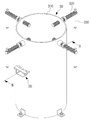
코어 드릴용 코어비트(3)는 도 1 및 도 2와 같이 하단부 중앙에 연결구(311)가 형성된 원통형 생크(31)와; 상기 원통형 생크(31)의 선단부에 나사결합되고, 상단부에 다수의 다이아몬드 또는 초경팁으로 된 절삭팁(321)이 형성되는 드릴링(32);으로 구성된다.The core bit for a
한편, 코어 드릴을 이용하여 콘크리트 구조물 등의 벽체 등을 천공 작업할 시 코어비트(3)의 드릴링(32)의 절삭팁(321)이 조금씩 마모되어 수회 사용할 경우 절삭팁(321)의 마모량이 증가되어 드릴링(32)을 교체 사용해야 한다. 드릴링(32)을 교체하여 사용할 수 있는 코이비트와 관련하여 특허문헌 0001(JP6291233B2), 특허문헌 0002(JP2017-159545A), 특허문헌 0003(JP4832688B2), 특허문헌 0004(JP2007-160517A) 등이 개시되어 있다.On the other hand, when drilling a wall such as a concrete structure using a core drill, the
코어 비트(3)의 드릴링(32)이 원통형 생크(31)에 나사결합되어 있고, 특히 천공 작업시 드릴링(32)에 작용되는 회전토크, 콘크리트 분진 및 산화 등에 의해 드릴링이 원통형 생크에 더욱 견고하게 나사결합된다. 이에 작업자들이 종래의 드릴링(32)을 분해하여 새로운 드릴링(32)으로 교체 결합하기 위해 종래의 드릴링(32)을 원통형 생크(31)로부터 분리하여야 하나, 종래의 드릴링(32)이 원통형 생크(31)에 견고하게 나사결합되어 있어, 드릴링(32)을 원통형 생크(31)로부터 분리하지 못하여 재사용이 가능한 원통형 생크(31)와 함께 폐기하는 문제가 있다.The
본 발명은 상술한 문제점을 해결하기 위하여 창출된 것으로서, 작업자가 마모된 드릴링이 원통형 생크에 견고하게 결합되어 있어도 용이하게 분해할 수 있는 원통형 생크를 재사용가능한 코어비트 분해용 고정장치를 제공하는 것을 그 목적으로 한다.The present invention was created in order to solve the above-described problem, and it is to provide a fixing device for reusable core bit disassembly of a cylindrical shank that can be easily disassembled even if the operator wears a worn drilling is firmly coupled to the cylindrical shank. The purpose.
상기와 같은 목적을 달성하기 위한 본 발명은 하단부에 연결구가 형성된 원통형 생크와, 상기 원통형 생크의 선단부에 나사결합되는 드릴링으로 구성된 코어비트를 분해하기 위한 코어비트 분해용 고정장치로서, 상기 코어비트의 원통형 생크가 내측에 수용된 상태에서 상기 코어비트의 원통형 생크의 상부의 3점 이상을 위치고정시키는 상부 위치고정부;를 포함하여 이루어지는 것을 특징으로 하는 코어비트 분해용 고정장치를 제공한다.The present invention for achieving the above object is a core bit disassembly fixing device for disassembling a core bit consisting of a cylindrical shank having a connector formed at a lower end and a drilling screwed to the tip of the cylindrical shank, It provides a fixing device for disassembling a core bit, comprising: an upper position fixing part for fixing at least three points of the upper portion of the cylindrical shank of the core bit while the cylindrical shank is accommodated therein.
여기서, 상기 원통형 생크의 연결구가 관통하는 관통구가 중앙에 형성되고, 상기 관통구에 상기 원통형 생크의 연결구가 관통한 상태로 상기 원통형 생크가 회전되는 것을 방지하는 회전방지 고정부가 구비되는 것이 바람직하다.Here, it is preferable that a through hole through which the connector of the cylindrical shank passes is formed in the center, and an anti-rotation fixing part that prevents rotation of the cylindrical shank while the connector of the cylindrical shank passes through the through hole is preferably provided. .
그리고, 상기 원통형 생크의 연결구의 외주면 양측에 플랫부가 형성되고, 상기 회전방지 고정부는 상기 상부 위치고정부에 수평방향으로 이동가능하게 설치되며, 상기 회전방지 고정부에 상기 플랫부와 면접촉되는 삽입홈이 상기 관통구와 연통되도록 형성되는 것이 바람직하다.And, a flat portion is formed on both sides of the outer peripheral surface of the connector of the cylindrical shank, the rotation-preventing fixing part is installed to be movable in a horizontal direction to the upper position fixing part, and the rotation-preventing fixing part is inserted in surface contact with the flat part. It is preferable that the groove is formed to communicate with the through hole.
또한, 상기 상부 위치고정부의 전측 외주면 및 타측 외주면에 상기 회전방지 고정부의 수평이동을 안내하는 안내구가 각각 형성되고, 상기 회전방지 고정부의 전측과 후측이 상기 안내구를 각각 관통한 상태로 상기 상부 위치고정부의 전측외부방향과 후측외부방향으로 일정길이로 노출되며, 상기 상부 위치고정부의 전측 외부방향과 후측 외부방향으로 일정길이로 노출된 상기 회전방지 고정부의 전측과 후측에 각각 손잡이부가 구비되는 것이 바람직하다.In addition, guide holes for guiding horizontal movement of the rotation-preventing fixing part are formed on the front outer circumferential surface and the other outer circumferential surface of the upper position fixing part, and the front and rear sides of the rotation preventing fixing part respectively penetrate the guide holes. In the front and rear sides of the rotation-preventing fixing part exposed to a predetermined length in the front outer direction and the rear outer direction of the upper position fixing part, and in the front outer direction and the rear outer direction of the upper position fixing part It is preferable that each handle is provided.
나아가, 상기 상부 위치고정부는 상기 코어비트의 원통형 생크가 내측에 수용되는 상부 고정관체와; 상기 상부 고정관체의 상부에 등각으로 3개 이상 나사결합된 상태로 내측단부가 내측으로 인입되어 상기 코어비트의 원통형 생크의 상부를 위치고정시키는 복수의 고정부재;를 포함하여 구성되는 것이 바람직하다.Further, the upper position fixing part includes an upper fixed tube body in which the cylindrical shank of the core bit is accommodated therein; It is preferable to include a plurality of fixing members for fixing the position of the upper portion of the cylindrical shank of the core bit in a state in which three or more are screwed at an equal angle to the upper fixing tube, the inner end is inserted inward.
더불어, 상기 상부 위치고정부의 복수의 고정부재의 외측단부에 손잡이가 구비되는 것이 바람직하다.In addition, it is preferable that a handle is provided on the outer ends of the plurality of fixing members of the upper position fixing part.
아울러, 상기 상부 위치고정부의 복수의 고정부재의 내측단부에 회전결합되어 상기 코어비트의 원통형 생크의 상부에 밀착고정되는 밀판부가 구비되는 것이 바람직하다.In addition, it is preferable that a pressurizing plate portion is provided that is rotatably coupled to the inner ends of the plurality of fixing members of the upper position fixing portion to be tightly fixed to the upper portion of the cylindrical shank of the core bit.
본 발명은 코어비트의 원통형 생크를 회전방지 고정부에 의해 회전되는 것을 방지할 수 있음은 물론 상부 위치고정부에 의해 원통형 생크가 일측으로 넘어지고 회전되는 것을 방지할 수 있고, 나아가 상기 회전방지 고정부 및 상부 위치고정부에 의해 원통형 생크를 고정한 상태에서 항타기, 전동 해머 등의 공구를 이용하여 드릴링을 나사결합 해제방향으로 타격하여 쉽게 분해하여 원통형 생크의 재사용할 수 있는 효과가 있다.The present invention can prevent the cylindrical shank of the core bit from being rotated by the rotation preventing fixing unit, as well as preventing the cylindrical shank from falling and rotating to one side by the upper position fixing unit, and furthermore, the rotation preventing fixing unit In the state where the cylindrical shank is fixed by the top and upper position fixing portions, the drilling is easily disassembled by hitting the drilling in the screw-unlocking direction using a tool such as a driving machine or an electric hammer, so that the cylindrical shank can be reused.
도 1은 코어 드릴용 코어비트를 개략적으로 나타내는 사시도이고,
도 2는 도 1의 A - A에 따른 단면도이고,
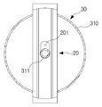
도 3은 본 발명의 일실시예인 코어비트 분해용 고정장치를 개략적으로 나타내는 사시도이고,
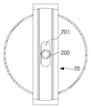
도 4는 상부 위치고정부로부터 회전방지 고정부가 분리된 상태를 개략적으로 나타내는 분리사시도이고,
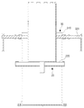
도 5는 도 3의 B - B선에 따른 결합단면도이고,
도 6은 코어비트의 원통형 생크의 하부가 회전 방지고정부에 안착된 상태를 개략적으로 나타내는 단면도이고,
도 7은 도 6의 C - C선에 따른 단면도이고,
도 8은 회전 방지고정부의 삽입홈에 원통형 생크의 연결구가 삽입된 상태를 개략적으로 나타내는 단면도이고,
도 9는 도 8의 D - D선에 따른 단면도이고,
도 10은 회전 방지 고정부의 관통구의 전측과 후측에 각각 삽입홈이 형성된 상태를 개략적으로 나타내는 단면도이고,
도 11 및 도 12는 도 10의 삽입홈 중 어느 하나의 삽입홈에 원통형 생크의 연결구가 삽입된 상태를 개략적으로 나타내는 단면도이고,
도 13은 상부 위치고정부의 내측에 코어비트의 원통형 생크가 위치고정된 상태를 개략적으로 나타내는 사시도이고,
도 14는 도 13의 E - E선에 따른 단면도이고,
도 15는 상부 위치고정부의 복수의 고정부재의 내측단부에 밀판부가 구비된 상태를 개략적으로 나타내는 단면도이고,
도 16은 원통형 생크로부터 드릴링이 분리되는 상태를 개략적으로 나타내는 단면도이다.1 is a perspective view schematically showing a core bit for a core drill,
2 is a cross-sectional view taken along A-A of FIG. 1,
3 is a perspective view schematically showing a fixing device for disassembling a core bit according to an embodiment of the present invention,
4 is an exploded perspective view schematically showing a state in which the rotation preventing fixing part is separated from the upper position fixing part,
Figure 5 is a cross-sectional view taken along line B-B of Figure 3,
6 is a cross-sectional view schematically showing a state in which the lower portion of the cylindrical shank of the core bit is seated on the rotation preventing fixing portion,
7 is a cross-sectional view taken along line C-C of FIG. 6,
8 is a cross-sectional view schematically showing a state in which the connector of the cylindrical shank is inserted into the insertion groove of the rotation preventing fixing part,
9 is a cross-sectional view taken along line D-D of FIG. 8,
10 is a cross-sectional view schematically showing a state in which insertion grooves are formed at the front and rear sides of the through hole of the rotation preventing fixing unit,
11 and 12 are cross-sectional views schematically showing a state in which a connector of a cylindrical shank is inserted into one of the insertion grooves of FIG. 10,
13 is a perspective view schematically showing a state in which the cylindrical shank of the core bit is fixed inside the upper position fixing part,
14 is a cross-sectional view taken along line E-E in FIG. 13,
15 is a cross-sectional view schematically showing a state in which a mil plate part is provided at inner ends of a plurality of fixing members of an upper position fixing part,
16 is a cross-sectional view schematically showing a state in which drilling is separated from the cylindrical shank.
이하, 본 발명의 바람직한 실시예를 첨부한 도면에 의거하여 보다 상세하게 설명하면 다음과 같다. 물론 본 발명의 권리범위는 하기의 실시예에 한정되는 것은 아니며, 본 발명의 기술적 요지를 벗어나지 않는 범위 내에서 당해 기술분야의 통상적인 지식을 가진자에 의하여 다양하게 변형 실시될 수 있다.Hereinafter, a preferred embodiment of the present invention will be described in more detail with reference to the accompanying drawings. Of course, the scope of the present invention is not limited to the following embodiments, and various modifications may be made by those of ordinary skill in the art within the scope not departing from the technical gist of the present invention.
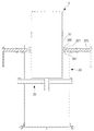
도 3은 본 발명의 일실시예인 코어비트 분해용 고정장치를 개략적으로 나타내는 사시도이고, 도 4는 상부 위치고정부로부터 회전방지 고정부가 분리된 상태를 개략적으로 나타내는 분리사시도이고, 도 5는 도 3의 B - B선에 따른 결합단면도이다.3 is a perspective view schematically showing a fixing device for disassembling a core bit according to an embodiment of the present invention, FIG. 4 is an exploded perspective view schematically showing a state in which the rotation preventing fixing part is separated from the upper position fixing part, and FIG. 5 is FIG. It is a cross-sectional view along the B-B line.
본 발명의 일실시예인 코어비트 분해용 고정장치는 하단부 중앙에 연결구(도 1 및 도 2의 311)가 형성된 원통형 생크(도 1 및 도 2의 31)와; 상기 원통형 생크(31)의 선단부에 나사결합되는 드릴링(도 1 및 도 2의 32)으로 구성된 코어비트(3)를 분해하기 위한 것으로서, 크게, 도 3 및 도 4에서 보는 바와 같이 상부위치고정부(30)를 포함하여 이루어진다.A fixing device for disassembling a core bit according to an embodiment of the present invention includes a cylindrical shank (31 in FIGS. 1 and 2) having a connector (311 in FIGS. 1 and 2) formed at the center of the lower end; As for disassembling the
상기 상부 위치고정부(30)는 일예로, 도 3 내지 도 5에서 보는 바와 같이 크게, 상부 고정관체(310)와 복수의 고정부재(320)를 포함하여 구성될 수 있다.The upper
상기 상부 고정관체(310)는 원통형 형상 등 다양한 형상으로 이루어질 수 있다.The upper
도 6은 코어비트의 원통형 생크의 하부가 회전 방지고정부에 안착된 상태를 개략적으로 나타내는 단면도이고, 도 7은 도 6의 C - C선에 따른 단면도이다.6 is a cross-sectional view schematically showing a state in which the lower portion of the cylindrical shank of the core bit is seated on the rotation preventing fixing portion, and FIG. 7 is a cross-sectional view taken along line C-C of FIG. 6.
도 6에서 보는 바와 같이 상기 상부 고정관체(310)의 내측에 상기 코어비트(3)의 원통형 생크(31)가 수용된 상태로 상기 코어비트(3)의 드릴링(32)이 상기 상부 고정관체(310)의 상부 외부방향으로 노출될 수 있다.As shown in FIG. 6, drilling 32 of the
복수의 상기 고정부재(320)는 상기 상부 고정관체(310)의 상부에 등각으로 3개 이상으로 방사형으로 나사결합될 수 있다.The plurality of
복수의 상기 고정부재(320)가 작업자에 의해 정방향으로 회전될 경우, 복수의 상기 고정부재(320)의 내측단부가 상기 상부 고정관체(310)의 내측으로 인입되어 후술할 회전방지 고정부(20)의 지지판(220)상에 안착된 상기 코어비트(3)의 원통형 생크(31)의 상부 외주면에 밀착고정되어 상기 코어비트(3)의 원통형 생크(31)의 상부를 위치고정시킬 수 있다.(도 14 참조.)When the plurality of
복수의 상기 고정부재(320)가 작업자에 의해 역방향으로 회전될 경우, 복수의 상기 고정부재(320)의 내측단부가 상기 상부 고정관체(310)의 외측방향으로 인출되면서 상기 코어비트(3)의 원통형 생크(31)의 상부 외주면에 밀착고정된 복수의 상기 고정부재(320)의 고정상태가 해제될 수 있다.When the plurality of
상기 상부 고정관체(310)의 상부에 등각으로 2개의 상기 고정부재(320)가 구비될 수도 있겠으나, 상기 코어비트(3)의 원통형 생크(31)가 회전되지 않도록 상기 원통형 생크(3)를 보다 더욱 높은 효율로 위치고정시키기 위해 상기 상부 고정관체(310)의 상부에 등각으로 3개 이상의 복수의 상기 고정부재(320)가 구비되는 것이 좋다.Two
상기 코어비트(3)의 원통형 생크(31)의 상부 외주면에 밀착고정되는 복수의 상기 고정부재(320)를 통해 상기 코어비트(3)의 원통형 생크(31)가 회전되는 것을 더욱 높은 효율로 방지할 수 있을 뿐만 아니라 외부 충격 등에 의해 상기 코어비트(3)가 넘어지는 것을 보다 용이하게 방지할 수 있게 된다.The rotation of the
복수의 상기 고정부재(320)를 작업자가 보다 용이하게 정역회전시킬 수 있도록 하기 위해 상기 상부 위치고정부(30)의 복수의 상기 고정부재(320)의 외측단부에는 복수의 상기 고정부재(320)의 외측단부를 수직관통한 상태로 용접고정 등 다양한 방식으로 고정될 수 있는 손잡이(330)가 구비될 수 있다.A plurality of
다음으로, 도 3 내지 도 6에서 보는 바와 같이 상기 원통형 생크(31)가 회전되는 것을 방지하기 위한 회전방지 고정부(20)가 구비될 수 있다.Next, as shown in FIGS. 3 to 6, an
상기 회전방지 고정부(20)는 도 4에서 보는 바와 같이 회전방지 고정프레임(210)과 지지판(220)을 포함하여 구성될 수 있다.The rotation preventing
상기 회전방지 고정프레임(210)은 상기 상부 위치고정부(30)의 전후방향으로 일정길이로 수평연장형성될 수 있다.The rotation preventing
상기 회전방지 고정프레임(210)의 일측과 타측은 각각 상기 상부 위치고정부(30)의 상부방향으로 수직절곡형성될 수 있고, 상기 회전방지 고정프레임(210)의 상부는 개방될 수 있다.One side and the other side of the rotation-preventing
상기 회전방지 고정프레임(210)의 중앙에는 상기 원통형 생크(31)의 연결구(311)가 수직관통하는 관통구(200)가 형성될 수 있다.A through
상기 지지판(220)은 상기 회전방지 고정프레임(210)의 상부 일측과 상부 타측에서 상기 회전방지 고정프레임(210)을 따라 일정길이로 수평연장형성될 수 있다.The
다음으로, 도 1, 도 2에서 보는 바와 같이 상기 원통형 생크(31)의 연결구(311)의 외주면 양측, 즉 상기 연결구(311)의 외주면 일측과 외주면 타측에는 상기 연결구(311)의 외주면에서 상기 연결구(311)의 내측으로 일정깊이로 수평함몰되는 홈형태의 플랫부(312)가 각각 형성될 수 있다.Next, as shown in Figs. 1 and 2, both sides of the outer circumferential surface of the
그리고, 상기 회전방지 고정부(20)의 회전방지 고정프레임(210)의 관통구(200)의 전측방향 또는 후측방향에 위치하는 상기 회전방지 고정프레임(210) 부위에는 상기 관통구(200)와 연통되는 삽입홈(201)이 편심형성될 수 있다.In addition, a portion of the rotation-preventing
상기 삽입홈(201)은 상기 회전방지 고정부(20)의 회전방지 고정프레임(210)의 전후방향으로 일정길이로 수평연장형성될 수 있다.The
상기 회전방지 고정부(20)는 상기 상부 위치고정부(30)의 상부 고정관체(310)의 상부에 작업자에 의해 상기 상부 위치고정부(30)의 전후방향으로 수평이동가능하게 설치될 수 있다.The rotation-preventing
일예로, 도 4에서 보는 바와 같이 상기 상부 위치고정부(30)의 상부 고정관체(310)의 전측 상부 외주면과 후측 상부 외주면에는 상기 회전방지 고정부(20)의 수평이동을 안내하는 안내구(300)가 각각 형성될 수 있다.As an example, as shown in FIG. 4, a guide tool for guiding the horizontal movement of the rotation-preventing
상기 회전방지 고정부(20)의 전측과 후측이 상기 안내구(300)를 각각 관통한 상태로 상기 상부 위치고정부(30)의 상부 고정관체(310)의 전측 외부방향과 후측 외부방향으로 일정길이로 노출될 수 있다.In a state in which the front and rear sides of the rotation-preventing
상기 상부 위치고정부(30)의 상부 고정관체(310)의 전측 외부방향과 후측 외부방향으로 일정길이로 노출된 상기 회전방지 고정부(20)의 전측 상부와 후측 상부에 각각 판형태 등으로 이루어질 수 있는 손잡이부(40)가 용접고정, 볼트고정 등 다양한 방식으로 고정구비될 수 있다.Each of the upper and rear portions of the rotation-preventing
작업자는 상기 손잡이부(40)를 이용하여 상기 회전방지 고정부(20)를 용이하게 수평이동시킬 수 있을 뿐만 아니라 상기 손잡이부(40)를 통해 상기 상부 위치고정부(30)의 상부 고정관체(310)로부터 상기 회전방지 고정부(20)가 이탈되는 것을 용이하게 방지할 수 있게 된다.The operator can easily horizontally move the rotation-preventing
도 8은 회전 방지고정부의 삽입홈에 원통형 생크의 연결구가 삽입된 상태를 개략적으로 나타내는 단면도이고, 도 9는 도 8의 D - D선에 따른 단면도이다.8 is a cross-sectional view schematically showing a state in which the connector of the cylindrical shank is inserted into the insertion groove of the rotation preventing fixing portion, and FIG. 9 is a cross-sectional view taken along line D-D of FIG. 8.
도 7 내지 도 9에서 보는 바와 같이 상기 회전방지 고정부(20)가 상기 상부 위치고정부(30)의 상부 고정관체(310)의 전측방향으로 수평이동하게 될 경우, 상기 연결구(311)가 상기 회전방지 고정부(20)의 삽입홈(201)에 삽입되면서 상기 삽입홈(201)의 일측 내주면 및 타측 내주면과 마주보는 상기 플랫부(312)의 내주면이 면접촉할 수 있게 되고, 이로 인해 상기 원통형 생크(31)가 회전되는 것을 방지할 수 있게 된다.7 to 9, when the rotation preventing fixing
도 10은 회전 방지 고정부의 관통구의 전측과 후측에 각각 삽입홈이 형성된 상태를 개략적으로 나타내는 단면도이고, 도 11 및 도 12는 도 10의 삽입홈 중 어느 하나의 삽입홈에 원통형 생크의 연결구가 삽입된 상태를 개략적으로 나타내는 단면도이다.10 is a cross-sectional view schematically showing a state in which insertion grooves are formed at the front and rear sides of the through hole of the rotation preventing fixing part, respectively, and FIGS. 11 and 12 are a connector of a cylindrical shank in any one of the insertion grooves of FIG. It is a cross-sectional view schematically showing the inserted state.
도 10 내지 도 12에서 보는 바와 같이 상기 회전방지 고정부(20)의 삽입홈(201)은 상기 회전방지 고정부(20)의 회전방지 고정프레임(210)의 관통구(200)의 전측방향과 후측방향에 각각 위치하는 상기 회전방지 고정프레임(210) 부위 모두에 각각 편심형성될 수도 있다.As shown in FIGS. 10 to 12, the
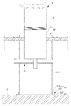
도 13은 상부 위치고정부의 내측에 코어비트의 원통형 생크가 위치고정된 상태를 개략적으로 나타내는 사시도이고, 도 14는 도 13의 E - E선에 따른 단면도이고, 도 15는 상부 위치고정부의 복수의 고정부재의 내측단부에 밀판부가 구비된 상태를 개략적으로 나타내는 단면도이고, 도 16은 원통형 생크로부터 드릴링이 분리되는 상태를 개략적으로 나타내는 단면도이다.13 is a perspective view schematically showing a state in which the cylindrical shank of the core bit is fixed in position inside the upper position fixing part, FIG. 14 is a cross-sectional view taken along line E-E of FIG. 13, and FIG. 15 is a view of the upper position fixing part. It is a cross-sectional view schematically showing a state in which the pushing plate is provided on the inner end of the plurality of fixing members, and FIG. 16 is a cross-sectional view schematically showing a state in which drilling is separated from the cylindrical shank.
도 13 내지 도 16에서 보는 바와 같이 상기 회전방지 고정부(20) 및 상부 위치고정부(30)에 의해 원통형 생크(31)를 고정한 상태에서 항타기, 전동 해머 등의 공구를 이용하여 드릴링을 나사결합 해제방향으로 타격하여 쉽게 분해하여 원통형 생크(31)의 재사용할 수 있다.As shown in Figs. 13 to 16, while the
도 15에서 보는 바와 같이 상기 상부 위치고정부(30)의 복수의 고정부재(320)의 내측단부에 밀판부(340)가 구비될 수 있다.As shown in FIG. 15, a
일예로, 복수의 상기 고정부재(320)의 내측단부에 볼부재(321)가 일체형성될 수 있다.As an example, a
그리고, 상기 볼부재(321)와 마주보는 상기 밀판부(340)의 중간부위에 상기 볼부재(321)가 회전가능하게 결합되는 결합홈(341)이 형성될 수 있다.Further, a
상기 결합홈(341)이 상기 볼부재(321)의 외주면을 감쌀 수 있도록 상기 결합홈(341)은 단면형상이 'C'형상 등 다양한 형상으로 형성될 수 있다.The
상기 밀판부(340)는 고무 재질 등의 탄성력을 지닌 재질 등 다양한 재질로 이루어질 수 있다.The
상기 밀판부(340)는 상기 지지플레이트(10)상에 안착된 상기 코어비트(3)의 원통형 생크(31)의 상부 외면에 밀착고정될 수 있다.The
상기 원통형 생크(31)의 상부 외면에 보다 더욱 넓은 면적으로 면접촉된 상태로 상기 원통형 생크(31)의 상부 외면에 밀착고정되는 상기 밀판부(340)를 통해 상기 원통형 생크(31)가 회전되지 않도록 상기 원통형 생크(3)를 보다 더더욱 높은 효율로 위치고정시킬 수 있게 된다.The
그리고, 상기 원통형 생크(31)로부터 상기 드릴링(32)을 분해하는 과정 중에 상기 하부 지지부(40)가 미끄러지면서 넘어지는 것을 방지하기 위해, 도 16에서 보는 바와 같이 상기 상부 위치고정부(30)의 상부 고정관체(310)의 하부 외주면에는 상기 상부 고정관체(310)를 지면(2)에 위치고정시키기 위한 위치고정부(60)가 방사형으로 더 구비될 수 있다.And, in order to prevent the
상기 위치고정부(60)는 일예로, 복수의 고정판(610)과 위치고정부재(620)로 구성될 수 있다.The
복수의 상기 고정판(610)의 일측은 상기 상부 위치고정부(30)의 상부 고정관체(310)의 상부 방향으로 수직으로 절곡형성되어 상기 상부 위치고정부(30)의 상부 고정관체(310)의 하부 외주면에 상기 상부 고정관체(310)의 하부 외주면을 따라 등간격으로 볼트고정 또는 용접고정 등 다양한 방식으로 고정될 수 있다.One side of the plurality of fixing
상기 위치고정부재(620)는 볼트(621)와 너트(622)로 구성될 수 있다.The
상기 볼트(621)는 복수의 상기 고정판(610)의 일측을 수직관통하여 지면에 삽입고정되는 앵커볼트 등 다양한 종류로 이루어질 수 있다.The
상기 너트(622)는 복수의 상기 고정판(610)의 일측 상부방향으로 일정길이로 노출되는 상기 볼트(621)의 상부에 나사결합되어 복수의 상기 고정판(610)의 일측 상부면에 밀착고정될 수 있다.The
3; 코어비트,
31; 원통형 생크,
32; 드릴링,
20; 회전방지 고정부,
30; 상부 위치고정부.3; Core bit, 31; Cylindrical shank,
32; Drilling, 20; Anti-rotation fixing part,
30; Upper position fixed.
Claims (7)
상기 코어비트의 원통형 생크가 내측에 수용된 상태에서 상기 코어비트의 원통형 생크의 상부의 3점 이상을 위치고정시키는 상부 위치고정부;를 포함하여 이루어지는 것을 특징으로 하는 코어비트 분해용 고정장치.
As a fixing device for disassembling a core bit consisting of a cylindrical shank having a connector formed at a lower end and a drilling screwed to the tip of the cylindrical shank,
And a fixing device for disassembling a core bit, comprising: an upper position fixing part for fixing at least three points of an upper portion of the cylindrical shank of the core bit while the cylindrical shank of the core bit is accommodated therein.
상기 원통형 생크의 연결구가 관통하는 관통구가 중앙에 형성되고, 상기 관통구에 상기 원통형 생크의 연결구가 관통한 상태로 상기 원통형 생크가 회전되는 것을 방지하는 회전방지 고정부가 구비되는 것을 특징으로 하는 코어비트 분해용 고정장치.
The method of claim 1,
A core, characterized in that a through hole through which the connector of the cylindrical shank passes is formed in the center, and an anti-rotation fixing part for preventing rotation of the cylindrical shank while the connector of the cylindrical shank passes through the through hole Fixture for disassembling bits.
상기 원통형 생크의 연결구의 외주면 양측에 플랫부가 형성되고,
상기 회전방지 고정부는 상기 상부 위치고정부에 수평방향으로 이동가능하게 설치되며,
상기 회전방지 고정부에 상기 플랫부와 면접촉되는 삽입홈이 상기 관통구와 연통되도록 형성되는 것을 특징으로 하는 코어비트 분해용 고정장치.
The method of claim 2,
Flat portions are formed on both sides of the outer peripheral surface of the connector of the cylindrical shank,
The rotation preventing fixing part is installed to be movable in a horizontal direction on the upper position fixing part,
The fixing device for disassembling a core bit, characterized in that the insertion groove in surface contact with the flat part in the rotation preventing fixing part is formed to communicate with the through hole.
상기 상부 위치고정부의 전측 외주면 및 타측 외주면에 상기 회전방지 고정부의 수평이동을 안내하는 안내구가 각각 형성되고,
상기 회전방지 고정부의 전측과 후측이 상기 안내구를 각각 관통한 상태로 상기 상부 위치고정부의 전측외부방향과 후측외부방향으로 일정길이로 노출되며,
상기 상부 위치고정부의 전측 외부방향과 후측 외부방향으로 일정길이로 노출된 상기 회전방지 고정부의 전측과 후측에 각각 손잡이부가 구비되는 것을 특징으로 하는 코어비트 분해용 고정장치.
The method of claim 3,
Guide holes for guiding the horizontal movement of the rotation preventing fixing part are formed on the front outer circumferential surface and the other outer circumferential surface of the upper position fixing part, respectively,
The front and rear sides of the rotation-preventing fixing part are exposed to a predetermined length in a front-outward direction and a rear-outward direction of the upper position fixing part, with each passing through the guide hole,
A fixing device for disassembling a core bit, characterized in that a handle part is provided on each of the front and rear sides of the rotation-preventing fixing part exposed to a predetermined length in a front outer direction and a rear outer direction of the upper position fixing part.
상기 상부 위치고정부는 상기 코어비트의 원통형 생크가 내측에 수용되는 상부 고정관체와;
상기 상부 고정관체의 상부에 등각으로 3개 이상 나사결합된 상태로 내측단부가 내측으로 인입되어 상기 코어비트의 원통형 생크의 상부를 위치고정시키는 복수의 고정부재;를 포함하여 구성되는 것을 특징으로 하는 코어비트 분해용 고정장치.
The method of claim 1,
The upper position fixing part includes an upper fixing tube in which the cylindrical shank of the core bit is accommodated therein;
Characterized in that it comprises a plurality of fixing members for fixing the position of the upper portion of the cylindrical shank of the core bit in a state in which three or more are screwed at an equal angle to the upper portion of the upper fixed tube, the inner end of which is inserted inward. Fixing device for disassembling the core bit.
상기 상부 위치고정부의 복수의 고정부재의 외측단부에 손잡이가 구비되는 것을 특징으로 하는 코어비트 분해용 고정장치.
The method of claim 5,
A fixing device for disassembling a core bit, characterized in that a handle is provided at outer ends of the plurality of fixing members of the upper position fixing part.
상기 상부 위치고정부의 복수의 고정부재의 내측단부에 회전결합되어 상기 코어비트의 원통형 생크의 상부에 밀착고정되는 밀판부가 구비되는 것을 특징으로 하는 코어비트 분해용 고정장치.The method of claim 5,
A fixing device for disassembling a core bit, characterized in that it is provided with a pressing plate portion that is rotatably coupled to the inner ends of the plurality of fixing members of the upper position fixing part and is tightly fixed to the upper portion of the cylindrical shank of the core bit.
Priority Applications (1)
| Application Number | Priority Date | Filing Date | Title |
|---|---|---|---|
| KR1020190016415A KR20200098826A (en) | 2019-02-13 | 2019-02-13 | Fixing device for core bit breaking |
Applications Claiming Priority (1)
| Application Number | Priority Date | Filing Date | Title |
|---|---|---|---|
| KR1020190016415A KR20200098826A (en) | 2019-02-13 | 2019-02-13 | Fixing device for core bit breaking |
Publications (1)
| Publication Number | Publication Date |
|---|---|
| KR20200098826A true KR20200098826A (en) | 2020-08-21 |
Family
ID=72235883
Family Applications (1)
| Application Number | Title | Priority Date | Filing Date |
|---|---|---|---|
| KR1020190016415A KR20200098826A (en) | 2019-02-13 | 2019-02-13 | Fixing device for core bit breaking |
Country Status (1)
| Country | Link |
|---|---|
| KR (1) | KR20200098826A (en) |
Citations (4)
| Publication number | Priority date | Publication date | Assignee | Title |
|---|---|---|---|---|
| JP2007160517A (en) | 2005-12-09 | 2007-06-28 | Nippon Fuasutemu Kk | Core bit and cutting device equipped therewith |
| JP4832688B2 (en) | 2001-09-28 | 2011-12-07 | サンゴバン株式会社 | Core bit |
| JP2017159545A (en) | 2016-03-09 | 2017-09-14 | 株式会社大林組 | Core bit and punching device |
| JP6291233B2 (en) | 2013-12-04 | 2018-03-14 | 旭ダイヤモンド工業株式会社 | Core collection bit |
-
2019
- 2019-02-13 KR KR1020190016415A patent/KR20200098826A/en active IP Right Grant
Patent Citations (4)
| Publication number | Priority date | Publication date | Assignee | Title |
|---|---|---|---|---|
| JP4832688B2 (en) | 2001-09-28 | 2011-12-07 | サンゴバン株式会社 | Core bit |
| JP2007160517A (en) | 2005-12-09 | 2007-06-28 | Nippon Fuasutemu Kk | Core bit and cutting device equipped therewith |
| JP6291233B2 (en) | 2013-12-04 | 2018-03-14 | 旭ダイヤモンド工業株式会社 | Core collection bit |
| JP2017159545A (en) | 2016-03-09 | 2017-09-14 | 株式会社大林組 | Core bit and punching device |
Similar Documents
| Publication | Publication Date | Title |
|---|---|---|
| JPH086865Y2 (en) | Drill for rock drill | |
| US8573707B2 (en) | Retainer sleeve and washer for cutting tool | |
| US3773122A (en) | Rock drilling tool | |
| FI125387B (en) | Drill bit and single phase drilling rig | |
| JP5641476B2 (en) | Method for machining a milling head and a pile head | |
| DE102004026850A1 (en) | Plug-in ends for a rotating and / or beating tool | |
| KR20200098826A (en) | Fixing device for core bit breaking | |
| US7237984B1 (en) | Hole-cutting saw | |
| KR102243146B1 (en) | Core Drill | |
| JP6191084B2 (en) | Impact mechanism and rock drill and drill rig equipped with the impact mechanism | |
| KR102120977B1 (en) | Rock breaking device | |
| KR20180108105A (en) | Expansion core bit for core drill | |
| KR20080052575A (en) | A one-piece drill bit for single-pass anchor bolting and single pass drilling apparatus | |
| US3163237A (en) | Impact drill | |
| US4153121A (en) | Fluid operated undercutter | |
| US2819880A (en) | Rock drills | |
| US2853904A (en) | Core cutter | |
| US2761440A (en) | Drilling apparatus for concrete and the like | |
| KR20200092594A (en) | Fixing device for disassembling core bit | |
| US20040035007A1 (en) | Attachment for a percussive tool | |
| GB2338438A (en) | A rotary tool | |
| KR20100047103A (en) | A punching equipment | |
| US20180354158A1 (en) | System, method, core drill bit and core drilling machine for hole drilling in an object | |
| KR200334854Y1 (en) | A tool for making blasting hole | |
| JP3231386U (en) | Drill anchor and anchor placing device |
Legal Events
| Date | Code | Title | Description |
|---|---|---|---|
| E701 | Decision to grant or registration of patent right |