KR20200096716A - Eye tracking device and display apparatus including the same - Google Patents
Eye tracking device and display apparatus including the same Download PDFInfo
- Publication number
- KR20200096716A KR20200096716A KR1020190113016A KR20190113016A KR20200096716A KR 20200096716 A KR20200096716 A KR 20200096716A KR 1020190113016 A KR1020190113016 A KR 1020190113016A KR 20190113016 A KR20190113016 A KR 20190113016A KR 20200096716 A KR20200096716 A KR 20200096716A
- Authority
- KR
- South Korea
- Prior art keywords
- light
- guide plate
- input
- light guide
- observer
- Prior art date
Links
Images


Classifications
-
- G—PHYSICS
- G06—COMPUTING; CALCULATING OR COUNTING
- G06F—ELECTRIC DIGITAL DATA PROCESSING
- G06F3/00—Input arrangements for transferring data to be processed into a form capable of being handled by the computer; Output arrangements for transferring data from processing unit to output unit, e.g. interface arrangements
- G06F3/01—Input arrangements or combined input and output arrangements for interaction between user and computer
- G06F3/011—Arrangements for interaction with the human body, e.g. for user immersion in virtual reality
- G06F3/013—Eye tracking input arrangements
-
- G—PHYSICS
- G02—OPTICS
- G02B—OPTICAL ELEMENTS, SYSTEMS OR APPARATUS
- G02B27/00—Optical systems or apparatus not provided for by any of the groups G02B1/00 - G02B26/00, G02B30/00
- G02B27/0093—Optical systems or apparatus not provided for by any of the groups G02B1/00 - G02B26/00, G02B30/00 with means for monitoring data relating to the user, e.g. head-tracking, eye-tracking
-
- G—PHYSICS
- G02—OPTICS
- G02B—OPTICAL ELEMENTS, SYSTEMS OR APPARATUS
- G02B27/00—Optical systems or apparatus not provided for by any of the groups G02B1/00 - G02B26/00, G02B30/00
-
- G—PHYSICS
- G02—OPTICS
- G02B—OPTICAL ELEMENTS, SYSTEMS OR APPARATUS
- G02B27/00—Optical systems or apparatus not provided for by any of the groups G02B1/00 - G02B26/00, G02B30/00
- G02B27/01—Head-up displays
- G02B27/017—Head mounted
- G02B27/0172—Head mounted characterised by optical features
-
- G—PHYSICS
- G06—COMPUTING; CALCULATING OR COUNTING
- G06F—ELECTRIC DIGITAL DATA PROCESSING
- G06F3/00—Input arrangements for transferring data to be processed into a form capable of being handled by the computer; Output arrangements for transferring data from processing unit to output unit, e.g. interface arrangements
- G06F3/01—Input arrangements or combined input and output arrangements for interaction between user and computer
- G06F3/011—Arrangements for interaction with the human body, e.g. for user immersion in virtual reality
-
- G06K9/00597—
-
- G—PHYSICS
- G06—COMPUTING; CALCULATING OR COUNTING
- G06V—IMAGE OR VIDEO RECOGNITION OR UNDERSTANDING
- G06V10/00—Arrangements for image or video recognition or understanding
- G06V10/10—Image acquisition
- G06V10/12—Details of acquisition arrangements; Constructional details thereof
- G06V10/14—Optical characteristics of the device performing the acquisition or on the illumination arrangements
- G06V10/141—Control of illumination
-
- G—PHYSICS
- G06—COMPUTING; CALCULATING OR COUNTING
- G06V—IMAGE OR VIDEO RECOGNITION OR UNDERSTANDING
- G06V10/00—Arrangements for image or video recognition or understanding
- G06V10/40—Extraction of image or video features
- G06V10/50—Extraction of image or video features by performing operations within image blocks; by using histograms, e.g. histogram of oriented gradients [HoG]; by summing image-intensity values; Projection analysis
- G06V10/507—Summing image-intensity values; Histogram projection analysis
-
- G—PHYSICS
- G06—COMPUTING; CALCULATING OR COUNTING
- G06V—IMAGE OR VIDEO RECOGNITION OR UNDERSTANDING
- G06V20/00—Scenes; Scene-specific elements
- G06V20/20—Scenes; Scene-specific elements in augmented reality scenes
-
- G—PHYSICS
- G06—COMPUTING; CALCULATING OR COUNTING
- G06V—IMAGE OR VIDEO RECOGNITION OR UNDERSTANDING
- G06V40/00—Recognition of biometric, human-related or animal-related patterns in image or video data
- G06V40/10—Human or animal bodies, e.g. vehicle occupants or pedestrians; Body parts, e.g. hands
- G06V40/18—Eye characteristics, e.g. of the iris
-
- G—PHYSICS
- G09—EDUCATION; CRYPTOGRAPHY; DISPLAY; ADVERTISING; SEALS
- G09G—ARRANGEMENTS OR CIRCUITS FOR CONTROL OF INDICATING DEVICES USING STATIC MEANS TO PRESENT VARIABLE INFORMATION
- G09G3/00—Control arrangements or circuits, of interest only in connection with visual indicators other than cathode-ray tubes
- G09G3/20—Control arrangements or circuits, of interest only in connection with visual indicators other than cathode-ray tubes for presentation of an assembly of a number of characters, e.g. a page, by composing the assembly by combination of individual elements arranged in a matrix no fixed position being assigned to or needed to be assigned to the individual characters or partial characters
-
- G—PHYSICS
- G02—OPTICS
- G02B—OPTICAL ELEMENTS, SYSTEMS OR APPARATUS
- G02B27/00—Optical systems or apparatus not provided for by any of the groups G02B1/00 - G02B26/00, G02B30/00
- G02B27/01—Head-up displays
- G02B27/0179—Display position adjusting means not related to the information to be displayed
- G02B2027/0187—Display position adjusting means not related to the information to be displayed slaved to motion of at least a part of the body of the user, e.g. head, eye
-
- G—PHYSICS
- G02—OPTICS
- G02B—OPTICAL ELEMENTS, SYSTEMS OR APPARATUS
- G02B27/00—Optical systems or apparatus not provided for by any of the groups G02B1/00 - G02B26/00, G02B30/00
- G02B27/28—Optical systems or apparatus not provided for by any of the groups G02B1/00 - G02B26/00, G02B30/00 for polarising
- G02B27/283—Optical systems or apparatus not provided for by any of the groups G02B1/00 - G02B26/00, G02B30/00 for polarising used for beam splitting or combining
-
- G—PHYSICS
- G02—OPTICS
- G02B—OPTICAL ELEMENTS, SYSTEMS OR APPARATUS
- G02B6/00—Light guides; Structural details of arrangements comprising light guides and other optical elements, e.g. couplings
- G02B6/24—Coupling light guides
- G02B6/26—Optical coupling means
- G02B6/34—Optical coupling means utilising prism or grating
-
- G—PHYSICS
- G09—EDUCATION; CRYPTOGRAPHY; DISPLAY; ADVERTISING; SEALS
- G09G—ARRANGEMENTS OR CIRCUITS FOR CONTROL OF INDICATING DEVICES USING STATIC MEANS TO PRESENT VARIABLE INFORMATION
- G09G2360/00—Aspects of the architecture of display systems
- G09G2360/14—Detecting light within display terminals, e.g. using a single or a plurality of photosensors
- G09G2360/145—Detecting light within display terminals, e.g. using a single or a plurality of photosensors the light originating from the display screen
Abstract
Description
개시된 실시예들은 시선 추적 장치 및 이를 포함하는 디스플레이 장치에 관한 것으로, 더욱 상세하게는 관찰자의 시선을 빠르고 정확하게 추적할 수 있으며 소형화가 가능한 시선 추적 장치 및 이를 포함하는 디스플레이 장치를 제공한다.The disclosed embodiments relate to a gaze tracking device and a display device including the same, and more particularly, to provide a gaze tracking device capable of quickly and accurately tracking an observer's gaze and miniaturization, and a display device including the same.
최근, 가상 현실(virtual reality)(VR)을 구현할 수 있는 전자기기 및 디스플레이 장치가 개발되면서, 이에 대한 관심이 높아지고 있다. 가상 현실(VR)의 다음 단계로 증강 현실(augmented reality)(AR) 및 혼합 현실(mixed reality)(MR)을 실현할 수 있는 기술도 연구되고 있다.Recently, as electronic devices and display devices capable of implementing virtual reality (VR) have been developed, interest in this has increased. A technology capable of realizing augmented reality (AR) and mixed reality (MR) as the next stage of virtual reality (VR) is also being studied.
증강 현실(AR)은, 완전 가상 세계를 전제로 하는 가상 현실(VR)과는 달리, 현실 세계의 환경 위에 가상의 대상이나 정보를 겹쳐(결합하여) 보여줌으로써 현실의 효과를 더욱 증가시키는 디스플레이 기술이다. 가상 현실(VR)이 게임이나 가상 체험과 같은 분야에만 한정적으로 적용이 가능했다면, 증강 현실(AR)은 다양한 현실 환경에 응용이 가능하다는 장점이 있다. 특히, 증강 현실(AR)은 유비쿼터스(ubiquitous) 환경이나 사물 인터넷(internet of things)(IoT) 환경에 적합한 차세대 디스플레이 기술로 주목받고 있다.Augmented reality (AR) is a display technology that further increases the effect of reality by superimposing (combining) virtual objects or information on the environment of the real world, unlike virtual reality (VR), which presupposes a complete virtual world. to be. While virtual reality (VR) can be limitedly applied to fields such as games and virtual experiences, augmented reality (AR) has an advantage that it can be applied to various reality environments. In particular, augmented reality (AR) is drawing attention as a next-generation display technology suitable for a ubiquitous environment or an Internet of things (IoT) environment.
한편, 이러한 가상 현실(VR), 증강 현실(AR), 또는 혼합 현실 장치(MR)는 디스플레이 되는 영상의 시점을 관찰자의 시선과 일치시키기 위하여 관찰자의 시선을 감지하는 시선 추적 장치를 포함한다.Meanwhile, the virtual reality (VR), augmented reality (AR), or mixed reality device (MR) includes a gaze tracking device that senses the gaze of the observer in order to match the view point of the displayed image with the gaze of the observer.
관찰자의 시선을 빠르고 정확하게 추적할 수 있으며 소형화가 가능한 시선 추적 장치 및 이를 포함하는 디스플레이 장치를 제공한다.It provides a gaze tracking device capable of quickly and accurately tracking an observer's gaze and miniaturization and a display device including the same.
일 실시예에 따르면, 조명광을 방출하는 광원; 빛을 감지하는 광검출기 어레이; 상기 광원으로부터 방출된 조명광을 관찰자의 눈에 전달하고, 관찰자의 눈의 망막에서 반사된 조명광을 상기 광원으로부터 방출된 조명광의 진행 방향과 반대 방향으로 전달하는 도광판; 및 상기 광검출기 어레이의 출력을 기초로 관찰자의 시선을 결정하는 신호 처리기;를 포함하는 시선 추적 장치가 제공된다. 여기서, 상기 신호 처리기는 상기 광검출기 어레이에서 감지되는 빛의 2차원 세기 분포를 기초로 관찰자의 시선을 결정하도록 구성될 수 있다.According to an embodiment, a light source for emitting illumination light; A photodetector array for sensing light; A light guide plate that transmits the illumination light emitted from the light source to the observer's eye, and transmits the illumination light reflected from the retina of the observer's eye in a direction opposite to a traveling direction of the illumination light emitted from the light source; And a signal processor configured to determine an observer's gaze based on the output of the photodetector array. Here, the signal processor may be configured to determine an observer's line of sight based on a 2D intensity distribution of light detected by the photodetector array.
상기 도광판은 입사광을 상기 도광판의 내부로 안내하고 상기 도광판의 내부를 따라 진행하는 빛을 상기 도광판의 외부로 출력하는 제 1 입출력 커플러와 제 2 입출력 커플러를 포함할 수 있다.The light guide plate may include a first input/output coupler and a second input/output coupler for guiding incident light to the inside of the light guide plate and outputting light traveling along the inside of the light guide plate to the outside of the light guide plate.
상기 시선 추적 장치는, 상기 광원으로부터 방출된 조명광을 상기 제 1 입출력 커플러에 전달하고, 상기 제 1 입출력 커플러로부터 오는 빛을 상기 광검출기 어레이에 전달하도록 구성된 빔스플리터를 더 포함할 수 있다.The eye tracking device may further include a beam splitter configured to transmit the illumination light emitted from the light source to the first input/output coupler and transmit light from the first input/output coupler to the photodetector array.
상기 광원은 상기 빔스플리터의 제 1 표면에 마주하여 배치되고 상기 광검출기 어레이는 상기 빔스플리터의 제 2 표면에 마주하여 배치될 수 있다.The light source may be disposed facing the first surface of the beam splitter, and the photodetector array may be disposed facing the second surface of the beam splitter.
상기 빔스플리터는 입사광의 절반을 반사하고 나머지 절반을 투과시키는 반투과 거울일 수 있다.The beam splitter may be a transflective mirror that reflects half of the incident light and transmits the other half.
상기 빔스플리터는 제 1 선편광 성분을 갖는 빛을 반사하고 제 1 선편광 성분에 직교하는 제 2 선편광 성분을 갖는 빛을 투과시키는 편광 빔스플리터일 수 있다.The beam splitter may be a polarization beam splitter that reflects light having a first linearly polarized component and transmits light having a second linearly polarized component orthogonal to the first linearly polarized component.
상기 시선 추적 장치는 상기 빔스플리터와 상기 도광판 사이에 배치된 1/4 파장판을 더 포함할 수 있다.The eye tracking apparatus may further include a quarter wave plate disposed between the beam splitter and the light guide plate.
상기 시선 추적 장치는 상기 빔스플리터와 상기 도광판 사이에 배치된 가변 초점 렌즈를 더 포함하며, 상기 가변 초점 렌즈는 상기 제 2 입출력 커플러와 관찰자의 눈 사이의 거리에 따라 초점길이를 변화시키도록 구성될 수 있다.The gaze tracking device further includes a variable focus lens disposed between the beam splitter and the light guide plate, and the variable focus lens is configured to change a focal length according to a distance between the second input/output coupler and the observer's eyes. I can.
일 예에서, 상기 도광판은 제 1 표면 및 제 1 표면에 마주하는 제 2 표면을 가지며, 상기 광원과 상기 광검출기 어레이는 상기 도광판의 제 1 표면에 마주하여 배치되고, 상기 제 1 입출력 커플러와 제 2 입출력 커플러는 상기 도광판의 제 2 표면 상에 배치될 수 있다.In one example, the light guide plate has a first surface and a second surface facing the first surface, the light source and the photodetector array are disposed facing the first surface of the light guide plate, and the first input/output coupler and the first The 2 input/output coupler may be disposed on the second surface of the light guide plate.
다른 예에서, 상기 도광판은 제 1 표면 및 제 1 표면에 마주하는 제 2 표면을 가지며, 상기 광원과 상기 광검출기 어레이는 상기 도광판의 제 1 표면에 마주하여 배치되고, 상기 제 1 입출력 커플러와 제 2 입출력 커플러는 상기 도광판의 제 1 표면 상에 배치될 수 있다.In another example, the light guide plate has a first surface and a second surface facing the first surface, the light source and the photodetector array are disposed facing the first surface of the light guide plate, and the first input/output coupler and the first The 2 input/output coupler may be disposed on the first surface of the light guide plate.
상기 제 2 입출력 커플러는 상기 도광판으로부터 출력되어 관찰자의 눈의 동공을 통과한 조명광이 관찰자의 눈의 중심에 포커싱되도록 양의 굴절력을 갖는 홀로그래픽 광학 소자일 수 있다.The second input/output coupler may be a holographic optical element having positive refractive power so that illumination light output from the light guide plate and passing through the pupil of the observer's eye is focused on the center of the observer's eye.
상기 광원은 적외선 광을 방출하는 적외선 광원일 수 있다.The light source may be an infrared light source that emits infrared light.
상기 광검출기 어레이는 2차원 배열된 다수의 적외선 검출기를 포함할 수 있다.The photodetector array may include a plurality of infrared detectors arranged in two dimensions.
상기 도광판은 만곡된 형태를 가질 수 있다.The light guide plate may have a curved shape.
다른 실시예에 따르면, 영상을 형성하는 영상 형성 장치; 관찰자의 시선을 추적하는 시선 추적 장치; 및 상기 시선 추적 장치로부터 제공된 관찰자의 시선에 따라 상기 영상을 이동시키는 영상 시프터;를 포함하는 디스플레이 장치가 제공된다. 여기서, 상기 시선 추적 장치는, 적외선 조명광을 방출하는 적외선 광원; 2차원 배열된 다수의 적외선 검출기를 구비하는 광검출기 어레이; 상기 적외선 광원으로부터 방출된 적외선 조명광을 관찰자의 눈에 전달하고, 관찰자의 눈의 망막에서 반사된 적외선 조명광을 상기 광검출기 어레이로 전달하는 도광판; 및 상기 광검출기 어레이의 출력을 기초로 관찰자의 시선을 결정하는 신호 처리기;를 포함하고, 상기 신호 처리기는 상기 광검출기 어레이에서 감지되는 적외선 광의 2차원 세기 분포를 기초로 관찰자의 시선을 결정하도록 구성될 수 있다.According to another embodiment, an image forming apparatus for forming an image; A gaze tracking device that tracks an observer's gaze; And an image shifter for moving the image according to the viewer's gaze provided from the gaze tracking device. Here, the eye tracking device includes: an infrared light source emitting infrared illumination light; A photodetector array including a plurality of infrared detectors arranged in two dimensions; A light guide plate that transmits the infrared illumination light emitted from the infrared light source to the observer's eye, and transmits the infrared illumination light reflected from the retina of the observer's eye to the photodetector array; And a signal processor for determining the observer's line of sight based on the output of the photodetector array, wherein the signal processor is configured to determine the observer's line of sight based on a two-dimensional intensity distribution of infrared light detected by the photodetector array. Can be.
또한, 상기 영상 형성 장치는, 가시광을 방출하는 가시광원; 및 상기 가시광원으로부터 방출된 빛을 변조하여 영상을 생성하는 공간 광변조기;를 포함할 수 있다.In addition, the image forming apparatus may include a visible light source emitting visible light; And a spatial light modulator for generating an image by modulating the light emitted from the visible light source.
상기 도광판은, 입사하는 적외선 조명광을 상기 도광판의 내부로 안내하고 상기 도광판의 내부를 따라 진행하는 적외선 조명광을 상기 도광판의 외부로 출력하는 제 1 입출력 커플러와 제 2 입출력 커플러; 입사하는 가시광을 상기 도광판의 내부로 안내하는 입력 커플러; 및 상기 도광판의 내부를 따라 진행하는 가시광을 상기 도광판의 외부로 출력하는 출력 커플러;를 포함할 수 있다.The light guide plate includes: a first input/output coupler and a second input/output coupler configured to guide incident infrared illumination light to the inside of the light guide plate and output infrared illumination light traveling along the inside of the light guide plate to the outside of the light guide plate; An input coupler for guiding incident visible light into the light guide plate; And an output coupler for outputting visible light traveling along the inside of the light guide plate to the outside of the light guide plate.
상기 도광판은 제 1 표면 및 제 1 표면에 마주하는 제 2 표면을 가지며, 상기 입력 커플러와 출력 커플러는 상기 도광판의 제 1 표면에 배치되고, 상기 제 1 입출력 커플러는 상기 도광판의 제 2 표면에 상기 입력 커플러와 마주하여 배치되고 상기 제 2 입출력 커플러는 상기 도광판의 제 2 표면에 상기 출력 커플러와 마주하여 배치될 수 있다.The light guide plate has a first surface and a second surface facing the first surface, the input coupler and the output coupler are disposed on the first surface of the light guide plate, and the first input/output coupler is disposed on the second surface of the light guide plate. The second input/output coupler may be disposed to face the input coupler, and the second input/output coupler may be disposed on the second surface of the light guide plate to face the output coupler.
상기 디스플레이 장치는, 상기 입력 커플러 및 상기 제 1 입출력 커플러에 마주하여 배치된 것으로, 상기 적외선 광원으로부터 방출된 적외선 조명광과 상기 영상 형성 장치에서 형성된 영상을 결합하여 동일한 광 경로를 따라 진행시키는 파장 선택성 거울을 더 포함할 수 있다.The display device, which is disposed facing the input coupler and the first input/output coupler, combines the infrared illumination light emitted from the infrared light source and the image formed by the image forming apparatus and proceeds along the same optical path. It may further include.
상기 디스플레이 장치는, 상기 파장 선택성 거울과 상기 도광판 사이에 배치되는 것으로, 상기 적외선 광원으로부터 방출된 적외선 조명광을 상기 제 1 입출력 커플러에 전달하고, 상기 제 1 입출력 커플러로부터 오는 적외선 광을 상기 광검출기 어레이에 전달하도록 구성된 빔스플리터를 더 포함할 수 있다.The display device is disposed between the wavelength-selective mirror and the light guide plate, and transmits infrared illumination light emitted from the infrared light source to the first input/output coupler, and transmits infrared light from the first input/output coupler to the photodetector array. It may further include a beam splitter configured to transmit to.
상기 적외선 광원은 상기 빔스플리터의 제 1 표면에 마주하여 배치되고 상기 광검출기 어레이는 상기 빔스플리터의 제 2 표면에 마주하여 배치될 수 있다.The infrared light source may be disposed facing the first surface of the beam splitter, and the photodetector array may be disposed facing the second surface of the beam splitter.
상기 빔스플리터는 입사하는 적외선 광의 절반을 반사하고 적외선 광의 나머지 절반을 투과시키며 가시광을 투과시키도록 구성될 수 있다.The beam splitter may be configured to reflect half of incident infrared light, transmit the other half of infrared light, and transmit visible light.
상기 빔스플리터는 제 1 선편광 성분을 갖는 적외선 광을 반사하고 제 1 선편광 성분에 직교하는 제 2 선편광 성분을 갖는 적외선 광을 투과시키며 가시광을 투과시키도록 구성될 수 있다.The beam splitter may be configured to reflect infrared light having a first linearly polarized component, transmit infrared light having a second linearly polarized component orthogonal to the first linearly polarized component, and transmit visible light.
상기 디스플레이 장치는 상기 빔스플리터와 상기 도광판 사이에 배치된 1/4 파장판을 더 포함할 수 있다.The display device may further include a quarter wave plate disposed between the beam splitter and the light guide plate.
상기 디스플레이 장치는 상기 빔스플리터와 상기 도광판 사이에 배치된 가변 초점 렌즈를 더 포함하며, 상기 가변 초점 렌즈는 상기 제 2 입출력 커플러와 관찰자의 눈 사이의 거리에 따라 초점길이를 변화시키도록 구성될 수 있다.The display device further includes a variable focus lens disposed between the beam splitter and the light guide plate, and the variable focus lens may be configured to change a focal length according to a distance between the second input/output coupler and the observer's eye. have.
상기 디스플레이 장치는 헤드 마운트형, 안경형 또는 고글형일 수 있다.The display device may be a head mounted type, a glasses type, or a goggle type.
상기 디스플레이 장치는 가상 현실(VR) 디스플레이 장치, 증강 현실(AR) 디스플레이 장치, 또는 혼합 현실(MR) 디스플레이 장치일 수 있다.The display device may be a virtual reality (VR) display device, an augmented reality (AR) display device, or a mixed reality (MR) display device.
개시된 시선 추적 장치는 넓은 각도 범위에 걸쳐 관찰자의 눈의 회전 각도를 탐지할 수 있다. 또한, 개시된 시선 추적 장치는 관찰자의 시선을 빠르고 정확하게 추적할 수 있다. 또한, 개시된 시선 추적 장치는 얇은 두께와 작은 중량을 갖도록 소형화가 가능하며, 시선 추적 장치를 채용하는 디스플레이 장치 내에 용이하게 결합될 수 있다. 따라서, 시선 추적 장치를 채용한 디스플레이 장치의 소형화가 가능하다. 또한, 고출력 광원을 사용하지 않기 때문에 소비전력이 낮고 관찰자의 눈을 손상시킬 위험도 낮다.The disclosed eye tracking device is capable of detecting the angle of rotation of an observer's eye over a wide angular range. In addition, the disclosed gaze tracking device can quickly and accurately track the gaze of an observer. In addition, the disclosed gaze tracking device can be miniaturized to have a thin thickness and a small weight, and can be easily incorporated into a display device employing the gaze tracking device. Therefore, it is possible to downsize a display device employing an eye-tracking device. In addition, since the high-power light source is not used, power consumption is low and the risk of damage to the observer's eyes is low.
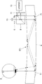
도 1은 일 실시예에 따른 시선 추적 장치의 구조를 개략적으로 보이는 단면도이다.
도 2a는 시선 추적 장치의 입출력 커플러가 광학적 굴절력을 갖지 않은 경우에 관찰자의 눈에서 빔의 경로를 예시적으로 보인다.
도 2b는 시선 추적 장치의 입출력 커플러가 광학적 굴절력을 갖는 경우에 관찰자의 눈에서 빔의 경로를 예시적으로 보인다.
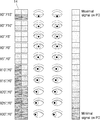
도 3은 광검출기 어레이가 2×2 배열의 적외선 검출기를 포함하는 경우에 관찰자의 눈의 회전에 따른 광검출기 어레이의 출력 변화를 예시적으로 보인다.
도 4는 광검출기 어레이가 2×10 배열의 적외선 검출기를 포함하는 경우에 관찰자의 눈의 회전에 따른 광검출기 어레이의 출력 변화를 예시적으로 보인다.
도 5는 다른 실시예에 따른 시선 추적 장치의 구조를 개략적으로 보이는 단면도이다.
도 6은 또 다른 실시예에 따른 시선 추적 장치의 구조를 개략적으로 보이는 단면도이다.
도 7은 또 다른 실시예에 따른 시선 추적 장치의 구조를 개략적으로 보이는 단면도이다.
도 8은 또 다른 실시예에 따른 시선 추적 장치의 구조를 개략적으로 보이는 단면도이다.
도 9는 시선 추적 장치를 포함하는 일 실시예에 따른 디스플레이 장치를 개략적으로 보이는 단면도이다.
도 10은 시선 추적 장치를 포함하는 다른 실시예에 따른 디스플레이 장치를 개략적으로 보이는 단면도이다.
도 11 내지 도 13은 디스플레이 장치를 적용할 수 있는 다양한 전자기기를 도시한다.1 is a cross-sectional view schematically showing the structure of an eye tracking device according to an embodiment.
2A is an exemplary view showing a path of a beam in an observer's eye when the input/output coupler of the eye tracking device does not have optical refractive power.
FIG. 2B exemplarily shows a path of a beam in an observer's eye when the input/output coupler of the eye tracking device has optical refractive power.
FIG. 3 exemplarily shows a change in output of the photodetector array according to the rotation of an observer's eye when the photodetector array includes a 2×2 array of infrared detectors.
FIG. 4 exemplarily shows a change in output of the photodetector array according to the rotation of an observer's eye when the photodetector array includes a 2×10 array of infrared detectors.
5 is a cross-sectional view schematically showing the structure of an eye tracking device according to another embodiment.
6 is a cross-sectional view schematically showing the structure of an eye tracking device according to another embodiment.
7 is a cross-sectional view schematically showing a structure of an eye tracking device according to another embodiment.
8 is a cross-sectional view schematically showing a structure of a gaze tracking device according to another embodiment.
9 is a schematic cross-sectional view of a display device according to an exemplary embodiment including a gaze tracking device.
10 is a schematic cross-sectional view of a display device according to another exemplary embodiment including a gaze tracking device.
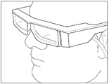
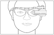
11 to 13 illustrate various electronic devices to which a display device can be applied.
이하, 첨부된 도면들을 참조하여, 시선 추적 장치 및 이를 포함하는 디스플레이 장치에 대해 상세하게 설명한다. 이하의 도면들에서 동일한 참조부호는 동일한 구성요소를 지칭하며, 도면상에서 각 구성요소의 크기는 설명의 명료성과 편의상 과장되어 있을 수 있다. 또한, 이하에 설명되는 실시예는 단지 예시적인 것에 불과하며, 이러한 실시예들로부터 다양한 변형이 가능하다. 또한 이하에서 설명하는 층 구조에서, "상부" 또는 "상"이라고 기재된 표현은 접촉하여 바로 위/아래/좌/우에 있는 것뿐만 아니라 비접촉으로 위/아래/좌/우에 있는 것도 포함할 수 있다.Hereinafter, a gaze tracking device and a display device including the same will be described in detail with reference to the accompanying drawings. In the following drawings, the same reference numerals refer to the same components, and the size of each component in the drawings may be exaggerated for clarity and convenience of description. In addition, the embodiments described below are merely exemplary, and various modifications are possible from these embodiments. In addition, in the layer structure described below, the expression “top” or “top” may include not only those that are directly above/below/left/right in contact but also those that are above/below/left/right in a non-contact manner.
도 1은 일 실시예에 따른 시선 추적 장치의 구조를 개략적으로 보이는 단면도이다. 도 1을 참조하면, 일 실시예에 따른 시선 추적 장치(100)는 조명광을 방출하는 광원(10), 빛을 감지하는 광검출기 어레이(14), 광원(10)으로부터 방출된 조명광을 관찰자의 눈(E)에 전달하고 관찰자의 눈(E)의 망막에서 반사된 조명광을 광원(10)으로부터 방출된 조명광의 진행 방향과 반대 방향으로 전달하는 도광판(8), 및 광검출기 어레이(14)의 출력을 기초로 관찰자의 시선을 결정하는 신호처리기(15)를 포함할 수 있다.1 is a cross-sectional view schematically showing the structure of an eye tracking device according to an embodiment. Referring to FIG. 1, the
광원(10)은 적외선을 방출하는 적외선 광원일 수 있다. 예를 들어, 광원(10)은 약 750 nm 내지 3 ㎛의 파장을 갖는 근적외선을 방출하는 발광 다이오드(LED; light emitting diode) 또는 레이저 다이오드(LD; laser diode)일 수 있다. 또한, 광원(10)은 사람의 눈에 대해 안전 기준(safety standard)을 만족하는 낮은 출력을 갖는 광원이 선택될 수 있다.The
광검출기 어레이(14)는 적외선을 감지할 수 있는 다수의 적외선 검출기를 포함할 수 있다. 예를 들어, 광검출기 어레이(14)는 근적외선 대역의 빛을 감지할 수 있는 2차원 배열된 다수의 적외선 검출기의 어레이를 포함할 수 있다. 특히, 광검출기 어레이(14)의 다수의 적외선 검출기는 광원(10)으로부터 방출된 조명광의 파장 대역에 대해 높은 감도를 갖는 포토다이오드일 수 있다.The
도광판(8)은 조명광을 전달하는 광도파로의 역할을 할 수 있도록 적외선에 대해 투명한 재료로 이루어질 수 있다. 예를 들어, 도광판(8)은 유리, PMMA(Poly methyl methacrylate), 또는 PDMS(Polydimethylsiloxane) 등과 같은 재료로 이루어질 수 있다. 또한, 도광판(8)은 납작하고 평평한 평판 형태를 가질 수 있다. 도광판(8)은 제 1 표면(8a) 및 제 1 표면(8a)에 마주하는 제 2 표면(8b)을 포함할 수 있다. 광원(10)과 광검출기 어레이(14)는 도광판(8)의 제 1 표면(8a) 쪽에 배치될 수 있으며, 도광판(8)의 제 2 표면(8b)에는 입사광을 도광판(8)의 내부로 경사지게 유도하고 도광판(8)의 내부에서 경사지게 진행하는 빛을 도광판(8)의 외부로 출력하도록 구성된 제 1 및 제 2 입출력 커플러(12, 13)가 배치될 수 있다. 예를 들어, 제 1 입출력 커플러(12)는 도광판(8)의 제 2 표면(8b)의 한쪽 가장자리에 배치될 수 있으며 제 2 입출력 커플러(13)는 도광판(8)의 제 2 표면(8b)의 다른 쪽 가장자리에 배치될 수 있다.The
제 1 및 제 2 입출력 커플러(12, 13)는 도광판(8)의 외부로부터 제 1 및 제 2 입출력 커플러(12, 13)에 대략적으로 수직한 방향으로 입사하는 빛을 도광판(8)의 내부로 경사지게 안내하도록 구성된다. 예를 들어, 제 1 및 제 2 입출력 커플러(12, 13)는 그의 표면에 수직한 방향을 중심으로 소정의 입사각 범위 내에서 제 1 및 제 2 입출력 커플러(12, 13)에 입사하는 빛을 도광판(8)의 내부로 안내하도록 구성될 수 있다. 도광판(8)의 내부로 안내된 빛은 도광판(8)의 제 1 표면(8a)과 제 2 표면(8b)에서 반복적으로 전반사되면서 도광판(8)의 내부를 따라 진행하게 된다.The first and second input/
또한, 제 1 및 제 2 입출력 커플러(12, 13)는 도광판(8)의 내부로부터 제 1 및 제 2 입출력 커플러(12, 13)에 경사지게 입사하는 빛을 도광판(8)의 외부로 대략적으로 수직한 방향으로 출력하도록 구성된다. 제 1 및 제 2 입출력 커플러(12, 13)는 소정의 입사각 범위 내에서 그의 표면에 경사지게 입사하는 빛에만 작용하고, 그의 표면에 수직하게 입사하는 빛에는 작용하지 않도록 구성될 수 있다. 다시 말해, 제 1 및 제 2 입출력 커플러(12, 13)는 그의 표면에 수직하게 입사하는 빛에 대해서는 단순히 투명한 평판의 역할을 할 수 있다.In addition, the first and second input/
이러한 제 1 및 제 2 입출력 커플러(12, 13)는, 예를 들어, 회절 광학 소자(diffractive optical element; DOE) 또는 홀로그래픽 광학 소자(holographic optical element; HOE)로 이루어질 수 있다. 회절 광학 소자(DOE)는 다수의 주기적인 미세한 격자 패턴을 포함한다. 회절 광학 소자(DOE)의 다수의 격자 패턴은 회절 격자의 역할을 하여 입사광을 회절시킨다. 특히, 격자 패턴들의 크기, 높이, 주기 등에 따라서, 특정한 각도 범위로 입사하는 빛을 회절시켜 소멸 간섭과 보강 간섭을 일으킴으로써 빛의 진행 방향을 바꿀 수 있다. 또한, 홀로그래픽 광학소자(HOE)는 격자 패턴 대신에 굴절률이 상이한 재료들의 주기적인 미세한 패턴들을 포함한다. 홀로그래픽 광학 소자(HOE)는 회절 광학 소자(DOE)와 단지 구성의 차이만이 있을 뿐이며 동작 원리는 회절 광학 소자(DOE)와 동일할 수 있다.The first and second input/
제 1 및 제 2 입출력 커플러(12, 13)를 구성하는 회절 광학 소자(DOE) 또는 홀로그래픽 광학소자(HOE)는 파장 의존성을 갖도록 구성될 수 있다. 다시 말해, 광원(10)으로부터 방출된 조명광의 파장 대역에 대해서만 입출력 커플러의 역할을 하고, 다른 파장 대역의 빛에 대해서는 투명하도록 제 1 및 제 2 입출력 커플러(12, 13)가 구성될 수 있다. 예를 들어, 적외선 대역의 빛만이 제 1 및 제 2 입출력 커플러(12, 13)에 의해 커플링되고, 가시광과 같은 나머지 파장 대역의 빛은 제 1 및 제 2 입출력 커플러(12, 13)를 투과할 수 있다.The diffractive optical element DOE or the holographic optical element HOE constituting the first and second input/
이러한 도광판(8)의 구성에서, 제 1 입출력 커플러(12)에 입사한 빛은 전반사를 통해 도광판(8)의 내부를 따라 진행하다가 제 2 입출력 커플러(13)를 통해 도광판(8)의 외부로 나오게 되며, 제 2 입출력 커플러(13)에 입사한 빛은 전반사를 통해 도광판(8)의 내부를 진행하다가 제 1 입출력 커플러(12)를 통해 도광판(8)의 외부로 나오게 된다. 도 1에 도시된 바와 같이, 제 1 입출력 커플러(12)에 마주하여 광원(10)이 배치되고 제 2 입출력 커플러(13)에 마주하여 관찰자의 눈(E)이 위치하는 경우, 광원(10)으로부터 방출된 조명광은 먼저 도광판(8)의 제 1 표면(8a)을 지나 제 1 입출력 커플러(12)에 입사한다. 그런 후, 조명광은 도광판(8)의 내부를 따라 제 1 방향(즉, 도면에서 우측 방향)으로 진행하게 된다. 그리고, 조명광은 제 2 입출력 커플러(13)에 의해 회절되면서 도광판(8)의 제 1 표면(8a)을 지나 관찰자의 눈(E)에 도달한다. 한편, 관찰자의 눈(E)에서 반사된 조명광은 도광판(8)의 제 1 표면(8a)을 지나 제 2 입출력 커플러(13)에 입사한 후, 도광판(8)의 내부를 따라 제 1 방향에 반대 방향인 제 2 방향(즉, 도면에서 좌측 방향)으로 진행한다. 그리고, 관찰자의 눈(E)에서 반사된 조명광은 제 1 입출력 커플러(12)에 의해 회절되면서 도광판(8)의 제 1 표면(8a)을 지나 광검출기 어레이(14)에 도달한다.In this configuration of the
광원(10)으로부터 방출된 조명광과 관찰자의 눈(E)에서 반사된 조명광을 분리하기 위하여 시선 추적 장치(100)는 빔스플리터(6)를 더 포함할 수 있다. 빔스플리터(6)는 도광판(8)의 제 1 표면(8a) 쪽에서 제 1 입출력 커플러(12)와 마주하도록 배치될 수 있다. 빔스플리터(6)는 서로 인접하는 제 1 표면(6a)과 제 2 표면(6b)을 포함하며, 광원(10)은 제 1 표면(6a)에 마주하여 배치되고 광검출기 어레이(14)는 제 2 표면(6b)에 마주하여 배치될 수 있다. 또한, 시선 추적 장치(100)는 광원(10)과 빔스플리터(6) 사이에 배치되어 광원(10)으로부터 발산하는 빔을 평행빔으로 만드는 콜리메이팅 렌즈(5)를 더 포함할 수 있다. 광원(10), 콜리메이팅 렌즈(5), 빔스플리터(6) 및 제 1 입출력 커플러(12)는 일직선 상에 배열되는 반면, 광검출기 어레이(14)는 빔스플리터(6)에 의해 약 90도로 절곡된 광 경로 상에 배치될 수 있다.In order to separate the illumination light emitted from the
이러한 구성에서, 빔스플리터(6)는 광원(10)으로부터 방출된 조명광을 투과시키고 관찰자의 눈(E)에서 반사된 조명광을 반사하도록 구성될 수 있다. 그러면, 광원(10)으로부터 방출된 조명광은 빔스플리터(6)의 제 1 표면(6a)에 입사한 후 빔스플리터(6)를 통과하여 제 1 입출력 커플러(12)에 도달할 수 있다. 그리고, 관찰자의 눈(E)에서 반사된 조명광은 제 1 입출력 커플러(12)에 의해 출력 커플링된 후, 빔스플리터(6)에서 반사되어 빔스플리터(6)의 제 2 표면(6b)을 통해 광검출기 어레이(14)에 입사할 수 있다.In this configuration, the
빔스플리터(6)는, 예를 들어, 단순히 입사광의 절반을 반사하고 나머지 절반을 투과시키는 반투과 거울일 수 있다. 그 대신에, 빔스플리터(6)는 편광 선택성을 갖는 편광 빔스플리터일 수도 있다. 예를 들어, 빔스플리터(6)는 제 1 선편광 성분을 갖는 빛을 반사하고 제 1 선평광 성분에 직교하는 제 2 선편광 성분을 갖는 빛을 투과시키도록 구성될 수 있다. 이 경우, 광원(10)으로부터 방출된 조명광 중에서 제 2 선편광 성분을 갖는 빛은 빔스플리터(6)를 투과하여 제 1 입출력 커플러(12)에 입사한다. 광 이용 효율을 향상시키기 위하여, 광원(10)은 제 2 선편광 성분의 빛만을 방출하는 편광 레이저와 같은 편광 광원일 수 있다. 그러면, 광원(10)으로부터 방출된 조명광이 거의 손실 없이 빔스플리터(6)를 투과하여 제 1 입출력 커플러(12)에 입사할 수 있다.The
빔스플리터(6)가 편광 빔스플리터인 경우, 시선 추적 장치(100)는 도광판(8)의 제 1 표면(8a)과 빔스플리터(6) 사이에 배치된 1/4 파장판(16)을 더 포함할 수 있다. 광원(10), 콜리메이팅 렌즈(5), 빔스플리터(6), 1/4 파장판(16) 및 제 1 입출력 커플러(12)는 일직선 상에 배열될 수 있다. 1/4 파장판(16)은 입사광을 입사광의 1/4 파장만큼 지연시키는 역할을 한다. 따라서, 빔스플리터(6)를 투과한 제 2 선평광 성분의 조명광은 1/4 파장판(16)을 지나면서 제 2 원편광 성분을 갖게 된다. 그런 후, 조명광은 관찰자의 눈(E)에 의해 입사 방향의 반대 방향으로 반사되면서 제 2 원편광 성분과 회전 방향이 반대인 제 1 원편광 성분을 갖게 된다. 제 1 원편광 성분을 갖는 조명광은 다시 1/4 파장판(16)을 지나면서 제 1 선편광 성분을 갖게 되어 빔스플리터(6)에 의해 반사된다. 그리고, 빔스플리터(6)에 의해 반사된 조명광은 광검출기 어레이(14)에 입사하게 된다.When the
또한 빔스플리터(6)는 파장 선택성을 갖도록 구성될 수 있다. 다시 말해, 빔스플리터(6)는 광원(10)으로부터 방출된 조명광의 파장 대역에 대해서만 빔스플리터의 역할을 하고, 다른 파장 대역의 빛에 대해서는 투명하도록 구성될 수 있다. 예를 들어, 빔스플리터(6)는 적외선 대역의 빛에 대해서만 반투과 거울 또는 편광 빔스플리터로서 작용하며, 가시광과 같은 나머지 파장 대역의 빛은 빔스플리터(6)를 투과할 수 있다.In addition, the
상술한 본 실시예에 따른 시선 추적 장치(100)의 구조에서, 광원(10)으로부터 방출되어 관찰자의 눈(E)에 입사한 후 관찰자의 눈(E)에서 반사되어 광검출기 어레이(14)로 되돌아오는 조명광의 2차원 세기 분포는 관찰자의 눈(E)의 시선 방향에 따라 달라질 수 있다. 예를 들어, 도 1에서 et1으로 표시된 바와 같이, 관찰자의 눈(E)이 제 2 입출력 커플러(13)를 정면으로 응시하고 있다면, 다시 말해 관찰자의 눈(E)의 동공의 광축이 제 2 입출력 커플러(13)에 대해 수직하다면, 광원(10)으로부터 방출된 조명광 중에서 제 2 입출력 커플러(13)에 대해 수직한 방향으로 출력 커플링되는 조명광이 관찰자의 눈(E)의 망막에 주로 도달한다. 그런 후, 망막에서 반사된 조명광은, 실선으로 표시된 바와 같이, 제 2 입출력 커플러(13)에 수직으로 입사한 후, 앞서 진행한 광 경로와 동일한 광 경로를 따라 반대 방향으로 진행하여 광검출기 어레이(14)의 중심부에 주로 입사하게 된다. 광원(10)으로부터 방출된 조명광 중에서 제 2 입출력 커플러(13)에 대해 경사진 방향으로 출력 커플링되는 조명광은 단지 일부만이 관찰자의 눈(E)의 망막에서 반사되어 광검출기 어레이(14)까지 도달할 수 있다.In the structure of the eye-tracking
한편, 도 1에서 et2로 표시된 바와 같이, 관찰자의 눈(E)이 제 2 입출력 커플러(13)를 비스듬하게 보고 있다면, 다시 말해 관찰자의 눈(E)의 동공의 광축이 제 2 입출력 커플러(13)에 대해 경사져 있다면, 광원(10)으로부터 방출된 조명광 중에서 제 2 입출력 커플러(13)에 대해 경사진 방향으로 출력 커플링되는 조명광이 관찰자의 눈(E)의 망막에 주로 도달한다. 특히, 관찰자의 눈(E)의 동공의 광축과 제 2 입출력 커플러(13)가 이루는 각도와 동일한 각도로 제 2 입출력 커플러(13)에 의해 출력 커플링되는 조명광이 관찰자의 눈(E)의 망막에 주로 도달한다. 그런 후, 망막에서 반사된 조명광은, 점선으로 표시된 바와 같이, 제 2 입출력 커플러(13)에 경사지게 입사한 후, 앞서 진행한 광 경로와 동일한 광 경로를 따라 반대 방향으로 진행하여 광검출기 어레이(14)의 주변부에 주로 입사하게 된다. 광원(10)으로부터 방출된 조명광 중에서 관찰자의 눈(E)의 동공의 광축과 제 2 입출력 커플러(13)가 이루는 각도와 상이한 각도로 제 2 입출력 커플러(13)에 의해 출력 커플링되는 조명광은 단지 일부만이 관찰자의 눈(E)의 망막에서 반사되어 광검출기 어레이(14)까지 도달할 수 있다.On the other hand, as indicated by et2 in FIG. 1, if the observer's eye E is looking at the second input/
따라서, 관찰자의 눈(E)의 동공의 광축 방향을 따라서 관찰자의 눈(E)에 입사하는 조명광이 관찰자의 눈(E)의 망막에서 반사되어 광검출기 어레이(14)로 되돌아갈 수 있다. 관찰자의 눈(E)의 망막에서 반사된 조명광이 앞서 진행한 광 경로와 동일한 광 경로를 따라 반대 방향으로 진행하도록 하기 위하여, 제 2 입출력 커플러(13)는 광학적 굴절력(optical power)을 갖지 않거나 또는 광학적 굴절력을 의도적으로 갖도록 구성될 수 있다. 예를 들어, 도 2a는 시선 추적 장치(100)의 제 2 입출력 커플러(13)가 광학적 굴절력을 갖지 않은 경우에 관찰자의 눈(E)에서 빔의 경로를 예시적으로 보이며, 도 2b는 시선 추적 장치(100)의 제 2 입출력 커플러(13)가 광학적 굴절력을 갖는 경우에 관찰자의 눈(E)에서 빔의 경로를 예시적으로 보인다.Accordingly, the illumination light incident on the observer's eye E along the optical axis direction of the pupil of the observer's eye E can be reflected from the retina of the observer's eye E to return to the
도 2a를 참조하면, 제 2 입출력 커플러(13)는 도광판(8)의 내부로부터 서로 동일한 각도로 제 2 입출력 커플러(13)에 입사하는 빛을 서로 동일한 각도로 출력 커플링시키도록 구성될 수 있다. 그러면, 도광판(8)의 내부로부터 서로 동일한 각도로 제 2 입출력 커플러(13)에 입사하는 빛은 제 2 입출력 커플러(13)에 의해 출력 커플링되면서 평행빔을 형성하게 된다. 출력 커플링된 평행빔 중에서 관찰자의 눈(E)의 동공의 광축과 평행하게 관찰자의 눈(E)의 동공에 입사하는 빛은 동공에 의해 관찰자의 눈(E)의 망막 위에 포커싱된다. 그런 후, 관찰자의 눈(E)의 망막에 의해 반사된 빛은 관찰자의 눈(E)의 동공에 의해 다시 평행빔이 되어 제 2 입출력 커플러(13)에 입사한다. 그러면, 조명광은 앞서 진행한 광 경로와 동일한 광 경로를 따라 반대 방향으로 진행하여 광검출기 어레이(14)에 도달할 수 있다.Referring to FIG. 2A, the second input/
또한, 도 2b를 참조하면, 제 2 입출력 커플러(13)는 도광판(8)의 내부로부터 서로 동일한 각도로 제 2 입출력 커플러(13)에 입사하는 빛을 출력 커플링하면서 한 점에 포커싱하도록 구성될 수 있다. 다시 말해, 제 2 입출력 커플러(13)는 입출력 커플러의 기능과 함께 양(+)의 굴절력을 갖는 렌즈의 기능을 수행하도록 구성될 수 있다. 이를 위해, 제 2 입출력 커플러(13)는 양(+)의 굴절력을 갖도록 설계된 홀로그래픽 광학소자(HOE)로 이루어질 수 있다. 더욱 구체적으로, 제 2 입출력 커플러(13)는 관찰자의 눈(E)의 동공에 입사한 빛이 관찰자의 눈(E)의 동공에 의해 추가적으로 포커싱되면서 망막 앞에, 특히 눈(E)의 회전 중심에 포커싱 포커싱되도록 하는 정도의 양(+)의 굴절력을 가질 수 있다.In addition, referring to FIG. 2B, the second input/
그러면, 제 2 입출력 커플러(13)에 의해 출력 커플링된 조명광 중에서 관찰자의 눈(E)의 동공의 광축을 따라 관찰자의 눈(E)의 동공에 입사하는 빛은 관찰자의 눈(E)의 회전 중심에 포커싱된 후 관찰자의 눈(E)의 망막에 수직하게 입사할 수 있다. 이 경우, 조명광이 관찰자의 눈(E)의 망막에 수직하게 입사하기 때문에, 반사된 조명광은 관찰자의 눈(E)의 망막에서부터 앞서 진행한 광 경로와 동일한 광 경로를 따라 반대 방향으로 진행하게 된다. 또한, 관찰자의 눈(E)의 회전 중심에서는 관찰자의 눈(E)의 동공에 수직하게, 즉 관찰자의 눈(E)의 동공의 광축을 따라 동공을 지나는 빛이, 눈의 위치와 관계 없이, 항상 존재한다. 따라서, 관찰자의 눈의 위치를 추적할 수 있는 영역의 범위가 넓어지게 된다. 또한, 조명광이 관찰자의 눈(E)의 동공에 입사하는 것을 보장하기 위하여 빔경(beam diameter)이 큰 조명광을 사용할 필요가 없어서, 광 이용 효율이 향상되어 시선 추적 장치(100)의 소비 전력을 저감시킬 수 있다.Then, among the illumination light output coupled by the second input/
지금까지 설명한 바와 같이, 광원(10)으로부터 방출된 조명광 중에서 일부만이 관찰자의 눈(E)의 망막에서 반사되어 광검출기 어레이(14)에 도달한다. 그리고, 광검출기 어레이(14)에 도달하는 조명광은 관찰자의 눈(E)의 동공의 광축과 제 2 입출력 커플러(13)가 이루는 각도에 따라 달라진다. 특히, 관찰자의 눈(E)의 동공의 광축과 제 2 입출력 커플러(13)가 이루는 각도에 따라 광검출기 어레이(14)에 입사하는 조명광의 세기의 2차원 분포가 달라질 수 있다. 이러한 입사광의 2차원 세기 분포는 광검출기 어레이(14)의 다수의 적외선 검출기를 이용하여 검출할 수 있다.As described so far, only a portion of the illumination light emitted from the
예를 들어, 도 3은 광검출기 어레이(14)가 2×2 배열의 포토다이오드를 포함하는 경우에 관찰자의 눈(E)의 회전에 따른 광검출기 어레이(14)의 출력 변화를 예시적으로 보인다. 도 3에서 X는 관찰자의 눈(E)의 좌우 방향의 회전 변위를 나타내며 Y는 관찰자의 눈(E)의 상하 방향의 회전 변위를 나타낸다. 도 3을 참조하면, 관찰자의 눈(E)이 정면을 응시하는 경우에, 다시 말해, X0˚Y0˚인 경우에, 4개의 포토다이오드에는 실질적으로 동일한 세기의 빛이 입사한다. 이때 입사하는 빛의 세기는 관찰자의 눈(E)의 시선의 모든 각도 범위에서 각각의 포토다이오드에 입사하는 빛의 최소 세기와 최대 세기 사이에 있는 세기 범위 중에서 중간보다 약간 큰 정도의 세기이다.For example, FIG. 3 exemplarily shows a change in output of the
그리고, 제 2 입출력 커플러(13)에 대해 관찰자의 눈(E)의 동공의 광축이 기울어짐에 따라 일부 포토다이오드에 입사하는 빛의 세기가 증가하고 다른 포토다이오드에 입사하는 빛의 세기가 감소한다. 예를 들어, 관찰자의 눈(E)이 좌우로 회전함에 따라(X5˚Y0˚, X10˚Y0˚, X15˚Y0˚), 좌측에 배열된 포토다이오드에 입사하는 빛의 세기가 증가/감소하거나 우측에 배열된 포토다이오드에 입사하는 빛의 세기 감소/증가한다. 그러나, 관찰자의 눈(E)의 좌우 방향 회전 각도가 시선 추적 장치(100)의 검출 한계를 벗어나면(X20˚Y0˚, X25˚Y0˚, X30˚Y0˚), 모든 포토다이오드에 입사하는 빛의 세기가 최소가 된다. 마찬가지로, 관찰자의 눈(E)이 상하로 회전함에 따라(X0˚Y5˚, X0˚Y10˚, X0˚Y15˚), 상부에 배열된 포토다이오드에 입사하는 빛의 세기가 증가/감소하거나 하부에 배열된 포토다이오드에 입사하는 빛의 세기 감소/증가한다. 그리고, 관찰자의 눈(E)의 상하 방향 회전 각도가 시선 추적 장치(100)의 검출 한계를 벗어나면, 모든 포토다이오드에 입사하는 빛의 세기가 최소가 된다. 도 3의 예에서는 좌우 방향 및 상하 방향으로 시선 추적 장치(100)의 검출 한계는 약 ±15˚이다.In addition, as the optical axis of the pupil of the observer's eye E is inclined with respect to the second input/
또한, 도 4는 광검출기 어레이(14)가 2×10 배열의 포토다이오드를 포함하는 경우에 관찰자의 눈(E)의 회전에 따른 광검출기 어레이(14)의 출력 변화를 예시적으로 보인다. 도 4를 참조하면, 관찰자의 눈(E)이 정면을 응시하는 경우에, 중앙의 4개의 포토다이오드에 대략적으로 동일한 세기의 빛이 입사하며, 중앙으로부터 좌우로 멀어질수록 포토다이오드에 입사하는 빛의 세기가 점차 작아진다. 그리고, 관찰자의 눈(E)이 좌우로 회전함에 따라(X5˚Y0˚, X10˚Y0˚, X15˚Y0˚, X20˚Y0˚, X25˚Y0˚, X30˚Y0˚), 좌측에 배열된 포토다이오드에 입사하는 빛의 세기가 증가/감소하거나 우측에 배열된 포토다이오드에 입사하는 빛의 세기 감소/증가하면서, 광검출기 어레이(14)에서 빛이 주로 입사하는 영역이 좌측 또는 우측으로 이동하게 된다. 도 4의 예에서는 좌우 방향으로 시선 추적 장치(100)의 검출 한계는 약 ±35˚이고 상하 방향으로 시선 추적 장치(100)의 검출 한계는 약 ±15˚이다.In addition, FIG. 4 exemplarily shows a change in output of the
도 3 및 도 4를 참고하여 설명한 시선 추적 장치(100)의 검출 한계는 단지 이해를 돕기 위한 예에 불과하며, 시선 추적 장치(100)의 검출 한계는 광검출기 어레이(14)에 2차원 배열된 포토다이오드의 개수, 또는 도광판(8)과 제 1 및 제 2 입출력 커플러(12, 13)의 광학적 특성에 따라 결정될 수 있다.The detection limit of the
상술한 바와 같이, 도 3 및 도 4에 예시된 광검출기 어레이(14)의 출력 변화를 기초로 관찰자의 눈(E)의 시선 위치를 정확하게 추적할 수 있다. 예를 들어, 신호 처리기(15)는 광검출기 어레이(14)에서 감지되는 빛의 2차원 세기 분포를 기초로 관찰자의 시선 위치를 결정할 수 있다. 이를 위해, 신호 처리기(15)는 광검출기 어레이(14)에서 감지되는 빛의 2차원 세기 분포와 관찰자의 눈(E)의 시선 위치 사이의 관계에 관한 미리 측정된 정보를 포함할 수 있다.As described above, based on the change in the output of the
이러한 방식으로, 본 실시예에 따른 시선 추적 장치(100)는 넓은 각도 범위에 걸쳐 관찰자의 눈(E)의 회전 각도를 정확하게 탐지할 수 있다. 또한, 시선 추적 장치(100)는, CCD(charge coupled device) 이미지 센서 또는 CMOS(complementary metal oxide semiconductor) 이미지 센서를 사용하여 얻은 눈의 영상을 이미지 처리 알고리즘을 통해 소프트웨어적으로 분석하는 기존의 시선 추적 장치에 비하여, 복잡한 연산이 필요 없기 때문에 관찰자의 시선을 비교적 빠르게 추적할 수 있다. 또한, 단지 포토다이오드만을 사용하기 때문에 시선 추적 장치(100)는 비교적 저렴하게 제작될 수 있다. 또한, 개시된 시선 추적 장치(100)는 얇은 도광판(8)을 이용하기 때문에 얇은 두께와 작은 중량을 갖도록 소형화가 가능하다. 또한, 개시된 시선 추적 장치(100)는 고출력의 광원을 사용하지 않아도 되기 때문에 소비전력이 비교적 낮고 관찰자의 눈을 손상시킬 위험도 비교적 낮다.In this way, the
도 5는 다른 실시예에 따른 시선 추적 장치(100')의 구조를 개략적으로 보이는 단면도이다. 도 1에 도시된 시선 추적 장치(100)와 비교할 때, 도 5에 도시된 시선 추적 장치(100')에서 광원(10)과 광검출기 어레이(14)의 위치가 서로 바뀌었다. 예를 들어, 광검출기 어레이(14)는 빔스플리터(6)의 제 1 표면(6a)에 마주하여 배치되고 광원(10)은 빔스플리터(6)의 제 2 표면(6b)에 마주하여 배치될 수 있다. 빔스플리터(6)가 제 1 선편광 성분을 갖는 빛을 반사하고 제 1 선평광 성분에 직교하는 제 2 선편광 성분을 갖는 빛을 투과시키도록 구성되는 경우, 광원(10)은 제 1 선편광 성분의 빛만을 방출하는 편광 레이저를 포함할 수 있다. 대신에, 광원(10)은 제 2 선편광 성분의 빛만을 방출하는 편광 레이저를 포함이며, 빔스플리터(6)는 제 2 선편광 성분을 갖는 빛을 반사하고 제 1 선편광 성분을 갖는 빛을 투과시키도록 구성될 수 있다.5 is a cross-sectional view schematically showing the structure of an eye tracking apparatus 100' according to another embodiment. Compared with the
도 6은 또 다른 실시예에 따른 시선 추적 장치(110)의 구조를 개략적으로 보이는 단면도이다. 도 1에 도시된 시선 추적 장치(100)와 비교할 때, 도 6에 도시된 시선 추적 장치(110)에서 제 1 및 제 2 입출력 커플러(12, 13)가 도광판(8)의 제 1 표면(8a)에 배치된다는 점에서 차이가 있다. 예를 들어, 제 1 입출력 커플러(12)는 도광판(8)의 제 1 표면(8a)의 한쪽 가장자리에 배치되며 제 2 입출력 커플러(13)는 도광판(8)의 제 1 표면(8a)의 다른 쪽 가장자리에 배치될 수 있다. 이 경우, 제 1 입출력 커플러(12)는 제 1 입출력 커플러(12)는 도광판(8)의 제 1 표면(8a) 상에서 빔스플리터(6)와 마주하도록 배치된다.6 is a cross-sectional view schematically showing the structure of the
도 7은 또 다른 실시예에 따른 시선 추적 장치(120)의 구조를 개략적으로 보이는 단면도이다. 도 7을 참조하면, 시선 추적 장치(120)는 도광판(8)과 빔스플리터(6) 사이에 배치된 가변 초점 렌즈(17)를 더 포함할 수 있다. 도 7에서 가변 초점 렌즈(17)는 1/4 파장판(16)과 도광판(8) 사이에 배치된 것으로 도시되었으나, 이에 반드시 한정되는 것은 아니다. 예를 들어, 가변 초점 렌즈(17)는 도광판(8)과 빔스플리터(6) 사이의 광 경로 어느 곳에도 제한 없이 배치될 수 있다. 또는, 가변 초점 렌즈(17)는 도광판(8)과 관찰자의 눈(E) 사이의 광 경로 어느 곳에도 제한 없이 배치될 수 있다.7 is a cross-sectional view schematically showing a structure of an
도 2b에 도시된 바와 같이, 제 2 입출력 커플러(13)가 양(+)의 굴절력을 갖는 경우, 관찰자의 눈(E)과 제 2 입출력 커플러(13) 사이의 거리가 미리 정해진 소정의 범위 내에 있을 때, 제 2 입출력 커플러(13)로부터 출력 커플링된 조명광이 관찰자의 눈(E)의 회전 중심에 정확하게 포커싱된다. 만약, 관찰자의 눈(E)이 제 2 입출력 커플러(13)에 너무 가깝게 접근하거나 제 2 입출력 커플러(13)로부터 너무 멀어지면 조명광이 관찰자의 눈(E)의 회전 중심에 포커싱되지 않는다. 또한, 눈(E)의 동공의 초점길이가 관찰자에 따라 다를 수 있기 때문에, 관찰자의 눈(E)의 동공의 초점길이에 따라서 조명광이 관찰자의 눈(E)의 회전 중심에 포커싱되지 않을 수도 있다. 조명광이 관찰자의 눈(E)의 회전 중심에 정확하게 포커싱되지 않으면, 망막에서 반사된 조명광은 앞서 진행한 광 경로와 동일한 광 경로를 따라 진행하지 않게 되어 시선 측정의 정확도가 저하될 수 있다.2B, when the second input/
또한, 도 2a에 도시된 바와 같이, 제 2 입출력 커플러(13)가 광학적 굴절력을 갖지 않는 경우에, 관찰자의 눈(E)의 동공의 초점길이에 따라서 조명광이 관찰자의 눈(E)의 망막에 정확하게 포커싱되지 않을 수도 있다. 이 경우에도, 망막에서 반사된 조명광은 앞서 진행한 광 경로와 동일한 광 경로를 따라 진행하지 않게 되어 시선 측정의 정확도가 저하될 수 있다.In addition, as shown in FIG. 2A, when the second input/
가변 초점 렌즈(17)는 제 2 입출력 커플러(13)로부터 출력 커플링된 조명광이 관찰자의 눈(E)의 회전 중심에 정확하게 포커싱되거나 또는 관찰자의 눈(E)의 망막에 정확하게 포커싱되도록 초점 길이를 변화시킬 수 있다. 예를 들어, 가변 초점 렌즈(17)는 제 2 입출력 커플러(13)와 관찰자의 눈(E) 사이의 거리에 따라 초점길이를 변화시키도록 구성될 수 있다. 따라서, 가변 초점 렌즈(17)를 사용함으로써 시선 측정의 정확도가 향상될 수 있다. 예를 들어, 이러한 가변 초점 렌즈(17)는 액정 렌즈 또는 전기 습윤 렌즈를 포함할 수 있다.The
도 8은 또 다른 실시예에 따른 시선 추적 장치(130)의 구조를 개략적으로 보이는 단면도이다. 도 1에 도시된 시선 추적 장치(100)와 비교할 때, 도 8에 도시된 시선 추적 장치(130)는 만곡된 곡선형 도광판(8)을 포함한다는 점에서 차이가 있다. 예를 들어, 헤드 장착형 디스플레이(HMD; head mounted display) 등과 같이 사람의 얼굴에 착용하는 디스플레이 장치에 시선 추적 장치(130)가 적용되는 경우, 곡선형 도광판(8)을 사용하는 것이 유용할 수 있다.8 is a cross-sectional view schematically showing the structure of the
상술한 시선 추적 장치(100, 100', 110, 120, 130)는 관찰자의 시점에 맞추어 영상을 제공하는 디스플레이 장치에 적용될 수 있다. 특히, 상술한 시선 추적 장치(100, 100', 110, 120, 130)는 도광판을 이용하여 영상을 제공하는 디스플레이 장치에 일체로 용이하게 결합될 수 있다. 예를 들어, 도 9는 시선 추적 장치를 포함하는 일 실시예에 따른 디스플레이 장치를 개략적으로 보이는 단면도이다. 도 9를 참조하면, 디스플레이 장치(200)는 도 1에 도시된 시선 추적 장치(100)와 일체로 결합된 구조를 갖는다. 예를 들어, 디스플레이 장치(200)는 영상을 형성하는 영상 형성 장치(20), 관찰자의 시선을 추적하는 시선 추적 장치, 및 시선 추적 장치로부터 제공된 관찰자의 시선에 따라 영상을 이동시키는 영상 시프터(27)를 포함할 수 있다. 도 9에는 시선 추적 장치가 도 1에 도시된 시선 추적 장치(100)와 동일한 구성을 갖는 것으로 도시되었지만, 디스플레이 장치(200)는 도 5 내지 도 8에 도시된 시선 추적 장치(100', 110, 120, 130)를 포함할 수도 있다.The above-described
시선 추적 장치는 적외선의 조명광을 방출하는 광원(10), 적외선을 감지하는 광검출기 어레이(14), 조명광을 전달하는 도광판(8), 광원(10)으로부터 방출된 조명광과 관찰자의 눈(E)에서 반사된 조명광을 분리하는 빔스플리터(6), 및 광검출기 어레이(14)의 출력을 기초로 관찰자의 시선을 결정하는 신호처리기(15)를 포함할 수 있다. 또한 시선 추적 장치는 광원(10)에서 방출된 적외선 조명광을 반사하여 빔스플리터(6)에 제공하는 파장 선택성 거울(11)을 포함할 수 있다. 예를 들어, 파장 선택성 거울(11)은 적외선 대역의 빛을 반사하고 가시광 대역의 빛을 투과하도록 구성될 수 있다. 파장 선택성 거울(11)과 빔스플리터(6) 사이에는 콜리메이팅 렌즈(5)가 더 배치될 수 있다.The eye tracking device includes a
또한, 영상 형성 장치(20)는 가시광을 방출하는 광원(21), 광원(21)으로부터 방출된 가시광을 변조하여 영상을 생성하는 공간 광변조기(24), 및 광원(21)으로부터 방출된 가시광을 공간 광변조기(24)에 전달하고, 공간 광변조기(24)에서 형성된 영상을 도광판(8)에 전달하는 빔스플리터(23)를 포함할 수 있다. 또한, 영상 형성 장치(20)는 광원(21)과 빔스플리터(23) 사이에 배치된 콜리메이팅 렌즈(22), 빔스플리터(23)를 투과한 광을 포커싱하는 포커싱 렌즈(25), 및 영상을 포함하는 빛만을 투과시키기 위한 조리개(26)를 더 포함할 수도 있다. 조리개(26)는 포커싱 렌즈(25)의 초점 위치에 배치될 수 있다. 본 실시예에 따르면, 시선 추적 장치의 빔스플리터(6), 콜리메이팅 렌즈(5), 및 파장 선택성 거울(11)과 영상 형성 장치(20)의 조리개(26), 포커싱 렌즈(25), 빔스플리터(23), 및 공간 광변조기(24)는 일직선을 따라 배열될 수 있다.In addition, the
빔스플리터(23)는 단순히 입사광의 절반을 반사하고 나머지 절반을 투과시키는 반투과 미러일 수 있다. 대신에, 빔스플리터(23)는 편광 선택성을 갖는 편광 빔스플리터일 수도 있다. 예를 들어, 빔스플리터(23)는 제 1 선편광 성분을 갖는 빛을 반사하고 제 1 선평광 성분에 직교하는 제 2 선편광 성분을 갖는 빛을 투과시키도록 구성될 수 있다. 이 경우, 광원(21)에서 방출된 가시광 중에서 제 1 선편광 성분을 갖는 빛은 빔스플리터(23)에 의해 반사되어 공간 광변조기(24)에 입사하고, 제 2 선편광 성분을 갖는 빛은 빔스플리터(23)를 투과하여 버려진다. 또한, 광원(21)은 제 1 선편광 성분을 갖는 빛만을 방출하는 편광 레이저일 수도 있다. 그러면 광원(21)에서 방출된 빛이 모두 빔스플리터(23)에 의해 반사되어 공간 광변조기(24)에 입사할 수 있다.The
도 9에 도시된 실시예에서, 공간 광변조기(24)는 입사광을 반사하면서 변조하는 반사형 공간 광변조기일 수 있다. 예컨대, 공간 광변조기(24)는, LCoS(liquid crystal on silicon), DMD(digital micromirror device), 또는 반도체 변조기를 사용할 수 있다. 빔스플리터(23)에 의해 반사된 빛은 공간 광변조기(24)에 의해 변조되어 영상 정보를 포함하게 된다. 그리고, 제 1 선편광 성분을 갖는 빛은 공간 광변조기(24)에 의해 반사되면서 제 2 선편광 성분을 갖게 된다. 따라서, 공간 광변조기(24)에 의해 변조된 빛은 빔스플리터(23)를 투과한다.In the embodiment shown in FIG. 9, the spatial
빔스플리터(23)를 투과한 가시광은 포커싱 렌즈(25)와 조리개(26)를 지나게 된다. 조리개(26)를 지나면서 가시광은 빔경이 점점 커지는 발산광이 된다. 그런 후, 가시광은 파장 선택성 거울(11)를 지나 콜리메이팅 렌즈(5)에 의해 평행광이 된다. 그런 후, 영상 정보를 담은 가시광은 시선 추적 장치의 빔스플리터(6)를 투과하여 도광판(8)에 입사한다. 앞서 설명한 바와 같이, 빔스플리터(6)는 광원(10)으로부터 방출된 조명광에 대해서만 빔스플리터의 역할을 하고, 다른 파장 대역의 빛에 대해서는 투명하도록 구성될 수 있다. 예를 들어, 빔스플리터(6)는 적외선에 대해서만 빔스플리터의 역할을 하고 가시광을 투과시키도록 구성될 수 있다. 따라서, 광원(21)으로부터 방출된 가시광은 빔스플리터(6)를 통과하여 도광판(8)에 입사할 수 있다.Visible light transmitted through the
도광판(8)은 적외선 광과 가시광을 모두 전달하도록 구성된다. 이를 위해, 도광판(8)의 제 1 표면(8a)에는 외부로부터 입사하는 가시광을 도광판(8)의 내부로 경사지게 안내하는 입력 커플러(7) 및 도광판(8)의 내부를 따라 경사지게 진행하는 가시광을 도광판(8)의 외부로 출력시키는 출력 커플러(9)가 더 배치될 수 있다. 예를 들어, 입출 커플러(7)는 도광판(8)의 제 1 표면(8a)의 한쪽 가장자리에 배치될 수 있으며 출력 커플러(9)는 도광판(8)의 제 1 표면(8a)의 다른 쪽 가장자리에 배치될 수 있다. 이러한 입력 커플러(7)와 출력 커플러(9)는, 제 1 및 제 2 입출력 커플러(12, 13)와 마찬가지로, 예를 들어, 회절 광학 소자(DOE) 또는 홀로그래픽 광학 소자(HOE)로 이루어질 수 있다. 특히, 출력 커플러(9)는 광학적 굴절력을 갖도록 구성될 수 있다. 그러면, 출력 커플러(9)는 출력 커플러(9)에 경사지게 입사하는 빛을 출력 커플링하면서 한 점에 포커싱할 수 있다.The
또한, 도광판(8)의 제 2 표면(8b)에는 외부로부터 입사하는 적외선 광을 도광판(8)의 내부로 경사지게 유도하고 도광판(8)의 내부에서 경사지게 진행하는 적외선 광을 도광판(8)의 외부로 출력시키는 제 1 및 제 2 입출력 커플러(12, 13)가 배치될 수 있다. 예를 들어, 제 1 입출력 커플러(12)는 도광판(8)의 제 2 표면(8b)의 한쪽 가장자리에 배치될 수 있으며 제 2 입출력 커플러(13)는 도광판(8)의 제 2 표면(8b)의 다른 쪽 가장자리에 배치될 수 있다.In addition, on the
도 9에는 제 1 및 제 2 입출력 커플러(12, 13)가 도광판(8)의 제 2 표면(8b)에 배치되고 입력 커플러(7)와 출력 커플러(9)가 도광판(8)의 제 1 표면(8a)에 배치되는 것으로 도시되었지만, 반드시 이에 한정되는 것은 아니다. 예를 들어, 제 1 및 제 2 입출력 커플러(12, 13)가 도광판(8)의 제 1 표면(8a)에 배치되고 입력 커플러(7)와 출력 커플러(9)가 도광판(8)의 제 2 표면(8b)에 배치될 수도 있다. 어떠한 경우이든, 입력 커플러(7)와 제 1 입출력 커플러(12)가 서로 마주하여 배치되고, 출력 커플러(9)와 제 2 입출력 커플러(13)가 서로 마주하여 배치된다. 또한, 입력 커플러(7)는 빔스플리터(6)와 마주하여 배치될 수 있다. 따라서, 제 1 입출력 커플러(12), 입력 커플러(7), 빔스플리터(6), 콜리메이팅 렌즈(5), 파장 선택성 거울(11), 조리개(26), 포커싱 렌즈(25), 빔스플리터(23), 공간 광변조기(24)가 일직선을 따라 순차적으로 배열되거나, 또는 입력 커플러(7), 제 1 입출력 커플러(12), 빔스플리터(6), 콜리메이팅 렌즈(5), 파장 선택성 거울(11), 조리개(26), 포커싱 렌즈(25), 빔스플리터(23), 공간 광변조기(24)가 일직선을 따라 순차적으로 배열될 수 있다.In FIG. 9, first and second input/
입력 커플러(7)와 출력 커플러(9)는 가시광에 대해서만 커플러로 작용하도록 구성될 수 있으며, 제 1 및 제 2 입출력 커플러(12, 13)는 적외선에 대해서만 커플러로 작용하도록 구성될 수 있다. 따라서, 빔스플리터(6)를 투과한 적외선 광은 입력 커플러(7)를 투과하여 제 1 입출력 커플러(12)에 의해 입력 커플링된다. 또한, 제 2 입출력 커플러(13)에 의해 출력 커플링된 적외선 광은 출력 커플러(9)를 투과하여 관찰자의 눈(E)에 입사하며, 관찰자의 눈(E)에서 반사된 적외선 광은 출력 커플러(9)를 투과하여 제 2 입출력 커플러(13)에 의해 입력 커플링된다. 그리고, 제 1 입출력 커플러(12)에 의해 출력 커플링된 적외선 광은 입력 커플러(7)를 투과하여 빔스플리터(6)에 의해 반사될 수 있다. 따라서, 영상 정보를 담은 가시광은 입력 커플러(7)와 출력 커플러(9)를 통해 관찰자의 눈(E)에 제공될 수 있다. 또한, 시선 추적을 위한 적외선 광은 제 1 및 제 2 입출력 커플러(12, 13)를 통해 관찰자의 눈(E)에 조사된 다음, 관찰자의 눈(E)에서 반사되어 광검출기 어레이(14)에 입사할 수 있다.The
시선 추적 장치의 신호 처리기(15)는 광검출기 어레이(14)의 출력을 기초로 관찰자의 시선을 결정하고, 결정된 시선 정보를 기초로 영상 시프터(27)를 제어할 수 있다. 예를 들어, 신호 처리기(15)는 영상 시프터(27)를 제어하여 영상의 위치를 관찰자의 시선을 따라 광축에 수직한 방향으로 이동시킴으로써, 영상을 관찰자의 눈(E)에 정확하게 제공할 수 있다. 따라서, 관찰자의 눈(E)의 위치 변화와 관계 없이 관찰자의 눈(E)에 항상 영상이 제공될 수 있다. 이러한 영상 시프터(27)는, 예를 들어, 조리개(26)의 출광면에 인접하여 배치될 수 있다. 영상 시프터(27)는, 조리개(26)를 통과하는 영상의 진행 각도를 변경하지 않으면서, 신호 처리기(15)의 제어에 따라 영상의 경로를 광축에 수직한 방향으로 이동시킬 수 있다. 그 대신에, 영상 시프터(27)는 영상 형성 장치(20) 자체를 광축에 수직한 방향으로 이동시키는 액추에이터일 수도 있다.The
상술한 바와 같이, 도 9에 도시된 구조를 갖는 디스플레이 장치(200)는 시선 추적 장치와 용이하게 결합이 가능한다. 예를 들어, 하나의 도광판(8)을 이용하여 시선 추적을 위한 적외선 광의 광 경로와 영상 제공을 위한 가시광의 광 경로를 형성할 수 있으며, 시선 추적을 위한 적외선 광과 영상 제공을 위한 가시광이 하나의 광 경로를 따라 서로 방해 없이 진행할 수 있다. 따라서, 시선 추적 장치를 채용한 디스플레이 장치(200)의 소형화가 가능하다. 또한, 영상 정보를 담은 가시광이 넓은 면적을 갖는 출력 커플러(9)에 의해 포커싱되어 관찰자의 눈(E)에 입사하기 때문에, 디스플레이 장치(200)는 비교적 넓은 시야각(field of view; FoV)을 제공할 수 있다.As described above, the
한편, 제 2 입출력 커플러(13)는 적외선 광에 대해서만 커플러로서 작용하도록 구성되고, 출력 커플러(9)는 경사지게 입사하는 가시광에 대해서만 커플러로서 작용하도록 구성된다. 그러면, 도광판(8)의 제 2 표면(8b)을 향해 외부로부터 입사하는 가시광은 제 2 입출력 커플러(13)와 출력 커플러(9)를 통과하여 관찰자의 눈(E)에 입사할 수 있다. 따라서, 본 실시예에 따른 디스플레이 장치(200)는 증강 현실(augmented reality)(AR) 또는 혼합 현실(mixed reality)(MR)을 구현하는데 적용될 수 있다. 이 경우, 본 실시예에 따른 홀로그래픽 디스플레이 장치(200)는 근안(near-eye) AR 디스플레이 장치일 수 있다. 예를 들어, 관찰자의 눈(E)에는 공간 광변조기(24)에 의해 재생된 영상(IMG1)과 출력 커플러(9)를 수직으로 투과한 외부의 전경(IMG2)을 담은 외부의 빛이 함께 보일 수 있다. 외부의 빛은 별도의 공간 광변조기에 의해 변조되어 생성되거나 또는 별도의 디스플레이 패널에 의해 표시되는 인공적인 영상이 아니라, 관찰자의 정면에 존재하는 실제 전경(IMG2)을 담고 있다. 따라서, 관찰자는 인공적으로 생성된 가상의 영상(IMG1)과 실제 전경(IMG2)을 함께 동시에 인지할 수 있다.Meanwhile, the second input/
도 9에서는 공간 광변조기(24)가 반사형인 것으로 설명하였으나, 투과하는 빛을 변조하는 투과형 공간 광변조기를 사용할 수도 있다. 예를 들어, 도 10은 시선 추적 장치를 포함하는 다른 실시예에 따른 디스플레이 장치를 개략적으로 보이는 단면도이다. 도 10을 참조하면, 디스플레이 장치(200')의 영상 형상 장치(20')는 빛의 진행 방향을 따라 차례로 배치된 광원(21), 콜리메이팅 렌즈(22), 공간 광변조기(24'), 포커싱 렌즈(25), 및 조리개(26)를 포함할 수 있다. 이 경우, 제 1 입출력 커플러(12), 입력 커플러(7), 빔스플리터(6), 콜리메이팅 렌즈(5), 파장 선택성 거울(11), 조리개(26), 포커싱 렌즈(25), 공간 광변조기(24'), 콜리메이팅 렌즈(22), 및 광원(21)이 일직선을 따라 배열될 수 있다.In FIG. 9, it has been described that the spatial
공간 광변조기(24')는 투과하는 빛을 변조하는 투과형 공간 광변조기이다. 예를 들어, 공간 광변조기(24')는 LCD(liquid crystal device)를 사용할 수 있다. 투과형 공간 광변조기(24')를 사용하면, 빔스플리터(23)가 생략될 수 있기 때문에 광학계의 구성이 보다 간단해질 수 있다. 도 10에 도시된 디스플레이 장치(200')의 나머지 구성은 도 9에 도시된 디스플레이 장치(200)와 동일하다.The spatial light modulator 24' is a transmission type spatial light modulator that modulates transmitted light. For example, the spatial light modulator 24' may use a liquid crystal device (LCD). If the transmission-type spatial light modulator 24' is used, the
앞서 설명한 바와 같이, 디스플레이 장치(200, 200')는 증강 현실 또는 혼합 현실을 구현하는데 적용될 수 있다. 예를 들어, 도 11 내지 도 13은 디스플레이 장치를 적용할 수 있는 다양한 전자기기를 도시한다. 도 11 내지 도 13에 도시된 바와 같이, 다양한 실시예들에 따른 디스플레이 장치의 적어도 일부는 웨어러블(wearable) 장치를 구성할 수 있다. 다시 말해, 디스플레이 장치는 웨어러블 장치에 적용될 수 있다. 예를 들어, 디스플레이 장치는 헤드 장착형 디스플레이(HMD; head mounted display)에 적용될 수 있다. 또한, 디스플레이 장치는 안경형 디스플레이(glasses-type display), 고글형 디스플레이(goggle-type display) 등에 적용될 수 있다. 도 11 내지 도 13에 도시된 웨어러블 전자기기들은 스마트폰(smart phone)과 연동되어 동작될 수도 있다.As described above, the
부가적으로, 다양한 실시예들에 따른 디스플레이 장치들은 스마트폰 내에 구비시킬 수 있고, 이러한 스마트폰 자체를 다중 영상 디스플레이 장치로 사용할 수도 있다. 다시 말해, 도 11 내지 도 13와 같은 웨어러블 기기가 아닌 소형 전자기기(모바일 전자기기) 내에 디스플레이 장치를 적용할 수도 있다. 그 밖에도 다양한 실시예들에 따른 디스플레이 장치들의 적용 분야는 다양하게 변화될 수 있다. 예를 들어, 다양한 실시예들에 따른 디스플레이 장치들은 증강 현실(AR) 또는 혼합 현실(MR)을 구현하는데 적용할 수 있을 뿐 아니라, 그 밖에 다른 분야에도 적용할 수 있다. 다시 말해, 증강 현실(AR)이나 혼합 현실(MR)이 아니더라도, 복수의 영상을 동시에 볼 수 있는 디스플레이에 상술한 다양한 실시예들의 사상들이 적용될 수 있다.Additionally, display devices according to various embodiments may be provided in a smart phone, and the smart phone itself may be used as a multi-image display device. In other words, a display device may be applied in a small electronic device (mobile electronic device) other than a wearable device as shown in FIGS. 11 to 13. In addition, application fields of display devices according to various embodiments may be variously changed. For example, display devices according to various embodiments may not only be applied to implement augmented reality (AR) or mixed reality (MR), but may also be applied to other fields. In other words, even if it is not augmented reality (AR) or mixed reality (MR), the above-described ideas of various embodiments may be applied to a display capable of simultaneously viewing a plurality of images.
상술한 시선 추적 장치 및 이를 포함하는 디스플레이 장치는 도면에 도시된 실시예를 참고로 설명되었으나, 이는 예시적인 것에 불과하며, 당해 분야에서 통상적 지식을 가진 자라면 이로부터 다양한 변형 및 균등한 타 실시예가 가능하다는 점을 이해할 것이다. 그러므로 개시된 실시예들은 한정적인 관점이 아니라 설명적인 관점에서 고려되어야 한다. 권리범위는 전술한 설명이 아니라 특허청구범위에 나타나 있으며, 그와 동등한 범위 내에 있는 모든 차이점은 권리범위에 포함된 것으로 해석되어야 할 것이다.The above-described gaze tracking device and a display device including the same have been described with reference to the embodiment shown in the drawings, but this is only an example, and various modifications and equivalent other embodiments are available from those of ordinary skill in the art. You will understand that it is possible. Therefore, the disclosed embodiments should be considered from an illustrative point of view rather than a limiting point of view. The scope of the rights is indicated in the claims rather than the above description, and all differences within the scope of the same should be interpreted as being included in the scope of the rights.
5.....콜리메이팅 렌즈
6.....빔스플리터
8, 8'.....도광판
10.....광원
11.....파장 선택성 거울
12, 13.....입출력 커플러
14.....광검출기 어레이
15.....신호 처리기
16.....1/4 파장판
17.....가변 초점 렌즈
20, 20'.....영상 형성 장치
21.....광원
22.....콜리메이팅 렌즈
23.....빔스플리터
24, 24'......공간 광변조기
25.....포커싱 렌즈
26.....조리개
27.....영상 시프터
100, 100', 110, 120, 130.....시선 추적 장치
200, 200'.....디스플레이 장치5.....collimating
8, 8'.....
11.....
14.....
16.....1/4
20, 20'.....Image forming
22.....collimating
24, 24'......Spatial
26.....
100, 100', 110, 120, 130..... eye tracking device
200, 200'.....display device
Claims (29)
빛을 감지하는 광검출기 어레이;
상기 광원으로부터 방출된 조명광을 관찰자의 눈에 전달하고, 관찰자의 눈의 망막에서 반사된 조명광을 상기 광원으로부터 방출된 조명광의 진행 방향과 반대 방향으로 전달하는 도광판; 및
상기 광검출기 어레이의 출력을 기초로 관찰자의 시선을 결정하는 신호 처리기;를 포함하고,
상기 신호 처리기는 상기 광검출기 어레이에서 감지되는 빛의 2차원 세기 분포를 기초로 관찰자의 시선을 결정하도록 구성되는 시선 추적 장치.A light source emitting illumination light;
A photodetector array for sensing light;
A light guide plate that transmits the illumination light emitted from the light source to the observer's eye, and transmits the illumination light reflected from the retina of the observer's eye in a direction opposite to a traveling direction of the illumination light emitted from the light source; And
Including; a signal processor for determining the line of sight of the observer based on the output of the photodetector array,
The signal processor is configured to determine an observer's line of sight based on a two-dimensional intensity distribution of light detected by the photodetector array.
상기 도광판은 입사광을 상기 도광판의 내부로 안내하고 상기 도광판의 내부를 따라 진행하는 빛을 상기 도광판의 외부로 출력하는 제 1 입출력 커플러와 제 2 입출력 커플러를 포함하는 시선 추적 장치.The method of claim 1,
The light guide plate includes a first input/output coupler and a second input/output coupler for guiding incident light to the inside of the light guide plate and outputting light traveling along the inside of the light guide plate to the outside of the light guide plate.
상기 광원으로부터 방출된 조명광을 상기 제 1 입출력 커플러에 전달하고, 상기 제 1 입출력 커플러로부터 오는 빛을 상기 광검출기 어레이에 전달하도록 구성된 빔스플리터를 더 포함하는 시선 추적 장치.The method of claim 2,
Further comprising a beam splitter configured to transmit the illumination light emitted from the light source to the first input/output coupler, and transmit light from the first input/output coupler to the photodetector array.
상기 광원은 상기 빔스플리터의 제 1 표면에 마주하여 배치되고 상기 광검출기 어레이는 상기 빔스플리터의 제 2 표면에 마주하여 배치되는 시선 추적 장치.The method of claim 3,
The light source is disposed facing the first surface of the beam splitter, and the photodetector array is disposed facing the second surface of the beam splitter.
상기 빔스플리터는 입사광의 절반을 반사하고 나머지 절반을 투과시키는 반투과 거울인 시선 추적 장치.The method of claim 3,
The beam splitter reflects half of the incident light and transmits the other half.
상기 빔스플리터는 제 1 선편광 성분을 갖는 빛을 반사하고 제 1 선편광 성분에 직교하는 제 2 선편광 성분을 갖는 빛을 투과시키는 편광 빔스플리터인 시선 추적 장치.The method of claim 3,
The beam splitter is a polarization beam splitter that reflects light having a first linearly polarized component and transmits light having a second linearly polarized component orthogonal to the first linearly polarized component.
상기 빔스플리터와 상기 도광판 사이에 배치된 1/4 파장판을 더 포함하는 시선 추적 장치.The method of claim 4,
Eye tracking device further comprising a quarter wave plate disposed between the beam splitter and the light guide plate.
상기 빔스플리터와 상기 도광판 사이에 배치된 가변 초점 렌즈를 더 포함하며, 상기 가변 초점 렌즈는 상기 제 2 입출력 커플러와 관찰자의 눈 사이의 거리에 따라 초점길이를 변화시키도록 구성된 시선 추적 장치.The method of claim 3,
And a variable focus lens disposed between the beam splitter and the light guide plate, wherein the variable focus lens is configured to change a focal length according to a distance between the second input/output coupler and an observer's eye.
상기 도광판은 제 1 표면 및 제 1 표면에 마주하는 제 2 표면을 가지며,
상기 광원과 상기 광검출기 어레이는 상기 도광판의 제 1 표면에 마주하여 배치되고, 상기 제 1 입출력 커플러와 제 2 입출력 커플러는 상기 도광판의 제 2 표면 상에 배치되는 시선 추적 장치.The method of claim 2,
The light guide plate has a first surface and a second surface facing the first surface,
The light source and the photodetector array are disposed to face a first surface of the light guide plate, and the first input/output coupler and the second input/output coupler are disposed on a second surface of the light guide plate.
상기 도광판은 제 1 표면 및 제 1 표면에 마주하는 제 2 표면을 가지며,
상기 광원과 상기 광검출기 어레이는 상기 도광판의 제 1 표면에 마주하여 배치되고, 상기 제 1 입출력 커플러와 제 2 입출력 커플러는 상기 도광판의 제 1 표면 상에 배치되는 시선 추적 장치.The method of claim 2,
The light guide plate has a first surface and a second surface facing the first surface,
The light source and the photodetector array are disposed to face a first surface of the light guide plate, and the first input/output coupler and the second input/output coupler are disposed on the first surface of the light guide plate.
상기 제 2 입출력 커플러는 상기 도광판으로부터 출력되어 관찰자의 눈의 동공을 통과한 조명광이 관찰자의 눈의 중심에 포커싱되도록 양의 굴절력을 갖는 홀로그래픽 광학 소자인 시선 추적 장치.The method of claim 2,
The second input/output coupler is a holographic optical element having a positive refractive power so that the illumination light output from the light guide plate and passing through the pupil of the observer's eye is focused on the center of the observer's eye.
상기 광원은 적외선 광을 방출하는 적외선 광원인 시선 추적 장치.The method of claim 1,
The light source is an infrared light source that emits infrared light.
상기 광검출기 어레이는 2차원 배열된 다수의 적외선 검출기를 포함하는 시선 추적 장치.The method of claim 1,
The photodetector array is a gaze tracking apparatus including a plurality of infrared detectors arranged in two dimensions.
상기 도광판은 만곡된 형태를 갖는 시선 추적 장치.The method of claim 1,
The light guide plate is a gaze tracking device having a curved shape.
관찰자의 시선을 추적하는 시선 추적 장치; 및
상기 시선 추적 장치로부터 제공된 관찰자의 시선에 따라 상기 영상을 이동시키는 영상 시프터;를 포함하며,
상기 시선 추적 장치는:
적외선 조명광을 방출하는 적외선 광원;
2차원 배열된 다수의 적외선 검출기를 구비하는 광검출기 어레이;
상기 적외선 광원으로부터 방출된 적외선 조명광을 관찰자의 눈에 전달하고, 관찰자의 눈의 망막에서 반사된 적외선 조명광을 상기 광검출기 어레이로 전달하는 도광판; 및
상기 광검출기 어레이의 출력을 기초로 관찰자의 시선을 결정하는 신호 처리기;를 포함하고,
상기 신호 처리기는 상기 광검출기 어레이에서 감지되는 적외선 광의 2차원 세기 분포를 기초로 관찰자의 시선을 결정하도록 구성되는 디스플레이 장치.An image forming apparatus for forming an image;
A gaze tracking device that tracks an observer's gaze; And
Includes; an image shifter for moving the image according to the gaze of the observer provided from the gaze tracking device,
The eye tracking device:
An infrared light source emitting infrared illumination light;
A photodetector array including a plurality of infrared detectors arranged in two dimensions;
A light guide plate that transmits the infrared illumination light emitted from the infrared light source to the observer's eye, and transmits the infrared illumination light reflected from the retina of the observer's eye to the photodetector array; And
Including; a signal processor for determining the line of sight of the observer based on the output of the photodetector array,
The signal processor is configured to determine an observer's line of sight based on a two-dimensional intensity distribution of infrared light detected by the photodetector array.
상기 영상 형성 장치는:
가시광을 방출하는 가시광원; 및
상기 가시광원으로부터 방출된 빛을 변조하여 영상을 생성하는 공간 광변조기;를 포함하는 디스플레이 장치.The method of claim 15,
The image forming apparatus:
A visible light source emitting visible light; And
And a spatial light modulator configured to generate an image by modulating the light emitted from the visible light source.
상기 도광판은:
입사하는 적외선 조명광을 상기 도광판의 내부로 안내하고 상기 도광판의 내부를 따라 진행하는 적외선 조명광을 상기 도광판의 외부로 출력하는 제 1 입출력 커플러와 제 2 입출력 커플러;
입사하는 가시광을 상기 도광판의 내부로 안내하는 입력 커플러; 및
상기 도광판의 내부를 따라 진행하는 가시광을 상기 도광판의 외부로 출력하는 출력 커플러;를 포함하는 디스플레이 장치.The method of claim 16,
The light guide plate is:
A first input/output coupler and a second input/output coupler for guiding incident infrared illumination light to the inside of the light guide plate and outputting the infrared illumination light traveling along the inside of the light guide plate to the outside of the light guide plate;
An input coupler for guiding incident visible light into the light guide plate; And
An output coupler configured to output visible light traveling along the inside of the light guide plate to the outside of the light guide plate.
상기 도광판은 제 1 표면 및 제 1 표면에 마주하는 제 2 표면을 가지며,
상기 입력 커플러와 출력 커플러는 상기 도광판의 제 1 표면에 배치되고,
상기 제 1 입출력 커플러는 상기 도광판의 제 2 표면에 상기 입력 커플러와 마주하여 배치되고 상기 제 2 입출력 커플러는 상기 도광판의 제 2 표면에 상기 출력 커플러와 마주하여 배치되는 디스플레이 장치.The method of claim 17,
The light guide plate has a first surface and a second surface facing the first surface,
The input coupler and the output coupler are disposed on the first surface of the light guide plate,
The first input/output coupler is disposed on a second surface of the light guide plate to face the input coupler, and the second input/output coupler is disposed on a second surface of the light guide plate to face the output coupler.
상기 입력 커플러 및 상기 제 1 입출력 커플러에 마주하여 배치된 것으로, 상기 적외선 광원으로부터 방출된 적외선 조명광과 상기 영상 형성 장치에서 형성된 영상을 결합하여 동일한 광 경로를 따라 진행시키는 파장 선택성 거울을 더 포함하는 디스플레이 장치.The method of claim 18,
A display further comprising a wavelength-selective mirror disposed facing the input coupler and the first input/output coupler and configured to proceed along the same optical path by combining the infrared illumination light emitted from the infrared light source and the image formed by the image forming apparatus. Device.
상기 파장 선택성 거울과 상기 도광판 사이에 배치되는 것으로, 상기 적외선 광원으로부터 방출된 적외선 조명광을 상기 제 1 입출력 커플러에 전달하고, 상기 제 1 입출력 커플러로부터 오는 적외선 광을 상기 광검출기 어레이에 전달하도록 구성된 빔스플리터를 더 포함하는 디스플레이 장치.The method of claim 19,
A beam disposed between the wavelength-selective mirror and the light guide plate and configured to transmit infrared illumination light emitted from the infrared light source to the first input/output coupler and transmit infrared light from the first input/output coupler to the photodetector array A display device further comprising a splitter.
상기 적외선 광원은 상기 빔스플리터의 제 1 표면에 마주하여 배치되고 상기 광검출기 어레이는 상기 빔스플리터의 제 2 표면에 마주하여 배치되는 디스플레이 장치.The method of claim 20,
The infrared light source is disposed facing a first surface of the beam splitter, and the photodetector array is disposed facing a second surface of the beam splitter.
상기 빔스플리터는 입사하는 적외선 광의 절반을 반사하고 적외선 광의 나머지 절반을 투과시키며 가시광을 투과시키도록 구성되는 디스플레이 장치.The method of claim 20,
The beam splitter is configured to reflect half of the incident infrared light, transmit the other half of the infrared light, and transmit visible light.
상기 빔스플리터는 제 1 선편광 성분을 갖는 적외선 광을 반사하고 제 1 선편광 성분에 직교하는 제 2 선편광 성분을 갖는 적외선 광을 투과시키며 가시광을 투과시키도록 구성되는 디스플레이 장치.The method of claim 20,
The beam splitter is configured to reflect infrared light having a first linearly polarized component, transmit infrared light having a second linearly polarized component orthogonal to the first linearly polarized component, and transmit visible light.
상기 빔스플리터와 상기 도광판 사이에 배치된 1/4 파장판을 더 포함하는 디스플레이 장치.The method of claim 23,
A display device further comprising a quarter wave plate disposed between the beam splitter and the light guide plate.
상기 빔스플리터와 상기 도광판 사이에 배치된 가변 초점 렌즈를 더 포함하며, 상기 가변 초점 렌즈는 상기 제 2 입출력 커플러와 관찰자의 눈 사이의 거리에 따라 초점길이를 변화시키도록 구성된 디스플레이 장치.The method of claim 20,
A display device further comprising a variable focus lens disposed between the beam splitter and the light guide plate, wherein the variable focus lens is configured to change a focal length according to a distance between the second input/output coupler and an observer's eye.
상기 제 2 입출력 커플러는 상기 도광판으로부터 출력되어 관찰자의 눈의 동공을 통과한 적외선 조명광이 관찰자의 눈의 중심에 포커싱되도록 양의 굴절력을 갖는 홀로그래픽 광학 소자인 디스플레이 장치.The method of claim 17,
The second input/output coupler is a holographic optical element having positive refractive power so that infrared illumination light output from the light guide plate and passing through the pupil of the observer's eye is focused on the center of the observer's eye.
상기 도광판은 만곡된 형태를 갖는 디스플레이 장치.The method of claim 15,
The light guide plate is a display device having a curved shape.
상기 디스플레이 장치는 헤드 마운트형, 안경형 또는 고글형인 디스플레이 장치.The method of claim 15,
The display device is a head mounted type, glasses type, or goggles type display device.
상기 디스플레이 장치는 가상 현실(VR) 디스플레이 장치, 증강 현실(AR) 디스플레이 장치, 또는 혼합 현실(MR) 디스플레이 장치인 디스플레이 장치.The method of claim 15,
The display device is a virtual reality (VR) display device, an augmented reality (AR) display device, or a mixed reality (MR) display device.
Priority Applications (2)
| Application Number | Priority Date | Filing Date | Title |
|---|---|---|---|
| US16/752,114 US11861063B2 (en) | 2019-02-05 | 2020-01-24 | Eye-tracking device and display apparatus including the same |
| EP20154332.9A EP3722863A1 (en) | 2019-02-05 | 2020-01-29 | Eye-tracking device and display apparatus including the same |
Applications Claiming Priority (2)
| Application Number | Priority Date | Filing Date | Title |
|---|---|---|---|
| RU2019103205 | 2019-02-05 | ||
| RU2019103205A RU2700373C1 (en) | 2019-02-05 | 2019-02-05 | Eye tracking system |
Publications (1)
| Publication Number | Publication Date |
|---|---|
| KR20200096716A true KR20200096716A (en) | 2020-08-13 |
Family
ID=67989939
Family Applications (1)
| Application Number | Title | Priority Date | Filing Date |
|---|---|---|---|
| KR1020190113016A KR20200096716A (en) | 2019-02-05 | 2019-09-11 | Eye tracking device and display apparatus including the same |
Country Status (3)
| Country | Link |
|---|---|
| EP (1) | EP3722863A1 (en) |
| KR (1) | KR20200096716A (en) |
| RU (1) | RU2700373C1 (en) |
Families Citing this family (1)
| Publication number | Priority date | Publication date | Assignee | Title |
|---|---|---|---|---|
| CN112578574B (en) * | 2019-09-30 | 2022-04-05 | 中山大学 | Optical waveguide optical field display system based on grating |
Family Cites Families (6)
| Publication number | Priority date | Publication date | Assignee | Title |
|---|---|---|---|---|
| RU106837U1 (en) * | 2009-06-05 | 2011-07-27 | Александр Викторович Тихов | OPHTHAL SURGICAL REFRACTION LASER SYSTEM |
| WO2013167864A1 (en) * | 2012-05-11 | 2013-11-14 | Milan Momcilo Popovich | Apparatus for eye tracking |
| US10684477B2 (en) * | 2014-09-30 | 2020-06-16 | Omnivision Technologies, Inc. | Near-eye display device and methods with coaxial eye imaging |
| US20170277259A1 (en) * | 2016-03-24 | 2017-09-28 | Daqri, Llc | Eye tracking via transparent near eye lens |
| WO2018122859A1 (en) * | 2016-12-31 | 2018-07-05 | Lumus Ltd. | Eye tracker based on retinal imaging via light-guide optical element |
| US10674143B2 (en) * | 2017-05-12 | 2020-06-02 | Qualcomm Incorporated | System for eye tracking |
-
2019
- 2019-02-05 RU RU2019103205A patent/RU2700373C1/en active
- 2019-09-11 KR KR1020190113016A patent/KR20200096716A/en unknown
-
2020
- 2020-01-29 EP EP20154332.9A patent/EP3722863A1/en active Pending
Also Published As
| Publication number | Publication date |
|---|---|
| EP3722863A1 (en) | 2020-10-14 |
| RU2700373C1 (en) | 2019-09-16 |
Similar Documents
| Publication | Publication Date | Title |
|---|---|---|
| KR102568792B1 (en) | Multi-image display apparatus including diffractive optical element | |
| US11861063B2 (en) | Eye-tracking device and display apparatus including the same | |
| EP3640744B1 (en) | Holographic projector for waveguide display | |
| US8582206B2 (en) | Laser-scanning virtual image display | |
| US10877273B2 (en) | Optical window system and see-through type display apparatus including the same | |
| KR102156405B1 (en) | Head-mounted display with an eyeball-tracker integrated system | |
| KR20200034401A (en) | See-through type display apparatus including the same | |
| US11372248B2 (en) | Thin waveguide wavelength-selective projector | |
| US11150485B2 (en) | Multi-image display apparatus including polarization selective lens and screen | |
| KR20210048946A (en) | Display apparatus having wide viewing window | |
| KR20220118549A (en) | Optical coupler comprising a polarization-selective element for pupil steering and a switchable half-wave plate | |
| EP3722863A1 (en) | Eye-tracking device and display apparatus including the same | |
| CN105242773B (en) | A kind of electronic equipment | |
| CN114967148B (en) | Optical waveguide device and augmented reality display apparatus | |
| KR102659198B1 (en) | Holographic display apparatus having reduced chromatic aberration | |
| US20240134115A1 (en) | Waveguide coupler for coupling laser beam into photonic integrated circuit | |
| CN116762024A (en) | Display device with transparent illuminator | |
| WO2022130372A1 (en) | Optical systems and methods for eye tracking based on eye imaging via collimating element and light-guide optical element | |
| KR20200004579A (en) | Holographic display apparatus having reduced chromatic aberration | |
| CN116964507A (en) | Light redirection features in waveguide displays |