KR20200090222A - Aerosol sources for steam delivery systems - Google Patents
Aerosol sources for steam delivery systems Download PDFInfo
- Publication number
- KR20200090222A KR20200090222A KR1020207018022A KR20207018022A KR20200090222A KR 20200090222 A KR20200090222 A KR 20200090222A KR 1020207018022 A KR1020207018022 A KR 1020207018022A KR 20207018022 A KR20207018022 A KR 20207018022A KR 20200090222 A KR20200090222 A KR 20200090222A
- Authority
- KR
- South Korea
- Prior art keywords
- liquid
- reservoir
- wick
- wall
- opening
- Prior art date
Links
- 239000000443 aerosol Substances 0.000 title claims abstract description 45
- 239000007788 liquid Substances 0.000 claims abstract description 190
- 238000007789 sealing Methods 0.000 claims abstract description 11
- 230000000694 effects Effects 0.000 claims abstract description 10
- 238000007906 compression Methods 0.000 claims description 75
- 230000006835 compression Effects 0.000 claims description 75
- 238000012546 transfer Methods 0.000 claims description 22
- 238000000034 method Methods 0.000 claims description 15
- 239000006200 vaporizer Substances 0.000 claims description 3
- 239000000463 material Substances 0.000 description 41
- 239000003571 electronic cigarette Substances 0.000 description 22
- 238000010438 heat treatment Methods 0.000 description 12
- 239000011148 porous material Substances 0.000 description 11
- 230000009471 action Effects 0.000 description 7
- 238000001704 evaporation Methods 0.000 description 7
- SNICXCGAKADSCV-JTQLQIEISA-N (-)-Nicotine Chemical compound CN1CCC[C@H]1C1=CC=CN=C1 SNICXCGAKADSCV-JTQLQIEISA-N 0.000 description 5
- 239000000835 fiber Substances 0.000 description 5
- 229960002715 nicotine Drugs 0.000 description 5
- SNICXCGAKADSCV-UHFFFAOYSA-N nicotine Natural products CN1CCCC1C1=CC=CN=C1 SNICXCGAKADSCV-UHFFFAOYSA-N 0.000 description 5
- 239000000853 adhesive Substances 0.000 description 4
- 230000001070 adhesive effect Effects 0.000 description 4
- 230000008020 evaporation Effects 0.000 description 4
- PEDCQBHIVMGVHV-UHFFFAOYSA-N Glycerine Chemical compound OCC(O)CO PEDCQBHIVMGVHV-UHFFFAOYSA-N 0.000 description 3
- 241000208125 Nicotiana Species 0.000 description 3
- 235000002637 Nicotiana tabacum Nutrition 0.000 description 3
- DNIAPMSPPWPWGF-UHFFFAOYSA-N Propylene glycol Chemical compound CC(O)CO DNIAPMSPPWPWGF-UHFFFAOYSA-N 0.000 description 3
- 238000013459 approach Methods 0.000 description 3
- 239000007787 solid Substances 0.000 description 3
- 229920000742 Cotton Polymers 0.000 description 2
- 230000000712 assembly Effects 0.000 description 2
- 238000000429 assembly Methods 0.000 description 2
- 230000004888 barrier function Effects 0.000 description 2
- 239000000919 ceramic Substances 0.000 description 2
- 230000001419 dependent effect Effects 0.000 description 2
- 238000013461 design Methods 0.000 description 2
- 238000005485 electric heating Methods 0.000 description 2
- 239000000796 flavoring agent Substances 0.000 description 2
- 235000019634 flavors Nutrition 0.000 description 2
- 239000012530 fluid Substances 0.000 description 2
- 239000003365 glass fiber Substances 0.000 description 2
- 238000004519 manufacturing process Methods 0.000 description 2
- 230000007246 mechanism Effects 0.000 description 2
- 239000004033 plastic Substances 0.000 description 2
- 229920003023 plastic Polymers 0.000 description 2
- 238000003825 pressing Methods 0.000 description 2
- 230000001737 promoting effect Effects 0.000 description 2
- 239000000758 substrate Substances 0.000 description 2
- 230000002745 absorbent Effects 0.000 description 1
- 239000002250 absorbent Substances 0.000 description 1
- 238000010521 absorption reaction Methods 0.000 description 1
- WYTGDNHDOZPMIW-RCBQFDQVSA-N alstonine Natural products C1=CC2=C3C=CC=CC3=NC2=C2N1C[C@H]1[C@H](C)OC=C(C(=O)OC)[C@H]1C2 WYTGDNHDOZPMIW-RCBQFDQVSA-N 0.000 description 1
- 239000012237 artificial material Substances 0.000 description 1
- 230000009286 beneficial effect Effects 0.000 description 1
- 210000000988 bone and bone Anatomy 0.000 description 1
- 229920002678 cellulose Polymers 0.000 description 1
- 239000001913 cellulose Substances 0.000 description 1
- 238000004891 communication Methods 0.000 description 1
- 238000007796 conventional method Methods 0.000 description 1
- 238000002788 crimping Methods 0.000 description 1
- 238000010586 diagram Methods 0.000 description 1
- 238000005516 engineering process Methods 0.000 description 1
- 230000007613 environmental effect Effects 0.000 description 1
- 239000003205 fragrance Substances 0.000 description 1
- 230000006698 induction Effects 0.000 description 1
- 239000004615 ingredient Substances 0.000 description 1
- 230000002427 irreversible effect Effects 0.000 description 1
- 238000005304 joining Methods 0.000 description 1
- 239000012669 liquid formulation Substances 0.000 description 1
- 238000003754 machining Methods 0.000 description 1
- 239000002184 metal Substances 0.000 description 1
- 239000007769 metal material Substances 0.000 description 1
- 239000000203 mixture Substances 0.000 description 1
- 238000000465 moulding Methods 0.000 description 1
- 239000004745 nonwoven fabric Substances 0.000 description 1
- 229920000307 polymer substrate Polymers 0.000 description 1
- 230000008569 process Effects 0.000 description 1
- 230000009467 reduction Effects 0.000 description 1
- 230000004044 response Effects 0.000 description 1
- 238000000926 separation method Methods 0.000 description 1
- 239000002993 sponge (artificial) Substances 0.000 description 1
- 238000003860 storage Methods 0.000 description 1
- 239000000126 substance Substances 0.000 description 1
- 238000011144 upstream manufacturing Methods 0.000 description 1
- XLYOFNOQVPJJNP-UHFFFAOYSA-N water Substances O XLYOFNOQVPJJNP-UHFFFAOYSA-N 0.000 description 1
- -1 wool Polymers 0.000 description 1
- 210000002268 wool Anatomy 0.000 description 1
- 239000002759 woven fabric Substances 0.000 description 1
Images


Classifications
-
- A—HUMAN NECESSITIES
- A24—TOBACCO; CIGARS; CIGARETTES; SIMULATED SMOKING DEVICES; SMOKERS' REQUISITES
- A24F—SMOKERS' REQUISITES; MATCH BOXES; SIMULATED SMOKING DEVICES
- A24F40/00—Electrically operated smoking devices; Component parts thereof; Manufacture thereof; Maintenance or testing thereof; Charging means specially adapted therefor
- A24F40/40—Constructional details, e.g. connection of cartridges and battery parts
- A24F40/44—Wicks
-
- A—HUMAN NECESSITIES
- A24—TOBACCO; CIGARS; CIGARETTES; SIMULATED SMOKING DEVICES; SMOKERS' REQUISITES
- A24F—SMOKERS' REQUISITES; MATCH BOXES; SIMULATED SMOKING DEVICES
- A24F40/00—Electrically operated smoking devices; Component parts thereof; Manufacture thereof; Maintenance or testing thereof; Charging means specially adapted therefor
- A24F40/40—Constructional details, e.g. connection of cartridges and battery parts
- A24F40/42—Cartridges or containers for inhalable precursors
-
- A—HUMAN NECESSITIES
- A24—TOBACCO; CIGARS; CIGARETTES; SIMULATED SMOKING DEVICES; SMOKERS' REQUISITES
- A24F—SMOKERS' REQUISITES; MATCH BOXES; SIMULATED SMOKING DEVICES
- A24F40/00—Electrically operated smoking devices; Component parts thereof; Manufacture thereof; Maintenance or testing thereof; Charging means specially adapted therefor
- A24F40/40—Constructional details, e.g. connection of cartridges and battery parts
- A24F40/48—Fluid transfer means, e.g. pumps
- A24F40/485—Valves; Apertures
-
- A—HUMAN NECESSITIES
- A24—TOBACCO; CIGARS; CIGARETTES; SIMULATED SMOKING DEVICES; SMOKERS' REQUISITES
- A24F—SMOKERS' REQUISITES; MATCH BOXES; SIMULATED SMOKING DEVICES
- A24F40/00—Electrically operated smoking devices; Component parts thereof; Manufacture thereof; Maintenance or testing thereof; Charging means specially adapted therefor
- A24F40/10—Devices using liquid inhalable precursors
-
- A—HUMAN NECESSITIES
- A24—TOBACCO; CIGARS; CIGARETTES; SIMULATED SMOKING DEVICES; SMOKERS' REQUISITES
- A24F—SMOKERS' REQUISITES; MATCH BOXES; SIMULATED SMOKING DEVICES
- A24F40/00—Electrically operated smoking devices; Component parts thereof; Manufacture thereof; Maintenance or testing thereof; Charging means specially adapted therefor
- A24F40/20—Devices using solid inhalable precursors
Abstract
증기 제공 시스템을 위한 에어로졸 소스는, 증기 발생 요소; 소스 액체를 유지하기 위한 저장조―저장조는 개구를 갖는 벽에 의해 경계지어짐―; 및 저장조로부터 개구를 통해 액체를 수용하도록 배열된 제1 부분, 제1 부분 주변의 제2 부분, 및 제1 부분으로부터 증기 발생 요소로 액체를 전달하도록 배열된 제3 부분을 포함하는 액체 이송 요소를 포함하며; 제2 부분의 적어도 일부는 사용 시에 개구 주위의 벽의 섹션에 대해 압축되어 제1 부분의 적어도 일부 주위에 밀봉 효과를 제공하여 증기 발생 요소를 향한 액체의 이동을 촉진시킨다.An aerosol source for a steam delivery system includes: a steam generating element; A reservoir for holding the source liquid, the reservoir being bounded by a wall with an opening; And a first portion arranged to receive liquid from the reservoir through the opening, a second portion around the first portion, and a third portion arranged to deliver liquid from the first portion to the steam generating element. Includes; At least a portion of the second portion is compressed against a section of the wall around the opening in use to provide a sealing effect around at least a portion of the first portion to promote movement of the liquid towards the vapor generating element.
Description
본 개시는 e-시가렛(e-cigarette)과 같은 전자 증기 제공 시스템(electronic vapour provision system)을 위한 에어로졸 소스(aerosol source)에 관한 것이다.The present disclosure relates to an aerosol source for an electronic vapor provision system, such as an e-cigarette.
많은 전자 증기 제공 시스템들, 예컨대 증발된 액체들을 통해 니코틴을 전달하는 e-시가렛들 및 다른 전자 니코틴 전달 시스템들(electronic nicotine delivery systems), 및 액체로부터 발생된 증기가 통과되는 담배 또는 다른 향미 요소(flavour element)의 일부를 추가로 포함하는 하이브리드 디바이스들(hybrid devices)은 2 개의 주요 구성요소들 또는 섹션들(sections), 즉 카토마이저(cartomiser) 및 제어 유닛(control unit)(배터리 섹션(battery section))으로 형성된다. 카토마이저는 일반적으로 액체의 저장조(reservoir) 및 액체를 증발시키기 위한 무화기(atomiser)를 포함한다. 이들 부분들은 통칭하여 에어로졸 소스로 지칭될 수 있다. 무화기는 코일(coil) 또는 다른 형상으로 형성된 와이어(wire)와 같은 전기 (저항) 히터(heater), 및 히터에 근접하여 있고 액체를 저장조로부터 히터로 이송하는 위킹 요소(wicking element)로서 구현될 수 있다. 제어 유닛은 일반적으로 무화기에 전력을 공급하기 위한 배터리를 포함한다. 배터리로부터의 전력은 히터로 전달되고, 히터는 저장조로부터 위킹 요소에 의해 전달된 소량의 액체를 증발시키도록 가열된다. 다음에, 증발된 액체는 사용자에 의해 흡입된다.Many electronic vapor delivery systems, such as e-cigarettes and other electronic nicotine delivery systems that deliver nicotine through evaporated liquids, and tobacco or other flavor elements through which vapor generated from the liquid is passed ( Hybrid devices further comprising a portion of the flavor element are composed of two main components or sections: a cartomizer and a control unit (battery section). )). The atomizer generally includes a reservoir of liquid and an atomizer to evaporate the liquid. These parts may be collectively referred to as aerosol sources. The atomizer can be implemented as an electric (resistive) heater, such as a coil or other shaped wire, and a wicking element that is close to the heater and transfers liquid from the reservoir to the heater. have. The control unit generally includes a battery for powering the atomizer. Electric power from the battery is transferred to the heater, and the heater is heated to evaporate the small amount of liquid delivered by the wicking element from the reservoir. Next, the evaporated liquid is sucked by the user.
저장조는 액체가 위킹 요소를 따라 유동하도록 저장조를 빠져나갈 수 있는 적어도 하나의 개구를 갖는다. 이러한 개구에서 누출이 일어날 수 있다. 또한, 때때로 위킹 요소는, 예를 들어 환경 압력 변화들 또는 물리적 충격들의 경우에, 히터가 증발할 수 있는 것보다 많은 액체를 흡수할 수 있다. 이것은 위킹 요소에 과잉의 자유 액체를 제공하여 누출을 초래할 수 있다. 예를 들어, 무화기의 베이스로부터 액체가 떨어질 수 있다. 따라서, 액체 누출들을 감소시키기 위한 접근법들에 관심이 있다.The reservoir has at least one opening through which the liquid can exit the reservoir to flow along the wicking element. Leaks can occur in these openings. In addition, sometimes the wicking element can absorb more liquid than the heater can evaporate, for example in the case of environmental pressure changes or physical impacts. This can provide excess free liquid to the wicking element, resulting in leakage. For example, liquid may drip from the atomizer's base. Accordingly, there is interest in approaches for reducing liquid leaks.
본원에 설명된 일부 실시예들의 제1 양태에 따르면, 증기 제공 시스템을 위한 에어로졸 소스가 제공되며, 에어로졸 소스는, 증기 발생 요소(vapour-generating element); 소스 액체(source liquid)를 유지하기 위한 저장조―저장조는 내부에 개구를 갖는 벽에 의해 경계지어짐―; 및 저장조로부터 개구를 통해 액체를 수용하도록 배열된 제1 부분, 제1 부분 주변의 제2 부분, 및 제1 부분으로부터 증기 발생 요소로 액체를 전달하도록 배열된 제3 부분을 포함하는 액체 이송 요소(liquid transport element)를 포함하며; 제2 부분의 적어도 일부는 사용 시에 개구 주위의 벽의 섹션에 대해 압축되어 제1 부분의 적어도 일부 주위에 밀봉 효과를 제공하여 증기 발생 요소를 향한 액체의 이동을 촉진시킨다.According to a first aspect of some embodiments described herein, an aerosol source for a vapor delivery system is provided, the aerosol source comprising: a vapor-generating element; A reservoir for holding the source liquid, the reservoir being bounded by a wall having an opening therein; And a first portion arranged to receive liquid from the reservoir through the opening, a second portion around the first portion, and a third portion arranged to transfer liquid from the first portion to the steam generating element ( liquid transport element); At least a portion of the second portion is compressed against a section of the wall around the opening in use to provide a sealing effect around at least a portion of the first portion to promote movement of the liquid towards the vapor generating element.
본원에 설명된 일부 실시예들의 제2 양태에 따르면, 증기 제공 시스템을 위한 증발기(vaporiser)가 제공되며, 증발기는, 액체로부터 증기를 발생시키기 위한 증기 발생 요소; 및 저장조로부터 저장조의 벽의 개구를 통해 액체를 수용하도록 구성된 제1 부분, 제1 부분 주변에 있고 개구 주위의 벽의 섹션에 대해 압축되도록 구성된 제2 부분, 및 제1 부분으로부터 증기 발생 요소로 액체를 전달하도록 구성된 제3 부분을 포함하는 액체 이송 요소를 포함한다.According to a second aspect of some embodiments described herein, a vaporizer for a vapor delivery system is provided, the vaporizer comprising: a steam generating element for generating vapor from a liquid; And a first portion configured to receive liquid from the reservoir through an opening in the wall of the reservoir, a second portion surrounding the first portion and configured to be compressed against a section of the wall around the opening, and liquid from the first portion to the steam generating element. It includes a liquid transfer element comprising a third portion configured to deliver.
본원에 설명된 일부 실시예들의 제3 양태에 따르면, 증기 제공 시스템을 위한 액체 이송 요소가 제공되며, 액체 이송 요소는, 저장조로부터 저장조의 벽의 개구를 통해 액체를 수용하도록 구성된 제1 부분; 제1 부분의 주변에 있고, 개구 주위의 벽의 섹션에 대해 압축되도록 구성된 제2 부분; 및 액체로부터 증기를 발생시키도록 구성된 증기 발생 요소로 제1 부분으로부터 액체를 전달하도록 구성된 제3 부분을 포함한다.According to a third aspect of some embodiments described herein, a liquid transfer element for a vapor delivery system is provided, the liquid transfer element comprising: a first portion configured to receive liquid from a reservoir through an opening in a wall of the reservoir; A second portion surrounding the first portion and configured to be compressed against a section of the wall around the opening; And a third portion configured to deliver liquid from the first portion to a vapor generating element configured to generate vapor from the liquid.
본원에 설명된 일부 실시예들의 제4 양태에 따르면, 제1 양태에 따른 에어로졸 소스, 제2 양태에 따른 증발기, 또는 제3 양태에 따른 액체 이송 요소를 포함하는, 증기 제공 시스템을 위한 카토마이저가 제공된다.According to a fourth aspect of some embodiments described herein, a cartomizer for a vapor delivery system comprising an aerosol source according to the first aspect, an evaporator according to the second aspect, or a liquid conveying element according to the third aspect Is provided.
본원에 설명된 일부 실시예들의 제5 양태에 따르면, 제1 양태에 따른 에어로졸 소스, 제2 양태에 따른 증발기, 제3 양태에 따른 액체 이송 요소, 또는 제4 양태에 따른 카토마이저를 포함하는 증기 제공 시스템이 제공된다.According to a fifth aspect of some embodiments described herein, a vapor comprising an aerosol source according to the first aspect, an evaporator according to the second aspect, a liquid conveying element according to the third aspect, or a cartomizer according to the fourth aspect A delivery system is provided.
본원에 설명된 일부 실시예들의 제6 양태에 따르면, 증기 제공 시스템이 제공되며, 증기 제공 시스템은, 액체를 보유하는 저장조; 증기 발생기; 및 사용자 흡입을 위한 증기를 발생시키도록 증발시키기 위해 저장조로부터 증기 발생기로 액체를 이송하도록 배열된 위킹 요소를 포함하며, 위킹 요소는 저장조 내로부터 액체를 수용하도록 배열된 제1 섹션 및 증기 발생기에 액체를 제공하도록 배열된 제2 섹션을 포함하고; 위킹 요소의 제1 섹션은 제1 섹션이 액체를 수용하는 벽의 개구 주위의 저장조의 벽의 섹션에 대해 압축되는 평탄 표면을 포함하며, 그에 따라 위킹 요소의 압축된 부분은 개구 주위에 적어도 부분적으로 시일을 형성한다.According to a sixth aspect of some embodiments described herein, a vapor providing system is provided, the vapor providing system comprising: a reservoir for holding a liquid; Steam generators; And a wicking element arranged to transfer liquid from the reservoir to the steam generator to evaporate to generate steam for user inhalation, the wicking element being liquid in the first section and the steam generator arranged to receive liquid from within the reservoir. A second section arranged to provide a; The first section of the wicking element includes a flat surface that is compressed against a section of the wall of the reservoir around which the first section receives the liquid, so that the compressed portion of the wicking element is at least partially around the opening. To form a seal.
특정 실시예들의 이들 및 다른 양태들이 첨부된 독립 청구항들 및 종속 청구항들에 기재되어 있다. 종속 청구항들의 특징들은 청구항들에 명시적으로 기재된 것 이외의 조합들로 서로 그리고 독립 청구항들의 특징들과 조합될 수 있다는 것이 이해될 것이다. 더욱이, 본원에 설명된 접근법은 하기에 기재된 것과 같은 특정 실시예들에 제한되는 것이 아니라, 본원에 제시된 특징들의 임의의 적절한 조합들을 포함하고 고려한다. 예를 들어, 에어로졸 소스 또는 에어로졸 소스를 포함하는 증기 제공 시스템은 후술하는 다양한 특징들 중 어느 하나 이상을 적절하게 포함하는 본원에 설명된 접근법들에 따라 제공될 수 있다.These and other aspects of certain embodiments are described in the appended independent and dependent claims. It will be understood that the features of the dependent claims may be combined with each other and with the features of the independent claims in combinations other than those explicitly stated in the claims. Moreover, the approaches described herein are not limited to specific embodiments such as those described below, but include and contemplate any suitable combinations of features presented herein. For example, an aerosol source or a vapor delivery system comprising an aerosol source can be provided according to the approaches described herein suitably including any one or more of the various features described below.
이제, 본 발명의 다양한 실시예들이 하기의 도면들을 참조하여 단지 예로서 상세하게 설명될 것이다:
도 1은 예들이 구현될 수 있는, 카토마이저 및 제어 유닛을 포함하는 예시적인 e-시가렛을 통한 단면을 도시하고:
도 2는 저장조, 심지 및 히터를 포함하는 증기 발생 조립체의 측단면도를 도시하며;
도 3은 예시적인 무화기의 사시도를 도시하고;
도 4는 도 3의 예와 같은 무화기를 포함하는 증기 발생 조립체의 측단면도를 도시하며;
도 5는 다른 예시적인 증기 발생 조립체의 일부의 측단면도를 도시하고;
도 6은 도 4의 조립체와 같은 조립체에 포함된 압축 본체의 평면도를 도시하며;
도 7은 예시적인 심지의 평면도를 도시하고;
도 8은 다른 예시적인 심지의 평면도를 도시하며;
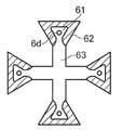
도 9는 또 다른 예시적인 심지의 평면도를 도시하고;
도 10은 또 다른 예시적인 심지의 일부의 평면도를 도시하며;
도 11은 다른 예시적인 증기 발생 조립체의 일부의 측단면도를 도시하고;
도 12는 다른 예시적인 무화기의 평면도를 도시하며;
도 13a 및 도 13b는 다른 예시적인 증기 발생 조립체들의 일부들의 측단면도들을 도시하고;
도 14는 관심있는 파라미터들을 나타내는 심지의 일부의 측단면도를 도시한다.Now, various embodiments of the present invention will be described in detail by way of example only with reference to the following drawings:
1 shows a cross section through an exemplary e-cigarette comprising a cartomizer and a control unit, in which examples can be implemented:
2 shows a side cross-sectional view of a steam generating assembly comprising a reservoir, a wick and a heater;
3 shows a perspective view of an exemplary atomizer;
4 shows a side cross-sectional view of a steam generating assembly comprising an atomizer as in the example of FIG. 3;
5 shows a side cross-sectional view of a portion of another exemplary steam generating assembly;
6 shows a top view of a compression body included in the assembly, such as the assembly of FIG. 4;
7 shows a top view of an exemplary wick;
8 shows a top view of another exemplary wick;
9 shows a top view of another exemplary wick;
10 shows a top view of a portion of another exemplary wick;
11 shows a side cross-sectional view of a portion of another exemplary steam generating assembly;
12 shows a top view of another exemplary atomizer;
13A and 13B show side cross-sectional views of portions of other example steam generating assemblies;
14 shows a cross-sectional side view of a portion of the wick showing the parameters of interest.
특정 예들 및 실시예들의 양태들 및 특징들이 본원에서 논의/설명된다. 특정 예들 및 실시예들의 일부 양태들 및 특징들은 통상적으로 구현될 수 있으며, 이들은 간결화를 위해 상세하게 논의/설명되지 않는다. 따라서, 상세하게 설명되지 않는, 본원에서 논의되는 장치 및 방법들의 양태들 및 특징들은 그러한 양태들 및 특징들을 구현하기 위한 임의의 통상적인 기술들에 따라 구현될 수 있다는 것이 이해될 것이다.Aspects and features of specific examples and embodiments are discussed/described herein. Certain aspects and features of certain examples and embodiments may be implemented conventionally, which are not discussed/detailed for brevity. Thus, it will be understood that aspects and features of the apparatus and methods discussed herein, not described in detail, may be implemented in accordance with any conventional techniques for implementing such aspects and features.
전술한 바와 같이, 본 개시는 전자 시가렛들과 같은 전자 에어로졸 또는 증기 제공 시스템들에 관한 것이다(그러나, 이에 제한되지 않음). 하기의 설명 전체에 걸쳐서, 용어들 "e-시가렛" 및 "전자 시가렛"이 때때로 사용될 수 있지만; 이들 용어들은 에어로졸(증기) 공급 시스템 또는 디바이스와 상호 교환 가능하게 사용될 수 있다는 것이 이해될 것이다. 또한, 본 개시는 액체를 증발시키고 담배와 같은 고체 기재를 통해 증기를 통과시킴으로써 니코틴 또는 다른 물질들을 전달하도록 구성된 하이브리드 디바이스들 및 시스템들에 적용 가능하다. 상기에 언급된 다양한 용어들은 그러한 디바이스들을 포함하는 것으로 이해되어야 한다. 유사하게, "에어로졸"은 "증기"와 상호 교환 가능하게 사용될 수 있다.As noted above, the present disclosure is directed to, but not limited to, electronic aerosol or vapor delivery systems, such as electronic cigarettes. Throughout the description below, the terms “e-cigarette” and “electronic cigarette” may be used from time to time; It will be understood that these terms may be used interchangeably with an aerosol (steam) supply system or device. Further, the present disclosure is applicable to hybrid devices and systems configured to deliver nicotine or other substances by evaporating a liquid and passing vapor through a solid substrate such as tobacco. It should be understood that the various terms mentioned above include such devices. Similarly, “aerosol” can be used interchangeably with “steam”.
본원에 사용된 바와 같이, 용어 "구성요소"는, 종종 외부 하우징(exterior housing) 또는 벽 내에, 몇몇의 보다 작은 부분들 또는 요소들을 포함하는 전자 시가렛의 부분(part), 섹션(section), 유닛(unit), 모듈(module), 조립체 또는 유사물을 지칭하는데 사용된다. 전자 시가렛은 하나 이상의 그러한 구성요소들로 형성되거나 만들어질 수 있으며, 구성요소들은 제거 가능하게 서로 연결 가능할 수 있거나, 제조 동안에 영구적으로 함께 결합되어 전체 전자 시가렛을 규정할 수 있다.As used herein, the term “component” is a part, section, unit of an electronic cigarette that includes several smaller parts or elements, often within an exterior housing or wall. Used to refer to (unit), module, assembly, or similar. The electronic cigarette may be formed or made of one or more such components, and the components may be removably connectable to each other or permanently joined together during manufacture to define the entire electronic cigarette.
도 1은 e-시가렛(10)과 같은 예시적인 에어로졸/증기 제공 시스템의 매우 개략적인 다이어그램(축척되어 있지 않음)이다. e-시가렛(10)은 파선으로 표시된 종축을 따라 연장되는 대체로 원통형인 형상을 가지며, 2 개의 주요 구성요소들, 즉 제어 또는 전력 구성요소 또는 섹션(20), 및 증기 발생 구성요소로서 작동하는 카트리지 조립체 또는 섹션(30)(때때로, 카토마이저, 클리어로마이저(clearomiser) 또는 무화기로 지칭됨)을 포함한다.1 is a very schematic diagram (not scaled) of an exemplary aerosol/vapor delivery system, such as
카트리지 조립체(30)는, 예를 들어 니코틴을 보유하는, 에어로졸이 생성될 액체 제제를 포함하는 소스 액체를 보유하는 저장조(3)를 포함한다. 일 예로서, 소스 액체는 약 1% 내지 3%의 니코틴 및 50%의 글리세롤(glycerol)을 포함할 수 있으며, 나머지는 거의 동일한 정도의 물 및 프로필렌 글리콜(propylene glycol)을 포함하고, 가능하게는 또한 향료들(flavourings)과 같은 다른 성분들을 포함한다. 예컨대 향료를 전달하기 위해, 니코틴이 없는 소스 액체가 또한 사용될 수 있다. 액체로부터 발생된 증기가 통과되는 담배 또는 다른 향미 요소의 일부와 같은 고체 기재(예시되지 않음)가 또한 포함될 수 있다. 저장조(3)는 소스 액체가 탱크의 범위 내에서 자유롭게 이동 및 유동하도록 소스 액체가 저장될 수 있는 용기 또는 리셉터클(receptacle)인 저장 탱크(storage tank)의 형태를 갖는다. 대안적으로, 저장조(3)는 다공성 구조물 내에 소스 액체를 유지하는 면 와딩(cotton wadding), 유리 섬유 또는 다공성 세라믹과 같은 소정량의 흡수성 재료를 보유할 수 있다. 저장조(3)는 소스 액체가 소비된 후에 폐기될 수 있도록 제조 동안 충전한 후에 밀봉될 수 있거나, 새로운 소스 액체가 추가될 수 있는 입구 포트(inlet port) 또는 다른 개구를 가질 수 있다. 카트리지 조립체(30)는 또한, 가열에 의한 소스 액체의 증발에 의해 에어로졸을 발생시키기 위해 저장조 탱크(3)의 외부에 위치된 전기 가열 요소 또는 히터(4)를 포함한다. 심지(wick) 또는 다른 다공성 요소(6)와 같은 액체 이송 배열체(액체 이송 요소)가 저장조(3)로부터 히터(4)로 소스 액체를 전달하도록 제공될 수 있다. 심지(6)는 소스 액체를 흡수하고 히터(4)와 접촉하는 심지(6)의 다른 부분들에 위킹 또는 모세관 작용에 의해 소스 액체를 전달할 수 있도록, 저장조(3) 내부에 위치되거나 다른 방식으로 저장조(3) 내의 액체와 유체 연통하는 하나 이상의 부분들을 갖는다. 이에 의해, 이러한 액체는 가열되고 증발되어, 심지(6)에 의해 히터(4)로 이송된 새로운 액체 소스로 대체된다. 따라서, 심지는 저장조로부터 히터로 액체를 전달하거나 이송하는, 저장조(3)와 히터(4) 사이의 브리지(bridge), 경로 또는 도관으로서 생각될 수 있다. 도관, 액체 도관, 액체 이송 경로, 액체 전달 경로, 액체 이송 메커니즘 또는 요소 및 액체 전달 메커니즘 또는 요소를 포함하는 용어들은 모두 심지 또는 대응하는 구성요소 또는 구조물을 지칭하기 위해 본원에서 상호 교환 가능하게 사용될 수 있다.The
히터와 심지(또는 유사물) 조합은 때때로 무화기 또는 무화기 조립체로 지칭되고, 그 소스 액체를 갖는 저장조 및 무화기는 통칭하여 에어로졸 소스로 지칭될 수 있다. 다른 전문용어는 액체 전달 조립체, 액체 이송 조립체, 또는 단순히 조립체를 포함할 수 있으며, 본 명세서에서, 이들 용어들은 증기 발생 요소(증기 발생기), 및 저장조로부터 증기 발생기로 액체를 전달하거나 이송하는 위킹 또는 유사한 구성요소 또는 구조물(액체 이송 요소)을 지칭하기 위해 상호 교환 가능하게 사용될 수 있다. 부분들이 도 1의 매우 개략적인 표현과 비교하여 상이하게 배열될 수 있는 다양한 디자인들이 가능하다. 예를 들어, 심지(6)는 히터(4)와 완전히 별개인 요소일 수 있거나, 히터(4)는 다공성이며 위킹 기능의 적어도 일부를 직접 수행할 수 있도록 구성될 수 있다(예를 들어, 금속 메쉬(metallic mesh)). 히터 대신에, 예를 들어 압전 효과에 기초한 진동 증발기와 같은 증기 발생을 위한 다른 수단이 사용될 수 있다. 전기 또는 전자 디바이스에서, 증기 발생기는 옴(ohmic)(줄(Joule)) 가열 또는 유도 가열에 의해 작동하는 전기 가열 요소일 수 있다. 또한, 디바이스는 예를 들어 펌프 작용에 의해 작동하는 비전기 디바이스(non-electrical device)일 수 있다. 따라서, 일반적으로, 무화기는, 그것에 전달된 소스 액체로부터 증기를 발생시킬 수 있는 증기 발생 또는 증발 요소, 및 위킹 작용/모세관력에 의해 저장조 또는 유사한 액체 저장소로부터 증기 발생기로 액체를 전달하거나 이송할 수 있는 액체 이송 요소인 것으로 간주될 수 있다. 본 개시의 실시예들은 모든 및 임의의 그러한 조립체 구성들에 적용 가능하다. 구현예에 관계없이, 부분들은 저장조(3)의 내부로부터 증발을 위해 히터(4)(또는 다른 증기 발생기)의 근방 및 표면까지 소스 액체를 이동시킬 수 있는 액체 유동 경로를 형성하도록 구성될 것이다. 이것은, 액체가 히터로 전달되고, 성공적으로 증발되어, 전자 시가렛 내부 또는 외부의 다른 위치들로 액체가 누설될 수 있는 누출을 형성하는 것이 방지되어야 하는 의도된 유체 경로이다. 이러한 작동은 증기 발생기가 유입 액체를 처리할 수 있도록 예상 속도로의 소스 액체의 전달에 기초한다. 그러나, 저장조 내부의 과잉 압력에 의해, 또는 증기 발생기가 작동하지 않을 때 정상 압력 조건들 하에서도 야기될 수 있는 것과 같은 누출의 경우에, 너무 많은 액체가 위킹 요소에 또는 그 안에 축적되고, 다음에 무화기를 수용하는 챔버 내의 자유 액체로서 떨어져서 누설될 수 있다.Heater and wick (or similar) combinations are sometimes referred to as atomizers or atomizer assemblies, and reservoirs and atomizers with their source liquids may be collectively referred to as aerosol sources. Other terminology may include a liquid delivery assembly, a liquid delivery assembly, or simply an assembly, where the terms are wicking elements (steam generators), and wicking or transferring liquids from a reservoir to a steam generator or It can be used interchangeably to refer to similar components or structures (liquid transport elements). Various designs are possible in which the parts can be arranged differently compared to the very schematic representation of FIG. 1. For example, the
도 1로 돌아오면, 카트리지 조립체(30)는 또한 사용자가 히터(4)에 의해 발생된 에어로졸을 흡입할 수 있는 개구 또는 공기 출구를 갖는 마우스피스(mouthpiece)(35)를 포함한다.Returning to FIG. 1, the
전력 구성요소(20)는 e-시가렛(10), 특히 히터(4)의 전기 구성요소들에 전력을 제공하기 위한 전지 또는 배터리(5)(이후에, 배터리로 지칭되며, 재충전식일 수 있음)를 포함한다. 추가적으로, 일반적으로 e-시가렛을 제어하기 위한 인쇄 회로 기판(28) 및/또는 다른 전자기기 또는 회로가 있다. 제어 전자기기/회로는, 증기가 요구되는 경우, 예를 들어 시스템(10) 상의 흡입을 검출하는 공기 압력 센서 또는 공기 유동 센서(도시되지 않음)로부터의 신호에 응답하여, 히터(4)를 배터리(5)에 연결하고, 흡입 동안에, 전력 구성요소(20)의 벽에 있는 하나 이상의 공기 입구들(26)을 통해 공기가 진입한다. 가열 요소(4)가 배터리(5)로부터 전력을 수취하는 경우, 가열 요소(4)는 심지(6)에 의해 저장조(3)로부터 전달된 소스 액체를 증발시켜 에어로졸을 발생시키고, 다음에 이것은 마우스피스(35)의 개구를 통해 사용자에 의해 흡입된다. 에어로졸은, 사용자가 마우스피스(35) 상을 흡입할 때, 에어로졸 소스에 대한 공기 입구(26)를 공기 출구에 연결하는 공기 채널(air channel)(도시되지 않음)을 따라 에어로졸 소스로부터 마우스피스(35)로 운반된다. 따라서, 전자 시가렛을 통한 공기 유동 경로는 무화기에 대한 공기 입구(들)(전력 구성요소에 있을 수 있거나, 있지 않을 수도 있음)와 마우스피스에 있는 공기 출구 사이에 규정된다. 사용 시에, 이러한 공기 유동 경로를 따르는 공기 유동 방향은 공기 입구로부터 공기 출구로의 방향이며, 그에 따라 무화기는 공기 입구의 하류 및 공기 출구의 상류에 놓이는 것으로 설명될 수 있다.The
이러한 특정 예에서, 전력 섹션(20) 및 카트리지 조립체(30)는, 도 1에서 실선 화살표들로 표시된 바와 같이, 종축에 평행한 방향으로 분리함으로써 서로 분해 가능한 별개 부분들이다. 구성요소들(20, 30)은, 디바이스(10)가 사용 중일 때, 전력 섹션(20)과 카트리지 조립체(30) 사이의 기계적 및 전기적 연결을 제공하는 협력 맞물림 요소들(21, 31)(예를 들어, 스크류(screw) 또는 베이어닛 끼워맞춤부(bayonet fitting))에 의해 함께 결합된다. 그러나, 이것은 단지 예시적인 배열일 뿐이며, 다양한 구성요소들이 전력 섹션(20)과 카트리지 조립체 섹션(30) 사이에 상이하게 분포될 수 있으며, 다른 구성요소들 및 요소들이 포함될 수 있다. 2 개의 섹션들은 도 1에서와 같이 종방향 구성으로 단부끼리 함께 연결될 수 있거나, 나란한 병렬 배열과 같은 다른 구성으로 함께 연결될 수 있다. 시스템은 대체로 원통형일 수 있거나 아닐 수도 있으며, 그리고/또는 대체로 종방향 형상을 가질 수 있거나 아닐 수도 있다. 어느 한쪽 또는 양쪽 섹션들 또는 구성요소들은 고갈된 경우(예를 들어, 저장조가 비거나, 배터리가 방전된 경우) 폐기되고 교체되도록 의도될 수 있거나, 저장조를 리필(refill)하거나 배터리를 재충전하는 것과 같은 동작들에 의해 다수 사용들이 가능해지도록 의도될 수 있다. 대안적으로, e-시가렛(10)은 2 개의 부분들로 분리될 수 없는 일체형 디바이스(일회용 또는 리필식/재충전식)일 수 있으며, 이러한 경우 모든 구성요소들은 단일 본체 또는 하우징 내에 포함된다. 본 개시의 실시예들 및 예들은 당업자가 인식하는 이들 구성들 및 다른 구성들 중 어느 구성에도 적용 가능하다.In this particular example, the
도 1의 예시적인 디바이스는 매우 개략적인 형식으로 제시되어 있다. 도 2는 탱크, 히터 및 심지의 예시적인 포지션들을 나타내는 에어로졸 소스의 보다 상세한 표현을 도시하고 있다.The exemplary device of FIG. 1 is presented in a very schematic format. 2 shows a more detailed representation of an aerosol source showing exemplary positions of the tank, heater and wick.
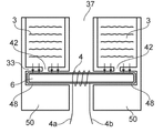
도 2는 예시적인 에어로졸 소스의 측단면도를 도시하고 있다. 저장조 탱크(3)는 외벽(32) 및 내벽(34)을 가지며, 이 벽들 각각은 대체로 관형이다. 내벽(34)은 외벽(32) 내의 중앙에 배치되어, 2 개의 벽들 사이에 환형 공간을 규정하며; 이것은 소스 액체를 유지하도록 의도된 탱크(3)의 내부 용적부이다. 탱크는 (도시된 배향에서) 그 하부 단부에서 저부 벽(bottom wall)(33)에 의해 폐쇄되고, 그 최상부 단부(top end)에서 상부벽(36)에 의해 폐쇄된다. 내벽(34)에 의해 둘러싸인 중앙 공간은 통로 또는 채널(37)이며, 이 통로 또는 채널(37)은, 그 하부 단부에서 (예컨대, 도 1에 도시된 공기 흡입구(26)를 통해) 전자 시가렛 내로 흡인된 공기를 수취하고, 그 상부 단부에서 (예컨대, 도 1의 마우스피스(35)를 통해) 흡입을 위한 에어로졸을 전달한다. 그것은 또한 무화기를 수용하는 챔버를 규정한다.2 shows a cross-sectional side view of an exemplary aerosol source. The
공기 유동 채널(37) 내에는, 히터(4) 및 심지(6)를 포함하는 무화기(40)가 배치된다. 심지, 즉, 본 예에서 로드형(rod-shaped)이고 다수의 섬유들로 형성될 수 있는 세장형의 다공성 요소는 공기 유동 통로를 가로질러 배열되어(탱크(3)의 하부 단부에 보다 근접한 것으로 도시되어 있지만, 보다 높게 위치결정될 수도 있음), 그 단부들이 내벽(34)의 구멍들을 통과하고 탱크(3)의 내부 용적부 내에 도달하여 내부의 소스 액체를 흡수한다. 히터(4)는 심지(6) 주위에 감겨진 와이어 코일(wire coil) 형태의 전동식 가열 요소이다. 연결 리드선들(connecting leads)(4a, 4b)은 배터리로부터의 전력 공급을 위해 히터(4)를 회로(도시되지 않음)에 결합시킨다. 에어로졸 소스는 전자 시가렛의 카트리지 조립체 섹션의 하우징 내에 배치될 것이며, (가능하게는 분리 가능한 구성요소에서) 그 최상부 단부에는 마우스피스가 배열되고, 그 하부 단부에는 제어기 및 배터리가 배열된다. 탱크(3)의 외벽(32)은 카트리지 조립체 하우징의 벽일 수도 있거나 아닐 수도 있다는 것에 주목한다. 이들 벽들이 공유되는 경우, 카트리지 조립체는 소스 액체가 소비되었을 때, 기존의 배터리/전력 섹션에 연결 가능한 새로운 카트리지 조립체로 교체되는 일회용이도록 의도될 수 있거나, 또는 저장조 탱크(3)가 소스 액체로 리필될 수 있도록 구성될 수 있다. 탱크 벽과 하우징 벽이 상이한 경우, 탱크(3) 또는 전체 에어로졸 소스는 소스 액체가 소비될 때 하우징 내에서 교체 가능할 수 있거나, 또는 리필 목적을 위해 하우징으로부터 제거 가능할 수 있다. 이들은 단지 예시적인 배열들이고, 제한하려고 의도된 것은 아니다.In the
사용 시에, 그 조립체 하우징 내의 에어로졸 소스가 (e-시가렛 디자인에 따라 분리 가능하게 또는 영구적으로) 배터리 섹션에 결합되고, 사용자가 마우스피스를 통해 흡입하는 경우, 입구 또는 입구들을 통해 디바이스 내로 흡인된 공기는 공기 유동 채널(37)로 진입한다. 히터(4)는 열을 생성하도록 활성화되고; 이것은 심지(6)에 의해 히터(4)로 들어온 소스 액체가 가열되어 증발되게 한다. 증기는, 또한 공기 유동 채널(37)을 따라 디바이스의 마우스피스로 유동하는 공기에 의해 운반되어 사용자에 의해 흡입된다. 화살표들(A)은 디바이스를 통한 공기 유동 경로를 따르는 공기 유동 및 그 방향을 표시한다.In use, an aerosol source in the assembly housing is coupled to the battery section (removably or permanently depending on the e-cigarette design) and, when the user inhales through the mouthpiece, is drawn into the device through the inlets or inlets. Air enters the
그러한 배열은 누출들에 잠재적으로 취약하다는 것이 이해될 것이다. 심지(6)가 탱크 내부로 진입하는 구멍들을 통한 저장조(3)로부터의 직접적인 액체 누출이 일어날 수 있다. 또한, 심지가 증발 작용에 의해 제거될 수 있는 것보다 많은 액체를 흡수하면, 이러한 액체는 심지(6)로부터 떨어질 수 있다. 그러한 방식들로, 자유 액체가 공기 유동 채널(37) 내에 도달할 수 있으며, 여기서 자유 액체는 증기와 함께 사용자에 의해 흡입되어 베이핑 경험(vaping experience)을 망쳐버릴 수 있거나, 또는 하향으로 이동하여, 전자 시가렛으로부터 완전히 누출되어 사용자 또는 그 소지품을 더럽히거나, 배터리 또는 제어 전자기기들과 같은 전자 시가렛의 다른 부분들을 오염시킬 수 있다.It will be understood that such an arrangement is potentially vulnerable to leaks. Direct liquid leakage from the
이를 해결하기 위해, 본 개시는 심지(위킹 요소 또는 액체 이송 요소)에 대한 대안적인 배열을 제안한다. 저장조의 내부로 도달하는 부분 또는 부분들을 갖는 심지 대신에, 다공성 재료로 형성된 심지가 저장조 내에 유지된 소스 액체와는 저장조 경계 벽의 반대측 상에서 저장조 외부에 배치된다. 저장조 벽의 개구 또는 구멍은 액체가 개구 위에 배치된 심지 상으로 공급될 수 있게 한다. 액체를 수용하는 영역 주위의 심지 부분은 밀봉 효과를 제공하기 위해 개구 주위의 저장조 벽에 대해 압축 상태로 배치된다. 이러한 방식으로, 개구를 통해 저장조를 빠져나가는 액체의 일부 봉쇄(containment)가 제공된다.To address this, the present disclosure proposes an alternative arrangement for the wick (wicking element or liquid conveying element). Instead of a wick having a portion or parts reaching into the reservoir, a wick formed of a porous material is placed outside the reservoir on the opposite side of the reservoir boundary wall with the source liquid held in the reservoir. An opening or hole in the reservoir wall allows liquid to be supplied onto the wick disposed above the opening. The wick portion around the area containing the liquid is placed compressed against the reservoir wall around the opening to provide a sealing effect. In this way, some containment of the liquid exiting the reservoir through the opening is provided.
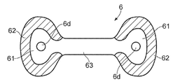
도 3은 심지(6)가 이러한 방식으로 사용되도록 구성된 예시적인 무화기(심지와 히터)의 사시도를 도시하고 있다. 본 예에서, 다공성 재료로 제조된 심지(6)는 길이 및 폭을 가지며 심지의 평면에 직교하는 두께(t)를 갖는 평면형 요소로서 형상화된다. 심지(6)는 좁은 중앙 부분(6a) 및 중앙 부분(6a)보다 심지의 평면에서 폭이 더 넓은 2 개의 확대된 단부 부분들(6b)을 갖는 점에서, "아령(dumbbell)" 또는 "개 뼈(dog bone)" 형상을 가지며, 단부 부분들(6b) 및 중앙 부분(6a) 둘 모두는 동일하거나 유사한 두께(t)를 갖는다(또는 적어도 두께(t)는 길이보다 작거나 훨씬 작음). 중앙 부분(6a)은 그와 연관된 히터(4)를 가지며, 히터(4)는 본 예에서는 심지(6)의 중앙 부분(6a) 주위에 래핑된 코일을 포함하는 와이어 가열 코일들(wire heating coils)이다. 무화기의 이러한 부분은 조립된 전자 시가렛의 증기 발생 구성요소의 공기 유동 채널 내에 배치될 것이다. 단부 부분들(6b) 각각은, 구체적으로 각 단부 부분(6b)의 중심을 향하여 있는, 도 3에서 작은 원으로 표시된 영역들(6d)에서, 저장조로부터 액체를 수용하도록 의도된다. 이들 액체 수용 영역(6d)은 저장조의 벽에 있는 개구들 위에, 개구들을 가로질러 또는 개구들에 대항하여 배치되고, 그에 따라 액체가 저장조로부터 심지(6) 상으로 유동할 수 있게 한다. 심지(6)의 다공성 구조의 위킹 또는 모세관 작용은 액체를 액체 수용 영역들(6d)로부터 단부 부분들(6b)을 통해 중앙 부분(6a) 내로 그리고 중앙 부분(6a)을 따라, 증발을 위해 히터(4)의 부근으로 운반한다.3 shows a perspective view of an exemplary atomizer (wick and heater) in which the
또한, 심지(6)의 단부 부분들(6b)은 도 3에서 음영으로 나타낸 압축 구역들(6c)을 포함한다. 이들은 심지가 저장조의 개구들로부터 액체를 수용하도록 설치될 때, 대체로 각 개구 주위의 저장조의 벽에 대해 압축되는 심지(6)의 구역들이다. 압축은 심지의 평면에 실질적으로 수직인 심지 두께(t)의 방향으로 된다. 도 3의 예에서, 이러한 배열은 압축 구역들(6c)인 단부 부분들(6b)의 주변부, 및 단부 부분들(6b)의 중심 또는 그 부근에 있는 액체 수용 영역(6d)에 의해 구현되며, 그에 따라 심지의 압축된 부분(6c)이 각각의 액체 수용 영역(6d)을 크게 둘러싸고 있다. 압축 구역(6c)이 액체 수용 영역(6d)을 완전히 에워싸거나 둘러싸지 않도록, 압축 구역에서 갭(gap)이 중앙 부분(6a)이 단부 부분(6b)에 결합되는 곳에 남겨져서, 액체 수용 영역(6d)으로부터 히터(4)로의 액체 유동 경로를 제공하며, 이 액체 유동 경로는 압축된 심지 재료를 포함하지 않는다.In addition, the
두께 방향으로 심지 재료의 압축은 압축 구역들에서 심지 재료의 기공들을 폐쇄하거나 적어도 크기를 감소시키는 효과가 있다. 이것은 액체 유동이 방해되도록 심지 재료의 위킹 및 흡수 능력을 감소시키거나 제거한다. 압축된 재료는 심지 내에서의 액체의 이동에 대한 배리어(barrier) 또는 부분적인 배리어를 형성한다. 이에 의해, 액체 유동은 의도된 대로, 즉 히터(4)를 향해 지향될 수 있고, 다른 방향들로의 누출이 감소될 수 있다.Compression of the wick material in the thickness direction has the effect of closing the pores of the wick material in the compression zones or at least reducing the size. This reduces or eliminates the wicking and absorbing capacity of the wicking material so that liquid flow is disturbed. The compressed material forms a barrier or partial barrier to the movement of liquid within the wick. Thereby, the liquid flow can be directed as intended, ie towards the
도 4는 저장조(3)와 관련하여 설치된 도 3의 심지(6)의 개략적인 측단면도를 도시하고 있다. 저장조(3)는 심지(6)가 연장되는 중앙 공기 유동 통로(37)를 갖고서 환형이라는 점에서 도 2의 저장조와 유사하게 형상화되며, 히터(4)가 이러한 통로(37)에 배치되어 있다. 탱크/저장조(3)의 하부 부분만이 도시되어 있다는 것에 주목하며; 실제로는 도 2에서와 같이 그 상부 단부가 폐쇄되어 있다.FIG. 4 shows a schematic side sectional view of the
저장조는 이전과 같이 하부 베이스 벽(33)을 가지며, 이것에는 통로(37)를 가로질러 대향하여 배열된 2 개의 개구들(42)이 제공된다. 심지(6)는 액체 수용 영역들(6d)이 개구들(42)과 일직선을 이룬 상태로 그 단부 부분들(6b)이 베이스 벽(33) 위에 놓이도록 설치된다. 이에 의해, 개구(42)는 심지의 단부 부분들에 의해 덮여 있다. 액체는 개구들(42)을 통해 저장조(3)로부터 심지(6) 내로 유동할 수 있다. 개구들(42) 각각의 주위에서, 압축 구역들(6c)의 심지의 재료는 심지의 두께 방향으로 압축되며; 이것은 도 4에서 화살표들로 표시되어 있다.The reservoir has a
본 예에서, 심지의 압축은 저장조(3)의 베이스 벽(33)과는 심지(6)의 반대측 표면에 배열된 압축 본체(50)에 의해 제공된다. 압축 본체(50)는 심지(6)가 위치되는 공동(48)을 남기도록 베이스 벽(33)으로부터 이격되어 위치결정된다. 심지(6)의 압축 구역들(6c)의 영역들에서, 압축 본체(50)는 심지의 두께(t)보다 작은 거리만큼 베이스 벽(33)으로부터 이격되어 있으며, 그에 따라 심지 재료는 압축 본체(50)에 의해 베이스 벽(33)에 대해 압착된다. 압축 본체(50)는, 예를 들어 저장조 벽(들) 상에 플라스틱 또는 금속 재료를 성형 또는 기계가공함으로써, 저장조(3)의 벽들과 일체로 형성될 수 있고, 다음에 심지(6)가 공동(48) 내로 삽입될 수 있다. 대안적으로, 압축 본체(50)는 저장조(3)와 별도로 형성될 수 있으며, 그에 따라 심지(6)가 베이스 벽(33) 위에 놓이고, 다음에 압축 본체(50)가 공동(48)을 형성하기에 적절한 간격으로 저장조(3)에 고정되거나, 심지(6)가 압축 본체(50)의 적절한 표면 상에 적층되고, 2 개의 부분들이 저장조 베이스 벽(33)으로부터 적절한 간격으로 고정될 수 있다. 압축 본체는 도 4에서와 같이 저장조에 결합될 수 있거나, 전자 시가렛의 상이한 구성요소와 일체형일 수 있으며, 그에 따라 압축 본체는 해당 구성요소가 저장조(3)와 조립될 때 공동(48)을 규정하고 심지(6)의 요구 압축을 생성하도록 정확하게 위치결정될 수 있다. 어느 경우에도, 심지(6)는 공동이 규정된 후에 공동(48) 내로 삽입될 수 있거나, 부품들이 함께 조립되기 전에 베이스 벽(33) 또는 압축 본체(50)와 적층될 수 있다.In this example, compression of the wick is provided by a
도 4는 공동(48) 내에 위치결정된 심지(6)를 도시하지만, 화살표들로 표시된 영역들에서의 압축으로부터 기인한 심지의 임의의 감소된 두께를 예시하지는 않고 있다. 실제로, 심지의 압축된 부분들은 압축되지 않은 부분들보다 얇게 되어 있다. 이것은 압축 구역들의 영역에 걸쳐 공동 내로 돌출되는, 압축 본체 및 저장조 벽 중 하나 또는 둘 모두의 표면 특징부들에 의해 달성될 수 있다. 따라서, 공동의 깊이는 표면 특징부들이 위치된 곳에서 감소되고, 심지 재료는 표면 특징부들(이들이 양 측면들 상에 있는 경우) 사이 또는 일 측면 상의 표면 특징부와 다른 측면 상의 베이스 벽 또는 압축 본체 사이에 압좌(squashing)되거나 압착되거나 다른 방식으로 압축된다.4 shows the
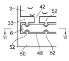
도 5는 심지 압축을 제공하기 위해 돌출 표면 특징부들로 구성된 심지 및 저장조의 일부의 개략적인 단면도를 도시하고 있다. 본 예에서, 저장조(3)의 베이스 벽(33) 및 압축 본체(50) 둘 모두에는 베이스 벽(33)과 압축 본체(50) 사이에 형성된 공동(48) 내로 내측으로 향하는 표면 돌출부들(52)이 제공된다. 돌출부들(52)은 공동(48)을 가로질러 서로 대향하여 위치결정되고, 베이스 벽(33)의 개구(42)를 부분적으로 둘러싸며, 본 예에서 개구(42)로부터 다소 이격되어 있다(다시 말해서, 이들은 개구(42)에 바로 인접하여 있지는 않음). 대향 돌출부들(52)은 심지(6)의 두께(t)보다 작은 거리만큼 분리되어 있으며, 그에 따라 심지(6)는 개구(42)를 가로질러 공동(48) 내에 설치될 때, 돌출부들(52)에 의해 개구(42) 주위의 영역에서 그 두께 방향으로 압축된다.5 shows a schematic cross-sectional view of a portion of a wick and reservoir composed of protruding surface features to provide wick compression. In this example, both the
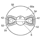
도 6은 도 5의 화살표들(VI)의 방향에서 본 압축 본체(50)의 평면도를 도시하고 있다. 사용 시에 저장조(3)의 베이스 벽(33)과 대면하는 표면(50a)에는 2 개의 직경방향 대향 리세스들(recesses)(54)이 형성되어 있다. 이들은 베이스 벽과 협력하여 심지(6)를 위한 공동을 형성한다(반대로, 평탄 압축 본체와 협력하도록 베이스 벽에 리세스들이 제공되거나, 양 부분들 모두가 리세스들을 가질 수 있음). 아치형 돌출부(52)는 각각의 리세스 내부에 형성되어, 심지의 압축이 요구되는 곳에 정렬되고, 즉 베이스 벽의 대응하는 개구를 거의 둘러싸지만 완전히 둘러싸고 있지는 않다. 심지(6) 및 베이스 벽의 개구들(42)의 포지션들은 가상선으로 도시되어 있다.FIG. 6 shows a top view of the
본 개시에 따른 심지는 도 3의 예에 제한되지 않으며, 압축 밀봉 기능을 구현하도록 포함된 다양한 부분들을 나타내기 위해 보다 일반적인 면에서 심지가 유용하게 설명될 수 있다.The wick according to the present disclosure is not limited to the example of FIG. 3, and the wick may be usefully described in a more general aspect to indicate various parts included to implement a compression sealing function.
도 7은 다양한 부분들을 포함하는 예시적인 심지(6)의 평면도를 도시하고 있다. 본 예는 다시 평면형이며, 해당 평면에서 아령 형상(dumbbell shape)을 갖는다. 심지(6)의 각 단부에서의 확대된 부분들은 각각 저장조 벽의 개구를 가로질러 배치되어 해당 개구를 통해 액체를 수용하도록 의도된 제1 부분(61)을 포함한다. 개구와 직접 정렬하기 위한 제1 부분(61)의 영역은 액체 수용 영역(6d)을 포함하고, 본 예에서, 제1 부분(61)은 액체 수용 영역(6d)을 넘어서 연장되며, 제1 부분(61)의 재료는 위킹 작용에 의해 액체 수용 영역(6d)으로부터 액체를 수용한다. 따라서, 제1 부분은 액체 수용 영역(6d) 및 저장조 개구보다 큰 영역을 갖는다. 각각의 제1 부분(61)의 주변에는 심지의 확대된 단부들의 에지 주위에 위치된 제2 부분(62)(음영으로 나타냄)이 있다. 제2 부분(62)은 심지가 설치될 때 압축되는 심지(6)의 영역이다. 2 개의 확대된 단부들을 결합하는 심지(6)의 좁은 중앙 부분은 액체를 히터와 같은 증기 발생 요소로 전달하는 제3 부분(63)이다. 본 예에서, 제3 부분(63)은, 그렇지 않으면 제1 부분(61)을 둘러싸는 제2 부분들(62)의 원호의 갭을 통해 제1 부분(61)과 직접 연속하여 있다. 액체 수용 영역(6d)에서 제1 부분(61)으로 진입하는 액체는 제1 부분의 심지 재료의 기공들을 통해 모세관 위킹에 의해 제3 부분(63)으로 이동한다. 이러한 방식으로, 액체는 저장조로부터 증기 발생 요소로 이동한다. 액체 수용 영역(6d)으로부터 다른 방향들로 이동하는 액체는 제2 부분(62)의 압축된 재료에 의해 방해될 것이다. 따라서, 압축은 제3 부분 및 관련 증기 발생 요소를 향한 방향 이외의 방향들로의 액체의 이동을 억제 또는 방지하는 밀봉 효과를 제공한다. 시일은 제1 부분 내의 액체를 증기 발생 요소를 향해 지향시키도록 작용하고, 이에 의해 이러한 방향으로의 액체의 이동을 촉진시키거나 증진시킨다. 이에 의해, 증기 발생 요소로부터의 액체 누출이 감소될 수 있다.7 shows a top view of an
용어들 "제1 부분", "제2 부분" 및 "제3 부분"의 사용은 제한하는 것으로 의도되지 않거나, 심지의 다양한 부분들 사이의 임의의 특정한 물리적 또는 구조적 차이 또는 분리를 나타내도록 의도된 것은 아니다(그렇지만, 심지는 단일 재료 피스 또는 서로 결합된 별도 피스들로 제조될 수 있음). 이들 용어들은 주로 특정 기능들, 다시 말해서 저장조로부터의 액체 수용, 밀봉을 위한 압축 및 증기 발생 요소에의 액체 제공을 수행하는 심지의 부분들을 나타내기에 편리한 라벨들이다. 임의의 심지에서, 기능들이 공유되는 경우, 다양한 부분들은 명확하게 구별되거나, 인접한 부분들과 혼합되거나 중첩될 수 있다. 예를 들어, 저장조 개구에서의 액체의 흡수, 개구로부터 멀리 그리고 증기 발생 요소를 향한 액체의 이송, 및 액체가 증발될 수 있는 증기 발생 영역의 바로 근처에의 액체의 전달은 모두 심지의 동일한 부분 내에서 일어나는 것으로 간주될 수 있고, 그에 따라 제1 부분과 제3 부분은 동일하거나 일치하는 것으로 간주될 수 있다. 이들 다양한 액체 이동 동작들 사이의 경계는 불분명할 수 있으며, 그에 따라 제1 부분과 제3 부분은 중첩되거나 심지의 재료를 공유한다.The use of the terms “first part”, “second part” and “third part” is not intended to be limiting, or intended to indicate any particular physical or structural difference or separation between the various parts of the wick. It is not (but the wick can be made from a single piece of material or separate pieces joined together). These terms are primarily labels that are convenient for indicating specific functions, ie parts of the wick that perform liquid reception from the reservoir, compression for sealing, and liquid supply to the steam generating element. In any wick, when the functions are shared, the various parts can be clearly distinguished, mixed or overlapped with adjacent parts. For example, absorption of liquid at the reservoir opening, transfer of liquid away from the opening and towards the steam generating element, and delivery of liquid to the immediate vicinity of the vapor generating region where liquid can be vaporized are all within the same part of the wick. It can be considered to occur in the first part and therefore the first part and the third part can be regarded as the same or coincident. The boundary between these various liquid movement operations may be unclear, so that the first part and the third part overlap or share the material of the wick.
심지의 다른 형상들 및 구성들이 사용될 수 있다. 도 7의 예와 유사한 복수의 이중 단부 형상들이 사용될 수 있으며, 여기서 각 단부는 액체 수용 영역을 갖는다. 예를 들어, 심지는 그 평면에서 나비 넥타이(bow-tie) 또는 개 뼈(dog-bone)로서 형상화될 수 있다. 또한, 2 개의 확대된 단부들은 동일한 형상 또는 크기일 필요는 없다. 그 벽에 2 개 초과의 개구들을 갖는 저장조로부터 2 개 초과의 영역들에서 액체를 수용하기 위해, 보다 복잡한 3 개 또는 4 개 단부 형상들이 사용될 수 있다.Other shapes and configurations of the wick can be used. A plurality of double end shapes similar to the example of FIG. 7 can be used, where each end has a liquid receiving region. For example, the wick can be shaped as a bow-tie or dog-bone in its plane. Also, the two enlarged ends need not be the same shape or size. To accommodate the liquid in more than two areas from a reservoir having more than two openings in its wall, more complex three or four end shapes can be used.
도 8은 둥근 확대된 단부들을 갖는 심지의 3 개 단부 형태를 도시하고, 도 9는 삼각형의 확대된 단부들을 갖는 십자 형상의 4 개 단부 심지를 도시하고 있다. 원하는 경우, 추가 단부들이 추가될 수 있다. 그러한 심지들은 액체를 하나 이상의 가열 코일들을 포함하는 증기 발생 요소에 전달할 수 있으며, 여기서 제3 부분(63)의 아암들은 가열 코일 또는 가열 코일의 일부에 의해 각각 래핑될 수 있거나 래핑되지 않을 수 있다.FIG. 8 shows a three-end shape of a wick with rounded enlarged ends, and FIG. 9 shows a cross-shaped four-end wick with triangular enlarged ends. If desired, additional ends can be added. Such wicks may deliver liquid to a steam generating element comprising one or more heating coils, wherein the arms of the
시일을 형성하도록 압축되는 구역인 심지의 제2 부분 또는 부분들은, 지금까지 도시된 바와 같이 (제1 구역이 액체 수용 영역보다 크도록) 액체 수용 영역으로부터 이격될 수 있거나, 제1 구역이 저장조 벽 개구와 동일한 형상 및 크기가 되도록 액체 수용 영역에 바로 인접하여 시작될 수 있다.The second part or portions of the wick, which are areas compressed to form a seal, can be spaced apart from the liquid receiving area (so that the first area is larger than the liquid receiving area) as shown so far, or the first area is a reservoir wall It can be started immediately adjacent to the liquid receiving area to be of the same shape and size as the opening.
도 10은 이러한 방식으로 구성된 심지의 일 단부를 도시하고 있다. 그러한 배열의 특징은 저장조 베이스 벽 또는 압축 본체 상에 형상화된 돌출부들이 필요하지 않다는 것이다. 대신에, 2 개의 대면하는 표면들은 편평할 수 있고, 베이스 벽과 압축 본체가 심지의 두께보다 작게 이격되는 경우(그래서, 공동의 깊이는 전체적으로 심지 두께보다 작음) 압축을 제공하도록 작용할 수 있다. 심지 단부는 액체 수용 영역을 제외하고 모든 부분들에서 압축되며, 여기서 저장조 벽에의 개구의 존재가 압축을 제공하지 않는다. 따라서, 심지의 제1 부분은 개구와 크기 및 형상이 동일하다.10 shows one end of the wick constructed in this way. A feature of such an arrangement is that no protrusions shaped on the reservoir base wall or compression body are required. Instead, the two facing surfaces can be flat and act to provide compression when the base wall and the compression body are spaced less than the thickness of the wick (so the depth of the cavity is less than the overall wick thickness). The wick end is compressed in all parts except the liquid receiving area, where the presence of an opening in the reservoir wall does not provide compression. Therefore, the first part of the wick has the same size and shape as the opening.
도 11은 이러한 방식으로 설치된 심지의 측단면도를 도시하고 있다. 저장조 단부 벽(33)과 압축 본체(50)의 대향 표면들에 의한 단부 모두에 걸친 심지의 압축은 이전 예들에서보다 심지의 두께를 더 넓게 감소시키고, 심지는 압축되지 않은 개구(42) 내로 팽출하고, 또한 공동(48)으로부터 공기 유동 채널(37) 내로 나올 때 팽출한다.11 shows a side cross-sectional view of the wick installed in this way. Compression of the wick across both ends by the opposing surfaces of the
본 예에서, 심지의 제2 부분(62)은 제1 부분(61)을 완전히 둘러싸고, 제3 부분(63)은 도 7의 예에서와 같이 제1 부분(61)과 연속하는 대신에 제2 부분(62)과 연속하여 있다는 것에 주목할 것이다. 심지 재료 및 압축량의 적절한 선택들은, 특히 제3 부분의 압축되지 않은 재료로 인해, 액체가 제1 부분(61)으로부터 압축된 제2 부분(62)을 통해 제3 부분(63)으로 위킹되게 할 수 있다.In this example, the
또한, 심지는 증기 발생 요소와 연관된 제3 부분의 폭과 비교하여 심지의 평면에서 확대된 단부를 가질 필요가 없다. 대신에, 심지는 그 단부간 길이를 따라 실질적으로 일정한 폭을 가질 수 있다. 가열 코일은 제3 부분 주위에 래핑될 수 있지만, 제3 부분에 대한 보다 큰 상대 폭을 허용하는 그러한 형상은 또한 다른 증기 발생 요소들과 함께 편리하게 사용될 수 있다.Furthermore, the wick need not have an enlarged end in the plane of the wick compared to the width of the third portion associated with the steam generating element. Instead, the wick can have a substantially constant width along the length between its ends. The heating coil can be wrapped around the third portion, but such a shape allowing for a larger relative width to the third portion can also be used conveniently with other vapor generating elements.
도 12는 예시적인 심지 및 히터 조립체의 개략적인 평면도를 도시하고, 여기서 심지(6)는 실질적으로 일정한 폭을 가지며 확대된 단부들이 없다. 이러한 경우에, 히터(4)는 제3 부분(63)에서의 심지(6)의 재료 내에 매립된 많은 루프들(loops)을 갖는 사행 와이어(serpentine wire)를 포함하는 매립형 히터로서 구성된다.12 shows a schematic top view of an exemplary wick and heater assembly, where the
비교적 넓은 제3 부분을 갖는 일정한 폭의 심지는 또한 저장조로부터 진동 메쉬(vibrating mesh) 형태의 증기 발생 요소로 액체를 전달하는데 유용할 수 있다.A constant width wick with a relatively wide third portion may also be useful for delivering liquid from a reservoir to a steam generating element in the form of a vibrating mesh.
다른 대안예에서, 심지는 하나의 제1 부분, 제1 부분 주변의 하나의 제2 부분 및 제1 부분으로부터 증기 발생 요소로 액체를 운반하기 위한 제3 부분을 포함하는 단일 단부 형상을 가질 수 있다. 이것은 단 하나의 개구를 갖는 저장조와 함께 사용될 수 있다. 대안적으로, 저장조는 하나 초과의 개구를 가질 수 있으며, 개구들 각각은 액체를 상이한 단일 단부 심지로 전달한다.In another alternative, the wick can have a single end shape that includes one first portion, one second portion around the first portion, and a third portion for transporting liquid from the first portion to the steam generating element. . It can be used with reservoirs with only one opening. Alternatively, the reservoir can have more than one opening, each of which delivers liquid to a different single-ended wick.
저장조는 도 4의 예에서와 같이 중앙 공기 유동 통로를 둘러싸는 환형 형상일 필요는 없다. 오히려, 저장조는 임의의 편리한 형상 또는 크기일 수 있으며, 심지의 제1 부분이 위에 놓이는 하나 이상의 개구들을 갖는 외벽에 의해 경계지어질 수 있다. 또한, 심지의 단일 제1 부분은 제1 부분이 저장조 벽의 하나 초과의 개구 위에 놓이도록 위치되는 경우, 하나 초과의 액체 수용 영역을 포함할 수 있다.The reservoir need not be of an annular shape surrounding the central air flow passage, as in the example of FIG. 4. Rather, the reservoir can be of any convenient shape or size and can be bounded by an outer wall with one or more openings over which the first portion of the wick is placed. Also, a single first portion of the wick can include more than one liquid receiving area when the first portion is positioned to overlie one or more openings in the reservoir wall.
편리하게는, 압축되지 않은 상태의 심지는 평면형 형상을 가지며, 이는 심지의 폭 및 길이가 그 두께보다 크고, 전형적으로 그 두께의 몇 배 또는 수배만큼 크다는 것을 의미한다. 평면형 형상은 전술한 예와 같은 다양한 형상들의 심지에 적합하며, 압축 시일이 압축 방향으로 보다 작은 치수와 함께 연장될 수 있는 보다 큰 구역을 제공한다. 그러나, 이것이 필수적인 것은 아니며, 심지는 압축되지 않은 상태에서 비평면형 형상을 가질 수 있다. 예를 들어, 두꺼운 끈 또는 섬유들의 다발과 같은 기다란 로드 형상(elongate rod shape)은 압축이 일 단부 또는 양 단부들에 효과적으로 인가될 수 있게 하기에 충분히 넓은 폭 또는 직경을 가질 수 있다. 증기 발생 요소는 제3 부분의 직경을 감소시키기 위해 단단히 감겨진 가열 코일을 포함할 수 있거나, 다른 히터 또는 증기 발생 요소들이 사용될 수 있다.Conveniently, the wick in an uncompressed state has a planar shape, meaning that the width and length of the wick is greater than its thickness, typically several times or several times its thickness. The planar shape is suitable for the wicking of various shapes, such as the example described above, and provides a larger area where the compression seal can extend with smaller dimensions in the compression direction. However, this is not essential, and the wick may have a non-planar shape in an uncompressed state. For example, an elongate rod shape, such as a thick string or bundle of fibers, can have a width or diameter that is wide enough to allow compression to be effectively applied to one or both ends. The steam generating element can include a tightly wound heating coil to reduce the diameter of the third portion, or other heaters or steam generating elements can be used.
명확하게는, 압축 구역에서, 심지는 저장조의 벽과 접촉한다. 압축된 제2 부분이 개구의 에지들로부터 이격되도록 제1 부분이 개구보다 큰 배열들에서, 개구의 에지들과 압축 구역의 시작부 사이에 압축되지 않은 제1 부분의 확장부가 있다. 심지가 배치된 공동이 심지의 두께보다 깊다면, 심지 표면이 이러한 확장부에서 저장조 벽과 접촉하거나, 저장조 벽으로부터 이격되는 옵션이 존재한다. 어느 대안예가 사용될 수 있지만, 압축되지 않은 재료와 저장조 벽 사이의 접촉은 모세관 밀봉 효과를 제공할 수 있다. 이것은 압축 구역에서의 심지의 압축에 의해 제공되는 밀봉을 보충할 수 있으며, 그래서 유익할 수 있다.Clearly, in the compression zone, the wick contacts the walls of the reservoir. In arrangements where the first portion is larger than the opening so that the compressed second portion is spaced from the edges of the opening, there is an extension of the uncompressed first portion between the edges of the opening and the beginning of the compression zone. If the cavity in which the wick is placed is deeper than the thickness of the wick, there is an option where the wick surface contacts the reservoir wall at this extension, or is spaced from the reservoir wall. Either alternative may be used, but contact between the uncompressed material and the reservoir wall can provide a capillary sealing effect. This can compensate for the seal provided by compression of the wick in the compression zone, so it can be beneficial.
도 13a 및 도 13b는 이들 2 개의 대안예들에 따라 설치된 심지들의 측단면도를 도시하고 있다. 각각의 경우에, 압축 구역(50)이 심지 에지들로부터 약간 내측에 위치된 도 5의 예와 대조적으로, 베이스 벽(33) 및 압축 구역(50)으로부터 연장되는 돌출부들(52)은 심지의 아주 에지들을 압축하도록 배치된다. 도 13a에서, 심지(6)는, 제2 부분에서 돌출부들(52)에 의해 압축되고 개구(42) 주위의 압축되지 않은 제1 부분에서 베이스 벽(33)과 접촉하는 그 상부면을 갖도록, 공동(48)과 동일한 두께를 갖는다. 모세관 시일은 베이스 벽(33)과 접촉하는 제1 부분의 압축되지 않은 재료의 이러한 영역에 걸쳐 형성된다. 도 13b에서, 심지(6)는 공동(48)의 깊이보다 작지만, 2 개의 대향 돌출부들(52)의 간격보다 큰 두께를 갖는다. 따라서, 돌출부들(52)은 제2 부분에서 심지(6)를 압축하지만, 심지의 상부면은 압축되지 않은 제1 부분에서 베이스 벽으로부터 이격되어 있다. 모세관 밀봉 효과가 보다 적게 제공되거나 전혀 제공되지 않는다.13A and 13B show side cross-sectional views of wicks installed according to these two alternatives. In each case, in contrast to the example of FIG. 5 where the
언급된 바와 같이, 심지의 압축은 심지가 설치된 위치에 있을 때 심지 재료의 압좌 또는 압착을 포함하며, 이는 압축이 가해지지 않을 때 심지의 두께와 비교하여 압착 포지션에서 심지의 두께를 감소시킨다. 심지 형상에 관계없이, 액체가 심지에서 제1 부분의 액체 수용 영역으로부터 제3 부분과 연관된 증기 발생 요소로 이동하는 평면에 대해 실질적으로 직교하거나 수직인 방향이거나, 액체 수용 영역으로부터 제3 부분으로의 일반적인 액체 유동 방향에 대해 실질적으로 직교하거나 수직인 방향인 심지의 두께 방향을 따라 압축이 인가된다. 따라서, 일반적으로 폭 및 길이보다 상당히 작은 두께를 갖는 평면형 심지의 경우, 압축은 심지의 평면에 직교한다.As mentioned, compression of the wick involves pressing or compressing the wick material when the wick is in the installed position, which reduces the thickness of the wick at the crimping position compared to the thickness of the wick when no compression is applied. Regardless of the wick shape, the liquid is in a direction substantially orthogonal or perpendicular to the plane moving from the liquid receiving region of the first portion to the vapor generating element associated with the third portion, or from the liquid receiving region to the third portion Compression is applied along the thickness direction of the wick, which is a direction that is substantially orthogonal or perpendicular to the normal liquid flow direction. Thus, in the case of a planar wick having a thickness substantially less than the width and length, the compression is orthogonal to the plane of the wick.
압축량은 다공성 심지 재료 내의 폐쇄된 기공들 또는 감소된 기공 크기로 인해 원하는 레벨의 압축 시일을 생성할 정도로 충분해야 한다. 이것은 심지 재료의 유형, 기공 크기 및 기공 밀도(다공도), 심지의 두께 및 소스 액체의 점도와 같은 요인들에 좌우될 것이다.The amount of compression should be sufficient to produce a desired level of compression seal due to the closed pores or reduced pore size in the porous wick material. This will depend on factors such as type of wick material, pore size and pore density (porosity), thickness of the wick and viscosity of the source liquid.
압축 방향에 따른 심지 두께가 압축되지 않은 두께와 비교하여 압축에 의해 감소되는 양의 면에서 압축량이 규정될 수 있다. 압축은 일 측면으로부터만 또는 양 측면들로부터 인가될 수 있다.The amount of compression can be defined in terms of the amount by which the wick thickness along the compression direction is reduced by compression compared to the uncompressed thickness. Compression can be applied from only one side or from both sides.
도 14는 관심있는 파라미터들을 나타내는 심지의 일부의 개략적인 측면도이다. 심지의 압축되지 않은 부분은 두께(t)를 가지며, 심지의 압축된 부분은 두께(T)를 갖는다. 압축은 심지 두께를 감소시키지만 완전히 감소시키지는 않기 때문에, 압축된 두께(T)는 항상 압축되지 않은 두께(t)보다 작으며, 그에 따라 0 < T < t 및 0 < T/t < 1이 된다. 전형적으로, 압축은 두께를 압축되지 않은 값의 절반 이하, 예를 들어 압축되지 않은 값의 약 1/10 아래로 감소시킬 수 있다. 따라서 일부 예들에서 0.1 < T/t < 0.5이다. T/t 비에 대한 다른 범위들은 0.1 < T/t < 0.4; 0.1 < T/t < 0.3; 0.1 < T/t < 0.2; 0.2 < T/t < 0.5; 0.2 < T/t < 0.4; 0.2 < T/t < 0.3; 0.3 < T/t < 0.5 및 0.3 < T/t < 0.4이다. 그러나, T/t 비에 대한 보다 큰 값들이 배제되지는 않으며, 그에 따라 0.1 < T/t < 0.6; 0.1 < T/t < 0.7; 0.1 < T/t < 0.8 또는 0.1 < T/t < 0.9가 된다. 유사하게, 보다 큰 압축이 이용될 수 있으며, 그에 따라 0 < T/t < 0.1이 된다.14 is a schematic side view of a portion of the wick showing the parameters of interest. The uncompressed portion of the wick has a thickness t, and the compressed portion of the wick has a thickness T. Since compression reduces the wick thickness but not completely, the compressed thickness (T) is always less than the uncompressed thickness (t), thus 0 <T <t and 0 <T/t <1. Typically, compression can reduce the thickness to less than half of the uncompressed value, for example, about 1/10 below the uncompressed value. Therefore, in some examples, 0.1 <T/t <0.5. Other ranges for the T/t ratio are 0.1 <T/t <0.4; 0.1 <T/t <0.3; 0.1 <T/t <0.2; 0.2 <T/t <0.5; 0.2 <T/t <0.4; 0.2 <T/t <0.3; 0.3 <T/t <0.5 and 0.3 <T/t <0.4. However, larger values for the T/t ratio are not excluded, so 0.1 <T/t <0.6; 0.1 <T/t <0.7; 0.1 <T/t <0.8 or 0.1 <T/t <0.9. Similarly, larger compression can be used, resulting in 0<T/t<0.1.
지금까지 설명된 바와 같이, 심지의 압축은 전자 시가렛의 구조물에 일체형인 2 개의 대향 표면들 사이에 심지를 압좌함으로써 수행되었다. 심지 재료가 탄력성 또는 탄성인 경우, 이러한 압축은 영구적이지 않으며, 심지는 저장조 개구 위에 놓이는 위치로부터 제거되면 원래 두께로 되돌아갈 것이다. 그러나, 바람직한 경우에, 다른 압축 방법들이 사용될 수도 있다. 예를 들어, 심지 두께의 영구적으로 비가역적인 감소를 제공하는 기술들이 사용될 수 있다.As described so far, compression of the wick was performed by squeezing the wick between two opposing surfaces integral to the structure of the electronic cigarette. If the wick material is resilient or elastic, this compression is not permanent, and the wick will return to its original thickness when removed from the position overlying the reservoir opening. However, other compression methods may be used if desired. For example, techniques can be used that provide a permanently irreversible reduction in wick thickness.
접착제가 심지의 제2 부분의 심지 재료 및/또는 개구 주위의 저장조 벽에 도포될 수 있고, 심지는 개구를 가로질러 제 위치에 배치될 수 있다. 접착제가 건조되기 전에, 예를 들어 제2 부분의 형상과 일치하는 특수 형상의 공구를 심지 재료 내로 가압함으로써 압축이 제2 부분에 인가되어 기공 구조를 폐쇄한다. 접착제가 이러한 압력 하에서 다공성 구조에 침투하는 경우, (아마도 자외선 또는 유사물의 작용에 의해 경화시킴으로써) 접착제가 건조될 때, 심지는 제2 부분에서 저장조 벽에 대해 제자리에 고정될 것이고, 제2 부분의 기공 구조는 압축 상태로 유지될 것이다. 이러한 배열에서 압축 본체에 대한 특별한 요구는 없지만, 저장조 벽으로부터 심지의 반대면 상의 표면이 임의의 누출된 액체를 보유하는데 유용할 수 있다.An adhesive can be applied to the wick material of the second portion of the wick and/or the reservoir wall around the opening, and the wick can be placed in place across the opening. Before the adhesive dries, compression is applied to the second part, for example, by pressing a special shaped tool into the wick material that matches the shape of the second part to close the pore structure. If the adhesive penetrates the porous structure under this pressure, when the adhesive is dried (perhaps by curing by the action of ultraviolet light or similar), the wick will be held in place against the reservoir wall in the second portion, The pore structure will remain compressed. There is no particular need for a compression body in this arrangement, but the surface on the opposite side of the wick from the reservoir wall can be useful to hold any leaked liquid.
심지에 사용된 재료에 따라, 재료가 압축된 상태로 융합되도록 제2 부분의 압축 동안 또는 압축 직전에, 제2 부분의 심지의 재료를 연화시키거나 용융시키는 에너지의 인가에 의해 유사한 결과가 달성될 수 있다. 저장조 벽이 플라스틱 재료와 같은 적합한 재료로 제조되는 경우, 심지는 동일한 절차로 벽에 융합될 수 있다. 예를 들어, 심지가 개구 위에 위치결정되었을 때 심지의 제2 부분에 대해 가압되는 가열된 공구의 적용에 의해 열이 가해질 수 있다. 레이저 빔이 심지 재료 상에 지향되어 심지 재료를 용융시키는데 필요한 에너지를 제공할 수 있고, 다음에 공구의 적용이 제2 부분의 연화된 재료를 압축하는데 사용될 수 있다.Depending on the material used for the wick, similar results may be achieved by application of energy to soften or melt the material of the wick of the second part, either during or just prior to compression of the second part so that the material fuses in a compressed state. Can. If the reservoir wall is made of a suitable material, such as plastic material, the wick can be fused to the wall in the same procedure. For example, heat may be applied by application of a heated tool that is pressed against the second portion of the wick when the wick is positioned over the opening. A laser beam can be directed on the wick material to provide the energy needed to melt the wick material, and then application of the tool can be used to compress the softened material of the second portion.
본 개시에 따른 심지에는 다양한 다공성 재료들이 사용될 수 있다. 재료는 사용될 것으로 구상되는 소스 액체 또는 액체들에 요구되는 위킹 속도(액체 전달 속도)를 제공하고 유용한 양의 밀봉을 제공하는 양만큼 압축 가능하기에 적절한 다공도를 가져야 한다. 따라서, 재료는 유연하고 연질이고 가요성이며, 그리고/또는 비강성이다. 평면형 심지의 경우, 시트(sheet) 또는 매트(mat)로 형성될 수 있는 임의의 그러한 재료가 사용될 수 있다. 시트는 직포 또는 부직포인 직물의 형태를 가질 수 있다. 예를 들어, 시트는 면, 울(wool), 셀룰로오스 또는 린넨(linen)과 같은 천연 재료들을 포함하는 섬유들, 또는 다양한 중합체들 및 플라스틱들과 같은 인공 재료들로 형성될 수 있다. 세라믹들 및 유리 섬유들이 또한 사용될 수 있다. 또한, 시트는 발포형 또는 스펀지(sponge) 재료(천연 및 인공 스펀지들을 포함함)를 포함할 수 있다. 심지 형상은 심지 재료의 보다 큰 시트로부터 절단되거나 스탬핑(stamping)될 수 있다. 언급된 바와 같이, 심지는 평면형 형태를 가질 필요는 없으며, 그에 따라 로프들, 끈들 또는 섬유들의 다발들이 사용될 수 있다. 예를 들어 상이한 재료들 또는 조성의 섬유들을 조합 또는 혼합함으로써, 2 개 이상의 재료들이 단일 심지에 포함될 수 있다.Various porous materials can be used for the wick according to the present disclosure. The material should have adequate porosity to provide the required wicking rate (liquid delivery rate) for the source liquid or liquids envisioned to be used and compressible by an amount that provides a useful amount of sealing. Thus, the material is flexible, soft, flexible, and/or non-rigid. In the case of a planar wick, any such material that can be formed into a sheet or mat can be used. The sheet may take the form of a woven or non-woven fabric. For example, the sheet can be formed of fibers comprising natural materials such as cotton, wool, cellulose or linen, or artificial materials such as various polymers and plastics. Ceramics and glass fibers can also be used. In addition, the sheet may include foamed or sponge material (including natural and artificial sponges). The wick shape can be cut from a larger sheet of wick material or stamped. As mentioned, the wick need not have a planar shape, so ropes, strings or bundles of fibers can be used. Two or more materials can be included in a single wick, for example by combining or mixing fibers of different materials or compositions.
결론적으로, 다양한 쟁점들을 해결하고 당해 기술을 진전시키기 위하여, 본 개시는, 청구된 발명(들)이 실시될 수 있는 다양한 실시예들을 예시로서 보여준다. 본 개시의 장점들 및 특징들은 실시예들의 대표적인 샘플에 불과하고, 여기에만 국한되고 그리고/또는 배타적인 것은 아니다. 이러한 장점들 및 특징들은 청구된 발명(들)을 이해하는 것을 돕기 위해 그리고 교시하기 위해 단지 제시된다. 본 개시의 장점들, 실시예들, 예들, 기능들, 특징들, 구조들, 및/또는 다른 양태들은 청구항들에 의해 정의된 바와 같은 본 개시에 대한 제한들로서, 또는 청구항들의 균등물들에 대한 제한들로서 고려되지 않아야 하고, 청구항들의 범위로부터 이탈하지 않으면서 다른 실시예들이 활용될 수 있고, 변형들이 행해질 수 있다는 것이 이해되어야 한다. 다양한 실시예들은 본원에 구체적으로 설명된 것들 이외의, 개시된 요소들, 구성요소들, 특징들, 부분들, 단계들, 수단들 등의 다양한 조합들을 적절하게 포함할 수 있거나, 이들로 구성될 수 있거나, 이들을 필수 구성으로 포함(consist essentially of)할 수 있다. 본 개시는 현재 청구되지 않지만 추후에 청구될 수 있는 다른 발명들을 포함할 수 있다.In conclusion, in order to solve various issues and advance the technology, the present disclosure shows by way of example various embodiments in which the claimed invention(s) may be practiced. The advantages and features of the present disclosure are merely representative samples of the embodiments, and are not limited to and/or exclusive. These advantages and features are presented only to help understand and teach the claimed invention(s). Advantages, embodiments, examples, functions, features, structures, and/or other aspects of the present disclosure are limitations to the present disclosure as defined by the claims, or limitations to the equivalents of the claims. It should be understood that other embodiments can be utilized and variations can be made without departing from the scope of the claims. Various embodiments may appropriately include or consist of various combinations of disclosed elements, components, features, parts, steps, means, etc., other than those specifically described herein. Or, they may be included in an essentially essential configuration. The present disclosure may include other inventions that are not currently claimed but may be claimed in the future.
Claims (19)
증기 발생 요소(vapour-generating element);
소스 액체(source liquid)를 유지하기 위한 저장조(reservoir)―상기 저장조는 개구를 갖는 벽에 의해 경계지어짐―; 및
상기 저장조로부터 상기 개구를 통해 액체를 수용하도록 배열된 제1 부분, 상기 제1 부분 주변의 제2 부분, 및 상기 제1 부분으로부터 상기 증기 발생 요소로 액체를 전달하도록 배열된 제3 부분을 포함하는 액체 이송 요소(liquid transport element)를 포함하며;
상기 제2 부분의 적어도 일부는 사용 시에 상기 개구 주위의 벽의 섹션에 대해 압축되어 상기 제1 부분의 적어도 일부 주위에 밀봉 효과를 제공하여 상기 증기 발생 요소를 향한 액체의 이동을 촉진시키는,
증기 제공 시스템을 위한 에어로졸 소스.As an aerosol source for a vapor provision system,
Vapor-generating elements;
A reservoir for holding the source liquid, said reservoir being bounded by a wall with an opening; And
A first portion arranged to receive liquid from the reservoir through the opening, a second portion around the first portion, and a third portion arranged to transfer liquid from the first portion to the steam generating element. A liquid transport element;
At least a portion of the second portion is compressed against a section of the wall around the opening in use to provide a sealing effect around at least a portion of the first portion to promote movement of the liquid towards the vapor generating element,
Aerosol source for steam delivery systems.
상기 액체 이송 요소는 두께(t)를 가지며, 상기 제2 부분은 상기 두께(t)보다 작은 압축된 두께(T)로 상기 두께(t)의 방향으로 압축되는,
증기 제공 시스템을 위한 에어로졸 소스.According to claim 1,
The liquid transport element has a thickness t, and the second portion is compressed in the direction of the thickness t to a compressed thickness T less than the thickness t,
Aerosol source for steam delivery systems.
상기 제2 부분은 0.1 < T/t < 0.5가 되도록 압축되는,
증기 제공 시스템을 위한 에어로졸 소스.According to claim 2,
The second portion is compressed such that 0.1 <T/t <0.5,
Aerosol source for steam delivery systems.
상기 저장조의 벽의 표면에 대면하는 표면을 제공하는 압축 본체(compression body)를 포함하며, 상기 2 개의 표면들은 상기 액체 이송 요소가 수용되는 공동(cavity)을 규정하도록 이격되어 있는,
증기 제공 시스템을 위한 에어로졸 소스.The method according to any one of claims 1 to 3,
A compression body providing a surface facing the surface of the wall of the reservoir, the two surfaces being spaced to define a cavity in which the liquid transport element is received,
Aerosol source for steam delivery systems.
상기 2 개의 표면들 중 적어도 일부는, 상기 액체 이송 요소가 상기 공동 내에 수용될 때 상기 제2 부분을 압축하도록 상기 액체 이송 요소의 두께보다 작은 깊이를 갖는 상기 공동을 규정하도록 이격되어 있는,
증기 제공 시스템을 위한 에어로졸 소스.According to claim 4,
At least some of the two surfaces are spaced to define the cavity having a depth less than the thickness of the liquid conveying element to compress the second portion when the liquid conveying element is received within the cavity,
Aerosol source for steam delivery systems.
상기 2 개의 표면들 중 하나 또는 둘 모두는, 상기 공동의 깊이를 상기 액체 이송 요소의 두께 미만으로 국부적으로 감소시키도록 상기 공동 내로 연장되는 돌출부(protrusion)를 갖는,
증기 제공 시스템을 위한 에어로졸 소스.The method of claim 5,
Either or both of the two surfaces have a protrusion extending into the cavity to locally reduce the depth of the cavity below the thickness of the liquid transfer element,
Aerosol source for steam delivery systems.
상기 제1 부분은 상기 제2 부분이 상기 개구의 주변부로부터 이격되도록 상기 저장조의 벽의 개구를 넘어서 연장되는,
증기 제공 시스템을 위한 에어로졸 소스.The method according to any one of claims 1 to 6,
The first portion extends beyond the opening of the wall of the reservoir such that the second portion is spaced from the periphery of the opening,
Aerosol source for steam delivery systems.
상기 제1 부분의 적어도 일부는 상기 개구 주위의 벽의 표면과 접촉하여 모세관 밀봉 효과를 제공하는,
증기 제공 시스템을 위한 에어로졸 소스.The method of claim 7,
At least a portion of the first portion contacts the surface of the wall around the opening to provide a capillary sealing effect,
Aerosol source for steam delivery systems.
상기 제1 부분은 상기 제3 부분과 동일하거나, 상기 제3 부분과 일치하거나, 상기 제3 부분과 중첩하거나, 또는 상기 제3 부분과 연속하는,
증기 제공 시스템을 위한 에어로졸 소스.The method according to any one of claims 1 to 8,
The first portion is the same as the third portion, coincides with the third portion, overlaps with the third portion, or continues with the third portion,
Aerosol source for steam delivery systems.
상기 액체 이송 요소는 상기 제2 부분의 압축 방향에 직교하는 평면에서의 폭 및 길이, 및 상기 길이보다 작은 상기 제2 부분의 압축 방향으로의 두께를 갖는 평면형 형상(planar shape)을 갖는,
증기 제공 시스템을 위한 에어로졸 소스.The method according to any one of claims 1 to 9,
The liquid conveying element has a planar shape having a width and length in a plane orthogonal to the compression direction of the second portion, and a thickness in the compression direction of the second portion smaller than the length,
Aerosol source for steam delivery systems.
상기 제2 부분의 압축 방향으로의 상기 액체 이송 요소의 두께는 상기 액체 이송 요소의 폭보다 작은,
증기 제공 시스템을 위한 에어로졸 소스.The method of claim 10,
The thickness of the liquid conveying element in the compression direction of the second portion is smaller than the width of the liquid conveying element,
Aerosol source for steam delivery systems.
상기 액체 이송 요소는 상기 제1 부분 및 상기 제2 부분을 포함하는 단부 부분을 가지며, 상기 단부 부분은 상기 제3 부분의 폭보다 큰 폭을 갖는,
증기 제공 시스템을 위한 에어로졸 소스.The method of claim 10 or 11,
The liquid conveying element has an end portion comprising the first portion and the second portion, the end portion having a width greater than the width of the third portion,
Aerosol source for steam delivery systems.
상기 액체 이송 요소는 상기 제2 부분의 압축 방향에 직교하는 평면에서 길이를 갖고, 상기 제1 부분 및 상기 제2 부분을 각각 포함하는 2 개의 단부 부분들을 가지며, 상기 단부 부분들은 상기 액체 이송 요소의 길이를 따라 상기 제3 부분의 양 측부 상에 배열되는,
증기 제공 시스템을 위한 에어로졸 소스.The method according to any one of claims 1 to 12,
The liquid conveying element has a length in a plane orthogonal to the compression direction of the second part, and has two end parts each including the first part and the second part, the end parts of the liquid conveying element Arranged on both sides of the third portion along the length,
Aerosol source for steam delivery systems.
상기 저장조는 벽에 의해 경계지어진 환형 형상(annular shape)을 가지며, 상기 벽은 상기 환형 형상의 직경을 가로질러 대향 배치된 2 개의 개구들을 갖는 단부 벽을 포함하고, 상기 액체 이송 요소는 상기 제1 부분들 각각이 상기 2 개의 개구들 중 하나를 통해 액체를 수용하고, 상기 제2 부분들 각각이 상기 2 개의 개구들 중 하나 주위의 단부 벽의 섹션에 대해 압축되도록 배열되는,
증기 제공 시스템을 위한 에어로졸 소스.The method of claim 13,
The reservoir has an annular shape bounded by a wall, the wall comprising an end wall having two openings disposed opposite the diameter of the annular shape, the liquid transport element being the first Each of the portions is configured to receive liquid through one of the two openings, and each of the second portions is arranged to be compressed against a section of the end wall around one of the two openings,
Aerosol source for steam delivery systems.
액체로부터 증기를 발생시키기 위한 증기 발생 요소; 및
저장조로부터 상기 저장조의 벽의 개구를 통해 액체를 수용하도록 구성된 제1 부분, 상기 제1 부분 주변에 있고 상기 개구 주위의 벽의 섹션에 대해 압축되도록 구성된 제2 부분, 및 상기 제1 부분으로부터 상기 증기 발생 요소로 액체를 전달하도록 구성된 제3 부분을 포함하는 액체 이송 요소를 포함하는,
증기 제공 시스템을 위한 증발기.A vaporizer for a vapor delivery system,
A steam generating element for generating steam from the liquid; And
A first portion configured to receive liquid from the reservoir through an opening in the wall of the reservoir, a second portion surrounding the first portion and configured to be compressed against a section of the wall around the opening, and the vapor from the first portion A liquid conveying element comprising a third portion configured to deliver liquid to the generating element,
Evaporator for steam delivery systems.
저장조로부터 상기 저장조의 벽의 개구를 통해 액체를 수용하도록 구성된 제1 부분;
상기 제1 부분의 주변에 있고, 상기 개구 주위의 벽의 섹션에 대해 압축되도록 구성된 제2 부분; 및
액체로부터 증기를 발생시키도록 구성된 증기 발생 요소로 상기 제1 부분으로부터 액체를 전달하도록 구성된 제3 부분을 포함하는,
증기 제공 시스템을 위한 액체 이송 요소.A liquid transfer element for a steam delivery system,
A first portion configured to receive liquid from the reservoir through an opening in the wall of the reservoir;
A second portion surrounding the first portion and configured to be compressed against a section of the wall around the opening; And
A third portion configured to deliver liquid from the first portion to a vapor generating element configured to generate vapor from the liquid,
Liquid transfer elements for steam delivery systems.
증기 제공 시스템을 위한 카토마이저(cartomiser).An aerosol source according to any of claims 1 to 14, an evaporator according to claim 15, or a liquid conveying element according to claim 16,
A cartomiser for a steam delivery system.
증기 제공 시스템.An aerosol source according to any one of claims 1 to 14, an evaporator according to claim 15, a liquid conveying element according to claim 16, or a cartomizer according to claim 17,
Steam delivery system.
액체를 보유하는 저장조;
증기 발생기; 및
사용자 흡입을 위한 증기를 발생시키도록 증발시키기 위해 상기 저장조로부터 상기 증기 발생기로 액체를 이송하도록 배열된 위킹 요소(wicking element)를 포함하며, 상기 위킹 요소는 상기 저장조 내로부터 액체를 수용하도록 배열된 제1 섹션 및 상기 증기 발생기에 액체를 제공하도록 배열된 제2 섹션을 포함하고;
상기 위킹 요소의 제1 섹션은 사용 시에 상기 제1 섹션이 액체를 수용하는 벽의 개구 주위의 저장조의 벽의 섹션에 대해 압축되는 평탄 표면을 포함하며, 그에 따라 상기 위킹 요소의 압축된 부분은 상기 개구 주위에 적어도 부분적으로 시일을 형성하는,
증기 제공 시스템.As a steam delivery system,
A reservoir for holding liquid;
Steam generators; And
A wicking element arranged to transfer liquid from the reservoir to the steam generator to evaporate to generate steam for user inhalation, the wicking element being arranged to receive liquid from within the reservoir. A first section and a second section arranged to provide liquid to the steam generator;
The first section of the wicking element comprises in use a flat surface that is compressed against a section of the wall of the reservoir around the opening of the wall in which the first section receives liquid, whereby the compressed portion of the wicking element is Forming a seal at least partially around the opening,
Steam delivery system.
Applications Claiming Priority (3)
| Application Number | Priority Date | Filing Date | Title |
|---|---|---|---|
| GBGB1801144.5A GB201801144D0 (en) | 2018-01-24 | 2018-01-24 | Aerosol source for a vapour provision system |
| GB1801144.5 | 2018-01-24 | ||
| PCT/GB2019/050186 WO2019145709A1 (en) | 2018-01-24 | 2019-01-23 | Aerosol source for a vapour provision system |
Publications (2)
| Publication Number | Publication Date |
|---|---|
| KR20200090222A true KR20200090222A (en) | 2020-07-28 |
| KR102475763B1 KR102475763B1 (en) | 2022-12-07 |
Family
ID=61283707
Family Applications (1)
| Application Number | Title | Priority Date | Filing Date |
|---|---|---|---|
| KR1020207018022A KR102475763B1 (en) | 2018-01-24 | 2019-01-23 | Aerosol Sources for Vapor Delivery Systems |
Country Status (8)
| Country | Link |
|---|---|
| US (1) | US11937637B2 (en) |
| EP (1) | EP3742910A1 (en) |
| JP (1) | JP7028397B2 (en) |
| KR (1) | KR102475763B1 (en) |
| CA (1) | CA3089274C (en) |
| GB (1) | GB201801144D0 (en) |
| RU (1) | RU2751630C1 (en) |
| WO (1) | WO2019145709A1 (en) |
Cited By (2)
| Publication number | Priority date | Publication date | Assignee | Title |
|---|---|---|---|---|
| KR20220078439A (en) * | 2020-12-03 | 2022-06-10 | 주식회사 케이티앤지 | Atomization assembly for aerosol generating device and aerosol generating device including the same |
| KR20220155026A (en) * | 2021-05-14 | 2022-11-22 | 주식회사 케이티앤지 | Cartridge and aerosol generating device including the same |
Families Citing this family (9)
| Publication number | Priority date | Publication date | Assignee | Title |
|---|---|---|---|---|
| JP2022524570A (en) * | 2019-03-27 | 2022-05-09 | ジェイティー インターナショナル エス.エイ. | Fluid transfer component for e-cigarette |
| US20210045456A1 (en) * | 2019-08-14 | 2021-02-18 | Altria Client Services Llc | Nicotine e-vaping section, and nicotine e-vaping device including nicotine e-vaping section |
| US11405983B2 (en) | 2019-08-14 | 2022-08-02 | Altria Client Services Llc | Non-nicotine e-vaping section, and non-nicotine e-vaping device including non-nicotine e-vaping section |
| KR102317841B1 (en) * | 2019-10-11 | 2021-10-26 | 주식회사 케이티앤지 | Vaporizer and aerosol generating device comprising the same |
| US20220346446A1 (en) * | 2020-09-15 | 2022-11-03 | Shenzhen Huachengda Precision Industry Co. Ltd. | Liquid conducting cotton atomization unit |
| JP7394212B2 (en) | 2021-04-19 | 2023-12-07 | 邁博高分子材料(寧波)有限公司 | Atomization module, aerosol cylinder and aerosol dispersion device |
| CN113995172A (en) * | 2021-10-13 | 2022-02-01 | 吉万(深圳)科技有限公司 | Atomizing core structure, atomizer and aerosol generating device |
| EP4197365A1 (en) * | 2021-12-16 | 2023-06-21 | Imperial Tobacco Limited | Vapour generating system |
| CN114223962A (en) * | 2021-12-22 | 2022-03-25 | 深圳市吉迩科技有限公司 | Liquid guide mechanism of atomization device, atomization device and assembly method of atomization device |
Citations (3)
| Publication number | Priority date | Publication date | Assignee | Title |
|---|---|---|---|---|
| US20160073692A1 (en) * | 2014-09-17 | 2016-03-17 | Fontem Holdings 2 B.V. | Device for storing and vaporizing liquid media |
| WO2016208756A1 (en) * | 2015-06-26 | 2016-12-29 | 日本たばこ産業株式会社 | Atomization unit |
| WO2017001819A1 (en) * | 2015-06-29 | 2017-01-05 | Nicoventures Holdings Limited | Electronic aerosol provision systems |
Family Cites Families (65)
| Publication number | Priority date | Publication date | Assignee | Title |
|---|---|---|---|---|
| JP2008035742A (en) | 2006-08-03 | 2008-02-21 | British American Tobacco Pacific Corporation | Evaporating apparatus |
| AU2008288170C1 (en) | 2007-08-10 | 2013-04-04 | Philip Morris Products S.A. | Distillation-based smoking article |
| GB2466758B (en) | 2008-02-29 | 2011-09-07 | Yunqiang Xiu | Electronic simulated cigarette and atomizing liquid thereof, smoking set for electronic simulated cigarette and smoking liquid capsule thereof |
| WO2011146174A2 (en) | 2010-05-15 | 2011-11-24 | Nathan Andrew Terry | Volume liquid storage reservoir in a personal vaporizing inhaler |
| CN201830900U (en) | 2010-06-09 | 2011-05-18 | 李永海 | Tobacco juice atomization device for electronic cigarette |
| CN201781984U (en) | 2010-08-18 | 2011-04-06 | 陈珍来 | Electronic cigarette atomizer and electronic cigarette |
| EP2460424A1 (en) | 2010-12-03 | 2012-06-06 | Philip Morris Products S.A. | An aerosol generating system with leakage prevention |
| KR20120098343A (en) | 2011-02-28 | 2012-09-05 | 주식회사 피앤디플러스 | Electronic cigaret |
| CN102106611B (en) * | 2011-03-28 | 2013-01-16 | 深圳市康泰尔电子有限公司 | Electronic cigarette |
| US8528569B1 (en) | 2011-06-28 | 2013-09-10 | Kyle D. Newton | Electronic cigarette with liquid reservoir |
| US9351522B2 (en) | 2011-09-29 | 2016-05-31 | Robert Safari | Cartomizer e-cigarette |
| US20130087160A1 (en) | 2011-10-06 | 2013-04-11 | Alexandru Gherghe | Electronic pipe personal vaporizer with concealed removable atomizer/ cartomizer |
| EP2856892A4 (en) | 2012-06-05 | 2016-02-24 | Kimree Hi Tech Inc | Electronic cigarette and suction rod thereof |
| US10004259B2 (en) * | 2012-06-28 | 2018-06-26 | Rai Strategic Holdings, Inc. | Reservoir and heater system for controllable delivery of multiple aerosolizable materials in an electronic smoking article |
| GB2507103A (en) | 2012-10-19 | 2014-04-23 | Nicoventures Holdings Ltd | Electronic inhalation device |
| US20140123989A1 (en) | 2012-11-05 | 2014-05-08 | The Safe Cig, Llc | Device and method for vaporizing a fluid |
| WO2014071623A1 (en) | 2012-11-12 | 2014-05-15 | Liu Qiuming | Electronic cigarette device, electronic cigarette and atomization device therefor |
| US9993023B2 (en) * | 2013-02-22 | 2018-06-12 | Altria Client Services Llc | Electronic smoking article |
| CA2901391A1 (en) | 2013-02-22 | 2014-08-28 | Altria Client Services Inc. | Electronic smoking article |
| GB2513639A (en) | 2013-05-02 | 2014-11-05 | Nicoventures Holdings Ltd | Electronic cigarette |
| GB2513638A (en) | 2013-05-02 | 2014-11-05 | Nicoventures Holdings Ltd | Electronic cigarette |
| CN103380952B (en) | 2013-07-08 | 2016-05-04 | 深圳市合元科技有限公司 | Without cotton atomizer and electronic cigarette |
| CN203555161U (en) | 2013-08-07 | 2014-04-23 | 深圳市合元科技有限公司 | Atomizer and electronic cigarette provided therewith |
| US9839237B2 (en) | 2013-11-22 | 2017-12-12 | Rai Strategic Holdings, Inc. | Reservoir housing for an electronic smoking article |
| CN103653260B (en) | 2013-12-04 | 2015-12-30 | 林光榕 | Without the atomising device of cotton electronic cigarette |
| KR20140002774U (en) | 2014-02-13 | 2014-05-09 | 박수철 | Electronec cigarette |
| US10932493B2 (en) | 2014-04-23 | 2021-03-02 | Fontem Holdings 1 B.V. | Electronic cigarette with coil-less atomizer |
| US9924741B2 (en) | 2014-05-05 | 2018-03-27 | Rai Strategic Holdings, Inc. | Method of preparing an aerosol delivery device |
| GB201411483D0 (en) | 2014-06-27 | 2014-08-13 | Batmark Ltd | Vaporizer Assembly |
| PL2959784T3 (en) | 2014-06-27 | 2019-10-31 | Fontem Holdings 1 Bv | Electronic smoking device and capsule system |
| CN205567813U (en) | 2014-07-16 | 2016-09-14 | 惠州市吉瑞科技有限公司 | Electron cigarette with a plurality of atomization component |
| CN205667357U (en) | 2014-07-21 | 2016-11-02 | 惠州市吉瑞科技有限公司 | A kind of electronic cigarette |
| GB201412954D0 (en) | 2014-07-22 | 2014-09-03 | Nicoventures Holdings Ltd | Electronic vapour provision system |
| CN204070562U (en) | 2014-08-12 | 2015-01-07 | 深圳市合元科技有限公司 | Nebulizer for electronic cigarette and electronic cigarette |
| WO2016033741A1 (en) | 2014-09-02 | 2016-03-10 | 惠州市吉瑞科技有限公司 | Atomizing component and electronic cigarette |
| WO2016041209A1 (en) * | 2014-09-19 | 2016-03-24 | 惠州市吉瑞科技有限公司 | Electronic cigarette and vaporizer thereof |
| CN204120237U (en) | 2014-09-23 | 2015-01-28 | 梅笑雨 | Electronic cigarette cartridge heater |
| US20160278163A1 (en) | 2014-10-10 | 2016-09-22 | Shenzhen Smoore Technology Limited | Inhaler and atomizing assembly thereof |
| CN104366695B (en) | 2014-10-29 | 2017-12-08 | 深圳麦克韦尔股份有限公司 | Atomizer, atomizing component and inhalator |
| WO2016079151A1 (en) | 2014-11-17 | 2016-05-26 | Mcneil Ab | Child-resistant container for nicotine-containing cartridges |
| WO2016090531A1 (en) * | 2014-12-08 | 2016-06-16 | 惠州市吉瑞科技有限公司 | Atomisation assembly and electronic cigarette |
| CN104720117B (en) | 2015-01-30 | 2018-05-15 | 林光榕 | Electronic smoke atomizer |
| CN204426699U (en) | 2015-02-12 | 2015-07-01 | 湖南中烟工业有限责任公司 | A kind of atomization core of electronic smoke atomizer and electronic cigarette |
| CN204483035U (en) | 2015-04-01 | 2015-07-22 | 湖北中烟工业有限责任公司 | Porous ceramics atomizer and there is the electronic cigarette of this porous ceramics atomizer |
| US10588350B2 (en) | 2015-05-04 | 2020-03-17 | Fontem Holdings 1 B.V. | Liquid guiding structure, coil-less heating element and power management unit for electronic cigarettes |
| JPWO2016190222A1 (en) | 2015-05-22 | 2017-11-30 | 日本たばこ産業株式会社 | Atomization unit manufacturing method, atomization unit and non-combustion flavor inhaler |
| US11589427B2 (en) | 2015-06-01 | 2023-02-21 | Altria Client Services Llc | E-vapor device including a compound heater structure |
| RU2709004C2 (en) | 2015-06-12 | 2019-12-12 | Филип Моррис Продактс С.А. | Cartridge for aerosol generating system |
| EP3108759B1 (en) | 2015-06-25 | 2019-11-20 | Fontem Holdings 2 B.V. | Electronic smoking device and atomizer |
| GB201511349D0 (en) | 2015-06-29 | 2015-08-12 | Nicoventures Holdings Ltd | Electronic aerosol provision systems |
| CN207653579U (en) | 2015-07-27 | 2018-07-27 | 惠州市吉瑞科技有限公司深圳分公司 | A kind of atomizer |
| CN105342010A (en) | 2015-11-05 | 2016-02-24 | 深圳市施美乐科技股份有限公司 | Ceramic atomization element and smoke cartridge |
| CN105433442A (en) | 2015-12-18 | 2016-03-30 | 颐中(青岛)实业有限公司 | Atomizing and heating assembly for electronic cigarette |
| CN205512338U (en) | 2015-12-25 | 2016-08-31 | 深圳瀚星翔科技有限公司 | Atomizing core and electron smog spinning disk atomiser |
| CN205285008U (en) | 2015-12-30 | 2016-06-08 | 湖南中烟工业有限责任公司 | Electronic cigarette and atomizer thereof |
| US10258087B2 (en) | 2016-03-10 | 2019-04-16 | Altria Client Services Llc | E-vaping cartridge and device |
| GB201605100D0 (en) | 2016-03-24 | 2016-05-11 | Nicoventures Holdings Ltd | Vapour provision system |
| US20190289914A1 (en) * | 2016-06-15 | 2019-09-26 | China Tobacco Hunan Industrial Co., Ltd. | Ultrasonic electronic cigarette atomizer and electronic cigarette |
| CN206119177U (en) | 2016-10-13 | 2017-04-26 | 深圳市新宜康科技有限公司 | Cavity leak protection electronics smog core |
| CN106376976B (en) | 2016-10-13 | 2023-05-12 | 深圳市新宜康科技股份有限公司 | Unilateral air flue oil-gas separation electron smog spinning disk atomiser |
| CN206197020U (en) | 2016-10-13 | 2017-05-31 | 深圳市新宜康科技有限公司 | A kind of unilateral hollow electronic cigarette atomizing core |
| CN206197019U (en) | 2016-10-13 | 2017-05-31 | 深圳市新宜康科技有限公司 | A kind of unilateral air flue Oil-gas Separation electronic smoke atomizer |
| GB201704674D0 (en) | 2017-03-24 | 2017-05-10 | Nicoventures Holdings Ltd | Aerosol source for a vapour provision system |
| GB201714300D0 (en) | 2017-09-06 | 2017-10-18 | British American Tobacco Investments Ltd | Vapour provision systems |
| GB201805510D0 (en) | 2018-04-04 | 2018-05-16 | Nicoventures Trading Ltd | Vapour provision systems |
-
2018
- 2018-01-24 GB GBGB1801144.5A patent/GB201801144D0/en not_active Ceased
-
2019
- 2019-01-23 JP JP2020539826A patent/JP7028397B2/en active Active
- 2019-01-23 WO PCT/GB2019/050186 patent/WO2019145709A1/en active Application Filing
- 2019-01-23 CA CA3089274A patent/CA3089274C/en active Active
- 2019-01-23 KR KR1020207018022A patent/KR102475763B1/en active IP Right Grant
- 2019-01-23 RU RU2020124567A patent/RU2751630C1/en active
- 2019-01-23 EP EP19702953.1A patent/EP3742910A1/en active Pending
- 2019-01-23 US US15/733,407 patent/US11937637B2/en active Active
Patent Citations (3)
| Publication number | Priority date | Publication date | Assignee | Title |
|---|---|---|---|---|
| US20160073692A1 (en) * | 2014-09-17 | 2016-03-17 | Fontem Holdings 2 B.V. | Device for storing and vaporizing liquid media |
| WO2016208756A1 (en) * | 2015-06-26 | 2016-12-29 | 日本たばこ産業株式会社 | Atomization unit |
| WO2017001819A1 (en) * | 2015-06-29 | 2017-01-05 | Nicoventures Holdings Limited | Electronic aerosol provision systems |
Cited By (2)
| Publication number | Priority date | Publication date | Assignee | Title |
|---|---|---|---|---|
| KR20220078439A (en) * | 2020-12-03 | 2022-06-10 | 주식회사 케이티앤지 | Atomization assembly for aerosol generating device and aerosol generating device including the same |
| KR20220155026A (en) * | 2021-05-14 | 2022-11-22 | 주식회사 케이티앤지 | Cartridge and aerosol generating device including the same |
Also Published As
| Publication number | Publication date |
|---|---|
| JP7028397B2 (en) | 2022-03-02 |
| RU2751630C1 (en) | 2021-07-15 |
| JP2021511049A (en) | 2021-05-06 |
| US20210093005A1 (en) | 2021-04-01 |
| KR102475763B1 (en) | 2022-12-07 |
| EP3742910A1 (en) | 2020-12-02 |
| WO2019145709A1 (en) | 2019-08-01 |
| GB201801144D0 (en) | 2018-03-07 |
| CA3089274C (en) | 2023-03-21 |
| US11937637B2 (en) | 2024-03-26 |
| CA3089274A1 (en) | 2019-08-01 |
Similar Documents
| Publication | Publication Date | Title |
|---|---|---|
| KR102475763B1 (en) | Aerosol Sources for Vapor Delivery Systems | |
| JP7088593B2 (en) | Electron vapor supply device with absorbent element and its components | |
| RU2722763C2 (en) | Electrically-driven system generating an aerosol with a liquid pump | |
| CN105916399B (en) | Cartridge for an aerosol-generating system | |
| UA125613C2 (en) | Vapour provision device with liquid capture | |
| JP7268824B2 (en) | Atomizer for steam supply system | |
| EP3742911B1 (en) | Aerosol source for a vapour provision system | |
| RU2753554C1 (en) | Apparatus and system for steam supply | |
| JP7382482B2 (en) | Cartridge for aerosol generation system | |
| JP2019129759A (en) | Cartridge for sucker, sucker having the cartridge, and aerosol generation method | |
| JP7351488B2 (en) | Components for steam supply systems |
Legal Events
| Date | Code | Title | Description |
|---|---|---|---|
| E902 | Notification of reason for refusal | ||
| E701 | Decision to grant or registration of patent right | ||
| GRNT | Written decision to grant |