KR20200089192A - Wheel bearing for vehicle - Google Patents
Wheel bearing for vehicle Download PDFInfo
- Publication number
- KR20200089192A KR20200089192A KR1020190005963A KR20190005963A KR20200089192A KR 20200089192 A KR20200089192 A KR 20200089192A KR 1020190005963 A KR1020190005963 A KR 1020190005963A KR 20190005963 A KR20190005963 A KR 20190005963A KR 20200089192 A KR20200089192 A KR 20200089192A
- Authority
- KR
- South Korea
- Prior art keywords
- wheel
- hub
- vehicle
- vehicle wheel
- present
- Prior art date
Links
Images


Classifications
-
- B—PERFORMING OPERATIONS; TRANSPORTING
- B60—VEHICLES IN GENERAL
- B60B—VEHICLE WHEELS; CASTORS; AXLES FOR WHEELS OR CASTORS; INCREASING WHEEL ADHESION
- B60B27/00—Hubs
- B60B27/0047—Hubs characterised by functional integration of other elements
-
- F—MECHANICAL ENGINEERING; LIGHTING; HEATING; WEAPONS; BLASTING
- F16—ENGINEERING ELEMENTS AND UNITS; GENERAL MEASURES FOR PRODUCING AND MAINTAINING EFFECTIVE FUNCTIONING OF MACHINES OR INSTALLATIONS; THERMAL INSULATION IN GENERAL
- F16C—SHAFTS; FLEXIBLE SHAFTS; ELEMENTS OR CRANKSHAFT MECHANISMS; ROTARY BODIES OTHER THAN GEARING ELEMENTS; BEARINGS
- F16C19/00—Bearings with rolling contact, for exclusively rotary movement
- F16C19/02—Bearings with rolling contact, for exclusively rotary movement with bearing balls essentially of the same size in one or more circular rows
- F16C19/14—Bearings with rolling contact, for exclusively rotary movement with bearing balls essentially of the same size in one or more circular rows for both radial and axial load
- F16C19/18—Bearings with rolling contact, for exclusively rotary movement with bearing balls essentially of the same size in one or more circular rows for both radial and axial load with two or more rows of balls
- F16C19/181—Bearings with rolling contact, for exclusively rotary movement with bearing balls essentially of the same size in one or more circular rows for both radial and axial load with two or more rows of balls with angular contact
- F16C19/183—Bearings with rolling contact, for exclusively rotary movement with bearing balls essentially of the same size in one or more circular rows for both radial and axial load with two or more rows of balls with angular contact with two rows at opposite angles
- F16C19/184—Bearings with rolling contact, for exclusively rotary movement with bearing balls essentially of the same size in one or more circular rows for both radial and axial load with two or more rows of balls with angular contact with two rows at opposite angles in O-arrangement
- F16C19/186—Bearings with rolling contact, for exclusively rotary movement with bearing balls essentially of the same size in one or more circular rows for both radial and axial load with two or more rows of balls with angular contact with two rows at opposite angles in O-arrangement with three raceways provided integrally on parts other than race rings, e.g. third generation hubs
-
- B—PERFORMING OPERATIONS; TRANSPORTING
- B60—VEHICLES IN GENERAL
- B60B—VEHICLE WHEELS; CASTORS; AXLES FOR WHEELS OR CASTORS; INCREASING WHEEL ADHESION
- B60B27/00—Hubs
- B60B27/0073—Hubs characterised by sealing means
-
- B—PERFORMING OPERATIONS; TRANSPORTING
- B60—VEHICLES IN GENERAL
- B60B—VEHICLE WHEELS; CASTORS; AXLES FOR WHEELS OR CASTORS; INCREASING WHEEL ADHESION
- B60B27/00—Hubs
- B60B27/0078—Hubs characterised by the fixation of bearings
- B60B27/0084—Hubs characterised by the fixation of bearings caulking to fix inner race
-
- F—MECHANICAL ENGINEERING; LIGHTING; HEATING; WEAPONS; BLASTING
- F16—ENGINEERING ELEMENTS AND UNITS; GENERAL MEASURES FOR PRODUCING AND MAINTAINING EFFECTIVE FUNCTIONING OF MACHINES OR INSTALLATIONS; THERMAL INSULATION IN GENERAL
- F16C—SHAFTS; FLEXIBLE SHAFTS; ELEMENTS OR CRANKSHAFT MECHANISMS; ROTARY BODIES OTHER THAN GEARING ELEMENTS; BEARINGS
- F16C29/00—Bearings for parts moving only linearly
- F16C29/04—Ball or roller bearings
- F16C29/06—Ball or roller bearings in which the rolling bodies circulate partly without carrying load
-
- F—MECHANICAL ENGINEERING; LIGHTING; HEATING; WEAPONS; BLASTING
- F16—ENGINEERING ELEMENTS AND UNITS; GENERAL MEASURES FOR PRODUCING AND MAINTAINING EFFECTIVE FUNCTIONING OF MACHINES OR INSTALLATIONS; THERMAL INSULATION IN GENERAL
- F16C—SHAFTS; FLEXIBLE SHAFTS; ELEMENTS OR CRANKSHAFT MECHANISMS; ROTARY BODIES OTHER THAN GEARING ELEMENTS; BEARINGS
- F16C33/00—Parts of bearings; Special methods for making bearings or parts thereof
- F16C33/30—Parts of ball or roller bearings
- F16C33/38—Ball cages
- F16C33/3812—Ball cages formed of interconnected segments, e.g. chains
-
- F—MECHANICAL ENGINEERING; LIGHTING; HEATING; WEAPONS; BLASTING
- F16—ENGINEERING ELEMENTS AND UNITS; GENERAL MEASURES FOR PRODUCING AND MAINTAINING EFFECTIVE FUNCTIONING OF MACHINES OR INSTALLATIONS; THERMAL INSULATION IN GENERAL
- F16C—SHAFTS; FLEXIBLE SHAFTS; ELEMENTS OR CRANKSHAFT MECHANISMS; ROTARY BODIES OTHER THAN GEARING ELEMENTS; BEARINGS
- F16C33/00—Parts of bearings; Special methods for making bearings or parts thereof
- F16C33/72—Sealings
- F16C33/76—Sealings of ball or roller bearings
- F16C33/78—Sealings of ball or roller bearings with a diaphragm, disc, or ring, with or without resilient members
- F16C33/7886—Sealings of ball or roller bearings with a diaphragm, disc, or ring, with or without resilient members mounted outside the gap between the inner and outer races, e.g. sealing rings mounted to an end face or outer surface of a race
-
- F—MECHANICAL ENGINEERING; LIGHTING; HEATING; WEAPONS; BLASTING
- F16—ENGINEERING ELEMENTS AND UNITS; GENERAL MEASURES FOR PRODUCING AND MAINTAINING EFFECTIVE FUNCTIONING OF MACHINES OR INSTALLATIONS; THERMAL INSULATION IN GENERAL
- F16C—SHAFTS; FLEXIBLE SHAFTS; ELEMENTS OR CRANKSHAFT MECHANISMS; ROTARY BODIES OTHER THAN GEARING ELEMENTS; BEARINGS
- F16C33/00—Parts of bearings; Special methods for making bearings or parts thereof
- F16C33/72—Sealings
- F16C33/76—Sealings of ball or roller bearings
- F16C33/80—Labyrinth sealings
- F16C33/805—Labyrinth sealings in addition to other sealings, e.g. dirt guards to protect sealings with sealing lips
-
- F—MECHANICAL ENGINEERING; LIGHTING; HEATING; WEAPONS; BLASTING
- F16—ENGINEERING ELEMENTS AND UNITS; GENERAL MEASURES FOR PRODUCING AND MAINTAINING EFFECTIVE FUNCTIONING OF MACHINES OR INSTALLATIONS; THERMAL INSULATION IN GENERAL
- F16C—SHAFTS; FLEXIBLE SHAFTS; ELEMENTS OR CRANKSHAFT MECHANISMS; ROTARY BODIES OTHER THAN GEARING ELEMENTS; BEARINGS
- F16C2326/00—Articles relating to transporting
- F16C2326/01—Parts of vehicles in general
- F16C2326/02—Wheel hubs or castors
Abstract
Description
본 발명은 차량의 차륜을 차체에 회전가능하게 장착하여 지지하는 휠베어링에 관한 것으로, 보다 상세하게는 휠허브의 허브 플랜지 구조를 개선해 생산성을 향상시키고 나아가 하중 용량 및 수명을 개선할 수 있도록 구성된 휠베어링에 관한 것이다.The present invention relates to a wheel bearing that rotatably mounts and supports a vehicle wheel on a vehicle body, and more specifically, a wheel configured to improve productivity by further improving the hub flange structure of the wheel hub and further improving load capacity and life. It is about bearings.
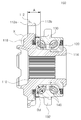
도 1을 참조하면 종래에 이용되고 있는 차량용 휠베어링(소위, 3세대 휠베어링)의 구조가 예시적으로 도시되어 있다. 도 1에 도시된 바와 같이, 휠베어링은 차륜(wheel)이 장착되는 회전요소(10; 휠허브)가 차체에 고정되는 비회전요소(20; 외륜)에 전동체(30)를 통해 연결되어 회전요소(10; 휠허브)에 장착된 차륜을 차체에 회전가능한 상태로 장착하여 지지하도록 구성된다.Referring to FIG. 1, a structure of a wheel bearing (so-called 3rd generation wheel bearing) for a vehicle that has been conventionally used is exemplarily illustrated. As shown in FIG. 1, the wheel bearing is connected to a non-rotating element 20 (outer ring) in which a rotating element 10 (wheel hub) on which a wheel is mounted is fixed to the vehicle body, and rotates through the
한편, 휠베어링의 회전요소(10; 휠허브)에는 브레이크 디스크(40)가 장착되어 차륜을 제동하도록 구성될 수 있다. 구체적으로, 브레이크 디스크(40)는 도 1에 도시된 바와 같이 휠허브(10)의 허브 플랜지(12)의 일측 단면에 장착되도록 구성될 수 있으며, 이러한 브레이크 디스크(40)는 차량에 구비된 한 쌍의 브레이크 패드(미도시) 사이에 배치되어 브레이크 패드와 브레이크 디스크(40) 사이의 마찰접촉에 의해 차륜의 회전을 제동하는 기능을 수행하게 된다. 예컨대, 차량에 구비된 브레이크 패드가 브레이크 디스크(40)를 향해 이동해 브레이크 디스크(40)와 접촉하게 되면, 브레이크 패드와 브레이크 디스크 사이(40) 사이에 발생하는 마찰접촉에 의해 회전요소(10; 휠허브) 및 회전요소(10; 휠허브)에 장착된 차륜이 감속 또는 정지하게 된다.Meanwhile, a
이와 같이 차량용 휠베어링의 휠허브(10)에 형성되는 허브 플랜지(12)는 일측 단면에 브레이크 디스크(40)가 면접촉하여 장착되기 때문에, 브레이크 디스크(40)가 장착되는 허브 플랜지(12)의 장착면이 높은 조도를 갖는 평탄한 평면으로 연마 가공되어야 한다.As described above, the
그러나, 연마 가공은 통상의 기계 가공에 비해 매우 긴 공정 시간이 소요되며 연마 지석 등의 소모로 높은 공구 비용이 발생하기 때문에, 허브 플랜지에 형성되는 브레이크 디스크 장착면의 형성은 휠허브의 제조 비용 및 제조 시간을 증가시키는 원인으로 작용하게 된다.However, abrasive machining takes a very long process time compared to normal machining, and because of the high tool cost due to the consumption of abrasive grindstones, the formation of a brake disc mounting surface formed on the hub flange requires the manufacturing cost of the wheel hub and It acts as a cause of increasing manufacturing time.
또한, 휠베어링의 하중 용량 및 수명을 증가시키기 위해서는 휠베어링에 삽입되는 복열의 전동체들이 축방향으로 보다 멀리 이격된 상태로 장착되는 것이 유리하다.In addition, in order to increase the load capacity and life of the wheel bearing, it is advantageous that the rolling elements inserted into the wheel bearing are mounted in a spaced apart state in the axial direction.
그러나, 휠베어링은 주변 부품과의 결합을 위한 복잡한 구조로 인해 전동체를 이격시켜 배치하는데 한계가 있다. 구체적으로, 차체측에 위치하는 전동체는 등속조인트 등의 인접 부품과의 결합을 위해 차체쪽으로 이동시켜 배치하는데 한계가 있고, 차륜측에 위치하는 전동체는 휠허브의 허브 플랜지와 전동체 사이에 씰링부재를 배치할 공간을 확보해야 하기 때문에 차륜측으로 이동시켜 배치하는데 어려움이 있다.However, the wheel bearing has a limitation in arranging the rolling elements apart from each other due to the complicated structure for coupling with peripheral parts. Specifically, the rolling element located on the vehicle body side is limited to move and arrange toward the vehicle body for coupling with adjacent parts such as constant velocity joints, and the rolling element located on the wheel side is between the hub flange of the wheel hub and the rolling element. Since it is necessary to secure a space for arranging the sealing member, it is difficult to arrange it by moving it to the wheel side.
본 발명은 차량용 휠베어링의 전술한 문제점을 해소하기 위한 것으로, 휠베어링의 휠허브에 구비되는 허브 플랜지의 구조를 개선해 휠허브의 생산성을 향상시키며 나아가 베어링의 하중 용량 및 수명을 개선할 수 있도록 구성된 차량용 휠베어링을 제공하는 것을 목적으로 한다.The present invention is to solve the above-described problems of the wheel bearing for a vehicle, and is configured to improve the structure of the hub flange provided in the wheel hub of the wheel bearing to improve the productivity of the wheel hub and further improve the load capacity and life of the bearing. It is an object to provide a wheel bearing for a vehicle.
전술한 목적을 달성하기 위한 본 발명의 대표적인 구성은 다음과 같다.A representative configuration of the present invention for achieving the above object is as follows.
본 발명의 일 실시예에 따르면, 차량의 차륜을 차체에 회전가능하게 장착하여 지지하는 차량용 휠베어링이 제공된다. 본 발명의 일 실시예에 따른 차량용 휠베어링은 차륜을 장착하기 위한 허브 플랜지를 구비하는 휠허브와, 휠허브의 일측에 압입되어 장착되는 하나 이상의 내륜과, 내륜의 반경방향 외측에 장착되며 외주면에 차체에 장착되는 장착 플랜지를 구비하는 외륜과, 외륜의 반경방향 내측에 장착되는 하나 이상의 전동체를 포함할 수 있다. 본 발명의 일 실시예에 따르면, 휠허브의 허브 플랜지는 일측 단면에 돌출부를 구비해 돌출부의 반경방향 외측에 위치하는 단면만 브레이크 디스크의 장착면으로 이용되도록 구성될 수 있다.According to an embodiment of the present invention, there is provided a wheel bearing for a vehicle that is rotatably mounted on a vehicle body and supported. A wheel bearing for a vehicle according to an embodiment of the present invention includes a wheel hub having a hub flange for mounting a wheel, one or more inner rings press-fitted on one side of the wheel hub, and radially outer side of the inner ring and mounted on an outer circumferential surface. It may include an outer ring having a mounting flange mounted on the vehicle body, and one or more rolling elements mounted on the radially inner side of the outer ring. According to one embodiment of the present invention, the hub flange of the wheel hub may be configured to have a protrusion on one end surface and only a cross section located on the radially outer side of the protrusion to be used as a mounting surface of the brake disc.
본 발명의 일 실시예에 따르면, 돌출부는 휠허브의 허브 플랜지의 차륜측 단면으로부터 돌출하여 형성되도록 구성될 수 있다.According to one embodiment of the present invention, the protrusion may be configured to protrude from the wheel-side end face of the hub flange of the wheel hub.
본 발명의 일 실시예에 따르면, 휠허브의 허브 플랜지의 차체측 단면에는 허브 플랜지의 차체측 단면으로부터 함몰되는 리세스가 구비될 수 있다.According to an embodiment of the present invention, a recess in the vehicle body side end face of the hub flange of the wheel hub may be provided with a recess recessed from the body side end face of the hub flange.
본 발명의 일 실시예에 따르면, 돌출부는 단조면으로 형성될 수 있다.According to one embodiment of the invention, the protrusion may be formed of a forged surface.
본 발명의 일 실시예에 따르면, 돌출부는 표면 조도가 Rz 25 이상으로 형성될 수 있다.According to an embodiment of the present invention, the protrusion may have a surface roughness of Rz 25 or higher.
본 발명의 일 실시예에 따르면, 리세스에 차륜측 씰링부재의 일부 또는 전부가 배치될 수 있다.According to an embodiment of the present invention, some or all of the wheel-side sealing member may be disposed in the recess.
본 발명의 일 실시예에 따르면, 차륜측 씰링부재는 휠허브에 장착되는 슬링거와, 외륜에 압입되어 장착되는 프레임과, 프레임에 부착되는 탄성 씰링부를 포함할 수 있으며, 차륜측 씰링부재의 슬링거는 전술한 리세스 내에 삽입되어 장착되도록 구성될 수 있다.According to an embodiment of the present invention, the sealing member on the wheel side may include a slinger mounted on the wheel hub, a frame that is press-fitted on the outer ring, and an elastic sealing portion attached to the frame, and the slinger on the wheel-side sealing member It can be configured to be inserted into and mounted in the aforementioned recess.
본 발명의 일 실시예에 따르면, 탄성 씰링부는 슬링거와 접촉식 또는 비접촉식으로 작동해 씰링을 수행하는 복수의 탄성 씰링립을 포함할 수 있다.According to an embodiment of the present invention, the elastic sealing portion may include a plurality of elastic sealing lips that perform contacting or non-contacting with the slinger to perform sealing.
본 발명의 일 실시예에 따르면, 탄성 씰링부는 리세스와 외륜 사이의 간극을 좁히도록 반경방향 외측으로 연장하는 댐부를 포함할 수 있다.According to an embodiment of the present invention, the elastic sealing portion may include a dam portion extending radially outward so as to narrow the gap between the recess and the outer ring.
본 발명의 일 실시예에 따르면, 전동체는 축방향으로 이격된 위치에 복열로 배치되도록 구성될 수 있다.According to an embodiment of the present invention, the rolling element may be configured to be arranged in a double row at a position spaced apart in the axial direction.
본 발명의 일 실시예에 따르면, 차륜측에 위치하는 전동체의 직경과 허브 플랜지의 차륜측 단면[브레이크 디스크 장착면]으로부터 차륜측에 위치하는 전동체의 중심까지의 축방향 거리 사이의 비율은 1.7 이하로 형성될 수 있다.According to an embodiment of the present invention, the ratio between the diameter of the rolling element located on the wheel side and the axial distance from the wheel side end face (brake disc mounting surface) of the hub flange to the center of the rolling element located on the wheel side is 1.7 or less.
이 외에도, 본 발명에 따른 차량용 휠베어링에는 본 발명의 기술적 사상을 해치지 않는 범위에서 다른 부가적인 구성이 더 포함될 수 있다.In addition to this, the wheel bearing for a vehicle according to the present invention may further include other additional components without detracting from the technical spirit of the present invention.
본 발명의 일 실시예에 따른 휠베어링 조립체는 브레이크 디스크가 장착되는 허브 플랜지의 일측 단면에 돌출부를 형성해 돌출부로부터 반경방향 외측에 위치하는 부분만 브레이크 디스크를 장착하는 장착면으로 이용되도록 구성되어 있어, 휠허브의 허브플랜지에 요구되는 추가 가공(선삭 가공, 연마 가공 등) 부위를 감소시키고 이를 통해 휠베어링의 제조 비용을 감소시킬 수 있는 효과를 제공할 수 있다.The wheel bearing assembly according to an embodiment of the present invention is configured to form a protrusion on one end surface of a hub flange on which a brake disk is mounted, so that only a portion located radially outward from the protrusion is used as a mounting surface for mounting the brake disk, It is possible to reduce the additional machining (turning, polishing, etc.) required for the hub flange of the wheel hub, and thereby provide an effect of reducing the manufacturing cost of the wheel bearing.
또한, 본 발명의 일 실시예에 따른 휠베어링 조립체는 돌출부가 형성되는 허브 플랜지의 타측 단면에 돌출부에 대응되는 위치에 리세스를 형성해 리세스 내로 차륜측 씰링부재를 삽입해 장착하도록 구성되어 있어 휠베어링에 장착되는 복열의 전동체를 보다 축방향으로 이격시킨 상태로 배치할 수 있고 이로 인해 휠베어링의 하중 용량 및 수명이 향상될 수 있게 된다.In addition, the wheel bearing assembly according to an embodiment of the present invention is configured to form a recess at a position corresponding to the protrusion on the other end face of the hub flange where the protrusion is formed, and insert the wheel-side sealing member into the recess to mount the wheel. The rolling elements mounted on the bearings can be arranged in a more axially spaced state, whereby the load capacity and life of the wheel bearings can be improved.
도 1은 종래에 이용되고 있는 차량용 휠베어링의 구조를 예시적으로 도시한다.
도 2는 본 발명의 일 실시예에 따른 차량용 휠베어링의 구조를 예시적으로 도시한다.
도 3는 본 발명의 일 실시예에 따른 차량용 휠베어링의 단면 구조를 예시적으로 도시한다.
도 4는 도 3에 도시된 X 부분을 확대하여 도시한다.
도 5는 본 발명의 일 실시예에 따른 차량용 휠베어링의 다른 실시형태를 예시적으로 도시한다.1 exemplarily shows a structure of a wheel bearing for a vehicle that has been conventionally used.
2 exemplarily shows a structure of a wheel bearing for a vehicle according to an embodiment of the present invention.
3 exemplarily shows a cross-sectional structure of a wheel bearing for a vehicle according to an embodiment of the present invention.
FIG. 4 is an enlarged view of a portion X shown in FIG. 3.
5 exemplarily shows another embodiment of a wheel bearing for a vehicle according to an embodiment of the present invention.
이하, 첨부한 도면을 참조하여 본 발명의 바람직한 실시예에 대해 본 발명이 속하는 기술 분야에서 통상의 지식을 가진 자가 용이하게 실시할 수 있을 정도로 상세하게 설명한다.Hereinafter, preferred embodiments of the present invention will be described in detail with reference to the accompanying drawings so that those skilled in the art to which the present invention pertains can easily implement them.
본 발명을 명확하게 설명하기 위하여 본 발명과 관계없는 부분에 대한 구체적인 설명은 생략하고, 명세서 전체를 통하여 동일한 구성요소에 대해서는 동일한 참조부호를 붙여 설명하도록 한다. 또한, 도면에 도시된 각 구성요소들의 형상 및 크기는 설명의 편의를 위해 임의로 도시된 것이므로, 본 발명이 반드시 도시된 형상 및 크기로 한정되는 것은 아니다. 즉, 명세서에 기재되어 있는 특정 형상, 구조 및 특성은 본 발명의 사상 및 범위를 벗어나지 않으면서 일 실시예로부터 다른 실시예로 변형되어 구현될 수 있으며, 개별 구성요소의 위치 또는 배치도 본 발명의 사상 및 범위를 벗어나지 않으면서 변경될 수 있는 것으로 이해되어야 한다. 따라서 후술하는 상세한 설명은 한정적인 의미로 행하여지는 것이 아니며, 본 발명의 범위는 특허청구범위의 청구항들이 청구하는 범위 및 그와 균등한 모든 범위를 포괄하는 것으로 받아들여져야 한다.In order to clearly describe the present invention, a detailed description of parts not related to the present invention is omitted, and the same reference numerals are given to the same components throughout the specification. In addition, since the shapes and sizes of each component illustrated in the drawings are arbitrarily illustrated for convenience of description, the present invention is not necessarily limited to the illustrated shapes and sizes. That is, specific shapes, structures, and characteristics described in the specification may be implemented by changing from one embodiment to another embodiment without departing from the spirit and scope of the present invention, and the location or arrangement of individual components is also the spirit of the present invention. And it should be understood that it can be changed without departing from the scope. Therefore, the detailed description to be described later is not made in a limiting sense, and the scope of the present invention should be taken to cover the scope claimed by the claims of the claims and all equivalents thereto.
본 발명의 바림직한 실시예A preferred embodiment of the invention
도 2 내지 도 5를 참조하면 본 발명의 일 실시예에 따른 휠베어링(100)이 예시적으로 도시되어 있다. 도 2 및 도 3에 도시된 바와 같이, 본 발명의 일 실시예에 따른 휠베어링(100)은 통상의 휠베어링과 전체적으로 유사한 구조로 형성될 수 있다.2 to 5, a wheel bearing 100 according to an embodiment of the present invention is illustrated. 2 and 3, the wheel bearing 100 according to an embodiment of the present invention may be formed in a structure generally similar to a conventional wheel bearing.
예컨대, 본 발명의 일 실시예에 따른 휠베어링(100)은 통상의 차량용 휠베어링과 같이 휠허브(110; 회전요소), 내륜(120), 외륜(130; 비회전요소), 전동체(140) 등으로 구성될 수 있으며, 양측 단부에는 휠베어링을 씰링하기 위한 씰링부재가 장착되도록 구성될 수 있다.For example, the wheel bearing 100 according to an exemplary embodiment of the present invention includes a wheel hub 110 (rotating element), an
본 발명의 일 실시예에 따르면, 휠허브(110)는 축방향을 따라 연장하는 대략 원통형 형상의 구조로 형성될 수 있으며, 휠허브(110)의 차륜측 단부 부근에는 허브 플랜지(112)가 구비될 수 있다. 허브 플랜지(112)는 휠허브(110)의 원주방향을 따라 반경방향 외측으로 연장된 형상으로 형성되어, 허브 볼트 등을 이용해 차륜을 휠허브(110)에 장착하는데 이용될 수 있다. 한편, 휠허브(110)의 차체측 단부에는 단차부(114)가 형성되어 내륜(120)을 장착하도록 구성될 수 있으며, 휠허브(110)의 외주면 일부에는 궤도면(내측 궤도면)이 형성되어 전동체(140)를 내측에서 지지하도록 구성될 수 있다.According to an embodiment of the present invention, the
내륜(120)은 휠허브(110)의 일측에 압입되어 장착되도록 구성될 수 있다. 예컨대, 내륜(120)은 도 3에 도시된 바와 같이 휠허브(110)의 내측 단부에 형성된 단차부(114)에 압입된 상태에서 휠허브(110)의 단부에 등속조인트 또는 너트를 결합하거나 휠허브의 끝단을 도 5에 도시된 바와 같이 소성변형시켜 휠허브(110)에 고정되도록 구성될 수 있다. 또한, 내륜(120)의 외주면에는 전동체(140)가 접촉하는 궤도면(내측 궤도면)이 구비되어 전동체를 내측에서 지지하도록 구성될 수 있다.The
외륜(130)은 외주면에 휠베어링(100)을 차체에 장착하기 위한 장착 플랜지(132)를 구비하고, 내주면에 전동체(140)가 접촉하는 궤도면(외측 궤도면)을 구비하도록 구성될 수 있다. 외륜(130)의 내주면에 형성된 궤도면(외측 궤도면)은 휠허브(110) 및/또는 내륜(120)에 형성된 궤도면(내측 궤도면)과 협력해 궤도면 사이에 구름요소인 전동체(140)를 수용하여 지지하도록 구성될 수 있다.The
전동체(140)는 외륜(130)의 반경방향 내측, 구체적으로는 외륜(130)에 형성된 궤도면(외측 궤도면)과 휠허브(110) 및/또는 내륜(120)에 형성된 궤도면(내측 궤도면) 사이에 배치되어, 차륜이 장착되는 휠허브(110)를 차체에 고정되는 외륜(130)에 대해 회전가능하게 지지하는 기능을 수행할 수 있다.The
본 발명의 일 실시예에 따르면, 휠허브(110)의 허브 플랜지(112)의 일측 단면[예컨대, 차륜측에 위치하는 단면(112a)]에는 단면으로부터 축방향으로 돌출되는 돌출부(116)가 구비될 수 있다. 돌출부(116)는 허브 플랜지(112)의 반경방향 내측 단부 부근에 형성되어, 허브 플랜지(112)에서 브레이크 디스크(미도시)가 장착되는 영역을 한정하는 기능을 수행할 수 있다. 예컨대, 본 발명의 일 실시예에 따른 휠베어링(100)은 휠허브(110)의 허브 플랜지(112)에 형성된 돌출부(116)의 반경방향 외측에 위치하는 허브 플랜지(112)의 단면(112a)만 브레이크 디스크를 체결하는 장착면으로 이용되도록 구성될 수 있다.According to an embodiment of the present invention, one side end surface of the
이러한 구성에 의하면, 허브 플랜지(112)는 차륜측에 위치하는 단면(112a) 가운데 돌출부(116)의 반경방향 외측에 위치하는 일부 부분만 브레이크 디스크(미도시)를 장착하기 위한 장착면으로 이용되기 때문에 허브 플랜지(112) 단면의 일부에만 연마 가공 등의 추가 가공을 수행해도 되고, 이로 인해 휠베어링 제조에 소요되는 시간 및 비용을 크게 저감시켜 생산성을 향상시킬 수 있게 된다.According to this configuration, the
본 발명의 일 실시예에 따르면, 돌출부(116)는 Rz 25 이상의 조도값을 갖도록 구성될 수 있다. 이와 같이 돌출부(116)를 높은 조도값을 갖는 표면으로 형성하게 되면(즉, 통상의 허브 플랜지에서보다 거친 표면으로 형성), 돌출부(116)를 추가 가공 없이 단조면 등으로 그대로 이용할 수 있어 생산성이 더욱 높아질 수 있게 된다. 예컨대, 본 발명의 일 실시예에 따른 휠베어링(100)은 돌출부(116)를 형성하는 단부(116a) 및 측부(116b)는 추가 기계 가공 없이 단조면을 그대로 이용하고, 돌출부(116)의 반경방향 외측에 위치하는 허브 플랜지(112)의 단부면만 연마 가공 등을 수행하여 이용할 수 있어 휠허브(100) 및 휠베어링(100)의 제조 효율이 크게 향상될 수 있게 된다.According to an embodiment of the present invention, the
한편, 본 발명의 일 실시예에 따르면, 허브 플랜지(112)의 타측 단면[예컨대, 차체측에 위치하는 단면(112b)]에는 단면(112b)으로부터 함몰되는 리세스(118)가 구비될 수 있다. 본 발명의 일 실시예에 따른 휠베어링은 허브 플랜지(112)의 차륜측 단면(112a)에 돌출부(116) 구비되어 있기 때문에 허브 플랜지(112)의 차체측 단면(112b)에 리세스(118)를 형성해도 허브 플랜지(112)의 두께가 감소해 강성이 저하되는 문제를 방지할 수 있게 된다.Meanwhile, according to an embodiment of the present invention, a
본 발명의 일 실시예에 따르면, 리세스(118)는 휠허브의 반경방향 내측으로 이동함에 따라 휠허브의 차체측 단면(112b)으로부터 함몰되는 제1 리세스(118a)와 제1 리세스(118a)로부터 추가로 함몰되는 제2 리세스(118b)를 포함하도록 구성될 수 있다. 본 발명의 일 실시예에 따르면, 제1 리세스(118a)는 외륜(130)의 축방향 단부에 대향하여 위치될 수 있으며, 제2 리세스(118b)는 제1 리세스(118a)의 반경방향 내측에 위치되어 차륜측 씰링부재(150)가 삽입되어 장착되도록 구성될 수 있다.According to an embodiment of the present invention, the
이러한 구성에 의하면, 본 발명의 일 실시예에 따른 휠베어링(100)은 차륜측 씰링부재(150)가 통상의 차량용 휠베어링에서 보다 차륜측으로 이동된 위치에 장착되되어 차륜측에 추가의 공간을 확보할 수 있고, 이와 같이 확보된 추가의 공간만큼 차륜측 전동체를 차륜측으로 이동시켜 배치함으로써 복열의 전동체 사이의 축방향 거리를 보다 멀게 형성하여 휠베어링의 하중 용량 및 수명 향상을 도모할 수 있게 된다.According to this configuration, the wheel bearing 100 according to an embodiment of the present invention is mounted at a position where the wheel-
예컨대, 도 4를 참조하면 본 발명의 일 실시예에 따른 휠베어링(100)에서 허브 플랜지(112)에 형성된 리세스(118) 내로 차륜측 씰링부재(150)를 삽입시켜 배치하는 구조가 예시적으로 도시되어 있다.For example, referring to FIG. 4, a structure in which the wheel-
본 발명의 일 실시예에 따르면, 차륜측 씰링부재(150)는 허브 플랜지(112)에 압입되어 장착되는 슬링거(152)와, 외륜(130)에 압입되어 장착되는 프레임(154)과, 이러한 프레임에 부착되는 탄성 씰링부(156) 등으로 구성될 수 있다.According to an embodiment of the present invention, the wheel-
본 발명의 일 실시예에 따르면, 슬링거(152)는 휠허브(110)의 외주면에 압입되어 장착되도록 구성될 수 있다. 구체적으로, 슬링거(152)는 대략 축방향으로 연장되어 휠허브에 압입되는 압입부와 압입부로부터 반경방향으로 연장되는 경방향 연장부를 포함하는 구조로 형성될 수 있으며, 허브 플랜지(112)에 형성된 리세스[제2 리세스(118b)] 내로 삽입되어 장착될 수 있도록 구성될 수 있다.According to an embodiment of the present invention, the
한편, 슬링거(152)의 차륜측에는 외륜(130)에 장착되어 슬링거(150)와 함께 씰링기능을 수행하는 씰링부[프레임(154) 및 탄성 씰링부(156)]가 구비될 수 있다. 본 발명의 일 실시예에 따르면, 프레임(154)은 외륜(130)의 외주면 또는 내주면에 압입되어 장착되며, 프레임(154)의 전부 또는 일부에는 고무 등의 탄성체로 형성된 탄성 씰링부(156)가 부착되어 씰링을 수행하도록 구성될 수 있다.Meanwhile, a sealing part (
본 발명의 일 실시예에 따르면, 탄성 씰링부(156)는 프레임(154)으로부터 연장하는 복수의 씰링립을 구비하도록 구성될 수 있다. 예컨대, 탄성 씰링부(156)는 프레임(154)으로부터 슬링거(152)를 향해 연장해 슬링거(152)와 접촉 또는 비접촉 방식으로 씰링을 수행하는 하나 이상의 탄성 씰링립(156a)을 포함하도록 구성될 수 있다.According to an embodiment of the present invention, the
또한, 본 발명의 일 실시예에 따르면, 탄성 씰링부(156)에는 리세스(118)와 외륜(130) 사이에 형성되는 간극을 보다 효과적으로 씰링하기 위해 탄성 씰링부(156)에 반경방향 외측으로 연장하는 댐부(156b)를 구비해 리세스(118)와 외륜(130) 사이에 형성되는 간극을 좁혀 보다 원활한 씰링이 수행되도록 구성될 수 있다.In addition, according to an embodiment of the present invention, the
이처럼 본 발명의 일 실시예에 따른 휠베어링(100)은 차륜측 씰링부재(150)를 휠허브(110)의 허브 플랜지(112)에 형성된 리세스(118) 내로 삽입시켜 장착한 다음 함몰된 리세스(118) 내에서 복잡한 라비린스(Labylinth) 구조를 형성하도록 구성되어 있어, 통상의 휠베어링에 비해 휠베어링 내부로 이물질이 유입되는 것을 보다 효과적으로 방지할 수 있게 된다.As such, the wheel bearing 100 according to an embodiment of the present invention is inserted into the
한편, 본 발명의 일 실시예에 따른 휠베어링(100)은 차륜측 씰링부재(150)를 보다 차륜측으로 이동시켜 장착함에 따라 확보된 공간을 이용해 차륜측에 배치되는 전동체를 차륜측으로 더 이동시켜 장착하도록 구성될 수 있다. 즉, 본 발명의 일 실시예에 따른 휠베어링(100)은 종래의 휠베어링에 비해 차륜측에 배치되는 전동체와 차체측에 배치되는 전동체 사이의 축방향 거리를 보다 멀리 배치할 수 있다.On the other hand, the wheel bearing 100 according to an embodiment of the present invention further moves the rolling element disposed on the wheel side to the wheel side by using the space secured by moving the wheel-
본 발명의 일 실시예에 따르면, 차륜측에 배치되는 전동체는 허브 플랜지(112)의 차체측 단면(112a)[즉, 브레이크 디스크 장착면]으로부터 차륜측 전동체의 중심까지의 축방향 거리(A)와 차륜측 전동체의 직경(Bd) 사이의 비율(A/Bd)이 1.7 이하로 형성되도록 구성될 수 있다.According to one embodiment of the present invention, the rolling element disposed on the wheel side is an axial distance from the vehicle body
차륜측 전동체를 이동시켜 복열의 전동체 사이의 축방향 거리를 증가시키기 위해서는 허브 플랜지로부터 차륜측 전동체의 중심까지의 축방향 거리가 감소되어야 한다. 그러나, 이러한 축방향 거리를 너무 작게 형성하게 되면 휠베어링에 하중이 가해질 때 허브 플랜지에 파손이 발생될 위험이 있어 적절한 제어가 요구된다.In order to increase the axial distance between the rolling elements by moving the wheel-side rolling elements, the axial distance from the hub flange to the center of the wheel-side rolling elements must be reduced. However, if such an axial distance is formed too small, there is a risk of damage to the hub flange when a load is applied to the wheel bearing, and appropriate control is required.
또한, 베어링에 장착되는 전동체는 크기가 커질수록 베어링의 수명 향상에 도움이 되나 전동체의 크기가 커지면 반대로 베어링의 중량이 증가되어 휠베어링의 성능이 저하될 수 있기 때문에, 베어링의 성능 및 수명을 향상시키기 위해서는 전동체(Bd)의 직경도 적절한 크기로 제어될 수 있어야 한다.In addition, as the size of the rolling element mounted on the bearing helps to improve the life of the bearing, as the size of the rolling element increases, on the contrary, the weight of the bearing increases, so the performance of the wheel bearing may deteriorate. In order to improve the diameter of the rolling element (Bd) should also be able to be controlled to an appropriate size.
이러한 점을 고려해 본 발명의 일 실시예에 따른 휠베어링은 허브 플랜지(112)의 차체측 단면(112a)으로부터 차륜측 전동체의 중심까지의 축방향 거리(A)와 차륜측 전동체의 직경(Bd) 사이의 비율이 특정한 값으로[예컨대 1.7 이하의 값]으로 제어하도록 구성하고 있다.In consideration of these points, the wheel bearing according to an embodiment of the present invention includes the axial distance A from the body-
이러한 구성에 의하면, 전동체의 직경과 복열의 전동체 사이의 거리가 베어링의 하중 용량을 증가시키면서 중량 증가 및 파손 위험은 억제할 수 있는 적절한 범위로 제어될 수 있기 때문에, 휠베어링이 보다 큰 하중 용량을 가질 수 있고 휠베어링의 수명이 더욱 향상될 수 있게 된다.According to this configuration, since the distance between the diameter of the rolling element and the rolling element of the double row increases the load capacity of the bearing, the weight increase and the risk of breakage can be controlled to an appropriate range that can be suppressed, so that the wheel bearing has a larger load. It can have a capacity and the life of the wheel bearing can be further improved.
이상에서는 본 발명을 구체적인 구성요소 등과 같은 특정 사항들과 한정된 실시예 및 도면을 통해 설명하였으나, 이는 본 발명의 보다 전반적인 이해를 돕기 위해서 제공된 것일 뿐이며, 본 발명이 상기 실시예들에 한정되는 것은 아니며, 본 발명이 속하는 기술분야에서 통상의 지식을 가진 자라면 이러한 기재로부터 다양한 수정 및 변형을 꾀할 수 있을 것이다. 예컨대, 앞서 설명한 실시예에서는 휠허브, 내륜, 외륜, 전동체 등으로 구성된 소위 3세대 방식의 휠베어링 구조를 이용해 본 발명에 따른 휠베어링 조립체의 구조를 설명하였으나, 본 발명에 따른 휠베어링 조립체는 3세대 방식의 휠베어링 이외에도 공지된 다양한 임의의 구조로 형성될 수 있다.In the above, the present invention has been described through specific embodiments, such as specific components, and limited embodiments and drawings, which are provided only to help the overall understanding of the present invention, and the present invention is not limited to the above embodiments. , Those skilled in the art to which the present invention pertains will be able to seek various modifications and variations from these descriptions. For example, in the above-described embodiment, the structure of the wheel bearing assembly according to the present invention was described using a so-called 3rd generation wheel bearing structure composed of a wheel hub, an inner ring, an outer ring, a rolling element, etc., but the wheel bearing assembly according to the present invention In addition to the third-generation wheel bearings, it can be formed of various known structures.
따라서, 본 발명의 사상은 전술한 실시예에 국한되어 정해져서는 아니되며, 후술하는 특허청구범위뿐만 아니라 이와 균등하게 또는 등가적으로 변형된 모든 것들은 본 발명의 사상의 범주에 속하는 것으로 해석되어야 한다.Therefore, the spirit of the present invention should not be limited to the above-described embodiments, and should be interpreted as belonging to the scope of the spirit of the present invention, as well as all claims that are equivalently or equivalently modified as well as the claims below.
100: 휠베어링
110: 휠허브
112: 허브 플랜지
114: 단차부
116: 돌출부
118: 리세스
118a: 제1 리세스
118b: 제2 리세스
120: 내륜
130: 외륜
132: 장착 플랜지
140: 전동체
150: 차륜측 씰링부재
152: 슬링거
154: 프레임
156: 탄성 씰링부
156a: 탄성 씰링립
156b: 댐부100: wheel bearing
110: wheel hub
112: hub flange
114: step
116: protrusion
118: recess
118a: first recess
118b: second recess
120: inner ring
130: paddle
132: mounting flange
140: rolling element
150: wheel-side sealing member
152: Slinger
154: frame
156: elastic sealing portion
156a: Elastic sealing lip
156b: Dam part
Claims (11)
차륜을 장착하기 위한 허브 플랜지를 구비하는 휠허브(110)와,
상기 휠허브(110)의 일측에 압입되어 장착되는 하나 이상의 내륜(120)과,
상기 내륜(120)의 반경방향 외측에 장착되며 외주면에 차체에 장착되는 장착 플랜지를 구비하는 외륜(130)과,
상기 외륜(130)의 반경방향 내측에 장착되는 하나 이상의 전동체(140)를 포함하고,
상기 휠허브(110)의 허브 플랜지(112)는 일측 단면에 돌출부(116)를 구비해, 상기 돌출부(116)의 반경방향 외측에 위치하는 단면만 브레이크 디스크의 장착면으로 이용되도록 구성되는,
차량용 휠베어링.A vehicle wheel bearing 100 for rotatably mounting a vehicle wheel to a vehicle body and supporting the vehicle wheel,
Wheel hub 110 having a hub flange for mounting the wheel, and
One or more inner wheels 120 that are pressed and mounted on one side of the wheel hub 110,
And the outer ring 130 is mounted on the radially outer side of the inner ring 120 and has a mounting flange mounted to the vehicle body on the outer circumferential surface,
It includes one or more rolling elements 140 mounted in the radially inner side of the outer ring 130,
The hub flange 112 of the wheel hub 110 is provided with a projection 116 on one side end surface, and configured to be used only as a mounting surface of the brake disc, only a section located radially outside the projection 116.
Vehicle wheel bearings.
상기 돌출부(116)는 상기 휠허브(110)의 허브 플랜지(112)의 차륜측 단면(112a)으로부터 돌출하여 형성되는,
차량용 휠베어링.According to claim 1,
The protrusion 116 is formed to protrude from the wheel-side end face 112a of the hub flange 112 of the wheel hub 110,
Vehicle wheel bearings.
상기 휠허브(110)의 허브 플랜지(112)의 차체측 단면(112b)에는 상기 허브 플랜지(112)의 차체측 단면으로부터 함몰되는 리세스(118)가 구비되는,
차량용 휠베어링.According to claim 2,
The vehicle hub-side end face 112b of the hub flange 112 of the wheel hub 110 is provided with a recess 118 recessed from the body-side end face of the hub flange 112,
Vehicle wheel bearings.
상기 돌출부(116)는 단조면으로 형성되는,
차량용 휠베어링.According to claim 3,
The protrusion 116 is formed of a forged surface,
Vehicle wheel bearings.
상기 돌출부(116)는 표면 조도가 Rz 25 이상으로 형성되는,
차량용 휠베어링.According to claim 4,
The protrusion 116 is formed with a surface roughness of Rz 25 or more,
Vehicle wheel bearings.
상기 리세스(118)에 차륜측 씰링부재(150)의 일부 또는 전부가 배치되는,
차량용 휠베어링.The method of claim 5,
Part or all of the wheel-side sealing member 150 is disposed in the recess 118,
Vehicle wheel bearings.
상기 차륜측 씰링부재(150)는 휠허브(110)에 장착되는 슬링거(152)와, 외륜(130)에 압입되어 장착되는 프레임(154)과, 상기 프레임(154)에 부착되는 탄성 씰링부(156)을 포함하고,
상기 슬링거(152)는 상기 리세스(118) 내에 삽입되어 장착되는,
차량용 휠베어링.The method of claim 6,
The wheel-side sealing member 150 includes a slinger 152 mounted on the wheel hub 110, a frame 154 mounted press-fitted on the outer ring 130, and an elastic sealing portion attached to the frame 154 ( 156),
The slinger 152 is inserted and mounted in the recess 118,
Vehicle wheel bearings.
상기 탄성 씰링부(156)는 상기 슬링거(152)와 접촉식 또는 비접촉식으로 작동해 씰링을 수행하는 복수의 탄성 씰링립(156a)을 포함하는,
차량용 휠베어링.The method of claim 7,
The elastic sealing portion 156 includes a plurality of elastic sealing lips (156a) operating in contact or non-contact with the slinger 152 to perform sealing,
Vehicle wheel bearings.
상기 탄성 씰링부(156)는 상기 리세스(118)와 상기 외륜(130) 사이의 간극을 좁히도록 반경방향 외측으로 연장하는 댐부(156b)를 포함하는,
차량용 휠베어링.The method of claim 8,
The elastic sealing portion 156 includes a dam portion 156b extending radially outward to narrow the gap between the recess 118 and the outer ring 130,
Vehicle wheel bearings.
상기 전동체(140)는 축방향으로 이격된 위치에 복열로 배치되는,
차량용 휠베어링.The method of claim 9
The rolling element 140 is disposed in a double row at a position spaced apart in the axial direction,
Vehicle wheel bearings.
차륜측에 위치하는 전동체의 직경(Bd)과 상기 허브 플랜지(112)의 차륜측 단면(112a)으로부터 차륜측에 위치하는 전동체의 중심까지의 축방향 거리(A) 사이의 비율(A/Bd)은 1.7 이하로 형성되는,
차량용 휠베어링.The method of claim 10,
Ratio (A/) between the diameter (Bd) of the rolling element located on the wheel side and the axial distance (A) from the wheel side end face (112a) of the hub flange 112 to the center of the rolling element located on the wheel side Bd) is formed below 1.7,
Vehicle wheel bearings.
Priority Applications (3)
| Application Number | Priority Date | Filing Date | Title |
|---|---|---|---|
| KR1020190005963A KR102522632B1 (en) | 2019-01-16 | 2019-01-16 | Wheel bearing for vehicle |
| DE112020000263.2T DE112020000263B4 (en) | 2019-01-16 | 2020-01-16 | VEHICLE WHEEL BEARINGS |
| PCT/KR2020/000830 WO2020149680A1 (en) | 2019-01-16 | 2020-01-16 | Vehicle wheel bearing |
Applications Claiming Priority (1)
| Application Number | Priority Date | Filing Date | Title |
|---|---|---|---|
| KR1020190005963A KR102522632B1 (en) | 2019-01-16 | 2019-01-16 | Wheel bearing for vehicle |
Publications (2)
| Publication Number | Publication Date |
|---|---|
| KR20200089192A true KR20200089192A (en) | 2020-07-24 |
| KR102522632B1 KR102522632B1 (en) | 2023-04-24 |
Family
ID=71613818
Family Applications (1)
| Application Number | Title | Priority Date | Filing Date |
|---|---|---|---|
| KR1020190005963A KR102522632B1 (en) | 2019-01-16 | 2019-01-16 | Wheel bearing for vehicle |
Country Status (3)
| Country | Link |
|---|---|
| KR (1) | KR102522632B1 (en) |
| DE (1) | DE112020000263B4 (en) |
| WO (1) | WO2020149680A1 (en) |
Families Citing this family (1)
| Publication number | Priority date | Publication date | Assignee | Title |
|---|---|---|---|---|
| DE102019205782B4 (en) * | 2019-04-23 | 2022-04-28 | Audi Ag | Wheel bearing arrangement for a motor vehicle |
Citations (2)
| Publication number | Priority date | Publication date | Assignee | Title |
|---|---|---|---|---|
| KR20170131974A (en) * | 2016-05-23 | 2017-12-01 | 주식회사 일진글로벌 | Slinger structure and wheel bearing assembly provided the same |
| US20180264879A1 (en) * | 2017-03-14 | 2018-09-20 | Audi Ag | Wheel bearing arrangement for a motor vehicle |
Family Cites Families (3)
| Publication number | Priority date | Publication date | Assignee | Title |
|---|---|---|---|---|
| DE102008034627A1 (en) | 2008-07-25 | 2010-01-28 | Schaeffler Kg | Rolling bearings with flange |
| JP2011007272A (en) * | 2009-06-26 | 2011-01-13 | Ntn Corp | Wheel bearing device |
| KR101802278B1 (en) | 2016-03-04 | 2017-11-28 | 주식회사 일진글로벌 | Wheel bearing and sealing apparatus thereof |
-
2019
- 2019-01-16 KR KR1020190005963A patent/KR102522632B1/en active IP Right Grant
-
2020
- 2020-01-16 DE DE112020000263.2T patent/DE112020000263B4/en active Active
- 2020-01-16 WO PCT/KR2020/000830 patent/WO2020149680A1/en active Application Filing
Patent Citations (2)
| Publication number | Priority date | Publication date | Assignee | Title |
|---|---|---|---|---|
| KR20170131974A (en) * | 2016-05-23 | 2017-12-01 | 주식회사 일진글로벌 | Slinger structure and wheel bearing assembly provided the same |
| US20180264879A1 (en) * | 2017-03-14 | 2018-09-20 | Audi Ag | Wheel bearing arrangement for a motor vehicle |
Also Published As
| Publication number | Publication date |
|---|---|
| KR102522632B1 (en) | 2023-04-24 |
| DE112020000263T5 (en) | 2021-09-09 |
| WO2020149680A1 (en) | 2020-07-23 |
| DE112020000263B4 (en) | 2023-12-21 |
Similar Documents
| Publication | Publication Date | Title |
|---|---|---|
| US10746229B2 (en) | Wheel bearing sealing device and manufacturing method therefor | |
| JP5708204B2 (en) | Seal structure | |
| CN211778585U (en) | Hub unit bearing | |
| KR102522632B1 (en) | Wheel bearing for vehicle | |
| CN111512057A (en) | Bearing device for wheel | |
| JP5708403B2 (en) | Sealing device for bearing | |
| KR101857192B1 (en) | Sealing apparatus of wheel bearing | |
| KR102536970B1 (en) | Wheel bearing for vehicle having improved sealing function | |
| JP2009074589A (en) | Sealing device | |
| KR101280616B1 (en) | Sealing apparatus of bearing and wheel bearing including the same | |
| JP6200252B2 (en) | Sealing device | |
| KR101211670B1 (en) | Sealing apparatus of bearing | |
| JP5365350B2 (en) | Sealing device and rolling bearing | |
| CN105691104A (en) | Hub driving assembly | |
| JP2019190608A (en) | Sealing device | |
| US20220260117A1 (en) | Bearing unit provided with a retention device having optimized lubrication | |
| JP2013096433A (en) | Sealed bearing | |
| KR20150065487A (en) | Wheel bearing assembly | |
| JP2006200628A (en) | Hub unit bearing | |
| JP2021173368A (en) | Rolling bearing device | |
| JP2023097884A (en) | Sealing device and bearing device | |
| JP2017219105A (en) | Sealing device | |
| CN101297125A (en) | Bearing device for wheel | |
| JP2006132547A (en) | Wheel bearing unit | |
| JP6226006B2 (en) | Hub unit for vehicles |
Legal Events
| Date | Code | Title | Description |
|---|---|---|---|
| E902 | Notification of reason for refusal | ||
| E701 | Decision to grant or registration of patent right |