KR20200087630A - Method and apparatus for indicating information related to dmrs in wireless communication system - Google Patents
Method and apparatus for indicating information related to dmrs in wireless communication system Download PDFInfo
- Publication number
- KR20200087630A KR20200087630A KR1020190004205A KR20190004205A KR20200087630A KR 20200087630 A KR20200087630 A KR 20200087630A KR 1020190004205 A KR1020190004205 A KR 1020190004205A KR 20190004205 A KR20190004205 A KR 20190004205A KR 20200087630 A KR20200087630 A KR 20200087630A
- Authority
- KR
- South Korea
- Prior art keywords
- dmrs
- pscch
- pssch
- case
- allocated
- Prior art date
Links
Images


Classifications
-
- H—ELECTRICITY
- H04—ELECTRIC COMMUNICATION TECHNIQUE
- H04L—TRANSMISSION OF DIGITAL INFORMATION, e.g. TELEGRAPHIC COMMUNICATION
- H04L27/00—Modulated-carrier systems
- H04L27/26—Systems using multi-frequency codes
- H04L27/2601—Multicarrier modulation systems
- H04L27/2602—Signal structure
- H04L27/261—Details of reference signals
- H04L27/2613—Structure of the reference signals
-
- H—ELECTRICITY
- H04—ELECTRIC COMMUNICATION TECHNIQUE
- H04L—TRANSMISSION OF DIGITAL INFORMATION, e.g. TELEGRAPHIC COMMUNICATION
- H04L5/00—Arrangements affording multiple use of the transmission path
- H04L5/003—Arrangements for allocating sub-channels of the transmission path
- H04L5/0048—Allocation of pilot signals, i.e. of signals known to the receiver
- H04L5/005—Allocation of pilot signals, i.e. of signals known to the receiver of common pilots, i.e. pilots destined for multiple users or terminals
-
- H—ELECTRICITY
- H04—ELECTRIC COMMUNICATION TECHNIQUE
- H04L—TRANSMISSION OF DIGITAL INFORMATION, e.g. TELEGRAPHIC COMMUNICATION
- H04L5/00—Arrangements affording multiple use of the transmission path
- H04L5/003—Arrangements for allocating sub-channels of the transmission path
- H04L5/0048—Allocation of pilot signals, i.e. of signals known to the receiver
- H04L5/0051—Allocation of pilot signals, i.e. of signals known to the receiver of dedicated pilots, i.e. pilots destined for a single user or terminal
-
- H—ELECTRICITY
- H04—ELECTRIC COMMUNICATION TECHNIQUE
- H04L—TRANSMISSION OF DIGITAL INFORMATION, e.g. TELEGRAPHIC COMMUNICATION
- H04L5/00—Arrangements affording multiple use of the transmission path
- H04L5/003—Arrangements for allocating sub-channels of the transmission path
- H04L5/0053—Allocation of signaling, i.e. of overhead other than pilot signals
-
- H—ELECTRICITY
- H04—ELECTRIC COMMUNICATION TECHNIQUE
- H04W—WIRELESS COMMUNICATION NETWORKS
- H04W72/00—Local resource management
- H04W72/02—Selection of wireless resources by user or terminal
-
- H—ELECTRICITY
- H04—ELECTRIC COMMUNICATION TECHNIQUE
- H04W—WIRELESS COMMUNICATION NETWORKS
- H04W72/00—Local resource management
- H04W72/04—Wireless resource allocation
- H04W72/044—Wireless resource allocation based on the type of the allocated resource
- H04W72/0446—Resources in time domain, e.g. slots or frames
-
- H—ELECTRICITY
- H04—ELECTRIC COMMUNICATION TECHNIQUE
- H04W—WIRELESS COMMUNICATION NETWORKS
- H04W72/00—Local resource management
- H04W72/04—Wireless resource allocation
- H04W72/044—Wireless resource allocation based on the type of the allocated resource
- H04W72/0453—Resources in frequency domain, e.g. a carrier in FDMA
-
- H—ELECTRICITY
- H04—ELECTRIC COMMUNICATION TECHNIQUE
- H04W—WIRELESS COMMUNICATION NETWORKS
- H04W72/00—Local resource management
- H04W72/12—Wireless traffic scheduling
- H04W72/1263—Mapping of traffic onto schedule, e.g. scheduled allocation or multiplexing of flows
-
- H—ELECTRICITY
- H04—ELECTRIC COMMUNICATION TECHNIQUE
- H04W—WIRELESS COMMUNICATION NETWORKS
- H04W72/00—Local resource management
- H04W72/20—Control channels or signalling for resource management
-
- H—ELECTRICITY
- H04—ELECTRIC COMMUNICATION TECHNIQUE
- H04W—WIRELESS COMMUNICATION NETWORKS
- H04W76/00—Connection management
- H04W76/10—Connection setup
- H04W76/14—Direct-mode setup
-
- H—ELECTRICITY
- H04—ELECTRIC COMMUNICATION TECHNIQUE
- H04B—TRANSMISSION
- H04B7/00—Radio transmission systems, i.e. using radiation field
- H04B7/02—Diversity systems; Multi-antenna system, i.e. transmission or reception using multiple antennas
- H04B7/04—Diversity systems; Multi-antenna system, i.e. transmission or reception using multiple antennas using two or more spaced independent antennas
- H04B7/0413—MIMO systems
- H04B7/0452—Multi-user MIMO systems
-
- H—ELECTRICITY
- H04—ELECTRIC COMMUNICATION TECHNIQUE
- H04L—TRANSMISSION OF DIGITAL INFORMATION, e.g. TELEGRAPHIC COMMUNICATION
- H04L5/00—Arrangements affording multiple use of the transmission path
- H04L5/0001—Arrangements for dividing the transmission path
- H04L5/0003—Two-dimensional division
- H04L5/0005—Time-frequency
- H04L5/0007—Time-frequency the frequencies being orthogonal, e.g. OFDM(A), DMT
-
- H—ELECTRICITY
- H04—ELECTRIC COMMUNICATION TECHNIQUE
- H04L—TRANSMISSION OF DIGITAL INFORMATION, e.g. TELEGRAPHIC COMMUNICATION
- H04L5/00—Arrangements affording multiple use of the transmission path
- H04L5/003—Arrangements for allocating sub-channels of the transmission path
- H04L5/0044—Arrangements for allocating sub-channels of the transmission path allocation of payload
-
- H—ELECTRICITY
- H04—ELECTRIC COMMUNICATION TECHNIQUE
- H04W—WIRELESS COMMUNICATION NETWORKS
- H04W4/00—Services specially adapted for wireless communication networks; Facilities therefor
- H04W4/30—Services specially adapted for particular environments, situations or purposes
- H04W4/40—Services specially adapted for particular environments, situations or purposes for vehicles, e.g. vehicle-to-pedestrians [V2P]
Abstract
Description
본 발명은 무선 통신 시스템에서 차량 통신(Vehicle to everything, 이하 V2X)을 지원하는 단말을 위한 DMRS(Demodulation Reference Signal)를 구성하는 방법 및 장치에 대한 것이다. 보다 구체적으로, NR(New Radio) 시스템에서 V2X(Vehicle to Everything)를 위한 DMRS 구성 방법 및 장치를 제공할 수 있다.The present invention relates to a method and apparatus for configuring a Demodulation Reference Signal (DMRS) for a terminal supporting vehicle communication (V2X) in a wireless communication system. More specifically, it is possible to provide a DMRS configuration method and apparatus for Vehicle to Everything (V2X) in a New Radio (NR) system.
ITU(International Telecommunication Union)에서는 IMT(International Mobile Telecommunication) 프레임워크 및 표준에 대해서 개발하고 있으며, 최근에는 "IMT for 2020 and beyond"라 칭하여지는 프로그램을 통하여 5 세대(5G) 통신을 위한 논의를 진행 중이다.The International Telecommunication Union (ITU) is developing the International Mobile Telecommunication (IMT) framework and standards, and is currently in the process of discussing 5G (5G) communication through a program called "IMT for 2020 and beyond." .
"IMT for 2020 and beyond" 에서 제시하는 요구사항들을 충족하기 위해서, 3GPP(3rd Generation Partnership Project) NR(New Radio) 시스템은 다양한 시나리오, 서비스 요구사항, 잠재적인 시스템 호환성 등을 고려하여, 시간-주파수 자원 단위 기준에 대한 다양한 뉴머롤로지(numerology)를 지원하는 방향으로 논의되고 있다.In order to meet the requirements presented by "IMT for 2020 and beyond," the 3rd Generation Partnership Project (3GPP) New Radio (NR) system takes into account various scenarios, service requirements, potential system compatibility, etc., and time-frequency It is being discussed in the direction of supporting various numerology of resource unit standards.
본 발명은 무선통신시스템에서 차량 통신을 지원하는 단말에 DMRS를 구성하는 방법 및 장치를 V2X를 위한 DMRS 관련 정보를 지시하는 방법 및 장치를 제공할 수 있다.The present invention can provide a method and apparatus for instructing DMRS-related information for V2X to a method and apparatus for configuring DMRS in a terminal supporting vehicle communication in a wireless communication system.
본 발명은 무선통신시스템에서 NR V2X를 위한 DMRS 구성 방법 및 장치를 제공할 수 있다.The present invention can provide a method and apparatus for configuring DMRS for NR V2X in a wireless communication system.
본 발명은 무선통신시스템에서 PSCCH(Physical Control Channel)와 PSSCH(Physical Shared Channel)가 하나 이상의 심볼 내에서 동시에 존재하는 자원 할당 구조를 고려하여 DMRS를 구성하는 방법 및 장치를 제공할 수 있다.The present invention can provide a method and apparatus for configuring DMRS in consideration of a resource allocation structure in which a physical control channel (PSCCH) and a physical shared channel (PSSCH) exist simultaneously in one or more symbols in a wireless communication system.
본 발명은 무선통신시스템에서 PSCCH와 PSSCH가 하나 이상의 심볼 내에서 동시에 존재하는 자원 할당 구조를 고려하여 자원을 효율적으로 사용하는 방법 및 장치를 제공할 수 있다. The present invention can provide a method and apparatus for efficiently using resources in consideration of a resource allocation structure in which PSCCH and PSSCH are simultaneously present in one or more symbols in a wireless communication system.
본 발명은 무선통신시스템에서 PSCCH와 PSSCH가 하나 이상의 심볼 내에서 동시에 존재하는 자원 할당 구조를 고려하여 데이터 복호를 빠르게 진행하는 방법 및 장치를 제공할 수 있다.The present invention can provide a method and apparatus for rapidly performing data decoding in consideration of a resource allocation structure in which PSCCH and PSSCH are simultaneously present in one or more symbols in a wireless communication system.
본 발명은 단말이 사이드링크를 통해 다른 단말과 통신을 수행하는 방법을 제공할 수 있다. 이때, 통신을 수행하는 방법은 DMRS 관련 정보를 획득하는 단계, PSCCH DMRS 및 PSSCH DMRS를 동시에 복호하는 단계 및 복호화된 PSCCH DMRS에 기초하여 PSCCH를 복호하고, 복호화된 PSCCH DMRS 및 PSSCH DMRS에 기초하여 PSSCH를 복호할 수 있다.The present invention can provide a method for a terminal to communicate with another terminal through a side link. At this time, the method of performing communication includes: obtaining DMRS-related information, simultaneously decoding PSCCH DMRS and PSSCH DMRS, and decoding PSCCH based on decoded PSCCH DMRS, and decoding PSCCH DMRS and PSSCH based on PSSCH DMRS Can be decoded.
본 개시에 대하여 위에서 간략하게 요약된 특징들은 후술하는 본 개시의 상세한 설명의 예시적인 양상일 뿐이며, 본 개시의 범위를 제한하는 것은 아니다.The features briefly summarized above with respect to the present disclosure are merely illustrative aspects of the detailed description of the present disclosure described below, and do not limit the scope of the present disclosure.
본 개시에 따르면, 무선통신시스템에서 차량 통신을 지원하는 단말에 DMRS를 구성하는 방법 및 장치를 V2X를 위한 DMRS 관련 정보를 지시할 수 있다.According to the present disclosure, a method and apparatus for configuring DMRS in a terminal supporting vehicle communication in a wireless communication system may indicate DMRS-related information for V2X.
본 개시에 따르면, 무선통신시스템에서 NR V2X를 위한 DMRS를 구성할 수 있다.According to the present disclosure, a DMRS for NR V2X can be configured in a wireless communication system.
본 개시에 따르면, 무선통신시스템에서 PSCCH와 PSSCH가 하나 이상의 심볼 내에서 동시에 존재하는 자원 할당 구조를 고려하여 DMRS를 구성할 수 있다.According to the present disclosure, a DMRS may be configured in consideration of a resource allocation structure in which PSCCH and PSSCH are simultaneously present in one or more symbols in a wireless communication system.
본 개시에 따르면, 무선통신시스템에서 PSCCH와 PSSCH가 하나 이상의 심볼 내에서 동시에 존재하는 자원 할당 구조를 고려하여 자원을 효율적으로 사용할 수 있다.According to the present disclosure, resources can be efficiently used in consideration of a resource allocation structure in which PSCCH and PSSCH are simultaneously present in one or more symbols in a wireless communication system.
본 개시에 따르면, 무선통신시스템에서 PSCCH와 PSSCH가 하나 이상의 심볼 내에서 동시에 존재하는 자원 할당 구조를 고려하여 데이터 복호를 빠르게 진행할 수 있다.According to the present disclosure, data decoding can be rapidly performed in consideration of a resource allocation structure in which PSCCH and PSSCH exist simultaneously in one or more symbols in a wireless communication system.
본 발명은 상술한 효과로 제한되지 않으며, 언급하지 않은 또 다른 효과들은 아래의 기재로부터 본 개시가 속하는 기술분야에서 통상의 지식을 가진 자에게 명확하게 이해될 수 있을 것이다.The present invention is not limited to the above-described effects, and other effects not mentioned will be clearly understood by those skilled in the art from the following description.
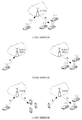
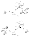
도 1은 본 개시가 적용될 수 있는 V2X 시나리오를 설명하기 위한 도면이다.
도 2는 본 개시가 적용될 수 있는 V2X 시나리오를 설명하기 위한 도면이다.
도 3은 본 개시가 적용될 수 있는 V2X 시나리오를 설명하기 위한 도면이다.
도 4는 본 개시가 적용될 수 있는 V2X 관련 서비스를 나타낸 도면이다.
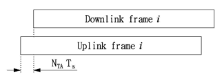
도 5는 본 개시가 적용될 수 있는 하향링크/상향링크 전송을 위한 프레임 구조를 나타낸 도면이다.
도 6은 본 개시가 적용될 수 있는 자원 그리드 및 자원 블록을 나타낸 도면이다.
도 7은 본 개시가 적용될 수 있는 PSCCH 및 PSSCH 자원 할당 방법을 나타낸 도면이다.
도 8은 본 개시가 적용될 수 있는 PSCCH 및 PSSCH 자원 할당 방법을 나타낸 도면이다.
도 9은 본 개시가 적용될 수 있는 PSCCH 및 PSSCH 자원 할당 방법을 나타낸 도면이다.
도 10은 본 개시가 적용될 수 있는 PSCCH 및 PSSCH 자원 할당 방법을 나타낸 도면이다.
도 11은 본 개시가 적용될 수 있는 PSCCH DMRS 할당 패턴 및 PSSCH DMRS 할당 패턴을 나타낸 도면이다.
도 12는 본 개시가 적용될 수 있는 PSCCH DMRS 할당 패턴 및 PSSCH DMRS 할당 패턴을 나타낸 도면이다.
도 13은 본 개시가 적용될 수 있는 PSCCH DMRS 할당 패턴 및 PSSCH DMRS 할당 패턴을 나타낸 도면이다.
도 14는 본 개시가 적용될 수 있는 PSCCH DMRS 할당 패턴 및 PSSCH DMRS 할당 패턴을 나타낸 도면이다.
도 15는 PSCCH DMRS와 PSSCH DMRS가 동시에 구성되는 경우로서 PSCCH DMRS 패턴 위치가 고정된 경우를 나타낸 도면이다.
도 16은 PSCCH DMRS와 PSSCH DMRS가 동시에 구성되는 경우로서 PSCCH DMRS 패턴 위치가 변동되는 경우를 나타낸 도면이다.
도 17는 본 개시가 적용될 수 있는 기지국 장치 및 단말 장치의 구성을 나타내는 도면이다.1 is a view for explaining a V2X scenario to which the present disclosure can be applied.
2 is a view for explaining a V2X scenario to which the present disclosure can be applied.
3 is a diagram for explaining a V2X scenario to which the present disclosure can be applied.
4 is a diagram illustrating a V2X-related service to which the present disclosure can be applied.
5 is a view showing a frame structure for downlink/uplink transmission to which the present disclosure can be applied.
6 is a diagram showing a resource grid and a resource block to which the present disclosure can be applied.
7 is a diagram showing a PSCCH and PSSCH resource allocation method to which the present disclosure can be applied.
8 is a diagram showing a PSCCH and PSSCH resource allocation method to which the present disclosure can be applied.
9 is a diagram showing a PSCCH and PSSCH resource allocation method to which the present disclosure can be applied.
10 is a diagram showing a PSCCH and PSSCH resource allocation method to which the present disclosure can be applied.
11 is a view showing a PSCCH DMRS allocation pattern and a PSSCH DMRS allocation pattern to which the present disclosure can be applied.
12 is a diagram showing a PSCCH DMRS assignment pattern and a PSSCH DMRS assignment pattern to which the present disclosure can be applied.
13 is a diagram showing a PSCCH DMRS assignment pattern and a PSSCH DMRS assignment pattern to which the present disclosure can be applied.
14 is a diagram showing a PSCCH DMRS assignment pattern and a PSSCH DMRS assignment pattern to which the present disclosure can be applied.
15 is a view showing a case where the PSCCH DMRS pattern position is fixed as the case where the PSCCH DMRS and the PSSCH DMRS are configured at the same time.
FIG. 16 is a diagram illustrating a case where PSCCH DMRS pattern positions are changed as PSCCH DMRS and PSSCH DMRS are configured simultaneously.
17 is a diagram showing the configuration of a base station apparatus and a terminal apparatus to which the present disclosure can be applied.
이하에서는 첨부한 도면을 참고로 하여 본 개시의 실시예에 대하여 본 개시가 속하는 기술 분야에서 통상의 지식을 가진 자가 용이하게 실시할 수 있도록 상세히 설명한다. 그러나, 본 개시는 여러 가지 상이한 형태로 구현될 수 있으며 여기에서 설명하는 실시예에 한정되지 않는다. Hereinafter, exemplary embodiments of the present disclosure will be described in detail with reference to the accompanying drawings so that those skilled in the art to which the present disclosure pertains can easily perform the embodiments. However, the present disclosure can be implemented in many different forms and is not limited to the embodiments described herein.
본 개시의 실시예를 설명함에 있어서 공지 구성 또는 기능에 대한 구체적인 설명이 본 개시의 요지를 흐릴 수 있다고 판단되는 경우에는 그에 대한 상세한 설명은 생략한다. 그리고, 도면에서 본 개시에 대한 설명과 관계없는 부분은 생략하였으며, 유사한 부분에 대해서는 유사한 도면 부호를 붙였다. In describing the embodiments of the present disclosure, when it is determined that a detailed description of known configurations or functions may obscure the subject matter of the present disclosure, detailed description thereof will be omitted. In the drawings, parts irrelevant to the description of the present disclosure are omitted, and similar reference numerals are used for similar parts.
본 개시에 있어서, 어떤 구성요소가 다른 구성요소와 "연결", "결합" 또는 "접속"되어 있다고 할 때, 이는 직접적인 연결관계뿐만 아니라, 그 중간에 또 다른 구성요소가 존재하는 간접적인 연결관계도 포함할 수 있다. 또한 어떤 구성요소가 다른 구성요소를 "포함한다" 또는 "가진다"고 할 때, 이는 특별히 반대되는 기재가 없는 한 다른 구성요소를 배제하는 것이 아니라 또 다른 구성요소를 더 포함할 수 있는 것을 의미한다. In the present disclosure, when a component is said to be "connected", "coupled" or "connected" with another component, this is not only a direct connection relationship, but also an indirect connection relationship in which another component exists in the middle. It may also include. Also, when a component is said to "include" or "have" another component, this means that other components may be further included, not specifically excluded, unless otherwise stated. .
본 개시에 있어서, 제1, 제2 등의 용어는 하나의 구성요소를 다른 구성요소로부터 구별하는 목적으로만 사용되며, 특별히 언급되지 않는 한 구성요소들간의 순서 또는 중요도 등을 한정하지 않는다. 따라서, 본 개시의 범위 내에서 일 실시예에서의 제1 구성요소는 다른 실시예에서 제2 구성요소라고 칭할 수도 있고, 마찬가지로 일 실시예에서의 제2 구성요소를 다른 실시예에서 제1 구성요소라고 칭할 수도 있다. In the present disclosure, terms such as first and second are used only for the purpose of distinguishing one component from other components, and do not limit the order or importance of components, etc., unless otherwise specified. Accordingly, within the scope of the present disclosure, the first component in one embodiment may be referred to as the second component in other embodiments, and likewise the second component in one embodiment may be the first component in another embodiment It can also be called.
본 개시에 있어서, 서로 구별되는 구성요소들은 각각의 특징을 명확하게 설명하기 위함이며, 구성요소들이 반드시 분리되는 것을 의미하지는 않는다. 즉, 복수의 구성요소가 통합되어 하나의 하드웨어 또는 소프트웨어 단위로 이루어질 수도 있고, 하나의 구성요소가 분산되어 복수의 하드웨어 또는 소프트웨어 단위로 이루어질 수도 있다. 따라서, 별도로 언급하지 않더라도 이와 같이 통합된 또는 분산된 실시예도 본 개시의 범위에 포함된다. In the present disclosure, components that are distinguished from each other are for clarifying each feature, and do not necessarily mean that components are separated. That is, a plurality of components may be integrated to be composed of one hardware or software unit, or one component may be distributed to be composed of a plurality of hardware or software units. Accordingly, such integrated or distributed embodiments are included within the scope of the present disclosure, unless otherwise stated.
본 개시에 있어서, 다양한 실시예에서 설명하는 구성요소들이 반드시 필수적인 구성요소들은 의미하는 것은 아니며, 일부는 선택적인 구성요소일 수 있다. 따라서, 일 실시예에서 설명하는 구성요소들의 부분집합으로 구성되는 실시예도 본 개시의 범위에 포함된다. 또한, 다양한 실시예에서 설명하는 구성요소들에 추가적으로 다른 구성요소를 포함하는 실시예도 본 개시의 범위에 포함된다. In the present disclosure, components described in various embodiments are not necessarily essential components, and some may be optional components. Accordingly, an embodiment composed of a subset of components described in one embodiment is also included in the scope of the present disclosure. Also, embodiments including other elements in addition to the elements described in various embodiments are included in the scope of the present disclosure.
또한 본 명세서는 무선 통신 네트워크를 대상으로 설명하며, 무선 통신 네트워크에서 이루어지는 작업은 해당 무선 통신 네트워크를 관할하는 시스템(예를 들어 기지국)에서 네트워크를 제어하고 데이터를 송신하는 과정에서 이루어지거나, 해당 무선 네트워크에 결합한 단말에서 작업이 이루어질 수 있다. In addition, this specification is described for a wireless communication network, the work performed in the wireless communication network is performed in the process of controlling the network and transmitting data in a system (for example, a base station) in charge of the wireless communication network, or the wireless The operation can be performed at the terminal coupled to the network.
즉, 기지국을 포함하는 다수의 네트워크 노드들(network nodes)로 이루어지는 네트워크에서 단말과의 통신을 위해 수행되는 다양한 동작들은 기지국 또는 기지국 이외의 다른 네트워크 노드들에 의해 수행될 수 있음은 자명하다. '기지국(Base Station, BS)'은 고정국(fixed station), Node B, eNodeB(eNB), gNodeB(gNB), 액세스 포인트(Access Point, AP) 등의 용어에 의해 대체될 수 있다. 또한, '단말(terminal)'은 UE(User Equipment), MS(Mobile Station), MSS(Mobile Subscriber Station), SS(Subscriber Station), 비-AP 스테이션(non-AP STA) 등의 용어로 대체될 수 있다. That is, it is apparent that various operations performed for communication with a terminal in a network consisting of a plurality of network nodes including a base station can be performed by a base station or other network nodes other than the base station. The'base station (BS)' may be replaced by terms such as a fixed station, a Node B, an eNodeB (eNB), a gNodeB (gNB), or an access point (AP). Also,'terminal' may be replaced with terms such as user equipment (UE), mobile station (MS), mobile subscriber station (MSS), subscriber station (SS), and non-AP STA. Can.
본 개시에서, 채널을 전송 또는 수신한다는 것은 해당 채널을 통해서 정보 또는 신호를 전송 또는 수신한다는 의미를 포함한다. 예를 들어, 제어 채널을 전송한다는 것은, 제어 채널을 통해서 제어 정보 또는 신호를 전송한다는 것을 의미한다. 유사하게, 데이터 채널을 전송한다는 것은, 데이터 채널을 통해서 데이터 정보 또는 신호를 전송한다는 것을 의미한다. In the present disclosure, transmitting or receiving a channel includes the meaning of transmitting or receiving information or a signal through the corresponding channel. For example, transmitting a control channel means transmitting control information or a signal through the control channel. Similarly, transmitting a data channel means transmitting data information or a signal through the data channel.
이하의 설명에 있어서, 본 개시의 다양한 예시들이 적용되는 시스템을 기존의 시스템과 구별하기 위한 목적으로 NR 시스템이라는 용어를 사용하지만, 본 개시의 범위가 이러한 용어에 의해 제한되는 것은 아니다. In the following description, the term NR system is used for the purpose of distinguishing a system to which various examples of the present disclosure are applied from an existing system, but the scope of the present disclosure is not limited by these terms.
일 예로, NR 시스템에서는 다양한 시나리오, 서비스 요구사항 및 잠재적인 시스템 호환성 등을 고려하여 다양한 서브캐리어 스페이싱(Subcarrier Spacing, SCS)을 지원하고 있다. 또한, NR 시스템은 높은 캐리어 주파수(carrier frequency) 상에서 발생하는 높은 방향-손실(path-loss), 페이즈-잡음(phase-noise) 및 주파수 오프셋(frequency offset) 등의 좋지 않은 채널 환경을 극복하고자 복수의 빔을 통한 물리 신호/채널의 전송을 지원할 수 있다. 이를 통해, NR 시스템에서는 eMBB(enhanced Mobile Broadband), mMTC(massive Machine Type Communications)/uMTC(ultra Machine Type Communications) 및 URLLC(Ultra Reliable and Low Latency Communications) 등의 애플리케이션을 지원할 수 있다. 다만, 본 명세서에서의 NR 시스템이라는 용어는 무선 통신 시스템의 예시로서 사용되지만, NR 시스템이라는 용어 자체가 상술한 특징에 제한되는 것은 아니다.For example, the NR system supports various subcarrier spacing (SCS) in consideration of various scenarios, service requirements, and potential system compatibility. In addition, NR systems are designed to overcome poor channel environments such as high path-loss, phase-noise and frequency offset occurring on a high carrier frequency. It can support the transmission of the physical signal / channel through the beam. Through this, the NR system can support applications such as enhanced Mobile Broadband (eMBB), Massive Machine Type Communications (mMTC)/ultra Machine Type Communications (uMTC), and Ultra Reliable and Low Latency Communications (URLLC). However, although the term NR system in this specification is used as an example of a wireless communication system, the term NR system itself is not limited to the above-described features.
또한, 일 예로, 5G 이동 통신 기술이 정의될 수 있다. 이때, 일 예로, 5G 이동 통신 기술은 상술한 NR 시스템뿐만 아니라, 기존의 LTE-A(Long Term Evolution-Advanced) 시스템까지 모두 포함하여 정의될 수 있다. 즉, 5G 이통 통신은 새롭게 정의된 NR 시스템뿐만 아니라 이전 시스템과의 역호환성(Backward Compatibility)을 고려하여 동작하는 기술일 수 있다.In addition, as an example, 5G mobile communication technology may be defined. In this case, as an example, 5G mobile communication technology may be defined to include not only the above-described NR system, but also an existing Long Term Evolution-Advanced (LTE-A) system. That is, 5G mobile communication may be a technology that operates in consideration of backward compatibility with a previous system as well as a newly defined NR system.
일 예로, 5G의 사이드링크(sidelink) 분야는 LTE 시스템에서의 사이드링크와 NR 시스템에서의 사이드링크 기술을 모두 포함할 수 있다. 이때, 사이드링크 분야는 초고신뢰 및 초저지연 등을 통한 성능 향상과 새롭고 다양한 서비스의 접목을 위해 필수적인 분야일 수 있다. As an example, the sidelink field of 5G may include both sidelink technology in an LTE system and sidelink technology in an NR system. At this time, the side link field may be an essential field for improving performance through ultra-high reliability and ultra-low delay, and grafting new and diverse services.
하기에서는 설명의 편의를 위해 NR 시스템에 기초하여 V2X를 위한 동작 및 관련 정보에 대해 서술한다. 다만, 하기 특징들은 특정 시스템으로 한정되는 것은 아닐 수 있으며, 유사하게 구현되는 다른 시스템에서 대해서도 동일하게 적용될 수 있으며, 상술한 실시예로 한정되지 않는다.For the convenience of description, the following describes the operation and related information for V2X based on the NR system. However, the following features may not be limited to a specific system, and may be applied to other systems similarly implemented, and are not limited to the above-described embodiments.
한편, V2X는 차량을 기반으로 한 통신일 수 있다. 이때, 차량의 개념이 단순 이동수단에서 새로운 플랫폼으로 변화하고 있다. 일 예로, 차량에 IT 기술들이 접목되고 있으며, 이에 기초하여 다양한 V2X 서비스들이 제공되고 있다. 일 예로, 교통사고 사전 방지, 교통 환경 개선, 자율주행 및 원격주행 등과 같은 서비스가 제공되고 있다. 이를 위해, V2X와 관련하여, 사이드링크 관련 기술에 대한 개발 및 적용에 대한 필요가 높아지고 있다.Meanwhile, V2X may be a vehicle-based communication. At this time, the concept of a vehicle is changing from a simple vehicle to a new platform. For example, IT technologies are applied to a vehicle, and various V2X services are provided based on this. For example, services such as preventing traffic accidents, improving the traffic environment, autonomous driving, and remote driving are provided. To this end, in relation to V2X, there is an increasing need for development and application of sidelink-related technologies.
보다 상세하게는, 기존의 통신 기술과 관련하여, 기지국으로부터의 단말로의 통신은 하향링크(downlink)이고, 단말로부터의 기지국으로의 통신은 상향링크(uplink)일 수 있다. 다만, 기지국과 단말과의 통신만 아니라 단말들 상호 간의 통신이 필요할 수 있으며, 단말로부터의 단말로의 통신이 상술한 사이드링크일 수 있다. 일 예로, 상술한 V2X와 관련해서 차량 상호 간 통신 또는 차량과 다른 물체(보행자 단말(pedestrian UE)이나 단말 타입의 도로 주변 유닛(UE-type RSU(roadside unit)) 등 기지국이 아닌 물체)와의 통신이 사이드링크일 수 있다. 즉, 차량을 기반으로 한 통신을 수행하는 경우에 있어서 기지국과의 통신만으로는 한계가 있는바, 상술한 사이드링크 기술이 개발되고, 적용될 수 있다. 이하에서는 상술한 바에 기초하여 V2X를 위한 DMRS 관련 정보 지시 방법에 대해 서술한다.More specifically, with respect to the existing communication technology, communication from the base station to the terminal may be downlink, and communication from the terminal to the base station may be uplink. However, not only communication between the base station and the terminal, but also communication between the terminals may be required, and communication from the terminal to the terminal may be the above-described side link. For example, in connection with the above-described V2X, communication between vehicles or other objects (non-base station objects such as a pedestrian terminal (UE) or a UE-type roadside unit (UES)) is communicated with the vehicle. This may be a side link. That is, in the case of performing vehicle-based communication, there is a limitation only by communication with a base station, and the above-described sidelink technology can be developed and applied. Hereinafter, a method of indicating DMRS-related information for V2X will be described based on the above.
도 1 내지 도 3은 V2X 시나리오를 나타낸 도면이다. 1 to 3 are diagrams showing a V2X scenario.
이때, 도 1은 상술한 사이드링크에 기초하여 통신을 수행하는 시나리오일 수 있다. 또한, 도 2는 단말(또는 차량) 및 기지국과의 통신을 이용한 V2X 동작 시나리오일 수 있다. 또한, 도 3은 상술한 사이드링크 및 기지국과의 통신을 모두 이용하여 V2X 동작을 수행하는 시나리오일 수 있다.In this case, FIG. 1 may be a scenario for performing communication based on the sidelink described above. In addition, FIG. 2 may be a V2X operation scenario using communication with a terminal (or vehicle) and a base station. In addition, FIG. 3 may be a scenario in which V2X operation is performed using both the above-described sidelink and base station communication.
이때, 일 예로, V2X와 관련하여, 하기에서 서술하는 단말은 차량일 수 있다. 하기에서는 설명의 편의를 위해 단말로 통일하게 지칭하지만, 단말은 V2X를 위한 차량일 수 있다. 또한, 일 예로, 단말은 사이드링크 및 기지국과의 통신을 수행할 수 있는 디바이스를 지칭할 수 있으며, 상술한 실시예로 한정되지 않는다. 다만, 하기에서는 설명의 편의를 위해 단말로 지칭한다.In this case, as an example, in relation to V2X, the terminal described below may be a vehicle. In the following, for convenience of description, the terminal is referred to as a unit, but the terminal may be a vehicle for V2X. Further, as an example, the terminal may refer to a device capable of performing communication with a sidelink and a base station, and is not limited to the above-described embodiment. However, hereinafter, it is referred to as a terminal for convenience of description.
또한, 일 예로, V2X와 관련하여 필요한 용어는 하기의 표 1과 같이 정의될 수 있다. 이때, 일 예로, D2D(Device to Device)는 단말간 통신을 의미할 수 있다. 또한, ProSe는 D2D 통신을 수행하는 단말에 대한 근접 서비스를 의미할 수 있다. 또한, SL(sidelink)은 상술한 사이드링크일 수 있으며, SCI(Sidelink Control Information)는 상술한 사이드링크와 관련된 제어 정보를 의미할 수 있다. 또한, PSSCH(Physical Sidelink Shared Channel)는 사이드링크를 통해 데이터가 전송되는 채널이고, PSCCH(Physical Sidelink Control Channel)는 사이드링크를 통해 제어 정보가 전송되는 채널일 수 있다. 또한, PSBCH(Physical Sidelink Broadcast Channel)는 사이드링크를 통해 신호를 브로드캐스트 방식으로 전송하는 채널로서 시스템 정보들이 전달될 수 있다. 또한, PSDCH(Physical Sidelink Discovery Channel)는 디스커버리 채널로서 신호 발견을 위한 용도로 사용되는 채널일 수 있다. 또한, SLSS(Sidelink Synchronization Signal)는 사이드링크를 위한 동기화 신호일 수 있으며, PSSID(Physical Sidelink Synchronization Identity)는 사이드링크 동기화를 위한 아이디 정보일 수 있다. 또한, 

[표 1][Table 1]

또한, 일 예로, V2X 통신에서 단말이 다른 단말로 전송하는 제어 정보는 SA일 수 있다. 상술한 제어 정보가 사이드링크 통신에서 사용되는 경우, 상술한 제어 정보는 SCI일 수 있다. 이때, 상술한 제어 정보는 사이드링크 이 때, 상기 제어 정보는 사이드링크에서 제어 정보가 전송되는 채널인 PSCCH를 통해서 전송될 수 있다. In addition, as an example, in V2X communication, control information transmitted from a terminal to another terminal may be SA. When the above-described control information is used in sidelink communication, the above-described control information may be SCI. In this case, the control information described above is a sidelink, and the control information may be transmitted through the PSCCH, a channel through which control information is transmitted in the sidelink.
또한, 일 예로, V2X 통신에서 단말이 다른 단말로 전송하는 데이터는 TB 단위로 구성될 수 있다. 이때, 사이드링크를 통해 데이터를 전송하는 경우, 상술한 데이터가 전송되는 채널인 PSSCH를 통해서 전송이 수행될 수 있다.In addition, as an example, in V2X communication, data transmitted from a terminal to another terminal may be configured in TB units. At this time, when data is transmitted through the sidelink, transmission may be performed through the PSSCH, which is a channel through which the above-described data is transmitted.
또한, 본 개시에서 V2X 통신 또는 직접 링크(e.g D2D, ProSe, 또는 SL) 통신을 위한 제어 정보 및 데이터 전송을 위한 자원 할당 방식에 따라서 동작 모드가 정의될 수 있다. In addition, in the present disclosure, an operation mode may be defined according to a resource allocation method for control information and data transmission for V2X communication or direct link (e.g. D2D, ProSe, or SL) communication.
일 예로, 기지국 자원 스케줄링 모드(eNodeB resource scheduling mode)는 V2X(또는 직접 링크) 제어 정보 및/또는 데이터를 전송하기 위해 단말이 사용하는 자원들을 기지국(eNodeB) 또는 릴레이 노드(relay node)가 스케줄링 하는 모드일 수 있다. 이를 통해, 단말은 V2X(또는 직접 링크) 제어 정보 및/또는 데이터를 전송할 수 있으며, 이러한 모드가 상술한 기지국 자원 스케줄링 모드일 수 있다. For example, the base station resource scheduling mode (eNodeB resource scheduling mode) is a base station (eNodeB) or a relay node (relay node) to schedule the resources used by the terminal to transmit V2X (or direct link) control information and / or data Mode. Through this, the terminal can transmit V2X (or direct link) control information and/or data, and this mode may be the base station resource scheduling mode.
일 예로, 기지국 또는 릴레이 노드는 하향링크 제어 정보(Downlink Control Information, DCI)를 통해서 사이드링크(또는 직접 링크) 제어 정보 및/또는 데이터 전송에 사용될 자원에 대한 스케줄링 정보를 사이드링크(또는 직접 링크) 전송 단말에게 제공할 수 있다. 이에 따라, 사이드링크(또는 직접 링크) 전송 단말은 사이드링크(또는 직접 링크) 수신 단말에게 사이드링크(또는 직접 링크) 제어 정보 및 데이터를 전송하고, 사이드링크(또는 직접 링크) 수신 단말은 사이드링크(또는 직접 링크) 제어 정보에 기초하여 사이드링크(또는 직접 링크) 데이터를 수신할 수 있다. As an example, the base station or the relay node sidelink (or direct link) scheduling information for resources to be used for sidelink (or direct link) control information and/or data transmission through downlink control information (DCI). It can be provided to the transmitting terminal. Accordingly, the sidelink (or direct link) transmitting terminal transmits sidelink (or direct link) control information and data to the sidelink (or direct link) receiving terminal, and the sidelink (or direct link) receiving terminal sidelinks. (Or direct link) Sidelink (or direct link) data may be received based on control information.
한편, 단말 자율 자원 선택 모드(UE autonomous resource selection mode)는 제어 정보 및 데이터를 전송하기 위해 단말이 사용하는 자원들을 단말이 스스로 선택하고, 이러한 자원 선택은 자원 풀(resource pool) (즉, 자원 후보의 집합)에서 단말이 센싱(sensing) 등에 의해서 결정될 수 있다. 이를 통해, 단말은 제어 정보 및 데이터를 전송할 수 있으며, 이러한 모드가 단말 자율 자원 선택 모드일 수 있다. On the other hand, the UE autonomous resource selection mode (UE autonomous resource selection mode), the UE selects resources used by the UE to transmit control information and data, and the resource selection is a resource pool (ie, resource candidate) (In the set of ), the terminal may be determined by sensing or the like. Through this, the terminal can transmit control information and data, and this mode may be a terminal autonomous resource selection mode.
일 예로, 사이드링크(또는 직접 링크) 전송 단말은 자신이 선택한 자원에서 사이드링크(또는 직접 링크) 수신 단말에게 사이드링크(또는 직접 링크) 제어 정보 및 데이터를 전송하고, 사이드링크(또는 직접 링크) 수신 단말은 사이드링크(또는 직접 링크) 제어 정보에 기초하여 사이드링크(또는 직접 링크) 데이터를 수신할 수 있다.For example, a sidelink (or direct link) transmitting terminal transmits sidelink (or direct link) control information and data to a sidelink (or direct link) receiving terminal from a resource selected by the sidelink, or a sidelink (or direct link). The receiving terminal may receive sidelink (or direct link) data based on sidelink (or direct link) control information.
이때, 일 예로, 상술한 기지국 자원 스케줄링 모드는 D2D 등을 위한 사이드링크(또는 직접 링크) 통신에서 모드 1(Mode 1)로 지칭될 수 있다. 또한, 상술한 기지국 자원 스케줄링 모드는 V2X 등을 위한 사이드링크 통신에서 모드 3(Mode 3)로 지칭될 수 있다. 또한, 단말 자율 자원 선택 모드는 D2D 등을 위한 사이드링크(또는 직접 링크) 통신에서 모드 2(Mode 2)로 지칭될 수 있다. 또한, 단말 자율 자원 선택 모드는 V2X 등을 위한 사이드링크 통신에서 모드 4(Mode 4)로 지칭될 수 있다. 다만, 이는 하나의 일 실시예일 뿐, 상술한 명칭에 한정되는 것은 아니다. 즉, 동일한 대상 및 동일한 동작에 대해서는 동일한 모드로 볼 수 있다.In this case, as an example, the above-described base station resource scheduling mode may be referred to as mode 1 (mode 1) in side link (or direct link) communication for D2D or the like. In addition, the above-described base station resource scheduling mode may be referred to as mode 3 (Mode 3) in sidelink communication for V2X and the like. In addition, the terminal autonomous resource selection mode may be referred to as
또한, 하기에서는 설명의 편의를 위해 V2X 통신을 기준으로 설명하지만, 이에 한정되는 것은 아니다. 일 예로, D2D, ProSe 등과 같이 직접 링크를 기반으로 하는 통신에 대해서는 본 발명이 동일하게 적용될 수 있으며, 상술한 실시예로 한정되지 않는다.In addition, hereinafter, for convenience of explanation, the description will be based on V2X communication, but is not limited thereto. For example, the present invention may be equally applied to communication based on a direct link such as D2D, ProSe, etc., and is not limited to the above-described embodiment.
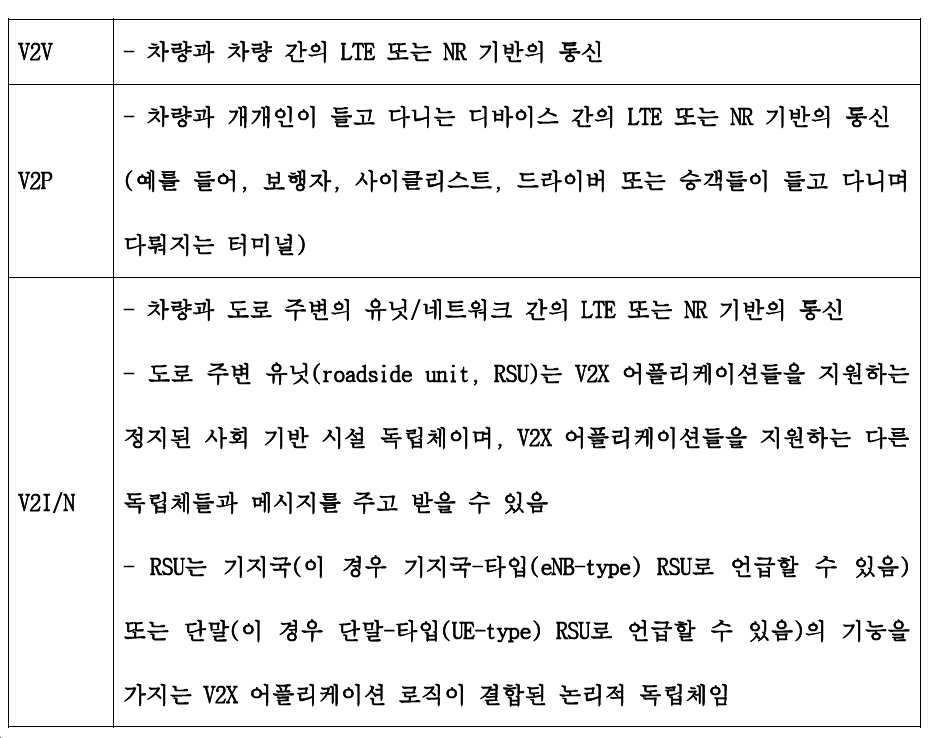
또한, 일 예로, V2X는 V2V, V2P 및 V2I/N을 통칭하는 용어일 수 있다. 이때, V2V, V2P 및 V2I/N의 각각은 하기 표 1과 같이 정의될 수 있으나, 이에 한정되는 것은 아니다. 즉, 하기 표 2는 하나의 일 예시일 뿐, 이에 한정되지 않는다.Further, as an example, V2X may be a general term for V2V, V2P and V2I/N. At this time, each of V2V, V2P and V2I/N may be defined as shown in Table 1 below, but is not limited thereto. That is, Table 2 below is only one example and is not limited thereto.
[표 2][Table 2]
또한, V2X 통신은 사이드링크 통신을 위한 인터페이스인 PC5 기반의 통신을 포함할 수 있다. In addition, V2X communication may include PC5 based communication which is an interface for sidelink communication.
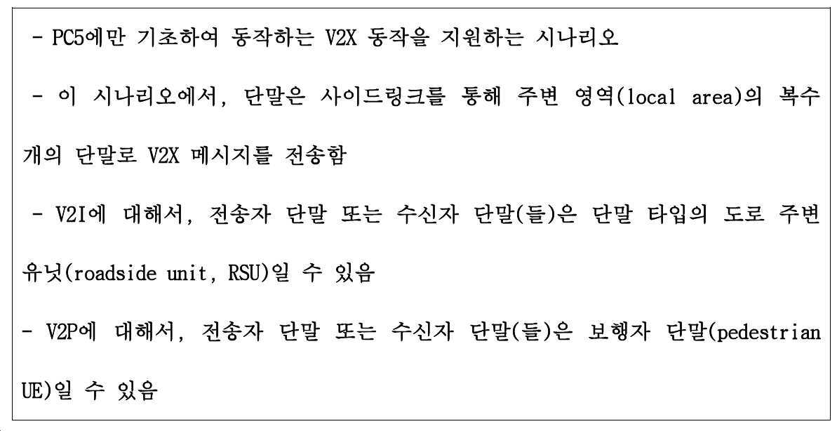
일 예로, 하기 표 3 및 도 1은 PC5 인터페이스(또는 SL)에만 기반한 V2X 동작을 지원하는 시나리오일 수 있다. 이때, 도 1의 (a)는 V2V 동작, (b)는 V2I 동작, (c)는 V2P 동작일 수 있다. 즉, 도 1에서는 상술한 사이드링크에 기초하여 통신을 수행하는 방식일 수 있으며, 기지국 없이 통신을 수행할 수 있다.As an example, Table 3 and FIG. 1 may be a scenario supporting V2X operation based only on the PC5 interface (or SL). In this case, FIG. 1(a) may be a V2V operation, (b) a V2I operation, and (c) a V2P operation. That is, in FIG. 1, communication may be performed based on the sidelink described above, and communication may be performed without a base station.
[표 3] [Table 3]
한편, 표 4 및 도 2는 Uu 인터페이스(즉, UE 와 eNodeB 사이의 인터페이스)에만 기반한 V2X 동작을 지원하는 시나리오일 수 있다. 일 예로, 도 2의 (a)는 V2V 동작, (b)는 V2I 동작, (c)는 V2P 동작을 나타낼 수 있다. 즉, 단말과 기지국 사이의 통신을 이용하여 V2X 동작을 지원할 수 있다.Meanwhile, Table 4 and FIG. 2 may be a scenario supporting V2X operation based only on a Uu interface (ie, an interface between a UE and an eNodeB). For example, (a) of FIG. 2 may indicate a V2V operation, (b) a V2I operation, and (c) a V2P operation. That is, V2X operation may be supported using communication between the terminal and the base station.
[표 4][Table 4]

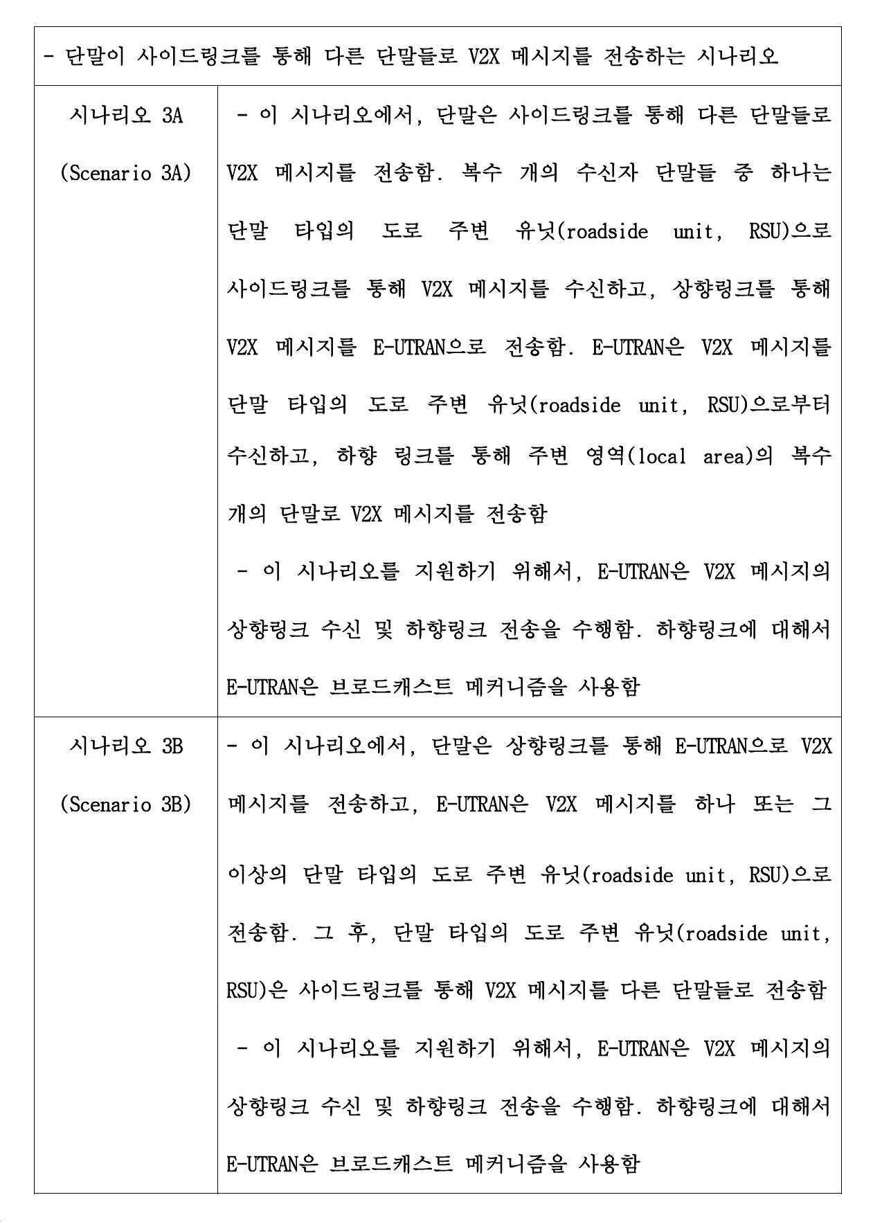
표 5 및 도 3은 Uu 인터페이스 및 PC5 인터페이스(또는 SL)를 모두 사용하는 V2X 동작을 지원하는 시나리오일 수 있다. 이때, 도 3(a)는 표 5의 시나리오 3A를 나타내고, 도 3(b)는 표 5의 시나리오 3B를 나타낼 수 있다. Table 5 and FIG. 3 may be a scenario supporting V2X operation using both Uu interface and PC5 interface (or SL). At this time, FIG. 3(a) may represent scenario 3A of Table 5, and FIG. 3(b) may represent scenario 3B of Table 5.
보다 상세하게는, 도 3(a)에 기초하면, 단말은 다른 단말들로 V2X 메시지를 사이드링크를 통해 전송할 수 있다. 이를 수신한 단말들 중 어느 하나는 기지국으로 상향 링크를 통해 V2X 메시지를 전송할 수 있다. 기지국은 V2X 메시지를 수신하고, 이에 기초한 메시지를 주변의 다른 단말들로 하향링크를 통해 전송할 수 있다. 이때, 일 예로, 하향링크는 브로드캐스트 방식을 통해 수행될 수 있다. More specifically, based on FIG. 3(a), the terminal may transmit a V2X message to other terminals through a side link. Any one of the terminals receiving this may transmit a V2X message to the base station through an uplink. The base station receives the V2X message, and may transmit the message based on this to other neighboring terminals through the downlink. In this case, as an example, the downlink may be performed through a broadcast method.
또 다른 일 예로, 도 3(b)는 단말이 V2X 메시지를 상향링크를 통해 기지국으로 전송하고, 기지국은 적어도 하나 이상의 단말이나 RSU(Roadside Unit) 등에 전송할 수 있다. 그 후, 이를 수신한 단말이나 RSU는 사이드링크를 통해 주변의 복수 개의 단말들로 메시지를 전송할 수 있다. As another example, FIG. 3(b) shows that a terminal transmits a V2X message to a base station through an uplink, and the base station can transmit at least one terminal or an RSU (Roadside Unit). Thereafter, the terminal or the RSU receiving the message may transmit a message to a plurality of nearby terminals through a side link.
즉, 도 3(a) 및 도 3(b) 모두 기지국과 단말 간 통신 및 사이드링크를 모두 이용하여 V2X 동작을 지원할 수 있으며, 상술한 실시예로 한정되지 않는다.That is, both of FIG. 3(a) and FIG. 3(b) can support V2X operation using both communication and a side link between a base station and a terminal, and are not limited to the above-described embodiment.
[표 5][Table 5]
전술한 바와 같이, V2X 통신은 기지국을 거쳐서 이뤄질 수도 있고, 단말 간에 직접 통신을 통해서 이뤄질 수도 있다. 이때, 기지국을 거치는 경우 LTE 기반의 V2X 통신에서는 LTE의 기지국과 단말 간의 통신 인터페이스인 Uu 링크를 통해 송/수신이 이뤄질 수 있다. 또한, 단말 간의 직접 통신으로서 사이드링크를 이용하는 경우, LTE 기반의 V2X 통신에서는 LTE의 단말과 단말 간의 통신 인터페이스인 PC5 링크를 통해 송/수신이 이뤄질 수 있다. As described above, V2X communication may be performed through a base station or may be achieved through direct communication between terminals. At this time, in the case of passing through the base station, in the LTE-based V2X communication, transmission/reception may be performed through a Uu link, which is a communication interface between the LTE base station and the terminal. In addition, when a side link is used as direct communication between terminals, in LTE-based V2X communication, transmission/reception may be performed through a PC5 link, which is a communication interface between an LTE terminal and a terminal.
또한, 일 예로서, NR 시스템에서도 단말과 기지국 간의 통신 및 단말 간의 사이드링크를 이용하여 V2X 통신이 수행될 수 있다. 이때, 일 예로, NR 시스템에서 기지국 및 단말 간의 통신(상향링크/하향링크)과 기존 시스템에서 기지국 및 단말 간의 통신(상향링크/하향링크) 방법이 차이가 있을 수 있다. 즉, 일부 특징에 대해서는 유사할 수 있으며, 새로운 시스템인 NR 시스템에 기초하여 변경되는 부분이 존재할 수 있다. 또한, 일 예로, 사이드링크 역시 기존 시스템에서의 사이드링크와 NR 시스템에서의 사이드링크에 차이가 있을 수 있다. 즉, 상술한 기지국 및 단말 간 통신의 차이점을 고려하여 사이드링크 역시 새로운 시스템인 NR 시스템에서 변경되는 부분이 존재할 수 있다. 하기에서는 상술한 특징에 기초하여 NR 시스템에서 V2X를 위한 DMRS 관련 정보를 전송하는 방법에 대해 서술한다.Also, as an example, V2X communication may be performed using a communication between a terminal and a base station and a side link between terminals in an NR system. In this case, as an example, the communication between the base station and the terminal (uplink/downlink) in the NR system and the communication between the base station and the terminal (uplink/downlink) in the existing system may be different. That is, some features may be similar, and there may be a part that is changed based on the new system NR system. In addition, as an example, the side link may also have a difference between a side link in an existing system and a side link in an NR system. That is, in consideration of the above-mentioned differences in communication between the base station and the terminal, a side link may also be changed in the new system NR system. Hereinafter, a method of transmitting DMRS-related information for V2X in an NR system based on the above-described features will be described.
도 4는 사이드링크에 기초하여 제공되는 서비스를 나타낸 도면이다. 4 is a diagram showing a service provided based on a side link.
도 4를 참조하면 5G 사이드링크에 기초하여 V2X 관련 서비스 또는 IoT(Internet of Things) 서비스가 제공될 수 있다. 이때, 일 예로, 5G 사이드링크라함은 기존 LTE 시스템에 기초한 사이드링크 및 NR 시스템을 고려한 사이드링크를 모두 포함하는 개념일 수 있다. 즉, 각각의 시스템에서 적용되는 사이드링크를 고려하여 제공되는 서비스일 수 있으며, 상술한 실시예로 한정되지 않는다.Referring to FIG. 4, a V2X related service or an Internet of Things (IoT) service may be provided based on 5G sidelink. In this case, as an example, the 5G sidelink may be a concept including both a sidelink based on an existing LTE system and a sidelink considering an NR system. That is, it may be a service provided in consideration of a side link applied in each system, and is not limited to the above-described embodiment.
일 예로, 도 4를 참조하면, V2X 서비스와 관련하여, 군집 주행(Platooning), 자율 주행(Automatic Driving), 진화된 센서(Advanced Sensor) 및 원격 주행(Remote Driving) 서비스가 제공될 수 있다. 이때, 군집 주행은 복수 개의 차량들이 동적으로 그룹을 형성하고, 유사하게 동작하는 기술일 수 있다. 또한, 자율 주행은 완전 자동화, 반-자동화에 기초하여 차량을 주행하는 기술일 수 있다. 또한, 진화된 센서는 센서나 비디오 영상으로부터 획득한 데이터를 수집하여 교환하는 기술일 수 있다. 또한, 원격 주행은 차량의 원격 제어를 위한 기술 및 어플리케이션에 대한 기술일 수 있다. 즉, V2X에 기초한 서비스로서 상술한 서비스들이 제공될 수 있다. 다만, 상술한 서비스는 하나의 일 예일 뿐이며, 상술한 실시예로 한정되지 않는다. 이때, 상술한 V2X 서비스를 제공하기 위해서는 초저지연, 초연결, 저전력 및 고신뢰성과 같은 요구 사항들이 필요할 수 있다. 따라서, 5G 사이드링크에서는 상술한 서비스 및 그에 따른 요구 사항을 만족하기 위한 동작 방법이 필요할 수 있으며, 하기에서는 이러한 요구 사항을 고려하여 구체적인 방법을 서술한다.For example, referring to FIG. 4, in relation to the V2X service, clustering, autonomous driving, advanced sensors, and remote driving services may be provided. At this time, cluster driving may be a technique in which a plurality of vehicles dynamically form a group and operate similarly. In addition, autonomous driving may be a technique of driving a vehicle based on fully automated and semi-automated. Further, the evolved sensor may be a technique of collecting and exchanging data obtained from a sensor or video image. Further, the remote driving may be a technology for remote control of a vehicle and a technology for applications. That is, the above-described services may be provided as a service based on V2X. However, the above-described service is only one example, and is not limited to the above-described embodiment. At this time, in order to provide the above-described V2X service, requirements such as ultra-low delay, ultra-connection, low power and high reliability may be required. Therefore, in the 5G sidelink, an operation method for satisfying the above-described service and the corresponding requirements may be required, and a detailed method will be described below in consideration of these requirements.
다음은 NR 시스템에 대해서 서술한다. 일 예로, 도 5 및 도 6은 NR 시스템에 대한 프레임 구조 및 자원 블록을 나타낸 도면이다.The following describes the NR system. As an example, FIGS. 5 and 6 are diagrams showing a frame structure and a resource block for an NR system.
도 5는 본 발명의 일 실시예에 따라, NR 프레임 구조(Frame Structure) 및 뉴머롤러지(Numerology)를 나타낸 도면이다. 5 is a diagram illustrating an NR frame structure and a numerology according to an embodiment of the present invention.
NR에서 시간 도메인의 기본 단위는 ![]()
![]()
![]()

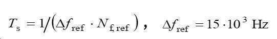


![]()
![]()
![]()
프레임 구조Frame structure
도 5를 참조하면, 하향링크 및 상향링크(Downlink/Uplink, DL/UL) 전송을 위한 프레임의 시간 구조는 ![]()
![]()
![]()
![]()
이때, 상향링크 전송 프레임 i의 전송 타이밍은 단말에서 하향링크 수신 타이밍을 기반으로 하기 수학식 1에 기초하여 결정된다.At this time, the transmission timing of the uplink transmission frame i is determined based on
하기 수학식 1에서 
![]()

![]()
[수학식 1][Equation 1]
도 6은 자원 그리드(Resource Grid) 및 자원 블록(Resource Block)을 나타내는 도면이다.6 is a diagram illustrating a resource grid and a resource block.
도 6을 참조하면, 자원 그리드 내의 자원요소(Resource element)는 각 서브 캐리어 스페이싱에 따라서 인덱싱될 수 있다. 이때, 안테나 포트마다 및 서브캐리어 스페이싱마다 하나의 자원 그리드를 생성할 수 있다. 상향링크 및 하향링크 송수신은 해당 자원 그리드를 기반으로 수행될 수 있다.Referring to FIG. 6, resource elements in a resource grid may be indexed according to each subcarrier spacing. At this time, one resource grid may be generated for each antenna port and for each subcarrier spacing. Uplink and downlink transmission and reception may be performed based on a corresponding resource grid.
하나의 자원 블록은 12개의 자원 요소(Resource Element)로 주파수 도메인 상에서 구성되며 하기 수학식 2와 같이 12개의 자원 요소마다 하나의 자원 블록에 대한 인덱스(![]()
![]()
[수학식 2][Equation 2]
뉴머놀러지(Numerologies)Numerologies
뉴머놀러지는 NR 시스템의 다양한 서비스와 요구사항을 만족하도록 다양하게 구성될 수 있다. 일 예로, 기존의 LTE/LTE-A 시스템에서 하나의 서브캐리어 스페이싱(Subcarrier Spacing, SCS)을 지원하는 것과 달리, 복수의 SCS를 지원할 수 있다.Numerology can be variously configured to satisfy various services and requirements of the NR system. For example, unlike the existing LTE/LTE-A system supporting one subcarrier spacing (SCS), multiple SCSs may be supported.
복수의 SCS를 지원하는 것을 포함하는 NR 시스템을 위한 새로운 뉴머롤로지는, 기존의 700MHz나 2GHz 등의 주파수 범위(frequency range) 또는 캐리어(carrier)에서 넓은 대역폭을 사용할 수 없었던 문제를 해결하기 위해 3GHz 이하, 3GHz~6GHz 또는 6GHZ~52.6GHz와 같은 주파수 범위 또는 캐리어에서 동작할 수 있다. 다만, 본 개시의 범위가 이에 제한되는 것은 아니다.New numerology for NR systems, including support for multiple SCSs, below 3 GHz to solve the problem of not being able to use a wide bandwidth in a frequency range or carrier such as 700 MHz or 2 GHz , 3GHz ~ 6GHz or 6GHZ ~ 52.6GHz frequency range or can operate in the carrier. However, the scope of the present disclosure is not limited thereto.
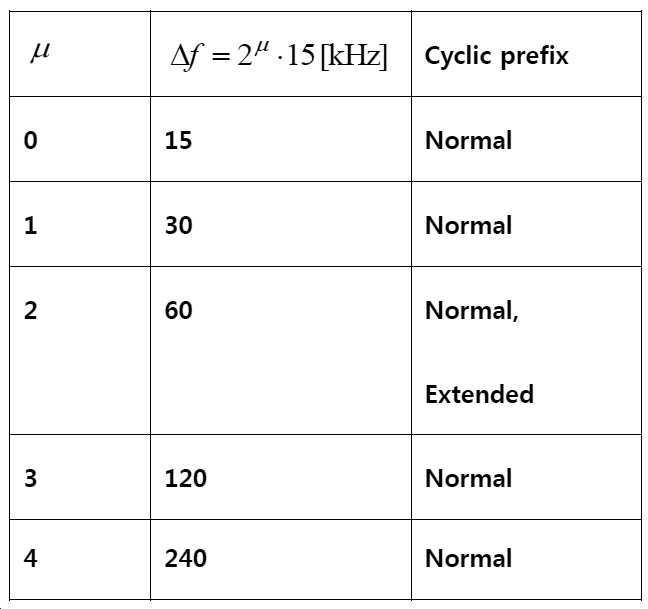
일 예로, 하기 표 6을 참조하면, 뉴머놀러지는 OFDM(Orthogonal Frequency Division Multiplexing) 시스템에서 사용하는 서브캐리어 스페이싱(Subcarrier Spacing, SCS), CP길이 및 슬롯당 OFDM 심볼의 수 등을 기준으로 정의될 수 있다. 상술한 값들은 상위레이어 파라미터 DL-BWP-mu and DL-BWP-cp (DL)과 UL-BWP-mu and UL-BWP-cp(UL)을 통해 단말에게 제공될 수 있다.As an example, referring to Table 6 below, numerology may be defined based on subcarrier spacing (SCS), CP length, and the number of OFDM symbols per slot used in an orthogonal frequency division multiplexing (OFDM) system. have. The above-described values may be provided to the terminal through higher layer parameters DL-BWP-mu and DL-BWP-cp (DL) and UL-BWP-mu and UL-BWP-cp (UL).
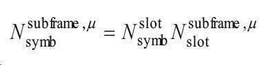
또한, 일 예로서, 하기 표 6에서 ![]()
![]()
[표 6][Table 6]
이때, 일반 슬롯(Normal slot)은 NR 시스템에서 기본적으로 하나의 데이터 및 제어 정보를 전송하는데 사용하는 기본 시간단위로 정의할 수 있다. 일반 슬롯의 길이는 기본적으로 14개 OFDM 심볼의 수로 구성될 수 있다. 또한, 슬롯과 다르게 서브프레임은 NR시스템에서 1ms에 해당하는 절대적인 시간 길이를 가지고 다른 시간 구간의 길이를 위한 참고 시간으로 활용될 수 있다. 이때, LTE와 NR 시스템의 공존 또는 역호환성(backward compatibility)을 위해 LTE의 서브프레임과 같은 시간 구간이 NR 규격에 필요할 수 있다.At this time, a normal slot (Normal slot) may be defined as a basic time unit used to basically transmit one data and control information in the NR system. The length of the general slot may basically consist of the number of 14 OFDM symbols. Also, unlike the slot, the subframe has an absolute time length corresponding to 1 ms in the NR system and can be used as a reference time for the length of another time interval. At this time, for coexistence or backward compatibility (backward compatibility) of the LTE and NR system, a time period such as a subframe of LTE may be required in the NR standard.
일 예로, LTE에서 데이터는 단위 시간인 TTI(Transmission Time Interval)에 기초하여 전송될 수 있으며, TTI는 하나 이상의 서브프레임 단위로 구성될 수 있었다. 이때, LTE에서도 하나의 서브프레임은 1ms로 설정될 수 있으며, 14개의 OFDM 심볼(또는 12개의 OFDM 심볼)이 포함될 수 있다.For example, in LTE, data may be transmitted based on a transmission time interval (TTI) that is a unit time, and the TTI may be configured in one or more subframe units. At this time, even in LTE, one subframe may be set to 1 ms, and 14 OFDM symbols (or 12 OFDM symbols) may be included.
또한, NR에서 넌-슬롯(non-slot)이 정의될 수 있다. 넌-슬롯은 일반 슬롯(normal slot) 보다 적어도 하나의 심볼만큼 작은 수를 가지는 슬롯을 의미할 수 있다. 일 예로, URLLC(Ultra-Reliable and Low Latency Communications) 서비스와 같이 낮은 지연 시간을 제공하는 경우, 일반 슬롯보다 작은 심볼 수를 가지는 넌-슬롯을 통해 지연 시간을 줄일 수 있다. 이때, 넌-슬롯에 포함된 OFDM 심볼 수는 주파수 범위를 고려하여 결정될 수 있다. 일 예로, 6GHz 이상의 주파수 범위에서는 1 OFDM 심볼 길이의 넌-슬롯을 고려할 수도 있다. 또 다른 일 예로, 넌-슬롯을 정의하는 OFDM 심볼의 수는 적어도 2개의 OFDM 심볼을 포함할 수 있다. 이때, 넌-슬롯에 포함되는 OFDM 심볼 수의 범위는 (일반 슬롯 길이)-1까지 미니 슬롯의 길이로써 구성이 가능할 수 있다. 다만, 넌-슬롯의 규격으로서 OFDM 심볼 수는 2, 4 또는 7개의 심볼로 범위가 제한될 수 있으나, 상술한 실시예로 한정되지 않는다.Also, a non-slot can be defined in the NR. The non-slot may mean a slot having a number as small as at least one symbol than a normal slot. For example, in the case of providing a low latency, such as an Ultra-Reliable and Low Latency Communications (URLLC) service, the latency may be reduced through a non-slot having a smaller number of symbols than a normal slot. In this case, the number of OFDM symbols included in the non-slot may be determined in consideration of the frequency range. For example, a non-slot of 1 OFDM symbol length may be considered in a frequency range of 6 GHz or more. As another example, the number of OFDM symbols defining a non-slot may include at least two OFDM symbols. At this time, the range of the number of OFDM symbols included in the non-slot may be configured as the length of the mini-slot up to (normal slot length)-1. However, as a non-slot standard, the number of OFDM symbols may be limited to 2, 4 or 7 symbols, but is not limited to the above-described embodiment.
또한, 일 예로, 6GHz 이하의 비면허 대역에서는 ![]()
![]()
또한, 표 7은 일반 CP인 경우에 각 서브캐리어 스페이싱 설정 마다 ![]()
![]()
[표 7] [Table 7]

또한, 상술한 바와 같이, ![]()

![]()
[표 8][Table 8]

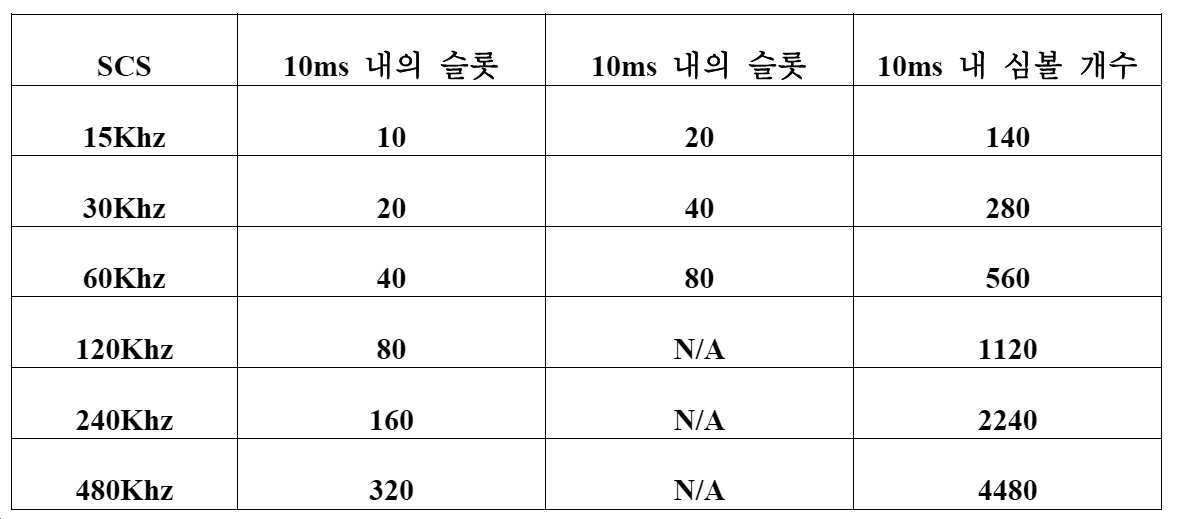
또한, 상술한 바와 같이 하나의 서브프레임은 시간 축 상에서 1ms에 해당할 수 있다. 또한, 하나의 슬롯은 시간 축 상에서 14개의 심볼에 해당할 수 있다. 또한, 일 예로, 하나의 슬롯은 시간 축 상에서 7개의 심볼에 해당할 수 있다. 이에 따라, 하나의 무선 프레임에 해당하는 10ms 내에서 각각의 고려될 수 있는 슬롯 및 심볼 수가 다르게 설정될 수 있다. 표 9는 각각의 SCS에 따른 슬롯 수 및 심볼 수를 나타낼 수 있다. 이때, 일 예로, 하기 표 9에서 480KHz의 SCS는 고려되지 않을 수 있으며, 상술한 실시예로 한정되지 않는다.In addition, as described above, one subframe may correspond to 1 ms on the time axis. In addition, one slot may correspond to 14 symbols on the time axis. Also, as an example, one slot may correspond to seven symbols on the time axis. Accordingly, the number of slots and symbols that can be considered may be set differently within 10 ms corresponding to one radio frame. Table 9 may indicate the number of slots and the number of symbols according to each SCS. In this case, as an example, SCS of 480KHz in Table 9 below may not be considered, and is not limited to the above-described embodiment.
[표 9][Table 9]
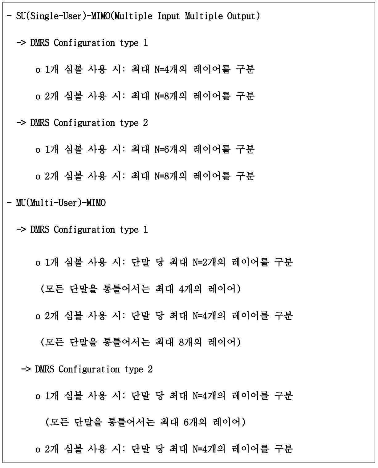
상술한 NR 시스템에 기초하여 V2X를 위한 DMRS를 구성할 수 있다. 일 예로, 기존 V2X에서 하나의 레이어(layer)에 대응되는 하나의 안테나 포트(antenna port) 상에서 DMRS가 전송될 수 있었다. DMRS for V2X can be configured based on the NR system described above. For example, DMRS may be transmitted on one antenna port corresponding to one layer in the existing V2X.
다만, V2X를 위한 DMRS 전송과 관련하여, 복수의 레이어들 간의 직교성(orthogonality)을 유지하면서 DMRS를 구성하고 전송하는 것이 가능할 수 있다.However, in connection with DMRS transmission for V2X, it may be possible to configure and transmit DMRS while maintaining orthogonality between a plurality of layers.
일 예로, NR 시스템에서 V2X를 위한 직교성을 유지하는 DMRS 안테나 포트(DMRS Orthogonal Antenna Port)의 수는 12개일 수 있다. 보다 상세하게는, NR 시스템에서 MU(Multi-User)-MIMO에서 모든 단말들을 고려하여 최대 12개의 레이어로 구별될 수 있다. 일 예로, DMRS 안테나 포트 넘버는 #0, #1, #2, #3, #4, #5, #6, #7, #8, #9, #10, #11로 설정될 수 있다. 또 다른 일 예로, DMRS의 첫 번째 안테나 포트에 해당하는 RS 안테나 포트 수가 A인 경우라면 DMRS 안테나 포트 수는 “#A, #A+1, #A+2, #A+3, #A+4, #A+5, #A+6, #A+7, #A+8, #A+9, #A+10, #A+11”일 수 있다.For example, the number of DMRS Orthogonal Antenna Ports maintaining orthogonality for V2X in an NR system may be 12. More specifically, in the NR system, it can be divided into up to 12 layers in consideration of all terminals in MU (Multi-User)-MIMO. For example, the DMRS antenna port numbers may be set to #0, #1, #2, #3, #4, #5, #6, #7, #8, #9, #10, #11. As another example, if the number of RS antenna ports corresponding to the first antenna port of DMRS is A, the number of DMRS antenna ports is “#A, #A+1, #A+2, #A+3, #A+4 , #A+5, #A+6, #A+7, #A+8, #A+9, #A+10, #A+11”.
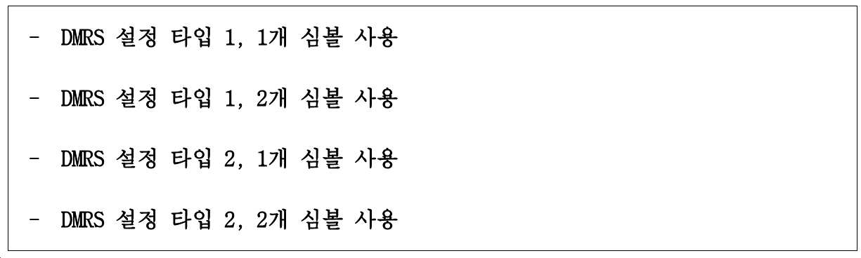
이때, DMRS에서 대한 설정은 DMRS 설정 타입 1(DMRS Configuration Type 1) 및 DMRS 설정 타입 2(DMRS Configuration Type 2)로 구성될 수 있다. 일 예로, DMRS 설정 타입 1은 IFDMA(Interleaved Frequency Divisional Multiple Access)에 기반할 수 있고, DMRS 설정 타입 2는 CDM(Code Division Multiplexing)에 기반할 수 있다. 다만, 상술한 실시예로 한정되지 않고, DMRS 설정 타입 1 및 DMRS 설정 타입 2가 각각 구별될 수 있다. At this time, the setting for DMRS may be configured as
또한, 일 예로, DMRS를 전송하는 경우, 한 개의 심볼을 사용하여 DMRS를 전송할 수 있다. 또 다른 일 예로, DMRS를 전송하는 경우, 두 개의 심볼을 사용하여 DMRS를 전송할 수 있다. 즉, DMRS를 전송하는 경우에 있어서는 상술한 DMRS 설정 타입 및 사용되는 심볼에 기초하여 하기 표 10과 같이 네 가지의 경우를 고려할 수 있다. 즉, 각각의 DMRS 설정 타입 별로 한 개의 심볼을 사용하는 경우와 두 개의 심볼을 사용하는 경우를 고려할 수 있다.Further, as an example, when transmitting DMRS, DMRS may be transmitted using one symbol. As another example, when transmitting DMRS, DMRS may be transmitted using two symbols. That is, in the case of transmitting DMRS, four cases may be considered as shown in Table 10 below based on the DMRS configuration type and the symbol used. That is, a case in which one symbol is used and a case in which two symbols are used may be considered for each DMRS configuration type.
[표 10]Table 10
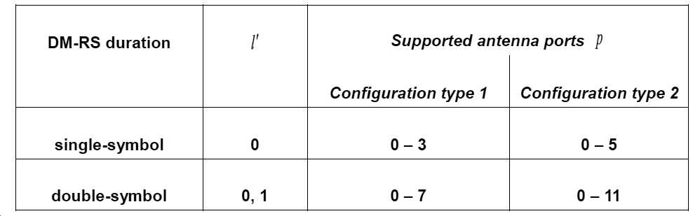
또한, 일 예로, 상술한 표 10에 기초하여 지원되는 안테나 포트는 하기 표 11과 같을 수 있다. 즉, DMRS 설정 타입 및 심볼 수에 기초하여 하기 표 11과 같이 설정될 수 있으며, 이에 대해서는 하기 표 13 및 14에서 후술한다. 이때, 일 예로, 은 심볼 수에 대응될 수 있다. 즉, 하나의 심볼인 경우에는 가 0이고, 두 개의 심볼인 경우에는 가 0, 1일 수 있다. 또한, p는 지원되는 안테나 포트를 지시할 수 있다.Further, as an example, the antenna ports supported based on Table 10 described above may be as shown in Table 11 below. That is, it may be set as shown in Table 11 below based on the DMRS configuration type and the number of symbols, which will be described later in Tables 13 and 14 below. In this case, as an example, may correspond to the number of symbols. That is, in the case of one symbol, is 0, and in the case of two symbols, may be 0 and 1. Also, p may indicate a supported antenna port.
[표 11][Table 11]
또한, 일 예로, 상술한 표 10에 기초하여 SU(Single-User)-MIMO(Multiple Input Multiple Output) 및 MU(Multi-User)-MIMO인 경우에 각각 사용할 수 있는 최대 레이어는 하기 표 12와 같을 수 있다. 즉, SU-MIMO 및 MU-MIMO에 기초하여 각각의 단말당 사용 가능한 DMRS 레이어의 최대 개수가 N개인 경우를 고려할 수 있다. 이때, 각각의 레이어는 상술한 DMRS 안테나 포트(12개의 안테나 포트) 중 하나에 대응될 수 있다.In addition, as an example, based on Table 10, the maximum layers that can be used respectively in the case of Single-User (SU)-Multiple Input Multiple Output (MIMO) and Multi-User (MU)-MIMO are as shown in Table 12 below. Can. That is, it is possible to consider a case in which the maximum number of DMRS layers available for each terminal is N based on SU-MIMO and MU-MIMO. At this time, each layer may correspond to one of the DMRS antenna ports (12 antenna ports) described above.
[표 12]Table 12
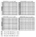
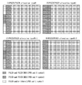
이때, 일 예로서, 상술한 DMRS 설정 타입 1 및 DMRS 설정 타입 2는 하기 표 13 및 표 14에 기초하여 최대 구분 가능한 DMRS 안테나 포트가 결정될 수 있다. 일 예로, 하기 표 13에서 ![]()
![]()
![]()
![]()
![]()
![]()
![]()
![]()
![]()
![]()
![]()
![]()
![]()
![]()
![]()
![]()
즉, DMRS 설정 타입이 1이고, 사용 가능한 심볼 수가 한 개인 경우, 하기 표 13에서 값은 0부터 3까지만 설정될 수 있는바, 최대 구분 가능한 DMRS 안테나 포트는 4개일 수 있다. 한편, DMRS 설정 타입이 1이고, 사용 가능한 심볼 수가 두 개인 경우에는 하기 표 13에서 ![]()
![]()
[표 13][Table 13]
또한, 일 예로, 표 14는 DMRS 설정 타입 2에 대응될 수 있다. 일 예로, 하기 표 14에서 ![]()
![]()
![]()
![]()
![]()
![]()
![]()
![]()
![]()
![]()
![]()
![]()
![]()
![]()
![]()
![]()
즉, DMRS 설정 타입이 2이고, 사용 가능한 심볼 수가 한 개인 경우, 하기 표 14에서 ![]()
![]()
![]()
![]()
[표 14] Table 14

보다 구체적인 일 예로서, DMRS 설정 타입 1에서 한 개의 심볼을 사용하는 경우에는 최대 4개의 DMRS 안테나 포트가 구별될 수 있다. 일 예로, DMRS 설정 타입 1은 IFDMA에 기초하여 설정될 수 있다. 이때, 주파수 영역에서 하나의 PRB(Physical Resource Block)로서 12개의 서브캐리어에서 하나의 서브캐리어마다 교차로 "Comb Pattern A(표 13의 CDM group 0에 해당, 하나의 PRB 내의 12개의 서브캐리어들(#0~#11) 중 #0, #2, #4, #6, #8, #10에 할당됨(#0부터 매 2개의 서브캐리어마다 할당되므로 Δ=0))" 및 "Comb Pattern B(표 13의 CDM group 1에 해당, 하나의 PRB 내의 12개의 서브캐리어들(#0~#11) 중 #1, #3, #5, #7, #9, #11에 할당됨(#1부터 매 2개의 서브캐리어마다 할당되므로 Δ=1))"가 설정될 수 있다. 이때, DMRS 패턴(pattern)은 주파수 축으로는 각각의 단말의 물리 채널(예를 들어 PDSCH, PUSCH 등) 전송을 위해 할당된 대역폭만큼 복수개의 PRB로 반복되어 확장될 수 있다. 또한, 시간 축으로는 하나의 슬롯 내에서 DMRS 구성 각각에 적용될 수 있다. 일 예로, DMRS 구성은 고정된 위치로서 "Front-loaded DMRS 구성" 또는 추가 구성으로서 "Additional DMRS 구성"일 수 있으며, 상술한 실시예로 한정되지 않는다.As a more specific example, when one symbol is used in
이때, 일 예로, 하나의 PRB는 12개의 RE(Resource Element)를 포함하고 있는바, 하나의 심볼에 대해서 Comb 패턴(pattern) 당 6개의 RE가 할당될 수 있다.At this time, as an example, one PRB includes 12 resource elements (REs), so 6 REs can be allocated per comb pattern for one symbol.
이때, DMRS 안테나 포트 구성은 하기 표 15와 같을 수 있다. 일 예로, 하기 표 15에서 Comb 패턴(pattern)은 상술한 "Comb pattern A" 또는 "Comb pattern B"일 수 있다. 다만, 이는 서로 다른 Comb 패턴(pattern)을 의미하는 것으로 상술한 명칭에 한정되지 않는다. 또한, CS(Cyclic Shift)는 DMRS 시퀀스의 순화 지연 값으로 가능한 값들의 범위가 0에서 X일 경우, "CS value A"는 그 값이 0이고, "CS value B"는 그 값이 X/2일 수 있다. 일 예로, X=12인 경우 "CS value A"는 그 값이 0이고 "CS value B"는 그 값이 6일 수 있다. 또한, 일 예로, X=2π인 경우 "CS value A"는 그 값이 0이고 "CS value B"는 그 값이 π일 수 있으나, 이에 한정되지 않는다. 즉, DRMS 설정 타입 1로서 심볼을 한 개 사용하는 경우, CS 값(value)으로 우선 구분되고, 다음으로 Comb 패턴(pattern)으로 구분될 수 있다.At this time, the DMRS antenna port configuration may be as shown in Table 15 below. For example, the Comb pattern (pattern) in Table 15 may be “Comb pattern A” or “Comb pattern B” described above. However, this means different Comb patterns and is not limited to the above-mentioned names. In addition, if the range of possible values is 0 to X as a cyclic delay value of a DMRS sequence in CS (Cyclic Shift), "CS value A" has a value of 0, and "CS value B" has a value of X/2. Can be For example, when X=12, “CS value A” may have a value of 0 and “CS value B” may have a value of 6. Further, as an example, when X=2π, “CS value A” may have a value of 0 and “CS value B” may have a value of π, but is not limited thereto. That is, when one symbol is used as the
또한, 일 예로, 하기 표 15에서 "Comb pattern A"에는 DMRS 안테나 포트 #0, #1이 할당될 수 있다. 또한, "Comb pattern B"에는 DMRS 안테나 포트 #2, #3이 할당될 수 있으며, 상술한 실시예로 한정되지 않는다.Also, as an example, DMRS
[표 15]Table 15

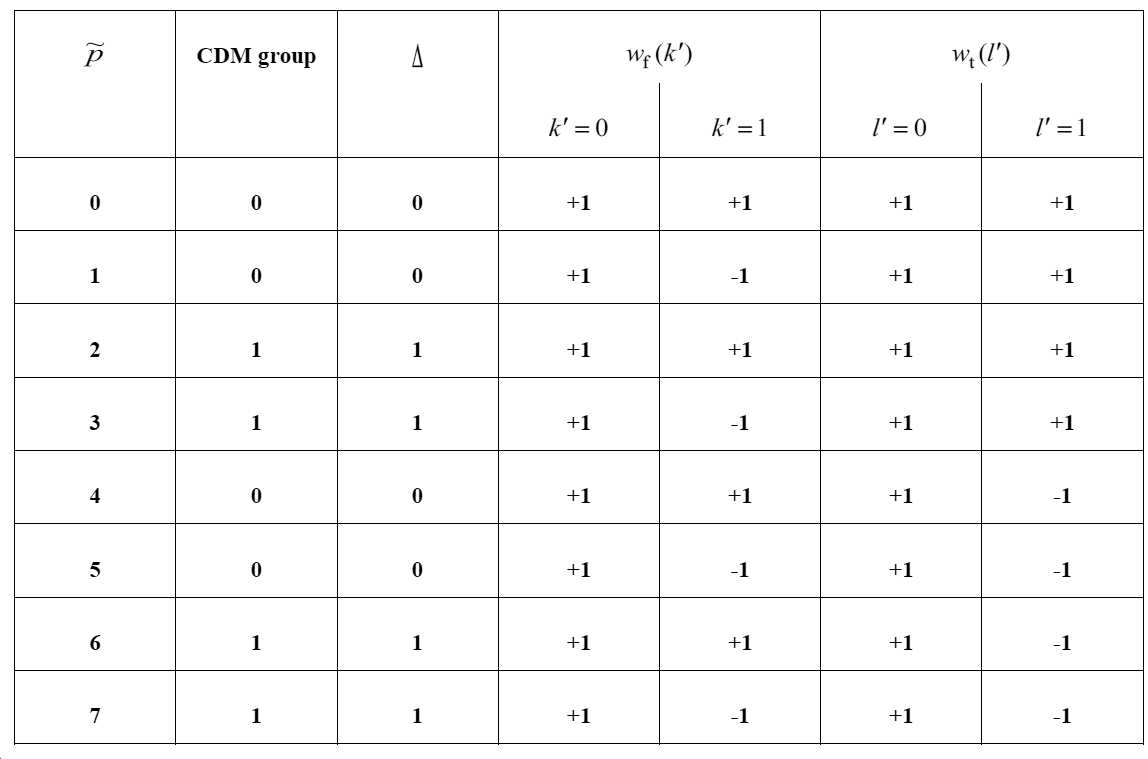
또 다른 일 예로, DMRS 설정 타입이 1이고, 사용 가능한 심볼 수가 두 개인 경우를 고려할 수 있다. 이때, 두 개의 심볼과 12개의 서브캐리어(주파수 영역에서 1개의 PRB에 해당)에서 "Comb Pattern A"와 "Comb Pattern B"이 설정될 수 있으며, 상술한 바와 유사하게 하나의 서브캐리어마다 교차로 설정될 수 있다. 이때, DMRS 패턴(pattern)은 주파수 축으로는 각각의 단말의 물리 채널(예를 들어 PDSCH, PUSCH 등) 전송을 위해 할당된 대역폭만큼 복수개의 PRB로 반복되어 확장될 수 있다. 또한, 시간 축으로는 하나의 슬롯 내에서 DMRS 구성 각각에 적용될 수 있다. 일 예로, DMRS 구성은 고정된 위치로서 "Front-loaded DMRS 구성" 또는 추가 구성으로서 "Additional DMRS 구성"일 수 있으며, 상술한 실시예로 한정되지 않는다.As another example, a case in which the DMRS configuration type is 1 and the number of available symbols is two may be considered. At this time, "Comb Pattern A" and "Comb Pattern B" may be set in two symbols and 12 subcarriers (corresponding to one PRB in the frequency domain), and similarly to the above, an intersection is set for each subcarrier. Can be. In this case, the DMRS pattern may be repeatedly extended to a plurality of PRBs by a bandwidth allocated for transmission of a physical channel (eg, PDSCH, PUSCH, etc.) of each terminal on a frequency axis. In addition, the time axis can be applied to each of the DMRS configuration in one slot. For example, the DMRS configuration may be a “Front-loaded DMRS configuration” as a fixed location or a “Additional DMRS configuration” as an additional configuration, and is not limited to the above-described embodiment.
이때, 하나의 PRB 내의 하나의 심볼에 대해 각각의 Comb 패턴(pattern) 당 총 6개의 RE(Resource Element)가 할당될 수 있다. DMRS 안테나 포트의 구성은 하기 표 16과 같을 수 있다. 하기 표 16에서 Comb 패턴(pattern)은 "Comb pattern A" 또는 "Comb pattern B"이며, CS(Cyclic Shift)는 DMRS 시퀀스의 순화 지연 값으로 가능한 값들의 범위가 0에서 X일 경우 "CS value A"는 그 값이 0일 수 있다. 또한, "CS value B"는 그 값이 X/2일 수 있다. 일 예로, X=12인 경우 "CS value A"는 그 값이 0이고 "CS value B"는 그 값이 6일 수 있다. X=2π인 경우 "CS value A"는 그 값이 0이고 "CS value B"는 그 값이 π일 수 있으나, 이에 한정된 것은 아니다.At this time, a total of six resource elements (REs) may be allocated for each symbol pattern in one PRB. The configuration of the DMRS antenna port may be as shown in Table 16 below. In Table 16, the Comb pattern (pattern) is "Comb pattern A" or "Comb pattern B", and CS (Cyclic Shift) is a purifying delay value of the DMRS sequence. When the range of possible values is 0 to X, "CS value A "May be 0. In addition, "CS value B" may have a value of X/2. For example, when X=12, “CS value A” may have a value of 0 and “CS value B” may have a value of 6. When X=2π, “CS value A” may have a value of 0 and “CS value B” may have a value of π, but is not limited thereto.
또한, TD-OCC(Time Domain-Orthogonal Cover Code)는 각각의 Comb 패턴(pattern) 내에서, 동일 서브캐리어 상에서 시간축 상으로 인접한 2개의 RE에 적용될 수가 있다. 이때, DMRS 시퀀스 생성 시 +1 또는 -1이 해당 RE에 매핑되는 DMRS 시퀀스의 시퀀스 값에 곱해질 수 있다. 보다 상세하게는, 동일 서브캐리어 상에서 시간축 상으로 우선한 RE, 동일 서브캐리어 상에서 시간축 상으로 다음 RE에 대하여 [+1, +1] 또는 [+1, -1]로서 DMRS 시퀀스 값이 곱해질 수 있다. In addition, TD-OCC (Time Domain-Orthogonal Cover Code) can be applied to two REs adjacent to each other on the time axis on the same subcarrier within each Comb pattern. At this time, when generating a DMRS sequence, +1 or -1 may be multiplied by the sequence value of the DMRS sequence mapped to the corresponding RE. More specifically, the DMRS sequence value can be multiplied by [+1, +1] or [+1, -1] for the RE that has priority on the time axis on the same subcarrier and the next RE on the time axis on the same subcarrier. have.
즉, DRMS 설정 타입 1로서 심볼을 두 개 사용하는 경우, CS 값(value)으로 우선 구분되고, 다음으로 Comb 패턴(pattern)으로 구분되며, 마지막으로 TD-OCC로 구분될 수 있다. 또한, 일 예로, "Comb pattern A"에는 DMRS 안테나 포트 #0, #1, #4, #5이 할당되고, "Comb pattern B"에는 DMRS 안테나 포트 #2, #3, #6, #7가 설정될 수 있으며, 상술한 실시예로 한정되지 않는다.That is, when two symbols are used as the
[표 16]Table 16

또 다른 일 예로, DMRS 설정 타입이 2이고, 하나의 심볼을 사용하는 경우를 고려할 수 있다. 이때, 하나의 심볼과 12개의 서브캐리어(주파수 영역에서 1개의 PRB에 해당)에서 "CDM group A(표 14의 CDM group 0에 해당, 하나의 PRB 내의 12개의 서브캐리어들(#0~#11) 중 #0, #1, #6, #7에 할당됨(#0 및 #1부터 매 6개의 서브캐리어마다 할당되므로 Δ=0))", "CDM group B(표 14의 CDM group 1에 해당, 하나의 PRB 내의 12개의 서브캐리어들(#0~#11) 중 #2, #3, #8, #9에 할당됨(#2 및 #3부터 매 6개의 서브캐리어마다 할당되므로 Δ=2))", "CDM group C(표 14의 CDM group 2에 해당, 하나의 PRB 내의 12개의 서브캐리어들(#0~#11) 중 #4, #5, #10, #11에 할당됨(#4 및 #5부터 매 6개의 서브캐리어마다 할당되므로 Δ=4))"이 구별될 수 있다. 이때, 세 개의 CDM 그룹(group)이 설정될 수 있음을 의미하며, 상술한 명칭으로 제한되지 않는다. 이때, DMRS 패턴(pattern)은 주파수 축으로는 각각의 단말의 물리 채널(예를 들어 PDSCH, PUSCH 등) 전송을 위해 할당된 대역폭만큼 복수개의 PRB로 반복되어 확장될 수 있다. 또한, 시간 축으로는 하나의 슬롯 내에서 DMRS 구성 각각에 적용될 수 있다. 일 예로, DMRS 구성은 고정된 위치로서 "Front-loaded DMRS 구성" 또는 추가 구성으로서 "Additional DMRS 구성"일 수 있으며, 상술한 실시예로 한정되지 않는다.As another example, a case in which the DMRS configuration type is 2 and one symbol is used may be considered. At this time, in one symbol and 12 subcarriers (corresponding to one PRB in the frequency domain), “CDM group A (corresponding to
이때, 각각의 CDM 그룹(group)이 세 개이므로 각각의 CDM 그룹(group) 당 총 4개의 RE가 할당될 수 있다. 일 예로, 상술한 DMRS 설정 타입 2에서 한 개의 심볼을 이용하는 경우, DMRS 안테나 포트는 하기 표 17과 같이 구성될 수 있다. 이때, 하기 CDM 그룹(group)은 "CDM group A", "CDM group B" 또는 "CDM group C"일 수 있다. 또한, 일 예로서, FD-OCC(Frequency Domain-Orthogonal Cover Code)는 각각의 CDM 그룹(group) 내에서 동일 심볼 상에서 주파수축 상으로 인접한 2개의 RE에 적용될 수가 있다. 그 값은 [+1, +1] 또는 [+1, -1]로서 DMRS 시퀀스 생성 시 +1 또는 -1이 해당 RE에 매핑되는 DMRS 시퀀스의 시퀀스 값에 곱해지게 된다. 즉, 동일 심볼상에서 주파수축 상으로 우선한 RE, 동일 심볼 상에서 주파수축 상으로 다음 RE에 기초하여 상술한 값이 설정될 수 있다. 즉, DMRS 설정 타입 2에서 하나의 심볼을 이용하는 경우, FD-OCC로 우선 구분되고, 그 후 CDM 그룹(group)으로 구분될 수 있다. 이때, 일 예로서, "CDM group A"는 DMRS antenna port #0, #1가 설정되고, "CDM group B"는 DMRS antenna port #2, #3이 설정되며, "CDM group C"는 DMRS antenna port #4, #5가 설정될 수 있으며, 상술한 실시예로 한정되지 않는다.At this time, since each CDM group is three, a total of 4 REs can be allocated for each CDM group. For example, when one symbol is used in the above-described
[표 17]Table 17

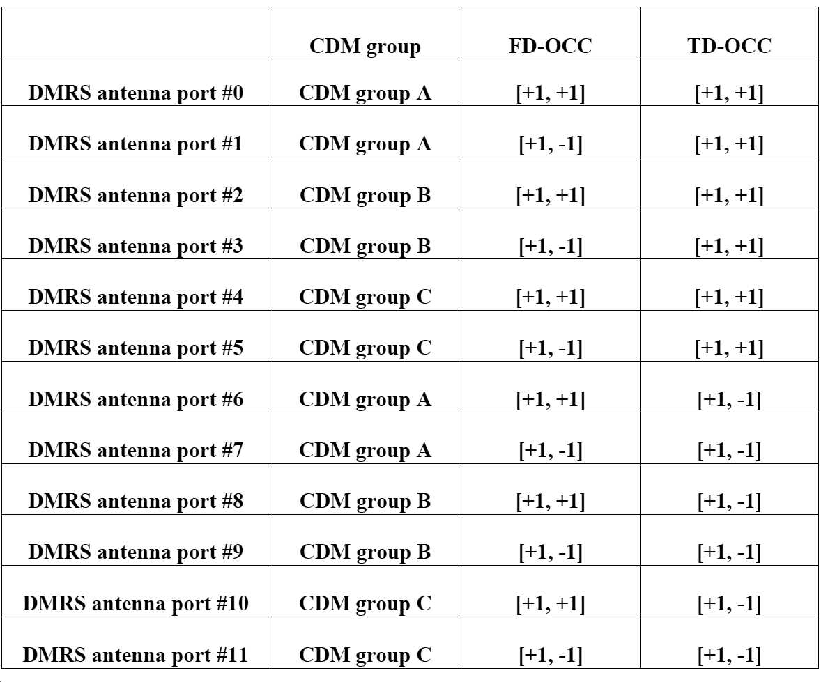
또한, 일 예로, DMRS 설정 타입 2에서 두 개의 심볼을 이용하는 경우, 최대 12개의 DMRS 안테나 포트가 구분될 수 있다. 일 예로, 두 개의 심볼과 12개의 서브캐리어(주파수 영역에서 1개의 PRB에 해당)에서 "CDM group A", "CDM group B", "CDM group C"가 설정될 수 있다. 즉, CDM 그룹(group)이 세 개가 설정될 수 있으며, 상술한 명칭에 한정되지 않는다. 이때, DMRS 패턴(pattern)은 주파수 축으로는 각각의 단말의 물리 채널(예를 들어 PDSCH, PUSCH 등) 전송을 위해 할당된 대역폭만큼 복수개의 PRB로 반복되어 확장될 수 있다. 또한, 시간 축으로는 하나의 슬롯 내에서 DMRS 구성 각각에 적용될 수 있다. 일 예로, DMRS 구성은 고정된 위치로서 "Front-loaded DMRS 구성" 또는 추가 구성으로서 "Additional DMRS 구성"일 수 있으며, 상술한 실시예로 한정되지 않는다.In addition, as an example, when two symbols are used in
이때, 각각의 CDM 그룹(group)이 세 개이므로 각각의 CDM 그룹(group) 당 총 4개의 RE가 할당될 수 있다. 일 예로, 상술한 DMRS 설정 타입 2에서 한 개의 심볼을 이용하는 경우, DMRS 안테나 포트는 하기 표 18과 같이 구성될 수 있다. 이때, 하기 표 18에서 CDM 그룹(group)은 "CDM group A", "CDM group B" 또는 "CDM group C"일 수 있다. At this time, since each CDM group is three, a total of 4 REs can be allocated for each CDM group. For example, when one symbol is used in the above-described
또한, FD-OCC(Frequency Domain-Orthogonal Cover Code)는 각각의 CDM 그룹(group) 내에서, 동일 심볼 상에서 주파수축 상으로 인접한 2개의 RE에 적용될 수가 있다. 그 값은 [+1, +1] 또는 [+1, -1]로서 DMRS 시퀀스 생성 시 +1 또는 -1이 해당 RE에 매핑되는 DMRS 시퀀스의 시퀀스 값에 곱해지게 된다. 즉, 동일 심볼상에서 주파수축 상으로 우선한 RE, 동일 심볼 상에서 주파수축 상으로 다음 RE에 대하여 상술한 DMRS 시퀀스의 시퀀스 값이 곱해지게 된다. In addition, FD-OCC (Frequency Domain-Orthogonal Cover Code) can be applied to two REs adjacent to each other on the frequency axis on the same symbol within each CDM group. The value is [+1, +1] or [+1, -1]. When generating a DMRS sequence, +1 or -1 is multiplied by the sequence value of the DMRS sequence mapped to the corresponding RE. That is, the sequence value of the above-described DMRS sequence is multiplied by the RE having priority on the frequency axis on the same symbol and the next RE on the frequency axis on the same symbol.
또한, TD-OCC(Time Domain-Orthogonal Cover Code)는 동일 서브캐리어 상에서 시간축 상으로 인접한 2개의 RE에 적용될 수가 있다. 그 값은 [+1, +1] 또는 [+1, -1]로서 DMRS 시퀀스 생성 시 +1 또는 -1이 해당 RE에 매핑되는 DMRS 시퀀스의 시퀀스 값에 곱해지게 된다. 즉, 동일 서브캐리어 상에서 시간축 상으로 우선한 RE, 동일 서브캐리어 상에서 시간축 상으로 다음 RE에 대하여 상술한 DMRS 시퀀스의 시퀀스 값이 곱해지게 된다. In addition, TD-OCC (Time Domain-Orthogonal Cover Code) can be applied to two REs adjacent to each other on the time axis on the same subcarrier. The value is [+1, +1] or [+1, -1]. When generating a DMRS sequence, +1 or -1 is multiplied by the sequence value of the DMRS sequence mapped to the corresponding RE. That is, the sequence value of the above-described DMRS sequence is multiplied by the RE that has priority on the time axis on the same subcarrier and the next RE on the time axis on the same subcarrier.
즉, DMRS 설정 타입 2에서 두 개의 심볼이 이용되는 경우, FD-OCC로 우선 구분되고, 그 다음 CDM 그룹(group)으로 구분되며, 마지막으로 TD-OCC로 구분될 수 있다. 이때, 일 예로, "CDM group A"에는 DMRS 안테나 포트 #0, #1, #6, #7이 설정되고, "CDM group B"에는 DMRS 안테나 포트 #2, #3, #8, #9이 설정되고, "CDM group C"에는 DMRS 안테나 포트 #4, #5, #10, #11가 설정될 수 있으며, 상술한 실시예로 한정되지 않는다.That is, when two symbols are used in the
[표 18]Table 18
하기에서는 NR V2X를 고려하여 PSCCH를 위한 DMRS 및 PSSCH를 위한 DMRS 구성 방법에 대해 서술한다. 일 예로, PSSCH를 위한 DMRS는 상술한 바에 기초하여 구성될 수 있다. 또한, 일 예로, 제어 채널로서 PSCCH를 위한 DMRS는 PUCCH 포맷 2 방식에 기초하여 구성될 수 있다. 이때, 하기 표 19는 PUCCH 포맷 2를 위한 자원 할당 방법일 수 있다. 일 예로, 하기 표 19를 참조하면, PUCCH 포맷 2에서 k는 자원 블록의 서브캐리어 0과 비교한 상대적 위치를 지시할 수 있다. 이때, k는 “3m+1” 값으로 설정될 수 있다. 즉, k는 m에 따라서 주파수 도메인 차원에서 고정된 위치로 설정될 수 있는바, 자원이 고정된 위치에 매핑될 수 있다. 이때, PSCCH를 위한 DMRS도 PUCCH 포맷 2와 유사하게 주파수 도메인에서 각각 고정된 위치로 설정될 수 있다. 즉, PSCCH를 위한 DMRS는 PUCCH 포맷 2 방식에 기초하여 상술한 k값을 통해 고정된 위치로 설정될 수 있다. 다만, PSCCH를 위한 DMRS를 PUCCH 포맷 2에 기초하여 구성하는 것은 하나의 일 예일 뿐, 다른 방법에 의해서도 구성될 수 있다. 일 예로, PSCCH를 위한 DMRS는 다른 방식에 기초하여 고정된 위치로 설정되는 것도 가능할 수 있으며, 상술한 실시예로 한정되지 않는다.Hereinafter, a description will be given of a DMRS for PSCCH and a DMRS configuration method for PSSCH in consideration of NR V2X. As an example, DMRS for PSSCH may be configured based on the above. In addition, as an example, DMRS for PSCCH as a control channel may be configured based on the
[표 19]Table 19

또한, 일 예로, NR V2X에서는 PSCCH 및 PSSCH가 FDM에 기초하여 구별되면서 시간 도메인에서 심볼 단위로 구별될 수 있다. 즉, PSCCH 및 PSSCH가 동일한 서브 프레임에서 심볼 별로 구별되어 할당될 수 있다. 구체적인 일 예로, 도 7 내지 도 10은 PSCCH 및 PSSCH가 할당되는 방법을 나타낼 수 있다. In addition, as an example, in NR V2X, PSCCH and PSSCH may be distinguished based on FDM, and may be distinguished in units of symbols in the time domain. That is, the PSCCH and the PSSCH can be allocated by being distinguished for each symbol in the same subframe. As a specific example, FIGS. 7 to 10 may show how PSCCH and PSSCH are allocated.
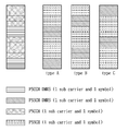
이때, 도 7은 PSCCH를 위한 DMRS가 하나의 심볼로 구성되고, PSSCH를 위한 DRMS가 하나의 심볼로 "Front-loaded DMRS”에 기초하여 설정되는 방법을 나타낸 도면이다. 일 예로, 도 7을 참조하면, PSCCH가 할당되는 주파수 영역과 PSSCH가 할당되는 주파수 영역이 동일한지 여부에 기초하여 다른 할당 타입이 설정될 수 있다. 이때, 도 7(A)에서는 타입 1로써, PSCCH가 할당되는 주파수 영역과 PSSCH가 할당되는 주파수 영역이 다를 수 있다. 반면, 도 7(B)에서는 타입 2로써, PSCCH가 할당되는 주파수 영역과 PSSCH가 할당되는 주파수 영역이 동일할 수 있다. 또한, 일 예로, 상술한 타입 1의 경우, PSCCH가 할당된 주파수 영역 이외의 다른 주파수 영역은 비워두거나 다른 채널이 할당될 수 있다. 반면, 도 7(C) 및 도 7(D)에서는 타입 3으로써, PSCCH가 할당된 주파수 영역 이외에 비워져 있는 공간에 PSSCH를 추가로 할당할 수 있다. 즉, PSCCH가 할당된 주파수 영역 이외의 비워져 있는 공간을 통해 데이터가 전송될 수 있다. 이때, 일 예로, 도 7(C)에서는 타입 3-1로써, PSCCH가 할당된 주파수 영역 이외의 영역에는 PSSCH만 할당될 수 있다. 즉, PSSCH를 위한 DMRS가 할당되지 않을 수 있다. 반면, 도 7(D)에서는 타입 3-2로써, PSCCH가 할당된 주파수 영역 이외의 영역에 PSSCH 및 PSSCH를 위한 DMRS가 할당될 수 있다. 이때, 상술한 할당 방법에 기초하여 PSCCH를 위한 DMRS 및 PSSCH를 위한 DMRS를 구성하는 방법이 필요할 수 있으며, 이에 대해서는 후술한다. 또한, 일 예로, 상술한 타입은 하나의 일 예일 뿐, 다른 타입으로 할당되는 것도 가능할 수 있으며, 상술한 실시예로 한정되지 않는다.In this case, FIG. 7 is a diagram illustrating a method in which the DMRS for the PSCCH is configured as one symbol, and the DRMS for the PSSCH is set based on the “Front-loaded DMRS” as a single symbol. Then, a different allocation type may be set based on whether the frequency domain to which the PSCCH is allocated and the frequency domain to which the PSSCH is allocated are the same, and in this case, as FIG. 7(A), the frequency domain to which the PSCCH is allocated is set. The frequency domain to which the PSSCH is allocated may be different, whereas in FIG. 7B, the frequency domain to which the PSCCH is allocated and the frequency domain to which the PSSCH is allocated may be the same as
또한, 일 예로, 상술한 도 7(C)의 타입 3-1과 도 7(D)의 타입 3-2를 고려하면 도 7(D)의 타입 3-2의 경우, PSSCH DMRS가 첫 번째 심볼부터 할당될 수 있는바, PSSCH에 대한 빠른 복호가 가능할 수 있다. 또한, 일 예로, 상술한 도 7(C)의 타입 3-1과 도 7(D)의 타입 3-2를 고려하면 도 7(D)의 타입 3-2의 경우, PSSCH DMRS에 대한 자원이 PSCCH DMRS 자원을 공유하므로 PSSCH DMRS를 위한 자원을 절약할 수 있다. 또 다른 일 예로, 넌-슬롯(non-slot) 기반 할당의 경우에는 도 7(D)의 타입 3-2의 경우에서 DMRS 할당이 효율적일 수 있으며, 상술한 실시예로 한정되지 않는다. 일 예로, 넌-슬롯은 일반 슬롯(normal slot) 보다 적어도 하나의 심볼만큼 작은 수를 가지는 슬롯을 의미할 수 있으며, 상술한 경우에 DMRS 할당이 효율적을 수 있다. 일 예로, 넌-슬롯으로써, 심볼이 2개인 경우, 상술한 타입 3-2에 기초하여 DMRS가 할당될 필요성이 있다.Further, as an example, when considering the above-described type 3-1 of FIG. 7(C) and type 3-2 of FIG. 7(D), in the case of type 3-2 of FIG. 7(D), the PSSCH DMRS is the first symbol. Since it can be allocated, fast decoding on the PSSCH may be possible. In addition, as an example, when considering the above-described type 3-1 of FIG. 7(C) and type 3-2 of FIG. 7(D), in the case of type 3-2 of FIG. 7(D), resources for PSSCH DMRS Since PSCCH DMRS resources are shared, resources for PSSCH DMRS can be saved. As another example, in the case of non-slot based allocation, DMRS allocation may be efficient in the case of type 3-2 of FIG. 7D, and is not limited to the above-described embodiment. As an example, the non-slot may mean a slot having a number as small as at least one symbol than a normal slot, and DMRS allocation may be efficient in the above-described case. As an example, as a non-slot, when there are two symbols, it is necessary to allocate DMRS based on the above-described type 3-2.
또한, 일 예로, 도 8은 PSCCH를 위한 DMRS가 두 개의 심볼로 구성되고, PSSCH를 위한 DRMS가 하나의 심볼로 "Front-loaded DMRS”에 기초하여 설정되는 방법을 나타낸 도면이다. 일 예로, 도 8을 참조하면, PSCCH가 할당되는 주파수 영역과 PSSCH가 할당되는 주파수 영역이 동일한지 여부에 기초하여 다른 할당 타입이 설정될 수 있다. 이때, 도 8(A)에서는 타입 1로써, PSCCH가 할당되는 주파수 영역과 PSSCH가 할당되는 주파수 영역이 다를 수 있다. 반면, 도 8(B)에서는 타입 2로써, PSCCH가 할당되는 주파수 영역과 PSSCH가 할당되는 주파수 영역이 동일할 수 있다. 이때, PSCCH는 두 개의 심볼에 할당되고, PSSCH는 하나의 심볼에 할당될 수 있다. 또한, 일 예로, 상술한 타입 1의 경우, PSCCH가 할당된 주파수 영역 이외의 다른 주파수 영역은 비워두거나 다른 채널이 할당될 수 있다. 반면, 도 8(C) 및 도 8(D)에서는 타입 3으로써, PSCCH가 할당된 주파수 영역 이외에 비워져 있는 공간에 PSSCH를 추가로 할당할 수 있다. 즉, PSCCH가 할당된 주파수 영역 이외의 비워져 있는 공간을 통해 데이터가 전송될 수 있다. 이때, 일 예로, 도 8(C)에서는 타입 3-1로써, PSCCH가 할당된 주파수 영역 이외의 영역에는 PSSCH만 할당될 수 있다. 즉, PSSCH를 위한 DMRS가 할당되지 않을 수 있다. 반면, 도 8(D)에서는 타입 3-2로써, PSCCH가 할당된 주파수 영역 이외의 영역에 PSSCH 및 PSSCH를 위한 DMRS가 할당될 수 있다. 다만, PSSCH를 위한 DMRS는 하나의 심볼에만 할당되는바, PSCCH가 할당된 두 개의 심볼 중 어느 하나의 심볼에만 PSSCH 및 PSSCH를 위한 DMRS가 할당될 수 있다. 이때, 상술한 할당 방법에 기초하여 PSCCH를 위한 DMRS 및 PSSCH를 위한 DMRS를 구성하는 방법이 필요할 수 있으며, 이에 대해서는 후술한다. Further, as an example, FIG. 8 is a diagram illustrating a method in which the DMRS for the PSCCH is composed of two symbols, and the DRMS for the PSSCH is set based on “Front-loaded DMRS” as one symbol. Referring to 8, a different allocation type may be set based on whether the frequency domain to which the PSCCH is allocated and the frequency domain to which the PSSCH is allocated are the same, wherein the PSCCH is allocated as the
또한, 일 예로, 상술한 도 8(C)의 타입 3-1과 도 8(D)의 타입 3-2를 고려하면 도 8(D)의 타입 3-2의 경우, PSSCH DMRS가 첫 번째 심볼부터 할당될 수 있는바, PSSCH에 대한 빠른 복호가 가능할 수 있다. 또한, 일 예로, 상술한 도 8(C)의 타입 3-1과 도 8(D)의 타입 3-2를 고려하면 도 8(D)의 타입 3-2의 경우, PSSCH DMRS에 대한 자원이 PSCCH DMRS 자원을 공유하므로 PSSCH DMRS를 위한 자원을 절약할 수 있다. 또 다른 일 예로, 넌-슬롯(non-slot) 기반 할당의 경우에는 도 8(D)의 타입 3-2의 경우에서 DMRS 할당이 효율적일 수 있으며, 상술한 실시예로 한정되지 않는다. 일 예로, 넌-슬롯은 일반 슬롯(normal slot) 보다 적어도 하나의 심볼만큼 작은 수를 가지는 슬롯을 의미할 수 있으며, 상술한 경우에 DMRS 할당이 효율적을 수 있다. 일 예로, 넌-슬롯으로써, 심볼이 2개인 경우, 상술한 타입 3-2에 기초하여 DMRS가 할당될 필요성이 있다.In addition, as an example, when considering the above-described type 3-1 of FIG. 8(C) and type 3-2 of FIG. 8(D), in the case of type 3-2 of FIG. 8(D), the PSSCH DMRS is the first symbol. Since it can be allocated, fast decoding on the PSSCH may be possible. In addition, as an example, when considering the above-described type 3-1 of FIG. 8(C) and type 3-2 of FIG. 8(D), in the case of type 3-2 of FIG. 8(D), resources for PSSCH DMRS Since PSCCH DMRS resources are shared, resources for PSSCH DMRS can be saved. As another example, in the case of non-slot based allocation, DMRS allocation may be efficient in the case of type 3-2 of FIG. 8(D), and is not limited to the above-described embodiment. As an example, the non-slot may mean a slot having a number as small as at least one symbol than a normal slot, and DMRS allocation may be efficient in the above-described case. As an example, as a non-slot, when there are two symbols, it is necessary to allocate DMRS based on the above-described type 3-2.
또한, 도 9는 PSCCH를 위한 DMRS가 하나의 심볼로 구성되고, PSSCH를 위한 DRMS가 두 개의 심볼로 "Front-loaded DMRS”에 기초하여 설정되는 방법을 나타낸 도면이다. 일 예로, 도 9를 참조하면, PSCCH가 할당되는 주파수 영역과 PSSCH가 할당되는 주파수 영역이 동일한지 여부에 기초하여 다른 할당 타입이 설정될 수 있다. 이때, 도 9(A)에서는 타입 1로써, PSCCH가 할당되는 주파수 영역과 PSSCH가 할당되는 주파수 영역이 다를 수 있다. 반면, 도 9(B)에서는 타입 2로써, PSCCH가 할당되는 주파수 영역과 PSSCH가 할당되는 주파수 영역이 동일할 수 있다. 또한, 일 예로, 상술한 타입 1의 경우, PSCCH가 할당된 주파수 영역 이외의 다른 주파수 영역은 비워두거나 다른 채널이 할당될 수 있다. 반면, 도 9(C) 및 도 9(D)에서는 타입 3으로써, PSCCH가 할당된 주파수 영역 이외에 비워져 있는 공간에 PSSCH를 추가로 할당할 수 있다. 즉, PSCCH가 할당된 주파수 영역 이외의 비워져 있는 공간을 통해 데이터가 전송될 수 있다. 이때, 일 예로, 도 9(C)에서는 타입 3-1로써, PSCCH가 할당된 주파수 영역 이외의 영역에는 PSSCH만 할당될 수 있다. 즉, PSSCH를 위한 DMRS가 할당되지 않을 수 있다. 반면, 도 9(D)에서는 타입 3-2로써, PSCCH가 할당된 주파수 영역 이외의 영역에 PSSCH 및 PSSCH를 위한 DMRS가 할당될 수 있다. 이때, PSSCH를 위한 DMRS는 두 개의 심볼에 할당되는바, PSCCH가 할당된 심볼 및 다음 심볼에서 할당될 수 있다. 상술한 할당 방법에 기초하여 PSCCH를 위한 DMRS 및 PSSCH를 위한 DMRS를 구성하는 방법이 필요할 수 있으며, 이에 대해서는 후술한다. In addition, FIG. 9 is a diagram illustrating a method in which the DMRS for the PSCCH is composed of one symbol, and the DRMS for the PSSCH is set based on the “Front-loaded DMRS” as two symbols. Then, a different allocation type may be set based on whether the frequency domain to which the PSCCH is allocated and the frequency domain to which the PSSCH is allocated are the same, and in this case, as the
또한, 일 예로, 상술한 도 9(C)의 타입 3-1과 도 9(D)의 타입 3-2를 고려하면 도 9(D)의 타입 3-2의 경우, PSSCH DMRS가 첫 번째 심볼부터 할당될 수 있는바, PSSCH에 대한 빠른 복호가 가능할 수 있다. 또한, 일 예로, 상술한 도 9(C)의 타입 3-1과 도 9(D)의 타입 3-2를 고려하면 도 9(D)의 타입 3-2의 경우, PSSCH DMRS에 대한 자원이 PSCCH DMRS 자원을 공유하므로 PSSCH DMRS를 위한 자원을 절약할 수 있다. 또 다른 일 예로, 넌-슬롯(non-slot) 기반 할당의 경우에는 도 9(D)의 타입 3-2의 경우에서 DMRS 할당이 효율적일 수 있으며, 상술한 실시예로 한정되지 않는다. 일 예로, 넌-슬롯은 일반 슬롯(normal slot) 보다 적어도 하나의 심볼만큼 작은 수를 가지는 슬롯을 의미할 수 있으며, 상술한 경우에 DMRS 할당이 효율적을 수 있다. 일 예로, 넌-슬롯으로써, 심볼이 2개인 경우, 상술한 타입 3-2에 기초하여 DMRS가 할당될 필요성이 있다.In addition, as an example, when considering the above-described type 3-1 of FIG. 9(C) and type 3-2 of FIG. 9(D), in the case of type 3-2 of FIG. 9(D), the PSSCH DMRS is the first symbol. Since it can be allocated, fast decoding on the PSSCH may be possible. In addition, as an example, considering type 3-1 of FIG. 9(C) and type 3-2 of FIG. 9(D), resources for PSSCH DMRS in case of type 3-2 of FIG. 9(D) are described above. Since PSCCH DMRS resources are shared, resources for PSSCH DMRS can be saved. As another example, in the case of non-slot based allocation, DMRS allocation may be efficient in the case of type 3-2 of FIG. 9(D), and is not limited to the above-described embodiment. As an example, the non-slot may mean a slot having a number as small as at least one symbol than a normal slot, and DMRS allocation may be efficient in the above-described case. As an example, as a non-slot, when there are two symbols, it is necessary to allocate DMRS based on the above-described type 3-2.
또한, 도 10은 PSCCH를 위한 DMRS가 두 개의 심볼로 구성되고, PSSCH를 위한 DRMS가 두 개의 심볼로 "Front-loaded DMRS”에 기초하여 설정되는 방법을 나타낸 도면이다. 일 예로, 도 10을 참조하면, PSCCH가 할당되는 주파수 영역과 PSSCH가 할당되는 주파수 영역이 동일한지 여부에 기초하여 다른 할당 타입이 설정될 수 있다. 이때, 도 10(A)에서는 타입 1로써, PSCCH가 할당되는 주파수 영역과 PSSCH가 할당되는 주파수 영역이 다를 수 있다. 반면, 도 10(B)에서는 타입 2로써, PSCCH가 할당되는 주파수 영역과 PSSCH가 할당되는 주파수 영역이 동일할 수 있다. 또한, 일 예로, 상술한 타입 1의 경우, PSCCH가 할당된 주파수 영역 이외의 다른 주파수 영역은 비워두거나 다른 채널이 할당될 수 있다. 반면, 도 10(C) 및 도 10(D)에서는 타입 3으로써, PSCCH가 할당된 주파수 영역 이외에 비워져 있는 공간에 PSSCH를 추가로 할당할 수 있다. 즉, PSCCH가 할당된 주파수 영역 이외의 비워져 있는 공간을 통해 데이터가 전송될 수 있다. 이때, 일 예로, 도 10(C)에서는 타입 3-1로써, PSCCH가 할당된 주파수 영역 이외의 영역에는 PSSCH만 할당될 수 있다. 즉, PSSCH를 위한 DMRS가 할당되지 않을 수 있다. 반면, 도 10(D)에서는 타입 3-2로써, PSCCH가 할당된 주파수 영역 이외의 영역에 PSSCH 및 PSSCH를 위한 DMRS가 할당될 수 있다. 이때, 상술한 할당 방법에 기초하여 PSCCH를 위한 DMRS 및 PSSCH를 위한 DMRS를 구성하는 방법이 필요할 수 있으며, 이에 대해서는 후술한다. In addition, FIG. 10 is a diagram illustrating a method in which a DMRS for PSCCH is composed of two symbols, and a DRMS for PSSCH is set based on “Front-loaded DMRS” as two symbols. Then, a different allocation type may be set based on whether the frequency domain to which the PSCCH is allocated and the frequency domain to which the PSSCH is allocated are the same, wherein the frequency domain to which the PSCCH is allocated is the
또한, 일 예로, 상술한 도 10(C)의 타입 3-1과 도 10 10(D)의 타입 3-2를 고려하면 도 10(D)의 타입 3-2의 경우, PSSCH DMRS가 첫 번째 심볼부터 할당될 수 있는바, PSSCH에 대한 빠른 복호가 가능할 수 있다. 또한, 일 예로, 상술한 도 10(C)의 타입 3-1과 도 10(D)의 타입 3-2를 고려하면 도 10(D)의 타입 3-2의 경우, PSSCH DMRS에 대한 자원이 PSCCH DMRS 자원을 공유하므로 PSSCH DMRS를 위한 자원을 절약할 수 있다. 또 다른 일 예로, 넌-슬롯(non-slot) 기반 할당의 경우에는 도 10(D)의 타입 3-2의 경우에서 DMRS 할당이 효율적일 수 있으며, 상술한 실시예로 한정되지 않는다. 일 예로, 넌-슬롯은 일반 슬롯(normal slot) 보다 적어도 하나의 심볼만큼 작은 수를 가지는 슬롯을 의미할 수 있으며, 상술한 경우에 DMRS 할당이 효율적을 수 있다. 일 예로, 넌-슬롯의 심볼이 2개인 경우, 상술한 타입 3-2에 기초하여 DMRS가 할당될 필요성이 있다.Further, as an example, when considering the above-described type 3-1 of FIG. 10(C) and type 3-2 of FIG. 10(D), in the case of type 3-2 of FIG. 10(D), PSSCH DMRS is the first Since symbols can be allocated, fast decoding of the PSSCH may be possible. In addition, as an example, when considering the above-described type 3-1 of FIG. 10(C) and type 3-2 of FIG. 10(D), in the case of type 3-2 of FIG. 10(D), resources for PSSCH DMRS Since PSCCH DMRS resources are shared, resources for PSSCH DMRS can be saved. As another example, in the case of non-slot based allocation, DMRS allocation may be efficient in the case of type 3-2 of FIG. 10(D) and is not limited to the above-described embodiment. As an example, the non-slot may mean a slot having a number as small as at least one symbol than a normal slot, and DMRS allocation may be efficient in the above-described case. For example, when there are two non-slot symbols, it is necessary to allocate DMRS based on the above-described type 3-2.
상술한 도 7 내지 도 10에서 PSCCH를 위한 DMRS 및 PSSCH를 위한 DMRS를 구성하는 방법이 필요할 수 있다. 일 예로, PSCCH DMRS 및 PSCCH DMRS는 별도로 구성될 수 있다. 이때, 도 7 내지 도 10에서 각각 타입 1, 타입 2 및 타입 3-1의 경우에는 PSCCH를 위한 DMRS와 PSSCH를 위한 DMRS가 동일한 심볼에 할당되지 않았는바, PSCCH DMRS 및 PSCCH DMRS는 별도로 구성하여 적용할 수 있다.7 to 10, a method of configuring DMRS for PSCCH and DMRS for PSSCH may be required. For example, PSCCH DMRS and PSCCH DMRS may be configured separately. In this case, in the case of
보다 상세하게는, 도 11을 참조하면, PSCCH DMRS 및 PSCCH DMRS를 별도로 구성하는 경우, PSCCH DMRS 할당 패턴은 고정된 패턴으로 설정될 수 있다. 이때, 일 예로, 상술한 표 19에 기초하여 PSCCH DMRS 할당 패턴은 PUCCH 포맷 2에 기초하여 고정된 위치로 할당될 수 있다. 다만, 이는 하나의 일 예일 뿐, PSCCH DMRS 할당 패턴은 다른 방법에 기초하여 고정된 패턴으로 설정될 수 있다. 이때, 상술한 바와 같이, DMRS는 안테나 포트를 구별하는 방법으로 설정될 수 있다. 다만, 일 예로, NR V2X에서 MIMO를 지원하지 않는 경우를 고려할 수 있다. 일 예로, SU-MIMO를 고려하지 않는 경우를 고려할 수 있다. 이때, 하나의 PRB 내의 동일한 심볼 내에서 총 네 가지 RE에 대해서 직교 시퀀스(orthogonal sequence)로서 “[+1, +1, +1, +1]”가 설정될 수 있다. 즉, DMRS에 대해서 안테나 포트를 구별할 필요성이 없는바, 직교 시퀀스로서 상술한 값이 동일하게 설정될 수 있다.In more detail, referring to FIG. 11, when PSCCH DMRS and PSCCH DMRS are separately configured, the PSCCH DMRS allocation pattern may be set as a fixed pattern. In this case, as an example, the PSCCH DMRS allocation pattern may be allocated to a fixed location based on
반면, 일 예로, NR V2X에서 MIMO를 지원하는 경우를 고려할 수 있다. 일 예로, SU-MIMO를 고려하는 경우를 고려할 수 있다. 이때, 일 예로, 전송 다이버시티를 고려하여 두 개의 안테나 포트를 지원하는 경우를 고려할 수 있다. 이때, 안테나 포트를 구별하기 위해 첫 번째 안테나 포트의 경우, 하나의 PRB 내의 동일한 심볼 내에서 총 네 가지 RE에 대해서 직교 시퀀스로서 “[+1, +1, +1, +1]”가 설정될 수 있다. 또한, 안테나 포트를 구별하기 위해 두 번째 안테나 포트의 경우, 하나의 PRB 내의 동일한 심볼 내에서 총 네 가지 RE에 대해서 직교 시퀀스로서 “[+1, -1, +1, -1]”가 설정될 수 있다. 즉, 두 개의 안테나 포트를 구별하기 위한 두 가지 타입의 직교 시퀀스 설정이 가능할 수 있다.On the other hand, as an example, a case in which MIMO is supported in NR V2X may be considered. As an example, a case in which SU-MIMO is considered may be considered. In this case, as an example, a case in which two antenna ports are supported in consideration of transmission diversity may be considered. At this time, in order to distinguish the antenna port, in the case of the first antenna port, “[+1, +1, +1, +1]” is set as an orthogonal sequence for all four REs within the same symbol in one PRB. Can. In addition, in order to distinguish the antenna port, in the case of the second antenna port, “[+1, -1, +1, -1]” is set as an orthogonal sequence for all four REs in the same symbol in one PRB. Can. That is, two types of orthogonal sequences may be set to distinguish two antenna ports.
반면, PSSCH DMRS 할당 패턴은 상술한 DMRS 설정 타입 2(DMRS Configuration Type 2)를 고려할 수 있다. 이때, PSSCH DMRS 할당 패턴은 아이디 값에 기초하여 결정될 수 있다. 이때, 아이디 값은 SCI(Sidelink Control Information) ID일 수 있다. 또한, 아이디 값은 다른 아이디 값일 수 있으며, 상술한 실시예로 한정되지 않는다. 한편, SCI ID는 PSCCH를 통해 확인할 수 있다. 즉, SCI ID는 PSCCH에 포함되어 전송될 수 있다. On the other hand, the PSSCH DMRS allocation pattern may consider the above-described DMRS Configuration Type 2 (DMRS Configuration Type 2). At this time, the PSSCH DMRS allocation pattern may be determined based on the ID value. At this time, the ID value may be a SCI (Sidelink Control Information) ID. In addition, the ID value may be another ID value, and is not limited to the above-described embodiment. Meanwhile, the SCI ID can be confirmed through PSCCH. That is, the SCI ID can be transmitted by being included in the PSCCH.
이때, 일 예로, SCI ID는 유니캐스트(unicast) 또는 그룹캐스트(groupcast) 전송을 고려하여 물리 계층에서 설정되는 아이디일 수 있다 (예를 들어, 사이드링크 레이어-1(SL Layer-1) ID). 이때, 일 예로, NR V2X에서 유니캐스트 또는 그룹캐스트에 기초하여 NR V2X 통신의 신뢰성을 보장하고, 저지연 요구를 만족시키기 위해 SL Layer-1 ID가 설정될 수 있다. 일 예로, LTE V2X에서는 오직 브로드캐스트(broadcast) 전송만을 지원하기 때문에 SL Layer-1 ID 값은 PSCCH 내에 SCI 정보에 부착되는 16비트의 CRC(Cyclic Redundancy Code) 정보에 기초하여 결정되어 사용될 수 있었다. 또한, 일 예로, LTE D2D에서는 SCI 정보 내에 송신 단말이 수신 단말에게 제공하는 목적지 ID(Destination ID(for layer-1))을 기반으로 물리 채널에서 SL Layer-1 ID 값이 활용될 수 있었다. 다만, NR V2X에서 기존 시나리오들과는 다르게 다수의 유니캐스트 및/또는 그룹캐스트가 존재할 수 있다. 또한, NR V2X에서 높은 QoS(Quality of Service) 요구사항을 가지는 데이터 전송을 물리계층에서 지원해야 할 필요성이 있다. 이때, 상술한 QoS 요구사항을 만족시키기 위해서는 링크 적응(link adaptation)을 고려하여 HARQ(Hybrid Automatic Repeat Request), CSI(Channel State Information)에 대한 정보가 필요할 수 있다. 또한, 일 예로, QoS 요구사항을 만족시키기 위한 다른 동작이 필요할 수 있으며, 상술한 실시예로 한정되지 않는다. 이때, 상술한 동작들을 고려하여 SL 유니캐스트 또는 그룹캐스트 전송을 위해 SL Layer-1 ID가 설정될 필요성이 있다. 즉, 단말은 기존의 브로드캐스트에 기초한 SL 전송과 함께 유니캐스트 또는 그룹캐스트 전송을 추가로 수행할 수 있다. 또한, 일 예로, 유니캐스트 전송에서는 높은 신뢰도와 지연시간을 요구하는 트래픽이 사용될 수 있는바, V2X 서비스가 제공되는 경우에 있어서 많은 단말 페어(UE pair for unicast)가 존재할 수 있다. 이때, 상술한 바처럼 제한된 통신 범위에 다양한 형태의 SL 통신이 더 높은 QoS 요구사항을 만족시켜야 할 필요성이 있는바, 물리계층에서도 신뢰성 있는 전송이 필요할 수 있다.In this case, as an example, the SCI ID may be an ID set at the physical layer in consideration of unicast or groupcast transmission (eg, side link layer-1 (SL Layer-1) ID). . At this time, as an example, SL layer-1 ID may be set in NR V2X to ensure reliability of NR V2X communication based on unicast or groupcast, and satisfy low-latency demand. For example, since LTE V2X supports only broadcast transmission, the SL Layer-1 ID value can be determined and used based on 16-bit Cyclic Redundancy Code (CRC) information attached to SCI information in the PSCCH. In addition, as an example, in LTE D2D, the SL Layer-1 ID value may be used in a physical channel based on a destination ID (for Destination-1 (for layer-1)) that a transmitting terminal provides to a receiving terminal in SCI information. However, in NR V2X, unlike the existing scenarios, there may be multiple unicast and/or group casts. In addition, there is a need to support data transmission with a high quality of service (QoS) requirement in the NR V2X at the physical layer. At this time, in order to satisfy the above-described QoS requirements, information on hybrid automatic repeat request (HARQ) and channel state information (CSI) may be required in consideration of link adaptation. In addition, as an example, other operations may be required to satisfy QoS requirements, and are not limited to the above-described embodiment. In this case, it is necessary to set the SL Layer-1 ID for SL unicast or group cast transmission in consideration of the above-described operations. That is, the terminal may additionally perform unicast or groupcast transmission together with SL transmission based on the existing broadcast. In addition, as an example, in a unicast transmission, traffic requiring high reliability and latency may be used, and in the case where a V2X service is provided, there may be many UE pairs for unicast. At this time, as described above, there is a need for various types of SL communication to satisfy higher QoS requirements in a limited communication range, and thus, reliable transmission may be required even in the physical layer.
상술한 바를 고려하여 SL Layer-1 ID 값이 정의될 수 있으며, 이를 활용할 수 있다. 일 예로, SL Layer-1 ID는 "layer-1 destination ID", "layer-1 source ID", "HARQ process ID" 및 "CRC bits of associated PSCCH" 중 적어도 어느 하나에 기초하여 결정될 수 있다. 또한, 일 예로, SL Layer-1 ID는 "layer-1 destination ID", "layer-1 source ID", "HARQ process ID" 및 "CRC bits of associated PSCCH" 중 둘 이상의 조합에 의해 layer-1 link ID로 설정될 수 있다. 또 다른 일 예로, 상기 layer-1 link ID는 layer-2 link ID의 일부로 설정될 수 있다. 일 예로, layer-2 link ID는 유니캐스트 및/또는 그룹캐스트 세션이 설립되는 경우에 있어서 생성될 수 있다. 이때, layer-1 link ID는 layer-2 link ID의 일부로 생성되어 설정될 수 있으며, 상술한 실시예로 한정되지 않는다.In consideration of the above, the SL Layer-1 ID value may be defined and utilized. For example, the SL Layer-1 ID may be determined based on at least one of “layer-1 destination ID”, “layer-1 source ID”, “HARQ process ID” and “CRC bits of associated PSCCH”. In addition, as an example, SL Layer-1 ID is a layer-1 link by a combination of two or more of "layer-1 destination ID", "layer-1 source ID", "HARQ process ID" and "CRC bits of associated PSCCH". ID can be set. As another example, the layer-1 link ID may be set as part of the layer-2 link ID. For example, the layer-2 link ID may be generated when a unicast and/or groupcast session is established. At this time, the layer-1 link ID may be generated and set as part of the layer-2 link ID, and is not limited to the above-described embodiment.
즉, 물리 계층을 위한 SL Layer-1 ID가 설정될 수 있으며, SL Layer-1 ID가 SCI ID일 수 있다. 하기에서는 상술한 아이디를 SCI ID로 지칭하여 서술한다. 즉, SCI ID는 물리 계층을 위한 SL Layer-1 ID를 지칭할 수 있으나, 설정되는 방법은 상술한 바에 한정되지 않는다.That is, the SL Layer-1 ID for the physical layer may be set, and the SL Layer-1 ID may be the SCI ID. In the following description, the above-described ID is referred to as an SCI ID. That is, the SCI ID may refer to the SL Layer-1 ID for the physical layer, but the set method is not limited to the above.
이때, PSSCH DMRS 할당 패턴도 NR V2X에서 MIMO를 지원하는지 여부에 기초하여 다르게 설정될 수 있다. 일 예로, NR V2X에서 MIMO를 지원하지 않는 경우를 고려할 수 있다. 일 예로, SU-MIMO를 고려하지 않는 경우를 고려할 수 있다. 이때, 도 11을 참조하면, MIMO를 지원하지 않은 경우, 하기 표 20 내지 표 22 중 어느 하나에 기초하여 DMRS 패턴이 결정될 수 있다.At this time, the PSSCH DMRS allocation pattern may also be set differently based on whether MIMO is supported in NR V2X. As an example, a case where MIMO is not supported in NR V2X may be considered. As an example, a case where SU-MIMO is not considered may be considered. In this case, referring to FIG. 11, when MIMO is not supported, a DMRS pattern may be determined based on any one of Tables 20 to 22 below.
[표 20]Table 20
[표 21]Table 21

[표 22]Table 22

반면, 일 예로, NR V2X에서 MIMO를 지원하는 경우를 고려할 수 있다. 일 예로, SU-MIMO를 고려하는 경우를 고려할 수 있다. 이때, 일 예로, 전송 다이버시티를 고려하여 두 개의 안테나 포트를 지원하는 경우를 고려할 수 있다. 이때, 안테나 포트를 구별하기 위해 첫 번째 안테나 포트 및 두 번째 안테나 포트는 하기 표 23처럼 직교 시퀀스에 기초하여 구별될 수 있다. On the other hand, as an example, a case in which MIMO is supported in NR V2X may be considered. As an example, a case in which SU-MIMO is considered may be considered. In this case, as an example, a case in which two antenna ports are supported in consideration of transmission diversity may be considered. At this time, in order to distinguish the antenna port, the first antenna port and the second antenna port may be distinguished based on an orthogonal sequence as shown in Table 23 below.
[표 23]Table 23

도 11 및 표 20 내지 표 23에서는 DMRS가 하나의 심볼에 할당되는 경우를 기준으로 서술하였다. 이때, 일 예로, DMRS가 두 개의 심볼에 할당되는 경우에는 상술한 도 11 및 표 20 내지 표 23에 대한 할당 방법이 동일하게 중복하여 적용될 수 있다. 즉, 두 개의 심볼인 경우에는 DMRS 할당이 반복될 수 있으며, 상술한 실시예로 한정되지 않는다.11 and Tables 20 to 23 are described based on the case where DMRS is assigned to one symbol. In this case, as an example, when DMRSs are allocated to two symbols, the above-described allocation methods for FIG. 11 and Tables 20 to 23 may be identically applied. That is, in the case of two symbols, DMRS allocation may be repeated and is not limited to the above-described embodiment.
이때, 일 예로, PSCCH DMRS 및 PSSCH DMRS를 별도로 구성하는 경우, DMRS 시퀀스는 하기 수학식 3에 기초하여 결정될 수 있다. 일 예로, PSCCH DMRS는 각 심볼에 대해서 PSCCH가 할당되어 있는 PRB들에 대해서 연속적으로 이어서 할당될 수 있다. 이때, 일 예로, 초기값 ![]()


![]()
[수학식 3][Equation 3]
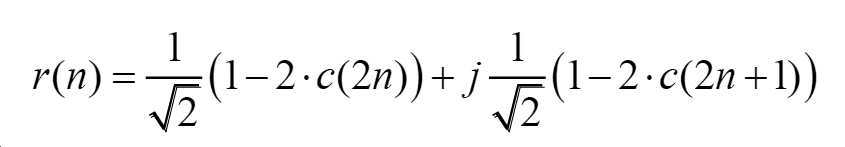
[수학식 4][Equation 4]
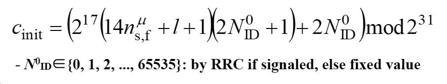
또한, 일 예로, PSSCH DMRS는 할당 위치가 변동될 수 있으며, 초기값 ![]()
![]()
![]()
![]()
![]()
![]()
![]()
![]()
![]()
![]()
![]()
![]()
![]()
![]()
[수학식 5][Equation 5]
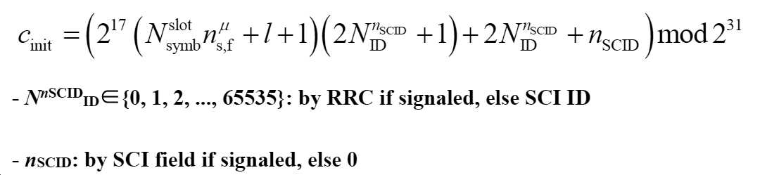
또 다른 일 예로, PSCCH DMRS와 PSSCH DMRS를 동시에 구성하는 경우를 고려할 수 있다. 일 예로, 상술한 도 7 내지 도 10 각각에서 타입 3-2의 경우를 고려할 수 있다. 즉, 동일한 심볼에서 PSCCH DMRS와 PSSCH DMRS가 할당되는 경우, PSCCH DMRS와 PSSCH DMRS를 동시에 구성할 수 있다. 다만, PSCCH DMRS와 PSSCH DMRS를 동시에 구성하는 방법에 대해서는 상술한 도 7 내지 도 10 각각에서 타입 1, 타입 2 및 타입 3-1에도 동일하게 적용될 수 있으며, 상술한 타입을 배제하는 것은 아니다. As another example, a case where PSCCH DMRS and PSSCH DMRS are simultaneously configured may be considered. As an example, a case of type 3-2 in each of the above-described FIGS. 7 to 10 may be considered. That is, when PSCCH DMRS and PSSCH DMRS are allocated in the same symbol, PSCCH DMRS and PSSCH DMRS can be configured simultaneously. However, the method of simultaneously configuring the PSCCH DMRS and the PSSCH DMRS may be applied to
이때, 도 7 내지 도 10 각각의 타입 3-2를 고려하면, 단말은 PSCCH DMRS에 대해서 우선적으로 부분 복호화하고, PSCCH를 복호화할 수 있다. 이때, PSCCH DMRS에 대한 패턴에 대한 정보는 사전에 기설정될 수 있다. 또한, 일 예로, PSCCH DMRS에 대한 패턴에 대한 정보는 사전에 시그널링을 통해 지시될 수 있다. 이때, SCI ID는 PSCCH에 포함되는 정보인바, 단말은 PSCCH를 복호화하면 SCI ID를 알 수 있다. 다음으로, PSSCH는 PSCCH DMRS 부분과 PSSCH DMRS 부분 모두를 고려하여 연속적으로 할당된 DMRS 시퀀스를 통해 채널이 추정될 수 있다. 상술한 바에 기초하여, 단말은 SCI ID를 통해 DMRS 할당 패턴을 확인할 수 있고, PSSCH는 확인된 DMRS 할당 패턴에 기초하여 PSCCH DMRS 부분과 PSSCH DMRS 부분 모두를 고려하여 연속적으로 할당된 DMRS 시퀀스를 통해 복호화 할 수 있다. 즉, 단말은 두 단계에 걸쳐서 복호화를 수행할 수 있다. 이때, PSCCH DMRS 패턴은 고정된 패턴인바, 단말은 블라인드 디코딩을 수행하지 않고, 상술한 바와 같이, 두 단계의 복호화를 통해 PSSCH에 대한 복호화를 수행할 수 있다. In this case, considering types 3-2 of FIGS. 7 to 10, the UE may preferentially partially decode the PSCCH DMRS and decode the PSCCH. At this time, the information on the pattern for the PSCCH DMRS may be preset. In addition, as an example, information about a pattern for the PSCCH DMRS may be indicated through signaling in advance. At this time, the SCI ID is information included in the PSCCH, and the terminal can know the SCI ID by decoding the PSCCH. Next, in the PSSCH, a channel may be estimated through a consecutively assigned DMRS sequence in consideration of both the PSCCH DMRS part and the PSSCH DMRS part. Based on the above, the UE can check the DMRS allocation pattern through the SCI ID, and the PSSCH is decoded through the consecutively allocated DMRS sequence considering both the PSCCH DMRS portion and the PSSCH DMRS portion based on the identified DMRS allocation pattern. can do. That is, the terminal can perform decoding in two steps. At this time, since the PSCCH DMRS pattern is a fixed pattern, the terminal does not perform blind decoding, and as described above, the PSSCH can be decoded through two steps of decoding.
이때, 일 예로, 상술한 도 11처럼 PSCCH DMRS와 PSSCH DMRS 오버헤드는 동일할 수 있으나, PSCCH DMRS 패턴과 PSSCH DMRS 패턴이 다를 수 있다. 즉, PSCCH DMRS 패턴은 고정된 패턴으로 PSSCH DMRS 패턴과 다르게 설정될 수 있다. 일 예로, PSCCH DMRS 할당 패턴은 상술한 바와 같이 고정된 패턴으로, MIMO를 고려하지 않은 경우, 하나의 PRB 내의 동일한 심볼 내에서 총 네 가지 RE에 대해서 직교 시퀀스 “[+1, +1, +1, +1]”를 설정할 수 있으며, 이는 상술한 바와 동일할 수 있다. 반면, PSCCH DMRS 할당 패턴을 MIMO를 고려하여 두 개의 안테나 패턴이 설정되는 경우, 첫 번째 안테나 포트는 하나의 PRB 내의 동일한 심볼 내의 총 네 가지의 RE에 대해서 직교 시퀀스 “[+1, +1, +1, +1]”로 설정될 수 있다. 또한, 두 번째 안테나 포트는 하나의 PRB 내의 동일한 심볼 내에서 총 네 가지 RE에 대해서 직교 시퀀스 “[+1, -1, +1, -1]”로 설정될 수 있다. 즉, 안테나 포트는 직교 시퀀스를 통해 구별될 수 있으며, 이는 상술한 바와 동일할 수 있다. At this time, as an example, as illustrated in FIG. 11, the PSCCH DMRS and PSSCH DMRS overhead may be the same, but the PSCCH DMRS pattern and the PSSCH DMRS pattern may be different. That is, the PSCCH DMRS pattern is a fixed pattern and may be set differently from the PSSCH DMRS pattern. For example, the PSCCH DMRS allocation pattern is a fixed pattern as described above. When MIMO is not considered, an orthogonal sequence “[+1, +1, +1] for all four REs within the same symbol in one PRB. , +1]”, which may be the same as described above. On the other hand, if two antenna patterns are set in consideration of the MIMO for the PSCCH DMRS allocation pattern, the first antenna port is an orthogonal sequence “[+1, +1, +] for all four REs in the same symbol in one PRB. 1, +1]”. In addition, the second antenna port may be set to an orthogonal sequence “[+1, -1, +1, -1]” for a total of four REs within the same symbol in one PRB. That is, the antenna port may be distinguished through an orthogonal sequence, which may be the same as described above.
또한, 상술한 바와 같이, PSSCH DMRS 할당 패턴도 NR V2X에서 MIMO를 지원하는지 여부에 기초하여 다르게 설정될 수 있다. 일 예로, NR V2X에서 MIMO를 지원하지 않는 경우를 고려할 수 있다. 이때, 상술한 도 11을 참조하면, MIMO를 지원하지 않은 경우, 하기 표 24 내지 표 26 중 어느 하나에 기초하여 DMRS 패턴이 결정될 수 있다.In addition, as described above, the PSSCH DMRS allocation pattern may also be set differently based on whether MIMO is supported in NR V2X. As an example, a case where MIMO is not supported in NR V2X may be considered. In this case, referring to FIG. 11 described above, when MIMO is not supported, the DMRS pattern may be determined based on any one of Tables 24 to 26 below.
[표 24]Table 24

[표 25]Table 25

[표 26]Table 26
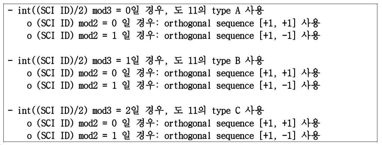
반면, 일 예로, NR V2X에서 MIMO를 지원하는 경우를 고려할 수 있다. 일 예로, SU-MIMO를 고려하는 경우를 고려할 수 있다. 이때, 일 예로, 전송 다이버시티를 고려하여 두 개의 안테나 포트를 지원하는 경우를 고려할 수 있다. 이때, 안테나 포트를 구별하기 위해 첫 번째 안테나 포트 및 두 번째 안테나 포트는 하기 표 27처럼 직교 시퀀스에 기초하여 구별될 수 있으며, 이는 상술한 바와 같다. On the other hand, as an example, a case in which MIMO is supported in NR V2X may be considered. As an example, a case in which SU-MIMO is considered may be considered. In this case, as an example, a case in which two antenna ports are supported in consideration of transmission diversity may be considered. At this time, in order to distinguish the antenna port, the first antenna port and the second antenna port may be distinguished based on an orthogonal sequence as shown in Table 27 below, as described above.
[표 27]Table 27

또한, 일 예로, 도 12처럼 PSCCH DMRS 패턴과 PSSCH DMRS 패턴이 동일할 수 있다. 이때, 도 12의 PSCCH DMRS 패턴과 도 11의 PSCCH DMRS 패턴을 비교하면 OCC를 적용하는 경우에 있어서, 도 12의 PSCCH DMRS 패턴이 효율적일 수 있다. 즉, 인접한 DMRS에 대해서 OCC 적용이 원활할 수 있는바, 도 12의 PSCCH DMRS 패턴이 효율적일 수 있다. 도 12를 참조하면, PSCCH DMRS 패턴은 고정된 패턴으로 PSSCH DMRS 패턴과 동일하게 설정될 수 있다. 일 예로, PSCCH DMRS 할당 패턴은 상술한 바와 같이 고정된 패턴으로, MIMO를 고려하지 않은 경우, 하나의 PRB 내의 동일한 심볼 내에서 총 네 가지 RE에 대해서 직교 시퀀스 “[+1, +1, +1, +1]”를 설정할 수 있으며, 이는 상술한 바와 동일할 수 있다. 반면, PSCCH DMRS 할당 패턴을 MIMO를 고려하여 두 개의 안테나 패턴이 설정되는 경우, 첫 번째 안테나 포트는 하나의 PRB 내의 동일한 심볼 내의 총 네 가지의 RE에 대해서 직교 시퀀스 “[+1, +1, +1, +1]”로 설정될 수 있다. 또한, 두 번째 안테나 포트는 하나의 PRB 내의 동일한 심볼 내에서 총 네 가지 RE에 대해서 직교 시퀀스 “[+1, -1, +1, -1]”로 설정될 수 있다. 즉, 안테나 포트는 직교 시퀀스를 통해 구별될 수 있으며, 이는 상술한 바와 동일할 수 있다. In addition, for example, as illustrated in FIG. 12, the PSCCH DMRS pattern and the PSSCH DMRS pattern may be the same. In this case, when the PSCCH DMRS pattern of FIG. 12 is compared with the PSCCH DMRS pattern of FIG. 11, when the OCC is applied, the PSCCH DMRS pattern of FIG. 12 may be efficient. That is, since the application of the OCC to the adjacent DMRS may be smooth, the PSCCH DMRS pattern of FIG. 12 may be efficient. Referring to FIG. 12, the PSCCH DMRS pattern is a fixed pattern and may be set to be the same as the PSSCH DMRS pattern. For example, the PSCCH DMRS allocation pattern is a fixed pattern as described above. When MIMO is not considered, an orthogonal sequence “[+1, +1, +1] for all four REs within the same symbol in one PRB. , +1]”, which may be the same as described above. On the other hand, if two antenna patterns are set in consideration of the MIMO for the PSCCH DMRS allocation pattern, the first antenna port is an orthogonal sequence “[+1, +1, +] for all four REs in the same symbol in one PRB. 1, +1]”. In addition, the second antenna port may be set to an orthogonal sequence “[+1, -1, +1, -1]” for a total of four REs within the same symbol in one PRB. That is, the antenna port may be distinguished through an orthogonal sequence, which may be the same as described above.
또한, 상술한 바와 같이, PSSCH DMRS 할당 패턴도 NR V2X에서 MIMO를 지원하는지 여부에 기초하여 다르게 설정될 수 있다. 일 예로, NR V2X에서 MIMO를 지원하지 않는 경우를 고려할 수 있다. 이때, 도 12을 참조하면, MIMO를 지원하지 않은 경우, 하기 표 28 내지 표 30 중 어느 하나에 기초하여 DMRS 패턴이 결정될 수 있다. In addition, as described above, the PSSCH DMRS allocation pattern may also be set differently based on whether MIMO is supported in NR V2X. As an example, a case where MIMO is not supported in NR V2X may be considered. At this time, referring to FIG. 12, when MIMO is not supported, the DMRS pattern may be determined based on any one of Tables 28 to 30 below.
[표 28]Table 28

[표 29]Table 29

[표 30]Table 30
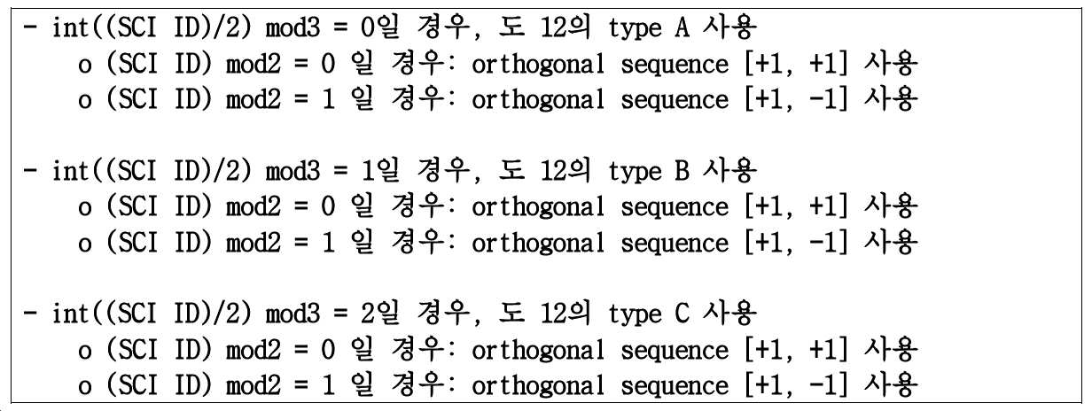
반면, 일 예로, NR V2X에서 MIMO를 지원하는 경우를 고려할 수 있다. 일 예로, SU-MIMO를 고려하는 경우를 고려할 수 있다. 이때, 일 예로, 전송 다이버시티를 고려하여 두 개의 안테나 포트를 지원하는 경우를 고려할 수 있다. 이때, 안테나 포트를 구별하기 위해 첫 번째 안테나 포트 및 두 번째 안테나 포트는 하기 표 31처럼 직교 시퀀스에 기초하여 구별될 수 있으며, 이는 상술한 바와 같다. On the other hand, as an example, a case in which MIMO is supported in NR V2X may be considered. As an example, a case in which SU-MIMO is considered may be considered. In this case, as an example, a case in which two antenna ports are supported in consideration of transmission diversity may be considered. At this time, in order to distinguish the antenna port, the first antenna port and the second antenna port may be distinguished based on an orthogonal sequence as shown in Table 31 below, as described above.
[표 31]Table 31

한편, 일 예로, PSCCH DMRS는 상술한 바와 다르게 변동되는 위치일 수 있다. 이때, 도 7 내지 도 10 각각의 타입 3-2를 고려하면, PSCCH DMRS 패턴 위치는 SCI ID에 따라 PSSCH DMRS의 패턴처럼 세 가지 타입으로 변화될 수 있다. 따라서, PSCCH DMRS와 PSSCH DMRS를 동시에 복호하여 PSCCH 및 PSSCH의 채널 추정이 가능할 수 있다. 즉, PSCCH DMRS와 PSSCH DMRS를 동시에 복호하는바, 상술한 바처럼 두 단계의 복호가 필요하지 않고 한번에 복호가 수행될 수 있다. 다만, SCI ID는 PSCCH에 포함되는 정보이고, 단말은 이를 확인할 수 없는바, PSCCH DMRS에 대해서 블라인드 디코딩이 수행될 수 있다. 또한, 일 예로, PSCCH를 통해 전송되는 SCI ID는 (SCI ID)/3의 정수 값(즉, int((SCI ID)/3)만 전송할 수 있는바, 전송 비트 값을 줄일 수 있다. On the other hand, as an example, the PSCCH DMRS may be a position that varies differently from the above. At this time, considering the types 3-2 of FIGS. 7 to 10, the PSCCH DMRS pattern position may be changed to three types, such as the pattern of the PSSCH DMRS according to the SCI ID. Accordingly, PSCCH DMRS and PSSCH DMRS may be simultaneously decoded to estimate the channels of PSCCH and PSSCH. That is, since the PSCCH DMRS and the PSSCH DMRS are simultaneously decoded, two steps of decoding are not required and decoding can be performed at once. However, the SCI ID is information included in the PSCCH, and since the terminal cannot confirm it, blind decoding may be performed on the PSCCH DMRS. In addition, as an example, since the SCI ID transmitted through the PSCCH can transmit only an integer value of (SCI ID)/3 (that is, int((SCI ID)/3), the transmission bit value can be reduced.
이때, 일 예로, 도 13을 참조하면, 상술한 바와 같이, PSCCH DMRS의 위치는 PSSCH DMRS처럼 변동될 수 있으나, PSCCH DMRS와 PSSCH DMRS의 패턴이 다를 수 있다. 일 예로, PSCCH DMRS와 PSSCH DMRS 오버헤드는 동일할 수 있으나, 도 13처럼 패턴이 다를 수 있다. 일 예로, PSCCH DMRS 위치는 PSSCH와 오버헤드를 동일하게 하기 위해 상술한 바처럼 DMRS 설정 2(DMRS Configuration type 2)를 고려하여 하기 표 32 및 표 33과 같이 설정될 수 있다. 일 예로, 표 32는 MIMO를 고려하지 않은 경우로서 직교 시퀀스가 동일하게 설정될 수 있다. 반면, 표 33은 MIMO를 고려한 경우로서 두 개의 안테나 포트가 구별되는 경우에 기초한 방법일 수 있다. 이때, 일 예로, SU-MIMO를 고려하는 경우, PSSCH DMRS만 SU-MIMO 고려할 수도 있다. 이때, 일 예로, 상술한 경우에는 PSCCH DMRS가 상술한 표 32에 기초하여 할당될 수 있으며, 상술한 실시예로 한정되지 않는다. At this time, as an example, referring to FIG. 13, as described above, the position of the PSCCH DMRS may be varied like the PSSCH DMRS, but the patterns of the PSCCH DMRS and the PSSCH DMRS may be different. For example, PSCCH DMRS and PSSCH DMRS overhead may be the same, but the pattern may be different as shown in FIG. 13. For example, the PSCCH DMRS location may be set as shown in Tables 32 and 33 in consideration of
[표 32]Table 32

[표 33]Table 33
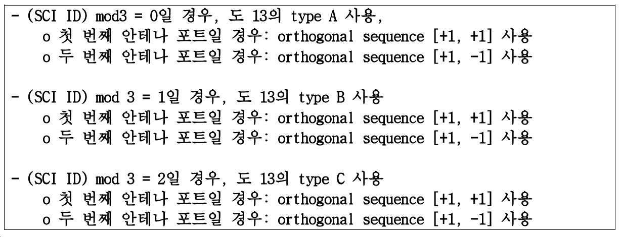
또 다른 일 예로, 도 14를 참조하면, 상술한 바와 같이, PSCCH DMRS의 위치는 PSSCH DMRS처럼 변동될 수 있고, PSCCH DMRS와 PSSCH DMRS의 패턴이 동일할 수 있다. 이때, 도 14의 PSCCH DMRS 패턴과 도 13의 PSCCH DMRS 패턴을 비교하면 OCC를 적용하는 경우에 있어서, 도 14의 PSCCH DMRS 패턴이 효율적일 수 있다. 즉, 인접한 DMRS에 대해서 OCC 적용이 원활할 수 있는바, 도 14의 PSCCH DMRS 패턴이 효율적일 수 있다. 또한, 도 14의 PSCCH DMRS 패턴은 DMRS 시퀀스가 도 13의 경우보다 균일한 배치일 수 있는바, 도 13보다 성능면에서 우수할 수 있다. 즉, 도 14를 참조하면, PSCCH DMRS 패턴은 PSSCH DMRS 패턴과 동일하게 설정될 수 있다. 이때, 일 예로, PSCCH DMRS 위치는 PSSCH와 오버헤드를 동일하게 하기 위해 상술한 바처럼 DMRS 설정 2(DMRS Configuration type 2)를 고려하여 하기 표 34 및 표 35과 같이 설정될 수 있다. 일 예로, 표 34는 MIMO를 고려하지 않은 경우로서 직교 시퀀스가 동일하게 설정될 수 있다. 반면, 표 35은 MIMO를 고려한 경우로서 두 개의 안테나 포트가 구별되는 경우에 기초한 방법일 수 있다. 이때, 일 예로, SU-MIMO를 고려하는 경우, PSSCH DMRS만 SU-MIMO 고려할 수도 있다. 이때, 일 예로, 상술한 경우에는 PSCCH DMRS가 상술한 표 34에 기초하여 할당될 수 있으며, 상술한 실시예로 한정되지 않는다. As another example, referring to FIG. 14, as described above, the position of the PSCCH DMRS may be varied like the PSSCH DMRS, and the patterns of the PSCCH DMRS and the PSSCH DMRS may be the same. In this case, when the PSCCH DMRS pattern of FIG. 14 is compared with the PSCCH DMRS pattern of FIG. 13, when the OCC is applied, the PSCCH DMRS pattern of FIG. 14 may be efficient. That is, since the application of the OCC to the adjacent DMRS may be smooth, the PSCCH DMRS pattern of FIG. 14 may be efficient. In addition, since the PSCCH DMRS pattern of FIG. 14 may have a more uniform arrangement of the DMRS sequence than that of FIG. 13, it may be superior in performance to FIG. 13. That is, referring to FIG. 14, the PSCCH DMRS pattern may be set to be the same as the PSSCH DMRS pattern. In this case, as an example, the PSCCH DMRS location may be set as shown in Tables 34 and 35 in consideration of
[표 34]Table 34

[표 35]Table 35

이 때, 일 예로, PSCCH DMRS 및 PSSCH DMRS를 동시에 구성하는 경우, DMRS 시퀀스는 상술한 수학식 3에 기초하여 결정될 수 있다. 일 예로, PSCCH DMRS 및 PSSCH DMRS는 각 심볼에 대해서 PSCCH 및/또는 PSSCH가 할당되어 있는 모든 PRB들에 대해서 연속적으로 할당될 수 있다. 이때, 일 예로, 초기값 ![]()

![]()
![]()

![]()
![]()
![]()
[수학식 6][Equation 6]

도 15는 PSCCH DMRS와 PSSCH DMRS가 동시에 구성되는 경우로서 PSCCH DMRS 패턴 위치가 고정된 경우를 나타낸 도면이다.15 is a view showing a case where the PSCCH DMRS pattern position is fixed as the case where the PSCCH DMRS and the PSSCH DMRS are configured at the same time.
도 15를 참조하면, 단말은 사이드링크 전송을 위한 DMRS 관련 정보를 획득할 수 있다.(S1510) 일 예로, 단말은 기지국으로부터 RRC 시그널링 또는 DCI를 통해 사이드링크 전송을 위한 DMRS 관련 정보를 획득할 수 있다. 또한, 일 예로, DMRS 관련 정보는 단말에 기설정될 수 있으며, 상술한 실시예로 한정되지 않는다. 이때, PSCCH DMRS와 PSCCH DMRS가 동시에 구성되는 경우로서 PSSCH DMRS 패턴 위치가 고정된 경우, 단말은 PSCCH DMRS 복호를 먼저 수행할 수 있다.(S1520) 즉, 상술한 도 7 내지 도 10의 타입 3-2와 같이 동일한 심볼에 PSCCH DMRS와 PSSCH DMRS가 동시에 구성된 경우로서 PSSCH DMRS 패턴 위치가 고정된 경우에는 PSCCH DMRS 복호를 먼저 수행할 수 있다. 그 후, 단말은 복호화된 PSCCH DMRS에 기초하여 PSCCH를 복호하고, PSCCH에 포함되는 SCI ID 정보를 획득할 수 있다.(S1530) 단말은 DMRS 관련 정보를 수신하여, PSCCH DMRS에 대한 복호를 수행하고, 이에 기초하여 PSCCH로부터 SCI ID 정보를 획득할 수 있다. 이때, 일 예로, 상술한 바와 같이, PSSCH DMRS 할당 패턴은 변동될 수 있다. 일 예로, PSSCH DMRS 할당 패턴은 상술한 바와 같이 DMRS 설정 타입 2(DMRS Configuration type 2)에 기초하여 설정될 수 있으나. 이에 한정되지 않는다. 이때, 단말은 획득한 SCI ID를 통해 PSSCH DMRS 패턴을 확인할 수 있다.(S1540) 즉, 상술한 바와 같이 PSSCH DMRS 패턴은 SCI ID에 기초하여 설정될 수 있으며, 이는 상술한 바와 같다. 다음으로, 단말은 PSSCH를 PSCCH DMRS 및 PSSCH DMRS 모두 이용하여 복호할 수 있다.(S1550) 즉, 단말은 PSCCH DMRS 부분과 PSSCH DMRS 부분 모두 연속적으로 할당된 DMRS 시퀀스를 통해 PSSCH에 대한 채널 추정을 수행할 수 있다. 단말은 상술한 바처럼 두 단계의 복호 과정을 수행할 수 있다.Referring to FIG. 15, the terminal may acquire DMRS-related information for sidelink transmission. (S1510) For example, the terminal may obtain DMRS-related information for sidelink transmission through RRC signaling or DCI from a base station. have. In addition, as an example, DMRS-related information may be preset in the terminal, and is not limited to the above-described embodiment. At this time, when the PSCCH DMRS and the PSCCH DMRS are configured at the same time, and the PSSCH DMRS pattern position is fixed, the UE may first perform PSCCH DMRS decoding. (S1520) That is, the type 3 of FIGS. 7 to 10 described above When PSCCH DMRS and PSSCH DMRS are simultaneously configured in the same symbol as in FIG. 2, and the PSSCH DMRS pattern position is fixed, PSCCH DMRS decoding may be performed first. Thereafter, the UE can decode the PSCCH based on the decoded PSCCH DMRS and obtain SCI ID information included in the PSCCH. (S1530) The UE receives DMRS-related information and performs decoding on the PSCCH DMRS, , Based on this, it is possible to obtain SCI ID information from the PSCCH. At this time, as an example, as described above, the PSSCH DMRS allocation pattern may be changed. For example, the PSSCH DMRS allocation pattern may be set based on
도 16은 PSCCH DMRS와 PSSCH DMRS가 동시에 구성되는 경우로서 PSCCH DMRS 패턴 위치가 변동되는 경우를 나타낸 도면이다.FIG. 16 is a diagram illustrating a case where PSCCH DMRS pattern positions are changed as PSCCH DMRS and PSSCH DMRS are configured simultaneously.
도 16을 참조하면, 단말은 사이드링크 전송을 위한 DMRS 관련 정보를 획득할 수 있다.(S1610) 이때, 단말은 기지국으로부터 RRC 시그널링 또는 DCI를 통해 사이드링크 전송을 위한 DMRS 관련 정보를 획득할 수 있다. 또한, 일 예로, DMRS 관련 정보는 단말에 기설정될 수 있으며, 상술한 실시예로 한정되지 않는다. 이때, PSCCH DMRS와 PSCCH DMRS가 동시에 구성되는 경우로서 PSSCH DMRS 패턴 위치가 변동되는 경우, 단말은 PSCCH DMRS 및 PSSCH DMRS를 동시에 복호할 수 있다.(S1620) 이때, 일 예로, 상술한 바처럼 PSCCH DMRS 역시 PSSCH DMRS와 마찬가지로 SCI ID에 따라서 할당 패턴이 변동될 수 있으며, 이는 상술한 바와 같다. 이때, 단말은 동시에 PSCCH DMRS 및 PSSCH DMRS를 복호할 수 있다. 다만, PSCCH도 할당 패턴이 변동될 수 있는바, 블라인드 디코딩이 필요할 수 있다. 다음으로, 단말은 복호화된 PSCCH DMRS를 이용하여 PSCCH를 복호화하고, PSCCH DMRS 및 PSSCH DMRS를 이용하여 PSSCH를 복호화할 수 있다.(S1630)Referring to FIG. 16, the terminal may acquire DMRS-related information for sidelink transmission. (S1610) At this time, the terminal may obtain DMRS-related information for sidelink transmission through RRC signaling or DCI from the base station. . In addition, as an example, DMRS-related information may be preset in the terminal, and is not limited to the above-described embodiment. In this case, when the PSCCH DMRS and the PSCCH DMRS are configured simultaneously and the PSSCH DMRS pattern position changes, the UE may simultaneously decode the PSCCH DMRS and the PSSCH DMRS. (S1620) At this time, as an example, the PSCCH DMRS as described above As in the case of PSSCH DMRS, the allocation pattern may be changed according to the SCI ID, as described above. At this time, the UE can simultaneously decode the PSCCH DMRS and PSSCH DMRS. However, since the allocation pattern may also change in the PSCCH, blind decoding may be required. Next, the UE can decode the PSCCH using the decoded PSCCH DMRS, and the PSSCH using the PSCCH DMRS and the PSSCH DMRS. (S1630)
도 17는 본 개시에 따른 기지국 장치 및 단말 장치의 구성을 나타내는 도면이다.17 is a view showing the configuration of a base station apparatus and a terminal apparatus according to the present disclosure.
기지국 장치(1700)는 프로세서(1710), 안테나부(1720), 트랜시버(1730), 메모리(1740)를 포함할 수 있다. The
프로세서(1710)는 베이스밴드 관련 신호 처리를 수행하며, 상위계층 처리부(1711) 및 물리계층 처리부(1712)를 포함할 수 있다. 상위계층 처리부(1711)는 MAC(Medium Access Control) 계층, RRC(Radio Resource Control) 계층, 또는 그 이상의 상위계층의 동작을 처리할 수 있다. 물리계층 처리부(1712)는 물리(physical, PHY) 계층의 동작(예를 들어, 상향링크 수신 신호 처리, 하향링크 송신 신호 처리, 사이드링크 송신 신호 처리, 사이드링크 수신 신호 처리)을 처리할 수 있다. 프로세서(1710)는 베이스밴드 관련 신호 처리를 수행하는 것 외에도, 기지국 장치(1700) 전반의 동작을 제어할 수도 있다.The processor 1710 performs baseband-related signal processing, and may include an upper layer processor 1711 and a
안테나부(1720)는 하나 이상의 물리적 안테나를 포함할 수 있고, 복수개의 안테나를 포함하는 경우 MIMO(Multiple Input Multiple Output) 송수신을 지원할 수 있다. 트랜시버(1730)는 무선 주파수(RF) 송신기와 RF 수신기를 포함할 수 있다. 메모리(1740)는 프로세서(1710)의 연산 처리된 정보, 기지국 장치(1700)의 동작에 관련된 소프트웨어, 운영체제, 애플리케이션 등을 저장할 수 있으며, 버퍼 등의 구성요소를 포함할 수도 있다.The
기지국(1700)의 프로세서(1710)는 본 발명에서 설명하는 실시예들에서의 기지국의 동작을 구현하도록 설정될 수 있다. The processor 1710 of the
단말 장치(1750)는 프로세서(1760), 안테나부(1770), 트랜시버(1780), 메모리(1790)를 포함할 수 있다. 한편, 일 예로, 본 발명에서는 사이드링크 통신에 기초하여 단말 장치들 간의 통신이 수행될 수 있다. 즉, 본 발명에서 사이드링크 통신을 수행하는 각각의 단말 장치(1750)는 기지국 장치(1700)뿐만 아니라 단말 장치(1750)와 사이드링크 통신을 수행하는 장치일 수 있으며, 상술한 실시예로 한정되지 않는다.The
프로세서(1760)는 베이스밴드 관련 신호 처리를 수행하며, 상위계층 처리부(1761) 및 물리계층 처리부(1762)를 포함할 수 있다. 상위계층 처리부(1761)는 MAC 계층, RRC 계층, 또는 그 이상의 상위계층의 동작을 처리할 수 있다. 물리계층 처리부(1762)는 PHY 계층의 동작(예를 들어, 하향링크 수신 신호 처리, 상향링크 송신 신호 처리, 사이드링크 송신 신호 처리, 사이드링크 수신 신호 처리)을 처리할 수 있다. 프로세서(1760)는 베이스밴드 관련 신호 처리를 수행하는 것 외에도, 단말 장치(1750) 전반의 동작을 제어할 수도 있다.The processor 1760 performs baseband-related signal processing, and may include an upper layer processing unit 1801 and a physical
안테나부(1770)는 하나 이상의 물리적 안테나를 포함할 수 있고, 복수개의 안테나를 포함하는 경우 MIMO 송수신을 지원할 수 있다. 트랜시버(1780)는 RF 송신기와 RF 수신기를 포함할 수 있다. 메모리(1790)는 프로세서(1760)의 연산 처리된 정보, 단말 장치(1750)의 동작에 관련된 소프트웨어, 운영체제, 애플리케이션 등을 저장할 수 있으며, 버퍼 등의 구성요소를 포함할 수도 있다.The
단말 장치(1750)의 프로세서(1760)는 본 발명에서 설명하는 실시예들에서의 단말의 동작을 구현하도록 설정될 수 있다. The processor 1760 of the
기지국 장치(1700) 및 단말 장치(1750)의 동작에 있어서 본 발명의 예시들에서 설명한 사항이 동일하게 적용될 수 있으며, 중복되는 설명은 생략한다.In the operation of the
본 개시의 예시적인 방법들은 설명의 명확성을 위해서 동작의 시리즈로 표현되어 있지만, 이는 단계가 수행되는 순서를 제한하기 위한 것은 아니며, 필요한 경우에는 각각의 단계가 동시에 또는 상이한 순서로 수행될 수도 있다. 본 개시에 따른 방법을 구현하기 위해서, 예시하는 단계에 추가적으로 다른 단계를 포함하거나, 일부의 단계를 제외하고 나머지 단계를 포함하거나, 또는 일부의 단계를 제외하고 추가적인 다른 단계를 포함할 수도 있다. Exemplary methods of the present disclosure are expressed as a series of operations for clarity of description, but are not intended to limit the order in which the steps are performed, and each step may be performed simultaneously or in a different order if necessary. In order to implement the method according to the present disclosure, the steps illustrated may include other steps in addition, other steps may be included in addition to the other steps, or other additional steps may be included in addition to some steps.
본 개시의 다양한 실시예는 모든 가능한 조합을 나열한 것이 아니고 본 개시의 대표적인 양상을 설명하기 위한 것이며, 다양한 실시예에서 설명하는 사항들은 독립적으로 적용되거나 또는 둘 이상의 조합으로 적용될 수도 있다. The various embodiments of the present disclosure are not intended to list all possible combinations, but are intended to describe representative aspects of the present disclosure, and the details described in various embodiments may be applied independently or in combination of two or more.
또한, 본 개시의 다양한 실시예는 하드웨어, 펌웨어(firmware), 소프트웨어, 또는 그들의 결합 등에 의해 구현될 수 있다. 하드웨어에 의한 구현의 경우, 하나 또는 그 이상의 ASICs(Application Specific Integrated Circuits), DSPs(Digital Signal Processors), DSPDs(Digital Signal Processing Devices), PLDs(Programmable Logic Devices), FPGAs(Field Programmable Gate Arrays), 범용 프로세서(general processor), 컨트롤러, 마이크로 컨트롤러, 마이크로 프로세서 등에 의해 구현될 수 있다. Further, various embodiments of the present disclosure may be implemented by hardware, firmware, software, or a combination thereof. For implementation by hardware, one or more Application Specific Integrated Circuits (ASICs), Digital Signal Processors (DSPs), Digital Signal Processing Devices (DSPDs), Programmable Logic Devices (PLDs), Field Programmable Gate Arrays (FPGAs), Universal It can be implemented by a processor (general processor), a controller, a microcontroller, a microprocessor.
본 개시의 범위는 다양한 실시예의 방법에 따른 동작이 장치 또는 컴퓨터 상에서 실행되도록 하는 소프트웨어 또는 머신-실행가능한 명령들(예를 들어, 운영체제, 애플리케이션, 펌웨어(firmware), 프로그램 등), 및 이러한 소프트웨어 또는 명령 등이 저장되어 장치 또는 컴퓨터 상에서 실행 가능한 비-일시적 컴퓨터-판독가능 매체(non-transitory computer-readable medium)를 포함한다. The scope of the present disclosure includes software or machine-executable instructions (eg, operating systems, applications, firmware, programs, etc.) that cause actions according to the methods of various embodiments to be executed on a device or computer, and such software or Instructions include a non-transitory computer-readable medium that is stored and executable on a device or computer.
기지국 : 1700
프로세서 : 1710
상위 계층 처리부 : 1711 물리 계층 처리부 : 1712
안테나부 : 1720
트랜시버 : 1730
메모리 : 1740
단말 : 1750
프로세서 : 1760
상위 계층 처리부 : 1761
물리 계층 처리부 : 1762
안테나부 : 1770
트랜시버 : 1780
메모리 : 1790Base station: 1700 Processor: 1710
Upper layer processing unit: 1711 Physical layer processing unit: 1712
Antenna part: 1720 Transceiver: 1730
Memory: 1740 Terminal: 1750
Processor: 1760 Upper layer processing unit: 1761
Physical layer processing unit: 1762 Antenna unit: 1770
Transceiver: 1780 Memory: 1790
Claims (1)
DMRS(Demodulation Reference Signal) 관련 정보를 획득하는 단계;
PSCCH(Physical Sidelink Control Channel) DMRS 및 PSSCH (Physical Sidelink Shared Channel) DMRS를 동시에 복호하는 단계; 및
상기 복호화된 PSCCH DMRS에 기초하여 PSCCH를 복호하고, 상기 복호화된 PSCCH DMRS 및 PSSCH DMRS에 기초하여 PSSCH를 복호하는, 통신 방법.
In the method for the first terminal to communicate with the second terminal through the side link,
Obtaining information related to a Demodulation Reference Signal (DMRS);
Decoding PSCCH (Physical Sidelink Control Channel) DMRS and PSSCH (Physical Sidelink Shared Channel) DMRS simultaneously; And
A PSCCH is decoded based on the decoded PSCCH DMRS, and a PSSCH is decoded based on the decoded PSCCH DMRS and PSSCH DMRS.
Priority Applications (6)
| Application Number | Priority Date | Filing Date | Title |
|---|---|---|---|
| KR1020190004205A KR20200087630A (en) | 2019-01-11 | 2019-01-11 | Method and apparatus for indicating information related to dmrs in wireless communication system |
| EP20738741.6A EP3910850A4 (en) | 2019-01-11 | 2020-01-08 | Method and apparatus for configuring dmrs in wireless communication system |
| PCT/KR2020/000341 WO2020145662A1 (en) | 2019-01-11 | 2020-01-08 | Method and apparatus for configuring dmrs in wireless communication system |
| CN202080008680.5A CN113287280A (en) | 2019-01-11 | 2020-01-08 | Method and apparatus for configuring DMRS in wireless communication system |
| US17/242,752 US20210250216A1 (en) | 2019-01-11 | 2021-04-28 | Method and apparatus for configuring dmrs in wireless communication system |
| US17/242,619 US20210250912A1 (en) | 2019-01-11 | 2021-04-28 | Method and apparatus for configuring dmrs in wireless communication system |
Applications Claiming Priority (1)
| Application Number | Priority Date | Filing Date | Title |
|---|---|---|---|
| KR1020190004205A KR20200087630A (en) | 2019-01-11 | 2019-01-11 | Method and apparatus for indicating information related to dmrs in wireless communication system |
Publications (1)
| Publication Number | Publication Date |
|---|---|
| KR20200087630A true KR20200087630A (en) | 2020-07-21 |
Family
ID=71521391
Family Applications (1)
| Application Number | Title | Priority Date | Filing Date |
|---|---|---|---|
| KR1020190004205A KR20200087630A (en) | 2019-01-11 | 2019-01-11 | Method and apparatus for indicating information related to dmrs in wireless communication system |
Country Status (5)
| Country | Link |
|---|---|
| US (2) | US20210250216A1 (en) |
| EP (1) | EP3910850A4 (en) |
| KR (1) | KR20200087630A (en) |
| CN (1) | CN113287280A (en) |
| WO (1) | WO2020145662A1 (en) |
Families Citing this family (2)
| Publication number | Priority date | Publication date | Assignee | Title |
|---|---|---|---|---|
| KR20200087630A (en) * | 2019-01-11 | 2020-07-21 | 주식회사 아이티엘 | Method and apparatus for indicating information related to dmrs in wireless communication system |
| US20220070869A1 (en) * | 2020-08-25 | 2022-03-03 | Qualcomm Incorporated | Crc scrambling for sci in nr sidelink |
Family Cites Families (30)
| Publication number | Priority date | Publication date | Assignee | Title |
|---|---|---|---|---|
| WO2015122629A1 (en) * | 2014-02-11 | 2015-08-20 | 엘지전자(주) | Method for transmitting/receiving signal in wireless communication system, and apparatus therefor |
| WO2015163662A1 (en) * | 2014-04-21 | 2015-10-29 | 엘지전자(주) | Method for transmitting and receiving downlink control information in wireless communication system supporting device-to-device communication and device therefor |
| WO2016117922A1 (en) * | 2015-01-20 | 2016-07-28 | 엘지전자 주식회사 | Method for selecting neighboring ue to perform d2d communication |
| US20160295624A1 (en) * | 2015-04-02 | 2016-10-06 | Samsung Electronics Co., Ltd | Methods and apparatus for resource pool design for vehicular communications |
| US10491354B2 (en) * | 2015-06-23 | 2019-11-26 | Electronics And Telecommunications Research Institute | Method and apparatus for transmitting data in direct device-to-device communication |
| WO2017010767A1 (en) * | 2015-07-12 | 2017-01-19 | 엘지전자 주식회사 | Method for transmitting or receiving d2d signal in wireless communication system and device therefor |
| EP3737026B1 (en) * | 2015-08-12 | 2023-08-16 | Apple Inc. | Demodulation in wireless communications |
| CN115297453B (en) * | 2015-09-24 | 2023-09-12 | 苹果公司 | V2X performance enhancement method and device in high-speed environment |
| US10383147B2 (en) * | 2015-12-28 | 2019-08-13 | Samsung Electronics Co., Ltd. | Methods and apparatus for resource collision avoidance in vehicle to vehicle communication |
| US10506402B2 (en) * | 2016-03-31 | 2019-12-10 | Samsung Electronics Co., Ltd. | Method and apparatus for transmission of control and data in vehicle to vehicle communication |
| JP2019149593A (en) * | 2016-07-15 | 2019-09-05 | シャープ株式会社 | Terminal and method |
| US11095411B2 (en) * | 2016-08-12 | 2021-08-17 | Qualcomm Incorporated | Demodulation reference signal design for vehicle-to-vehicle communication |
| CN108307535B (en) * | 2016-08-25 | 2021-05-07 | 北京三星通信技术研究有限公司 | Method and device for transmitting data |
| US10038979B1 (en) * | 2017-01-31 | 2018-07-31 | Qualcomm Incorporated | System and method for ranging-assisted positioning of vehicles in vehicle-to-vehicle communications |
| CN115460697A (en) * | 2017-03-23 | 2022-12-09 | 苹果公司 | Method, user equipment and storage medium for transmission side link transmission |
| WO2019134096A1 (en) * | 2018-01-04 | 2019-07-11 | Oppo广东移动通信有限公司 | Method for transmitting data in internet of vehicles, and terminal device and network device |
| US10681722B2 (en) * | 2018-04-17 | 2020-06-09 | Huawei Technologies Co., Ltd. | Method for communication and an apparatus thereof |
| US11044748B2 (en) * | 2018-05-01 | 2021-06-22 | Huawei Technologies Co., Ltd. | Methods and apparatus for sidelink communications and resource allocation |
| US11303399B2 (en) * | 2018-05-11 | 2022-04-12 | At&T Intellectual Property I, L.P. | Reference signal transmission scheme for non-orthogonal multiple access systems |
| US10925054B2 (en) * | 2018-05-14 | 2021-02-16 | Apple Inc. | Configurable resynchronization signal (RSS) for machine type communication (MTC) in new radio (NR) systems |
| KR102647886B1 (en) * | 2018-05-16 | 2024-03-14 | 삼성전자주식회사 | Method and apparatus for configuration of demodulation reference siganl information in vehicle-to-everything system |
| WO2020035983A1 (en) * | 2018-08-17 | 2020-02-20 | Nec Corporation | System and method for vehicular data communication |
| CN112385252A (en) * | 2018-11-01 | 2021-02-19 | 松下电器(美国)知识产权公司 | Transmitting apparatus, receiving apparatus and method thereof |
| KR20200050853A (en) * | 2018-11-02 | 2020-05-12 | 삼성전자주식회사 | A method and apparatus for automatic gain control in vehicle-to-everything |
| KR20200087630A (en) * | 2019-01-11 | 2020-07-21 | 주식회사 아이티엘 | Method and apparatus for indicating information related to dmrs in wireless communication system |
| KR20200087698A (en) * | 2019-01-11 | 2020-07-21 | 주식회사 아이티엘 | Method and apparatus for determining sidelink physical layer session identification in new radio vehicle to everything system |
| EP3955502A4 (en) * | 2019-05-02 | 2022-06-15 | LG Electronics Inc. | Method for transmitting and receiving phase tracking reference signal in wireless communication system, and apparatus therefor |
| EP3952191B1 (en) * | 2019-05-03 | 2023-09-06 | LG Electronics Inc. | Method and device for transmitting sidelink reference signal in nr v2x |
| CN114982179B (en) * | 2019-11-20 | 2023-11-10 | Lg电子株式会社 | Method and device for transmitting reference signal in NR V2X |
| US20220070869A1 (en) * | 2020-08-25 | 2022-03-03 | Qualcomm Incorporated | Crc scrambling for sci in nr sidelink |
-
2019
- 2019-01-11 KR KR1020190004205A patent/KR20200087630A/en active Search and Examination
-
2020
- 2020-01-08 CN CN202080008680.5A patent/CN113287280A/en active Pending
- 2020-01-08 WO PCT/KR2020/000341 patent/WO2020145662A1/en unknown
- 2020-01-08 EP EP20738741.6A patent/EP3910850A4/en active Pending
-
2021
- 2021-04-28 US US17/242,752 patent/US20210250216A1/en active Pending
- 2021-04-28 US US17/242,619 patent/US20210250912A1/en active Pending
Also Published As
| Publication number | Publication date |
|---|---|
| US20210250912A1 (en) | 2021-08-12 |
| EP3910850A4 (en) | 2022-10-12 |
| US20210250216A1 (en) | 2021-08-12 |
| CN113287280A (en) | 2021-08-20 |
| WO2020145662A1 (en) | 2020-07-16 |
| EP3910850A1 (en) | 2021-11-17 |
Similar Documents
| Publication | Publication Date | Title |
|---|---|---|
| JP7285887B2 (en) | A method for a terminal to transmit data to another terminal in a wireless communication system | |
| US20210235420A1 (en) | Method for performing sidelink communication and device therefor | |
| US11540210B2 (en) | Method for transmitting and receiving downlink channel for MTC terminal, and apparatus therefor | |
| JP6907330B2 (en) | V2X communication method of terminal in wireless communication system and terminal using the above method | |
| CN108476521B (en) | Method and apparatus for transmitting or receiving control information in wireless communication system | |
| EP3100563B1 (en) | Time domain multiplexing ul transmission on multiple serving cells for a mobile station with single transmitter | |
| JP6235095B2 (en) | Method and apparatus for multiplexing a downlink control channel by a base station in a wireless communication system | |
| JP5222859B2 (en) | Scheduling information transmission method in TDD system | |
| US11722915B2 (en) | V2X communication performance method performed by V2X terminal in wireless communication system, and terminal using the method | |
| CN105451211B (en) | Method and apparatus for device-to-device communication | |
| CN112930658A (en) | Method and apparatus for performing HARQ feedback process in NR V2X system | |
| CN110249678B (en) | Method and apparatus for measuring and transmitting channel occupancy CR by terminal in wireless communication system | |
| US11848784B2 (en) | Method and apparatus for performing HARQ operation | |
| CN105340198A (en) | Method and apparatus for acquiring control information in wireless communication system | |
| KR102246695B1 (en) | A method of performing V2X communication performed by a V2X terminal in a wireless communication system and a terminal using the method | |
| US8886238B2 (en) | Method of allocating radio resource in wireless communication system | |
| KR20230019999A (en) | Sounding feedback utilizing shortened frame structures | |
| US20230082998A1 (en) | Method for transmitting and receiving downlink channel for mtc terminal, and apparatus therefor | |
| CN108702280B (en) | Method for establishing uplink data channel based on shared demodulation reference signal and apparatus thereof | |
| US20210250912A1 (en) | Method and apparatus for configuring dmrs in wireless communication system | |
| KR20190139624A (en) | Method and apparatus of indicating information related to dmrs for v2x in new radio system | |
| CN116134765A (en) | Side chain HARQ feedback control method and equipment thereof | |
| KR20200050821A (en) | Method and apparatus for configurations of resource pool for sidelink in nr system | |
| KR20200050820A (en) | Method and apparatus for transmitting and receiving harq feedback procedure in new radio vehicle to everything system | |
| JP2012516619A (en) | Method and apparatus for transmitting uplink control signal in wireless communication system |
Legal Events
| Date | Code | Title | Description |
|---|---|---|---|
| A201 | Request for examination |