KR20200086786A - Light sensor, display device including the same, and driving method of display device - Google Patents
Light sensor, display device including the same, and driving method of display device Download PDFInfo
- Publication number
- KR20200086786A KR20200086786A KR1020190002921A KR20190002921A KR20200086786A KR 20200086786 A KR20200086786 A KR 20200086786A KR 1020190002921 A KR1020190002921 A KR 1020190002921A KR 20190002921 A KR20190002921 A KR 20190002921A KR 20200086786 A KR20200086786 A KR 20200086786A
- Authority
- KR
- South Korea
- Prior art keywords
- display device
- optical sensor
- respect
- user
- camera
- Prior art date
Links
- 238000000034 method Methods 0.000 title claims abstract description 52
- 230000003287 optical effect Effects 0.000 claims abstract description 90
- 239000000758 substrate Substances 0.000 claims abstract description 25
- 210000005252 bulbus oculi Anatomy 0.000 claims description 47
- 210000001508 eye Anatomy 0.000 claims description 39
- 238000005259 measurement Methods 0.000 claims description 15
- 230000005540 biological transmission Effects 0.000 claims description 11
- 230000010485 coping Effects 0.000 abstract 1
- 230000008569 process Effects 0.000 description 18
- 230000002093 peripheral effect Effects 0.000 description 10
- 101000599778 Homo sapiens Insulin-like growth factor 2 mRNA-binding protein 1 Proteins 0.000 description 8
- 101000988591 Homo sapiens Minor histocompatibility antigen H13 Proteins 0.000 description 8
- 102100029083 Minor histocompatibility antigen H13 Human genes 0.000 description 8
- 102100036464 Activated RNA polymerase II transcriptional coactivator p15 Human genes 0.000 description 7
- 101000713904 Homo sapiens Activated RNA polymerase II transcriptional coactivator p15 Proteins 0.000 description 7
- 229910004444 SUB1 Inorganic materials 0.000 description 7
- 229910004438 SUB2 Inorganic materials 0.000 description 7
- 101100311330 Schizosaccharomyces pombe (strain 972 / ATCC 24843) uap56 gene Proteins 0.000 description 7
- 101150018444 sub2 gene Proteins 0.000 description 7
- 239000004973 liquid crystal related substance Substances 0.000 description 4
- 101000960626 Homo sapiens Mitochondrial inner membrane protease subunit 2 Proteins 0.000 description 3
- 101000828788 Homo sapiens Signal peptide peptidase-like 3 Proteins 0.000 description 3
- 102100023501 Signal peptide peptidase-like 3 Human genes 0.000 description 3
- 230000008901 benefit Effects 0.000 description 3
- 239000000463 material Substances 0.000 description 3
- 238000010586 diagram Methods 0.000 description 2
- 239000011521 glass Substances 0.000 description 2
- 239000002184 metal Substances 0.000 description 2
- 239000004033 plastic Substances 0.000 description 2
- 239000012780 transparent material Substances 0.000 description 2
- 241000598041 Prochas Species 0.000 description 1
- 239000011248 coating agent Substances 0.000 description 1
- 238000000576 coating method Methods 0.000 description 1
- 239000003086 colorant Substances 0.000 description 1
- 230000005684 electric field Effects 0.000 description 1
- 230000006870 function Effects 0.000 description 1
- 238000004519 manufacturing process Methods 0.000 description 1
- 238000000691 measurement method Methods 0.000 description 1
- 238000012986 modification Methods 0.000 description 1
- 230000004048 modification Effects 0.000 description 1
- 238000003825 pressing Methods 0.000 description 1
- 230000001681 protective effect Effects 0.000 description 1
- 239000002096 quantum dot Substances 0.000 description 1
- 230000004044 response Effects 0.000 description 1
- 238000003860 storage Methods 0.000 description 1
- 238000002834 transmittance Methods 0.000 description 1
Images


Classifications
-
- G—PHYSICS
- G01—MEASURING; TESTING
- G01J—MEASUREMENT OF INTENSITY, VELOCITY, SPECTRAL CONTENT, POLARISATION, PHASE OR PULSE CHARACTERISTICS OF INFRARED, VISIBLE OR ULTRAVIOLET LIGHT; COLORIMETRY; RADIATION PYROMETRY
- G01J1/00—Photometry, e.g. photographic exposure meter
- G01J1/42—Photometry, e.g. photographic exposure meter using electric radiation detectors
-
- G—PHYSICS
- G09—EDUCATION; CRYPTOGRAPHY; DISPLAY; ADVERTISING; SEALS
- G09G—ARRANGEMENTS OR CIRCUITS FOR CONTROL OF INDICATING DEVICES USING STATIC MEANS TO PRESENT VARIABLE INFORMATION
- G09G5/00—Control arrangements or circuits for visual indicators common to cathode-ray tube indicators and other visual indicators
- G09G5/10—Intensity circuits
-
- G—PHYSICS
- G09—EDUCATION; CRYPTOGRAPHY; DISPLAY; ADVERTISING; SEALS
- G09G—ARRANGEMENTS OR CIRCUITS FOR CONTROL OF INDICATING DEVICES USING STATIC MEANS TO PRESENT VARIABLE INFORMATION
- G09G3/00—Control arrangements or circuits, of interest only in connection with visual indicators other than cathode-ray tubes
- G09G3/20—Control arrangements or circuits, of interest only in connection with visual indicators other than cathode-ray tubes for presentation of an assembly of a number of characters, e.g. a page, by composing the assembly by combination of individual elements arranged in a matrix no fixed position being assigned to or needed to be assigned to the individual characters or partial characters
-
- G—PHYSICS
- G01—MEASURING; TESTING
- G01J—MEASUREMENT OF INTENSITY, VELOCITY, SPECTRAL CONTENT, POLARISATION, PHASE OR PULSE CHARACTERISTICS OF INFRARED, VISIBLE OR ULTRAVIOLET LIGHT; COLORIMETRY; RADIATION PYROMETRY
- G01J1/00—Photometry, e.g. photographic exposure meter
- G01J1/02—Details
-
- G—PHYSICS
- G01—MEASURING; TESTING
- G01J—MEASUREMENT OF INTENSITY, VELOCITY, SPECTRAL CONTENT, POLARISATION, PHASE OR PULSE CHARACTERISTICS OF INFRARED, VISIBLE OR ULTRAVIOLET LIGHT; COLORIMETRY; RADIATION PYROMETRY
- G01J1/00—Photometry, e.g. photographic exposure meter
- G01J1/42—Photometry, e.g. photographic exposure meter using electric radiation detectors
- G01J1/4204—Photometry, e.g. photographic exposure meter using electric radiation detectors with determination of ambient light
-
- G—PHYSICS
- G01—MEASURING; TESTING
- G01J—MEASUREMENT OF INTENSITY, VELOCITY, SPECTRAL CONTENT, POLARISATION, PHASE OR PULSE CHARACTERISTICS OF INFRARED, VISIBLE OR ULTRAVIOLET LIGHT; COLORIMETRY; RADIATION PYROMETRY
- G01J1/00—Photometry, e.g. photographic exposure meter
- G01J1/42—Photometry, e.g. photographic exposure meter using electric radiation detectors
- G01J1/4228—Photometry, e.g. photographic exposure meter using electric radiation detectors arrangements with two or more detectors, e.g. for sensitivity compensation
-
- G—PHYSICS
- G06—COMPUTING; CALCULATING OR COUNTING
- G06F—ELECTRIC DIGITAL DATA PROCESSING
- G06F3/00—Input arrangements for transferring data to be processed into a form capable of being handled by the computer; Output arrangements for transferring data from processing unit to output unit, e.g. interface arrangements
- G06F3/01—Input arrangements or combined input and output arrangements for interaction between user and computer
- G06F3/011—Arrangements for interaction with the human body, e.g. for user immersion in virtual reality
- G06F3/013—Eye tracking input arrangements
-
- G—PHYSICS
- G06—COMPUTING; CALCULATING OR COUNTING
- G06T—IMAGE DATA PROCESSING OR GENERATION, IN GENERAL
- G06T7/00—Image analysis
- G06T7/70—Determining position or orientation of objects or cameras
-
- G—PHYSICS
- G09—EDUCATION; CRYPTOGRAPHY; DISPLAY; ADVERTISING; SEALS
- G09F—DISPLAYING; ADVERTISING; SIGNS; LABELS OR NAME-PLATES; SEALS
- G09F9/00—Indicating arrangements for variable information in which the information is built-up on a support by selection or combination of individual elements
- G09F9/30—Indicating arrangements for variable information in which the information is built-up on a support by selection or combination of individual elements in which the desired character or characters are formed by combining individual elements
- G09F9/33—Indicating arrangements for variable information in which the information is built-up on a support by selection or combination of individual elements in which the desired character or characters are formed by combining individual elements being semiconductor devices, e.g. diodes
-
- G—PHYSICS
- G09—EDUCATION; CRYPTOGRAPHY; DISPLAY; ADVERTISING; SEALS
- G09F—DISPLAYING; ADVERTISING; SIGNS; LABELS OR NAME-PLATES; SEALS
- G09F9/00—Indicating arrangements for variable information in which the information is built-up on a support by selection or combination of individual elements
- G09F9/30—Indicating arrangements for variable information in which the information is built-up on a support by selection or combination of individual elements in which the desired character or characters are formed by combining individual elements
- G09F9/35—Indicating arrangements for variable information in which the information is built-up on a support by selection or combination of individual elements in which the desired character or characters are formed by combining individual elements being liquid crystals
-
- G—PHYSICS
- G09—EDUCATION; CRYPTOGRAPHY; DISPLAY; ADVERTISING; SEALS
- G09G—ARRANGEMENTS OR CIRCUITS FOR CONTROL OF INDICATING DEVICES USING STATIC MEANS TO PRESENT VARIABLE INFORMATION
- G09G3/00—Control arrangements or circuits, of interest only in connection with visual indicators other than cathode-ray tubes
- G09G3/20—Control arrangements or circuits, of interest only in connection with visual indicators other than cathode-ray tubes for presentation of an assembly of a number of characters, e.g. a page, by composing the assembly by combination of individual elements arranged in a matrix no fixed position being assigned to or needed to be assigned to the individual characters or partial characters
- G09G3/22—Control arrangements or circuits, of interest only in connection with visual indicators other than cathode-ray tubes for presentation of an assembly of a number of characters, e.g. a page, by composing the assembly by combination of individual elements arranged in a matrix no fixed position being assigned to or needed to be assigned to the individual characters or partial characters using controlled light sources
- G09G3/30—Control arrangements or circuits, of interest only in connection with visual indicators other than cathode-ray tubes for presentation of an assembly of a number of characters, e.g. a page, by composing the assembly by combination of individual elements arranged in a matrix no fixed position being assigned to or needed to be assigned to the individual characters or partial characters using controlled light sources using electroluminescent panels
- G09G3/32—Control arrangements or circuits, of interest only in connection with visual indicators other than cathode-ray tubes for presentation of an assembly of a number of characters, e.g. a page, by composing the assembly by combination of individual elements arranged in a matrix no fixed position being assigned to or needed to be assigned to the individual characters or partial characters using controlled light sources using electroluminescent panels semiconductive, e.g. using light-emitting diodes [LED]
- G09G3/3208—Control arrangements or circuits, of interest only in connection with visual indicators other than cathode-ray tubes for presentation of an assembly of a number of characters, e.g. a page, by composing the assembly by combination of individual elements arranged in a matrix no fixed position being assigned to or needed to be assigned to the individual characters or partial characters using controlled light sources using electroluminescent panels semiconductive, e.g. using light-emitting diodes [LED] organic, e.g. using organic light-emitting diodes [OLED]
-
- G—PHYSICS
- G09—EDUCATION; CRYPTOGRAPHY; DISPLAY; ADVERTISING; SEALS
- G09G—ARRANGEMENTS OR CIRCUITS FOR CONTROL OF INDICATING DEVICES USING STATIC MEANS TO PRESENT VARIABLE INFORMATION
- G09G3/00—Control arrangements or circuits, of interest only in connection with visual indicators other than cathode-ray tubes
- G09G3/20—Control arrangements or circuits, of interest only in connection with visual indicators other than cathode-ray tubes for presentation of an assembly of a number of characters, e.g. a page, by composing the assembly by combination of individual elements arranged in a matrix no fixed position being assigned to or needed to be assigned to the individual characters or partial characters
- G09G3/34—Control arrangements or circuits, of interest only in connection with visual indicators other than cathode-ray tubes for presentation of an assembly of a number of characters, e.g. a page, by composing the assembly by combination of individual elements arranged in a matrix no fixed position being assigned to or needed to be assigned to the individual characters or partial characters by control of light from an independent source
- G09G3/36—Control arrangements or circuits, of interest only in connection with visual indicators other than cathode-ray tubes for presentation of an assembly of a number of characters, e.g. a page, by composing the assembly by combination of individual elements arranged in a matrix no fixed position being assigned to or needed to be assigned to the individual characters or partial characters by control of light from an independent source using liquid crystals
-
- H—ELECTRICITY
- H04—ELECTRIC COMMUNICATION TECHNIQUE
- H04N—PICTORIAL COMMUNICATION, e.g. TELEVISION
- H04N23/00—Cameras or camera modules comprising electronic image sensors; Control thereof
- H04N23/90—Arrangement of cameras or camera modules, e.g. multiple cameras in TV studios or sports stadiums
-
- G—PHYSICS
- G06—COMPUTING; CALCULATING OR COUNTING
- G06T—IMAGE DATA PROCESSING OR GENERATION, IN GENERAL
- G06T2207/00—Indexing scheme for image analysis or image enhancement
- G06T2207/30—Subject of image; Context of image processing
- G06T2207/30196—Human being; Person
- G06T2207/30201—Face
-
- G—PHYSICS
- G09—EDUCATION; CRYPTOGRAPHY; DISPLAY; ADVERTISING; SEALS
- G09G—ARRANGEMENTS OR CIRCUITS FOR CONTROL OF INDICATING DEVICES USING STATIC MEANS TO PRESENT VARIABLE INFORMATION
- G09G2300/00—Aspects of the constitution of display devices
- G09G2300/04—Structural and physical details of display devices
-
- G—PHYSICS
- G09—EDUCATION; CRYPTOGRAPHY; DISPLAY; ADVERTISING; SEALS
- G09G—ARRANGEMENTS OR CIRCUITS FOR CONTROL OF INDICATING DEVICES USING STATIC MEANS TO PRESENT VARIABLE INFORMATION
- G09G2320/00—Control of display operating conditions
- G09G2320/06—Adjustment of display parameters
- G09G2320/0626—Adjustment of display parameters for control of overall brightness
-
- G—PHYSICS
- G09—EDUCATION; CRYPTOGRAPHY; DISPLAY; ADVERTISING; SEALS
- G09G—ARRANGEMENTS OR CIRCUITS FOR CONTROL OF INDICATING DEVICES USING STATIC MEANS TO PRESENT VARIABLE INFORMATION
- G09G2320/00—Control of display operating conditions
- G09G2320/06—Adjustment of display parameters
- G09G2320/0686—Adjustment of display parameters with two or more screen areas displaying information with different brightness or colours
-
- G—PHYSICS
- G09—EDUCATION; CRYPTOGRAPHY; DISPLAY; ADVERTISING; SEALS
- G09G—ARRANGEMENTS OR CIRCUITS FOR CONTROL OF INDICATING DEVICES USING STATIC MEANS TO PRESENT VARIABLE INFORMATION
- G09G2320/00—Control of display operating conditions
- G09G2320/06—Adjustment of display parameters
- G09G2320/0693—Calibration of display systems
-
- G—PHYSICS
- G09—EDUCATION; CRYPTOGRAPHY; DISPLAY; ADVERTISING; SEALS
- G09G—ARRANGEMENTS OR CIRCUITS FOR CONTROL OF INDICATING DEVICES USING STATIC MEANS TO PRESENT VARIABLE INFORMATION
- G09G2330/00—Aspects of power supply; Aspects of display protection and defect management
- G09G2330/02—Details of power systems and of start or stop of display operation
- G09G2330/021—Power management, e.g. power saving
-
- G—PHYSICS
- G09—EDUCATION; CRYPTOGRAPHY; DISPLAY; ADVERTISING; SEALS
- G09G—ARRANGEMENTS OR CIRCUITS FOR CONTROL OF INDICATING DEVICES USING STATIC MEANS TO PRESENT VARIABLE INFORMATION
- G09G2354/00—Aspects of interface with display user
-
- G—PHYSICS
- G09—EDUCATION; CRYPTOGRAPHY; DISPLAY; ADVERTISING; SEALS
- G09G—ARRANGEMENTS OR CIRCUITS FOR CONTROL OF INDICATING DEVICES USING STATIC MEANS TO PRESENT VARIABLE INFORMATION
- G09G2360/00—Aspects of the architecture of display systems
- G09G2360/14—Detecting light within display terminals, e.g. using a single or a plurality of photosensors
- G09G2360/141—Detecting light within display terminals, e.g. using a single or a plurality of photosensors the light conveying information used for selecting or modulating the light emitting or modulating element
-
- G—PHYSICS
- G09—EDUCATION; CRYPTOGRAPHY; DISPLAY; ADVERTISING; SEALS
- G09G—ARRANGEMENTS OR CIRCUITS FOR CONTROL OF INDICATING DEVICES USING STATIC MEANS TO PRESENT VARIABLE INFORMATION
- G09G2360/00—Aspects of the architecture of display systems
- G09G2360/14—Detecting light within display terminals, e.g. using a single or a plurality of photosensors
- G09G2360/144—Detecting light within display terminals, e.g. using a single or a plurality of photosensors the light being ambient light
Abstract
Description
본 발명은 광 센서, 이를 포함하는 표시 장치, 및 표시 장치의 구동 방법에 관한 것이다.The present invention relates to an optical sensor, a display device including the same, and a driving method of the display device.
정보화 기술이 발달함에 따라 사용자와 정보간의 연결매체인 표시 장치의 중요성이 부각되고 있다. 이에 부응하여 액정 표시 장치(Liquid Crystal Display Device), 유기 발광 표시 장치(Organic Light Emitting Display Device), 플라즈마 표시 장치(Plasma Display Device) 등과 같은 표시 장치의 사용이 증가하고 있다.With the development of information technology, the importance of a display device that is a connection medium between a user and information has emerged. In response to this, the use of display devices such as liquid crystal display devices, organic light emitting display devices, and plasma display devices is increasing.
표시 장치는 영상 표시 면을 구성하는 화소들의 발광 조합에 의해 영상을 표시할 수 있다. 하지만, 태양, 실내 조명 등의 외광원으로부터 외광이 영상 표시 면에 반사되어 반사광이 발생하는 경우, 반사광이 발생한 영상 표시 면의 부분은 사용자가 영상을 시인하기 어려운 문제점이 있다.The display device may display an image by a combination of light emission of pixels constituting the image display surface. However, when external light is reflected from an external light source, such as the sun or indoor lighting, and reflected light is generated on the image display surface, a portion of the image display surface where the reflected light is generated is difficult for a user to visually recognize the image.
종래에는 표시 장치의 영상 표시 면에 반사 방지 필름을 코팅하는 등의 수동적인 수단을 이용하여, 외광 반사를 저감하고자 한 바 있다.Conventionally, it has been intended to reduce external light reflection by using passive means such as coating an antireflection film on the image display surface of the display device.
해결하고자 하는 기술적 과제는, 외광에 대한 반사광이 발생하는 영상 표시 면의 부분의 휘도를 국부적으로 상승시킴으로써 외광 반사에 능동적으로 대처할 수 있는 광 센서, 이를 포함하는 표시 장치, 및 표시 장치의 구동 방법을 제공하는 데 있다.A technical problem to be solved is to locally increase the luminance of a portion of an image display surface where reflected light for external light is generated, to provide an optical sensor capable of actively responding to external light reflection, a display device including the same, and a driving method of the display device To provide.
본 발명의 한 실시예에 따른 광 센서는, 오목 면을 포함하는 제1 기판; 상기 오목 면에 배열된 광 센서 유닛들; 및 상기 오목 면을 커버하되 상기 광 센서 유닛들로부터 이격되고, 투과 영역 및 비투과 영역을 포함하는 커버를 포함한다.An optical sensor according to an embodiment of the present invention includes a first substrate including a concave surface; Optical sensor units arranged on the concave surface; And a cover covering the concave surface, spaced apart from the light sensor units, and including a transmissive area and a non-transmissive area.
상기 오목 면은 반구 형상일 수 있다.The concave surface may have a hemisphere shape.
상기 투과 영역은 상기 반구 형상의 중심에 대응하여 위치할 수 있다.The transmission region may be positioned corresponding to the center of the hemisphere shape.
상기 커버는 제2 기판을 포함하고, 상기 투과 영역은 상기 제2 기판의 개구부에 대응할 수 있다.The cover includes a second substrate, and the transmission area may correspond to an opening of the second substrate.
상기 투과 영역으로부터 상기 광 센서 유닛들까지의 거리들은 서로 동일할 수 있다.Distances from the transmission area to the light sensor units may be the same.
본 발명의 한 실시예에 따른 표시 장치는, 영상 표시 면; 제1 카메라; 제1 광 센서; 및 상기 제1 광 센서를 이용하여 상기 영상 표시 면의 제1 영역에 대한 외광의 입사각을 결정하고, 상기 제1 카메라를 이용하여 상기 제1 영역에 대한 사용자 안구의 반사각을 결정하고, 상기 입사각과 상기 반사각이 서로 대응하는 경우 상기 제1 영역의 휘도를 상승시키는 프로세서를 포함한다.A display device according to an exemplary embodiment of the present invention includes an image display surface; A first camera; A first optical sensor; And using the first optical sensor to determine the incident angle of external light to the first area of the image display surface, and using the first camera to determine the angle of reflection of the user's eye with respect to the first area. And a processor that increases the luminance of the first region when the reflection angles correspond to each other.
상기 프로세서는 상기 제1 광 센서에 대한 상기 외광의 입사각을 상기 제1 영역에 대한 상기 외광의 입사각으로 결정할 수 있다.The processor may determine an incident angle of the external light to the first optical sensor as an incident angle of the external light to the first region.
상기 프로세서는 상기 제1 카메라에 대한 상기 사용자 안구의 반사각을 상기 제1 카메라에 대한 상기 제1 영역의 상대적인 거리들을 이용해 보정함으로써, 상기 제1 영역에 대한 상기 사용자 안구의 반사각을 결정할 수 있다.The processor may determine a reflection angle of the user's eyeball with respect to the first region by correcting the reflection angle of the eyeball with respect to the first camera using relative distances of the first region with respect to the first camera.
상기 표시 장치는, 상기 제1 카메라와 이격된 제2 카메라를 더 포함하고, 상기 프로세서는 상기 제1 카메라 및 상기 제2 카메라를 이용하여 상기 제1 영역에 대한 상기 사용자 안구의 반사각을 결정할 수 있다.The display device further includes a second camera spaced apart from the first camera, and the processor can determine a reflection angle of the user's eye with respect to the first area using the first camera and the second camera. .
상기 표시 장치는, 상기 제1 광 센서와 이격된 제2 광 센서를 더 포함하고, 상기 프로세서는 상기 제1 광 센서 및 상기 제2 광 센서를 이용하여 상기 표시 장치에 대한 외광원의 3차원 위치를 결정하고, 상기 프로세서는 상기 외광원의 3차원 위치를 이용하여 상기 제1 영역에 대한 상기 외광의 입사각을 결정할 수 있다.The display device further includes a second optical sensor spaced apart from the first optical sensor, and the processor uses the first optical sensor and the second optical sensor to position the 3D position of the external light source relative to the display device. The processor may determine an incident angle of the external light with respect to the first region using the three-dimensional position of the external light source.
상기 제1 광 센서는: 오목 면을 포함하는 제1 기판; 상기 오목 면에 배열된 광 센서 유닛들; 및 상기 오목 면을 커버하되 상기 광 센서 유닛들로부터 이격되고, 투과 영역 및 비투과 영역을 포함하는 커버를 포함할 수 있다.The first optical sensor includes: a first substrate including a concave surface; Optical sensor units arranged on the concave surface; And a cover covering the concave surface, spaced apart from the light sensor units, and including a transmissive region and a non-transmissive region.
상기 제1 광 센서 또는 상기 제2 광 센서는: 오목 면을 포함하는 제1 기판; 상기 오목 면에 배열된 광 센서 유닛들; 및 상기 오목 면을 커버하되 상기 광 센서 유닛들로부터 이격되고, 투과 영역 및 비투과 영역을 포함하는 커버를 포함할 수 있다.The first optical sensor or the second optical sensor includes: a first substrate including a concave surface; Optical sensor units arranged on the concave surface; And a cover covering the concave surface, spaced apart from the light sensor units, and including a transmissive region and a non-transmissive region.
본 발명의 한 실시예에 따른 표시 장치의 구동 방법은, 제1 광 센서를 이용하여 영상 표시 면의 제1 영역에 대한 외광의 입사각을 결정하는 단계; 제1 카메라를 이용하여 상기 제1 영역에 대한 사용자 안구의 반사각을 결정하는 단계; 및 상기 입사각과 상기 반사각이 서로 대응하는 경우 상기 제1 영역의 휘도를 상승시키는 단계를 포함한다.A driving method of a display device according to an exemplary embodiment of the present invention includes determining an incident angle of external light with respect to a first area of an image display surface using a first optical sensor; Determining a reflection angle of the user's eye with respect to the first area using a first camera; And raising the luminance of the first region when the incident angle and the reflected angle correspond to each other.
상기 표시 장치의 구동 방법은, 상기 표시 장치에 대한 상기 사용자 안구의 높이를 캘리브레이션하는 단계를 더 포함할 수 있다.The driving method of the display device may further include calibrating the height of the user's eyeball with respect to the display device.
상기 캘리브레이션하는 단계는: 상기 표시 장치의 제1 측정 영역 상에 상기 사용자 안구가 위치하도록 요청하는 단계; 상기 제1 카메라에 대한 상기 사용자 안구의 제1 각도를 측정하는 단계; 상기 표시 장치에 대한 상기 사용자 안구의 높이를 유지하면서, 상기 표시 장치의 제2 측정 영역 상으로 상기 사용자 안구가 위치하도록 요청하는 단계; 상기 제1 카메라에 대한 상기 사용자 안구의 제2 각도를 측정하는 단계; 및 상기 제1 각도, 상기 제2 각도, 및 상기 제1 측정 영역 및 상기 제2 측정 영역 사이의 거리에 기초하여 상기 표시 장치에 대한 상기 사용자 안구의 높이를 결정하는 단계를 포함할 수 있다.The calibrating may include: requesting the user's eyeball to be positioned on a first measurement area of the display device; Measuring a first angle of the user's eyeball with respect to the first camera; Requesting that the user's eyeball be positioned on a second measurement area of the display device while maintaining the height of the user's eyeball with respect to the display device; Measuring a second angle of the user's eyeball with respect to the first camera; And determining the height of the user's eyeball with respect to the display device based on the first angle, the second angle, and the distance between the first measurement area and the second measurement area.
상기 사용자 안구의 반사각을 결정하는 단계에서, 결정된 상기 사용자 안구의 높이를 이용할 수 있다.In the step of determining the reflection angle of the user's eyeball, the determined height of the user's eyeball may be used.
상기 제1 영역에 대한 상기 외광의 입사각을 결정하는 단계에서, 상기 제1 광 센서에 대한 상기 외광의 입사각을 상기 제1 영역에 대한 상기 외광의 입사각으로 결정할 수 있다.In the step of determining the incident angle of the external light to the first region, the incident angle of the external light to the first optical sensor may be determined as the incident angle of the external light to the first region.
상기 제1 영역에 대한 상기 사용자 안구의 반사각을 결정하는 단계에서, 상기 제1 카메라에 대한 상기 사용자 안구의 반사각을 상기 제1 카메라에 대한 상기 제1 영역의 상대적인 거리들을 이용해 보정함으로써, 상기 제1 영역에 대한 상기 사용자 안구의 반사각을 결정할 수 있다.In the step of determining the reflection angle of the user's eyeball with respect to the first area, by correcting the reflection angle of the user's eyeball with respect to the first camera using relative distances of the first region with respect to the first camera, the first The reflection angle of the user's eyeball with respect to the area may be determined.
상기 제1 영역에 대한 상기 사용자 안구의 반사각을 결정하는 단계에서, 상기 제1 카메라 및 상기 제1 카메라와 이격된 제2 카메라를 이용하여 상기 제1 영역에 대한 사용자 안구의 반사각을 결정할 수 있다.In the determining of the reflection angle of the user's eyeball with respect to the first region, the reflection angle of the user's eyeball with respect to the first region may be determined using the first camera and a second camera spaced apart from the first camera.
상기 제1 영역에 대한 상기 외광의 입사각을 결정하는 단계에서, 상기 제1 광 센서 및 상기 제1 광 센서와 이격된 제2 광 센서를 이용하여 상기 표시 장치에 대한 외광원의 3차원 위치를 결정하고, 상기 외광원의 3차원 위치를 이용하여 상기 제1 영역에 대한 상기 외광의 입사각을 결정할 수 있다.In the step of determining the incident angle of the external light with respect to the first area, a three-dimensional position of the external light source with respect to the display device is determined using the first optical sensor and the second optical sensor spaced apart from the first optical sensor. In addition, an incident angle of the external light with respect to the first region may be determined using a 3D position of the external light source.
본 발명에 따른 광 센서, 이를 포함하는 표시 장치, 및 표시 장치의 구동 방법은 외광에 대한 반사광이 발생하는 영상 표시 면의 부분의 휘도를 국부적으로 상승시킴으로써 외광 반사에 능동적으로 대처할 수 있다.The optical sensor according to the present invention, a display device including the same, and a driving method of the display device can actively cope with external light reflection by locally raising the luminance of a portion of an image display surface where reflected light for external light is generated.
도 1 및 도 2는 본 발명의 한 실시예에 따른 표시 장치를 설명하기 위한 도면이다.
도 3 내지 도 6는 본 발명의 한 실시예에 따른 광 센서를 설명하기 위한 도면이다.
도 7 내지 도 11은 사용자 안구의 위치를 결정하기 위한 과정을 설명하기 위한 도면이다.
도 12는 영상 표시 면의 제1 영역의 휘도를 국부적으로 상승시키는 경우를 설명하기 위한 도면이다.
도 13 및 도 14는 표시 장치에 대한 사용자 안구의 높이를 캘리브레이션하는 과정을 설명하기 위한 도면이다.
도 15 및 도 16은 2 개의 카메라들을 이용하여 사용자 안구의 3차원 위치를 결정하는 과정을 설명하기 위한 도면이다.
도 17 및 도 18은 2 개의 광 센서들을 이용하여 외광원의 3차원 위치를 결정하는 과정을 설명하기 위한 도면이다.1 and 2 are views illustrating a display device according to an exemplary embodiment of the present invention.
3 to 6 are views for explaining an optical sensor according to an embodiment of the present invention.
7 to 11 are views for explaining a process for determining the position of the user's eyeball.
12 is a view for explaining a case where the luminance of the first area of the image display surface is locally increased.
13 and 14 are views for explaining a process of calibrating the height of the user's eyeball with respect to the display device.
15 and 16 are diagrams for explaining a process of determining a 3D position of a user's eyeball using two cameras.
17 and 18 are views for explaining a process of determining a three-dimensional position of an external light source using two optical sensors.
이하, 첨부한 도면을 참고로 하여 본 발명의 여러 실시 예들에 대하여 본 발명이 속하는 기술 분야에서 통상의 지식을 가진 자가 용이하게 실시할 수 있도록 상세히 설명한다. 본 발명은 여러 가지 상이한 형태로 구현될 수 있으며 여기에서 설명하는 실시 예들에 한정되지 않는다.Hereinafter, various embodiments of the present invention will be described in detail with reference to the accompanying drawings so that those skilled in the art to which the present invention pertains can easily practice. The present invention can be implemented in many different forms and is not limited to the embodiments described herein.
본 발명을 명확하게 설명하기 위해서 설명과 관계없는 부분은 생략하였으며, 명세서 전체를 통하여 동일 또는 유사한 구성요소에 대해서는 동일한 참조 부호를 붙이도록 한다. 따라서 앞서 설명한 참조 부호는 다른 도면에서도 사용할 수 있다.In order to clearly describe the present invention, parts irrelevant to the description are omitted, and the same reference numerals are assigned to the same or similar elements throughout the specification. Therefore, reference numerals described above may be used in other drawings.
또한, 도면에서 나타난 각 구성의 크기 및 두께는 설명의 편의를 위해 임의로 나타내었으므로, 본 발명이 반드시 도시된 바에 한정되지 않는다. 도면에서 여러 층 및 영역을 명확하게 표현하기 위하여 두께를 과장되게 나타낼 수 있다.In addition, since the size and thickness of each component shown in the drawings are arbitrarily shown for convenience of description, the present invention is not necessarily limited to what is illustrated. In the drawings, thickness may be exaggerated in order to clearly express various layers and regions.
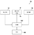
도 1 및 도 2는 본 발명의 한 실시예에 따른 표시 장치를 설명하기 위한 도면이다.1 and 2 are views illustrating a display device according to an exemplary embodiment of the present invention.
도 1 및 도 2를 참조하면, 본 발명의 한 실시예에 따른 표시 장치(DD1)는 영상 표시 면(DP), 제1 광 센서(LS1), 및 제1 카메라(CM1)를 포함할 수 있다.1 and 2, the display device DD1 according to an exemplary embodiment of the present invention may include an image display surface DP, a first optical sensor LS1, and a first camera CM1. .
또한, 표시 장치(DD1)는 적어도 하나의 프로세서(PROC) 및 메모리(MEM)를 포함할 수 있다. 메모리(MEM)는 디지털 정보 또는 아날로그 정보를 저장하기 위한 기억 소자일 수 있다. 프로세서(PROC)는 특정 알고리즘을 구현하기 위한 전용 프로세서(dedicated purpose processor)일 수도 있고, 다양한 알고리즘을 구현할 수 있는 범용 프로세서(general purpose processor)일 수도 있다. 예를 들어, 후술하는 알고리즘은 하나의 범용 프로세서로 구현될 수도 있고, 알고리즘의 각 부분을 구현하는 복수의 전용 프로세서들로 구현될 수도 있다. 또한, 알고리즘은 범용 프로세서와 전용 프로세서들의 조합으로 구현될 수도 있다. 이하에서는 설명의 편의를 위해서 하나의 범용 프로세서로 알고리즘의 각 부분의 동작을 설명하나, 당업자라면 알고리즘의 각 부분에 해당하는 전용 프로세서를 제작할 수도 있을 것이다.Also, the display device DD1 may include at least one processor PROC and a memory MEM. The memory MEM may be a storage element for storing digital information or analog information. The processor PROC may be a dedicated purpose processor for implementing a specific algorithm, or a general purpose processor capable of implementing various algorithms. For example, the algorithm described below may be implemented with one general purpose processor, or may be implemented with a plurality of dedicated processors that implement each part of the algorithm. Also, the algorithm may be implemented with a combination of general purpose processors and dedicated processors. Hereinafter, for the convenience of description, the operation of each part of the algorithm is described with one general-purpose processor, but a person skilled in the art may manufacture a dedicated processor corresponding to each part of the algorithm.
영상 표시 면(DP)은 화소들(PXs)의 발광 면에 대응할 수 있다. 각각의 화소들(PXs)은 대응하는 계조 값에 기초하여 발광할 수 있다. 화소들(PXs)의 발광 조합을 통해서 영상 표시 면(DP)은 영상 프레임을 표시할 수 있다.The image display surface DP may correspond to the emission surface of the pixels PXs. Each pixel PXs may emit light based on a corresponding gradation value. The image display surface DP may display an image frame through a combination of light emission of the pixels PXs.
화소들(PXs)은 발광 다이오드 표시 패널, 액정 표시 패널 등으로 구성될 수 있다. 발광 다이오드 표시 패널에서 각 화소는 적어도 하나의 유기 발광 다이오드 또는 무기 발광 다이오드를 포함할 수 있다. 또한, 각 화소는 적어도 하나의 양자점 발광 소자를 포함할 수도 있다. 발광 다이오드들이 자발광함으로써, 표시 장치(DD1)는 영상 프레임을 표시할 수 있다. 액정 표시 패널에서 화소들은 백라이트 유닛으로부터 방출된 광의 투과 정도를 조정함으로써, 표시 장치(DD1)는 영상 프레임을 표시할 수 있다. 광의 투과 정도는 각 화소에 대응하는 액정 층에 인가되는 전계의 크기 및 방향으로 조절할 수 있다. 표시 패널 상에 보호 필름 또는 윈도우가 더 부착될 수도 있다.The pixels PXs may be formed of a light emitting diode display panel, a liquid crystal display panel, and the like. In the LED display panel, each pixel may include at least one organic light emitting diode or inorganic light emitting diode. Further, each pixel may include at least one quantum dot light emitting device. As the light emitting diodes self-emit, the display device DD1 can display an image frame. In the liquid crystal display panel, pixels adjust the transmittance of light emitted from the backlight unit, so that the display device DD1 can display an image frame. The degree of light transmission can be adjusted in the size and direction of the electric field applied to the liquid crystal layer corresponding to each pixel. A protective film or window may be further attached on the display panel.
영상 표시 면(DP)은 임의 크기의 영역들로 구획될 수 있다. 각 영역은 적어도 하나의 화소를 포함할 수 있다. 예를 들어, 각 영역의 크기는 화소 단위로 나타낼 수 있다. 각 영역의 크기는 미리 설정되거나, 제품 출하 후 사용자에 의해 또는 제조자 업데이트에 의해 설정될 수도 있다.The image display surface DP may be divided into regions of any size. Each region may include at least one pixel. For example, the size of each region may be expressed in units of pixels. The size of each area may be set in advance, or may be set by a user after product shipment or by manufacturer update.
본 실시예에서는 임의의 한 화소를 제1 영역(ar1)으로 가정한다. 이때, 해당 화소의 발광 면적이 제1 영역(ar1)에 해당할 수 있다.In this embodiment, it is assumed that any one pixel is the first area ar1. In this case, the emission area of the corresponding pixel may correspond to the first area ar1.
예를 들어, 외광원(OL)은 제1 영역(ar1)에 대해 입사각(agi)을 갖는 외광(ray1)을 방출할 수 있다. 외광원(OL)은 태양, 외부 조명, 내부 조명 등에 해당할 수 있다.For example, the external light source OL may emit external light ray1 having an incident angle agi with respect to the first region ar1. The external light source OL may correspond to the sun, external lighting, internal lighting, or the like.
프로세서(PROC)는 제1 광 센서(LS1)를 이용하여 제1 영역(ar1)에 대한 외광원(OL)의 입사각(agi)을 결정할 수 있다. 본 발명의 한 실시예에 따른 제1 광 센서(LS1)의 구성은 도 2 내지 도 5를 참조하여 후술한다. 실시예에 따라, 프로세서(PROC)는 제1 광 센서(LS1)를 이용하여 외광원(OL)의 입사각(agi)뿐만 아니라 세기(intensity)도 결정할 수 있다.The processor PROC may determine the incident angle agi of the external light source OL with respect to the first area ar1 using the first optical sensor LS1. The configuration of the first optical sensor LS1 according to an embodiment of the present invention will be described later with reference to FIGS. 2 to 5. According to an embodiment, the processor PROC may determine not only the incident angle agi of the external light source OL but also the intensity using the first optical sensor LS1.
프로세서(PROC)는 제1 카메라(CM1)를 이용하여 제1 영역(ar1)에 대한 사용자 안구(PP)의 반사각(agr)을 결정할 수 있다. 제1 카메라(CM1)는 종래의 카메라로 구성될 수 있다. 제1 카메라(CM1)를 이용한 반사각(agr) 결정 과정은 도 6 내지 도 10을 참조하여 후술한다.The processor PROC may determine the reflection angle agr of the user's eye PP with respect to the first area ar1 using the first camera CM1. The first camera CM1 may be configured as a conventional camera. The process of determining the reflection angle agr using the first camera CM1 will be described later with reference to FIGS. 6 to 10.
제1 영역(ar1)에서 입사각(agi)과 반사각(agr)이 대응하는 경우, 프로세서(PROC)는 제1 영역(ar1)의 휘도를 상승시킬 수 있다. 예를 들어, 제1 영역(ar1)에서 입사각(agi)과 반사각(agr)이 일치하는 경우, 외광(ray1)의 반사광(rray1)에 의해서 사용자는 제1 영역(ar1)에서의 영상 표시를 시인하기 어려울 수 있다. 따라서, 프로세서(RPOC)가 제1 영역(ar1)의 휘도를 국부적으로 상승시킴으로써, 사용자는 반사광(rray1)에도 불구하고 제1 영역(ar1)의 영상을 보다 용이하게 시인할 수 있다.When the incident angle agi and the reflected angle agr correspond to the first area ar1, the processor PROC may increase the luminance of the first area ar1. For example, when the incident angle agi and the reflection angle agr coincide in the first area ar1, the user visually recognizes the image display in the first area ar1 by the reflected light rray1 of the external light ray1. It can be difficult to do. Therefore, the processor RPOC locally increases the luminance of the first area ar1, so that the user can more easily visualize the image of the first area ar1 despite the reflected light rray1.
외광원(OL)의 크기 몇 형상에 따라 제1 영역(ar1)의 주변 영역(RL)에도 외광원(OL)의 상(image)이 맺혀 사용자가 주변 영역(RL)의 영상을 시인하기 어려울 수 있다. 프로세서(PROC)는 제1 영역(ar1)의 주변 영역(RL)에 대해서도 전술한 과정을 반복 수행함으로써, 주변 영역(RL)의 휘도를 국부적으로 상승시킬 수 있다. 다른 실시예에서, 프로세서(RPOC)는 제1 영역(ar1)의 휘도를 국부적으로 상승시킬 때, 제1 영역(ar1)으로부터 미리 결정된 범위 내인 주변 영역(RL)에 대해서 전술한 과정을 수행함이 없이(즉, 즉각적으로) 휘도를 국부적으로 상승시킬 수도 있다.The size of the external light source OL The image of the external light source OL is also formed in the peripheral area RL of the first area ar1 according to some shapes, so that it may be difficult for a user to visually recognize the image of the peripheral area RL. have. The processor PROC may locally increase the luminance of the peripheral area RL by repeatedly performing the above-described process on the peripheral area RL of the first area ar1. In another embodiment, when the luminance of the first area ar1 is locally increased, the processor RPOC does not perform the above-described process on the peripheral area RL within a predetermined range from the first area ar1. It is also possible to locally (ie instantaneously) increase the luminance.
이하에서, 정확한 위치 설명을 위해서, 영상 표시 면(DP)은 서로 직교하는 제1 방향(DR1) 및 제2 방향(DR2)으로 연장되는 평면 상에 위치하는 것으로 가정한다. 제3 방향(DR3)은 제1 방향(DR1) 및 제2 방향(DR2)에 직교하는 방향으로써, 영상 표시 면(DP)과 수직한 방향인 것으로 가정한다. 전술한 입사각(agi) 및 반사각(agr)은 제1 영역(ar1)에서 제3 방향(DR3)의 축을 기준으로 한 각도를 의미한다.Hereinafter, for accurate location description, it is assumed that the image display surface DP is located on a plane extending in the first direction DR1 and the second direction DR2 orthogonal to each other. The third direction DR3 is a direction orthogonal to the first direction DR1 and the second direction DR2, and is assumed to be a direction perpendicular to the image display surface DP. The above-described incidence angle agi and reflection angle agr refer to an angle based on an axis of the third direction DR3 in the first area ar1.
다만, 이러한 가정은 정확한 위치 설명을 위한 것으로써, 표시 패널이 플렉서블한 경우, 영상 표시 면(DP)은 평면이 아닐 수도 있다.However, this assumption is for accurate location description, and when the display panel is flexible, the image display surface DP may not be a flat surface.
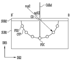
도 3 내지 도 6은 본 발명의 한 실시예에 따른 광 센서를 설명하기 위한 도면이다.3 to 6 are views for explaining an optical sensor according to an embodiment of the present invention.
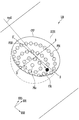
도 3 내지 도 6을 참조하면, 본 발명의 한 실시예에 따른 제1 광 센서(LS1)는 기판(SUB1), 광 센서 유닛들(PD1, PD2, PDc, PDt, ...), 및 커버(CV)를 포함할 수 있다.3 to 6, the first optical sensor LS1 according to an embodiment of the present invention includes a substrate SUB1, optical sensor units PD1, PD2, PDc, PDt, ..., and a cover (CV).
도 3은 기판(SUB1)을 설명하기 위한 것이고, 도 4는 도 3의 기판(SUB1) 상에 커버(CV)가 위치한 경우를 설명하기 위한 것이다. 도 5는 도 3 및 도 4의 A-A' 선에 따른 단면도이고, 도 6은 도 3 및 도 4의 B-B' 선에 따른 단면도이다.3 is for explaining the substrate SUB1, and FIG. 4 is for explaining the case where the cover CV is located on the substrate SUB1 of FIG. 3. 5 is a cross-sectional view taken along line A-A' in FIGS. 3 and 4, and FIG. 6 is a cross-sectional view taken along line B-B' in FIGS. 3 and 4.
기판(SUB1)은 오목 면(CVP)을 포함한다. 오목 면(CVP)은 반구(semi-sphere) 형상일 수 있다. 기판(SUB1)은 유리, 플라스틱, 금속 등 경질의 소재로 구성될 수 있다. 오목 면(CVP)이 광 센서 유닛들(PD1, PD2, PDc, PDt, ...)을 지지할 수 있다면, 기판(SUB1)의 소재는 제한되지 않는다.The substrate SUB1 includes a concave surface CVP. The concave surface CVP may have a semi-sphere shape. The substrate SUB1 may be made of a hard material such as glass, plastic, or metal. If the concave surface CVP can support the optical sensor units PD1, PD2, PDc, PDt, ..., the material of the substrate SUB1 is not limited.
광 센서 유닛들(PD1, PD2, PDc, PDt, ...)은 오목 면(CVP)에 배열될 수 있다. 광 센서 유닛들(PD1, PD2, PDc, PDt, ...)은 포토 다이오드(photo diode), 포토 트랜지스터(photo transistor), 광 도전 셀(photo conductive cell), 포토 커플러(photo coupler), 포토 인터럽터(photo interrupter), 서모파일(thermopile), 볼로미터(bolometer), 광전관(photoelectric tube) 등으로 구성될 수 있다.The optical sensor units PD1, PD2, PDc, PDt, ... may be arranged on the concave surface CVP. The photo sensor units PD1, PD2, PDc, PDt, ... are photo diodes, photo transistors, photo conductive cells, photo couplers, photo interrupters It can be composed of (photo interrupter), thermopile, bolometer, photoelectric tube, and the like.
커버(CV)는 오목 면(CVP)을 커버하되 광 센서 유닛들(PD1, PD2, PDc, PDt, ...)로부터 이격되고, 투과 영역 및 비투과 영역을 포함할 수 있다. The cover CV covers the concave surface CVP, but is spaced from the optical sensor units PD1, PD2, PDc, PDt, ..., and may include a transmissive region and a non-transmissive region.
커버(CV)는 제2 기판(SUB2)을 포함할 수 있다. 제2 기판(SUB2)은 불투명한 소재일 수 있다. 예를 들어, 투과 영역은 제2 기판(SUB2)의 개구부(CO)에 대응할 수 있다. 이때, 비투과 영역은 제2 기판(SUB2)에서 개구부(CO)를 제외한 나머지 영역을 의미할 수 있다. 다른 예를 들어, 제2 기판(SUB2)에서 투과 영역은 개구부가 아닌 투명 소재(유리, 플라스틱, 금속 등)로 구성될 수도 있다. 다른 예를 들어, 제2 기판(SUB2)은 투명한 소재로 구성되고, 비투과 영역에 대해서 불투명한 필름 등이 부착될 수도 있다. 이하에서는 설명의 편의를 위해, 투과 영역이 개구부(CO)이고, 비투과 영역이 개구부(CO)를 제외한 기판(SUB2)인 경우로 설명한다.The cover CV may include a second substrate SUB2. The second substrate SUB2 may be an opaque material. For example, the transmissive region may correspond to the opening CO of the second substrate SUB2. In this case, the non-transmissive region may mean the remaining region excluding the opening CO in the second substrate SUB2. For another example, the transmission region in the second substrate SUB2 may be made of a transparent material (glass, plastic, metal, etc.) rather than an opening. For another example, the second substrate SUB2 is made of a transparent material, and an opaque film or the like may be attached to the non-transmissive region. Hereinafter, for convenience of description, it will be described as a case where the transmission region is the opening CO and the non-transmission region is the substrate SUB2 excluding the opening CO.
오목 면(CVP)이 반구 형상인 경우, 투과 영역은 반구 형상의 중심에 대응하여 위치할 수 있다. 반구 형상의 중심이란, 반구 표면의 임의의 위치들까지의 거리가 동일한 특정 위치를 의미할 수 있다. 예를 들어, 투과 영역으로부터 광 센서 유닛들(PD1, PD2, PDc, PDt, ...)까지의 거리들은 서로 동일할 수 있다.When the concave surface CVP is hemispherical, the transmissive region may be positioned corresponding to the center of the hemispherical shape. The hemisphere-shaped center may refer to a specific location in which the distances to arbitrary locations on the hemisphere surface are the same. For example, the distances from the transmission area to the light sensor units PD1, PD2, PDc, PDt, ... may be the same.
프로세서(PROC)는 광 센서 유닛들(PD1, PD2, PDc, PDt, ...) 중 외광원(OL)에 대해 가장 큰 신호(예를 들어, 전류 신호 또는 전압 신호)를 발생시키는 대상 광 센서 유닛(PDt)을 결정할 수 있다. 프로세서(PROC)는 개구부(CO)로부터 대상 광 센서 유닛(PDt)의 상대적인 위치를 이용하여 외광(ray2)의 입사각을 결정할 수 있다.The processor PROC is a target optical sensor that generates the largest signal (eg, current signal or voltage signal) for the external light source OL among the optical sensor units PD1, PD2, PDc, PDt, ... The unit PDt can be determined. The processor PROC may determine the incident angle of the external light ray2 using the relative position of the target optical sensor unit PDt from the opening CO.
예를 들어, 프로세서(PROC)는 개구부(CO)를 원점으로 하는 구면 좌표 계를 이용하여 대상 광 센서 유닛(PDt)의 3차원 위치를 결정할 수 있다. 또한, 프로세서(PROC)는 임의의 원점을 기준으로 하는 직교 좌표 계를 이용하여 개구부(CO)에 대한 광 센서유닛(PDt)의 3차원 위치를 결정할 수도 있다.For example, the processor PROC may determine a three-dimensional position of the target optical sensor unit PDt using a spherical coordinate system having an opening CO as an origin. In addition, the processor PROC may determine a three-dimensional position of the optical sensor unit PDt with respect to the opening CO using a Cartesian coordinate system based on an arbitrary origin.
이하에서는 간소화된 표시를 위해서, 제1 방향(DR1)과 제3 방향(DR3)을 기준으로 하는 제1 평면에서 외광들(ray1, ray2) 및 반사광(rray1)의 각도를 정의하고, 제2 방향(DR2)과 제3 방향(DR3)을 기준으로 하는 제2 평면에서 외광들(ray1, ray2)과 반사광(rray1)의 각도를 정의한다. 서로 평행하지 않는 제1 평면 및 제2 평면에서의 각도들을 조합하면, 3차원 공간에서의 각도가 정의될 수 있다.Hereinafter, for simplified display, the angles of the external light rays ray1 and ray2 and the reflected light ray1 are defined in a first plane based on the first direction DR1 and the third direction DR3, and the second direction The angles of the external light rays ray1 and ray2 and the reflected light ray1 are defined in a second plane based on the DR2 and the third direction DR3. By combining the angles in the first and second planes that are not parallel to each other, the angle in the three-dimensional space can be defined.
예를 들어 도 5를 참조하면 제1 평면에서 광축(CAXs1)에 대한 외광(ray2)의 입사각(agi11)이 도시되고, 도 6을 참조하면 제2 평면에서 광축(CAXs1)에 대한 외광(ray2)의 입사각(agi12)이 도시된다. 광축(CAXs1)은 개구부(CO)의 중심을 제3 방향(DR3)으로 지나는 것으로 정의한다. 제1 평면에서의 입사각(agi11) 및 제2 평면에서의 입사각(agi12)을 조합하면, 외광(ray2)의 3차원 공간에서의 입사각이 정의될 수 있다.For example, referring to FIG. 5, the incident angle agi11 of the external light ray2 with respect to the optical axis CAXs1 in the first plane is illustrated, and with reference to FIG. 6, the external light ray2 with respect to the optical axis CAXs1 in the second plane is shown. The incidence angle of agi12 is shown. The optical axis CAXs1 is defined as passing the center of the opening CO in the third direction DR3. When the incidence angle agi11 in the first plane and the incidence angle agi12 in the second plane are combined, the incidence angle in the three-dimensional space of the external light ray2 may be defined.
이러한 각도 표현 방법은 외광들(ray1, ray2) 및 반사광(rray1)의 각도들을 결정하는 방법을 한정하는 것이 아니며, 외광들(ray1, ray2) 및 반사광(rray1)의 각도들이 다양한 측면에서 표현될 수 있음을 설명하기 위한 것이다.The angle expression method is not limited to a method for determining the angles of the external lights (ray1, ray2) and reflected light (rray1), and the angles of the external lights (ray1, ray2) and reflected light (rray1) can be expressed in various aspects. It is to explain the existence.
프로세서(PROC)는 제1 광 센서(LS1)를 이용하여 영상 표시 면(DP)의 제1 영역(ar1)에 대한 외광(ray1)의 입사각(agi)을 결정할 수 있다. 예를 들어, 프로세서(PROC)는 제1 광 센서(LS1)에 대한 외광(ray2)의 입사각을 제1 영역(ar1)에 대한 외광(ray1)의 입사각(agi)으로 결정할 수 있다. 도 1에서는 지면의 한계로 인해 외광들(ray1, ray2)의 입사각들이 서로 다른 것처럼 도시되었지만, 외광원(OL)이 표시 장치(DD1)로부터 충분히 멀리 떨어진 경우, 외광들(ray1, ray2)의 입사각들은 실질적으로 동일할 수 있다.The processor PROC may determine the incident angle agi of the external light ray1 with respect to the first area ar1 of the image display surface DP using the first optical sensor LS1. For example, the processor PROC may determine an incident angle of the external light ray2 with respect to the first optical sensor LS1 as an incident angle agi of the external light ray1 with respect to the first area ar1. In FIG. 1, the incident angles of the external lights ray1 and ray2 are different due to the limitation of the ground, but when the external light source OL is sufficiently far away from the display device DD1, the incident angles of the external lights ray1 and ray2 Can be substantially the same.
도 7 내지 도 11은 사용자 안구의 위치를 결정하기 위한 과정을 설명하기 위한 도면이다.7 to 11 are views for explaining a process for determining the position of the user's eyeball.
프로세서(PROC)는 카메라(CM1)에 대한 사용자 안구(PP)의 반사각(agr)을 제1 카메라(CM1)에 대한 제1 영역(ar1)의 상대적인 거리들((-)ref1, (+)ref2)을 이용해 보정함으로써, 제1 영역(ar1)에 대한 사용자 안구(PP)의 반사각(agr)을 결정할 수 있다.The processor PROC measures the reflection angle agr of the user's eyeball PP with respect to the camera CM1 relative distances of the first region ar1 with respect to the first camera CM1 ((-)ref1, (+)ref2 ) To determine the reflection angle agr of the user's eye PP with respect to the first area ar1.
먼저, 도 7 및 도 8을 참조하여 제1 카메라(CM1)에 대한 사용자 안구(PP)의 반사각(agr)을 결정하는 방법을 설명한다. 도 7을 참조하면 제1 평면에서 제1 카메라(CM1)에 대한 사용자 안구(PP)의 반사각(agr11)이 도시되고, 도 8을 참조하면 제2 평면에서 제1 카메라(CM1)에 대한 사용자 안구(PP)의 반사각(agr12)이 도시된다.First, a method of determining the reflection angle agr of the user's eye PP with respect to the first camera CM1 will be described with reference to FIGS. 7 and 8. Referring to FIG. 7, the reflection angle agr11 of the user's eyeball PP with respect to the first camera CM1 in the first plane is illustrated, and with reference to FIG. 8, the user's eyeball with respect to the first camera CM1 in the second plane The reflection angle agr12 of (PP) is shown.
제1 카메라 원점(O1)으로부터 제1 카메라(CM1)의 제1 이미지 평면(IMP1)까지의 초점 거리(focal length, f1)는 제1 카메라(CM1)의 고정된 파라미터 값일 수 있다. 제1 카메라(CM1)의 광학 축(CAXc1)은 제1 카메라 원점(O1)으로부터 제1 이미지 평면(IMP1)을 제3 방향(DR3)으로 지나갈 수 있다.The focal length (f1) from the first camera origin O1 to the first image plane IMP1 of the first camera CM1 may be a fixed parameter value of the first camera CM1. The optical axis CAXc1 of the first camera CM1 may pass through the first image plane IMP1 in the third direction DR3 from the first camera origin O1.
도 7을 참조하면, 프로세서(PROC)는 제1 이미지 평면(IMP1)에서 사용자 안구(PP)의 이미지가 위치하는 지점(P1)을 탐색할 수 있다. 지점(P1)이 결정되면, 프로세서(PROC)는 광학 축(CAXc1)과 제1 이미지 평면(IMP1)의 교점으로부터 지점(P1)까지의 제1 방향(DR1)의 거리(d11)를 측정할 수 있다. 따라서, 프로세서(PROC)는 직각 삼각형의 특징을 이용하여 제1 평면에서 제1 카메라(CM1)에 대한 사용자 안구(PP)의 반사각(agr11)을 결정할 수 있다.Referring to FIG. 7, the processor PROC may search for a point P1 where the image of the user's eye PP is located in the first image plane IMP1. When the point P1 is determined, the processor PROC can measure the distance d11 in the first direction DR1 from the intersection of the optical axis CAXc1 and the first image plane IMP1 to the point P1. have. Accordingly, the processor PROC may determine the reflection angle agr11 of the user's eye PP with respect to the first camera CM1 in the first plane using the feature of the right triangle.
한 대의 제1 카메라(CM1)만을 이용하는 경우, 제1 카메라 원점(O1) 또는 제1 카메라(CM1)로부터 사용자 안구(PP)까지의 높이(Z1)를 측정할 수는 없다.When only one first camera CM1 is used, the height Z1 from the first camera origin O1 or the first camera CM1 to the user's eye PP cannot be measured.
다만, 높이(Z1)는 제품 출하 전 미리 설정되거나, 제품 출하 후 설정될 수도 있다. 또한, 후술하는 바와 같이 높이(Z1)는 사용자에 의해 캘리브레이션(calibration)될 수도 있다. 높이(Z1)가 결정된다면, 직각 삼각형의 특징을 이용하여 제1 카메라 원점(O1) 또는 제1 카메라(CM1)로부터 사용자 안구(PP)까지의 제1 방향(DR1)의 거리(dd11)를 알 수 있다. 이하에서는 높이(Z1)가 특정 수치로 결정된 상태임을 가정한다.However, the height Z1 may be set before the product is shipped, or may be set after the product is shipped. Also, as described later, the height Z1 may be calibrated by the user. If the height Z1 is determined, the distance dd11 in the first direction DR1 from the first camera origin O1 or the first camera CM1 to the user's eye PP is known using the feature of the right triangle. Can. Hereinafter, it is assumed that the height Z1 is determined by a specific value.
도 8을 참조하면, 유사한 방법으로, 프로세서(PROC)는 광학 축(CAXc1)과 제1 이미지 평면(IMP1)의 교점으로부터 지점(P1)까지의 제2 방향(DR2)의 거리(d12)를 측정할 수 있다. 따라서, 프로세서(PROC)는 직각 삼각형의 특징을 이용하여 제2 평면에서 제1 카메라(CM1)에 대한 사용자 안구(PP)의 반사각(agr12)을 결정할 수 있다.Referring to FIG. 8, in a similar manner, the processor PROC measures the distance d12 of the second direction DR2 from the intersection of the optical axis CAXc1 and the first image plane IMP1 to the point P1. can do. Accordingly, the processor PROC may determine the reflection angle agr12 of the user's eye PP with respect to the first camera CM1 in the second plane using the feature of the right triangle.
전술한 바와 같이, 높이(Z1)가 특정 수치로 결정된 상태임을 가정할 때, 직각 삼각형의 특징을 이용하여, 제1 카메라 원점(O1) 또는 제1 카메라(CM1)로부터 사용자 안구(PP)까지의 제2 방향(DR2)의 거리(dd12)를 알 수 있다.As described above, assuming that the height Z1 is determined to be a specific numerical value, from the first camera origin O1 or the first camera CM1 to the user's eye PP using a feature of a right-angled triangle The distance dd12 in the second direction DR2 is known.
도 9를 참조하면, 제1 카메라(CM1)에 대한 제1 영역(ar1)의 상대적인 거리들((-)ref1, (+)ref2)이 예시적으로 도시된다.Referring to FIG. 9, relative distances ((−)ref1, (+)ref2) of the first area ar1 to the first camera CM1 are exemplarily illustrated.
축(axDR2)은 제1 카메라(CM1)를 지나고 제1 방향(DR1)으로 연장될 수 있다. 축(axDR1)은 제1 카메라(CM1)를 지나고 제2 방향(DR2)으로 연장될 수 있다.The axis axDR2 may pass through the first camera CM1 and extend in the first direction DR1. The axis axDR1 may pass through the first camera CM1 and extend in the second direction DR2.
제1 영역(ar1)은 제1 카메라(CM1)로부터 제1 방향(DR1)의 반대 방향으로 제1 거리((-)ref1)에 위치하고, 제2 방향(DR2)으로 제2 거리((+)ref2)에 위치할 수 있다.The first area ar1 is located at a first distance ((-)ref1) in a direction opposite to the first direction DR1 from the first camera CM1, and a second distance (+) in the second direction DR2. ref2).
이와 같이, 제1 카메라(CM1)에 대한 각 영역의 상대적인 거리들은 미리 정해진 값들이므로, 제품 출하 전에 LUT(look-up table) 형태로 작성되어 메모리(MEM)에 저장될 수 있다.As described above, since the relative distances of each region to the first camera CM1 are predetermined values, they may be written in a look-up table (LUT) form before shipment of the product and stored in the memory MEM.
도 9 및 도 10을 참조하면, 프로세서(PROC)는 거리(dd11) 및 제1 거리((-)ref1)의 차이를 계산함으로써, 제1 영역(ar1)으로부터 사용자 안구(PP)까지의 제1 방향(DR1)의 거리(dd11')를 산출할 수 있다.9 and 10, the processor PROC calculates the difference between the distance dd11 and the first distance ((-)ref1), so that the first area AR1 to the user's eye PP is calculated. The distance dd11' of the direction DR1 can be calculated.
전술한 바와 같이 높이(Z1)가 미리 결정된 상태이므로, 프로세서(PROC)는 직각 삼각형의 특징을 이용하여 제1 평면에서 제1 영역(ar1)에 대한 사용자 안구(PP)의 반사각(agr11')을 결정할 수 있다.As described above, since the height Z1 is a predetermined state, the processor PROC uses the feature of the right triangle to determine the reflection angle agr11' of the user's eye PP with respect to the first area ar1 in the first plane. Can decide.
도 9 및 도 11을 참조하면, 프로세서(PROC)는 거리(dd12) 및 제2 거리((+)ref2)의 차이를 계산함으로써, 제1 영역(ar1)으로부터 사용자 안구(PP)까지의 제2 방향(DR2)의 거리(dd12')를 산출할 수 있다.9 and 11, the processor PROC calculates the difference between the distance dd12 and the second distance (+)ref2, so that the second area from the first area ar1 to the user's eye PP is calculated. The distance dd12' of the direction DR2 can be calculated.
전술한 바와 같이 높이(Z1)가 미리 결정된 상태이므로, 프로세서(PROC)는 직각 삼각형의 특징을 이용하여 제2 평면에서 제1 영역(ar1)에 대한 사용자 안구(PP)의 반사각(agr12')을 결정할 수 있다.As described above, since the height Z1 is in a predetermined state, the processor PROC uses the feature of the right triangle to determine the reflection angle agr12' of the user's eye PP with respect to the first area ar1 in the second plane. Can decide.
전술한 바와 같이, 제1 평면에서의 반사각(agr11')과 제2 평면에서의 반사각(agr12')을 조합하면, 제1 영역(ar1)에 대한 사용자 안구(PP)의 3차원 공간에서의 반사각(agr)을 정의할 수 있다.As described above, when the reflection angle agr11' in the first plane and the reflection angle agr12' in the second plane are combined, the reflection angle in the three-dimensional space of the user's eye PP with respect to the first area ar1 (agr) can be defined.
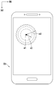
도 12는 영상 표시 면의 제1 영역의 휘도를 국부적으로 상승시키는 경우를 설명하기 위한 도면이다.12 is a view for explaining a case where the luminance of the first area of the image display surface is locally increased.
프로세서(PROC)는 입사각(agi)과 반사각(agr)이 서로 대응하는 경우 제1 영역(ar1)의 휘도를 상승시킬 수 있다. 전술한 바와 같이, 외광원(OL)으로부터 제1 영역(ar1)에 대한 입사각(agi)이 제1 영역(ar1)에 대한 사용자 안구(PP)의 반사각(agr)이 대응(예를 들어, 동일)하는 경우, 사용자는 반사광(rray1)에 의해 제1 영역(ar1)에 표시된 영상의 시인이 어려울 수 있다.The processor PROC may increase the luminance of the first region ar1 when the incident angle agi and the reflected angle agr correspond to each other. As described above, the incident angle agi from the external light source OL to the first area ar1 corresponds to the reflection angle agr of the user's eye PP to the first area ar1 (eg, the same) ), the user may have difficulty viewing the image displayed on the first area ar1 by the reflected light rray1.
따라서, 프로세서(PROC)는 제1 영역(ar1)의 휘도를 국부적으로 상승시킴으로써, 반사광(rray1)의 존재에 불구하고, 사용자는 제1 영역(ar1)에 표시된 영상을 보다 용이하게 시인할 수 있다.Accordingly, the processor PROC locally increases the luminance of the first area ar1, so that despite the presence of the reflected light rray1, the user can more easily view the image displayed on the first area ar1. .
실시예에 따라, 프로세서(PROC)는 제1 영역(ar1)으로부터 미리 결정된 거리(rd1)에 위치하는 주변 영역의 휘도를 국부적으로 상승시킬 수 있다. 이때, 주변 영역의 휘도 상승량은 제1 영역(ar1)의 휘도 상승량과 동일할 수 있다.According to an embodiment, the processor PROC may locally increase the luminance of the peripheral area located at a predetermined distance rd1 from the first area ar1. At this time, the luminance increase amount of the peripheral area may be the same as the luminance increase amount of the first area ar1.
실시예에 따라, 프로세서(PROC)는 제1 영역(ar1)으로부터 미리 결정된 거리(rd2)에 위치하는 주변 영역의 휘도를 국부적으로 상승시킬 수 있다. 이때, 제1 영역(ar1)으로부터 거리가 멀어질 수록 주변 영역의 휘도 상승량은 작아질 수 있다. 이로써, 휘도 상승된 제1 영역(ar1)과 휘도가 유지된 주변 영역(예를 들어, 거리(rd2)보다 멀리 위치하는 주변 영역)의 휘도 차이가 보다 부드럽게(softly) 사용자에게 시인될 수 있다.According to an embodiment, the processor PROC may locally increase the luminance of the peripheral area located at a predetermined distance rd2 from the first area ar1. At this time, as the distance from the first region (ar1) increases, the luminance increase in the surrounding region may decrease. As a result, the difference in luminance between the first region (ar1) where the luminance is increased and the peripheral region where the luminance is maintained (for example, a peripheral region located farther than the distance rd2) may be softly recognized by the user.
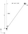
도 13 및 도 14는 표시 장치에 대한 사용자 안구의 높이를 캘리브레이션하는 과정을 설명하기 위한 도면이다.13 and 14 are views for explaining a process of calibrating the height of the user's eyeball with respect to the display device.
프로세서(PROC)는 표시 장치(DD1)에 대한 사용자 안구의 높이(Z1')를 캘리브레이션할 수 있다.The processor PROC may calibrate the height Z1' of the user's eyeball with respect to the display device DD1.
먼저, 프로세서(PROC)는 사용자에게 제1 측정 영역(are1) 상에 사용자 안구(PPe1)가 위치하도록 요청할 수 있다. 예를 들어, 프로세서(PROC)는 영상 표시 면(DP)의 제1 측정 영역(are1)을 강조하는 영상(예를 들어, 깜빡임, 다른 색상, 더 높은 휘도 등)을 표시하고, 사용자에게 제1 측정 영역(are1)으로부터 제3 방향(DR3)에 사용자 안구(PPe1)가 위치하도록 요청할 수 있다. 요청은 사운드, 영상 표시 등으로 수행될 수 있다.First, the processor PROC may request the user to place the user's eye PPe1 on the first measurement area are1. For example, the processor PROC displays an image (for example, flickering, different colors, higher luminance, etc.) that emphasizes the first measurement area are1 of the image display surface DP, and displays the first to the user. The user's eye PPe1 may be requested to be located in the third direction DR3 from the measurement area are1. The request can be performed by sound, video display, and the like.
사용자는 사용자 안구(PPe1)를 제1 측정 영역(are1) 상에 위치시킨 이후에, 완료 버튼을 누르거나 음성 인식 기능을 통해 프로세서(PROC)에게 사용자 안구(PPe1)가 제1 측정 영역(are1) 상에 위치됨을 알릴 수 있다.After the user has placed the user's eye PPe1 on the first measurement area are1, the user's eye PPe1 is pushed to the processor PROC by pressing the Done button or through the voice recognition function. It can be noticed that it is located on.
다음으로, 프로세서(PROC)는 제1 카메라(CM1)에 대한 사용자 안구(PPe1)의 제1 각도(agr121)를 측정할 수 있다. 각도 측정 방법에 대해서는 도 7 및 도 8에 대한 설명을 참조한다.Next, the processor PROC may measure the first angle agr121 of the user's eye PPe1 with respect to the first camera CM1. For the angle measurement method, refer to the description of FIGS. 7 and 8.
다음으로, 프로세서(PROC)는 표시 장치(DD1)에 대한 사용자 안구(PPe2)의 높이(Z1')를 유지하면서, 표시 장치(DD1)의 제2 측정 영역(are2) 상으로 사용자 안구(PPe2)가 위치하도록 요청할 수 있다.Next, the processor PROC maintains the height Z1' of the user's eye PPe2 with respect to the display device DD1, while the user's eye PPe2 is on the second measurement area are2 of the display device DD1. Can be requested to be located.
전술한 과정과 유사한 과정을 통해서, 프로세서(PROC)는 제1 카메라(CM1)에 대한 사용자 안구(PPe2)의 제2 각도(agr122)를 측정할 수 있다.Through a process similar to the above-described process, the processor PROC may measure the second angle agr122 of the user's eye PPe2 with respect to the first camera CM1.
다음으로, 프로세서(PROC)는 제1 각도(agr121), 제2 각도(agr122), 및 제1 측정 영역(are1) 및 제2 측정 영역(are2) 사이의 거리(dPP)에 기초하여 표시 장치(DD1)에 대한 사용자 안구(PPe1)의 높이(Z1')를 결정할 수 있다.Next, the processor PROC displays the display device based on the first angle agr121, the second angle agr122, and the distance dPP between the first measurement area are1 and the second measurement area are2. It is possible to determine the height Z1' of the user's eye PPe1 for DD1).
각도(agd1)는 90도와 각도(agr121)의 차이 값이다. 각도(agd2)는 180도와 각도(agd1)의 차이 값이다. 각도(agd3)는 각도(agr122)와 각도(agr121)의 차이 값이다. 각도(agd4)는 180도에서 각도(agd2) 및 각도(agd3)를 제하고 남은 값이다. The angle agd1 is a difference value between 90 degrees and the angle agr121. The angle agd2 is the difference value between 180 degrees and the angle agd1. The angle agd3 is a difference value between the angle agr122 and the angle agr121. The angle agd4 is the value remaining after subtracting the angle agd2 and agd3 from 180 degrees.
사용자는 사용자 안구(PPe1 or PPe2)의 높이(Z1')를 유지하면서 거리(dPP')만큼 이동시키도록 요청 받았으므로, 거리(dPP')는 거리(dPP)와 동일하다고 가정할 수 있다.Since the user is requested to move the distance dPP' while maintaining the height Z1' of the user's eye PPe1 or PPe2, it can be assumed that the distance dPP' is equal to the distance dPP.
따라서, 사용자 안구(PPe1)의 이동 전 위치, 사용자 안구(PPe2)의 이동 후 위치, 및 제1 카메라 원점(O1)을 연결하는 삼각형이 특정될 수 있으므로, 프로세서(PROC)는 높이(Z1')를 산출할 수 있다.Accordingly, since the position before the movement of the user's eyeball PPe1, the position after the movement of the user's eyeball PPe2, and the triangle connecting the first camera origin O1 may be specified, the processor PROC has a height Z1'. Can be calculated.
프로세서(PROC)는 사용자 안구(PP)의 반사각(agr)을 결정하는 과정에서, 결정된 사용자 안구(PP)의 높이(Z1')를 사용할 수 있다. 예를 들어, 프로세서(PROC)는 도 7 내지 도 11의 과정에서 높이(Z1)를 높이(Z1')로 대체하여 사용할 수 있다.In the process of determining the reflection angle agr of the user's eyeball PP, the processor PROC may use the determined height Z1' of the user's eyeball PP. For example, the processor PROC may be used by replacing the height Z1 with the height Z1' in the process of FIGS. 7 to 11.
본 실시예에 의하면, 한 대의 제1 카메라(CM1)만으로 사용자 안구(PP)의 반사각(agr)을 결정할 수 있다는 장점이 있다.According to this embodiment, there is an advantage that the reflection angle agr of the user's eyeball PP can be determined only by using one first camera CM1.
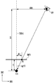
도 15 및 도 16은 2 개의 카메라들을 이용하여 사용자 안구의 3차원 위치를 결정하는 과정을 설명하기 위한 도면이다.15 and 16 are diagrams for explaining a process of determining a 3D position of a user's eyeball using two cameras.
도 15를 참조하면, 표시 장치(DD2)는 도 1의 표시 장치(DD1)에 비해 제2 카메라(CM2)를 더 포함할 수 있다. 제2 카메라(CM2)는 제1 카메라(CM1)로부터 거리(do12)만큼 이격될 수 있다.Referring to FIG. 15, the display device DD2 may further include a second camera CM2 as compared to the display device DD1 of FIG. 1. The second camera CM2 may be spaced apart from the first camera CM1 by a distance do12.
도 16을 참조하면, 삼각 측량법(triangulation)을 이용하여 사용자 안구(PP)의 높이(Z1)를 획득하는 과정이 도시되어 있다.Referring to FIG. 16, a process of acquiring the height Z1 of the user's eye PP using a triangulation is illustrated.
제1 카메라(CM1)는 초점 거리(f1) 및 거리(d11)를 이용하여 각도(agr11)를 산출할 수 있다. 초점 거리(f1)는 제1 카메라 원점(O1)으로부터 제1 이미지 평면(IMP1)까지의 거리이다. 거리(d11)는 축(CAXc1)과 제1 이미지 평면(IMP1)의 교점으로부터 제1 이미지 평면(IMP1)에 사용자 안구(PP)의 이미지가 맺히는 지점(P1)까지의 간격을 의미한다.The first camera CM1 may calculate the angle agr11 using the focal length f1 and the distance d11. The focal length f1 is a distance from the first camera origin O1 to the first image plane IMP1. The distance d11 refers to an interval from an intersection of the axis CAXc1 and the first image plane IMP1 to a point P1 where the image of the user's eye PP is formed on the first image plane IMP1.
제2 카메라(CM2)는 초점 거리(f2) 및 거리(d21)를 이용하여 각도(agr21)를 산출할 수 있다. 초점 거리(f2)는 제2 카메라 원점(O2)으로부터 제2 이미지 평면(IMP2)까지의 거리이다. 거리(d21)는 축(CAXc2)과 제2 이미지 평면(IMP2)의 교점으로부터 제2 이미지 평면(IMP2)에 사용자 안구(PP)의 이미지가 맺히는 지점(P2)까지의 간격을 의미한다.The second camera CM2 may calculate the angle agr21 using the focal length f2 and the distance d21. The focal length f2 is the distance from the second camera origin O2 to the second image plane IMP2. The distance d21 means the distance from the intersection of the axis CAXc2 and the second image plane IMP2 to the point P2 where the image of the user's eye PP is formed on the second image plane IMP2.
각도(agr11r)는 90도와 각도(agr11)의 차이에 해당하고, 각도(agr21r)는 90도와 각도(agr21)의 차이에 해당한다. 제1 카메라 원점(O1)과 제2 카메라 원점(O2) 간의 거리, 즉 베이스 라인(base line)의 길이에 해당하는 거리(do12)는 미리 정해진 값이다.The angle agr11r corresponds to the difference between 90 degrees and the angle agr11, and the angle agr21r corresponds to the difference between 90 degrees and the angle agr21. The distance between the first camera origin O1 and the second camera origin O2, that is, the distance do12 corresponding to the length of the base line is a predetermined value.
따라서, 제1 카메라 원점(O1), 제2 카메라 원점(O2), 및 사용자 안구(PP)를 연결하는 삼각형이 특정될 수 있으므로, 프로세서(PROC)는 높이(Z1)를 산출할 수 있다.Accordingly, since a triangle connecting the first camera origin O1, the second camera origin O2, and the user's eyeball PP can be specified, the processor PROC can calculate the height Z1.
본 실시예에 의하면, 캘리브레이션 과정이 불필요하며 실시간으로 사용자 안구(PP)의 높이(Z1)를 측정할 수 있다는 장점이 있다.According to this embodiment, the calibration process is unnecessary and has the advantage of being able to measure the height Z1 of the user's eyeball PP in real time.
이외에, 당업자는 스테레오 비전(stereo-vision)의 다른 방법을 이용하여 사용자 안구(PP)의 높이(Z1)를 획득할 수도 있다. 예를 들어, 에피폴라 지오메트리(epipolar geometry)를 이용하는 방법이 있다. 이는 공지된 방법이므로, 별도로 설명하지 않는다.In addition, a person skilled in the art may obtain the height Z1 of the user's eyeball PP using another method of stereo-vision. For example, there is a method using epipolar geometry. Since this is a known method, it is not described separately.
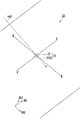
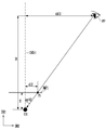
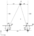
도 17 및 도 18은 2 개의 광 센서들을 이용하여 외광원의 3차원 위치를 결정하는 과정을 설명하기 위한 도면이다.17 and 18 are views for explaining a process of determining a three-dimensional position of an external light source using two optical sensors.
도 17을 참조하면, 표시 장치(DD3)는 도 1의 표시 장치(DD1)와 달리 제2 광 센서(LS2)를 더 포함할 수 있다. 제2 광 센서(LS2)는 제1 광 센서(LS1)로부터 거리(ds12)만큼 이격될 수 있다.Referring to FIG. 17, unlike the display device DD1 of FIG. 1, the display device DD3 may further include a second optical sensor LS2. The second optical sensor LS2 may be spaced apart from the first optical sensor LS1 by a distance ds12.
제2 광 센서(LS2)의 구성은 제1 광 센서(LS1)의 구성과 실질적으로 동일할 수 있으므로, 중복된 설명은 생략한다.Since the configuration of the second optical sensor LS2 may be substantially the same as that of the first optical sensor LS1, a duplicate description is omitted.
프로세서(PROC)는 제1 광 센서(LS1) 및 제2 광 센서(LS2)를 이용하여 표시 장치(DD3)에 대한 외광원(OL)의 3차원 위치를 결정할 수 있다.The processor PROC may determine the three-dimensional position of the external light source OL with respect to the display device DD3 using the first light sensor LS1 and the second light sensor LS2.
전술한 바와 같이, 프로세서(PROC)는 외광원(OL)으로부터 제1 광 센서(LS1)에 대한 외광의 입사각(agi21)을 획득할 수 있다. 유사하게, 프로세서(PROC)는 외광원(OL)으로부터 제2 광 센서(LS2)에 대한 외광의 입사각(agi11)을 획득할 수 있다. 입사각(agi11)은 제1 광 센서(LS1)의 광축(CAXs1)을 기준으로 하고, 입사각(agi21)은 제2 광 센서(LS2)의 광축(CAXs2)를 기준으로 한다.As described above, the processor PROC may acquire the incident angle agi21 of the external light to the first optical sensor LS1 from the external light source OL. Similarly, the processor PROC may obtain an incident angle agi11 of external light to the second optical sensor LS2 from the external light source OL. The incident angle agi11 is based on the optical axis CAXs1 of the first optical sensor LS1, and the incident angle agi21 is based on the optical axis CAXs2 of the second optical sensor LS2.
각도(agi21r)는 90도와 입사각(agi21)의 차이에 해당하고, 각도(agi11r)는 90도와 입사각(agi11)의 차이에 해당한다. 거리(ds12)는 미리 결정된 값이다.The angle agi21r corresponds to the difference between 90 degrees and the incident angle agi21, and the angle agi11r corresponds to the difference between 90 degrees and the incident angle agi11. The distance ds12 is a predetermined value.
따라서, 제1 광 센서(LS1), 제2 광 센서(LS2), 및 외광원(OL)을 연결하는 삼각형이 특정될 수 있으므로, 프로세서(PROC)는 외광원(OL)의 높이(Z2)를 산출할 수 있다.Accordingly, since the triangle connecting the first light sensor LS1, the second light sensor LS2, and the external light source OL can be specified, the processor PROC determines the height Z2 of the external light source OL. Can be calculated.
본 실시예에 의하면, 외광원(OL)이 표시 장치(DD3)로부터 충분히 멀리 위치하지 않은 경우, 외광원(OL)의 높이(Z2) 또는 3차원 위치를 실시간으로 특정할 수 있다는 장점이 있다.According to the present embodiment, when the external light source OL is not sufficiently far from the display device DD3, it is advantageous in that the height Z2 or the three-dimensional position of the external light source OL can be specified in real time.
프로세서(PROC)는 외광원(OL)의 3차원 위치를 이용하여 제1 영역(ar1)에 대한 외광의 입사각을 결정할 수 있다. 도 9 내지 도 11을 참조하여, 제1 카메라(CM1)에 대한 사용자 안구(PP)의 반사각(agr11, agr12)을 제1 카메라(CM1)에 대한 제1 영역(ar1)의 상대적인 거리들((-)ref1, (+)ref2)을 이용해 보정함으로써, 제1 영역(ar1)에 대한 사용자 안구(PP)의 반사각(agr11', agr12')을 결정하는 과정을 설명한 바 있다. 유사하게, 제1 광 센서(LS1)에 대한 외광원(OL)의 입사각(agi11, agi12)을 제1 광 센서(LS1)에 대한 제1 영역(ar1)의 상대적인 거리들을 이용해 보정함으로써, 제1 영역(ar1)에 대한 외광원(OL)의 입사각을 결정할 수 있다. 중복되는 내용의 설명은 생략한다.The processor PROC may determine the incident angle of the external light with respect to the first area ar1 using the three-dimensional position of the external light source OL. Referring to FIGS. 9 to 11, the relative distances of the first area ar1 to the first camera CM1 relative to the reflection angles agr11 and agr12 of the user's eyeball PP relative to the first camera CM1 (( The process of determining the reflection angles agr11' and agr12' of the user's eyeball PP with respect to the first area ar1 by correcting them using -)ref1 and (+)ref2) has been described. Similarly, by correcting the incident angles agi11 and agi12 of the external light source OL with respect to the first optical sensor LS1 using the relative distances of the first area ar1 with respect to the first optical sensor LS1, the first The incident angle of the external light source OL with respect to the area ar1 may be determined. Description of overlapping content is omitted.
이로써, 외광원(OL)이 표시 장치(DD3)로부터 충분히 멀리 위치하지 않은 경우, 제1 영역(ar1)에 대한 입사각을 보다 정확히 산출할 수 있는 장점이 있다.Accordingly, when the external light source OL is not positioned far enough from the display device DD3, there is an advantage in that the incident angle with respect to the first region ar1 can be more accurately calculated.
지금까지 참조한 도면과 기재된 발명의 상세한 설명은 단지 본 발명의 예시적인 것으로서, 이는 단지 본 발명을 설명하기 위한 목적에서 사용된 것이지 의미 한정이나 특허청구범위에 기재된 본 발명의 범위를 제한하기 위하여 사용된 것은 아니다. 그러므로 본 기술 분야의 통상의 지식을 가진 자라면 이로부터 다양한 변형 및 균등한 타 실시 예가 가능하다는 점을 이해할 것이다. 따라서, 본 발명의 진정한 기술적 보호 범위는 첨부된 특허청구범위의 기술적 사상에 의해 정해져야 할 것이다.The drawings referenced so far and the detailed description of the described invention are merely exemplary of the present invention, which are used for the purpose of describing the present invention only and are used to limit the scope of the present invention as defined in the claims or the claims. It is not. Therefore, those of ordinary skill in the art will understand that various modifications and other equivalent embodiments are possible therefrom. Therefore, the true technical protection scope of the present invention should be determined by the technical spirit of the appended claims.
DD1: 표시 장치
LS1: 제1 광센서
CM1: 제1 카메라
CVP: 오목 면
SUB1: 제1 기판
CV: 커버
PD1, PD2, PDc, PDt: 광 센서 유닛들DD1: display device
LS1: 1st optical sensor
CM1: First camera
CVP: concave
SUB1: First substrate
CV: cover
PD1, PD2, PDc, PDt: Optical sensor units
Claims (20)
상기 오목 면에 배열된 광 센서 유닛들; 및
상기 오목 면을 커버하되 상기 광 센서 유닛들로부터 이격되고, 투과 영역 및 비투과 영역을 포함하는 커버를 포함하는,
광 센서.A first substrate including a concave surface;
Optical sensor units arranged on the concave surface; And
A cover covering the concave surface, spaced apart from the light sensor units, and including a cover including a transmissive area and a non-transmissive area,
Optical sensor.
상기 오목 면은 반구 형상인,
광 센서.According to claim 1,
The concave surface is a hemispherical shape,
Optical sensor.
상기 투과 영역은 상기 반구 형상의 중심에 대응하여 위치한,
광 센서.According to claim 2,
The transmission region is located corresponding to the center of the hemisphere shape,
Optical sensor.
상기 커버는 제2 기판을 포함하고,
상기 투과 영역은 상기 제2 기판의 개구부에 대응하는,
광 센서.According to claim 3,
The cover includes a second substrate,
The transmission region corresponds to the opening of the second substrate,
Optical sensor.
상기 투과 영역으로부터 상기 광 센서 유닛들까지의 거리들은 서로 동일한,
광 센서.According to claim 1,
The distances from the transmission area to the light sensor units are equal to each other,
Optical sensor.
제1 카메라;
제1 광 센서; 및
상기 제1 광 센서를 이용하여 상기 영상 표시 면의 제1 영역에 대한 외광의 입사각을 결정하고, 상기 제1 카메라를 이용하여 상기 제1 영역에 대한 사용자 안구의 반사각을 결정하고, 상기 입사각과 상기 반사각이 서로 대응하는 경우 상기 제1 영역의 휘도를 상승시키는 프로세서를 포함하는,
표시 장치.Video display surface;
A first camera;
A first optical sensor; And
The first optical sensor is used to determine the incident angle of external light to the first area of the image display surface, and the first camera is used to determine the reflection angle of the user's eye to the first area, the incident angle and the And a processor that increases the luminance of the first region when the reflection angles correspond to each other,
Display device.
상기 프로세서는 상기 제1 광 센서에 대한 상기 외광의 입사각을 상기 제1 영역에 대한 상기 외광의 입사각으로 결정하는,
표시 장치.The method of claim 6,
The processor determines an incident angle of the external light to the first optical sensor as an incident angle of the external light to the first region,
Display device.
상기 프로세서는 상기 제1 카메라에 대한 상기 사용자 안구의 반사각을 상기 제1 카메라에 대한 상기 제1 영역의 상대적인 거리들을 이용해 보정함으로써, 상기 제1 영역에 대한 상기 사용자 안구의 반사각을 결정하는,
표시 장치.The method of claim 6,
The processor determines a reflection angle of the user's eyeball with respect to the first region by correcting the reflection angle of the eyeball with respect to the first camera using relative distances of the first region with respect to the first camera,
Display device.
상기 제1 카메라와 이격된 제2 카메라를 더 포함하고,
상기 프로세서는 상기 제1 카메라 및 상기 제2 카메라를 이용하여 상기 제1 영역에 대한 상기 사용자 안구의 반사각을 결정하는,
표시 장치.The method of claim 6,
Further comprising a second camera spaced apart from the first camera,
The processor determines the reflection angle of the user's eye with respect to the first area using the first camera and the second camera,
Display device.
상기 제1 광 센서와 이격된 제2 광 센서를 더 포함하고,
상기 프로세서는 상기 제1 광 센서 및 상기 제2 광 센서를 이용하여 상기 표시 장치에 대한 외광원의 3차원 위치를 결정하고,
상기 프로세서는 상기 외광원의 3차원 위치를 이용하여 상기 제1 영역에 대한 상기 외광의 입사각을 결정하는,
표시 장치.The method of claim 6,
Further comprising a second optical sensor spaced apart from the first optical sensor,
The processor determines the 3D position of the external light source with respect to the display device using the first optical sensor and the second optical sensor,
The processor determines the incident angle of the external light with respect to the first region using the three-dimensional position of the external light source,
Display device.
상기 제1 광 센서는:
오목 면을 포함하는 제1 기판;
상기 오목 면에 배열된 광 센서 유닛들; 및
상기 오목 면을 커버하되 상기 광 센서 유닛들로부터 이격되고, 투과 영역 및 비투과 영역을 포함하는 커버를 포함하는,
표시 장치.The method of claim 6,
The first optical sensor:
A first substrate including a concave surface;
Optical sensor units arranged on the concave surface; And
A cover covering the concave surface, spaced apart from the light sensor units, and including a cover including a transmissive area and a non-transmissive area,
Display device.
상기 제1 광 센서 또는 상기 제2 광 센서는:
오목 면을 포함하는 제1 기판;
상기 오목 면에 배열된 광 센서 유닛들; 및
상기 오목 면을 커버하되 상기 광 센서 유닛들로부터 이격되고, 투과 영역 및 비투과 영역을 포함하는 커버를 포함하는,
표시 장치.The method of claim 10,
The first optical sensor or the second optical sensor:
A first substrate including a concave surface;
Optical sensor units arranged on the concave surface; And
A cover covering the concave surface, spaced apart from the light sensor units, and including a cover including a transmissive area and a non-transmissive area,
Display device.
제1 카메라를 이용하여 상기 제1 영역에 대한 사용자 안구의 반사각을 결정하는 단계; 및
상기 입사각과 상기 반사각이 서로 대응하는 경우 상기 제1 영역의 휘도를 상승시키는 단계를 포함하는,
표시 장치의 구동 방법.Determining an incident angle of external light with respect to the first area of the image display surface using the first optical sensor;
Determining a reflection angle of the user's eye with respect to the first area using a first camera; And
And when the incidence angle and the reflection angle correspond to each other, increasing the luminance of the first region,
Method of driving the display device.
상기 표시 장치에 대한 상기 사용자 안구의 높이를 캘리브레이션하는 단계를 더 포함하는,
표시 장치의 구동 방법.The method of claim 13,
Further comprising the step of calibrating the height of the user's eyeball with respect to the display device,
Method of driving the display device.
상기 캘리브레이션하는 단계는:
상기 표시 장치의 제1 측정 영역 상에 상기 사용자 안구가 위치하도록 요청하는 단계;
상기 제1 카메라에 대한 상기 사용자 안구의 제1 각도를 측정하는 단계;
상기 표시 장치에 대한 상기 사용자 안구의 높이를 유지하면서, 상기 표시 장치의 제2 측정 영역 상으로 상기 사용자 안구가 위치하도록 요청하는 단계;
상기 제1 카메라에 대한 상기 사용자 안구의 제2 각도를 측정하는 단계; 및
상기 제1 각도, 상기 제2 각도, 및 상기 제1 측정 영역 및 상기 제2 측정 영역 사이의 거리에 기초하여 상기 표시 장치에 대한 상기 사용자 안구의 높이를 결정하는 단계를 포함하는,
표시 장치의 구동 방법.The method of claim 14,
The calibration step is:
Requesting the user's eyeball to be positioned on a first measurement area of the display device;
Measuring a first angle of the user's eyeball with respect to the first camera;
Requesting that the user's eyeball be positioned on a second measurement area of the display device while maintaining the height of the user's eyeball with respect to the display device;
Measuring a second angle of the user's eyeball with respect to the first camera; And
Determining a height of the user's eyeball with respect to the display device based on the first angle, the second angle, and a distance between the first measurement area and the second measurement area,
Method of driving the display device.
상기 사용자 안구의 반사각을 결정하는 단계에서, 결정된 상기 사용자 안구의 높이를 이용하는,
표시 장치의 구동 방법.The method of claim 15,
In the step of determining the reflection angle of the user's eye, using the determined height of the user's eye,
Method of driving the display device.
상기 제1 영역에 대한 상기 외광의 입사각을 결정하는 단계에서,
상기 제1 광 센서에 대한 상기 외광의 입사각을 상기 제1 영역에 대한 상기 외광의 입사각으로 결정하는,
표시 장치의 구동 방법.The method of claim 13,
In the step of determining the incident angle of the external light to the first area,
Determining an incident angle of the external light to the first optical sensor as an incident angle of the external light to the first region,
Method of driving the display device.
상기 제1 영역에 대한 상기 사용자 안구의 반사각을 결정하는 단계에서,
상기 제1 카메라에 대한 상기 사용자 안구의 반사각을 상기 제1 카메라에 대한 상기 제1 영역의 상대적인 거리들을 이용해 보정함으로써, 상기 제1 영역에 대한 상기 사용자 안구의 반사각을 결정하는,
표시 장치의 구동 방법.The method of claim 13,
In the step of determining the reflection angle of the user's eye with respect to the first area,
Determining a reflection angle of the user's eyeball with respect to the first region by correcting the reflection angle of the eyeball with respect to the first camera using relative distances of the first region with respect to the first camera,
Method of driving the display device.
상기 제1 영역에 대한 상기 사용자 안구의 반사각을 결정하는 단계에서,
상기 제1 카메라 및 상기 제1 카메라와 이격된 제2 카메라를 이용하여 상기 제1 영역에 대한 사용자 안구의 반사각을 결정하는,
표시 장치의 구동 방법.The method of claim 13,
In the step of determining the reflection angle of the user's eye with respect to the first area,
Determining a reflection angle of the user's eye with respect to the first area by using the first camera and a second camera spaced apart from the first camera,
Method of driving the display device.
상기 제1 영역에 대한 상기 외광의 입사각을 결정하는 단계에서,
상기 제1 광 센서 및 상기 제1 광 센서와 이격된 제2 광 센서를 이용하여 상기 표시 장치에 대한 외광원의 3차원 위치를 결정하고,
상기 외광원의 3차원 위치를 이용하여 상기 제1 영역에 대한 상기 외광의 입사각을 결정하는,
표시 장치의 구동 방법.The method of claim 13,
In the step of determining the incident angle of the external light to the first area,
A 3D position of an external light source with respect to the display device is determined by using the first optical sensor and the second optical sensor spaced apart from the first optical sensor,
Determining the angle of incidence of the external light with respect to the first region by using the three-dimensional position of the external light source,
Method of driving the display device.
Priority Applications (5)
| Application Number | Priority Date | Filing Date | Title |
|---|---|---|---|
| KR1020190002921A KR20200086786A (en) | 2019-01-09 | 2019-01-09 | Light sensor, display device including the same, and driving method of display device |
| US16/543,297 US10923078B2 (en) | 2019-01-09 | 2019-08-16 | Photo sensor, display device including the same, and driving method thereof |
| CN201911317380.0A CN111486948B (en) | 2019-01-09 | 2019-12-19 | Photosensor, display device including the photosensor, and driving method thereof |
| JP2020000335A JP2020112554A (en) | 2019-01-09 | 2020-01-06 | Optical sensor, display device including optical sensor and driving method of display device |
| EP20151011.2A EP3680884A3 (en) | 2019-01-09 | 2020-01-09 | Photo sensor, display device including the same, and driving method thereof |
Applications Claiming Priority (1)
| Application Number | Priority Date | Filing Date | Title |
|---|---|---|---|
| KR1020190002921A KR20200086786A (en) | 2019-01-09 | 2019-01-09 | Light sensor, display device including the same, and driving method of display device |
Publications (1)
| Publication Number | Publication Date |
|---|---|
| KR20200086786A true KR20200086786A (en) | 2020-07-20 |
Family
ID=69182466
Family Applications (1)
| Application Number | Title | Priority Date | Filing Date |
|---|---|---|---|
| KR1020190002921A KR20200086786A (en) | 2019-01-09 | 2019-01-09 | Light sensor, display device including the same, and driving method of display device |
Country Status (5)
| Country | Link |
|---|---|
| US (1) | US10923078B2 (en) |
| EP (1) | EP3680884A3 (en) |
| JP (1) | JP2020112554A (en) |
| KR (1) | KR20200086786A (en) |
| CN (1) | CN111486948B (en) |
Family Cites Families (11)
| Publication number | Priority date | Publication date | Assignee | Title |
|---|---|---|---|---|
| US5854661A (en) * | 1997-09-30 | 1998-12-29 | Lucent Technologies Inc. | System and method for subtracting reflection images from a display screen |
| US6853445B2 (en) * | 2002-01-07 | 2005-02-08 | Motorola, Inc. | Two-dimensional angle of arrival detection device |
| US20120229487A1 (en) * | 2011-03-11 | 2012-09-13 | Nokia Corporation | Method and Apparatus for Reflection Compensation |
| US9582083B2 (en) | 2011-12-22 | 2017-02-28 | Apple Inc. | Directional light sensors |
| US9557813B2 (en) * | 2013-06-28 | 2017-01-31 | Tactus Technology, Inc. | Method for reducing perceived optical distortion |
| KR101471612B1 (en) * | 2013-07-01 | 2014-12-12 | 남부대학교산학협력단 | Solar position Tracking Precision Measurement system based on precision optical lenses. |
| EP3042312B1 (en) * | 2013-09-03 | 2021-06-09 | Seeing Machines Limited | Low power eye tracking system and method |
| KR101907143B1 (en) | 2013-11-22 | 2018-10-12 | 한국과학기술연구원 | a fabricating method for anti-reflection film with an excellent performance and a anti-reflection film fabricated thereof |
| KR102142624B1 (en) * | 2013-12-30 | 2020-08-10 | 삼성디스플레이 주식회사 | Display device |
| WO2015161495A1 (en) * | 2014-04-25 | 2015-10-29 | Telefonaktiebolaget L M Ericsson (Publ) | Adjusting brightness of display |
| KR20170060353A (en) * | 2015-11-24 | 2017-06-01 | 삼성전자주식회사 | Electronic apparatus, distance measurement sensor and control method for electronic apparatus and distance measurement sensor |
-
2019
- 2019-01-09 KR KR1020190002921A patent/KR20200086786A/en not_active Application Discontinuation
- 2019-08-16 US US16/543,297 patent/US10923078B2/en active Active
- 2019-12-19 CN CN201911317380.0A patent/CN111486948B/en active Active
-
2020
- 2020-01-06 JP JP2020000335A patent/JP2020112554A/en active Pending
- 2020-01-09 EP EP20151011.2A patent/EP3680884A3/en not_active Withdrawn
Also Published As
| Publication number | Publication date |
|---|---|
| EP3680884A3 (en) | 2020-07-22 |
| JP2020112554A (en) | 2020-07-27 |
| EP3680884A2 (en) | 2020-07-15 |
| CN111486948B (en) | 2024-04-12 |
| US20200219462A1 (en) | 2020-07-09 |
| US10923078B2 (en) | 2021-02-16 |
| CN111486948A (en) | 2020-08-04 |
Similar Documents
| Publication | Publication Date | Title |
|---|---|---|
| US11042034B2 (en) | Head mounted display calibration using portable docking station with calibration target | |
| US10025101B2 (en) | Dynamic draft for Fresnel lenses | |
| US10371952B2 (en) | Fresnel lens with dynamic pitch | |
| US10133076B2 (en) | Hybrid fresnel lens with reduced artifacts | |
| US9951935B2 (en) | Display device | |
| CN114153014B (en) | Fresnel lens with dynamic draft for reducing optical artifacts | |
| US20170186231A1 (en) | Increasing field of view of head-mounted display using a mirror | |
| US11841502B2 (en) | Reflective polarizer for augmented reality and virtual reality display | |
| US11347071B1 (en) | Display with a resolution enhanced region | |
| US20180074323A1 (en) | Fresnel Lens with Dynamic Draft for Reduced Optical Artifacts | |
| US20180373348A1 (en) | Systems and methods of active brightness depth calculation for object tracking | |
| US10551500B2 (en) | Infrared optical element for proximity sensor system | |
| US20180267601A1 (en) | Light Projection for Guiding a User within a Physical User Area During Virtual Reality Operations | |
| KR20200086786A (en) | Light sensor, display device including the same, and driving method of display device | |
| US10572731B1 (en) | Infrared transparent backlight device for eye tracking applications | |
| TWI683135B (en) | Head-mounted display device and adjusting method for the same | |
| US20230077073A1 (en) | Augmented reality device and method for obtaining depth map by using depth sensor | |
| CN115857256A (en) | Light source module with adaptive illumination |
Legal Events
| Date | Code | Title | Description |
|---|---|---|---|
| E902 | Notification of reason for refusal | ||
| E601 | Decision to refuse application |